
Fluid Condition Monitoring - Southern Fluid Power
80
Fluid Condition Monitoring and Fuel Hydrocarbon Monitoring Solutions
-
Upload
khangminh22 -
Category
Documents
-
view
2 -
download
0
Transcript of Fluid Condition Monitoring - Southern Fluid Power

Fluid ConditionMonitoringand Fuel Hydrocarbon Monitoring Solutions

• Consistent quality• Technical innovation• Premier customer service
Parkers technical resources provide thecorrect filtration technologies that conformto your requirements. That’s why thousandsof manufacturers and equipment users aroundthe world rely on Parker Filtration productsand people.
Worldwide Salesand ServiceParker Filtration’s global reputation as a reliablesupplier of superior filtration products is the resultof a focused and integrated development andmanufacturing system.
Parker Filtration consolidates quality filtrationproducts, manufactured by process filtration, airand gas filtration and separation, fuel conditioningand filtration, hydraulic and lubrication filtration,fluid power products and fluid condition monitoringequipment into one broad-based range thatcovers many markets and most applications,as detailed here.
Hydraulic, Lubrication &Coolant Filtration
High-performance filtrationsystems for productionmachinery in industrial, mobileand military/marine applications.
Compressed Air &Gas Filtration
Complete line of compressedair/gas filtration products!coalescing, particulate andadsorption filters in manyapplications in manyindustries.
Process & ChemicalFluid Filtration
Liquid filtration systems forbeverage, chemical and foodprocessing! cosmetic, paint,water treatment! photo-processing! and micro-chipfabrication.
Racor Fuel Conditioning& Filtration
Parker air, fuel and oil filtrationsystems provide qualityprotection for enginesoperating in any environment,anywhere in the world.
Photo courtesy of GLASBAU HAHN.
System ContaminationMonitoring
On-line dynamic particleanalysis, off-line bottlesampling and fluid analysis andmeasurement of water contentpolluting the oil in a system.All important and achievable,cost-effective solutions availableto equipment manufacturersand end users alike.
Condition Monitoring Products
ContentsFluid Condition Monitoring and Contamination Control
1
LaserCM Contamination Monitor 3"niversal Bottle Sampler ##Single Point Sampler #$System %& Sensors and Monitors %#MCM%& Autoremote Monitor %$Icount PD Particle Detector 3#H%Oil – Water in Oil Monitor 41Moisture Sensor Range 45Oilcheck Monitor '3
Fluid condition monitoring
Asic ‘Performer’ '$
Transducers & transmitters
Parker HannifinHydraulic Filter Division EuropeFDCB3$'"(.
Introduction
Working with equipment manufacturers, hydraulic systemdesigners and maintenance engineers, one of the key factorsfor Parker Filtration’s Condition Monitoring and ContaminationControl Division relates to the environment. It has beenmade abundantly clear that our top priority has to be energyconservation and pollution control.
System efficiency, reduced downtime and predictivemaintenance are all components that play a significant role in ourcustomers being able to more efficiently manage their hydraulicapplications and systems and maintaining peak power andefficiency of those systems. In the field of fluid contaminationmonitoring, the laser has become a key component in themonitoring of systems where OEM’s and end users alike areevaluating system cleanliness and filtration effectiveness withcondition monitoring analysis and data logging of results.
As a leading manufacturer and design authority of portableparticle analysers, we are )ustifiably proud of the developmentswe have made over recent years. At Parker’s ConditionMonitoring Centre, located at Thetford in the East of Englandwe are particularly proud that we have been able to playour part in the hydraulic fluids and fuel industries, where ourCondition Monitoring equipment provides accurate indicationsof filtration efficiency and system cleanliness levels.
ACM%& Lab "nit *#ACM%& +% Particle Counter (ATEX Approved) *,
Fuel Hydrocarbon Monitoring
Condition Monitoring Products
Important changes to our productordering information
Standard Product Tables and a Product Configurator
Parker HannifinHydraulic Filter Division EuropeFDCB3$'"(.
%
Parker Filtration has recently undertaken a review of its partnumbering with a view to standardising on a common partnumber style for all Filtration products. As a result of the manyacquisitions we have made over the past #& years, it becameclear to us that there was a need to standardise on a clearformat for our part numbers.
Accordingly, in this new catalogue, you will find the new partnumber system with both a configurator and a supersedescross reference relating to previous part numbers, issued inearlier editions of our generic catalogues. In the event that theprevious reference you use is not shown in this catalogue, couldwe ask you to please contact our European Product InformationCentre. Contact details are on the back of this catalogue.
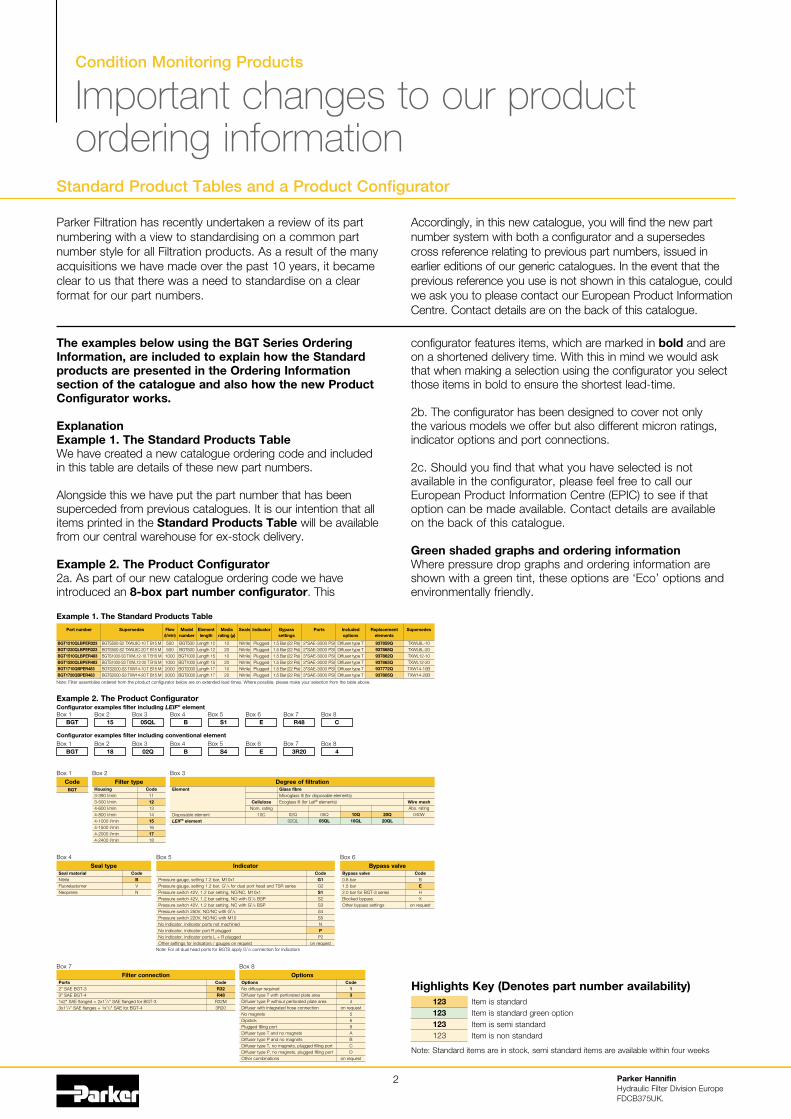
The examples below using the BGT Series OrderingInformation, are included to explain how the Standardproducts are presented in the Ordering Informationsection of the catalogue and also how the new ProductConfigurator works.
ExplanationExample 1. The Standard Products TableWe have created a new catalogue ordering code and includedin this table are details of these new part numbers.
Alongside this we have put the part number that has beensuperceded from previous catalogues. It is our intention that allitems printed in the Standard Products Table will be availablefrom our central warehouse for ex-stock delivery.
Example 2. The Product Configurator%a. As part of our new catalogue ordering code we haveintroduced an 8-box part number configurator. This
configurator features items, which are marked in bold and areon a shortened delivery time. With this in mind we would askthat when making a selection using the configurator you selectthose items in bold to ensure the shortest lead-time.
%b. The configurator has been designed to cover not onlythe various models we offer but also different micron ratings,indicator options and port connections.
%c. Should you find that what you have selected is notavailable in the configurator, please feel free to call ourEuropean Product Information Centre (EPIC) to see if thatoption can be made available. Contact details are availableon the back of this catalogue.
Green shaded graphs and ordering informationWhere pressure drop graphs and ordering information areshown with a green tint, these options are ‘Eco’ options andenvironmentally friendly.
Item is standardItem is standard green optionItem is semi standardItem is non standard
123123123#%3
Highlights Key (Denotes part number availability)
Note: Standard items are in stock, semi standard items are available within four weeks
Note: Filter assemblies ordered from the product configurator below are on extended lead times. Where possible, please make your selection from the table above.
Example 2. The Product ConfiguratorConfigurator examples filter including LEIF® elementBox #
Code1112#31415#*1718
Housing3-3,& l/min3-'&& l/min--*&& l/min--.&& l/min--#&&& l/min--#'&& l/min--%&&& l/min--%-&& l/min
Filter typeBox %
BGTBox %
15Box 3
05QLBox -
BBox '
S1Box *
EBox $
R48Box .
C
Configurator examples filter including conventional elementBox #
BGTBox %
18Box 3
02QBox -
BBox '
S4Box *
EBox $
3R20Box .
4
Part number
BGT1210QLBPER323BGT1220QLBPER323BGT1510QLBPER483BGT1520QLBPER483BGT1710QBPER483BGT1720QBPER483
Supersedes
BGTS'&&-S% TXWL.C-#& T B#' MBGTS'&&-S% TXWL.C-%& T B#' MBGTS#&&&-S3 TXWL#%-#& T B#' MBGTS#&&&-S3 TXWL#%-%& T B#' MBGTS%&&&-S3 TXW#--#& T B#' MBGTS%&&&-S3 TXW#--%& T B#' M
Flow(l/min)
'&&'&&
#&&&#&&&%&&&%&&&
Modelnumber
BGT'&&BGT'&&BGT#&&&BGT#&&&BGT%&&&BGT%&&&
Elementlength
Length #%Length #%Length #'Length #'Length #$Length #$
Mediarating (µ)
#&%&#&%&#&%&
Seals
NitrileNitrileNitrileNitrileNitrileNitrile
Indicator
PluggedPluggedPluggedPluggedPluggedPlugged
Bypasssettings
#.' Bar (%% Psi)#.' Bar (%% Psi)#.' Bar (%% Psi)#.' Bar (%% Psi)#.' Bar (%% Psi)#.' Bar (%% Psi)
Includedoptions
Diffuser type TDiffuser type TDiffuser type TDiffuser type TDiffuser type TDiffuser type T
Replacementelements
937859Q937868Q937862Q937865Q937772Q937805Q
Supersedes
TXWL.L-#&TXWL.L-%&TXWL#%-#&TXWL#%-%&TXW#--#&BTXW#--%&B
Ports
%/SAE-3&&& PSI%/SAE-3&&& PSI3/SAE-3&&& PSI3/SAE-3&&& PSI3/SAE-3&&& PSI3/SAE-3&&& PSI
BGT
CodeBox #
CodeBVN
Seal materialNitrileFluorelastomerNeoprene
Seal typeBox -
CodeBEHX
on request
Bypass valve&.. bar#.' bar%.& bar for BGT-3 seriesBlocked bypassOther bypass settings
Bypass valveBox *
CodeG1G%S1S%S3S4S5NPP%
on request
Pressure gauge, setting #.% bar, M#&x#Pressure gauge, setting #.% bar, G1/8 for dual port head and TSR seriesPressure switch -%0, #.% bar setting, NO/NC, M#&x#Pressure switch -%0, #.% bar setting, NO with G1/8 BSPPressure switch -%0, #.% bar setting, NC with G1/8 BSPPressure switch %'&0, NO/NC with G1/8
Pressure switch %%&0, NO/NC with M#&No indicator, indicator ports not machinedNo indicator, indicator port R pluggedNo indicator, indicator ports L 1 R pluggedOther settings for indicators / gauges on request
IndicatorBox '
CodeR32R48
R3%M3R%&
Ports%/ SAE BGT-33/ SAE BGT--#x%/ SAE flanged 1 %x#1/4/ SAE flanged for BGT-33x#1/4/ SAE flanges 1 #x1/%/ SAE for BGT--
Filter connectionBox $
Code134
on request5*8ABCD
on request
OptionsNo diffuser requiredDiffuser type T with perforated plate areaDiffuser type P without perforated plate areaDiffuser with integrated hose connectionNo magnetsDipstickPlugged filling portDiffuser type T and no magnetsDiffuser type P and no magnetsDiffuser type T, no magnets, plugged filling portDiffuser type P, no magnets, plugged filling portOther combinations
OptionsBox .
Example 1. The Standard Products Table
Note: For all dual head ports for BGTS apply G1/8 connection for indicators
Box 3
Element
Disposable elementLEIF® element
CelluloseNom. rating
#&C 20Q20QL
Abs. rating&-&W10Q
10QL&'2
05QL&%2&%2L
Glass fibreMicroglass III (for disposable elements)Ecoglass III (for Leif® elements) Wire mesh
Degree of filtration

Portable Particle Counter
LaserCMFluid Condition Monitoring
Fluid condition monitoring3

Portable Particle Counter
LaserCMFeatures & Benefits
Test time: ! minutes
Particle counts: !", #", $#", !#", #%" and $%%"microns
&", '", $&", !$", 3(" and )%"microns(c)
International codes: ISO )-!!, NAS %-$!
Data retrieval: Memory access gives test searchfacility
Max. working pressure: &!% bar
Max. flow rate: &%% I/min when used with system!% Sensors. Higher with singlepoint sampler (consult Parker)
Working conditions: LaserCM will operate with thesystem working normally
Computer compatibility: Interface via RS!3! connection* +'%% baud rate.
Special ‘diagnostics’ are incorporated into the LaserCMmicroprocessor control to ensure effective testing.Routine contamination monitoring of oil systems withLaserCM saves time and saves money.Contamination monitoring is now possible whilemachinery is working - LaserCM saves onproduction downtime.
Parker HannifinHydraulic Filter Division EuropeFDCB3)#,-. Section $
4
Data entry allows individual equipment test log detailsto be recorded.Data retrieval of test results from memory via handset display.Automatic test cycle logging of up to 3%% tests canbe selected via hand set display.Totally portable, can be used as easily in the field asin the laboratory.Automatic calibration reminder.Instant, accurate results achieved with a ! minutetest cycle.Data entry allows individual equipment footprint record.Data graphing selectable via the integral printer.Auto 3%%-test cycle logging via LCD handset input.RS!3! serial port computer interface.Limit level output to control peripheral equipment suchas off-line filtration via internal relay limit switches.Auto-testing allows for the conducting of automaticsequencing tests on flushing systems for example.Optional bar code swipe wand to allow handsetdata loading.Worldwide service and technical support.Re-calibration - Annual certification by an approvedParker Service Centre.
Typical Applications
Construction machineryIndustrial plantHydraulic equipment . systemmanufacturersResearch . testing institutesOffshore . power generationMarineMilitary equipment applications
Parker LaserCM Portable ParticleCounter.With $# years experience in manufacturing theworld’s best selling ‘white light’ portable particlecounter / CM!%, the progression to the LaserCMwith its opto-mechanical, continuous wave singlepoint source laser (SPSL) is both a natural andcustomer driven development.
Fluid condition monitoring5
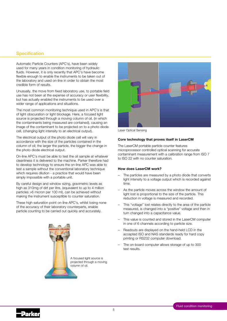
Specification
Automatic Particle Counters (APC’s), have been widelyused for many years in condition monitoring of hydraulicfluids. However, it is only recently that APC’s have becomeflexible enough to enable the instruments to be taken out ofthe laboratory and used on-line in order to obtain the mostcredible form of results.
"nusually, the move from fixed laboratory use, to portable fielduse has not been at the expense of accuracy or user flexibility,but has actually enabled the instruments to be used over awider range of applications and situations.
The most common monitoring technique used in APC’s is thatof light obscuration or light blockage. Here, a focused lightsource is pro)ected through a moving column of oil, (in whichthe contaminants being measured are contained), causing animage of the contaminant to be pro)ected on to a photo diodecell, (changing light intensity to an electrical output).
The electrical output of the photo diode cell will vary inaccordance with the size of the particles contained in thecolumn of oil! the larger the particle, the bigger the change inthe photo diode electrical output.
On-line APC’s must be able to test the oil sample at whatevercleanliness it is delivered to the machine. Parker therefore hadto develop technology to ensure the on-line APC was able totest a sample without the conventional laboratory techniquewhich requires dilution - a practice that would have beensimply impossible with a portable unit.
By careful design and window sizing, gravimetric levels ashigh as 3#&mg of dirt per litre, (equivalent to up to - millionparticles 3* micron per #&& ml), can be achieved withoutmaking the instrument susceptible to counter saturation.
These high saturation point on-line APC’s, whilst losing noneof the accuracy of their laboratory counterparts, enableparticle counting to be carried out quickly and accurately.
Core technology that proves itself in LaserCM
The LaserCM portable particle counter featuresmicroprocessor controlled optical scanning for accuratecontaminant measurement with a calibration range from ISO $to ISO %% with no counter saturation.
How does LaserCM work?
4 The particles are measured by a photo diode that convertslight intensity to a voltage output which is recorded againsttime.
4 As the particle moves across the window the amount oflight lost is proportional to the size of the particle. Thisreduction in voltage is measured and recorded.
4 This “voltage” lost relates directly to the area of the particlemeasured, is changed into a “positive” voltage and then inturn changed into a capacitance value.
4 This value is counted and stored in the LaserCM computerin one of * channels according to particle size.
4 Readouts are displayed on the hand-held LCD in theaccepted ISO and NAS standards ready for hard copyprinting or RS%3% computer download.
4 The on-board computer allows storage of up to 3&&test results.
A focused light source ispro)ected through a movingcolumn of oil.
Laser Optical Sensing

Description
Lexan, structural foam and ABS case
ABS handheld display
Mechanical composition 4 Brass,
plated steel, stainless steel and aluminium
Fluorocarbon seals
Perfluoroelastomer seals
Nylon hoses (kevlar braided microbore)
Stainless steel armoured hose ends
#.%m fluid connection hose
Rechargeable battery pack
#%0dc power supply
Fast blow fuse
"nique optical scanning system
Bonded glass optical window enclosed in SS plate
Micron channels analysis (Six)
Analysis range ISO $ to %% incl. (NAS & to #%)
3% character dot matrix LCD. Alpha numeric keypad
Data retrieval
Calibration to ISO standards*
0iscosity range % to #&& cSt. '&& cSt.with SPS
Operating temp.1' to 1.&5C
Ambient temp.1' to 1-&5C
% minute test completion time
Memory store 4 3&& test memory
Battery operated * x #.' D cells
Phosphate Ester group compatibility
Mineral oil 6 petroleum based fluid compatibility
"p to -%& bar (*&&& psi)
Integral #* column printer
RS%3% computer interface
Astra board case weight 4 ((g)
"nit weight 4 ((g)
DAT"M software and cable link pack
Weather protector cover
CE certified
Auto logging
*Note: In compliance with international standards, all Parker portable particle counters canmeet the ISO Medium test dust standards. The LaserCM’s, in addition to the complete rangeof Condition Monitoring products, are capable of achieving certification to ISO --&*:#,,, andwith traceability to ISO ###$# for SRM %.&*, via ISO ##,-3.
Portable Particle Counter
LaserCM
Parker HannifinHydraulic Filter Division EuropeFDCB3$'"(. Section #
*
Specification
%'.
%.#%
*3%
%-,
%-&
Commissioning Kit
Re-chargeablebattery pack
Instructionmanual 6 barcode software
Power lead,printer ribbon,
bar code pen 6weather cover
Batteries 6printer reel
Power supplyLimit socket, fuse
6 )ack plug ScrewdriverDatum 6
cable assy
LaserCM(LCM202022)
LaserCM(LCM202062)

Fluid condition monitoring
Operation
$
Operating the Parker LaserCM is as simple as pressingthe start button and turning the dial. The test procedure isautomatic and in the case of the LaserCM takes no more than% minutes to complete.
LaserCM makes the difference in industry
Fully accredited to BS EN *&.%':#,,% and IEC *&.%'-# (safetyof laser products) Standards, accredited to "SA Standards andachieving full ISO certification. LaserCM offers users advancedlaser technology, a fast, dynamic and on-line % minute systemtest cycle. A LaserCM Aggressive Fluids model is also available,suitable for monitoring corrosive fluids such as phosphate esterbased lubricants used in commercial aviation.
MTD calibration
Laser CM%& MTD Calibration variants are certified via a primaryISO ###$# calibrated automatic particle counter. All MTD LaserCM%&’s achieve ISO --&*:#,,, criteria, via ISO ##,-3.
Understanding MTD
ACFTD (Air Cleaner Fine Test Dust) was formatted in the#,*&’s, but is no longer being produced. The obsolescence ofthis dust has led to the adoption of a new dust MTD.
MTD (Medium Test Dust) having a particle size distributionclose to ACFTD was selected as a replacement. However,MTD produced results somewhat different to ACFTD, so theNIST (National Institute of Standards 6 Technology) undertooka pro)ect to certify the particle size distribution of ISO MTD.
The result was particle sizes below #&7m were greater thanpreviously measured.
Particles sizes reported based on NIST would be representedas 7m (c), with “c” referring to “certified”. Therefore the CM%&reported sizes are as follows:
ACFTD MTD%7 -7 (c)'7 *7 (c)#'7 #-7 (c)%'7 %#7 (c)'&7 3.7 (c)#&&7 $&7 (c)
MTD offers true traceability, improved particle size accuracyand better batch to batch reproduction.
Switch On Start Test
LCM20Using SPS

Portable Particle Counter
LaserCMWhy On-Site Fluid Contamination Monitoring?
Datum Data Management
Certification of fluid cleanliness levels.Early warning instrument to help preventcatastrophic failure in critical systems.Immediate results with laboratory accuracy.To comply with customer cleanlinessrequirements and specifications.New equipment warranty compliance.New oil cleanliness testing.
Parker HannifinHydraulic Filter Division EuropeFDCB3$'"(. Section #
8
Laser CM Test
ON LINE TEST
TEST N"MBER &%%
D M YDate &--&3-&*Time #'-'%ISO: %&/#'/&,
Count / #&&ml
3-7 (c) .%&$%#3*7 (c) 3#'*-3#-7 (c) 3#-3%#7 (c) *-33.7 (c) #-3$&7 (c) &
NOTES
ISO --&* - #,,, Correlation to NAS #*3.
#*-column printer for hard copy data. A feature of theLaserCM is the on-board printout data graphing optiondeveloped to support predictive maintenance procedures.
Laser CM Test
ON LINE TEST
TEST N"MBER &%%
D M YDate &--&3-&*Time #'-'%NAS CLASS: $
Count / #&&ml
-/*7 (c) $.,#'$*/#-7 (c) 3#%'&NAS CLASS $#-/%#7 (c) %'&NAS CLASS 3%#/3.7 (c) '&NAS CLASS 33./$&7 (c) #-NAS CLASS -3$&7 (c) &NAS CLASS &
NOTES
Datum, dedicated software, provides the link betweena Laser CM%&, System %& EM%& or the H%Oil - Waterin Oil and your computer management system.
Features:Windows based, Icon driven programFull graphic outputTables/results downloadTrend analysis and predictive maintenanceAuto test communication allows Datum to controlparticle counter testing and water in oil monitoringCertification creator using downloaded dataCustomer customised fields
Fluid condition monitoring
Ordering Information (LaserCM and ‘Classic’ LaserCM)
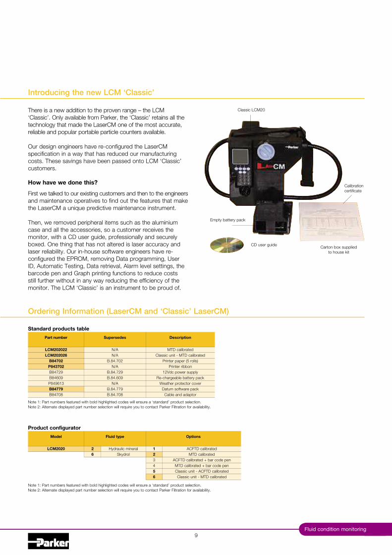
Introducing the new LCM ‘Classic’
,
There is a new addition to the proven range 4 the LCM‘Classic’. Only available from Parker, the ‘Classic’ retains all thetechnology that made the LaserCM one of the most accurate,reliable and popular portable particle counters available.
Our design engineers have re-configured the LaserCMspecification in a way that has reduced our manufacturingcosts. These savings have been passed onto LCM ‘Classic’customers.
How have we done this?
First we talked to our existing customers and then to the engineersand maintenance operatives to find out the features that makethe LaserCM a unique predictive maintenance instrument.
Then, we removed peripheral items such as the aluminiumcase and all the accessories, so a customer receives themonitor, with a CD user guide, professionally and securelyboxed. One thing that has not altered is laser accuracy andlaser reliability. Our in-house software engineers have re-configured the EPROM, removing Data programming, "serID, Automatic Testing, Data retrieval, Alarm level settings, thebarcode pen and Graph printing functions to reduce costsstill further without in any way reducing the efficiency of themonitor. The LCM ‘Classic’ is an instrument to be proud of.
Part number
LCM202022LCM202026
B84702P843702B.-$%,B.-*&,P.-,*#3B84779B.-$&.
Supersedes
N/AN/A
B..-.$&%N/A
B..-.$%,B..-.*&,
N/AB..-.$$,B..-.$&.
Description
MTD calibratedClassic unit - MTD calibrated
Printer paper (' rolls)Printer ribbon
#%0dc power supplyRe-chargeable battery pack
Weather protector coverDatum software pack
Cable and adaptor
Note #: Part numbers featured with bold highlighted codes will ensure a ‘standard’ product selection.Note %: Alternate displayed part number selection will require you to contact Parker Filtration for availability.
Standard products table
Model
LCM2020
Fluid type
26
Hydraulic mineralSkydrol
Product configurator
Options
123456
ACFTD calibratedMTD calibrated
ACFTD calibrated 1 bar code penMTD calibrated 1 bar code penClassic unit - ACFTD calibratedClassic unit - MTD calibrated
Note #: Part numbers featured with bold highlighted codes will ensure a ‘standard’ product selection.Note %: Alternate displayed part number selection will require you to contact Parker Filtration for availability.
Classic LCM%&
CD user guide
Empty battery pack
Calibrationcertificate
Carton box suppliedto house kit

Parker HannifinHydraulic Filter Division EuropeFDCB3$'"(.
#&
Notes

Offline Sampling
Universal Bottle Sampler
Fluid condition monitoring11

Offline Sampling
Universal Bottle Sampler
#%
Typical Applications
Batch samplingAircraft rig certificationOil researchLaboratory testingTransfer line monitoring
Features & Benefits
Simple operationEfficient testing procedureClean and contamination free samplingAvailable for both mineral based and aggressive fluidsFurther advances the LCM%&’s flexibility into laboratorybottle sampling environmentsCan accept various different sized bottlesMinimal working partsInternal auto setting fuse for overload protectionSimple maintenance procedures
Providing The Dynamic Link To All PortableParticle / Water Counters.The "BS off-line, has microprocessor technology to recogniseand ad)ust to the connecting monitor including the LaserCMand Water in Oil Monitor.
Simple To Use UBSThe oil sample is drawn into the "BS Off-line where it issecured, free from further contamination, in a bottle togetherwith a clean waste bottle by a peristaltic, self-priming pump.Simple operation and efficient testing are assured once the "BSOff-line is connected to any of the CM monitors, and poweredup using it’s own power source. The oil sample requiresagitation and de-gassing before carrying out the contaminationtest. A de-gassing kit option is available and consists of avacuum chamber and pump. (Standard with "BS.,&&%)
Parker HannifinHydraulic Filter Division EuropeFDCB3$'"(. Section %

Description
0iscosity range % to %'& cStOperating temp 1' to 1.&5CTest time %m#'s / -m#'s (Flush %m)#% 0dc power supplyExtruded aluminium construction"nit weight - ((g)Mineral oil and petroleum based compatibilityPhosphate Ester group compatibilityCE certifiedMilitary approvedManual operationBottle packDe-gassing chamberManualSample tube packInterface cable to LCM%&, H%Oil etc.
.& CTRS
#%& CTRS
3#,
#*'#-$#$,
151
11
#&&
CTR
S
Fluid condition monitoring
Installation Details
Specification
#3

Offline Sampling
Universal Bottle Sampler
Bottle Cleanliness
It is preferable that bottles have sealing screw caps andboth parts are cleaned to a suitable level in accordance withlSO3$%%.
The bottle should not contain more than one tenth the numberof particles per #&&mI than are expected to be monitored.Standard Parker bottles are supplied clean to lSO#3/## (NASClass -) and should not be used to accurately count oilscleaner than ISO #'/#% (NAS Class *) although they may beused for “trend monitoring” at lower levels.
The bottle should remain capped until time of sample fillingand re-capped immediately afterwards.
Sample Mixing
Sedimentation of contaminant in a sample will occur, therate of which is dependent upon both fluid and particlecharacteristics.
Samples should be analysed, without delay, once agitatedand de-gassed.
Usage Specifications
System Flow Rate
Samples are best taken from a point in the system wherethe flow is T"RB"LENT (Reynolds No. greater than -&&&).The turbulent flow creates a mixing action. Where flow isstreamline or LAMINAR, larger particulate may tend to settletoward the lower pipe surface and not be sampled.
System Condition Changes
Changes in the system operating condition, flow, temperature,pressure or vibration, can result in previously sedimentedcontaminant being retrained into the flowing oil. It is alsopossible that these changes may cause partially contaminatedfilter elements to shed particulate into the system. Samplesshould, therefore, be extracted when the system is in a steadystate condition and the result less likely to be distorted bycontaminant peaks.
There are a number of proprietary sampling valves availablewhich adhere to good theoretical principles. However, theydo tend to generate a level of precision and cost which isunnecessary for trend monitoring.
Sampling points should enable extraction of a samplewithout changing the system’s condition. Fine control needlevalves are not desirable, as they have a tendency to silt upunder some operating conditions, causing the distribution ofcontaminants in the fluid to be changed. The sampling portshould be protected to maintain cleanliness and thoroughlyflushed before collecting the sample for analysis. Allowsufficient airspace in the bottle to enable .&8 fill.
Parker HannifinHydraulic Filter Division EuropeFDCB3$'"(. Section %
14
B..,.,## x '& 9 B..,.,#& B..,.,&$

Fluid condition monitoring
Ordering Information
15
Part number
UBS9002UBS9003UBS9004UBS9005
Description
"niversal bottle sampler (includes aluminium case and accessories)"niversal bottle sampler
Aggressive universal bottle samplerAggressive universal bottle sampler (Includes aluminium case and accessories)
Note #: Part numbers featured with bold highlighted codes will ensure a ‘standard’ product selection.Note %: Alternate displayed part number selection will require you to contact Parker Filtration for availability.
Standard products table
Part number
B89907B89911B89910S.-&&'-S.,&&&'B.,*&3B.,,&%
Description
B..,.,&$B..,.,#&B..,.,#&
N/AN/A
B..,.*&3B..,.,&%
Sample bottle pair with plain capSample bottle pair with oil extraction hose
Sample bottle pack ('& x B.,,##)Power supply and socket
De-gassing chamber and pumpDe-gassing chamber only
Cable and adaptor
Supersedes
Accessories

Parker HannifinHydraulic Filter Division EuropeFDCB3$'"(.
#*
Notes
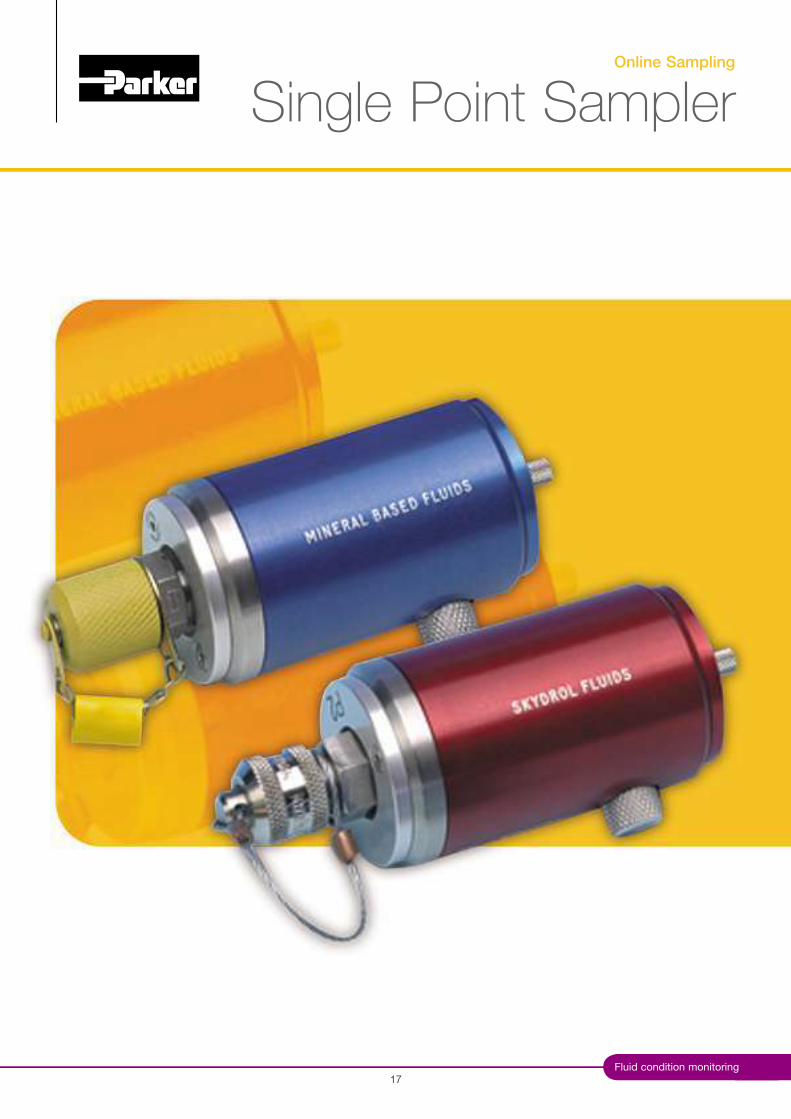
Online Sampling
Single Point Sampler
#$Fluid condition monitoring
Connection Instructions
Online Sampling
Single Point Sampler
18
Features & Benefits
The Single Point Sampler provides a means toconnect an LCM%& or H%Oil to a single pressuretest point and balance the differential pressureacross the system, to provide a controlled flowof oil into the monitor and away into a waste oilreceptacle.
Lightweight, compact and easy to use designFingertip operated control valve even at highpressures-%& bar (*,&&&PSI) ratedFacilitates testing from large diameter pipesCapability to test up to '&&cSt viscosity oils(pressure permitting)Pressure compensated flow control mechanismPossible to control the valve with the same levelof accuracy whether the device is operating athigh or low pressureCapable of allowing a flow rate in excess of#&ml/min when operating at any viscosity withinthe product specificationSuitable for fluid temperatures from 1'5C to 1.&5C(1-#5F to 1#$*5F)High quality polished finish. (stainless steel/aircraft grade aluminium)
Capable of working with a LCM%& or H%Oilconnected into a system via the standard onemetre extension hose kitSuitable for use with mineral and biodegradableoils, petroleum based and phosphate ester fluidsPhosphate ester version utilises the 5/8” BSFHSP style fittingDesigned so that it meets the lowest possiblelevel of magnetic permeabilitySupplied with accessories kitIt will maintain the set flow rate between upperand lower limits within a #&& bar inline pressurechangeClear product identification to ensure that it isconnected correctly. (i.e. downstream of theLCM%& or H%Oil)
Parker HannifinHydraulic Filter Division EuropeFDCB3$'"(. Section 3
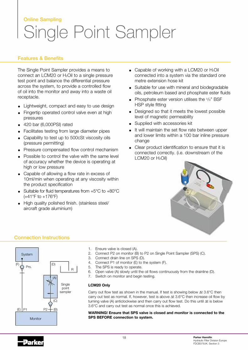
#. Ensure valve is closed (A).%. Connect P% on monitor (B) to P% on Single Point Sampler (SPS) (C).3. Connect drain line on SPS (D).-. Connect P# of monitor (E) to the system (F).'. The SPS is ready to operate.*. Open valve (A) slowly until the oil flows continuously from the drainline (D).$. Switch on monitor and begin testing.
LCM20 Only
Carry out flow test as shown in the manual. If test is showing below Dt 3.*5C thencarry out test as normal. If, however, test is above Dt 3.*5C then increase oil flow byturning valve (A) anticlockwise and then carry out flow test. Do this until Dt is below3.*5C and carry out test as normal once this is achieved.
WARNING! Ensure that SPS valve is closed and monitor is connected to theSPS BEFORE connection to system.Monitor
System
Singlepoint
sampler
Prs.(F) (D)
R
P# P%
(A)
(C)
(B)(E)
Fluid condition monitoring
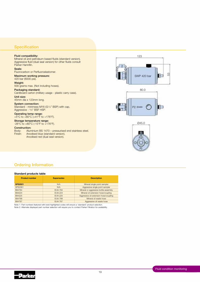
Specification
Fluid compatibility:Mineral oil and petroleum based fluids (standard version).Aggressive fluid (dual seal version) for other fluids consultParker Hannifin.Seals:Fluorocarbon or Perfluoroelastomer.Maximum working pressure:-%& bar (*&&& psi).Weight:'&& grams max. (Not including hoses).Packaging standard:Cardboard carton (military usage - plastic carry case).Unit size:-'mm dia x #%3mm long.System connection:Standard - minimess M#* (G1/4” BSP) with cap,Aggressive - 5/8” BSF HSP.Operating temp range:1'5C to 1.&5C (1-#5F to 1#$*5F).Storage temperature range:-%*5C to 1.&5C (-#'5F to 1#$*5F).Construction:Body: Aluminium BS #-$& 4 pressurised end stainless steel.Finish: Anodised blue (standard version).
Anodised red (dual seal version).
#,
#%3
'3
.&.&
:-'.&
P%
SWP -%& bar
Product number
SPS2021SPS%&*#B.-$.-B.-%%-B.-%%'B.-$..B.-$.$
Supersedes
N/AN/A
B..-.$.-B..-.%%-B..-.%%'B..-.$..B..-.$.$
Description
Mineral single point samplerAggressive single point sampler
Mineral or aggressive bottle assemblyMineral oil extension hose/coupling
Aggressive oil extension hose/couplingMineral oil waste hose
Aggressive oil waste hose
Note #: Part numbers featured with bold highlighted codes will ensure a ‘standard’ product selection.Note %: Alternate displayed part number selection will require you to contact Parker Filtration for availability.
Standard products table
Ordering Information

Parker HannifinHydraulic Filter Division EuropeFDCB3$'"(.
%&
Notes
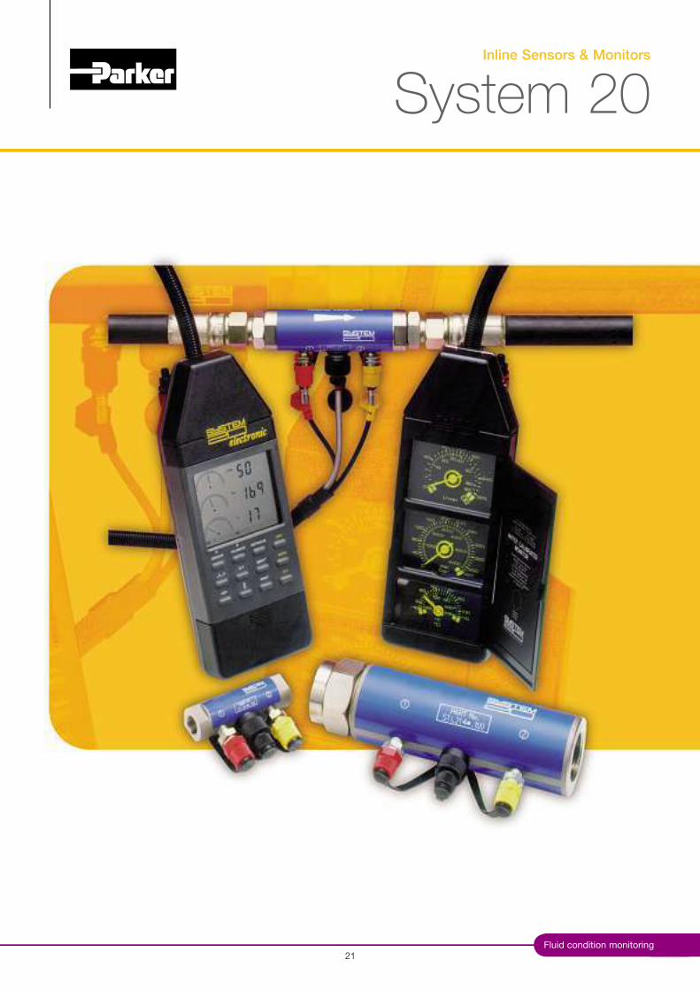
Inline Sensors & Monitors
System 20
%#Fluid condition monitoring

Inline Sensors & Monitors
System 20
Typical Applications
Drilling equipmentMiningGrinding and conveyingIndustrial hydraulicsMobile
Hydraulic system users need to ensure that lostproduction is kept to the absolute minimum. Toensure this, predictive maintenance and thereforeroutine condition monitoring of ma)or componentsis essential.
System %& inline sensors remain at the heart ofcondition and contamination monitoring. Whether you’remining the coal, building the new bypass, harvestingthe crops, crossing the oceans or drilling offshore4 whatever the industry, System %& represents thepremier system monitoring available today.
Features & Benefits
Parker HannifinHydraulic Filter Division EuropeFDCB3$'"(. Section -
%%
Covering a wide range of flow rates, fluid typesand applications, Parker’s System %& sensors aredesigned to be used with System %& electronic oranalogue monitors, contamination monitors and theH%Oil. Specially developed System %& sensors areavailable for use with aggressive fluids. (EPDM Seals)
System %& monitors, combined with the inlinesensor, give the user accurate and instantreadings of flow, pressure and temperaturewithout the need to shut down the system.For use with all mineral oils, water and water/oilemulsions.Analogue Monitor"tilises 3 Day-Glo dial gauges with a protectivehinged cover.Calibrated up to 3.& l/min with dual scale bar/psi 6 5C/5F. ("S GPM also available)EM20 Electronic MonitorGives a full digital display.Automatically calibrated for all 3 sizes of sensor.Indicates line, differential and rising peak pressure.Easily scrolled from metric to "S.3&& test memory.Capable of downloading saved data to datum.
,'
;3&
'*
#3$
ø41
**.'
%3#.3
$3.'
;**.
$
Fluid condition monitoring
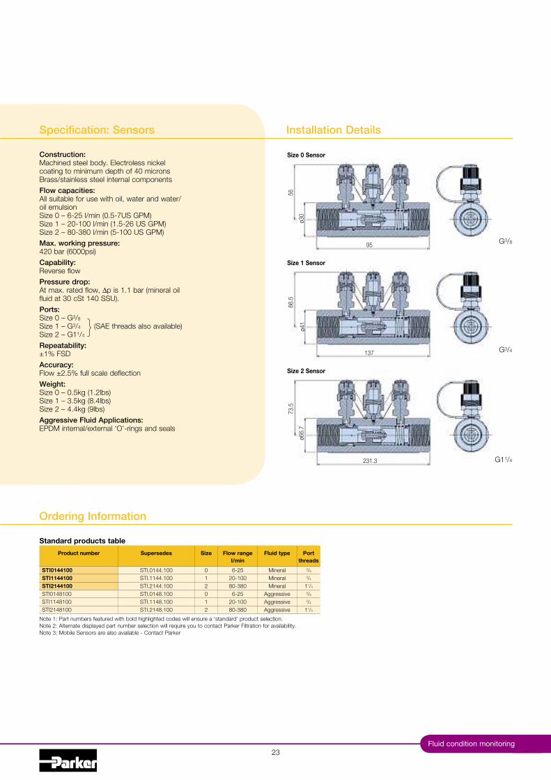
Specification: Sensors
Construction:Machined steel body. Electroless nickelcoating to minimum depth of -& micronsBrass/stainless steel internal componentsFlow capacities:All suitable for use with oil, water and water/oil emulsionSize & 4 *-%' l/min (&.'-$"S GPM)Size # 4 %&-#&& l/min (#.'-%* "S GPM)Size % 4 .&-3.& l/min ('-#&& "S GPM)Max. working pressure:-%& bar (*&&&psi)Capability:Reverse flowPressure drop:At max. rated flow, Dp is #.# bar (mineral oilfluid at 3& cSt #-& SS").Ports:Size & 4 G3/8
Size # 4 G3/4 (SAE threads also available)Size % 4 G#1/4
Repeatability:<#8 FSDAccuracy:Flow <%.'8 full scale deflectionWeight:Size & 4 &.'kg (#.%lbs)Size # 4 3.'kg (..-lbs)Size % 4 -.-kg (,lbs)Aggressive Fluid Applications:EPDM internal/external ‘O’-rings and seals
%3
Size 0 Sensor
Size 1 Sensor
Size 2 Sensor
Installation Details
}G3/4
G#1/4
G3/8
Product number
STI0144100STI1144100STI2144100STI&#-.#&&STI##-.#&&STI%#-.#&&
Supersedes
STI.&#--.#&&STI.##--.#&&STI.%#--.#&&STI.&#-..#&&STI.##-..#&&STI.%#-..#&&
Size
&1%&1%
Flow rangeI/min
*-%'%&-#&&.&-3.&*-%'
%&-#&&.&-3.&
Fluid type
MineralMineralMineral
AggressiveAggressiveAggressive
Portthreads
3/8
3/4
11/4
3/8
3/4
11/4
Note #: Part numbers featured with bold highlighted codes will ensure a ‘standard’ product selection.Note %: Alternate displayed part number selection will require you to contact Parker Filtration for availability.Note 3: Mobile Sensors are also available - Contact Parker
Standard products table
Ordering Information

Inline Sensors & Monitors
System 20
System 20 Electronic Monitor
With System %& inline sensors installed in a hydraulic system,faults can be predicted and remedied, all you have to do isconnect the System %& Electronic Hand Held Monitor (EM%&).Designed to display flow, temperature, differential, rising peakand line pressure, System %& Electronic can also calculatehydraulic power (kW and hp.) at a given point in a system toestablish efficiency and power consumption.
System %& electronics versatility does not end there. TheEM%& is automatically calibrated for all System %& inlinesensors using water or oil and can display in l/min, "S GPM,bar, psi and kg/cm%.
Battery powered andcompletely portable,the EM%& displaysreadings on the LCDand can store undera test number. Datacan be downloaded viaan RS%3% connectionto Datum. A sealedkeyboard and fingertipcontrol make the unitmaintenance free andsimple to use anywhere.
System 20 -The Key To Predictive Maintenance
The risk of fluid contamination by intrusive test devicesis eliminated. "sing System %& Sensors and the monitortogether, hydraulic fluids need never be disturbed. Themonitoring procedure takes only a matter of minutes. Withone System %& monitor a user can check a complete fleetof vehicles or a factory full of hydraulic plant equipment.Predicting a problem means it can be put right as part of aplanned maintenance programme. Simple routine monitoringwith System %& keeps machines running at a high level ofoperational efficiency.
System 20 -The Proven System
For operators of industrial and mobile machinery whorecognise the benefits of installing System %& in a hydraulicsystem, the System %& hand-held analogue monitor offerssignificant advantages, particularly in intrinsically safeapplications. Like the System %& electronic, the analoguemonitor is completely portable and can be connectedimmediately to a purpose-designed inline System %& sensorbut requires no power source.
The analogue monitor will then - provide the user with anaccurate and repeatable analysis of system flow, pressure andtemperature - without having to stop the machine.
Designed as a sealed assembly requiring no routinemaintenance or ad)ustment, analogue monitors are suitable foruse with all mineral oils, water/oil emulsions and water.
The lightweight monitor has3 dayglo dial gauges andfeatures a protective hingedcover. The flow scale featuresdouble scale calibration - upto #&& l/min and 3.& l/minand has excess flow andreverse flow indication.
Parker HannifinHydraulic Filter Division EuropeFDCB3$'"(. Section -
%-
A drilling equipment operation in a zinc mine has had System%& installed for several years.
System 20 Saving £50,000 Pump Damage
Installing System %& was part of a ma)or restructuring planto improve mining effectiveness and profitability. Machineoperator training and oil storage operative training wereessential elements of the plan. Prior to this investment, pumpterminal damage could cost =#&,&&& for a replacement, over=#&&& service costs and up to =3,,&&& in lost production.Add to this the difficulties of the mine’s geography and it’seasy to see the problems that have now been overcome.
System 20 Saving £325,000 A Day Lost Production
The mining industry puts a considerable demand onhydraulics and there are others such as agricultural machinery,harvesters or tractors and, for example, cement manufacturingplants that are equally demanding of hydraulic efficiency.
A grinding and conveying plant processes in excess of #&&&tons of ore per day in the manufacture of cement products.A days lost production costs =3%,&&&. After one year ofoperation the Plant Engineers decided to invest in System %&equipment, strategically placed to allow the Engineers to ‘fault-find’ the ma)or components quickly and easily. The result is thatdowntime and loss of production have been reduced by .&8.

Fluid condition monitoring%'
Ordering Information
Electronic Monitor Specification
Construction:A sealed assembly requiring no routine maintenance or ad)ustment.Body moulding in Acrylonitrile Butadene Styrene (ABS). (ey padmoulded in silicon rubber. The monitor is suitable for use with allmineral oils, water and water/oil emulsions.
LCD detailsFlow section:The analogue flow scale has reverse flow and overflow indication andprovides a percentage reading of the digital full scale displayautomatically calibrated for all sizes of System %& Sensor.Pressure section:Designed to indicate line pressure, differential pressure and risingpeak pressure. Connected to a System %& Sensor it will monitorpressure up to -%& bar (*&&& psi) with an accuracy of <#8 FSD.Temperature section:Temperature reading between -#&5C and 1##&5C (&5F to %3&5F).
Dimensions:The ABS Case is %,#mm (##.-*”) long, #&'mm (-.#3”) wideand $*mm (3”) deep overall.Weight:#.-kg (3lbs).Data logging:Each test logs the following data:Test number! time 6 date! sensor size! media tested! flow rate,pressure 6 temperature.Data download:The System %& electronic monitor is capable of downloadingsaved test data to a #* column serial printer, or a compatible PCvia an RS%3% connection using datum.Batteries:* x AA batteries.Re-calibration:Annual certification by an approved Parker Service Centre.
Hoseretainers
%,#m
m(#
#.-*
in)
#&'mm (-.#3in) $*mm (3in)
Purgeknob
Display
Functionkeys
Batterycovers
#&&&
mm
(3,.
-&in
)nom
inal
Product number
EM209000B84779P*'3*&$B.'*#$
Supersedes
N/AB..-.$$,
N/AB..'.*#$
Description
System %& electronic monitorDatum download software
Monitor and sensor carrying caseDongle and cable assembly
Note #: Part numbers featured with bold highlighted codes will ensure a ‘standard’ product selection.Note %: Alternate displayed part number selection will require you to contact Parker Filtration for availability.
Standard products table
Inline Sensors & Monitors
System 20
Ordering Information
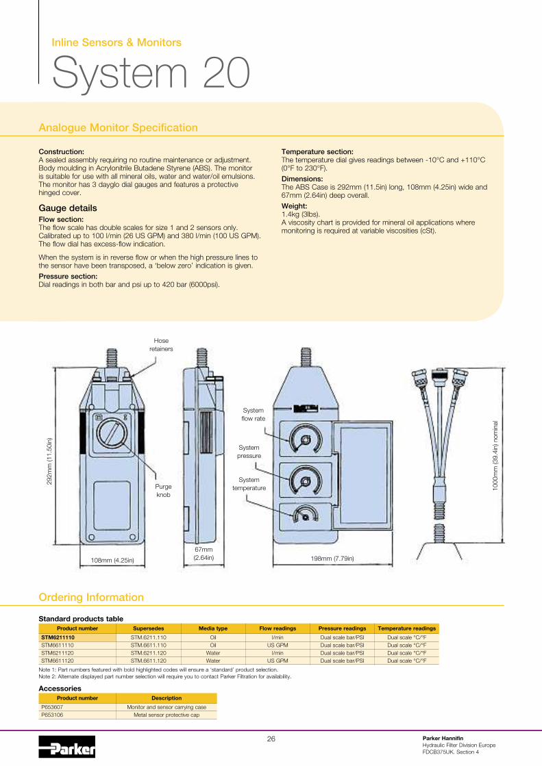
Analogue Monitor Specification
Construction:A sealed assembly requiring no routine maintenance or ad)ustment.Body moulding in Acrylonitrile Butadene Styrene (ABS). The monitoris suitable for use with all mineral oils, water and water/oil emulsions.The monitor has 3 dayglo dial gauges and features a protectivehinged cover.
Gauge detailsFlow section:The flow scale has double scales for size # and % sensors only.Calibrated up to #&& l/min (%* "S GPM) and 3.& l/min (#&& "S GPM).The flow dial has excess-flow indication.
When the system is in reverse flow or when the high pressure lines tothe sensor have been transposed, a ‘below zero’ indication is given.Pressure section:Dial readings in both bar and psi up to -%& bar (*&&&psi).
Temperature section:The temperature dial gives readings between -#&5C and 1##&5C(&5F to %3&5F).Dimensions:The ABS Case is %,%mm (##.'in) long, #&.mm (-.%'in) wide and*$mm (%.*-in) deep overall.Weight:#.-kg (3lbs).A viscosity chart is provided for mineral oil applications wheremonitoring is required at variable viscosities (cSt).
Parker HannifinHydraulic Filter Division EuropeFDCB3$'"(. Section -
%*
Hoseretainers
%,%m
m(#
#.'&
in)
#&.mm (-.%'in)
*$mm(%.*-in)
Purgeknob
Systemflow rate
Systempressure
Systemtemperature #&
&&m
m(3
,.-i
n)no
min
al
#,.mm ($.$,in)
Product number
STM6211110STM**####&STM*%###%&STM**###%&
Supersedes
STM.*%##.##&STM.**##.##&STM.*%##.#%&STM.**##.#%&
Media type
OilOil
WaterWater
Flow readings
l/min"S GPM
l/min"S GPM
Pressure readings
Dual scale bar/PSIDual scale bar/PSIDual scale bar/PSIDual scale bar/PSI
Temperature readings
Dual scale 5C/5FDual scale 5C/5FDual scale 5C/5FDual scale 5C/5F
Note #: Part numbers featured with bold highlighted codes will ensure a ‘standard’ product selection.Note %: Alternate displayed part number selection will require you to contact Parker Filtration for availability.
Product number
P*'3*&$P*'3#&*
Description
Monitor and sensor carrying caseMetal sensor protective cap
Accessories
Standard products table

Autoremote Particle Counter
MCM20
%$Fluid condition monitoring

Autoremote Particle Counter
MCM20
%.
Typical Applications
Test rigsConstruction machineryIndustrial plantHydraulic equipment 6 system manufacturersPaper processingSteel rolling millsMilitary equipment application
Features & Benefits
The MCM%& is an online continuous particlecounter ensuring constant system monitoringwithin defined parameters.PC/PLC controlledEnsures constant system monitoring.Can be pre-set to carry out tests at specificintervals.Can also be set up via detachable Handset.Enclosed in a metal casing, with internalworkings on a removable chassis for ease ofservice and calibration.Connects permanently to a System %& sensorvia % meter hose assembly (supplied).
Simple data formatting programme for trendanalysis."ser-friendly instrument improving familiarityand awareness of service and maintenancepersonnel.
The Parker MCM20"sing proven portable particle counting technology (LCM%&), theMCM%& and its principles are available to users where continuous,permanent installed monitoring is required.
The MCM%& utilises the latest laser diode method of particlecounting. The unit is enclosed in a metal casing with access to thehydraulic connection, DC input power, fuse holder and PC/PLCconnection ports located on the front panel.
The internal workings are manufactured onto a removable chassis forease of service and calibration.
Parker HannifinHydraulic Filter Division EuropeFDCB3$'"(. Section '

Fluid condition monitoring
Specification
Test cycle time:0ariable between 3& seconds and 3 minutes.Repeat test time:Continuous Mode or between 3& seconds and #--& minutes(%- Hours).Principle of operation:Optical scanning analysis and measurement of actual particles.Particle counts:* channels either ACFTD or MTD calibrated.International codes:ISO $-%%, NAS &-#%.Storage temperature:--&5C to 1.&5C.Operating temperature:1'5C to 1*&5C (hydraulic oil temperature).Unit control connection:Terminal protocol via RS %3% or optional handset.Data retrieval:Local PC / PLC program or by optional handset.Calibration:By accepted on-line methods confirmed by relevantInternational Standard Organisation procedures.Re-calibration:Annual certification by an approved Parker Service Centre.
Max. working pressure:-%& bar.Minimum working pressure:% bar.Fluid compatibility:Mineral oil or petroleum based fluids.Aggressive fluid version also available.Sample requirements:&.3 4 #.' DP bar (differential pressure) via approved inlinesampling concept.System connection:0ia System %& inline sensors / single point samplerComputer compatibility:Interface via RS %3% connection > ,*&& baud rate.Size/weight:%-,mm x %'-mm x #,#mm / ..$'kg.Power requirement:#% 0dc input. (#.%'A (T) fuse). Regulated.Installation:Back/base M*x#.& mounting inserts (see annotated diagrams).Software:Lab0iew demonstration software.
%,
#,#
Over fixing screws
#.$
*-#%
&C
TRS
,& CTRS
#.%
- mounting holeM* x #.&
%-,
##$
%%&
%'-
%-* ‘Power on’
green LED
*3
#.%'A fuse
M#* minimess adaptors(P% 6 P#)

Parker HannifinFilter Division EuropeFDCB3$'"(. Section '
3&
Autoremote Particle Counter
MCM20
Labview Optional Remote Handset
Communications Protocol
The comms protocol for the productis as follows:Baud rate 9 ,*&&Data bits 9 .Parity 9 NoneStop bits 9 #Flow control 9 None
Customiseddemonstration/softwarefor MCM operation.Full graphic display.0isual indication of limitparameters.
Optional remote handset fordirect interface control.Please consult Parker formore information.
Product number
MCM202022MCM202022HSMCM202021MCM202021HSMCM202061MCM202062MCM202061HSMCM202062HSB94106B94107B94802B94801
Supersedes
N/AMCM%&.%&%%.HS
N/AMCM%&.%&%#.HS
N/AN/A
MCM%&.%&*#.HSMCM%&.%&*%.HS
B.,-.#&*B.,-.#&$B.,-..&%B.,-..&#
Description
MTD calibrated - mineralMTD calibrated - mineral - with handset
ACFTD calibrated - mineralACFTD calibrated - mineral - with handset
ACFTD calibrated - aggressiveMTD calibrated - aggressive
ACFTD calibrated - aggressive - with handsetMTD calibrated - aggressive - with handset
Handset (blue)Handset (red)
%m mineral hose assembly%m aggressive hose assembly
Note #: Part numbers featured with bold highlighted codes will ensure a ‘standard’ product selection.Note %: Alternate displayed part number selection will require you to contact Parker Filtration for availability.
Standard products table

Fluid condition monitoring3#
Online Particle Detector
IcountPD

3% Parker HannifinHydraulic Filter Division EuropeFDCB3%#"(. Section *
Diagnostic Self Check Start-up Time:5 secondsMeasurement Period:' to #.& secondsReporting interval through RS232:& to 3*&& secondsDigital LED display update time:Every secondLimit Relay Output:Changes occur 1/- # ISO code at set limit (Hysteresis ON) or customerset (Hysteresis OFF)4-20mA Output Signal:ContinuousPrinciple of operation:Laser diode optical detection of actual particulates.Reporting Codes:ISO $ 4 %#, NAS & 4 #%, (AS && 4 #% Contact Parker)Icount will also report less than ISO $, sub)ect to the statisticaluncertainty de?ned in ISO--&*:#,,,, which is shown in the RS%3%,reporting results as appropriate e.g “3*”Calibration:By recognised on-line methods, con?rmed by the relevant InternationalStandard Organisation procedures.Calibration Recommendation:#% monthsPerformance:1/- # ISO Code (Dependant on stability of @ow)Reproducibility / Repeatability:Better than # ISO CodePower Requirement:Regulated , to -&0dcMaximum Current Draw:#'&mAHydraulic Connection:M#* x % hydraulic test points ('/.” BSF foraggressive version)
Flow Range through the device:-& to #-& ml/min (Optimum Flow 9 *&ml/min)Online Flow Range via System 20 Inline Sensors:Size & 9 * to %' l/min - (Optimum Flow 9 #' l/min)Size # 9 %- to #&& l/min - (Optimum Flow 9 $& l/min)Size % 9 #$& to 3.& l/min - (Optimum Flow 9 %'& l/min)Required Differential Pressure across Inline Sensors:&.- bar (Minimum)Viscosity Range:#& to '&& cStTemperature:Operating Environment -%&5C to 1*&5C (--5F to 1#-&5F)Storage --&5C to 1.&5C (--&5F to 1#$*5F)Operating Fluid &5C to 1.'5C (13%5F to 1#.'5F)Working pressure:% to -%& bar (3& to *,&&& PSI)Moisture sensor calibration:<'8 RH (over compensated temperature range of 1#&5C to 1.&5C)Operating humidity range:'8 RH to #&&8 RHMoisture sensor stability:<&.%8 RH typical at '&8 RH in one yearCertification:IP** ratedEMC/RFI – EN*#&&&-*-%:%&&#
EN*#&&&-*-3:%&&#Materials:"ser friendly Abs construction.Stainless Steel hydraulic block.0iton seals.Dimensions:#.%mm x #''mm x .*mm ($.%” x *.#” x 3.-”)Weight:#.3kg (%.,lb)
Online Particle Detector
IcountPD
Features & Benefits
Independent monitoring of systemcontamination trendsEarly warning LED or digital display indicatorsfor Low, Medium and High contamination levels.Moisture 8 RH indicator (optional)Cost effective solution in prolonging fluid life andreducing machine downtime.0isual indicators with power and alarm outputwarnings.Continuous performance for prolonged analysisHydraulic, Phosphate Ester 6 Fuel fluidcompatible constructionSelf diagnostic softwareFully PC/PLC integration technology such as:- RS%3% and &-' 0olt, --%&mA, CAN (A#,3,)(Contact Parker for other options).
IcountPDThe Icount Particle Detector from Parker representsthe most up to date technology in solid particledetection.The design dynamics, attention to detail andmoulding compactness of the permanentlymounted, on-line particle detectormodule, combined withon-board, laser based,leading-edge technology,brings to all industriesa truly revolutionary,particle detector as aremarkable cost effectivemarket solution tofluid management andcontamination control.

Fluid condition monitoring33
Online Particle Detector
IcountPD
Dimensions / Installation Details
Typical Applications
Mobile Equipmento Earth Moving Machineryo Harvestingo Forestryo Agriculture
Monitoring of the hydraulics, enabling the vehiclesto function to there best capability under loadconditions through pistons, servo valves, controlrams and gear pumps.
Industrial Equipmento Production Plantso Fluid Transferso Pulp 6 Papero Refineries
To monitor the cleanliness of the equipmentthroughout the production line, from the machinetool controlled hydraulics through to contaminationof fluid transfer. Ensuring the integrity of the fluid ismaintained throughout the refining process.
Power Generationo Wind Turbineso Gearboxeso Lubrication Systems
With continuous monitoring the optimum level isachieved in the least amount of time.
Maintenanceo Test Rigso Flushing Stands
To increase efficiency of your equipment bycontinuously monitoring the cleanliness level of thehydraulic fluid.
Maximum Torque 5Nm

3- Parker HannifinHydraulic Filter Division EuropeFDCB3%#"(. Section *
1
%
3
4
5
*
$
8
NOT "SED
RS%3% Ground (Pin '**)
Channel A, ISO -7m(c)*
Channel B, ISO *7m (c)* or NAS
(if selected)
RS%3% Receive (Pin 3**)
RS%3% Transmit (Pin %**)
Moisture sensor channel (if fitted)
Channel C, ISO #-7m (c)*
NOT "SED
RS%3% Ground (Pin '**)
Channel A, ISO -7m(c)*
Channel B, ISO *7m (c)* or NAS
(if selected)
RX%3% Receive (Pin3**)
RS%3% Transmit (Pin %**)
Moisture sensor channel (if fitted)
Channel C, ISO #-7m (c)*
M12 Communication cable: wiring configuration
(Limit Relay Wiring Instructions)NORMALLY OPENNORMALLY CLOSEDCOMMON
Pin 4-20mA option connections 0-5v/0-3v option connections
M#% Communication cable
Important Note: It is the responsibility of the end user to ensure that the cable’s braided screenis terminated to a suitable earth bonding point.
* Optional 4 refer to the ‘IcountPD part number specifier’ section in this manual.** A standard "SB serial adaptor can be used with the recommended ,-way D-type
connector to convert RS%3% to "SB.
Limit relay alarm levels
The IcountPD can be specified with a built-in limit switch relay which can be triggered when a preset alarm levelis reached. The relay contacts can be used to switch on or off an external device.
Pin Current loop options connections
1
%
3
4
5
*
$
8
Product supply ,--&0dc
--%&mA Supply #%-%&0dc
Relay (Normally Closed)*** (if fitted)
Relay (Normally Open)*** (if fitted)
NOT "SED
NOT "SED
Main supply &0dc
Relay (Common)*** (if fitted)
0-5v/0-3v option connections
Product supply ,--&0dc
&-' / &-30 Supply #%-%-0dc
Relay (Normally Closed)*** (if fitted)
Relay (Normally Open)*** (if fitted)
NOT "SED
&-'0 / &-30 Supply & 0dc
Product supply &0dc
Relay (Common)*** (if fitted)
M#% Supply and Relay (if fitted) cable
Note: If the moisture sensor is fitted without either option then the output is RS%3%.
Parker Hannifin recommend that the mating M#% connector cables are screened. Thesecables are available from Parker Hannifin 4 ordering information section.
*** Optional 4 refer to ordering information section.

Fluid condition monitoring3'
Online Particle Detector
IcountPD
Variable mA output settings
4-20mA output settings
ISO SettingmA current 9 (ISO Code / %) 1- eg. #&mA 9 (ISO #% / %) 1-orISO Code 9 (mA current - -) *% eg. ISO #% 9 (#&mA --) *%
NAS SettingmA current 9 NAS Code 1' eg. #'mA 9 NAS #& 1'orNAS Code 9 mA current -' eg. NAS #& 9 #'mA 4 '
The following table can be used to equate the analogueoutput to an ISO or NAS Code.
Example ISO code #% is equal to #&mA
-.&-.''.&'.'*.&*.'$.&$.'..&..',.&,.'#&.&#&.'##.&##.'#%.&#%.'#3..'#-.&#-.'#'.&#'.'#*.&#*.'#$.&#$.'#..&#..'#,.&#,.'%&.&
&1%345*$8,#&11#%#31415#*#$18#,%&%#****************
O0ERRANGE
O0ERRANGE
ERROR
mA ISO45*$8,#&11#%#31415#*#$18#,%&
&&&1%345*$8,#&11#%****
ERROR
mA NAS
0.02.04.06.08.0
10.012.014.016.018.020.0
201918171615141312115 6 7 8 9 1043210 21
ISO CODE
Mill
iam
pO
utpu
t
ISO V MILLIAMP
02468
101214161820
1312115 6 7 8 9 1043210NAS CODE
Mill
iam
pO
utpu
t
NAS V MILLIAMP
The following table can be used to equate theanalogue output to an ISO or NAS Code.
Example ISO code #% is equal to #&mA
Variable voltage output settings
The variable voltage output option has the capability of two different voltage ranges: a &4'0dc range asstandard, and a user-selectable &430dc range. The ‘Full list of commands’ on how to change the voltageoutput, are available from Parker.The following tables can be used to relate the analogue ouptut to an ISO or NAS code.For example, in a &4'0dc range, ISO code #* is equal to an output of 3.'0dc. In a &430dc range, ISO code .is equal to an output of #.&0dc.
ISO Err
0–5Vdc
0–3Vdc
B&.%
B&.#'
0
&.3
&.%
1
&.'
&.3
2
&.$
&.-
3
&.,
&.'
4
#.#
&.*
5
#.3
&.$
6
#.'
&..
7
#.$
&.,
8
#.,
#.&
9
%.#
#.#
10
%.3
#.%
11 3
%.'
#.3
Table relating ISO codes to Voltage output
cont. ISO 120–5Vdc
0–3Vdc
%.$
#.-
13
%.,
#.'
14
3.#
#.*
15
3.3
#.$
16
3.'
#..
17
3.$
#.,
18
3.,
%.&
19
-.#
%.#
20
-.3
%.%
21
-.'
%.3
22
-.$
%.-
Err
3-..
3%.-'
ISO Err
0–5Vdc
0–3Vdc
B&.-
B&.%
00 0
&.*
N.S.
1
&.,
&.3
2
#.%
&.'
3
#.'
&.$
4
#..
&.,
5
%.#
#.#
6
%.-
#.3
7
%.$
#.'
8
3.&
#.$
9
3.3
#.,
10
3.*
%.#
11 12 Err
3.,
%.3
-.%
%.'
-.'
%.$
3-.*
3%..
Table relating NAS codes to Voltage output

3* Parker HannifinHydraulic Filter Division EuropeFDCB3%#"(. Section *
Digital display parameters (ISO 4406/NAS 1638)
Digital display indicationThe digital display will show the actual measured codes, the channel (7) size and the user definable limits.Note that the channel size and limits will alternate between the two.The Moisture Sensor reading (8RH) will also be shown 4 if the Moisture Sensor option is fitted.The order of trigger for both the codes and Moisture Sensor option is:• Solid digit(s) 9 code(s) that are at or below the set point (limit)• Flashing digit(s) 9 code(s) that are above the set point (limit)The display for ISO--&* and NAS#*3. are identical. The ISO display is shown below.
Error detection:In the unlikely event of a error occurring, the digital display on the IcountPD will simply display the actualerror code only 4 i.e. ERROR #3 (A full list of error codes are detailed in the IcountPD "ser Manual).
Channel sizes/Limits
Automatic light sensor
MTD calibrated
Measured ISO codes
Moisture sensor reading
Saturation 4–20mA 0–3Vdc 0–5Vdc5%
25%
50%
75%
100%
4.8
8
12
16
20
0.15
0.75
1.50
2.25
3.00
0.25
1.25
2.50
3.75
5.00
Start up#. Once the IcountPD has been connected to a regulated power supply, the product logo is displayed for
approximately five seconds as the IcountPD performs a self system diagnostic check.%. The IcountPD then automatically starts monitoring using factory default test parameters.
Moisture sensor output settingsThe Moisture Sensor is an option that can be included when specifying the IcountPD.The Moisture Sensor reports on the saturation levels of the fluid passing through the IcountPD sensing cell.The output is a linear scale, reporting within the range of '8 saturation to #&&8 saturation.Table relating Saturation levels in the sensing cell to IcountPD outputs

Fluid condition monitoring3$
Online Particle Detector
IcountPD
Auxiliary Flow Device
The pressure compensated, Flow control device(Part Number S.-&&$-) has been developedto give the IcountPD user greater flexibility. TheFlow control device will enable testing where flowranges are outside the IcountPD specifications(-& 4 #-& ml/min), or where pipe diameters do notallow the IcountPD to be installed.The Flow control device fits onto the downstream(outlet) side of the IcountPD, connecting through amanifold block, via a self-sealing quick connection testpoint and is fitted with a differential pressure valve.This Flow control device automatically compensatesfor pressure and viscosity changes, whilst maintainingits setting even as the workload changes.Simply position the valve to match the viscosity of theoil you are testing.The chart below can be used to determine the valveposition:
Example:If the fluid you wish to analyse has a viscosity of'&cSt under normal operating conditions then thecontrol knob on the Flow Control Device should beset to valve position ‘3’The flow device will now automatically control theflow rate through the IcountPD to within its workingrange of -&-#-&ml/min.
Note: The Flow control device will still operate correctly even with thehigh pressure side at %&&bar and the return back to an open systemof & bar (DP 9 %&&bar)
Valve Position cSt Range3
3..
-.%
5
up to #&&
,& - %&&
#,& - 3%&
3#& - '&&

Hydraulic Connection Diagram Dimensions
Actuator Manual flow rate ad)ustable via control knobMounting Type - off mounting holes to suit M* screws (not supplied)Mounting position AnyWeight #.$kg (3.$lb)Fluid Temperature '5C to 1.&5C (1-#5F to #$*5F)Ambient storage temperature -%&5C to 1-&5C (--5F to 1#&-5F)Viscosity range %&cSt to '&&cSt (If lower than %&cSt contact Parker)Differential pressure range ' to 3#' barMaximum pressure 3#' barFlow direction ‘IN’ to ‘O"T’ flow control functionPort thread detail #/.” BSPP (test points not supplied)Internal Seals Viton
IcountPD
P#P%
High PressureLine Side
Low PressureReturn Side
OutIn
Flow ControlDevice
,&.&
%&.& $.
.%##
3.%
'..%
$..%
-*.''&.&
G#/. ports either sideof mounting block
“In”
- holes *.*& Thro’
“Out”
3..& Ctrs
*%.&
.&.&
Ctrs
-,.%
3. Parker HannifinHydraulic Filter Division EuropeFDCB3$'"(. Section *

Online Particle Detector
IcountPD
Communication Protocol
Communication Options
The IcountPD may be configured using the IcountPD Setup "tility. For more direct control of the device using itscommunications protocol, you may also use the Microsoft Windows® HyperTerminal program, but note that thisprogram is not currently supplied with the Windows 0ista™ operating system. These two ways of communicatingwith IcountPD are described in the following section.
The Communication protocol for the serialcommunication link is to be used with MicrosoftWindows HyperTerminal. The settings are as follows:
Baud rate ,*&&Data bits .Parity NoneStop bits #Flowcontrol None
The commands used with this product are made upof Read, Set and Start / Stop commands.• Set commands allow the value or values of
parameters to be set• Read commands allow the value or values or
parameters to be read• Start/Stop allows the user to start and stop tests.
Example:CSDF dd/mm/yyD - sets the date format.CRDFD - reads the product date format.
All commands are sent in ASCII characters, andthe protocol accepts both upper and lower casecharacters as the examples below:
SDFSdF
Note: A full list of commands are detailed in the usermanual
IcountPD Setup Utility software
3,Fluid condition monitoring

NoRS232
Parker HannifinHydraulic Filter Division EuropeFDCB3$'"(. Section *
-&
Ordering Information
Part number Fluid type Calibration Display Limit relay Communications Moisture sensor Cable connector kit Future option
IPD12212130
IPD12212230
IPD12222130
IPD12222230
IPD12312130
IPD12312230
IPD12322130
IPD12322230
Mineral
Mineral
Mineral
Mineral
Mineral
Mineral
Mineral
Mineral
MTD
MTD
MTD
MTD
MTD
MTD
MTD
MTD
LED
LED
LED
LED
Digital
Digital
Digital
Digital
No
No
Yes
Yes
No
No
Yes
Yes
RS%3% / --%&mA
RS%3% / --%&mA
RS%3% / --%&mA
RS%3% / --%&mA
RS%3% / --%&mA
RS%3% / --%&mA
RS%3% / --%&mA
RS%3% / --%&mA
No
Yes
No
Yes
No
Yes
No
Yes
M#% - . pin
M#% - . pin
M#% - . pin
M#% - . pin
M#% - . pin
M#% - . pin
M#% - . pin
M#% - . pin
N/A
N/A
N/A
N/A
N/A
N/A
N/A
N/A
# metre hose length% metre hose length' metre hose length
Minimess 1/4” BSP fittingMinimess 1/8” BSP fittingMinimess 1/8” NPT fitting
Single point samplerInternal flow device
Power supply' Metre, M#%
. Pin Plug and Socket Cable (it*Deutsch Connector (it
RS%3% To "SB Converter
Description Part numberMineralB*',-*B,-.&%B,-.&-P*'3#&,P*'3##&P*'3'#%SPS%&%#S.-&&$-
B.-.%,
Contact ParkerB.-*'-P.-3#3&B.-&##
AggressiveB.-.%$* *B,-.&#* *B.-.%.* *P.-3&.#P.'3&&.P.'3&&'SPS%&*#
Contact Parker
* M#% Cable kit consists of two ' metre cables to enable all output options(Communications cable and Relay/Power Supply cable)* * Note that the aggressive fluid hoses are provided as a single hose, not in pairs.
Accessories
Standard Products Table
Part number Supercedes Size Flow range l/min
STI0144100
STI1144100
STI2144100
STI0148100
STI1148100
STI2148100
STI.&#--.#&&
STI.##--.#&&
STI.%#--.#&&
STI.&#-..#&&
STI.##-..#&&
STI.%#-..#&&
&
1
%
&
1
%
*-%'
%&-#&&
.&-3.&
*-%'
%&-#&&
.&-3.&
Fluid type
Mineral
Mineral
Mineral
Aggressive
Aggressive
Aggressive
Port threads3/8
3/4
11/4
3/8
3/4
11/4
Key Fluid type Calibration Display Communications Cable connector kit Future optionMoisture sensorLimit relay
Product Configurator
IPD 123
4
MineralAggressiveAviation fuel
hazardous areasAviation fuel
non-hazardousarea
123
ACFTDMTD
AS-&',
123
NoneLED
Digital4 GSM
12
NoYes
12 RS232 / 4-20mA345
RS232 / 0-5VRS%3% / RS-.'
RS%3% / CAN(A#,3,)
12 1
3
0 0Yes
NoDeutsch DT Series ConnectorM12, 8 Pin Plug Connector*

Fluid Condition Monitoring
H2Oil - Water in Oil Monitor
41Fluid condition monitoring

Fluid Condition Monitoring
H2Oil - Water in Oil Monitor
-%
Typical Applications
Off-shore 6 power generationMarineConstruction machineryPaper millsHydraulic equipment 6 system manufacturersResearch 6 testing institutesMilitary equipment application
Features & Benefits
Water monitoring is now possible whilemachinery is working - H%Oil saves onproduction downtime.Totally portable, can be used easily in the fieldwithout the need for mains power, as well as inthe laboratory.Connects into system at pressures up to -%& bar,via either system %& sensor or single point sampler.,& second test time.Scrolling memory for '&& tests plus memory for%& different oil calibration curves.Routine water monitoring of oil systems with H%Oilsaves time and money, promoting oil longevity.Samples that are tested are truly representativeof water in the system. Analysis carried outbefore sample hydrodynamics change.Data entry facility enables user to store uniquedata test log details with every test carried out.
Instant, accurate results are available on thedisplay or the built-in printer ensuring maintenancedecisions can be taken immediately.Computer interface available for downloadingdata on to the computer through the RS%3%serial port.Internal diagnostics features ensures H%Oil willwork accurately and reliably.Supplied in a robust aluminium carrying case.Optional oil delivery kit for simple offlinesampling (see fig.#) .
The H%Oil is a two channel non-dispersive absorptionspectrometer, designed to measure the level of watercontent polluting the oil, reducing system efficiency,promoting wear and affecting safety.
The H%Oil makes it possible for an end user or serviceengineer to carry out quick, accurate measurements,taken in the field instead of remote laboratory analysis.
With its secured hoses the H%Oil connects to an in-lineSystem %& sensor or single point sampler and features are-chargeable #%0dc power pack, diagnostic computer andon-board printer for effective logging and retrieval of data.
Parker HannifinHydraulic Filter Division EuropeFDCB3$'"(. Section $
Fig.#

Fluid condition monitoring
Specification
Construction:Case-Noryl structural foam and ABS printercover. (ey pad silicone rubber.Mechanical composition:Brass, plated steel, stainless steel.Seals:Fluorocarbon.Hoses:Nylon ((evlar braided microbore).Hose length:Fluid connection hose #.% metre (3., feet).Flow rate:"p to -&& l/min (#&& "S GPM).(System %& Sensors). Higher flows with SPS.Max. working pressure:"p to -%& Bar (*&&& psi).Fluid compatibility:Mineral oil and petroleum based fluids.Power:Re-chargeable battery pack (#%0dc tricklecharger supplied).
Fuse:'.& amp fast blow fuse included foroverload protection.H2Oil technology:Infrared absorption spectroscopyMeasurement and range:PPM (&-3&&&) or 8 content.Max operating temperature:1'5C to 1.&5C (1-#5F to 1#$*5C).Environmental temperature:1'5C to 1-&5C (1-#5F to 1#&-5F).Test completion time:,& seconds.Memory store:'&& TEST (scrolling memory) capacity.Printer facility:Integral #* column thermal printer for hardcopy data.Computer interface RS%3%.Repeatability/accuracy:Better than '8 (typical).
-3
Viscosity range:%-#&& cSt (,--*& SS"). '&&cSt with SPS.Commissioning kit:Includes % re-chargeable battery packs(# fitted to monitor), % x thermal printerrolls, spare fuse,screwdriver, #%0dc tricklecharger and user manual.Data entry:%- character two line back lit dot matrixLCD. Full alpha numeric keypad.Data retrieval:Memory access gives test search facility.Monitor carry case:Robust padlockable aluminiumpresentation case.Datum:Condition monitoring data software packplus cable included in commissioning kit.Performance recheck:Annual recheck of performance by anapproved Parker Service Centre.
%3'mm (,.%'”) %&mm(&.$,”) #.&mm ($.&,”)
#3&mm('.#%”)
3#.m
m(#
%.'#
”)
3-*m
m(#
3.*%
”)ha
ndle
rais
ed

Fluid Condition Monitoring
H2Oil - Water in Oil Monitor
Effective Oil Maintenance
Take a typical application where water can have a verydetrimental effect on bearings. Cracks are generated earlyin life of a bearing and water, once condensed in the crack,leads to corrosion and early damage.
Loss of bearing life, due to water contamination, (see below)can be prevented by stopping the water from entering thesystem in the first place. Introducing a regular water contentmonitoring function into the programme, such as the H%Oil,would support such efforts.
Whatever the application, whether it be offshore in the oilindustry or off-road in the construction or earth movingindustry, the portability of the H%Oil makes it an essential kitfor the service van or engineers tool.
How the H2Oil Works
On-line testing allows a mixed and flowing sample of oil andwater to pass through the infrared measuring cell. A seriesof measurements can be taken and the average given as aresult. With this method a representative oil sample is seen,unlike the usual reservoir samples sent for analysis. Also,by taking the test at working temperature and pressure, atrue water content is taken, as both affect the way water isabsorbed in oil.
The flowing sample passes through a special “water free”optical cell.
The infrared detector monitors two narrow band passfilters, one of which matches the spectral width of the waterattenuation band. The second narrow wave band selectedis unaffected by water and serves as a reference. By takingthe transmission ratio between the two points an effectivemeasurement of water can be made.
Parker HannifinHydraulic Filter Division EuropeFDCB3$'"(. Section $
44
% Water In Oil
0
50
100
150
200
250
%B
eari
ngLi
feR
emai
ning
Core Technology
H%Oil uses true infrared (IR) analysis technique - the principleused in all laboratory spectrometers, to measure absorbedwater (before saturation point).
Channel one (%.*7) is the reference point, whereas channeltwo (37) is H%O.
The IR source is a tungsten halogen bulb.
Product number
WOM9100B91701S840134B84779B91706
Supersedes
N/AB.,#.$&#
N/AB..-.$$,B.,#.$&*
Description
H%Oil (includes aluminium case and kit)Printer paper (' rolls)
Oil delivery unitDatum download software
Cable and adaptor
Note #: Part numbers featured with bold highlighted codes will ensure a‘standard’ product selection.Note %: Alternate displayed part number selection will require you to contactParker Filtration for availability.
Standard products table
Ordering Information

MOISTURE SENSOR RANGE
45Fluid condition monitoring
Fluid Condition Monitoring

Cost Effective Moisture Detection
Moisture Sensor Range
-*
Typical Applications
Ground support vehiclesPulp and paper plantsMarine hydraulicsPower transmission 6distributionForestryIndustrial hydraulics
Earth moving applicationsAgriculturalHazardous Areas (+one %)Theme parks (Ridehydraulics)
Features & Benefits
Continuous, online moisture indication, forhydraulic and lubricating systems.Reporting of 8 relative humidity of watercontent, giving the user information on howclose to the fluids real saturation point.Reliable data on the rate of water absorption.Sensing cell technology using a laser trimmedthermoset polymer, for capacitive sensing thatis capable of absorbing water molecules due toits micro porous structure."ses a thermistor for temperature compensationcorrection. Offering total confidence in reportingthe 8RH relative humidity over the sensorstemperature range.
A purpose designed tee adaptor allows for easyinstallation into an existing fluid system.The MS%&& can also be specified with a benchtop wand offering the end user greater flexibility.Not available on M'#'&
In-Line Moisture Measurement of Hydraulic& Lubricating Oils.Parkers Moisture Sensor Range offers fast, reliable and accuratein-line detection of moisture in fluids. The MS transducer typetechnology has been especially designed with the preventativemaintenance programme environment in mind.
The industry accepted sensing cell device will monitor and reportRelative Humidity (RH), moisture content in oils. The water contentmeasurement technique offers the end user benefits over the currentstandard form of water content reporting (PPM).
This allows for real time preventative maintenance to be undertakenand corrective actions to be made. By knowing that the watercontamination is still within the oils absorbing range, less than #&&8,reclaiming fluid properties before additive damage occurs can initiatecalculable cost savings.
Parker HannifinHydraulic Filter Division EuropeFDCB3$'"(. Section .

Fluid condition monitoring47
Installation Details
Specification
Pressure:Maximum allowable operating pressure. (MAOP): 10 bar (145 PSI).Operating temperature:Minimum: -20°C (-4°F).Maximum: +85°C (+185°F).Flow through sensor cell:Installed in active flowstream.Fluid compatibility:Mineral oils, petroleum-based andPhosphate ester.Viscosity range:Unlimited.
Port connections:1/4” BSPT or 1/4” NPT.Supply voltage:+8 to +30 Vdc.Sensor size/weight/material:80mm x 43mm/0.1kg/AluminiumIP ratings:IP68%RH Outputs:(1+ to +5 Vdc) or (+4 to 20mA)Temperature Outputs:0 to +5 Vdc
40.0 A/F 24.0 41.0
87-88
Ø38
.0
Ø10
.0
All dimensions in millimetres (mm) Dimensions are for reference only
Pin12345
DesignationSupply%RH%RHTemperatureCommon
I/OInputOutputOutputOutputInput
DescriptionSupply voltage (+8 to +30Vdc)% Saturation out (+1 to +5Vdc)% Saturation out (+4 to +20mA)Temperature out (0 to +5Vdc)Common (0Vdc) ground frompower supply (not chassis ground)
MS150 moisture sensor pin designations
Sensor Outputs
MS150 Moisture Sensor
15.0
Ø10
.0
R1/4 BSPT
11.0
maximum
Flow
inei
ther
dire
ctio
n
Tapp
ing
drill
10.8 withreamer
11.2 withoutreamer
Tap to gauge
Installation details for R1/4 BSPT taper
Thread Form Options
BSPT
17.0
Ø10
.0
1/4 NPT
maximum
11.0
Tapp
ing
drill
Flow
inei
ther
dire
ctio
n
10.7 withreamer
11.1 withoutreamer
Installation details for 1/4 NPT
NPT
Interpreting the data
Oil type: Texaco Rando 46.Saturation point: 400ppm @ 65ºC (150ºF).At the above operating condition, the meter displays 100%saturation. As the meters scale indicates a reduction in thesaturation percentage, there is also a corresponding reductionin PPM at a constant temperature. In the example above,a meter reading of 50% saturation could be interpreted as200ppm at 65ºC (150ºF).
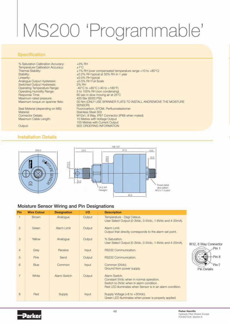

Fluid condition monitoring-,
Specification
Pressure:Maximum allowable operating pressure.(MAOP): -%& bar (*&&& PSI).Operating temperature:Minimum: --&5C (--&5F) - dependent on seal material.Maximum: 1.'5C (1#.'5F).Flow through sensor cell:Installed in active flowstream.Fluid compatibility:Mineral oils, petroleum-based and Phosphate ester-Skydrol option available.Viscosity range:"nlimited.Thread form connections:See ordering information.
Outputs:--%&mA (current loop).Calibration accuracy:1/- '8 RHCompensated thermal stability:1/- #8 RH (1 #&5C to 1.&5C)Materials:Stainless steel 3&3.Sensor size/weight:#&$mm x ;'&mm/&.3(g.IP ratings:IP*. (with specified moulded cable)
Developed in association with Triteq Ltd.
MS300 Intrinsically Safe
The MS3&& has been certi?ed as Intrinsically Safe Electrical Apparatus and offers fast, reliable and accuratein-line detection of moisture in @uids for use in hazardous areas.
ATEX Certi?cation allows the MS3&& into areas of a potentially explosive atmosphere, that have previously notbeen allowed without permits, it is intended for use in +one & hazardous areas requiring the use of category #Gequipment and has been designed for use with galvanic isolators to the speci?ed values stated below:
The electrical parameters: "i: %.0 Ii: ,3mA Pi:&.*'W Ci: 3.&nF Li: &
The following instructions apply to MS3&& - --%&mA Current Loop Moisture Sensor covered by certi?catenumber Sira &$ATEX%%'':
#. The equipment may be located where @ammable gases of Group I may be present. The equipment is onlycerti?ed for use in ambient temperatures in the range -%&5C to 1-&5C and should not be used outside this range.
%. The equipment has not been assessed as a safety-related device (as referred to by Directive ,-/,/EC Annex II,clause #.').
3. Installation of this equipment shall be carried out by suitably trained personnel in accordance with theapplicable code of practice.
-. Repair of this equipment shall be carried out by the manufacturer or in accordance with the applicablecode of practice (IEC *&&$,-#,).
Installation Details - See MS200

Parker HannifinHydraulic Filter Division EuropeFDCB3$'"(. Section .
'&
Moisture sensor output settingThe Moisture sensor reports on the saturation levels of the fluid passing through the sensing cell. The outputis a linear scale, reporting within the range of '8 saturation to #&&8 saturation.
Visual Indicators Specifications
DD"#&&# PBG.3-#ADD"#&&%
Description
Power supplyAccuracySample rateOperating temp (5C)Storage temp (5C)DisplayPower output (0dc)Weight (kg)Panel cutout (mm)Dimensions (mm)
DDU1001
%% - '' 0dc< &/ typical#& per second
& - ''-#& to 1$&' digit LED
%-&.%#
,%x-. </&.'-.x,*x#&&
DDU1002
##& - %-& 0dc< &.#8 typical%.' per second
& - '&-#& to 1$&
31/% digit LED%-
&.3&,3x-' </&.'-.x,*x,3
Alternative Indicator
Bar Graph Indicator (PBG8341A)Construction:Housing 4 nylon */*, window 4 acrylic,bezel/board supports 4 ABS,pins 4 phosphor bronze.Power supply:## 4 3& 0dc.Signal input: (By dipswitch configuration)Off 4 differential up to '0.A 4 single signal (Ref. &0) up to '0.B 4 single signal (Ref. #0) up to *0.Cut out size:-'.*mm x -'.*mm.Fixing:Push fit panel thickness &.,mm to 3.%mm.Sealing:Designed to IP'& standard.(Front face may be silicon sealed after LED configuration).Scale:Supplied & to #&&8 in horizontal.Other scales, in volume, consult Parker Hannifin.Scaling factors:#&8 to #&&8 range. Fully ad)ustable.Lamp intensity:-mcd each.Front viewing:Polarised.Weight:%,gms.
Product Number Supersedes Description
Product accessories part numbers
P9732PVC10 P.,$3%P0C-#& #& meter M#% IP*. P0C coated cable Y N YP9732PVC05 P.,$3%P0C-&' ' meter M#% IP*. P0C coated cable Y N YP9732PVC02 P.,$3%P0C-&% % meter M#% IP*. P0C coated cable Y N Y
P9732PUR10HS N/A #& meter M#% ' way high speci?ed P"R coated cable N N YP9732PUR10 P.,$3%P"R-#& #& meter M#% IP*. P"R coated cable Y N YP9732PUR05 P.,$3%P"R-&' ' meter M#% IP*. P"R coated cable Y N YP9732PUR02 P.,$3%P"R-&% % meter M#% IP*. P"R coated cable Y N Y
DDU1001 DD"-#&&# 1%% to 1'' 0dc process indicator Y Y Y*DDU1002 DD"-#&&% 1##& to 1%-& 0ac process indicator Y Y Y
PBG8341A PBG..3-#.A 1## to 13& 0dc bar graph indicator Y Y Y*B97200 N/A ' meter M#% x #, . way moulded cable (IP*.) N Y NP973200 N/A 'way Re-wireable M#% connector (IP*') Y N NS970400 N/A #% 0dc power supply Y Y NS970410 N/A #& meter extension box Y Y NPAM8342 PAM..3-% Alarm module
* Only for use in a safe zone (ie laboratory)
MS150 MS200 MS300
Saturation 4–20mA 0–3Vdc 0–5Vdc5%
25%
50%
75%
100%
4.8
8
12
16
20
0.15
0.75
1.50
2.25
3.00
0.25
1.25
2.50
3.75
5.00
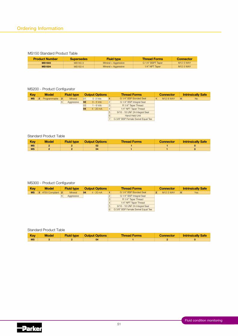
Key Model Fluid type Output Options Thread Forms Intrinsically SafeConnector
MS300 - Product Configurator
MS 3 ATEX Compliant 26
MineralAggressive
04 4 - 20 mA 2 M12 5 WAY 0 Yes123 R 1/4” Taper Thread4 1/4” NPT Taper Thread56 G 3/8” BSP Female Swivel Equal Tee
9/16 - 18 UNF 2A Integral Seal
G 1/4” BSP Integral SealG 1/4” BSP Bonded Seal
Key Model Fluid type Output Options Thread Forms Intrinsically SafeConnector
Standard Product Table
MS 3 2 04 2 01
51
Key Model Fluid type Output Options Thread Forms Intrinsically SafeConnector
MS200 - Product Configurator
MS 2 Programmable 26
MineralAggressive
010203
0 -3 Vdc0 - 5 Vdc1 - 6 Vdc
04 4 - 20 mA
1 M12 8 WAY 0 No123 R 1/4” Taper Thread4 1/4” NPT Taper Thread56 Hand Held Unit7 G 3/8” BSP Female Swivel Equal Tee
9/16 - 18 UNF 2A Integral Seal
G 1/4” BSP Integral SealG 1/4” BSP Bonded Seal
Key Model Fluid type Output Options Thread Forms Intrinsically SafeConnector
Standard Product Table
MS 2 22
0204
1 011
MS 2 1 0
Fluid condition monitoring
Ordering Information
Thread Forms
Mineral + Aggressive
Product Number Supersedes Fluid typeMS1503 MS150-3
MS150 Standard Product Table
Mineral + Aggressive
MS1504 MS150-4
G 1/4” BSPT Taper1/4” NPT Taper
ConnectorM12 5 WAYM12 5 WAY

Parker HannifinHydraulic Filter Division EuropeFDCB3$'"(. Section .
'%
Notes

Hand-held Oil Condition Monitor
Oilcheck
'3Fluid condition monitoring

Hand-held Oil Condition Monitor
Oilcheck
Typical Applications
Fleet ownersConstruction equipment maintenance0ehicle service garagesPlant hire maintenance
The Oilcheck from Parker Filtration’s ConditionMonitoring Centre detects and measures thedielectric constant of oil, by comparing themeasurements obtained from used and unusedoils of the same brand.
"sed as a regular service monitoring instrument,the Oilcheck will give the engineer warning of animpending engine failure and promote increasedengine life. Oilcheck is the low-cost solution thatwill take the guesswork out of oil changes, savingmoney and time.
Features & Benefits Using Oilcheck
• A comparator between new and used oils.• Oilcheck gives early warning of impending
engine failure.• Cost effective solution to save money
and help increase engine life.• Completely portable, battery powered.• Ideal for fleet owners, garages and DIY
mechanics.• Numerical display to show positive or negative
increase in dielectrics.
Following the simple sampling procedure. TheOilcheck will ensure effective and highly repeatableresults. Once a clean oil sample has been placed inthe ‘Sensor Well’ and the ‘TEST’ button has beenpressed, the instrument will ‘zero’ on the sample.
Once cleaned out with a degreaser and replaced bya contaminated sample, a new reading is obtainedon the LCD, which can be easily compared againstthe green/amber/red efficiency scale.
Parker HannifinHydraulic Filter Division EuropeFDCB3$'"(. Section ,
54

55Fluid condition monitoring
Specification
Case construction:ABS.Circuitry:Microprocessor control.Battery:# x ,0 alkaline.Display:LCD.Suitable oil types:Mineral and synthetic based oils.Repeatability:Better than '8.Readout:Green/amber/red grading, Numerical value(&-#&&).Battery lifetime:3#'& hours or 3,&&& tests.Dimensions:%'&mm x ,'mm x 3-mm (,..” x 3.$” x #.3”).Weight:&.-kg.
Ordering Information
Installation Details
:,'
%'&
*- 3%
3-
Numericaldisplay
Samplesensor
Re calbutton
On/OffHi/Lo switch
Testbutton
Visualdisplay
Using Oilcheck
The Oilcheck can remove the need for costlyand time consuming laboratory analysis ofmineral and synthetic oils used in engines,gearboxes and bearing lubrication systems.It detects mechanical wear and any loss oflubricating properties in the oil with a repeataccuracy of less than '8.
The Oilcheck is able to show changes in theoil condition brought about by the ingress ofwater content, fuel contamination, metalliccontent and oxidation.
Green/amber/rednumerical value
Functionbuttons
Product number
OLK605OLK611
Description
Oilcheck kit with numerical readoutOilcheck cleaner
Standard products table
Note #: Part numbers featured with bold highlighted codes will ensure a ‘standard’ product selection.Note %: Alternate displayed part number selection will require you to contact Parker Filtration for availability.

Parker HannifinHydraulic Filter Division EuropeFDCB3$'"(.
'*
Notes

'$Transducers and transmitters
Pressure Transducers and Transmitters
ASIC ‘Performer’25, 60, 100, 250, 400 and 600 bar

Pressure Transducers and Transmitters
ASIC ‘Performer’
A comprehensive range of Pressure Transducers andTransmitters are available from Parker Filtration.
One-piece body and diaphragm machining ensureslong-term product stability.All stainless steel construction.* transducer pressure ratings with &-'0dcand #-*0dc outputs.* transmitter pressure ratings with a %-wire--%&mA output.Microdin plug and M#% connector options.
The CompletePerformer range utilisesASIC technology(Application SpecificIntegrated Circuit)programmablesoftware.
Applications for the ASIC Performer
Fork lift trucks - braking and load systems.Truck mounted cranes - load safety systems.Earth moving machinery - hydraulic gearbox control.Racing car - gearbox, fuel, cooling and suspension systems.Water usage systems - pressurised systems for industrial and hi-rise usage.Forest Machinery - felling and logging.Paper mills - speed control and weighing systems.
The Parker Filtration ASIC Performer PressureTransducers and Transmitters.The ASIC Performer offersa wide range of pressuresensors for mobile orindustrial applications.
These sensors have beendesigned for the requirements of industrial instrumentationsystems. Accordingly, the housings and all components incontact with the medium are made of stainless steel. Thusgiving compatibility with a wide range of media. There is achoice of two plug connectors of either DIN or M#%. There are
six measuring ranges available anda choice of outputs in the form ofeither voltage or current signals.Sensors with output signals from-...%& mA are available in two wiretechnology.
The built-in voltage regulator allows the sensors to be operatedwith a supply voltage of #%-3*/,-3* 0dc. All sensors aremanufactured in our own production facility, typical of ParkerHannifin’s continued commitment to flexibility and quality.
AC/DC display unit (DD"#&&%)
Parker HannifinHydraulic Filter Division EuropeFDCB3$'"(. Section #&
58

Installation Details
Wiring Information
Specification Thread Forms
Electrical Product Performance
Pressure ranges:%', *&, #&&, %'&, -&&, *&& bar.Pressure Tolerance Specifications:
Vibration resistance:IEC *&&*.-%-*:1/- 'mm/#&Hz...3%Hz%&&m/s% / 3%Hz...%kHzInstallation:Spanner size %%A/F.Max. (recommended) tightening torque 9 3&Nm.Weight:%&& - %3&gLifespan:#& million cycles
G1/4 (1/4BSP) with ED seal.All thread forms and sensor interfaceare made from#.-3&# stainless steel.Non standard threads - contactParker CMC
Linearity:Typical: &.38FS.Max: &.*8FS.Hysteresis:Typical: &.#8FS.Max: &.%'8FS.Repeatability:Typical: &.%8FS.Max: &.-8FS.
Functional temp range:--&5C to 1.'5C.Compensated temperature:-%&5C to 1.'5C.Stability:B&.#8FS/a (typ).Response time:9 B#mS.
Supply voltage Output#% - 3*0dc & - '0dc#% - 3*0dc # - *0dc, - 3*0dc - - %&mA
Transducer current draw = <6mALoad impedance (ohm) = >10KOutput signal noise = 0.1%FS
ConnectorIndustrial Micro Din9.4mm
ConnectorM12
1%3E
PINDo not connect
Supply 1veDo not connect
Return
4 - 20mASignal outputSupply 1ve
Do not connectSupply ref. (&v)
0 - 5VdcSignal outputSupply 1ve
Do not connectSupply ref. (&v)
1 - 6Vdc
ED seal
1 2
34
SW%% -3.%
M#%x#
1%34
PINSupply 1ve
Do not connectReturn
Do not connect
4 - 20mASupply 1ve
Signal outputSupply ref. (&v)Do not connect
0 - 5VdcSupply 1ve
Signal outputSupply ref. (&v)Do not connect
1 - 6Vdc
hex. %%
#%
G1/4
:#...
:%%
:%%
ED seal
SW%%
-$
hex. %%
#%
G1/4
:#,
3
2 1
Rating
%'*&#&&%'&-&&*&&
Maximum OverloadPressure
x *.& (#'& bar)x %.' (#'& Bar)x %.' (%'& bar)x -.& (#&&& Bar)x %.' (#&&& Bar)x #.' (#&&& Bar)
Maximum BurstPressure
x %&.& ('&& Bar)x ..& ('&& Bar)x '.& ('&& Bar)x $.& (#.&& Bar)x -.' (#.&& Bar)x 3.& (#.&& Bar)
E
',Transducers and transmitters
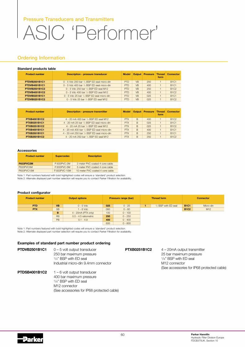
Pressure Transducers and Transmitters
ASIC ‘Performer’Ordering Information
PTDVB2501B1C1 & 4 ' volt output transducer%'& bar maximum pressure1/4” BSP with ED sealIndustrial micro-din ,.-mm connector
PTDSB4001B1C2 # 4 * volt output transducer-&& bar maximum pressure1/4” BSP with ED sealM#% connector(See accessories for IP*. protected cable)
PTXB0251B1C2 - 4 %&mA output transmitter%' bar maximum pressure1/4” BSP with ED sealM#% connector(See accessories for IP*. protected cable)
Product number
PTDVB2501B1C1PTDVB4001B1C1PTDVB2501B1C2PTDVB4001B1C2PTDVB0251B1C1PTDVB0251B1C2
Description - pressure transducer
& - ' 0dc %'& bar 1/4 BSP ED seal micro-din& - ' 0dc -&& bar 1/4 BSP ED seal micro-din
& - ' 0dc %'& bar 1/4 BSP ED seal M#%& - ' 0dc -&& bar 1/4 BSP ED seal M#%
& - ' 0dc %' bar 1/4 BSP ED seal micro-din& - ' 0dc %' bar 1/4 BSP ED seal M#%
Model
PTDPTDPTDPTDPTDPTD
Output
0B0B0B0B0B0B
Pressure
%'&-&&%'&-&&&%'&%'
Threadform
111111
Connector
B#C#B#C#B#C%B#C%B#C#B#C%
Product number
PTXB4001B1C2PTXB0251B1C1PTXB0251B1C2PTXB4001B1C1PTXB2501B1C1PTXB2501B1C2
Description - pressure transmitter
- - %& mA -&& bar 1/4 BSP ED seal M#%- - %& mA %' bar 1/4 BSP ED seal micro-din
- - %& mA %' bar 1/4 BSP ED seal M#%- - %& mA -&& bar 1/4 BSP ED seal micro-din- - %& mA %'& bar 1/4 BSP ED seal micro-din
- - %& mA %'& bar 1/4 BSP ED seal M#%
Model
PTXPTXPTXPTXPTXPTX
Output
BBBBBB
Pressure
-&&&%'&%'-&&%'&%'&
Threadform
111111
Connector
B#C%B#C#B#C%B#C#B#C#B#C%
Standard products table
Product number
P833PVC2MP.33P0C'MP.33P0C#&M
Supercedes
P..33P0C-%MP..33P0C-'MP..33P0C-#&M
Description
% meter P0C coated - core cable' meter P0C coated - core cable#& meter P0C coated - core cable
Note #: Part numbers featured with bold highlighted codes will ensure a ‘standard’ product selection.Note %: Alternate displayed part number selection will require you to contact Parker Filtration for availability.
Accessories
Product number
PTDPTX
Output options
VBSBB
RBPB
& - ' 0dc# - * 0dc
- - %&mA (PTX only)&.' - -.' ratiometric
&.# - -.,
Pressure range (bar)
025&*&#&&250400*&&
Thread form
1& - %'& - *&& - #&&& - %'&& - -&&& - *&&
1/4 BSP with ED seal
Connector
B1C1B1C2
Micro-dinM#%
Product configurator
Note #: Part numbers featured with bold highlighted codes will ensure a ‘standard’ product selection.Note %: Alternate displayed part number selection will require you to contact Parker Filtration for availability.
Examples of standard part number product ordering
Parker HannifinHydraulic Filter Division EuropeFDCB3$'"(. Section #&
*&

Aviation Fuel Contamination Monitoring
ACM20 Lab Unit
61Fluid condition monitoring
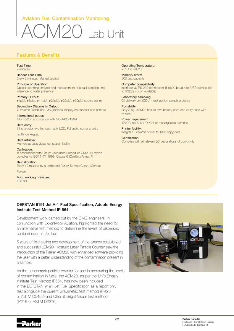
62 Parker HannifinHydraulic Filter Division EuropeFDCB375UK. Section 11
Test Time:2 minutes
Repeat Test Time:Every 2 minutes (Manual testing)
Principle of Operation:Optical scanning analysis and measurement of actual particles andinference to water presence
Primary Output:>4µ(c), >6µ(c), >14µ(c), >21µ(c), >25µ(c), >30µ(c) counts per ml
Secondary Diagnostic Output:% Volume Distribution, via graphical display on handset and printout
International codes:ISO 7-22 in accordance with ISO 4406-1999
Data entry:32 character two line dot matrix LCD. Full alpha numeric entry
facility on keypad
Data retrieval:Memory access gives test search facility
Calibration:In accordance with Parker Calibration Procedure CM20-N, whichcomplies to ISO11171:1999, Clause 6 (Omitting Annex F)
Re-calibration:Every 12 months by a dedicated Parker Service Centre (Consult
Parker)
Max. working pressure:420 bar
Operating Temperature:+5°C to +80°C
Memory store:300 test capacity
Computer compatibility:Interface via RS 232 connection @ 9600 baud rate (USB serial cableto RS232 option available)
Laboratory sampling:Oil delivery unit (ODU) - test portion sampling device
Portability:Only 8 kg. ACM20 has its own battery pack and carry case withwheels
Power requirement:12vDC input, 6 x ‘D’ Cell or rechargeable batteries
Printer facility:Integral 16 column printer for hard copy data
Certification:Complies with all relevant EC declarations of conformity
Aviation Fuel Contamination Monitoring
ACM20 Lab Unit
Features & Benefits
DEFSTAN 9191 Jet A-1 Fuel Specification, Adopts EnergyInstitute Test Method IP 564
Development work carried out by the CMC engineers, inconjunction with ExxonMobil Aviation, highlighted the need foran alternative test method to determine the levels of dispersedcontamination in Jet fuel.
5 years of field testing and development of the already establishedand successful LCM20 Hydraulic Laser Particle Counter saw theintroduction of the Parker ACM20 with enhanced software providingthe user with a better understanding of the contamination present ina sample.
As the benchmark particle counter for use in measuring the levelsof contamination in fuels, the ACM20, as per the UK’s EnergyInstitute Test Method IP564, has now been includedin the DEFSTAN 9191 Jet Fuel Specification as a report onlytest alongside the current Gravimetric test method (IP423or ASTM D5452) and Clear & Bright Visual test method(IP216 or ASTM D2276).

Fluid condition monitoring63
Specification
Construction:Case-Lexan structural foam and ABSHand-held display - ABSKeypad flurosilicone rubber
Mechanical Components:Brass, plated steel, stainless steel and aluminium
Seals:Fluorocarbon
Hoses:Nylon (Kevlar braided microbore). St. steel armouredends
Flow Rate:25 - 50ml/min (dictated by ODU)
Fluid Compatability:Hydrocarbon Fuel, Mineral Oil. For other fluidsconsult Parker
Fuse:1.25 amp fast blow fuse included for overloadprotection (spare supplied)
ACM20 Technology:Patented flow cell, light obscuration
Repeatability/Accuracy:As per or better than ISO 11171
Coincidence:40,000 particles per ml
Viscosity Range:1 -100 centistokes
ACM20 Weight:8 kg
Monitor Carrying Case:Astra Board case
Carrying Case Weight:5 kg
The Parker ACM20 Portable Particle Counterhas been developed from existing technologyfor monitoring contamination in AvTur and otherHydrocarbon fuels, in accordance with the EnergyInstitute (EI) Method IP 564.
In addition, the ACM can also be used to monitorvarious fuels from existing sampling points inlocations from refineries, pipelines, distributionterminals, airport fuel supply systems all the waythrough to the point of uplift into aircraft*.
* Hot works permit required for online sampling (ATEX Zone || unit
available).
• Fuel Testing Laboratories – DefStan 9191In order to better understand dispersedcontamination in jet fuel, particle counting isnow included alongside existing laboratorytechniques
• Bottle Sampling - Energy Institute (EI) - IP 564Laboratory determination of the level ofdispersed contamination in aviation kerosineusing an Automatic Particle Counter (APC)
• Replace Clear & Bright and GravimetricWith the introduction of the ACM20, allsubjectivity surrounding Clear & Bright andGravimetric methods can be removed
• Also for use on petroleum based hydraulicapplications (Skydrol compatible available)Suitable for use with mineral oil andpetroleum based fluid as per standardhydraulic particle counter, reporting fluidcleanliness to ISO 4406:1999
Applications

64 Parker HannifinHydraulic Filter Division EuropeFDCB375UK. Section 11
DEF STAN 91-91 Issue 6
Defence Standard 91-91 is the specification for aviation turbine fuel, which the United KingdomCivil Aviation Authority (CAA) has agreed is under the technical authority of the Director of theDefence Fuels Group.
Laboratory determination of the level of dispersed contamination in aviation kerosene using anAutomatic Particle Counter (APC).
This standard describes a method for determining the level of dispersed contamination in aviationkerosene fuels, specifically dirt particles and water droplets in the range from >4µ(c) to >30µ(c).This method relates specifically to Aviation fuels but the equipment can be used on all fuels,petroleum and mineral based fluids.
Aviation Fuel Contamination Monitoring
ACM20 Lab Unit
IP 564

Fluid condition monitoring65
IP 564 Procedure
Apparatus:The apparatus shall be set up in accordance withmanufacturers’ operating instructions
Test Portion Preparation:Decant a minimum of 450ml of the field sampleinto a clean test portion container
Aviation Fuel Contamination Monitoring
ACM20 Lab Unit
1
2
3
4
5
Prior to starting a test, tumble the test portionend over end for 60 seconds to ensure any settledparticles are redistributed
Flush the equipment with the new test sample for60 seconds prior to starting the test
Following the flush, start a test by turning theblue valve in the direction indicatedRepeat a further 3 times
Note:The implementation date for IP 564 test method “Determination of the level of cleanliness ofaviation turbine fuel - laboratory automatic particle counter” will be June 2009. It is the specificationauthorities intention to replace current test methods with particle counting at the earliest opportunity

66 Parker HannifinHydraulic Filter Division EuropeFDCB375UK. Section 11
Field Monitoring - ACM202022
Field Monitoring - ACM202032 (Z2)
For use in non-hazardous areas, the ACM2022is designed for online sampling of hydrocarbonfuels and hydraulic systems, utilising existing“quick connect” sampling points such as theMillipore Adaptor
Aviation Fuel Contamination Monitoring
ACM20 Family
The ACM202032 (Z2) is the worlds only ATEX approvedportable particle counter for sampling directly from theprocess line in hazardous areas
• Assembled in an approved and certified stainless steelenclosure to comply with ATEX Directive 94/9/ECand EN50 021 requirements
• Certified to CE Ex 11 3 G Ex nR/nl 11C T6
• “A” Class product defined for the Aviation market
• ATEX approved handset and keypad

Fluid condition monitoring67
Ordering Information
Note 1: Part numbers featured with bold highlighted codes will ensure a ‘standard’ product selection.Note 2: Alternate displayed part number selection will require you to contact Parker Filtration for availability.* Hot works permit required for online sampling.
Standard products table - ACM20
Product number
ACM202022UKACM202022USACM202022EURACM202024UKACM202024USACM202024EURB84794B84816P843855B84746B84745B84645B84609B84817B84830B84831B84832
Description
Particle counter UK*Particle counter US*
Particle counter Euro*Particle counter with lab kit UK (DefStan 9191)Particle counter with lab kit US (DefStan 9191)
Particle counter with lab kit Euro (DefStan 9191)1m process cable assembly
Parsmart downloader softwareCarry case
Bottle assemblyThrottle kit
Millipore adaptor assyRe-chargeable battery pack
UK power supplyUS power supply
Euro power supplyLaboratory kit

Parker HannifinHydraulic Filter Division EuropeFDCB375UK.
68
Notes

Fluid condition monitoring69
ATEX Approved Portable Particle Counter
ACM20 Z2

ATEX Approved Portable Particle Counter
ACM20 Z2Features & Benefits
Parker HannifinHydraulic Filter Division EuropeFDCB198UK. Section 12
70
Test Time:2 minutes.Repeat Test Time:Every 2 minutes (Manual testing) Every 6 minutes (Automatic).Principle of Operation:Optical scanning analysis and measurement of actual particles andinference to water presence.Primary Output:>4µ(c), >6µ(c), >14µ(c), >21µ(c), >25µ(c), >30µ(c) counts per ml.Secondary Diagnostic Output:% Volume Distribution, via graphical display on handset.International codes:ISO 7-22 in accordance with ISO 4406-1999Data entry:32 character two line dot matrix LCD. Full alpha numeric entry facilityon keypad.Data retrieval:Memory access gives test search facility.Calibration:In accordance with Parker Calibration Procedure CM20-N, whichcomplies to ISO11171:1999, Clause 6 (Omitting Annex F).
Re-calibration:Every 12 months by a dedicated Parker Service Centre (ConsultParker).Max. working pressure:420 bar.Operating Temperature:+5°C to +80°CMemory store:300 test (scrolling memory) capacity.Computer compatibility:Interface via RS 232 connection @ 9600 baud rate.Portability:15 kg. ACM20 has its own battery pack and carry case with wheels.Power requirement:Rechargeable battery powered or via the 12vDC input.System connection:Via Millipore adaptor with flow restriction through supplied needle valve.Certification:Complies with all relevant EC declarations of conformity
• Assembled in an approved and certifiedstainless steel enclosure to comply with ATEXDirective 94/9/EC and EN50 021 requirements.
• Can be used in explosive and hazardous areas,including Offshore and Mining.
• Certified to CE Ex II 3 G Eex nA/nL IIB T *(*as tested)
• “A” Class product defined for the Aviationmarket.
• ATEX approved Handset and keypad.• Suitable for use with mineral oil and petroleum
based fluid as per LCM20 particle counter.

Specification Using ACM20 Z2
Construction:Unit: stainless steelCarrying case: ABSHand-held display: ABSKeypad: polyester membraneMechanical components:Brass, plated steel, stainless steel and aluminiumSeals: VitonHoses: Nylon (Kevlar braided microbore)Fluid compatibility:All fuels. For other fluids consult ParkerInternal rechargeable battery:Note: ONLY to be charged outside of the hazardous area,with the unit switched offFuse:1.25A fast blow fuse included for overload protectionReturn to Parker Hannifin if fuse is blownACM20.2032 technology:Unique optical scanning systemRepeatability/Accuracy:Better than 5% (typical)
Applications in Fuels
71Fluid condition monitoring
Oil Refineryo To count and verify the levels of dispersed
contamination in accordance withspecification limits.
Distribution Terminals/Hubso For use on receipt and outbound supply.
Also to provide filtration performance, tankcleanliness and product quality checks.
Storageo Settling times can be reduced by monitoring
with the ACM by ensuring that levelsof dispersed contamination are belowacceptable levels.
Airport Fuel Farmo Monitoring of the fuels into storage, through
the fuel farm, hydrant system and uplift intowing.
Pipeline Commissioningo Fast real time monitoring of pipelines
following pigging and cleaning processes.Oil and Gas Platformso Used to monitor the filtration performance,
system cleanliness and quality of deliveredproduct.
ACM20Z2 is designed to be used to monitorvarious fuels from existing sampling points inhazardous locations from refineries, pipelines,distribution terminals, airport fuel supply systemsall the way through to the point of uplift intoaircraft. With Zone 2 classification, the ACM20Z2is the worlds only ATEX approved particle counter.

ATEX Approved Portable Particle Counter
ACM20 Z2
Parker HannifinHydraulic Filter Division EuropeFDCB198UK. Section 12
72
Applications in hydraulics
Solutions in the offshore industry.In addition, the ACM20 Z2 can be used in many hydraulicsystem applications as detailed below.
In many industries, worker awareness needs to be maintainedat a high level to ensure the safety of their operation. Thisis particularly relevant to offshore oil-drilling and gas-drillingcrews, given the interactive and hazardous nature of theirwork. The Zone 2 ACM20 portable particle analyser is a triedand tested technology designed, proven and approved as afluid contamination monitor that crews are using and trustingin such hazardous and demanding environments.
• Certified to CE Ex II 3 G EexnA/nL IIB T* (*as tested).• Can be used in explosive and hazardous areas, including
Offshore and Mining.• Primary Output. Six cumulative particle size channels
ranging from >4µm(c) to >30µm(c) and numbers per mlin accordance with ISO4406-1999.
ACM20Z2 – operational in oil refineries and fuel fields.Already operational in oil refineries and designed to be used inside commercial airfieldfuel locations and at the point of upload of fuel into the aircraft, ACM20Z2 has animpressive success record in this approvals sensitive area of operation.
With a number of safety features designed in as operational standards, the ACM20Z2can be taken to the point of use, connected in moments and reporting in little morethan 2 minutes to ISO approved standards.
• Assembled in an approved and certified stainless steel enclosure to comply withATEX Directive 94/9/EC and EN50 021 requirements.
• ‘A’ Class product defined for the aviation market.• Designed for on-line operation, connecting to the process line via existing
Millipore™ fittings, already in use for other industry equipment.
Applications in other hazardous environments.• Railroad equipment manufacturer - Warranty protection.• Power generation stations - Preventative maintenance.• Mobile equipment - Roll-off cleanliness testing.• Mining operations - Service tool.• Steel mills - Preventative maintenance.

Fluid condition monitoring73
Online Commission Kit
Installation Details
a – ACM20 Zone 2 Particle Counterb – Battery Chargerc – Process Cabled – User Manuale – Downloader Softwaref – Throttle Kitg – Millipore Adaptor Assemblyh – Aluminium Casei – Bottle Assembly
a
b
h
d
cg
i
f
e

ATEX Approved Portable Particle Counter
Parker HannifinHydraulic Filter Division EuropeFDCB198UK. Section 12
74
ACM20 Z2Alternative Fuel Monitoring
Average Particle Counts in AV System
In addition to the Z2 Parker also have the ACM20 laboratory Particle Counter which hasbeen designed in accordance with the Energy Institute (EI) Method IP PM DK.
The ACM20 with additional laboratory kit is proposed as an alternative method for usewithin DefStan 9191 – the standard for aviation turbine fuel, which the United KingdomCivil Aviation Authority (CAA) has agreed is under the technical authority of the DirectorDefence Fuels Group.
The ACM can also be used to monitor various fuels from existing sampling points in thesame way as the Z2*.
*Hot works permit required for online sampling.
Laboratory KitThe Oil Delivery Unit (ODU) laboratory kit is a peristaltic pump unit that allows fuelto be pumped through the ACM20 for testing purposes offline.
SpecificationHeight: 150mm wide x 150mm deep x 170mmWeight: 1.7 kgPower Requirement:Can be run from the 12-volt ACM20 power supply or from another suitable supplyvia the connecting lead supplied.Fuse: 0.5 amp fast blow fuse included for overload protection.Minimum Flow Rate: 15ml/min.
The table below gives estimated counts found in a typical aviation fuel distribution system, and is given as guidance, in which APR/EI filtration equipment is installed.
Receipt into MicrofilterExpect 2,500 counts per mlor cleaner @ 4µ(c)
Receipt into Microfilter
>4µ(c)>6µ(c)>14µ(c)
ISO Code - 4406 1999
High Count2,50035010
High Count Code181510
MF
Receipt into FWS (After MF)
>4µ(c)>6µ(c)>14µ(c)
ISO Code - 4406 1999
High Count500505
High Count Code16139
FWSReceipt into FWS (After MF)Expect 500 counts per mlor cleaner @ 4µ(c)
Receipt into Storage (After FWS/MF)
>4µ(c)>6µ(c)>14µ(c)
ISO Code - 4406 1999
High Count100101
High Count Code14107
Airport storageReceipt into Storage (After FWS/MF)Expect 100 counts per mlor cleaner @ 4µ(c)
FWS Out of Storage
>4µ(c)>6µ(c)>14µ(c)
ISO Code - 4406 1999
High Count500505
High Count Code16139
FWSFWS out of storageExpect 500 counts per mlor cleaner @ 4µ(c)
After FWS Into Hydrant
>4µ(c)>6µ(c)>14µ(c)
ISO Code - 4406 1999
High Count100101
High Count Code14107
To Hydrant/RefuellerAfter FWS into HydrantExpect 100 counts per mlor cleaner @ 4µ(c)
After Monitor Into Plane
>4µ(c)>6µ(c)>14µ(c)
ISO Code - 4406 1999
High Count100101
High Count Code14107
After Monitor Into PlaneExpect 100 counts per mlor cleaner @ 4µ(c)
Note: Figures will vary from location to location.
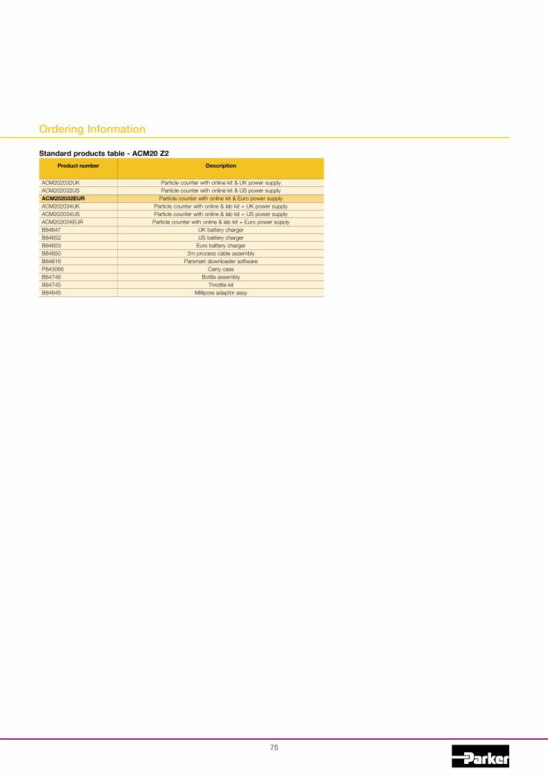
75
Product number Description
Particle counter with online kit & UK power supplyParticle counter with online kit & US power supply
Particle counter with online kit & Euro power supplyParticle counter with online & lab kit + UK power supplyParticle counter with online & lab kit + US power supply
Particle counter with online & lab kit + Euro power supplyUK battery chargerUS battery charger
Euro battery charger2m process cable assembly
Parsmart downloader softwareCarry case
Bottle assemblyThrottle kit
Millipore adaptor assy
Standard products table - ACM20 Z2
Ordering Information
ACM202032UKACM202032USACM202032EURACM202034UKACM202034USACM202034EURB84647B84652B84653B84650B84816P843066B84746B84745B84645

Parker HannifinHydraulic Filter Division EuropeFDCB375UK.
76
Important Information
WARNING — USER RESPONSIBILITYFAILURE OR IMPROPER SELECTION OR IMPROPER USE OF THE PRODUCTS DESCRIBED HEREIN ORRELATED ITEMS CAN CAUSE DEATH, PERSONAL INJURY AND PROPERTY DAMAGE.
• This document and other information from Parker Hannifin Corporation, its subsidiaries and authorized distributors provideproduct or system options for further investigation by users having technical expertise.
• The user, through its own analysis and testing, is solely responsible for making the final selection of the system andcomponents and assuring that all performance, endurance, maintenance, safety and warning requirements of the applicationare met.
The user must analyze all aspects of the application, follow applicable industry standards, and follow the informationconcerning the product in the current product catalogue and in any other materials provided from Parker or its subsidiaries orauthorized distributors.
• To the extent that Parker or its subsidiaries or authorized distributors provide component or system options based upon dataor specifications provided by the user, the user is responsible for determining that such data and specifications are suitable andsufficient for all applications and reasonably foreseeable uses of the components or systems.
Sales conditions
The items described in this document are available for sale by Parker Hannifin Corporation, its subsidiaries or its authorizeddistributors. Any sale contract entered into by Parker will be governed by the provisions stated in Parker’s standard terms andconditions of sale (copy available upon request).
!

AEROSPACEKey Markets! Aircraft engines! Business & general aviation! Commercial transports! Land-based weapons systems! Military aircraft! Missiles & launch vehicles! Regional transports! Unmanned aerial vehicles
Key Products! Flight control systems
& components! Fluid conveyance systems! Fluid metering delivery
& atomization devices! Fuel systems & components! Hydraulic systems & components! Inert nitrogen generating systems! Pneumatic systems & components! Wheels & brakes
CLIMATE CONTROLKey Markets! Agriculture! Air conditioning! Food, beverage & dairy! "#$% &'#%('%& ) *%+#',-! Precision cooling! Processing! Transportation
Key Products! CO2 controls! Electronic controllers! Filter driers! Hand shut-off valves! Hose & fittings! Pressure regulating valves! Refrigerant distributors! Safety relief valves! Solenoid valves! Thermostatic expansion valves
FILTRATIONKey Markets! Food & beverage! Industrial machinery! Life sciences! Marine! Mobile equipment! Oil & gas! Power generation! Process! Transportation
Key Products! Analytical gas generators! Compressed air & gas filters! Condition monitoring! Engine air, fuel & oil filtration
& systems! Hydraulic, lubrication &
coolant filters! Process, chemical, water
& microfiltration filters! Nitrogen, hydrogen & zero
air generators
ELECTROMECHANICALKey Markets! Aerospace! Factory automation! Life science & medical! Machine tools! Packaging machinery! Paper machinery! Plastics machinery & converting! Primary metals! Semiconductor & electronics! Textile! Wire & cable
Key Products! AC/DC drives & systems! Electric actuators, gantry robots
& slides! Electrohydrostatic actuation systems! Electromechanical actuation systems! Human machine interface! Linear motors! Stepper motors, servo motors,
drives & controls! Structural extrusions
PNEUMATICSKey Markets! Aerospace! Conveyor & material handling! Factory automation! Life science & medical! Machine tools! Packaging machinery! Transportation & automotive
Key Products! Air preparation! Brass fittings & valves! Manifolds! Pneumatic accessories! Pneumatic actuators & grippers! Pneumatic valves & controls! Quick disconnects! Rotary actuators! Rubber & thermoplastic hose
& couplings! Structural extrusions! Thermoplastic tubing & fittings! Vacuum generators, cups & sensors
FLUID & GAS HANDLINGKey Markets! Aerospace! Agriculture! Bulk chemical handling! Construction machinery! Food & beverage! Fuel & gas delivery! Industrial machinery! Mobile! Oil & gas! Transportation! Welding
Key Products! Brass fittings & valves! Diagnostic equipment! Fluid conveyance systems! Industrial hose! PTFE & PFA hose, tubing &
plastic fittings! Rubber & thermoplastic hose
& couplings! Tube fittings & adapters! Quick disconnects
HYDRAULICSKey Markets! Aerospace! Aerial lift! Agriculture! Construction machinery! Forestry! Industrial machinery! Mining! Oil & gas! Power generation & energy! Truck hydraulics
Key Products! Diagnostic equipment! Hydraulic cylinders
& accumulators! Hydraulic motors & pumps! Hydraulic systems! Hydraulic valves & controls! Power take-offs! Rubber & thermoplastic hose
& couplings! Tube fittings & adapters! Quick disconnects
PROCESS CONTROLKey Markets! Chemical & refining! Food, beverage & dairy! Medical & dental! Microelectronics! Oil & gas! Power generation
Key Products! Analytical sample conditioning
products & systems! Fluoropolymer chemical delivery
fittings, valves & pumps! High purity gas delivery fittings,
valves & regulators! Instrumentation fittings, valves
& regulators! Medium pressure fittings & valves! Process control manifolds
SEALING & SHIELDINGKey Markets! Aerospace! Chemical processing! Consumer! Energy, oil & gas! Fluid power! General industrial! Information technology! Life sciences! Military! Semiconductor! Telecommunications! Transportation
Key Products! Dynamic seals! Elastomeric o-rings! EMI shielding! Extruded & precision-cut,
fabricated elastomeric seals! Homogeneous & inserted elastomeric
shapes! High temperature metal seals! Metal & plastic retained composite
seals! Thermal management
Parker’sMotion&Control TechnologiesAt Parker, we’re guided bya relentless drive to helpour customers become moreproductive and achievehigher levels of profitabilityby engineering the best sys-tems for their requirements.It means looking at customerapplications from manyangles to find new ways tocreate value. Whatever themotion or control technologyneed, Parker has the experi-ence, breadth of product andglobal reach to consistentlydeliver. No company knowsmore about motion and con-trol technology than Parker.

Parker Hannifin Ltd.Hydraulic Filter Division EuropeCondition Monitoring CentreTel.: +44 (0) 1842 763299Email: [email protected]/hfde
Catalogue FDCB375UK 05/2008
Your local authorised Parker distributor
© 2008 Parker Hannifin Corporation. All rights reserved.
AE – UAE, DubaiTel: +971 4 [email protected]
AR – Argentina, Buenos AiresTel: +54 3327 44 4129
AT – Austria, Wiener NeustadtTel: +43 (0)2622 [email protected]
AT – Eastern Europe,Wiener NeustadtTel: +43 (0)2622 23501 [email protected]
AU – Australia, Castle HillTel: +61 (0)2-9634 7777
AZ – Azerbaijan, BakuTel: +994 50 2233 [email protected]
BE/LU – Belgium, NivellesTel: +32 (0)67 280 [email protected]
BR – Brazil, Cachoeirinha RSTel: +55 51 3470 9144
BY – Belarus, MinskTel: +375 17 209 [email protected]
CA – Canada, Milton, OntarioTel: +1 905 693 3000
CH – Switzerland, EtoyTel: +41 (0) 21 821 02 [email protected]
CN – China, ShanghaiTel: +86 21 5031 2525
CZ – Czech Republic, KlecanyTel: +420 284 083 [email protected]
DE – Germany, KaarstTel: +49 (0)2131 4016 [email protected]
DK – Denmark, BallerupTel: +45 43 56 04 [email protected]
ES – Spain, MadridTel: +34 902 33 00 [email protected]
FI – Finland, VantaaTel: +358 (0)20 753 [email protected]
FR – France, Contamine s/ArveTel: +33 (0)4 50 25 80 [email protected]
GR – Greece, AthensTel: +30 210 933 [email protected]
HK – Hong KongTel: +852 2428 8008
HU – Hungary, BudapestTel: +36 1 220 [email protected]
IE – Ireland, DublinTel: +353 (0)1 466 [email protected]
IN – India, MumbaiTel: +91 22 6513 7081-85
IT – Italy, Corsico (MI)Tel: +39 02 45 19 [email protected]
JP – Japan, TokyoTel: +(81) 3 6408 3901
KR – South Korea, SeoulTel: +82 2 559 0400
KZ – Kazakhstan, AlmatyTel: +7 7272 505 [email protected]
LV – Latvia, RigaTel: +371 6 745 [email protected]
MX – Mexico, ApodacaTel: +52 81 8156 6000
MY – Malaysia, Subang JayaTel: +60 3 5638 1476
NL – The Netherlands,OldenzaalTel: +31 (0)541 585 [email protected]
NO – Norway, SkiTel: +47 64 91 10 [email protected]
NZ – New Zealand, Mt WellingtonTel: +64 9 574 1744
PL – Poland, WarsawTel: +48 (0)22 573 24 [email protected]
PT – Portugal, Leca da PalmeiraTel: +351 22 999 [email protected]
RO – Romania, BucharestTel: +40 21 252 [email protected]
RU – Russia, MoscowTel: +7 495 [email protected]
SE – Sweden, SpångaTel: +46 (0)8 59 79 50 [email protected]
SG – SingaporeTel: +65 6887 6300
SK – Slovakia, Banská BystricaTel: +421 484 162 [email protected]
SL – Slovenia, Novo MestoTel: +386 7 337 [email protected]
TH – Thailand, BangkokTel: +662 717 8140
TR – Turkey, IstanbulTel: +90 216 [email protected]
TW – Taiwan, TaipeiTel: +886 2 2298 8987
UA – Ukraine, KievTel +380 44 494 [email protected]
UK – United Kingdom,WarwickTel: +44 (0)1926 317 [email protected]
US – USA, ClevelandTel: +1 216 896 3000
VE – Venezuela, CaracasTel: +58 212 238 5422
ZA – South Africa,Kempton ParkTel: +27 (0)11 961 [email protected]
Parker Worldwide
European Product Information Centre
Free phone: 00 800 27 27 5374
(from AT, BE, CH, CZ, DE, EE, ES, FI, FR, IE,
IT, PT, SE, SK, UK)