Pressure and Temperature Regulators
60
Pressure and Temperature Regulators RC.4X.B1.22 January 1999 Technical leaflet
-
Upload
khangminh22 -
Category
Documents
-
view
0 -
download
0
Transcript of Pressure and Temperature Regulators

© Danfoss A/S 01-99 1
Pressure andTemperature Regulators
RC.4X.B1.22January 1999
Technical leaflet

2 © Danfoss A/S 01-99
Contents PageEvaporator Pressure Regulators
Type KVP......................................................................................................... 3
Type PKV/PKVS .............................................................................................. 9
Hot Gas Bypass Capacity Regulators
Type KVC ...................................................................................................... 35
Type CPCE/LG .............................................................................................. 43
Crankcase Pressure Regulators
Type KVL ....................................................................................................... 49
Condenser Pressure Regulators
Type KVR/NRD.......................................................................................... .... 27
Receiver Pressure Regulators
Type KVD ..................................................................................................... 59
Metric conversions1 psi = 0.07 bar5/9 (t1°F – 32) = t2°C1 ton = 3.5 kW1 in. = 25.4 mm1 ft = 0.3 m1 lb = 0.454 kg1 oz = 28.35 gUS gal/min = 0.86 m3/h
Electronic type KVQ ...................................................................................... 17
Technical Leaflet Pressure and Temperature Regulators
RC.4X.B1.22

© Danfoss A/S 01-99 3
Introduction KVP evaporator pressure regulators aremounted in the suction line of refrigeration andair conditioning systems.They are used to maintain a constant pressurecorresponding to a constant temperature onthe evaporator.
Features � Accurate, adjustable pressure regulation
� Wide capacity and operating range
� Pulsation damping design
� Stainless steel bellows
� Compact angle design for easy installationin any position
� "Hermetic" brazed construction
� 1/4 in. Schrader valve for pressure testing
� Available with flare and ODF solderconnections
� For use with CFC, HCFC and HFCrefrigerants
Approvals ��UL listed, file SA7200 ��CSA approved
Technical data RefrigerantsCFC, HCFC, HFC
Regulation range0 to 80 psigFactory setting = 29 psig
Maximum working pressureMWP = 200 psig
Maximum test pressureKVP 12 to 22: p' = 410 psigKVP 28 to 35: p' = 370 psig
Maximum temperature of medium: 212°F *)
Minimum temperature of medium: – 40°F *)
P band (full valve stroke)KVP 12 to 22 = 26 psiKVP 28 to 35 = 40 psi*) If the Schrader valve cone is removed and the connector
is sealed with cap and nut, the maximum temperature is300°F and the minimum temperature is – 330°F.
Metric conversions1 psi = 0.07 bar5/9 (t1°F – 32) = t2°C
They also protect against too low anevaporating pressure by throttling down whenpressure falls below the set value.They are also used to differentiate theevaporating pressures in two or moreevaporators in systems with one compressor.
Contents Introduction ---------------------------------------------------------------------------------------------------- Page 3Features -------------------------------------------------------------------------------------------------------- Page 3Approvals ------------------------------------------------------------------------------------------------------- Page 3Technical data ------------------------------------------------------------------------------------------------- Page 3Ordering -------------------------------------------------------------------------------------------------------- Page 4Capacity -------------------------------------------------------------------------------------------------- Pages 4 - 5Sizing ------------------------------------------------------------------------------------------------------------ Page 6Design and function ------------------------------------------------------------------------------------------ Page 7Dimensions and weights ------------------------------------------------------------------------------------ Page 8
Technical Leaflet Evaporator Pressure Regulators, type KVP
RD.4A.E1.22
4 © Danfoss A/S 01-99
Ordering
1) Rated capacity is based on:Evaporating temperature te = 40�FCondensing temperature tc = 100�FPressure drop across regulator �p = 2 psiOffset (design evaporating pressureminus minimum allowable evaporator pressure) = 9 psi.
Note: The connection dimensions chosenmust not be too small, as gas velocities inexcess of 130 ft/s at the inlet of the regulatorcan result in flow noise.
Type Rated capacity 1) Flare connection 2) Solder connectiontons
R 22 R 134a R 404A/R 507 R 407C in. Code no in. ODF Code no
KVP 12 1.3 0.9 1.2 1.2 1/2 034L0021 1/2 034L0023
KVP 15 1.3 0.9 1.2 1.2 5/8 034L0022 5/8 034L0029
KVP 22 1.3 0.9 1.2 1.2 7/8 034L0025
KVP 28 2.8 1.9 2.4 2.6 11/8 034L0026
KVP 35 2.8 1.9 2.4 2.6 13/8 034L0032
Maximum regulator capacity Qe1)
Type Pressure drop Capacity Qe in tonsacross regulator at evaporating temperature te °F
�p psi 10 20 30 40 50 60 70
KVP 12 2 0.6 0.7 0.8 0.9 1.0 1.1 1.2KVP 15 4 0.8 0.9 1.0 1.2 1.3 1.5 1.7KVP 22 6 0.9 1.0 1.2 1.4 1.6 1.8 2.0
10 1.0 1.2 1.5 1.7 2.0 2.2 2.520 1.0 1.3 1.6 2.0 2.4 2.8 3.3
KVP 28 2 1.3 1.5 1.7 1.9 2.1 2.4 2.6KVP 35 4 1.7 2.0 2.3 2.6 2.9 3.3 3.6
6 2.0 2.3 2.7 3.1 3.5 3.9 4.410 2.2 2.7 3.2 3.7 4.3 4.9 5.520 2.2 2.8 3.5 4.4 5.2 6.1 7.1
�) The capacities are based on:Liquid temperature ahead of expansion valve tl = 100°FRegulator offset �p = 9 psi
R 134a
Metric conversions1 psi = 0.07 bar5/9 (t1°F – 32) = t2°C1 ton = 3.5 kW1 in. = 25.4 mm
2) KVP supplied without flare nuts.Separate flare nuts can be supplied:1/2 in., code no 011L11035/8 in., code no 011L1167
CapacityMaximum regulator capacity Qe
1)Type Pressure drop Capacity Qe in tons
across regulator at evaporating temperature te °F
�p psi – 20 – 10 0 10 20 30 40 50 60 70
KVP 12 2 0.6 0.7 0.8 0.9 1.0 1.2 1.3 1.4 1.5 1.7KVP 15 4 0.9 1.0 1.1 1.3 1.4 1.6 1.8 2.0 2.2 2.4KVP 22 6 1.0 1.2 1.3 1.5 1.7 1.9 2.2 2.4 2.6 2.9
10 1.1 1.4 1.6 1.9 2.1 2.4 2.7 3.0 3.3 3.620 1.1 1.4 1.8 2.2 2.6 3.0 3.5 3.9 4.4 4.9
KVP 28 2 1.4 1.6 1.8 2.0 2.3 2.5 2.8 3.1 3.4 3.7KVP 35 4 1.9 2.2 2.5 2.8 3.1 3.5 3.9 4.3 4.7 5.2
6 2.1 2.5 2.9 3.3 3.8 4.2 4.7 5.2 5.7 6.310 2.4 2.9 3.5 4.0 4.6 5.2 5.8 6.5 7.2 7.920 2.4 3.0 3.8 4.7 5.6 6.6 7.5 8.5 9.6 10.6
R 22
Technical Leaflet Evaporator Pressure Regulators, type KVP
RD.4A.F1.22

© Danfoss A/S 01-99 5
Technical Leaflet Evaporator Pressure Regulators, type KVP
tl °F 50 60 70 80 90 100 110 120
R 22 0.82 0.85 0.88 0.92 0.96 1.0 1.05 1.10
R 134a 0.79 0.82 0.86 0.90 0.95 1.0 1.06 1.13
R 404A/R 507 0.71 0.75 0.80 0.85 0.92 1.0 1.10 1.24
R 407C 0.78 0.81 0.85 0.89 0.94 1.0 1.07 1.15
Offsetpsi 3 6 9 12 15 18 21
KVP 12KVP 15 2.5 1.4 1 0.77 0.67 0.59KVP 22
KVP 28 1.4 1 0.77 0.67 0.59 0.53KVP 35
Metric conversions1 psi = 0.07 bar5/9 (t1°F – 32) = t2°C1 ton = 3.5 kW
Maximum regulator capacity Qe1)
Type Pressure drop Capacity Qe in tonsacross regulator at evaporating temperature te °F
�p psi – 30 – 20 – 10 0 10 20 30 40 50 60 70
KVP 12 2 0.5 0.5 0.6 0.7 0.8 0.9 1.1 1.2 1.3 1.4 1.5KVP 15 4 0.6 0.7 0.8 0.9 1.1 1.3 1.4 1.6 1.8 1.9 2.2KVP 22 6 0.7 0.8 1.0 1.1 1.3 1.5 1.7 1.9 2.1 2.4 2.6
10 0.8 1.0 1.2 1.3 1.6 1.9 2.0 2.4 2.8 3.0 3.420 0.8 1.0 1.3 1.6 1.9 2.3 2.7 3.2 3.6 4.1 4.5
KVP 28 2 1.0 1.1 1.3 1.5 1.8 2.0 2.2 2.4 2.8 3.0 3.4KVP 35 4 1.3 1.5 1.8 2.0 2.4 2.7 3.1 3.4 3.9 4.3 4.8
6 1.5 1.8 2.1 2.4 2.9 3.2 3.7 4.1 4.7 5.1 5.710 1.7 2.1 2.5 2.9 3.5 4.1 4.6 5.2 5.9 6.5 7.220 1.7 2.1 2.7 3.4 4.3 5.2 5.9 6.8 7.8 8.8 9.8
R 404A and R 507
Correction factors for liquid temperature tl
Correction factors for offset
Capacity (continued)
Maximum regulator capacity Qe1)
Type Pressure drop Capacity Qe in tonsacross regulator at evaporating temperature te °F
�p psi – 20 – 10 0 10 20 30 40 50 60 70
KVP 12 2 0.5 0.6 0.7 0.8 0.9 1.0 1.2 1.3 1.4 1.7KVP 15 4 0.7 0.9 0.9 1.1 1.2 1.4 1.7 1.9 2.1 2.3KVP 22 6 0.8 1.0 1.1 1.3 1.5 1.7 2.0 2.3 2.5 2.8
10 0.9 1.1 1.4 1.6 1.9 2.2 2.5 2.8 3.1 3.520 0.9 1.1 1.5 1.9 2.3 2.7 3.2 3.7 4.2 4.8
KVP 28 2 1.1 1.3 1.5 1.7 2.0 2.3 2.6 2.9 3.2 3.6KVP 35 4 1.5 1.8 2.1 2.4 2.7 3.2 3.6 4.0 4.5 5.0
6 1.7 2.1 2.5 2.8 3.3 3.8 4.3 4.9 5.4 6.110 1.9 2.4 3.0 3.4 4.0 4.7 5.3 6.1 6.8 7.720 1.9 2.5 3.2 4.0 4.9 5.9 6.9 8.0 9.1 10.3
R 407C
1) The capacities are based on:Liquid temperature ahead of expansion valvetl = 100°FRegulator offset �p = 9 psi
RD.4A.E1.22

6 © Danfoss A/S 01-99
Technical Leaflet Evaporator Pressure Regulators, type KVP
Step 4
Step 5
Metric conversions1 psi = 0.07 bar5/9 (t1°F – 32) = t2°C1 ton = 3.5 kW1 in. = 25.4 mm
For optimum performance, it is important toselect a KVP valve according to systemconditions and application.The following data must be used when sizing aKVP valve:
Sizing � Refrigerant - CFC, HCFC or HFC� Evaporator capacity Qe in tons� Evaporating temperature (required
temperature) te in °F� Minimum evaporating temperature te in °F� Liquid temperature ahead of expansion valve
tl in °F� Connection type flare or solder� Connection size in inches
Step 2
Step 3
Valve selectionExample
When selecting the appropiate valve it may benecessary to convert the actual evaporatorcapacity using a correction factor. This isrequired when your system conditions aredifferent than the table conditions.The selection is also dependant on theacceptable pressure drop across the valve.The following example illustrates how this isdone.
Refrigerant: R134aEvaporator capacity: Qe = 1.5 tonsEvaporating temperature: te = 40°F ~ 36 psigMinimum evaporating temperature: 35°F ~30.5 psigLiquid temperature ahead of expansion valve:tl = 80°FConnection type: SolderConnection size: 5/8 in.
Step 1 Determine the correction factor for liquidtemperature tl ahead of the expansion valve.
Correction factors for liquid temperature tl
tl °F 50 60 70 80 90 100 110 120
R 22 0.82 0.85 0.88 0.92 0.96 1.0 1.05 1.10
R 134a 0.79 0.82 0.86 0.90 0.95 1.0 1.06 1.13
R 404A/R 507 0.71 0.75 0.80 0.85 0.92 1.0 1.10 1.24
R 407C 0.78 0.81 0.85 0.89 0.94 1.0 1.07 1.15
Correction factors for offsetOffsetpsi 3 6 9 12 15 18 21
KVP 12KVP 15 2.5 1.4 1 0.77 0.67 0.59KVP 22
KVP 28 1.4 1 0.77 0.67 0.59 0.53KVP 35
From the correction factors table (see below) aliquid temperature of 80°F, R134a correspondsto a factor of 0.90.
Determine the correction factor for the valveoffset.The offset is defined as the difference betweenthe design evaporating pressure and theminimum evaporating pressure (see page 7 formore information on offset).From the offset correction factor table, anoffset of 5.5 psi (36 – 30.5) corresonds to afactor of 1.4.
Corrected evaporator capacity isQe = 0.90 x 1.4 x 1.5 = 1.89 tons
Now select the appropriate capacity table andchoose the column for an evaporatingtemperature of te=40°F.
Using the corrected evaporator capacity, selecta valve that provides an equivalent or greatercapacity at an acceptable pressure drop.
KVP 12/15/22 delivers 2.0 tons at a 20 psipressure drop across the valve.
KVP 28/35 delivers 1.9 tons at a 2 psipressure drop across the valve.
Based on the required connection size of 5/8in., the KVP 15 is the proper selection for thisexample.
KVP 15, 5/8 in. solder connection:code no. 034L0029, see Ordering on page 4.
RD.4A.F1.22

© Danfoss A/S 01-99 7
Technical Leaflet Evaporator Pressure Regulators, type KVP
RD.4A.E1.22
Metric conversions1 psi = 0.07 bar5/9 (t1°F – 32) = t2°C
Design andFunction
1.Protective cap2.Gasket3.Setting screw4.Main spring5.Valve body6.Equalization bellows7.Valve plate8.Valve seat9.Damping device
10.Pressure gauge connection11.Cap12.Gasket13.Insert
Evaporator pressure regulator type KVPopens on a rise in pressure on the inlet side,i.e. when the pressure in the evaporatorexceeds the set value.Type KVP regulates on inlet pressure only.Pressure variations on the outlet side of theregulator do not affect the degree of openingas the valve is equipped with equalizationbellows (6).The bellows have an effective areacorresponding to that of the valve seatneutralizing any affect to the setting. Theregulator is also equipped with a dampingdevice (9) providing protection againstpulsations which can normally arise in arefrigeration system.The damping device helps to ensure long lifefor the regulator without impairing regulationaccuracy.
P-band and Offset
OffsetThe offset is defined as the permissiblepressure variation in evaporator pressure(temperature). It is calculated as the differencebetween the required working pressure and theminimum allowable pressure.The offset is always a part of the P-band.
Example with R22:A working temperature of 40°F ~ 70 psig isrequired, and the temperature must not dropbelow 33°F ~ 60 psig.The offset will then be 10 psi.When selecting a valve, be sure to correct theevaporator capacity based on the requiredoffset.
Proportional bandThe proportional band or P-band is defined asthe amount of pressure required to move thevalve plate from closed to full open position.
Example: If the valve is set to open at 58 psigand the valve p-band is 25 psi, the valve willgive maximum capacity when the inlet pres-sure reaches 83 psig.

8 © Danfoss A/S 01-99RD.4X.E1.22
Dimensions and weights
Type Connection NV1 NV2 H1 H2 H3 B1 B2 C dia. D Weight
Flare Solder ODF
in. in. in. in. in. in. in. in. in. in. in. lbs.
KVP 12 1/2 1/2 0.748 0.945 7.047 3.898 2.598 2.520 1.614 0.394 1.181 0.9
KVP 15 5/8 5/8 0.748 0.945 7.047 3.898 2.598 2.520 1.614 0.472 1.181 0.9
KVP 22 7/8 0.945 0.945 7.047 3.898 2.598 2.520 1.614 0.669 1.181 0.9
KVP 28 11/8 0.945 0.945 10.197 5.945 4.055 4.134 1.890 0.787 1.693 2.0
KVP 35 13/8 10.197 5.945 4.055 4.134 1.890 0.984 1.693 2.0
Metric conversions1 in. = 25.4 mm1 lb = 0.454 kg
Technical Leaflet Evaporator Pressure Regulators, type KVP

© Danfoss A/S 01-99 9RD.4A.F1.22
Technical leaflet Evaporator Pressure Regulators, type PKV/PKVS
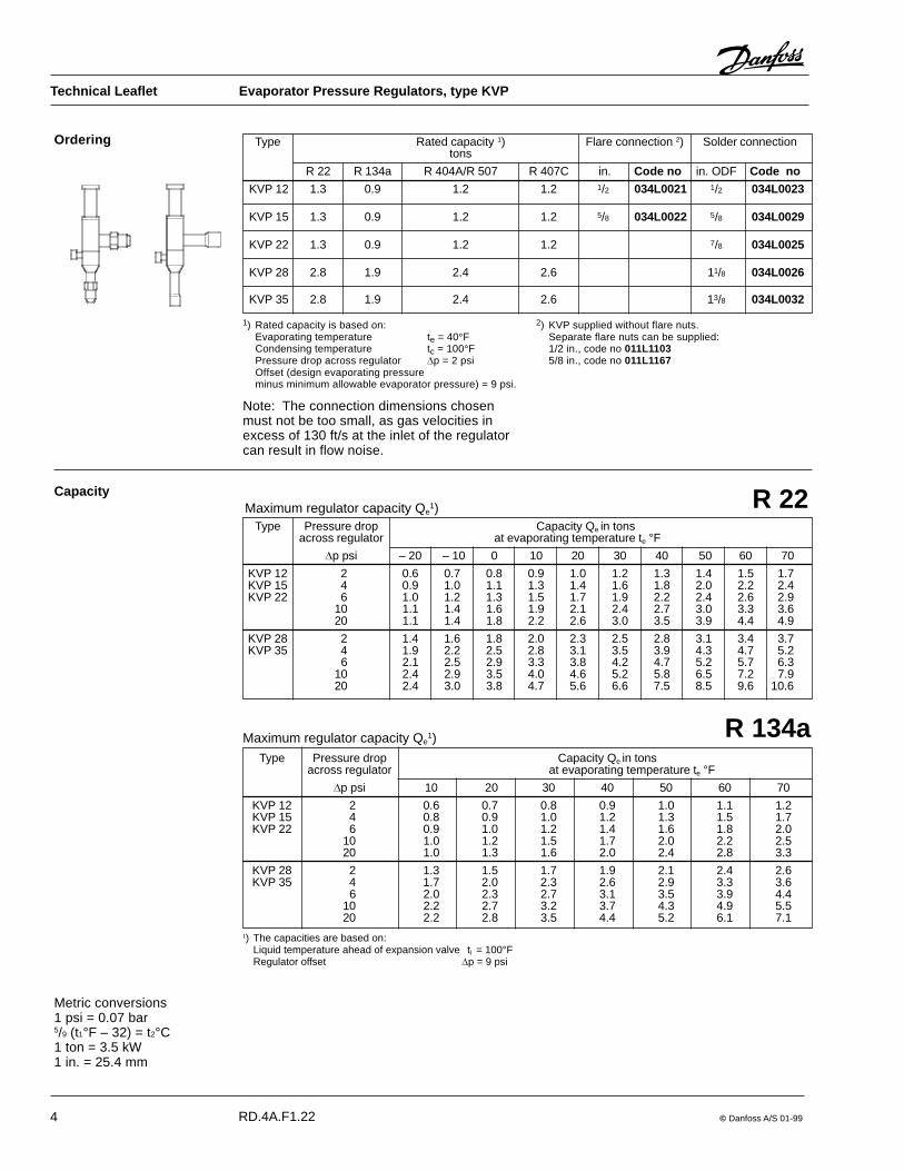
Introduction PKV is a servo-operated, evaporator pressureregulator that operates with minimum pressuredrop in the suction line.When designing refrigeration systems, it isimportant to minimize the pressure drop in thesuction line, because increased pressure dropreduces compressor capacity, resulting inlonger running times and higher energy costs.
Technical data RefrigerantsCFC, HCFC, HFC
Regulating range0 to 86 psig
Maximum working pressureMWP = 305 psig
Maximum test pressurep' = 405 psig
Features � Accurate, adjustable pressure regulation
� Wide capacity and operating ranges
� Control by high side pressure results inminimal suction line pressure drop
� Two versions, PKV and PKVS; PKVS isfitted with an EVR 3 NC pilot solenoidvalve
� 1/4 in. Schrader valve for pressure testing
� Installs in either horizontal or verticalposition
� For use with CFC, HCFC and HFCrefrigerants
Approvals ��UL listed, file SA7200 ��CSA certified, LR 92682
Contents Introduction ---------------------------------------------------------------------------------------------------- Page 9Features -------------------------------------------------------------------------------------------------------- Page 9Approvals ------------------------------------------------------------------------------------------------------- Page 9Technical data ------------------------------------------------------------------------------------------------- Page 9Ordering -------------------------------------------------------------------------------------------------------Page 10Capacity ----------------------------------------------------------------------------------------------- Pages 10 - 12Sizing -----------------------------------------------------------------------------------------------------------Page 12Valve selection ---------------------------------------------------------------------------------------- Pages 12 -13Design and function --------------------------------------------------------------------------------- Pages 13 - 14Application ----------------------------------------------------------------------------------------------------Page 14Dimensions and weights -----------------------------------------------------------------------------------Page 15
Metric conversions1 psi = 0.07 bar5/9 (t1°F – 32) = t2°C
PKV has been specifically developed for lowtemperature systems where pressure drop hasthe greatest effect.PKVS is fitted with an EVR 3 solenoid valvefor use in systems with hot gas defrost andwhere positive shut-off is required.
Maximum media temperaturePKV: 220�FPKVS: 190�F
Minimum media temperaturePKV/PKVS: � 40�F
Minimum opening differential pressure0 psi
Differential pressure between pilot pressureand suction pressure50 to 305 psi

10 © Danfoss A/S 01-99
Ordering
1) Rated capacity is based on:Evaporating temperature te = 40�FLiquid temperature tl = 100�FPressure drop across valve �p = 2 psi
2) With 115 V coil
Note: Type PKVS is supplied with an EVR 3 NC solenoid valve (032F1155) fitted in the vent line.EVR 3 is supplied without coil and must be ordered seperately.
Capacity
Type Rated capacity 1) Connection Code no.tons solder
ODF
R 22 R 134a R 404A/R507 R407C in.
PKV 12 5.2 3.8 4.4 4.8 11/8 034N1051
PKV 15 8.3 6.1 7.0 7.7 13/8 034N1052
PKV 20 13.5 10.1 11.4 12.6 15/8 034N1053
PKVS 12 5.2 3.8 4.4 4.8 11/8 034N1080 2)
PKVS 15 8.3 6.1 7.0 7.7 13/8 034N1081 2)
PKVS 20 13.5 10.1 11.4 12.6 15/8 034N1082 2)
Maximum regulator capacity Qe1)
Type Pressure drop Capacity Qe in tonsacross regulator at evaporating temperature te °F
�p psi – 20 – 15 – 10 0 5 10 15 20 30 40
PKV 12 0.5 1.3 1.4 1.5 1.7 1.8 1.9 2.0 2.1 2.3 2.6PKVS 12 1 1.9 2.0 2.1 2.4 2.5 2.6 2.9 3.0 3.3 3.6
2 2.6 2.8 3.0 3.3 3.5 3.7 4.0 4.2 4.7 5.25 3.9 4.2 4.5 5.2 5.5 5.8 6.2 6.5 7.3 8.010 5.0 5.4 5.8 6.8 7.4 7.8 8.4 8.9 10.0 11.1
PKV 15 0.5 2.1 2.3 2.4 2.8 2.9 3.1 3.2 3.4 3.7 4.2PKVS 15 1 3.0 3.2 3.4 3.9 4.1 4.3 4.5 4.7 5.3 5.8
2 4.2 4.4 4.7 5.4 5.6 6.1 6.4 6.7 7.5 8.35 6.3 6.7 7.2 8.1 8.7 9.2 9.8 10.3 11.6 12.910 8.0 8.7 9.5 10.9 11.7 12.5 13.3 14.2 16.0 17.7
PKV 20 0.5 3.5 3.7 4.0 4.4 4.7 5.0 5.3 5.5 6.2 6.8PKVS 20 1 4.8 5.2 5.5 6.3 6.6 7.0 7.4 7.8 8.7 9.3
2 6.8 7.3 7.7 8.7 9.2 9.8 10.3 11.0 12.2 13.55 10.1 10.9 11.8 13.4 14.3 15.2 16.1 16.9 18.9 21.010 13.0 14.2 15.4 17.8 19.1 20.5 21.8 23.2 26.1 29.0
R 22
tl °F 50 60 70 80 90 100 110 120
R 22 0.82 0.85 0.88 0.92 0.96 1.0 1.05 1.10
Correction factors for liquid temperature tl
1) The capacities are based on:Liquid temperature ahead of expansion valvetl = 100°F
Metric conversions1 psi = 0.07 bar5/9 (t1°F – 32) = t2°C1 ton = 3.5 kW1 in. = 25.4 mm
Technical leaflet Evaporator Pressure Regulators, type PKV/PKVS
RD.4A.F1.22
© Danfoss A/S 01-99 11
Technical leaflet Evaporator Pressure Regulators, type PKV/PKVS
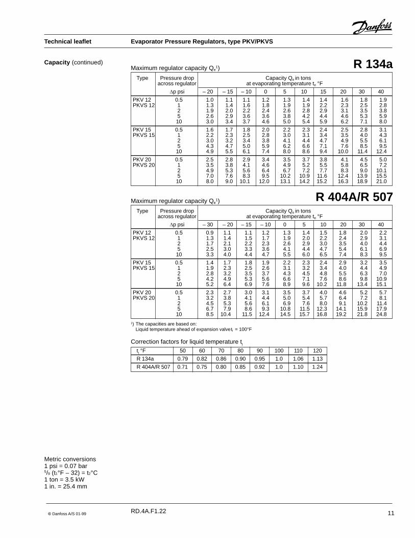
Capacity (continued)Maximum regulator capacity Qe
1)
Type Pressure drop Capacity Qe in tonsacross regulator at evaporating temperature te °F
�p psi – 20 – 15 – 10 0 5 10 15 20 30 40
PKV 12 0.5 1.0 1.1 1.1 1.2 1.3 1.4 1.4 1.6 1.8 1.9PKVS 12 1 1.3 1.4 1.6 1.8 1.9 1.9 2.2 2.3 2.5 2.8
2 1.9 2.0 2.2 2.4 2.6 2.8 2.9 3.1 3.5 3.85 2.6 2.9 3.6 3.6 3.8 4.2 4.4 4.6 5.3 5.910 3.0 3.4 3.7 4.6 5.0 5.4 5.9 6.2 7.1 8.0
PKV 15 0.5 1.6 1.7 1.8 2.0 2.2 2.3 2.4 2.5 2.8 3.1PKVS 15 1 2.2 2.3 2.5 2.8 3.0 3.1 3.4 3.5 4.0 4.3
2 3.0 3.2 3.4 3.8 4.1 4.4 4.7 4.9 5.5 6.15 4.3 4.7 5.0 5.9 6.2 6.6 7.1 7.6 8.5 9.510 4.9 5.5 6.1 7.4 8.0 8.6 9.4 10.0 11.4 12.4
PKV 20 0.5 2.5 2.8 2.9 3.4 3.5 3.7 3.8 4.1 4.5 5.0PKVS 20 1 3.5 3.8 4.1 4.6 4.9 5.2 5.5 5.8 6.5 7.2
2 4.9 5.3 5.6 6.4 6.7 7.2 7.7 8.3 9.0 10.15 7.0 7.6 8.3 9.5 10.2 10.9 11.6 12.4 13.9 15.510 8.0 9.0 10.1 12.0 13.1 14.2 15.2 16.3 18.9 21.0
R 134a
tl °F 50 60 70 80 90 100 110 120
R 134a 0.79 0.82 0.86 0.90 0.95 1.0 1.06 1.13
R 404A/R 507 0.71 0.75 0.80 0.85 0.92 1.0 1.10 1.24
Correction factors for liquid temperature tl
1) The capacities are based on:Liquid temperature ahead of expansion valvetl = 100°F
Maximum regulator capacity Qe1)
Type Pressure drop Capacity Qe in tonsacross regulator at evaporating temperature te °F
�p psi – 30 – 20 – 15 – 10 0 5 10 20 30 40
PKV 12 0.5 0.9 1.1 1.1 1.2 1.3 1.4 1.5 1.8 2.0 2.2PKVS 12 1 1.3 1.4 1.5 1.7 1.9 2.0 2.2 2.4 2.9 3.1
2 1.7 2.1 2.2 2.3 2.6 2.9 3.0 3.5 4.0 4.45 2.5 3.0 3.3 3.6 4.1 4.4 4.7 5.4 6.1 6.910 3.3 4.0 4.4 4.7 5.5 6.0 6.5 7.4 8.3 9.5
PKV 15 0.5 1.4 1.7 1.8 1.9 2.2 2.3 2.4 2.9 3.2 3.5PKVS 15 1 1.9 2.3 2.5 2.6 3.1 3.2 3.4 4.0 4.4 4.9
2 2.8 3.2 3.5 3.7 4.3 4.5 4.8 5.5 6.3 7.05 4.2 4.9 5.3 5.6 6.6 7.1 7.6 8.6 9.8 10.910 5.2 6.4 6.9 7.6 8.9 9.6 10.2 11.8 13.4 15.1
PKV 20 0.5 2.3 2.7 3.0 3.1 3.5 3.7 4.0 4.6 5.2 5.7PKVS 20 1 3.2 3.8 4.1 4.4 5.0 5.4 5.7 6.4 7.2 8.1
2 4.5 5.3 5.6 6.1 6.9 7.6 8.0 9.1 10.2 11.45 6.7 7.9 8.6 9.3 10.8 11.5 12.3 14.1 15.9 17.910 8.5 10.4 11.5 12.4 14.5 15.7 16.8 19.2 21.8 24.8
R 404A/R 507
Metric conversions1 psi = 0.07 bar5/9 (t1°F – 32) = t2°C1 ton = 3.5 kW1 in. = 25.4 mm
RD.4A.F1.22

12 © Danfoss A/S 01-99
Technical leaflet Evaporator Pressure Regulators, type PKV/PKVS
Capacity (continued)Maximum regulator capacity Qe
1)
Type Pressure drop Capacity Qe in tonsacross regulator at evaporating temperature te °F
�p psi – 20 – 15 – 10 0 5 10 15 20 30 40
PKV 12 0.5 1.1 1.2 1.3 1.5 1.6 1.7 1.8 1.9 2.1 2.4PKVS 12 1 1.6 1.7 1.8 2.1 2.2 2.3 2.6 2.7 3.0 3.3
2 2.2 2.4 2.6 2.8 3.0 3.3 3.6 3.7 4.3 4.85 3.2 3.5 3.8 4.5 4.8 5.1 5.5 5.8 6.6 7.410 4.2 4.5 4.9 5.8 6.4 6.9 7.5 7.9 9.1 10.3
PKV 15 0.5 1.7 1.9 2.0 2.4 2.5 2.7 2.8 3.0 3.4 3.9PKVS 15 1 2.5 2.7 2.9 3.4 3.6 3.8 4.0 4.2 4.8 5.4
2 3.5 3.7 4.0 4.6 4.9 5.4 5.7 6.0 6.8 7.75 5.2 5.6 6.1 7.0 7.6 8.1 8.6 9.2 10.6 12.010 6.6 7.3 8.1 9.4 10.2 11.0 11.8 12.6 14.6 16.5
PKV 20 0.5 2.9 3.1 3.4 3.8 4.1 4.4 4.7 4.9 5.6 6.3PKVS 20 1 4.0 4.4 4.7 5.4 5.7 6.2 6.6 6.9 7.9 8.6
2 5.6 6.1 6.5 7.5 8.0 8.6 9.2 9.8 11.1 12.65 8.4 9.2 10.0 11.5 12.4 13.4 14.3 15.0 17.2 19.510 10.8 11.9 13.1 15.3 16.6 18.0 19.4 20.6 23.8 27.0
R 407C
tl °F 50 60 70 80 90 100 110 120
R 407C 0.78 0.81 0.85 0.89 0.94 1.0 1.07 1.15
Correction factors for liquid temperature tl
1) The capacities are based on:Liquid temperature ahead of expansion valvetl = 100°F
Metric conversions1 psi = 0.07 bar5/9 (t1°F – 32) = t2°C1 ton = 3.5 kW1 in. = 25.4 mm
For optimum performance, it is important toselect a PKV/PKVS valve according to systemconditions and application.The selection is also dependant on theacceptable pressure drop across the valve.The following data must be used when sizing aPKV/PKVS valve:
SizingExample
� Refrigerant - CFC, HCFC or HFC� Evaporator capacity Qe in tons� Evaporating temperature (required
temperature) te in °F� Liquid temperature ahead of expansion
valve tl in °F� Connection type flare or solder� Connection size in inches
Valve selectionExample
When selecting the appropiate valve it may benecessary to convert the actual evaporatorcapacity using a correction factor. This isrequired when your system conditions aredifferent than the table conditions.The following example illustrates how this isdone.
Refrigerant: R134aEvaporator capacity: Qe = 7.4 tonsEvaporating temperature: te = 40°F ~ 36 psigLiquid temperature ahead of expansion valvetl = 80°FConnection size:15/8 in.
Step 1 Determine the correction factor for liquidtemperature tl ahead of the expansion valve.
Correction factors for liquid temperature tl
tl °F 50 60 70 80 90 100 110 120
R 22 0.82 0.85 0.88 0.92 0.96 1.0 1.05 1.10
R 134a 0.79 0.82 0.86 0.90 0.95 1.0 1.06 1.13
R 404A/R 507 0.71 0.75 0.80 0.85 0.92 1.0 1.10 1.24
R 407C 0.78 0.81 0.85 0.89 0.94 1.0 1.07 1.15
From the correction factors table (see below) aliquid temperature of 80°F, R134a correspondsto a factor of 0.90.
RD.4A.F1.22

© Danfoss A/S 01-99 13
Technical leaflet Evaporator Pressure Regulators, type PKV/PKVS
Sizing (continued)Step 2
Function
Fig. 1 PKV
Vent line
PKV is a normally-open servo-operatedpressure regulator designed to maintain aconstant evaporating pressure.PKV uses pressure pc from the high pressureside of the system to close the valve andspring pressure p3 to open the valve (whenpressure is relieved through the vent line).Therefore, pressure drop is not necessary tomaintain the valve`s open position.
The evaporating pressure is set by adjustingspring pressure p1 which then balancesevaporating pressure pe.
For type PKVS, which is fitted with a solenoidvalve in the vent line, the valve functions asdescribed above, except when positive shut.offis required, as for a hot gas defrost. When adefrost is called for, the pilot solenoid is de-energized, closing the high side vent line. Highside pressure builds rapidly in the chamberabove the piston and closes the valveimmediately.A falling evaporating pressure will result in pebecoming lower than the set pressure p1.The set spring will begin to close the pilot portwhere high pressure pc will begin to build overthe valve piston, becoming greater than p3,and thus begin closing the valve.
Step 4
Metric conversions1 psi = 0.07 bar5/9 (t1°F – 32) = t2°C1 ton = 3.5 kW1 in. = 25.4 mm
Step 3
Corrected evaporator capacity isQe = 7.4 x 0.90 = 6.66 tons
Select the approprate capacity table andchoose the column for evaporatingtemperature te = 40°F.Note that the regulator capacity must beequal to or slightly more than the correctedevaporator capacity.
In this example PKV 20 or PKVS 20 will besuitable since the capacity (7.2 tons at apressure drop across the regulator of 1 psi)and the connection size fullfill the conditions.
PKV 20, code no 034N1053PKVS 20, code no 034N1082 ( see Orderingon page10).
RC.4A.F1.22

14 © Danfoss A/S 01-99
Technical leaflet Evaporator Pressure Regulators, type PKV/PKVS
Application
Bleed flowWhen the valve is completely open, there isflow through bleed orifice( A).The table gives resulting capacity reduction inpercent. Table values are given for a pressuredrop of 1 psi across the valve.If the pressure drop across the valve is greaterthan 1 psi, the percentage capacity reductionbecomes smaller.
Percentage reduction of full capacity
Function (continued)
PKV is fitted in the suction line of a systemcontaining several evaporators and a commonsuction manifold. PKV maintains a setevaporating pressure for the circuit.
PKVS, which is fitted with a solenoid valve, isused for positive shut-off and hot gas defrost.
Fig. 2 shows a typical hot gas piping layoutand the location of a PKVS.
Pilot pressure for the PKVS valves comes fromthe high pressure side. When defrost isrequired, the pilot valve must be closed,resulting in a pressure build up over the pistonimmediately closing the valve.
Fig. 2 Application with PKVS
The EVR hot gas solenoid valve is thenopened to allow hot gas to flow into theevaporator.At the end of the defrost cycle, the hot gassolenoid is closed and the pilot valve on thePKVS must be opened to allow normalevaporator regulation.
Metric conversions1 psi = 0.07 bar
RC.4A.F1.22
As can be seen from the table, the capacityreduction is insignificant. When the valve isclosed, bleed flow is zero.When PKV regulates the evaporatingpressure, i.e. when the valve is partly open,bleed flow will be at a point between zero andthe values stated in the table.
Refrigerant Valve type
PKV 12 PKV 15 PKV 20
R 22 0.5 0.3 0.2
R134a 0.4 0.3 0.2
R 404A/R 507 0.5 0.3 0.2
R 407C 0.5 0.3 0.2

© Danfoss A/S 01-99 15
Technical leaflet Evaporator Pressure Regulators, type PKV/PKVS
Dimensions and weights
Type A B C D Weight 1)in. in. in. in. lbs
PKV 12 (PKVS 12) 7.165 8.465 0.827 4.252 5.1
PKV 15 (PKVS 15) 7.480 11.220 1.260 4.252 7.7
PKV 20 (PKVS 20) 7.992 11.220 1.102 4.252 8.6
1) Without solenoid valve
Metric conversions1 in. = 25.4 mm1 lb = 0.454 kg
RD.4A.F1.22

16 © Danfoss A/S 01-99

© Danfoss A/S 01-99 17
Technical leaflet Electronic Evaporating Pressure Regulators, type KVQ + EKS 67
RD.4J.C1.22
Introduction Actuator and valve KVQ + controller EKS 67 +sensor AKS combine to form an electronicsystem that, by controlling evaporatingpressure regulates the temperature of themedium in systems where precise temperatureregulation is required.
Features Apart from its normal regulating function, theKVQ and EKS 67 electronic system contains adefrost function and an alarm function. It alsohas facilities for a series of supplementaryfunctions:� Remote setting of reference temperature
� Temperature readout on external display
� Temperature diagnosis
� Evaporating pressure limiter
The KVQ + EKS 67 regulates the temperatureof the medium so that the requiredtemperature is maintained to an accuracy of� 1�F or less.
KVQ + EKS 67 is especially suited for use indisplay cases which require a high humidityand exact temperature control.
Defrost, external alarm, and supplementaryfunctions require the connection of extraequipment.
Approvals ��UL listed, file SA7200 ��CSA certified, LR 92682
Contents Introduction ---------------------------------------------------------------------------------------------------Page 17Features -------------------------------------------------------------------------------------------------------Page 17Approvals ------------------------------------------------------------------------------------------------------Page 17Technical data ----------------------------------------------------------------------------------------- Pages 18, 19Sizing -----------------------------------------------------------------------------------------------------------Page 19Ordering -------------------------------------------------------------------------------------------------------Page 20Capacity ------------------------------------------------------------------------------------------------ Pages 21, 22Selection -------------------------------------------------------------------------------------------------------------- 22Design ----------------------------------------------------------------------------------------------------------Page 23Function --------------------------------------------------------------------------------------------------------------- 24Dimensions and weights ---------------------------------------------------------------------------- Pages 25, 26

18 © Danfoss A/S 01-99
Technical leaflet Electronic Evaporating Pressure Regulators, type KVQ + EKS 67
RD.4J.C1.22
Technical dataActuator and valve, KVQ
Regulating range pe = 0 to 100 psig
Refrigerent temperature in regulating range Refrigerant pe = 0 psig pe = 100 psig
R 22 � 42�F 59�F
R 134a � 15�F 87�F
R 404A � 50�F 48�F
R 407C � 32�F 63�F
R 507 � 52�F 46�F
Refrigerants HFC, HCFC and CFCOther fluorinated refrigerants can be used at the statedtemperatures and pressures
Maximum ambient temperature During operation: � 50 to 105�FDuring transport: � 60 to 150�F
Maximum working pressure MWP 310 psig
Maximum test pressure p' 400 psig
Supply voltage 24 V pulsating a.c. from EKS 67 controller
Consumption 30 VA / 24 V a.c.
Enclosure NEMA; IP 54 to IEC 529
Cable entry Pg 13.5
During forced closing by hot-gas defrosting:
Maximum closing pressure 250 psig
Maximum hot gas temperature 250�F
Regulating range – 30 to 77°F REFThe unit regulates with an accuracy � � 1�F
Functions 1. LIMIT (alarm limit):2 to 9�F � 1�F on both sides of REF
2. DELAY (alarm delay):15 to120 min.
3. DEFROST (defrost stop):0� to 45�F
Regulating principle PI, proportional, integral.
Regulation parameters Proportional amplification: Kp = 2 to 6Factory setting: Kp = 4Integral time: Tn = 2 to 6 min.Factory setting: Tn = 4 min.
Ambient temperature – 4�F to 104�F (for plastic case)– 4��F to 113�F (for silumin case)– 4��F to 122�F (for panel mounting)
Ambient temperature at transport – 40�F to 140�FSupply voltage 24 V a.c. +10% to �15%, 50/60 Hz
Consumption 2 VA at 24 V a.c.
Alarm Alarm is indicated by ON/ALARM lamp being outAlarm output voltage falls to 0 V a.c.
Cable entry Pg 9 (plastic case)Pg 13,5 (silumin case)
Enclosure NEMA 2; IP 41 to IEC 529 (plastic case)NEMA 3; IP 54 to IEC 529 (silumin case)
Alarm output Triac, 24 V a.c., maximum load 0.5 A
Defrost output Triac, 24 V a.c., maximum load 0.5 A
Controller EKS 67

© Danfoss A/S 01-99 19
Technical leaflet Electronic Evaporating Pressure Regulators, type KVQ + EKS 67
RD.4J.C1.22
Sensor type Pt 1000 ohmApplication range and enclosure
Sensor type Application range Enclosure Code no.
Pt 1000 ohm surface sensor, type AKS 21A – 95 to 320�F NEMA 4; IP 67 084N2007with 8 ft cable to IEC 529
Pt 1000 ohm media sensor, type AKS 21M – 95 to 320�F NEMA 4; IP 67 084N2003with 8 ft cable to IEC 529
Pt 1000 ohm immersion sensor, type AKS 21W – 95 to 320�F NEMA 3; IP 56 084N2016with terminal box to IEC 529
Pt 1000 ohm immersion sensor, type AKS 21W – 95 to 320�F NEMA 3; IP 56 084N2017with pocket and 8 ft cable to IEC 529
Time constants
Sensor type Time constant Object of measurementmaximum sec.
AKS 21A 14 Fixed on copper tube
AKS 21W 18 Water flow
AKS 21M 35 Air at velocity of 4 m / sec.
AKS 21M 6 Water flow
Cable cross section 0.2 mm2
Technical dataand code nos.
Ordering Valve / actuator type KVQ
1) Rated capacity is based on:evaporating temperature te = 40�Fcondensing temperature tc = 100�Fpressure drop across valve �p = 3 psi
Type Rated capacity 1) Valve Actuator
tonsConnection Code no. Code no.
R 22 R 134a R 404A/R 507 R 407C in.
KVQ 15 3.0 2.3 2.7 2.9 5/8 034L0117 034L0105
KVQ 22 3.0 2.3 2.7 2.9 7/8 034L0114 034L0105
KVQ 28 7.2 5.5 6.4 6.8 11/8 034L0115 034L0106
KVQ 35 7.2 5.5 6.4 6.8 13/8 034L0120 034L0106

20 © Danfoss A/S 01-99
Technical leaflet Electronic Evaporating Pressure Regulators, type KVQ + EKS 67
RD.4J.C1.22
Symbol EKS 67 complete controller Code no.
Controller type EKS 67
Components for controller type EKS 67
Symbol EKS 67 components Code no.
Controller insert 084B1021
Multipurpose case (silium case) 084B1035incl. base with triac module and mounting bracket
Sensor type AKS, Pt 1000 ohmTechnical data, code nos., dimension andweights, see section "Sensors, type AKS" inthis catalogue.
Complete controllerincl. base with triac module and 084B1020mounting brackets
```````` 084B3161
Ordering (continued)
CapacityMaximum regulator capacity Qe
1)
Type
PressureCapacity Qe in tonsdrop
at evaporating temperature te °Facrossregulator
�p psi – 30 – 20 – 10 0 10 20 30 40 50 60 70
KVQ 15 1 0,8 0,9 1,0 1,2 1,3 1,5 1,6 1,8 2,0 2,2 2,4KVQ 22 3 1,3 1,5 1,7 2,0 2,2 2,5 2,8 3,0 3,4 3,7 4,0
5 1,5 1,8 2,1 2,4 2,8 3,1 3,5 3,9 4,3 4,7 5,27 1,6 2,0 2,4 2,8 3,2 3,6 4,0 4,5 5,0 5,5 6,0
10 1,7 2,1 2,6 3,1 3,6 4,1 4,7 5,2 5,8 6,5 7,1KVQ 28 1 1,9 2,2 2,4 2,8 3,1 3,4 3,8 4,2 4,6 5,1 5,6KVQ 35 3 3,0 3,5 4,0 4,6 5,2 5,8 6,5 7,2 7,9 8,7 9,5
5 3,6 4,3 5,0 5,7 6,5 7,3 8,2 9,1 10,1 11,1 12,27 3,9 4,7 5,6 6,5 7,5 8,5 9,5 10,6 11,8 13,0 14,3
10 3,9 5,0 6,1 7,3 8,5 9,7 11,0 12,3 13,7 15,2 16,8
R 22

© Danfoss A/S 01-99 21
Technical leaflet Electronic Evaporating Pressure Regulators, type KVQ + EKS 67
RD.4J.C1.22
Maximum regulator capacity Qe1)
Type Pressure Capacity Qe in tonsdrop at evaporating temperature te °F
acrossregulator
�p psi – 30 – 20 – 10 0 10 20 30 40 50 60 70
KVQ 15 1 1,0 1,1 1,2 1,4 1,5 1,7 1,9KVQ 22 3 1,6 1,8 2,0 2,3 2,6 2,9 3,3
5 1,9 2,2 2,5 2,9 3,3 3,7 4,17 2,1 2,5 2,9 3,3 3,8 4,3 4,8
10 2,2 2,7 3,2 3,8 4,3 4,9 5,6KVQ 28 1 2,2 2,6 2,9 3,2 3,6 4,1 4,5KVQ 35 3 3,7 4,2 4,8 5,5 6,1 6,9 7,7
5 4,4 5,2 6,0 6,8 7,7 8,7 9,77 4,9 5,8 6,8 7,8 8,9 10,1 11,3
10 5,2 6,4 7,6 8,9 10,2 11,6 13,1
R 134a
Maximum regulator capacity Qe1)
Type Pressure Capacity Qe in tonsdrop at evaporating temperature te °F
acrossregulator
�p psi – 30 – 20 – 10 0 10 20 30 40 50 60 70
KVQ 15 1 0,6 0,7 0,9 1,0 1,1 1,3 1,4 1,6 1,8 2,0 2,2KVQ 22 3 1,0 1,2 1,4 1,6 1,9 2,1 2,4 2,7 3,0 3,4 3,7
5 1,3 1,5 1,8 2,1 2,4 2,7 3,1 3,4 3,8 4,3 4,87 1,4 1,7 2,0 2,4 2,7 3,1 3,5 4,0 4,5 5,0 5,6
10 1,5 1,8 2,2 2,7 3,1 3,6 4,1 4,7 5,3 5,9 6,6KVQ 28 1 1,5 1,7 2,0 2,3 2,6 3,0 3,3 3,7 4,1 4,6 5,1KVQ 35 3 2,5 2,9 3,4 3,9 4,4 5,0 5,7 6,4 7,1 7,9 8,8
5 3,0 3,5 4,2 4,8 5,6 6,3 7,2 8,1 9,1 10,1 11,27 3,3 4,0 4,7 5,5 6,4 7,3 8,3 9,4 10,6 11,8 13,1
10 3,4 4,3 5,3 6,3 7,3 8,5 9,7 11,0 12,4 13,9 15,5
R 404A/R 507
Capacity (continued)
Maximum regulator capacity Qe1)
Type Pressure Capacity Qe in tonsdrop at evaporating temperature te °F
acrossregulator
�p psi – 30 – 20 – 10 0 10 20 30 40 50 60 70
KVQ 15 1 0,7 0,8 0,9 1,1 1,2 1,4 1,5 1,7 1,9 2,1 2,3KVQ 22 3 1,1 1,3 1,5 1,7 2,0 2,3 2,6 2,9 3,2 3,6 4,0
5 1,2 1,5 1,8 2,1 2,5 2,9 3,2 3,7 4,1 4,6 5,17 1,3 1,6 2,0 2,4 2,8 3,3 3,7 4,2 4,8 5,3 5,9
10 1,3 1,7 2,2 2,7 3,2 3,7 4,3 4,9 5,6 6,2 7,0KVQ 28 1 1,6 1,9 2,2 2,5 2,8 3,2 3,6 4,0 4,5 5,0 5,5KVQ 35 3 2,5 3,0 3,5 4,1 4,7 5,4 6,1 6,8 7,6 8,5 9,4
5 2,9 3,6 4,3 5,1 5,9 6,7 7,6 8,6 9,7 10,8 12,07 3,0 3,9 4,8 5,7 6,7 7,7 8,8 10,0 11,2 12,6 14,0
10 3,0 4,0 5,1 6,3 7,5 8,8 10,1 11,6 13,1 14,7 16,4
R 407C
SizingKVQ valve
For optimum performance, it is important toselect a KVQ valve according to systemconditions and application.The selection is also dependant on theacceptable pressure drop across the valve.The following data must be used when sizing aKVQ valve:
� Refrigerant - CFC, HCFC or HFC� Evaporator capacity Qe in tons� Evaporating temperature (required
temperature) te in °F� Minimum evaporating temperature te in °F� Liquid temperature ahead of expansion valve
tl in °F� Connection type flare or solder� Connection size in inches

22 © Danfoss A/S 01-99
Technical leaflet Electronic Evaporating Pressure Regulators, type KVQ + EKS 67
RD.4J.C1.22
When selecting the appropriate valve, it maybe necessary to convert the actual evaporatorcapacity using a correction factors.This is required when your system conditionsare different than the table conditions.The following example illustrates how this isdone.
Valve selectionExample
Refrigerant: R 22Evaporator capacity Qe = 7.6 tonsEvaporating temperature te = 30°FLiquid temperature ahead of expansion valvetl = 110°FConnection size: 1 1/8 in.
Step 1 From the correction factor table (see below), aliquid temperature of 110 °F, R 22 correspondsto a factor of 1.05.
Determine the corrections factor for the liquidtemperature tl ahead of the expansion valve.
Corrected evaporator capacity is1.05 x 7.6 = 8.0 tons.
Correction factors for liquid temperature tl
tl °F 50 60 70 80 90 100 110 120
R 22 0.82 0.85 0.88 0.92 0.96 1.0 1.05 1.10
R 134a 0.79 0.82 0.86 0.90 0.95 1.0 1.06 1.13
R 404A/R 507 0.71 0.75 0.80 0.85 0.92 1.0 1.10 1.24
R 407C 0.78 0.81 0.85 0.89 0.94 1.0 1.07 1.15
Step 2
Now select the appropriate capacity table andchoose the column for an evaporatingtemperature of te = 30°F.
Using the corrected evaporator capacity, selecta valve that provides an equivalent or greatercapacity at an acceptable pressure drop.
Step 3
KVQ 28, 1 1/8 in. solder connection,code no 034L0115 and actuator,code no 034L0106 (see Ordering on page20).
KVQ 28/35 delivers 8,2 tons at a 5 psi pres-sure drop across the valve.
Based on the required connection size of1 1/8 in., the KVQ 28 is the proper selection forthis example.
Step 4
Selection of transformer ExampleThe choice of transformer depends on thetotal power consumption.
KVQ + DEFROST ALARM TotalEKS 67 consumption
VA
32 VA/ 3224 V a.c.
32 VA/ 24 VA/ 5624 V a.c. 24 V a.c.
32 VA/ 24 VA/ 12 VA/ 6824 V a.c. 24 V a.c. 24 V a.c.
Total power consumption = sum of theindividual power consumptions.A class II transformer should be usedaccording to CEE 15.
Psc. Connections ConsumptionVA
2 KVQ + EKS 67 à 32 VA/24 V a.c. 64
2 ALARM à 12 VA/24 V a.c. 24
1 DEFROST à 24 VA/24 V a.c. 24
Total consumption 112
In this example the choice is a transformersized to suit the power consumption:115 VA / 24 V a.c., 50/60 Hz or greater

© Danfoss A/S 01-99 23
Technical leaflet Electronic Evaporating Pressure Regulators, type KVQ + EKS 67
RD.4J.C1.22
Design1.Cover2.Connection terminals3.NTC resistor4.Heating element5.Pressure reservoir6.Bellows7.Bellows capsule8.Pressure pin9.Gasket
10.Threaded connection11.Guide pin12.Valve plate13.Orifice14.Damping device15.Inlet16.Outlet
KVQ

24 © Danfoss A/S 01-99
Technical leaflet Electronic Evaporating Pressure Regulators, type KVQ + EKS 67
RD.4J.C1.22
Function
Regulation of KVQ with electronic controller EKS 67The form of regulation is pulse cascades of a.c. supplyvoltage
On deviations between the required andregistered temperature the EKS 67instantaneously sends more or fewer pulsesto the actuator to counteract the error. Thepressure in the actuator changes slightly sothat the valve moves in the opening or closingdirection.Changes in the suction pressure have noinfluence because the bellows area is thesame as the orifice area.
In the event of current failure, the valve will befully open.
EKS 67 defrost functionThe EKS 67 controller has two defrost modes,hot-gas defrost and electric defrost, selectableby a switch. The system has built in defroststop by temperature and time delay. Thedefrost must be started from an external timer(clock).During defrosting, the temperature rises abovethe set alarm LIMIT. This cuts in the controllerDELAY function, i.e. the timer that delaysalarm release.If the temperature setting for defrost functioncut-off is reached before the delay time haselapsed, the controller cuts off defrosting. Atthe same time DELAY is set at zero.If the selected ALARM delay is exceededduring a defrost period, defrosting is stoppedby the ALARM delay and the alarm is activated(lamp goes out) until the temperature of themedium is again within the alarm limit.
Hot-gas defrostingDefrosting with hot-gas is initiated by anexternal defrost timer and KVQ is forcedclosed by the EKS 67.As soon as EKS 67 registers that KVQ isclosed, the lamp "DEFROST" lights up andvoltage is applied to the triac output.The solenoid valve opens so that hot gas isable to flow into the evaporator. A defrostsensor, S2, is placed at the point on theevaporator where ice disappears last. Whenthe temperature at sensor S2 reaches thetemperature set on the EKS 67, defrosting isstopped. The solenoid valve closes and thelamp "DEFROST" goes out. After defrost, theKVQ valve opens slowly to avoid liquidhammer.
Electric defrostingElectric defrosting is also started by a signalfrom an external defrost timer.The lamp "DEFROST" lights up and voltage isapplied to the triac output.The solenoid valve ahead of the thermostaticexpansion valve closes.The heating element is cut in without the KVQvalve being previously closed.When the temperature on the evaporator rises,the KVQ valve will be fully open.Electric defrosting is cut off when defrostsensor S2 measures a temperaturecorresponding to the stop temperature set onthe EKS 67. The solenoid valve ahead of thethermostatic expansion valve opens.There are facilities for forced defrosting of thesystem.

© Danfoss A/S 01-99 25
Technical leaflet Electronic Evaporating Pressure Regulators, type KVQ + EKS 67
RD.4J.C1.22
Dimensions and weights Valve/Actuator type KVQ
KVQ actuator
KVQ valve
Complete KVQ
KVQ actuator
Type H1 B C NV D dia.�1 dia.�2 Weightin. in. in. in. in. in. in. lbs
KVQ 15 - 22 6.398 2.126 1.063 1.260 M16 � 1.5 2.480 2.362 1.1
KVQ 28 - 35 6.398 2.126 1.063 1.260 M18 � 1.5 2.480 2.362 1.1
KVQ valve
Type Connection H2 H3 B1 C D D1 NV Weightin. in. in. in. in. in. in. in. lbs
KVQ 15 5/8 3.898 5.984 2.520 0.472 1.181 1.102 0.945 0.9
KVQ 22 7/8 3.898 5.984 2.520 0.472 1.181 1.102 0.945 0.9
KVQ 28 11/8 6.102 8.465 4.134 0.866 1.693 1.378 1.181 1.8
KVQ 35 13/8 6.102 8.465 4.134 0.985 1.693 1.378 1.181 1.8
Complete KVQType H4 H5 Weight
in. in. lbs
KVQ 15-22 11.929 8.031 2.0
KVQ 28-35 14.409 8.307 2.9

26 © Danfoss A/S 01-99
Technical leaflet Electronic Evaporating Pressure Regulators, type KVQ + EKS 67
RD.4J.C1.22
Dimensions and weights(continued)
Controller type EKS 67
WeightController without base: 0.39 lbs
Base: 0.28 lbs

© Danfoss A/S 01-99 27
Tecnical Leaflet Condenser Pressure Regulators, type KVR/NRD
RD.4B.C1.22
Introduction KVR condenser regulators can be mounted ineither the gas or liquid side of the condenserin refrigeration and air conditioning systems.They are used to maintain a constant andsufficiently high condensing pressure withsystems using air-cooled condensers.
They can also be used with valve types NRDor KVD to assure that adequate pressure ismaintained on the receiver.
Features � Accurate, adjustable pressure regulation
� Wide capacity and operating range
� Pulsation damping design
� Stainless steel bellows
� Compact angle design for easy installationin any position
� "Hermetic" brazed construction
� 1/4 in. Schrader valve for pressure testing
� Available with flare and ODF solderconnections
� For use with CFC, HCFC and HFCrefrigerants
� Can be used as a relief valve from highpressure to suction side
Approvals ��UL listed, file SA7200 ��CSA approved
Technical data RefrigerantsCFC, HCFC, HFC
Regulation range 70 to 250 psigFactory setting = 145 psig
Maximum working pressureKVR: MWP = 400 psigNRD: MWP = 400 psig
Maximum test pressureKVR: p' = 450 psigNRD: p' = 530 psig
Maximum temperature of mediumKVR: 212°F *)NRD: 275°F
Minimum temperature of medium– 40°F
P band (full valve stroke)KVR 12 to 22: 90 psiKVR 28 to 35: 72.5 psi
Opening differential pressure for NRDFully open: �p = 43 psi
*) If the Schrader valve cone is removed and the connectoris sealed with cap and nut, the maximum temperature is265°F.
Metric conversions1 psi = 0.07 bar5/9 (t1°F – 32) = t2°C
Contents Introduction ....................................................................................................................... Page 27Features ............................................................................................................................ Page 27Approvals .......................................................................................................................... Page 27Technical data ................................................................................................................... Page 27Ordering ............................................................................................................................ Page 28Capacity ................................................................................................................... Pages 28 - 29Sizing and selection ................................................................................................. Pages 30 - 31Design and function ................................................................................................. Pages 31 - 32Dimensions and weights ................................................................................................... Page 33

28 © Danfoss A/S 01-99
Note: The connection dimensions chosenmust not be too small, as gas velocities inexcess of 130 ft/s at the inlet of the regulatorcan result in flow noise.
Metric conversions1 psi = 0.07 bar5/9 (t1°F – 32) = t2°C1 ton = 3.5 kW1 in. = 25.4 mm
2) KVR are delivered without flare nuts. Separate flare nutscan be supplied:1/2 in. code no 011L11035/8 in. code no 011L1167
Ordering
Type Rated liquid capacity1) Rated hot gas capacity1) Flare connection2) Solder connection(evaporator capacity) (evaporator capacity)
tons tons
R 22 R 134a R 404A/R 507 R 407C R 22 R 134a R 404A/R 507 R 407C in. Code no. in. Code no.
KVR 12 12.7 11.8 8.2 13.8 4.13 3.03 3.27 4.50 1/2 034L0091 1/2 034L0093
KVR 15 12.7 11.8 8.2 13.8 4.13 3.03 3.27 4.50 5/8 034L0092 5/8 034L0097
KVR 22 12.7 11.8 8.2 13.8 4.13 3.03 3.27 4.50 7/8 034L0094
KVR 28 32.6 30.2 20.9 35.5 10.93 8.04 8.66 11.91 11/8 034L0095
KVR 35 32.6 30.2 20.9 35.5 10.93 8.04 8.66 11.91 13/8 034L0100
NRD 1/2 020 -1132
Capacity
R 22KVR 12 50 13.1 17.6 25.2 32.9 52.6KVR 15 70 11.9 16.0 23.0 30.0 48.0KVR 22 90 10.6 14.4 20.8 27.0 43.2
110 9.2 12.7 18.4 23.9 38.2130 7.8 11.0 16.0 20.7 33.1
KVR 28 50 33.5 45.0 64.4 84.2 134.6KVR 35 70 30.4 41.1 58.9 76.8 122.8
90 27.1 37.0 53.2 69.2 110.6110 23.6 32.6 47.2 61.3 97.8130 20.0 28.0 40.9 53.0 84.6
Type Condensing Liquid capacity in tonstemperature tc (evaporator capacity)
Offset 45 psi
Pressure drop � psi
°F 1.5 3 6 10 25
Hot gas capacity in tons(evaporator capacity)
Offset 45 psi
Pressure drop �p psi
1.5 3 6 10 25
R 221.81 2.47 3.52 4.51 6.861.92 2.62 3.75 4.83 7.442.04 2.76 3.96 5.12 7.942.13 2.89 4.13 5.36 8.342.20 2.98 4.27 5.54 8.64
4.77 6.50 9.31 11.95 18.155.11 6.93 9.92 12.79 19.665.42 7.34 10.48 13.54 20.985.67 7.65 10.93 14.16 22.065.79 7.83 11.23 14.60 22.85
1)Rated capacity is based on:Evaporating temperaturete = 40°FCondensing temperaturetc = 110°FPressure drop across valve ��p = 3 psi for liquid capacity�p = 6 psi for hot gas capacity
Maximum regulator capacity Qe1)
1) The capacities are based on:Evaporating temperature te = 40°F
For other evaporating temperatures, see correctiontable.
Correction factors (evaporating temperature)te �F �40 �20 0 20 40 50
R 22 0.89 0.92 0.95 0.97 1.0 1.02
System capacity � correction factor = table capacity.
RD.4B.C1.22
Tecnical Leaflet Condenser Pressure Regulators, type KVR/NRD

© Danfoss A/S 01-99 29
Tecnical Leaflet Condenser Pressure Regulators, type KVR/NRD
1) The capacities are based on:Evaporating temperature te = 40°F
For other evaporating temperatures, see correction table.
Correction factors (evaporating temperature)te �F �40 �20 0 20 40 50
R 134a 0.82 0.86 0.91 0.96 1.0 1.04
R 404A 0.76 0.82 0.88 0.94 1.0 1.05
R 407C 0.83 0.87 0.92 0.96 1.0 1.04
R 507 0.74 0.81 0.88 0.94 1.0 1.06
System capacity � correction factor = table capacity.
Capacity(continued) Maximum regulator capacity Qe1)
Metric conversions1 psi = 0.07 bar5/9 (t1°F – 32) = t2°C1 ton = 3.5 kW
RD.4B.C1.22
R 134aKVR 12 50 12.0 16.9 24.0 31.0 49.1KVR 15 70 11.9 16.0 23.0 30.0 48.0KVR 22 90 9.6 13.6 19.2 24.8 39.3
110 8.4 11.8 16.7 21.6 34.2130 7.1 10.0 14.2 18.3 29.0
KVR 28 50 30.7 43.4 61.3 79.2 126.0KVR 35 70 27.6 39.1 55.3 71.4 113.0
90 24.5 34.7 49.1 63.4 100.0110 21.4 30.2 42.8 55.3 87.5130 18.1 25.6 36.3 46.9 74.2
R 134a1.40 1.97 2.75 3.50 5.151.92 2.62 3.75 4.83 7.441.50 2.12 2.97 3.80 5.751.53 2.15 3.03 3.87 5.921.52 2.14 3.01 3.86 5.95
3.72 5.24 7.31 9.26 13.603.87 5.44 7.63 9.71 14.493.99 5.62 7.89 10.07 15.224.06 5.71 8.04 10.28 15.694.03 5.68 8.00 10.25 15.77
R 404A/R 507KVR 12 50 9.2 12.4 17.6 23.0 37.0KVR 15 70 8.1 10.9 15.7 20.4 32.7KVR 22 90 7.0 9.6 13.8 17.9 28.7
110 5.9 8.2 11.8 15.4 24.5130 4.8 6.8 10.0 13.0 20.6
KVR 28 50 23.6 31.7 45.2 59.0 94.5KVR 35 70 20.8 27.9 40.1 52.2 83.6
90 17.9 24.5 35.2 45.9 73.4110 15.1 20.9 30.3 39.3 62.7130 12.3 17.4 25.7 33.1 52.7
R 404A/R 5071.63 2.09 2.99 3.84 5.871.60 2.17 3.10 4.00 6.171.65 2.25 3.21 4.15 6.451.68 2.28 3.27 4.24 6.601.69 2.31 3.34 4.34 6.78
4.06 5.52 7.89 10.15 15.484.24 5.74 8.20 10.58 16.324.41 5.96 8.50 10.99 17.064.88 6.06 8.66 11.22 17.494.49 6.12 8.82 11.45 17.92
R 407CKVR 12 50 4.2 19.0 27.2 35.5 56.8KVR 15 70 12.9 17.3 24.8 32.4 51.8KVR 22 90 11.5 15.6 22.5 29.2 46.7
110 10.0 13.8 20.1 26.1 41.6130 8.6 12.1 17.6 22.8 36.4
KVR 28 50 36.2 48.6 69.6 90.9 145.4KVR 35 70 32.8 44.4 63.6 82.9 132.6
90 29.3 40.0 57.5 74.7 119.5110 25.7 35.5 51.5 66.8 106.6130 22.0 30.8 45.0 58.3 93.1
R 407C1.96 2.67 3.80 4.87 7.412.07 2.83 4.05 5.22 8.042.20 2.98 4.28 5.53 8.582.32 3.15 4.50 5.84 9.092.42 3.28 4.70 6.09 9.50
5.15 7.02 10.06 12.91 19.605.52 7.48 10.71 13.81 21.235.85 7.93 11.32 16.62 22.666.18 8.34 11.91 15.43 24.056.37 8.61 12.35 16.06 25.14
Type Condensing Liquid capacity Qe tonstemperature tc (evaporator capacity)
Offset 45 psi
Pressure drop � psi
°F 1.5 3 6 10 25
Hot gas capacity Qe tons(evaporator capacity)
Offset 45 psi
Pressure drop �p psi
1.5 3 6 10 25

30 © Danfoss A/S 01-99
Tecnical Leaflet Condenser Pressure Regulators, type KVR/NRD
For optimum performance, it is important toselect a KVR valve according to systemconditions and application.The following data must be used when sizing aKVR valve:
Sizing � Refrigerant: CFC, HCFC or HFC� Evaporating capacity Qe in tons� Evaporating temperature te in °F� Condensing temperature tc in °F� Connection type flare or solder� Connection size in inches
Step 1
Step 2
Step 3
Capacity application Hot gas capacity application
Correction factors (evaporating temperature)
te �F � 40 � 20 0 20 40 50
R 22 0.89 0.92 0.95 0.97 1.0 1.02
R 134a 0.82 0.86 0.91 0.96 1.0 1.04
R 404A/ 0.76 0.82 0.88 0.94 1.0 1.05R 507
R 407C 0.83 0.87 0.92 0.96 1.0 1.04
Valve selectionExample
When selecting the appropiate valve it may benecessary to convert the actual evaporatorcapacity using a correction factors. This isrequired when your system conditions aredifferent than the table conditions.The selection is also dependant on theacceptable pressure drop across the valve. The following example illustrates how this isdone.
KVR in a liquid capacity applicationRefrigerant: R 22Evaporating capacity Qe = 28.7 tonsEvaporating temperature te = – 40°F ~ 21 psigCondensing temperature tc = 90°F ~ 170 psigConnection type: SolderConnection size: 5/8 in.
Application example
Determine the correction factor for evaporatingtemperature te.From the correction factors table anevaporating temperature of – 40°F, R 22corresponds to a factor of 0.89.
Corrected evaporator capacity isQe = 28.7 x 0.89 = 25.5 tons
Now select the appropriate capacity table andchoose the line for a condensing temperaturetc = 90°F.Using the corrected evaporator capacity, selecta valve that provides an equivalent or greatercapacity at an acceptable pressure drop.
KVR 12/15/22 delivers 27.0 tons at a 10 psipressure drop across the valve.Based on the required connection size of 5/8 in.ODF, the KVR 15 is the proper selection for thisexample.
KVR 15, 5/8 in. solder connection:code no. 034L0097 (see Ordering on page 28)
Step 4
RD.4B.C1.22

© Danfoss A/S 01-99 31
Tecnical Leaflet Condenser Pressure Regulators, type KVR/NRD
Design andFunction
KVR1. Seal cap2. Gasket3. Setting screw4. Main spring5. Valve body6. Equalizing bellows7. Valve plate8. Valve seat9. Damping device
10. Manometer connection11. Cap12. Gasket13. Insert
NRD1. Piston2. Valve plate3. Piston guide4. Valve body5. SpringKVR NRD
Regulator type KVR opens on a rise inpressure on the inlet side, i.e. when thepressure in the condenser reaches the setvalue.KVR regulates on the inlet pressure only.Pressure variations on the outlet side of theregulator do not affect the degree of opening,as the valve is equipped with equalizationbellows (6). The bellows has an effective areacorresponding to that of the valve seatneutralizing any affect to the setting.
The regulator is also equipped with adamping device (9) providing protectionagainst pulsations which can normally arise ina refrigeration system. The damping devicehelps to ensure long life for the regulatorwithout impairing regulation accuracy.
Differential valve type NRD begins to openwhen the pressure drop across the valve is 20psig. The valve is fully open when thepressure drop reaches 43 psig.
Metric conversions1 psi = 0.07 bar5/9 (t1°F – 32) = t2°C
P-band and Offset
OffsetThe offset is defined as the permissiblepressure variation in condenser pressure(temperature). It is calculated as the differencebetween the required working pressure and theminimum allowable pressure.The offset is always a part of the P-band.
Example with R22:A working temperature of 110°F ~ 230 psig isrequired, and the temperature must not dropbelow 100°F ~ 200 psig.The offset will then be 30 psi.
Proportional bandThe proportional band or P-band is defined asthe amount of pressure required to move thevalve plate from closed to full open position.
Example: If the valve is set to open at 120psig and the valve p-band is 90 psi, the valvewill give maximum capacity when the inletpressure reaches 210 psig.
RD.4B.C1.22

32 © Danfoss A/S 01-99
Tecnical Leaflet Condenser Pressure Regulators, type KVR/NRD
KVR
NRD
Dimensions and weights
Type Connection in NV1 NV2 H1 H2 H3 L L1 B1 B2 C dia.D Weight
Flare Solder ODF in. in. in. in. in. in. in. in. in. in. in. lbs.
KVR 12 1/2 1/2 0.748 0.945 7.045 3.898 2.598 2.520 1.614 0.394 1.181 0.88
KVR 15 5/8 5/8 0.945 0.945 7.045 3.898 2.598 2.520 1.614 0.472 1.181 0.88
KVR 22 7/8 7.045 3.898 2.598 2.520 1.614 0.669 1.181 0.88
KVR 28 11/8 10.197 5.945 4.055 4.134 1.890 0.787 1.693 2.20
KVR 35 13/8 10.197 5.945 4.055 4.134 1.890 0.984 1.693 2.20
NRD 1/2 5.157 0.394 0.866 0.22
Metric conversions1 in. = 25.4 mm1 lb = 0.454 kg
RD.4B.C1.22

© Danfoss A/S 01-99 33
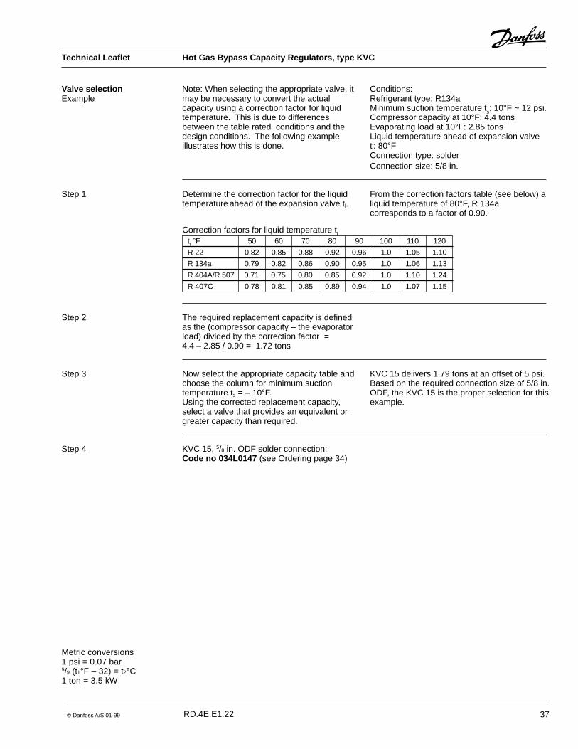
KVC capacity regulators are used to adaptcompressor capacity to actual evaporatorload by supplying a replacement capacity inform of hot/cool gas.
Introduction
Features � Accurate, adjustable pressure regulation
� Wide capacity and operating range
� Pulsation, damping design
� Stainless steel bellows
Technical data
It is installed in a bypass line between thehigh and low pressure sides of therefrigeration system and is designed for directgas injection into the suction line
� Compact angle design for easy installation
� "Hermetic" brazed construction
� Available with flare and ODF solderconnections
� For CFC, HCFC and HFC refrigerants
Approvals ��UL listed, file SA7200 ��CSA approved
RefrigerantsCFC, HCFC, HFC
Regulation range3 to 85 psigFactory setting = 29 psig
Maximum working pressureMWP = 400 psig
Metric conversions1 psi = 0.07 bar5/9 (t1°F – 32) = t2°C1 ton = 3.5 kW
Contents Introduction --------------------------------------------------------------------------------------------------- page 33Features ------------------------------------------------------------------------------------------------------ page 33Approvals ------------------------------------------------------------------------------------------------------ page 33Technical data ----------------------------------------------------------------------------------------------- page 33Ordering ------------------------------------------------------------------------------------------------------ page 34Replacement capacity ------------------------------------------------------------------------------pages 34 - 36Sizing and selection --------------------------------------------------------------------------------pages 36 - 37Design and function ---------------------------------------------------------------------------------------- page 38Dimensions and weights ---------------------------------------------------------------------------------- page 39
Maximum test pressurep' = 450 psig
Maximum temperature of medium300°F
Minimum temperature of medium– 40°F
Maximum P-band29 psi
RD.4E.E1.22
Technical Leaflet Hot Gas Bypass Capacity Regulators, type KVC

34 © Danfoss A/S 01-99
Ordering Type Rated capacity1) tons Flare connection2) Solder connection
R 22 R 134a R 404A/R 507 R 407C in. Code no. in. ODF Code no.
KVC 12 2.14 1.36 2.02 2.31 1/2 034L0141 1/2 034L0143
KVC 15 4.17 2.65 3.93 4.50 5/8 034L0142 5/8 034L0147
KVC 22 5.35 3.41 5.04 5.78 7/8 034L01441) Rated capacity is based on:
Suction gas temperature ts = 10°FLiquid temperature tl = 100°FOffset ���������������������������������p = 10 psi
Metric conversions1 psi = 0.07 bar5/9 (t1°F – 32) = t2°C1 ton = 3.5 kW1 in. = 25.4 mm
2) KVC are delivered without flare nuts. Separate flare nutscan be supplied:1/2 in. code no 011L11035/8 in. code no 011L1167
Note: The connection dimensions chosen mustnot be too small, as gas velocities in excess of130 ft/s at the inlet of the regulator can resultin flow noise.
R 22KVC 12 1.5 0.68 0.70 0.71 0.73 0.75 0.77
2.0 0.93 0.95 0.97 1.00 1.03 1.053.0 1.33 1.36 1.39 1.43 1.47 1.515.0 1.75 1.79 1.83 1.88 1.93 1.987.5 1.93 1.97 2.01 2.07 2.12 2.18
10.0 2.00 2.04 2.08 2.14 2.20 2.2615.0 2.19 2.24 2.28 2.35 2.41 2.4820.0 2.62 2.67 2.72 2.80 2.87 2.94
KVC 15 1.5 1.01 1.03 1.06 1.09 1.12 1.152.0 1.20 1.23 1.25 1.29 1.32 1.353.0 1.73 1.77 1.80 1.85 1.90 1.955.0 2.64 2.69 2.75 2.83 2.90 2.987.5 3.39 3.46 3.54 3.63 3.73 3.83
10.0 3.90 3.98 4.06 4.17 4.28 4.3915.0 4.76 4.66 4.75 4.88 5.01 5.1420.0 5.05 5.16 5.27 5.42 5.57 5.72
KVC 22 1.5 1.09 1.12 1.14 1.17 1.21 1.242.0 1.38 1.41 1.44 1.48 1.52 1.563.0 1.89 1.93 1.97 2.02 2.07 2.125.0 2.88 2.94 3.00 3.08 3.16 3.247.5 4.02 4.11 4.19 4.31 4.43 4.54
10.0 4.98 5.09 5.20 5.35 5.50 5.6415.0 6.35 6.49 6.63 6.82 7.01 7.2020.0 7.10 7.25 7.40 7.60 7.79 7.99
Type Offset Regulator capacity Q tons�p Suction gas temperature ts after pressure/temperature reduction °F
psi – 50 – 40 – 25 – 10 10 30 50
1) The capacities are based on:Liquid temperature ahead of the expansion valve tl = 100°F
Maximum regulator capacity Qe1)
Correction factors for liquid temperature tlWhen liquid temperature tl ahead of theevaporator is other than 100°F, adjust thetable capacities by multiplying them by theappropriate correction factor found in thefollowing table.
tl �F 60 70 80 90 100 110 120
R 22 0.60 0.71 0.80 0.90 1.0 1.11 1.22
System capacity x correction factor = table capacity
Replacement capacity
If the temperature in the discharge gas line istoo high according to the compressorspecifications, it is recommanded to install aliquid injection valve in a bypass from the liquidline to the suction line.
RD.4E.E1.22
Technical Leaflet Hot Gas Bypass Capacity Regulators, type KVC

© Danfoss A/S 01-99 35
Technical Leaflet Hot Gas Bypass Capacity Regulators, type KVC
R 134aKVC 12 1.5 0.41 0.43 0.46 0.48 0.50
2.0 0.58 0.60 0.62 0.66 0.703.0 0.83 0.86 0.91 0.95 1.005.0 1.09 1.14 1.20 1.25 1.317.5 1.20 1.25 1.31 1.37 1.44
10.0 1.25 1.30 1.36 1.42 1.4915.0 1.36 1.42 1.49 1.56 1.6320.0 1.62 1.69 1.78 1.86 1.94
KVC15 1.5 0.62 0.65 0.68 0.72 0.762.0 0.74 0.78 0.82 0.86 0.903.0 1.08 1.13 1.18 1.24 1.285.0 1.64 1.72 1.79 1.87 1.967.5 2.12 2.21 2.30 2.41 2.51
10.0 2.45 2.54 2.65 2.77 2.8815.0 2.87 2.96 3.11 3.25 3.4020.0 3.13 3.26 3.44 3.61 3.79
KVC 22 1.5 0.67 0.70 0.73 0.78 0.822.0 0.86 0.90 0.94 0.97 1.023.0 1.18 1.22 1.28 1.33 1.395.0 1.80 1.86 1.96 2.04 2.127.5 2.52 2.62 2.74 2.87 2.99
10.0 3.13 3.25 3.41 3.55 3.7115.0 4.00 4.15 4.34 4.54 4.7420.0 4.43 4.61 4.82 5.05 5.28
1) The capacities are based on:Liquid temperature ahead of theexpansion valve tl =100°F
Metric conversions1 psi = 0.07 bar5/9 (t1°F – 32) = t2°C1 ton = 3.5 kW
Replacement capacity(continued) Type Offset Regulator capacity Q tons
�p Suction gas temperature ts after pressure/temperature reduction °F
psi – 50 – 40 – 25 – 10 10 30 50
Maximum regulator capacity Qe1)
Correction factors for liquid temperature tlWhen liquid temperature tl ahead of theevaporator is other than 100°F, adjust thetable capacities by multiplying them by theappropriate correction factor found in thefollowing table.
tl �F 60 70 80 90 100 110 120
R 134a 0.60 0.70 0.80 0.90 1.0 1.10 1.21
R 404A/R 507 0.69 0.79 0.87 0.94 1.0 1.05 1.09
System capacity x correction factor = table capacity
R 404A/R 507KVC 12 1.5 0.57 0.58 0.62 0.64 0.67 0.70 0.74
2.0 0.79 0.81 0.85 0.88 0.92 0.97 1.013.0 1.16 1.19 1.23 1.28 1.34 1.40 1.465.0 1.54 1.58 1.64 1.69 1.77 1.85 1.937.5 1.68 1.73 1.79 1.86 1.96 2.05 2.13
10.0 1.74 1.78 1.85 1.93 2.02 2.11 2.2115.0 1.89 1.94 2.01 2.10 2.20 2.31 2.4120.0 2.27 2.33 2.42 2.51 2.62 2.74 2.85
KVC 15 1.5 0.86 0.89 0.92 0.96 1.01 1.06 1.102.0 1.05 1.07 1.11 1.16 1.21 1.27 1.323.0 1.51 1.55 1.61 1.66 1.74 1.82 1.905.0 2.29 2.34 2.44 2.53 2.65 2.77 2.897.5 2.94 3.01 3.14 3.26 3.42 3.58 3.74
10.0 3.38 3.47 3.61 3.75 3.93 4.11 4.3015.0 3.95 4.06 4.22 4.39 4.61 4.82 5.0420.0 4.36 4.48 4.66 4.85 5.09 5.34 5.58
KVC 22 1.5 0.92 0.96 0.99 1.02 1.08 1.12 1.182.0 1.19 1.22 1.27 1.31 1.38 1.44 1.513.0 1.71 1.75 1.83 1.89 1.98 2.08 2.175.0 2.63 2.71 2.81 2.92 3.06 3.20 3.347.5 3.58 3.67 3.82 3.96 4.17 4.35 4.54
10.0 4.33 4.46 4.63 4.81 5.04 5.28 5.5115.0 5.49 5.64 5.86 6.08 6.39 6.69 6.9920.0 6.31 6.49 6.74 7.01 7.35 7.70 8.04
RD.4E.E1.22

36 © Danfoss A/S 01-99
Technical Leaflet Hot Gas Bypass Capacity Regulators, type KVC
Replacement capacity(continued)
R 407CKVC 12 1.5 0.73 0.76 0.77 0.79 0.81 0.83
2.0 1.00 1.03 1.05 1.08 1.11 1.133.0 1.44 1.47 1.50 1.54 1.59 1.635.0 1.89 1.93 1.98 2.03 2.08 2.147.5 2.08 2.13 2.17 2.24 2.29 2.35
10.0 2.16 2.20 2.25 2.31 2.38 2.4415.0 2.37 2.42 2.46 2.54 2.60 2.6820.0 2.83 2.88 2.94 3.02 3.10 3.18
KVC15 1.5 1.09 1.11 1.14 1.18 1.21 1.242.0 1.30 1.33 1.35 1.39 1.43 1.463.0 1.87 1.91 1.94 2.00 2.05 2.115.0 2.85 2.91 2.97 3.06 3.13 3.227.5 3.66 3.74 3.82 3.92 4.03 4.14
10.0 4.21 4.30 4.38 4.50 4.62 4.7415.0 4.92 5.03 5.13 5.27 5.41 5.5520.0 5.45 5.57 5.69 5.85 6.02 6.18
KVC 22 1.5 1.18 1.21 1.23 1.26 1.31 1.342.0 1.49 1.52 1.56 1.60 1.64 1.683.0 2.04 2.08 2.13 2.18 2.24 2.295.0 3.11 3.18 3.24 3.33 3.41 3.507.5 4.34 4.44 4.53 4.65 4.78 4.90
10.0 5.38 5.50 5.62 5.78 5.94 6.0915.0 6.86 7.01 7.16 7.37 7.57 7.7820.0 7.67 7.83 7.99 8.21 8.41 8.63
Correction factors for liquid temperature tlWhen liquid temperature tl ahead of theevaporator is other than 100°F, adjust thetable capacities by multiplying them by theappropriate correction factor found in thefollowing table.
tl �F 60 70 80 90 100 110 120
R 407C 0.66 0.74 0.82 0.91 1.0 1.09 1.17
Type Offset Regulator capacity Q tons�p Suction gas temperature ts after pressure/temperature reduction °F
psi – 50 – 40 – 25 – 10 10 30 50
Metric conversions1 psi = 0.07 bar5/9 (t1°F – 32) = t2°C1 ton = 3.5 kW
Sizing
1) The capacities are based on:Liquid temperature ahead of theexpansion valve tl = 100°F
For optimum performance, it is important toselect a KVC valve according to systemconditions and application.The following data must be used when sizing aKVC valve:
� Refrigerant: CFC, HCFC or HFC� Minimum suction temperature ts in °F/psig� Compressor capacity in tons� Evaporating load in tons� Liquid temperature ahead of expansion
valve tl in °F� Connection type flare or solder� Connection size in inches
RD.4E.E1.22
© Danfoss A/S 01-99 37
Technical Leaflet Hot Gas Bypass Capacity Regulators, type KVC
Valve selectionExample
Step 2
Conditions:Refrigerant type: R134aMinimum suction temperature ts: 10°F ~ 12 psi.Compressor capacity at 10°F: 4.4 tonsEvaporating load at 10°F: 2.85 tonsLiquid temperature ahead of expansion valvetl: 80°FConnection type: solderConnection size: 5/8 in.
Metric conversions1 psi = 0.07 bar5/9 (t1°F – 32) = t2°C1 ton = 3.5 kW
Note: When selecting the appropriate valve, itmay be necessary to convert the actualcapacity using a correction factor for liquidtemperature. This is due to differencesbetween the table rated conditions and thedesign conditions. The following exampleillustrates how this is done.
Step 1 Determine the correction factor for the liquidtemperature ahead of the expansion valve tl.
Correction factors for liquid temperature tl
tl °F 50 60 70 80 90 100 110 120
R 22 0.82 0.85 0.88 0.92 0.96 1.0 1.05 1.10
R 134a 0.79 0.82 0.86 0.90 0.95 1.0 1.06 1.13
R 404A/R 507 0.71 0.75 0.80 0.85 0.92 1.0 1.10 1.24
R 407C 0.78 0.81 0.85 0.89 0.94 1.0 1.07 1.15
From the correction factors table (see below) aliquid temperature of 80°F, R 134acorresponds to a factor of 0.90.
The required replacement capacity is definedas the (compressor capacity – the evaporatorload) divided by the correction factor =4.4 – 2.85 / 0.90 = 1.72 tons
Now select the appropriate capacity table andchoose the column for minimum suctiontemperature ts = – 10°F.Using the corrected replacement capacity,select a valve that provides an equivalent orgreater capacity than required.
KVC 15 delivers 1.79 tons at an offset of 5 psi.Based on the required connection size of 5/8 in.ODF, the KVC 15 is the proper selection for thisexample.
Step 3
KVC 15, 5/8 in. ODF solder connection:Code no 034L0147 (see Ordering page 34)
Step 4
RD.4E.E1.22

38 © Danfoss A/S 01-99
Technical Leaflet Hot Gas Bypass Capacity Regulators, type KVC
Design andFunction
Capacity regulator type KVC opens on a fall inpressure on the outlet side, i.e. when thepressure in the evaporator reaches the setvalue.
Type KVC regulates on outlet pressure(suction pressure) only. Pressure variationson the inlet side of the regulator do not affectthe degree of opening as the valve is equippedwith equalization bellows (6).The bellows has an effective areacorresponding to that of the valve seatneutralizing any affect to the setting.The regulator is also equipped with a dampingdevice (9) providing protection againstpulsations which can normally arise in arefrigeration system. The damping devicehelps to ensure long life for the regulatorwithout impairing regulation accuracy.
KVC
1. Protective cap2. Gasket3. Setting screw4. Main spring5. Valve body6. Equalization bellows7. Valve plate8. Valve seat9. Damping device
P-band and Offset
OffsetThe offset is defined as the permissiblepressure variation in suction line pressure(temperature). It is calculated as the differencebetween the required working pressure andthe minimum allowable pressure.The offset is always a part of the P-band.
Example with R 404A:A suction temperature ahead of thecompressor of 25°F ~ 61 psig is required, andthe temperature must not drop below14°F ~ 48 psig.The offset will then be 13 psi.
Proportional bandThe proportional band or P-band is defined asthe amount of pressure required to move thevalve plate from closed to full open position.If the setting is 58 psig and the p-band is 22psi, the pressure at which the valve givesmaximum capacity will be 36 psig.
RD.4E.E1.22

© Danfoss A/S 01-99 39
Technical Leaflet Hot Gas Bypass Capacity Regulators, type KVC
Dimensions and weights
KVC
Metric conversions1 in. = 25.4 mm1 lb = 0.454 kg
Type Connection NV1 NV2 H1 H2 B1 C dia D Weight
Flare Solder ODF
in. in. in. in. in. in. in. in. in. lbs.
KVC 12 1/21/2
3/415/16 7.047 3.898 2.520 0.394 1.181 0.88
KVC 15 5/85/8
15/1615/16 7.047 3.898 2.520 0.472 1.181 0.88
KVC 22 7/8 7.047 3.898 2.520 0.669 1.181 0.88
RD.4E.E1.22

40 © Danfoss A/S 01-99
© Danfoss A/S 01-99 41
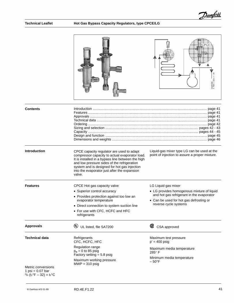
CPCE Hot gas capacity valve
� Superior control accuracy
� Provides protection against too low anevaporator temperature
� Direct connection to system suction line
� For use with CFC, HCFC and HFCrefrigerants
Features LG Liquid gas mixer
� LG provides homogenous mixture of liquidand hot gas refrigerant in the evaporator
� Can be used for hot gas defrosting orreverse cycle systems
RefrigerantsCFC, HCFC, HFC
Regulation rangepe = 0 to 85 psigFactory setting = 5.8 psig
Maximum working pressureMWP = 310 psig
Technical data Maximum test pressurep’ = 400 psig
Maximum media temperature285� F
Minimum media temperature– 50°F
Approvals ��UL listed, file SA7200 ��CSA approved
Metric conversions1 psi = 0.07 bar5/9 (t1°F – 32) = t2°C
Contents Introduction ....................................................................................................................... page 41Features ............................................................................................................................ page 41Approvals .......................................................................................................................... page 41Technical data ................................................................................................................... page 41Ordering ............................................................................................................................ page 42Sizing and selection ................................................................................................. pages 42 - 43Capacity ................................................................................................................... pages 44 - 45Design and function .......................................................................................................... page 45Dimensions and weights ................................................................................................... page 46
Introduction CPCE capacity regulator are used to adaptcompressor capacity to actual evaporator load.It is installed in a bypass line between the highand low pressure sides of the refrigerationsystem and is designed for hot gas injectioninto the evaporator just after the expansionvalve.
Liquid-gas mixer type LG can be used at thepoint of injection to assure a proper mixture.
Technical Leaflet Hot Gas Bypass Capacity Regulators, type CPCE/LG
RD.4E.F1.22

42 © Danfoss A/S 01-99
Capacity regulator
1) Rated capacity is based on:Minimum suction temperature ts = 15� FCondensing temperature tc = 100� FSuperheat of expansion valve �������������ts = 7� F.
Liquid - gas mixer
Sizing
OrderingType Connection Rated capacity 1) Code no.
tons
Flare SolderODF
in. in. R 22 R 134a R 404A/R 507 R 407C
CPCE 12 1/2 6.2 4.3 6.3 6.7 034N0081
CPCE 12 1/2 6.2 4.3 6.3 6.7 034N0082
CPCE 15 5/8 9.2 6.3 9.1 9.9 034N0083
CPCE 22 7/8 12.2 8.4 12.1 13.2 034N0084
Type Connection Code no.
For expansion valve For hot gas For liquid distributorin. ODM in. ODF in. ODF
LG 12-16 5/8 1/2 5/8 069G4001
LG 12-22 7/8 1/2 7/8 069G4002
LG 16-28 1 1/8 5/8 1 1/8 069G4003
LG 22-35 1 3/8 7/8 1 3/8 069G4004
Metric conversions1 psi = 0.07 bar5/9 (t1°F – 32) = t2°C1 ton = 3.5 kW
For optimum performance, it is important toselect a CPCE valve according to systemconditions and application.The following data must be used when sizing aCPCE valve:
SelectionExample
When selecting the appropriate valve it may benecessary to convert the actual capacity usinga corrections factors. This is required whenyour system conditions are different than thetable conditions.The following examples illustrate how this isdone.
� Refrigerant: CFC, HCFC or HFC� Minimum suction temperature ts in °F� Compressor capacity at minimum suction
temperature Q1 in tons� Evaporator load at minimum suction
temperature Q2 in tons� Superheat setting of expansion valve in °F� Condensing temperature tc in °F� Connection type flare or solder
Refrigerant: R 404AMinimum suction temperature ts: – 20°FCompressor capacity at minimum suctiontemperature Q1: 22.5 tonsEvaporator load at minimum suctiontemperature Q2: 17 tonsSuperheat setting of expansion valve: 9°FCondensing temperature tc: 90°FConnection type: solder
Step 1 Determine the replacement capacity. This isdone by taking the compressor capacity atminimum suction temperature Q1 minusevaporator load at minimum suctiontemperature Q2.Q1 – Q2 = 22.5 – 17 = 5.5 tons.
Technical Leaflet Hot Gas Bypass Capacity Regulators, type CPCE/LG
RD.4E.F1.22

© Danfoss A/S 01-99 43
Correction factorsSuction Refrigerant Superheat of expansion valve �ts �F
temperature tsafter reduction
�F 1 3 5 7 9 11 13
50 R 134a 0.1 0.5 0.9 1.0 1.0 1.0 1.0
R 22, R 404A, 0.3 0.9 1.0 1.0 1.0 1.0 1.0R 407C, R 507
30 R 134a 0.1 0.3 0.7 1.0 1.0 1.0 1.0
R 22, R 404A, 0.2 0.9 1.0 1.0 1.0 1.0 1.0R 407C, R 507
15 R 134a 0.1 0.3 0.6 1.0 1.3 1.4 1.4
R 22, R 404A, 0.1 0.5 1.0 1.0 1.0 1.0 1.0R 407C, R 507
� 5 R 134a 0.1 0.3 0.6 1.0 1.5 2.2 2.4
R 22, R 404A, 0.1 0.3 0.7 1.0 1.0 1.0 1.0R 407C, R 507
� 20 R 134a 0.1 0.3 0.6 1.0 1.5 2.2 2.9
R 22, R 404A, 0.1 0.3 0.6 1.0 1.3 1.4 1.4R 407C, R 507
� 40 R 22, R 404A, 0.1 0.3 0.6 1.0 1.5 2.0 2.2R 407C, R 507
Selection (continued)
Step 2
Step 3
Step 4
Determine the corrections factor for theexpansion valve superheat setting.
From the correction factors table (see below)a superheat setting of 9°F, R 404Acorresponds to a factor of 1.3.
Corrected replacement capacity isQ = 1.3 x 5.5 = 7.2 tons
Now select the appropriate capacity table andchoose the column for minimum suctiontemperature ts and the column for condensingtemperature tc.Using the corrected replacement capacity,select a valve that provides an equivalent orgreater capacity.
A CPCE 22 delivers a replacement capacity of8.0 ton at a minimum suction temperature of– 20°F and a condensing temperature of 90°F.
Step 5 CPCE 22, 7/8 in. solder connection,code no 034N0084 (see Ordering page 42).
Metric conversions1 psi = 0.07 bar5/9 (t1°F – 32) = t2°C1 ton = 3.5 kW
Technical Leaflet Hot Gas Bypass Capacity Regulators, type CPCE/LG
RD.4E.F1.22

44 © Danfoss A/S 01-99
R 134aCPCE 12 50 0.9 4.2 5.8 7.2 9.1
30 3.1 4.5 5.8 7.3 9.115 2.3 3.2 4.3 5.8 7.3- 5 1.4 1.8 2.5 3.3 4.2
- 20 0.9 1.1 1.5 2.0 2.5
CPCE 15 50 0.9 6.1 8.5 10.7 13.430 4.6 6.7 8.5 10.7 13.415 3.3 4.7 6.3 8.5 10.7- 5 1.9 2.7 3.5 4.8 6.1
- 20 1.1 1.4 2.0 2.6 3.2
CPCE 22 50 1.3 8.2 11.2 14.1 17.730 6.1 8.9 11.3 14.1 17.715 4.4 6.1 8.4 11.2 14.1- 5 2.6 3.5 4.7 6.3 8.2
- 20 1.5 2.0 2.8 3.6 4.5
CPCE 12 50 2.2 4.6 6.2 7.7 9.630 3.6 5.0 6.2 7.715 3.9 5.0 6.3 7.7
� 5 4.0 5.0 6.3� 20 3.1 4.2 5.4� 40 1.7 2.2 2.9
CPCE 15 50 3.3 6.8 9.1 11.3 14.130 5.4 7.3 9.1 11.315 5.7 7.3 9.1 11.3
� 5 5.7 7.3 9.1� 20 4.5 6.1 7.9� 40 2.4 3.2 4.1
CPCE 22 50 4.4 9.0 12.1 15.0 18.730 7.2 9.6 12.1 15.015 7.6 9.6 12.1 15.1
� 5 7.6 9.8 12.1� 20 5.9 8.0 10.5� 40 3.2 4.3 5.4
R 404A/R 507
Capacity
CPCE 12 50 2.2 4.6 6.1 7.6 9.530 3.7 4.9 6.2 7.715 3.9 4.9 6.2 7.8
� 5 3.9 5.0 6.3 7.9� 20 2.3 3.1 4.2 5.3� 40 1.2 1.6 2.2
CPCE 15 50 3.3 6.8 9.0 11.2 13.930 5.3 7.2 9.1 11.315 5.7 7.3 9.2 11.4
� 5 5.7 7.3 9.3 11.6� 20 3.3 4.5 6.0 7.7� 40 1.7 2.2 3.0
CPCE 22 50 4.3 9.0 11.9 14.9 18.430 7.1 9.5 12.0 15.015 7.5 9.7 12.2 15.2
� 5 7.6 9.7 12.2 15.3� 20 4.4 6.0 8.0 10.2� 40 2.3 3.0 4.1
R 22
Type Minimum suction Regulator capacity Q tonstemperature ts after at condensing temperature tc �F
pressure/temperaturereduction
�F 70 90 100 120 140
Metric conversions1 psi = 0.07 bar5/9 (t1°F – 32) = t2°C1 ton = 3.5 kW
The capacities are based on:Liquid temperature ahead of expansion valve tl = 100°F
Technical Leaflet Hot Gas Bypass Capacity Regulators, type CPCE/LG
RD.4E.F1.22

© Danfoss A/S 01-99 45
Type Minimum suction Regulator capacity Q tonstemperature ts after at condensing temperature tc �F
pressure/temperaturereduction
�F 70 90 100 120 140
Metric conversions1 psi = 0.07 bar5/9 (t1°F – 32) = t2°C1 ton = 3.5 kW
CPCE 12 50 2.4 5.0 6.6 8.2 10.330 4.0 5.3 6.7 8.315 4.2 5.3 6.7 8.4
� 5 4.2 5.4 6.8 8.5� 20 2.5 3.3 4.5 5.7� 40 1.3 1.7 2.4
CPCE 15 50 3.6 7.3 9.7 12.1 15.030 5.7 7.8 9.8 12.215 6.2 7.9 9.9 12.3
� 5 6.2 7.9 10.0 12.5� 20 3.6 4.9 6.5 8.3� 40 1.8 2.4 3.2
CPCE 22 50 4.6 9.7 12.9 16.1 19.930 7.7 10.3 13.0 16.215 8.1 10.5 13.2 16.4
� 5 8.2 10.5 13.2 16.5� 20 4.8 6.5 8.6 11.0
R 407C
Design andFunction
CPCE
LG
1. Inlet2. Outlet3. Pilot pressure connection4. Protective cap5. Setting screw6. Main spring7. Diaphragm8. Pressure pin9. Pilot orifice
10. Servo piston11. Pressure equalizing hole12. Main orifice
Capacity regulator type CPCE is a servo-operated valve. The diaphram (7) is acted onby two forces: The spring force (6) and theforce created from the pilot pressure (3)(suction pressure). When the pilot pressurefalls below the valves setting, the throttling ball(6) is forced away from the pilot orifice (9) bythe spring pressure transfered through thepressure pin (8).The pressure over the servo piston (10) is thenrelieved through the pilot connection allowingthe differential pressure across the inlet andoutlet to open the valve allowing the flow of hotgas into the evaporator.When the pilot pressure (suction pressure)rises above the valves setting, the throttlingball seals off the piston chamber where highpressure begins to build through theequalization hole (11) causing the valve toclose.
1. Liquid inlet2. Hot gas inlet3. Outlet
Capacity (continued)
The capacities are based on:Liquid temperature ahead of expansion valve tl = 100°F
Technical Leaflet Hot Gas Bypass Capacity Regulators, type CPCE/LG
RD.4E.F1.22
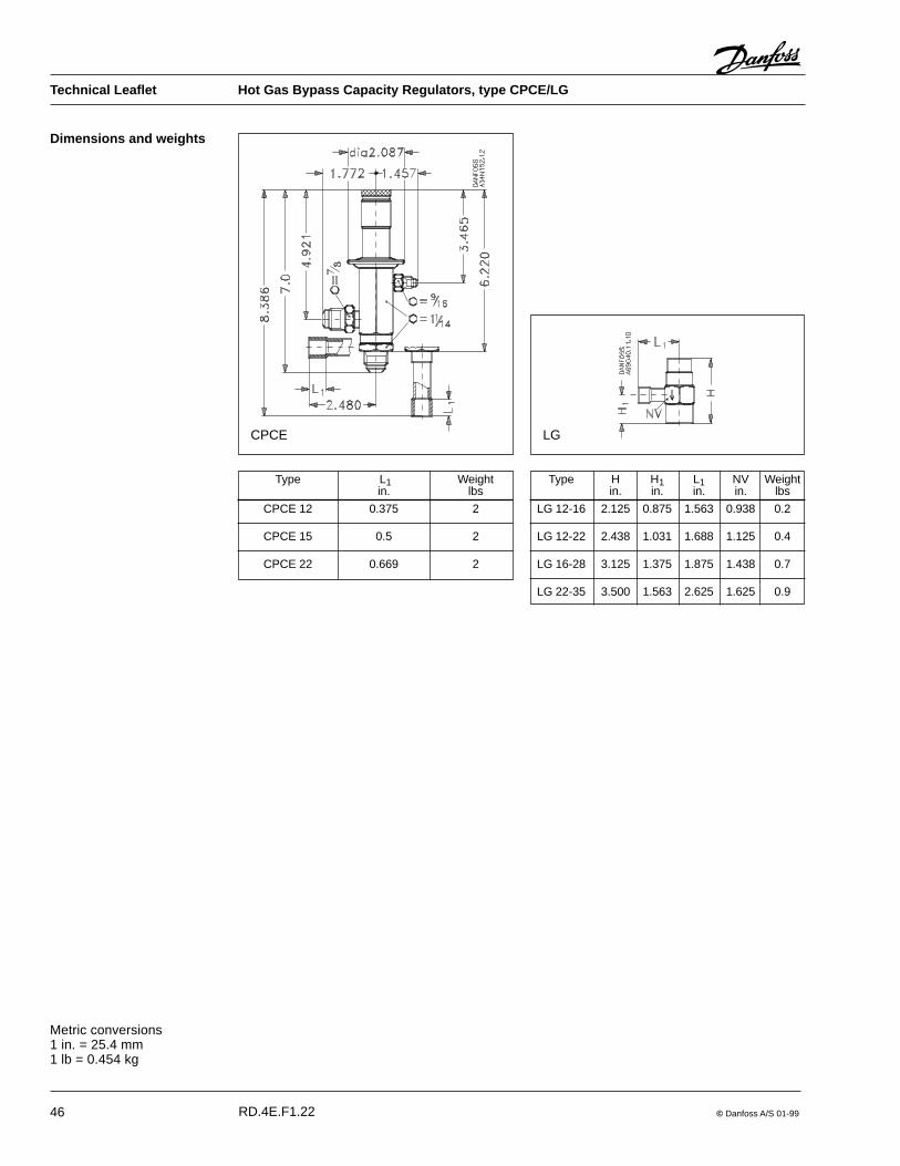
46 © Danfoss A/S 01-99
Dimensions and weights
CPCE LG
Type H H1 L1 NV Weightin. in. in. in. lbs
LG 12-16 2.125 0.875 1.563 0.938 0.2
LG 12-22 2.438 1.031 1.688 1.125 0.4
LG 16-28 3.125 1.375 1.875 1.438 0.7
LG 22-35 3.500 1.563 2.625 1.625 0.9
Type L1 Weightin. lbs
CPCE 12 0.375 2
CPCE 15 0.5 2
CPCE 22 0.669 2
Metric conversions1 in. = 25.4 mm1 lb = 0.454 kg
Technical Leaflet Hot Gas Bypass Capacity Regulators, type CPCE/LG
RD.4E.F1.22

© Danfoss A/S 01-99 47
Introduction They are installed in the suction line ofrefrigeration systems.
Features � Accurate, adjustable pressure regulation
� Wide capacity and operating range
� Pulsation damping design
� Stainless steel bellows
� Compact angle design for easy installationin any position
Approvals
Technical data
KVL cranckcase pressure regulators are usedto protect the compressor motor againstoverload experienced during startup after longoff periods or just after defrost periods.
� "Hermetic" brazed construction
� Available with flare and ODF solderconnections
� For use with CFC, HCFC and HFCrefrigerants
��UL listed, file SA7200 ��CSA approved
RefrigerantsCFC, HCFC, HFC
Regulation range3 to 85 psigFactory setting = 29 psig
Maximum working pressureKVL 12 to 22: MWP = 200 psigKVL 28 to 35: MWP = 200 psig
Maximum test pressureKVL 12 to 22: p' = 405 psigKVL 28 to 35: p' = 370 psig
Maximum temperature of medium300°F
Minimum temperature of medium– 325°F
Maximum P-bandKVL 12 to 22: 29 psiKVL 28 to 35: 22 psi
Metric conversions1 psi = 0.07 bar5/9 (t1°F – 32) = t2°C1 ton = 3.5 kW
Contents Introduction ....................................................................................................................... Page 47Features ............................................................................................................................ Page 47Approvals .......................................................................................................................... Page 47Technical data ................................................................................................................... Page 47Ordering ............................................................................................................................ Page 48Capacity ................................................................................................................... Pages 49 - 52Sizing and selection .......................................................................................................... Page 53Design and function .......................................................................................................... Page 54Dimensions and weights ................................................................................................... Page 55
Technical Leaflet Crankcase Pressure Regulators, type KVL
RD.4G.B1.22

48 © Danfoss A/S 01-99
Metric conversions1 psi = 0.07 bar5/9 (t1°F – 32) = t2°C1 ton = 3.5 kW1 in. = 25.4 mm
Ordering
1) Rated capacity is based on:Maximum suction pressure ps = 70 psigSuction temperature ts = 10�FCondensing temperature tc = 100�FPressure drop across regulator �p = 2 psi
Type Rated capacity 1) Flare connection 2) Solder connectiontons
R 22 R 134a R 404A/R 507 R 407C in. Code no in. ODF Code no
KVL 12 1.2 0.8 1.0 1.1 1/2 034L0041 1/2 034L0043
KVL 15 1.2 0.8 1.0 1.1 5/8 034L0042 5/8 034L0049
KVL 22 1.2 0.8 1.0 1.1 7/8 034L0045
KVL 28 4.1 2.6 3.4 3.8 11/8 034L0046
KVL 35 4.1 2.6 3.4 3.8 13/8 034L0052
2) KVL are supplied without flare nuts. Separate flare nutscan be supplied:1/2 in., code no 011L11035/8 in., code no 011L1167.
Note: The connection dimensions chosenmust not be too small, as gas velocities inexcess of 130 ft/s at the inlet of the regulatorcan result in flow noise.
Technical Leaflet Crankcase Pressure Regulators, type KVL
RD.4G.B1.22

© Danfoss A/S 01-99 49
Capacities
Maximum regulator capacity Qe1) at condensing temperature tc = 100°F
Type Pressure Maximum Capacity Qe tonsdrop suction at suction temperature ts after the regulator, °F
across pressureregulator ps
��ppsi psig – 30 – 20 – 10 0 10 20 30 40 50 60 70
KVL 12 2 10 0.3KVL 15 20 0.7 0.6 0.3KVL 22 30 0.8 0.9 0.9 0.5
40 0.8 0.9 1.0 1.0 0.750 0.8 0.9 1.0 1.1 1.2 0.860 0.8 0.9 1.0 1.1 1.2 1.3 0.670 0.8 0.9 1.0 1.1 1.2 1.4 1.4 0.280 0.8 0.9 1.0 1.1 1.2 1.4 1.5 1.390 0.8 0.9 1.0 1.1 1.2 1.4 1.5 1.6 0.9
3 10 0.420 0.9 0.8 0.430 0.9 1.1 1.0 0.740 0.9 1.1 1.2 1.3 0.950 0.9 1.1 1.2 1.3 1.5 0.960 0.9 1.1 1.2 1.3 1.5 1.6 0.870 0.9 1.1 1.2 1.3 1.5 1.7 1.7 0.380 0.9 1.1 1.2 1.3 1.5 1.7 1.8 1.690 0.9 1.1 1.2 1.3 1.5 1.7 1.8 2.0 1.1
4 10 0.520 1.0 0.9 0.430 1.1 1.2 1.2 0.840 1.1 1.2 1.4 1.5 1.050 1.1 1.2 1.4 1.6 1.7 1.160 1.1 1.2 1.4 1.6 1.7 1.9 0.970 1.1 1.2 1.4 1.6 1.7 1.9 2.0 0.380 1.1 1.2 1.4 1.6 1.7 1.9 2.1 1.990 1.1 1.2 1.4 1.6 1.7 1.9 2.1 2.3 1.3
KVL 28 2 10 0.8 1.6KVL 35 20 2.0 2.7 0.7
30 2.5 2.9 2.3 1.240 2.5 2.9 3.2 3.0 1.650 2.5 2.9 3.2 3.6 3.5 1.860 2.5 2.9 3.2 3.6 4.1 3.8 1.470 2.5 2.9 3.2 3.6 4.1 4.5 3.9 0.480 2.5 2.9 3.2 3.6 4.1 4.5 5.0 3.490 2.5 2.9 3.2 3.6 4.1 4.5 5.0 5.5 2.0
3 10 0.920 2.4 1.9 0.830 3.1 3.4 2.8 1.540 3.1 3.5 4.0 3.6 2.050 3.1 3.5 4.0 4.5 4.3 2.260 3.1 3.5 4.0 4.5 5.0 4.7 1.870 3.1 3.5 4.0 4.5 5.0 5.5 4.7 0.580 3.1 3.5 4.0 4.5 5.0 5.5 6.1 4.290 3.1 3.5 4.0 4.5 5.0 5.5 6.1 6.7 2.5
4 10 1.120 2.8 2.2 0.930 3.6 3.9 3.3 1.840 3.6 4.1 4.6 4.2 2.350 3.6 4.1 4.6 5.2 4.9 2.560 3.6 4.1 4.6 5.2 5.8 5.4 2.070 3.6 4.1 4.6 5.2 5.8 6.4 5.5 0.680 3.6 4.1 4.6 5.2 5.8 4.5 7.1 4.890 3.6 4.1 4.6 5.2 5.8 4.5 7.1 7.7 2.9
R 22
tl °F 50 60 70 80 90 100 110 120
R 22 0.82 0.85 0.88 0.92 0.96 1.0 1.05 1.10
Correction factors for liquid temperature tl
System capacity ���correction factor = table capacity
1) The capacities are based onLiquid temperature tl = 100°F
Metric conversions1 psi = 0.07 bar5/9 (t1°F – 32) = t2°C1 ton = 3.5 kW
Technical Leaflet Crankcase Pressure Regulators, type KVL
RD.4G.B1.22

50 © Danfoss A/S 01-99
Capacities (continued)
Maximum regulator capacity Qe at condensing temperature tc = 100°FR 134a
System capacity ���correction factor = table capacity
Type Pressure Maximum Capacity Qe tonsdrop suction at suction temperature ts after the regulator, °F
across pressureregulator ps
��ppsi psig – 30 – 20 – 10 0 10 20 30 40 50 60 70
KVL 12 2 10 0.4 0.5 0.4 0.3KVL 15 20 0.4 0.5 0.6 0.6 0.4KVL 22 30 0.4 0.5 0.6 0.7 0.7 0.6
40 0.4 0.5 0.6 0.7 0.8 0.9 0.750 0.4 0.5 0.6 0.7 0.8 0.9 1.0 0.860 0.4 0.5 0.6 0.7 0.8 0.9 1.0 1.1 1.070 0.4 0.5 0.6 0.7 0.8 0.9 1.0 1.1 1.3 1.280 0.4 0.5 0.6 0.7 0.8 0.9 1.0 1.1 1.3 1.4 1.590 0.4 0.5 0.6 0.7 0.8 0.9 1.0 1.1 1.3 1.4 1.5
3 10 0.5 0.6 0.6 0.420 0.6 0.6 0.7 0.7 0.530 0.6 0.6 0.7 0.8 0.9 0.740 0.6 0.6 0.7 0.8 1.0 1.0 0.850 0.6 0.6 0.7 0.8 1.0 1.1 1.2 1.060 0.6 0.6 0.7 0.8 1.0 1.1 1.2 1.4 1.370 0.6 0.6 0.7 0.8 1.0 1.1 1.2 1.4 1.5 1.580 0.6 0.6 0.7 0.8 1.0 1.1 1.2 1.4 1.5 1.7 1.890 0.6 0.6 0.7 0.8 1.0 1.1 1.2 1.4 1.5 1.7 1.9
4 10 0.6 0.7 0.6 0.520 0.7 0.8 0.8 0.8 0.630 0.7 0.8 0.9 1.0 1.0 0.840 0.7 0.8 0.9 1.0 1.1 1.2 1.050 0.7 0.8 0.9 1.0 1.1 1.3 1.4 1.260 0.7 0.8 0.9 1.0 1.1 1.3 1.4 1.6 1.570 0.7 0.8 0.9 1.0 1.1 1.3 1.4 1.6 1.8 1.880 0.7 0.8 0.9 1.0 1.1 1.3 1.4 1.6 1.8 2.0 2.190 0.7 0.8 0.9 1.0 1.1 1.3 1.4 1.6 1.8 2.0 2.2
KVL 28 2 10 1.3 1.3 1.1 0.7KVL 35 20 1.5 1.7 1.7 1.5 1.0
30 1.5 1.7 2.0 2.2 1.9 1.340 1.5 1.7 2.0 2.3 2.6 2.5 1.750 1.5 1.7 2.0 2.3 2.6 3.0 3.1 2.160 1.5 1.7 2.0 2.3 2.6 3.0 3.3 3.7 2.770 1.5 1.7 2.0 2.3 2.6 3.0 3.3 3.7 4.2 3.480 1.5 1.7 2.0 2.3 2.6 3.0 3.3 3.7 4.2 4.7 4.190 1.5 1.7 2.0 2.3 2.6 3.0 3.3 3.7 4.2 4.7 5.2
3 10 1.6 1.5 1.4 0.920 1.9 2.1 2.1 1.8 1.230 1.9 2.1 2.5 2.7 2.4 1.640 1.9 2.1 2.5 2.8 3.2 3.1 2.150 1.9 2.1 2.5 2.8 3.2 3.6 3.8 2.660 1.9 2.1 2.5 2.8 3.2 3.6 4.1 4.6 3.370 1.9 2.1 2.5 2.8 3.2 3.6 4.1 4.6 5.1 4.180 1.9 2.1 2.5 2.8 3.2 3.6 4.1 4.6 5.1 5.7 5.190 1.9 2.1 2.5 2.8 3.2 3.6 4.1 4.6 5.1 5.7 6.3
4 10 1.8 1.8 1.6 1.020 2.2 2.4 2.4 2.1 1.430 2.2 2.5 2.9 3.1 2.8 1.840 2.2 2.5 2.9 3.3 3.7 3.5 2.450 2.2 2.5 2.9 3.3 3.7 4.2 4.4 3.060 2.2 2.5 2.9 3.3 3.7 4.2 4.7 5.3 3.870 2.2 2.5 2.9 3.3 3.7 4.2 4.7 5.3 5.9 4.880 2.2 2.5 2.9 3.3 3.7 4.2 4.7 5.3 5.9 6.6 5.990 2.2 2.5 2.9 3.3 3.7 4.2 4.7 5.3 5.9 6.6 7.3
Metric conversions1 psi = 0.07 bar5/9 (t1°F – 32) = t2°C1 ton = 3.5 kW
tl °F 50 60 70 80 90 100 110 120
R 134a 0.79 0.82 0.86 0.90 0.95 1.0 1.06 1.13
Correction factors for liquid temperature tl
Technical Leaflet Crankcase Pressure Regulators, type KVL
RD.4G.B1.22

© Danfoss A/S 01-99 51
Capacities (continued) Maximum regulator capacity Qe1)
at condensing temperature tc = 100°FType Pressure Maximum Capacity Qe tons
drop suction at suction temperature ts after the regulator, °Facross pressure
regulator ps��ppsi psig – 30 – 20 – 10 0 10 20 30 40 50 60 70
KVL 12 2 10KVL 15 20 0.5 0.3KVL 22 30 0.6 0.6 0.5
40 0.6 0.7 0.8 0.650 0.6 0.7 0.8 0.9 0.760 0.6 0.7 0.8 0.9 1.0 0.770 0.6 0.7 0.8 0.9 1.0 1.1 0.580 0.6 0.7 0.8 0.9 1.0 1.1 1.190 0.6 0.7 0.8 0.9 1.1 1.2 1.3 1.1
3 1020 0.6 0.330 0.8 0.8 0.640 0.8 0.9 0.9 0.750 0.8 0.9 1.0 1.1 0.860 0.8 0.9 1.0 1.1 1.2 0.870 0.8 0.9 1.0 1.1 1.3 1.4 0.680 0.8 0.9 1.0 1.1 1.3 1.5 1.590 0.8 0.9 1.1 1.2 1.3 1.5 1.6 1.3
4 1020 0.7 0.430 0.9 0.9 0.740 0.9 1.0 1.1 0.950 0.9 1.0 1.1 1.3 1.060 0.9 1.0 1.1 1.3 1.4 1.070 0.9 1.0 1.1 1.4 1.5 1.7 0.780 0.9 1.0 1.1 1.4 1.5 1.7 1.790 0.9 1.1 1.2 1.4 1.5 1.7 1.9 1.5
KVL 28 2 10KVL 35 20 1.2 0.6
30 2.0 1.7 1.140 2.0 2.3 2.2 1.550 2.0 2.4 2.7 2.8 1.760 2.1 2.4 2.7 3.1 3.2 1.670 2.1 2.4 2.7 3.1 3.4 3.3 1.180 2.1 2.4 2.7 3.1 3.4 3.9 3.290 2.1 2.4 2.7 3.1 3.5 3.9 4.3 2.6
3 10 0.120 1.4 0.730 2.5 2.1 1.340 2.6 3.0 2.9 1.950 2.6 3.0 3.2 3.4 2.160 2.6 3.0 3.2 3.8 3.9 2.170 2.6 3.0 3.2 3.9 4.3 4.2 1.380 2.6 3.0 3.2 3.9 4.3 4.8 4.090 2.6 3.1 3.3 3.9 4.3 4.8 5.4 3.3
4 10 0.120 1.7 0.830 2.8 2.5 1.540 3.0 3.4 3.3 2.150 3.0 3.4 3.9 4.0 2.460 3.0 3.4 3.9 4.3 4.4 2.470 3.0 3.4 4.0 4.4 4.9 4.8 1.780 3.0 3.4 4.0 4.4 4.9 5.5 4.690 3.1 3.5 4.0 4.4 4.9 5.6 6.2 3.7
System capacity ���correction factor = table capacityMetric conversions1 psi = 0.07 bar5/9 (t1°F – 32) = t2°C1 ton = 3.5 kW
R 404A/R507
tl °F 50 60 70 80 90 100 110 120
R 404A/R 507 0.71 0.75 0.80 0.85 0.92 1.0 1.10 1.24
Correction factors for liquid temperature tl
1) The capacities are based on:Liquid temperature tl = 100°F
Technical Leaflet Crankcase Pressure Regulators, type KVL
RD.4G.B1.22

52 © Danfoss A/S 01-99
Capacities (continued)Maximum regulator capacity Qe at condensing temperature tc = 100°F
Type Pressure Maximum Capacity Qe tonsdrop suction at suction temperature ts after the regulator, °F
across pressureregulator ps
��ppsi psig – 30 – 20 – 10 0 10 20 30 40 50 60 70
KVL 12 2 10 0.2KVL 15 20 0.6 0.5 0.3KVL 22 30 0.7 0.8 0.8 0.4
40 0.7 0.8 0.9 0.9 0.650 0.7 0.8 0.9 1.0 1.1 0.760 0.7 0.8 0.9 1.0 1.1 1.2 0.670 0.7 0.8 0.9 1.0 1.1 1.3 1.3 0.280 0.7 0.8 0.9 1.0 1.1 1.3 1.4 1.290 0.8 0.9 0.9 1.0 1.1 1.3 1.4 1.5 0.9
3 10 0.320 0.8 0.7 0.330 0.8 1.0 0.9 0.640 0.8 1.0 1.1 1.2 0.850 0.8 1.0 1.1 1.2 1.4 0.860 0.8 1.0 1.1 1.2 1.4 1.5 0.770 0.8 1.0 1.1 1.2 1.4 1.6 1.6 0.380 0.8 1.0 1.1 1.2 1.4 1.6 1.7 1.590 0.9 1.0 1.1 1.2 1.4 1.6 1.7 1.9 1.0
4 10 0.420 0.9 0.8 0.330 1.0 1.0 1.0 0.740 1.0 1.1 1.3 1.4 0.950 1.0 1.1 1.3 1.4 1.5 1.060 1.0 1.1 1.3 1.5 1.6 1.7 0.870 1.0 1.1 1.3 1.5 1.6 1.8 1.8 0.380 1.0 1.1 1.3 1.5 1.6 1.8 2.0 1.890 1.0 1.1 1.3 1.5 1.6 1.8 2.0 2.2 1.2
KVL 28 2 10 0.7KVL 35 20 1.7 2.3 0.6
30 2.2 2.5 2.0 1.040 2.2 2.6 2.9 2.7 1.450 2.3 2.6 2.9 3.2 3.2 1.660 2.3 2.6 2.9 3.3 3.7 3.5 1.370 2.3 2.7 2.9 3.3 3.8 4.1 3.6 0.480 2.3 2.7 3.0 3.4 3.8 4.2 4.7 3.290 2.4 2.7 3.0 3.4 3.9 4.2 4.7 5.2 1.9
3 10 0.720 2.0 1.6 0.730 2.7 3.0 2.4 1.340 2.8 3.1 3.6 3.2 1.850 2.8 3.2 3.6 4.1 3.9 2.060 2.8 3.2 3.6 4.1 4.6 4.3 1.670 2.9 3.2 3.7 4.1 4.6 5.1 4.3 0.580 2.9 3.3 3.7 4.2 4.7 5.1 5.7 3.990 2.9 3.3 3.8 4.2 4.7 5.2 5.7 6.3 2.4
4 10 0.920 2.4 1.9 0.830 3.1 3.4 2.9 1.640 3.2 3.7 4.1 3.7 2.150 3.2 3.7 4.1 4.7 4.4 2.360 3.3 3.7 4.2 4.7 5.3 4.9 1.870 3.3 3.8 4.2 4.8 5.3 5.9 2.1 0.680 3.4 3.8 4.3 4.8 5.4 6.0 6.6 4.590 3.4 3.9 4.3 4.9 5.5 6.0 6.7 7.2 2.7
R 407C
System capacity ���correction factor = table capacity
Metric conversions1 psi = 0.07 bar5/9 (t1°F – 32) = t2°C1 ton = 3.5 kW
tl °F 50 60 70 80 90 100 110 120
R 407C 0.78 0.81 0.85 0.89 0.94 1.0 1.07 1.15
Correction factors for liquid temperature tl
Technical Leaflet Crankcase Pressure Regulators, type KVL
RD.4G.B1.22
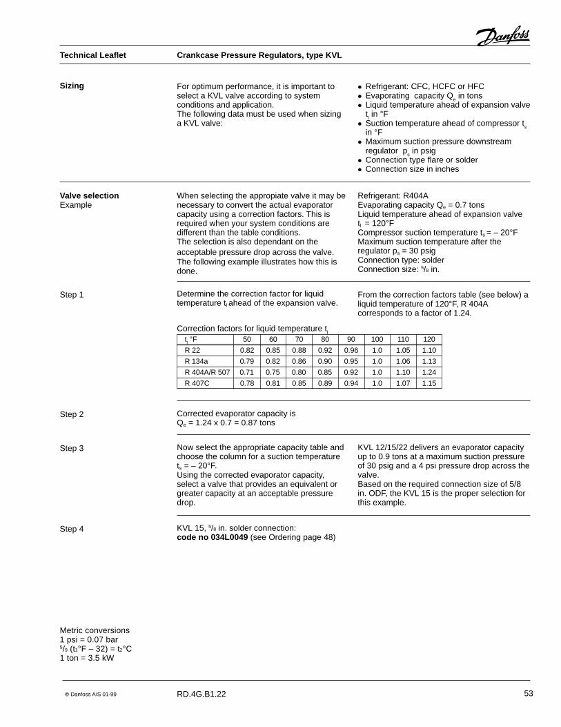
© Danfoss A/S 01-99 53
Sizing For optimum performance, it is important toselect a KVL valve according to systemconditions and application.The following data must be used when sizinga KVL valve:
� Refrigerant: CFC, HCFC or HFC� Evaporating capacity Qe in tons� Liquid temperature ahead of expansion valve
tl in °F� Suction temperature ahead of compressor ts
in °F� Maximum suction pressure downstream
regulator ps in psig� Connection type flare or solder� Connection size in inches
Step 2
Step 1
Step 3
Valve selectionExample
When selecting the appropiate valve it may benecessary to convert the actual evaporatorcapacity using a correction factors. This isrequired when your system conditions aredifferent than the table conditions.The selection is also dependant on theacceptable pressure drop across the valve.The following example illustrates how this isdone.
Refrigerant: R404AEvaporating capacity Qe = 0.7 tonsLiquid temperature ahead of expansion valvetl = 120°FCompressor suction temperature ts = – 20°FMaximum suction temperature after theregulator ps = 30 psigConnection type: solderConnection size: 5/8 in.
tl °F 50 60 70 80 90 100 110 120
R 22 0.82 0.85 0.88 0.92 0.96 1.0 1.05 1.10
R 134a 0.79 0.82 0.86 0.90 0.95 1.0 1.06 1.13
R 404A/R 507 0.71 0.75 0.80 0.85 0.92 1.0 1.10 1.24
R 407C 0.78 0.81 0.85 0.89 0.94 1.0 1.07 1.15
Correction factors for liquid temperature tl
Determine the correction factor for liquidtemperature tl ahead of the expansion valve.
From the correction factors table (see below) aliquid temperature of 120°F, R 404Acorresponds to a factor of 1.24.
Corrected evaporator capacity isQe = 1.24 x 0.7 = 0.87 tons
Now select the appropriate capacity table andchoose the column for a suction temperaturets = – 20°F.Using the corrected evaporator capacity,select a valve that provides an equivalent orgreater capacity at an acceptable pressuredrop.
KVL 12/15/22 delivers an evaporator capacityup to 0.9 tons at a maximum suction pressureof 30 psig and a 4 psi pressure drop across thevalve.Based on the required connection size of 5/8in. ODF, the KVL 15 is the proper selection forthis example.
Step 4 KVL 15, 5/8 in. solder connection:code no 034L0049 (see Ordering page 48)
Metric conversions1 psi = 0.07 bar5/9 (t1°F – 32) = t2°C1 ton = 3.5 kW
Technical Leaflet Crankcase Pressure Regulators, type KVL
RD.4G.B1.22

54 © Danfoss A/S 01-99
Design and function
1. Protective cap2. Gasket3. Setting screw4. Main spring5. Valve body6. Equalization bellows7. Valve plate8. Valve seat9. Damping device
KVL
Crankcase pressure regulator type KVLopens on a fall in pressure on the outlet side,i.e. when the suction pressure falls below theset value.Type KVL regulates on outlet pressure only.Pressure variations on the inlet side of theregulator do not affect the degree of openingas the valve is equipped with equalizationbellows (6).The bellows has an effective areacorresponding to that of the valve seatneutralizing any affect to the setting.The regulator is also equipped with adamping device (9) providing protectionagainst pulsations which can normally arisein a refrigeration system. The damping devicehelps to ensure long life for the regulatorwithout impairing regulation accuracy.
P-band and offset
OffsetThe offset is defined as the permissiblepressure variation in evaporator pressure(temperature). It is calculated as the differencebetween the required working pressure and theminimum allowable pressure.The offset is always a part of the P-band.
Note: Offset is not used together with KVL dueto the valve operation.
Metric conversions1 psi = 0.07 bar5/9 (t1°F – 32) = t2°C
Proportional bandThe proportional band or P-band is defined asthe amount of pressure required to move thevalve plate from closed to full open position.If the setting is 58 psig and the p-band is22 psi, the pressure at which the valve givesmaximum capacity will be 36 psig.
Technical Leaflet Crankcase Pressure Regulators, type KVL
RD.4G.B1.22

© Danfoss A/S 01-99 55
Dimensions and weights
Metric conversions1 in. = 25.4 mm1 lb = 0.454 kg
Technical Leaflet Crankcase Pressure Regulators, type KVL
RD.4G.B1.22
Type Connection (in.) H1 H2 B1 C dia. D Weight
Flare Solder ODF in. in. in. in. in. lbs.
KVL 12 1/2 1/2 7.047 3.898 2.520 0.375 1.181 0.9
KVL 15 5/8 5/8 7.047 3.898 2.520 0.5 1.181 0.9
KVL 22 7/8 7.047 3.898 2.520 0.625 1.181 0.9
KVL 28 1 1/8 10.197 5.945 4.134 0.875 1.693 2.0
KVL 35 1 3/8 10.197 5.945 4.134 1.0 1.693 2.0

56 © Danfoss A/S 01-99
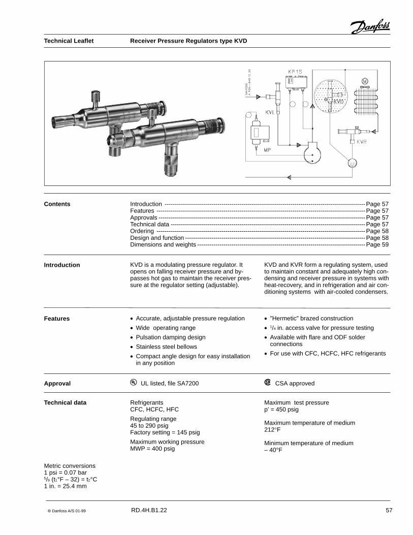
© Danfoss A/S 01-99 57
KVD is a modulating pressure regulator. Itopens on falling receiver pressure and by-passes hot gas to maintain the receiver pres-sure at the regulator setting (adjustable).
Introduction KVD and KVR form a regulating system, usedto maintain constant and adequately high con-densing and receiver pressure in systems withheat-recovery, and in refrigeration and air con-ditioning systems with air-cooled condensers.
Features � Accurate, adjustable pressure regulation
� Wide operating range
� Pulsation damping design
� Stainless steel bellows
� Compact angle design for easy installationin any position
Technical data RefrigerantsCFC, HCFC, HFC
Regulating range45 to 290 psigFactory setting = 145 psig
Maximum working pressureMWP = 400 psig
Maximum test pressurep’ = 450 psig
Maximum temperature of medium212�F
Minimum temperature of medium– 40°F
� "Hermetic" brazed construction
� 1/4 in. access valve for pressure testing
� Available with flare and ODF solderconnections
� For use with CFC, HCFC, HFC refrigerants
Approval ��UL listed, file SA7200 ��CSA approved
Metric conversions1 psi = 0.07 bar5/9 (t1°F – 32) = t2°C1 in. = 25.4 mm
Contents Introduction ---------------------------------------------------------------------------------------------------Page 57Features -------------------------------------------------------------------------------------------------------Page 57Approvals ------------------------------------------------------------------------------------------------------Page 57Technical data ------------------------------------------------------------------------------------------------Page 57Ordering -------------------------------------------------------------------------------------------------------Page 58Design and function -----------------------------------------------------------------------------------------Page 58Dimensions and weights -----------------------------------------------------------------------------------Page 59
Technical Leaflet Receiver Pressure Regulators type KVD
RD.4H.B1.22
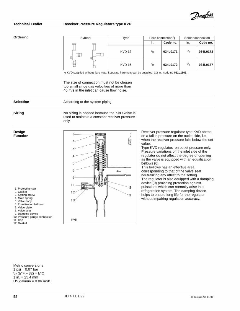
58 © Danfoss A/S 01-99
Ordering
1) KVD supplied without flare nuts. Separate flare nuts can be supplied: 1/2 in., code no 011L1103.
The size of connection must not be chosentoo small since gas velocities of more than40 m/s in the inlet can cause flow noise.
Symbol Type Flare connection1) Solder connection
in. Code no. in. Code no.
KVD 12 1/2 034L0171 1/2 034L0173
KVD 15 5/8 034L0172 5/8 034L0177
Metric conversions1 psi = 0.07 bar5/9 (t1°F – 32) = t2°C1 in. = 25.4 mmUS gal/min = 0.86 m3/h
Selection According to the system piping.
DesignFunction
Receiver pressure regulator type KVD openson a fall in pressure on the outlet side, i.e.when the receiver pressure falls below the setvalue.Type KVD regulates on outlet pressure only.Pressure variations on the inlet side of theregulator do not affect the degree of openingas the valve is equipped with an equalizationbellows (6).This bellows has an effective areacorresponding to that of the valve seatneutralizing any affect to the setting.The regulator is also equipped with a dampingdevice (9) providing protection againstpulsations which can normally arise in arefrigeration system. The damping devicehelps to ensure long life for the regulatorwithout impairing regulation accuracy.
KVD
1. Protective cap2. Gasket3. Setting screw4. Main spring5. Valve body6. Equalization bellows7. Valve plate8. Valve seat9. Damping device
10. Pressure gauge connection11. Cap12. Gasket
Sizing No sizing is needed because the KVD valve isused to maintain a constant receiver pressureonly.
Technical Leaflet Receiver Pressure Regulators type KVD
RD.4H.B1.22

© Danfoss A/S 01-99 59
Dimensions and weights
Type Connection NV1 NV2 H1 H2 H3 B1 B2 C dia. D Weight
Flare Solder ODF
in. in. in. in. in. in. in. in. in. in. in. lbs.
KVD 12 1/2 1/2 0.748 0.945 7.047 3.898 2.598 2.520 1.614 0.394 1.181 0.9
KVD 15 5/8 5/8 0.945 0.945 7.047 3.898 2.598 2.520 1.614 0.472 1.181 0.9
Technical Leaflet Receiver Pressure Regulators type KVD
RD.4H.B1.22
60 © Danfoss A/S 01-99
Technical Leaflet Pressure and Temperature Regulators
RC.4X.B1.22
Refrigeration and Air Conditioning Controls, part of the Danfoss concern, is certified inaccordance with international standard ISO 9001. This means that Danfoss fulfils theinternational standard in respect of product development, design, production and sale.
ISO 9001 quality approval
© Danfoss A/S 01-99 -AO