La difusió d - TDX (Tesis Doctorals en Xarxa)
109
ADVERTIMENT. La consulta d’aquesta tesi queda condicionada a l’acceptació de les següents condicions d'ús: La difusió d’aquesta tesi per mitjà del servei TDX (www.tesisenxarxa.net ) ha estat autoritzada pels titulars dels drets de propietat intel·lectual únicament per a usos privats emmarcats en activitats d’investigació i docència. No s’autoritza la seva reproducció amb finalitats de lucre ni la seva difusió i posada a disposició des d’un lloc aliè al servei TDX. No s’autoritza la presentació del seu contingut en una finestra o marc aliè a TDX (framing). Aquesta reserva de drets afecta tant al resum de presentació de la tesi com als seus continguts. En la utilització o cita de parts de la tesi és obligat indicar el nom de la persona autora. ADVERTENCIA. La consulta de esta tesis queda condicionada a la aceptación de las siguientes condiciones de uso: La difusión de esta tesis por medio del servicio TDR (www.tesisenred.net ) ha sido autorizada por los titulares de los derechos de propiedad intelectual únicamente para usos privados enmarcados en actividades de investigación y docencia. No se autoriza su reproducción con finalidades de lucro ni su difusión y puesta a disposición desde un sitio ajeno al servicio TDR. No se autoriza la presentación de su contenido en una ventana o marco ajeno a TDR (framing). Esta reserva de derechos afecta tanto al resumen de presentación de la tesis como a sus contenidos. En la utilización o cita de partes de la tesis es obligado indicar el nombre de la persona autora. WARNING. On having consulted this thesis you’re accepting the following use conditions: Spreading this thesis by the TDX (www.tesisenxarxa.net ) service has been authorized by the titular of the intellectual property rights only for private uses placed in investigation and teaching activities. Reproduction with lucrative aims is not authorized neither its spreading and availability from a site foreign to the TDX service. Introducing its content in a window or frame foreign to the TDX service is not authorized (framing). This rights affect to the presentation summary of the thesis as well as to its contents. In the using or citation of parts of the thesis it’s obliged to indicate the name of the author
-
Upload
khangminh22 -
Category
Documents
-
view
0 -
download
0
Transcript of La difusió d - TDX (Tesis Doctorals en Xarxa)
ADVERTIMENT. La consulta d’aquesta tesi queda condicionada a l’acceptació de les següents condicions d'ús: La difusió d’aquesta tesi per mitjà del servei TDX (www.tesisenxarxa.net) ha estat autoritzada pels titulars dels drets de propietat intel·lectual únicament per a usos privats emmarcats en activitats d’investigació i docència. No s’autoritza la seva reproducció amb finalitats de lucre ni la seva difusió i posada a disposició des d’un lloc aliè al servei TDX. No s’autoritza la presentació del seu contingut en una finestra o marc aliè a TDX (framing). Aquesta reserva de drets afecta tant al resum de presentació de la tesi com als seus continguts. En la utilització o cita de parts de la tesi és obligat indicar el nom de la persona autora. ADVERTENCIA. La consulta de esta tesis queda condicionada a la aceptación de las siguientes condiciones de uso: La difusión de esta tesis por medio del servicio TDR (www.tesisenred.net) ha sido autorizada por los titulares de los derechos de propiedad intelectual únicamente para usos privados enmarcados en actividades de investigación y docencia. No se autoriza su reproducción con finalidades de lucro ni su difusión y puesta a disposición desde un sitio ajeno al servicio TDR. No se autoriza la presentación de su contenido en una ventana o marco ajeno a TDR (framing). Esta reserva de derechos afecta tanto al resumen de presentación de la tesis como a sus contenidos. En la utilización o cita de partes de la tesis es obligado indicar el nombre de la persona autora. WARNING. On having consulted this thesis you’re accepting the following use conditions: Spreading this thesis by the TDX (www.tesisenxarxa.net) service has been authorized by the titular of the intellectual property rights only for private uses placed in investigation and teaching activities. Reproduction with lucrative aims is not authorized neither its spreading and availability from a site foreign to the TDX service. Introducing its content in a window or frame foreign to the TDX service is not authorized (framing). This rights affect to the presentation summary of the thesis as well as to its contents. In the using or citation of parts of the thesis it’s obliged to indicate the name of the author
UNIVERSITAT POLITÈCNICA DE CATALUNYA
INSTITUT DE CIÈNCIA DE MATERIALS DE BARCELONA – CONSEJO SUPERIOR DE INVESTIGACIONES CIENTÍFICAS
DISSERTATION PRESENTED TO OBTAIN THE PhD DEGREE IN
CHEMICAL PROCESS ENGINEERING
USE OF THE SUPERCRITICAL FLUID
TECHNOLOGY FOR THE PREPARATION OF
NANOSTRUCTURED HYBRID MATERIALS
AND DESIGN OF THE INTERFACE
Carlos A. García González
PhD Director: Dr. Concepción Domingo Pascual
PhD Tutor: Prof. Francesc Recasens Baxarias
Barcelona, December 2009
i
SHORT ABSTRACT
The use of nanostructured composites is a promising solution for the design of
multifunctional materials. However, the lack of coupling or bonding between the organic and
inorganic components of most nanostructured hybrid composites often leads to anisotropic
macroscopic properties, limiting the use of these materials. Hence, the interaction at the
components interphase must be engineered to enhance materials performance. In this PhD
Thesis, the sustainable supercritical carbon dioxide (scCO2) technology is used for both the
surface modification of inorganic nanoparticles and the preparation of nanostructured hybrid
materials.
Bifunctional alkoxysilanes, acting as adhesion promoters, are herein investigated for the
surface modification of inorganic nanoparticles; particularly, titanium dioxide (TiO2). For the
silanization process, scCO2 is used as the solvent of choice for alkoxysilanes. Fundamental studies
on the solubility of octyltriethoxysilane in compressed CO2 and on the kinetics of the TiO2
silanization process are performed. Silanization experiments are conducted to ascertain the
influence of pressure and temperature in the tunable physicochemical properties of scCO2 and in
the process. This information is needed for the engineering control of the characteristics of the
silane coatings. Extension of the supercritical silanization process to other sets of alkoxysilanes
and inorganic nanoparticles are presented.
Further, nanostructured hybrid materials are prepared using scCO2 technology. Prior to
obtain the composite materials, the inorganic nanoparticles are surface silanized in order to
facilitate the homogeneous distribution of the nanoparticles within the matrix and to improve
the filler-organic matrix interaction. Firstly, biopolymeric matrices of either poly(L-lactic acid) or
the blend poly(methylmethacrylate)/poly(ε-caprolactone) loaded with nanometric TiO2 or
hydroxyapatite, respectively, are processed employing scCO2 as an anti-solvent and the Particles
ii
from a Compressed Anti-Solvent technique. Precipitated materials have potential applications in
tissue engineering. Secondly, lipid blend matrices of hydrogenated castor oil/glyceryl
monostearate loaded with nanometric TiO2 and caffeine are prepared employing scCO2 as a
solute and the Particles from Gas Saturated Solutions technique. Precipitated materials have
potential applications in sunscreens and pharmaceutical dermal products.
Finally, the extension of the silanization scCO2-assisted process to multiscale complex
hybrid materials is assessed. The technology is presented for the two-step carbonation-
silanization process of cement-based materials. Firstly, the carbonation of cement is accelerated
by using scCO2 as the carbonation agent. The carbonation process is followed by the hydrophobic
treatment of the carbonated cement using the supercritical silanization method. The supercritical
silanization of the carbonated cement confers water repellence to the material. Prepared
materials may be potentially used for the confinement of hazardous wastes in a humid
environment or as durable construction materials.
iii
RESUMEN
Los materiales compuestos nanoestructurados son considerados una opción prometedora
para la concepción de materiales multifuncionales. Sin embargo, la falta habitual de interacción
entre los componentes orgánicos e inorgánicos en los materiales híbridos nanoestructurados
comporta unas propiedades macroscópicas anisotrópicas que limitan su uso. Por ello, se hace
necesario el diseño de la interfase formada entre los componentes mencionados a fin de mejorar
sus prestaciones. En esta Tesis Doctoral se ha optado por el uso de dióxido de carbono supercrítico
(scCO2) para la modificación superficial de nanopartículas inorgánicas y para la preparación de
materiales híbridos nanoestructurados. Estos procesos supercríticos, diseñados como sostenibles,
se proponen como sustitutos de técnicas convencionales que empleen disolventes orgánicos.
El tratamiento superficial de nanopartículas de dióxido de titanio (TiO2) con
octiltrietoxisilano se ha empleado como sistema de estudio para evaluar el uso de recubrimientos
de alcoxisilanos bifuncionales como promotores de adhesión de partículas inorgánicas
nanométricas. El scCO2 se emplea como disolvente del alcoxisilano para la silanización del TiO2.
También se han llevado a cabo estudios fundamentales de solubilidad de octiltrietoxisilano en
CO2 y de la cinética del proceso de silanización del TiO2. La modulación de las propiedades
fisicoquímicas del scCO2 con la presión y la temperatura permite el control de las características
del recubrimiento con silano. El proceso de silanización supercrítico se ha extendido a diferentes
sistemas alcoxisilano-nanopartículas inorgánicas.
Asimismo, se ha evaluado la tecnología de scCO2 para la preparación de materiales
híbridos nanoestructurados que contengan nanopartículas inorgánicas silanizadas. El tratamiento
superficial de las nanopartículas favorece la distribución homogénea de éstas en el material
híbrido y mejora la interacción relleno-matriz orgánica. Se han procesado matrices
biopoliméricas de interés en ingeniería tisular, compuestas de ácido poliláctico o la mezcla
iv
polimetilmetacrilato/policaprolactona, con adiciones de nanopartículas de TiO2 o hidroxiapatita,
respectivamente. Para su procesado, se ha empleado scCO2 como no-disolvente utilizando la
técnica Particles from a Compressed Anti-Solvent (PCA). Además, se han preparado partículas
híbridas formadas por una mezcla lipídica de aceite de ricino hidrogenado y glicerilmonoestearato
con adiciones de TiO2 y cafeína, con posibles aplicaciones en cremas para uso tópico. Estas
partículas sólidas lipídicas se han obtenido usando la técnica Particles from Gas Saturated
Solutions (PGSS) que emplea scCO2 como soluto.
Por último, el proceso de silanización supercrítico se ha ensayado para materiales híbridos
complejos multiescalados. Se han procesado materiales de base cemento empleando un proceso
supercrítico de carbonatación-silanización en dos etapas. Primero, el cemento se carbonata de
manera acelerada usando scCO2 como agente de carbonatación. Este cemento, ya carbonatado, se
somete, finalmente, a un tratamiento hidrofóbico mediante silanización supercrítica, para su
posible aplicación en confinamiento de residuos peligrosos en ambientes húmedos o como
material de construcción duradero.
v
ABSTRACT
Nowadays, society is asking for a global changing in the way of manufacturing goods in a
more sustainable manner. Indeed, the weight of the classical factors (cost, quality, appearance)
influencing the acceptance of a certain good in the market have currently changed.
Manufacturing requirements and regulations concerning environment protection (e.g., resource
consumption, sustainability, toxicity, CO2 footprint, recycling potential) and quality features (e.g.,
product guarantees, durability against aggressive environments, corporate vision) are aspects of
increasing concern. The competitive position of a company is influenced by seizing the
opportunities and challenges and by managing the risks that the changeable market has. As a
consequence, the industry is continuously looking for smart and innovative solutions for the
design and manufacturing of materials with novel properties and increased added value, and for
the production of materials already existing in the market in a more efficient manner.
Nanostructured hybrid composites have emerged as a promising class of innovative
materials for many industrial sectors (e.g., energy, optoelectronics, biomedicine, cosmetics). The
multicomponent composition of these materials provides them with unique properties arising
from the synergistic combination of the characteristics of their individual components structured
at the nanolevel. Nevertheless, in numerous hybrid materials, the lack of coupling or bonding
between the components often leads to anisotropic macroscopic properties, limiting their use.
Hence, the interaction at the interphase between hybrid components must be properly
engineered to enhance materials properties. In this PhD Thesis, the quest for sustainable and
environmentally friendly processes led to the use of supercritical carbon dioxide (scCO2) for both
the surface modification of nanometric inorganic particles and the preparation of nanostructured
hybrid materials. These processes are designed for the replacement of conventional methods
using organic solvents.
vi
Bifunctional alkoxysilane molecules, acting as adhesion promoters, are, herein,
investigated for the surface modification of nanometric inorganic particles. The surface treatment
of titanium dioxide (TiO2) nanoparticles with octyltriethoxysilane is taken as the model system
for study. In terms of processing, scCO2 is used as the solvent of choice for alkoxysilanes for the
surface modification of TiO2. Fundamental studies on the solubility of the used silane in CO2 in
the pressure range 8-18 MPa at two different temperatures (318 and 348 K) and on the kinetics of
the TiO2 silanization process are performed. For the scCO2-aided silanization process, studies are
conducted to ascertain the effects and interactions of the operating variables on the properties of
the final material. Results show that the tunable physicochemical properties of scCO2 with
pressure and temperature (e.g., density, solvation power) allows the engineering control of the
characteristics of the silane coating. Examples of the extension of the application of the
supercritical silanization process to other sets of alkoxysilanes and inorganic nanoparticles are
also presented.
The preparation of hybrid materials including silanized inorganic nanoparticles and
organic matrices is further tested using scCO2 technology. Surface treated nanoparticles are used
to facilitate the homogeneous distribution of the nanoparticles within the matix and to improve
the inorganic filler-organic matrix interaction. Biopolymeric matrices of either poly(L-lactic acid)
(L-PLA) or the blend poly(methylmethacrylate)/poly(ε-caprolactone) (PMMA/PCL) loaded with
nanometric titanium dioxide or hydroxyapatite, respectively, are prepared. To obtain these
hybrid materials, scCO2 is employed as an anti-solvent, using the Particles from a Compressed
Anti-Solvent (PCA) technique. Studies are performed to pursue the effect of the processing
conditions on the morphology of the precipitated hybrid materials. The resulting material,
obtained in the form of fibers, has suitable properties for its potential application in tissue
engineering. In a different system, hybrid particles composed of a lipidic matrix (hydrogenated
castor oil/glyceryl monostearate) loaded with silanized titanium dioxide and caffeine are
prepared. The Particles from Gas Saturated Solutions (PGSS) technique, assisted by the use of
scCO2 as a solute, is employed for the production of these solid lipid particles. The obtained
hybrid material is evaluated concerning the drug carrier and release ability and the UV-shielding
capacity. The UV-light protection and photoaging prevention capacity of the lipid-based hybrid
material provide excellent properties for the use of these particles in the formulation of
sunscreens and pharmaceutical dermal products.
vii
Finally, the possibility of extending the supercritical silane treatment to multiscale
complex hybrid materials is assessed. The technology based on the use of scCO2 is presented for
the two-step carbonation-silanization process of cement-based materials. In the first step, the
carbonation of cement is accelerated using scCO2 as the carbonation agent. The effects of the
cement formulation and process operation conditions on the microstructure and physicochemical
properties of carbonated samples are evaluated. The carbonation process is followed by the
hydrophobic treatment of the carbonated samples using a supercritical silanization method. The
surface modification of carbonated cement with octyltriethoxysilane confers water repellence to
the material. The carbonation-silanization process is scheduled and integrated to mitigate the
consumption of raw materials and the use of facilities.
ix
ACKNOWLEDGEMENTS
The PhD Thesis is eventually written and finished. It seemed far away this moment when
I started four years ago, but it is already done! So now it is time to start getting in touch again
with friends and family (I hope they still remember me!). Research work is a very hard job that
cannot be done alone. This is the reason why I would like to thank to the colleagues and friends
who helped and supported me during these years.
En primer lugar y especialmente a Concha, mi Directora de Tesis, no sólo por
proporcionarme la oportunidad de realizar la Tesis Doctoral en su grupo de investigación, sino
también por volcarse en todo momento conmigo tanto a nivel de trabajo como personal. Es un
orgullo haber podido trabajar con una persona tan competente, clarividente y, al mismo tiempo,
cercana. Gracias por enseñarme el significado de las palabras interdisciplinaridad y colaborar, y la
sinonimia de las palabras científico, ingeniero e investigador.
Me gustaría también dar las gracias a todo el personal del Institut de Ciències de Materials
de Barcelona – Consejo Superior de Investigaciones Científicas y de MATGAS 2000 AIE por
proporcionarme un ambiente de trabajo agradable y propicio para desarrollar la investigación en
sus instalaciones. En especial, me gustaría agradecer a Julio (Matu), mi aliado, por las horas de
trabajo y de risas que hemos pasado juntos. A Ana (Dra. López-Periago), mi compañera de batallas
de laboratorio, por su ayuda y por contagiarme su vitalidad y pasión por la investigación
(¡graciñas!). A Elena, por sus conversaciones y cafés que me ayudaron a desconectar del mundo de
la ciencia. Al resto de compañeros de laboratorio (Raúl, Nadia y Nerea), por su apoyo.
Agradezco al Consejo Superior de Investigaciones Científicas por el apoyo financiero de la
bolsa predoctoral I3P otorgada y a las Administraciones autonómicas, estatales y europeas
(SurfaceT project) por su colaboración en los proyectos en los que he estado involucrado.
I would like to thank Sergei (Prof. Kazarian) for giving me the opportunity to visit his
laboratories in the Department of Chemical Engineering of the Imperial College London. Many
x
thanks to Jean Michel (Dr. Andanson) for introducing me to the world of the “spectroscopy”. My
stay in London would not be so pleasant and fruitful without the rest of my “tea-break”
colleagues (Francesca —Dr. Palombo— and Feng —future Dr. Tay—).
Je voudrais remercier Pascale (Dr. Subra-Paternault) pour son aide et sa collaboration afin
que je puisse réaliser un stage au Laboratoire d'Ingénierie des Matériaux et des Hautes Pressions
(LIMHP-CNRS). Les résultats n'auraient pas pu être obtenus sans l'inestimable aide et les conseils
d’Arlette (Dr. Vega-González).
Gostaria de agradecer à Catarina (Dra. Duarte) por me ter oferecido a oportunidade de dar
o “toque final” à minha Tese de Doutoramento nos laboratórios do Instituto de Biologia
Experimental e Tecnológica (IBET). Muito obrigado à Raquel (Dra. Sampaio da Sousa) pela sua
ajuda e conselhos durante o meu estágio. É muito fácil estar num grupo de laboratório (Ana —
Dra. Matias—, Raquel —Dra. Frade—, Teresa —futura Dra. Serra—, Susana, Patrícia, Pedro, etc.)
com tão bom ambiente de trabalho e bom humor. Ao Filipe e à Barbara pela sua hospitalidade e
compreensão com o meu “portunhol avançado”.
Vull agrair al Xavi (Dr. Saurina) i a l’Anna (futura Dra. Argemí) del Departament de
Química Analítica de la Universitat de Barcelona pel seu suport i la seva disponibilitat en tot
moment. Sempre m’hi he sentit com al meu segon laboratori, gràcies. El món de l’Analítica és
menys fosc del que pot semblar si és explicat per gent tan experta i competent com vosaltres.
Mi agradecimiento a mi Tutor de Tesis, Francesc (Prof. Recasens), por su colaboración y
consejos a lo largo de estos años. Extiendo este agradecimiento a todo el Departament
d’Enginyeria Química de la Universitat Politècnica de Catalunya.
Malia que non é doado estar lonxe da familia da terriña (papiños, Ana e padrinos), eu
sentín preto o voso agarimo e apoio incondicional en todo momento. Os alicerces desta Tese están
baseados nos valores e no espírito de sacrificio que aprendín convosco. Por sorte, a morriña
sempre se leva mellor con parte da familia preto. Co apoio de Nuria e Goyo (cuñaaao) e coas
fedelladas de Danuco e Paulecha, non podo lembrar máis que bos momentos convosco en BCN.
Especialmente, quero agradecer a Inés por ser a persoa que estivo sempre comigo e que
me padeceu durante todos estes anos (oi?). O teu agarimo e a túa ledicia son o alimento esencial
do meu optimismo. Este ano de redacción de teses foi de tolos, mais xa o recuperaremos.
Finally, I am in debt with everyone who has helped me and collaborated in my research
during these years, and who is not explicitly mentioned above. He/she deserves to be
acknowledged as much as anyone else herein cited. Thank you very much!
xi
TABLE OF CONTENTS
SHORT ABSTRACT .............................................................................................................. i
RESUMEN............................................................................................................................ iii
ABSTRACT ........................................................................................................................... v
ACKNOWLEDGEMENTS .................................................................................................. ix
TABLE OF CONTENTS ...................................................................................................... xi
INDEX OF FIGURES AND TABLES................................................................................. xv
CHAPTER 0 – INTRODUCTION........................................................................................ 1
0.1. NANOSTRUCTURED ORGANIC-INORGANIC HYBRID MATERIALS.................2
0.2. PRINCIPLES OF SUPERCRITICAL FLUIDS ................................................................3
0.3. OBJECTIVES.....................................................................................................................6
0.4. STRATEGIES FOR scCO2 TECHNOLOGY ...................................................................7
0.5. REMARKS ON THE USE OF scCO2 TECHNOLOGY................................................10
0.6. SCOPE AND STRUCTURE OF THE THESIS .............................................................13
0.7. REFERENCES .................................................................................................................14
CHAPTER 1 – PROCESSING USING scCO2 TECHNOLOGY........................................ 23
1.1. INTRODUCTION...........................................................................................................24
1.2. SUPERCRITICAL PROCESSING EQUIPMENT ........................................................27
1.2.1. Multi-purpose supercritical batch equipment .......................................................27
1.2.2. Multi-purpose supercritical equipment with a continuous flow of scCO2 .........28
1.2.3. Supercritical-assisted anti-solvent equipment.......................................................30
1.2.4. Supercritical-assisted PGSS equipment ..................................................................32
1.3. CONCLUSIONS..............................................................................................................34
1.4. REFERENCES .................................................................................................................34
xii
CHAPTER 2 - USE OF scCO2 AS A SOLVENT: SUPERCRITICAL
SILANIZATION REACTION ............................................................................................ 39
2.1. INTRODUCTION...........................................................................................................40
2.2. MATERIALS AND METHODS ....................................................................................44
2.2.1. Materials....................................................................................................................44
2.2.2. Process .......................................................................................................................44
2.2.3. Characterization .......................................................................................................45
2.3. RESULTS .........................................................................................................................46
2.4. CONCLUSIONS..............................................................................................................99
2.5. REFERENCES .................................................................................................................99
CHAPTER 3 - USE OF scCO2 AS AN ANTI-SOLVENT: PREPARATION OF
HYBRID MATERIALS..................................................................................................... 107
3.1. INTRODUCTION.........................................................................................................108
3.2. MATERIALS AND METHODS ..................................................................................110
3.2.1. Materials..................................................................................................................110
3.2.2. Process .....................................................................................................................110
3.2.3. Characterization .....................................................................................................110
3.3. RESULTS .......................................................................................................................111
3.4. CONCLUSIONS............................................................................................................123
3.5. REFERENCES ...............................................................................................................123
CHAPTER 4 – USE OF scCO2 AS A SOLUTE PREPARATION OF LIPID-BASED
PARTICLES....................................................................................................................... 127
4.1. INTRODUCTION.........................................................................................................128
4.2. MATERIALS AND METHODS ..................................................................................130
4.2.1. Materials..................................................................................................................130
4.2.2. Process .....................................................................................................................130
4.2.3. Characterization .....................................................................................................131
4.3. RESULTS .......................................................................................................................132
xiii
4.4. CONCLUSIONS............................................................................................................143
4.5. REFERENCES ...............................................................................................................143
CHAPTER 5 – USE OF scCO2 AS A REAGENT: ACCELERATED CEMENT
CARBONATION .............................................................................................................. 145
5.1. INTRODUCTION.........................................................................................................146
5.2. MATERIALS AND METHODS ..................................................................................149
5.2.1. Materials..................................................................................................................149
5.2.2. Process .....................................................................................................................149
5.2.3. Characterization .....................................................................................................150
5.3. RESULTS .......................................................................................................................151
5.4. PROCESS OPTIMIZATION........................................................................................181
5.4.1. Scheduling...............................................................................................................181
5.4.2. Process integration .................................................................................................182
5.4.3. Study of the regime change in the semicontinuous processing .........................183
5.5. CONCLUSIONS............................................................................................................187
5.6. REFERENCES ...............................................................................................................187
SUMMARY OF RESULTS................................................................................................ 193
CONCLUSIONS................................................................................................................ 197
CURRICULUM VITAE .................................................................................................... 201
xv
INDEX OF FIGURES AND TABLES
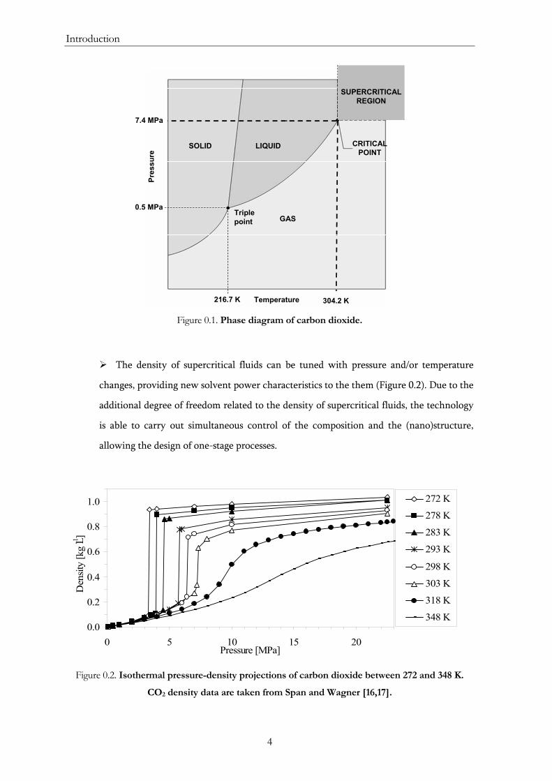
Figure 0.1. Phase diagram of carbon dioxide...................................................................................... 4
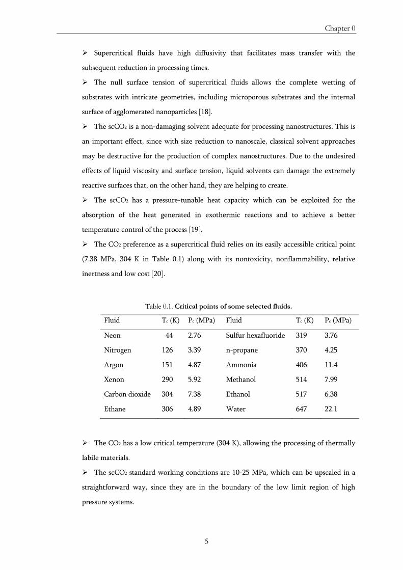
Figure 0.2. Isothermal pressure-density projections of carbon dioxide between 272 and 348
K. ......................................................................................................................................................... 4
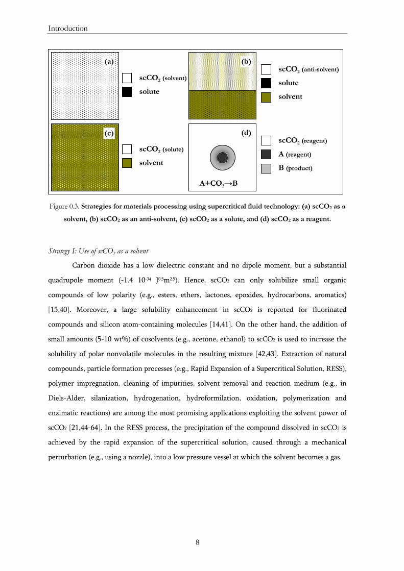
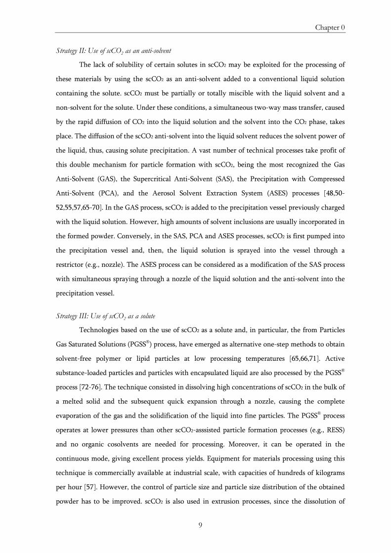
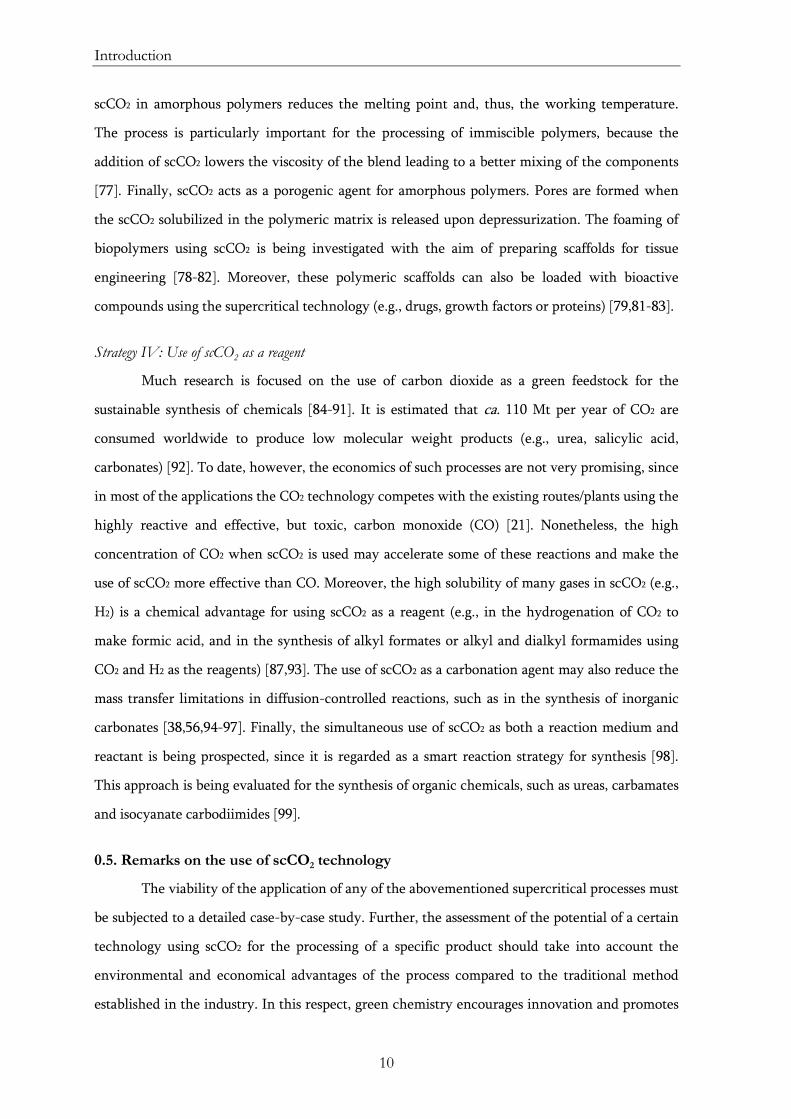
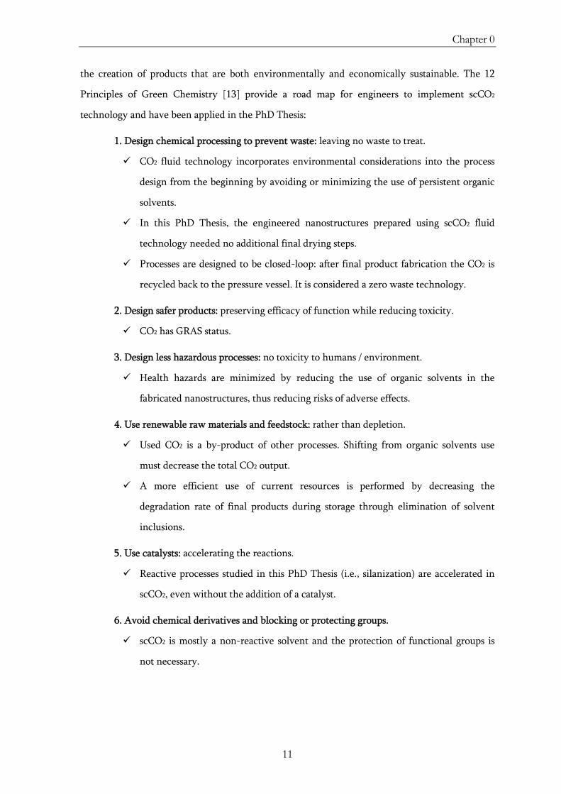
Figure 0.3. Strategies for materials processing using supercritical fluid technology: (a) scCO2
as a solvent, (b) scCO2 as an anti-solvent, (c) scCO2 as a solute, and (d) scCO2 as a reagent....... 8
Figure 1.1. PFD of the multi-purpose supercritical batch equipment............................................ 28
Figure 1.2. PFD of the multi-purpose supercritical equipment with a continuous flow of
scCO2................................................................................................................................................. 29
Figure 1.3. PFD of the supercritical-assisted anti-solvent equipment............................................ 31
Figure 1.4. PFD of the supercritical-assisted PGSS equipment....................................................... 33
Figure 2.1. Contact angle of a 1 μL-water droplet applied on the surface of compacted
pellets of raw (TiO2) and supercritically silanized TiO2 particles with methyltrimethoxy-
(Ti-C1), isobutyltriethoxy- (Ti-C4), octyltriethoxy- (Ti-C8), octyldimethylmethoxy- (Ti-
C8(C1)2) and octadecyltrimethoxysilane (Ti-C18)........................................................................... 41
Figure 2.2. Schematic representation of the different steps (1-5) of the silanization reaction
with a triethoxysilane occurring on the surface of inorganic nanoparticles.............................. 42
Figure 2.3. Silane monolayer formation: (a) schematic representation, and (b) TEM picture
of an octadecylsilane monolayer on TiO2 nanoparticles obtained by the supercritical
silanization process.......................................................................................................................... 43
Figure 2.4. Schematic drawing of the initial set-up of the reactor used for the supercritical
silanization experiments ................................................................................................................. 45
Figure 3.1. Sketch of the prepared polymeric fibers loaded with inorganic fillers..................... 109
Figure 4.1. Sketch of the prepared lipid-based particles loaded with an inorganic UV-filter
and an active compound ............................................................................................................... 129
Figure 5.1. Sketch of a deep geological repository placed in a granitic rock ............................... 147
Figure 5.2. Sketch of an integrated cement carbonation/coal-fired power plant........................ 147
Figure 5.3. Gantt diagram of the process of carbonation-silanization of cementitious
materials ......................................................................................................................................... 182
Figure 5.4. Modified equipment for the integrated batch carbonation-silanization process ..... 182

xvi
Figure 5.5. Scheduling of the integrated carbonation-silanization process ................................. 183
Figure 5.6. Modified equipment for the semicontinuous carbonation-silanization process ...... 184
Figure 5.7. Gantt diagram of the semicontinuous carbonation-silanization process .................. 184
Figure 5.8. PFD of the semicontinuous supercritical carbonation-silanization process with
mass and energy integration......................................................................................................... 185
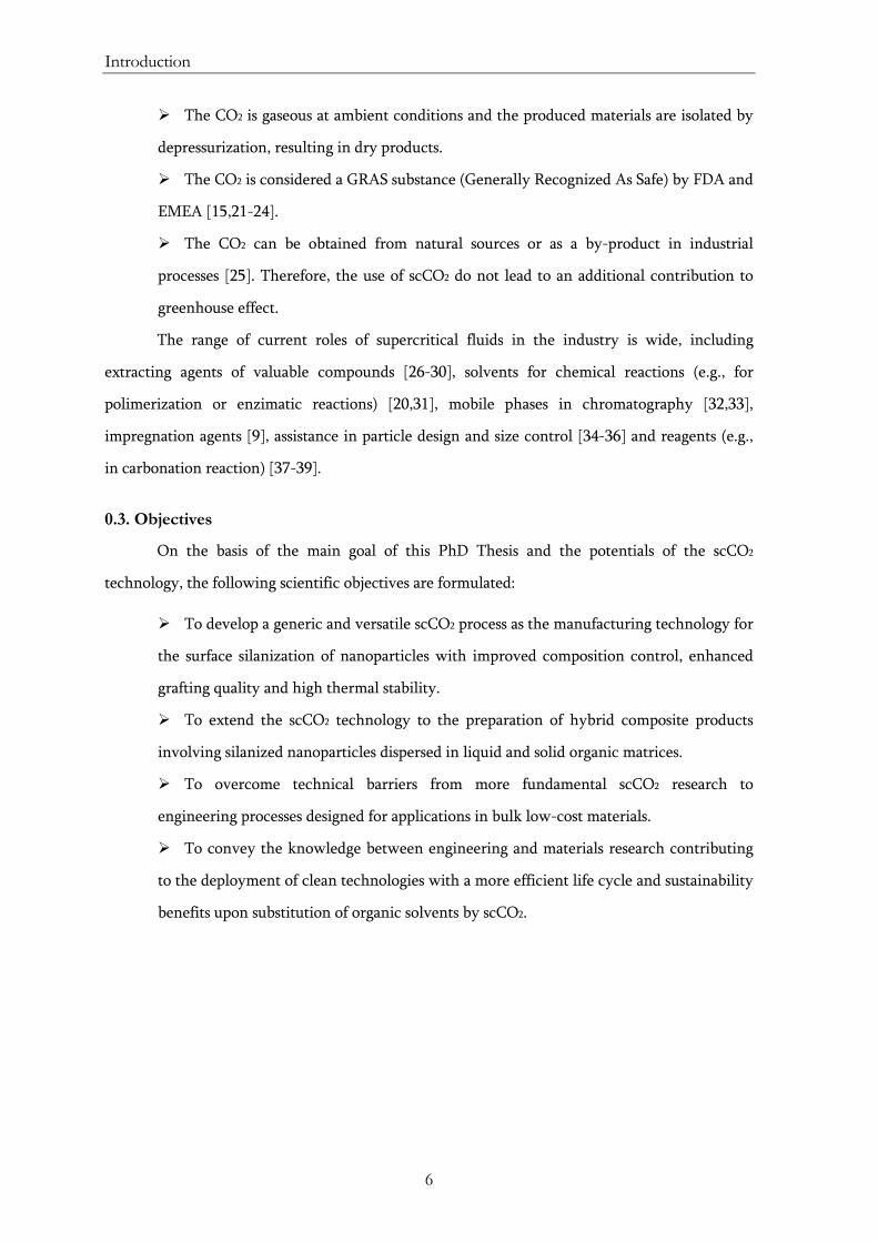
Table 0.1. Critical points of some selected fluids ............................................................................... 5
1
Chapter 0
INTRODUCTION
Nanostructured hybrid composites are multicomponent materials with novel and unique
properties arising from the synergistic combination at the nanoscale of their dissimilar
constituents. However, the components of these composites may be incompatible, and the
formed interphase must be often engineered to induce interaction between the dissimilar
constituents. The main goal of this PhD Thesis is the development of sustainable and
environmentally friendly processes based in the use of supercritical carbon dioxide for the
preparation of hybrid composite materials of designed interphase. The main goal is attained after
accomplishing the specific objectives described in Section 0.3. In this Chapter, the overall
structure of this PhD Thesis is also outlined.
Introduction
2
0.1. Nanostructured organic-inorganic hybrid materials
Nanostructured hybrid materials are an especial class of composite systems comprised of
organic and inorganic components distributed at the nanometric scale. The synergistic
combination of both components in a single material at the nanosize level provides novel
properties for the development of multifunctional materials [1-4]. There are two key approaches
for the creation of composite structures at the nanometer scale: self-aggregation and dispersion.
By using the self-aggregation approach, normally ordered hybrid materials are obtained; while
disordered composites are often prepared by dispersing nanoparticles in a matrix. Nanostructured
self-aggregated hybrid composites are materials with spatially well-defined domains for both the
organic and inorganic components and with control of their mutual arrangement at the
nanolevel. On the other hand, the combination by dispersion of low dimensional dispersed
nanoparticles (fillers) with soft matter, particularly polymers, allows the easy preparation of
hybrid materials with improved properties. The fascinating properties of these unique structural
nanocomposites enable a wide range of applications in the fields of energy, biomedicine,
optoelectronics, etc. [1-4].
Fillers are small particles (usually of less than 1000 μm length) added to matrices as
admixtures, usually at high loadings, for the formulation of composites. Inorganic particles are
used widespread as fillers, with a market value in Europe of 2.3 billion Euros in 2007 [5]. Fillers
are basically divided into inactive and functional fillers. The term inactive is related to the
primary use of fillers focused in reducing final material cost; while the term of functional is
applied to emphasize the modern use of fillers that are employed to modify specific properties of
the final composite product, such as density, shrinkage, expansion coefficient, conductivity,
permeability, mechanical properties or thermal behaviour [4,6]. The addition of fillers to matrices
to form composite materials has very different purposes, ranging from fire retardant effects to the
hardening of soft matter (polymers, plastics) [5,7].
The use of nanoparticles as fillers has attracted the interest of scientists and engineers. On
one side, nanotechnology has developed to a stage that allows the large-scale production of
different tailored single-component nanosized entities, ranging from metal nanoparticles to
carbon nanotubes. Hence, at this stage, a major challenge is to demonstrate the feasibility of the
fabrication of complex nanostructured products or devices, such as nanostructured composites.
However, the actual bottom-up mass-production methods (vapor-related physical routes or
Chapter 0
3
liquid-related chemical bulk processes) to further develop heterostructures of various
nanoentities have severe limitations related to high cost and reduced purity. On the other hand,
in order to effectively explore the remarkable properties of nanocomposites and to manipulate
nanoparticles to form nanostructured hybrid composites, one essential step is the surface
functionalization of the nanoparticles. The reason is that as-prepared inorganic fillers are often
incompatible with organic-soft matrices, due to the low interfacial interaction between both
phases [8]. This fact is especially relevant for nanometric fillers, which have a large surface area
to volume ratio [9]. The lack of filler-matrix coupling or bonding often leads to the preparation of
hybrid materials with non-isotropic properties and relatively poor mechanical behavior that
limited their applications [10,11]. Therefore, the dispersion enhancement of nanometric fillers in
the bulk of diverse organic matrices through their surface modification is technically needed [12].
Moreover, effects of weathering (e.g., wetting, permeability, fouling and corrosion) in the formed
composite can be suppressed, or at least mitigated, by treating the surface of the inorganic filler,
which increases the durability of the final material. The high surface reactivity of most inorganic
nanoparticles facilitates their surface modification and functionalization.
By using the unique properties of compressed gases and supercritical fluids, which are
intermediate between liquids (high density) and gases (high diffusivity, low viscosity and null
surface tension), these fluids can be used to design innovative processes for the production of
heterostructures, taking advantage of both abovementioned fabrication bottom-up approaches
(physical & chemical). In this respect, this Thesis aims at demonstrating that the supercritical
fluid technology can be used for the production of complex high purity nanoproducts fulfilling
the majority of the Twelve Green Chemistry Principles [13].
0.2. Principles of Supercritical Fluids
Fluids turn supercritical when both temperature and pressure are above the value of the
critical point (Figure 0.1) [14,15]. Besides, in the supercritical region, an isothermal pressure
increase above the critical pressure (Pc) or an isobaric temperature increase above the critical
temperature (Tc) maintains the fluid at supercritical conditions.
Supercritical fluid technology often uses supercritical carbon dioxide (scCO2) as the fluid
for materials processing. Supercritical fluids in general and scCO2 in particular, have a set of
characteristics that facilitates the processing of materials:
Introduction
4
Temperature216.7 K 304.2 K
7.4 MPa
CRITICALPOINT
0.5 MPaTriple point GAS
LIQUIDSOLID
SUPERCRITICAL REGION
Pres
sure
Figure 0.1. Phase diagram of carbon dioxide.
The density of supercritical fluids can be tuned with pressure and/or temperature
changes, providing new solvent power characteristics to the them (Figure 0.2). Due to the
additional degree of freedom related to the density of supercritical fluids, the technology
is able to carry out simultaneous control of the composition and the (nano)structure,
allowing the design of one-stage processes.
0.0
0.2
0.4
0.6
0.8
1.0
0 5 10 15 20Pressure [MPa]
Den
sity
[kg
L-1]
272 K
278 K
283 K
293 K
298 K
303 K
318 K
348 K
Figure 0.2. Isothermal pressure-density projections of carbon dioxide between 272 and 348 K.
CO2 density data are taken from Span and Wagner [16,17].
Chapter 0
5
Supercritical fluids have high diffusivity that facilitates mass transfer with the
subsequent reduction in processing times.
The null surface tension of supercritical fluids allows the complete wetting of
substrates with intricate geometries, including microporous substrates and the internal
surface of agglomerated nanoparticles [18].
The scCO2 is a non-damaging solvent adequate for processing nanostructures. This is
an important effect, since with size reduction to nanoscale, classical solvent approaches
may be destructive for the production of complex nanostructures. Due to the undesired
effects of liquid viscosity and surface tension, liquid solvents can damage the extremely
reactive surfaces that, on the other hand, they are helping to create.
The scCO2 has a pressure-tunable heat capacity which can be exploited for the
absorption of the heat generated in exothermic reactions and to achieve a better
temperature control of the process [19].
The CO2 preference as a supercritical fluid relies on its easily accessible critical point
(7.38 MPa, 304 K in Table 0.1) along with its nontoxicity, nonflammability, relative
inertness and low cost [20].
Table 0.1. Critical points of some selected fluids.
Fluid Tc (K) Pc (MPa) Fluid Tc (K) Pc (MPa)
Neon 44 2.76 Sulfur hexafluoride 319 3.76
Nitrogen 126 3.39 n-propane 370 4.25
Argon 151 4.87 Ammonia 406 11.4
Xenon 290 5.92 Methanol 514 7.99
Carbon dioxide 304 7.38 Ethanol 517 6.38
Ethane 306 4.89 Water 647 22.1
The CO2 has a low critical temperature (304 K), allowing the processing of thermally
labile materials.
The scCO2 standard working conditions are 10-25 MPa, which can be upscaled in a
straightforward way, since they are in the boundary of the low limit region of high
pressure systems.
Introduction
6
The CO2 is gaseous at ambient conditions and the produced materials are isolated by
depressurization, resulting in dry products.
The CO2 is considered a GRAS substance (Generally Recognized As Safe) by FDA and
EMEA [15,21-24].
The CO2 can be obtained from natural sources or as a by-product in industrial
processes [25]. Therefore, the use of scCO2 do not lead to an additional contribution to
greenhouse effect.
The range of current roles of supercritical fluids in the industry is wide, including
extracting agents of valuable compounds [26-30], solvents for chemical reactions (e.g., for
polimerization or enzimatic reactions) [20,31], mobile phases in chromatography [32,33],
impregnation agents [9], assistance in particle design and size control [34-36] and reagents (e.g.,
in carbonation reaction) [37-39].
0.3. Objectives
On the basis of the main goal of this PhD Thesis and the potentials of the scCO2
technology, the following scientific objectives are formulated:
To develop a generic and versatile scCO2 process as the manufacturing technology for
the surface silanization of nanoparticles with improved composition control, enhanced
grafting quality and high thermal stability.
To extend the scCO2 technology to the preparation of hybrid composite products
involving silanized nanoparticles dispersed in liquid and solid organic matrices.
To overcome technical barriers from more fundamental scCO2 research to
engineering processes designed for applications in bulk low-cost materials.
To convey the knowledge between engineering and materials research contributing
to the deployment of clean technologies with a more efficient life cycle and sustainability
benefits upon substitution of organic solvents by scCO2.
Chapter 0
7
The following technical achievements need to be reached to meet the abovementioned
objectives:
Engineering of flexible bench-scale facilities for products preparation (preferably
one-step) using scCO2 as a solvent, anti-solvent or solute.
Engineering of high pressure instrumentation for phase equilibria and solubility
measurements.
Process optimization by application of experimental design.
Development of protocols for designing and evaluating surface modification
(silanization) processes using scCO2 as a solvent.
Development of protocols for manufacturing hybrid nanostructured composite
materials of the type inorganic nanoparticles dispersed in organic matrices using scCO2
either as an antisolvent or as a solvent.
Development of protocols and methods for off-situ materials characterization in solid
(X-ray diffraction, infrared spectroscopy, Raman spectroscopy, low-temperature N2
adsorption-desorption, mercury intrusion porosimetry, thermogravimetry, differential
scanning calorimetry, scanning electron microscopy, transmission electron microscopy,
UV-Vis spectroscopy, energy dispersive spectrometry, solid 29Si nuclear magnetic
resonance, water permeability test, static contact angle), dissolved (1H nuclear magnetic
resonance, high performance liquid chromatography) or dispersed mode (laser scattering
and dynamic light scattering).
0.4. Strategies for scCO2 technology
The physicochemical properties of scCO2 offer a widespread set of alternatives for novel
processing protocols and strategies. Moreover, some post-processing steps (e.g., grinding, milling,
solvent removal by evaporation or extraction) needed in some specific industries (e.g., coating,
drug delivery systems) using conventional technologies are usually avoided when using scCO2.
Strategies of the use of scCO2 for materials processing purposes are, herein, classified in four main
groups (Figure 0.3):
Introduction
8
Figure 0.3. Strategies for materials processing using supercritical fluid technology: (a) scCO2 as a
solvent, (b) scCO2 as an anti-solvent, (c) scCO2 as a solute, and (d) scCO2 as a reagent.
Strategy I: Use of scCO2 as a solvent
Carbon dioxide has a low dielectric constant and no dipole moment, but a substantial
quadrupole moment (-1.4 10-34 J0.5m2.5). Hence, scCO2 can only solubilize small organic
compounds of low polarity (e.g., esters, ethers, lactones, epoxides, hydrocarbons, aromatics)
[15,40]. Moreover, a large solubility enhancement in scCO2 is reported for fluorinated
compounds and silicon atom-containing molecules [14,41]. On the other hand, the addition of
small amounts (5-10 wt%) of cosolvents (e.g., acetone, ethanol) to scCO2 is used to increase the
solubility of polar nonvolatile molecules in the resulting mixture [42,43]. Extraction of natural
compounds, particle formation processes (e.g., Rapid Expansion of a Supercritical Solution, RESS),
polymer impregnation, cleaning of impurities, solvent removal and reaction medium (e.g., in
Diels-Alder, silanization, hydrogenation, hydroformilation, oxidation, polymerization and
enzimatic reactions) are among the most promising applications exploiting the solvent power of
scCO2 [21,44-64]. In the RESS process, the precipitation of the compound dissolved in scCO2 is
achieved by the rapid expansion of the supercritical solution, caused through a mechanical
perturbation (e.g., using a nozzle), into a low pressure vessel at which the solvent becomes a gas.
scCO2 (anti-solvent)
solute
solvent
A+CO2→B
scCO2 (reagent)
A (reagent)
B (product)
scCO2 (solvent)
solute
scCO2 (solute)
solvent
(a) (b)
(d)(c)
Chapter 0
9
Strategy II: Use of scCO2 as an anti-solvent
The lack of solubility of certain solutes in scCO2 may be exploited for the processing of
these materials by using the scCO2 as an anti-solvent added to a conventional liquid solution
containing the solute. scCO2 must be partially or totally miscible with the liquid solvent and a
non-solvent for the solute. Under these conditions, a simultaneous two-way mass transfer, caused
by the rapid diffusion of CO2 into the liquid solution and the solvent into the CO2 phase, takes
place. The diffusion of the scCO2 anti-solvent into the liquid solvent reduces the solvent power of
the liquid, thus, causing solute precipitation. A vast number of technical processes take profit of
this double mechanism for particle formation with scCO2, being the most recognized the Gas
Anti-Solvent (GAS), the Supercritical Anti-Solvent (SAS), the Precipitation with Compressed
Anti-Solvent (PCA), and the Aerosol Solvent Extraction System (ASES) processes [48,50-
52,55,57,65-70]. In the GAS process, scCO2 is added to the precipitation vessel previously charged
with the liquid solution. However, high amounts of solvent inclusions are usually incorporated in
the formed powder. Conversely, in the SAS, PCA and ASES processes, scCO2 is first pumped into
the precipitation vessel and, then, the liquid solution is sprayed into the vessel through a
restrictor (e.g., nozzle). The ASES process can be considered as a modification of the SAS process
with simultaneous spraying through a nozzle of the liquid solution and the anti-solvent into the
precipitation vessel.
Strategy III: Use of scCO2 as a solute
Technologies based on the use of scCO2 as a solute and, in particular, the from Particles
Gas Saturated Solutions (PGSS®) process, have emerged as alternative one-step methods to obtain
solvent-free polymer or lipid particles at low processing temperatures [65,66,71]. Active
substance-loaded particles and particles with encapsulated liquid are also processed by the PGSS®
process [72-76]. The technique consisted in dissolving high concentrations of scCO2 in the bulk of
a melted solid and the subsequent quick expansion through a nozzle, causing the complete
evaporation of the gas and the solidification of the liquid into fine particles. The PGSS® process
operates at lower pressures than other scCO2-asssisted particle formation processes (e.g., RESS)
and no organic cosolvents are needed for processing. Moreover, it can be operated in the
continuous mode, giving excellent process yields. Equipment for materials processing using this
technique is commercially available at industrial scale, with capacities of hundreds of kilograms
per hour [57]. However, the control of particle size and particle size distribution of the obtained
powder has to be improved. scCO2 is also used in extrusion processes, since the dissolution of
Introduction
10
scCO2 in amorphous polymers reduces the melting point and, thus, the working temperature.
The process is particularly important for the processing of immiscible polymers, because the
addition of scCO2 lowers the viscosity of the blend leading to a better mixing of the components
[77]. Finally, scCO2 acts as a porogenic agent for amorphous polymers. Pores are formed when
the scCO2 solubilized in the polymeric matrix is released upon depressurization. The foaming of
biopolymers using scCO2 is being investigated with the aim of preparing scaffolds for tissue
engineering [78-82]. Moreover, these polymeric scaffolds can also be loaded with bioactive
compounds using the supercritical technology (e.g., drugs, growth factors or proteins) [79,81-83].
Strategy IV: Use of scCO2 as a reagent
Much research is focused on the use of carbon dioxide as a green feedstock for the
sustainable synthesis of chemicals [84-91]. It is estimated that ca. 110 Mt per year of CO2 are
consumed worldwide to produce low molecular weight products (e.g., urea, salicylic acid,
carbonates) [92]. To date, however, the economics of such processes are not very promising, since
in most of the applications the CO2 technology competes with the existing routes/plants using the
highly reactive and effective, but toxic, carbon monoxide (CO) [21]. Nonetheless, the high
concentration of CO2 when scCO2 is used may accelerate some of these reactions and make the
use of scCO2 more effective than CO. Moreover, the high solubility of many gases in scCO2 (e.g.,
H2) is a chemical advantage for using scCO2 as a reagent (e.g., in the hydrogenation of CO2 to
make formic acid, and in the synthesis of alkyl formates or alkyl and dialkyl formamides using
CO2 and H2 as the reagents) [87,93]. The use of scCO2 as a carbonation agent may also reduce the
mass transfer limitations in diffusion-controlled reactions, such as in the synthesis of inorganic
carbonates [38,56,94-97]. Finally, the simultaneous use of scCO2 as both a reaction medium and
reactant is being prospected, since it is regarded as a smart reaction strategy for synthesis [98].
This approach is being evaluated for the synthesis of organic chemicals, such as ureas, carbamates
and isocyanate carbodiimides [99].
0.5. Remarks on the use of scCO2 technology
The viability of the application of any of the abovementioned supercritical processes must
be subjected to a detailed case-by-case study. Further, the assessment of the potential of a certain
technology using scCO2 for the processing of a specific product should take into account the
environmental and economical advantages of the process compared to the traditional method
established in the industry. In this respect, green chemistry encourages innovation and promotes
Chapter 0
11
the creation of products that are both environmentally and economically sustainable. The 12
Principles of Green Chemistry [13] provide a road map for engineers to implement scCO2
technology and have been applied in the PhD Thesis:
1. Design chemical processing to prevent waste: leaving no waste to treat.
CO2 fluid technology incorporates environmental considerations into the process
design from the beginning by avoiding or minimizing the use of persistent organic
solvents.
In this PhD Thesis, the engineered nanostructures prepared using scCO2 fluid
technology needed no additional final drying steps.
Processes are designed to be closed-loop: after final product fabrication the CO2 is
recycled back to the pressure vessel. It is considered a zero waste technology.
2. Design safer products: preserving efficacy of function while reducing toxicity.
CO2 has GRAS status.
3. Design less hazardous processes: no toxicity to humans / environment.
Health hazards are minimized by reducing the use of organic solvents in the
fabricated nanostructures, thus reducing risks of adverse effects.
4. Use renewable raw materials and feedstock: rather than depletion.
Used CO2 is a by-product of other processes. Shifting from organic solvents use
must decrease the total CO2 output.
A more efficient use of current resources is performed by decreasing the
degradation rate of final products during storage through elimination of solvent
inclusions.
5. Use catalysts: accelerating the reactions.
Reactive processes studied in this PhD Thesis (i.e., silanization) are accelerated in
scCO2, even without the addition of a catalyst.
6. Avoid chemical derivatives and blocking or protecting groups.
scCO2 is mostly a non-reactive solvent and the protection of functional groups is
not necessary.
Introduction
12
7. Maximize the incorporation of materials used in the process into the final product.
Products recoveries in the single-stage supercritical processes is generally enhanced
(ca. 80-90%), offering significantly higher yields than the conventional multi-stage
processing (ca. 30-50%).
The used compressed fluid is easily recycled, and the remaining high value raw
materials are simply recovered by lowering the pressure of the CO2.
8. Use safer solvents: innocuous.
In the chemical and pharmaceutical industry, major advances are needed to reduce
the use of organic solvents (methanol, toluene, xylene, methyl ethyl ketone, and
dichloromethane), which account for 27% of total Toxics Release Inventory
Chemicals. This PhD Thesis mainly uses CO2, an environmental friendly solvent.
9. Increase energy efficiency: energy and economic impacts should be minimized.
Produced materials are isolated by CO2 depressurization resulting in a dry product.
This eliminates the cost of the energy-intensive filtration and drying procedures.
The energy usage is reduced in the designed one-stage process due to the
minimization in volume of waste disposal, recycling or destruction.
10. Design chemicals and products to degrade after use: do not persist.
This principle implies the use of polymers vs. metals, since polymers are more
easily recycled. scCO2 is an adequate solvent to process polymers either pure or as a
part of a composite.
11. In-process monitoring and control: analyze in real time to prevent pollution.
In-process chemical monitoring for high-pressure equipment is difficult. However,
the PhD Thesis intends the development of in-situ (phase behavior) high pressure
and off-situ analytical instrumentation for the understanding of CO2 fluid
technology and nanoscale effects.
12. Minimize the potential for accidents: releases to the environment, explosions.
CO2 is a friendly solvent that improves working conditions when replacing organic
solvents, by avoiding exposure of workers to hazardous, flammable and toxic
materials.
High pressure risks are limited by taking correct established engineering measures.
Chapter 0
13
0.6. Scope and Structure of the Thesis
This Chapter has given an overview of the state-of-the-art of supercritical carbon dioxide
technology and its use in materials processing. In the following Chapters, a rigorous study of the
effects of the operation parameters on the studied supercritical processes and on the
characteristics of the obtained end products is presented.
Chapter 1 – Processing using scCO2 technology, contains the description of the general
aspects and some rules-of-thumb to take into account when designing equipment working with
scCO2. Then, the components of the supercritical equipment, the process flow diagrams and the
technological aspects of the different equipment used for materials processing in this PhD Thesis
are described.
Chapter 2 - Use of scCO2 as a solvent: Supercritical silanization reaction, contains the
study of the surface treatment of inorganic nanoparticles with alkoxysilanes using scCO2 as the
reaction medium. Firstly, studies of the solubility of octyltriethoxysilane in compressed CO2 and
the kinetics of the silanization process of the surface of titanium dioxide nanoparticles, used as a
model material, are undertaken. Then, the screening of the feasible set of the operating
conditions in the supercritical silanization process to obtain silanized TiO2 particles with the
desired characteristics is carried out using chemometric tools. Finally, the compilation of all these
data provides enough information for the engineering control of the degree and quality of the
silane coating and for the implementation of the process to other combinations of inorganic
nanoparticles and alkoxysilanes.
Chapter 3 – Use of scCO2 as an anti-solvent: preparation of hybrid materials, contains the
description of a scCO2-assisted process designed for the preparation of fibers of biopolymers
(poly(methylmethacrylate)/poly(ε-caprolactone) and poly(L-lactic acid)) loaded with inorganic
nanometric fillers (titanium dioxide and hydroxyapatite). The effects of the operating parameters
on the properties of the final material and the potential applicability of the fibers in tissue
engineering are assessed.
Chapter 4 – Use of scCO2 as a solute: preparation of lipid-based particles, contains the
experimental data and the development of a scCO2-assisted process for the preparation of
particles composed of the lipid blend hydrogenated castor oil/glyceryl monostearate loaded with
titanium dioxide nanoparticles and caffeine. The choice of the feasible region for the supercritical
processing is assessed through the measurements of the variations in the lipids melting point in
Introduction
14
contact with scCO2. The properties of the resulting lipid-based particles are determined for their
potential applicability in topical cosmetics.
Chapter 5 – Use of scCO2 as a reagent: accelerated cement carbonation, contains the study
of the accelerated carbonation of Portland-cement based materials with scCO2. Changes in
composition, porosity and microstructure of supercritically carbonated cement samples without
and with admixtures (silica fume and fly ash) are analyzed and compared to those of
atmospherically carbonated samples. The supercritical silanization of the carbonated cement
samples is performed with the objective of conferring water repellence and enhanced durability
to the material. The silane treatment of cement-based samples also acts as an evaluation test for
the implementation of the supercritical silanization process to multiscale complex composite
materials. Finally, a detailed study on scheduling, processing time reduction and process
integration is performed for the carbonation-silanization process of cement-based materials.
0.7. References
[1] C. Sanchez, G.J. de A.A. Soler-Illia, F. Ribot, T. Lalot, C.R. Mayer, V. Cabuil, Designed hybrid organic−inorganic nanocomposites from functional nanobuilding blocks. Chemistry of Materials 2001, 13(10), 3061-3083.
[2] P.M. Ajayan, L.S. Schadler, P.V. Braun, Nanocomposite science and technology. Wiley-VCH: Weinheim, 2003.
[3] P. Gómez-Romero, C. Sanchez, Functional hybrid materials, 6th edition. Wiley-VCH: Weinheim, 2004.
[4] G. Kickelbick, Hybrid materials: Synthesis, characterization, and applications, 1st edition. Wiley-VCH: Weinheim, 2007.
[5] R.N. Rothon, Fillers and their surface modifiers for polymer applications. Plastics Informations Direct: Bristol, 2007.
[6] L.E. Nielsen, R.F. Landel, Mechanical properties of polymers and composites, 1st edition. CRC: New York, 1993.
[7] P.R. Hornsby, Fire retardant fillers for polymers. International Materials Reviews 2001, 46(4), 199-210.
[8] Y. Liu, R. Yang, J. Yu, K. Wang, Investigation of interfacial structure of coupling agent treated fillers by Fourier transform infrared spectroscopy and attenuated total reflection-FTIR spectroscopy. Polymer Composites 2002, 23(1), 28-33.
Chapter 0
15
[9] C. Domingo, E. Loste, J. Fraile, Grafting of trialkoxysilane on the surface of nanoparticles by conventional wet alcoholic and supercritical carbon dioxide deposition methods. The Journal of Supercritical Fluids 2006, 37(1), 72-86.
[10] Y. Zhou, K. Cooper, Y. Li, Z. Li, Use of coupling agents to improve the interface in absorbable polymer composites. U.S. Patent 20,090,149,873 (2009).
[11] P.C. Wernett, Surface treated inorganic particle additive for increasing the toughness of polymers. WO Patent 2,009,077,860 (2009).
[12] M.Z. Rong, M.Q. Zhang, W.H. Ruan, Surface modification of nanoscale fillers for improving properties of polymer nanocomposites: A review. Materials Science and Technology 2006, 22(7), 787–796.
[13] P.T. Anastas et al., Green chemistry: Theory and practice. Oxford University Press: New York, 1998.
[14] M.A. McHugh, V.J. Krukonis, Supercritical fluid extraction: principles and practice. Butterworth-Heinemann: Boston, 1994.
[15] Y. Sun, Supercritical fluid technology in materials science and engineering. Marcel Dekker: New York, 2002.
[16] R. Span, W. Wagner, A new equation of state for carbon dioxide covering the fluid region from the triple-point temperature to 1100 K at pressures up to 800 MPa. Journal of Physical and Chemical Reference Data 1996, 25(6), 1509-1596.
[17] L.W. Diamond, N.N. Akinfiev, Solubility of CO2 in water from -1.5 to 100ºC and from 0.1 to 100 MPa: evaluation of literature data and thermodynamic modelling. Fluid Phase Equilibria 2003, 208(1-2), 265-290.
[18] J. García-Carmona, M.A. Fanovich, J. Llibre, R. Rodríguez-Clemente, C. Domingo, Processing of microporous VPI-5 molecular sieve by using supercritical CO2: stability and adsorption properties. Microporous and Mesoporous Materials 2002, 54(1-2), 127-137.
[19] H. Jin, B. Subramaniam, Exothermic oxidations in supercritical CO2: effects of pressure-tunable heat capacity on adiabatic temperature rise and parametric sensitivity. Chemical Engineering Science 2003, 58(9), 1897-1901.
[20] S.P. Nalawade, F. Picchioni, L.P.B.M. Janssen, Supercritical carbon dioxide as a green solvent for processing polymer melts: Processing aspects and applications. Progress in Polymer Science 2006, 31(1), 19-43.
[21] E.J. Beckman, Supercritical and near-critical CO2 in green chemical synthesis and processing. The Journal of Supercritical Fluids 2004, 28 (2-3), 121-191.
Introduction
16
[22] C. Vemavarapu, M.J. Mollan, M. Lodaya, T. E. Needham, Design and process aspects of laboratory scale SCF particle formation systems. International Journal of Pharmaceutics 2005, 292 (1-2), 1-16.
[23] A.R. Sampaio da Sousa, Development of functional particles using supercritical fluid technology: Fundamentals, processing and applications. PhD Thesis. Oeiras, 2007.
[24] P. Tundo, A. Perosa, F. Zecchini, Methods and reagents for green chemistry. Wiley: New Jersey, 2007.
[25] T. Clifford, Fundamentals of Supercritical Fluids. Oxford University Press: New York, 1999.
[26] O.J. Catchpole, P. Simoes, J.B. Grey, E.M.M. Nogueiro, P.J. Carmelo, M. Nunes da Ponte, Fractionation of Lipids in a Static Mixer and Packed Column Using Supercritical Carbon Dioxide. Industrial & Engineering Chemistry Research 2000, 39(12), 4820-4827.
[27] M. Fullana, F. Trabelsi, F. Recasens, Use of neural net computing for statistical and kinetic modelling and simulation of supercritical fluid extractors. Chemical Engineering Science 2000, 55(1), 79-95.
[28] S.J. Park, C.J. Kim, B.S. Rhee, Fractionation of aromatic heavy oil by dynamic supercritical fluid extraction. Industrial & Engineering Chemistry Research 2000, 39(12), 4897-4900.
[29] K.C. Zancan, M.O.M. Marques, A.J. Petenate, M.A.A. Meireles, Extraction of ginger (Zingiber officinale Roscoe) oleoresin with CO2 and co-solvents: a study of the antioxidant action of the extracts. The Journal of Supercritical Fluids 2002, 24(1), 57-76.
[30] E. Reverchon, I. De Marco, Supercritical fluid extraction and fractionation of natural matter. The Journal of Supercritical Fluids 2006, 38(2), 146-166.
[31] Z. Knez, M. Habulin, Compressed gases as alternative enzymatic-reaction solvents: a short review. The Journal of Supercritical Fluids 2002, 23(1), 29-42.
[32] K. Sato, S.S. Sasaki, Y. Goda, T. Yamada, O. Nunomura, K. Ishikawa, T. Maitani, Direct connection of supercritical fluid extraction and supercritical fluid chromatography as a rapid quantitative method for Capsaicinoids in placentas of Capsicum. Journal of Agricultural and Food Chemistry 1999, 47(11), 4665-4668.
[33] T. Aro, C. Brede, P. Manninen, H. Kallio, Determination of semivolatile compounds in Baltic herring (Clupea harengus membras) by supercritical fluid extraction-supercritical fluid chromatography-gas chromatography-mass spectrometry. Journal of Agricultural and Food Chemistry 2002, 50(7), 1970-1975.
[34] J. Jung, M. Perrut, Particle design using supercritical fluids: Literature and patent survey. The Journal of Supercritical Fluids 2001, 20(3), 179-219.
Chapter 0
17
[35] P. Chattopadhyay, R.B. Gupta, Supercritical CO2 based production of magnetically responsive micro- and nanoparticles for drug targeting. Industrial & Engineering Chemistry Research 2002, 41(24), 6049-6058.
[36] C.G. Kalogiannis, C.M. Michailof, C.G. Panayiotou, Microencapsulation of amoxicillin in poly(L-lactic acid) by supercritical antisolvent precipitation. Industrial & Engineering Chemistry Research 2006, 45(25), 8738-8743.
[37] J.B. Rubin, C.M.V. Taylor, Partial replacement of Portland cement with fly ashes and kiln dusts using supercritical carbon dioxide processing. Los Alamos National Laboratory: Los Alamos, USA, 1998.
[38] C.A. García-González, A. Hidalgo, C. Andrade, M.C. Alonso, J. Fraile, A.M. López-Periago, C. Domingo, Modification of composition and microstructure of Portland cement pastes as a result of natural and supercritical carbonation procedures. Industrial & Engineering Chemistry Research 2006, 45(14), 4985-4992.
[39] G. Rimmelé, V. Barlet-Gouédard, O. Porcherie, B. Goffé, F. Brunet, Heterogeneous porosity distribution in Portland cement exposed to CO2-rich fluids. Cement and Concrete Research 2008, 38 (8-9), 1038-1048.
[40] Y.J. Sheng, P.C. Chen, Y.P. Chen, D. Shan, Calculations of solubilities of aromatic compounds in supercritical carbon dioxide. Industrial & Engineering Chemistry Research 1992, 31(3), 967-973.
[41] C.A. García-González, J. Fraile, A. López-Periago, J. Saurina, C. Domingo, Measurements and correlation of octyltriethoxysilane solubility in supercritical CO2 and assembly of functional silane monolayers on the surface of nanometric particles. Industrial & Engineering Chemistry Research, In Press (doi: 10.1021/ie900775z).
[42] R.K. Roop, A. Akgerman, Entrainer effect for supercritical extraction of phenol from water. Industrial & Engineering Chemistry Research 1989, 28(10), 1542-1546.
[43] S.S.T. Ting, D.L. Tomasko, S.J. MacNaughton, N.R. Foster, Chemical-physical interpretation of co-solvent effects in supercritical fluids. Industrial & Engineering Chemistry Research 1993, 32(7), 1482-1487.
[44] C. Domingo, E.M. Berends, G.M. van Rosmalen, Precipitation of ultrafine benzoic acid by expansion of a supercritical carbon dioxide solution through a porous plate nozzle. Journal of Crystal Growth 1996, 166(1-4), 989-995.
[45] C. Domingo, E. Berends, G.M. van Rosmalen, Precipitation of ultrafine organic crystals from the rapid expansion of supercritical solutions over a capillary and a frit nozzle. The Journal of Supercritical Fluids 1997, 10(1), 39-55.
[46] A. Roig, I. Mata, E. Molins, C. Miravitlles, J. Torras, J. Llibre, Silica aerogels by supercritical extraction. Journal of the European Ceramic Society 1998, 18(9), 1141-1143.
Introduction
18
[47] C. Domingo, F.E. Wubbolts, R. Rodríguez-Clemente, G.M. van Rosmalen, Solid crystallization by rapid expansion of supercritical ternary mixtures. Journal of Crystal Growth 1999, 198-199(1), 760-766.
[48] M. Perrut, J.-Y. Clavier, Supercritical Fluid Formulation: Process Choice and Scale-up. Industrial & Engineering Chemistry Research 2003, 42(25), 6375-6383.
[49] E. Loste, J. Fraile, M.A. Fanovich, G.F. Woerlee, C. Domingo, Anhydrous supercritical carbon dioxide method for the controlled silanization of inorganic nanoparticles. Advanced Materials 2004, 16(8), 739-744.
[50] P. Subra, P. Berroy, A. Vega, C. Domingo, Process performances and characteristics of powders produced using supercritical CO2 as solvent and antisolvent. Powder Technology 2004, 142(1), 13-22.
[51] S.-D. Yeo, E. Kiran, Formation of polymer particles with supercritical fluids: A review. The Journal of Supercritical Fluids 2005, 34 (3), 287-308.
[52] J.L. Martínez, Supercritical fluid extraction of nutraceuticals and bioactive compounds. CRC Press, Taylor & Francis Group: Boca Raton, 2007.
[53] E. Reverchon, A. Antonacci, Polymer microparticles production by supercritical assisted atomization. The Journal of Supercritical Fluids 2007, 39 (3), 444-452.
[54] A. Santana, M.A. Larrayoz, E. Ramírez, J. Nistal, F. Recasens, Sunflower oil hydrogenation on Pd in supercritical solvents: Kinetics and selectivities. The Journal of Supercritical Fluids 2007, 41(3), 391-403.
[55] K. Byrappa, S. Ohara, T. Adschiri, Nanoparticles synthesis using supercritical fluid technology – towards biomedical applications. Advanced Drug Delivery Reviews 2008, 60(3), 299-327.
[56] C.A. García-González, N. El Grouh, A. Hidalgo, J. Fraile, A.M. López-Periago, C. Andrade, C. Domingo, New insights on the use of supercritical carbon dioxide for the accelerated carbonation of cement pastes. The Journal of Supercritical Fluids 2008, 43(3), 500-509.
[57] I. Pasquali, R. Bettini, Are pharmaceutics really going supercritical? International Journal of Pharmaceutics 2008, 364(2), 176-187.
[58] S. Rodríguez-Rojo, J. Marienfeld, M.J. Cocero, RESS process in coating applications in a high pressure fluidized bed environment: Bottom and top spray experiments. Chemical Engineering Journal 2008, 144(3), 531-539.
[59] C.A. García-González, J.M. Andanson, S.G. Kazarian, C. Domingo, J. Saurina, Application of principal component analysis to the thermal characterization of silanized nanoparticles obtained at supercritical carbon dioxide conditions. Analytica Chimica Acta 2009, 635(2), 227–234.
Chapter 0
19
[60] C.A. García-González, J.M. Andanson, S.G. Kazarian, J. Saurina, C. Domingo, Preparation of nanostructured organic–inorganic hybrid materials using supercritical fluid technology. Composite Interfaces 2009, 16(2-3), 143–155.
[61] C.A. García-González, J. Fraile, A. López-Periago, C. Domingo, Preparation of silane-coated TiO2 nanoparticles in supercritical CO2. Journal of Colloid and Interface Science 2009, 338(2), 491-499.
[62] C.A. García-González, J. Saurina, J.A. Ayllón, C. Domingo. Preparation and characterization of surface silanized TiO2 nanoparticles under compressed CO2: Reaction kinetics. The Journal of Physical Chemistry C 2009, 113(31), 13780-13786.
[63] A. López-Periago, C.A. García-González, C. Domingo, Impregnation of a triphenylpyrylium cation into zeolite cavities using supercritical CO2. J. Supercritical Fluids 2009, 50(3), 305-312.
[64] A. López-Periago, C.A. García-González, C. Domingo, Solvent- and thermal-induced crystallization of poly-L-lactic acid in supercritical CO2 medium. Journal of Applied Polymer Science 2009, 111(1), 291-300.
[65] R. Marr, T. Gamse, Use of supercritical fluids for different processes including new developments – a review. Chemical Engineering and Processing 2000, 39(1), 19-28.
[66] E. Weidner, M. Petermann, Z. Knez, Multifunctional composites by high-pressure spray processes. Current Opinion in Solid State and Materials Science 2003, 7(4-5), 385-390.
[67] F. Miguel, A. Martín, T. Gamse, M.J. Cocero, Supercritical anti solvent precipitation of lycopene: Effect of the operating parameters. The Journal of Supercritical Fluids 2006, 36(3), 225-235.
[68] P. Subra-Paternault, C. Roy, D. Vrel, A. Vega-González, C. Domingo, Solvent effect on tolbutamide crystallization induced by compressed CO2 as antisolvent. Journal of Crystal Growth 2007, 309(1), 76-85.
[69] A. Vega-González, P. Subra-Paternault, A.M. López-Periago, C.A. García-González, C. Domingo, Supercritical CO2 antisolvent precipitation of polymer networks of L-PLA, PMMA and PMMA/PCL blends for biomedical applications. European Polymer Journal 2008, 44(4), 1081-1094.
[70] C.A. García-González, A. Vega-González, A.M. López-Periago, P. Subra-Paternault, C. Domingo, Composite fibrous biomaterials for tissue engineering obtained using a supercritical CO2 antisolvent process. Acta Biomaterialia 2009, 5(4), 1094-1103.
[71] E. Weidner, Z. Knez, Z. Novak, Process for preparing particles or powders, WO Patent WO95/21,688 (1995).
[72] M. Rodrigues, N. Peiriço, H. Matos, E. Gomes de Azevedo, M.R. Lobato, A.J. Almeida, Microcomposites theophylline/hydrogenated palm oil from a PGSS process for controlled drug delivery systems. The Journal of Supercritical Fluids 2004, 29(1-2), 175-184.
Introduction
20
[73] A.R. Sampaio de Sousa, A.L. Simplício, H.C. de Sousa, C.M.M. Duarte, Preparation of glyceryl monostearate-based particles by PGSS®—Application to caffeine. The Journal of Supercritical Fluids 2007, 43(1), 120-125.
[74] A.R. Sampaio de Sousa, R. Silva, F.H. Tay, A.L. Simplício, S.G. Kazarian, C.M.M. Duarte, Solubility enhancement of trans-chalcone using lipid carriers and supercritical CO2 processing. The Journal of Supercritical Fluids 2009, 48(2), 120-125.
[75] M.J. Cocero, A. Martín, F. Mattea, S. Varona, Encapsulation and co-precipitation processes with supercritical fluids: Fundamentals and applications. The Journal of Supercritical Fluids 2009, 47 (3), 546-555.
[76] C.A. García-González, A.R. Sampaio da Sousa, A. Argemí, A. López Periago, J. Saurina, C.M.M. Duarte, C. Domingo, Production of hybrid lipid-based particles loaded with inorganic nanoparticles and active compounds for prolonged topical release. International Journal of Pharmaceutics 2009, 382(1-2), 296-304.
[77] S.P. Nalawade, F. Picchioni, L.P.B.M. Janssen, Supercritical carbon dioxide as a green solvent for processing polymer melts: Processing aspects and applications. Progress in Polymer Science 2006, 31(1), 19-43.
[78] H.M. Woods, M.M.C.G. Silva, C. Nouvel, K.M. Shakesheff, S.M. Howdle, Materials processing in supercritical carbon dioxide: surfactants, polymers and biomaterials. Materials Chemistry 2004, 14(11), 1663-1678.
[79] A. Argemí, A. López-Periago, C. Domingo, J. Saurina, Spectroscopic and chromatographic characterization of triflusal delivery systems prepared by using supercritical impregnation technologies. Journal of Pharmaceutical and Biomedical Analysis 2008, 46(3), 456-462.
[80] A.M. López-Periago, A. Vega, P. Subra, A. Argemí, J. Saurina, C.A. García-González, C. Domingo, Supercritical CO2 processing of polymers for the production of materials with applications in tissue engineering and drug delivery. Journal of Materials Science 2008, 43(6), 1939-1947.
[81] J.M. Andanson, A. López-Periago, C.A. García-González, C. Domingo, S.G. Kazarian, Spectroscopic analysis of triflusal impregnated into PMMA from supercritical CO2 solution. Vibrational Spectroscopy 2009, 49(2), 183-189.
[82] A. López-Periago, A. Argemí, J.M. Andanson, V. Fernández, C.A. García-González, S.G. Kazarian, J. Saurina, C. Domingo, Impregnation of a biocompatible polymer aided by supercritical CO2: evaluation of drug stability, drug-matrix interactions. The Journal of Supercritical Fluids 2009, 48(1), 56-63.
[83] C. Elvira, A. Fanovich, M. Fernández, J. Fraile, J. San Román, C. Domingo, Evaluation of drug delivery characteristics of microspheres of PMMA–PCL–cholesterol obtained by supercritical-CO2 impregnation and by dissolution–evaporation techniques. Journal of Controlled Release 2004, 99(2), 231-240.
Chapter 0
21
[84] A. Behr, Carbon dioxide as an alternative C1 synthetic unit: activation by transition-metal complexes. Angewandte Chemie International Edition in English 1988, 27(5), 661-678.
[85] M.T. Reetz, W. Könen, T. Strack, Supercritical carbon dioxide as a reaction medium and reaction partner. CHIMIA International Journal for Chemistry 1993, 47(12), 493.
[86] D.H. Gibson, The organometallic chemistry of carbon dioxide. Chemical Reviews 1996, 96(6), 1063-2095.
[87] P.G. Jessop, Y. Hsiao, T. Ikariya, R. Noyori, Homogeneous catalysis in supercritical fluids: hydrogenation of supercritical carbon dioxide to formic acid, alkyl formates, and formamides. Journal of the American Chemical Society 1996, 118(2), 344-355.
[88] T. Ikariya, P.G. Jessop, Y. Hsiao, R. Noyori, Method for producing formic acid or its derivatives. US Patent No. 5,763,662 (1998).
[89] C.S. Pomelli, J. Tomasi, M. Solà, Theoretical study on the thermodynamics of the elimination of formic acid in the last step of the hydrogenation of CO2 catalyzed by rhodium complexes in the gas phase and supercritical CO2. Organometallics 1998, 17(15), 3164-3168.
[90] A.-A.G. Shaikh, S. Sivaram, Organic carbonates. Chemical Reviews 1996, 96(3), 951-976.
[91] C. Vieville, J.W. Yoo, S. Pelet, Z. Mouloungui, Synthesis of glycerol carbonate by direct carbonation of glycerol in supercritical CO2 in the presence of zeolites and ion exchange resin. Catalysys Letters 1998, 56(4), 245-247.
[92] H. Arakawa et al., Catalysis research of relevance to carbon management: Progress, challenges, and opportunities. Chemical Reviews 2001, 101(4), 953-996.
[93] P.G. Jessop, Homogeneous catalysis using supercritical fluids: Recent trends and systems studied. The Journal of Supercritical Fluids 2006, 38(2), 211-231.
[94] C. Domingo, J. García-Carmona, E. Loste, A. Fanovich, J. Fraile, J. Gómez-Morales, Control of calcium carbonate morphology by precipitation in compressed and supercritical carbon dioxide media. Journal of Crystal Growth 2004, 271(1-2), 268-273.
[95] C. Domingo, E. Loste, J. Gómez-Morales, J. García-Carmona, J. Fraile, Calcite precipitation by a high-pressure CO2 carbonation route. The Journal of Supercritical Fluids 2006, 36(3), 202-215.
[96] C.A. García-González, A. Hidalgo, J. Fraile, A.M. López-Periago, C. Andrade, C. Domingo, Porosity and water permeability study of supercritically carbonated cement pastes involving mineral additions. Industrial & Engineering Chemistry Research 2007, 46(8), 2488-2496.
[97] A. Hidalgo, C. Domingo, C. Garcia, S. Petit, C. Alonso, C. Andrade, Microstructural changes induced in Portland cement-based materials due to natural and supercritical carbonation. Journal of Materials Science 2008, 43(9), 3101-3111.
Introduction
22
[98] P.G. Jessop, W. Leitner, Chemical synthesis using supercritical fluids. VCH/Wiley: Weinheim, 1999.
[99] A. Scondo, F. Dumarcay-Charbonnier, A. Marsura, D. Barth, Supercritical CO2 phosphine imide reaction on peracetylated β-cyclodextrins. The Journal of Supercritical Fluids 2009, 48(1), 41-47.
23
Chapter 1
PROCESSING USING SCCO2 TECHNOLOGY
The design of equipment for processes involving the use of scCO2 implies some special
features that must be taken into account before construction. Some important rules-of-thumb for
high-pressure equipment design, selection of building materials and safety procedures are, herein,
summarized. These principles have been applied in the supercritical equipment used in this PhD
Thesis (multi-purpose supercritical batch equipment, multi-purpose supercritical equipment with
a continuous flow of scCO2, supercritical-assisted anti-solvent equipment and Particles from Gas
Saturated Solutions equipment). In this Chapter, a detailed description of the process flow
diagrams (PFD), the technical aspects and the running procedures are presented for all the used
supercritical equipment.
Processing using scCO2 Technology
24
1.1. Introduction
Inherent physicochemical properties of supercritical fluids imply special aspects to be
considered for the design and selection of equipment involving the use of these compressed
fluids. The first available off-the-shelf supercritical fluid apparatus in the market were designed
and intended to be used for extraction purposes, mainly for the commercialization of the
supercritical technology for the extraction of caffeine and flavors [1-4]. Nowadays, numerous
suppliers of equipment for several specific applications of supercritical fluid technology are
currently in the market [5-11]. For multi-purpose design, the general practice is to adapt or
reconfigure already existing high-pressure components or equipments for the intended end
application using supercritical fluids.
Materials selection for the supercritical equipment must take into account the used
supercritical fluid, the operating conditions (pressure, temperature), as well as the chemical
nature of the reagents used in the process. An initial approach to equipment materials choice
should be performed using a decision table on chemical resistance of materials to solvents and
aggressive chemicals. These tables give essential information regarding the risk for deterioration
of the material and potential chemical accidents [12-18]. In general, AISI-316 stainless steel is the
typical construction material employed for vessels, valves, piping and fittings using supercritical
CO2, due to the chemical inertness and sturdiness of this material, able to withstand both the
operating temperatures and pressures intended for the equipment [3,16]. Maximum allowable
working pressure of any AISI-316 stainless steel pressure vessel must be stated in terms of the
temperature at which it applies. As a rule-of-thumb, the design pressure should be at least 10%
higher than the maximum allowable working pressure, and the safety factor between the
bursting pressure of the equipment and the design pressure is typically 2.4-3.0 [19-21]. Tables of
the pressure rating factors as a function of the material permit the calculation of the maximum
allowable working pressures at different operating temperatures.
The choice of the closure system type in the vessels and the material to be used for the
assembly of the different components of the supercritical equipment depend on the operating
conditions, the bore diameter and on the frequency of opening. Metallic seals are generally
preferred for the assembly of fittings (e.g,, Swagelok®, A-Lok®, Gyrolok®, NPT, CPI, ANSI/ASME
B1.20.1, BS21 (ISO 7-1), BSPP, SAE) [22,23]. The type of closure of pressure vessels may vary
from metallic rings or polymeric o-rings to finger tight closures of graphite reinforced Teflon
Chapter 1
25
rings containing a self-energizing spring [24]. Metallic seals are usually made of stainless steel,
brass or Inconel®, while there is a wide range of materials for polymeric o-rings (e.g., Teflon®,
Viton®, Vespel®, Kalrez®, polyaryletheretherketone –PEEK–, ethylene propylene rubber –EPR–,
polyimide C, chlorotrifluoroethylene –CTFE–, ethylene propylene diene monomer rubber –
EPDM–) [22,25]. The selection of the elastomer is influenced by the operating pressure and
temperature and the desired durability of the seal. Furthermore, leakages can be caused by the
sorption of scCO2 in the polymeric o-rings producing swelling, the ring extrusion due to high
loadings (e.g. fluid hammer and pressure surges), heating-chilling cycles or the ring wear. The
severity of these phenomena in the process influences the choice of the seal material.
The most common practice of achieving the supercritical conditions for CO2 is in two
steps: from the compressed gas (CO2 supply lines are usually at 5.0-7.0 MPa under ambient
temperature) to the liquid state (i.e., condensation) and, then, from liquid to supercritical
conditions. The condensation of CO2 is achieved by passing the gas through cooling lines (e.g.,
chiller or cryostat). The pumping of CO2 in the liquid state ensures the successful pressurization
of the fluid without cavitation problems. Syringe, liquid driven and air driven plunger pumps are
the most common choice for CO2 pumping. Syringe pumps are mainly limited to laboratory scale
applications in the batch mode. Among the liquid driven plunger pumps, membrane pumps are
usually preferred. From them, despite their relative high cost, pumps with metallic membranes
are usually chosen to assure an acceptable CO2-tightness, rather than Teflon or other elastomeric
membrane pumps. In terms of the economy of the process, air driven plunger pumps are the
choice for services needing high pumping flow capacity (f.i., circulation pumps). For these
purposes, the reduced price of the air driven plunger pumps compensates their lower energy
efficiency in comparison to membrane pumps. For air driven pumps, special care should be taken
to the compatibility of CO2 with all materials used in the plunger part of the pump, especially the
materials for sealing. To avoid pressure fluctuations with both liquid- and air-driven plunger
pumps, the strategy to be adopted is to use several pumps not working in phase. Otherwise, an
alternative and economical method for reducing pressure fluctuations and flow variations is to
install a pulsation dampener in the pipeline. Finally, the pressurized liquid coming from the
pump is heated and brought to supercritical conditions using a heat exchanger [26].
Ball, needle and check valves are the most common choices to put in contact or to isolate
lines pressurized with scCO2. Ball valves are used for on-off or switching services. Needle valves
can provide a certain capacity of flow regulation and are even used as backpressure regulators

Processing using scCO2 Technology
26
(i.e., devices intended for avoiding the loss of pressure upstream of the point where compressed
CO2 is depressurized). The flow regulation capacity of the valve depends on its intrinsic flow
coefficient (Cv) [27]. In general, low Cv values allows a fine capacity of regulation at low fluid
flow rates. Finally, check valves are used to ensure the CO2 flow in only one direction.
The relatively high pressures that accompanied supercritical fluid technology using scCO2
may lead to possible hazards for both personnel and equipment integrity [4]. Hence, a detailed
protocol of operation during start-up, processing and shut-down procedures should be
meticulously prepared [28]. For supercritical fluids, process control engineering is of special
concern in the risk assessment of the equipment, since small variations in temperature and/or
volume in the system lead to dramatic changes in pressure (see f.i., Figure 0.2). The measurement
of the main operating parameters would help to the control and troubleshooting of the
supercritical process. The use of off-the-shelf instrumentation for the follow-up of temperature
(e.g., J- or K-type thermocouples and resistance temperature detectors), pressure (e.g., Bourdon
pressure gauges and piezoresistive transducers), level (e.g., sapphire or quartz view windows) and
fluid mass flow (e.g., rotameters, thermo flow meters or Coriolis flow meters) of the process
should be foreseen in the design of the supercritical equipment [29].
Finally, safety procedures should include not only the use of hardware rated for high
pressures but also pressure-relief mechanisms in the supercritical equipment. A partial or fully
depressurization of the system must take place in case an unexpected event lead to an
uncontrolled pressure increase above the limit value of the operating pressure fixed for the
pressure-relief mechanism. For these purposes, rupture discs and relief or safety valves are the
most common choices. Rupture discs are pressure relief devices providing instantaneous full-
opening in case of an overpressure situation. Burst pressure of rupture discs are rated between a
minimum and a maximum value. Normal operating pressure of the supercritical equipment
should not exceed 70% of the rated minimum burst pressure. Rupture discs have different designs
(flat or angle) and are available in several materials providing a broad operating service in a wide
range of temperature, pressure and corrosion conditions [30-33]. Relief valves are devices with a
spring designed to allow partial evacuation of the flow through the valve above a certain pressure
value (cracking pressure) proportionately to the increase in upstream pressure [30,34-37]. Once
the overpressure ceases and the normal operating conditions are reestablished, the upstream
pressure is lower than the closing force exerted by the spring of the safety valve and the relief
stops. The choice of either rupture discs or relief valves or both together relies on several factors,
Chapter 1
27
like margin between operating pressure and desired relief pressure, expected pressure
fluctuations or use in an aggressive environment. Rupture discs are generally selected when the
supercritical or gaseous stream contains solids or sticky compounds, since their presence may
infer failures in the relief valves. The design of these relief devices must have inner and outer
exhaust sections with dimensions at least equal to the sum of the sections of all the piping inlets
of the operating unit at which they are giving service [30,32,33,38-40].
1.2. Supercritical processing equipment
1.2.1. Multi-purpose supercritical batch equipment
The PFD of the equipment used in this PhD Thesis for the experiments performed under
scCO2 in the batch mode is shown in Figure 1.1. The unit basically consists of three parts: cooling,
compression and reaction sections.
The CO2 (T1) initially enters in the equipment pipelines at 5-7 MPa and laboratory
temperature. Then, the CO2 is liquified using a 6-liter poly(ethylene glycol) (PEG) / water bath
(EX1, Polyscience 9102). The used refrigeration system provides enough chilling and contact area
between CO2 and the circulating refrigeration fluid to achieve the temperature needed for getting
liquid CO2 before fluid pumping, even working with a continuous CO2 flow at the low flow rate
of 1-2 g min-1. Needle valves with a Teflon sealing are used in the equipment (valves V1-V5 from
HiP), since they provide a certain capacity of flow rate regulation.
A syringe pump with a body of 240 mL (P1, Thar Designs SP240) is used to raise the
pressure of CO2 up to the desired working value. The plunger movement of the pump can be
controlled by setting either a constant displacement rate or a pressure set-point value (PIC-101).
In the latter case, the plunger displacement rate remains constant until the difference between
the set-point value and the system pressure is less than 1 MPa, and, then, the rate slows down so
that the desired pressure can be precisely attained and overshoots are prevented. The pumping
automatically stops in case the outlet pressure goes beyond the pre-set maximum pressure alarm
(PAH-101). Additionally, a rupture disc (1/4” angle of Inconel rated at a burst pressure of 51 MPa
at 295 K, Autoclave Engineers) is placed in the discharge line of the pump as a safety procedure in
case of overpressure.
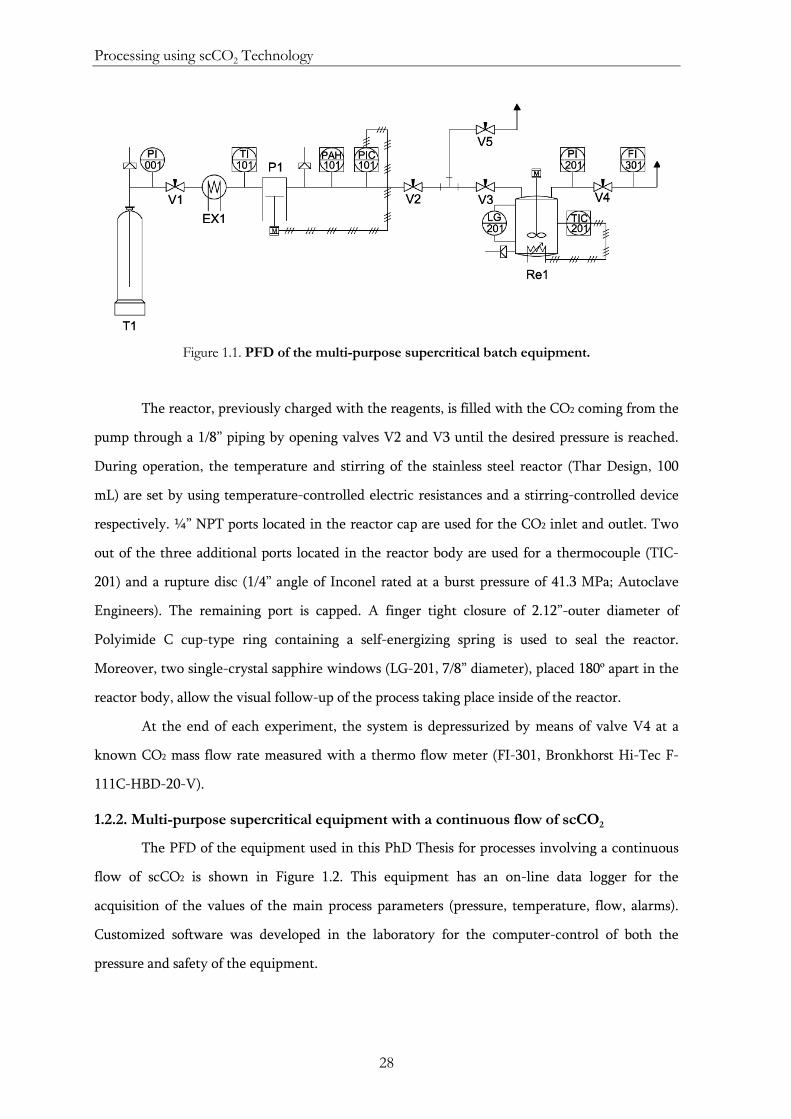
Processing using scCO2 Technology
28
Figure 1.1. PFD of the multi-purpose supercritical batch equipment.
The reactor, previously charged with the reagents, is filled with the CO2 coming from the
pump through a 1/8” piping by opening valves V2 and V3 until the desired pressure is reached.
During operation, the temperature and stirring of the stainless steel reactor (Thar Design, 100
mL) are set by using temperature-controlled electric resistances and a stirring-controlled device
respectively. ¼” NPT ports located in the reactor cap are used for the CO2 inlet and outlet. Two
out of the three additional ports located in the reactor body are used for a thermocouple (TIC-
201) and a rupture disc (1/4” angle of Inconel rated at a burst pressure of 41.3 MPa; Autoclave
Engineers). The remaining port is capped. A finger tight closure of 2.12”-outer diameter of
Polyimide C cup-type ring containing a self-energizing spring is used to seal the reactor.
Moreover, two single-crystal sapphire windows (LG-201, 7/8” diameter), placed 180º apart in the
reactor body, allow the visual follow-up of the process taking place inside of the reactor.
At the end of each experiment, the system is depressurized by means of valve V4 at a
known CO2 mass flow rate measured with a thermo flow meter (FI-301, Bronkhorst Hi-Tec F-
111C-HBD-20-V).
1.2.2. Multi-purpose supercritical equipment with a continuous flow of scCO2
The PFD of the equipment used in this PhD Thesis for processes involving a continuous
flow of scCO2 is shown in Figure 1.2. This equipment has an on-line data logger for the
acquisition of the values of the main process parameters (pressure, temperature, flow, alarms).
Customized software was developed in the laboratory for the computer-control of both the
pressure and safety of the equipment.
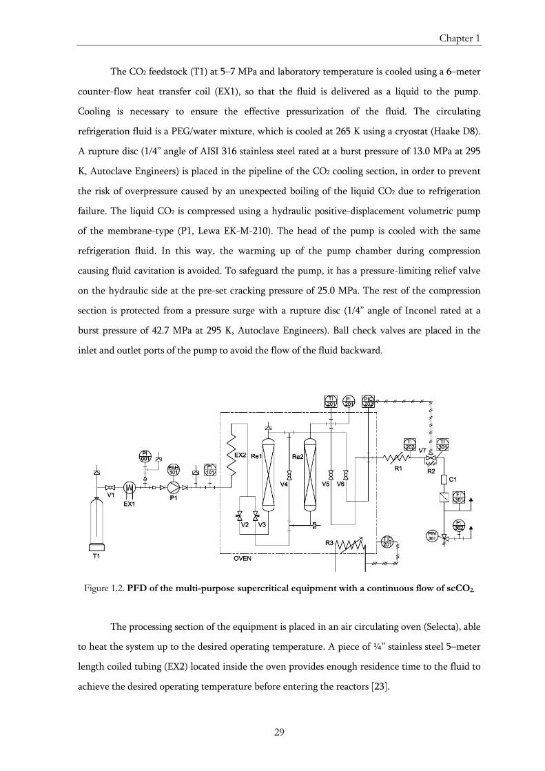
Chapter 1
29
The CO2 feedstock (T1) at 5–7 MPa and laboratory temperature is cooled using a 6–meter
counter-flow heat transfer coil (EX1), so that the fluid is delivered as a liquid to the pump.
Cooling is necessary to ensure the effective pressurization of the fluid. The circulating
refrigeration fluid is a PEG/water mixture, which is cooled at 265 K using a cryostat (Haake D8).
A rupture disc (1/4” angle of AISI 316 stainless steel rated at a burst pressure of 13.0 MPa at 295
K, Autoclave Engineers) is placed in the pipeline of the CO2 cooling section, in order to prevent
the risk of overpressure caused by an unexpected boiling of the liquid CO2 due to refrigeration
failure. The liquid CO2 is compressed using a hydraulic positive-displacement volumetric pump
of the membrane-type (P1, Lewa EK-M-210). The head of the pump is cooled with the same
refrigeration fluid. In this way, the warming up of the pump chamber during compression
causing fluid cavitation is avoided. To safeguard the pump, it has a pressure-limiting relief valve
on the hydraulic side at the pre-set cracking pressure of 25.0 MPa. The rest of the compression
section is protected from a pressure surge with a rupture disc (1/4” angle of Inconel rated at a
burst pressure of 42.7 MPa at 295 K, Autoclave Engineers). Ball check valves are placed in the
inlet and outlet ports of the pump to avoid the flow of the fluid backward.
Figure 1.2. PFD of the multi-purpose supercritical equipment with a continuous flow of scCO2.
The processing section of the equipment is placed in an air circulating oven (Selecta), able
to heat the system up to the desired operating temperature. A piece of ¼” stainless steel 5–meter
length coiled tubing (EX2) located inside the oven provides enough residence time to the fluid to
achieve the desired operating temperature before entering the reactors [23].
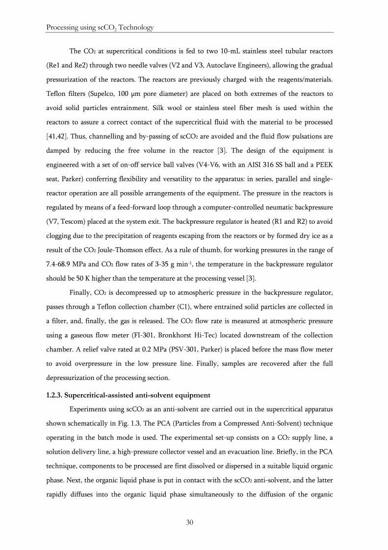
Processing using scCO2 Technology
30
The CO2 at supercritical conditions is fed to two 10-mL stainless steel tubular reactors
(Re1 and Re2) through two needle valves (V2 and V3, Autoclave Engineers), allowing the gradual
pressurization of the reactors. The reactors are previously charged with the reagents/materials.
Teflon filters (Supelco, 100 μm pore diameter) are placed on both extremes of the reactors to
avoid solid particles entrainment. Silk wool or stainless steel fiber mesh is used within the
reactors to assure a correct contact of the supercritical fluid with the material to be processed
[41,42]. Thus, channelling and by-passing of scCO2 are avoided and the fluid flow pulsations are
damped by reducing the free volume in the reactor [3]. The design of the equipment is
engineered with a set of on-off service ball valves (V4-V6, with an AISI 316 SS ball and a PEEK
seat, Parker) conferring flexibility and versatility to the apparatus: in series, parallel and single-
reactor operation are all possible arrangements of the equipment. The pressure in the reactors is
regulated by means of a feed-forward loop through a computer-controlled neumatic backpressure
(V7, Tescom) placed at the system exit. The backpressure regulator is heated (R1 and R2) to avoid
clogging due to the precipitation of reagents escaping from the reactors or by formed dry ice as a
result of the CO2 Joule-Thomson effect. As a rule of thumb, for working pressures in the range of
7.4-68.9 MPa and CO2 flow rates of 3-35 g min-1, the temperature in the backpressure regulator
should be 50 K higher than the temperature at the processing vessel [3].
Finally, CO2 is decompressed up to atmospheric pressure in the backpressure regulator,
passes through a Teflon collection chamber (C1), where entrained solid particles are collected in
a filter, and, finally, the gas is released. The CO2 flow rate is measured at atmospheric pressure
using a gaseous flow meter (FI-301, Bronkhorst Hi-Tec) located downstream of the collection
chamber. A relief valve rated at 0.2 MPa (PSV-301, Parker) is placed before the mass flow meter
to avoid overpressure in the low pressure line. Finally, samples are recovered after the full
depressurization of the processing section.
1.2.3. Supercritical-assisted anti-solvent equipment
Experiments using scCO2 as an anti-solvent are carried out in the supercritical apparatus
shown schematically in Fig. 1.3. The PCA (Particles from a Compressed Anti-Solvent) technique
operating in the batch mode is used. The experimental set-up consists on a CO2 supply line, a
solution delivery line, a high-pressure collector vessel and an evacuation line. Briefly, in the PCA
technique, components to be processed are first dissolved or dispersed in a suitable liquid organic
phase. Next, the organic liquid phase is put in contact with the scCO2 anti-solvent, and the latter
rapidly diffuses into the organic liquid phase simultaneously to the diffusion of the organic
Chapter 1
31
solvent into scCO2. This double-mechanism leads to the supersaturation of the dissolved
components in the organic phase, causing their precipitation. The dispersed components in the
organic solution are expected to be embedded within the precipitated particles during their
formation.
Figure 1.3. PFD of the supercritical-assisted anti-solvent equipment.
In a typical experiment, the CO2 at 5-7 MPa (T1) is first cooled at 273 K using a cryostat
(EX1, Haake) and, then, pressurized to the desired operating pressure using three hydraulic
positive-displacement volumetric pumps of the membrane-type arranged in parallel (P1-A/B/C,
Lewa EK3). The fluid is compressed and, then, heated (EX2), and introduced into the collector
vessel (Re1, Autoclave Engineers) by opening the needle valve V2 (HiP). The three pumps have
similar protections against overpressure and cavitation as has pump P1 in the equipment
described in Section 1.2.2 (head pump cooling, high pressure alarm and rupture discs). The
precipitation vessel has 0.5 L of capacity of and a clamp closure with a Teflon O-ring sealing. The
vessel is equipped with three pairs of sapphire windows at three different levels (LG-201, LG-202,
LG-203), used for the visual follow-up of the process taking place inside. The vessel is heated
with heating jackets (Watlow) and the temperature is controlled using a thermocouple (TIC-201).
A rupture disc (1/4” angle of Inconel rated at a burst pressure of 32.0 MPa at 333K, Autoclave
Engineers) is placed in one of the ports of the vessel as a safety procedure in case of overpressure.
In a normal procedure, once the pressure and the temperature of the precipitation vessel are
Processing using scCO2 Technology
32
stabilized, the liquid is injected into it. This liquid contains dispersed solid compounds to be
sprayed together with dissolved species. A double-piston liquid metering pump (P2-A/B, Milton
Roy CP300), typical off-the-self item for liquid chromatographic systems, is used to deliver the
liquid suspension into the processing vessel against the head pressure of the compressed fluid.
The liquid metering pump has a rupture disc. A check valve is placed in the line delivering the
suspension upstream of the needle valve V3 (HiP) to avoid CO2 entry in the liquid line. The
suspension is injected into the vessel through a conical spray (swirl) nozzle (Lechler, 100 μm
diameter). The stainless steel nozzle is a restriction device that generates the expansion of the
fluid. At the bottom of the vessel, a membrane filter placed on the top of a stainless steel frit
(ColoChrom, 2 μm porosity) allows the collection of the precipitated solids.
Before solid collection, the ball valve V4 (Parker) is opened to remove the organic solvent
by rinsing with a continuous flow of CO2, remaining in the vessel Re1 the precipitated product.
The micrometering needle valve V5 (Autoclave Engineers) is used as a backpressure regulator to
maintain constant the working pressure employed during the rinsing period. A sudden pressure
decrease of the fluid to atmospheric conditions takes place in the micrometering valve V5. The
outlet pipeline and valves V4 and V5 are heated to prevent clogging due to CO2 Joule-Thomson
effect. The low solvation power of CO2 at atmospheric pressure favors the liquid solvent
separation from the stream and the collection of the liquid fraction in the separator S1 (Pirex).
When the rinsing step is completed, the high-pressure vessel is slowly depressurized and the
processed material is collected.
1.2.4. Supercritical-assisted PGSS® equipment
Experiments using scCO2 as a solute in the Particles from Gas Saturated Solution (PGSS®)
process are carried out in the equipment shown in the PFD of Figure 1.4. The unit basically
consists on a CO2 supply line, a high pressure vessel (Re1), a collector vessel (Re2) and an
evacuation line [43]. Briefly, in the PGSS® technique, the solid components to be processed are
first charged in the high pressure vessel. Then, compressed CO2 is fed into the vessel. After
heating, the mixture melts and the scCO2 is solubilized in large quantities in the melt. Optionally,
solid admixtures can be dispersed in the melt. After homogenization of the mixture, the CO2-
saturated melted solid is rapidly expanded through a restrictor (typically, a nozzle). The sudden
change from supercritical pressure to ambient pressure causes the supersaturation of the CO2 in
the mixture and the quick expansion of the nucleated gaseous CO2 bubbles. As a result, the melt
cools down due to the Joule-Thomson effect. This effect, together with the volume expansion of
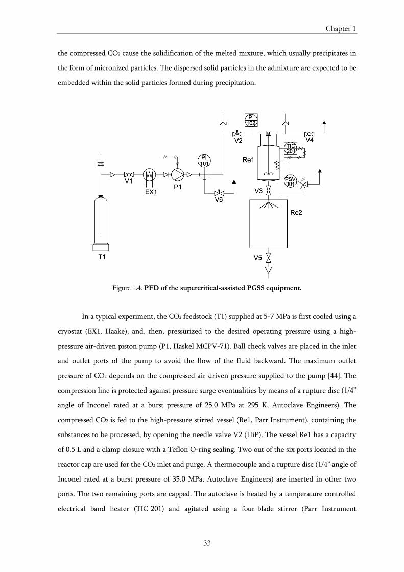
Chapter 1
33
the compressed CO2 cause the solidification of the melted mixture, which usually precipitates in
the form of micronized particles. The dispersed solid particles in the admixture are expected to be
embedded within the solid particles formed during precipitation.
Figure 1.4. PFD of the supercritical-assisted PGSS equipment.
In a typical experiment, the CO2 feedstock (T1) supplied at 5-7 MPa is first cooled using a
cryostat (EX1, Haake), and, then, pressurized to the desired operating pressure using a high-
pressure air-driven piston pump (P1, Haskel MCPV-71). Ball check valves are placed in the inlet
and outlet ports of the pump to avoid the flow of the fluid backward. The maximum outlet
pressure of CO2 depends on the compressed air-driven pressure supplied to the pump [44]. The
compression line is protected against pressure surge eventualities by means of a rupture disc (1/4”
angle of Inconel rated at a burst pressure of 25.0 MPa at 295 K, Autoclave Engineers). The
compressed CO2 is fed to the high-pressure stirred vessel (Re1, Parr Instrument), containing the
substances to be processed, by opening the needle valve V2 (HiP). The vessel Re1 has a capacity
of 0.5 L and a clamp closure with a Teflon O-ring sealing. Two out of the six ports located in the
reactor cap are used for the CO2 inlet and purge. A thermocouple and a rupture disc (1/4” angle of
Inconel rated at a burst pressure of 35.0 MPa, Autoclave Engineers) are inserted in other two
ports. The two remaining ports are capped. The autoclave is heated by a temperature controlled
electrical band heater (TIC-201) and agitated using a four-blade stirrer (Parr Instrument
Processing using scCO2 Technology
34
A1120HC). In a normal procedure, once the pressure and the temperature of the vessel are
stabilized and the materials are homogenized, the mixture is rapidly depressurized through a
nozzle by opening the ball valve V3 (Parker). A stainless steel 600 μm-diameter cone nozzle
(Spraying Systems Co) is used to generate the expansion of the melted mixture in a controlled
way. The precipitated particles are collected in a 10-L vessel (Re2, Pirex). The vessel Re2 is
equipped with a venting system to avoid overpressure.
1.3. Conclusions
Good performance and safety of processes involving the use of scCO2 may be
compromised without the assumption of a set of rule-of-thumbs and technical aspects related to
materials selection, specifications of the equipment and health and safety practices. These
recommendations are fulfilled in the design of the equipment used in this PhD Thesis for the
supercritical processing of materials. A multi-purpose supercritical batch equipment, a multi-
purpose equipment with a continuous flow of scCO2, a supercritical-assisted anti-solvent
equipment and a supercritical-assisted Particles from Gas Saturated Solution equipment are
optimized for the preparation of the desired end-products. Customized protocols of operation are
established for the high pressure equipment. Follow-up and control of the operating parameters
(pressure, temperature, CO2 flow, stirring rate) are carried out at different points of the
equipment through the proper installation of measuring devices.
1.4. References
[1] K. Zosel, Process for the decaffeination of coffee, US Patent 4,247,570 (1981).
[2] G.F. Woerlee, Process and device for separating a mixture or extracting a material, WO Patent 013,377 (1994).
[3] C. Vemavarapu, M.J. Mollan, M. Lodaya, T.E. Needham, Design and process aspects of laboratory scale SCF particle formation systems. International Journal of Pharmaceutics 2005, 292 (1-2), 1-16.
[4] J.L. Martínez, Supercritical fluid extraction of nutraceuticals and bioactive compounds. Ed. CRC Press, Taylor & Francis Group: Boca Raton, 2007.
[5] FeyeCon Development & Implementation B.V. Information available on the website: www.feyecon.com. Accessed on July 2009.
[6] High Pressure Equipment Co. Information available on the website: www.highpressure.com. Accessed on July 2009.
Chapter 1
35
[7] Iberfluid Instruments, S.A. Information available on the website: www.iberfluid.com. Accessed on July 2009.
[8] NATEX Prozesstechnologie GesmbH. Information available on the website: www.natex.at. Accessed on July 2009.
[9] Parr Instrument Co. Information available on the website: www.parrinst.com. Accessed on July 2009.
[10] SEPAREX S.A. Information available on the website: www.separex.fr. Accessed on July 2009.
[11] Thar Technologies, Inc. Information available on the website: www.thartec.com. Accessed on July 2009.
[12] Boc Edwards Group plc., Product data – Carbon dioxide. Publication No. Z023-01-895. 2002. Available on the website: www. bocedwards.com. Accessed on July 2009.
[13] ColePalmer Instrument co., Chemical compatibility tester. Available on the website: www.coleparmer.com/techinfo/ChemComp.asp. Accessed on July 2009.
[14] Eldon James Corp, Chemical resistance of plastic & stainless steel. Available on the website: www.eldonjames.com/html/chemical.html. Accessed on July 2009.
[15] Georg Fischer Piping Systems, Chemical resistance of plastics and elastomers. Available on the website: www.georgfischer.es. Accessed on July 2009.
[16] C.W. Kovach, High performance stainless steels. Available on the website: www.stainless-steel-world.net. Accessed on July 2009.
[17] N.A., HELCOM Manual on co-operation in response to marine pollution within the framework of the convention on the protection of the marine environment of the Baltic sea area (Helsinki convention), Volume 2, Annex 2: Chemical resistance of materials, 2002. Available on the website: www.kbv.se/ra/volume2/start.htm. Accessed on July 2009.
[18] N.A., HAM-LET, Advanced control technology. Corrosion data. Technical Information Bulletin. Available on the website: www.accutech.com.sg/Images/Products/Reference/ CATALOGE_PDF/CORROSION_DATA.pdf. Accessed on July 2009.
[19] D.M. Fryer, J.F. Harvey, High pressure vessels, 1st edition. Chapman & Hall: New York, 1998.
[20] S. Chattopadhyay, Pressure vessels – Design and practice, 1st edition. CRC Press: Boca Raton, 2004.
[21] J.R. Farr, M.H. Jawad, Guidebook for the design of ASME Section VIII pressure vessels, 3rd edition. ASME Press: New York, 2006.
Processing using scCO2 Technology
36
[22] R.K. Flitney, Seals and sealing handbook, 5th Edition. Elsevier Science: Oxford, 2007.
[23] D. Green, R. Perry. Perry's chemical engineers' handbook, 8th edition. McGraw-Hill Professional: New York, 2007.
[24] L.M. Kumar, Pressure vessel seal with self-energizing seal. US Patent 5,850,934. (1998).
[25] N.P. Cheremisinoff, P.N. Cheremisinoff, Elastomer technology handbook, 1st edition. CRC-Press: Boca Raton, 1993.
[26] M. van der Kraan, M.M.W. Peeters, M.V. Fernandez Cid, G.F. Woerlee, W.J.T. Veugelers, G.J. Witkamp, The influence of variable physical properties and buoyancy on heat exchanger design for near- and supercritical conditions. The Journal of Supercritical Fluids 2005, 34(1), 99-105.
[27] Swagelok Co., Valve Sizing – Technical Bulletin. USA, 2002. Available on the website: www.swagelok.com. Accessed on September 2009.
[28] J. García-Serna, J.L. Martínez, M.J. Cocero, Green HAZOP analysis: incorporating green engineering into design, assessment and implementation of chemical processes. Green Chemistry 2007, 9, 111-124.
[29] B.G. Liptak, Instrument engineers' handbook - Process measurement and analysis, 3rd Edition. Butterworth-Heinemann. Boca Raton, 1995.
[30] Ministerio de Industria, Comercio y Turismo, Código español de recipientes y aparatos a presión (CERAP). Madrid, 1992.
[31] LAMOT Corporation, Rupture discs - Product selection guide. USA, 2002. Available on the website: www.lamot.com. Accessed on July 2009.
[32] E. Turmo Sierra, NTP 456: Discos de ruptura (I): Características. Instituto Nacional de Seguridad e Higiene en el Trabajo. Ministerio de Trabajo y Asuntos Sociales.
[33] E. Turmo Sierra, NTP 457: Discos de ruptura (II): Dimensionado. Instituto Nacional de Seguridad e Higiene en el Trabajo. Ministerio de Trabajo y Asuntos Sociales.
[34] C.F. Parry, Relief systems handbook. Institution of Chemical Engineers: Rugby, 1992.
[35] American Institute of Chemical Engineers (AIChE), Guidelines for engineering design for process safety. AIChE: New York, 1993.
[36] J.M. Storch de Gracia, Manual de seguridad industrial en plantas químicas y petroleras. Fundamentos, evaluación de riesgos y diseño. McGrawHill/Interamericana de España: Madrid, 1998.
[37] Parker Instrumentation, Relief valves (RH4 Series). Catalog no. 4131-RH. USA, 2001.
Chapter 1
37
[38] A. Cejalvo Lapeña, NTP 342: Válvulas de seguridad (I): Características técnicas. Instituto Nacional de Seguridad e Higiene en el Trabajo. Ministerio de Trabajo y Asuntos Sociales.
[39] A. Cejalvo Lapeña, NTP 346: Válvulas de seguridad (II): Capacidad de alivio y dimensionado. Instituto Nacional de Seguridad e Higiene en el Trabajo. Ministerio de Trabajo y Asuntos Sociales.
[40] E. Turmo Sierra, NTP 510: Válvulas de Seguridad: Selección. Instituto Nacional de Seguridad e Higiene en el Trabajo. Ministerio de Trabajo y Asuntos Sociales.
[41] T.H. Kim, D.Y. Lim, B.S. Yu, J.H. Lee, M. Goto, Effect of stirring and heating rate on the formation of TiO2 powders using supercritical fluid, Industrial & Engineering Chemistry Research 2000, 39(12), 4702–4706.
[42] B.Y. Shekunov, J. Baldyga, P. York, Particle formation by mixing with supercritical antisolvent at high Reynolds numbers, Chemical Engineering Science 2001, 56(7), 2421–2433.
[43] A.R. Sampaio da Sousa, Development of Functional Particles using Supercritical Fluid Technology: Fundamentals, processing and applications. PhD Thesis. Oeiras, 2007.
[44] Haskel International, Inc., Liquid Pump Catalog. USA, 2002. Available on the website: www.haskel.com. Accessed on September 2009.
39
Chapter 2
USE OF SCCO2 AS A SOLVENT:
SUPERCRITICAL SILANIZATION REACTION
In this Chapter, the use of scCO2 as the solvent of choice for alkoxysilanes for the
surface treatment of inorganic nanoparticles is assessed. The silanization of nanometric
titanium dioxide (TiO2) particles with octyltriethoxysilane is taken as the model system.
Chemometric analysis (23 full factorial design and Principal Component Analysis (PCA)) [1-3]
is used to ascertain the feasible region of pressure and temperature for the scCO2-aided
silanization process and the effects and interactions of the operating variables on the properties
of the final material. The characterization of the silanized materials is performed regarding the
chemical structure of the silane on the surface, the silane content and the thermal stability of
the coating, and the microstructure of the hybrid composite (porosity and dispersibility). The
solubility measurements of octyltriethoxysilane in compressed CO2 and the kinetic study of the
TiO2 silanization process allow the engineering control of the silane coating procedure. Finally,
the conclusions obtained from the full study of the octyltriethoxysilane-TiO2 model system are
implemented to different silane molecules and inorganic substrates.
Supercritical silanization reaction
40
2.1. Introduction
Considerable research has been focused on nanostructured materials comprising
nanoparticles, such as polymer composites [4,5], ceramic composites [6,7] and self-aggregated
structures [8,9]. A significant proportion of hybrid inorganic-organic composites is
compounded with particles and fibres used as fillers to improve various physical and
mechanical properties of a matrix, such as the mechanical strength and the modulus, the
rigidity or the heat-resistance [10]. Additionally, the use of inorganic fillers in hybrid materials
compounded with polymeric matrices could reduce total costs [11]. These composites should
meet many requirements for being used in different industrial applications such as adhesives,
sealing materials, optical devices, sensors and artificial membranes [12].
The dispersion of most inorganic fillers into polymeric matrices is technically
challenging, due to the low interfacial interaction between both phases [10,13,14]. For
nanostructured hybrid composites, the large surface area to volume ratio of nanoparticles
increases the relevance of the boundaries dividing the components [15].
The interfacial interaction between the dissimilar organic and inorganic phases can be
increased by the surface modification of the inorganic nanoparticles. Many bifunctional
organic molecules acting as coupling agents or adhesion promoters have been investigated for
the surface modification of inorganic phases (e.g., organosilanes, organotitanates, aluminates,
zirconates, zircoaluminates) [15-22]. These molecules are bifunctional chemical additives that
interact with both the inorganic filler and the organic matrix, providing a molecular bridge
between both components of the composite. Bifunctional organotrialkoxysilanes, a group of
low toxicity and environmentally compliant chemicals, are the dominant coupling agents and
adhesion promoters in the market [11,23,24]. Surface coating by silanization is also used in
other applications such as surface protection against corrosive environments [25], water
repellency (Fig. 2.1) [26-28], protection of labile biomolecules [29], metal recovery [30,31] or
chromatographic stationary phase design [32].
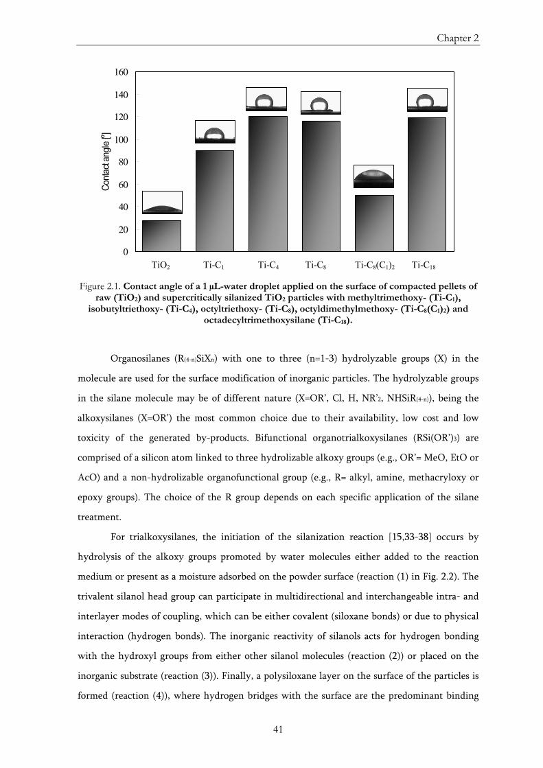
Chapter 2
41
0
20
40
60
80
100
120
140
160
TiO2 TiC1 TiC4 TiC8-2w TiC8C12 TiC18
Conta
ct an
gle [ o ]
TiO2 Ti-C1 Ti-C4 Ti-C8 Ti-C8(C1)2 Ti-C18 Figure 2.1. Contact angle of a 1 µL-water droplet applied on the surface of compacted pellets of
raw (TiO2) and supercritically silanized TiO2 particles with methyltrimethoxy- (Ti-C1), isobutyltriethoxy- (Ti-C4), octyltriethoxy- (Ti-C8), octyldimethylmethoxy- (Ti-C8(C1)2) and
octadecyltrimethoxysilane (Ti-C18).
Organosilanes (R(4-n)SiXn) with one to three (n=1-3) hydrolyzable groups (X) in the
molecule are used for the surface modification of inorganic particles. The hydrolyzable groups
in the silane molecule may be of different nature (X=OR’, Cl, H, NR’2, NHSiR(4-n)), being the
alkoxysilanes (X=OR’) the most common choice due to their availability, low cost and low
toxicity of the generated by-products. Bifunctional organotrialkoxysilanes (RSi(OR’)3) are
comprised of a silicon atom linked to three hydrolizable alkoxy groups (e.g., OR’= MeO, EtO or
AcO) and a non-hydrolizable organofunctional group (e.g., R= alkyl, amine, methacryloxy or
epoxy groups). The choice of the R group depends on each specific application of the silane
treatment.
For trialkoxysilanes, the initiation of the silanization reaction [15,33-38] occurs by
hydrolysis of the alkoxy groups promoted by water molecules either added to the reaction
medium or present as a moisture adsorbed on the powder surface (reaction (1) in Fig. 2.2). The
trivalent silanol head group can participate in multidirectional and interchangeable intra- and
interlayer modes of coupling, which can be either covalent (siloxane bonds) or due to physical
interaction (hydrogen bonds). The inorganic reactivity of silanols acts for hydrogen bonding
with the hydroxyl groups from either other silanol molecules (reaction (2)) or placed on the
inorganic substrate (reaction (3)). Finally, a polysiloxane layer on the surface of the particles is
formed (reaction (4)), where hydrogen bridges with the surface are the predominant binding
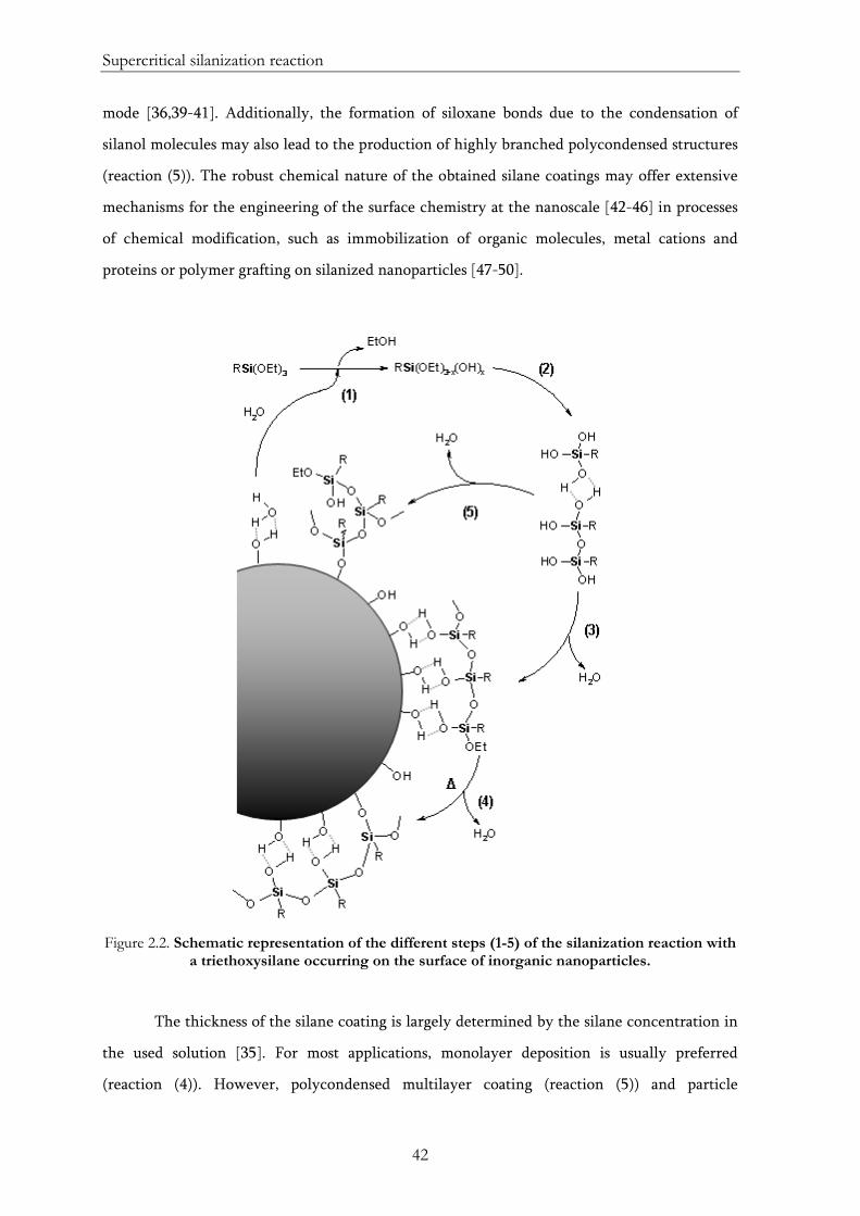
Supercritical silanization reaction
42
mode [36,39-41]. Additionally, the formation of siloxane bonds due to the condensation of
silanol molecules may also lead to the production of highly branched polycondensed structures
(reaction (5)). The robust chemical nature of the obtained silane coatings may offer extensive
mechanisms for the engineering of the surface chemistry at the nanoscale [42-46] in processes
of chemical modification, such as immobilization of organic molecules, metal cations and
proteins or polymer grafting on silanized nanoparticles [47-50].
Figure 2.2. Schematic representation of the different steps (1-5) of the silanization reaction with
a triethoxysilane occurring on the surface of inorganic nanoparticles.
The thickness of the silane coating is largely determined by the silane concentration in
the used solution [35]. For most applications, monolayer deposition is usually preferred
(reaction (4)). However, polycondensed multilayer coating (reaction (5)) and particle
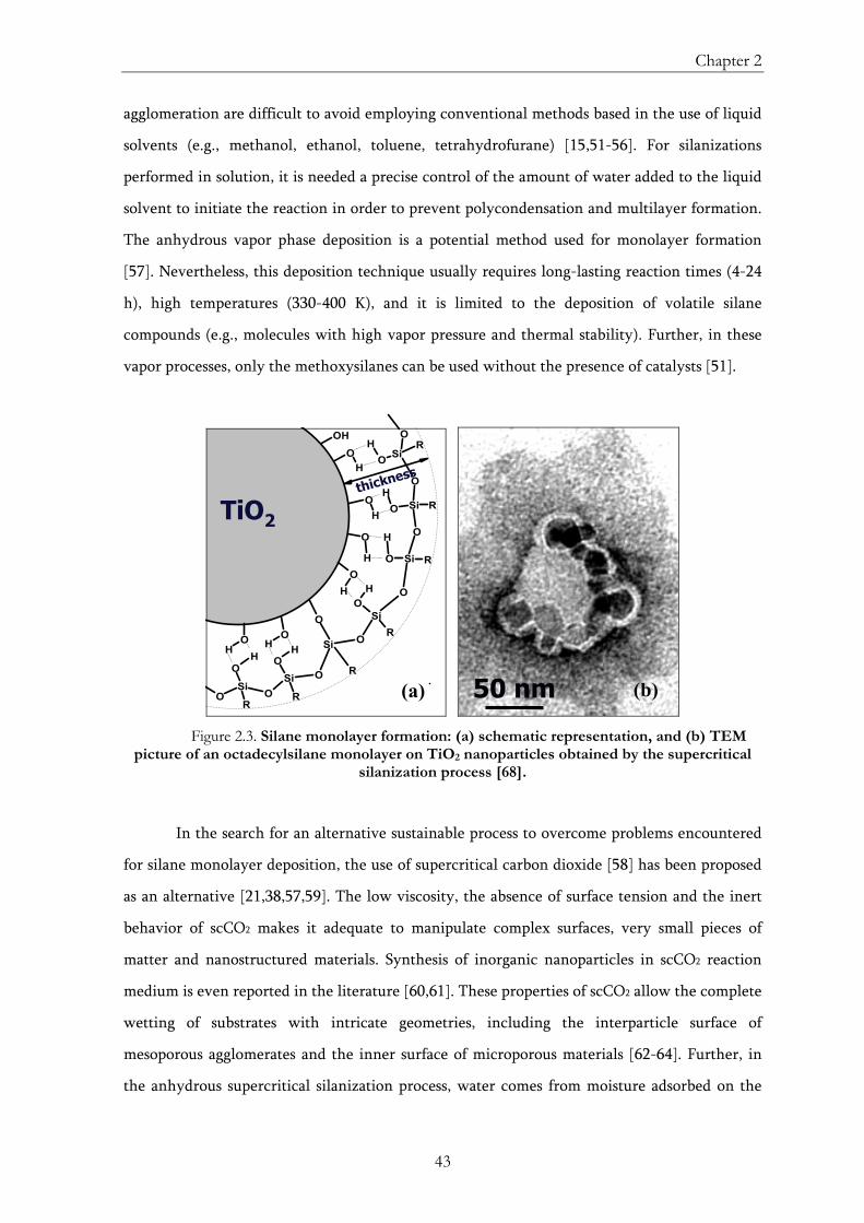
Chapter 2
43
agglomeration are difficult to avoid employing conventional methods based in the use of liquid
solvents (e.g., methanol, ethanol, toluene, tetrahydrofurane) [15,51-56]. For silanizations
performed in solution, it is needed a precise control of the amount of water added to the liquid
solvent to initiate the reaction in order to prevent polycondensation and multilayer formation.
The anhydrous vapor phase deposition is a potential method used for monolayer formation
[57]. Nevertheless, this deposition technique usually requires long-lasting reaction times (4-24
h), high temperatures (330-400 K), and it is limited to the deposition of volatile silane
compounds (e.g., molecules with high vapor pressure and thermal stability). Further, in these
vapor processes, only the methoxysilanes can be used without the presence of catalysts [51].
OH
OH
O
H
SiO R
O
Si
O
O
RSi
OR
Si
OO
HH
R
OH
SiO R
O
SiO R
Si
O
O
O
R
O
H
H
H
OH
OH
OHO
H
thickness
TiO2
50 nm
Figure 2.3. Silane monolayer formation: (a) schematic representation, and (b) TEM
picture of an octadecylsilane monolayer on TiO2 nanoparticles obtained by the supercritical silanization process [68].
In the search for an alternative sustainable process to overcome problems encountered
for silane monolayer deposition, the use of supercritical carbon dioxide [58] has been proposed
as an alternative [21,38,57,59]. The low viscosity, the absence of surface tension and the inert
behavior of scCO2 makes it adequate to manipulate complex surfaces, very small pieces of
matter and nanostructured materials. Synthesis of inorganic nanoparticles in scCO2 reaction
medium is even reported in the literature [60,61]. These properties of scCO2 allow the complete
wetting of substrates with intricate geometries, including the interparticle surface of
mesoporous agglomerates and the inner surface of microporous materials [62-64]. Further, in
the anhydrous supercritical silanization process, water comes from moisture adsorbed on the
(a) (b)
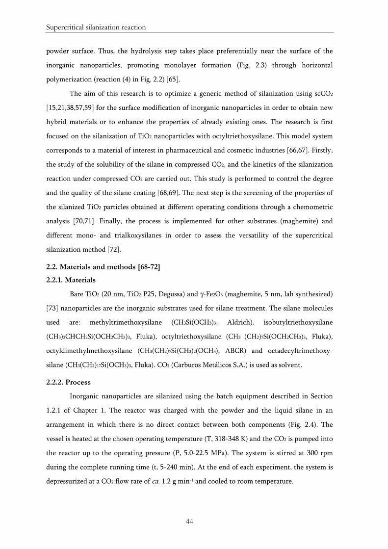
Supercritical silanization reaction
44
powder surface. Thus, the hydrolysis step takes place preferentially near the surface of the
inorganic nanoparticles, promoting monolayer formation (Fig. 2.3) through horizontal
polymerization (reaction (4) in Fig. 2.2) [65].
The aim of this research is to optimize a generic method of silanization using scCO2
[15,21,38,57,59] for the surface modification of inorganic nanoparticles in order to obtain new
hybrid materials or to enhance the properties of already existing ones. The research is first
focused on the silanization of TiO2 nanoparticles with octyltriethoxysilane. This model system
corresponds to a material of interest in pharmaceutical and cosmetic industries [66,67]. Firstly,
the study of the solubility of the silane in compressed CO2, and the kinetics of the silanization
reaction under compressed CO2 are carried out. This study is performed to control the degree
and the quality of the silane coating [68,69]. The next step is the screening of the properties of
the silanized TiO2 particles obtained at different operating conditions through a chemometric
analysis [70,71]. Finally, the process is implemented for other substrates (maghemite) and
different mono- and trialkoxysilanes in order to assess the versatility of the supercritical
silanization method [72].
2.2. Materials and methods [68-72]
2.2.1. Materials
Bare TiO2 (20 nm, TiO2 P25, Degussa) and γ-Fe2O3 (maghemite, 5 nm, lab synthesized)
[73] nanoparticles are the inorganic substrates used for silane treatment. The silane molecules
used are: methyltrimethoxysilane (CH3Si(OCH3)3, Aldrich), isobutyltriethoxysilane
(CH3)2CHCH2Si(OCH2CH3)3, Fluka), octyltriethoxysilane (CH3 (CH2)7Si(OCH2CH3)3, Fluka),
octyldimethylmethoxysilane (CH3(CH2)7Si(CH3)2(OCH3), ABCR) and octadecyltrimethoxy-
silane (CH3(CH2)17Si(OCH3)3, Fluka). CO2 (Carburos Metálicos S.A.) is used as solvent.
2.2.2. Process
Inorganic nanoparticles are silanized using the batch equipment described in Section
1.2.1 of Chapter 1. The reactor was charged with the powder and the liquid silane in an
arrangement in which there is no direct contact between both components (Fig. 2.4). The
vessel is heated at the chosen operating temperature (T, 318-348 K) and the CO2 is pumped into
the reactor up to the operating pressure (P, 5.0-22.5 MPa). The system is stirred at 300 rpm
during the complete running time (t, 5-240 min). At the end of each experiment, the system is
depressurized at a CO2 flow rate of ca. 1.2 g min-1 and cooled to room temperature.
Chapter 2
45
Figure 2.4. Schematic drawing of the initial set-up of the reactor used for the supercritical
silanization experiments.
Silanized samples are further washed to remove the excess of silane by using the
supercritical equipment described in Section 1.2.2 of Chapter 1, running with a continuous
flow of CO2 at a flow rate of 1.5-3.5 g min-1, 318-348 K and 10.0-20.0 MPa, during different
periods of time (15-120 min).
2.2.3. Characterization
The solubility measurement of octyltriethoxysilane in compressed CO2 (8-18 MPa) is
performed using a variable volume cell at two different temperatures (318 and 348 K). The
properties of the silane coating deposited on the nanometric particles are studied by infrared
and Raman spectroscopies, 29Si nuclear magnetic resonance, energy dispersive spectrometry
and thermogravimetric analysis. Textural characteristics of the silanized inorganic particles are
analyzed by low-temperature N2 adsorption-desorption, scanning electron microscopy and
transmission electron microscopy. Laser scattering and dynamic light scattering methods are
used to study the dispersibility of the silanized samples in an oleophilic medium (petroleum
special). Finally, the static contact angle of a water droplet deposited on the surface of pellets
made of compacted silanized nanoparticles is measured using a goniometer.
CO2 inlet CO2 outlet
Cartridge made of filter paper containing the inorganic particles
Liquid silane
Metallic support for cartridges
Reactor vessel
Magnetic stirrer
Supercritical silanization reaction
46
2.3. Results
Article no. 1
Title: Measurements and correlation of octyltriethoxysilane solubility in supercritical
CO2 and assembly of functional silane monolayers on the surface of nanometric particles
Authors: C. A. García-González, J. Fraile, A. López-Periago, J. Saurina, C. Domingo
Journal: Ind. Eng. Chem. Res., In Press (doi: 10.1021/ie900775z)
Article no. 2
Title: Preparation and Characterization of Surface Silanized TiO2 Nanoparticles under
Compressed CO2: Reaction Kinetics
Authors: C. A. García-González, J. Saurina, J. A. Ayllón, C. Domingo
Journal: J. Phys. Chem. C, 113 (2009) 13780-13786
Article no. 3
Title: Preparation of Nanostructured Organic–Inorganic HybridMaterials Using
Supercritical Fluid Technology
Authors: C. A. García-González, J.-M. Andanson, S. G. Kazarian, J. Saurina, C. Domingo
Journal: Compos. Interfaces 16 (2009) 143–155
Article no. 4
Title: Application of principal component analysis to the thermal characterization of
silanized nanoparticles obtained at supercritical carbon dioxide conditions
Authors: C. A. García-González, J. M. Andanson, S. G. Kazarian, C. Domingo, J. Saurina
Journal: Anal. Chim. Acta 635 (2009) 227–234
Article no. 5
Title: Preparation of silane-coated TiO2 nanoparticles in supercritical CO2
Authors: C. A. García-González, J. Fraile, A. López-Periago, C. Domingo
Journal: J. Col. Inter. Sci., 338 (2009), 491-499
Chapter 2
99
2.4. Conclusions
The optimization of a generic method of silanization using scCO2 for the surface
modification of inorganic nanoparticles is, herein, developed. The obtained silane coating
using the supercritical silanization approach is thermally stable up to ca. 520 K, regardless of
the operating conditions (pressure, temperature and reaction time) [71]. Free unbounded
silane on the surface of the inorganic particles is completely removed by means of a
continuous flow of scCO2. A significant interaction of the variables operating pressure and
temperature, influencing the properties of the final silanized materials, is revealed using
chemometric analysis [70]. The combination of these two variables tunes the CO2 density,
varying the silane concentration in the reaction medium (i.e., silane solubility) and,
subsequently, the quality of the silane coating on the inorganic particles [69]. The
silanization process under compressed CO2 can be described using a Langmuir-like kinetics
model, which is largely influenced by the solubility of the silane in compressed CO2 [68]. A
fast silane monolayer formation on the TiO2 surface is obtained by using CO2 at supercritical
conditions. Conversely, the degree of silane coating can be time-controlled if CO2 at near-
critical conditions is used. Compilation of the characterization data allows the definition of
an objective function used to choose the operating conditions that lead to optimal material
performance for two areas of potential application of TiO2 nanoparticles silanized with
octyltriethoxysilane: cosmetics and plastics industries. Finally, the process is implemented
for other inorganic substrate (maghemite) and different mono- and tri-alkoxysilanes [72].
Hence, the versatility of the supercritical silanization method is demonstrated for its
application in the preparation of hybrid materials.
2.5. References
[1] G.E.P. Box, W.G. Hunter, J.S. Hunter, Statistics for experimenters: An introduction to design, data analysis, and model building. John Wiley and Sons: New York, 1978.
[2] H. Martens, T. Naes, Multivariate calibration, John Wiley & Sons: New York, 1989.
[3] P. Subra, P. Berroy, J. Saurina, C. Domingo, Influence of expansion conditions on the characteristics of cholesterol crystals analyzed by statistical design. Journal of Supercritical Fluids 2004, 31(3), 313-322.
[4] H. Zhang, Z. Cui, Y. Wang, K. Zhang, X. Ji, C. Lü, B. Yang, M. Gao, From water-soluble CdTe nanocrystals to fluorescent nanocrystal-polymer transparent composites using polymerizable surfactants. Advanced Materials 2003, 15(10), 777-780.
Supercritical silanization reaction
100
[5] H. Althues, R. Palkovits, A. Rumplecker, P. Simon, W. Sigle, M. Bredol, U. Kynast, S. Kaskel, Synthesis and characterization of transparent luminescent ZnS:Mn/PMMA nanocomposites. Chemistry of Materials 2006, 18(4), 1068-1072.
[6] P. Limthongkul, H. Wang, H.Y.–M. Chiang, Nanocomposite Li-ion battery anodes produced by the partial reduction of mixed oxides. Chemistry of Materials 2001, 13(7), 2397-2402.
[7] X. F. Zhang, G. Harley, L .C. DeJonghe, Co-continuous metal−ceramic nanocomposites. Nano Letters 2005, 5(6), 1035-1037.
[8] F. Caruso, M. Spasova, V. Salgueiriño-Maceira, L.M. Liz-Marzán, Multilayer assemblies of silica-encapsulated gold nanoparticles on decomposable colloid templates. Advanced Materials 2001, 13(14), 1090-1094.
[9] E.V. Shevchenko, D.V. Talapin, N.A. Kotov, S. O’Brien, C.B. Murray, Structural diversity in binary nanoparticle superlattices. Nature 2006, 439, 55-59.
[10] Y. Liu, R. Yang, J. Yu, K. Wang, Investigation of interfacial structure of coupling agent treated fillers by fourier transform infrared spectroscopy and attenuated total reflection-FTIR spectroscopy. Polymer Composites 2002, 23(1), 28-33.
[11] N.A., Bridging the gap with coupling agents. Plastics, Additives and Compounding 2003, 5(3), 40-45.
[12] C. Sánchez, B. Julián, P. Belleville, M. Popall, Applications of hybrid organic–inorganic nanocomposites. Journal of Materials Chemistry 2005, 15(35-36), 3559 – 3592.
[13] P.C. Wernett, Surface treated inorganic particle additive for increasing the toughness of polymers. WO Patent 2,009,077,860 (2009).
[14] Y. Zhou, K. Cooper, Y. Li, Z. Li, Use of coupling agents to improve the interface in absorbable polymer composites. US Patent 20,090,149,873 (2009).
[15] C. Domingo, E. Loste, J. Fraile, Grafting of trialkoxysilane on the surface of nanoparticles by conventional wet alcoholic and supercritical carbon dioxide deposition methods. The Journal of Supercritical Fluids 2006, 37(1), 72-86.
[16] R. Rothon, Particulate-filled polymer composites. Longman Scientific & Technical: Harlow, 1995.
[17] Z. Demjén, B. Pukánszky, E. Földes, J. Nagy, Interaction of silane coupling agents with CaCO3. Journal of Colloid and Interface Science 1997, 190(2), 427-436.
[18] H. Fujimatsu, K. Iyo, H. Usami, S. Ogasawara, K. Kajiwara, Adhesion between polyethylene molding and metal surface-modified with silane coupling agents by use of polyethylene gels. Composite Interfaces 2002, 9(3), 259-272.
Chapter 2
101
[19] M.-I. Baraton. Synthesis, functionalization and surface treatment of nanoparticles. American Scientific Publishers: Los Angeles, 2003.
[20] G.A. Holmes, E. Feresenbet and D. Raghavan, Using self-assembled monolayer technology to probe the mechanical response of the fiber interphase-matrix interphase interface. Composite Interfaces 2003, 10(6), 515-546.
[21] E. Loste, J. Fraile, M.A. Fanovich, G.F. Woerlee, C. Domingo, Anhydrous supercritical carbon dioxide method for the controlled silanization of inorganic nanoparticles. Advanced Materials 2004, 16(8), 739-744.
[22] Z.X. Jiang, L.H. Meng, Y.D. Huang, L. Liu, C. Lu, Influence of coupling agent chain lengths on interfacial performances of polyarylacetylene resin and silica glass composites. Applied Surface Science 2007, 253(9), 4338-4343.
[23] N.R. Jana, C. Earhart, J.Y. Ying, Synthesis of water-soluble and functionalized nanoparticles by silica coating. Chemistry of Materials 2007, 19(21), 5074-5082.
[24] R.D. Palma, S. Peeters, M.J.V. Bael, H. Van den Rul, K. Bonroy, W. Laureyn, J. Mullens, G. Borghs, G. Maes, Silane ligand exchange to make hydrophobic superparamagnetic nanoparticles water-dispersible. Chemistry of Materials 2007, 19(7), 1821-1831.
[25] V. Palanivel, D. Zhu, W.J. van Ooij, Nanoparticle-filled silane films as chromate replacements for aluminum alloys. Progress in Organic Coatings 2003, 47(3-4), 384-392.
[26] D.-H. Park, N. Nishiyama, Y. Egashira, K. Ueyama, Enhancement of hydrothermal stability and hydrophobicity of a silica MCM-48 membrane by silylation. Industrial & Engineering Chemistry Research 2001, 40(26), 6105-6110.
[27] C.A. García-González, N. El Grouh, A. Hidalgo, J. Fraile, A.M. López-Periago, C. Andrade, C. Domingo, New insights on the use of supercritical carbon dioxide for the accelerated carbonation of cement pastes. The Journal of Supercritical Fluids 2008, 43(3), 500-509.
[28] S.A. Kulkarni, S.B. Ogale, K.P. Vijayamohanan, Tuning the hydrophobic properties of silica particles by surface silanization using mixed self-assembled monolayers. Journal of Colloid and Interface Science 2008, 318(2), 372-379.
[29] I. Gill, Bio-doped nanocomposite polymers: sol-gel bioencapsulates. Chemistry of Materials 2001, 13(10), 3404-3421.
[30] P. Wu, Z. Xu, Silanation of nanostructured mesoporous magnetic particles for heavy metal recovery. Industrial & Engineering Chemistry Research 2005, 44(4), 816-824.
[31] Y. Turhan, P. Turan, M. Doan, M. Alkam, H. Namli, Ö. Demirbaş, Characterization and adsorption properties of chemically modified sepiolite. Industrial & Engineering Chemistry Research 2008, 47(6), 1883-1895.
Supercritical silanization reaction
102
[32] N.M. Scully, L.O. Healy, T. O’Mahony, J.D. Glennon, B. Dietrich, K. Albert, Effect of silane reagent functionality for fluorinated alkyl and phenyl silica bonded stationary phases prepared in supercritical carbon dioxide. Journal of Chromatography A 2008, 1191(1-2), 99-107.
[33] E.P. Plueddemann, Silane adhesion promoters in coatings, Progress in Organic Coatings 1983, 11(3), 297-308.
[34] E.P. Plueddemann, Silane coupling agents, 2nd ed. Plenum Press: NewYork, 1991.
[35] G.L. Witucki, A silane primer: Chemistry and applications of alkoxy silanes. Journal of Coatings Technology 1993, 65(822), 57-60.
[36] C.P. Tripp, M.L. Hair, Reaction of methylsilanols with hydrated silica surfaces: The hydrolysis of trichloro-, dichloro-, and monochloromethylsilanes and the effects of curing. Langmuir 1995, 11(1), 149-155.
[37] C.P. Tripp, J.R. Combes, Chemical modification of metal oxide surfaces in supercritical CO2: The interaction of supercritical CO2 with the adsorbed water layer and the surface hydroxyl groups of a silica surface. Langmuir 1998, 14(26), 7348–7352.
[38] C. Cao, A.Y. Fadeev, T.J. McCarthy, Reactions of organosilanes with silica surfaces in carbon dioxide. Langmuir 2001, 17(3), 757-761.
[39] R. Maoz, J. Sagiv, D. Degenhardt, H. Möhwald, P. Quint, Hydrogen-bonded multilayers of self-assembling silanes: Structure elucidation by combined Fourier transform infra-red spectroscopy and X-ray scattering techniques. Supramolecular Science 1995, 2(1), 9-24.
[40] A.Y. Fadeev, R. Helmy, S. Marcinko, Self-assembled monolayers of organosilicon hydrides supported on titanium, zirconium, and hafnium dioxides. Langmuir 2002, 18(20), 7521-7529.
[41] S. Marcinko, A.Y. Fadeev, Hydrolytic stability of organic monolayers supported on TiO2 and ZrO2. Langmuir 2004, 20(6), 2270-2273.
[42] S.R. Wasserman, Y.T. Tao, G.M. Whitesides, Structure and reactivity of alkylsiloxane monolayers formed by reaction of alkyltrichlorosilanes on silicon substrates. Langmuir 1989, 5(4), 1074–1087.
[43] N. Balachander, C.N. Sukenik, Monolayer transformation by nucleophilic substitution: Applications to the creation of new monolayer assemblies. Langmuir 1990, 6(11), 1621–1627.
[44] R. Maoz, S.R. Cohen, J. Sagiv, Nanoelectrochemical patterning of monolayer surfaces: toward spatially defined self-assembly of nanostructures. Advanced Materials 1999, 11(1), 55–61.
Chapter 2
103
[45] R. Maoz, E. Frydman, S.R. Cohen, J. Sagiv, “Constructive nanolithography”: Inert monolayers as patternable templates for in-situ nanofabrication of metal-semiconductor-organic surface structures - A generic approach. Advanced Materials 2000, 12(10), 725–731.
[46] A.S. Killampalli, P.F. Ma, J.R. Engstrom, The reaction of tetrakis(dimethylamido)-titanium with self-assembled alkyltrichlorosilane monolayers possessing −OH, −NH2, and −CH3 terminal groups. Journal of the American Chemical Society 2005, 127, 6300–6310.
[47] H.H. Weetall, Preparation of immobilized proteins covalently coupled through silane coupling agents to inorganic supports. Advances in Molecular and Cell Biology 1996, 15(1), 161-192.
[48] G.-J. Kim, J.-H. Shin, The catalytic activity of new chiral salen complexes immobilized on MCM-41 by multi-step grafting in the asymmetric epoxidation. Tetrahedron Letters 1999, 40(37), 6827-6830.
[49] C.D. Nunes, A.A. Valente, M. Pillinger, A.C. Fernandes, C.C. Romao, J. Rocha, I.S. Gonçalves, MCM-41 functionalized with bipyridyl groups and its use as a support for oxomolybdenum(VI) catalysts. Journal of Materials Chemistry 2002, 12(6), 1735–1742.
[50] K. Matsuyama, K. Mishima, Preparation of poly(methyl methacrylate)–TiO2 nanoparticle composites by pseudo-dispersion polymerization of methyl methacrylate in supercritical CO2. The Journal of Supercritical Fluids 2009, 49(2), 256-264.
[51] S.R. Wasserman, Y.T. Tao, G.M. Whitesides, Structure and reactivity of alkylsiloxane monolayers formed by reaction of alkyltrichlorosilanes on silicon substrates. Langmuir 1989, 5(4), 1074–1087.
[52] N.R.E.N. Impens, P. van der Voort, E.F. Vansant, Silylation of micro-, meso- and non-porous oxides: a review. Microporous and Mesoporous Materials 1999, 28(2), 217-232.
[53] T. Jesionowski, Modification and characterization of titanium dioxide surface, Pigment & Resin Technology 2001, 30(5), 287-295.
[54] A.M. Almanza-Workman, S. Raghavan, P. Deymier, D.J. Monk, R.J. Roop, Water dispersible silanes for wettability modification of polysilicon. Journal of The Electrochemical Society 2002, 149(1), H6-H11.
[55] C. Santos, R.L. Clarke, M. Braden, F. Guitian, K.W.M. Davy, Water absorption characteristics of dental composites incorporating hydroxyapatite filler. Biomaterials 2002, 23(8), 1897-1904.
[56] E. Ukaji, T. Furusawa, M. Sato, N. Suzuki, The effect of surface modification with silane coupling agent on suppressing the photo-catalytic activity of fine TiO2 particles as inorganic UV filter. Applied Surface Science 2007, 254(2), 563-569.
Supercritical silanization reaction
104
[57] W. Gu, C.P. Tripp, Reaction of silanes in supercritical CO2 with TiO2 and Al2O3. Langmuir 2006, 22(13), 5748-5752.
[58] Y. Sun, Supercritical fluid technology in materials science and engineering. Marcel Dekker: New York, 2002.
[59] Y. Shin, T.S. Zemanian, G.E. Fryxell, L.-Q. Wang, J. Liu, Supercritical processing of functionalized size selective microporous materials. Microporous and Mesoporous Materials 2000, 37(1-2), 49-56.
[60] E. Alonso, I. Montequi, S. Lucas, M.J. Cocero, Synthesis of titanium oxide particles in supercritical CO2: Effect of operational variables in the characteristics of the final product. The Journal of Supercritical Fluids 2007, 39(3), 453-461.
[61] E. Alonso, I. Montequi, M.J. Cocero, Effect of synthesis conditions on photocatalytic activity of TiO2 powders synthesized in supercritical CO2. The Journal of Supercritical Fluids 2009, 49(2), 233-238.
[62] C. Domingo, J. García-Carmona, J. Llibre, R. Rodríguez-Clemente, Organic-guest/microporous-host composite materials obtained by diffusion from a supercritical solution. Advanced Materials 1998, 10(9), 672-676.
[63] C. Domingo, J. García-Carmona, M.A. Fanovich, J. Llibre, R. Rodríguez-Clemente, Single or two-solute adsorption processes at supercritical conditions: an experimental study. The Journal of Supercritical Fluids 2001, 21(2), 147-157.
[64] J. García-Carmona, M.A. Fanovich, J. Llibre, R. Rodríguez-Clemente, C. Domingo, Processing of microporous VPI-5 molecular sieve by using supercritical CO2: Stability and adsorption properties. Microporous and Mesoporous Materials 2002, 54(1-2), 127-137.
[65] E. Loste, J. Fraile, M.A. Fanovich, G.F. Woerlee, C. Domingo, Supercritical carbon dioxide anhydrous method for the controlled silanization of inorganic nanoparticles. Advanced Materials 2004, 16(8), 739-744.
[66] N.J. Lowe, N.A. Shaath, M.A. Pathak, Sunscreens: Development, evaluation, and regulatory aspects, 2nd edition. Cosmetic Science and Technology Series, Vol. 15. Marcel Dekker: New York, 1997.
[67] S.C. Gad. Pharmaceutical manufacturing handbook: Production and processes, 1st edition. Wiley-Interscience: Hoboken, 2008.
[68] C.A. García-González, J. Saurina, J.A. Ayllón, C. Domingo. Preparation and characterization of surface silanized TiO2 nanoparticles under compressed CO2: Reaction kinetics. The Journal of Physical Chemistry C 2009, 113(31), 13780-13786.
[69] C.A. García-González, J. Fraile, A. López-Periago, J. Saurina, C. Domingo, Measurements and correlation of octyltriethoxysilane solubility in supercritical CO2 and
Chapter 2
105
assembly of functional silane monolayers on the surface of nanometric particles. Industrial & Engineering Chemistry Research, In Press (doi: 10.1021/ie900775z).
[70] C.A. García-González, J.-M. Andanson, S.G. Kazarian, J. Saurina, C. Domingo, Preparation of nanostructured organic–inorganic hybrid materials using supercritical fluid technology. Composite Interfaces 2009, 16(2-3), 143–155.
[71] C.A. García-González, J.M. Andanson, S.G. Kazarian, C. Domingo, J. Saurina, Application of principal component analysis to the thermal characterization of silanized nanoparticles obtained at supercritical carbon dioxide conditions. Analytica Chimica Acta 2009, 635(2), 227–234.
[72] C.A. García-González, J. Fraile, A. López-Periago, C. Domingo, Preparation of silane-coated TiO2 nanoparticles in supercritical CO2. Journal of Colloid and Interface Science 2009, 338(2), 491-499.
[73] P. Tartaj, M. P. Morales, T. González-Carreño, S. Veintemillas-Verdaguer, C.J. Serna, Advances in magnetic nanoparticles for biotechnology applications. Journal of Magnetism and Magnetic Materials 2005, 290-291(1), 28-34.
107
Chapter 3
USE OF SCCO2 AS AN ANTI-SOLVENT:
PREPARATION OF HYBRID MATERIALS
This Chapter focuses on the assessment of the use of scCO2 as an anti-solvent for the
preparation of biopolymer-based materials organized in a three-dimensional network of fibers
containing inorganic nanometric fillers. Either poly(L-lactic acid) (L-PLA) or the blend
poly(methylmethacrylate)/poly(ε-caprolactone) (PMMA/PCL) is chosen as the biopolymer to be
processed. The preparation of these materials is carried out by a supercritical anti-solvent
technique, named Particles from a Compressed Anti-solvent (PCA). The polymeric matrices are
loaded with ca. 15-20 wt% of the inorganic phase (either titanium dioxide or hydroxyapatite)
distributed throughout the composite. The enhancement of the interaction at the filler-polymer
interface and the homogeneous distribution of the filler in the polymeric matrix are achieved
through the previous surface modification of the nanometric inorganic particles using the
supercritical silanization process described in Chapter 2. Finally, the incorporation of an anti-
inflammatory drug (ketoprofen) to the hybrid matrix during composite precipitation is also
attempted. The incorporation of this drug can provide local inflammatory treatment early upon
transplantation of the synthetic scaffold [1].
Preparation of biopolymer-based materials using scCO2
108
3.1. Introduction
In regenerative biomedicine, cell transplantation has emerged as an alternative treatment
to the traditional replacement with biostable implants of damaged parts in the body [2-6]. Tissue
engineering embraces the research on this topic and is defined by Langer and Vacanti as “an
interdisciplinary field that applies the principles of engineering and life sciences toward the
development of biological substitutes that restore, maintain, or improve tissue function or a
whole organ” [4]. From a materials engineering point of view, tissues are regarded as cellular
composites where living cells are building blocks to be assembled into a three-dimensional (3D)
support (scaffold). Thus, research is currently focused on the engineering of suitable scaffolds able
to mimic the natural extracellular matrix and to induce both in vivo and in vitro tissue growth
[7-9]. Main requirements for these scaffolds are a high mechanical strength, an interconnected
3D macroporous structure necessary for cell proliferation, a high microporosity essential for
neovascularization, and a high surface area required for cell attachment and growth [10,11]. The
synthetic polymers used for tissue engineering applications are typically biodegradable
compounds (e.g., L-PLA, PCL, PGA —poly(glycolic acid)—) and, only in some cases, non-
biodegradable materials (e.g., PMMA, EVA —ethylene vinyl-acetate—). Moreover, the
combination of both types of polymers provides final materials with specific advantages in regard
of the degradation rate and mechanical properties [12,13]. However, designed polymeric 3D-
scaffolds to be used in load-bearing applications (e.g., bones and cartilages) lack of the appropriate
mechanical strength and rigidity in comparison to metallic implants [5]. The dispersion of
relatively low amounts of nanosized inorganic particles in the polymeric matrix constituting the
scaffold improves the mechanical properties (e.g., strength, stiffness) of the material, maintaining
at the same time the ductile properties (i.e. toughness and elongation-to-break ratio) [14,15]. The
hybrid composite engineered in this Chapter (Figure 3.1) is expected to allow the conception of
materials with novel properties arising from the synergic combination of the dissimilar
characteristics of the constituents.
The most important techniques for the fabrication of polymeric scaffolds include
chemical fiber gluing and/or thermal treatment forming meshes constituted by woven or
nonwoven fibers, solvent methods forming blown films, sintering of polymer particles, etc [5,16-
19]. Conventional techniques used for their fabrication often involves the use of organic solvents
(e.g., solvent casting, foaming, phase separation, freeze drying). As a consequence, the residual
solvent molecules within the polymeric matrix remaining after processing can be harmful to the
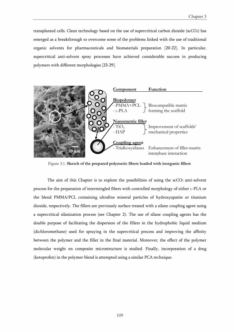
Chapter 3
109
transplanted cells. Clean technology based on the use of supercritical carbon dioxide (scCO2) has
emerged as a breakthrough to overcome some of the problems linked with the use of traditional
organic solvents for pharmaceuticals and biomaterials preparation [20-22]. In particular,
supercritical anti-solvent spray processes have achieved considerable success in producing
polymers with different morphologies [23-29].
Figure 3.1. Sketch of the prepared polymeric fibers loaded with inorganic fillers
The aim of this Chapter is to explore the possibilities of using the scCO2 anti-solvent
process for the preparation of intermingled fibers with controlled morphology of either L-PLA or
the blend PMMA/PCL containing ultrafine mineral particles of hydroxyapatite or titanium
dioxide, respectively. The fillers are previously surface treated with a silane coupling agent using
a supercritical silanization process (see Chapter 2). The use of silane coupling agents has the
double purpose of facilitating the dispersion of the fillers in the hydrophobic liquid medium
(dichloromethane) used for spraying in the supercritical process and improving the affinity
between the polymer and the filler in the final material. Moreover, the effect of the polymer
molecular weight on composite microstructure is studied. Finally, incorporation of a drug
(ketoprofen) in the polymer blend is attempted using a similar PCA technique.
10 μm
Component Function Biopolymer - PMMA+PCL Biocompatible matrix - L-PLA forming the scaffold Nanometric filler - TiO2 Improvement of scaffolds’ - HAP mechanical properties Coupling agent - Trialkoxysilanes Enhancement of filler-matrix
interphase interaction
Preparation of biopolymer-based materials using scCO2
110
3.2. Materials and Methods [30]
3.2.1. Materials
Several polymers are selected as matrices for the hybrid materials: L-PLA (Biovalley,
100,000 g mol-1), PCL (Aldrich, 14,000 g mol-1) and two kinds of PMMA (PMMA1: Bonar, 300,000
g mol-1; PMMA2: Aldrich, 120,000 g mol-1). Bare TiO2 (TiO2 P25S, Degussa) and lab-synthesized
nanometric hydroxyapatite (HAP) are used as fillers [31]. Using a supercritical silanization
procedure (see Chapter 2), TiO2 is functionalized with octyltriethoxysilane (CH3
(CH2)7Si(OCH2CH3)3, Fluka). Commercially silanized TiO2 (TiO2 T805, Degussa) is used for
comparison. HAP nanoparticles are silanized with γ-methacryloxypropyltrimethoxysilane
(H2C=C(CH3)CO2(CH2)3Si(OCH3)3, Sigma) following a similar supercritical silanization approach
than that used for TiO2 [31]. Ketoprofen (K, Aldrich) is used as the model drug. Carbon dioxide
(CO2, Air Liquide) and dichloromethane (DCM, Prolabo) are used as the anti-solvent and the
solvent, respectively.
3.2.2. Process
Experiments are carried out in a PCA equipment (see Section 1.2.3 of Chapter 1). For the
preparation of the fibers, CO2 is introduced in a high pressure vessel (Re1 in Fig. 1.3) until a
pressure of 11.0 MPa and a temperature of 312 K are reached. Then, a DCM suspension
containing the nanoparticles and the dissolved polymer is injected into the vessel through a swirl
nozzle at a rate of 1.5-2 mLmin-1. The fibers are precipitated and deposited on the walls and at the
bottom of the vessel. Once the injection of the DCM solution is finished, the precipitated hybrid
material is dried using a continuous flow of scCO2 of 65 gmin-1 during 10 min at 312 K and 11.0
MPa. Finally, the high-pressure vessel is slowly depressurized, and samples are collected for
characterization.
3.2.3. Characterization
Obtained hybrid fibers or particles are analyzed using thermogravimetric analysis,
differential scanning calorimetry, scanning electron microscopy with energy dispersive
spectrometry, low-temperature N2 adsorption-desorption analysis and 1H nuclear magnetic
resonance.
Chapter 3
111
3.3. Results
Article no. 1
Title: Composite fibrous biomaterials for tissue engineering obtained using a supercritical
CO2 antisolvent process
Authors: C. A. García-González, A. Vega-González, A. M. López-Periago, P. Subra-
Paternault, C. Domingo
Journal: Acta Biomaterialia 5 (2009) 1094-1103
Chapter 3
123
3.4. Conclusions
Networks of fibers of the L-PLA homopolymer and several PMMA/PCL blends (85:15
wt%) loaded with HAP and TiO2 (15-20 wt%), respectively, are prepared using the anti-solvent
PCA process. The silanization of the fillers facilitates nanoparticles dispersion in the DCM
solution injected in the high-pressure vessel. Using the silane surface modification method,
silanized TiO2 particles incorporated in the PMMA/PCL fibers are homogeneously distributed
throughout the hybrid material. Instead of the fibers obtained when processing either L-PLA or
high molecular weight PMMA, agglomerated microparticles are prepared when low molecular
weight PMMA is used in the PMMA/PCL blend. Hence, the viscosity of the polymeric solution
influences the formation of either fibers or microparticles. Under the used experimental
conditions, the incorporation of ketoprofen within the polymeric matrix is not achieved, due to
the removal of the drug from the polymer during the drying of the fibers with scCO2.
3.5. References
[1] M. Ricci, P. Blasi, S. Giovagnoli, C. Rossi, G. Macchiarulo, G. Luca, G. Basta, R. Calafiore Ketoprofen controlled release from composite microcapsules for cell encapsulation: Effect on post-transplant acute inflammation. Journal of Controlled Release 2005, 107(3), 395-407.
[2] L.G. Cima, D. Ingber, J.P. Vacanti, Hepatocyte culture on biodegradable polymeric substrates. Biotechnology and bioengineering 1991, 38(2), 145-158.
[3] L.G. Cima, J.P. Vacanti, C. Vacanti, Tissue engineering by cell transplantation using degradable polymer substrates. Journal of Biomechanical Engineering 1991, 113(2), 143-151.
[4] R. Langer, J.P. Vacanti, Tissue engineering. Science 1993, 260(5110), 920-926.
[5] S. Yang, K.-F. Leong, Z. Du, C.-K. Chua, The design of scaffolds for use in tissue engineering. Part I. Traditional factors. Tissue Engineering 2001, 7(6), 679-689.
[6] D. Shi, Biomaterials and tissue engineering, 1st edition. Springer: Heidelberg, 2004.
[7] L.G. Griffith, Polymeric biomaterials. Acta Materialia 2000, 48(1), 263-277.
[8] D.W. Hutmacher, Scaffolds in tissue engineering bone and cartilage. Biomaterials 2000, 21(24), 2529-2543.
[9] H. Shin, S. Jo, A.G. Mikos, Biomimetic materials for tissue engineering. Biomaterials 2003, 24(24), 4353-4364.
[10] K. Whang, C.H. Thomas, K.E. Healy, G. Nuber, A novel method to fabricate bioabsorbable scaffolds. Polymer 1995, 36(4), 837-842.
Preparation of biopolymer-based materials using scCO2
124
[11] T. Tateishi, G. Chen, T. Ushida, Polyfunctional scaffolds for tissue engineering. Journal of Biomechanical Science and Engineering 2006, 1(1), 8-15.
[12] G.A. Abraham, A. Gallardo, A. Motta, C. Migliaresi, J. San Román, Microheterogeneous polymer systems prepared by suspension polymerization of methyl methacrylate in the presence of poly(ε-caprolactone). Macromolecular Materials and Engineering 2000, 282(1), 44-50.
[13] G.A. Abraham, K. Kesenci, L. Fambri, C. Migliaresi, A. Gallardo, J. San Román, Microcomposite of poly(ε-caprolactone) and poly(methyl methacrylate) prepared by suspension polymerization in the presence of poly(ε-caprolactone) macromonomer. Macromolecular Materials and Engineering 2002, 287(12), 938-945.
[14] W.-Y. Yeong, Ch.-K. Chua, K.-F. Leong, M. Chandrasekaran, Rapid prototyping in tissue engineering: challenges and potential. Trends in Biotechnology 2004, 22(12), 643-652.
[15] Y. Zhou, K. Cooper, Y. Li, Z. Li, Use of coupling agents to improve the interface in absorbable polymer composites. US Patent 20,090,149,873 (2009).
[16] A.G. Mikos, J.S. Temenoff, Formation of highly porous biodegradable scaffolds for tissue engineering. Electronic Journal of Biotechnology 2000, 3(2), 1-6.
[17] D.W. Hutmacher, Scaffold design and fabrication technologies for engineering tissues—State of the art and future perspectives. Journal of Biomaterials Science: Polymer Edition 2002, 12(1), 107–124.
[18] L. Moroni, J.R. de Wijn, C.A. van Blitterswijk, 3D fiber-deposited scaffolds for tissue engineering: Influence of pores geometry and architecture on dynamic mechanical properties. Biomaterials 2006, 27(7), 974–985.
[19] S.H. Park, T.G. Kim, H.C. Kim, D.Y. Yang, T.G. Park, Development of dual scale scaffolds via direct polymer melt deposition and electrospinning for applications in tissue regeneration. Acta Biomaterialia 2008, 4(5), 1198–1207.
[20] E. Reverchon, G. Della Porta, I. De Rosa, P. Subra, D. Letourneur, Supercritical antisolvent micronization of some biopolymers. The Journal of Supercritical Fluids 2000, 18(3), 239-245.
[21] R.A. Quirk, R.M. France, K.M. Shakesheff, S.M. Howdle, Supercritical fluid technologies and tissue engineering scaffolds. Current Opinion in Solid State and Materials Science 2004, 8(3-4), 313-321.
[22] A.R.C. Duarte, J.F. Mano, R.L. Reis, Perspectives on: Supercritical fluid technology for 3D tissue engineering scaffold applications. Journal of the Bioactive and Compatible Polymers 2009, 24(4), 385-400.
[23] K.J.L. Burg, S. Porter, J.F. Kellam, Biomaterial developments for bone tissue engineering. Biomaterials 2000, 21(23), 2347-2359.
Chapter 3
125
[24] N. Elvassore, A. Bertucco, Production of protein-loaded polymeric microcapsules by compressed CO2 in a mixed solvent. Industrial & Engineering Chemistry Research 2001, 40(3), 795–800.
[25] A.J. Salgado, O.P. Coutinho, R.L. Reis, Bone tissue engineering: State of the art and future trends. Macromolecular Bioscience 2004, 4(8), 743-765.
[26] A. Vega-González, C. Domingo, C. Elvira, P. Subra, Precipitation of PMMA/PCL blends using supercritical carbon dioxide. Journal of Applied Polymer Science 2004, 91(4), 2422-2426.
[27] S.-D. Yeo, E. Kiran, Formation of polymer particles with supercritical fluids: A review. The Journal of Supercritical Fluids 2005, 34(3), 287-308.
[28] F. Miguel, A. Martín, F. Mattea, M.J. Cocero, Precipitation of lutein and co-precipitation of lutein and poly-lactic acid with the supercritical anti-solvent process. Chemical Engineering and Processing: Process Intensification 2008, 47(9-10), 1594-1602.
[29] A. Vega-González, P. Subra-Paternault, A.M. López-Periago, C.A. García-González, C. Domingo, Supercritical CO2 antisolvent precipitation of polymer networks of L-PLA, PMMA and PMMA/PCL blends for biomedical applications. European Polymer Journal 2008, 44(4), 1081-1094.
[30] C.A. García-González, A. Vega-González, A.M. López-Periago, P. Subra-Paternault, C. Domingo, Composite fibrous biomaterials for tissue engineering obtained using a supercritical CO2 antisolvent process. Acta Biomaterialia 2009, 5(4), 1094-1103.
[31] C. Domingo, E. Loste, J. Fraile, Grafting of trialkoxysilane on the surface of nanoparticles by conventional wet alcoholic and supercritical carbon dioxide deposition methods. The Journal of Supercritical Fluids 2006, 37(1), 72-86.
127
Chapter 4
USE OF SCCO2 AS A SOLUTE:
PREPARATION OF LIPID-BASED PARTICLES
This Chapter focuses on the use of scCO2 as a solute in the Particles from Gas
Saturated Solutions (PGSS®) process for the preparation of solid lipid hybrid particles
containing active compounds. A lipid blend composed of glyceryl monostearate and
hydrogenated castor oil is used as the carrier. The influence of the lipid composition and the
presence of CO2 in the melting point depression of the mixture are studied from atmospheric
pressure to 16 MPa. Particles consisting in a lipidic matrix loaded with ca. 6 wt% of
nanoparticles of titanium dioxide are obtained using the PGSS® technique. TiO2 nanoparticles
are previously surface hydrophobized using a supercritical silanization method (see Chapter 2)
to improve their dispersibility in the lipidic matrix. The UV-shielding ability of TiO2 after its
incorporation in the lipid particles is assessed by solid UV-Vis spectroscopy. Finally, lipid
particles loaded with ca. 6 wt% of TiO2 and ca. 4 wt% of caffeine are prepared using a similar
PGSS® process. The water dissolution profile of the caffeine loaded in the lipid particles is
studied.
Preparation of lipid-based particles using scCO2
128
4.1. Introduction
Pharmaceutical and cosmetic industries are working on the development of new
strategies for the formulation and processing of new products for topical applications
containing active compounds [1]. When possible, topical treatment of skin diseases is
preferred to oral or parenteral administration of drugs, since high drug concentrations can be
achieved at the site of application with reduced systemic side effects [2]. Among the different
studied systems, lipid-based drug delivery systems have become an attractive carrier for the
formulation of pharmaceuticals and cosmetics. Most lipids, typically saturated and unsaturated
fatty acids and derivatives, are well tolerated by the human body due to their quick
metabolization into non-toxic products [3,4]. Lipid-based carriers can be obtained in the form
of emulsions, liposomes or solid particles depending on the processing technique, the mixture
of lipids used and the composition of the formulation. As a carrier, solid lipid particles (SLP)
are particularly advantageous in terms of physical stability, drug protection against chemical
degradation and cost [5]. The research activity on SLP is especially intensified for cosmetic
and pharmaceutical dermal applications [2,6,7].
The development of sunscreens with SLP containing inorganic UV-blockers (e.g.,
titanium dioxide, zinc oxide) and organic UV-absorbers (e.g., avobenzone, oxybenzone,
octinoxate, octocrylene, homosalate) for the prevention of skin damages inferred by UV
radiation in humans is being investigated [2,8,9]. In these formulations, the lipid matrix can
act as a complementary UV-filter [2,8,9]. Among the used inorganic UV-blockers,
nanoparticulate titanium dioxide (TiO2) is widely employed in the industry of cosmetics as an
effective and transparent UVA-light and UVB-light blocker [10]. The entrapping of the TiO2
nanoparticles into SLP may provide an excellent medium for the incorporation of this UV-
filter in the formulation of sunscreens. In this way, the dispersion of the TiO2 particles into
the oil phase of sunscreens is facilitated and the segregation of the inorganic component is
minimized [2]. Moreover, the encapsulation of nanoparticles into larger particles often
minimizes the potential negative environmental and health impact of the nanoparticles
[10,11]. However, owing to the intrinsic hydrophilic character of non-treated TiO2 surfaces,
the dispersion of the nanoparticles in the lipid matrices and in the organic media used in
cosmetics is not easily achieved. A hydrophobic surface treatment of the TiO2 nanoparticles
facilitates particles dispersion and mitigates their tendency to agglomeration [12].
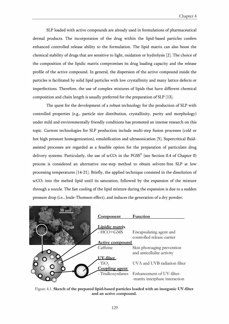
Chapter 4
129
SLP loaded with active compounds are already used in formulations of pharmaceutical
dermal products. The incorporation of the drug within the lipid-based particles confers
enhanced controlled release ability to the formulation. The lipid matrix can also boost the
chemical stability of drugs that are sensitive to light, oxidation or hydrolysis [2]. The choice of
the composition of the lipidic matrix compromises its drug loading capacity and the release
profile of the active compound. In general, the dispersion of the active compound inside the
particles is facilitated by solid lipid particles with low crystallinity and many lattice defects or
imperfections. Therefore, the use of complex mixtures of lipids that have different chemical
composition and chain length is usually preferred for the preparation of SLP [13].
The quest for the development of a robust technology for the production of SLP with
controlled properties (e.g., particle size distribution, crystallinity, purity and morphology)
under mild and environmentally friendly conditions has promoted an intense research on this
topic. Current technologies for SLP production include multi-step fusion processes (cold or
hot high pressure homogenization), emulsification and ultrasonication [5]. Supercritical fluid-
assisted processes are regarded as a feasible option for the preparation of particulate drug
delivery systems. Particularly, the use of scCO2 in the PGSS® (see Section 0.4 of Chapter 0)
process is considered an alternative one-step method to obtain solvent-free SLP at low
processing temperatures [14-21]. Briefly, the applied technique consisted in the dissolution of
scCO2 into the melted lipid until its saturation, followed by the expansion of the mixture
through a nozzle. The fast cooling of the lipid mixture during the expansion is due to a sudden
pressure drop (i.e., Joule-Thomson effect), and induces the generation of a dry powder.
Figure 4.1. Sketch of the prepared lipid-based particles loaded with an inorganic UV-filter and an active compound.
50 μmComponent Function Lipidic matrix - HCO+GMS Encapsulating agent and controlled release carrier Active compound Caffeine Skin photoaging prevention and anticellulite activity UV-filter - TiO2 UVA and UVB radiation filter Coupling agent - Trialkoxysilanes Enhancement of UV-filter-
-matrix interphase interaction
Preparation of lipid-based particles using scCO2
130
In this Chapter, the use of the PGSS® process is assessed for the production of
particulate hybrid carriers consisting of a complex lipid matrix (Lumulse® GMS K / Cutina®
HR blend) containing nanometric particles of TiO2 and caffeine. Firstly, the effects of the lipid
mixture composition and the presence of CO2 on the extent of the melting point depression of
the lipid blend are studied. Pure SLP are primarily produced using the PGSS® technique.
Obtained particles are analyzed regarding physical state, thermal stability and morphology.
The production of SLP loaded with a physical UV-blocker (TiO2) is then carried out. TiO2 is
previously surface treated with two different silane adhesion promoters (octyltriethoxysilane
and octadecyltrimethoxysilane) using a supercritical silanization process (see Chapter 2). The
effects of the presence of TiO2 on the properties of the obtained lipid-based particles are
analyzed. Finally, composite particles are loaded with an active agent (caffeine) using a similar
PGSS® technique (Figure 4.1).
4.2. Materials and Methods [21]
4.2.1. Materials
The selected lipid blend matrix is composed of Lumulse® GMS K (GMS; Lambent
Technologies) and Cutina® HR (HCO, José M. Vaz Pereira S.A.) in a 1:1 weight ratio. Bare
TiO2 (TiO2 P25, Degussa) is used as the inorganic UV-blocker. Using a supercritical
silanization procedure (see Chapter 2), TiO2 is coated with either octyltriethoxysilane (CH3
(CH2)7Si(OCH2CH3)3, Fluka) or octadecyltrimethoxysilane (CH3(CH2)17Si(OCH3)3, Fluka).
Caffeine (Sigma-Aldrich) is used as the active compound to be incorporated in the lipid
matrix. Carbon dioxide (CO2, Air Liquide) is used in the PGSS® materials processing.
4.2.2. Process
Experiments are carried out in the PGSS® (Particles from Gas Saturated Solutions)
equipment described in Section 1.2.4 of Chapter 1. For the preparation of the solid lipid-based
particles, a 0.5-L high pressure vessel (Re1 in Fig. 1.4) is first charged with the lipids, the TiO2
and the caffeine. Then, CO2 is supplied to the vessel Re1 until a pressure of 13.0 MPa and a
temperature of 345 K are reached. The mixture is stirred during 1 h, time after which the
system is depressurized through a nozzle. A free-flowing powder is collected in a 10-L vessel
(Re2).
Chapter 4
131
4.2.3. Characterization
Melting point measurements of HCO:GMS blends (1:1 and 3:1 weight ratios) under
compressed CO2 (0.1-18.0 MPa) are performed using a 4-mL view cell. The obtained hybrid
particles are analyzed using thermogravimetric analysis, differential scanning calorimetry,
transmission electron microscopy, scanning electron microscopy with energy dispersive
spectrometry, X-ray diffraction and UV-Vis spectroscopy. The caffeine dissolution profile in
water is determined by high performance liquid chromatography.
Preparation of lipid-based particles using scCO2
132
4.3. Results
Article no. 1
Title: Production of hybrid lipid-based particles loaded with inorganic nanoparticles
and active compounds for prolonged topical release
Authors: C. A. García-González, A. R. Sampaio da Sousa, A. Argemí, A. López Periago,
J. Saurina, C. M. M. Duarte, C. Domingo
Journal: Int. J. Pharm. 382 (2009) 296-304
143
4.4. Conclusions
The supercritically aided PGSS® method is used for the incorporation of inorganic
nanoparticles (TiO2) and active compounds (caffeine) into a lipid blend matrix (HCO/GMS
weight ratio= 1:1). Using this one-step supercritical technique, a decrease in the processing
temperature is achieved. Moreover, a solvent-free product is obtained. The use of a blend
instead of a pure lipid provides a reduction in the crystallinity of the mixture which increases
the capacity of the lipidic matrix for drug incorporation. The silanization of the TiO2 surface
facilitates the homogeneous distribution of the inorganic nanoparticles within the lipidic
matrix. Negative effects of silane coating and lipid encapsulation on the UV-shielding ability
of the TiO2 are not noticeable. A two-step dissolution profile was obtained for the caffeine
loaded in the lipid particles.
4.5. References
[1] R. Liu, Water-insoluble drug formulation. Interpharm/CRC Press: Boca Raton, 2000.
[2] J. Pardeike, A. Hommoss, R.H. Müller, Lipid nanoparticles (SLN, NLC) in cosmetic and pharmaceutical dermal products. International Journal of Pharmaceutics 2009, 366(1-2), 170-184.
[3] K. Westesen, Novel lipid-based colloidal dispersions as potential drug administration systems: expectations and reality. Colloid and Polymer Science 2000, 278(7), 608-618.
[4] V. Jannin, J. Musakhanian, D. Marchaud, Approaches for the development of solid and semi-solid lipid-based formulations. Advanced Drug Delivery Reviews 2008, 60(6), 734-746.
[5] R.H. Müller, K. Mäder, S. Gohla, Solid lipid nanoparticles (SLN) for controlled drug delivery – A review of the state of the art. European Journal of Pharmaceutics and Biopharmaceutics 2000, 50(1), 161-177.
[6] R.H. Müller, M. Radtke, S.A. Wissing, Solid lipid nanoparticles (SLN) and nanostructured lipid carriers (NLC) in cosmetic and dermatological preparations. Advanced Drug Delivery Reviews 2002, 54(1), S131-S155.
[7] C. Puglia, P. Blasi, L. Rizza, A. Schoubben, F. Bonina, C. Rossi, M. Ricci, Lipid nanoparticles for prolonged topical delivery: An in vitro and in vivo investigation. International Journal of Pharmaceutics 2008, 357(1-2), 295-304.
[8] G. Yener, T. Incegül, N. Yener, Importance of using solid lipid microspheres as carriers for UV filters on the example octyl methoxy cinnamate. International Journal of Pharmaceutics 2003, 258(1-2), 203-207.
[9] J.R. Villalobos-Hernández, C.C. Müller-Goymann, Novel nanoparticulate carrier system based on carnauba wax and decyl oleate for the dispersion of inorganic sunscreens in
Preparation of lipid-based particles using scCO2
144
aqueous media. European Journal of Pharmaceutics and biopharmaceutics 2005, 60(1), 113-122.
[10] A. Grobe, O. Renn, A. Jaeger, A report for IRGC: Risk governance of nanotechnology applications in food and cosmetics. International Risk Governance Council: Geneva, 2008.
[11] W. Klöpffer, Nanotechnology and life cycle assessment: A systems approach to nanotechnology and environment. Nanotechnology and Life Cycle Assessment: Washington, 2007.
[12] C.A. García-González, J. Fraile, A. López-Periago, C. Domingo, Preparation of silane-coated TiO2 nanoparticles in supercritical CO2. Journal of Colloid and Interface Science 2009, 338(2), 491-499.
[13] A.R. Sampaio de Sousa, M. Calderone, E. Rodier, J. Fages, C.M.M. Duarte, Solubility of carbon dioxide in three lipid-based biocarriers. The Journal of Supercritical Fluids 2006, 39(1), 13-19.
[14] E. Weidner, Z. Knez, Z. Novak, Process for preparing particles or powders, WO Patent WO95/21,688 (1995).
[15] M. Rodrigues, N. Peiriço, H. Matos, E. Gomes de Azevedo, M.R. Lobato, A.J. Almeida, Microcomposites theophylline/hydrogenated palm oil from a PGSS process for controlled drug delivery systems. The Journal of Supercritical Fluids 2004, 29(1-2), 175-184.
[16] M. Calderone, E. Rodier, J.-J. Letorneau, J. Fages, Solidification of Precirol® by the expansion of a supercritical fluid saturated melt: From the thermodynamic balance towards the crystallization aspect. The Journal of Supercritical Fluids 2007, 42(2), 189-199.
[17] A.R. Sampaio de Sousa, A.L. Simplício, H.C. de Sousa, C.M.M. Duarte, Preparation of glyceryl monostearate-based particles by PGSS®—Application to caffeine. The Journal of Supercritical Fluids 2007, 43(1), 120-125.
[18] A.R. Sampaio da Sousa, Development of functional particles using supercritical fluid technology: Fundamentals, processing and applications. PhD Thesis. Oeiras, 2007.
[19] A.R. Sampaio de Sousa, R. Silva, F.H. Tay, A.L. Simplício, S.G. Kazarian, C.M.M. Duarte, Solubility enhancement of trans-chalcone using lipid carriers and supercritical CO2 processing. The Journal of Supercritical Fluids 2009, 48(2), 120-125.
[20] F. Temelli, Perspectives on supercritical fluid processing of fats and oils. The Journal of Supercritical Fluids 2009, 47(3), 583-590.
[21] C.A. García-González, A.R. Sampaio da Sousa, A. Argemí, A. López Periago, J. Saurina, C.M.M. Duarte, C. Domingo, Production of hybrid lipid-based particles loaded with inorganic nanoparticles and active compounds for prolonged topical release. International Journal of Pharmaceutics 2009, 382(1-2), 296-304.
145
Chapter 5
USE OF SCCO2 AS A REAGENT:
ACCELERATED CEMENT CARBONATION
The carbonation of Portland cement increases the density and reduces the macroporosity,
the water permeability and the pH of the material, which enhances its durability in certain
applications. Cement carbonation not only generates a high added value product, but also could
help to CO2 capture and storage and, therefore, it is regarded as a sustainable process.
Nevertheless, natural carbonation is a very slow process and feasible alternatives for accelerated
carbonation are being prospected. Cement carbonation may be greatly accelerated if scCO2 is
used as the carbonating agent. In this Chapter, the carbonation of several cementitious materials
of different compositions and admixtures with scCO2 is described. The effects of the supercritical
process on the microstructure and physicochemical properties of the prepared samples are
studied. On the other hand, the durability of cement-based materials is usually compromised by
weathering and problems related with water ingress (coming from percolated ground water and
infiltrated rainwater) in the cementitious matrix. Therefore, a surface treatment consisting in the
supercritical silanization of the carbonated cement-based materials with octytriethoxysilane as
the hydrophobic agent is assessed. The objective is to prevent the water ingress in the bulk of the
cementitious material. Finally, some of the tools for the management of resources and process
integration are applied to the supercritical carbonation-silanization process.
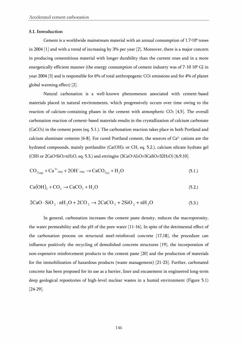
Accelerated cement carbonation
146
5.1. Introduction
Cement is a worldwide mainstream material with an annual consumption of 1.7•109 tones
in 2004 [1] and with a trend of increasing by 3% per year [2]. Moreover, there is a major concern
in producing cementitious material with longer durability than the current ones and in a more
energetically efficient manner (the energy consumption of cement industry was of 7-10 109 GJ in
year 2004 [3] and is responsible for 6% of total anthropogenic CO2 emissions and for 4% of planet
global warming effect) [2].
Natural carbonation is a well-known phenomenon associated with cement-based
materials placed in natural environments, which progressively occurs over time owing to the
reaction of calcium-containing phases in the cement with atmospheric CO2 [4,5]. The overall
carbonation reaction of cement-based materials results in the crystallization of calcium carbonate
(CaCO3) in the cement pores (eq. 5.1.). The carbonation reaction takes place in both Portland and
calcium aluminate cements [6-8]. For cured Portland cement, the sources of Ca2+ cations are the
hydrated compounds, mainly portlandite (Ca(OH)2 or CH, eq. 5.2.), calcium silicate hydrate gel
(CSH or 2CaO•SiO2•nH2O, eq. 5.3.) and ettringite (3CaO•Al2O3•3CaSO4•32H2O) [6,9,10].
OHCaCO2OHCaCO 2(s)3(aq)(aq)2
(aq)2 +→++ −+ (5.1.)
( ) OHCaCOCOOHCa 2322 +→+ (5.2.)
OnH2SiO2CaCO2COOnHSiO2CaO 223222 ++→+⋅⋅ (5.3.)
In general, carbonation increases the cement paste density, reduces the macroporosity,
the water permeability and the pH of the pore water [11-16]. In spite of the detrimental effect of
the carbonation process on structural steel-reinforced concrete [17,18], the procedure can
influence positively the recycling of demolished concrete structures [19], the incorporation of
non-expensive reinforcement products to the cement paste [20] and the production of materials
for the immobilization of hazardous products (waste management) [21-23]. Further, carbonated
concrete has been proposed for its use as a barrier, liner and encasement in engineered long-term
deep geological repositories of high-level nuclear wastes in a humid environment (Figure 5.1)
[24-29].
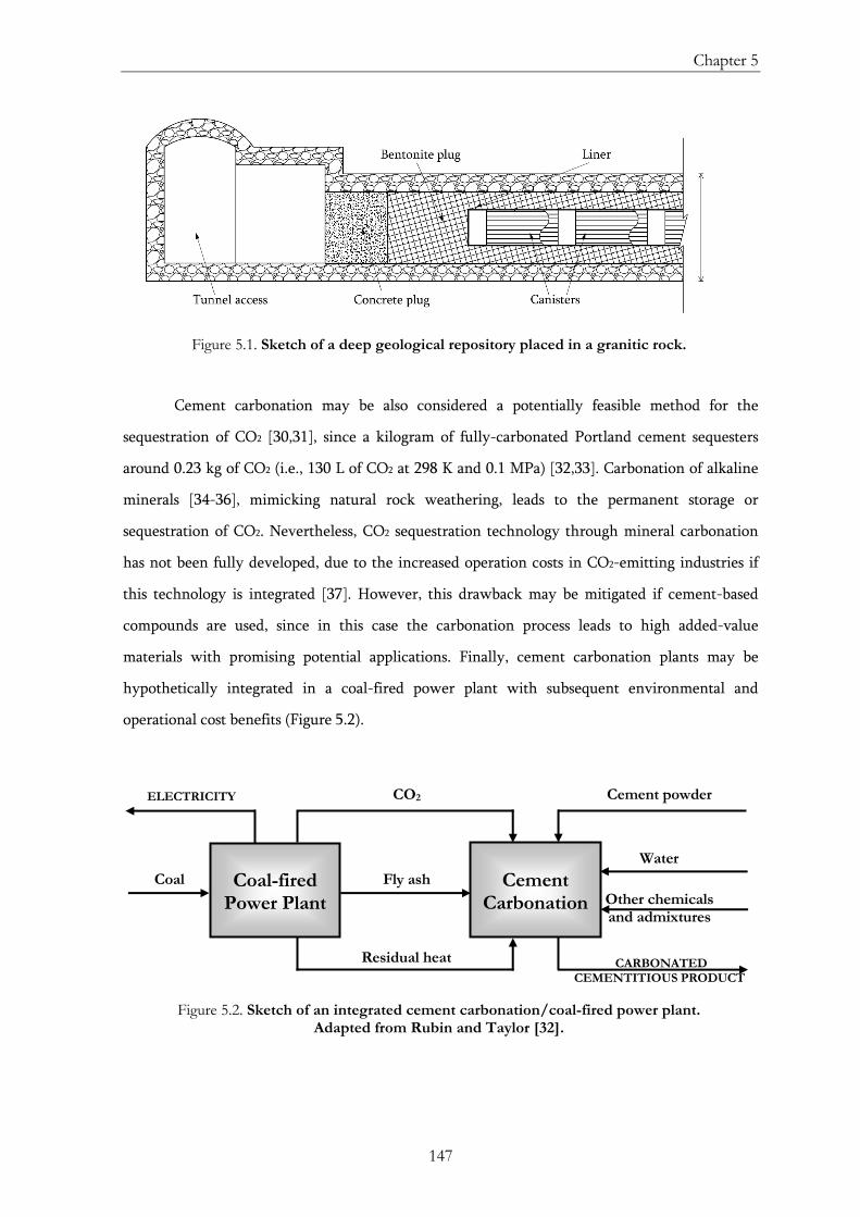
Chapter 5
147
Figure 5.1. Sketch of a deep geological repository placed in a granitic rock.
Cement carbonation may be also considered a potentially feasible method for the
sequestration of CO2 [30,31], since a kilogram of fully-carbonated Portland cement sequesters
around 0.23 kg of CO2 (i.e., 130 L of CO2 at 298 K and 0.1 MPa) [32,33]. Carbonation of alkaline
minerals [34-36], mimicking natural rock weathering, leads to the permanent storage or
sequestration of CO2. Nevertheless, CO2 sequestration technology through mineral carbonation
has not been fully developed, due to the increased operation costs in CO2-emitting industries if
this technology is integrated [37]. However, this drawback may be mitigated if cement-based
compounds are used, since in this case the carbonation process leads to high added-value
materials with promising potential applications. Finally, cement carbonation plants may be
hypothetically integrated in a coal-fired power plant with subsequent environmental and
operational cost benefits (Figure 5.2).
Figure 5.2. Sketch of an integrated cement carbonation/coal-fired power plant.
Adapted from Rubin and Taylor [32].
Other chemicals and admixtures
Coal-fired
Power Plant
Cement
Carbonation Fly ash
Residual heat
CO2 ELECTRICITY
Coal
CARBONATED CEMENTITIOUS PRODUCT
Cement powder
Water
Accelerated cement carbonation
148
The concentration of the CO2 reagent plays an important role in cement carbonation
processes. The natural carbonation process is too slow (in the order of months) to be
implemented for any of the industrial applications already mentioned. The low carbonation rate
is due to the low CO2 concentration in the atmosphere (0.03-0.06 vol. %) and the slow diffusion
velocity of CO2 into the cement pores [38]. Thus, the aim is to develop a controlled accelerated
carbonation method in order to obtain a carbonated cementitious material in a reasonable period
of time. Cement carbonation in a gaseous CO2 enriched atmosphere reduces the duration of the
process from months up to weeks, due to the high CO2 content in the gas phase [39-41]. In this
case, the difussion of CO2 inside the cement pores is the rate-limiting step of the carbonation
process.
Cement carbonation may be greatly accelerated if scCO2 is used as the carbonation agent
[7,13-15,22,23,32,42]. Hyper-stoichiometric CO2 concentration and enhanced CO2 solubility in
water is obtained when working with scCO2. Further, the reaction acceleration is also due to the
ease of penetration and diffusion of the scCO2 into the micropores of the cement paste, providing
continuous availability of fresh reactant. In this Chapter, the effects of supercritical carbonation
on the physicochemical properties of different types of hardened Portland cement pastes are
studied. Results are compared with those obtained from natural carbonation.
Additionally, a water repellency treatment confers high-added value to some
construction materials (e.g., concrete, bricks, wood, stone, marble) [43-47]. Although water is
very important to concrete during hardening stages, it could cause severe damages with time. For
instance, some water-associated problems of the concrete are freeze−thaw damage, alkali silica
reaction or sulphate attack [45,48-52]. Consequently, the next step of this research is to achieve
an increase in the durability of concrete by preventing water ingress in the bulk of the matrix.
Various hydrophobic treatments are currently used to prevent or minimize water penetration
into concrete; among them, barrier systems are the most used ones [53]. Moreover, durability
enhancement and graffiti prevention of cement-based materials have been reported using silane
solutions as the hydrophobic agents [54]. In this Chapter, cement silanization using scCO2 as a
solvent (see Chapter 2) is performed [14,45]. Octyltriethoxysilane is used as the water-repellent
agent [55] by forming a polysiloxane network on the surface of the inorganic material: the ethoxy
groups hydrolize to produce silanols that bond with the surface hydroxyl groups of the cement,
while the long-chain alkyl groups of the organic silane confer hydrophobicity to the surface.
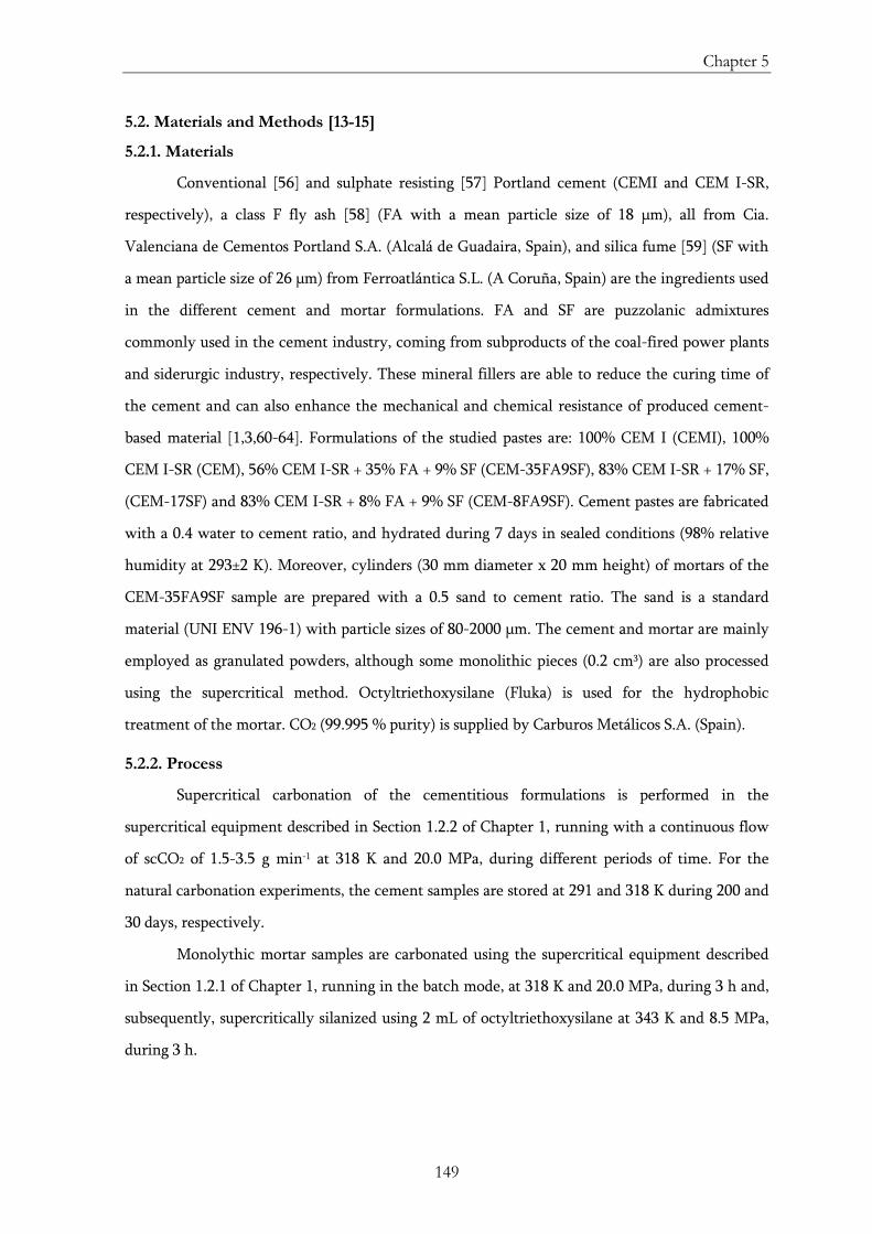
Chapter 5
149
5.2. Materials and Methods [13-15]
5.2.1. Materials
Conventional [56] and sulphate resisting [57] Portland cement (CEMI and CEM I-SR,
respectively), a class F fly ash [58] (FA with a mean particle size of 18 μm), all from Cia.
Valenciana de Cementos Portland S.A. (Alcalá de Guadaira, Spain), and silica fume [59] (SF with
a mean particle size of 26 μm) from Ferroatlántica S.L. (A Coruña, Spain) are the ingredients used
in the different cement and mortar formulations. FA and SF are puzzolanic admixtures
commonly used in the cement industry, coming from subproducts of the coal-fired power plants
and siderurgic industry, respectively. These mineral fillers are able to reduce the curing time of
the cement and can also enhance the mechanical and chemical resistance of produced cement-
based material [1,3,60-64]. Formulations of the studied pastes are: 100% CEM I (CEMI), 100%
CEM I-SR (CEM), 56% CEM I-SR + 35% FA + 9% SF (CEM-35FA9SF), 83% CEM I-SR + 17% SF,
(CEM-17SF) and 83% CEM I-SR + 8% FA + 9% SF (CEM-8FA9SF). Cement pastes are fabricated
with a 0.4 water to cement ratio, and hydrated during 7 days in sealed conditions (98% relative
humidity at 293±2 K). Moreover, cylinders (30 mm diameter x 20 mm height) of mortars of the
CEM-35FA9SF sample are prepared with a 0.5 sand to cement ratio. The sand is a standard
material (UNI ENV 196-1) with particle sizes of 80-2000 μm. The cement and mortar are mainly
employed as granulated powders, although some monolithic pieces (0.2 cm3) are also processed
using the supercritical method. Octyltriethoxysilane (Fluka) is used for the hydrophobic
treatment of the mortar. CO2 (99.995 % purity) is supplied by Carburos Metálicos S.A. (Spain).
5.2.2. Process
Supercritical carbonation of the cementitious formulations is performed in the
supercritical equipment described in Section 1.2.2 of Chapter 1, running with a continuous flow
of scCO2 of 1.5-3.5 g min-1 at 318 K and 20.0 MPa, during different periods of time. For the
natural carbonation experiments, the cement samples are stored at 291 and 318 K during 200 and
30 days, respectively.
Monolythic mortar samples are carbonated using the supercritical equipment described
in Section 1.2.1 of Chapter 1, running in the batch mode, at 318 K and 20.0 MPa, during 3 h and,
subsequently, supercritically silanized using 2 mL of octyltriethoxysilane at 343 K and 8.5 MPa,
during 3 h.
Accelerated cement carbonation
150
5.2.3. Characterization
Cement-based samples are analyzed using X-ray diffraction, thermogravimetric analysis,
low-temperature N2 adsorption-desorption analysis, mercury intrusion porosimetry, scanning
electron microscopy with backscattered electron imaging, water permeability test, particle size
distribution by light scattering, and Fourier transform infrared spectrometry.
Chapter 5
151
5.3. Results
Article no. 1
Title: Modification in Composition and Microstructure of Portland Cement Pastes as a
Result of Natural and Supercritical Carbonation Procedures
Authors: C. A. García-González, A. Hidalgo, C. Andrade, M. C. Alonso, J. Fraile, A. M.
López, C. Domingo
Journal: Ind. Eng. Chem. Res. 45 (2006) 4985-4992
Article no. 2
Title: Porosity and Water Permeability Study of Supercritically Carbonated Cement
Pastes Involving Mineral Additions
Authors: C. A. García-González, A. Hidalgo, J. Fraile, A. M. López-Periago, C. Andrade,
C. Domingo
Journal: Ind. Eng. Chem. Res. 46 (2007) 2488-2496
Article no. 3
Title: New Insights on the Use of Supercritical Carbon Dioxide for the Accelerated
Carbonation of Cement Pastes
Authors: C. A. García-González, N. El Grouh, A. Hidalgo, J. Fraile, A. M. López-Periago,
C. Andrade, C. Domingo
Journal: J. Supercritical Fluids 43 (2008) 500-509
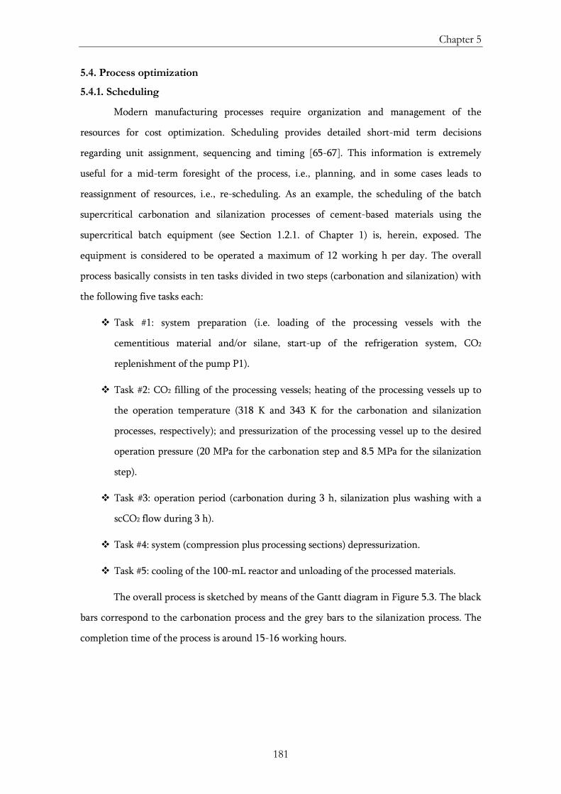
Chapter 5
181
5.4. Process optimization
5.4.1. Scheduling
Modern manufacturing processes require organization and management of the
resources for cost optimization. Scheduling provides detailed short-mid term decisions
regarding unit assignment, sequencing and timing [65-67]. This information is extremely
useful for a mid-term foresight of the process, i.e., planning, and in some cases leads to
reassignment of resources, i.e., re-scheduling. As an example, the scheduling of the batch
supercritical carbonation and silanization processes of cement-based materials using the
supercritical batch equipment (see Section 1.2.1. of Chapter 1) is, herein, exposed. The
equipment is considered to be operated a maximum of 12 working h per day. The overall
process basically consists in ten tasks divided in two steps (carbonation and silanization) with
the following five tasks each:
Task #1: system preparation (i.e. loading of the processing vessels with the
cementitious material and/or silane, start-up of the refrigeration system, CO2
replenishment of the pump P1).
Task #2: CO2 filling of the processing vessels; heating of the processing vessels up to
the operation temperature (318 K and 343 K for the carbonation and silanization
processes, respectively); and pressurization of the processing vessel up to the desired
operation pressure (20 MPa for the carbonation step and 8.5 MPa for the silanization
step).
Task #3: operation period (carbonation during 3 h, silanization plus washing with a
scCO2 flow during 3 h).
Task #4: system (compression plus processing sections) depressurization.
Task #5: cooling of the 100-mL reactor and unloading of the processed materials.
The overall process is sketched by means of the Gantt diagram in Figure 5.3. The black
bars correspond to the carbonation process and the grey bars to the silanization process. The
completion time of the process is around 15-16 working hours.
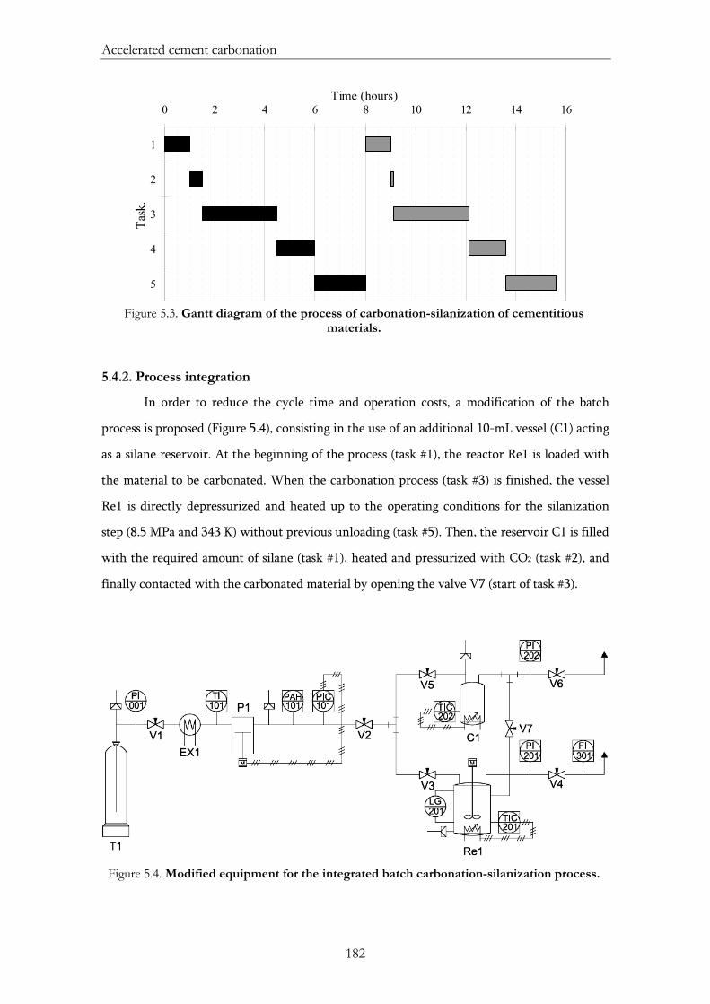
Accelerated cement carbonation
182
0 2 4 6 8 10 12 14 16
1
2
3
4
5
Task
.
Time (hours)
Figure 5.3. Gantt diagram of the process of carbonation-silanization of cementitious
materials.
5.4.2. Process integration
In order to reduce the cycle time and operation costs, a modification of the batch
process is proposed (Figure 5.4), consisting in the use of an additional 10-mL vessel (C1) acting
as a silane reservoir. At the beginning of the process (task #1), the reactor Re1 is loaded with
the material to be carbonated. When the carbonation process (task #3) is finished, the vessel
Re1 is directly depressurized and heated up to the operating conditions for the silanization
step (8.5 MPa and 343 K) without previous unloading (task #5). Then, the reservoir C1 is filled
with the required amount of silane (task #1), heated and pressurized with CO2 (task #2), and
finally contacted with the carbonated material by opening the valve V7 (start of task #3).
Figure 5.4. Modified equipment for the integrated batch carbonation-silanization process.
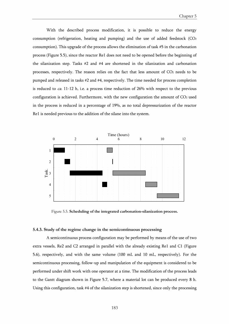
Chapter 5
183
With the described process modification, it is possible to reduce the energy
consumption (refrigeration, heating and pumping) and the use of added feedstock (CO2
consumption). This upgrade of the process allows the elimination of task #5 in the carbonation
process (Figure 5.5), since the reactor Re1 does not need to be opened before the beginning of
the silanization step. Tasks #2 and #4 are shortened in the silanization and carbonation
processes, respectively. The reason relies on the fact that less amount of CO2 needs to be
pumped and released in tasks #2 and #4, respectively. The time needed for process completion
is reduced to ca. 11-12 h, i.e. a process time reduction of 26% with respect to the previous
configuration is achieved. Furthermore, with the new configuration the amount of CO2 used
in the process is reduced in a percentage of 19%, as no total depressurization of the reactor
Re1 is needed previous to the addition of the silane into the system.
0 2 4 6 8 10 12
1
2
3
4
5
Task
.
Time (hours)
Figure 5.5. Scheduling of the integrated carbonation-silanization process.
5.4.3. Study of the regime change in the semicontinuous processing
A semicontinuous process configuration may be performed by means of the use of two
extra vessels, Re2 and C2 arranged in parallel with the already existing Re1 and C1 (Figure
5.6), respectively, and with the same volume (100 mL and 10 mL, respectively). For the
semicontinuous processing, follow-up and manipulation of the equipment is considered to be
performed under shift work with one operator at a time. The modification of the process leads
to the Gantt diagram shown in Figure 5.7, where a material lot can be produced every 8 h.
Using this configuration, task #4 of the silanization step is shortened, since only the processing
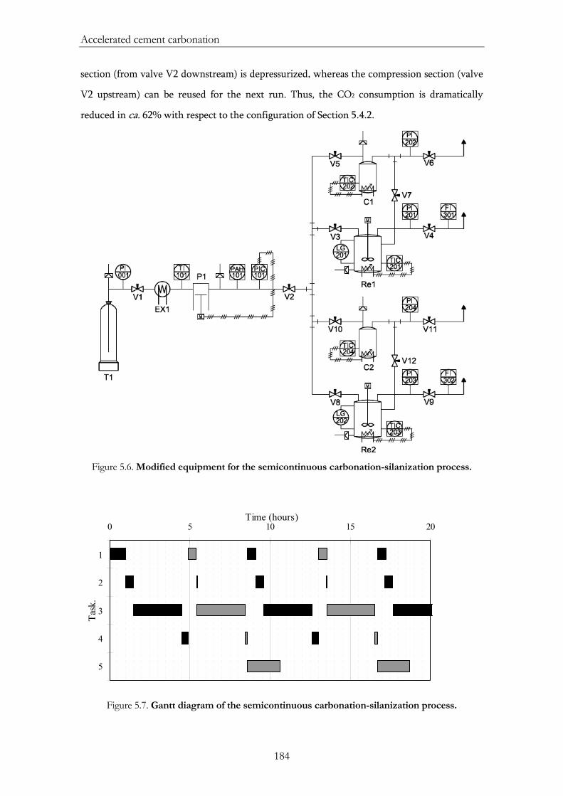
Accelerated cement carbonation
184
section (from valve V2 downstream) is depressurized, whereas the compression section (valve
V2 upstream) can be reused for the next run. Thus, the CO2 consumption is dramatically
reduced in ca. 62% with respect to the configuration of Section 5.4.2.
Figure 5.6. Modified equipment for the semicontinuous carbonation-silanization process.
0 5 10 15 20
1
2
3
4
5
Task
.
Time (hours)
Figure 5.7. Gantt diagram of the semicontinuous carbonation-silanization process.
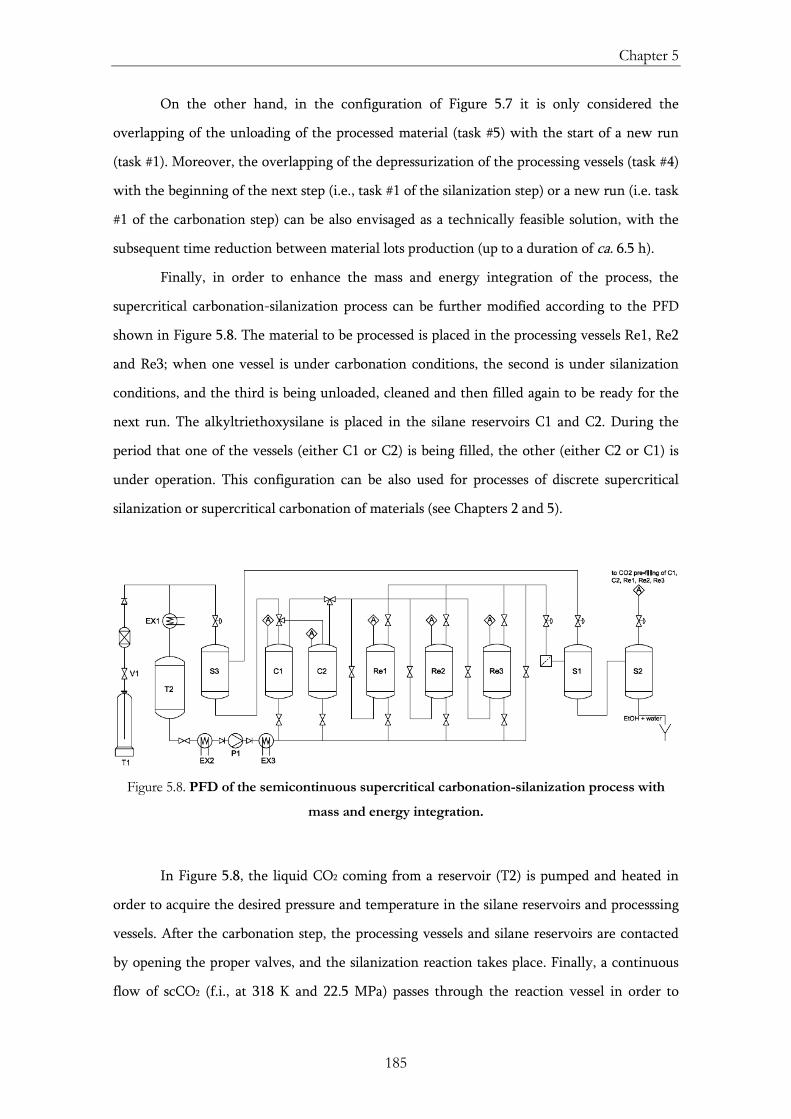
Chapter 5
185
On the other hand, in the configuration of Figure 5.7 it is only considered the
overlapping of the unloading of the processed material (task #5) with the start of a new run
(task #1). Moreover, the overlapping of the depressurization of the processing vessels (task #4)
with the beginning of the next step (i.e., task #1 of the silanization step) or a new run (i.e. task
#1 of the carbonation step) can be also envisaged as a technically feasible solution, with the
subsequent time reduction between material lots production (up to a duration of ca. 6.5 h).
Finally, in order to enhance the mass and energy integration of the process, the
supercritical carbonation-silanization process can be further modified according to the PFD
shown in Figure 5.8. The material to be processed is placed in the processing vessels Re1, Re2
and Re3; when one vessel is under carbonation conditions, the second is under silanization
conditions, and the third is being unloaded, cleaned and then filled again to be ready for the
next run. The alkyltriethoxysilane is placed in the silane reservoirs C1 and C2. During the
period that one of the vessels (either C1 or C2) is being filled, the other (either C2 or C1) is
under operation. This configuration can be also used for processes of discrete supercritical
silanization or supercritical carbonation of materials (see Chapters 2 and 5).
Figure 5.8. PFD of the semicontinuous supercritical carbonation-silanization process with
mass and energy integration.
In Figure 5.8, the liquid CO2 coming from a reservoir (T2) is pumped and heated in
order to acquire the desired pressure and temperature in the silane reservoirs and processsing
vessels. After the carbonation step, the processing vessels and silane reservoirs are contacted
by opening the proper valves, and the silanization reaction takes place. Finally, a continuous
flow of scCO2 (f.i., at 318 K and 22.5 MPa) passes through the reaction vessel in order to
Accelerated cement carbonation
186
perform the cleaning step, where the unreacted silane is eliminated of the silanized material.
Neither the use of cosolvents nor a further treatment with organic solvents is necessary.
Small amounts of water and ethanol (EtOH) are obtained as by-products of the
silanization process and should be removed. The separation of the majority of these chemicals
from the main stream of the process can be performed by means of the use of gas-liquid
separators (S1 and S2). EtOH and water are removed from the CO2 in these separators by
decreasing the solubilizing power of the solvent through a change in the operating conditions
(i.e., pressure and temperature) [68]. Thus, CO2 and unreacted silane can be both recycled and
used again in the next runs. EtOH coming from the hydrolysis of the silane molecules (see
Chapter 2) can be removed in a separator by reducing the pressure below 10.0 MPa and
raising the temperature above 353 K. Under these operating conditions and with enough
residence time, a fluid-liquid equilibrium is obtained with a CO2-rich fluid phase (CO2 molar
fraction of 0.95) and a liquid phase containing water, EtOH and CO2 (f.i., at 10.0 MPa and
353K, and for a system with a negligible content of water, the EtOH:CO2 molar ratio is 3:2)
[69-71]. By a further pressure reduction and a temperature decrease, the majority of the CO2
can be separated from water and EtOH and recycled (f.i., at 2.0 MPa and 333 K). For a system
with a negligible content of water, the EtOH:CO2 molar ratio is 10:1 in the liquid phase and
the CO2 molar fraction in the gaseous phase is 0.97 [70,71].
As far as the residual silane separation from the flow of CO2 is concerned, it should be
taken into account that the silane has low solubility in gaseous CO2 [72]. Therefore, the silane
can be separated from the CO2 by means of the gas-liquid separator S3 by reducing the
pressure below the critical point of the CO2. The collected silane can be recycled and used in
the next run. This fact is extremely important, taking into account the large amount of silane
excess used in the supercritical process and the cost of this chemical (Chapter 2).
Chapter 5
187
5.5. Conclusions
The natural carbonation process is strongly accelerated by using scCO2 as the
carbonating agent for Portland cement powder and complete carbonation can be attained in
less than 2 h. The tunability of the physicochemical properties of scCO2 with pressure, its low
viscosity and its high diffusivity allow the penetration of this fluid into very fine pores and
increase the depth of carbonation of cement pastes. Ca(OH)2 is the main source of Ca2+ ions
during the carbonation process. Meanwhile, the partial decalcification of CSH gel indicates
that this component is a secondary Ca2+ ion source for calcite formation. Complete
disappearance of ettringite due to the supercritical carbonation process is also noticed.
Calcium carbonate is mainly obtained in the form of the calcite polymorph. The massive
precipitation of calcium carbonate inside the cement pores after supercritical treatment causes
the refinement of the microstructure, thus reducing water permeability to a large extent
(more than 4 orders of magnitude with respect to uncarbonated samples, measured at 0.02
MPa of water). Moreover, supercritical carbonation led to partial neutralization of the pore
water alkalinity in the cement-based materials. Surface modification of the cement-based
samples through the supercritical silanization process conferred weathering resistance to the
material. The silane layer formed on the surface of the cementitious material led to a dramatic
change in the hydrophobic behaviour of the sample, leading to an important reduction in the
absorption of liquid water through the concrete. Finally, scheduling is a valuable tool for the
management of resources and is applied for assisting the implementation and integration of
the supercritical carbonation-silanization process.
5.6. References
[1] E. Gartner, Industrially interesting approaches to "low-CO2" cements. Cement and Concrete Research 2004, 34(9), 1489-1498.
[2] R. McCaffrey, Climate Change and the Cement Industry. Global Cement and Lime Magazine 2002, Environmental Special Issue, 15-19.
[3] J.W. Phair, Green chemistry for sustainable cement production and use. Green Chemistry 2006, 8(9), 763-780.
[4] T.K.H. Al-Kadhimi, P.F.G. Banfill, S.G. Millard, J.H. Bungey, An accelerated carbonation procedure for studies on concrete. Advances in Cement Research 1996, 8(23), 47-59.
[5] J. Khunthongkeaw, S. Tangtermsirikul, T. Leelawat, A study on carbonation depth prediction for fly ash concrete. Construction and Building Materials 2006, 20(9), 744-753.
Accelerated cement carbonation
188
[6] H.F.W. Taylor, Cement chemistry. Academic Press: New York, 1990.
[7] L. Fernández-Carrasco, J. Rius, C. Miravitlles, Supercritical carbonation of calcium aluminate cement. Cement and Concrete Research 2008, 38(8-9), 1033-1037.
[8] A. Hidalgo, C. Domingo, F.J. Huertas, C. García González, J.L. García Calvo, M. Rozalén, C. Alonso, Supercritically carbonation of concretes based in calcium aluminate cement and silica fume. Application to a high level nuclear waste repository. Journal of Hazardous Materials. Under Revision.
[9] J.J. Chen, J.J. Thomas, H.F. W. Taylor, H.M. Jennings, Solubility and structure of calcium silicate hydrate. Cement and Concrete Research 2004, 34(9), 1499-1519.
[10] B.G. Kutchko, B.R. Strazisar, D.A. Dzombak, G.V. Lowry, N. Thaulow, Degradation of well cement by CO2 under geologic sequestration conditions. Environmental Science & Technology 2007, 41(13), 4787-4792.
[11] A.C. Garrabrants, F. Sánchez, D.S. Kosson, Changes in constituent equilibrium leaching and pore water characteristics of a Portland cement mortar as a result of carbonation. Waste Management 2004, 24(1), 19-36.
[12] D.J. Anstice, C.L. Page, M.M. Page, The pore solution phase of carbonated cement pastes. Cement and Concrete Research 2005, 35(2), 377-383.
[13] C.A. García-González, A. Hidalgo, C. Andrade, M.C. Alonso, J. Fraile, A.M. López-Periago, C. Domingo, Modification of composition and microstructure of Portland cement pastes as a result of natural and supercritical carbonation procedures. Industrial & Engineering Chemistry Research 2006, 45(14), 4985-4992.
[14] C.A. García-González, A. Hidalgo, J. Fraile, A.M. López-Periago, C. Andrade, C. Domingo, A porosity and water permeability study of supercritically carbonated cement pastes involving mineral additions. Industrial & Engineering Chemistry Research 2007, 46(8), 2488–2496.
[15] C.A. García-González, N. El Grouh, A. Hidalgo, J. Fraile, A.M. López-Periago, C. Andrade, C. Domingo, New insights on the use of supercritical carbon dioxide for the accelerated carbonation of cement pastes. The Journal of Supercritical Fluids 2008, 43(3), 500–509.
[16] A. Hidalgo, C. Domingo, C. Garcia, S. Petit, C. Alonso, C. Andrade, Microstructural changes induced in Portland cement-based materials due to natural and supercritical carbonation. Journal of Materials Science 2008, 43(9), 3101-3111.
[17] S.K. Roy, K.B. Poh, D.O. Northwood, Durability of concrete-accelerated carbonation and weathering studies. Building and Environment 1999, 34(5), 597-606.
[18] J. Khunthongkeaw, S. Tangtermsirikul, T. Leelawat, A study on carbonation depth prediction for fly ash concrete. Construction and Building Materials 2006, 20(9), 744-753.
Chapter 5
189
[19] L. Liu, J. Ha, T. Hashida, S. Teramura, Development of a CO2 solidification method for recycling autoclaved lightweight concrete waste. Journal of Materials Science Letters 2001, 20(19), 1791-1794.
[20] P. Purnell, J. Beddows, Durability and simulated ageing of new matrix glass fibre reinforced concrete. Cement and Concrete Composites 2005, 27(9-10), 875-884.
[21] L.C. Lange, C.D. Hills, A.B. Poole, Effect of carbonation on properties of blended and non-blended cement solidified waste forms. Journal of Hazardous Materials 1997, 52(2-3), 193-212.
[22] T. Van Gerven, D. Van Baelen, V. Dutré, C. Vandecasteele, Influence of carbonation and carbonation methods on leaching of metals from mortars. Cement and Concrete Research 2004, 34(1), 149-156.
[23] L. Van Ginneken, V. Dutré, W. Adriansens, H. Weyten, Effect of liquid and supercritical carbon dioxide treatments on the leaching performance of a cement-stabilised waste form. The Journal of Supercritical Fluids 2004, 30(2), 175-188.
[24] W.L. Clarke, Safe disposal of nuclear waste. Science & Technology Review 1996, 3, 6-16.
[25] N.A., Origen y gestión de residuos radiactivos. 3rd edition. Ilustre Colegio Oficial de Físicos: Madrid, 2000.
[26] A. Pastor, El almacenamiento geológico profundo de los residuos radiactivos de alta actividad. Principios básicos y tecnología. Enresa: Madrid, 2001.
[27] N.A., Engineered barrier systems and the safety of deep geological repositories. Organization for Economic Co-operation and Development: Paris, 2003.
[28] A. Agüero, P. Pinedo, D. Cancio, I. Simón, M. Moraleda, D. Pérez-Sánchez, C. Trueba, Spanish methodological approach for biosphere assessment of radioactive waste disposal. Science of The Total Environment 2007, 384(1-3), 36-47.
[29] F.J. Huertas, A. Hidalgo, M.L. Rozalén, S. Pellicione, C. Domingo, C.A. García-González, C. Andrade, C. Alonso, Interaction of bentonite with supercritically carbonated concrete. Applied Clay Science 2009, 42(3-4), 488-496.
[30] O.L. Shtepenko, C.D. Hills, N.J. Coleman, A. Brough, Characterization and preliminary assessment of a sorbent produced by accelerated mineral carbonation. Environmental Science and Technology 2005, 39(1), 345-354.
[31] J. Stolaroff, H. Ecke, Demobilization of critical contaminants in four typical waste-to-energy ashes by carbonation. Waste Management 2006, 26(4), 430-441.
[32] J.B. Rubin, C.M.V. Taylor, Partial replacement of Portland cement with fly ashes and kiln dusts using supercritical carbon dioxide processing. Los Alamos National Laboratory: Los Álamos, 1998.
Accelerated cement carbonation
190
[33] A. Iizuka, M. Fujii, A. Yamasaki, Y. Yanagisawa, Development of a new CO2 sequestration process utilizing the carbonation of waste cement. Industrial & Engineering Chemistry Research 2004, 43(24), 7880-7887.
[34] K.S. Lackner, Carbonate chemistry for sequestering fossil carbon. Annual Review for Energy and the Environment 2002, 27, 193-232.
[35] Intergovernamental Panel on Climate Change (IPCC), IPCC special report on carbon dioxide capture and storage. Cambridge University Press: Cambridge, 2005.
[36] W.J.J. Huijgen, R.N.J. Comans, Carbonation of steel slag for CO2 sequestration: leaching of products and reaction mechanisms. Environmental Science and Technology 2006, 40(8), 2790-2796.
[37] W.K. O’Connor, D.C. Dahlin, G.E. Rush, S.J. Gerdermann, L.R. Penner, D.N. Nilsen, Aqueous mineral carbonation: mineral availability, pretreatment, reaction parameters, and process studies. Albany Research Center: Albany, 2005.
[38] J.M. Bukowski, R.L. Berger, Reactivity and strength development of CO2 activated non-hydraulic calcium silicates. Cement and Concrete Research 1979, 9(1), 57-68.
[39] R.K. Dhir, M.R. Jones, J.G.L. Munday, A practical approach to studying carbonation on concrete. Concrete 1985, 19(10), 32-34.
[40] L. Liu, J. Ha, T. Hashida, S. Teramura, Development of a CO2 solidification method for recycling autoclaved lightweight concrete waste. Journal of Materials Science Letters 2001, 20(19), 1791-1794.
[41] G. Costa, R. Baciocchi, A. Polettini, R. Pomi, C. Hills, P.J. Carey, Current status and perspectives of accelerated carbonation processes on municipal waste combustion residues. Environmental Monitoring and Assessment 2007, 135(1-3), 55-75.
[42] T. Hartmann, P. Paviet-Hartmann, J.B. Rubin, M.R. Fitzsimmons, K.E. Sickafus, The effect of supercritical carbon dioxide treatment on the leachability and structure of cemented radioactive waste-forms. Waste Management 1999, 19(5), 355-361.
[43] R.L. Cuthbert, E.P. Plueddemann, Aqueous silane water repellent compositions. US Patent 5,073,195 (1991).
[44] I.J. de Vries, R.B. Polder, Hydrophobic treatment of concrete. Construction and Building Materials 1997, 11(4), 259-265.
[45] A. Frattolillo, G. Giovinco, M.C. Mascolo, A. Vitale, Effects of hydrophobic treatment on thermophysical properties of lightweight mortars. Experimental Thermal and Fluid Science 2005, 29(6), 733–741.
Chapter 5
191
[46] C. Ricci, C. Miliani, B.G. Brunetti, A. Sgamellotti, Non-invasive identification of surface materials on marble artifacts with fiber optic mid-FTIR reflectance spectroscopy. Talanta 2006, 69(5), 1221–1226.
[47] C. Domingo, M. Álvarez de Buergo, S. Sánchez-Cortés, R. Fort, J.V. García-Ramos, M. Gómez-Heras, Possibilities of monitoring the polymerization process of silicon-based water repellents and consolidants in stones through infrared and Raman spectroscopy. Progress in Organic Coatings 2008, 63(1), 5-12.
[48] M. Pigeon, J. Prevost, J.M. Semard, Freeze−thaw durability versus freezing rate. Journal of the American Concrete Institute 1985, 82(5), 684-692.
[49] B. Mather, How to make concrete that will not suffer deleterious alkali−silica reaction. Cement and Concrete Research 1999, 29(8), 1277-1280.
[50] E.E. Hekala, E. Kishar, H. Mostafa, Magnesium sulfate attack on hardened blended cement pastes under different circumstances. Cement and Concrete Research 2002, 32(9), 1421-1427.
[51] A. Al-Otoom, A. Al-Khlaifa, A. Shawaqfeh, Crystallization technology for reducing water permeability into concrete. Industrial & Engineering Chemistry Research 2007, 46(16), 5463-5467.
[52] F. Tittarelli, G. Moriconi, The effect of silane-based hydrophobic admixture on corrosion of reinforcing steel in concrete. Cement and Concrete Research 2008, 38(11), 1354-1357.
[53] A. Barbucci, M. Delucchi, G. Cerisola, Organic coating for concrete protection. Liquid water and water vapor permeabilities. Progress in Organic Coatings 1997, 30(4), 293-297.
[54] N.A., Protectosil Antigraffiti SP: Solutions for preventing surface damaging effects. Technical information from Evonik industries.
[55] A. Be, D.T. Liles, F.G.P. Wilhelmi, D.J. Romenesko, Storage-stable water-repellent composition for masonry materials. US Patent 5,919,296 (1999).
[56] N.A., UNE-EN 197-1:2000. Cemento. Parte I: Composición, especificaciones y criterios de conformidad de los cementos comunes. AENOR: Madrid, 2000.
[57] N.A., UNE 80303-1:2001. Cementos con características adicionales. Parte 1: Cementos resistentes a los sulfatos. AENOR: Madrid, 2001.
[58] N.A., UNE-EN 450:1994. Cenizas volantes como adición al hormigón. Definiciones, especificaciones y control de calidad. AENOR: Madrid, 1995.
[59] N.A., UNE 83460-1/2. Adiciones al hormigón: Humo de sílice. AENOR: Madrid, 2005
Accelerated cement carbonation
192
[60] S.K. Malhotra, N.G. Dave, Investigations into the effect of addition of fly ash and burnt clay pozzolana on certain engineering properties of cement composites. Cement and Concrete Composites 1999, 21(4), 285-291.
[61] A. Guerrero, S. Goñi, A. Macias, M.P. Luxan, Effect of the starting fly ash on the microstructure and mechanical properties of fly ash-belite cement mortars. Cement and Concrete Research 2000, 30(4), 553-559.
[62] X. Fu, Z. Wang, W. Tao, C. Yang, W. Hou, Y. Dong, X. Wu, Studies on blended cement with a large amount of fly ash. Cement and Concrete Research 2002, 32(7), 1153-1159.
[63] M.I. Khan, C.J. Lynsdale, Strength, permeability, and carbonation of high-performance concrete. Cement and Concrete Research 2002, 32(1), 123-131.
[64] I. Janotka, T. Nurnbergerova, Effect of temperature on structural quality of the cement paste and high-strength concrete with silica fume. Nuclear Engineering and Design 2005, 235(17-19), 2019-2032.
[65] J. Blazewicz, K.H. Ecker, E. Pesch, G. Schmidt, J. Weglarz, Scheduling computer and manufacturing processes. Springer: Berlin, 2001.
[66] M.L. Pinedo, Planning and scheduling in manufacturing and services. Springer: New York, 2005.
[67] J.W. Herrmann, Handbook of production scheduling. Springer: New York, 2006.
[68] K. Zosel, Verfahren zur Trennung von Stoffgemischen, die organische Verbindungen und/oder organische Gruppen aufweisende Verbindungen enthalten, German Patent 1,493,190 (1965).
[69] M.L. Gilbert, M.E. Paulaitis, Gas-liquid equilibrium for ethanol-water-carbon dioxide mixtures at elevated pressures. Journal of Chemical & Engineering Data 1986, 31(3), 296-298.
[70] K. Suzuki, H. Sue, M. Itou, R.L. Smith, H. Inomata, K. Arai, S. Saito, Isothermal vapor-liquid equilibrium data for binary systems at high pressures: carbon dioxide-methanol, carbon dioxide-ethanol, carbon dioxide-1-propanol, methane-ethanol, methane-1-propanol, ethane-ethanol, and ethane-1-propanol systems. Journal of Chemical & Engineering Data 1990, 35(1), 63-66.
[71] Ž. Knez, M. Škerget, L. Ilič, C. Lütge, Vapor–liquid equilibrium of binary CO2–organic solvent systems (ethanol, tetrahydrofuran, ortho-xylene, meta-xylene, para-xylene). The Journal of Supercritical Fluids 2008, 43(3), 383-389.
[72] C.A. García-González, J. Fraile, A. López-Periago, J. Saurina, C. Domingo, Measurements and correlation of octyltriethoxysilane solubility in supercritical CO2 and assembly of functional silane monolayers on the surface of nanometric particles. Industrial & Engineering Chemistry Research, In Press (doi: 10.1021/ie900775z).
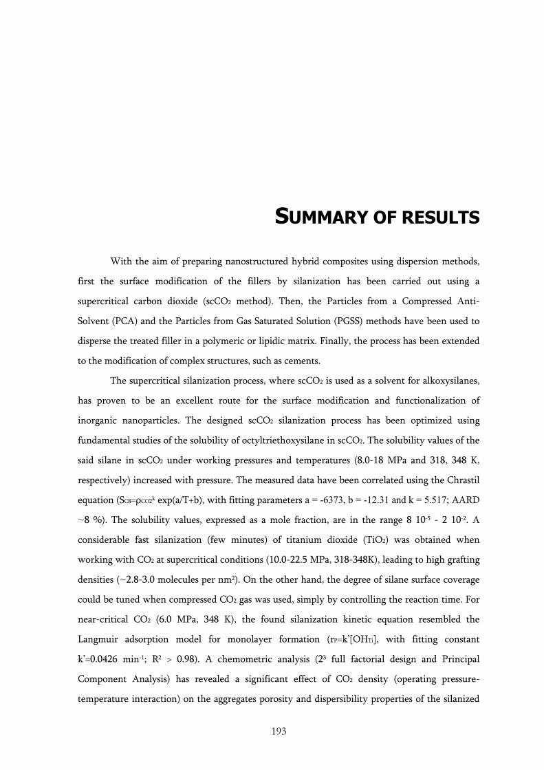
193
SUMMARY OF RESULTS
With the aim of preparing nanostructured hybrid composites using dispersion methods,
first the surface modification of the fillers by silanization has been carried out using a
supercritical carbon dioxide (scCO2 method). Then, the Particles from a Compressed Anti-
Solvent (PCA) and the Particles from Gas Saturated Solution (PGSS) methods have been used to
disperse the treated filler in a polymeric or lipidic matrix. Finally, the process has been extended
to the modification of complex structures, such as cements.
The supercritical silanization process, where scCO2 is used as a solvent for alkoxysilanes,
has proven to be an excellent route for the surface modification and functionalization of
inorganic nanoparticles. The designed scCO2 silanization process has been optimized using
fundamental studies of the solubility of octyltriethoxysilane in scCO2. The solubility values of the
said silane in scCO2 under working pressures and temperatures (8.0-18 MPa and 318, 348 K,
respectively) increased with pressure. The measured data have been correlated using the Chrastil
equation (SC8=ρCO2k exp(a/T+b), with fitting parameters a = -6373, b = -12.31 and k = 5.517; AARD
~8 %). The solubility values, expressed as a mole fraction, are in the range 8 10-5 - 2 10-2. A
considerable fast silanization (few minutes) of titanium dioxide (TiO2) was obtained when
working with CO2 at supercritical conditions (10.0-22.5 MPa, 318-348K), leading to high grafting
densities (~2.8-3.0 molecules per nm2). On the other hand, the degree of silane surface coverage
could be tuned when compressed CO2 gas was used, simply by controlling the reaction time. For
near-critical CO2 (6.0 MPa, 348 K), the found silanization kinetic equation resembled the
Langmuir adsorption model for monolayer formation (rP=k’[OHTi], with fitting constant
k’=0.0426 min-1; R2 > 0.98). A chemometric analysis (23 full factorial design and Principal
Component Analysis) has revealed a significant effect of CO2 density (operating pressure-
temperature interaction) on the aggregates porosity and dispersibility properties of the silanized
Summary of Results
194
TiO2 nanoparticles. Moreover, the supercritical silanization process has produced a chemical and
thermally stable silane coating (ca. up to 520 K), regardless of the used operating conditions
(pressure, temperature and reaction time). Densely packed monolayers (~3.0 molecules per nm2)
have also been successfully prepared by reacting different chain length (from methyl to
octadecyl) alkyltrialkoxysilanes with TiO2 nanoparticles in a scCO2 medium. In contrast, the
grafting density decreased (~1.5 molecules per nm2) when a trialkylmonoalkoxysilane was used.
Finally, it is shown that the silane surface treatment with trialkoxysilanes intensifies the
compatibility of hydrophilic TiO2 or maghemite (γ-Fe2O3) nanoparticles with hydrophobic
organic phases.
The first class of prepared nanostructured hybrid materials consisted in polymers with
dispersed inorganic fillers, and was prepared using the PCA technique, where scCO2 acted as an
anti-solvent. Networks of fibers consisting of biopolymeric matrices of either poly(L-lactic acid)
(L-PLA) or the blend high molecular weight-poly(methylmethacrylate)/poly(ε-caprolactone)
(PMMA/PCL) loaded with ca. 15-20 wt.% of nanometric hydroxyapatite (HAP) or TiO2,
respectively, have been obtained. The inorganic fillers dispersed in the hybrid materials were
previously surface treated through the supercritical silanization process. The silanization of HAP
and TiO2 has facilitated the dispersion of the nanoparticles in the dichloromethane solution of
the biopolymer prepared before the addition of scCO2 as the anti-solvent. Silanized nanoparticles
incorporated in the biopolymeric fibers are homogeneously distributed throughout the hybrid
material. The viscosity of the polymeric solution influences the morphology of the precipitated
material. Hence, agglomerated microparticles, instead of fibers, have been obtained when low
molecular weight PMMA was used in the blend PMMA/PCL. The prepared materials have
potential applications in tissue engineering.
A second class of studied composites was solid lipid hybrid particles prepared using the
PGSS technique, assisted by the use of scCO2 as a solute. Using this process, the rapid cooling of a
lipid-based mixture during expansion promoted the formation of a low ordered lipidic blend. The
low order in the blend crystals facilitated the incorporation of inorganic nanoparticles and drugs
within the matrix. The studied system was formed by a lipid matrix of hydrogenated castor
oil/glyceryl monostearate (1:1 weight ratio) loaded with nanometric TiO2 (ca. 6 wt.%) and
caffeine (ca. 4 wt.%). Again, the previous surface treatment of the nanometric TiO2, using the
described supercritical silanization process, facilitated the dispersion of the nanoparticles
throughout the bulk of the lipid matrix. The UV-shielding ability of the TiO2 was preserved after
Summary of Results
195
the silanization and its subsequent incorporation in the lipid particles. The dissolution profile in
water of the caffeine contained in the lipid particles had two steps: an initial burst of 60 wt.%
occurring in ca. 1-2 h, corresponding to the caffeine deposited on the surface of the particles,
followed by a slow release of residual caffeine entrapped within the lipid core. The obtained
lipid-based particles encompassed the UV-light protection of the TiO2 and the photoaging
prevention properties of the caffeine, and can be potentially exploited for topical cosmetic and
pharmaceutical purposes.
Finally, the possibility of extending the silane treatment under scCO2 conditions to
multiscale complex materials has been tested. Thus, the use of the scCO2 technology has been
evaluated in the two-step carbonation-silanization processing of cement-based materials. The
supercritical carbonation step was compared to natural carbonation with atmospheric air under
ambient conditions. The use of supercritical CO2 accelerated the carbonation reaction (from
months to hours) due to the huge rise of CO2 solubility in water (near 100-fold) when increasing
the pressure from 0.1 to 20 MPa and to the ease of penetration and diffusion of the scCO2 into the
cement paste pores. Cement paste densification and total pore volume reduction of the
carbonated cement were observed in both carbonation scenarios (natural and accelerated), due to
the deposition of calcium carbonate. However, there was a shift of the pore volume values to
fractions with small pores when cement samples were processed with scCO2, which resulted in a
significant reduction in the water permeability of the carbonated material. In a second step of the
process, the surface modification of the carbonated cement with octyltriethoxysilane using scCO2
as a solvent has conferred to the material water repellence and reduced the water absorption due
to capillary rise (from 3 wt.% to 0.5 wt.%). Finally, for the efficient management of resources,
the scheduling and the process integration were applied to the carbonation-silanization process,
leading to reductions in CO2 consumption of ca. 62% and in processing time of ca. 30%.
197
CONCLUSIONS
• scCO2 is a convenient solvent of alkoxysilanes used for silane monolayer deposition on the
surface of nanoparticulate materials. The system TiO2 nanoparticles/octyltriethoxysilane has
been used as the model system for the development of a generic and versatile scCO2
silanization process. High grafting densities (~2.8-3.0 molecules per nm2) and robust thermal
stability (ca. 520 K) were obtained after a few minutes of supercritical silanization. The acidic
conditions of water in contact with CO2 accelerated the kinetics of the silanization process.
The quality of the layer of deposited silane was largely influenced by the scCO2 density
related with the concentration of the silane in the supercritical fluid. Monolayer formation
was obtained by working in the silane mole fraction range of 3.9 10-4-1.5 10-3. On the other
hand, silane polycondensation and multilayer deposition on the TiO2 surface took place when
the octyltriethoxysilane concentration in scCO2 was higher than 1.5 10-3 mole fraction. The
solubility of the silane in scCO2 was successfully correlated by the Chrastil equation (fitting
parameters a = -6373, b = -12.31 and k = 5.517; AARD~8 %).
• The silanization of TiO2 nanoparticles with octyltriethoxysilane under near-critical CO2 (6.0
MPa, 348 K) followed a Langmuir adsorption-like kinetic model (fitting constant k’=0.0426
min-1, R2 > 0.98). In this case, the control of the reaction time allowed for the tailor-made
degree of silane coverage of TiO2 nanoparticles. Maximum grafting densities (~2.7 molecules
per nm2) were obtained after 2 h.
• Closely packed silane monolayers (ca. 3 molecules per nm2) deposited on TiO2 nanoparticles
were also successfully prepared using alkyltrialkoxysilanes with different chain lengths of the
alkyl group (from isobutyl to octadecyl) in a scCO2 medium (22.5 MPa, 318 K). In contrast,
Conclusions
198
covalently attached monolayers prepared from trialkylmonoalkoxysilane had a grafting
density of only ca. 1.5 molecules per nm2 due to sterical hindrance. Moreover, the
supercritical silanization process was successfully extended to other inorganic nanoparticles,
such as maghemite and hydroxyapatite.
• The supercritical hydrophobic treatment of inorganic nanoparticles with octyltriethoxysilane
enhanced the dispersibility of the surface-treated powder in hydrophobic liquids (e.g.,
petroleum, dichloromethane, avocado oil) and the homogeneous distribution of the particles
in solid hydrophobic matrices (e.g., PMMA/PCL and HCO/GMS blends). The supercritical
silanization treatment of TiO2 nanoparticles would facilitate the dispersion of this UV-
blocker in the formulations used in cosmetics.
• Networks of fibers of PMMA/PCL polymer blend loaded with TiO2 (18-23 wt%) and L-PLA
biopolymer loaded with HAP (7-14 wt%) were prepared using the PCA supercritical
technique. The proper choice of the physicochemical properties of the biopolymers
(molecular weight, blend composition) and the PCA operating conditions (pressure,
temperature, polymer concentration in the liquid solution) allowed the production of fibers
with an interconnected 3D macroporous structure and high microporosity, valid as materials
for tissue engineering purposes. Solid lipid microparticles of the HCO/GMS lipid blend loaded
with silanized TiO2 (ca. 6 wt%) and caffeine (ca. 4 wt%) were prepared using the PGSS
supercritical technique. The rapid lipid solidification taking place in the PGSS process during
expansion diminished the crystallinity of the lipid blend, which facilitated the loading of the
particles. Caffeine was both deposited on the solid surface (60 %) and entrapped within the
lipid core (40%), resulting in a characteristic two-step dissolution profile in water. The
material found applications in cosmetic and pharmaceutical products.
• The accelerated carbonation of Portland cement-based materials using scCO2 (20.0 MPa, 318
K, 1.5-3.5 g min-1) was performed in few hours, while the carbonation under atmospheric air
(natural carbonation) could take several months. The process evolved from the diffusion of
CO2 inside of the pores as the rate-limiting step for natural carbonation to the detachment of
calcium cations from the cement matrix for the supercritical carbonation. The supercritical
silanization process was also applied to the surface treatment of the supercritically carbonated
Portland cement. The coating of the material with octyltriethoxysilane conferred water
Conclusions
199
repellence and reduction of water absorption due to capillary rise (from 3 wt% to 0.5 wt%).
Cement paste densification, reduction in total pore volume and in water permeability are
consequences of the supercritical treatment. The developed properties allowed the use of
these bulk low-cost cementitious materials for hazardous waste confinement purposes.
• The combined contribution of scCO2 processes design and fundamentals, based on
engineering concepts, and end-products characteristics, based on materials research concepts,
moves forward on the launching of sustainable solutions for the preparation of advanced
materials with null or minimized consumption of organic solvents.
7.1. Future work
Open lines of research related to the topic of this PhD Thesis are the preparation of other
complex hybrid materials using the supercritical silanization process. The large catalogue of silane
molecules with a broad range of functional groups opens the possibility to the engineering of
composite materials fitting the requirements of many industrial applications (e.g., plastics,
biomedical devices, drug carriers, water repellent materials or gas sensors).
Finally, further investigation on the scale-up of the supercritical silanization process
applied to inorganic nanoparticles will provide essential information for the potential
implementation of the process in a larger scale.