KAERI/TR-2420/2003 - OSTI.GOV
466
KAERI/TR-2420/2003 -£8 1/23:71 £3£^7l-g- MARS 3— ^#2# 7jt Development of the MARS Input Model for Ulchin 1/2 Transient Analyzer KAERI 2003. 3. tb -8 x> a -y ^ ^
-
Upload
khangminh22 -
Category
Documents
-
view
1 -
download
0
Transcript of KAERI/TR-2420/2003 - OSTI.GOV
KAERI/TR-2420/2003
-£8 1/23:71 £3£^7l-g- MARS 3— ^#2# 7jt
Development of the MARS Input Model for Ulchin 1/2 Transient Analyzer
KAERI2003. 3.
tb -8 x> a -y ^ ^

*11 T=r
*1 #3.3^ # 2003#£. "4 #5. ## #4 ## ##7] 7^#' #44 7l#iL
4^ Til ##44.
44: #4 1/2#7] ####7]# MARS SH. 4 4#
Development of the MARS Input Model for Ulchin 1/2 Transient Analyzer
2003# 3#
###: #4#
44 4: 444
#4#

4
4444-4 4#a# 44 RETRAN# MARS# 4### 44 4a1#44# 7flHai oir}. RETRAN# MARS aa# a 4 44# ## #4 ##4#4, 4 #444444# mars aa# 44 44 244 444 44 444 444a 4 44 444 444a 444 #444 444 4a 4 4a#4 444# retran aa# 4 444.
4 aa4# #4 1/244 44 444444 mars aa 44al(4#4 4 44a 4 a 1)4 7fl4 R44- Calculation Note# ####. 4 444 4 #4 444&# 4 #44 4##^ ^ #a#^ 444#& 4# #4 444&4 444# #44%# #4 444, 4 444-5.7} #4 i/2a4 4-4444# mars aa 44 jg_!4 4#44#^ ### # %## #4#%4.
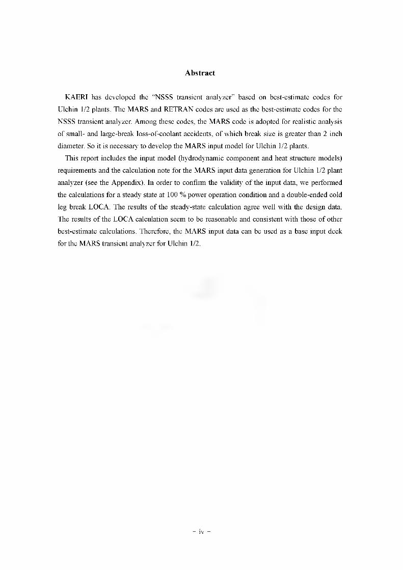
Abstract
KAERI has developed the "NSSS transient analyzer’’ based on best-estimate codes for
Ulchin 1/2 plants. The MARS and RETRAN codes are used as the best-estimate codes for the
NSSS transient analyzer. Among these codes, the MARS code is adopted for realistic analysis
of small- and large-break loss-of-coolant accidents, of which break size is greater than 2 inch
diameter. So it is necessary to develop the MARS input model for Ulchin 1/2 plants.
This report includes the input model (hydrodynamic component and heat structure models)
requirements and the calculation note for the MARS input data generation for Ulchin 1/2 plant
analyzer (see the Appendix). In order to confirm the validity of the input data, we performed
the calculations for a steady state at 100 % power operation condition and a double-ended cold
leg break LOCA. The results of the steady-state calculation agree well with the design data.
The results of the LOCA calculation seem to be reasonable and consistent with those of other
best-estimate calculations. Therefore, the MARS input data can be used as a base input deck
for the MARS transient analyzer for Ulchin 1/2.
- iv -

4 4-
1. 44 1/244 mars sm. 445.1 444 44 ^ 44 ..................................... l
2. MARS a^4 444& 44 4 -0-4 .................................................................... 2
2.1 444& 44 44 .......................................................................................................2
2.2. 444& 444 ^444............................................................................................ 3
2.3. Calculation Note 44 4 44 44 ........................................................................ 4
3. 4 4 X}S. Calculation Note ............................................................................................... 6
4. 4444 4 4£44 4444 44 ............................................................................... 7
4.1. 4444 44 44 .............................................................................................. 7
4.2. 4£44 414 44: 44444 444^ ............................................................... 13
5. 4e........................................................................................................................176. 4al 44.................................................................................................................................18
44: Calculation Note for Ulchin 1/2 MARS Base Input Deck Generation
- v -

a 4 ^
& i. 444M 4444 4 M .....................................................................................................g
zi ^ 4 #
1. '§■'51 1/247] MARS nodalization ................................................................................. 5
:;-4 2. 44 44 ......................................................................................................... 8:'-4 3. 7}<g-7] 4 44\'M4 44 44 .....................................................................................8
:'-4 4. 7] 9|-y] 4 44\'M4 49] 7] 4 .....................................................................................9
A-4 5. 14 44 ^|7|-4] 4-2A 44 .............................................................................................. 9
:'-4 6. 14 44 ^4-4 44 7]4- .......................................................................................... 10
:'-4 7. 44444 if-4 4 47] 44 7]4.......................................................................... 10
A-4 8. 44444 41444 7]4...........................................................................................11
A. 4 9. LBLOCA44 4444= 7] 4....................................................................................... 13
A. 4 10. LBLOCA44 491-7] 4 444494 91-4 44.................................................... 13
A. 4 ll. LBLOCA44 2^4 #4 44......................................................................................14
A. 4 12. LBLOCA44 Accumulator 4444= 44............................................................... 14
A. 4 13. LBLOCA44 4444 44 44................................................................. 15
A. 4 14. LBLOCA44 Downcomer 4 2,%4 4?i 44............................................................15
A. 4 15. LBLOCA44 2,%4 4 = 4 44................................................................................ 16
' 4 16. LBLOCA44 '.'(Hot rod) 44 4£ 44.................................................... 16
- vi -
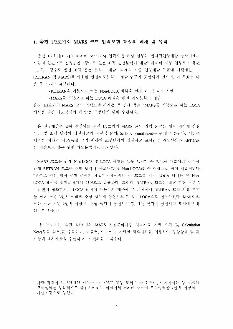
1. 1/2S.7] # MARS ^^2.1 ^2) ^
1-5 1/254 [1, 2] —] MARS 22 [3-5] 4 4 5# #4 4## 4 4" 1 4 # 41 ##4 9] ^
A}44 4425. 41#4 “442 44 44 444471 4#” 444 44 442 444
4. 4, “442 44 44 44 444 7H9# 444 4# 447Hil: 4*4 444422
(RETRAN 4 MARS)# 444 4442444 44 4 #7} =444 424, 4 #5# 4
4 4 442 4444:
-RETRAN# 4422 4# Non-LOCA 444 44 4-2444 44
-MARS# 4425 4# LOCA 444 44 4-2444 7114 44 1/2444 mars 22 4451 444 4 44 #2 “mars# 4555 ## loca
444 44 4-2444 7HW’# 4444 44 4444.
4 4#44# 79444 44 1/2444 mars 22 44 214 14 147]) 44
A}2 4 24 14-711 4442_4 7}44 24(Realistic Simulation)# 44 A}444. 4##
7)144 444 437(44 44 444 2414711 44A}2 ##) 4 4244# retran # 44:25 4# 44 454-4 4 5 5444.
MARS 22# 41 Non-LOCA 4 LOCA 42# 5# 5^f t 45# 4444#. 44
41 RETRAN 22# #1 141 44 #2 4 Non-LOCA# # 1425 4# 44444.
“445 44 44 44 #44 44” 4 7)147]# # 22# 44 loca 444 4 Non-
loca 444 44#444 1425 #444. 244, retran 22# 44 44 44 3
~ 4 44 45444 loca 444 7}#44 4#4 5 4447^ retran 22 7}# 44
# 44 44 344 444 24 147]) 447}31 4 Non-LOCA25 44444. MARS 2
2# 44 44 244 44'4 21 147H 4442 ^ 41 147H 44A}2 544 4# 445 4^4.
# 5271# 44 1/25714 mars #4#44 4 4 4 %}5 44 24 4 Calculation Note/## 42)# ##44. 444. 4 4 4 4 444 144-5# 4444 4444 4 4 544 44444 #14-2 5 14# ##44-.
1 44 414 2-3444 1## # 225 5# 544 # 424, 47MM# # 224 5444# ##425 #447)4# 4444 mars 224 5444# 244 4#4 #44125 #44.
1
2. MARS <^*>3. 4^ 444 4 A4
1-5 1/2^7]4 mars an 44 £14: 44 194711 11 4-5 4 44 1947H 444 5(1144 2 14 44)4 #-8. 44 444 444 &4# # 4^4 #4444 44,
4^. 4^44 141 # 4# NSSS 44 412:44- #4# # 01^4 44 1 442:14 4444 44.
2.1 444-3- 4^ 44
7>. 444 44 £1(1) 44-5. 4 14-2. 14 444#
- 47}^ -0-4- 444 (4 4=1)- £144 (4 4 = 1)- 14-2. D44I 4 =- 44173 4 144- 7}44 4 444
(2) 24- 4#
- #417^ 4 244- 444 4 1115 (MSIV)- 444# (4- #4#7g4^ MSiv 44)- 4444 (4 4447^4^ MSiv 44)- 444 (Turbine governor valve lx])
(3) 44 44- 7} 4 4 Safety valves, PORVs
- 4 7] 4 Safety valves, PORVs
- MSIVs
- Dump valves
- Governor valve
4. 1444 51
(1) 445. 4(2) 44 !4| 4 7%(3) 7}44 7} 14(4) 4x>5 44 1 41 42:4(5) 541 1 441
2

(6) 7}<g-7] -0-7]
(7) #7]# ^7] -0-7]
(8) 44- #2#
4. 443:4(44 4 ##4# #4)-
(1) 44 4#
- 444 4 43:44# tmdpvol 4 tmdpjun °-2 4#.
(2) ##44#
Governor valve 4 Dump valves
(3) 44#44#(a_444#4, 4444#4, #44)
- 44714 “accum” components. SLf.
- a444#4 4 444444# tmdpvol 4 tmdpjunS.2 #444 44# 4444
4 44s. &4.
(4) Charging/Letdown
-tmdpvol 4 tmdpjunS-S. S41.
(5) 4# Break junctions: Cold legs. Hot legs, SG tubes (4 4#4)- Valve(Servo valve; srwlvjS. S-444 2:7]44 4444 s. 44-
4. 27] 3:4
(1)100% 4#4 4444 #4 3:4
2.2. 444
4 4 x}&44 7] 444 A}ff #444 44.
7>. 4#4 44 44# l/D7> 124 H24 #444.
4. #44 #444(L/U)4 7>44 444^4 #444.
4. 4424# 444# 444 #444 (24 1 4 4a#4 6,7 42)
4. 4 4444 0] 444 #4# 4444 4444.
4. Volume# Junction4 Control Flag# 4444 4444 7}#4 Default# 4444-
4. 444 44 4#4#4 4## 4#4 44 #444:- -0-7]: 100-279
- 7>ot-7] 7>ot-7] 444:280-300
2 4 ##4 MARS 4 4 4&# 444# #44 44#(Fideiity)4 44 a4 444 # 4 4. 4444# 4444 4 244 444 444444a #44 ##4 44# 44#4 #4 #4# #a 4 4 4&# #4444 44(4a#4 7# 4#.
3

- #7}^ ## ## 1: 300-399
- ## ## 2: 400-499
- #7}^ # = 3:500-599
- 1# ^ ###: 600-699
- ^7]#/g 7] 2# 27}# ^ ###: 700-799
- ^7]#/i|7] 3# 27}# ^ #7]^: goo-899
- ### #: 900 - 999
- Break junctions: 11 - 99
- #, S_# Volume# # Jl# 4#^ #31 S_# Junction# #Jl# ##-.A}. ##£#(###)# ##2} &### 7^S-S}t]] °]##4.
2.3. Calculation Note A| A}-^
7}. Calculation note# ### #2:## Chi#}# ####-.#. Calculation note## ###Aj ## 7]2:X} iC# xj ## ##-## MARS code input data7}
#### #-## ##### #r}. 51#, # #-# # Aj 5L-9# 7}## 7] ##r}.
#-. Calculation note# # # # 2} #### 7}xj 0} #4
5}. Calculation note# ## # ## # -§-##-## Electronic File# # #5, ##4.
4

Loop 1
Loop 3
n nn
txj Continuous valve area control X On-off valve control # Mass flow rate control
CQ On-off pump control________
UCN 1&2 No realization for MARS Plant Analyzer
1. Ir^ l/2-$-7l MARS nodalization
5
3. # # 4-ji Calculation Note
m 444 4^4 44 & 4^ #3144 i9#4 444.
H R. Choi, Generation of the RELAP5 Base Input Data for Ulchin-1/2, DS-SA-UL9-90125E, Korea Atomic Energy Research Institute,Dec. 8,1990.
6

4. % 4^^ 41^1 14
4.1. 144^ 411: 14
100 % 4#4 T]### #45:4# “new stdy-st” option# 4 #44 2002: #4 Null
transient 44# #444 #444. 44) 4-4)4 4# Time step control card# ##44 44 44) cti-cr| h-4 #440] 200 # #4# #44 4^s)s# 444.
*
* time end min dt max dt option m.e.freq M.e.freq r.e.freq
201 200. l.e-8 0.01 19 100 2000 10000*
n# 2 ~ 8# 444Ell 44 444 ## 44 44# #4 #4. S-# 444 4 #4 444
44 444 4##^ #447}Ti 4 # 44.
s. 1# 44-4-4 4444# 4444- 4^4 444. ## 4#4 4444 4##4 4
4444 444-tl 44. 1# 4# #4 4 #£# 44 44# #4#4 4# Form loss
factor# 5:444 44)^4 44 44 # 44.
7

& i. wja
Plant Parameter Design Calculation
Reactor
Core Power [MWt] 2775 2775.0Direct Moderator Heating [%] 2.6% 2.6%
Reactor Pressure Drop [bar] 2.76 2.7
Vessel Head Cooling Flow [kg/s] 277.6 279.3Nozzle Leakage Flow [41.3kg/s]
354.5 355.5Battle-barrel Region Flow [72.6kg/s]
Core By-pass Flow [240.6kg/s]
Total Core By-pass Fraction[%] 4.44 4.5Core Flow [kg/s] 13605.7 13957.0Fuel Assembly Pressure Drop [bar] 1.57 1.6
PrimarySide
Loop 1 Flowrate [kg/s] 4746.0 4745.2Hot Leg Temperature [K] 595.05 595.2Cold Leg Temperature [K] 560.45 560.3PZR Level [%] 63.15 63.5PZR Pressure [bar] 155.1 155.1Pump Head [m] 80 79.9Pump Torque [Nm] 47545.0 42892.0Pump Speed [rpm] 1185 1189.8Primary Side SG Pressure Drop [bar] 2.6 2.6
SecondarySide
Feedwater Flowrate [kg/s] 504.4 503.4Steam Flowrate [kg/s] 504.4 503.4Steam Pressure [bar] 57.7 57.7SG Level [%] 44 44.07SG Recirculation Ratio - 3.87
Pressure (MPa)
unffi,CO
hi»ao|)J
hi
Jffl
o({1
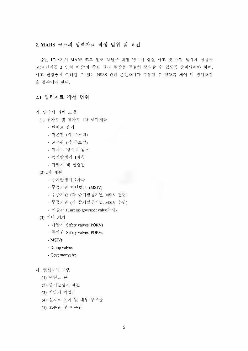
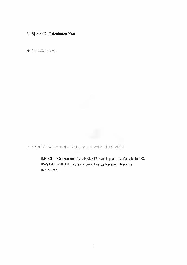
Pressurizer
SG 1
I
Core power (MW)
8 8 5§ § §|i I i I i L J
Unffi,co
riB
tfljoh#'Jffl
o({1
2800
Temperature (K)
u
Aojmo£
rl°M
o({1
g>?
Water level (m)
unffi,a-
»ao|)J
o({1
in ™o(j) CD -A V)
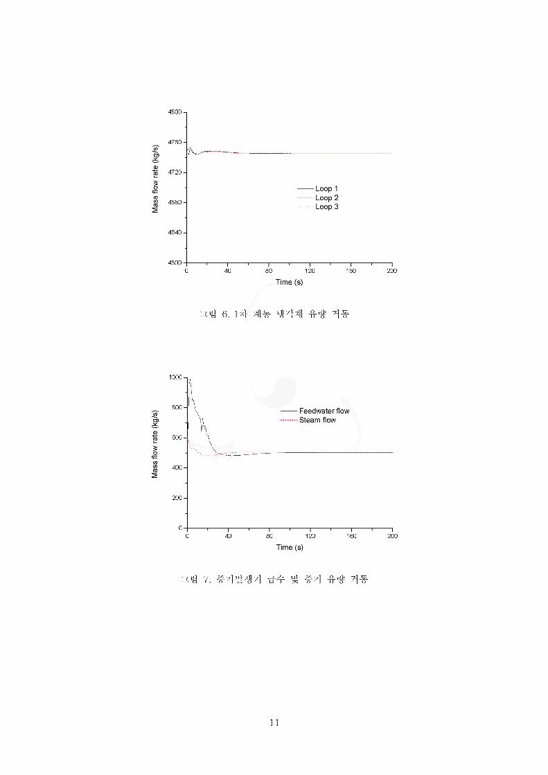
4800
4760-
4720-
4680-
4640-
Time (s)
6. 31# ^431 f # ^1#
1000 -,
800- Feedwater flow Steam flow
600-'
400-
200-
Time (s)
7. #7]#^ 7] ^ ^7} f ^ 7}%-
11
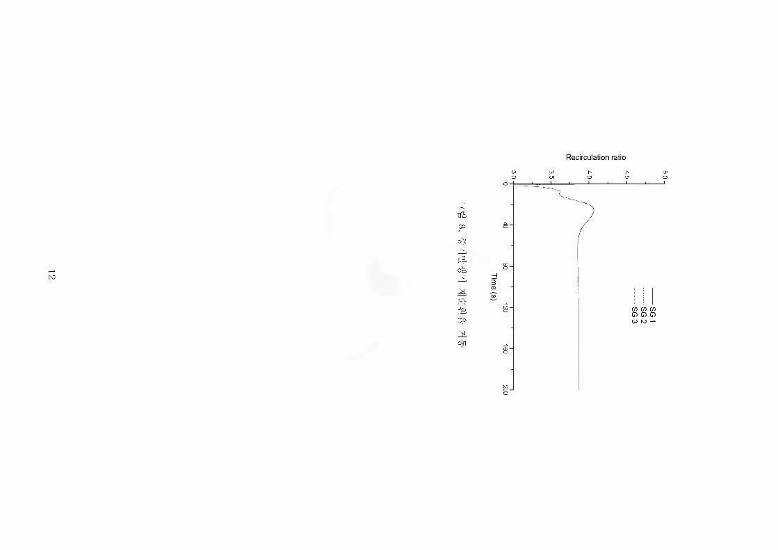
8. #7]#
7
] 7]
o({1
Recirculation ratio
CO CO Jx _Jx Olo oi o b o
o o o

unk Pressure (MPa)
k kk
V30
19T6
2000
Mass flow rate (kg/s)
in O,
in W rir
jk nk jkk VO kJk l $oik CTn jkk rk kk A rSnk rk kkrk
oikk®lra
nrUnk
k_2, knyi
kk
k inJi koik nok °iv
n|onr
kruk krk kjk
kloivk Jk
rkrk kkrk
aokckJk
okrh>N
Jl
Jkko(okkrk[UhLinrirkrk
k[Ujoo({1kr
-kNo
-£dkk,
£
W1o
00o
Nrirkin-k
NrirJtLr(orkkrk[tiSk
unk
_n,nrk
in>j
wOo
_2,kkk
JkkkkrkkJkkkinrkkck[Ujo
Jkrk-kkinkkokjkrkaoko£Jk
okk
[k -tz lb
fe lh
:ivlk
[v lb
’z’p
unffi,
Mass flow rate (kg/s)
4^
55>
>oo3wo•“t
4^cS
o({1
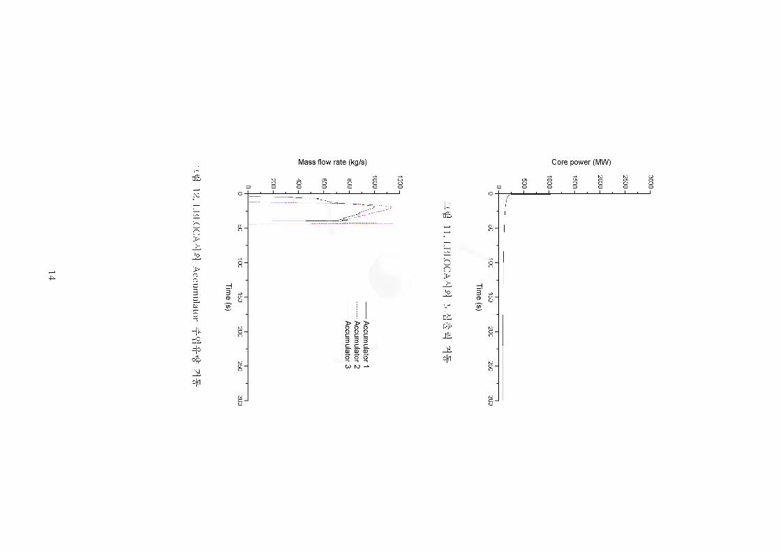
11. LB
L0CA
44
Core power (MW)
u
Kdh#'Jffl
o({1
2000
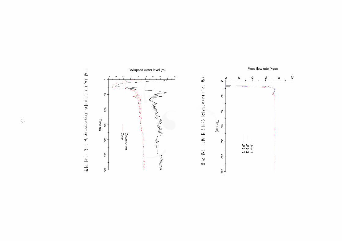
13. LBLO
CA
^M
Mass flow rate (kg/s)
unffi.
4X
nlSLIti
o({1

unffi,I—1 Oi
55>
Pjju£o
O6fci
r(oM
o({1
Clad temp. (K)
15. LBL0C
A44
8w
Kdh
lU(o
o({1
Void fraction
P P P P P
o o oo o
5. ##
4 4^1 tsJf #4 i-5 ms-7] 4-44444- mars 2H ^4 S-li: o]
444-^4 44 44-71)4-4 4^ 4 4iH 44-71144 7>J7 0] a}70^ ^4# 4 44^
71144 444. 444-5. >$44 44 4 44 CalculationNote4 1^5 44444.
4 4444 71144 444&4 4444 57)4^ 44-4-4 4 4^# 44 4444-711
447}314 44444 44444. 4# #4 444&^ 4444 44444 44 44
4, 44 4 44x}&7} i-xi i/2ji7l 444444 mars 2E 44 514 44 44-4^
7}4# 4 444 44444.
17
6.
[1] 444^44, 1-5 1125.7} $1 44 iUl4(knu 9&10).
[2] 444444, 1-5 1,2 5.7} 4444 #2^4 1996. 10.
[3] W. J. Lee, B. D. Chung, J. J. Jeong, and K.S. Ha, “Development of a Multidimensional Realistic
Thermal-Hydraulic Analysis Code, MARS 1.3 and its Verification,” KAERI/TR-1108/98, KAERI,
1998.
[4] W. J. Lee, B. D. Chung, J. J. Jeong, and K.S. Ha, “Improvement of Multidimensional Realistic
Thermal-Hydraulic Analysis Code, MARS 1.3,” KAERI/TR-1141/98, KAERI, 1998.
[5] W. J. Lee, B. D. Chung, J. J. Jeong, and K.S. Ha, “Improved Features of MARS 1.4 and its
Verification” KAERI/TR-1386/99, KAERI, 1999.
[6] $1 44- Generation of the RELAP5 Base Input Data for Ulchin-1/2, DS-SA-UL9-90125E, Rev. 0,
44444 4 4^. Dec. 8, 1990.
[7] 444 4 44. &4 1,2 5.7} 44444444 4444# 44 RELAP5/MOD3 4^
7}S. (4444: #4 1,2^7] EOP /R444 4 4/R44 4444 4444(444 II).
44447144444 454 44444,2002.2.
18
Appendix of KAERI/TR-2420/2003 TAD/M2002-07 Rev. 0
Catenation Note for Ulchin 1/2
MARS Base Input Deck Generation
March 2003
Prepared by
KAERI&
PNC Technology Co.
Korea Atomic Energy Research Institute

List of Contents
1. Introduction........................................................... A1
2. Hydraudynamic Component Data........................ A3
2.1 Reactor Pressure Vessel......................... A4
2.2 Reactor Coolant Lines andSteam Generator Primary Sides.............. A152
2.3 Pressurizer and Surgeline......................... A221
2.4 Reactor Coolant Pump............................. A250
2.5 Steam Generator Secondary Side........... A254
2.6 Main Steam Line System.......................... A306
2.7 ECC System.............................................. A334
3. Heat Structure Data.............................................. A342
4. Interactive Control Input......................................... A434
5. References A437
1. Introduction
This report includes the background data and the calculation sequence of the MARS input for Ulchin Nuclear Units 1 & 2 [1], This input data has been developed from the RELAP5 base input deck for Ulchin Nuclear Units 1/2 [2] and has been modified for the use in the MARS plant analyzer (MPA). The MPA is being developed for ease-to-use, realistic analysis of medium- and large-break loss-of-coolant accidents in a user-friendly environment [3-5].
The requirements for the MARS input model is given in Reference 6.
It is noted that most of the raw data used for the generation of this input were directly obtained from Reference 2:
H.R. Choi, Generation of the RELAP5 Base Input Data for Ulchin-1/2, DS-SA-UL9-90125E, Korea Atomic Energy Research Institute,Dec. 8,1990.
(^) U§ =£| 1/2S2I2I MARS 2E°ja JHHEOia.MARS 2.1—1 "Interactive Control Function"# AfgXPf 33IE2#
*||0]if 4 2W. U§ = El□ 2.| 2# SfEfOlIb g gd|@"Interactive Control Function"2| #9£|CH 24.p-.
- At -

U12 N
odalization for MA
RS
Loop 1J— 822
Loop 3
n JUL
x Continuous valve area control X On-off valve control # Mass flow rate control
’-O On-off pump control
UCN 1 &2 Nodalization for MARS Plant Analyzer

2. Hydraudynamic Component Data
-A3 -
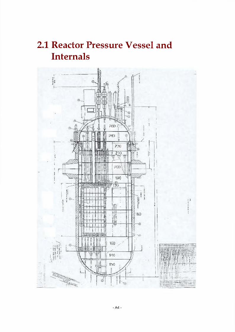
2.1 Reactor Pressure Vessel and Internals
:i■ ■; 11 rr:ii; __
- A4 -
(-•■r
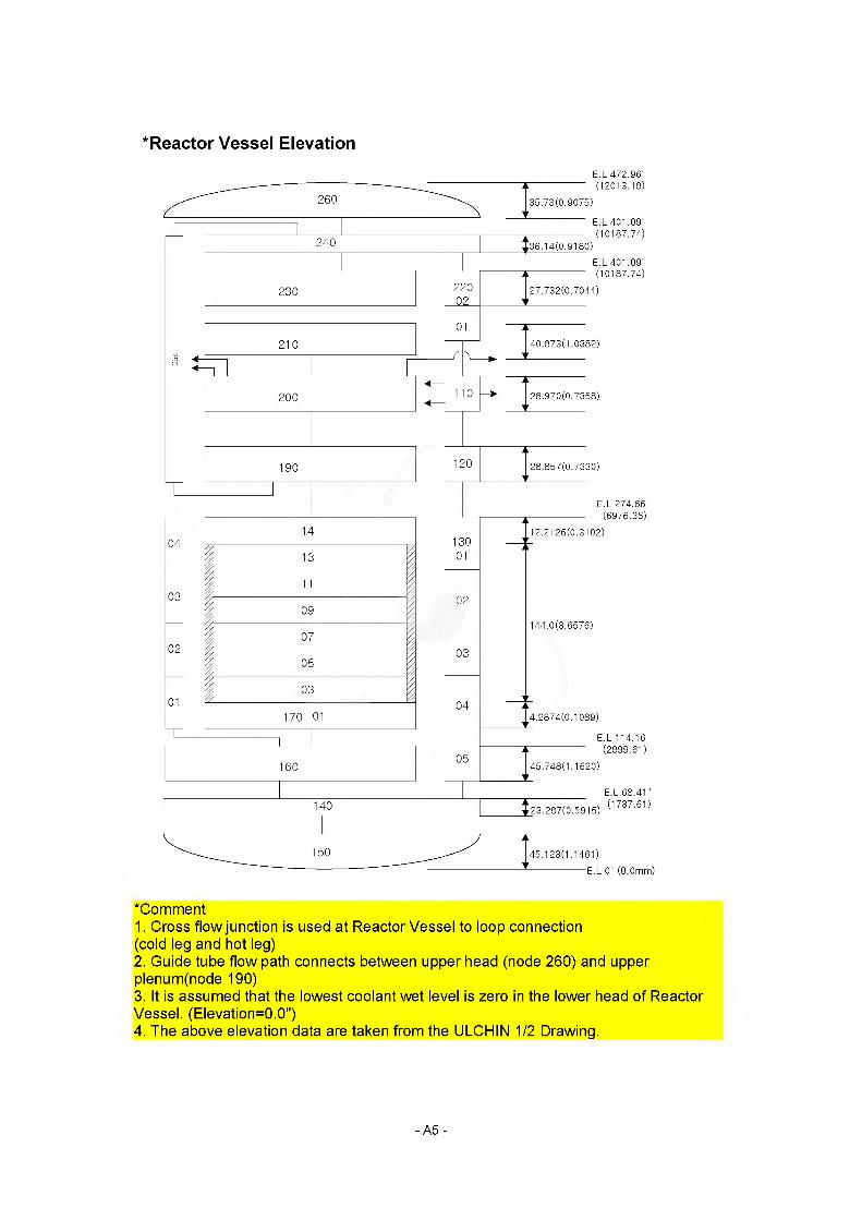
* Reactor Vessel Elevation
E.L 472.96'(12013.18)
35.73(0.9075)
E.L 401.09(10187.74)
E.L 401.09(10187.74)
27.732(0.7044)
40.873(1.0382)
28.970(0.7358)
28.857(0.7330)
E.L 274.66 (6976.36)
12.2126(0.3102)
144.0(3.6576)
4.2874(0.1089)
(2899.61)45.748(1.1620)
E.L 68.41(1737.61)23.287(0.5915)
45.123(1.1461)E.L 0" (0.0mm)
"Comment1. Cross flow junction is used at Reactor Vessel to loop connection (cold leg and hot leg)2. Guide tube flow path connects between upper head (node 260) and upper plenum(node 190)3. It is assumed that the lowest coolant wet level is zero in the lower head of Reactor Vessel. (Elevation=0.0")4. The above elevation data are taken from the ULCHIN 1/2 Drawing.
- A5 -
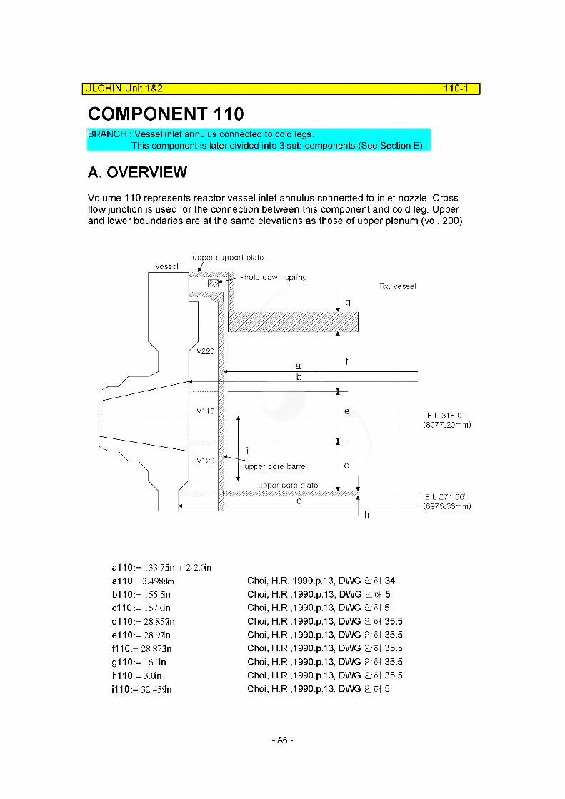
COMPONENT 110| ULCHIN Unit 1&2 110-1
BRANCH : Vessel inlet annulus connected to cold legs.This component is later divided into 3 sub-components (See Section E).
A. OVERVIEWVolume 110 represents reactor vessel inlet annulus connected to inlet nozzle. Cross flow junction is used for the connection between this component and cold leg. Upper and lower boundaries are at the same elevations as those of upper plenum (vol. 200)
upper support platevessel
hold down springRx. vessel
V220
V1 10
V120upper core barrel
upper core plate
E.L 318.0" (8077.20mm)
E.L 274.66" (6976.36mm)
a110:= 133.75n + 2-2.0ina110 = 3.4988m Choi, H.R.,1990.p.13, DWG °}§H 34b110:= 155.Sin Choi, H.R.,1990.p.13, DWG °}§H 5c110 := 157.On Choi, H.R.,1990.p.13, DWG °}§H 5d110:= 28.85ln Choi, H.R.,1990.p.13, DWG °}§H 35.5e110:= 28.97in Choi, H.R.,1990.p.13, DWG °}§H 35.5f110:= 28.873n Choi, H.R.,1990.p.13, DWG °}§H 35.5g110:= 16.0in Choi, H.R.,1990.p.13, DWG °}§H 35.5h110:= 3 On Choi, H.R.,1990.p.13, DWG °}§H 35.5i 110:= 32.459n Choi, H.R.,1990.p.13, DWG °}§H 5
- A6 -
ULCHIN Unit 1&2 110-2
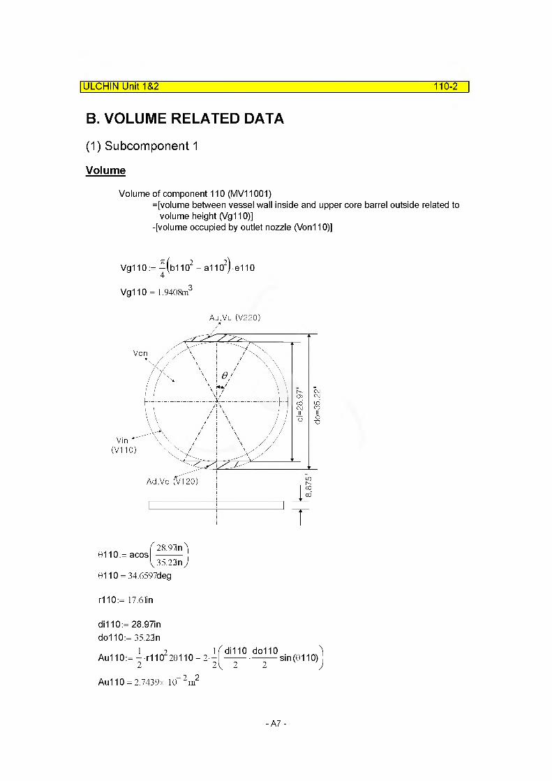
B. VOLUME RELATED DATA
(1) Subcomponent 1
Volume
Volume of component 110 (MV11001)=[volume between vessel wall inside and upper core barrel outside related to
volume height (Vg 110)]-[volume occupied by outlet nozzle (Von110)]
Vg110 :=-^(bl 102 — a1102) e110
Vg110 = 1.9408m3
Au.Vu (V220)
0/110)
Ad.Vd (V120)
. 28.91n) 0110:= acos| --------- .
35.23nJ9110 = 34.6597deg
r110:= 17.6 li n
di 110:= 28.97indo110:= 35.22n
Au110:= — r1102 20110-2 -2 2
Au110 = 2.7439x 10“ 2 m2
di110 do1102 ' 2 sin (0110)
1
)
-A7 -

ULCHIN Unit 1&2 110-3
Vu110 := Au110-8.875nVu110 = 6.1854x 10“ 3 m3
Vd110:= Vu110
Don110:= 35.22in
Aon110:= —Don11024
Aon110 = 0.6285m2
Von110':= Aon110-8.85ln
Von110' = 0.1414m3 (5.0037 ft3)
Total volume occupied by outlet nozzle(Von110) Von110 := 3Von110'Von110 = 0.4242m3
Therefore, volume of component 110 (MV11001) is MV11001 := Vg110 - Von110MV11001 = 1.5166m3
Flow Length
MFLOWL11001 := e110 MFLOWL11001 = 0.7358m
Flow Area : Default
Area is default because we had already known volume and length MV11001
MFLOWA11001:=----------------------MFLOWL11001
MFLOWA11001 = 2.0610m2
Hydraulic Diameter
Do110:= b110 Di 110:= a110
MDIA11001 := Do110 - Di110 MDIA11001 = 0.4509m
- A8 -
ULCHIN Unit 1&2 110-4
Elevation Change
MZVOL11001:= e110sin (-90deg) MZVOL11001 = -0.7358m
C. JUNCTION RELATED DATAJunction 1,2,3 are connections between inlet nozzle and inlet annulus. Junction 4,5 are the gap area between vessel and upper core barrel. And junction 1,2,3 used crossflow junctions option.
(1) Junction Area
Dj 110:= 35.22in(See the figure in next page.)
Junction Area 1~3
MAJUN11001:= —DjUO24
MAJUN11002:= MAJUN11001 MAJUN11003:= MAJUN11001MAJUN11001 = 0.6285m2
MAJUN11002= 0.6285m2
MAJUN11003= 0.6285m2
Junction Area 4~5
71MAJUN 11004:=
4
MAJUN11004= 2.6375m2
MAJUN 11005:= MAJUN 11004 MAJUN11005= 2.6375m2
- A9 -

ULCHIN Unit 1&2 110-5
(2) Loss Coefficient (MFJUNF/R) - Forward & Reverse
D0j110:= 21 Mn Idj110:= 39.5625n aj 110:= 5.6deg
D1j110:= 35.22n hj 110:= 8.873n R0j110:= 4.5in
hj110 D0j110
ROj 1100.3231 —------=0.1638
D0j110Choi, H.R., 1990, p.16
D1j110 D0j110
1.2821
Forward Loss Factor for Junction 1~3
KF110=f(hi110/D0j110) hj110
—------- =0.3231DOj 110
Therefore, KF11001 := 0.33 Forward Loss Factor(KF11001)KF11001 =0.3300
Reference Area(F0i110)ID_refjl 10:= 27.41n
F0j110:=^(ID_refj11Q2
F0j110 = 0.3824m2
-A10-
ULCHIN Unit 1&2 110-6
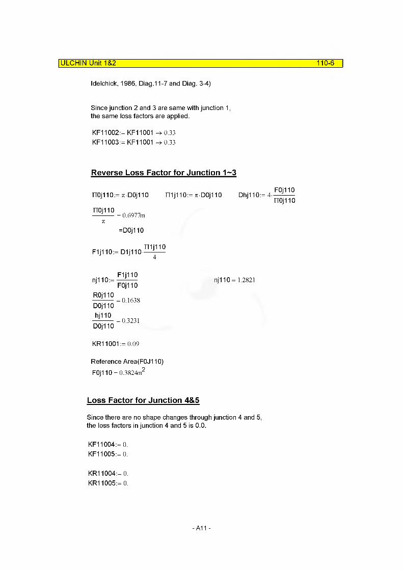
Idelchick, 1986, Diag.11-7 and Diag. 3-4)
Since junction 2 and 3 are same with junction 1, the same loss factors are applied.
KF11002:= KF11001 -> 0.33 KF11003:= KF11001 -> 0.33
Reverse Loss Factor for Junction 1~3
71
=DOj 110
mjiioF1j110:= D1j110-----------
nj 110 = 1.2821
DOj 110 hj110
—------- =0.3231DOj 110
KR11001:= 0.09
Reference Area(F0J110)F0j110 = 0.3824m2
Loss Factor for Junction 4&5
Since there are no shape changes through junction 4 and 5, the loss factors in junction 4 and 5 is 0.0.
KF11004:= 0.KF11005:= 0.
KR11004:= 0.KR11005:= 0.
- A11 -
ULCHIN Unit 1&2 110-7
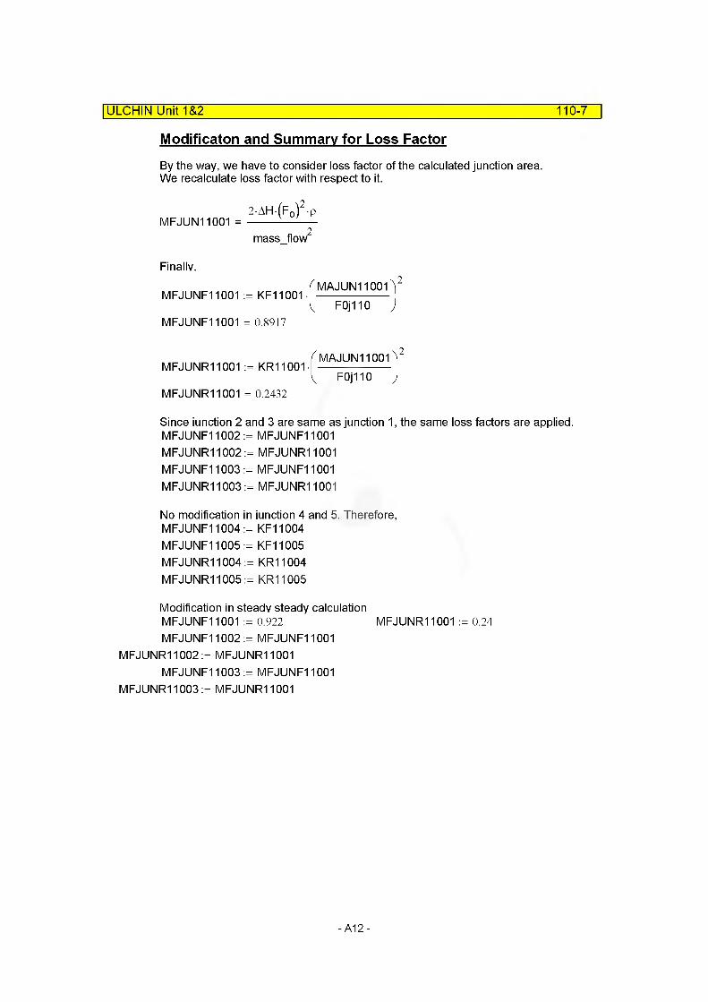
Modificaton and Summary for Loss Factor
By the way, we have to consider loss factor of the calculated junction area. We recalculate loss factor with respect to it.
MFJUN11001 =2AH-(F0)2p
mass flow2
Finally.
MFJUNF11001 := KF11001 •
MFJUNF11001 = 0.8917
MAJUN11001)
F 0j 110 )
2
( MAJUN11001VMFJUNR11001 := KR11001- -------------------
L F 0 j 110 )MFJUNR11001 = 0.2432
Since junction 2 and 3 are same as junction 1, the same loss factors are applied.MFJUNF11002 := MFJUNF11001MFJUNR11002:= MFJUNR11001MFJUNF11003 := MFJUNF11001MFJUNR11003:= MFJUNR11001
No modification in junction 4 and 5. Therefore,MFJUNF11004 := KF11004 MFJUNF11005 := KF11005 MFJUNR11004:= KR11004 MFJUNR11005:= KR11005
Modification in steady steady calculation MFJUNF11001 := 0.922 MFJUNR11001 := 0.24MFJUNF11002 := MFJUNF11001
MFJUNR11002:= MFJUNR11001MFJUNF11003 := MFJUNF11001
MFJUNR11003:= MFJUNR11001
-A12-

ULCHIN Unit 1&2 110-8
D. SUMMARY OF DATAcomponent type = branch
(1) VOLUME RELATED DATA : 1 Subvolume
Volume 1
MFLOWL11001 = 0.7358mMFLOWA11001 = 2.0610m2 Default
MV11001 = 1.5166m3
MDIA11001 = 0.4509m MZVOL11001 = -0.7358mVolume Flag =0000 Default
(2) JUNCTION RELATED DATA : 5 Junctions
Junction 1
From component =To component =MAJUN11001 = 0.6285m2
MFJUNF11001 = 0.9220 MFJUNR11001 = 0.2400 Junction Flag =
Junction 2
From component =To component =MAJUN11002= 0.6285m2
MFJUNF11002= 0.9220 MFJUNR11002= 0.2400 Junction Flag =
Junction 3
From component = 590030002To component = 110010003MAJUN 11003= 0.6285m2 Modified into 0.972
MFJUNF11003= 0.9220 Modified into 0.243MFJUNR11003= 0.2400Junction Flag = 00001 (Momentun Flux)
490030002110010003
Modified into 0.972 Modified into 0.243
00001 (Momentun Flux)
390030002110010003
Modified into 0.972 Modified into 0.243
00001 (Momentun Flux)
-A13-
ULCHIN Unit 1&2 110-9
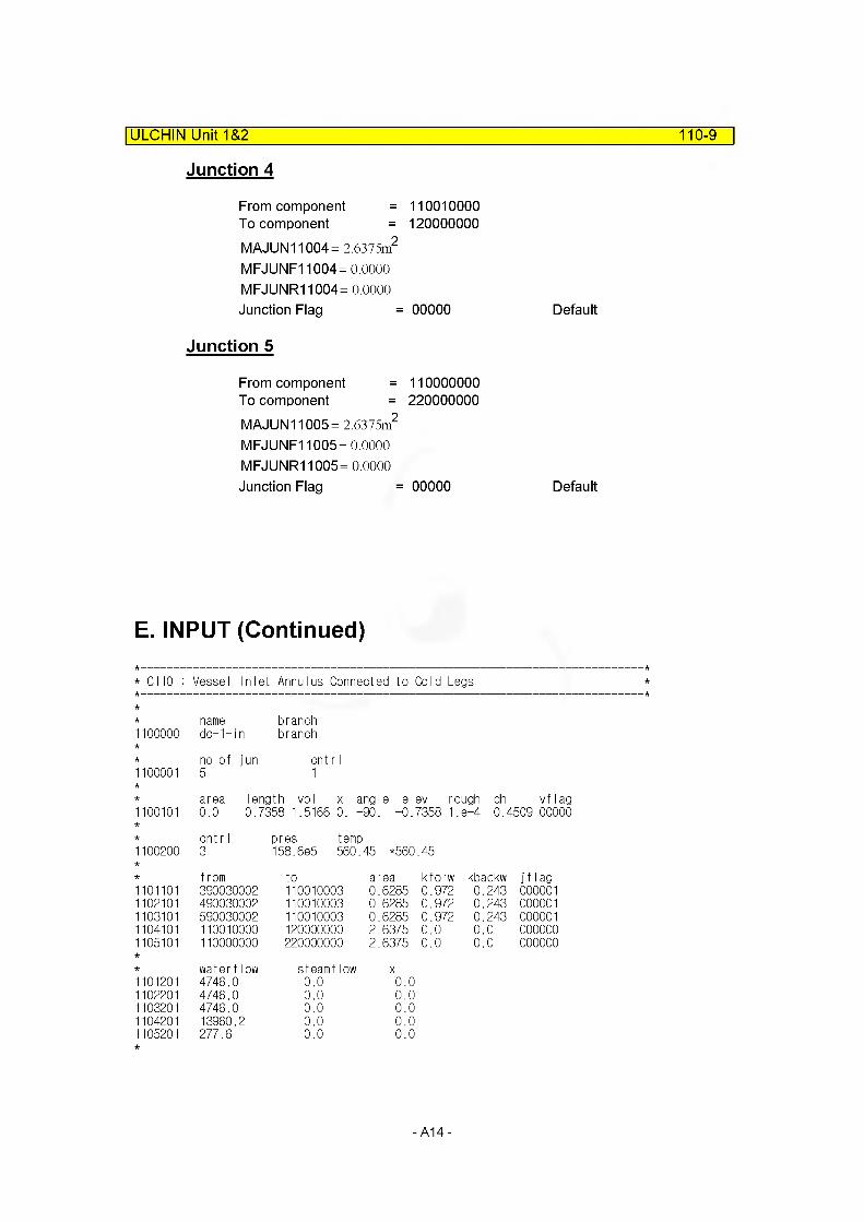
Junction 4
From component = 110010000 To component = 120000000MAJUN11004= 2.6375m2
MFJUNF11004= 0.0000 MFJUNR11004= 0.0000Junction Flag = 00000 Default
Junction 5
From component = 110000000 To component = 220000000MAJUN11005= 2.6375m2
MFJUNF11005= 0.0000 MFJUNR11005= 0.0000Junction Flag = 00000 Default
E. INPUT (Continued)
* C110 : Vessel Inlet Annulus Connected to Cold Legs
* name branch1100000 dc-1-in branch
no of jun cnt r I1100001 5 1
area length vol x angle elev rough dh vf lag1100101 0.0 0.7358 1.5166 0. -90. -0.7358 1. 8-4 0.4509 00000
cnt r I pres temp1100200 3 158.6e5 560 .45 *560 .45
from to area kforw kbackw if lag1101101 390030002 110010003 0.6285 0.972 0.243 0000011102101 490030002 110010003 0.6285 0.972 0.243 0000011103101 590030002 110010003 0.6285 0.972 0.243 0000011104101 110010000 120000000 2.6375 0.0 0.0 0000001105101 110000000 220000000 2.6375 0.0 0.0 000000
water flow steamflow X1101201 4746.0 0.0 0.01102201 4746.0 0.0 0.01103201 4746.0 0.0 0.01104201 13960.2 0.0 0.01105201 277.6 0.0 0.0
-A14-
ULCHIN Unit 1&2 110-10
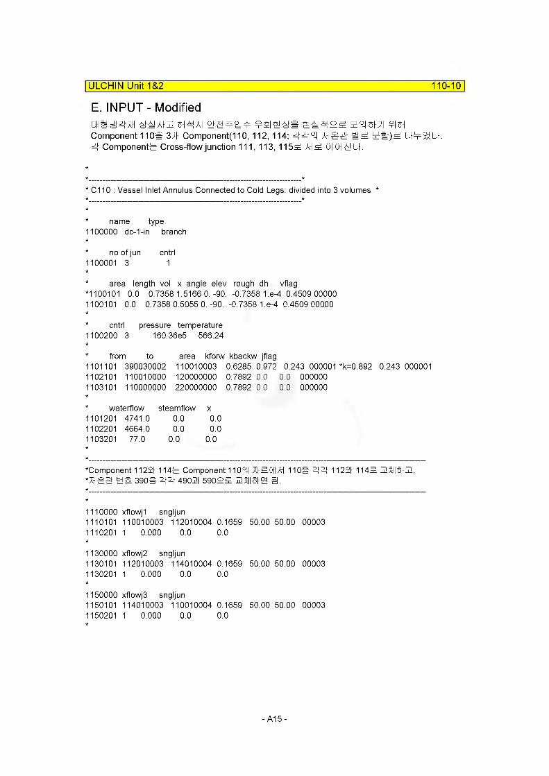
E. INPUT - ModifiedCHSyzHH 6t^AI2 §H^A| ¥Sie^S S^$I25 H2I8PI ?I§HComponent 110# 3HH Component(110, 112, 114; 555 XH gg 5#) 5 U521Q-. 5 Components Cross-flow junction 111, 113, 1155 AH 5 0| CHS Q-.
* C110 : Vessel Inlet Annulus Connected to Cold Legs: divided into 3 volumes *
* name type 1100000 dc-1-in branch
* no of jun cntrl1100001 3 1
* area length vol x angle elev rough dh vflag*1100101 0.0 0.7358 1.5166 0.-90. -0.7358 1.e-4 0.4509 00000 1100101 0.0 0.7358 0.5055 0.-90. -0.7358 1.e-4 0.4509 00000
* cntrl 1100200 3
pressure temperature 160.36e5 566.24
* from to 1101101 390030002 1102101 110010000 1103101 110000000
area kforw kbackw jflag110010003 0.6285 0.972 0.243 000001 *k=0.892 0.243 000001120000000 0.7892 0.0 0.0 000000 220000000 0.7892 0.0 0.0 000000
waterflow steamflow x1101201 4741.0 1102201 4664.0 1103201 77.0
0.0 0.00.0 0.0
0.0 0.0
‘Component 11221 1145 Component 1105 XI-50II AH 110# 5"5" 11221 1145 Hx-Holll, *XHSS 5S 390# ## 49021 59055 5X1161 EH H.
1110000 xflowjl sngljun1110101 110010003 112010004 0.1659 50.00 50.00 00003 1110201 1 0.000 0.0 0.0
1130000 xflowj2 sngljun1130101 112010003 114010004 0.1659 50.00 50.00 00003 1130201 1 0.000 0.0 0.0
1150000 xflowjS sngljun1150101 114010003 110010004 0.1659 50.00 50.00 00003 1150201 1 0.000 0.0 0.0
-A15-
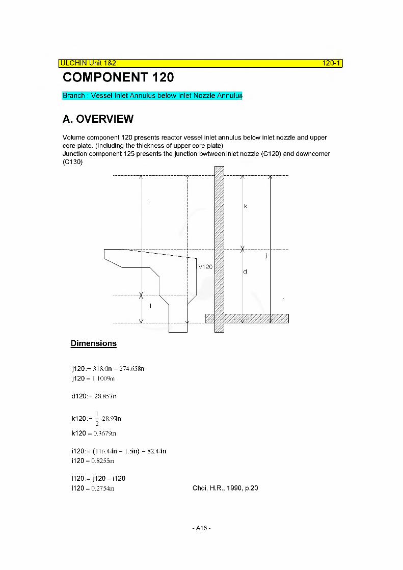
COMPONENT 120| ULCHIN Unit 1&2 120-1
Branch : Vessel Inlet Annulus below Inlet Nozzle Annulus
A. OVERVIEWVolume component 120 presents reactor vessel inlet annulus below inlet nozzle and upper core plate. (Including the thickness of upper core plate)Junction component 125 presents the junction bwtween inlet nozzle (C120) and downcomer (C130)
V120
Dimensions
j120 := 318.an-274.65Sn j120 = 1.1009m
d120:=28.85ln
k120 := — 28.97in2
k120 = 0.3679m
1120:= (116.44n - 1.5in) - 82.44in1120 = 0.8255m
1120:= j120 - i 1201120 = 0.2754m Choi, H.R., 1990, p.20
-A16-
ULCHIN Unit 1&2 120-2
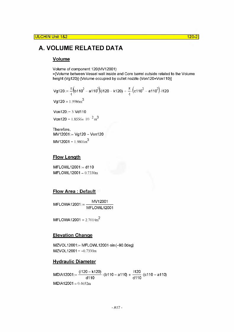
A. VOLUME RELATED DATA
Volume
Volume of component 120(MV12001)=[Volume between Vessel wall inside and Core barrel outside related to the Volume height (Vg120)]-[Volume occupied by outlet nozzle (Von120=Von110)]
Vg120 := ^(b1102 - a1102)(i120 - k120) + ^ • (c1102 - a1102) 1120
Vg120 = 1.9986m3
Von120 := 3Vd110Von 120 = 1.8556x 10“ 2 m3
Therefore,MV12001 := Vg120 - Von120 MV12001 = 1.9801m3
Flow Length
MFLOWL12001 := d 110 MFLOWL12001 = 0.7330m
Flow Area : Default
MFLOWA12001 :=MV12001
MFLOWL12001
MFLOWA12001 = 2.7014m2
Elevation Change
MZVOL12001 := MFLOWL12001 sin (-90.0deg)MZVOL12001 = -0.7330m
Hydraulic Diameter
(i120 — k120) 1120MDIA12001 := ------------------ (b110 - a110) +--------(c110 - a110)
d110 d110MDIA12001 = 0.4652m
-A17-

C. JUNCTION RELATED DATA
(1) Junction Area : Default
Same as MFLOWA12001.
Therefore,MAJUN12500:= MFLOWA12001 MAJUN12500= 2.7014m2
(2) Loss Factor
Calculation of Loss Factor(x) by Idelchik Diag. 4-3
Forward loss factor
| ULCHIN Unit 1&2 120-3
F0J12500:= — (b1102 - a1102)4 V '
F0J12500= 2.6375m2
F2J12500:= — (c1102 - a1102)4 V '
F2J12500= 2.8750m2
Thus,F2J12500
n12500:=-------------F0J12500
n12500= 1.0901
Let's assume m12500:= 4.
Then,KF12500:= 0.04
Reverse loss factor
By Idelchik, 1966, Diag. 3-9
KR12500:= O.sf 1 - F0J12500>|
\ F2J12500)KR12500 = 4.1307x 10“ 2
-A18-

ULCHIN Unit 1&2 120-4
Modification and Summary for Loss Factor
As loss factor are overestimated, we neglect them for RPV steady-state initialization. That is,
MFJUNF12500:= 0.MFJUNR12500:= 0.
D. SUMMARY OF DATAcomponent type = Annulus
(1) VOLUME RELATED DATA : 1 Subvolume
Volume 1
MFLOWL12001 = 0.7330m
MFLOWA12001 = 2.7014m2 Default
MV12001 = 1.9801m3
MDIA12001 = 0.4652m MZVOL12001 =-0.7330mVolume Flag = 0000 Default
(2) JUNCTION RELATED DATA
Number of junctions = single junction.
Junction 1
from component = 120010000to component = 130000000MAJUN12500= 2.7014m2 Default
MFJUNF12500 =0.0000 MFJUNR12500= 0.0000Junction Flag = 0000 Default
-A19-
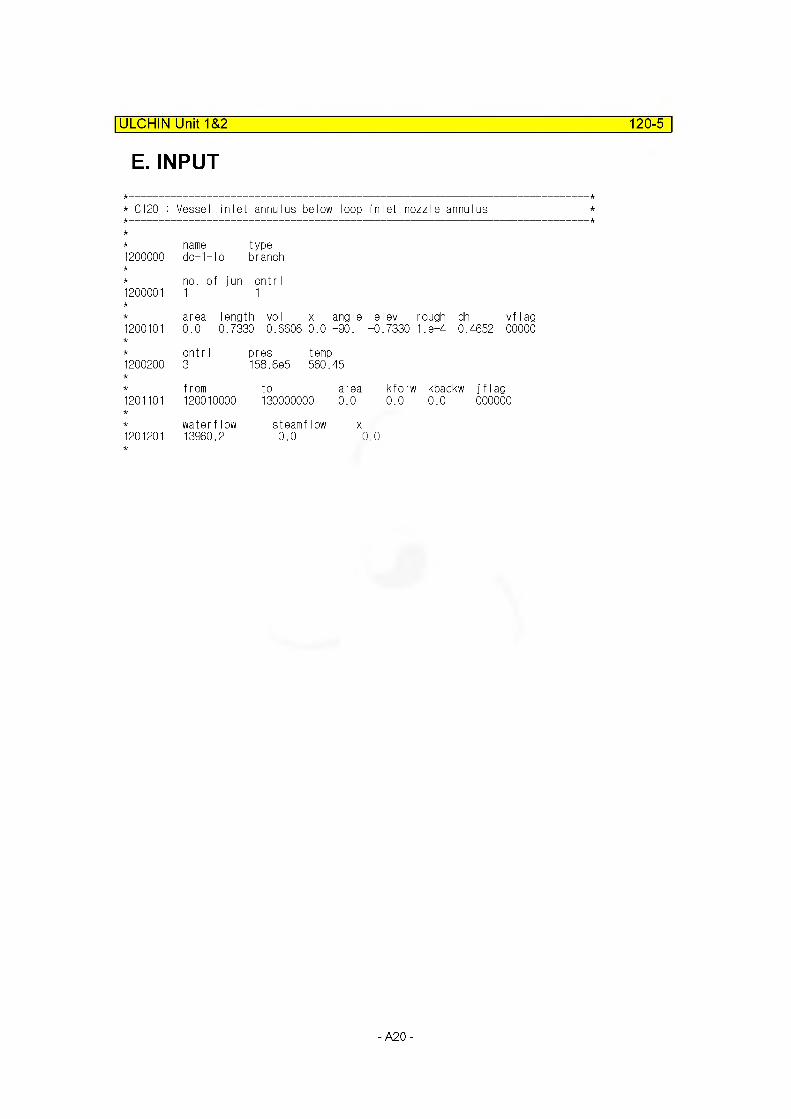
E. INPUT
ULCHIN Unit 1&2______________________________________________________ 120-5
* C120 : Vessel inlet annulus below loop inlet nozzle annulus
name type1200000 do—1—Io branch
no. of jun cntr I1200001 1 1
area length vol x angle elev rough dh vf lag1200101 0.0 0.7330 0.6606 0.0 -90. -0.7330 1. e-4 0. 4652 00000
cntr I pres temp1200200 3 158.6e5 560.45
from to area kforw kbackw j f I ag1201101 120010000 130000000 0.0 0.0 0.0 000000
waterflow steamflow x1201201 13960.2 0.0 0.0
-A20-
ULCHIN Unit 1&2 130-1
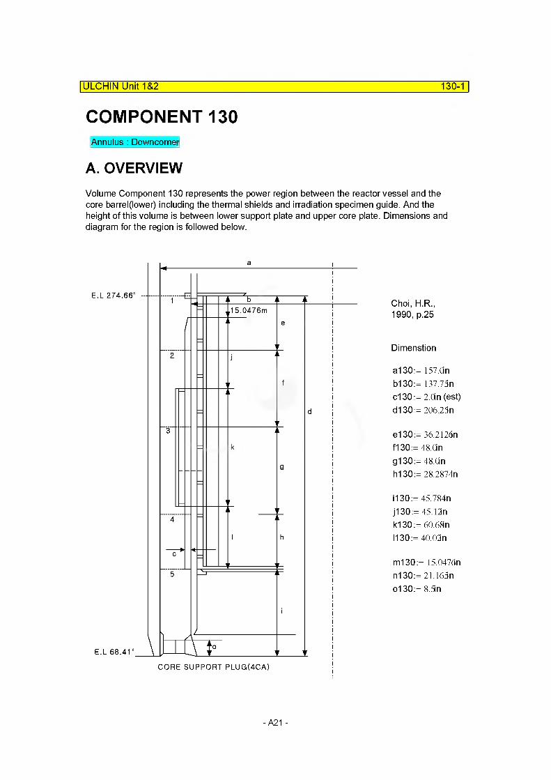
COMPONENT 130Annulus : Downcomer
A. OVERVIEWVolume Component 130 represents the power region between the reactor vessel and the core barrel(lower) including the thermal shields and irradiation specimen guide. And the height of this volume is between lower support plate and upper core plate. Dimensions and diagram for the region is followed below.
E.L 274.66"
E.L 68.4V
I 5.0476m
CORE SUPPORT PLUG(4CA)
Choi, H.R., 1990, p.25
Dimenstion
a130:= 157.On b130:= 137.75n c130 := 2.0in (est) d130:= 206.25n
e130:= 36.212dn f130 := 48.0in g130 := 48.0in hi 30 := 28.2874n
i 130 := 45.784n j130 := 45.12n k130:=60.68n 1130:= 40.02n
m130:= 15.0476n n130:=2l.l65n o130:= 8.5in
- A21 -

B. VOLUME RELATED DATA
ULCHIN Unit 1&2_____________________________________________________ 130-2
Volume 130 is devided 5 subvolume parts
(1) Subcomponent 1
Volume
Volume of subcomponent 13001 (MV13001)= [Volume between vessel wall and lower core barrel related to
the volume height(V1v130)]-[Some of Neutron shield panel volume(V1vSP130)]KSL-CN-862004)
V1v130:= -(alSO2 - b130>e130
V1v130= 2.6444m3
V1vSP130:= (j130 + k130 + 1130)-36.75n c130 + (j130+ k130+ 1130) 50.23n c130 3 V1vSP130 = 0.8957m3
MV13001 := V1 v130------------------------------ V1 vSP130(j130 + k130 + 1130)
MV13001 = 2.5144m3
Flow Length
Flow Length of 13001 (MFLOWL13001)
MFLOWL13001 := e130 MFLOWL13001 = 0.9198m
-A22-

ULCHIN Unit 1&2 130-3
Flow Area : Default
Flow Area of 13001 (MFLOWA13001)
MV13001MFLOWA13001 :=
MFLOWL13001MFLOWA13001 = 2.7337m2
Elevation Change
MZVOL13001 := MFLOWL13001 sin (-90.0deg)MZVOL13001 = -0.9198m
Hydraulic Diameter
Hydraulic Diameter of 13001 (MDIA13001)
Weted Parameter of 13001 (P13001)P13001 := 7i(a130 + b130) - 3-50.22n - l-36.75n + 3(50.22n + 4.Qn) + (36.75n + 4in) P13001 = 23.9264m
MDIA13001 = 0.4703m
(2) Subcomponent 2 and 3
All the variables in 13003 are same to those of 13002.
Volume
Volume of subcomponent 13002(MV13002)= [Volume between vessel wall and lower core barrel related to
the volume height(V2v130)]-[Nuetron shield panel volume(V2SPv130)]-[Irradiation specimen guide volume(V2.iSGv130)]
There are no detail drawing of irradiation specimen guide to calculate the volume and other data. And we neglect the volume because it is so small volume.That is,V2iSGv130:= O.in3
V2v130:=4 'i men 3V2v130= 3.5052m
-A23-

ULCHIN Unit 1&2 130-4
f130 rV2SPv130:= -------------------------- (j130 + k130 + I130)-36.75n-c130 ...
J130 + k130 + I130^+ [(ji30 + k130+ I130)-50.22n-c130]-3
V2SPv130 = 0.2948m3
Therefore,MV13002 := V2v130 - V2SPv130 - V2iSGv130 MV13002 = 3.2104m3
For Subcomponent 3 MV13003:= MV13002
Flow LengthMFLOWL13002:= f130 MFLOWL13002 = 1.2192m
For Subcomponent 3 MFLOWL13003:= MFLOWL13002
Flow Area : Default
M FLO WA13002:=MV13002
MFLOWL13002
M FLO WA13002 = 2.6332m2
For Subcomponent 3 MFLOWA13003 := MFLOWA13002
Elevation ChangeMZVOL13002:= f130sin (-90.0deg) MZVOL13002=-1.2192m
For Subcomponent 3 MZVOL13003:= MZVOL13002
Hydraulic DiameterHydraulic Diameter of 13002 (MDIA13002)
MDIA13002=The second term of MDIA130014MFLOWA13001)
P13001 )
4MFLOWA13001MDIA13002:=-------------------------
P13001MDIA13002= 0.4570 m
For Subcomponent 3 MDIA13003 := MDIA13002
-A24-

130-5
(4) Subcomponent 4
| ULCHIN Unit 1&2 ~
Volume
Volume of Subcomponet 13004 (MV13004)= The first term of volume MV13001 (But h130 instead of e 130) [V4v130] + The second tern of volume MV13001
(Buthi30 .
j 130 + k130 + 1130J instead ofn130 \
j 130 + k130 + 1130)'
V4v130 := — (a1302 - b130>h1304V ’
V4v130 = 2.0657 m3
V4vSP130 := V1vSP130 V4vSP130 = 0.8957 m3
Therefore.
MV13004 := V4v130 -h130
(j130+ k130 + 1130)V4vSP130
MV13004 = 1.8920 m3
Flow Length
MFLOWL13004:= h130 MFLOWL13004 = 0.7185m
Flow Area : Default
M FLO WA13004:=MV13004
MFLOWL13004
M FLO WA13004 = 2.6332m
Elevation Change
MZVOL13004:= MFLOWL13004 sin (-90.0deg) MZVOL13004=-0.7185m
Hydraulic Diameter
Hydraulic diameter of 13004 (MDIA13004) is same to that of MDIA13002.
MDIA13004:= MDIA13002 MDIA13004= 0.4570m
-A25-
ULCHIN Unit 1&2 130-6
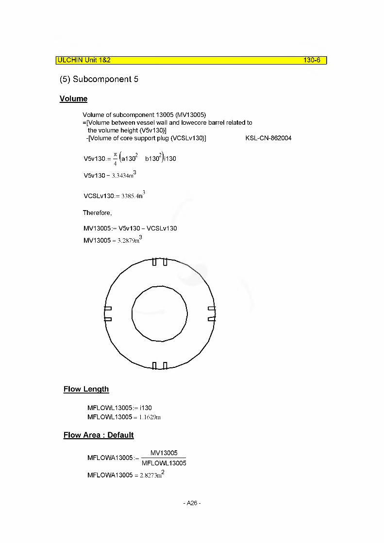
(5) Subcomponent 5
Volume
Volume of subcomponent 13005 (MV13005)=[Volume between vessel wall and lowecore barrel related to
the volume height (V5v130)]-[Volume of core support plug (VCSLvl 30)] KSL-CN-862004
71V5v130:=
4
V5v130= 3.3434m3
VCSLvl 30:= 3385.4n3
Therefore,
MV13005 := V5v130 - VCSLvl 30 MV13005 = 3.2879m3
Flow Length
MFLOWL13005:= i 130 MFLOWL13005 = 1.1629m
Flow Area : Default
MV13005M FLO WA13005:=
M FLO WA13005 = 2.8273m
MFLOWL130052
-A26-
ULCHIN Unit 1&2 130-7
Elevation Change
MZVOL13005:= MFLOWL13005-sin (-90.0deg) MZVOL13005=-1.1629m
Hydraulic Diameter
Hydraulic Diameter of 13005 (MDIA13005)
Wetted Parameter corresponding to o130 Part P13005:= 7i(a130 + b130) + 4(6.8in-2 + 3.8in-2)
Flow Area Corresponding to o130 Part
Ao130:= 4-- •(alSO2 -bISO2)
- 4 (6.8in- 18.0in
Ao130 = 11.2431m
3.8in-6.0in)
Therefore,(i130-o130)
MDIA13005:= ---------------- (a130 - b130) +L i130 )
MDIA13005= 0.4795m
o130) Ao130
i130 ) P13005
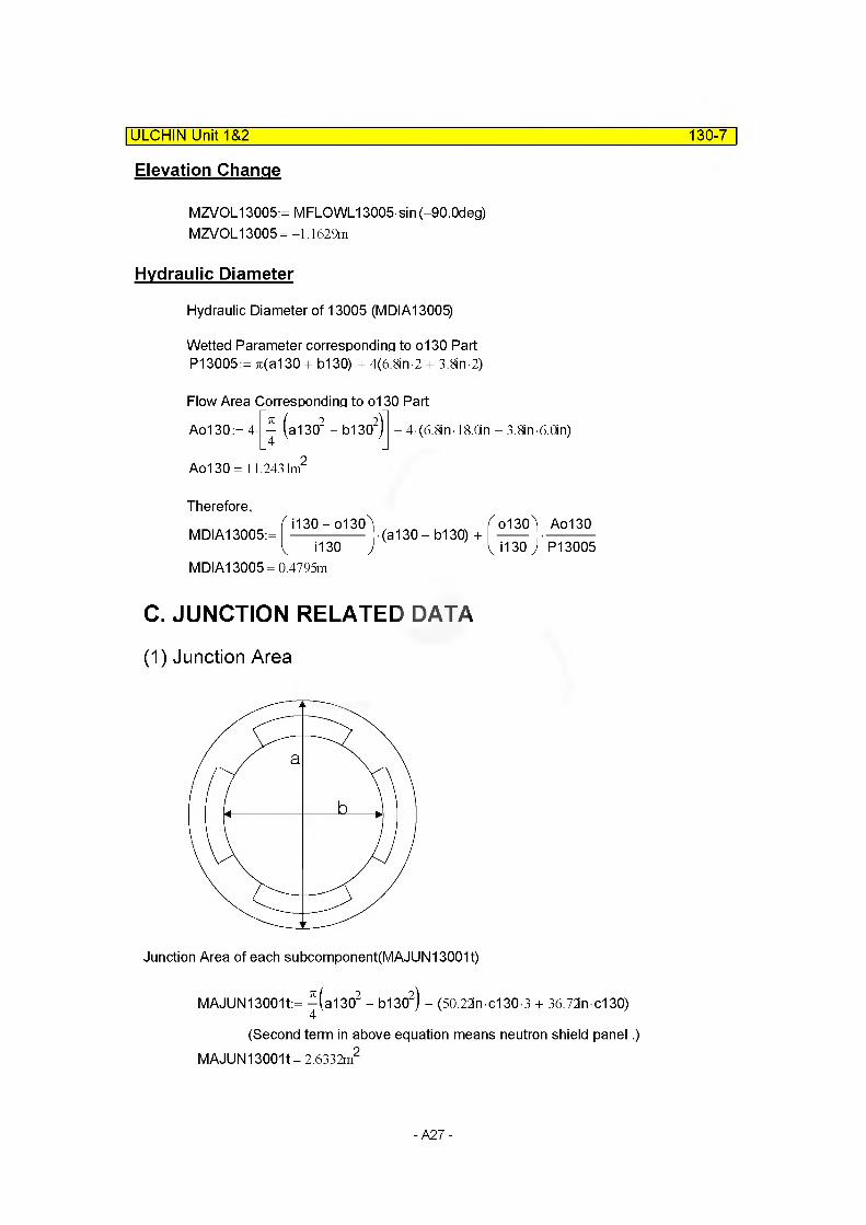
C. JUNCTION RELATED DATA
(1) Junction Area
Junction Area of each subcomponent(MAJUN13001t)
MAJUN13001t:= -^(alSO2 - M302) - (50.22n c130-3 + 36.72n c130)
(Second term in above equation means neutron shield panel.) MAJUN13001t= 2.6332m2
-A27-
ULCHIN Unit 1&2 130-8
Junction areas (2—4) of the other junctions are same to junction area 1 (MAJUN13001).
MAJUN13002t:= MAJUN13001t MAJUN13003t:= MAJUN13001t MAJUN13004t:= MAJUN13001t
By the way, It is necessary that we check the flow area of each
MFLOWA13001 = 2.7337m2
M FLO WA13002 = 2.6332m2
M FLO WA13003 = 2.6332m2
M FLO WA13004 = 2.6332m2
M FLO WA13005 = 2.8273m2
We can find that each flow area is slightly different from one other, even more from junction areas.And it is not prefereable to use the above MAJUN13001-04.
Instead, it is more reasonable to use default junction area, because the default is the minimum area in from- and to-volumes.
MAJUN13001 := 0.MAJUN13002:= 0.MAJUN13003:= 0.MAJUN 13004:= 0.
(2) Loss Coefficient
Forward Loss Factor for Junction 1
Calculation of Loss Factor by Diag. 3-0 (Idelchik, 1986)
Area of two sections related with repect to iucntion 13001 F0j13001 := ^(alSO2 - b1302) - (50.22nc130-3) - (36.72nc130)
F0j13001 = 2.6332m2
4
F1j13001 = 2.8750m2
Loss factor is caculated as
KF13001 = 4.2048x 10"
-A28-
ULCHIN Unit 1&2 130-9
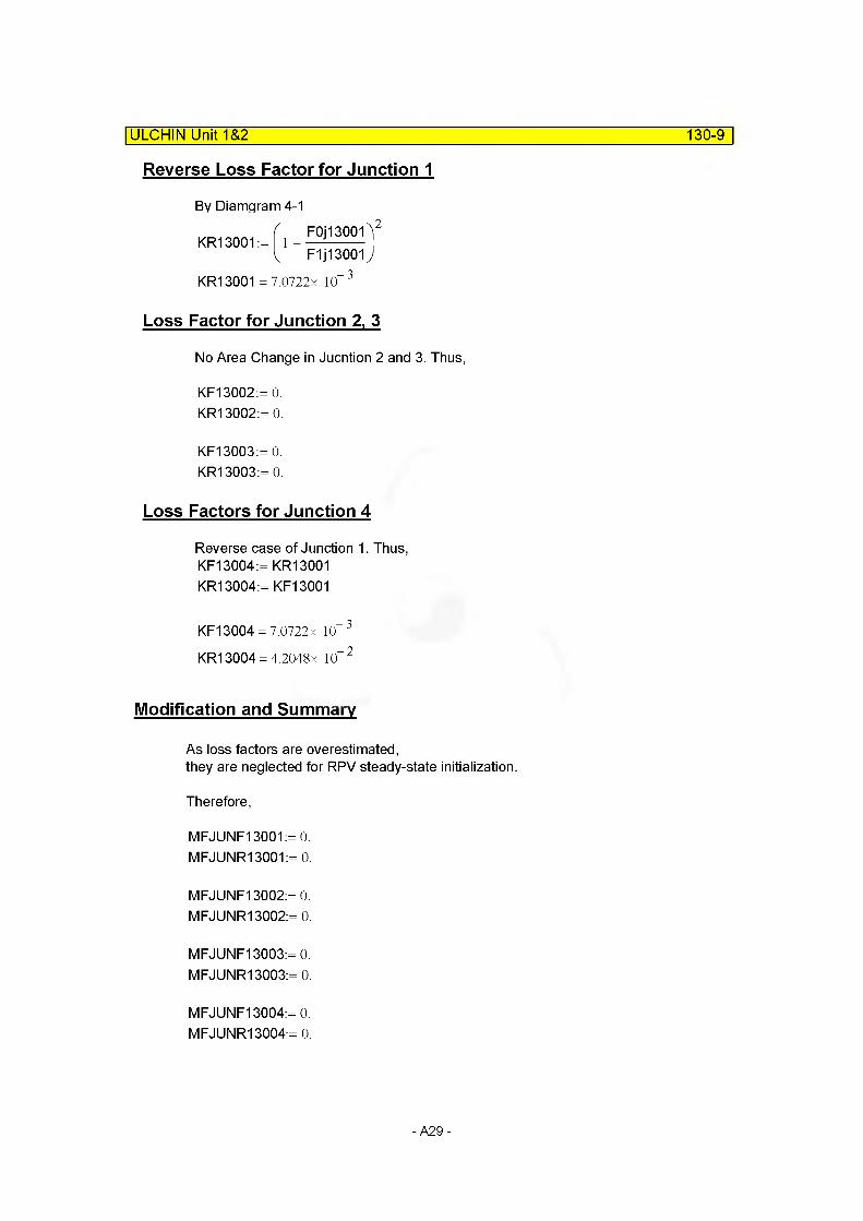
Reverse Loss Factor for Junction 1
By Diamgram 4-1
KRiaOOlJ,- 2
L F1 j1 3001 JKR13001 = 7.0722x 10“ 3
Loss Factor for Junction 2, 3
No Area Change in Jucntion 2 and 3. Thus,
KF13002:= 0.KR13002:= 0.
KF13003:= 0. KR13003:= 0.
Loss Factors for Junction 4
Reverse case of Junction 1. Thus, KF13004:= KR13001 KR13004:= KF13001
KF13004 = 7.0722x 10“ 3
KR13004 = 4.2048x 10“ 2
Modification and Summary
As loss factors are overestimated,they are neglected for RPV steady-state initialization.
Therefore,
MFJUNF13001:= 0.MFJUNR13001:= 0.
MFJUNF13002:= 0.MFJUNR13002:= 0.
MFJUNF13003:= 0.MFJUNR13003:= 0.
MFJUNF13004:= 0.MFJUNR13004:= 0.
-A29-

ULCHIN Unit 1&2 130-10
D. SUMMARY OF DATA
component type ANNULUS
(1) VOLUME RELATED DATA : 5 Subvolumes
Volume 1
MFLOWL13001 = 0.9198m
MFLOWA13001 = 2.7337m2 Default
MV13001 = 2.5144m3
MDIA13001 = 0.4703m MZVOL13001 = -0.9198mVolume Flag =000000 Default
Volume 2~3
MFLOWL13002 = 1.2192m
M FLO WA13002 = 2.6332m2
MV13002 = 3.2104m3
MDIA13002= 0.4570m MZVOL13002=-1.2192m Volume Flag = 000000
MFLOWL13003 = 1.2192m
M FLO WA13003 = 2.6332m2
MV13003 = 3.2104m3
MDIA13003= 0.4570m MZVOL13003= -1.2192m
Volume 4
MFLOWL13004 = 0.7185m M FLO WA13004 = 2.6332m2
MV13004= 1.8920m3
MDIA13004= 0.4570m MZVOL13004=-0.7185m Volume Flag =000000
Default
Default
Default
Default
Default
-A30-

ULCHIN Unit 1&2 130-11
Volume 5
MFLOWL13005 = 1.1629m
MFLOWA13005 = 2.8273m2 Default
MV13005 = 3.2879m3
MDIA13005= 0.4795m MZVOL13005=-1.1629mVolume Flag =000000 Default
(2) JUNCTION RELATED DATA : 4 Junctions
Junction 1~4
from component : internal junctionto component : internal junctionMAJUN13001 = 0.0000 DefaultMFJUNF13001 = 0.0000 DefaultMFJUNR13001 = 0.0000 DefaultJunction Flag =0000 Default
MAJUN 13002 =0.0000 DefaultMFJUNF13002= 0.0000 DefaultMFJUNR13002= 0.0000 Default
MAJUN 13003 =0.0000 DefaultMFJUNF13003= 0.0000 DefaultMFJUNR13003= 0.0000 Default
MAJUN 13002 =0.0000 DefaultMFJUNF13003= 0.0000 DefaultMFJUNR13003= 0.0000 Default
- A31 -

E. INPUT| ULCHIN Unit~T&2 130-12
* C130 : Vessel inlet annulus 2 below loop inlet nozzle annulus
* name type1300000 do-1-01 annulus
* number of volumes1300001 5
* area 1300101 0.0
* j-area 1300201 0.0
* length 1300301 0.9198 1300302 1.2192 1300303 0.7185 1300304 1.1629
* voIume 1300401 2.5144 1300402 3.2104 1300403 1.8920 1300404 3.2879
* xx 1300501 0.0
* angle 1300601 -90.
no of voI 5
no of junction 4
no of vol 1345
no of vol 1345
no of vol 5
no of vol 5
no of volelev. 1300701 -0.9198 1 1300702 -1.2192 3 1300703 -0.7185 4 1300704 -1.1629 5
rough dhydr. no of vol1300801 1 .e-4 0.4703 11300802 1 .e-4 0.4570 41300803 1 .e-4 0.4795 5
kforw kbackw no of jun1300901 0.0 0.0 4
v-flag no of vol1301001 00000 5
j-flag no of jun1301101 000000 4
cnt r I pres temp no of vo1301201 3 158.6e5 560.45 0.0 0.0 0.0 11301202 3 158.6e5 560.45 0.0 0.0 0.0 21301203 3 158.6e5 560.45 0.0 0.0 0.0 31301204 3 158.6e5 560.45 0.0 0.0 0.0 41301205 3 158.6e5 560.45 0.0 0.0 0.0 5
cnt r I1301300 1
water flow steamflow no of jun1301301 13960.2 0 .0 0 .0 4
A32 -
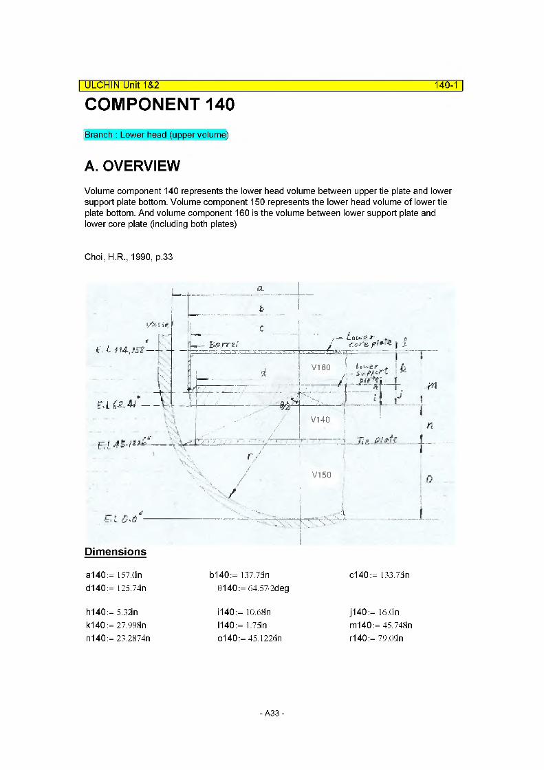
COMPONENT 140| ULCHIN Unit 1&2 140-1
Branch : Lower head (upper volume)
A. OVERVIEWVolume component 140 represents the lower head volume between upper tie plate and lower support plate bottom. Volume component 150 represents the lower head volume of lower tie plate bottom. And volume component 160 is the volume between lower support plate and lower core plate (including both plates)
Choi, H.R., 1990, p.33
a.
b
C
/ ' \ l7-. . v ir - ----- --- j,"—-----j------
V,M \k
u
- \ \vrEl! ----------- s“
V 1] ; :. - ^ 3r-i;r , .... 7
IV140
m
cs. r//
■ 5V
iJ i
nJ\S. .
Vl 50 0
Dimensions
a140:= 157.On d140 := 125.74n
b140 := 137.75n c140:= 133.75n6140:= 64.57-2deg
hi 40 := 5.32in k140 := 27.998n n140 := 23.2874n
1140:= 10.68n 1140:= 1.75lno140:= 45.122dn
j140 := 16.On m140:= 45.748n r140:= 79.09n
-A33-
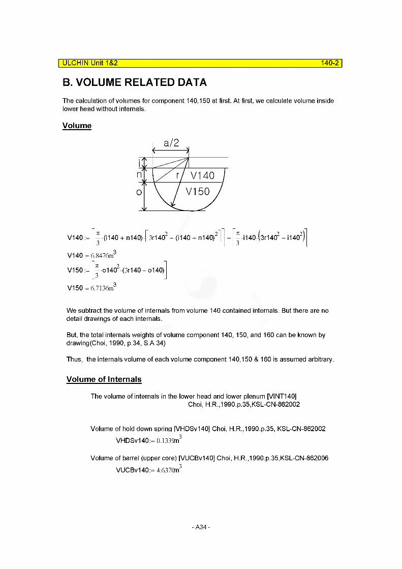
B. VOLUME RELATED DATA
ULCHIN Unit 1&2______________________________________________________ 140-2
The calculation of volumes for component 140,150 at first. At first, we calculate volume inside lower head without internals.
Volume
I7 V140V150
V140
V140
V150
V150
j (1140 + n140) [sr14(f - (1140 + n140)2]
6.847^
^•o1402 (3r140-o140)
6.713^
— H40 (3r1402 - H402)3 V ’
We subtract the volume of internals from volume 140 contained internals. But there are no detail drawings of each internals.
But, the total internals weights of volume component 140, 150, and 160 can be known by drawlng(Choi, 1990, p.34, S.A 34)
Thus, the internals volume of each volume component 140,150 & 160 is assumed arbitrary.
Volume of Internals
The volume of internals in the lower head and lower plenum [VINT140]Choi, H.R.,1990.p.35,KSL-CN-862002
Volume of hold down spring [VHDSv140] Choi, H.R.,1990.p.35, KSL-CN-862002 VHDSv140:= 0.1339n3
Volume of barrel (upper core) [VUCBv140] Choi, H.R.,1990.p.35,KSL-CN-862006 VUCBv140:= 4.637Qn3
-A34-
ULCHIN Unit 1&2 140-3
Volume of baffle [VBAFv140l Choi, H.R.,1990.p.35,KSL-CN-862006 VBAFv140 := 1.5889n3
Volume of former [VFORv140l Choi, H.R.,1990.p.35,KSL-CN-862006 VFORv140:= 0.125Qn3
Volume of neutron shield panels [VNSPv140] Choi, H.R.,1990.p.35,KSL-CN-862006 VNSPv140:= 0.8957fn3
Conversional VOL. of TOTAL EST. WT of LOWER internals [VCONv140]Choi,H.R.,1990.p.35,KSL-CN-862006
VCONv140:= 10.5422n3
VINTv140:= VCONv140- f VHDSv140 + VUCBv140 + VBAFv140 ... ^VFORvI 40 + VNSPvl 40 J
VI NTv140= 3.1617m3
So, VINTv140 is summation volumes of internals, That is, lower core (plate, support columns, support) tie plates, instrumentation guides and secondary core support.
Volume of Component 160 with Internals
Volume of component 160 [V1601 with internals
V160:= ^(b140)2m140
V160 = 11.1724m3
Total volume of lower head & lower plenum with internals
VTv140:= V140 + V150 + V160
VTv140= 24.7335m3
Total water volume without internals [VWTv140|
VWTv140:= VTv140- VINTv140
VWTv140= 21.5718m3
-A35-
ULCHIN Unit 1&2 140-4
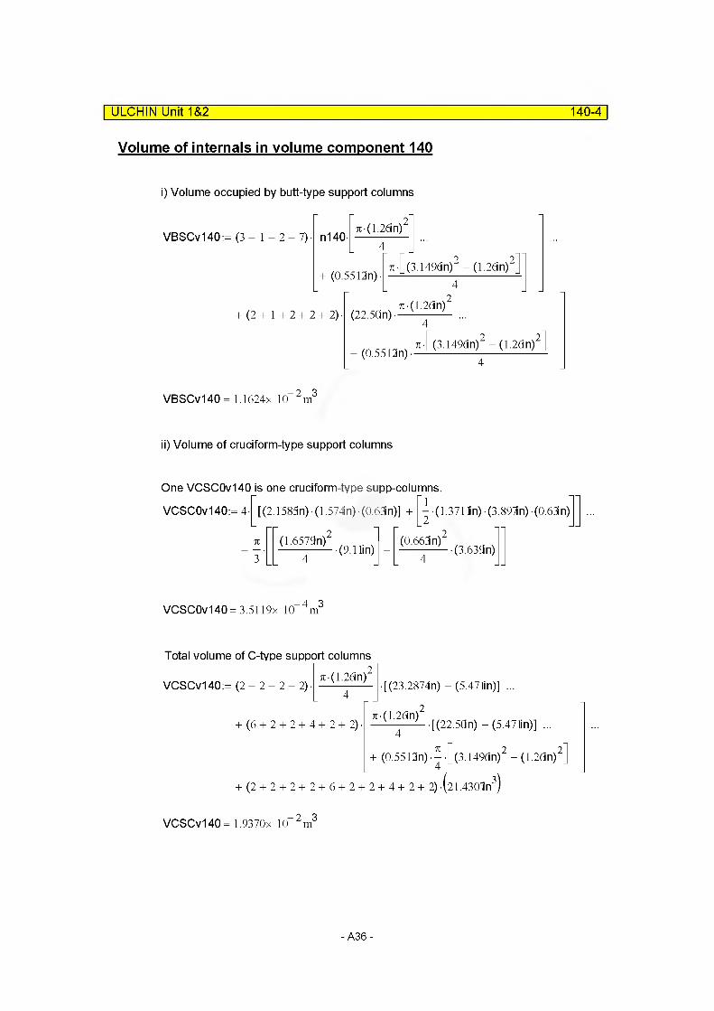
Volume of internals in volume component 140
i) Volume occupied by butt-type support columns
.2VBSCv140:= (3 + 1 + 2 + 7) n140
7t • (1.2(3 n)
+ (0.5512n)7r-[(3.1496n)2 - (1.26in)2
+ (2 + 1 + 2+ 2+2) (22.50n)7i • (1,2(3n)
+ (0.5512n)7t [(3.149dn)2 - (1.26n)2
VBSCv140= 1.1624x 10 2m3
ii) Volume of cruciform-type support columns
One VCSC0v140 is one cruciform-type supp-columns.
VCSC0v140:= 4- [(2.158fin) (1.574in) (0.63n)] +1
• (1.371 lin) • (3 897in) • (0.63in)
71(1.6579n)2 ^ (0.663n)2 ^ ^
+ —•
34 (9.1 lin) -(3.63bln)
VCSC0v140= 3.5119x 10 4m3
Total volume of C-type support columns7t-< i /(in'2
VCSCv140:= (2 + 2 + 2 + 2)7t(1.26in)
+ (6+2 + 2+ 4+ 2+2)
[(23.2874n) - (5.471in)] ...
.27t(1.26in)• [(22.5Qn) - (5.471in)] ...
4-k+ (0.5512n) •[_(3.1496n)2 - (1.26in)2
+ (2 + 2 + 2+ 2+ 6 + 2 + 2+ 4+ 2+2) -\21.4307n•(21.4302n3)
VCSCv140= 1.9370x 10 2m3
-A36-
ULCHIN Unit 1&2 140-5
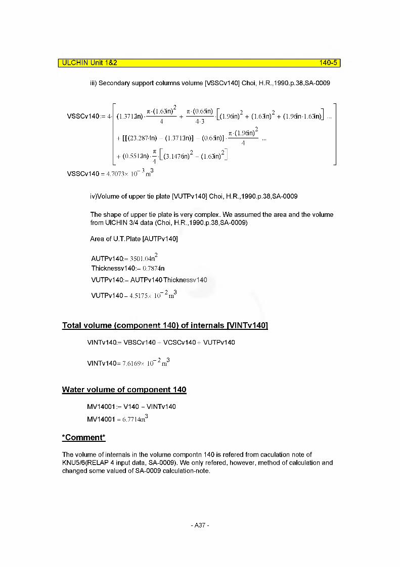
iii) Secondary support columns volume [VSSCv140] Choi, H.R.,1990.p.38,SA-0009
VSSCv140:= 4- (1.3712n)-
7i(1.96n)+ [[(23.2874n) - (1.3712n)] - (0.63n)] —-------- -
VSSCv140 = 4.7073x 10 3m3
iv)Volume of upper tie plate [VUTPv140] Choi, H.R.,1990.p.38,SA-0009
The shape of upper tie plate is very complex. We assumed the area and the volume from UICHIN 3/4 data (Choi, H.R.,1990.p.38,SA-0009)
Area of U.T.PIate [AUTPv140]
AUTPv140:= 3501.04n2
Thicknessv140:= 0.7874n
VUTPv140:= AUTPv140Thicknessv140
VUTPv140= 4.5175x 10“ 2 m3
Total volume (component 140) of internals IVINTv1401
VINTv140:= VBSCv140 + VCSCv140 + VUTPv140
VINTv140= 7.6169x 10“ 2m3
Water volume of component 140
MV14001 := V140 - VINTv140 MV14001 = 6.7714m3
*Comment*
The volume of internals in the volume compontn 140 is refered from caculation note of KNU5/6(REI_AP 4 input data, SA-0009). We only refered, however, method of calculation and changed some valued of SA-0009 calculation-note.
-A37-
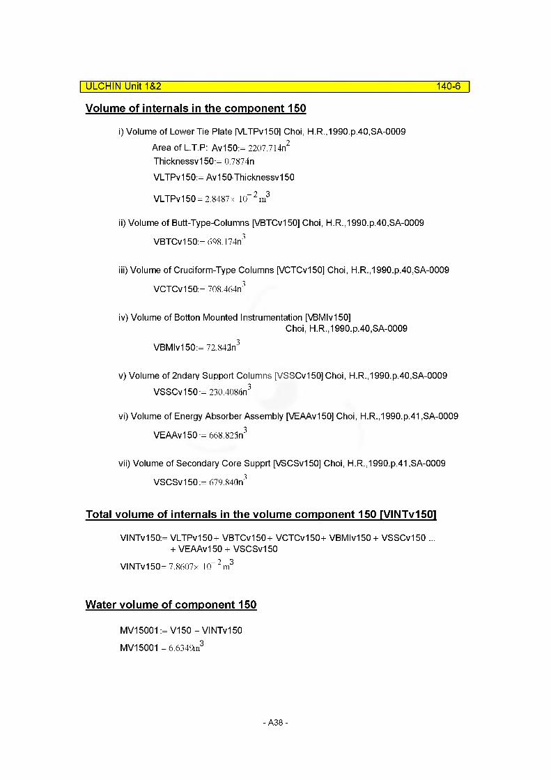
Volume of internals in the component 150
i) Volume of Lower Tie Plate [VLTPv150l Choi, H.R.,1990.p.40,SA-0009Area of L.T.P: Av150:= 2207.714n2
Thicknessv150:= 0.7874n
VLTPvl 50:= Av150Thicknessv150
VLTPvl 50 = 2.8487 x 10“2m3
II) Volume of Butt-Type-Columns [VBTCvl 50] Choi, H.R.,1990.p.40,SA-0009
VBTCvl 50:= 698.174n3
ill) Volume of Cruciform-Type Columns [VCTCv150] Choi, H.R.,1990.p.40,SA-0009
VCTCv150:= 708.464n3
iv) Volume of Botton Mounted Instrumentation [VBMIv150]Choi, H.R.,1990.p.40,SA-0009
VBMIv150:= 72.842n3
v) Volume of 2ndary Support Columns [VSSCv150] Choi, H.R.,1990.p.40,SA-0009VSSCv150:= 230.4086n3
vi) Volume of Energy Absorber Assembly [VEAAv150] Choi, H.R.,1990.p.41 .SA-0009
VEAAvl 50 := 668.825n3
vii) Volume of Secondary Core Supprt [VSCSvl 50] Choi, H.R.,1990.p.41,SA-0009
VSCSv150:= 679.840n3
Total volume of internals in the volume component 150 IVINTv1501
VINTv150:= VLTPvl50+ VBTCvl50+ VCTCv150+ VBMIv150 + VSSCv150 ...+ VEAAvl 50 + VSCSvl 50
VINTv150= 7.8607x 10“ 2 m3
Water volume of component 150
MV15001 := V150 - VINTv150 MV15001 = 6.6349m3
ULCHIN Unit 1&2_____________________________________________________ 140-6
-A38-
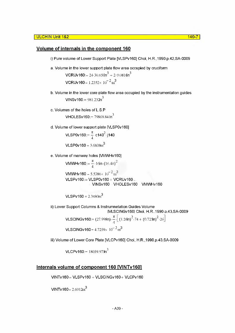
Volume of internals in the component 160
i) Pure volume of Lower Support Plate [VLSPv160] Choi, H.R.,1990.p.42,SA-0009
a. Volume in the lower support plate flow area occupied by cruciformVCRUv160:= 24-30.650n3 + 2-9.0816n3
VCRUv160= 1.2352x 10“2m3
b. Volume in the lower core plate flow area occupied by the instrumentation guidesVINSv160:= 981.232n3
c. Volumes of the holes of L.S.PVHOLESv160:= 79869.841n3
d. Volume of lower support plate [VLSP0v160]
VLSP0v160:= - c1402 j1404
VLSP0v160 = 3.6838m3
e. Volume of manway holes [VMWHv160]
VMWHv160:= ^16in(16.4in)2
VMWHv160 = 5.5386x 10“2m3
VLSPv160:= VLSP0v160 + VCRUv160 ...+ VINSv160- VHOLESv160 - VMWHv160
VLSPv160 = 2.3480m3
II) Lower Support Columns & Instrumnetation Guides Volume|VLSCINGv160l Choi, H.R.,1990.p.43,SA-0009
VLSCINGv160:= (27.998n)[(1.26n)2-74 + (0.725n)2-26]
VLSCINGv160= 4.7259x 10“ 2m3
ill) Volume of Lower Core Plate [VLCPv160] Choi, H.R.,1990.p.43,SA-0009
VLCPv160:= 18059.973n3
Internals volume of component 160 rVINTv1601
VINTv160:= VLSPv160 + VLSCINGv160+ VLCPv160
VI NTv160= 2.6912m3
ULCHIN Unit 1&2______________________________________________________ 140-7
-A39-

ULCHIN Unit 1&2 140-8
Water volume of component 160 IVWv160l
MV16001 := V160 - VINTV160
MV16001 = 8.4812m
Hydraulic Diameter
Hydraulic diameter of component 140 [MDIA14001]
Flow area=Volume/length
MFLOWL14001 := n140MV14001
MFLOWA14001 :=MFLOWL14001
MFLOWA14001 = 11.4478m
Hydraulic diameter
DAVEv140:= 2-MFLOWA14001
No. of cruciform type support column [av140] av140:= 22
No. of butt-type support column [bv140] bv140:= 26
No. of 2ndary support column [cv140] cv140:= 4
DCRUv14Q= 1.26ft DBTCv14Q= 1.26ft DSSCv140:= 1.96ft
Total volume occupied by columns [VTCOLv140] VTCOLv140:= 1263.96n3 + 778.81in3 + 317.82n3
ACOLv140:=VTCOLv140
MFLOWL14001 ACOLv140= 6.5398x 10“ 2m2
4- (MFLOWA14001 +-ACOLv14QMDIA14001 := —7------ --------------------------------------------
ti-f DAVEv140+ av140DCRUv140...bv140 DBTCvl 40+ cv140DSSCv140
MDIA14001 = 0.5881m
Elevation Change
MZVOL14001 := 23.2874n
-A40-

C. JUNCTION RELATED DATA
(1) Junction Area
| ULCHIN Unit 1&2 140-9
Junction area 1[MAJUN14001]: DefaultMAJUN14001 := MFLOWA13001 MAJUN14001 = 2.7337m2
Junction area 2[MAJUN14002]: Default
6.6349n oMAJUN14002:=------------ MAJUN14002= 5.789hn
1.1461m
Junction area of junctions [MAJUN14003] Choi, H.R.,1990,p.45,SA-0009=[Flow area of the lower (core) support plate]
VHOLESv160 oMAJUN 14003:=------------------- MAJUN14003= 3.2206ni
j140
(2) Loss Coefficient (MFJUN14003)
Loss factor (MFJUN14003) of Junction 3Junction 3 accounts for the flow resistance of the lower support plate.
Diag. 8-4 (ldelchik.1986)
Forward Loss Factor
MFLOWA14001 = 11.4478m2
MFLOWA14003 := MAJUN14003
There are many holes with various diameters in the lower core plate.Therefore we used the average diameter of holes in the application of flow resistance calculation
DAVGj140:= 7.783n
Ij140 := 16.0in
In application
fBARj140:=M FLO WA14003 MFLOWA14001
x j 14 0: = 0.044MFLOWA14003
Dhj140:=-------------------------7i(DAVGj140) -96
Ij140
Dhj1401.8809
fBARj140 = 0.2813
Dhj140 = 0.2161m
- A41 -

ULCHIN Unit 1&2 140-10
By diagram 8-4Coj140:= (o.5 + xj140-V 1 + -fBARj14o)(l + -fBARj140) + (1 + -fBARj140)2
Coj140 =0.9002 >j140:= 0.02
( Ij140 ) 1140:= Coj140+Xj140—-------------------------v Dhj140j
qi40= 11.8497 MFJUNF014003:= y 140
Reverse loss factor
Flow area of component 160 [MFLOWA160]276.929^
MFLOWA160 :=-------------(45.748n)
MFLOWA160 = 6.7485m2
Flow area of lower core support plate [MFLOWA150] MFLOWA150 := MAJUN14003MFLOWA150 = 3.2206m2
In Application
fBARj160:=
fBARj160 = 0.4772
MFLOWA150MFLOWA160
y0j160:= (o.5 + xj140-V 1 -fBARj160) (l -fBARj160) + (1 - fBARj160)2
C0j160 =0.5498
MFJUNR014003:= C0J160 + Xj140 —------ ------------------v Dhj140j fBAtW
MFJUNR014003= 2.5793
Forward loss factor(MFJUNF014001)
MFJUNF014003= 11.8497
Reverse loss factor(MFJUNR014003)
MFJUNR014003= 2.5793
# As loss factors are overestimated, pressure drop is large.
So, we apply other diagram of Idelchik (1986) to calculate them. The procedures are shown in the next pages.
-A42-
Forward Loss Factor
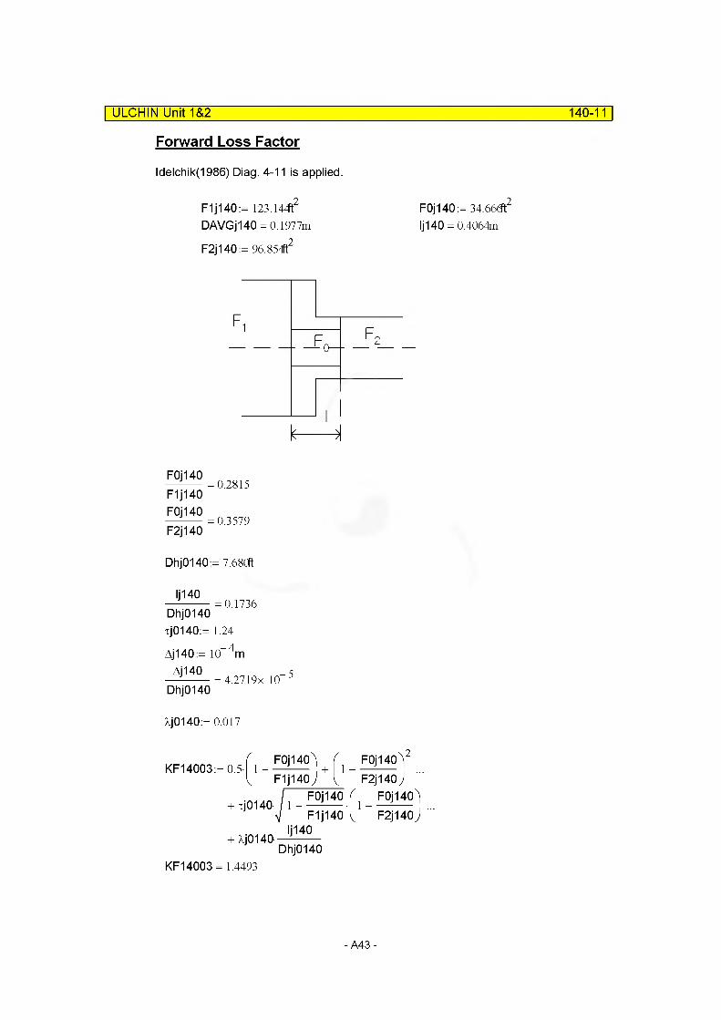
ldelchik(1986) Diag. 4-11 is applied.
F1j140 := 123.144t2 F0j140:= 34.66(ft2
DAVGj140 = 0.1977m Ij140 = 0.4064m
F2j140 := 96.854ft2
ULCHIN Unit 1&2_____________________________________________________ 140-11
k---------H
F0J140
F1j140 F0J140
F2j140
0.2815
0.3579
Dhj0140 := 7.68Cft
Ij140 Dhj0140
0.1736
xj0140:= 1.24
Aj140 := 10 4m
Aj140—-------- = 4.2719x 10Dhj0140
5
Xj0140:= 0.017
KF14003:= 0.5-F0j140\r F1j140 ) L
+ xj0140-
+ XJ0140-
L F0j140 fv F1j140\
Ij140Dhj0140
F0j140)2
F2j140 ) F0j140)
~ F2j140J "
KF14003= 1.4493
-A43-

ULCHIN Unit 1&2 140-12
Reverse loss factor
F1j0140:= F2j140 F0j0140:= F0j140 F2j0140 := F1 j140
F0j0140
F1J01400.3579
F0J0140
F2J01400.2815
KR14003:= 0.5-f 1 -L F1 j0140)
^ F2j0140) V F1 j0140 ^ F2j0140jIj140
+ XJ0140—--------Dhj0140
KR14003 = 1.5541
Modification of loss factors
Through the sample run of RPV. steady-state calculation loss factors were modified
MFJUNF14001:= 0.001 MFJUNF14002:= 0.0025 MFJUNF14003:= 1.600
MFJUNR14001:= 0.0005 MFJUNR14002:= 0.01 MFJUNR14003:= 1.5
D. SUMMARY OF DATAcomponent type = branch
(1) VOLUME RELATED DATA : 1 Subvolume
Volume 1
MFLOWL14001 = 0.5915m
MFLOWA14001 = 11.4478m2 Default
MV14001 = 6.7714m3
MDIA14001 = 0.5881m MZVOL14001 = 0.5915m
-A44-

140-13
(2) Junction related data : 3 Junctions
Junction 1
| ULCHIN Unit 1&2
from component : 130050000to component : 140010000MAJUN14001 = 2.7337m2 Default
Junction Flag :00100 Abrupt area changeMFJUNF14001:= 0.0 MFJUNR14001:= 0.0
Junction 2from component : 150010000to component : 140000000MAJUN14002= 5.7891m2 Default
Junction Flag :00100 Abrupt area changeMFJUNF14002:= 0.0 MFJUNR14002:= 0.0
Junction 3from component : 140010000to component : 160000000MAJUN14003= 3.2206m2
Junction Flag :0000MFJUNF14003= 1.6000 Modified into 1.9MFJUNR14003= 1.5000 Modified into 2.6
E. INPUT
* C140 : lower plenum 2
name type1400000 Iow-p12 branch
no of jun cnt r I1400001 3 1
area length vol x angle elev rough dh1400101 0.0 0.5915 6.7714 0. +90. 0.5915 1.e-4 0.5881 1
cnt r I pres temp1400200 3 159.0e5 560. 45
from to area kforw kbackw j f1ag1401101 130010000 140010000 0.0 0.001 0.0005 0001001402101 150010000 140000000 0.0 0.002 0.01 0001001403101 140010000 160000000 3.2206 1.900 2.6 000000
waterflow steamflow X1401201 13960.2 0.0 0.01402201 0.0 0.0 0.01403201 13960.2 0.0 0.0
-A45-
COMPONENT 150
ULCHIN Unit 1&2_____________________________________________________ 150-1
Singvol: Lower head (lower volume)
A. OVERVIEWSee page 140-1.
B. VOLUME RELATED DATA
Volume
Water volume of component 150 [VW150]page 140-7 MV15001 = 6.6349m3
Flow length
MFLOWL15001 := 1.1461m
Flow area
MFLOWA15001 :=MV15001
MFLOWL15001
Elevation change
MZVOL15001 := 45.122dn (Reference, Vessel Center Line)
Hydraulic diameter
MDIA15001:= MAJUN14002
C. JUNCTION RELATED DATA
N/A
-A46-
D. SUMMARY OF DATAcomponent type = snglvol
(1) VOLUME RELATED DATA : 1 Subvolume
MFLOWL15001 = 1.1461m
MFLOWA15001 =5.7892m2 Default
MV15001 = 6.6349m3
MDIA15001 = 5.7891m2
MZVOL15001 = 1.1461m
ULCHIN Unit 1&2______________________________________________________150-2
E. INPUT
* C150 : lower plenum 1
name type1500000 Iow-pI'1 snglvol
area length vol x angle el ev rough dh vf lag1500101 0.0 1.1451 6.6349 0.0 +90. 1.1461 1 .e-4 0.0 00000
cnt r I pres temp1500200 3 159.2e5 560.45
-A47-

COMPONENT 160Branch : Core inlet
| ULCHIN Unit 1&2 160-1
A. OVERVIEW
See page 140-1.
The fuel of ULCHIN 1/2 or YGN 1&2 is Vantage 5H.However, since the data related to component 160 is not available, the available data of OFA or KWU was adopted.
But, it is expected that the part related to component 160 is not far different from each other.
B. VOLUME RELATED DATA
(1) Subcomponent 1
Volume
Water volume of component 160 [MV160] p.140-9MV16001 = 8.4812m3
.998(28
Ref. Choi, H.R., 1990, p.55
L160v1:= 16in L160v2:= 27.998n L160v3:= 1.75n
Flow Length
MFLOWL16001 := L160v1 + L160v2+ L160v3 MFLOWL16001 = 1.1620m
-A48-
ULCHIN Unit 1&2 160-2
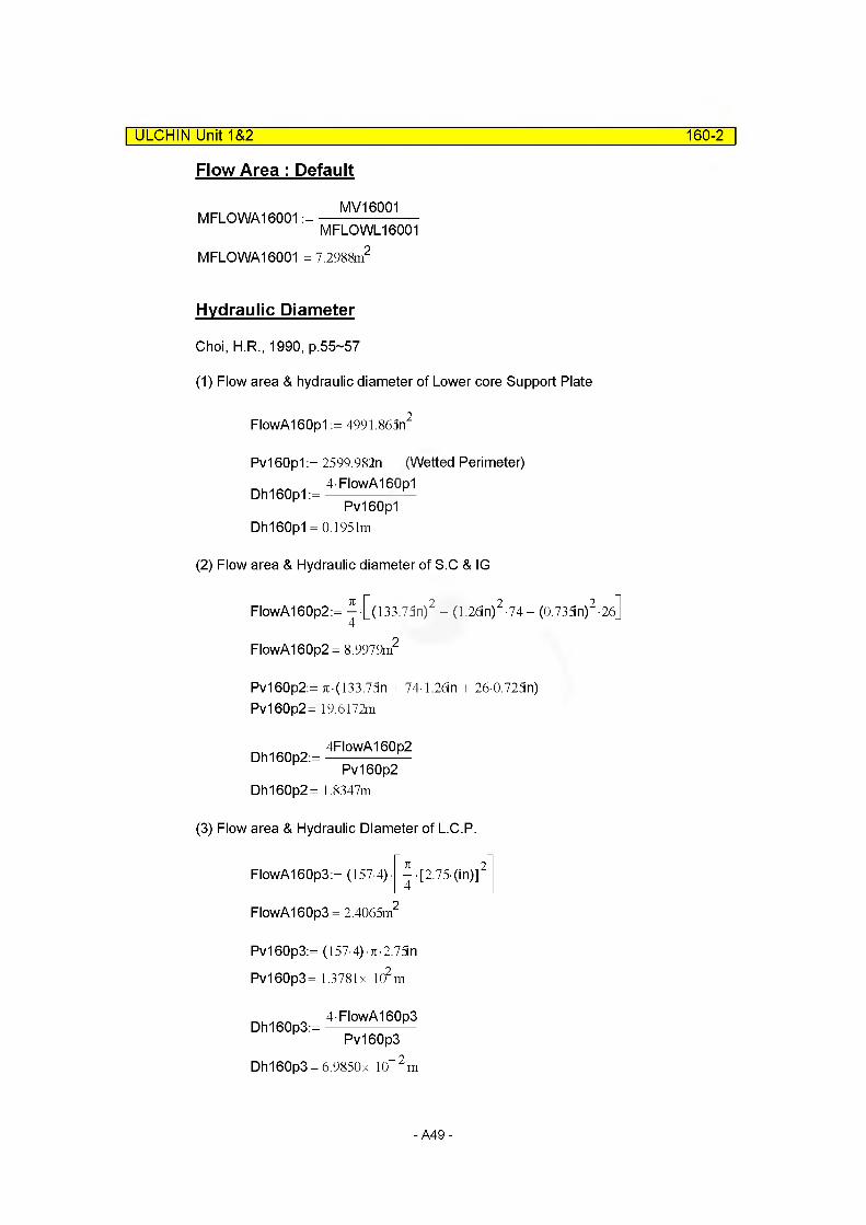
Flow Area : Default
MFLOWA16001 :=MV16001
MFLOWL16001
MFLOWA16001 = 7.2988m
Hydraulic Diameter
Choi, H.R., 1990, p.55~57
(1) Flow area & hydraulic diameter of Lower core Support Plate
FlowA160p1:= 4991.865n2
Pv160p1:= 2599.982n (Wetted Perimeter)4FlowA160p1
Dh160p1:=---------------- —Pv160p1
Dh160p1 = 0.1951m
(2) Flow area & Hydraulic diameter of S.C & IG
FlowA160p2:= ^ [(133.75n)2 - (1.26m)2-74- (0.735in)2-2o]
FlowA160p2= 8.9979m2
Pv160p2:= 7i(133.75n + 74 1.2dn + 260.725n)Pv160p2= 19.6172m
4FlowA160p2Dh160p2:=--------------- —
Pv160p2Dh160p2= 1.8347m
(3) Flow area & Hydraulic Diameter of L.C.P.
FlowA160p3:= (157-4) - ^ [2 75-(in)]2
FlowA160p3 = 2.4065m2
Pv160p3:= (157 4) % 2.75in
Pv160p3= 1.3781x 10² m
4FlowA160p3Dh160p3:=---------------- —
Pv160p3Dh160p3= 6.9850x 10“2m
-A49-

Let's check the basic paramters.MFLOWA160 = 6.7485m2 p.140-10
L160v1 = 0.4064m L160v2= 0.7111m
L160v3= 4.4450x 10“2m
ULCHIN Unit 1&2_____________________________________________________ 160-3
Consoliating all the hydraulic diameters above,
(MFLOWL160/MDIA16001)=
MFLOWL160 over MDIA16001:=L160v1 MFLOWA160
Dh160p1 FlowA160p1L160v2 MFLOWA160
+ •Dh160p2 FlowA160p2L160v3 MFLOWA160
Dh160p3 FlowA160p3MFLOWL160 over MDIA16001= 6.4409
MFLOWL16001Thus,
MDIA16001 := —MFLOWL160_over_MDIA16001
MDIA16001 =0.1804m
Elevation Change
MZVOL16001 := MFLOWL16001 sin (90deg) MZVOL16001 = 1.1620m
C. JUNCTION RELATED DATA
(1) Junction Area
Junction 1 area
i) for OFA(W)
Bottom nozzles area of fuel assemblies in the core[MAJUN16001OFA](Choi, H.R.,1990, p.58, KSL-CN-863008)
MAJUN16001OFA:= 22.96-in2-157
ii) for KWU FUEL assembly(Choi, H.R.,1990, p.58, B121/B111/85/183)
MAJUN16001 KWU:= 143.7cm2 157
# Above junction area is determined based on the bottom nozzle flow area, that is the most restricted area.
-A50-
ULCHIN Unit 1&2 160-4
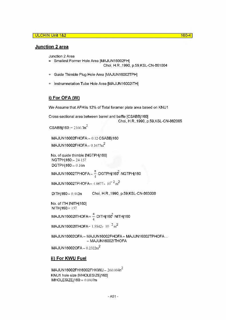
Junction 2 area
Junction 2 Area= Smallest Former Hole Area [MAJUN16002FH]
Choi, H.R.,1990, p.59,KSL-CN-861004
+ Guide Thimble Plug Hole Area [MAJUN16002TPH]
+ Instrumnetation Tube Hole Area [MAJUN16002ITH]
i) For OFA (W)
We Assume that AFH is 12% of Total foramer plate area based on KNU1
Cross-sectional area between barrel and baffle [CSABBj160]Choi, H.R.,1990, p.59,KSL-CN-862005
CSABBj160:=2l66.ln2
MAJUN16002FHOFA:= 0.l2CSABBj160 MAJUN16002FHOFA= 0.1677m2
No. of guide thimble [NGTPHj160]NGTPHj160:= 24-157 DGTPHjl 60:= 0.16m
MAJUN16002TPHOFA:=^DGTPHj16C?NGTPHj160
MAJUN16002TPHOFA= 4.8877x 10“2m2
DITHjl60:= 0.442in Choi, H.R.,1990, p.59,KSL-CN-863008
No. ofITH [NITHj160]NITHj160:= 157
MAJUN16002ITHOFA=^DITHj16(?NITHj160
MAJUN16002ITHOFA= 1.5542x 10“2m2
MAJUN160020FA:= MAJUN16002FHOFA+ MAJUN16002TPHOFA... + MAJUN16002ITHOFA
MAJUN160020FA= 0.2322m2
ii) For KWU Fuel
MAJUN16002FH16002FHKWU:=260.004n2
KNU1 hole size [MHOLESIZEj160]MHOLESIZEj160:= O.OOOTn
- A51 -
ULCHIN Unit 1&2_________________________________________________________ 160-5
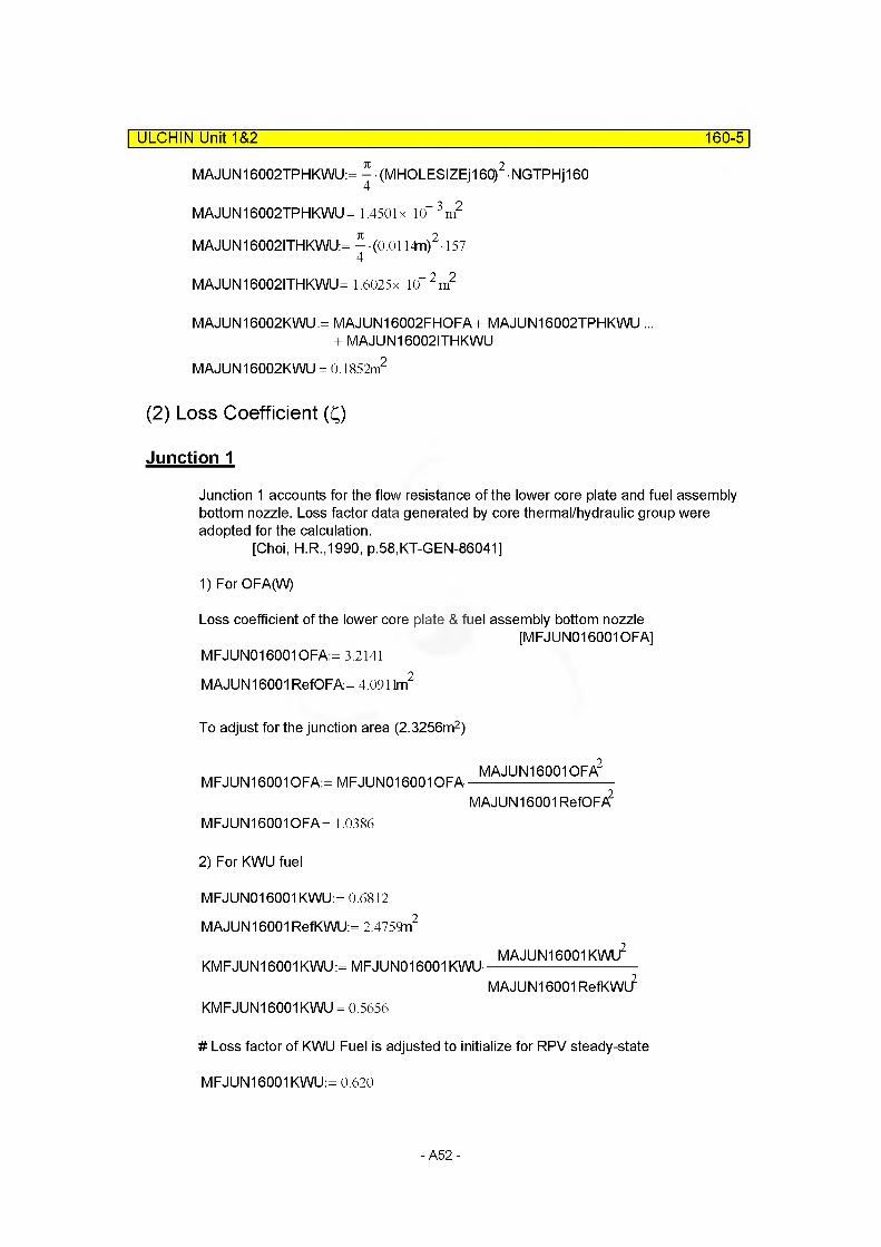
MAJUN16002TPH KWU: = ^ • (MHOLESIZEjl 60)2 • NGTPHjl 60
MAJUN16002TPHKWU= 1.4501x 10“ 3m2
MAJUN16002ITHKWU: = ^ (0.0114n)2-157
MAJUN16002ITHKWU= 1.6025x 10“2m2
MAJUN16002KWU:= MAJUN16002FHOFA+ MAJUN16002TPHKWU ...+ MAJUN16002ITHKWU
MAJUN16002KWU = 0.1852m2
(2) Loss Coefficient (Q
Junction 1
Junction 1 accounts for the flow resistance of the lower core plate and fuel assembly bottom nozzle. Loss factor data generated by core thermal/hydraulic group were adopted for the calculation.
[Choi, H.R.,1990, p.58,KT-GEN-86041]
1) For OFA(W)
Loss coefficient of the lower core plate & fuel assembly bottom nozzle[MFJUN016001OFA]
MFJUN016001 OFA:= 3.2141
MAJUN16001 RefOFA= 4.0911m2
To adjust for the junction area (2.3256m2)
MFJUN16001OFA:= MFJUN016001 OFAMAJUN16001 OFA2
MAJUN16001 RefOF/5?
MFJUN16001 OFA = 1.0386
2) For KWU fuel
MFJUN016001 KWU:= 0.6812
MAJUN16001 RefKWU:= 2.4759n2
KMFJUN16001 KWU := MFJUN016001 KWU-MAJUN16001 KWU2
MAJUN16001 RefKWL?
KMFJUN16001 KWU = 0.5656
# Loss factor of KWU Fuel is adjusted to initialize for RPV steady-state
MFJUN16001 KWU:= 0.620
-A52-
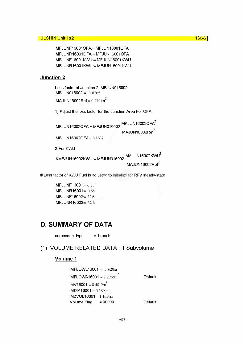
ULCHIN Unit 1&2 160-6
MFJUNF16001 OFA:= MFJUN160010FA MFJUNR160010FA:= MFJUN160010FA MFJUNF16001KWU:= MFJUN16001KWU MFJUNR16001 KWU:= MFJUN16001 KWU
Junction 2
Loss factor of Junction 2 [MFJUN016002] MFJUN016002:= 11.8265
MAJUN16002Ref:= 0.2791m2
1) Adjust the loss factor for the Junction Area For OFA
MFJUN160020FA:= MFJUN016002-MAJUN160020FA2
MAJUN16002Ref
MFJUN160020FA= 8.1832
2)For KWU
KMFJUN16002KWU:= MFJUN016002-MAJUN16002KWU2
MAJUN16002Ref2
# Loss factor of KWU Fuel is adjusted to initialize for RPV steady-state
MFJUNF16001:= 0.85 MFJUNR16001:= 0.85 MFJUNF16002:= 32.6 MFJUNR16002:= 32.6
D. SUMMARY OF DATAcomponent type = branch
(1) VOLUME RELATED DATA : 1 Subvolume
Volume 1
MFLOWL16001 = 1.1620m
MFLOWA16001 = 7.2988m2 Default
MV16001 = 8.4812m3
MDIA16001 =0.1804m MZVOL16001 = 1.1620mVolume Flag = 00000 Default
-A53-
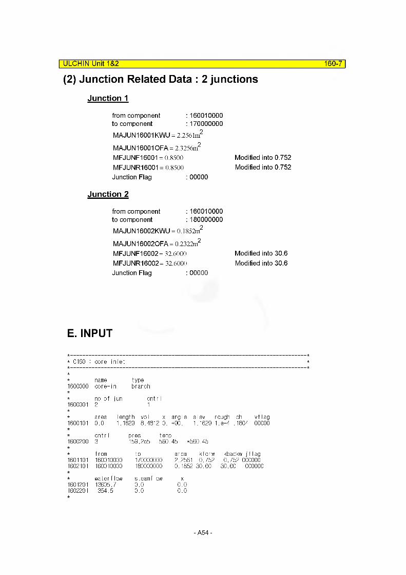
(2) Junction Related Data : 2 junctions| ULCHIN Unit 1&2 160-7
Junction 1
from component : 160010000to component : 170000000MAJUN16001KWU = 2.2561m2
MAJUN16001OFA= 2.3256m2
MFJUNF16001 = 0.8500 Modified into 0.752MFJUNR16001 = 0.8500 Modified into 0.752Junction Flag : 00000
Junction 2
from component : 160010000to component : 180000000MAJUN 16002KWU = 0.1852m2
MAJUN 160020FA= 0.2322m2
MFJUNF16002= 32.6000 Modified into 30.6MFJUNR16002= 32.6000 Modified into 30.6Junction Flag : 00000
E. INPUT
* C160 : core inlet
name type1600000 core-in branch
no of jun cnt r I1600001 2 1
area length vol x angle elev rough dh vflag1600101 0.0 1.1629 8.48120. +90. 1.1629 1.8-4 .1804 00000
cntr I pres temp1600200 3 159.2e5 560. 45 *560.45
from to area kforw kbackw j fIag1601101 160010000 170000000 2.2561 0.752 0.752 0000001602101 160010000 180000000 0.1852 30.60 30.60 000000
waterflow steamflow X1601201 13605.7 0.0 0.01602201 354.5 0.0 0.0
-A54-
COMPONENT 170| ULCHIN Unit 1&2 170-1
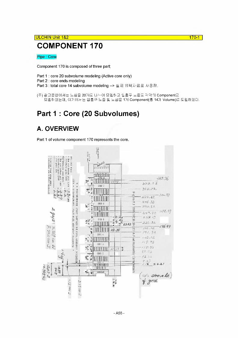
Pipe : Core
Component 170 is composed of three part;
Part 1 : core 20 subvolume modeling (Active core only)Part 2 : core ends modelingPart 3 : total core 14 subvolume modeling -> All 4 ^XI-SS. AlSif.
(4) SUSSOHAHS 448 204* I44CH ei§|2 4*4 48* 444 ComponentsSfljSiabQI, 014 011 AH ^ 4*4 4fi SH 448 14 Components 144 Volume)* SISiaQ.
Part 1 : Core (20 Subvolumes)
A. OVERVIEWPart 1 of volume component 170 represents the core.
5J
- II .! =V> V:
4^^ A
.---- V?-: ? :
ti v
■25 i _i
- A55

-9SV-
ftrf
-■'£ o ■ u —>'//
£Q-i O oi2ZZ2^r P l:>V r /
- o
■r-;< ft/rt-i/v ——■
?7^7"/ /
7 CiC ,£■■'■,' —
v
r ? c i: >■
Wtfjfi fa. -r:'
sv£? v!- "t' ■■- V:
6&P-&M
ZE>
fZZ77
^ / T S" a"
,:-1 ■■■? "j: ■ v/ '/ r? r? ■ -■
'-r- S-- 22
1 3- ■ ■ --■ .Z ^ ■-
r.J£.9@ --r rY C □ >"-
; V■ > - — 1/ / . ’ 5 #
' -7// a: i "
[ J a | aui j
— Sc
■ y^ r^t'7
i-!"z
/:
"7/
//
- -Zi - *
■ -.' T - V
- 5V l} P £■ /
- z" ■"A M V
™ — ■:■■' . 4 / /
yf": :; ■' '■■■■■'
■ =-: ?zz'.o c'
■ ^./Z'XZ :y
— m=vf
PZ?
9k:i 7/ T
75Z /
-
:f,L:. V A ■>"■
yStrr-
[ jaiauij
2-ozi. Z^L 1!UD NIHOin
170-3
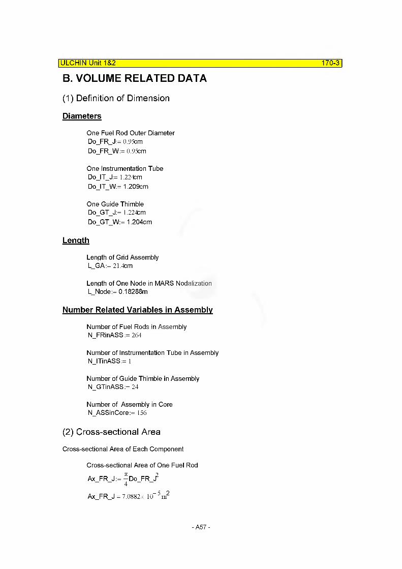
B. VOLUME RELATED DATA
(1) Definition of Dimension
Diameters
One Fuel Rod Outer Diameter Do_FR_J:= 0.95cm Do_FR_W:= 0.95cm
One Instrumentation Tube Do_IT_J:= 1.224cm Do_IT_W:= 1,209cm
One Guide Thimble Do_GT_J:= 1.224cm Do_GT_W:= 1,204cm
Length
Length of Grid Assembly L_GA:= 21.4cm
Length of One Node in MARS Nodalization L_Node:= 0.18288m
Number Related Variables in Assembly
Number of Fuel Rods in Assembly N_FRinASS := 264
Number of Instrumentation Tube in Assembly N_ITinASS:= 1
Number of Guide Thimble in Assembly N_GTinASS:= 24
Number of Assembly in Core N_ASSinCore:= 156
(2) Cross-sectional Area
Cross-sectional Area of Each Component
Cross-sectional Area of One Fuel Rod
Ax FR J:=—Do FR
Ax FR J = 7.0882x 10“ 5 m2
| ULCHIN Unit 1&2
-A57-
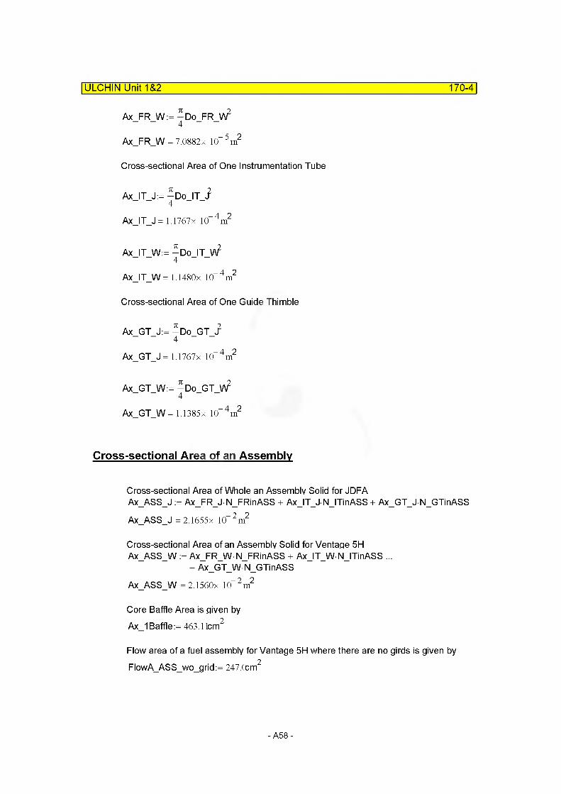
Ax_FR_W := -Do_FR_W2
Ax_FR_W = 7.0882x 10“ 5 m2
Cross-sectional Area of One Instrumentation Tube
Ax_IT_J:= -Do_IT_i
Ax_IT_J = 1.1767x 10“ 4m2
Ax_IT_W:= — Do_IT_V\?
Ax_IT_W= 1.1480x 10“ 4 m2
Cross-sectional Area of One Guide Thimble
Ax_GT_J:= -Do_GT_i
Ax_GT_J= 1.1767x 10“ 4 m2
Ax_GT_W:= -Do_GT_W2
Ax_GT_W= 1.1385x 10“ 4 m2
Cross-sectional Area of an Assembly
Cross-sectional Area of Whole an Assembly Solid for JDFAAx_ASS_J := Ax_FR_J N_FRinASS + Ax_IT_J N_ITinASS + Ax_GT_J N_GTinASSAx_ASS_J =2.1655x 10“ 2 m2
Cross-sectional Area of an Assembly Solid for Ventage 5H Ax_ASS_W := Ax_FR_W• N_FRinASS + Ax_IT_W NJTinASS ...
+ Ax_GT_WN_GTinASSAx_ASS_W = 2.1560x 10“ 2 m2
Core Baffle Area is given by Ax_1 Baffle := 463.11cm2
Flow area of a fuel assembly for Vantage 5H where there are no girds is given by FlowAASSwogrid := 247.0cm2
ULCHIN Unit 1&2_______________________________________________________170-4
-A58-

(3) Volume of Solid Component
Volume of Each Solid Component
Volume of Guide Thimbles for each Node over the Core
V GT Node:= — Do GT V\? N GTinASS N ASSinCoreL Node
V_GT_Node = 7.7955x 10“ 2 m3
Volume of Instrument Tubes for each Node over the Core
V_IT_Node:= — Do_IT_V\? N ITinASS N ASSinCore L Node
V_IT_Node= 3.2752x 10“ 3m3
Volume of Fuel Rods for each Node over the Core
V FR Node:=—Do FR W2 N FRinASS N ASSinCoreL Node
V FR Node = 0.5339m3
ULCHIN Unit 1&2_______________________________________________________170-5
Volumes for Mid-grid
Volume of Grid V_MGrid_J := 157.72cm3
V_MGrid_W := 127.82cm3
Volume of Sleeve V_MSIeeve_J:= 19.8cm3
V_MSIeeve_W:= 8.194cm3
Volume of Spring V_MSpring_J := 10.526cm3
V_MSpring_W := 0cm3
Volume of Strap and SerrationV_MStSer_J := 5.3cm3
V MStSer W := 0
for JDFA
for Vantage 5H
for JDFA
for Vantage 5H
for JDFA
for Vantage 5H
for JDFAfor Vantage 5H (Not Specified)
Length of Strap for Mid-grid
L_MStrap_J := 4.2cm for JDFAL_MStrap_W := 3.81cm for Vantage 5H
-A59-
ULCHIN Unit 1&2 170-6
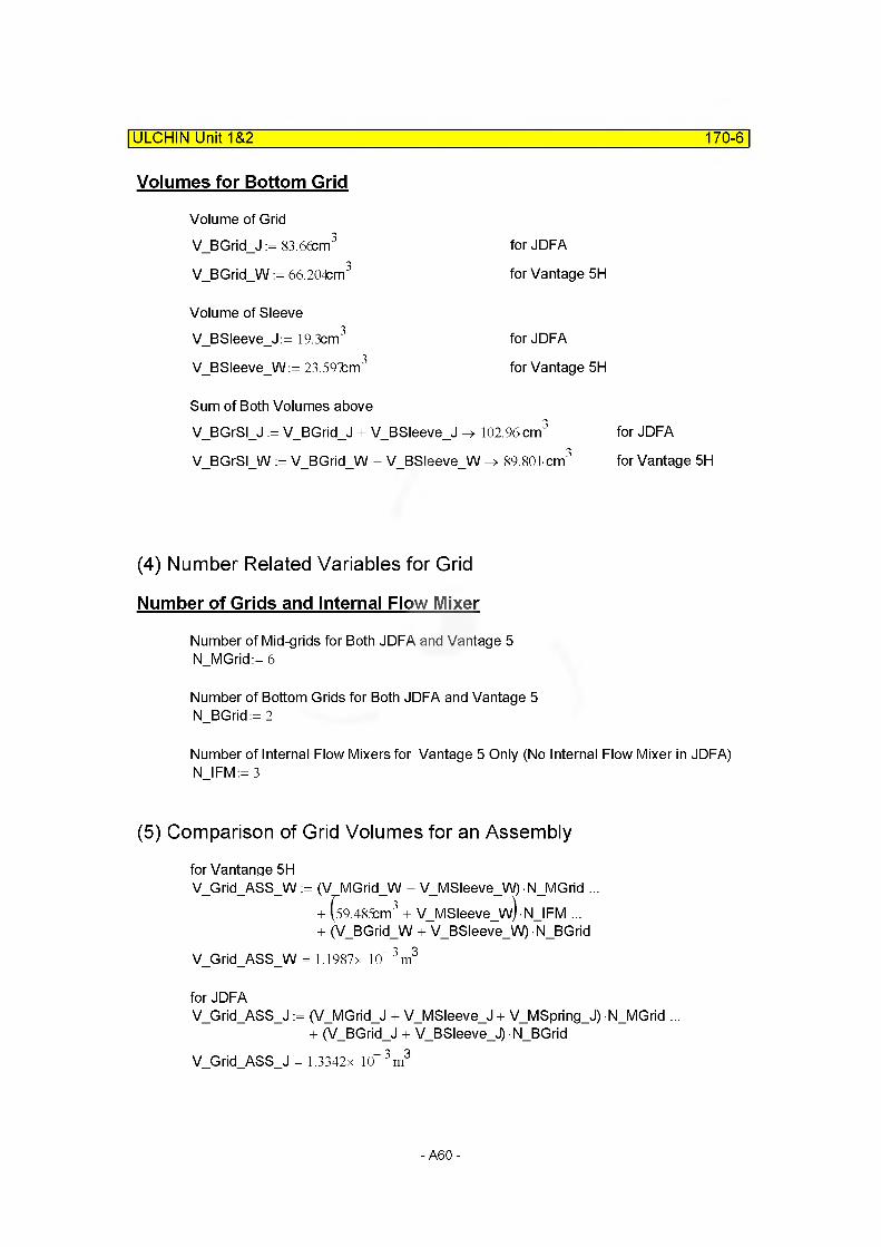
Volumes for Bottom Grid
Volume of GridVBGridJ := 83.66cm3 for JDFA
V_BGrid_W := 66.204cm3 for Vantage 5H
Volume of Sleeve V_BSIeeve_J:= 19.3cm3
V BSIeeve W:= 23.591km3
for JDFA
for Vantage 5H
Sum of Both Volumes aboveV_BGrSI_J := V_BGrid_J + V_BSIeeve_J -> 102.96cm3 for JDFA
VBGrSIW := VBGridW + VBSIeeveW 89.801 cm3 for Vantage 5H
(4) Number Related Variables for Grid
Number of Grids and Internal Flow Mixer
Number of Mid-grids for Both JDFA and Vantage 5 N_MGrid:= 6
Number of Bottom Grids for Both JDFA and Vantage 5 N_BGrid:= 2
Number of Internal Flow Mixers for Vantage 5 Only (No Internal Flow Mixer in JDFA) N IFM := 3
(5) Comparison of Grid Volumes for an Assembly
for Vantange 5HV_Grid_ASS_W := (V MGrid_W + V_MSIeeve_W) N_MGrid ...
+ (59.485cm3 + V_MSIeeve_w)• N_IFM ...
+ (V BGrid W + V BSIeeve W) N BGridV_G rid_ASS_W = 1.1987 x 10“ 3 m3
for JDFAV_Grid_ASS_J := (V MGrid J + V MSIeeve J + V MSpring J) N MGrid ...
+ (V BGrid J + V BSIeeve J) N BGridV Grid ASS J = 1.3342x 10“ 3m3
-A60-
| ULCHIN Unit 1&2
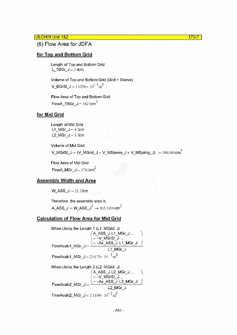
(6) Flow Area for JDFA
for Top and Bottom Grid
170-7
Length of Top and Bottom Grid L_TBGr_J:= 3.8cm
Volume of Top and Bottom Grid (Gird + Sleeve)V_BGrSI_J = 1.0296x 10“ 4m3
Flow Area of Top and Bottom Grid FlowA_TBGr_J:= 182.0cm2
for Mid Grid
Length of Mid Grid L1_MGr_J:= 4.2cm L2_MGr_J:= 5.3cm
Volume of Mid GridVMGrSIJ := (V MGrid J + VMSIeeveJ + VMSpringJ) -> 188.046cm3
Flow Area of Mid Grid FlowA_MGr_J:= 174.0cm2
Assembly Width and Area
W_ASS_J := 21.52cm
Therefore, the assembly area is A_ASS_J := W_ASS_J2 -> 463.1104cm2
Calculation of Flow Area for Mid Grid
When Using the Length 1 (L1 MGrid J)/A_ASS_J • L1 _MGr_J ... + -V MGrSI J ...
FlowAcalcI MGr J:=v -Ax ASS J L1 MGr J
L1_MGr_JFlowAcalcI MGr J = 2.0179x 10“ 2 m2
1
J
When Using the Length 2 (L2 MGrid J)f A_ASS_J L2_MGr_J ... )
+ -V MGrSI J ...
FlowAcalc2 MGr J:=V + -Ax ASS J L2 MGr J
L2_MGr_JFlowAcalc2 MGr J = 2.1108x 10“ 2 m2
)
- A61 -
ULCHIN Unit 1&2 170-8
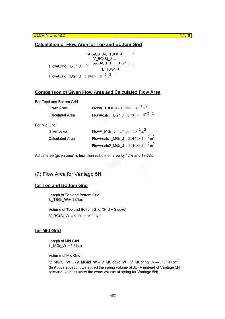
Calculation of Flow Area for Top and Bottom Grid
f A_ASS_J L_TBGr_J... )+ -V_BGrSI_J ...
v+-Ax ASS J L TBGr J JFlowAcalc TBGr J:=
FlowAcalc TBGr J = 2.1947x 10 m"
L_TBGr_J2 2
Comparison of Given Flow Area and Calculated Flow Area
For Topd and Bottom Grid
Given Area
Calculated Area
: FlowA_TBGr_J= 1.8200x 10 2 m2
: FlowAcalc TBGr J = 2.1947x 10 2m2
For Mid Grid
Given Area
Calculated Area
: FlowA_MGr_J= 1.7400x 10 2m2
: FlowAcalc1_MGr_J = 2.0179x 10_2m2
: FlowAcalc2 MGr J = 2.1108x 10“2m2
Actual area (given area) is less than calculated area by 17% and 17.6%.
(7) Flow Area for Vantage 5H
for Top and Bottom Grid
Length of Top and Bottom Grid L_TBGr_W:= 3.87cm
Volume of Top and Bottom Grid (Gird + Sleeve)V_BGrSI_W = 8.980lx 10“ 5m3
for Mid Grid
Length of Mid Grid L_MGr_W:= 3.81cm
Volume of Mid GridVMGrSIW := (V MGrid W + VMSIeeveW + V MSpring J) 146.540cm3
(In Above equation, we added the spring volume of JDFA instead of Vantage 5H, because we don't know the exact volume of spring for Vantage 5H)
-A62-
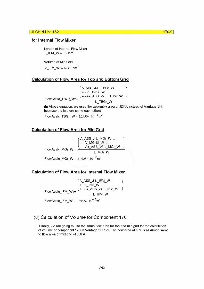
for Internal Flow Mixer
Length of Internal Flow Mixer L_IFM_W:= 1.21cm
Volume of Mid GridV IFM W:= 67.67£m3
ULCHIN Unit 1&2_______________________________________________________170-9
Calculation of Flow Area for Top and Bottom Grid
/A_ASS_J • L_TBG r_W ... + -V BGrSI W ...
FlowAcalc_TBGr_W:=V + -Ax ASS W L TBGr W
L_TBGr_W
1
J
(In Above equation, we used the assembly area of JDFA instead of Vantage 5H, because the two are same each other)FlowAcalc_TBGr_W = 2.2430x 10“ 2 m2
Calculation of Flow Area for Mid Grid
^A_ASS_J • L_MGr_W ... + -V MGrSI W ...
FlowAcalc MGr W:=V + -Ax ASS W • L MGr W
L_MGr_WFlowAcalc_MGr_W = 2.0905 x 10“ 2 m2
1
J
Calculation of Flow Area for Internal Flow Mixer
FlowAcalc IFM W:=
(A_ASS_J -L_lFM_W ... )+ -V_IFM_W ...
v+ -Ax ASS W • LJ FM W JL IFM W
FlowAcalc IFM W = 1.9158x 10" 2m2
(8) Calculation of Volume for Component 170
Finally, we are going to use the same flow area for top and mid grid for the calculation of volume of component 170 in Vantage 5H fuel. The flow area of IFM is assumed same to flow area of mid grid of JDFA.
-A63-
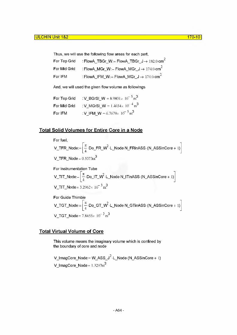
ULCHIN Unit 1&2 170-10
Thus, we will use the following flow areas for each part,For Top Grid : FlowA_TBGr_W:= FlowATBGrJ -» 182.0-cm2
For Mid Grid : FlowA_MGr_W:= FlowAMGrJ -> 174.0-cm2
For IFM : FlowA_IFM_W:= FlowA MGr J -> 174.0-cm2
And, we will used the given flow volume as followings
For Top Grid :V_BGrSI_W = 8.9801 x 10“5m3
For Mid Grid : V_MGrSI_W = 1.4654x 10“ 4m3
For IFM : V IFM W=6.7679x 10“ 5m3
Total Solid Volumes for Entire Core in a Node
For fuel,
V TFR Node:= •Do_FR_W2 L Node N FRinASS (N ASSinCore + 1)
V TFR Node= 0.5373m
For Instrumentation Tube
V TIT Node:= Do_IT_V\? L_Node NJTinASS (N_ASSinCore + 1)
V TIT Node= 3.2962x 10 3m3
For Guide Thimble
V TGT Node:= • Do_GT_V\? L Node N GTinASS (N ASSinCore + 1)
V TGT Node= 7.8455x 10 2m3
Total Virtual Volume of Core
This volume means the imaginary volume which is confined by the boundary of core and node
VI mag Co re_N od e: = W ASS J2 L Node (N ASSinCore + 1)
V I mag Co re_N od e = 1.3297m3
-A64-
ULCHIN Unit 1&2 170-11
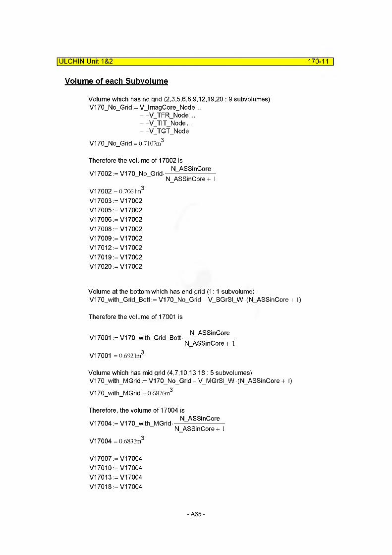
Volume of each Subvolume
Volume which has no grid (2,3,5,6,8,9,12,19,20 : 9 subvolumes) V170_No_Grid:= V_lmagCore_Node...
+ -VTFRNode ...+ -VTITNode...+ -VTGTNode
V170 No Grid = 0.7107m3
Therefore the volume of 17002 isN ASSinCore
V17002 := V170 No Grid--------N ASSinCore + 1
V17002 = 0.7061m3
V17003 :=V17002 V17005 :=V17002 V17006 :=V17002 V17008 :=V17002 V17009 :=V17002 V17012:= V17002 V17019:= V17002 V17020 :=V17002
Volume at the bottom which has end grid (1: 1 subvolume) V170_with_Grid_Bott:= V170_No_Grid - V_BGrSI_W(N_ASSinCore + 1)
Therefore the volume of 17001 is
V17001 := V170 with Grid BottNASSinCore
N ASSinCore + 1V17001 = 0.6921m3
Volume which has mid grid (4,7,10,13,18 : 5 subvolumes)V170_with_MGrid := V170_No_Grid - V_MGrSI_W • (N_ASSinCore + 1)V170 with MGrid = 0.6876m3
Therefore, the volume of 17004 isN ASSinCore
V17004 := V170 with MGrid--------N ASSinCore + 1
V17004 =0.683 3m3
V17007 :=V17004 V17010:=V17004 V17013:= V17004 V17018:= V17004
-A65-

ULCHIN Unit 1&2 170-12
Volume which has internal flow mixer (11,14,17:3 subvolumes) V170_with_IFM := V170_No_Grid - V_IFM_W(N_ASSinCore + 1)V170 with IFM = 0.7000m3
Therefore, the volume of 17011 isN ASSinCore
V17011 := V170 with IFM----- --N ASSinCore + 1
V17011 = 0.6956m3
V17014:= V17011 V17017 := V17011
Volume which has a half of grid (15, 16 : 2 subvolumes)
These two subvolumes have a grid between the two subvolumes, as shown in figure in page 170-3. Thus, each volume should be calculated taking into account this fact. In other words, the contribution of a grid should be counted, and each volume is [volume of subvolume which has no grid (MV17002 etc)] - [volume portion of grid that contribute to each volume]
At first, let's define the variables that are releted with the volume contribution of grid. They can be the elevations of grid top and bottom, and node elevation between subvolume 15 and 16.
Elevation of Junction 15 ElevJI 7015:= 2.74425nBottom of Grid Elev_Bott_Grid17015:= 2.7252nTop of Grid Elev_Top_Grid17016= 2.7633m
Therefore, the volume of 17015 is(Elev Top Grid17016- ElevJI 7019
V17015 := V17002-
V17004-
(Elev_Top_Grid17016- Elev_Bott_Grid17015) (ElevJI7015- Elev Bott Grid 1701 ^
(Elev_Top_Grid17016- Elev_Bott_Grid17015)
V17015 = 0.6947m
V17016:= V17015
- A66 -

(9) Calculation of Flow Length
| ULCHIN Unit 1&2 170-13
Flow length of each subvolume was already defined in page 170-3. Here, let's rearrange them.
FLOWL17001 FLOWL17002 FLOWL17003 FLOWL17004 FLOWL17005 FLOWL17006 FLOWL17007 FLOWL17008 FLOWL17009 FLOWL17010 FLOWL17011 FLOWL17012 FLOWL17013 FLOWL17014 FLOWL17015 FLOWL17016 FLOWL17017 FLOWL17018 FLOWL17019 FLOWL17020
= LNode =LNode = LNode =LNode = LNode =LNode = LNode =LNode = LNode =LNode = LNode =LNode = LNode =LNode = LNode =LNode = LNode =LNode = LNode =L Node
-» ,18288 m -> ,18288 m -> ,18288 m -> ,18288 m -> ,18288 m -» ,18288 m -> ,18288 m -> ,18288 m -> ,18288 m -> ,18288 m -» ,18288 m -> ,18288 m -> ,18288 m -> ,18288 m -> ,18288 m -» ,18288 m -> ,18288 m -> ,18288 m -> ,18288 m -> ,18288 m
(10) Calculation of Flow Area : Default
The flow area of each subvolume can be easily calculated using flow lengths and volume.
FLOWA17001 :=V17001
FLOWL17001
FLOWA17001 = 3.7845m
FLOWA17002:=V17002
FLOWL17002
FLOWA17002 = 3.861 lm
FLOWA17003:=V17003
FLOWL17003
FLOWA17003 = 3.861 lm
-A67-
ULCHIN Unit 1&2 170-14
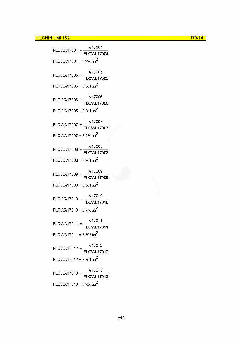
FLOWA17004:V17004
™ FLOWL17004
FL0WA17004 == 3.7361m2
FLOWA17005:V17005
™ FLOWL17005
FLOWA17005 == 3.8611m2
FLOWA17006:V17006
™ FLOWL17006
FLOWA17006 == 3.8611m2
FLOWA17007:V17007
™ FLOWL17007
FLOWA17007 == 3.7361m2
FLOWA17008:V17008
™ FLOWL17008
FLOWA17008 == 3.8611m2
FLOWA17009:V17009
™ FLOWL17009
FLOWA17009 == 3.8611m2
FLOWA17010:V17010
™ FLOWL17010
FLOWA17010 == 3.7361m2
FLOWA17011:V17011
™ FLOWL17011
FLOWA17011 == 3.8034m2
FLOWA17012:V17012
™ FLOWL17012
FLOWA17012 == 3.8611m2
FLOWA17013:V17013
™ FLOWL17013
FLOWA17013 == 3.7361m2
-A68-

ULCHIN Unit 1&2 170-15
FLOWA17014:=V17014
FLOWL17014
FLOWA17014 = 3.8034m2
FLOWA17015:=V17015
FLOWL17015
FLOWA17015 = 3.7986n2
FLOWA17016:=V17016
FLOWL17016
FLOWA17016 = 3.7986m2
FLOWA17017:=V17017
FLOWL17017
FLOWA17017 = 3.8034m2
FLOWA17018:=V17018
FLOWL17018
FLOWA17018 = 3.7361m2
FLOWA17019:=V17019
FLOWL17019
FLOWA17019 = 3.8611m2
FLOWA17020:=V17020
FLOWL17020
FLOWA17020 = 3.8611m2
C. JUNCTION RELATED DATA
(1) Junction Area
Junction area is default.
AJUN17001:= min (FLOWA17001, FLOWA17002) AJUN17001 = 3.7845m2
AJUN17002:= min (FLOWA17002, FLOWA17003) AJUN17002= 3.8611m2
AJUN17003:= min (FLOWA17003, FLOWA17004) AJUN17003= 3.7361m2
-A69-

AJUN17004:= min (FLOWA17004, FLOWA17005)AJUN17004= 3.7361m2
AJUN17005:= min (FLOWA17005, FLOWA17006)AJUN17005= 3.8611m2
AJUN17006:= min (FLOWA17006, FLOWA17007)AJUN17006= 3.7361m2
AJUN17007:= min (FLOWA17007, FLOWA17008)AJUN17007= 3.7361m2
AJUN17008:= min (FLOWA17008, FLOWA17009)AJUN17008= 3.8611m2
AJUN17009:= min (FLOWA17009, FLOWA17010)AJUN17009= 3.7361m2
AJUN17010:= min (FLOWA17010, FLOWA17011)AJUN17010= 3.7361m2
AJUN17011 := min (FLOWA17011, FLOWA17012)AJUN17011 = 3.8034m2
AJUN17012:= min(FLOWA17012, FLOWA17013)AJUN17012= 3.7361m2
AJUN17013:= min(FLOWA17013, FLOWA17014)AJUN17013= 3.7361m2
AJUN17014:= min(FLOWA17014, FLOWA17015)AJUN17014= 3.7986m2
AJUN17015:= min(FLOWA17015, FLOWA17016)AJUN17015= 3.7986m2
AJUN17016:= min(FLOWA17016, FLOWA17017)AJUN17016= 3.7986m2
AJUN17017:= min(FLOWA17017, FLOWA17018)AJUN17017= 3.7361m2
ULCHIN Unit 1&2_____________________________________________________ 170-16
-A70-
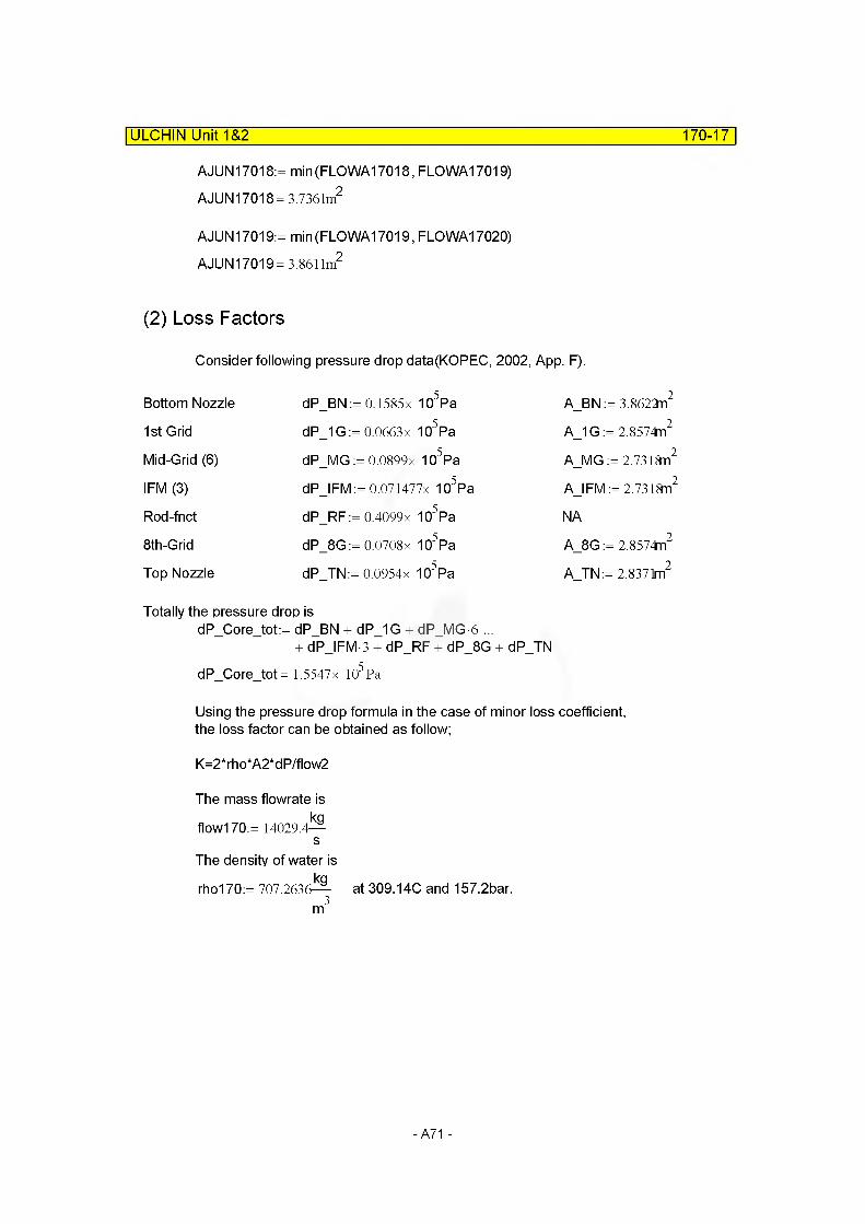
AJUN17018:= min(FLOWA17018, FLOWA17019)AJUN17018= 3.7361m2
AJUN17019:= min(FLOWA17019, FLOWA17020)AJUN17019= 3.8611m2
ULCHIN Unit 1&2_____________________________________________________ 170-17
(2) Loss Factors
Consider following pressure drop data(KOPEC, 2002, App. F).
Bottom Nozzle
1st Grid
Mid-Grid (6)
IFM (3)
Rod-fnct
8th-G rid
Top Nozzle
dP_BN := 0.1585x 10⁵Pa
dP_1G:= 0.0663 x 10⁵Pa
dP_MG := 0.0899x 10⁵Pa
dP_IFM:= 0.071477x 10⁵Pa
dP_RF:= 0.4099x 10⁵Pa
dP_8G:= 0.0708x 10⁵Pa
dP TN:= 0.0954x 10⁵Pa
A_BN := 3.8622n2
A_1 G := 2.8574n2
A_MG := 2.7318n2
AJFM := 2.7318n2
NA
A_8G := 2.8574n2
A TN:= 2.8371m2
Totally the pressure drop isdP_Core_tot:= dP BN + dP_1G + dP MG 6 ...
+ dPJFM-3 + dP_RF + dP_8G + dP_TNdP Core tot= 1.55 47x 105Pa
Using the pressure drop formula in the case of minor loss coefficient,the loss factor can be obtained as follow;
K=2* rh o*A2*d P/flow2
The mass flowrate is kg
flow170:= 14029.4— s
The density of water is Kqrho170:= 707.2636-^- at 309.14C and 157.2bar. m3
- A71 -
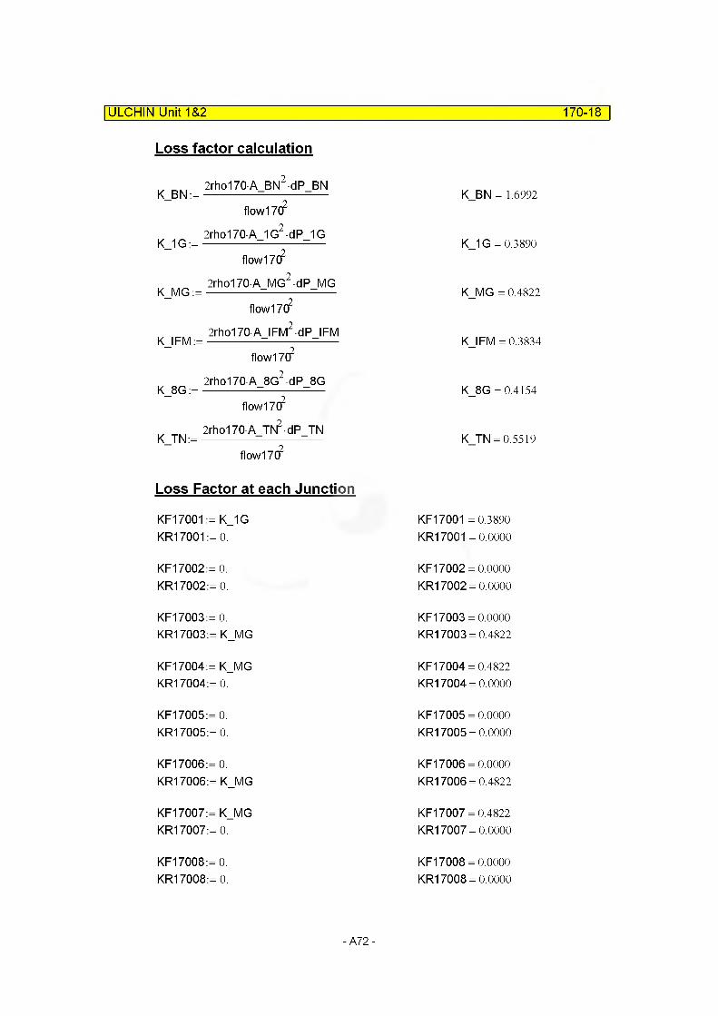
ULCHIN Unit 1&2 170-18
Loss factor calculation
2rho170 A BN2-dP BN K_BN :=------------ =----------- =—
flow17(f
2rho170A 1G2-dP 1G K_1 G :=-------------=----------- =—
flow17(f
2rho170A MG2-dP MG K_MG :=-------------=-----------=------
flow17(f
2rho170A IFM2 dP IFM KJ FM :=------------ =-----------=------
flow17(f
2rho170A 8G2 dP 8G K_8G :=-------------=----------- =—
flow17(f
2rho170A TN2 dP TNK_TN:=--------------------------—
flow17C?
K_BN = 1.6992
K_1G = 0.3890
K_MG = 0.4822
KJFM = 0.3834
K_8G = 0.4154
K TN = 0.5519
Loss Factor at each Junction
KF17001 := K_1G KR17001 := 0.
KF17002:= 0. KR17002:= 0.
KF17003:= 0. KR17003:= K_MG
KF17004:= K_MG KR17004:= 0.
KF17005:= 0. KR17005:= 0.
KF17006:= 0. KR17006:= K_MG
KF17007 := K_MG KR17007:= 0.
KF17008:= 0. KR17008:= 0.
KF17001 =0.3890 KR17001 = 0.0000
KF17002 = 0.0000 KR17002 = 0.0000
KF17003 = 0.0000 KR17003 = 0.4822
KF17004 = 0.4822 KR17004 = 0.0000
KF17005 = 0.0000 KR17005 = 0.0000
KF17006 = 0.0000 KR17006 = 0.4822
KF17007 = 0.4822 KR17007 = 0.0000
KF17008 = 0.0000 KR17008 = 0.0000
-A72-

ULCHIN Unit 1&2 170-19
KF17009:= 0. KF17009 = 0.0000KR17009:= K_MG KR17009 = 0.4822
KF17010:= K_MG KF17010 = 0.4822KR17010:= KJFM KR17010 = 0.3834
KF17011 := KJFM KF17011 =0.3834KR17011 := 0. KR17011 =0.0000
KF17012:= 0. KF17012 = 0.0000KR17012:= K_MG KR17012 = 0.4822
KF17013:= K_MG KF17013 = 0.4822KR17013:= KJFM KR17013 = 0.3834
KF17014:= KJFM KF17014 = 0.3834KR17014:= 0. KR17014 = 0.0000
KF17015:= K_MG KF17015 = 0.4822KR17015:= K_MG KR17015 = 0.4822
KF17016:= 0. KF17016 = 0.0000KR17016:= KJFM KR17016 = 0.3834
KF17017:= KJFM KF17017 = 0.3834KR17017:= K_MG KR17017 = 0.4822
KF17018:= K_MG KF17018 = 0.4822KR17018:= 0. KR17018 = 0.0000
KF17019 := 0. KF17019 = 0.0000KR17019:= 0. KR17019 = 0.0000
-A73-

ULCHIN Unit 1&2 170-20
Q Reference:D:\Development\TA\U12\U12_FNC2\U12_Ch2_1b_R0.mcd(R)
Part 2 : Bottom and Top Nozzles
A. OVERVIEWPart 2 of represents the bottom and top nozzles of FAs. In this section, volumes 17001 and 17008 indicate the bottom and top nozzles of FAs, respectively.
kil
?rtf
It is assumed that all the parameters of core ends related to MARS modeling (volume, length, area and so on) in Vantage 5H fuel are same to those of KWU fuel.Ref. Choi, H.R., 1989, p.69
-A74-

B. VOLUME RELATED DATA| ULCHIN Unit 1&2 170-21
Dimensions of KWU fuel assembly
Number of fuel rods Number of guide thimbles Number of instrumentation guide Number of fuel assembly
N_FR170:= 264 N_GT170:= 24N_IT 170:= 1N FA170:= 157
Diameter of fuel rods : D FR170:= 9.50mmd
Outer diameter of guide thimble : D_GTo170:= 12.24mmInner diameter of guide thimble : D_GTi170:= 11.4Cmm
Inner diameter of instrumentaion : D_ITi170:= 11.4CmmOuter diameter of instrumentaion : D ITo170:= 12.24mm
Inner diameter of guide tube dashpot : D_GDi170:= 10.08mmOuter diameter of guide tube dashpot : D_GDo170:= 12.24mm
Number of grids : N Grid170:= 6 + 2
Length of dashpot : L_DP170:= 622.CmmLength of upper part dashpot : LJJDP170:= 3273.3nm
Ref. Choi, H.R., 1989, p.70, B121/B111/85/183
(1) Subcomponent 170-01
Length
FLOWL17001 KWU := 4.2874n
Volume
Volume of subcomponent 17001[V17001 KWU] =Volume of inside core baffle [VCB17001]
-Volume of bottom nozzle [V BN17001]-Volume of guide thimble [V GT17001]-Volume of instrumentation tube [VJT17001]-Volume of fuel rod [V FR17001]
-A75-
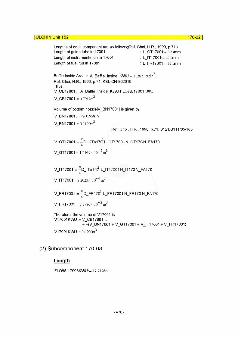
ULCHIN Unit 1&2 170-22
Lengths of each component are as follows;(Ref. Choi, H.R., 1990, p.71,)Length of guide tube in 17001 : L_GT17001 := 39.4mmLength of instrumentation in 17001 : L_IT17001:= 44.4mmLength of fuel rod in 17001 : L_FR17001:= 11.5mm
Baffle Inside Area is ABafflelnsideKWU := 11267.792In2
Ref. Choi, H.R., 1990, p.71, KSL-CN-862010Thus,V_CB17001 := A_Baffle_lnside_KWU- FLOWL17001KWU V_CB17001 = 0.7917m3
Volume of bottom nozzle[V_BN17001] is given by V_BN17001 := 7260.9581n3
V_BN17001 = 0.1190m3
Ref. Choi, H.R., 1990, p.71, B121/B111/85/183
VJ3T17001 := - D_GTo17(? L_GT17001- N_GT170 N_FA170
V GT17001 = 1.7469x 10“ 2 m3
VJT17001 := - D_ITo17(? • LJT17001 N_IT170 N_FA170
V IT17001 = 8.2023x 10“4m3
V_FR17001 := - D_FR1 id • L_FR17001 • N_FR170- N_FA170
V_FR17001 = 3.3786x 10“ 2 m3
Therefore, the volume of V17001 is V17001 KWU := V_CB17001 ...
+ -(V_BN 17001 + V_GT17001 + VJT17001 + V_FR17001)V17001 KWU = 0.6206m3
(2) Subcomponent 170-08
Length
FLOWL17008KWU := 12.2126n
-A76-

ULCHIN Unit 1&2 170-23
Volume
Volume of subcomponent 17008 =Volume of inside core baffle -Volume of bottom nozzle -Volume of guide thimble -Volume of instrumentation tube -Volume of top gird -Volume of fuel rod
[V17008KWU][V_CB17008][VTN17008][VJ3T17008][VJT17008][V_TG 17008][V_FR17008]
Lengths of each component are as follows;(Ref. Choi, H.R., 1989, p.76,)Length of guide tube in 17008 Length of instrumentation in 17008 Length of fuel rod in 17008
L_GT17008:= 197.Smrn L_IT17008:= 212.6mm L FR17008:= 177.5mm
V_CB17008 := A_Baffle_lnside_KWU- FLOWL17008KWU V_CB17008 = 2.2550m3
Volume of top nozzle (V BN17008) is given by V_BN17008 := 996.75cm3 N_FA170
V_BN17008 = 0.1565m3
Ref. Choi, H.R., 1989, p.76, B121/B111/85/183
V_GT17008 := - D_GTo17C? L_GT17008 N_GT170 N_FA170
V GT17008 = 8.7742x 10“ 2 m3
VJT17008:= - D_ITo17(? • LJT17008 N_IT170 N_FA170
V_IT17008=3.9275x 10“ 3 m3
V_TG17008:= 102.33cm3 N_FA170 (=Volume of bottom end grid)
V_TG 17008 = 1,6066x 10“ 2 m3
Ref. Choi, H.R., 1989, p.76 & p.70
V_FR17008 := - D_FR17(f • L_FR17008 N_FR170 N_FA170
V FR17008 = 0.5215m3
Therefore, the volume of V17008 is V17008KWU := V_CB17008 ...
+ -(V_BN 17008 + V_GT17008 + V_IT17008 ... L+ V_TG17008 + V_FR17008
V17008KWU = 1.4693m3
-A77-
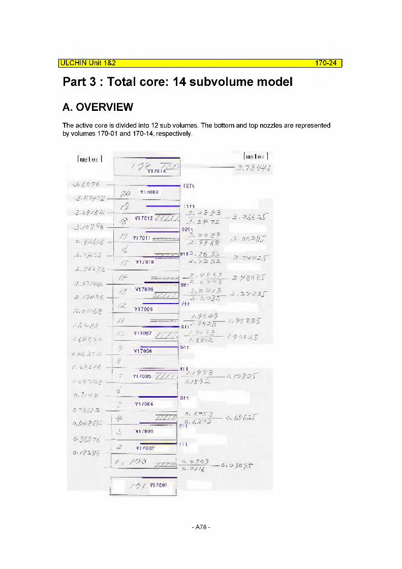
ULCHIN Unit 1&2________________________________________________________ 170-24
Part 3 : Total core: 14 subvolume model
A. OVERVIEWThe active core is divided into 12 sub volumes. The bottom and top nozzles are represented by volumes 170-01 and 170-14, respectively.
[inuLm l
■J- - - r -
/ y r .///VI /II M'
[iiihIri l
? 7-V vV:
j #% -
-
—
f... -
a c iJ&M
:01V
i :u
in
7-z
,:.-L VI 7C1V
111 i.n, ^ r. ^
j
"r
if 11'VI .11" II
jfy V170JS.
—1" y --4-lit t
- -v v J- —
/■ -i: A -.
T-. - : / |..4?
.■i ^
■"ill
' I /. i isz: / i
v17<Kj6 b- h
■. - ■: ■■■/ —vi /out)
..hi
■■■/S ■■ - W-" )
^. : ■ -■ ¥ HMY I I'jllL,
--
C. sfr^_j
i 7Z7~T - Z-.I- ■;
>1 7IIOX
V IVTjftp-
,7
I I
/ - . L '— lv:> 5c yr
■ * / Yl TC(C
-A78-
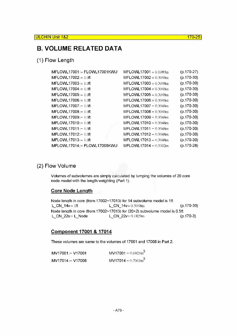
ULCHIN Unit 1&2 170-25
B. VOLUME RELATED DATA
(1) Flow Length
MFLOWL17001 MFLOWL17002 MFLOWL17003 MFLOWL17004 MFLOWL17005 MFLOWL17006 MFLOWL17007 MFLOWL17008 MFLOWL17009 MFLOWL17010 MFLOWL17011 MFLOWL17012 MFLOWL17013 MFLOWL17014
(2) Flow Volume
Volumes of subvolumes are simply calculated by lumping the volumes of 20 core node model with the length weighting (Part 1).
Core Node Length
Node length in core (from 17002-17013) for 14 subvolume model is 1ft L_CN_14v:= 1ft L_CN_14v= 0.3048m (p.170-30)Node length in core (from 17002-17013) for (20+2) subvolume model is 0.5ft L_CN_22v:= L_Node L_CN_22v= 0.1829m (p.170-3)
FLOWL17001KWU MFLOWL17001 = 0.1089m (p.170-27)1.0ft MFLOWL17002 = 0.3048m (p.170-30)1.0ft MFLOWL17003 = 0.3048m (p.170-30)1.0ft MFLOWL17004 = 0.3048m (p.170-30)1.0ft MFLOWL17005 = 0.3048m (p.170-30)1.0ft MFLOWL17006 = 0.3048m (p.170-30)1.0ft MFLOWL17007 = 0.3048m (p.170-30)1.0ft MFLOWL17008 = 0.3048m (p.170-30)1.0ft MFLOWL17009 = 0.3048m (p.170-30)1.0ft MFLOWL17010 = 0.3048m (p.170-30)1.0ft MFLOWL17011 = 0.3048m (p.170-30)1.0ft MFLOWL17012 = 0.3048m (p.170-30)1.0ft MFLOWL17013 = 0.3048m (p.170-30)FLOWL17008KWU MFLOWL17014 = 0.3102m (p.170-28)
Component 17001 & 17014
These volumes are same to the volumes of 17001 and 17008 in Part 2.
MV17001 := V17001 MV17001 = 0.6921m3
MV17014 := V17008 MV17014 = 0.7061m3
-A79-

ULCHIN Unit 1&2 170-26
Component 17002
Volume of subcomponent 17002 [MV17002]= Volume of subcomponet 17001 in Part 1 [V17001]+ Part volume of subcomponet 17002 in Part 1 (V17002)
L CN 14v- L CN 22vMV17002 :=V17001 + ——=--------=—=----- V17002
L_CN_22vMV17002= 1.1629m3
Component 17003
Volume of subcomponent 17003 [MV17003]= Volume of subcomponet 17003 in Part 1 [V17003]+ Part volume of subcomponet 17002 in Part 1 (V17002) + Part volume of subcomponet 17004 in Part 1 (V17004)
MV17003 :=V17003 ...+ fl-L-CN-14v-L-CN_22v|v17002
l L_CN_14V Jf 2 L CN 14v-3L CN 22v)
+ =—=--------- =—=— V17004V L_CN_22v J
MV17003= 1.3576m3
Component 17004
Volume of subcomponent 17004 [MV17004]= Volume of subcomponet 17005in Part 1 [V17005]+ Part volume of subcomponet 17004 in Part 1 (V17004)
MV17004 :=V17005 ...( 2 L CN 14v-3L CN 22v)
+ 1-------=—=---------- =—=— V17004V L_CN_22v J
MV17004= 1.1616m3
Component 17005
Volume of subcomponent 17005 [MV17005]= Volume of subcomponet 17006 in Part 1 [V17006]+ Part volume of subcomponet 17007 in Part 1 (V17007)
MV17005 :=V17006 ...(7L CN 22v-4 L CN 14v)
+ ——=-----------=—=— V17007V L_CN_22v J
MV17005 = 0.9339m3
-A80-
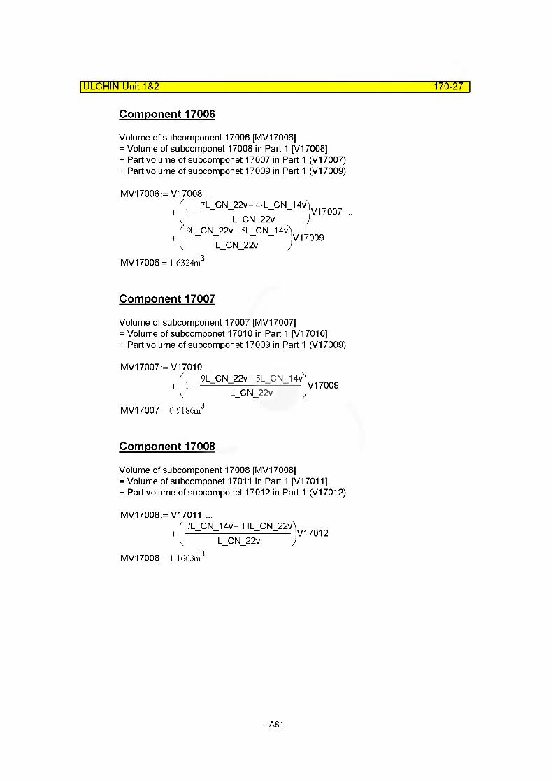
ULCHIN Unit 1&2 170-27
Component 17006
Volume of subcomponent 17006 [MV17006]= Volume of subcomponet 17008 in Part 1 [V17008]+ Part volume of subcomponet 17007 in Part 1 (V17007) + Part volume of subcomponet 17009 in Part 1 (V17009)
MV17006 :=V17008 ...7L CN 22v-4 L CN 14v)
1------=—=---------- =—=— V17007L CN 22v )
9L CN 22v- 5L CN 14v)
L_CN_22v )V17009
MV17006 = 1.6324m
Component 17007
Volume of subcomponent 17007 [MV17007]= Volume of subcomponet 17010 in Part 1 [V17010]+ Part volume of subcomponet 17009 in Part 1 (V17009)
MV17007 :=V17010 ...i_9L_CN_22v-5L_CN_14vV17009
L_CN_22v )MV17007 = 0.9186m
Component 17008
Volume of subcomponent 17008 [MV17008]= Volume of subcomponet 17011 in Part 1 [V17011]+ Part volume of subcomponet 17012 in Part 1 (V17012)
MV17008 :=V17011 ...
+7L CN 14v- 1 lL CN 22v)
L_CN_22v )V17012
MV17008= 1.1663m3
- A81 -
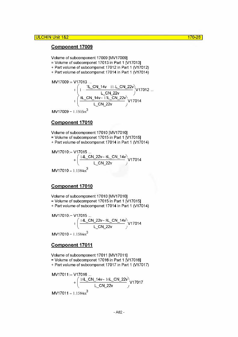
ULCHIN Unit 1&2 170-28
Component 17009
Volume of subcomponent 17009 [MV17009]= Volume of subcomponet 17013 in Part 1 [V17013]+ Part volume of subcomponet 17012 in Part 1 (V17012) + Part volume of subcomponet 17014 in Part 1 (V17014)
MV17009:= V17013 ...7L CN 14v- 11 1 CN 22v)
1---- =—=------------- =—=— V17012 ...L_CN_22v J
8L CN 14v- 13L CN 22v)
L CN 22v )V17014
MV17009= 1.1505m
Component 17010
Volume of subcomponent 17010 [MV17010]= Volume of subcomponet 17015 in Part 1 [V17015]+ Part volume of subcomponet 17014 in Part 1 (V17014)
MV17010:= V17015 ...14L CN 22v- 8L CN 14v)
L CN 22v )V17014
MV17010 = 1.1584m
Component 17010
Volume of subcomponent 17010 [MV17010]= Volume of subcomponet 17015 in Part 1 [V17015]+ Part volume of subcomponet 17014 in Part 1 (V17014)
MV17010:= V17015 ...14L CN 22v- 8L CN 14v)
L CN 22v )V17014
MV17010 = 1.1584m
Component 17011
Volume of subcomponent 17011 [MV17011]= Volume of subcomponet 17016 in Part 1 [V17016]+ Part volume of subcomponet 17017 in Part 1 (V17017)
MV17011 := V17016 ...lOL CN 14v- 16L CN 22v)
L CN 22v )V17017
MV17011 = 1.1584m3
-A82-

ULCHIN Unit 1&2 170-29
Component 17012
Volume of subcomponent 17012 [MV17012]= Volume of subcomponet 17018 in Part 1 [V17018]+ Part volume of subcomponet 17017 in Part 1 (V17017) + Part volume of subcomponet 17019 in Part 1 (V17019)
MV17012:= V17018 ...10L CN 14v- 16L CN 22v)
1------- =—=-----------=—=— V17017 ...L_CN_22v )
I IL CN 14v- 18L CN 22v)
L CN 22v )V17019
MV17012 = 1.1505m
Component 17013
Volume of subcomponent 17013 [MV17013]= Volume of subcomponet 17020 in Part 1 [V17020]+ Part volume of subcomponet 17019 in Part 1 (V17019)
MV17013:= V17020 ...llL CN 14v- 18L CN 22v)
1 - ■
L CN 22v )V17019
MV17013 = 1.1769m
(3) Flow Area : Default
MFLOWA17001 :=
M FLO WA17002:=
M FLO WA17003:=
M FLO WA17004:=
M FLO WA17005:=
M FLO WA17006:=
M FLO WA17007:=
M FLO WA17008:=
MV17001
MFLOWL17001MV17002
MFLOWL17002MV17003
MFLOWL17003MV17004
MFLOWL17004MV17005
MFLOWL17005MV17006
MFLOWL17006MV17007
MFLOWL17007MV17008
MFLOWL17008
MFLOWA17001 = 6.3555m2
M FLO WA17002 = 3.8152m2
M FLO WA17003 = 4.4539m2
MFLOWA17004 = 3.8111m2
M FLO WA17005 = 3.0639m2
M FLO WA17006 = 5.3556m2
M FLO WA17007 = 3.0139m2
M FLO WA17008 = 3.8265m2
-A83-
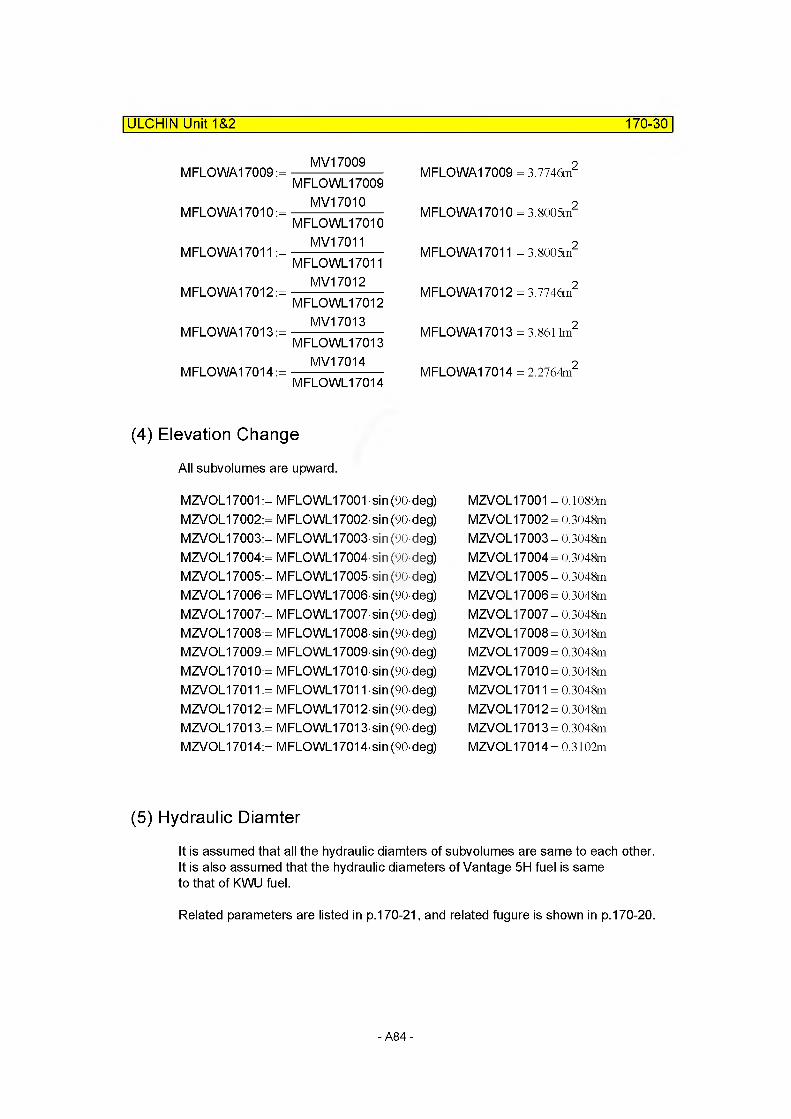
ULCHIN Unit 1&2 170-30
MV17009MFLOWA17009 :=----------------------
MFLOWL17009MV17010
MFLOWA17010:=----------------------MFLOWL17010
MV17011MFLOWA17011 :=----------------------
MFLOWL17011MV17012
MFLOWA17012:=----------------------MFLOWL17012
MV17013MFLOWA17013:=----------------------
MFLOWL17013MV17014
MFLOWA17014:=----------------------MFLOWL17014
M FLO WA17009 = 3.7746m2
M FLO WA17010 = 3.8005m2
M FLO WA17011 = 3.8005m2
MFLOWA17012 = 3.7746m2
MFLOWA17013 = 3.8611m2
MFLOWA17014 = 2.2764m2
(4) Elevation Change
All subvolumes are upward.
MZVOL17001 := MFLOWL17001 sin (90-deg) MZVOL17002:= MFLOWL17002-sin (90-deg) MZVOL17003:= MFLOWL17003-sin (90-deg) MZVOL17004:= MFLOWL17004-sin (90-deg) MZVOL17005:= MFLOWL17005-sin (90-deg) MZVOL17006:= MFLOWL17006-sin (90-deg) MZVOL17007:= MFLOWL17007-sin (90-deg) MZVOL17008:= MFLOWL17008-sin (90-deg) MZVOL17009:= MFLOWL17009-sin (90-deg) MZVOL17010:= MFLOWL17010 sin (90-deg) MZVOL17011 := MFLOWL17011 -sin (90-deg) MZVOL17012:= MFLOWL17012-sin (90-deg) MZVOL17013:= MFLOWL17013-sin (90-deg) MZVOL17014:= MFLOWL17014-sin (90-deg)
MZVOL17001 = 0.1089m MZVOL17002= 0.3048m MZVOL17003= 0.3048m MZVOL17004= 0.3048m MZVOL17005= 0.3048m MZVOL17006= 0.3048m MZVOL17007= 0.3048m MZVOL17008= 0.3048m MZVOL17009= 0.3048m MZVOL17010= 0.3048m MZVOL17011 = 0.3048m MZVOL17012= 0.3048m MZVOL17013= 0.3048m MZVOL17014= 0.3102m
(5) Hydraulic Diamter
It is assumed that all the hydraulic diamters of subvolumes are same to each other. It is also assumed that the hydraulic diameters of Vantage 5H fuel is same to that of KWU fuel.
Related parameters are listed in p.170-21, and related fugure is shown in p.170-20.
-A84-

ULCHIN Unit 1&2 170-31
Flow Area of Core
Flow Area of Core [A_C170KWU]=lnner area of baffle [A B170KWU]- Cross-sectional area of fuel rod [A_FR170KWU]- Cross-sectional area of guide thimble [AGT170KWU]- Cross-sectional area of instrumentation area [AJT170KWU]
A_B170KWU := 11267.792In2
A_B170KWU = 7.2695m2 Ref. Choi, H.R., 1989, p.78, KCL-CN-862010
A_FR170KWU := - D_FR17(f • N_FR170 N_FA170
A FR170KWU = 2.9379m2
A_GT170KWU := - D_GTo17C? • N_GT170 N_FA170
A_GT170KWU = 0.4434m2
AJT170KWU := - D_ITo17(? • N_IT170 N_FA170
A_IT170KWU= 1.8474x 10“2m2
Therefore,A_C170KWU:= A_B170KWU - (A_FR170KWU + A_GT170KWU + AJT170KWU) A C170KWU = 3.8698m2
Wetted Perimeter
Wetted perimeter [P_W170KWU]= Core baffle [P_CB170KWU]+ Fuel rods [P_FR170KWU]+ Guide thimble [P GT170KWU]+ Instrumentation tube [PJT170KWU]
P_CB170KWU := [(12.7245n + 16.934n + 8.468n-3 + 8.4605n)-2]-4P_CB170KWU = 12.9079m Ref. Choi, H.R., 1989, p.79, KCL-CN-862010
P_FR170KWU := tiD_FR1 70 N_FR170 N_FA170 P FR170KWU = 1.2370x 10³m
-A85-
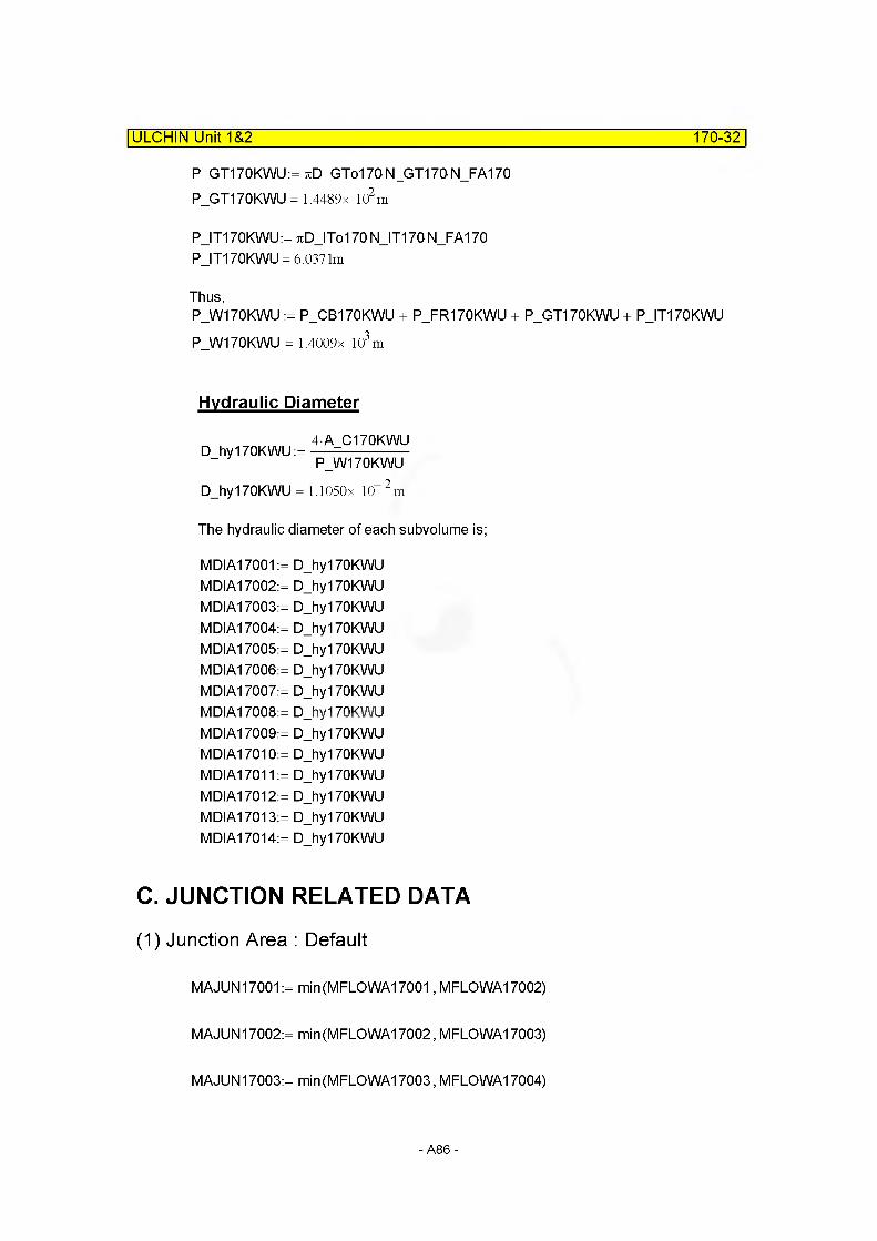
P GT170KWU:= tiD GTo1 70N_GT170N_FA170 P_GT170KWU= 1.4489x l(f m
PJT170KWU:= jcDJTol 70 N JT170 N_FA170 P_IT170KWU = 6.0371m
Thus,P_W170KWU := P_CB170KWU + P_FR170KWU + P_GT170KWU + P_IT170KWU P W170KWU = 1.4009x 10³m
ULCHIN Unit 1&2______________________________________________________170-32
Hydraulic Diameter
D_hy170KWU:=4A C170KWU P W170KWU
D_hy170KWU = 1.1050x 10 2m
The hydraulic diameter of each subvolume is;
MDIA17001:= D_hy170KWU MDIA17002:= D_hy170KWU MDIA17003:= D_hy170KWU MDIA17004:= D_hy170KWU MDIA17005:= D_hy170KWU MDIA17006:= D_hy170KWU MDIA17007:= D_hy170KWU MDIA17008:= D_hy170KWU MDIA17009:= D_hy170KWU MDIA17010:= D_hy170KWU MDIA17011 := D_hy170KWU MDIA17012:= D_hy170KWU MDIA17013:= D_hy170KWU MDIA17014:= D_hy170KWU
C. JUNCTION RELATED DATA
(1) Junction Area : Default
MAJUN17001 := min(MFLOWA17001, MFLOWA17002)
MAJUN17002:= min(MFLOWA17002, MFLOWA17003)
MAJUN17003:= min(MFLOWA17003, MFLOWA17004)
-A86-
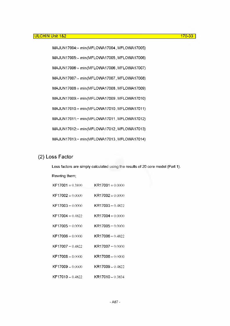
MAJUN 17004:= min(MFLOWA17004, MFLOWA17005)
MAJUN17005:= min(MFLOWA17005, MFLOWA17006)
MAJUN17006:= min(MFLOWA17006, MFLOWA17007)
MAJUN17007:= min(MFLOWA17007, MFLOWA17008)
MAJUN17008:= min(MFLOWA17008, MFLOWA17009)
MAJUN17009:= min(MFLOWA17009, MFLOWA17010)
MAJUN17010:= min(MFLOWA17010, MFLOWA17011)
MAJUN17011 := min(MFLOWA17011, MFLOWA17012)
MAJUN17012:= min(MFLOWA17012, MFLOWA17013)
MAJUN17013:= min(MFLOWA17013, MFLOWA17014)
(2) Loss Factor
ULCHIN Unit 1&2_____________________________________________________ 170-33
Loss factors are simply calculated using the results of 20 core model (Part 1)
Rewring them;
KF17001 =0.3890 KR17001 = 0.0000
KF17002 = 0.0000 KR17002 = 0.0000
KF17003 = 0.0000 KR17003 = 0.4822
KF17004 = 0.4822 KR17004 = 0.0000
KF17005 = 0.0000 KR17005 = 0.0000
KF17006 = 0.0000 KR17006 = 0.4822
KF17007 = 0.4822 KR17007 = 0.0000
KF17008 = 0.0000 KR17008 = 0.0000
KF17009 = 0.0000 KR17009 = 0.4822
KF17010 = 0.4822 KR17010 = 0.3834
-A87-
ULCHIN Unit 1&2 170-34
KF17011 =0.3834 KR17011 =0.0000
KF17012 = 0.0000 KR17012 = 0.4822
KF17013 = 0.4822 KR17013 = 0.3834
KF17014 = 0.3834 KR17014 = 0.0000
KF17015 = 0.4822 KR17015 = 0.4822
KF17016 = 0.0000 KR17016 = 0.3834
KF17017 = 0.3834 KR17017 = 0.4822
KF17018 = 0.4822 KR17018 = 0.0000
KF17019 = 0.0000 KR17019 = 0.0000
For in-core subjunctions (J17002-J17012), considering the figure in page 170-24, the loss factors in 14 subvolume model can be obtained .
For the end junctions (J17001, J17013), the loss factor can be calculated using the pressure drop data of FSAR T4.4-1 and Vantage 5H fuel.
J17001 &J17013
Pressure droo throuah entire core (from the bottom to top in component 170) is; dP 170FSAR:= 165473Pa FSAR T 4.4-1
Pressure droo throuah Vantaae 5H fuel is; dP_Core_tot = 1.5547 x 10⁵Pa p.170-17
Pressure droo that was omitted in local loss factor calculation is; dP_RF = 4.0990 x 10⁴Pa p.170-17
Thus, the pressure drop throuah J17001 or 17013 isdP 170FSAR - (dP Core tot - dP RF)
dP J17001 := —=------------------—=----- =---------- =—-2
dP J17001 = 2.5495 x 10⁴Pa
The pressure drop equation is given by; 2rhoA2dP
flow
-A88-
ULCHIN Unit 1&2 170-35
The reference conditions are (p.170-17);
The mass flowrate :
The density of water:
flow170= 1.4029x 10⁴ —s
rho170= 7.0726x 10² — 3 m
Therefore,
CF17001 :=2rho170 MAJUN170012 dP J17001
flow17(f
CF17001 = 2.6670
and,CR17001:= CF17001 CF17013:= CF17001 CR17013:= CF17001
CR17001 = 2.6670 CF17013 =2.6670 CR17013= 2.6670
at 309.14C and 157.2bar.
Junction J17002~J17012
For in-core subjunctions (J17002-J17012), considering the figure in p.170-24, the loss factors in 14 subvolume model can be obtained by simplt adding the loss factors in Part 1 (p.170-18&170-19).
CF17002:= KF17001CR17002:= KR17001
CF17002 =0.3890 CR17002 =0.0000
CF17003:= KF17002 + KF17003 CR17003:= KR17002+ KR17003
CF17003 =0.0000 CR17003 =0.4822
CF17004:= KF17004 + KF17005 CR17004:= KR17004+ KR17005
CF17004 =0.4822 CR17004 =0.0000
CF17005:= KF17006CR17005:= KR17006
CF17005 =0.0000 CR17005 =0.4822
CF17006:= KF17007 + KF17008 CR17006:= KR17007 + KR17008
CF17006 =0.4822 CR17006 =0.0000
CF17007:= KF17009+ KF17010 CR17007:= KR17009+ KR17010
CF17007 =0.4822 CR17007= 0.8655
CF17008:= KF17011CR17008:= KR17011
CF17008= 0.3834 CR17008 =0.0000
-A89-

ULCHIN Unit 1&2 170-36
CF17009:= KF17012 + KF17013CR17009:= KR17012+ KR17013
CF17009 =0.4822CR17009= 0.8655
CF17010:= KF17014 + KF17015CR17010:= KR17014+ KR17015
CF17010=0.8655CR17010=0.4822
CF17011:= KF17016CR17011:= KR17016
CF17011 = 0.0000CR17011 = 0.3834
CF17012:= KF17017+ KF17018+ KF17019 CR17012:= KR17017+ KR17018 + KR17019
CF17012= 0.8655CR17012= 0.4822
Modification of Loss Factors
Loss factors are modified through comparison with the steady state results
MFJUNF17001 :=CF17001MFJUNR17001:= (R17001
MFJUNF17001 = 2.6670MFJUNR17001 = 2.6670
MFJUNF17002:= CF17002MFJUNR17002:= (R17002
MFJUNF17002= 0.3890MFJUNR17002= 0.0000
MFJUNF17003:= CF17003MFJUNR17003:= (R17003
MFJUNF17003 =0.0000MFJUNR17003= 0.4822
MFJUNF17004:= CF17004MFJUNR17004:= (R17004
MFJUNF17004 = 0.4822MFJUNR17004= 0.0000
MFJUNF17005:= CF17005MFJUNR17005:= (R17005
MFJUNF17005= 0.0000MFJUNR17005= 0.4822
MFJUNF17006:= CF17006MFJUNR17006:= (R17006
MFJUNF17005= 0.0000MFJUNR17006= 0.0000
MFJUNF17007:= CF17007MFJUNR17007:= (R17007
MFJUNF17007= 0.4822MFJUNR17007= 0.8655
MFJUNF17008:= CF17008MFJUNR17008:= (R17008
MFJUNF17008= 0.3834MFJUNR17008= 0.0000
MFJUNF17009:= CF17009MFJUNR17009:= (R17009
MFJUNF17009= 0.4822MFJUNR17009= 0.8655
MFJUNF17010:=CF17010MFJUNR17010:= (R17010
MFJUNF17010=0.8655MFJUNR17010=0.4822
-A90-
ULCHIN Unit 1&2 170-37
MFJUNF17011:=CF17011 MFJUNR17011:= (R17011
MFJUNF17012:=CF17012 MFJUNR17012:= (R17012
MFJUNF17013:=CF17013 MFJUNR17013:= (R17013
D. SUMMARY OF DATAcomponent type = pipe
(1) VOLUME RELATED DATA : 14 Subvolumes
Volume 1
MFLOWL17001 = 0.1089m
MV17001 = 0.6921m3
MFLOWA17001 = 6.3555m2 : Default
MDIA17001 = 1.1050x 10“2m
MZVOL17001 = 0.1089mVolume Flag =0100 : rod bundle interphase friction model not used
MFJUNF17011 = 0.0000 MFJUNR17011 = 0.3834
MFJUNF17012 =0.8655 MFJUNR17012= 0.4822
MFJUNF17013= 2.6670 MFJUNR17013= 2.6670
Volume 2
MFLOWL17002 = 0.3048m
MV17002= 1.1629m3
M FLO WA17002 = 3.8152m2 : Default
MDIA17002= 1.1050x 10“2m
MZVOL17002= 0.3048mVolume Flag =0100 : rod bundle interphase friction model not used
Volume 3
MFLOWL17003 = 0.3048m
MV17003= 1.3576m3
MFLOWA17003 = 4.4539m2 : Default
MDIA17003= 1.1050x 10“2m
MZVOL17003= 0.3048mVolume Flag =0100 : rod bundle interphase friction model not used
- A91 -
Volume 4
MFLOWL17004 = 0.3048m
MV17004= 1.1616m3
MFLOWA17004 = 3.811 lm2 : Default
MDIA17004= 1.1050x 10“2m
MZVOL17004= 0.3048mVolume Flag =0100 : rod bundle interphase friction model not used
Volume 5
MFLOWL17005 = 0.3048m
MV17005 = 0.9339m3
MFLOWA17005 = 3.0639m2 : Default
MDIA17005= 1.1050x 10“2m
MZVOL17005= 0.3048mVolume Flag =0100 : rod bundle interphase friction model not used
Volume 6
MFLOWL17006 = 0.3048m
MV17006= 1.6324m3
MFLOWA17006 = 5.3556m2 : Default
MDIA17006= 1.1050x 10“2m
MZVOL17006= 0.3048mVolume Flag =0100 : rod bundle interphase friction model not used
Volume 7
MFLOWL17007 = 0.3048m
MV17007 = 0.9186m3
MFLOWA17007 = 3.0139m2 : Default
MDIA17007= 1.1050x 10“2m
MZVOL17007= 0.3048mVolume Flag =0100 : rod bundle interphase friction model not used
ULCHIN Unit 1&2_____________________________________________________ 170-38
-A92-

ULCHIN Unit 1&2 170-39
Volume 8
MFLOWL17008 = 0.3048m
MV17008= 1.1663m3
MFLOWA17008 = 3.8265m2 : Default
MDIA17008= 1.1050x 10“2m
MZVOL17008= 0.3048mVolume Flag =0100 : rod bundle interphase friction model not used
Volume 9
MFLOWL17009 = 0.3048m
MV17009= 1.1505m3
MFLOWA17009 = 3.7746m2 : Default
MDIA17009= 1.1050x 10“2m
MZVOL17009= 0.3048mVolume Flag =0100 : rod bundle interphase friction model not used
Volume 10
MFLOWL17010 = 0.3048m
MV17010= 1.1584m3
M FLO WA17010 = 3.8005m2 : Default
MDIA17010= 1.1050x 10“2m
MZVOL17010= 0.3048mVolume Flag =0100 : rod bundle interphase friction model not used
Volume 11
MFLOWL17011 = 0.3048m
MV17011 = 1.1584m3
MFLOWA17011 = 3.8005m2 : Default
MDIA17011 = 1.1050x 10“2m
MZVOL17011 = 0.3048mVolume Flag =0100 : rod bundle interphase friction model not used
-A93-
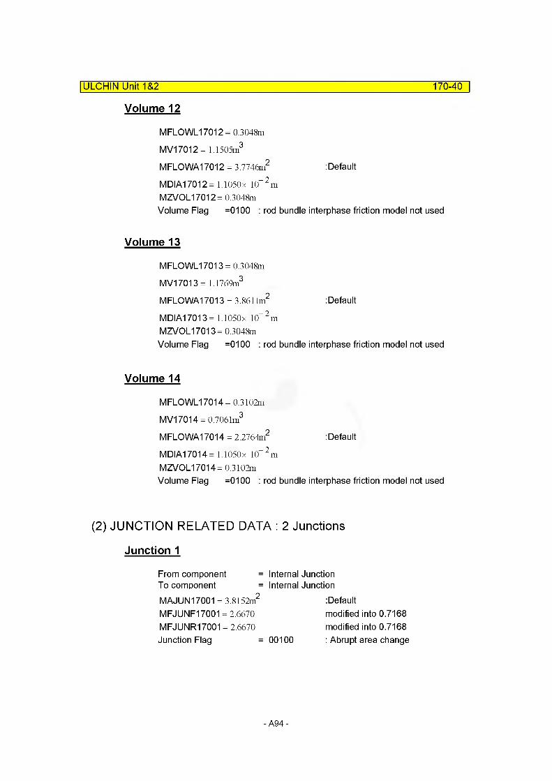
Volume 12
MFLOWL17012 = 0.3048m
MV17012= 1.1505m3
MFLOWA17012 = 3.7746m2 : Default
MDIA17012= 1.1050x 10“2m
MZVOL17012= 0.3048mVolume Flag =0100 : rod bundle interphase friction model not used
Volume 13
MFLOWL17013 = 0.3048m
MV17013= 1.1769m3
MFLOWA17013 = 3.861 lm2 : Default
MDIA17013= 1.1050x 10“2m
MZVOL17013= 0.3048mVolume Flag =0100 : rod bundle interphase friction model not used
Volume 14
MFLOWL17014 = 0.3102m
MV17014 = 0.7061m3
MFLOWA17014 = 2.2764m2 : Default
MDIA17014= 1.1050x 10“2m
MZVOL17014= 0.3102mVolume Flag =0100 : rod bundle interphase friction model not used
ULCHIN Unit 1&2_____________________________________________________ 170-40
(2) JUNCTION RELATED DATA : 2 Junctions
Junction 1
From component = Internal JunctionTo component = Internal JunctionMAJUN17001 = 3.8152m2 :Default
MFJUNF17001 = 2.6670 modified into 0.7168MFJUNR17001 = 2.6670 modified into 0.7168Junction Flag = 00100 : Abrupt area change
-A94-
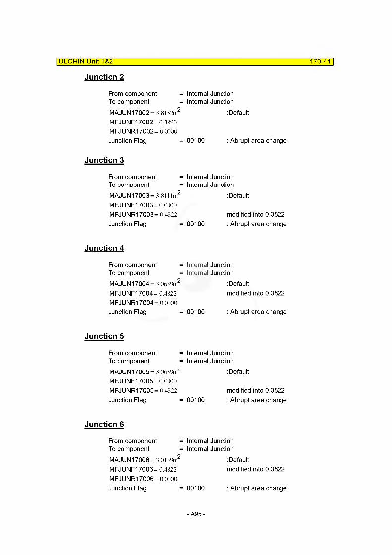
ULCHIN Unit 1&2 170-41
Junction 2
From component =To component =MAJUN17002= 3.8152m2
MFJUNF17002= 0.3890 MFJUNR17002= 0.0000 Junction Flag =
Junction 3
From component =To component =MAJUN17003= 3.8111m2
MFJUNF17003= 0.0000 MFJUNR17003= 0.4822 Junction Flag =
Junction 4
From component =To component =MAJUN 17004= 3.0639m2
MFJUNF17004 = 0.4822 MFJUNR17004= 0.0000 Junction Flag =
Junction 5
From component =To component =MAJUN17005= 3.0639m2
MFJUNF17005= 0.0000 MFJUNR17005= 0.4822 Junction Flag =
Junction 6
From component =To component =MAJUN 17006= 3.0139m2
MFJUNF17006 = 0.4822 MFJUNR17006= 0.0000 Junction Flag =
Internal Junction Internal Junction
: Default
00100 : Abrupt area change
Internal Junction Internal Junction
: Default
modified into 0.3822 00100 : Abrupt area change
Internal Junction Internal Junction
: Defaultmodified into 0.3822
00100 : Abrupt area change
Internal Junction Internal Junction
: Default
modified into 0.3822 00100 : Abrupt area change
Internal Junction Internal Junction
: Defaultmodified into 0.3822
00100 : Abrupt area change
-A95-

ULCHIN Unit 1&2_________________________________________________________170-42
Junction 7
From component =To component =MAJUN17007 = 3.0139m2
MFJUNF17007 =0.4822 MFJUNR17007= 0.8655 Junction Flag =
Internal Junction Internal Junction
: Defaultmodified into 0.3822 modified into 0.7655
00100 : Abrupt area change
Junction 8
From component =To component =MAJUN17008= 3.7746m2
MFJUNF17008= 0.3834 MFJUNR17008= 0.0000 Junction Flag =
Junction 9
From component =To component =MAJUN17009= 3.7746m2
MFJUNF17009 =0.4822 MFJUNR17009= 0.8655 Junction Flag =
Junction 10
From component =To component =MAJUN17010= 3.8005m2
MFJUNF17010=0.8655 MFJUNR17010=0.4822 Junction Flag =
Internal Junction Internal Junction
: Default
00100 : Abrupt area change
Internal Junction Internal Junction
: Defaultmodified into 0.3822 modified into 0.7655
00100 : Abrupt area change
Internal Junction Internal Junction
: Defaultmodified into 0.7655 modified into 0.3822
00100 : Abrupt area change
Junction 11
From component =To component =MAJUN17011 = 3.7746m2
MFJUNF17011 = 0.0000 MFJUNR17011 = 0.3834 Junction Flag =
Internal Junction Internal Junction
: Default
00100 : Abrupt area change
-A96-
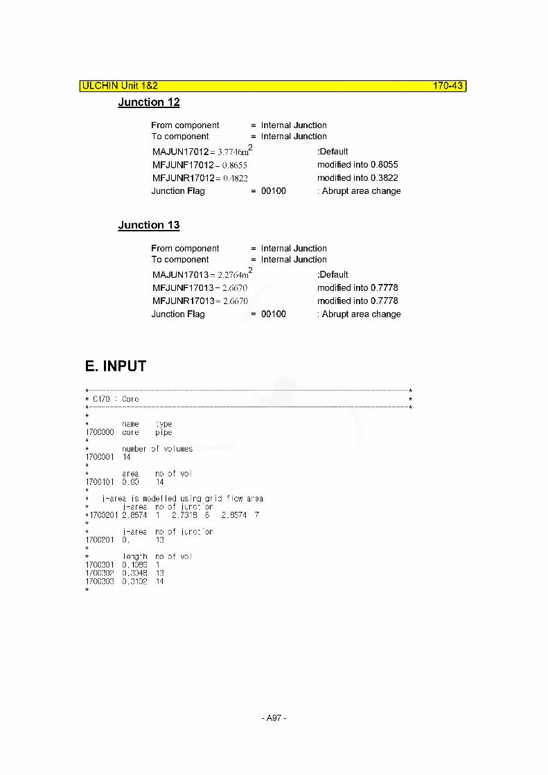
ULCHIN Unit 1&2_________________________________________________________170-43
Junction 12
From component =To component =MAJUN17012= 3.7746m2
MFJUNF17012 =0.8655 MFJUNR17012= 0.4822 Junction Flag =
Internal Junction Internal Junction
: Defaultmodified into 0.8055 modified into 0.3822
00100 : Abrupt area change
Junction 13
From component =To component =MAJUN17013= 2.2764m2
MFJUNF17013 =2.6670 MFJUNR17013= 2.6670 Junction Flag =
Internal Junction Internal Junction
: Defaultmodified into 0.7778 modified into 0.7778
00100 : Abrupt area change
E. INPUT
* C170 : Core
* name type 1700000 core pipe
* number of volumes1700001 14
area no of VO I1700101 0.00 14
* j-area is model led using grj-area no of junction
*1700201 2.8574 1 2..7318 6
j-area no of junction1700201 0. 13
Iength no of vo I1700301 0.1089 11700302 0.3048 131700303 0.3102 14
-A97-
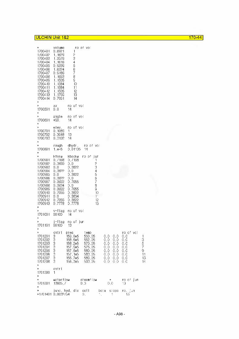
ULCHIN Unit 1&2 170-44
1700401volume0.6921
no of voI
1700402 1.1629 21700403 1.3576 31700404 1.1616 41700405 0.9339 51700406 1.6324 61700407 0.9186 71700408 1.1663 81700409 1.1505 91700410 1.1584 101700411 1.1584 111700412 1.1505 121700413 1.1769 131700414 0.7061 14
XX no of voI1700501 0.0 14
angle no of vol1700601 +90. 14
elev. no of vol1700701 0.1089 11700702 0.3048 131700703 0.3102 14
rough dhydr. no of vo1700801 1. e-6 0.01105 14
kforw kbackw no of jun1700901 0.7168 0.7168 11700902 0.3890 0.0 21700903 0.0 0.3822 31700904 0.3822 0.0 41700905 0.0 0.3822 51700906 0.3822 0.0 61700907 0.3822 0.7655 71700908 0.3834 0.0 81700909 0.3822 0.7655 91700910 0.7055 0.3822 101700911 0.0 0.3834 111700912 0.7055 0.3822 121700913 0.7778 0.7778 13
v-flag no of vol1701001 00100 14
j-flag no of jun1701101 00100 13
cnt r I pres temp1701201 3 159.0e5 560.051701202 3 158.6e5 562.051701203 3 158.2e5 570.051701204 3 157.9e5 575.051701205 3 157.5e5 580.051701206 3 157.1e5 583.051701207 3 156.7e5 589.051701208 3 156.3e5 593.05
cnt r I1701300 1
waterflow steamflow1701301 13605.7 0. 0
no of vol0..0 0..0 0.0 10..0 0..0 0.0 30..0 0..0 0.0 50..0 0..0 0.0 70..0 0..0 0.0 90..0 0..0 0.0 110..0 0..0 0.0 130..0 0..0 0.0 14
* no of jun0.0 13
* junc. hyd. dia oof I*1701401 0.0032754 0.
beta slope no. jun 1. 1. 13
-A98-
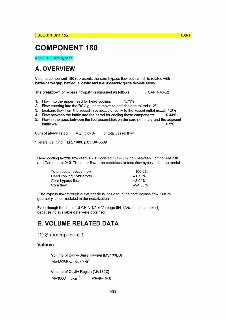
ULCHIN Unit 1&2 180-1
COMPONENT 180Annulus : Core bypass
A. OVERVIEWVolume component 180 represents the core bypass flow path which is related with baffle-barrel gap, baffle-fuel cavity and fuel assembly guide thimble tubes.
The breakdown of bypass flowpath is assumed as follows. (FSAR 4.4.42)
1. Flow into the upper head for head cooling: 1.73%2. Flow entering into the RCC guide thimbles to cool the control rods: 2%3. Leakage flow from the vessel inlet nozzle directily to the vessel outlet nozzl: 1.0%4. Flow between the baffle and the barrel for cooling these components: 0.44%5. Flow in the gaps between the fuel assemblies on the core periphery and the adjacent
baffle wall: 0.5%
Sum of above listed = s 5.67% of total vessel flow
‘Reference: Choi, H.R.,1989, p.83,SA-0009
Head cooling nozzle flow (item.1.) is modeled in the junction between Component 230 and Component 240. The other flow area combines to core flow bypassed in the model.
Total reactor vessel flow =100.0%Head cooling nozzle flow =1.73%Core bypass flow =3.94%Core flow =94.33%
‘The bypass flow through outlet nozzle is included in the core bypass flow. But its geometry is not modeled in the nodalization
Even though the fuel of ULCHIN 1/2 is Vantage 5H, KWU data is adopted, because no available data were obtained.
B. VOLUME RELATED DATA
(1) Subcomponent 1
Volume
Volume of Baffle-Barrel Region [MV180BB] MV180BB := 196.830ft3
Volume of Cavity Region [MV180C] MV180C:= 0.0m3 (Neglected)
-A99-

ULCHIN Unit 1&2 180-2
Volume Inside Guide Thimble [V180CG]
4•3.2733m ... -24-157
4MV180CG= 1.4459m3
Volume Inside Instrumentation Tube [MV180IT]
MV180IT:= - (ll.4010“3m) 3.915m 1574
3.915m 157
MV180IT = 6.2738x 10 2m3
Volume Occupied By RCCA And Thimble Plug,Assuming all rods are in the core [MV180RC]MV180RC:=0.4l62n3
Volume of Guide Thimble Region [MV180GT]MV180GT:= MV180CG + MV180IT- MV180RCMV180GT = 1.0925m3
Volume of Subcomponent 180 [MV1801 MV180 := MV180BB + MV180C + MV180GTMV180 = 6.6661m3
Total core bypass volume is devided into 4 subvolumes in proportion to its height.
MFLOWL18001 := 28.2874n MFLOWL180:= 160.5n
Volume of Subcomponent 18001 [V18001]
MV18001 := MV180-MFLOWL18001MFLOWL180
MV18001 = 1.1749m'3
MV18001MFLOWA18001 :=
MFLOWL18001
(2) Subcomponent 2
MFLOWL18002:= 48in
Volume of Subcomponent 18002 [V18002]
-A100-
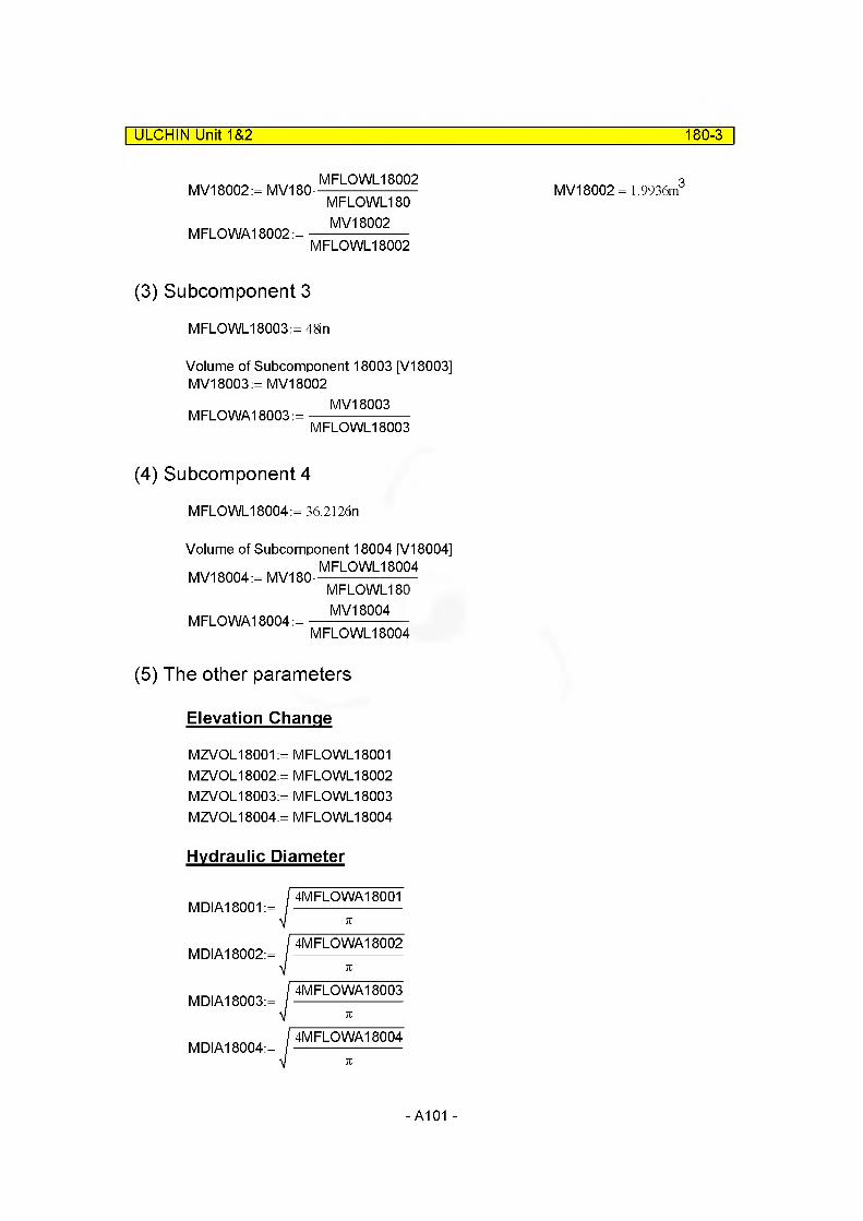
ULCHIN Unit 1&2 180-3
MV18002:= MV180-
M FLO WA18002:=
MFLOWL18002 MFLOWL180 MV18002
MFLOWL18002
MV18002= 1.9936m3
(3) Subcomponent 3
MFLOWL18003:=48in
Volume of Subcomponent 18003 [V18003] MV18003:= MV18002
MV18003MFLOWA18003 :=----------------------
MFLOWL18003
(4) Subcomponent 4
MFLOWL18004:= 36.2126n
Volume of Subcomponent 18004 [V18004] MV18004,MV180MFLOWL18004
M FLO WA18004:=
MFLOWL180 MV18004
MFLOWL18004
(5) The other parameters
Elevation Change
MZVOL18001MZVOL18002MZVOL18003MZVOL18004
= MFLOWL18001 = MFLOWL18002 = MFLOWL18003 = MFLOWL18004
Hydraulic Diameter
MDIA18001:=4MFLOWA18001
MDIA18002:=4M FLO WA18002
MDIA18003:=4M FLO WA18003
MDIA18004:=4M FLO WA18004
-A101-
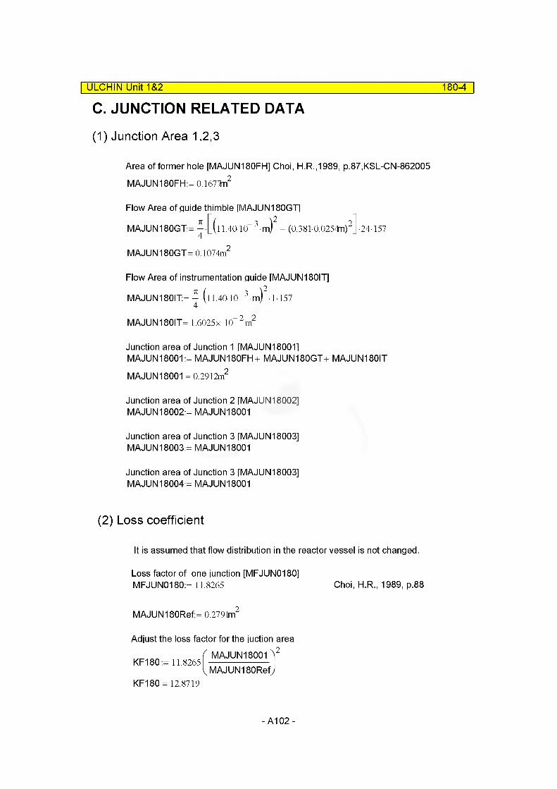
| ULCHIN UniO&2 180-4
C. JUNCTION RELATED DATA
(1) Junction Area 1,2,3
Area of former hole [MAJUN180FH] Choi, H.R.,1989, p.87,KSL-CN-862005 MAJUN180FH:=0.l677fn2
Flow Area of guide thimble [MAJUN180GT1
MAJUN180GT:= —• (l 1.4010"4
MAJUN180GT= 0.1074m2
Flow Area of instrumentation guide [MAJUN180IT]
MAJUN180IT:= --(ll.40-10“ 3-m) -1-1574
MAJUN180IT= 1.6025x 10 2m2
Junction area of Junction 1 [MAJUN180011MAJUN18001 := MAJUN180FH+ MAJUN180GT+ MAJUN180ITMAJUN18001 = 0.2912m2
Junction area of Junction 2 [MAJUN18002]MAJUN18002:= MAJUN18001
Junction area of Junction 3 [MAJUN 18003]MAJUN18003:= MAJUN18001
Junction area of Junction 3 [MAJUN 18003]MAJUN18004:= MAJUN18001
(2) Loss coefficient
It is assumed that flow distribution in the reactor vessel is not changed.
Loss factor of one junction [MFJUN0180]MFJUN0180:= 11.8265 Choi, H.R., 1989, p.88
MAJUN180Ref:= 0.2791m2
Adjust the loss factor for the juction area
KF180:= 11.8265MAJUN18001 Y
MAJUN180RefJKF180 = 12.8719
-A102-
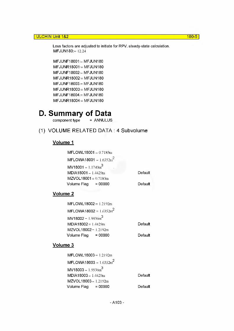
ULCHIN Unit 1&2 180-5
Loss factors are adjusted to initiate for RPV. steady-state calculation. MFJUN180:= 12.24
MFJUNF18001:= MFJUN180 MFJUNR18001:= MFJUN180 MFJUNF18002:= MFJUN180 MFJUNR18002:= MFJUN180 MFJUNF18003:= MFJUN180 MFJUNR18003:= MFJUN180 MFJUNF18004:= MFJUN180 MFJUNR18004:= MFJUN180
D. Summary of Datacomponent type = ANNULUS
(1) VOLUME RELATED DATA : 4 Subvolume
Volume 1
MFLOWL18001 = 0.7185m
MFLOWA18001 = 1.6352m2
M V18001 = 1.1749m3
MDIA18001 = 1.4429m DefaultMZVOL18001 = 0.7185mVolume Flag = 00000 Default
Volume 2
MFLOWL18002 = 1.2192m
M FLO WA18002 = 1.6352m2
MV18002= 1.9936m3
MDIA18002= 1.4429m DefaultMZVOL18002= 1.2192mVolume Flag = 00000 Default
Volume 3
MFLOWL18003 = 1.2192m
M FLO WA18003 = 1.6352m2
MV18003= 1.9936m3
MDIA18003= 1.4429m DefaultMZVOL18003= 1.2192mVolume Flag = 00000 Default
-A103-
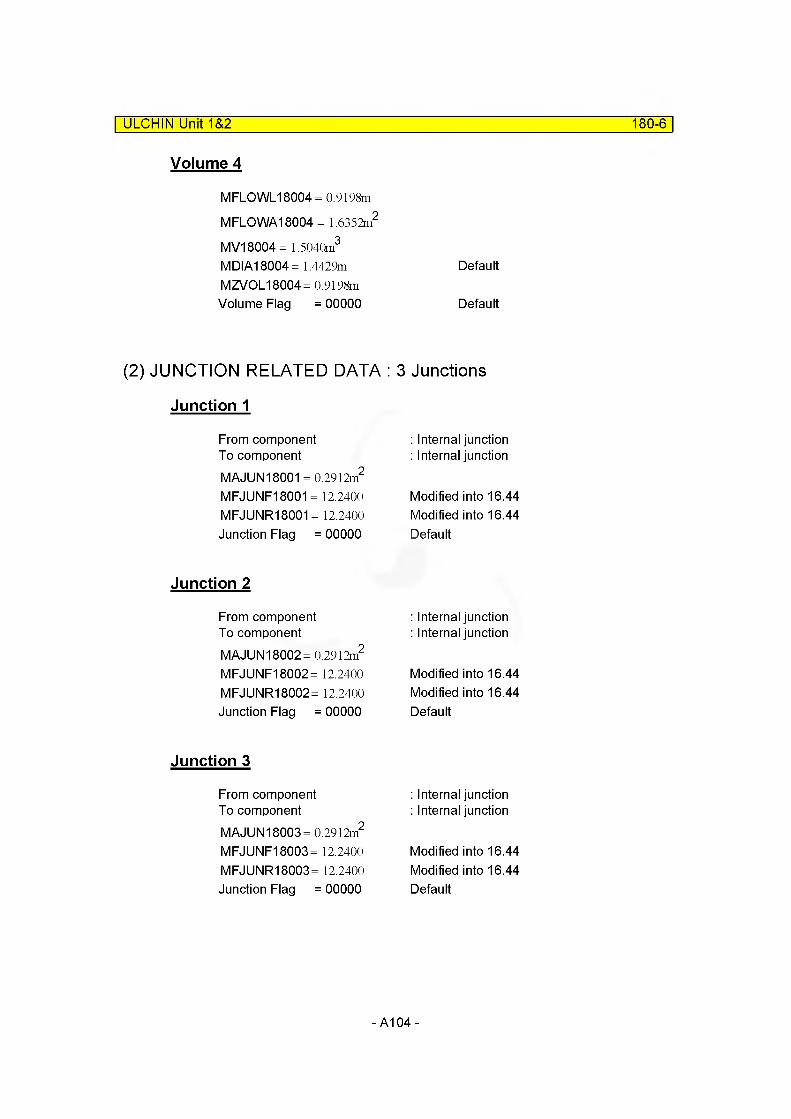
ULCHIN Unit 1&2 180-6
Volume 4
MFLOWL18004 = 0.9198m
M FLO WA18004 = 1.6352m2
MV18004= 1.5040m3
MDIA18004= 1.4429m DefaultMZVOL18004= 0.9198mVolume Flag = 00000 Default
(2) JUNCTION RELATED DATA : 3 Junctions
Junction 1
From component : Internal junctionTo component : Internal junctionMAJUN18001 = 0.2912m2
MFJUNF18001 = 12.2400 Modified into 16.44MFJUNR18001 = 12.2400 Modified into 16.44Junction Flag = 00000 Default
Junction 2
From component : Internal junctionTo component : Internal junctionMAJUN18002= 0.2912m2
MFJUNF18002= 12.2400 Modified into 16.44MFJUNR18002= 12.2400 Modified into 16.44Junction Flag = 00000 Default
Junction 3
From component : Internal junctionTo component : Internal junctionMAJUN18003= 0.2912m2
MFJUNF18003= 12.2400 Modified into 16.44MFJUNR18003= 12.2400 Modified into 16.44Junction Flag = 00000 Default
-A104-
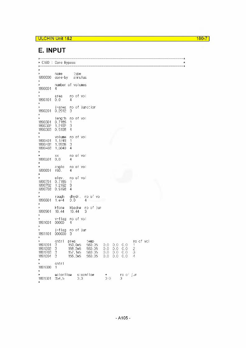
ULCHIN Unit 1&2 180-7
E. INPUT
* C180 : Core Bypass
* name type1800000 core-by annulus
* number of volumes1800001 4
area no of vo I1800101 0.0 4
j-area no of junction1800201 0.2912 3
Iength no of vo I1800301 0.7185 11800302 1.2192 31800303 0.9198 4
volume no of vo I1800401 1.1749 11800402 1.9936 31800403 1.5040 4
XX no of vol1800501 0.0 4
angle no of vol1800601 +90. 4
elev. no of vol1800701 0.7185 11800702 1.2192 31800703 0.9198 4
rough dhydr. no of vol1800801 1. e-4 0.0 4
kforw kbackw1 no of jun1800901 16.44 16.44 3
v-flag no of vol1801001 00000 4
j-flag no of jun1801101 000000 3
cnt r I pres temp no1801201 3 159.0e5' 560.05 0.0 0.0 0.0 11801202 3 158.2e5' 560.05 0.0 0.0 0.0 21801203 3 157.1e5' 560.05 0.0 0.0 0.0 31801204 3 156.3e5' 560.05 0.0 0.0 0.0 4
cnt r I1801300 1
waterflow steamflow no of jun1801301 354.5 0. 0 0.0 3
- A105-
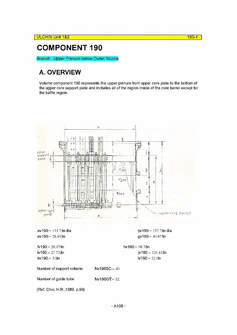
COMPONENT 190Branch : Upper Plenum below Outlet Nozzle
| ULCHIN Unit 1&2 190-1
A. OVERVIEWVolume component 190 represents the upper plenum from upper core plate to the bottom of the upper core support plate and includes all of the region inside of the core barrel except for the baffle region.
av190:= 133.75n dia ev190:= 28.851n
bv190:= 137.75n dia gv190:= 40.873n
fv190:= 28.97Qn iv190:= 27.732n kv190:= 3.0in
hv190:= 98.7dnjv190:= 126.432n Iv190:= 12.0n
Number of support column Nv190SC:= 40
Number of guide tube Nv190GT:= 52
(Ref. Choi, H.R.,1989, p.90)
-A106-
ULCHIN Unit 1&2 190-2
B. VOLUME RELATED DATA
(1) Subcomponent 1
Volume
Volume of Component 190 [MV190]= Volume Inside Upper Core Barrel [MV190UCB] - {Volume of Support Columns [MV190SC]
Choi, H.R.,1989, p.91,SA-0009 + Volume of Lower Guide Tubes [MV190LGT]
Choi, H.R.,1990,p.91 ,SA-0009
+ Volume of Upper Core Plate [MV190UCP]Choi, H.R.,1990, p.91,SA-0009
MV190UCB:= ^(av19Q2ev190
MV190UCB = 6.6440m3
As the volume of guide tubes and support columns cannot be calculated due to the lack of detailed dimension drawings, it is assumed which is divided as the ratio of part to total length. And the detailed calculation is refered to
Choi, H.R., 1990, p.91
Total volume of support Columns in upper plenum
MV190TSC:= 33993.44n3 Choi, H.R.,1990, p.91,SA-0009
MV190SC = 0.1721m3
Volume Occupied By Component 260, That is Control Rod Guide Tubes Volumes(Metal) and inside Volume.
Dv190OGT:= 8.0in
MV260LGT(Dv190OGTJ2 • (ev190 - kv190) Nv190GT
MV260LGT = 1.1075m3
MV190UCP:= 26527.28ln3
MV19001 := MV190UCB - (MV190SC + MV260LGT + MV190UCP) MV19001 = 4.9297m3
* We neglects the volume of orifice plates fuel ass'y guide pin, core plate insert.
-A107-

ULCHIN Unit 1&2 190-3
Hydraulic Diameter
Hydraulic Diameter of Component 190 [MDIA190]
Upper Core Plate is not Accounted for in the Calculation.
MV19001 = 4.9297m MFLOWL19001 := 28.851n
MV19001MFLOWA19001 :=
MFLOWL19001
MFLOWA19001 = 6.7257m
Perimeter [Pv190]
[Pv190] Accounts for The Perimeter of Core Barrel, Support Column, CRDM Drive Rod,Lower Guide Tube.
Perimeter of Core Barrel [Pv190CB]
Pv190CB:= 7iav190 Pv190CB= 10.6728m
Perimeter of Support Column [Pv190SC]
Nv190SC= 40.0000Outside Diameter [Dv190O] (Choi, H.R.,1990, p.93,SA-0009.est.) Dv190O:= 3.5in
Pv190SC:= tiDv1900Nv190SC Pv190SC= 11.1715m
Perimeter of Lower Guide Tube [Pv190LG7]Dv190LGT:= Sin Ref. Choi, H.R.,1990, p.93,SA-0009Pv190LGT:= ttDv190LGTNv190GT Pv190LGT= 33.1953m
Pv190:= Pv190CB+ Pv190SC+ Pv190LGTPv190= 55.0396m
4MFLOWA19001MDIA19001 :=-------------------------
Pv190MDIA19001 = 0.4888m
-A108-
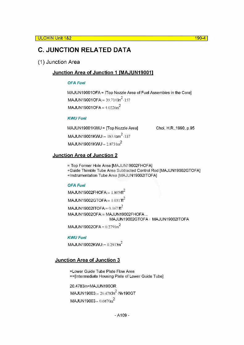
ULCHIN Unit 1&2 190-4
C. JUNCTION RELATED DATA
(1) Junction Area
Junction Area of Junction 1 rMAJUNI90011
OFA Fuel
MAJUN19001OFA = [Top Nozzle Area of Fuel Assembles in the Core] MAJUN19001OFA:= 39.714ln2 -157
MAJUN19001 OFA = 4.0226m2
KWU Fuel
MAJUN19001 KWU = [Top Nozzle Area] Choi, H.R.,1990, p.95
MAJUN19001 KWU:= 183.Ccm2-157
MAJUN19001 KWU = 2.873 lm2
Junction Area of Junction 2
= Top Former Hole Area [MAJUN19002FHOFA]+Guide Thimble Tube Area Subtracted Control Rod [MAJUN19002GTOFA] +lnstrumentation Tube Area [MAJUN19002ITOFA]
OFA FuelMAJUN19002FHOFA:= 1.805<ft2
MAJUN19002GTOFA:= 1.0317ft2
MAJUN19002ITOFA= 0.1673ft2
MAJUN190020FA:= MAJUN19002FHOFA...+ MAJUN19002GTOFA+ MAJUN19002ITOFA
MAJUN190020FA= 0.2791m2
KWU FuelMAJUN19002KWU:= 0.2913m2
Junction Area of Junction 3
=Lower Guide Tube Plate Flow Area ==[lntermediate Housing Plate of Lower Guide Tube]
20.4783in=MAJUN190OR MAJUN19003:= 20.4783n2-Nv190GT
MAJUN19003= 0.6870m2
-A109-
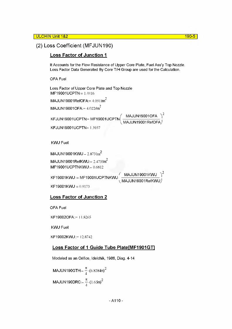
| ULCHIN UniO&2 190-5
(2) Loss Coefficient (MFJUN190)
Loss Factor of Junction 1
It Accounts for the Flow Resistance of Upper Core Plate, Fuel Ass'y Top Nozzle. Loss Factor Data Generated By Core T/H Group are used for the Calculation.
OFA Fuel
Loss Factor of Upper Core Plate and Top Nozzle MF19001 UCPTN:= 1.4416
MAJUN19001 RefOFA= 4.0911m2
MAJUN19001OFA:= 4.0226n2
KFJUN19001 UCPTN= MF19001UCPTN-
KFJUN19001 UCPTN= 1.3937
KWU Fuel
MAJUN19001 KWU = 2.873 lm2
MAJUN19001 RefKWU:= 2.4759n2
MF19001 UCPTNKWU:= 0.6812
KF19001 KWU := MF19001UCPTNKWU
KF19001 KWU = 0.9173
Loss Factor of Junction 2
OFA Fuel
KF190020FA:= 11.8265
KWU Fuel
KF19002KWU := 12.8742
Loss Factor of 1 Guide Tube PlaterMF1901GTl
Modeled as an Orifice, Idelchik, 1986, Diag. 4-14
MAJUN190GTH:= ^(6.8384n)2
MAJUN190DRC:= ^(1.65in)2
-A110-
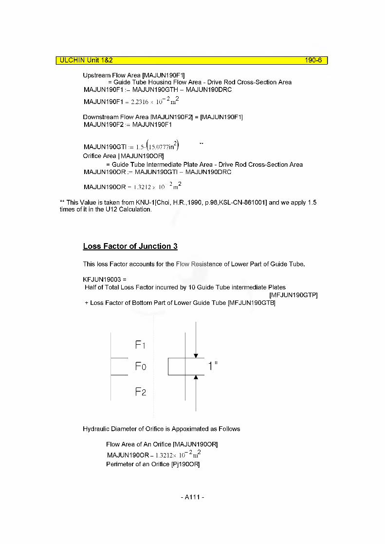
ULCHIN Unit 1&2 190-6
Upstream Flow Area [MAJUN190F1]= Guide Tube Housina Flow Area - Drive Rod Cross-Section Area
MAJUN190F1 := MAJUN190GTH - MAJUN190DRCMAJUN190F1 = 2.2316 x 10“2m2
Downstream Flow Area HVIAJUN190F2] = [MAJUN190F1]MAJUN190F2 := MAJUN190F1
MAJUN190GTI := 1.5-(l5.0777in2)
Orifice Area [ MAJUN190OR]= Guide Tube Intermediate Plate Area - Drive Rod Cross-Section Area
MAJUN190OR := MAJUN190GTI - MAJUN190DRC
MAJUN190OR = 1.3212 x 10™ 2 m2
** This Value is taken from KNU-1[Choi, H.R.,1990, p.98,KSL-CN-861001] and we apply 1.5 times of it in the U12 Calculation.
Loss Factor of Junction 3
This loss Factor accounts for the Flow Resistance of Lower Part of Guide Tube.
KFJUN19003 =Half of Total Loss Factor incurred by 10 Guide Tube intermediate Plates
[MFJUN190GTP]+ Loss Factor of Bottom Part of Lower Guide Tube [MFJUN190GTB]
F1
Fo ! 1
F2
Hydraulic Diameter of Orifice is Appoximated as Follows
Flow Area of An Orifice [MAJUN190OR] MAJUN190OR= 1.3212x 10“2m2
Perimeter of an Orifice [Pj190OR]
-A111-

ULCHIN Unit 1&2 190-7
Pj190OR:= 7i• aj190 + (8bj190) 4 + 7i l.65in Pj190OR = 2.3472mMDIA190OR:= 4 MAJUN190OR
PJ190OR MDIA190OR= 2.2515x 10“2m
aj190:= 2.3in (by scaling) bj190 := 2.5in (by scaling) cj190 := 0.3in(by scaling) Choi, H.R.,1990, p.100
Ij190 := lin Ij190
MDIA190OR1.1281
xj 190:= 0.17
MRatio190:=MAJUN190OR
MAJUN190F1MRatiol 90 = 0.5920
Aj190 := 1 10 4m
ABARj190:=Aj190
MDIA190OR
ABARj190 = 4.4415x 10" 7j190:= 0.028
(Fully developed flow)
MFJUN190GTOR= (o.5+ xj190-V 1 - MRatiol9o) (l - MRatiol90) ...
+ (1 - MRatiol 90) + 7j190Ij190
MDIA190OR
I MRatiol 90
MFJUN190GTOR= 1.2733 Reference Area
MAJUN190RefGTOR= 34.590n
-A112-

ULCHIN Unit 1&2 190-8
MFJUN190GTP:= 10MFJUN190GTOR-2
MFJUN190GTP= 6.3667 Reference Area
MAJUN190RefGTP:= MAJUN190RefGTOR
Loss Factor of Bottom Part of Lower Guide Tube [MFJUN190GTB] Forward Loss Factor Idelchik Diag. 11-28
MAJUN190F1 = 2.2316x 10“ 2 m2
Fo
1.0 For
MAJUN0190OR = Hole Area of Lower Guie Tube Lower Plate - Drive Rod Cross-Section Area
MAJUN0190OR:= MAJUN190HGT- MAJUN190DRC MAJUN0190OR= 1.9172x 10“2m2
** This value is taken from KNU-1 DATA in U12 Calculation, We apply 1.5 times
Lower Guide Tube Lower Plate
caj0190:= 6.37in (by scaling)
bj190 = 6.3500x 10“ 2 m
(by scaling)Cj190 = 7.6200x 10“ 3 m
(by scaling)
-A113-
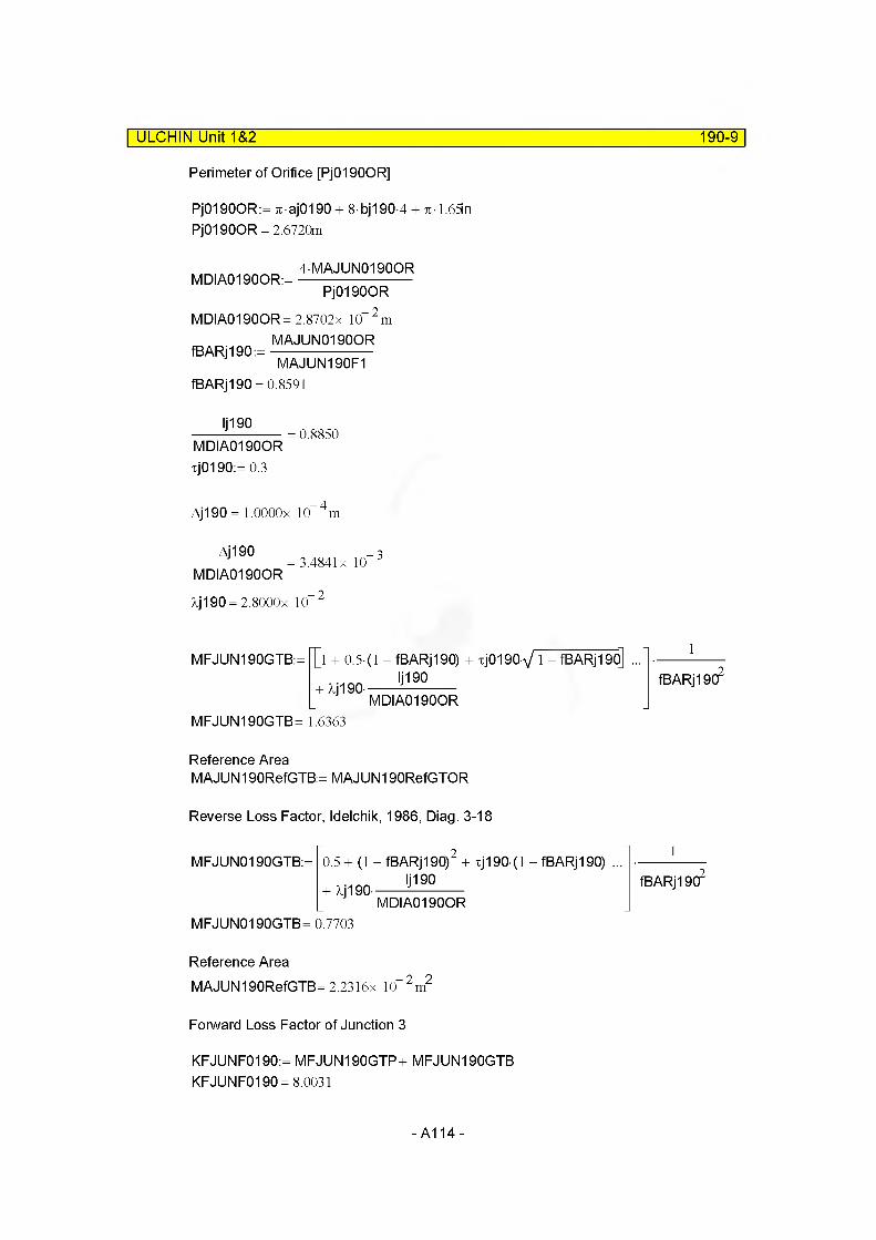
ULCHIN Unit 1&2 190-9
Perimeter of Orifice [PJ0190OR]
Pj0190OR:= 7T aj0190 + 8 bj190 4 + %-1.65in Pj0190OR = 2.6720m
MDIA0190OR:=4MAJUN01900R
PJ0190ORMDIA0190OR= 2.8702x 10 2m
MAJUN0190ORfBARj190:=----------------------
MAJUN190F1fBARj190 = 0.8591
Ij190MDIA0190OR xj0190:= 0.3
0.8850
Aj190 = l.OOOOx 10 4m
Aj190 _ 3= 3.4841x 10
MDIA01900R
Aj190 = 2.8000x 10.- 2
MFJUN190GTB:= |”[l + 0.5 (1 - fBARj190) + xj0190V 1 - fBARj19o] ...Ij190
+ XJ190-
MFJUN190GTB= 1.6363MDIA01900R
fBARj 1902
Reference AreaMAJUN190RefGTB:= MAJUN190RefGTOR
Reverse Loss Factor, Idelchik, 1986, Diag. 3-18
MFJUN0190GTB:= 0.5+ (1 -fBARj190) + xj 190 (1 - fBARj 190) ... + Xj190- 'j19°
MDIA01900R
fBARj 1902
MFJUN0190GTB= 0.7703
Reference AreaMAJUN190RefGTB= 2.2316x 10“2m2
Forward Loss Factor of Junction 3
KFJUNF0190:= MFJUN190GTP+ MFJUN190GTB KFJUNF0190 =8.0031
-A114-
ULCHIN Unit 1&2 190-10
Reverse Loss Factor of Junction 3
KFJUNR0190:= MFJUN190GTP+ MFJUN0190GTB KFJUNR0190= 7.1370
Adjust Loss Factor For Junction Area.
( MAJUN190OR YKFJUNF19003:= KFJUNF0190- --------------------------
V MAJUN190RefGTBjKFJUNF19003 =2.8051
KFJUNR19003:= KFJUNR0190-
KFJUNR19003= 2.5015
MAJUN190OR y
MAJUN190RefGTBj
* We calculated loss factors of junctions. But we could not confide exactly because of scarcity of plant drawings. After they are used in test run of RPV steady-state, they adjusted to initialize for RPV steady-state again. That is,
MFJUNF19001:= 0.35 MFJUNR19001:= 0.35
MFJUNF19002:= 32.60 MFJUNR19002:= 62.60
MFJUNF19003:= 0.03 MFJUNR19003:= 0.03
D. SUMMARY OF DATA(KWU Only)component type : branch
(1) VOLUME RELATED DATA
Volume 1
MFLOWL19001 = 0.7330m
MFLOWA19001 = 6.7257m2
MV19001 = 4.9297m3
MDIA19001 = 0.4888m MZVOL19001 := MFLOWL19001 MZVOL19001 = 0.7330mVolume Flag = 000000 Default
-A115-

(2) JUNCTION RELATED DATA : 3 Junctions| ULCHIN Unit 1&2 190-11
Junction 1from component =17001000to component =190000000
MAJUN19001KWU = 2.873 lm2
MFJUNF19001 = 0.3500 Modified into 0.21MFJUNR19001 = 0.3500 Modified into 0.21Junction Flag =100000 CCFL model applied
Junction 2
from component =180010000to component =190000000MAJUN19002KWU = 0.2913m2
MFJUNF19002= 32.6000 Modified into 30.6MFJUNR19002 =62.6000 Modified into 30.6Junction Flag = 00000 Default
Junction 3
from component = 250010000to component =190000000MAJUN19003= 0.6870m2
MFJUNF19003=3.0000x 10 2 Modified into 0.028
MFJUNR19003= 3.0000x 10™ 2 Modified into 0.028Junction Flag = 00000 Default
put Cards* C190 : upper plenum 1
name type1900000 uppr-pl1 branch
no of jun cnt r I1900001 3 1
area length vol x angle elev rough dh vf 111900101 0.0 0.7330 4.9297 0. +90. +0.7330 1.8-4 0.4888 00
cntr I pres temp1900200 3 156.3e5 595. 05
from to area kforw kbackw j f I ag1901101 170010000 190000000 2.8731 0.21 0.21 1000001902101 180010000 190000000 0.2913 30.60 30.60 0000001903101 250010000 190000000 0.6870 0.028 0.028 00000
waterflow steamflow X1901201 13605.7 0.0 0.01902201 354.5 0.0 0.01903201 277.6 0.0 0.0
-A116-
COMPONENT 200| ULCHIN Unit 1&2 200-1
Branch : upper plenum connected to outlet nozzle (hot leg)
A. OverviewVolume component 200 represents the upper plenum region connected to the outlet nozzle. Upper and lower boundaries are the same elevation as those of the outlet nozzle annulus. Related diagram can be found on page 190-1.
B. VOLUME RELATED DATA
(1) Subcomponent 1
Volume
Volume of Component 200 [MV200]= Volume inside Upper Core Barrel [MV200UCB]- {Volume of Lower Guide Tubes [MV200LG"I]VOL260 + Volume of Support Columns [MV200SC]}
av200:= av190 fv200:=fv190
MV200UCB:= — av20C? fv2004
MV200UCB = 6.6700m3
Assume that the volume of support columns is propotional to its height in the upper plenum.
MV200TSC:= 19.6721ft3
kv200:= kv190 Iv200:= Iv190 hv200:= hv190
fv200MV200SC:= MV200TSC-------------------------------
hv200- kv200 - Iv200MV200SC = 0.1928m3
Volume of Lower Guide Tubes [MV200LGT]= Volume Occupied by Component 260
Dv200OGT:= Dv190OGT Nv200GT:= Nv190GT
-A117-
MV200LGT:= - • Dv2000cf • fv200 Nv200GT4
MV200LGT = 1.2409m3
MV20001 := MV200UCB - (MV200LGT + MV200SC)MV20001 = 5.2364m3
ULCHIN Unit 1&2_____________________________________________________ 200-2
Flow Length
MFLOWL20001 := fv200 MFLOWL20001 = 0.7358m
Flow Area : Default
MFLOWA20001 :=MV20001
fv200
MFLOWA20001 = 7.1162m"
Elevation Change
MZVOL20001 := MFLOWL20001 sin (90deg) MZVOL20001 = 0.7358m
Hydraulic Diameter
Hydraulic Diameter of Component 200 [MDIA200]
Perimeter of Component 200 [Pv200]= Perimeter of Core Barrel [Pv200CB]
+ Perimeter of Support Column [Pv200SC] + Perimeter of Guide Tube [Pv200GT]
Pv200CB:= 7iav200
Pv200CB = 10.6728m
Dv200GSC:= Dv1900 Nv200OSC:= Nv190SC Pv200SC:= k ■ Dv200OSC Nv200OSC Pv200SC= 11.1715m
Pv200GT:= 7tDv2000GTNv200GT Pv200GT= 33.1953m
-A118-
ULCHIN Unit 1&2 200-3
Pv200:= Pv200CB+ Pv200SC+ Pv200GT Pv200= 55.0396m
4MFLOWA20001MDIA20001 :=-------------------------
Pv200MDIA20001 =0.5172m
C. JUNCTION RELATED DATA
(1) Junction Area
Area of Junction 1 rMAJUN20001. 2, 31
Dv200i:= 28.91n
MAJUN20001 := - • Dv200? MAJUN20001 = 0.4253m24
MAJUN20002:= MAJUN20001 MAJUN20003:= MAJUN20001
Area of Junction 2 rMAJUN20004.51
MAJUN20004:= min(MFLOWA19001, MFLOWA20001) MAJUN20004= 6.7257m2
MAJUN20005:=min(MFLWOA20001 ,MFLOWA21001) MAJUN20005:= 5.5712n2 (MFLOWA21001)
(2) Loss Coefficient (MFJUN200)
Calculation of Loss Factor for Junction 1,2
Forward Loss Factor [MFJUNF200] Idelchik, 1986, Diag. 3-6
MFJUNF200 = f( — , a)Dh
l=3.0in (est.)Dh=28.97in l/Dh=0.10a=60deg (est.)
MFJUNF20001 := 0.18 MFJUNF20002 := 0.18
-A119-
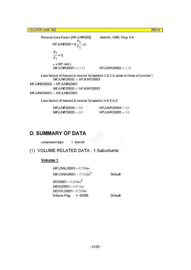
Idelchik, 1986, Diag. 5-6
ULCHIN Unit 1&2 200-4
Reverse Loss Factor [MFJUNR200]F0
MFJUNR200 = f( —, a)Fi
Fi
a = 60° (est.)MFJUNR20001 := 1.15 MFJUNR20002 := 1.15
Loss factors of forward & reverse for junction 2 & 3 is same to those of junction 1. MFJUNF20002 := MFJUNF20001
MFJUNR20002 := MFJUNR20001MFJUNF20003 := MFJUNF20001
MFJUNR20003 := MFJUNR20001
Loss factors of forward & reverse for junction 4 & 5 is 0.
MFJUNF20004 := 0.0 MFJUNF20005 := 0.0
MFJUNR20004 := 0.0 MFJUNR20005 := 0.0
D. SUMMARY OF DATAcomponent type = branch
(1) VOLUME RELATED DATA : 1 Subvolume
Volume 1
MFLOWL20001 = 0.7358m
MFLOWA20001 = 7.1162m'2 Default
MV20001 = 5.2364m3
MDIA20001 =0.5172m MZVOL20001 = 0.7358m Volume Flag = 00000 Default
-A120 -
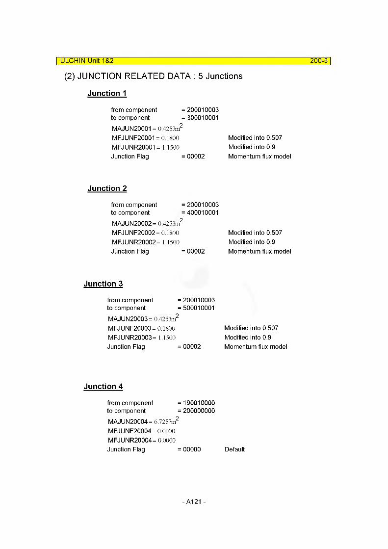
(2) JUNCTION RELATED DATA : 5 Junctions
Junction 1
| ULCHIN Unit 1&2 200-5
from component =200010003to component = 300010001MAJUN20001 = 0.4253m2
MFJUNF20001 = 0.1800 Modified into 0.507MFJUNR20001 = 1.1500 Modified into 0.9Junction Flag = 00002 Momentum flux model
Junction 2
from component =200010003to component =400010001MAJUN20002= 0.4253m2
MFJUNF20002 = 0.1800 MFJUNR20002= 1.1500 Junction Flag = 00002
Modified into 0.507 Modified into 0.9 Momentum flux model
Junction 3
from component =to component =MAJUN20003= 0.4253m2
MFJUNF20003 = 0.1800 MFJUNR20003= 1.1500 Junction Flag =
Junction 4
from component =to component =MAJUN20004= 6.7257m2
MFJUNF20004= 0.0000 MFJUNR20004= 0.0000 Junction Flag =
200010003500010001
Modified into 0.507 Modified into 0.9
00002 Momentum flux model
190010000200000000
00000 Default
- A121-

E. INPUT| ULCHIN UnlO&2 200-6
* C200 : upper plenum 2
name type2000000 uppr-p12 branch
no of jun cnt r I2000001 5 1
area length vol x angle elev rough dh vf lag2000101 0.0 0.7358 5.2364 0. +90. 0 .7358 1. e-4 .5172 00
cntr I pres temp2000200 3 156.3e5 595. 05
from to area kforw kbackw j f I ag2001101 200010003 300010001 0.4253 0.057 0.900 000022002101 200010003 400010001 0.4253 0.057 0.900 000022003101 200010003 500010001 0.4253 0.057 0.900 000022004101 190010000 200000000 0.0 0.0 0.0 000002005101 200010000 210010000 0.0 0.0 0.0 00000
waterflow steamflow X2001201 4746.00 0.0 0.02002201 4746.00 0.0 0.02003201 4746.00 0.0 0.02004201 14238.00 0.0 0.02005201 0.00 0.0 0.0
- A122-
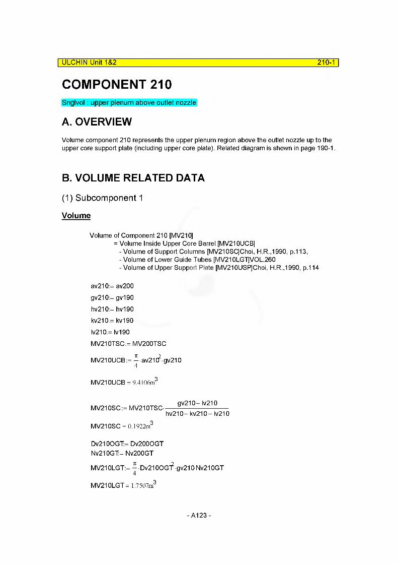
ULCHIN Unit 1&2 210-1
COMPONENT 210Snglvol: upper plenum above outlet nozzle
A. OVERVIEWVolume component 210 represents the upper plenum region above the outlet nozzle up to the upper core support plate (including upper core plate). Related diagram is shown in page 190-1.
B. VOLUME RELATED DATA
(1) Subcomponent 1
Volume
Volume of Component 210 [MV210]= Volume Inside Upper Core Barrel [MV210UCB]
- Volume of Support Columns [MV210SC]Choi, H.R.,1990, p.113,- Volume of Lower Guide Tubes [MV210LG1]VOL.260-Volume of Upper Support Plate [MV210USP]Choi, H.R.,1990, p.114
av210:= av200
gv210:= gv190
hv210:= hv190
kv210:= kv190
Iv210:= Iv190
MV210TSC:= MV200TSC
MV210UCB:= ^-av21C?-gv210
MV210UCB = 9.4106m3
MV210SC:= MV210TSC-
MV210SC = 0.1922m3
Dv210OGT:= Dv2000GT Nv210GT:= Nv200GT
gv210- Iv210
hv210- kv210 - Iv210
MV210LGT:= ^ • Dv21 OOcf gv210 Nv210GT
MV210LGT = 1.7507m3
-A123-
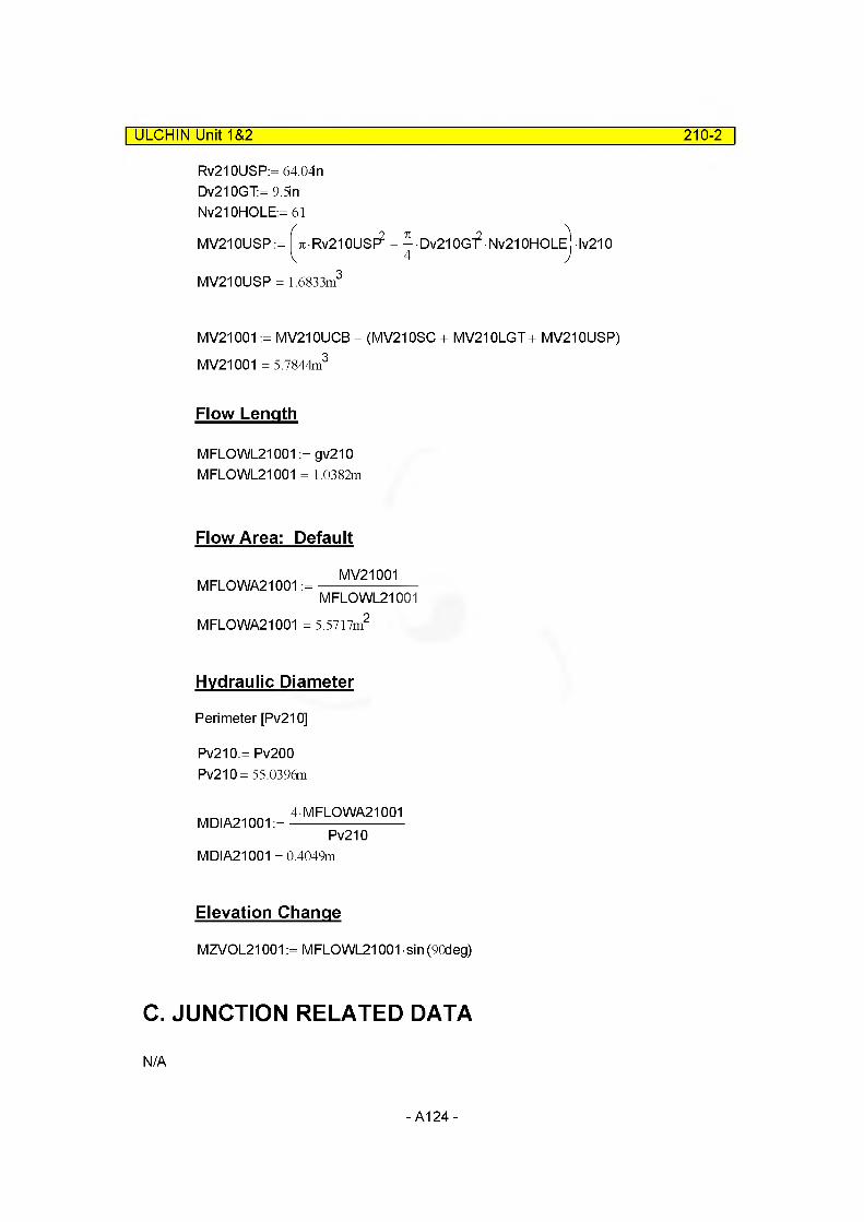
ULCHIN Unit 1&2 210-2
Rv210USP:=64.04n Dv210GT:= 9 5m Nv210HOLE:= 61MV210USP:= ^•Rv210USF?
MV210USP = 1.6833m3
•Dv21 0G12- Nv210HOLE Iv210
MV21001 := MV210UCB - (MV210SC + MV210LGT + MV210USP) MV21001 = 5.7844m3
Flow Length
MFLOWL21001 := gv210 MFLOWL21001 = 1.0382m
Flow Area: Default
MFLOWA21001 :=MV21001
MFLOWL21001
MFLOWA21001 = 5.5717ni
Hydraulic Diameter
Perimeter [Pv210]
Pv210:= Pv200 Pv210= 55.0396m
4MFLOWA21001MDIA21001 :=-------------------------
Pv210MDIA21001 = 0.4049m
Elevation Change
MZVOL21001 := MFLOWL21001 sin (90deg)
C. JUNCTION RELATED DATA
N/A
-A124-
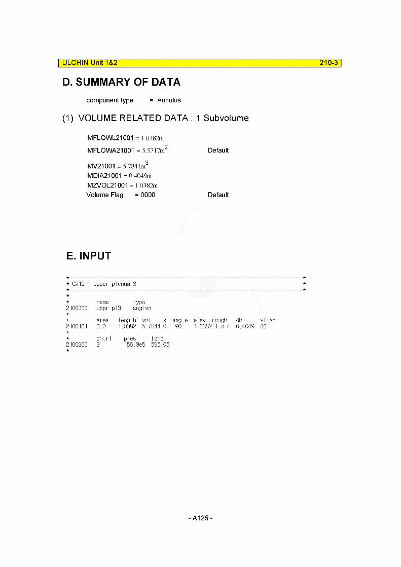
ULCHIN Unit 1&2 210-3
D. SUMMARY OF DATAcomponent type = Annulus
(1) VOLUME RELATED DATA : 1 Subvolume
MFLOWL21001 = 1.0382m
MFLOWA21001 = 5.5717m2 Default
MV21001 = 5.7844m3
MDIA21001 = 0.4049m MZVOL21001 = 1.0382mVolume Flag = 0000 Default
E. INPUT
* C210 : upper plenum 3
name type2100000 uppr- pi 3 snglvol
area length vol x angle elev rough dh vf lag2100101 0.0 1.0382 5.7844 0. -90. -1.0382 1.8-4 0.4049 00
cnt r I pres temp2100200 3 156.3e5 595.05
- A125-
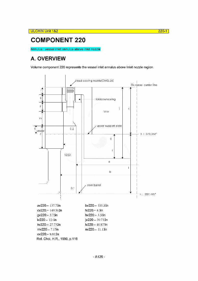
COMPONENT 220| ULCHIN Unit 1&2 220-1
Annulus : vessel inlet annulus above inlet nozzle
A. OVERVIEWVolume component 220 represents the vessel inlet annulus above Inlet nozzle region.
lead cooling nozzle(DWG.28)Rx.vessel center line
Holddownspring
upper support plate
E.L 373.358"
V220
core barrel
E.L 332.485"
av220:= 137.73n cv220:= 149.562n gv220:= 3.75n iv220:= 12.0n kv220:= 27.732n mv220:= 7.17in ov220:= 8.812n
bv220:= 155.5Qn fv220:= 4 5m hv220:= 3.50n jv220:= 39.732n Iv220:= 40.873n nv220:= 11.15 n
Ref. Choi, H.R., 1990, p.116
- A126-
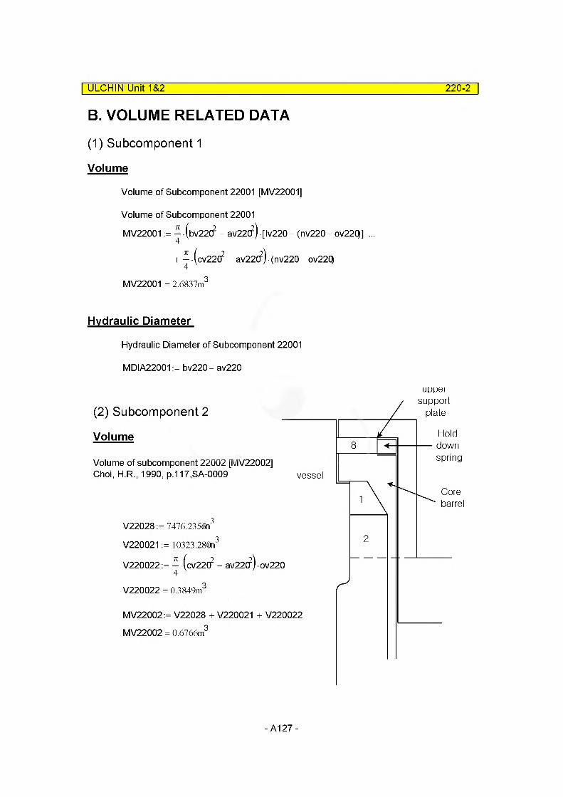
B. VOLUME RELATED DATA
(1) Subcomponent 1
Volume
Volume of Subcomponent 22001 [MV22001]
Volume of Subcomponent 22001MV22001 := ^-(bv22C? - av22(?) • [Iv220- (nv220- ov22Q] ...
+ ^ (cv22(f - av22(?)-(nv220- ov22Q
MV22001 = 2.6837m3
Hydraulic Diameter
Hydraulic Diameter of Subcomponent 22001
MDIA22001 := bv220- av220
ULCHIN Unit 1&2_____________________________________________________ 220-2
uppersupport
plate(2) Subcomponent 2
Holddownspring
Volume
Volume of subcomponent 22002 [MV22002] Choi, H.R., 1990, p.117.SA-0009 vessel
Corebarrel
V22028 := 7476.235<fn
V220021 := 10323.28(i)n
V220022:=
V220022 = 0.3849m
MV22002:= V22028 + V220021 + V220022
MV22002 = 0.6766m
-A127-

ULCHIN Unit 1&2 220-3
Hydraulic Diameter
MDIA22002= [GAP : Region Between Core Barrel and Vessel Wall] MDIA22002:= cv220 - av220MDIA22002= 0.3000m MFLOWL22001 := Iv220
MV22001MFLOWA22001 :=
MFLOWA22002 :=
MFLOWL22001 MV22002
MFLOWL22002
M FLO WL22002: = kv220
C. JUNCTION RELATED DATA
(1) Junction Area
Inter-Junction Area of Component 220MAJUN220:= - (cv22(f - av22CH
4 V ’
MAJUN220= 1.7196m2
(2) Loss Coefficient (MFJUN220)
* Loss Factor of Junction by Idelchik, 1986, Diag. 3-9 F220O:= MAJUN220
F220i := — (bv22C? - av22C?)4 V ’
F220i = 2.6375m2
( F220O)KF220:= 0.5- 1 -------------
L F220i )KF220 = 0.1740
By Idelchik, 1986, Diag. 4-1 F2202:= F220i
KR220:=( F220O)2
V ~ F2202 )KR220 = 0.1211 *
* Loss Factor is neglected MFJUNF220:= 0.0 MFJUNR220:= 0.0
Because the pressure drop is overestimated in RPV steady-state calculation.
MZVOL22001 := MFLOWL22001 MZVOL22002:= MFLOWL22002
-A128-
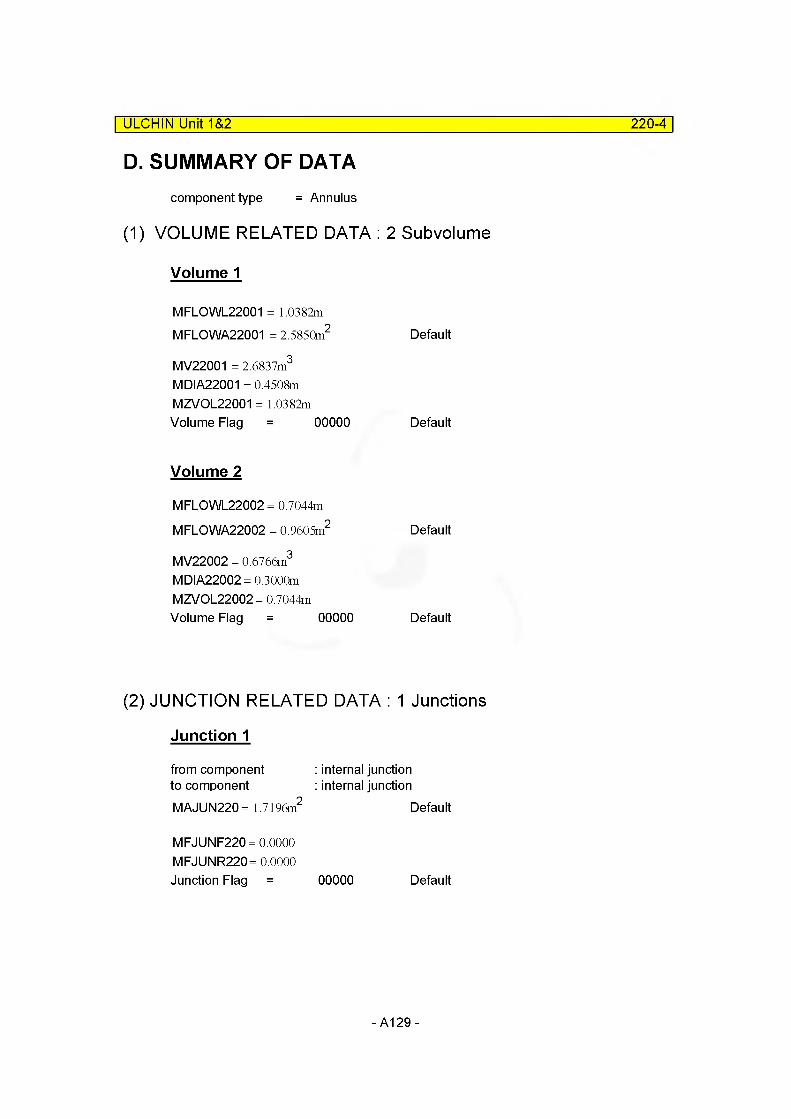
ULCHIN Unit 1&2 220-4
D. SUMMARY OF DATAcomponent type = Annulus
(1) VOLUME RELATED DATA : 2 Subvolume
Volume 1
MFLOWL22001 = 1.0382mMFLOWA22001 = 2.5850m2 Default
MV22001 = 2.6837m3
MDIA22001 = 0.4508m MZVOL22001 = 1.0382mVolume Flag = 00000 Default
Volume 2
MFLOWL22002 = 0.7044m
MFLOWA22002 = 0.9605m2 Default
MV22002 = 0.6766m3
MDIA22002= 0.3000m MZVOL22002= 0.7044mVolume Flag = 00000 Default
(2) JUNCTION RELATED DATA : 1 Junctions
Junction 1
from component to componentMAJUN220= 1.7196m2
: internal junction : internal junction
Default
MFJUNF220= 0.0000 MFJUNR220= 0.0000Junction Flag = 00000 Default
- A129-

E. INPUT
ULCHIN Unit 1&2______________________________________________________ 220-5
*0220 : Vessel inlet annulus above the connection to cold legs
name type2200000 dc-1-upi annulus
2200001number2
of volumes
area no of vol2200101 0.0 2
j-area no of junction2200201 1.7196 1
Iength no of vol2200301 1.0382 12200302 0.7044 2
volume no of vol2200401 2.6837 12200402 0.6766 2
XX no of vol2200501 0.0 2
angle no of vol2200601 +90. 2
elev. no of vol2200701 1.0382 12200702 0.7044 2
rough dhydr. no of vol2200801 1. e-4 0.4508 12200802 1 .e-4 0.3000 2
kforw kbackw no of jun2200901 0.0 0.0 1
v-flag no of vol2201001 00000 2
j-flag no of jun2201101 000000 1
cnt r I pres temp no of vol2201201 3 159.0e5 560.45 0.0 0.0 0.0 12201202 3
cnt r I
159.0e5 560.45 0.0 0.0 0.0 2
2201300 1
* waterflow steamflow * no of jun2201301 67.38 0.0 0.0 1
-A130-
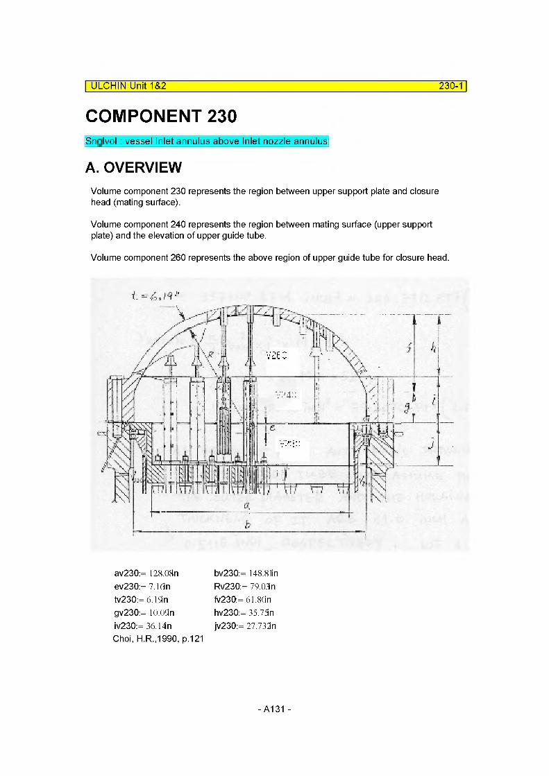
ULCHIN Unit 1&2 230-1
COMPONENT 230Snglvol: vessel Inlet annulus above Inlet nozzle annulus
A. OVERVIEWVolume component 230 represents the region between upper support plate and closure head (mating surface).
Volume component 240 represents the region between mating surface (upper support plate) and the elevation of upper guide tube.
Volume component 260 represents the above region of upper guide tube for closure head.
av230:= 128.08n ev230:= 7.1dn tv230:= 6.19i n gv230:= lO.OSIn iv230:= 36.14n Choi, H.R.,1990, p.121
bv230:= 148.81in Rv230:= 79.03 n fv230:= 61.80n hv230:= 35.73n jv230:= 27.733n
-A131-

ULCHIN Unit 1&2 230-2
B. VOLUME RELATED DATA
(1) Subcomponent 1
Volume
Volume of Component 230 [ MV230]= Inside Volume of Upper Support Plate [MV230IUSP]- Volume of Upper Guide Tube of Component 230 [MV230UGT]- Volume of Thermocouple Column [MV230TC]
MV230IUSP:= av23(fjv230
Dv230OUGT= 1 tin Nv230GT:= 52
MV230UGT:= - • DV230OUGT2-jv230- Nv230GT4
MV230UGT = 2.2457m3
* As we do not have any detail dreawing of upper guide tube, we assume that the outer diameter and the housing thickness of it are 1.0 inch and 0.5115 inch, respectively.We also refer to Choi, H.R., 1990, p.122, SA-0009 Note (G1)
MV230KNU1 :=2
MV230TC:= 1.5MV230KNU1MV230TC= 1.5525x 10“2m3
MV23001 := MV230IUSP - MV230UGT- MV230TCMV23001 = 3.5938m3
Flow Length
MFLOWL23001 := jv230
Flow Area : Default
MFLOWA23001
MFLOWA23001
MV23001
MFLOWL23001= 5.1020m2
- A132 -

ULCHIN Unit 1&2 230-3
Hydraulic Diameter
Perimeter of Component 230 [Pv230]= PUPPER Support Plate + PUPPER GUIDE TUBE + PTHERMPOCOUPLECOLUMN
Pv230USP:= 7iav230 Pv230USP = 10.2203m
Pv230UGT:= k ■ Dv2300UGTNv230GT Pv230UGT= 45.6436m
Dv230OTC= 2.185 li n Nv230TC:= 3Pv230TC:= tiDv2300TCNv230TC Pv230TC= 0.5231m
Pv230:= Pv230USP+ Pv230UGT+ Pv230TC Pv230= 56.3870m
Therefore,
4MFLOWA23001MDIA23001 :=-------------------------
Pv230MDIA23001 = 0.3619m
* The diameter and the volume of thermocouple column are assumed and refered from KNU-1 (Choi, H.R.,1990, p.123,KSL-CN-861002)
Elevation Change
MZVOL23001 := MFLOWL23001 sin (90deg)
C. JUNCTION RELATED DATA
NA
- A133-
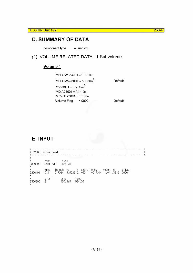
ULCHIN Unit 1&2 230-4
D. SUMMARY OF DATAcomponent type = singlvol
(1) VOLUME RELATED DATA : 1 Subvolume
Volume 1
MFLOWL23001 = 0.7044m
MFLOWA23001 = 5.1020m2 Default
MV23001 = 3.5938m3
MDIA23001 = 0.3619m MZVOL23001 = 0.7044mVolume Flag = 0000 Default
E. INPUT
* 0230 : upper head 1
2300000nameuppr-
type-hd1 snglvol
2300101area0.0
length vol x angle0.7044 3.5938 0. +90.
elev+0.7044
rough1 .e-4
dh.3619
vf lag0000
2300200cnt r I 3
pres156.3e5
temp594.05
- A134 -

COMPONENT 240
ULCHIN Unit 1&2_____________________________________________________ 240-1
Branch : upper head(middle volume)
A. OVERVIEWVolume component 240 represents the lower part of closure head by the end of upper guide tube. The figure is shown in page 230-1.
B. VOLUME RELATED DATA
(1) Subcomponent 1
Volume
Volume of Component 240 [MV240]= Volume of Lower Part of Closure Head [MV240LCH]
Choi, H.R.,1990, p.126,SA0009- Volume of Upper Guide Tube [MV240UGT]- Volume of Thermocouple Column [MV240TC]
V24002:=234.2738t3
V24003 := 101.566(ft3
V240ext := 9.3653t3
MV240LCH:= V24002 + V24003 + V240ext MV240LCH= 9.7751m3
Volume V2 & V3 are taken from Choi, H.R.,1990, p.127,SA-0009 and Vext is calculated due to difference of height.
Dv240OUGT= Dv230OUGT iv240:= iv230 Nv240GT:= Nv230GT
MV240UGT:= - • Dv240OUcf • iv240- Nv240GT4
MV240UGT = 2.9266m3
- A135-

ULCHIN Unit 1&2 240-2
35.75
1.165
42.1 15 r=79.03
rv240:= 79.03in
V240T := — • 7t • rv24C?3
V240T = 16.9409m3
hv24001:= hv230
V024001 := 5.hv240012 (3rv240- hv24001)
V024001 = 4.4158m3
hv24003:= 42.115n
V024003 := 5. hv24003 (3rv24C? - hv240of)
V024003 = 12.2598m3
V024002 := V240T - V024001 - V024003 V024002 = 0.2652m3
* H24002:= 36.14n - lO.OSIn - 24.885n
H24002 = 2.9591 x 10“2m
MV240TC:= 1.5MV230KNU1 MV240TC= 1.5525x 10“2m3
MV24001 := MV240LCH - MV240UGT - MV240TC MV24001 = 6.8330m3
Flow Length
MFLOWL24001 := iv240
- A136 -
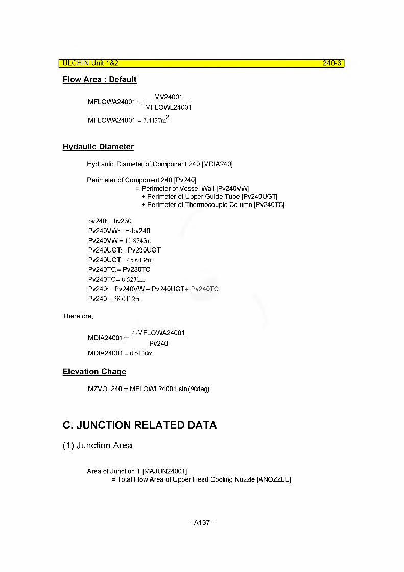
ULCHIN Unit 1&2 240-3
Flow Area : Default
MFLOWA24001 :=MV24001
MFLOWL24001
MFLOWA24001 = 7.4437m
Hvdaulic Diameter
Hydraulic Diameter of Component 240 [MDIA240]
Perimeter of Component 240 [Pv240]= Perimeter of Vessel Wall [Pv240VW]
+ Perimeter of Upper Guide Tube [Pv240UG"i]+ Perimeter of Thermocouple Column [Pv240TC]
bv240:= bv230 Pv240VW:= re • bv240 Pv240VW = 11.8745m Pv240UGT:= Pv230UGT Pv240UGT= 45.6436m Pv240TC:= Pv230TC Pv240TC= 0.5231mPv240:= Pv240VW+ Pv240UGT+ Pv240TC Pv240= 58.0412m
Therefore,
4MFLOWA24001MDIA24001 :=-------------------------
Pv240MDIA24001 =0.5130m
Elevation Chaqe
MZVOL240:= MFLCWL24001 sin (90deg)
C. JUNCTION RELATED DATA
(1) Junction Area
Area of Junction 1 [MAJUN24001]= Total Flow Area of Upper Head Cooling Nozzle [ANOZZLE]
-A137-

ULCHIN Unit 1&2 240-4
/4C.9 tMAv FtLf. TwooC»wfl
WITH A GAP Of
TO w£UUH<f.mi. i6 Qn*.<T| 0 Rtr.
T'rPiL^L zi p; Af.^
Choi, H.R., 1990, p.130D24001 NOZ:= 0.469n N24001 NOZ:= 24
MAJUN24001 := - • D24001 Nof • N24001NOZ4
MAJUN24001 = 2.6749x 10“ 3 m2
Area of Junction 2 [MAJUN24002]
= Flow Area of Component 230 MAJUN24002:= MFLOWA23001
Area of Junction 3 [MAJUN24003]
= Flow Area of Component 2504.2949n3
MAJUN24003:=------------0.9073TI
- A138-
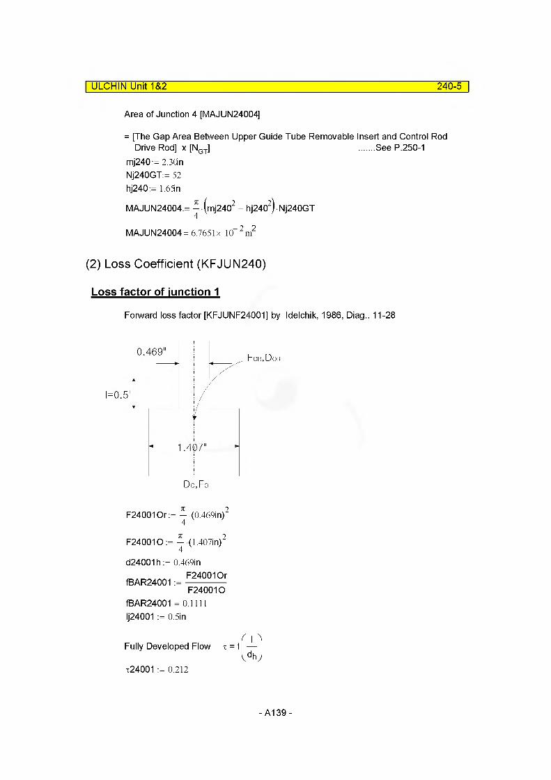
ULCHIN Unit 1&2 240-5
Area of Junction 4 [MAJUN24004]
= [The Gap Area Between Upper Guide Tube Removable Insert and Control Rod Drive Rod] x [NGT] ......See P.250-1
mj240:= 2.30in Nj240GT:= 52 h]240:= 1.65n
MAJUN24004:= ^ (m]2402 - h]2402) • Nj240GT
MAJUN24004= 6.7651 x 10“2m2
(2) Loss Coefficient (KFJUN240)
Loss factor of junction 1
Forward loss factor [KFJUNF24001] by Idelchik, 1986, Diag.. 11-28
0.469For,Dor
1.407
F240010r:= ^ -(0.469m)2
F240010 := ^-(1.407m)2
d24001h := 0.469inF240010r
fBAR24001 :=--------------F240010
fBAR24001 = 0.1111 Ij24001 := 0.5in
Fully Developed Flow
t24001 := 0.212
T =mldh J
- A139-
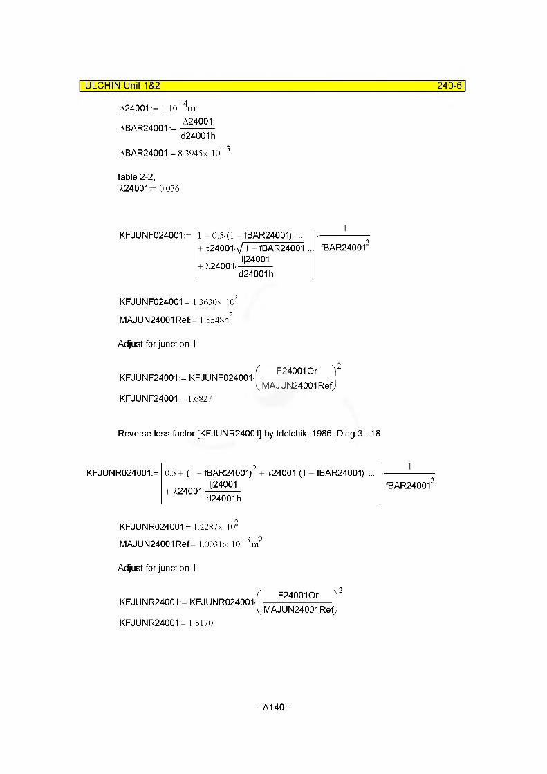
ULCHIN Unit 1&2 240-6
A24001 := 1 10 mA24001
ABAR24001 :=d24001h
ABAR24001 = 8.3945x 10
table 2-2, X24001:= 0.036
KFJUNF024001:= 1 + 0.5 (1 -fBAR24001) ... + %24001 Y 1 - fBAR24001
Ij24001+ X24001-
d24001h
1
fBAR240012
KFJUNF024001 = 1.3630x 10²
MAJUN24001 Ref:= 1.5548n2
Adjust for junction 1
KFJUNF24001 := KFJUNF024001-
KFJUNF24001 = 1.6827
F240010r )2
MAJUN24001Refj
Reverse loss factor [KFJUNR24001] by Idelchik, 1986, Diag.3 -18
KFJUNR024001:= 0.5 + (1 - fBAR24001) + x24001 (l - fBAR24001) ... IJ24001
+ X24001-d24001h
1
fBAR240012
KFJUNR024001= 1.2287 x 10²
MAJUN24001 Ref = 1.0031 x 10“3m2
Adjust for junction 1
KFJUNR24001:= KFJUNR024001-
KFJUNR24001 = 1.5170
F240010r )2
MAJUN24001 Refj
- A140-
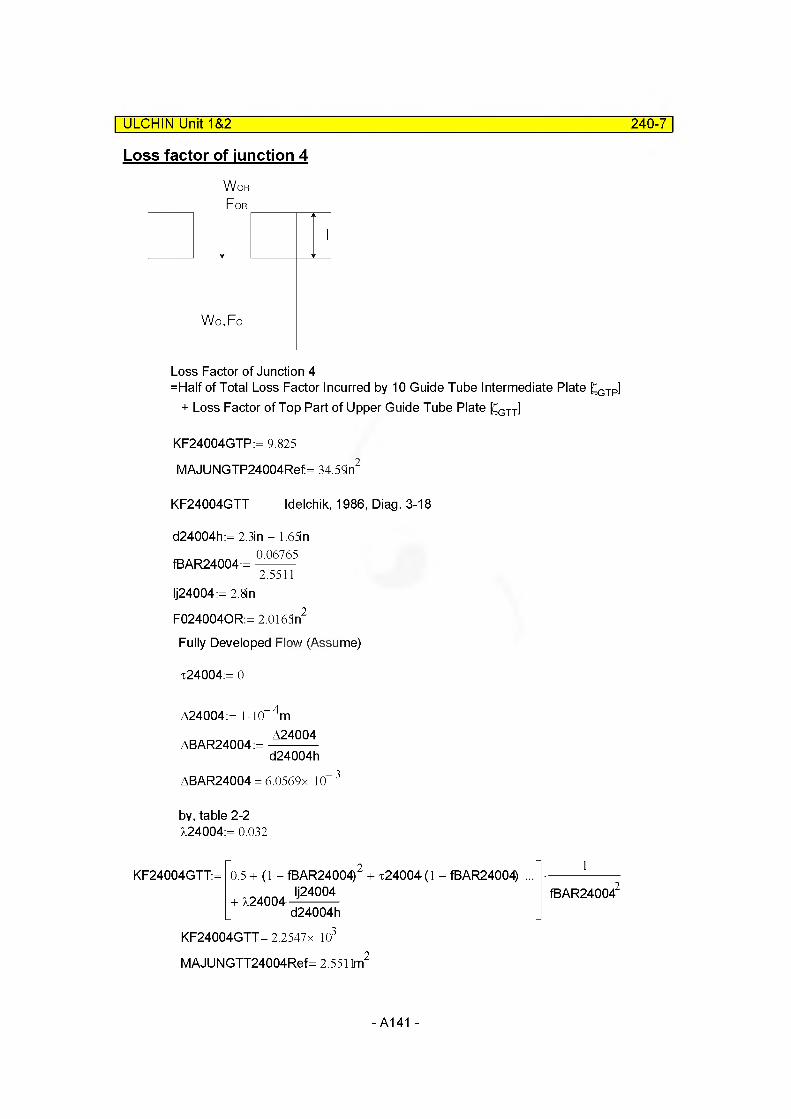
Loss factor of junction 4
WoRFor
ULCHIN Unit 1&2______________________________________________________240-7
Wo,Fo
Loss Factor of Junction 4=Half of Total Loss Factor Incurred by 10 Guide Tube Intermediate Plate £GTP]
+ Loss Factor of Top Part of Upper Guide Tube Plate [CGTT]
KF24004GTP:= 9.825
MAJUNGTP24004Ref= 34.59n2
KF24004GTT Idelchik, 1986, Diag. 3-18
d24004h:= 2.3in - 1.65in
fBAR24004:= 0067652.5511
Ij24004:= 2.8in
F0240040R:= 2.0165n
Fully Developed Flow (Assume)
t24004:= 0
A24004:= 1 10 4m
ABAR24004:=A24004d24004h
ABAR24004 = 6.0569x 10 3
by, table 2-2 724004:= 0.032
KF24004GTT:= 0.5 + (1 - fBAR24004) + x24004 (l - fBAR24004) Ij24004
+ 724004-d24004h
KF24004GTT = 2.2547x 10,3
MAJUNGTT24004Ref= 2.551 lm
1
fBAR240042
- A141-
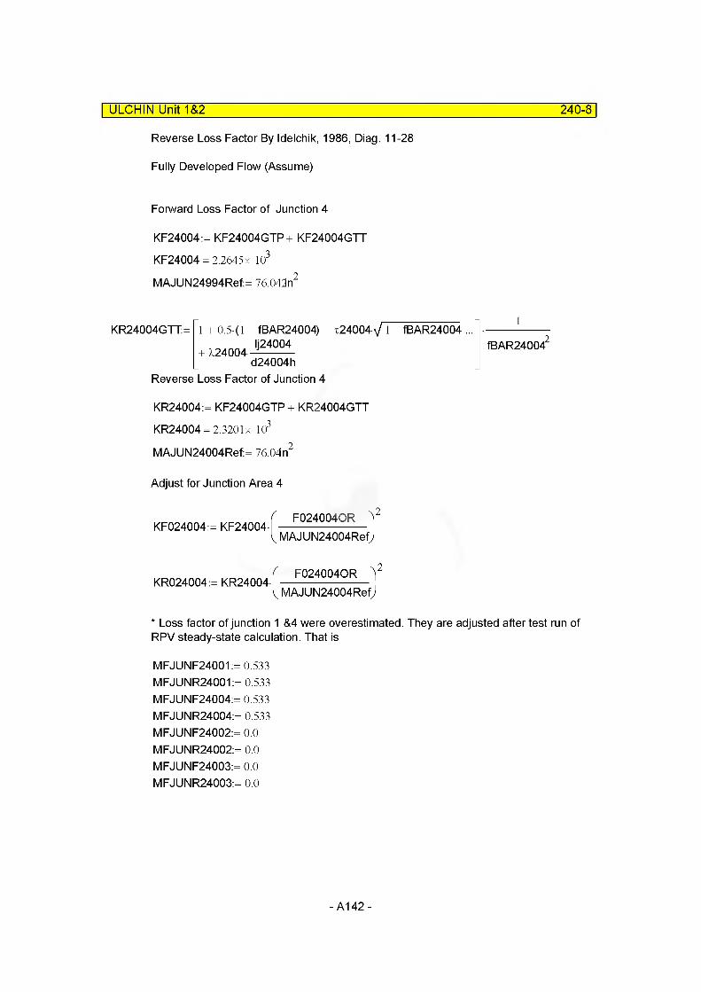
ULCHIN Unit 1&2 240-8
Reverse Loss Factor By Idelchik, 1986, Diag. 11-28
Fully Developed Flow (Assume)
Forward Loss Factor of Junction 4
KF24004:= KF24004GTP+ KF24004GTT KF24004 = 2.2645 x 10³
MAJUN24994Ref:= 76.042n2
KR24004GTT:= 1 + 0.5 (1 - TBAR24004) + x24004 V 1 - TBAR24004 ... Ij24004
+ X24004-d24004h
Reverse Loss Factor of Junction 4
1
fBAR240042
KR24004:= KF24004GTP + KR24004GTT
KR24004 = 2.3201 x 10³
MAJUN24004Ref:= 76.04 n2
Adjust for Junction Area 4
KF024004:= KF24004-F0240040R )2
MAJUN24004RefJ
KR024004:= KR24004-F0240040R )2
MAJUN24004Refj
* Loss factor of junction 1 &4 were overestimated. They are adjusted after test run of RPV steady-state calculation. That is
MFJUNF24001:= 0.533 MFJUNR24001:= 0.533 MFJUNF24004:= 0.533 MFJUNR24004:= 0.533 MFJUNF24002:= 0.0 MFJUNR24002:= 0.0 MFJUNF24003:= 0.0 MFJUNR24003:= 0.0
- A142-
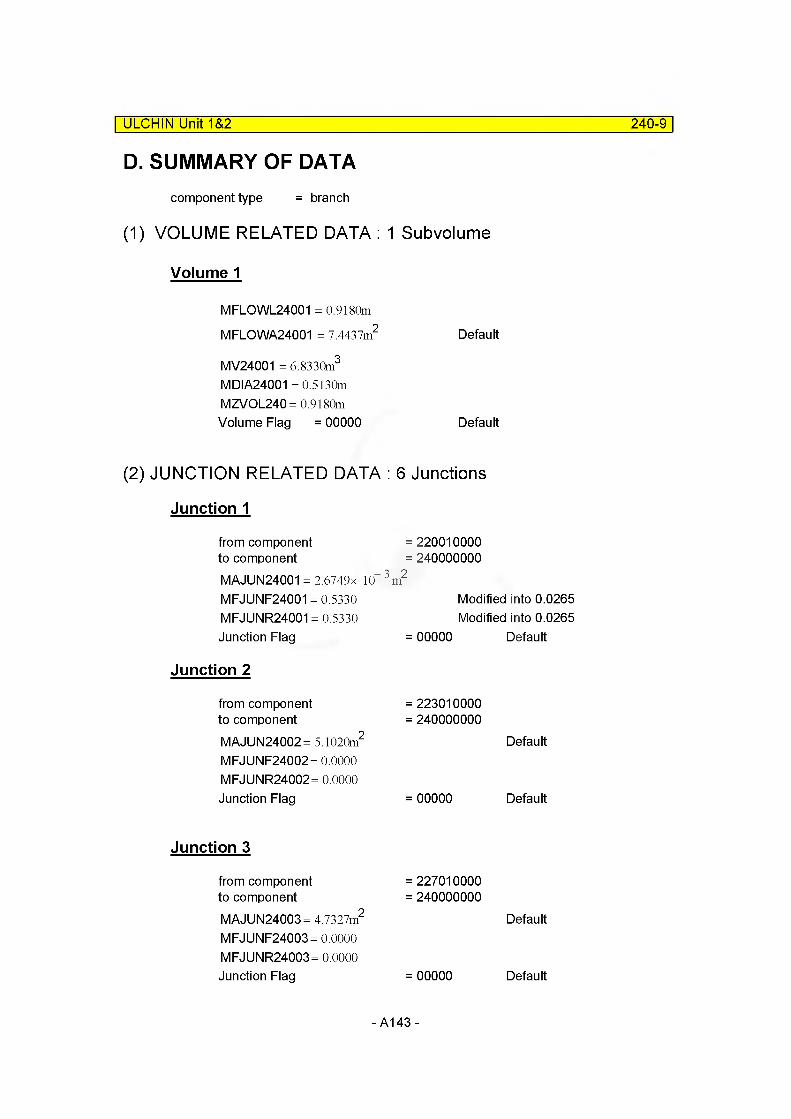
ULCHIN Unit 1&2 240-9
D. SUMMARY OF DATAcomponent type = branch
(1) VOLUME RELATED DATA : 1 Subvolume
Volume 1
MFLOWL24001 = 0.9180m
MFLOWA24001 = 7.4437m2 Default
MV24001 = 6.8330m3
MDIA24001 =0.5130m MZVOL240= 0.9180mVolume Flag = 00000 Default
(2) JUNCTION RELATED DATA : 6 Junctions
Junction 1
from component to component
MAJUN24001 = 2.6749x 10 MFJUNF24001 = 0.5330 MFJUNR24001 = 0.5330 Junction Flag
Junction 2
from component to componentMAJUN24002= 5.1020m2
MFJUNF24002= 0.0000 MFJUNR24002= 0.0000 Junction Flag
Junction 3
from component to componentMAJUN24003= 4.7327m2
MFJUNF24003= 0.0000 MFJUNR24003= 0.0000 Junction Flag
= 220010000 = 240000000)
Modified into 0.0265 Modified into 0.0265
= 00000 Default
= 223010000 = 240000000
Default
= 00000 Default
= 227010000 = 240000000
Default
= 00000 Default
- A143-
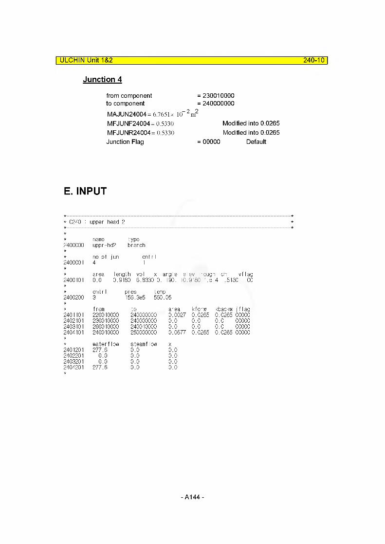
ULCHIN Unit 1&2 240-10
Junction 4
from component to componentMAJUN24004= 6.7651 x 10“ 2
MFJUNF24004= 0.5330 MFJUNR24004= 0.5330 Junction Flag
= 230010000 = 240000000
i2
Modified into 0.0265 Modified into 0.0265
= 00000 Default
E. INPUT
* C240 : upper head 2
name type2400000 uppr-hd2 branch
no of jun cnt r I2400001 4 1
area length vol x angle elev rough dh vf lag2400101 0.0 0.9180 6.8330 0. +90. +0..9180 1.8--4 . 5130 00
cntr I pres temp2400200 3 156.3e5 560 o cn
from to area kforw kbackw j f I ag2401101 220010000 240000000 0.0027 0.0265 0.0265 000002402101 230010000 240000000 0.0 0.0 0.0 000002403101 260010000 240010000 0.0 0.0 0.0 000002404101 240010000 250000000 0.0677 0.0265 0.0265 00000
waterflow steamflow X2401201 277.6 0.0 0.02402201 0.0 0.0 0.02403201 0.0 0.0 0.02404201 277.6 0.0 0.0
- A144-
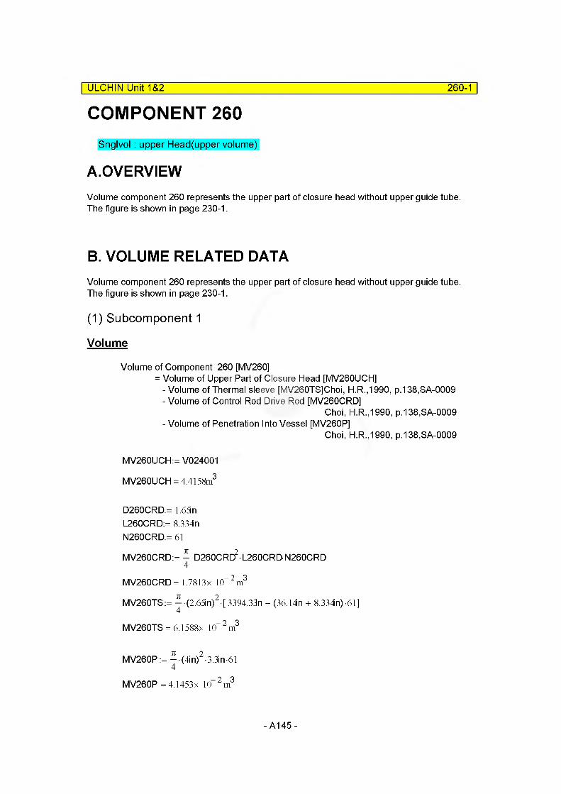
COMPONENT 260| ULCHIN Unit 1&2 260-1
Snglvol: upper Head(upper volume)
A.OVERVIEWVolume component 260 represents the upper part of closure head without upper guide tube. The figure is shown in page 230-1.
B. VOLUME RELATED DATAVolume component 260 represents the upper part of closure head without upper guide tube. The figure is shown in page 230-1.
(1) Subcomponent 1
Volume
Volume of Component 260 [MV260]= Volume of Upper Part of Closure Head [MV260UCH]
- Volume of Thermal sleeve [MV260TS]Choi, H.R.,1990, p.138,SA-0009- Volume of Control Rod Drive Rod [MV260CRD]
Choi, H.R.,1990, p.138,SA-0009- Volume of Penetration Into Vessel [MV260P]
Choi, H.R.,1990, p.138,SA-0009
MV260UCH:= V024001
MV260UCH = 4.4158m3
D260CRD:= 1.65n L260CRD:= 8.334n N260CRD:= 61
MV260CRD:= - • D260CRC? • L260CRD- N260CRD4
MV260CRD= 1.7813x 10“2m3
MV260TS:= ^ (2.65ln)2 [ 3394.33n - (36.14n + 8.334n) -61]
MV260TS = 6.1588x 10“ 2 m3
MV260P := - (4ln)2 3.3ln 614
MV260P = 4.1453x 10“2m3
- A145-

MV26001 := MV260UCH - (MV260TS + MV260CRD + MV260P)MV26001 = 4.2950m3
* Volume of thermocouple column is neglected, because the volume is very small.
Flow Length
MFLOWL26001 := 0.9075m
Flow Area : Default
ULCHIN Unit 1&2_____________________________________________________ 260-2
MFLOWA26001 :=
MFLOWA26001 = 4.7328 m'
MV26001
MFLOWL260012
Hydraulic Diameter
Perimeter of Component 260 [Pv260]= Perimeter of Vessel Wall [Pv260VW]+ Perimeter of Thermal Sleeve [Pv260TS]
Pv260VW= | -^Volume of Upper Part of Closure Head]* 3 b- XI □ °|
Dv260 := 57.305in Pv260VW := re • Dv260 Pv260VW = 4.5727 m Dv260TS := 2.65in Nv260TS := 61Pv260TS := 7i • Dv260TS • Nv260TS Pv260TS = 12.8991m Pv260 := Pv260VW + Pv260TS Pv260 = 17.4718m
Therefore,
MDIA26001
MDIA26001
Elevation Change
MZVOL26001 := MFLCWL26001 sin (-90deg)MZVOL26001 = -0.9075 m
4 MFLOWA26001
Pv260= 1.0835 m
- A146-
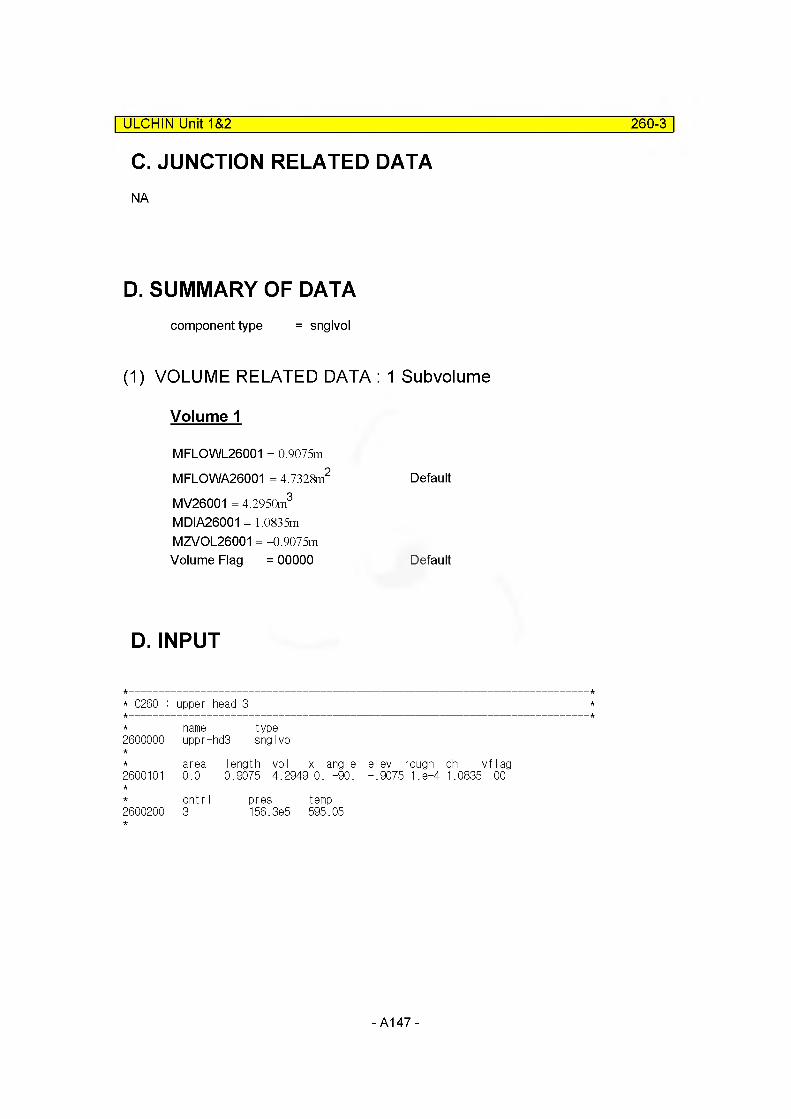
ULCHIN Unit 1&2 260-3
C. JUNCTION RELATED DATANA
D. SUMMARY OF DATAcomponent type = snglvol
(1) VOLUME RELATED DATA : 1 Subvolume
Volume 1
MFLOWL26001 = 0.9075m
MFLOWA26001 = 4.7328m2 Default
MV26001 = 4.2950m3
MDIA26001 = 1.0835mMZVOL26001 = -0.9075mVolume Flag = 00000 Default
D. INPUT
* 0260 : upper head 3
2600000nameuppr-
type-hd3 snglvol
2600101area0.0
length vol x angle elev rough dh vflag0.9075 4.2949 0. -90. -.9075 1.8-4 1.0835 00
2600200cnt r I 3
pres temp156.3e5 595.05
-A147-
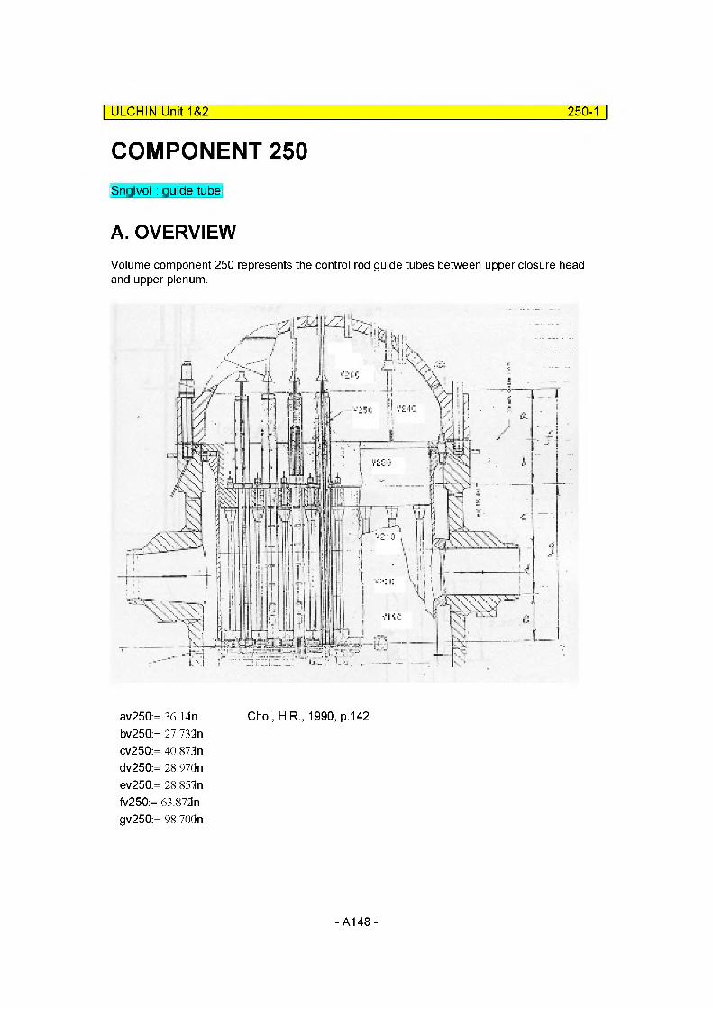
ULCHIN Unit 1&2 250-1
COMPONENT 250Snglvol: guide tube
A. OVERVIEWVolume component 250 represents the control rod guide tubes between upper closure head and upper plenum.
av250:= 36.14n Choi, H.R., 1990, p.142bv250:= 27.732ncv250:= 40.873ndv250:= 28.97Qnev250:= 28.851nfv250:= 63.872ngv250:= 98.70dn
- A148-

ULCHIN Unit 1&2 250-2
DETAIL A. *SA-0009
h= 1 .650"1 = 9.9771 11 j=1 1 .0" k=6.8384 I = 8.0" f=63.872' g = 98.70"
Upper Guide Tube
Lower Guide Tube
DETAIL A (Ref.KNU-1)
2.80 " = nREMOVABLE
INSERT
m = 2.3"(est.)
hv250:= 1.65Qn iv250:= 9.9771in jv250:= 11 On kv250:= 6.8384n Iv250:= 8 On
Choi, H.R., 1990, p.143
- A149-
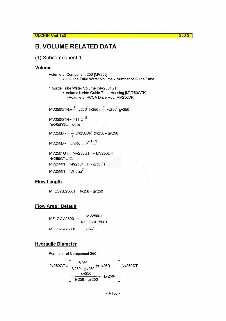
ULCHIN Unit 1&2 250-3
B. VOLUME RELATED DATA
(1) Subcomponent 1
VolumeVolume of Component 250 [MV250]
= 1 Guide Tube Water Volume x Number of Guide Tube
1 Guide Tube Water Volume [MV2501G7]= Volume Inside Guide Tube Housing [MV250GTH]
- Volume of RCCA Drive Rod [MV250DR]
MV250GTH:= — iv25C? fv250+ - kv25(f gv2504 4
MV250GTH= 0.1412m3
Dv250DR= 1.650n
MV250DR:= ^ Dv250DF^ (fv250+ gv25Q
MV250DR = 5.6965 x 10" 3 m3
MV2501GT:= MV250GTH - MV250DR Nv250GT:= 52MV25001 := MV2501GTNv250GT MV25001 = 7.0479m3
Flow Length
MFLOWL25001 := fv250+ gv250
Flow Area : Default
MFLOWA25001 :=MV25001
MFLOWL25001
MFLOWA25001 = 1.7068m
Hydraulic Diameter
Perimeter of Component 250
Pv250GT:=fv250
fv250+ gv250 gv250
fv250+ gv250
(7iiv25Q)
(7ikv250)
•Nv250GT
- A150-
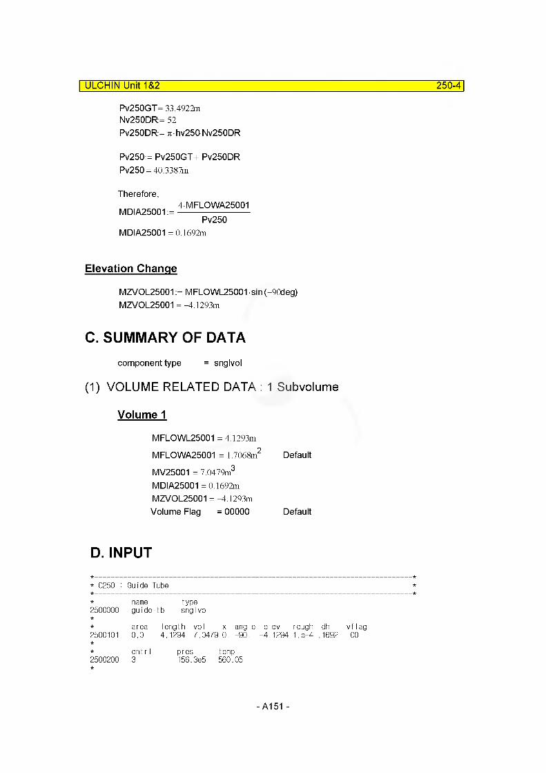
ULCHIN Unit 1&2 250-4
Pv250GT= 33.4922m Nv250DR= 52Pv250DR:= 7thv250Nv250DR
Pv250:= Pv250GT+ Pv250DR Pv250= 40.3387m
Therefore,MDIA25001:= ^FLQWA25001
Pv250MDIA25001 =0.1692m
Elevation Change
MZVOL25001 := MFLOWL25001 sin (-90deg) MZVOL25001 =-4.1293m
C. SUMMARY OF DATAcomponent type = snglvol
(1) VOLUME RELATED DATA : 1 Subvolume
Volume 1
MFLOWL25001 = 4.1293m
MFLOWA25001 = 1.7068m2 Default
MV25001 = 7.0479m3
MDIA25001 =0.1692m MZVOL25001 =-4.1293m Volume Flag = 00000 Default
D. INPUT
* C250 : Guide Tube
name type2500000 guide--tb snglvol
area length vol x angle elev rough dh vf lag2500101 0.0 4.1294 7.0479 0. -90. -4.1294 1.8-4 .1692 00
cnt r I pres temp2500200 3 156.3e5 560.05
- A151 -

2.2 Reactor Coolant Lines and Steam Generator Primary Sides
-A152-
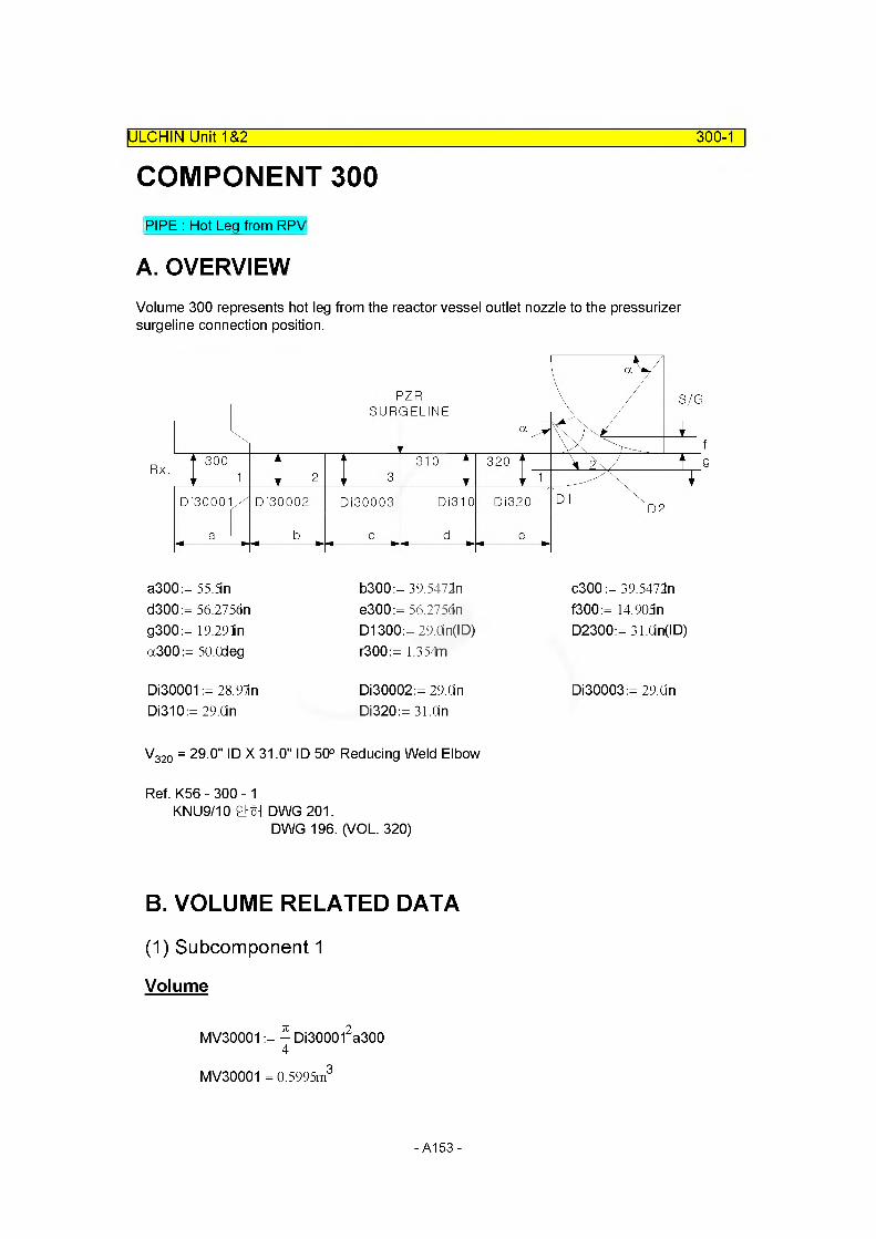
COMPONENT 300IULCHIN Unit 1&2 300-1
PIPE : Hot Leg from RPV
A. OVERVIEWVolume 300 represents hot leg from the reactor vessel outlet nozzle to the pressurizer surgeline connection position.
c300 := 39.5472n f300:= 14.905n D2300:= 31.Cin(ID)
0130003:= 29.0n
V320 = 29.0" ID X 31.0" ID 50° Reducing Weld Elbow
Ref. K56 -300-1KNU9/10 °}§H DWG 201.
DWG 196. (VOL. 320)
B. VOLUME RELATED DATA
(1) Subcomponent 1
Volume
a300:= 55.5n d300:= 56.2756n g300:= 19.291in a300:= SO.Odeg
DI30001 := 28.91n 01310:= 29.On
b300:= 39.5472n e300:= 56.275dn D1300:= 29.0in(ID) r300:= 1.354m
0130002:= 29.Qn 01320:= 31.On
MV30001 := - DI300012a3004
MV30001 = 0.5995m3
-A153-

ULCHIN Unit 1&2 300-2
Flow Length
MFLOWL30001 := a300 MFLOWL30001 = 1.4097m
Flow Area : Default
MV30001MFLOWA30001 :=----------------------
MFLOWL30001MFLOWA30001 = 0.4253m2
Elevation Change
MZVOL30001 := MFLOWL30001 sin (O.deg) MZVOL30001 = 0.0000m
Hydraulic Diameter: Default
MDIA30001 := Di30001 MDIA30001 = 0.7358m
(2) Subcomponent 2
Volume
MV30002:= - Di300022b3004
MV30002 = 0.4281m3
Flow Length
M FLO WL30002: = b300 MFLOWL30002 = 1.0045m
Flow Area : Default
MFLOWA30002 :=MV30002
MFLOWL30002
MFLOWA30002 = 0.4261m
-A154-
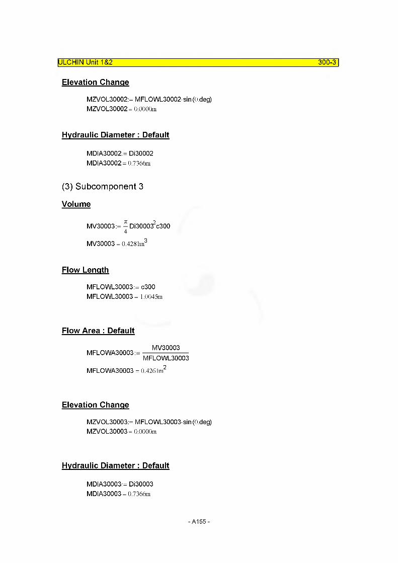
Elevation Change
MZVOL30002:= MFLOWL30002 sin (O.deg)MZVOL30002= 0.0000m
Hydraulic Diameter: Default
MDIA30002:= Di30002 MDIA30002= 0.7366m
(3) Subcomponent 3
Volume
MV30003:= - Di300032c3004
MV30003 = 0.4281m3
Flow Length
MFLOWL30003:= c300 MFLOWL30003 = 1.0045m
ULCHIN Unit 1&2_______________________________________________________ 300-3
Flow Area : Default
MFLOWA30003 :=MV30003
MFLOWL30003
MFLOWA30003 = 0.4261m
Elevation Change
MZVOL30003:= MFLOWL30003 sin (O.deg) MZVOL30003= 0.0000m
Hydraulic Diameter: Default
MDIA30003:= Di30003 MDIA30003= 0.7366m
- A155 -

ULCHIN Unit 1&2 300-4
C. JUNCTION RELATED DATA
(1) Junction Area
Junction1,2 : Default
MAJUN30001 := min(MFLOWA30001, MFLOWA30002) MAJUN30001 = 0.4253m2
MAJUN30002:= min(MFLOWA30002, MFLOWA30003) MAJUN30002= 0.4261m2
(2) Loss Factor
Junction1,2 : Default
MFJUNF30001:= 0.0 MFJUNR30001:= 0.0 MFJUNF30002:= 0.0 MFJUNR30002:= 0.0
D. SUMMARY OF DATAcomponent type = pipe
(1) VOLUME RELATED DATA : 3 Subvolume
Volume 1
MFLOWL30001 = 1.4097m
MFLOWA30001 = 0.4253m2 Default
MV30001 = 0.5995m3
MDIA30001 = 0.7358m DefaultMZVOL30001 = 0.0000mVolume Flag =0000 Default
-A156-
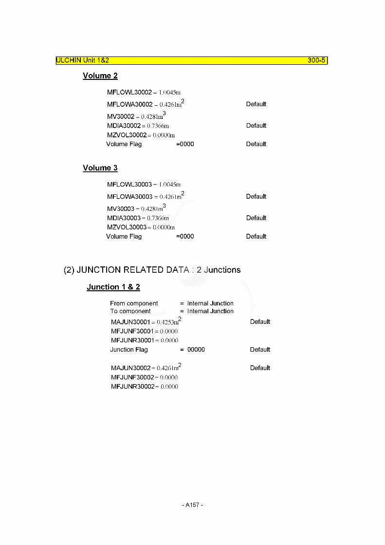
Volume 2
MFLOWL30002 = 1.0045m
MFLOWA30002 = 0.4261m2 Default
MV30002 = 0.4281m3
MDIA30002 = 0.7366m DefaultMZVOL30002= 0.0000mVolume Flag =0000 Default
Volume 3
MFLOWL30003 = 1.0045m
MFLOWA30003 = 0.4261m2 Default
MV30003 = 0.4281m3
MDIA30003 = 0.7366m DefaultMZVOL30003= 0.0000mVolume Flag =0000 Default
(2) JUNCTION RELATED DATA : 2 Junctions
Junction 1 & 2
From component = Internal JunctionTo component = Internal JunctionMAJUN30001 = 0.4253m2 Default
MFJUNF30001 = 0.0000 MFJUNR30001 = 0.0000Junction Flag = 00000 Default
MAJUN30002= 0.4261m2 Default
MFJUNF30002= 0.0000 MFJUNR30002= 0.0000
ULCHIN Unit 1&2_______________________________________________________ 300-5
-A157-
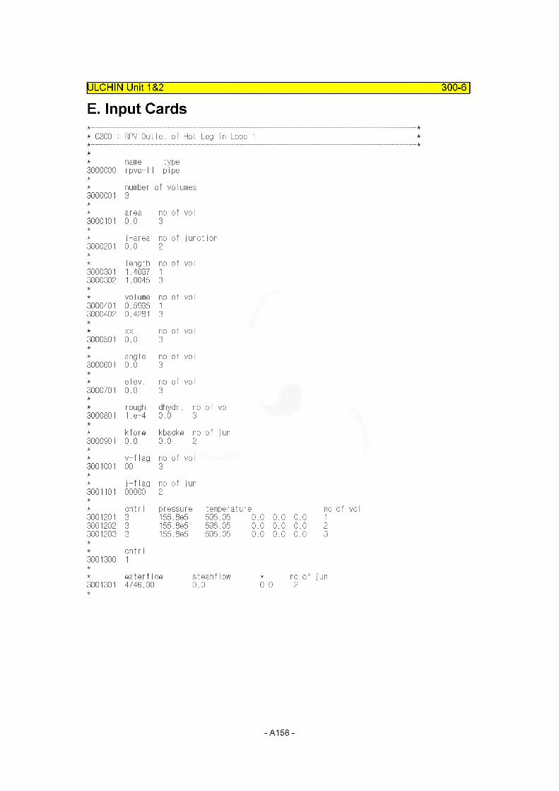
IULCHIN Unit~T&2~ 300-6
E. Input Cards
* C300 : RPV Outlet of Hot Leg in Loop 1
name type3000000 rpvo-l1 pipe
number of volumes3000001 3
area no of voI3000101 0.0 3
j-area no of junction3000201 0.0 2
Iength no of voI3000301 1.4097 13000302 1.0045 3
volume no of vol3000401 0.5995 13000402 0.4281 3
XX no of vol3000501 0.0 3
angle no of vol3000601 0.0 3
elev. no of vol3000701 0.0 3
rough dhydr. no of vol3000801 1. e-4 0.0 3
kforw kbackw no of jun3000901 0.0 0.0 2
v-flag no of vol3001001 00 3
j-flag no of jun3001101 00000 2
cnt r I pressure temperature no of vol3001201 3 155.8e5 595.05 0.0 0.0 0.0 13001202 3 155.8e5 595.05 0.0 0.0 0.0 23001203 3 155.8e5 595.05 0.0 0.0 0.0 3
cnt r I3001300 1
waterflow steamflow * no of jun3001301 4746.00 0.0 0. 0 2
-A158-
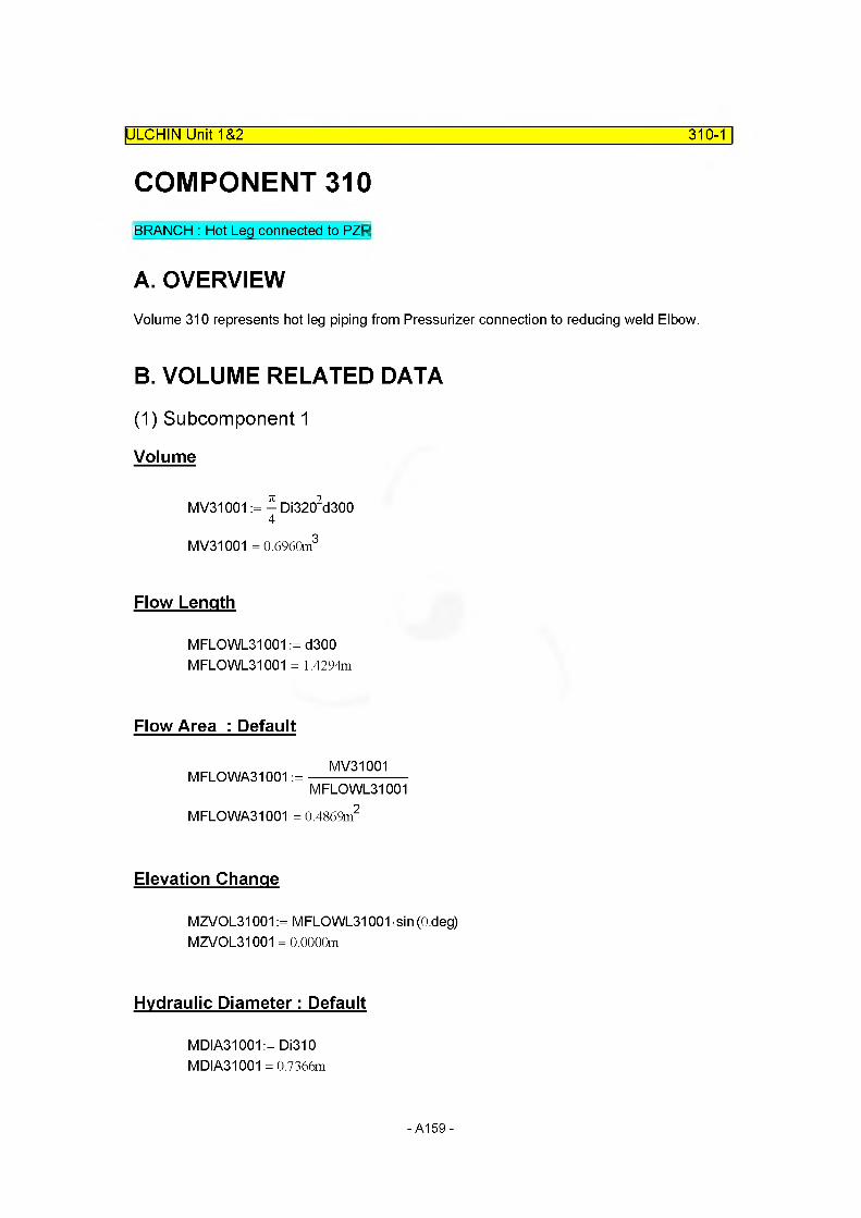
COMPONENT 310
ULCHIN Unit 1&2_______________________________________________________ 310-1
BRANCH : Hot Leg connected to PZR
A. OVERVIEWVolume 310 represents hot leg piping from Pressurizer connection to reducing weld Elbow.
B. VOLUME RELATED DATA
(1) Subcomponent 1
Volume
MV31001:=-Di3202d3004
MV31001 = 0.6960m3
Flow Length
MFLOWL31001 := d300 MFLOWL31001 = 1.4294m
Flow Area : Default
MFLOWA31001 :=MV31001
MFLOWL31001
MFLOWA31001 = 0.4869m"
Elevation Change
MZVOL31001 := MFLOWL31001 sin (O.deg) MZVOL31001 = 0.0000m
Hydraulic Diameter: Default
MDIA31001 := Di310 MDIA31001 = 0.7366m
-A159-

ULCHIN Unit 1&2 310-2
C. JUNCTION RELATED DATA
(1) Junction Area
Junctionl : Default
MAJUN31001 := min(MFLOWA30003, MFLOWA31001) MAJUN31001 = 0.4261m2
Junction2 : Default
MAJUN31002 = min(MFLOWA31001 .MFLOWA32001) Since two areas above are same with each other, MAJUN31002 := MFLOWA31001MAJUN31002 = 0.4869 m2
(2) Loss Factor
Junctionl,2 : Default
MFJUNF31001 := 0.0 MFJUNR31001 := 0.0 MFJUNF31002 := 0.0 MFJUNR31002 := 0.0
D. SUMMARY OF DATAcomponent type = branch
(1) VOLUME RELATED DATA : 1 Subvolume
Volume 1
MFLOWL31001 = 1.4294m
MFLOWA31001 = 0.4869m2 Default
MV31001 = 0.6960m3
MDIA31001 = 0.7366m DefaultMZVOL31001 = 0.0000mVolume Flag =0000 Default
-A160-
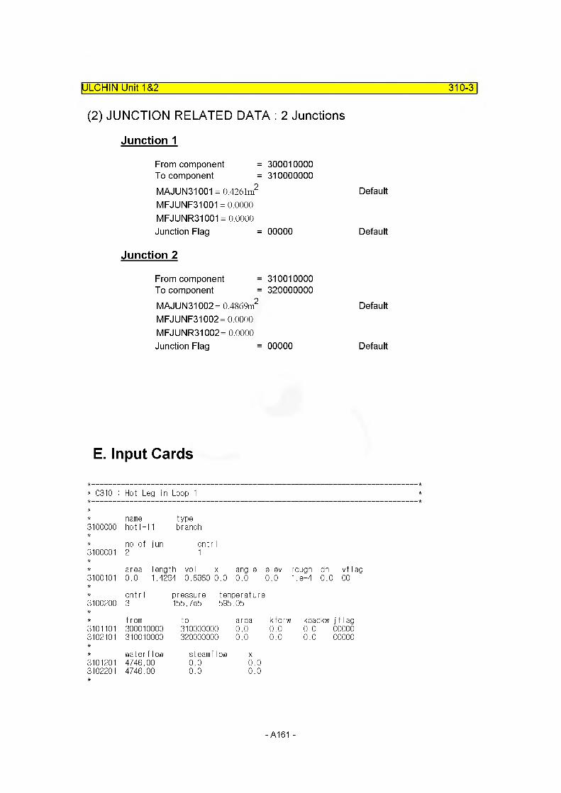
ULCHIN Unit 1&2 310-3
(2) JUNCTION RELATED DATA : 2 Junctions
Junction 1
From component =To component =MAJUN31001 = 0.4261m2
300010000310000000
DefaultMFJUNF31001 = 0.0000MFJUNR31001 = 0.0000 Junction Flag = 00000 Default
Junction 2
From component =To component =MAJUN31002= 0.4869m2
310010000320000000
DefaultMFJUNF31002 =0.0000MFJUNR31002= 0.0000 Junction Flag = 00000 Default
E. Input Cards
* C310 : Hot Leg in Loop 1
name type3100000 hotl-l1 branch
no of jun cntr I3100001 2 1
area length vol x angle elev rough dh vf lag3100101 0.0 1.4294 0.69600.0 0.0 0.0 1 .e-4 0.0) 00
cnt r I pressure temperature3100200 3 155.7e5 595 .05
from to area kforw kbackw j f I ag3101101 300010000 310000000 0.0 0.0 0.0 000003102101 310010000 320000000 0.0 0.0 0.0 00000
water flow steamflow X3101201 4746.00 0.0 0.03102201 4746.00 0.0 0.0
A161

COMPONENT 320
ULCHIN Unit 1&2_____________________________________________________ 320-1
BRANCH : Hot Leg connected to SG Inlet Plenum
A. OVERVIEWVolume 320 represents hot leg piping pertained to steam generator inlet plenum, which includes 50° elbow and steam generator inlet nozzle.
B. VOLUME RELATED DATA
(1) Subcomponent 1
Volume
Volume of Component 320 [MV32001]= Volume of 50° Elbow [Velv320] +Volume of Steam Generator Inlet Nozzle [Vsiv320]
Velv320:= 0.5666n3
Vsiv320:= 0.2973m3 MV32001 := Velv320 + Vsiv320MV32001 = 0.8639m3
Flow Area
MFLOWA32001 := MFLOWA30002 MFLOWA32001 = 0.4261m2
Flow Length : Default
MV32001MFLOWL32001 :=----------------------
MFLOWA32001MFLOWL32001 = 2.0273m
Elevation Change
MZVOL32001 := f300 + g300 MZVOL32001 = 0.8686m
-A162-
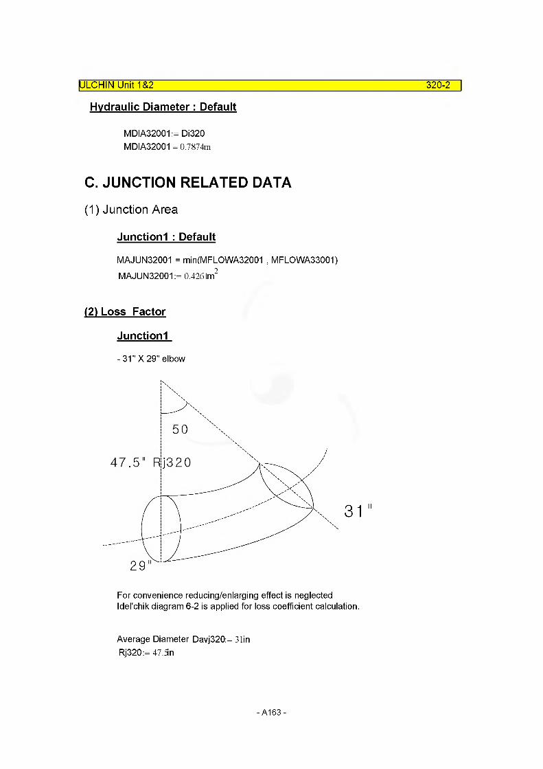
Hydraulic Diameter: Default
MDIA32001 := Di320 MDIA32001 = 0.7874m
C. JUNCTION RELATED DATA
(1) Junction Area
Junctionl : Default
MAJUN32001 = min(MFLOWA32001 , MFLOWA33001)MAJUN32001 := 0.4261m2
(2) Loss Factor
Junctionl
- 31" X 29" elbow
ULCHIN Unit 1&2_____________________________________________________ 320-2
47.5" R|j320
For convenience reducing/enlarging effect is neglected Idel'chik diagram 6-2 is applied for loss coefficient calculation.
Average Diameter Davj320:= 3tin Rj320:= 47.5n
-A163-
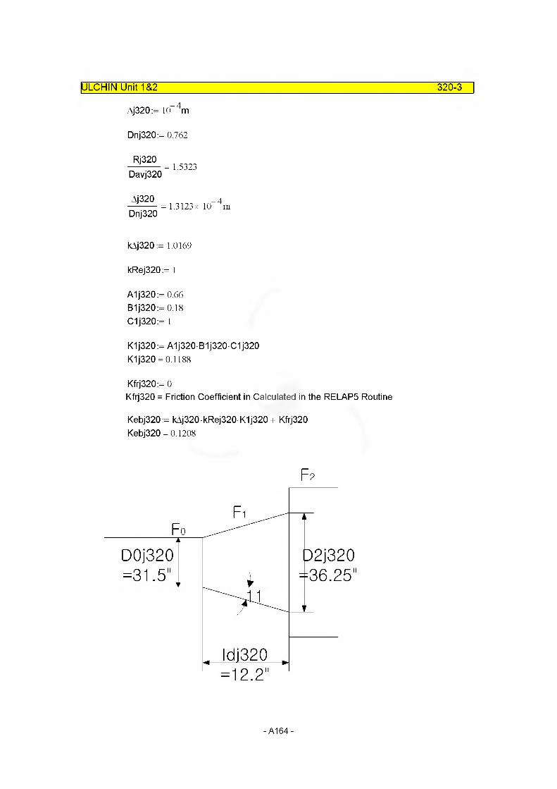
ULCHIN Unit 1&2_________________________________________________________320-3
Aj320:= 10™ 4m
Dnj320:= 0.762
Rj320
Davj3201.5323
Aj320 _ 4—------ = 1.3123x 10 mDnj320
kAj320 := 1.0169
kRej320:= 1
A1j320:= 0.66 B1j320:= 0.18 C1j320:= 1
K1j320:= A1j320 B1j320 C1j320 K1j320 = 0.1188
Kfrj320:= 0Kfrj320 = Friction Coefficient in Calculated in the RELAP5 Routine
Kebj320:= kAj320 kRej320 K1j320 + Kfrj320 Kebj320 = 0.1208
F2
D0j320=31.5"
-A164-

ULCHIN Unit 1&2__________________________________________________________320-4
For Ideel'chik diagram 5-8 is applied
Idj320:= 12.3n
D0j320:= 31.Sin
D2j320:= 36.25n
Idj320D0j320
0.3873
F0j320:=^D0j3202
F1j320:=^D2j3202
F2i320 =Steam Generator Inlet Plenum Area F2j320:= 3897in2
F2j320n:=---------
F0j320n = 5.0006
Kminj320:= 0.29
F0j320
F1j3200.7551
ct]320:= 0.13
KsiFj320 := (1 + oj320) Kminj320
KslFj320 = 0.3277
(Reverse Loss Coefficient)
Idel'chik diagram 3-9 is applied (Inlet edge)
F0j320
F2J3200.2000
Idj320
D0J3200.3873
a0j320:= 22deg K'j320:= 0.21
-A165-

ULCHIN Unit 1&2_________________________________________________________320-5
KsiRj320:=K'j320(>-i||)
KsiRj320 = 0.1680
Loss Coefficient of Junction 1
= - X Loss Coefficient of 50° Elbow + Steam Generator Inlet Nozzle2
MFJUNF32001 := ^Kebj320 + KsiFj320
MFJUNF32001 = 0.3881
MFJUNR32001 := ^Kebj320 + KsiRj320
MFJUNR32001 = 0.2284
D. SUMMARY OF DATAcomponent type = branch
(1) VOLUME RELATED DATA : 1 Subvolume
Volume 1
MFLOWL32001 = 2.0273m DefaultMFLOWA32001 = 0.4261m2
MV32001 = 0.8639m3
MDIA32001 = 0.7874m DefaultMZVOL32001 = 0.8686mVolume Flag =0000 Default
(2) JUNCTION RELATED DATA : 1 Junctions
Junction 1
From component = 320010000To component = 330000000MAJUN32001 = 0.4261m2
MFJUNF32001 = 0.3881 MFJUNR32001 = 0.2284 Junction Flag = 00000
DefaultModified into 0.20 Modified into 0.1040
Default
-A166-
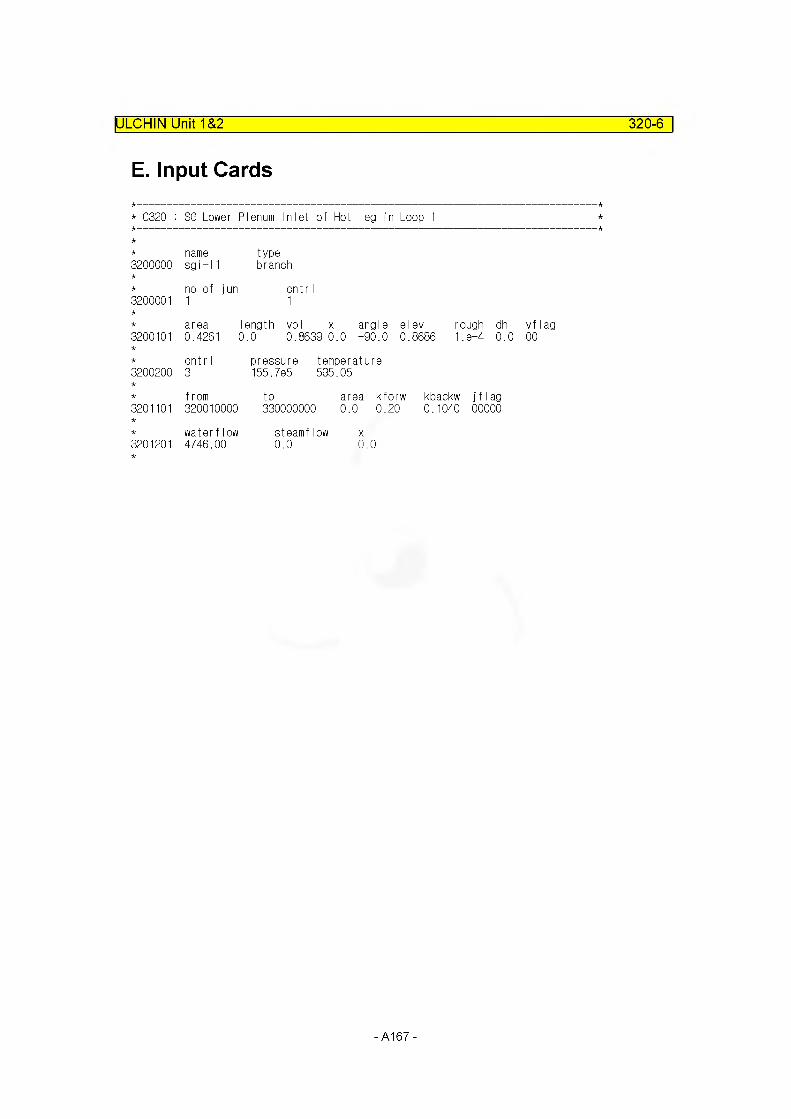
ULCHIN Unit 1&2 320-6
E. Input Cards
* C320 : SG Lower Plenum Inlet of Hot leg in Loop 1
name type3200000 sgi-l1 branch
no of jun cntr I3200001 1 1
area length vol x angle elev rough dh3200101 0.4261 i0.0 0.8639 0.0 +90.0 0.8686 1. e-4 0.0
cnt r I pressure temperature3200200 3 155.7e5 595.05
from to area kforw kbackw j f I ag3201101 320010000 330000000 0. 0 0.20 0.1040 00000
water flow steamflow X3201201 4746.00 0.0 0.0
-A167-
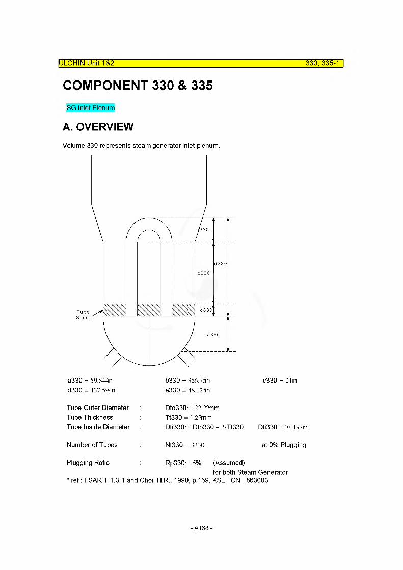
COMPONENT 330 & 335
ULCHIN Unit 1&2___________________________________________________330, 335-1
SG Inlet Plenum
A. OVERVIEWVolume 330 represents steam generator inlet plenum.
d330
b330
o330TubeSheet
e330
a330:= 59.844nd330:= 437.594n
b330:= 356.75ne330:=48.125n
c330:=21in
Tube Outer DiameterTube ThicknessTube Inside Diameter
Dto330:= 22.22nmTt330:= 1.27mmDti330:= Dto330 - 2 Tt330 Dti330 = 0.0197m
Number of Tubes Nt330:= 3330 at 0% Plugging
Plugging Ratio Rp330:= 5% (Assumed)for both Steam Generator
* ref: FSART-1.3-1 and Choi, H.R., 1990, p.159, KSL - CN - 863003
-A168-
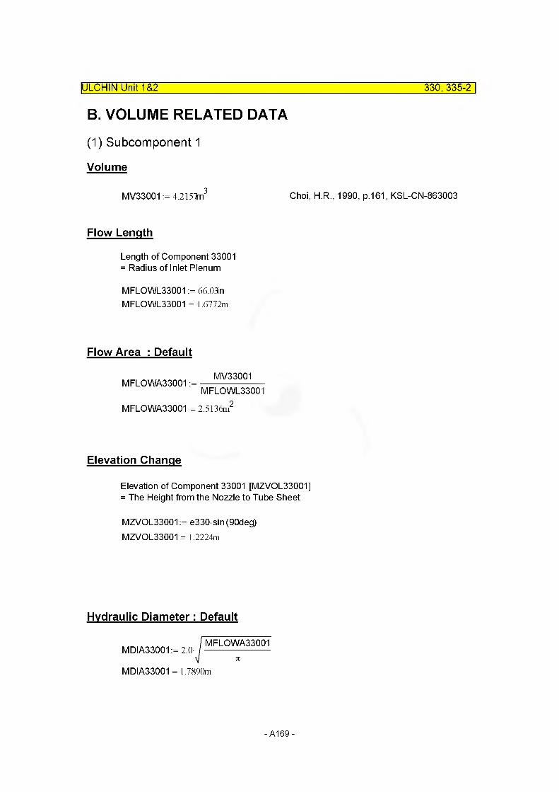
ULCHIN Unit 1&2 330, 335-2
B. VOLUME RELATED DATA
(1) Subcomponent 1
Volume
MV33001 := 4.2157fn3 Choi, H.R., 1990, p.161, KSL-CN-863003
Flow Length
Length of Component 33001 = Radius of Inlet Plenum
MFLOWL33001 := 66.03 n MFLOWL33001 = 1.6772m
Flow Area : Default
MFLOWA33001 :=MV33001
MFLOWL33001
MFLOWA33001 = 2.5136m
Elevation Change
Elevation of Component 33001 [MZVOL33001] = The Height from the Nozzle to Tube Sheet
MZVOL33001 := e330 sin(90deg)
MZVOL33001 = 1.2224m
Hydraulic Diameter: Default
MDIA33001 := 2.0-MFLOWA33001
MDIA33001 = 1.7890m
-A169-
C. JUNCTION RELATED DATA
(1) Junction Area
Junctionl : Default
MAJUN33001 = min(MFLOWA33001 , MFLOWA34001)MAJUN33001 := 0.9541m2
(2) Loss Factor
Junctionl : Default
Abrupt area opition is used for the loss coefficient calculation
MFJUNF33001:= 0.0 MFJUNR33001:= 0.0
D. SUMMARY OF DATAcomponent type = snglvol & sngljun
(1) VOLUME RELATED DATA : 1 Subvolume
Volume 1
IULCHIN Unit 1&2 330,335-3
MFLOWL33001 = 1.6772m
MFLOWA33001 = 2.5136m2 Default
MV33001 = 4.2157m3
MDIA33001 = 1.7890m DefaultMZVOL33001 = 1.2224mVolume Flag =0000 Default
(2) JUNCTION RELATED DATA : Junction 335
Junction 335
From component = 330010000To component = 340000000MAJUN33001 = 0.9541m2
MFJUNF33001 = 0.0000 MFJUNR33001 = 0.0000
Default Modified into 0.3 Modified into 0.4
Junction Flag = 0000 Default
-A170-

E. Input Cards
ULCHIN Unit 1&2___________________________________________________330, 335-4
* C330 : SG Inlet Lower Plenum in Loop 1
3300000namesgip-l
type1 snglvol
3300101area0.0
length vol 1.6772 4.2157
x angle elev rough0.0 +90. 1.2224 1.8-4
dh0.0
vf lag00
3300200cnt r I3
pressure 155.7e5
temperature595.05
* C335 : Junction between SG Inlet Lower Plenum and U-tubes in Loop 1
3350000name tubij-
type•11 sngljun
3350101from to330010000 340000000
area kforw kbackw0.0 0.3 0.4
j f I ag 00000
3350201cnt r I1
waterflow 4746.00
steamflow x0.0 0.0
- A171 -
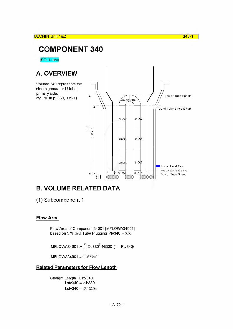
ULCHIN Unit 1&2 340-1
COMPONENT 340SG U-tube
A. OVERVIEWVolume 340 represents the steam generator U-tube primary side.(figure in p. 330, 335-1)
B. VOLUME RELATED DATA
(1) Subcomponent 1
Flow Area
Flow Area of Component 34001 [MFLOWA34001] based on 5 % S/G Tube Plugging Ptv340:= 0.05
MFLOWA34001 := ^ Dti3302 Nt330 (1 - Ptv340)
MFLOWA34001 = 0.9623m2
Related Parameters for Flow Length
Straight Length [Lstv3401 Lstv340:= 2b330 Lstv340 = 18.1229m
-A172-

ULCHIN Unit 1&2 340-2
Length in Hemispherical portion [Lhev340]
Total Heat Transfer Area of U-Tube [Aht340t]Aht340t := 4699m2 FSAR T-1.3-1 (15/30)
Thus, the equivalent length that preserves the total heat transfer area is,
L340eq:=Aht340t
7iDto330 Nt330L340eq= 20.2147m
And, length in Hemispherical portion [Lhev340]
Lhev340:= L340eq - Lstv340 Lhev340= 2.0918m
Length of U-tube in Tube Sheet [Lushv340]Lushv340:= 2c330
Lushv340= 1.0668m
Thus, total length [Ltv3401 is the sum of above three paramteres. Ltv340:= Lhev340+ Lstv340+ Lushv340
Ltv340= 21.2815m
Total U-tube Volume [Vt3401
Vt340 := — Dti3302 Ltv340 Nt3304
Vt340 = 21.5569m3
Flow Length
Length of Subcomponent 34001 [MFLOWL34001]= 0.5*Tube Sheet Length [Lshv340]+ Length of Bottom Downcomer [Lbdcv340] (Subcomponent 60005)
Lshv340:= 2 c330 Lbdcv340:= 14in
MFLOWL34001 := Lshv340 - + Lbdcv3402
MFLOWL34001 = 0.8890m
-A173-

Volume : Default
Volume of Component 34001 [MV34001]
MV34001 := MFLOWA34001 MFLOWL34001 MV34001 = 0.8555m3
ULCHIN Unit 1&2_____________________________________________________ 340-3
Elevation Change
MZVOL34001 := MFLOWL34001 sin (90deg) MZVOL34001 = 0.8890m
Hydraulic Diameter
MDIA34001 := Dti330 MDIA34001 = 0.0197m
(2) Subcomponent 2 ~4, 7~9
Flow Area
Flow Area of subcomponent 34002 ~ 34009 are same with subcomponent 34001.
MFLOWA34002:= ^ Dti3302 Nt330 (l - Ptv340)
MFLOWA34002 = 0.9623m2
MFLOWA34003 := MFLOWA34002 MFLOWA34004 := MFLOWA34002 MFLOWA34007 := MFLOWA34002 MFLOWA34008 := MFLOWA34002 MFLOWA34009 := MFLOWA34002
-A174-

Flow Length
Length of Subcomponent 34002-34004, 34007-34009[MFLOWL34002 - MFLOWL34004, MFLOWL34007 - MFLOWL34009]
= 1/6*(Representitive Total Tube Length [Ltv340]- Length of subcomponent 34001 & 34010- Length in hemispherical portion [Lhev340]
ULCHIN Unit 1&2_____________________________________________________ 340-4
M FLO WL34002:=(Ltv340 - 2MFLOWL34001 - Lhev34Q
6MFLOWL34002 = 2.9019m
M FLO WL34003: = MFLOWL34002 M FLO WL34004: = MFLOWL34002
MFLOWL34007 := MFLOWL34002 M FLO WL34008: = MFLOWL34002 M FLO WL34009: = MFLOWL34002
Volume : Default
MV34002:= M FLO WA34002 • M FLO WL34002 MV34002 = 2.7925m3
MV34003:= MFLOWA34003 MFLOWL34003 MV34004:= M FLO WA34004 • M FLO WL34004
MV34007 := MFLOWA34007 MFLOWL34007 MV34008:= MFLOWA34008 MFLOWL34008 MV34009:= MFLOWA34009 MFLOWL34009
Elevation Change
For upward volumes,
MZVOL34002:= MFLOWL34002 sin (90deg) MZVOL34002 = 2.9019m
MZVOL34003:= MZVOL34002 MZVOL34004:= MZVOL34002
-A175-

ULCHIN Unit 1&2 340-5
For downward volumes,
MZVOL34007:= MFLOWL34007 sin (-90deg) MZVOL34007 = -2.9019m
MZVOL34008:= MZVOL34007 MZVOL34009:= MZVOL34007
Hydraulic Diameter
MDIA34002:= Dti330 MDIA34002 = 0.0197m MDIA34003:= Dti330 MDIA34004:= Dti330
MDIA34007:= Dti330 MDIA34008:= Dti330 MDIA34009:= Dti330
(3) Subcomponent 5~6
Flow Area
Flow Areas of subcomponent 34005(34006) and subcomponent 34001 are same. MFLOWA34005 := MFLOWA34001 MFLOWA34005 = 0.9623m2
MFLOWA34006 := MFLOWA34005
Flow Length
Length of Subcomponent 34005 [MFLOWL34005] =1/2 * Length in hemispherical portion [Lhev340]
M FLO WL34005:=
M FLO WL34006:=
Lhev340MFLOWL34005 = 1.0459m
MFLOWL34005
-A176-
ULCHIN Unit 1&2 340-6
Volume : Default
MV34005:= MFLOWA34005 MFLOWL34005 MV34005= 1.0065m3
MV34006:= M FLO WA34006 • M FLO WL34006 MV34006= 1.0065m3
Elevation Change
Heigh of the U-tube bundle = 417 inHeigh of the Straight U-tube = 365.75 in Choi, H.R., 1990, p. A-265
Thus, the maximum elevation change is;MZVOL34005:= 417in - 365.75n MZVOL34005= 1.3018m
MZVOL34006:= -MZVOL34005 MZVOL34006= -1.3018m
Hydraulic Diameter
MDIA34005:= Dti330 MDIA34005= 0.0197m
MDIA34006:= Dti330 MDIA34006= 0.0197m
-A177-

(4) Subcomponent 10
Flow Area
Flow Areas of subcomponent 34010 and subcomponent 34001 are same.
Flow Area of Subcomponent 34010 [MFLOWA34010]MFLOWA34010 := MFLOWA34001MFLOWA34010 = 0.9623m2
ULCHIN Unit 1&2_____________________________________________________ 340-7
Flow Length
Flow lengths of component 34010 and component 34001 are same.
Length of Subcomponent 34010 [MFLOWL34010]Length of Subcomponent 34001 [MFLOWL34001]
MFLOWL34010:= MFLOWL34001 MFLOWL34010 = 0.8890m
Volume : Default
Volume of Component 34010 [MV34010]
MV34010 := M FLO WA34010 • M FLO WL34010 MV34010 = 0.8555m3
Elevation Change
MZVOL34010:= MFLOWL34010 sin (-90deg) MZVOL34010=-0.8890m
Hydraulic Diameter
MDIA34010:= Dti330 MDIA34010= 0.0197m
-A178-

C. JUNCTION RELATED DATA
(1) Junction Area
IULCHIN Unit 1&2 340-8
Junctionl ~ 9 : Default
MAJUN34001 := min(MFLOWA34001, MFLOWA34002) MAJUN34001 = 0.9623m2
MAJUN34002:= MAJUN34001 MAJUN34002= 0.9623m2
MAJUN34003:= MAJUN34001 MAJUN34003= 0.9623m2
MAJUN34004:= MAJUN34001 MAJUN34004= 0.9623m2
MAJUN34005:= MAJUN34001 MAJUN34005= 0.9623m2
MAJUN34006:= MAJUN34001 MAJUN34006= 0.9623m2
MAJUN34007:= MAJUN34001 MAJUN34007= 0.9623m2
MAJUN34008:= MAJUN34001 MAJUN34008= 0.9623m2
MAJUN34009:= MAJUN34001 MAJUN34009= 0.9623m2
(2) Loss Factor
Junctionl ~ 3 : Default
MFJUNF34001:= 0.0 MFJUNR34001:= 0.0
MFJUNF34002:= 0.0 MFJUNR34002:= 0.0
-A179-
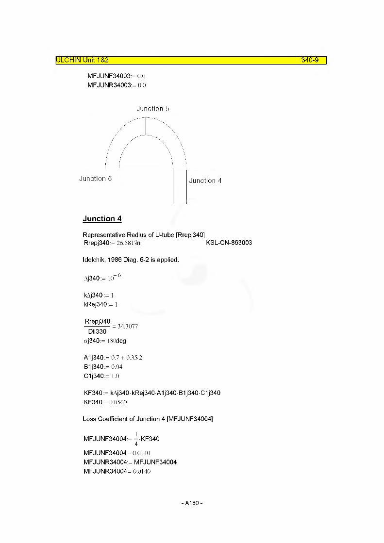
ULCHIN Unit 1&2 340-9
MFJUNF34003:= 0.0 MFJUNR34003:= 0.0
Junction 5
Junction Junction 4
Junction 4
Representative Radius of U-tube [Rrepj340]Rrepj340:= 26.5817n KSL-CN-863003
Idelchik, 1986 Diag. 6-2 is applied.
Aj340:= 10“ 6
kAj340 := 1 kRej340:= 1
Rrepj340
Dti33034.3077
oj340:= 180deg
A1j340:= 0.7+ 0.35-2B1j340:= 0.04 C1j340:= 1.0
KF340:= kAj340-kRej340-A1j340 B1j340 C1j340 KF340 = 0.0560
Loss Coefficient of Junction 4 [MFJUNF34004]
MFJUNF34004:= - KF3404
MFJUNF34004= 0.0140 MFJUNR34004:= MFJUNF34004 MFJUNR34004= 0.0140
-A180-
ULCHIN Unit 1&2 340-10
Junctions
MFJUNF34005:= - KF3402
MFJUNF34005= 0.0280 MFJUNR34005:= MFJUNF34005 MFJUNR34005= 0.0280
Junctions
MFJUNF34006:= MFJUNF34004
MFJUNF34006= 0.0140 MFJUNR34006:= MFJUNF34004 MFJUNR34006= 0.0140
Junction? ~ 9 : Default
MFJUNF34007:= 0.0 MFJUNR34007:= 0.0
MFJUNF34008:= 0.0 MFJUNR34008:= 0.0
MFJUNF34009:= 0.0 MFJUNR34009:= 0.0
D. SUMMARY OF DATAcomponent type = pipe
(1) VOLUME RELATED DATA : 10 Subvolume
Volume 1
MFLOWL34001 = 0.8890m
MFLOWA34001 = 0.9623m2
MV34001 = 0.8555m3 Default
MDIA34001 = 0.0197m MZVOL34001 = 0.8890mVolume Flag =0000 Default
- A181 -
Volume 2 ~ 4
MFLOWL34002 = 2.9019m
MFLOWA34002 = 0.9623m2
MV34002 = 2.7925m3 Default
MDIA34002= 0.0197m MZVOL34002 = 2.9019mVolume Flag =0000 Default
MFLOWL34003 = 2.9019m
MFLOWA34003 = 0.9623m2
MV34003 = 2.7925m3 Default
MDIA34003= 0.0197m MZVOL34003= 2.9019mVolume Flag =0000 Default
MFLOWL34004 = 2.9019m
MFLOWA34004 = 0.9623m2
MV34004 = 2.7925m3 Default
MDIA34004= 0.0197m MZVOL34004 = 2.9019mVolume Flag =0000 Default
Volume 5 ~ 6
MFLOWL34005 = 1.0459m
MFLOWA34005 = 0.9623m2
MV34005 = 1,0065m3 Default
MDIA34005= 0.0197m MZVOL34005= 1.3018mVolume Flag =0000 Default
MFLOWL34006 = 1.0459m
MFLOWA34006 = 0.9623m2
MV34006 = 1,0065m3 Default
MDIA34006= 0.0197m MZVOL34006=-1.3018mVolume Flag =0000 Default
ULCHIN Unit 1&2_____________________________________________________ 340-11
-A182-
ULCHIN Unit 1&2_________________________________________________________340-12
Volume 7 ~ 9
MFLOWL34007 = 2.9019m
MFLOWA34007 = 0.9623m2
MV34007 = 2.7925m3 Default
MDIA34007= 0.0197m MZVOL34007 = -2.9019mVolume Flag =0000 Default
MFLOWL34008 = 2.9019m
MFLOWA34008 = 0.9623m2
MV34008 = 2.7925m3 Default
MDIA34008= 0.0197m MZVOL34008= -2.9019mVolume Flag =0000 Default
MFLOWL34009 = 2.9019m
MFLOWA34009 = 0.9623m2
MV34009 = 2.7925m3
MDIA34009= 0.0197m MZVOL34009= -2.9019m Volume Flag =0000
Volume 10
MFLOWL34010 = 0.8890m
MFLOWA34010 = 0.9623m2
MV34010 = 0.8555m3
MDIA34010= 0.0197m MZVOL34010=-0.8890m Volume Flag =0000
Default
Default
Default
Default
(2) JUNCTION RELATED DATA : 10 Junctions
Junction 1 ~ 3
From component = Internal JunctionTo component = Internal JunctionMAJUN34001 = 0.9623m2
MFJUNF34001 = 0.0000 MFJUNR34001 = 0.0000Junction Flag = 00000
Default
-A183-

ULCHIN Unit 1&2 340-13
From component =To component =MAJUN34002= 0.9623m2
Internal JunctionInternal Junction
DefaultMFJUNF34002= 0.0000MFJUNR34002= 0.0000Junction Flag = 00000
From component =To component =MAJUN34003= 0.9623m2
Internal JunctionInternal Junction
DefaultMFJUNF34003= 0.0000MFJUNR34003= 0.0000Junction Flag = 00000
Junction 4 ~ 6
From component = Internal JunctionTo component =MAJUN34004= 0.9623m2
Internal Junction
DefaultMFJUNF34004= 0.0140 Modified into 0.01MFJUNR34004= 0.0140 Modified into 0.009Junction Flag = 00000
From component =To component =MAJUN34005= 0.9623m2
Internal JunctionInternal Junction
DefaultMFJUNF34005= 0.0280 Modified into 0.02MFJUNR34005= 0.0280 Modified into 0.013Junction Flag = 00000
From component =To component =MAJUN34006= 0.9623m2
Internal JunctionInternal Junction
DefaultMFJUNF34006= 0.0140 Modified into 0.01MFJUNR34006= 0.0140 Modified into 0.009Junction Flag = 00000
Junction 7 ~ 9
From component = Internal JunctionTo component =MAJUN34007= 0.9623m2
Internal Junction
DefaultMFJUNF34007= 0.0000MFJUNR34007= 0.0000Junction Flag = 00000
-A184-

ULCHIN Unit 1&2 340-14
From component =To component =MAJUN34008= 0.9623m2
MFJUNF34008= 0.0000 MFJUNR34008= 0.0000 Junction Flag =
From component =To component =MAJUN34009= 0.9623m2
MFJUNF34009= 0.0000 MFJUNR34009= 0.0000 Junction Flag =
Internal Junction Internal Junction
Default
Internal Junction Internal Junction
Default
00000
00000
E. Input Cards
* 0340 : SG U-tubes in Loop 1
name type3400000 sgtub-l 1 pipe
number of 'volumes3400001 10
area no of VO I3400101 0.9796 10
j-area no of junction3400201 0.0 9
I ength no of vo I3400301 0.8834 13400302 2.4385 53400303 2.4385 93400304 0.8834 10
volume no of vo I3400401 0.0 10
XX no of vo I3400501 0.0 10
angle no of vol3400601 +90. 53400602 -90. 10
-A185-

ULCHIN Unit 1&2 340-15
elev. no of vo I3400701 +0.8834 13400702 +2.4385 53400703 -2.4385 93400704 -0.8834 10
rough dhydr. no of vol3400801 1.Oe-6 0.0197 10
kforw kbackw no of fun3400901 0.0 0.0 33400902 0.01 0.009 43400903 0.02 0.013 53400904 0.01 0.009 63400905 0.0 0.0 9
v-flag no of vol3401001 00 10
j-flag no of fun3401101 00000 9
cnt r I pres temp no3401201 3 155.7e5 595.0 0.0 0.0 0.0 13401202 3 155.4e5 590.1 0.0 0.0 0.0 23401203 3 155.1e5 580.4 0.0 0.0 0.0 33401204 3 154.8e5 570.9 0.0 0.0 0.0 43401205 3 154.5e5 565.4 0.0 0.0 0.0 53401206 3 154.2e5 564.9 0.0 0.0 0.0 63401207 3 153.9e5 563.4 0.0 0.0 0.0 73401208 3 153.6e5 562.9 0.0 0.0 0.0 83401209 3 153.3e5 561.5 0.0 0.0 0.0 93401210 3 152.9e5 560.25 0.0 0.0 0.0 10
cnt r I3401300 1
water flow steamflow no of3401301 4746.00 0.0 0.0 9
no of voI
-A186-
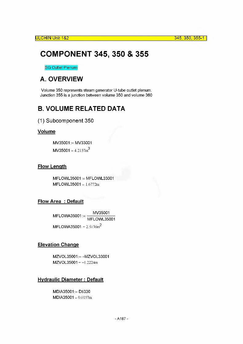
ULCHIN Unit 1&2 345, 350, 355-1
COMPONENT 345, 350 & 355SG Outlet Plenum
A. OVERVIEWVolume 350 represents steam generator U-tube outlet plenum. Junction 355 is a junction between volume 350 and volume 360
B. VOLUME RELATED DATA
(1) Subcomponent 350
Volume
MV35001 := MV33001 MV35001 = 4.2157m3
Flow Length
MFLOWL35001 := MFLOWL33001 MFLOWL35001 = 1.6772m
Flow Area : Default
MFLOWA35001 :=MV35001
MFLOWL35001
MFLOWA35001 = 2.5136m"
Elevation Change
MZVOL35001 := -MZVOL33001 MZVOL35001 = -1.2224m
Hydraulic Diameter: Default
MDIA35001 := Dti330 MDIA35001 = 0.0197m
-A187-

ULCHIN Unit 1&2 345, 350, 355-2
C. JUNCTION RELATED DATA
(1) Junction Area
Junction 345 : Default
MAJUN35001 := min(MFLOWA34010, MFLOWA35001)MAJUN35001 = 0.9623m2
Junction 355
MAJUN35002 = min(MFLOW35001 , MFLOWA36001)MAJUN35002:= 0.48695n2
(2) Loss Factor
Junction345 : Default
Abrupt area change option is used.MFJUNF35001:= 0.0 MFJUNR35001:= 0.0
Junction2 : Default
Loss Coefficient of 40° Elbow [ElbF40j35002 , ElbR40j35002]ElbF40j35002 := 0.117 ElbR40j35002 := 0.117
Loss Coefficient of Steam Generator Outlet Nozzle [KsoFj350 , KsoRj350]= Loss Coefficient of Steam Generator Inlet Nozzle [KsiR320 , KsiFj320]
KsoFj350 := KsiRj320 KsoRj350 := KsiFj320
Loss Coefficient of Single Junction 2 [MFJUNF35002 , MFJUNR35002]
= X Loss Coefficient of 40° Elbow [ElbF40j35002 , ElbR40j35002]
+ Loss Coefficient of Steam Generator Outlet Nozzle [KsoFj350 , KsoRj350]
MFJUNF35002 := ^ EIbF40j35002 + KsoFj350
MFJUNF35002 = 0.2265
MFJUNR35002 := ^EIbR40j35002 + KsoRj350
MFJUNR35002 = 0.3862
-A188-

ULCHIN Unit 1&2 345, 350, 355-3
D. SUMMARY OF DATAcomponent type = sngvol, sngjun
(1) VOLUME RELATED DATA : 1 Subvolume
Volume 350
MFLOWL35001 = 1.6772m
MFLOWA35001 = 2.5136m2 Default
MV35001 = 4.2157m3
MDIA35001 = 0.0197m DefaultMZVOL35001 = -1.2224mVolume Flag =0000 Default
(2) JUNCTION RELATED DATA : 2 Junctions
Junction 345
From component =To component =MAJUN35001 = 0.9623m2
MFJUNF35001 = 0.0000 MFJUNR35001 = 0.0000 Junction Flag =
Junction 355
From component = 350001000To component = 360000000MAJUN35002= 0.4870m2
MFJUNF35002= 0.2265 Modified into 0.1040MFJUNR35002= 0.3862 Modified into 0.20Junction Flag = 00000 Default
340010000350000000
DefaultModified into 0.4 Modified into 0.3
0000 Default
-A189-
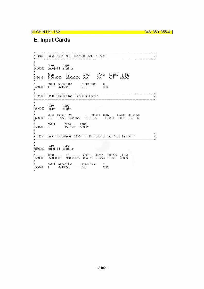
E. Input CardsIULCHIN Unit 1&2 345, 350, 355-4
* C345 : Junction of SG U-tubes Outlet in Loop 1
3450000nametuboj-
type11 sngljun
3450101from to340010000 350000000
area0.0
kforw0.4
kbackw0.3
j f I ag000000
3450201cnt r I1
waterflow 4745.00
steamflow 0.0
X
0.0
* C350 : SG U-tube Outlet Plenum in Loop 1
name type3500000 sgop- 1 snglvoI
area length vol x angle elev rough dh vflag3500101 0.0 1.6772 4.21570 0.0 -90. -1.2224 1. e-4 0.0 00
cnt r I pres temp3500200 3 152.9e5 560.25
* C355 : Junction between SG Outlet Plenum and Loop Seal in Loop 1
3550000namesglcj-
f rom
type11 sngljun
to area kforw kbackw j f I ag3550101 350010000 360000000 0.4670 0.1040 0.20 00000
cnt r I waterflow steamflow X3550201 1 4746.00 0.0 0.0
-A190-
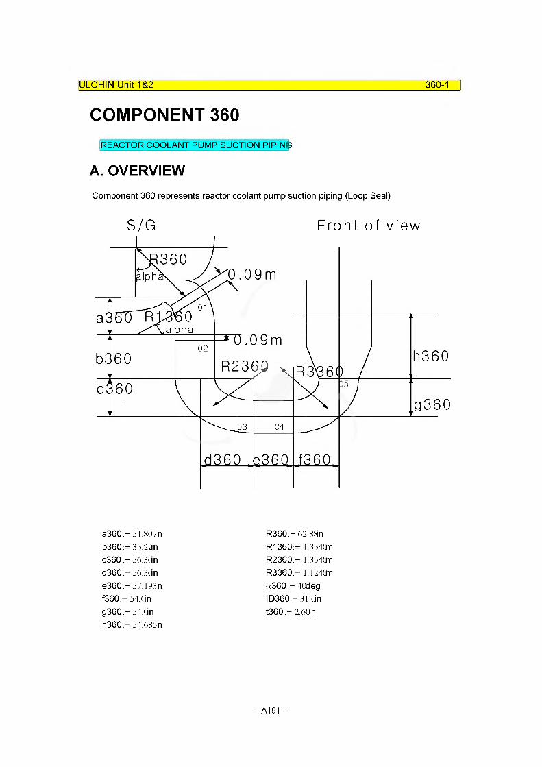
ULCHIN Unit 1&2 360-1
COMPONENT 360REACTOR COOLANT PUMP SUCTION PIPING
A. OVERVIEWComponent 360 represents reactor coolant pump suction piping (Loop Seal)
S/G Front of view
h360
a360:= 51.801n 6360:= 35.22n c360 := 56.3Qn d360:= 56.3Qn e360:= 57.193n f360:= 54.Cin g360:= 54.Cin h360:= 54.685n
R360:= 62.88n R1360:= 1.3540n R2360:= 1.3540n R3360:= 1.1240n a360:= 40deg ID360:= 31.On t360 := 2.6Cin
- A191 -

B. VOLUME RELATED DATA
(1) Subcomponent 1
Flow Area
ULCHIN Unit 1&2_____________________________________________________ 360-2
MFLOWA36001 := —-ID36024
MFLOWA36001 = 0.4869m2
Volume
Volume of Component 36001 [MV36001]= Volume of S/G Outlet Nozzle [VONv36001] + Volume of 40o Elbow [V40elbv36001]
VONv36001:= 0.2521m3
V40elbv36001:= 0.4638n3
MV36001 := VONv36001 + V40elbv36001 MV36001 = 0.7159m3
Flow Length : Default
MFLOWL36001 :=MV36001
MFLOWA36001 MFLOWL36001 = 1.4702m
Elevation Change
MZVOL36001 := a360 sin(-90deg) MZVOL36001 =-1.3159m
Hydraulic Diameter: Default
MDIA36001 := ID360 MDIA36001 = 0.7874m
-A192-

(2) Subcomponent 2
Flow Area
MFLOWA36002:= --ID36024
MFLOWA36002 = 0.4869m2
Flow Length
M FLO WL36002: = 6360 MFLOWL36002 = 0.8946m
Volume : Default
MV36002:= M FLO WA36002 • M FLO WL36002 MV36002 = 0.4356m3
Elevation Change
MZVOL36002:= b360 sin(-90deg)MZVOL36002= -0.8946m
Hydraulic Diameter: Default
MDIA36002:= ID360 MDIA36002= 0.7874m
(3) Subcomponent 3
Flow Area
MFLOWA36003:= - ID36(f4
MFLOWA36003 = 0.4869m2
ULCHIN Unit 1&2_____________________________________________________ 360-3
-A193-
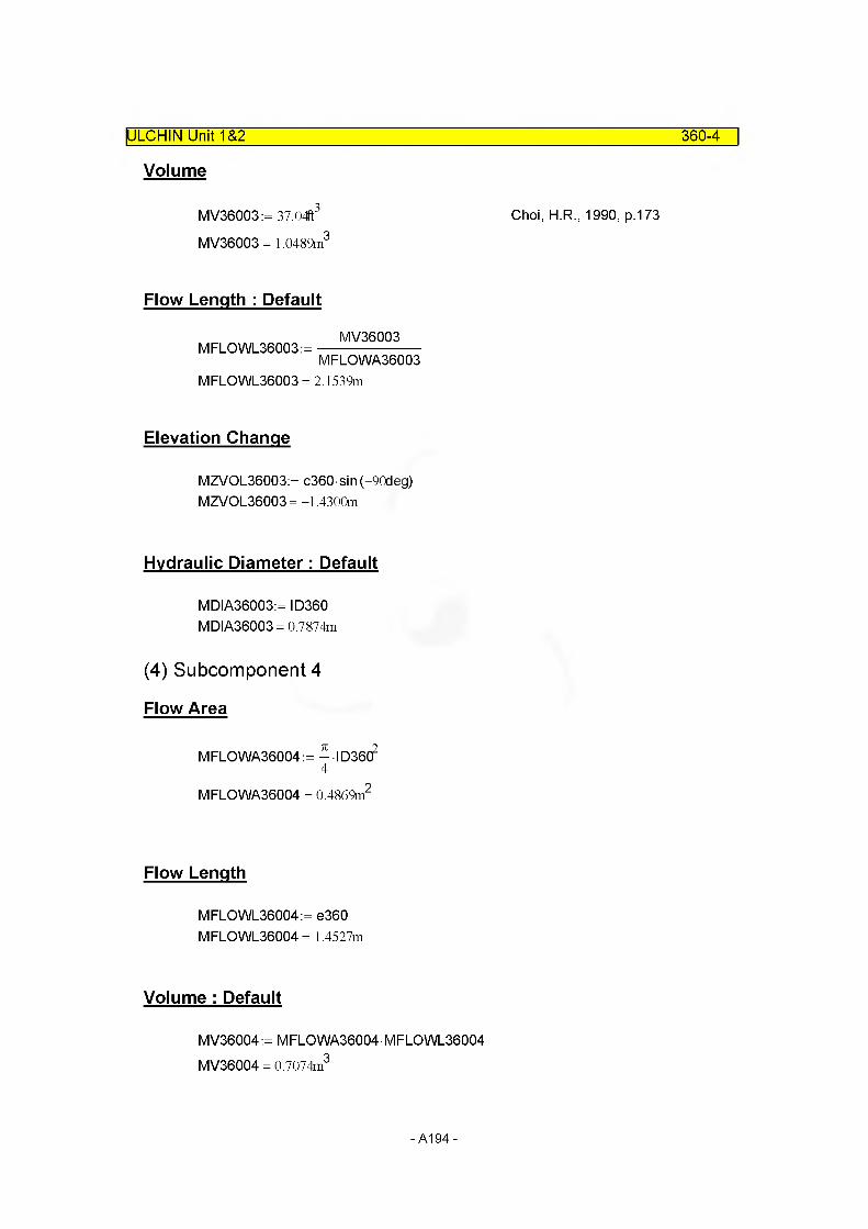
ULCHIN Unit 1&2 360-4
Volume
MV36003:= 37.04ft3 Choi, H.R., 1990, p.173
MV36003= 1.0489m3
Flow Length : Default
MV36003M FLO WL36003: =----------------------
MFLOWA36003MFLOWL36003 = 2.1539m
Elevation Change
MZVOL36003:= c360 sin(-90deg)MZVOL36003= -1.4300m
Hydraulic Diameter: Default
MDIA36003:= ID360 MDIA36003= 0.7874m
(4) Subcomponent 4
Flow Area
MFLOWA36004:= - ID36(f4
MFLOWA36004 = 0.4869m2
Flow Length
M FLO WL36004: = e360 MFLOWL36004 = 1.4527m
Volume : Default
MV36004:= M FLO WA36004 • M FLO WL36004 MV36004 = 0.7074m3
-A194-
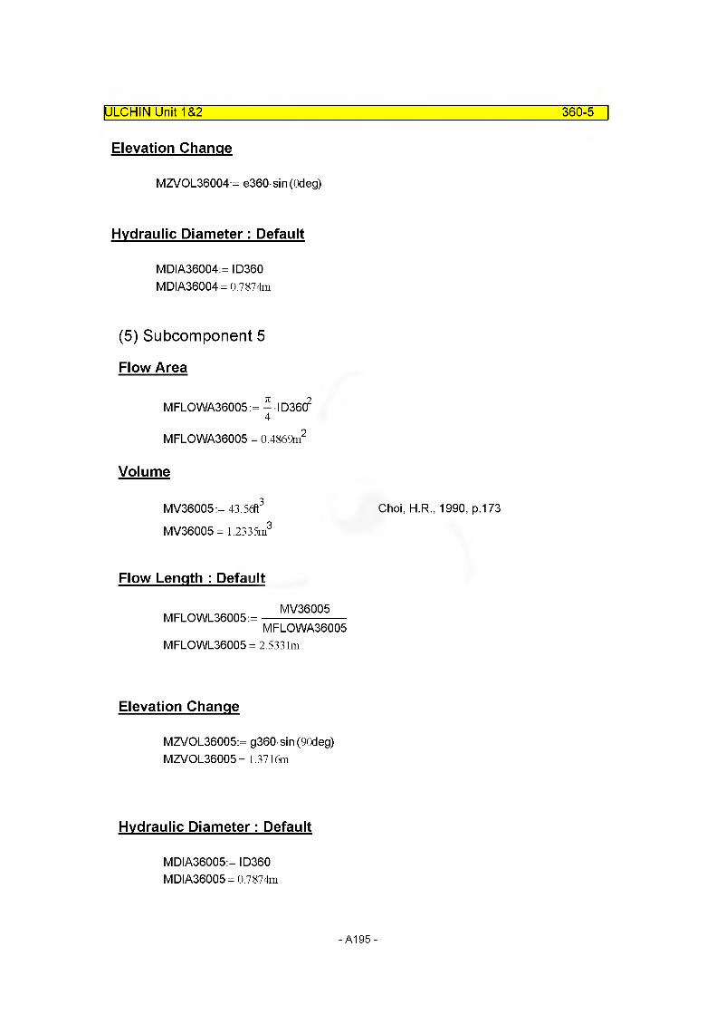
ULCHIN Unit 1&2 360-5
Elevation Change
MZVOL36004:= e360 sin(0deg)
Hydraulic Diameter: Default
MDIA36004:= ID360 MDIA36004= 0.7874m
(5) Subcomponent 5
Flow Area
MFLOWA36005:= --ID36024
MFLOWA36005 = 0.4869m2
Volume
MV36005:= 43.5<ft3 Choi, H.R., 1990, p.173
MV36005= 1.2335m3
Flow Length : Default
MV36005M FLO WL36005: =----------------------
MFLOWA36005MFLOWL36005 = 2.5331m
Elevation Change
MZVOL36005:= g360 sin(90deg) MZVOL36005= 1.3716m
Hydraulic Diameter: Default
MDIA36005:= ID360 MDIA36005= 0.7874m
-A195-
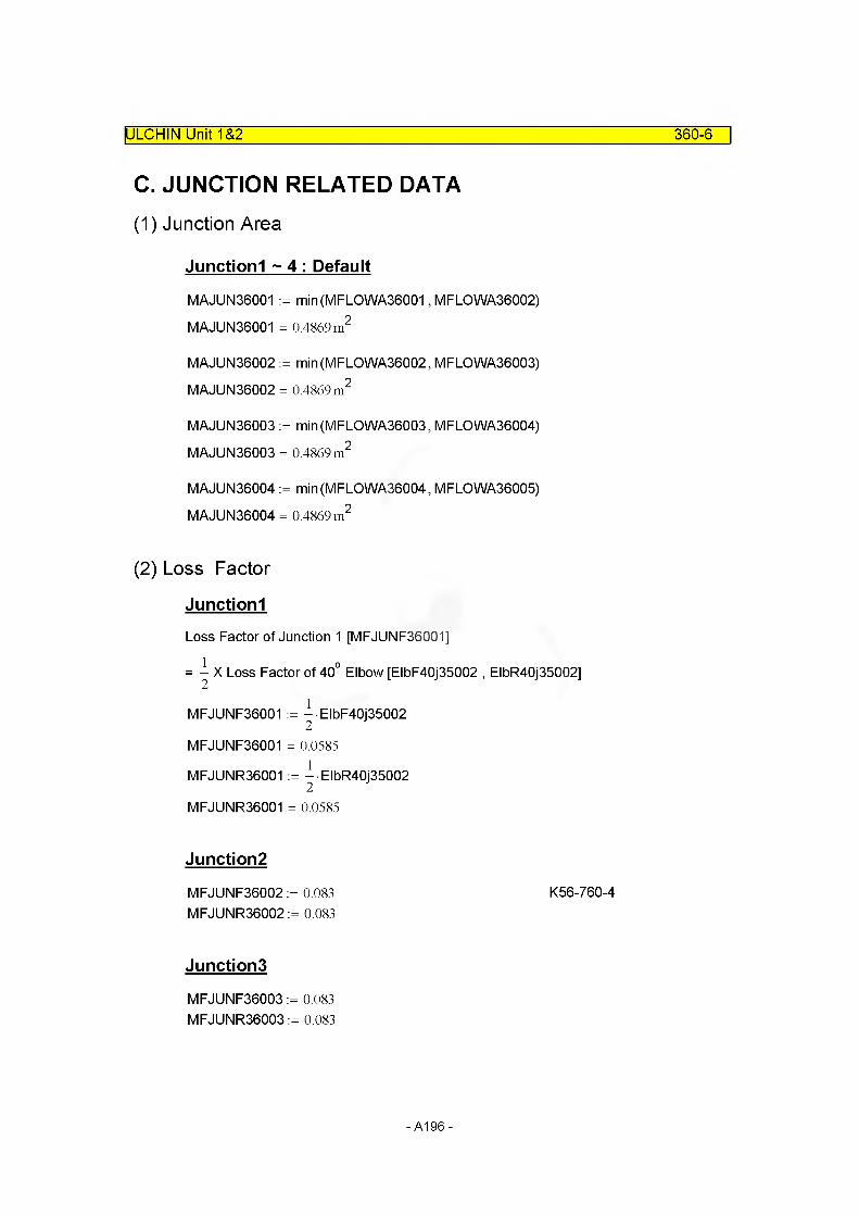
ULCHIN Unit 1&2 360-6
C. JUNCTION RELATED DATA
(1) Junction Area
Junctionl ~ 4 : Default
MAJUN36001 := min(MFLOWA36001, MFLOWA36002) MAJUN36001 = 0.4869 m2
MAJUN36002 := min(MFLOWA36002, MFLOWA36003) MAJUN36002 = 0.4869 m2
MAJUN36003 := min(MFLOWA36003, MFLOWA36004) MAJUN36003 = 0.4869 m2
MAJUN36004 := min(MFLOWA36004, MFLOWA36005) MAJUN36004 = 0.4869 m2
(2) Loss Factor
Junctionl
Loss Factor of Junction 1 [MFJUNF36001]
= X Loss Factor of 40° Elbow [ElbF40j35002 , ElbR40j35002]
MFJUNF36001 := ^EIbF40j35002
MFJUNF36001 = 0.0585
MFJUNR36001 := ^EIbR40j35002
MFJUNR36001 = 0.0585
Junction2
MFJUNF36002 := 0.083 K56-760-4MFJUNR36002 := 0.083
Junctions
MFJUNF36003 := 0.083 MFJUNR36003 := 0.083
-A196-
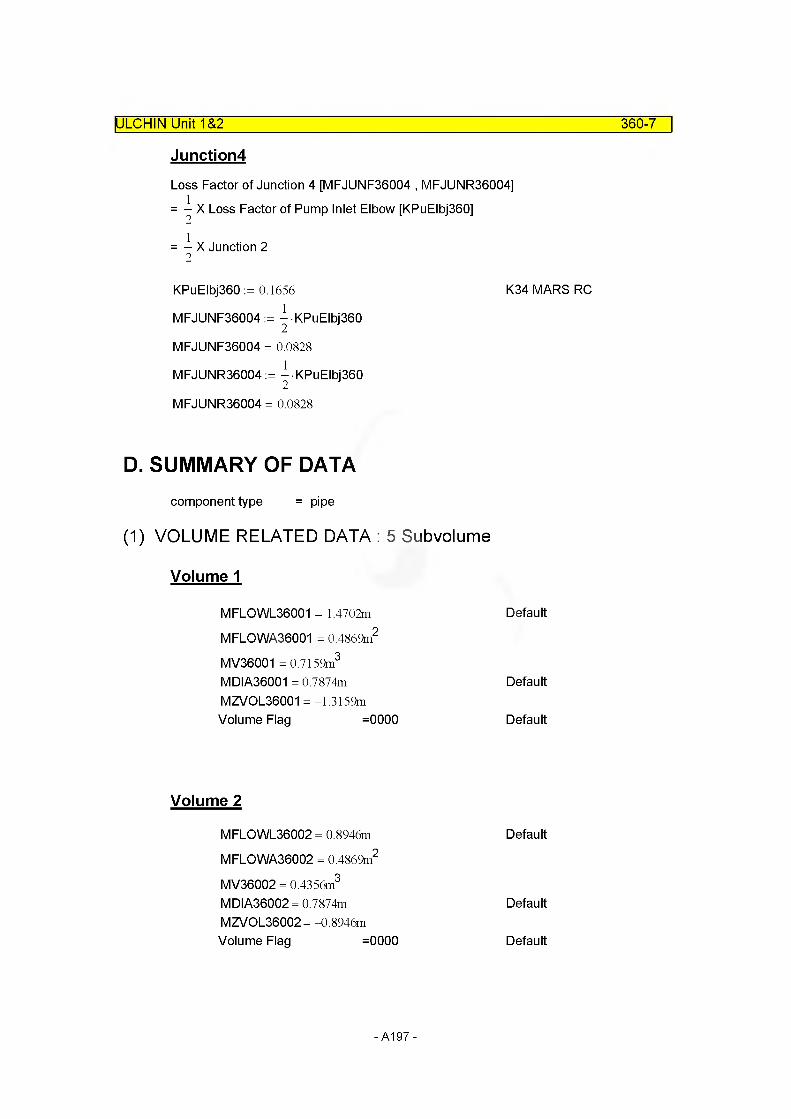
ULCHIN Unit 1&2 360-7
Junction4
Loss Factor of Junction 4 [MFJUNF36004 , MFJUNR36004]= -^ X Loss Factor of Pump Inlet Elbow [KPuElbj360]
= - X Junction 22
KPuElbj360 := 0.1656 K34 MARS RCMFJUNF36004 := ^ KPuElbj360
MFJUNF36004 = 0.0828
MFJUNR36004 := ^KPuElbj360
MFJUNR36004 = 0.0828
D. SUMMARY OF DATAcomponent type = pipe
(1) VOLUME RELATED DATA : 5 Subvolume
Volume 1
MFLOWL36001 = 1.4702m
MFLOWA36001 = 0.4869m2
MV36001 = 0.7159m3
MDIA36001 = 0.7874m MZVOL36001 =-1.3159m Volume Flag =0000
Volume 2
MFLOWL36002 = 0.8946m
MFLOWA36002 = 0.4869m2
MV36002 = 0.4356m3
MDIA36002= 0.7874m MZVOL36002= -0.8946m Volume Flag =0000
Default
Default
Default
Default
Default
Default
-A197-
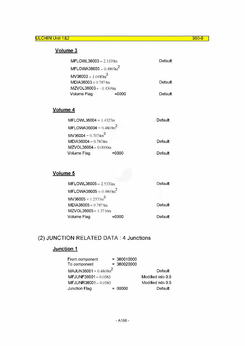
ULCHIN Unit 1&2 360-8
Volume 3
MFLOWL36003 = 2.1539m DefaultMFLOWA36003 = 0.4869m2
MV36003= 1.0489m3
MDIA36003 = 0.7874m DefaultMZVOL36003= -1.4300mVolume Flag =0000 Default
Volume 4
MFLOWL36004 = 1.4527m DefaultMFLOWA36004 = 0.4869m2
MV36004 = 0.7074m3
MDIA36004 = 0.7874m DefaultMZVOL36004= 0.0000mVolume Flag =0000 Default
Volume 5
MFLOWL36005 = 2.5331m DefaultMFLOWA36005 = 0.4869m2
MV36005= 1.2335m3
MDIA36005 = 0.7874m DefaultMZVOL36005= 1.3716mVolume Flag =0000 Default
(2) JUNCTION RELATED DATA : 4 Junctions
Junction 1
From component = 360010000To component = 360020000MAJUN36001 = 0.4869m2
MFJUNF36001 = 0.0585 MFJUNR36001 = 0.0585 Junction Flag = 00000
Default Modified into 0.5 Modified into 0.5
Default
-A198-
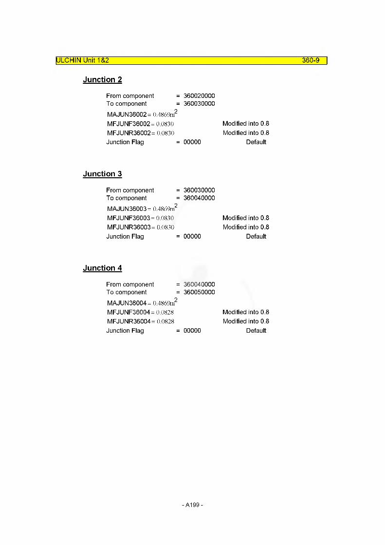
ULCHIN Unit 1&2 360-9
Junction 2
From component =To component =MAJUN36002= 0.4869m2
MFJUNF36002= 0.0830 MFJUNR36002= 0.0830 Junction Flag =
Junction 3
From component =To component =MAJUN36003= 0.4869m2
MFJUNF36003= 0.0830 MFJUNR36003= 0.0830 Junction Flag =
Junction 4
From component =To component =MAJUN36004= 0.4869m2
MFJUNF36004 = 0.0828 MFJUNR36004= 0.0828 Junction Flag =
360020000360030000
Modified into 0.8 Modified into 0.8
00000 Default
360030000360040000
Modified into 0.8 Modified into 0.8
00000 Default
360040000360050000
Modified into 0.8 Modified into 0.8
00000 Default
-A199-

E. INPUT DATAIULCHIN Unit 1&2 360-10
* C360 : Loop Seal in Loop 1
name type3600000 I seal-I 1 pipe
3600001number5
of volumes
area no of vo I3600101 0.4869 5
j-area no of junction3600201 0.0 4
Iength no of vo I3600301 0.0 5
volume no of vo I3600401 0.7159 13600402 0.4356 23600403 1.0489 33600404 0.7074 43600405 1.2335 5
XX no of vol3600501 0.0 5
angle no of vol3600601 -90.0 33600602 0.0 43600603 +90.0 5
elev. no of vol3600701 -1.3159 1 3600702 -0.8946 2 3600703 -1.4300 3 3600704 0.0 4 3600705 1.3716 5
rough dhydr. no of vol3600801 1. e-4 0.0 5
kforw kbackw no of jun3600901 0.05 0.05 13600902 0.08 0.08 33600903 0.08 0.08 4
v-flag no of vol3601001 00 5
j-flag no of jun3601101 00000 4
cnt r I pressure temperature no of vol3601201 3 152.9e5 560.25 0.0 0.0 0.0 13601202 3 152.9e5 560.25 0.0 0.0 0.0 23601203 3 152.7e5 560.25 0.0 0.0 0.0 33601204 3 152.7e5 560.25 0.0 0.0 0.0 43601205 3 152.7e5 560.25 0.0 0.0 0.0 5
cnt r I3601300 1
water flow steamflow no of jun3601301 4746.00 0.0 0 .0 4
- A200 -
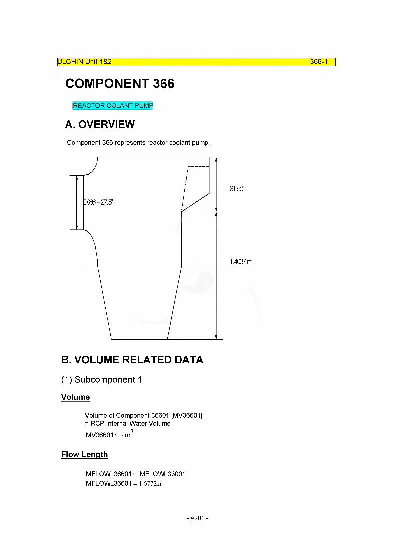
ULCHIN Unit 1&2 366-1
COMPONENT 366REACTOR COLANT PUMP
A. OVERVIEWComponent 366 represents reactor coolant pump.
31.53"
1.4C67m
B. VOLUME RELATED DATA
(1) Subcomponent 1
Volume
Volume of Component 36601 [MV36601] = RCP Internal Water VolumeMV36601 := 4m3
Flow Length
MFLOWL36601 := MFLOWL33001 MFLOWL36601 = 1.6772m
- A201 -
ULCHIN Unit 1&2 366-2
Flow Area : Default
MFLOWA36601 :=MV35001
MFLOWL35001
MFLOWA36601 = 2.5136m"
Elevation Change
MZVOL36601 := 1.4003
Hydraulic Diameter: Default
MDIA36601 := Di30001 MDIA36601 = 0.7358m
C. JUNCTION RELATED DATA
(1) Junction Area
Junctionl : Default
MAJUN36601 := min(MFLOWA36005, MFLOWA36601) MAJ UN36601 = 0.4869 m2
(2) Loss Factor
Junctionl : Default
Loss Factor of Junction 1 [MFJUNF36601 , MFJUNR36601] = -^ X Loss Factor of Pump Inlet Elbow [KPuElbj360]
MFJUNF36601 := ^KPuElbj360
MFJUNF36601 = 0.0828
MFJUNR36601 := ^KPuElbj360
MFJUNR36601 = 0.0828
- A202 -
ULCHIN Unit 1&2 366-3
D. SUMMARY OF DATAcomponent type = pump
(1) VOLUME RELATED DATA : 1 Subvolume
Volume 1
MFLOWL36601 = 1.6772m
MFLOWA36601 = 2.5136m2
MV36601 = 4.0000m3
MDIA36601 = 0.7358m MZVOL36601 = 1.4003 Volume Flag =0000
Default
DefaultDefault
Default
(2) JUNCTION RELATED DATA : 1 Junctions
Junction 1
From component = 360010000To component = 370000000MAJ UN36601 = 0.4869m2 Default
MFJUNF36601 = 0.0828 MFJUNR36601 = 0.0828Junction Flag = 00000 Default
- A203 -

ULCHIN Unit 1&2 366-4
E. Input Cards
* 0366 : Reactor Coolant Pump in Loop 1
name type3660000 rep—1 pump
area length volume x angle elev. vf lag3660101 0.0 1.6772 4.0 0.0 +90, 1.4003 00
from area kforw kbachw jflag3660108 360010000 0.4869 0.08 0.08 00000
to area kforw kbackw jflag3660109 370000000 0.3832 0.0 0.0 00000
entr I pressure temperature3660200 3 152.7e5 560.25
entr I waterflow steamflow X3660201 1 4746.00 0.0 0.03660202 1 4746.00 0.0 0.0
3660301
3660302
3660303
pump index and option cards -2 -1 -2 -1 -1
p-vel flow head124.6 1.0 6.3056 80.
p-trip rev-indi 511 0
torque moment density 38916.5 4000. 745.0
mot-torque42576.2
fric-t 2 134.9
fric-tO 1.0
fric-t1 3523.8
fric-t3 0.0
- A204 -
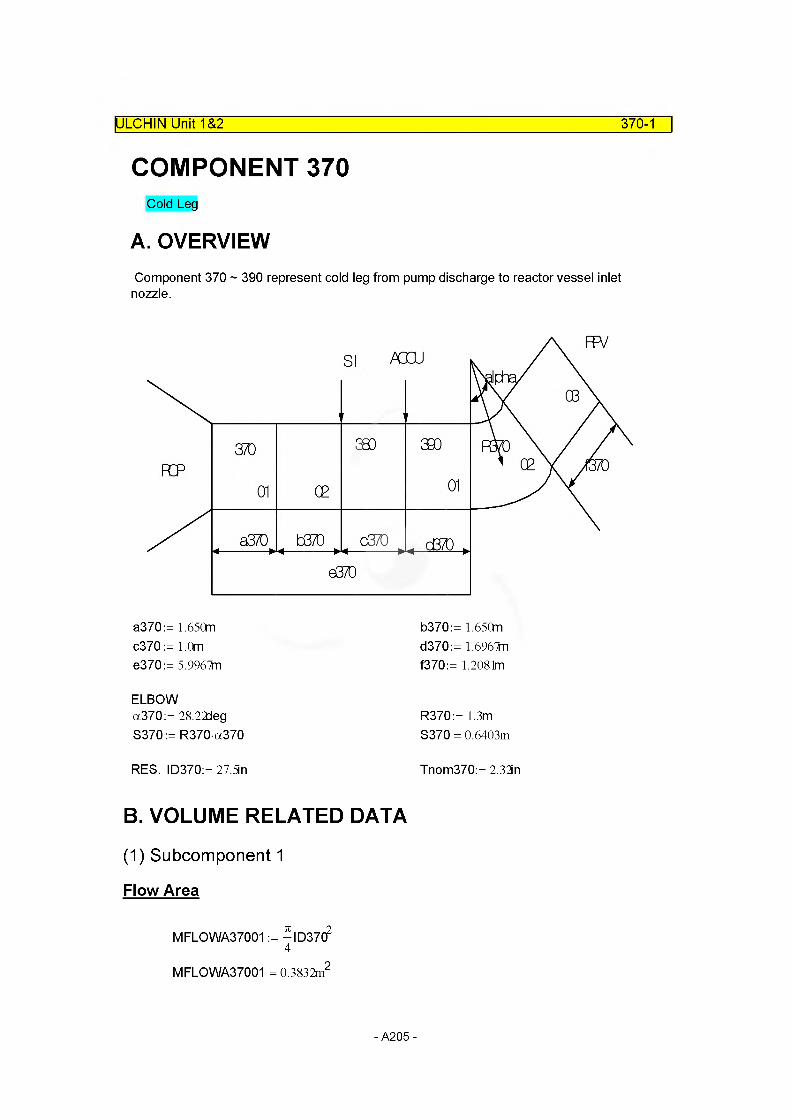
ULCHIN Unit 1&2 370-1
COMPONENT 370Cold Leg
A. OVERVIEWComponent 370 ~ 390 represent cold leg from pump discharge to reactor vessel inlet nozzle.
a370:= 1.65Cm c370:= 1.0m e370:= 5.9967fn
b370:= 1.65Cm d370:= 1.696Tn f370:= 1.2081m
ELBOWa370:= 28.22deg S370:= R370a370
R370:= 1.3m S370 = 0.6403m
RES. ID370:= 27.5in Tnom370:= 2.32in
B. VOLUME RELATED DATA
(1) Subcomponent 1
Flow Area
MFLOWA37001 := -ID37C?4
MFLOWA37001 = 0.3832m2
- A205 -
Flow Length
MFLOWL37001 := a370 MFLOWL37001 = 1.6500m
Volume : Default
MV37001 := MFLOWA37001 MFLOWL37001 MV37001 = 0.6323m3
Elevation Change
MZVOL37001 := 0.0
ULCHIN Unit 1&2_____________________________________________________ 370-2
Hydraulic Diameter: Default
MDIA37001 := ID370 MDIA37001 = 0.6985m
(2) Subcomponent 2
Flow Area
MFLOWA37002 := -ID37C?4
MFLOWA37002 = 0.3832m2
Flow Length
M FLO WL37002: = b370 MFLOWL37002 = 1.6500m
- A206 -

Volume : Default
MV37002:= MFLOWL37002 MFLOWA37002 MV37002 = 0.6323m3
Elevation Change
MZVOL37002:= 0.0
ULCHIN Unit 1&2_____________________________________________________ 370-3
Hydraulic Diameter: Default
MDIA37002:= ID370 MDIA37002= 0.6985m
C. JUNCTION RELATED DATA
(1) Junction Area
Junctionl : Default
MAJUN37001 := min(MFLOWA37001, MFLOWA37002) MAJUN37001 = 0.3832m2
(2) Loss Factor
Junctionl : Default
MFJUNF37001:= 0.0 MFJUNR37001:= 0.0
- A207 -

D. SUMMARY OF DATAIULCHIN Unit 1&2 370-4
component type = pipe
(1) VOLUME RELATED DATA : 2 Subvolume
Volume 1
MFLOWL37001 = 1.6500m
MFLOWA37001 = 0.3832m2
MV37001 = 0.6323m3 DefaultMDIA37001 = 0.6985m DefaultMZVOL37001 = 0.0000Volume Flag =0000 Default
Volume 2
MFLOWL37002 = 1.6500m
MFLOWA37002 = 0.3832m2
MV37002 = 0.6323m3 DefaultMDIA37002= 0.6985m DefaultMZVOL37002= 0.0000Volume Flag =0000 Default
(2) JUNCTION RELATED DATA : 1 Junctions
Junction 1
From component = Internal JunctionTo component = Internal JunctionMAJUN37001 = 0.3832m2 Default
MFJUNF37001 = 0.0000 MFJUNR37001 = 0.0000Junction Flag = 000000 Default
- A208 -

E. Input CardsIULCHIN Unit 1&2 370-5
* C370 : Cold Leg in Loop 1
name type3700000 c I — 11 pipe
number of volumes3700001 2
area no of vol3700101 0.3832 2
j-area no of junction3700201 0.0 1
length no of vol3700301 1.6500 2
voIume no of vol3700401 0.0 2
XX no of vol3700501 0.0 2
angle no of vol3700601 0.0 2
elev. no of vol3700701 0.0 2
rough dhydr. no of vol3700801 1 .e-4 0.0 2
kforw kbackw1 no of jun3700901 0.0 0.0 1
v-flag no of vol3701001 00 2
j-flag no of jun3701101 000000 1
cnt r I pressure temperati3701201 3 158.6e5 560.45
cnt r I3701300 1
waterflow steamflow3701301 4746.00 0.0
no of voI 0.0 2
no of jun 1
- A209 -

COMPONENT 380IULCHIN Unit 1&2 380-1
Loop 1 Cold leg pipe having safety injection line
A. OVERVIEWComponent 380 represents cold leg piping from SI line to accumulator line.
B. VOLUME RELATED DATA
(1) Subcomponent 1
Flow Area
MFLOWA38001 := -ID37C?4
MFLOWA38001 = 0.3832m2
Flow Length
MFLOWL38001 := c370 MFLOWL38001 = 1.0000m
Volume : Default
MV38001 := MFLOWA38001 MFLOWL38001 MV38001 = 0.3832m3
Elevation Change
MZVOL38001 := 0.0
Hydraulic Diameter: Default
MDIA38001 := ID370 MDIA38001 = 0.6985m
-A210-

C. JUNCTION RELATED DATA
(1) Junction Area
Junctionl ~ 2 : Default
MAJUN38001=min(MFLOWA37801 ,MFLOWA38001)Flow area of component 378 is smaller than 380.MAJUN38001 := 0.0699n2
MAJUN38002 = min(MFLOWA38001 , MFLOWA39001)MAJUN38002:= MFLOWA38001
(2) Loss Factor
Junctionl ~ 2
MFJUNF38001:= 0.0
MFJUNR38001:= 108
MFJUNF38002:= 0.0 MFJUNR38002:= 0.0
ULCHIN Unit 1&2_____________________________________________________ 380-2
D. SUMMARY OF DATAcomponent type = branch
(1) VOLUME RELATED DATA : 1 Subvolume
Volume 1
MFLOWL38001 = 1.0000m
MFLOWA38001 = 0.3832m2
MV38001 = 0.3832m3 DefaultMDIA38001 = 0.6985m DefaultMZVOL38001 = 0.0000Volume Flag =0000 Default
- A211 -
ULCHIN Unit 1&2 380-3
(2) JUNCTION RELATED DATA : 2 Junctions
Junction 1
From component = 378010000To component = 380000000MAJUN38001 = 0.0695m2 Default
MFJUNF38001 = 0.0000
MFJUNR38001 = l.OOOOx 108
Junction Flag = 00000 Default
Junction 2
From component = 370010000To component = 380000000MAJUN38002= 0.3832m2 Default
MFJUNF38002= 0.0000
MFJUNR38001 = l.OOOOx 108
Junction Flag = 00000 Default
-A212-

E. Input Cards
ULCHIN Unit 1&2_____________________________________________________ 380-4
* C380 : ECC Mixer Part of Cold Leg in Loop 1
name type3800000 eccmx-l1 branch
no of jun cntr I3800001 2 1
area length vol x angle el ev rough dhydr vflag3800101 0.3832 1.0 0.0 0.0 0.0 0.0 1. e-4 0.0 00
cnt r I pressure temperature3800200 3 158.7e5 560.45
from to area kforw kbackw j fIag3801101 378010000 380000000 0.0 0.0 1 ,e8 000003802101 370010000 380000000 0.0 0.0 0.0 00000
water flow steamflow x3801201 0.0 0.0 0.03802201 4748.00 0.0 0.0
* 0385 : Junction of ECC Mixer IDart and Rx Inlet in Loop 1
name type3850000 cl jun-1 valve
from to area kforw kbackw j f I ag3850101 380010000 390000000 0.0 0.0 0.0 000000
cnt rI waterflow steamflow X3850201 1 4748.0 0.0 0.0
valve type3850300 t rpvlv
trip number3850301 500
-A213-
COMPONENT 390IULCHIN Unit 1&2 390-1
Cold Leg
A. OVERVIEWComponent 390 represents cold leg piping from accumulator line to reactor vessel inlet nozzle.
B. VOLUME RELATED DATA
(1) Subcomponent 1
Flow Area
MFLOWA39001 := -ID37C?4
MFLOWA39001 = 0.3832m2
Flow Length
MFLOWL39001 := d370 MFLOWL39001 = 1.6967m
Volume : Default
MV39001 := MFLOWA39001 MFLOWL39001 MV39001 = 0.6502m3
Elevation Change
MZVOL39001 := 0.0
Hydraulic Diameter: Default
MDIA39001 := ID370 MDIA39001 = 0.6985m
-A214-
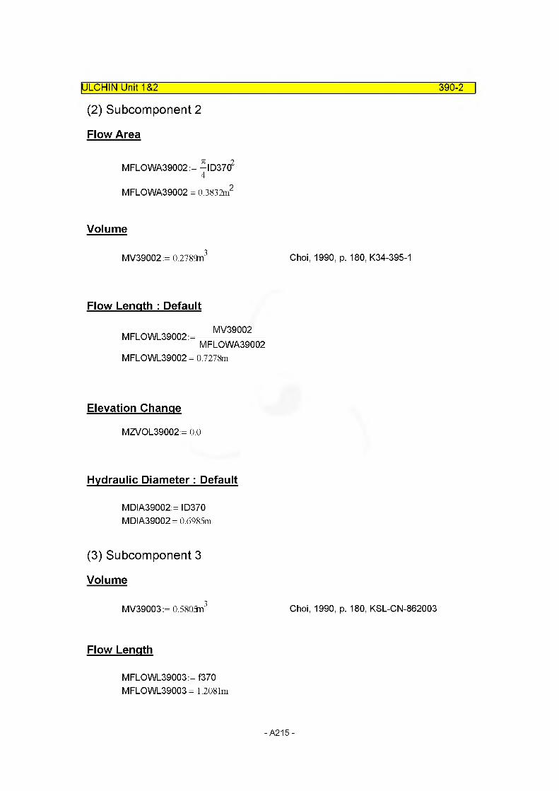
IULCHIN Unit 1&2
(2) Subcomponent 2
Flow Area
390-2
MFLOWA39002 := -ID37C?4
MFLOWA39002 = 0.3832m2
Volume
MV39002:= 0.2789n3 Choi, 1990, p. 180, K34-395-1
Flow Length : Default
MV39002M FLO WL39002: =----------------------
MFLOWA39002MFLOWL39002 = 0.7278m
Elevation Change
MZVOL39002:= 0.0
Hydraulic Diameter: Default
MDIA39002:= ID370 MDIA39002= 0.6985m
(3) Subcomponent 3
Volume
MV39003:= 0.5805n3 Choi, 1990, p. 180, KSL-CN-862003
Flow Length
MFLOWL39003:=f370 MFLOWL39003 = 1.2081m
-A215-
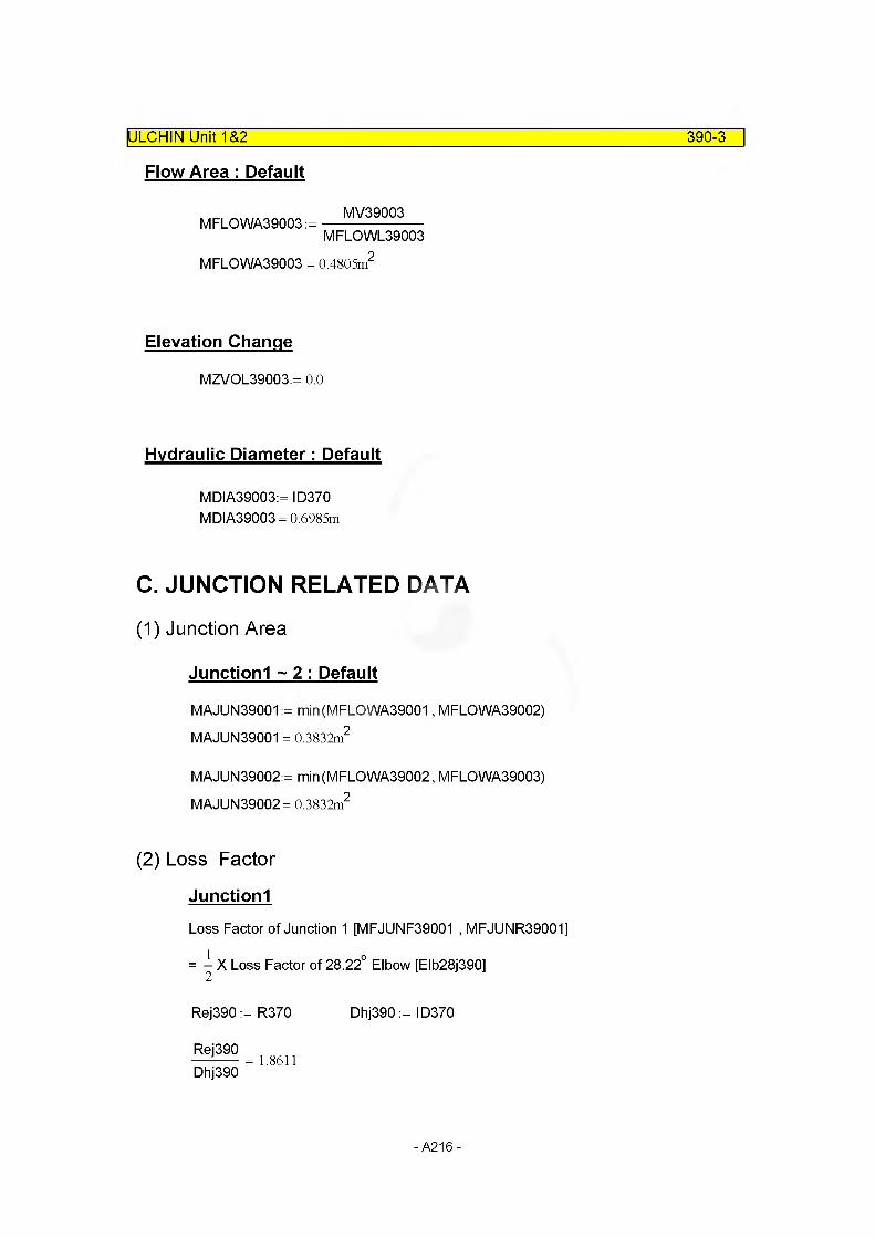
ULCHIN Unit 1&2 390-3
Flow Area : Default
MFLOWA39003 :=MV39003
MFLOWL39003
MFLOWA39003 = 0.4805m
Elevation Change
MZVOL39003:= 0.0
Hydraulic Diameter: Default
MDIA39003:= ID370 MDIA39003= 0.6985m
C. JUNCTION RELATED DATA
(1) Junction Area
Junctionl ~ 2 : Default
MAJUN39001 := min(MFLOWA39001, MFLOWA39002) MAJUN39001 = 0.3832m2
MAJUN39002:= min(MFLOWA39002, MFLOWA39003) MAJUN39002= 0.3832m2
(2) Loss Factor
Junctionl
Loss Factor of Junction 1 [MFJUNF39001 , MFJUNR39001]
= X Loss Factor of 28.22° Elbow [Elb28j390]
Rej390 := R370
Rej390Dhj390
1.8611
Dhj390 := ID370
-A216-

ULCHIN Unit 1&2 390-4
Idel'chek DIA 6-2 is applied.
Rough walls l Aj390 > 0, Rej390 >2-105)
Aj390 := MO 4m
Kj390 = 1.4316 x 10"
kAj390 := 1 + Kj3902 106kAj390 = 1.0205
kRej390:= 1.0
A1j390:= 0.9-sin (28.22Jeg) A1j390 = 0.4256
B1j390:= °'21
R370
v Dhj390 B1j390 = 0.1539
C1j390:= 1.0
Klj390:= A1j390 B1j390 C1j390 Klj390 = 0.0655
Elb28j390:= kAj390 kRej390 Klj390 Elb28j390 = 0.0669
MFJUNF39001:= - Elb28j390
MFJUNF39001 = 0.0334 MFJUNR39001:= ^Elb28j390
MFJUNR39001 = 0.0334
Junction 2
MFJUNF39002:= - Elb28j390
MFJUNF39002= 0.0334 MFJUNR39002:= ^Elb28j390
MFJUNR39002= 0.0334
-A217-
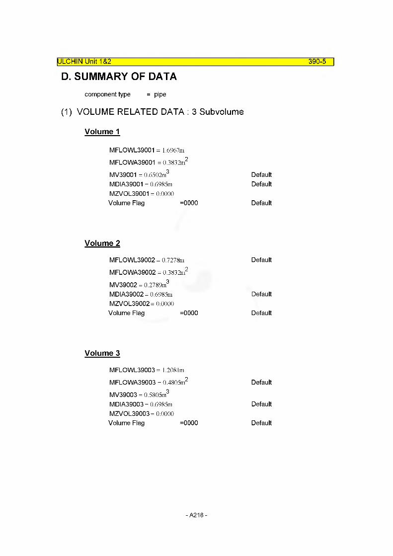
D. SUMMARY OF DATAIULCHIN Unit 1&2 390-5
component type = pipe
(1) VOLUME RELATED DATA : 3 Subvolume
Volume 1
MFLOWL39001 = 1.6967m
MFLOWA39001 = 0.3832m2
MV39001 = 0.6502m3 DefaultMDIA39001 = 0.6985m DefaultMZVOL39001 = 0.0000Volume Flag =0000 Default
Volume 2
MFLOWL39002 = 0.7278m Default
MFLOWA39002 = 0.3832m2
MV39002 = 0.2789m3
MDIA39002= 0.6985m DefaultMZVOL39002= 0.0000Volume Flag =0000 Default
Volume 3
MFLOWL39003 = 1.2081m
MFLOWA39003 = 0.4805m2 DefaultMV39003 = 0.5805m3
MDIA39003= 0.6985m DefaultMZVOL39003= 0.0000Volume Flag =0000 Default
-A218-

ULCHIN Unit 1&2 390-6
(2) JUNCTION RELATED DATA : 2 Junctions
Junction 1
From component = 390010000To component = 390020000MAJUN39001 = 0.3832m2
MFJUNF39001 = 0.0334 MFJUNR39001 = 0.0334 Junction Flag = 001000
Default
Junction 2
From component = 39002000To component = 390030000MAJUN39002= 0.3832m2
MFJUNF39002= 0.0334 MFJUNR39002= 0.0334 Junction Flag = 001000
Default
-A219-
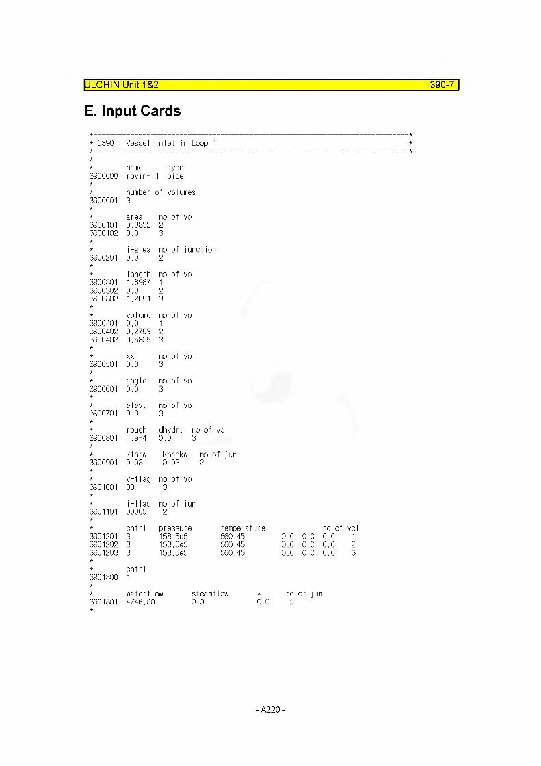
ULCHIN Unit 1&2 390-7
E. Input Cards
* 0390 : Vessel Inlet in Loop 1
name type3900000 rpvin-l 1 pipe
3900001number3
of volumes
area no of voI3900101 0.3832 23900102 0.0 3
j-area no of junction3900201 0.0 2
I ength no of voI3900301 1.6967 13900302 0.0 23900303 1.2081 3
volume no of vol3900401 0.0 13900402 0.2789 23900403 0.5805 3
XX no of vol3900501 0.0 3
angle no of vol3900601 0.0 3
elev. no of vol3900701 0.0 3
rough dhydr. no of vol3900801 1. e-4 0.0 3
kforw kbackw no of jun3900901 0.03 0.03 2
v-flag no of vol3901001 00 3
j-flag no of jun3901101 00000 2
cnt r I pressure temperature no of vol3901201 3 158.6e5 560.45 0.0 0.0 0.0 13901202 3 158.6e5 560.45 0.0 0.0 0.0 23901203 3 158.6e5 560.45 0.0 0.0 0.0 3
* cntrl3901300 1
* waterflow steamflow * no of jun3901301 4746.00 0.0 0.0 2
- A220 -

2.3 Pressurizer and Surge Line
- A221 -
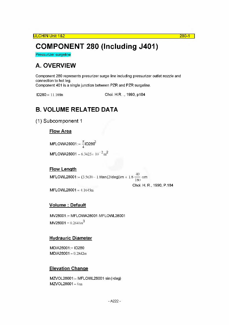
280-1
COMPONENT 280 (Including J401)Pressurizer surgeline
A. OVERVIEW
IULCHIN Unit 1&2 ~
Component 280 represents presurizer surge line including pressurizer outlet nozzle and connection to hot leg.Component 401 is a single junction between PZR and PZR surgeline.
ID280:= 11.188n Choi. H R. ., 1990, p184
B. VOLUME RELATED DATA
(1) Subcomponent 1
Flow Area
MFLOWA28001 := -ID28C?4
MFLOWA28001 =6.3425x 10“2m2
Flow Length40
MFLOWL28001 := (3.5630- 1.8tan(20deg))m + 1.8------%m
MFLOWL28001 = 4.1645mChoi. H. R„ 1990, P.184
Volume : Default
MV28001 := MFLOWA28001 MFLOWL28001 MV28001 = 0.2641m3
Hydrauric Diameter
MDIA28001 := ID280 MDIA28001 = 0.2842m
Elevation Change
MZVOL28001 := MFLOWL28001 sin (Odeg) MZVOL28001 = 0m
- A222 -

280-2
(2) Subcomponent 2
Flow Length
IULCHIN Unit 1&2 ~
M FLO WL28002:= (2.1 - 1.8tan(20deg) - 1.8tan(17.5deg)) + 1.8-----n
90+ (3.260— 1.8tan (17.5d6g) — 1.8) + 1.8-----k
Choi. H. R. .,1990, P.184 MFLOWL28002 = 5.6968m
m
Flow Area
MFLOWA28002 := MFLOWA28001 MFLOWA28002 = 6.3425x 10“ 2 m2
Volume : Default
MV28002:= M FLO WA28002 • M FLO WL28002 MV28002 = 0.3613m3
Hvdrauric Diameter
MDIA28002:= MDIA28001 MDIA28002 = 0.2842m
Elevation Change
MZVOL28002:= MFLOWL28002 sin (Odeg)MZVOL28002= 0m
(3) Subcomponent 3
Flow Length
MFLOWL28003: = (3.998n - 2-1.8m) + ^ 1.8m ...
+ [(3.68)m - 1.8m - 1.8m tan(37.5deg)]MFLOWL28003 = 3.7242m Choi. H. R., 1990, P.185
Flow Area
MFLOWA28003 := MFLOWA28001
- A223 -

Volume : Default
MV28003:= MFLOWA28003 MFLOWL28003 MV28003 = 0.2362m3
Hvdrauric Diameter
MDIA28003:= MDIA28001 MDIA28003 = 0.2842m
Elevation Change
MZVOL28003:= MFLOWL28003 sin (Odeg)MZVOL28003= 0m
(4) Subcomponent 4
Flow Length
75degM FLOWL28004: =--------- % 1.8m
180degMFLOWL28004 = 2.3562m
Flow Area
MFLOWA28004 := MFLOWA28001
Volume : Default
MV28004:= M FLO WA28004 • M FLO WL28004
Hvdrauric Diameter
MDIA28004:= MDIA28001
Elevation Change
MZVOL28004:= MFLOWL28004 sin (Odeg)MZVOL28004= 0m
ULCHIN Unit 1&2_____________________________________________________ 280-3
- A224 -

ULCHIN Unit 1&2 280-4
(5) Subcomponent 5
Flow Length
M FLO WL28005:=3.058- 0.7112+ -^-0.7112^ (Per nozzle outlet)
Choi, H. R., 1990, P.185 MFLOWL28005 = 3.464m
Flow Area
MFLOWA28005 := MFLOWA28001
Volume : Default
MV28005:= MFLOWA28005 MFLOWL28005
Hvdrauric Diameter
MDIA28005:= MDIA28001
Elevation Change
MZVOL28005:= 2.6671n Choi. H. R„ 1990, P.185
C. JUNCTION RELATED DATA
(1) Junction Area
Internal Junction : Default
MAJUN28001 := min(MFLOWA28001, MFLOWA28002) MAJUN28002:= min(MFLOWA28002, MFLOWA28003) MAJUN28003:= min(MFLOWA28003, MFLOWA28004) MAJUN28004:= min(MFLOWA28004, MFLOWA28005)
External Junction 401
MAJUN40101:=-ID28(f4
MAJUN40101 = 6.3425 x 10“ 2 m2
- A225 -

ULCHIN Unit 1&2 280-5
(2) Loss Coefficient
Internal Junction 1
Loss Factor of Junction 1= - x LOSS FACTOR OF 40° ELBOW2
40o ELBOW, Ro28001 := 1.8m ID28001 := 0.2842m Choi. H R. ., 1990, P.186
Ro28001--------------= 6.3336ID28001
Idelchik, 1986, Dia. 6-2
A28001 := l-10“4m
DK28001 := 0.2842mChoi. H R. .. 1990, P.186
ABar28001 :=A28001
DK28001
ABar28001 = 3.5186 x 10⁻⁴
KRe28001 := 1.0
KA28001 := (l)2 + ABar280012-106
KA28001 = 1.1238
A128001 := 0.9-sin (40deg) A128001 = 0.5785 deg
B128001:=0.21
Ro28001DK28001
-2B128001 = 8.3444 x 10
C128001 := 1.0
Therefore. Idelchik Dia 6 - 2 is aooliedKF28001 := KRe28001 -KA28001 -A128001 -B128001 0128001
ROUGHNESS !A> 0) Re > 2x 10⁵
KF28001 = 5.425 x 10“ 2
KR28001 := KF28001KR28001 = 5.425 x 10“ 2
- A226 -
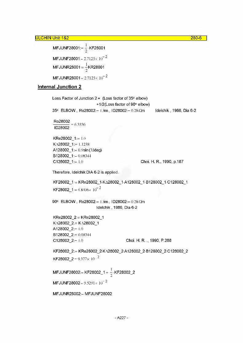
ULCHIN Unit 1&2 280-6
MFJUNF28001:= - KF280012
MFJUNF28001 = 2.7125x 10“ 2
MFJUNR28001:= -KR280012
MFJUNR28001 = 2.7125x 10“ 2
Internal Junction 2
Loss Factor of Junction 2 = (Loss factor of 35° elbow)+1/2(Loss factor of 90° elbow)
35° ELBOW , Ro28002:= 1.8m , 1028002:= 0.2842n Idelchik , 1986, Dia 6-2
Ro28002------------- = 6.3336ID28002
KRe28002_1 := 1.0 KA28002_1 := 1.1238 A128002_1 := 0.9sin(35deg)B128002_1 := 0.08344C128002_1:= 1.0 Choi. H. R., 1990, p.187
Therefore, Idelchik DIA 6-2 is applied.
KF28002_1 := KRe28002_1 • KA28002_1 • A128002_1 • B128002_1 •C128002_1 KF28002 1 = 4.8406x 10“ 2
90° ELBOW, Ro28002:= 1.8m, 1028002:= 0.2842nIdelchik, 1986, Dia 6-2
KRe28002_2:= KRe28002_1 KA28002_2:= KA28002_1 A128002_2:= 1.0 B128002_2:= 0.08344C128002_2:= 1.0 Choi. H. R. ., 1990, P.288
KF28002_2:= KRe28002_2KA28002_2A128002_2B128002_2C128002_2
KF28002_2= 9.377 x 10“ 2
MFJUNF28002:= KF28002 1 + -KF28002 22
MFJUNF28002=9.5291x 10“ 2
MFJUNR28002:= MFJUNF28002
- A227 -
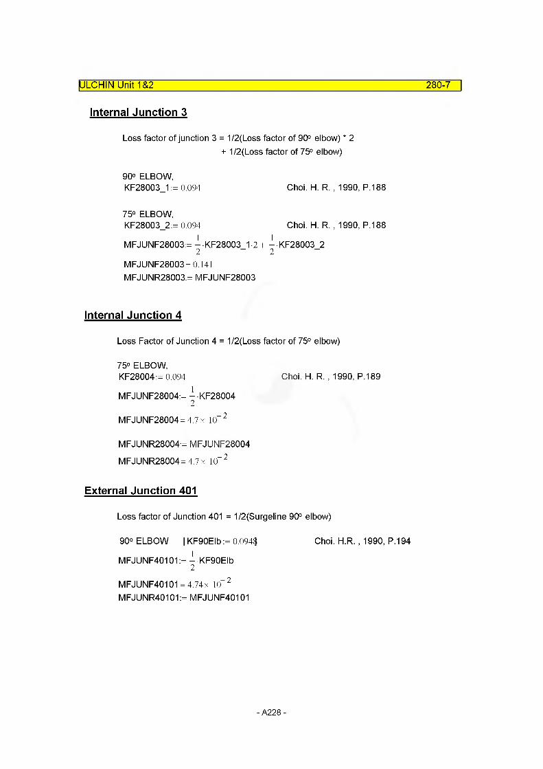
ULCHIN Unit 1&2 280-7
Internal Junction 3
Loss factor of junction 3 = 1/2(Loss factor of 90° elbow) * 2 + 1/2(Loss factor of 75° elbow)
90° ELBOW,KF28003_1 := 0.094 Choi. H. R. , 1990, P.188
75° ELBOW,KF28003_2:= 0.094 Choi. H. R. , 1990, P.188
1 1MFJUNF28003:= - KF28003 1-2 + - KF28003 2
2 2MFJUNF28003= 0.141 MFJUNR28003:= MFJUNF28003
Internal Junction 4
Loss Factor of Junction 4 = 1/2(Loss factor of 75° elbow)
75° ELBOW,KF28004:= 0.094 Choi. H. R. , 1990, P.189
MFJUNF28004:= - KF280042
MFJUNF28004= 4.7 x 10“ 2
MFJUNR28004:= MFJUNF28004 MFJUNR28004= 4.7 x 10“ 2
External Junction 401
Loss factor of Junction 401 = 1/2(Surgeline 90° elbow)
90° ELBOW | KF90Elb:= 0.094$ Choi. H R. , 1990, P.194
MFJUNF40101:= - KF90Elb2
MFJUNF40101 = 4.74x 10“ 2
MFJUNR40101:= MFJUNF40101
- A228 -
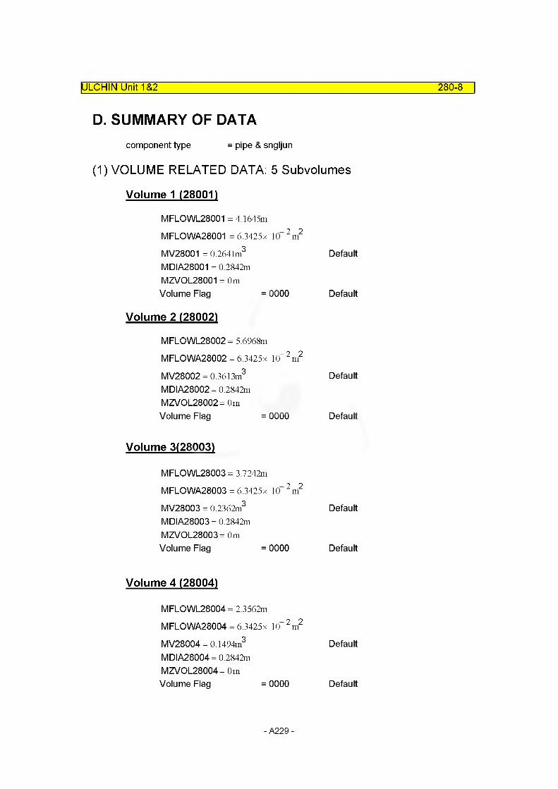
ULCHIN Unit 1&2 280-8
D. SUMMARY OF DATAcomponent type = pipe & sngljun
(1) VOLUME RELATED DATA: 5 Subvolumes
Volume 1 (28001)
MFLOWL28001 = 4.1645m
MFLOWA28001 =6.3425x 10“2m2
MV28001 = 0.2641m3 DefaultMDIA28001 = 0.2842mMZVOL28001 = 0mVolume Flag = 0000 Default
Volume 2 (28002)
MFLOWL28002 = 5.6968m
MFLOWA28002 = 6.3425x 10“ 2 m2
MV28002 = 0.3613m3 DefaultMDIA28002 = 0.2842mMZVOL28002= 0mVolume Flag = 0000 Default
Volume 3(28003)
MFLOWL28003 = 3.7242m
MFLOWA28003 = 6.3425x 10“ 2 m2
MV28003 = 0.2362m3 DefaultMDIA28003 = 0.2842mMZVOL28003= OmVolume Flag = 0000 Default
Volume 4 (28004)
MFLOWL28004 = 2.3562m
MFLOWA28004 = 6.3425x 10“ 2 m2
MV28004 = 0.1494m3 DefaultMDIA28004 = 0.2842mMZVOL28004= OmVolume Flag = 0000 Default
- A229 -

ULCHIN Unit 1&2 280-9
Volume 5 (28005)
MFLOWL28005 = 3.464m
MFLOWA28005 = 6.3425x 10“ 2 m2
MV28005 = 0.2197m3 DefaultMDIA28005 = 0.2842mMZVOL28005= 2.667mVolume Flag = 0000 Default
(2) JUNCTION RELATED DATA : 4 Junction and 1 Ext. Junctions
Junction 1
From Component = Internal JunctionTo Component = Internal JunctionMAJUN28001 = 6.3425x 10“ 2 m2 Default
MFJUNF28001 = 2.7125x 10“ 2
MFJUNR28001 = 2.7125x 10“ 2
Junction Flag = 00000 Default
Junction 2
From Component = Internal JunctionTo Component = Internal JunctionMAJUN28002= 6.3425 x 10“ 2 m2 Default
MFJUNF28002=9.5291x 10“ 2
MFJUNR28002= 9.5291 x 10“ 2
Junction Flag = 00000 Default
Junction 3
From Component = Internal JunctionTo Component = Internal JunctionMAJUN28003= 6.3425 x 10“ 2 m2 Default
MFJUNF28003= 0.141 MFJUNR28003= 0.141Junction Flag = 00000 Default
- A230 -

ULCHIN Unit 1&2 280-10
Junction 4
From Component = Internal JunctionTo Component = Internal JunctionMAJUN28004= 6.3425 x 10“ 2 m2 Default
MFJUNF28004= 4.7 x 10™ 2
MFJUNR28004= 4.7 x 10“ 2
Junction Flag = 00000 Default
Junction J401
from component = 280000000to component = 400010000
MAJUN40101 = 6.3425 x 10“ 2 m2
MFJUNF40101 = 4.74x 10“ 2
MFJUNR40101 = 4.74x 10“ 2
Junction Flag = 00001
E. Input Cards
* C401 : June! ion connecting pzr surge I ine and hot leg
4010000name typesurgel sngljun
4010101from to area280000000 400010000 0.0634
kforw4.74e-2
kbackw4.748-2
j f I ag10001
4010201cntrl waterflow1 0.101
steamflow0.0
X
0.0
- A231 -

ULCHIN Unit 1&2 280-11
* C280 : Surge Iine
* name type 2800000 srgline pipe
* number of volumes 2800001 5
area no of vol 0.063425 52800101
* j-area 2800201 0.0
* length 2800301 4.1645 2800302 5.6968 2800303 3.7242 2800304 2.3562 2800305 2.6670
* volume 2800401 0.0
* xx 2800501 0.0
* angle 2800601 0.0 2800602 90.0
* elev. 2800701 0.0 2800702 2.6670
no of junct ion 4
no of vol 12345
no of vol 5
no of vol 5
no of vol45
no of vol45
rough dhydr. no of vol2800801 1. e-4 0.0 5
kforw kbackw no of jun2800901 2.7125e--2 2.71258-2 12800902 9.52918--2 9.52918-2 22800903 0.141 0.141 32800904 4.78-2 4.78-2 4
v-flag no of vol2801001 00 5
j-flag no of jun2801101 00000 4
2801201cnt r I3
pressure157.76285
temp603.12 0.0 0.0 0.0
no of vol 1
2801202 3 157.717e5 608.24 0.0 0.0 0.0 22801203 3 157.664e5 611.51 0.0 0.0 0.0 32801204 3 157.625e5 614.43 0.0 0.0 0.0 42801205 3 157.537e5 615.56 0.0 0.0 0.0 5
2801300cnt r I1
waterflow steamflow no of jun2801301 0.101 0..0 0.0 4
- A232 -
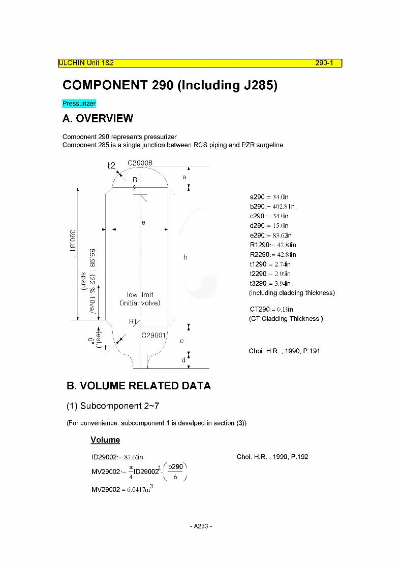
ULCHIN Unit 1&2 290-1
COMPONENT 290 (Including J285)Pressurizer
A. OVERVIEWComponent 290 represents pressurizerComponent 285 is a single junction between RCS piping and PZR surgeline.
C29008
C29001
a290:= 34.Cin b290:= 402.8 tin c290 := 34.Cin d290:= 15.0in e290:= 83.62in R1290:= 42.8 tin R2290:= 42.81in t1290 := 2.74in t2290:= 2.0Sin t3290:= 3.94in(including cladding thickness)
CT290:= 0.19i n (CT:Cladding Thickness)
Choi. H R. , 1990, P.191
B. VOLUME RELATED DATA
(1) Subcomponent 2~7
(For convenience, subcomponent 1 is develped in section (3))
Volume
1029002:= 83.62n Choi. H R. , 1990, P.192
MV29002:= -ID290of4 i 6 ;MV29002 = 6.0417m3
- A233 -

ULCHIN Unit 1&2 290-2
MV29003:= MV29002 MV29004:= MV29002 MV29005:= MV29002 MV29006:= MV29002 MV29007 := MV29002
Flow Length
M FLO WL29002:=b290
6MFLOWL29002 = 1.7052m M FLO WL29003: = MFLOWL29002 M FLO WL29004: = MFLOWL29002 M FLO WL29005: = MFLOWL29002 M FLO WL29006: = MFLOWL29002 MFLOWL29007 := MFLOWL29002
Flow Area : Default
MFLOWA29002 :=
MFLOWA29003 :=
MFLOWA29004 :=
MFLOWA29005 :=
MFLOWA29006 :=
MFLOWA29007 :=
MV29002MFLOWL29002
MV29003MFLOWL29003
MV29004MFLOWL29004
MV29005MFLOWL29005
MV29006MFLOWL29006
MV29007MFLOWL29007
Hydraulic Diameter
MDIA29002:= ID29002 MDIA29003:= ID29002 MDIA29004:= ID29002 MDIA29005:= ID29002 MDIA29006:= ID29002 MDIA29007:= ID29002
- A234 -

ULCHIN Unit 1&2 290-3
Elevation Change
MZVOL29002:= MFLOWL29002 sin (90deg)MZVOL29002= 1.7052m MZVOL29003:= MZVOL29002 MZVOL29004:= MZVOL29002 MZVOL29005:= MZVOL29002 MZVOL29006:= MZVOL29002 MZVOL29007:= MZVOL29002
(2) Subcomponent 8
Pressurizer Dome
Volume
TOTAL PZR VOLUME {MVTOTAL290}MVTOTAL290:= 1400ft3 Choi. H R. , 1990, P.192
PZR NOZZLE VOLUME {MVNOZ290}
ID29008:= 11.188n Choi. H R. , 1990, P.192
MVNO290:= -102900^ 15in4
MVNO290 = 2.4165x 10“ 2 m3
MV29008:= ^ c2902(3R1290- c290)
MV29008 = 1.8733m3
Length
M FLO WL29008: = a290 MFLOWL29008 = 0.8636m
Flow Area : Default
MFLOWA29008 :=MV29008
MFLOWL29008
MFLOWA29008 = 2.1691m
Hydraulic Diameter
MDIA29008:= ID29008
- A235 -
ULCHIN Unit 1&2 290-4
Elevation Change
MZVOL29008:= MFLOWL29008 sin (90deg)MZVOL29008= 0.8636m
(3) Subcomponent 1
Pressurizer lower part
Volume
MV29002:= 213.361 ft3
MV29008:= 66.1535ft3
MVNO290:= 0.8534ft3
MVTOTAL:= 1400ft3
MV29001 := MVTOTAL- (MV29002-6) - MV29008 - MVNO290 MV29001 = 1.4959m3 (See Subcomponent 2~7 and 8 below.)
Flow Length
MFLOWL29001 := c290 MFLOWL29001 = 0.8636m
Flow Area : Default
MV29001MFLOWA29001 :=----------------------
MFLOWL29001MFLOWA29001 = 1.7321m2
Hydraulic Diameter: Default
MDIA29001 = 1.4851m
Elevation Change
MZVOL29001 := MFLOWL29001 sin (90deg) MZVOL29001 = 0.8636m
- A236 -
C. JUNCTION RELATED DATA
(1) Junction Area
IULCHIN Unit 1&2 290-5
Internal JunctionMAJUN29001:=^(e290)2
MAJUN29001 = 3.5431m2
MAJUN29002:= MAJUN29001 MAJUN29003:= MAJUN29001 MAJUN29004:= MAJUN29001 MAJUN29005:= MAJUN29001 MAJUN29006:= MAJUN29001 MAJUN29007:= MAJUN29001
External Junction : Junction 285
MAJUN28501:=-ID28C?4
MAJUN28501 = 6.3425 x 10“ 2 m2
(2) Loss Coefficient
Internal Junction : Default
MFJUNF29001:= 0.0MFJUNR29001:= 0.0 Choi. H R. , 1990, P.193
MFJUNF29002:= MFJUNF29001
MFJUNF29003:= MFJUNF29001
MFJUNF29004:= MFJUNF29001MFJUNF29005:= MFJUNF29001
MFJUNF29006:= MFJUNF29001MFJUNF29007:= MFJUNF29001
MFJUNR29002:= MFJUNR29001 MFJUNR29003:= MFJUNR29001
MFJUNR29004:= MFJUNR29001
MFJUNR29005:= MFJUNR29001 MFJUNR29006:= MFJUNR29001
MFJUNR29007:= MFJUNR29001
- A237 -
ULCHIN Unit 1&2 290-6
External Junction 285
F1280 := MFLOWA29001 Fo280:= MFLOWA28004
KF28501 := 0.5-Fo280)0'75
F1280JKF28501 = 0.4862 Idelchik, 1986, Dia 4-9
KR28501 := 1 -Fo280Y
F1280JKR28501 =0.9281 Idelchik, 1986, Dia 4-1
MFJUNF28501:= MFJUNF28004+ KF28501 MFJUNF28501 = 0.5332
MFJUNR28501:= MFJUNR28001 + KR28501 MFJUNR28501 = 0.9552
F1
Fo
D. SUMMARY OF DATAcomponent type = pipe
(1) VOLUME RELATED DATA : 8 Subvolumes
Volume 1
MFLOWL29001 = 0.8636m
MFLOWA29001 = 1.7321m2 Default
MV29001 = 1.4959m3
MDIA29001 = 1.4851mMZVOL29001 = 0.8636m DefaultVolume Flag =0000 Default
Volume 2~7
MFLOWL29002 = 1.7052m MFLOWL29003 = 1.7052m MFLOWL29004 = 1.7052m MFLOWL29005 = 1.7052m MFLOWL29006 = 1.7052m MFLOWL29007 = 1.7052m
- A238 -

ULCHIN Unit 1&2 290-7
MFLOWA29002
MFLOWA29003
MFLOWA29004
MFLOWA29005
MFLOWA29006
MFLOWA29007
MV29002 = 6.0417m3
MV29003 = 6.0417m3
MV29004 = 6.0417m3
MV29005 = 6.0417m3
MV29006 = 6.0417m3
MV29007 = 6.0417m3
MDIA29002= 2.1239m MDIA29003= 2.1239m MDIA29004= 2.1239m MDIA29005= 2.1239m MDIA29006= 2.1239m MDIA29007= 2.1239m
MZVOL29002= 1.7052m MZVOL29003= 1.7052m MZVOL29004= 1.7052m MZVOL29005= 1.7052m MZVOL29006= 1.7052m MZVOL29007 = 1.7052m
Volume Flag
Default
Default
Default
Default
Default
Default
=0000 Default
= 3.5431m2
= 3.5431m2
= 3.5431m2
= 3.5431m2
= 3.5431m2
= 3.5431m2
Volume 8
MFLOWL29008 = 0.8636m
MFLOWA29008 = 2.1691m2 Default
MV29008= 1.8733m3
MDIA29008 = 0.2842m MZVOL29008= 0.8636mVolume Flag =0000 Default
- A239 -
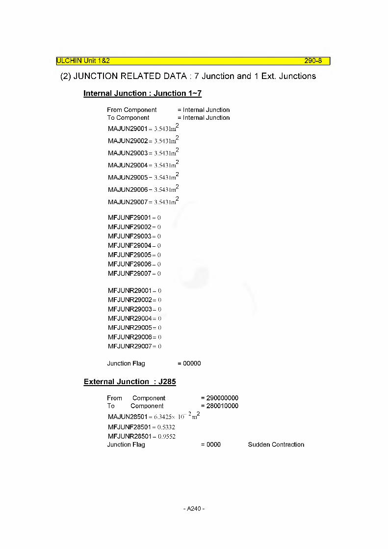
(2) JUNCTION RELATED DATA : 7 Junction and 1 Ext. Junctions
IULCHIN Unit 1&2 290-8
Internal Junction : Junction 1~7
From Component = Internal JunctionTo Component = Internal JunctionMAJUN29001 = 3.5431m2
MAJUN29002= 3.5431m2
MAJUN29003= 3.5431m2
MAJUN29004= 3.5431m2
MAJUN29005= 3.5431m2
MAJUN29006= 3.5431m2
MAJUN29007 = 3.5431m2
MFJUNF29001 = 0 MFJUNF29002= 0 MFJUNF29003= 0 MFJUNF29004= 0 MFJUNF29005= 0 MFJUNF29006= 0 MFJUNF29007= 0
MFJUNR29001 = 0 MFJUNR29002= 0 MFJUNR29003= 0 MFJUNR29004= 0 MFJUNR29005= 0 MFJUNR29006= 0 MFJUNR29007= 0
Junction Flag = 00000
External Junction : J285
From Component = 290000000To Component =280010000MAJUN28501 = 6.3425 x 10“ 2 m2
MFJUNF28501 = 0.5332 MFJUNR28501 = 0.9552 Junction Flag = 0000 Sudden Contraction
- A240 -
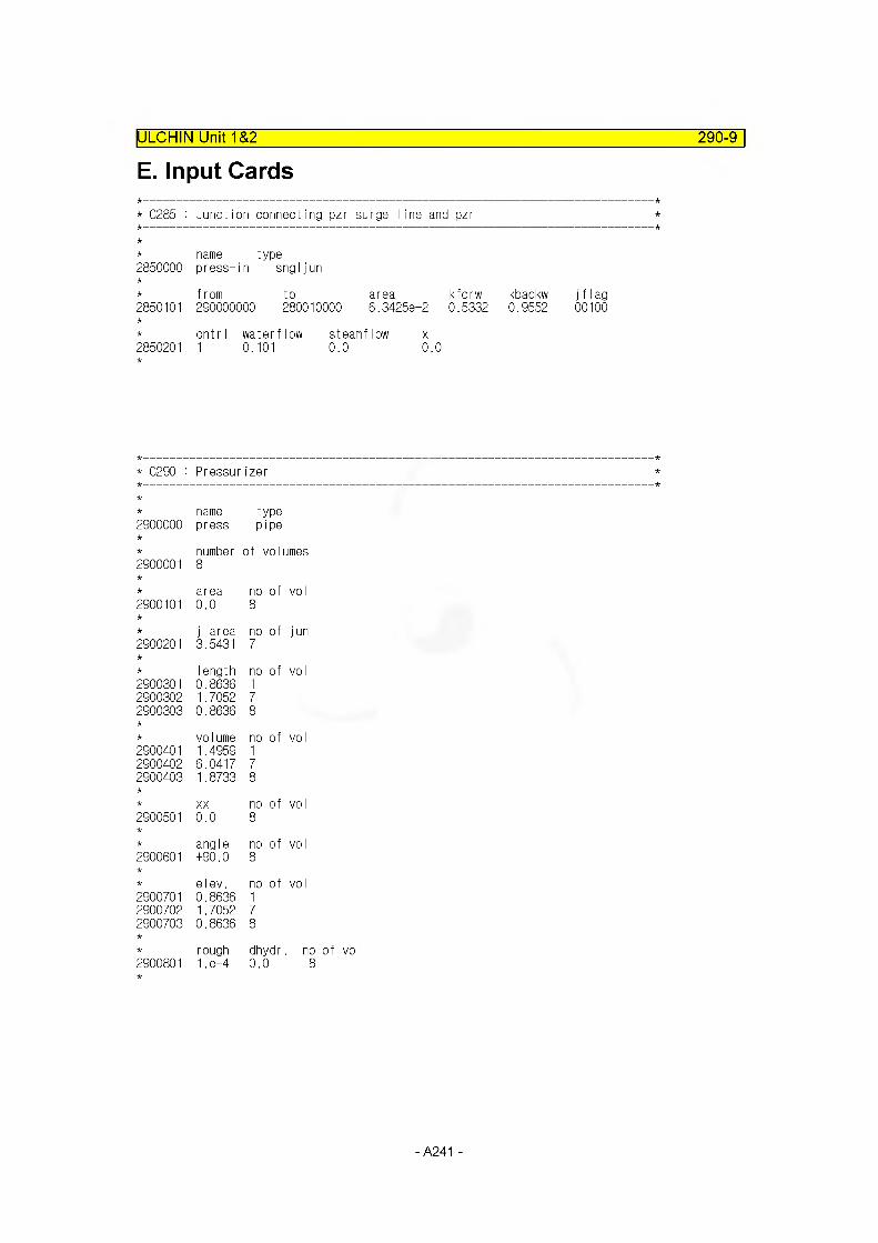
E. Input CardsIULCHIN Unit 1&2 290-9
* C285 : Junction connecting pzr surge line and pzr
* name type2850000 press-in sngljun
* from2850101 290000000
to area280010000 6.34258-2
kforw kbackw jflag 0.5332 0.9552 00100
* cntrl waterflow2850201 1 0.101
steamflow 0.0
x0.0
* 0290 : Pressurizer
name type2900000 press pipe
2900001number8
of volumes
area no of vo I2900101 0.0 8
j-area no of jun2900201 3.5431 7
Iength no of vo I2900301 0.8636 12900302 1.7052 72900303 0.8636 8
volume no of vo I2900401 1.4959 12900402 6.0417 72900403 1.8733 8
XX no of vol2900501 0.0 8
angle no of vol2900601 +90.0 8
elev. no of vol2900701 0.8636 12900702 1.7052 72900703 0.8636 8
rough dhydr.. no2900801 1. e-4 0.0 8
- A241 -

ULCHIN Unit 1&2 290-10
kforw kbackw no of jun2900901 0.0 0.0 7
v-flag no of vol2901001 00 8
j-flag no of jun2901101 00000 7
cntr I pressure quality no of vol2901201 2 155.5e5 0.0 0.0 0.0 0.0 12901202 2 155.4e5 0.0 0.0 0.0 0.0 42901203 2 155.3e5 0.045 0.0 0.0 0.0 52901204 2 155.2e5 1.0 0.0 0.0 0.0 62901205 2 155.1e5 1.0 0.0 0.0 0.0 8
cntr I2901300 1
water flow steamflow no of jun2901301 0.0 0.0 0.0 7
- A242 -

Pressurizer Water LevelFrom the figure in p. 290-1, we can calculate the collapsed water level of pressurizer.
IULCHIN Unit 1&2 290-11
The level is measured through the lower tap and upper tap.
Pressurizer Level (%) = [ MFLOWL29002*voidf(290020000)+ MFLOWL29003*voidf(290030000)+ MFLOWL29004*voidf(290040000)+ MFLC>WL29005*voidf(290050000)+ MFLC>WL29006*voidf(290060000)+ MFLC>WL29007*voidf(290070000)- 6.0in] // tap lift from the bottom of V29002/(b290-6.0in)*100 //level span
where 6in = 0.1524m1 1
--------------------100 = 9.921644802-(b290 - 6.0in) m
- A243 -
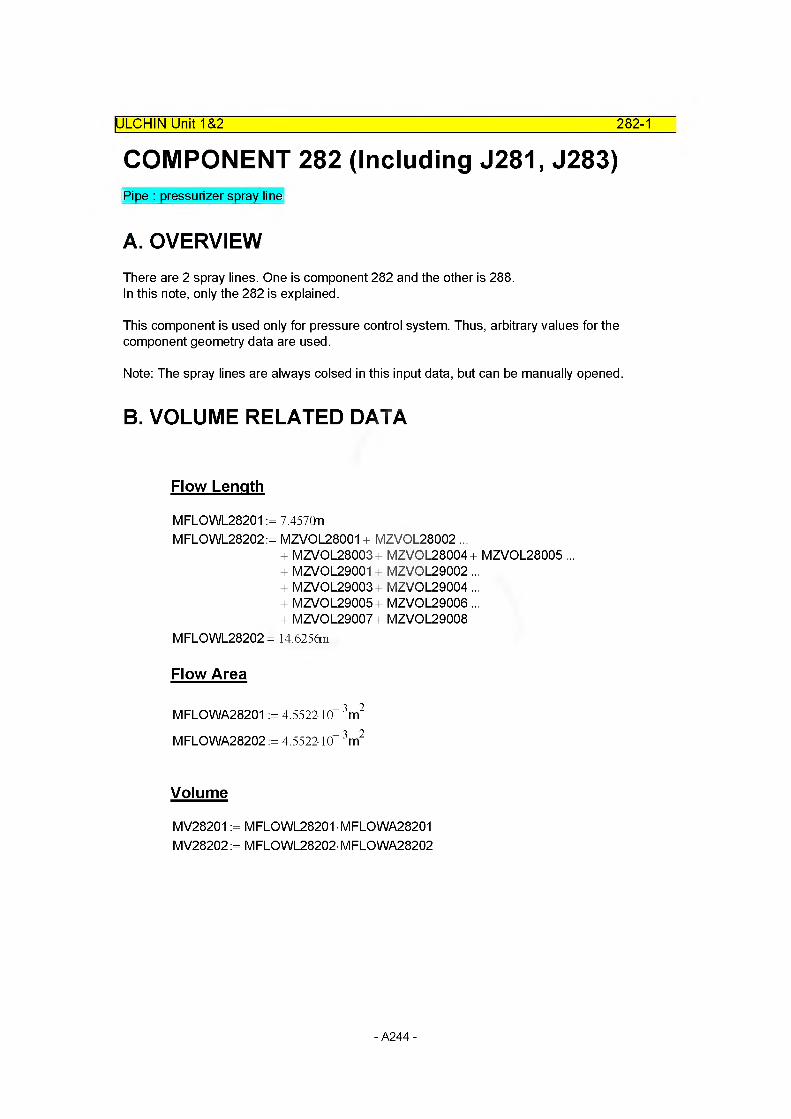
282-1IULCHIN UnitT&2
COMPONENT 282 (Including J281, J283)Pipe : pressurizer spray line
A. OVERVIEWThere are 2 spray lines. One is component 282 and the other is 288.In this note, only the 282 is explained.
This component is used only for pressure control system. Thus, arbitrary values for the component geometry data are used.
Note: The spray lines are always colsed in this input data, but can be manually opened.
B. VOLUME RELATED DATA
Flow Length
MFLOWL28201 := 7.457QnMFLOWL28202:= MZVOL28001 + MZVOL28002 ...
+ MZVOL28003+ MZVOL28004+ MZVOL28005 ... + MZVOL29001 + MZVOL29002 ...+ MZVOL29003+ MZVOL29004...+ MZVOL29005+ MZVOL29006...+ MZVOL29007 + MZVOL29008
MFLOWL28202 = 14.6256m
Flow Area
MFLOWA28201 := 4.552210“ 3m2
MFLOWA28202 := 4.552210“ 3m2
Volume
MV28201 := MFLOWL28201 MFLOWA28201 MV28202:= M FLO WL28202- M FLO WA28202
- A244 -
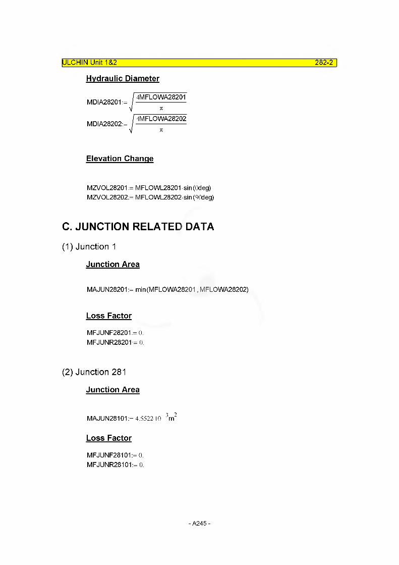
ULCHIN Unit 1&2 282-2
Hydraulic Diameter
MDIA28201 :=
MDIA28202:=
4MFLOWA28201
4MFLOWA28202
Elevation Change
MZVOL28201 := MFLOWL28201 sin (Odeg) MZVOL28202:= MFLOWL28202sin (90deg)
C. JUNCTION RELATED DATA
(1) Junction 1
Junction Area
MAJUN28201 := min(MFLOWA28201, MFLOWA28202)
Loss Factor
MFJUNF28201:= 0.MFJUNR28201:= 0.
(2) Junction 281
Junction Area
MAJUN28101 := 4.5522-10 3m2
Loss Factor
MFJUNF28101 := 0. MFJUNR28101:= 0.
- A245 -
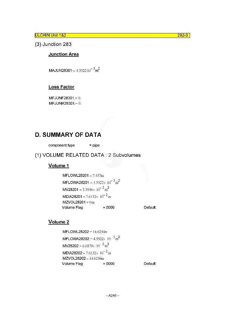
IULCHIN Unit 1&2
(3) Junction 283
282-3
Junction Area
MAJUN28301 := 4.552210“ 3m2
Loss Factor
MFJUNF28301:= 0. MFJUNR28301:= 0.
D. SUMMARY OF DATAcomponent type = pipe
(1) VOLUME RELATED DATA : 2 Subvolumes
Volume 1
MFLOWL28201 = 7.457m MFLOWA28201 = 4.5522x 10“ 3m2
MV28201 = 3.3946x 10“2m3
MDIA28201 = 7.6132x 10“ 2 m
MZVOL28201 = 0m Volume Flag = 0000
Volume 2
MFLOWL28202 = 14.6256mMFLOWA28202 = 4.5522x 10“ 3 m2
MV28202 = 6.6579x 10“2m3
MDIA28202=7.6132x 10“ 2 m
MZVOL28202= 14.6256m Volume Flag = 0000
Default
Default
- A246 -
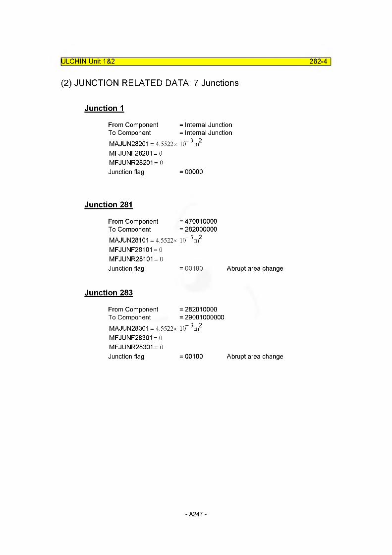
ULCHIN Unit 1&2 282-4
(2) JUNCTION RELATED DATA: 7 Junctions
Junction 1
From Component = Internal JunctionTo Component = Internal JunctionMAJUN28201 = 4.5522x 10“ 3 m2
MFJUNF28201 = 0 MFJUNR28201 = 0 Junction flag = 00000
Junction 281
From Component =470010000 To Component = 282000000MAJUN28101 = 4.5522x 10“ 3 m2
MFJUNF28101 = 0 MFJUNR28101 = 0Junction flag = 00100 Abrupt area change
Junction 283
From Component =282010000 To Component =29001000000MAJUN28301 = 4.5522x 10“ 3 m2
MFJUNF28301 = 0 MFJUNR28301 = 0Junction flag = 00100 Abrupt area change
- A247 -

E. Input CardsIULCHIN Unit 1&2 282-5
* C281 : Junction Connecting Spray Line and Cold Leg of Loop 2
2810000name spray 11
type sngljun
2810101from to370010000 282000000
area4.14e-6
kforw1.
kbackw1,0e9
j f I ag000100
2810201cnt r I1
waterflow0.0
steamflow 0.0
X0.0
* 0283 : Spray 1
2830000namesprayl
typevalve
2830101from to282010000 290010000
area4.5522e-3
kforw0.2
kbackw0.2
j f I ag000100
2830201cnt r I1
water flow0.0
steamflow 0.0
X0.0
* valve type 2830300 srvvlv
* controLvar2830301 999 *always closed
- A248 -

ULCHIN Unit 1&2 282-6
* C282 : Spray Line 1
name type2820000 srgline pipe
number of 'volumes2820001 2
area no of vo I2820101 4.5522e-3 2
j-area no of junction2820201 0.0 1
I ength no of vo I2820301 7.4570 12820302 14.6254 2
volume no of vo I2820401 0.0 2
XX no of vol2820501 0.0 2
angle no of vol2820601 0.0 12820602 90.0 2
elev. no of vol2820701 0.0 12820702 14.6254 2
rough dhydr. no of vol2820801 1. e-4 0.0 2
kforw kbackw no of jun2820901 0.03 0.03 1
v-flag no of vol2821001 00 2
j-flag no of jun2821101 00000 1
cntrl pressure temp no of vol2821201 3 155 . 1e5 560.45 0.0 0.0 0.0 12821202 3 155 . 1e5 560.45 0.0 0.0 0.0 2
cntr I2821300 1
waterflow steamflow no of jun2821301 0.0 0.0 0.0 1
- A249 -

2.4 Reactor Coolant Pump
- A250 -

pump-0
COMPONENT PumpReactor Coolant Pump
Motor power = 5900 kW (7912.Ohp)
Pump speed =1185 rpm= 124.1 rad/sec
T PMM 03
| ULCHIN Unit 1 &2
590010^124.1
= 47542.3 Nm
cf. 42576.2 Nm KOPEC, 2002, App. I
Moment of inertia
Design speed (N*)
Design head (H*)
Design flow (Q*)
Specific speed (Ns)Ns = N* x
= 4000 kg-m2
= 1185 rpm
= 80 m (262.47ft)
= 22700 m3/hr (99950 gpm)
q*o.5 / h*o.75 RELAP5 MANUAL VOL. 11
V 99950= 1185 —--------- = 5745.1
262470.75Mixed flow pump
Built-in pump specific speed = 5200 W - PUMP
KNU 9/10 RCP is similar to built-in W - PUMP.
MARS INPUT DATA- Rated pump velocity
- Rated flow
- Rated head
- Rated torque
- Rated density
: 1185 rpm = 124.1 rad/s
: 12700 m3/hr = 6.3056 nf/s
: 80 m (262 ft)
: 38916.5 Nm
: 745.0 kg/m3
- A251 -

- Motor torqueTorque transferd to the pump shaft: Power input
Power = 5900 kW
Power T = ---------
ip 63 r
= 5900 x 103/124.1 = 47545.0 Nm
of. 42576.2 Nm KOPEC, 2002, App. I
- Hydraulic torque by the fluid flow
T =1^hy 03
= 745.0 x 9.81 x 6.3056 x 80 /124.6 = 29588.55 Nm
- Pump impeller Oil S Si"3 b Torque (Brake HP)
Tim = 4849 kW/124.6 rad/s= 38916.5 Nm
- Mechanical loss torque = Friction torque
"Hr - "Hp _ "Hm= 42576.2 - 38946.5 = 3659.7 Nm
ULCHIN Unit 1&2____________________________________________________ pump-1
EfficiencyHydraulic efficiency (q )
hy
Overall efficiency (q ) o
hp Thy
bhp Tjm
29588.5 " 38916.50
= 0.760 (76.0 %)
bp _ Thy
ip Tip
29588.55 42576.2
= 0.695 (69.5 %)
- A252 -
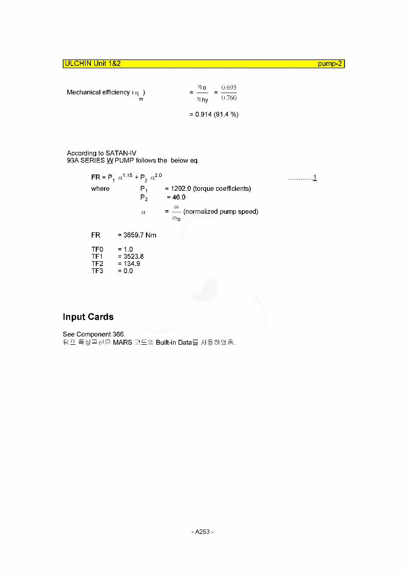
ULCHIN Unit 1&2 pump-2
Mechanical efficiency (r| )
According to SATAN-IV93A SERIES W PUMP follows the below eg.
FR= P1 a115 + P2 a2 0 ............... 1
where P1 = 1202.0 (torque coefficients)P2 = 46.0
a = — (normalized pump speed)03 o
FR = 3659.7 Nm
TFO =1.0 TF1 = 3523.8TF2 = 134.9TF3 = 0.0
no _ 0.695
T| hy 0.760
0.914 (91.4 %)
Input Cards
See Component 366.mn MARS 3E°| Built-in Data* Atgm&S.
- A253 -

2.5 Steam Generator Secondary Side
- A254 -
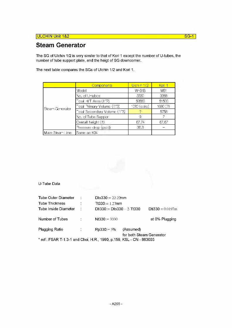
Steam Generator| ULCHIN Unit 1&2 SG-1
The SG of Ulchin 1/2 is very similar to that of Kori 1 except the number of U-tubes, the number of tube support plate, and the heigt of SG downcomer.
The next table compares the SGs of Ulchin 1/2 and Kori 1.
Components Ulchin 1/2 Kori 1
Steam Generator
Model W-51B W51
No. of U-tubes 3330 3388
Total H/T Area (fT2) 50580 51500
Total Primary Volume (1T3) 1080 (cold) 1080 (?)
Total Secondary Volume (fT3) ? 5758
No. of Tube Support 9 7
Overall height (ft) 67.74 67.67
Pressure drop (psid) 36.3 -
Main Steam Line Same as K34
U-Tube Data
Tube Outer Diameter Tube Thickness Tube Inside Diameter
Dto330:= 22.22nm Tt330:= 1.27mmDti330:= Dto330 - 2 Tt330 Dti330 = 0.0197m
Number of Tubes Nt330:= 3330 at 0% Plugging
Plugging Ratio Rp330:= 5% (Assumed)for both Steam Generator
* ref: FSART-1.3-1 and Choi, H.R., 1990, p.159, KSL - CN - 863003
- A255 -

Nodalization and Important Dimensions| ULCHIN Unit 1&2 SG-2
Top of Outlet Nozzle :
Top of Secondary Separator :
- Upper Level Tap : 48.936ft = 14.91 57m
Top of Primary Separator :
Feedwater Nozzle :
__ Lower Level Tap :■: 36.936ft = 11.2581m Bottom of Primary Separator :
Top of Tube Bundle :
Top of Straight U-tube :
29.38
24.25
Feedwater Entrance : 14" ■ Lower Level Tap : 0.3m
Top of Tube Sheet
SG Inner Diameter in Straight U-Tube Part : DiSG := 129.38n Riser Outer Diameter in Straight U-Tube Part : DoRISE:= 124.25nRiser Inner Diameter in Straight U-Tube Part : DiRISE := 123.5n
Ref. Choi, H.R., 1990, p.265-270 & 1996, p.90
- A256 -
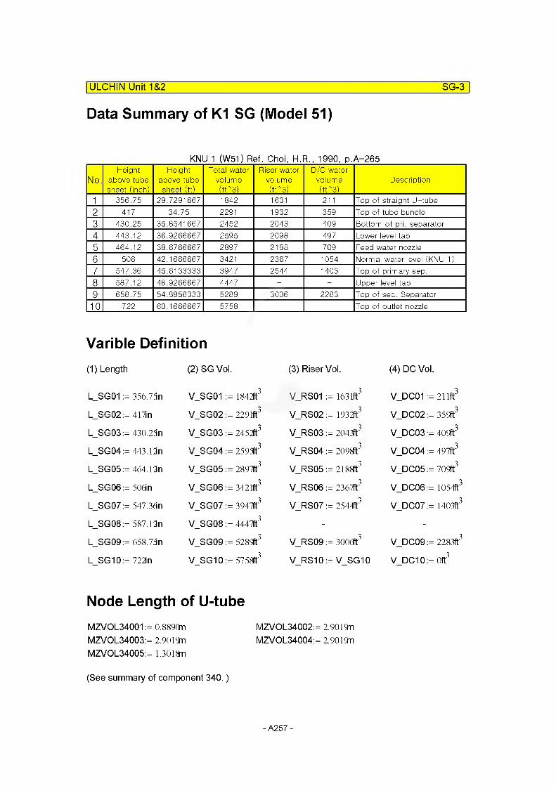
Data Summary of K1 SG (Model 51)
ULCHIN Unit 1&2_____________________________________________________ SG-3
KNU 1 (W51) Ref. Choi, H.R., 1990, p.A-265
No.Height
above tube sheet (inch)
Height above tube sheet (ft)
Total watervolume(irs)
Riser watervolume(irs)
D/C water volume(irs)
Description
1 356.75 29.7291667 1842 1631 211 Top of straight U-tube
2 417 34.75 2291 1932 359 Top of tube bundle3 430.25 35.8541 667 2452 2043 409 Bottom of pri. separator
4 443.12 36.9266667 2595 2098 497 Lower level tap5 464.12 38.6766667 2897 2188 709 Feed water nozzle
6 506 42.1666667 3421 2367 1054 Normal water level (KNU 1)7 547.36 45.6133333 3947 2544 1403 Top of primary sep.
8 587.12 48.9266667 4447 - - Upper level tap9 658.75 54.8958333 5289 3006 2283 Top of sec. Separator
10 722 60.1666667 5758 Top of outlet nozzle
Varible Definition(1) Length (2) SG Vol. (3) Riser Vol. (4) DC Vol.
L_SG01 := 356.75n V_SG01 := 1842ft3 V_RS01 = 1631ft3 V_DC01 := 211ft3
L_SG02:= 417in V_SG02 := 2291ft3 V_RS02 = 1932ft3 V_DC02 := 359ft3
L_SG03:= 430.23n V_SG03 := 2452ft3 V_RS03 = 2043ft3 V_DC03 := 409ft3
L_SG04:= 443.12n V_SG04 := 2593t3 V_RS04 = 2098ft3 V_DC04 := 497ft3
L_SG05:= 464.12n V_SG05 := 2897ft3 V_RS05 = 2188ft3 V_DC05 := 709ft3
L_SG06:= 506in V_SG06 := 3421ft3 V_RS06 = 2367ft3 V_DC06 := 1054ft3
L_SG07 := 547.36n V_SG07 := 3947ft3 V_RS07 = 2544ft3 V_DC07 := 1403ft3
L_SG08:= 587.12n V_SG08 := 4447ft3 - -
L_SG09:= 658.73n V_SG09 := 5289ft3 V_RS09 = 3ooa3 V_DC09 := 2283ft3
L_SG10:= 722in V_SG10 := 5758ft3 V_RS10 = V_SG10 V_DC10:=0ft3
Node Length of U-tubeMZVOL34001 := 0.889QnMZVOL34003:= 2.9019nMZVOL34005:= 1.3018n
MZVOL34002:= 2.9019nMZVOL34004:= 2.9019n
(See summary of component 340.)
- A257 -
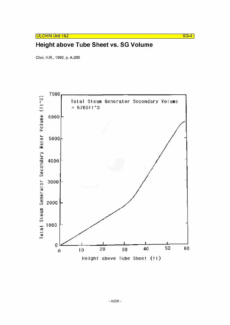
Tota
l Steam
Gene
rato
r Seco
ndar
y Wat
er Vol
ume (f
tA3)
Height above Tube Sheet vs. SG VolumeIULCHIN Unit 1&2 SG-4
Choi, H.R., 1990, p. A-266
Total Steam Generator Secondary Volume = G7G0TV8
4000
Height atmve Tube Sheet (t t)
- A258 -
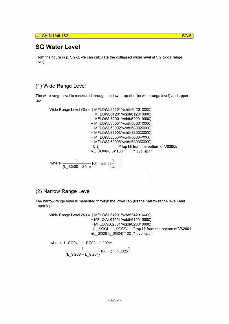
ULCHIN Unit 1&2 SG-5
SG Water LevelFrom the figure in p. SG-2, we can calculate the collapsed water level of SG (wide range level).
(1) Wide Range Level
The wide range level is measured through the lower tap (for the wide range level) and upper tap.
Wide Range Level (%) = [ MFLOWL64201 *voidf(642010000)+ MFLOWL61201 *voidf(612010000)+ MFLOWL62001 *voidf(620010000)+ MFLGWL63001 *voidf(630010000)+ M FLO WL63002*voidf(630020000)+ MFLOWL63003*voidf(630030000)+ MFLOWL63004*voidf(630040000)+ MFLOWL63005*voidf(630050000)- 0.3] // tap lift from the bottom of V63005/(L_SG08-0.3)*100 // level span
1---------------------------- 1 .where-------------------------100= 6.8433—
(L SG08 - 0.3m) m
(2) Narrow Range Level
The narrow range level is measured through the lower tap (for the narrow range level) and upper tap.
Wide Range Level (%) = [ MFLOWL64201 *voidf(642010000)+ MFLOWL61201 *voidf(612010000)+ MFLOWL62001*voidf(620010000)- (L SG04 - L SG03)] // tap lift from the bottom of V62001/(L_SG08-L_SG04)*100 // level span
.where L_SG04 - L_SG03 = 0.3269m1 1
------------------------------ 100= 27.3403325-(L SG08 - L SG04) m
- A259 -
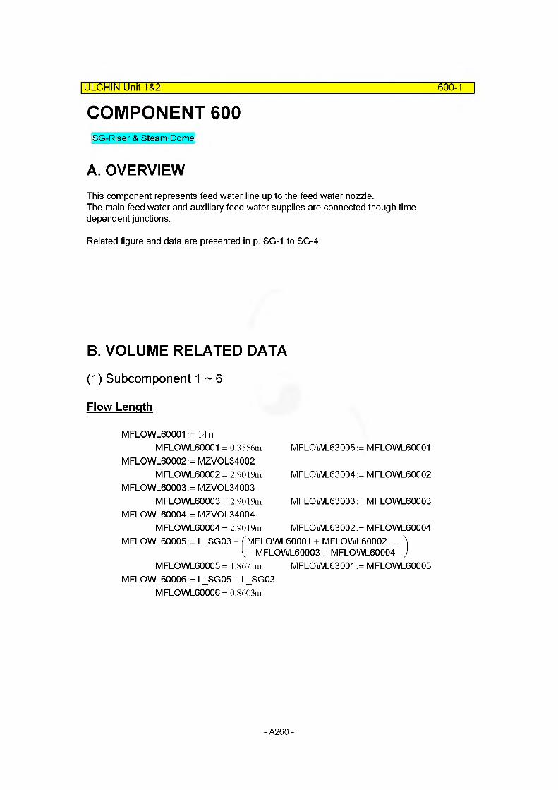
COMPONENT 600| ULCHIN Unit 1&2 600-1
SG-Riser & Steam Dome
A. OVERVIEWThis component represents feed water line up to the feed water nozzle.The main feed water and auxiliary feed water supplies are connected though time dependent junctions.
Related figure and data are presented in p. SG-1 to SG-4.
B. VOLUME RELATED DATA
(1) Subcomponent 1 ~ 6
Flow Length
MFLOWL60001 := 14inMFLOWL60001 = 0.3556m MFLOWL63005:= MFLOWL60001
M FLO WL60002: = MZVOL34002MFLOWL60002 = 2.9019m MFLOWL63004:= MFLOWL60002
M FLO WL60003: = MZVOL34003MFLOWL60003 = 2.9019m MFLOWL63003:= MFLOWL60003
M FLO WL60004: = MZVOL34004MFLOWL60004 = 2.9019m MFLOWL63002:= MFLOWL60004
MFLOWL60005: = L_SG03 - f MFLOWL60001 + MFLOWL60002 ...V MFLOWL60003 + MFLOWL60004
MFLOWL60005 = 1.8671m MFLOWL63001 := MFLOWL60005MFLOWL60006: = L_SG05 - L_SG03
MFLOWL60006 = 0.8603m
- A260 -
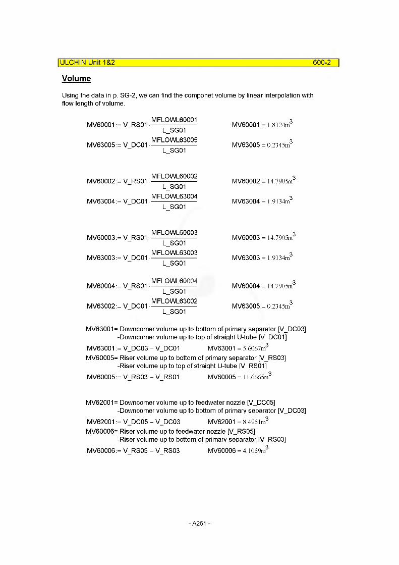
ULCHIN Unit 1&2 600-2
Volume
Using the data in p. SG-2, we can find the componet volume by linear interpolation with flow length of volume.
MV60001 := V_RS01 •
MV63005:= V DC01 •
MFLOWL60001L_SG01
MFLOWL63005 L SG01
MV60001 = 1.8124m3
MV63005 = 0.2345m3
MV60002:= V_RS01 •
MV63004:= V DC01 •
MFLOWL60002L_SG01
MFLOWL63004 L SG01
MV60002 = 14.7905m3
MV63004= 1.9134m3
MV60003:= V_RS01 •
MV63003:= V DC01 •
MFLOWL60003L_SG01
MFLOWL63003 L SG01
MV60003 = 14.7905m3
MV63003= 1.9134m3
MV60004:= V_RS01 •
MV63002:= V DC01 •
MFLOWL60004L_SG01
MFLOWL63002 L SG01
MV60004 = 14.7905m3
MV63005 = 0.2345m3
MV63001= Downcomer volume up to bottom of primary separator [VDC03] -Downcomer volume up to top of straight U-tube [V DC01]
MV63001 := V_DC03 - V_DC01 MV63001 = 5.6067m3
MV60005= Riser volume up to bottom of primary separator [VRS03]-Riser volume up to top of straight U-tube IV RS011
MV60005:= V RS03 - V RS01 MV60005 = 11.6665m3
MV62001= Downcomer volume up to feedwater nozzle [V_DC05]-Downcomer volume up to bottom of primary separator [VDC03]
MV62001 := V_DC05 - V_DC03 MV62001 = 8.4951m3
MV60006= Riser volume up to feedwater nozzle [V_RS05]-Riser volume up to bottom of primary separator IV RS03]
MV60006 := V RS05 - V RS03 MV60006 = 4.1059m3
- A261 -
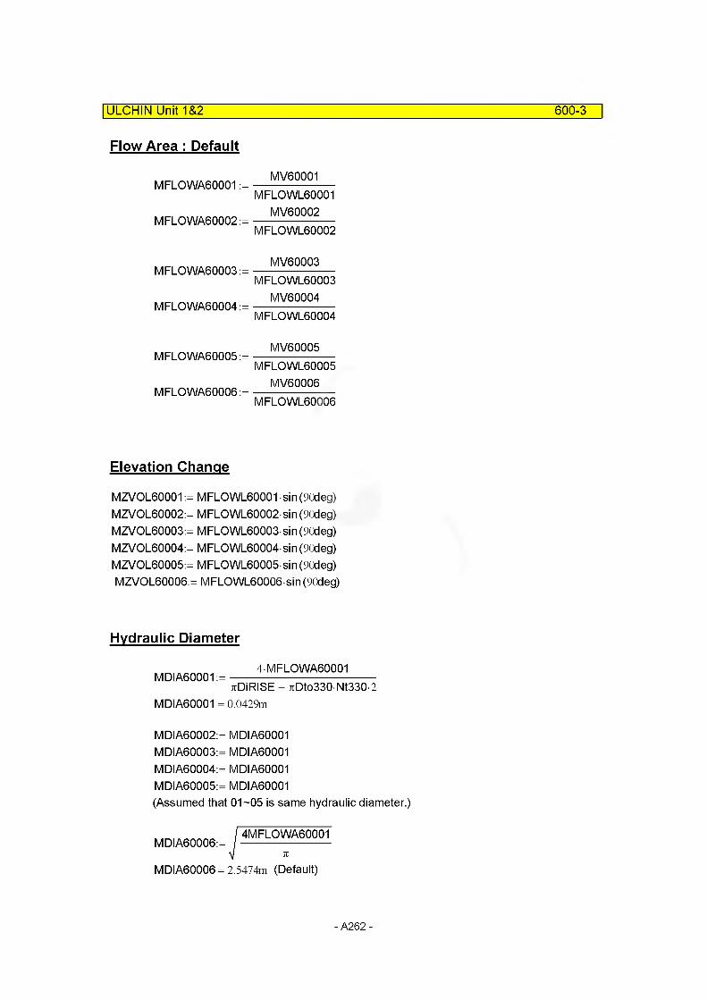
ULCHIN Unit 1&2 600-3
Flow Area : Default
MFLOWA60001 :=
MFLOWA60002 :=
MV60001MFLOWL60001
MV60002MFLOWL60002
MFLOWA60003 :=
MFLOWA60004 :=
MV60003MFLOWL60003
MV60004MFLOWL60004
MFLOWA60005 :=
MFLOWA6OOO6 :=
MV60005MFLOWL60005
MV60006MFLOWL6OOO6
Elevation Change
MZVOL60001 := MFLOWL60001 sin (90deg) MZVOL60002:= MFLOWL60002 sin (90deg) MZVOL60003:= MFLOWL60003 sin (90deg) MZVOL60004:= MFLOWL60004 sin (90deg) MZVOL60005:= MFLOWL60005 sin (90deg) MZVOL60006:= MFLOWL60006 sin (90deg)
Hydraulic Diameter
MDIA60001 :=4MFLOWA60001
TtDiRISE + 7iDto330 Nt330-2 MDIA60001 = 0.0429m
MDIA60002:= MDIA60001 MDIA60003:= MDIA60001 MDIA60004:= MDIA60001 MDIA60005:= MDIA60001 (Assumed that 01-05 is same hydraulic diameter.)
MDIA60006:=4MFLOWA60001
MDIA60006 = 2.5474m (Default)
- A262 -
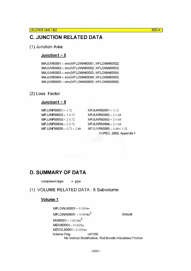
C. JUNCTION RELATED DATA
(1) Junction Area
Junctionl ~ 5
MAJUN60001 := min(MFLOWA60001, MFLOWA60002)MAJUN60002:= min(MFLOWA60002, MFLOWA60003)MAJUN60003:= min(MFLOWA60003, MFLOWA60004)MAJUN60004:= min(MFLOWA60004, MFLOWA60005)MAJUN60005:= min(MFLOWA60005, MFLOWA60006)
| ULCHIN Unit 1&2 600-4
(2) Loss Factor
Junctionl ~ 5
MFJUNF60001:= 1.72 MFJUNF60002:= 2-0.72 MFJUNF60003:= 2-0.72 MFJUNF60004:= 2-0.72 MFJUNF60005:= 0.72+ 2.88
MFJUNR60001:= 1.15 MFJUNR60002:= 2-0.48 MFJUNR60003:= 2-0.48 MFJUNR60004:= 2-0.48 MFJUNR60005:= 0.48+ 1.92
KOPEC, 2002, Appendix I
D. SUMMARY OF DATAcomponent type = pipe
(1) VOLUME RELATED DATA : 6 Subvolume
Volume 1
MFLOWL60001 = 0.3556m
MFLOWA60001 = 5.0968m2 Default
MV60001 = 1.8124m3
MDIA60001 = 0.0429m MZVOL60001 = 0.3556m Volume Flag =01100
No Vertical Stratification, Rod Bundle Interphase Friction
- A263 -
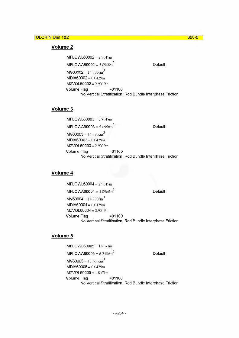
ULCHIN Unit 1&2 600-5
Volume 2
MFLOWL60002 = 2.9019m
MFLOWA60002 = 5.0968m2 Default
MV60002 = 14.7905m3
MDIA60002= 0.0429m MZVOL60002 = 2.9019m Volume Flag =01100
No Vertical Stratification, Rod Bundle Interphase Friction
Volume 3
MFLOWL60003 = 2.9019m
MFLOWA60003 = 5.0968m2 Default
MV60003 = 14.7905m3
MDIA60003= 0.0429m MZVOL60003= 2.9019m Volume Flag =01100
No Vertical Stratification, Rod Bundle Interphase Friction
Volume 4
MFLOWL60004 = 2.9019m
MFLOWA60004 = 5.0968m2 Default
MV60004 = 14.7905m3
MDIA60004= 0.0429m MZVOL60004 = 2.9019m Volume Flag =01100
No Vertical Stratification, Rod Bundle Interphase Friction
Volume 5
MFLOWL60005 = 1.8671m
MFLOWA60005 = 6.2486m2 Default
MV60005 = 11.6665m3
MDIA60005= 0.0429m MZVOL60005= 1.8671m Volume Flag =01100
No Vertical Stratification, Rod Bundle Interphase Friction
- A264 -
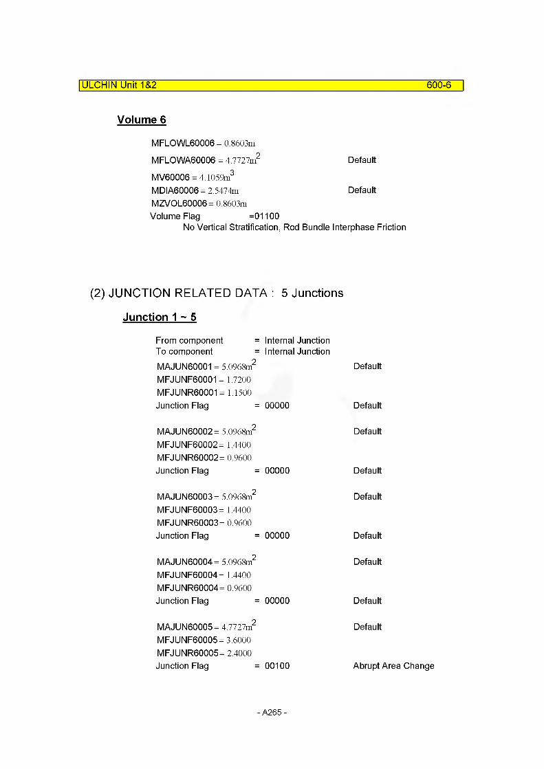
ULCHIN Unit 1&2 600-6
Volume 6
MFLOWL6OOO6 = 0.8603m
MFLOWA60006 = 4.7727m2 Default
MV60006 = 4.1059m3
MDIA60006 = 2.5474m DefaultMZVOL60006= 0.8603m Volume Flag =01100
No Vertical Stratification, Rod Bundle Interphase Friction
(2) JUNCTION RELATED DATA : 5 Junctions
Junction 1 ~ 5
From component =To component =MAJUN60001 = 5.0968m2
MFJUNF60001= 1.7200 MFJUNR60001 = 1.1500 Junction Flag =
MAJUN60002= 5.0968m2
MFJUNF60002= 1.4400 MFJUNR60002 = 0.9600 Junction Flag =
MAJUN60003= 5.0968m2
MFJUNF60003= 1.4400 MFJUNR60003 = 0.9600 Junction Flag =
Internal Junction Internal Junction
Default
00000 Default
Default
00000 Default
Default
00000 Default
MAJUN60004= 5.0968m2
MFJUNF60004= 1.4400 MFJUNR60004 = 0.9600 Junction Flag =
Default
00000 Default
MAJUN60005= 4.7727m2 Default
MFJUNF60005= 3.6000 MFJUNR60005= 2.4000Junction Flag = 00100 Abrupt Area Change
- A265 -

E. Input Cards| ULCHIN Unit 1&2 600-7
* C600 : Riser of SG Secondary Side in Loop 1
name type6000000 riser-l 1 pipe
6000001number6
of volumes
area no of voI6000101 0.0 6
j-area no of jun6000201 0.0 5
I ength no of voI6000301 0.3556 16000302 2.9019 46000303 1.8671 56000304 0.8603 6
volume no of vol6000401 1.8124 16000402 14.7905 46000403 11.6665 56000404 4.1059 6
XX no of vol6000501 0.0 6
angle no of vol6000601 90. 6
elev. no of vol6000701 0.3556 16000702 2.9019 46000703 1.8671 56000704 0.8603 6
rough dhydr.6000801 1. e-4 0.0429 i6000802 1 .e-4 0. I
kforw kbackw no6000901 1.72 1.15 16000902 1.44 0.96 46000903 3.6 2.4 5
v-flag no of vol6001001 01100 6
j-flag no of jun6001101 00000 46001102 00100 5
- A266 -
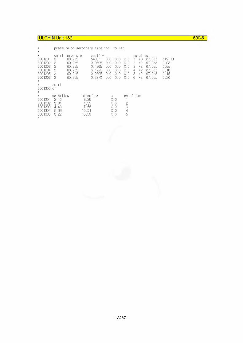
ULCHIN Unit 1&2 600-8
pressure on secondary side for fouled
cnt r I pressure duality no of vo I6001201 3 60.2e5 548.1 0.0 0.0 0.0 1 *3 67.0e5 549.106001202 2 60.2e5 0.0595 0.0 0.0 0.0 2 *2 67.0e5 0.036001203 2 60.2e5 0.1265 0.0 0.0 0.0 3 *2 67.0e5 0.656001204 2 60.2e5 0.1920 0.0 0.0 0.0 4 *2 67.0e5 0.106001205 2 60.2e5 0.2695 0.0 0.0 0.0 5 *2 67.0e5 0.156001206 2 60.2e5 0.2870 0.0 0.0 0.0 6 *2 67.0e5 0.20
cnt r I6001300 0
waterflow steamflow no of: jun6001301 2.10 3.29 0.0 16001302 3.04 4.85 0.0 26001303 4.40 7.58 0.0 36001304 5.63 10.01 0.0 46001305 8.22 10.50 0.0 5
- A267 -
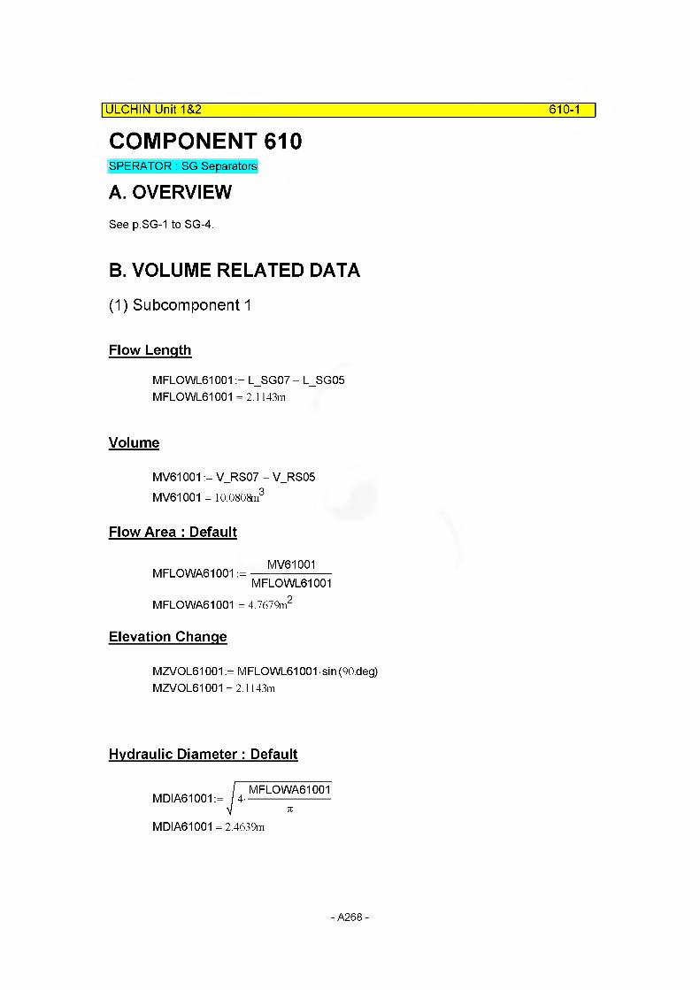
610-1| ULCHIN Unit~T&2
COMPONENT 610SPERATOR: SG Separators
A. OVERVIEWSee p.SG-1 to SG-4.
B. VOLUME RELATED DATA
(1) Subcomponent 1
Flow Length
MFLOWL61001 := L_SG07 - L_SG05 MFLOWL61001 = 2.1143m
Volume
MV61001 := V RS07 - V_RS05 MV61001 = 10.0808m3
Flow Area : Default
MV61001MFLOWA61001 :=
MFLOWL61001MFLOWA61001 = 4.7679m2
Elevation Change
MZVOL61001 := MFLOWL61001 sin (90.deg) MZVOL61001 = 2.1143m
Hydraulic Diameter: Default
MDIA61001 = 2.4639m
- A268 -
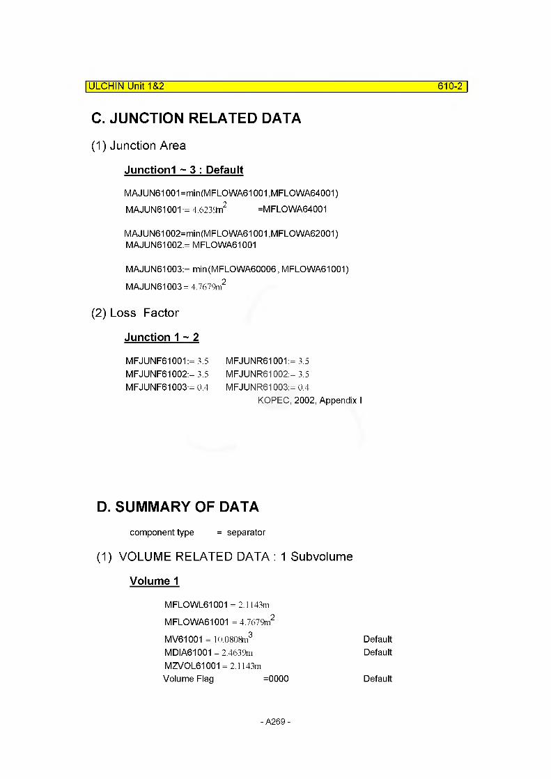
ULCHIN Unit 1&2 610-2
C. JUNCTION RELATED DATA
(1) Junction Area
Junctionl ~ 3 : Default
MAJUN61001=min(MFLOWA61001 ,MFLOWA64001) MAJUN61001 := 4.6239n2 =MFLOWA64001
MAJUN61002=min(MF LO WA61001 ,MFLOWA62001) MAJUN61002:= MFLOWA61001
MAJUN61003:= min(MFLOWA60006, MFLOWA61001) MAJUN61003= 4.7679m2
(2) Loss Factor
Junction 1 ~ 2
MFJUNF61001:= 3.5 MFJUNR61001:= 3.5MFJUNF61002:= 3.5 MFJUNR61002:= 3.5MFJUNF61003:= 0.4 MFJUNR61003:= 0.4
KOPEC, 2002, Appendix I
D. SUMMARY OF DATAcomponent type = separator
(1) VOLUME RELATED DATA : 1 Subvolume
Volume 1
MFLOWL61001 = 2.1143m
MFLOWA61001 = 4.7679m2
MV61001 = 10.0808m3 DefaultMDIA61001 = 2.4639m DefaultMZVOL61001 = 2.1143mVolume Flag =0000 Default
- A269 -
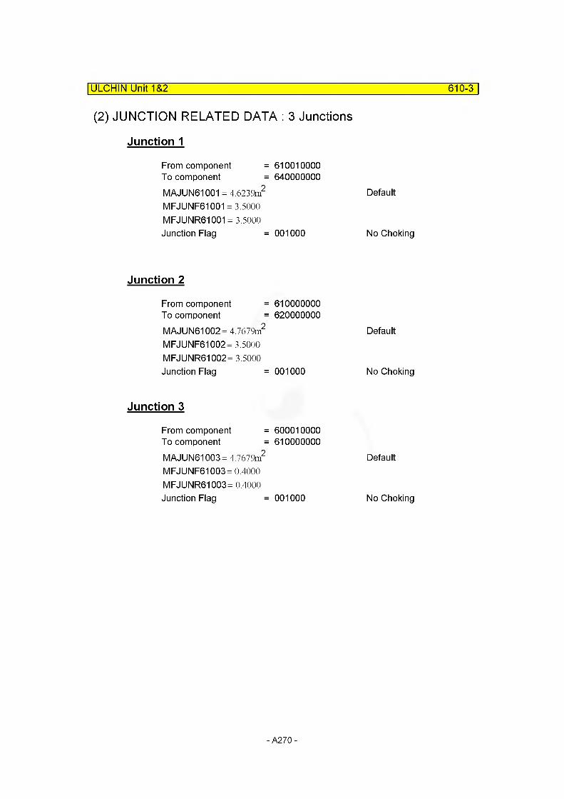
ULCHIN Unit 1&2 610-3
(2) JUNCTION RELATED DATA : 3 Junctions
Junction 1
From component =To component =MAJUN61001 = 4.6239m2
610010000640000000
DefaultMFJUNF61001 = 3.5000MFJUNR61001 = 3.5000 Junction Flag = 001000 No Choking
Junction 2
From component =To component =MAJUN61002= 4.7679m2
610000000620000000
DefaultMFJUNF61002= 3.5000MFJUNR61002= 3.5000 Junction Flag = 001000 No Choking
Junction 3
From component =To component =MAJUN61003= 4.7679m2
600010000610000000
DefaultMFJUNF61003 =0.4000MFJUNR61003= 0.4000 Junction Flag = 001000 No Choking
- A270 -
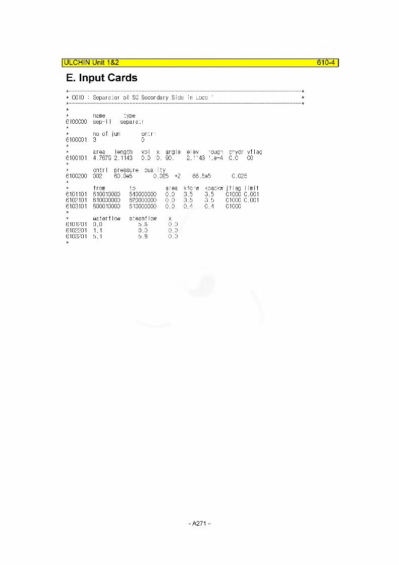
E. Input Cards| ULCHIN Unit 1&2 610-4
* C610 : Separator of SG Secondary Side in Loop 1
6100000
6100001
6100101
typeseparatr
name sep-l
no of jun 3
area length 4.7679 2.1143
cnt r I 0
voI x angle 0.0 0. 90.
* cntrI pressure qual ity6100200 002 60.0e5 0.025 *2
elev rough dhydr vflag 2.1143 1.8-4 0.0 00
66.5e5 0.025
from to6101101 610010000 6400000006102101 610000000 6200000006103101 600010000 610000000
water flow steamflow6101201 0.0 5.66102201 1.1 0.06103201 5.1 5.8
area kforw kbackw j f I ag limit0.0 3.5 3.5 01000 0.0010.0 3.5 3.5 01000 0.0010.0
X
0.4 0.4 01000
0.00.00.0
- A271 -
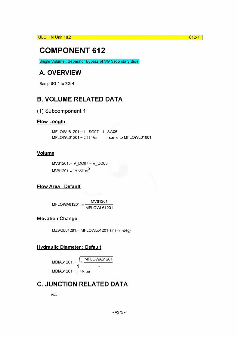
ULCHIN Unit 1&2 612-1
COMPONENT 612Single Volume : Separator Bypass of SG Secondary Side
A. OVERVIEWSee p.SG-1 to SG-4.
B. VOLUME RELATED DATA
(1) Subcomponent 1
Flow Length
MFLOWL61201 := L_SG07 - L_SG05MFLOWL61201 =2.1143m same to MFLOWL61001
Volume
MV61201 := V_DC07 - V_DC05 MV61201 = 19.6519m3
Flow Area : Default
MFLOWA61201 :=MV61201
MFLOWL61201
Elevation Change
MZVOL61201 := MFLOWL61201 sin (-90.deg)
Hydraulic Diameter: Default
MDIA61201 := 4-MFLOWA61201
MDIA61201 = 3.4401m
C. JUNCTION RELATED DATANA
- A272 -
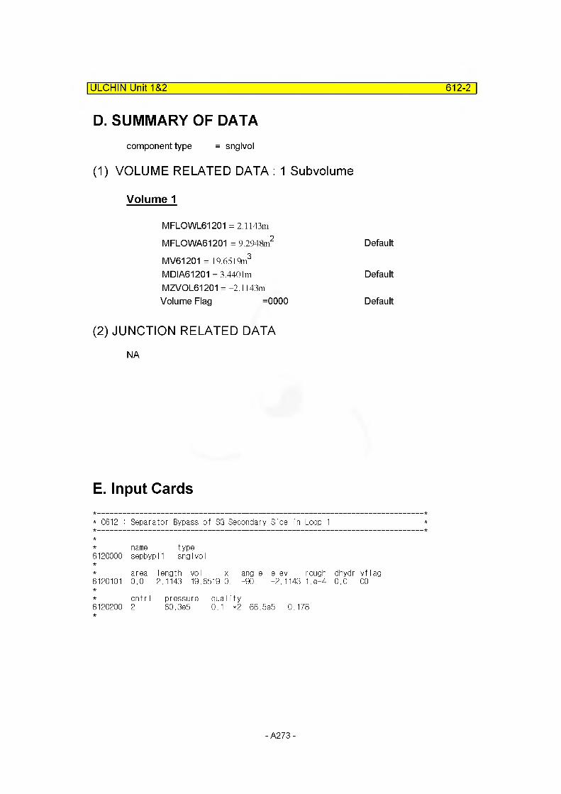
ULCHIN Unit 1&2 612-2
D. SUMMARY OF DATAcomponent type = snglvol
(1) VOLUME RELATED DATA : 1 Subvolume
Volume 1
MFLOWL61201 = 2.1143m
MFLOWA61201 = 9.2948m2 Default
MV61201 = 19.6519m3
MDIA61201 = 3.4401m DefaultMZVOL61201 =-2.1143mVolume Flag =0000 Default
(2) JUNCTION RELATED DATA
NA
E. Input Cards
* C612 : Separator Bypass of SG Secondary Side in Loop 1
name type6120000 sepbypl1 snglvol
area length vol X
6120101 0.0 2.1143 19.6519 0.
cntr I pressure duality6120200 2 60.3e5 0."1 *2
angle elev rough dhydr vflag-90. -2.1143 1.8-4 0.0 00
66.5e5 0.178
- A273 -
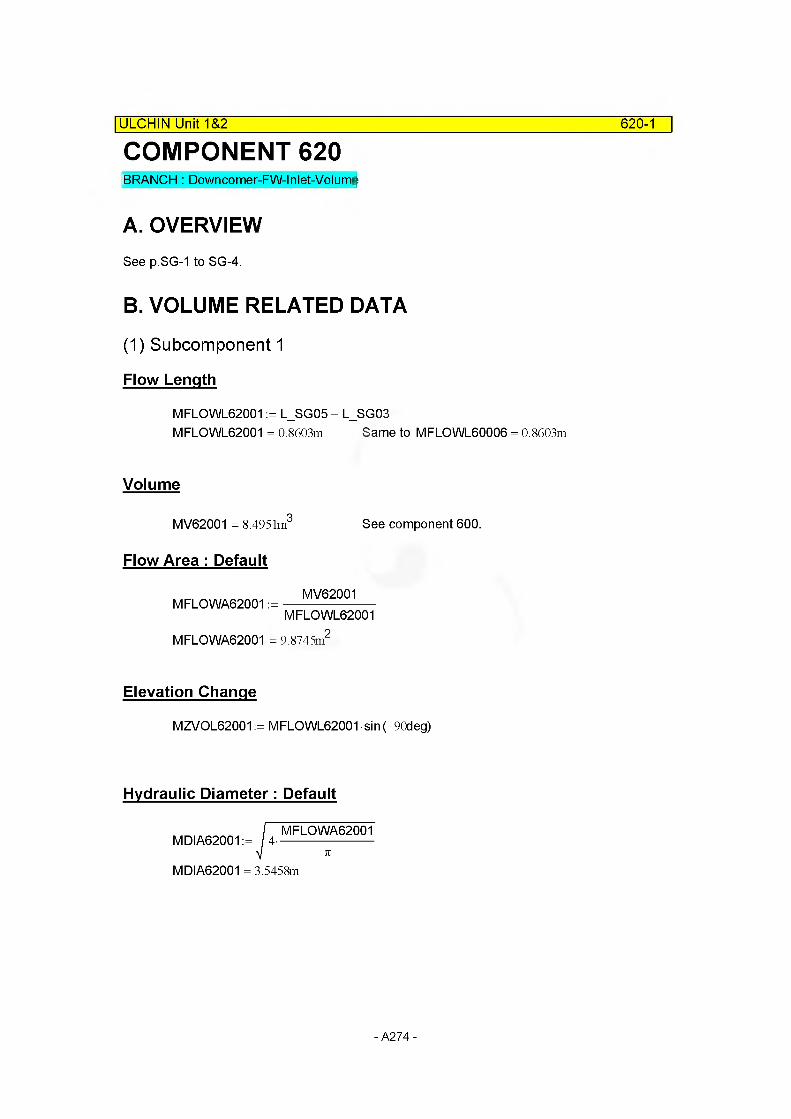
COMPONENT 620BRANCH : Downcomer-FW-Inlet-Volume
| ULCHIN Unit 1&2 620-1
A. OVERVIEWSee p.SG-1 to SG-4.
B. VOLUME RELATED DATA
(1) Subcomponent 1
Flow Length
MFLOWL62001 := L_SG05 - L_SG03MFLOWL62001 = 0.8603m Same to MFLOWL6OOO6 = 0.8603m
Volume
MV62001 = 8.4951m3
Flow Area : Default
MFLOWA62001 :=
See component 600.
MV62001
MFLOWL62001
MFLOWA62001 = 9.8745m
Elevation Change
MZVOL62001 := MFLOWL62001 sin (-90deg)
Hydraulic Diameter: Default
MDIA62001 := 4 -MFLOWA62001
MDIA62001 = 3.5458m
- A274 -
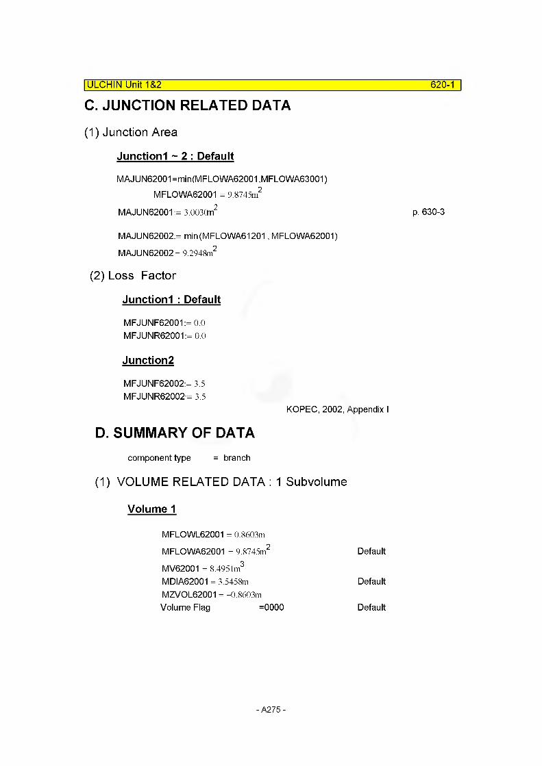
C. JUNCTION RELATED DATA
(1) Junction Area
| ULCHIN Unit 1&2 620-1
Junctionl ~ 2 : Default
MAJUN62001=min(MFLOWA62001 ,MFLOWA63001) MFLOWA62001 = 9.8745m2
MAJUN62001 := 3.003Qn2
MAJUN62002:= min(MFLOWA61201, MFLOWA62001) MAJUN62002= 9.2948m2
(2) Loss Factor
Junctionl : Default
MFJUNF62001:= 0.0 MFJUNR62001:= 0.0
Junction2
MFJUNF62002:= 3.5 MFJUNR62002:= 3.5
KOPEC, 2002, Appendix I
D. SUMMARY OF DATAcomponent type = branch
(1) VOLUME RELATED DATA : 1 Subvolume
Volume 1
MFLOWL62001 = 0.8603m
MFLOWA62001 = 9.8745m2 Default
MV62001 = 8.4951m3
MDIA62001 = 3.5458m DefaultMZVOL62001 = -0.8603mVolume Flag =0000 Default
p. 630-3
- A275 -
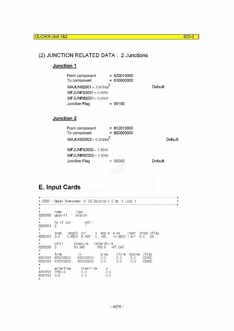
ULCHIN Unit 1&2 620-2
(2) JUNCTION RELATED DATA : 2 Junctions
Junction 1
From component =To component =MAJUN62001 = 3.0030m2
MFJUNF62001 = 0.0000 MFJUNR62001 = 0.0000 Junction Flag =
Junction 2
From component =To component =MAJUN62002= 9.2948m2
MFJUNF62002= 3.5000 MFJUNR62002= 3.5000 Junction Flag =
620010000630000000
Default
00100
612010000620000000
Default
00000 Default
E. Input Cards
* C620 : Upper Downcomer of SG Secondary Side in Loop 1
name type6200000 updo-11 branch
no of jun cnt r I6200001 2 1
area length vol x angle elev rough dhydr vf6200101 0.0 0.8603 8.4951 0 . -90. -0.8603 1 .e-4 0.0 00
cntr I pressure temperature6200200 3 60.0e5 543.6 *67.0e5
from to area kforw kbackw1 j f1ag6201101 620010000 630000000 0.0 0.0 0.0 001006202101 612010000 620000000 0.0 3.5 3.5 00000
waterflow steamflow X6201201 2280.0 0.0 0.06202201 0.0 0.0 0.0
- A276 -
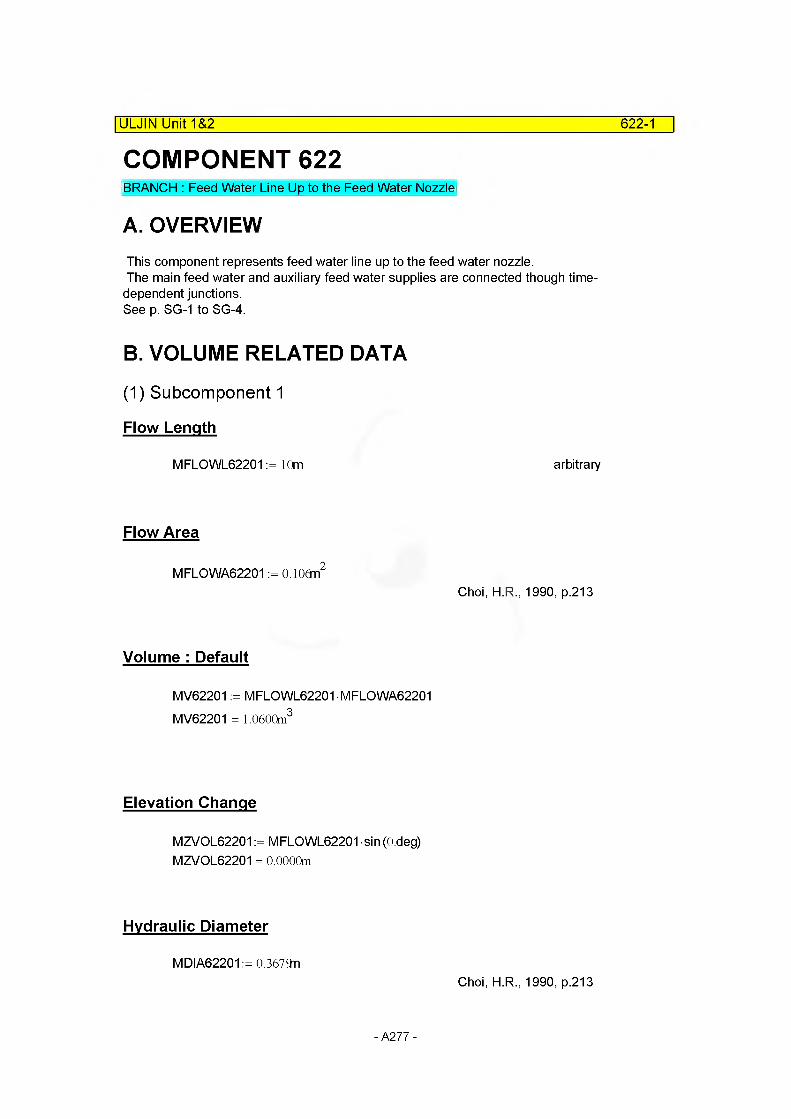
COMPONENT 622|ULJIN Unit 1&2 622-1
BRANCH : Feed Water Line Up to the Feed Water Nozzle
A. OVERVIEWThis component represents feed water line up to the feed water nozzle.The main feed water and auxiliary feed water supplies are connected though time- dependent junctions.See p. SG-1 to SG-4.
B. VOLUME RELATED DATA
(1) Subcomponent 1
Flow Length
MFLOWL62201 := 10m arbitrary
Flow Area
MFLOWA62201 := O.lOdn2
Choi, H.R., 1990, p.213
Volume : Default
MV62201 := MFLOWL62201 MFLOWA62201 MV62201 = 1.0600m3
Elevation Change
MZVOL62201 := MFLOWL62201 sin (O.deg) MZVOL62201 = 0.0000m
Hydraulic Diameter
MDIA62201 := 0.3679nChoi, H.R., 1990, p.213
- A277 -
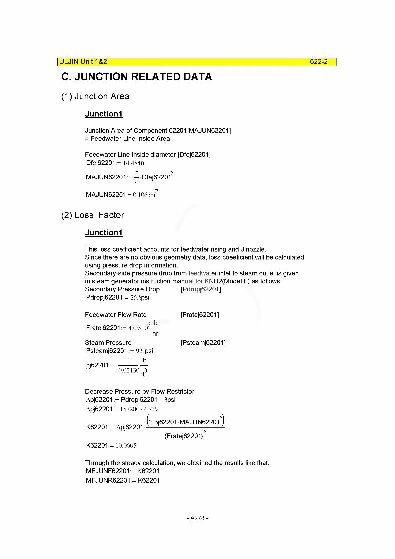
C. JUNCTION RELATED DATA
(1) Junction Area
|ULJIN Unit 1&2 622-2
Junctionl
Junction Area of Component 62201 [MAJUN62201] = Feedwater Line Inside Area
Feedwater Line Inside diameter [Dfej62201] Dfej62201 := 14.484n
MAJUN62201 := ^ • Dfej622012
MAJUN62201 = 0.1063m2
(2) Loss Factor
Junctionl
This loss coefficient accounts for feedwater rising and J nozzle.Since there are no obvious geometry data, loss coeeficient will be calculated using pressure drop information.Secondary-side pressure drop from feedwater inlet to steam outlet is given in steam generator instruction manual for KNU2(Model F) as follows. Secondary Pressure Drop [Pdropj62201]Pdropj62201:= 25.8psi
Feedwater Flow Rate
Fratej62201 := 4.09-106
Steam Pressure Psteamj62201 := 920psi
1 lbpj62201 :=
lb
hr
0.02130.3ft
[Fratej62201]
[Psteamj62201]
Decrease Pressure by Flow Restrictor Apj62201 := Pdropj62201 - 3psi Apj62201 = 157200.466^3
2Pj62201 MAJUN622012
(Fratej62201)2
K62201 = 10.0605
K62201 := Apj62201 •
Through the steady calculation, we obtained the results like that. MFJUNF62201:= K62201 MFJUNR62201:= K62201
- A278 -
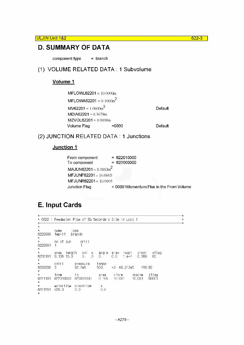
D. SUMMARY OF DATA|ULJIN Unit 1&2 622-3
component type = branch
(1) VOLUME RELATED DATA : 1 Subvolume
Volume 1
MFLOWL62201 = 10.0000m
MFLOWA62201 = 0.1060m2
MV62201 = 1.0600m3 Default
MDIA62201 = 0.3679m MZVOL62201 = 0.0000mVolume Flag =0000 Default
(2) JUNCTION RELATED DATA : 1 Junctions
Junction 1
From component = 622010000To component = 620000000MAJUN62201 = 0.1063m2
MFJUNF62201 = 10.0605 MFJUNR62201 = 10.0605Junction Flag = 00001 Momentum Flux in the From Volume
E. Input Cards
* C622 : Feedwater Pipe of SG Secondary Side in Loop 1
6220000name fwp-l‘
typeI branch
6220001no of1
jun cntrI1
6220101area0.106
length vol x 10.0 0. .0
angle0.
elev rough dhydr 0.0 1.8-4 0.368
vf lag 00
6220200cntr I3
pressure62.7e5
temper503. *3 68.243e5 499.82
6221101from to622010000 620000000
area0.106
kforw kbackw10.061 10.061
j f I ag 00001
6221201water flow steamflow 520.0 0.0
X
0.0
- A279 -

COMPONENT 623Main Feedwater Supply System
A. OVERVIEWThis component represents the main feedwater supply system.It will be modelled as a time-dependent junction controlled by trip logic
B. VOLUME RELATED DATANA
C. JUNCTION RELATED DATA
(1) Junction Area
Junctionl
MAJUN62301:= O.lOSn2 arbitrary
ULJIN Unit 1&2_______________________________________________________623-1
D. SUMMARY OF DATAcomponent type = time dependent junction
(1) VOLUME RELATED DATA :
NA
(2) JUNCTION RELATED DATA : 1 Junctions
Junction 1
From component = 624000000To component = 622000000MAJUN62301 = 0.1060m2 arbitrary
- A280 -

E. Input Cards|ULJIN Unit 1&2 623-2
* C623 : Feedwater Supply of SG Secondary Side in Loop 1
name type6230000 mfwj-l1 tmdpjun
from to area6230101 624000000 622000000 0.106
cnt r I trip6230200 1 755 cntrIvar 162
var waterflow steamflow X6230201 -1,0e9 0.0 0.0 0.06230202 0. 0.0 0.0 0.06230203 0.1 2000.19 0.0 0.06230204 17. 2000.19 0.0 0.06230205 44. 504.4 0.0 0.06230206 80. 0. 0.0 0.06230207 1,0e9 0. 0.0 0.0
- A281 -
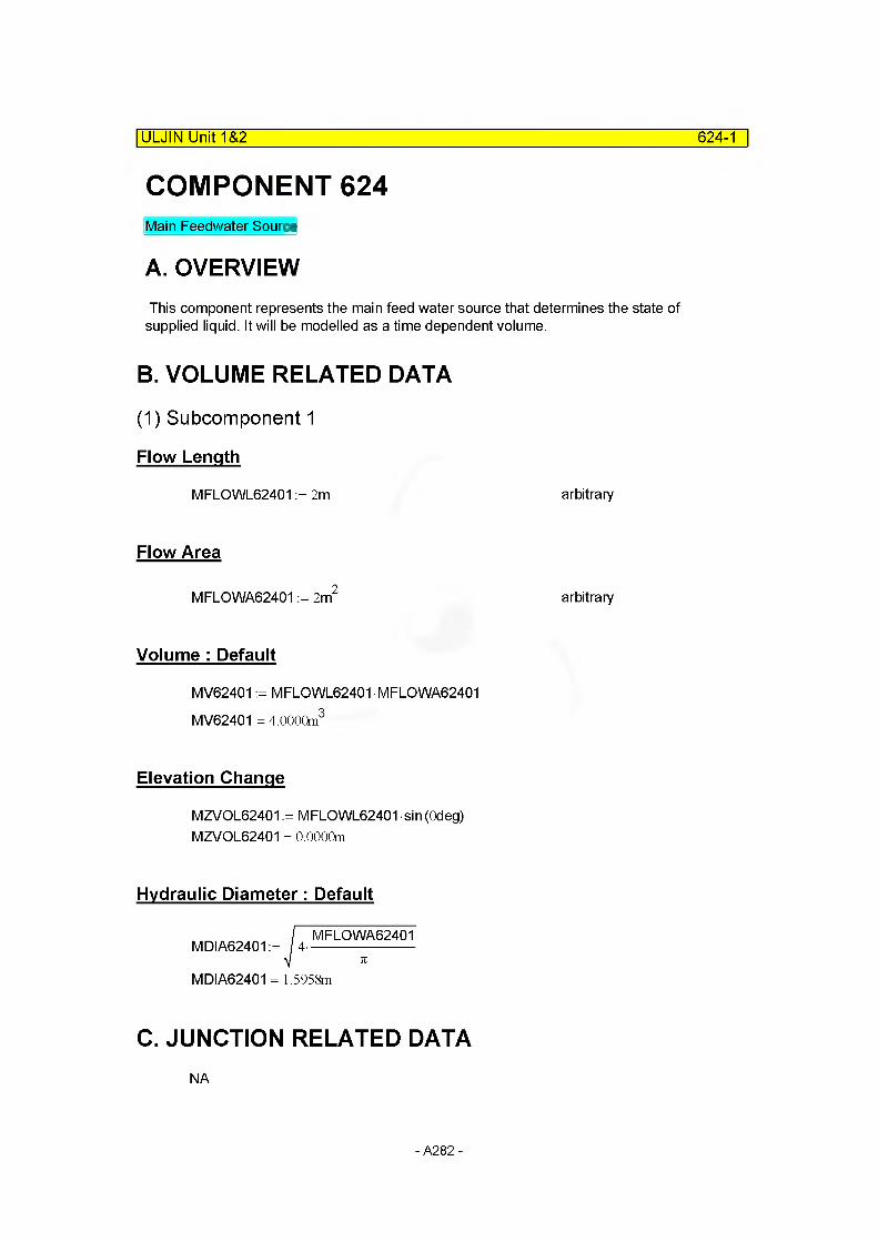
COMPONENT 624Main Feedwater Source
A. OVERVIEWThis component represents the main feed water source that determines the state of
supplied liquid. It will be modelled as a time dependent volume.
B. VOLUME RELATED DATA
(1) Subcomponent 1
Flow Length
MFLOWL62401 := 2m arbitrary
Flow Area
MFLOWA62401 := 2m2 arbitrary
Volume : Default
MV62401 := MFLOWL62401 MFLOWA62401 MV62401 = 4.0000m3
Elevation Change
MZVOL62401 := MFLOWL62401 sin (Odeg)MZVOL62401 = 0.0000m
ULJIN Unit 1&2_______________________________________________________624-1
Hydraulic Diameter: Default
MDIA62401 := / 4-MFLOWA62401
MDIA62401 = 1.5958m
C. JUNCTION RELATED DATANA
- A282 -
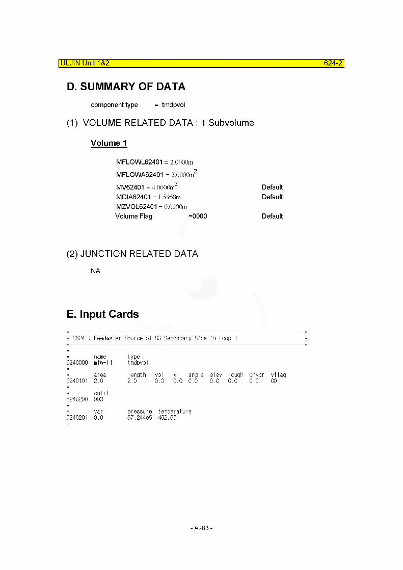
ULJIN Unit 1&2 624-2
D. SUMMARY OF DATAcomponent type = tmdpvol
(1) VOLUME RELATED DATA : 1 Subvolume
Volume 1
MFLOWL62401 = 2.0000m
MFLOWA62401 = 2.0000m2
MV62401 = 4.0000m3 DefaultMDIA62401 = 1.5958m DefaultMZVOL62401 = 0.0000mVolume Flag =0000 Default
(2) JUNCTION RELATED DATA
NA
E. Input Cards
* 0624 : Feedwater Source of SG Secondary Side in Loop 1
6240000name mfw-l1
typetmdpvol
6240101area2.0
Iength 2.0
voI x angle0.0 0.0 0.0
elev rough 0.0 0.0
dhydr0.0
vf lag00
6240200cntr I003
6240201var0.0
pressure 67.244e5
temperature492.65
- A283 -

625-1
COMPONENT 625|ULJIN Unit 1&2
Mortor Driven Auxiliary Feedwater Supply System
A. OVERVIEWThis component represents the auxiliary feedwater supply system. It is modelled as a time dependent junction controlled by trip logic.
B. VOLUME RELATED DATANA
C. JUNCTION RELATED DATA
(1) Junction Area
Junctionl
MAJUN62501:= 0.0074n2 arbitrary
4" SCH80 ID = 3.826"Choi H R. ,1990 , page 217
D. SUMMARY OF DATAcomponent type = tmdpjun
(1) VOLUME RELATED DATANA
(2) JUNCTION RELATED DATA : 1 Junctions
Junction 1
From component = 626000000To component = 622000000MAJUN62501 = 0.0074m2
Junction Flag = 00000arbitraryDefault
- A284 -

E. Input Cards
ULJIN Unit 1&2_______________________________________________________625-2
* C625 : MD AFW Supply of SG Secondary Side in Loop 1
name type6250000 md1-afw tmdpjun
from to area6250101 626000000 622000000 7.4e-3
cnt r I trip6250200 1 561
var waterflow steamflow X6250201 -1.0 0.0 0.0 0.06250202 0.0 0. 0.0 0.06250203 0.1 0. 0.0 0.06250204 5.0 24.23 0.0 0.0 * 88 mA3/hr*991.2448kg/mA3=24.23kg/s6250205 1,0e9 24.23 0.0 0.0
- A285 -
626-1
COMPONENT 626Motor Driven Auxiliary Feedwater Source
A. OVERVIEWThis component represents the auxiliary feedwater source.It will be modelled as a time dependent volume whose size is arbitrary.
B. VOLUME RELATED DATA
(1) Subcomponent 1
Flow Length
MFLOWL62601 := 2m arbitrary
Flow Area
MFLOWA62601 := 2m2 arbitrary
Volume : Default
MV62601 := MFLOWL62601 MFLOWA62601 MV62601 = 4.0000m3
|ULJIN Unit 1&2
Elevation Change
MZVOL62601 := MFLOWL62601 sin (Odeg) MZVOL62601 = 0.0000m
Hydraulic Diameter: Default
MDIA62601 := 4-MFLOWA62601
MDIA62601 = 1.5958m
C. JUNCTION RELATED DATANA
- A286 -

ULJIN Unit 1&2 626-2
D. SUMMARY OF DATAcomponent type = tmdpvol
(1) VOLUME RELATED DATA : 1 Subvolume
Volume 1
MFLOWL62601 = 2.0000m
MFLOWA62601 = 2.0000m2
MV62601 = 4.0000m3 DefaultMDIA62601 = 1.5958m DefaultMZVOL62601 = 0.0000mVolume Flag =0000 Default
(2) JUNCTION RELATED DATA
NA
E. Input Cards
* C626 : MD AFW Source of SG Secondary Side in Loop 1
6260000namemdafwsl
typetmdpvol
6260101area2.0
1ength2.0
vol x angle elev rough dhydr0.0 0.0 0.0 0.0 0.0 0.0
vf lag 00
6260200cntr 1003
6260201var0.0
pressure74.0e5
temperature323.15 * density=991,2448kg/mA3
- A287 -
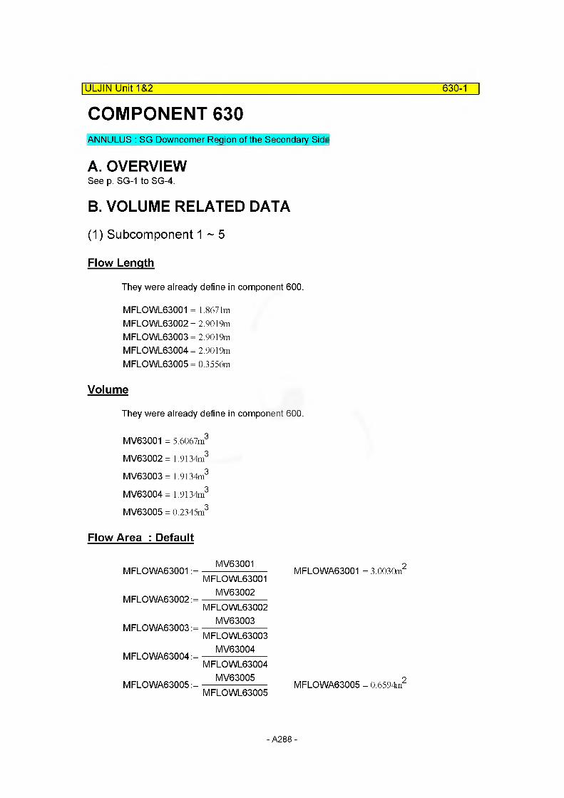
COMPONENT 630ANNULUS : SG Downcomer Region of the Secondary Side
|ULJIN Unit 1&2 630-1
A. OVERVIEWSee p. SG-1 to SG-4.
B. VOLUME RELATED DATA
(1) Subcomponent 1 ~ 5
Flow Length
They were already define in component 600.
MFLOWL63001 = 1.8671m MFLOWL63002 = 2.9019m MFLOWL63003 = 2.9019m MFLOWL63004 = 2.9019m MFLOWL63005 = 0.3556m
Volume
They were already define in component 600.
MV63001 = 5.6067m3
MV63002= 1.9134m3
MV63003= 1.9134m3
MV63004= 1.9134m3
MV63005 = 0.2345m3
Flow Area : Default
MFLOWA63001 :=
MFLOWA63002 :=
MFLOWA63003 :=
MFLOWA63004 :=
MFLOWA63005 :=
MV63001MFLOWL63001
MV63002MFLOWL63002
MV63003MFLOWL63003
MV63004MFLOWL63004
MV63005MFLOWL63005
MFLOWA63001 = 3.0030m2
MFLOWA63005 = 0.6594m2
- A288 -
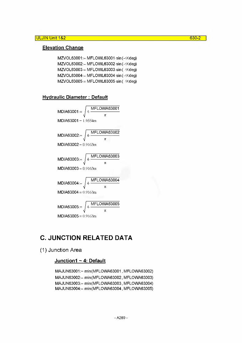
ULJIN Unit 1&2 630-2
Elevation Change
MZVOL63001 := MFLOWL63001 sin (-90deg) MZVOL63002:= MFLOWL63002 sin (-90deg) MZVOL63003:= MFLOWL63003 sin (-90deg) MZVOL63004:= MFLOWL63004 sin (-90deg) MZVOL63005:= MFLOWL63005 sin (-90deg)
Hydraulic Diameter: Default
MDIA63001 := 4-MFLOWA63001
MDIA63001 = 1.9554m
MDIA63002:= 4 -MFLOWA63002
MDIA63002= 0.9163m
MDIA63003:= 4-
MDIA63003= 0.9163m
MFLOWA63003
MDIA63004:= / 4-MFLOWA63004
MDIA63004= 0.9163m
MDIA63005:= 4-MFLOWA63005
MDIA63005= 0.9163m
C. JUNCTION RELATED DATA
(1) Junction Area
Junctionl ~ 4: Default
MAJUN63001 := min(MFLOWA63001, MFLOWA63002) MAJUN63002:= min(MFLOWA63002, MFLOWA63003) MAJUN63003:= min(MFLOWA63003, MFLOWA63004) MAJUN63004:= min(MFLOWA63004, MFLOWA63005)
- A289 -
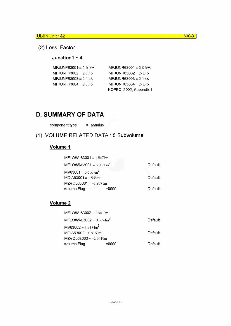
ULJIN Unit 1&2 630-3
(2) Loss Factor
Junctionl ~ 4
MFJUNF63001:= 2-0.098 MFJUNF63002:= 2-1.46 MFJUNF63003:= 2-1.46 MFJUNF63004:= 2-1.46
MFJUNR63001:= 2-0.098 MFJUNR63002:= 2-1.46 MFJUNR63003:= 2-1.46 MFJUNR63004:= 2-1.46 KOPEC, 2002, Appendix I
D. SUMMARY OF DATAcomponent type = annulus
(1) VOLUME RELATED DATA : 5 Subvolume
Volume 1
MFLOWL63001 = 1.8671m
MFLOWA63001 = 3.0030m2 Default
MV63001 = 5.6067m3
MDIA63001 = 1.9554mMZVOL63001 = -1.8671m
Default
Volume Flag =0000
Volume 2
Default
MFLOWL63002 = 2.9019m
MFLOWA63002 = 0.6594m2 Default
MV63002= 1.9134m3
MDIA63002= 0.9163mMZVOL63002= -2.9019m
Default
Volume Flag =0000 Default
- A290 -
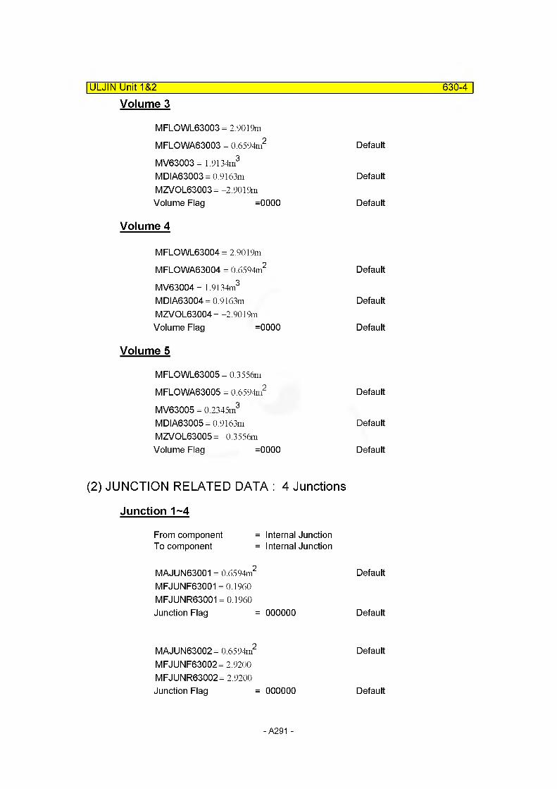
ULJIN Unit 1&2__________________________________________________________ 630-4
Volume 3
MFLOWL63003 = 2.9019m
MFLOWA63003 = 0.6594m2 Default
MV63003= 1.9134m3
MDIA63003 = 0.9163m DefaultMZVOL63003= -2.9019mVolume Flag =0000 Default
Volume 4
MFLOWL63004 = 2.9019m
MFLOWA63004 = 0.6594m2 Default
MV63004= 1.9134m3
MDIA63004 = 0.9163m DefaultMZVOL63004= -2.9019mVolume Flag =0000 Default
Volume 5
MFLOWL63005 = 0.3556m
MFLOWA63005 = 0.6594m2 Default
MV63005 = 0.2345m3
MDIA63005 = 0.9163m DefaultMZVOL63005= -0.3556mVolume Flag =0000 Default
(2) JUNCTION RELATED DATA : 4 Junctions
Junction 1~4
From component = Internal JunctionTo component = Internal Junction
MAJUN63001 = 0.6594m2 Default
MFJUNF63001 = 0.1960 MFJUNR63001 = 0.1960Junction Flag = 000000 Default
MAJUN63002= 0.6594m2 Default
MFJUNF63002 = 2.9200 MFJUNR63002 = 2.9200Junction Flag = 000000 Default
- A291 -
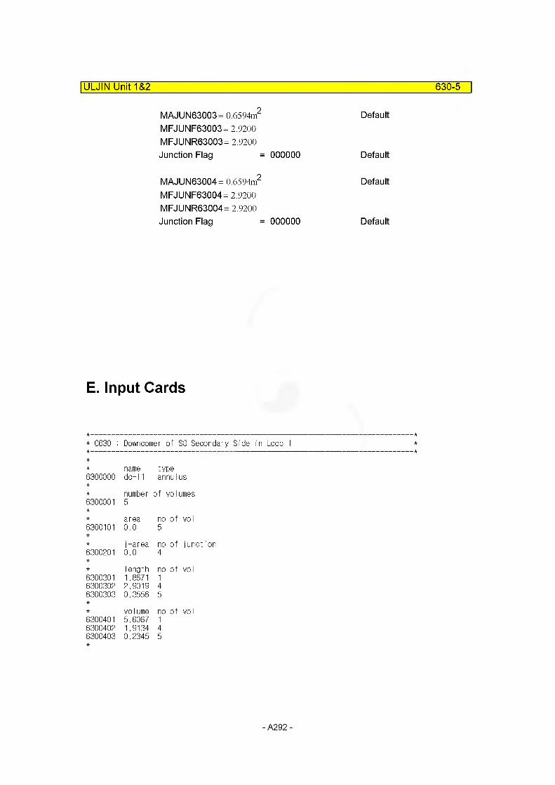
ULJIN Unit 1&2 630-5
MAJUN63003= 0.6594m2 DefaultMFJUNF63003 = 2.9200MFJUNR63003 = 2.9200 Junction Flag = 000000 Default
MAJUN63004= 0.6594m2 DefaultMFJUNF63004 = 2.9200MFJUNR63004 = 2.9200 Junction Flag = 000000 Default
E. Input Cards
* C630 : Downcomer of SG Secondary Side in Loop 1
name type6300000 do-11 annuI us
6300001number5
of volumes
area no of voI6300101 0.0 5
j-area no of junction6300201 0.0 4
Iength no of voI6300301 1.8671 16300302 2.9019 46300303 0.3556 5
volume no of vol6300401 5.6067 16300402 1.9134 46300403 0.2345 5
- A292 -
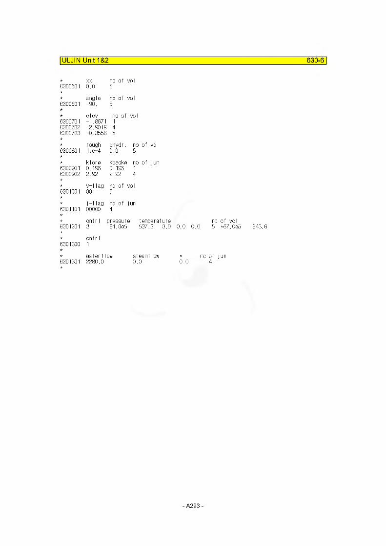
ULJIN Unit 1&2 630-6
XX no of vo I6300501 0.0 5
angle no of vo I6300601 -90. 5
elev no of vol6300701 -1.8671 16300702 -2.9019 46300703 -0.3556 5
rough dhydr. no of vol6300801 1 .e-4 0.0 5
kforw kbackw no of jun6300901 0.196 0.196 16300902 2.92 2.92 4
v-flag no of vol6301001 00 5
j-flag no of jun6301101 00000 4
cntrl |oressure temperat6301201 3 61,0e5 537.3
6301300cnt r I1
water flow steamflow6301301 2280.0 0.0
no of voI0.0 0.0 5 *67.0e5
* no of jun 0.0 4
543.6
- A293 -
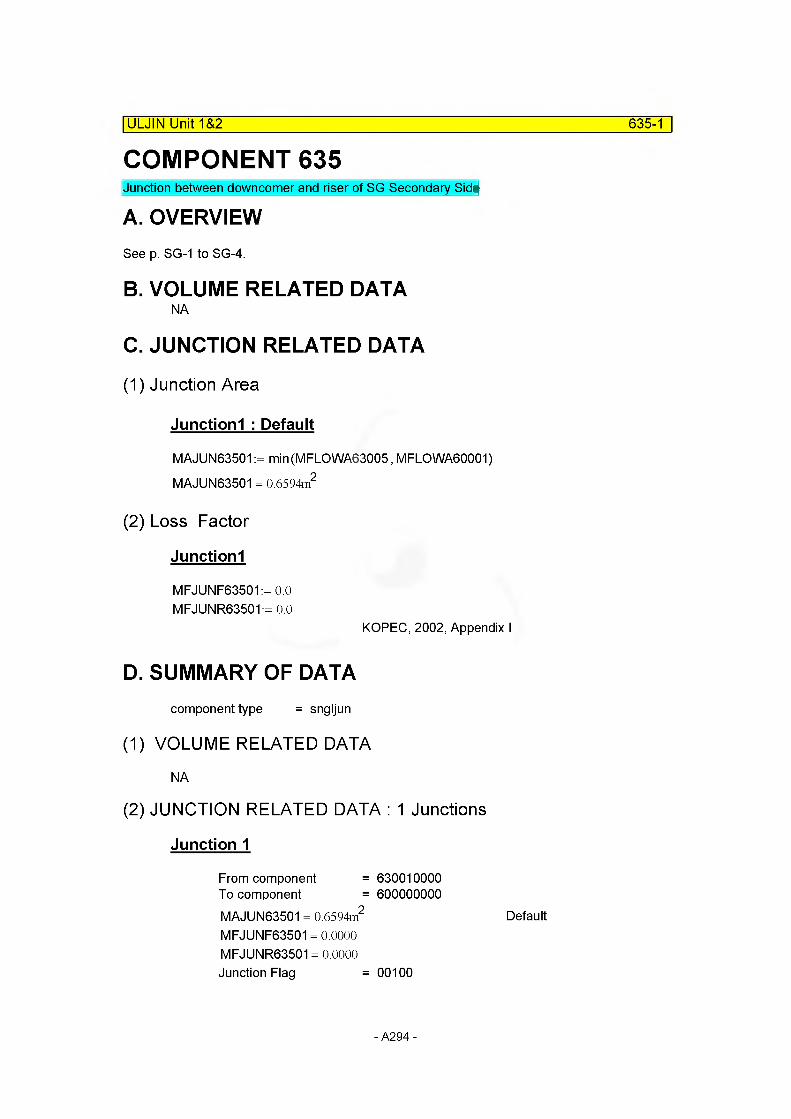
COMPONENT 635|ULJIN Unit 1&2 635-1
Junction between downcomer and riser of SG Secondary Side
A. OVERVIEWSee p. SG-1 to SG-4.
B. VOLUME RELATED DATANA
C. JUNCTION RELATED DATA
(1) Junction Area
Junctionl : Default
MAJUN63501 := min(MFLOWA63005, MFLGWA60001) MAJUN63501 = 0.6594m2
(2) Loss Factor
Junctionl
MFJUNF63501:= 0.0 MFJUNR63501:= 0.0
KOPEC, 2002, Appendix I
D. SUMMARY OF DATAcomponent type = sngljun
(1) VOLUME RELATED DATA
NA
(2) JUNCTION RELATED DATA : 1 Junctions
Junction 1
From component = 630010000To component = 600000000MAJUN63501 = 0.6594m2 Default
MFJUNF63501 = 0.0000 MFJUNR63501 = 0.0000 Junction Flag = 00100
- A294 -
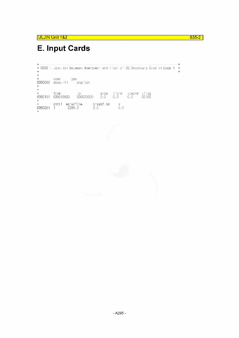
ULJIN Unit 1&2 635-2
E. Input Cards
* C635 : Junction between downcomer and riser of SG Secondary Side in Loop
name type6350000 dcout- 11 sngljun
f rom to area kforw kbackw j f I ag6350101 630010000 60000000Ci 0.0 0.0 0.0 00100
cnt r I waterflow steamflow X6350201 1 2280.0 0.0 0.0
- A295 -
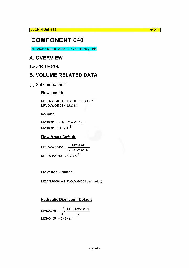
ULCHIN Unit 1&2 640-1
COMPONENT 640BRANCH : Steam Dome of SG Secondary Side
A. OVERVIEWSee p. SG-1 to SG-4.
B. VOLUME RELATED DATA
(1) Subcomponent 1
Flow Length
MFLOWL64001 := L_SG09 - L_SG07 MFLOWL64001 = 2.8293m
Volume
MV64001 := V_RS09 - V_RS07 MV64001 = 13.0824m3
Flow Area : Default
MV64001MFLOWA64001 :=----------------------
MFLOWL64001MFLOWA64001 = 4.6239m2
Elevation Change
MZVOL64001 := MFLOWL64001 sin (90.deg)
Hydraulic Diameter: Default
MDIA64001 = 2.4264m
- A296 -
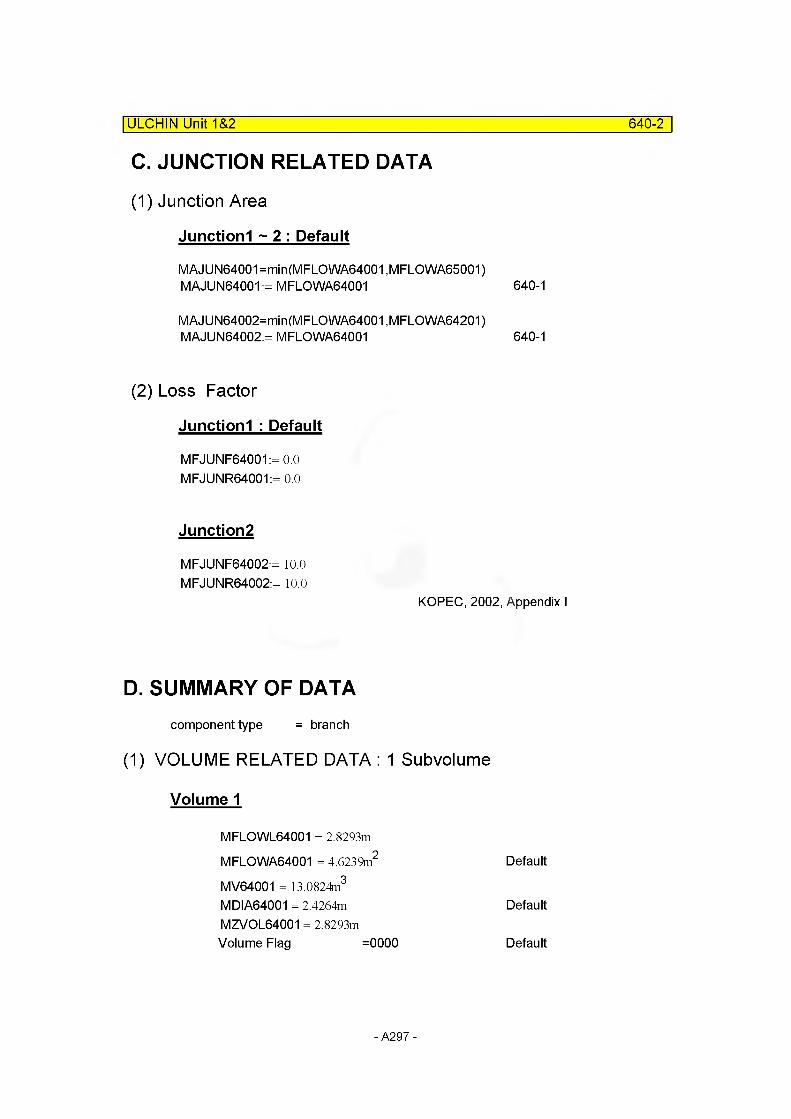
ULCHIN Unit 1&2 640-2
C. JUNCTION RELATED DATA
(1) Junction Area
Junctionl ~ 2 : Default
MAJUN64001=min(MFLOWA64001 ,MFLOWA65001)MAJUN64001 := MFLOWA64001
MAJUN64002=min(MFLOWA64001 ,MFLOWA64201) MAJUN64002:= MFLOWA64001
(2) Loss Factor
Junctionl : Default
MFJUNF64001:= 0.0 MFJUNR64001:= 0.0
Junction2
MFJUNF64002:= 10.0 MFJUNR64002:= 10.0
KOPEC, 2002, Appendix I
640-1
640-1
D. SUMMARY OF DATAcomponent type = branch
(1) VOLUME RELATED DATA : 1 Subvolume
Volume 1
MFLOWL64001 = 2.8293m
MFLOWA64001 = 4.6239m2 Default
MV64001 = 13.0824m3
MDIA64001 = 2.4264m DefaultMZVOL64001 = 2.8293mVolume Flag =0000 Default
- A297 -
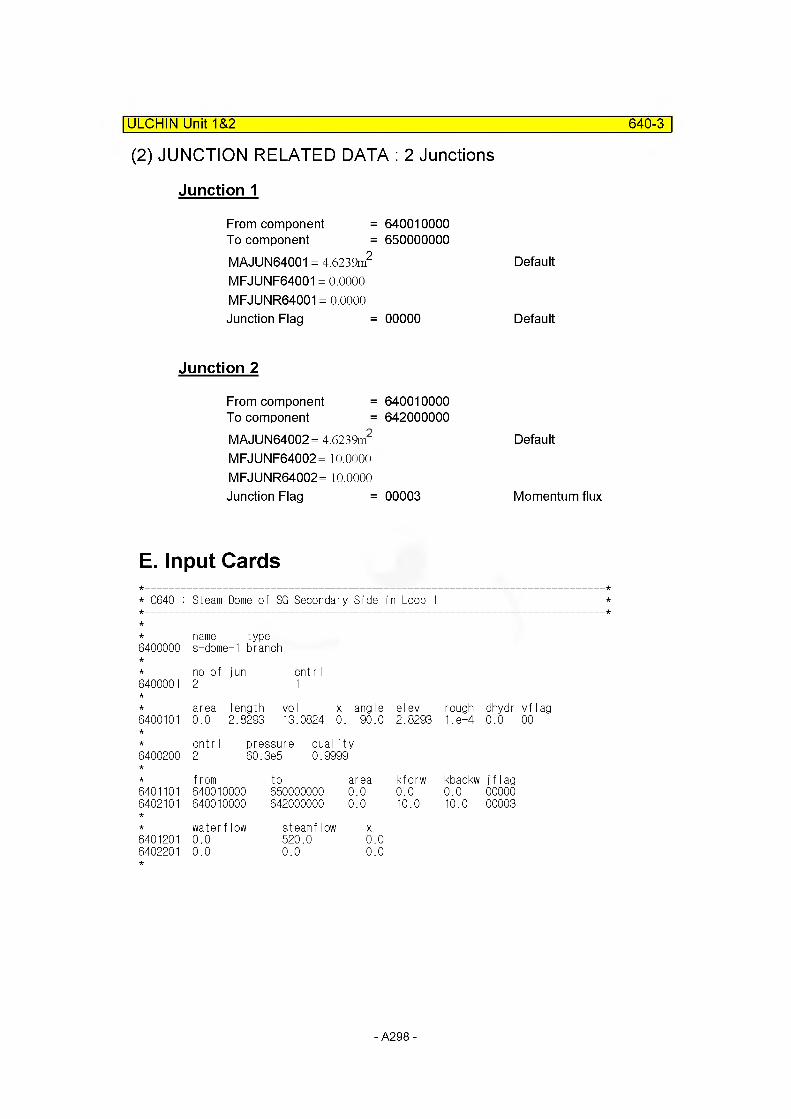
(2) JUNCTION RELATED DATA : 2 Junctions
| ULCHIN Unit 1&2 640-3
Junction 1
From component =To component =MAJUN64001 = 4.6239m2
MFJUNF64001 = 0.0000 MFJUNR64001 = 0.0000 Junction Flag =
Junction 2
From component =To component =MAJUN64002= 4.6239m2
MFJUNF64002= 10.0000 MFJUNR64002= 10.0000 Junction Flag =
640010000650000000
Default
00000 Default
640010000642000000
Default
00003 Momentum flux
E. Input Cards
* 0640 : Steam Dome of SG Secondary :Side in Loop 1
name type6400000 s-domei-1 branch
no of jun cntrI6400001 2 1
area length vol x angle el ev rough dhydr vf lag6400101 0.0 2.8293 13.0824 0. 90.0 2.8293 1 .e-4 0.0 00
cntr I pressure quality6400200 2 60.3e5 0.9999
from to area kforw kbackw j f I ag6401101 640010000 650000000 0 .0 0.0 0.0 000006402101 640010000 642000000 0 .0 10.0 10.0 00003
water flow steamflow X6401201 0.0 520.0 0.06402201 0.0 0.0 0.0
- A298 -

ULCHIN Unit 1&2 642-1
COMPONENT 642BRANCH : Dome Bypass of SG Secondary Side
A. OVERVIEWSee p. SG-1 to SG-4.
B. VOLUME RELATED DATA
(1) Subcomponent 1
Flow Length
MFLOWL64201 := L_SG09 - L_SG07MFLOWL64201 = 2.8293m same to MFLOWL64001 = 2.8293m
Volume
MV64201 := V_DC09 - V_DC07 MV64201 = 24.9188m3
Flow Area : Default
MV64201MFLOWA64201 :=----------------------
MFLOWL64201
Elevation Change : Default
MZVOL64201 := MFLOWL64201 sin (-90deg)
Hydraulic Diameter: Default
MDIA64201 = 3.3487mKOPEC, 2002, Appendix I
- A299 -
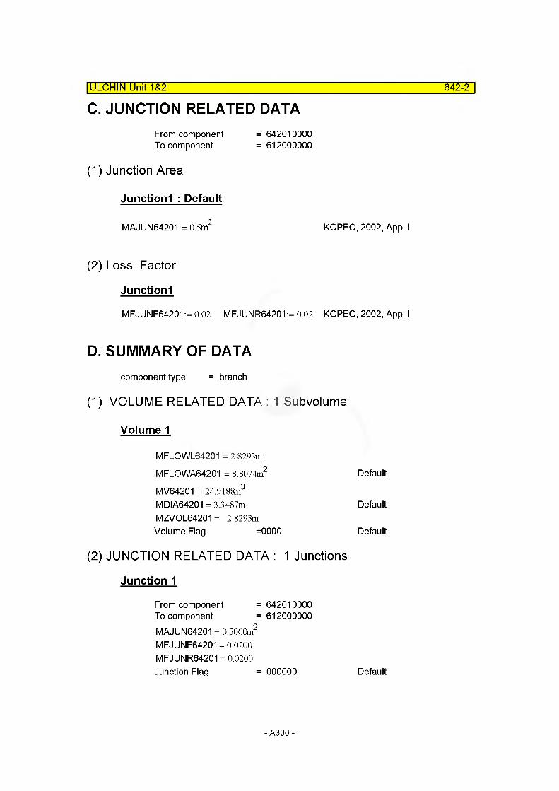
C. JUNCTION RELATED DATA| ULCHIN Unit 1&2 642-2
From component To component
(1) Junction Area
= 642010000 = 612000000
Junctionl : Default
MAJUN64201 := 0.5m2 KOPEC, 2002, App. I
(2) Loss Factor
Junctionl
MFJUNF64201 := 0.02 MFJUNR64201 := 0.02 KOPEC, 2002, App. I
D. SUMMARY OF DATAcomponent type = branch
(1) VOLUME RELATED DATA : 1 Subvolume
Volume 1
MFLOWL64201 = 2.8293m
MFLOWA64201 = 8.8074m2 Default
MV64201 = 24.9188m3
MDIA64201 = 3.3487m DefaultMZVOL64201 = -2.8293mVolume Flag =0000 Default
(2) JUNCTION RELATED DATA : 1 Junctions
Junction 1
From component = 642010000To component = 612000000MAJUN64201 = 0.5000m2
MFJUNF64201 = 0.0200 MFJUNR64201 = 0.0200Junction Flag = 000000 Default
- A300-

E. Input Cards
ULCHIN Unit 1&2_____________________________________________________ 642-3
* C642 : Dome Bypass of SG Secondary Side in Loop 1
6420000namedomeby11
typebranch
6420001no of1
fun cntr I1
6420101area0.0
Iength 2.8293
voI x angle elev rough24.9188 0. -90. -2.8293 1.8-4
dhydr ' 0.0 (
6420200cnt r I 2
pressure quality60.3e5 0.9999 *2 66.5e5 0.9999
6421101from642010000
to area kforw kbackw612000000 0.5 0.02 0.02
if lag 000000
6421201water flow 0.0
steamflow x0.0 0.0
- A301 -

ULJIN Unit 1&2 650-1
COMPONENT 650Single Volume : Dome of SG Secondary Side
A. OVERVIEWThis component represents steam dome region above the secondary separator component.
B. VOLUME RELATED DATA
(1) Subcomponent 1
Flow Length
MFLOWL65001 := L_SG10 - L_SG09 MFLOWL65001 = 1.6065m
Volume
MV65001 := V_SG10 - V_SG09 MV65001 = 13.2806m3
Flow Area : Default
MV65001MFLOWA65001 :=
MFLOWL65001MFLOWA65001 = 8.2665m2
Elevation Change
MZVOL65001 := MFLOWL65001 sin (90deg)
Hydraulic Diameter: Default
MDIA65001 = 3.2443m
C. JUNCTION RELATED DATANA
- A302-
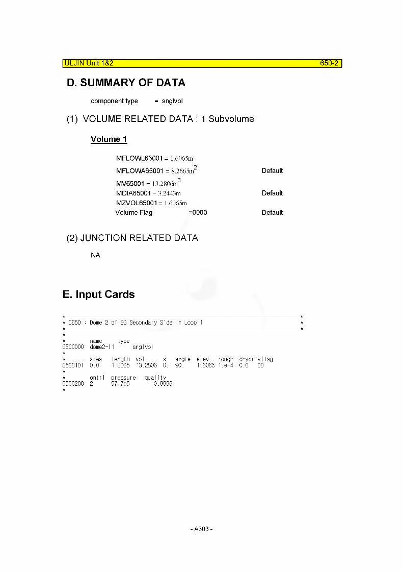
ULJIN Unit 1&2 650-2
D. SUMMARY OF DATAcomponent type = snglvol
(1) VOLUME RELATED DATA : 1 Subvolume
Volume 1
MFLOWL65001 = 1.6065m
MFLOWA65001 = 8.2665m2 Default
MV65001 = 13.2806m3
MDIA65001 = 3.2443m DefaultMZVOL65001 = 1.6065mVolume Flag =0000 Default
(2) JUNCTION RELATED DATA
E. Input Cards
* C650 : Dome 2 of SG Secondary Side in Loop 1
6500000namedome2-
type11 snglvol
6500101area0.0
length vol x1.6065 13.2806 0.
angle elev90. 1.6065
rough1 .e-4
dhydr0.0
vf lag00
6500200cntr I2
pressure qua I ity 57.7e5 0.9996
- A303-

ULJIN Unit 1&2 655-1
COMPONENT 655Steam generator outlet nozzle
A. OVERVIEWThis component represents the connection between the steam generator and the main steam line (steam outlet nozzle) . It will be modelled as a single junction.
B. VOLUME RELATED DATANA
C. JUNCTION RELATED DATA
(1) Junction Area
Junctionl
Outlet Nozzle orifice
- Inlet Diameter [ Dinj655:= 6.03n]-Number [ Nj655:= 7]
ref: Choi, H.R., p.221, W DWG 1184 J60, W DWG 1182J33
Junction Area
MAJUN65501:= ^•Dinj6552 Nj655
MAJUN65501 = 0.1290m2
(2) Loss Factor
Junctionl
Pressure Drop through Flow Restrictor - 3.0 psi at 4.09 x 10⁶ Ib/hr [ Apj655:= 3.0psi ]
[ Mflowj655:= 4.09-106 — ] (ref : FSAR 5, 4, 4, 3)
oj655 :=--------------at 964 psi (steam condition)0.46449 „3ft
- A304-
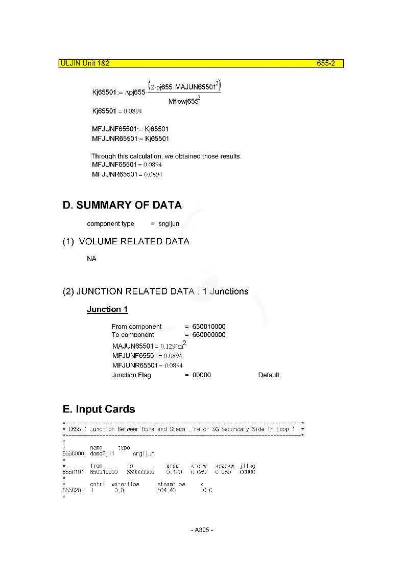
ULJIN Unit 1&2 655-2
2Pj655 MAJUN655012
Mflowj65^
Kj65501 = 0.0894
MFJUNF65501:= Kj65501 MFJUNR65501:= Kj65501
Through this calculation, we obtained those results. MFJUNF65501 = 0.0894 MFJUNR65501 = 0.0894
Kj65501 := Apj655-
D. SUMMARY OF DATAcomponent type = sngljun
(1) VOLUME RELATED DATA
NA
(2) JUNCTION RELATED DATA : 1 Junctions
Junction 1
From component = 650010000To component = 660000000MAJUN65501 = 0.1290m2
MFJUNF65501 = 0.0894 MFJUNR65501 = 0.0894Junction Flag = 00000 Default
E. Input Cards
* C655 : Junction Between Dome and Steam Line of SG Secondary Side in Loop 1 *
6550000name dome2jI
type1 sngljun
6550101from to650010000 660000000
area0.129
kforw0.089
kbackw0.089
j f I ag 00000
6550201cntr I1
water flow0.0
steamflow 504.40
X
0.0
- A305-

2.6 Main Steam Line System
Component 660 - Component 680
These components represent the main steam lines from the SG flow restrictor to the inlet of the steam header.
- A306-
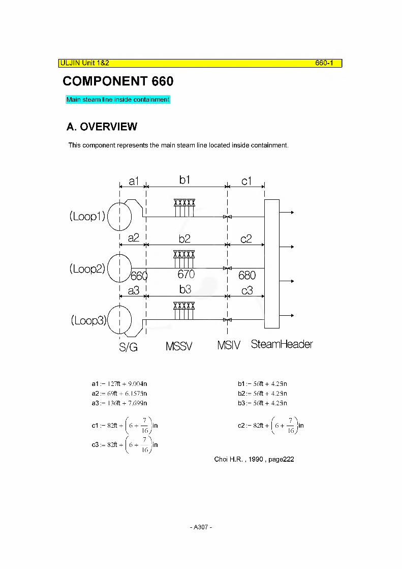
COMPONENT 660|ULJIN Unit 1&2 660-1
Main steam line inside containment
A. OVERVIEWThis component represents the main steam line located inside containment.
(Loop!)
(Loop2)
(LoopS)
S/G MSSV MSIV SteamHeader
a1a2a3
= 127ft + 9.004n = 69ft + 6.1573 n = 136ft + 7.699n
b1b2b3
= 56ft + 4.23 n = 56ft + 4.23 n = 56ft + 4.23 n
7 )c1 := 82ft + | 6 + —jin
, 7 \c3 ;= 82ft + 6 + — , in
16 J
7 )c2 := 82ft + | 6 + —jin
Choi H R. ,1990, page222
- A307-
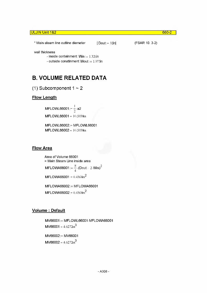
ULJIN Unit 1&2 660-2
* Main steam line outline diameter [Dout:=32in] (FSAR10. 3-2)
wall thickness- inside containment Win := 1.32dn- outside conatinment Wout := 1.973n
B. VOLUME RELATED DATA
(1) Subcomponent 1 ~ 2
Flow Length
MFLOWL66001 := - a22
MFLOWL66001 = 10.5938m
M FLO WL66002: = MFLOWL66001 MFLOWL66002 = 10.5938m
Flow Area
Area of Volume 66001 = Main Steam Line inside area
MFLOWA66001 := ^ (Dout - 2 Wn)2
MFLOWA66001 = 0.4368m2
MFLOWA66002 := MFLOWA66001 MFLOWA66002 = 0.4368m2
Volume : Default
MV66001 := MFLOWL66001 MFLOWA66001 MV66001 = 4.6272m3
MV66002:= MV66001 MV66002 = 4.6272m3
- A308-
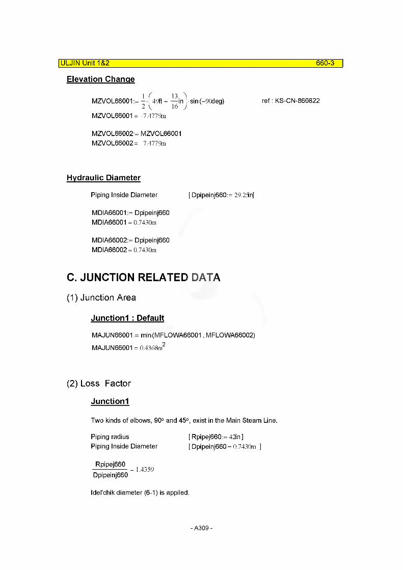
ULJIN Unit 1&2 660-3
Elevation Change
MZVOL66001 := - / 49ft + —in! sin (-90deg) ref: KS-CN-8608222 ^ 16 J ^
MZVOL66001 = -7.4779m
MZVOL66002:= MZVOL66001 MZVOL66002= -7.4779m
Hydraulic Diameter
Piping Inside Diameter [ Dpipeinj660:= 29.25n]
MDIA66001 := Dpipeinj660 MDIA66001 = 0.7430m
MDIA66002:= Dpipeinj660 MDIA66002= 0.7430m
C. JUNCTION RELATED DATA
(1) Junction Area
Junctionl : Default
MAJUN66001 := min(MFLOWA66001, MFLOWA66002) MAJUN66001 = 0.4368m2
(2) Loss Factor
Junctionl
Two kinds of elbows, 90° and 45°, exist in the Main Steam Line.
Piping radius [ Rpipej660:= 42in ]Piping Inside Diameter [ Dpipeinj660 = 0.7430m ]
_Rpipej660_ = 1 435g Dpipeinj660
Idel'chik diameter (6-1) is applied.
- A309-
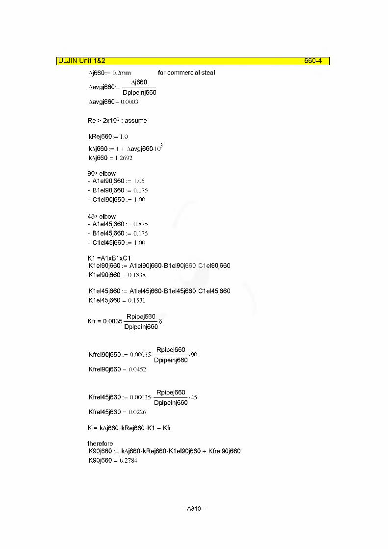
for commercial steal
ULJIN Unit 1&2
Aj660:= 0.2mm
Aavgj660:=Aj660
Dpipeinj660 Aavgj660= 0.0003
Re > 2x10⁵ : assume
kRej660:= 1.0
kAj660 := 1 + Aavgj660103
kAj660 = 1.2692
90° elbow- A1el90j660 := 1.05- B1el90j660 := 0.175- C1el90j660 := 1.00
45° elbow- A1el45j660 := 0.875- B1el45j660 := 0.175- C1el45j660 := 1.00
K1 =A1xB1xC1K1el90j660 := A1el90j660 B1el90j660 C1el90j660 K1el90j660 = 0.1838
K1el45j660 := A1el45j660 B1el45j660 C1el45j660 K1el45j660 = 0.1531
Kfr = 0.0035 Rpip6i66° 5 Dpipeinj660
660-4
Kfrel90j660 := 0.00035-Rpipej660
Dpipeinj660-90
Kfrel90j660 = 0.0452
Kfrel45j660 := 0.00035-Rpipej660
Dpipeinj660•45
Kfrel45j660 = 0.0226
K = kAj660 • kRej660 • K1 + Kfr
thereforeK90j660 := kAj660 kRej660 K1el90j660 + Kfrel90j660 K90j660 = 0.2784
-A310-

ULJIN Unit 1&2 660-5
K45j660:= kAj660 kRej660 K1el45j660 + Kfrel45j660 K45j660 = 0.2170
There are two 90° elbow in the component 660.Loss coefficient of internal junction [MFJUN66001]
So, we obtained those loss coefficients.MFJUNF66001:= 2K90j660 MFJUNF66001 = 0.5569
MFJUNR66001:= MFJUNF66001 MFJUNR66001 = 0.5569
D. SUMMARY OF DATAcomponent type = pipe
(1) VOLUME RELATED DATA : 2 Subvolume
Volume 1 ~ 2
MFLOWL66001 = 10.5938m
MFLOWA66001 = 0.4368m2
MV66001 = 4.6272m3 Default
MDIA66001 = 0.7430m MZVOL66001 = -7.4779mVolume Flag =0000 Default
MFLOWL66002 = 10.5938m
MFLOWA66002 = 0.4368m2
MV66002 = 4.6272m3 Default
MDIA66002= 0.7430m MZVOL66002= -7.4779mVolume Flag =0000 Default
(2) JUNCTION RELATED DATA : 1 Junctions
Junction 1
From component = Internal JunctionTo component = Internal JunctionMAJUN66001 = 0.4368m2
MFJUNF66001 = 0.5569 MFJUNR66001 = 0.5569Junction Flag = 00000
Default
Default
- A311 -
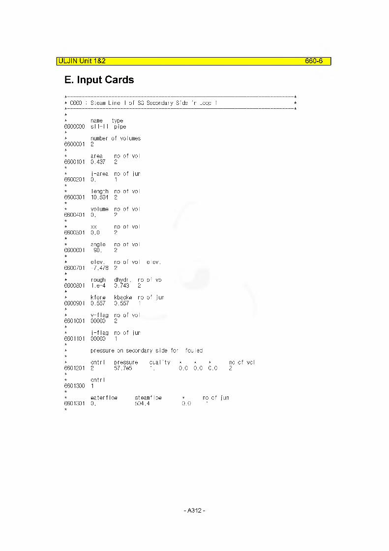
ULJIN Unit 1&2 660-6
E. Input Cards
* C660 : Steam Line 1 of SG Secondary Side in Loop 1
name type6600000 si 1-11 pipe
number of volumes6600001 2
area no of voI6600101 0.437 2
j-area no of jun6600201 0. 1
I ength no of voI6600301 10.594 2
volume no of vol6600401 0. 2
XX no of vol6600501 0.0 2
angle no of vol6600601 -90. 2
elev. no of vol elev.6600701 -7.478 2
rough dhydr. no of vol6600801 1. e-4 0.743 2
kforw kbackw no of jun6600901 0.557 0.557 1
v-flag no of vol6601001 00000 2
j-flag no of jun6601101 00000 1
pressure on secondary side for fouled
cnt r I pressure qua Iity * *6601201 2 57.7e5 1. 0.0 0.0
cnt r I6601300 1
waterflow steamflow * i6601301 0. 504.4 0.0
-A312-
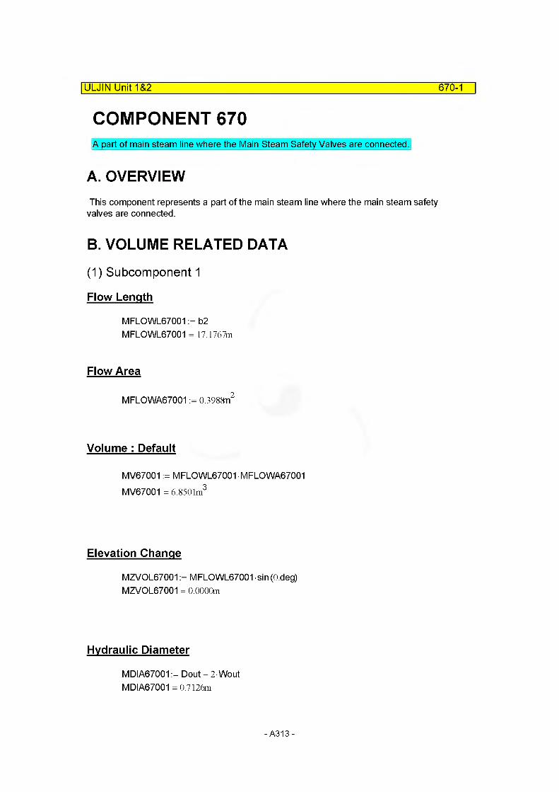
ULJIN Unit 1&2 670-1
COMPONENT 670A part of main steam line where the Main Steam Safety Valves are connected.
A. OVERVIEWThis component represents a part of the main steam line where the main steam safety
valves are connected.
B. VOLUME RELATED DATA
(1) Subcomponent 1
Flow Length
MFLOWL67001 := b2 MFLOWL67001 = 17.1767m
Flow Area
MFLOWA67001 := 0.3988n2
Volume : Default
MV67001 := MFLOWL67001 MFLOWA67001 MV67001 = 6.8501m3
Elevation Change
MZVOL67001 := MFLOWL67001 sin (O.deg) MZVOL67001 = 0.0000m
Hydraulic Diameter
MDIA67001 := Dout - 2-Wout MDIA67001 =0.7126m
-A313-

C. JUNCTION RELATED DATA
(1) Junction Area
|ULJIN Unit 1&2 670-2
Junctionl , 2
MAJUN67001:= ^ (Dout - 2 Wout)2
MAJUN67001 = 0.3988m2
MAJUN67002:= MAJUN67001 MAJUN67002= 0.3988m2
(2) Loss Factor
Junctionl,2
Loss Coefficient of Junction 1 [MFJUN67001]= 1 x Loss Coefficient of 90° elbow [K90j660]
MFJUNF67001:= K90j660 MFJUNF67001 = 0.2784 MFJUNR67001:= MFJUNF67001 MFJUNR67001 = 0.2784
Loss Coefficient of Junction 2 [MFJUN67002]= Loss Coeffcient of Main Steam Isolation Valve MFJUNF67002:= 0.2 MFJUNR67002:= 0.2
Idel'chik, 1980, Diag. 9-6
D. SUMMARY OF DATAcomponent type = branch
(1) VOLUME RELATED DATA : 1 Subvolume
Volume 1
MFLOWL67001 = 17.1767m
MFLOWA67001 = 0.3988m2
MV67001 = 6.8501m3 Default
MDIA67001 =0.7126m MZVOL67001 = 0.0000mVolume Flag =0000 Default
-A314-
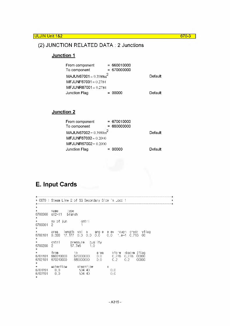
670-3
(2) JUNCTION RELATED DATA : 2 Junctions
Junction 1
|ULJIN Unit 1&2
From component = 660010000To component = 670000000MAJUN67001 = 0.3988m2 Default
MFJUNF67001 = 0.2784 MFJUNR67001 = 0.2784Junction Flag = 00000 Default
Junction 2
From component = 670010000To component = 680000000MAJUN67002= 0.3988m2
MFJUNF67002= 0.2000 MFJUNR67002= 0.2000 Junction Flag = 00000
Default
Default
E. Input Cards
* C670 : Steam Line 2 of SG Secondary Side in Loop 1
name type6700000 s 12-1 ■I branch
no of jun cnt r I6700001 2 1
area length vol x angle elev rough dhydr vflag6700101 0.399 17. 177 0.0 0.0 0.0 0..0 1.8-4 0.713 00
cntr I pressure qua I ity6700200 2 57.7e5 1. 0
from to area kforw kbackw jflag6701101 660010000 670000000 0.0 0.278 0.278 000006702101 670010000 680000000 0.0 0.2 0.2 00000
waterflow steamflow X6701201 0.0 504.40 0.06702201 0.0 504.40 0.0
-A315-
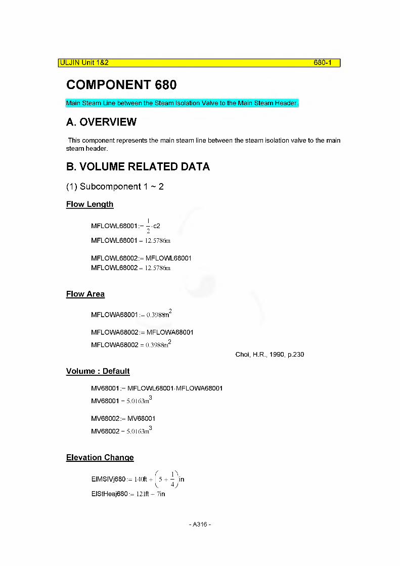
ULJIN Unit 1&2 680-1
COMPONENT 680Main Steam Line between the Steam Isolation Valve to the Main Steam Header.
A. OVERVIEWThis component represents the main steam line between the steam isolation valve to the main steam header.
B. VOLUME RELATED DATA
(1) Subcomponent 1 ~ 2
Flow Length
MFLOWL68001 := - c22
MFLOWL68001 = 12.5786m
M FLO WL68002: = MFLOWL68001 MFLOWL68002 = 12.5786m
Flow Area
MFLOWA68001 := 0.3988n2
MFLOWA68002 := MFLOWA68001 MFLOWA68002 = 0.3988m2
Choi, H.R., 1990, p.230
Volume : Default
MV68001 := MFLOWL68001 MFLOWA68001 MV68001 = 5.0163m3
MV68002:= MV68001 MV68002 = 5.0163m3
Elevation Change
EIMSIVj680 := 140ft + ^5 + £)in
EIStHeaj680:= 121ft + 7in
-A316-
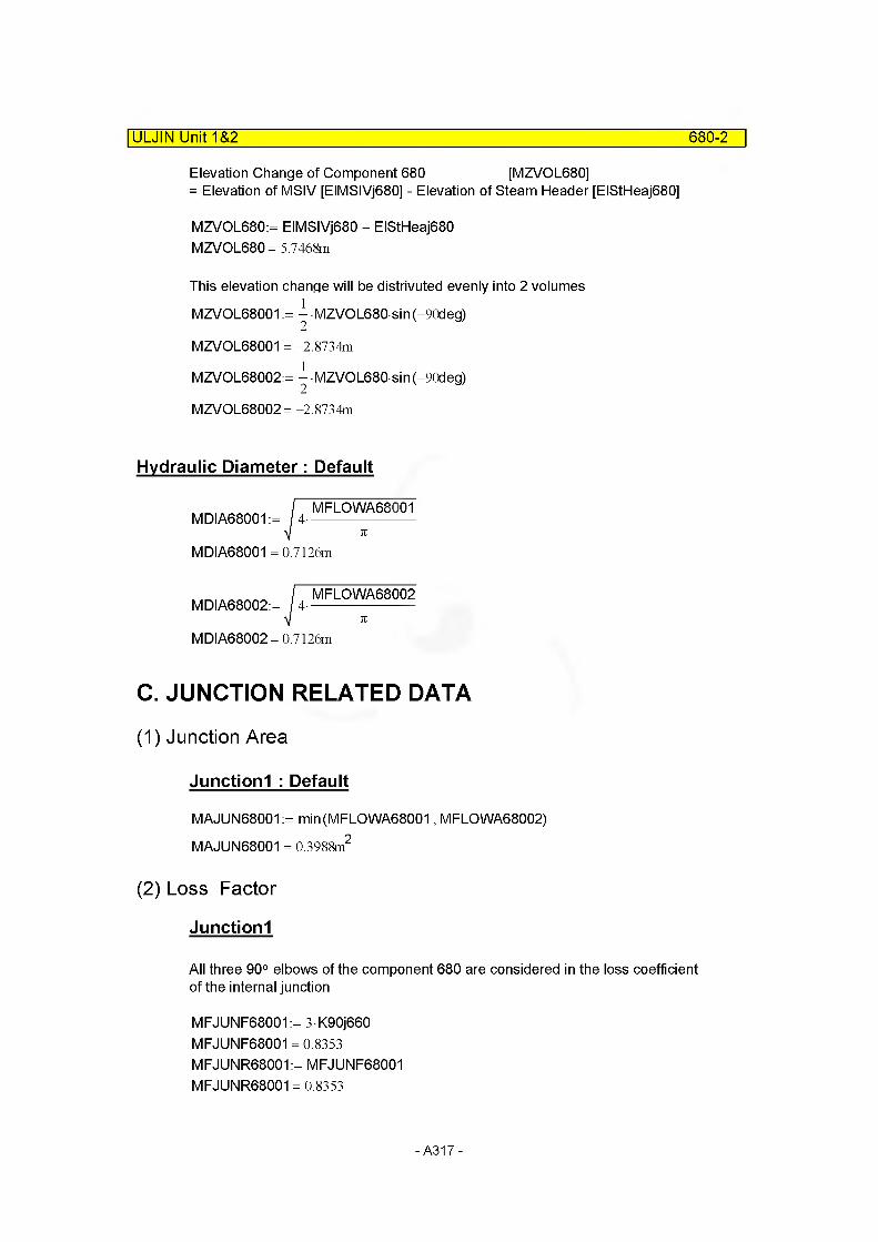
ULJIN Unit 1&2 680-2
Elevation Change of Component 680 [MZVOL680]= Elevation of MSIV [EIMSIVj680] - Elevation of Steam Header [EIStHeaj680]
MZVOL680:= EIMSIVj680 - EIStHeaj680 MZVOL680= 5.7468m
This elevation change will be distrivuted evenly into 2 volumes MZVOL68001 := ^ MZVOL680 sin(-90deg)
MZVOL68001 = -2.8734m
MZVOL68002:= ^ MZVOL680 sin(-90deg)
MZVOL68002= -2.8734m
Hydraulic Diameter: Default
MDIA68001 := 4-MFLOWA68001
MDIA68001 =0.7126m
MDIA68002:= 4-MFLOWA68002
MDIA68002= 0.7126m
C. JUNCTION RELATED DATA
(1) Junction Area
Junctionl : Default
MAJUN68001 := min(MFLOWA68001, MFLOWA68002) MAJUN68001 = 0.3988m2
(2) Loss Factor
Junctionl
All three 90° elbows of the component 680 are considered in the loss coefficient of the internal junction
MFJUNF68001:= 3 K90j660 MFJUNF68001 = 0.8353 MFJUNR68001:= MFJUNF68001 MFJUNR68001 = 0.8353
-A317-
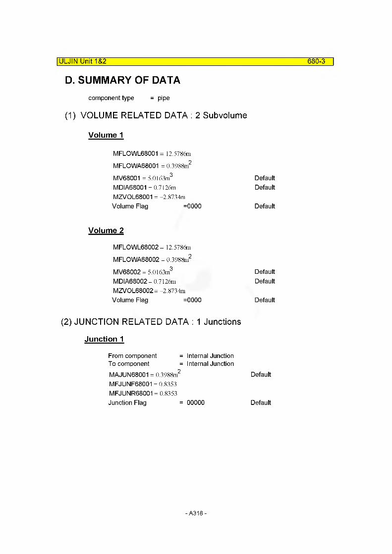
ULJIN Unit 1&2 680-3
D. SUMMARY OF DATAcomponent type = pipe
(1) VOLUME RELATED DATA : 2 Subvolume
Volume 1
MFLOWL68001 = 12.5786m
MFLOWA68001 = 0.3988m2
MV68001 = 5.0163m3 DefaultMDIA68001 =0.7126m DefaultMZVOL68001 = -2.8734mVolume Flag =0000 Default
Volume 2
MFLOWL68002 = 12.5786m
MFLOWA68002 = 0.3988m2
MV68002 = 5.0163m3 DefaultMDIA68002= 0.7126m DefaultMZVOL68002= -2.8734mVolume Flag =0000 Default
(2) JUNCTION RELATED DATA : 1 Junctions
Junction 1
From component = Internal JunctionTo component = Internal JunctionMAJUN68001 = 0.3988m2
MFJUNF68001 = 0.8353 MFJUNR68001 = 0.8353Junction Flag = 00000
Default
Default
-A318-
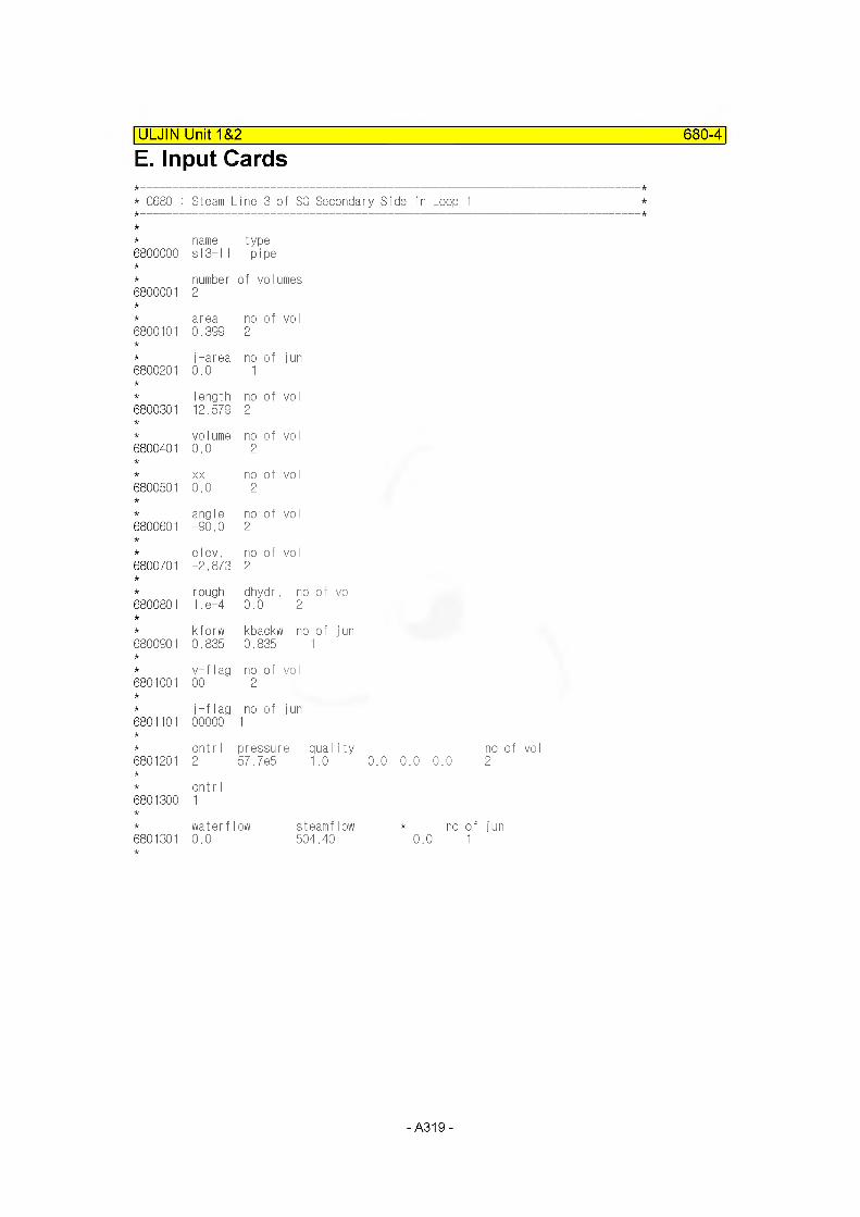
ULJIN Unit 1&2 680-4
E. Input Cards
* C680 : Steam Line 3 of SG Secondary Side in Loop 1
name type6800000 s 13-11 pipe
number of volumes6800001 2
area no of voI6800101 0.399 2
j-area no of jun6800201 0.0 1
Iength no of vol6800301 12.579 2
volume no of vol6800401 0.0 2
XX no of vol6800501 0.0 2
angle no of vol6800601 -90.0 2
elev. no of vol6800701 -2.873 2
rough dhydr. no of vol6800801 1. e-4 0.0 2
kforw kbackw no of jun6800901 0.835 0.835 1
v-flag no of vol6801001 00 2
j-flag no of jun6801101 00000 1
cnt r I pressure quality6801201 2 57.7e5 1.0
6801300cnt r I1
waterflow steamflow6801301 0.0 504.40
0.0 0.0 0.0no of voI 2
0.0no of jun
-A319-
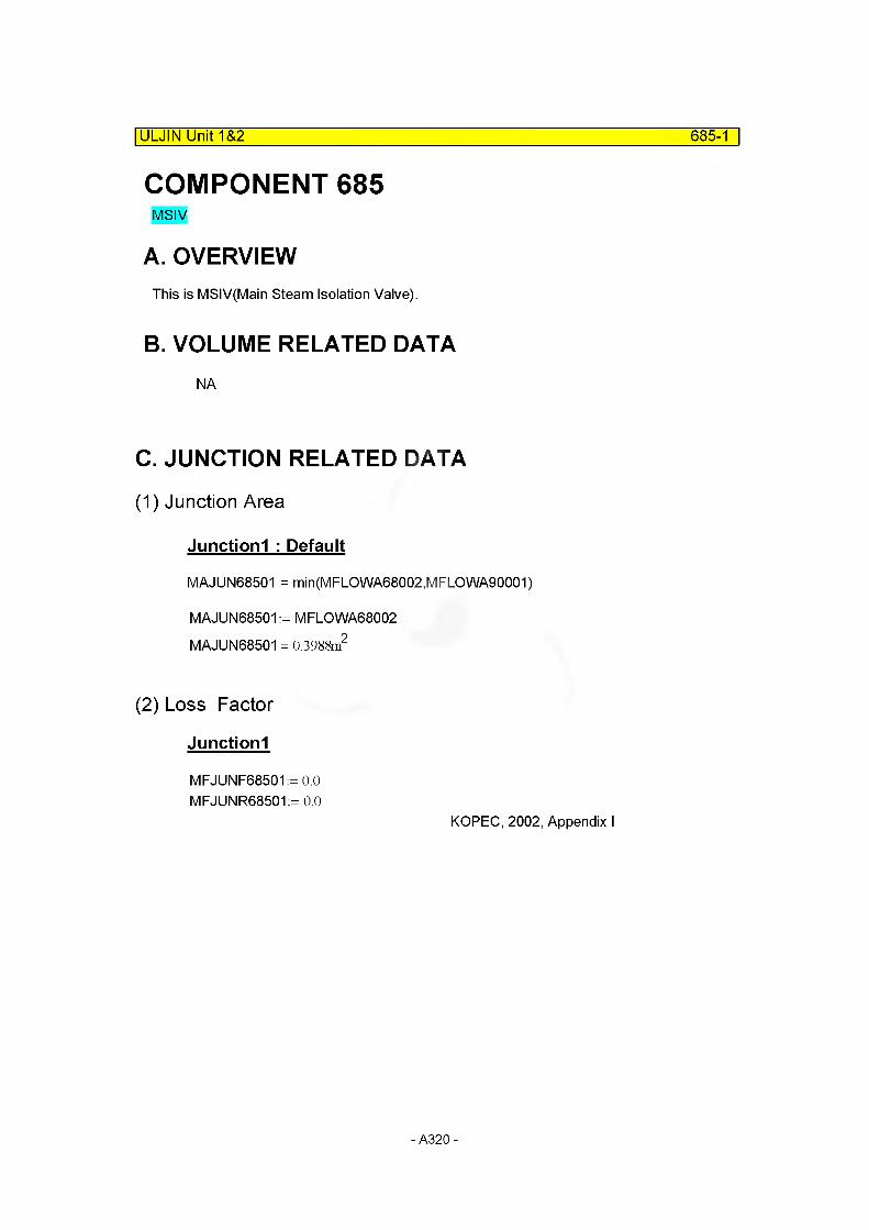
ULJIN Unit 1&2 685-1
COMPONENT 685MSIV
A. OVERVIEWThis is MSIV(Main Steam Isolation Valve).
B. VOLUME RELATED DATANA
C. JUNCTION RELATED DATA
(1) Junction Area
Junctionl : Default
MAJUN68501 = min(MFLOWA68002,MFLOWA90001)
MAJUN68501 := MFLOWA68002 MAJUN68501 = 0.3988m2
(2) Loss Factor
Junctionl
MFJUNF68501:= 0.0 MFJUNR68501:= 0.0
KOPEC, 2002, Appendix I
- A320-
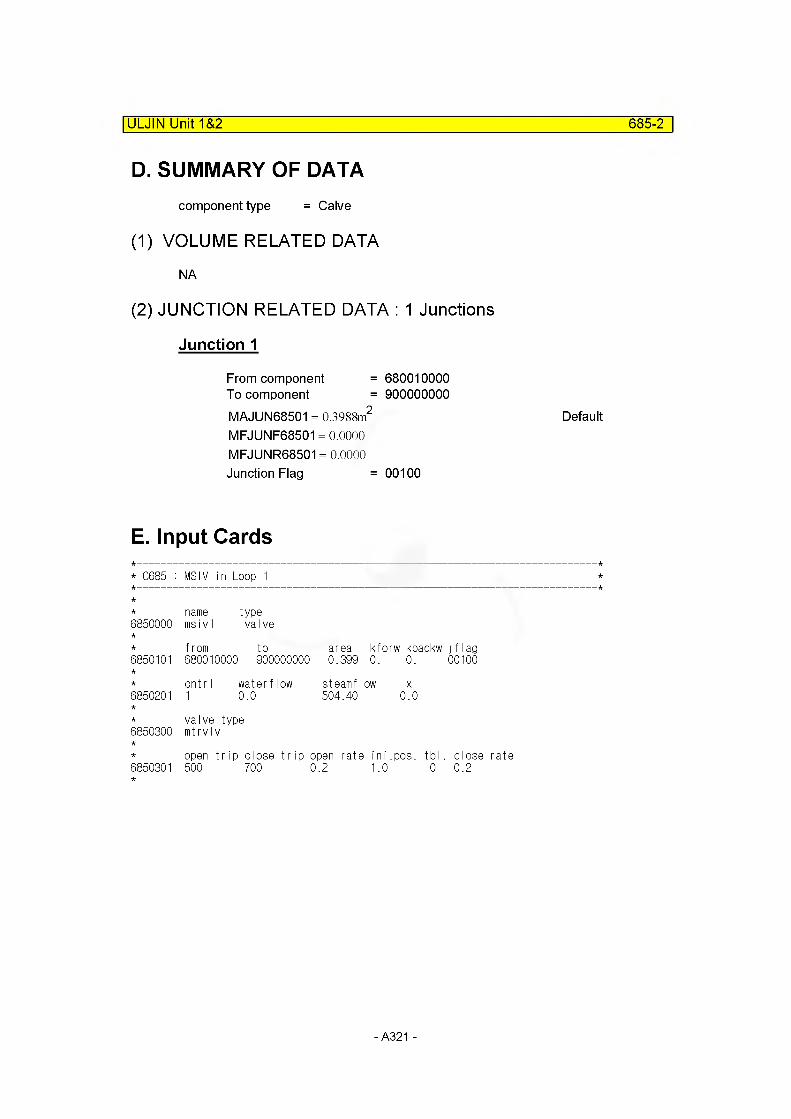
ULJIN Unit 1&2 685-2
D. SUMMARY OF DATAcomponent type = Calve
(1) VOLUME RELATED DATA
NA
(2) JUNCTION RELATED DATA : 1 Junctions
Junction 1
From component = 680010000To component = 900000000MAJUN68501 = 0.3988m2 Default
MFJUNF68501 = 0.0000 MFJUNR68501 = 0.0000 Junction Flag = 00100
E. Input Cards
* C685 : MSIV in Loop 1 * *
* name type6850000 ms i v1 valve
* from to area kforw kbackw jflag6850101 680010000 900000000 0.399 0. 0. 00100
* cntrl water flow steamflow x6850201 1 0.0 504.40 0.0
* valve type6850300 mtrvlv
* open trip close trip open rate ini.pos. tbl. close rate6850301 500 700 0.2 1.0 0 0.2
- A321 -
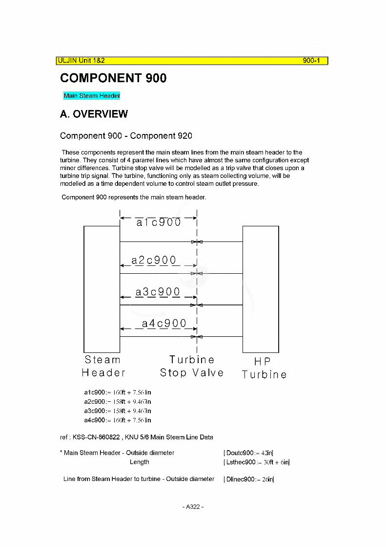
COMPONENT 900|ULJIN Unit 1&2 900-1
Main Steam Header
A. OVERVIEW
Component 900 - Component 920
These components represent the main steam lines from the main steam header to the turbine. They consist of 4 pararrel lines which have almost the same configuration except minor differences. Turbine stop valve will be modelled as a trip valve that closes upon a turbine trip signal. The turbine, functioning only as steam collecting volume, will be modelled as a time dependent volume to control steam outlet pressure.
Component 900 represents the main steam header.
"a f"c 9~0~0 —1
a2c900
a3c900
a4c900 1
Steam T u rb iHeader Stop V Turbinea1c900:= 160ft + 7.56 tin a2c900:= 158ft + 9.461n a3c900:= 158ft + 9.461n a4c900:= 160ft + 7.56 lin
ref: KSS-CN-860822 , KNU 5/6 Main Steam Line Data
* Main Steam Header - Outside diameter [ Doutc900:= 42in]Length [ Lsthec900 := 30ft + 6in]
Line from Steam Header to turbine - Outside diameter [ Dlinec900:= 26in]
- A322-

900-2
B. VOLUME RELATED DATA
(1) Subcomponent 1
Flow Length
MFLOWL90001 := Lsthec900 MFLOWL90001 = 9.2964m
Flow Area
Only outside diameter, 42", can be formed in the drawing assuming that wall thickness is 2".
MFLOWA90001 := ^ (Doutc900 - 2-2in)2
MFLOWA90001 = 0.7317m2
Volume : Default
MV90001 := MFLOWL90001 MFLOWA90001 MV90001 = 6.8020m3
Elevation Change
MZVOL90001 := -5.75m KOPEC, 2002, Appendix I
Hydraulic Diameter
MDIA90001 := Doutc900 - 2 2in MDIA90001 = 0.9652m
C. JUNCTION RELATED DATA
(1) Junction Area
Junctionl : Default
MAJUN90001 = min(MFLOWA90001 , MFLOWA91001)MAJUN90001 := MFLOWA90001MAJUN90001 = 0.7317m2
|ULJIN Unit 1&2
- A323-

|ULJIN Unit 1&2
(2) Loss Factor
900-3
Junctionl
Loss coefficient from steam heade to steam line can be calculated considering sudden contradiction
Kconj900:= 0.5
MFJUNF90001:= Kconj900 MFJUNF90001 = 0.5000
MFJUNR90001 = 0.5000
D. SUMMARY OF DATAcomponent type = branch
(1) VOLUME RELATED DATA : 1 Subvolume
Volume 1
MFLOWL90001 = 9.2964m
MFLOWA90001 = 0.7317m2
MV90001 = 6.8020m3 Default
MDIA90001 = 0.9652m MZVOL90001 = -5.7500mVolume Flag =000000 Default
(2) JUNCTION RELATED DATA : 1 Junctions
Junction 1
From component = 900010000To component = 910000000MAJUN90001 = 0.7317m2 Default
MFJUNF90001 = 0.5000 MFJUNR90001 = 0.5000Junction Flag = 001000 No choking
- A324-

ULJIN Unit 1&2 900-4
E. Input Cards
* C900 : Main Steam Header
name type9000000 stm-hdr branch
no of jun cntrl9000001 1 1
area length vol x angle elev rough dhydr vflag9000101 0.732 9.296 0.0 0.0-90.0 -5.75 1.e-4 0.965 00
cnt r I pressure quality9000200 2 57.7e5 1.0
from to area kforw kbackw jflag9001101 900010000 910000000 0.0 0.5 0.5 00000
waterflow steamflow X
9001201 0.0 1578.0 0.
- A325-
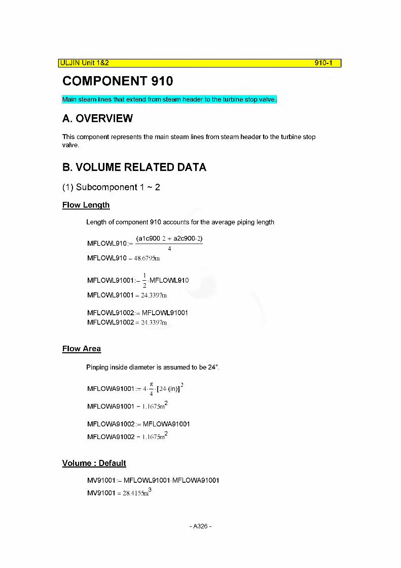
COMPONENT 910|ULJIN Unit 1&2 910-1
Main steam lines that extend from steam header to the turbine stop valve.
A. OVERVIEWThis component represents the main steam lines from steam header to the turbine stop valve.
B. VOLUME RELATED DATA
(1) Subcomponent 1 ~ 2
Flow Length
Length of component 910 accounts for the average piping length
(a1c900 2 + a2c900-2)4
MFLOWL910 = 48.6795m
MFLOWL91001 := - MFLOWL9102
MFLOWL91001 = 24.3397m
MFLOWL91002:= MFLOWL91001 MFLOWL91002 = 24.3397m
Flow Area
Pinping inside diameter is assumed to be 24".
MFLOWA91001 := 4 ^ [24-(in)]2
MFLOWA91001 = 1.1675m2
MFLOWA91002 := MFLOWA91001 M FLO WA91002 = 1.1675m2
Volume : Default
MV91001 := MFLOWL91001 • MFLOWA91001 MV91001 = 28.4155m3
- A326-
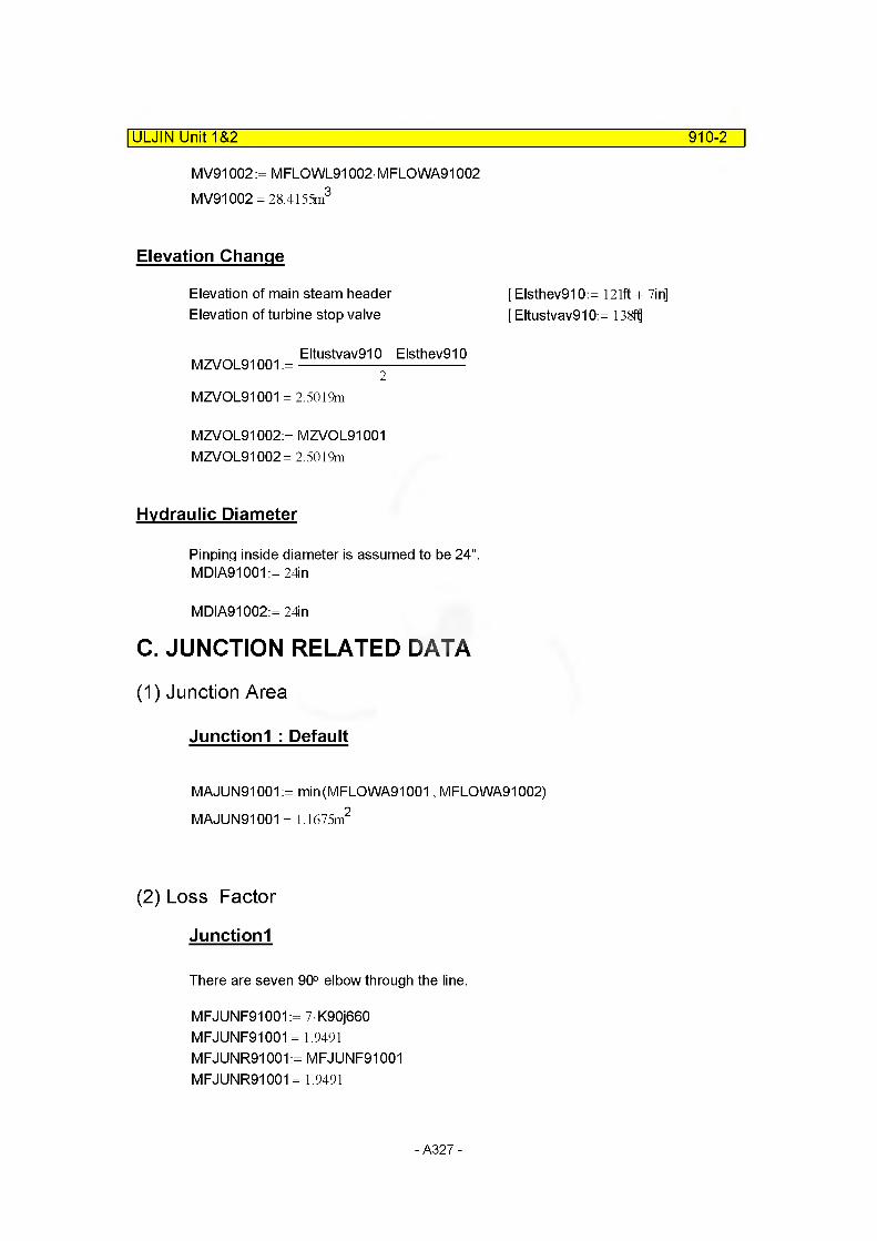
ULJIN Unit 1&2 910-2
MV91002 := MFLOWL91002- MFLOWA91002 MV91002 = 28.4155m3
Elevation Change
Elevation of main steam header Elevation of turbine stop valve
[ Elsthev910:= 121ft + 7in] [ Eltustvav910:= 138ffl
Eltustvav910- Elsthev910 MZVOL91001 :=------------------------------------
2MZVOL91001 = 2.5019m
MZVOL91002:= MZVOL91001 MZVOL91002= 2.5019m
Hydraulic Diameter
Pinping inside diameter is assumed to be 24". MDIA91001 := 24in
MDIA91002:=24in
C. JUNCTION RELATED DATA
(1) Junction Area
Junctionl : Default
MAJUN91001:= min(MFLOWA91001, MFLOWA91002) MAJUN91001 = 1.1675m2
(2) Loss Factor
Junctionl
There are seven 90° elbow through the line.
MFJUNF91001:= 7K90j660 MFJUNF91001= 1.9491 MFJUNR91001:= MFJUNF91001 MFJUNR91001 = 1.9491
- A327-

910-3
D. SUMMARY OF DATAcomponent type = pipe
(1) VOLUME RELATED DATA : 2 Subvolume
Volume 1
|ULJIN Unit 1&2
MFLOWL91001 = 24.3397m
MFLOWA91001 = 1.1675m2
MV91001 = 28.4155m3 Default
MDIA91001 = 0.6096m MZVOL91001 = 2.5019mVolume Flag =0000 Default
Volume 2
MFLOWL91002 = 24.3397m
M FLO WA91002 = 1.1675m2
MV91002 = 28.4155m3
MDIA91002= 0.6096m MZVOL91002= 2.5019m Volume Flag =0000
Default
Default
(2) JUNCTION RELATED DATA : 1 Junctions
Junction 1
From component = Internal JunctionTo component = Internal JunctionMAJUN91001 = 1.1675m2 Default
MFJUNF91001= 1.9491 MFJUNR91001 = 1.9491Junction Flag = 001000 Default
- A328-

E. Input Cards|ULJIN Unit 1&2 910-4
* C910 : Pipe to Turbine
name type9100000 turbine pipe
number of volumes9100001 2
area no of voI9100101 1.1675 2
j-area no of jun9100201 0.0 1
Iength no of voI9100301 24.34 2
volume no of vol9100401 0.0 2
XX no of vol9100501 0.0 2
angle no of vol9100601 90.0 2
elev. no of vol9100701 2.502 2
rough dhydr. no of vol9100801 1. e-4 0.61 2
kforw kbackw no of jun9100901 1.949 1.949 1
v-flag no of vol9101001 00 2
j-flag no of jun9101101 00000 1
cnt r I pressure quality no of vol9101201 2 57.7e5 1.0 0.0 0.0 0.0 2
cnt r I9101300 1
waterflow steamflow * no of jun9101301 0.0 1578.0 0.0 1
- A329-
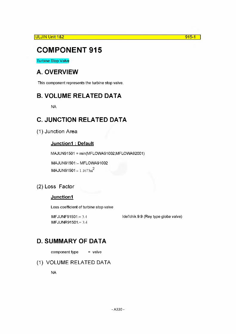
COMPONENT 915Turbine Stop Valve
A. OVERVIEWThis component represents the turbine stop valve.
B. VOLUME RELATED DATANA
C. JUNCTION RELATED DATA
(1) Junction Area
Junctionl : Default
MAJUN91501 = mi n (M F LO WA91002, M F LO WA92001)
MAJUN91501:= M FLO WA91002 MAJUN91501 = 1.1675m2
(2) Loss Factor
Junctionl
Loss coefficient of turbine stop valve
MFJUNF91501:= 3.4 Idel'chik 9.9 (Rey type globe valve)MFJUNR91501:= 3.4
D. SUMMARY OF DATAcomponent type = valve
(1) VOLUME RELATED DATA
NA
ULJIN Unit 1&2_______________________________________________________915-1
- A330-

ULJIN Unit 1&2 915-2
(2) JUNCTION RELATED DATA : 1 Junctions
Junction 1
From component = 910010000To component = 940000000MAJUN91501 = 1.1675m2 Default
MFJUNF91501 = 3.4000MFJUNR91501 = 3.4000Junction Flag = 001000
E. Input Cards
* 0915 : Turbine Valve
9150000name tbn_vlv
typevalve
9150101from910010000
to940000000
area0.0
kforw1.0
kbackw1.0
j f I ag001000 * 1.4 1.4
9150201cntr I1
water flow 0.0
steamflow 1513.3
X0.0
* valve type 9150300 trpvlv
* trip number 9150301 750
- A331 -

940-1
COMPONENT 940TURBINE : act as a steam collecting volume (time-dependent volume)
A. OVERVIEWThis component represents the turbine that function as a steam collecting volume.
B. VOLUME RELATED DATA
(1) Subcomponent 1
Flow Length
MFLOWL94001 := 10m arbitrary
Flow Area
MFLOWA94001 := 100m2 arbitrary
Volume : Default
MV94001 := MFLOWL94001 MFLOWA94001 MV94001 = lOOO.OOOQn3
|ULJIN Unit 1&2
Elevation Change
MZVOL94001 := MFLOWL94001 sin (O.deg) MZVOL94001 = 0.0000m
Hydraulic Diameter: Default
MDIA94001 := 4-MFLOWA94001
MDIA94001 = 11.2838m
- Initial Condition Data
00263.5bar1.00
controlpressurequality
- A332-
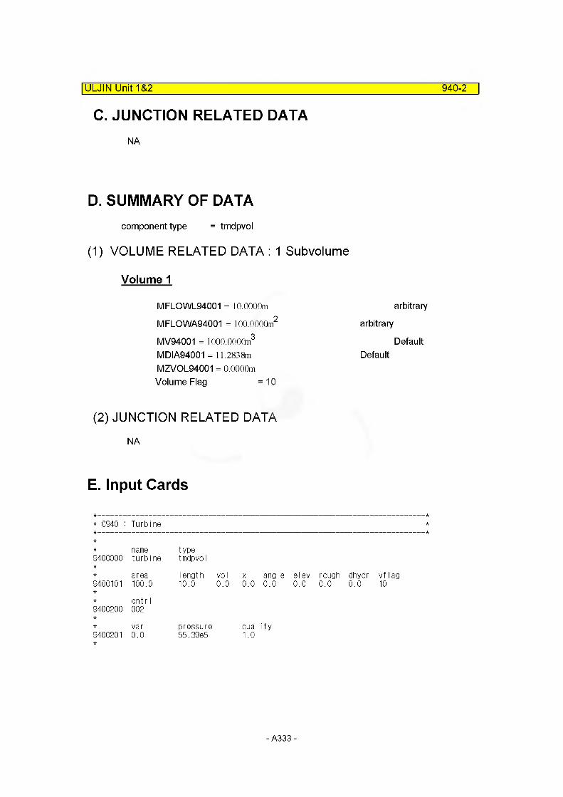
ULJIN Unit 1&2 940-2
C. JUNCTION RELATED DATANA
D. SUMMARY OF DATAcomponent type = tmdpvol
(1) VOLUME RELATED DATA : 1 Subvolume
Volume 1
MFLOWL94001 = 10.0000m
MFLOWA94001 = lOO.OOOCtn2
MV94001 = lOOO.OOOQn3
MDIA94001 = 11.2838m MZVOL94001 = 0.0000m Volume Flag =10
arbitrary
arbitrary
DefaultDefault
(2) JUNCTION RELATED DATA
NA
E. Input Cards
* C940 : Turbine
name type9400000 turbine tmdpvol
area length vol x angle el ev rough dhydr vf lag9400101 100.0 10.0 0.0 0.0 0.0 0.0 0.0 0.0 10
cntr I9400200 002
var pressure qua I ity9400201 0.0 55.39e5 1.0
- A333-

2.7 ECC System
- A334-

Accumulator-1ULCHIN Unit 1&2
4.1 Accumulator* Acc.(U1/2) geometry & operating data (refer to FSAR Chap.6)
No. of ACCU:3Operating tempNominal operating pressureTotal volumeWater volumeBoric acidWall thicknessInner areaLiquid leveL(h,)*Gas level(hg)*Acc. Iength(h|+hg)*Surge line lengthElevation drop of surge line andstand pipe(H)
Injection line area(A )L
40 °C41 (gauge bar)41 m326.9 ~ 28.6 m3 2000 (minimal ppm) 57.5 mm7.7505 m3 (41 / 5.29) 3.4707 m 1.8193 m 5.29 m 26.32 m
Ref: Choi, H. R.(1990) , p. 366
Ref: Choi, H. R.(1990) , p. 366 Ref: Choi, H. R.(1990) , p. 366
: -11.97 m Ref: Choi, H. R.(1990) , p. 366
12
—-0.21142V -0.298522
= 0.0629 m
*lt is assumed that the geometry of accumulator is straight cylinderical vessel. That is, accumulator inner area is constant.
- A335-

ULCHIN Unit 1&2 Accumulator-2
* U1/2 - Acc. surge line
K
1. Total length (approx.) :1143 + 2639.9 + (1090 + 576 + 140 + 181 + 734 + 727)+ 579 + 548 + (125 + 1539 + 1786 + 700) + (582 + 3798 + 700) + (125 + 233 + 2263) + 606 + 49 + 100 + 589 +24 + 606 + (582 + 1713 +359) + 379 + 646 + 457 = 26.32 m
2. Elevation drop (H): - 3047 - 8920 = -11967 = -11.97 m
- A336-

ULCHIN Unit 1&2 Accumulator-3
* Loss coefficienti) forward flow Ek| = 7.4572ii) reverse flow Ekj = 7.41
Size N L/D f K|=L/DxfxN
12" pipe
SCH140 25.177/0.2667 0.013 1.2272
SCH80S 1.143/0.2985 0.013 0.0498
90" elbow
SCH140 7 20 0.013 201x7=1.8200
SCH80S 2 20 0.013 201x2=0.5200
45o elbow SCH140 2 15 0.013 151x2=0.39
30o elbow SCh140 3 8 0.013 81x3=0.3120
Tee12"x12"x10"
-SCH1 40(rum type) 1 20 0.013 201=0.26
valve
CHECK 2 50 0.013 1.3
GATE 1 8 0.013 0.104
Sudden contraction 1 0.5(1 -F0/F2)=0.4955
Sudden expantion 1 (1-Fo/F2^=0.9787
EKi= 7.4572
->0.4272(reverse)->0.9999(reverse)
* 1) Crane A-292) Idelchik (1986), Diags., 3-9, 4-1,6-1
Input
* C372 : Accumulator in Loop 1
3720000nameaccum-1
typeaccum
3720101area0.0
Iength 5.290
vo I41.0
x angle elev rough dhydr vflag0.0 90. 4.4740 1.8-4 0.0 00
3720200pres42.0e5
temp313.15
boron0.0
3721101to VO I 378000000
j_area0.0629
kford7.4572
kback j fIag7.410 00000
3722200Iiq_voI 26.9
I iq_ I v I 0.0
surge26.32
elev dr wall hflag t den heap trip-11.97 0.0575 0 0.0 0.0 700
- A337-
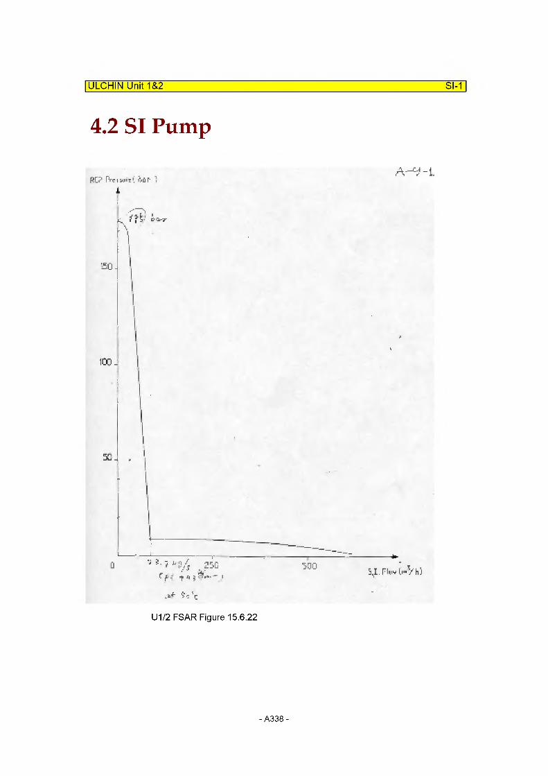
ULCHIN Unit 1&2 SI-1
4.2 SI Pump
PC? FV-r i hiii OuT 1
L 1 ? t-' i<vz
50-
100 -
50 J
: 25GC f - -f n j “
530 s,i. riiw ii"V ii)
.vf- ■(■
U1/2 FSAR Figure 15.6.22
- A338-

ULCHIN Unit 1&2 SI-2
Graphical Interpretation
Original Data(HPSI+LPSI)Flow[m~3/h] Pres[bar]
1.0 175.424.0 170.034.6 150.542.3 129.753.8 99.371 .2 51 .486.5 9.0
301 .0 7.8400.0 6.7500.0 4.4600.0 1 .5613.5 1 .1
Only HPSIPres[bar] Flow[m^3/h] | Massflow[kg/s]
1 75.4 0.0 0.001 70.0 24.0 6.621 51 .0 34.6 9.54130.0 42.3 11.66100.0 53.8 14.8351 .0 71 .1 19.609.0 86.5 23.84
Only LPSIPres[bar] Flow[m^3/h] Massflow[kg/s]
9.0 0.0 0.007.8 214.5 59.127.0 313.5 86.414.4 413.5 113.981 .5 513.5 141 .541 .1 526.5 145.12
* Water density in RWST
KQ orho RWST := 992.29------ at 1 atm and 40 C
mOperating pressure = Atmosphric Operating temperature = 7~40[°C]
Ref. FSAR T-6.3-1 (3/3)
- A339-

ULCHIN Unit 1&2 SI-3
Input Cards:Single Failure (SI pump one-train off)# HBIlf 3 °
* C374 : LPSI Water Source in Loop 1
name type3740000 lpsi-l1 tmdpvol
area length vol x angle elev rough dhydr vf lag3740101 2.0 2.0 0.0 0.0 0.0 0.0 0.0 0.0 00
cnt r I3740200 003
var pressure temperature3740201 0.0 1.0132585 313.15
* 0375 : LPSI Junction in Loop 1
name type3750000 I ps i j 1 tmdpjun
from to area3750101 374010000 378000000 0.106
cnt r I trip3750200 1 496 p 380010000
var waterflow steamflow X3750201 -1.0 0. 0.0 0.03750202 0.0 77.11 0.0 0.03750203 1,014e5 77.11 0.0 0.03750204 3.973e5 68.92 0.0 0.03750205 6.260e5 55.28 0.0 0.03750206 8.27885 41.64 0.0 0.03750207 9.22085 28.00 0.0 0.03750208 10.30e5 14.36 0.0 0.03750209 10.57e5 0.00 0.0 0.0
- A340-

ULCHIN Unit 1&2 SI-4
* C376 :: HRS I Water Source in Loop 1
3760000name hpsi-l1
typetmdpvol
3760101area2.0
length vol2.0 0.0
x angle0.0 0.0
elev0.0
rough0.0
dhydr0.0
vf lag00
3760200cntr I
003
3760201var0.0
pressure1.01325e5
temperature313.15
* C377 : HRS I Junction in Loop 1
name type3770000 hpsij1 tmdpjun
from to area3770101 376010000 378000000 0.106
cntr I trip3770200 1 496 p 380010000
var water flow steamflow X
3770201 -1.0 0.0 0.0 0.03770202 0.0 11.79 0.0 0.03770203 1,014e5 11.79 0.0 0.03770204 28.59e5 11.04 0.0 0.03770205 56.17e5 9.93 0.0 0.03770206 83.75e5 8.56 0.0 0.03770207 111.3e5 6.83 0.0 0.03770208 152.7e5 4.22 0.0 0.03770209 161.0e5 2.55 0.0 0.03770210 166.5e5 0.00 0.0 0.0
- A341 -
3. Heat Structure Data
Reference FilesQ Reference:D:\Development\TA\U12\U12_FNC2\U12_Ch2_1a_R0.mcd(R)
Q Reference:D:\Development\TA\U12\U12_FNC2\U12_Ch2_1b_R0.mcd(R)
0 Reference:D:\Development\TA\U12\U12_FNC2\U12_Ch2_1c_R0.mcd(R)
0 Reference:D:\Development\TA\U12MJ12_FNC2\U12_Ch2_1 d_RO.mcd(R)
0 Reference:D:\Development\TA\U12\U12_FNC2\U12_Ch2_2_R0.mcd(R)
0 Reference:D:\Development\TA\U12\U12_FNC2\U12_Ch2_3_R0.mcd(R)
0 Reference:D:\Development\TA\U12\U12_FNC2\U12_Ch2_4_R0.mcd(R)
0 Reference:D:\Development\TA\U12\U12_FNC2\U12_Ch2_5_R0.mcd(R)
0 Reference:D:\Development\TA\U12\U12_FNC2\U12_Ch2_6_R0.mcd(R)
- A342-
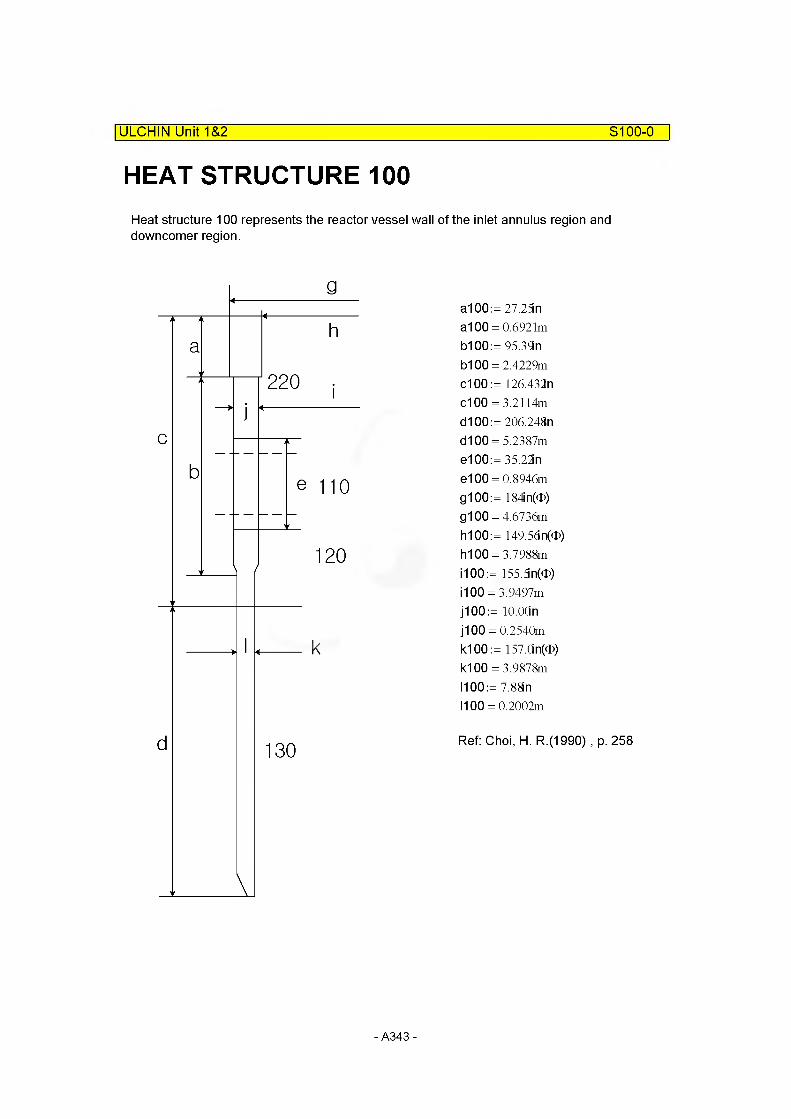
HEAT STRUCTURE 100
ULCHIN Unit 1&2___________________________________________________ S100-0
Heat structure 100 represents the reactor vessel wall of the inlet annulus region and downcomer region.
g
c
ah
0 i
b
j22
e 110
120
d
I t k
V
130
a100:= 27.25n a100 = 0.6921m b100:= 95.39nb100 = 2.4229m c100 := 126.432n c100 = 3.2114m d100 := 206.248n d100 = 5.2387m e100:= 35.22in e100 = 0.8946m g100:= 184in(0) g100 = 4.6736m h100:= 149.56n(0) hi 00 = 3.7988m 1100:= 155.5n(®)1100 = 3.9497m j100 := lO.OOn j100 = 0.2540m k100:= 157.0n(®)1(100 = 3.9878m 1100:= 7.88in 1100 = 0.2002m
Ref: Choi, H. R.(1990) , p. 258
- A343-
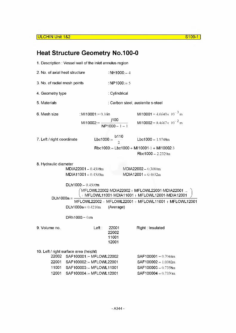
ULCHIN Unit 1&2 S100-1
Heat Structure Geometry No.100-01. Description : Vessel wall of the inlet annulus region
2. No. of axial heat structure : NH1000:= 4
3. No. of radial mesh points : NP1000:= 5
4. Geometry type : Cylindrical
5. Materials : Carbon steel, austenite s-steel
6. Mesh size : MI10001 := O.ldn MI10001 = 4.0640x 10™ 3m
i100 9Ml 10002:=------- ------------- MI10002= 8.4667x 10 m
NP1000- 1 - 1
b1107. Left / right coordinate Lbc1000:= Lbc1000 = 1.9748m
Rbc1000:= LbdOOO + Ml 10001-1 + MI10002 3
Rbc1000= 2.2329m
8. Hydraulic diameterMDIA22001 = 0.4508m MDIA22002 = 0.3000mMDIA11001 = 0.4509m MDIA12001 = 0.4652m
DLh1000:= 0.4509nfMFLOWL22002 MDIA22002+ MFLOWL22001 MDIA22001 ... ^U MFLOWL11001 • MDIA11001 + MFLOWL12001 MDIA12001 J
DLh1000a:= —-----------------------------------------------------------------------------------------—MFLOWL22002 + MFLOWL22001 + MFLOWL11001 + MFLOWL12001
DLh1000a= 0.4210m (Average)
DRh1000:= O.m
9. Volume no. Left : 22001220021100112001
10. Left / right surface area (height)22002 SAF100001 := MFLOWL22002 22001 SAF100002:= MFLCWL22001 11001 SAF100003 := MFLOWL11001 12001 SAF100004 := MFLOWL12001
Right: Insulated
SAF100001 = 0.7044m SAF100002= 1.0382m SAF100003 = 0.7358m SAF100004 = 0.7330m
- A344-
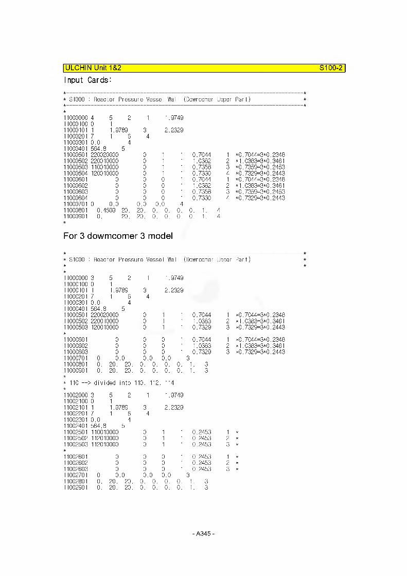
ULCHIN Unit 1&2______________________________________________________ S100-2
Input Cards:
* S1000 : Reactor Pressure Vessel Wal I (Downcomer Upper Part)
11000000 4 5 2 1 1.974911000100 0 111000101 1 1.9789 3 2.232911000201 7 1 6 411000301 0.0 411000401 564.8 511000501 220020000 0 1 1 0.7044 1 *0.7044=3*0.234811000502 220010000 0 1 1 1.0382 2 *1.0383=3*0.346111000503 110010000 0 1 1 0.7358 3 *0.7359=3*0.245311000504 120010000 0 1 1 0.7330 4 *0.7329=3*0.244311000601 0 0 0 1 0.7044 1 *0.7044=3*0.234811000602 0 0 0 1 1.0382 2 *1.0383=3*0.346111000603 0 0 0 1 0.7358 3 *0.7359=3*0.245311000604 0 0 0 1 0.7330 4 *0.7329=3*0.244311000701 0 0.0 0.0 0 .0 411000801 0.4509 20. 20. 0. 0. 0. 0. 1. 411000901 0. 20. 20. 0. 0. 0. 0. 1. 4
For 3 dowmcomer 3 model
* S1000 :: Reactor Pressure Vessel Wall (Downcomer Upper Part)
11000000 3 5 2 1 1.974911000100 0 111000101 1 1.9789 3 2.232911000201 7 1 6 411000301 0.0 411000401 564.8 511000501 220020000 0 1 1 0.7044 1 *0.7044=3*0.234811000502 220010000 0 1 1 1.0383 2 *1.0383=3*0.346111000503 120010000 0 1 1 0.7329 3 *0.7329=3*0.2443
11000601 0 0 0 1 0.7044 1 *0.7044=3*0.234811000602 0 0 0 1 1.0383 2 *1.0383=3*0.346111000603 0 0 0 1 0.7329 3 *0.7329=3*0.244311000701 0 0.0 0.0 0.0 311000801 0. 20. 20. 0. 0. 0. 0. 1. 311000901 0. 20. 20. 0. 0. 0. 0. 1. 3
* 110 —> divided into 110, 112, 114
11002000 352 11002100 0 111002101 1 1.978911002201 7 1 611002301 0.0 411002401 564.8 511002501 110010000 11002502 112010000 11002503 112010000
1
34
000
1.9749
2.2329
1 1 0.2453 1 *1 1 0.2453 2 *1 1 0.2453 3 *
110026011100260211002603110027011100280111002901
000
0 0.00. 20. 20.0. 20. 20.
0 00 00 00.0 0.0
0. 0. 0.0. 0. 0.
1 0.24531 0.24531 0.2453
30. 1. 3 0. 1. 3
1 *
2 *
3 *
- A345
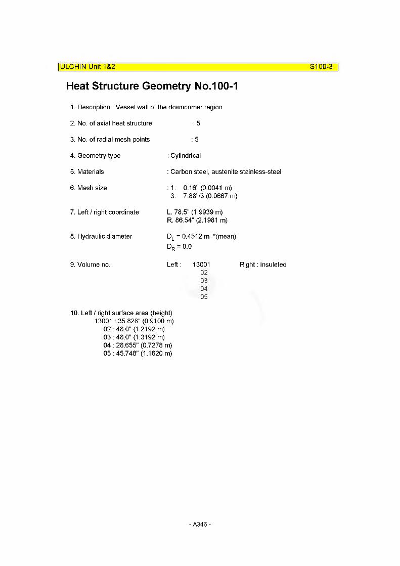
ULCHIN Unit 1&2 S100-3
Heat Structure Geometry No.100-1
1. Description : Vessel wall of the downcomer region
2. No. of axial heat structure : 5
3. No. of radial mesh points : 5
4. Geometry type : Cylindrical
5. Materials : Carbon steel, austenite stainless-steel
6. Mesh size : 1. 0.16" (0.0041 m)3. 7.8873 (0.0667 m)
7. Left / right coordinate L. 78.5" (1.9939 m)R. 86.54" (2.1981 m)
8. Hydraulic diameter Dl = 0.4512 m *(mean)
Dr = 0.0
9. Volume no. Left: 13001 Right: insulated02030405
10. Left / right surface area (height) 13001 : 35.828" (0.9100 m)
02 : 48.0" (1.2192 m)03 : 48.0" (1.3192 m)04 : 28.655" (0.7278 m)05 : 45.748" (1.1620 m)
- A346-

ULCHIN Unit 1&2 S100-4
Input Cards
* S1001 : Reactor Pressure Vessel Wall (Downcomer Lower Part)
1001000 5 5 2 1 1.99391001100 0 11001101 1 1.9980 3 2.19811001201 7 1 6 41001301 0.0 41001401 564.8 51001501 130010000 0 1 1 0.9100 1 0.9099=3*0.30331001502 130020000 10000 1 1 1.2192 3 1.2192=3*0.40641001503 130040000 0 1 1 0.7278 4 0.7278=3*0.24261001504 130050000 0 1 1 1.1620 5 1.1619=3*0.38731001601 0 0 0 1 0.9100 1 0.9099=3*0.30331001602 0 0 0 1 1.2192 3 1.2192=3*0.40641001603 0 0 0 1 0.7278 4 0.7278=3*0.24261001604 0 0 0 1 1.1620 5 1.1619=3*0.38731001701 0 0.0 0 .0 0.0 51001801 0.4512 20. 20. 0. 0. 0. 0. 1. 51001901 0. 20. 20. 0. 0. 0. 0. 1. 5
- A347-
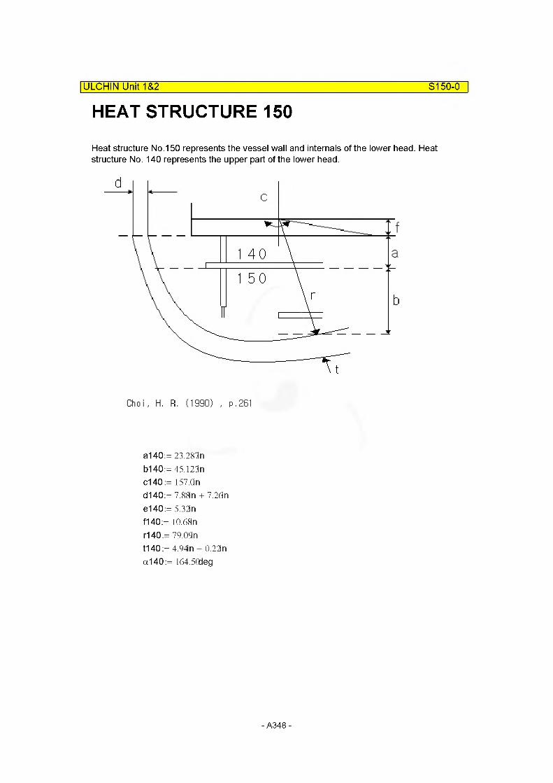
S150-0
HEAT STRUCTURE 150| ULCHIN Unit 1&2
Heat structure No.150 represents the vessel wall and internals of the lower head. Heat structure No. 140 represents the upper part of the lower head.
Choi, H. FI. (1990) , p.261
a140:=23.28ln b140:=45.l23n c140 := 157.On d140:= 7.88in + 7.26in e140:= 5.32in f140 := 10.68n r140:= 79.09n t140 := 4.94in + 0.22in a140:= 164.50deg
- A348-
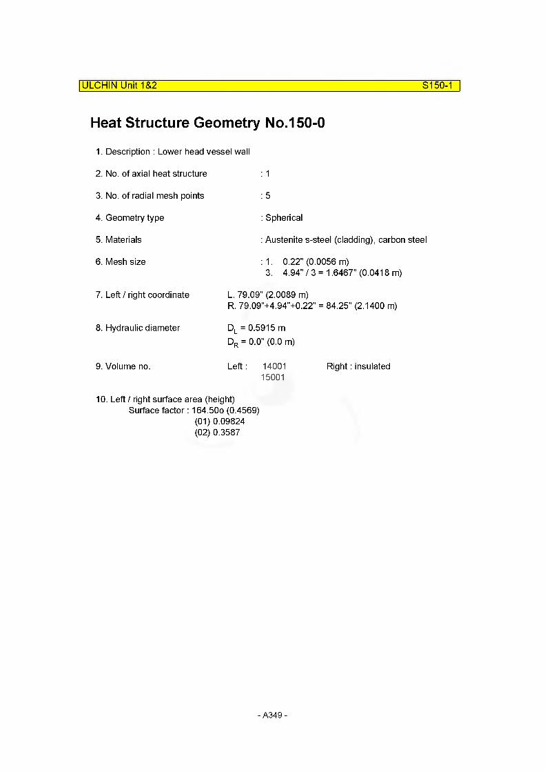
ULCHIN Unit 1&2 S150-1
Heat Structure Geometry No.150-0
1. Description : Lower head vessel wall
2. No. of axial heat structure
3. No. of radial mesh points
4. Geometry type
5. Materials
6. Mesh size
: 1
: 5
: Spherical
: Austenite s-steel (cladding), carbon steel
: 1. 0.22" (0.0056 m)3. 4.94" / 3 = 1.6467" (0.0418 m)
7. Left / right coordinate L. 79.09" (2.0089 m)R. 79.09"+4.94"+0.22" = 84.25" (2.1400 m)
8. Hydraulic diameter DL = 0.5915 mDr = 0.0" (0.0 m)
9. Volume no. Left : 14001 Right: insulated15001
10. Left / right surface area (height)Surface factor: 164.50o (0.4569)
(01) 0.09824(02) 0.3587
- A349-
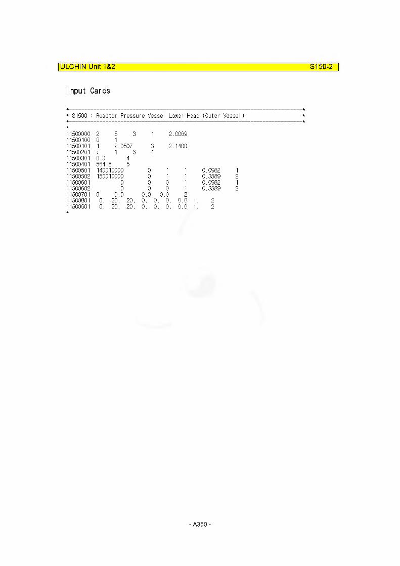
ULCHIN Unit 1&2 S150-2
Input Cards
* S1500 : Reactor Pressure Vessel Lower Head (Outer Vessel)
1500000 2 5 3 1 2..00891500100 0 11500101 1 2.0507 3 2..14001500201 7 1 6 41500301 0.0 41500401 564. 8 51500501 140010000 0 1 1 0.0982 11500502 150010000 0 1 1 0.3589 21500601 0 0 0 1 0.0982 11500602 0 0 0 1 0.3589 21500701 0 0.0 0.0 0.0 21500801 0. 20. 20. 0. 0. 0. 0.0 '1. 21500901 0. 20. 20. 0. 0. 0. 0.0 '1. 2
- A350-

ULCHIN Unit 1&2 S150-3
Heat Structure Geometry No.150-1
Internals volumes of hydrodynamic component 140, 150, and 160.(Choi, H.R., 1990, p.264)
IV14001 := o.ososm3IV15001 := 0.0786n3
IV16001 := 2.6913m3
We assumed that all of internals in lower plenum are columns and number of the columns are 52. The height of one column is 114.158 " (2.90m).
Total internal volume of lower plenum {IVTLP14_5_6Q}
IVTLP14_5_60:= IV14001 + IV15001 + IV16001 IVTLP14_5_60= 2.8508m3
Height of columns {HC14 5 60}
HC14_5_60:= 2.90m
Area of one column {AC14 5 60}
HC14 5 60
----- 52
AC14 5 60= 1.8905x 10“2m2
Diameter of one column { DC14 5 60}
DC14 5 60= 0.1551m
- A351 -

ULCHIN Unit 1&2 S150-4
1. Description : Lower head vessel internals
2. No. of axial heat structure
3. No. of radial mesh points
4. Geometry type
5. Materials
6. Mesh size
7. Left / right coordinate
8. Hyraulic diameter
9. Volume no.
: 3
: 3
: Cylindrical
: Stainless -steel
:0.1551 m/2 = 0.07755 m
L : 0.0 m R: 0.1551 m Dl = 0.0Dr = 0.1551 m Left, right: 160
140 150
10. Left / right surface area (height)Surface factor = 1.162x52 = 60.424 m
0.5915 x 52 = 30.758 m 1.1461 x 52 = 59.5972 m
Input Cards
* S1501 : Reactor Pressure Vessel Lower Head (Internal Structure)
1501000 3 3 2 1 0.01501100 0 11501101 2 0.077551501201 4 21501301 0.0 21501401 564.8 31501501 160010000 0 1 1 60.4240 11501502 140010000 0 1 1 30.7580 21501503 150010000 0 1 1 59.5972 31501601 160010000 0 1 1 60.4240 11501602 140010000 0 1 1 30.7580 21501603 150010000 0 1 1 59.5972 31501701 0 0.0 0 .0 0.0 31501801 0. 20. 20. 0. 0. 0. 0. 1. 31501901 0. 20. 20. 0. 0. 0. 0. 1. 3
- A352-

STRUCTURE 170
ULCHIN Unit 1&2___________________________________________________S170-0
Heat structure no. 170 represents fuel rods in average core, one hot fuel rod, and internals of fuel assembly without active core.(That is, bottom nozzle, top nozzle, grid, etc.)
rhuh Lei l'VZA
VI f\\ M"
[iiihIhi l
? /■: vV:
V roiy
//
_-i ---
-
J' "ill :f:
/.V J.
-'■■■
/. ■ _ - - 7/
I -d
in
1$! I11"g AM:FI.J01
.-3X r j- * ?
VI . |l' II ■■■ -2 fTJi. 7-v:v. ■■
j r? < r
, v V170 JSIttl -7 • 7 f?
?. .7 ■'■■■ /
■-j
V17006m
~.. I.-**
v i too7 y
V17040
sr,/ 5
■■ b: t
vnoiib /7y■11 i
■■■■ ■- V V ■ - M’ v j
c. 7- -'^ _ Z any i ram;
I y- 1-L ?: I
V|7HOXJ: 7l
=■VI ■■ oil:1-
I I
zz: J -. n— C ■ O /
— 3c V.-i-
■7 / V|700:
- A353-

ULCHIN Unit 1&2 S170-1
The fuel of U12 is Vantage-5H.Vantage-5H is same to KWU fuel in outer diameter, number of rods in an assembly, number of instrumentation tube in an assembly, number of guide thimble in an assembly, and number of assembly in the core. Thus, the structure data of KWU fuel for MARS analysis is used instead of Vantage-5H fuel.
a b c
From Choi, H.R., 1990, p. 268 (B121/B11/85/183)- Pellet dia
as170:= 8.05mm- Cladding innner dia
bs170:= 8.22mm- Cladding outer dia
cs170:= 9.5mm- Diametral gap
ds170:= 0.17mm
Fuel assembly (Vantage-5H)17x17N_Ass170:= 157 N_Fuel170:= 264N_Guid170:= 24 N_lnst170:= 1
KOPEC, 2002, App. F.* Fuel center temperature : 4700 °F FSAR 4. 4.-1 (3/3)
coolant temperature (in avg. core) : 592.2 °F FSAR 4.1 -1 (2/6)
- uesign- No. of fuel Ass'y- U02 rods per Ass'y
- No. of guide- No. of Instrumnent auide
- A354-
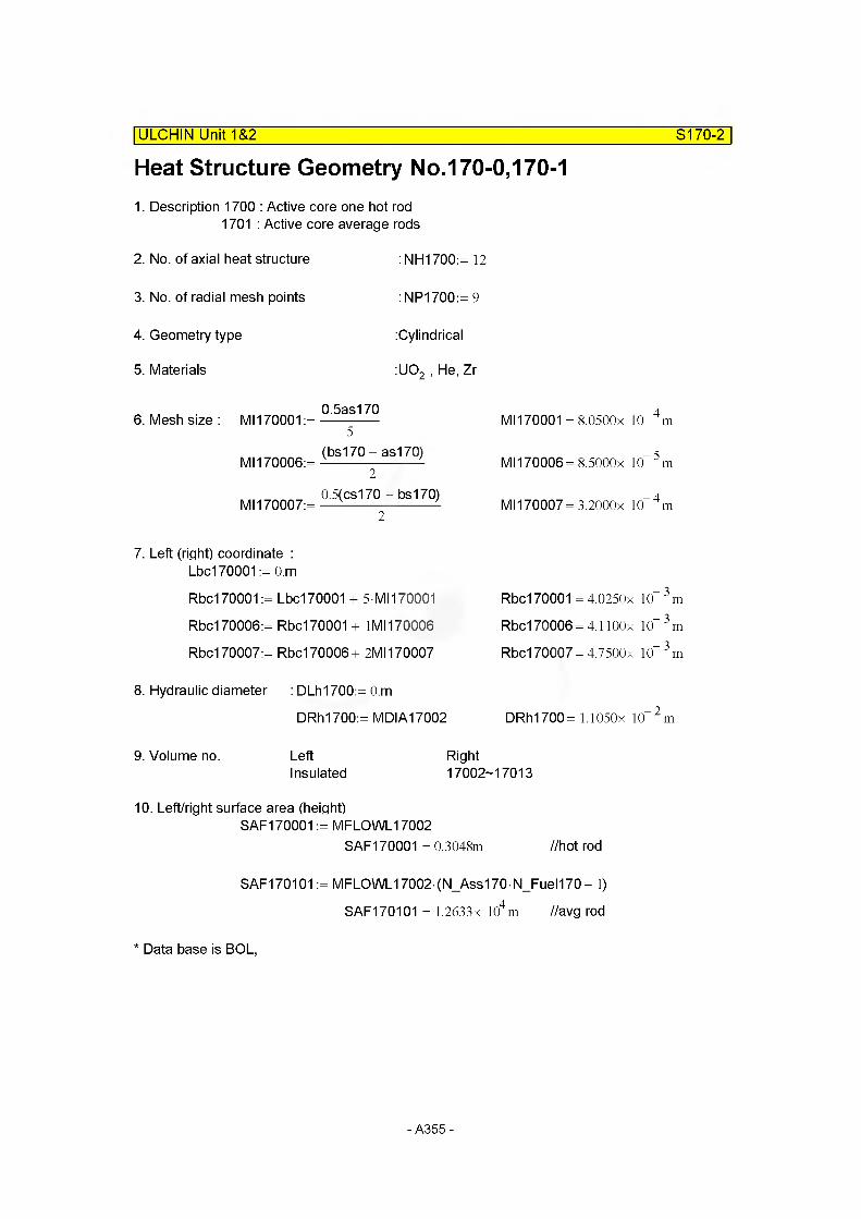
Heat Structure Geometry No.170-0,170-1| ULCHIN Unit 1&2 S170-2
1. Description 1700 : Active core one hot rod 1701 : Active core average rods
2. No. of axial heat structure
3. No. of radial mesh points
4. Geometry type
5. Materials
: NH1700:= 12
: NP1700:= 9
:Cylindrical
:U02 , He, Zr
6. Mesh size : MI170001 :=
MI170006:=
Ml 170007:=
0.5as1705
(bs170 - as170)2
0.5(cs170 - bs170)2
7. Left (right) coordinate :Lbc170001 := O.m
Rbc170001:= Lbc170001 + 5 MI170001
Rbc170006:= Rbc170001 + 1M1170006
Rbc170007:= Rbc170006+ 2M1170007
Ml 170001 = 8.0500x 10“ 4 m
Ml 170006= 8.5000x 10“ 5 m
Ml 170007= 3.2000x 10“ 4 m
Rbc170001 = 4.0250x 10“ 3 m
Rbc170006 = 4.1 lOOx 10“ 3 m
Rbc170007 = 4.7500x 10“ 3 m
8. Hydraulic diameter : DLh1700:= O.m
DRh1700:= MDIA17002 DRh1700= 1.1050x 10“2m
9. Volume no. Left RightInsulated 17002-17013
10. Left/right surface area (height)SAF170001 := MFLOWL17002
SAF170001 = 0.3048m //hot rod
SAF170101 := MFLOWL17002- (N_Ass170- N_Fuel170 - 1)
SAF170101 = 1.2633x 10⁴m //avg rod
* Data base is BOL,
- A355-
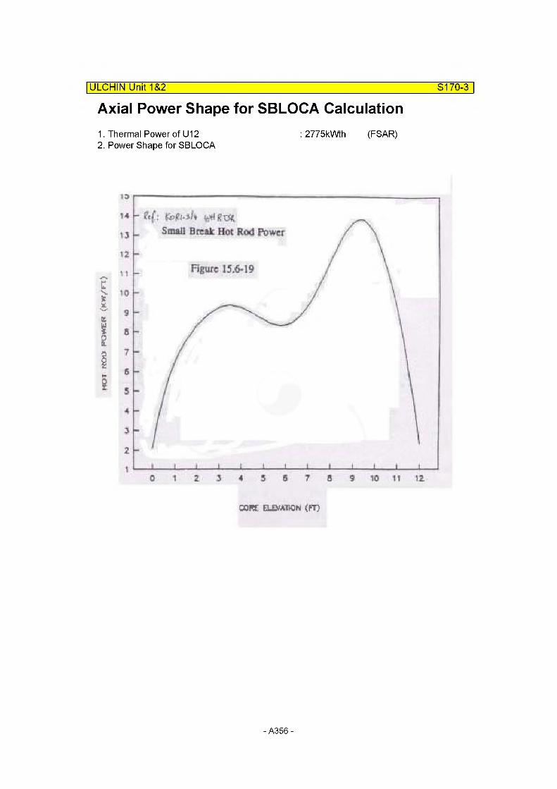
I-Kto
POY
VEf
T i'r.W
/F7>
Axial Power Shape for SBLOCA Calculation| ULCHIN Unit 1 &2 S170-3
1. Thermal Power of U12 : 2775kWth (FSAR)2. Power Shape for SBLOCA
Small Break Hot Rod Power
CORE elevation (ft>
- A356-
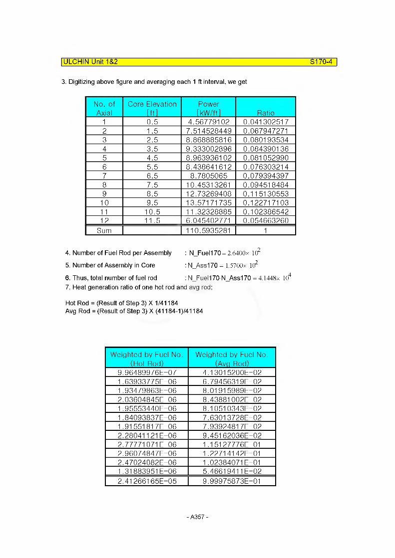
ULCHIN Unit 1&2 S170-4
3. Digitizing above figure and averaging each 1 ft interval, we get
No. of Axial
Core Elevation [ftl
Power[kW/ftl Ratio
1 0.5 4.56779102 0.0413025172 1 .5 7.514528449 0.0679472713 2.5 8.868885816 0.0801935344 3.5 9.333002896 0.0843901365 4.5 8.963936102 0.0810529906 5.5 8.438641612 0.0763032147 6.5 8.7805065 0.0793943978 7.5 10.45313261 0.0945184849 8.5 12.73269408 0.115130553
10 9.5 13.57171735 0.12271710311 10.5 11.32328885 0.10238654212 11.5 6.045402771 0.054663260
Sum 110.5935281 1
4. Number of Fuel Rod per Assembly : N_Fuel170 = 2.6400x 10²
5. Number of Assembly in Core : N_Ass170 = 1.5700x 10²
6. Thus, total number of fuel rod : N Fuelt 70 N_Ass1 70 = 4.1448x 10⁴
7. Heat generation ratio of one hot rod and avg rod;
Hot Rod = (Result of Step 3) X 1/41184 Avg Rod = (Result of Step 3) X (41184-1)/41184
Weighted by Fuel No. (Hot Rod)
Weighted by Fuel No. (Avg Rod)
9.96489976E-07 4.1 301 5200E-021.63933775E-06 6.79456319E-021.93479863E-06 8.01915989E-022.03604845E-06 8.43881002E-021.95553440E-06 8.1 051 0343E-021.84093837E-06 7.63013728E-021.91 551817E-06 7.93924817E-022.280411 21E-06 9.45162036E-022.77771071E-06 1 .1 51 27776E-012.96074847E-06 1 .22714142E-012.47024082E-06 1.02384071 E-011.31883951E-06 5.4661 9411E-022.41266165E-05 9.99975873E—01
- A357-
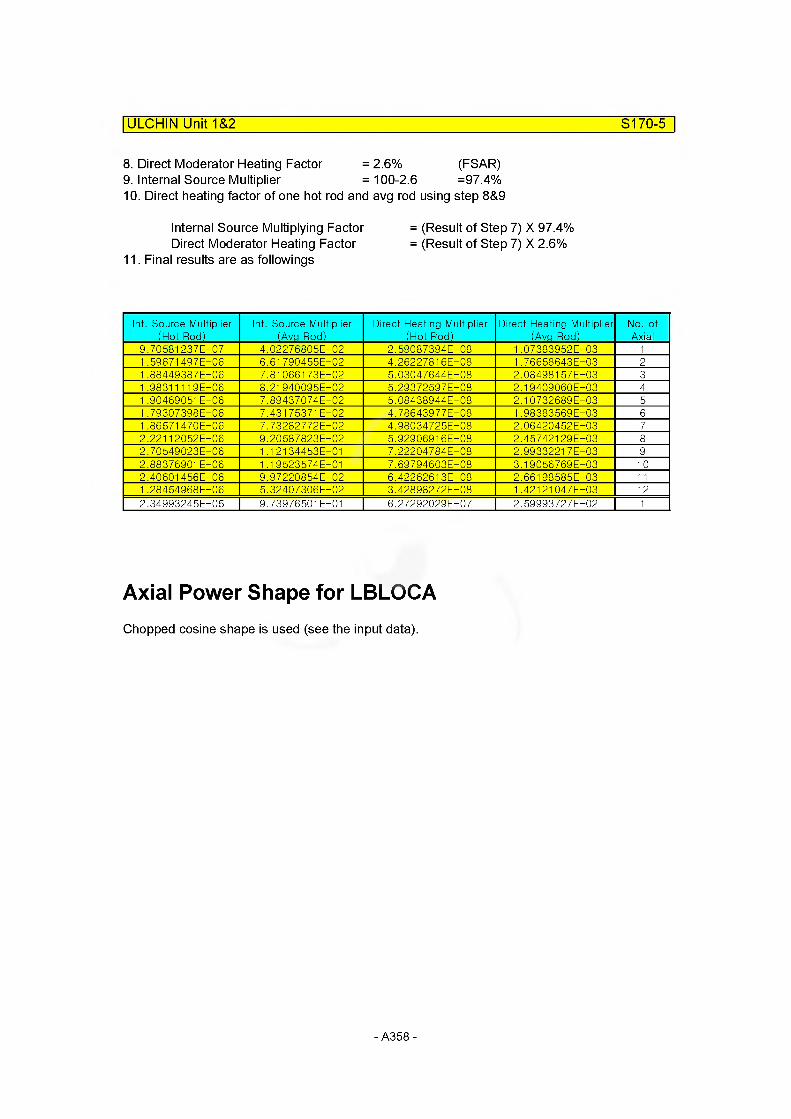
ULCHIN Unit 1&2 S170-5
8. Direct Moderator Heating Factor = 2.6% (FSAR)9. Internal Source Multiplier = 100-2.6 =97.4%10. Direct heating factor of one hot rod and avg rod using step 8&9
Internal Source Multiplying Factor = (Result of Step 7) X 97.4%Direct Moderator Heating Factor = (Result of Step 7) X 2.6%
11. Final results are as followings
Int. Source Multiplier (Hot Rod)
Int. Source Multiplier (Avp Rod)
Direct Heating Multiplier (Hot Rod)
Direct Heating Multiplier (Avg Rod)
No. of Axial
9.70581 237E-07 4.02276805E-02 2.59087394E-08 1.07383952E-03 11.59671497E-06 6.61 790455E-02 4.26227816E-08 1.76658643E-03 21 .88449387E-06 7.81 0661 73E-02 5.03047644E-08 2.08498157E-03 31 .98311119E-06 8.21 940095E-02 5.29372597E-08 2.19409060E-03 41 .90469051 E-06 7.89437074E-02 5.08438944E-08 2.10732689E-03 51 .79307398E-06 7.431 75371 E-02 4.78643977E-08 1.98383569E-03 61 .86571 470E-06 7.73282772E-02 4.98034725E-08 2.06420452E-03 72.22112052E-06 9.20587823E-02 5.92906916E-08 2.45742129E-03 82.70549023E-06 1.12134453E-01 7.22204784E-08 2.9933221 7E-03 92.88376901 E-06 1.19523574E-01 7.69794603E-08 3.19056 769 E-03 102.40601 456E-06 9.97220854E-02 6.42262613E-08 2.66198585E-03 111 .28454968E-06 5.32407306E-02 3.42898272E-08 1.42121 047E-03 122.34993245E-05 9.73976501 E-01 6.27292029E-07 2.59993727E-02 1
Axial Power Shape for LBLOCAChopped cosine shape is used (see the input data).
- A358-

ULCHIN Unit 1&2________________________________________________ S170-6
Input Cards
* S1700 : 1 Hotest Rod
11700000NH12
NP Type I9 2 1
_FIag Lbc 0.0
11700001I nt_P71.96e5
Ref voI170140000
11700003
O LO
8o o
11700004LF_FIag1
11700011F_rough2.8-6
C_rough Rad_DisF1.e—6 1.5615e—5
Rad_DisC -8.380e-6
11700100Mesh L F0
Mesh F F1
NH12
* No I Record11700101 5 4.02358-3 1 4.1155e-3 2 4.7570e-3
* Comp. I No11700201 1 5
* Source I No11700301 1.0 5
* Ini_T emp_FIag11700400 0
-8 6
0.0 8
-3 8
* Temp NP11700401 2866.48 111700402 932.69 611700403 891.86 711700404 584.37 9
*Lef t BVo I . I acre BC SAC SAF NH11700501 0 0 0 1 0.3048 111700502 0 0 0 1 0.3048 211700503 0 0 0 1 0.3048 311700504 0 0 0 1 0.3048 411700505 0 0 0 1 0.3048 511700506 0 0 0 1 0.3048 611700507 0 0 0 1 0.3048 711700508 0 0 0 1 0.3048 811700509 0 0 0 1 0.3048 911700510 0 0 0 1 0.3048 1011700511 0 0 0 1 0.3048 1111700512 0 0 0 1 0.3048 12
*Right BVo I . I acre BC SAC SAF NH11700601 170020000 0 1 1 0.3048 111700602 170030000 0 1 1 0.3048 211700603 170040000 0 1 1 0.3048 311700604 170050000 0 1 1 0.3048 411700605 170060000 0 1 1 0.3048 511700606 170070000 0 1 1 0.3048 611700607 170080000 0 1 1 0.3048 711700608 170090000 0 1 1 0.3048 811700609 170100000 0 1 1 0.3048 911700610 170110000 0 1 1 0.3048 1011700611 170120000 0 1 1 0.3048 1111700612 170130000 0 1 1 0.3048 12
- A359-
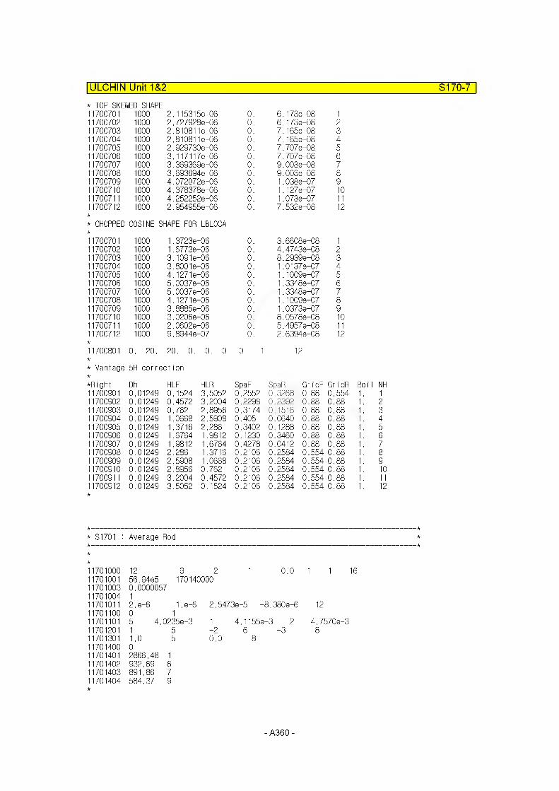
ULCHIN Unit 1&2 S170-7
* TOP SKEWED SHAPE11700701 1000 2.115315e—06 0. 6.173e-08 111700702 1000 2.7279288-06 0. 6.173e-08 211700703 1000 2.8108118-06 0. 7.165e-08 311700704 1000 2.8108118-06 0. 7.165e-08 411700705 1000 2.9297308-06 0. 7.7078-08 511700706 1000 3.117117 e—06 0. 7.7078-08 611700707 1000 3.3693698-06 0. 9.0038-08 711700708 1000 3.6936948-06 0. 9.0038-08 811700709 1000 4.0720728-06 0. 1.038e-07 911700710 1000 4.3783788-06 0. 1.1278-07 1011700711 1000 4.2522528-06 0. 1.073e-07 1111700712 1000 2.954955e-06 0. 7.5328-08 12
* CHOPPED COSINE SHAPE FOR LBLOCA
11700701 1000 1.3723e-06 0. 3.66088-08 111700702 1000 1.6773e-06 0. 4.47438-08 211700703 1000 3.10918-06 0. 8.29398-08 311700704 1000 3.80018-06 0. 1.01378-07 411700705 1000 4.1271e—06 0. 1.10098-07 511700706 1000 5.00378-06 0. 1.3348e-07 611700707 1000 5.00378-06 0. 1.3348e-07 711700708 1000 4.1271e—06 0. 1.10098-07 811700709 1000 3.88858-06 0. 1.0373e-07 911700710 1000 3.02068-06 0. 8.0578e-08 1011700711 1000 2.06028-06 0. 5.4957e-08 1111700712 1000 9.89448-07 0. 2.63948-08 12
11700801 0. 20. 20. 0. 0. 0. 0. 1 12
* Vantage 5H cor rection
*Right Dh HLF HER SpaF SpaR GridF Gr idR Boil NH11700901 0.01249 0.1524 3.5052 0.2552 0.3268 0.88 0.554 1. 111700902 0.01249 0.4572 3.2004 0.2298 0.2392 0.88 0.88 1. 211700903 0.01249 0.762 2.8956 0.3174 0.1516 0.88 0.88 1. 311700904 0.01249 1.0668 2.5908 0.405 0.0640 0.88 0.88 1. 411700905 0.01249 1.3716 2.286 0.3402 0.1288 0.88 0.88 1. 511700906 0.01249 1.6764 1.9812 0.1230 0.3460 0.88 0.88 1. 611700907 0.01249 1.9812 1.6764 0.4278 0.0412 0.88 0.88 1. 711700908 0.01249 2.286 1.3716 0.2106 0.2584 0.554 0.88 1. 811700909 0.01249 2.5908 1.0668 0.2106 0.2584 0.554 0.88 1. 911700910 0.01249 2.8956 0.762 0.2106 0.2584 0.554 0.88 1. 1011700911 0.01249 3.2004 0.4572 0.2106 0.2584 0.554 0.88 1. 1111700912 0.01249 3.5052 0.1524 0.2106 0.2584 0.554 0.88 1. 12
: S1701 : Average Rod
1701000 12 9 2 1 0.0 1 1 161701001 56.94e5 1701400001701003 0.00000571701004 11701011 2.e-6 1.e-6 2.54738-5 -8.3808-6 121701100 0 11701101 5 4.02358-3 1 4.1155e—3 2 4.7570e-31701201 1 5 -26 -3 81701301 1.0 5 0.0 81701400 01701401 2866.48 11701402 932.69 61701403 891.86 71701404 584.37 9
- A360-
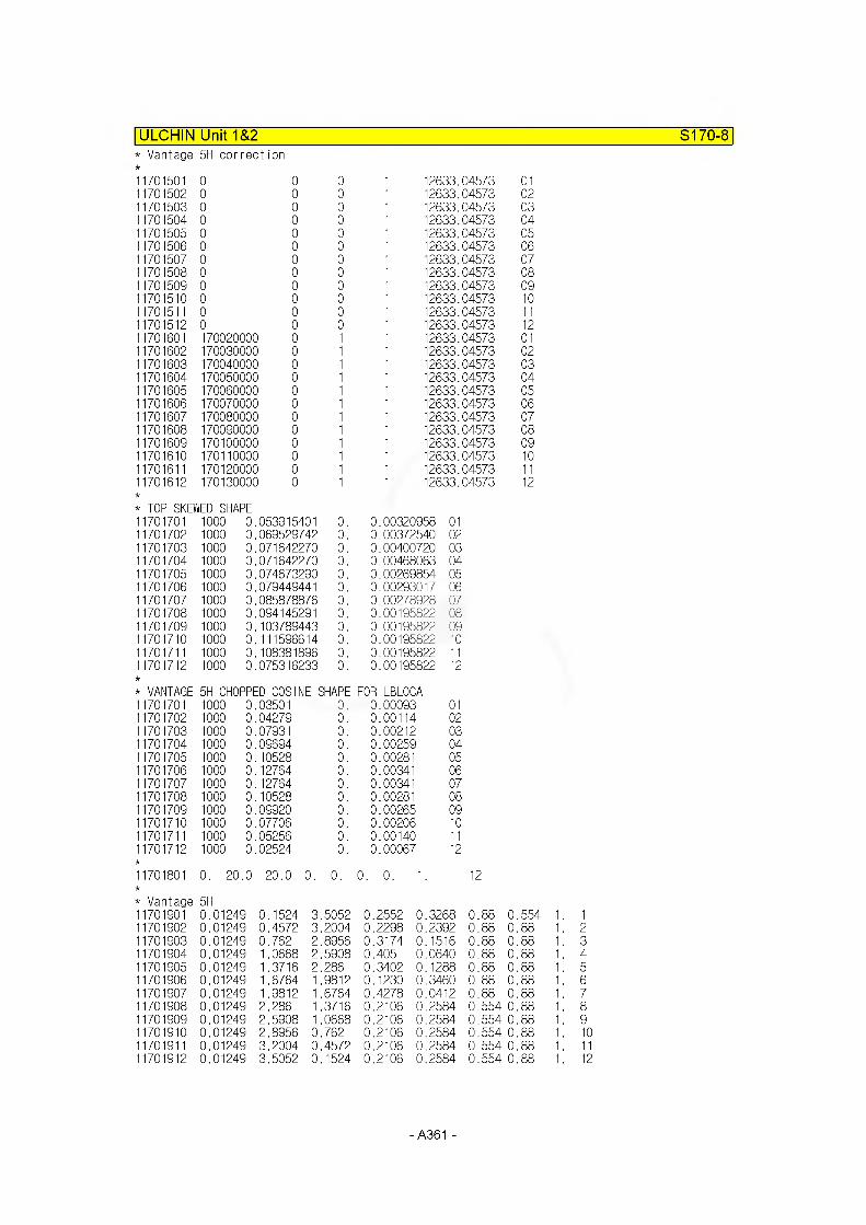
ULCHIN Unit 1&2* Vantage 5H correction
S170-8
1701501 01701502 01701503 01701504 01701505 01701506 01701507 01701508 01701509 01701510 01701511 01701512 01701601 1700200001701602 1700300001701603 1700400001701604 1700500001701605 1700600001701606 1700700001701607 1700800001701608 1700900001701609 1701000001701610 1701100001701611 1701200001701612 170130000
0 0 1 0 0 1 0 0 1 0 0 1 0 0 1 0 0 1 0 0 1 0 0 1 0 0 1 0 0 1 0 0 1 0 0 1 0 1 1 0 1 1 0 1 1 0 1 1 0 1 1 0 1 1 0 1 1 0 1 1 0 1 1 0 1 1 0 1 1 0 1 1
12633.04573 0112633.04573 0212633.04573 0312633.04573 0412633.04573 0512633.04573 0612633.04573 0712633.04573 0812633.04573 0912633.04573 1012633.04573 1112633.04573 1212633.04573 0112633.04573 0212633.04573 0312633.04573 0412633.04573 0512633.04573 0612633.04573 0712633.04573 0812633.04573 0912633.04573 1012633.04573 1112633.04573 12
* TOP SKEWED SHAPE11701701 1000 0.053915401 0. 0.00320958 0111701702 1000 0.069529742 0. 0.00372540 0211701703 1000 0.071642270 0. 0.00400720 0311701704 1000 0.071642270 0. 0.00468063 0411701705 1000 0.074673290 0. 0.00269854 0511701706 1000 0.079449441 0. 0.00293017 0611701707 1000 0.085878876 0. 0.00278928 0711701708 1000 0.094145291 0. 0.00195822 0811701709 1000 0.103789443 0. 0.00195822 0911701710 1000 0.111596614 0. 0.00195822 1011701711 1000 0.108381896 0. 0.00195822 1111701712 1000 0.075316233 0. 0.00195822 12
* VANTAGE 5H CHOPPED COSINE SHAPE FOR LBLOCA11701701 1000 0.03501 0. 0.00093 0111701702 1000 0.04279 0. 0.00114 0211701703 1000 0.07931 0. 0.00212 0311701704 1000 0.09694 0. 0.00259 0411701705 1000 0.10528 0. 0.00281 0511701706 1000 0.12764 0. 0.00341 0611701707 1000 0.12764 0. 0.00341 0711701708 1000 0.10528 0. 0.00281 0811701709 1000 0.09920 0. 0.00265 0911701710 1000 0.07706 0. 0.00206 1011701711 1000 0.05256 0. 0.00140 1111701712 1000 0.02524 0. 0.00067 12
11701801 0. 20 .0 20.0 0. 0.
oo
* Vantage 5H11701901 0.01249 0.1524 3.505211701902 0.01249 0.4572 3.200411701903 0.01249 0.762 2.895611701904 0.01249 1.0668 2.590811701905 0.01249 1.3716 2.28611701906 0.01249 1.6764 1.981211701907 0.01249 1.9812 1.676411701908 0.01249 2.286 1.371611701909 0.01249 2.5908 1.066811701910 0.01249 2.8956 0.76211701911 0.01249 3.2004 0.457211701912 0.01249 3.5052 0.1524
0.2552 0.3268 0.88 0.554 1 . 10.2298 0.2392 0.88 0.88 1 . 20.3174 0.1516 0.88 0.88 1 . 30.405 0.0640 0.88 0.88 1 . 40.3402 0.1288 0.88 0.88 1 . 50.1230 0.3460 0.88 0.88 1 . 60.4278 0.0412 0.88 0.88 1 . 70.2106 0.2584 0.554 0.88 1 . 80.2106 0.2584 0.554 0.88 1 . 90.2106 0.2584 0.554 0.88 1 . 100.2106 0.2584 0.554 0.88 1 . 110.2106 0.2584 0.554 0.88 1 . 12
A361 -

UCN 1&2 Power data
To Generate gap conductance data
Total Rx. power = 2775.0 MWt
One hot rod power = 110.864 KW
Avg. rods power = 2774.889736 MWt
Local peak power of hot rod *1)= 12.33 KW/FT (404.53 W/Cm)of avg. rods*2)= 7.4460 KW/FT (244.2920 W/Cm)
Avg. power of hot rod = 9.2387 KW/FT (303.1059 W/Cm) of avg. rods = 5.5792 KW/FT (193.0443 W/Cm)
ULCHIN Unit 1&2____________________________________________________ S170-9
No. of fuel assembly = 157 No. of fuel rod per assembly = 264
*1), 2)Based on the top skewed power shape (UCN 1&2 FSAR 15.6-23)
- A362-

ULCHIN Unit 1&2 S170-10
Thermal Conductivity of fuel *
TEMP [kl LAMDA[W/MKl TEMP [Kl LAMDA[W/MKl273.15 7.293 373.15 7.293473.15 6.697 573.15 5.815673.15 5.136 773.15 4.603873.15 4.172 973.15 3.8191073.15 3.527 1173.15 3.2811273.15 3.075 1373.15 2.9031473.15 2.759 1573.15 2.6411673.15 2.546 1773.15 2.4741873.15 2.423 1973.15 2.3922073.15 2.382 2173.15 2.3922273.15 2.422 2373.15 2.4732473.15 2.546 2573.15 2.6432673.15 2.762 2773.15 2.9072873.15 3.078 2973.15 3.4743073.15 3.504 3173.15 3.7623573.15 5.133 4873.15 14.699
Porosity = 2.09 % (0.0209)
X = X x95
1 - 2.5p 0.875
= 1.083143 x Xg5
*The effect of porosity on thermal conductivity is considered.
- A363-

ULCHIN Unit 1&2 S170-11
CARO - RUN D3XF144Burn up : 70.90 MWD/KG (Min. Conductance base) Roughness : Clad = 1.0 x 10⁻⁶ m
Pellet = 2.0 x 10⁻⁶ m
1. Cold geometryClad : D0 = 9.574 mm , D, = 8.231 mm
Dm = 8.8725 mmPellet; D = 8.047 mm
2. Porosity
P = 2.09 %avg.
Pi niP :=------
Ei
^ pellet ^95 x1 - 2.5P
0.8751.083
3. Hot geometry (Related to dia. D^)183.04W/cm
a) Clad {%} Avg.powerCreep down -0.1889
244.3W/cm 404.53W/cmpeak power Avg. peak power Hot
-0.1889 -0.1889
b) Pellet {%} Swelling Relocation
4. Pressure In gap {bar}
-0.7461 -0.74611.3204 1.2718
-0.74611.0952
(43.04 x 10⁻⁶) (38.77 x 10⁻⁶) (19.457 x 10⁻⁶)
56.92 62.71 72.24
5. Gas compositionHe 95.11 94.57 90.79/V 3.96 3.94 3.78Nz 0.08 0.13 0.49Xe 0.76 1 .22 4.45Kr 0.08 0.13 0.5
- A364-
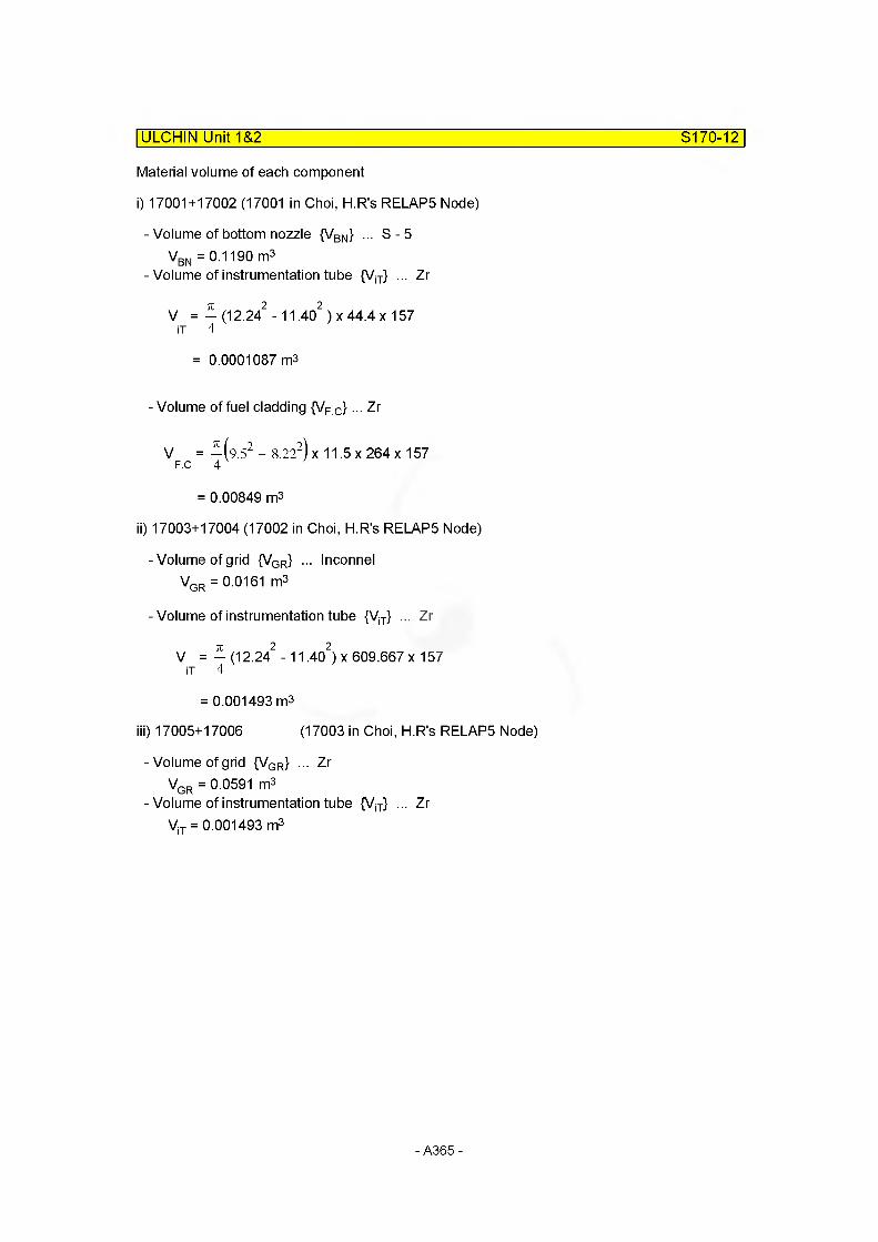
Material volume of each component
i) 17001+17002 (17001 in Choi, H R's RELAP5 Node)
- Volume of bottom nozzle {VBN} ... S - 5VBN = 0.1190 m3
- Volume of instrumentation tube {ViT} ... Zr
V = — (12.242 - 11.402)x 44.4x 157 iT 4
= 0.0001087 m3
- Volume of fuel cladding {VF C}... Zr
V = -(9.52 - 8.222)x 11.5 x 264 x 157 F.C 4
= 0.00849 m3
II) 17003+17004 (17002 in Choi, H R's RELAP5 Node)
- Volume of grid {VGR} ... InconnelVGR = 0.0161 m3
- Volume of instrumentation tube {ViT} ... Zr
V = — (12.242 -11,402) x 609.667 x 157 iT 4
= 0.001493 m3
iii) 17005+17006 (17003 in Choi, H R's RELAP5 Node)
-Volume of grid {VGR} ... Zr VGR = 0.0591 m3
- Volume of instrumentation tube {ViT} ... ZrViT = 0.001493 m3
ULCHIN Unit 1&2___________________________________________________ S170-12
- A365-
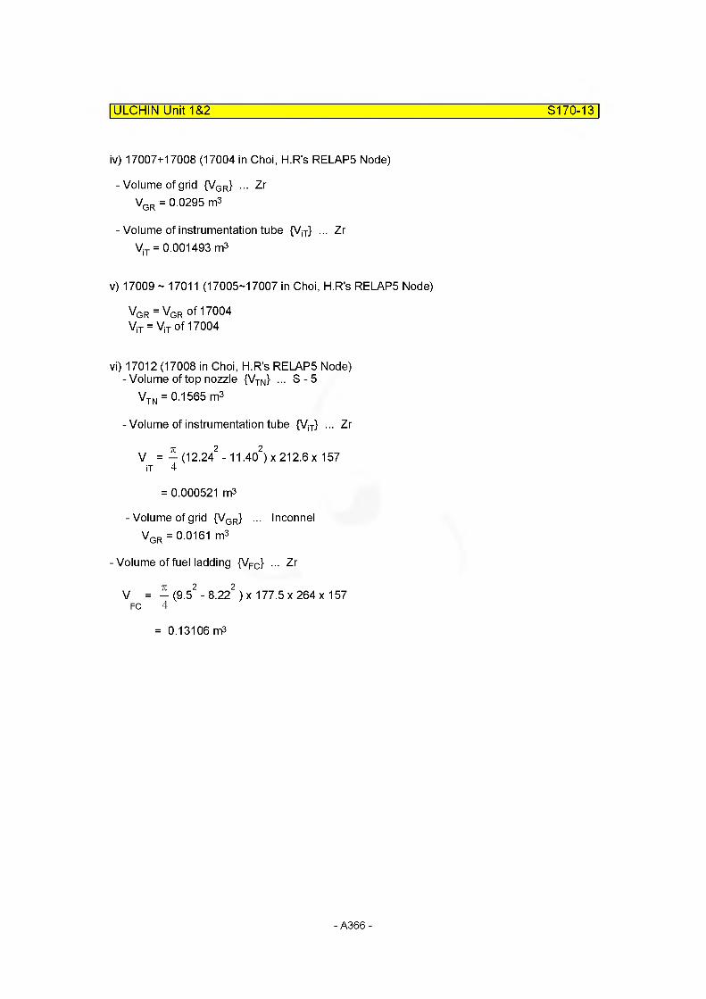
ULCHIN Unit 1&2 S170-13
iv) 17007+17008 (17004 in Choi, H R's RELAP5 Node)
-Volume of grid {VGR} ... Zr VGR = 0.0295 m3
- Volume of instrumentation tube {ViT} ... Zr ViT = 0.001493 m3
v) 17009 ~ 17011 (17005-17007 in Choi, H R's RELAP5 Node)
VGr = VGR of 17004 ViT = ViT of 17004
vi) 17012 (17008 in Choi, H R's RELAP5 Node)-Volume of top nozzle {VTN} ... S-5
VTN = 0.1565 m3
- Volume of instrumentation tube {ViT} ... Zr
V = -(12.242 - 11.402)x 212.6 x 157 iT 4
= 0.000521 m3
- Volume of grid {VGR} ... InconnelVGR = 0.0161 m3
-Volume of fuel ladding {VFC} ... Zr
V = - (9.52 - 8.222 ) x 177.5 x 264 x 157 FC 4
= 0.13106 m3
- A366-
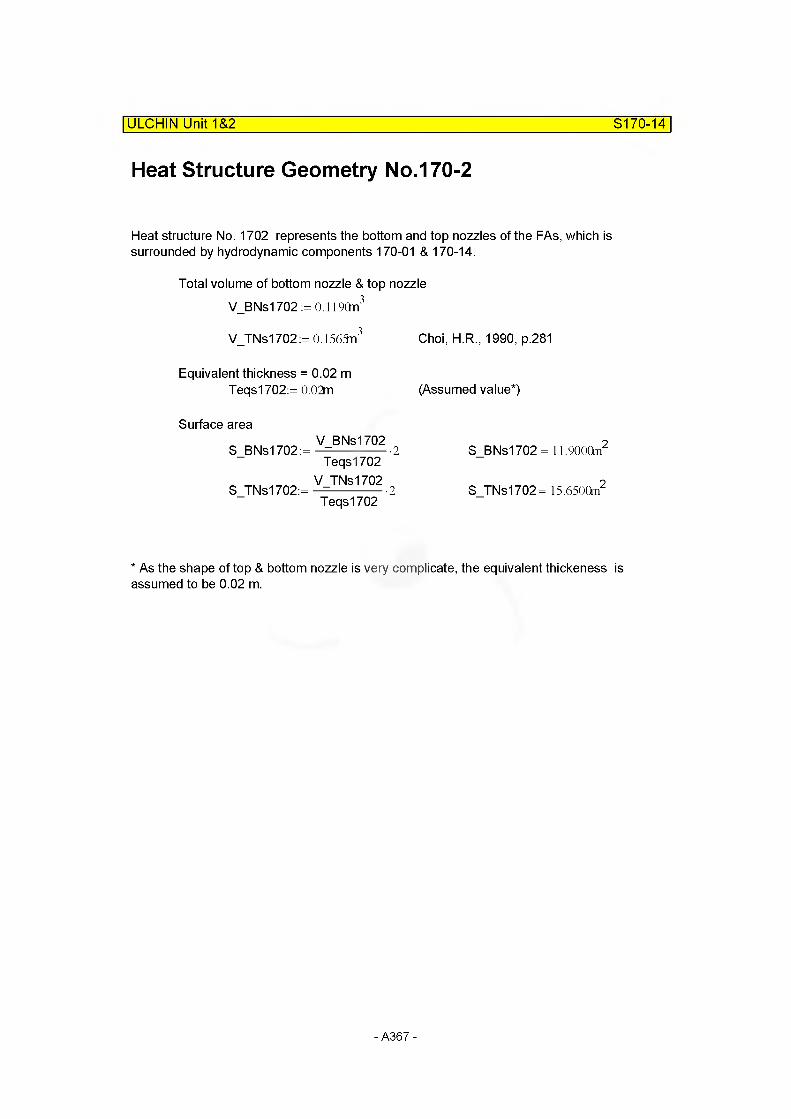
ULCHIN Unit 1&2 S170-14
Heat Structure Geometry No.170-2
Heat structure No. 1702 represents the bottom and top nozzles of the FAs, which is surrounded by hydrodynamic components 170-01 & 170-14.
Total volume of bottom nozzle & top nozzle V_BNs1702:=0.ll9Cm3
V_TNs1702:= 0.1565n3 Choi, H.R., 1990, p.281
Equivalent thickness = 0.02 mTeqs1702:= 0.02m (Assumed value*)
Surface areaV BNs1702 o
S_BNs1702:= —--------------2 S_BNs1702 = 11.9000mTeqs1702
V TNs1702 9S TNs1702:= —------------- 2 S TNs1702= 15.6500ni
Teqs1702
* As the shape of top & bottom nozzle is very complicate, the equivalent thickeness is assumed to be 0.02 m.
- A367-
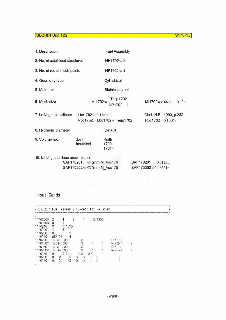
ULCHIN Unit 1&2 S170-15
1. Description
2. No. of axial heat structures
3. No. of radial mesh points
4. Geometry type
5. Materials
6. Mesh size
: Fuel Assembly
: NH1702:= 2
: NP1702:= 4
:Cylindrical
:Stainless-steel
: MI1702:= T6qS1702
NP1702- 1Ml 1702 = 6.6667x 10 3m
7. Left/right coordinate : Lbc1702:= 0.13CmRbc1702:= Lbc1702+ Teqsl 702
Choi, H.R., 1990, p.282 Rbc1702 =0.1500m
8. Hydraulic diameter : Default
9. Volume no. :Left Rigthinsulated 17001
17014
10. Left/right surface area(height)SAF170201 := 69.5mm N_Ass170 SAF170201 = 10.9115mSAF170202:= 93.2mm N Ass170 SAF 170202 = 14.6324m
Input Cards
* S1702 : Fuel Assembly (Except Active Core)
1702000 2 4 2 1 0.13001702100 0 11702101 3 0.15001702201 4 31702301 0.0 31702401 582.28 41702501 170010000 0 1 1 10.9115 11702502 170140000 0 1 1 14.6324 21702601 170010000 0 1 1 10.9115 11702602 170140000 0 1 1 14.6324 21702701 0 0.0 0 .0 0.0 21702801 0. 20. 20. 0. 0. 0. 0. 1 21702901 0. 20. 20. 0. 0. 0. 0. 1 2
- A368-

ULCHIN Unit 1&2 S170-16
Heat Structure Geometry No.170-3Heat structure No. 1703 represents the instrumentation tubes.
3 (Inconnel)
(Zr)
V_Gr1703lnco:= 0.0161m'
V IT1703Zr:=0.00l493n3
- Equivalent thickness of gridTe1703Gr:= 0.33Cmm Re1703Gr:= 130mm
- Equivalent thickness of instrumentaion tubeTe1703IT:= 0.42Cmm Re1703IT:= 5.7mmHe1703:= 95.7178n (Height)
- A369-

ULCHIN Unit 1&2 S170-17
1. Description
2. No. of axial heat structure
3. No. of radial mesh points
4. Geometry type
5. Materials
: Intrumentation tube
: NH1703:= 14
: NP1703:= 4
:Cylindrical
: Zr
6. Mesh size : Ml 1703:=Te1703IT
NP1703- 1MI1703 = 1.4000x 10 4m
7. Left/right coordinate : Lbc1703:= Re1703IT
Rbc1703:= Re1703IT+ Te1703IT
Lbc1703= 5.7000x 10 3m
Rbc1703 = 6.l200x 10“ 3m
8. Hydraulic diameter : Default
9. Volume no. :Leftinsulated
Rigth17001 ~17014
10. Left/right surface area(height)SAF170301 := 6.9708nm
SAF170302:=95.7178n
SAF170314:= 33.3782n
HS 1
SAF170302 = 47.8589m HS2-13
HS 14Choi, H.R., 1990, p.284
- A370-

ULCHIN Unit 1&2 S170-18
Input Cards
S1703 : Core Structure 1 (Except Active Core and Fuel Assembly)
1703000 14 4 2 1 0.00571703100 0 11703101 3 0.006121703201 3 31703301 0.0 31703401 582.28 41703501 170010000 0 1 1 6.9708 011703502 170020000 0 1 1 47.8589 021703503 170030000 0 1 1 47.8589 031703504 170040000 0 1 1 47.8589 041703505 170050000 0 1 1 47.8589 051703506 170060000 0 1 1 47.8589 061703507 170070000 0 1 1 47.8589 071703508 170080000 0 1 1 47.8589 081703509 170090000 0 1 1 47.8589 091703510 170100000 0 1 1 47.8589 101703511 170110000 0 1 1 47.8589 111703512 170120000 0 1 1 47.8589 121703513 170130000 0 1 1 47.8589 131703514 170140000 0 1 1 33.3782 141703601 170010000 0 1 1 6.9708 011703602 170020000 0 1 1 47.8589 021703603 170030000 0 1 1 47.8589 031703604 170040000 0 1 1 47.8589 041703605 170050000 0 1 1 47.8589 051703606 170060000 0 1 1 47.8589 061703607 170070000 0 1 1 47.8589 071703608 170080000 0 1 1 47.8589 081703609 170090000 0 1 1 47.8589 091703610 170100000 0 1 1 47.8589 101703611 170110000 0 1 1 47.8589 111703612 170120000 0 1 1 47.8589 121703613 170130000 0 1 1 47.8589 131703614 170140000 0 1 1 33.3782 141703701 0 0.0 0 .0 0.0 141703801 0. 20. 20. 0. 0. 0. 0. 'I. 141703901 0. 20. 20. 0. 0. 0. 0. 'I. 14
- A371 -
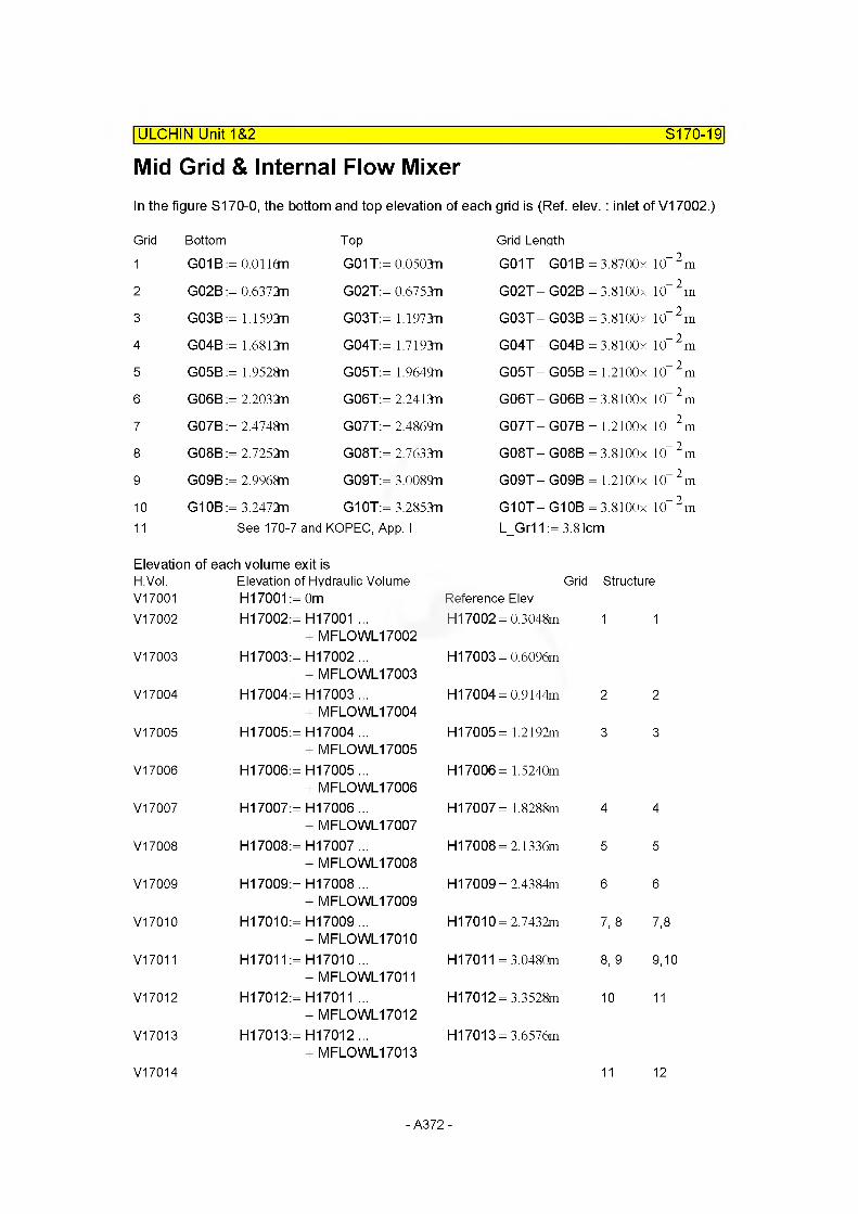
Mid Grid & Internal Flow MixerIn the figure S170-0, the bottom and top elevation of each grid is (Ref. elev. : inlet of V17002.)
| ULCHIN Unit 1&2 S170-19
Grid Bottom Top Grid Lenqth1 G01B::= 0.0116m G01T:= 0.0503m G01T- G01B = 3.8700x 10" 2m
2 G02B::= 0.6372TI G02T:= 0.6753m G02T- G02B = 3.8100x 10" 2m
3 G03B::= 1.1592n G03T:= 1.1973m G03T- G03B = 3.8100x 10" 2 m
4 G04B::= 1.6812n G04T:= 1.7193m G04T — G04B 3.8100x 10" 2 m
5 G05B::= 1.9528n G05T:= 1.9649n GOST G05B= 1.2100x 10" 2 m
6 G06B::= 2.2032T1 G06T:= 2.2413m G06T- G06B = 3.8100x 10" 2 m
7 G07B::= 2.4748n G07T:= 2.4869n G07T- G07B = 1.2100x 10" 2 m
8 G08B::= 2.7252n G08T:= 2.7633m GOST - G08B = 3.8100x 10" 2m
9 G09B: = 2.9968n G09T:= 3.0089n G09T- G09B = 1.2100x 10" 2m
10 G10B::= 3.2472n G10T:= 3.2853m G10T- G10B = 3.8100x 10" 2m
11 See 170-7 and KOPEC, App. I L_Gr11 := 3.81cm
Elevation of each volume exit isH.Vol. Elevation of Hydraulic VolumeV17001 H17001 := 0m
GridReference Elev
Structure
V17002 H17002: = H17001 ...+ MFLOWL17002
H17002 = 0.3048m 1 1
V17003 H17003: = 1-117002...+ MFLOWL17003
H17003 = 0.6096m
V17004 H17004: = H17003 ...+ MFLOWL17004
H17004 = 0.9144m 2 2
V17005 H17005: = H17004 ...+ MFLOWL17005
H17005= 1.2192m 3 3
V17006 H17006: = H17005 ...+ MFLOWL17006
H17006= 1.5240m
V17007 H17007: = H17006 ...+ MFLOWL17007
H17007= 1.8288m 4 4
V17008 H17008: = H17007 ...+ MFLOWL17008
H17008 = 2.1336m 5 5
V17009 H17009: = H17008 ...+ MFLOWL17009
H17009 = 2.4384m 6 6
V17010 H17010: = H17009 ...+ MFLOWL17010
H17010 = 2.7432m 7, 8 7,8
V17011 H17011: = H17010 ...+ MFLOWL17011
H17011 = 3.0480m 8,9 9,10
V17012 H17012: = H17011 ...+ MFLOWL17012
H17012= 3.3528m 10 11
V17013 H17013: = H17012 ...+ MFLOWL17013
H17013= 3.6576m
V17014 11 12
- A372-
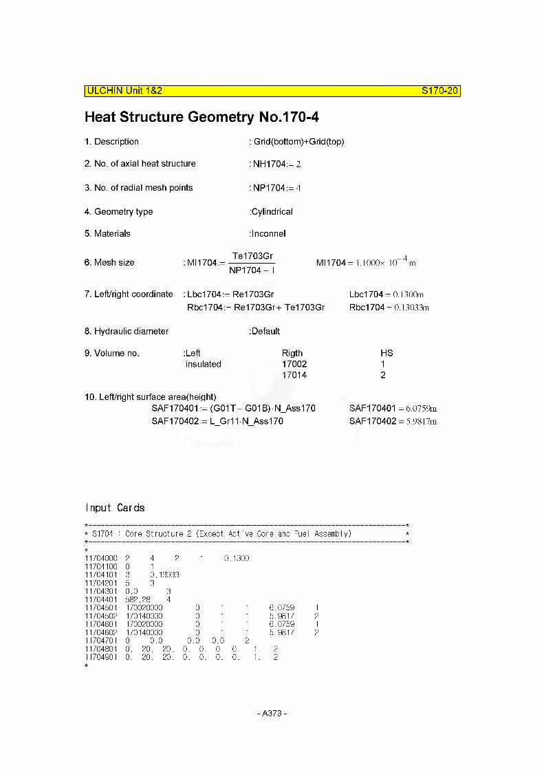
ULCHIN Unit 1&2 S170-20
Heat Structure Geometry No.170-41. Description
2. No. of axial heat structure
3. No. of radial mesh points
4. Geometry type
5. Materials
: Grid(bottom)+Grid(top)
: NH1704:= 2
: NP1704:= 4
:Cylindrical
:lnconnel
6. Mesh size : Ml 1704:=Te1703Gr
NP1704- 1MI1704 = l.lOOOx 10 4m
7. Left/right coordinate : Lbc1704:= Re1703GrRbc1704:= Re1703Gr+ Te1703Gr
Lbc1704 = 0.1300m Rbc1704= 0.13033m
8. Hydraulic diameter : Default
9. Volume no. :Left Rigthinsulated 17002
17014
HS12
10. Left/right surface area(height)SAF170401 := (G01T- G01B) N_Ass170 SAF170402:= L Gr11N Ass170
SAF 170401 = 6.0759m SAF170402 = 5.9817m
Input Cards
* S1704 : Core Structure 2 (Except Active Core and Fuel Assembly)
1704000 2 4 2 1 0.13001704100 0 11704101 3 0.130331704201 5 31704301 0.0 31704401 582.28 41704501 170020000 0 1 1 6.0759 11704502 170140000 0 1 1 5.9817 21704801 170020000 0 1 1 6.0759 11704802 170140000 0 1 1 5.9817 21704701 0 0.0 0 .0 0.0 21704801 0. 20. 20. 0. 0. 0. 0. 1 . 21704901 0. 20. 20. 0. 0. 0. 0. 1 . 2
- A373-
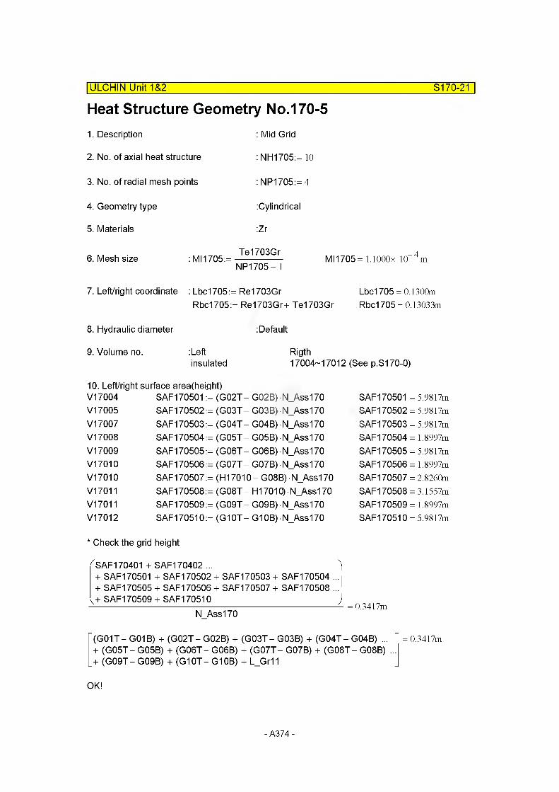
Heat Structure Geometry No.170-5| ULCHIN Unit 1&2 S170-21
1. Description
2. No. of axial heat structure
3. No. of radial mesh points
4. Geometry type
5. Materials
: Mid Grid
: NH1705:= 10
: NP1705:= 4
:Cylindrical
:Zr
6. Mesh size : Ml 1705:=Te1703Gr
NP1705- 1MI1705 = l.lOOOx 10 4m
7. Left/right coordinate : Lbc1705:= Re1703Gr Lbc1705 = 0.1300mRbc1705:= Re1703Gr+ Te1703Gr Rbc1705 = 0.13033m
8. Hydraulic diameter :Default
9. Volume no. :Left Rigthinsulated 17004-17012 (See p.S170-0)
10. Left/right surface area(height)V17004 SAF170501 := (G02T- G02B) N_Ass170V17005 SAF170502:= (G03T- G03B) N_Ass170V17007 SAF170503:= (G04T- G04B) N_Ass170V17008 SAF170504:= (GOST- G05B) N_Ass170V17009 SAF170505:= (G06T- G06B) N_Ass170V17010 SAF170506:= (G07T- G07B) N_Ass170V17010 SAF170507 := (H17010- G08B) • N_Ass170V17011 SAF170508:= (GOST - H17010) N_Ass170V17011 SAF170509:= (G09T- G09B) N_Ass170V17012 SAF170510:= (G10T-G10B) N_Ass170
SAF170501 = 5.9817m SAF170502 = 5.9817m SAF170503 = 5.9817m SAF170504= 1.8997m SAF170505 = 5.9817m SAF 170506= 1.8997m SAF170507 = 2.8260m SAF170508 = 3.1557m SAF 170509= 1.8997m SAF170510 = 5.9817m
* Check the grid height
f SAF170401 + SAF170402 ... )+ SAF170501 + SAF170502 + SAF170503 + SAF170504 ...i + SAF170505 + SAF170506 + SAF170507 + SAF170508 ...1
v+ SAF170509 + SAF170510 )N Ass170
0.3417m
(G01T- G01B) + (G02T- G02B) + (G03T- G03B) + (G04T- G04B) ... + (GOST- G05B) + (G06T- G06B) + (G07T- G07B) + (GOST - G08B) + (G09T-G09B) + (G10T-G10B) + L_Gr11
0.3417m
OK!
- A374-

ULCHIN Unit 1&2 S170-22
Input Cards
* S1705 : Core Structure 3 (Except Active Core and Fuel Assembly)
1705000 10 4 2 1 0.13001705100 0 11705101 3 0.130331705201 3 31705301 0.0 31705401 582.28 41705501 170040000 0 1 1 5.9817 11705502 170050000 0 1 1 5.9817 21705503 170070000 0 1 1 5.9817 31705504 170080000 0 1 1 1.8997 41705505 170090000 0 1 1 5.9817 51705506 170100000 0 1 1 1.8997 61705507 170100000 0 1 1 2.8260 71705508 170110000 0 1 1 3.1557 81705509 170110000 0 1 1 1.8997 91705510 170120000 0 1 1 5.9817 101705601 170040000 0 1 1 5.9817 11705602 170050000 0 1 1 5.9817 21705603 170070000 0 1 1 5.9817 31705604 170080000 0 1 1 1.8997 41705605 170090000 0 1 1 5.9817 51705606 170100000 0 1 1 1.8997 61705607 170100000 0 1 1 2.8260 71705608 170110000 0 1 1 3.1557 81705609 170110000 0 1 1 1.8997 91705610 170120000 0 1 1 5.9817 101705701 0 0.0 0 .0 0.0 101705801 0. 20. 20. 0. 0. 0. 0. 1. 101705901 0. 20. 20. 0. 0. 0. 0. 1. 10
- A375-
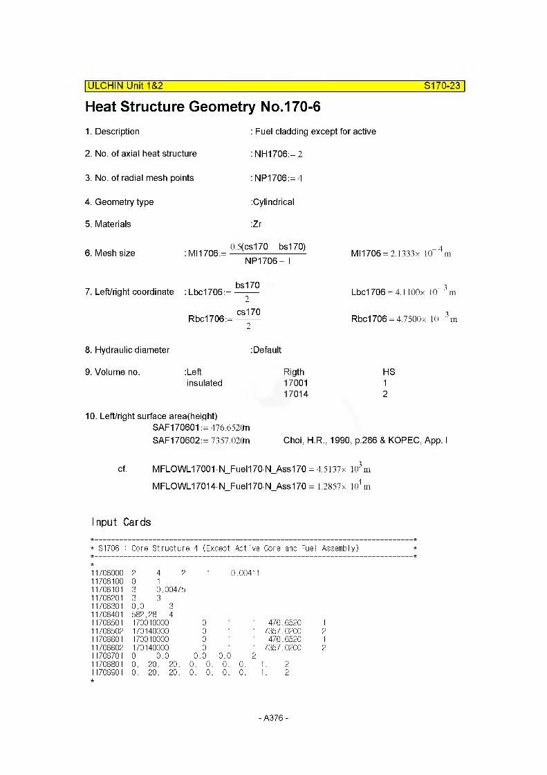
Heat Structure Geometry No.170-6| ULCHIN Unit 1&2 S170-23
1. Description
2. No. of axial heat structure
3. No. of radial mesh points
4. Geometry type
5. Materials
: Fuel cladding except for active
: NH1706:= 2
: NP1706:= 4
:Cylindrical
:Zr
6. Mesh size :MI1706:= 05(C5l7°~b5l70) NP1706- 1
7. Left/right coordinate :Lbc1706:=bs170
2
Rbc1706:=cs170
2
MI1706 = 2.1333x 10 4m
Lbc1706 = 4.1100x 10“ 3 m
Rbc1706 = 4.7500x 10“ 3 m
8. Hydraulic diameter : Default
9. Volume no. :Left Rigthinsulated 17001
17014
HS12
10. Left/right surface area(height)SAF170601 := 476.6520nSAF170602:= 7357.020n Choi, H.R., 1990, p.286 & KOPEC, App. I
cf. MFLOWL17001 • N_Fuel170- N_Ass170 = 4.5137x 10³m
MFLOWL17014 N Fuel170 N Ass170 = 1.2857x 10⁴m
Input Cards
* S1706 : Core Structure 4 (Except Active Core and Fuel Assembly)
1706000 2 4 2 1 0.004111706100 0 11706101 3 0.004751706201 3 31706301 0.0 31706401 582.28 41706501 170010000 0 1 1 476.6520 11706502 170140000 0 1 1 7357.0200 21706601 170010000 0 1 1 476.6520 11706602 170140000 0 1 1 7357.0200 21706701 0 0.0 0 .0 0.0 21706801 0. 20. 20. 0. 0. 0. 0. 1. 21706901 0. 20. 20. 0. 0. 0. 0. 1. 2
- A376-

STRUCTURE 180
ULCHIN Unit 1&2__________________________________________________ S180-0
Heat structure No. 180 represents heat structure of core bypass region, which consists of guide thimble, baffle, former, barrel and thermal shields (Neutron panel).
Ref: Choi , H. R. (1990) , p. 287
barrel
quicle thimble
thermal shield
Former
- A377-
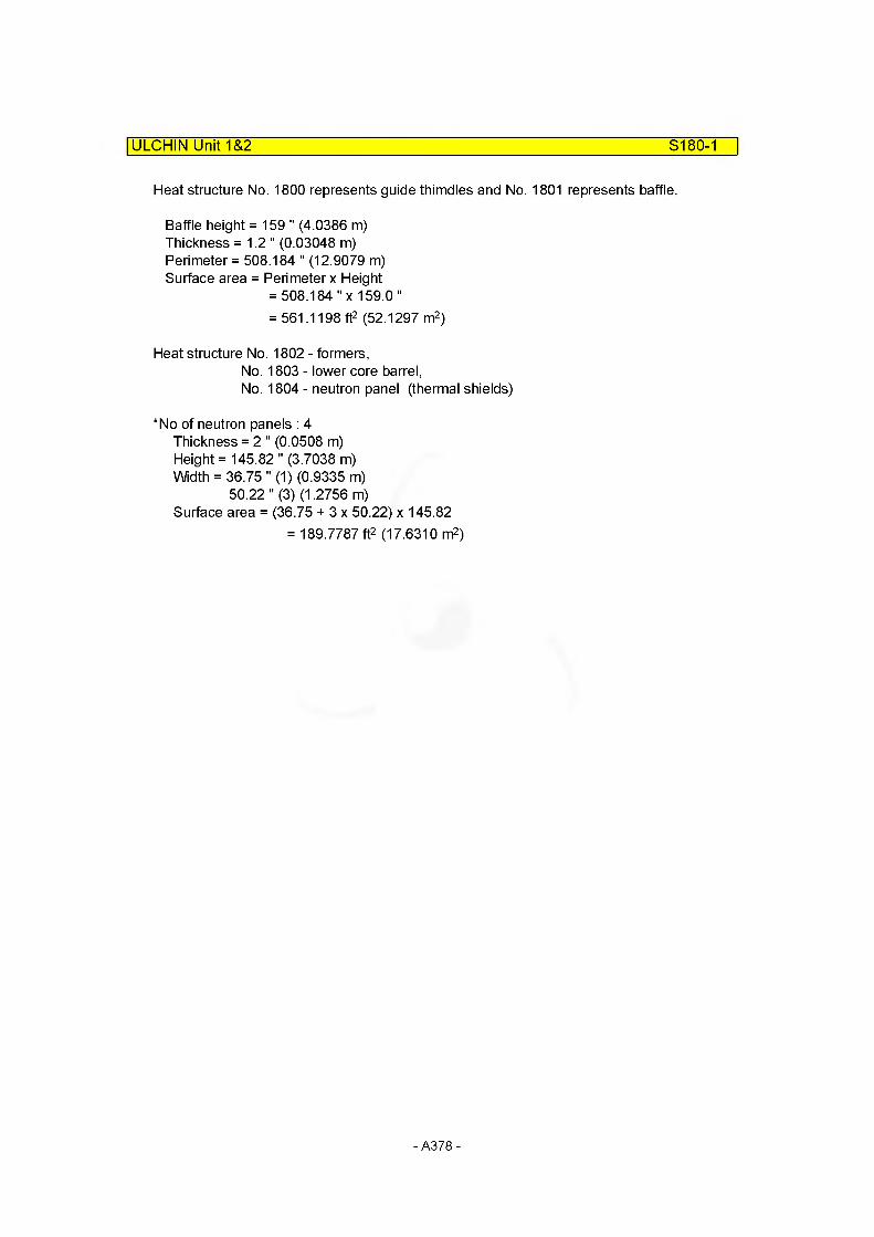
ULCHIN Unit 1&2 S180-1
Heat structure No. 1800 represents guide thimdles and No. 1801 represents baffle.
Baffle height = 159 " (4.0386 m)Thickness = 1.2" (0.03048 m)Perimeter = 508.184 " (12.9079 m)Surface area = Perimeter x Height
= 508.184 "x 159.0"= 561.1198 ft2 (52.1297 m2)
Heat structure No. 1802 - formers,No. 1803 - lower core barrel,No. 1804 - neutron panel (thermal shields)
*No of neutron panels : 4 Thickness = 2 " (0.0508 m)Height = 145.82 "(3.7038 m)Width = 36.75 " (1) (0.9335 m)
50.22 " (3) (1.2756 m)Surface area = (36.75 + 3 x 50.22) x 145.82
= 189.7787 ft2 (17.6310 m2)
- A378-
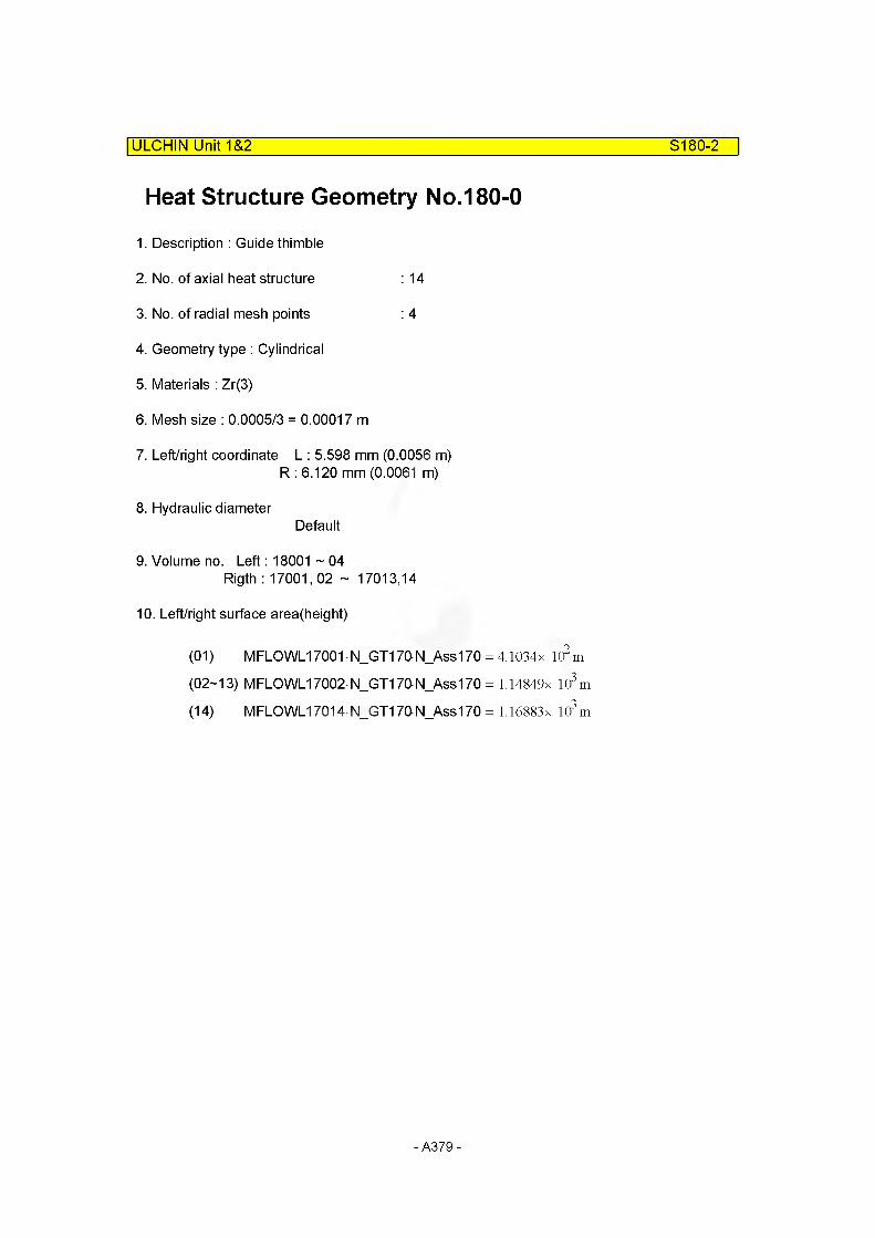
ULCHIN Unit 1&2 S180-2
Heat Structure Geometry No.180-0
1. Description : Guide thimble
2. No. of axial heat structure : 14
3. No. of radial mesh points : 4
4. Geometry type : Cylindrical
5. Materials : Zr(3)
6. Mesh size : 0.0005/3 = 0.00017 m
7. Left/right coordinate L : 5.598 mm (0.0056 m)R : 6.120 mm (0.0061 m)
8. Hydraulic diameterDefault
9. Volume no. Left: 18001 ~ 04Rigth : 17001,02 ~ 17013,14
10. Left/right surface area(height)
(01) MFLOWL17001 N_GT170N_Ass170 = 4.1034x l(?m (02-13) MFLGWL17002 N_GT170 N_Ass170 = 1.14849x 10³m
(14) MFLOWL17014N_GT170N_Ass170 = 1.16883 x 10³m
- A379-

ULCHIN Unit 1&2 S180-3
Input Cards
* S1800 : Core Bypass - Guide Thimble
1800000 14 4 2 1 0.00561800100 0 11800101 3 0.00611800201 3 31800301 0.0 31800401 582.28 41800501 180010000 0 1 1 410.34 11800502 180010000 0 1 1 1148.49 21800503 180010000 0 1 1 1148.49 31800504 180020000 0 1 1 1148.49 41800505 180020000 0 1 1 1148.49 51800506 180020000 0 1 1 1148.49 61800507 180020000 0 1 1 1148.49 71800508 180030000 0 1 1 1148.49 81800509 180030000 0 1 1 1148.49 91800510 180030000 0 1 1 1148.49 101800511 180030000 0 1 1 1148.49 111800512 180040000 0 1 1 1148.49 121800513 180040000 0 1 1 1148.49 131800514 180040000 0 1 1 1168.83 141800601 170010000 0 1 1 410.34 11800602 170020000 0 1 1 1148.49 21800603 170030000 0 1 1 1148.49 31800604 170040000 0 1 1 1148.49 41800605 170050000 0 1 1 1148.49 51800606 170060000 0 1 1 1148.49 61800607 170070000 0 1 1 1148.49 71800608 170080000 0 1 1 1148.49 81800609 170090000 0 1 1 1148.49 91800610 170100000 0 1 1 1148.49 101800611 170110000 0 1 1 1148.49 111800612 170120000 0 1 1 1148.49 121800613 170130000 0 1 1 1148.49 131800614 170140000 0 1 1 1168.83 141800701 0 0.0 0.0 0.0 141800801 0. 20. 20. 0. 0. 0. 0. 1 141800901 0. 20. 20. 0. 0. 0. 0. 1 14
- A380-
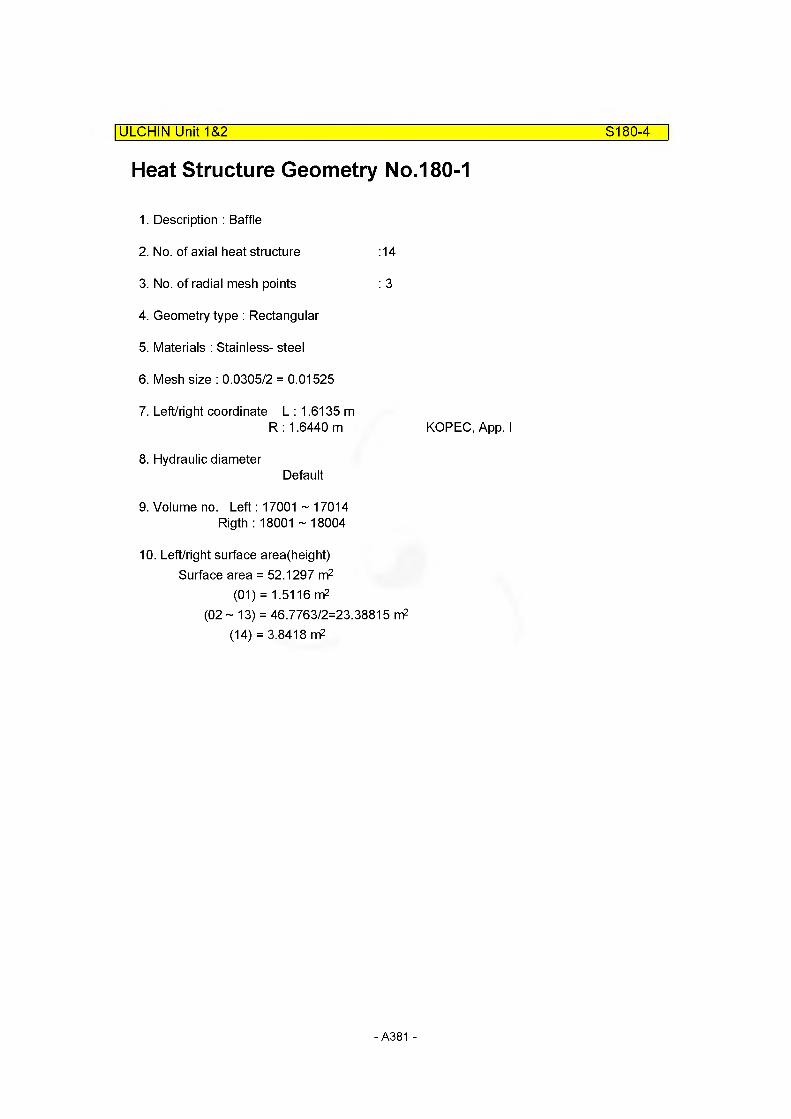
ULCHIN Unit 1&2 S180-4
Heat Structure Geometry No.180-1
1. Description : Baffle
2. No. of axial heat structure :14
3. No. of radial mesh points : 3
4. Geometry type : Rectangular
5. Materials : Stainless- steel
6. Mesh size : 0.0305/2 = 0.01525
7. Left/right coordinate L : 1.6135 mR : 1.6440 m KOPEC, App. I
8. Hydraulic diameterDefault
9. Volume no. Left: 17001 ~ 17014Rigth : 18001 ~ 18004
10. Left/right surface area(height)Surface area = 52.1297 m2
(01) = 1.5116 m2(02 ~ 13) = 46.7763/2=23.38815 nf
(14) = 3.8418 m2
- A381 -
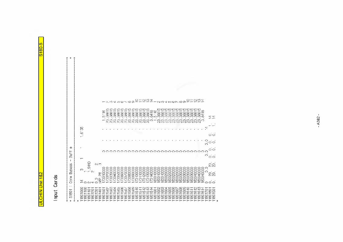
CO"O
c5o
O T— CD CD xh O T— CD CO xhCXJ CO xh LO CO co CD 2 3 4 LO CO 00 CD
LO LO LO LO LO LO LO LO LO LO LO LO00
LO LO LO LO LO LO LO LO LO LO LO LO00CD CD
m no no no no no no no 00 00 00 no 00 00 00 no no no no no 00 CO 00 no<n no no no no no m no 00 00 00 no xh 00 00 00 (X) (X) U) CD 00 00 00 CD xh
LQ CD CD CD CD CD CD CD CD CO CO CO CD 00 LO CO CO CO CO CO CO CO CD CO CO CO CD CD
i— CO CO CO CO CO CO CO CO CO CO CO CO CO CO CO CO CO CO CO CO CO CO CO CO CO COLVJ CD CD CD CD CD CD CD CD CD CD CD CD CD CD CD CD CD CD CD CD CD CD CD
oooooooooooooooooooooooooooooo
ICO o o o o o o o o o o o o o o o o o o o o o o o o o o o o o
Q. CO o o o o o o o o o o o o o o o o o o o o o o o o o o o o>, •’— ■*— CD o o o o o o o o o o o o o o o o o o o o o o o o o o o o o
CO 00 o o o o o o o o o o o o o o o o o o o o o o o o o o o o o oCD CD CO xh LO CO h- 00 CD o CD CD xh CD CD CD CD CD CD CD CD xh xh xh CD CD
CD o o o o o o o o o o o o o o o o o o o o o o oO CD o o o o o o o o o o o o o o o o o o o o o o o o o o o o
O h~~ h- h~~ h- h~~ h- h- h- 00 00 00 00 00 00 00 00 00 00 00 00 00 00o ’-OCDxt'OLO 1 0 0 o
O O T--- -1--- -1-- -1— CD CO xh LO CO h- 00 CD o CD CD xh CD CD xh LO CO 00 CD o CD CD X|- T— T—o o o o o o o o o o o o o o o o o o o o o o o o T— O O o
O O CD CO xh LO LO LO LO LO LO LO LO LO LO LO LO LO LO CO CO CO CO CO CO CO CO CO CO CO CO CO CO D- CO CD00
o o o o o o o o o o o o o o o o o o o o o o o o o o o o o o o o o o o o oCD 00 00 00 00 00 00 00 00 00 00 00 00 00 00 00 00 00 00 00 00 00 00 00 00 00 00 00 00 00 00 00 00 00 00 00 00 00
- A38
2-
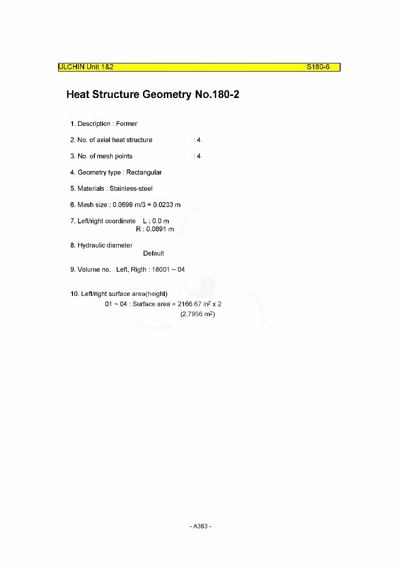
ULCHIN Unit 1&2 S180-6
Heat Structure Geometry No.180-2
1. Description : Former
2. No. of axial heat structure : 4
3. No. of mesh points : 4
4. Geometry type : Rectangular
5. Materials : Stainless-steel
6. Mesh size : 0.0699 m/3 = 0.0233 m
7. Left/right coordinate L : 0.0 mR : 0.0691 m
8. Hydraulic diameterDefault
9. Volume no. Left, Rigth : 18001 ~ 04
10. Left/right surface area(height)01 - 04 : Surface area = 2166.67 in2 x 2
(2.7956 m2)
- A383-

ULCHIN Unit 1&2 S180-7
Input Cards
* S1802 : Core Bypass - Former
1802000 4 4 I 1 1 .62871802100 0 11802101 3 1.69861802201 4 31802301 0.0 31802401 582.28 41802501 180010000 10000 1 1 2.79561802601 180010000 10000 1 1 2.79561802701 0 0.0 0.0 0.0 41802801 0. 20. 20. 0. 0. 0. 0. 1.. 41802901 0. 20. 20. 0. 0. 0. 0. 1.. 4
- A384-
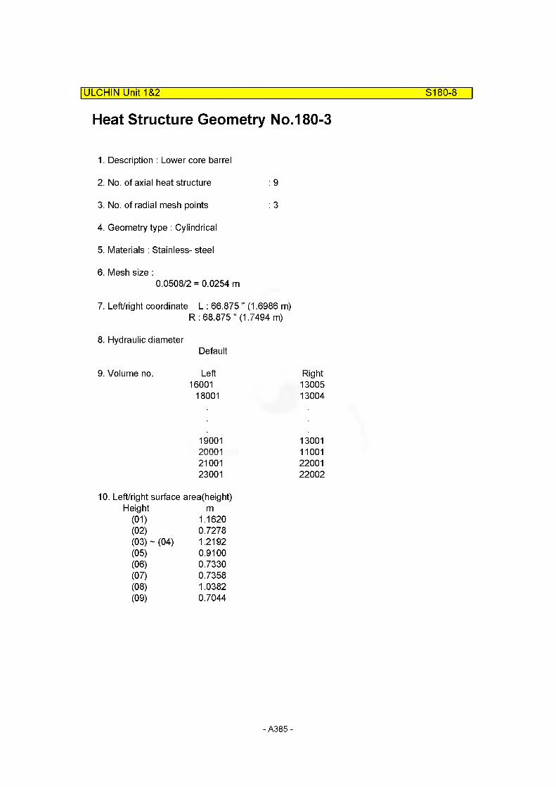
Heat Structure Geometry No.180-3
ULCHIN Unit 1&2___________________________________________________ S180-8
1. Description : Lower core barrel
2. No. of axial heat structure : 9
3. No. of radial mesh points : 3
4. Geometry type : Cylindrical
5. Materials : Stainless- steel
6. Mesh size :0.0508/2 = 0.0254 m
7. Left/right coordinate L : 66.875 " (1.6986 m)R : 68.875 " (1.7494 m)
8. Hydraulic diameterDefault
9. Volume no. Left Right16001 13005
18001 13004
19001 1300120001 1100121001 2200123001 22002
10. Left/right surface area(height)Height m
(01) 1.1620(02) 0.7278(03) ~ (04) 1.2192(05) 0.9100(06) 0.7330(07) 0.7358(08) 1.0382(09) 0.7044
A385-

ULCHIN Unit 1&2 S180-9
Input Cards
* S1803 : Core Bypass - Barrel
11803000 9 3 2 1 1 .698611803100 0 111803101 2 1.749411803201 4 211803301 0.0 211803401 582.28 311803501 160010000 0 1 1 1.1620 111803502 180010000 0 1 1 0.7278 211803503 180020000 10000 1 1 1.2192 411803504 180040000 0 1 1 0.9100 511803505 190010000 0 1 1 0.7330 611803506 200010000 0 1 1 0.7358 711803507 210010000 0 1 1 1.0382 811803508 230010000 0 1 1 0.7044 911803601 130050000 0 1 1 1.1620 111803602 130040000 0 1 1 0.7278 211803603 130030000 - 10000 1 1 1.2192 411803604 130010000 0 1 1 0.9100 511803605 120010000 0 1 1 0.7330 611803606 110010000 0 1 1 0.7358 711803607 220010000 0 1 1 1.0382 811803608 220020000 0 1 1 0.7044 911803701 0 0.0 0.0 0.0 911803801 0. 20. 20. 0. 0. 0. 0. 1 911803901 0. 20. 20. 0. 0. 0. 0. 1 9
- A386-

For t
he 3
dow
ncom
er m
odel
OOCO
CO
- (XJ LO CO N- 00 - (XJ Tj- LO CO N- 00
O 00 (XJ O O (XJ O 00 (XJ O O (XJ CO CO CO CO CO CO(XJ N- CD O CO 00 -sf (XJ N- CD O CO 00 LO LO LO LO LO LOCO CM 1— ''— CO CO o 0 C\J 1— ''— CO CO o xh xh xh xj- xj- xj-■’— NCVJONON ■’— NC\J 0N ON 00 00 CXJ CXJ CXJ CXJ CXJ CXJ
f— O'1— O O 1— O f— O'1— O O 1— O o o o o o o
CO oo CO CO00 00CD CDCO o o CO o o
o oo o o ooCXJ
oCD 1— C) o 1— o oo o o o o o o o o o o o o o o o o o o o o oo o03 o o o o o
CO o o o o o o1 CXJ CXJ
xh o xhw CD CXJ CO o o CD (XJ CO o ow xj- CXJ CXJ d xh CXJ CXI03 N~ o o o o o o o o o o o o o o o N- o o o o o o oQ. o o o o o o o o o o o o o o o o o o o oN CO •’— •’— CXJ o o o o o o o o o o o o o o o "O CO CXJ o o o o o o o
CO 00 o o o o o o o o o o o o o o o o CD 00 o o o o o o o oCXJ CXJ x)- LO x)- CO CXI CXJ CXJ "O CXJ CXJ CXI
CD o o o o o o o o o o o o o o o o o o o oo CXJ o o o o o o o o o o o o o o > o CXJ o o o o CXJ X)-O 00 CO 00 00 00 CD CO CO CO CO CO CXJ CXJ CXI 00 o o oo 8 0 2 4 0 LO CXJ CXJ CXJ CXJ
00 o "O 3 0 2 4 0 LO CXJ CXJ CXJ
00 o
O O T— T— T— CXJ CO X)- LO CO N~ CXJ CO X)- LO CO N~ o o CXJ CO CXJ coCO o o o o o o o o o o o o o o o o o o o o o o o o o o o o o o o o o o o o o oo O'1— ■*— CXJ CO xl" LO LO LO LO LO LO LO CO CO CO CO CO CO CO N- 00 03 O ^— CXI CO xh LO LO LO CO CO CO N- 00 CD00 CO CO CO CO CO CO CO CO CO CO CO CO CO CO CO CO CO CO CO CO CO CO CO o LQ LQ LQ LQ LQ LO LO LO LO LO LO LO LO LO LOo o o o o o o o o o o o o o o o o o o o o o o o o o o o o o o o o o o o o o00 00 00 00 00 00 00 00 00 00 00 00 00 00 00 00 00 00 00 00 00 00 00 00 00 00 00 00 00 00 00 00 00 00 00 00 00 00 00
- A38
7-

ULCHIN Unit 1&2 S180-11
Heat Structure Geometry No.180-4
1. Description : Thermal shield
2. No. of axial heat structure
3. No. of radial mesh points
4. Geometry type : Rectangular
5. Materials : Stainless- steel
6. Mesh size : 0.0508/3 = 0.0169
7. Left/right coordinate L : 3.4989 mR : 3.5497 m
8. Hydraulic diameterDefault
: 4
: 4
KOPEC, App. I
9. Volume no. Left: 0 Right: 13004030201
10. Left/right surface area(height)
(01) AREA = 28 655 x 17.6310 = 3.4647 m2145.82
(02 ~ 03) = x 17.6310 = 5.8036 m2145.82
(04) = x 17.6310 = 2.5590 m2145.82
- A388-
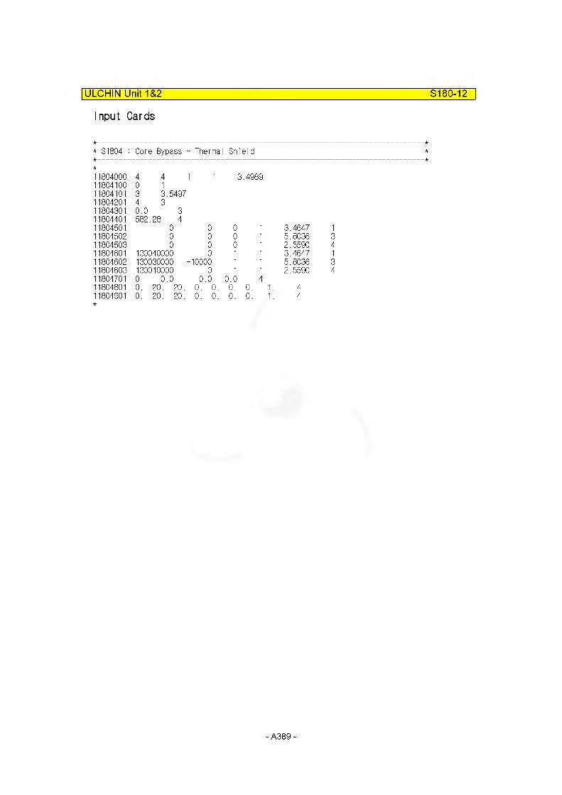
ULCHIN Unit 1&2 S180-12
Input Cards
* S1804 : Core Bypass - Thermal Shield
1804000 4 4 1 1 3.49891804100 0 11804101 3 3.54971804201 4 31804801 0.0 31804401 582.28 41804501 0 0 0 1 3.4647 11804502 0 0 0 1 5.8036 31804503 0 0 0 1 2.5590 41804801 130040000 0 1 1 3.4647 11804802 130030000 -10000 1 1 5.8036 31804803 130010000 0 1 1 2.5590 41804701 0 0.0 0.0 0.0 41804801 0. 20. 20 . 0. 0. 0. 0. 1. 41804901 0. 20. 20 . 0. 0. 0. 0. 1. 4
- A389-
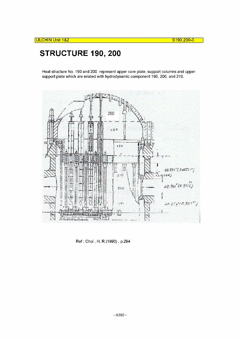
ULCHIN Unit 1&2 S190,200-0
STRUCTURE 190, 200
Heat structure No. 190 and 200 represent upper core plate, support columns and upper support plate which are related with hydrodynamic component 190, 200, and 210.
Ref: Choi , H. R.(1990) , p.294
- A390-
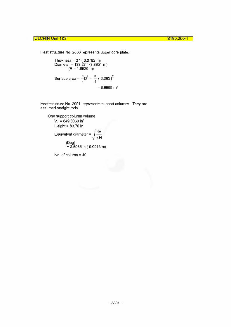
ULCHIN Unit 1&2 8190,200-1
Heat structure No. 2000 represents upper core plate.
Thickness = 3 " (0.0762 m)Diameter = 133.27 " (3.3851 m)
(R = 1.6926 m)
Surface area = —D2 = — x 3.385124 4
= 8.9998 m2
Heat structure No. 2001 represents support columns. They are assumed straight rods.
One support column volume V1 = 849.8360 in3 Height = 83.70 in
Equivalent diameter =
(Deg)= 3.5955 in (0.0913 m)
No. of column = 40
- A391 -
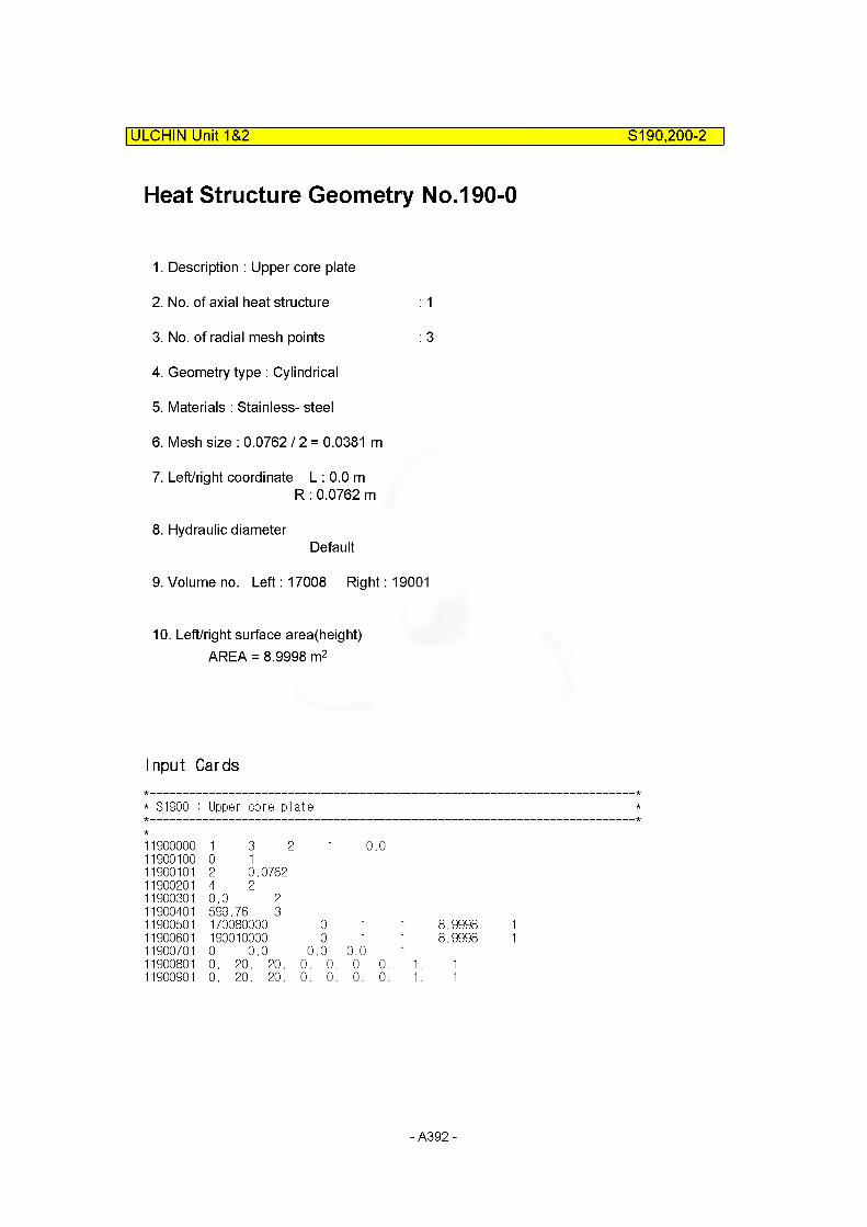
ULCHIN Unit 1&2 S190,200-2
Heat Structure Geometry No.190-0
1. Description : Upper core plate
2. No. of axial heat structure : 1
3. No. of radial mesh points : 3
4. Geometry type : Cylindrical
5. Materials : Stainless- steel
6. Mesh size : 0.076212 = 0.0381 m
7. Left/right coordinate L : 0.0 mR : 0.0762 m
8. Hydraulic diameterDefault
9. Volume no. Left: 17008 Right: 19001
10. Left/right surface area(height)AREA = 8.9998 m2
Input Cards
* S1900 : Upper core plate
1900000 1 3 2 1 0.01900100 0 11900101 2 0.07621900201 4 21900301 0.0 21900401 599.76 31900501 170080000 0 1 1 8.99981900601 190010000 0 1 1 8.99981900701 0 0.0 0 .0 0.0 11900801 0. 20. 20. 0. 0. 0. 0. 1. 11900901 0. 20. 20. 0. 0. 0. 0. 1. 1
- A392-
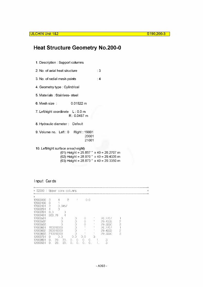
ULCHIN Unit 1&2 S190,200-3
Heat Structure Geometry No.200-0
1. Description : Support columns
2. No. of axial heat structure : 3
3. No. of radial mesh points : 4
4. Geometry type : Cylindrical
5. Materials : Stainless- steel
6. Mesh size : 0.01522 m
7. Left/right coordinate L : 0.0 mR : 0.0457 m
8. Hydraulic diameter: Default
9. Volume no. Left: 0 Right: 190012000121001
10. Left/right surface area(height)(01) Height = 25.857 " x 40 = 26.2707 m(02) Height = 28.970 " x 40 = 29.4335 m(03) Height = 28.873 " x 40 = 29.3350 m
Input Cards
* S2000 : Upper core columns
12000000 3 4 2 1 0.012000100 0 112000101 3 0.045712000201 4 312000301 0.0 312000401 599.76 412000501 0 0 0 1 26.2707 112000502 0 0 0 1 29.4335 212000503 0 0 0 1 29.3350 312000601 190010000 0 1 1 26.2707 112000602 200010000 0 1 1 29.4335 212000603 210010000 0 1 1 29.3350 312000701 0 0.0 0 .0 0.0 312000801 0. 20. 20. 0. 0. 0. 0. 1 312000901 0. 20. 20. 0. 0. 0. 0. 1 3
- A393-

Heat Structure Geometry No.200-1
Heat structure No. 2001 represents upper support plate.
Thickness = 12 " (0.3048 m)Diameter = 133.08 " (3.3802 m)One surface area
= -D2 = - x 3.380224 4
= 8.9739 m2
1. Description : Upper support plate
2. No. of axial heat structure : 1
3. No. of radial mesh points : 5
4. Geometry type : Rectangular
5. Materials : Stainless- steel
6. Mesh size : 0.3048/4 = 0.0762 m
7. Left/right coordinate L : 0.0 mR : 0.3048 m
8. Hydraulic diameterDefault
9. Volume no. Left: 21001 Right: 23001
10. Left/right surface area(height)AREA = 8.9739 m2
ULCHIN Unit 1&2______________________________________________ S190,200-4
Input Cards
* S2001 : Upper support plate
12001000 1 5 1 1 0.012001100 0 112001101 4 0.304812001201 4 412001301 0.0 412001401 599.76 512001501 210010000 0 1 1 8.9739 112001601 230010000 0 1 1 8.9739 112001701 0 0.0 0 .0 0.0 112001801 0. 20. 20. 0. 0. 0. 0. 1. 112001901 0. 20. 20. 0. 0. 0. 0. 1. 1
- A394-

STRUCTURE 240, 260
ULCHIN Unit 1&2______________________________________________ 8240,260-0
Heat structure No. 240 and 260 represent reactor vessel wall of upper head which are related with hydrodynamic component 240 and 260, respectively.
Heat structure geometry No. 2400 is reactor vessel wall.
- A395-
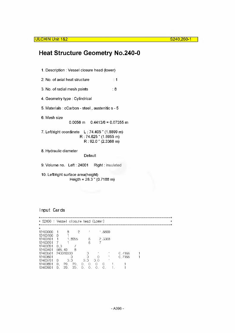
Heat Structure Geometry No.240-0
1. Description : Vessel closure head (lower)
2. No. of axial heat structure : 1
3. No. of radial mesh points : 8
4. Geometry type : Cylindrical
5. Materials : cCarbon - steel, austenitic s - 5
6. Mesh size0.0056 m 0.4413/6 = 0.07355 m
7. Left/right coordinate L : 74.405 " (1.8899 m)R : 74.625 " (1.8955 m)
R : 92.0 " (2.3368 m)
8. Hydraulic diameterDefault
9. Volume no. Left: 24001 Right: insulated
10. Left/right surface area(height)Heigth = 28.3 " (0.7188 m)
ULCHIN Unit 1&2______________________________________________ 8240,260-1
Input Cards
* S2400 : Vessel closure head (Lower)
1240000012400100
10
8 21
1
12400101 1 1.8955 612400201 7 1 612400301 0.0 712400401 565,.40 812400501 240010000 012400601 0 012400701 0 0.0 0 .012400801 0. 20. 20. 0. 012400901 0. 20. 20. 0. 0
1.8899
2.33687
1 1 0.7188 10 1 0.7188 1
0.0 10. 0. 1. 10. 0. 1. 1
- A396-
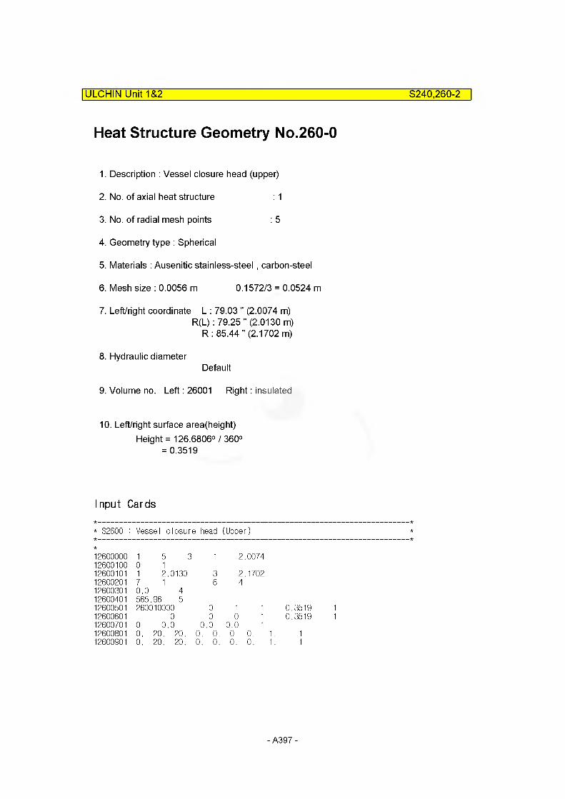
ULCHIN Unit 1&2 3240,260-2
Heat Structure Geometry No.260-0
1. Description : Vessel closure head (upper)
2. No. of axial heat structure : 1
3. No. of radial mesh points : 5
4. Geometry type : Spherical
5. Materials : Ausenitic stainless-steel, carbon-steel
6. Mesh size : 0.0056 m 0.1572/3 = 0.0524 m
7. Left/right coordinate L : 79.03 " (2.0074 m)R(L): 79.25 "(2.0130 m)
R: 85.44 "(2.1702 m)
8. Hydraulic diameterDefault
9. Volume no. Left: 26001 Right: insulated
10. Left/right surface area(height)Height = 126.6806° / 360°
= 0.3519
Input Cards
* S2600 : Vessel closure head (Upper)
1260000012600100
10
5 31
1
12600101 1 2.0130 312600201 7 1 612600301 0.0 412600401 565,.96 512600501 260010000 012600601 0 012600701 0 0.0 0 .012600801 0. 20. 20. 0. 012600901 0. 20. 20. 0. 0
2.0074
2.17024
1 1 0.3519 10 1 0.3519 1
0.0 10. 0. 1. 10. 0. 1. 1
- A397-
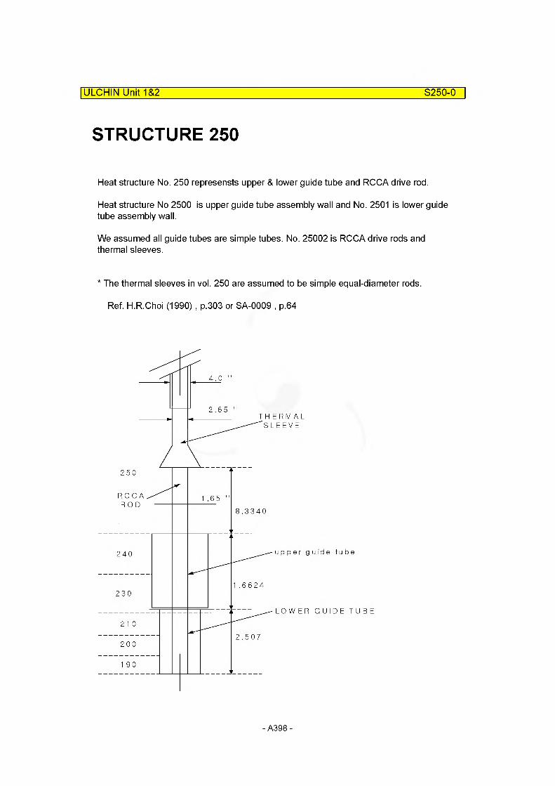
ULCHIN Unit 1&2 S250-0
STRUCTURE 250
Heat structure No. 250 represensts upper & lower guide tube and RCCA drive rod.
Heat structure No 2500 is upper guide tube assembly wall and No. 2501 is lower guide tube assembly wall.
We assumed all guide tubes are simple tubes. No. 25002 is RCCA drive rods and thermal sleeves.
* The thermal sleeves in vol. 250 are assumed to be simple equal-diameter rods.
Ref. H.R.Choi (1990) , p.303 or SA-0009 , p.64
2.65THERMAL
SLEEVE
RCCA 1.65ROD
8.3340
u id e tubeupper
1.6624
LOWER GUIDE TUBE
2.507
-A398-

Heat Structure Geometry No.250-0
1. Description : Guide tube upper assembly wall
2. No. of axial heat structure : 2
3. No. of radial mesh points : 3
4. Geometry type : Cylindrical
5. Materials : Stainless-steel
6. Mesh size0.0065 m
7. Left/right coordinate L : 4.9886 in (0.1267m)R : 5.5 " (0.1397 m)
8. Hydraulic diameter : DL = 8.3171 " (0.2115 m)Dr = Default
9. Volume no. Left: 250 Right: 2400123001
10. Left/right surface area(height)Factor (01) = 0.913 x 52 = 47.7360 m
(02) = 0.7044 x 52 = 36.6288 m
ULCHIN Unit 1&2___________________________________________________S250-1
Input Cards
* S2500 : Guide tube upper assembly wall
12500000 2 3 2 1 0.126712500100 0 112500101 2 0.139712500201 4 212500301 0.0 212500401 566.33 312500501 250010000 0 1 1 47.7360 112500502 250010000 0 1 1 36.6288 212500601 240010000 0 1 1 47.7360 112500602 230010000 0 1 1 36.6288 212500701 0 0.0 0 .0 0.0 212500801 0. 20. 20. 0. 0. 0. 0. 1. 212500901 0. 20. 20. 0. 0. 0. 0. 1. 2
- A399-

Heat Structure Geometry No.250-1
ULCHIN Unit 1&2___________________________________________________S250-2
1. Description : Guide tube lower assembly
2. No. of axial heat structure : 3
3. No. of radial mesh points : 3
4. Geometry type : Cylindrical
5. Materials : Stainless-steel
6. Mesh size : 0.0296 m
7. Left/right coordinate L : 3.4192 " (0.0868m)R : 4.0 " (0.1016 m)
8. Hydraulic diameter : DL = 5.1884 " (0.1318 m)
9. Volume no. Left: 250 Right: 210012000119001
10. Left/right surface area(height)Factor (01) = 1.0382 x 52 = 53.9864 m
(02) = 0.7358 x 52 = 38.2616 m(03) = 0.1318x 52 = 6.8536 m
Input Cards
* S2501 : Guide tube lower assembly wall
12501000 3 3 2 1 0.086812501100 0 112501101 2 0.101612501201 4 212501301 0.0 212501401 566.33 312501501 250010000 0 1 1 53.9864 112501502 250010000 0 1 1 38.2616 212501503 250010000 0 1 1 6.8536 312501601 210010000 0 1 1 53.9864 112501602 200010000 0 1 1 38.2616 212501603 190010000 0 1 1 6.8536 312501701 0 0.0 0 .0 0.0 312501801 0. 20. 20. 0. 0. 0. 0. 1. 312501901 0. 20. 20. 0. 0. 0. 0. 1. 3
- A400 -
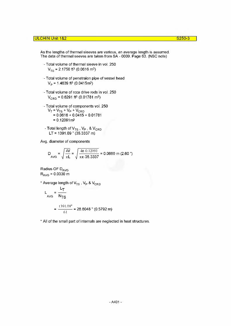
ULCHIN Unit 1&2 S250-3
As the lengths of thermal sleeves are various, an average length is assumed. The data of thermal seeves are taken from SA - 0009. Page 63. (NSC note)
- Total volume of thermal sleeve in vol. 250VTS = 2.1750 ft3 (0.0616 m3)
- Total volume of penetraion pipe of vessel headVp = 1.4639 ft3 (0.0415m3)
- Total volume of rcca drive rods in vol. 250VCRD = 0.6291 ft3 (0.01781 m3)
- Total volume of components vol. 250Vj = VTS + VP + VCRD
= 0.0616 + 0.0415 + 0.01781 = 0.12091 m3
- Total length of Vjg , Vp , & VqRq LT= 1391.09 " (35.3337 m)
Avg. diameter of components
D = / — =AVG
4x 0.12091
7ix-35.33370.0660 m (2.60 ")
Radius OF DAVG RAvg = 0.0330 m
* Average length of VTS , VP & VCRD
AVG Nyg
1391.09"= ----------- = 28.8048 " (0.5792 m)
61 *
* All of the small part of internals are neglected in heat structures.
- A401 -

ULCHIN Unit 1&2 S250-4
Heat Structure Geometry No.250-2
1. Description : RCCA drive rod & Thermal sleeves
2. No. of axial heat structure : 6
3. No. of radial mesh points : 3
4. Geometry type : Cylindrical
5. Materials : Stainless-steel
6. Mesh size : 0.0330/2 = 0.0165 m
7. Left/right coordinate L : 0.0 mR: 0.0330 m
8. Hydraulic diameter : Default DL = 0Dr = 0.0660
9. Volume no. Left: 0.0 Right: 260012400123001210012000119001
10. Left/right surface area(height)HEIGHT (01) = 35.3337 m
(02) = 55.7418 m(03) = 42.9684 m(04) = 63.3302 m(05) = 44.8838 m(06) = 44.7130m
Sum from 02 to 06 = 251.6372 m
- A402 -
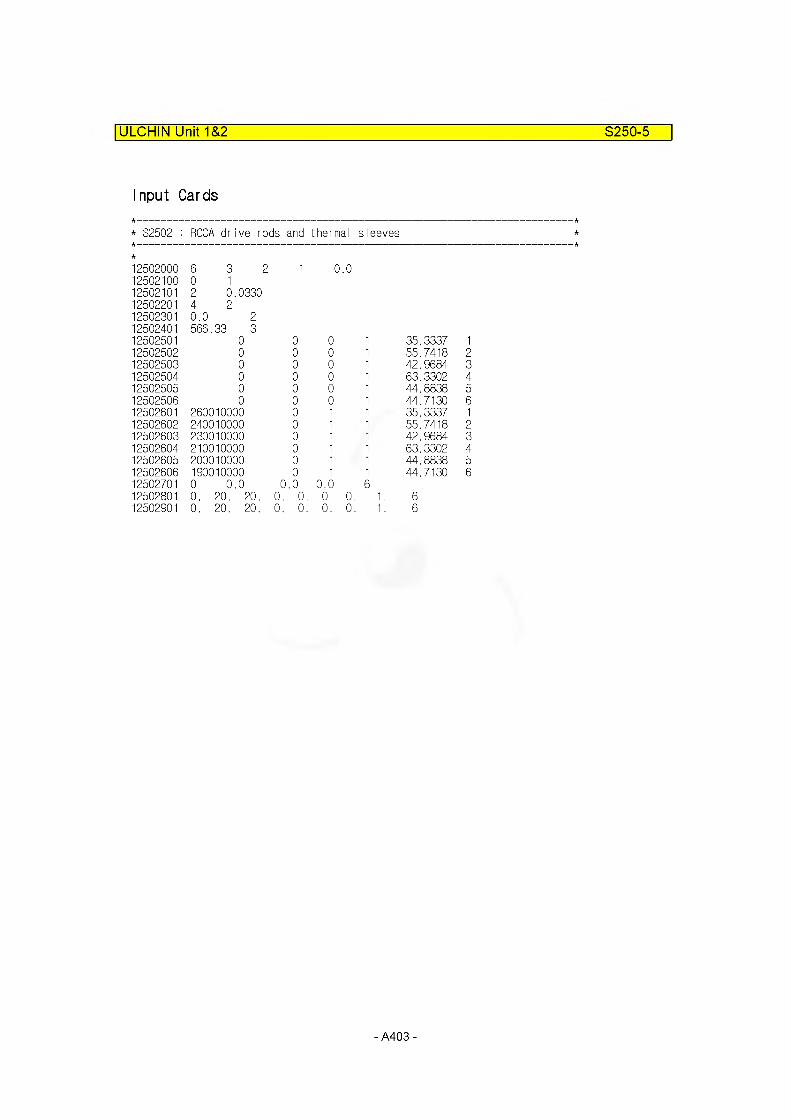
ULCHIN Unit 1&2 S250-5
Input Cards
* S2502 : RCCA drive rods and thermal sleeves
12502000 6 3 2 1 0 .012502100 0 112502101 2 0 .033012502201 4 212502301 0.0 212502401 566,
8
312502501 0 0 0 1 35.3337 112502502 0 0 0 1 55.7418 212502503 0 0 0 1 42.9684 312502504 0 0 0 1 63.3302 412502505 0 0 0 1 44.8838 512502506 0 0 0 1 44.7130 612502601 260010000 0 1 1 35.3337 112502602 240010000 0 1 1 55.7418 212502603 230010000 0 1 1 42.9684 312502604 210010000 0 1 1 63.3302 412502605 200010000 0 1 1 44.8838 512502606 190010000 0 1 1 44.7130 612502701 0 0 .0 0 .0 0.0 612502801 0. 20. 20. 0. 0. 0. 0. 1. 612502901 0. 20. 20. 0. 0. 0. 0. 1. 6
- A403 -
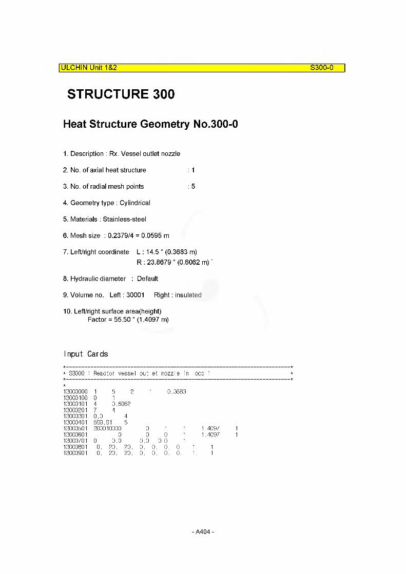
STRUCTURE 300
Heat Structure Geometry No.300-0
1. Description : Rx. Vessel outlet nozzle
2. No. of axial heat structure : 1
3. No. of radial mesh points : 5
4. Geometry type : Cylindrical
5. Materials : Stainless-steel
6. Mesh size : 0.2379/4 = 0.0595 m
7. Left/right coordinate L : 14.5 " (0.3683 m)R : 23.8679 " (0.6062 m) *
8. Hydraulic diameter : Default
9. Volume no. Left: 30001 Right: insulated
10. Left/right surface area(height)Factor = 55.50 " (1.4097 m)
ULCHIN Unit 1&2___________________________________________________S300-0
Input Cards
* S3000 : Reactor vessel outlet nozzle in loop 1
13000000 1 5 2 1 0 .368313000100 0 113000101 4 0.606213000201 7 413000301 0.0 413000401 599. 91 513000501 300010000 0 1 1 1.4097 113000601 0 0 0 1 1.4097 113000701 0 0.0 0.0 0.0 113000801 0. 20. 20. 0. 0. 0. 0. 1. 113000901 0. 20. 20. 0. 0. 0. 0. 1. 1
- A404 -

Heat Structure Geometry No.300-1
ULCHIN Unit 1&2___________________________________________________S300-1
1. Description : Rx. Vessel hot leg piiping
2. No. of axial heat structure : 4
3. No. of radial mesh points : 5
4. Geometry type : Cylindrical
5. Materials : Stainless-steel
6. Mesh size : 0.0635/4 = 0.0159 m
7. Left/right coordinate L : 14.5 " (0.3683 m)R: 17.0 "(0.4318 m)
8. Hydraulic diameter : Default
9. Volume no. Left: 30002 Right: insulated03
3100132001
0210. Left/right surface area(height)
Height: (01) = 1,0045m(02) = 1,0045m(03) = 1,4294m(04) = 1,4294m(05) = 1.1816m
Input Cards
* S3001 : Reactor vessel hot leg piping in loop 1
13001000 4 5 2 I 0 .368313001100 0 113001101 4 0.431813001201 7 413001301 0.0 413001401 599. 91 513001501 300020000 10000 1 1 0.9874 213001502 310010000 0 1 1 2.2098 313001503 320010000 0 1 1 1.2488 413001601 0 0 0 1 0.9874 213001602 0 0 0 1 2.2098 313001603 0 0 0 1 1.2488 413001701 0 0.0 0.0 0.0 413001801 0. 20. 20. 0. 0. 0. 0. 1. 413001901 0. 20. 20. 0. 0. 0. 0. 1. 4
- A405 -
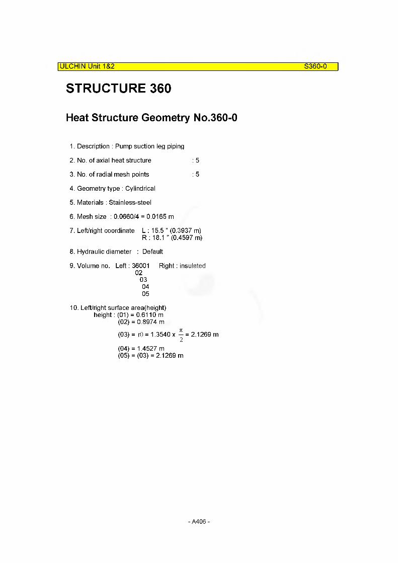
ULCHIN Unit 1&2 S360-0
STRUCTURE 360
Heat Structure Geometry No.360-0
1. Description : Pump suction leg piping
2. No. of axial heat structure : 5
3. No. of radial mesh points : 5
4. Geometry type : Cylindrical
5. Materials : Stainless-steel
6. Mesh size : 0.0660/4 = 0.0165 m
7. Left/right coordinate L : 15.5 " (0.3937 m)R : 18.1 " (0.4597 m)
8. Hydraulic diameter : Default
9. Volume no. Left: 36001 Right: insulated02
030405
10. Left/right surface area(height)height: (01) = 0.6110 m
(02) = 0.8974 m
(03) = r6 = 1.3540 x — = 2.1269 m2
(04) = 1.4527 m(05) = (03) = 2.1269 m
- A406 -
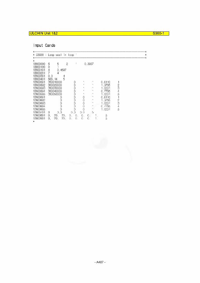
ULCHIN Unit 1&2 S360-1
Input Cards
* S3600 : Loop seal in loop 1
13600000 5 5 2 1 0 .393713600100 0 113600101 4 0.459713600201 7 413600301 0.0 413600401 566,. 14 513600501 360010000 0 1 1 0.6110 113600502 360020000 0 1 1 1.3795 213600503 360030000 0 1 1 1.0224 313600504 360040000 0 1 1 0.7795 413600505 360050000 0 1 1 1.0224 513600601 0 0 0 1 0.6110 113600602 0 0 0 1 1.3795 213600603 0 0 0 1 1.0224 313600604 0 0 0 1 0.7795 413600605 0 0 0 1 1.0224 513600701 0 0.0 0 .0 0.0 513600801 0. 20. 20. 0. 0. 0. 0. 1 513600901 0. 20. 20. 0. 0. 0. 0. 1 5
- A407 -

ULCHIN Unit 1&2 S370-0
STRUCTURE 370
Heat Structure Geometry No.370-0
1. Description : Cold leg (pump discharge) pipng
2. No. of axial heat structure : 5
3. No. of radial mesh points : 5
4. Geometry type : Cylindrical
5. Materials : Austenitic s-steel
6. Mesh size : 0.0589/4 = 0.0147 m
7. Left/right coordinate L : 13.75 " (0.3493 m)R: 16.07 " (0.4082 m)
8. Hydraulic diameter : Default
9. Volume no. Left: 37001 Right: insulated02
3800139001
02
10. Left/right surface area(height)height (01) MFLOWL37001 = 1.6500m
(02) MFLCWL37002 = 1.6500m(03) MFLOWL38001 = 1.0000m(04) MFLOWL39001 = 1.6967m(05) MFLOWL39002 = 0.7278m
- A408 -

ULCHIN Unit 1&2 S370-1
Input Cards
* S3700 : Cold Leg in Loop 1
13700000 5 5 2 1 0..349313700100 0 113700101 4 0.408213700201 4 413700301 0.0 413700401 566. 14 513700501 370010000 10000 1 1 1.6500 213700502 380010000 0 1 1 1.0000 313700503 390010000 0 1 1 1.6967 413700504 390020000 0 1 1 0.7278 513700601 0 0 0 1 1.6500 213700602 0 0 0 1 1.0000 313700603 0 0 0 1 1.6967 413700604 0 0 0 1 0.7278 513700701 0 0.0 0.0 0.0 513700801 0. 20. 20. 0. 0. 0. 0. 1. 513700901 0. 20. 20. 0. 0. 0. 0. 1. 5
- A409 -
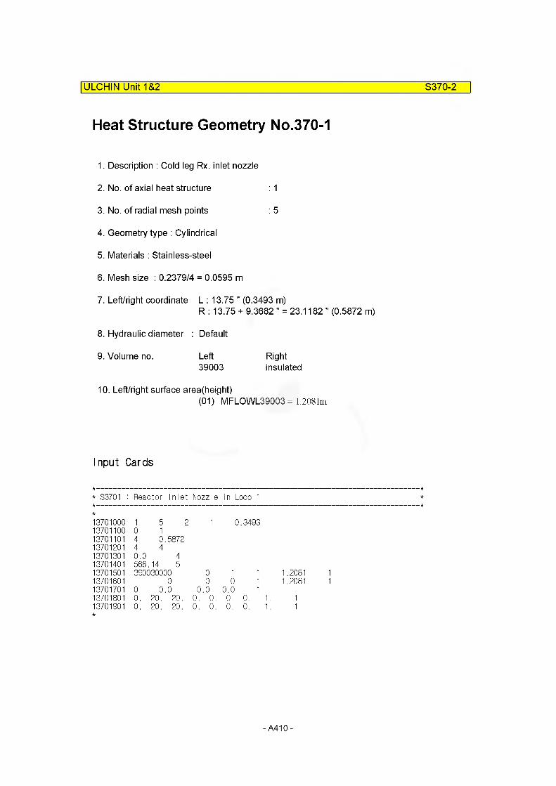
ULCHIN Unit 1&2 S370-2
Heat Structure Geometry No.370-1
1. Description : Cold leg Rx. inlet nozzle
2. No. of axial heat structure : 1
3. No. of radial mesh points : 5
4. Geometry type : Cylindrical
5. Materials : Stainless-steel
6. Mesh size : 0.2379/4 = 0.0595 m
7. Left/right coordinate L : 13.75 " (0.3493 m)R : 13.75 + 9.3682 " = 23.1182 " (0.5872 m)
8. Hydraulic diameter : Default
9. Volume no. Left Right39003 insulated
10. Left/right surface area(height)(01) MFLCWL39003= 1.2081m
Input Cards
* S3701 : Reactor Inlet Nozzle in Loop 1
13701000 1 5 2 1 0.349313701100 0 113701101 4 0.587213701201 4 413701301 0.0 413701401 566.14 513701501 390030000 0 1 1 1.208113701601 0 0 0 1 1.208113701701 0 0.0 0 .0 0.0 113701801 0. 20. 20. 0. 0. 0. 0. 1. 113701901 0. 20. 20. 0. 0. 0. 0. 1. 1
-A410-
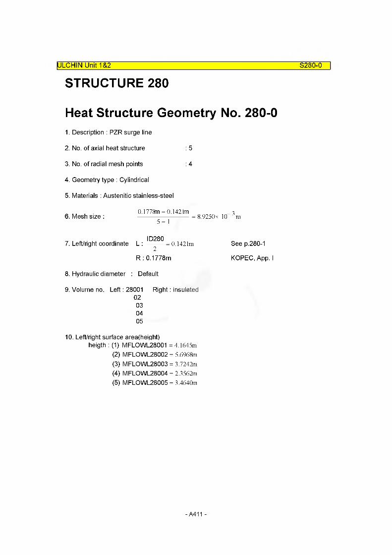
S280-0
STRUCTURE 280IULCHIN Unit 1&2
Heat Structure Geometry No. 280-01. Description : PZR surge line
2. No. of axial heat structure : 5
3. No. of radial mesh points : 4
4. Geometry type : Cylindrical
5. Materials : Austenitic stainless-steel
6. Mesh size :0.1778n -0.1421m-------------------------- = 8.9250x 10 m
5- 1
ID2807. Left/right coordinate L : —-— = 0.1421m
R : 0.1778m
8. Hydraulic diameter : Default
9. Volume no. Left: 28001 Right: insulated02030405
See p.280-1
KOPEC, App. I
10. Left/right surface area(height)heigth : (1) MFLOWL28001 = 4.1645m
(2) MFLOWL28002 = 5.6968m(3) MFLOWL28003 = 3.7242m(4) MFLOWL28004 = 2.3562m(5) MFLOWL28005 = 3.4640m
- A411 -
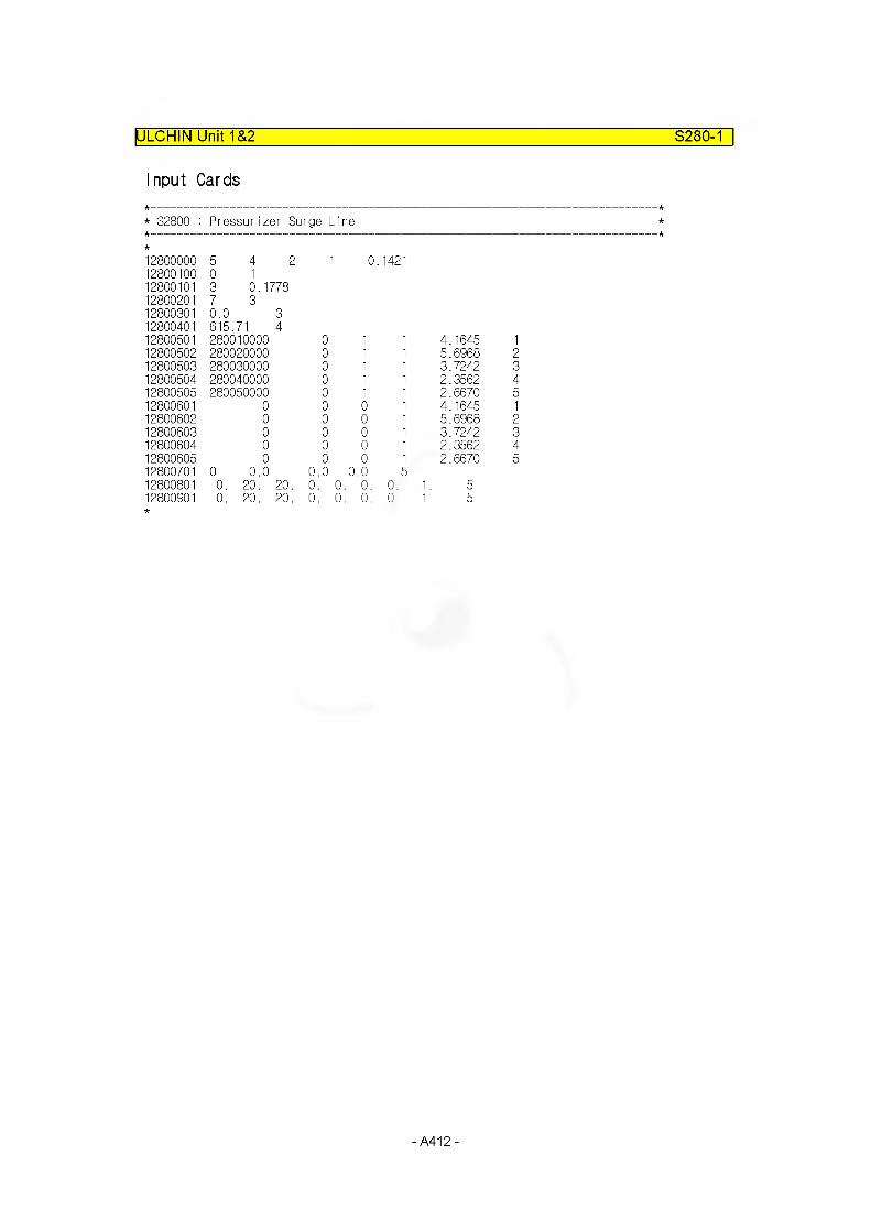
ULCHIN Unit 1&2 S280-1
Input Cards
* S2800 : Pressurizer Surge Line
12800000 5 4 2 I 0. 142112800100 0 112800101 3 0.177812800201 7 312800301 0.0 312800401 615. 71 412800501 280010000 0 1 1 4.1645 112800502 280020000 0 1 1 5.6968 212800503 280030000 0 1 1 3.7242 312800504 280040000 0 1 1 2.3562 412800505 280050000 0 1 1 2.6670 512800601 0 0 0 1 4.1645 112800602 0 0 0 1 5.6968 212800603 0 0 0 1 3.7242 312800604 0 0 0 1 2.3562 412800605 0 0 0 1 2.6670 512800701 0 0.0 0.0 0.0 512800801 0. 20. 20. 0. 0. 0. 0. 1. 512800901 0. 20. 20. 0. 0. 0. 0. 1. 5
-A412-
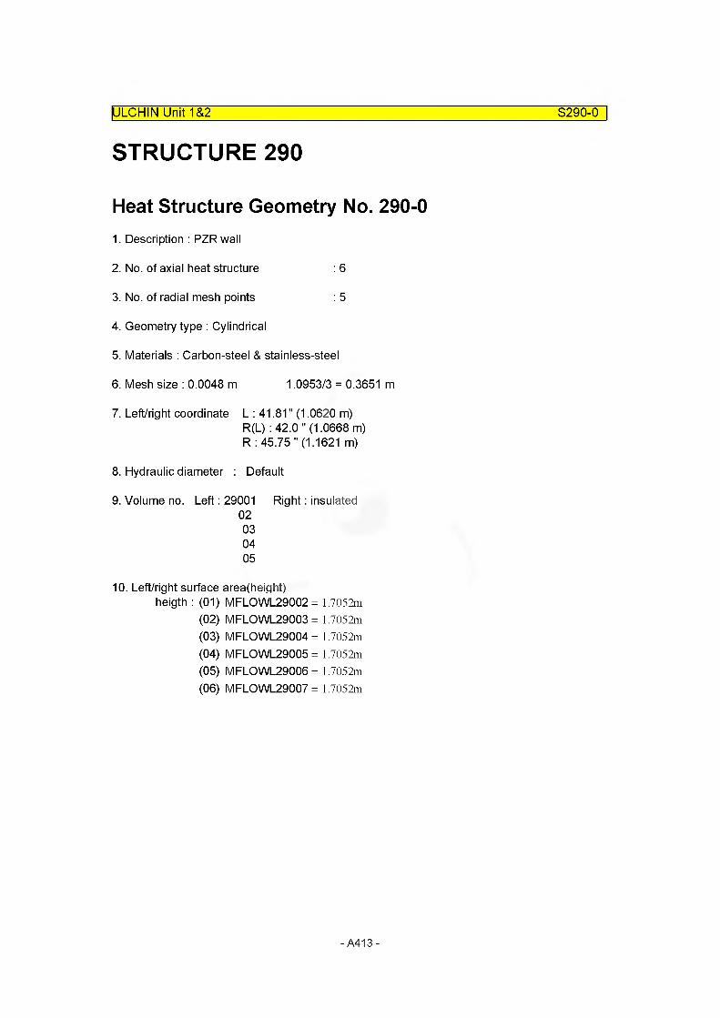
ULCHIN Unit 1&2 S290-0
STRUCTURE 290
Heat Structure Geometry No. 290-01. Description : PZR wall
2. No. of axial heat structure : 6
3. No. of radial mesh points : 5
4. Geometry type : Cylindrical
5. Materials : Carbon-steel & stainless-steel
6. Mesh size : 0.0048 m 1.0953/3 = 0.3651 m
7. Left/right coordinate L : 41.81" (1.0620 m)R(L) : 42.0 " (1.0668 m)R : 45.75 " (1.1621 m)
8. Hydraulic diameter : Default
9. Volume no. Left: 29001 Right: insulated02030405
10. Left/right surface area(height)heigth : (01) MFLCWL29002 = 1.7052m
(02) MFLCWL29003 = 1.7052m(03) MFLCWL29004 = 1.7052m(04) MFLCWL29005 = 1.7052m(05) MFLCWL29006 = 1.7052m(06) MFLCWL29007 = 1.7052m
-A413-

ULCHIN Unit 1&2 S290-1
Input Cards
* S2900 : Pressurizer Mid Part
12900000 6 5 2 1 1 .062012900100 0 112900101 1 1.0668 3 1 .162112900201 4 1 6 412900301 0.0 412900401 615.71 512900501 290020000 10000 1 1 1.705212900601 0 0 0 1 1.705212900701 0 0.0 0.0 0.0 612900801 0. 20. 20. 0. 0. 0. 0. 1. 612900901 0. 20. 20. 0. 0. 0. 0. 1. 6
-A414-

ULCHIN Unit 1&2 S290-2
Heat Structure Geometry No. 290-11. Description : PZR lower head
2. No. of axial heat structure : 1
3. No. of radial mesh points : 5
4. Geometry type : Spherical
5. Materials : Carbon-steel & stainless-steel
6. Mesh size : 0.0048 m 0.0648/3 = 0.0216 m
7. Left/right coordinate L : 42.81" (1.0874 m)R(L) : 43.0 " (1.0922 m)R: 45.55 " (1.1570 m)
8. Hydraulic diameter : Default
9. Volume no. Left: 29001 Right: insulated
10. Left/right surface area(height)Factor: 155.1833/360 = 0.4311
Input Cards
* S2901 : Pressurizer Lower Part
1290100012901100
10
51
3 1 1..0874
12901101 1 1.0922 3 1..157012901201 4 1 6 412901301 0.0 412901401 615. 71 512901501 290010000 0 1 112901601 0 0 0 112901701 0 0.0 0.0 0.0 112901801 0. 20. 20. 0. 0. 0. 0.12901901 0. 20. 20. 0. 0. 0. 0.
-A415-
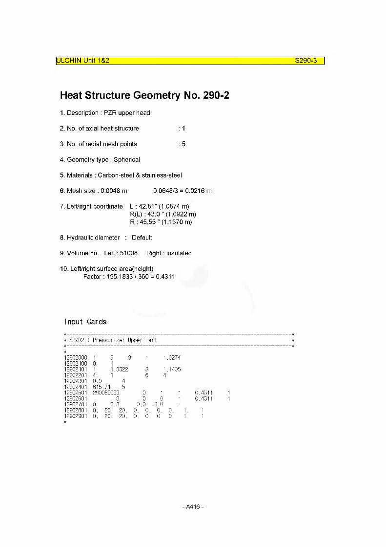
ULCHIN Unit 1&2 S290-3
Heat Structure Geometry No. 290-21. Description : PZR upper head
2. No. of axial heat structure : 1
3. No. of radial mesh points : 5
4. Geometry type : Spherical
5. Materials : Carbon-steel & stainless-steel
6. Mesh size : 0.0048 m 0.0648/3 = 0.0216 m
7. Left/right coordinate L : 42.81" (1.0874 m)R(L) : 43.0 " (1.0922 m)R: 45.55 " (1.1570 m)
8. Hydraulic diameter : Default
9. Volume no. Left: 51008 Right: insulated
10. Left/right surface area(height)Factor: 155.1833/360 = 0.4311
Input Cards
* S2902 : Pressurizer Upper Part
1290200012902100
10
51
3 1
12902101 1 1..0922 312902201 4 1 612902301 0.0 412902401 615..71 512902501 290080000 012902601 0 012902701 0 0.,0 0 .012902801 0. 20. 20. 0. 012902901 0. 20. 20. 0. 0
1.0274
1.14054
1 1 0.4311 10 1 0.4311 1
0.0 10. 0. 1. 10. 0. 1. 1
-A416-
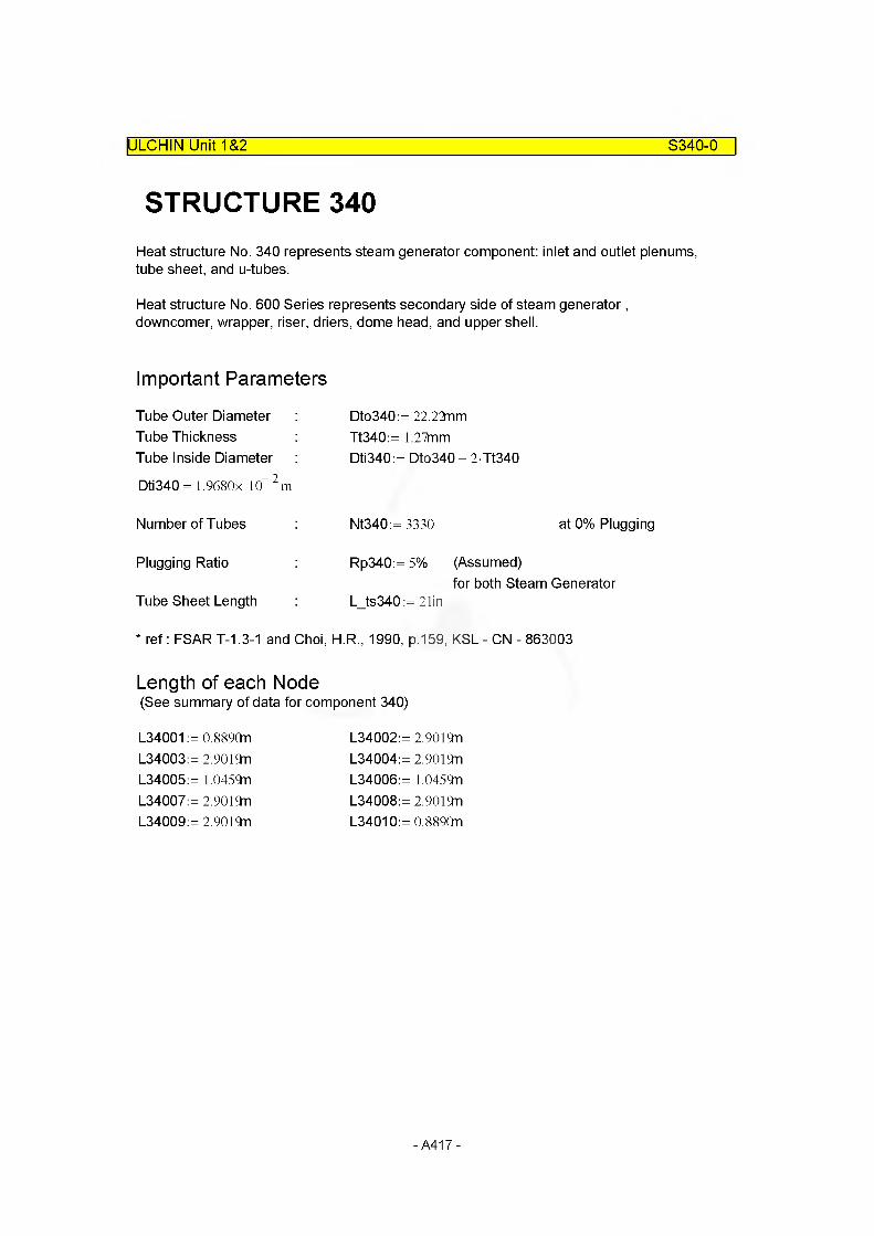
ULCHIN Unit 1&2 S340-0
STRUCTURE 340Heat structure No. 340 represents steam generator component: inlet and outlet plenums, tube sheet, and u-tubes.
Heat structure No. 600 Series represents secondary side of steam generator, downcomer, wrapper, riser, driers, dome head, and upper shell.
Important Parameters
Tube Outer Diameter Tube Thickness Tube Inside Diameter
Dti340 = 1.9680x 10™ 2 m
Dto340:= 22.22nm Tt340:= 1.27mm Dti340:= Dto340 - 2 Tt340
Number of Tubes
Plugging Ratio
Nt340:= 3330 at 0% Plugging
Rp340:= 5% (Assumed)for both Steam Generator
Tube Sheet Length L_ts340:= 21in
* ref: FSART-1.3-1 and Choi, H.R., 1990, p.159, KSL - ON - 863003
Length of each Node(See summary of data for component 340)
L34001 = 0.889On L34002 = 2.9019nL34003 = 2.9019n L34004 = 2.9019nL34005 = 1.0459n L34006 = 1.0459nL34007 = 2.9019n L34008 = 2.9019nL34009 = 2.9019n L34010 = 0.889On
-A417-

Heat Structure Geometry No.340-0
ULCHIN Unit 1&2___________________________________________________S340-1
1. Description : steam generator U-tube
2. No. of axial heat structure : NH3400:= 10
3. No. of radial mesh points : NP3400:= 6
4. Geometry type : Cylindrical
5. Materials : Inconnel
6. Mesh size : MI34001 :=Tt340
(NP3400 - 1)MI34001 = 2.5400x 10 m
Dti340 _ 37. Left/right coordinate : Lbc3400:=—-— Lbc3400 = 9.8400x 10 m
Dto340 _ 9Rbc3400:=---------- Rbc3400= l.lllOx 10 m
8. Hydraulic diameter : DLh3400:= Dti340 DLh3400= 1.9680x 10⁻²
4MFLOWA60001 _ 2DRh3400:=------------------------ DRh3400= 4.3852x 10 27iDto340 Nt340-2
m
m
9. Volume no. : Left3400134002340033400434005
Right Left Right60001 34006 6000560002 34007 6000460003 34008 6000360004 34009 6000260005 34010 60001
10. Left/right surface area = Length Tube Number Plugging Rate
SAF340001 := (L34001 - L_ts340) Nt340 (l
SAF340002:= L34002 Nt340 (1 - Rp340)
SAF340003:= L34003 Nt340 (1 - Rp340)
SAF340004:= L34004 Nt340 (1 - Rp340)
SAF340005:= L34005 Nt340 (1 - Rp340)
SAF340006:= L34006 Nt340 (1 - Rp340)
SAF340007:= L34007 Nt340 (1 - Rp340)
SAF340008:= L34008 Nt340 (1 - Rp340)
SAF340009:= L34009 Nt340 (1 - Rp340)
SAF340010:= (L34010- L_ts340) Nt340 (l
Rp340) SAF340001 = 1.1249x 10³m
SAF340002 = 9.1802x 10³m
SAF340003 = 9.1802x 10³m
SAF340004 = 9.1802x 10³m
SAF340005 = 3.3087 x 10³m
SAF340006 = 3.3087 x 10³m
SAF340007 = 9.1802x 10³m
SAF340008 = 9.1802x 10³m
SAF340009 = 9.1802x 10³m
Rp340) SAF340010 = 1.1249x 10³m
-A418-
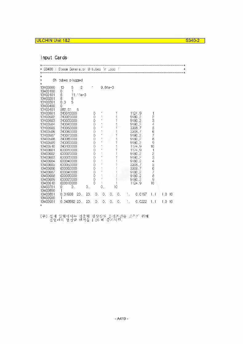
ULCHIN Unit 1&2 S340-2
Input Cards
* S3400 : Steam Generator U-tubes in Loop 1
5% tubes plugged
13400000 10 6 2 1 9.84e-313400100 0 113400101 5 11.11e-313400201 5 513400301 0.0 513400400 013400401 582.91 613400501 340010000 0 1 1 1124.9 113400502 340020000 0 1 1 9180.2 213400503 340030000 0 1 1 9180.2 313400504 340040000 0 1 1 9180.2 413400505 340050000 0 1 1 3308.7 513400506 340060000 0 1 1 3308.7 613400507 340070000 0 1 1 9180.2 713400508 340080000 0 1 1 9180.2 813400509 340090000 0 1 1 9180.2 913400510 340100000 0 1 1 1124.9 1013400601 600010000 0 1 1 1124.9 1
13400602 600020000 0 1 1 9180.2 213400603 600030000 0 1 1 9180.2 313400604 600040000 0 1 1 9180.2 413400605 600050000 0 1 1 3308.7 513400606 600050000 0 1 1 3308.7 613400607 600040000 0 1 1 9180.2 713400608 600030000 0 1 1 9180.2 813400609 600020000 0 1 1 9180.2 913400610 600010000 0 1 1 1124.9 1013400701 0 0. 0. 0. 1013400800 113400801 0.01968 20. 20. 0.
OOO
1. 0.0197 1.1 1.0 1013400900 113400901 0.043582 20. 20. 0.
Ooo
1. 0.0222 1.1 1.0 10
‘Mii y 1.26 Hfl ^7>A] rg .
-A419-
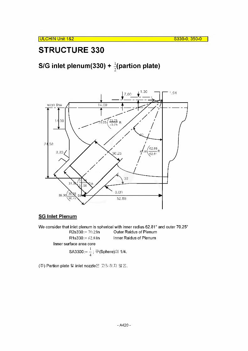
STRUCTURE 330| ULCHIN Unit 1&2 S330-0, 350-0
S/G inlet plenum(330) + parti on plate)
work line 14.09
70.75o.25 trtt R70.25
62.88
36.25 62.81
39.00.30.75 52.88
SG Inlet Plenum
We consider that inlet plenum is spherical with inner radius 62.81" and outer 70.25" R2s330:= 70.25n Outer Raidus of PlenumR1s330:= 62.8tin Inner Raidus of Plenum
Inner surface area coreSA3300 := -j- ; (Sphere)°| 1/4.
(t) Partion plate §/ inlet nozzleg 32 El SI-XI Ssll.
- A420 -
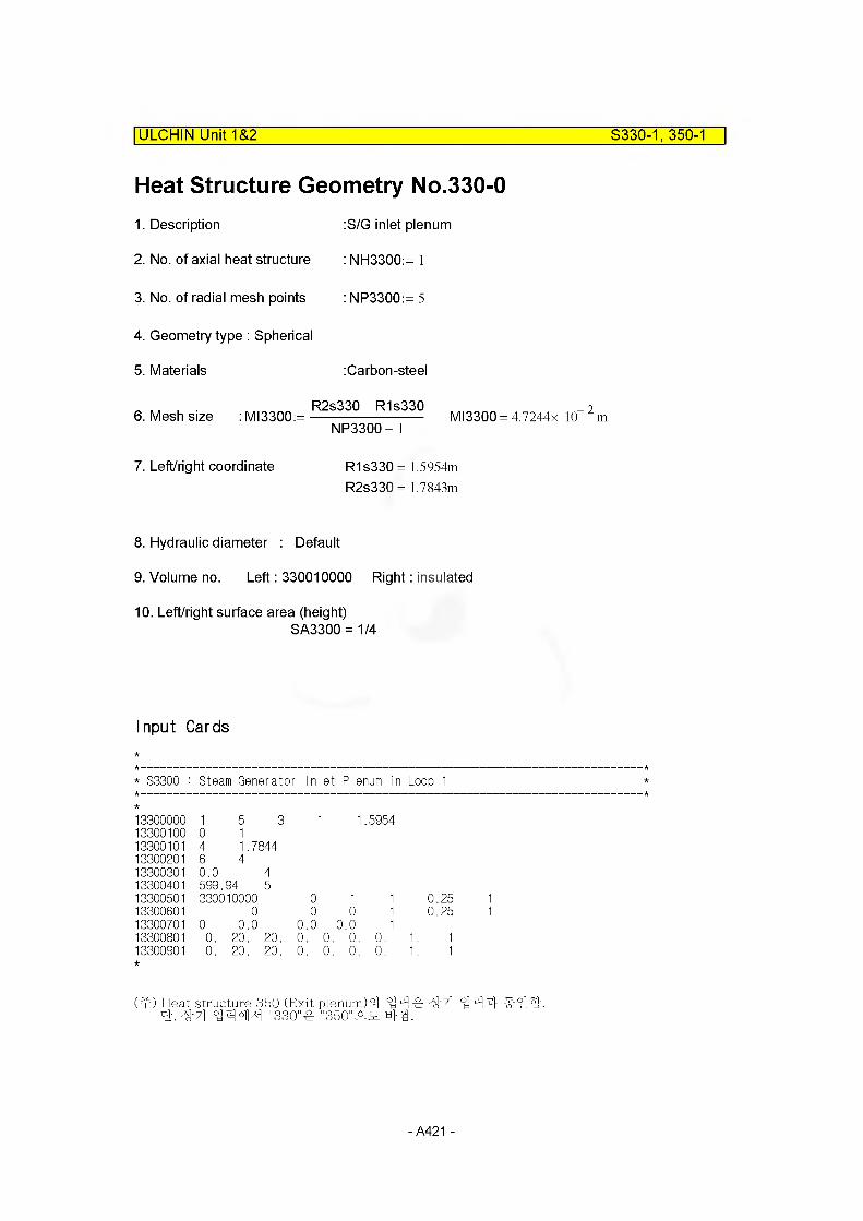
ULCHIN Unit 1&2 S330-1, 350-1
Heat Structure Geometry No.330-01. Description
2. No. of axial heat structure
3. No. of radial mesh points
4. Geometry type : Spherical
5. Materials
:S/G inlet plenum
: NH3300:= 1
: NP3300:= 5
:Carbon-steel
6. Mesh sizeR2s330 - R1s330
: MI3300:=------------------------NP3300 - 1
MI3300 = 4.7244x 10 2 m
7. Left/right coordinate R1s330 = 1.5954m
R2s330 = 1.7843m
8. Hydraulic diameter : Default
9. Volume no. Left: 330010000 Right: insulated
10. Left/right surface area (height)SA3300 = 1/4
Input Cards
* S3300 : Steam Generator Inlet Plenum in Loop 1
1330000013300100
10
5 31
1 1 .5954
13300101 4 1.784413300201 6 413300301 0.0 413300401 599..94 513300501 330010000 0 1 1 0.2513300601 0 0 0 1 0.2513300701 0 0.0 0.0 0.0 113300801 0. 20. 20. 0. 0. 0. 0. 1. 113300901 0. 20. 20. 0. 0. 0. 0. 1. 1
(m) Heat structure 350 (Exit plenum)S] "ntM 4r "#7| ^ zf cf. "9-71 "330" "350"^
- A421 -
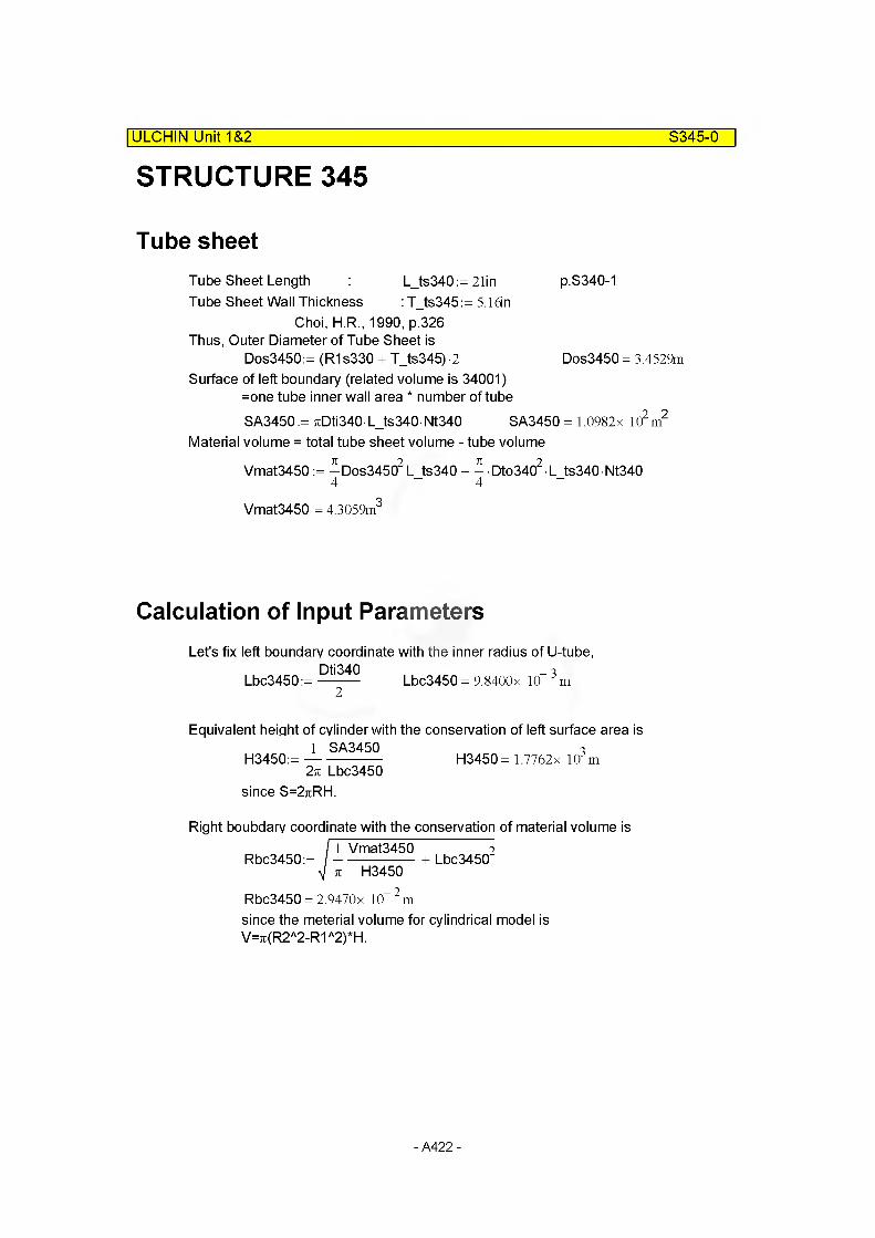
STRUCTURE 345| ULCHIN Unit 1&2 S345-0
Tube sheetTube Sheet Length L_ts340:= 21in p.S340-1Tube Sheet Wall Thickness : T_ts345:= 5.1dn
Choi, H.R., 1990, p.326 Thus, Outer Diameter of Tube Sheet is
Dos3450:= (R1s330 + T_ts345)-2 Dos3450 = 3.4529mSurface of left boundary (related volume is 34001)
=one tube inner wall area * number of tubeSA3450:= 7iDti340 L_ts340 Nt340 SA3450 = 1.0982x l(?m
Material volume = total tube sheet volume - tube volume
Vmat3450:=-Dos34502L ts340 - - • Dto3402 • L ts340 Nt3404 4
Vmat3450 = 4.3059m3
Calculation of Input ParametersLet's fix left boundary coordinate with the inner radius of U-tube,
Lbc3450:=Dti340 Lbc3450 = 9.8400x 10 3m
Equivalent height of cylinder with the conservation of left surface area isH3450:= — SA345°
2tt Lbc3450since S=2jiRH.
H3450 = 1.7762x 10³m
Right boubdary coordinate with the conservation of material volume is
Rbc3450:=_,ymat3450 +Lbc34502 k H3450
Rbc3450 = 2.9470x 10 2 m
since the mete rial volume for cylindrical model is V=7i(R2A2-R1 a2)*H.
- A422 -

ULCHIN Unit 1&2 S345-1
Heat Structure Geometry No.345-01. Description Tubesheet
2. No. of axial heat structure : NH3450:= 1
3. No. of radial mesh points : NP3450:= 5
4. Geometry type : Cylindrical
5. Materials : Carbon-steel & inconnel
6. Mesh size : MI34501:= Tt340
MI34501 = 1.2700x 10“ 3 m
(Rbc3450 - Lbc3450) - Ml34501MI34502:= ---------------------------- ----------------
NP3450 - 1 -1
MI34502= 6.1199x 10“ 3 m
7. Left/right coordinate : Lbc3450 = 9.8400x 10 3m
Rbc3450 = 2.9470x 10“ 2 m
8. Hydraulic diameter :Default
9. Volume no. Left : 340010000 ; 340100000Right: insulated
10. Left/right surface area(height):SAF3450:= H3450 SAF3450 = 1.7762x 10³m
Input Cards
* S3450 : Steam Generator Inlet Tube Sheet in Loop 1
13450000 15 2 1 0.0098413450100 0 113450101 4 0.0294713450201 5 1 6 413450301 0.0 413450401 599.94 513450501 340010000 0 1 1 1776.213450601 0 0 0 1 1776.213450701 0 0.0 0.0 0.0 113450801 0.0 20. 20. 0. 0. 0. 0. 1.13450901 0. 20. 20. 0. 0. 0. 0. 1.
- A423 -
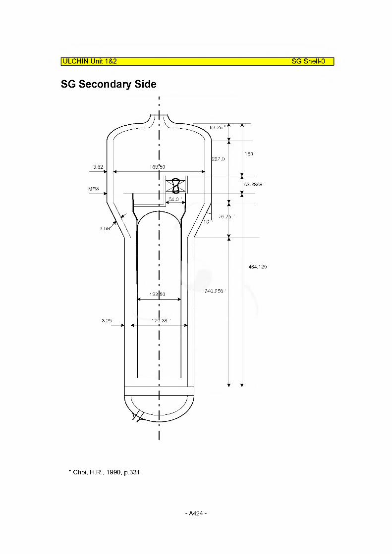
ULCHIN Unit 1&2 SG Shell-0
SG Secondary Side
63.25
227.0
53.3858
464.120
340.258
* Choi, H.R., 1990, p.331
- A424 -
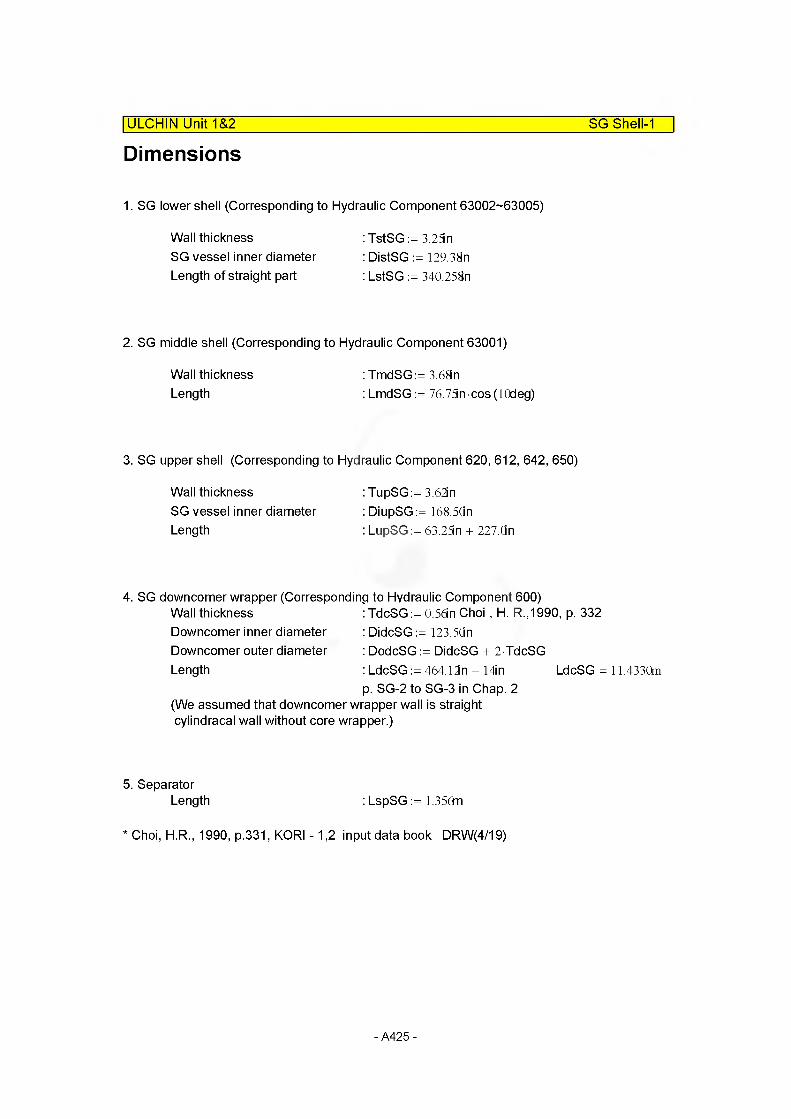
Dimensions| ULCHIN Unit~T&2~ SG Shell-1
1. SG lower shell (Corresponding to Hydraulic Component 63002-63005)
Wall thickness : TstSG := 3.25mSG vessel inner diameter : DistSG := 129.38nLength of straight part : LstSG := 340.258n
2. SG middle shell (Corresponding to Hydraulic Component 63001)
Wall thickness : TmdSG:= 3.68nLength : LmdSG := 76.75n cos(10deg)
3. SG upper shell (Corresponding to Hydraulic Component 620, 612, 642, 650)
Wall thickness : TupSG:= 3.62inSG vessel inner diameter : DiupSG := 168.5GnLength : LupSG := 63.25in + 227.On
4. SG downcomer wrapper (Corresponding to Hydraulic Component 600)Wall thickness : TdcSG:= 0.56in Choi , H. R.,1990, p. 332Downcomer inner diameter : DidcSG := 123.5Gn Downcomer outer diameter : DodcSG := DidcSG + 2-TdcSG Length : LdcSG := 464.12n - 14in LdcSG = 11.4330m
p. SG-2 to SG-3 in Chap. 2(We assumed that downcomer wrapper wall is straight cylindracal wall without core wrapper.)
5. SeparatorLength : LspSG := 1.356m *
* Choi, H.R., 1990, p.331, KORI -1,2 input data book DRW(4/19)
- A425 -
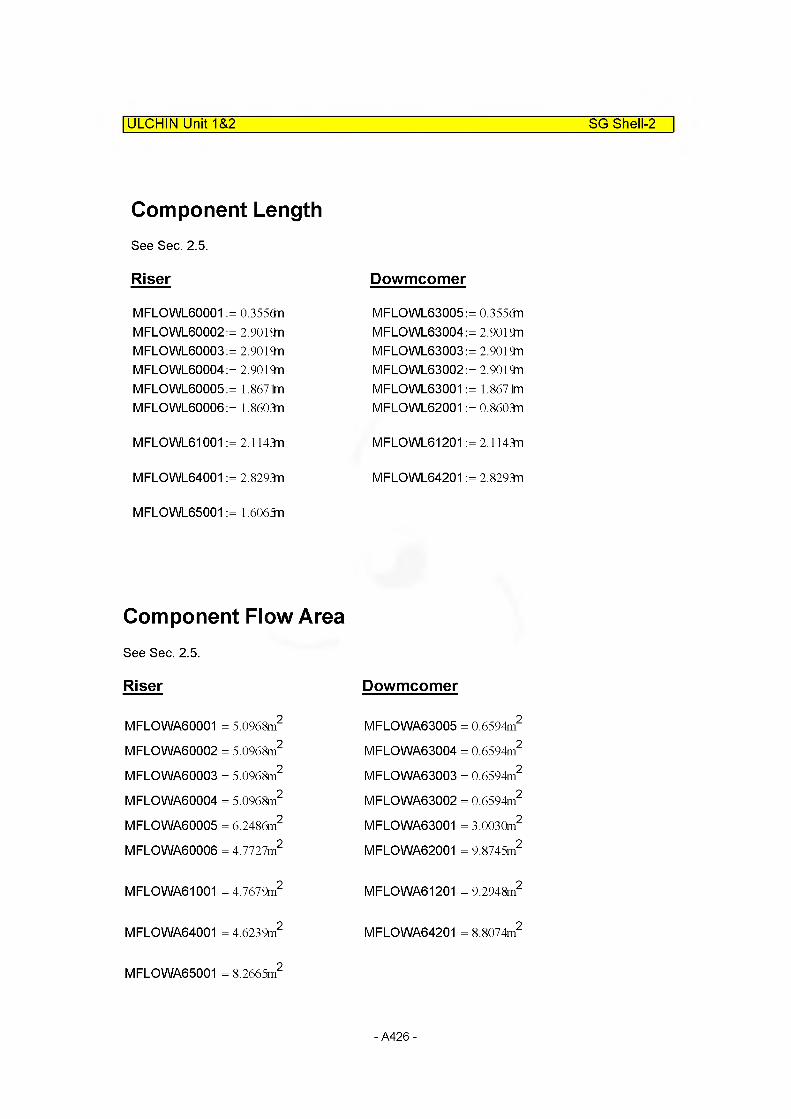
ULCHIN Unit 1&2 SG Shell-2
Component LengthSee Sec. 2.5.
Riser
MFLOWL60001 := 0.355<3n M FLO WL60002: = 2.9019n M FLO WL60003: = 2.9019n M FLO WL60004: = 2.9019n M FLO WL60005: = 1.8671m M FLO WL60006: = 1.8603n
MFLOWL61001 := 2.1143nn
MFLOWL64001 := 2.8293n
MFLOWL65001 := 1.6065n
Dowmcomer
M FLO WL63005: = 0.355dn M FLO WL63004: = 2.9019n M FLO WL63003: = 2.9019n M FLO WL63002: = 2.9019n MFLOWL63001 := 1.8671m MFLOWL62001 := 0.8603n
MFLOWL61201 := 2.1143n
MFLOWL64201 := 2.8293n
Component Flow AreaSee Sec. 2.5.
Riser
MFLOWA60001 = 5.0968m2
MFLOWA60002 = 5.0968m2
MFLOWA60003 = 5.0968m2
MFLOWA60004 = 5.0968m2
MFLOWA60005 = 6.2486m2
MFLOWA60006 = 4.7727m2
MFLOWA61001 = 4.7679m2
MFLOWA64001 = 4.6239m2
MFLOWA65001 = 8.2665m2
Dowmcomer
MFLOWA63005 = 0.6594m2
MFLOWA63004 = 0.6594m2
MFLOWA63003 = 0.6594m2
MFLOWA63002 = 0.6594m2
MFLOWA63001 = 3.0030m2
MFLOWA62001 = 9.8745m2
MFLOWA61201 = 9.2948m2
MFLOWA64201 = 8.8074m2
- A426 -

STRUCTURE 630| ULCHIN Unit 1&2 S630-0
Heat Structure Geometry No.630-0
1. Description : Steam generator vessel wall - lower section
2. No. of axial heat structure : NH6300:= 5
3. No. of radial mesh points
4. Geometry type
5. Materials
: NP6300:= 5
:Cylindrical
:Carbon-steel
TmdSG6. Mesh size : MI63001 :=----------------
NP6300 - 1MI63001 = 2.3368x 10 2 m
TstSGMI63002:=----------------
NP6300 - 1MI63002= 2.0637x 10“ 2 m
DistSG7. Left/right coordinate : Lbc6300:= —-— Lbc6300 = 1.6431m
DistSGRbc63002:=---------- + TstSG
2Rbc63002= 1.7257m //straight part
DiupSGRbc63001 :=----- -— + TmdSG Rbc63001 = 2.2334m //upper part
8. Hydraulic diameter : DLh6000:= 2.38n DLh6000 = 6.0452x 10 2mDRh6000:= O.in DRh6000 = 0.0000m
9. Volume no. Left: 630010000 Right: insulated
05
10. Left/right surface area(height)SAF63001 := MFLOWL63001 SAF63002:= MFLOWL63002 SAF63003:= MFLOWL63003 SAF63004:= MFLOWL63004 SAF63005:= MFLOWL63005
SAF63001 = 1.8671m SAF63002 = 2.9019m SAF63003 = 2.9019m SAF63004 = 2.9019m SAF63005 = 0.3556m
- A427 -
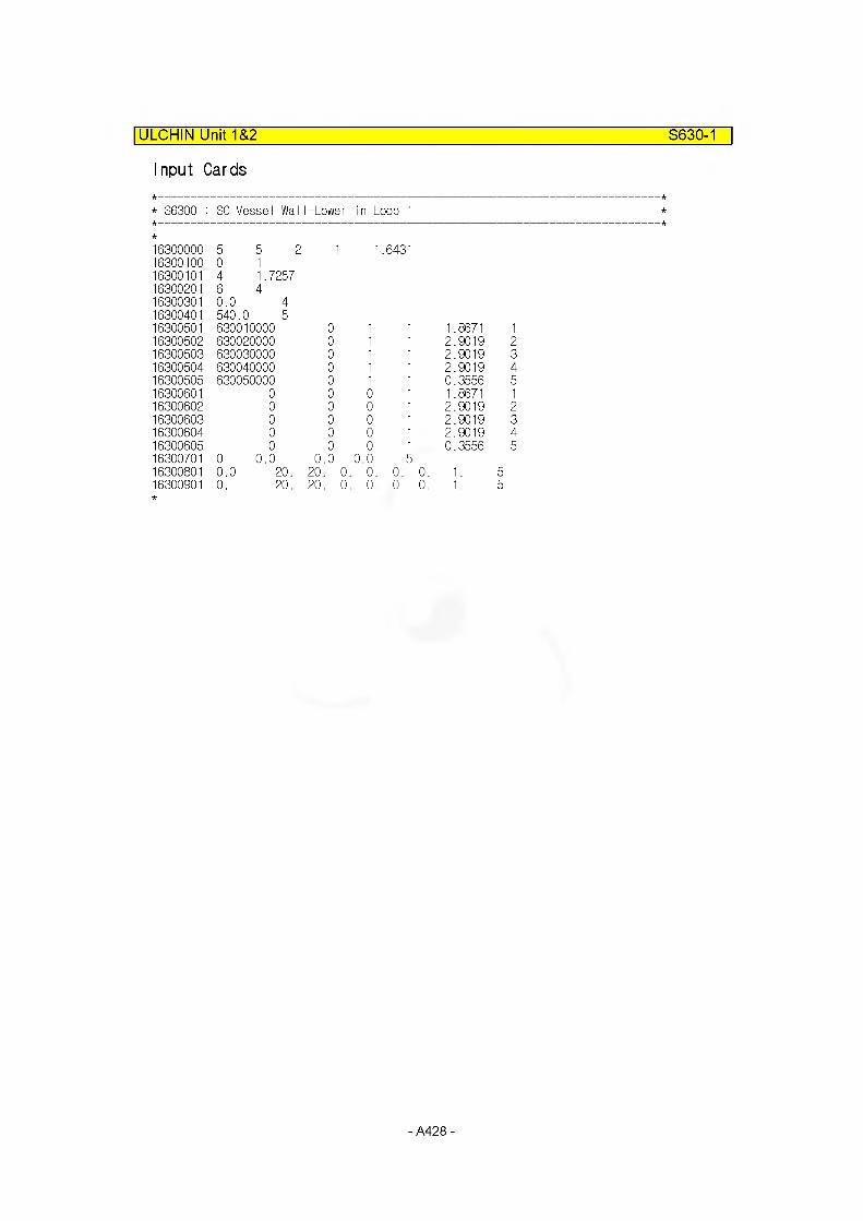
ULCHIN Unit 1&2 S630-1
Input Cards
* S6300 : SG Vessel WalI-Lower in Loop 1
16300000 5 5 2 I 1 .643116300100 0 116300101 4 1.725716300201 6 416300301 0.0 416300401 540. 0 516300501 630010000 0 1 1 1.8671 116300502 630020000 0 1 1 2.9019 216300503 630030000 0 1 1 2.9019 316300504 630040000 0 1 1 2.9019 416300505 630050000 0 1 1 0.3556 516300601 0 0 0 1 1.8671 116300602 0 0 0 1 2.9019 216300603 0 0 0 1 2.9019 316300604 0 0 0 1 2.9019 416300605 0 0 0 1 0.3556 516300701 0 0.0 0.0 0.0 516300801 0.0 20. 20. 0. 0. 0. 0.. 1. 516300901 0. 20. 20. 0. 0. 0. 0.. 1. 5
- A428 -
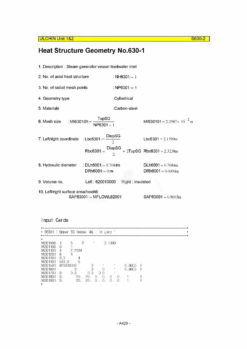
Heat Structure Geometry No.630-1
ULCHIN Unit 1&2______________________________________________________S630-2
1. Description : Steam generator vessel feedwater inlet
2. No. of axial heat structure : NH6301 := 1
3. No. of radial mesh points
4. Geometry type
5. Materials
: NP6301 := 5
:Cylindrical
:Carbon-steel
6. Mesh size : MI630101 :=TupSG
NP6301 - 1
7. Left/right coordinate : Lbc6301 :=
Rbc6301 :=
DiupSG2
DiupSG
MI630101 = 2.2987x 10 2m
Lbc6301 = 2.1399m
+ 2TupSG Rbc6301 = 2.3238m
8. Hydraulic diameter : DLh6001 := 0.7684nDRh6001 := O.m
DLh6001 = 0.7684m DRh6001 = 0.0000m
9. Volume no. Left: 620010000 Right: insulated
10. Left/right surface area(height)SAF63001 := MFLOWL62001 SAF63001 = 0.8603m
Input Cards
* S6301 : Upper SG Vessel Wall in Loop 1
16301000 15 2 1 2. 139916301100 0 116301101 4 2.233416301201 6 416301301 0.0 416301401 540.0 516301501 620010000 0 1 1 0.860316301601 0 0 0 1 0.860316301701 0 0.0 0.0 0.0 116301801 0. 20. 20. 0. 0. 0. 0. 1.16301901 0. 20. 20. 0. 0. 0. 0. 1.
- A429 -

ULCHIN Unit 1&2 S600-0
STRUCTURE 600
Heat Structure Geometry No.600-0
1. Description : S/G downcomer wrapper & cone wrapper
2. No. of axial heat structure : NH6000:= 6
3. No. of radial mesh points
4. Geometry type
5. Materials
6. Mesh size : MI60001 :=
: NP6000:= 3
:Cylindrical
: Stain less-steel
TdcSG
NP6000 - 1MI60001 = 7.1120x 10
7. Left/right coordinate :Lbc6000:=DidcSG
2
Rbc60001 :=DodcSG
2
Lbc6000 = 1.5684m
Rbc60001 = 1.5827m
8. Hydraulic diameter DLh6300:= 0.343n DLh6300= 8.7122x 10 3m
DRh6300:= 0.343n + TdcSG DRh6300= 2.2936x 10“2m
9. Volume no. Left600010000600020000600030000600040000600050000600060000
Right630050000630040000630030000630020000630010000620010000
10. Left/right surface area(height)SAF60001 := MFLOWL60001 SAF60002:= MFLOWL60002 SAF60003:= MFLOWL60003 SAF60004:= MFLOWL60004 SAF60005:= MFLOWL60005 SAF60006 := MFLOWL60006
SAF60001 = 0.3556m SAF60002 = 2.9019m SAF60003 = 2.9019m SAF60004 = 2.9019m SAF60005 = 1.8671m SAF60006 = 1.8603m
- A430

ULCHIN Unit 1&2 S600-1
Input Cards
* S6000 : SG Downcomer Wrapper & Cone Wrapper in Loop 1
16000000 6 3 2 1 1.568416000100 0 116000101 2 1.58267416000201 4 216000301 0.0 216000401 540.0 316000501 600010000 0 1 1 0.3556 116000502 600020000 0 1 1 2.9019 216000503 600030000 0 1 1 2.9019 316000504 600040000 0 1 1 2.9019 416000505 600050000 0 1 1 1.8671 516000506 600060000 0 1 1 1.8603 616000601 630050000 0 1 1 0.3556 116000602 630040000 0 1 1 2.9019 216000603 630030000 0 1 1 2.9019 316000604 630020000 0 1 1 2.9019 416000605 630010000 0 1 1 1.8671 516000606 630010000 0 1 1 1.8603 616000701 0 0.0 0.0 0.0 616000801 0.0 20. 20. 0. 0. 0. 0. 1. 616000901 0.0 20. 20. 0. 0. 0. 0. 1. 6
- A431 -
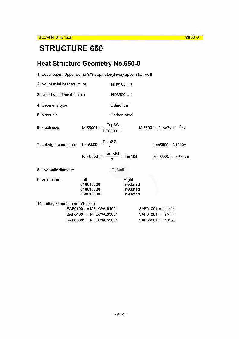
STRUCTURE 650| ULCHIN Unit 1&2 S650-0
Heat Structure Geometry No.650-01. Description : Upper dome S/G separator^river) upper shell wall
2. No. of axial heat structure : NH6500:= 3
3. No. of radial mesh points
4. Geometry type
5. Materials
6. Mesh size : MI65001 :=
: NP6500:= 5
:Cylindrical
: Carbon-steel
TupSGNP6500 - 1
MI65001 = 2.2987x 10 m
7. Left/right coordinate :Lbc6500:=DiupSG
2
Rbc65001DiupSG
2+ TupSG
Lbc6500 = 2.1399m
Rbc65001 = 2.2319m
8. Hydraulic diameter : Default
9. Volume no. Left Right610010000 Insulated640010000 Insulated650010000 Insulated
10. Left/right surface area(height)SAF61001 := MFLOWL61001 SAF64001 := MFLOWL63001 SAF65001 := MFLOWL65001
SAF61001 = 2.1143m SAF64001 = 1.8671m SAF65001 = 1.6065m
- A432 -
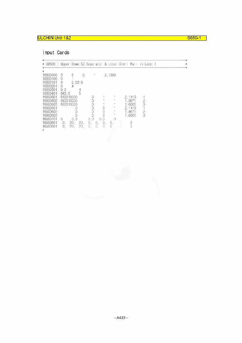
ULCHIN Unit 1&2 S650-1
Input Cards
* S6500 : Upper Dome SG Separator & Upper She I I WalI in Loop 1
16500000 3 5 2 1 2. 139916500100 0 116500101 4 2.231916500201 6 416500301 0.0 416500401 540.0 516500501 610010000 0 1 1 2.1143 116500502 640010000 0 1 1 1.8671 216500503 650010000 0 1 1 1.6065 316500601 0 0 0 1 2.1143 116500602 0 0 0 1 1.8671 216500603 0 0 0 1 1.6065 316500701 0 0.0 0.0 0. 0 316500801 0. 20. 20. 0. 0. 0. 0. 1. 316500901 0. 20. 20. 0. 0. 0. 0. 1. 3
- A433 -

4. Interactive Control InputPage A2°l §5! V2^J\°\ MARS JHHEOia. 01 g#
8t&0||g # ^XtSOII Stiig "Interactive Control Function'll D\S.D\ SS9(M 910.oi dig# Atsste Atsxpt imi 4 910.
U-M2.I Sc "Interactive Control Function" M 9S Junction/Trip No.# Sfgtf 301 CK
Cardno. Content of interactive control
Controltype
Valve/Junction Trip no.
801 Reactor trip trip 531802 TBN stop valve (Turbine trip) on-off 905 750
806 PRZ spray valve, loop 1 valve area 283807 PRZ spray valve, loop 2 valve area 289808 PRZ PORV 1 valve area 951809 PRZ PORV 2 valve area 953
811 RCP 1 trip 511812 RCP 2 trip 512813 RCP 3 trip 513818 Charqinq flow mass flow 393819 Letdown flow mass flow 597
821 LPSI, loop 1 mass flow 375822 HPSI, loop 1 mass flow 377823 LPSI, loop 2 mass flow 475824 HPSI, loop 2 mass flow 477825 LPSI, loop 3 mass flow 575826 HPSI, loop 3 mass flow 577
- A434 -
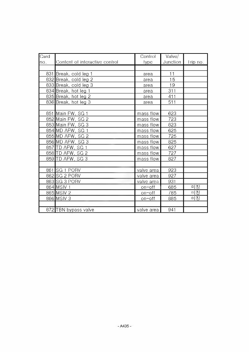
Cardno. Content of interactive control
Controltype
Valve/Junction Trip no.
831 Break, cold leg 1 area 11832 Break, cold leg 2 area 15833 Break, cold leg 3 area 19834 Break, hot leg 1 area 311835 Break, hot leg 2 area 411836 Break, hot leg 3 area 511
851 Main FW, SG 1 mass flow 623852 Main FW, SG 2 mass flow 723853 Main FW, SG 3 mass flow 823854 MD AFW, SG 1 mass flow 625855 MD AFW, SG 2 mass flow 725856 MD AFW, SG 3 mass flow 825857 TD AFW, SG 1 mass flow 627858 TD AFW, SG 2 mass flow 727859 TD AFW, SG 3 mass flow 827
861 SG 1 PORV valve area 923862 SG 2 PORV valve area 927863 SG3P0RV valve area 931864 MSIV 1 on-off 685 □IS865 MSIV 2 on-off 785 □IS866 MSIV 3 on-off 885 □IS
872 TBN bypass valve valve area 941
- A435 -

Input Cards
801 trip 531 "Manual reactor trip"802 trip 540 "Manual turbine trip"
806 vlvarea 283 "PRZ spray valve 1"807 vlvarea 289 "PRZ spray valve 2"808 vlvarea 951 "PRZ PORV 1"809 vlvarea 953 "PRZ PORV 2"
811 trip 511 "RCP 1 trip"812 trip 512 "RCP 2 trip"813 trip 513 "RCP 3 trip"
818 mflowfj 493 "Charging flow"819 mflowfj 397 "Letdown flow"
821 mflowfj 375 "LPSI flow, loop 1"822 mflowfj 377 "HPSI flow, loop 1"823 mflowfj 475 "LPSI flow, loop 2"824 mflowfj 477 "HPSI flow, loop 2"825 mflowfj 575 "LPSI flow, loop 3"826 mflowfj 577 "HPSI flow, loop 3"
831 vlvarea 11 "Break, cold leg 1"832 vlvarea 15 "Break, cold leg 2"833 vlvarea 19 "Break, cold leg 3"834 vlvarea 311 "Break, hot leg 1"835 vlvarea 411 "Break, hot leg 2"836 vlvarea 511 "Break, hot leg 3"
851 mflowfj 623 "Main FW, SG 1"852 mflowfj 723 "Main FW, SG 2"853 mflowfj 823 "Main FW, SG 3"
854 mflowfj 625 "MD AFW, SG 1"855 mflowfj 725 "MD AFW, SG 2"856 mflowfj 825 "MD AFW, SG 3"
857 mflowfj 627 "TD AFW, SG 1"858 mflowfj 727 "TD AFW, SG 2"859 mflowfj 827 "TD AFW, SG 3"
861 vlvarea 923 "SG 1 PORV"862 vlvarea 927 "SG 2 PORV"863 vlvarea 931 "SG 3 PORV"
*864 trip 743 "MSIV 1 isolation" *865 trip 744 "MSIV 2 isolation" *866 trip 745 "MSIV 3 isolation"
872 vlvarea 941 "TBN bypass valve'

5. References
[1] #@1/2 m;i s^@¥#al
[2] H R. Choi, Generation of the RELAP5 Base Input Data for Ulchin-1/2, DS-SA-UL9-90125E, Korea Atomic Energy Research Institute, Dec. 8, 1990.
[3] W. J. Lee, B. D. Chung, J. J. Jeong, and K.S. Ha, “Development of a Multidimensional Realistic Thermal-Hydraulic Analysis Code, MARS 1.3 and its Verification,”KAERI/TR-1108/98, KAERI, 1998.
[4] W. J. Lee, B. D. Chung, J. J. Jeong, and K.S. Ha, “Improvement of Multidimensional Realistic Thermal-Hydraulic Analysis Code, MARS 1.3,” KAERI/TR-1141/98, KAERI, 1998.
[5] W. J. Lee, B. D. Chung, J. J. Jeong, and K.S. Ha, “Improved Features of MARS 1.4 and its Verification,” KAERI/TR-1386/99, KAERI, 1999.
[6] XI ¥ GEE, "Guidelines for the MARS Input Model Generation of UCN 1/2", TAD/M2002-03, Rev. 0, 2002.
[7] ilAlls 21 "#@ 1,2 m;i d|@#@lGAH2|RELAP5/MOD3 @¥XlE", ¥ J\#¥¥3 Al @ XIE# AIPH 2002. 6.
[8] #@@X1¥X1I1#@A, "#@1,2m;i #¥ EHE#", @¥@¥SAl, 1996.
[9] I.E. Idelchick et al., "Handbook of Hydraulic Resistance", 2nd Ed., 1986.
[10] Crane, "Flow of Fluids through Valves, Fittings, and Pipe", 1978.
- A437 -
4 4 4 4
&#^_a43^ inis *4 a:
KAERI/TR-2420/2003
4*/*4*3 l/2±7] *3*44* MARS aa 332-3 ?]] UT-
3*33^} ^ *44 44* (3*3333**)
3 * 7} ^ * A^ ig 34*. 3**, 333, 43*. #**
3 4 #1 3 #<@7]# 3*3 7M 3*^ MM3 2003. 3.
4 3 4 p. 455 a & 3*( V ), g^*( ) 71 26 Cm.
#aA]-#- *44 3*. 4*& 33 44 *3 #-4 7] ;]]#
333: '7%( V ), 44 3( ), _ 3-HR 7l*£L51Ai
3*444# 44 #3:
&* (15-20#44)
#*3443*di* 4443aa RETRAN# MARS* 3*4* 33 *3*47]* 4# 43. ^14. RETRAN4 MARS an# 2.4 ** *# # *3*3344* MARS 23= * 43 33 233 334 a# 344 **A]-j7 43 334 3*4-3. *44 #*4-3 334 4.3. ^ 4a* 3 *44* RETRAN a^* 3**3.
* M.a4* *3 1/247] 43 *3*44* MARS 334-3.4 7H# 3.33 CalculationNote* **#3. o}*3, 3444 7l]#* 337]-a_# 3*33 4*4-4 ^ 4a*4 444 ** *4133., 3* *3 344^4 334* #333* *3 3^4-, ** * 3443.7]- *3 1/2^4 *3*44* MARS aa 33 a#4 4# 333_a A}*# * ^** *3^- 34.
*4444a (103344)
4*^33 44 *3*44, 34^7]-a:*3 1/23:7] MARS 334a.
MARS a:

BIBLIOGRAPHIC INFORMATION SHEET
Performing Org.Report No.
Sponsoring Org.Report No. Standard Report No. INIS Subject Code
KAERI/TR - 2420/2003
Subtitle * 6 ^ Development of the MARS Input Model for Ulchin 1/2 Transient Analyzer
Project Manager and Department J. J. Jeong (T/H Safety Research Div.)
Researcher and Department K.D. Kim, S. W. Lee, Y. J. Lee, B. D. Chung, M. Hwang
PublicationPlace
Daejeon Publisher KAERI PublicationDate
Mar. 2003
Page p. 455 111. & Tab. Yes( V ), No ( ) Size 26 Cm.
Note
Classified Open( V ), Restricted/ ),__ Class Document Report Type Technical Report
Sponsoring Org. Contract No.
Abstract (15-20 Lines)
KAERI has been developing the NSSS transient analyzer based on best-estimate codes. The MARS and RETRAN code are adopted as the best-estimate codes for the NSSS transient analyzer. Among these two codes, the MARS code is to be used for realistic analysis of small- and large-break loss-of-coolant accidents, of which break size is greater than 2 inch diameter. This report includes the MARS input model requirements and the calculation note for the MARS input data generation (see the Appendix) for Ulchin 1/2 plant analyzer. In order to confirm the validity of the input data, we performed the calculations for a steady state at 100 % power operation condition and a double-ended cold leg break LOCA. The results of the steady-state calculation agree well with the design data. The results of the LOCA calculation seem to be reasonable and consistent with those of other best-estimate calculations. Therefore, the MARS input data can be used as a base input deck for the MARS transient analyzer for Ulchin 1/2.
Subject Keywords NSSS Transient Analyzer, Best-estimate code, (About 10 words) MARS, MARS input model for Ulchin 1/2 Plants.


![3} tj- 7] - OSTI.GOV](https://static.fdokumen.com/doc/165x107/631c4c86b8a98572c10cd705/3-tj-7-ostigov.jpg)