IODP Smear Slides Digital Reference for Sediment Analysis
236
Part 1: Methodology and Atlas of Siliciclastic and Volcanogenic Components Integrated Ocean Drilling Program Technical Note 1 IODP Smear Slides Digital Reference for Sediment Analysis 2013 Version 1.0/July
-
Upload
khangminh22 -
Category
Documents
-
view
2 -
download
0
Transcript of IODP Smear Slides Digital Reference for Sediment Analysis
Part 1: Methodology and Atlas
of Siliciclastic and Volcanogenic Components
Integrated Ocean Drilling Program Technical Note 1
IODP Smear Slides Digital Reference for Sediment Analysis
2013 Version 1.0/July

2
Publisher’s NotesMaterial in this publication may be copied without restraint for library, abstract service, educational, or personal research purposes; however, this source should be appropriately acknowledged.
Citation
Marsaglia, K., Milliken, K., and Doran, L., 2013. Smear slides of marine mud for IODP core description, Volume I. Part 1: Methodology and atlas of siliciclastic and volcanogenic components. IODP Technical Note 1. doi:10.2204/iodp.tn.1.2013
Distribution
Electronic copies of this series may be obtained from the Integrated Ocean Drilling Program (IODP) Scientific Publications homepage on the World Wide Web at www.iodp.org/scientific-publications/.
This publication was prepared on behalf of IODP Management International (IODP-MI), Inc. Funding for the program is provided by the following agencies:
1) National Science Foundation (NSF), United States2) Ministry of Education, Culture, Sports, Science and Technology (MEXT), Japan3) European Consortium for Ocean Research Drilling (ECORD)4) Ministry of Science and Technology (MOST), People’s Republic of China5) Korea Institute of Geoscience and Mineral Resources (KIGAM)6) Australian Research Council (ARC) and GNS Science (New Zealand), Australian/New Zealand Consortium7) Ministry of Earth Sciences (MoES), India8) Coordination for Improvement of Higher Education Personnel, Brazil
Disclaimer
Any opinions, findings, and conclusions or recommendations expressed in this publication are those of the author(s) and do not necessarily reflect the views of the participating agencies, IODP implementing organizations, or IODP-MI.
July 2013

Interactive Table of Contents

4
Introduction
Smear slide examination is an essential aspect of the description of the fine-grained materials (mud) that dominate marine sedimentary successions. The goal of this tutorial is to convey the essentials of the smear slide method to sedimentologists engaged in marine core description on board Integrated Ocean Drilling Program (IODP) drilling vessels or at IODP core repositories. Study of this tutorial will help core describers develop and apply solid skills in the identification and semiquantification of mud components.
The tutorial was produced in two phases, the first focusing on siliciclastic and volcanogenic components and associated authigenic components (Part 1) and the second concentrating on biogenic and associated authigenic components (Part 2, in prep.).
How to use this material
This document is in a layered, interactive, portable document format (PDF), created using Adobe Reader version 10.1.4. Buttons and text links allow flexible navigation of the contents. Additional links throughout the document, in the form of both buttons and highlighted text, allow additional options for navigation. It is possible to study the entire document sequentially, through the use of the “next” button on each page, but many other options for navigation are provided.
The main areas of the tutorial include:
1. Text describing the smear slide method, smear slide production, and smear slide description.
2. An atlas of common components as seen in smear slides. This section contains basic guidance for identification of common siliciclastic components in smear slides, a thumbnail page to assist navigation to individual atlas images, and an extensive image collection covering major categories of grains and diagenetic sediment components. For the atlas images, you must fully open the layers window on the left side of the main pdf window.
5
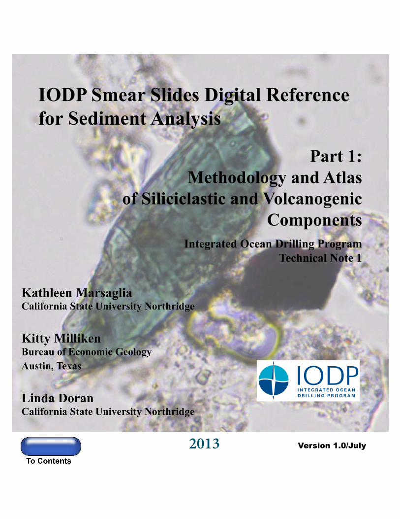
Atlas images contain multiple layers, though not every image will contain every possible layer. The layers window can be opened by clicking on the “blue stacked paper” symbol on the left side of the page (Figure 1). Layers active for a given image are indicated when the layer is shown in bold on the layers window (Figure 2).
Figure 1: Screen shot of first page of this pdf document showing the location of the layers symbol (red arrow), which can be opened with a click of the mouse.

6
Figure 2: Screen shot of image page with the layers window opened. Black background in petrographic image on right and “eyeball” icon activated on left indicates the cross-polar view as well as the yellow scale grid have been activated.
Individual layers can be toggled on and off by clicking the “eye” symbols to reveal: a plane-light image with text, a crossed-polar image, an alternative image (such as higher magnification or reflected light) where provided, an information layer, and two possible scale grids. The information layer may contain active areas that provide information on mouseover. The general image description is placed in a text box beneath the image.
3. A tutorial section (also with layered images) that allows the user to test acquired knowledge of component identification and estimation in broader fields of view that contain many grain types.
4. A list of 50 slides that make up the siliciclastic smear slide reference set. Sets of these slides are available for study on IODP drilling vessels and at IODP core repositories. Information on sample origin, rationale for study of the sample, and details concerning the key components is provided.
7
Authors
Kathie Marsaglia, Ph.D.
Although her research has centered on provenance and distribution of marine sand, early in her career Kathie realized the importance of char-acterizing the mud fraction using the smear slide technique. She produced and described her first smear slide aboard the JOIDES Resolution on Leg 126 in 1989. Since then she has participated as a shipboard sedimentolo-gist on Ocean Drilling Program (ODP Legs 141, 149, 161, 198, and 210) and IODP expeditions (317, 320T), where she enthusiastically volunteered to make and describe smear slides. With Shawn Shapiro she produced an Atlas of Sedimentary Structures and Lithologies using ODP core photos. She has published on petrology and diagenesis of sand and sandstone, Precambrian and Permian carbonate-to-volcaniclastic transitions, Cretaceous oceanic anoxic layers and chert, and the Messinian evaporite-to-carbonate transition. She is a Professor of Geology at California State University Northridge.
Kitty Milliken, Ph.D.
A research focus on the chemical and mechanical evolution of rocks in the subsurface has led Kitty to an interest in petrographic methods. Her pre-vious projects in petrographic education include Sandstone Petrology: A Tutorial Petrographic Image Atlas, (v. 1.0 and 2.0; 2003, 2007) and Carbonate Petrology v. 1.0: An Interactive Petrography Tutorial (2011). She first encountered the smear slide technique under the tutelage of Kathie Marsaglia on ODP Leg 149 to the Iberia Abyssal Plain. Subsequently, she sailed as a sedimentologist on the Chikyu (IODP Expedition 316) and on the JOIDES Resolution (IODP Expedition 320T). Her published papers examine the diagenesis of sandstone, mudrock, limestone, dolomite, chert, and serpentinite. She is a Senior Research Scientist at the Bureau of Economic Geology and a member of the Graduate Studies Committee in the Jackson School of Geosciences at The University of Texas at Austin.
Linda Doran, B.S.
After earning a bachelor’s degree in Geology at the University of New Mexico and spending many years as a science writer, most recently in education outreach at NASA’s Jet Propulsion Laboratory, she entered a master’s degree program working with Kathie Marsaglia at California State University Northridge. Her graduate research is focused on the provenance of Taranaki Basin sediments off of South Island, New Zealand. Previous stints have included working in corporate communications at Sandia National Laboratories in Albuquerque, New Mexico, and in science reporting for the San Gabriel Valley Tribune in West Covina, California.
8
Acknowledgments
Construction of this tutorial atlas was funded under a grant from IODP- Management International, Inc. (Marsaglia, PI). Hiroshi Kawamura and Jamus Collier (IODP-MI) provided essential enthusiasm and support at the project’s inception. We are grateful to Cedric John, Steffen Kutterolf, and Lawrence Krissek for their efforts to review and comment on early versions of this product. We also thank geology students Rosemarie Wrigley and Daniel Tentori at California State University Northridge for their assistance in processing images for this document. Some of the concepts for digital tutorial construction implemented here were developed in collaboration with Suk-joo Choh (Korea University) under previous grants from the Course, Curriculum, and Laboratory Improvement program of the Division of Undergraduate Education at the National Science Foundation (Milliken, PI; award numbers 0088763, 0230578, and 0536085).

9
The Smear Slide Method
Introduction
As outlined in the “Handbook for Shipboard Sedimentologists” by Mazzullo and Graham (1988; http://www-odp.tamu.edu/publications/tnotes/digital/tnote_08.pdf), the two major aspects of core description by shipboard and shore-based sedimentologists are direct visual observation of the core (supported by hand lens observation and low-magnification stereo microscopy) and microscopic observation via smear slides or thin sections viewed with a petrographic microscope. Image-based aids have been developed through the Joint Oceanographic Institutions (JOI) for core description (Marsaglia and Shapiro, 2005) and independently for identification of generally sand-sized components in sediments and lithified sedimentary rocks (Milliken and Choh, 2011; Milliken et al., 2007; Scholle, 1978, 1979; Scholle and Ulmer-Scholle, 2003), but there is no similar guide for smear slide analysis of unlithified fine-grained sediment. Most of the cores recovered by Deep Sea Drilling Project (DSDP), ODP, and IODP are unlithified and fine-grained, so the smear slide technique is critical to sediment characterization and the determination of lithologic names assigned to cored materials. Mastery of the technique requires that sedimentologists have sufficient training in optical mineralogy, sedimentary petrography, and micropaleontology to identify individual sediment compo-nents. Unfortunately, microscopy training in many academic programs is on the decline or has been dropped from the curriculum entirely. This tutorial fills a distinct need for a self-instructive module on smear slide preparation, description, and interpretation for use by shipboard sedimentologists who have not previously benefited from petrographic training in describing sedi-ments and sedimentary rocks. Even trained petrographers who have not worked previously with smear slides will benefit from using these tutorial resources and reference materials. Throughout this tutorial we assume a basic understanding of the components and operation of a petrographic microscope. If you have no such training then we recommend that you first look at basic texts such as Kerr (1977) or Nesse (2004) to get information on the petrographic microscope, as well as basic mineral attributes in thin section such as color, relief, cleavage, birefringence (or alternatively isotropism), pleochroism, twinning, and zoning that we will discuss in the course of this tutorial. The Reference Slide Set consists of 100 smear slides (50 in Volume 1, 50 in Volume 2) showing examples of components in various proportions. The samples used for images and smear slides come from archived ODP and IODP cores. Effort was made to cover a variety of oceanographic and tectonic settings to make the sample array globally relevant.
10
Rationale for selection of smear slide samples during core description
The smear slide method is mainly used for description of cores obtained with the Advanced Piston Corer (APC) in soft sediments and Extended Core Barrel (XCB) in the sediment to sedimentary rock transition zone where recovered materials can be most easily disaggregated. It can also provide some information on more lithified rocks (e.g., cement mineralogy, amygdule filling, mineralogy of phenocrysts or grains) at depths where Rotary Core Barrel (RCB) coring is necessary. APC cores are generally the first type of samples encountered in the borehole. Once the APC cores are processed, sliced with a wire, and separated into archive and sampling halves, the description process can begin on the archive half. It is common practice to lay out the fully split core, with the working half on the sampling table and archive half on the description table. This enables the sedimentary description (archive half) and physical properties groups (working half) to quickly review and discuss the core prior to analysis. At this point, broad variations in lithology are noted, and physical property measurements/sampling, carbonate/total organic carbon (TOC) sampling, and smear slide sampling are coordinated. Smear slides are not taken until after the archive core is digitally color- imaged and scanned with a spectrophotometer. Smear slides can be made to identify fine-grained major and minor lithologies as well as isolated components (e.g., burrow fills, pods, fossil fills). The tendency at the first site in an Expedition is to make smear slides of all major and minor fine-grained lithologies in the first cores. As discussed below, coarser lithologies with sand-sized grains are better determined using hand-lens and binocular microscope observations, or alternatively by examining thin sections of loose grain mounts or semilithified bits. Lithological variation determines the distribution and number of smear slides needed. Only in situations where a core is completely visually homogenous is a single smear slide sufficient. Generally a minimum of two smear slides (major and minor lithology) are needed per core, with three to four being more common. Smear slides are not only meant to facilitate shipboard description but also to serve as archives of information for future scientific study. For this reason, they are boxed and returned to core repositories along with the cores. Like thin sections, the smear slides can be requested by shipboard and shore-based scientists to clarify shipboard descriptions and/or help define sampling intervals of cores. Thus, it is the duty of the shipboard sedimentologists to document core lithology in smear slides and thin sections as a legacy of the Expedition.

11
How to make a smear slide
Smear slide production is generally quick and easy, requiring minimal equipment (highlighted in discussion below) and bench space (Figure 3). Our favored technique is outlined below and pictured in Figures 4 through 7.
Figure 3. The equipment needed for smear slide preparation includes a hot plate (A); UV curing apparatus, either a UV light (B) or specially manufactured box (D); slide storage, such as wood benchtop box with trays (C) or plastic portable box (F); water bottle (E), preferably with nanopure water if available; flat toothpicks (G); slide coverslips (H); optical adhesive (I) such as Norland 61; glass slides (J); slide labels (M); and a permanent fine-point marker (L). Note that shipboard slide labels are automatically generated with barcodes. Shore-based slides can be marked with adhesive labels, but these may ultimately deteriorate. If glass slides with frosted ends are used, slide information can be written directly on the slide with a permanent fine-point marker.
1. Pick intervals for smear slide analysis and create slide labels using a computer and label printer (alternatively, information can be written directly on frosted slide ends). Slide labels should include Expedition, Site, Hole, Core, Section, and Interval information as well as information as to whether the slide is made from a minor or major lithology and a unique barcode.

12
2. Affix slide labels to ends of long (25 × 75 mm) glass slides (note that slides may need to be cleaned depending on quality of manufacture). We prefer to lay these slides out on a clipboard, essentially using it as a tray to carry them to and from the core description table (Figure 4).
Figure 4. With muddy sediments the amount of material needed is small, just covering the end of a toothpick. Two amounts are shown, one smaller (c) and one larger (d), with the latter wetted and in the process of disaggregation. The amount of material determines the consistency of the slurry, whether it is more dilute (C) or more dense (D), which in turn affects the petrographic analysis. The material can be too thinly or too thickly spread. See Slide Tutorials for examples.
3. At the core description table, use flat wooden toothpicks to sample the core (note that pointed toothpicks will not work!). At each interval, use the flat end of a toothpick to scoop approximately 1-2 mm3 of sediment from the cut and cleaned core surface. Next, stick the muddy toothpick end to its labeled slide (Figure 4). Once all intervals are sampled, carry the clipboard with toothpick-laden slides to the preparation bench. With consolidated and well-lithified cores it is best to not scrape the sawn flat core surface, but to
13
sample the curved drilled surface in contact with the core liner. Generally such cores occur in pieces that can be manipulated in the core liner. First rotate the core piece in the core liner to expose the rounded outer edge of the core. Clean the core surface by scraping it with a metal spatula. Next, place a slide close to the core surface and scrape a representative amount of material onto the slide. Of course, this method tends to pulverize grains and minerals and only serves to provide minimal information for core description while the core is on the description table. Representative thin section billets should always be requested for thorough description of lithified units, but these take time to produce and a quick smear slide may be useful in deter-mining lithology as the core is being described.
4. At the preparation bench, moisten the sample with a few drops of water (preferably nanopure) from a squeeze bottle, making sure not to wet the label (Figure 4). Use the toothpick to break up and create a diluted slurry of sediment on the slide. Note that if the sediment is cohesive and/or semilithified, it helps to let the sample soak a bit before attempting disaggregation. Rather than use the toothpick to disaggregate harder samples, it is best to crush the sample with a metal spatula rather than grind it vigorously with a toothpick, as the latter approach adds wood fragments to the slurry. Once crushed with the spatula, a toothpick can be used to create the slurry. Lightly tamping the flat toothpick lengthwise across the slide helps to spread the slurry across the slide surface (Figure 4). The slurry should be semitranslucent rather than densely packed, but a variable density across the slide is preferable, ranging from more closely packed grains (darker) to more thinly disseminated material at the other end. If the sediment is spread too thin, it is difficult to estimate percentages, but if it is too dense it is difficult to identify constituent grains.
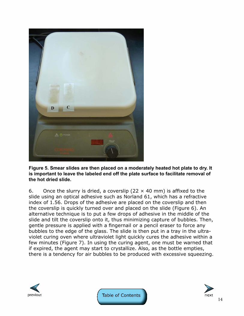
5. The preparation bench equipment should include a large hot plate where slides are placed once the desired consistency of slurry is reached (Figure 5). To facilitate easy removal, only the end of the slide with the slurry is placed on the hot plate and left for a few minutes until completely dry. The label end of the slide is left off the edge of the hot plate so that the slide can be easily removed by hand without burning your fingers. A moderate hot-plate temperature is best.
14
Figure 5. Smear slides are then placed on a moderately heated hot plate to dry. It is important to leave the labeled end off the plate surface to facilitate removal of the hot dried slide.
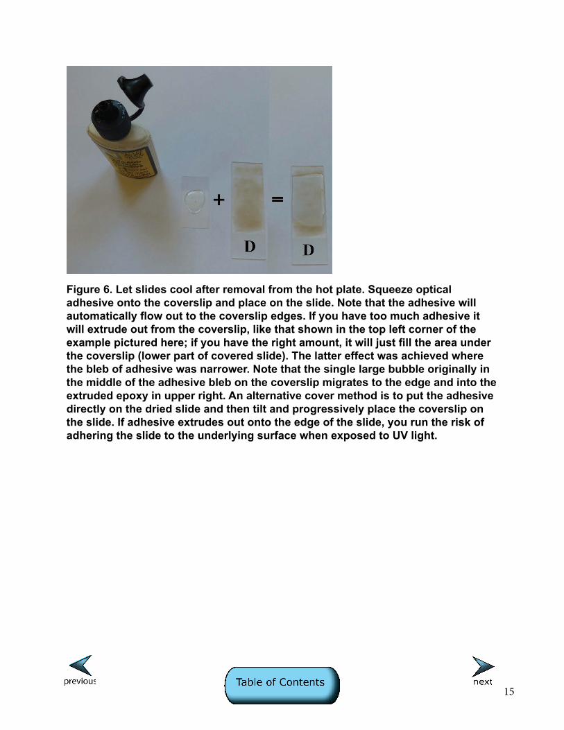
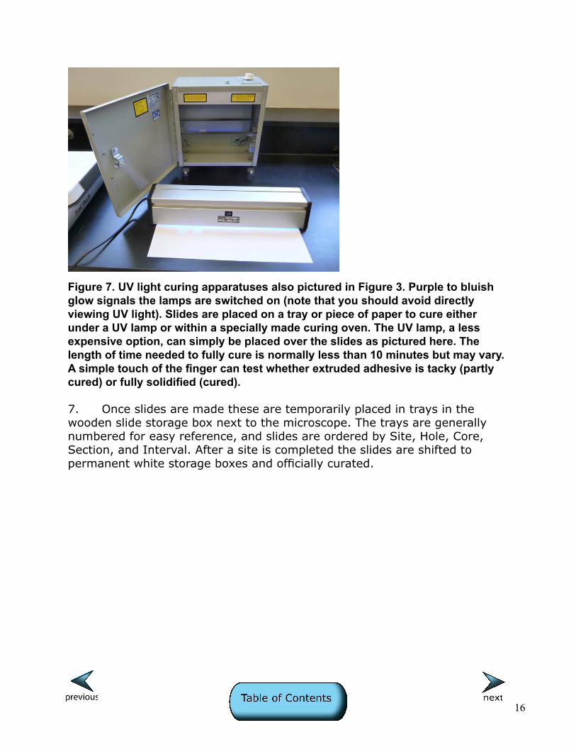
6. Once the slurry is dried, a coverslip (22 × 40 mm) is affixed to the slide using an optical adhesive such as Norland 61, which has a refractive index of 1.56. Drops of the adhesive are placed on the coverslip and then the coverslip is quickly turned over and placed on the slide (Figure 6). An alternative technique is to put a few drops of adhesive in the middle of the slide and tilt the coverslip onto it, thus minimizing capture of bubbles. Then, gentle pressure is applied with a fingernail or a pencil eraser to force any bubbles to the edge of the glass. The slide is then put in a tray in the ultra-violet curing oven where ultraviolet light quickly cures the adhesive within a few minutes (Figure 7). In using the curing agent, one must be warned that if expired, the agent may start to crystallize. Also, as the bottle empties, there is a tendency for air bubbles to be produced with excessive squeezing.
15
Figure 6. Let slides cool after removal from the hot plate. Squeeze optical adhesive onto the coverslip and place on the slide. Note that the adhesive will automatically flow out to the coverslip edges. If you have too much adhesive it will extrude out from the coverslip, like that shown in the top left corner of the example pictured here; if you have the right amount, it will just fill the area under the coverslip (lower part of covered slide). The latter effect was achieved where the bleb of adhesive was narrower. Note that the single large bubble originally in the middle of the adhesive bleb on the coverslip migrates to the edge and into the extruded epoxy in upper right. An alternative cover method is to put the adhesive directly on the dried slide and then tilt and progressively place the coverslip on the slide. If adhesive extrudes out onto the edge of the slide, you run the risk of adhering the slide to the underlying surface when exposed to UV light.
16
Figure 7. UV light curing apparatuses also pictured in Figure 3. Purple to bluish glow signals the lamps are switched on (note that you should avoid directly viewing UV light). Slides are placed on a tray or piece of paper to cure either under a UV lamp or within a specially made curing oven. The UV lamp, a less expensive option, can simply be placed over the slides as pictured here. The length of time needed to fully cure is normally less than 10 minutes but may vary. A simple touch of the finger can test whether extruded adhesive is tacky (partly cured) or fully solidified (cured).
7. Once slides are made these are temporarily placed in trays in the wooden slide storage box next to the microscope. The trays are generally numbered for easy reference, and slides are ordered by Site, Hole, Core, Section, and Interval. After a site is completed the slides are shifted to permanent white storage boxes and officially curated.
17
Selection of shipboard petrographer(s)
The shipboard duties of the sedimentary description group generally include scanning the archive halves, describing cores including sedimentary structures and features in the cores, and doing smear slide petrography. The latter task usually falls to the person(s) who have the most petrographic training or are the most willing to learn. Uniformity of methods between shifts is best accomplished by having a designated individual responsible for acquiring these data on each shift (this should be considered in making shift assignments). In situations where only one petrographer can be designated, this person should consider straddling shifts (e.g., 6 a.m. - 6 p.m). Once criteria are established for the first site, alternate petrographers can be trained and designated as needed later in the cruise. Note that haphazard assignment or minimal attention to this responsibility may result in the need for painful revisions later in the cruise or at the first postcruise meeting, especially in the event that lithologic names have been inconsistently determined and reported in barrel sheets and smear slide reports. It is not uncommon for sedimentologists to make significant revisions to the report at the first site later in the cruise!

18
Smear slide description and data collection
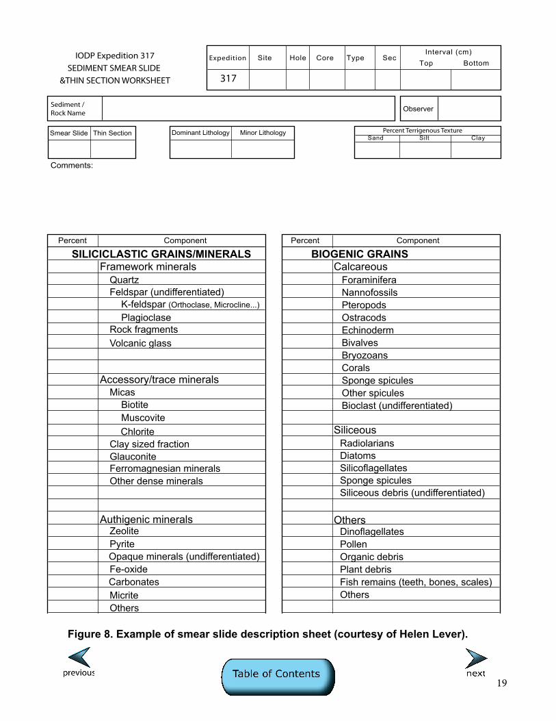
The petrographic microscope in the sedimentology description area should be equipped with a range of objectives, optimally a 40×, 20×, 10×, and 5×, and an eyepiece with reticule. It is important that the highest magnification objective be clean and centered. If not already indicated on the microscope, an optical micrometer should be used to determine the scale of reticule subdivisions, particularly the size cutoffs for clay- and silt-sized particles (4 and 63 µm, respectively). There is a tendency to be paperless on the JOIDES Resolution, but we have found that smear slide description sheets (see example in Figure 8) are useful means of documenting components and percentages. Shipboard computers have been known to be problematic (erase data) and these sheets serve as a needed backup for data. They also provide a handy place to take notes on specific components and other corroborating data sets, such as carbonate measurements, TOC, and X-ray diffracton (XRD). As there can be uneven concentration of certain components across a slide, it is common practice to estimate percentages at several places in a slide, then average those, and adjust to 100% of the sample. Later these data need to be calibrated using carbonate measurements on the intervals (see note about coordinated sampling above and about calibration below). As these calibrations often result in the need to adjust percentage totals, we recom-mend not putting the data into the computer database until this calibration process is complete. These sheets should ultimately be scanned and archived as part of the shipboard database for the Expedition. The major components of marine sediments are listed on the smear slide description sheet with space for additional components or name modification. Review of Shipboard Results from previous DSDP, ODP, and IODP cruises in the region may help provide information on what compo-nents are likely to be encountered in a smear slide. It is often helpful to organize the database entry table in the same order as the components are listed on the sheet to minimize time needed for input into the shipboard database. This list also serves as a reminder for the operator to specifically look for certain components in each smear slide. Even documenting trace amounts of certain components may be helpful to other shipboard scientists (for example, it may help biostratigraphers focus on key intervals for dating or alert physical properties scientists to minor diagenetic features that have strong effects on bulk rock properties).
19
Figure 8. Example of smear slide description sheet (courtesy of Helen Lever).
Expedition Site Hole Core Type SecTop
Observer
BottomInterval (cm)
Sediment / Rock Name
Smear Slide Thin Section Dominant Lithology Minor Lithology Percent Terrigenous Texture
IODP Expedition 317SEDIMENT SMEAR SLIDE
&THIN SECTION WORKSHEET
Sand Silt Clay
Percent
Comments:
Component Percent Component
317
Framework minerals
Accessory/trace minerals
Quartz
Micas
Clay sized fraction
Authigenic minerals
Opaque minerals (undifferentiated)Pyrite
Micrite
Fe-oxideCarbonates
Others
GlauconiteFerromagnesian minerals
Zeolite
Feldspar (undifferentiated)
Rock fragments
K-feldspar (Orthoclase, Microcline...)
Plagioclase
BiotiteMuscovite
SILICICLASTIC GRAINS/MINERALSCalcareous
Foraminifera
PteropodsNannofossils
SiliceousRadiolariansDiatoms
OthersDinoflagellatesPollenOrganic debrisPlant debris
Sponge spicules
Echinoderm
Fish remains (teeth, bones, scales)
BryozoansBivalves
CoralsSponge spicules
Silicoflagellates
Volcanic glass
Chlorite
Other dense minerals
BIOGENIC GRAINS
Ostracods
Bioclast (undifferentiated)Other spicules
Siliceous debris (undifferentiated)
Others
20
Estimating percentages of components
Comparator charts (Figure 16 on p. 41 in: http://www-odp.tamu.edu/publications/tnotes/digital/tnote_08.pdf) are the best method of estimating relative percentages of minerals in the silt- to sand-sized grain fraction. Estimating the abundance of the clay-sized (4-micron) fraction is challenging. With this in mind, we have created a series of reference slides with known proportions of clay-sized vs. silt-sized minerals. Specific tech-niques for seeing the clay fraction include viewing at high magnification (40× or 60×). Note that where sand grains are present in a slide, this may pre-clude one from focusing on the fines at high magnification because the separation between the cover glass and the slide onto which the fines have settled is too great. That is why we suggest segregating the coarse material at one end of the slide so that the coverslip rests at an angle, allowing for closer magnification on the fine end of the slide. The clay- to fine-silt fraction is best seen when the polars are semicrossed, providing an oblique illumination. Estimated proportions of clay and silt may be corroborated by tactile tests on core material (ability to create a ribbon between thumb and fore- finger, grittiness on the teeth). Another test is to suspend the sediment in water in a translucent glass vial (paleosample vial) and observe how rapidly the sediment settles (sand and silt) or remains suspended for a long period (clay). Again, the proportion of sand, silt, and clay determines the sediment name, and terminology must be consistently applied between smear slide and core describers.

21
Calibration of smear estimates using other data
Chemical determination of bulk carbonate and XRD mineralogical data should be used to help calibrate smear slide estimates of components. This is possible only if sampling is coordinated for these analyses (in the same exact intervals), as noted above. The proportion of carbonate is significant in naming the sediment lithology in that it determines the classification scheme used (see Handbook for Shipboard Sedimentologists: http://www-odp.tamu.edu/publications/tnotes/digital/tnote_08.pdf). The percentage of clay minerals versus carbonate in the clay-sized fraction can be a difficult call, especially in finer-grained Pleistocene sediments where nannofossils are very small (page 223) and exhibit low birefringence, making them less easily quantified even at high (40×) magnification. Recognition of very small Pleistocene nannofossils is usually a problem starting with the very first cores described on the expedition, so again coordination with carbonate analyses is best begun immediately at the start of core description. In some instances where the microscope setup lacked a 40× objective, carbonate content has been completely missed! X-ray diffraction analyses can be used to clarify identification of major and (to some extent) minor mineral components in smear slides. We have used such data to provide semiquantitative ratios of quartz and feldspar, as well as to identify dense mineral components and authigenic minerals such as clays, zeolites, Fe sulfides, and carbonates. Amorphous material (volcanic glass and opal) also may be identified using this method, though these components are usually easily discerned optically.
22
References Cited and Petrography Resources
Haq , B.U., and Boersma, A., 1976 and 1998, Introduction to marine micropaleontology, Elsevier, 376 p.
Kerr, P.F., 1977, Optical Mineralogy, McGraw-Hill, New York, 492 p.
Mange, M.A., and Maurer, H.F.W., 1992, Heavy minerals in colour, Chapman and Hall, London, 147 p.
Marsaglia, K.M., and Shapiro, S., 2005, ODP Core Photo Atlas, CD format (submitted report/project -- publication status pending).
Mazzullo, J., and Graham, A.G., 1988, Handbook for shipboard sedimentologists, Ocean Drilling Program, Technical Note No. 8, 70 p.
Milliken, K. L., and S.-J. Choh, 2011, Carbonate Petrology: An Interactive Petrography Tutorial, v. 1.0, Discovery Series, Tulsa, Oklahoma, American Association of Petroleum Geologists.
Milliken, K. L., S.-J. Choh, and E. F. McBride, 2007, Sandstone Petrology: A Tutorial Petrographic Image Atlas, v. 2.0, Discovery Series, Tulsa, Oklahoma, American Association of Petroleum Geologists.
Nesse, W.D. 2004, Introduction to Optical Mineralogy, Oxford University Press, New York, 348 p.
Rothwell, R.G., 1989, Minerals and mineraloids in marine sediments: Elsevier, 279 p.
Scholle, P. A., 1978, A Color Illustrated Guide to Carbonate Rock Constitu-ents, Textures, Cements, and Porosities: Memoir, v. 27: Tulsa, Oklahoma, American Association of Petroleum Geologists, 241 p.
Scholle, P. A., 1979, A Color Illustrated Guide to Constituents, Textures, Cements, and Porosities of Sandstones and Associated Rocks: Memoir, v. 28: Tulsa, Oklahoma, American Association of Petroleum Geologists, 201 p.
Scholle, P. A., and D. S. Ulmer-Scholle, 2003, A Color Guide to the Petrography of Carbonate Rocks: Grains, Textures, Porosity, Diagenesis: Memoir, v. 77: Tulsa, Oklahoma, American Association of Petroleum Geologists, 474 p.
23
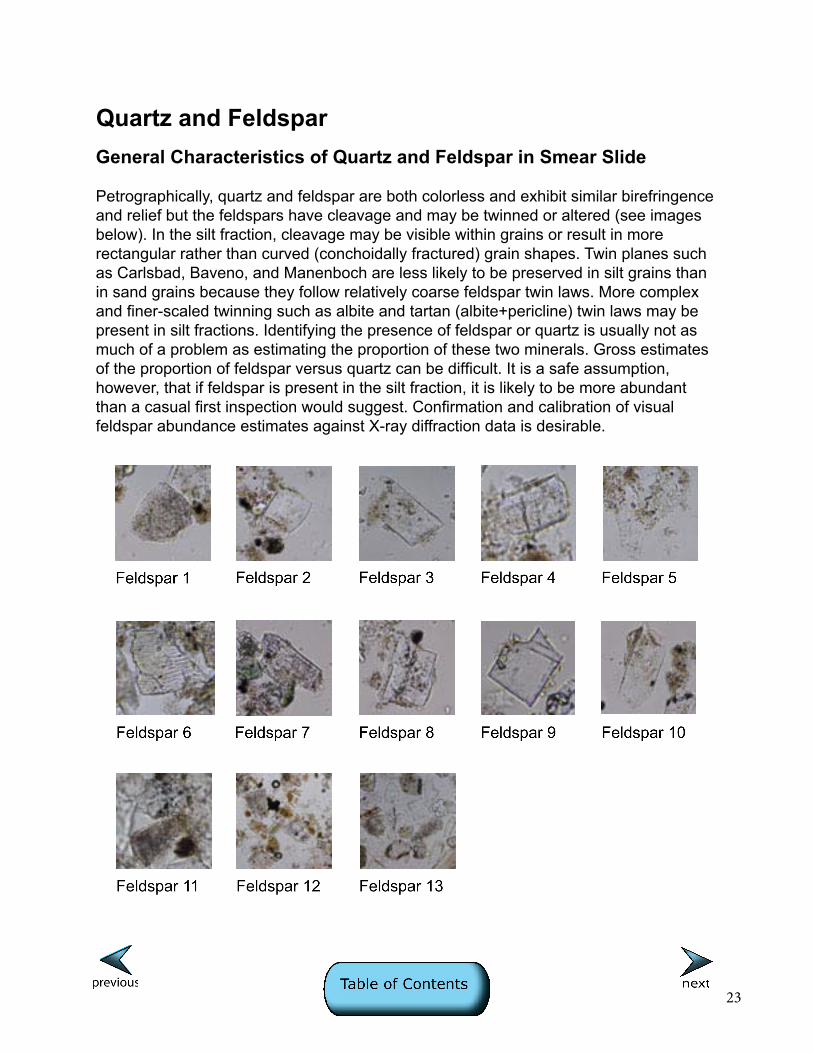
Quartz and FeldsparGeneral Characteristics of Quartz and Feldspar in Smear Slide
Petrographically, quartz and feldspar are both colorless and exhibit similar birefringence and relief but the feldspars have cleavage and may be twinned or altered (see images below). In the silt fraction, cleavage may be visible within grains or result in more rectangular rather than curved (conchoidally fractured) grain shapes. Twin planes such as Carlsbad, Baveno, and Manenboch are less likely to be preserved in silt grains than in sand grains because they follow relatively coarse feldspar twin laws. More complex and finer-scaled twinning such as albite and tartan (albite+pericline) twin laws may be present in silt fractions. Identifying the presence of feldspar or quartz is usually not as much of a problem as estimating the proportion of these two minerals. Gross estimates of the proportion of feldspar versus quartz can be difficult. It is a safe assumption, however, that if feldspar is present in the silt fraction, it is likely to be more abundant than a casual first inspection would suggest. Confirmation and calibration of visual feldspar abundance estimates against X-ray diffraction data is desirable.
24
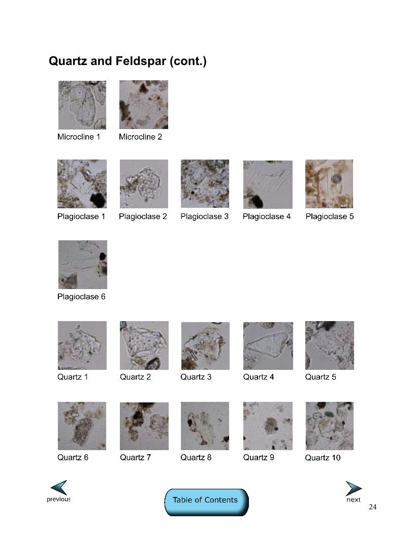
Quartz and Feldspar (cont.)
Component: Feldspar
25
Imag
e ID
: 0
005/0
006
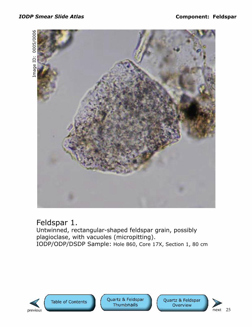
Feldspar 1.Untwinned, rectangular-shaped feldspar grain, possibly plagioclase, with vacuoles (micropitting).IODP/ODP/DSDP Sample: Hole 860, Core 17X, Section 1, 80 cm
Cells are 10 µm.
Component: Feldspar
26
Imag
e ID
: 0
017/0
018
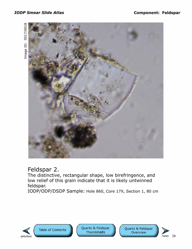
Feldspar 2.The distinctive, rectangular shape, low birefringence, and low relief of this grain indicate that it is likely untwinned feldspar.IODP/ODP/DSDP Sample: Hole 860, Core 17X, Section 1, 80 cm
Cells are 10 µm.
Component: Feldspar
27
Imag
e ID
: 0
024/0
025
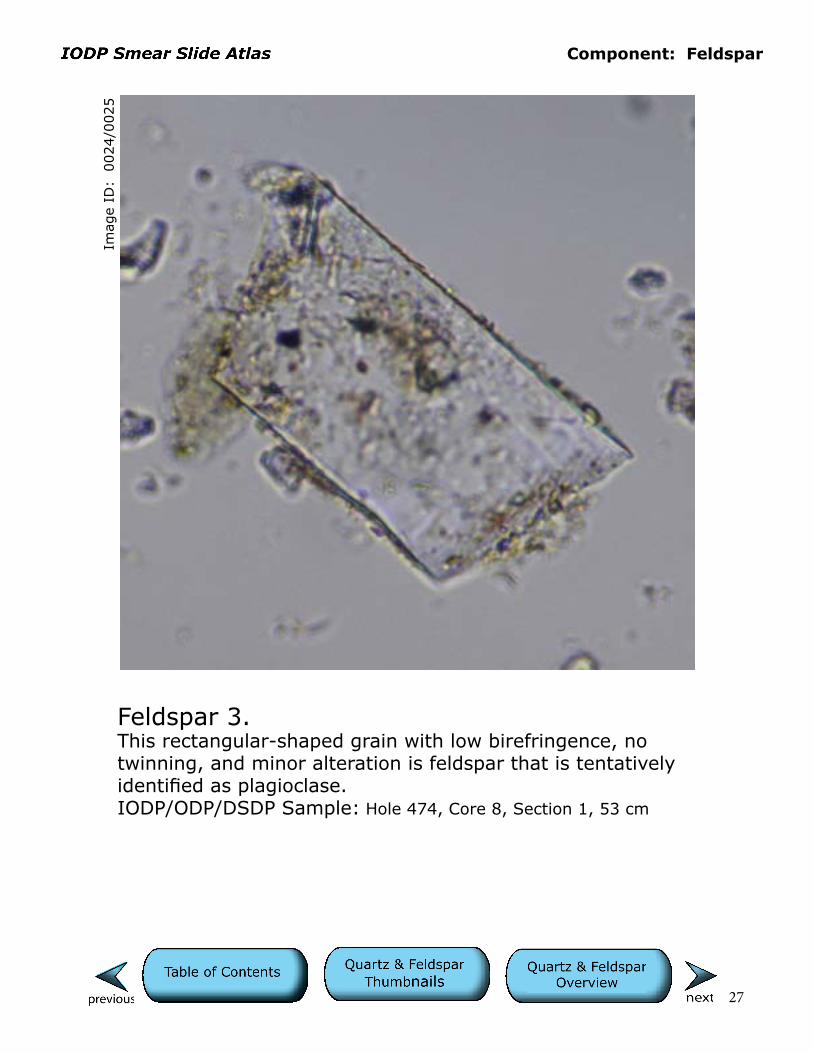
Feldspar 3.This rectangular-shaped grain with low birefringence, no twinning, and minor alteration is feldspar that is tentatively identified as plagioclase.IODP/ODP/DSDP Sample: Hole 474, Core 8, Section 1, 53 cm
Cells are 10 µm.

Component: Feldspar
28
Imag
e ID
: 0
027/0
028
Feldspar 4.This rectangular-shaped grain with low birefringence and relief is feldspar, probably plagioclase. It exhibits slight vacuolization but no characteristic twinning.IODP/ODP/DSDP Sample: Hole 474, Core 8, Section 1, 53 cm
Cells are 10 µm.
Component: Feldspar
29
Imag
e ID
: 0
029/0
030
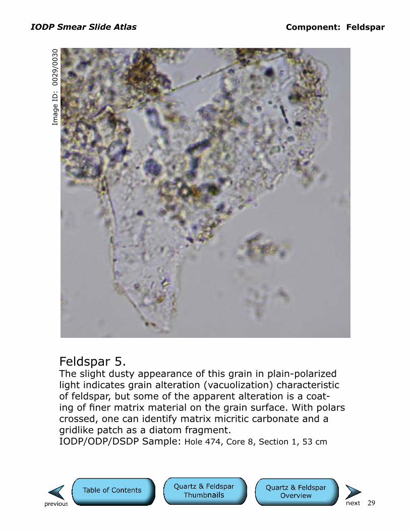
Feldspar 5.The slight dusty appearance of this grain in plain-polarized light indicates grain alteration (vacuolization) characteristic of feldspar, but some of the apparent alteration is a coat-ing of finer matrix material on the grain surface. With polars crossed, one can identify matrix micritic carbonate and a gridlike patch as a diatom fragment.IODP/ODP/DSDP Sample: Hole 474, Core 8, Section 1, 53 cm
Cells are 10 µm.
Component: Feldspar
30
Imag
e ID
: 0
035/0
036
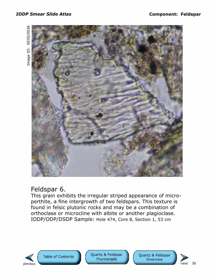
Feldspar 6.This grain exhibits the irregular striped appearance of micro-perthite, a fine intergrowth of two feldspars. This texture is found in felsic plutonic rocks and may be a combination of orthoclase or microcline with albite or another plagioclase. IODP/ODP/DSDP Sample: Hole 474, Core 8, Section 1, 53 cm
Cells are 10 µm.

Component: Feldspar
31
Imag
e ID
: 0
102/0
103
Feldspar 7.Untwinned and vacuolized, rectangular-shaped feldspar that is likely plagioclase.IODP/ODP/DSDP Sample: Hole 178, Core 32, Section 2, 18 cm
Cells are 10 µm.
Component: Feldspar
32
Imag
e ID
: 0
104/0
105
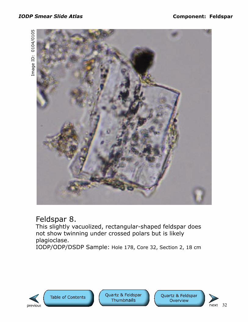
Feldspar 8.This slightly vacuolized, rectangular-shaped feldspar does not show twinning under crossed polars but is likely plagioclase.IODP/ODP/DSDP Sample: Hole 178, Core 32, Section 2, 18 cm
Cells are 10 µm.

Component: Feldspar
33
Imag
e ID
: 0
069/0
070
Feldspar 9.The untwinned feldspar shown here has a form that may be a combination of original crystal shape and cleavage.IODP/ODP/DSDP Sample: Hole 1119C, Core 10H, Section 2W, 125 cm
Cells are 10 µm.

Component: Feldspar
34
Imag
e ID
: 0
077/0
078
Feldspar 10.This is a rectangular, untwinned feldspar grain.IODP/ODP/DSDP Sample: Hole 1119C, Core 10H, Section 2W, 125 cm
Cells are 10 µm.
Component: Feldspar
35
Imag
e ID
: 0
170/0
171
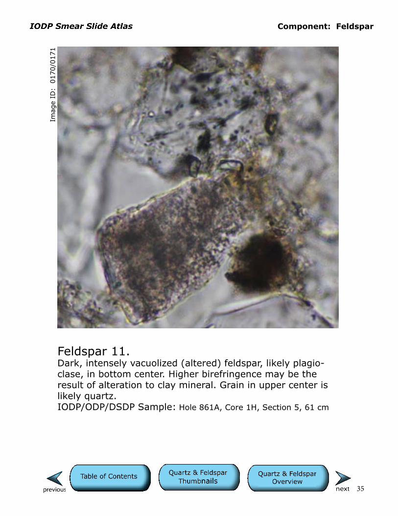
Feldspar 11.Dark, intensely vacuolized (altered) feldspar, likely plagio-clase, in bottom center. Higher birefringence may be the result of alteration to clay mineral. Grain in upper center is likely quartz.IODP/ODP/DSDP Sample: Hole 861A, Core 1H, Section 5, 61 cm
Cells are 10 µm.

Component: Feldspar
36
Imag
e ID
: 0
251/0
252
Feldspar 12.Variably altered, rectangular feldspar grains in center and on left have a dusty appearance in plane-polarized light. Brown clumps of material are likely semilithified clayey matrix not completely disaggregated during smear slide preparation. Note: This is a common problem with older, clay-rich cores that have dried during storage. Note also the cluster of opaque pyrite framboids in the center and spiny silicoflagellate test on lower right. IODP/ODP/DSDP Sample: Hole 475, Core 15, Section 3, 84 cm
Cells are 10 µm.
Component: Feldspar
37
Imag
e ID
: 0
701/0
702
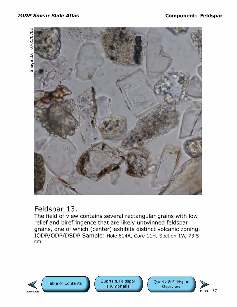
Feldspar 13.The field of view contains several rectangular grains with low relief and birefringence that are likely untwinned feldspar grains, one of which (center) exhibits distinct volcanic zoning.IODP/ODP/DSDP Sample: Hole 614A, Core 11H, Section 1W, 73.5 cm
Cells are 10 µm.

Component: Feldspar
38
Imag
e ID
: 0
087/0
088
Microcline 1.Semirounded microcline grain exhibiting characteristic tartan twinning with polars crossed. Birefringent “doughnuts” to left of grain and adhering to lower tip of grain are large nannofossils.IODP/ODP/DSDP Sample: Hole 1119C, Core 10H, Section 2W, 125 cm
Cells are 10 µm.

Component: Feldspar
39
Imag
e ID
: 0
240/0
241
Microcline 2.Large grain of microcline in center exhibits characteristic tartan twinning with polars crossed.IODP/ODP/DSDP Sample: Hole 475, Core 3, Section 3, 78 cm
Cells are 10 µm.
Component: Feldspar
40
Imag
e ID
: 0
007/0
008
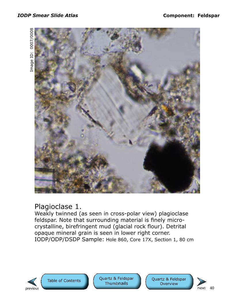
Plagioclase 1.Weakly twinned (as seen in cross-polar view) plagioclase feldspar. Note that surrounding material is finely micro- crystalline, birefringent mud (glacial rock flour). Detrital opaque mineral grain is seen in lower right corner.IODP/ODP/DSDP Sample: Hole 860, Core 17X, Section 1, 80 cm
Cells are 10 µm.

Component: Feldspar
41
Imag
e ID
: 0
106/0
107
Plagioclase 2.In the cross-polar view this plagioclase grain exhibits albite twinning.IODP/ODP/DSDP Sample: Hole 178, Core 32, Section 2, 18 cm
Cells are 10 µm.

Component: Feldspar
42
Imag
e ID
: 0
013/0
014
Plagioclase 3.Distinct albite twinning in the large grain in center of the field of view identifies it as plagioclase feldspar. Note that surrounding material is finely microcrystalline and birefrin-gent mud (glacial rock flour). High relief and high birefrin-gent grain in upper right may be a zircon. Circular opaque minerals are likely framboidal, authigenic pyrite.IODP/ODP/DSDP Sample: Hole 860, Core 17X, Section 1, 80 cm
Cells are 10 µm.

Component: Feldspar
43
Imag
e ID
: 0
062/0
063
Plagioclase 4.Irregularly shaped plagioclase with albite twinning.IODP/ODP/DSDP Sample: Hole 790B, Core 8H, Section 5, Cm 110
Cells are 10 µm.

Component: Feldspar
44
Imag
e ID
: 0
398/0
399
Plagioclase 5.Distinctly twinned plagioclase. Note that crystal is thicker than 30 µm, increasing the birefringence from the usual gray to red/yellow with polars crossed. Dark gray circular region is an out-of-focus bubble in the mounting medium.IODP/ODP/DSDP Sample: Hole 179, Core 21, Section 1, 134 cm
Cells are 10 µm.
Component: Feldspar
45
Imag
e ID
: 0
753/0
754
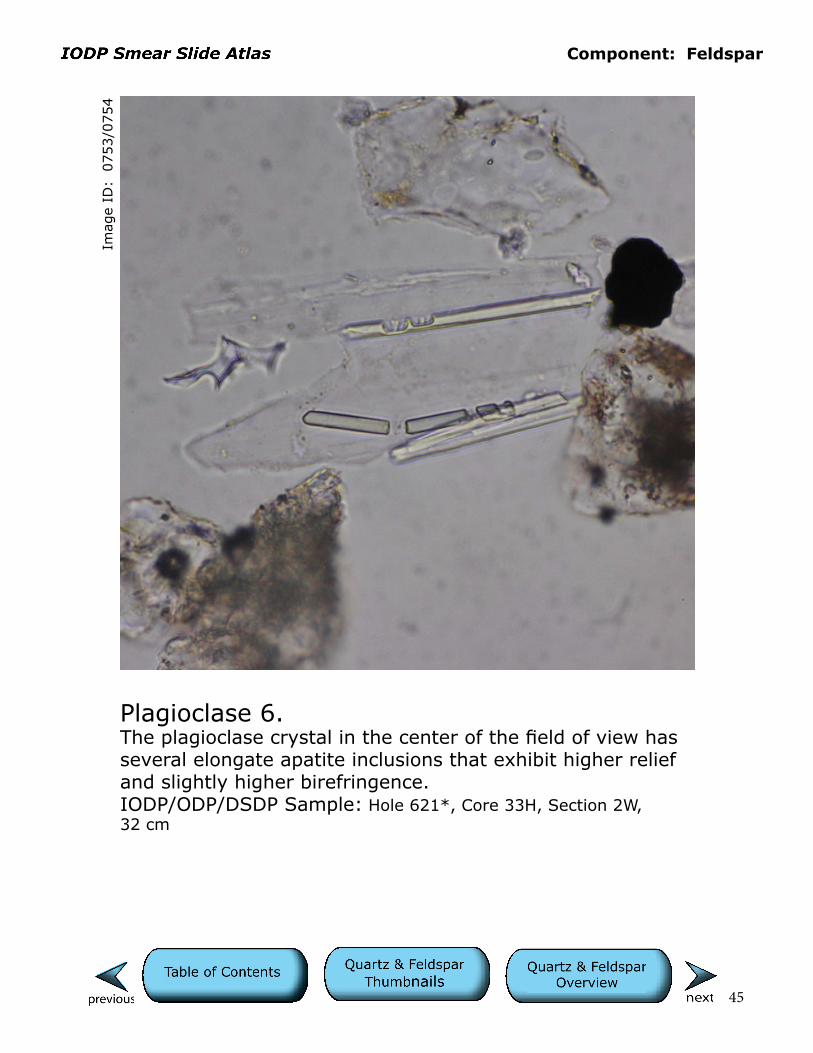
Plagioclase 6.The plagioclase crystal in the center of the field of view has several elongate apatite inclusions that exhibit higher relief and slightly higher birefringence.IODP/ODP/DSDP Sample: Hole 621*, Core 33H, Section 2W, 32 cm
Cells are 10 µm.
Component: Quartz
46
Imag
e ID
: 0
099/0
100
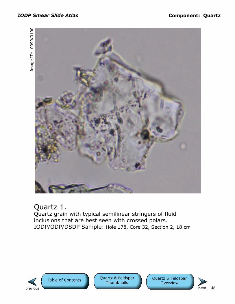
Quartz 1.Quartz grain with typical semilinear stringers of fluid inclusions that are best seen with crossed polars. IODP/ODP/DSDP Sample: Hole 178, Core 32, Section 2, 18 cm
Cells are 10 µm.

Component: Quartz
47
Imag
e ID
: 0
108/0
109
Quartz 2.This is an ordinary, angular quartz grain. Note the largest fluid inclusion has a gas-phase bubble that produces an eye-like effect best seen with polars crossed. Some such gas-phase bubbles are in constant motion (“dancing bubbles”) as a consequence of Brownian forces or convection in the fluid phase powered by small thermal gradients. Smaller, high-relief grain in lower center is likely zoisite or clinozoisite.IODP/ODP/DSDP Sample: Hole 178, Core 32, Section 2, 18 cm
Cells are 10 µm.
Component: Quartz
48
Imag
e ID
: 0
075/0
076
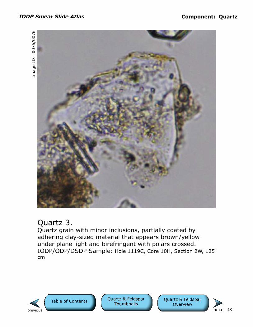
Quartz 3.Quartz grain with minor inclusions, partially coated by adhering clay-sized material that appears brown/yellow under plane light and birefringent with polars crossed.IODP/ODP/DSDP Sample: Hole 1119C, Core 10H, Section 2W, 125 cm
Cells are 10 µm.

Component: Quartz
49
Imag
e ID
: 0
140/0
141
Quartz 4.Translucent quartz with conchoidal fractures.IODP/ODP/DSDP Sample: Hole 1352B, Core 11H, Section 2W, 21 cm
Cells are 10 µm.

Component: Quartz
50
Imag
e ID
: 0
118/0
119
Quartz 5.Typical quartz grain with irregular fractured surfaces.IODP/ODP/DSDP Sample: Hole 1352B, Core 54X, Section 4W, 97 cm
Cells are 10 µm.

Component: Quartz
51
Imag
e ID
: 0
255/0
256
Quartz 6.Vacuolized quartz and other nonbirefringent, opaline siliceous debris, including silicoflagellate in upper left corner. Formation of vacuolized quartz has been attributed to hydro-thermal processes in the source rock. Subtle linear features (toggle on info layer) may be healed fractures.IODP/ODP/DSDP Sample: Hole 475, Core 15, Section 3, 84 cm
Cells are 10 µm.
Component: Quartz
52
Imag
e ID
: 0
265/0
266
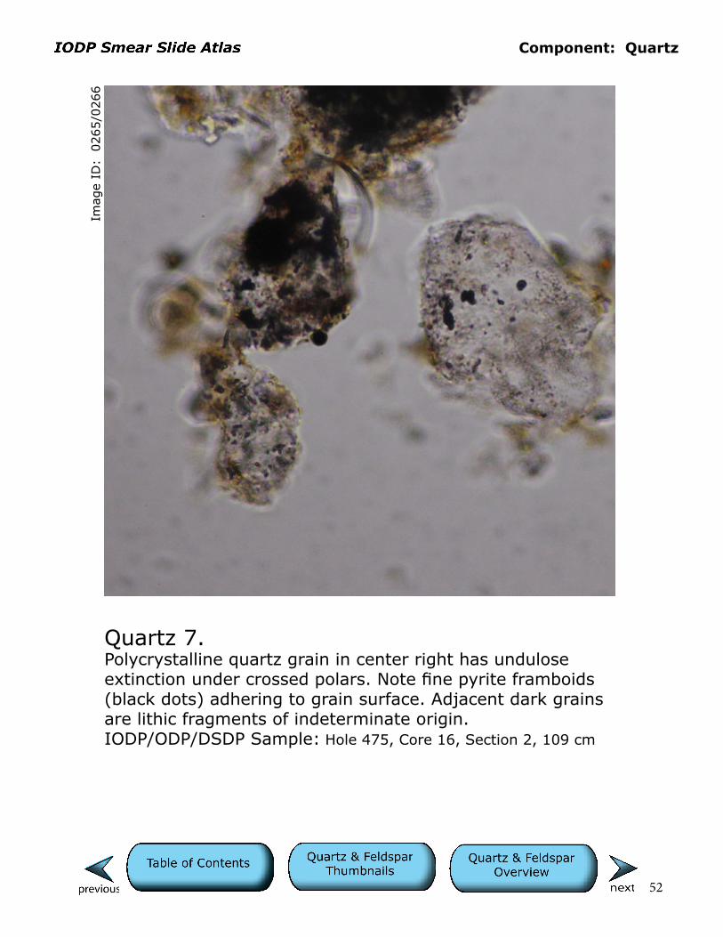
Quartz 7.Polycrystalline quartz grain in center right has undulose extinction under crossed polars. Note fine pyrite framboids (black dots) adhering to grain surface. Adjacent dark grains are lithic fragments of indeterminate origin.IODP/ODP/DSDP Sample: Hole 475, Core 16, Section 2, 109 cm
Cells are 10 µm.
Component: Quartz
53
Imag
e ID
: 0
562/0
563
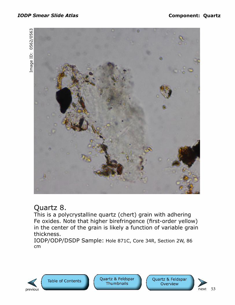
Quartz 8.This is a polycrystalline quartz (chert) grain with adhering Fe oxides. Note that higher birefringence (first-order yellow) in the center of the grain is likely a function of variable grain thickness.IODP/ODP/DSDP Sample: Hole 871C, Core 34R, Section 2W, 86 cm
Cells are 10 µm.

Component: Quartz
54
Imag
e ID
: 0
486/0
487
Quartz 9.This polycrystalline quartz (chert) grain is dirty in appearance owing to the presence of impurities. Such impure cherts are commonly silicified claystones.IODP/ODP/DSDP Sample: Hole 615*, Core 19X, Section 1W, 122 cm
Cells are 10 µm.
Component: Quartz
55
Imag
e ID
: 0
737/0
738
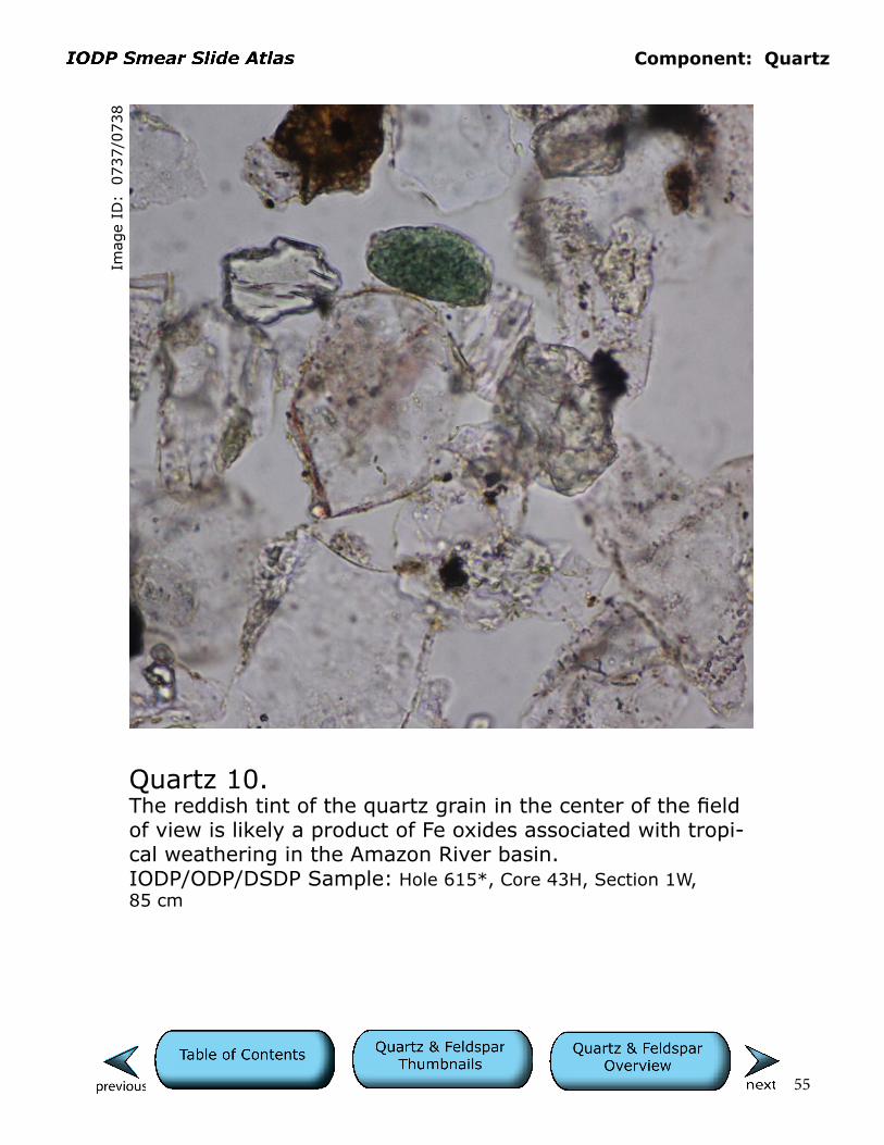
Quartz 10.The reddish tint of the quartz grain in the center of the field of view is likely a product of Fe oxides associated with tropi-cal weathering in the Amazon River basin.IODP/ODP/DSDP Sample: Hole 615*, Core 43H, Section 1W, 85 cm
Cells are 10 µm.
56
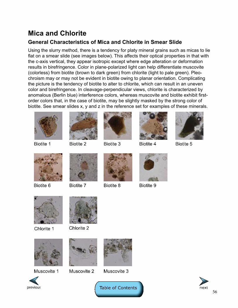
Mica and ChloriteGeneral Characteristics of Mica and Chlorite in Smear SlideUsing the slurry method, there is a tendency for platy mineral grains such as micas to lie flat on a smear slide (see images below). This affects their optical properties in that with the c-axis vertical, they appear isotropic except where edge alteration or deformation results in birefringence. Color in plane-polarized light can help differentiate muscovite (colorless) from biotite (brown to dark green) from chlorite (light to pale green). Pleo-chroism may or may not be evident in biotite owing to planar orientation. Complicating the picture is the tendency of biotite to alter to chlorite, which can result in an uneven color and birefringence. In cleavage-perpendicular views, chlorite is characterized by anomalous (Berlin blue) interference colors, whereas muscovite and biotite exhibit first-order colors that, in the case of biotite, may be slightly masked by the strong color of biotite. See smear slides x, y and z in the reference set for examples of these minerals.
Component: Mica and Chlorite
57
Imag
e ID
: 0
085/0
086
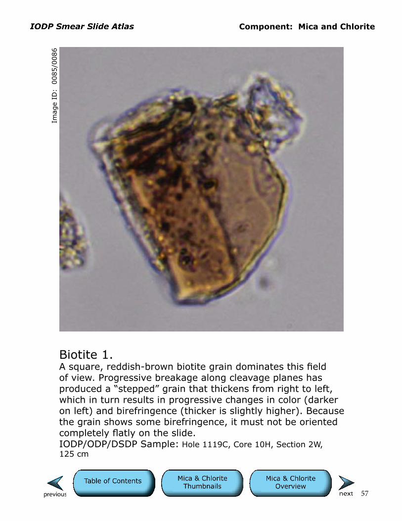
Biotite 1.A square, reddish-brown biotite grain dominates this field of view. Progressive breakage along cleavage planes has produced a “stepped” grain that thickens from right to left, which in turn results in progressive changes in color (darker on left) and birefringence (thicker is slightly higher). Because the grain shows some birefringence, it must not be oriented completely flatly on the slide.IODP/ODP/DSDP Sample: Hole 1119C, Core 10H, Section 2W, 125 cm
Cells are 10 µm.

Component: Mica and Chlorite
58
Imag
e ID
: 0
156/0
157
Biotite 2.This reddish-brown biotite grain is mostly isotropic with polars crossed.IODP/ODP/DSDP Sample: Hole 1352B, Core 11H, Section 2W, 21 cm
Cells are 10 µm.

Component: Mica and Chlorite
59
Imag
e ID
: 0
383
Biotite 3.Dark brownish-green biotite with color variations as a func-tion of breakage along cleavage planes and resulting thick-ness changes (lighter olive green is thinner). In crossed polars (not included), grain has no birefringence.
IODP/ODP/DSDP Sample: Hole 179, Core 10, Section 3, 78 cm
Cells are 10 µm.
Component: Mica and Chlorite
60
Imag
e ID
: 0
370/0
371
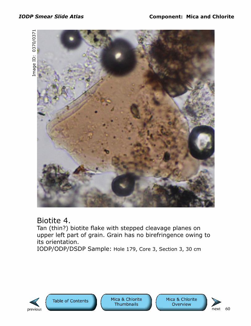
Biotite 4.Tan (thin?) biotite flake with stepped cleavage planes on upper left part of grain. Grain has no birefringence owing to its orientation.IODP/ODP/DSDP Sample: Hole 179, Core 3, Section 3, 30 cm
Cells are 10 µm.

Component: Mica and Chlorite
61
Imag
e ID
: 0
349/0
350
Biotite 5.Stepped color gradation from nearly opaque in the upper right to light olive green in the lower left part of the slide is a function of breakage along basal cleavage and result-ing thickness changes (lower left edge is thinner than upper right). Grain has no birefringence owing to its orientation. Dark circular features in upper right corner are bubbles.IODP/ODP/DSDP Sample: Hole 178, Core 43, Section 5, 12
Cells are 10 µm.
Component: Mica and Chlorite
62
Imag
e ID
: 0
218/0
219
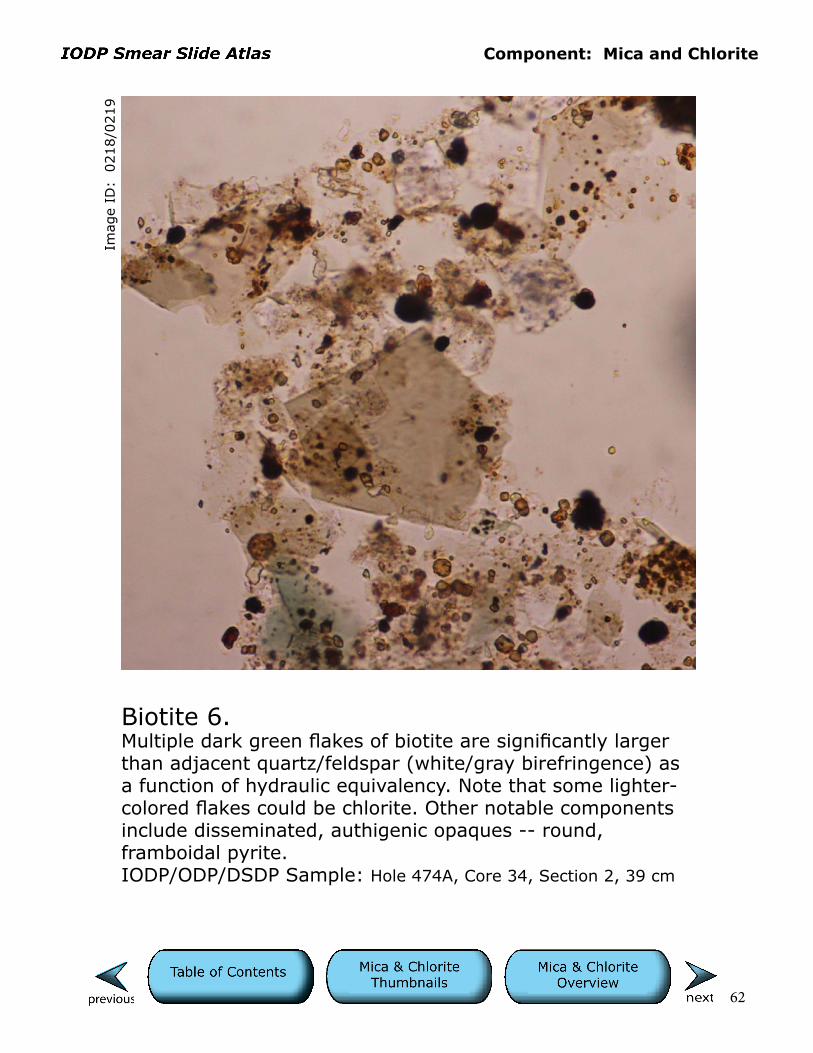
Biotite 6.Multiple dark green flakes of biotite are significantly larger than adjacent quartz/feldspar (white/gray birefringence) as a function of hydraulic equivalency. Note that some lighter-colored flakes could be chlorite. Other notable components include disseminated, authigenic opaques -- round, framboidal pyrite.IODP/ODP/DSDP Sample: Hole 474A, Core 34, Section 2, 39 cm
Cells are 10 µm.
Component: Mica and Chlorite
63
Imag
e ID
: 0
344/0
345
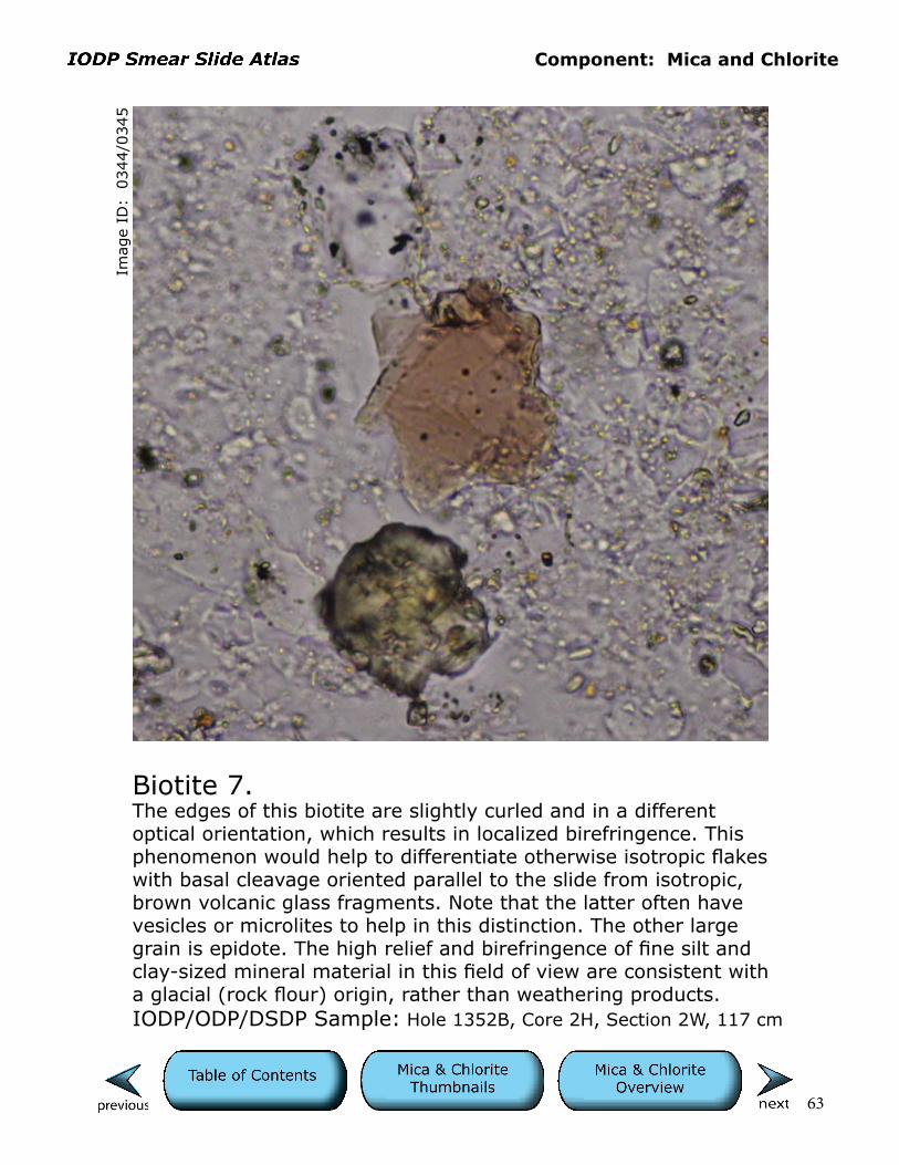
Biotite 7.The edges of this biotite are slightly curled and in a different optical orientation, which results in localized birefringence. This phenomenon would help to differentiate otherwise isotropic flakes with basal cleavage oriented parallel to the slide from isotropic, brown volcanic glass fragments. Note that the latter often have vesicles or microlites to help in this distinction. The other large grain is epidote. The high relief and birefringence of fine silt and clay-sized mineral material in this field of view are consistent with a glacial (rock flour) origin, rather than weathering products.IODP/ODP/DSDP Sample: Hole 1352B, Core 2H, Section 2W, 117 cm
Cells are 10 µm.
Component: Mica and Chlorite
64
Imag
e ID
: 0
220/0
221
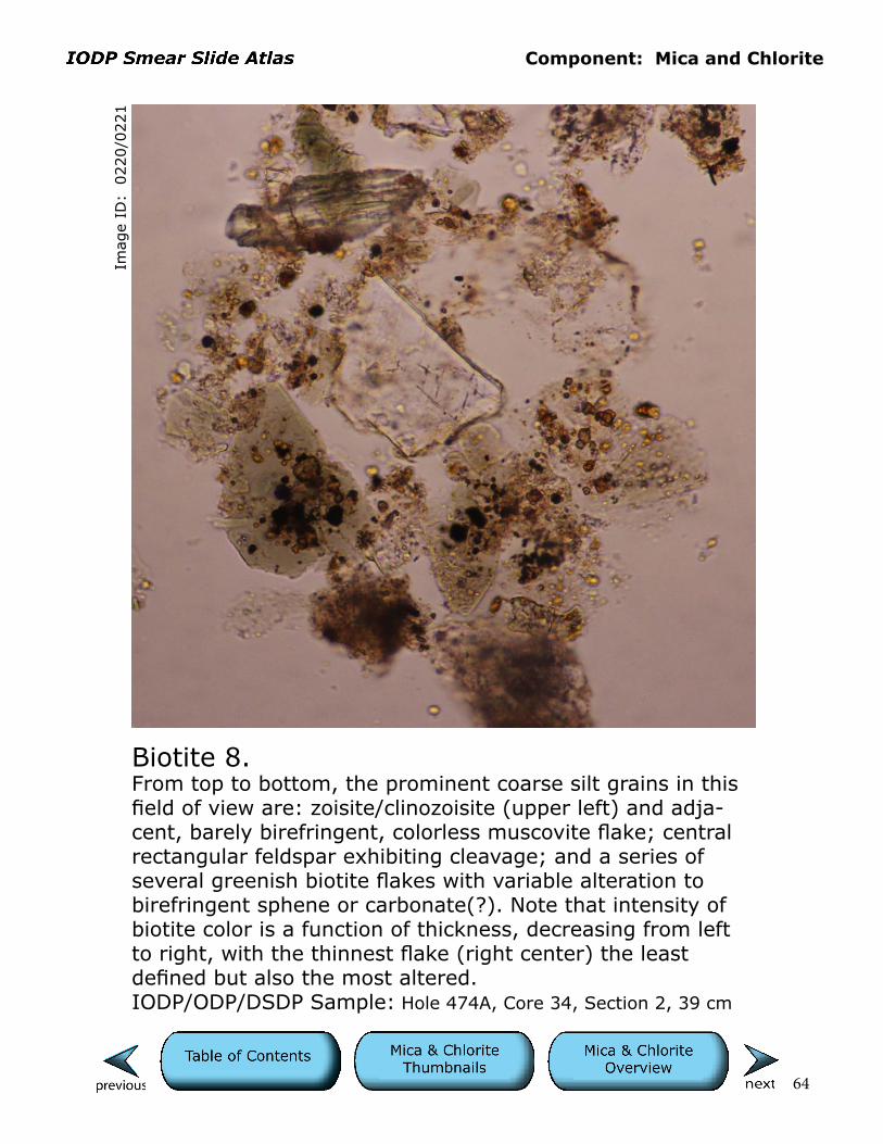
Biotite 8.From top to bottom, the prominent coarse silt grains in this field of view are: zoisite/clinozoisite (upper left) and adja-cent, barely birefringent, colorless muscovite flake; central rectangular feldspar exhibiting cleavage; and a series of several greenish biotite flakes with variable alteration to birefringent sphene or carbonate(?). Note that intensity of biotite color is a function of thickness, decreasing from left to right, with the thinnest flake (right center) the least defined but also the most altered. IODP/ODP/DSDP Sample: Hole 474A, Core 34, Section 2, 39 cm
Cells are 10 µm.

Component: Mica and Chlorite
65
Imag
e ID
: 0
699/0
700
Biotite 9.This brown biotite grain is a semieuhedral crystal indicating that it may be of volcanic origin.IODP/ODP/DSDP Sample: Hole 614A, Core 11H, Section 1W, 73.5 cm
Cells are 10 µm.

Component: Mica and Chlorite
66
Imag
e ID
: 0
112/0
113
Chlorite 1.This pale green grain of chlorite exhibits semirounded edges. It shows no birefringence with polars crossed because it rests flat on the glass slide on its basal cleavage (c-axis of the crystal is perpendicular to the slide). IODP/ODP/DSDP Sample: Hole 1352B, Core 54X, Section 4W, 97 cm
Cells are 10 µm.
Component: Mica and Chlorite
67
Imag
e ID
: 0
146/0
147
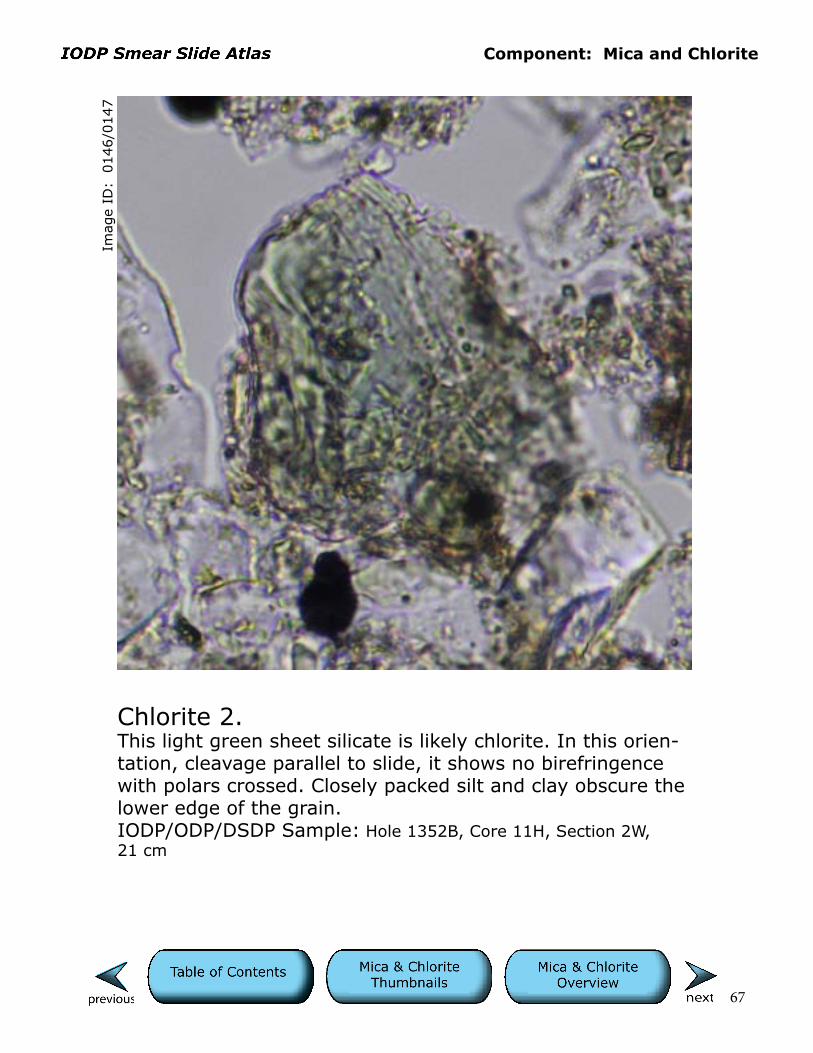
Chlorite 2.This light green sheet silicate is likely chlorite. In this orien-tation, cleavage parallel to slide, it shows no birefringence with polars crossed. Closely packed silt and clay obscure the lower edge of the grain.IODP/ODP/DSDP Sample: Hole 1352B, Core 11H, Section 2W, 21 cm
Cells are 10 µm.
Component: Mica and Chlorite
68
Imag
e ID
: 0
132/0
133
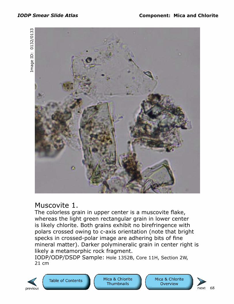
Muscovite 1.The colorless grain in upper center is a muscovite flake, whereas the light green rectangular grain in lower center is likely chlorite. Both grains exhibit no birefringence with polars crossed owing to c-axis orientation (note that bright specks in crossed-polar image are adhering bits of fine mineral matter). Darker polymineralic grain in center right is likely a metamorphic rock fragment.IODP/ODP/DSDP Sample: Hole 1352B, Core 11H, Section 2W, 21 cm
Cells are 10 µm.

Component: Mica and Chlorite
69
Imag
e ID
: 0
134/0
135
Muscovite 2.Elongate flake of muscovite with adhering pyrite framboids (circular opaques) and slight birefringence.IODP/ODP/DSDP Sample: Hole 1352B, Core 11H, Section 2W, 21 cm
Cells are 10 µm.
Component: Mica and Chlorite
70
Imag
e ID
: 0
136/0
137
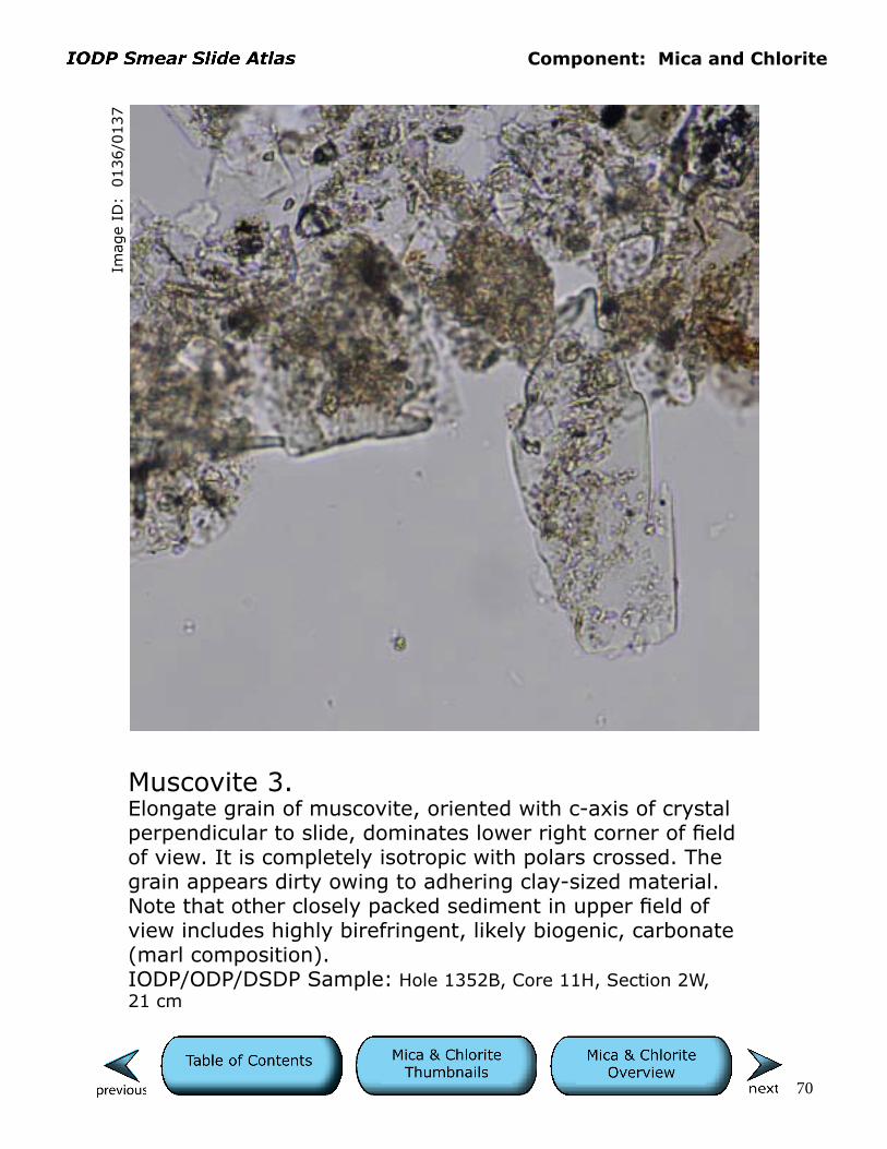
Muscovite 3.Elongate grain of muscovite, oriented with c-axis of crystal perpendicular to slide, dominates lower right corner of field of view. It is completely isotropic with polars crossed. The grain appears dirty owing to adhering clay-sized material. Note that other closely packed sediment in upper field of view includes highly birefringent, likely biogenic, carbonate (marl composition).IODP/ODP/DSDP Sample: Hole 1352B, Core 11H, Section 2W, 21 cm
Cells are 10 µm.
71
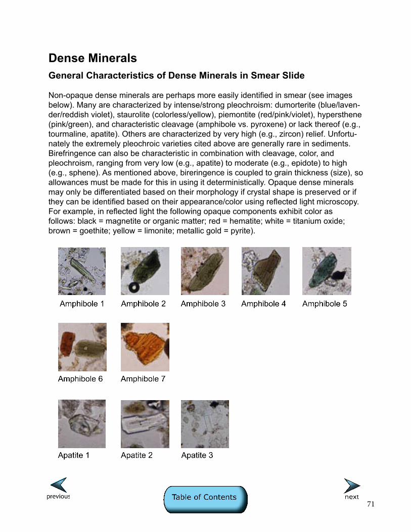
Dense MineralsGeneral Characteristics of Dense Minerals in Smear Slide
Non-opaque dense minerals are perhaps more easily identified in smear (see images below). Many are characterized by intense/strong pleochroism: dumorterite (blue/laven-der/reddish violet), staurolite (colorless/yellow), piemontite (red/pink/violet), hypersthene (pink/green), and characteristic cleavage (amphibole vs. pyroxene) or lack thereof (e.g., tourmaline, apatite). Others are characterized by very high (e.g., zircon) relief. Unfortu-nately the extremely pleochroic varieties cited above are generally rare in sediments. Birefringence can also be characteristic in combination with cleavage, color, and pleochroism, ranging from very low (e.g., apatite) to moderate (e.g., epidote) to high (e.g., sphene). As mentioned above, bireringence is coupled to grain thickness (size), so allowances must be made for this in using it deterministically. Opaque dense minerals may only be differentiated based on their morphology if crystal shape is preserved or if they can be identified based on their appearance/color using reflected light microscopy. For example, in reflected light the following opaque components exhibit color as follows: black = magnetite or organic matter; red = hematite; white = titanium oxide; brown = goethite; yellow = limonite; metallic gold = pyrite).

72
Dense Minerals (cont.)

73
Dense Minerals (cont.)

74
Dense Minerals (cont.)

Component: Dense Minerals
75
Imag
e ID
: 0
001/0
002
Amphibole 1.Elongate shape, prominent cleavage, cleavage angles (see image info layer), color, pleochroism, and birefringence (see cross-polar view) all contribute to the identification of this grain as an amphibole.IODP/ODP/DSDP Sample: Hole 860, Core 17X, Section 1, 80 cm
Cells are 10 µm.
Component: Dense Minerals
76
Imag
e ID
: 0
020/0
021
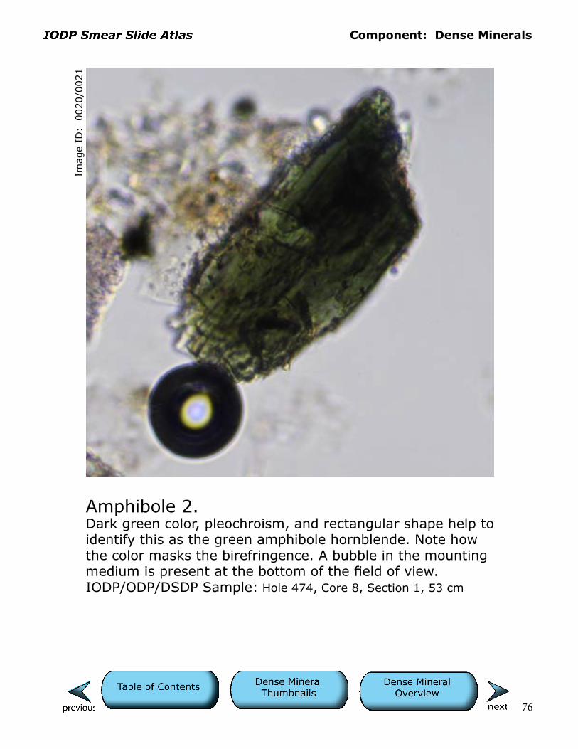
Amphibole 2.Dark green color, pleochroism, and rectangular shape help to identify this as the green amphibole hornblende. Note how the color masks the birefringence. A bubble in the mounting medium is present at the bottom of the field of view.IODP/ODP/DSDP Sample: Hole 474, Core 8, Section 1, 53 cm
Cells are 10 µm.
Component: Dense Minerals
77
Imag
e ID
: 0
033/0
034
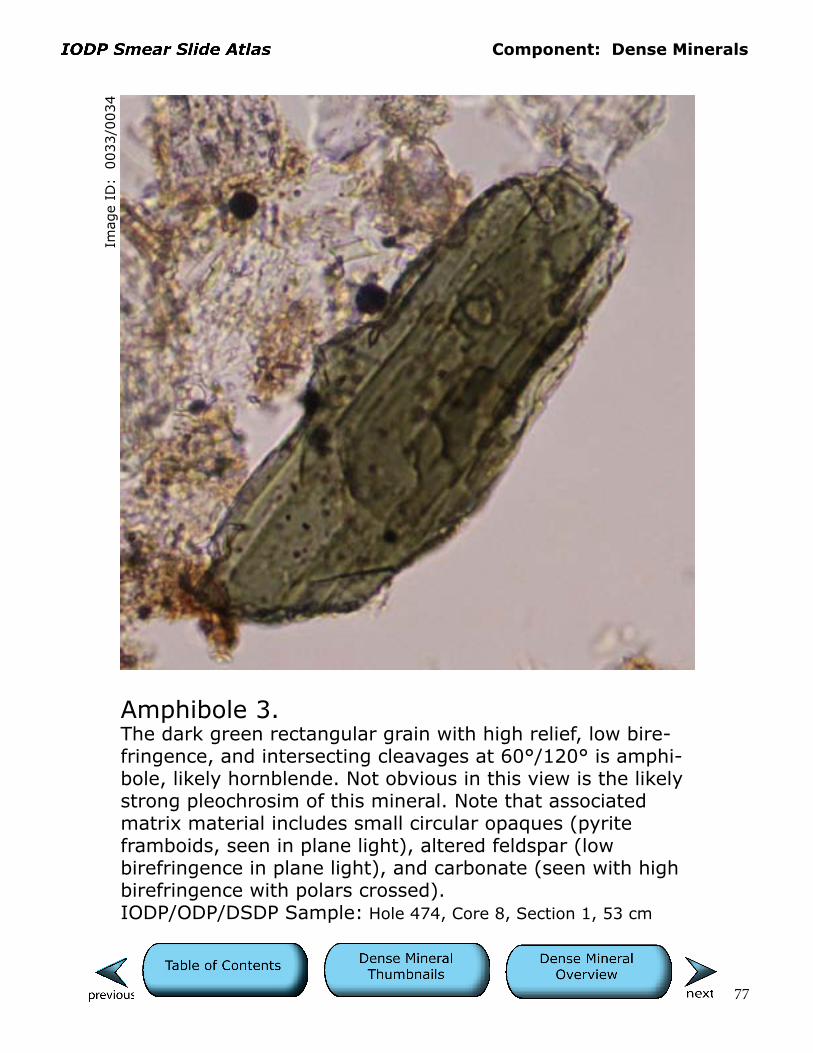
Amphibole 3.The dark green rectangular grain with high relief, low bire-fringence, and intersecting cleavages at 60°/120° is amphi-bole, likely hornblende. Not obvious in this view is the likely strong pleochrosim of this mineral. Note that associated matrix material includes small circular opaques (pyrite framboids, seen in plane light), altered feldspar (low birefringence in plane light), and carbonate (seen with high birefringence with polars crossed).IODP/ODP/DSDP Sample: Hole 474, Core 8, Section 1, 53 cm
Cells are 10 µm.

Component: Dense Minerals
78
Imag
e ID
: 0
091/0
092
Amphibole 4.This dark olive-brown grain of hornblende exhibits cleavage and low first-order color birefingence. Amphibole grains are often strongly pleochroic.IODP/ODP/DSDP Sample: Hole 1119C, Core 10H, Section 2W, 125 cm
Cells are 10 µm.
Component: Dense Minerals
79
Imag
e ID
: 0
093/0
094
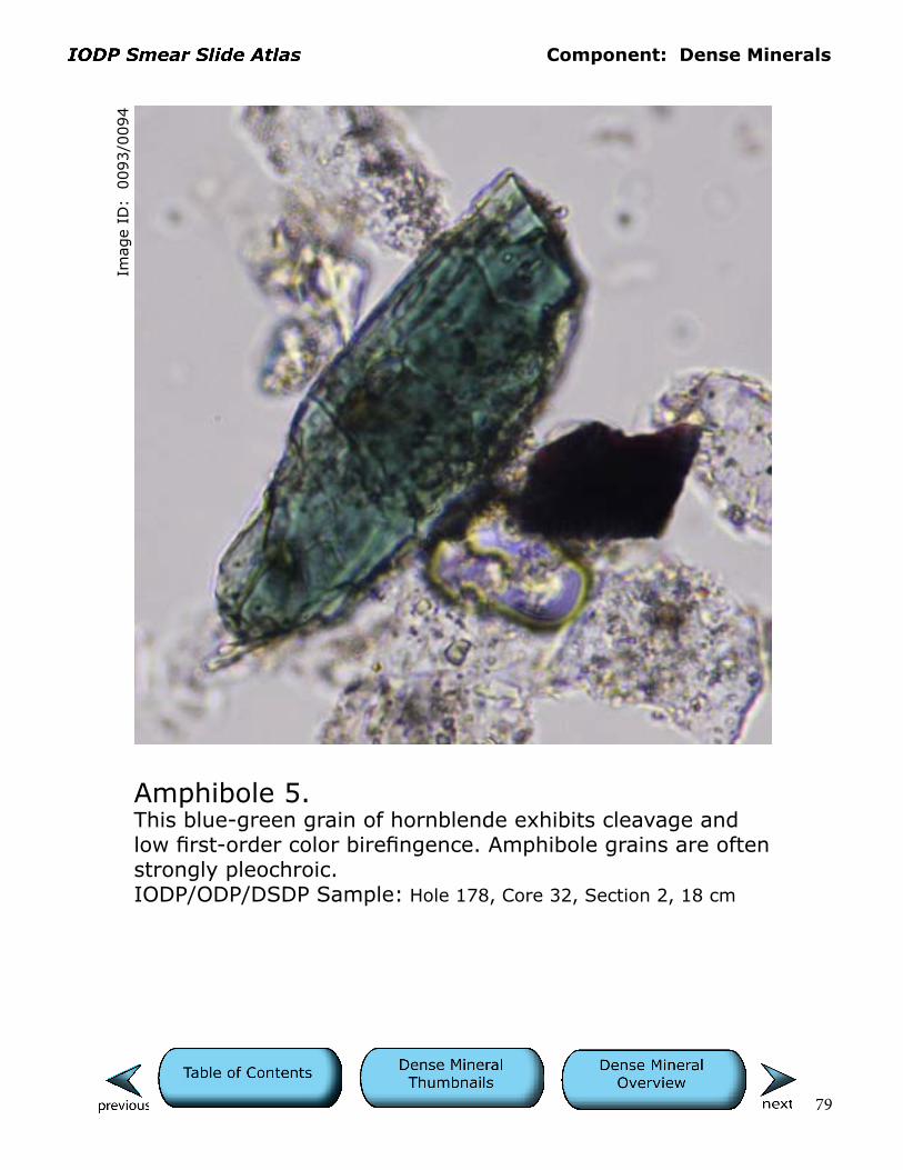
Amphibole 5.This blue-green grain of hornblende exhibits cleavage and low first-order color birefingence. Amphibole grains are often strongly pleochroic.IODP/ODP/DSDP Sample: Hole 178, Core 32, Section 2, 18 cm
Cells are 10 µm.

Component: Dense Minerals
80
Imag
e ID
: 0
396/0
397
Amphibole 6.Strong color, cleavage, fairly low birefringence, and rectangular shapes are consistent with these grains being brown and green amphibole. The green amphibole has a prominent inclusion.IODP/ODP/DSDP Sample: Hole 179, Core 21, Section 1, 134 cm
Cells are 10 µm.

Component: Dense Minerals
81
Imag
e ID
: 0390/0
391
Amphibole 7.The strong, well developed cleavage, deep brownish-orange color, and pleochroism (see info layer) are consistent with this being an amphibole (kaersutite?). Note the irregular etched margin of this grain.IODP/ODP/DSDP Sample: Hole 179, Core 21, Section 1, 134 cm
Cells are 10 µm.

Component: Dense Minerals
82
Imag
e ID
: 0
236/0
237
Apatite 1.Moderate relief, low birefringence, and crystal form indicate that this is a grain of apatite.IODP/ODP/DSDP Sample: Hole 475, Core 3, Section 3, 78 cm
Cells are 10 µm.
Component: Dense Minerals
83
Imag
e ID
: 0
242/0
243
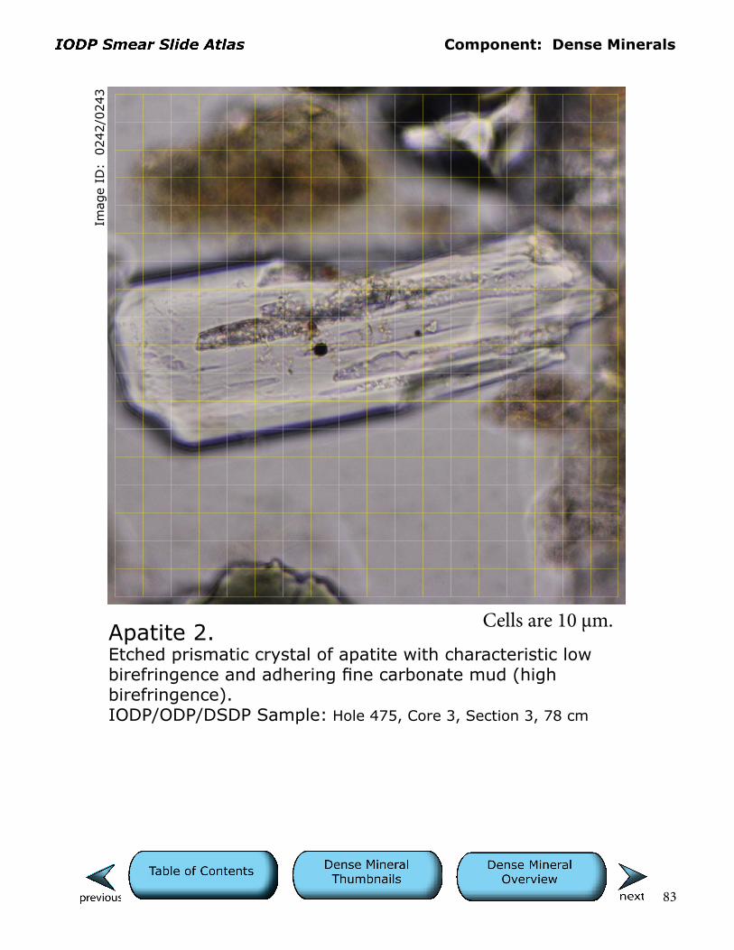
Apatite 2.Etched prismatic crystal of apatite with characteristic low birefringence and adhering fine carbonate mud (high birefringence). IODP/ODP/DSDP Sample: Hole 475, Core 3, Section 3, 78 cm
Cells are 10 µm.
Component: Dense Minerals
84
Imag
e ID
: 0
743/0
744
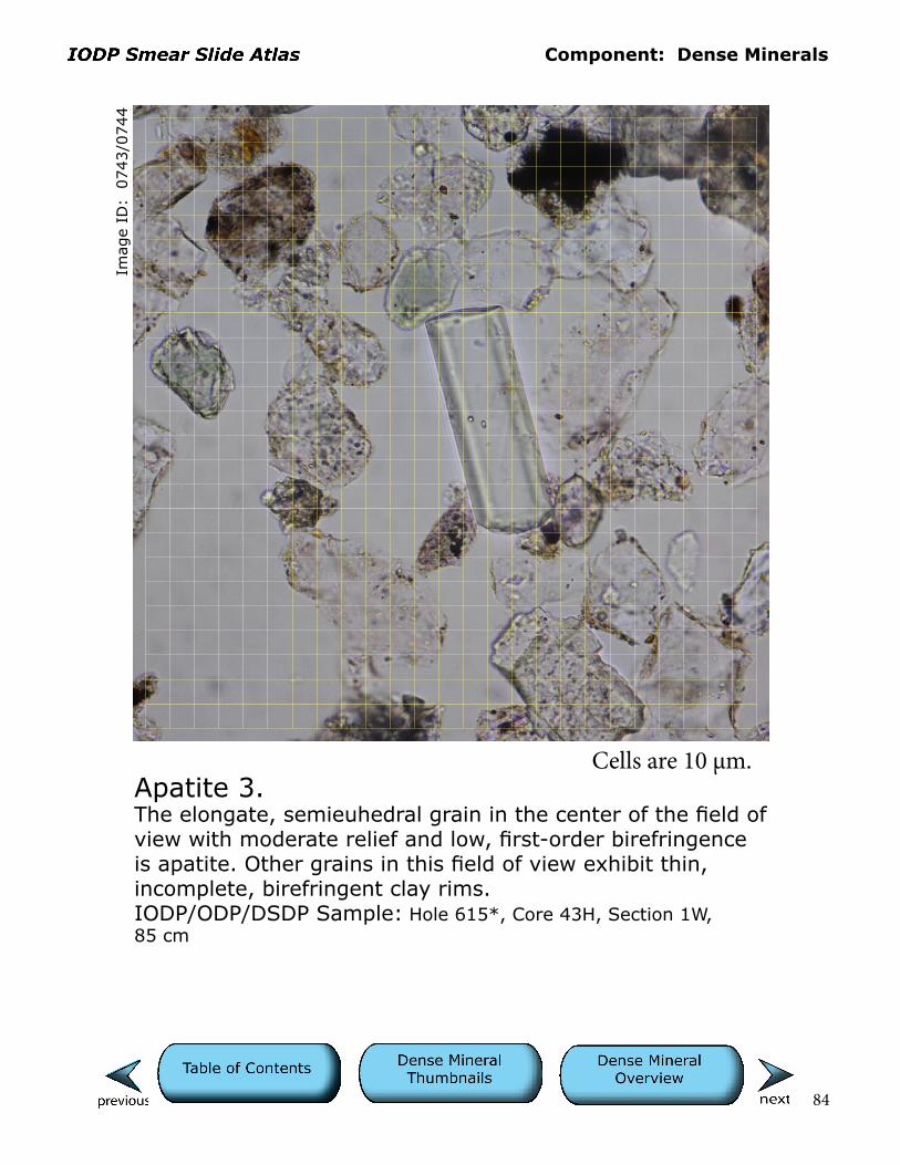
Apatite 3.The elongate, semieuhedral grain in the center of the field of view with moderate relief and low, first-order birefringence is apatite. Other grains in this field of view exhibit thin, incomplete, birefringent clay rims.IODP/ODP/DSDP Sample: Hole 615*, Core 43H, Section 1W, 85 cm
Cells are 10 µm.
Component: Dense Minerals
85
Imag
e ID
: 0
095/0
096
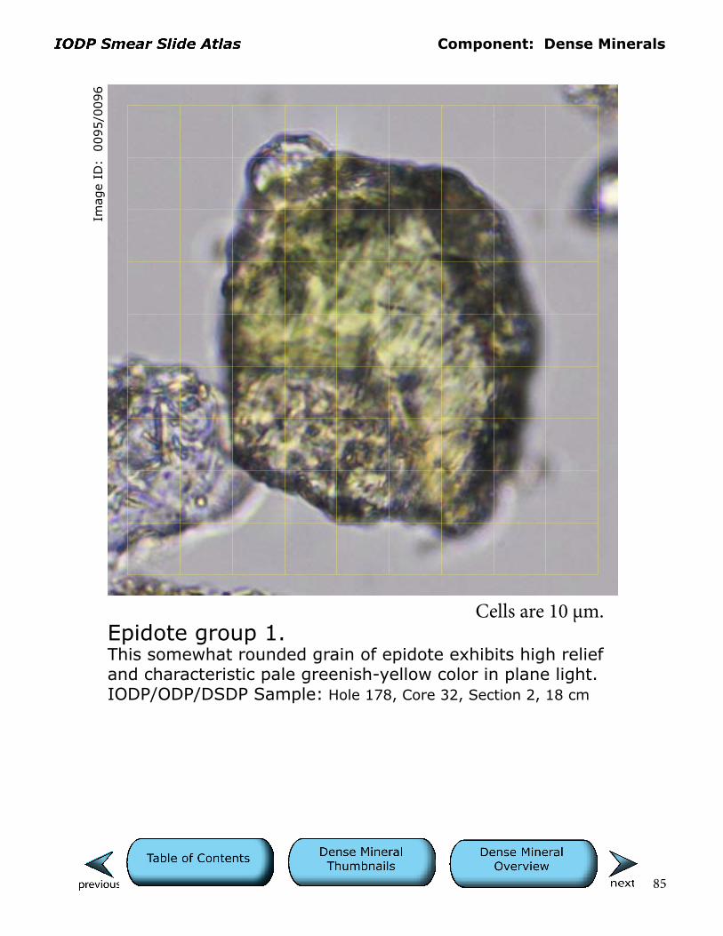
Epidote group 1.This somewhat rounded grain of epidote exhibits high relief and characteristic pale greenish-yellow color in plane light. IODP/ODP/DSDP Sample: Hole 178, Core 32, Section 2, 18 cm
Cells are 10 µm.

Component: Dense Minerals
86
Imag
e ID
: 0
009/0
010
Epidote group 2 and toothpick 1. Moderate relief, pale greenish-yellow color in plane light, and low, first-order yellow birefringence, are consistent with this being clinozoisite. The cellular fragment below this grain is likely a piece of toothpick and an artifact of sample preparation.IODP/ODP/Sample: Hole 860, Core 17X, Section 1, 80 cm
Cells are 10 µm.
Component: Dense Minerals
87
Imag
e ID
: 0
116/0
117
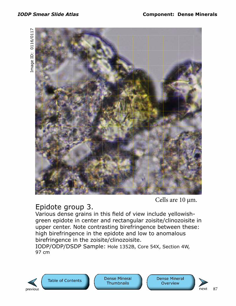
Epidote group 3.Various dense grains in this field of view include yellowish-green epidote in center and rectangular zoisite/clinozoisite in upper center. Note contrasting birefringence between these: high birefringence in the epidote and low to anomalous birefringence in the zoisite/clinozoisite.IODP/ODP/DSDP Sample: Hole 1352B, Core 54X, Section 4W, 97 cm
Cells are 10 µm.
Component: Dense Minerals
88
Imag
e ID
: 0
120/0
121
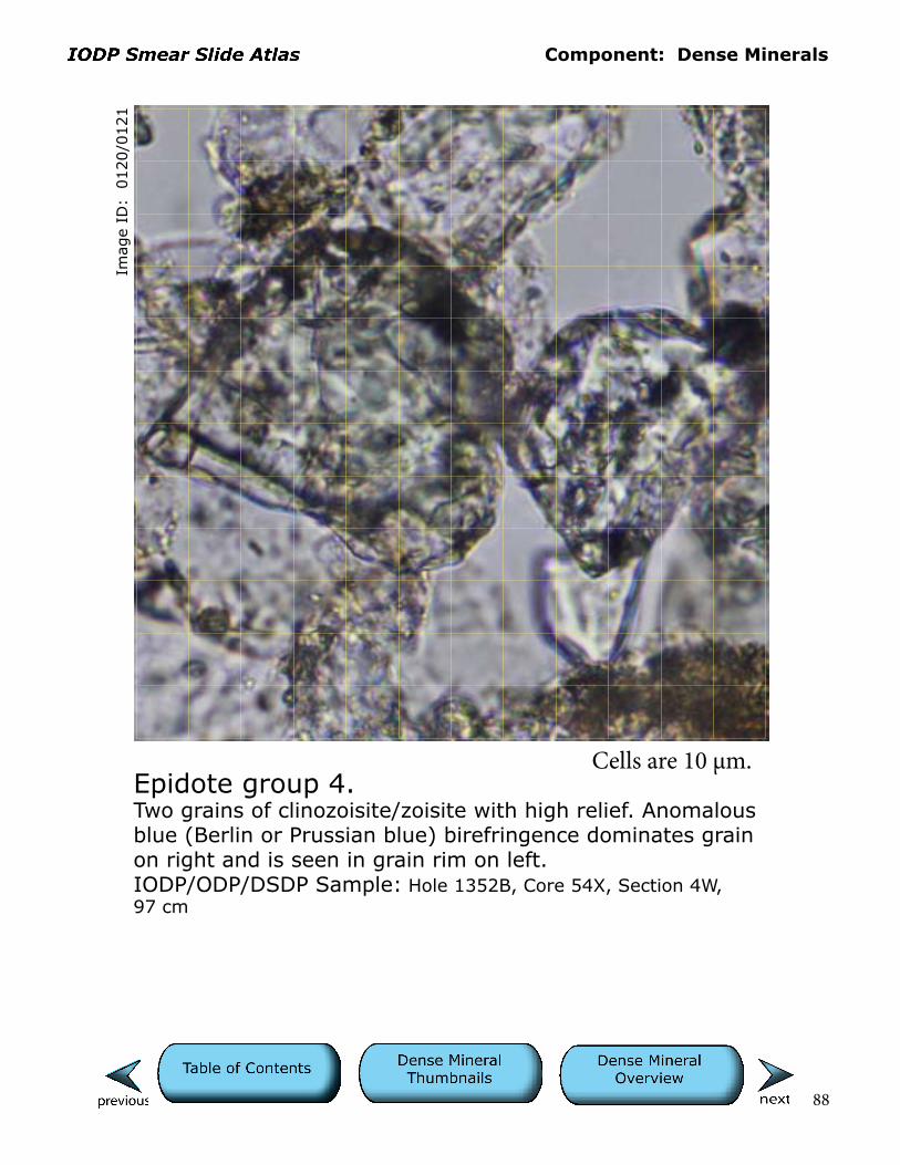
Epidote group 4.Two grains of clinozoisite/zoisite with high relief. Anomalous blue (Berlin or Prussian blue) birefringence dominates grain on right and is seen in grain rim on left.IODP/ODP/DSDP Sample: Hole 1352B, Core 54X, Section 4W, 97 cm
Cells are 10 µm.
Component: Dense Minerals
89
Imag
e ID
: 0
124/0
125
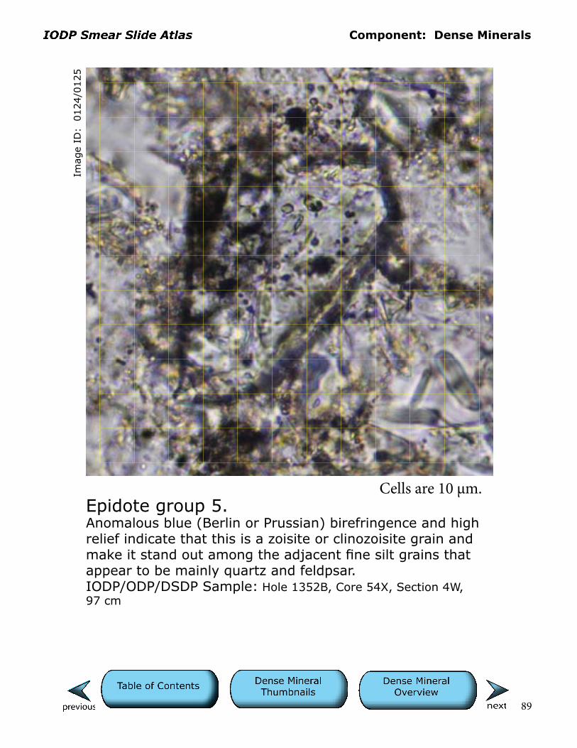
Epidote group 5.Anomalous blue (Berlin or Prussian) birefringence and high relief indicate that this is a zoisite or clinozoisite grain and make it stand out among the adjacent fine silt grains that appear to be mainly quartz and feldpsar.IODP/ODP/DSDP Sample: Hole 1352B, Core 54X, Section 4W, 97 cm
Cells are 10 µm.

Component: Dense Minerals
90
Imag
e ID
: 0
206/0
207
Epidote group 6.This rectangular dense mineral grain that exhibits cleavage, moderate relief, and anomalous blue birefringence is tenta-tively identified as zoisite.IODP/ODP/DSDP Sample: Hole 863A, Core 7X, Section 1, 56 cm
Cells are 10 µm.

Component: Dense Minerals
91
Imag
e ID
: 0
335/0
336
Epidote group 7.Epidote or zoisite grain on left and clay-rich lithic fragment (mudstone) on right.IODP/ODP/DSDP Sample: Hole 1352B, Core 2H, Section 2W, 117 cm
Cells are 10 µm.
Component: Dense Minerals
92
Imag
e ID
: 0
386/0
387
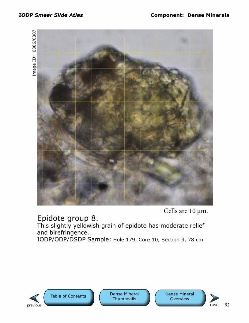
Epidote group 8.This slightly yellowish grain of epidote has moderate relief and birefringence.IODP/ODP/DSDP Sample: Hole 179, Core 10, Section 3, 78 cm
Cells are 10 µm.

Component: Dense Minerals
93
Imag
e ID
: 0
357/0
358
Garnet 1.The high relief of the colorless garnet grain in the center produces a dark halo and makes focusing difficult.IODP/ODP/DSDP Sample: Hole 178, Core 47, Section 2, 0 cm
Cells are 10 µm.

Component: Dense Minerals
94
Imag
e ID
: 0
359/0
360
Garnet 2.The high relief of the colorless garnet grain near the center right edge produces a dark halo and makes focusing difficult. Garnets can be mistaken for bubbles in the mount-ing medium at this magnification; however, the latter may show birefringence of underlying minerals. An example of such a bubble is in the upper left corner of this field of view.IODP/ODP/DSDP Sample: Hole 178, Core 47, Section 2, 0 cm
Cells are 10 µm.

Component: Dense Minerals
95
Imag
e ID
: 0
101
Opaque 1.Mixture of mainly detrital (likely igneous origin), semieuhedral opaque grains and small, round (right center), authigenic pyrite framboid. Meshlike grain in upper center is a toothpick fragment. IODP/ODP/DSDP Sample: Hole 178, Core 32, Section 2, 18 cm
Cells are 10 µm.

Component: Dense Minerals
96
Imag
e ID
: 0
340/0
341
Opaque 2.The origin (authigenic vs. detrital) of this euhedral, opaque pyrite(?) grain is equivocal.IODP/ODP/DSDP Sample: Hole 1352B, Core 2H, Section 2W, 117 cm
Cells are 10 µm.

Component: Dense Minerals
97
Imag
e ID
: 0
589/0
590
Opaque 3.This opaque grain may be sphalerite. Note the translucent edge.IODP/ODP/DSDP Sample: Hole 1035A, Core 1H, Section 3W, 35 cm
Cells are 10 µm.
Component: Dense Minerals
98
Imag
e ID
: 0
003/0
004
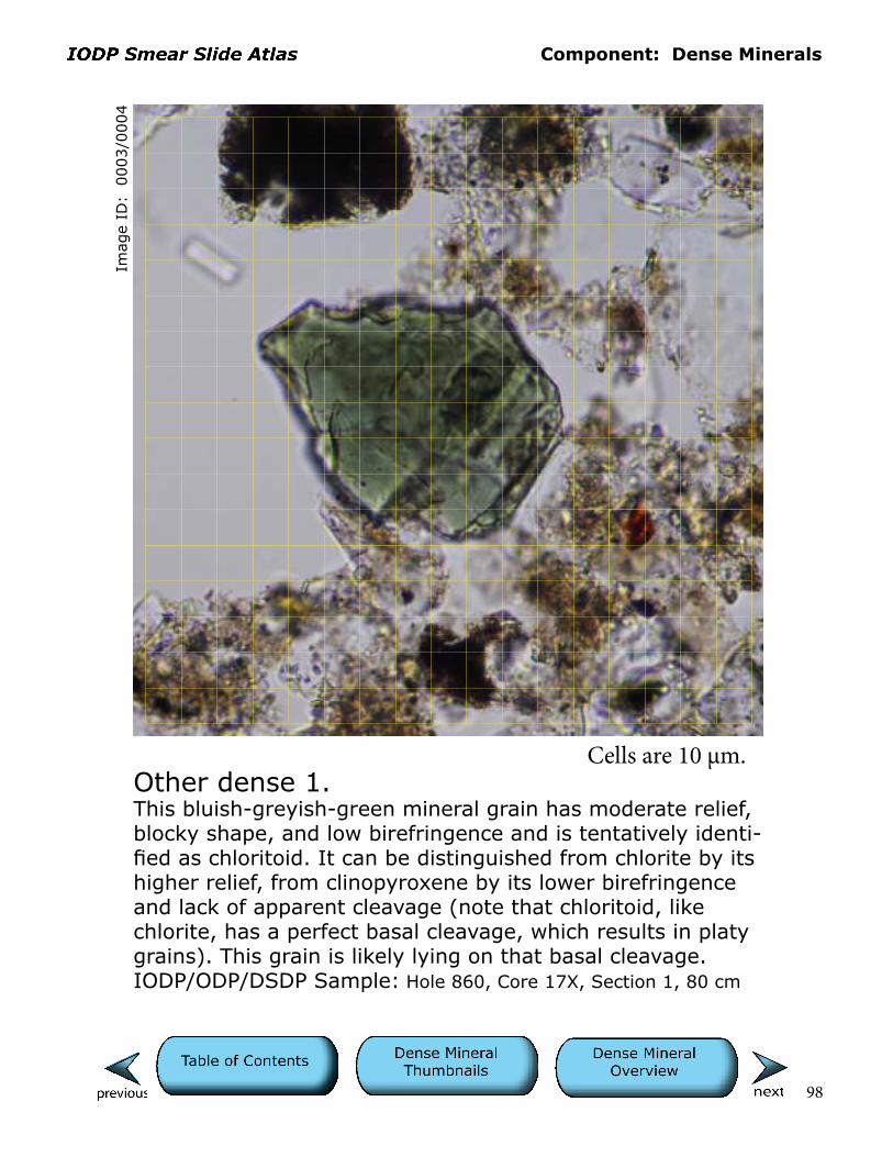
Other dense 1.This bluish-greyish-green mineral grain has moderate relief, blocky shape, and low birefringence and is tentatively identi-fied as chloritoid. It can be distinguished from chlorite by its higher relief, from clinopyroxene by its lower birefringence and lack of apparent cleavage (note that chloritoid, like chlorite, has a perfect basal cleavage, which results in platy grains). This grain is likely lying on that basal cleavage.IODP/ODP/DSDP Sample: Hole 860, Core 17X, Section 1, 80 cm
Cells are 10 µm.

Component: Dense Minerals
99
Imag
e ID
: 0
011/0
012
Other dense 2.Pale green in plane light, with very low birefringence, this grain may be chloritoid or possibly pyroxene. Platy cleavage (stepped topography on grain in upper left) favors the former interpretation. Note that chlorite, another possibility, would likely show no birefringence in this grain orientation (c-axis perpendicular).IODP/ODP/DSDP Sample: Hole 860, Core 17X, Section 1, 80 cm
Cells are 10 µm.

Component: Dense Minerals
100
Imag
e ID
: 0
110/0
111
Other dense 3.Brown color, high relief, conchoidal fracture, and birefringence are consistent with this being a grain of spinel.IODP/ODP/DSDP Sample: Hole 178, Core 32, Section 2, 18 cm
Cells are 10 µm.
Component: Dense Minerals
101
Imag
e ID
: 0
556/0
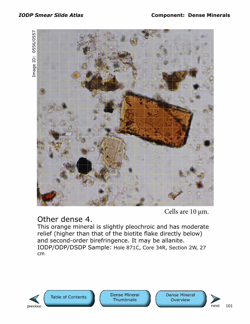
557
Other dense 4.This orange mineral is slightly pleochroic and has moderate relief (higher than that of the biotite flake directly below) and second-order birefringence. It may be allanite.IODP/ODP/DSDP Sample: Hole 871C, Core 34R, Section 2W, 27 cm
Cells are 10 µm.
Component: Dense Minerals
102
Imag
e ID
: 0
687/0
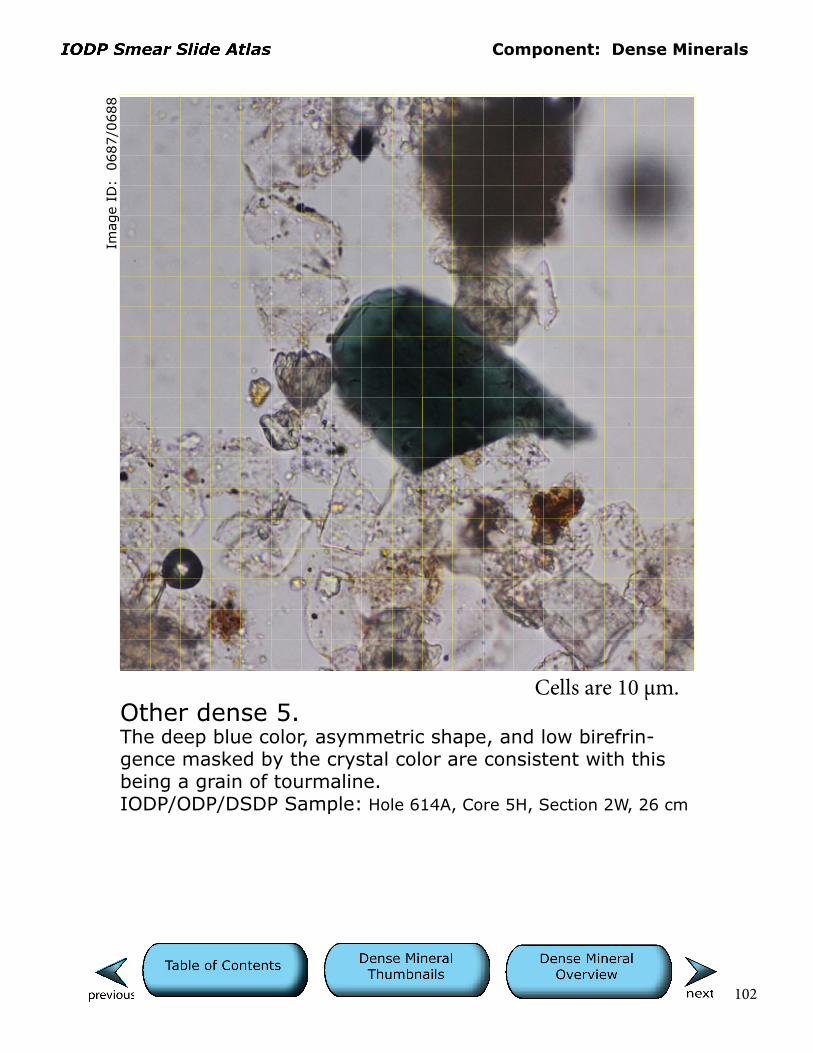
688
Other dense 5.The deep blue color, asymmetric shape, and low birefrin-gence masked by the crystal color are consistent with this being a grain of tourmaline.IODP/ODP/DSDP Sample: Hole 614A, Core 5H, Section 2W, 26 cm
Cells are 10 µm.

Component: Dense Minerals
103
Imag
e ID
: 0
721/0
722
Other dense 6.The high relief, intense brown color to the point of opacity, and yet high birefringence are consistent with the central, irregularly shaped grain being rutile. Its skeletal appearance may be a function of dissolution or growth of a cluster of small crystals.IODP/ODP/DSDP Sample: Hole 615, Core 5H, Section 6W, 85 cm
Cells are 10 µm.

Component: Dense Minerals
104
Other dense 7.The rutile grain in the center of this field of view exhibits the characteristic golden color, high relief, birefringence, and crystal form of this mineral.IODP/ODP/DSDP Sample: Hole 615, Core 5H, Section 6, 85 cm
Imag
e ID
: 0
725/0
725
Cells are 10 µm.
Component: Dense Minerals
105
Imag
e ID
: 0
751/0
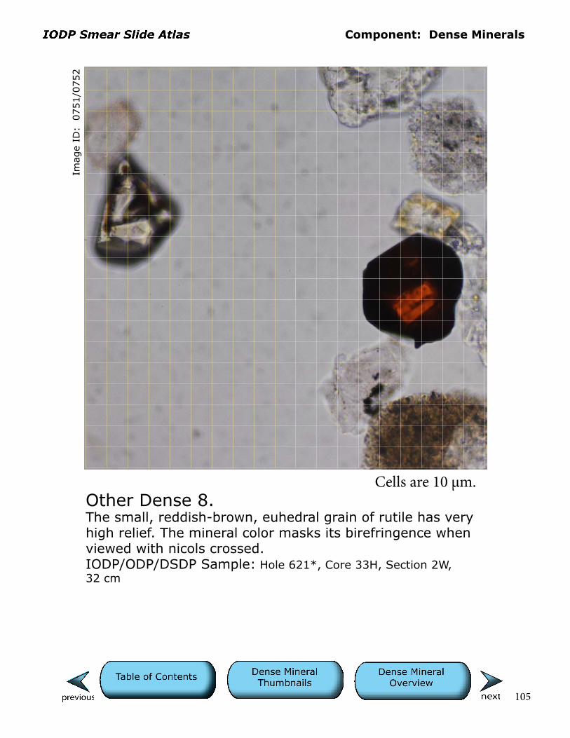
752
Other Dense 8.The small, reddish-brown, euhedral grain of rutile has very high relief. The mineral color masks its birefringence when viewed with nicols crossed.IODP/ODP/DSDP Sample: Hole 621*, Core 33H, Section 2W, 32 cm
Cells are 10 µm.

Component: Dense Minerals
106
Imag
e ID
: 0
312/0
313
Pyroxene 1.Pyroxene grain has subtle development of sawtooth (cockscomb) dissolution texture. Low birefringence and inclined extinction indicate that this is likely clinopyroxene.IODP/ODP/DSDP Sample: Hole 791B, Core 62R, Section 1, 3 cm
Cells are 10 µm.
Component: Dense Minerals
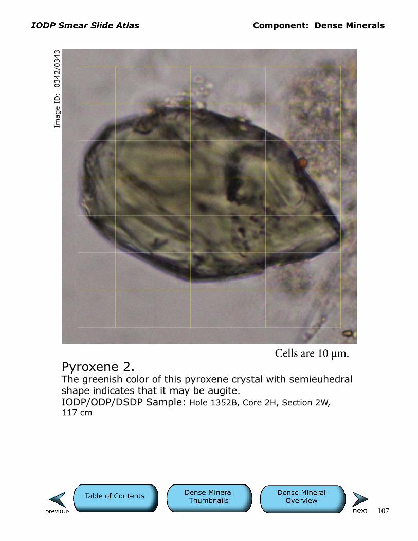
107
Pyroxene 2.The greenish color of this pyroxene crystal with semieuhedral shape indicates that it may be augite. IODP/ODP/DSDP Sample: Hole 1352B, Core 2H, Section 2W, 117 cm
Imag
e ID
: 0
342/0
343
Cells are 10 µm.

Component: Dense Minerals
108
Pyroxene 3.The field of view is dominated by two tan pyroxene grains exhibiting subtle sawtooth (cockscomb) textures where grain surfaces are etched and jagged.IODP/ODP/DSDP Sample: Hole 179, Core 10, Section 3, 78 cm
Imag
e ID
: 0
378/0
379
Cells are 10 µm.
Component: Dense Minerals
109
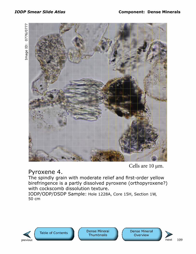
Pyroxene 4.The spindly grain with moderate relief and first-order yellow birefringence is a partly dissolved pyroxene (orthopyroxene?) with cockscomb dissolution texture.IODP/ODP/DSDP Sample: Hole 1228A, Core 15H, Section 1W, 50 cm
Imag
e ID
: 0
776/0
777
Cells are 10 µm.

Component: Dense Minerals
110
Imag
e ID
: 0
772/0
773
Pyroxene 5.This pyroxene (orthopyroxene?) has an etched surface with cockscomb texture and exhibits pale color, low birefringence, and moderate relief. IODP/ODP/DSDP Sample: Hole 1228A, Core 15H, Section 1W, 50 cm
Cells are 10 µm.

Component: Dense Minerals
111
Pyroxene 6.The delicately etched pyroxene in the center of the field of view exhibits cockscomb texture, low birefringence, pale color, and moderate relief.IODP/ODP/DSDP Sample: Hole 1228A, Core 15H, Section 1W, 50 cm
Imag
e ID
: 0
778/0
779
Cells are 10 µm.
Component: Dense Minerals
112
Imag
e ID
: 0
234/0
235
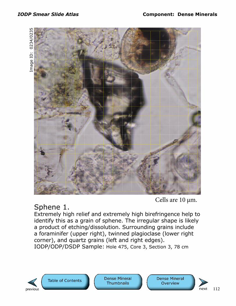
Sphene 1.Extremely high relief and extremely high birefringence help to identify this as a grain of sphene. The irregular shape is likely a product of etching/dissolution. Surrounding grains include a foraminifer (upper right), twinned plagioclase (lower right corner), and quartz grains (left and right edges).IODP/ODP/DSDP Sample: Hole 475, Core 3, Section 3, 78 cm
Cells are 10 µm.

Component: Dense Minerals
113
Imag
e ID
: 0
368/0
369
Sphene 2.Dark brown claystone lithic fragment in center is flanked by grains of green amphibole in upper left and sphene in lower right.IODP/ODP/DSDP Sample: Hole 179, Core 3, Section 3, 30 cm
Cells are 10 µm.
Component: Dense Minerals
114
Imag
e ID
: 0
782/0
783
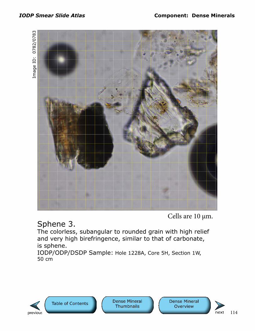
Sphene 3.The colorless, subangular to rounded grain with high relief and very high birefringence, similar to that of carbonate, is sphene.IODP/ODP/DSDP Sample: Hole 1228A, Core 5H, Section 1W, 50 cm
Cells are 10 µm.

Component: Dense Minerals
115
Imag
e ID
: 0
039/0
040
Zircon 1.The very high relief of this colorless mineral is manifested by a dark edge. The slightly elongate and blunt prismatic crystal shape and high birefringence (third-order colors) are consistent with this being a silt-sized zircon grain.IODP/ODP/DSDP Sample: Hole 474, Core 8, Section 1, 53 cm
Cells are 10 µm.

Component: Dense Minerals
116
Imag
e ID
: 0
089/0
090
Zircon 2.Elongate shape, high relief, and birefringence suggest that this colorless grain is zircon. IODP/ODP/DSDP Sample: Hole 178, Core 32, Section 2, Cm 18
Cells are 10 µm.

Component: Dense Minerals
117
Imag
e ID
: 0
065/0
066
Zircon 3.High relief, birefringence, lack of color in plane light, and crystal shape indicate that this is probably a grain of zircon.IODP/ODP/DSDP Sample: Hole 1119C, Core 10H, Section 2W, 125 cm
Cells are 10 µm.
Component: Dense Minerals
118
Imag
e ID
: 0
122/0
123
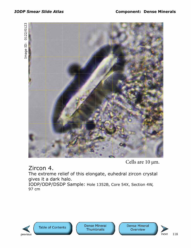
Zircon 4.The extreme relief of this elongate, euhedral zircon crystal gives it a dark halo.IODP/ODP/DSDP Sample: Hole 1352B, Core 54X, Section 4W, 97 cm
Cells are 10 µm.
Component: Dense Minerals
119
Imag
e ID
: 0
126/0
127
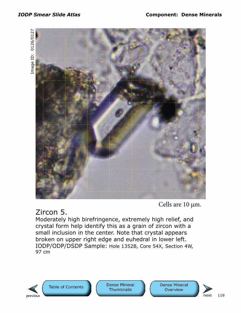
Zircon 5.Moderately high birefringence, extremely high relief, and crystal form help identify this as a grain of zircon with a small inclusion in the center. Note that crystal appears broken on upper right edge and euhedral in lower left.IODP/ODP/DSDP Sample: Hole 1352B, Core 54X, Section 4W, 97 cm
Cells are 10 µm.

Component: Dense Minerals
120
Imag
e ID
: 0
232/0
233
Zircon 6.Broken (lower darker edge), semieuhedral zircon crystal in center contains a dark inclusion. Surrounding grains include isotropic (lying flat on cleavage) brown biotite on left, monocrystalline quartz in upper and lower right corners, and highly birefringent carbonate grains above and in right center. The latter are likely bioclastic debris.IODP/ODP/DSDP Sample: Hole 475, Core 3, Section 3, 78 cm
Cells are 10 µm.
Component: Dense Minerals
121
Imag
e ID
: 0
384/0
385
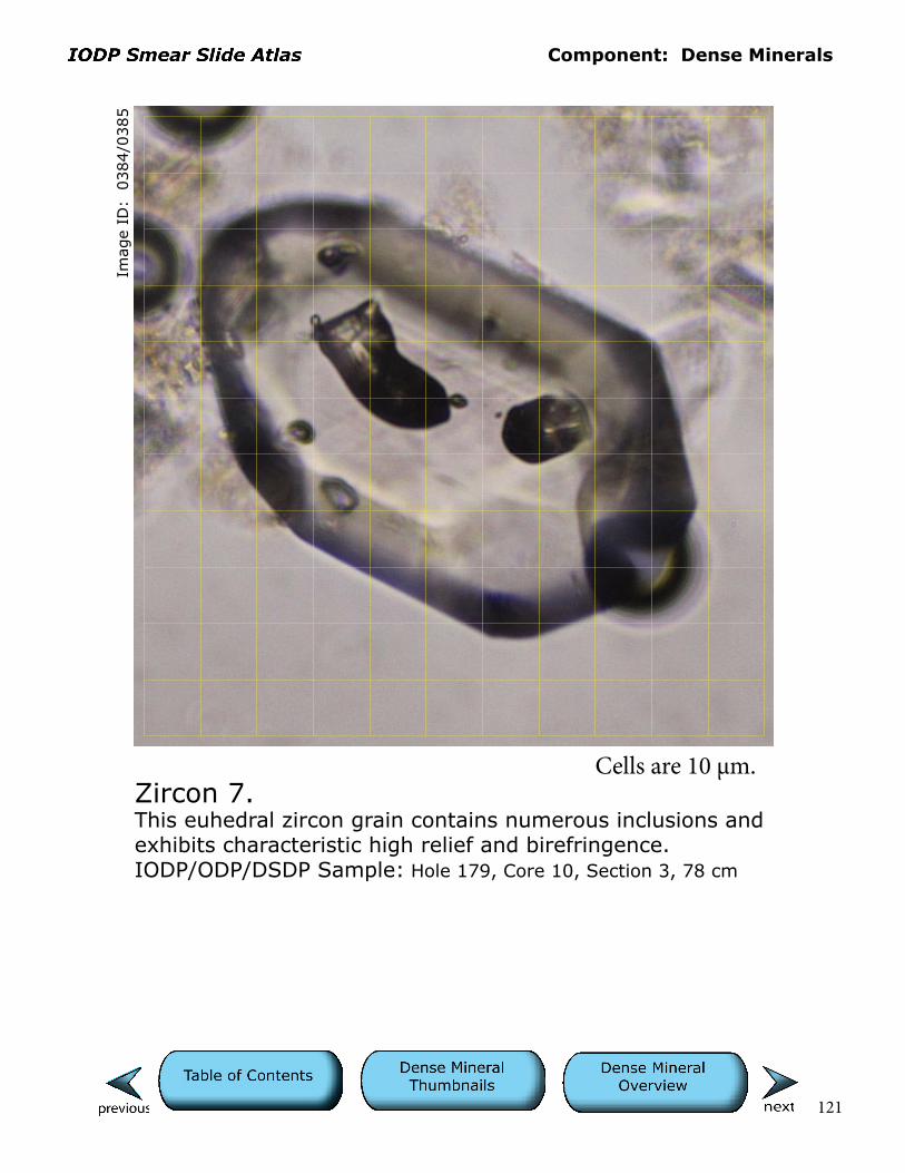
Zircon 7.This euhedral zircon grain contains numerous inclusions and exhibits characteristic high relief and birefringence.IODP/ODP/DSDP Sample: Hole 179, Core 10, Section 3, 78 cm
Cells are 10 µm.
Component: Dense Minerals
122
Imag
e ID
: 0
723/0
724
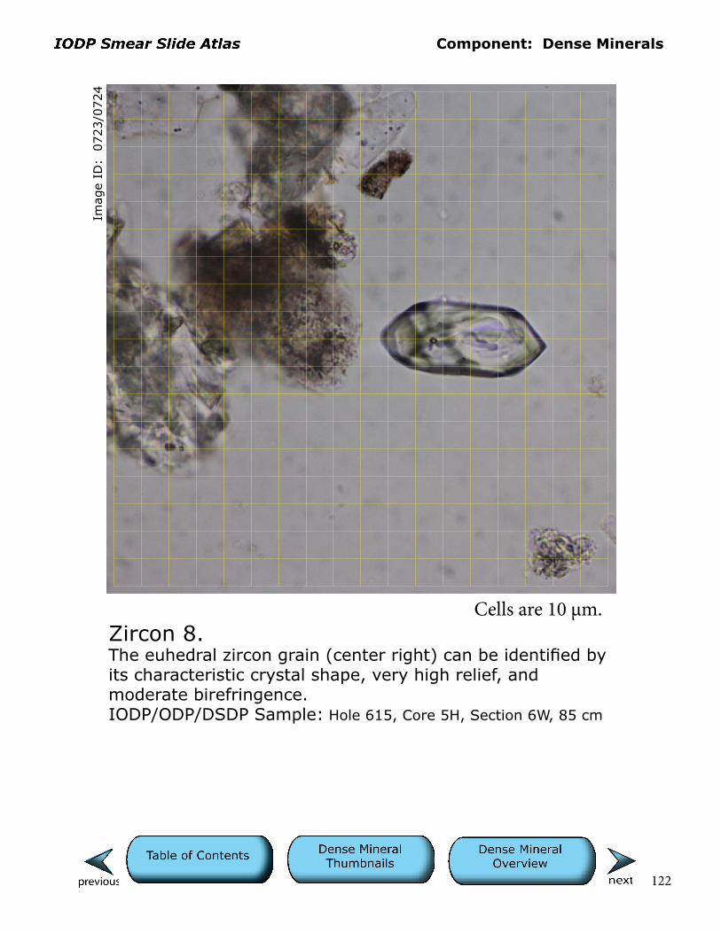
Zircon 8.The euhedral zircon grain (center right) can be identified by its characteristic crystal shape, very high relief, and moderate birefringence.IODP/ODP/DSDP Sample: Hole 615, Core 5H, Section 6W, 85 cm
Cells are 10 µm.
Component: Dense Minerals
123
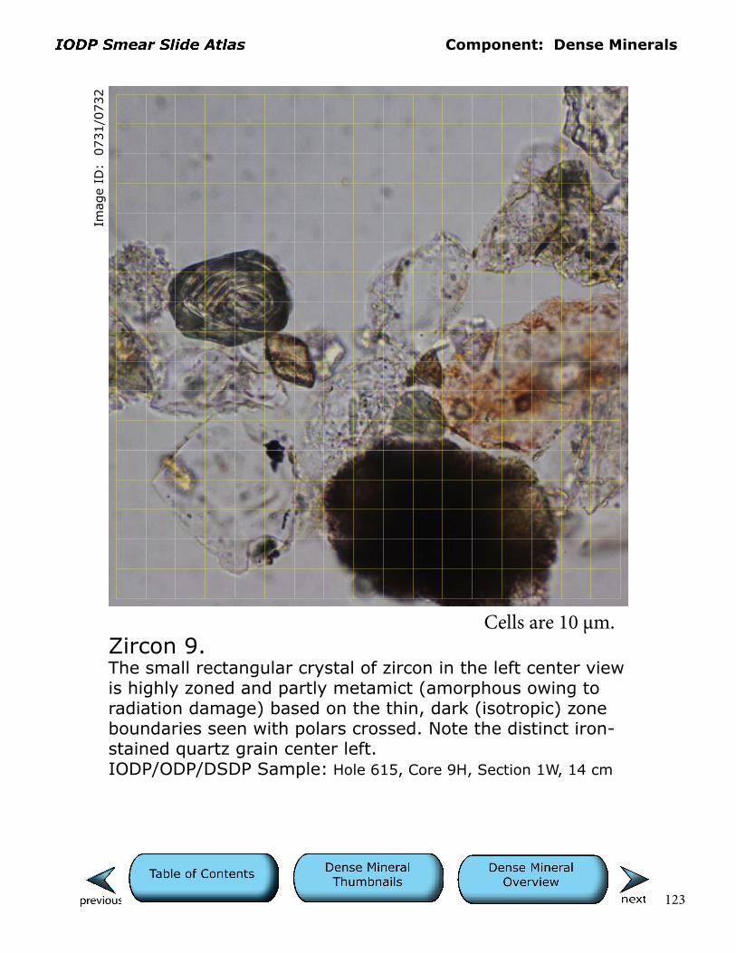
Zircon 9.The small rectangular crystal of zircon in the left center view is highly zoned and partly metamict (amorphous owing to radiation damage) based on the thin, dark (isotropic) zone boundaries seen with polars crossed. Note the distinct iron-stained quartz grain center left.IODP/ODP/DSDP Sample: Hole 615, Core 9H, Section 1W, 14 cm
Imag
e ID
: 0
731/0
732
Cells are 10 µm.

Component: Dense Minerals
124
Zircon 10.This subhedral zircon grain with rounded edges may be recycled.IODP/ODP/DSDP Sample: Hole 615, Core 3H, Section 2W, 97 cm
Imag
e ID
: 0
713/0
714
Cells are 10 µm.

125
Lithic FragmentsGeneral Characteristics of Lithic Fragments in Smear SlideIf silt-sized (<0.0625 mm) lithic components are present they may be fairly opaque (aphanitic to microcrystalline) and difficult to identify even at higher magifications. Lithic grains are much more limited in the silt than in the sand fractions of cores.
Sedimentary Lithic ClastsSedimentary lithic fragments are limited to chert, mudstone, and carbonate varieties. Mudstone clasts may show variable proportions of terrigenous silt, clay, biogenic debris, carbonate, and authigenic phases such as pyrite. Note that some calcareous fossil ultrastructures are aphanitic and in very small, silt-sized fragments can be mistaken for sedimentary lithic fragments. We include anhedral coarse carbonate of likely detrital origin in the sedimentary lithic category. Such grains may be carbonate (limestone, dolomite) rock fragments or detrital pieces of authigenic phases in sand-stone (cements).Sedimentary Lithic Fragment Thumbnails

126
Metamorphic Lithic Fragment ThumbnailsPolymineralic lithic fragments (e.g., quartz+feldspar, quartz+mica, feldspar+mica, or +dense) with no distinct metamorphic foliation or sedimentary textures are equivocal in origin, potentially derived from igneous plutonic or metamorphic schist/gneiss. Recognizable metamorphic lithic fragments are limited to combinations of quartz and fine mica, chlorite, and metamorphic amphibole.
127
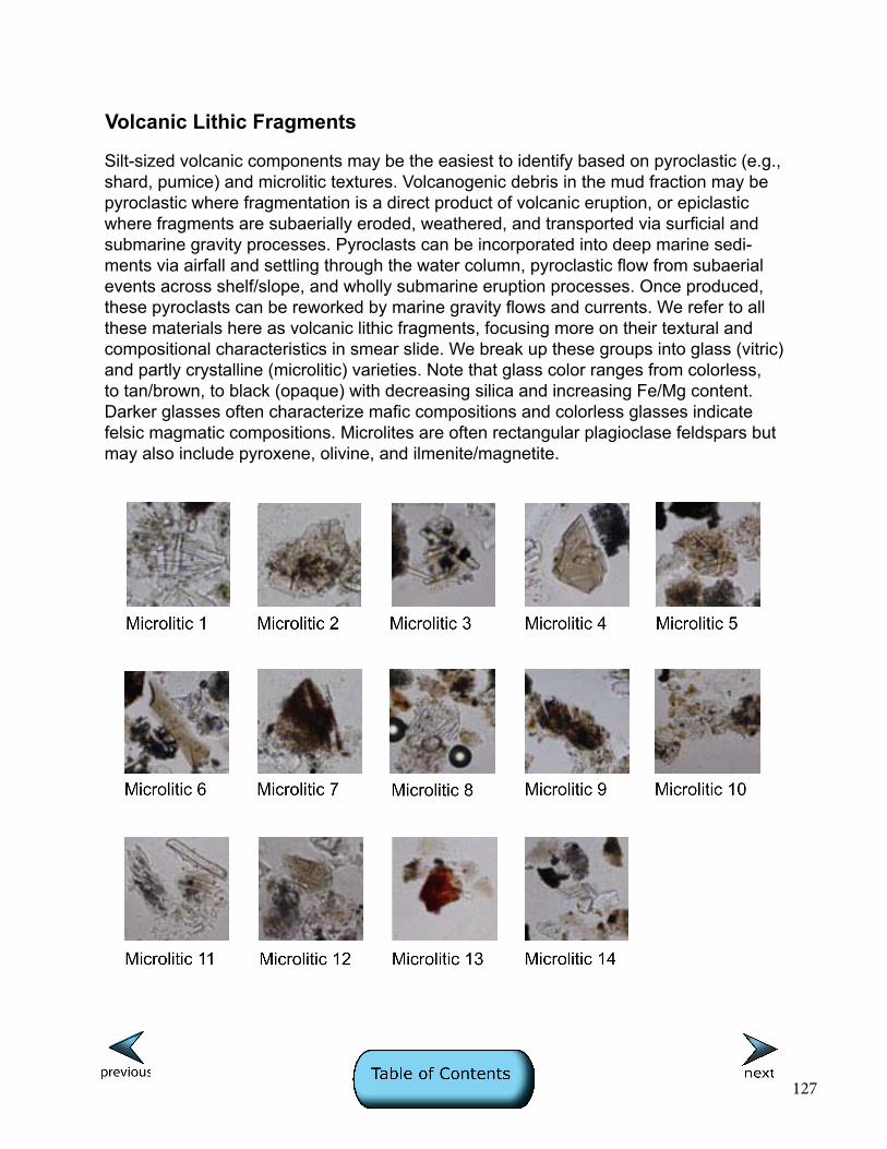
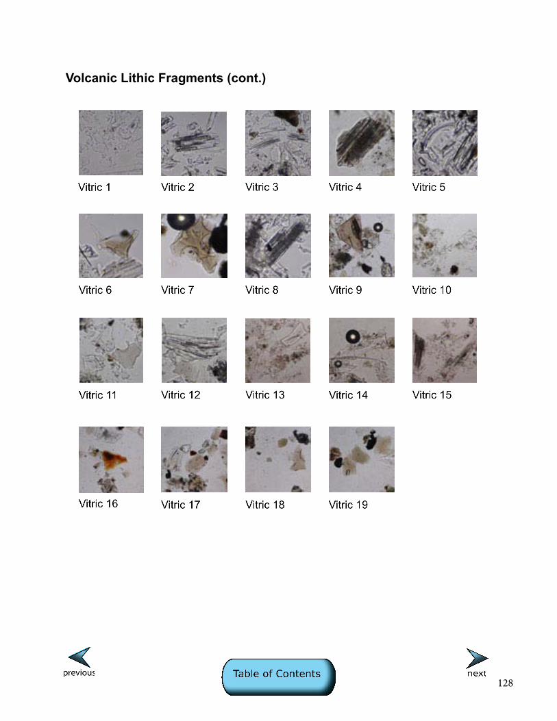
Volcanic Lithic Fragments
Silt-sized volcanic components may be the easiest to identify based on pyroclastic (e.g., shard, pumice) and microlitic textures. Volcanogenic debris in the mud fraction may be pyroclastic where fragmentation is a direct product of volcanic eruption, or epiclastic where fragments are subaerially eroded, weathered, and transported via surficial and submarine gravity processes. Pyroclasts can be incorporated into deep marine sedi-ments via airfall and settling through the water column, pyroclastic flow from subaerial events across shelf/slope, and wholly submarine eruption processes. Once produced, these pyroclasts can be reworked by marine gravity flows and currents. We refer to all these materials here as volcanic lithic fragments, focusing more on their textural and compositional characteristics in smear slide. We break up these groups into glass (vitric) and partly crystalline (microlitic) varieties. Note that glass color ranges from colorless, to tan/brown, to black (opaque) with decreasing silica and increasing Fe/Mg content. Darker glasses often characterize mafic compositions and colorless glasses indicate felsic magmatic compositions. Microlites are often rectangular plagioclase feldspars but may also include pyroxene, olivine, and ilmenite/magnetite.
128
Volcanic Lithic Fragments (cont.)

Component: Sedimentary Lithics
129
Imag
e ID
: 0
031/0
032
Carbonate 1.This is a subhedral monocrystal of carbonate, potentially a lime-stone or bioclast fragment. With polars crossed, one can see the bright first-order colors on a thin edge passing up to higher-order birefringence and pale colors. Thin black stripes represent these orders on a steeper, lower edge of the grain. Counting the orders like tree rings indicate at least up to fifth order. Carbonate may show changing relief as the stage is rotated, a trait only exhibited by this mineral group. A square (euhedral) opaque mineral of unknown origin (authigenic?) is seen in upper center. IODP/ODP/DSDP Sample: Hole 474, Core 8, Section 1, 53 cm
Cells are 10 µm.
Component: Sedimentary Lithics
130
Imag
e ID
: 0
037/0
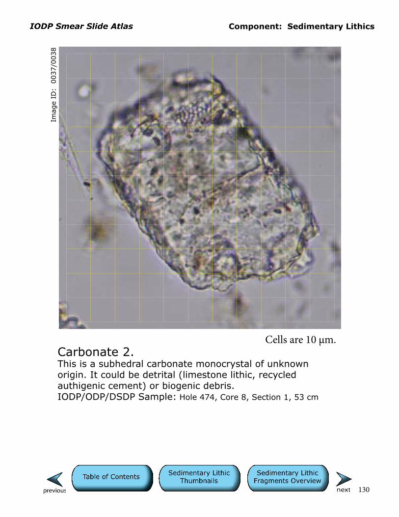
038
Carbonate 2.This is a subhedral carbonate monocrystal of unknown origin. It could be detrital (limestone lithic, recycled authigenic cement) or biogenic debris.IODP/ODP/DSDP Sample: Hole 474, Core 8, Section 1, 53 cm
Cells are 10 µm.
Component: Sedimentary Lithics
131
Imag
e ID
: 0
073/0
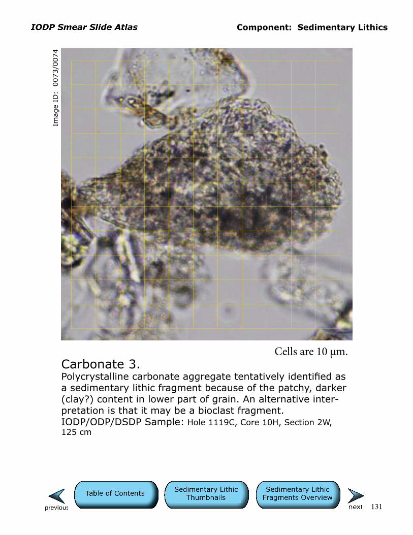
074
Carbonate 3.Polycrystalline carbonate aggregate tentatively identified as a sedimentary lithic fragment because of the patchy, darker (clay?) content in lower part of grain. An alternative inter-pretation is that it may be a bioclast fragment.IODP/ODP/DSDP Sample: Hole 1119C, Core 10H, Section 2W, 125 cm
Cells are 10 µm.
Component: Sedimentary Lithics
132
Imag
e ID
: 0
079/0
080
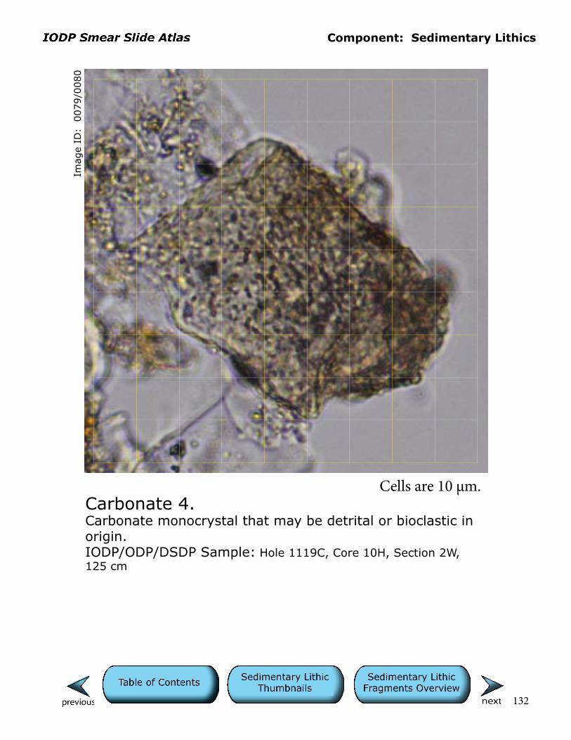
Carbonate 4.Carbonate monocrystal that may be detrital or bioclastic in origin.IODP/ODP/DSDP Sample: Hole 1119C, Core 10H, Section 2W, 125 cm
Cells are 10 µm.
Component: Sedimentary Lithics
133
Imag
e ID
: 0
083/0
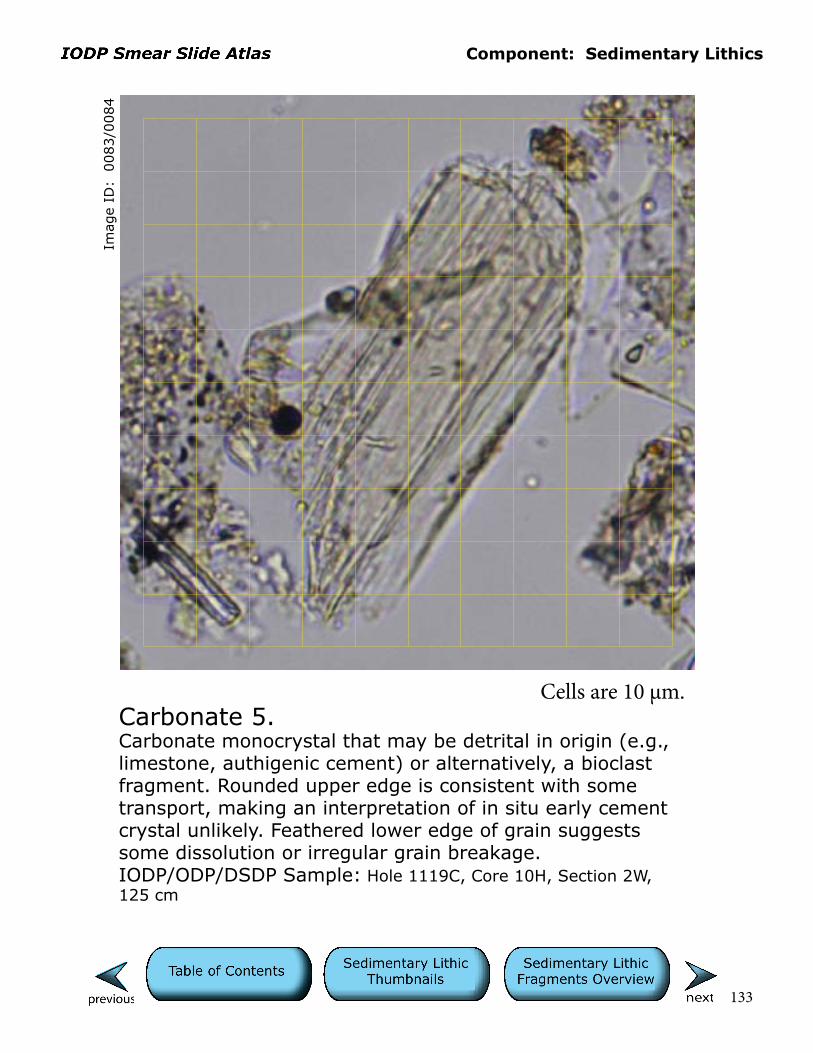
084
Carbonate 5.Carbonate monocrystal that may be detrital in origin (e.g., limestone, authigenic cement) or alternatively, a bioclast fragment. Rounded upper edge is consistent with some transport, making an interpretation of in situ early cement crystal unlikely. Feathered lower edge of grain suggests some dissolution or irregular grain breakage. IODP/ODP/DSDP Sample: Hole 1119C, Core 10H, Section 2W, 125 cm
Cells are 10 µm.

Component: Sedimentary Lithics
134
Imag
e ID
: 0
693/0
694
Carbonate 6.The one broken edge on this otherwise euhedral carbonate (dolomite?) grain suggests that it is detrital in origin. Note the Fe oxide staining that indicates possible ferroan composition. The adjacent clast is a fragment of vesicular, colorless glass.IODP/ODP/DSDP Sample: Hole 614A, Core 8H, Section 2W, 6 cm
Cells are 10 µm.

Component: Sedimentary Lithics
135
Imag
e ID
: 0
705/0
706
Carbonate 7.This field of view contains several carbonate grains that are largely subrounded to rounded in shape and similar in size to surrounding grains, consistent with a detrital origin. The shape of the orange carbonate (ferroan dolomite?) grain in the center suggests that it is a function of cleavage and also of detrital origin. Such grains are known to have been produced by glacial erosion of Paleozoic limestone and dolomite units on the North American craton.IODP/ODP/DSDP Sample: Hole 614A, Core 11H, Section 1W, 73.5 cm
Cells are 10 µm.
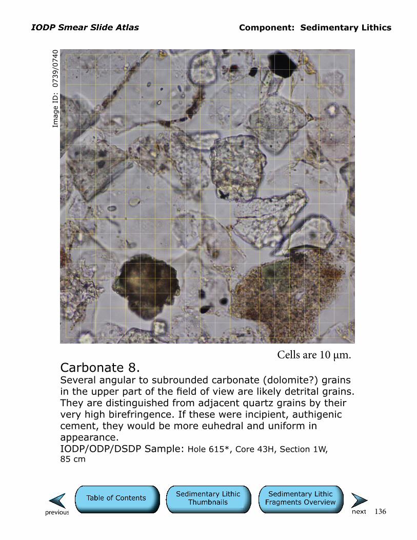
Component: Sedimentary Lithics
136
Imag
e ID
: 0
739/0
740
Carbonate 8.Several angular to subrounded carbonate (dolomite?) grains in the upper part of the field of view are likely detrital grains. They are distinguished from adjacent quartz grains by their very high birefringence. If these were incipient, authigenic cement, they would be more euhedral and uniform in appearance.IODP/ODP/DSDP Sample: Hole 615*, Core 43H, Section 1W, 85 cm
Cells are 10 µm.

Component: Sedimentary Lithics
137
Imag
e ID
: 0
786/0
787
Carbonate 9.Dense mineral assemblage with several opaque grains (bottom), a rectangular green amphibole(?) grain (right), and a slightly irregular, zoned dolomite(?) grain (left).IODP/ODP/DSDP Sample: Hole 1228A, Core 15H, Section 1W, 50 cm
Cells are 10 µm.

Component: Sedimentary Lithics
138
Imag
e ID
: 0
210/0
211
Chert 1.This view contains three light-colored (in plane light) rock fragments that are quartz-rich with variable amounts of opaque minerals and fine sericite (white mica with yellow birefringence). They range from dirty chert in left center to possible metamorphic fragments on right.IODP/ODP/DSDP Sample: Hole 474A, Core 13, Section 4, 101 cm
Cells are 10 µm.
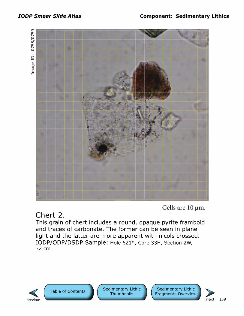
Component: Sedimentary Lithics
139
Imag
e ID
: 0
758/0
759
Cells are 10 µm.

Component: Sedimentary Lithics
140
Imag
e ID
: 0
085/0
686
Glauconite 1.The glauconite grain at center right exhibits characteristic bright green color and microcrystalline birefringence. Its shape -- rounded on the bottom and angular on top -- is consistent with breakage during reworking. This glauconite may have been reworked from coeval shallow water environments where pelletal glauconite was forming, or re-cycled from older glauconite-bearing sedimentary rocks.IODP/ODP/DSDP Sample: Hole 614A, Core 5H, Section 2W, 26 cm
Cells are 10 µm.
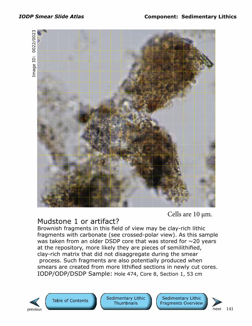
Component: Sedimentary Lithics
141
Imag
e ID
: 0
022/0
023
Mudstone 1 or artifact?Brownish fragments in this field of view may be clay-rich lithic fragments with carbonate (see crossed-polar view). As this sample was taken from an older DSDP core that was stored for ~20 years at the repository, more likely they are pieces of semilithified, clay-rich matrix that did not disaggregate during the smear process. Such fragments are also potentially produced when smears are created from more lithified sections in newly cut cores.IODP/ODP/DSDP Sample: Hole 474, Core 8, Section 1, 53 cm
Cells are 10 µm.
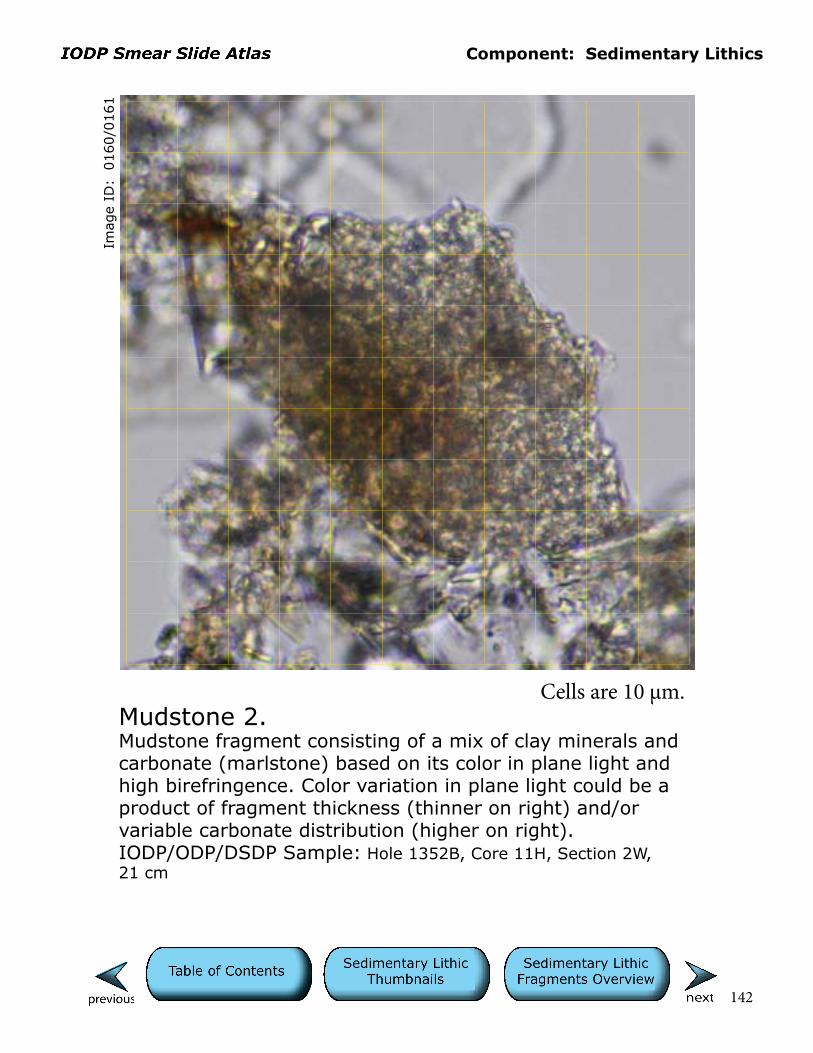
Component: Sedimentary Lithics
142
Imag
e ID
: 0
160/0
161
Mudstone 2.Mudstone fragment consisting of a mix of clay minerals and carbonate (marlstone) based on its color in plane light and high birefringence. Color variation in plane light could be a product of fragment thickness (thinner on right) and/or variable carbonate distribution (higher on right).IODP/ODP/DSDP Sample: Hole 1352B, Core 11H, Section 2W, 21 cm
Cells are 10 µm.
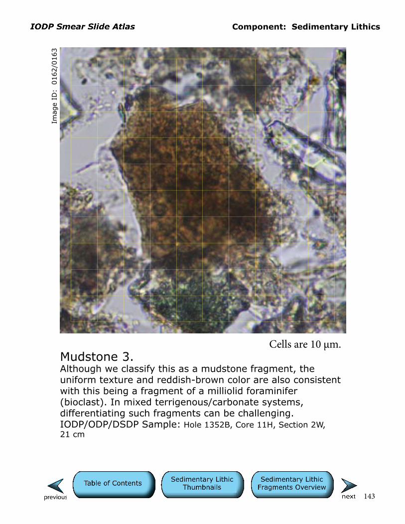
Component: Sedimentary Lithics
143
Imag
e ID
: 0
162/0
163
Mudstone 3.Although we classify this as a mudstone fragment, the uniform texture and reddish-brown color are also consistent with this being a fragment of a milliolid foraminifer (bioclast). In mixed terrigenous/carbonate systems, differentiating such fragments can be challenging. IODP/ODP/DSDP Sample: Hole 1352B, Core 11H, Section 2W, 21 cm
Cells are 10 µm.

Component: Sedimentary Lithics
144
Imag
e ID
: 0
381/0
381
Mudstone 4.Vague microlites in darker rock fragment in upper left sug-gest that it may be opaque-rich basalt. This interpretation is bolstered by its lack of birefringence with polars crossed. Contrast this with the other brownish fragments, which are more birefringent. The latter are clay-rich mudstone. IODP/ODP/DSDP Sample: Hole 179, Core 10, Section 3, 78 cm
Cells are 10 µm.

Component: Sedimentary Lithics
145
Imag
e ID
: 0
366/0
367
Mudstone 5.The large brown grain is a clay-rich, sedimentary rock fragment (mudstone) containing some fine opaques and birefringent silt.IODP/ODP/DSDP Sample: Hole 179, Core 3, Section 3, 30 cm
Cells are 10 µm.
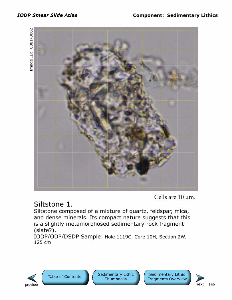
Component: Sedimentary Lithics
146
Imag
e ID
: 0
081/0
082
Siltstone 1.Siltstone composed of a mixture of quartz, feldspar, mica, and dense minerals. Its compact nature suggests that this is a slightly metamorphosed sedimentary rock fragment (slate?).IODP/ODP/DSDP Sample: Hole 1119C, Core 10H, Section 2W, 125 cm
Cells are 10 µm.
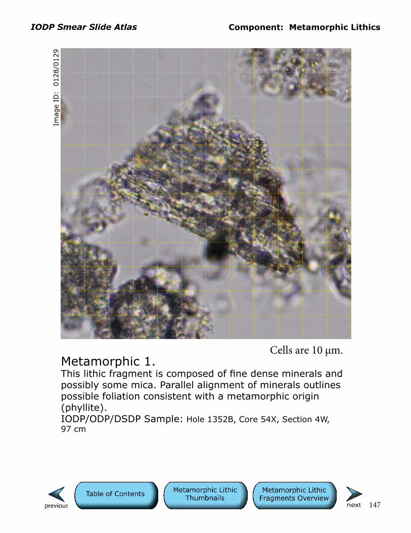
Component: Metamorphic Lithics
147
Imag
e ID
: 0
128/0
129
Metamorphic 1.This lithic fragment is composed of fine dense minerals and possibly some mica. Parallel alignment of minerals outlines possible foliation consistent with a metamorphic origin (phyllite).IODP/ODP/DSDP Sample: Hole 1352B, Core 54X, Section 4W, 97 cm
Cells are 10 µm.
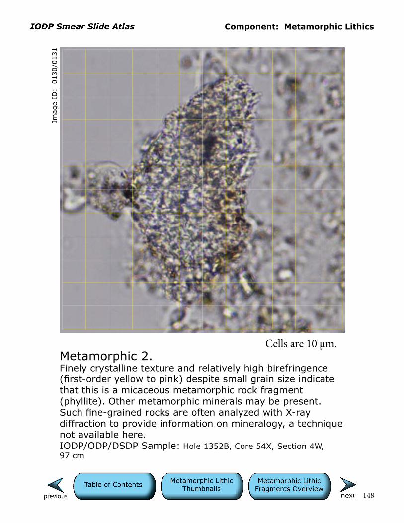
Component: Metamorphic Lithics
148
Imag
e ID
: 0
130/0
131
Metamorphic 2.Finely crystalline texture and relatively high birefringence (first-order yellow to pink) despite small grain size indicate that this is a micaceous metamorphic rock fragment (phyllite). Other metamorphic minerals may be present. Such fine-grained rocks are often analyzed with X-ray diffraction to provide information on mineralogy, a technique not available here.IODP/ODP/DSDP Sample: Hole 1352B, Core 54X, Section 4W, 97 cm
Cells are 10 µm.

Component: Metamorphic Lithics
149
Imag
e ID
: 0
271/0
272
Metamorphic 3.These obscure, polymineralic (quartz-feldspar-mica) lithics are likely metamorphic in origin, possibly altered volcanics. IODP/ODP/DSDP Sample: Hole 475, Core 16, Section 2, 109 cm
Cells are 10 µm.
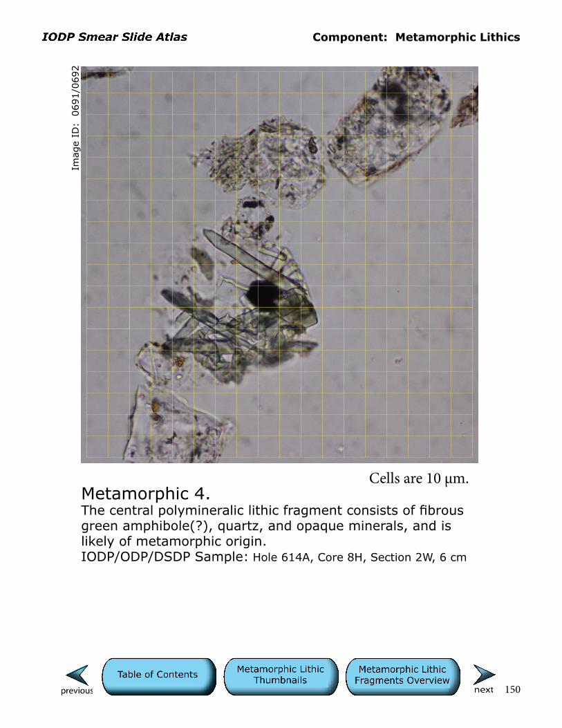
Component: Metamorphic Lithics
150
Imag
e ID
: 0
691/0
692
Metamorphic 4.The central polymineralic lithic fragment consists of fibrous green amphibole(?), quartz, and opaque minerals, and is likely of metamorphic origin.IODP/ODP/DSDP Sample: Hole 614A, Core 8H, Section 2W, 6 cm
Cells are 10 µm.
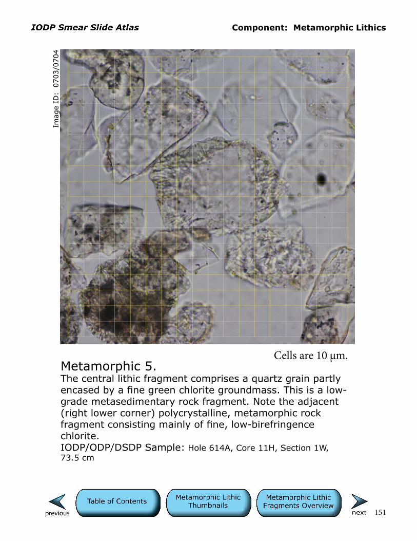
Component: Metamorphic Lithics
151
Imag
e ID
: 0
703/0
704
Metamorphic 5.The central lithic fragment comprises a quartz grain partly encased by a fine green chlorite groundmass. This is a low-grade metasedimentary rock fragment. Note the adjacent (right lower corner) polycrystalline, metamorphic rock fragment consisting mainly of fine, low-birefringence chlorite.IODP/ODP/DSDP Sample: Hole 614A, Core 11H, Section 1W, 73.5 cm
Cells are 10 µm.

Component: Metamorphic Lithics
152
Imag
e ID
: 0
729/0
730
Metamorphic 6.The polymineralic lithic fragment in the lower right corner includes quartz/feldspar, opaques, and distinctive, elongate crystals of amphibole(?). The composition and texture suggest that it is a metamorphic rock fragment.IODP/ODP/DSDP Sample: Hole 615, Core 9H, Section 1W, 14 cm
Cells are 10 µm.

Component: Volcanic Lithics
153
Imag
e ID
: 0
168/0
169
Microlitic 1.This fragment is classified as a microlitic volcanic; its birefringence, however, suggests that it could also be a holocrystalline fragment (glomerocryst?) of pyroxene and plagioclase.IODP/ODP/DSDP Sample: Hole 861A, Core 1H, Section 5, 61 cm
Cells are 10 µm.

Component: Volcanic Lithics
154
Imag
e ID
: 0172/0
173
Microlitic 2.This is a fragment of microlitic, colorless glass with curved vesicular edge showing dark, adhering, clay-sized material (glass?) and feldspar silt. The microlites are elongate plagioclase and birefringent smaller crystals (pinpoints) of pyroxene(?). IODP/ODP/DSDP Sample: Hole 861A, Core 1H, Section 5, 61 cm
Cells are 10 µm.
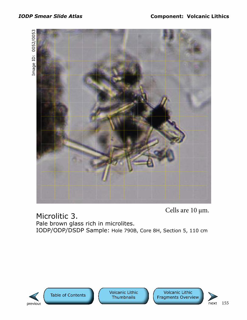
Component: Volcanic Lithics
155
Imag
e ID
: 0
052/0
053
Microlitic 3.Pale brown glass rich in microlites.IODP/ODP/DSDP Sample: Hole 790B, Core 8H, Section 5, 110 cm
Cells are 10 µm.

Component: Volcanic Lithics
156
Imag
e ID
: 0
054/0
055
Microlitic 4.At center is a fragment of pale brown, microlitic glass with swal-low-tail (pronged ends) plagioclase microlites. Curved margins of this grain are where the fragment broke across vesicles. Adjacent lithics include opaque-rich, black, tachylitic glass (upper right), and colorless pumice (center left). Note graininess of tachylitic fragment where microcrystallinity is evident on irregular edges of the fragment. Out-of-focus rectangular grain in upper left corner is a plagioclase grain, likely a phenocryst liberated during pyroclastic eruption rather than eroded from preexisting rocks (epiclastic).IODP/ODP/DSDP Sample: Hole 790B, Core 8H, Section 5, 110 cm
Cells are 10 µm.

Component: Volcanic Lithics
157
Imag
e ID
: 0
056/0
057
Microlitic 5.The central fragment exibits a microlitic volcanic texture with slightly birefringent plagioclase microlites set in a tan glassy groundmass. Other surrounding grains on top and bottom are mainly dark mafic (tachylitic), glassy grains. Nearby carbonate bioclasts are highly birefringent.IODP/ODP/DSDP Sample: Hole 790B, Core 8H, Section 5, 110 cm
Cells are 10 µm.

Component: Volcanic Lithics
158
Imag
e ID
: 0
058/0
059
Microlitic 6.The central elongate volcanic clast exhibits microlitic texture with elongate plagioclase microlites. Curved upper left edge is part of a vesicle wall. Adjacent dark tachylitic volcanic grain on left is microlitic with elongate, low-birefringent pla-gioclase and more highly birefringent (bright pinpoint) pyroxene when viewed with polars crossed. Colorless grain, upper middle right, is likely a plagioclase exhibiting unusual dark bands with polars crossed that may be twinning.IODP/ODP/DSDP Sample: Hole 790B, Core 8H, Section 5, 110 cm
Cells are 10 µm.
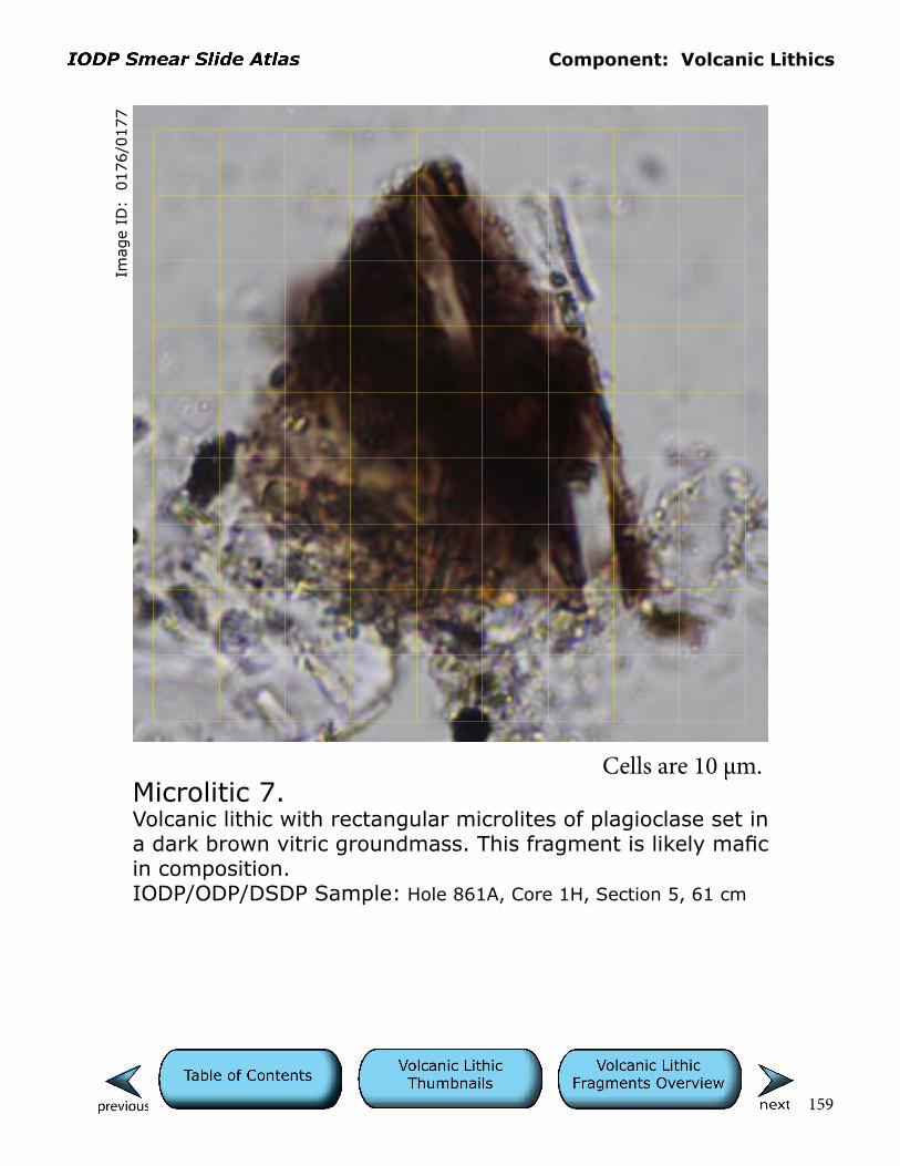
Component: Volcanic Lithics
159
Imag
e ID
: 0
176/0
177
Microlitic 7.Volcanic lithic with rectangular microlites of plagioclase set in a dark brown vitric groundmass. This fragment is likely mafic in composition.IODP/ODP/DSDP Sample: Hole 861A, Core 1H, Section 5, 61 cm
Cells are 10 µm.

Component: Volcanic Lithics
160
Imag
e ID
: 0
259/0
260
Microlitic 8.Microlitic volcanic rock fragment exhibits a trachytic texture (semialigned plagioclase microlites) typical of andesitic volcanic rocks. The fragment consists of mostly semialigned plagioclase crystals with little glass (holocrystalline).IODP/ODP/DSDP Sample: Hole 475, Core 16, Section 2, 109 cm
Cells are 10 µm.

Component: Volcanic Lithics
161
Imag
e ID
: 0
015/0
016
Microlitic 9.Fine, elongate, rectangular plagioclase microlites are set in a dark brown glassy groundmass in this volcanic lithic fragment, which judging by its birefringence may be devitrified/altered. This glass color and grain rounding (note truncated microlites on top corner) are consistent with it being epiclastic basalt.IODP/ODP/DSDP Sample: Hole 860, Core 17X, Section 1, 80 cm
Cells are 10 µm.

Component: Volcanic Lithics
162
Imag
e ID
: 0
269/0
270
Microlitic 10.Rounded holocrystalline(?) volcanic lithic fragment in center consists mainly of plagioclase and fine opaque microlites. Some glassy groundmass may be present. Darker fragments on either side are also likely to be volcanic in origin.IODP/ODP/DSDP Sample: Hole 475, Core 16, Section 2, 109 cm
Cells are 10 µm.

Component: Volcanic Lithics
163
Microlitic 11.This view contains a variety of microlitic (mainly plagioclase) fragments, ranging from highly vesicular and colorless (left) to nonvesicular, colorless (bottom center), and brown (right center) glass types. The large grain (crystal) in the upper right exhibits a selvage (partially attached glassy ground-mass) of colorless glass, attesting to its pyroclastic origin.IODP/ODP/DSDP Sample: Hole 790C , Core 11X, Section 4, 44 cm
Imag
e ID
: 0
277/0
278
Cells are 10 µm.
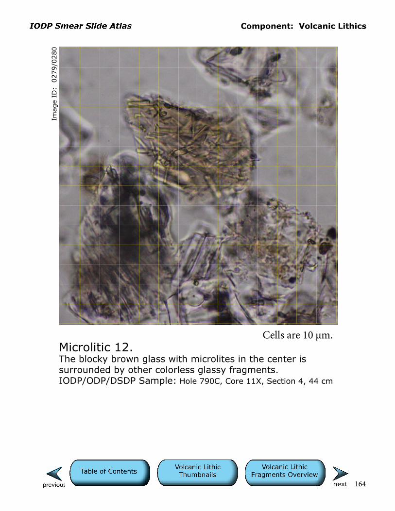
Component: Volcanic Lithics
164
Imag
e ID
: 0
279/0
280
Microlitic 12.The blocky brown glass with microlites in the center is surrounded by other colorless glassy fragments.IODP/ODP/DSDP Sample: Hole 790C, Core 11X, Section 4, 44 cm
Cells are 10 µm.

Component: Volcanic Lithics
165
Microlitic 13.Reddish-brown, altered (oxidized/palagonitized?) volcanic rock fragment with microlitic texture.IODP/ODP/DSDP Sample: Hole 1232A, Core 10H, Section 3W, 25 cm
Imag
e ID
: 0
804/0
805
Cells are 10 µm.
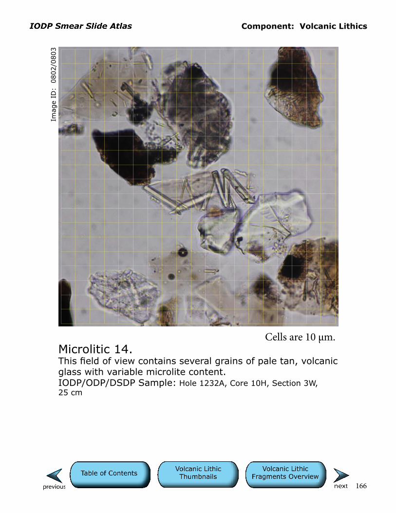
Component: Volcanic Lithics
166
Microlitic 14.This field of view contains several grains of pale tan, volcanic glass with variable microlite content. IODP/ODP/DSDP Sample: Hole 1232A, Core 10H, Section 3W, 25 cm
Imag
e ID
: 0
802/0
803
Cells are 10 µm.
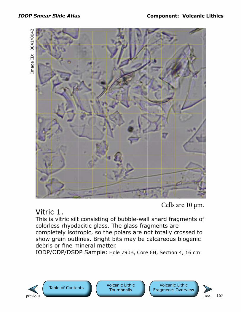
Component: Volcanic Lithics
167
Imag
e ID
: 0
041/0
042
Vitric 1.This is vitric silt consisting of bubble-wall shard fragments of colorless rhyodacitic glass. The glass fragments are completely isotropic, so the polars are not totally crossed to show grain outlines. Bright bits may be calcareous biogenic debris or fine mineral matter.IODP/ODP/DSDP Sample: Hole 790B, Core 6H, Section 4, 16 cm
Cells are 10 µm.
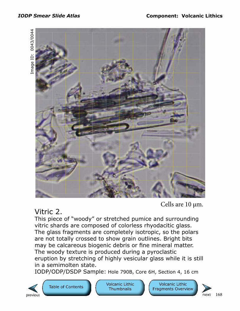
Component: Volcanic Lithics
168
Imag
e ID
: 0
043/0
044
Vitric 2.This piece of “woody” or stretched pumice and surrounding vitric shards are composed of colorless rhyodacitic glass. The glass fragments are completely isotropic, so the polars are not totally crossed to show grain outlines. Bright bits may be calcareous biogenic debris or fine mineral matter. The woody texture is produced during a pyroclastic eruption by stretching of highly vesicular glass while it is still in a semimolten state. IODP/ODP/DSDP Sample: Hole 790B, Core 6H, Section 4, 16 cm
Cells are 10 µm.
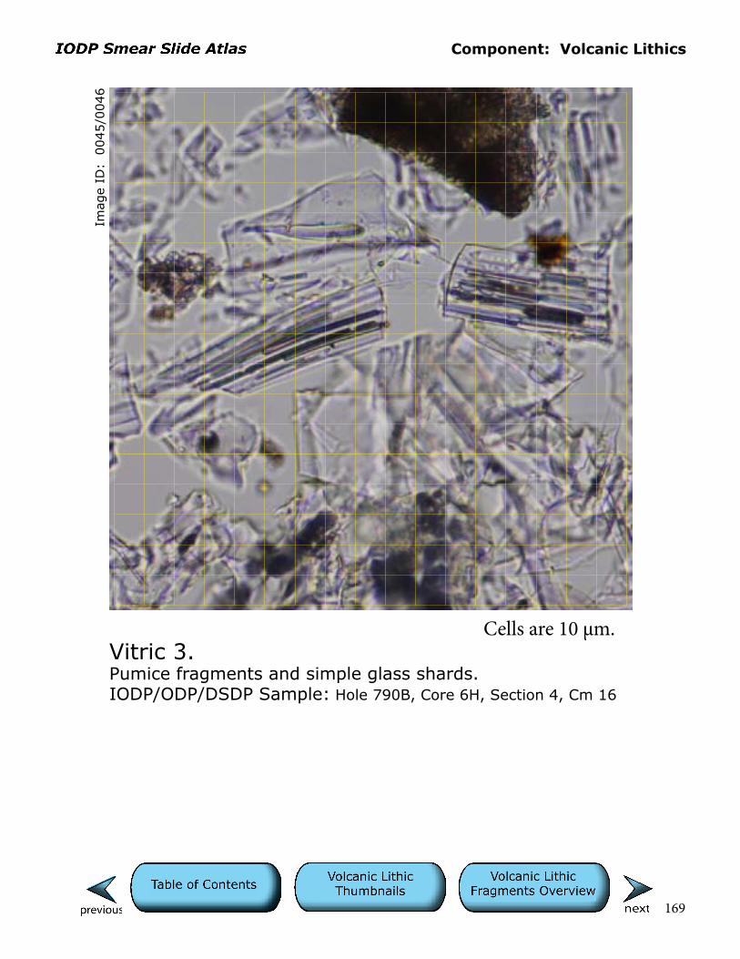
Component: Volcanic Lithics
169
Imag
e ID
: 0
045/0
046
Vitric 3.Pumice fragments and simple glass shards.IODP/ODP/DSDP Sample: Hole 790B, Core 6H, Section 4, Cm 16
Cells are 10 µm.
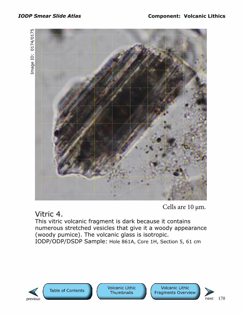
Component: Volcanic Lithics
170
Imag
e ID
: 0
174/0
175
Vitric 4.This vitric volcanic fragment is dark because it contains numerous stretched vesicles that give it a woody appearance (woody pumice). The volcanic glass is isotropic.IODP/ODP/DSDP Sample: Hole 861A, Core 1H, Section 5, 61 cm
Cells are 10 µm.
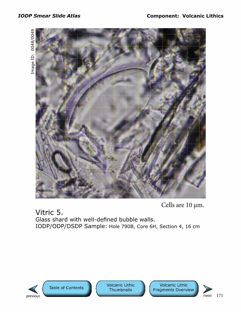
Component: Volcanic Lithics
171
Imag
e ID
: 0
048/0
049
Vitric 5.Glass shard with well-defined bubble walls.IODP/ODP/DSDP Sample: Hole 790B, Core 6H, Section 4, 16 cm
Cells are 10 µm.

Component: Volcanic Lithics
172
Imag
e ID
: 0
050/0
051
Vitric 6.Pale brown glass with bubble wall.IODP/ODP/DSDP Sample: Hole 790B, Core 8H, Section 5, 110 cm
Cells are 10 µm.

Component: Volcanic Lithics
173
Imag
e ID
: 0
060/0
061
Vitric 7.This vesicular fragment of brown glass is likely intermediate to mafic (scoria) in composition. Adjacent opaque mineral grain exhibits semilinear crystal faces. Note the large bubble in the mounting medium on upper left.IODP/ODP/DSDP Sample: Hole 790B, Core 8H, Section 5, 110 cm
Cells are 10 µm.
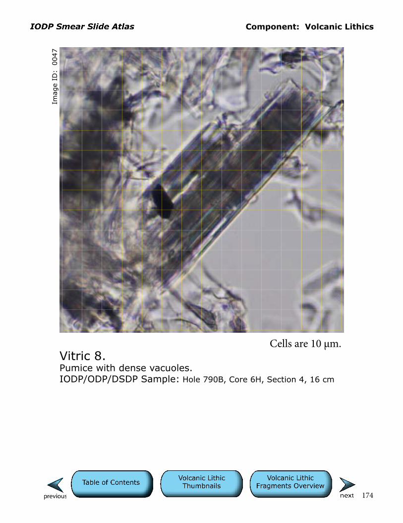
Component: Volcanic Lithics
174
Imag
e ID
: 0
047
Vitric 8.Pumice with dense vacuoles.IODP/ODP/DSDP Sample: Hole 790B, Core 6H, Section 4, 16 cm
Cells are 10 µm.

Component: Volcanic Lithics
175
Imag
e ID
: 0
185/0
186
Vitric 9.An angular fragment of brown volcanic glass with subtle color banding lies in the upper left corner. Other notable grains include twinned plagioclase and zoisite/clinozoisite grains in the lower right corner. Other components range from fine silt to clay-sized “matrix.”IODP/ODP/DSDP Sample: Hole 861C, Core 6H, Section 1, 132 cm
Cells are 10 µm.

Component: Volcanic Lithics
176
Vitric 10.Relatively large fragment of colorless glass (right center) is isotropic and exhibits an irregular, ribbed appearance (pos-sibly owing to breakage across vesicle walls?). The other, poorly sorted material includes a range of grain sizes from fine silt to clay and may be of glacial origin (rock flour?).IODP/ODP/DSDP Sample: Hole 179, Core 10, Section 3, 78 cm
Imag
e ID
: 0
372/0
373
Cells are 10 µm.

Component: Volcanic Lithics
177
Imag
e ID
: 0
282/0
283
Vitric 11.Large, semiequant fragments of colorless glass show curved margins where clast shape is determined by vesicles (gas bubbles) in erupting magma. Note that some shards may be platy in three dimensions, essentially thin bubble-wall fragments lying flat on the slide like mica flakes.IODP/ODP/DSDP Sample: Hole 790C, Core 11X, Section 4, 44 cm
Cells are 10 µm.
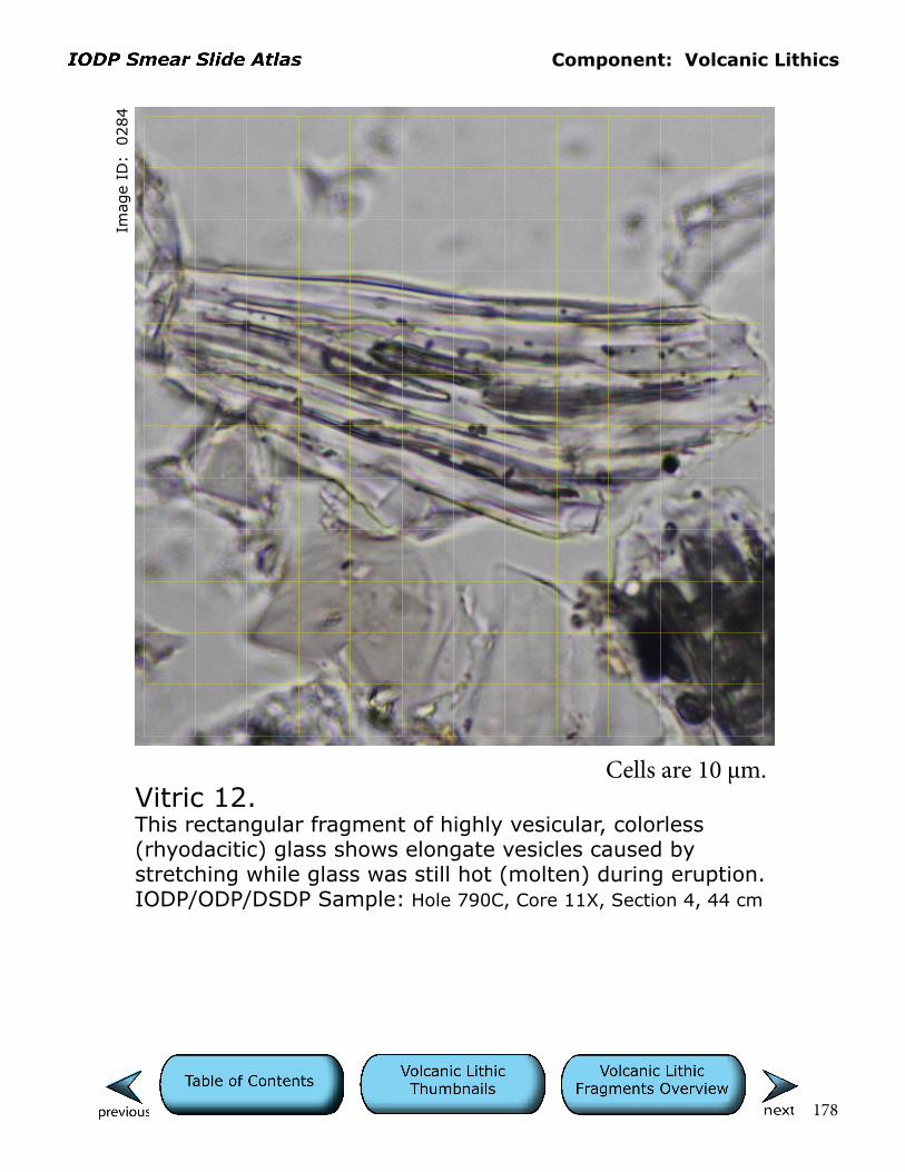
Component: Volcanic Lithics
178
Imag
e ID
: 0
284
Vitric 12.This rectangular fragment of highly vesicular, colorless (rhyodacitic) glass shows elongate vesicles caused by stretching while glass was still hot (molten) during eruption.IODP/ODP/DSDP Sample: Hole 790C, Core 11X, Section 4, 44 cm
Cells are 10 µm.
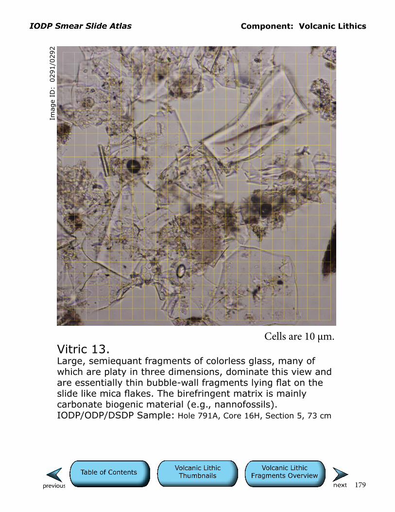
Component: Volcanic Lithics
179
Imag
e ID
: 0
291/0
292
Vitric 13.Large, semiequant fragments of colorless glass, many of which are platy in three dimensions, dominate this view and are essentially thin bubble-wall fragments lying flat on the slide like mica flakes. The birefringent matrix is mainly carbonate biogenic material (e.g., nannofossils).IODP/ODP/DSDP Sample: Hole 791A, Core 16H, Section 5, 73 cm
Cells are 10 µm.
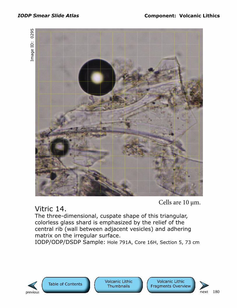
Component: Volcanic Lithics
180
Imag
e ID
: 0
295
Vitric 14.The three-dimensional, cuspate shape of this triangular, colorless glass shard is emphasized by the relief of the central rib (wall between adjacent vesicles) and adhering matrix on the irregular surface.IODP/ODP/DSDP Sample: Hole 791A, Core 16H, Section 5, 73 cm
Cells are 10 µm.

Component: Volcanic Lithics
181
Imag
e ID
: 0
296/0
297
Vitric 15.Two large, stretched (“woody”) pumice fragments dominate this field of view. The finer matrix is mainly glassy fragments with some birefringent nannofossils.IODP/ODP/DSDP Sample: Hole 791A, Core 16H, Section 5, 73 cm
Cells are 10 µm.

Component: Volcanic Lithics
182
Imag
e ID
: 0
806/0
807
Vitric 16.This is a reddish-brown, altered (oxidized/palagonitized?) volcanic glass fragment with a single, circular vesicle.IODP/ODP/DSDP Sample: Hole 1232A, Core 10H, Section 3W, 25 cm
Cells are 10 µm.

Component: Volcanic Lithics
183
Imag
e ID
: 0
794/0
795
Vitric 17.The colorless glass fragment on the left exhibits subtle flow structure. Other tan glassy fragments in this field of view are variably microlitic.IODP/ODP/DSDP Sample: Hole 1232A, Core 10H, Section 3W, 25 cm
Cells are 10 µm.
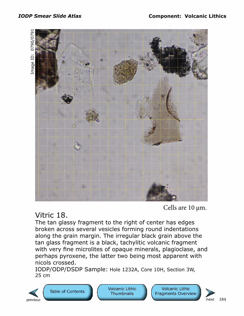
Component: Volcanic Lithics
184
Imag
e ID
: 0
790/0
791
Vitric 18.The tan glassy fragment to the right of center has edges broken across several vesicles forming round indentations along the grain margin. The irregular black grain above the tan glass fragment is a black, tachylitic volcanic fragment with very fine microlites of opaque minerals, plagioclase, and perhaps pyroxene, the latter two being most apparent with nicols crossed. IODP/ODP/DSDP Sample: Hole 1232A, Core 10H, Section 3W, 25 cm
Cells are 10 µm.
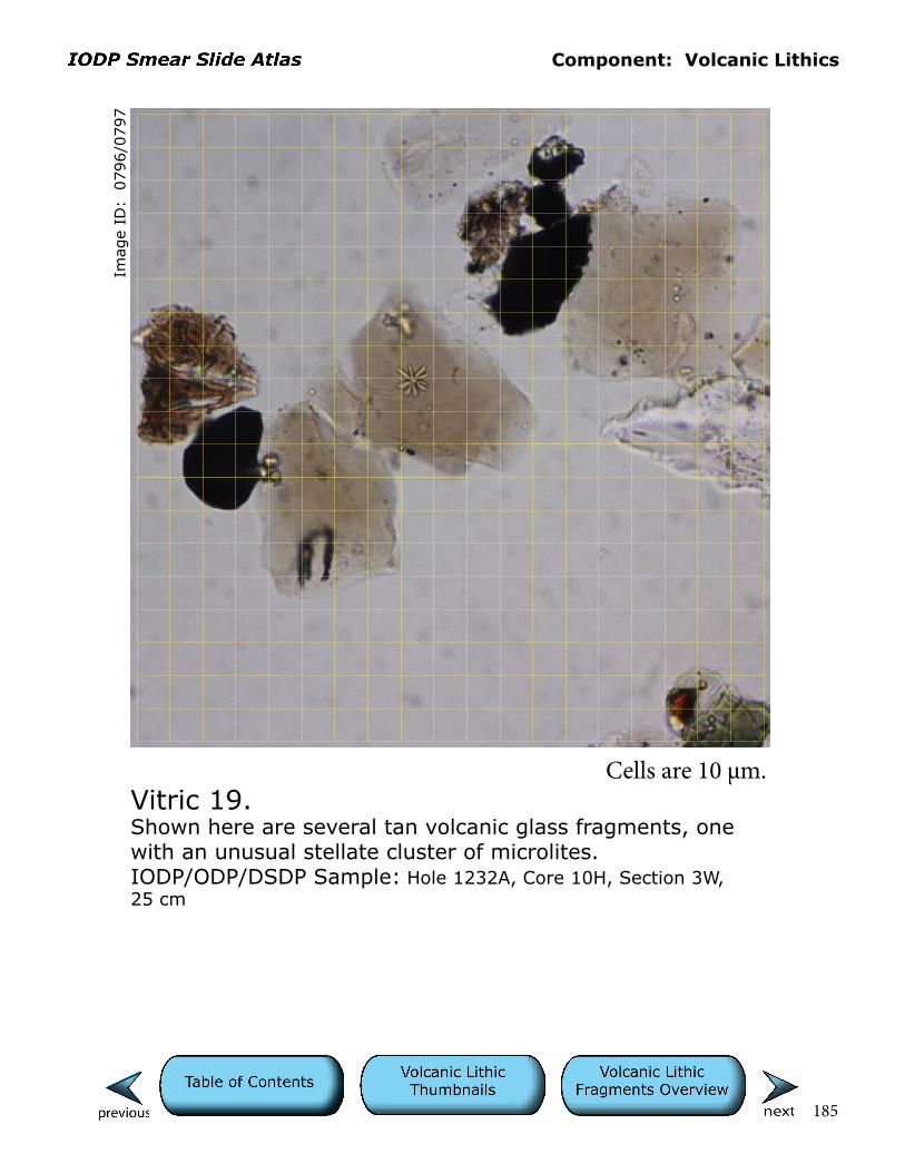
Component: Volcanic Lithics
185
Imag
e ID
: 0
796/0
797
Vitric 19.Shown here are several tan volcanic glass fragments, one with an unusual stellate cluster of microlites. IODP/ODP/DSDP Sample: Hole 1232A, Core 10H, Section 3W, 25 cm
Cells are 10 µm.
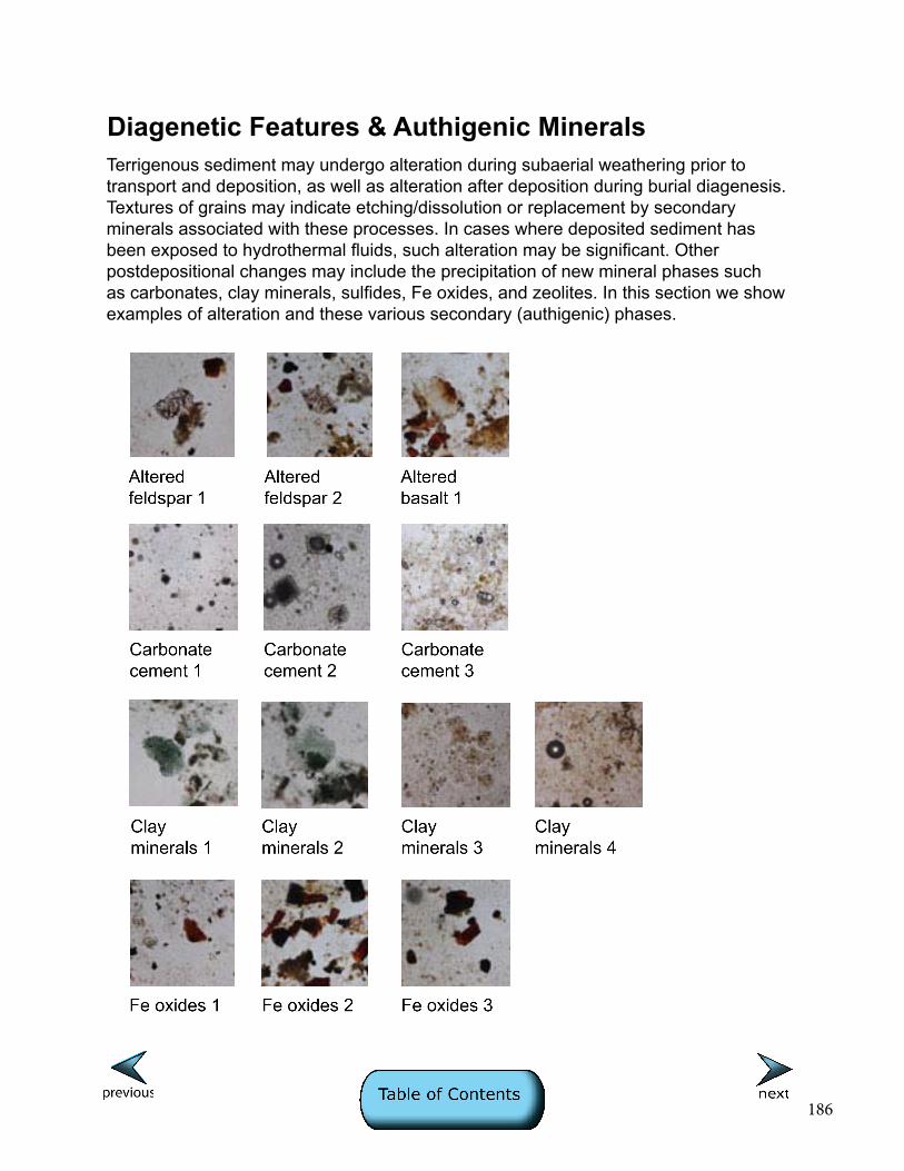
186
Diagenetic Features & Authigenic MineralsTerrigenous sediment may undergo alteration during subaerial weathering prior to transport and deposition, as well as alteration after deposition during burial diagenesis. Textures of grains may indicate etching/dissolution or replacement by secondary minerals associated with these processes. In cases where deposited sediment has been exposed to hydrothermal fluids, such alteration may be significant. Other postdepositional changes may include the precipitation of new mineral phases such as carbonates, clay minerals, sulfides, Fe oxides, and zeolites. In this section we show examples of alteration and these various secondary (authigenic) phases.
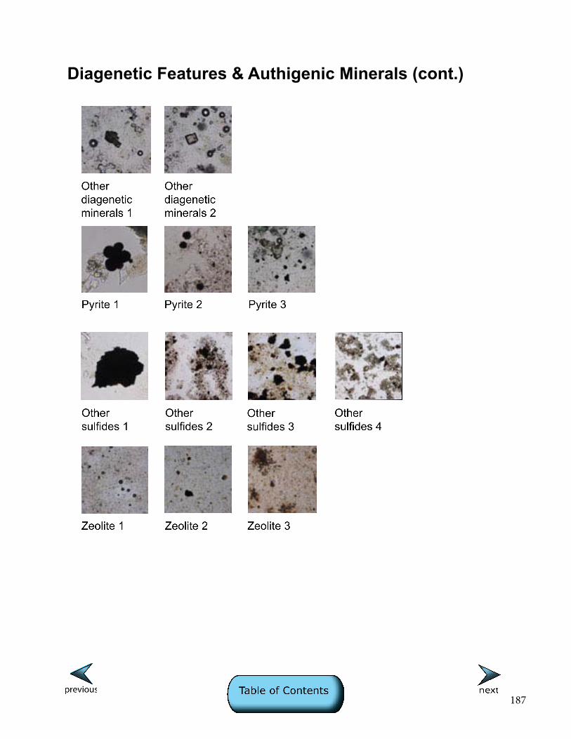
187
Diagenetic Features & Authigenic Minerals (cont.)
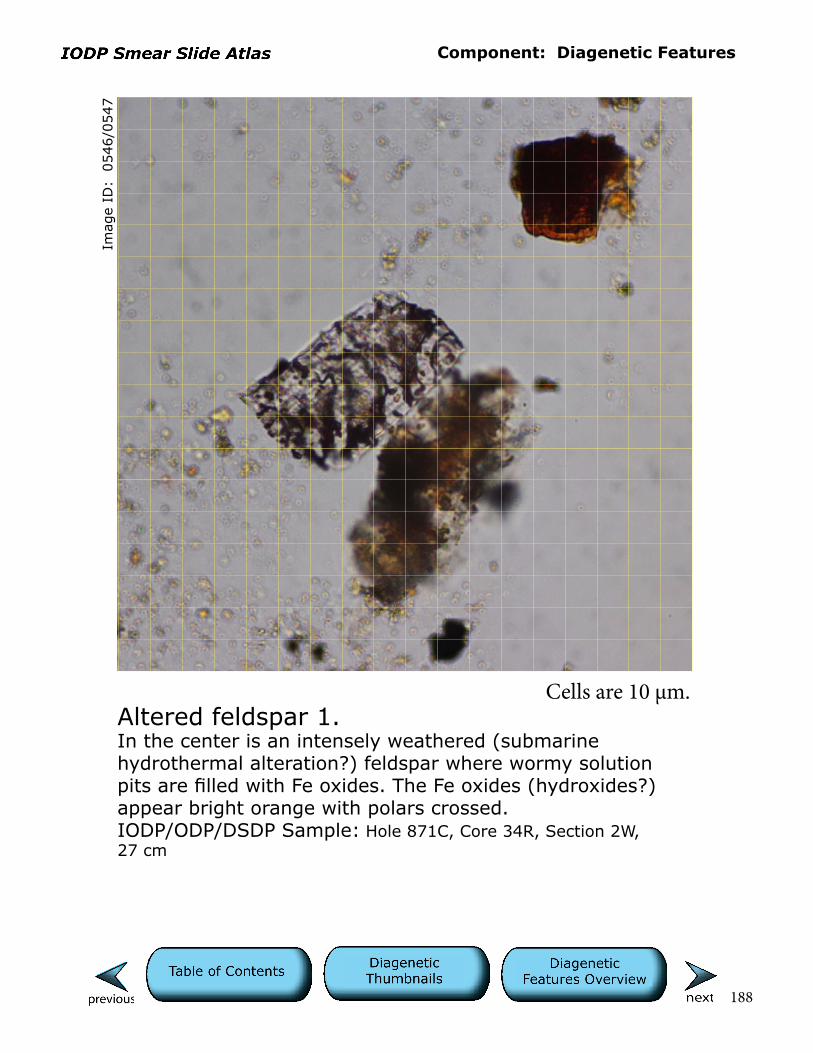
Component: Diagenetic Features
188
Imag
e ID
: 0
546/0
547
Altered feldspar 1.In the center is an intensely weathered (submarine hydrothermal alteration?) feldspar where wormy solution pits are filled with Fe oxides. The Fe oxides (hydroxides?) appear bright orange with polars crossed.IODP/ODP/DSDP Sample: Hole 871C, Core 34R, Section 2W, 27 cm
Cells are 10 µm.

Component: Diagenetic Features
189
Imag
e ID
: 0
538/0
539
Altered feldspar 2.In the center is an intensely weathered (submarine hydrothermal alteration?) feldspar where wormy solution pits are filled with Fe oxides. The Fe oxides (hydroxides?) appear bright orange with polars crossed.IODP/ODP/DSDP Sample: Hole 871C, Core 34R, Section 1W, 46 cm
Cells are 10 µm.

Component: Diagenetic Features
190
Imag
e ID
: 0
542/0
543
Altered basalt 1.Fragments of birefringent Fe oxides and fibro-radiating, amygdule-filling (quartz? zeolite? clay?) minerals that are likely alteration residues of basalt.IODP/ODP/DSDP Sample: Hole 871C, Core 34R, Section 1W, 46 cm
Cells are 10 µm.

Component: Diagenetic Features
191
Imag
e ID
: 0
519/0
520
Carbonate cement 1.General view of mud with larger zoned rhombs of authigenic dolomite.IODP/ODP/DSDP Sample: Hole 858B, Core 2H, Section 2W, 37 cm
Cells are 10 µm.
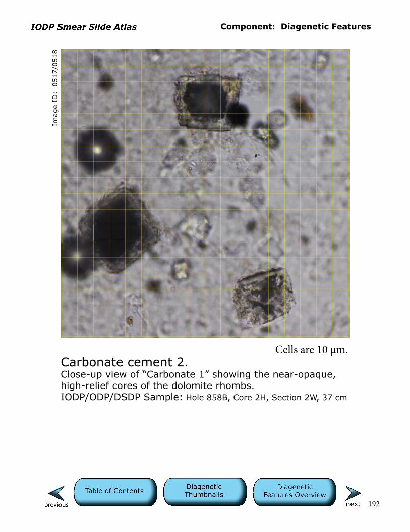
Component: Diagenetic Features
192
Imag
e ID
: 0
517/0
518
Carbonate cement 2.Close-up view of “Carbonate 1” showing the near-opaque, high-relief cores of the dolomite rhombs.IODP/ODP/DSDP Sample: Hole 858B, Core 2H, Section 2W, 37 cm
Cells are 10 µm.

Component: Diagenetic Features
193
Imag
e ID
: 0
656/0
657
Carbonate cement 3.Authigenic carbonate crystals (micrite) within this diatom ooze/clay are best seen with polars crossed, where the birefringent micrite stands out against the nonbirefringent, opaline biogenic debris and clay. The uniform crystal size of the micrite is another indication that it is authigenic. Irregular shapes suggest that these crystals may have nucleated on nannofossils.IODP/ODP/DSDP Sample: Hole 1229A, Core 2H, Section 6W, 26 cm
Cells are 10 µm.

Component: Diagenetic Features
194
Imag
e ID
: 0
576/0
577
Clay minerals 1.These clumps of bluish-green clay may be authigenic glaucony (general term referring to Fe-rich, marine clay minerals) or, alternatively, celadonite, a common alteration product of basalt.IODP/ODP/DSDP Sample: Hole 877A, Core 20R, Section 3W, 42 cm
Cells are 10 µm.
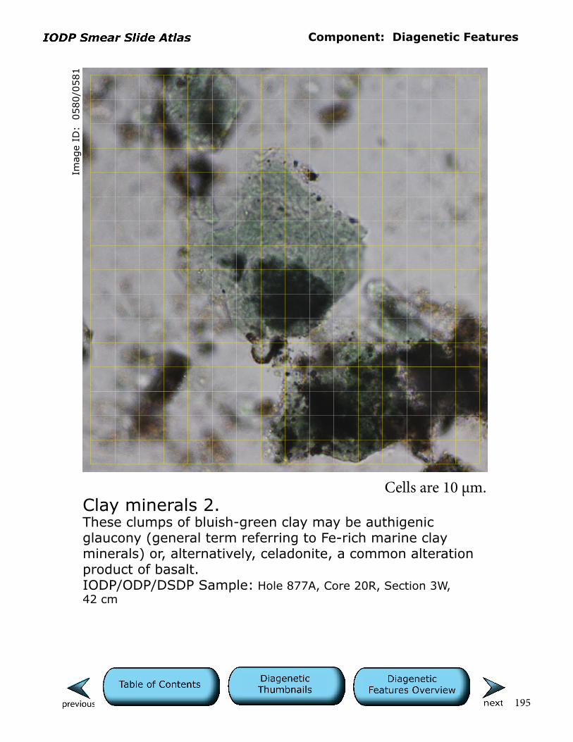
Component: Diagenetic Features
195
Imag
e ID
: 0
580/0
581
Clay minerals 2.These clumps of bluish-green clay may be authigenic glaucony (general term referring to Fe-rich marine clay minerals) or, alternatively, celadonite, a common alteration product of basalt.IODP/ODP/DSDP Sample: Hole 877A, Core 20R, Section 3W, 42 cm
Cells are 10 µm.
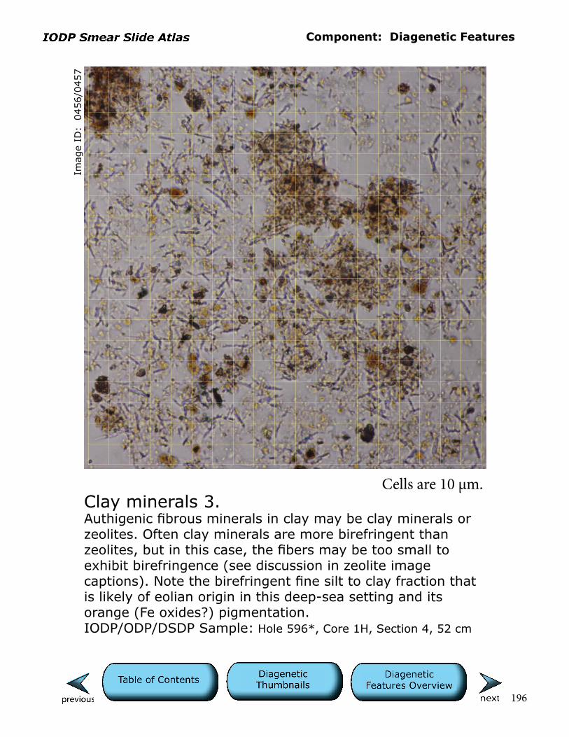
Component: Diagenetic Features
196
Imag
e ID
: 0
456/0
457
Clay minerals 3.Authigenic fibrous minerals in clay may be clay minerals or zeolites. Often clay minerals are more birefringent than zeolites, but in this case, the fibers may be too small to exhibit birefringence (see discussion in zeolite image captions). Note the birefringent fine silt to clay fraction that is likely of eolian origin in this deep-sea setting and its orange (Fe oxides?) pigmentation.IODP/ODP/DSDP Sample: Hole 596*, Core 1H, Section 4, 52 cm
Cells are 10 µm.
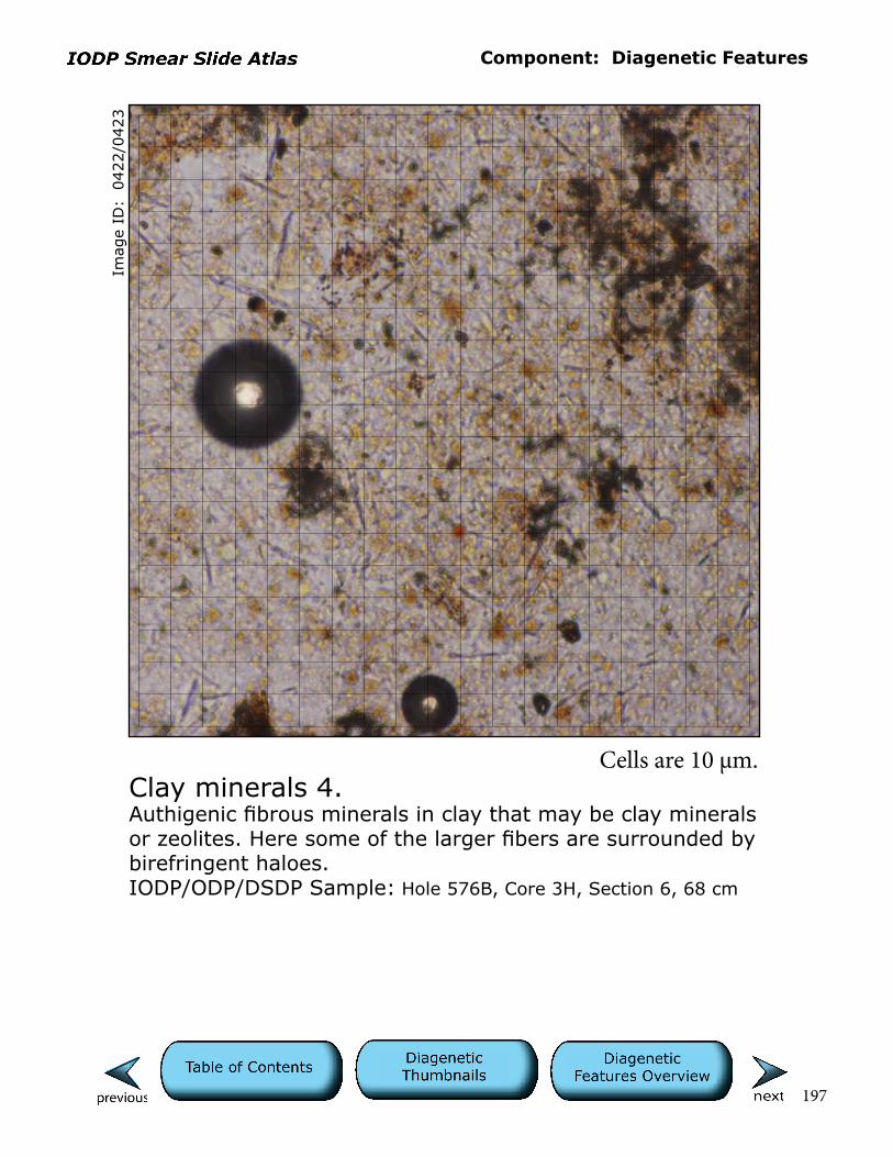
Component: Diagenetic Features
197
Imag
e ID
: 0
422/0
423
Clay minerals 4.Authigenic fibrous minerals in clay that may be clay minerals or zeolites. Here some of the larger fibers are surrounded by birefringent haloes.IODP/ODP/DSDP Sample: Hole 576B, Core 3H, Section 6, 68 cm
Cells are 10 µm.
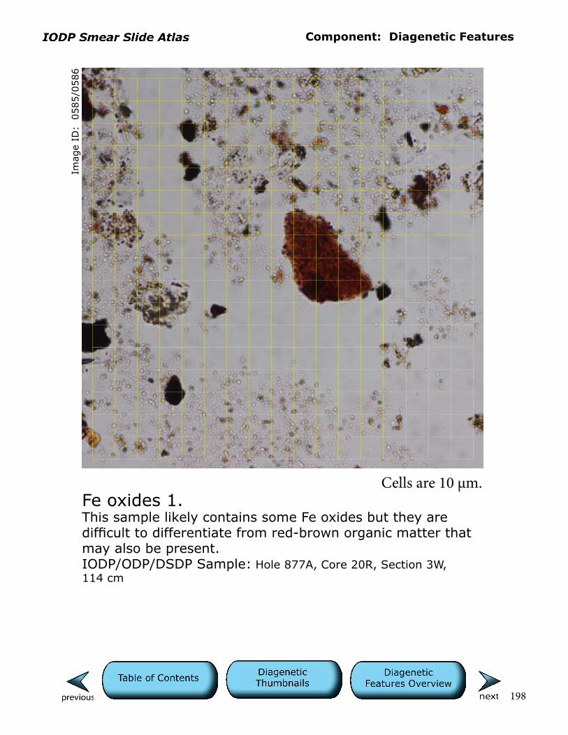
Component: Diagenetic Features
198
Imag
e ID
: 0
585/0
586
Fe oxides 1.This sample likely contains some Fe oxides but they are difficult to differentiate from red-brown organic matter that may also be present.IODP/ODP/DSDP Sample: Hole 877A, Core 20R, Section 3W, 114 cm
Cells are 10 µm.

Component: Diagenetic Features
199
Imag
e ID
: 0
536/0
537
Fe oxides 2.Large orange-brown crystals are likely Fe oxides that may be pseudomorphs after silicate minerals in highly weathered basalt or soil precipitates (paleosol horizon on guyot).IODP/ODP/DSDP Sample: Hole 871C, Core 34R, Section 1W, 46cm
Cells are 10 µm.
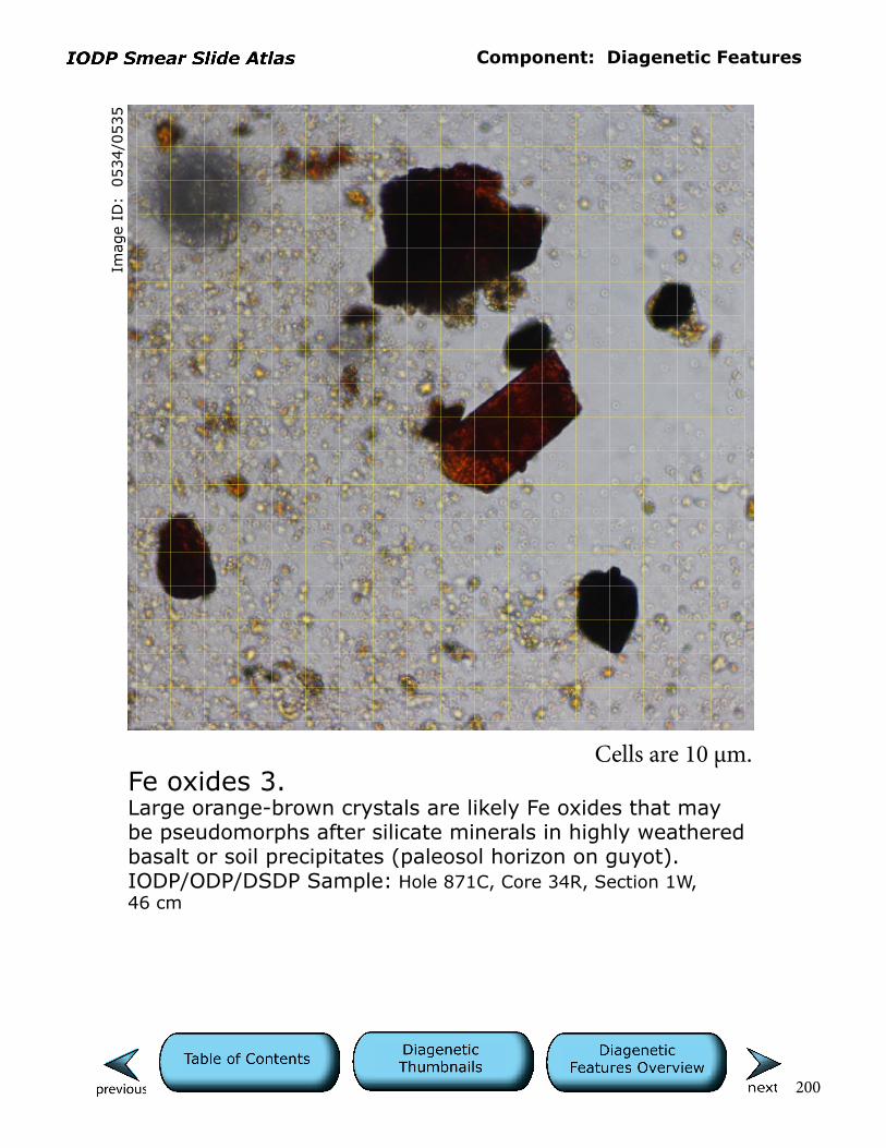
Component: Diagenetic Features
200
Imag
e ID
: 0
534/0
535
Fe oxides 3.Large orange-brown crystals are likely Fe oxides that may be pseudomorphs after silicate minerals in highly weathered basalt or soil precipitates (paleosol horizon on guyot).IODP/ODP/DSDP Sample: Hole 871C, Core 34R, Section 1W, 46 cm
Cells are 10 µm.
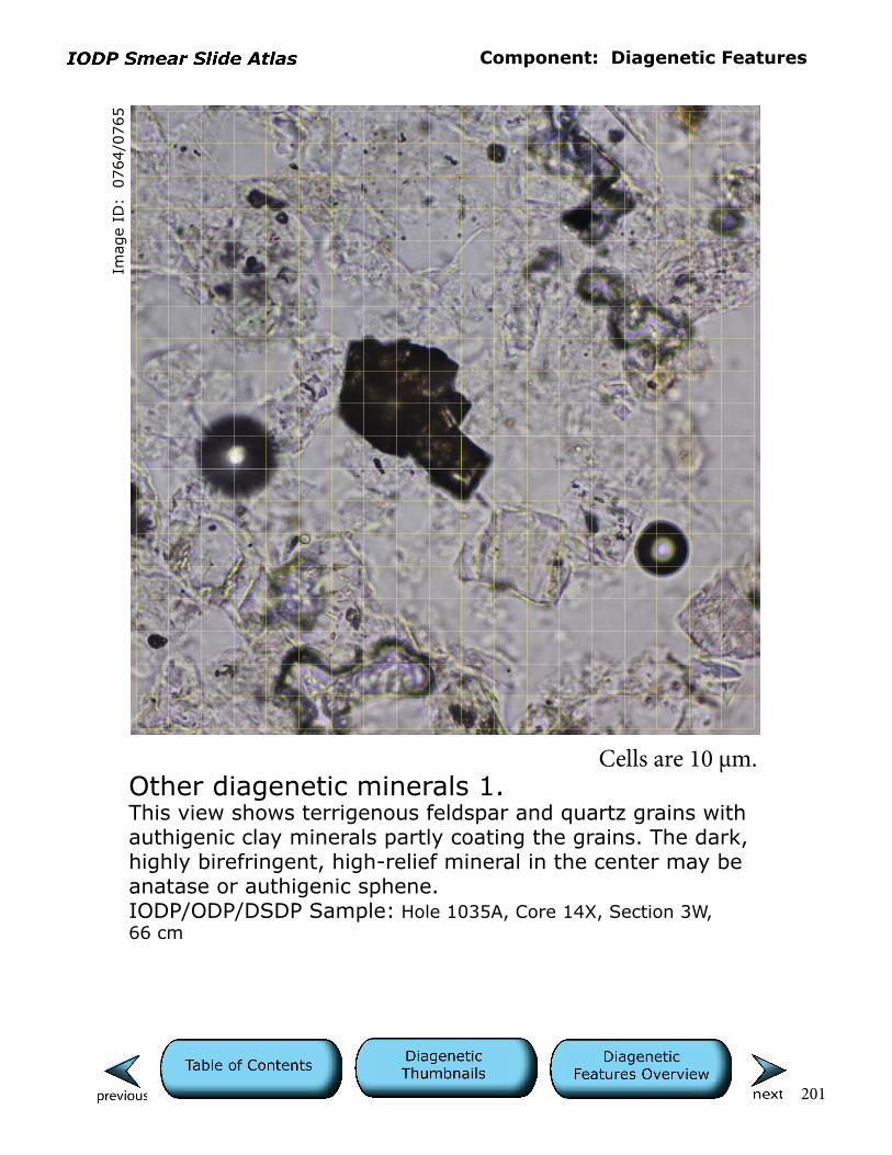
Component: Diagenetic Features
201
Imag
e ID
: 0
764/0
765
Other diagenetic minerals 1.This view shows terrigenous feldspar and quartz grains with authigenic clay minerals partly coating the grains. The dark, highly birefringent, high-relief mineral in the center may be anatase or authigenic sphene.IODP/ODP/DSDP Sample: Hole 1035A, Core 14X, Section 3W, 66 cm
Cells are 10 µm.
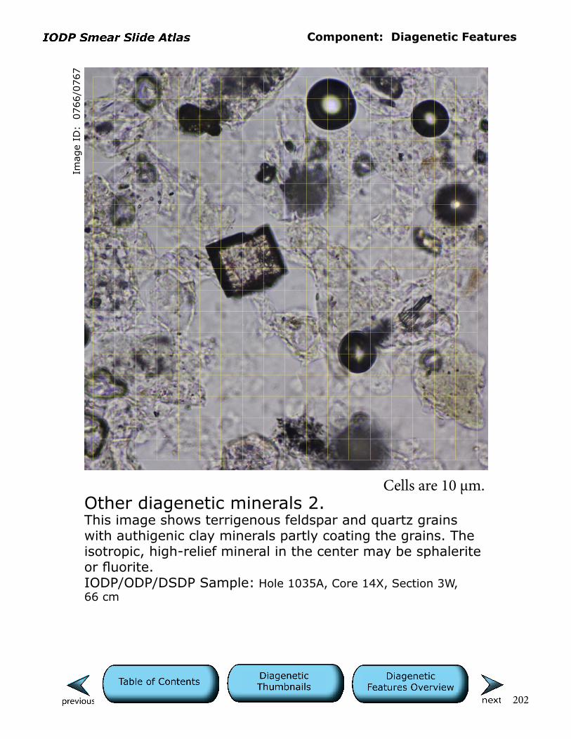
Component: Diagenetic Features
202
Imag
e ID
: 0
766/0
767
Other diagenetic minerals 2.This image shows terrigenous feldspar and quartz grains with authigenic clay minerals partly coating the grains. The isotropic, high-relief mineral in the center may be sphalerite or fluorite.IODP/ODP/DSDP Sample: Hole 1035A, Core 14X, Section 3W, 66 cm
Cells are 10 µm.
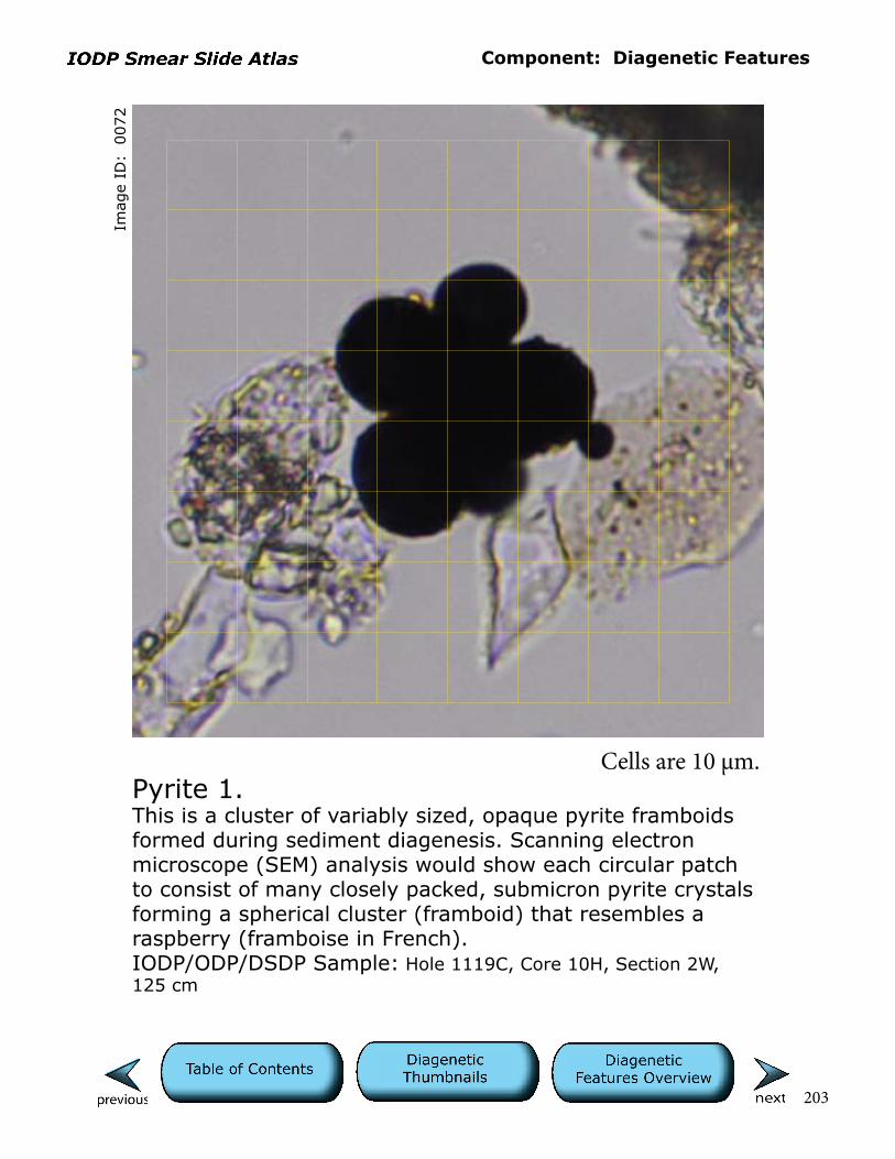
Component: Diagenetic Features
203
Imag
e ID
: 0
072
Pyrite 1.This is a cluster of variably sized, opaque pyrite framboids formed during sediment diagenesis. Scanning electron microscope (SEM) analysis would show each circular patch to consist of many closely packed, submicron pyrite crystals forming a spherical cluster (framboid) that resembles a raspberry (framboise in French).IODP/ODP/DSDP Sample: Hole 1119C, Core 10H, Section 2W, 125 cm
Cells are 10 µm.
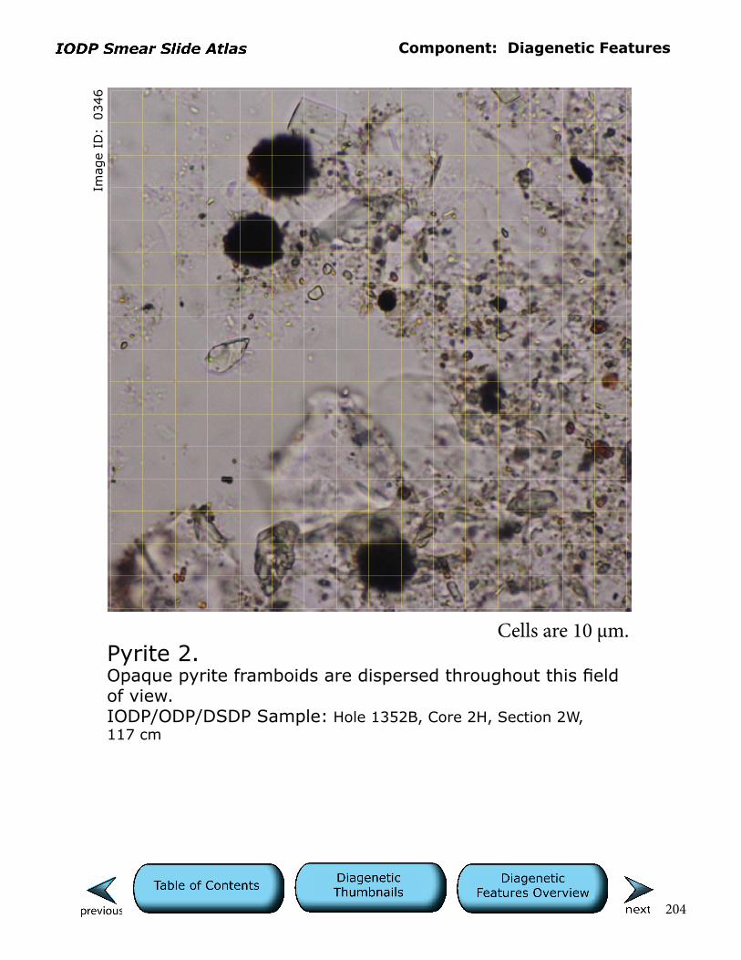
Component: Diagenetic Features
204
Imag
e ID
: 0
346
Pyrite 2.Opaque pyrite framboids are dispersed throughout this field of view.IODP/ODP/DSDP Sample: Hole 1352B, Core 2H, Section 2W, 117 cm
Cells are 10 µm.
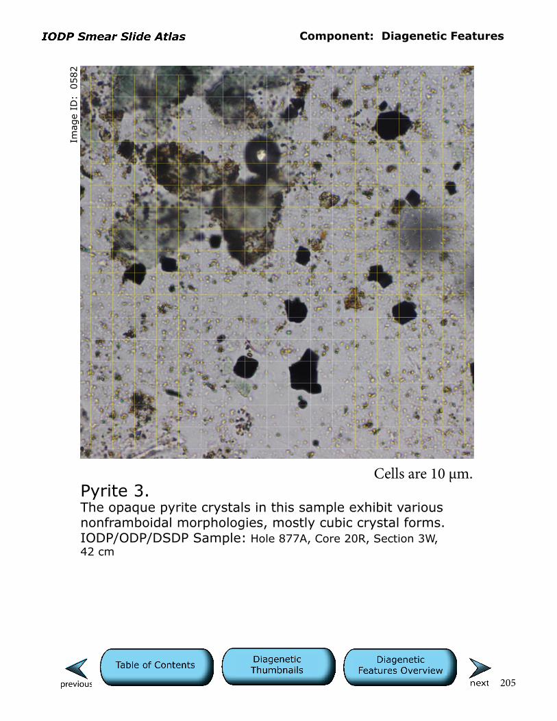
Component: Diagenetic Features
205
Imag
e ID
: 0
582
Pyrite 3.The opaque pyrite crystals in this sample exhibit various nonframboidal morphologies, mostly cubic crystal forms.IODP/ODP/DSDP Sample: Hole 877A, Core 20R, Section 3W, 42 cm
Cells are 10 µm.
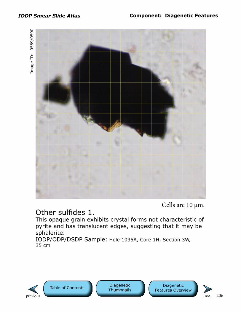
Component: Diagenetic Features
206
Imag
e ID
: 0
589/0
590
Other sulfides 1.This opaque grain exhibits crystal forms not characteristic of pyrite and has translucent edges, suggesting that it may be sphalerite.IODP/ODP/DSDP Sample: Hole 1035A, Core 1H, Section 3W, 35 cm
Cells are 10 µm.

Component: Diagenetic Features
207
Imag
e ID
: 0
601/0
602
Other sulfides 2.General view of sulfide-rich sediment (opaque grains) associated with a mid-ocean ridge hydrothermal system. The opaque minerals may be pyrrhotite, pyrite, sphalerite, and Cu-Fe sulfides.IODP/ODP/DSDP Sample: Hole 1035D, Core 1L, Section 3W, 51 cm
Cells are 10 µm.
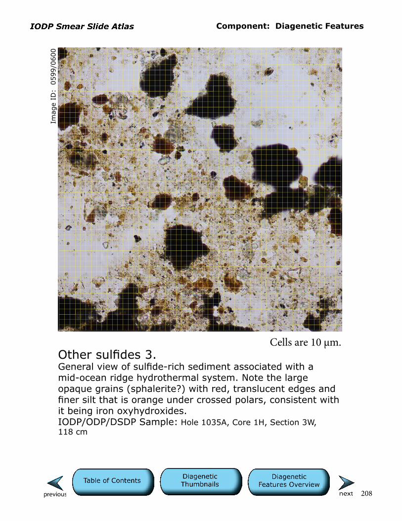
Component: Diagenetic Features
208
Imag
e ID
: 0
599/0
600
Other sulfides 3.General view of sulfide-rich sediment associated with a mid-ocean ridge hydrothermal system. Note the large opaque grains (sphalerite?) with red, translucent edges and finer silt that is orange under crossed polars, consistent with it being iron oxyhydroxides.IODP/ODP/DSDP Sample: Hole 1035A, Core 1H, Section 3W, 118 cm
Cells are 10 µm.

Component: Diagenetic Features
209
Imag
e ID
: 0
592/0
593
Other sulfides 4.General view of sulfide-rich sediment associated with a mid-ocean ridge hydrothermal system. Note the colorless, high-relief, silt-sized grains distributed throughout the field of view. Their low birefringence suggests that they are likely barite. See higher-magnification image in “alternative view” that more clearly shows the colorless, high-relief, silt-sized, low-birefringence barite (?) grains and orange iron oxyhydroxides(?).IODP/ODP/DSDP Sample: Hole 1035A, Core 1H, Section 3W, 118 cm
Cells are 10 µm.

Component: Diagenetic Features
210
Imag
e ID
: 0
501/0
502
Zeolite 1.This sample mainly consists of clay and silt-sized authigenic crystals of zeolite. The zeolite crystals are degrading and appear frayed, suggesting that they are either dissolving or altering to birefringent clay minerals (see largest crystal in center of field of view). Residual, blunt, rod-shaped crystal morphology is most consistent with phillipsite.IODP/ODP/DSDP Sample: Hole 842B, Core 3H, Section 4, 64 cm
Cells are 10 µm.
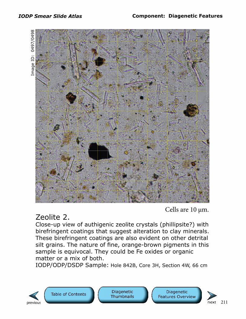
Component: Diagenetic Features
211
Imag
e ID
: 0
497/0
498
Zeolite 2.Close-up view of authigenic zeolite crystals (phillipsite?) with birefringent coatings that suggest alteration to clay minerals. These birefringent coatings are also evident on other detrital silt grains. The nature of fine, orange-brown pigments in this sample is equivocal. They could be Fe oxides or organic matter or a mix of both.IODP/ODP/DSDP Sample: Hole 842B, Core 3H, Section 4W, 66 cm
Cells are 10 µm.
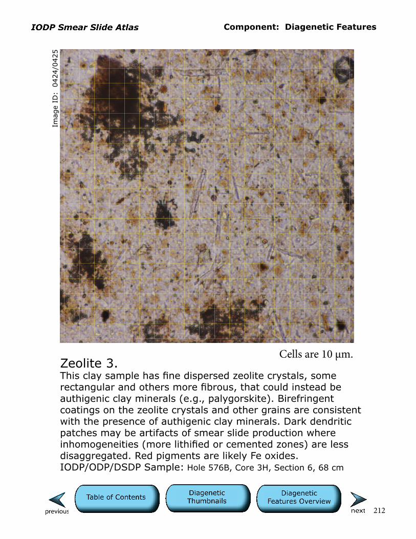
Component: Diagenetic Features
212
Imag
e ID
: 0
424/0
425
Zeolite 3.This clay sample has fine dispersed zeolite crystals, some rectangular and others more fibrous, that could instead be authigenic clay minerals (e.g., palygorskite). Birefringent coatings on the zeolite crystals and other grains are consistent with the presence of authigenic clay minerals. Dark dendritic patches may be artifacts of smear slide production where inhomogeneities (more lithified or cemented zones) are less disaggregated. Red pigments are likely Fe oxides.IODP/ODP/DSDP Sample: Hole 576B, Core 3H, Section 6, 68 cm
Cells are 10 µm.

213
Clay-sized MaterialClay-size grains (≤ 4 µm in diameter) may consist of a mixture of clay minerals, both detrital and authigenic, as well as very fine, non-clay minerals and biogenic materials. In many cases, the composition of this material is indeterminate in smear slide (40× to 60× objectives) and requires other techniques for identifi-cation and quantification, such as X-ray diffraction or scanning electron micros-copy. Terrigenous sediment in this size fraction is usually the product of subaerial weathering or glacial erosion, whereas volcanogenic material is of pyroclastic origin, all potentially delivered to the deep sea by wind processes, submarine currents, or submarine gravity flows. This size fraction may also include biogenic debris, organic matter, and authigenic mineral phases. Estimating the percent-age of clay-sized sediment in a sample can be difficult in smear slide. Thus, we recommend the use of silt and clay end members and the more general “silty clay to clayey silt” to refer to mixtures. Here we show end-member examples of sediments (clay/claystone) where the clay-sized fraction dominates (≥75%). Note that the terminology changes for mixed and biogenic sediments where clay-sized nonterrigenous components dominate (e.g., ooze).

Component: Clay-sized Material
214
Cells are 10 µm.
Imag
e ID
: 0
524
Clay 1.General view of evenly dispersed clay-sized material with larger, opaque pyrite framboids and a zoned carbonate crystal (upper left corner). The fine grain size precludes clay-particle identification except for clay-sized versions of the authigenic phases already mentioned.IODP/ODP/DSDP Sample: Hole 858B, Core 2H, Section 2W, 37 cm
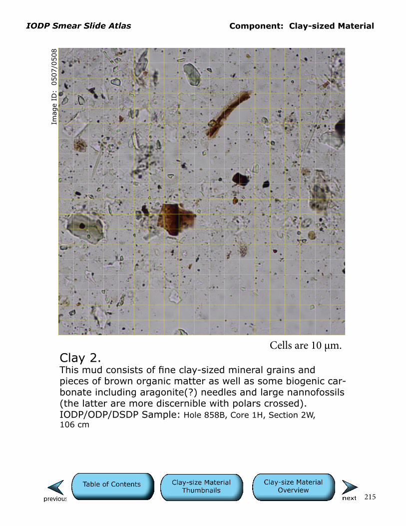
Component: Clay-sized Material
215
Cells are 10 µm.
Imag
e ID
: 0
507/0
508
Clay 2.This mud consists of fine clay-sized mineral grains and pieces of brown organic matter as well as some biogenic car-bonate including aragonite(?) needles and large nannofossils (the latter are more discernible with polars crossed). IODP/ODP/DSDP Sample: Hole 858B, Core 1H, Section 2W, 106 cm

Component: Clay-sized Material
216
Cells are 10 µm.Clay 3. This sample consists mainly of very fine clay-sized material that is unevenly distributed across the field of view. Estimat-ing the distribution in plane light is aided by the presence of brownish organic matter or Fe oxides, whereas with polars crossed, the birefringence of the fine sediment is evident. A large wispy toothpick fragment is only discernible when polars are crossed owing to its birefringence.IODP/ODP/DSDP Sample: Hole 596*, Core 2H, Section 5W, 32 cm
Imag
e ID
: 0
460/0
461

Component: Clay-sized Material
217
Cells are 10 µm.Clay 4.Clay with disseminated organic pigment? Note birefringence of fine mineral particles with polars crossed and isotropic nature of possible organic matter.IODP/ODP/DSDP Sample: Hole 596*, Core 2H, Section 5W, 32 cm
Imag
e ID
: 0
462/0
463
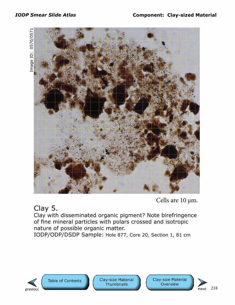
Component: Clay-sized Material
218
Cells are 10 µm.Clay 5.Clay with disseminated organic pigment? Note birefringence of fine mineral particles with polars crossed and isotropic nature of possible organic matter.IODP/ODP/DSDP Sample: Hole 877, Core 20, Section 1, 81 cm
Imag
e ID
: 0
570/0
571
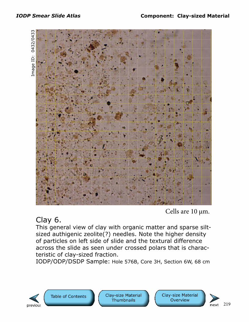
Component: Clay-sized Material
219
Cells are 10 µm.Clay 6.This general view of clay with organic matter and sparse silt-sized authigenic zeolite(?) needles. Note the higher density of particles on left side of slide and the textural difference across the slide as seen under crossed polars that is charac-teristic of clay-sized fraction.IODP/ODP/DSDP Sample: Hole 576B, Core 3H, Section 6W, 68 cm
Imag
e ID
: 0
432/0
433
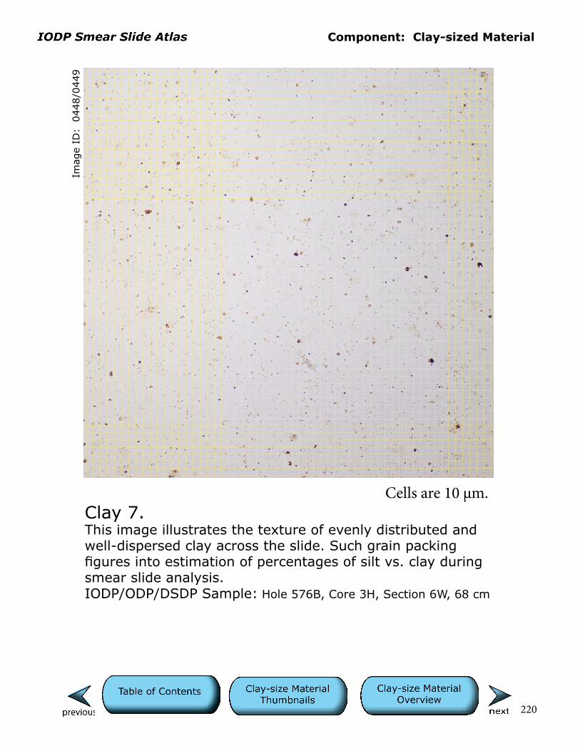
Component: Clay-sized Material
220
Cells are 10 µm.Clay 7.This image illustrates the texture of evenly distributed and well-dispersed clay across the slide. Such grain packing figures into estimation of percentages of silt vs. clay during smear slide analysis.IODP/ODP/DSDP Sample: Hole 576B, Core 3H, Section 6W, 68 cm
Imag
e ID
: 0
448/0
449
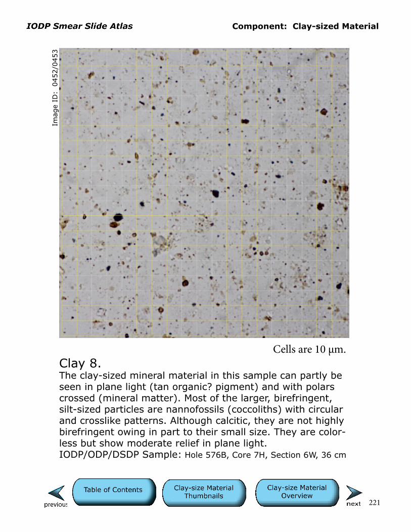
Component: Clay-sized Material
221
Cells are 10 µm.Clay 8.The clay-sized mineral material in this sample can partly be seen in plane light (tan organic? pigment) and with polars crossed (mineral matter). Most of the larger, birefringent, silt-sized particles are nannofossils (coccoliths) with circular and crosslike patterns. Although calcitic, they are not highly birefringent owing in part to their small size. They are color-less but show moderate relief in plane light. IODP/ODP/DSDP Sample: Hole 576B, Core 7H, Section 6W, 36 cm
Imag
e ID
: 0
452/0
453

Component: Clay-sized Material
222
Cells are 10 µm.
Imag
e ID
: 0
408/0
409
Clay 9.This is a mud with siliceous debris (diatom, radiolarian fragments) and nannofossils. The latter are very small but birefringent and could be mistaken for clay-sized minerals except for their curious shapes and tendency to have a black dot in their centers under crossed polars. Pleistocene nannofossils are notoriously small and an often overlooked component in the uppermost cores. The reddish clump of material in the center of the field of view could be a fecal pellet.IODP/ODP/DSDP Sample: Hole 576B, Core 1H, Section 1, 5 cm
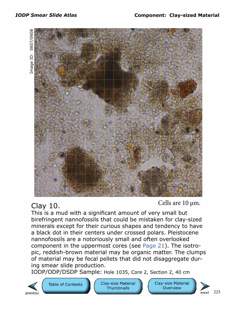
Component: Clay-sized Material
223
Cells are 10 µm.Clay 10.This is a mud with a significant amount of very small but birefringent nannofossils that could be mistaken for clay-sized minerals except for their curious shapes and tendency to have a black dot in their centers under crossed polars. Pleistocene nannofossils are a notoriously small and often overlooked component in the uppermost cores (see Page 21). The isotro-pic, reddish-brown material may be organic matter. The clumps of material may be fecal pellets that did not disaggregate dur-ing smear slide production.IODP/ODP/DSDP Sample: Hole 1035, Core 2, Section 2, 40 cm
Imag
e ID
: 0
607/0
608
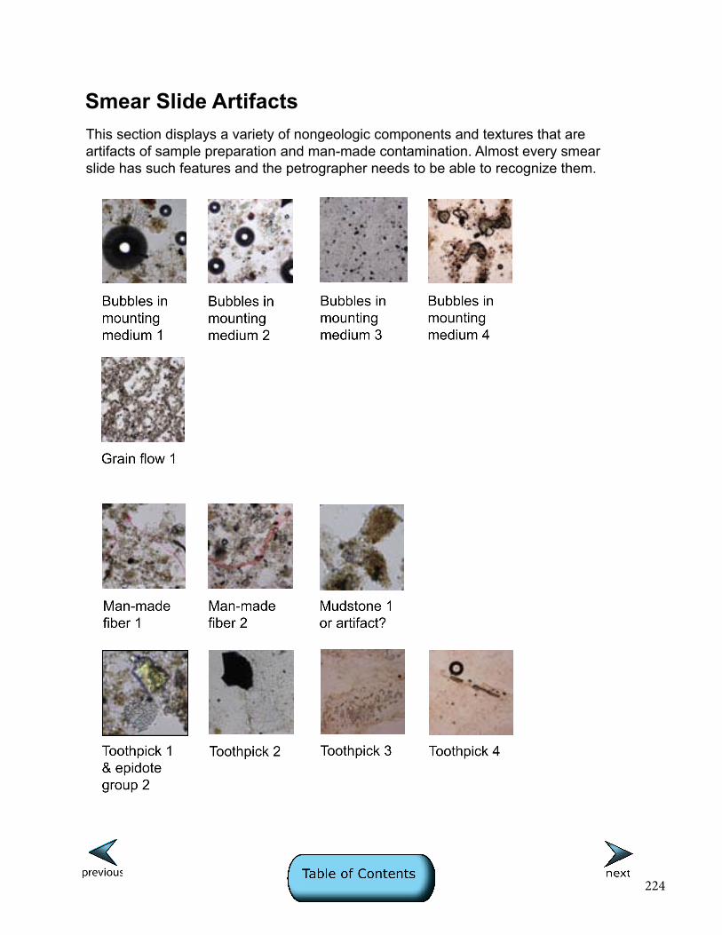
224
Smear Slide ArtifactsThis section displays a variety of nongeologic components and textures that are artifacts of sample preparation and man-made contamination. Almost every smear slide has such features and the petrographer needs to be able to recognize them.
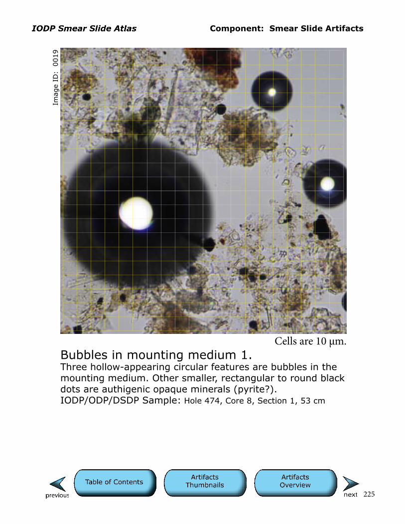
Component: Smear Slide Artifacts
225
Imag
e ID
: 0
019
Bubbles in mounting medium 1.Three hollow-appearing circular features are bubbles in the mounting medium. Other smaller, rectangular to round black dots are authigenic opaque minerals (pyrite?).IODP/ODP/DSDP Sample: Hole 474, Core 8, Section 1, 53 cm
Cells are 10 µm.

226
Component: Artifacts
Imag
e ID
: 0
180
Bubbles in mounting medium 2.Field of silicate grains with abundant bubbles in epoxy.IODP/ODP/DSDP Sample: Hole 861C, Core 6H, Section 1, 132 cm
Cells are 10 µm.
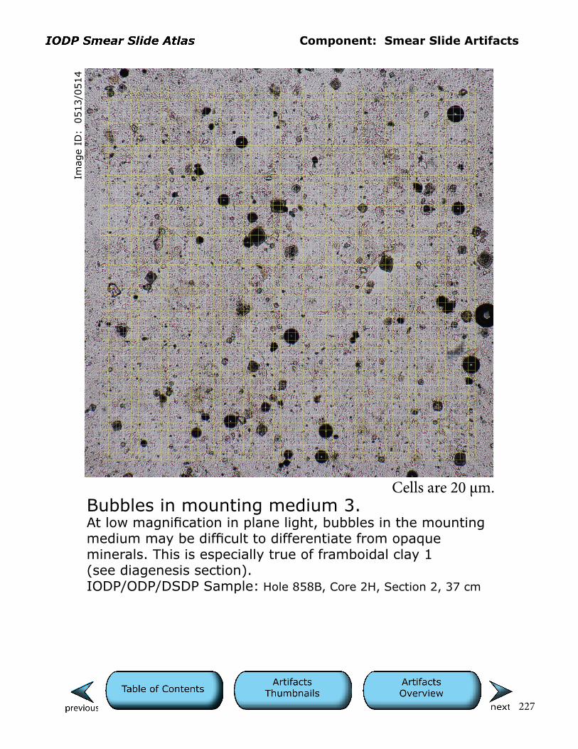
Component: Smear Slide Artifacts
227
Imag
e ID
: 0
513/0
514
Bubbles in mounting medium 3.At low magnification in plane light, bubbles in the mounting medium may be difficult to differentiate from opaque minerals. This is especially true of framboidal clay 1(see diagenesis section).IODP/ODP/DSDP Sample: Hole 858B, Core 2H, Section 2, 37 cm
Cells are 20 µm.
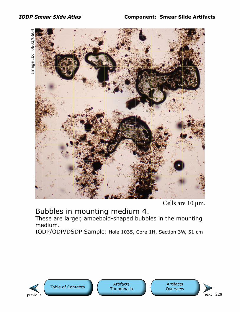
Component: Smear Slide Artifacts
228
Imag
e ID
: 0
603/0
604
Bubbles in mounting medium 4.These are larger, amoeboid-shaped bubbles in the mounting medium. IODP/ODP/DSDP Sample: Hole 1035, Core 1H, Section 3W, 51 cm
Cells are 10 µm.
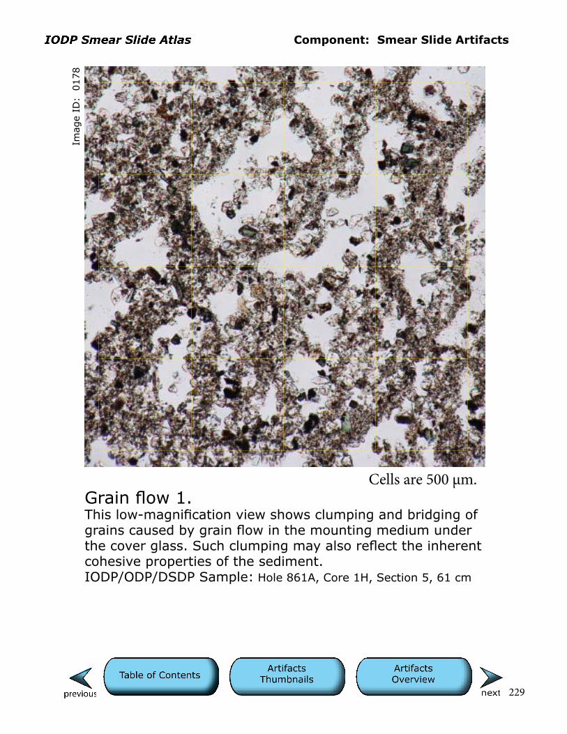
Component: Smear Slide Artifacts
229
Imag
e ID
: 0
178
Grain flow 1.This low-magnification view shows clumping and bridging of grains caused by grain flow in the mounting medium under the cover glass. Such clumping may also reflect the inherent cohesive properties of the sediment.IODP/ODP/DSDP Sample: Hole 861A, Core 1H, Section 5, 61 cm
Cells are 500 µm.

Component: Smear Slide Artifacts
230
Imag
e ID
: 0
138
Man-made fiber 1.The pink fiber extending across the field of view is man-made contamination and not a sediment component.IODP/ODP/DSDP Sample: Hole 1352B, Core 11H, Section 2W, 21 cm
Cells are 10 µm.

Component: Smear Slide Artifacts
231
Imag
e ID
: 0
204/0
205
Man-made fiber 2.The reddish fiber extending across the field of view is man-made contamination and not a sediment component. Note the birefringence of this material under crossed polars. IODP/ODP/DSDP Sample: Hole 863A, Core 7X, Section 1, 56 cm
Cells are 10 µm.

Component: Smear Slide Artifacts
232
Imag
e ID
: 0
022/0
023
Mudstone 1 or artifact?Brownish fragments in this field of view may be clay-rich lithic fragments with carbonate (see crossed-polar view). As this sample was taken from an older DSDP core that was stored for ~20 years at the repository, more likely they are pieces of semilithified, clay-rich matrix that did not disaggregate during the smear process. Such fragments are also potentially produced when smears are created from more lithified sections in newly cut cores.IODP/ODP/DSDP Sample: Hole 474, Core 8, Section 1, 53 cm
Cells are 10 µm.
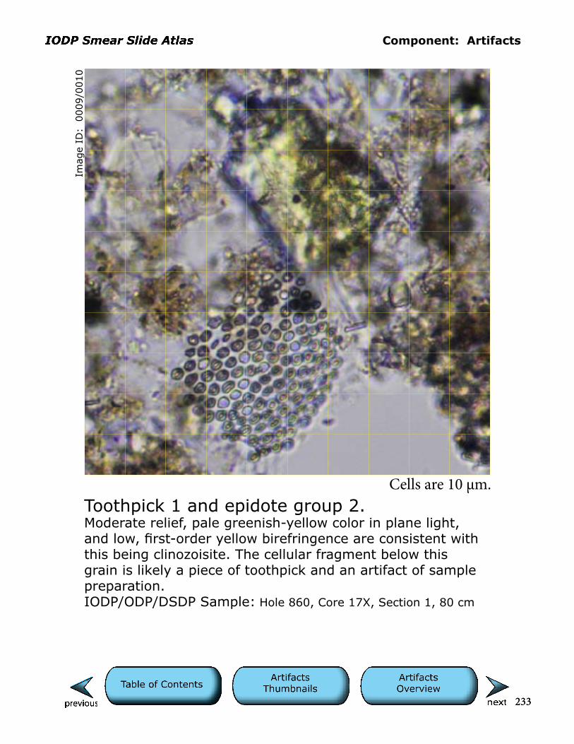
233
Component: Artifacts
233
Imag
e ID
: 0
009/0
010
Toothpick 1 and epidote group 2. Moderate relief, pale greenish-yellow color in plane light, and low, first-order yellow birefringence are consistent with this being clinozoisite. The cellular fragment below this grain is likely a piece of toothpick and an artifact of sample preparation.IODP/ODP/DSDP Sample: Hole 860, Core 17X, Section 1, 80 cm
Cells are 10 µm.
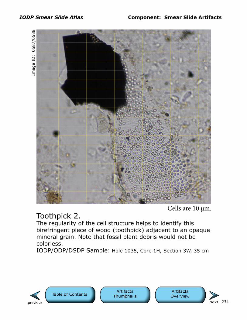
Component: Smear Slide Artifacts
234
Imag
e ID
: 0
587/0
588
Toothpick 2.The regularity of the cell structure helps to identify this birefringent piece of wood (toothpick) adjacent to an opaque mineral grain. Note that fossil plant debris would not be colorless.IODP/ODP/DSDP Sample: Hole 1035, Core 1H, Section 3W, 35 cm
Cells are 10 µm.

Component: Smear Slide Artifacts
235
Imag
e ID
: 0
436/0
437
Toothpick 3.A large piece of toothpick debris with regular cellular struc-ture that is colorless but birefringent. Note that fossil plant debris would not be colorless.IODP/ODP/DSDP Sample: Hole 576B, Core 6H, Section 3W, 59* cm
Cells are 10 µm.

Component: Smear Slide Artifacts
236
Imag
e ID
: 0
440/0
441
Toothpick 4.This elongate wood (toothpick) fragment shows a cellular structure. The mica-like shape and birefringence can result in misidentification of such fragments as detrital muscovite.IODP/ODP/DSDP Sample: Hole 576B, Core 6H, Section 3W, 59* cm
Cells are 10 µm.