Synthetic Asphaltene as A Novel Dye in Dye Sensitized Solar ...

Highly Efficient Solar Cells using TiO2Nanotube Arrays Sensitized with aDonor-Antenna DyeKarthik Shankar,† Jayasundera Bandara,‡ Maggie Paulose,† Helga Wietasch,‡Oomman K. Varghese, Gopal K. Mor,† Thomas J. LaTempa,†Mukundan Thelakkat,* and Craig A. Grimes*,†
Department of Electrical Engineering, Materials Research Institute, The PennsylVaniaState UniVersity, UniVersity Park, PennsylVania 16802, and Applied FunctionalPolymers, UniVersitystr-30, UniVersity of Bayreuth, 95440 Bayreuth, Germany
Received February 12, 2008; Revised Manuscript Received April 7, 2008
ABSTRACT
Donor antenna dyes provide an exciting route to improving the efficiency of dye sensitized solar cells owing to their high molar extinctioncoefficients and the effective spatial separation of charges in the charge-separated state, which decelerates the recombination of photogeneratedcharges. Vertically oriented TiO2 nanotube arrays provide an optimal material architecture for photoelectrochemical devices because of theirlarge internal surface area, lower recombination losses, and vectorial charge transport along the nanotube axis. In this study, the resultsobtained by sensitizing TiO2 nanotube arrays with the donor antenna dye Ru-TPA-NCS are presented. Solar cells fabricated using an antennadye-sensitized array of 14.4 µm long TiO2 nanotubes on Ti foil subjected to AM 1.5 one sun illumination in the backside geometry exhibitedan overall conversion efficiency of 6.1%. An efficiency of 4.1% was obtained in the frontside illumination geometry using a 1 µm long arrayof transparent TiO2 nanotubes subjected to a TiCl4 treatment and then sensitized with the Ru-TPA-NCS dye. Open circuit voltage decaymeasurements give insight into the recombination behavior in antenna-dye sensitized nanotube photoelectrodes, demonstrating outstandingproperties likely due to a reduction in the influence of the surface traps and reduced electron transfer from TiO2 to ions in solution.
Vertically oriented TiO2 nanotube arrays fabricated byanodization of titanium are now the focus of research in thefields of catalytic oxidation of organics,1–4 water photolysis,5–8
solar energy conversion,9–11 gas sensing,12,13 drug delivery,14,15
and biomedical implants16 because of several attractiveproperties related to the unique material architecture of thesenanotube (NT) arrays; recent review papers on the topic areavailable.17,18 For dye sensitized solar cells, the propertiesof interest include the large internal surface area, enhancedoptical absorption due to scattering effects,19 and lowerrecombination. Preliminary studies of ordered one-dimen-sional architectures including TiO2 nanotubes and nanowireshave indicated that, while the electron transport time issimilar to that reported for dye sensitized solar cells madefrom TiO2 nanoparticles, the electron recombination time ismuch larger than for nanoparticulate electrodes resulting inimproved charge collection efficiencies.9,20 In comparison toordered one-dimensional nanowire electrodes, nanotubeshave significantly larger surface area because of the avail-
ability of both the internal and the external area of thenanotubes for dye coating.
The donor-antenna dye cis-di(thiocyanato)(2,2′-bipyridyl-4,4′-dicarboxylic acid)-(2,2′-bipyridyl-4,4′-bis(vinyltriphenyl-amine)ruthenium(II) (from here on referred to as Ru-TPA-NCS) contains the electron rich donor triphenylamine linkedto the bpy by a conjugated vinyl spacer. The molecularstructures of the Ru-TPA-NCS donor-antenna dye and thecommercially available N-719 dye (Solaronix, Switzerland)are shown in Figure 1a,b, respectively. The extended πelectron delocalization in the bpy ligand that results enablesthe donor-antenna dye molecules to have high molar extinc-tion coefficients, more than twice that of the commonly usedN-719 dye.21 Furthermore, unlike in N-719, the highestoccupied molecular orbitals (HOMO) of Ru-TPA-NCS arespread over the triphenyl amine moieties.22,23 The increasedseparation of the HOMO orbitals from the TiO2 surface hasbeen shown to retard the recombination process at theTiO2-dye interface and at the TiO2-hole conductor interfacein solid state solar cells.24 The procedures for the synthesisof the donor-antenna dye have been detailed elsewhere.24
In films sensitized by molecular dyes, the thickness of thenanostructured TiO2 film needs to be at least 10 µm to harvest
* Corresponding author. Email: [email protected](M.T.) and [email protected] (C.G.).
† The Pennsylvania State University.‡ University of Bayreuth.
NANOLETTERS
2008Vol. 8, No. 61654-1659
10.1021/nl080421v CCC: $40.75 2008 American Chemical SocietyPublished on Web 04/30/2008

the maximal amount of incident photons. By using such ananocrystalline film of titania sensitized by N-719, a solar-to-electric energy conversion efficiency of 10% has beenobtained.25 The absorption characteristics and molar extinc-tion coefficient of a dye play a crucial role in deciding theperformance of a dye-sensitized solar cell. Table 1 gives theabsorption peaks and the corresponding molar extinctioncoefficients of both dyes, Ru-TPA-NCS and N-719. Theunprecedented optical density values of Ru-TPA-NCS arethe highest reported for (bipyridyl)Ru(II)-dyes, significantlygreater that of the N-719 dye. The donor-antenna dye Ru-TPA-NCS exhibits 4-5 times higher molar extinctioncoefficient than N-719 at 400 nm.21 Because of the muchhigher molar extinction coefficient of the Ru-TPA-NCS dye,a much lower film thickness should suffice to harvest asimilar amount of incident photons. In this report, we employvertically oriented TiO2 nanotube arrays in conjunction withthe Ru-TPA-NCS donor-antenna dye to fabricate liquidjunction dye sensitized solar cells. The superior molarextinction coefficient of the Ru-TPA-NCS dye manifestsitself in the form of much higher light harvesting forelectrodes coated with this dye. For example, Figure 2compares the ultraviolet-visible (UV-vis) absorption spec-tra obtained from transmittance measurements of 1 µm longtransparent TiO2 nanotube array samples, pristine and coatedwith Ru-TPA-NCS dye as well as N-719 dye. The nanotube
samples used for dye coating were nearly identical and inboth cases were immersed in dye solution for 24 h. It isclearly evident from Figure 2 that the TiO2 NT arrayelectrode sensitized with Ru-TPA-NCS dye has higher opticalabsorption than the N-719 coated sample across the entiresolar spectrum with an absorbance more than twice that ofthe N-719 dye at 470 nm, which corresponds to thewavelength of maximum irradiance in the solar spectrum.
The morphology and active surface area of the verticallyoriented TiO2 nanotubes fabricated by anodization is afunction of several variables including the anodizationpotential and the electrolyte composition.26–28 The anodizationparameters, including electrolyte, influence the relativeroughness of the walls of the nanotube morphology. Fromdye desorption measurements, we have found that the densityof active surface sites available for dye adsorption onnanotube electrodes formed in formamide are almost threetimes that of nanotubes formed in ethylene glycol.18 Toexplore the limits of solar cell performance achievable usingnontransparent nanotube arrays sensitized with the donorantenna dye, we chose high surface area nanotube arraysformed by anodization for 55 h in formamide-based elec-trolytes containing 0.14 M NH4F and 5% deionized water.The resulting nanotubes were 14.4 µm long with an averagepore size of 90 nm and a wall thickness of 19 nm. Fromdesorption experiments conducted using N-719 dye, thesesamples were found to have an effective internal surface area∼1800 times that of a flat unstructured surface.6 Fieldemission scanning electron microscope (FESEM) images ofthe top view and cross section of these nanotube arrays areshown in Figure 3. Crystallinity was induced by annealingthe as-anodized samples at 525 °C for 3 h in an oxygenambient. Further details on TiO2 nanotube array fabricationhave been extensively discussed elsewhere.26–33
The I-V characteristics of solar cells fabricated using 14µm long nontransparent nanotubes sensitized with Ru-TPA-NCS are shown in Figure 4a (assembly and testing detailsare given in Supporting Information). The cell showed a shortcircuit photocurrent density (Jsc) of 13.44 mA cm-2, an open
Figure 1. Molecular structure of (a) Ru-TPA-NCS and (b) N-719.
Table 1. Absorption Peaks and Peak Molar ExtinctionCoefficients of N-719 and Ru-TPA-NCS Dyes Measuredin Solution
dye λmax1 ε1 λmax2 ε2 λmax3 ε3
N-719 309 46400 378 11500 514 11700Ru-TPA-NCS 307 58300 423 54500 526 24500
Figure2.Effectof thedyeonopticalabsorption:(a)Ultraviolet-visible(UV-vis) absorption spectra of pristine 1 µm long transparent TiO2
Nanotubes (red); Ru-TPA-NCS sensitized 1 µm long transparentTiO2 nanotubes (blue); and N-719 sensitized 1 µm long transparentTiO2 nanotubes (green).
Nano Lett., Vol. 8, No. 6, 2008 1655

circuit potential (Voc) of 723 mV, and a fill-factor of 0.63resulting in an overall conversion efficiency of 6.1%. VariousTiO2 nanotube array samples were sensitized with N-719and Ru-TPA-NCS by immersing them overnight in theirrespective dye solutions. The dyes were then desorbed fromtheir respective dye-coated electrodes into methanolic KOHcontaining 50 vol % N,N′-dimethylformamide (DMF). Fromthe amount of desorbed dye, the surface coverage of dyewas determined with the results shown in Table 2. Thesimilar values of the surface coverage confirm that theincreased optical density of the Ru-TPA-NCS coated samplesarises from the higher extinction coefficient of the dye. Table2 also indicates that the surface coverage of the dyes on 1µm long transparent nanotube arrays is relatively poor,increasing by nearly a factor of 4 with the TiCl4 treatment.
Frontside illumination was employed using 1 µm longtransparent nanotube arrays on fluorine-doped tin oxide(FTO) coated glass. The details of the fabrication oftransparent nanotubes have been explained elsewhere.34
Briefly, 1 µm films of Ti were magnetron sputtered onto FTOcoated glass substrates, which were subsequently anodizedto form nanotubes. The crystallinity inducing anneal wasperformed at 450 °C to reduce the degradation in theresistivity of the FTO layer. The resulting nanotubes were 1µm long with an average pore diameter of 100 nm. Unlikethe nontransparent nanotubes which are anodized in forma-mide, transparent nanotubes were formed by anodizing them
in an ethylene glycol based electrolyte which results insmoother nanotubes. Hence, the transparent nanotube arraysamples were subjected to a TiCl4 treatment by placing themin a 0.05 M TiCl4 solution for 30 min at 70 °C within airtightbottles. Subsequently, these samples were rinsed with waterand ethanol and annealed in air at 450 °C for 30 min. Webelieve that the TiCl4 treatment improves performance byincreasing the effective surface area available for dye
Figure 3. Field emission scanning electron microscope (FESEM)images of 14.4 µm TiO2 nanotube array: (a) top view and (b) crosssection.
Figure 4. (a) Current-voltage characteristics of backside il-luminated solar cells with Ru-TPA-NCS sensitized 14.4 µm longTiO2 NT array under 1 sun AM 1.5 illumination. (b) Current-voltagecharacteristics of frontside illuminated solar cells with Ru-TPA-NCS sensitized 1 µm long TiCl4 treated TiO2 nanotube array under1 sun AM 1.5 illumination. (c) AM 1.5 current-voltage charac-teristics of a TiCl4-treated 1 µm long transparent nanotube arraywith N-719.
1656 Nano Lett., Vol. 8, No. 6, 2008
adsorption by increasing the roughness of the tube walls.Further, the TiCl4 treatment appears to improve bondingbetween the TiO2 and the dye, resulting in better chargeinjection.35 The TiCl4 treated transparent nanotube arrayswere sensitized with Ru-TPA-NCS dye and used to fabricatesolar cells, whose I-V characteristics are shown in Figure4b. With transparent nanotube arrays, the commerciallyavailable redox electrolyte MPN-100 (Solaronix, Inc., Swit-zerland) containing 100 mM of tri-iodide in methoxypropi-onitrile was used. A conductive glass slide sputter-coatedwith 80 nm of platinum was used as the counter-electrodefor the transparent nanotube array-based solar cells, whichwere subjected to front-side illumination, where light isincident on the TiO2 nanotube array after passing throughthe FTO coated glass. In Figure 4b, we see that a 1 µm longTiO2 nanotube array yields a short circuit photocurrentdensity of 10.1 mA cm-2, an open circuit potential of 743mV, and a fill factor of 0.55 resulting in an overall conversionefficiency of 4.1%. In Figure 4c, we show the performanceof a similar solar cell constructed by sensitizing a TiCl4-treated 1 µm long transparent nanotube array with N-719.While the use of N-719 results in slightly larger values ofthe open circuit potential, the short circuit photocurrentdensity Jsc is nearly half that obtained with Ru-TPA-NCSsensitization because of the smaller amount of light har-vested.
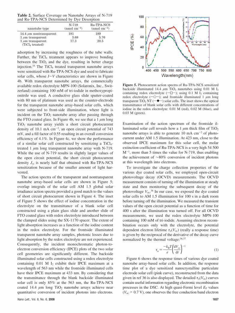
The action spectra of the transparent and nontransparentnanotube array-based solar cells are shown in Figure 5;overlap integrals of the solar cell AM 1.5 global solarirradiance action spectra provided a good match to the valuesof short circuit photocurrent shown in Figure 4. The insetof Figure 5 shows the effect of iodine concentration in theelectrolyte on the transmittance of a blank solar cellconstructed using a plain glass slide and another slide ofFTO coated glass with redox electrolyte introduced betweenthe clamped slides using the SX-1170 spacer. The extent oflight absorption increases as a function of the iodine contentin the redox electrolyte. For the frontside illuminatedtransparent nanotube array samples, photonic losses due tolight absorption by the redox electrolyte are not experienced.Consequently, the incident monochromatic photon-to-electron conversion efficiency (IPCE) plots of the two solarcell geometries are significantly different. The backsideilluminated solar cells constructed using a redox electrolytecontaining 0.01 M I2 exhibit their IPCE maximum at awavelength of 563 nm while the frontside illuminated cellshave their IPCE maximum at 433 nm. By considering thatthe transmittance through the blank backside illuminatedsolar cell is only 85% at the 563 nm, the Ru-TPA-NCScoated 14.4 µm long TiO2 nanotube arrays achieve nearquantitative conversion of incident photons into electrons.
Examination of the action spectrum of the frontside il-luminated solar cell reveals how a 1 µm thick film of TiO2
nanotube arrays is able to generate 10 mA cm-2 of photo-current under AM 1.5 illumination. At 423 nm, close to theobserved IPCE maximum for this solar cell, the molarextinction coefficient of Ru-TPA-NCS is a very high 54 500M-1, more than 5 times the value for N-719, thus enablingthe achievement of ∼80% conversion of incident photonsat this wavelength into electrons.
To investigate the charge collection properties of thevarious dye coated solar cells, we employed open-circuitphotovoltage decay (OCVD) measurements. The OCVDmeasurement consists of turning off the illumination at steadystate and then monitoring the subsequent decay of thephotovoltage Voc.36 In our case, we exposed the dye coatedsolar cells to AM 1.5 illumination for 100 s in a dark roombefore turning off the illumination. We measured the transientvalues of the open circuit potential as a function of time for400 s after the illumination was turned off. For all OCVDmeasurements, we used the redox electrolyte MPN-100containing 100 mM of tri-iodide. Assuming electron recom-bination occurs only with the electrolyte, the potentialdependent electron lifetime τn(Voc) (really a response time)is given by the reciprocal of the derivative of the decay curvenormalized by the thermal voltage:36,37
τn )-kBT
e (dVoc
dt )-1
(1)
Figure 6 shows the response times of various dye coatednanotube array-based solar cells. In addition, the responsetime plot of a dye sensitized nanocrystalline particulateelectrode solar cell (pink curve), reconstructed from the datagiven in ref 36 is also displayed. The detailed τn(Voc) curvescontain useful information regarding electronic recombinationprocesses in the DSC. At high quasi-Fermi level EF values(Voc > 0.7 V), one observes the free conduction band electron
Table 2. Surface Coverage on Nanotube Arrays of N-719and Ru-TPA-NCS Determined by Dye Desorption
nanotube typeN-719
(nmol cm-2)Ru-TPA-NCS(nmol cm-2)
14.4 µm nontransparent 181 1891 µm transparent 3.68 5.761 µm transparent
(TiCl4 treated)17.3 20.5
Figure 5. Photocurrent action spectra of Ru-TPA-NCS sensitizedbackside illuminated 14.4 µm TiO2 nanotubes using 0.01 M I2
containing redox electrolyte (s0s); using 0.1 M I2 containingredox electrolyte (sOs); and frontside illuminated 1 µm longtransparent TiO2 NT (s[s) solar cells. The inset shows the opticaltransmittance of blank solar cells with different concentrations ofiodine in the redox electrolyte: 0.01 M (red), 0.02 M (blue), and0.03 M (green).
Nano Lett., Vol. 8, No. 6, 2008 1657

lifetime which is a constant given by τcb:38
τcb )1
eox(cb)(Ec)
(2)
The variable eox(cb)(Ec) denotes the conduction band transi-
tion probability, determined by the rate constant for isoen-ergetic electron transfer and the probability densities of thefluctuating energy levels in solution given by the Marcus-Gerischer model for electron transfer.38
For EF < 0.7 eV, charge transfer is still dominated byconduction band states, but the bulk trap capacitance Cµ
(traps)
becomes larger than the conduction band capacitance Cµ(cb).
In this case, the response time is given by:38
τn )Cµ
(traps)
Cµ(cb)
τcb (3)
In this regime, expression 3 predicts a linear shape in thelog/linear response time plot of Figure 6. In our experimentsusing TiO2 nanotube arrays (NTAs), we observed that theVoc values obtained with N-719 were consistently higher thanthose obtained with Ru-TPA-NCS by 5-10 mV. Whetherthis is intrinsic to the dye or a function of dye purity,dye-nanotube interaction, and so forth is not known at thispoint. Consequently, in the region of high Voc values, theN-719 dye shows a higher recombination lifetime by theOCVD technique than Ru-TPA-NCS. For nanocrystallineelectrodes, in the region of lower Voc values, the lineardependence turns into a curved one since the charge transferis now governed by the distribution of surface traps with alifetime given by:38
τn )Cµ
(traps)
Cµ(st)eox
(st)(EF)τcb (4)
where Cµ(st) is the chemical capacitance of the surface traps
and eox(st) is the transition probability for electron transfer from
the semiconductor to the oxidized species in the liquidelectrolyte.
For all nanotube array based solar cells, the response timeplot remains linear with potential, implying that electrontransfer through the conduction band states is dominant upto very low values of the Fermi level in the TiO2 film. Thissuggests the nanotube array samples have a smaller numberof surface traps compared with nanocrystalline electrodesor an exponential distribution of traps with a reduced depth.38
We found that the values of the maximum open circuitphotovoltage generated with the Ru-TPA-NCS dye are50-100 mV smaller than that generated with N-719 dye.However, the slopes of the response time plot for thenanotube array cells (both transparent and nontransparent)sensitized with Ru-TPA-NCS are similar and significantlyhigher than that observed for N-719 sensitization.
Since all variables used in expressions 2 and 3 aredependent on electronic states within the nanotubular semi-conductor, and as such are dye-independent, it appears thatthe transition probability for electron transfer from the Ru-TPA-NCS coated nanotubular TiO2 to the electrolyte ionicspecies is lower than that for N-719. At first glance, this issomewhat counter-intuitive; since the size of the Ru-TPA-NCS molecule is larger than N-719, the self-assembledmonolayer it forms on the TiO2 surface would be expectedto be less well-packed than N-179 because of the sterichindrance from the additional bulky triphenylamine groups.The resulting gaps in the Ru-TPA-NCS monolayer wouldprovide less blocking behavior and allow easier access forthe electrolyte ions to the TiO2 surface. Yet, our workindicates the slope of the response time plot to be muchhigher for Ru-TPA-NCS with lifetimes approaching 100 sat low Voc values. One possibility is that the Ru-TPA-NCSforms a more closely packed layer than N-719. Alternatively,we surmise that (a) even though the Ru-TPA-NCS layer isless closely packed, the nonpolar TPA end groups mayprovide similar or better blocking action against electrolyteionic species, and (b) the consequent larger spatial separationbetween the TiO2 surface and the electrolyte ions due thelarger size of the donor antenna molecule results in a lowertransition probability. Additionally, dipole effects at theinterface caused by the donor antenna dye may also play arole here in determining the charge transfer and recombina-tion dynamics. Figure 6 shows that with the TiCl4 treatmentthe slope of the response time plot deviates from linearitywith curvature increasing at lower Voc values. Hence, withthe TiCl4 treatment, the recombination dynamics of thenanotube array appear to acquire more of a nanoparticulatecharacter.
In summary, the much higher molar extinction coefficientof the donor antenna dye Ru-TPA-NCS allows a 1 µm thickfilm of dye sensitized nanotubular titania to achieve aconversion efficiency in excess of 4% in a liquid junctionsolar cell. By increasing the length of the transparentnanotube array electrodes into the tens of microns, a clearpathway toward the realization of very high efficiency dyesensitized solar cells using Ru-TPA-NCS is seen. Theperformance of backside illuminated solar cells is limitedby light absorption losses resulting from the device geometry,yet photoconversion efficiencies of 6.1% and IPCE values
Figure 6. Response time determined from open circuit photovoltagedecay measurements for various dye sensitized solar cells. Allresponses except that of the nanocrystalline TiO2 are curve fit usingan exponential line.
1658 Nano Lett., Vol. 8, No. 6, 2008

of up to 82% have been obtained because of maximal lightharvesting with very high surface area long nanotube arrayelectrodes sensitized with the highly absorbing donor antennadye. It is known from previous work that the Ru-TPA-NCSdye provides improved performance in solid state solar cells,due partly to the improved wetting of the dye by the spiro-OMETAD hole transporting layer24 and also to the increasedspatial separation of the final charge separate states reducingthe interfacial recombination losses.22,23 Herein, we demon-strate that in liquid junction solar cells the donor antennadye sensitized solar cells exhibit larger recombinationlifetimes attributable to a combination of two factors: areduced influence of surface trap states in nanotube arrayelectrodes and a lower transition probability for back electrontransfer from Ru-TPA-NCS coated TiO2 to oxidized elec-trolyte species.
Acknowledgment. C.A.G. gratefully acknowledges sup-port of this work by the Department of Energy under GrantDE-FG02-06ER15772. J.B. is grateful for an Alexander vonHumboldt fellowship. M.T. acknowledges financial supportfor this work from SFB 481, German Research Council(DFG). The authors thank the referees for their helpfulcomments and suggestions.
Supporting Information Available: Assembly and testingdetails of solar cells fabricated using 14 µm long nontrans-parent nanotubes sensitized with Ru-TPA-NCS. This materialis available free of charge via the Internet at http://pubs.acs.org.
References(1) Yang, L. X.; Yang, W. Y.; Cai, Q. Y. J. Phys. Chem. C 2007, 111,
16613.(2) Zhang, Z. H.; Yuan, Y.; Fang, Y. J.; Liang, L. H.; Ding, H. C.; Shi,
G. Y.; Jin, L. T. J. Electroanal. Chem. 2007, 610, 179.(3) Liu, Z.; Zhang, X.; Nishimoto, S.; Jin, M.; Tryk, D. A.; Murakami,
T.; Fujishima, A. J. Phys. Chem. C 2008, 112, 253.(4) Yang, L.; He, D.; Cai, Q.; Grimes, C. A. J. Phys. Chem. C 2007, 111,
8214.(5) Mor, G. K.; Shankar, K.; Paulose, M.; Varghese, O. K.; Grimes, C. A.
Nano Lett. 2005, 5, 191.(6) Shankar, K.; Mor, G. K.; Prakasam, H. E.; Yoriya, S.; Paulose, M.;
Varghese, O. K.; Grimes, C. A. Nanotechnology 2007, 18, ArticleNo. 065707.
(7) Mohapatra, S. K.; Misra, M. J. Phys. Chem. C 2007, 111, 11506.(8) Mor, G. K.; Prakasam, H. E.; Varghese, O. K.; Shankar, K.; Grimes,
C. A. Nano Lett. 2007, 7, 2356.(9) Mor, G. K.; Shankar, K.; Paulose, M.; Varghese, O. K.; Grimes, C. A.
Nano Lett. 2006, 6, 215.(10) Mor, G. K.; Shankar, K.; Paulose, M.; Varghese, O. K.; Grimes, C. A.
Appl. Phys. Lett. 2007, 91 Art. No. 152111.
(11) Shankar, K.; Mor, G. K.; Prakasam, H. E.; Varghese, O. K.; Grimes,C. A. Langmuir 2007, 23, 12445.
(12) Varghese, O. K.; Gong, D. W.; Paulose, M.; Ong, K. G.; Dickey,E. C.; Grimes, C. A. AdV. Mater. 2003, 15, 624.
(13) Varghese, O. K.; Yang, X.; Kendig, J.; Paulose, M.; Zeng, K.; Palmer,C.; Ong, K. G.; Grimes, C. A. Sensor Letters 2006, 4, 120.
(14) Popat, K. C.; Eltgroth, M.; LaTempa, T. J.; Grimes, C. A.; Desai,T. A. Biomaterials 2007, 28, 4880.
(15) Popat, K. C.; Eltgroth, M.; La Tempa, T. J.; Grimes, C. A.; Desai,T. A. Small 2007, 3, 1878.
(16) Popat, K. C.; Leoni, L.; Grimes, C. A.; Desai, T. A. Biomaterials2007, 28, 3188.
(17) Grimes, C. A. J. Mater. Chem. 2007, 17, 1451.(18) Mor, G. K.; Varghese, O. K.; Paulose, M.; Shankar, K.; Grimes, C. A.
Solar Energy Materials and Solar Cells 2006, 90, 2011.(19) Ong, K. G.; Varghese, O. K.; Mor, G. K.; Shankar, K.; Grimes, C. A.
Solar Energy Materials and Solar Cells 2007, 91, 250.(20) Zhu, K.; Neale, N. R.; Miedaner, A.; Frank, A. J. Nano Lett. 2007, 7,
69.(21) Karthikeyan, C. S.; Wietasch, H.; Thelakkat, M. AdV. Mater. 2007,
19, 1091.(22) Handa, S.; Wietasch, H.; Thelakkat, M.; Durrant, J. R.; Haque, S. A.
Chem. Commun. 2007, 1725.(23) Haque, S. A.; Handa, S.; Peter, K.; Palomares, E.; Thelakkat, M.;
Durrant, J. R. Angewandte Chemie-International Edition 2005, 44,5740.
(24) Karthikeyan, C. S.; Peter, K.; Wietasch, H.; Thelakkat, M. Solar EnergyMaterials and Solar Cells 2007, 91, 432.
(25) Nazeeruddin, M. K.; Kay, A.; Rodicio, I.; Humphrybaker, R.; Muller,E.; Liska, P.; Vlachopoulos, N.; Gratzel, M. J. Am. Chem. Soc. 1993,115, 6382.
(26) Prakasam, H. E.; Shankar, K.; Paulose, M.; Varghese, O. K.; Grimes,C. A. J. Phys. Chem. C 2007, 111, 7235.
(27) Shankar, K.; Mor, G. K.; Fitzgerald, A.; Grimes, C. A. J. Phys. Chem.C 2007, 111, 21.
(28) Allam, N. K.; Grimes, C. A. J. Phys. Chem. C 2007, 111, 13028.(29) Paulose, M.; Shankar, K.; Yoriya, S.; Prakasam, H. E.; Varghese,
O. K.; Mor, G. K.; Latempa, T. A.; Fitzgerald, A.; Grimes, C. A. J.Phys. Chem. B 2006, 110, 16179.
(30) Xiao, P.; Garcia, B. B.; Guo, Q.; Liu, D. W.; Cao, G. Z. Electrochem.Commun. 2007, 9, 2441.
(31) Regonini, D.; Bowen, C. R.; Stevens, R.; Allsopp, D.; Jaroenworaluck,A. Physica Status Solidi a-Applications and Materials Science 2007,204, 1814.
(32) Yin, Y. X.; Jin, Z. G.; Hou, F.; Wang, X. J. Am. Ceram. Soc. 2007,90, 2384.
(33) Richter, C.; Wu, Z.; Panaitescu, E.; Willey, R. J.; Menon, L. AdV.Mater. 2007, 19, 946.
(34) Mor, G. K.; Varghese, O. K.; Paulose, M.; Grimes, C. A. AdV. Func.Mater. 2005, 15, 1291.
(35) Sommeling, P. M.; O’Regan, B. C.; Haswell, R. R.; Smit, H. J. P.;Bakker, N. J.; Smits, J. J. T.; Kroon, J. M.; van Roosmalen, J. A. M.J. Phys. Chem. B 2006, 110, 19191.
(36) Zaban, A.; Greenshtein, M.; Bisquert, J. ChemPhysChem 2003, 4, 859.(37) Fabregat-Santiago, F.; Garcia-Canadas, J.; Palomares, E.; Clifford,
J. N.; Haque, S. A.; Durrant, J. R.; Garcia-Belmonte, G.; Bisquert, J.J. Appl. Phys. 2004, 96, 6903.
(38) Bisquert, J.; Zaban, A.; Greenshtein, M.; Mora-Sero, I. J. Am. Chem.Soc. 2004, 126, 13550.
NL080421V
Nano Lett., Vol. 8, No. 6, 2008 1659
Copyright © 2022 FDOKUMEN