Dynamic on-bottom stability analysis of subsea pipelines ...
Upload
khangminh22Category
view
0download
0
Installation and IMR on a subseaproduction system
Andreas Hansen LieØyvind Tjomsland
Subsea Technology
Supervisor: Tor Berge Gjersvik, IGPCo-supervisor: Mariana J.C. Diaz Arias, IGP
Department of Geoscience and Petroleum
Submission date: June 2017
Norwegian University of Science and Technology

Preface
This master‘s thesis was written during spring 2017, and is the closing part of our 2-year Master‘s Degree Programme in Subsea Technology, at the Norwegian University ofScience and Technology. The project was conducted at the Department of Geoscience andPetroleum, and is a part of a SUBPRO project involving development of a new conceptcalled "Subsea Gate Box". SUBPRO is a combined research center between NTNU andindustry partners.
Our supervisor, Professor Tor Berge Gjersvik, gave the idea of this project and we wouldlike to thank him for guidance throughout the semester. Also a thank you to our co-supervisor Postdoctoral Fellow Mariana J.C. Diaz Arias for guidance and input.
Trondheim, June 11, 2017
Øyvind Tjomsland Andreas H. Lie

Summary
In recent years, the focus on increased production and reducing operating costs has becomean important goal for the oil and gas industry. This trend is likely to be even more impor-tant in the future. Installation and maintenance of underwater production and processingfacilities is expensive, complicated and can cause problems. Solutions that facilitate easiermaintenance operations, are an essential factor that reduces operating costs over time.
SUBPRO is a combined research program between the Norwegian University of Scienceand Technology and industry partners, that are developing a concept to mitigate theseproblems. This concept is called "Subsea Gate Box", where one of the goals is to increaseproduction from individual wells within the same well network. To achieve this, eachwell will be prepared for further processing, before they are commingled in a commonmanifold. Thereby, each well is to a higher degree accommodated with its own processingequipment.
This thesis addresses modular architecture, and investigates solutions that can contributeto achieve a versatile process facility, as well as facilitating for an efficient installation,inspection, maintenance, and repair of the Gate Box system. In order to identify importantfactors that are related to these subjects, and than be able to come with some suggestions,relevant theory and "state of the art"-solutions for existing systems have been investigated.Based on this, a number of requirements and specifications have been stated. Furthermore,these requirements and specifications are the basis for the solutions presented in two dif-ferent cases, which contain various module architecture and connection systems. The twocases were evaluated according to the given specifications in order to identify which one ofthem fits the requirements best. Important factors that were considered includes; modularinterfaces, system redundancy, access to equipment, and possibility for easy replacementof equipment modules. The survey shows that both cases have their advantages and dis-advantages, but the layout that allows fast disconnection and replacement of modules,appears to be the best solution.
i

ii

Sammendrag
De siste årene har økt produksjon og en reduksjon av driftskostnadene blitt viktige målfor olje og gass industrien. Disse målene vil trolig bli enda viktigere i fremtiden. Instal-lasjon og utførelse av vedlikehold på undervanns produksjon- og prosesseringsanlegg erbåde kostbart og komplisert. Løsninger som kan tilrettelegge for enklere vedlikeholdsop-perasjoner er en esensiell faktor som kan bidra til redusere driftskostnadene på sikt.
SUBPRO er et kombinert forskningsprogram mellom Norges Teknisk NaturvitenskapligeUniversitet og en rekke industripartnere, hvor målet er å utvikle et konsept for å redusereproblemene knyttet til økt produksjon og driftskostnader. Konseptet kalles "Subsea GateBox" og har som målsetning å blant annet øke produksjonen fra individuelle brønner in-nenfor samme brønnnettverk. For å oppnå dette vil hver brønn være klargjort for videreprosessering, før de omsider blir samlet i en felles manifold. Et slikt system vil dermed istørre grad være avhengig av hver enkelt brønn har sitt egne prosesseringsutstyr.
Denne oppgaven tar for seg modularkitektur og undersøker løsninger som kan bidra til etallsidig prosessanlegg, og samtidig tilrettelegge for effektiv installasjon, inspeksjon, ved-likehold og reparasjon av Gate Box-systemet. For å identifisere viktige faktorer som errelatert til disse områdene og igjen kunne foreslå løsninger, har relevant teori og "state ofthe art"-løsninger for eksisterende systemer blitt undersøkt. Ut i fra dette, har en rekkekrav og spesifikasjoner blitt identifisert. Disse kravene og spesifikasjonene dannet videregrunnlaget for løsningene som er presentert i de forskjellige casene med ulik modularkitek-tur og koblingssystem. Casene ble til slutt vurdert i henhold til de gitte spesifikasjonenefor å identifisere hvilken av dem som tilfredsstiller kravene best.
Viktige faktorer som blant annet har blitt vurdert er: standardisering av modulgrensesnitt,grad av redundans for systemet, tilkomst til utstyr og muligheten for enkel utskiftning avutstyrsmoduler. Undersøkelsen viser at begge casene har sine fordeler og ulemper, menoppsettet som tillater raskest avkobling og utskiftning av moduler ser ut til å være denbeste løsningen.
iii

iv

Table of Contents
Preface 1
Summary i
Sammendrag iii
Table of Contents viii
List of Tables ix
List of Figures xiii
Abbreviations xv
1 Introduction 1
1.1 Background . . . . . . . . . . . . . . . . . . . . . . . . . . . . . . . . . 1
1.2 Objectives . . . . . . . . . . . . . . . . . . . . . . . . . . . . . . . . . . 2
1.3 Limitations . . . . . . . . . . . . . . . . . . . . . . . . . . . . . . . . . 3
1.4 Approach . . . . . . . . . . . . . . . . . . . . . . . . . . . . . . . . . . 3
1.5 Structure of the Thesis . . . . . . . . . . . . . . . . . . . . . . . . . . . 4
v

2 Theoretical Background 5
2.1 Subsea Production and Processing Systems . . . . . . . . . . . . . . . . 7
2.1.1 Subsea Factory . . . . . . . . . . . . . . . . . . . . . . . . . . . 8
2.2 Connection Systems . . . . . . . . . . . . . . . . . . . . . . . . . . . . . 10
2.2.1 Installation and Connection Procedures . . . . . . . . . . . . . . 10
2.2.2 Connectors for Production Fluids . . . . . . . . . . . . . . . . . 14
2.2.3 Multibore Connection Systems . . . . . . . . . . . . . . . . . . . 16
2.2.4 Seals and Gaskets . . . . . . . . . . . . . . . . . . . . . . . . . . 21
2.3 Subsea Control Systems . . . . . . . . . . . . . . . . . . . . . . . . . . 21
2.4 Subsea Valves . . . . . . . . . . . . . . . . . . . . . . . . . . . . . . . . 22
2.5 Subsea Inspection, Maintenance and Repair . . . . . . . . . . . . . . . . 24
2.5.1 Categorizing of IMR-operations . . . . . . . . . . . . . . . . . . 25
2.5.2 Preventive and Corrective Maintenance . . . . . . . . . . . . . . 25
2.6 Marine Operations Related to IMR . . . . . . . . . . . . . . . . . . . . . 26
2.6.1 Vessels . . . . . . . . . . . . . . . . . . . . . . . . . . . . . . . 26
2.6.2 Installation Capability . . . . . . . . . . . . . . . . . . . . . . . 28
2.6.3 Subsea Lifting Operations . . . . . . . . . . . . . . . . . . . . . 29
2.6.4 Heave Compensating and Module Handling . . . . . . . . . . . . 30
2.6.5 Remotely Operated Vehicles . . . . . . . . . . . . . . . . . . . . 33
3 System Design for Efficient IMR Operations 37
3.1 Minimizing the Need for Intervention . . . . . . . . . . . . . . . . . . . 38
3.1.1 Maximizing the Availability for the System . . . . . . . . . . . . 38
3.1.2 Condition/Performance Monitoring and Condition Based Mainte-nance . . . . . . . . . . . . . . . . . . . . . . . . . . . . . . . . 39
vi
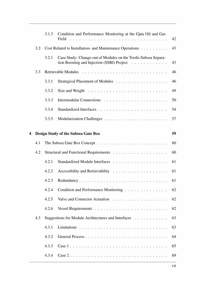
3.1.3 Condition and Performance Monitoring at the Gjøa Oil and GasField . . . . . . . . . . . . . . . . . . . . . . . . . . . . . . . . 42
3.2 Cost Related to Installation- and Maintenance Operations . . . . . . . . . 43
3.2.1 Case Study: Change-out of Modules on the Tordis Subsea Separa-tion Boosting and Injection (SSBI) Project . . . . . . . . . . . . 43
3.3 Retrievable Modules . . . . . . . . . . . . . . . . . . . . . . . . . . . . 46
3.3.1 Strategical Placement of Modules . . . . . . . . . . . . . . . . . 46
3.3.2 Size and Weight . . . . . . . . . . . . . . . . . . . . . . . . . . 49
3.3.3 Intermodular Connections . . . . . . . . . . . . . . . . . . . . . 50
3.3.4 Standardized Interfaces . . . . . . . . . . . . . . . . . . . . . . . 54
3.3.5 Modularization Challenges . . . . . . . . . . . . . . . . . . . . . 57
4 Design Study of the Subsea Gate Box 59
4.1 The Subsea Gate Box Concept . . . . . . . . . . . . . . . . . . . . . . . 60
4.2 Structural and Functional Requirements . . . . . . . . . . . . . . . . . . 60
4.2.1 Standardized Module Interfaces . . . . . . . . . . . . . . . . . . 61
4.2.2 Accessibility and Retrievability . . . . . . . . . . . . . . . . . . 61
4.2.3 Redundancy . . . . . . . . . . . . . . . . . . . . . . . . . . . . . 61
4.2.4 Condition and Performance Monitoring . . . . . . . . . . . . . . 62
4.2.5 Valve and Connector Actuation . . . . . . . . . . . . . . . . . . 62
4.2.6 Vessel Requirements . . . . . . . . . . . . . . . . . . . . . . . . 62
4.3 Suggestions for Module Architectures and Interfaces . . . . . . . . . . . 63
4.3.1 Limitations . . . . . . . . . . . . . . . . . . . . . . . . . . . . . 63
4.3.2 General Process . . . . . . . . . . . . . . . . . . . . . . . . . . . 64
4.3.3 Case 1 . . . . . . . . . . . . . . . . . . . . . . . . . . . . . . . . 65
4.3.4 Case 2 . . . . . . . . . . . . . . . . . . . . . . . . . . . . . . . . 69
vii

4.4 Multibore Connection Approach . . . . . . . . . . . . . . . . . . . . . . 73
5 Discussion 77
5.1 General Requirements . . . . . . . . . . . . . . . . . . . . . . . . . . . 77
5.1.1 Standardization . . . . . . . . . . . . . . . . . . . . . . . . . . . 77
5.1.2 System Size . . . . . . . . . . . . . . . . . . . . . . . . . . . . . 78
5.1.3 Vessel Requirements . . . . . . . . . . . . . . . . . . . . . . . . 78
5.1.4 Control Systems . . . . . . . . . . . . . . . . . . . . . . . . . . 79
5.1.5 Monitoring and Maintenance Strategy . . . . . . . . . . . . . . . 79
5.2 Case 1 . . . . . . . . . . . . . . . . . . . . . . . . . . . . . . . . . . . . 79
5.2.1 Advantages . . . . . . . . . . . . . . . . . . . . . . . . . . . . . 80
5.2.2 Disadvantages . . . . . . . . . . . . . . . . . . . . . . . . . . . 80
5.3 Case 2 . . . . . . . . . . . . . . . . . . . . . . . . . . . . . . . . . . . . 81
5.3.1 Advantages . . . . . . . . . . . . . . . . . . . . . . . . . . . . . 81
5.3.2 Disadvantages . . . . . . . . . . . . . . . . . . . . . . . . . . . 82
5.4 Case Summary . . . . . . . . . . . . . . . . . . . . . . . . . . . . . . . 83
5.5 IPB Connector Configuration . . . . . . . . . . . . . . . . . . . . . . . . 84
6 Conclusion and Further Work 85
6.1 Conclusion . . . . . . . . . . . . . . . . . . . . . . . . . . . . . . . . . 85
6.2 Recommendations for Further Work . . . . . . . . . . . . . . . . . . . . 86
Bibliography 87
Appendix 91
A Calculations For Maintenance Strategy 91
viii

List of Tables
2.1 Comparison between horizontal and vertical tie-in. . . . . . . . . . . . . 13
3.1 Relationship between reliability, maintainability and availability. . . . . . 39
3.2 Intervention strategies and their yearly costs. . . . . . . . . . . . . . . . . 40
3.3 Main modules for the Tordis SSBI. . . . . . . . . . . . . . . . . . . . . . 44
3.4 Key features for selected vessels. . . . . . . . . . . . . . . . . . . . . . . 44
3.5 Summary of the change-out operations for Tordis SSBI. . . . . . . . . . . 45
3.6 Advantages of standardization for oil companies and the suppliers. . . . . 55
5.1 Case comparison. . . . . . . . . . . . . . . . . . . . . . . . . . . . . . . 83
ix

x
List of Figures
1.1 Stepwise approach for this thesis. . . . . . . . . . . . . . . . . . . . . . . 3
2.1 Actual sale of petroleum from 1970-2015 and a forecast forward to 2020. 5
2.2 Forecast for operational costs from 2013-2020 and costs distributed onfield status. . . . . . . . . . . . . . . . . . . . . . . . . . . . . . . . . . 6
2.3 Historical investment on different categories and forecast for 2011-2021. . 6
2.4 Statoil Subsea Factory™. . . . . . . . . . . . . . . . . . . . . . . . . . . 8
2.5 Vertical connection configuration. . . . . . . . . . . . . . . . . . . . . . 11
2.6 Horizontal connector configuration. . . . . . . . . . . . . . . . . . . . . 11
2.7 Tie-in operation between manifold an X-mas tree. . . . . . . . . . . . . . 12
2.8 Bolted flange connector. . . . . . . . . . . . . . . . . . . . . . . . . . . 14
2.9 Bolted clamp connector. . . . . . . . . . . . . . . . . . . . . . . . . . . 14
2.10 Cross sectional view of the interface between the hubs and clamp. . . . . 15
2.11 ROV operated clamp connector. . . . . . . . . . . . . . . . . . . . . . . 15
2.12 Cross sectional view of the connector mechanism on a wellhead colletconnector. . . . . . . . . . . . . . . . . . . . . . . . . . . . . . . . . . . 16
2.13 Cross sectional view of an umbilical. . . . . . . . . . . . . . . . . . . . . 17
xi
2.14 Umbilical Termination Assembly (UTA). . . . . . . . . . . . . . . . . . 17
2.15 Flying lead for hydraulic supply. . . . . . . . . . . . . . . . . . . . . . . 18
2.16 Cross section of an Integrated Production Umbilical (IPU). . . . . . . . . 18
2.17 Integrated production bundle jumper between manifold and X-mas tree. . 19
2.18 Non-oriented multiple passageway flow line connector. . . . . . . . . . . 19
2.19 Concentric multibore connector interface. . . . . . . . . . . . . . . . . . 20
2.20 Non-concentric multibore connector interface. . . . . . . . . . . . . . . . 20
2.21 Gate valve with fail-safe-close function and ROV actuation feature. . . . . 23
2.22 Ball valve with fail-safe-close function and ROV actuation feature. . . . . 23
2.23 Retrievable choke module with ROV actuated clamp connector. . . . . . . 24
2.24 Offshore construction and IMR vessel Seven Viking. . . . . . . . . . . . 27
2.25 Steps of a subsea lifting operation. . . . . . . . . . . . . . . . . . . . . . 30
2.26 Module Handling System. . . . . . . . . . . . . . . . . . . . . . . . . . 31
2.27 Module lowered through the splash zone. . . . . . . . . . . . . . . . . . 33
2.28 Oceaneering Millennium Plus work class ROV. . . . . . . . . . . . . . . 34
2.29 Elumee snake AUV. . . . . . . . . . . . . . . . . . . . . . . . . . . . . . 35
3.1 Design Basis Hierarchy. . . . . . . . . . . . . . . . . . . . . . . . . . . . 38
3.2 Overview of a typical CM/CBM system . . . . . . . . . . . . . . . . . . 41
3.3 Base frame with one process train. . . . . . . . . . . . . . . . . . . . . . 47
3.4 Base frame with two process trains. . . . . . . . . . . . . . . . . . . . . 48
3.5 Base frame with three process trains. . . . . . . . . . . . . . . . . . . . . 49
3.6 Processing system with vertical connectors in the flow base. . . . . . . . 51
3.7 Pazflor subsea separation system. . . . . . . . . . . . . . . . . . . . . . . 52
3.8 Alignment deviations on modular connector interfaces. . . . . . . . . . . 54
3.9 SUBSEA BUS system implemented in SPRINGS subsea station. . . . . . 57
xii
4.1 Conventional setup of a boosting station on the left, and the Subsea GateBox setup on the right. . . . . . . . . . . . . . . . . . . . . . . . . . . . 60
4.2 Subsea Gate Box process flow diagram. . . . . . . . . . . . . . . . . . . 64
4.3 Module overview with horizontal connectors to manifold. . . . . . . . . . 65
4.4 Overview of process with the rerouting options. . . . . . . . . . . . . . . 67
4.5 Overview of process and architecture. . . . . . . . . . . . . . . . . . . . 68
4.6 Simple overview of the module architecture with tree process trains. . . . 69
4.7 Side view of one process train with vertical connectors. . . . . . . . . . . 69
4.8 Side view of the flow distribution between the modules. . . . . . . . . . . 71
4.9 Overview of the process with rerouting possibilities between the trains. . 72
4.10 Side view of modules with process. . . . . . . . . . . . . . . . . . . . . . 73
4.11 Process overview with module architecture. . . . . . . . . . . . . . . . . 73
4.12 Module overview with separate power and control connections. . . . . . . 74
4.13 Overview of module architecture with horizontal connectors, wherepower, control and production are fed through multibore connectors. . . . 75
4.14 Process train seen from the side, with vertical multibore connector forpower, control and production. . . . . . . . . . . . . . . . . . . . . . . . 75
xiii

xiv

Abbreviations
AUV = Autonomous Underwater VehicleCBM = Condition Based MaintenanceDP = Dynamic PositioningHSE = Health, Safety, EnvironmentIMR = Inspection, Maintenance, RepairIPB = Integrated Production BundleIPU = Integrated Production UmbilicalJIP = Joint Industry ProjectKPI = Key Performance IndicatorMHS = Module Handling SystemMHT = Module Handling TowerMNOK = Million Norwegian KronerMOC = Milti Quick ConnectorMRU = Motion Reference UnitMTTF = Mean Time To FailureNCS = Norwegian Continental ShelfNDT = Non Destructive TestingRFO = Ready For OperationROV = Remotely Operated VehicleSCM = Subsea Control ModuleSHS = Special Handling SystemSSBI = Subsea Separation, Boosting, and InjectionTCI = Technical Condition IndexUTA = Umbilical Termination AssemblyWoW = Waiting on Weather
xv

xvi
Chapter 1Introduction
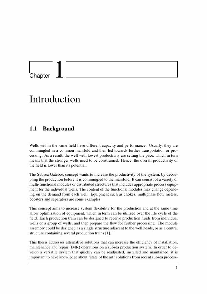
1.1 Background
Wells within the same field have different capacity and performance. Usually, they arecommingled in a common manifold and then led towards further transportation or pro-cessing. As a result, the well with lowest productivity are setting the pace, which in turnmeans that the stronger wells need to be constrained. Hence, the overall productivity ofthe field is lower than its potential.
The Subsea Gatebox concept wants to increase the productivity of the system, by decou-pling the production before it is commingled to the manifold. It can consist of a variety ofmulti-functional modules or distributed structures that includes appropriate process equip-ment for the individual wells. The content of the functional modules may change depend-ing on the demand from each well. Equipment such as chokes, multiphase flow meters,boosters and separators are some examples.
This concept aims to increase system flexibility for the production and at the same timeallow optimization of equipment, which in term can be utilized over the life cycle of thefield. Each production train can be designed to receive production fluids from individualwells or a group of wells, and then prepare the flow for further processing. The moduleassembly could be designed as a single structure adjacent to the well heads, or as a centralstructure containing several production trains [1].
This thesis addresses alternative solutions that can increase the efficiency of installation,maintenance and repair (IMR) operations on a subsea production system. In order to de-velop a versatile system that quickly can be readjusted, installed and maintained, it isimportant to have knowledge about "state of the art" solutions from recent subsea process-
1

Chapter 1. Introduction
ing systems. From already existing systems one can bring the benefits while highlightingand mitigating drawbacks for designing a best possible system. Different solutions shouldbe considered and compared to investigate which possible solution has the most benefitsin order to meet the desired requirements for the system.
1.2 Objectives
In order to propose possible solutions for the stated challenges, this Master’s Thesis con-tains the following objectives:
1. Perform a survey on connection systems and their potential to enhance the efficiencyof installation and retrieval operations.
2. Present a study on existing subsea processing system with information about main-tenance operations that is conducted.
3. Highlight important factors to consider in the design phase of modules, that canoptimize installation and IMR operations.
4. Present architectural solutions for the Subsea Gatebox concept with different mod-ule setups and connection systems, and investigate possible benefits by integratingboth control and production lines into the same intermodular connector.
5. Give recommendations on which solutions that may be beneficial for the SubseaGate Box.
2

1.3 Limitations
1.3 Limitations
The presented proposals for the Subsea Gatebox only consider a three phase flow. Prob-lems related to sand handling and flow assurance is not accounted for in this thesis. Fur-thermore, this thesis does not include the processing itself. The proposed setups onlyshows how the modules and configurations can be put in relation to each other.
This thesis is based on literature gathered from bibliographic databases provided by theuniversity, and occasional correspondence with the industry. With this in mind, the litera-ture and solutions presented are limited to the information these sources can provide.
1.4 Approach
A stepwise approach as illustrated in Figure 1.1, are carried out for this thesis. First,a problem formulation was established in collaboration with supervisors. Secondly, aliterature study should be conducted on relevant topics. Third, essential information areextracted, and is the basis for developing the two presented cases. As a part of the casedevelopment, the software AutoCad Plant 3D, and Inkscape 0.92 are used to create processflow diagrams, and illustrations for architecture. As a closing part, a discussion on relevantfindings which should lead to a conclusion, is performed.
Figure 1.1: Stepwise approach for this thesis.
3
Chapter 1. Introduction
1.5 Structure of the Thesis
This heading presents the structure of the thesis and content of each of the listed chapters:
• Chapter 2 presents basic theory regarding subsea production systems, connectorsystems and equipment related to this. Further, it presents marine operations relatedto installation, maintenance and repair (IMR) for subsea production systems.
• Chapter 3 presents important features for obtaining a system design that facilitatesfor efficient installation and IMR operations.
• Chapter 4 concerns a design study of the Subsea Gate Box with proposals of twocases with different architecture and connection system.
• Chapter 5 discusses the design suggestions given in the previous chapter.
• Chapter 6 presents suggestions for further work and gives a conclusion on the con-sidered cases.
4
Chapter 2Theoretical Background
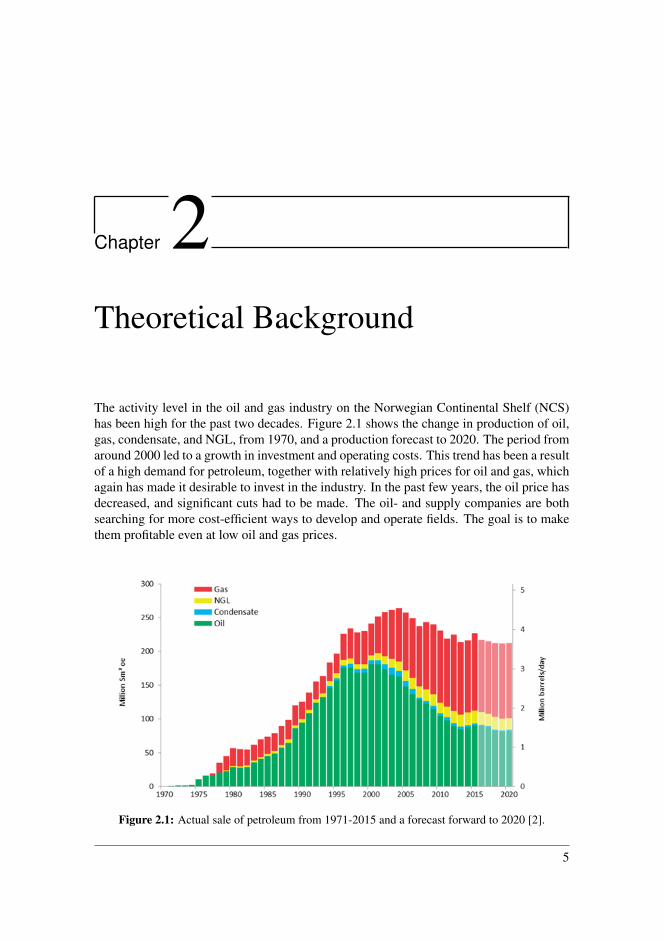
The activity level in the oil and gas industry on the Norwegian Continental Shelf (NCS)has been high for the past two decades. Figure 2.1 shows the change in production of oil,gas, condensate, and NGL, from 1970, and a production forecast to 2020. The period fromaround 2000 led to a growth in investment and operating costs. This trend has been a resultof a high demand for petroleum, together with relatively high prices for oil and gas, whichagain has made it desirable to invest in the industry. In the past few years, the oil price hasdecreased, and significant cuts had to be made. The oil- and supply companies are bothsearching for more cost-efficient ways to develop and operate fields. The goal is to makethem profitable even at low oil and gas prices.
Figure 2.1: Actual sale of petroleum from 1971-2015 and a forecast forward to 2020 [2].
5

Chapter 2. Theoretical Background
In 2015 there were 82 fields producing on the NCS and the total operational costs thatyear was approximately 60 billion NOK [2]. Figure 2.2 illustrates the operational cost bydifferent field status. Oil companies have an ongoing struggle to cut these costs, but fromFigure 2.2 it seems to increase. This is because new fields will be put into production, andcontribute to keep the it at a stable high level in the future.
Figure 2.2: Forecast for operational costs from 2013-2020 and costs distributed on field status [2].
Figure 2.3: Historical investment on different categories and forecast for 2011-2021 [2].
6

2.1 Subsea Production and Processing Systems
A large part of the operational costs is due to inspection, maintenance and repair (IMR),which is necessary to maintain the production. Figure 2.3 illustrates a historical overview,and a forecast of the investment in development wells, existing wells, new fixed and float-ing facilities, new subsea facilities, pipelines, and terminals, on the NCS. It shows thatinvestments in new subsea facilities, and floating and fixed facilities has been relativelyhigh from 2011 to present. The reasons for this is due to ongoing developments, such asJohan Sverdrup [2]. The forecast show that investments in floating and fixed facilities willdecrease, and that new subsea developments will increase until 2021.
When oil companies develop new fields, there are economical reasons to develop moreaccessible shallow fields first. However, such fields are more or less already developed,and the search for oil and gas is moving towards deeper and more hostile environments,such as the Arctic. This can be an indication for a further increase in developments ofsubsea facilities in the future. The need for better and cheaper ways to operate and main-tain production systems on the seabed arises, and new technology and ideas needs to bedeveloped. In this chapter, basic theory regarding subsea processing systems, connectionsystems, and installation and IMR procedures will be presented.
2.1 Subsea Production and Processing Systems
In 1961, the first subsea well was put into production, and in the early 80s, Norway’s firstsubsea project Frigg was developed. Later, Statoil started the development of Gullfaks,where it was decided to invest in a subsea solution. Additionally, development of Tom-meliten Gamma started in 1988, which was the first field using a subsea template structureserving several wells. In the early 90s, engineers understood and acknowledged the po-tential of moving production equipment down to the seabed. The goal was to connect thesubsea systems to the already existing infrastructure, and avoid building new topside facil-ities. This made it economically feasible to develop smaller fields with tieback to a nearbyhost. Ever since, Norway has been in the forefront in the development of subsea produc-tion systems where larger and more complex systems have been put into production.
Some of the main drivers for moving production facilities to the seabed, can be summa-rized as follows [3]:
• Increased recovery of hydrocarbons through enhanced oil recovery and acceleratedproduction.
• Possibility to produce from marginal fields.
• Better energy efficiency due to facilities located closer to the well.
• Increased production on already existing wells.
• Reduced topside equipment.
7
Chapter 2. Theoretical Background
• Enables production from remote fields like the Arctic and deep waters.
• Improved flow assurance which allows longer tiebacks.
2.1.1 Subsea Factory
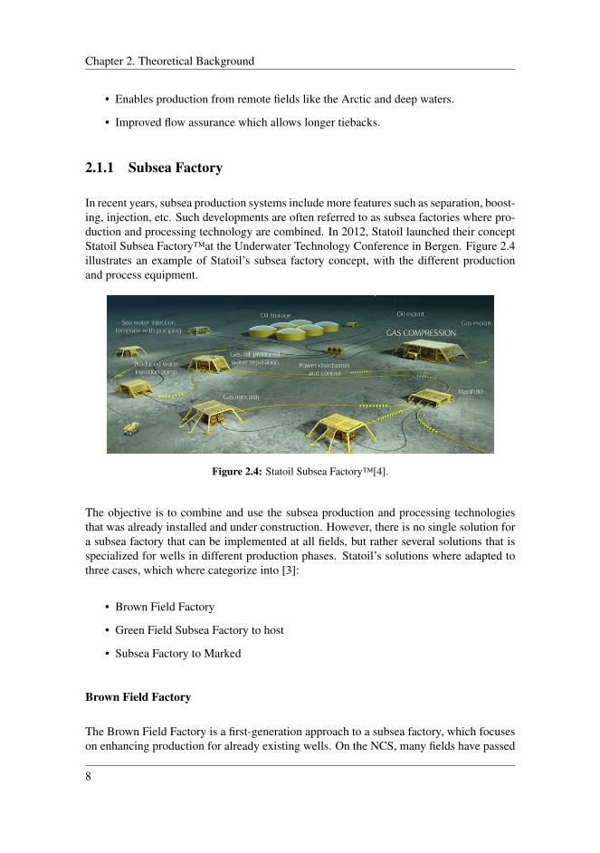
In recent years, subsea production systems include more features such as separation, boost-ing, injection, etc. Such developments are often referred to as subsea factories where pro-duction and processing technology are combined. In 2012, Statoil launched their conceptStatoil Subsea Factory™at the Underwater Technology Conference in Bergen. Figure 2.4illustrates an example of Statoil’s subsea factory concept, with the different productionand process equipment.
Figure 2.4: Statoil Subsea Factory™[4].
The objective is to combine and use the subsea production and processing technologiesthat was already installed and under construction. However, there is no single solution fora subsea factory that can be implemented at all fields, but rather several solutions that isspecialized for wells in different production phases. Statoil’s solutions where adapted tothree cases, which where categorize into [3]:
• Brown Field Factory
• Green Field Subsea Factory to host
• Subsea Factory to Marked
Brown Field Factory
The Brown Field Factory is a first-generation approach to a subsea factory, which focuseson enhancing production for already existing wells. On the NCS, many fields have passed
8
2.1 Subsea Production and Processing Systems
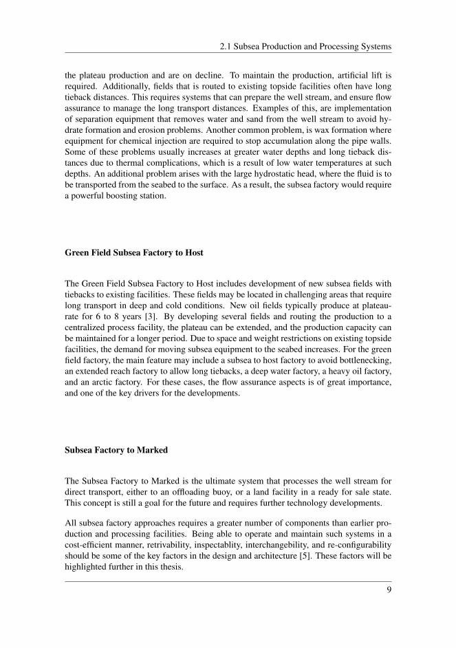
the plateau production and are on decline. To maintain the production, artificial lift isrequired. Additionally, fields that is routed to existing topside facilities often have longtieback distances. This requires systems that can prepare the well stream, and ensure flowassurance to manage the long transport distances. Examples of this, are implementationof separation equipment that removes water and sand from the well stream to avoid hy-drate formation and erosion problems. Another common problem, is wax formation whereequipment for chemical injection are required to stop accumulation along the pipe walls.Some of these problems usually increases at greater water depths and long tieback dis-tances due to thermal complications, which is a result of low water temperatures at suchdepths. An additional problem arises with the large hydrostatic head, where the fluid is tobe transported from the seabed to the surface. As a result, the subsea factory would requirea powerful boosting station.
Green Field Subsea Factory to Host
The Green Field Subsea Factory to Host includes development of new subsea fields withtiebacks to existing facilities. These fields may be located in challenging areas that requirelong transport in deep and cold conditions. New oil fields typically produce at plateau-rate for 6 to 8 years [3]. By developing several fields and routing the production to acentralized process facility, the plateau can be extended, and the production capacity canbe maintained for a longer period. Due to space and weight restrictions on existing topsidefacilities, the demand for moving subsea equipment to the seabed increases. For the greenfield factory, the main feature may include a subsea to host factory to avoid bottlenecking,an extended reach factory to allow long tiebacks, a deep water factory, a heavy oil factory,and an arctic factory. For these cases, the flow assurance aspects is of great importance,and one of the key drivers for the developments.
Subsea Factory to Marked
The Subsea Factory to Marked is the ultimate system that processes the well stream fordirect transport, either to an offloading buoy, or a land facility in a ready for sale state.This concept is still a goal for the future and requires further technology developments.
All subsea factory approaches requires a greater number of components than earlier pro-duction and processing facilities. Being able to operate and maintain such systems in acost-efficient manner, retrivability, inspectablity, interchangebility, and re-configurabilityshould be some of the key factors in the design and architecture [5]. These factors will behighlighted further in this thesis.
9
Chapter 2. Theoretical Background
2.2 Connection Systems
There are several types of connector systems in use within the oil and gas industry. Theyplay a vital role for interconnecting equipment, so production fluids, hydraulics, chemicals,electrical power, and electrical signals, can be transported and distributed between thecomponents in a subsea production and processing system. Connector systems designedfor subsea equipment usually requires a higher degree of durability compared to the onesused topside. This is mainly due to harsh conditions and remote locations on the seabed.Further in this section, fundamental information regarding subsea connectors and tie-intechnologies are presented. The purpose is to provide insight how the connection systemswork, and furthermore be able to suggest a reliable and flexible connection system that canbe used in a subsea system.
2.2.1 Installation and Connection Procedures
Lack of direct access to subsea equipment results in a connection procedure that rely onassistance from a Remotely Operated Vehicle (ROV). Functions of an ROV will be elabo-rated in Section 2.6.5. In general, this makes the connectors more complex than the com-monly used for topside applications. There are mainly two types of mating configurations;vertical- and horizontal connection.
Vertical Connection system
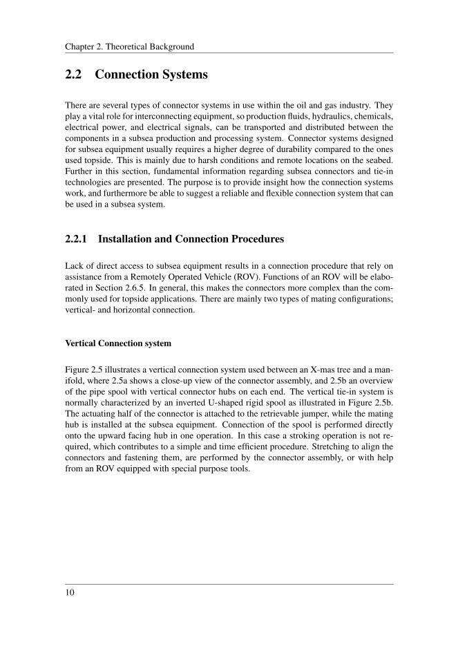
Figure 2.5 illustrates a vertical connection system used between an X-mas tree and a man-ifold, where 2.5a shows a close-up view of the connector assembly, and 2.5b an overviewof the pipe spool with vertical connector hubs on each end. The vertical tie-in system isnormally characterized by an inverted U-shaped rigid spool as illustrated in Figure 2.5b.The actuating half of the connector is attached to the retrievable jumper, while the matinghub is installed at the subsea equipment. Connection of the spool is performed directlyonto the upward facing hub in one operation. In this case a stroking operation is not re-quired, which contributes to a simple and time efficient procedure. Stretching to align theconnectors and fastening them, are performed by the connector assembly, or with helpfrom an ROV equipped with special purpose tools.
10

2.2 Connection Systems
(a) Vertical connection assembly [6]. (b) Installation overview of a vertical connectionsystem [7].
Figure 2.5: Vertical connection configuration.
Horizontal Connection System
Figure 2.6 illustrates a horizontal connector. Illustration 2.6a shows the mating operationthat is performed by a stroking mechanism on the assembly, which extends the pipe hubtowards the opposite hub on the production and processing equipment. Illustration 2.6bon the right, shows the connectors mounted on the rigid jumper spool.
(a) Horizontal connection assembly for tie-in [8]. (b) Overview of an installation of a horizontalconnection system [8].
Figure 2.6: Horizontal connector configuration.
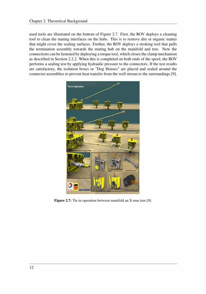
Installation and connection procedures may differ, as the mechanical design of connectorassemblies usually are unique for the various suppliers. A typical installation procedurefor a rigid pipe spool with a horizontal connection configuration is illustrated in Figure 2.7.With this approach, one of the connector assemblies is first landed, which in this case is onthe manifold porch. Secondly, the connector head is lowered on to the X-mas tree guidebase. This makes it easier guiding the spool into correct position, where it only needs toalign one end at a time. After both spool ends are landed onto the manifold and X-mastree, the ROV uses several tools to prepare and perform the connection operation. The
11
Chapter 2. Theoretical Background
used tools are illustrated on the bottom of Figure 2.7. First, the ROV deploys a cleaningtool to clean the mating interfaces on the hubs. This is to remove dirt or organic matterthat might cover the sealing surfaces. Further, the ROV deploys a stroking tool that pullsthe termination assembly towards the mating hub on the manifold and tree. Now theconnections can be fastened by deploying a torque tool, which closes the clamp mechanismas described in Section 2.2.2. When this is completed on both ends of the spool, the ROVperforms a sealing test by applying hydraulic pressure to the connectors. If the test resultsare satisfactory, the isolation boxes or "Dog Houses" are placed and sealed around theconnector assemblies to prevent heat transfer from the well stream to the surroundings [9].
Figure 2.7: Tie-in operation between manifold an X-mas tree [9].
12

2.2 Connection Systems
Comparison Between Horizontal- and a Vertical Connection Setup
Both the horizontal- and vertical configuration are widely used for production spools con-necting X-mas trees and manifolds, with both rigid steel pipes and flexible pipes. Theconnection systems consists of a connector assembly, often a clamp connector or a colletconnector, which is described in Section 2.2.2. Connection and installation procedures onthe horizontal and vertical configurations, are slightly different.
Both systems have advantages and disadvantages. Table 2.1 compares the two configura-tions in a tie-in situation on several evaluation issues. From the table, the main advantageswith the horizontal connection system is that it only require a relatively simple clamp con-nection mechanism, has lower weight, lower chance of snagging by anchors and trawlgear, lower requirement on installation vessel, simple seal change, and low dependency onweather. The latter is because the mating procedure is not dependent on crane support, butrather a higher degree of ROV assistance.
Table 2.1: Comparison between horizontal and vertical tie-in [10].
Evaluation Issue Horizontal Connection Vertical Connection
Equipment Requirement Complex SimpleDuration Long ShortComplexity and size Simple ComplexFabrication requirements Medium HighPossibility of Snagging Low HighVessel requirements Low HighSeal change Simple MediumWeather dependence Low High
In a situation with a connection between retrievable modules in a production- or process-ing system, the horizontal connection system might have an advantage over the verticalsystem. This is due to the integrated stroking feature, which allows disconnection ofequipment without removing the connector head. Hence, removal of a module can beconducted without retrieving the adjacent modules, which is a great advantage regardingmaintenance. A similar feature is also possible with the vertical configuration, where theconnectors are placed at the bottom of the modules, instead of the sides.
The main drawbacks with the horizontal configuration is that the mating operation is morecomplex and more time consuming. A vertical configuration has a relatively simple de-ployment, low reliance on ROV assistance and require less deployment of equipment.However, the complexity of the vertical connector is relatively high. During landing, asoft-landing mechanism is needed. This mechanism prevents uncontrolled movementsgenerated by waves at the surface, which may damage the metal seals. Such mechanismscontributes to increase the weight of the connector assemblies, which again affects the ver-satility of the connectors. Additionally, the vertical setup has a higher profile, which makesit more exposed for snagging. Consequently, it may require a larger protection frame. On
13

Chapter 2. Theoretical Background
the other hand, this will mainly be an issue in areas with trawl activity in relatively shallowwaters [10].
2.2.2 Connectors for Production Fluids
Figure 2.8 shows a bolted flange connector, while Figure 2.9 shows a bolted clamp con-nector. These connector types are typically used topside, or for pipes connections withinretrievable modules for subsea production and processing systems.
Figure 2.8: Bolted flange connector [11].
.
Figure 2.9: Bolted clamp connector [12].
The bolted flange connector creates a tight seal by forcing the two hubs together. Thisis achieved by tightening them with a metal seal in between. A drawback for the boltedflange connector, is the difficulty of achieving a uniform sealing force for the two flanges.To accomplish this, the bolts must be tightened in a fixed sequence with correct torque.This is a relatively simple procedure onshore, or on topside facilities, but time consumingand more complicated subsea.
ROV Operated Clamp Connectors
As illustrated on Figure 2.10, the clamp connector achieves a tight seal by forcing the twopipe ends together with a clamping device that surrounds the circumference of the hubs.The clamp has a chamfered surface on each side. By forcing it down onto the chamferedsurfaces, the clamping force is transferred to a uniform axial force along the pipe length,which again pushes the flanges together against the metal seal.
Due to the more challenging fastening mechanism for the bolted option, it is not convenientto deploy them at the seabed. On this basis, they are mainly used for pipe-connections thatare performed topside. For connections on subsea applications, ROV operated connectors
14

2.2 Connection Systems
Figure 2.10: Cross sectional view of the interface between the hubs and clamp [13].
are required. Figure 2.11 shows the coupling mechanism for an ROV operated clampconnector, that is widely used for production pipes subsea. This type of clamp connectorhas the same sealing mechanism as the bolted clamp connector, but the bolts are replacedby either a torque mechanism, or a hydraulic mechanism that provides the clamp force.The clamp connector showed in Figure 2.11, is a torque operated connector, where an ROVmust deploy a torque tool that can rotate a connector screw, which tightens or detachesthe connection. For a hydraulic configuration, the clamping force is achieved by forcinghydraulic fluid provided by the ROV into a cylinder that again squeezes the clamp aroundthe pipe hubs.
Figure 2.11: ROV operated clamp connector [14].
ROV Operated Collet Connectors
Collet connectors are also widely used for subsea applications such as flow line tie-ins,connecting wellheads and umbilicals. Figure 2.12 illustrates a hydraulic wellhead colletconnector. The locking mechanism principle is the same for pipe and umbilical connec-tors, except that the umbilical connector often requires an additional rotational alignmentmechanism, which will be further explained in Section 2.2.3.
The connection mechanism for a collet connector, is illustrated in Figure 2.12. To lock
15
Chapter 2. Theoretical Background
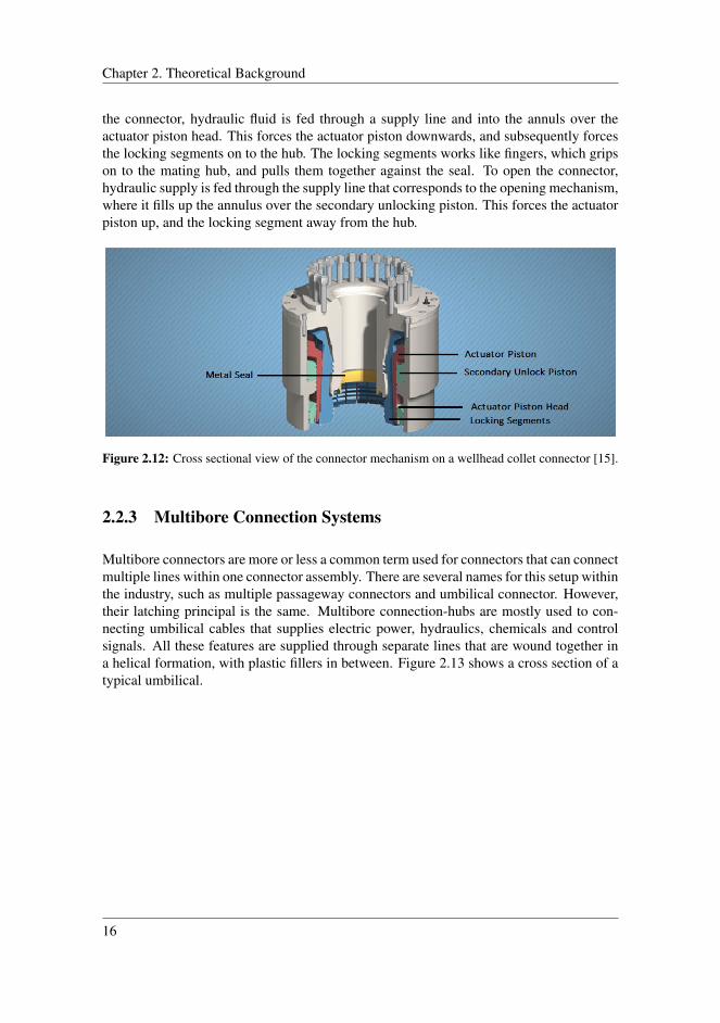
the connector, hydraulic fluid is fed through a supply line and into the annuls over theactuator piston head. This forces the actuator piston downwards, and subsequently forcesthe locking segments on to the hub. The locking segments works like fingers, which gripson to the mating hub, and pulls them together against the seal. To open the connector,hydraulic supply is fed through the supply line that corresponds to the opening mechanism,where it fills up the annulus over the secondary unlocking piston. This forces the actuatorpiston up, and the locking segment away from the hub.
Figure 2.12: Cross sectional view of the connector mechanism on a wellhead collet connector [15].
2.2.3 Multibore Connection Systems
Multibore connectors are more or less a common term used for connectors that can connectmultiple lines within one connector assembly. There are several names for this setup withinthe industry, such as multiple passageway connectors and umbilical connector. However,their latching principal is the same. Multibore connection-hubs are mostly used to con-necting umbilical cables that supplies electric power, hydraulics, chemicals and controlsignals. All these features are supplied through separate lines that are wound together ina helical formation, with plastic fillers in between. Figure 2.13 shows a cross section of atypical umbilical.
16

2.2 Connection Systems
Figure 2.13: Cross sectional view of an umbilical [16].
The multipurpose solution that umbilicals provides, contributes to reduce the number ofpipes and connections required in a system. Additionally, this also affects the number ofinstallation operations, which has a direct impact on the overall installation costs. How-ever, when various supply and production features are combined in one cable or pipe, thecomplexity of the connector system also increases. For control umbilicals, the cable isoften fitted with a Umbilical Termination Assembly (UTA). The UTA, as shown on Figure2.14, is already attached to the umbilical end, which again is rolled onto a reel. Under in-stallation, the umbilical with the UTA attached, is lowered to the seabed. Here it functionsas a distribution center, where the different supply lines can be routed to several locations.
Figure 2.14: Umbilical Termination Assembly (UTA) [17].
Figure 2.14 shows a UTA for a multiplexed electro-hydraulic control system, that enablesdistribution of hydraulics and electric power to several Subsea Control Modules (SCM).Distribution is achieved by fitting several connection points around the UTA, where flyingleads can be connected. Figure 2.15 shows a flying lead Multi-Quick Connector (MQC)stab plate for hydraulic supply, which can provide connection from an UTA to the in-dividual X-mas trees. In general, there are two configurations of connector interfaces;concentric and non-concentric. These will be explained later in this section.
17
Chapter 2. Theoretical Background
Electrical connectors that can be connected subsea, so called wet mate connectors, requiresa special mating technology. In general terms, this technology relies on achieving anelectrical connection, where the two electrical lines are connected without having anytrapped seawater between the interfaces. To achieve this, a flushing mechanism must beintegrated into the connector.
Figure 2.15: Flying lead for hydraulic supply [18].
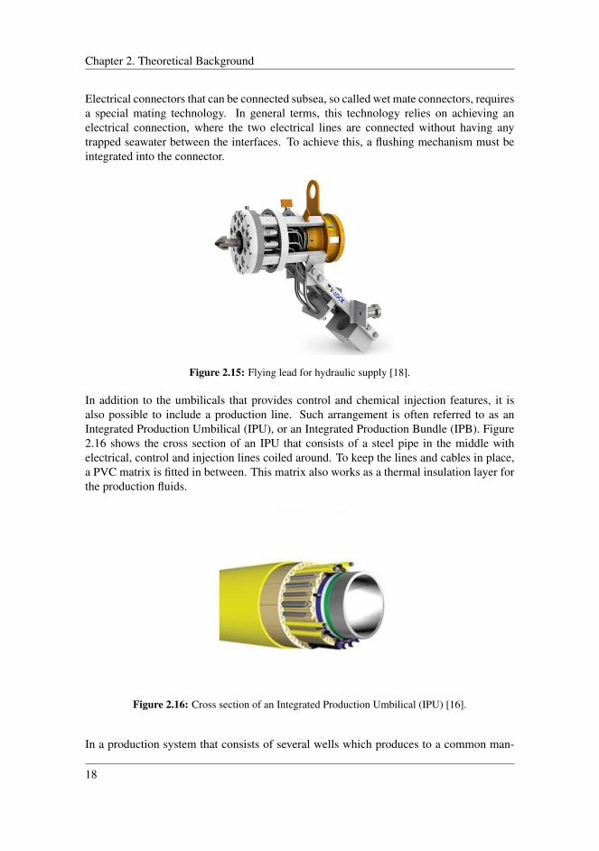
In addition to the umbilicals that provides control and chemical injection features, it isalso possible to include a production line. Such arrangement is often referred to as anIntegrated Production Umbilical (IPU), or an Integrated Production Bundle (IPB). Figure2.16 shows the cross section of an IPU that consists of a steel pipe in the middle withelectrical, control and injection lines coiled around. To keep the lines and cables in place,a PVC matrix is fitted in between. This matrix also works as a thermal insulation layer forthe production fluids.
Figure 2.16: Cross section of an Integrated Production Umbilical (IPU) [16].
In a production system that consists of several wells which produces to a common man-
18
2.2 Connection Systems
ifold, one can skip the UTA solution. Instead, the control umbilical can directly be con-nected onto the manifold. Further, from the manifold to the X-mas trees, both controland production can be routed through IPB spools. This solution will require an integratedcontrol distribution system in the manifold.
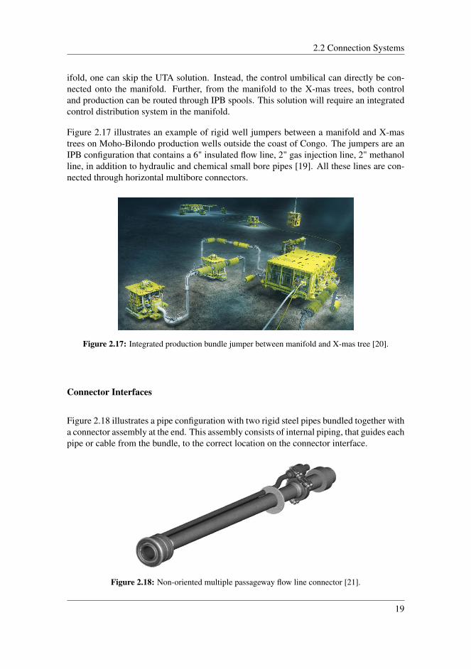
Figure 2.17 illustrates an example of rigid well jumpers between a manifold and X-mastrees on Moho-Bilondo production wells outside the coast of Congo. The jumpers are anIPB configuration that contains a 6" insulated flow line, 2" gas injection line, 2" methanolline, in addition to hydraulic and chemical small bore pipes [19]. All these lines are con-nected through horizontal multibore connectors.
Figure 2.17: Integrated production bundle jumper between manifold and X-mas tree [20].
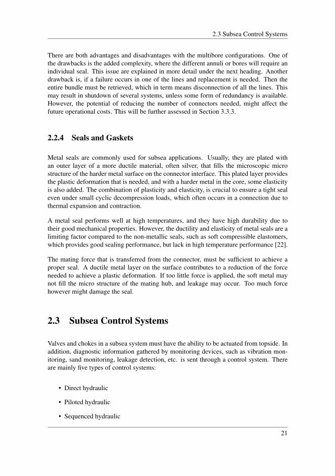
Connector Interfaces
Figure 2.18 illustrates a pipe configuration with two rigid steel pipes bundled together witha connector assembly at the end. This assembly consists of internal piping, that guides eachpipe or cable from the bundle, to the correct location on the connector interface.
Figure 2.18: Non-oriented multiple passageway flow line connector [21].
19

Chapter 2. Theoretical Background
The connector interface on this connector, is a concentric configuration as illustrated inFigure 2.19. It is designed in such way that all the annuli has a common center. This meansthere is no need for rotational alignment of the connector interface during the matingprocedure.
Figure 2.19: Concentric multibore connector interface.
Figure 2.20 shows a connector interface with bores oriented in a non-concentric pattern.This configuration has no common center for the different bores, as they are placed arounda bore in the middle. To make sure that the right bores on the two connector assembliesalign, an alignment mechanism must be included in the connection system. Such a mech-anism may contribute to increase the overall weight of the assembly. This configuration isstill the most commonly used in the industry. A potential benefit is that the interface cancontain more connection points, while for the concentric setup, a great number of supplylines could be complicated, and result in a large and heavy connector assembly.
Figure 2.20: Non-concentric multibore connector interface.
20
2.3 Subsea Control Systems
There are both advantages and disadvantages with the multibore configurations. One ofthe drawbacks is the added complexity, where the different annuli or bores will require anindividual seal. This issue are explained in more detail under the next heading. Anotherdrawback is, if a failure occurs in one of the lines and replacement is needed. Then theentire bundle must be retrieved, which in term means disconnection of all the lines. Thismay result in shutdown of several systems, unless some form of redundancy is available.However, the potential of reducing the number of connectors needed, might affect thefuture operational costs. This will be further assessed in Section 3.3.3.
2.2.4 Seals and Gaskets
Metal seals are commonly used for subsea applications. Usually, they are plated withan outer layer of a more ductile material, often silver, that fills the microscopic microstructure of the harder metal surface on the connector interface. This plated layer providesthe plastic deformation that is needed, and with a harder metal in the core, some elasticityis also added. The combination of plasticity and elasticity, is crucial to ensure a tight sealeven under small cyclic decompression loads, which often occurs in a connection due tothermal expansion and contraction.
A metal seal performs well at high temperatures, and they have high durability due totheir good mechanical properties. However, the ductility and elasticity of metal seals are alimiting factor compared to the non-metallic seals, such as soft compressible elastomers,which provides good sealing performance, but lack in high temperature performance [22].
The mating force that is transferred from the connector, must be sufficient to achieve aproper seal. A ductile metal layer on the surface contributes to a reduction of the forceneeded to achieve a plastic deformation. If too little force is applied, the soft metal maynot fill the micro structure of the mating hub, and leakage may occur. Too much forcehowever might damage the seal.
2.3 Subsea Control Systems
Valves and chokes in a subsea system must have the ability to be actuated from topside. Inaddition, diagnostic information gathered by monitoring devices, such as vibration mon-itoring, sand monitoring, leakage detection, etc. is sent through a control system. Thereare mainly five types of control systems:
• Direct hydraulic
• Piloted hydraulic
• Sequenced hydraulic
21
Chapter 2. Theoretical Background
• Multiplexed electrohydraulic
• All-electric
Direct control systems relies on hydraulic supply from topside, as a result, it performsweakly on long distances due to the lack of response time.
Piloted hydraulic systems works by hydraulic supply from topside, with an additionalaccumulator at the SCM that boosts hydraulic supply, and decreases the actuation time.This system is typically used for single satellite wells, with short and medium distancesfrom the host facility.
Sequenced hydraulic control systems is similar to the pilot hydraulic system, but it consistsof several sequence valves and accumulators. This system also has limited range, but canbe used for more complex control operations.
Multiplexed control systems has much faster response time, and are usually used on deep-water installations. While the control systems mentioned above only relies on hydraulicsupply form topside, the multiplexed system is a combination between electrical and hy-draulic supply.
All-electric control systems rely only on electrical supply. This reduces the umbilical costand decreases the actuation time significantly. An all-electrical system is typically usedin complex, marginal, long distance, high pressure and high temperature fields [23]. Thistype of system is not put in extensive use yet, but can be expected in the future.
2.4 Subsea Valves
Valves are essential in the production of oil and gas, as they control the flow and arean important barrier that contribute to the integrity of a system. Operating the valves ismostly done by remotely controlled actuators. The actuators is operated by an energysource, which can be hydraulic pressure, pneumatic pressure or electric current. Somevalves can both be operated hydraulically and mechanically by an ROV.
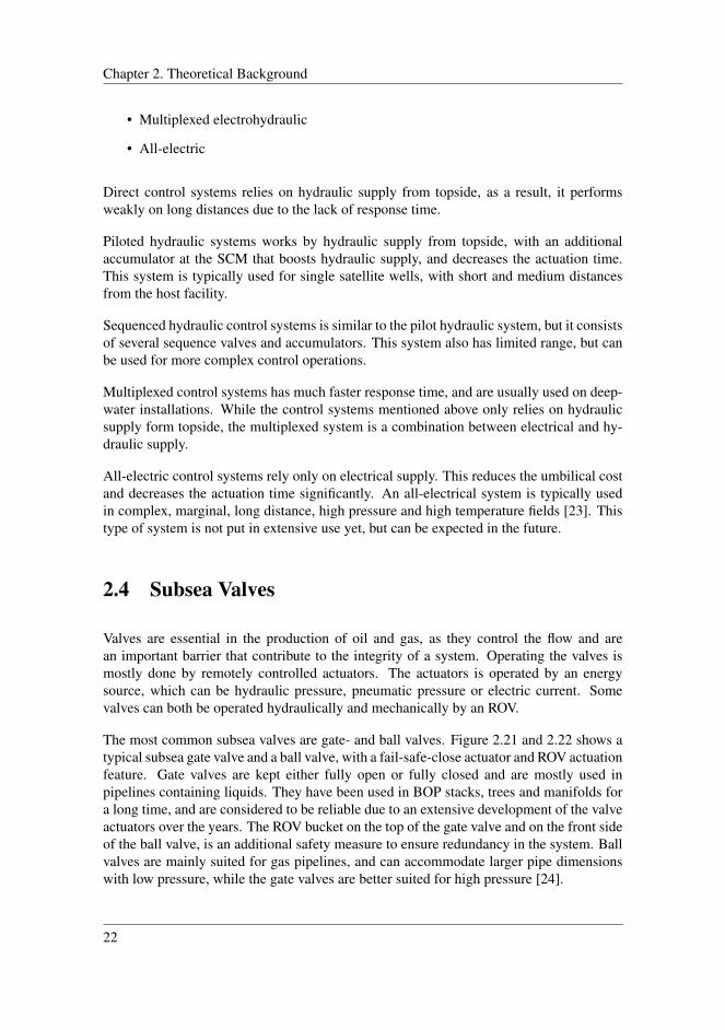
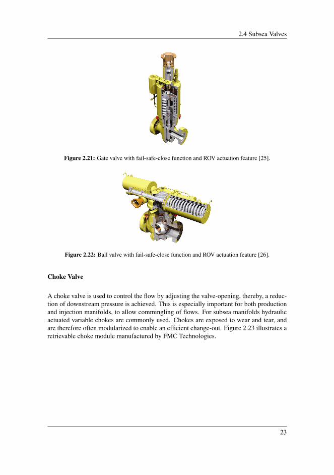
The most common subsea valves are gate- and ball valves. Figure 2.21 and 2.22 shows atypical subsea gate valve and a ball valve, with a fail-safe-close actuator and ROV actuationfeature. Gate valves are kept either fully open or fully closed and are mostly used inpipelines containing liquids. They have been used in BOP stacks, trees and manifolds fora long time, and are considered to be reliable due to an extensive development of the valveactuators over the years. The ROV bucket on the top of the gate valve and on the front sideof the ball valve, is an additional safety measure to ensure redundancy in the system. Ballvalves are mainly suited for gas pipelines, and can accommodate larger pipe dimensionswith low pressure, while the gate valves are better suited for high pressure [24].
22
2.4 Subsea Valves
Figure 2.21: Gate valve with fail-safe-close function and ROV actuation feature [25].
Figure 2.22: Ball valve with fail-safe-close function and ROV actuation feature [26].
Choke Valve
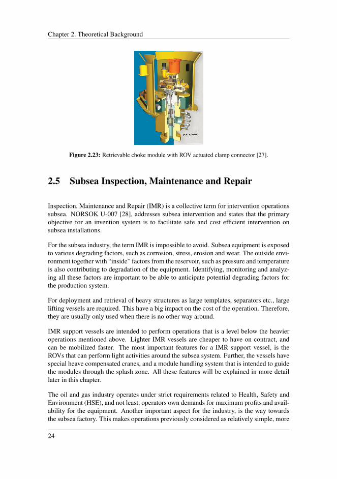
A choke valve is used to control the flow by adjusting the valve-opening, thereby, a reduc-tion of downstream pressure is achieved. This is especially important for both productionand injection manifolds, to allow commingling of flows. For subsea manifolds hydraulicactuated variable chokes are commonly used. Chokes are exposed to wear and tear, andare therefore often modularized to enable an efficient change-out. Figure 2.23 illustrates aretrievable choke module manufactured by FMC Technologies.
23
Chapter 2. Theoretical Background
Figure 2.23: Retrievable choke module with ROV actuated clamp connector [27].
2.5 Subsea Inspection, Maintenance and Repair
Inspection, Maintenance and Repair (IMR) is a collective term for intervention operationssubsea. NORSOK U-007 [28], addresses subsea intervention and states that the primaryobjective for an invention system is to facilitate safe and cost efficient intervention onsubsea installations.
For the subsea industry, the term IMR is impossible to avoid. Subsea equipment is exposedto various degrading factors, such as corrosion, stress, erosion and wear. The outside envi-ronment together with “inside” factors from the reservoir, such as pressure and temperatureis also contributing to degradation of the equipment. Identifying, monitoring and analyz-ing all these factors are important to be able to anticipate potential degrading factors forthe production system.
For deployment and retrieval of heavy structures as large templates, separators etc., largelifting vessels are required. This have a big impact on the cost of the operation. Therefore,they are usually only used when there is no other way around.
IMR support vessels are intended to perform operations that is a level below the heavieroperations mentioned above. Lighter IMR vessels are cheaper to have on contract, andcan be mobilized faster. The most important features for a IMR support vessel, is theROVs that can perform light activities around the subsea system. Further, the vessels havespecial heave compensated cranes, and a module handling system that is intended to guidethe modules through the splash zone. All these features will be explained in more detaillater in this chapter.
The oil and gas industry operates under strict requirements related to Health, Safety andEnvironment (HSE), and not least, operators own demands for maximum profits and avail-ability for the equipment. Another important aspect for the industry, is the way towardsthe subsea factory. This makes operations previously considered as relatively simple, more
24
2.5 Subsea Inspection, Maintenance and Repair
complex.
2.5.1 Categorizing of IMR-operations
The IMR activities can be divided up by its complexity. The industry classifies the activi-ties under the headings; I-type, M-type and R-type:
I-type (Inspection)
Classified as scheduled condition monitoring such as structural inspection, pipeline inspec-tion, or corrosion monitoring, are usually performed by an ROV. Inspections may reveal aneed for more extensive jobs as maintenance or repair.
M-type (Maintenance)
These tasks arise from earlier condition monitoring, or a decreased performance reportedby the operator. Typical maintenance tasks would be replacement of modules (chokes,pumps, control modules etc.), jumpers, seals, or removal of objects, like fishnets.
R-type (Repair)
According to NORSOK Z-008 [29], repair is considered as more complex operations onstructures, such as repair of caisson or conductor pipe, repair of template hatches, locksand hinges. Maintenance activities use standardized procedures and running tools, whilerepair activities often require customized solutions to perform the job [30].
2.5.2 Preventive and Corrective Maintenance
NORSOK Z-008 [29], defines maintenance as: "combination of all technical, adminis-trative and managerial actions, including supervision actions, during the life cycle of anitem inended to retain it in, or restore it to, a state in which it can perform the requiredfunction".
In the most simplistic way, one can divide maintenance in two categories; preventive andcorrective:
Preventive maintenance is performed before the equipment has failed. This type of mainte-nance is often performed after a certain time interval determined on the basis of criticality
25
Chapter 2. Theoretical Background
and experience (calendar based maintenance). On the other hand, corrective maintenanceis performed after a fail occurs (run to failure). This type of maintenance is not sched-uled if otherwise not stated. There are exceptions. If a component that is not critical, ora component with redundancy fails, the maintenance might be scheduled and carried outtogether with already scheduled jobs. This must of course be consistent with the statedguidelines for equipment given by operators and authorities.
As mentioned this is only the most simplistic way to explain the different types of main-tenance operations. However, the truth is that the operations are more complicated. Theoil and gas industry used advanced methods, sophisticated tools, and strategies, to achievetheir goals. Relevant methods and strategies for improving the safety and availability forsubsea production systems are described more in detail in Section 3.1.2.
2.6 Marine Operations Related to IMR
Subsea equipment is built at yards onshore, and must be transported and installed in asafe and efficient manner at its intended location. This is often associated with challengesand complex operations, including weather conditions, positioning and heavy lifting. Ata later stage in the life cycle, the equipment must be inspected, maintained or repaired.This chapter explains features that are associated with installation and IMR operations onsubsea equipment.
2.6.1 Vessels
Various types of vessels may be used for transportation and installation of subsea struc-tures and equipment. Planning helps to choose the most appropriate alternative. Commonvessels that are used for various installations, are listed below [31]:
• Transportation barges and tug boats
• Pipe-Laying vessel
• Umbilical-Laying vessel
• Heavy lift vessels
• Light IMR vessels
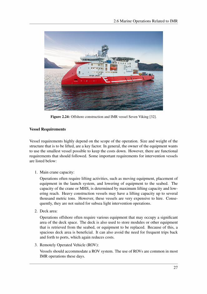
For installation of typical subsea equipment, such as modules, a medium- or light vesselwith on board crane or Module Handling System (MHS), is used. MHS is further describedin Section 2.6.4. The lifting operation takes place through the moonpool or over the side ofthe vessel. Figure 2.24 shows the vessel "Seven Viking", which is state of the art regardingIMR operations.
26
2.6 Marine Operations Related to IMR
Figure 2.24: Offshore construction and IMR vessel Seven Viking [32].
Vessel Requirements
Vessel requirements highly depend on the scope of the operation. Size and weight of thestructure that is to be lifted, are a key factor. In general, the owner of the equipment wantsto use the smallest vessel possible to keep the costs down. However, there are functionalrequirements that should followed. Some important requirements for intervention vesselsare listed below:
1. Main crane capacity:
Operations often require lifting activities, such as moving equipment, placement ofequipment in the launch system, and lowering of equipment to the seabed. Thecapacity of the crane or MHS, is determined by maximum lifting capacity and low-ering reach. Heavy construction vessels may have a lifting capacity up to severalthousand metric tons. However, these vessels are very expensive to hire. Conse-quently, they are not suited for subsea light intervention operations.
2. Deck area:
Operations offshore often require various equipment that may occupy a significantarea of the deck space. The deck is also used to store modules or other equipmentthat is retrieved from the seabed, or equipment to be replaced. Because of this, aspacious deck area is beneficial. It can also avoid the need for frequent trips backand forth to ports, which again reduces costs.
3. Remotely Operated Vehicle (ROV):
Vessels should accommodate a ROV system. The use of ROVs are common in mostIMR operations these days.
27

Chapter 2. Theoretical Background
4. Module Handling System (MHS):
MHS is a custom-made lifting and handling system for subsea modules. It is mostcommon to have a MHS tower over the moonpool. Installation through the moon-pool is beneficial because of better stability and tolerance due to weather conditions.This features is more thoroughly explained in Section 2.6.4.
5. Ready For Operation (RFO):
RFO are used to verify the integrity and functionality of the installed equipment.
2.6.2 Installation Capability
The installation complexity increases with the water depth. The depth challenges may bea constraint due to the lowering, load control and positioning system.
Steel wires are durable and well proven, but they have their weaknesses at ultra-deepwaters. For a steel wire with a diameter of 5 inches (0,13 meters) at depth of 3000 meters,the weight of the wire itself is about 170 metric tons. As the depth increases the payloadincreases with it. At 6000 meters, the weight of the wire is so high that it will not be ableto carry any equipment [24].
Another challenge is the resonance from the natural period of the load on the wire andwith surface vessel excitation, this can result in large dynamic loads. It can also be chal-lenging to estimate the added load created by hydrodynamic drag, especially for complexgeometries. An alternative to steel wires is fiber rope. The fiber rope has benefits suchas lower self-weight, allows small bend radius, lower stiffness, good ability for absorbingheave from surface waves, and the ability to be repaired. However, fiber ropes unfortu-nately also have shortcomings, such as creep, stretch related problems and relatively lowmelting point [24].
Heave, positioning, and stability is a challenge when lowering a structure. During loweringof heavy structures, large dynamic forces are present. Excitation caused by motions fromthe vessel, can be amplified with large oscillations and high dynamic loads in the liftingwire. A structure load can be many times bigger than its own weight in air, due to the watertrapped both inside and around it. Therefore, the shape of the structure to be installed orretrieved is an important factor that determines the added mass. The added mass canbe crucial to the dynamic response, and to the installation capability. When installing astructure in deep water there will almost always be a depth at which resonant responsewill occur. This resonant region must be passed through as quickly as possible, and notto occur at final depth where complete control is required for a smooth placement on theseabed [24].
When installing structures at deep water, the heave motions must be compensated. Activeand passive motion compensation systems are frequently used for the installation opera-tion. A further explanation on heave compensation systems is provided in Section 2.6.4.
28

2.6 Marine Operations Related to IMR
2.6.3 Subsea Lifting Operations
Different installation methods, with their own advantages and disadvantages, exists. Inthis thesis, the traditional installation method is explained. A subsea installation can bedivided into the following categories [33]:
Installation positioning
The vessel must keep its position with great accuracy to perform the installation in anefficient manner. A well-known solution for this, is Dynamic Positioning (DP), whichallows the vessel to keep its position with help from thrusters and satellite positioning.
Lifting from the deck
At installation site, the structure can be prepared for lowering. The crane operation shouldbe as simple as possible to avoid unnecessary risks. Test-lift inshore is recommended.Once the structure is airborne, pendulum forces, and stability motion of the vessel mustbe considered. A situation where the structure accidentally is dropped, also needs to beanalyzed.
Lowering through the wave zone
Entering the splash-zone reduces the pendulum effect, but the challenges are not over.This is where one get introduced to the most violent dynamics. Relative motion betweenstructure and sea, and acceleration due to wave motion, slamming of waves, and motionsdue to crane tip movement is present. Rolling motion of the vessel will also contributeto the lowering speed of the structure. All this makes transportation through the splashzone problematic, thus it is critical to perform it correct. As mentioned, MHS systems forguiding the equipment through this critical zone, is described in Section 2.6.4.
Further lowering down to seabed
The pendulum motion of the wire is not a concern a this point. When submerged, the waveimpact will disappear. The dynamics is then dependent on the crane tip motion.
29
Chapter 2. Theoretical Background
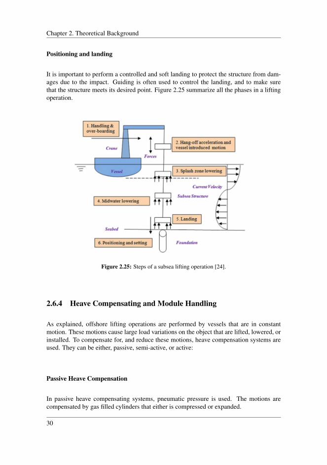
Positioning and landing
It is important to perform a controlled and soft landing to protect the structure from dam-ages due to the impact. Guiding is often used to control the landing, and to make surethat the structure meets its desired point. Figure 2.25 summarize all the phases in a liftingoperation.
Figure 2.25: Steps of a subsea lifting operation [24].
2.6.4 Heave Compensating and Module Handling
As explained, offshore lifting operations are performed by vessels that are in constantmotion. These motions cause large load variations on the object that are lifted, lowered, orinstalled. To compensate for, and reduce these motions, heave compensation systems areused. They can be either, passive, semi-active, or active:
Passive Heave Compensation
In passive heave compensating systems, pneumatic pressure is used. The motions arecompensated by gas filled cylinders that either is compressed or expanded.
30
2.6 Marine Operations Related to IMR
Semi-active Heave Compensation
The semi-active system is a combination system where a passive system absorbs most ofthe motions, and an additional active system absorbs the remaining motions.
Active Heave Compensation
With active heave compensation, the energy is supplied to the system as function of theheave measurements performed from an Motion Reference Unit (MRU). Based on datafrom an accelerometer, the unit calculates the required compensation force that is requiredto stabilize the load. The supplied energy can come from hydraulic or electric poweredcylinders.
These heave compensating systems can be mounted with the vessel crane, or in connectionwith module handling systems.
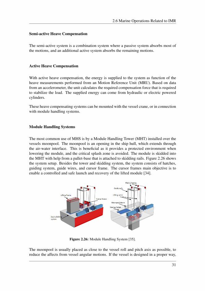
Module Handling Systems
The most common use of MHS is by a Module Handling Tower (MHT) installed over thevessels moonpool. The moonpool is an opening in the ship hull, which extends throughthe air-water interface. This is beneficial as it provides a protected environment whenlowering the module, and the critical splash zone is avoided. The module is skidded intothe MHT with help from a pallet-base that is attached to skidding rails. Figure 2.26 showsthe system setup. Besides the tower and skidding system, the system consists of hatches,guiding system, guide wires, and cursor frame. The cursor frames main objective is toenable a controlled and safe launch and recovery of the lifted module [34].
Figure 2.26: Module Handling System [35].
The moonpool is usually placed as close to the vessel roll and pitch axis as possible, toreduce the affects from vessel angular motions. If the vessel is designed in a proper way,
31
Chapter 2. Theoretical Background
the motions in the moonpool should be smaller than from lowering the module from thevessel side. Below some advantages and disadvantages are listed [34]:
Advantages:
• Protection of equipment from environmental forces.
• Skidding system eliminates the need to lift equipment on deck.
• Minimized affect from the vessels angular motions during lifting operations, due tomoonpool close to vessel roll and pitch axis.
Disadvantages:
• Water plugs within moonpool may cause flooding of vessel deck and large loads onequipment in moonpool.
• Risk of equipment slamming into cursor frame or get stuck when entering the moon-pool.
• Size limitations of equipment.
Special Handling System (SHS)
The Special Handling System, is a concept developed by AxTech for launch and recoveryof heavy subsea modules under extreme environment and sea states. The special designedlifting system, has a safe work load of 420 tones at a sea state as high as 4,5 meterssignificant wave height [36].
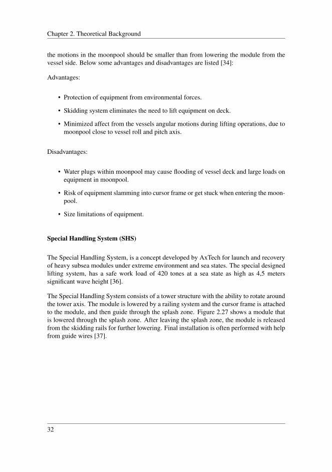
The Special Handling System consists of a tower structure with the ability to rotate aroundthe tower axis. The module is lowered by a railing system and the cursor frame is attachedto the module, and then guide through the splash zone. Figure 2.27 shows a module thatis lowered through the splash zone. After leaving the splash zone, the module is releasedfrom the skidding rails for further lowering. Final installation is often performed with helpfrom guide wires [37].
32
2.6 Marine Operations Related to IMR
Figure 2.27: Module lowered through the splash zone [37].
2.6.5 Remotely Operated Vehicles
There are many different types of ROVs. The most common types used in the subsea in-dustry, are inspection and working ROVs. Inspection ROVs are vehicles equipped withcameras to give visuals of the structure. It usually has the capability to perform Non De-structive Testing tasks (NDT). A work ROV is shown in Figure 2.28. This is a muchbigger vehicle that normally is equipped with two manipulators. A manipulator is a re-motely controlled arm that is intended to execute required work tasks. The ROV mustmeet the interface requirements from the different intervention tasks. The most commontools are listed below [38]:
• Cleaning tools - Various types, mainly used for cleaning of connectors, seal surfacesand removal of marine growth.
• Cutting tools - Mainly used for cutting ropes in connection to decommissioning orother intervention tasks.
• Intervention tools - Various types, such as alignment framing for docking on inter-face, change out of gaskets, etc.
• Camera/Lightning/Displays - Used for observations and assisting other tasks.
• Override tools - Mainly used for actuation of different types of valves.
• Measurement tools - Used for data collection.
• Skids - Framing structure mounted to the ROV, used for fluid intervention such asinjection of hydraulic fluid or methanol.
• Hot Stabs - Used for powering hydraulic tools, transfer fluid, perform chemicalinjections, and to monitor pressure.
• Torque tools - Used for operating of docking interfaces.
33
Chapter 2. Theoretical Background
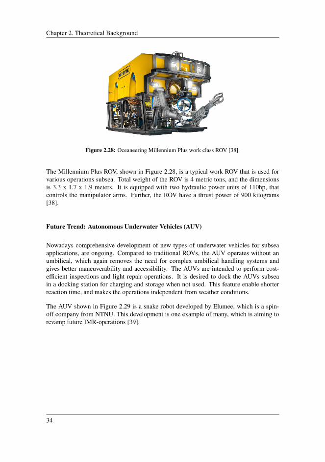
Figure 2.28: Oceaneering Millennium Plus work class ROV [38].
The Millennium Plus ROV, shown in Figure 2.28, is a typical work ROV that is used forvarious operations subsea. Total weight of the ROV is 4 metric tons, and the dimensionsis 3.3 x 1.7 x 1.9 meters. It is equipped with two hydraulic power units of 110hp, thatcontrols the manipulator arms. Further, the ROV have a thrust power of 900 kilograms[38].
Future Trend: Autonomous Underwater Vehicles (AUV)
Nowadays comprehensive development of new types of underwater vehicles for subseaapplications, are ongoing. Compared to traditional ROVs, the AUV operates without anumbilical, which again removes the need for complex umbilical handling systems andgives better maneuverability and accessibility. The AUVs are intended to perform cost-efficient inspections and light repair operations. It is desired to dock the AUVs subseain a docking station for charging and storage when not used. This feature enable shorterreaction time, and makes the operations independent from weather conditions.
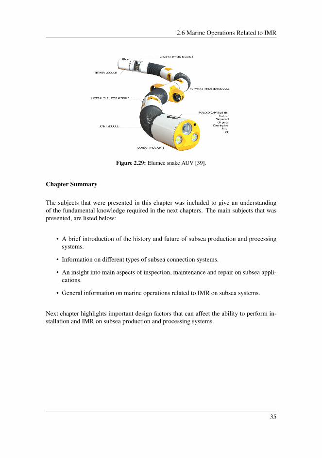
The AUV shown in Figure 2.29 is a snake robot developed by Elumee, which is a spin-off company from NTNU. This development is one example of many, which is aiming torevamp future IMR-operations [39].
34
2.6 Marine Operations Related to IMR
Figure 2.29: Elumee snake AUV [39].
Chapter Summary
The subjects that were presented in this chapter was included to give an understandingof the fundamental knowledge required in the next chapters. The main subjects that waspresented, are listed below:
• A brief introduction of the history and future of subsea production and processingsystems.
• Information on different types of subsea connection systems.
• An insight into main aspects of inspection, maintenance and repair on subsea appli-cations.
• General information on marine operations related to IMR on subsea systems.
Next chapter highlights important design factors that can affect the ability to perform in-stallation and IMR on subsea production and processing systems.
35

Chapter 2. Theoretical Background
36
Chapter 3System Design for Efficient IMROperations
Development of subsea systems is a stepwise process. After over 30 years of developmentalmost all processing can be performed subsea. The main drivers for a subsea systemdesign is to achieve a high availability and quality. These drivers are obtained through:
• High quality on the selected equipment.
• Some degree of redundancy and fault tolerance on a system level.
• Efficient design for IMR operations for replacing failed or degraded equipment.
This chapter presents important methodology for subsea production and processing devel-opments that has its main focus on easy installation, inspection, maintenance, and repair.Important factors will be pointed out by studying already existing subsea production andprocessing developments. For instance, the architecture of a subsea production systemshould provide a degree of redundancy for some of the equipment. As it is not feasible tohave a redundant component for every part of the system, the parts must be closely mon-itored instead, so that failure or lack of performance on equipment can be detected in anearly phase. The final and most important factor in term of this thesis, is the modularizationof the system. Efficient replacement of failing equipment is essential to achieve the desiredavailability. Solutions as redundancy, rerouting, and monitoring of performances, is onlytemporary solutions, while the replacement operation is the final solution for bringing thesystem back to optimal condition.
The system design must also compile with given rules and regulations given by standards,
37
Chapter 3. System Design for Efficient IMR Operations
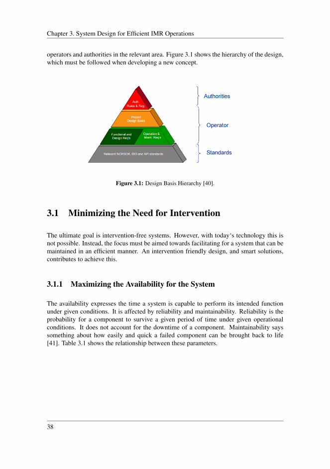
operators and authorities in the relevant area. Figure 3.1 shows the hierarchy of the design,which must be followed when developing a new concept.
Figure 3.1: Design Basis Hierarchy [40].
3.1 Minimizing the Need for Intervention
The ultimate goal is intervention-free systems. However, with today‘s technology this isnot possible. Instead, the focus must be aimed towards facilitating for a system that can bemaintained in an efficient manner. An intervention friendly design, and smart solutions,contributes to achieve this.
3.1.1 Maximizing the Availability for the System
The availability expresses the time a system is capable to perform its intended functionunder given conditions. It is affected by reliability and maintainability. Reliability is theprobability for a component to survive a given period of time under given operationalconditions. It does not account for the downtime of a component. Maintainability sayssomething about how easily and quick a failed component can be brought back to life[41]. Table 3.1 shows the relationship between these parameters.
38

3.1 Minimizing the Need for Intervention
Table 3.1: Relationship between reliability, maintainability and availability [42].
Reliability Maintainability Availability
Constant Decreases DecreasesConstant Increases IncreasesIncreases Constant IncreasesDecreases Constant Decreases
By studying the relationships between the factors, one can seen that the availability willincrease if the system is designed in a manner that facilitate for efficient maintenance.
3.1.2 Condition/Performance Monitoring and Condition BasedMaintenance
As described in Section 2.5 about IMR, subsea equipment will sooner or later be in needfor intervention in terms of maintenance. However, the problem is to know exactly whenthe need arises. This is where predictive maintenance, by implementation of condition andperformance monitoring comes into play.
Condition monitoring while systems are operating, is relatively new. The application ofthese systems is most advanced within military, industrial, and consumer sectors, wheresafety and reliability are highly valued. The space, aviation, and automotive sectors startedoff with these systems - and are still in the forefront of developing and using advancedmonitoring systems [43].
On the other hand, the subsea industry is some steps behind regarding utilization of thistechnology, and the "run equipment until it fails" philosophy have been more accepted.However, the subsea industry is gradually developing and implementing condition moni-toring systems. An example of this implementation is presented in Section 3.1.3.
By implementing a condition based maintenance strategy for subsea equipment, efficiencyof the intervention operations, and decrease of the operation costs, can be achieved at thesame time.
Implementation of Condition Monitoring for a Subsea Pump
Further, an example of implementing condition based maintenance will be presented. Theexample addresses the maintenance strategy for a subsea pump. Such pumps, is typicallypredicted to have a Mean Time To Failure (MTTF) of 5-10 years. Typical maintenancestrategies for this pump might be:
39

Chapter 3. System Design for Efficient IMR Operations
1. Run to failure
2. Replace after a certain time (calendar/time based)
3. Replace when performance is reduced (condition based)
The run to failure strategy uses the "if it works, don´t touch it" philosophy. By usingthis approach, the time between each intervention operation is maximized. However, anunexpected fail will result in longer downtime due to mobilization time for new equip-ment, vessel, crew, etc. This time could range from days up to months, depending on thecircumstances.
If the time based strategy is applied, the highest numbers of intervention operations areexpected. Change-out of equipment is only dependent of time/usage. (e.g an oil filter fora car is changed every 12 months, or when reached 15000 kilometers). Another draw-back with this strategy, is that one may end up replacing completely intact equipment.Also worth mentioning, is that the intervention operation itself is not risk free, as otherequipment in the system may be damaged during a scheduled intervention operation.
The last strategy, where equipment is changed on basis of the condition is the most op-timal solution with respect to intervention intervals and costs. To achieve this strategy acombination of run to failure and time based are used together with condition monitoringtools.
Table 3.2 compares the yearly costs for a subsea pump module with the different mainte-nance strategies applied. These numbers are derived from simple assumptions and calcu-lations, and they are only meant for showing the potential difference in costs by makinguse of the different maintenance approaches. Assumptions and calculations can be seen inAppendix A.
Table 3.2: Intervention strategies and their yearly costs.
Strategy Yearly costs (MNOK)
Run-to-failure 25.6Time based 6Condition Based 2.4
This simple example shows that by implementing condition monitoring and predictivemaintenance in form of condition based maintenance, both costs and the intervals of inter-vention are optimized [44].
The concept of Condition Based Maintenance (CBM), is to get an indication of the systemstatus, and most desirable a warning in good time before a failure occurs. By achievingthis, the maintenance can be performed by the "just in time" philosophy before a failoccurs or when the performance is reduced. Further, scheduling of change-out of well-functioning equipment is avoided. However, it is not possible to avoid all failures. Sudden
40
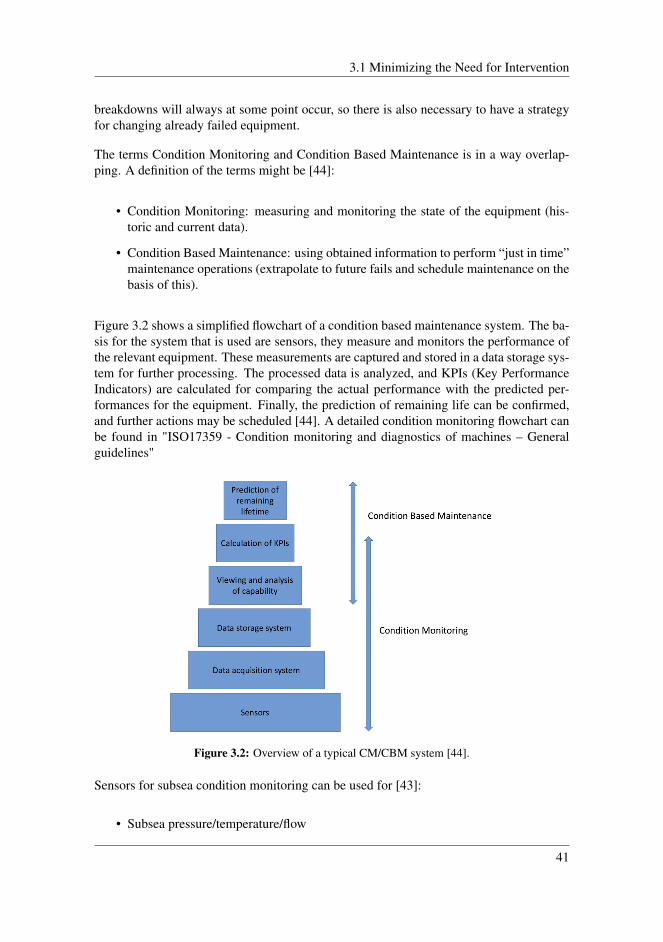
3.1 Minimizing the Need for Intervention
breakdowns will always at some point occur, so there is also necessary to have a strategyfor changing already failed equipment.
The terms Condition Monitoring and Condition Based Maintenance is in a way overlap-ping. A definition of the terms might be [44]:
• Condition Monitoring: measuring and monitoring the state of the equipment (his-toric and current data).
• Condition Based Maintenance: using obtained information to perform “just in time”maintenance operations (extrapolate to future fails and schedule maintenance on thebasis of this).
Figure 3.2 shows a simplified flowchart of a condition based maintenance system. The ba-sis for the system that is used are sensors, they measure and monitors the performance ofthe relevant equipment. These measurements are captured and stored in a data storage sys-tem for further processing. The processed data is analyzed, and KPIs (Key PerformanceIndicators) are calculated for comparing the actual performance with the predicted per-formances for the equipment. Finally, the prediction of remaining life can be confirmed,and further actions may be scheduled [44]. A detailed condition monitoring flowchart canbe found in "ISO17359 - Condition monitoring and diagnostics of machines – Generalguidelines"
Figure 3.2: Overview of a typical CM/CBM system [44].
Sensors for subsea condition monitoring can be used for [43]:
• Subsea pressure/temperature/flow
41

Chapter 3. System Design for Efficient IMR Operations
• Control pod pressure/temperature
• Downhole pressure/temperature/flow
• Subsea processing pressure/temperature/flow
• Pipe wall thickness/erosion/corrosion
• Stress/strain
• Acceleration/vibration
• Voltage/amperage/resistance/impedance
• Leak detection/video
3.1.3 Condition and Performance Monitoring at the Gjøa Oil andGas Field
The Gjøa Field is a successful example of the benefits obtained by implementing a condi-tion and performance monitoring system. The CPM system is developed by TechnipFMC(previously FMC Technologies), on behalf of Engie E&P Norge (previously GdF Suez)which operate the field. The purpose of the system is to maximize production uptime andasset availability.
As previously described in section 3.1.2, this kind of systems collect, store, and processesdata in real time. It uses integrity monitoring beyond traditional KPIs by taking a holis-tic approach, and utilizing all available data and information, where design parameters,criticality, system experience and operating philosophy is modeled and built into what isdefined as Technical Condition Index (TCI) [45].
It takes maximum ten minutes for the operator to get total overview of the system TCIstatus, and it gives the possibility to detect faults in real time.
In less than one year following cases are solved with help from the CPM system
• Detected leak in subsea router module early. Change-out facilitated before failure.
• Erosion damage to choke. Detected before serious degradation. Componentchanged.
• The CPM system detected abnormally high pressure drop over oil filter in controlsystem.
The initial investments in the CPM system was paid back in less than two months, due toproperly planning of the IMR-operations [45].
42
3.2 Cost Related to Installation- and Maintenance Operations
3.2 Cost Related to Installation- and Maintenance Oper-ations
This section will provide an insight of costs related to maintenance operations of moduleson a subsea processing system. Costs for installation and IMR operations subsea is a bigvariable. As indicated, all subsea field developments are unique, with different processesand equipment. Because of this, it is difficult to compare one field to another. However,it is possible to compare similar equipment. Most subsea process equipment is modulebased, and the procedures for retrieving or installing a module is quite similar.
The costs related to installation and IMR operations are usually, frame contracts with con-tractors executing the operations, planning of operations, personnel, overhaul of equip-ment, new equipment, and logistics. Repair operations often requires extensive planningand customized solutions, which may involve special vessels, additional personnel, andspecial equipment. This is much more expensive compared to standard operations.
Section 3.2.1 addresses replacement of two different modules on the Tordis Subsea Sepa-ration Boosting and Injection station. Both replacements are considered as standard oper-ations. Hence, as explained in Section 2.5.1, they are regarded as maintenance operations.
3.2.1 Case Study: Change-out of Modules on the Tordis Subsea Sep-aration Boosting and Injection (SSBI) Project
The Tordis field is located in the Tampen area in the North Sea. Production from the fieldstarted in 1994, and the field is developed as a subsea tieback to the Gullfaks C facility.The Tordis SSBI is a further development of the Troll pilot separation, and was installed in2007. The system is the world’s first commercial subsea separation, boosting, and injectionfacility. Originally, it was supposed to separate water and sand from the oil and gas, andthen re-injects the water through a 12-inch injection well to Utsira, a non-hydrocarbonreservoir. However, this feature is no longer operational, and the water and sand is treatedtopside.
The separator itself is 17 meters long, has a diameter of 2.1 meters and a weight of 250metric tons. The footprint of the entire system is 40 x 25 x 19 meters, and the total weightis approximately 1130 metric tons [46]. Table 3.3 lists the main building blocks for theSSBI system that all are independently retrievable:
43
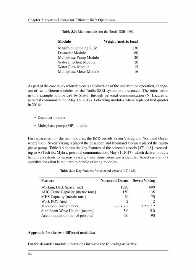
Chapter 3. System Design for Efficient IMR Operations
Table 3.3: Main modules for the Tordis SSBI [46].
Module Weight [metric tons]
Manifold including SCM 230Desander Module 60Multiphase Pump Module 20Water Injection Module 20Water Flow Module 15Multiphase Meter Module 16
As part of the case study related to costs and duration of the intervention operation, change-out of two different modules on the Tordis SSBI system are presented. The informationin this example is provided by Statoil through personal communication (N. Lazarevic,personal communication, May 16, 2017). Following modules where replaced first quarterin 2016:
• Desander module
• Multiphase pump (MP) module
For replacement of the two modules, the IMR-vessels Seven Viking and Normand Oceanwhere used. Seven Viking replaced the desander, and Normand Ocean replaced the multi-phase pump. Table 3.4 shows the key features of the selected vessels [47], [48]. Accord-ing to AxTech (R. Myhre, personal communication, May 31, 2017), which deliver modulehandling systems to various vessels, these dimensions are a standard based on Statoil’sspecifications that is required to handle existing modules.
Table 3.4: Key features for selected vessels [47] [48].
Feature Normand Ocean Seven Viking
Working Deck Space [m2] 1020 600AHC Crane Capacity [metric tons] 150 135MHS Capacity [metric tons] 40 70Work ROV (no.) 2 2Moonpool Size [meters] 7.2 x 7.2 7.2 x 7.2Significant Wave Height [meters] 5.0 5.0Accommodation (no. of persons) 90 90
Approach for the two different modules:
For the desander module, operations involved the following activities:
44
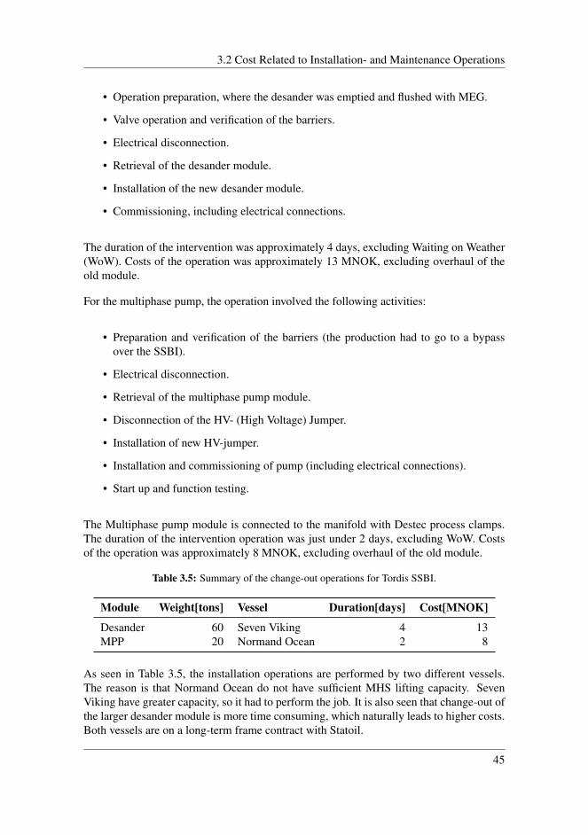
3.2 Cost Related to Installation- and Maintenance Operations
• Operation preparation, where the desander was emptied and flushed with MEG.
• Valve operation and verification of the barriers.
• Electrical disconnection.
• Retrieval of the desander module.
• Installation of the new desander module.
• Commissioning, including electrical connections.
The duration of the intervention was approximately 4 days, excluding Waiting on Weather(WoW). Costs of the operation was approximately 13 MNOK, excluding overhaul of theold module.
For the multiphase pump, the operation involved the following activities:
• Preparation and verification of the barriers (the production had to go to a bypassover the SSBI).
• Electrical disconnection.
• Retrieval of the multiphase pump module.
• Disconnection of the HV- (High Voltage) Jumper.
• Installation of new HV-jumper.
• Installation and commissioning of pump (including electrical connections).
• Start up and function testing.
The Multiphase pump module is connected to the manifold with Destec process clamps.The duration of the intervention operation was just under 2 days, excluding WoW. Costsof the operation was approximately 8 MNOK, excluding overhaul of the old module.
Table 3.5: Summary of the change-out operations for Tordis SSBI.
Module Weight[tons] Vessel Duration[days] Cost[MNOK]
Desander 60 Seven Viking 4 13MPP 20 Normand Ocean 2 8
As seen in Table 3.5, the installation operations are performed by two different vessels.The reason is that Normand Ocean do not have sufficient MHS lifting capacity. SevenViking have greater capacity, so it had to perform the job. It is also seen that change-out ofthe larger desander module is more time consuming, which naturally leads to higher costs.Both vessels are on a long-term frame contract with Statoil.
45

Chapter 3. System Design for Efficient IMR Operations
3.3 Retrievable Modules
Subsea production and processing systems are usually divided into several separate mod-ules in which the equipment are installed. Within the industry, all equipment that makesup the processing system, is often referred to as a process train. The process trains, withassociated modules, are placed inside a framing structure, which is supposed to protect theequipment from e.g. trawling activity or dropped objects. In addition, the frame shouldwork as a foundation, and carry the load of the process trains. One of the reasons for amodularization setup is because subsea production equipment in some cases is too largeand heavy to be lifted in one operation. Consequently, the base structure and the separatemodules, are occasionally installed separately.
Another reason addresses maintenance operations, where it is desirable that the equipmenthas a high availability through high maintainability. The idea is to be able to retrieve onlythe relevant equipment in a separate operation, without removing the entire system. Thisprovides versatility, in which maintenance and repair can be performed throughout theentire life cycle. There are several variables involved for achieving easy installation andretrieval. Installation vessels, operational planning, module design and module architec-ture are some of them. To keep the installation and intervention costs as low as possiblethroughout the life cycle, the time it takes to install and retrieve a module is a relevantfactor during the design phase. Further in this section, some important factors to take intoaccount in the module design regarding installation and IMR, will be presented.
3.3.1 Strategical Placement of Modules
In general, the components that have the highest probability of failure are placed in sucha way that they are easy to access, easy to retrieve and, and easy to install. Some ex-amples of typical "vulnerable" components are pumps, compressors, chokes, SCM, andmultiphase meters. Modularization of subsea equipment must be balanced in a optimalway to facilitate for easy IMR operations. These components are likely to require frequentintervention, thus, they should be placed in a strategical position to ensure an efficientchange-out operation [49].
Providing easy access to components, is an important part to achieve a module configu-ration that facilitates for easy IMR. This can include factors like sufficient space betweencomponents, so that the ROV and crane can reach the relevant equipment. Preferably, theneed for ROV intervention should be kept at a minimal level. However, when the needarises and ROV assistance is necessary, the design must facilitate for this. Placement ofmodules must be clearly arranged and with clearances so that the ROV mounted tools canreach the desired point. Interfaces on the modules should be standardized for commonROV tooling. Choke and valve operations that is not hydraulic, or operated electricallymust be in reach for an ROV. Further the structures must be designed for easy inspectionand monitoring. However, there are some important consequences to take into account.Increased space between the components might result in an increase in the module size,
46
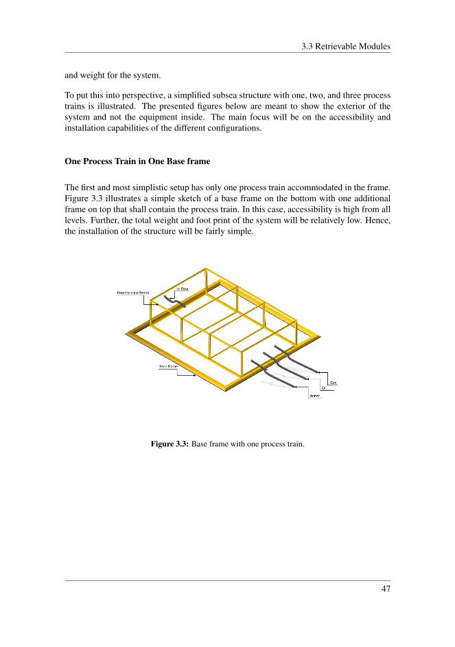
3.3 Retrievable Modules
and weight for the system.
To put this into perspective, a simplified subsea structure with one, two, and three processtrains is illustrated. The presented figures below are meant to show the exterior of thesystem and not the equipment inside. The main focus will be on the accessibility andinstallation capabilities of the different configurations.
One Process Train in One Base frame
The first and most simplistic setup has only one process train accommodated in the frame.Figure 3.3 illustrates a simple sketch of a base frame on the bottom with one additionalframe on top that shall contain the process train. In this case, accessibility is high from alllevels. Further, the total weight and foot print of the system will be relatively low. Hence,the installation of the structure will be fairly simple.
Figure 3.3: Base frame with one process train.
47
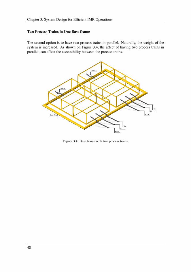
Chapter 3. System Design for Efficient IMR Operations
Two Process Trains in One Base frame
The second option is to have two process trains in parallel. Naturally, the weight of thesystem is increased. As shown on Figure 3.4, the affect of having two process trains inparallel, can affect the accessibility between the process trains.
Figure 3.4: Base frame with two process trains.
48
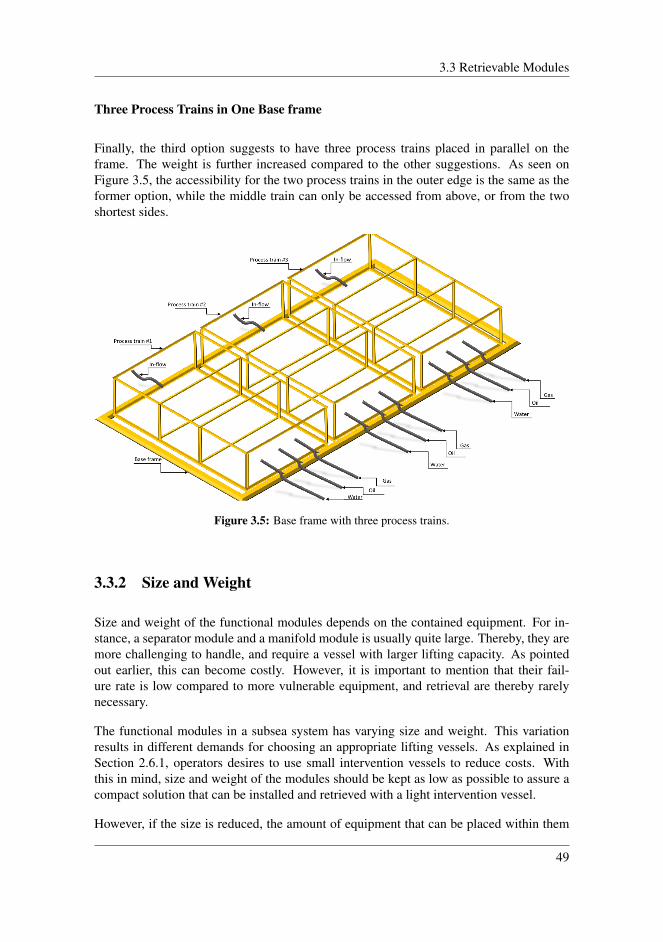
3.3 Retrievable Modules
Three Process Trains in One Base frame
Finally, the third option suggests to have three process trains placed in parallel on theframe. The weight is further increased compared to the other suggestions. As seen onFigure 3.5, the accessibility for the two process trains in the outer edge is the same as theformer option, while the middle train can only be accessed from above, or from the twoshortest sides.
Figure 3.5: Base frame with three process trains.
3.3.2 Size and Weight
Size and weight of the functional modules depends on the contained equipment. For in-stance, a separator module and a manifold module is usually quite large. Thereby, they aremore challenging to handle, and require a vessel with larger lifting capacity. As pointedout earlier, this can become costly. However, it is important to mention that their fail-ure rate is low compared to more vulnerable equipment, and retrieval are thereby rarelynecessary.
The functional modules in a subsea system has varying size and weight. This variationresults in different demands for choosing an appropriate lifting vessels. As explained inSection 2.6.1, operators desires to use small intervention vessels to reduce costs. Withthis in mind, size and weight of the modules should be kept as low as possible to assure acompact solution that can be installed and retrieved with a light intervention vessel.
However, if the size is reduced, the amount of equipment that can be placed within them
49
Chapter 3. System Design for Efficient IMR Operations
decreases. Further, the number of separate module-frames increases to be able to accom-modate all necessary equipment, which also affects the number of connectors required inthe system. An additional consequence may result in less accessibility, and performingIMR may become more challenging.
It is apparent that there are some challenges and trade-offs involved in choosing the bestconfiguration. This will be further elaborated in Section 3.3.5.
3.3.3 Intermodular Connections
Between modules in a subsea processing system, supply of either hydraulic, electricalpower, control signals, production flow, or all of the above, are required. These sourcesrely on intermodular connectors to achieve their intended function. These connections arecrucial to functionality of the system. A failure in any of them, may lead to reduced pro-duction or even shutdown. Further in this section, two different intermodular connectionapproaches will be explained.
Connector system
Connector systems that are used between the modules, varies depending on the supplierand the equipment that is to be connected. Every supplier have to some degree their ownconnector design that differs from other competitors. To generalize, subsea connectors fortie-in of production fluids, as described in Section 2.2.2, usually include a clamp- or col-let system. Both solutions can be used for either a horizontal or a vertical configuration.Figure 3.6 shows a simple sketch of a subsea processing facility, with production pipingrouted though the base structure, also called flow base. Connections between the modulesare made through vertical connectors mounted on the top of the base structure, while thepiping that is to be routed to the next module, are fitted with a mating hub at the bottomof the module-frame. During installation, modules are guided down towards the connec-tor hub on the production base, and then onto a soft-landing mechanism, as described inSection 2.2.1. At this point, the connector hubs are aligned, and an ROV can operate theconnection mechanism from a panel located somewhere with easy access.
50

3.3 Retrievable Modules
Figure 3.6: Processing system with vertical connectors in the flow base.
Figure 3.7 shows the module setup of Pazflor subsea separation station, which consists ofa separator module on the right, two pump modules to the left, and a manifold betweenthe separator and pumps. Additionally, the production fluids goes through an inlet moduleas seen in the front on the figure. In this setup, there is no flow base as in the formerexample. All the modules are placed on an intermediate frame, which again is placed onthe foundation base structure. The manifold is integrated into the intermediate frame, andcannot be retrieved separately. Installation of the system was divided into four operations.First, the foundation base structure, then intermediate frame with manifold, then separator,and finally the pump modules. Connection system for the intermodular connections, is ahorizontal configuration. Tie-in of the connectors on the separator module, pumps, andinlet module was performed accordingly [50]:
• After landing the separator module on to the intermediate frame, tie-in to the mani-fold was achieved by sliding the separator module on low friction pads 800 millime-ters towards the connector hubs on the manifold. Connector interface between theseparator and manifold, includes three connector hubs being mated together. Theseparator module has a submerged weight of 283 metric tons, and was pushed byhigh pressure cylinders operated by an ROV. Duration of the operation was 1.28days.
• The tie-in of pump modules was performed in the same way as the separator module.In this case, there where two sets of connector hubs, both inboard and outboard foreach pump, with one monobore and one multibore hub. The tie-in of one modulewas 0.6 days.
• Tie-in of the inlet manifold to the separator module was achieved by skiding it 600millimeters towards the connector hubs on the separator module. Then a connectoractuator tool is lowered down to make the connections. Duration of the tie-in was0.9 days.
51

Chapter 3. System Design for Efficient IMR Operations
Figure 3.7: Pazflor subsea separation system [51].
Connector systems that connects piping for production fluids between the modules aremore or less the same as the ones used for tie-ins described in Section 2.2.1. It can besome differences regarding the procedure connector hubs are joined together, and fromwhere actuation of the locking mechanism is controlled. In some cases, there are notenough space between the modules to allow an actuator tool to reach the connectors. Thisresults in the need for alternative mating methods, where actuation must be performedaway from the connector assembly. This is usually done as explained in the first example,where the connector is operated from a panel located away from the assembly. This panelallows an ROV to apply hydraulic power to the latching mechanism, for instance, a clampor collet mechanism.
Multibore Connectors for Intermodular Connections
A problem regarding connectors between pipes or cables, is that the overall pipe integrityis decreased around the connection points. A leakage is in general more likely to occurat a connection than other parts of the pipe or cable. With this in mind, a reduction ofconnections can affect the availability of the system. Therefore, it will be beneficial tokeep the number as low as possible. An additional factor is the time consumption ofinstalling and operate connectors. A reduction of these operations can contribute to reducethe overall time it takes to retrieve, and install modules. As a result, the operational costscan be reduced in the long run.
As described in Section 2.2.3, the electrical and control supply are transported through um-
52
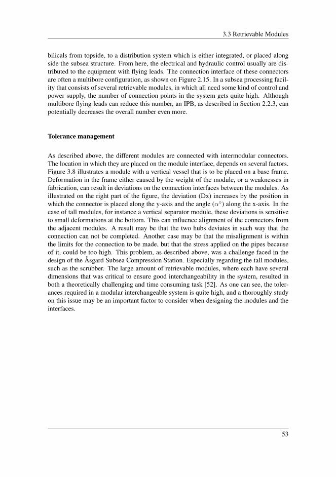
3.3 Retrievable Modules
bilicals from topside, to a distribution system which is either integrated, or placed alongside the subsea structure. From here, the electrical and hydraulic control usually are dis-tributed to the equipment with flying leads. The connection interface of these connectorsare often a multibore configuration, as shown on Figure 2.15. In a subsea processing facil-ity that consists of several retrievable modules, in which all need some kind of control andpower supply, the number of connection points in the system gets quite high. Althoughmultibore flying leads can reduce this number, an IPB, as described in Section 2.2.3, canpotentially decreases the overall number even more.
Tolerance management
As described above, the different modules are connected with intermodular connectors.The location in which they are placed on the module interface, depends on several factors.Figure 3.8 illustrates a module with a vertical vessel that is to be placed on a base frame.Deformation in the frame either caused by the weight of the module, or a weaknesses infabrication, can result in deviations on the connection interfaces between the modules. Asillustrated on the right part of the figure, the deviation (Dx) increases by the position inwhich the connector is placed along the y-axis and the angle (α◦) along the x-axis. In thecase of tall modules, for instance a vertical separator module, these deviations is sensitiveto small deformations at the bottom. This can influence alignment of the connectors fromthe adjacent modules. A result may be that the two hubs deviates in such way that theconnection can not be completed. Another case may be that the misalignment is withinthe limits for the connection to be made, but that the stress applied on the pipes becauseof it, could be too high. This problem, as described above, was a challenge faced in thedesign of the Åsgard Subsea Compression Station. Especially regarding the tall modules,such as the scrubber. The large amount of retrievable modules, where each have severaldimensions that was critical to ensure good interchangeability in the system, resulted inboth a theoretically challenging and time consuming task [52]. As one can see, the toler-ances required in a modular interchangeable system is quite high, and a thoroughly studyon this issue may be an important factor to consider when designing the modules and theinterfaces.
53

Chapter 3. System Design for Efficient IMR Operations
Figure 3.8: Alignment deviations on modular connector interfaces.
3.3.4 Standardized Interfaces
For subsea production and processing facilities that are based on a modular design, stan-dardization of modular interfaces can contribute to ensure the availability of spare parts inthe future, as the operator is not dependent on one supplier throughout the life cycle of thesystem. An additional advantage, is that the duration for engineering and manufacturingof equipment, is reduced due to standardization. The equipment can thereby be deliveredfaster and with lower costs.
However, it is important to acknowledge that standardization not just involves modular in-terfaces and material specifications, but also the process in which the projects are deliveredand handed over to the operator. Another important thing to address, is that standardiza-tion should not come in the way of further innovation. After all, the main goal is to removeoperations that does not contribute to either quality or functionality. An example of this isthe lack of standardization for supplying of materials. As a result, the equipment suppliersare more hesitant to order materials, due to own risk and cost prior to have a contract withthe costumer ready. This can typically add 7-12 months delivery time for forgings [49].
A Joint Industry Project (JIP) was started by DNV GL together with the industry partnersFMC, OneSubsea, Petrobras, Shell, Statoil, and Woodside, to standardize subsea pumping.The objective of the JIP, is to "reduce costs in a lifetime perspective by giving a guidelinefor subsea processing modules and interfaces that are efficient, reliable and within limitsfor effective installation and retrieval" [49]. A higher degree of standardization benefitsboth the oil companies and the suppliers. Table 3.6 presents some of the benefits.
54
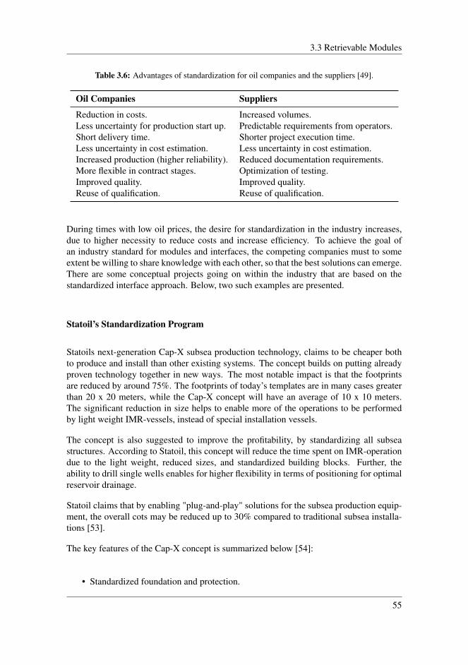
3.3 Retrievable Modules
Table 3.6: Advantages of standardization for oil companies and the suppliers [49].
Oil Companies Suppliers
Reduction in costs. Increased volumes.Less uncertainty for production start up. Predictable requirements from operators.Short delivery time. Shorter project execution time.Less uncertainty in cost estimation. Less uncertainty in cost estimation.Increased production (higher reliability). Reduced documentation requirements.More flexible in contract stages. Optimization of testing.Improved quality. Improved quality.Reuse of qualification. Reuse of qualification.
During times with low oil prices, the desire for standardization in the industry increases,due to higher necessity to reduce costs and increase efficiency. To achieve the goal ofan industry standard for modules and interfaces, the competing companies must to someextent be willing to share knowledge with each other, so that the best solutions can emerge.There are some conceptual projects going on within the industry that are based on thestandardized interface approach. Below, two such examples are presented.
Statoil’s Standardization Program
Statoils next-generation Cap-X subsea production technology, claims to be cheaper bothto produce and install than other existing systems. The concept builds on putting alreadyproven technology together in new ways. The most notable impact is that the footprintsare reduced by around 75%. The footprints of today’s templates are in many cases greaterthan 20 x 20 meters, while the Cap-X concept will have an average of 10 x 10 meters.The significant reduction in size helps to enable more of the operations to be performedby light weight IMR-vessels, instead of special installation vessels.
The concept is also suggested to improve the profitability, by standardizing all subseastructures. According to Statoil, this concept will reduce the time spent on IMR-operationdue to the light weight, reduced sizes, and standardized building blocks. Further, theability to drill single wells enables for higher flexibility in terms of positioning for optimalreservoir drainage.
Statoil claims that by enabling "plug-and-play" solutions for the subsea production equip-ment, the overall cots may be reduced up to 30% compared to traditional subsea installa-tions [53].
The key features of the Cap-X concept is summarized below [54]:
• Standardized foundation and protection.
55
Chapter 3. System Design for Efficient IMR Operations
• Standardized equipment envelopes.
• Snag free design.
• Full access when the hatches are open.
• Small design enables optimal placement relative to the reservoir.
• Flexibility to change and reuse equipment.
• Improved IMR-operations.
The improvement of IMR-operations are of special interest for this thesis. The reducedsizes enable for smaller IMR vessels to perform operations in harsher weather. Furtherthis leads to an reduced mobilization and transit time. The standardized design will alsoenable for the usage of one standardized module handeling system.
Open Source Architecture Development
A project started by Sonsub (Saipem brand name) involves developing a "open sourcearchitecture" Subsea Factory with standard building blocks and standardized interfaces[5]. A part of this project is integrating a system that is independent of any proprietaryequipment and exclusive interfaces, called SUBSEA BUS. This system is a module basedstructure that makes it possible to use the same building blocks in different subsea ar-chitectures. It contains the distribution system for process, chemicals, service fluids andcontrol. In addition, manifold functions with inlet and outlet facilities are integrated. TheSUBSEA BUS system contributes to a reduction of modular interfaces and consequentlynumber of flow-line connections. Figure 3.9 shows the SUBSEA BUS concept appliedin the seawater treatment plant called SPRINGS developed by Saipem. In this case theSUBSEA BUS is placed in the middle, while the other equipment modules are placed andconnected alongside.
The key driver of the Subsea Factory is creating a system based on changeability, robust-ness, and sustainability [5]. Changeability implies the possibility of expansion or recon-figuration in situations where the performance requirements change over time. This ismainly obtained by modularization of the different components involved in the processingfacility. Robustness involves building the system so that it can maintain the productionup time. This is achieved by applying high redundancy to the system and make sure thatIMR operations easily can be performed on the installed equipment. Sustainability impliesthat it should be possible to keep the life cycle cost low by allowing future developmentthrough standardization of the modular interfaces.
56

3.3 Retrievable Modules
Figure 3.9: SUBSEA BUS system implemented in SPRINGS subsea station [5].
3.3.5 Modularization Challenges
Besides all the positive features that a modular design presents, there are some aspectsto take into consideration. In addition to an increase in the equipment maintainability,modularization also increases the complexity, weight and building cost. Due to the optionto remove the equipment, the amount of flow-, electrical- and hydraulic connections in-creases. This results in a higher possibility of leakage and electrical failure, and will affectthe overall availability of the system.
Future subsea developments will probably contain an even larger number of components,with more advanced technology than today, and a modular approach to the design will beinevitable to ensure a long operational life. The modularization concept always involvesa carefully considered trade-off between reliability and maintainability. This of coursedepends on several factors, where the operator and the supplier must decide which of thecomponents that should be included in each module.
57

Chapter 3. System Design for Efficient IMR Operations
Chapter Summary
The main subjects in this chapter includes:
• Factors that can minimize the the need for intervention.
• Costs related to installation and maintenance operations.
• Important factors to consider in the module design of a subsea production and pro-cessing system.
The upcoming chapter will contain suggestions for solutions, and point out important fac-tors that should be considered for the Subsea Gate Box concept.
58

Chapter 4Design Study of the Subsea GateBox
This chapter addresses important factors regarding structural and functional requirementsfor the Subsea Gate Box concept. The factors presented are supposed to contribute to effi-cient installation and IMR operations, as well as providing a versatile system, that allowsfurther enhancement and replacement of equipment throughout the life cycle of the field.There are several factors that play a role to achieve this. Two cases with different systemarchitecture, and connection systems, will be presented later in this chapter. Regardingthe functional requirements, factors that can affect time and cost of installation and IMRoperations, will be highlighted. Suggestions for structural and architectural solutions willfocus on the following parts:
• Module architecture
• Module interfaces
• Inter-modular connections
• Redundancy and rerouting options
All suggestions and recommendations presented are based on literature described in theprevious chapters. This includes literature about fundamental principles for installationand IMR operations on subsea equipment, as well as information about structural solutionsgathered from already existing subsea processing developments. Additionally, relevantfactors from other concept developments will be considered.
59
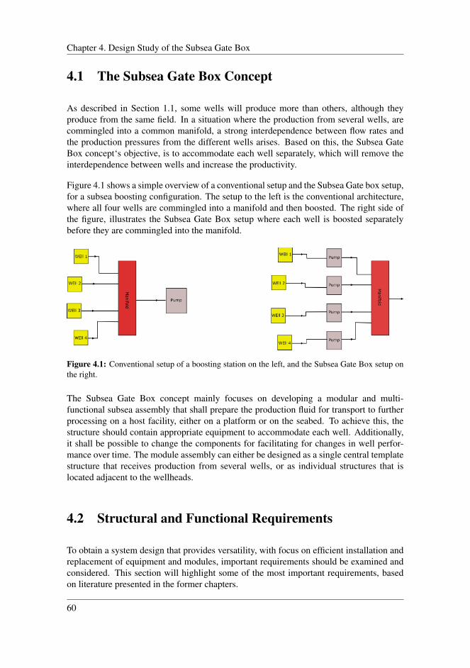
Chapter 4. Design Study of the Subsea Gate Box
4.1 The Subsea Gate Box Concept
As described in Section 1.1, some wells will produce more than others, although theyproduce from the same field. In a situation where the production from several wells, arecommingled into a common manifold, a strong interdependence between flow rates andthe production pressures from the different wells arises. Based on this, the Subsea GateBox concept‘s objective, is to accommodate each well separately, which will remove theinterdependence between wells and increase the productivity.
Figure 4.1 shows a simple overview of a conventional setup and the Subsea Gate box setup,for a subsea boosting configuration. The setup to the left is the conventional architecture,where all four wells are commingled into a manifold and then boosted. The right side ofthe figure, illustrates the Subsea Gate Box setup where each well is boosted separatelybefore they are commingled into the manifold.
Figure 4.1: Conventional setup of a boosting station on the left, and the Subsea Gate Box setup onthe right.
The Subsea Gate Box concept mainly focuses on developing a modular and multi-functional subsea assembly that shall prepare the production fluid for transport to furtherprocessing on a host facility, either on a platform or on the seabed. To achieve this, thestructure should contain appropriate equipment to accommodate each well. Additionally,it shall be possible to change the components for facilitating for changes in well perfor-mance over time. The module assembly can either be designed as a single central templatestructure that receives production from several wells, or as individual structures that islocated adjacent to the wellheads.
4.2 Structural and Functional Requirements
To obtain a system design that provides versatility, with focus on efficient installation andreplacement of equipment and modules, important requirements should be examined andconsidered. This section will highlight some of the most important requirements, basedon literature presented in the former chapters.
60

4.2 Structural and Functional Requirements
4.2.1 Standardized Module Interfaces
To ensure that installation and IMR operations for the functional modules in the SubseaGate Box is as cost efficient as possible, the modular interfaces should be standardized.Ideally, subsea production and processing systems should contain as much standardizedparts as possible, to reduce development costs and to obtain interchangeability. Unfor-tunately, this is not straight forward. No reservoirs are equal, hence different productionand processing developments to some extent requires their own unique solution. However,the framework used for accommodating the equipment, such as retrievable modules andbase structure, has potential to be further standardized. Considering retrievable modules,connector points in which the modules are interconnected, should be standardized bothwith regard to location in which they are placed, and the connector system used. This cancontribute to increase the interchangeability of the equipment, where the production linescan be routed between modules at fixed locations. The idea is to increase the versatility ofthe system where one can change equipment inside the retrievable modules, and keep thesame intermodular connection points. As a result, one can deploy the same modules fromother Gate Box systems that are in stock, without any prior adjustments.
4.2.2 Accessibility and Retrievability
As described in Section 3.3.1, the most "vulnerable" equipment in a subsea productionand processing system should be located at a place where it easily can be retrieved andaccessed by an ROV. The Subsea Gate Box should have an architecture and module designthat facilitates for space to perform inspection and maintenance.
Additionally, a high degree of retrievability should be implemented in the system. Thereby,separate retrieval of the functional modules must be possible. The connector system thatis used for production and control lines should allow fast and simple deployment andretrieval of modules. Accessibility to the actuation mechanism should be sufficient so thatan ROV can easily operate them. Additionally, the number of connectors should be keptas low as possible to reduce installation and retrieval time.
4.2.3 Redundancy
During maintenance or in a situation with equipment failure, the opportunity to bypassproduction fluid around equipment modules should be included in the design. Either to aredundant component, or through the entire processing train. This solution contributes tomitigate production shutdowns, and retrieval of functional modules can subsequently beperformed while keeping the production capacity at an acceptable level.
In a system where the Gate Box consists of several process trains that serves their ownwells, the possibility to reroute the production increases, as equipment from other trains
61
Chapter 4. Design Study of the Subsea Gate Box
can function as a redundant component.
4.2.4 Condition and Performance Monitoring
As explained in Section 3.1.2, condition and performance monitoring can contribute toa more stable operation, and earlier detection of system degradation. This gives a betterdecision making basis for planning and scheduling maintenance of equipment. Some kindof condition and performance monitoring should be considered in the Subsea Gate Boxdesign. This feature is however not included in the illustrations for the cases presentedlater, but rater mentioned here as a general requirement that should be considered, as itcan contribute to further optimize maintenance procedures.
4.2.5 Valve and Connector Actuation
Utilizing ROVs to perform actuation of valves, connectors, and similar, can be time con-suming. To reduce reliance on ROV support, the actuation components should ideally notbe too dependent on this. A step towards all-electric control system, that allows remoteactuation, would be beneficial. As for condition monitoring, this feature is not included inthe illustrations of the cases, but only mentioned here as a general requirement that shouldbe considered for the Gate Box concept.
A hydraulic system for actuation of connectors is in this case required. This is partly be-cause it is by far the most used solution within the industry and in relation to the literaturereview, information regarding electrically operated production connectors have not beeninvestigated.
Subsea control systems are briefly described in Section 2.3. In general, this field is notcovered in detail in this thesis, but as it can potentially contribute to increase the maintain-ability, it is mentioned.
4.2.6 Vessel Requirements
In terms of vessel requirements, the Gate Box should be designed to allow use of alreadyexisting vessels, for both installation and IMR operations. In other words, functional mod-ules should be designed in a such way that they fit the given module handling systemsprovided by the contracted vessels. Operators of the various fields already have long termcontracts with IMR-vessels for performing services. Previously in Section 3.2.1, examplesof module change-outs on the Tordis SSBI are presented. These modules where changedby Normand Ocean and Seven Viking, which is similar light IMR-vessels contracted byStatoil.
62
4.3 Suggestions for Module Architectures and Interfaces
With great flexibility and response time due to its high equipment specifications, thesevessels meet most requirements for performing IMR-operations in today’s market. Stateof the art features, such as large moonpool, dynamic positioning system, crane capacitywith heave compensation, module handling systems and accommodation for work ROVs,are the key features of these vessels.
In special cases, such as the Åsgard Gas Compression project, the vessel North Sea Giantwas modified with a unique special module handling system as described in Section 2.6.4,which is capable of installing large modules up to 420 metric tons. North Sea Giant is alsoon long term contract for serving Åsgard. In special cases, this vessel might be availablefor assistance.
4.3 Suggestions for Module Architectures and Interfaces
As stated in Chapter 3, modularization of the different process equipment basically makesit possible to change individual components and not the entire system. This is one ofthe fundamental features regarding maintainability and versatility in a subsea processingsystem. Further in this section, two different cases for module architecture and connectionconfiguration, are presented. The suggestions are based on the requirements stated above.
4.3.1 Limitations
As stated in Section 1.3, this thesis does not include the processing itself, but mainlyfocuses on modular design and interfaces that contribute to efficient installation and IMRoperations. As described, the components within the modules of the Subsea Gate Box,can be customized for a variety of reservoir conditions. The process and equipment thatare integrated in the two cases, is consequently only an example to give a more holisticoverview of the retrieval possibilities of modules, and at the same time keep the productiongoing. In reality, the equipment could be entirely different. Processing equipment that willbe included are presented under the next heading.
The illustrations provided in the two cases are just simplified sketches and does not containall necessary equipment needed to operate the system. Structural dimensions will not bestated, as the solutions presented only are supposed to show the functional principles ofthe concept, and not a fully functional processing station. Electric and hydraulic lines arenot included, but solutions regarding their connection to the modules in the processingtrains, will be elaborated in Section 4.4. Valves that are integrated in the flow paths are notspecified by type, as they are only added to show the routing options for the productionflow, in case of retrieval of modules for maintenance. Control lines for actuation of theconnectors, are not illustrated, and only explained in words.
Regarding process flow, for simplistic reasons the gas is assumed to flow freely to the host
63

Chapter 4. Design Study of the Subsea Gate Box
without need for compression. To further simplify, it is assumed that there is no sand in theproduction fluid. Therefore, equipment for sand handling is not included. Additionally,the process trains for the two cases presented later are only assumed to accommodate onewell each.
4.3.2 General Process
Based on common components required in a subsea processing facility, the Subsea GateBox contains following equipment:
• Choke valve
• Inlet booster
• Separator
• Flow metering
• Outlet booster
Figure 4.2 shows a simplified overview of the process with the different components. First,the well stream marked in black, which is oil, water and gas, enters a choke that controlsthe inflow. Then it enters an inlet booster pump that can handle multiphase flow. Thispump is optional, as the system can function without it. In this case, it functions as aredundant pump, where the production can be bypassed to other equipment and transporteddirectly to a host facility. This feature is not illustrated in this sketch, but is shown in detailfor the different cases in Figure 4.4, Figure 4.9, and Figure 4.10. Further, the productionfluid enters a separator that separates the three phases. After the separation, the oil (green),water (blue), and gas (red), enters the flow meters. The gas is assumed to flow freely tothe host without the need for compression. The oil and water on the other hand, is boostedby one pump each.
Figure 4.2: Subsea Gate Box process flow diagram.
64

4.3 Suggestions for Module Architectures and Interfaces
4.3.3 Case 1
Figure 4.3 shows a simple overview of the setup that consists of a manifold and two pro-cess trains placed on each side. The two trains also contain the equipment modules, andall these components are again placed on a base frame. Equipment that is to be placedwithin the modules is not included in this figure, but rather given their appropriate name.According to the illustration, the functionality of the modules is only stated on train one,but it is assumed that both trains will contain the same equipment as described in Section4.3.2.
For easy access, the clearance between the manifold and the process modules should besufficient for an ROV to reach the connectors, and tools required to perform connection.This will also result in easier change-out of connector seals, as well as good inspectionconditions within the structure.
The manifold placed between the two trains, contain connection points, in which all func-tional modules are connected. The connectors are based on a horizontal configuration thatextends out from the side of the modules, with either a collet or clamp mechanism. Thisconnector system would require a stroking mechanism as described in Section 2.2.1. Thismechanism can extend and retract one of the connector hubs. Hence, installation and re-trieval of the modules can be performed separately. The hubs containing stroking- andlocking mechanism should be mounted on the retrievable modules in the process trains.This is to allow easier maintenance on connectors, as it would be easier to retrieve thesemodules compared to the manifold. Location of the connectors on the module interfacewill be, as stated in the structural requirements Section 4.2, standardized to increase theversatility, and decrease the development costs.
Figure 4.3: Module overview with horizontal connectors to manifold.
65

Chapter 4. Design Study of the Subsea Gate Box
As shown on in Figure 4.3, the choke module is placed within the manifold. This isbecause the choke is relatively small compared to other modules, and it will not require itsown slot in the production train. Additionally, the choke is in the first stage where the flowenters the system, so that the flow rate can be controlled before it reaches the processingfacility.
Process
Figure 4.4 shows a process flow diagram for the architecture described in Figure 4.3, withequipment and flow paths for both process trains.
Distribution of fluids from the wells to the functional modules in the process trains, isprovided by the manifold. In Figure 4.5, the manifold frame with fluid lines is shown inmore detail. In this case, as illustrated in Figure 4.4, the manifold consists of four distri-bution lines, Distribution Line 1 (black), containing all three phases, Distribution Line2 (green), containing oil, Distribution Line 3 (blue), containing water, and DistributionLine 4 (red), containing gas. Each of these distribution lines presents the opportunityto route the flow to the functional modules, in their associated process train, separately.Additionally, to add redundancy to the system, the fluids can also be rerouted betweenfunctional modules in the two trains, as well as go past modules within the individualtrains. These bypass options are on Figure 4.4 labeled with two numbers that categorizeswhich distribution line it belongs to, and which rerouting option it is. The first bypassoption for distribution line 1 is (1.1), the second (1.2), etc. For distribution line 2, the firstbypass option will be (2.1), the second (2.2), and so forth. The labels are also given theirappropriate color according to the fluid phase.
The first option to redirect the flow from the wells, will be before the chokes in distributionline 1, through bypass (1.1). By closing the valve before one of the chokes, and openingthe valve on the bypass line, the flow can be combined with the fluid from the other processtrain. This makes it possible to perform maintenance on modules in one train and redirectthe flow to the other. Further, the unseparated well stream in distribution line 1, from eitherboth, or only one well, can bypass the multiphase pumps (MP-001) and (MP-002) throughline (1.2) and (1.3). After the chokes and the multiphase pumps, the flow from the twowells have the option to be routed into their corresponding separators, or rerouted to theseparator on the other train through (1.4). Additionally, the unseparated fluid can bypassboth the separator modules (TK-001) and (TK-002) by entering the Distribution Line 2through (1.5). Here, it can either be distributed into the metering modules and the outletbooster modules, or pass all the modules. In the latter case, the multiphase pumps canfunction as a redundant pump and boost the production up to the host facility for furtherprocessing.
When the production from well 1 and well 2 are directed into their corresponding separa-tors in distribution line 1, the separated fluids oil, water and gas then enters the side of thedistribution lines that is associated with their process train. The water that are separatedout in (TK-001), enters distribution line 3, and can be rerouted to the other train through
66
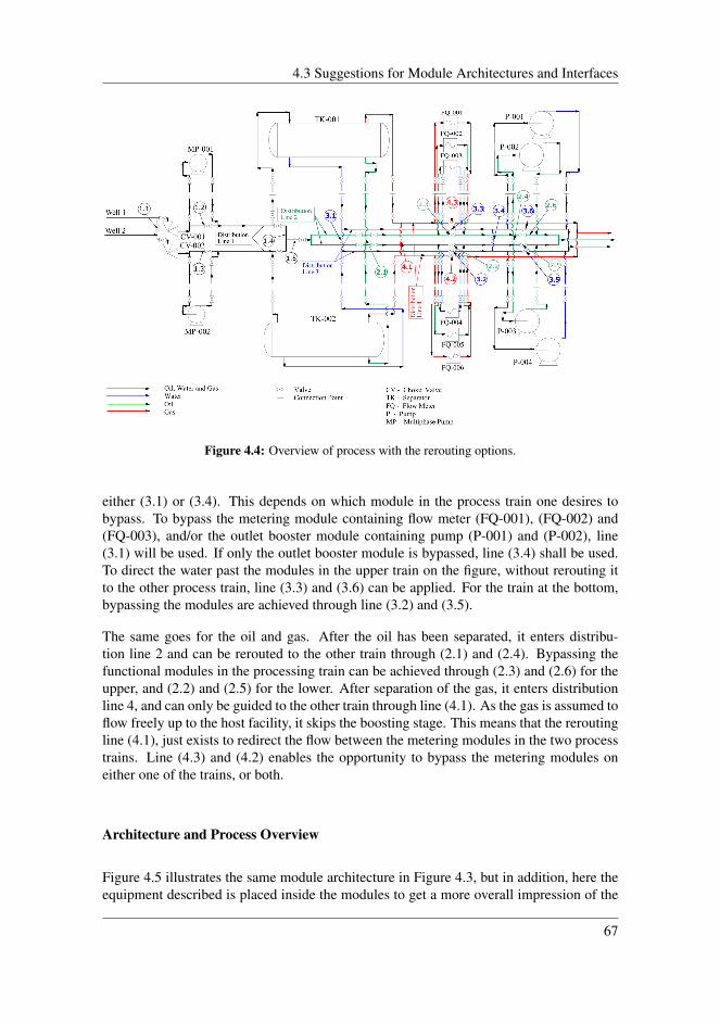
4.3 Suggestions for Module Architectures and Interfaces
Figure 4.4: Overview of process with the rerouting options.
either (3.1) or (3.4). This depends on which module in the process train one desires tobypass. To bypass the metering module containing flow meter (FQ-001), (FQ-002) and(FQ-003), and/or the outlet booster module containing pump (P-001) and (P-002), line(3.1) will be used. If only the outlet booster module is bypassed, line (3.4) shall be used.To direct the water past the modules in the upper train on the figure, without rerouting itto the other process train, line (3.3) and (3.6) can be applied. For the train at the bottom,bypassing the modules are achieved through line (3.2) and (3.5).
The same goes for the oil and gas. After the oil has been separated, it enters distribu-tion line 2 and can be rerouted to the other train through (2.1) and (2.4). Bypassing thefunctional modules in the processing train can be achieved through (2.3) and (2.6) for theupper, and (2.2) and (2.5) for the lower. After separation of the gas, it enters distributionline 4, and can only be guided to the other train through line (4.1). As the gas is assumed toflow freely up to the host facility, it skips the boosting stage. This means that the reroutingline (4.1), just exists to redirect the flow between the metering modules in the two processtrains. Line (4.3) and (4.2) enables the opportunity to bypass the metering modules oneither one of the trains, or both.
Architecture and Process Overview
Figure 4.5 illustrates the same module architecture in Figure 4.3, but in addition, here theequipment described is placed inside the modules to get a more overall impression of the
67
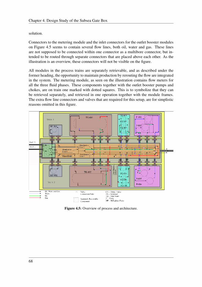
Chapter 4. Design Study of the Subsea Gate Box
solution.
Connectors to the metering module and the inlet connectors for the outlet booster moduleson Figure 4.5 seems to contain several flow lines, both oil, water and gas. These linesare not supposed to be connected within one connector as a multibore connector, but in-tended to be routed through separate connectors that are placed above each other. As theillustration is an overview, these connectors will not be visible on the figure.
All modules in the process trains are separately retrievable, and as described under theformer heading, the opportunity to maintain production by rerouting the flow are integratedin the system. The metering module, as seen on the illustration contains flow meters forall the three fluid phases. These components together with the outlet booster pumps andchokes, are on train one marked with dotted squares. This is to symbolize that they canbe retrieved separately, and retrieved in one operation together with the module frames.The extra flow line connectors and valves that are required for this setup, are for simplisticreasons omitted in this figure.
Figure 4.5: Overview of process and architecture.
68
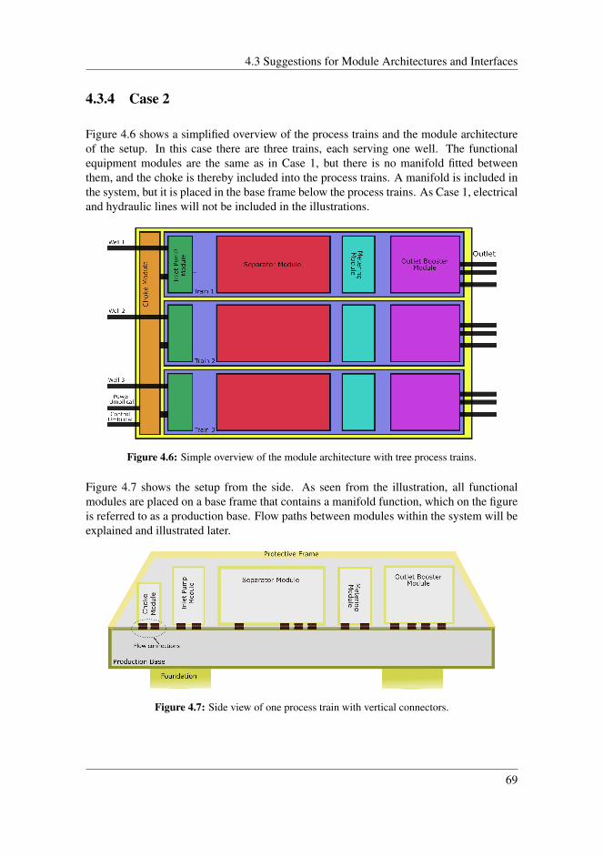
4.3 Suggestions for Module Architectures and Interfaces
4.3.4 Case 2
Figure 4.6 shows a simplified overview of the process trains and the module architectureof the setup. In this case there are three trains, each serving one well. The functionalequipment modules are the same as in Case 1, but there is no manifold fitted betweenthem, and the choke is thereby included into the process trains. A manifold is included inthe system, but it is placed in the base frame below the process trains. As Case 1, electricaland hydraulic lines will not be included in the illustrations.
Figure 4.6: Simple overview of the module architecture with tree process trains.
Figure 4.7 shows the setup from the side. As seen from the illustration, all functionalmodules are placed on a base frame that contains a manifold function, which on the figureis referred to as a production base. Flow paths between modules within the system will beexplained and illustrated later.
Figure 4.7: Side view of one process train with vertical connectors.
69
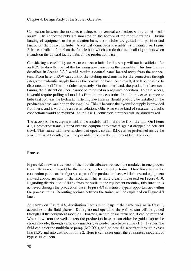
Chapter 4. Design Study of the Subsea Gate Box
Connection between the modules is achieved by vertical connectors with a collet mech-anism. The connector hubs are mounted on the bottom of the module frames. Duringlanding of equipment to the production base, the modules are guided into position andlanded on the connector hubs. A vertical connection assembly, as illustrated on Figure2.5a has a built-in funnel on the female hub, which can do the last small alignments whenit lands on the upward facing hubs on the production base.
Considering accessibility, access to connector hubs for this setup will not be sufficient foran ROV to directly control the fastening mechanism on the assembly. This function, asdescribed in Section 3.3.3 would require a control panel located away from the connec-tors. From here, a ROV can control the latching mechanisms for the connectors throughintegrated hydraulic supply lines in the production base. As a result, it will be possible todisconnect the different modules separately. On the other hand, the production base con-taining the distribution lines, cannot be retrieved in a separate operation. To gain access,it would require pulling all modules from the process trains first. In this case, connectorhubs that contains the hydraulic fastening mechanism, should probably be installed on theproduction base, and not on the modules. This is because the hydraulic supply is providedfrom here, and it would be an better solution. Otherwise some kind of separate hydraulicconnections would be required. As in Case 1, connector interfaces will be standardized.
The access to the equipment within the models, will mainly be from the top. On Figure4.7, a protective frame is fitted over the equipment to protect against dropped objects andtrawl. This frame will have hatches that opens, so that IMR can be performed inside thestructure. Additionally, it will be possible to access the equipment from the sides.
Process
Figure 4.8 shows a side view of the flow distribution between the modules in one processtrain. However, it would be the same setup for the other trains. Flow lines below theconnection points on the figure, are part of the production base, while lines and equipmentshowed above, are part of the modules. This is more clearly illustrated on Figure 4.10.Regarding distribution of fluids from the wells to the equipment modules, this function isachieved through the production base. Figure 4.8 illustrates bypass opportunities withinthe process trains. Rerouting options between the trains, will be explained on Figure 4.9later.
As shown on Figure 4.8, distribution lines are split up in the same way as in Case 1,according to the fluid phases. During normal operation the well stream will be guidedthrough all the equipment modules. However, in case of maintenance, it can be rerouted.When flow from the wells enters the production base, it can either be guided up to thechoke module, through vertical connectors, or guided into bypass line (1.1). Further, thefluid can enter the multiphase pump (MP-001), and go past the separator through bypassline (1.3), and into distribution line 2. Here it can either enter the equipment modules, orbypass all of them.
70
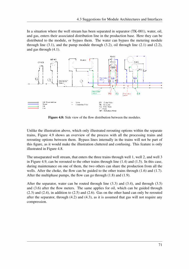
4.3 Suggestions for Module Architectures and Interfaces
In a situation where the well stream has been separated in separator (TK-001), water, oil,and gas, enters their associated distribution line in the production base. Here they can bedistributed to the module, or bypass them. The water can bypass the metering modulethrough line (3.1), and the pump module through (3.2), oil through line (2.1) and (2.2),and gas through (4.1).
Figure 4.8: Side view of the flow distribution between the modules.
Unlike the illustration above, which only illustrated rerouting options within the separatetrains, Figure 4.9 shows an overview of the process with all the processing trains andrerouting options between them. Bypass lines internally in the trains will not be part ofthis figure, as it would make the illustration cluttered and confusing. This feature is onlyillustrated in Figure 4.8.
The unseparated well stream, that enters the three trains through well 1, well 2, and well 3in Figure 4.9, can be rerouted to the other trains through line (1.4) and (1.5). In this case,during maintenance on one of them, the two others can share the production from all thewells. After the choke, the flow can be guided to the other trains through (1.6) and (1.7).After the multiphase pumps, the flow can go through (1.8) and (1.9).
After the separator, water can be routed through line (3.3) and (3.4), and through (3.5)and (3.6) after the flow meters. The same applies for oil, which can be guided through(2.3) and (2.4), in addition to (2.5) and (2.6). Gas on the other hand can only be reroutedafter the separator, through (4.2) and (4.3), as it is assumed that gas will not require anycompression.
71
Chapter 4. Design Study of the Subsea Gate Box
Figure 4.9: Overview of the process with rerouting possibilities between the trains.
On Figure 4.9, it is illustrated that the three phases oil, water, and gas from three pro-cess trains have separate outlets. Water-, oil- and gas production from these trains can becommingled into one line, but with regard to simplicity, this option is not included.
Architecture and Process Overview
Figure 4.10 and 4.11 shows the process drawings described earlier placed within the mod-ule frames. As in Case 1, Figure 4.10 only illustrates two connectors on the meteringmodule. Since the system is shown from the side, only the foremost connectors are visible.Hence, production lines for oil, water, and gas appears to go through the same connectors.In reality these lines will have their own connectors placed behind each other.
On Figure 4.11, an overview of the process trains is presented. Flow lines, which on thefigure appears to be routed between the modules, are originally installed in the productionbase and would not be visible. However, to show an overall view of the process, it isincluded. Additionally, connectors between modules are not illustrated in this figure, andalthough the pumps in the outlet booster modules are placed in the same module as in Case1, they can be retrieved separately. The same applies for the chokes.
72

4.4 Multibore Connection Approach
Figure 4.10: Side view of modules with process.
Figure 4.11: Process overview with module architecture.
4.4 Multibore Connection Approach
The illustrations presented in Case 1 and 2, only illustrated connectors and lines for pro-duction flow. When electric and control lines are included in the system, number of con-nection points increases significantly. Further, connection options for electrical and hy-draulic supply will be presented with illustrations for both Case 1 and 2. The figures arehighly simplified, and does not include all necessary control lines to operate the system.The only purpose is to show the general principle behind the connection solution.
Figure 4.12 shows an overview of the setup in Case 1 with separate inlets for electrical andcontrol signals on one module. All the equipment modules in the system requires somekind of power supply, but to simplify, it is only included on the separator modules. In this
73
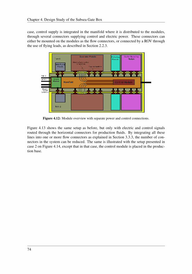
Chapter 4. Design Study of the Subsea Gate Box
case, control supply is integrated in the manifold where it is distributed to the modules,through several connectors supplying control and electric power. These connectors caneither be mounted on the modules as the flow connectors, or connected by a ROV throughthe use of flying leads, as described in Section 2.2.3.
Figure 4.12: Module overview with separate power and control connections.
Figure 4.13 shows the same setup as before, but only with electric and control signalsrouted through the horizontal connectors for production fluids. By integrating all theselines into one or more flow connectors as explained in Section 3.3.3, the number of con-nectors in the system can be reduced. The same is illustrated with the setup presented incase 2 on Figure 4.14, except that in that case, the control module is placed in the produc-tion base.
74
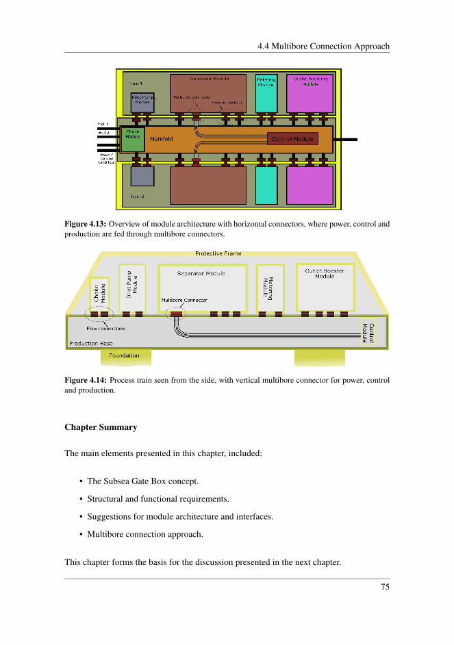
4.4 Multibore Connection Approach
Figure 4.13: Overview of module architecture with horizontal connectors, where power, control andproduction are fed through multibore connectors.
Figure 4.14: Process train seen from the side, with vertical multibore connector for power, controland production.
Chapter Summary
The main elements presented in this chapter, included:
• The Subsea Gate Box concept.
• Structural and functional requirements.
• Suggestions for module architecture and interfaces.
• Multibore connection approach.
This chapter forms the basis for the discussion presented in the next chapter.
75

Chapter 4. Design Study of the Subsea Gate Box
76

Chapter 5Discussion
This chapter, compares the two presented cases against each other, to determine how wellthey fit the requirements stated in Section 4.2. The purpose is to highlight advantages anddrawbacks with both solutions, and thereby be able to point out the most advantageoussetup.
5.1 General Requirements
In Section 4.2, some requirements for the Gate Box concept were stated. However, not allof them are illustrated and explained in the two cases. Rather they are listed as general re-quirements that should be considered in the development of the Subsea Gate Box concept.Some of them will be discussed in the following section.
5.1.1 Standardization
As one for the goals for the Subsea Gate Box is to accommodate several well configura-tions, a degree of versatility in the system architecture should be allowed. However, asexplained in Section 3.3.4, some standardization of the functional building blocks will bebeneficial in terms of future operations and development costs. Equipment placed withinthe modules may vary depending on the requirement from the wells. Additionally, therequirements stated in Section 4.2, point out that module interfaces are to be standardizedin terms of connector system and their location on the modules. This feature is supposedto ensure the versatility and interchangeability of the system, where the same structuralmodule frames can be used, to accommodate tailor made equipment in the frame. Stan-
77
Chapter 5. Discussion
dardized modules enable interchangeability across various Gate Box systems. However,an important factor to have in mind, is that standardization should not come in the way offurther enhancements, and not compromise either quality or functionality of the system.After all, the goal is to obtain these features.
5.1.2 System Size
In Section 3.3.2, it is stated that size an weight of modules should be kept as low as pos-sible. As indicated in the figures of the presented cases, the systems might be extensive.For instance, the Tordis separator presented in Section 3.2.1, is 17 meters long, and havea diameter of 2.1 meters. Such dimensions, and weight may be a limiting factor for real-izing the system. Thereby, the applicability of compact solutions, for instance, separation,should be examined to decrease the overall system size.
5.1.3 Vessel Requirements
Marine operations related to installation and IMR-operations for subsea systems, repre-sents significant costs for the operators. High demands for safety, competence and callouts at any time, are some of the elements that drives the cost up. To meet all demands,both operations and IMR-vessels has to be "state of the art". Associated costs for these op-erations are naturally necessary to ensure the desired availability. However, by improvingthe efficiency of the operations, costs may be reduced.
Since module design for both cases are equal, the corresponding vessel requirements forboth of them are alike. The only difference, is the production train architecture. From therequirements in Section 4.2.6, it is stated that the modules in the Gate Box should allowuse of already existing vessels for installation and IMR operations. As described, size andweight of modules are of significant interest and should be within reasonable limits. Themain reason is the handling capacity for intended vessels. From Table 3.4, it is seen thatmodule size should not exceed 70 metric tons or the dimension of 7.2 x 7.2 meters. Ingeneral, lighter and more compact modules enable use of lighter vessels, which in turn aremore reliable and affordable to hire.
IMR vessels are equipped with work ROVs for assisting installation and intervention tasks.Tooling interfaces on equipment should be in compliance with standardized ROV tools. Interms of inspection, as presented in Section 2.6.5, there are recently ongoing developmentswithin underwater vehicles that can contribute to reduce inspection costs. These vehiclesare intended to be permanently placed on the seabed. This means that inspections can beperformed from onshore, instead of sending an IMR-vessel for deploying an ROV whichis dependent on an umbilical extended from the vessel. Compared to traditional ROVsystems, the AUV system can be a promising system for the future, since it can maneuverinto more confined spaces, and are independent from weather conditions. This advantagemay potentially contribute to a more compact system design. The AUV systems are not
78
5.2 Case 1
investigated in detail in this thesis, but are a technology that should be further consideredfor the Subsea Gate Box.
5.1.4 Control Systems
As stated in Section 4.2.5, the control system for the Gate Box should in a least possiblemanner rely on ROV support, and instead ,if possible, be based on an all-electric controlsystem approach. As described in Section 2.3, an all-electric system has several benefitswith regard to actuation time and reduced umbilical costs.
However, for actuation of connectors, a hydraulic system is in this case assumed. Thisthesis does not go into detail on the control system itself, but briefly describes the differenttypes, as it can be a factor that contributes to decrease actuation time, and furthermoreaffect the maintainability. A more thoroughly study on this feature should be considered.
5.1.5 Monitoring and Maintenance Strategy
The simplified example presented in Section 3.1.2 shows that implementation of a con-dition based maintenance strategy can bring great benefits. Being able to predict futureevents gives a better basis for planning and scheduling of maintenance operations. In turn,this leads to reduced downtime and reduced costs for the operations.
Implementation of performance monitoring as presented in Section 3.1.3, regarding theGjøa Field, proves the obtained benefits by implementing monitoring on the performanceof the producing system. This has given indispensable information which enable the abilityto plan maintenance and predict upcoming incidents.
A similar system should be considered for development of the Gate Box concept. A pro-cessing system contains a large number of valves and connectors. Subsea leak detection isa technology under development that would be interesting to implement in the concept.
5.2 Case 1
The setup in Case 1, as seen in Figure 4.5, consists of two process trains, with a manifoldplaced between them. In this section both advantages and disadvantages will be discussed.
79

Chapter 5. Discussion
5.2.1 Advantages
For Case 1, modules from the two trains are connected to the manifold by horizontalconnectors with a stroking mechanism. In this setup, it is allowed enough space betweenthe manifold and the modules. As a result, an ROV can access and actuate the lockingmechanism directly onto the connector assemblies. This space also contributes to easierinspection, and access to modules in both process trains. Because of the direct access toconnectors, there is no need for any complex latching system. As stated in Section 2.2.1,and Table 2.1, this configuration only requires a simple clamp connector operated by atorque tool.
An additional advantage is that changing seals is rather easy, and can be accomplishedwithout retrieving any modules, since the stroking feature can be used to achieve access.The horizontal connection configuration also allows separate retrieval of all modules inthe process trains, including the manifold, but in the latter case, all connections must bedisconnected. Retrieval of the flow meters, outlet booster pumps, and chokes, can both beremoved separately, and in one operation. This solution can contribute to reducing instal-lation and retrieval time. Additionally, rerouting of the flow can be achieved both betweenthe two process trains, and by bypass options within them. This feature is beneficial interms of allowing production to proceed, while performing maintenance on one of thetrains.
Regarding maintenance on the connectors, it will in this case be possible to mount theconnector hubs that contain the stroking feature and locking mechanism on the retrievablemodules in the process trains. This is a preferable solution, as it is both easier and lesscostly to retrieve the smaller modules, rather than the manifold.
5.2.2 Disadvantages
Placement of the manifold is a limiting factor in terms of how many processing trains theSubsea Gate Box can accommodate. For this case, it is only possible to connect modulesalong the manifold sides. An option could be to place two process trains on top of eachother on both sides of the manifold. However, this would affect the retrievability of thelower modules, and additionally increase the structural strength required to tolerate theadded weight on the lower trains. An additional solution could be to take the manifold outof the structure, and rather locate it nearby as a separate system. In this case, it is possibleto add more process trains, as the module configuration will be similar to Case 2. On theother hand, redundancy in term of rerouting between the separate trains, will not be pos-sible to the same extent as the presented cases. Additionally, it could potentially increasethe number of installation operations, as the manifold would require its own foundationstructure.
Regarding sufficient access to equipment, there is a trade-off involved in achieving a com-pact solution, and at the same time facilitate for adequate inspection and availability to
80
5.3 Case 2
components. A result may be an increase of the structural footprint in addition to theweight. This can further affect the installation operation, since one may need a largerinstallation vessel, which again can increase the cost of the operation.
As previously explained, rerouting options for the flow has its benefits. However, it alsohas some disadvantages. The number of valves required in the system increases, and be-cause all of them need some kind of control, it becomes more complex. This can also affectthe total weight and cost of the structure. Hence, it can be important during the develop-ment phase to evaluate at which extent one need rerouting possibilities for all the equip-ment modules. In general, components that require more frequent maintenance should beprioritized.
Regarding the duration for performing connection of the functional modules, as stated inTable 2.1, this setup will be relatively slow and challenging. This problem occurs becausethe ROV has to physically access all the different connectors in which both the strokingand locking mechanism must be initiated.
As explained in Section 4.3.3, connectors into the metering modules and inlet to the outletbooster module, appears to contain several lines. This was not the case, as they were in-stead routed through separate connectors placed above each other. With this setup as elab-orated in Section 3.3.3, one should be aware of potential misalignment problems. Placingconnectors too far apart in either horizontal or vertical direction, can result in complica-tions during stroking of the assemblies towards the opposite facing hubs. Small deviationson the base frame, or module frame can therefore result in an incomplete connection. Forlonger rigid tie-in spools, it is usually room for some flexibility and alignment is conse-quently relatively easy. However, on intermodular connections tie-in distances are quiteshort. This affects the flexibility of the pipes, and corrections for misalignment can bemore difficult. A guiding system for retrievable modules, that can handle the requiredalignment tolerances, can be an important feature to include in the design.
5.3 Case 2
Figure 4.10 and 4.11 shows the setup of Case 2, which consist of three process trainsplaced on top of a production base. As in Case 1, this solution also has its advantages anddisadvantages.
5.3.1 Advantages
The fact that Case 2 accommodates three processing trains, is just used as an example. Itcan consist of a variety of different train configurations, depending on the number of wellsto host. This contributes to increase the versatility of the system, as it potentially can servemore wells compared with the setup in Case 1. Naturally, there are limitations regarding
81
Chapter 5. Discussion
size and weight, as installation may become too challenging and costly.
Regarding retrievability of components in this setup, as in Case 1, all equipment modulesin the process trains can be retrieved separately. Additionally, rerouting options betweenthem are facilitated to the same extent as Case 1.
In Case 2, connectors are placed at the bottom of the module frame, and direct ROV accessis not possible. Actuation of the connectors will in this case need to be conducted froman ROV-panel placed in distance from the assemblies. Such solution would require anintegrated hydraulic system that is routed to all the connectors. This may be an advantagewhere actuation of the different connectors can be conducted relatively fast. The mainreason is that there are less connector tools that must be deployed, and an ROV does nothave to move around inside the structure as in Case 1. The only action needed from theROV, is to apply hydraulic power into the panel.
Landing the modules onto the connectors on the production base can, in this case, beconducted relatively easy. As in Case 1, one should keep in mind possible misalignmentcomplications and assure a proper guidance system, to ensure that the modules fit thetolerance requirements.
5.3.2 Disadvantages
As mentioned in the previous section, all the modules in the process trains can be retrievedseparately. However, unlike in Case 1, the manifold function which in this case is locatedin the production base, cannot be retrieved separately. This action would require retrievalof all the other modules first, and can be a drawback in terms of availability of components,such as the subsea control module. As illustrated in Figure 4.14, the SCM is placed in theproduction base. To be able to reach this component, it should be located in a place wheresufficient access is provided.
Access to the modules in the process trains may in this case be restricted compared toCase 1. As explained in Section 3.3.1, this mainly includes the middle train, where thetwo other trains potentially can restrict both access and view to the equipment. A solutioncould be to facilitate for easy access from above.
In Case 2, the connector assembly containing hydraulic actuation mechanism, is mountedon the production base. This is because hydraulic supply has to be available during ac-tuation. By placing it on the retrievable modules, actuation will not be achieved duringinstallation, as the module at this point is separated from the production base. Mainte-nance on a connector will therefore require retrieval of the production base, which, asmentioned earlier, requires disconnection and retrieval of all the modules. However, thiscan be avoided with some kind of hydraulic connection system that is integrated into theinterface between the modules and the production base. With this solution, the connectorassemblies can be mounted onto modules in the process trains instead. To achieve con-nection when modules are landed on the base structure, hydraulic supply from lines on
82

5.4 Case Summary
the modules actuates the connector mechanism. Another solution could be to implement aretrieval solution for the connector assemblies. In this case it is only necessary to removethe equipment modules, and subsequently retrieve the connectors. These solutions is notstudied in this thesis but can be important factors that should be further investigated.
Regarding change-out of connector seals, it is probably more difficult in this configuration,as equipment modules must be removed to achieve access to the connector assembly.
5.4 Case Summary
Table 5.1 summarizes the advantages and disadvantages presented previously for the twocases. This is done by comparing them against several criteria, and indicate which of thetwo cases that fulfills them. All the criteria mentioned is related to the stated requirements.The columns for Case 1 and Case 2 contain either a 1 or a 0. A 1 symbolizes the case thatsatisfies the criteria the most, and 0 the case that fulfills it the least.
Table 5.1: Case comparison.
Criteria Case 1 Case 2
Redundancy 1 1Accessibility 1 0Connection duration 0 1Low ROV dependence 0 1Number of Trains 0 1Seal change 1 0Compactness 0 1Retrievability 1 0Sum 4 5
As seen from the summation on the bottom row of the table, both cases has almost equalscores. Regardless of this, Case 2 appears to be the best solution. However, some ofthese criteria are more significant than others, and that is not considered. For instance,considering retrievability, it is possible to separately remove all the functional modulesin both cases. The only difference, is that the manifold in Case 2 is restricted by thetrains placed on top. This is why Case 1 is indicated as a better solution in this criterion.On the other hand, retrieval of a manifold for maintenance is not that common comparedwith pumps, chokes, etc. Additionally, connection and disconnection of modules in Case2 are both simpler, faster, and less ROV dependent than Case 1. As stated in the table,Case 2 also has less restrictions on number of process trains it can contain, and it haspotential to be a more compact solution, compared to Case 1. In terms of redundancy, theyboth provide the same extent of rerouting options. The only down sides are the possibleaccessibility and seal change restrictions.
83
Chapter 5. Discussion
5.5 IPB Connector Configuration
In Section 4.4, a suggestion for including production and control lines in the same con-nector is presented. As described in Section 3.3.3, the main advantage with this setup, isthat it can decrease the amount of connectors needed in the system. Hence, time spent onconnection operations during installation or maintenance, can potentially be reduced.
Apart from the possible advantages, connecting several lines within one assembly may alsohave some potential challenges. As one can imagine, the size of the individual connectorswill probably increase due to the added lines. Additionally, the amount of individual lineson the connector interface may contribute to further increase complexity of the connector.Also, due to the added size, the weight of the assembly may be affected.
It should be mentioned that there is some uncertainties regarding this specific subject. Thisis mainly because it was not found any literature on already existing systems that haveintegrated this solution for intermodular connections. The only similar use that was foundin the literature, had included this setup in a tie-in spool between X-mas tree and manifold,as showed on Figure 2.17. Although, as little information about the applicability of thisspecific solution were found, the potential benefits it can provide, regarding installationand maintenance, can be significant. Consequently, a further investigation into the subjectshould be conducted.
84
Chapter 6Conclusion and Further Work
6.1 Conclusion
Based on the literature study, it was found that to obtain a subsea production and process-ing system, that is both versatile and enables easy installation and retrieval of modules, thefollowing requirements should be fulfilled:
• Standardized module interfaces.
• Sufficient access to important equipment.
• Easy module retrievability.
• Redundancy and rerouting options.
• Module design in accordance to requirements from already existing IMR-vessels.
• Implementation of condition and performance monitoring to optimized interventionfrequency.
Two cases with different architecture and connector configuration between modules werepresented. Based on the comparison of these cases in the discussion, Case 2 appears to bethe most satisfactory setup in accordance with the stated requirements. A high degree ofretrievability, redundancy, and versatility, is obtained in the design. However, it should berecognized that the size and weight of the two cases can be a limiting factor. Therefore,compact solutions that can contribute to mitigate these limitations, should be considered.The Subsea Gate Box concept is still at an early stage in the conceptual development, andsuggesting a final solution would thereby be difficult.
85
Chapter 6. Conclusion and Further Work
Considering the possible benefits by connecting control- and production lines in the sameconnector, it shows good potential as it can reduce the duration of Installation and mainte-nance operations.
6.2 Recommendations for Further Work
This thesis presents the fundamental design factors that should be considered during thedesign of the Gate Box. These factors are then used as a theoretical foundation for thesetups presented in the two cases. However, there are some solutions that are not includedand only briefly mentioned. The main elements in this thesis that should be further inves-tigated, includes the following tasks:
1. Perform a feasibility study on the us of Integrated Production Bundle (IPB) connec-tors for connections between modules.
2. Conduct an investigation on the possible effects an all-electric control system canhave on the maintainability of a subsea production and processing system.
3. Investigate the feasibility of facilitating for an AUV systems to perform interventiontasks, and additionally the potential benefits this can have on the structural design,in terms of achieving a compact structure as well as easy IMR.
86
Bibliography
[1] SUBPRO. Report 2017. Annual Report, Norwegian University of Science and Tech-nology, 2017.
[2] Norwegian Petroleum Directorate. The shelf in 2015 – investment and cost fore-casts, 2016. URL: http : / / www . npd . no / en / news / News / 2016 /Summary/Investment- and- cost- forecasts/. Access date: 02-03-2017.
[3] O. Økland, S. Davies, R. M. Ramberg, and H. Rognø. Steps to the subsea factory.In OTC 24307. Offshore Technology Conference, 2013. Rio de Janeiro, Brasil.
[4] Subsea World News. Watch: Statoil, OneSubsea on subsea compression at OTC,2015. URL: http://subseaworldnews.com/2015/05/07/watch-statoil-onesubsea-on-subsea-compression-at-otc/. Accessdate: 15-03-2017.
[5] A.Radicioni and M. Fontolan. Open source architectures development for subseafactory. In OTC 26628. Offshore Technology Conference, 2016. Kuala Lumpur,Malaysia.
[6] FMC Technologies. Vecon Tie-in System. URL: http : / / www .fmctechnologies . com / en / SubseaSystems / Technologies /SubseaProductionSystems / TieInAndFlowlines /VerticalAndHorizontalTieInSystems/VerticalTieIn/VECON.aspx#. Access date: 15-02-2017.
[7] FMC Technology. Vertical tie-in system. Brochure, NO-3601 Kongsberg.
[8] FMC Technology. Horizontal tie-in system. Brochure, NO-3601 Kongsberg.
[9] J.L. Lafitte, M. Perrot, J. Lesgent, J. Bouville, S. Le Pennec, P. Dahl, and S. Lind-seth. Dalia Subsea production system, presentation and challenges. In OTC 18541.Offshore Technology Conference, 2007. Huston Texas, U.S.A.
87
[10] Yong Bai and Qiang Bai. Chapter 21 - subsea connections and jumpers. In Sub-sea Engineering Handbook, pages 663–701. Gulf Professional Publishing, Boston,2010. ISBN: 978-1-85617-689-7.
[11] Freudenberg. Vector (SPO) compact flange, 2016. URL: http://www.fogt.com/Compact-Flange-Vector-SPO.html. Access date: 13-02-2017.
[12] Freudenberg Oil & Gas Technology. Vector Techlok clamp connector, 2017. URL:http://www.freudenberg-og.com/clamp-connector.html. Ac-cess date: 05-04-2017.
[13] OCEANEERING. Grayloc Technology. URL: http://www.oceaneering.com/grayloc/grayloc-technology/. Access date: 13-02-2017.
[14] Subsea Design. ‘SeAlign’ – self aligning connector, 2017. URL: http : / /subseadesign.com/?page_id=114. Access date: 13-02-2017.
[15] Cameron. HCH4 collet connector. URL: https : / / cameron . slb . com /products - and - services / drilling / pressure - control -equipment/collet-connectors/hch4-collet-connector. Accessdate: 13-02-2017.
[16] Phil Collins. Umbilicals, 2017. URL: http://www.subseapedia.org/w/index.php?title=Umbilicals. Access date: 17-03-2017.
[17] Oilfield Wiki. (subsea) umbilical termination assembly (uta), 2011. URL: http://www.oilfieldwiki.com/wiki/File:SUTA.png. Access date: 18-03-2017.
[18] Subsea World News. Viper Subsea Inks collaboration agreement with AustralianVelocious, 2012. URL: http : / / subseaworldnews . com / 2012 / 04 /26 / viper - subsea - inks - collaboration - agreement - with -australian-velocious/. Access date: 21-04-2017.
[19] D.Carrè and J. O’Sullivan. Moho bilbado: subsea production system experience. InOTC 20280. Offshore Technology Conference, 2009. Huston Texas, USA.
[20] Aker Solutions. Aker solutions and total collaborate to cut subsea field developmentcosts, 2016. URL: http://akersolutions.com/news/news-archive/2016/aker-solutions-and-total-to-cooperate-on-subsea-technology-development/. Access date: 16-05-2017.
[21] Gary Galle and Rudolf Bond. The nonoriented, multiple passageway flowline con-nection system. Transactions-American Society of Mechanical Engineers Journalof Energy Resources Technology, 122(1):42–47, 2000.
[22] Cindy Krishna and Michel Lefrançois. Metal seal technology in subsea applications.In OTC-26912-MS. Offshore Technology Conference, 2016. Huston, Texas, USA.
[23] Yong Bai and Qiang Bai. Chapter 7 - subsea control. In Subsea Engineering Hand-book, pages 193–224. Gulf Professional Publishing, Boston, 2010. ISBN: 978-1-85617-689-7.
[24] Yong Bai and Qiang Bai. Chapter 19 - subsea manifolds. In Subsea EngineeringHandbook, pages 571–632. Gulf Professional Publishing, Boston, 2010. ISBN: 978-1-85617-689-7.
88
[25] Offshoretechnology.com. Well oiled-new standards for subsea valves. URL: http://www.offshore- technology.com/features/feature96758/feature96758-3.html. Access date: 05-04-17.
[26] Offshoretechnology.com. Well oiled-new standards for subsea valves. URL: http://www.offshore- technology.com/features/feature96758/feature96758-2.html. Access date: 05-04-17.
[27] FMC Technology. Chokes and Flow Modules. Brochure, Houston TX 77067.
[28] Subsea Intervention Systems. Norsk Standard U-007, Norwegian Technology Cen-tre, Oslo, NO, June 1998.
[29] Criticality analysis for maintenance purposes. Standard NORSOK (Z)-008, Norwe-gian Technology Centre, Oslo, Norway, November 2001.
[30] Efosa Emmanuel Uyiomendo and Tore Markeset. Subsea maintenance service de-livery: Mapping factors influencing scheduled service duration. Article 7(2) May2010, International Journal of Automation and Computing, 2010.
[31] Yong Bai and Qiang Bai. Chapter 5 - installation and vessels. In Subsea EngineeringHandbook, pages 139–158. Gulf Professional Publishing, Boston, 2010. ISBN: 978-1-85617-689-7.
[32] Eidesvik. Seven Viking. URL: https : / / www . eidesvik . no / seven -viking/category186.html#. Access date: 09-06-2017.
[33] Helge Johnsgard and Elisabeth Gjølmesli. Installation of subsea modules. MarineOperations a Brief Summary of Operations and Engineering:32–35, 2011.
[34] Erlend Revheim. Moonpool operations on Havila subsea – improvement study.Master‘s thesis, University of Stavanger, 2012.
[35] Ingvild Roti. Seastate limitations for the deployment of subsea compression stationmodules. Master‘s thesis, Norwegian University of Science and Technology, 2012.
[36] AxTech. 420t special handling system, 2017. URL: http://www.axtech.no/index.php/system-solutions/420t-special-handling-system. Access date: 02-06-2017.
[37] Anders Selvåg. Wave Impact Forces on complex structures during lowering throughthe splash zone. Master‘s thesis, Norwegian University of Science and Technology,2013.
[38] OCEANEERING. Millennium plus ROV. URL: http://www.oceaneering.com/rovs/rov-systems/millennium-plus-rov/. Access date 10-05-2017.
[39] Elumee Subsea Intervention. The story. URL: https://eelume.com/#the-story. Access date: 25-05-2017.
[40] Bjørn Sørgård and Anders Husby. Subsea Standard & Rules - What is Subsea?Presentation, DNV GL Oil & Gas, 2011.
[41] Håvard Brandt and Remi Eriksen. RAM analysis for deepwater subsea develop-ments. In OTC 13003. Offshore Technology Conference, 2001. Huston Texas, USA.
89
[42] ReliaSoft Corporation. Reliability basics. URL: http : / / weibull . com /hotwire/issue26/relbasics26.htm. 13-04-2017.
[43] Tor Berge S. Gjersvik. Condition and performance monitoring. Lecture notes,NTNU, 2016.
[44] K. Eriksson and K. Antonakoupolos. Subsea processing systems: optimizing themaintenance, maximizing the production. In OTC 24688. Offshore TechnologyConference, 2014. Kuala Lumpur, Malaysia.
[45] Per-Kristian Roald, Torgrim Aas, George Gibbs Smith, Clarence Soosaioillai, DagEvald Alfstad, and Jean-Yves Bressand. Condition performance monitoring for sub-sea: experience and value documentation from the gjøa field. In OTC 24182. Off-shore Technology Conference, 2013. Huston Texas, USA.
[46] Christin Gjerdseth, Audun Faanes, and Rune Ramberg. The Tordis IOR Project. InOTC 18749. Offshore Technology Conference, 2007. Huston Texas, USA.
[47] Deepocean. Rem ocean - vessel specification sheet, 2014. URL: https : / /deepoceangroup . com / wp - content / uploads / 2015 / 11 /539eab38523a4.pdf. Access date: 31-05-2017.
[48] i-Tech7. Seven Viking IMR & light construction, 2017. URL: http://www.subsea7 . com / content / dam / subsea7 / documents / whatwedo /Fleet_2017/Seven%20Viking.pdf. Access date:31-05-2017.
[49] Svein Gundersen, Kari Lønvik, Bjørn Søgård, Christian Markussen, and Per Wallin.Subsea Facilities–Tehnology Developments, Incidents and Future Trends. ReportPP088320, DNV GL Oil & Gas, 2014.
[50] Alin Poincheval and Philippe Gleize. Frontier subsea technlogy. In OTC 23177.Offshore Technology Conference, 2012. Huston Texas, USA.
[51] Offshore. OTC 2012: FMC’s Pazflor subsea separation system manages four reser-voirs, 2012. URL: http://www.offshore-mag.com/articles/2012/04/otc-2012--fmc-s-pazflor-subsea-separation-system.html. Access date: 06-05-2017.
[52] Anders Storstenvik. Subsea compression - designing and building a subsea com-pressor station. In OTC 27197. Offshore Technology Conference, 2016. HustonTexas, USA.
[53] OILPRO. Cap-X technology helps reduce project costs. URL: http://oilpro.com/announcement/4794/cap-x-technology-helps-reduce-project-costs. Access date: 14-05-2017.
[54] Kjell Einar Ellingsen. Statoil Cap-X solution; a new subsea standard. URL: http://www.subops.no/content/uploads/2016/05/Kjell-Einar-Ellingsen.pdf. Access date: 13-05-2017.
90

Appendix ACalculations For MaintenanceStrategy
For calculating the costs in this example it is assumed that:
• It takes 24 hours (1 day) to change a pump module. Assumes that the IMR vessel ison site and the pump is tested and ready for installation.
• It takes 30 days to mobilize a spare module if the "run-to-failure" strategy is used.This time includes mobilization of IMR-vessel, crew, testing of the new module andwaiting for weather etc.
• When the module is shut down the production is reduced or stopped. Lost revenueis assumed to be 4 MNOK/day.
• The cost of replacing the module is set to 8 MNOK, which is based on the costsof replacing a multiphase pump on Tordis subsea separation and injection station in2016.(N. Lazarevic, personal communication, May 16, 2017) Overhaul costs for thereplaced module is not considered in this calculation.
• The lifetime of the pump module is assumed to be 5 years. This can of course beless, and it can be more.
The assumption above for loss of revenue is not precise due to varying production ratesand oil price. The same goes for the intervention costs where duration and vessel pricesalso change. Anyhow, the numbers give an indication of the cost involved.
Calculated costs for using the different strategies are presented below:
91
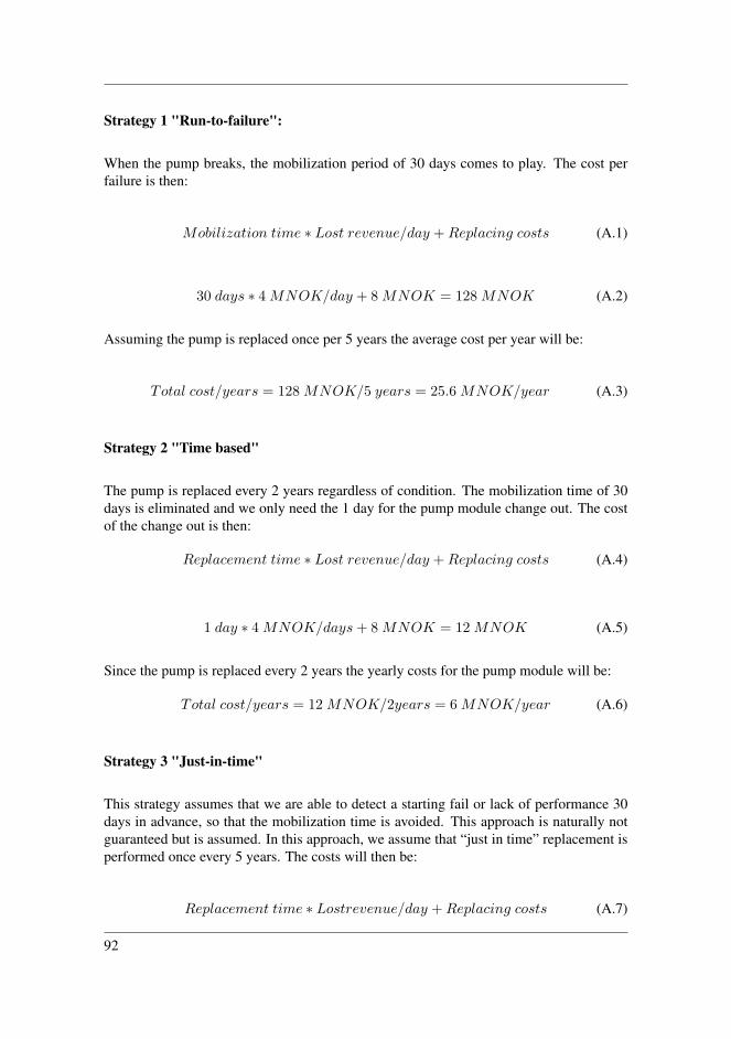
Strategy 1 "Run-to-failure":
When the pump breaks, the mobilization period of 30 days comes to play. The cost perfailure is then:
Mobilization time ∗ Lost revenue/day +Replacing costs (A.1)
30 days ∗ 4 MNOK/day + 8 MNOK = 128 MNOK (A.2)
Assuming the pump is replaced once per 5 years the average cost per year will be:
Total cost/years = 128 MNOK/5 years = 25.6 MNOK/year (A.3)
Strategy 2 "Time based"
The pump is replaced every 2 years regardless of condition. The mobilization time of 30days is eliminated and we only need the 1 day for the pump module change out. The costof the change out is then:
Replacement time ∗ Lost revenue/day +Replacing costs (A.4)
1 day ∗ 4 MNOK/days+ 8 MNOK = 12 MNOK (A.5)
Since the pump is replaced every 2 years the yearly costs for the pump module will be:
Total cost/years = 12 MNOK/2years = 6 MNOK/year (A.6)
Strategy 3 "Just-in-time"
This strategy assumes that we are able to detect a starting fail or lack of performance 30days in advance, so that the mobilization time is avoided. This approach is naturally notguaranteed but is assumed. In this approach, we assume that “just in time” replacement isperformed once every 5 years. The costs will then be:
Replacement time ∗ Lostrevenue/day +Replacing costs (A.7)
92

1 day ∗ 4 MNOK/days+ 8 MNOK = 12 MNOK (A.8)
The yearly cost if this strategy will then be:
Total cost/years = 12 MNOK/5years = 2.4 MNOK/year (A.9)
93
Copyright © 2022 FDOKUMEN