Instability of Thin Polymer Films on Coated Substrates: Rupture, Dewetting, and Drop Formation
17
JOURNAL OF COLLOID AND INTERFACE SCIENCE 178, 383–399 (1996) ARTICLE NO. 0133 Instability of Thin Polymer Films on Coated Substrates: Rupture, Dewetting, and Drop Formation ASHUTOSH SHARMA * ,1 AND GU ¨ NTER REITER² * Department of Chemical Engineering, Indian Institute of Technology at Kanpur, Kanpur-208016, India; and ² Institut de Chimie des Surfaces et Interfaces, CNRS, 15 rue Jean Starcky, F-68057 Mulhouse, France Received November 7, 1994; accepted August 16, 1995 INTRODUCTION We present a direct comparison of theoretical predictions and experimental results on instabilities and various stages of dewetting Stability and homogeneity of thin films (1–9) on solid of thin ( õ60 nm) films on coated substrates. Thin ( ú10 nm) poly- supports are of technological and scientific importance in styrene films, prepared on silicon wafers with three different nanos- applications ranging from coatings (10–12), paints, adhe- ized ( Ç1 nm) coatings, dewet spontaneously above the glass transi- sives, and photographic films to fundamental studies of tion temperature by the growth of cylindrical holes with wavy rims. multilayer adsorption (13), diffusion (14), wetting (15– We could clearly distinguish, and theoretically explain, four differ- 18), and film boiling/condensation (19–21). ent stages as dewetting proceeded: (a) rupture of the film; (b) expansion and coalescence of holes to form a polygonal ‘‘cellular’’ While relatively thick micrometer-sized films can rupture pattern; (c) disintegration of polymer ridges forming the polygon and dewet due to large-amplitude external disturbances ex- into spherical drops due to Rayleigh instability; and (d) fingering ceeding a critical size (9, 22, 23), the free interfaces of instability of hole rims during hole expansion witnessed only on ultrathin ( õ100 nm) films become unstable and deform low wettability coatings. The theory gives a clear understanding of spontaneously whenever the intermolecular disjoining pres- roles of substrate (silicon) wettability, coating wettability, and the sure (24) increases with increased film thickness (1–9). film thickness in various stages (phenomena). For films much The initial growth of instability may lead either to a true thicker than the coating, the wettability (contact angle) of the rupture (hole formation) with the appearance of a receding coated substrate by polystyrene has no influence on the initial length three-phase contact line (5, 6, 12, 25–28), or to a time- scale of the instability (number density of holes). This is explained stationary nonuniform film consistings of drops and films by the dominating influence of long-range Lifshitz–van der Waals when repulsive forces become dominant (8, 9, 26–30). For (LW) interactions originating from the bulk substrate; the LW and short-ranged polar interactions with the coating determine only the relatively thick ( ú10 nm) charge-neutral films, the initial contact angle after appearance of an ultrathin three-phase contact instability on uncoated substrates is governed largely by the zone (rupture). In stage b also, the final polygon diameters are longer ranged apolar Lifshitz–van der Waals (LW) forces rather independent of the coating, which is explained by insensitiv- (8, 26, 27) and the rupture occurs whenever the effective ity of stage a to the coating properties and a competition between Hamaker constant is positive, i.e., the LW component of the the Rayleigh instability (leading to droplets) and drainage from spreading coefficient is negative (8, 26, 27), and the short- ridges (leading, to coalescence). Hole growth, fingering instability, range repulsive interactions ( when present ) are dominated and the drop diameters, on the contrary, are highly affected by the by the LW interactions. surface properties (wettability) of coatings. An increase in the film Numerical solutions (5, 8, 12, 20, 25, 27, 31) of the thickness ( h ) decreases the number density of initial holes (ah 04 ), nonlinear equations of motion for thin films on uncoated increases the polygon diameter ( ah 2 ), increases the drop diameter substrates have provided useful information on the ( ah q , q varies from 1 to 1.5 depending on the contact angle), and makes the fingering instability stronger. Theory and experiment are lengthscale (wavelength) of the fastest growing (preferred) in excellent qualitative and quantitative agreement. The theory also mode of the instability, and on the initial shape of 2-D, suggests several interesting possibilities for the design of future ex- axisymmetric holes formed in the film. However, after ap- periments on the dewetting of thin films. q 1996 Academic Press, Inc. pearance of a three-phase contact line, dynamic simulations Key Words: coated substrates; thin film stability; dewetting; drop are inadequate in tracking the evolution of complex 3-D formation; disjoining pressure; contact angle patterns which result from the growth and interaction of neighboring holes. For stratified foam films (31, 32), it is known that even during the early stages of the hole forma- 1 Author to whom correspondence should be addressed. tion, the hole profile may lose its radial symmetry, and its 383 0021-9797/96 $18.00 Copyright q 1996 by Academic Press, Inc. All rights of reproduction in any form reserved.
-
Upload
independent -
Category
Documents
-
view
0 -
download
0
Transcript of Instability of Thin Polymer Films on Coated Substrates: Rupture, Dewetting, and Drop Formation
JOURNAL OF COLLOID AND INTERFACE SCIENCE 178, 383–399 (1996)ARTICLE NO. 0133
Instability of Thin Polymer Films on Coated Substrates:Rupture, Dewetting, and Drop Formation
ASHUTOSH SHARMA*,1AND GUNTER REITER†
*Department of Chemical Engineering, Indian Institute of Technology at Kanpur, Kanpur-208016, India; and†Institut de Chimie des Surfaces et Interfaces, CNRS, 15 rue Jean Starcky, F-68057 Mulhouse, France
Received November 7, 1994; accepted August 16, 1995
INTRODUCTIONWe present a direct comparison of theoretical predictions and
experimental results on instabilities and various stages of dewetting Stability and homogeneity of thin films (1–9) on solidof thin (õ60 nm) films on coated substrates. Thin (ú10 nm) poly-
supports are of technological and scientific importance instyrene films, prepared on silicon wafers with three different nanos-applications ranging from coatings (10–12), paints, adhe-ized (Ç1 nm) coatings, dewet spontaneously above the glass transi-sives, and photographic films to fundamental studies oftion temperature by the growth of cylindrical holes with wavy rims.multilayer adsorption (13), diffusion (14), wetting (15–We could clearly distinguish, and theoretically explain, four differ-18), and film boiling/condensation (19–21).ent stages as dewetting proceeded: (a) rupture of the film; (b)
expansion and coalescence of holes to form a polygonal ‘‘cellular’’ While relatively thick micrometer-sized films can rupturepattern; (c) disintegration of polymer ridges forming the polygon and dewet due to large-amplitude external disturbances ex-into spherical drops due to Rayleigh instability; and (d) fingering ceeding a critical size (9, 22, 23), the free interfaces ofinstability of hole rims during hole expansion witnessed only on ultrathin (õ100 nm) films become unstable and deformlow wettability coatings. The theory gives a clear understanding of spontaneously whenever the intermolecular disjoining pres-roles of substrate (silicon) wettability, coating wettability, and the sure (24) increases with increased film thickness (1–9).film thickness in various stages (phenomena). For films much
The initial growth of instability may lead either to a truethicker than the coating, the wettability (contact angle) of therupture (hole formation) with the appearance of a recedingcoated substrate by polystyrene has no influence on the initial lengththree-phase contact line (5, 6, 12, 25–28), or to a time-scale of the instability (number density of holes). This is explainedstationary nonuniform film consistings of drops and filmsby the dominating influence of long-range Lifshitz–van der Waalswhen repulsive forces become dominant (8, 9, 26–30). For(LW) interactions originating from the bulk substrate; the LW and
short-ranged polar interactions with the coating determine only the relatively thick (ú10 nm) charge-neutral films, the initialcontact angle after appearance of an ultrathin three-phase contact instability on uncoated substrates is governed largely by thezone (rupture). In stage b also, the final polygon diameters are longer ranged apolar Lifshitz–van der Waals (LW) forcesrather independent of the coating, which is explained by insensitiv- (8, 26, 27) and the rupture occurs whenever the effectiveity of stage a to the coating properties and a competition between Hamaker constant is positive, i.e., the LW component of thethe Rayleigh instability (leading to droplets) and drainage from spreading coefficient is negative (8, 26, 27), and the short-ridges (leading, to coalescence). Hole growth, fingering instability,
range repulsive interactions (when present) are dominatedand the drop diameters, on the contrary, are highly affected by theby the LW interactions.surface properties (wettability) of coatings. An increase in the film
Numerical solutions (5, 8, 12, 20, 25, 27, 31) of thethickness (h) decreases the number density of initial holes (ah04) ,nonlinear equations of motion for thin films on uncoatedincreases the polygon diameter (ah2) , increases the drop diametersubstrates have provided useful information on the(ahq , q varies from 1 to 1.5 depending on the contact angle), and
makes the fingering instability stronger. Theory and experiment are lengthscale (wavelength) of the fastest growing (preferred)in excellent qualitative and quantitative agreement. The theory also mode of the instability, and on the initial shape of 2-D,suggests several interesting possibilities for the design of future ex- axisymmetric holes formed in the film. However, after ap-periments on the dewetting of thin films. q 1996 Academic Press, Inc. pearance of a three-phase contact line, dynamic simulations
Key Words: coated substrates; thin film stability; dewetting; drop are inadequate in tracking the evolution of complex 3-Dformation; disjoining pressure; contact angle patterns which result from the growth and interaction of
neighboring holes. For stratified foam films (31, 32), it isknown that even during the early stages of the hole forma-
1 Author to whom correspondence should be addressed. tion, the hole profile may lose its radial symmetry, and its
383 0021-9797/96 $18.00Copyright q 1996 by Academic Press, Inc.
All rights of reproduction in any form reserved.
AID JCIS 4001 / m4860$$143 02-15-96 14:05:32 coidas AP: Colloid
384 SHARMA AND REITER
rim may evolve into a 3-D wavy pattern due to the curvature right up to their surfaces. Surface contamination, hydration,and reactions (e.g., Si r SiO2) can frequently change theinduced instability (31).
While all of the previous theoretical analyses of thin film surface properties rather profoundly. In such cases, top layersof the substrate may be thought of as pseudo-coatings.stability have been confined to films on uncoated single sub-
strates, the surfaces of most substrates encountered in appli- The main goals of the paper are the following: (a) identi-fication of possible mechanisms for the evolution of variouscations are variously modified by thin coatings. The role of
surface coatings in the dewetting of thin films and in altering types of instabilities during different stages of dewetting offilms on coated substrates; (b) theoretical descriptions ofthe wettability of composite substrates has not been system-
atically investigated. Recent experimental studies (28, 33) the film instability, dewetting, and equilibrium contact angleon coated substrates; and (c) a direct comparison of theof thin polymer films heated above their glass transition
temperature on coated silicon wafers present a fascinating present theory with previously reported experimental results(28, 33), which should also help our understanding of thecatalogue of various types of instabilities and patterns during
different stages of dewetting. Initially smooth polystyrene unanswered questions/apparent anamolous behavior ob-served experimentally. In view of these goals, we believe itfilms (õ100 nm) break up by the creation of holes, which
repeatedly grow and coalesce until the drainage from their is necessary to briefly summarize and partially repeat thekey experimental observations reported previously (28, 33).giant rims slows down greatly and a polygonal, 2-D foam-
like structure is created. The polymer ribbons forming the In what follows, we first briefly identify various mechanismsfor the unfolding of the experimentally observed (28, 33)polygon then decay into spherical drops, possibly due to the
Rayleigh instability of cylindrical masses. This hypothesis instability of thin polymer films on variously coated siliconsubstrates. The influences of the film thickness and the sur-is tested in the present work. During the hole growth, the
generation of droplets due to fingering instabilities is also face properties of the substrate, coatings, and the film on thefilm stability and wetting are then theoretically explored andobserved on the low wettability surfaces.
Among other things, we identify the key mechanisms of compared with experiments (28, 33).the instability during different stages of dewetting and pro-vide, for the first time, evidence for the nonaxisymmetric, EVOLUTION OF THE INSTABILITY:wavy nature of the hole-rim during dewetting. QUALITATIVE CONSIDERATIONS
For thin films on uncoated substrates, the initial formationof holes, as well as the equilibrium contact angles of resultant While the details concerning the experiments are given
elsewhere (33), we summarize here the key experimentaldrops, is governed by the macroscopic parameters of wet-ting—the apolar and polar components of the spreading observations necessary for formulating the theory of thin
film stability on coated substrates. In addition, we also iden-coefficient (8, 18, 26, 27, 29). Thus, for uncoated substrates,the film stability may be correlated with the equilibrium tify here the dominant physical mechanisms that appear to
control the evolution of instability at various stages of dewet-wettability of the surface (8, 18, 26, 27, 29). However, apuzzling aspect of the polymer film experiments (28, 33) ting.
Experiments on the dewetting of thin films are best doneon coated substrates is the way in which wettability of thesurface affects different stages of dewetting. On silicon wa- with amorphous polymer films because (a) the high viscosity
of the polymer allows time-resolved experiments, (b) thefers with nano-sized coatings of different wettabilities, theearly stages of dewetting and the diameters of holes and vapor pressure is practically zero, thus ensuring minimal
mass loss, and (c) thin and smooth films can be initiallypolygons are largely unaffected by the wettability (contactangle) of the polymer on the composite surface (substrate prepared and stored below the glass transition temperature.
Briefly, relatively smooth thin films of varying thicknessplus coating). However, diameters of final droplets dependsignificantly on the equilibrium contact angle of the polymer (Ç10–60 nm) were deposited by spin coating solutions of
polystyrene (Mw Å 28 and 660 Kg/mol) onto three differenton coated substrates. An understanding of these phenomenarequires quantification of the effects of surface coatings on types of surfaces—two types of silicon wafers (wafers A
and B) with unknown surface coatings (as received fromthe film stability and on the contact angle. While it is experi-mentally known that nano-sized coatings are sufficient to Wacker Chemitronics, Germany) and silicon wafers with
self-assembled octadecyltrichlorosilane (OTS) coatings. X-alter the equilibrium contact angles drastically (33–37), theinfluence of coating properties on the thin film stability has ray reflectrometry was used to measure the film thickness
and the roughness of various interfaces with an accuracy ofnever been quantified. This aspect is important because inmany applications (e.g., biomaterials, flotation), thin surface 0.2 nm. The thickness of various coatings (A, B, and OTS)
on silicon wafers, as well as the roughness of the polymer–coatings are applied for tailoring of surface properties andwettability (10, 11). Even when coatings are not applied, air and the polymer–coating interfaces were all less than 1
nm. The film surface also did not show any structure orfew substrates may be considered chemically homogeneous
AID JCIS 4001 / m4860$$144 02-15-96 14:05:32 coidas AP: Colloid
385INSTABILITY OF THIN POLYMER FILMS
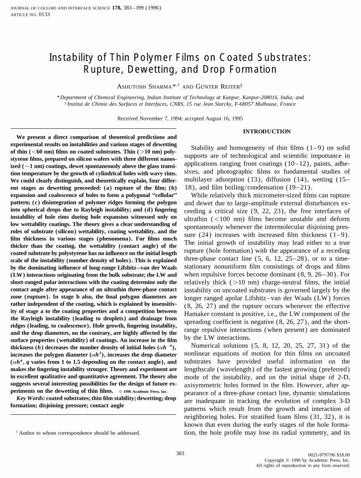
hole is formed, it grows on the substrate due to the conjoin-ing pressure near the contact line and also because of thesurface tension force engendered by the circumferential cur-vature (perpendicular to the plane of the drawing in Fig. 1)of the hole. The surface tension force due to the circumferen-tial curvature is proportional to (g f /r) (ÌH /Ìr) , where g f
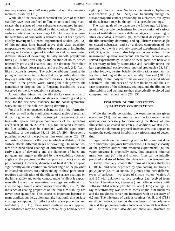
is the polymer surface tension, H(r , t) is the local thicknessof the deformed film, and r is the radial coordinate describingthe hole/rim surface, measured from the center of the hole.This induces liquid flow away from the crater and drivesthe rim surrounding the hole outward. Figure 2 is a typicalmicrograph of uniform, growing holes with their associatedFIG. 1. Schematic of the growth of a hole in a thin film on a coated
substrate. rims that appear dark. The excess polymer displaced by thegrowing hole forms a thick rim around the hole, because theviscous resistance for the flow through the film builds up asdefects within the resolution of interference light microscopy
(laterally 1 mm and vertically 1 nm). mH03 (6, 7) , thus preventing an easy escape of the polymer.However, the rim does not grow indefinately because theFigure 1 is the schematic presentation of the initially
smooth film (broken line) on a coated substrate. Solid lines surface tension force engendered by the transverse curvature(proportional to Ì 2H /Ìr 2) hinders the growth of rim to largerepresent the initial stages in the formation of a hole.
The film samples were annealed in a vacuum oven above heights, as is also shown for hole formation in stratifiedfoam films (31). For wafer A, the number of holes (NH)the glass transition temperature (135 to 1707C) for periods
ranging from 15 min to 24 h. The structural details concern- per reference area were counted when the holes first becamedetectable by light microscopy.ing the film breakup and dewetting did not depend on the
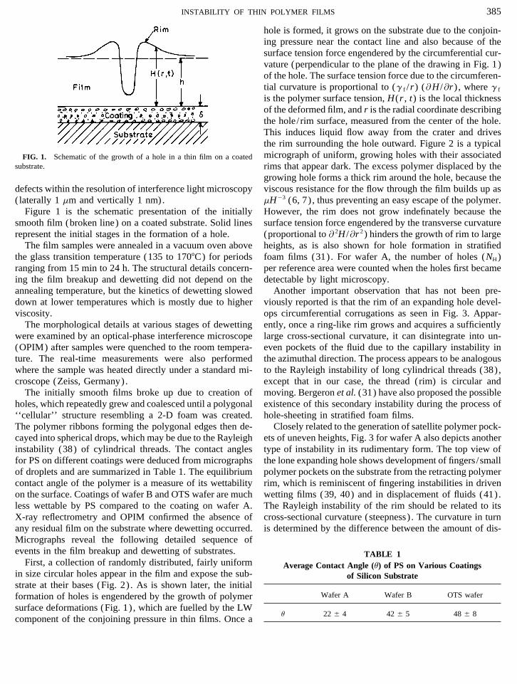
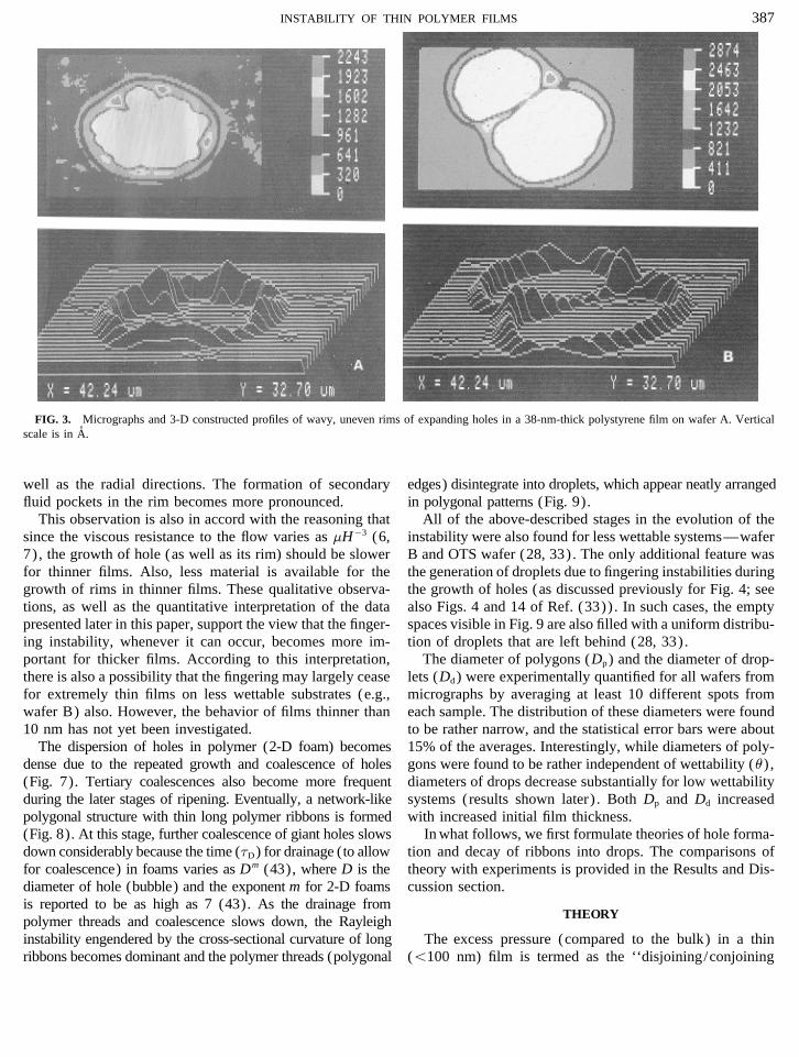
annealing temperature, but the kinetics of dewetting slowed Another important observation that has not been pre-viously reported is that the rim of an expanding hole devel-down at lower temperatures which is mostly due to higher
viscosity. ops circumferential corrugations as seen in Fig. 3. Appar-ently, once a ring-like rim grows and acquires a sufficientlyThe morphological details at various stages of dewetting
were examined by an optical-phase interference microscope large cross-sectional curvature, it can disintegrate into un-even pockets of the fluid due to the capillary instability in(OPIM) after samples were quenched to the room tempera-
ture. The real-time measurements were also performed the azimuthal direction. The process appears to be analogousto the Rayleigh instability of long cylindrical threads (38),where the sample was heated directly under a standard mi-
croscope (Zeiss, Germany). except that in our case, the thread (rim) is circular andmoving. Bergeron et al. (31) have also proposed the possibleThe initially smooth films broke up due to creation of
holes, which repeatedly grew and coalesced until a polygonal existence of this secondary instability during the process ofhole-sheeting in stratified foam films.‘‘cellular’’ structure resembling a 2-D foam was created.
The polymer ribbons forming the polygonal edges then de- Closely related to the generation of satellite polymer pock-ets of uneven heights, Fig. 3 for wafer A also depicts anothercayed into spherical drops, which may be due to the Rayleigh
instability (38) of cylindrical threads. The contact angles type of instability in its rudimentary form. The top view ofthe lone expanding hole shows development of fingers/smallfor PS on different coatings were deduced from micrographs
of droplets and are summarized in Table 1. The equilibrium polymer pockets on the substrate from the retracting polymerrim, which is reminiscent of fingering instabilities in drivencontact angle of the polymer is a measure of its wettability
on the surface. Coatings of wafer B and OTS wafer are much wetting films (39, 40) and in displacement of fluids (41).The Rayleigh instability of the rim should be related to itsless wettable by PS compared to the coating on wafer A.
X-ray reflectrometry and OPIM confirmed the absence of cross-sectional curvature (steepness) . The curvature in turnis determined by the difference between the amount of dis-any residual film on the substrate where dewetting occurred.
Micrographs reveal the following detailed sequence ofevents in the film breakup and dewetting of substrates. TABLE 1
First, a collection of randomly distributed, fairly uniform Average Contact Angle (u) of PS on Various Coatingsin size circular holes appear in the film and expose the sub- of Silicon Substratestrate at their bases (Fig. 2) . As is shown later, the initial
Wafer A Wafer B OTS waferformation of holes is engendered by the growth of polymersurface deformations (Fig. 1) , which are fuelled by the LW
u 22 { 4 42 { 5 48 { 8component of the conjoining pressure in thin films. Once a
AID JCIS 4001 / m4860$$144 02-15-96 14:05:32 coidas AP: Colloid
386 SHARMA AND REITER
FIG. 2. Micrograph of formation of holes in a 40-nm-thick polystyrene film on wafer A. The rims are dark. The length of the bar is 100 mm.Polystyrene samples shown in all micrographs have a molecular weight of 28 K, except the micrographs in Figs. 7 and 8.
placed polymer added to the rim from the expanding hole that the fingering cannot be induced on wafer A even whenthe velocity of hole growth is increased by increasing theand the amount which flows radially outward from the rim
region in the same time. For high wettability systems (e.g., annealing temperature, thereby decreasing the polymer vis-cosity. However, a decrease in viscosity not only increaseswafer A), the velocity, £ of the hole growth is low since £
a u 3 (15, 33, 42) and the small fingers seen in Fig. 3 remain the velocity of hole growth, but also facilitates a faster flowaway from the rim. This may leave the curvature of the rimunderdeveloped and attached to the main body of the moving
rim-mass. The faster growth of holes for large contact angles rather unaffected, at least in the temperature range investi-gated.should, however, produce less diffused, steeper rims, re-
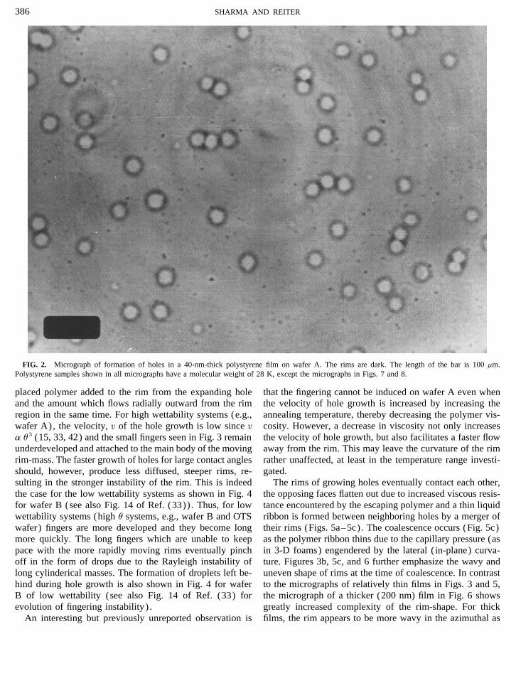
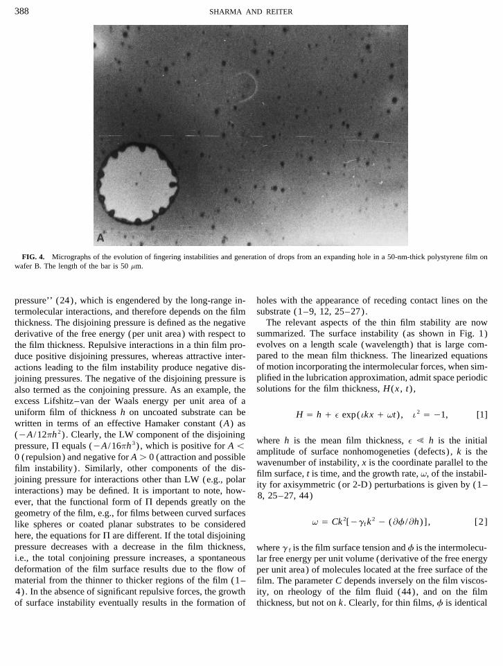
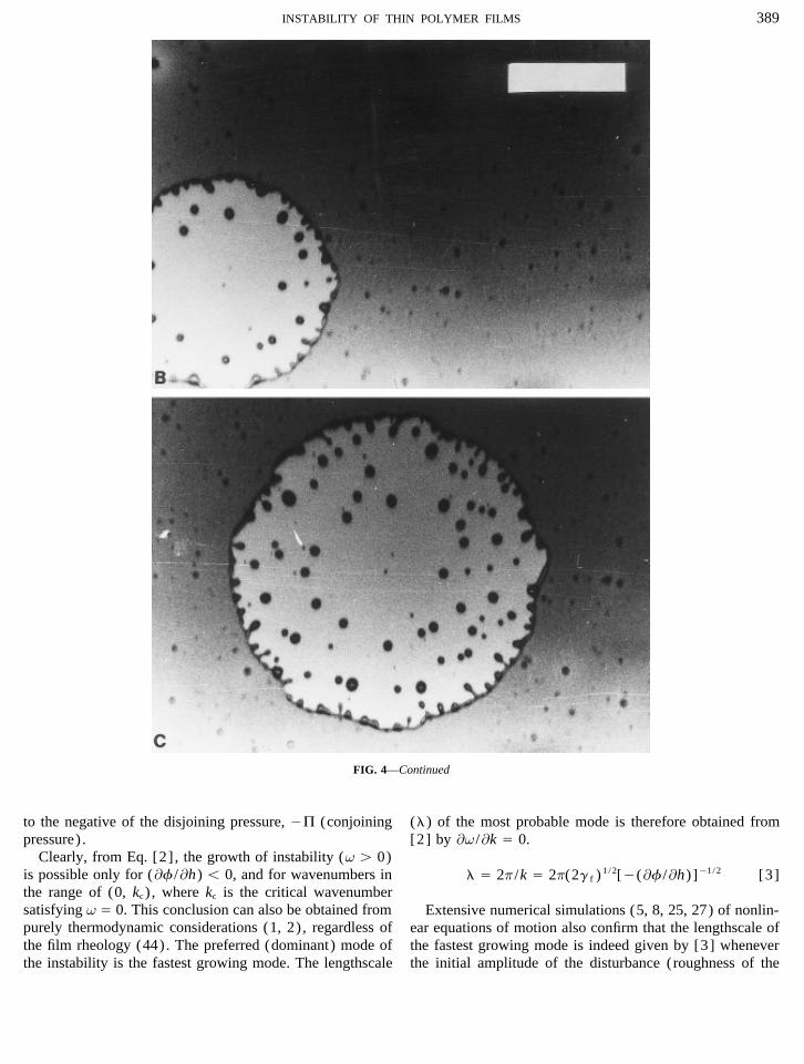
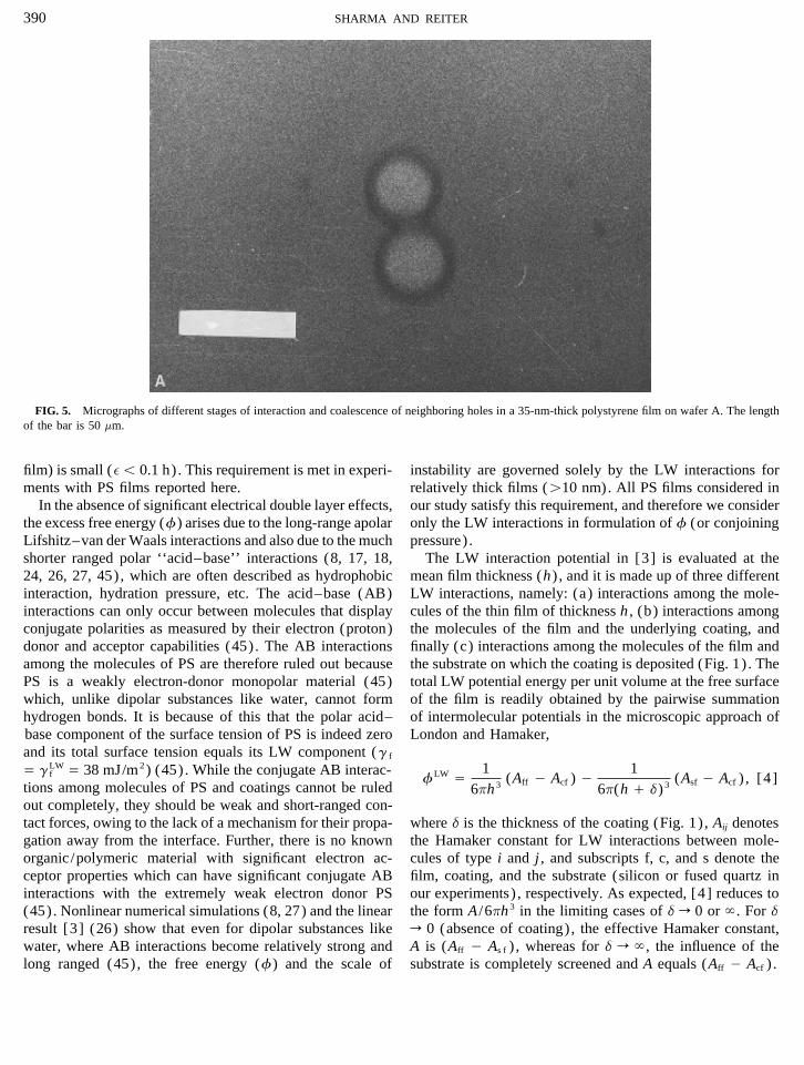
sulting in the stronger instability of the rim. This is indeed The rims of growing holes eventually contact each other,the opposing faces flatten out due to increased viscous resis-the case for the low wettability systems as shown in Fig. 4
for wafer B (see also Fig. 14 of Ref. (33)) . Thus, for low tance encountered by the escaping polymer and a thin liquidribbon is formed between neighboring holes by a merger ofwettability systems (high u systems, e.g., wafer B and OTS
wafer) fingers are more developed and they become long their rims (Figs. 5a–5c). The coalescence occurs (Fig. 5c)as the polymer ribbon thins due to the capillary pressure (asmore quickly. The long fingers which are unable to keep
pace with the more rapidly moving rims eventually pinch in 3-D foams) engendered by the lateral ( in-plane) curva-ture. Figures 3b, 5c, and 6 further emphasize the wavy andoff in the form of drops due to the Rayleigh instability of
long cylinderical masses. The formation of droplets left be- uneven shape of rims at the time of coalescence. In contrastto the micrographs of relatively thin films in Figs. 3 and 5,hind during hole growth is also shown in Fig. 4 for wafer
B of low wettability (see also Fig. 14 of Ref. (33) for the micrograph of a thicker (200 nm) film in Fig. 6 showsgreatly increased complexity of the rim-shape. For thickevolution of fingering instability) .
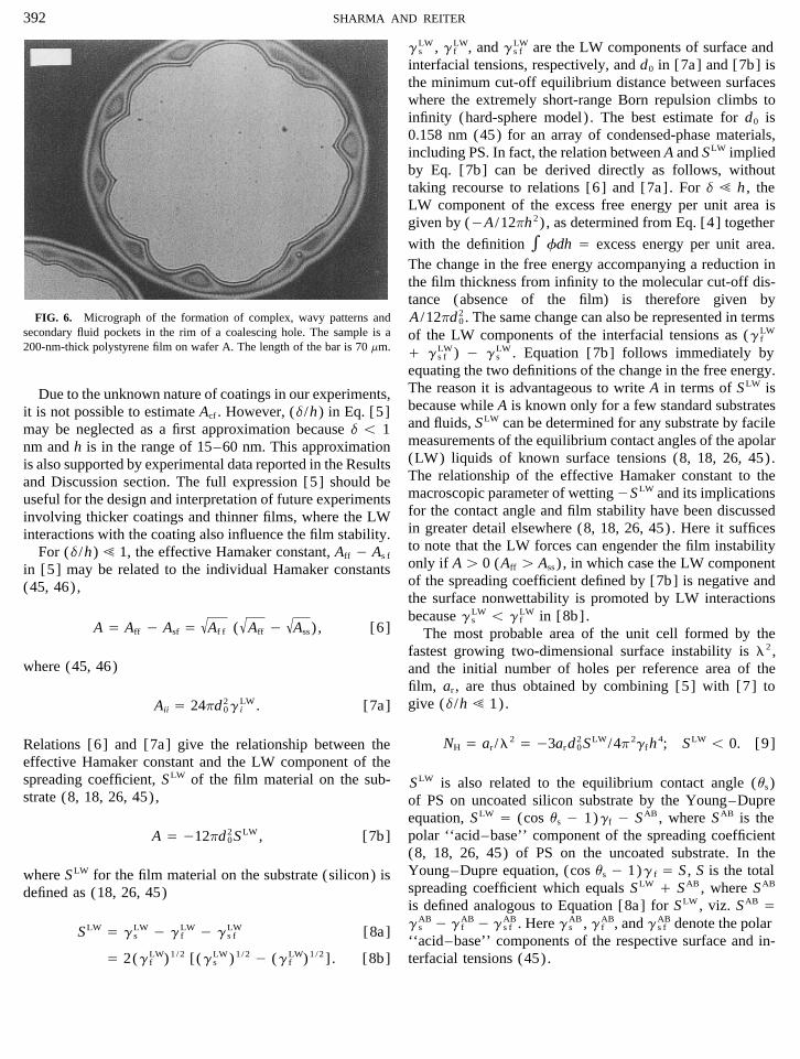
An interesting but previously unreported observation is films, the rim appears to be more wavy in the azimuthal as
AID JCIS 4001 / m4860$$144 02-15-96 14:05:32 coidas AP: Colloid
387INSTABILITY OF THIN POLYMER FILMS
FIG. 3. Micrographs and 3-D constructed profiles of wavy, uneven rims of expanding holes in a 38-nm-thick polystyrene film on wafer A. Verticalscale is in A.
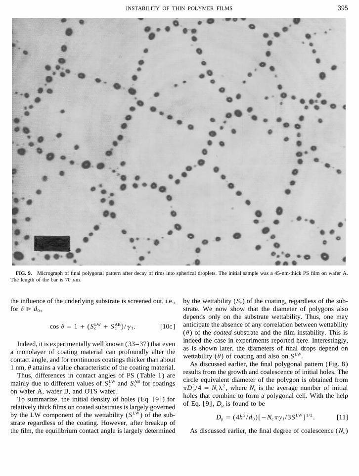
well as the radial directions. The formation of secondary edges) disintegrate into droplets, which appear neatly arrangedin polygonal patterns (Fig. 9).fluid pockets in the rim becomes more pronounced.
This observation is also in accord with the reasoning that All of the above-described stages in the evolution of theinstability were also found for less wettable systems—wafersince the viscous resistance to the flow varies as mH03 (6,
7) , the growth of hole (as well as its rim) should be slower B and OTS wafer (28, 33). The only additional feature wasthe generation of droplets due to fingering instabilities duringfor thinner films. Also, less material is available for the
growth of rims in thinner films. These qualitative observa- the growth of holes (as discussed previously for Fig. 4; seealso Figs. 4 and 14 of Ref. (33)) . In such cases, the emptytions, as well as the quantitative interpretation of the data
presented later in this paper, support the view that the finger- spaces visible in Fig. 9 are also filled with a uniform distribu-tion of droplets that are left behind (28, 33).ing instability, whenever it can occur, becomes more im-
portant for thicker films. According to this interpretation, The diameter of polygons (Dp) and the diameter of drop-lets (Dd) were experimentally quantified for all wafers fromthere is also a possibility that the fingering may largely cease
for extremely thin films on less wettable substrates (e.g., micrographs by averaging at least 10 different spots fromeach sample. The distribution of these diameters were foundwafer B) also. However, the behavior of films thinner than
10 nm has not yet been investigated. to be rather narrow, and the statistical error bars were about15% of the averages. Interestingly, while diameters of poly-The dispersion of holes in polymer (2-D foam) becomes
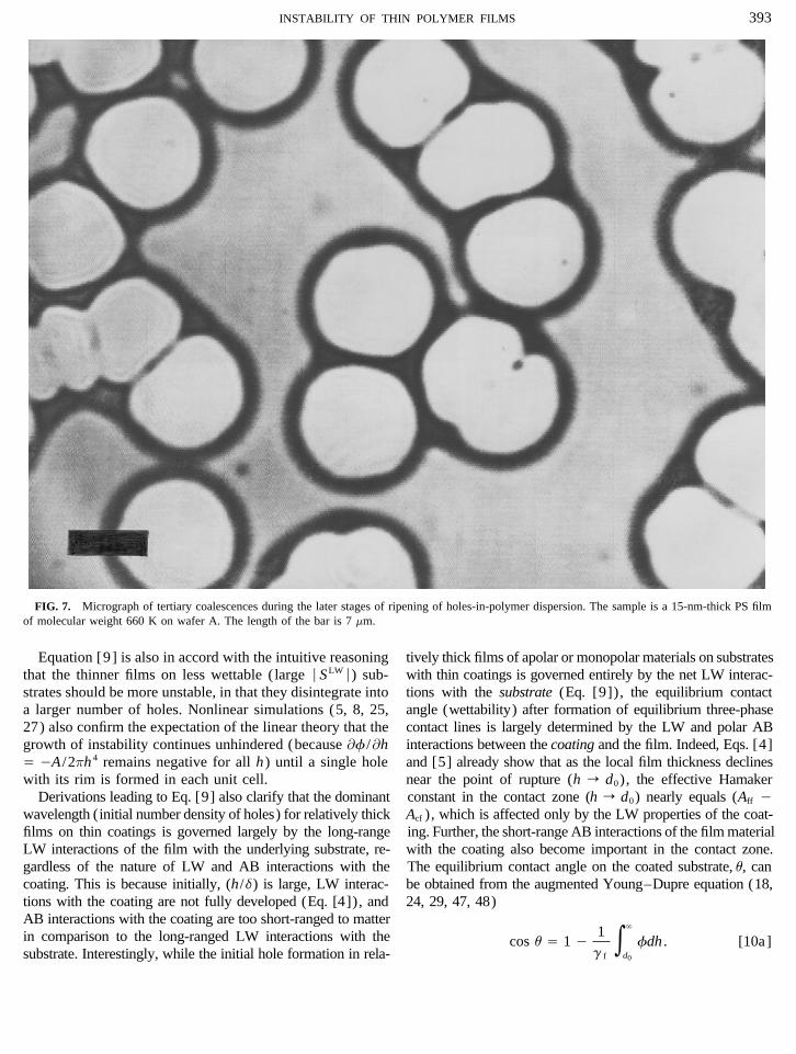
dense due to the repeated growth and coalescence of holes gons were found to be rather independent of wettability (u) ,diameters of drops decrease substantially for low wettability(Fig. 7). Tertiary coalescences also become more frequent
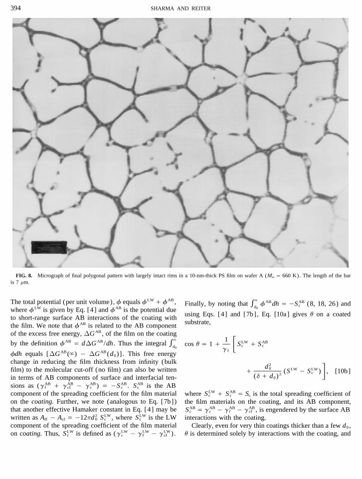
during the later stages of ripening. Eventually, a network-like systems (results shown later) . Both Dp and Dd increasedwith increased initial film thickness.polygonal structure with thin long polymer ribbons is formed
(Fig. 8). At this stage, further coalescence of giant holes slows In what follows, we first formulate theories of hole forma-tion and decay of ribbons into drops. The comparisons ofdown considerably because the time (tD) for drainage (to allow
for coalescence) in foams varies as Dm (43), where D is the theory with experiments is provided in the Results and Dis-cussion section.diameter of hole (bubble) and the exponent m for 2-D foams
is reported to be as high as 7 (43). As the drainage fromTHEORYpolymer threads and coalescence slows down, the Rayleigh
instability engendered by the cross-sectional curvature of long The excess pressure (compared to the bulk) in a thin(õ100 nm) film is termed as the ‘‘disjoining/conjoiningribbons becomes dominant and the polymer threads (polygonal
AID JCIS 4001 / m4860$$144 02-15-96 14:05:32 coidas AP: Colloid
388 SHARMA AND REITER
FIG. 4. Micrographs of the evolution of fingering instabilities and generation of drops from an expanding hole in a 50-nm-thick polystyrene film onwafer B. The length of the bar is 50 mm.
pressure’’ (24), which is engendered by the long-range in- holes with the appearance of receding contact lines on thesubstrate (1–9, 12, 25–27).termolecular interactions, and therefore depends on the film
The relevant aspects of the thin film stability are nowthickness. The disjoining pressure is defined as the negativesummarized. The surface instability (as shown in Fig. 1)derivative of the free energy (per unit area) with respect toevolves on a length scale (wavelength) that is large com-the film thickness. Repulsive interactions in a thin film pro-pared to the mean film thickness. The linearized equationsduce positive disjoining pressures, whereas attractive inter-of motion incorporating the intermolecular forces, when sim-actions leading to the film instability produce negative dis-plified in the lubrication approximation, admit space periodicjoining pressures. The negative of the disjoining pressure issolutions for the film thickness, H(x , t) ,also termed as the conjoining pressure. As an example, the
excess Lifshitz–van der Waals energy per unit area of auniform film of thickness h on uncoated substrate can be H Å h / e exp(ikx / vt) , i 2 Å 01, [1]written in terms of an effective Hamaker constant (A) as(0A /12ph 2) . Clearly, the LW component of the disjoining
where h is the mean film thickness, e ! h is the initialpressure, P equals (0A /16ph 3) , which is positive for A õ
amplitude of surface nonhomogeneties (defects) , k is the0 (repulsion) and negative for Aú 0 (attraction and possible
wavenumber of instability, x is the coordinate parallel to thefilm instability) . Similarly, other components of the dis-
film surface, t is time, and the growth rate, v, of the instabil-joining pressure for interactions other than LW (e.g., polar ity for axisymmetric (or 2-D) perturbations is given by (1–interactions) may be defined. It is important to note, how- 8, 25–27, 44)ever, that the functional form of P depends greatly on thegeometry of the film, e.g., for films between curved surfaces
v Å Ck 2[0gfk2 0 (Ìf /Ìh)] , [2]like spheres or coated planar substrates to be considered
here, the equations for P are different. If the total disjoiningpressure decreases with a decrease in the film thickness, where g f is the film surface tension and f is the intermolecu-i.e., the total conjoining pressure increases, a spontaneous lar free energy per unit volume (derivative of the free energydeformation of the film surface results due to the flow of per unit area) of molecules located at the free surface of thematerial from the thinner to thicker regions of the film (1– film. The parameter C depends inversely on the film viscos-4) . In the absence of significant repulsive forces, the growth ity, on rheology of the film fluid (44), and on the film
thickness, but not on k . Clearly, for thin films, f is identicalof surface instability eventually results in the formation of
AID JCIS 4001 / m4860$$145 02-15-96 14:05:32 coidas AP: Colloid
389INSTABILITY OF THIN POLYMER FILMS
FIG. 4—Continued
to the negative of the disjoining pressure, 0P (conjoining (l) of the most probable mode is therefore obtained from[2] by Ìv /Ìk Å 0.pressure) .
Clearly, from Eq. [2] , the growth of instability (v ú 0)is possible only for (Ìf /Ìh) õ 0, and for wavenumbers in l Å 2p /k Å 2p(2g f ) 1/2[0(Ìf /Ìh)]01/2 [3]the range of (0, kc ) , where kc is the critical wavenumbersatisfying v Å 0. This conclusion can also be obtained from Extensive numerical simulations (5, 8, 25, 27) of nonlin-purely thermodynamic considerations (1, 2) , regardless of ear equations of motion also confirm that the lengthscale ofthe film rheology (44). The preferred (dominant) mode of the fastest growing mode is indeed given by [3] whenever
the initial amplitude of the disturbance (roughness of thethe instability is the fastest growing mode. The lengthscale
AID JCIS 4001 / m4860$$145 02-15-96 14:05:32 coidas AP: Colloid
390 SHARMA AND REITER
FIG. 5. Micrographs of different stages of interaction and coalescence of neighboring holes in a 35-nm-thick polystyrene film on wafer A. The lengthof the bar is 50 mm.
film) is small (eõ 0.1 h). This requirement is met in experi- instability are governed solely by the LW interactions forrelatively thick films (ú10 nm). All PS films considered inments with PS films reported here.
In the absence of significant electrical double layer effects, our study satisfy this requirement, and therefore we consideronly the LW interactions in formulation of f (or conjoiningthe excess free energy (f) arises due to the long-range apolar
Lifshitz–van der Waals interactions and also due to the much pressure) .The LW interaction potential in [3] is evaluated at theshorter ranged polar ‘‘acid–base’’ interactions (8, 17, 18,
24, 26, 27, 45), which are often described as hydrophobic mean film thickness (h) , and it is made up of three differentLW interactions, namely: (a) interactions among the mole-interaction, hydration pressure, etc. The acid–base (AB)
interactions can only occur between molecules that display cules of the thin film of thickness h , (b) interactions amongthe molecules of the film and the underlying coating, andconjugate polarities as measured by their electron (proton)
donor and acceptor capabilities (45). The AB interactions finally (c) interactions among the molecules of the film andthe substrate on which the coating is deposited (Fig. 1) . Theamong the molecules of PS are therefore ruled out because
PS is a weakly electron-donor monopolar material (45) total LW potential energy per unit volume at the free surfaceof the film is readily obtained by the pairwise summationwhich, unlike dipolar substances like water, cannot form
hydrogen bonds. It is because of this that the polar acid– of intermolecular potentials in the microscopic approach ofLondon and Hamaker,base component of the surface tension of PS is indeed zero
and its total surface tension equals its LW component (g f
Å gLWf Å 38 mJ/m2) (45). While the conjugate AB interac-
fLW Å 16ph 3 (Aff 0 Acf ) 0 1
6p(h / d)3 (Asf 0 Acf ) , [4]tions among molecules of PS and coatings cannot be ruledout completely, they should be weak and short-ranged con-tact forces, owing to the lack of a mechanism for their propa- where d is the thickness of the coating (Fig. 1) , Aij denotes
the Hamaker constant for LW interactions between mole-gation away from the interface. Further, there is no knownorganic/polymeric material with significant electron ac- cules of type i and j , and subscripts f, c, and s denote the
film, coating, and the substrate (silicon or fused quartz inceptor properties which can have significant conjugate ABinteractions with the extremely weak electron donor PS our experiments) , respectively. As expected, [4] reduces to
the form A /6ph 3 in the limiting cases of d r 0 or ` . For d(45). Nonlinear numerical simulations (8, 27) and the linearresult [3] (26) show that even for dipolar substances like r 0 (absence of coating), the effective Hamaker constant,
A is (Aff 0 As f ) , whereas for d r ` , the influence of thewater, where AB interactions become relatively strong andlong ranged (45), the free energy (f) and the scale of substrate is completely screened and A equals (Aff 0 Acf ) .
AID JCIS 4001 / m4860$$145 02-15-96 14:05:32 coidas AP: Colloid

391INSTABILITY OF THIN POLYMER FILMS
FIG. 5—Continued
The lengthscale of the instability is obtained from Eqs. pends on the ratio of the coating thickness and the film thick-ness. l varies as h2 both for (d/h) r 0 and (d/h) r ` , but[3] and [4] asthe effective Hamaker constants for these two situations are
l Å 4p(pg f ) 1/2h 2F(Aff 0 Acf ) different, as described earlier. Also in the case when the differ-ence (Acf 0 As f ) is small, the film is governed by a singleeffective Hamaker constant, A Å Aff 0 Acf á Aff 0 As f . Asimilarity of LW interactions for the substrate and coating,/ S1 / d
hD04
(Acf 0 As f )G01/2
. [5]however, does not necessarily imply similar wetting character-istics. As is discussed later, the wettability (u) is profoundlyaltered by the short-range polar ‘‘acid–base’’ interactions.Interestingly, the effect of coating on the film stability de-
AID JCIS 4001 / m4860$$145 02-15-96 14:05:32 coidas AP: Colloid
392 SHARMA AND REITER
gLWs , gLW
f , and gLWs f are the LW components of surface and
interfacial tensions, respectively, and d0 in [7a] and [7b] isthe minimum cut-off equilibrium distance between surfaceswhere the extremely short-range Born repulsion climbs toinfinity (hard-sphere model) . The best estimate for d0 is0.158 nm (45) for an array of condensed-phase materials,including PS. In fact, the relation between A and SLW impliedby Eq. [7b] can be derived directly as follows, withouttaking recourse to relations [6] and [7a]. For d ! h , theLW component of the excess free energy per unit area isgiven by (0A /12ph 2) , as determined from Eq. [4] together
with the definition * fdh Å excess energy per unit area.The change in the free energy accompanying a reduction inthe film thickness from infinity to the molecular cut-off dis-tance (absence of the film) is therefore given by
FIG. 6. Micrograph of the formation of complex, wavy patterns and A /12pd 20 . The same change can also be represented in terms
secondary fluid pockets in the rim of a coalescing hole. The sample is a of the LW components of the interfacial tensions as (gLWf
200-nm-thick polystyrene film on wafer A. The length of the bar is 70 mm. / gLWs f ) 0 gLW
s . Equation [7b] follows immediately byequating the two definitions of the change in the free energy.The reason it is advantageous to write A in terms of SLW isDue to the unknown nature of coatings in our experiments,because while A is known only for a few standard substratesit is not possible to estimate Acf . However, (d /h) in Eq. [5]and fluids, SLW can be determined for any substrate by facilemay be neglected as a first approximation because d õ 1measurements of the equilibrium contact angles of the apolarnm and h is in the range of 15–60 nm. This approximation(LW) liquids of known surface tensions (8, 18, 26, 45).is also supported by experimental data reported in the ResultsThe relationship of the effective Hamaker constant to theand Discussion section. The full expression [5] should bemacroscopic parameter of wetting0SLW and its implicationsuseful for the design and interpretation of future experimentsfor the contact angle and film stability have been discussedinvolving thicker coatings and thinner films, where the LWin greater detail elsewhere (8, 18, 26, 45). Here it sufficesinteractions with the coating also influence the film stability.to note that the LW forces can engender the film instabilityFor (d /h) ! 1, the effective Hamaker constant, Aff 0 As fonly if A ú 0 (Aff ú Ass ) , in which case the LW componentin [5] may be related to the individual Hamaker constantsof the spreading coefficient defined by [7b] is negative and(45, 46),the surface nonwettability is promoted by LW interactionsbecause gLW
s õ gLWf in [8b].
A Å Aff 0 Asf Å√Af f (
√Aff 0
√Ass ) , [6] The most probable area of the unit cell formed by the
fastest growing two-dimensional surface instability is l 2 ,where (45, 46) and the initial number of holes per reference area of the
film, ar , are thus obtained by combining [5] with [7] togive (d /h ! 1).Aii Å 24pd 2
0gLWi . [7a]
NH Å ar /l2 Å 03ard
20SLW/4p 2gfh
4; SLW õ 0. [9]Relations [6] and [7a] give the relationship between theeffective Hamaker constant and the LW component of thespreading coefficient, SLW of the film material on the sub- SLW is also related to the equilibrium contact angle (us )strate (8, 18, 26, 45), of PS on uncoated silicon substrate by the Young–Dupre
equation, SLW Å (cos us 0 1)gf 0 SAB, where SAB is thepolar ‘‘acid–base’’ component of the spreading coefficientA Å 012pd 2
0SLW, [7b](8, 18, 26, 45) of PS on the uncoated substrate. In theYoung–Dupre equation, (cos us 0 1)g f Å S , S is the totalwhere SLW for the film material on the substrate (silicon) isspreading coefficient which equals SLW / SAB, where SAB
defined as (18, 26, 45)is defined analogous to Equation [8a] for SLW, viz. SAB ÅgAB
s 0 gABf 0 gAB
s f . Here gABs , gAB
f , and gABs f denote the polar
SLW Å gLWs 0 gLW
f 0 gLWs f [8a]
‘‘acid–base’’ components of the respective surface and in-terfacial tensions (45).Å 2(gLW
f )1/2 [(gLWs )1/2 0 (gLW
f )1/2 ] . [8b]
AID JCIS 4001 / m4860$$145 02-15-96 14:05:32 coidas AP: Colloid
393INSTABILITY OF THIN POLYMER FILMS
FIG. 7. Micrograph of tertiary coalescences during the later stages of ripening of holes-in-polymer dispersion. The sample is a 15-nm-thick PS filmof molecular weight 660 K on wafer A. The length of the bar is 7 mm.
Equation [9] is also in accord with the intuitive reasoning tively thick films of apolar or monopolar materials on substrateswith thin coatings is governed entirely by the net LW interac-that the thinner films on less wettable (large ÉSLW
É) sub-strates should be more unstable, in that they disintegrate into tions with the substrate (Eq. [9]), the equilibrium contact
angle (wettability) after formation of equilibrium three-phasea larger number of holes. Nonlinear simulations (5, 8, 25,27) also confirm the expectation of the linear theory that the contact lines is largely determined by the LW and polar AB
interactions between the coating and the film. Indeed, Eqs. [4]growth of instability continues unhindered (because Ìf /ÌhÅ 0A /2ph 4 remains negative for all h) until a single hole and [5] already show that as the local film thickness declines
near the point of rupture (h r d0), the effective Hamakerwith its rim is formed in each unit cell.Derivations leading to Eq. [9] also clarify that the dominant constant in the contact zone (h r d0) nearly equals (Aff 0
Acf ), which is affected only by the LW properties of the coat-wavelength (initial number density of holes) for relatively thickfilms on thin coatings is governed largely by the long-range ing. Further, the short-range AB interactions of the film material
with the coating also become important in the contact zone.LW interactions of the film with the underlying substrate, re-gardless of the nature of LW and AB interactions with the The equilibrium contact angle on the coated substrate, u, can
be obtained from the augmented Young–Dupre equation (18,coating. This is because initially, (h/d) is large, LW interac-tions with the coating are not fully developed (Eq. [4]), and 24, 29, 47, 48)AB interactions with the coating are too short-ranged to matterin comparison to the long-ranged LW interactions with the cos u Å 1 0 1
g f*
`
d0
fdh . [10a]substrate. Interestingly, while the initial hole formation in rela-
AID JCIS 4001 / m4860$$146 02-15-96 14:05:32 coidas AP: Colloid
394 SHARMA AND REITER
FIG. 8. Micrograph of final polygonal pattern with largely intact rims in a 10-nm-thick PS film on wafer A (Mw Å 660 K). The length of the baris 7 mm.
The total potential (per unit volume), f equals fLW / fAB, Finally, by noting that *`
d0fABdh Å 0SAB
c (8, 18, 26) andwhere fLW is given by Eq. [4] and fAB is the potential due
using Eqs. [4] and [7b], Eq. [10a] gives u on a coatedto short-range surface AB interactions of the coating withsubstrate,the film. We note that fAB is related to the AB component
of the excess free energy, DGAB, of the film on the coating
by the definition fAB Å dDGAB/dh . Thus the integral *`
d0cos u Å 1 / 1
g fFSLW
c / SABc
fdh equals [DGAB(`) 0 DGAB(d0)] . This free energychange in reducing the film thickness from infinity (bulkfilm) to the molecular cut-off (no film) can also be written / d 2
0
(d / d0) 2 (SLW 0 SLWc )G , [10b]
in terms of AB components of surface and interfacial ten-sions as (gAB
f / gABcf 0 gAB
c ) Å 0SABc . SAB
c is the ABcomponent of the spreading coefficient for the film material where SLW
c / SABc Å Sc is the total spreading coefficient of
on the coating. Further, we note (analogous to Eq. [7b]) the film materials on the coating, and its AB component,that another effective Hamaker constant in Eq. [4] may be SAB
c Å gABc 0 gAB
f 0 gABcf , is engendered by the surface AB
written as Aff 0 Acf Å 012pd 20 SLW
c , where SLWc is the LW interactions with the coating.
component of the spreading coefficient of the film material Clearly, even for very thin coatings thicker than a few d0 ,u is determined solely by interactions with the coating, andon coating. Thus, SLW
c is defined as (gLWc 0 gLW
f 0 gLWcf ) .
AID JCIS 4001 / m4860$$146 02-15-96 14:05:32 coidas AP: Colloid
395INSTABILITY OF THIN POLYMER FILMS
FIG. 9. Micrograph of final polygonal pattern after decay of rims into spherical droplets. The initial sample was a 45-nm-thick PS film on wafer A.The length of the bar is 70 mm.
the influence of the underlying substrate is screened out, i.e., by the wettability (Sc ) of the coating, regardless of the sub-strate. We now show that the diameter of polygons alsofor d @ d0 ,depends only on the substrate wettability. Thus, one mayanticipate the absence of any correlation between wettabilitycos u Å 1 / (SLW
c / SABc ) /g f . [10c]
(u) of the coated substrate and the film instability. This isindeed the case in experiments reported here. Interestingly,Indeed, it is experimentally well known (33–37) that evenas is shown later, the diameters of final drops depend ona monolayer of coating material can profoundly alter thewettability (u) of coating and also on SLW.contact angle, and for continuous coatings thicker than about
As discussed earlier, the final polygonal pattern (Fig. 8)1 nm, u attains a value characteristic of the coating material.results from the growth and coalescence of initial holes. TheThus, differences in contact angles of PS (Table 1) arecircle equivalent diameter of the polygon is obtained frommainly due to different values of SLW
c and SABc for coatings
pD 2p /4 Å Ncl
2 , where Nc is the average number of initialon wafer A, wafer B, and OTS wafer.holes that combine to form a polygonal cell. With the helpTo summarize, the initial density of holes (Eq. [9]) forof Eq. [9] , Dp is found to berelatively thick films on coated substrates is largely governed
by the LW component of the wettability (SLW ) of the sub- Dp Å (4h 2 /d0)[0Ncpg f /3SLW ]1/2 . [11]strate regardless of the coating. However, after breakup ofthe film, the equilibrium contact angle is largely determined As discussed earlier, the final degree of coalescence (Nc )
AID JCIS 4001 / m4860$$147 02-15-96 14:05:32 coidas AP: Colloid
396 SHARMA AND REITER
before disintegration of ribbons (edges) into droplets is de-termined by a competition between the time scales of drain-age (tD) and the Rayleigh instability (tR) of the slowlydraining polymer ribbon formed between holes. An a prioriprediction of Nc would therefore require an understandingof the complete 3-D dynamics of these processes occuringsimultaneously, which has never been attempted. However,as a first approximation, Nc may be obtained by the conditionthat the time for drainage (leading to coalescence) becomeslarger than the time for the Rayleigh instability (leading todrop formation), i.e., tD ú tR. Whereas tD in 2-D foamsshows a very strong dependence on Dp (tD a Dm
p , m rangesfrom 5 to 7) (43) and tR is a relatively weak function (38)of the cross-sectional perimeter of the ribbon (tR a (ur)2/
3 ) , where r is the cross-sectional curvature of the polymerribbon (thread). Thus, the condition tD Ç tR implies that
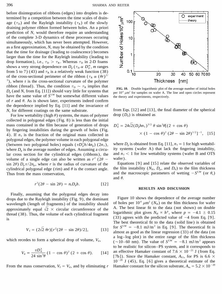
FIG. 10. Double logarithmic plot of the average number of initial holesDp (and Nc from Eq. [11]) should vary little for systems that per 104 mm2 for samples on wafer A. The line and open circles representhave the same value of SLW but somewhat different values the theory and experiments, respectively.of r and u. As is shown later, experiments indeed confirmthe dependence implied by Eq. [11] and the invariance of
from Eqs. [12] and [13], the final diameter of the sphericalNc for different coatings on the same substrate.drop (Dd) is obtained asFor low wettability (high u) systems, the mass of polymer
collected in polygonal edges (Fig. 8) is less than the initialmass contained in the film because of generation of drops D 3
d Å 24√2(Dphn f ) 3/2 u sin3u[(2 / cos u)
by fingering instabilities during the growth of holes (Fig.1 (1 0 cos u)2 (2u 0 sin 2u)1/2 ]01 , [15]4) . If n f is the fraction of the original mass collected in
polygonal edges, the polymer volume in each polygonal edgewhere Dp is obtained from Eq. [11], n f Å 1 for high wettabil-(between two polygonal holes) equals (pD 2
ph /4np) (2n f ) ,ity systems (wafer A) that lack the fingering instability,where Dp is the average number of edges. Assuming a circu-and n f õ 1 for low wettability systems (wafer B and OTSlar cross section for the cylindrical edges (ribbons) , thewafer) .volume of a single edge can also be written as r 2 (2u 0
Equations [9] and [15] relate the observed variables ofsin 2u) Dpp /2np , where r is the radius of curvature of thethe film instability (NH, Dp , and Dd) to the film thicknesscylindrical polygonal edge (rim) and u is the contact angle.and the macroscopic parameters of wetting 0SLW (or us )Thus from the mass conservation,and u.
r 2(2u 0 sin 2u) Å nfDph . [12]RESULTS AND DISCUSSION
Finally, assuming that the polygonal edges decay intoFigure 10 shows the dependence of the average numberdrops due to the Rayleigh instability (Fig. 9) , the dominant
of holes per 104 mm2 (NH) on the film thickness for waferwavelength (length of fragments) of the instability shouldA. The best linear fit to the data (not shown) on doubleapproximately equal
√2 1 circular circumference of the
logarithmic plot gives NH } h p , where p Å 04.1 { 0.15thread (38). Thus, the volume of each cylindrical fragment(33) agrees with the predicted value of 04 from Eq. [9] .isThe best theoretical fit to the data (solid line) is obtainedfor SLW Å 08.1 mJ/m2 in Eq. [9] . The theoretical fit is
V f Å (2√2 ur)[r 2(2u 0 sin 2u) /2] , [13]
almost as good as the linear regression (33) of the data (ona log–log plot) in the entire range of the film thickness
which recedes to form a spherical drop of volume, Vd , (Ç10–60 nm). The value of SLW Å 08.1 mJ/m2 appearsto be realistic for silicon–PS system, and it corresponds toan effective Hamaker constant of 7.6 1 10021 J (from Eq.Vd Å
pD 3d
24 sin3u(1 0 cos u)2 (2 / cos u) . [14]
[7b]) . Since the Hamaker constant, Af f , for PS is 6.6 110020 J (45), Eq. [6] gives a theoretical estimate of theHamaker constant for the silicon substrate, Ass Å 5.2 1 10020From the mass conservation, Vf Å Vd , and by eliminating r
AID JCIS 4001 / m4860$$147 02-15-96 14:05:32 coidas AP: Colloid
397INSTABILITY OF THIN POLYMER FILMS
J. This is in agreement with the measured values of the TABLE 2The Best Fit Values of Parameter C in Equation [16]Hamaker constant for fused quartz, which range from 5 1
for Various Coatings of Silicon Substrate10020 to 6 1 10020 J (46). The calculated value of SLWc for
the coating of wafer A is much smaller (á02.8 mJ/m2 fromWafer A Wafer B OTS WaferEq. [10c] with SAB
c á 0 and u Å 227, Table 1).It is also interesting to note that dewetting of PS films did Ca 0.0896 { 0.002 0.090 { 0.002 0.074 { 0.003
not occur on wafers when the oxide layer was stripped bya The mean value of C for all data is 0.088, and the mean percent errorhydrofluoric acid. This is because the oxide removal exposes
in prediction of the data from Eq. [16] is about 14%.the higher energy Si surface, thus increasing the value ofAss , and decreasing A (from Eq. 6). Indeed, based on the
summarized in Table T2. The mean errors in prediction ofcontact angles of apolar liquids, Zhao et al. (30) reportedthe data using Eq. [16] are 8%, 13%, and 15% for wafer B,about a 22% increase in gLW
s (or Ass from Eq. [7a]) of thewafer A, and OTS wafer, respectively.oxide-stripped Si surface. An increase in Ass of similar mag-
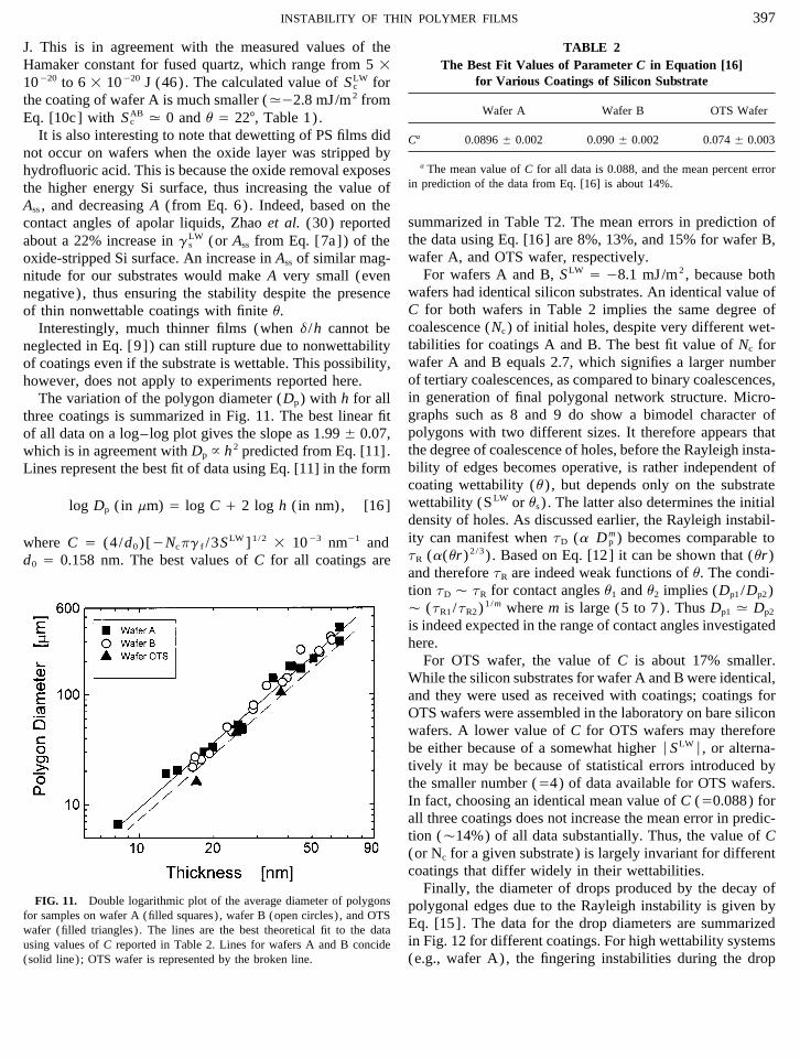
For wafers A and B, SLW Å 08.1 mJ/m2, because bothnitude for our substrates would make A very small (evenwafers had identical silicon substrates. An identical value ofnegative) , thus ensuring the stability despite the presenceC for both wafers in Table 2 implies the same degree ofof thin nonwettable coatings with finite u.coalescence (Nc ) of initial holes, despite very different wet-Interestingly, much thinner films (when d /h cannot betabilities for coatings A and B. The best fit value of Nc forneglected in Eq. [9]) can still rupture due to nonwettabilitywafer A and B equals 2.7, which signifies a larger numberof coatings even if the substrate is wettable. This possibility,of tertiary coalescences, as compared to binary coalescences,however, does not apply to experiments reported here.in generation of final polygonal network structure. Micro-The variation of the polygon diameter (Dp) with h for allgraphs such as 8 and 9 do show a bimodel character ofthree coatings is summarized in Fig. 11. The best linear fitpolygons with two different sizes. It therefore appears thatof all data on a log–log plot gives the slope as 1.99 { 0.07,the degree of coalescence of holes, before the Rayleigh insta-which is in agreement with Dp } h 2 predicted from Eq. [11].bility of edges becomes operative, is rather independent ofLines represent the best fit of data using Eq. [11] in the formcoating wettability (u) , but depends only on the substratewettability (SLW or us ) . The latter also determines the initiallog Dp ( in mm) Å log C / 2 log h ( in nm), [16]density of holes. As discussed earlier, the Rayleigh instabil-ity can manifest when tD (a Dm
p ) becomes comparable towhere C Å (4/d0)[0Ncpg f /3SLW ]1/2 1 1003 nm01 andtR (a(ur)2/3 ) . Based on Eq. [12] it can be shown that (ur)d0 Å 0.158 nm. The best values of C for all coatings areand therefore tR are indeed weak functions of u. The condi-tion tD Ç tR for contact angles u1 and u2 implies (Dp1 /Dp2)Ç (tR1/tR2)1/m where m is large (5 to 7). Thus Dp1 á Dp2
is indeed expected in the range of contact angles investigatedhere.
For OTS wafer, the value of C is about 17% smaller.While the silicon substrates for wafer A and B were identical,and they were used as received with coatings; coatings forOTS wafers were assembled in the laboratory on bare siliconwafers. A lower value of C for OTS wafers may thereforebe either because of a somewhat higher ÉSLW
É, or alterna-tively it may be because of statistical errors introduced bythe smaller number (Å4) of data available for OTS wafers.In fact, choosing an identical mean value of C (Å0.088) forall three coatings does not increase the mean error in predic-tion (Ç14%) of all data substantially. Thus, the value of C(or Nc for a given substrate) is largely invariant for differentcoatings that differ widely in their wettabilities.
Finally, the diameter of drops produced by the decay ofFIG. 11. Double logarithmic plot of the average diameter of polygons polygonal edges due to the Rayleigh instability is given by
for samples on wafer A (filled squares) , wafer B (open circles) , and OTSEq. [15]. The data for the drop diameters are summarizedwafer (filled triangles) . The lines are the best theoretical fit to the datain Fig. 12 for different coatings. For high wettability systemsusing values of C reported in Table 2. Lines for wafers A and B concide
(solid line); OTS wafer is represented by the broken line. (e.g., wafer A), the fingering instabilities during the drop
AID JCIS 4001 / m4860$$147 02-15-96 14:05:32 coidas AP: Colloid
398 SHARMA AND REITER
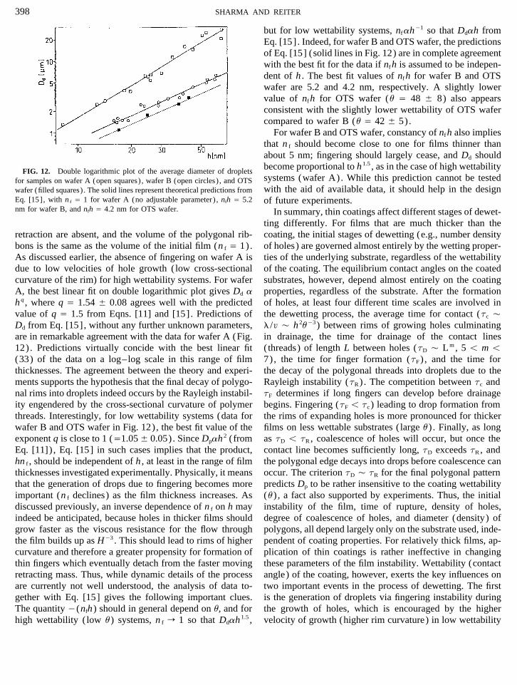
but for low wettability systems, nfah01 so that Ddah fromEq. [15]. Indeed, for wafer B and OTS wafer, the predictionsof Eq. [15] (solid lines in Fig. 12) are in complete agreementwith the best fit for the data if nfh is assumed to be indepen-dent of h . The best fit values of nfh for wafer B and OTSwafer are 5.2 and 4.2 nm, respectively. A slightly lowervalue of nfh for OTS wafer (u Å 48 { 8) also appearsconsistent with the slightly lower wettability of OTS wafercompared to wafer B (u Å 42 { 5).
For wafer B and OTS wafer, constancy of nfh also impliesthat n f should become close to one for films thinner thanabout 5 nm; fingering should largely cease, and Dd shouldbecome proportional to h 1.5 , as in the case of high wettabilityFIG. 12. Double logarithmic plot of the average diameter of dropletssystems (wafer A). While this prediction cannot be testedfor samples on wafer A (open squares) , wafer B (open circles) , and OTSwith the aid of available data, it should help in the designwafer (filled squares) . The solid lines represent theoretical predictions from
Eq. [15], with n f Å 1 for wafer A (no adjustable parameter) , nfh Å 5.2 of future experiments.nm for wafer B, and nfh Å 4.2 nm for OTS wafer. In summary, thin coatings affect different stages of dewet-
ting differently. For films that are much thicker than thecoating, the initial stages of dewetting (e.g., number densityretraction are absent, and the volume of the polygonal rib-
bons is the same as the volume of the initial film (n f Å 1). of holes) are governed almost entirely by the wetting proper-ties of the underlying substrate, regardless of the wettabilityAs discussed earlier, the absence of fingering on wafer A is
due to low velocities of hole growth (low cross-sectional of the coating. The equilibrium contact angles on the coatedsubstrates, however, depend almost entirely on the coatingcurvature of the rim) for high wettability systems. For wafer
A, the best linear fit on double logarithmic plot gives Dd a properties, regardless of the substrate. After the formationof holes, at least four different time scales are involved inhq , where q Å 1.54 { 0.08 agrees well with the predicted
value of q Å 1.5 from Eqns. [11] and [15]. Predictions of the dewetting process, the average time for contact (tc Çl /£ Ç h 2u03) between rims of growing holes culminatingDd from Eq. [15], without any further unknown parameters,
are in remarkable agreement with the data for wafer A (Fig. in drainage, the time for drainage of the contact lines(threads) of length L between holes (tD Ç Lm, 5 õ m õ12). Predictions virtually concide with the best linear fit
(33) of the data on a log–log scale in this range of film 7), the time for finger formation (tF) , and the time forthe decay of the polygonal threads into droplets due to thethicknesses. The agreement between the theory and experi-
ments supports the hypothesis that the final decay of polygo- Rayleigh instability (tR) . The competition between tc andtF determines if long fingers can develop before drainagenal rims into droplets indeed occurs by the Rayleigh instabil-
ity engendered by the cross-sectional curvature of polymer begins. Fingering (tF õ tc ) leading to drop formation fromthe rims of expanding holes is more pronounced for thickerthreads. Interestingly, for low wettability systems (data for
wafer B and OTS wafer in Fig. 12), the best fit value of the films on less wettable substrates ( large u) . Finally, as longas tD õ tR, coalescence of holes will occur, but once theexponent q is close to 1 (Å1.05 { 0.05). Since Dpah 2 (from
Eq. [11]) , Eq. [15] in such cases implies that the product, contact line becomes sufficiently long, tD exceeds tR, andthe polygonal edge decays into drops before coalescence canhn f , should be independent of h , at least in the range of film
thicknesses investigated experimentally. Physically, it means occur. The criterion tD Ç tR for the final polygonal patternpredicts Dp to be rather insensitive to the coating wettabilitythat the generation of drops due to fingering becomes more
important (n f declines) as the film thickness increases. As (u) , a fact also supported by experiments. Thus, the initialinstability of the film, time of rupture, density of holes,discussed previously, an inverse dependence of n f on h may
indeed be anticipated, because holes in thicker films should degree of coalescence of holes, and diameter (density) ofpolygons, all depend largely only on the substrate used, inde-grow faster as the viscous resistance for the flow through
the film builds up as H03 . This should lead to rims of higher pendent of coating properties. For relatively thick films, ap-plication of thin coatings is rather ineffective in changingcurvature and therefore a greater propensity for formation of
thin fingers which eventually detach from the faster moving these parameters of the film instability. Wettability (contactangle) of the coating, however, exerts the key influences onretracting mass. Thus, while dynamic details of the process
are currently not well understood, the analysis of data to- two important events in the process of dewetting. The firstis the generation of droplets via fingering instability duringgether with Eq. [15] gives the following important clues.
The quantity 0(nfh) should in general depend on u, and for the growth of holes, which is encouraged by the highervelocity of growth (higher rim curvature) in low wettabilityhigh wettability (low u) systems, n f r 1 so that Ddah 1.5 ,
AID JCIS 4001 / m4860$$148 02-15-96 14:05:32 coidas AP: Colloid
399INSTABILITY OF THIN POLYMER FILMS
22. Taylor, G. I., and Michael, D. H., J. Fluid Mech. 58, 625 (1973).systems. Second, the final diameter of drops resulting from23. Sharma, A., J. Colloid Interface Sci. 156, 96 (1993).the decay of polygonal rims is also influenced by the coating24. Derjaguin, B. V., Kollid. Zh. 17, 191 (1955); Derjaguin, B. V., Chur-
wettability (Eq. 15). The influence of substrate wettability aev, N. V., and Muller, V. M., ‘‘Surface Forces.’’ Consultants Bureau,on Dd , however, also remains important because Dp in Eq. New York, 1987.
25. Yiantsios, S. G., and Higgins, B. G., J. Colloid Interface Sci. 147, 341[15] is determined by the substrate properties (Eq. 11).(1991).The present theory and the interpretation of experiments
26. Sharma, A., Langmuir 9, 861 (1993).should also be an aid to the better design of thin film experi-27. Sharma, A., and Jameel, A. T., J. Chem. Soc. Faraday Trans. 90, 625
ments in the future. (1994).28. Reiter, G., Phys. Rev. Lett. 68, 75 (1992).29. Jameel, A. T., and Sharma, A., J. Colloid Interface Sci. 164, 416REFERENCES
(1994).30. Zhao, W., Rafailovich, M. H., Sokolov, J., Fetters, L. J., et al., Phys.1. Sheludko, A., Adv. Colloid Interface Sci. 1, 391 (1967).
2. Vrij, A., and Overbeek, J. Th. G., J. Am. Chem. Soc. 90, 3074 (1968). Rev. Lett. 70, 1453 (1993).31. Bergeron, V., Jimenez-Laguna, A. I., and Radke, C. J., Langmuir 8,3. Ruckenstein, E., and Jain, R. K., Faraday Trans. 70, 132 (1974).
4. Maldarelli, C., Jain, R. K., Ivanov, I., and Ruckenstein, E., J. Colloid 3027 (1992).32. Kralchevsky, P. A., Nikolov, A. D., Wasan, D. T., and Ivanov, I. B.,Interface Sci. 78, 118 (1980).
5. Williams, M. B., and Davis, S. H., J. Colloid Interface Sci. 90, 220 Langmuir 6, 1180 (1990).33. Reiter, G., Langmuir 9, 1344 (1993).(1982).
6. Sharma, A., and Ruckenstein, E., J. Colloid Interface Sci. 113, 456 34. Langmuir, I., Trans. Faraday Soc. 15, 62 (1920).35. Zisman, W. A., Adv. Chem. Soc. 43, 1 (1964).(1986).
7. Teletzke, G. F., Davis, H. T., and Scriven, L. E., Chem. Eng. Commun. 36. Whitesides, G. M., and Laibinis, P. E., Langmuir 6, 87 (1990).37. Extrand, C. W., Langmuir 9, 475 (1993).55, 41 (1987).
8. Sharma, A., and Jameel, A. T., J. Colloid Interface Sci. 161, 190 38. Rayleigh, Lord, Proc. London Math. Soc. 10, 4 (1978); Sekimoto, K.,Oguma, R., and Kawaski, K., Ann. Phys. 176, 359 (1987).(1993).
9. Mitlin, V. S., J. Colloid Interface Sci. 156, 491 (1993). 39. Cazabat, A. M., Heslot, F., Troian, S. M., and Carles, P., Nature 346,824 (1990).10. Wicks, Z. W., Jones, F. N., and Pappas, S. P., ‘‘Organic Coatings:
Science and Technology.’’ Wiley-Interscience, New York, 1992. 40. Brochard-Wyart, F., and Redon, C., Langmuir 8, 2324 (1992).41. Saffman, P. G., and Taylor, G. I., Proc. Roy. Soc. London Ser. A. 245,11. Garbassi, F., Morra, M., and Occhiello, E., ‘‘Polymer Surfaces.’’ Wiley,
Chichester, 1994. 312 (1958).42. Tanner, L. H., J. Phys. D: Appl. Phys. 12, 1473 (1979).12. Kheshgi, H., and Scriven, L. E., Chem. Eng. Sci. 46, 519 (1991).
13. Philip, J. R., J. Chem. Phys. 66, 5069 (1977). 43. Hartland, S., in ‘‘Thin Liquid Films’’ (I. B. Ivanov, Ed.) , SurfactantScience Series, pp. 663–766. Dekker, New York, 1988.14. Karim, A., Mansour, A., Felcher, G. P., and Russell, T. P., Phys. Rev.
B. 42, 6846 (1990). 44. Sathyagal, A. N., and Narasimhan, G., Chem. Eng. Commun. 111, 161(1992).15. de Gennes, P. G., Rev. Mod. Phys. 57, 827 (1985).
16. Cazabat, A.-M., Contemp. Phys. 28, 347 (1987). 45. van Oss, C. J., Chaudhury, M. K., and Good, R. J., Chem. Rev. 88,927 (1988); Sep. Sci. Technol. 24, 15 (1989); van Oss, C. J., Colloids17. Teletzke, G. F., Davis, H. T., and Scriven, L. E., Revue Phys. Appl.
23, 989 (1988). Surf. A. 78, 1 (1993); and references therein.46. Israelachvili, J. H., ‘‘Intermolecular and Surface Forces.’’ Academic18. Sharma, A., Langmuir 9, 3580 (1993).
19. Neogi, P., and Berryman, J. P., J. Colloid Interface Sci. 88, 100 (1982). Press, New York, 1985.47. Frumkin, A. N., Zh. Fiz. Khim. 12, 337 (1938).20. Burelbach, J. P., Bankoff, S. G., and Davis, S. H., J. Fluid Mech. 195,
463 (1988). 48. Wong, H., Morris, S., and Radke, C. J., J. Colloid Interface Sci. 148,317 (1992).21. Wayner, P. C., Jr., Colloids Surf. 52, 71 (1991).
AID JCIS 4001 / m4860$$148 02-15-96 14:05:32 coidas AP: Colloid