Solution precursor plasma deposition of nanostructured ZnO coatings
Dc
AKa
b
a
ARR2AA
KNDCSI
1
sipshrpst[b(tg
la
0h
Applied Surface Science 288 (2014) 215– 221
Contents lists available at ScienceDirect
Applied Surface Science
j ourna l ho me page: www.elsev ier .com/ locate /apsusc
omain growth of carbon nanotubes assisted by dewetting of thinatalyst precursor films
lok Kumar Srivastavaa,b, Priyanka Sachanb, Chandan Samantab,ingsuk Mukhopadhyaya, Ashutosh Sharmab,∗
Defence Materials and Stores R & D Establishment (DRDO), GT Road, Kanpur 208013, IndiaDepartment of Chemical Engineering, Indian Institute of Technology, Kanpur 208016, India
r t i c l e i n f o
rticle history:eceived 26 May 2013eceived in revised form9 September 2013ccepted 1 October 2013vailable online 11 October 2013
eywords:anostructures
a b s t r a c t
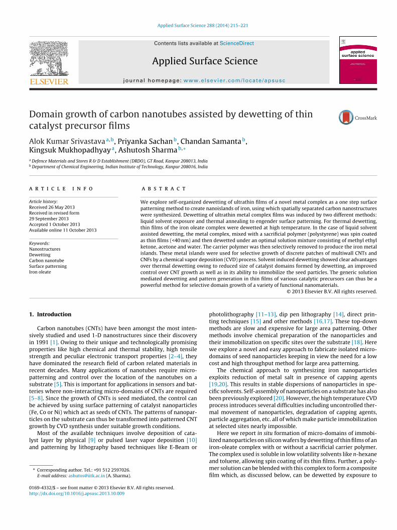
We explore self-organized dewetting of ultrathin films of a novel metal complex as a one step surfacepatterning method to create nanoislands of iron, using which spatially separated carbon nanostructureswere synthesized. Dewetting of ultrathin metal complex films was induced by two different methods:liquid solvent exposure and thermal annealing to engender surface patterning. For thermal dewetting,thin films of the iron oleate complex were dewetted at high temperature. In the case of liquid solventassisted dewetting, the metal complex, mixed with a sacrificial polymer (polystyrene) was spin coatedas thin films (<40 nm) and then dewetted under an optimal solution mixture consisting of methyl ethylketone, acetone and water. The carrier polymer was then selectively removed to produce the iron metal
ewettingarbon nanotubeurface patterningron oleate
islands. These metal islands were used for selective growth of discrete patches of multiwall CNTs andCNFs by a chemical vapor deposition (CVD) process. Solvent induced dewetting showed clear advantagesover thermal dewetting owing to reduced size of catalyst domains formed by dewetting, an improvedcontrol over CNT growth as well as in its ability to immobilize the seed particles. The generic solutionmediated dewetting and pattern generation in thin films of various catalytic precursors can thus be a
ctive
powerful method for sele. Introduction
Carbon nanotubes (CNTs) have been amongst the most inten-ively studied and used 1-D nanostructures since their discoveryn 1991 [1]. Owing to their unique and technologically promisingroperties like high chemical and thermal stability, high tensiletrength and peculiar electronic transport properties [2–4], theyave dominated the research field of carbon related materials inecent decades. Many applications of nanotubes require micro-atterning and control over the location of the nanotubes on aubstrate [5]. This is important for applications in sensors and bat-eries where non-interacting micro-domains of CNTs are required5–8]. Since the growth of CNTs is seed mediated, the control cane achieved by using surface patterning of catalyst nanoparticlesFe, Co or Ni) which act as seeds of CNTs. The patterns of nanopar-icles on the substrate can thus be transformed into patterned CNTrowth by CVD synthesis under suitable growth conditions.
Most of the available techniques involve deposition of cata-yst layer by physical [9] or pulsed laser vapor deposition [10]nd patterning by lithography based techniques like E-Beam or
∗ Corresponding author. Tel.: +91 512 2597026.E-mail address: [email protected] (A. Sharma).
169-4332/$ – see front matter © 2013 Elsevier B.V. All rights reserved.ttp://dx.doi.org/10.1016/j.apsusc.2013.10.009
domain growth of a variety of functional nanomaterials.© 2013 Elsevier B.V. All rights reserved.
photolithography [11–13], dip pen lithography [14], direct prin-ting techniques [15] and other methods [16,17]. These top-downmethods are slow and expensive for large area patterning. Othermethods involve chemical preparation of the nanoparticles andtheir immobilization on specific sites over the substrate [18]. Herewe explore a novel and easy approach to fabricate isolated micro-domains of seed nanoparticles keeping in view the need for a lowcost and high throughput method for large area patterning.
The chemical approach to synthesizing iron nanoparticlesexploits reduction of metal salt in presence of capping agents[19,20]. This results in stable dispersions of nanoparticles in spe-cific solvents. Self-assembly of nanoparticles on a substrate has alsobeen previously explored [20]. However, the high temperature CVDprocess introduces several difficulties including uncontrolled ther-mal movement of nanoparticles, degradation of capping agents,particle aggregation, etc. all of which make particle immobilizationat selected sites nearly impossible.
Here we report in situ formation of micro-domains of immobi-lized nanoparticles on silicon wafers by dewetting of thin films of aniron-oleate complex with or without a sacrificial carrier polymer.
The complex used is soluble in low volatility solvents like n-hexaneand toluene, allowing spin coating of its thin films. Further, a poly-mer solution can be blended with this complex to form a compositefilm which, as discussed below, can be dewetted by exposure to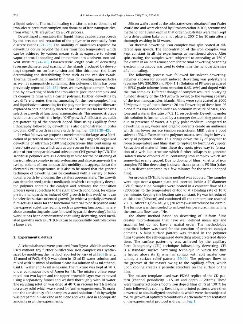
2 Surfac
aif
bddcvv(tdTaptitaesiplt
cdiasttettctppbfitawaa
2
us1m6uruTttwa
16 A.K. Srivastava et al. / Applied
liquid solvent. Thermal annealing transforms micro-domains ofron-oleate precursor complex into domains of iron nanoparticles,rom which CNT are grown by a CVD process.
Dewetting of an unstable thin liquid film on a substrate proceedsy the breakup and retraction of the polymer to eventually formiscrete islands [21–23]. The mobility of molecules required forewetting occurs beyond the glass transition temperature whichan be achieved by various means such as exposure to solventapor, thermal annealing and immersion into a solvent–non sol-ent mixture [24–28]. Characteristic length scale of dewettingaverage diameter and spacing of the islands produced by dewet-ing) depends on surface tension and film thickness; the latteretermining the destabilizing force such as the van der Waals.hermal dewetting of metal thin films for creating nanoparticless well as nanoparticle containing thin polymeric films has beenreviously reported [29–38]. Here, we investigate domain forma-ion by dewetting of both the iron-oleate precursor complex andts composite films with a carrier polymer. Further, dewetting bywo different routes, thermal annealing for the iron-complex filmsnd liquid solvent annealing for the polymer-iron complex films arexplored to obtain spatially discrete nanostructures for further areaelective growth of functional nanomaterials. This generic strategys demonstrated with the help of CNT growth. An illustrative, quickre-patterning of the smooth doped films using Capillary force
ithography followed by dewetting is also demonstrated in ordero obtain CNT growth in a more orderly manner [26,28,39–42].
In what follows, we propose a novel method for large-area fabri-ation of patterned micro-domains of CNT by using self-organizedewetting of ultrathin (<100 nm) polystyrene film containing an
ron oleate complex, which acts as a precursor for the in situ gener-tion of iron nanoparticles and subsequent CNT growth by CVD. Theacrificial polymer acts as a delivery vehicle for the positioning ofhe iron oleate complex in micro-domains and also circumvents thewin problems of iron nanoparticle mobility and aggregation at thelevated CVD temperature. It is also to be noted that the genericechnique of dewetting can be combined with a variety of func-ional growth by choosing the catalyst appropriately. The growthan either be seed particle mediated (in which a completely dewet-ed polymer contains the catalyst and activates the depositionrocess upon subjecting to the right growth conditions, for exam-le iron nanoparticles induced CNT growth in this work) or it cane selective surface oriented growth (in which a partially dewettedlm acts as a mask for the functional material to be deposited ontohe exposed substrate regions, such as growing functional materi-ls on a conducting substrate followed by partial dewetting). In thisork, it has been demonstrated that using dewetting, seed medi-
ted growths such as CNT/CNFs can be successfully controlled over large area.
. Experimental details
All chemicals used were procured from Sigma–Aldrich and weresed without any further purification. Iron complex was synthe-ized by modifying the method reported by Park et al. [20]. Briefly,2 mmol of FeCl3·6H2O was taken in 12 ml DI water solution andixed with 36 mmol of sodium oleate in a solution of 24 ml ethanol,
ml DI water and 42 ml n-hexane. The mixture was kept at 70 ◦Cnder continuous flow of Argon for 4 h. The mixture phase sepa-ated into two layers and the upper brownish layer was removedsing a separatory funnel and washed thoroughly with DI water.he resulting solution was dried at 40 ◦C in vacuum for 3 h leading
o a waxy solid which was stored for further experiments. To main-ain the consistency of the samples, a stock solution of 1% by weightas prepared in n-hexane or toluene and was used in appropriatemounts in all the experiments.
e Science 288 (2014) 215– 221
Silicon wafers used as the substrates were obtained from WaferWorld Inc. and were cleaned by ultrasonication in TCE, acetone andmethanol for 10 min each in that order. Substrates were then keptfor a dehydration bake on a hot plate at 200 ◦C for 30 min after athorough washing in DI water.
For thermal dewetting, iron complex was spin coated at dif-ferent spin speeds. The concentration of the iron complex waskept constant in all the experiments as mentioned above. Afterspin coating, the samples were subjected to annealing at 750 ◦Cfor 20 min in an inert atmosphere for thermal dewetting. Scanningelectron microscopy was used to determine the nanoparticle sizeafter annealing.
The following process was followed for solvent dewetting.Polymer chosen for solvent induced dewetting was polystyrene(average MW 280,000 and PDI < 1.1). Solution of PS were preparedin HPLC grade toluene (concentration 0.4%, w/v) and doped withthe iron complex. Different dosage of complex resulted in varyingnumber density of the CNT growth owing to the varying sparsityof the iron nanoparticles islands. Films were spin coated at 3000RPM providing a film thickness ∼20 nm. Dewetting of these Iron-PSblend films was induced under an optimum mixture of MEK, ace-tone and water in the ratio of 7:3:15, respectively. Dewetting underthis solution is further aided by a stronger destabilizing potentialdue to presence of water, a highly polar medium. Compared todewetting in air, water and organic solvents create an ambiencewhich has lower surface tension restrictions. MEK being a goodsolvent of PS, diffuses into the polymer matrix, resulting in low vis-cosity of polymer chains. This brings down the Tg of polymer toroom temperature and films start to rupture by forming dry spots.Retraction of material from these dry spots gives way to forma-tion of a web like structure which further collapses to generateisolated micro droplets of PS containing iron complex which aresomewhat evenly spaced. Due to doping of films, kinetics of ironcomplex-PS film dewetting is slower than a pristine PS film (takes∼1 h to dewet compared to a few minutes for the same undopedfilm).
For growing CNTs, following method was adopted. The sampleswere kept over a quartz plate and inserted inside a 2′′ diameterCVD furnace tube. Samples were heated in a constant flow of He(200 sccm) to the temperature of 400 ◦C at a heating rate of 10 ◦Cper minute. Keeping the heating rate constant, H2 was introducedat this time (30 sccm) and continued till the temperature reached750 ◦C. After this, flow of C2H2 (20 sccm) was introduced for 20 min.The furnace was then cooled to ambient temperature, maintainingthe constant flow rate of He.
The above method based on dewetting of uniform filmscreates micro-domains that have well defined mean size andspacings but do not have a spatial order. The methodologydescribed below was used for the creation of ordered catalystdomains. A faint surface pattern was created in the polymerfilms to guide the self-organized dewetting along preferred direc-tions. The surface patterning was achieved by the capillaryforce lithography (CFL) technique followed by dewetting. CFLis a standard surface patterning technique in which the filmis heated above its Tg when in contact with soft master con-taining a surface relief pattern [39,40]. The polymer flows inthe grooves of the master owing to the capillary effect, whichupon cooling creates a periodic structure on the surface of thefilm.
The master template used was PDMS replica of the CD pat-tern (channel periodicity ∼1.5 �m and depth ∼120 nm). Thesewere transferred onto smooth iron doped films of PS at 130 ◦C for
5 min followed by cooling. Resulting imprinted patterns were thendewetted to obtain aligned nanoislands which were then subjectedto CNT growth at optimized conditions. A schematic representationof the experimental protocol is drawn in Fig. 1.
A.K. Srivastava et al. / Applied Surface Science 288 (2014) 215– 221 217
ng the
e(
3
itoadmtfa
t(o5ooc
fiistwF4
Fp
Fig. 1. A schematic showi
Characterization of hence grown CNTs was done using fieldmission scanning electron microscope (Zeiss Supra 40VP), TEMFEI Technai 20U), XRD (PAN Analytical) and Raman (WITec).
. Results and discussion
In the present study, we demonstrate the in situ formation andmmobilization of nanoparticles in micro-domains even at highemperatures over silicon substrate. This is achieved by dewettingf thin films of an iron oleate complex, alone or in conjunction with
carrier polymer, to produce micro-domains. Spatially orderedomains could also be obtained by directed dewetting guided by aild surface patterning of the film. Immobilized iron seed nanopar-
icles are then synthesized in the domains by thermal annealingollowing which the domain growth of carbon nanostructures ischieved by CVD.
TGA of the synthesized complex was done (in inert condi-ions) to observe the temperature of decomposition of the complexFig. 2). It was observed that almost all the organic componentsf complex were dissociated before reaching the temperature of00 ◦C. Polystyrene also degrades much below 500 ◦C in the absencef oxygen [43]. Since the degradation of both organic componentsccurs below the CNT growth temperature, our method remainsonsistent with the materials used.
Since the complex is soluble in low boiling point solvents, a thinlm of the complex is easily formed on the substrate by spin coat-
ng. The thickness of the film depends on different factors like spinpeed, concentration of the solution and adhesion of the solution
o the substrate surface. In the present study, the last two factorsere kept constant by fixing the concentration and the substrate.or thermal dewetting, spin speed was increased from 1000 rpm to000 rpm, and the samples were annealed at 750 ◦C for 10 min in
ig. 2. Thermogravimetric analysis of Iron complex indicating the dissociation tem-erature.
experiment framework.
inert atmosphere. The results indicate that on increasing the spinspeeds, the size of the nanoparticles formed on the surface afterannealing decreases. This is consistent with the fact that by increas-ing the spin speed, the thickness of the film decreases resulting inless amount of complex and hence less number of iron atoms perunit area. Upon heating, all the residual organic components dis-sociate and evaporate and the neighboring iron atoms coalesce toform nanoparticles. Hence higher coating speed results in lowersize particles. It was also observed that beyond 4000 rpm, the spincoated films were not uniform and contained defects such as cracksdue to high residual stresses. In films coated below 1000 rpm, thestructures formed were interconnected as observed in the drop castsamples as well.
It has been well established earlier that CNT growth is onlypossible if the catalyst particle size is in the desired range [44].Our results show that even in the case of drop cast iron complexwhich practically has no aggregation, dense forest like growth wasobtained, which implies that the particles formed fell in the desiredsize range. It was observed that for the above-mentioned concen-tration and materials, the best island structures were obtainedat spin speed of 2000 rpm. As seen from Fig. 3, well separatednanoislands were obtained under this condition with a size range50–100 nm.
Although the growth of CNTs was isolated as a result of ther-mal dewetting, the density of such structures was found to bevery low. One of the possible reasons is the lateral movement ofiron nanoparticles onto the silicon surface due to high tempera-ture of processing. This mobility leads to fusion of the neighboringnanoparticles resulting into lesser number density and hence lesserCNT growth density. It also indicates that beyond a certain point,growth of CNTs assisted by thermal dewetting is difficult to controldue to process limitations. This problem can be circumvented byusing the solvent induced dewetting as discussed below.
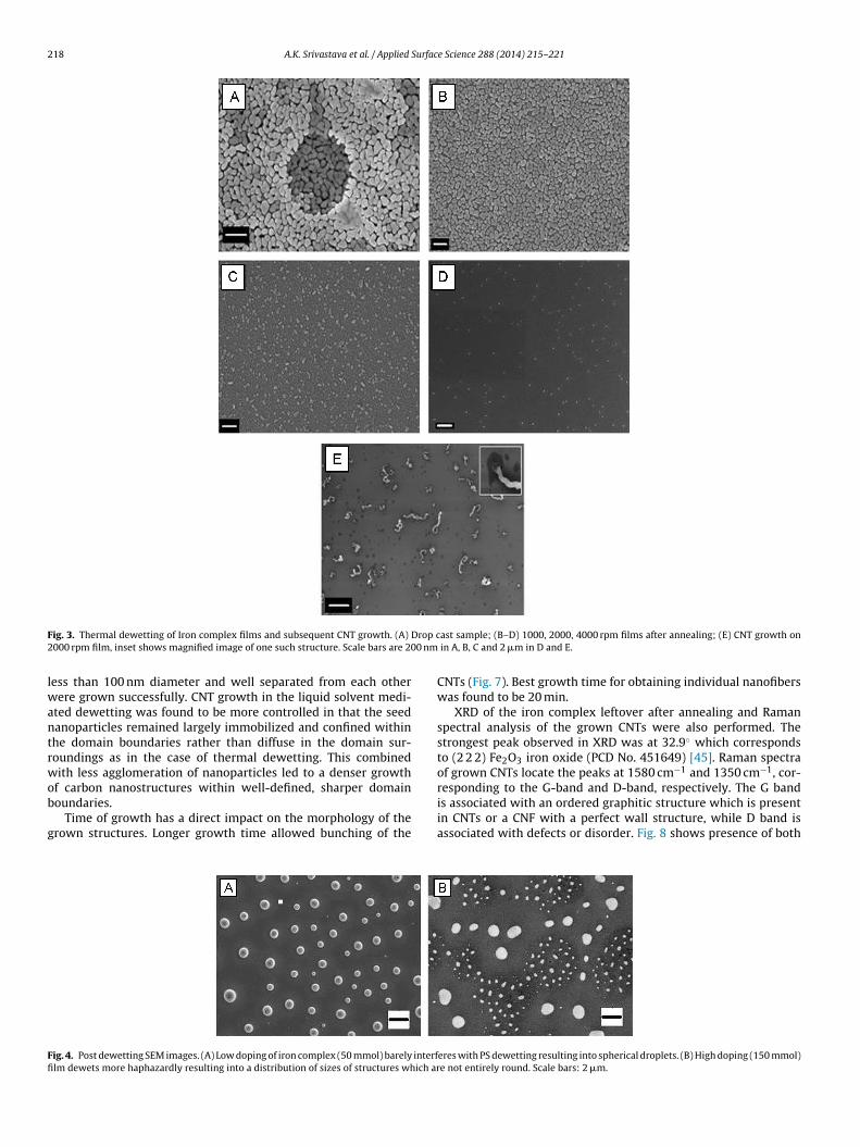
In case of solvent dewetting, iron complex was mixed in differ-ent quantities with PS-toluene solution and dewetted completely.A few representative SEM images of dewetted films having high andlow doping of iron are shown in Fig. 4. In the high nanoparticle con-centration cases, the dewetted islands have deformed shapes owingto the presence of the particles compared to the low nanoparticleconcentration islands which are more spherical.
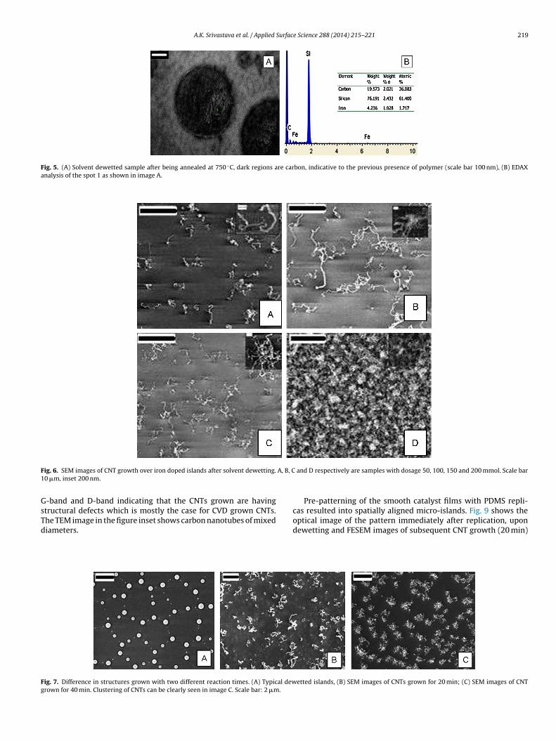
To see the iron content of these islands, EDAX analysis was doneon a dewetted sample post annealing. Fig. 5 shows one such datathat confirms the presence of iron in these structures. The imagealso shows the debris of carbonized polymer surrounding the iron.This debris constrains the movement of iron nanoparticles whensample is subjected to high temperature, thus ensuring the confine-ment of each nanoparticle within the carbon stain boundaries. Due
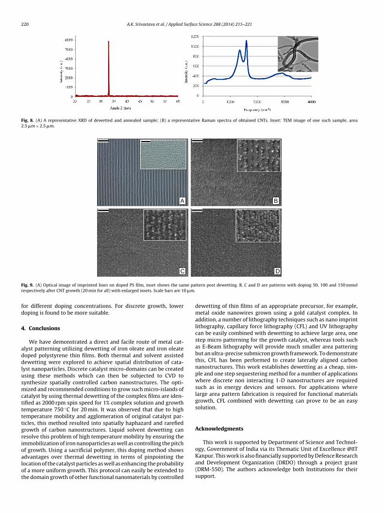
to this immobilization, each island has theoretically same proba-bility of growing isolated CNT structures.It was possible to grow spatially separated nanostructuresusing the optimized conditions. As Fig. 6 shows, nanostructures
218 A.K. Srivastava et al. / Applied Surface Science 288 (2014) 215– 221
F Drop c2 00 nm
lwantrwob
g
Ffi
ig. 3. Thermal dewetting of Iron complex films and subsequent CNT growth. (A)
000 rpm film, inset shows magnified image of one such structure. Scale bars are 2
ess than 100 nm diameter and well separated from each otherere grown successfully. CNT growth in the liquid solvent medi-
ted dewetting was found to be more controlled in that the seedanoparticles remained largely immobilized and confined withinhe domain boundaries rather than diffuse in the domain sur-oundings as in the case of thermal dewetting. This combinedith less agglomeration of nanoparticles led to a denser growth
f carbon nanostructures within well-defined, sharper domainoundaries.
Time of growth has a direct impact on the morphology of therown structures. Longer growth time allowed bunching of the
ig. 4. Post dewetting SEM images. (A) Low doping of iron complex (50 mmol) barely interflm dewets more haphazardly resulting into a distribution of sizes of structures which ar
ast sample; (B–D) 1000, 2000, 4000 rpm films after annealing; (E) CNT growth on in A, B, C and 2 �m in D and E.
CNTs (Fig. 7). Best growth time for obtaining individual nanofiberswas found to be 20 min.
XRD of the iron complex leftover after annealing and Ramanspectral analysis of the grown CNTs were also performed. Thestrongest peak observed in XRD was at 32.9◦ which correspondsto (2 2 2) Fe2O3 iron oxide (PCD No. 451649) [45]. Raman spectraof grown CNTs locate the peaks at 1580 cm−1 and 1350 cm−1, cor-
responding to the G-band and D-band, respectively. The G bandis associated with an ordered graphitic structure which is presentin CNTs or a CNF with a perfect wall structure, while D band isassociated with defects or disorder. Fig. 8 shows presence of botheres with PS dewetting resulting into spherical droplets. (B) High doping (150 mmol)e not entirely round. Scale bars: 2 �m.
A.K. Srivastava et al. / Applied Surface Science 288 (2014) 215– 221 219
Fig. 5. (A) Solvent dewetted sample after being annealed at 750 ◦C, dark regions are carbon, indicative to the previous presence of polymer (scale bar 100 nm), (B) EDAXanalysis of the spot 1 as shown in image A.
F A, B, C1
GsTd
Fg
ig. 6. SEM images of CNT growth over iron doped islands after solvent dewetting.0 �m, inset 200 nm.
-band and D-band indicating that the CNTs grown are having
tructural defects which is mostly the case for CVD grown CNTs.he TEM image in the figure inset shows carbon nanotubes of mixediameters.ig. 7. Difference in structures grown with two different reaction times. (A) Typical dewrown for 40 min. Clustering of CNTs can be clearly seen in image C. Scale bar: 2 �m.
and D respectively are samples with dosage 50, 100, 150 and 200 mmol. Scale bar
Pre-patterning of the smooth catalyst films with PDMS repli-
cas resulted into spatially aligned micro-islands. Fig. 9 shows theoptical image of the pattern immediately after replication, upondewetting and FESEM images of subsequent CNT growth (20 min)etted islands, (B) SEM images of CNTs grown for 20 min; (C) SEM images of CNT
220 A.K. Srivastava et al. / Applied Surface Science 288 (2014) 215– 221
Fig. 8. (A) A representative XRD of dewetted and annealed sample; (B) a representative Raman spectra of obtained CNTs. Inset: TEM image of one such sample, area2.5 �m × 2.5 �m.
F e par 0 �m.
fd
4
addlusmcttttgrioalot
ig. 9. (A) Optical image of imprinted lines on doped PS film, inset shows the samespectively after CNT growth (20 min for all) with enlarged insets. Scale bars are 1
or different doping concentrations. For discrete growth, loweroping is found to be more suitable.
. Conclusions
We have demonstrated a direct and facile route of metal cat-lyst patterning utilizing dewetting of iron oleate and iron oleateoped polystyrene thin films. Both thermal and solvent assistedewetting were explored to achieve spatial distribution of cata-
yst nanoparticles. Discrete catalyst micro-domains can be createdsing these methods which can then be subjected to CVD toynthesize spatially controlled carbon nanostructures. The opti-ized and recommended conditions to grow such micro-islands of
atalyst by using thermal dewetting of the complex films are iden-ified as 2000 rpm spin speed for 1% complex solution and growthemperature 750 ◦C for 20 min. It was observed that due to highemperature mobility and agglomeration of original catalyst par-icles, this method resulted into spatially haphazard and rarefiedrowth of carbon nanostructures. Liquid solvent dewetting canesolve this problem of high temperature mobility by ensuring themmobilization of iron nanoparticles as well as controlling the pitchf growth. Using a sacrificial polymer, this doping method shows
dvantages over thermal dewetting in terms of pinpointing theocation of the catalyst particles as well as enhancing the probabilityf a more uniform growth. This protocol can easily be extended tohe domain growth of other functional nanomaterials by controlledttern post dewetting. B, C and D are patterns with doping 50, 100 and 150 mmol
dewetting of thin films of an appropriate precursor, for example,metal oxide nanowires grown using a gold catalyst complex. Inaddition, a number of lithography techniques such as nano imprintlithography, capillary force lithography (CFL) and UV lithographycan be easily combined with dewetting to achieve large area, onestep micro patterning for the growth catalyst, whereas tools suchas E-Beam lithography will provide much smaller area patteringbut an ultra-precise submicron growth framework. To demonstratethis, CFL has been performed to create laterally aligned carbonnanostructures. This work establishes dewetting as a cheap, sim-ple and one step sequestering method for a number of applicationswhere discrete non interacting 1-D nanostructures are requiredsuch as in energy devices and sensors. For applications wherelarge area pattern fabrication is required for functional materialsgrowth, CFL combined with dewetting can prove to be an easysolution.
Acknowledgments
This work is supported by Department of Science and Technol-ogy, Government of India via its Thematic Unit of Excellence @IIT
Kanpur. This work is also financially supported by Defence Researchand Development Organization (DRDO) through a project grant(DRM-550). The authors acknowledge both Institutions for theirsupport.
Surfac
R
[
[
[
[
[
[
[
[
[
[
[
[
[
[
[
[
[
[
[
[
[
[
[
[
[
[
[
[
[
[
[
[
[
[
A.K. Srivastava et al. / Applied
eferences
[1] S. Iijima, Helical microtubules of graphitic carbon, Nature 354 (1991) 56–58.[2] R.H. Baughman, A.A. Zakhidov, W.A. de Heer, Carbon nanotubes – the route
toward applications, Science 297 (2002) 787–792.[3] Q. Cao, H.S. Kim, N. Pimparkar, J.P. Kulkarni, C. Wang, M. Shim, K. Roy, M.A.
Alam, J.A. Rogers, Medium-scale carbon nanotube thin-film integrated circuitson flexible plastic substrates, Nature 454 (2008) 495–500.
[4] T. Sekitani, Y. Noguchi, K. Hata, T. Fukushima, T. Aida, T. Someya, A rubber-like stretchable active matrix using elastic conductors, Science 321 (2008)1468–1472.
[5] H. Dai, Carbon nanotubes: synthesis, integration, and properties, Accounts ofChemical Research 35 (2002) 1035–1044.
[6] M. Dresselhaus, G. Dresselhaus, J. Charlier, E. Hernandez, Electronic, thermaland mechanical properties of carbon nanotubes, Philosophical Transactionsof the Royal Society A: Mathematical Physical and Engineering Sciences 362(2004) 2065–2098.
[7] M. Meyyappan, D. Srivastava, Carbon Nanotubes Handbook of Nanoscience,Engineering, and Technology, CRC Press, Boca Raton, FL, 2003.
[8] R. Saito, G. Dresselhaus, M.S. Dresselhaus, Physical Properties of Carbon Nano-tubes, World Scientific, 1998.
[9] L. Dai, A. Patil, X. Gong, Z. Guo, L. Liu, Y. Liu, D. Zhu, Aligned nanotubes,ChemPhysChem 4 (2003) 1150–1169.
10] M. Gaillard, C. Boulmer-Leborgne, N. Semmar, É. Millon, A. Petit, Carbon nano-tube growth from metallic nanoparticles deposited by pulsed-laser depositionon different substrates, Applied Surface Science 258 (2012) 9237–9241.
11] J. Kong, H.T. Soh, A.M. Cassell, C.F. Quate, H. Dai, Synthesis of individual single-walled carbon nanotubes on patterned silicon wafers, Nature 395 (1998)878–881.
12] K. Teo, M. Chhowalla, G. Amaratunga, W. Milne, D. Hasko, G. Pirio, P. Legagneux,F. Wyczisk, D. Pribat, Uniform patterned growth of carbon nanotubes withoutsurface carbon, Applied Physics Letters 79 (2001) 1534–1536.
13] A. Tselev, K. Hatton, M.S. Fuhrer, M. Paranjape, P. Barbara, A photolithographicprocess for fabrication of devices with isolated single-walled carbon nanotubes,Nanotechnology 15 (2004) 1475.
14] B. Li, C.F. Goh, X. Zhou, G. Lu, H. Tantang, Y. Chen, C. Xue, F.Y. Boey, H. Zhang,Patterning colloidal metal nanoparticles for controlled growth of carbon nano-tubes, Advanced Materials 20 (2008) 4873–4878.
15] C. Chatzikomis, S.W. Pattinson, K.K. Koziol, I.M. Hutchings, Patterning of carbonnanotube structures by inkjet printing of catalyst, Journal of Materials Science(2012) 1–6.
16] W.S. Chang, J.W. Kim, D.G. Choi, C.S. Han, Fabrication of nano-electrode arraysof free-standing carbon nanotubes on nano-patterned substrate by imprintmethod, Applied Surface Science 257 (2011) 3063–3068.
17] M. Gaillard, C. Boulmer-Leborgne, N. Semmar, E. Millon, A. Petit, Carbon nano-tube growth from metallic nanoparticles deposited by pulsed-laser depositionon different substrates, Applied Surface Science 258 (2012) 9237–9241.
18] C.M. Seah, S.P. Chai, S. Ichikawa, A.R. Mohamed, Synthesis of single-walledcarbon nanotubes over a spin-coated Fe catalyst in an ethanol-PEG colloidalsolution, Carbon 50 (2012) 960–967.
19] C. Murray, C. Kagan, M. Bawendi, Synthesis and characterization of monodis-perse nanocrystals and close-packed nanocrystal assemblies, Annual Reviewof Materials Science 30 (2000) 545–610.
20] J. Park, K. An, Y. Hwang, J.E.G. Park, H.J. Noh, J.Y. Kim, J.H. Park, N.M. Hwang,T. Hyeon, Ultra-large-scale syntheses of monodisperse nanocrystals, NatureMaterials 3 (2004) 891–895.
21] G. Reiter, Dewetting of thin polymer films, Physical Review Letters 68 (1992)75–78.
22] A. Sharma, G. Reiter, Instability of thin polymer films on coated substrates:rupture, dewetting, and drop formation, Journal of Colloid and Interface Science178 (1996) 383–399.
[
[
e Science 288 (2014) 215– 221 221
23] A. Verma, A. Sharma, Enhanced self, organized dewetting of ultrathin polymerfilms under water, organic solutions: fabrication of sub, micrometer sphericallens arrays, Advanced Materials 22 (2010) 5306–5309.
24] G. Reiter, Unstable thin polymer films: rupture and dewetting processes, Lang-muir 9 (1993) 1344–1351.
25] R. Xie, A. Karim, J.F. Douglas, C.C. Han, R.A. Weiss, Spinodal dewetting of thinpolymer films, Physical Review Letters 81 (1998) 1251–1254.
26] A. Sehgal, V. Ferreiro, J.F. Douglas, E.J. Amis, A. Karim, Pattern-directed dewet-ting of ultrathin polymer films, Langmuir 18 (2002) 7041–7048.
27] A. Sharma, R. Verma, Pattern formation and dewetting in thin films of liq-uids showing complete macroscale wetting: from pancakes to Swiss cheese,Langmuir 20 (2004) 10337–10345.
28] A. Verma, A. Sharma, Submicrometer pattern fabrication by intensificationof instability in ultrathin polymer films under a water–solvent mix, Macro-molecules 44 (2011) 4928–4935.
29] J. Bischof, D. Scherer, S. Herminghaus, P. Leiderer, Dewetting modes of thinmetallic films: nucleation of holes and spinodal dewetting, Physical ReviewLetters 77 (1996) 1536–1539.
30] S. Herminghaus, K. Jacobs, K. Mecke, J. Bischof, A. Fery, M. Ibn-Elhaj, S.Schlagowski, Spinodal dewetting in liquid crystal and liquid metal films, Sci-ence 282 (1998) 916–919.
31] K.A. Barnes, A. Karim, J.F. Douglas, A.I. Nakatani, H. Gruell, E.J. Amis, Suppressionof dewetting in nanoparticle-filled polymer films, Macromolecules 33 (2000)4177–4185.
32] J. Huang, F. Kim, A.R. Tao, S. Connor, P. Yang, Spontaneous formation of nanopar-ticle stripe patterns through dewetting, Nature Materials 4 (2005) 896–900.
33] C. Favazza, J. Trice, R. Kalyanaraman, R. Suresh Kumar, Self-organized metalnanostructures through laser-interference driven thermocapillary convection,Applied Physics Letters 91 (2007).
34] S.J. Randolph, J.D. Fowlkes, A.V. Melechko, K.L. Klein, H.M. Meyer III, M.L. Simp-son, P.D. Rack, Controlling thin film structure for the dewetting of catalystnanoparticle arrays for subsequent carbon nanofiber growth, Nanotechnology18 (2007).
35] J. Trice, C. Favazza, D. Thomas, H. Garcia, R. Kalyanaraman, R. Sureshkumar,Novel self-organization mechanism in ultrathin liquid films: theory and exper-iment, Physical Review Letters 101 (2008).
36] R. Mukherjee, S. Das, A. Das, S.K. Sharma, A.K. Raychaudhuri, A. Sharma, Sta-bility and dewetting of metal nanoparticle filled thin polymer films: control ofinstability length scale and dynamics, ACS Nano 4 (2010) 3709–3724.
37] Y. Fang, Y. Hou, F. Teng, Z. Lou, A. Tang, B. Zhang, L. Meng, Y. Ning, L. Lu, Char-acterization of nanoscale clusters fabricated by pulsed laser irradiation of thinAu films, Applied Surface Science 273 (2013) 625–631.
38] J. Wei, Q. Liu, M. Xiao, Laser pulse induced micropatterning on sandwiched thinfilms, Applied Surface Science 280 (2013) 89–92.
39] C.M. Bruinink, M. Péter, P.A. Maury, M. de Boer, L. Kuipers, J. Huskens, D.N.Reinhoudt, Capillary force lithography: fabrication of functional polymer tem-plates as versatile tools for nanolithography, Advanced Functional Materials 16(2006) 1555–1565.
40] K.-Y. Suh, M.C. Park, P. Kim, Capillary force lithography: a versatile tool for struc-tured biomaterials interface towards cell and tissue engineering, AdvancedFunctional Materials 19 (2009) 2699–2712.
41] K. Kargupta, A. Sharma, Dewetting of thin films on periodic physically andchemically patterned surfaces, Langmuir 18 (2002) 1893–1903.
42] R. Mukherjee, D. Bandyopadhyay, A. Sharma, Control of morphology in patterndirected dewetting of thin polymer films, Soft Matter 4 (2008) 2086–2097.
43] D.-R. Yei, S.-W. Kuo, Y.-C. Su, F.-C. Chang, Enhanced thermal properties of PSnanocomposites formed from inorganic POSS-treated montmorillonite, Poly-
mer 45 (2004) 2633–2640.44] A.C. Dupuis, The catalyst in the CCVD of carbon nanotubes – a review, Progressin Materials Science 50 (2005) 929–961.
45] L. Ben-Dor, E. Fischbein, Z. Kalman, Concerning the [beta] phase of iron(III)oxide, Acta Crystallographica B 32 (1976) 667.
Copyright © 2022 FDOKUMEN