Viscoelastic analysis of RFDA measurements applied to oxide ...
Upload
independentCategory
view
4download
0
THE JOURNAL OF CHEMICAL PHYSICS 134, 064705 (2011)
Instability and dewetting of ultrathin solid viscoelastic filmson homogeneous and heterogeneous substrates
Ajoy Patra,1 Dipankar Bandyopadhyay,2 Gaurav Tomar,3 Ashutosh Sharma,4,a) andGautam Biswas1
1Department of Mechanical Engineering, Indian Institute of Technology, Kanpur, UP 208016, India2Department of Chemical Engineering, Indian Institute of Technology, Guwahati, Assam 781039, India3Department of Mechanical Engineering, Indian Institute of Science, Bangalore, Karnataka 560012, India4Department of Chemical Engineering, Indian Institute of Technology, Kanpur, UP 208016, India
(Received 27 September 2010; accepted 24 January 2011; published online 9 February 2011)
Instability and dewetting engendered by the van der Waals force in soft thin (<100 nm) linear vis-coelastic solid (e.g., elastomeric gel) films on uniform and patterned surfaces are explored. Linearstability analysis shows that, although the elasticity of the film controls the onset of instability andthe corresponding critical wavelength, the dominant length-scale remains invariant with the elasticmodulus of the film. The unstable modes are found to be long-wave, for which a nonlinear long-waveanalysis and simulations are performed to uncover the dynamics and morphology of dewetting. Thestored elastic energy slows down the temporal growth of instability significantly. The simulationsalso show that a thermodynamically stable film with zero-frequency elasticity can be made unsta-ble in the presence of physico-chemical defects on the substrate and can follow an entirely differentpathway with far fewer holes as compared to the viscous films. Further, the elastic restoring force canretard the growth of a depression adjacent to the hole-rim and thus suppress the formation of satelliteholes bordering the primary holes. These findings are in contrast to the dewetting of viscoelastic liq-uid films where nonzero frequency elasticity accelerates the film rupture and promotes the secondaryinstabilities. Thus, the zero-frequency elasticity can play a major role in imposing a better-definedlong-range order to the dewetted structures by arresting the secondary instabilities. © 2011 AmericanInstitute of Physics. [doi:10.1063/1.3554748]
I. INTRODUCTION
Instability and dynamics of thin films have been ex-tensively studied1–20 because the self-organized microstruc-tures originating from the thin film instabilities hold greatpromise toward the fabrication of superhydrophobic surfaces,solar/fuel cells, optoelectronic, and microfluidic devices. Anearly breakthrough in the understanding was the recognitionthat the instabilities in thin viscous films are usually of a long-wave character that are amenable to a nonlinear analysis by aproper scaling of the Navier–Stokes equations.2, 4, 15–20 Pre-vious research works7, 10, 15–20 uncovered that dewetting of anultrathin film on a homogeneous substrate follow a “spinodal”mechanism and is initiated by the formation of random holesat a mean distance referred to as the spinodal length scale.Subsequently, these holes grow leading to form ribbon likestructures, which later breaks up to form randomly placedisolated droplets on the substrate. In contrast to the spinodaldewetting, which is a spontaneous self-organizing process,physical, and chemical defects present on the substrate canalso initiate dewetting. A number of recent experimental21–34
and theoretical35–45 studies suggest that periodic physico-chemical defects on the substrate can lead to the orderingof the dewetted structures when synchronization between thespinodal length scale and the periodicity of the substrate pat-
a)Author to whom correspondence should be addressed. Electronic mail:[email protected].
tern takes place. A number of detail reviews on the dewettingof ultrathin films exist in the literature.3, 12, 46
The focus of the above mentioned theoretical studies hadbeen primarily on dewetting of purely viscous films. It is im-portant to note here that most of the patterning applicationsin the areas ranging from optoelectronic and microfluidic de-vices, coatings, microelectromechanical systems, sensors tothe fundamental experimental studies employ thin films ofhigh molecular weight polymeric melts and elastomers (suchas gels and concentrated polymer solutions), which exhibitviscoelastic rheology. Although stability of thin viscoelasticliquid films has also been extensively studied,47–50 there areno simulations on the dynamics and morphology of viscoelas-tic solid films.
Sathyagal and Narsimhan51 presented a linear stabil-ity analysis (LSA) of thin films with viscoelastic (Maxwelltype) liquid–gas interface and a Newtonian bulk phase.Herminghaus et al.52, 53 proposed a phenomenological vis-coelastic model to explain the dynamics and morphologicalevolution of hole growth in thin polymer films. Rauscheret al.,54 using Jeffrey’s constitutive relation to model theviscoelastic behavior, showed that the rheological propertieshave little effect on the shape of rims formed during thegrowth of holes. Later, Tomar et al.55 studied the dewettingof a Jeffrey’s type liquid film and showed that the elastic-ity (relaxation time constant) has no influence on the dewet-ting length-scale, but the finite-frequency elasticity signif-icantly expedites the dewetting process and the dynamics
0021-9606/2011/134(6)/064705/11/$30.00 © 2011 American Institute of Physics134, 064705-1
Downloaded 09 Feb 2011 to 202.3.77.11. Redistribution subject to AIP license or copyright; see http://jcp.aip.org/about/rights_and_permissions

064705-2 Patra et al. J. Chem. Phys. 134, 064705 (2011)
becomes faster with increasing relaxation time of the ma-terial. These conclusions relate to viscoelastic liquid filmsthat lack a permanent, zero-frequency elasticity, unlike softsolids such as cross-linked gels. In one notable early contri-bution, Safran and Klein56 studied a dewetting viscoelasticfilm consisting of zero-frequency as well as frequency de-pendent elasticity using a long-wave linear stability analysis.Shenoy and Sharma57 performed the LSA of a solid viscoelas-tic film destabilized by an arbitrary external field. However,the explicit calculations in the study were focused on contact-mediated instability of relatively thicker elastic films, whichdisplay short-wave elastic contact instability and the effectsof surface tension can be neglected. Kumar and Matar58 stud-ied the role of a viscoelastic substrate on the dewetting ofa viscous film and showed that the deformation of the sub-strate has a destabilizing effect on the liquid film.59 Sarkar andSharma60 recently introduced a unified LSA of field-inducedsurface instabilities in zero-frequency solid viscoelastic films,which showed different regimes of thin film instabilities rang-ing from elastic to viscous, from adhesive (confined) to wet-ting (free surface), and from short- to long-wave instabili-ties. Importantly, the unified study highlighted that the vander Waals force driven long-wave instability is possible onlyif the film is elastically soft with its shear modulus less thanabout 1 kPa. The critical thickness below which instabilitymanifests at this modulus is already about 3 nm. A stiffer filmcan thus be rendered unstable by the van der Waals force onlyif it is possibly a small molecule monolayer brush! There areas yet no systematic experiments on soft ultrathin solid filmsthat can be quantitatively compared to the proposed unifiedtheory.60 However, there are some relevant experimental ob-servations on ultrathin (<10 nm) solidlike polymer films andbrushes, including monolayers, that undergo dewetting androughening by a long-wave instability manifest over a muchlonger time span.61–64 The LSA60 applied to a purely elas-tic van der Waals film65 could explain the wavelength scalingseen in these experiments.61 Another interesting observationin this context is the suppression of instability in nanoparti-cle filled polymer melt films,66 which can be correlated to theelasticity of such films.
In view of all these, we extend the linear theory60 andinvestigate the nonlinear stability, dewetting and morphologyof ultrathin (<100 nm) linear viscoelastic thin film having azero-frequency elastic modulus. The constitutive model usedfor this study is particularly useful in describing the rheolog-ical behavior of soft gels such as partially cross-linked poly-mers like polyacrylamide (PA) and poly-(dimethylsiloxane)(PDMS) gels.68–70 The major objectives of this work are(i) identify the conditions under which the zero-frequencythin elastomeric films are unstable, (ii) uncover the differ-ent pathways of dewetting of the zero-frequency viscoelas-tic film through nonlinear simulations, and (iii) compare andcontrast the dynamics with the Newtonian35, 36 and frequencydependent linear viscoelastic films.55 For this purpose, in thebeginning of the study, a brief LSA is presented to motivatethe underlying physics. The LSA shows that a thin film withzero-frequency elasticity can be stable if its shear modulus orthe film thicknesses are higher than some respective criticalthreshold values. This is in contrast to purely viscous films
and viscoelastic liquid films,55 which are unconditionally un-stable under the influence of a destabilizing interaction po-tential. The nonlinear simulations in this paper also show thatthe zero-frequency elasticity has a profound retarding influ-ence on the growth of instability and its morphology. Thedefect induced dewetting for the zero-frequency viscoelas-tic film highlights a phenomenon that the physical or chemi-cal defects present on the surface can induce dewetting evenin a thermodynamically stable film by engendering a lateralwettability gradient. However, the LSA and the nonlinear sim-ulations also suggest together that the lateral wettability gra-dient has to overcome the restoring elastic and surface ten-sion forces to promote such instabilities in case of elastomerfilms. The dewetting pathways of defect induced dewettingare found to be different from those in viscous films.35–39 Thesimulations below show that during the defect induced dewet-ting, after the formation of the primary hole, the depressionadjacent to the primary hole-rim does not necessarily growwith time because of the restoring elastic force present in thefilm. Thus, the formation of secondary satellite holes is sup-pressed which is a common phenomenon in the dewetting ofliquid films.55 The suppression of secondary instabilities byzero-frequency elasticity can be of importance in long-rangeordering of microstructures. Specific examples of periodic or-dering of microstructures are also shown on substrates withperiodic physical or chemical patterns.
II. PROBLEM FORMULATION
Figure 1 shows the schematic of a thin film resting on aphysically heterogeneous solid substrate. The coordinate axisparallel and normal to the surface (Fig. 1) are representedby x and z, respectively. The surface of the substrate is de-scribed by the function z = a f (x), where a and f (x) are theamplitude of the heterogeneity with reference to the datum,z = 0 and the shape function, respectively. A homogeneousplanar substrate can be obtained (i) when the function f (x)is identically equal to zero everywhere and (ii) in the limita → 0. The mean and local film thicknesses are h0 and s(x, t)= h(x, t) − a f (x), respectively. The function h(x, t) givesthe thickness of the film as measured from the datum, z = 0.
A. Governing equations
In this study, we investigate the stability of thin linearviscoelastic films (thickness <100 nm) under the influence of
FIG. 1. Schematic of a viscoelastic film resting on a physically heteroge-neous solid substrate. The solid substrate is described by the function z= af(x), where, a is the amplitude of the heterogeneity function f(x) fromthe datum, z = 0. The mean thickness and the local thickness of the film areh0 and s = h(x, t) − af(x), respectively.
Downloaded 09 Feb 2011 to 202.3.77.11. Redistribution subject to AIP license or copyright; see http://jcp.aip.org/about/rights_and_permissions

064705-3 Dewetting of ultrathin viscoelastic films J. Chem. Phys. 134, 064705 (2011)
intermolecular forces. Owing to the small thickness of thefilm, inertia is neglected and the intermolecular forces are as-sumed to be much stronger body force than the gravitationalforces. Resulting quasistatic equation of motion for the in-compressible elastomeric film is
− ∇ p + ∇ · τ = 0, (1)
∇ · u = 0, (2)
where p is the total pressure, τ is the viscoelastic stress ten-sor, and u is the displacement vector with x and z compo-nents given by u and w, respectively. The total pressure p = p− � comprises the hydrostatic pressure, p, and the disjoiningpressure, �, arising from the intermolecular interactions. Thedisjoining pressure, �, is due to intermolecular interactionsand can be obtained from the interaction energy (�G) perunit area of the film as
� = −∂(�G)
∂s, where �G = − A
12πs2+ B
s8, (A, B > 0).
(3)
The interaction energy comprises of two components, along range attractive van der Waals force (with the effectiveHamaker constant A) and extremely short range Born repul-sion. The Born repulsion coefficient, B is incorporated to re-move the contact line singularity of the van der Waals attrac-tion. The expression B is obtained by the minimization of thefree energy at the equilibrium distance l015–17 and using S= �G(l0) − �G(∞), where S is the Lifshitz–van der Waalscomponent of spreading coefficient. This theoretical formal-ism has been widely employed previously in the context ofdewetting of both purely viscous15–20, 34–40 and purely elasticfilms.60, 67, 68 The film initially deforms under the influence ofthe attractive van der Waals force, but eventually the deforma-tion at the minimum thickness ceases and a locally flat film ofequilibrium thickness l0 is formed. Thus, the film thickness atthe bottom of a full-thickness hole as shown in the simulationssubsequently corresponds to the equilibrium thickness, l0.
The Hamaker constant in Eq. (3) can be correlated tothe spreading coefficient as A = −12πd2
0 S and d0 is the cut-off distance (∼0.158 nm).15, 23 The corresponding equilibriumdistance is given by l0 = √
3d0/2 (∼0.137 nm).15–17, 23 A thinfilm spreads wetting the surface for S >0 and spontaneousdewetting occurs for S <0. In the present study, we are inter-ested in dewetting films and therefore assume positive valuesof the Hamaker constant, A.
The linear viscoelastic stress tensor defining the rheologyof the thin elastomeric film is given by,
τ = μ(∇u + ∇uT ) + η∂
∂t(∇u + ∇uT ), (4)
where η and μ are the viscosity and the shear modulus of thefilm, respectively. The superscript T implies the transpose andt is the dimensional time. The above constitutive relation rep-resents a combination of frequency-independent (Newtonian)viscous loss and elastic storage moduli. The constitutive rela-tion ensures that the material deforms at a decreasing rate un-der a constant stress and asymptotically approaches a steady-state strain. Upon stress removal, the material gradually re-
laxes to its undeformed state with the characteristic time scaleof (η/μ). This model is useful in explaining the stress relax-ation behaviors of cross-linked polymers such as PDMS orPA gels when the load is not too high and the material un-dergoes small strains as in the long-wave regime. The resultsof this model for the field-induced instabilities in cross-linkedPDMS have already been verified.68–70 We use this basic vis-coelastic model to capture the essential physics of the nonlin-ear morphological evolution.57–59
B. Boundary conditions
The displacement, velocity, and pressure field satisfyingthe above governing equations satisfy the following boundaryconditions:
It is assumed that the film is rigidly bonded to the sub-strate, i.e., no-slip and impermeability boundary conditions atthe film-substrate interface, z = a f (x) gives
u = w = ∂u
∂t= ∂w
∂t= 0. (5)
The tangential and normal stress balance at the fluid–air inter-face (z = h(x, t)) yields
τxz = 0, (6)
p + � + γ κ − τzz = 0. (7)
Here, γ is the surface tension coefficient and κ is the localcurvature at the interface. The kinematic condition at the film–air interface (z = h(x, t)) is given by
∂h
∂t+ ∂u
∂t
∣∣∣∣z=h
∂h
∂x= ∂w
∂t
∣∣∣∣z=h
. (8)
III. LINEAR STABILITY ANALYSIS
In this section, we investigate the linear stability of athin viscoelastic film dewetting a homogeneous substrate(a f (x) = 0). In order to perform the LSA, the governingequations (Sec. IIA) and the boundary conditions (Sec. IIB)are linearized using the normal linear modes as following:
h = h0 + heikx+ωt ,
p = p0 + p(z)eikx+ωt ,(9)
u = u(z)eikx+ωt ,
w = w(z)eikx+ωt .
The base state is described by h = h0, p0 = −�0 = A/
(6πh30), u = 0, w = 0. Substituting the linearized parameters
in the governing equations [Eqs. (1) and (2)] and bound-ary conditions [Eqs. (5)–(8)], we obtained the followinglinearized equations governing the perturbation amplitude.The linearized x and z component of the momentum equationsand the incompressibility condition are
− ik p − (μ + ηω)k2u + (μ + ηω)u′′ = 0, (10)
− p′ − (μ + ηω)k2w + (μ + ηω)w ′′ = 0, (11)
iku + w ′ = 0. (12)
Downloaded 09 Feb 2011 to 202.3.77.11. Redistribution subject to AIP license or copyright; see http://jcp.aip.org/about/rights_and_permissions

064705-4 Patra et al. J. Chem. Phys. 134, 064705 (2011)
The no-slip and the impermeability boundary conditionsat the film-substrate interface (z = a f (x) = 0) are given by,
u = w = 0. (13)
The shear and normal stress balance at the free interface(z = h) yields
u′ + ikw = 0, (14)
p − 2(μ + ηω)w ′ + (Y − k2γ )w = 0. (15)
The kinematic condition yields,
h = w |z=h . (16)
Here, the superscript ′ denotes the derivative with respect to zand Y is the interaction stiffness given by
Y = −∂�
∂h= − A
2πh40
. (17)
The following biharmonic ordinary differential equationcan be obtained by eliminating p from the linearized govern-ing equations [Eqs. (10) and (11)]:
w I V − 2k2w I I + k4w = 0, (18)
where the superscripts II and IV indicate the order of thederivative with respect to z. The general solution of the aboveequation is given by
w = (A1 + A3z)ekz + (A2 + A4z)e−kz, (19)
where the integration constants Ai are determined using theboundary conditions [Eqs. (13), (14), and (16)] as shown inAppendix A. Substituting p obtained from Eq. (10) into Eq.(15) yields the dispersion relation given by60
ω = − (−1 + e4h0k − 4h0ke2h0k)
2kη(1 + e4h0k + e2h0k(2 + 4(h0k)2))(k2γ + Y ) − μ
η.
(20)
The first term in the dispersion relation represents the stabiliz-ing surface tension force, the intermolecular forces contributeto the destabilizing second term and the stabilization by theelastic force is represented by the third term. In the absenceof solidlike elasticity in the film (μ → 0), one can easily ob-tain the dispersion relation for the viscous film.1 Instabilityresults when the intermolecular interactions to overcome thestabilizing influences of surface curvature and the elastic de-formations. The condition for the instability is ω > 0. Clearly,instability requires a destabilizing force denoted by a nega-tive value of the spinodal parameter, Y < 0. For any nonzeroelastic modulus, a critical minimum destabilizing force, Yc isrequired in Eq. (20) to attain a positive value of the growthcoefficient and initiate the instability. For any |Y | > |Yc|, thefastest growing mode of instability is found by searchingfor the wavelength (λm = 2π/km) which gives the maximumgrowth rate (ωm) from Eq. (20). It is evident from Eq. (20)that the film would not undergo spontaneous dewetting if theinteraction stiffness is below a critical value, Yc, determinedby the shear modulus, μ, of the film. Similarly, for a given in-teraction stiffness Y, the film would be stable for μ > μc. The
FIG. 2. (a) Contours of ωm on μ − η plane. The other variables are h0= 4 nm, γ = 0.03 N/m and A = 10−20 J. (b) Variation of λm with γ (h0= 10 nm; curve 1) and variation of λm with h0 (γ = 30 mN/m, curve 2).(c) Variation of λc with h0 (γ = 30 mN/m).
dispersion relation asymptotically reduces to that for a New-tonian fluid by putting μ = 0.1, 2 Also, the critical conditionfor the onset of instability in thin rigidly bonded elastic filmscan be obtained by setting η = 0.57, 60 The dispersion relationreadily shows that the viscosity, η, and the shear modulus, μ,have no influence on the dominant length scale of the instabil-ity. However, they strongly govern the time scale of the insta-bility. Figure 2(a) depicts a phase diagram of the ωm contourson a μ − η plane. The zero contour shown in the plot dividesthe plane into two zones: (i) ωm > 0 depicts the unstable zoneand (ii) ωm < 0 shows the zone for stability. The zero con-tour is a vertical line on the μ − η plane suggesting that thereexists a critical shear-modulus above (below) which the filmis stable (unstable). The contour plot also suggests that thefilm viscosity does not determine the stability criterion but itsignificantly alters the kinetics of dewetting by altering thegrowth rate. Figure 2(b) shows the variation of λm with: (i)γ at constant h0 and (ii) h0 at constant γ . The figure clearlyshows that similar to viscous films λm progressively increasesfor elastomeric films with increase in h0 and γ because of theweaker destabilizing van der Waals interaction and strongerstabilizing capillary forces, respectively.
At this point, it is important to distinguish between twodifferent types of experimental systems that are possible withthe dewetting elastomeric films. In the first type, dewettingexperiment can be performed on a spin-coated film of thick-ness less than the critical thickness. In such a situation, thefilm is already unstable at its base state because the desta-bilizing force is already stronger than the stabilizing forces.The dynamics is thus expected to follow the dominant modeof instability with a length scale of λm . The other type canbe when the intermolecular force exactly balances the stabi-lizing forces and the system follows the critical mode with alength scale of λc, which corresponds to the critical destabiliz-ing force, Yc. In general, the critical mode of instability is notcommonly observed in the dewetting scenario. However, it
Downloaded 09 Feb 2011 to 202.3.77.11. Redistribution subject to AIP license or copyright; see http://jcp.aip.org/about/rights_and_permissions

064705-5 Dewetting of ultrathin viscoelastic films J. Chem. Phys. 134, 064705 (2011)
can be readily realized by modulation of external forces suchas under a destabilizing electric field.67 Figure 2(c) illustratesthat for an elastomeric film it is the critical wavelength ratherthan the dominant wavelength that changes with the elasticshear modulus of the film (μ). This is in contrast to the dom-inant mode of instability where the length scale remains in-variant with the elastic modulus of the film.
For a more compact representation Eq. (20) can be ex-pressed in nondimensional form as
� = −(
(−1 + e4K − 4K e2K )
(1 + e4K + e2K (2 + 4K 2))
)(K 2γ − 1)
2K− W,
(21)
where, K = h0k is the nondimensional wavenumber, γ
= γ /(−Y h20) is the ratio of the surface tension force to the
interaction force, W = μ/ (−Y h0) is a nondimensional num-ber indicating the strength of elastic forces compared tothe interaction force, and � = ηω/(−Y h0) is the nondimen-sional growth rate. For a typical system with high intermolec-ular forces, defined by the parameters, h0 = 4 nm, A = 5× 10⁻²⁰J (Y = −3 × 10¹³ N/m3), γ = 0.03 N/m, η = 1 Pa s,and μ = 32.5 Pa, the typical values of the nondimensionalparameters defined above are given by, γ = 60.3 and W= 2.6 × 10⁻⁴.
Figure 3(a) shows the variation of dimensionless growthrate (�) with the dimensionless wavenumber (K ) for differentvalues of W for a constant γ (=33.3). Curve 1 shows that for arange of wavenumbers K1 to K2, � is positive. Wavenumbersless than K1 and greater than K2 are stabilized by the elas-tic and the capillary forces, respectively.57, 60 This is in con-trast to the dewetting Newtonian films, for which the film sur-face is always unstable for longer wavelengths. Curve 2 showsthat for a critical value of W = 2.43 × 10⁻³ the two unstablearms of the dispersion curves reduce to a point correspondingto the most dominant wavenumber (�m = 0). At this criti-cal value of W, the net of the capillary and elastic forces ex-actly balances the destabilizing intermolecular forces for themost dominant wavenumber. Increasing W beyond this valuemakes the film stable to all the wavenumbers as shown byCurve 3 for W = 3.33 × 10⁻³. Figure 3(b) shows a bifurca-tion diagram, where we plot K with W for different values ofγ under the neutral stability condition (� = 0). The bifurca-tion curves in this figure show the region of instability below a
FIG. 3. (a) Variation of � with h0k for different values of W. Curves 1–3 cor-respond to, W = 1.67 × 10⁻³, W = 2.43 × 10⁻³, and W = 3.33 × 10⁻³,respectively. The value of γ = 33.3 is kept constant. (b) Variation of K withW for different values of γ . Curves 1–6 correspond to γ = 33.3, 41.7, 50,66.7, 100, and 167.
critical value of Wc, which corresponds to a critical wavenum-ber Kc. Higher values of γ signify relatively larger capillaryforce or a weaker intermolecular force. Thus, to stabilize aweakly unstable film a small amount of elasticity (small W) issufficient whereas if the value of γ is small the critical W re-quired to stabilize the film for all modes is higher. For exam-ple, for γ = 33.3, Wc = 2.43 × 10⁻³ whereas for γ = 375,Wc = 2. × 10−4. Therefore, if the surface tension coefficientof an otherwise stable film is reduced, it is possible to destabi-lize and dewet the film provided that the elasticity of the filmis just above the critical Wc. Similarly, an otherwise unstablethin elastomeric film can be stabilized by sufficiently increas-ing the cross-linking in the film. Since the thickness of thefilm also plays a role in reducing the interaction stiffness it ispossible to produce a stable thicker elastomeric film. This isin stark contrast to dewetting Newtonian films which wouldbe rendered unstable by even the smallest destabilizing force.
The dispersion relation given by Eq. (21) can be simpli-fied in the long-wave limit to yield
� = −K 2(K 2γ − 1) − W. (22)
Figure 4 shows the variation in K fm/K l
m with γ , where K fm
and K lm are the dominant wavenumbers obtained using the
full dispersion relation [Eq. (21)] and the dispersion rela-tion in the long-wave approximation [Eq. (22)], respectively.Figure clearly shows that for γ >10, the ratio K f
m/K lm is
∼0.99 implying that the long-wave approximation holds goodfor higher value of γ . For typical values of h0∼5−50 nm,γ∼0.01−0.04 N/m, μ∼0−0.1 MPa, and A∼10−21−10−19 J,one can obtain γ∼15−105, which is in access of 10 imply-ing that the long-wave approximation holds good for mostsystems. Using the long-wave dispersion relation, one canimmediately obtain the dominant wavelength, Km = 1/
√2γ
and �m = 1/(4γ ) − W . The critical value of Wc = 1/(4γ )(obtained by setting �m = 0), below which the film woulddewet, also puts a constraint on the minimum film thicknessfor dewetting. The critical shear modulus of a film for dewet-ting should be μc < A2/(16π2)h5
0γ . For typical values of A= 10−19, γ = 0.01 N/m, and μ = 2 kPa for soft elastomericfilms, we get, h0 < 5 nm. Soft viscoelastic free films thus dis-play a critical thickness limit (or equivalently a critical shearmodulus) for instability which is in contrast to a purely vis-cous film which is unconditionally unstable for any monoton-ically decaying disjoining pressure. This is also in contrast toliquid viscoelastic films with frequency dependent elasticity.
10-3 10-2 10-1 100 101 102 103 104
0.4
0.8
1.2
Kf m/K
l m
γ−
FIG. 4. Comparison between dominant wavenumber obtained using full dis-persion relation (K f
m ) and dominant wavenumber obtained using long-wavedispersion relation (K l
m ) with γ .
Downloaded 09 Feb 2011 to 202.3.77.11. Redistribution subject to AIP license or copyright; see http://jcp.aip.org/about/rights_and_permissions

064705-6 Patra et al. J. Chem. Phys. 134, 064705 (2011)
Tomar et al.55 and Rauscher et al.54 used the Jeferrey’s typeconstitutive relation with one relaxation time constant to studyliquid dewetting films. It was shown that the instability lengthscale for a viscoelastic liquid film is similar to that of a New-tonian film, but the time scale of evolution is much shorter,indicating kinetic destabilization by liquidlike elasticity.
In Sec. IV, we study the nonlinear evolution of the filmmorphology by performing nonlinear simulations of dewet-ting viscoelastic films on physically and chemically homoge-neous and heterogeneous substrates.
IV. NONLINEAR SIMULATIONS
The governing equations for the morphological evolutionof the film can be derived assuming long-wave approxima-tion. The linear viscoelastic constitutive equation [Eq. (4)]employed to describe the rheology of the film is also validin the long-wave regime as only small strains and small de-formations are incurred in the film.
A. Thin film equations
The formalism employed here to derive the nonlinearequations for the free surface of a viscoelastic solid waspreviously employed for deriving the thin film equation ofa viscous film resting on or bounded by linear viscoelas-tic solids.58, 59 The details of the derivation is provided inAppendix B. The set of nonlinear equations are nondimen-sionalized using the following dimensionless parameters:
H = h
h0, l = l0
h0, α = a
h0, X = 1√
3γ
x
h0, T = 1
27
t
γ 2ηh0/γ,
where X and T are the nondimensional x-coordinate andtime, respectively, and α is the nondimensionalized ampli-tude of the physical heterogeneity of the substrate. The pa-rameter l, is the nondimensionalized equilibrium length (seeSec. IIA). Constants c1 and c2, obtained while deriving thethin film equations (see Appendix B), are also rescaled asC1 = 6
√3W γ 1/2h0c1 and C2 = 3
√3W γ 1/2c2, respectively.
The nondimensional form of the governing equations(derived in the Appendix B) is
∂ H
∂T= ∂
∂ X
[(H − α f )3
(∂ P
∂ X
)+ (H − α f )3
2C1(X, T )
+3 (H − α f )2
2C2(X, T )
], (23)
∂C1
∂T= 27W γ
[∂ P
∂ X− C1(X, T )
], (24)
∂C2
∂T= −27W γ
[(H − α f )
(∂ P
∂ X
)+ C2(X, T )
]. (25)
Here,
P = 1
(H − α f )3
{1 −
(l
(H − α f )
)6}
− ∂2 H
∂ X2, (26)
is the nondimensionalized total pressure comprising the in-termolecular interaction and the surface tension forces. The
nondimensional thin film evolution equations for a physicallyhomogeneous surface can be obtained by setting α = 0 in theEqs. (23), (25), and (26).
B. Solution methodology
The set of coupled partial differential equations [Eqs.(23)–(26)] were first discretized in space by central differenc-ing with half node interpolation and then for each discretizedpoint a set of coupled ordinary differential equations were ob-tained in time and solved using Gear’s algorithm. The compu-tational domain was chosen to be sufficiently larger than thefastest growing nondimensional wavelength, �, which wasevaluated from the dimensional dominant wavenumber Km ofthe long-wave dispersion relation [see Eq. (22)]. Unless men-tioned periodic boundary conditions were enforced at the spa-tial boundaries. The grid independence of the solutions wasverified. Initial conditions for H(X, T) were chosen as peri-odic or random perturbations with small amplitude.
C. Dewetting on homogeneous substrates
In this section, we study the effect of elasticity on themorphological evolution of the dewetting film on a homoge-nous surface. Figure 5 shows the evolution of an unstable filmin a 3� wide computational domain. The film surface is per-turbed with a small amplitude (ε = 0.01) random perturba-tion. The initial random perturbation reorganizes into threecompeting modes in a 3� domain (curve 2). Further in thenonlinear regime one of the modes grow faster (curve 3) andforms holes (curve 4). The spacing between the competing un-stable modes obtained in the simulation is in agreement withthe predictions of the LSA, thus validating the implementa-tion of the numerical algorithm.
The nonlinear evolution shown in Fig. 6 starts with asmall amplitude (ε = 0.01) sinusoidal perturbation [curve 1in Fig. 6(a)] in a 2� domain. The wavelength of the perturba-tion is chosen to be the dominant wavelength predicted by theLSA. The amplitude of the perturbation grows in time eventu-ally leading to the rupture of the film. Subsequently, the holesinitiated at the rupture of the film grow in time leading to theformation of isolated droplets. The morphological evolutionfor a viscoleastic film shown in Fig. 6 is similar to that ofa dewetting Newtonian film.15, 16 Figure 7(a) shows the vari-ation in rim height (HR) with the hole diameter (D) for W
FIG. 5. Nonlinear evolution of a thin viscoelastic film for W = 2.6 × 10⁻⁴
(γ = 0.03 N/m, A = 10−20 J, h0 = 4 nm, and μ = 6.5 Pa) from an initialrandom perturbation (amplitude ε = 0.01) up to film breakup on a 3� do-main, where � is predicted by the LSA.
Downloaded 09 Feb 2011 to 202.3.77.11. Redistribution subject to AIP license or copyright; see http://jcp.aip.org/about/rights_and_permissions

064705-7 Dewetting of ultrathin viscoelastic films J. Chem. Phys. 134, 064705 (2011)
FIG. 6. Nonlinear evolution of a thin film for W = 2.6 × 10⁻⁴ (γ = 0.03N/m, A = 10−20 J, h0 = 4 nm, and μ = 6.5 Pa) with initial sinusoidal per-turbation (amplitude ε = 0.01) on a 2� domain. Plot (a) Curves 1–4 show theevolution of film interface up to rupture. Plot (b) Curves 5–8 show the evolu-tion of film interface after rupture. Curves 1–8 correspond to nondimensionaltime (T) = 0.0, 18.3421, 18.6461, 18.7453, 18.7457, 18.7480, 18.7513, and18.7574, respectively.
= 0 (purely viscous liquid), 9.9 × 10⁻⁵ and 2.6 × 10⁻⁴. In-terestingly, the overlapping curves for different values of Win this figure indicate that the morphological evolution of thefilm is independent of the rheology of the film. Therefore,we can conclude that on homogeneous surface the dewettingmechanisms essentially remain the same for both viscous andviscoelastic films. The curves clearly show the two differentphases of the evolution process, namely, (i) the rims adjacentto the holes grows in height with the widening of the holes and(ii) subsequently the rims coalesce to form an isolated droplet(curves 7 and 8 in Fig. 6). Keeping in view the morphologicalinvariance, we define a renormalized time, TN = (T − TR)/(TE
− TR), which rescales the dynamics of the dewetting and re-sults in a master dynamics curve [see Fig. 7(b)]. Here, TE isthe equilibrium time or the time beyond which the change inmorphology is negligible (∼1%).55 Figure 7(b) clearly showsthe invariance in the morphological evolution (hole diameter)even for several orders of change in the elasticity parameter,W, in the renormalized time coordinate.
To study the effect of elasticity on dewetting time scale,we perform simulations for different values of W and comparerupture time (TR) with the Newtonian film rupture time scale(TRN). Figure 8 shows variation in TR/TRN with W. Increas-ing the elasticity component in the viscoelastic film (W), the
FIG. 7. (a) Variation of rim height with hole diameter. (b) Variation of holediameter with normalized time scale [(T − TR)/(TE − TR)], where, TE is thetime after which change of morphology is negligible (<1%) as observed inthe simulations. Here γ is fixed at 301.6.
0 1 2 30
2.5
5
7.5
10
12.5
T R/T
RN
W X 10-4
FIG. 8. Variation of viscoelastic film rupture time (TR) relative to that ofa Newtonian film (TRN) of same viscosity. Rupture time for the Newtonianliquid (TRN) is 1.4621. Here, TR is the time at which free surface of the filmfirst touches the substrate. Here γ is fixed at 301.6.
rupture time scale decreases suggesting the stabilizing influ-ence of the elastic forces. For smaller values of W, the elasticforces are weak and therefore the difference in rupture timefor Newtonian and linear viscoelastic fluid is <2. The rup-ture time increases rapidly with small changes in W and di-verges for higher values of W suggesting the approach of thecritical Wc beyond which the film is stable to infinitesimalperturbations. This is in contrast to the other liquid viscoelas-ticity models such as the Oldroyd B model where the rup-ture time decreases with an increase in the elastic (storage)component.55 The solidlike elasticity on the other hand en-sures the nondissipative storage of energy even in the long-time final equilibrium structure.
D. Dewetting on heterogeneous substrates
In this section, we discuss the effect of physical andchemical heterogeneity on the dewetting of a linear viscoelas-tic film. The disjoining pressure � for an unstable film on aphysically or chemically heterogeneous substrate is a func-tion of the film thickness and spatial coordinates. Thus, thegradient of disjoining pressures can be written in the follow-ing manner as the sum of forces on the film surface arisingfrom two different mechanisms,35–39
d�
dx=
(∂�
∂h
dh
dx+ ∂�
∂x
∣∣∣∣h
), (27)
where the first term on the right hand side of the Eq. (27) sig-nifies the variations in the potential due to variations in thelocal film thickness and the second term accounts for the lat-eral variations in the potential due to the presence of physi-cal and chemical heterogeneities on the substrate. The dewet-ting pathway is different in many ways on heterogeneoussurfaces35–39 than the spinodal dewetting on a homogeneoussurfaces. The condition for heterogeneous dewetting is thatthe destabilizing wettability gradient generated by the hetero-geneity present on the substrate must overcome the combinedstabilizing influence from the surface tension and the elasticforces present in the film. In a spinodally unstable film on aheterogeneous substrate both modes of instability compete.However, as the film thickness increases and the spinodal pa-rameters become weaker, the forces arising from the hetero-geneity become increasingly important.
In order to study the influence of a physical heterogene-ity, we choose an otherwise stable viscoelastic film on a
Downloaded 09 Feb 2011 to 202.3.77.11. Redistribution subject to AIP license or copyright; see http://jcp.aip.org/about/rights_and_permissions

064705-8 Patra et al. J. Chem. Phys. 134, 064705 (2011)
FIG. 9. Evolution of free surface instability with W = 4 × 10⁻⁴, bonded toa physically heterogeneous substrate (flat elevated region at 0 ≤ X ≤ 1.5;h0 = 4 nm, γ = 0.03 N/m, A = 10−20 J, and μ = 10 Pa). The computationaldomain size is 6� (here we are showing only 3� domain). The width andamplitude of heterogeneity are 0.057 μm and 0.1 nm, respectively. Curves1–6 correspond to nondimensional time T = 0.0, 171.960, 172.083, 172.087,172.119, and 172.168, respectively.
homogeneous substrate with W > 8.5 × 10⁻⁵ and γ = 960.The film is stabilized owing to a large stabilizing elastic force.A physical heterogeneity of the substrate causes a lateral gra-dient of potential which if strong enough may destabilizethe film. Figure 9 shows the film rupture and subsequenthole growth in a viscoelastic thin film with W = 4 × 10⁻⁴.The computational domain size chosen for this simulation is6�, where � denotes the dimensionless dominant wavelengthfrom LSA. A symmetric boundary condition is enforced atX = 0 to perform the simulations. The heterogeneity is con-sidered as a flat elevated region from the datum, Z = 0 for0 ≤ X ≤ 1.5. The width and amplitude (α) of the elevationare 2�/3 and 0.025h0, respectively. The intermolecular forceis stronger at the elevated region and leads to the first rupture(curve 3). Subsequently, the hole grows because of the un-compensated Young’s force at the contact line and the hole-growth leads to a depression adjacent to the rim. This is alsothe case when rupture occurs on heterogeneity in a spinodallyunstable film (results not shown). However, in contrast to anunstable liquid viscoelastic film where secondary holes cangrow even faster compared to a viscous film,55 the secondarydepressions in the solid viscoelastic films do not grow to formsecondary holes owing to a more profound influence of sta-bilizing elastic force. Therefore, the equilibrium morphologyin defect induced local rupture is composed of isolated pri-mary holes on the heterogeneities. This observation is alsoin contrast with the physical heterogeneity induced dewet-ting of Newtonian films, where secondary instabilities startfrom the peripheral depressions leading to the formation ofsatellite holes decorated around the primary hole.35–39 Theseholes can further grow leading to the formation of a cascade ofholes and isolated droplets.35–39 The elasticity can thus limitthe scope and propagation of instability around the defects.Further, it may be noted that the lateral defect-induced wetta-bility gradients may not always be sufficient to destabilize astable solid film, which is in contrast to the liquid films thatare unconditionally unstable.
We also perform the simulations which uncover the in-fluence of lateral wettability gradient arising from the chem-ical heterogeneity. A chemically heterogeneous substrate ismodeled by considering a patch of effective Hamaker con-stant Ah on the surrounding substrate of Hamaker constant, A(Ah > A). This engenders a local gradient in the destabilizing
FIG. 10. Evolution of surface instabilitiy of a thin film bonded to a chem-ically heterogeneous substrate (W = 1.5 × 10⁻³ because h0 = 4 nm, γ
= 0.03 N/m, Ah = 6.6 × 10⁻²⁰, and μ = 250 Pa). The film is initially per-turbed with a periodic perturbation of small amplitude (ε = 0.01). The simu-lation domain is 4�. The heterogeneous patch (at the right hand corner of thesubstrate as shown in the figure) is of the length of 2.02 (18.5 ≤ X ≤ 20.52).The excess intermolecular potential for the patch and the surroundings areevaluated for the value of Ah = 6.6 × 10⁻²⁰ and A = 4.7 × 10⁻²⁰, respec-tively. Curves 1–6 correspond to nondimensional time T = 0.0, 1.486, 1.620,1.630, 1.647, and 1.671, respectively.
intermolecular potential. Figure 10 shows the evolution of aviscoelastic film where the dimensionless parameter W is setto 1.5 × 10⁻³ on the chemical patch, which corresponds to aspinodally stable film in the absence of any heterogeneity. Thecomputational domain size is chosen to be 4� for this simu-lation. A chemically heterogeneous patch (Hamaker constantAh) of width 2�/3 is provided at the right corner of the sub-strate as shown in Fig. 10. The excess intermolecular poten-tial for the surroundings is evaluated using Hamaker constantAh > A. The presence of a less wettable patch on the substratecreates a lateral wettability gradient on the substrate, thus cre-ating a growing bulge and a trough at the locations of strongerand weaker interactions, respectively. This eventually leadsto the rupture of the viscoelastic film (curve 3). Subsequenthole-growth mechanism (curves 4–6) is essentially similar tothe morphological evolution of the film around a physical het-erogeneity (discussed earlier in this section). Figures 9 and 10show that stable viscoelastic films respond to the patches ofphysical and chemical heterogeneity, which can also be ex-ploited for patterning applications by defect triggered local-ized dewetting on top of a physico-chemically patterned mas-ter template.
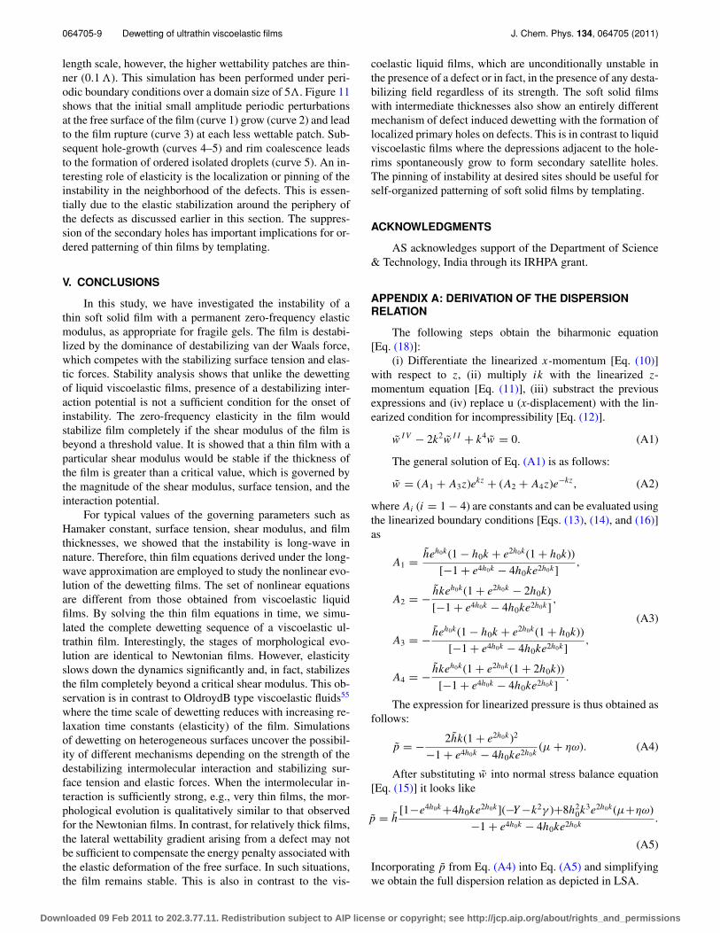
Figure 11 shows dewetting of an otherwise stable vis-coelastic film on a chemically textured substrate. The peri-odicity of the chemical patches is the same as the dewetting
FIG. 11. Evolution of surface instabilities of the same system as shown inFig. 10; however, here the simulation domain is 5� and substrate is consid-ered as periodically repeated less (of the length of 0.1�) and high energypatchs as shown in the figure and simulations have been performed under pe-riodic boundary conditions. Curves 1–5 correspond to nondimensional timeT = 0.0, 0.767, 1.258, 1.266, and 1.285, respectively.
Downloaded 09 Feb 2011 to 202.3.77.11. Redistribution subject to AIP license or copyright; see http://jcp.aip.org/about/rights_and_permissions
064705-9 Dewetting of ultrathin viscoelastic films J. Chem. Phys. 134, 064705 (2011)
length scale, however, the higher wettability patches are thin-ner (0.1 �). This simulation has been performed under peri-odic boundary conditions over a domain size of 5�. Figure 11shows that the initial small amplitude periodic perturbationsat the free surface of the film (curve 1) grow (curve 2) and leadto the film rupture (curve 3) at each less wettable patch. Sub-sequent hole-growth (curves 4–5) and rim coalescence leadsto the formation of ordered isolated droplets (curve 5). An in-teresting role of elasticity is the localization or pinning of theinstability in the neighborhood of the defects. This is essen-tially due to the elastic stabilization around the periphery ofthe defects as discussed earlier in this section. The suppres-sion of the secondary holes has important implications for or-dered patterning of thin films by templating.
V. CONCLUSIONS
In this study, we have investigated the instability of athin soft solid film with a permanent zero-frequency elasticmodulus, as appropriate for fragile gels. The film is destabi-lized by the dominance of destabilizing van der Waals force,which competes with the stabilizing surface tension and elas-tic forces. Stability analysis shows that unlike the dewettingof liquid viscoelastic films, presence of a destabilizing inter-action potential is not a sufficient condition for the onset ofinstability. The zero-frequency elasticity in the film wouldstabilize film completely if the shear modulus of the film isbeyond a threshold value. It is showed that a thin film with aparticular shear modulus would be stable if the thickness ofthe film is greater than a critical value, which is governed bythe magnitude of the shear modulus, surface tension, and theinteraction potential.
For typical values of the governing parameters such asHamaker constant, surface tension, shear modulus, and filmthicknesses, we showed that the instability is long-wave innature. Therefore, thin film equations derived under the long-wave approximation are employed to study the nonlinear evo-lution of the dewetting films. The set of nonlinear equationsare different from those obtained from viscoelastic liquidfilms. By solving the thin film equations in time, we simu-lated the complete dewetting sequence of a viscoelastic ul-trathin film. Interestingly, the stages of morphological evo-lution are identical to Newtonian films. However, elasticityslows down the dynamics significantly and, in fact, stabilizesthe film completely beyond a critical shear modulus. This ob-servation is in contrast to OldroydB type viscoelastic fluids55
where the time scale of dewetting reduces with increasing re-laxation time constants (elasticity) of the film. Simulationsof dewetting on heterogeneous surfaces uncover the possibil-ity of different mechanisms depending on the strength of thedestabilizing intermolecular interaction and stabilizing sur-face tension and elastic forces. When the intermolecular in-teraction is sufficiently strong, e.g., very thin films, the mor-phological evolution is qualitatively similar to that observedfor the Newtonian films. In contrast, for relatively thick films,the lateral wettability gradient arising from a defect may notbe sufficient to compensate the energy penalty associated withthe elastic deformation of the free surface. In such situations,the film remains stable. This is also in contrast to the vis-
coelastic liquid films, which are unconditionally unstable inthe presence of a defect or in fact, in the presence of any desta-bilizing field regardless of its strength. The soft solid filmswith intermediate thicknesses also show an entirely differentmechanism of defect induced dewetting with the formation oflocalized primary holes on defects. This is in contrast to liquidviscoelastic films where the depressions adjacent to the hole-rims spontaneously grow to form secondary satellite holes.The pinning of instability at desired sites should be useful forself-organized patterning of soft solid films by templating.
ACKNOWLEDGMENTS
AS acknowledges support of the Department of Science& Technology, India through its IRHPA grant.
APPENDIX A: DERIVATION OF THE DISPERSIONRELATION
The following steps obtain the biharmonic equation[Eq. (18)]:
(i) Differentiate the linearized x-momentum [Eq. (10)]with respect to z, (ii) multiply ik with the linearized z-momentum equation [Eq. (11)], (iii) substract the previousexpressions and (iv) replace u (x-displacement) with the lin-earized condition for incompressibility [Eq. (12)].
w I V − 2k2w I I + k4w = 0. (A1)
The general solution of Eq. (A1) is as follows:
w = (A1 + A3z)ekz + (A2 + A4z)e−kz, (A2)
where Ai (i = 1 − 4) are constants and can be evaluated usingthe linearized boundary conditions [Eqs. (13), (14), and (16)]as
A1 = heh0k(1 − h0k + e2h0k(1 + h0k))
[−1 + e4h0k − 4h0ke2h0k],
A2 = − hkeh0k(1 + e2h0k − 2h0k)
[−1 + e4h0k − 4h0ke2h0k],
(A3)
A3 = − heh0k(1 − h0k + e2h0k(1 + h0k))
[−1 + e4h0k − 4h0ke2h0k],
A4 = − hkeh0k(1 + e2h0k(1 + 2h0k))
[−1 + e4h0k − 4h0ke2h0k].
The expression for linearized pressure is thus obtained asfollows:
p = − 2hk(1 + e2h0k)2
−1 + e4h0k − 4h0ke2h0k(μ + ηω). (A4)
After substituting w into normal stress balance equation[Eq. (15)] it looks like
p = h[1−e4h0k +4h0ke2h0k](−Y −k2γ )+8h2
0k3e2h0k(μ+ηω)
−1 + e4h0k − 4h0ke2h0k.
(A5)
Incorporating p from Eq. (A4) into Eq. (A5) and simplifyingwe obtain the full dispersion relation as depicted in LSA.
Downloaded 09 Feb 2011 to 202.3.77.11. Redistribution subject to AIP license or copyright; see http://jcp.aip.org/about/rights_and_permissions

064705-10 Patra et al. J. Chem. Phys. 134, 064705 (2011)
APPENDIX B: DERIVATION OF THE NONLINEAREQUATIONS FOR THE INTERFACE
In the long-wave limit, applying lubrication approxima-tion the governing equations and boundary conditions are re-duced to the following forms:
x-momentum equation:
− ∂p
∂x+ μ
(∂2u
∂z2
)+ η
∂
∂t
(∂2u
∂z2
)= 0. (B1)
z-momentum equation:
∂p
∂z= 0. (B2)
Incompressibility condition:
∂u
∂x+ ∂w
∂z= 0. (B3)
The no-slip and impermeable condition at z = af(x)
u = w = ∂u
∂t= ∂w
∂t= 0. (B4)
Shear stress balance at z = h:
μ∂u
∂z+ η
∂
∂t
(∂u
∂z
)= 0. (B5)
Normal stress balance at z = h:
p = A
6π (h − a f )3
{1−
(l0
(h − a f )
)6}
−γ∂2h
∂x2. (B6)
Kinematic equation:
∂h
∂t+ ∂u
∂t
∣∣∣∣h
∂h
∂x= ∂w
∂t
∣∣∣∣h
. (B7)
The stresses across the film are varying a little and there-fore, we assume that streamwise displacement satisfy the fol-lowing form:
u = c1(x, t)z2 + c2(x, t)z + c3(x, t), (B8)
where c2 and c1 refers to shear stress and divergence of shearstress, respectively, and c3 is a constant. Using continuity weget the expression for w-displacement as follows:
− w = ∂c1(x, t)
∂x
z3
3+ ∂c2(x, t)
∂x
z2
2+ ∂c3(x, t)
∂xz + c4(x, t),
(B9)
where c4 is a constant. Incorporating Eqs. (B8) and (B9) intokinematic condition (B7) we get the nonlinear equation forthe deforming interface in the following form:
∂h
∂t+ ∂
∂x
[∂c1
∂t
h3
3+ ∂c2
∂t
h2
2+ ∂c3
∂th
]+ ∂c4
∂t= 0. (B10)
Impermeability and no-slip boundary conditions atz = a f (x) are used to evaluate c3 and c4:
c3 = −c1 (a f )2 − c2 (a f ) , (B11)
c4 = ∂c1
∂x
(a f )3
3+ ∂c2
∂x
(a f )2
2
− ∂
∂x[c1(a f )2](a f ) − ∂
∂x[c2(a f )](a f ). (B12)
Invoking Eq. (B8) into x-momentum Eq. (B1) give us thefollowing expression for c1:
∂c1
∂t= 1
η
[1
2
(∂p
∂x
)− μc1
]. (B13)
Similarly, invoking Eq. (B9) into shear stress balance(B5) we obtain the following expression for c2:
∂c2
∂t= −1
η
[h
(∂p
∂x
)+ μc2
]. (B14)
Introducing Eqs. (B11)–(B14) in (B10), the nonlinearequation for the deforming interface takes the following form:
∂h
∂t− 1
η
∂
∂x
[(h − a f )3
3
∂p
∂x+ (h − a f )3
3(μc1) + (h − a f )2
2
× μ (2c1 (a f ) + c2)
]= 0. (B15)
Now redefining c2 by c2 = 2c1 (a f ) + c2 Eqs. (B14) and(B15), respectively, reduce to
∂c2
∂t= −1
η
[(h − a f )
(∂p
∂x
)+ μc2
], (B16)
∂h
∂t− 1
η
∂
∂x
[(h − a f )3
3
∂p
∂x+ (h − a f )3
3(μc1)
+ (h − a f )2
2(μc2)
]= 0, (B17)
where p can be obtained from the normal stress bal-ance [Eq. (B6)]. The dimensional form of the long-wavedispersion relation [Eq. (22)] is obtained on a homoge-neous surface
[a f = 0
]by linearizing the set of nonlinear
Eqs. (B13), (B14), and (B17) with the normal linear modesc2 = c2eωt+ikx , c1 = c1eωt+ikx , and h = h0 + εeωt+ikx .
1E. Ruckenstein and R. K. Jain, J. Chem. Soc., Faraday Trans. 70(2), 132(1974).
2M. B. Williams and S. H. Davis, J. Colloid Interface Sci. 90, 220 (1982).3P. G. De Gennes, Rev. Mod. Phys. 57, 827 (1985).4A. Sharma and E. Ruckenstein, Langmuir 2, 480 (1986).5S. G. Bankoff and S. H. Davis, Physchem. Hydrodyn. 9, 5 (1987).6F. Brochard-Wyart and J. Dailaant, Can. J. Phys. 68, 1084 (1990).7G. Reiter, Phys. Rev. Lett. 68, 75 (1992).8U. Steiner, J. Klein, E. Eiser, A. Budkowski, and L. J. Fetters, Science 258,1126 (1992).
9A. Sharma, Langmuir 9, 861 (1993).10G. Reiter, Langmuir 9, 1344 (1993).11F. Brochard-Wyart, P. G. De Gennes, H. Hervert, and C. Redon, Langmuir
10, 1566 (1994).12A. Oron, S. H. Davis, and S. G. Bankoff, Rev. Mod. Phys. 69, 931 (1997).13T. G. Stange, D. F. Evans, and W. A. Hendrickson, Langmuir 13, 4459
(1997).14K. Jacobs and S. Herminghaus, Langmuir 14, 965 (1998).15A. Sharma and R. Khanna, Phys. Rev. Lett. 81, 3463 (1998).16A. Sharma and R. Khanna, J. Chem. Phys. 110, 4929 (1999).17A. Ghatak, R. Khanna, and A. Sharma, J. Colloid Inteface Sci. 212, 483
(1999).18A. Oron and S. G. Bankoff, J. Colloid Interface Sci. 218, 152 (1999).19A. Oron, Phys. Rev. Lett. 85, 2108 (2000).20J. Becker, G. Grun, R. Seemann, H. Mantz, K. Jacobs, K. Meke, and R.
Blossey, Nature Mater. 2, 59 (2003).21G. Reiter, P. Auroy, and L. Auvray, Macromolecules 29, 2150 (1996).22A. Sehgal, V. Ferreiro, J. F. Douglas, E. J. Amis, and A. Karim, Langmuir
18, 7041 (2002).23A. Sharma, Eur. Phys. J. E 12, 397 (2003).
Downloaded 09 Feb 2011 to 202.3.77.11. Redistribution subject to AIP license or copyright; see http://jcp.aip.org/about/rights_and_permissions

064705-11 Dewetting of ultrathin viscoelastic films J. Chem. Phys. 134, 064705 (2011)
24O. Wunnicke, P. Müller-Buschbaum, M. Wolkenhauer, C. Lorenz-Haas, R.Cubitt, V. Leiner, and M. Stamm, Langmuir 19, 8511 (2003).
25X. Zhang, F. Xie, and O. K. C. Tsui, Polymer 46, 8416 (2005).26C. Luo, R. Xing, Z. Zhang, J. Fu, and Y. Han, J. Colloid Interface Sci. 269,
158 (2004).27R. Mukherjee, M. Gonuguntla, and A. Sharma, J. Nanosci. Nanotechnol. 7,
2069 (2007).28Y. S. Kim and H. H. Lee, Adv. Mater. 15, 332 (2003).29J. H. Wei, D. C. Coffey, and D. Ginger, J. Phys. Chem. B 110, 24324
(2006).30G. G. Baralia, C. Filiatre, B. Nysten, and A. M. Jones, Adv. Mater. 19, 4453
(2007).31C. P. Martin, M. O. Blunt, E. Pauliac-Vaujour, A. Stannard, and P. Moriarty,
Phys. Rev. Lett. 99, 116103 (2007).32D. Julthongpiput, W. H. Zhang, J. F. Douglas, A. Karim, and M. J. Fasolka,
Soft Matter 3, 613 (2007).33B. C. Berry, C. M. Stafford, M. Pandya, L. A. Lucas, A. Karim, and M.
Fasolka, J. Rev. Sci. Instum. 78, 072202 (2007).34R. Mukherjee, D. Bandyopadhyay, and A. Sharma, Soft Matter 4, 2086
(2008).35R. Konnur, K. Kargupta, and A. Sharma, Phys. Rev. Lett. 84, 931 (2000).36K. Kargupta and A. Sharma, Phys. Rev. Lett. 86, 4536 (2001).37M. Zope, K. Kargupta, and A. Sharma, J. Chem. Phys. 114, 7211 (2001).38U. Thiele, M. Velarde, and K. Neuffer, Phys. Rev. Lett. 87, 016104 (2001).39K. Kargupta and A. Sharma, J. Colloid Interface Sci. 245, 99 (2002).40L. Brusch, H. Kühne, U. Thiele, and M. Bär, Phys. Rev. E 66, 011602
(2002).41U. Thiele, L. Brusch, M. Bestehorn, and M. Bär, Eur. Phys. J. E 11, 255
(2003).42J. C. T. Kao, A. A. Golovin, and S. H. Davis, J. Colloid Interface Sci. 303,
532 (2006).43D. Simmons and A. Chauhan, J. Colloid Interface Sci. 295, 472 (2006).44S. Saprykin, P. M. J. Trevelyan, R. J. Koopmans, and S. Kalliadasis, Phys.
Rev. E 75, 026306 (2007).45R. D. Lenz and S. Kumar, J. Fluid Mech. 571, 33 (2007).46R. V. Craster and O. K. Matar, Rev. Mod. Phys. 81, 1131 (2009).47G. Reiter, Phys. Rev. Lett. 87, 186101 (2001).
48R. Seemann, S. Herminghaus, and K. Jacobs, Phys. Rev. Lett. 87, 196101(2001).
49J. L. Masson and P. F. Green, Phys. Rev. Lett. 88, 205504 (2002).50P. Damman, N. Baudelet, and G. Reiter, Phys. Rev. Lett. 91, 216101
(2003).51A. Sathyagal and G. Narsimhan, Chem. Eng. Commun. 111, 161 (1992).52S. Herminghaus, R. Seemann and K. Jacobs, Phys. Rev. Lett. 89, 056101
(2002).53S. Herminghaus, K. Jacobs, and R. Seemann, Eur. Phys. J. E 12, 101
(2003).54M. Rauscher, A. Münch, B. Wagner, and R. Blossey, Eur. Phys. J. E 17,
373 (2005).55G. Tomar, V. Shankar, S. K. Shukla, A. Sharma, and G. Biswas, Eur. Phys.
J E 20, 185 (2006).56S. A. Safran and J. Klein, J. Phys. (France) 3, 749 (1993).57V. Shenoy and A. Sharma, J. Mech. Phys. Solids 50, 1155 (2002).58S. Kumar and O. K. Matar, J. Colloid Interface Sci. 273, 581 (2004).59O. K. Matar, V. Gkanis, and S. Kumar, J. Colloid Interface Sci. 286, 319
(2005).60J. Sarkar and A. Sharma, Langmuir 26, 8464 (2010).61J. Wang, M. Tolan, O. H. Seeck, S. K. Sinha, O. Bahr, M. H. Rafailovich,
and J. Sokolov, Phys. Rev. Lett. 83, 564 (1999).62C. Bollinne, S. Cuenot, B. Nysten, and A. M. Jonas, Eur. Phys. J. E 12, 389
(2003).63N. Rehse, C. Wang, M. Hund, M. Geoghegan, R. Magerle, and
G. Karausch, Eur. Phys. J. E 4, 69 (2001).64M. Aubouy, Phys. Rev. E 56, 3370 (1997).65S. Q. Huang, B. Li, and S. Q. Feng, J. Appl. Phys. 103, 083501 (2008).66K. A. Barnes, A. Karim, J. F. Douglas, A. I. Nakatani, H. Gruell, and E. J.
Amis, Macromolecules 33, 4177 (2000).67J. Sarkar, A. Sharma, and V. Shenoy, Phys. Rev. E. 77, 031604 (2008).68M. Gonuguntla, A. Sharma, J. Sarkar, S. A. Subramanian, M. Ghosh, and
V. Shenoy, Phys. Rev. Lett. 97, 018303 (2006).69N. Arun, A. Sharma, P. S. G. Pattader, I. Banerjee, H. M. Dixit, and K. S.
Narayan, Phys. Rev. Lett. 102, 254502 (2009).70P. S. G. Pattader, I. Banerjee, A. Sharma, and D. Bandyopadhyay, Adv.
Funct. Mater. 21, 324 (2011).
Downloaded 09 Feb 2011 to 202.3.77.11. Redistribution subject to AIP license or copyright; see http://jcp.aip.org/about/rights_and_permissions
Copyright © 2022 FDOKUMEN