Avalanche Photodiodes Performance Parameters Estimation under Thermal Irradiation Fields

Infrared photodiodes based on Type-II strained layer superlattices
Sankha D. Das1, Yu Ling Goh1, Chee Hing Tan1, John Paul R. David*1 Jean-Baptiste Rodriguez2, Elena A. Plis2, Yagya D. Sharma2, Ha Sul Kim2, Sanjay Krishna2
1 Department of Electronic and Electrical Engineering, The University Of Sheffield,
Mappin Street, Sheffield, S1 3JD, U.K. 2 Center for High Technology Materials, Department of Electrical and Computer Engineering,
University of New Mexico, Albuquerque, New Mexico 87106.
ABSTRACT The InAs/GaSb Type-II strained layer superlattice (SLS) is promising III-V material system for infrared (IR) devices due to the ability to engineer its bandgap between 3-30 µm and potentially have many advantages over current technologies such as smaller leakage and tunnelling currents due to reduced Auger recombination and high electron effective mass, mature III-V growth technology which are crucial for large IR focal plane arrays. However, an issue with this material system is that it relies on growth on GaSb substrates. These substrates are significantly more expensive than silicon, used for HgCdTe detectors, lower quality and are only available commercially as 3” diameters. Moreover, it has to go through thinning down before it could be hybridized to readout integrated circuits. GaAs substrate is a possible alternative. We report on growth and characterisation of Type-II InAs/GaSb SLS photodiodes grown on GaAs substrates for mid-wave infrared spectral region (MWIR) with peak responses of 3.5 µm at 77K and 4.1 µm at 295K. Comparisons with similar structure grown on GaSb substrates show similar structural, optical and electrical characteristics. Broadening of X-ray rocking curves were observed on the structure grown on GaAs substrate. The peak responsivity values of ~ 1.9 A/W and ~ 0.7 A/W were measured at 77K and 295K for devices grown on GaAs substrate. This room temperature responsivity suggests that these photodiodes are promising as high temperature IR detectors.
Keywords: Infrared photodiode, InAs/GaSb, superlattice, MWIR, GaAs substrate, GaSb substrate, X-ray, dark current, responsivity, quantum efficiency
1. INTRODUCTION Infrared detection technology is very important for both civilian and military applications. Mid-wave infrared technology (3-5 µm) uses primarily HgCdTe detectors for these applications as it is a mature technology and can provide devices with excellent detectivity values, D* ~ 1012 Jones1 (T=77K , λc = 10 µm). However, HgCdTe still suffers from high dark currents at elevated temperatures as well as significant challenges in growth and fabrication. Operating temperature range of 77K – 120K have been reported in literature2. Moreover, to obtain high quantum efficiency, the thickness of the absorption region has to be very thick and achieving
*email: [email protected]; Tel: +44 (0)114 222 5185; Fax: +44 (0)114 222 5143
Electro-Optical and Infrared Systems: Technology and Applications V, edited by David A. Huckridge, Reinhard R. EbertProc. of SPIE Vol. 7113, 71130I · © 2008 SPIE · CCC code: 0277-786X/08/$18 · doi: 10.1117/12.802203
Proc. of SPIE Vol. 7113 71130I-1

high crystal quality and high wafer uniformity in very thick HgCdTe is challenging, particularly for large area focal plane arrays (FPAs). Typical thickness of the total detector for bi-spectral HgCdTe could be 15 µm 3. Moreover, HgCdTe as well as alternate technologies such as quantum well infrared detectors (QWIPs) or quantum dot infrared detectors (QDIPs) based on III-V materials require significant cooling to reduce the dark currents. Other problems with QWIPs and QDIPs are the need for gratings to detect normal incidence light in the former and the poor quantum efficiency due to the small absorbing volume in the latter. The InAs/GaSb Type-II strained layer superlattice (SLS), first proposed by Smith and Mailhiot4, is a promising III-V material system for IR devices due to the ability to engineer its bandgap between 3-30 µm, while avoiding many of the problems in current technologies mentioned above. These structures provide high responsivity with relatively thinner structures compared to HgCdTe and established III-V technologies gives highly uniform defect free structures, which is suitable for large area focal plane arrays. The total thickness of these structures could vary from 3 to 5 µm 5 to reach high quantum efficiencies.
These type-II SLS structures comprise alternating layers of thin InAs and GaSb and the overall system is latticed matched to a GaSb substrate using strain balancing techniques. In this system the band alignment is so-called broken gap type II structure where the valence band of GaSb is ~ 140 eV above the conduction band in InAs. Mini-bands created in conduction and valence bands enable the wavelength of detection to be adjusted by changing the thickness of the InAs and GaSb layers. The effective bandgap of the SLS structure is defined as separation between the lowest conduction miniband and the highest valence miniband. The intensity of optical transition is determined by exponential decaying envelope wave function tails. The overlap of the wave function tails is a function of layer thickness and decrease in thickness causes increase in the overlap. The bandgap is engineered by changing the period of the superlattice, an increase in the GaSb layer thickness results in shorter cutoff wavelength, or by introducing indium in the GaSb layers as GaxIn1-
xSb. This gives the option of designing binary-binary or binary–ternary superlattices to achieve the same effective bandgap with different quantum efficiency while keeping the thickness of the absorption region the same 6.
However, an issue with this material system is that it relies on growth on GaSb substrates. These substrates are significantly more expensive than the silicon, used for HgCdTe detectors, suffer from poor quality and are only available commercially in diameters of 2” and 3“. Recent publications suggest that good quality bulk GaSb can be grown on GaAs substrates using interfacial misfit array in place of a thick buffer layer. Due to the relative spacing between atoms in a GaSb lattice and GaAs, dislocations can be constrained to the hetero-interface and no threading dislocations occur. This has been demonstrated on lasers 7.
In this paper we investigate the feasibility of growing type-II SLS p+-i(SLS)-n+ photodiodes on GaAs substrates and explore the room temperature performance of these devices.
2. GROWTH AND PROCESSING First, a simple test structure was grown to asses the feasibility of growing GaSb on GaAs substrate. This structure comprises of bulk epitaxial layer of GaSb on a n+ GaAs substrate with a 100 nm GaAs buffer. Root mean square (rms) roughness of this layer assessed by Atomic Force Microscopy (AMF) was equal to 1.5 nm, as shown in Fig 1. The X-ray diffraction rocking curve of this sample showed a reasonable narrow GaSb peak with full width of half maximum (FWHM) equal to 218
Proc. of SPIE Vol. 7113 71130I-2

1
V
arcsec and the much narrower GaAs substrate peak. The GaSb epilayer appears almost fully relaxed to the GaAs substrate and its large FWHM is a consequence of lattice bending due to this relaxation process. These results indicate good quality bulk GaSb can possibly be grown on GaAs substrate.
Next, two MWIR p+-i(SLS)-n+ structures were grown, one on a n-type (Te doped) GaSb substrate
and another on a 3” GaAs substrate. Heterostructure schematics of both structures are shown in Fig. 3 (a) and (b), respectively. The diode structure in both devices was identical, comprising of 8x8 monolayers (ML) of InAs/GaSb superlattice for p+, undoped absorption region and n+ regions. Having the same effective band-gap for all these regions reduces the possibility that photogenerated carriers will get trapped at band-gap discontinuities and reduces the quantum efficiency. Structure on GaSb substrate has a buffer of 5x5 ML SLS while the structure on GaAs substrate was grown with bulk GaSb substrate Both structures were capped with a thin p-type GaSb contacting layer and showed smooth defect free surfaces after the growth.
Fig.1. 1µm2 AFM image of a 2µm bulk GaSb/ GaAs epilayer.
The X-ray diffraction rocking curves (XRDs) of the MWIR p+-i(SLS)-n+ detector grown on GaSb and GaAs substrates (Fig. 4(a) & (b)) showed intense narrow peaks indicating good quality of the as-grown structures. Fig. 4(a) shows FWMH of first SLS peak of 25 arcsec. The satellite peaks correspond to the superlattice structure. Fig. 4 (b) is broadly similar but the peaks are broadened, suggesting that the growth on the GaAs substrate results in some non-uniformity or roughness in the layers. In addition to a peak corresponding to the effective GaSb Bragg angle at ~30.4o, there is also a peak from the GaAs substrate ~ 33.2o. The broadening of the main peak as well as the satellite SLS peaks of detector grown on the GaAs substrate indicates that there is still room for improvement in the growth, however it indicates an almost identical 8x8 ML SL structure can be grown on the GaAs substrate.
Proc. of SPIE Vol. 7113 71130I-3

Fig.2. X-ray diffraction rocking curve for bulk GaSb/ GaAs epilayer.
GaSb: Te (n-type) substrate
InAs:Si/GaSb n+ 8x8 MLs 20p
InAs/GaSb (nid) 8x8 MLs 450p
InAs/GaSb:Be p+ 8x8 MLs 20p
GaSb: Be p+ 50 nm contact
100 nm Al0.2GaSb
SL InAs:Si/GaSb n+5x5 MLs 150p
GaSb 1µm
SL InAs/GaSb n+ 8x8 MLs 100p
SL InAs/GaSb (nid) 8x8 MLs 416p
SL InAs/GaSb p+ 8x8 MLs 50p
GaSb: Be p+ 100 nm contact
GaAs 3inch. substrate
(a) (b)
Fig.3. p+-i(SLS)-n+ structures grown on (a) GaSb substrate (b) GaAs substrate
After the growth, mesa structures with diameters ranging from 50µm to 400µm (Fig.5) were fabricated using a combination of dry reactive ion etching (RIE) and wet etching. RIE dry etch utilizes Cl2 and Ar plasma at a low pressure of 3 mT. The etch rate was found to be approximately 0.2 µm/min and gives reasonably vertical sidewalls. Immediately after the dry etch, the devices were dipped in diluted H2O2 and H3PO4 for a few seconds to provide a finishing etch which removes any surface damage caused by the RIE. The larger devices had top optical windows enabling photocurrent measurements to be undertaken.
GaSb GaAs
Proc. of SPIE Vol. 7113 71130I-4

0*0•@
: Q4è
29 30 31 32 33 34101
102
103
104
105
Cou
nts/
s
Ω/2θ (ο)29 30 31 32 33 34
101
102
103
104
Cou
nts/
s
Ω/2θ (ο)
(a) (b)
Fig.4. X-ray rocking curves for p+-i(SLS)-n+ structures grown on (a) GaSb substrate (b) GaAs substrate
Fig.5. Plan view of mesa diodes showing diameter varying from 400 µm to 50µm
3. DEVICE CHARACTERIZATION Temperature dependent dark current measurements were performed using liquid nitrogen cooled ST-500 Janis probe station and a Keithley 236 source measurement unit. These results from the unpassivated devices showed at relatively high dark currents of 8.93 x 10⁻³ A/cm2 and 6.7 x 10⁻³ A/cm2 (77K, 50 mV) for devices on GaSb and GaAs substrates, respectively, as shown in Fig.6. In both sets of devices, the dark currents increased by 2 orders of magnitude as the temperature increased from 77K to room temperature. Published results 5 on similar MWIR structures show significantly lower dark currents are achievable.
Spectral measurements were performed using a Varian 7000e FTS system with standard ceramic IR source and KBr beam splitter (with extended range of 7500 cm-1 to 400 cm-1). Results in Fig 7 (a) and (b) showed good absorption in the expected 3-5 µm region. Both the designs showed 5% cutoff wavelength, with respect to peak, of 5 µm at room temperature.
Proc. of SPIE Vol. 7113 71130I-5

Bias (V)-0.5 -0.4 -0.3 -0.2 -0.1 0.0 0.1 0.2
Cur
rent
Den
sity
(A/c
m2 )
10-5
10-4
10-3
10-2
10-1
100
101
102
p-i-n on GaSb substratep-i-n on GaAs substrate
77K
295K
Fig.6. Temperature dependent dark current density of unpassivated MWIR p+-i(SLS)-n+ devices
Expected shift to lower wavelengths at lower temperature due to change in the bandgap of superlattice constituents with decrease in temperature was also observed. Fig.8 (a) and (b) show the effect of an increasing reverse bias on the photoresponse at 77K. For the structure grown on the GaSb substrate, there is a significant increase in the peak response with increasing bias, however for the structure grown on GaAs, there is virtually no change with bias.
Wavelength (µm)2.0 2.5 3.0 3.5 4.0 4.5 5.0
Res
pons
ivity
(A/W
)
0.0
0.2
0.4
0.6
0.8
1.0
1.2
77K
295K
Wavelength (µm)
2.0 2.5 3.0 3.5 4.0 4.5 5.0
Res
pons
ivity
(A/W
)
0.0
0.5
1.0
1.5
2.0
77K
295K
(a) (b)
Fig.7. Temperature dependent responsivity of large area p+-i(SLS)-n+ devices grown on (a) GaSb substrate (b) GaAs substrate.
Devices grown on GaSb substrates showed good response between 2 - 3 µm at room temperature, this may be due to presence of shorter wavelength InAs/ GaSb superlattice (5x5 MLs). From bias dependent spectra one can see the effect of higher field, as longer wavelength SLS response becomes stronger than shorter wavelength SLS.
Proc. of SPIE Vol. 7113 71130I-6
wavelength (µm)2.0 2.5 3.0 3.5 4.0 4.5
Res
pons
e (a
.u.)
-0.2
0.0
0.2
0.4
0.6
0.8
1.0
1.2
0.0 V -0.5 V-1.0 V
(a)
wavelength (µm)2.0 2.5 3.0 3.5 4.0 4.5
Res
pons
e (a
.u.)
-0.2
0.0
0.2
0.4
0.6
0.8
1.0
1.2
0.0 V-0.5 V -1.0 V
(b)
Fig.8. Bias dependent spectra at 77K of large area p+-i(SLS)-n+ devices grown on (a) GaSb substrate (b) GaAs substrate
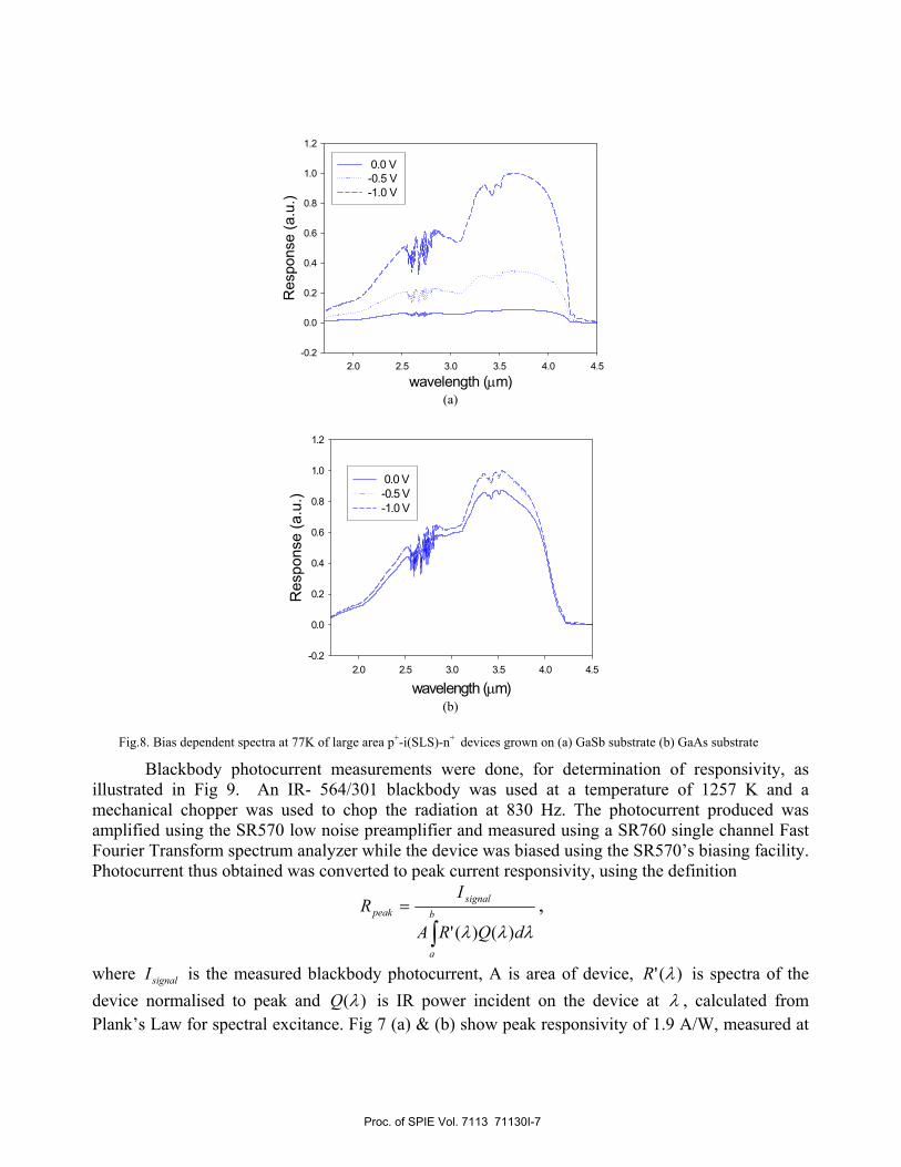
Blackbody photocurrent measurements were done, for determination of responsivity, as illustrated in Fig 9. An IR- 564/301 blackbody was used at a temperature of 1257 K and a mechanical chopper was used to chop the radiation at 830 Hz. The photocurrent produced was amplified using the SR570 low noise preamplifier and measured using a SR760 single channel Fast Fourier Transform spectrum analyzer while the device was biased using the SR570’s biasing facility. Photocurrent thus obtained was converted to peak current responsivity, using the definition
∫= b
a
signalpeak
dQRA
IR
λλλ )()(',
where signalI is the measured blackbody photocurrent, A is area of device, )(' λR is spectra of the device normalised to peak and )(λQ is IR power incident on the device at λ , calculated from Plank’s Law for spectral excitance. Fig 7 (a) & (b) show peak responsivity of 1.9 A/W, measured at
Proc. of SPIE Vol. 7113 71130I-7

Aperture
KBrWindow
Device plane Apeilure Plane
77K (-0.3V), resulting in 67.43% external quantum efficiency for devices grown on GaAs substrate. Decrease in the magnitude of the responsivity also occurs as the temperature increases. At 295K (-0.3V) responsivity decreases to 0.7 A/W (QE ~ 21.7%) for these devices. Devices grown on GaSb substrate showed similar responsivity values of 1.3 A/W at 77K and 0.3 A/W at 295K.
Fig.9. Schematic diagram of blackbody photocurrent measurement setup
Fig. 10 (a) and (b), shows the temperature and bias dependent responsivity of these devices. At 0V for the structure on GaSb substrate the responsivity initially drops significantly as the temperature decreases, before increasing to almost its 300K value at 77K. Although the responsivity does not appear to change significantly with reverse bias at 300K, at low temperatures a significant increase is observed. The behaviour is different for the structure grown on the GaAs substrate, where a very low responsivity is observed at 300K and at 0V. This value increases dramatically as the temperature decreases; however unlike the structure grown on GaSb, the responsivity here is not significantly dependent on the reverse bias voltage. At 77K and low reverse bias both devices appear to have very similar responsivity.
Bias (V)-0.5 -0.4 -0.3 -0.2 -0.1 0.0
Res
pons
ivity
(A/W
)
10-2
10-1
100
77K150K 200K250K 295K
(a)
Proc. of SPIE Vol. 7113 71130I-8

Bias (V)-0.5 -0.4 -0.3 -0.2 -0.1 0.0
Res
pons
ivity
(A/W
)
10-3
10-2
10-1
100
101
77K 150K 200K 250K 295K
(b)
Fig.10. Temperature and bias dependent responsivity of large area p+-i(SLS)-n+ devices grown on (a) GaSb substrate (b) GaAs substrate
4. CONCLUSION
We have demonstrated that reasonably good quality bulk epitaxial layers of GaSb can be grown on
GaAs substrates, and showed that p+-i(SLS)-n+ with a 8x8 ML of GaSb/InAs works well with both GaSb and cheaper GaAs substrates. Although a reasonably high responsivity is obtained both at 77K and 295K, further work on optimising the dark current will be required in the future.
References
[1] A. Rogalski, “Material consideration for third generation infrared photon detectors”, Infra.
Phys. & Tech., 50, 240-252, 2007. [2] A. Rogalski, “HgCdTe infrared detector material: history, status and outlook”, Rep. Prog.
Phys., 68, 2267-2336, 2005. [3] E. Smith et. Al., “Two-colour HgCdTe Infrared Starling Focal Plane Arrays”, Proc. Of SPIE,
5209, 1-13, 2003. [4] D.L. Smith, C. Mailhiot, “Proposal for strained type II superlattice infrared detectors”, J.
Appl. Phys. 62, 2545, 1987. [5] R. Rehm, M. Walther, J. Schmitz, J. Fleibner, J. Ziegler, W. Cabanski and R. Breiter, “ Dual-
colour thermal imaging with InAs/GaSb superlattice in mid-wavelength infrared spectral range”, Elec. Lett., 42(10), 2006.
[6] M. O. Manaresh, “Semiconductor Quantum Wells and Superlattices for Long-Wavelength Infrared Detectors”, 55-108, Artech House, London, 1993.
[7] J. Tatebayashi, A. Jallipalli, M. N. Kutty, S.H. Huang, G. Balakrishnan, L. R. Dawson, D.L. Huffaker. “Room-temperature lasing at 1.82 µm of GaInSb/AlGaSb quantum wells grown on GaAs substrates using interfacial misfit array”, Appl. Phys. Lett., 91, 141102, 2007.
Acknowledgement
Proc. of SPIE Vol. 7113 71130I-9

The work reported in this paper was funded by the Electro-Magnetic Remote Sensing (EMRS) Defence Technology Centre, established by the UK Ministry of Defence and run by a consortium SELEX Sensors and Airborne Systems, Thales Defence, Roke Manor Research and Filtronic.
Proc. of SPIE Vol. 7113 71130I-10
Copyright © 2022 FDOKUMEN