Rehabilitation of Distal Radius Fractures: A Biomechanical ...
Veterinary Surgery 25: 45 3-462. I996
In Vitro Biomechanical and Histological Assessment of Pilot Hole Diameter for Positive-Profile External Skeletal Fixation
Pins in Canine Tibiae
This study was conducted to evaluate the effect of pilot hole (PH) diameter (0, 1.5, 2.0, 2.7, 3.1, 3.3, 3.5, and 3.7 mm) on the biomechanical and microstructural performance of positive- profile threaded external skeletal fixation pins (3.18 mm inner diameter, 3.97 mm outer diameter) using cadaveric canine tibiae. Eight pins per pilot hole diameter (four pins per bone) were used to assess differences in end-insertional torque and pin pull-out strength. Histological evaluation of eight bicortical pin tracts per pilot hole diameter was accomplished using computer-interfaced videomicroscopy on specimens processed using a bulk-staining technique. Compared with no predrill, use of 2.7 mm PH increased end-insertional torque and pull-out strength by 25% and 13.5%, respectively. No significant differences were observed in biomechanical variables for the PH diameter range of 2.0 to 3.1 mm. Compared with no predrill, use of a 3.1 mm PH increased thread area by 18%. Microfracturing around the threads decreased as PH diameter increased. Damage to the interface at the entry and exit sites of both near and far cortices also decreased as PH diameter increased. It was concluded that predrilling a PH whose diameter approximates, but does not exceed the inner diameter of the positive profile pin will not only improve initial pin stability compared with no predrilling, but it will also reduce microstructural damage that may lead to excessive bone resorption and premature pin loosening. OCopyright 1996 by The American College of Veterinary Surgeons
N RECENT YEARS, external skeletal fixation I (ESF) has become more widely used by orthope- dic surgeons, both in human and veterinary medi- cine. With increasing experience and experimenta- tion, ESF frame design has evolved to the point where surgeons are now attempting to repair highly unstable fractures using ESF with some measure of success.”* Despite such advancements, pin tract in- fection, and premature pin loosening do occur and continue to be the more common reasons for patient morbidity related to the fracture fixation.’ Factors affecting the integrity of the pin-bone interface (PBI) include pin design, pin insertion technique, initial bone quality, and the osseous response to pin implan- tation and loading.3
Fixation pins may be smooth or threaded, the latter of which have been reported to have significantly greater stability in response to axial and rotational loading4-’ However, conventional negative-profile (NGP) pins, which have a reduction of the core di- ameter in the threaded region, are more susceptible to bending and breaking compared with smooth pins.6 Although placement of the threaded-non- threaded junction within the medullary cavity, eg, Ellis pin technique, may reduce the risk of bending, this results in a reduction in the force required to initiate axial or rotational displacement of the pin because thread purchase occurs only in the far cor- tex.6 To overcome these limitations of NGP pins, positive-profile (PSP) fixation pins have been devel-
From the Department of Companion Animal and Special Species Medicine, College of Veterinary Medicine, North Carolina
Research supported in part by a Companion Animal and Special Species Medicine Grant, College of Veterinary Medicine, North
Address reprint requests to Erik M. Clary, DVM, MS, Department of Surgery, Duke University Medical Center Box 2613,
OCopyright 1996 by The American College of Veterinary Surgeons
State University, Raleigh, NC.
Carolina State University; additional funding provided by IMEX Veterinary, Inc, Longview, TX.
Durham, NC 27710.
01 6 1-349919612506-0001$3.00/0
453
454 CLARY AND ROE
oped. The threads of a PSP pin are raised above a constant diameter shaft, and consequently there is no significant weakening of the threaded-nonthreaded junction. Because these pins also have a larger outer diameter than NGP pins of comparable shank diame- ter, they would be expected to have a greater resis- tance to axial extraction.6ss However, in a recently published study, researchers were unable to detect a significant difference in pull-out strengths of PSP and Ellis pins of equal shank diameter.5 In the latter study, gross fracturing of the far cortex was observed for almost 50% of the PSP pins and for none of the Ellis pins. The authors conceded that predrilling a pilot hole, which was not performed in their study as per the manufacturer’ s recommendation, would have decreased the likelihood of iatrogenic fracture thereby increasing the pull-out strength of the PSP pins.
Studies designed to determine the optimal pilot hole size for threaded fixation pins are limited. Au- thors have postulated that a circumferential compres- sive interaction between pin and bone, commonly referred to as “radial preload” is created when in- serting a pin into an undersized hole and may be beneficial in minimizing microm~tion.~ However, re- searchers evaluating the effect of pilot hole diameter on pull-out strength of bone screws showed a sig- nificant reduction in pull-out strength when pilot hole diameter was decreased below the screw inner diameter. lo The study presented herein was under- taken to determine an optimal pilot hole diameter for a commonly used PSP pin, the IMEX medium Interface pin (IMEX Veterinary, Inc, Longview, TX).
MATERIALS AND METHODS
Right and left tibiae were removed from 16 dogs that weighed an average of 27.4 kg (range, 18.2 to 36.8 kg). The dogs were euthanatized for reasons unrelated to this study. Immediately after the dogs were euthanatized, the bones were stripped of soft tissue attachments, radio- graphed to ensure that they were normal and skeletally mature, wrapped in saline (0.9%) soaked towels, and placed in a freezer (-20°C). Twenty-four hours before testing, the bones were removed from the freezer and thawed at room temperature, taking care to keep the speci- mens moist with saline.
Determining Variation in Pilot Hole Diameter
Supply, Livonia, MI) and the diameter of each drill bit was measured using digital calipers (Ultra-Cal Mark 111; Fred V. Fowler Co, Newton, MA). For each drill bit diameter, ten bicortical holes were drilled into one tibia1 diaphysis using a hand-held high speed (600 rpm) drill. Each tibia was sectioned sagittally and then transversely creating three medial and three lateral cortical segments. The periosteal surfaces of each segment were sanded per- pendicular to the drill hole creating a flat surface, which was then mounted onto a slide using light-activated meth- ylmethacrylate. The endosteal surface of each segment was then sanded perpendicular to the drill hole to reach a uniform cortical width of 2 mm. The drill holes of each segment were cleared of debris by using the compressed air and water jet of a dental cleaning device. High detail radiographs of each segment were made using a cabinet x-ray system (Faxitron model 43855; Hewlett Packard, McMinnville, OR) set at 28 kVp for 70 seconds. A rod of known length was also radiographed to allow determi- nation of the degree of magnification for use in subse- quent calculations. The radiographic image of each pilot hole was viewed under light microscopy (20X) and cap- tured digitally using a specialized software package (PAX-IT, Midwest Information Systems, Inc, Hillside, IL) interfaced with a photomicrographic microscope sys- tem (Vanox AHBS3, Olympus Optical Co Ltd, Japan). The digital image was then imported into a graphics anal- ysis program (Image-Pro Plus; Media Cybernetics, Silver Spring, MD) which allowed tracing and calculation of the circumference. The diameter of the hole was then calculated by dividing the circumference by the value of 7r. Data were then analyzed using an analysis of variance (ANOVA). Model effects included drill bit diameter, cor- tex (near or far), and the interaction between the two.
Biomechanical Study
Measurement of the diaphyseal length of the tibiae used in this study indicated that only four pins could be placed per diaphysis to allow a space of 1 .5 cm between adjacent pins. In defining the experimental units for this study, left and right tibiae were considered homogeneous,” thereby permitting the collective assignment of both tibiae from eight dogs to an 8 x 8 Latin square design in random fashion. The blocking criteria used were donor (dog) and diaphyseal position (four positions each in left and right tibiae of each dog). A one-way treatment structure was used with pilot hole diameter (0, 1.5, 2.1, 2.7, 3.1, 3.3, 3.5 or 3.7 mm) as the main effect.
For pilot hole drilling and pin insertion, bone speci- mens were mounted onto a holding device that anchored the bone proximally and distally without compressing the diaphysis. A custom-made drill guide was used to main-
High-speed Jobbers drill bits (1.5, 2.0, 2.7, 3.1, 3.3, 3.5 and 3.7 mm diameter) were obtained (J&L Industrial
tain consistent spacing of the pins within the diaphysis. Pilot holes were drilled using a hand-held high speed (600
T
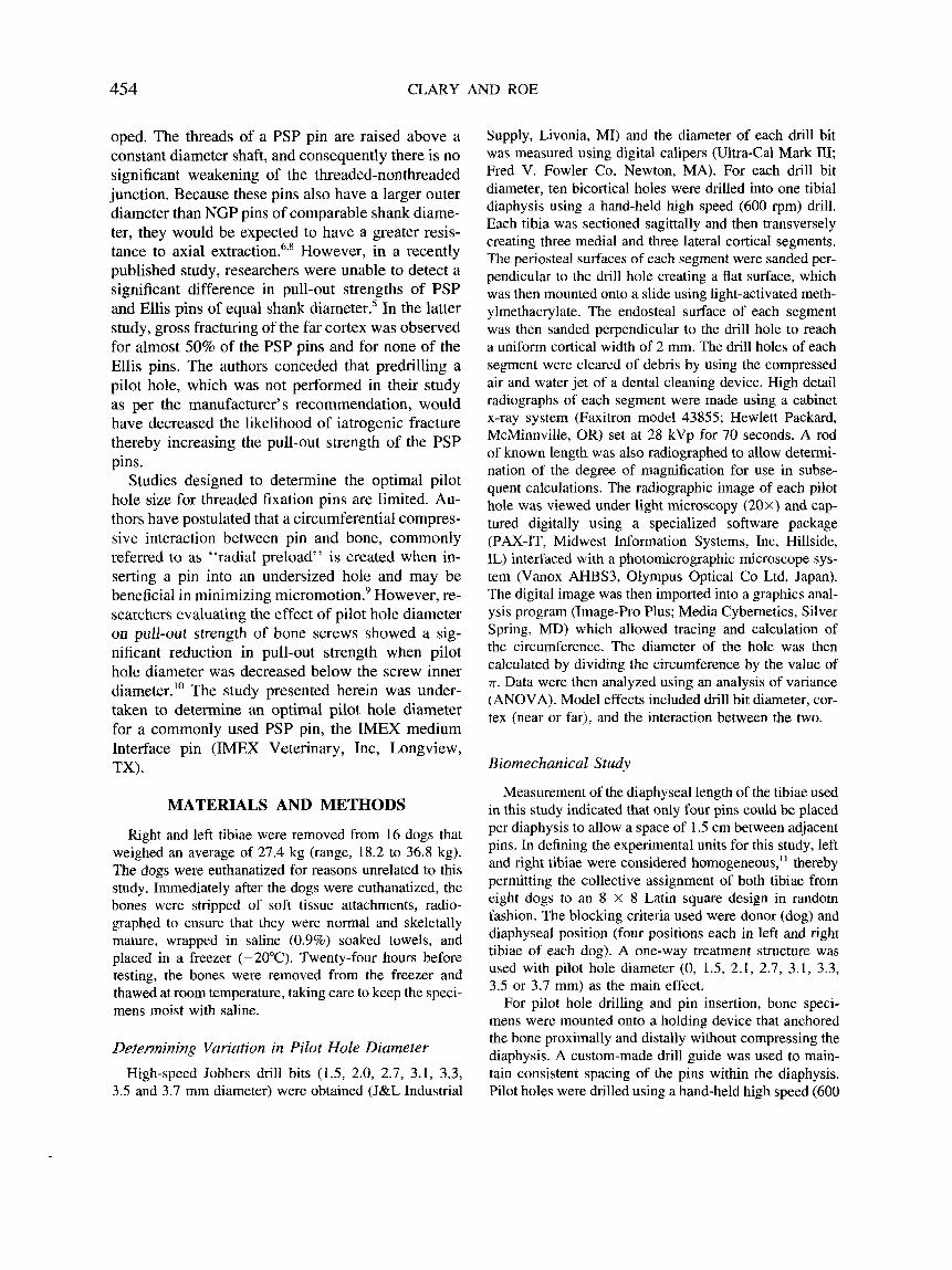
Fig 1. Apparatus used in measurement of end-insertional torque. The entire apparatus is mounted on a load cell (not pictured) within the materials testing machine. A 0.95 cm Steinmann pin (large arrow) is secured within the crosshead of the machine. Downward displacement of the crosshead causes the pin to contact the aluminum rod at a point exactly 1 cm from the center of pin rotation (encircled, small arrow).
rpm) drill. Four medium IMEX Interface fixation pins (3.18 mm inner diameter, 3.97 mm outer diameter) were inserted into each tibia1 diaphysis from medial to lateral using low speed (100 rpm) power until the entire trocar tip extended beyond the lateral cortex. The peak pin tip temperature was measured immediately after pin insertion by applying the sensor of a thermocouple (Digi-Sense thermocouple thermometer model 8528-20; Cole-Parmer Instrument Co, Chicago, IL) to one face of the trocar pin tip. Each bone was radiographed (two orthogonal views) after the temperature measurement to evaluate the speci- mens for cortical fractures.
The bone specimen containing all four pins was then secured to a holding device which in turn was mounted onto the load cell of a materials testing machine (MTM, Instron model 1122; Instron Corp, Canton, MA). A rotat- able moment arm was constructed from a chuck and 20 cm piece of angled aluminum rod. The midsection of the rod was affixed to the base of the chuck. This apparatus was applied to the pin to be tested and tightened with a 2 mm space between the rod and the periosteal surface of the medial cortex (Fig 1). On the horizontal surface of the rod, 2.54 cm from the axis of rotation, a 1 mm circular indentation was made. The load cell was positioned within the MTM such that the tip of a 0.95 cm Steinmann pin secured vertically within the crosshead of the machine would contact the rod on the indentation. A target level was positioned on the side of the chuck opposite the indentation. In beginning the torque testing, the chuck apparatus was positioned with the side of the indentation
elevated 20” above horizontal. Using an indelible ink pen, the position of the fixation pin was marked relative to the adjacent bone so that pin slippage in the chuck could be detected. Downward displacement of the Steinmann pin at a rate of 20 d m i n produced rotation of the chuck apparatus, and consequently the fixation pin. At the point the rod was completely level, a tick mark was made on the chart recording (chart speed 500 mdmin) . To calcu- late end-insertional torque, the force recorded at that in- stant was multiplied by the length of the moment arm (2.54 cm).
After completion of torque testing, a 5 kN load cell was placed within the crosshead of the machine. The shank of the pin to be tested was placed through the stop ring (1 1 mm inner diameter) of the holding device mounted to the machine based and secured to the grasping device attached to the crosshead. The holding device was constructed with a self-centering mechanism to maintain axial alignment of the pin during testing. The pin shank was again marked with an ink pen just above the grasping device to allow assessment for pin slippage. Pins were tested to failure with an upward crosshead speed of 50 mdmin . The maximum percent of full scale load was determined from the chart recording and multiplied by 5 kN to yield the maximum pull-out force. Pin tip tempera- ture, end-insertional torque and pull-out force were ana- lyzed as a Latin square design with variation partitioned into donor, bone position, and pilot hole diameter using the ANOVA procedure. Differences between means were tested using Fisher’s least significant difference method only after F tests were significant (P < .05).
Histological Study
Eight, medium Interface fixation pins were inserted (low-speed power, 100 rpm) into the diaphyses of eight tibiae, from medial to lateral, using pilot holes of 0, 1.5, 2.1, 2.7, 3.1, 3.3, 3.5 or 3.7 mm diameter until the entire trocar tip was exposed beyond the lateral cortex. Immedi- ately after insertion, pins were gently removed by hand using a Jacob’s chuck. The bones were then sectioned sagitally, and then transversely, creating 16, 1 -cm long, half-circumferential segments with a pin tract in the center of each. Specimens were then stained with I % basic fuch- sin in 100% ethyl alcohol using the bulk-staining proce- dure of Frost.” This technique allowed differentiation of microstructural damage that occurred before and after subsequent histological preparation. After staining, each segment was embedded in methylmethacrylate. Unde- calcified longitudinal sections were cut through the pin tract (frontal plane), mounted onto glass slides, ground, and polished to a final average thickness of 100 pm. Using the computer-interfaced videomicroscopic system described previously, the following parameters were de- termined for each unicortical sample: cortical width adja-
456 CLARY AND ROE
Table 1. Mean Diameter and Variation of Pilot Holes Created Using Drill Bits of Varying Diameter
Drill Bit Pilot Hole Standard Coefficient of Diameter (mm) Diameter (mm) Deviation (mm) Variation (%)
power drill did not produce excessive variation in pilot hole diameter that would preclude comparison of pilot hole diameters that differed by 0.2 mm or greater.
1.5 1.52 ,023 1.51 2.0 2.02 .011 0.54 2.1 2.72 ,018 0.66 3.1 3.14 ,032 I .02 3.3 3.33 ,034 1.02 3.5 3.51 ,019 0.54 3.1 3.73 ,050 1.34
cent to the pin tract, cross-sectional area of the centermost thread, distance from pin entry site to the first recogniz- able thread expressed as a percentage of cortical width (entry damage), width of cortex fractured as the advanc- ing pin exited the cortex, also expressed as a percentage of cortical width (exit damage), and depth of stain pene- tration at the centermost root (trough between adjacent bone threads) of the threaded interface. A 1.4 mm wide region adjacent to the pin tract was evaluated for bone damage, as evidenced by stain uptake. Using an eyepiece grid reticle and 40X magnification, the area fraction of damaged bone, expressed as a percentage, was determined as the ratio of the number of grid intersection points on stained, damaged bone to the total number of grid points on bone.'? The grid was positioned with one edge lying along the tip of the bone threads parallel to the long axis of the pin tract with the remainder of the grid extending away from the pin tract overlying bone subjacent to the PBI.
Data were analyzed by the general linear models proce- dure of SAS (SAS Institute, Cary NC). Model effects were pilot hole diameter, cortex (near or far), and the interaction between the two. Least square means were separated by least significant difference only after F tests were significant ( P < .05).
RESULTS
Determining Variation in Pilot Hole Diameter
The average pilot hole diameters for holes drilled with each of the seven drill bits are presented in Table 1. In considering the standard deviation, ex- pressed as a percentage of the mean (coefficient of variation), the variation was extremely small. Ex- pressed as a percentage of the drill bit diameter, the difference between the mean pilot hole diameter and the drill bit diameter ranged from 0.29% to 1.3%. No significant difference in pilot hole diameter was observed between near and far cortices. It was con- cluded that low-speed drilling using a hand-held
Biomechanical Study
Data from the thermal and biomechanical tests are presented in Table 2. Significant reductions in exit- ing pin tip temperature were observed for pins in- serted into pilot holes of 3.1, 3.3, 3.5, and 3.7 mm diameter when compared with pins inserted without a pilot hole. When compared with temperatures of pins inserted without predrilling, reductions in mean pin tip temperature were 9% and 23% for the 3.1 and 3.7 mm groups, respectively. Pin tip temperatures ranged from 30.4 to 5 1.1 "C, exceeding 50°C for one pin each in the 0 and 1.5 mm groups. After pin insertion, no gross fractures were noted, either on direct inspection or on radiographs.
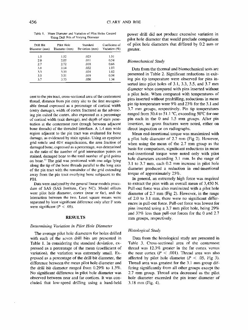
Mean end-insertional torque was maximized with a pilot hole diameter of 2.7 mm (Fig 2). However, when using the mean of the 2.7 mm group as the basis for comparison, significant reductions in mean end-insertional torque were noted only with pilot hole diameters exceeding 3.1 mm. Ln the range of 3.1 to 3.7 mm, each 0.2 mm increase in pilot hole diameter produced a reduction in end-insertional torque of approximately 25 % .
In general, an extremely high force was required to extract the pins with an overall mean of 3,450 N. Pull-out force was also maximized with a pilot hole diameter of 2.7 mm (Fig 2). However, in the range of 2.0 to 3.1 mm, there were no significant differ- ences in pull-out force. Pull-out force was lowest for pins inserted using a 3.7 mm pilot hole, being 29% and 37% less than pull-out forces for the 0 and 2.7 mm groups, respectively.
Histological Study
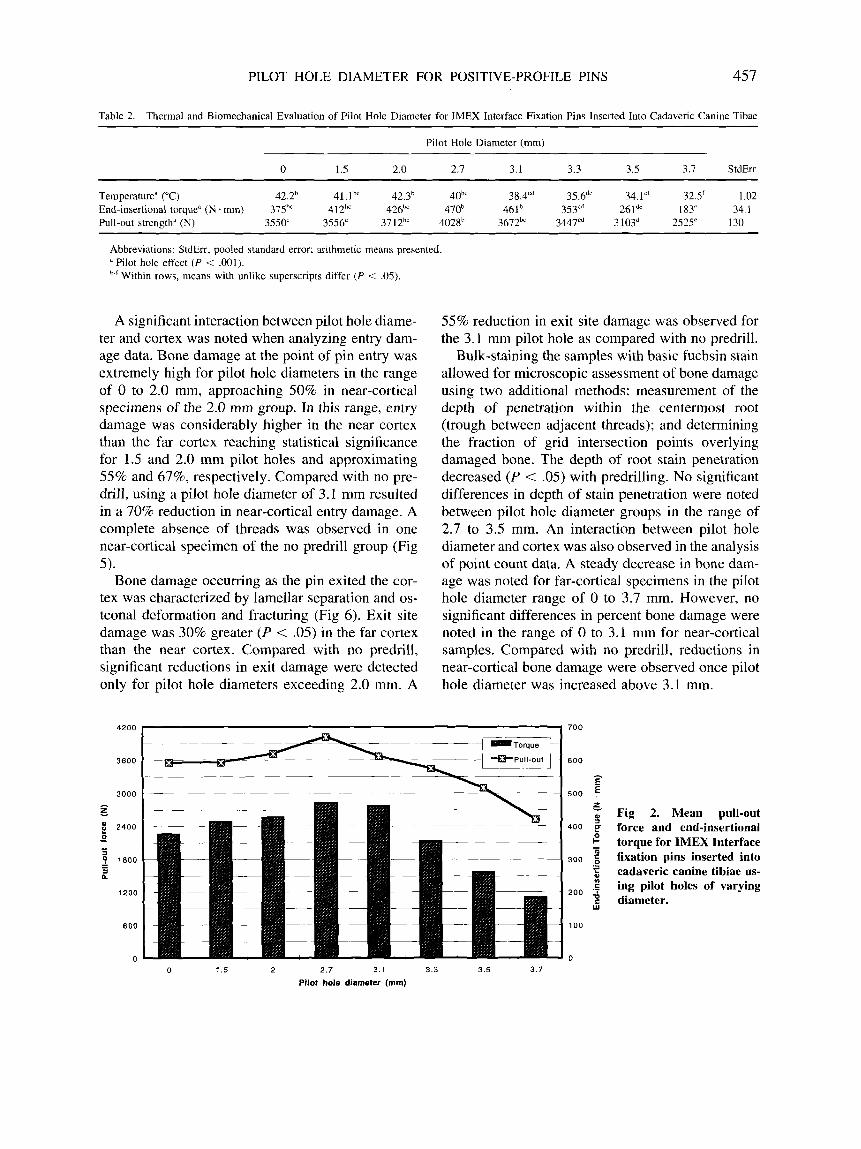
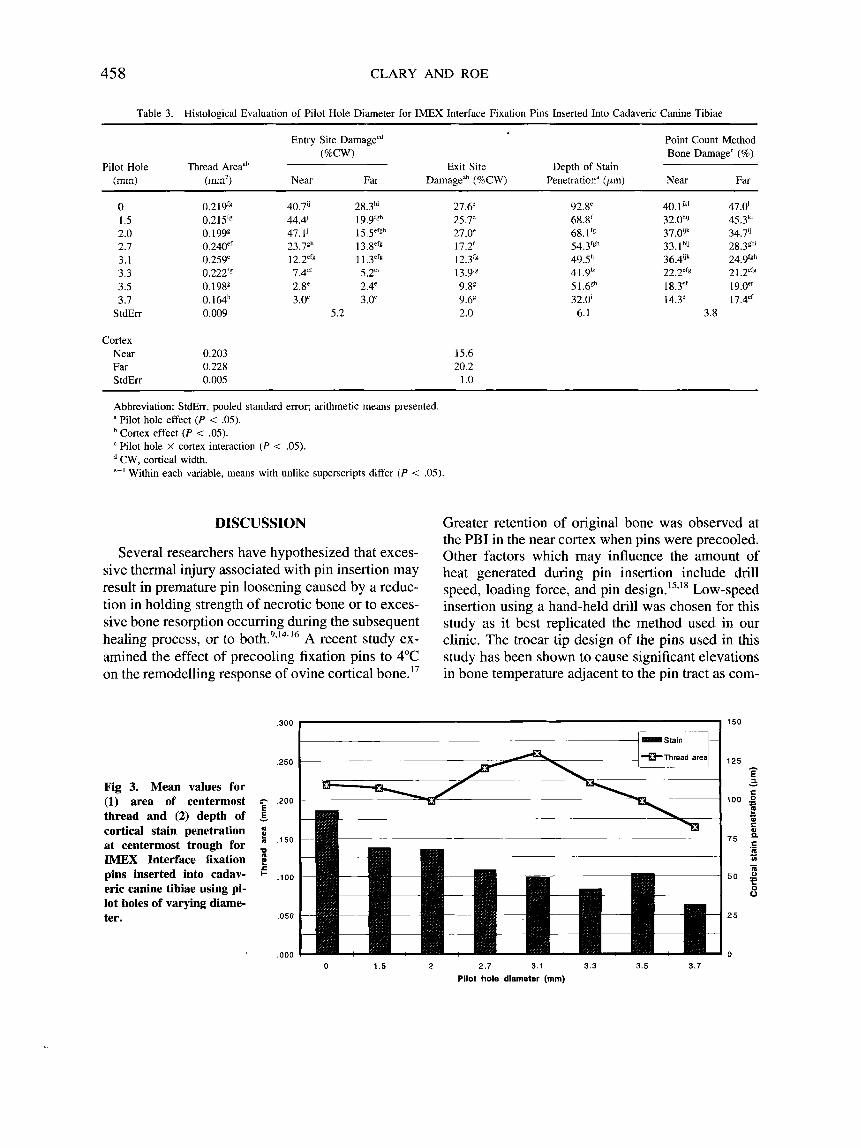
Data from the histological study are presented in Table 3. Cross-sectional area of the centermost thread was 12.3% greater in the far cortex versus the near cortex ( P < .00l). Thread area was also affected by pilot hole diameter ( P < .05, Fig 3). Thread area was greatest for the 3.1 mm group dif- fering significantly from all other groups except the 2.7 mm group. Thread area decreased as the pilot hole diameter exceeded the pin inner diameter of 3.18 mm (Fig. 4).
PILOT HOLE DIAMETER FOR POSITIVE-PROFILE PINS 457
Table 2. Thermal and Biomechanical Evaluation of Pilot Hole Diameter for IMEX Interface Fixation Pins Inserted Into Cadaveric Canine Tibae
Pilot Hole Diameter (mm) ~~ ~ ~~ ~
0 1.5 2.0 2.1 3.1 3.3 3.5 3.7 StdErr
Temperature" ("C) 42.2h 41.1hc 42.3h 40'' 38.4Cd 35.6"' 34.1"' 32.5' 1.02 End-insertional torque" (N - mm) 375h' 412" 426bC 470' 461' 3 5 P 261"' 183' 34. I Pull-out strength" (N) 3550' 3556' 3712'' 4028h 3672" 3447cd 3103d 2525' 130
Abbreviations: StdErr, pooled standard error; arithmetic means presented. a Pilot hole effect ( P < .O01). '-'Within rows, means with unlike superscripts differ ( P < 0 5 ) .
A significant interaction between pilot hole diame- ter and cortex was noted when analyzing entry dam- age data. Bone damage at the point of pin entry was extremely high for pilot hole diameters in the range of 0 to 2.0 mm, approaching 50% in near-cortical specimens of the 2.0 mm group. In this range, entry damage was considerably higher in the near cortex than the far cortex reaching statistical significance for 1.5 and 2.0 mm pilot holes and approximating 55% and 67%, respectively. Compared with no pre- drill, using a pilot hole diameter of 3.1 mm resulted in a 70% reduction in near-cortical entry damage. A complete absence of threads was observed in one near-cortical specimen of the no predrill group (Fig 5).
Bone damage occurring as the pin exited the cor- tex was characterized by lamellar separation and os- teonal deformation and fracturing (Fig 6). Exit site damage was 30% greater ( P < .05) in the far cortex than the near cortex. Compared with no predrill, significant reductions in exit damage were detected only for pilot hole diameters exceeding 2.0 mm. A
4200
3600
3000 - 5
2400 * g I
1800 - - a n
1200
600
0
55% reduction in exit site damage was observed for the 3.1 mm pilot hole as compared with no predrill.
Bulk-staining the samples with basic fuchsin stain allowed for microscopic assessment of bone damage using two additional methods: measurement of the depth of penetration within the centermost root (trough between adjacent threads); and determining the fraction of grid intersection points overlying damaged bone. The depth of root stain penetration decreased ( P < .05) with predrilling. No significant differences in depth of stain penetration were noted between pilot hole diameter groups in the range of 2.7 to 3.5 mm. An interaction between pilot hole diameter and cortex was also observed in the analysis of point count data. A steady decrease in bone dam- age was noted for far-cortical specimens in the pilot hole diameter range of 0 to 3.7 mm. However, no significant differences in percent bone damage were noted in the range of 0 to 3.1 mm for near-cortical samples. Compared with no predrill, reductions in near-cortical bone damage were observed once pilot hole diameter was increased above 3.1 mm.
700
600 - E
500 E t Fig 2. Mean pull-out
400 $ force and end-insertional 2 - torque for IMEX Interface
300 { fixation pins inserted into 5 cadaveric canine tibiae us- .g ing pilot holes of varying s diameter.
.-
200
W
100
0
0 1.5 2 2.7 3.1 3.3 3.5 3.7 Pilot hole diameter (mm)
45 8 CLARY AND ROE
Table 3. Histological Evaluation of Pilot Hole Diameter for IMEX Interface Fixation Pins Inserted Into Cadaveric Canine Tibiae
Entry Site Damagecd Point Count Method (%CW) Bone Damage' (%)
(mm) (m2) Near Far Damagedh (%CW) Penetration" (pm) Near Far Pilot Hole Thread Areaah Exit Site Depth of Stain
0 1.5 2.0 2.7 3.1 3.3 3.5 3.7
StdErr
Cortex Near Far StdErr
0.2IY'g 0.215" 0.199€ 0.240e' 0.259' 0.222'g 0. 19gg 0. 164h 0.009
0.203 0.228 0.005
40.7" 28.3h' 44.4' lY.YfSh 47.1' 15 .5"'gh
23.7gh 13.8"'€ 12.2"s 1 1 .3efg 7.4'' 5.2e' 2.8' 2.4' 3.0' 3.0"
5.2
27.6' 25.7' 27.0' 17.2' 12.P 13.9" 9.V 9.6' 2.0
15.6 20.2
1 .o
92.8' 68.8' 68.1 fg
54.3Igh 49Sh 4 1 .9h' 51.68h 32.0' 6.1
40.1Jk' 47.0' 32.0h" 45.3k1 37.@Jk 34.7" 33.1 h'J 28.3Eh 36.4'" 24.9'gh 22.2"" 2 1 .2=f€ 18.3"' 19 .oef 14.3' 17.4"'
3.8
Abbreviation: StdErr, pooled standard error; arithmetic means presented. a Pilot hole effect ( P < .05).
Cortex effect ( P < .05). Pilot hole X cortex interaction ( P < .05). CW, cortical width.
'-'Within each variable, means with unlike superscripts differ ( P < .05).
DISCUSSION
Several researchers have hypothesized that exces- sive thermal injury associated with pin insertion may result in premature pin loosening caused by a reduc- tion in holding strength of necrotic bone or to exces- sive bone resorption occurring during the subsequent healing process, or to b ~ t h . ~ , ' ~ - ' ~ A recent study ex- amined the effect of precooling fixation pins to 4°C on the remodelling response of ovine cortical bone.I7
Greater retention of original bone was observed at the PBI in the near cortex when pins were precooled. Other factors which may influence the amount of heat generated during pin insertion include drill speed, loading force, and pin design.l5,l8 Low-speed insertion using a hand-held drill was chosen for this study as it best replicated the method used in our clinic. The trocar tip design of the pins used in this study has been shown to cause significant elevations in bone temperature adjacent to the pin tract as com-
,300 150
Fig 3. Mean values for (1) area of centermost thread and (2) depth of cortical stain penetration at centermost trough for IMEX Interface fixation pins inserted into cadav- eric canine tibiae using pi- lot holes of varying diame- ter.
,250
g .200
c .I50
E - 6
u
c ?! + ,100
.050
,000 0 1.5 2 2 .7 3.1 3.3 3.5 3.7
Pilot hole diameter (mm)
PILOT HOLE DIAMETER FOR POSITIVE-PROFILE PINS 459
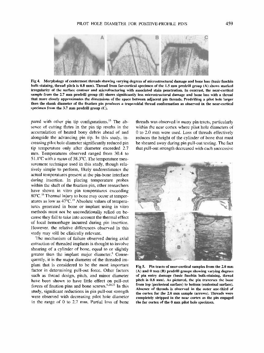
Fig 4. Morphology of centermost threads showing varying degrees of microstructural damage and bone loss (basic fuschin bulk-staining, thread pitch is 0.8 mm). Thread from far-cortical specimen of the 1.5 mm predrill group (A) shows marked irregularity of the surface contour and microfracturing with associated stain penetration. In contrast, the near-cortical sample from the 2.7 mm predrill group (B) shows significantly less microstructural damage and bone loss with a thread that more closely approximates the dimensions of the space between adjacent pin threads. Predrilling a pilot hole larger than the shank diameter of the fixation pin produces a trapezoidal thread conformation as observed in the near-cortical specimen from the 3.7 mm predrill group (C).
pared with other pin tip configuration^.'^ The ab- sence of cutting flutes in the pin tip results in the accumulation of heated bony debris ahead of and alongside the advancing pin tip. In this study, in- creasing pilot hole diameter significantly reduced pin tip temperature only after diameter exceeded 2.7 mm. Temperatures observed ranged from 30.4 to 51.1"C with a mean of 38.3"C. The temperature mea- surement technique used in this study, though rela- tively simple to perform, likely underestimates the actual temperatures present at the pin-bone interface during insertion. In placing temperature probes within the shaft of the fixation pin, other researchers have shown in vitro pin temperatures exceeding 80°C." Thermal injury to bone may occur at temper- atures as low as 47"C.I9 Absolute values of tempera- tures generated in bone or implant using in vitro methods must not be unconditionally relied on be- cause they fail to take into account the thermal effect of local hemorrhage incurred during pin insertion. However, the relative differences observed in this study may still be clinically relevant.
The mechanism of failure observed during axial extraction of threaded implants is thought to involve shearing of a cylinder of bone, equal to or slightly greater than the implant major diameter.' Conse- quently, it is the major diameter of the threaded im- plant that is considered to be the most important factor in determining pull-out force. Other factors such as thread design, pitch, and minor diameter have been shown to have little effect on pull-out forces of fixation pins and bone screws.6,2092' In this study, significant reductions in pin pull-out strength were observed with decreasing pilot hole diameter in the range of 0 to 2.7 mm. Partial loss of bone
threads was observed in many pin tracts, particularly within the near cortex where pilot hole diameters of 0 to 2.0 mm were used. Loss of threads effectively reduces the height of the cylinder of bone that must be sheared away during pin pull-out testing. The fact that pull-out strength decreased with each successive
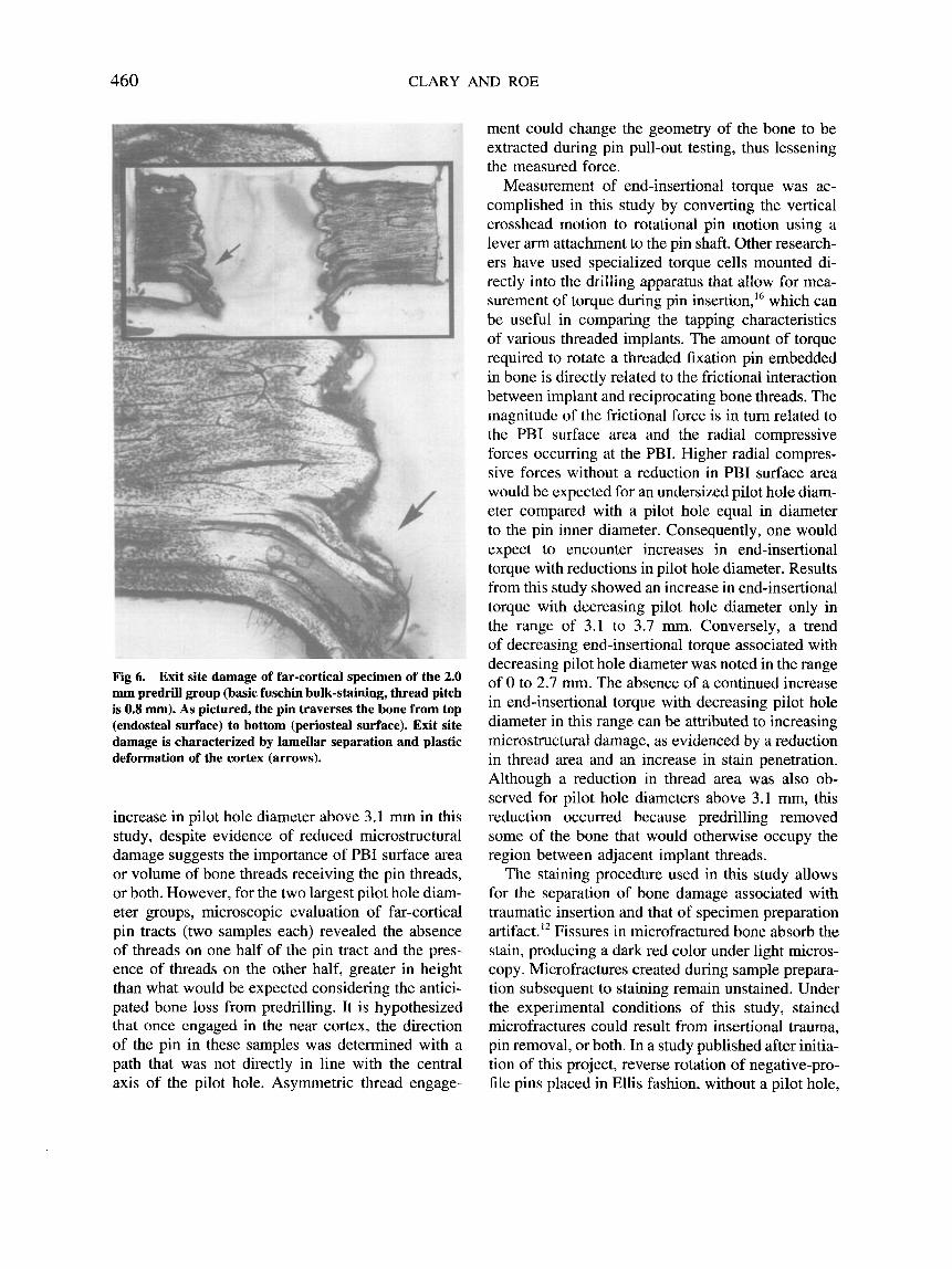
Fig 5. Pin tracts of near-cortical samples from the 2.0 mm (A) and 0 mm (B) predrill groups showing varying degrees of pin entry damage (basic fuschin bulk-staining, thread pitch is 0.8 mm). As pictured, the pin traverses the bone from top (periosteal surface) to bottom (endosteal surface). Absence of threads is observed in the outer one-third of the cortex for the 2.0 mm sample (arrows). Threads were completely stripped in the near cortex as the pin engaged the far cortex of the 0 mm pilot hole specimen.
460 CLARY AND ROE
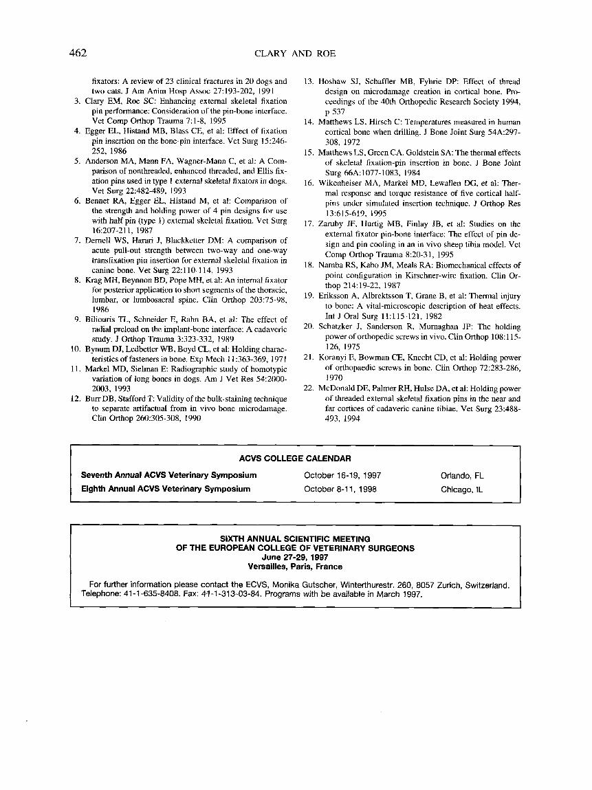
Fig 6. Exit site damage of far-cortical specimen of the 2.0 mm predrill group (basic fuschin bulk-staining, thread pitch is 0.8 mm). As pictured, the pin traverses the bone from top (endosteal surface) to bottom (periosteal surface). Exit site damage is characterized by lamellar separation and plastic deformation of the cortex (arrows).
increase in pilot hole diameter above 3.1 rnm in this study, despite evidence of reduced microstructural damage suggests the importance of PBI surface area or volume of bone threads receiving the pin threads, or both. However, for the two largest pilot hole diam- eter groups, microscopic evaluation of far-cortical pin tracts (two samples each) revealed the absence of threads on one half of the pin tract and the pres- ence of threads on the other half, greater in height than what would be expected considering the antici- pated bone loss from predrilling. It is hypothesized that once engaged in the near cortex, the direction of the pin in these samples was determined with a path that was not directly in line with the central axis of the pilot hole. Asymmetric thread engage-
ment could change the geometry of the bone to be extracted during pin pull-out testing, thus lessening the measured force.
Measurement of end-insertional torque was ac- complished in this study by converting the vertical crosshead motion to rotational pin motion using a lever arm attachment to the pin shaft. Other research- ers have used specialized torque cells mounted di- rectly into the drilling apparatus that allow for mea- surement of torque during pin insertion,I6 which can be useful in comparing the tapping characteristics of various threaded implants. The amount of torque required to rotate a threaded fixation pin embedded in bone is directly related to the frictional interaction between implant and reciprocating bone threads. The magnitude of the frictional force is in turn related to the PBI surface area and the radial compressive forces occurring at the PBI. Higher radial compres- sive forces without a reduction in PBI surface area would be expected for an undersized pilot hole diam- eter compared with a pilot hole equal in diameter to the pin inner diameter. Consequently, one would expect to encounter increases in end-insertional torque with reductions in pilot hole diameter. Results from this study showed an increase in end-insertional torque with decreasing pilot hole diameter only in the range of 3.1 to 3.7 111111. Conversely, a trend of decreasing end-insertional torque associated with decreasing pilot hole diameter was noted in the range of 0 to 2.7 mm. The absence of a continued increase in end-insertional torque with decreasing pilot hole diameter in this range can be attributed to increasing microstructural damage, as evidenced by a reduction in thread area and an increase in stain penetration. Although a reduction in thread area was also ob- served for pilot hole diameters above 3.1 mm, this reduction occurred because predrilling removed some of the bone that would otherwise occupy the region between adjacent implant threads.
The staining procedure used in this study allows for the separation of bone damage associated with traumatic insertion and that of specimen preparation artifact.12 Fissures in microfractured bone absorb the stain, producing a dark red color under light micros- copy. Microfractures created during sample prepara- tion subsequent to staining remain unstained. Under the experimental conditions of this study, stained microfractures could result from insertional trauma, pin removal, or both. In a study published after initia- tion of this project, reverse rotation of negative-pro- file pins placed in Ellis fashion, without a pilot hole,

PILOT HOLE DIAMETER FOR POSITIVE-PROFILE PINS 46 1
was shown to decrease pull-out strength by l 2 % 1 . ~ It is not known if the detrimental effect of pin retrac- tion would be linear across the range of pilot hole diameters used in this study. It is likely that thread damage associated with pin retraction may be worse with smaller pilot holes. The decision to remove the implants before staining was based on the results of pilot studies that examined various alternatives, including sample sectioning with pin in place, pre- ceded or followed by bulk staining. Although others have reported using this bulk staining technique on samples containing threaded implants,” we were un- able to achieve sufficient stain penetration at the PBI despite the presence of considerable osteonal com- pression and microfracturing noted in some samples sectioned after staining and methylmethacry late em- bedding were first performed with the pin in place. Other studies have used scanning electron micros- copy (SEM) to evaluate the PBI.’6,22 Similar to the experience of these studies, we found it difficult to develop objective methods of assessing SEM photo- micrographs. By using the computer-interfaced vid- eomicroscopy, we were able to more objectively evaluate the data by creating an area of interest con- sistent in size and location between individual sam- ples from which numerical data could be generated.
Bone damage occurring at the point of cortical entry was severe in near-cortical samples for the pilot-hole range 0 to 2.0 mm, exceeding far-cortical entry damage by almost 70% for the 2.0 mm group. In evaluating the relative contributions of both near and far cortical purchase to pull-out strength of IMEX Interface fixation pins inserted into canine tibiae without a pilot hole, other researchers reported that the near cortical penetration site provided only 25% of the total strength.22 As possible explanations for these results, the authors cited greater pin wobble in the near cortex, possible stripping of near cortical threads as the pin engaged the far cortex, greater length of pin traveling through the near cortex, and possible differences in near and far cortical response to pin insertion based on the anisotropic properties of bone.
Although it was technically simple to perform, the point count method of determining bone damage likely underestimated the severity of damage for PBIs where considerable thread loss had occurred during pin insertion. In all specimens examined, a gradation of bone damage was observed with the greatest damage occurring at the PBI, lessening with greater distance from the PBI. Loss of bone in the
threaded region removed damaged bone from the primary area of interest and likely affected grid posi- tioning, favoring greater coverage over subjacent bone which was less likely to be damaged. Conse- quently, the lack of significant difference in bone damage assessed with the point count method be- tween near cortical samples for the range 0 to 3.1 mm may be explained in large part by the significant reduction in thread area occurring in the range 0 to 2.0 mm as compared with the 3.1 mm group. Determination of the depth of stain penetration, thread area, and exit and entry cortical width damage provided a more reliable estimate of bone damage than the point count method alone.
The results from this study show the beneficial effect of predrilling before insertion of a positive- profile pin on acute thermal, biomechanical, and his- tological performance. Although significantly un- dersizing a pilot hole may produce a theoretical biomechanical advantage, ie, radial compressive pre- load, this seems to be negated by the microstructural damage that occurs during pin insertion. Excessive bone damage produced during pin insertion not only compromises the interlock between bone and im- plant, it also dictates a host tissue response character- ized by significant bone resorption, which can lead to premature pin loosening.’ On the other end of the spectrum, an excessively large pilot hole may reduce initial holding strength below a desired level, thus predisposing the implant to failure. Results from this study indicate that choosing a pilot hole diameter that approximates the inner diameter of the IMEX Interface external skeletal fixation pin represents the best compromise between maximization of initial holding strength and minimization of insertional bone damage.
ACKNOWLEDGMENTS
The authors thank Ms Ashlyn Clary, Ms Ree Coan, Mrs Bonnie DeYoung, Dr Michael Dykstra, Dr Hall Grif- fin, Ms Sandra Horton, M r Matthew Kay, M r Thearayouk Keo, Ms Wendy Savage, and M r Timothy Seaboch for their assistance.
REFERENCES
1. Aron DN, Foutz TL, Keller WG, et al: Experimental and clinical experience with an IM pin external skeletal fixa- tor tie-in configuration. Vet Comp Orthop Trauma 4:86- 94, 1991
2. Foland MA, Egger EL: Application of type 111 external
462 CLARY AND ROE
fixators: A review of 23 clinical fractures in 20 dogs and two cats. J Am Anim Hosp Assoc 27:193-202, 1991
3. Clary EM, Roe SC: Enhancing external skeletal fixation pin performance: Consideration of the pin-bone interface. Vet Comp Orthop Trauma 7:l-8, 1995
4. Egger EL, Histand MB, Blass CE, et al: Effect of fixation pin insertion on the bone-pin interface. Vet Surg 15:246- 252, 1986
5. Anderson MA, Mann FA, Wagner-Mann C, et al: A Com- parison of nonthreaded, enhanced threaded, and Ellis fix- ation pins used in type 1 external skeletal fixators in dogs. Vet Surg 22:482-489, 1993
6. Bennet RA, Egger EL, Histand M, et al: Comparison of the strength and holding power of 4 pin designs for use with half pin (type I) external skeletal fixation. Vet Surg
7. Dernell WS, Harari J, Blackketter DM: A comparison of acute pull-out strength between two-way and one-way transfixation pin insertion for external skeletal fixation in canine bone. Vet Surg 22:110-114, 1993
8. Krag MH, Beynnon BD, Pope MH, et a]: An internal fixator for posterior application to short segments of the thoracic, lumbar, or lumbosacral spine. Clin Orthop 203:75-98, 1986
9. Biliouris TL, Schneider E, Rahn BA, et al: The effect of radial preload on the implant-bone interface: A cadaveric study. J Orthop Trauma 3:323-332, 1989
10. Bynum DJ, Ledbetter WB, Boyd CL, et al: Holding charac- teristics of fasteners in bone. Exp Mech 11:363-369, 1971
11. Markel MD, Sielman E: Radiographic study of homotypic variation of long bones in dogs. Am J Vet Res 54:2000- 2003, 1993
12. Burr DB, Stafford T Validity of the bulk-staining technique to separate artifactual from in vivo bone microdamage. Clin Orthop 260:305-308, 1990
16:207-211, 1987
13. Hoshaw SJ, Schaffler MB, Fyhrie DP: Effect of thread design on microdamage creation in cortical bone. Pro- ceedings of the 40th Orthopedic Research Society 1994,
14. Matthews LS, Hirsch C: Temperatures measured in human cortical bone when drilling. J Bone Joint Surg 54A:297- 308, 1972
15. Matthews LS, Green CA, Goldstein SA: The thermal effects of skeletal fixation-pin insertion in bone. J Bone Joint Surg 66A:1077-1083, 1984
16. Wikenheiser MA, Markel MD, Lewallen DG, et al: Ther- mal response and torque resistance of five cortical half- pins under simulated insertion technique. J Orthop Res
17. Zaruby JF, Hurtig MB, Finlay JB, et al: Studies on the external fixator pin-bone interface: The effect of pin de- sign and pin cooling in an in vivo sheep tibia model. Vet Comp Orthop Trauma 8:20-31, 1995
18. Namba RS, Kabo JM, Meals RA: Biomechanical effects of point configuration in Kirschner-wire fixation. Clin Or-
19. Eriksson A, Albrektsson T, Grane B, et al: Thermal injury to bone: A vital-microscopic description of heat effects. Int J Oral Surg 11:115-121, 1982
20. Schatzker J , Sanderson R, Murnaghan JP: The holding power of orthopedic screws in vivo. Clin Orthop 108: 115- 126, 1975
21. Koranyi E, Bowman CE, Knecht CD, et al: Holding power of orthopaedic screws in bone. Clin Orthop 72:283-286, 1970
22. McDonald DE, Palmer RH, Hulse DA, et al: Holding power of threaded external skeletal fixation pins in the near and far cortices of cadaveric canine tibiae. Vet Surg 23:488- 493. 1994
p 537
13 161 5-61 9, 1995
thop 214:19-22, 1987
ACVS COLLEGE CALENDAR
Seventh Annual ACVS Veterinary Symposium
Eighth Annual ACVS Veterinary Symposium
October 16-1 9, 1997
October 8-1 1, 1998
Orlando, FL Chicago, IL
I SIXTH ANNUAL SCIENTIFIC MEETING
OF THE EUROPEAN COLLEGE OF VETERINARY SURGEONS June 27-29,1997
Versailles, Paris, France
For further information please contact the ECVS, Monika Gutscher, Winterthurestr. 260, 8057 Zurich, Switzerland. Telephone: 41-1 -635-8408. Fax: 4?-1-313-03-84. Programs with be available in March 1997.
I
Copyright © 2022 FDOKUMEN