Periostin regulates collagen fibrillogenesis and the biomechanical properties of …
Upload
khangminh22Category
view
1download
0
University of New Orleans University of New Orleans
ScholarWorks@UNO ScholarWorks@UNO
University of New Orleans Theses and Dissertations Dissertations and Theses
5-22-2006
A Study of Carasaurus' (Dinosaura: Sauropodomorph) Torso and A Study of Carasaurus' (Dinosaura: Sauropodomorph) Torso and
its Biomechanical Implications its Biomechanical Implications
Jacqueline Mary Wood University of New Orleans
Follow this and additional works at: https://scholarworks.uno.edu/td
Recommended Citation Recommended Citation Wood, Jacqueline Mary, "A Study of Carasaurus' (Dinosaura: Sauropodomorph) Torso and its Biomechanical Implications" (2006). University of New Orleans Theses and Dissertations. 369. https://scholarworks.uno.edu/td/369
This Thesis is protected by copyright and/or related rights. It has been brought to you by ScholarWorks@UNO with permission from the rights-holder(s). You are free to use this Thesis in any way that is permitted by the copyright and related rights legislation that applies to your use. For other uses you need to obtain permission from the rights-holder(s) directly, unless additional rights are indicated by a Creative Commons license in the record and/or on the work itself. This Thesis has been accepted for inclusion in University of New Orleans Theses and Dissertations by an authorized administrator of ScholarWorks@UNO. For more information, please contact [email protected].

A STUDY OF CAMARASAURUS' (DINOSAURIA: SAUROPODOMORPH) TORSO AND ITS BIOMECHANICAL IMPLICATIONS
A Thesis
Submitted to the Graduate Faculty of the University of New Orleans in partial fulfillment of the
requirements for the degree of
Masters of Science in
Geology
Jacqueline Mary Wood
B.A. University of Kansas, 2003
May 2006

ii
Acknowledgements
This work would not have been completed without the assistance and generosity
of both Dr. Kraig Derstler and Dr. Ray Wilhite. Dr. Derstler provided me with countless
hours of discussion, and has become a great friend, despite his corny jokes. Dr. Wilhite
provided me with many incredibly insightful ideas and comments. Thank you both for
all the assistance! I also want to thank the third member of my committee, Dr.
Christopher Parkinson.
The following institutions provided grants for this project, which were vital to this
project: The Jurassic Foundation, New Orleans Geological & Geophysical Society, and
the Department of Geology and Geophysics at the University of New Orleans.
Dr. Brooks Britt and Dr. Rod Scheetz at Brigham Young University allowed me
to visit their institution and make the molds and casts of BYU 9047. Jim and Chris
Madsen loaned the casts of the Camarasaurus . Drs. Wilhite and Hillmann of Louisiana
State University provided me with the animals I needed for dissection. Dr. Sever of
Southeastern Louisiana University for allowed me to mount the camarasaur torso in his
lab. Thank you all, your help was essential for this project.
Thanks also to Dr. Larry Martin and Dave Burnham of the University of Kansas
for providing me with the opportunity to visit and take as many measurements as I
needed from specimens in their care.
Thanks also to my assistant Becky Totten for helping me make the molds and
casts at BYU. I couldn't have done it without you. John Watson and Erik Day helped
create the camarasaur mount. This assistance is much appreciated!

iii
Finally, a hefty thank you to my mother, Mary, my husband, Matt, and my
son, Jaeden. Thank you so much for believing in me and for listening to countless hours
of dinosaur rambling. Without the inspiration of my mother, the project would have
taken much longer to complete. Without Matt helping me with the mount, and to help me
see the light at the end of the tunnel, this project would have taken much longer to
complete. I couldn't have done it without you. Jaeden is by far the biggest inspiration in
my life, and I am lucky to be his mother. Thank you so much.

iv
Table of Contents
Abstract...........................................................................................................................v Chapter 1: Introduction....................................................................................................1 Chapter 2: Materials and Methodology............................................................................6
I. Dissections .......................................................................................................6 II. Physical Model................................................................................................7
A. Molds and Casts ..................................................................................7 B. Measurements......................................................................................8 C. Mount................................................................................................ 10
Chapter 3: Observations ................................................................................................ 12
I. Dissections ..................................................................................................... 12 II. Physical Model.............................................................................................. 17
A. Materials and Methods ...................................................................... 17 B. Reconstruction................................................................................... 18 C. Body Shape ....................................................................................... 22
Chapter 4: Interpretations .............................................................................................. 25
I. Physical Model ............................................................................................... 25 A. Reconstruction................................................................................... 25 B. Body Volume .................................................................................... 29 C. Viscera .............................................................................................. 31
II. Muscle Reconstruction .................................................................................. 32 III. Biomechanical Reconstruction ..................................................................... 37
A. Dorsal Vertebrae................................................................................ 37 B. Scapular Position ............................................................................... 40
Conclusions ....................................................................................................... 42
Addendum..................................................................................................................... 44
References..................................................................................................................... 45 Appendix
Appendix A: Dorsal Rib Description.................................................................. 49 Appendix B: Dorsal Vertebrae ........................................................................... 91
A. Anatomical Definitions...................................................................... 91 B. Measurements.................................................................................... 92
Appendix C: Anatomical Planes and Positions................................................... 93

vi
Table of Contents
Appendix D: Dorsal Rib & Vertebrae Articulation............................................. 94 Vita ............................................................................................................................... 95

vi ii
Abstract
Physical examination of the articulations between the dorsal vertebrae and the
dorsal ribs of the sauropod dinosaur Camarasaurus (Upper Cretaceous, Wyoming or
whatever) shows that the dorsal vertebral column has a slight double curve and the torso
is more narrow and volumetrically smaller than previously reconstructed. The shape of
the dorsal vertebrae series was based upon the position of the zygopophyses and centrum
spacing. The dorsal ribs were placed on the vertebrae based upon the position of
tuberculum/diapophysis, capitulum/parapophysis, and the lateral edge of the rib head.
Comparisons between the articulated torso of Camarasaurus and extant relatives
allowed for the first attempt in reconstructing the three intercostal muscle groups. The
newly defined torso shape in combination with the presence of scapular facets on the ribs
allowed the scapulocoracoid to be placed upon the torso at an angle of 20-30°.

1
CHAPTER 1: Introduction
Various workers have investigated fossilized sauropod dinosaurs axial osteology
and appendicular elements (Bonnan, 2000; Bonnan, 2003; Campos et al., 1999; Stevens
& Parrish, 1999; Willhite, 2000; & Wilhite, 2003). These elements are occasionally
found articulated and their biomechanics relatively obvious. In contrast, sauropod
researchers largely ignore dorsal ribs. In particular, these bones are passed over in the
field and in the lab because of their size, unstable nature, and assumed lack of
importance. Dorsal ribs are rarely preserved in articulation and their biomechanical
relationship to the other skeletal components are relatively unknown. Also, ribs behave
in a ductile fashion postmortem, and most ribs have bends or twists resulting from a large
bone resting on top of the rib. Usually dorsal ribs are found strewn beneath the underbelly
of the skeleton with no indication to a correct sequence. More often than not, researchers
give gastralia a higher priority than dorsal ribs (Filla et al., 1994; Claessens, 2004). Prior
to the present work, the lack of attention to rib osteology made accurate reconstruction of
the torso impossible.
As a result, the configuration of dorsal ribs in the overall morphology of
sauropods is not well known. Little attention is given to sequencing of the ribs or
variation in rib morphology within the series (McIntosh et al., 1996a; McIntosh et al.,
1996b). Discussion of the ribs usually appears as a general description with little insight
into functional anatomy (e.g. Filla et al., 1994; McIntosh et al., 1996a; McIntosh et al.,
1996b; Clavo 1999; Carvalho et al., 2003). The most extensive description of the dorsal

2
vertebrae and rib articulations is found in Borsuk-Bialynicka (1977), dealing with
Opisthocoelicaudia skarzynskii.
The aim of the present research is to accurately articulate sauropod dorsal ribs
onto the vertebrate column, and to accurately restore the shape of the torso. The dorsal
ribs and their articulation with their associated vertebrae play an important role in
determining the overall shape of the torso. For the purposes of this research, the torso is
defined as the overall shape resulting from the dorsal vertebrae and dorsal ribs without
the pectoral girdle.
To date, there have been no detailed studies of sauropod ribs as explained above.
When sauropods are reconstructed, the dorsal ribs and their articulations are rarely
scrutinized, but instead are manipulated to produce a barrel-shaped torso. This approach
has resulted in overly robust reconstructions and exaggerated weight estimates (e.g.
Dodson, 1991; Paul, 1988; Weaver, 1983).
Since the bulk of the animal is found in its torso, it is assumed a correct
articulation of the dorsal vertebrae and ribs will yield more accurate weight estimate for
the animal. The final goal of this study is to accurately depict the torso in Camarasaurus
and to begin exploring the implications for sauropod pectoral and axial biomechanics.
Camarasaurus was chosen as the focus of this study due to the copius amount of
fossil material. One particular skeleton, BYU 9047 was selected for this study since it
has an almost complete set of ribs. Some of these ribs were preserved in articulation,
giving a good starting point for placement as well as angulations and spacing for articular
cartilaginous pads.

3
Rib descriptions are present in Appendix A (see also Table 1 for a summary of
their designating characters. For rib anatomical definitions, refer to figures A1 and A2 in
Appendix A, for dorsal vertebrae anatomical definitions refer to figure B1 in Appendix
B, and for the definition of anatomical planes and positions refer to Appendix C.).
Intercostal musculature, torso volume, the dorsal vertebral curve, overall torso shape, and
scapular position are all considered in the body of this work.
Table 1. Brief overview of identifying characteristics of dorsal ribs.

4
Stevens and Parrish (1999), introduced DinoMorph, a digital 3-D modeling
program that allows the user to explore different ranges of motion in an articulated
skeleton. DinoMorph was used to determine plausible neck postures in sauropods. Note
that the dinosaurs modeled lack dorsal ribs (Figure 1). The present study will provide the
measurements needed to mathematically create the ribs for eventual use in DinoMorph
simulations. Originally, the present writer intended to produce such a digital model of
the torso. However, this work was postponed indefinitely because of interminable delays
resulting from Hurricane Katrina.
Figure 1. Modeled Apatosaurus in DinoMorph with no dorsal ribs (Stevens and Parrish, 1999).
Several previous works have reconstructed major portions of the musculature for
sauropods (e.g. Romer, 1923; Borsuk-Bialynicka, 1977). However, the writer is not
aware of any reconstructions of the intercostal musculature. The present work includes
the first attempt at reconstructing this important muscle system.
5
Abbreviations
BYU: Brigham Young University, Provo, Utah
CEU: College of Eastern Utah, Price, Utah
CMNH: Carnegie Museum of Natural History, Pittsburgh, Pennsylvania
GMNH: Gunma Museum of Natural History, Gunma, Japan
KUVP: Kansas University Vertebrate Paleontology, Lawrence, Kansas
6
CHAPTER 2: MATERIALS AND METHODOLOGY
This project is founded on three sets of observations: dissections of modern
animals, cast of sauropod bones, and the fit of these casts into a reconstructed torso. The
materials and methods used to obtain observations are described in the following
sections.
I. Dissections
To fully understand sauropod rib mechanics it is first necessary to investigate rib
anatomy and function in extant taxa. Alligator mississippiensis, Iguana iguana, and
Gallus domesticus were dissected to examine rib articulations in reptiles and birds. These
dissections focused upon three sets of observations: 1) intercostal musculature, 2) dorsal
rib and vertebral articulation, and 3) articulation angle between each dorsal vertebrae and
its associated rib. All specimens were fresh tissue dissections. Only one specimen of the
alligator and iguana were dissected, and three chickens were dissected. The alligator was
approximately six feet in length, the iguana was approximately five and a half feet, and
the chickens were standard-size market carcasses obtained from a local food vendor.
Each dissection was recorded with written accounts, sketches, and selected photographs.
Intercostal muscles are rarely examined in detail, and as a result, little has been
published. During the course of each dissection the writer carefully recorded the
intercostal muscle attachments, number of muscle layers, and the orientation of muscle
fibers for each intercostal muscle set.
Once the muscles were studied and removed, the articulation of the dorsal
vertebrae and the rib was observed. The main characteristic noted was the amount of
articular cartilage between the tuberculum and diapophysis, and the capitulum and
7
parapophysis. The thickness of each articular cartilage pad was especially critical and it
was measured with great care.
The last feature studied was the angle of articulation between the tuberculum and
diapophysis and the capitulum and parapophysis. This observation was recorded through
diagrams and photos and is included in the observation section (e.g. Figures 5-8). Since
the bones of all three specimens are rather small, especially when compared to the
camarasaur, the actual angle of articulation could not be directly measured, but was
charted by direct visual observations.
II. PHYSICAL MODEL
A. Molds and Casts
Molds and casts of BYU 9047's dorsal ribs were prepared to create the physical
model. The actual bones were too delicate and unstable to use directly. Because a
number of dorsal vertebrae from this specimen were missing, they were replaced with
casts of the CEU specimen. Both sets of casts were used to create the physical model.
The dorsal ribs were molded using thixotrophic silicone, Rhodorsil VRM-65,
from Sunbelt Materials. The silicone was first brushed on to each bone. After the silicon
set, it was backed with an outer mold (see below). After both molds hardened, they were
carefully removed from the bone. VRM-65 has both a high tensile strength and tear
resistance, making it superior to other materials during the demolding process.
Thixotrophic silicone also has the ability to record microscopic detail, which proved
useful for muscle reconstructions (Goodwin & Chaney, 1994). The methods used to
prepare the VRM-65 is discussed within several preparation handbooks (Rigby & Clark,
1965; Rixon, 1976; Converse, 1984; Goodwin & Chaney, 1994).

8
The silicone molds are strong, but not rigid. To preserve the actual rib shape an
outer mold (or mother mold) was also created for each rib, made from an AT- product
line polyurethane foam. The actual product was a 5 pound foam. Each mother mold was
constructed in the same fashion as outlined for plaster molds by Rixon (1976) and
Goodwin & Chaney (1994).
Once the silicone and foam molds were prepared and removed from the original
fossils, they were used to create the casts. The casting agent used was Por-a-Kast due to
its lightweight nature, quick cure time, and its ability to pick up minute details (Goodwin
& Chaney, 1994). The epoxy resin was prepared by the methods included in the
instructions.
Half of each mold was laid out and the casting material was painted onto the
inside of the silicon. Once both sides of the mold were cured, the plastic cast was
removed and the two halves glued together. This method of cast making was chosen
because the resulting hollow casts were lightweight and relatively inexpensive.
B. Measurements
Measurements of the original dorsal ribs were taken to check the accuracy of the
casts and for descriptive purposes. The following rib measurements were taken on all of
BYU 9047's preserved ribs: capitulum diameter, capitulum length, tuberculum diameter,
tuberculum length, capitulum-tuberculum distance (Figure 2), proximal shaft diameter,
midshaft diameter, distal shaft diameter, and total rib length (See Appendix A, Table A1).

9
Figure 2 Measurements taken on the head of each dorsal rib in BYU 9047
The dorsal vertebrae of both BYU 9047 and the CEU specimen were also
measured (See Appendix B, Table B1 & B2) centrum length, centrum height, centrum
width, both right and left transverse process diameter, right and left transverse process
angle, right and left transverse process length, neural spine height, neural spine width,
distance between proximal neural spine and distal centrum, right and left
prezygopophysis diameter, right and left prezygopophysis length, distance between right
and left prezygopophysis, right and left postzygopophysis diameter, right and left
postzygopophysis length, and distance between right and left postzygopophysis. Since
only the left side of the CEU specimen was available, only the left measurements from
the aforementioned list were taken.

10
Fortunately, BYU 9047 dorsal vertebrae nine, ten, and eleven were preserved in
articulation. This allowed measurement of the space between the vertebral centra to also
be recorded.
As explained above, casts of the CEU specimen dorsal vertebrae were used
herein. Prior to their use in the present work, DINOLAB sliced the casts sagittally
[medially]. The right halves were employed within a museum mount, leaving only the
left halves for this project. As compared to BYU 9047, the CEU specimen is 10%
smaller overall. This difference was taken into account in hanging and articulating the
ribs onto the vertebrae. Not all of the original vertebrae were available, so the following
are duplicates: 5 & 6, 7 & 8, 9 & 10, and 11 & 12. In order correct for the size difference
between the duplicated vertebrae, 10% was added to the diapophysis and parapophysis
with modeling clay to dorsal vertebrae 6, 8, 10, and 12.
C. Mount
The full set of dorsal vertebrae and ribs were hung from a wooden frame. Gauge
20 steel wire provided adequate strength and flexibility to support the full set of casts in
articulation.
The relative position of the dorsal vertebrae were determined by the adjacent
prezygopophyses and postzygopophyses, combined with previously mentioned
measurement of the dorsal centrum spacing. As the work proceeded, the results were
found to be consistent with the articulations observed in the dissections.
Several dorsal vertebrae series have been previously published illustrating curves
within the series (e.g. McIntosh et al., 1996b; Borsuk-Bialynicka, 1977; Bellmann et al.,
2005; Schwartz et al., 2005). However, none of these published models were as a guide

11
in reconstruction. The dorsal series reconstructed herein is solely dependent upon the
prezygopophyses and postzygopohysis as described above (Figure 3). Thus, the dorsal
axial curve shown here is entirely based upon the morphology of the individual bones.
Figure 3. Dorsal vertebrae casts suspended in articulation
Once the dorsal series was mounted, the ribs were articulated onto the series. The
articulation between the capitulum/tuberculum and transverse process was manually
manipulated until the most accurate articulation was obtained. Although the rib parts are
based strictly upon their skeletal anatomy, they are found to be entirely consistent with
the analogs seen in dissection.

12
CHAPTER 3: OBSERVATIONS
I. Dissections
Intercostal musculature plays a vital role in the aiding breathing systems of both
reptiles (Farmer & Carrier, 2000) and birds (Troyer et al., 2005).
Alligator mississippiensis and Iguana iguana
Alligator intercostal muscles have been previously described by Reese (1915);
however these descriptions are relatively brief and lacking in detail. Reese described
only two intercostals, one superficial and one deep. In the present work, closer
examination revealed three intercostal muscle groups in both the alligator and iguana:
superficial, mid, and deep. All three sets of intercostal muscle groups run between
adjacent ribs. All three groups are relatively thick. The superficial and mid intercostal
muscle groups sets have orientations parallel to one another. Both run perpendicular to
the deep intercostal set.
The superficial intercostal (Figure 4) is the most dorsal of the three groups. This
muscle attaches on the fascia of the caudal [posterior] side of the rib, and attaches on the
next rib in the series on the fascia of the craniosagittal [anteriomedial] side of the rib. The
muscle does not attach along the entire length of the rib, but extends from the ventral
portion of the rib head to the distal portion of the midshaft region of each rib. The
superficial intercostal is oriented in a caudal-cranial [posterior-anterior] direction.

13
Figure 4. Alligator superfical intercostal muscle. The blue arrows indicate the cranial [anterior] attachment, and the red arrows indicate caudal [posterior] attachment. The slight black lines were added to emphasize muscle orientation.
The mid-intercostal (Figure 5) lies between the superficial and the deep
intercostal. This muscle attaches on the fascia of the craniosagittal [anteriomedial] side
of the rib, and attaches on the next rib in the series on the fascia of the anterior-lateral
side of the rib. The muscle runs underneath the originating rib to the top of the inserting
rib. Similar to the superficial muscle, the mid-intercostal does not run the entire length of
the rib, but runs the same distance as the superficial. The orientation of the mid-
intercostal is the same as the superficial, a caudal-cranial [posterior-anterior] direction.
Despite similarities in orientation the attachments for the mid-intercostal are in a different
position than the superficial intercostal, indicating that they are separate muscles.

14
Figure 5. Alligator mid-intercostal. The blue arrows indicate the cranial [anterior] attachment and the red arrows indicate the caudal [posterior] attachment. Slight black lines were added onto the muscle to help see muscle orientation.
The deep intercostal (Figure 6) is the most internal of the three intercostals. This
muscle attaches on the fascia of the craniosagittal [anteriomedial] side of the rib, and
attaches on the next rib in the series on the fascia of the interior of the mid-sagittal
[medial] side of the rib. The muscle passes underneath the cranial [anterior] rib and runs
beneath the caudal [posterior] rib to the attachment point in the middle of the sagittal
[medial] side. This muscle also does not use the entire intercostal space, but runs from
the midshaft to the ventral end of each rib. The orientation of the deep intercostal is in a

15
cranial-caudal [anterior-posterior] direction, perpendicular to the superficial and mid-
intercostal.
Figure 6. Alligator deep intercostal muscle. The blue arrow indicates cranial [anterior] attachment, and the red arrow indicates caudal [posterior] attachment. The slight black line was added to emphasize the muscle orientation.
Gallus domesticus
Upon dissection, Gallus domesticus was found to have only two intercostal
muscles: superficial and deep. These intercostal muscles run from rib to rib and both are
fairly thick. These two sets of muscles run perpendicular to each other, as described by
Troyer et al., 2005. The superficial intercostal group (Figure 7) is the most superior
muscles. This muscle attaches on the fascia of the caudal [posterior] side of the rib, and
attaches on the next rib in the series on the caudosagittal [anteriomedial] side of the rib.
The muscle does not run the entire length of the rib, but runs from the ventral portion of
the rib head and stops at the uncinate processes. The superficial intercostal muscle fibers
are oriented in a caudal-cranial [posterior-anterior] direction.

16
Figure 7. Chicken superficial intercostal muscle. The blue arrows indicate the cranial [anterior] attachment, and the red arrows indicate caudal [posterior] attachment. The slight black lines were added to emphasize muscle orientation.
The deep intercostal muscle (Figure 8) lies beneath the superficial intercostal
muscle. This muscle attaches on the fascia of the craniosagittal [anteriomedial] side of the
rib and attaches on the next rib in the series on the fascia of the interior of the mid-sagittal
[medial] side of the rib. This muscle also does not run the entire length of the rib, but
extends from the ventral portion of the rib head to the uncinate process. The orientation
of the deep intercostal muscle fibers are in a cranial-caudal [anterior-posterior] direction,
perpendicular to the superficial intercostal group.

17
Figure 8. Chicken deep intercostal muscle. The blue arrows indicate the cranial [anterior] attachment, and the red arrows indicate caudal [posterior] attachment. The slight black lines were added to emphasize muscle orientation.
II. Physical Model
A. Materials and Methods
In creating the molds of BYU 9047 dorsal ribs, two major problems were
encountered. In crafting the mother molds, the major benefit of using AT line foam is the
rigidity, but that was also its first downfall. The rigidity was a positive factor in that the
original shape of the bone was maintained and carried through to the silicon molds.
However, on the larger ribs the foam mother mold became extremely difficult to remove
from the rib once hardened. To avoid damaging some of the more fragile ribs, only the
silicon inner mold was made. For this reason, left ribs 2, 4, 6, and right rib 5 did not have
a foam mother mold.. To compensate for the lack of a mother mold, the silicon mold
halves were placed in a sandbox before making the casts. This way, it was possible to
approximate the original shape of each bone. Naturally, this introduced a small amount of

18
distortion into these casts. To minimize this problem, the silicon mold was compared
against all available pictures and measurements before starting each cast.
The second downfall of the mother mold is that foam must be poured rather than
painted onto the silicon-coated bones. Once set, the unavoidable extra masses of foam
made it very difficult to remove the mother molds from several of the specimens.
B. Reconstruction
The CEU specimen was excavated from the Clevland-Lloyd dinosaur quarry in
Utah. Unfortunately the dorsal vertebrae was not found in articulation, but instead were
found scattered in the quarry. Based upon the size of the vertebrae, it is highly likely that
all the dorsal vertebrae belonged to one individual. Even though this specimen is
considered a composite, the consistent size through the dorsal vertebrae series lends the
specimen reliable for this study.
However, one major problem appeared in the CEU specimen. It appears that
"dorsal vertebrae 1" is actually one of the cervicals.1 The shape of the centrum is
elongate, as found in cervicals. (In the writer’s experience, dorsals have a more
rectangular centrum.) Second, the parapophysis is aligned in a cranial-caudal [anterior-
posterior] direction, as seen in Camarasaurus cervicals, rather than the dorsal-ventral
alignment found on dorsal vertebrae. This problem could not be remedied, and as a result,
dorsal rib 1 does not completely articulate onto the vertebra. Nevertheless, the rib was
hung in proper position, as if the cast actually was a first dorsal.
Once the dorsal vertebrae were accurately placed, the dorsal ribs were articulated
onto the dorsal series. Fortunately, BYU 9047 left ribs 11-12 was preserved in
1 On completion of this study, it was determined that dorsal 1 is in fact cervical 11. See addendum for more details.

19
articulation. Since the bones were stored as separate elements, it was necessary to
recover this information from published photographs (McIntosh, et al., 1996a).
As an interesting aside, the sagittally [medially] cut vertebrae casts permitted
observation of the interior articulation of the neural arches. As shown in Figure 9, the
openings for the brachial plexus are noticeably enlarged. The brachial plexus passed
through three openings, located at the contact between dorsal vertebrae 2/3, 3/4, and 4/5.
The brachial nerves would have passed through these enlarged opening into the pectoral
assembly. As might be anticipated, these openings coincide with the location of the
scapula as determined by the scapular facets found on dorsal ribs 1-6 (see Observations
herein for further details).
Figure 9. Dorsal vertebrae in sagittal view. The red outline represents where the brachial plexus would pass through to go to the pectoral assembly. The opening for the brachial plexus is much larger than the openings in between all the other vertebrae.
Returning to the ribs, they are readily articulated upon the transverse processes.
The facets found on the articular surface of the tuberculum and capitulum articulate with
the articular surface on the diapophysis and parapophysis respectively (Figures 10-12).
Note again the 10% difference in the size between the BYU 9047 ribs and the CEU
20
vertebrae. While this size difference guaranteed that the capitulum and tuberculum do not
articulate exactly with the diapophysis or parapophysis, the articulation angle remained
accurate. The lower-sagittal [medial] portion of the tuberculum articulates onto the
lateral portion of the diapophysis. The capitulum articulates into a cup-shaped
parapophysis. The depth of this concavity on the parapophysis ranges from shallow on
the cranial [anterior] vertebrae to deep in the caudal [posterior] vertebrae.
If no information were available, a rib could be restored into any number of positions on
the torso. Fortunately, the location can be precisely determined. The tuberculum and
capitulum articulations fix the rib at two points onto its vertebra. Geometrically, a third
source of information is needed to precisely restore the rib position. This information is
available from two different sources -- lateral flattening on each rib head, and the precise
fit between the rib heads and their articulations on the vertebra. The flat portion on the
lateral side of the rib head must sit parallel to the vertebral column for direct muscle
attachment. Taking this into account, the ribs heads have a slight posterior twist. This
gives the ribs a caudoventral [posterioventral] sweep seen in lateral view (Figure 13).
This is entirely consist with the results obtained by matching the shape of each rib-
vertebra articulation.
In dissections, the dorsal rib-vertebrae articulation results in minimal cartilage
space between them. As a consequence of the chosen method of articulation herein, the
cartilage space is minimal. This minimal amount of cartilage space further constrains the
rib-vertebrae articulation in three-dimensional space.

21
Figure 10. Left rib 1 articulation to the transverse process on dorsal vertebrae, representing an
anterior series articulation. A) Cranial [anterior] view with dorsal vertebrae expanded 10% B) Caudal [posterior] view with dorsal vertebrae expanded 10%. For original articulation without the vertebral expansion refer to Appendix C.
A B
Figure 11. Left rib 5 articulation to the transverse process of dorsal vertebrae 5, representing a mid series articulation A) Cranial [anterior] view B) Caudal [posterior] view. For original articulation without the vertebral expansion refer to Appendix C.
Figure 12. Left rib 8 articulation to the transverse process of dorsal vertebrae 8, representing a posterior series articulation. A) Cranial [anterior] view with dorsal vertebrae expanded 10% B) Caudal [posterior] view with dorsal vertebrae expanded 10%. For original articulation without the dorsal expansion refer to Appendix C.

22
Figure 13. Camarasaurus torso in lateral view. When the ribs are correctly articulated a caudoventral swing results. A) Picture of specimen, picture was taken while standing in line with dorsal vertebrae 5 B) Drawing of specimen.
C. Body Shape
As restored here, different portions of the torso have distinctly different cross
sections. (Figure 14). First, ribs 1 and 2 maintains the rib head perpendicular to the
transverse process. This results in a small, elongated bell shaped torso. These ribs are
probably angled so steeply in order to leave room for the scapulocoracoid and the
associated musculature. Second, ribs 3-9 articulate with an angle beginning around 60°
and becoming more acute caudally [posteriorly]. The rib shaft sweeps caudoventrally

23
[posterioventrally] moving distally down the shaft, a condition which can be seen in
lateral view. This results in a wider bell, but not a barrel shape. Ribs 5-7 are the longest
in the series and also depict the widest point in the torso. These two torso shapes are
rather slender, and leave plenty of space for the pectoral musculature. The pectoral
musculature is bulky and heavy, and by reducing the volume of the torso frame, it allows
for more bulk to be added onto it. Finally ribs 10-12 do depict the typical barrel shape,
however, there is also a slight caudoventral [posteriorventral] sweep moving ventrally
down the shaft. Similar to neoceratopsians, the ribs in the caudal [posterior] region come
close to each other distally (Paul & Christiansen, 2000). There is an abrupt transition
between the broad bell and barrel shape.
Figure 14. Three resulting torso shapes. A) Torso in cranial [anterior] view. Yellow bell represents the most cranial [anterior] rib shape including ribs 1-2. B) Torso in cranial [anterior] view. The red bell represents the mid torso shape including ribs 5-9. c) Torso in caudal [posterior] view. Blue oval represents the most posterior rib shape including ribs 10-12.

24
Ribs 1-9 attached to the sternum via cartilaginous articulations. This is based on a
complete ventral ends which exhibit a rugose cartilaginous pattern, which can be seen on
another Camarasaurus: KUVP 129716. Ribs 10- 12 do not exhibit any rugose
cartilaginous pattern on the ventral surface, instead they come to a blunt point similar to
the end of a cigar. Ribs 10-12 also angle steeply into the chest, which make the
attachment to a sternum unlikely. Similar to mammals, the ventral end of the ribs that
attach to the sternum are broad and flat, unlike those that do not (Derstler, pers.
communication, 2006). However, they may have attached to the sternum with a costal
arch, as seen in mammals. No gastralia were found with the specimen, but due to their
presence in some camarasaur specimens and other sauropods (Filla & Redman, 1994) it is
probable that all camarasaurs possessed gastralia.

25
CHAPTER 4: INTERPRETATIONS
I. Physical Model
A. Reconstruction
When mounting fossilized skeletons, regardless of type or age, a margin of error
will always be present. Errors most likely result from changes in the overall shape of the
bone due to diagenetic alteration, imperfect direct knowledge of the correct articulation,
range of motion, preparation errors, and excavation-related damage. In practice,
disarticulated remains (even with semi-random crushing) are the best specimens to
articulate and ascertain the actual shape of the animal.
Practically no skeleton is found completely articulated and uncrushed. The only
camarasaur specimen nearing this degree of perfection is CMNH11338. Ignoring
compaction, the only way to understand the articulation between bones, or specifically in
this case between vertebrae, is through dissections of extant relatives. Having completed
several dissections, I was able to gain a clear understanding of the articulation between
the prezygopophyses and postzygapophyses. Granted, these are extant relatives, but there
is a strong consistency to the design of all vertebrate skeletons, both past and present.
In many cases, museum mounts have been put together such that correct
articulation of the ribs were not observed (Figure 15). In reconstructing the CEU
specimen, the articulation was based on the fit of the prezygopophyses and
postzygapophyses and centrum spacing. A curve in the dorsal vertebrae series has long
been suspected and is usually added in to the paleontologist's discretion (McIntosh et al.,
1996b; Borsuk-Bialynicka, 1977; Bellmann et al., 2005; & Schwartz et al., 2005).

26
However, many of the resulting articulations are hyperextended. The curve noted in the
model presented here is not hyperextended (Figure 18).
Figure 15. Thanksgiving Point Brachiosaurus. Yellow lines represent the tuberculum and diapophysis articulation. Red lines represent the capitulum parapophysis articulation. The matching colored lines should match up if the ribs were correctly articulated.
No matter how accurate this model may be, there is likely still some degree of
error. In life, the torso of Camarasaurus was not a rigid, thus introducing some potential
for error. For example, this factor presented itself when placing the disk space between
the vertebrae. The measured disk space was between 2-2.5cm, however, it was nearly
impossible to keep this even, even within one disk. In most instances the writer was
forced to be satisfied with approximating the 2.5 cm spacing.
Several authors suggest a curve in the dorsal series (McIntosh et al., 1996b;
Borsuk-Bialynicka, 1977; Bellmann et al., 2005; & Schwartz et al., 2005) also (Figure
16). However, I did not use a model as a basis for this articulation. The articulation

27
relied upon the fit of the individual bones with one another to provide the correct spinal
curve. A curve naturally formed within the dorsal series and it differs from previously
published curves (Figure 17). Dorsal vertebrae 1-3 are angled approximately 20°
upward, creating a smooth transition into the cervical series. Dorsal vertebrae 4-8 curve
dorsally, and vertebrae 9-12 curve slightly down ventrally to create the transition into the
sacral vertebrae. This curve is not nearly as steep as the previously mentioned published
figures, but it does show the cranial [anterior] dorsal vertebrae curving upwards into the
cervical series. However, the specimen used for this model supports the alternative
posture.
Figure 16. Curves depicted in the dorsal vertebrae of Camarasaurus. A) Dorsal vertebrae curve depicted for GMNH-PV 101 by McIntosh et al., 1996b. B) Dorsal vertebrae curve depicted for Opisthocoelicaudia skarzynskii nov. by Borsuk-Bialynicka, 1977. C) Dorsal curve preserved on CMNH 11338 as laser scanned by Bellmann et al., 2005 D) Dorsal curve depicted for Camarasuaurs by Schwartz, et al., 2005. The red line was added to all four reconstructions to aid in identifying the degree and angulation of the curve in the dorsal vertebrae series.

28
Figure 17. Dorsal vertebrae curve for the CEU specimen, as reconstructed herein.
In most mounts, the fit between ribs and vertebrae (as well as the shape of the
individual ribs) is manipulated until a barrel shape is achieved. The barrel-shaped chest
is a mammalian characteristic and thus appears normal to our mammalian eyes. This
usually results in the tuberculum and capitulum "articulating" inches away from the
transverse process, or not in-line with the diapophysis or parapophysis. While
articulating the ribs, the writer placed the rib heads in order to achieve the closed
articulation with the corresponding vertebral processes possible (Figure 18).
A B Figure 18. BYU 9047 ribs and the CEU specimen torso in cross section. Only the left side was mounted, so the right side in each figure is mirrored in. A) Picture of actual specimen B) Drawing of specimen with the dorsal vertebrae expanded by 10% in order to fit the BYU 9047 ribs. Since only the left side of BYU 9047 was mounted, the writer wanted to be sure
the torso shape and the caudoventral [posterioventral] sweep of the ribs were present on
both sides. The few existing ribs from the right side were mirrored as left ribs and drawn

29
on the left side, using Adobe Illustrator (Figure 19). Graphically, the resulting shape
matched for both sides.
Figure 19. A) Torso in cranial [anterior] view with the dark gray ribs representing the right side ribs B) Torso in lateral view with the dark gray ribs representing the right ribs. The resulting shape formed by the right ribs is close to the shape formed by the left ribs.
B. Body Volume
In 2002, Parrish and Stevens suggested that dorsal ribs should be studied in order
to determine the position of the pectoral girdle. It was also mentioned that the overall
torso shape would have major impact in calculating body mass. Body mass in sauropods
has been studied in a variety of ways (Seebacher, 2001; Henderson, 1999); however, a
rigorously articulated torso did not figure into these studies. There are two other,

30
independent measures of mass in tetrapods, the first being limb cross-section analysis
relating to weight (Anderson et al., 1985) and the second is trackway depth. The former
is widely accepted and often used. However, the latter is more complex; in fact the
problem is not sufficiently constrained to be useful (Derstler, pers. communication). The
torso contains the bulk of the animal, thus a change in the shape of the torso should result
in a significant change in the body mass calculation.
While body mass is not directly studied in this work, body volume is. Volume is
the starting point for in calculating body mass directly. Calculating the body mass of
Camarasaurus will be pursued by the writer at a future date.
As noted above, Camarasaurus body shape is shown to be narrower than has been
illustrated in previous reconstructions. This narrower profile affords a smaller body
volume. A smaller body volume has implications for Camarasaurus, and other
sauropods. It considerably lightens the animal, suggesting that it was more agile and
potentially had a wider range of motion, since weight may not be as much of a factor.
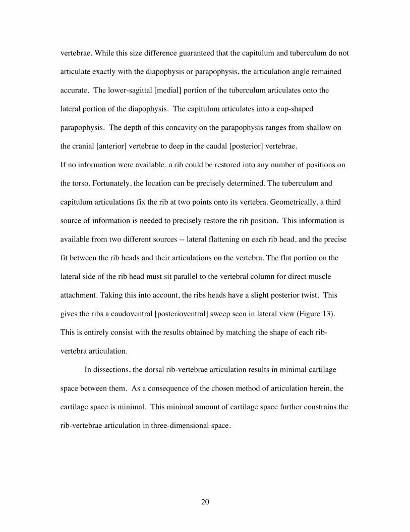
In comparing GMNH-PV101 to BYU 9047 (Figure 20), the torso volume of BYU
9047 is approximately half of GMNH-PV101. The two Camarasaurus specimens were
scaled to be the same size, and the body outline was traced at dorsal ribs 5/6, which was
found to be the widest part of the torso. GMNH-PV101 torso volume included the
sternals, so BYU 9047's volume was constructed as if the sternals were also present.
31
Figure 20. Comparison of restored torso volume between A) BYU 9047 and B) GMNH-PV101 C) Diagramatic representation of the resulting volume of the two Camarasaurus specimens. The light gray circle represents GMNH-PV101, and the dark gray circle represents BYU 9047.
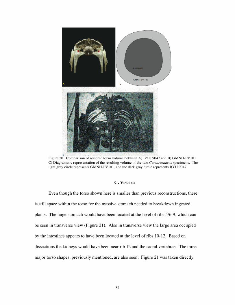
C. Viscera
Even though the torso shown here is smaller than previous reconstructions, there
is still space within the torso for the massive stomach needed to breakdown ingested
plants. The huge stomach would have been located at the level of ribs 5/6-9, which can
be seen in transverse view (Figure 21). Also in transverse view the large area occupied
by the intestines appears to have been located at the level of ribs 10-12. Based on
dissections the kidneys would have been near rib 12 and the sacral vertebrae. The three
major torso shapes, previously mentioned, are also seen. Figure 21 was taken directly

32
beneath dorsal vertebrae 2, so the splay of the cranial [anterior] ribs is a result of the
picture angle.
Figure 21. Camarasaurus torso seen in ventral view. Picture was taken beneath dorsal vertebrae 2, and the resulting angle caused the anterior ribs to appear artificially splayed. The area for the gastrointestinal tract would be inferior to ribs 10-12, the stomach inferior to ribs 5/6-10, and the kidneys were located between dorsal rib 12 and the sacrals.
II. Muscle Reconstruction
Based upon dissections and examination of the rib surfaces on BYU 9047, the
writer believes Camarasaurus had three intercostal muscles, as in modern Alligator
mississippiensis and Iguana iguana. Note that the chicken possesses only two groups of
intercostal muscles. While the present sample is too small to make a firm conclusion, the
writer suggests birds lost the mid-intercostal set as they acquired a highly specialized
breathing mechanism. This mechanism employs the intercostals musculature. Hence their
intercostal condition is less relevant to sauropod musculature. The three-intercostal
condition is found in two different groups of modern diapsid reptiles. In short, the writer
33
suggests that the three-intercostal condition is primitive for diapsids. In keeping with the
assumed basal characteristics, the writer modeled Camarasaurus with the same three
intercostals. Interpretation of probable muscle scars on the ribs of BYU 9047 support
this hypothesis.
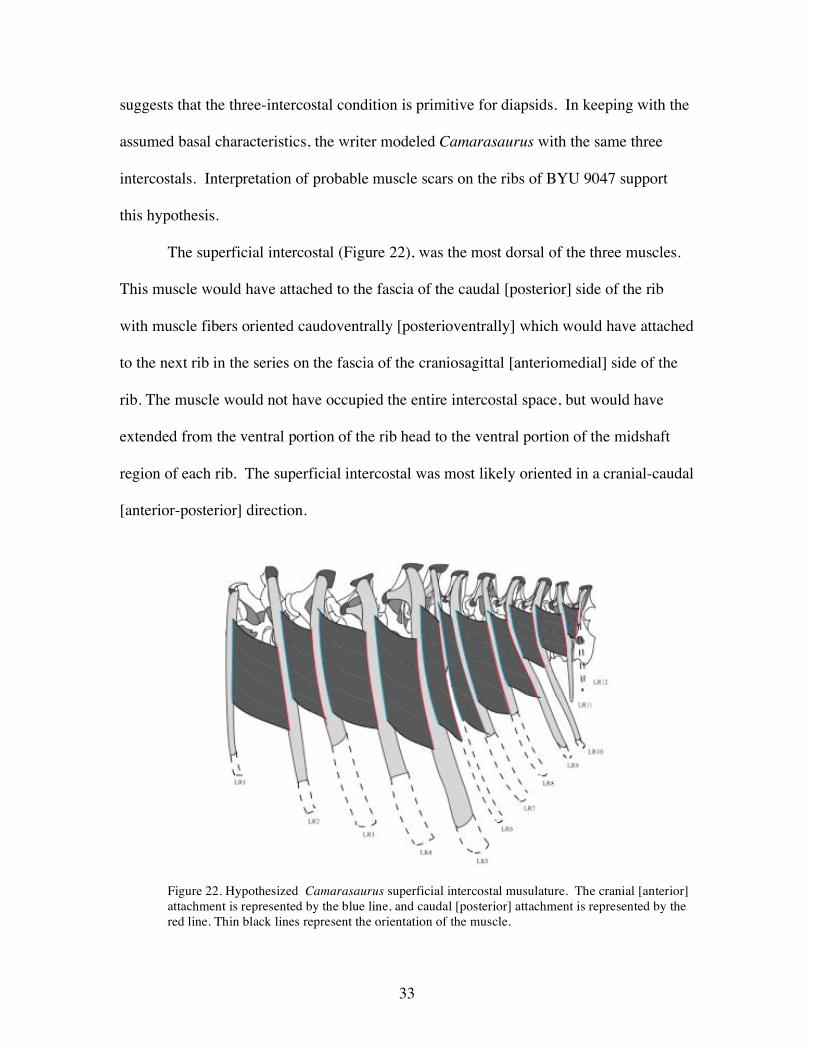
The superficial intercostal (Figure 22), was the most dorsal of the three muscles.
This muscle would have attached to the fascia of the caudal [posterior] side of the rib
with muscle fibers oriented caudoventrally [posterioventrally] which would have attached
to the next rib in the series on the fascia of the craniosagittal [anteriomedial] side of the
rib. The muscle would not have occupied the entire intercostal space, but would have
extended from the ventral portion of the rib head to the ventral portion of the midshaft
region of each rib. The superficial intercostal was most likely oriented in a cranial-caudal
[anterior-posterior] direction.
Figure 22. Hypothesized Camarasaurus superficial intercostal musulature. The cranial [anterior] attachment is represented by the blue line, and caudal [posterior] attachment is represented by the red line. Thin black lines represent the orientation of the muscle.

34
The mid-intercostal (Figure 23), would have been located between the superficial
and the deep intercostal. This muscle would have attached to the fascia of the
craniosagittal [anteriomedial] side of the rib with muscle fibers oriented caudoventrally
[posterioventrally] and it would have attached to the next rib in the series on the fascia of
the craniolateral [anteriolateral] side of the rib. The muscle extends beneath the cranial
[anterior] rib to the top of the caudal [posterior] rib. Similar to the superficial muscle, the
mid-intercostal does not occupy the entire intercostal space, but would have extended the
same distance as the superficial. The mid intercostal was most likely oriented in a
cranial-caudal [anterior-posterior] direction.
Figure 23. Hypothesized Camarasaurus mid-intercostal musculature. The cranial [anterior] attachment is represented by the blue line, and the caudal [posterior] attachment is represented by the red line. Thin black lines represent the orientation of the muscle.
The deep intercostal (Figure 24), is the most ventral of the three intercostals. This
muscle is believed to have attached to the fascia of the interior of the craniosagittal
[posteriomedial] side of the rib, and would have attached to the next rib in the series on

35
the fascia of the ventral portion of the mid-sagittal [medial] side of the rib. The muscle
would have extended beneath the originating rib and continuing beneath the cranial
[anterior] rib to the attachment site on the middle of the sagittal [medial] side. This
muscle would not have occupied the entire intercostal space, but would have extended
from the midshaft to the ventral end of each rib. The deep intercostal was most likely
oriented in the cranial-caudal [anterior-posterior] direction, or perpendicular to the
superficial and mid-intercostal.
Figure 24. Hypothesized Camarasaurus deep intercostal muscle. The cranial [anterior] attachment is represented by the red line, and caudal [posterior] attachment is represented by the blue line. Thin black lines represent the orientation of the muscle.
One difference between the alligator, iguana, and Camarasaurus is that former
two possess a cartilaginous (usually non-ossified) uncinate process on the thoracic ribs.
Uncinates have never been reported on any sauropod fossil. In modern crocodilians,
uncinates serve as the origination for the obliquus abdominis externus, which is a flexor

36
muscle responsible for propulsive movement (Reese, 1915). If sauropods possessed
uncinate processes, they were almost certainly non-ossified cartilage. Interestingly, the
intercostal musculature suggested herein suggests that sauropods may have had such
uncinates. When all three intercostal muscle sets are placed together (Figure 25), a bare
space exists on each rib in the position where an uncinate process could have existed.
This hypothesis deserves further investigation.
Figure 25. Complete intercostal muscle reconstruction for Camarasaurus. Reconstruction contains all three sets of intercostal muscles. The light blue line on the caudal [posterior] edge of each rib represents possible sites of non-ossified uncinate processes.
III. Biomechanical Implications
A. Dorsal Vertebrae The dorsal vertebrae column in sauropods have been depicted with varying
degrees of curvature (Figure 16) (McIntosh et al., 1996b; Borusk-Bialynicka, 1977;
Bellmann et al., 2005; and Schwartz, et al., 2005). Naturally, the curve in the dorsal

37
series plays an important role in determining the angle of the cervical series. The upward
flexion in the cranial [anterior] dorsals also plays an important role in lateral flexion of
the neck (Parrish & Stevens, 2000).
Stevens and Parrish (1999) used DinoMorph to argue that Diplodocus' and
Apatosaurus' neutral neck position close to horizontal. They used the shape of the
cervical prezygopophyses and postzygapophyses to reconstruct a curve for their sauropod
necks. Their results show dorsals 1-3 forming a 30-35° upward curve. Despite the
present writer’s difficulty with the vertebrae in the CEU specimen, this fossil
demonstrates at least a slight upward curve in the same part of the dorsal series. Since the
neck was mounted upon the forward part of the dorsal series, even a perfectly straight
Camarasaurus neck would have been held as much as 30 -40 degrees above the horizonal.
The upward curve in the cranial end of the dorsal series, shown here, would have served
as a smooth transition between the cervicals and dorsals. There is therefore no need to
hypothesize a sharp angle between the neck and the torso.
The orientation and shape of the articular facets on zygopophyses can reveal the
degree and direction of movement between vertebrae. Using this approach, dorsals 1-3
show an amazing amount of horizontal and modest vertical movement. The
zygapophyses in dorsals 1-3 are broad and flat, with the articulating surface very wide
allowing for a great amount of movement (Figure 26). The zygapophyses are able to
slide over one another on their broad surfaces potentially allowing for significant
horizontal movement. Stevens and Parrish (1999) also suggested this type of movement
in the cranial [anterior] dorsals of Diplodocus. Since the zygapophyses of dorsals 1-3 are
flat, they do not limit vertical movement as much as the zygopophyses on dorsals 5-12,

38
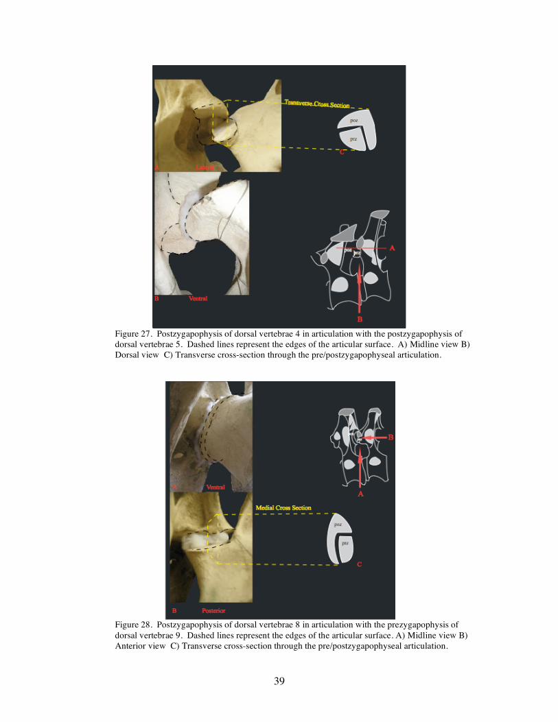
while dorsal 4 is transitional (Figure 27). The postzygapophysis of dorsal 4 is not broad
and approximately half as wide as that on dorsals 1-3. The sagittal [medial] side of the
postzygapophysis curves ventrally at a 90° angle. This prohibits much horizontal
movement. Dorsals 5-12 exhibit the same sagittal -ventral [medial-ventral] curve, thus
prohibiting horizontal movement (Figure 28). Dorsals 5-12 exhibit a lock and key
mechanism, they fit together so tightly that there is little room for flexion, either
horizontal or vertical. Thus, the cranial [anterior] dorsal vertebrae facilitated lateral
movement of the neck, while the remainder of the dorsal series provided a relatively rigid
torso.
Figure 26. Postzygapophysis of dorsal vertebrae 2 in articulation with the prezygapophysis of dorsal vertebrae 3. Dashed lines represent the edge of the articular surface. A) Midline view B) Dorsal view C) Transverse cross-section through the pre/postzygapophyseal articulation.
39
Figure 27. Postzygapophysis of dorsal vertebrae 4 in articulation with the postzygapophysis of dorsal vertebrae 5. Dashed lines represent the edges of the articular surface. A) Midline view B) Dorsal view C) Transverse cross-section through the pre/postzygapophyseal articulation.
Figure 28. Postzygapophysis of dorsal vertebrae 8 in articulation with the prezygapophysis of dorsal vertebrae 9. Dashed lines represent the edges of the articular surface. A) Midline view B) Anterior view C) Transverse cross-section through the pre/postzygapophyseal articulation.

40
B. Scapular position
In most reconstructions, the scapulocoracoid is placed on the torso with the
scapular blade situated 40-60° from horizontal, similar to mammalian posture (McIntosh
et al., 1996b; Borsuk-Bialynicka, 1977; Bellmann et al., 2005; Schwartz et al., 2005), (eg.
Figure 16). However, several workers have noticed a scapular facet on the dorsal ribs
(Stevens & Parrish, 1999; Kozisek & Derstler, 2004) suggesting a more nearly horizonal
orientation for the scapular blade.
Such scapular rib facets are found in various groups of dinosaurs. Besides
sauropods, they are seen in hadrosaurs and at least some neoceratopsians (Stevens &
Parrish, 1999; & Kozisek & Derstler, 2004). The facet is visible as a slight flattened
region on the basal portion of the rib head. The area is rather inconspicuous, which may
be why it has not been noticed until recently. In each case, the facets are seen on dorsal
ribs 1-5, and in some instances rib 6. The facets have a slightly climbing tract moving
caudodorsally [posteriodorsally]. On an articulated torso, the facet tract sits at an angle
of approximately 20-30° from the horizonal (Figure 29). These facets are believed to
correspond to scapular orientation, which would ultimately place the scapula at an angle
of 20-30° instead of the 40-50° (Figure 30)..
41
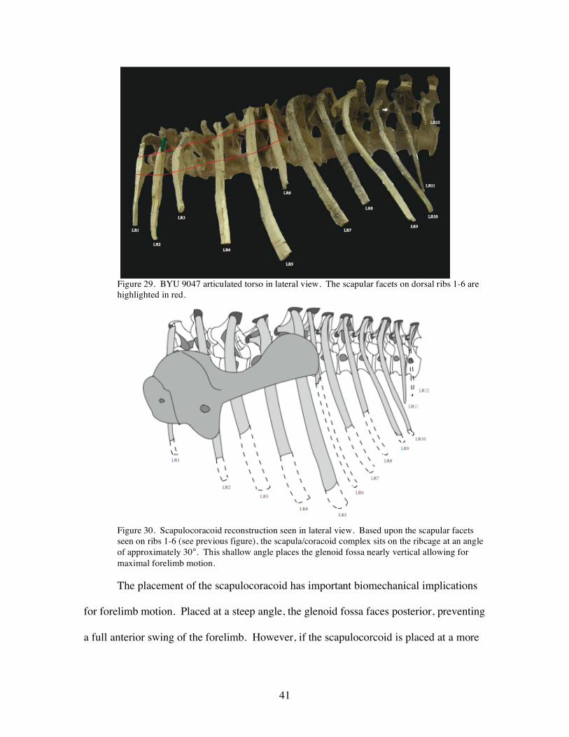
Figure 29. BYU 9047 articulated torso in lateral view. The scapular facets on dorsal ribs 1-6 are highlighted in red.
Figure 30. Scapulocoracoid reconstruction seen in lateral view. Based upon the scapular facets seen on ribs 1-6 (see previous figure), the scapula/coracoid complex sits on the ribcage at an angle of approximately 30°. This shallow angle places the glenoid fossa nearly vertical allowing for maximal forelimb motion.
The placement of the scapulocoracoid has important biomechanical implications
for forelimb motion. Placed at a steep angle, the glenoid fossa faces posterior, preventing
a full anterior swing of the forelimb. However, if the scapulocorcoid is placed at a more

42
shallow angle, the glenoid is oriented more nearly ventral, allowing the forelimb to have
a greater range of forward motion (Wilhite, 2003).
The rib facets may have enhanced the strength of their attachment with the
scapulocoracoid. This is vital for "heavy" quadrapeds (those with columnar forelimbs)
since it aids in the transmission and diffusion of stress. Quite a bit of stress is placed on
the pectoral girdle during normal activity in these very large animals. Proper
transmission of this stress and strain is important to avoid stress buildup in one specific
area causing the area to become weaker. A strong pectoral girdle could help diffuse these
stresses throughout the whole body, and thus lower the total stress put upon the rest of the
skeleton.
Conclusions
Prior to the present study, all sauropods, including Camarasaurus, have been
reconstructed with heavy, bulky, barrel-shaped torso and a relatively straight series of
dorsal vertebrae. However, the work reported herein shows this is not the case, at least in
BYU 9047 and the CEU specimen. The resident position of the CEU vertebrae define a
gentle double curve for the dorsal axial skeleton. This double curve has important
implications for resident neck posture, a topic not investigated in this study.
Combining the CEU results with the ribs from BYU 9047 demonstrate a resulting
torso shape in Camarasaurus that is much more narrow and volumetrically smaller than
all previously reconstructed.
This study is the first to suggest that a sauropod had three sets of intercostal
muscles.

43
The change in the body shape has important implications for pectoral assembly
placement and function. By placing the scapulocoracoid on the facets on the narrower
ribcage, the scapula sits 20-30° from horizontal. Placing the scapulocoracoid at this
shallow angle positions the glenoid fossa subhorizontal. Apparently, the Camarasaurus
forelimb had a greater range of forward motion that previously realized.
In this study, the writer considered sauropod body volume. The next step might be
to look at body mass. Since there is a significant reduction in body volume with this
reconstruction, it is expected that there should be a significant reduction in body mass as
well.
Preliminary inspection of the measurements taken here on each rib suggests that it
should ultimately be possible to confidently identify each rib individually. Such a
capacity would prove to be an invaluable tool both in the field and in mounting
specimens.
Finally, when the results of this study are digitized, they can easily be added to
previous digital sauropod models (Wilhite, 2000; Stevens & Parrish, 1999). Not only
would this improve the models, it will allow them to used to investigate sauropod neck
posture, pectoral girdle positioning, and forelmb motion.

44
Addendum
Upon completion of this study, I conferred with Dr. Ray Wilhite and Dr. Jack
McIntosh about the possibility of what was labeled as dorsal 1 really being cervical 12.
Through discussion, it was realized that dorsal 1 is most likely cervical 11, and what was
labeled as dorsal 2 is really dorsal 1, and so forth. In reality only 11 dorsals were present,
and 1 cervical. In the future, the study should be rechecked with a more complete
specimen to ensure the accuracy of this study. The general overall look of the torso
should not change that drastically, however there might be a slight change to the
individual angle of articulation between the dorsal vertebrae and its associated rib. The
major change might occur in the dorsal vertebrae curve. The curve in dorsals 1-4 might
be more acute or more obtuse.

45
References
Anderson, J. F., A. Hall-Martin, & D. A. Russell. 1985. Long-bone circumference and
weight in mammals, birds, and dinosaurs. Journal of Zoology: 53-61.
Bellman, A., T. Suthau, S. Stoinski, A. Friedrich, O. Hellwich, & H. -Ch Gungu. 3-D
modeling of dinosaurs. 7th Conference on Optical 3-D Measurement Techniques,
3-5 October 2005.
Bonnan, M. F. 2000. The presence of a calcaneum in a Diplodocid sauropod. Journal of
Vertebrate Paleontology 20 (2): 317-323.
Bonnan, M. F. 2003. The evolution of manus shape in sauropod dinosaurs: implications
for functional morphology, forelimb orientation, and phylogeny. Journal of
Vertebrate Paleontology 23 (3): 595-613.
Borsuk-Bialynicka, M. 1977. A new camarasaurid sauropod Opisthocoelicaudia
skarzynskii, gen, n., sp.n. from the upper Cretaceous of Mongolia. Palaeontologia
Polonica 37(1977): 5-64.
Carvalho, I. S., L. S. Avilla, & L. Salgado. 2003. Amazonsaurus maranhensis gen. et sp.
Nov. (Sauropoda, Diplodocoidea) from the Lower Cretaceous (Aptian-Albian) of
Brazil. Cretaceous Research 24: 697-713.
Claessens, L. P. A. M. 2004. Dinosaur gastralia; origin, morphology, and function.
Journal of Vertebrae Paleontology 24(1): 89-106.
Clavo, J.O. 1999. Dinosaurs and other vertebrates of the Lake Ezequiel Ramos Mexia
area, Neuguen-Patagonia, Argentina. In Y. Tomida, T. H. Rich, and P. Vickers-
Rich (eds.) Proceedings of the Second Gondwanan Dinosaur Symposium.
National Science Museum, Tokyo, 15: 13-45.

46
Campos, D. A., A. W. A. Kellner. 1999. On some sauropod (Titanosauridae) pelves
from the continental Cretaceous of Brazil; in Y. Tomida, T. H. Rich, and P.
Vickers-Rich (eds) Proceeding of the Second Gondwanan Dinosaur Symposium.
Natural Science Museum Monograph 15: 143-166.
Converse, H. H. Jr. 1984. Chapter 7: Casting Techniques. In Handbook of Paleo-
Preparation Techniques. Florida State Museum, University of Florida, pgs. 77-
110.
Dodson, P. 1991. Life styles of the huge and famous. Natural History 100(12): 30-34.
Farmer, C. G., and D. R. Carrier. 2000. Pelvic aspiration in the American alligator
(Alligator mississippiens). The Journal of Experimental Biology 203: 1679-1687.
Filla, B. J., and P. D. Redman. 1994. Apatosaurus yahnahpin: a preliminary description
of a new species of Diplodocid dinosaur from the Late Jurassic Morrison
Formation of Southern Wyoming, the first sauropod dinosaur going with a
complete set of “belly ribs”. Forty-Fourth Annual Field Conference- Wyoming
Geological Association Guidebook 44: 159-178.
Goodwin, M. B., and D. S. Chaney. 1994. Chapter 10: molding, casting and painting, p.
235-271. In P. Leggi, and P. May eds. Vertebrate Paleontological Techniques.
Cambridge University Press, Cambridge.
Henderson, D. M. 1999. Estimating the masses and centers of extinct animals by 3-D
mathematical slicing. Paleobiology 25(1): 88-106.
Kozisek, J. M., and K. Derstler. 2004. Scapular facets on the dorsal ribs of sauropod and
neoceratopsian dinosaurs. Journal of Vertebrate Paleontology 24(supplement to
3): 80A.

47
McIntosh, J. S., W. E. Miller, K. L. Stadtman, and D. D. Gillette. 1996a. The osteology
of Camarasaurus lewisi (Jensen, 1988). Geological Studies 41: 73-116.
------------, C. Miles, K. Cloward, and R. Jeffrie. 1996b. A new nearly complete skeleton
of Camarasaurus. Bulletin of Gunma Museum of Natural History 1:1-87.
Paul, G. 1988. The Brachiosaur giants of the Morrison and Tendaguru with a description
of a new subgenus, Giraffatitan, a comparison of the world's largest dinosaurs.
Hunteria 2(3): 1-14.
---------, and P. Christiansen. 2000. Forelimb posture in Neoceratopsian dinosaurs:
implications for gait and locomotion. Paleobiology 26(3): 450-465.
Parrish, J. M., and K. A. Stevens. 2002. Rib angulation, scapular position, and body
profiles in sauropod dinosaurs. Journal of Vertebrate Paleontology
22(Supplement to number 3): 95A.
-------------, 2000. Technical comment. Science 287: 547b.
Reese, A. M. 1915. The Alligator and Its Allies. The Knickerbocker Press, New York.
Rigby, J.K., and D. L. Clark. 1965. Section E: Cassting and Molding. Kummel, B ed. In
The Handbook of Paleontological Techniques. Pgs. 389-411.
Rixon, A.E. 1976. Chapter 9: Casting. In Fossil Animal Remains. Athlone Press,
University of London, pgs 193-229.
Romer, A. S. 1923. The pelvic musculature of saurischian dinosaurs. Bulletin of the
American Museum of Natural History XLVIII: 605-617.
Schwarz, D., C. A. Meyer, & E. Frey. New frontiers in reconstructing sauropod
dinosaurs. 3rd Swiss Geoscience Meeting, Zurich, 18-19 November 2005

48
Seebacher, F. 2001. A new method to calculate allometric length-mass relationships of
dinosaurs. Journal of Vertebrate Paleontology 21(1): 51-60.
Stevens, K. A., and P. J. Parrish. 1999. Neck postures and feeding habits of two Jurassic
sauropod dinosaurs. Science 284(5415): 798-801.
Troyer, A. D., P. A. Kirkwood, and T. A. Wilson. 2005. Respiratory action of the
intercostal muscles. Physiology Review 85: 717-756.
Weaver, J. C. 1983. The improbable endotherm: the energetics of the sauropod dinosaur
Brachiosaurus. Paleobiology 9(2): 173-182.
Wilhite, Ray. 2000. Ontogenetic variation in the appendicular skeleton of the genus
Camarasaur. Brigham Young University, M.S., 30pp.
---------------. 2003. Biomechanical Reconstruction of the Appendicular Skeleton in
Three North American Jurassic Sauropods. Dissertation, Louisiana State
University, Baton Rouge, Louisiana, USA.

49
APPENDIX A: Dorsal Rib Description (Figures A1 and A2)
Camarasaurus has twelve pairs of dorsal ribs each articulating to their
corresponding dorsal vertebrae. The entire left series of ribs in BYU 9047 is present, and
was found articulated; whereas, the right side has only numbers 1, 2, rib head fragments
of 3, 5, 6, 7, 9, 11, and 12 were found disarticulated (McIntosh et al. 1996).
Distinguishing rib features are present on all ribs; however, measurements for
each feature vary from rib to rib. All dorsal ribs have both a tuberculum and a capitulum.
The tuberculum is the most dorsal process of the rib head which articulates to the
diapophysis on its corresponding dorsal vertebrae. The capitulum is the ventral process of
the rib head which articulates to the parapophysis on its corresponding dorsal vertebrae.
The size and shape of the tuberculum and capitulum varies with each rib. The lateral side
of the capitulum is wider than the sagittal [medial], and tapers into the articular surface in
ribs 1-4, but does not taper in ribs 5-12. The articular surfaces for the tuberculum and
capitulum are the facies articularis capitis costae. Every tuberculum and capitulum
exhibits a facies articularis capitis, however the size and shape varies. The facies
articularis capitis always exhibits a rugose cartilaginous pattern which can also be seen
on the ends of all sauropod limb bones. The angle formed between the tuberculum and
the capitulum is the angulus costae, and the angle itself varies, however the angle
becomes more obtuse with the caudal [posterior] ribs. On ribs 1-8 the lateral margin of
the shaft extends somewhat further laterally than the lateral margin of the proximal end,
which results in a bowed shape in the dorsal view (eg. Figures A3e, A4e, A5e, A6e, A7e,
A8e, A9c, & A10e). The neck of the rib, where the tuberculum/capitulum junction meets
the shaft of the rib is the collum costae, and is present in all ribs. On the cranial [anterior]

50
side of each rib is the crista capitis costae, which is the crest between the tuberculum and
capitulum. A crista capitis costae are present in all ribs, but becomes less pronounced on
the more caudal [posterior] the ribs. Also, in BYU 9047, not all ribs show this feature;
and this may be due to diagenic alteration. Also on the cranial [anterior] side of all ribs
are the cristae colli costae, which were formerly called prominent tuberculum ridges
(McIntosh et al 1996). This ridge runs from the dorsal tuberculum to about two-thirds of
the way down the shaft of the rib. The crista colli costae is the attachment site for the
cranial [anterior] costotransverse ligament, which aids in keeping the spine stable. The
height of the crista colli costae varies from rib to rib. On the caudal [posterior] side of all
ribs is the prominent caudal [posterior] tuberculum ridge, which also runs from the dorsal
tuberculum to about two-thirds of the way down the shaft. Cristae colli costae are present
on ribs 1-7, hardly noticeable in rib 8, and not present in ribs 9-12. The cristae colli
costae are not as well developed in ribs 4-7 and appears to originate more ventrally. The
cristae colli costae can be seen in dorsal view in ribs 1-3, are difficult to see in ribs 4-7,
and cannot be seen in ribs 8-12. The height of the prominent caudal [posterior]
tuberculum ridge varies from rib to rib. Between the prominent caudal [posterior]
tuberculum ridge and the rib head is the sulcus costae. This depression ranges from
shallow to deep depending on the height of the prominent caudal [posterior] tuberculum
ridge. Ribs 1-3 have a 90° angle on the lateral edge of the sulcus costae, ribs 4-6 have a
near 90° angle, and ribs 7-12 have a gradually shallowing sulcus costae the further
caudally [posteriorly]. The intercostal nerves and vessels lie in the sulcus costae.
The shaft of the rib is referred to as the corpus costae, and is present on all ribs.
However, the length, width, and curvature vary from rib to rib. In all ribs the corpus
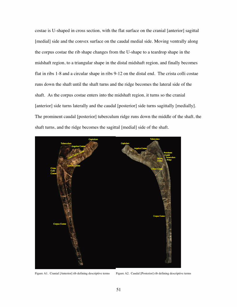
51
costae is U-shaped in cross section, with the flat surface on the cranial [anterior] sagittal
[medial] side and the convex surface on the caudal medial side. Moving ventrally along
the corpus costae the rib shape changes from the U-shape to a teardrop shape in the
midshaft region, to a triangular shape in the distal midshaft region, and finally becomes
flat in ribs 1-8 and a circular shape in ribs 9-12 on the distal end. The crista colli costae
runs down the shaft until the shaft turns and the ridge becomes the lateral side of the
shaft. As the corpus costae enters into the midshaft region, it turns so the cranial
[anterior] side turns laterally and the caudal [posterior] side turns sagittally [medially].
The prominent caudal [posterior] tuberculum ridge runs down the middle of the shaft, the
shaft turns, and the ridge becomes the sagittal [medial] side of the shaft.
Figure A1. Cranial [Anterior] rib defining descriptive terms Figure A2. Caudal [Posterior] rib defining descriptive terms

52
LEFT RIB 1 (Figure A3)
The preserved portion of left rib 1 (LR1) consists of a complete rib head, with
both a capitulum and tuberculum. All dimensions for LR1 are in Table A1. Even though
the tuberculum is not complete, the angulus costae is still present. Due to the great
length of the tuberculum, as well as the capitulum, the greatest capitulum-tuberculum
length is in LR1. The proximal end of the tuberculum is cup-shaped. In cross section the
tuberculum is square-shaped. The rib head has a typical bowed shape.
The articular surface of the capitulum is mostly complete, however it is not as
well preserved as the tuberculum. The caudal [posterior] surface of the capitulum is
convex and the cranial [anterior] side is more flat giving the capitulum a U-shape in cross
section, which can be seen in dorsal view (Figure A3e).
The corpus costae is about 30% complete. In dorsal view (Figure A3e), the
corpus costae is straight, showing little to no curve, forming a rather straight line with the
tuberculum.

53
LEFT RIB 2 (Figure A4)
The preserved portion of left rib 2 (LR2), consists of a complete rib head, with
both a capitulum and tuberculum. All dimensions for LR2 are seen in Table A1. As
mentioned in McIntosh et al (1996), the crista colli costae is more developed than LR1.
The well-developed crista colli costae on this side gives the tuberculum a v-shape in cross
section which can be seen in dorsal view (Figure A4e). The overall length of the
tuberculum is much shorter than in LR1. In caudal [posterior] view (Figure A4b & d) the
proximal end of the tuberculum is cup shaped, similar to LR1.

54
In cranial [anterior] view (Figure A4a & c), the capitulum is complete. The
cranial [anterior] and caudal [posterior] surfaces are relatively flat giving the capitulum
an I shape in cross section, which can be seen in dorsal view (Figure A4e). Unlike LR1,
the ventral side does not curve inwards, but more cranial [anterior] towards the junction
of the capitulum to the rib head, and instead is straight.
The corpus costae is approximately 70% complete. The shaft of the rib is slightly
bowed, which can be seen in dorsal view (Figure A4e), the shaft does not form a straight
line with the tuberculum, and instead turns in more caudal [posterior].

55
LEFT RIB 3 (Figure A5)
The preserved portion of left rib 3 (LR3), consists of an incomplete rib head, with
only the capitulum. All dimensions for LR3 are seen in Table A1. In cranial [anterior]
view (Figure A5a & c), the crista colli costae is present, even though there is no
preserved tuberculum.
The overall length of the capitulum is longer than LR2. The lateral side of the
capitulum is tapered, however, not nearly as much as LR1 & 2. The cranial [anterior]
surface shape resembles half of a teardrop. The cross section shape of the capitulum is
similar to a teardrop, which can be seen in dorsal view (Figure A5e).
The corpus costae on LR3 is about 30% complete. The preserved shaft is
relatively straight, running perpendicular to where the tuberculum was.

56
LEFT RIB 4 (Figure A6)
The preserved portion of left rib 4 (LR4), consists of a complete rib head, with
both capitulum and tuberculum. All dimensions for LR4 are seen in Table A1. The total
length of the tuberculum is greatly reduced as compared to LR3. This results in little/no
slope at the angulus costae and a decreased capitulum-tuberculum length. The capitulum
is two times the length of the tuberculum. In caudal [posterior] view (Figure A6b & d),
the proximal end tuberculum is bowl shaped and has widened out as compared to LR1-3.
In cross section the tuberculum is shaped like an oval letter L, giving the rib head a
bowed shape.

57
The lateral side of the capitulum is tapered and is more pronounced in the
preceding ribs (Figure A6a-d). The diameter of the capitulum has slightly increased as
compared to LR1-3. The capitulum has an expanded teardrop shape, which can be seen in
dorsal view (Figure A6e). The ventral side of the capitulum is more rounded than the
cranial [anterior] side, and in dorsal view (Figure A6e), the capitulum is turned more
cranially [anteriorly].
The corpus costae is complete. The preserved corpus costae extends perpendicular
from where the tuberculum would have been.

58
LEFT RIB 5 (Figure A7)
The preserved portion of left rib 5 (LR5), consists of a complete rib head, with
both capitulum and tuberculum. All dimensions for LR5 are seen in Table A1. In cranial
[anterior] and caudal [posterior] views (Figure A7a-d), the total length as well as the
diameter of the tuberculum is more decreased than LR4. This decreased length results in
little/no slope at the angulus costae and reduces the capitulum-tuberculum length. The
capitulum is twice the length as the tuberculum. In caudal [posterior] view (Figure A7b &
d), the proximal end of the tuberculum is bowl shaped, since the walls of the tuberculum
has widened as compared to previous ribs. In cross section the tuberculum is shaped like
a widened L. In dorsal view (Figure A7e), the tuberculum has straightened out slightly as
compared to previous ribs.
The capitulum also curves more ventrally than previous ribs. The overall length
of the capitulum is greater than LR4, however the diameter has decreased slightly. The
capitulum has a D-shape, which can be seen in dorsal view (Figure A7e). In dorsal view
(Figure A7e), the capitulum is turned more caudally [posteriorly].
The corpus costae is not complete, and is in two sections. The main section is
attached to the rib head, and the second section contains bite marks and does not fit onto
the main section. The preserved first section is relatively straight, running perpendicular
from where the tuberculum was.
The secondary shaft is not of great length, and belongs somewhere in the midshaft
region. On the cranial [anterior] side (Figure A7f), three bite marks are present. The
secondary section has a slight sagittal [medial] curve to it, as seen in dorsal view (Figure
A7h).

59
60
LEFT RIB 6 (Figure A8)
The preserved portion of left rib 6 (LR6), consists of a complete rib head, with
both capitulum and tuberculum. All dimensions for LR6 are seen in Table A1. In cranial
[anterior] and caudal [posterior] views (Figure A8a-d), the total length as well as
diameter of the tuberculum is more reduced than previous ribs. This decreased length
results in little/no slope at the angulus costae. However, unlike the previous rib, the
capitulum also lengthens, increasing the capitulum-tuberculum length. The capitulum is
almost twice the length as the tuberculum. In caudal [posterior] view (Figure A8b & d),
the proximal end tuberculum is bowl shaped. The tuberculum is triangular shaped in
cross section.
The overall length of the capitulum is greater than LR5, but the diameter is
comparable. It has a D shape which can be seen in dorsal view (Figure A8e). In dorsal
view, the capitulum is turned more caudally [posteriorly].
The corpus costae is not complete, and is in two sections. The main section is
attached to the rib head, and the second section does not articulate with the main section.
Of the preserved main corpus costae, the shaft is curved sagittally [medially], giving the
rib a bowed shape, as seen in dorsal view (Figure A8e).
The secondary corpus costae is not of great length, and belongs in the ventral
midshaft region. This secondary section of midshaft has a slight sagittal [medial] curve to
it, as seen in dorsal view (Figure A8h).

61

62
LEFT RIB 7 (Figure A9)
The preserved portion of left rib 7 (LR7), consists of an incomplete rib head, with
only a nearly complete capitulum. All dimensions for LR7 are seen in Table A1. The
capitulum has a D shape, which can be seen in dorsal view (Figure A9c).
The corpus costae is not complete, and is in three sections. A small portion is
attached rib head, the second section does not articulate with the main section, and the
third does not articulate to either piece. Of the preserved main shaft, it is curved sagittally
[medially], giving the rib a bowed shape, as seen in dorsal view (Figure A9f).
The secondary corpus costae is not of great length, and belongs in the midshaft
region. Overall, the secondary section of midshaft has a slight sagittal [medial] curve to
it, which can be seen in dorsal view (Figure A9i).
The third shaft section is not of great length, and belongs in the ventral region.
Overall, the third section has a slight sagittal [medial] curve to it, which can be seen in
dorsal view (Figure A9l).

63

64
LEFT RIB 8 (Figure A10)
The preserved portion of Left Rib 8 (LR8), consists of a complete rib head, with
both capitulum and tuberculum. All dimensions for LR8 are seen in Table A1. The total
length of the tuberculum is more reduced than in all previous ribs, however the diameter
is greater than LR6 (last rib with a preserved tuberculum). The tuberculum rises slightly
from the rib head, unlike LR5-6, and a 90° slope is present at the angulus costae. The
capitulum is shorter in length, and the length between the capitulum-tuberculum is
comparable to LR6. The capitulum is almost twice the length as the tuberculum. The
cranial [anterior] side of the articular surface of the tuberculum (Figure A10a & c),
extends more cranially [anteriorly] than the main body of the tuberculum. In cross section
the tuberculum is round.
The lateral side of the capitulum is of comparable size as the medial, not tapering
like the previous ribs, curves dorsally, and is turned caudally [posteriorly] (Figure A10a-
d). The overall length and diameter of the capitulum is shorter than LR6-7. The
capitulum has an oval shape, which can be seen in dorsal view (Figure A10e).
The corpus costae is not complete. Of the preserved main shaft, it is curved
sagittally [medially], giving the rib a bowed shape, which can be seen in dorsal view
(Figure A10e).

65
LEFT RIB 9 (Figure A11)
The preserved portion of left rib 9 (LR9), consists of a complete rib head, with
both capitulum and tuberculum. All dimensions for LR9 are seen in Table A1. The total
length of the tuberculum is slightly reduced than in all previous ribs, yet is slightly
greater than LR8. The tuberculum rises somewhat from the rib head, and an obtuse angle
results at the angulus costae. The capitulum elongates, and the length between the
capitulum-tuberculum is comparable to LR8. The capitulum is almost four times the
length as the tuberculum. In caudal [posterior] view (Figure A11b & d), the articular
surface of tuberculum is turned slightly caudolaterally [posteriolaterally] and the
66
proximal end is flattened, since the walls have widened drastically. The cranial [anterior]
side of the articular surface of the tuberculum (Figure A11a & c), extends more cranially
[anteriorly] than the main body of the tuberculum, however the posterior side extends
further than the main body. In cross section the tuberculum is D-shaped.
The overall length and diameter of the capitulum is slightly larger than LR8. The
articular surface widens cranially [anteriorly] in an exaggerated convex fashion. In
caudal [posterior] view (Figure A11b & d), the capitulum is turned more caudolaterally
[posteriolaterally] than previous ribs. The capitulum is D shaped similar to the
tuberculum, which can be seen in dorsal view (Figure A11e).
The corpus costae is not complete and is in two sections. The first section is
attached to the rib head, and the second section does not attach onto the main section. Of
the preserved main section, it is curved caudosagittally [posteriomedially], giving the rib
a bowed shape, which can be seen in dorsal view (Figure A11e).
The secondary shaft consists of the midshaft region and most of the ventral
portion; however, the terminus is not present. Overall, the secondary section of midshaft
has a slight sagittal [medial] curve to it, which can be seen in dorsal view (Figure A11h).

67
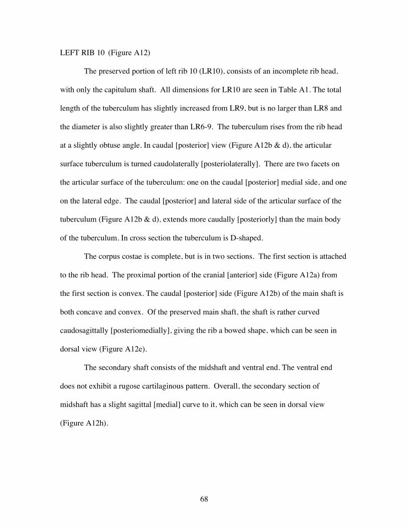
68
LEFT RIB 10 (Figure A12)
The preserved portion of left rib 10 (LR10), consists of an incomplete rib head,
with only the capitulum shaft. All dimensions for LR10 are seen in Table A1. The total
length of the tuberculum has slightly increased from LR9, but is no larger than LR8 and
the diameter is also slightly greater than LR6-9. The tuberculum rises from the rib head
at a slightly obtuse angle. In caudal [posterior] view (Figure A12b & d), the articular
surface tuberculum is turned caudolaterally [posteriolaterally]. There are two facets on
the articular surface of the tuberculum: one on the caudal [posterior] medial side, and one
on the lateral edge. The caudal [posterior] and lateral side of the articular surface of the
tuberculum (Figure A12b & d), extends more caudally [posteriorly] than the main body
of the tuberculum. In cross section the tuberculum is D-shaped.
The corpus costae is complete, but is in two sections. The first section is attached
to the rib head. The proximal portion of the cranial [anterior] side (Figure A12a) from
the first section is convex. The caudal [posterior] side (Figure A12b) of the main shaft is
both concave and convex. Of the preserved main shaft, the shaft is rather curved
caudosagittally [posteriomedially], giving the rib a bowed shape, which can be seen in
dorsal view (Figure A12e).
The secondary shaft consists of the midshaft and ventral end. The ventral end
does not exhibit a rugose cartilaginous pattern. Overall, the secondary section of
midshaft has a slight sagittal [medial] curve to it, which can be seen in dorsal view
(Figure A12h).

69

70
LEFT RIB 11 (Figure A13)
The preserved portion of left rib 11 (LR11), consists of an incomplete rib head,
with just the tuberculum. All dimensions for LR11 are seen in Table A1. In cranial
[anterior] and caudal [posterior] views (Figure A13a-d), the total length and diameter of
the tuberculum is comparable to LR10. The tuberculum rises from the rib head at a
slightly obtuse angle, but does not rise as high as LR10. In caudal [posterior] view
(Figure A13b & d), the articular surface tuberculum is turned slightly caudolaterally
[posteriolaterally]. There are two facets on the articular surface of the tuberculum: one on
the caudal [posterior] edge, and one on the cranial [anterior] edge. Both the caudal
[posterior] and cranial [anterior] side of the articular surface on the tuberculum (Figure
A13c-d), extends further than the main body of the tuberculum. In cross section the
tuberculum is V-shaped.
The preserved corpus costae on is attached to the rib head, and is nearly 40%
complete, and no sagittal [medial] curve is present. No midshaft or ventral portion is
present.

71
LEFT RIB 12 (Figure A14)
The preserved portion of left rib 12 (LR12), consists of an incomplete rib
head, with only the capitulum which has a large pathology. All dimensions for LR12 are
seen in Table A1. In cranial [anterior] and caudal [posterior] views (Figure A14a-b), the
total length of the capitulum is twice that of LR11, and the diameter is also greatly
increased. However, this increase is caused by pathology, and is not a true artifact of the
original, pre-pathologic rib. The capitulum rises from the rib head at an obtuse angle.
There are two facets on the articular surface: one on the caudal [posterior] edge, and one
on the cranial [anterior] edge. All sides of the capitulum extend further than the body of
the capitulum, but this is attributed the pathology (Figure A14a-b).

72
The corpus costae is not complete and is in three sections. The first section is
attached to the rib head. The diameter has been greatly reduced than all previous ribs.
The second section belongs to the midshaft, and does not attach to the proximal
portion on the rib head. There is a slight sagittal [medial] curve to this section.
The third section belongs to the ventral portion, and does not attach to the second
section. A slight sagittal [medial] curve is noticed in dorsal view (Figure A14i).

73
RIGHT RIB 1 (Figure A15)
The preserved portion of right rib 1 (RR1), consists of a complete rib head, with
both capitulum and tuberculum. All dimensions for RR1 are seen in Table A1. Due to
the great lengths of the tuberculum and capitulum, the greatest capitulum-tuberculum
length is noticed in this rib. The proximal end of the tuberculum is cupped shaped. In
cross section the tuberculum is shaped like an oval letter L.
The cranial [anterior] surface of the capitulum is slightly convex, and rounds out
further as it reaches the articular surface. The capitulum a round shape in cross section,
which is seen in dorsal view (Figure A15e).
The corpus costae is in two sections. The main section is attached to the rib head.
In dorsal view (Figure A15e), the shaft itself is rather straight, showing no curve, forming
a straight line with the tuberculum.

74
The secondary shaft is of substantial length, and belongs to the midshaft and
ventral region. This section of midshaft has a no curve to it, similar to the proximal
portion described above (Figure A15h).

75
RIGHT RIB 2 (Figure A16)
The preserved portion of right rib 2 (RR2), consists of an incomplete rib head,
with only the tuberculum. All dimensions for RR2 are seen in Table A1. Similar to LR2,
the crista colli costae is more developed than in RR1. The overall length of the
tuberculum is slightly shorter than in RR1. In caudal [posterior] view (Figure A16b) the
proximal end of the tuberculum is cupped shaped, similar to RR1.
The corpus costae is in two sections. The first section belongs to the proximal
shaft, but does not attach onto the rib head, however, there is not much missing in
between the two sections, since the developed sagittal [medial] and lateral ridges on the
caudal [posterior] side are still noticed (Figure A16d-e). There is no sagittal [medial] or
lateral curve to this section.
The second section belongs to the midshaft region, and does not attach to the
proximal shaft section. There is no sagittal [medial] or lateral curve to this section

76

77
RIGHT RIB 3 (Figure A17)
All that is preserved for right rib 3 (RR3) are two small, unidentifiable pieces
belonging to the rib head. Both are pictured in Figure A17. There are no measurements
given.
RIGHT RIB 4
Right rib 4 was not preserved.

78
RIGHT RIB 5 (Figure A18)
The preserved portion of right rib 5 (RR5), consists an incomplete rib head, with
only the tuberculum. All dimensions for RR5 are seen in Table A1. The tuberculum is
reduced in size. In cross section the tuberculum is shaped like an O.
The corpus costae is in two sections. The main section is attached to the rib head.
In dorsal view (Figure A18e) the shaft itself is slightly bowed in the proximal portion,
and straightens out in the midshaft.
The secondary section is of substantial length, and belongs in ventral midshaft –
proximal ventral region. This section of midshaft has a slight curve to it, similar to the
midshaft described above.
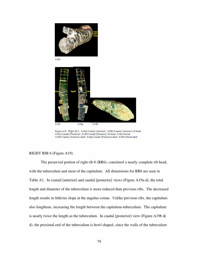
79
RIGHT RIB 6 (Figure A19)
The preserved portion of right rib 6 (RR6), consistsof a nearly complete rib head,
with the tuberculum and most of the capitulum. All dimensions for RR6 are seen in
Table A1. In cranial [anterior] and caudal [posterior] views (Figure A19a-d), the total
length and diameter of the tuberculum is more reduced than previous ribs. The decreased
length results in little/no slope at the angulus costae. Unlike previous ribs, the capitulum
also lengthens, increasing the length between the capitulum-tuberculum. The capitulum
is nearly twice the length as the tuberculum. In caudal [posterior] view (Figure A19b &
d), the proximal end of the tuberculum is bowl shaped, since the walls of the tuberculum

80
have widened out as compared to previous ribs. In cross section the tuberculum is shaped
in a triangular fashion.
The capitulum has a D shape, which can be seen in dorsal view (Figure A19e).
The ventral side of the capitulum is much more rounded than on the cranial [anterior]
side. The capitulum is turned more posterior, which can be seen in dorsal view.
Four sections of the corpus costae are preserved. The first section is of substantial
length and belongs to the proximal – midshaft region. The entire shaft is bowed sagittally
[medially] which can be seen in dorsal view (Figure A19h).
All three other pieces are of inconsequential length, and therefore cannot be
determined exactly where on the shaft they are located. Section piece 2 is pictured in
Figures A19i-k. Section piece 3 is pictured in Plate Figure A19X. Finally, section piece
4 is pictured in Figures A19l-n.

81

82

83
RIGHT RIB 7 (Figure A20)
The only preserved portion for right rib 7 (RR7) is the proximal –midshaft region
of the corpus costae. All dimensions for RR7 are seen in Table A1. The entire shaft is
bowed sagittally [medially], which can be seen in dorsal view (Figure A20c).

84
RIGHT RIB 8 (Figure A21)
The only preserved portion for right rib 8 (RR8) is the corpus costae proximal –
midshaft region. All dimensions for RR8 are seen in Table A1. The entire shaft has little
to no sagittal [medial] curve, which can be seen in dorsal view (FigureA21c).
RIGHT RIB 9 (Figure A22)
The preserved portion of right rib 9 (RR9), consists of an incomplete rib head,
with only the tuberculum. All dimensions for RR9 are seen in Table A1. The greatly
reduced size of the tuberculum is noticed which is seen in cranial [anterior] view (Figure

85
A22a & c). The curve for the rib places the rib head more sagittal [medial] than the
ventral end. In cross section the tuberculum is shaped like a D.
The corpus costae is one piece and is attached to the rib head. In the midshaft
portion, a groove is seen on the sagittal [medial] edge, which may be due to muscle
scaring. The shaft is bowed sagittally [medially], which can be seen in dorsal view
(Figure A22e).
RIGHT RIB 10
There are no preserved elements of right rib 10 (RR10).

86
RIGHT RIB 11 (Figure A23)
The preserved portion of right rib 11 (RR11), consists a complete rib head, with
both tuberculum and capitulum. All dimensions for RR11 are seen in Table A1. The
total length of the tuberculum is comparable to the capitulum, but the diameter could not
be measured due to incompleteness. The tuberculum rises from the rib head at a slightly
acute angle, and little/no slope is noticed at the angulus costae. The ventral edge of the rib
head exhibits a greenstick fracture (Figure A23 a-b). There is to two facet surfaces on the
articular surface of the tuberculum: both on the caudal [posterior] edge, one lateral and
one sagittal [medial]. Both the caudal [posterior] and cranial [anterior] side of the
articular surface of the tuberculum extends further than the main body of the tuberculum.
In cross section the tuberculum is oval shaped.
The capitulum curves slightly sagittally [medially]. The overall length is similar
to the tuberculum. The sagittal [medial] edge is thicker than the lateral, giving the
capitulum a teardrop shape in cross section, which can be seen in dorsal view (Figure
A23c).
Three pieces of the corpus costae are preserved. The first piece is of unsubstantial
length, but most likely belongs to the proximal portion right below the greenstick fracture
(Figures 23d-f). The second piece (Figures A23g-i) is also of unsubstantial length, and
belongs to the proximal portion of the shaft. This piece has also been damaged.
The third piece of the corpus costae is of substantial length and contains the
midshaft and most of the ventral portion. The proximal portion exhibits a lateral groove,
and this may be due to muscle scaring. In all views, but mainly the dorsal (Figure A23l),

87
a great medial curve to the shaft is noticed. If the head were attached, the distal end
would most likely extend further laterally than the rib head, similar to RR9.

88
RIGHT RIB 12 (Figure A24)
The preserved portion of right rib 12 (RR12), consists of a complete rib head,
with both tuberculum and capitulum. All dimensions for RR12 are seen in Table A1.
The total length of the tuberculum is greatly reduced compared to the capitulum. The
tuberculum rises from the rib head at a slightly obtuse angle, and little/no slope is noticed
at the angulus costae. The overall smaller size of the tuberculum (and rib head in
general) as compared to LR12 should be noted.
The capitulum curves slightly sagittally [medially], which can be seen in cranial
[anterior] view (Figure A24a). The overall length is much greater than the tuberculum.

89
The only preserved corpus costae is the proximal portion attached to the rib head.
In cranial [anterior] view (Figure A24a) the lateral edge is well developed, and exhibits a
slight rugose extension. This may be a result of either; 1) muscle scaring, or 2) an
attachment to the sacrum.

90
Table A1. Measurements for BYU 9047 dorsal ribs

91
APPENDIX B: Dorsal Vertebrae
A. Anatomical Definitions
Figure B1. Dorsal vertebrae anatomy. na- neural arch, centrum, dia- diapophysis, para- parapophysis, pre-
prezygopophysis, poz- postzygopophysis

92
B.Measurements
Table B1. Measurements taken from BYU 9047 dorsal vertebrae. * not complete, measurement not taken,
# reconstructed, ^ not complete, but measurement taken.
Table B2. Measurements taken from the CU specimen dorsal vertebrae.
93
Appendix C: Anatomical Planes and Positions
Planes
Sagittal: View across the middle, specifically running down the centra of dorsal vertebrae
1-12
Transverse: View across the body segment dorsal to ventral, specifically looking dorsal
from a ventral position.
Positions
Caudal: The portion of the body towards the abdomen, in this study towards the tail,
same as posterior.
Cranial: The portion of the body towards the head, same as anterior.
Distal: Away from the axis of the body
Dorsal: The upper surface of animal when resting, opposite the side with limbs.
Inferior: A lower position relative to the bone or structure in question.
Lateral: On the side of the body or bone.
Proximal: Closer to axis of body.
Ventral: The lower surface or underside of the animal when resting, the side including
limbs.

94
APPENDIX D: Dorsal Rib & Vertebrae Articulation
Figure D1. Real articulations without the 10% increase in the dorsal vertebrae.
A) Cranial [anterior] view of dorsal vertebrae/rib 1 B) Caudal [posterior] view of dorsal
vertebrae/rib 1 C) Cranial [anterior] view of dorsal vertebrae/rib 5 D) Caudal [posterior] view of
dorsal vertebrae/rib 5 E) Cranial [anterior] view of dorsal vertebrae/rib 8 F) Caudal [posterior]
view of dorsal vertebrae/rib 8

95
Vita
The author was born Jacqueline Kozisek in Naperville, Illinois in 1980. As a
young child she always had an interest in dinosaurs. In junior high she meet Tom
Cesario, a ameatur fossil collector, who took her fossil collecting numerous times
throughout junior high, high school, and college, and kept her interest in Paleontology
alive. With Tom, she joined the Chicago Area Paleontological Society (CAPS) where
she gave her first lecture at the age of 16, on the K-T boundary extinction.
At the age of 17, she became a volunteer at the Field Museum of Natural History
in Chicago, Illinois as a preparator. She was fortunate enough to work on the
Madagascar dinosaur project and help out in the molding and casting process of the
famous T-Rex Sue. After high school, she completed her first two years of college at the
College of DuPage and was awarded the Jewel Foods Scholarship and the Earth Science
Club of Illinois Scholarship (ESCONI).
From 2000 - 2003 she attended the University of Kansas in Lawrence and earned
a Bachleor of Arts degree in Biology with a minor in Geology. While she was there she
worked in the preparation lab as a preparator at the University of Kansas Natural History
Museum. In addition to being a preparator she also ran the volunteer preparation lab.
She was fortunate enough to partake in two field seasons, one aiding a doctoral student in
a burrow collection in Colorado and the other season digging up a Brachiosaurus in
Wyoming. In her studies at the University she gave two lectures at the Kansas Academy
of Sciences, one on a Hypsilophodon she prepared and another on the K-T boundary
extinction, and she also gave two poster presentations at the Society of Vertebrate
96
Paleontology (SVP) on the same subjects. While there she received a Kansas and
Missouri Paleontological Society (KAMPS) scholarship twice.
After graduating from the University of Kansas, she decided to pursue a graduate
degree at the University of New Orleans. During her time there she presented two talks,
one at SVP on scapular facets found in sauropods and neoceratopsians, and the other at
the Geological Society of America (GSA) on the K-T boundary extinction. During the
summer of 2005, she worked as an intern at the Pioneer Trails Regional Museum in
Bowman, North Dakota. As an intern she worked on educating the public on the
Geology and Paleontology of the region and worked on the museum's current research
projects. While in attendance at the University of New Orleans there she received a
University of New Orleans Geological and Geophysical Society (UNOGGS) scholarship,
a GSA scholarship, and a New Orleans Geological Society (NOGS) scholarship. In May
of 2005 she married Matthew Wood, and in November of 2005 they had their first son,
Jaeden. She received her Masters of Science degree in May of 2006. She plans on
pursuing her PhD at a later date.
Copyright © 2022 FDOKUMEN