Biomechanical Simulation and Control of Hands and ...
10
Biomechanical Simulation and Control of Hands and Tendinous Systems Prashant Sachdeva 1 * Shinjiro Sueda 2⇤ Susanne Bradley 1 Mikhail Fain 1 Dinesh K. Pai 1 1 University of British Columbia 2 California Polytechnic State University Figure 1: Our biomechanical simulation and control framework can model the human hand performing tasks such as writing (a-b), and typing on a keyboard (c). We can also simulate clinical conditions such as boutonni´ ere deformity (d) by cutting a tendon insertion. Abstract The tendons of the hand and other biomechanical systems form a complex network of sheaths, pulleys, and branches. By mod- eling these anatomical structures, we obtain realistic simulations of coordination and dynamics that were previously not possible. First, we introduce Eulerian-on-Lagrangian discretization of tendon strands, with a new selective quasistatic formulation that eliminates unnecessary degrees of freedom in the longitudinal direction, while maintaining the dynamic behavior in transverse directions. This formulation also allows us to take larger time steps. Second, we introduce two control methods for biomechanical systems: first, a general-purpose learning-based approach requiring no previous system knowledge, and a second approach using data extracted from the simulator. We use various examples to compare the performance of these controllers. CR Categories: I.6.8 [Simulation and Modeling]: Types of Simulation—Combined Keywords: muscles, tendons, hands, physically based simulation, constrained strands, Lagrangian mechanics 1 Introduction Although simulations of hands and grasp have consistently received attention in the graphics community, modeling and simulating the dynamics of the complex tendon network of the hand has remained relatively unexplored. Much of the previous simulation techniques for the hand have been based on rigid links with either joint torques [Pollard and Zordan 2005; Kry and Pai 2006; Liu 2009] or line- of-force muscles [Albrecht et al. 2003; Tsang et al. 2005; Johnson et al. 2009]. In the real hand, however, the motion of the digital ⇤ Equal contributions. phalanges are driven by muscles originating in the forearm acting through tendons passing through a complex network of sheaths and pulleys [Valero-Cuevas et al. 2007]. This design has an important effect on the compliance and coupling of the fingers. In our approach, we model each tendon as a physical primitive rather than using joint torques or moment arms. This is advantageous be- cause it allows us to properly model the complexity of the tendon network, which we believe is important for obtaining realistic mo- tions. As an added bonus, the biomechanical modeling of tendons and ligaments can give us proper joint coupling for free. As a simple example, let us consider the coordinated motion of the joints, shown in Fig. 7. The two distal joints of the finger (PIP and DIP) flex and extend in a coordinated fashion not because of the synchronized activation signals computed by the brain, but because of the arrange- ment of tendons and ligaments in the finger. In our simulator, pulling on a single tendon (flexor digitorum profundus) achieves this result, whereas with a torque-based approach, we would need to manu- ally coordinate the torques at these two joints. Another example is in the coupling between the extensor tendons in the back of the hand. Although this lack of complete independence between the fingers is partly due to the neural control, mechanical coupling has been hypothesized as having a significant role [Lang and Schieber 2004]. We are also able to simulate hand deformities, which have applications not only in surgical planning and medicine, but also in computer graphics (Figs. 1(d) and 8). Some virtual character designs are based on deformities or injuries, and the ability to procedurally produce anatomically-based abnormal characters may prove useful, since obtaining real-world data of such characters can be a challenge. We also introduce two methods for control of biomechanical systems. The first is a general-purpose learning method requiring no previous knowledge of the inner workings of the system and is suitable for control of any “black box” simulator. The second controller extracts controller parameters from the internals of the simulator. Contributions We address three main issues that are especially important for biomechanical simulation. First, by applying the Eulerian-on-Lagrangian discretization of the tendon strand [Sueda et al. 2011], we greatly simplify the contact handling between ten- dons and bones. Second, we develop a new formulation to deal with highly stiff strands, by assuming that strain and stress propagate instantaneously through the strand, allowing us to use large time steps even for stiff tendons (§3.2). Third, we introduce and assess two methods for control of these systems (§4.2, §4.3).
-
Upload
khangminh22 -
Category
Documents
-
view
1 -
download
0
Transcript of Biomechanical Simulation and Control of Hands and ...

Biomechanical Simulation and Control of Hands and Tendinous Systems
Prashant Sachdeva1* Shinjiro Sueda2⇤ Susanne Bradley1 Mikhail Fain1 Dinesh K. Pai11University of British Columbia 2California Polytechnic State University
Figure 1: Our biomechanical simulation and control framework can model the human hand performing tasks such as writing (a-b), and typingon a keyboard (c). We can also simulate clinical conditions such as boutonniere deformity (d) by cutting a tendon insertion.
Abstract
The tendons of the hand and other biomechanical systems forma complex network of sheaths, pulleys, and branches. By mod-eling these anatomical structures, we obtain realistic simulationsof coordination and dynamics that were previously not possible.First, we introduce Eulerian-on-Lagrangian discretization of tendonstrands, with a new selective quasistatic formulation that eliminatesunnecessary degrees of freedom in the longitudinal direction, whilemaintaining the dynamic behavior in transverse directions. Thisformulation also allows us to take larger time steps. Second, weintroduce two control methods for biomechanical systems: first,a general-purpose learning-based approach requiring no previoussystem knowledge, and a second approach using data extracted fromthe simulator. We use various examples to compare the performanceof these controllers.
CR Categories: I.6.8 [Simulation and Modeling]: Types ofSimulation—Combined
Keywords: muscles, tendons, hands, physically based simulation,constrained strands, Lagrangian mechanics
1 Introduction
Although simulations of hands and grasp have consistently receivedattention in the graphics community, modeling and simulating thedynamics of the complex tendon network of the hand has remainedrelatively unexplored. Much of the previous simulation techniquesfor the hand have been based on rigid links with either joint torques[Pollard and Zordan 2005; Kry and Pai 2006; Liu 2009] or line-of-force muscles [Albrecht et al. 2003; Tsang et al. 2005; Johnsonet al. 2009]. In the real hand, however, the motion of the digital
⇤Equal contributions.
phalanges are driven by muscles originating in the forearm actingthrough tendons passing through a complex network of sheaths andpulleys [Valero-Cuevas et al. 2007]. This design has an importanteffect on the compliance and coupling of the fingers.
In our approach, we model each tendon as a physical primitive ratherthan using joint torques or moment arms. This is advantageous be-cause it allows us to properly model the complexity of the tendonnetwork, which we believe is important for obtaining realistic mo-tions. As an added bonus, the biomechanical modeling of tendonsand ligaments can give us proper joint coupling for free. As a simpleexample, let us consider the coordinated motion of the joints, shownin Fig. 7. The two distal joints of the finger (PIP and DIP) flex andextend in a coordinated fashion not because of the synchronizedactivation signals computed by the brain, but because of the arrange-ment of tendons and ligaments in the finger. In our simulator, pullingon a single tendon (flexor digitorum profundus) achieves this result,whereas with a torque-based approach, we would need to manu-ally coordinate the torques at these two joints. Another exampleis in the coupling between the extensor tendons in the back of thehand. Although this lack of complete independence between thefingers is partly due to the neural control, mechanical coupling hasbeen hypothesized as having a significant role [Lang and Schieber2004]. We are also able to simulate hand deformities, which haveapplications not only in surgical planning and medicine, but also incomputer graphics (Figs. 1(d) and 8). Some virtual character designsare based on deformities or injuries, and the ability to procedurallyproduce anatomically-based abnormal characters may prove useful,since obtaining real-world data of such characters can be a challenge.
We also introduce two methods for control of biomechanical systems.The first is a general-purpose learning method requiring no previousknowledge of the inner workings of the system and is suitable forcontrol of any “black box” simulator. The second controller extractscontroller parameters from the internals of the simulator.
Contributions We address three main issues that are especiallyimportant for biomechanical simulation. First, by applying theEulerian-on-Lagrangian discretization of the tendon strand [Suedaet al. 2011], we greatly simplify the contact handling between ten-dons and bones. Second, we develop a new formulation to deal withhighly stiff strands, by assuming that strain and stress propagateinstantaneously through the strand, allowing us to use large timesteps even for stiff tendons (§3.2). Third, we introduce and assesstwo methods for control of these systems (§4.2, §4.3).
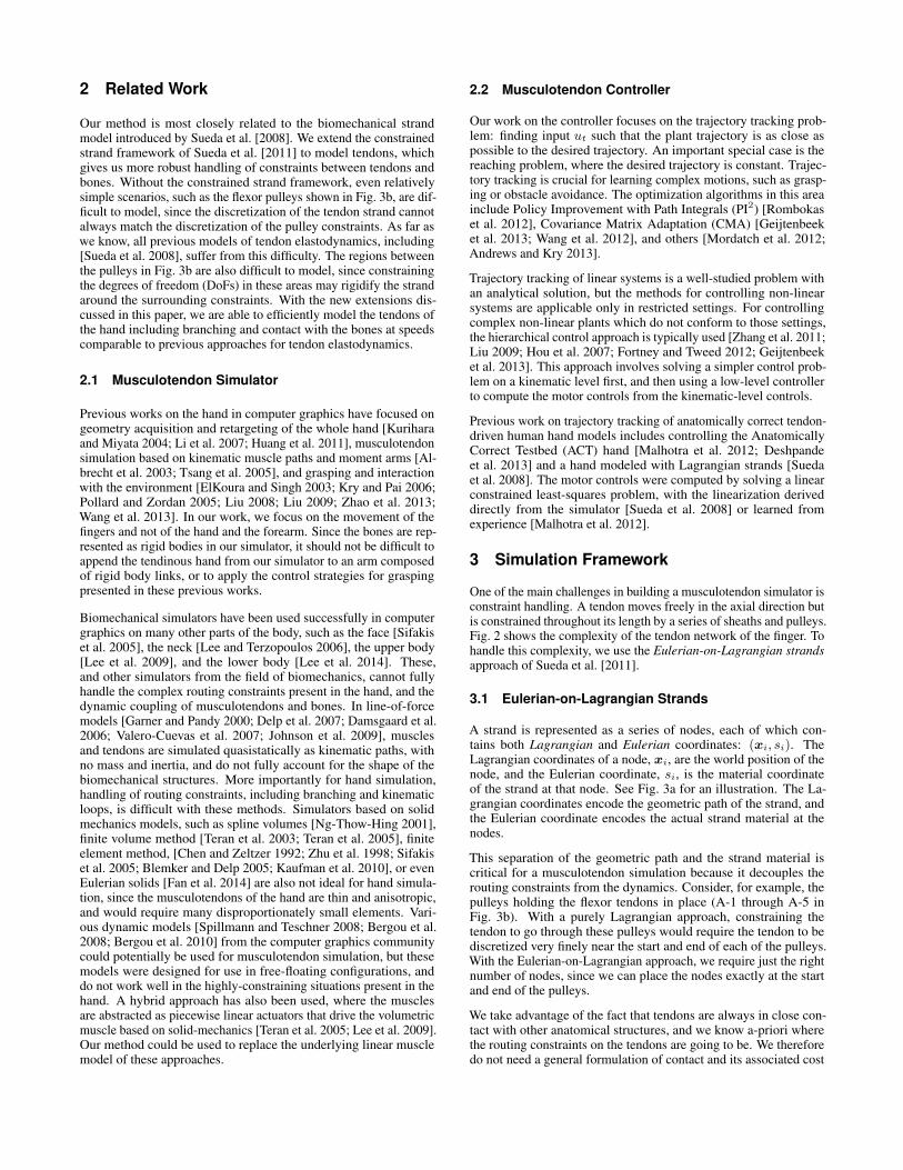
2 Related Work
Our method is most closely related to the biomechanical strandmodel introduced by Sueda et al. [2008]. We extend the constrainedstrand framework of Sueda et al. [2011] to model tendons, whichgives us more robust handling of constraints between tendons andbones. Without the constrained strand framework, even relativelysimple scenarios, such as the flexor pulleys shown in Fig. 3b, are dif-ficult to model, since the discretization of the tendon strand cannotalways match the discretization of the pulley constraints. As far aswe know, all previous models of tendon elastodynamics, including[Sueda et al. 2008], suffer from this difficulty. The regions betweenthe pulleys in Fig. 3b are also difficult to model, since constrainingthe degrees of freedom (DoFs) in these areas may rigidify the strandaround the surrounding constraints. With the new extensions dis-cussed in this paper, we are able to efficiently model the tendons ofthe hand including branching and contact with the bones at speedscomparable to previous approaches for tendon elastodynamics.
2.1 Musculotendon Simulator
Previous works on the hand in computer graphics have focused ongeometry acquisition and retargeting of the whole hand [Kuriharaand Miyata 2004; Li et al. 2007; Huang et al. 2011], musculotendonsimulation based on kinematic muscle paths and moment arms [Al-brecht et al. 2003; Tsang et al. 2005], and grasping and interactionwith the environment [ElKoura and Singh 2003; Kry and Pai 2006;Pollard and Zordan 2005; Liu 2008; Liu 2009; Zhao et al. 2013;Wang et al. 2013]. In our work, we focus on the movement of thefingers and not of the hand and the forearm. Since the bones are rep-resented as rigid bodies in our simulator, it should not be difficult toappend the tendinous hand from our simulator to an arm composedof rigid body links, or to apply the control strategies for graspingpresented in these previous works.
Biomechanical simulators have been used successfully in computergraphics on many other parts of the body, such as the face [Sifakiset al. 2005], the neck [Lee and Terzopoulos 2006], the upper body[Lee et al. 2009], and the lower body [Lee et al. 2014]. These,and other simulators from the field of biomechanics, cannot fullyhandle the complex routing constraints present in the hand, and thedynamic coupling of musculotendons and bones. In line-of-forcemodels [Garner and Pandy 2000; Delp et al. 2007; Damsgaard et al.2006; Valero-Cuevas et al. 2007; Johnson et al. 2009], musclesand tendons are simulated quasistatically as kinematic paths, withno mass and inertia, and do not fully account for the shape of thebiomechanical structures. More importantly for hand simulation,handling of routing constraints, including branching and kinematicloops, is difficult with these methods. Simulators based on solidmechanics models, such as spline volumes [Ng-Thow-Hing 2001],finite volume method [Teran et al. 2003; Teran et al. 2005], finiteelement method, [Chen and Zeltzer 1992; Zhu et al. 1998; Sifakiset al. 2005; Blemker and Delp 2005; Kaufman et al. 2010], or evenEulerian solids [Fan et al. 2014] are also not ideal for hand simula-tion, since the musculotendons of the hand are thin and anisotropic,and would require many disproportionately small elements. Vari-ous dynamic models [Spillmann and Teschner 2008; Bergou et al.2008; Bergou et al. 2010] from the computer graphics communitycould potentially be used for musculotendon simulation, but thesemodels were designed for use in free-floating configurations, anddo not work well in the highly-constraining situations present in thehand. A hybrid approach has also been used, where the musclesare abstracted as piecewise linear actuators that drive the volumetricmuscle based on solid-mechanics [Teran et al. 2005; Lee et al. 2009].Our method could be used to replace the underlying linear musclemodel of these approaches.
2.2 Musculotendon Controller
Our work on the controller focuses on the trajectory tracking prob-lem: finding input ut such that the plant trajectory is as close aspossible to the desired trajectory. An important special case is thereaching problem, where the desired trajectory is constant. Trajec-tory tracking is crucial for learning complex motions, such as grasp-ing or obstacle avoidance. The optimization algorithms in this areainclude Policy Improvement with Path Integrals (PI2) [Rombokaset al. 2012], Covariance Matrix Adaptation (CMA) [Geijtenbeeket al. 2013; Wang et al. 2012], and others [Mordatch et al. 2012;Andrews and Kry 2013].
Trajectory tracking of linear systems is a well-studied problem withan analytical solution, but the methods for controlling non-linearsystems are applicable only in restricted settings. For controllingcomplex non-linear plants which do not conform to those settings,the hierarchical control approach is typically used [Zhang et al. 2011;Liu 2009; Hou et al. 2007; Fortney and Tweed 2012; Geijtenbeeket al. 2013]. This approach involves solving a simpler control prob-lem on a kinematic level first, and then using a low-level controllerto compute the motor controls from the kinematic-level controls.
Previous work on trajectory tracking of anatomically correct tendon-driven human hand models includes controlling the AnatomicallyCorrect Testbed (ACT) hand [Malhotra et al. 2012; Deshpandeet al. 2013] and a hand modeled with Lagrangian strands [Suedaet al. 2008]. The motor controls were computed by solving a linearconstrained least-squares problem, with the linearization deriveddirectly from the simulator [Sueda et al. 2008] or learned fromexperience [Malhotra et al. 2012].
3 Simulation Framework
One of the main challenges in building a musculotendon simulator isconstraint handling. A tendon moves freely in the axial direction butis constrained throughout its length by a series of sheaths and pulleys.Fig. 2 shows the complexity of the tendon network of the finger. Tohandle this complexity, we use the Eulerian-on-Lagrangian strandsapproach of Sueda et al. [2011].
3.1 Eulerian-on-Lagrangian Strands
A strand is represented as a series of nodes, each of which con-tains both Lagrangian and Eulerian coordinates: (xi, si). TheLagrangian coordinates of a node, xi, are the world position of thenode, and the Eulerian coordinate, si, is the material coordinateof the strand at that node. See Fig. 3a for an illustration. The La-grangian coordinates encode the geometric path of the strand, andthe Eulerian coordinate encodes the actual strand material at thenodes.
This separation of the geometric path and the strand material iscritical for a musculotendon simulation because it decouples therouting constraints from the dynamics. Consider, for example, thepulleys holding the flexor tendons in place (A-1 through A-5 inFig. 3b). With a purely Lagrangian approach, constraining thetendon to go through these pulleys would require the tendon to bediscretized very finely near the start and end of each of the pulleys.With the Eulerian-on-Lagrangian approach, we require just the rightnumber of nodes, since we can place the nodes exactly at the startand end of the pulleys.
We take advantage of the fact that tendons are always in close con-tact with other anatomical structures, and we know a-priori wherethe routing constraints on the tendons are going to be. We thereforedo not need a general formulation of contact and its associated cost

DIP PIP MCP Distal
Middle Proximal Metacarpal
FDP FDS
EDC DI/PI
LUM
OL
ExtLat IntMed Sagittal View
Dorsal View EDC
DI LUM OL
IntMed ExtLat
PI
Figure 2: Anatomy of the finger (of the right hand) showingthe components modeled. From proximal to distal, the fourbones of the finger are metacarpal, proximal, middle, and distal.They are connected by the metacarpophalangeal (MCP), proximal-interphalangeal (PIP), and distal-interphalangeal (DIP) joints.The three long tendons are extensor digitorum communis (EDC),flexor digitorum superficialis (FDS), and flexor digitorum profundus(FDP). These tendons originate from outside the hand, and are hencecalled “extrinsic.” The three “intrinsic” musculotendons are thelumbrical (LUM), dorsal interosseus (DI) and palmar interosseus(PI). Each finger has a slightly different insertion arrangement ofthese three intrinsic musculotendons. We simplified the model byusing the arrangement in the index finger for all fingers and omittingthe symmetric components on the ulnar side. The oblique ligament(OL), which spans the PIP and DIP joints, helps synchronize thesetwo joints when the FDP is pulled. The two crossing tendons, extrin-sic lateral (ExtLat) and intrinsic medial (IntMed) transfer tensionfrom extrinsic extensors and intrinsic extensors to the PIP and DIP.(Not present in all the examples.)
in simulation and modeling time. Collisions need to be handledonly by the Lagrangian part of the discretization, which determinesthe kinematic path of the strand; the Eulerian part is oblivious tocollision detection and resolution. This is a major advantage fortendon simulation, since most of the movement is in the axial di-rection, which means that the Lagrangian part does not move inspace too much, and is often completely stationary with respect tothe skeleton.
3.2 Selective Quasistatics
Tendons are very stiff, making them challenging to simulate nu-merically. One approach for incorporating such stiff forces is toapproximate them by hard constraints. Ideally, unilateral constraintsare preferred, since tendons should not be able to push—i.e., thetendon strand should prevent stretch but allow compression. How-ever, unilateral constraints are more costly to maintain than bilateralconstraints, and so should be avoided as much as possible.
There are two problems with modeling a stiff tendon as a bilaterallyconstrained strand. First, as we stated earlier, bilateral constraintsprevent strand compression, which means that they can push as wellas pull. However, because of the design of our muscle model de-scribed in §3.3, muscles never push back on the tendons, and so thisis not a serious drawback in all cases. Second, and more importantly,bilateral constraints can cause locking in some situations that areprevalent in hand simulation because of the complexity of the tendonnetwork of the finger, which contains several branching and mergingtendons. Modeling tendons as inextensible strands can cause thistendon network to turn into a reduced degrees-of-freedom (DoF)system. With our formulation, we can easily model these loops, asshown in Fig. 7.
(a)
A1 A2 A3
A4
A5 FDP
(b)
Figure 3: (a) Illustration of Eulerian coordinates with a stretchedelastic band. (top) In a purely Lagrangian simulator, the strandmaterial, which can be visualized as the texture, is fixed to the nodes.(middle) If we move the middle node to the left, then the material iscompressed in the left segment and stretched in the right segmentwith respect to the previous configuration. (bottom) If we relax theassumption that the material is fixed to the nodes (i.e., Euleriannode), then the material will start to flow from left to right. (b)Pulleys to hold the tendon in place.
Our solution is to use bilateral constraints only when the origin ofthe strand is free. The high stiffness of these strands that do not formloops can be safely approximated by bilateral constraints. For thosespecial cases where the strand forms a loop, we use a novel selectivequasistatic discretization of the strand. The basic assumption ofthe selective quasistatic discretization is that the strain propagatesinstantaneously along the strand. This is similar to the idea proposedfor discrete elastic rods by Bergou et al. [2008], where the twist ofthe strand was assumed to propagate instantaneously. Similarly, wepropose to enforce all neighboring segments to have the same strain,eliminating the Eulerian coordinates from the equations of motion.Note the selective nature of the elimination—even if we eliminatethe Eulerian DoFs from the equations of motion, the strand is stilldynamic since its Lagrangian DoFs are still present.
Static condensation techniques, e.g., [DiMaio and Salcudean 2002],remove all internal degrees of freedom using a quasistatic assump-tion. With our selective quasistatic formulation, on the other hand,we gain the ability to insert Lagrangian DoFs without increasingthe number of Eulerian DoFs—a flexibility that is useful for routingtendons around bones.
Another advantage of using selective quasistatics is improved condi-tioning, allowing larger time steps. As an illustration, imagine twoconsecutive nodes coming very close to each other at some fingerposture (e.g., the small spacing between the A2 and A3 pulleys inFig. 3b). Intuitively, without the quasistatic assumption, this wouldcause the Eulerian DoF of a node to affect only a small amount ofthe mass of the strand located around these nodes. With selectivequasistatics, these small inertias are distributed to their surroundingLagrangian DoFs, improving the condition number of the systemmatrix, thus allowing us to take larger time steps. The comparison ofthe largest time steps allowed as a function of the number of nodesis shown in Fig. 4. With quasistatic nodes, the maximum time stepremains constant, whereas without the quasistatic assumption, thetime step decreases rapidly with the number of nodes.
Consider a strand consisting of n+ 1 segments as shown in Fig. 5.Let node 0 denote the first node, and n + 1 denote the last node.Using the quasistatic strain assumption, we want to eliminate s1through sn by expressing them as a function of the Lagrangian DoFs(x0, · · · ,xn+1) and the first and last Eulerian DoFs (s0, sn+1).The derivation starts1 with the computation of the strain of segmenti between nodes i and i+1: "i = li
�si�1, where �si = si+1�si,
1See the supplemental document for a detailed derivation.

Number of Nodes100 101N
orm
aliz
ed T
ime
Step
10-1
100
EulerianQuasistatic
Figure 4: An elastic strand stretching and sliding on a plank. Theleft end of the strand is fixed, and the right end is attached to thehanging box. The left-most node is a standard Lagrangian node;the remaining are Eulerian nodes that allow the strand material toslide through them. The Lagrangian coordinates of all the nodesare fixed to the plank. The plot shows a log-log comparison ofmaximum time steps (�t) vs. the number of Eulerian nodes withand without selective quasistatics. With selective quasistatics (red),the maximum �t remains constant (normalized to 1.0). Withoutselective quasistatics (blue), the maximum �t decreases rapidly.
�xi = xi+1�xi, and li = k�xik. These quantities are computedfrom the coordinates of the two nodes of the ith segment. Thequasistatic strain constraint implies that the strain values of all thesegments are equal; i.e., "0 = · · · = "i = "i+1 = · · · = "n. Usingthe expression for strain given above and rearranging, we can rewrite"i = "i+1 as
�li+1si + (li + li+1)si+1 � lisi+2 = 0. (1)
This holds for all neighboring segments i = 0, · · · , n � 1. As-sembling these into a linear system, we obtain a tridiagonal matrixequation Ls = b, where
L =
0
BBBB@
l0 + l1 �l0�l2 l1 + l2 �l1
. . .�ln�1 ln�2 + ln�1 �ln�2
�ln ln�1 + ln
1
CCCCA
s =
0
BBBB@
s1s2...
sn�1
sn
1
CCCCA, b =
0
BBBB@
l1s00...0
ln�1sn+1
1
CCCCA.
(2)
L is (n⇥ n), s is (n⇥ 1), and b is (n⇥ 1). Solving this equationgives the Eulerian DoFs (s1, . . . , sn) that make the strain the samethroughout the strand given the Lagrangian DoFs (x0, · · · ,xn+1)and the first and last Eulerian DoFs (s0, sn+1). In order to eliminatethese DoFs, we also need the Jacobian matrix, which maps thevelocities of the remaining DoFs to the velocities of the eliminatedDoFs. Taking the time derivative of s = L�1b and using the identityfor the derivative of the inverse, we arrive at
0
1
CA = �L�1�S�X| {z }J
0
B@x0
...xn+1
1
CA . (3)
(We assumed here that s0 and sn+1 are fixed. It is also possible torelax this assumption.) The resulting (n⇥ 3(n+ 2)) matrix, J , isthe Jacobian for the eliminated Eulerian coordinates. The blocks of
Figure 5: If we assume that the strain is the same throughout thestrand, we can eliminate the Eulerian coordinates s1 through sngiven x0, . . . ,xn+1, s0, and sn+1.
J are composed of:
�S =
0
B@��s1 �s0
. . .��sn �sn�1
1
CA ,
�X =
0
B@��x
T0 �x
T0
. . .��x
Tn �x
Tn
1
CA ,
(4)
where �x = �x/k�xk. �S is (n⇥ (n+ 1)), and �X is((n+ 1)⇥ 3(n+ 2)). J is of size (n⇥ 3(n+ 2)) and is the Jaco-bian for the eliminated Eulerian coordinates. Although J is dense, itis relatively small, and since all of the matrices involved are banded,it is cheap to form.
This Jacobian matrix can then be used to eliminate the internalEulerian DoFs from equations of motion (i.e., reduced coordinateapproach), or it can be used to define the equality constraint matrixbetween the internal Eulerian DoFs and the remaining DoFs (i.e.,maximal coordinate approach). In our implementation, we take thereduced approach to obtain a smaller but denser system matrix.
3.3 Muscle Model
Muscles are complex active materials with significant volumetriceffects; practical volumetric muscle models have been recently de-veloped (e.g., [Fan et al. 2014]). In the present context we proposea simpler lumped muscle model, which relates the force at the ori-gin of the tendon to the tendon excursion (i.e., displacement of thetendon origin).
Such lumped models are widely used in biomechanics, but our modeldiffers significantly from the standard Hill-Zajac model [Zajac 1989],and may be more useful in applications. In the standard model, theforce exerted by a muscle is modeled as the sum of passive andactive forces: f = fP + fA, usually depicted as the muscle’spassive and active force-length (FL) curves. The passive FL curveis a monotonically increasing function, and the active FL curve is aconcave function obtained from physiological experiments, startingwith the classic experiments of A. V. Hill a century ago. When themuscle is activated, the active FL curve is scaled by the activationlevel of the muscle. The resulting total force, shown in Fig. 6(left),contains a region of negative stiffness, which means that as an activemuscle is stretched, its force output decreases. Numerically, thenegative slope manifests itself as instabilities in simulations, sinceany perturbation away from equilibrium is magnified by the negativeforce.
We therefore use a simple piecewise linear model that does notsuffer from these difficulties; more detailed, non-linear constitutivemodels can also be used, depending on the application. We modelthe total muscle force as a piecewise linear function that is shiftedto the left when activated. Fig. 6(middle & right) shows our musclemodel. The passive FL curve is simply the unshifted curve. Whenthe muscle is activated, it pulls on the tendon even at zero excursion

a$FL$
0$ !$
FL$
0$ !$0$
FL$
!$a$
Figure 6: (left) A typical FL curve of an activated muscle, depictingforce as a function of tendon excursion. (middle) Piece-wise linearmuscle model. The muscle exerts no force if the excursion is non-positive. The force increases linearly otherwise. (right) When themuscle is activated, the functions are shifted to the left.
(i.e., in the isometric condition). Finally, because the function isalways positive, the muscle never pushes back on the tendon.
Even though this model is simple and robust, it is also potentiallymore realistic than the standard model as a constitutive model ofcontrolled muscles. The problem with the direct application of Hill’swidely misunderstood FL curve is that it is not a constitutive modelof active muscle; rather, it is a depiction of maximum force whenisometrically activated at different lengths. It is now well knownthat muscle activation and stretch do not commute. Unlike thepredictions of the standard model, it has been shown experimentallythat if a muscle is activated first and then stretched, the resultingforce does not decrease [Epstein and Herzog 1998]. Moreover, thebehavior of entire muscles during stretch is mediated by a complexneural signal based on feedback from muscle proprioceptors andchanges in fiber recruitment. There are very few studies of howmuscles behave in vivo, especially in humans. A striking exceptionis the classic paper of Robinson, et al. [1969] which measured FLcurves of active human eye muscles in vivo. Figure 2 in that paper iscloser to ours than to the standard model. Our model needs furtherinvestigation, but there is physiological support for using it.
4 Control
In this section, we present our controller framework and discuss twomethods used to learn the necessary control parameters. §4.2 de-scribes a general learning method, to which we will refer henceforthas “black box control,” that uses no prior system knowledge and issuitable for control of a “black box” simulator. We then present in§4.3 a method – denoted as “white box control” – for extracting therelevant parameters for control of a biomechanical system directlyfrom the simulator. We compare these methods to explore how muchwe benefit from exploiting the inner workings of the system we areattempting to control, and to assess how a general-purpose learningmethod performs compared to a method with detailed prior systemknowledge.
4.1 Controller Algorithm
Since our plant is non-linear and input-constrained, we employeda hierarchical control approach, modeling the plant as a simpleunconstrained system on a higher (kinematic) level, and an input-constrained locally-linear system at the lower (muscle activation)level. For concreteness, we consider the index finger, but the methodis more general.
At the high level, we model the fingertip motion as simple controlleddynamical system:
qt+1 = qt + vt (5)
where qt is a 3⇥ 1 task descriptor variable (in this case, the fingertiplocation) at time t, and vt are the kinematic controls.
The kinematic controls vt are defined by:
vt := vp + vb. (6)
Here vp = vp(qt, t) is the 3 ⇥ 1 passive dynamics term, the com-putation of which is described in §4.2; for a complete derivation ofthe equations of motion, we refer the reader to our supplementarymaterial. vp captures the significant nonlinearities in dynamics, andallows the high level controller to assume the simpler form of Eq. (5).vb = vb(qt, t) is the 3 ⇥ 1 feedback control term for tracking thereference trajectory. It is computed by:
vb = KP (qr � qt) +KD(qr � qt). (7)
KP and KD are scalar gains, and qr is the target configuration at agiven timestep.
In turn, the low-level activation controller transforms kinematiccontrols vt computed by the high-level controller to activations ut
at each timestep t using the formulation of Sueda et al. [2008]:
ut = argminu
↵||R(qt)u� vt||2 + �||u||2
+ �||u� ut�1||2
s.t. 0 u 1
(8)
where ↵,�, and � are blending weights, and R(qt) is the activation-velocity matrix (AVM) described below. The first term imple-ments the kinematic controls, the second term penalizes large activa-tions, and the third penalizes large changes in activations betweentimesteps. We scale the parameters such that ↵+�+� = 1. Setting↵ = 1 and � = � = 0 corresponds to no smoothing. Thus, theparameters of the controller are the gains KP and KD , R(qt), thepassive dynamics term vp(qt, t), and the smoothing terms ↵,�, and�.
This model is similar to those used by Matsuoka and co-workers;it extends the model of Malhotra et al. [2012] by including passivedynamics compensation and by making the matrix R configuration-dependent. We used the fingertip location as a choice of the con-figuration variable as in [Sueda et al. 2008]. Unlike joint angles[Deshpande et al. 2013] or tendon excursions [Malhotra et al. 2012],fingertip position does not fully describe the finger configuration.There is, however, some physiological basis for this choice of con-figuration variable as evidence exists that humans do use fingertipposition directly for reaching movements [Bedard and Sanes 2009].
4.2 Estimating Black Box Controller Parameters
PD gains and smoothing The PD gains were empirically se-lected to be KP = 0.23 2
�t , KD = 0.95. The factor 2�t is used
for bringing the position and velocity terms in Eq. (7) to a commonscale, and is derived from the observation that the absolute valueof the velocity is �t
2 times larger than the absolute value of thechange in position if the body is constantly accelerated for time �t.The smoothing parameters are also chosen empirically, though wefind that the unsmoothed controllers work nearly as well as the bestsmoothed controllers (see §5). Both the gains and smoothing pa-rameters are chosen from a user-specified set of possible parametervalues via automatic selection of the parameters which give the bestperformance on a trial task.
Activation-Velocity Matrix The matrix R(qt) is estimated atN = 60 configurations q and approximated at a new point by adistance-weighted average. Because of this choice of approximationmethod, our controller can be seen as a linearly blended composi-tion of controllers with different matrices R, which are valid in the

neighborhood of the corresponding configurations q [Burridge et al.1999].
The data were collected with an extension of the self-identificationmethod [Malhotra et al. 2012]. At each of the N stable configura-tions q (chosen by applying a constant, random activation for longenough to let the system stabilize), the passive dynamics are com-puted by applying zero activations for one timestep, and recordingthe resulting velocity q0. The ith column of R(q) is estimated byfully activating the corresponding muscle ui for one timestep at theconfiguration q, and subtracting q0 from the resulting velocity qi.
Passive dynamics term Our passive dynamics compensationterm is related to equilibrium point control (reviewed in [Shadmehr1998]). We define an equilibrium point as a pair of state and control{qeq, ueq} such that qeq = f(qeq, ueq). That is, the system withdynamics qt+1 = f(qt, u(qt, t)) does not move. Unlike traditionalequilibrium point control we use an equilibrium point to record theconfiguration-dependent part of the passive dynamics term; we ig-nore the velocity-dependent terms in the black box controller sincethese are harder to estimate.
We gathered training data by sampling n ⇡ 39000 points on auniform grid in the activation space. Each sampled point becamean activation that we applied to the plant until it reached a stableconfiguration. The resulting configuration was then an equilibriumpoint q(i) corresponding to the applied activation u(i), where thenotation u(i), q(i) represents the ith training data point. To estimatethe equilibrium activation ueq corresponding to some target positionqr , we performed an approximate m-nearest-neighbor search ofthe points q in the training data. Then, at a state qt when we areattempting to reach a target qr , we set the passive dynamics term tovp = R(qt)ueq .
To improve the efficiency of the m-nearest-neighbor search, we useda locality-sensitive hashing (LSH) algorithm [Indyk and Motwani1998]. The advantage of this approach is that its space and querytime are both linear in the number of points to search, compared toother current nearest-neighbor algorithms which have either space orquery time that is exponential in the dimension of the data [Andoniand Indyk 2008]. These algorithms are based on the existence oflocality-sensitive hashing functions, which possess the propertiesthat, for any two points p, r 2 Rd:
1. If ||p� r|| D then Pr[h(r) = h(p)] P1
2. If ||p� r|| � cD then Pr[h(r) = h(p)] � P2
where P1 > P2 and c � 1.
We can concatenate several LSH functions to amplify the gap be-tween P1 and P2. Specifically, for parameters k and L, we chooseL functions gj(r) = (h1,j(r), ..., hk,j(r)) where the hash func-tions hl,j(1 l k, 1 j L) are chosen at random froma family of LSH functions. We then construct a hash table struc-ture by placing each point qi from the input set into the bucketgj(p), j = 1, ..., L. To process a query point q, we scan through thebuckets g1(q), ..., gL(q) and retrieve the points stored in them. Foreach retrieved point, we compute the distance between it and q andreport the m closest points.
For our purposes, the hash functions used consist of projecting apoint onto a random 1-dimensional line in Rd, which is then parti-tioned into uniform segments. The bucket into which a particularpoint is hashed corresponds to the index of the segment containingit. For Euclidean distances, these functions are locality-sensitive;for proof of this, we refer the reader to [Andoni and Indyk 2008].We set the algorithm parameters to k = 20, L = 30 and m = 1,as we found that these parameters were most effective in predicting
activations leading to a given target. In particular, experiments usinglocal polynomial regression models with different values of m didnot yield improved accuracy over m = 1. We speculate that thisis due to sparsity in the training data, and the non-linearity of themapping between activation and position space.
4.3 Extracting White Box Controller Parameters
The Activation Velocity Matrix, R(qt), can be extracted directlyfrom the simulator as in [Sueda et al. 2008]. The forward simulatorsolves the velocity-level Karush-Kuhn-Tucker (KKT) system:
✓M GT
G 0
◆✓qt+1
�
◆=
✓f(qt, qt) + fA(qt)
0
◆, (9)
where � is the vector of Lagrange multipliers and fA(qt) is theactive impulse. Note that qt in Eq. (9) need not be the same as inEq. (5), but for simplicity of exposition we will use the same notationin this section. The impulse on the right hand side is separated intotwo parts: impulse due to muscle activations (2nd term) and impulsedue to all other forces (1st term). We can rewrite Eq. (9) as
M ˜qt+1 = f(qt, qt) + fA(qt), (10)
where each quantity represents the corresponding block ma-trix/vector. In particular, ˜qt+1 is the concatenation of the next veloc-ities and the Lagrange multipliers (constraint force magnitudes).
fA(qt) can be further decomposed into a matrix vector product,fA(qt) = A(qt)ut, where ut is the vector of muscle activations,and A(qt) is the matrix that maps muscle activations to impulses.Here, we assumed that the impulses are linear in muscle activations,a common assumption for many muscle models [Zajac 1989]. Thisallows us to write
˜qt+1 = M�1f(qt, qt) + M�1A(qt)ut. (11)
This gives us an affine map from muscle activations to resultingsystem velocities.
For most tasks, we are interested in just some of the velocities ratherthan the whole system velocity. We therefore apply an extractormatrix �: qt+1 = �˜qt+1. Applying this matrix to both sides andadding and subtracting qt from the right side, we obtain an equationin the form of Eq. (5):
qt+1 = qt + (vp +R(qt)ut), (12)
where vp = �M�1f(qt, qt)� qt is the passive part of the kinematiccontrols and R(qt) = �M�1A(qt) is the AVM.
4.4 Comparison of White Box and Black Box Methods
Because the black box control method requires no prior knowledgeof the system we want to control, it is well-suited for problems inwhich we lack access to the system’s internal workings. When thesystem’s inner workings are known – as is the case with the indexfinger simulator – we can generally achieve better results with somevariant of the white box control method, as this will yield a muchbetter approximation of the system dynamics. The disadvantage ofwhite box methods – apart from their inapplicability in the absenceof significant prior knowledge – is in development time: as there isno ‘one-size-fits-all’ method, this approach must be tailor-made forthe system we wish to control. This can require significantly morework than general-purpose black box methods.
In this paper, we compare the white box and black box methods forcontrol of the index finger. The black box method suffers from the

(a) (b)
(c) (d)
Figure 7: Synchronized joint motion with the oblique retinacularligament, shown in red. (a-b) Without the ligament, pulling on thetendon flexes the DIP fully, before the PIP. (c-d) With the ligament,the same tendon flexes the finger in a much more natural, synchro-nized fashion.
sparsity of the training data; it estimates the AVM based on valuesobserved at discrete points in the configuration space, in contrast tothe white box method, which extracts the AVM from the simulator ateach timestep. The principal disadvantage of our white box methodis the failure of the extracted AVMs to take joint limits into account.Our simulator deals with joint limit constraints separately from theAVM calculations; thus, the AVM values extracted near joint limitstend to imply that applying certain activations will lead to unreach-able configurations. This can lead to some unexpected behavior nearthe joint limits. The black box controller does not suffer from thisparticular difficulty, as all AVM estimates are obtained empiricallyand thus take positional constraints into account.
5 Results
We implemented our system in C++. Simulations were run on acommodity PC with an Intel Core i5 3570 processor and 16GB ofmemory. The bone geometry was obtained from a CT scan andreconstructed using custom software. The joint axes were obtainedfrom motion-capture data, and the tendon paths were created man-ually with a 3D modeling software, based on standard textbookmodels in the literature [Kapandji 2007]. We did not render the skin,but it should be relatively easy to augment existing work on skinningto add both cutaneous and subcutaneous motion [Sueda et al. 2008;McAdams et al. 2011; Li et al. 2013] for rendering.
For the index finger plant, the computation time for a simulationwith a 3 ms time step is approximately 10 seconds per second of con-trolled simulation. This breaks down into 8 seconds for simulatingthe plant and 2 seconds for computing the controls.
Joint coupling With a tendon-based simulator, we obtain naturaljoint coupling for free. Fig. 7 demonstrates how pulling on a singletendon produces synchronized flexion in two joints. A single tendon(FDP), with no other tendons and ligaments present, pulls on thedistal phalanx of the index finger. The joints flex by “rolling”: first,the distal joint (DIP) fully flexes, and then the proximal joint (PIP)starts to flex. With the oblique ligament (OL) added, which spansboth the DIP and the PIP, pulling on the FDP causes both joints toflex in a natural, synchronized fashion.
Coupling also occurs between joints from different fingers. InFig. 1d, each finger is used to press down on the keyboard, whichis simulated together with the hand. Because the extrinsic muscles
Figure 8: Swan neck deformity.
Tracking ErrorUnsmoothed Smoothed
Average Max Average MaxBlack Box 0.021 0.12 0.017 0.10White Box 0.0045 0.087 0.0045 0.085
Table 1: Table of trajectory tracking errors (in cm) for the circletracking experiment. We report both the average distance betweenthe target fingertip position and the actual fingertip position overthe task, as well as the maximum distance between the target andactual positions.
(FDP, FDS, EDC) are coupled across the fingers by inter-tendinousbands [Leijnse et al. 1992], moving one finger causes the other fin-gers to move as well, even though the activation controller was givenonly the target trajectory of a single finger.
Deformities By changing some of the tendon parameters, we cansimulate clinical deformities of the hand. We simulated two commondeformities: boutonniere and swan-neck [Zancolli 1979].
In the boutonniere deformity, the DIP hyper-extends, and the PIPremains locked in a flexed position (Fig. 1(d)). We simulate thisinjury by cutting the insertion of the EDC into the middle phalanx.Once the lateral bands (intrinsic and extrinsic lateral) fall below therotation axis of the PIP, no muscle can extend the joint, causing thejoint to remain flexed unless fixed externally.
The swan-neck deformity has the opposite joint configuration: hyper-extension of the PIP and flexion of the DIP (Fig. 8). There are manycauses of this deformity, and among them is the elongation of theoblique ligament (OL). In the simulator, we first lengthen the OLand then pull on the EDC to extend the PIP. Once the OL rises abovethe axis of rotation of the PIP, pulling on the FDP causes the DIP toflex and PIP to hyper-extend.
Trajectory tracking To test the control algorithms described inSection 4, we experimented with tracing a circle of radius 0.6 cm.In this and the next experiment, we constrain the fingertip to lieon a plane to simulate drawing on a touchscreen. Fig. 9 shows thetrajectories tracked for both the black and white box controllers, withand without smoothing, with the corresponding activation patternsshown in Fig. 10. Table 1 shows the average per-timestep trackingerror for each run, measured as the average Euclidean distancebetween the target fingertip position qr and actual fingertip positionqt at each timestep, as well as the maximum positional error at anytimestep.
As expected, the white box controller outperforms the black boxcontroller in both smooth and unsmoothed control. Both the acti-vations and the movements generated by the white box controller

−0.5 0 0.5−0.6
−0.4
−0.2
0
0.2
0.4
q2
q 1
(a)
−0.5 0 0.5−0.6
−0.4
−0.2
0
0.2
0.4
q2
q 1(b)
−0.5 0 0.5−0.6
−0.4
−0.2
0
0.2
0.4
q2
q 1
(c)
−0.5 0 0.5−0.6
−0.4
−0.2
0
0.2
0.4
q2
q 1
(d)
Figure 9: Results of tracking a circle trajectory with the fingertip(target trajectory is shown by a dotted line, actual trajectory by asolid line). (a-b) Black box controller, without smoothing (left) andwith smoothing parameters ↵ = 0.971,� = 0.0145, � = 0.0145(right). (c-d) White box controller, without smoothing (left) and withsmoothing parameters ↵ = 0.999,� = 0.0, � = 0.001 (right)
are smoother than for the black box, likely as a result of the relativesparsity of the black box’s training data. For the smoothed examples,we use a script to automatically select the best smoothing parametersfrom a set of 1500 different values. The black box controller’s per-formance is visibly improved by the use of appropriate smoothingparameters, while we find that it makes almost no difference for thewhite box controller.
Lastly, we have included a 3-dimensional tracking example inFig. 11. Performing the circle tracing task in 3 dimensions is, under-standably, more difficult than tracing a circle constrained to a plane,but in this case we achieve good results using the unsmoothed whitebox controller. The average error for this run was 0.012 cm and themaximum error was 0.19 cm.
Writing Here we performed a variation on our trajectory trackingtask in which the controller imitated a human writing on a tabletscreen. We obtained the trajectory by having a human subject writethe word “SIGG” on a touchscreen. The subject’s writing was cap-tured and converted to a sequence of numerical coordinates suitablefor use by the controller; this can be done on any touchscreen plat-form. As before, we constrained the fingertip location to lie on aplane. As our model only allows for control of the index finger anddoes not incorporate wrist movement, we manually translated thewrist after each letter is written to allow the controller to write theentire word. We performed this task using the white box controllerwithout smoothing.
Fig. 1(a-b) shows side-by-side shots of the controller and a humansubject attempting this task. See our accompanying video for amore detailed comparison. The average tracking error for this task –measured in the same way as for the circle tracking task – was 0.013cm, while the maximum error observed was 0.18 cm.
DI EDC FDP
FDS LUM PI
(a)
DI EDC FDP
FDS LUM PI
(b)
DI EDC FDP
FDS LUM PI
(c)
DI EDC FDP
FDS LUM PI
(d)
Figure 10: Graph of muscle activations (ranging from 0 to 1) gen-erated over the duration of the circle tracking task (time range from0 to 1 second). Each figure shows the activation of the muscles(clockwise from left): distal interosseus (DI), extensor digitorumcommunis (EDC), flexor digitorum profundus (FDP), flexor digi-torum superficialis (FDS), lumbrical, and palmar interosseus (PI).(a-b) Black box controller, without smoothing (left) and with smooth-ing parameters ↵ = 0.971,� = 0.0145, � = 0.0145 (right). (c-d)White box controller, without smoothing (left) and with smoothingparameters ↵ = 0.999,� = 0.0, � = 0.001 (right)
6 Conclusion
We presented a framework for biomechanical simulation with ten-dons that can handle the complex routing constraints of the hand,such as pulleys and sheaths. By extending the constrained strandsframework of Sueda et al. [2011], we were able to efficiently handlecontact between bones and tendons, and to take large time stepsdespite the stiffness of the tendons. We showed that modeling thetendon network gives us coupled motion of the digits, as well asenergy storage in tendons. We also simulated deformities of the handby changing some of the tendon parameters. Finally, we developedtwo methods for control of a human index finger model, which wewere able to use successfully in trajectory tracking.
Although we were able to simulate a highly complex system oftendons and ligaments, there are still many more approximationsthat remain. For example, the system is sensitive to values of thebiomechanical parameters; it would be useful to learn these frommeasurements of human hands. We still approximate biomechanicaljoints as simple mechanical joints; an interesting avenue of futurework would be to extend this framework for handling joint limitsusing ligaments. Our technique should work very well with thethumb, and its inclusion is in progress.
Acknowledgments
This work was supported in part by NSERC, CFI, ICICS and theCanada Research Chairs Program. We thank Duo Li and CrawfordDoran for their early contributions to the software, Mitsunori Tadafor the CT images, and Benjamin Gilles for the segmentation help;we are grateful to Ye Fan and Darcy Harrison for their timely rescue

(a)
DI EDC FDP
FDS LUM PI
(b)
Figure 11: Results of tracking a circle trajectory in 3 dimensions,using the white box controller without smoothing. (a) Screenshot ofthe task and (b) (b) the resulting muscle activations (ranging from 0to 1) generated over the duration of the task (0 to 1 second).
of the video.
References
ALBRECHT, I., HABER, J., AND SEIDEL, H.-P. 2003. Constructionand animation of anatomically based human hand models. InACM SIGGRAPH/Eurographics symp. comput. anim., 98–109.
ANDONI, A., AND INDYK, P. 2008. Near-optimal hashing al-gorithms for approximate nearest neighbor in high dimensions.Communications of the ACM 51 (Jan), 117–122.
ANDREWS, S., AND KRY, P. G. 2013. Goal directed multi-fingermanipulation: Control policies and analysis. Computers & Graph-ics 37, 7, 830–839.
BEDARD, P., AND SANES, J. 2009. Gaze and hand positioneffects on finger-movement-related human brain activation. J.Neurophysiol. 101, 2 (Feb), 834–842.
BERGOU, M., WARDETZKY, M., ROBINSON, S., AUDOLY, B.,AND GRINSPUN, E. 2008. Discrete elastic rods. ACM Trans.Graph. 27, 3 (Aug), 63:1–63:12.
BERGOU, M., AUDOLY, B., VOUGA, E., WARDETZKY, M., ANDGRINSPUN, E. 2010. Discrete viscous threads. ACM Trans.Graph. 29, 4 (Jul), 116:1–116:10.
BLEMKER, S. S., AND DELP, S. L. 2005. Three-dimensionalrepresentation of complex muscle architectures and geometries.ANN BIOMED ENG 33, 5 (May), 661–673.
BURRIDGE, R. R., RIZZI, A. A., AND KODITSCHEK, D. E. 1999.Sequential Composition of Dynamically Dexterous Robot Behav-iors. Int J Robot Res 18, 6 (June), 534–555.
CHEN, D. T., AND ZELTZER, D. 1992. Pump it up: computeranimation of a biomechanically based model of muscle using thefinite element method. In Computer Graphics (Proc. SIGGRAPH92), vol. 26, ACM, 89–98.
DAMSGAARD, M., RASMUSSEN, J., CHRISTENSEN, S., SURMA,E., AND DEZEE, M. 2006. Analysis of musculoskeletal systemsin the AnyBody Modeling System. SIMUL MODEL PRACT TH14, 8 (Nov.), 1100–1111.
DELP, S. L., ANDERSON, F. C., ARNOLD, A. S., LOAN, P.,HABIB, A., JOHN, C. T., GUENDELMAN, E., AND THELEN,D. G. 2007. OpenSim: open-source software to create andanalyze dynamic simulations of movement. IEEE Trans. Biomed.Eng. 54, 11, 1940–1950.
DESHPANDE, A. D., KO, J., FOX, D., AND MATSUOKA, Y. 2013.Control strategies for the index finger of a tendon-driven hand.Int J Robot Res 32, 1 (Jan.), 115–128.
DIMAIO, S., AND SALCUDEAN, S. 2002. Needle insertion mod-elling and simulation. In ICRA, vol. 2, 2098 – 2105 vol.2.
ELKOURA, G., AND SINGH, K. 2003. Handrix: animating thehuman hand. In ACM SIGGRAPH/Eurographics symp. comput.anim., 110–119.
EPSTEIN, M., AND HERZOG, W. 1998. Theoretical Models ofSkeletal Muscle. John Wiley and Sibs.
FAN, Y., LITVEN, J., AND PAI, D. K. 2014. Active volumetricmusculoskeletal systems. ACM Trans. Graph. 33, 4 (July), 152:1–152:9.
FORTNEY, K., AND TWEED, D. B. 2012. Computational advan-tages of reverberating loops for sensorimotor learning. Neuralcomputation 24, 3 (Mar.), 611–34.
GARNER, B., AND PANDY, M. 2000. The obstacle-set method forrepresenting muscle paths in musculoskeletal models. ComputMethods Biomech Biomed Engin 3, 1, 1–30.
GEIJTENBEEK, T., VAN DE PANNE, M., AND VAN DER STAPPEN,A. F. 2013. Flexible Muscle-Based Locomotion for BipedalCreatures. ACM Transactions on Graphics 32, 6.
HOU, Z.-G., GUPTA, M. M., NIKIFORUK, P. N., TAN, M., ANDCHENG, L. 2007. A Recurrent Neural Network for HierarchicalControl of Interconnected Dynamic Systems. IEEE Transactionson Neural Networks 18, 2 (Mar.), 466–481.
HUANG, H., ZHAO, L., YIN, K., QI, Y., YU, Y., AND TONG, X.2011. Controllable hand deformation from sparse examples withrich details. In ACM SIGGRAPH/Eurographics symp. comput.anim., 73–82.
INDYK, P., AND MOTWANI, R. 1998. Approximate nearest neigh-bor: Towards removing the curse of dimensionality. In Proc.STOC, 604–613.
JOHNSON, E., MORRIS, K., AND MURPHEY, T. 2009. A varia-tional approach to strand-based modeling of the human hand. InAlgorithmic Foundation of Robotics VIII, G. Chirikjian, H. Choset,M. Morales, and T. Murphey, Eds., vol. 57 of Springer Tracts inAdvanced Robotics. Springer, 151–166.
KAPANDJI, I. A. 2007. The Physiology of the Joints, Volume 1:Upper Limb, 6 ed. Churchill Livingstone.
KAUFMAN, K. R., MORROW, D. A., ODEGARD, G. M., DON-AHUE, T. L. H., COTTLER, P. J., WARD, S., AND LIEBER,R. 2010. 3d model of skeletal muscle to predict intramuscularpressure. In ASB Annual Conference.
KRY, P. G., AND PAI, D. K. 2006. Interaction capture and synthesis.ACM Trans. Graph. 25, 3 (Jul), 872–880.
KURIHARA, T., AND MIYATA, N. 2004. Modeling de-formable human hands from medical images. In ACM SIG-GRAPH/Eurographics symp. comput. anim., 355–363.
LANG, C. E., AND SCHIEBER, M. H. 2004. Human finger inde-pendence: limitations due to passive mechanical coupling versusactive neuromuscular control. J. Neurophysiol. 92, 5 (Nov.),2802–2810.
LEE, S.-H., AND TERZOPOULOS, D. 2006. Heads up!: biome-chanical modeling and neuromuscular control of the neck. ACMTrans. Graph. 25, 3 (Jul), 1188–1198.

LEE, S.-H., SIFAKIS, E., AND TERZOPOULOS, D. 2009. Com-prehensive biomechanical modeling and simulation of the upperbody. ACM Trans. Graph. 28, 4 (Sep), 99:1–99:17.
LEE, Y., PARK, M. S., KWON, T., AND LEE, J. 2014. Locomotioncontrol for many-muscle humanoids. ACM Trans. Graph. 33, 6(Nov.), 218:1–218:11.
LEIJNSE, J. N., BONTE, J. E., LANDSMEER, J. M., KALKER,J. J., VAN DER MEULEN, J. C., AND SNIJDERS, C. J. 1992.Biomechanics of the finger with anatomical restrictions–the sig-nificance for the exercising hand of the musician. J. Biomech. 25,11, 1253–1264.
LI, Y., FU, J. L., AND POLLARD, N. S. 2007. Data-driven graspsynthesis using shape matching and task-based pruning. IEEETrans. Vis. Comput. Graphics 13 (July), 732–747.
LI, D., SUEDA, S., NEOG, D. R., AND PAI, D. K. 2013. Thin skinelastodynamics. ACM Trans. Graph. (Proc. SIGGRAPH) 32, 4(July), 49:1–49:9.
LIU, C. K. 2008. Synthesis of interactive hand manipulation. InACM SIGGRAPH/Eurographics symp. comput. anim., 163–171.
LIU, C. K. 2009. Dextrous manipulation from a grasping pose.ACM Trans. Graph. 28 (Jul), 59:1–59:6.
MALHOTRA, M., ROMBOKAS, E., THEODOROU, E., TODOROV,E., AND MATSUOKA, Y. 2012. Reduced Dimensionality Controlfor the ACT Hand. In ICRA, IEEE, 5117–5122.
MCADAMS, A., ZHU, Y., SELLE, A., EMPEY, M., TAMSTORF,R., TERAN, J., AND SIFAKIS, E. 2011. Efficient elasticityfor character skinning with contact and collisions. ACM Trans.Graph. 30, 4 (Jul), 37:1–37:12.
MORDATCH, I., POPOVIC, Z., AND TODOROV, E. 2012. Contact-invariant optimization for hand manipulation. In Proceedings ofthe ACM SIGGRAPH/Eurographics symp. comput. anim., Euro-graphics Association, 137–144.
NG-THOW-HING, V. 2001. Anatomically-based models for physicaland geometric reconstruction of humans and other animals. PhDthesis, The University of Toronto.
POLLARD, N. S., AND ZORDAN, V. B. 2005. Physi-cally based grasping control from example. In ACM SIG-GRAPH/Eurographics symp. comput. anim., 311–318.
ROBINSON, D., O’MEARA, D., SCOTT, A., AND COLLINS, C.1969. Mechanical components of human eye movements. Journalof Applied Physiology 26, 5, 548–553.
ROMBOKAS, E., MALHOTRA, M., THEODOROU, E., TODOROV,E., AND MATSUOKA, Y. 2012. Tendon-Driven VariableImpedance Control Using Reinforcement Learning. In RSS.
SHADMEHR, R. 1998. Equilibrium point hypothesis. In Thehandbook of brain theory and neural networks, MIT Press, 370–372.
SIFAKIS, E., NEVEROV, I., AND FEDKIW, R. 2005. Automaticdetermination of facial muscle activations from sparse motioncapture marker data. ACM Trans. Graph. 24, 3 (Jul), 417–425.
SPILLMANN, J., AND TESCHNER, M. 2008. An adaptive contactmodel for the robust simulation of knots. Computer GraphicsForum 27, 2, 497–506.
SUEDA, S., KAUFMAN, A., AND PAI, D. K. 2008. Musculotendonsimulation for hand animation. ACM Trans. Graph. 27, 3 (Aug),83:1–83:8.
SUEDA, S., JONES, G. L., LEVIN, D. I. W., AND PAI, D. K. 2011.Large-scale dynamic simulation of highly constrained strands.ACM Trans. Graph. 30, 4 (Jul), 39:1–39:9.
TERAN, J., BLEMKER, S., HING, V. N. T., AND FEDKIW, R. 2003.Finite volume methods for the simulation of skeletal muscle. InACM SIGGRAPH/Eurographics symp. comput. anim., 68–74.
TERAN, J., SIFAKIS, E., BLEMKER, S. S., NG-THOW-HING, V.,LAU, C., AND FEDKIW, R. 2005. Creating and simulating skele-tal muscle from the visible human data set. IEEE Transactionson Visualization and Computer Graphics 11, 3, 317–328.
TSANG, W., SINGH, K., AND FIUME, E. 2005. Helping hand:an anatomically accurate inverse dynamics solution for uncon-strained hand motion. In ACM SIGGRAPH/Eurographics symp.comput. anim., 319–328.
VALERO-CUEVAS, F., YI, J.-W., BROWN, D., MCNAMARA, R.,PAUL, C., AND LIPSON, H. 2007. The tendon network of thefingers performs anatomical computation at a macroscopic scale.IEEE Trans. Biomed. Eng. 54, 6, 1161–1166.
WANG, J. M., HAMNER, S. R., DELP, S. L., AND KOLTUN,V. 2012. Optimizing locomotion controllers using biologically-based actuators and objectives. ACM Trans. Graph. 31, 4 (July),25:1–25:11.
WANG, Y., MIN, J., ZHANG, J., LIU, Y., XU, F., DAI, Q., ANDCHAI, J. 2013. Video-based hand manipulation capture throughcomposite motion control. ACM Trans. Graph. 32, 4 (July),43:1–43:14.
ZAJAC, F. 1989. Muscle and tendon: properties, models, scaling,and application to biomechanics and motor control. Crit RevBiomed Eng. 17, 4, 359–411.
ZANCOLLI, E. 1979. Structural and Dynamic Bases of HandSurgery. Lippincott.
ZHANG, A., MALHOTRA, M., AND MATSUOKA, Y. 2011. Musicalpiano performance by the ACT Hand. In IEEE InternationalConference on Robotics and Automation, IEEE, Shanghai, 3536–3541.
ZHAO, W., ZHANG, J., MIN, J., AND CHAI, J. 2013. Robustrealtime physics-based motion control for human grasping. ACMTrans. Graph. 32, 6 (Nov.), 207:1–207:12.
ZHU, Q.-H., CHEN, Y., AND KAUFMAN, A. 1998. Real-timebiomechanically-based muscle volume deformation using FEM.Computer Graphics Forum 17, 3, 275–284.