Improving utilization of reconfigurable resources using two dimensional compaction
6
Improving Utilization of Reconfigurable Resources Using Two Dimensional Compaction Ahmed A. El Farag Hatem M. El-Boghdadi* Samir I. Shaheen Computer Eng. Dept., Faculty of Eng., Cairo University, Giza, Egypt. Abstract system and task relocation. Here we adopt task compaction Partial reconfiguration allows parts of the as our strategy to task relocation. reconfigurable chip area to be configured without affecting The area management contains two aspects: task the rest of the chip. This allows placement of tasks at run placement and task compaction. A task placement is time on the reconfigurable chip. Area management is a very responsible for the decision where a task is mapped in the important issue which highly affect the utilization of the reconfigurable area. If placement has failed, the compaction chip and hence the performance. unit tries to rearrange the running tasks to reduce chip This paper focuses on a major aspect of moving running fragmentation and then find a place for the incoming task. tasks to free space for new incoming tasks (compaction). Compaction is collecting used area near to each other We study the effect of compacting running tasks to free and so collecting scattered free cells to generate larger free more contiguous space on the system performance. First, areas. Hopefully, the new free areas can accommodate the we introduce a straightforward compaction strategy called new incoming task. Compaction requires preemption, where Blind compaction. We use its performance as a reference to running tasks are stopped and continued at a different measure the performance of other compaction algorithms. location [2]. If all the running tasks are involved in the Then we propose a two-dimensional compaction algorithm compaction process, then the compaction is total other wise called one-corner compaction. This algorithm runs with it is partial. respect to one chip corner. We further extend this algorithm Total compaction is moving all tasks, if possible, to free to the four corners of the chip and introduce the 4-corner more contiguous area. This can be done in two ways. The compaction algorithm. Finally, we compare the first way is to stop all tasks, compact the tasks and then performance of these algorithms with some existing resume all tasks again. The second way is to stop one task compaction strategies [3]. The simulation results show and resume it in a new location. This process is repeated for improvement in average task allocation time when using all tasks. The former method gives better arrangement but the 4-corner compaction algorithm by 15% and in chip consumes much more time. The later method consumes utilization by 16% over the Blind compaction. These results minimum stopping time per task, while the stopping time of outperform the existing strategies. a task is only the time to move its configuration to the new place. But this method needs more effort in the choice of the 1. INTRODUCTION selected task and its new place. In this paper we concentrate on the second method. Today's Field-Programmable Gate Array (FPGA) Partial compaction is moving some of the tasks (one or devices provide several millions of gates and allow partial more) on the chip to generate a free location area that just reconfiguration. Partial reconfiguration allows part of the fits the new task. This method preempts tasks that only help chip to be configured with a new task without affecting in the solution. The method does not disturb other tasks, but other currently running tasks. While this technique can it consumes more time to test all possible task movements to increase the device utilization, it also leads to complex find the solution [3]. Also, this method presents a short-term allocation situations for dynamic task sets. Even if good solution for the current new task, and does not help any placement method is used, the reconfigured area will be other incoming task or improve the fragmentation of the fragmented. A high fragmentation can lead to undesirable reconfigurable area. situation where a new task cannot be placed although there In this paper, we discuss a preemptive partially would be sufficient number of scattered cells [1]. So, there reconfigurable system that executes a set of independent exist a serious need for well-defined system service that tasks. We study different compaction strategies and show helps to efficiently manage the area resource. The benefit of their effects on FPGA area utilization and performance. We using the area management strategy is to increase the area compare the quality and complexity of these strategies. utilization and so increase the system performance [2]. On First, a base line compaction algorithm, Blind Compaction, the other hand, these benefits are paid for by overheads in is presented. The algorithm is a straightforward algorithm the required computation time of the area management that we introduce to be able to evaluate other compaction Correspondence: helboghdadi@eng eg 978-3-9810801 -2-4/DATE07 (D 2007 EDAA
-
Upload
independent -
Category
Documents
-
view
0 -
download
0
Transcript of Improving utilization of reconfigurable resources using two dimensional compaction

Improving Utilization of Reconfigurable Resources Using Two DimensionalCompaction
Ahmed A. El Farag Hatem M. El-Boghdadi* Samir I. ShaheenComputer Eng. Dept., Faculty of Eng.,
Cairo University, Giza, Egypt.
Abstract system and task relocation. Here we adopt task compactionPartial reconfiguration allows parts of the as our strategy to task relocation.
reconfigurable chip area to be configured without affecting The area management contains two aspects: taskthe rest of the chip. This allows placement of tasks at run placement and task compaction. A task placement istime on the reconfigurable chip. Area management is a very responsible for the decision where a task is mapped in theimportant issue which highly affect the utilization of the reconfigurable area. If placement has failed, the compactionchip and hence the performance. unit tries to rearrange the running tasks to reduce chip
This paper focuses on a major aspect of moving running fragmentation and then find a place for the incoming task.tasks to free space for new incoming tasks (compaction). Compaction is collecting used area near to each otherWe study the effect of compacting running tasks to free and so collecting scattered free cells to generate larger freemore contiguous space on the system performance. First, areas. Hopefully, the new free areas can accommodate thewe introduce a straightforward compaction strategy called new incoming task. Compaction requires preemption, whereBlind compaction. We use its performance as a reference to running tasks are stopped and continued at a differentmeasure the performance of other compaction algorithms. location [2]. If all the running tasks are involved in theThen we propose a two-dimensional compaction algorithm compaction process, then the compaction is total other wisecalled one-corner compaction. This algorithm runs with it is partial.respect to one chip corner. We further extend this algorithm Total compaction is moving all tasks, if possible, to freeto the four corners of the chip and introduce the 4-corner more contiguous area. This can be done in two ways. Thecompaction algorithm. Finally, we compare the first way is to stop all tasks, compact the tasks and thenperformance of these algorithms with some existing resume all tasks again. The second way is to stop one taskcompaction strategies [3]. The simulation results show and resume it in a new location. This process is repeated forimprovement in average task allocation time when using all tasks. The former method gives better arrangement butthe 4-corner compaction algorithm by 15% and in chip consumes much more time. The later method consumesutilization by 16% over the Blind compaction. These results minimum stopping time per task, while the stopping time ofoutperform the existing strategies. a task is only the time to move its configuration to the new
place. But this method needs more effort in the choice of the1. INTRODUCTION selected task and its new place. In this paper we concentrate
on the second method.Today's Field-Programmable Gate Array (FPGA) Partial compaction is moving some of the tasks (one or
devices provide several millions of gates and allow partial more) on the chip to generate a free location area that justreconfiguration. Partial reconfiguration allows part of the fits the new task. This method preempts tasks that only helpchip to be configured with a new task without affecting in the solution. The method does not disturb other tasks, butother currently running tasks. While this technique can it consumes more time to test all possible task movements toincrease the device utilization, it also leads to complex find the solution [3]. Also, this method presents a short-termallocation situations for dynamic task sets. Even if good solution for the current new task, and does not help anyplacement method is used, the reconfigured area will be other incoming task or improve the fragmentation of thefragmented. A high fragmentation can lead to undesirable reconfigurable area.situation where a new task cannot be placed although there In this paper, we discuss a preemptive partiallywould be sufficient number of scattered cells [1]. So, there reconfigurable system that executes a set of independentexist a serious need for well-defined system service that tasks. We study different compaction strategies and showhelps to efficiently manage the area resource. The benefit of their effects on FPGA area utilization and performance. Weusing the area management strategy is to increase the area compare the quality and complexity of these strategies.utilization and so increase the system performance [2]. On First, a base line compaction algorithm, Blind Compaction,the other hand, these benefits are paid for by overheads in is presented. The algorithm is a straightforward algorithmthe required computation time of the area management that we introduce to be able to evaluate other compaction
Correspondence: helboghdadi@eng eg978-3-9810801 -2-4/DATE07 (D 2007 EDAA

algorithm. The algorithm is one- dimensional (compaction applied with some candidate cells to check the minimumof tasks is done in one direction) and the order of tasks is cost movement place. This operation requires O(n3) where n
preserved after compaction. Second, we compare the is the number of currently running tasks on the chip. Weexisting one-dimensional partial compaction algorithms [3] compare our work with the results of their orderedwith the new base line. Then, we introduce a two- compaction method.dimensional compaction algorithm, one-corner compaction, Koester [9] assumes one dimensional compaction on thein which we compact the tasks in two dimensions toward FPGA area; this is due to the block distribution of the usedone corner of the chip. Finally, we extended the corner reconfigurable device.compaction algorithm to work with respect to the four In contrast to the previous work, this paper focuses oncorners of the chip, 4-corner compaction. In this algorithm, pre-emptive task re-arrangement when placement unit couldtasks that are closer to a certain chip corner are compacted not find free contiguous space for the new incoming task.toward that corner using the corner compaction algorithm. We assume that tasks need a rectangular area. We furtherOur results show an improvement of about 16% in area discuss the compaction algorithms and compare theirutilization and 15% in allocation time over the blind performances. This paper presents a novel two-dimensionalcompaction. compaction algorithm and its extension that improve the
The next section presents the previous work. Section 3 reconfigurable chip utilization and the system performance.describes the system model. In Section 4, we describe theBlind compaction algorithm. Section 5 describes the corner 3. SYSTEM MODELand 4-corner compaction algorithms. Section 6 presents thesimulation results. In Section 7, we summarize our results This section presents the tasks characteristics for a partialand make some concluding remarks. reconfigurable system. Then, we define the preemptive
system model we use in this paper.2. RELATED WORK
3.1 Task CharacteristicsA lot of work has been done in offline arrangement of
tasks, where task sizes and service times are known in An HxW partially reconfigurable FPGA chip consists ofadvance. In an offline scenario, one can afford to spend the H rows and W columns is used. The lower left corner is thetime to derive optimal or near-optimal solutions. In this case chip origin. Part of the chip can be configured withoutthe problem is much similar to the traditional packing affecting the rest of the chip. Our system assumes that tasksproblem [4]. arrive online, queued and placed in arrival order. TaskA substantial work has been done in finding empty place parameters (size, arrival time, service time) are not known
on the reconfigurable area [5] and the online task in advance. These task parameters are defined as follows.placement methodology [6][7] to improve their efficiency. For a task ti, ti = ( hi, wi, xi, yi ), where hi (resp. wi)They all deal with non-preemptive tasks, and so they do not represents its height (resp. width) and measured in numberoffer task re-arrangement. Compton et al. [8] discuss a of rows (resp. columns). The parameters hi and wi arehardware modification to the FPGA that provides task uniformly distributed in a predefined region. The size of therelocation and transforms to reduce fragmentation. Task task is hiXwi. The rectangular area assigned to the task istransforms consist of a series of rotation and flip operations. presented by its lower left corner (xi,yi) where xi: row
Diessel et al. [3] tackle the fragmentation problem in number, and yi: column number.partially reconfigurable FPGAs. They perform a task Tasks are re-locatable; i.e. the task can be placed at anyrearrangement by techniques denoted as local repacking and free area in the reconfigurable chip area, and at any time itordered compaction. Local repacking method attempts to can be suspended and resumed in another free place. Re-repack the tasks within a part of the chip so as to locatable tasks can be placed at arbitrary positions withaccommodate the waiting task as well. A quad tree different row and column offsets. In fact, task relocationdecomposition of the free space in the chip is used and a involves some difficulties, while intra-task wires aredepth-first search of the tree allows promising parts to be translated, wires running between different tasks or betweenidentified and evaluated. This operation requires O(n3log n) tasks and I/Os need to be re-routed dynamically. Here, wewhere n is the number of currently running tasks on the assume that tasks are independent, so we do not havechip. Diessel et al. [3] also presented an ordered onboard task communications.compaction heuristic that moves some tasks to one side of The asynchronous tasks arrival times as well as the tasksthe chip and places the waiting task at the freed location, service times are uniformly distributed in a predefinedOrdered compaction therefore has the effect of moving the interval and are a-priori unknown. These characteristicsrunning tasks that are to be compacted closer together while reflect a general-purpose computing system.preserving their relative order. To select the moved tasks a Formally, a task t, arrives at time ai, starts to execute atdirect dependency graph is built and depth-first traversal is time s, , and finishes at f, . Thus, the task's response time is
given by resp (ti) = f - ai . The allocation time, alloc (ti) is 4. BLIND COMPACTION ALGORITHMthe time the task is waiting at the top of the waiting queuetill it finds a place on the reconfigurable area. In this section, we introduce a baseline for all
All arriving tasks are queued in arrival order. Tasks are compaction algorithms and call it Blind compaction. Thetaken one by one from this list to be located in the baseline algorithm is a straightforward methodology toreconfigurable chip. compact tasks and its performance can be used as a
reference for other compaction algorithms. The algorithm is3.2 System Characteristics blind in that it performs the compaction if a place is not
found even if the compaction will not result in an enoughIn this paper we consider homogeneous devices. area for the incoming task. The algorithm is one-
Although many new reconfigurable devices are dimensional, in which, compaction of tasks are done in oneheterogeneous, the homogeneous systems are still wide direction. There is no loss of generality to choose the chipspread in many applications. Also, the work presented here right side.could be applied to the homogeneous portions of theheterogeneous devices. Definition 1 For HxW reconfigurable area with n active
The resource management system consists of two main tasks, a task tj = (hj, wj, xj, yj), I< j < n, is in the direct eastunits: Placement unit and Compaction unit. The placement of a task ti = (hi, wi, xi, yi), I< i < n, if yj > yi + wi and thereunit is responsible of finding empty place on the FPGA to exists a row k, such that xi < k < xi + wi and xj < k < xj +wjplace the task, while the compaction unit is responsible of where 1< k < H. nperforming the compaction algorithm to free contiguous The above definition means that task tj is in direct east ofplace for the new task. task ti if tj is on the right of ti and they have a common row.When a task executed and there exist some waiting tasks For example in Figure 1, row 6 is common between t3 and
in the waiting list, the above process is repeated. This t4, also t4 is on the right of t3. Thus t4 is in direct east of t3.process continues till all the required tasks end execution. While t2 is not in direct east of t3, and t3 is not in direct east
of t1.3.3 Performance Measures The Blind compaction algorithm simply moves all tasks
to the nearest place to the right side of the chip. Tasks areThe main objective is to improve chip utilization and sorted in ascending order with respect to the distance
system performance. For a task set T with N tasks used in between task's right edge and the chip right side. The firstthe evaluation process, we test the reconfigurable chip task is selected and moved to the right such that its rightutilization, U(T), that quantifies how well we use the edge is directly touching the chip right side. The next task isresource. With respect to time analysis of the system, we selected and moved to the most possible right free place tillmeasure the average allocation time, A(T), and the average it touched either the chip right side or any other task's leftresponse time, R(T). The allocation time quantifies the edge. The process is repeated till all tasks have been visited.average waiting time for each task while testing the FPGA In doing this, each task moves once to its final place. Also,area till an empty place exists. The response time quantifies each task is stopped the minimum possible time (the time tothe average time duration for each task from entering to transfer the task data from the current location to the newleaving the system. We also calculate the average number of location). Finally tasks are compacted while preserving theirparallel running tasks on the chip, n, and the number of relative ordered.compaction trials done to allocate all tasks. The overall Figure 2 shows the Blind compaction algorithm. The firstexecution time, E(T), of all tasks is the time elapsed from step calculates the distance mi between the right side of eachthe arrival of the first task till the departure of the last task. task and the chip right edges. Step 2 sorts the tasks withAssuming that first task arrives at time 0, we can calculate respect to the distances computed in Step 1. Any sortingthe above measures as follows: algorithm can be used, for example a linear sort with
complexity 0(n2). The second step selects a task in orderE(T) max(fi) where (1 < i < N), and computes the free distance between this task and the
1 N nearest task to its right. The second step takes 0(n2). TheA(T)=N , Ialloc(ti) overall complexity of this method is 0(n2).
1 N Since the tasks are sorted, no task will need furtherR(T) -Z resp(t.) movement after it reaches its destination. As intended, this
Nh h xw x(f - sW)Blind compaction algorithm will be used as a reference for
U(T)=i= 1 1 1 tx100 other compaction algorithms.nE(T)xHxW
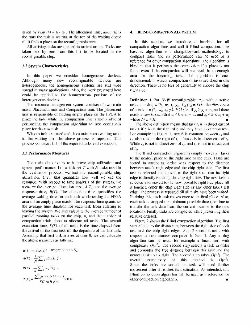
7 left corner, the distance from a task's bottom-left corner to
6 __- T4- the bottom left corner of the chip, which can be calculated5 as = Ix 2+ ~y2 for a task ti, might not yield always a good
4 __ _l T _-choice. As shown in Figure 1, for tasks t1 and t2, although d23 7 _*_ > dl, we need to move t2 before tl.2 T2
d]1 r Id2 Definition 2 For HxW reconfigurable area with n active
1 2 3 4 5 6 7 tasks, atask tj = (hj, wj, xj, yj), 1< j < n, is in the south-westFigure 1: Relative distance. region of a task ti = (hi, wi, xi, yi), 1< i < n, if yj < yi + wi
and xj < xi + hi,.The above definition means that task tj is in the direct
Algorithm 1: Blind Compaction(Lt a) south west of task ti if the lower left corner of task tj is in the
n AlistL wita iv , .I south-west region of task ti. For example, in Figure 1, tl, t2,L = {et,; t, = (hj, w,X,Y;,),)1 . .<n' and t3 are in the south-west region of t4.Output: A compacted list L' with n active tasks,
L= {t,; t = (h,, W, x, ,~),1 . i . l} | Definition 3 A task tj has relative distance, Xtj, less than the1. For i = I to n relative distance, Xti, of a task ti if:mi = W- (yi + wi) (1) tj is in the south-west region of ti or2. Sort L with respect to mi in descending order, in L'. (2) dj < di and (1) is not true. n3. For i = I to n The above definition defines the criteria on which we will
3.1 ti=L'(i) arrange the tasks to be moved in the two-dimensional3.2 Forj = I to i-1 compaction algorithm. For example, in Figure 1, Xt2 < Xt1
t=LCj) because t2 is in the south-west region of tl. Also Xt2 < Xt3If (t) in the direct east of (ti) because d2 < d3 and t2 is not in the south-west region of t3.
Next j The algorithm in Figure 3 takes 0(n2) where each task3.3 Move ti to the right mi colunms, i.e. (y'i = yi + mi) has to ask the other n tasks to identify its relative order in
Next i the sorted list SL. For example in Figure 1, since Xt2 < (Xt1,Xt3, Xt4), the first task is t2. The sorted list of tasks in Figure1 will be {t2, t1, t3, t4}.n
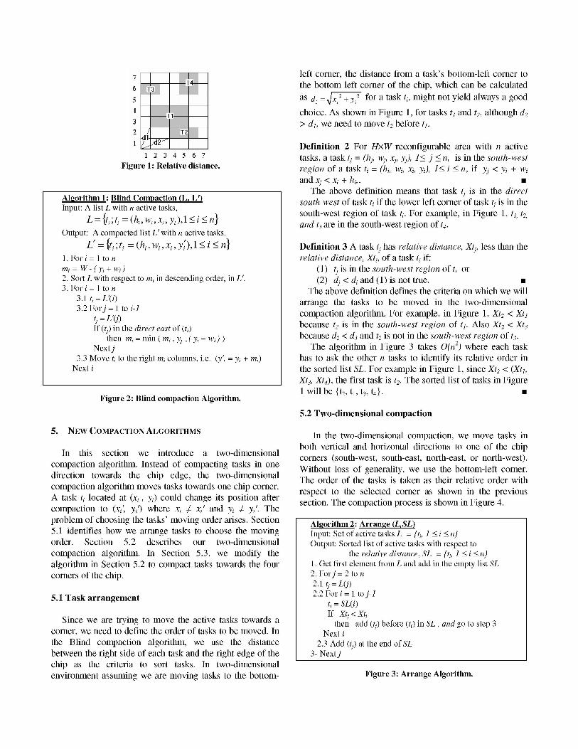
Figure 2: Blind compaction Algorithm.5.2 Two-dimensional compaction
5. NEW COMPACTION ALGORITHMS In the two-dimensional compaction, we move tasks inboth vertical and horizontal directions to one of the chipIn this section we introduce a two-dimensional corners (south-west, south-east, north-east, or north-west).
compaction algorithm. Instead of compacting tasks in one Without losstofwenerality,-wesus the ot orner.direction towards the chip edge, the two-dimensional
Wihu oso eeaiy euetebto-etcre.direction towrd tehiegetewodieThe order of the tasks is taken as their relative order with
compaction algorithm moves tasks towards one chip corner. respect to the selected corner as shown in the previousA task ti located at (xi, yi) could change its position after section. The compaction process is shown in Figure 4.compaction to (xi', yi) where xi #& xi' and yi 7# yi'. Theproblem of choosing the tasks' moving order arises. Section Algorithm 2: Arrange (L,SL)5.1 identifies how we arrange tasks to choose the moving Input: Set of active tasks L = [ti, 1 < i < niorder. Section 5.2 describes our two-dimensional Output: Sorted list of active tasks with respect tocompaction algorithm. In Section 5.3, we modify the the relative distance, SL = [ti, 1 < i <nalgorithm in Section 5.2 to compact tasks towards the four 1. Get first element from L and add in the empty list SLcorners of the chip. 2. Forj = 2 to n
2.1 tj=L(j)5.1 Task arrangement 2.2 Fori= Ito j-
ti= SL(i)If Xt < Xt,
Since we are trying to move the active tasks towards a fthen add () before (ti) in SL, and go to step 3corner, we need to define the order of tasks to be moved. In Next ithe Blind compaction algorithm, we use the distance 2.3 Add (n) at the end of SLbetween the right side of each task and the right edge of the 3- Next]jchip as the criteria to sort tasks. In two-dimensionalenvironment assuming we are moving tasks to the bottom- Figure 3: Arrange Algorithm.
independently chosen uniformly distributed randomAlgorithm 3: One-Corner-Compaction(L, L) variables were generated. Two random variables represent
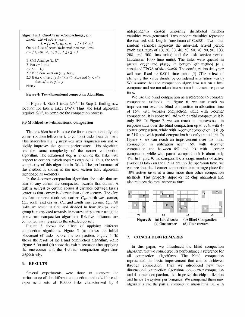
Input: List of active tasks, the two task side lengths (maximum of 32x32). Two otherL = fti =(hi, wi, xi, Yi) ;1<i< n] random variables represent the inter-task arrival period
Output: List of active tasks with new positions, (with maximum of 10, 20, 30, 40, 50, 60, 70, 80, 90, 100,
Li=ft,=(h,, wi, xj yi,)] _ _200, and 300 time units) and the task service period1- Call Arrange (L, L') (maximum 1000 time units). The tasks were queued in2- For i= 1 to n arrival order and placed in bottom left method to a2.1 ti = L'(i) simulated FPGA of size 64x64. The configuration delay per2.2 Find new location (x, y) for ti cell was fixed to 0.001 time units [3] (The effect of2.3 If ((x < xi) and (y < yi)) or ((x < xi) and (y < Yi)) changing this value should be considered in a future work.)
then xi' = x, Yi' = Y We assume that the compaction algorithms run on a host
L_Next i computer and are not taken into account in the task responseFigure 4: Two-dimensional compaction Algorithm. time.
We use the blind compaction as a reference to compare
In Figure 4, Step 1 takes 0(n2). In Step 2, finding new compaction methods. In Figure 6, we can reach an
location for task ti takes 0(n2). Thus, the total algorithm improvement over the blind compaction in allocation timerequires 0(n2) to complete the compaction process. of 15% with 4-corner compaction, while with 1-corner
compaction, it is about 8% and with partial compaction it is
5.3 Modified two-dimensional compaction only 5%. In Figure 7, we can reach an improvement inresponse time over the blind compaction up to 37% with 4-
The new idea here is to use the four corners, not only one corner compaction, while with 1-corner compaction, it is upcorner (bottom left corner), to compact tasks towards them. to 21% and with partial compaction it is only up to 11%. InThis algorithm highly improves area fragmentation and so Figure 8, we can reach an improvement over the blind
highly improves the system performance. This algorithm compaction in utilization near 16% with 4-cornerhas the same complexity of the corner compaction compaction and between 8% and 9% with 1-corneralgorithm. The additional step is to divide the tasks with compaction while with partial compaction it is about onlyrespect to corners, which requires only 0(n). Thus, the total 4%. In Figure 9, we compare the average number of activecomplexity of this algorithm is 0(n2). The performance of (working) tasks on the FPGA chip in the operation time, wethis method is shown in the next section (this algorithm can see that the 4-corner compaction can manage place formentioned as 4-corner). 10% active tasks at a time more than other compaction
In the 4-corner compaction algorithm, the tasks that are methods. This property improves the chip utilization andnear to any corner are compacted towards that corner. A also reduces the total response time.task is nearest to certain corner if distance between task'scenter to that corner is shorter than other corners. The chip 1T4 - T4 T4 T3
has four corners: north east corner, Cne, north west corner, T3 T3 TCnw, south east corner, CSe, and south west corner, C5W. All * T=
Ti~~~~~tasks are tested at first and divided to four groups, each T2 -Ti-- T2
group is compacted towards its nearest chip corner using theone-corner compaction algorithm. Relative distances are (a) (b) (C__ _ d_computed with respect to the selected corner. Figure 5: (a) Initial tasks (b) Blind Compaction
Figure 5 shows the effect of applying different (c) One corner (d) Four cornerscompaction algorithms. Figure 5 (a) shows the initialplacement of tasks before any compaction. Figure 5 (b) 7. CONCLUDING REMARKSshows the result of the Blind compaction algorithm, whileFigure 5 (c) and (d) show the task placement after applying In this paper, we introduced the blind compactionthe one-corner and the 4-corner compaction algorithms algorithm that we considered its performance a reference forrespectively. all compaction algorithms. The blind compaction
6. RESULTS represented the basic improvement that can be achievedthrough compaction. Then we introduced new two-dimensional compaction algorithms, one-corner compaction
Several experiments were done to compare the an.-onrcmato,htipoeteci utiizaioperformance of the different compaction methods. For each and hence the system performance. We compared these newexperiment, sets of 10,000 tasks characterized by 4 loihsadteprilcopcinagrtm 3,wt

the reference performance. The comparison showed an Hashing", International Parallel and Distributed Processingimprovement in the system performance. For the utilization, Symposium, April 2003.the 4-corner compaction is 12% better than the partial [7] M. Handa and R. Vemuri, "An Efficient Algorithm forcompaction and 7% better than the one-corner compaction. Finding Empty Space for Online FPGA Placement", Design
We h s r i i t x tAutomation Conference, San Diego, CA, June 2004, pp. 960-We have several directhions to extend this work. We plan 965.to apply these algorithms in real time system and test the [8] Katherine Compton, James Cooley, Stephen Knol, and Scotteffect of compaction on the system lmiss ratio. Real time Hauck. "Configuration Relocation and Defragmentation foroperating system is an important application of such Reconfigurable Computing". In Proceedings of the IEEEsystems. Extending the work to consider heterogeneous Symposium on FPGAs for Custom Computing Machinesreconfigurable system is another direction. In addition to the (FCCM). IEEE CS Press, April 2001.placement of the tasks, it is necessary to consider the [9] H. Kalte, M. Koester, B. Kettelhoit, M. Porrmann and U.communication infrastructure. Therefore, the model can be Riickert " A Comparative Study on System Approaches forextended by a formal description of the communication Partially Reconfigurable Architectures ". Engineering ofinfrastructure. Reconfigurable Systems and Algorithms (ERSA06).
75 ~~~~~~~~~~~~~~~~300000-60 - 250000 -
cn 200000045 - 150000
E100000E 30 - |15 -
Iso oo50000
10 20 30 40 50 60 70 80 90 100 200 3000 - | || | | |||||Inter Task Arrival Time
10 20 30 40 50 60 70 80 90 100 200 300 - lind PartialInter Task Arrival Time Bin- - aa1 Corner - - 4 Corner
Blind --- Partial ___ _1 _Corner - - 4 Corner Figure 7: Compaction algorithms effect on response time.
Figure 6: Compaction algorithms effect on allocation time.75-
REFERENCES -.
[1] Manuel G. Gericota, Gustavo R. Alves, Miguel L. Silva, Jos6 50M. Ferreira, "On-line Defragmentation for Run-TimePartially Reconfigurable FPGAs", FPL 2002, LNCS 2438,pp. 302-311,2002.____________________
[2] Manuel G. Gericota, Gustavo R. Alves, Miguel L. Silva, Jos6 25, , , ~~~~~~~~~~~1020 30 40 50 60 70 80 90 100 200 300M. Ferreira, "Run-Time Management of Logic Resources on Inter Task Arrival Time
Reconfigurable Systems", In Proceedings of the Design, Ind ArvPata
Automation and Test in Europe 2003 Conference and 1_Corner - - 4_CornerExhibition (DATE'2003), Munich, Germany, March 2003,pp. 974-979. Figure 8: Compaction algorithms effect on chip Utilization.
[3] 0. Diessel, H. ElGindy, M. Middendorf, H. Schmeck, and B.Schmidt, "Dynamic scheduling of tasks on partially 11reconfigurable FPGAs". In IEEE Proceedings on Computersand Digital Techniques, volume 147, pages 181-188, May2000. Cn
[4] Sandor P. Fekete, and Jorg Schepers. "A Combinatorial 9.5co
Characterization of Higher-Dimensional Orthogonal _ -Packing". In Mathematics of Operations Research, Volume29: 353-368 (2004). __8______________________
[5] Kiarash Bazargan, Ryan Kastner, and Majid Sarrafzadeh. 810 20 30 40 50 60 70 80 90 100 200 300"Fast Template Placement for Reconfigurable Computing Inter Task Arrival Timel
Systems". In IEEE Design and Test of Computers, volume - Blind --- Partial17, pages 68-83, 2000. ___ 1Conr__-4Cone_
[6] H. Walder, C. Steiger, and M. Platzner, "Fast Online Task 1 Conr -l4CrePlacement on FPGAs: Free Space Partitioning and 2D- Figure 9: Average number of active tasks.