An automated, reconfigurable, low-power RFID tag
6
An Automated, Reconfigurable, Low-Power RFID Tag Alex K. Jones, Raymond R. Hoare, Swapna R. Dontharaju, Shenchih Tung Ralph Sprang, Josh Fazekas, James T. Cain, and Marlin H. Mickle {akjones,hoare,cain,mickle}@ece.pitt.edu Department of Electrical and Computer Engineering University of Pittsburgh Pittsburgh, PA 15261 ABSTRACT This paper describes an ultra low power active RFID tag and its au- tomated design flow. RFID primitives to be supported by the tag are enumerated with RFID macros and the behavior of each primitive is specified using ANSI-C within the template to automatically gen- erate the tag controller. Two power saving components, a passive transceiver/burst switch and a smart buffer, are presented to save power and increase tag lifetime. Based on a test program, the pro- cessors required 183, 43, and 19 μJ per transaction for StrongARM, XScale, and EISC processors, respectively. Three hardware con- trollers using a Fusion FPGA, Coolrunner II CPLD, and ASIC re- quired 13 nJ, 1.3 nJ, and 0.07 nJ per transaction. Categories and Subject Descriptors C.3 [Special Purpose and Application-Based Systems]: Real- time and embedded systems; B.7.1 [Integrated Circuits]: Types and Design Styles—Gate arrays General Terms Performance, Design, Human Factors, Languages 1. INTRODUCTION RFID tags generally come in two types, active and passive. Ac- tive tags require an internal power source (usually a battery) to power the transceiver for receiving queries and transmitting re- sponses. The power supply also powers the tag’s controller, which may be an ASIC or an embedded microprocessor. Passive tags do not contain an internal power source. As a result, these tags not only receive information from a query, they also receive energy. This energy is used to power the tag to determine and send a re- sponse to the query. While passive tags are generally cheaper than active tags, they have two major disadvantages: (1) the range of passive tags is significantly lower than active tags and (2) the com- plexity of response is significantly reduced over active tags due to Permission to make digital or hard copies of all or part of this work for personal or classroom use is granted without fee provided that copies are not made or distributed for profit or commercial advantage and that copies bear this notice and the full citation on the first page. To copy otherwise, to republish, to post on servers or to redistribute to lists, requires prior specific permission and/or a fee. DAC 2006, July 24–28, 2006, San Francisco, California, USA. Copyright 2006 ACM 1-59593-381-6/06/0007 ...$5.00. the limited energy budget. However, active tags in addition to be- ing more costly than passive tags also require maintenance, often to change the battery. Ultra Low-power Active RFID Tag Smart Buffer Passive Energy Receiver Passive Transceiver Switch Transceiver Controller Figure 1: Extensible, low-power RFID tag. The tag shown in Figure 1 addresses two current problems in the field of RFID. The first problem is that many applications require a “custom” tag, either active or passive. Standards have been de- veloped but in some cases additional capabilities are required for a specific application. Currently, the cost of designing and imple- menting such a custom tag is prohibitive. Our tag consists of a pro- grammable controller that can be easily customized to work with different standards combined with custom proprietary commands. The second problem is that there are many applications that require the capability of an active RFID tag but the application is such that battery replacement is at least inconvenient, if not impossible. Our tag provides the capability of an active tag but with several power saving components that allow the tag to operate on a single battery throughout its lifetime. To program the controller, a design automation tool has been de- veloped that allows RFID primitives to be specified using RFID macros, an assembly-like format. These RFID macros are pro- cessed to generate a template file to specify the behavior for each macro. All behavior is specified using ANSI-C allowing the user to create arbitrarily complex behaviors. Finally, the RFID compiler generates the final controller used for managing the tag. In order to reduce the power consumption of the tag we present a technique called a burst switch that allows the tag to remain asleep with its transceiver and controller either completely off or in a hibernate mode. Additionally, during a transaction, the power can be further reduced by a smart buffer that keeps the tag in a standby mode with the controller remaining asleep until it is needed. Because RFID 9.2 131
-
Upload
independent -
Category
Documents
-
view
0 -
download
0
Transcript of An automated, reconfigurable, low-power RFID tag

An Automated, Reconfigurable, Low-Power RFID Tag
Alex K. Jones, Raymond R. Hoare, Swapna R. Dontharaju, Shenchih TungRalph Sprang, Josh Fazekas, James T. Cain, and Marlin H. Mickle
{akjones,hoare,cain,mickle}@ece.pitt.edu
Department of Electrical and Computer EngineeringUniversity of PittsburghPittsburgh, PA 15261
ABSTRACTThis paper describes an ultra low power active RFID tag and its au-tomated design flow. RFID primitives to be supported by the tag areenumerated with RFID macros and the behavior of each primitive isspecified using ANSI-C within the template to automatically gen-erate the tag controller. Two power saving components, a passivetransceiver/burst switch and a smart buffer, are presented to savepower and increase tag lifetime. Based on a test program, the pro-cessors required 183, 43, and 19 µJ per transaction for StrongARM,XScale, and EISC processors, respectively. Three hardware con-trollers using a Fusion FPGA, Coolrunner II CPLD, and ASIC re-quired 13 nJ, 1.3 nJ, and 0.07 nJ per transaction.
Categories and Subject DescriptorsC.3 [Special Purpose and Application-Based Systems]: Real-time and embedded systems; B.7.1 [Integrated Circuits]: Typesand Design Styles—Gate arrays
General TermsPerformance, Design, Human Factors, Languages
1. INTRODUCTIONRFID tags generally come in two types, active and passive. Ac-
tive tags require an internal power source (usually a battery) topower the transceiver for receiving queries and transmitting re-sponses. The power supply also powers the tag’s controller, whichmay be an ASIC or an embedded microprocessor. Passive tags donot contain an internal power source. As a result, these tags notonly receive information from a query, they also receive energy.This energy is used to power the tag to determine and send a re-sponse to the query. While passive tags are generally cheaper thanactive tags, they have two major disadvantages: (1) the range ofpassive tags is significantly lower than active tags and (2) the com-plexity of response is significantly reduced over active tags due to
Permission to make digital or hard copies of all or part of this work forpersonal or classroom use is granted without fee provided that copies arenot made or distributed for profit or commercial advantage and that copiesbear this notice and the full citation on the first page. To copy otherwise, torepublish, to post on servers or to redistribute to lists, requires prior specificpermission and/or a fee.DAC 2006, July 24–28, 2006, San Francisco, California, USA.Copyright 2006 ACM 1-59593-381-6/06/0007 ...$5.00.
the limited energy budget. However, active tags in addition to be-ing more costly than passive tags also require maintenance, oftento change the battery.
Ultra Low-power Active RFID Tag
Smart Buffer
Passive Energy Receiver
Passive Transceiver
Switch Transceiver
Controller
Figure 1: Extensible, low-power RFID tag.The tag shown in Figure 1 addresses two current problems in the
field of RFID. The first problem is that many applications requirea “custom” tag, either active or passive. Standards have been de-veloped but in some cases additional capabilities are required fora specific application. Currently, the cost of designing and imple-menting such a custom tag is prohibitive. Our tag consists of a pro-grammable controller that can be easily customized to work withdifferent standards combined with custom proprietary commands.The second problem is that there are many applications that requirethe capability of an active RFID tag but the application is such thatbattery replacement is at least inconvenient, if not impossible. Ourtag provides the capability of an active tag but with several powersaving components that allow the tag to operate on a single batterythroughout its lifetime.
To program the controller, a design automation tool has been de-veloped that allows RFID primitives to be specified using RFIDmacros, an assembly-like format. These RFID macros are pro-cessed to generate a template file to specify the behavior for eachmacro. All behavior is specified using ANSI-C allowing the userto create arbitrarily complex behaviors. Finally, the RFID compilergenerates the final controller used for managing the tag. In orderto reduce the power consumption of the tag we present a techniquecalled a burst switch that allows the tag to remain asleep with itstransceiver and controller either completely off or in a hibernatemode. Additionally, during a transaction, the power can be furtherreduced by a smart buffer that keeps the tag in a standby mode withthe controller remaining asleep until it is needed. Because RFID
9.2
131
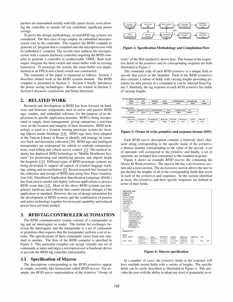
packets are transmitted serially with kHz speed clocks, even allow-ing the controller to remain off can contribute significant powersavings.
To prove this design methodology, several RFID tag systems areconsidered. The first class of tags employ an embedded micropro-cessor core as the controller. This requires the RFID compiler togenerate a C program that is compiled onto the microprocessor withits embedded C compiler. The second class replaces the micropro-cessor with a custom hardware controller requiring the RFID com-piler to generate a controller in synthesizable VHDL. Both tech-niques integrate the burst switch and smart buffer with an existingtransceiver. To prototype the system, the smart buffer was imple-mented in an FPGA and a burst switch was constructed..
The remainder of the paper is organized as follows: Section 2describes related work in the RFID systems domain. The RFIDcompiler is presented in Section 3. Section 4 briefly introducesthe power saving technologies. Results are related in Section 5.Section 6 discusses conclusions and future directions.
2. RELATED WORKResearch and development in RFID has been focused on hard-
ware and firmware components such as active and passive RFIDtags, readers, and embedded software, for the purpose of its de-ployment in specific application domains. RFID is being incorpo-rated in supply chain management, giving enterprises a real-timeview on the location and integrity of their inventories. RFID tech-nology is used in a location sensing prototype system for locat-ing objects inside buildings [14]. RFID tags have been adoptedin the Vatican Library in Rome to identify and manage its exten-sive book and document collection [20]. RFID tags and intelligenttransponders are widespread for vehicle to roadside communica-tions, road tolling and vehicle access control [1]. The medical in-dustry has deployed RFID technology in “Mobile Healthcare Sys-tems” for positioning and identifying persons and objects insidethe hospitals [13]. Different types of RFID prototype systems arebeing developed to support all aspects of aviation baggage track-ing, sorting and reconciliation [2]. Recent research has focused onthe collection and storage of RFID data using Geo-Time visualiza-tion [16]. Distributed Application Specification Language (DASL)has been used to model and deploy software applications to processRFID event data [12]. Most of the above RFID systems use pro-prietary hardware and software that cannot tolerate changes to theapplication or standard. However, the use of design automation forthe development of RFID systems and the combination of passiveand active technology together for increased capability and reducedpower have not been studied.
3. RFIDTAGCONTROLLERAUTOMATIONThe RFID communication system consists of a transponder or
tag and an interrogator or reader. The format for exchanges be-tween the interrogator and the transponder is a set of commandsor primitives that requests that the transponder perform a set of ac-tions. The specifications of these commands varies from one stan-dard to another. The flow of the RFID compiler is specified inFigure 2. This particular compiler can accept virtually any set ofcommands as input and target a microprocessor or hardware deviceto provide the RFID tag controller functionality.
3.1 Specification of MacrosThe descriptions corresponding to the RFID primitives appear
as simple, assembly-like instructions called RFID macros. For ex-ample, the RFID macro representation of the primitive “Owner id
RFID Specification
Convert to RFID Macros
RFID Parserrfpp
Behavior Template
Include RFID Behavior
RFID Compilerrfcc
Embedded C Compiler
µprocessor based RFID
Tag
Commercial Synthesis
Flow
hardware based RFID
Tag
C
VHDL
Figure 2: Specification Methodology and Compilation Flow
write” of the ISO standard is shown here. The format of the respec-tive fields of the primitive and its corresponding response are bothillustrated in Figure 3.
The command code of each RFID primitive is a unique field oropcode that serves as the identifier. Each of the RFID primitivesalso contains a subset of fields with varying lengths providing po-sitions for data present in a command as can be inferred from Fig-ure 3. Similarly, the tag response to each RFID primitive has fieldsof varying lengths.
Figure 3: Owner id write primitive and response format (ISO)
Each RFID macro description contains a relatively short char-acter string corresponding to the specific name of the primitive,a distinct number corresponding to the value of the opcode, a setof operands will correspond to the primitive and finally, a set ofoperands are included that correspond to the standard response.
Figure 4 shows an example RFID macros file containing theOwner Id Write primitive. The macros file has a declarations sec-tion and a main section. The declarations section allows the user topre-declare the lengths of all of the corresponding fields that occurin each of the primitives and responses. In the section identifiedas main, the primitives and their specific responses are defined interms of their fields.
Figure 4: Macros specification
In a number of cases, the primitive fields or the response willhave multiple nested fields with a variety of lengths. The specificfields can be easily described as illustrated in Figure 4. This pro-vides the user with the ability to adopt any level of granularity in or-
132

der to manipulate the primitives and their corresponding responses.In the macro illustrated below, the string denoting the owner idwrite command is ionw. The decimal value of the command codefor this specific command is “137”.
Initially, the Extensible Markup Language (XML) [18] was eval-uated as a candidate for the macro specification. In this specific ex-ample, the form presented in Figure 4 does not require a full parserand was considered easier for the end user to understand. In addi-tion, it was noted that the nested structures were hard to work withwhen employing the pre-existing XML parsers.
3.2 Behavior TemplateThe communications from the RFID interrogator (Reader) is ac-
complished by transmitting the primitive to the RFID tag using astandard air interface. The tag will respond by changing the cur-rent state and / or transmitting a designated response message tothe interrogator. The user has the capability of specifying the tagbehavior in ANSI C.
In order to simplify the user interaction, a template is generatedby the RFID parser to assist the user in providing the response be-havior code. C language constructs (conditionals, loops, etc.) canbe included by the user in order to check the values of the fieldsof an incoming RFID primitive to specify the field values of theresponse. The resulting template, which has been generated as aresult of the collection command (icol in the macros specificationfrom Figure 3) is shown in Figure 5(a). Similar templates are con-tained in a file for each of the macros that are a part of the macrosspecification file.
The details involving size and field position in the command ofthe interrogator and the corresponding response packet are handledby the compiler. Therefore, complexities encountered in unpack-ing the command and subsequently packing the response can beabstracted from the user as shown in Figure 5. However, the abilityfor the user to manipulate each of the individual fields in the re-sponse is intact. Therefore, the response customization along withthe corresponding state changes can increase in complexity withuser ease.
(a) Template Generated (b) After User Input
Figure 5: Tag Behavior for Collection Command
3.3 Compiler-Generated RFID Tag ProgramThe code generation is the final compiler phase determined by
the tag behavior and the input macros specification. Code genera-tion can be in the form of ANSI-C for general purpose micropro-cessor controllers or VHDL in the case of hardware controllers.The decode instructions generated by the compiler identify the re-ceived RFID primitive. For each incoming command, routines are
Basic Block 0
!=
mux
S
mux
S
mux
S
isPasswordProtected
1
0
2
modefield
modefield
2
reserved1
reserved1
2
acknowledge
acknowledge
2
!=
mux
S
1
reserved2tagtypereserved3useridbatterymesglen
0
1
7
1
commandValid
1
0
2
0
1
1
2
3210014
Figure 6: SDFG for the “Owner id write” (ionw) command.
generated by the compiler, which unpack the command generatingthe fields that it is expected to contain. The corresponding behavioris attached to each field, and the corresponding routines for pack-ing the response are then generated. By virtue of the fact that C is asignificant and universally known language than classical hardwaredescription languages, the primitive behaviors are specified in C inthe case of a specified VHDL target. Therefore the C code must beconverted to a readily synthesizable hardware code.
During the hardware conversion, the C code is converted intoa control and data flow graph (CDFG). Compilers commonly useCDFGs to perform optimizations and transformations. Typically,behavioral synthesis tools will also use CDFGs as an internal rep-resentation [19]. In many cases, the control dependencies presentin a CDFG create cycle boundries during high-level synthesis.
In contrast, in our RFID compiler the CDFG is transformed intoan entirely combinational representation by the SuperCISC Com-piler. The result is a super data flow graph (SDFG). The SuperCISCcompiler [10, 6] takes advantage of well known compiler transfor-mations including loop unrolling and function inlining and hard-ware predication in order to convert each control dependency intoa data dependency creating a combinational representation. TheSDFG for the ionw is shown in Figure 6. The need for many po-tentially high-power consuming sequential constructs such as regis-ters and clock trees are removed by this technique. Thus, the result-ing SDFG based hardware implementations are extremely powerefficient [11].
4. POWER REDUCTION TECHNIQUESA typical RFID tag consists of three primary elements; (1) trans-
mitter, (2) controller, and (3) receiver. From the classical opera-tional scenario, the transmitter is only needed when there is data totransmit. Thus, the transmitter can easily be turned off when notneeded. The controller can be put in a low power/sleep mode tosave energy. The only element that is not in a low power mode isthe receiver, which is kept active to know when there is an inquiryfrom the interrogator. Thus, the receiver becomes is the determi-nant of the shelf life of an active RFID tag.
To reduce the power of the RFID tag receiver two main technolo-ges are employed, a passive transceiver or burst switch allows thetag to remain in a sleep mode until activated with RF energy and asmart buffer, which allows the controller to remain asleep while anincoming packet is buffered.
The burst switch, shown in Figure 7, is a passive receiver that ispowered by RF energy from the air, which allows the active receiverto be turned completely off. Thus, the shelf life is determined pri-marily by the controller sleep power. The active receiver and smartbuffer are turned only when the burst switch is activated by thewake-up signal(s) from the interrogator. The controller is managedby the smart buffer. The result is an active tag with minimal powerconsumption that can operate on a single battery for its lifetime.
133
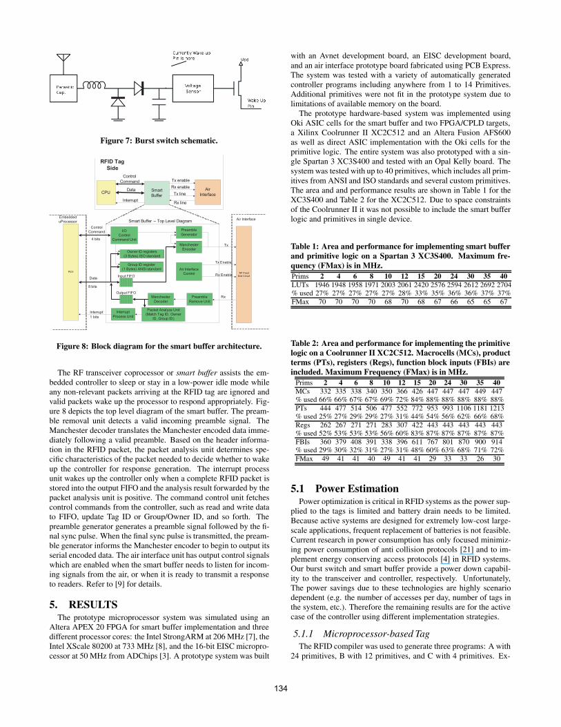
Figure 7: Burst switch schematic.
Smart
Buffer
Air
Interface
Rx enable
Tx line
Rx line
RFID Tag
Side
CPUData
Interrupt
PIO1
Interrupt
Data
I/O
Control
Command Unit
Control
Command
Owner ID registers
(3 Bytes) ISO standard
Group ID register
(1 Bytes) ANSI standard
Input FIFO
Output FIFO
Interrupt
Process Unit
Packet Analyze Unit
(Match Tag ID, Owner
ID, Group ID)
Preamble
Generator
Manchester
Encoder
Preamble
Remove Unit
Manchester
Decoder
Embedded
uProcessor
Tx
Rx
Air Interface
Control
Tx Enable
Rx EnableRF Front
End Circuit
Air Interface
Control
Command Tx enable
8 bits
4 bits
1 bits
Smart Buffer – Top Level Diagram
Figure 8: Block diagram for the smart buffer architecture.
The RF transceiver coprocessor or smart buffer assists the em-bedded controller to sleep or stay in a low-power idle mode whileany non-relevant packets arriving at the RFID tag are ignored andvalid packets wake up the processor to respond appropriately. Fig-ure 8 depicts the top level diagram of the smart buffer. The pream-ble removal unit detects a valid incoming preamble signal. TheManchester decoder translates the Manchester encoded data imme-diately following a valid preamble. Based on the header informa-tion in the RFID packet, the packet analysis unit determines spe-cific characteristics of the packet needed to decide whether to wakeup the controller for response generation. The interrupt processunit wakes up the controller only when a complete RFID packet isstored into the output FIFO and the analysis result forwarded by thepacket analysis unit is positive. The command control unit fetchescontrol commands from the controller, such as read and write datato FIFO, update Tag ID or Group/Owner ID, and so forth. Thepreamble generator generates a preamble signal followed by the fi-nal sync pulse. When the final sync pulse is transmitted, the pream-ble generator informs the Manchester encoder to begin to output itsserial encoded data. The air interface unit has output control signalswhich are enabled when the smart buffer needs to listen for incom-ing signals from the air, or when it is ready to transmit a responseto readers. Refer to [9] for details.
5. RESULTSThe prototype microprocessor system was simulated using an
Altera APEX 20 FPGA for smart buffer implementation and threedifferent processor cores: the Intel StrongARM at 206 MHz [7], theIntel XScale 80200 at 733 MHz [8], and the 16-bit EISC micropro-cessor at 50 MHz from ADChips [3]. A prototype system was built
with an Avnet development board, an EISC development board,and an air interface prototype board fabricated using PCB Express.The system was tested with a variety of automatically generatedcontroller programs including anywhere from 1 to 14 Primitives.Additional primitives were not fit in the prototype system due tolimitations of available memory on the board.
The prototype hardware-based system was implemented usingOki ASIC cells for the smart buffer and two FPGA/CPLD targets,a Xilinx Coolrunner II XC2C512 and an Altera Fusion AFS600as well as direct ASIC implementation with the Oki cells for theprimitive logic. The entire system was also prototyped with a sin-gle Spartan 3 XC3S400 and tested with an Opal Kelly board. Thesystem was tested with up to 40 primitives, which includes all prim-itives from ANSI and ISO standards and several custom primitives.The area and and performance results are shown in Table 1 for theXC3S400 and Table 2 for the XC2C512. Due to space constraintsof the Coolrunner II it was not possible to include the smart bufferlogic and primitives in single device.
Table 1: Area and performance for implementing smart bufferand primitive logic on a Spartan 3 XC3S400. Maximum fre-quency (FMax) is in MHz.Prims 2 4 6 8 10 12 15 20 24 30 35 40LUTs 1946 1948 1958 1971 2003 2061 2420 2576 2594 2612 2692 2704% used 27% 27% 27% 27% 27% 28% 33% 35% 36% 36% 37% 37%FMax 70 70 70 70 68 70 68 67 66 65 65 67
Table 2: Area and performance for implementing the primitivelogic on a Coolrunner II XC2C512. Macrocells (MCs), productterms (PTs), registers (Regs), function block inputs (FBIs) areincluded. Maximum Frequency (FMax) is in MHz.
Prims 2 4 6 8 10 12 15 20 24 30 35 40MCs 332 335 338 340 350 366 426 447 447 447 449 447% used 66% 66% 67% 67% 69% 72% 84% 88% 88% 88% 88% 88%PTs 444 477 514 506 477 552 772 953 993 1106 1181 1213% used 25% 27% 29% 29% 27% 31% 44% 54% 56% 62% 66% 68%Regs 262 267 271 271 283 307 422 443 443 443 443 443% used 52% 53% 53% 53% 56% 60% 83% 87% 87% 87% 87% 87%FBIs 360 379 408 391 338 396 611 767 801 870 900 914% used 29% 30% 32% 31% 27% 31% 48% 60% 63% 68% 71% 72%FMax 49 41 41 40 49 41 41 29 33 33 26 30
5.1 Power EstimationPower optimization is critical in RFID systems as the power sup-
plied to the tags is limited and battery drain needs to be limited.Because active systems are designed for extremely low-cost large-scale applications, frequent replacement of batteries is not feasible.Current research in power consumption has only focused minimiz-ing power consumption of anti collision protocols [21] and to im-plement energy conserving access protocols [4] in RFID systems.Our burst switch and smart buffer provide a power down capabil-ity to the transceiver and controller, respectively. Unfortunately,The power savings due to these technologies are highly scenariodependent (e.g. the number of accesses per day, number of tags inthe system, etc.). Therefore the remaining results are for the activecase of the controller using different implementation strategies.
5.1.1 Microprocessor-based TagThe RFID compiler was used to generate three programs: A with
24 primitives, B with 12 primitives, and C with 4 primitives. Ex-
134
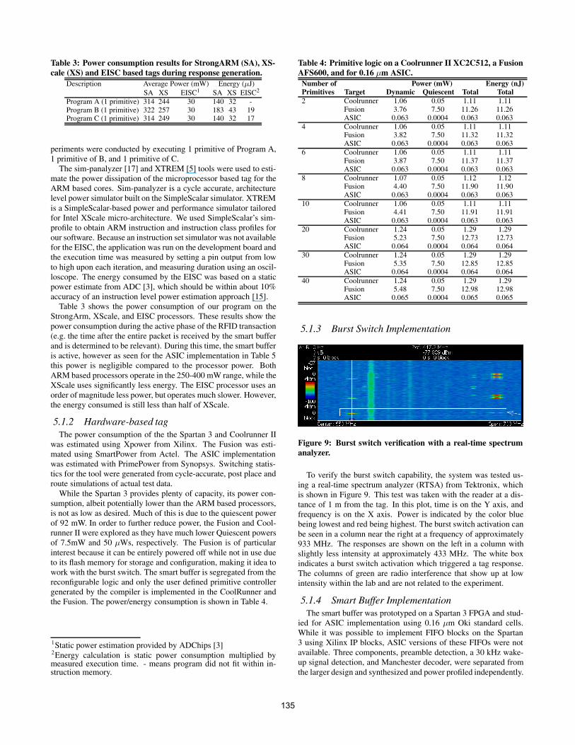
Table 3: Power consumption results for StrongARM (SA), XS-cale (XS) and EISC based tags during response generation.
Description Average Power (mW) Energy (µJ)SA XS EISC1 SA XS EISC2
Program A (1 primitive) 314 244 30 140 32 -Program B (1 primitive) 322 257 30 183 43 19Program C (1 primitive) 314 249 30 140 32 17
periments were conducted by executing 1 primitive of Program A,1 primitive of B, and 1 primitive of C.
The sim-panalyzer [17] and XTREM [5] tools were used to esti-mate the power dissipation of the microprocessor based tag for theARM based cores. Sim-panalyzer is a cycle accurate, architecturelevel power simulator built on the SimpleScalar simulator. XTREMis a SimpleScalar-based power and performance simulator tailoredfor Intel XScale micro-architecture. We used SimpleScalar’s sim-profile to obtain ARM instruction and instruction class profiles forour software. Because an instruction set simulator was not availablefor the EISC, the application was run on the development board andthe execution time was measured by setting a pin output from lowto high upon each iteration, and measuring duration using an oscil-loscope. The energy consumed by the EISC was based on a staticpower estimate from ADC [3], which should be within about 10%accuracy of an instruction level power estimation approach [15].
Table 3 shows the power consumption of our program on theStrongArm, XScale, and EISC processors. These results show thepower consumption during the active phase of the RFID transaction(e.g. the time after the entire packet is received by the smart bufferand is determined to be relevant). During this time, the smart bufferis active, however as seen for the ASIC implementation in Table 5this power is negligible compared to the processor power. BothARM based processors operate in the 250-400 mW range, while theXScale uses significantly less energy. The EISC processor uses anorder of magnitude less power, but operates much slower. However,the energy consumed is still less than half of XScale.
5.1.2 Hardware-based tagThe power consumption of the the Spartan 3 and Coolrunner II
was estimated using Xpower from Xilinx. The Fusion was esti-mated using SmartPower from Actel. The ASIC implementationwas estimated with PrimePower from Synopsys. Switching statis-tics for the tool were generated from cycle-accurate, post place androute simulations of actual test data.
While the Spartan 3 provides plenty of capacity, its power con-sumption, albeit potentially lower than the ARM based processors,is not as low as desired. Much of this is due to the quiescent powerof 92 mW. In order to further reduce power, the Fusion and Cool-runner II were explored as they have much lower Quiescent powersof 7.5mW and 50 µWs, respectively. The Fusion is of particularinterest because it can be entirely powered off while not in use dueto its flash memory for storage and configuration, making it idea towork with the burst switch. The smart buffer is segregated from thereconfigurable logic and only the user defined primitive controllergenerated by the compiler is implemented in the CoolRunner andthe Fusion. The power/energy consumption is shown in Table 4.
1Static power estimation provided by ADChips [3]2Energy calculation is static power consumption multiplied bymeasured execution time. - means program did not fit within in-struction memory.
Table 4: Primitive logic on a Coolrunner II XC2C512, a FusionAFS600, and for 0.16 µm ASIC.Number of Power (mW) Energy (nJ)Primitives Target Dynamic Quiescent Total Total2 Coolrunner 1.06 0.05 1.11 1.11
Fusion 3.76 7.50 11.26 11.26ASIC 0.063 0.0004 0.063 0.063
4 Coolrunner 1.06 0.05 1.11 1.11Fusion 3.82 7.50 11.32 11.32ASIC 0.063 0.0004 0.063 0.063
6 Coolrunner 1.06 0.05 1.11 1.11Fusion 3.87 7.50 11.37 11.37ASIC 0.063 0.0004 0.063 0.063
8 Coolrunner 1.07 0.05 1.12 1.12Fusion 4.40 7.50 11.90 11.90ASIC 0.063 0.0004 0.063 0.063
10 Coolrunner 1.06 0.05 1.11 1.11Fusion 4.41 7.50 11.91 11.91ASIC 0.063 0.0004 0.063 0.063
20 Coolrunner 1.24 0.05 1.29 1.29Fusion 5.23 7.50 12.73 12.73ASIC 0.064 0.0004 0.064 0.064
30 Coolrunner 1.24 0.05 1.29 1.29Fusion 5.35 7.50 12.85 12.85ASIC 0.064 0.0004 0.064 0.064
40 Coolrunner 1.24 0.05 1.29 1.29Fusion 5.48 7.50 12.98 12.98ASIC 0.065 0.0004 0.065 0.065
5.1.3 Burst Switch Implementation
Figure 9: Burst switch verification with a real-time spectrumanalyzer.
To verify the burst switch capability, the system was tested us-ing a real-time spectrum analyzer (RTSA) from Tektronix, whichis shown in Figure 9. This test was taken with the reader at a dis-tance of 1 m from the tag. In this plot, time is on the Y axis, andfrequency is on the X axis. Power is indicated by the color bluebeing lowest and red being highest. The burst switch activation canbe seen in a column near the right at a frequency of approximately933 MHz. The responses are shown on the left in a column withslightly less intensity at approximately 433 MHz. The white boxindicates a burst switch activation which triggered a tag response.The columns of green are radio interference that show up at lowintensity within the lab and are not related to the experiment.
5.1.4 Smart Buffer ImplementationThe smart buffer was prototyped on a Spartan 3 FPGA and stud-
ied for ASIC implementation using 0.16 µm Oki standard cells.While it was possible to implement FIFO blocks on the Spartan3 using Xilinx IP blocks, ASIC versions of these FIFOs were notavailable. Three components, preamble detection, a 30 kHz wake-up signal detection, and Manchester decoder, were separated fromthe larger design and synthesized and power profiled independently.
135
Table 5: ASIC vs. FPGA power for portions of Smart BufferComponent Spartan 3 0.16 µm ASICWake-up Signal 0.01 mW 0.001 mWPreamble Detection 0.87 mW 0.005 mWManchester Decoder 0.95 mW 0.284 mWQuiescent Power 92 mW 0 mWTotal 93.83 mW 0.29 mW
The power estimates of the ASIC and Spartan 3 based smartbuffer components are displayed in Table 5. The analyses are basedon post synthesis simulation with the exact same stimuli. TheFPGA power results were computed in a similar manner to Sec-tion 5.1.2. Based on the results from Table 5 the ASIC version ofthe implementation uses orders of magnitude less dynamic powerfor all components. Interestingly, the quiescent power of the FPGAalone is nearly three orders of magnitude greater than the dynamicpower of the ASIC.
6. CONCLUSIONS AND FUTURE WORKThis paper presents an ultra low power active RFID tag sys-
tem and an automated tag controller design flow. By providing aburst switch front end, the active transceiver can remain off untilrequested by a interrogator. Finally, during a communication, thesmart buffer allows the controller to remain off until required toprocess a packet. This system provides the capabilities of an activeRFID tag with the maintainability and power consumption similarto passive RFID tag. The RFID compiler can automatically gen-erate software or hardware for both microprocessor and hardwarebased tags from a simple description of the standards and behaviorin C. The system is extensible, as it allows for addition (or removal)of a set of custom primitives that may be a subset or superset of theoriginal standard(s).
To select the appropriate tag architecture for an extensible low-power tag, consider the power consumption for the different tagsystems described in Section 5.1. Based on the results from Sec-tion 5.1.4 coupled with the fact that smart buffer does not requirereconfiguration except in drastic redesign of RFID systems, imple-menting the smart buffer directly in silicon is the preferred option.
Three low-power embedded microprocessors were power pro-filed, StrongARM, XScale, and EISC. The XScale provided capac-ity advantages with reasonable power, while the EISC was morepower efficient, but could handle relatively few primitives. Threecustom hardware controllers were considered, an Actel Fusion, Xil-inx Coolrunner II, and direct ASIC implementation. The ASIC ap-proach provides a large power advantage, but is not extensible. TheCoolrunner II requires less energy per transaction than the Fusion(1.3 nJ versus 13 nJ); however, the Coolrunner requires the 50 µWof static power to remain programmed during the sleep mode whilethe Fusion can be entirely disconnected from power. The appropri-ate choice depends on the RFID system deployment scenerio.
We plan to introduce security into the RFID tag design in thefuture. Because our tag provides the capability of active tags withthe power consumption and maintainability of passive tags, it maybe possible to encrypt the communication without significantly de-grading the lifetime of the tag. The design automation makes thistask easier allowing C-based encryption algorithms to be leveraged.To prevent a malicious interrogator from running down the tag bat-tery by constantly activating the burst switch, it is possible to createactivation codes using burst duration and combining multiple burstswitches at different frequencies to prevent this denial of serviceattack.
7. REFERENCES[1] P. Blythe. RFID for road tolling, road-use pricing and vehicle
access control. IEE Colloquium on RFID Technology, 1999.[2] A. Cerino and W. P. Walsh. Research and application of radio
frequency identification (RFID) technology to enhanceaviation security. In Proc. IEEE NAECON, 2000.
[3] Y. Cha. EISC core. ADChips Presentation, February 2005.[4] I. Chlamtac, C. Petrioli, and J. Redi. Energy-conserving
access protocols for identification networks. IEEE/ACMTransactions on Networking (TON), 7(1), February 1999.
[5] C. Gilberto, M. Martonosi, J. Peng, R. Ju, and G. Lueh.XTREM: A power simulator for the Intel XScale core. InProc. ACM LCTES, 2004.
[6] R. Hoare, A. K. Jones, D. Kusic, J. Fazekas, J. Foster,S. Tung, and M. McCloud. Rapid VLIW processorcustomization for signal processing applications usingcombinational hardware functions. EURASIP Journal onApplied Signal Processing, 2006.
[7] Intel. SA-110 microprocessor technical reference manual,1998. ftp://download.intel.com.
[8] Intel. Intel PXA27x processor family developers manual,2004. ftp://download.intel.com.
[9] A. K. Jones, R. Hoare, S. R. Dontharaju, S. Tung, ,R. Sprang, J. Fazekas, J. T. Cain, and M. H. Mickle. Anautomated, FPGA-based reconfigurable, low-power RFIDtag. Journal of Microprocessors and Microsystems, to appear.
[10] A. K. Jones, R. Hoare, D. Kusic, J. Fazekas, and J. Foster.An FPGA-based VLIW processor with custom hardwareexecution. In Proc. of FPGA, 2005.
[11] A. K. Jones, R. Hoare, D. Kusic, G. Mehta, J. Fazekas, andJ. Foster. Reducing power while increasing performance withsupercisc. ACM TECS, to appear.
[12] M. Kaundinya and A. Syed. Modeling event drivenapplications with a specification language (MEDASL). InProc. ACM OOPSLA, 2004.
[13] C. Li, L. Liu, S. Chen, C. C. Wu, C. Huang, and X. Chen.Mobile healthcare service system using RFID. In Proc. IEEEICNSC, volume 2, 2004.
[14] L. M. Ni, Y. Liu, Y. C. Lau, and A. P. Patil. LANDMARC:indoor location sensing using active RFID. WirelessNetworks, 10, November 2004.
[15] J. Russell and M. Jacome. Software power estimation andoptimization for high performance, 32-bit embeddedprocessors. In Proc. of ICCD, 1998.
[16] D. Shuping and W. Wright. Geotime visualization of RFIDsupply chain data. RFID Journal, March 2005.
[17] Sim-panalyzer. Simplescalar-ARM power modeling project.http://www.eecs.umich.edu/ panalyzer.
[18] T. Bray and J. Paoli and C. M. Sperberg-McQueen.Extensible markup language (XML) 1.0. W3CRecommendation, 1998.http://www.w3.org/TR/1998/REC-xml-19980210.
[19] X. Tang, T. Jiang, A. Jones, and P. Banerjee. Compileroptimizations in the PACT behavioral synthesis tool forASICs and FPGAs. In Proc. of SoC, September 2003.
[20] TI. Texas instruments’ RFID technology streamlinesmanagement of vatican library’s treasured collections, 2004.
[21] F. Zhou, C. Chen, D. Jin, C. Huang, and H. Min. Evaluatingand optimizing power consumption of anti-collisionprotocols for applications in RFID systems. In Proc.ISLPED, 2004.
136