Accurate Self-Localization in RFID Tag Information Grids Using FIR Filtering
10
Accurate Self-Localization in RFID Tag Information Grids Using FIR Filtering Juan J. Pomárico-Franquiz and Yuriy S. Shmaliy, Fellow, IEEE Abstract—Grid navigation spaces nested with the radio-frequency identification (RFID) tags are promising for industrial and other needs, because each tag can deliver information about a local two- dimensional or three-dimensional surrounding. The approach, how- ever, requires high accuracy in vehicle self-localization. Otherwise, errors may lead to collisions; possibly even fatal. We propose a new extended finite impulse response (EFIR) filtering algorithm and show that it meets this need. The EFIR filter requires an optimal averaging interval, but does not involve the noise statistics which are often not well known to the engineer. It is more accurate than the extended Kalman filter (EKF) under real operation conditions and its iterative algorithm has the Kalman form. Better performance of the proposed EFIR filter is demonstrated based on extensive simulations in a comparison to EKF, which is widely used in RFID tag grids. We also show that errors in noise covariances may provoke divergence in EKF, whereas the EFIR filter remains stable and is thus more robust. Index Terms—Extended Kalman filter (EKF), extended unbiased finite impulse response (EFIR) filter, indoor localization, radio- frequency identification (RFID) tag information grid. I. INTRODUCTION I NFORMATION grids organized using radio-frequency identification (RFID) tags [1], [2] have drawn researches attention in the last decade [3]–[5] owing to several useful features. Each tag has its own identification (ID) number corre- sponding to unique coordinates of location and may be either active [6] or passive [7]–[9]. Information describing a local 2D or 3D surrounding can be programmed in each tag [3] and delivered to users by request that makes the RFID tag-nested grids smart and promising for industrial and other needs. The method is low cost and available for any purpose, provided the communication between a target and tags. Although an accessible map-library organized and saved in such a way has indubitable value, information usefulness can be appreciated only if a target (vehicle, mobil robot, etc.) self-localization is provided with a sufficient accuracy [10], [11]. Otherwise, errors may lead to collisions, even fatal. The problem is complicated by the required low-cost measurements which are typically accompanied with large noise. First applications of RFID tags to localize vehicles were probably reported in [12]. Most recent designs employ diverse trilateration schemes [13]–[15]. Utilizing received signal strength information (RSSI), the approach implies measuring distances between a vehicle and two or three tags in which locations are precisely known. The trilateration basically requires three tags to solve the three algebraic equations for vehicle coordinates and heading. Multilateration algorithms utilizing averaging over some time interval are most widely used here [16]–[18]. Other algorithms [19]–[21] can also be employed, including the directional ones [22], [23]. In line with this, there were developed various hybrid structures in which information received from the tags is combined with information received from other sources. The support vector machine was used in [24] in order to analyze information received from the RFID tags and make a decision about a certain robot location. The use of a single vision camera was proposed in [25] to make necessary corrections to the robot movements [26]. In the design of an intelligent wheelchair [27], information from the RFID system was combined with information received from the Global Positioning System in order to obtain autonomous traveling capability. Reviews of RFID tag-based localization algorithms are given in [2], [20] and some other relevant results can be found in [28]–[33]. A common drawback of multilateration and other “algebraic” algorithms is that noise reduction often cannot be provided efficiently or otherwise the bias error can be large. Optimal estimators are thus required. Although there is still a discussion on which estimator is better for RFID tag-nested grids, most frequently we meet applications of various modifications of the Kalman filter [9], [34]–[39] and particle filter (PF) [15], [40]–[42]. A disadvantage of the Kalman filter-based approach is that noise is required to be white and its statistics and the initial errors known in order for extended Kalman filter (EKF) to be subopti- mal. Otherwise, accuracy provided by EKF may be low [43] and unacceptable for information grids. Furthermore, the EKF is able to produce large errors under the uncertainties peculiar to industrial applications and when noise is heavy-tailed or Gaussian with outliers [44]. Also, the EKF often diverges under the conditions of large nonlinearities and intensive noise [45] that can be observed at the grid cell boundaries. On the other hand, it is known that the Gauss’s least squares (LS) often give accuracy that is superior to the best available EKF [46]. Thus, methods of averaging implemented in LS and finite impulse response (FIR) filters, which inherently have the bounded input bounded output (BIBO) stability may be superior to the recursive method implemented in EKF in applications to the RFID tag grids. Manuscript received November 15, 2013; revised January 06, 2014; accepted February 22, 2014. Date of publication March 11, 2014; date of current version May 02, 2014. Paper no. TII-13-0886. J. J. Pomárico-Franquiz and Y. S. Shmaliy are with the Department of Electronics Engineering, Universidad de Guanajuato, Salamanca 36885, Mexico (e-mail: [email protected]). Color versions of one or more of the figures in this paper are available online at http://ieeexplore.ieee.org. Digital Object Identifier 10.1109/TII.2014.2310952 IEEE TRANSACTIONS ON INDUSTRIAL INFORMATICS, VOL. 10, NO. 2, MAY 2014 1317 1551-3203 © 2014 IEEE. Personal use is permitted, but republication/redistribution requires IEEE permission. See http://www.ieee.org/publications_standards/publications/rights/index.html for more information.
Transcript of Accurate Self-Localization in RFID Tag Information Grids Using FIR Filtering
Accurate Self-Localization in RFID TagInformation Grids Using FIR Filtering
Juan J. Pomárico-Franquiz and Yuriy S. Shmaliy, Fellow, IEEE
Abstract—Grid navigation spaces nestedwith the radio-frequencyidentification (RFID) tags are promising for industrial and otherneeds, because each tag can deliver information about a local two-dimensional or three-dimensional surrounding. The approach, how-ever, requires high accuracy in vehicle self-localization. Otherwise,errors may lead to collisions; possibly even fatal. We propose a newextendedfinite impulse response (EFIR)filteringalgorithmand showthat itmeets this need. TheEFIR filter requires an optimal averaginginterval, but does not involve the noise statistics which are often notwell known to the engineer. It is more accurate than the extendedKalman filter (EKF) under real operation conditions and its iterativealgorithmhas theKalman form. Better performance of the proposedEFIR filter is demonstrated based on extensive simulations in acomparison to EKF, which is widely used in RFID tag grids. Wealso show that errors in noise covariancesmayprovoke divergence inEKF,whereas theEFIRfilter remains stable and is thusmore robust.
Index Terms—ExtendedKalman filter (EKF), extended unbiasedfinite impulse response (EFIR) filter, indoor localization, radio-frequency identification (RFID) tag information grid.
I. INTRODUCTION
I NFORMATION grids organized using radio-frequencyidentification (RFID) tags [1], [2] have drawn researches
attention in the last decade [3]–[5] owing to several usefulfeatures. Each tag has its own identification (ID) number corre-sponding to unique coordinates of location and may be eitheractive [6] or passive [7]–[9]. Information describing a local 2D or3D surrounding can be programmed in each tag [3] and deliveredto users by request that makes the RFID tag-nested grids smartand promising for industrial and other needs. The method is lowcost and available for any purpose, provided the communicationbetween a target and tags. Although an accessible map-libraryorganized and saved in such a way has indubitable value,information usefulness can be appreciated only if a target(vehicle, mobil robot, etc.) self-localization is provided with asufficient accuracy [10], [11]. Otherwise, errors may lead tocollisions, even fatal. The problem is complicated by the requiredlow-cost measurements which are typically accompanied withlarge noise.
First applications of RFID tags to localize vehicles wereprobably reported in [12]. Most recent designs employ diverse
trilateration schemes [13]–[15]. Utilizing received signalstrength information (RSSI), the approach implies measuringdistances between a vehicle and two or three tags in whichlocations are precisely known. The trilateration basicallyrequires three tags to solve the three algebraic equations forvehicle coordinates and heading. Multilateration algorithmsutilizing averaging over some time interval are most widelyused here [16]–[18]. Other algorithms [19]–[21] can also beemployed, including the directional ones [22], [23]. In line withthis, there were developed various hybrid structures in whichinformation received from the tags is combined with informationreceived from other sources. The support vector machine wasused in [24] in order to analyze information received from theRFID tags and make a decision about a certain robot location.The use of a single vision camera was proposed in [25] to makenecessary corrections to the robot movements [26]. In the designof an intelligent wheelchair [27], information from the RFIDsystemwas combinedwith information received from theGlobalPositioning System in order to obtain autonomous travelingcapability. Reviews of RFID tag-based localization algorithmsare given in [2], [20] and some other relevant results can be foundin [28]–[33].
A common drawback of multilateration and other “algebraic”algorithms is that noise reduction often cannot be providedefficiently or otherwise the bias error can be large. Optimalestimators are thus required. Although there is still a discussionon which estimator is better for RFID tag-nested grids, mostfrequently we meet applications of various modifications of theKalman filter [9], [34]–[39] and particle filter (PF) [15],[40]–[42].
A disadvantage of the Kalman filter-based approach is thatnoise is required to be white and its statistics and the initial errorsknown in order for extended Kalman filter (EKF) to be subopti-mal. Otherwise, accuracy provided by EKF may be low [43]and unacceptable for information grids. Furthermore, the EKFis able to produce large errors under the uncertainties peculiarto industrial applications and when noise is heavy-tailed orGaussian with outliers [44]. Also, the EKF often divergesunder the conditions of large nonlinearities and intensive noise[45] that can be observed at the grid cell boundaries. On the otherhand, it is known that the Gauss’s least squares (LS) often giveaccuracy that is superior to the best available EKF [46]. Thus,methods of averaging implemented in LS and finite impulseresponse (FIR) filters, which inherently have the bounded inputbounded output (BIBO) stabilitymay be superior to the recursivemethod implemented in EKF in applications to the RFID taggrids.
Manuscript received November 15, 2013; revised January 06, 2014; acceptedFebruary 22, 2014. Date of publication March 11, 2014; date of current versionMay 02, 2014. Paper no. TII-13-0886.
J. J. Pomárico-Franquiz and Y. S. Shmaliy are with the Department ofElectronics Engineering, Universidad de Guanajuato, Salamanca 36885,Mexico(e-mail: [email protected]).
Color versions of one ormore of the figures in this paper are available online athttp://ieeexplore.ieee.org.
Digital Object Identifier 10.1109/TII.2014.2310952
IEEE TRANSACTIONS ON INDUSTRIAL INFORMATICS, VOL. 10, NO. 2, MAY 2014 1317
1551-3203 © 2014 IEEE. Personal use is permitted, but republication/redistribution requires IEEE permission.See http://www.ieee.org/publications_standards/publications/rights/index.html for more information.
As a counterpart to the infinite response Kalman filter, the FIRfilter has been under the development for decades [44],[47]–[53]. It has been shown that the FIR filter is more robustthan the Kalman filter under the unbounded disturbances [51]. Itis also lesser sensitive to noise and produces smaller round-offerrors owing to averaging. Designers may appreciate that com-plex optimal FIR (OFIR) structures [47], [48] do not demonstrateessential advantages against simple unbiased FIR (UFIR) ones[52]which ignore the noise statistics and the initial error statistics[44], [48].Moreover, the difference between the OFIR andUFIRestimates vanishes by large averaging intervals that has made theUFIR filter a strong rival to the Kalman filter. Recently, theUFIRalgorithm was developed in [53] to the extended UFIR (EFIR)algorithm following the same strategy as for the Kalman filter.Having more capabilities on the averaging interval, the FIRstructures seem to be useful to overcome some sensor network-induced phenomena [54], [55].
In this paper, we propose an EFIRfilter for vehicle localizationand show that it ismore successful in accuracy than EKF inRFIDtag-nested grids. The rest of the paper is organized as follows.Section II discusses the RFID tag-based localization problem.Section III develops the EFIR filtering algorithm. Simulationsare provided in Section IV and a comparison with resultspublished by diverse authors is given in Section V. Finally,concluding remarks can be found in Section VI.
II. RFID TAG-BASED VEHICLE LOCALIZATION
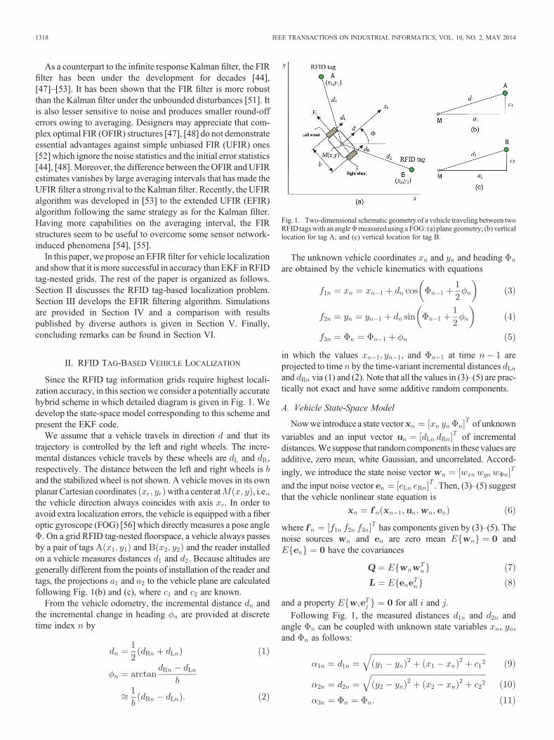
Since the RFID tag information grids require highest locali-zation accuracy, in this section we consider a potentially accuratehybrid scheme in which detailed diagram is given in Fig. 1. Wedevelop the state-space model corresponding to this scheme andpresent the EKF code.
We assume that a vehicle travels in direction and that itstrajectory is controlled by the left and right wheels. The incre-mental distances vehicle travels by these wheels are and ,respectively. The distance between the left and right wheels isand the stabilized wheel is not shown. A vehicle moves in its ownplanarCartesian coordinates with a center at , i.e.,the vehicle direction always coincides with axis . In order toavoid extra localization errors, the vehicle is equipped with a fiberoptic gyroscope (FOG) [56] which directly measures a pose angle. On a grid RFID tag-nested floorspace, a vehicle always passes
by a pair of tags and and the reader installedon a vehicle measures distances and . Because altitudes aregenerally different from the points of installation of the reader andtags, the projections and to the vehicle plane are calculatedfollowing Fig. 1(b) and (c), where and are known.
From the vehicle odometry, the incremental distance andthe incremental change in heading are provided at discretetime index by
The unknown vehicle coordinates and and headingare obtained by the vehicle kinematics with equations
in which the values , and at time areprojected to time by the time-variant incremental distancesand via (1) and (2). Note that all the values in (3)–(5) are prac-tically not exact and have some additive random components.
A. Vehicle State-Space Model
Nowwe introduce a state vector of unknown
variables and an input vector of incrementaldistances.Wesuppose that randomcomponents in these values areadditive, zero mean, white Gaussian, and uncorrelated. Accord-
ingly, we introduce the state noise vector
and the input noise vector . Then, (3)–(5) suggestthat the vehicle nonlinear state equation is
where has components given by (3)–(5). Thenoise sources and are zero mean and
have the covariances
and a property for all and .
Following Fig. 1, the measured distances and andangle can be coupled with unknown state variables , ,and as follows:
Fig. 1. Two-dimensional schematic geometry of a vehicle traveling between twoRFID tagswith an angle measured using a FOG: (a) plane geometry; (b) verticallocation for tag A; and (c) vertical location for tag B.
1318 IEEE TRANSACTIONS ON INDUSTRIAL INFORMATICS, VOL. 10, NO. 2, MAY 2014
Now, If we introduce the observation vector
, the nonlinear function vector
, and the measurement additive noise vector, then the state observation equation can be
written as
where noise is white Gaussian with zero meanthe covariance
and the properties and for all and
. The vehicle dynamics is thus represented with the state-spacemodel using (6) and (12).
B. Expanded State-Space Model
In order to estimate usingmethods of linearfiltering such asKalman filtering, (6) needs to be expanded to the first-orderTaylor series. The standard procedure applied to ≜
yields
where is the estimate1 of . An expansion (14)fits the case when is insignificant on a unit time stepand the noise components are zeros at an initial point:and . Here, is aknown input of the expanded model and , and areJacobian. Note that the second-order expansion of (6) and (12)has no definitive advantages [53] and is not considered in thispaper.
The Jacobian matrix can be found to be
Because noise is additive with respect to the componentsof in (3)–(5) and , we also have
Finally, the Jacobian matrix can be written as
where and .
Similarly to (6), the nonlinear function can beexpanded at as
where is known and isJacobian
where and
.
The first-order expanded state-space model is thus
where the zero mean noise vectors and have the covar-iances, respectively
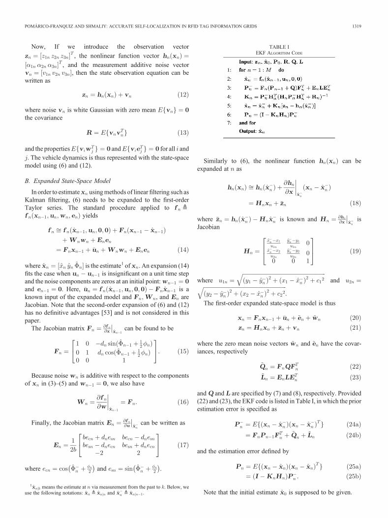
and and are specified by (7) and (8), respectively. Provided(22) and (23), the EKF code is listed in Table I, in which the priorestimation error is specified as
and the estimation error defined by
Note that the initial estimate is supposed to be given.
TABLE IEKF ALGORITHM CODE
1 means the estimate at via measurement from the past to . Below, weuse the following notations: ≜ and ≜ .
POMÁRICO-FRANQUIZ AND SHMALIY: ACCURATE SELF-LOCALIZATION IN RFID TAG INFORMATION GRIDS 1319
III. EXTENDED UFIR FILTERING
In this section, we solve the localization problem using EFIRfiltering and develop the EFIR filter code for the extended model(20) and (21).
Although the suboptimal EKF algorithm (Table I) is quitetraditional for many applications, the problem often arises withnot well-known covariance matrices which in the RFID taginformation grids may cause unacceptable errors [43]. Contraryto the optimal Kalman filter minimizing the mean square error(MSE), the FIR filter [53] satisfies only the unbiasedness condi-tion . Accordingly, the EFIR filter completelyignores the noise statistics, but requires an optimal averaginginterval of points in order to be suboptimal.
Iterative EFIR filtering is organized similar to the Kalmanfilter. The EFIR estimate appears iteratively as
where an auxiliary variable ranges from to and. Here, is the number of the states and is
an averaging horizon representing the FIRfilter order. The outputis taken when in each iterative cycle. The bias correctiongain is defined here only by the model matrices as
via the generalized noise power gain (GNPG)
in which the inverse for stable systems is commonly guaranteedby ⩾ .
In a particular case of associated with vehicle locali-zation, the initial estimate values at can befound in batch forms as
where is a vector of linear measurements of , which maynot be available directly. If is available, then it can be usedinstead of (29). A specific of the scheme shown in Fig. 1 is thatGNPG is almost unity at time index for the vehicle coordinatesand heading. One thus may let , where is the identitymatrix. Such a simplification ignoring (29)–(32) does not affectthe localization accuracy essentially that will be proved furtherby simulations.
The proposed EFIR filtering algorithm can finally be coded asin Table II. It requires only and to start computing andupdating iteratively all the vectors and matrices via and .No noise statistics are involved that is an important advantageagainst EKF. Although the algorithm (Table II) admits ,one can substitute with (30). On the other hand, the EFIRfilter is unbiased, thus it does not guarantee optimality in theminimum MSE sense. To optimize EFIR filter, must beprovided.
IV. SIMULATIONS
Now, we consider a robot traveling on an indoor grid floor-space and localize it using the EKF algorithm (Table I) and EFIRfiltering algorithms (Table II) based on simulations.
The floorspace is nested with RFID tags which coordinates oflocations are saved in vehicle memory along with coded localreliefs. Each tag has a circular detection area with the detectionrange . Both the short range tags ( < ) [9] and long-rangetags ( < ) [35] can be used. We suppose that a robot has areader that is able to measure distances to at least two RFID tagsat once employing the maximum RSSI given by the Friisequation [9], [20]
where is the received power, is the transmitted power, isa reader-to-( th)tag distance, and is a coefficient dependent onthe transmitter and received antenna gains, system loss factor,and wavelength. A FOG installed on a vehicle directly measuresa pose angle .
All noise sources are supposed to be additive, stationary, zeromean, white Gaussian, and uncorrelated. Accordingly, we intro-duce the estimation error variances , and and specify thenoise covariance matrix (7) with the main diagonaldiag and all other components zeros. For the
TABLE IIEFIR FILTERING ALGORITHM CODE
1320 IEEE TRANSACTIONS ON INDUSTRIAL INFORMATICS, VOL. 10, NO. 2, MAY 2014
noise variances and in the inputs and , we specify(8) with the main diagonal diag and all othercomponents zeros. Finally, for the measurement noise variances
, and , covariance (13) is specified as diag
with all other components zeros.
A. Reference Circular Trajectory
We first simulate a circular trajectory in order to learn possiblelocalization errors and negative effects. In doing so, we admitsmall state and input errors by setting
and . Note that, in [9], , andwere supposed to be zeros. Following [42], we allow noise in
the measured distances to have and let. Discrete measurements are obtained at 5000 points.
The reader range is supposed to be and we place twolong-range tags and at (0, 6 m) and (0,0) as shown in Fig. 2.To test the EFIR filter and EKF, we suppose that the robot actualtrajectory is known or measured simultaneously using aprecise equipment.
In the scheme shown in Fig. 1, direct measurements of andare unavailable. We therefore solve the inverse problem
applied to (9) and (10) with the given RFID tag positions,and , and go to “linear” measure-
ments of and
where , and .For further applications, we unite and in a measurement
vector . Since vector is known by testmeasurements, we follow [57], minimize the MSE (25a) by
as
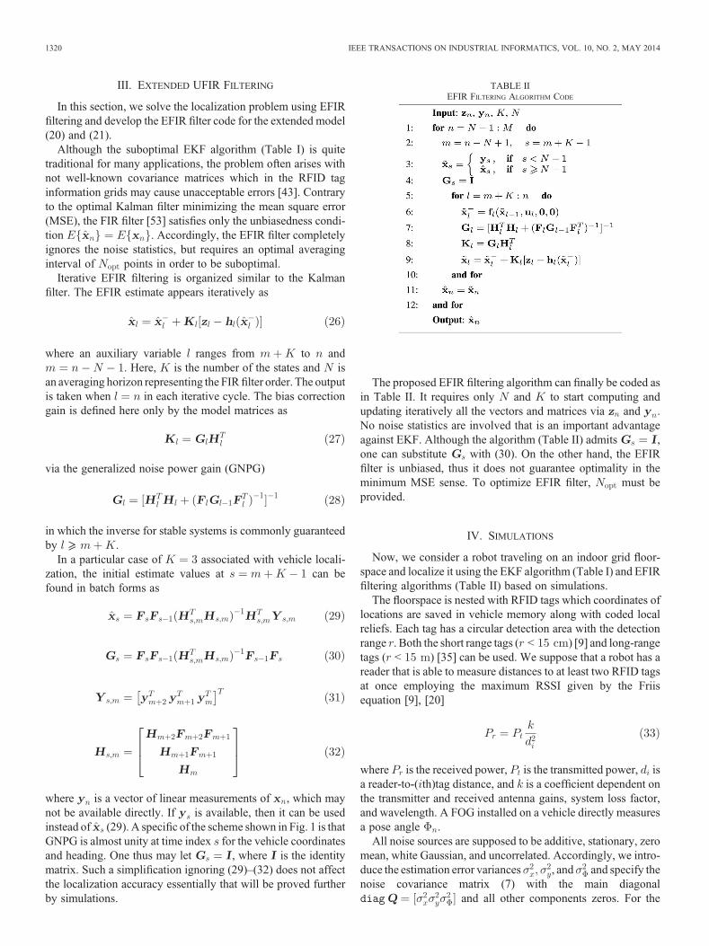
and find . Typical measurements (34) and (35) alongwith the EKF and EFIR estimates are shown in Fig. 2 for exactlyknown noise covariances , and , initial state ,initial error , and . Under such conditions, theestimates sketched in Fig. 2 can be said to be the best available bythe EFIR filter and EKF. As can be seen, the estimates areconsistent, although the filters produce larger errors close to theboundary linking the tags.
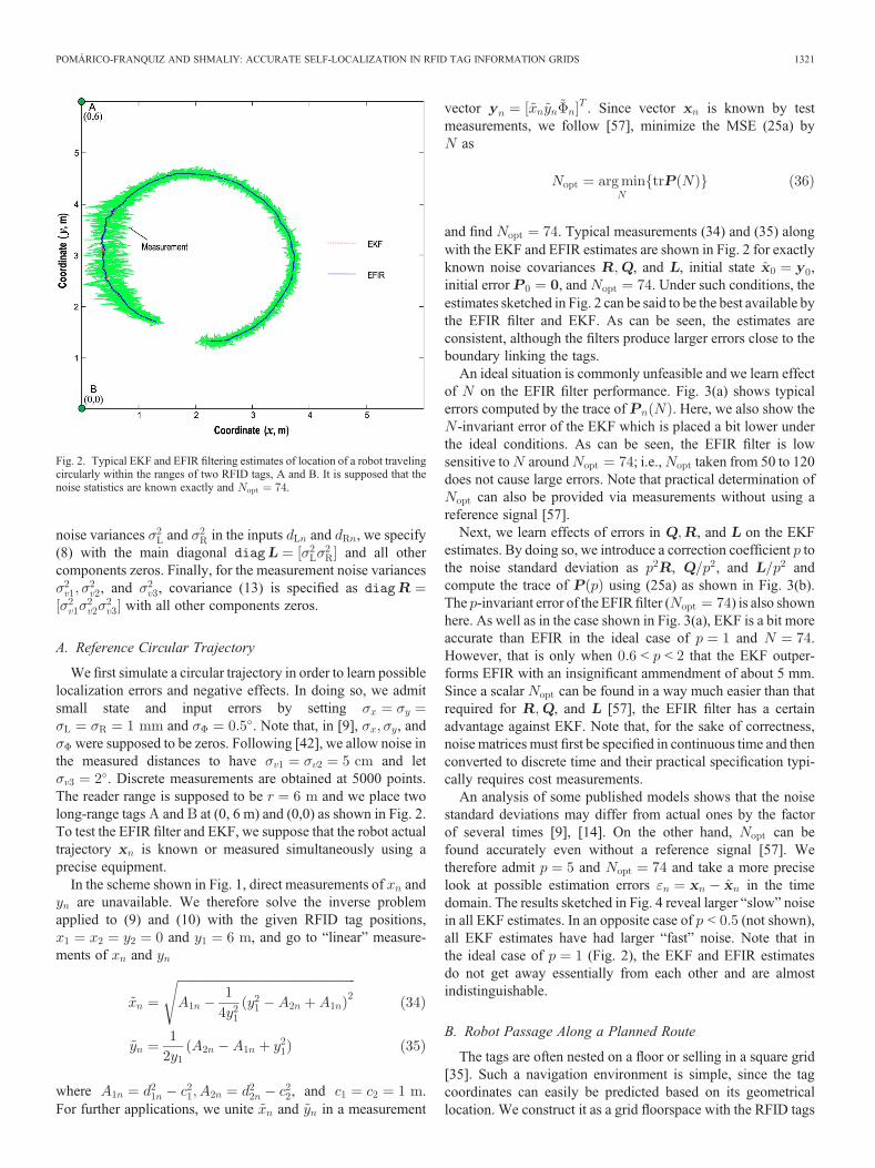
An ideal situation is commonly unfeasible and we learn effectof on the EFIR filter performance. Fig. 3(a) shows typicalerrors computed by the trace of . Here, we also show the-invariant error of the EKF which is placed a bit lower under
the ideal conditions. As can be seen, the EFIR filter is lowsensitive to around ; i.e., taken from 50 to 120does not cause large errors. Note that practical determination of
can also be provided via measurements without using areference signal [57].
Next, we learn effects of errors in , and on the EKFestimates. By doing so, we introduce a correction coefficient tothe noise standard deviation as , , and andcompute the trace of using (25a) as shown in Fig. 3(b).The -invariant error of the EFIRfilter ( ) is also shownhere. As well as in the case shown in Fig. 3(a), EKF is a bit moreaccurate than EFIR in the ideal case of and .However, that is only when < < that the EKF outper-forms EFIR with an insignificant ammendment of about 5 mm.Since a scalar can be found in a way much easier than thatrequired for , and [57], the EFIR filter has a certainadvantage against EKF. Note that, for the sake of correctness,noise matrices must first be specified in continuous time and thenconverted to discrete time and their practical specification typi-cally requires cost measurements.
An analysis of some published models shows that the noisestandard deviations may differ from actual ones by the factorof several times [9], [14]. On the other hand, can befound accurately even without a reference signal [57]. Wetherefore admit and and take a more preciselook at possible estimation errors in the timedomain. The results sketched in Fig. 4 reveal larger “slow” noisein all EKF estimates. In an opposite case of < (not shown),all EKF estimates have had larger “fast” noise. Note that inthe ideal case of (Fig. 2), the EKF and EFIR estimatesdo not get away essentially from each other and are almostindistinguishable.
B. Robot Passage Along a Planned Route
The tags are often nested on a floor or selling in a square grid[35]. Such a navigation environment is simple, since the tagcoordinates can easily be predicted based on its geometricallocation. We construct it as a grid floorspace with the RFID tags
Fig. 2. Typical EKF and EFIR filtering estimates of location of a robot travelingcircularly within the ranges of two RFID tags, A and B. It is supposed that thenoise statistics are known exactly and .
POMÁRICO-FRANQUIZ AND SHMALIY: ACCURATE SELF-LOCALIZATION IN RFID TAG INFORMATION GRIDS 1321
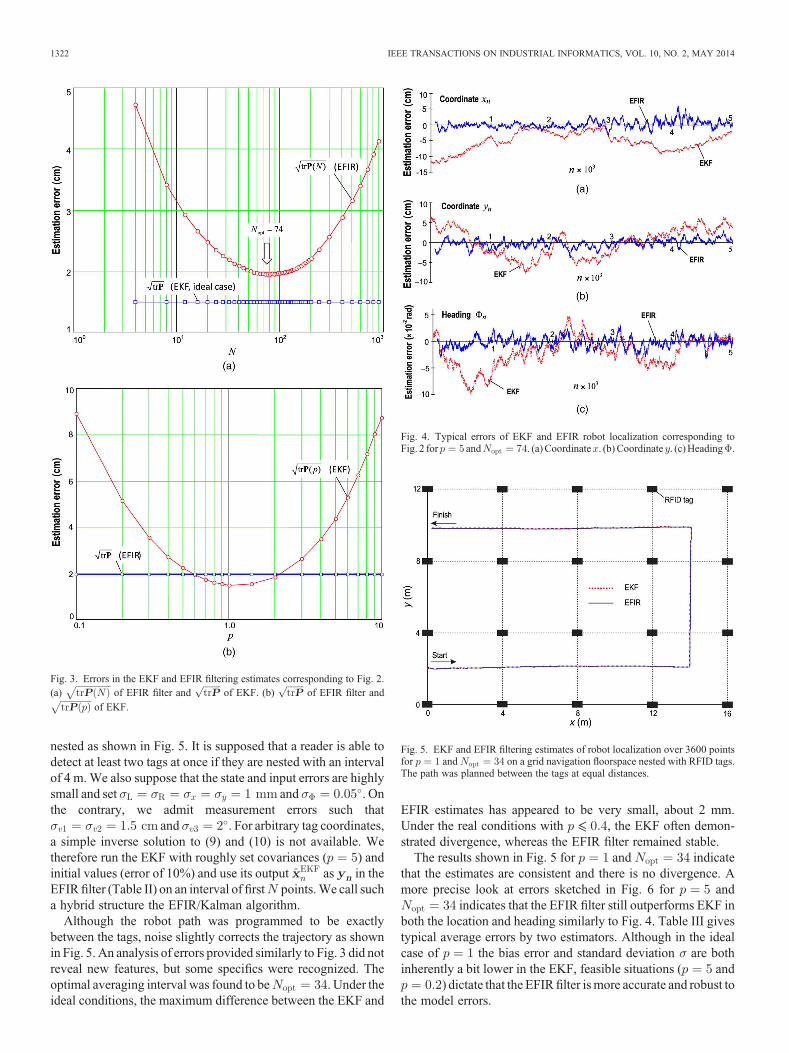
nested as shown in Fig. 5. It is supposed that a reader is able todetect at least two tags at once if they are nested with an intervalof 4 m.We also suppose that the state and input errors are highlysmall and set and . Onthe contrary, we admit measurement errors such that
and . For arbitrary tag coordinates,a simple inverse solution to (9) and (10) is not available. Wetherefore run the EKF with roughly set covariances ( ) andinitial values (error of 10%) and use its output as in theEFIR filter (Table II) on an interval of first points.We call sucha hybrid structure the EFIR/Kalman algorithm.
Although the robot path was programmed to be exactlybetween the tags, noise slightly corrects the trajectory as shownin Fig. 5. An analysis of errors provided similarly to Fig. 3 did notreveal new features, but some specifics were recognized. Theoptimal averaging interval was found to be . Under theideal conditions, the maximum difference between the EKF and
EFIR estimates has appeared to be very small, about 2 mm.Under the real conditions with ⩽ , the EKF often demon-strated divergence, whereas the EFIR filter remained stable.
The results shown in Fig. 5 for and indicatethat the estimates are consistent and there is no divergence. Amore precise look at errors sketched in Fig. 6 for and
indicates that the EFIR filter still outperforms EKF inboth the location and heading similarly to Fig. 4. Table III givestypical average errors by two estimators. Although in the idealcase of the bias error and standard deviation are bothinherently a bit lower in the EKF, feasible situations ( and
) dictate that the EFIRfilter ismore accurate and robust tothe model errors.
Fig. 4. Typical errors of EKF and EFIR robot localization corresponding toFig. 2 for and . (a)Coordinate . (b) Coordinate . (c)Heading .
Fig. 5. EKF and EFIR filtering estimates of robot localization over 3600 pointsfor and on a grid navigation floorspace nested with RFID tags.The path was planned between the tags at equal distances.
Fig. 3. Errors in the EKF and EFIR filtering estimates corresponding to Fig. 2.(a) of EFIR filter and of EKF. (b) of EFIR filter and
of EKF.
1322 IEEE TRANSACTIONS ON INDUSTRIAL INFORMATICS, VOL. 10, NO. 2, MAY 2014
C. Free Traveling Under Typical Conditions
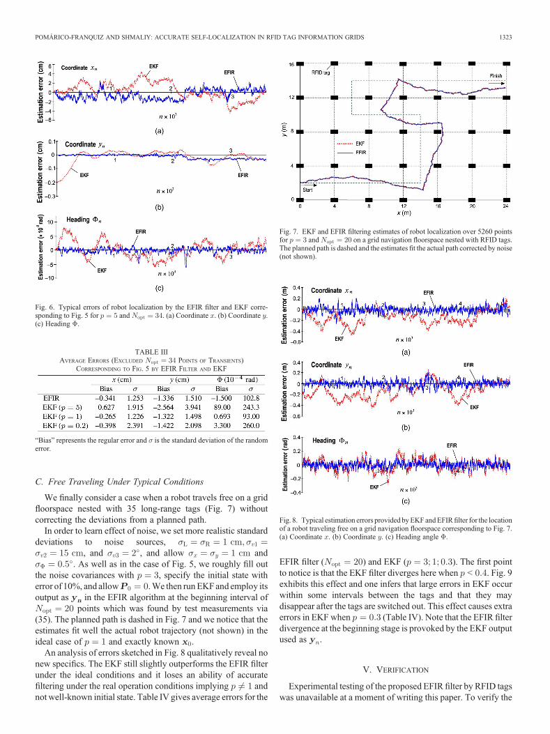
We finally consider a case when a robot travels free on a gridfloorspace nested with 35 long-range tags (Fig. 7) withoutcorrecting the deviations from a planned path.
In order to learn effect of noise, we set more realistic standarddeviations to noise sources,
, and , and allow and. As well as in the case of Fig. 5, we roughly fill out
the noise covariances with , specify the initial state witherror of 10%, and allow .We then runEKFand employ itsoutput as in the EFIR algorithm at the beginning interval of
points which was found by test measurements via(35). The planned path is dashed in Fig. 7 and we notice that theestimates fit well the actual robot trajectory (not shown) in theideal case of and exactly known .
An analysis of errors sketched in Fig. 8 qualitatively reveal nonew specifics. The EKF still slightly outperforms the EFIR filterunder the ideal conditions and it loses an ability of accuratefiltering under the real operation conditions implying andnot well-known initial state. Table IV gives average errors for the
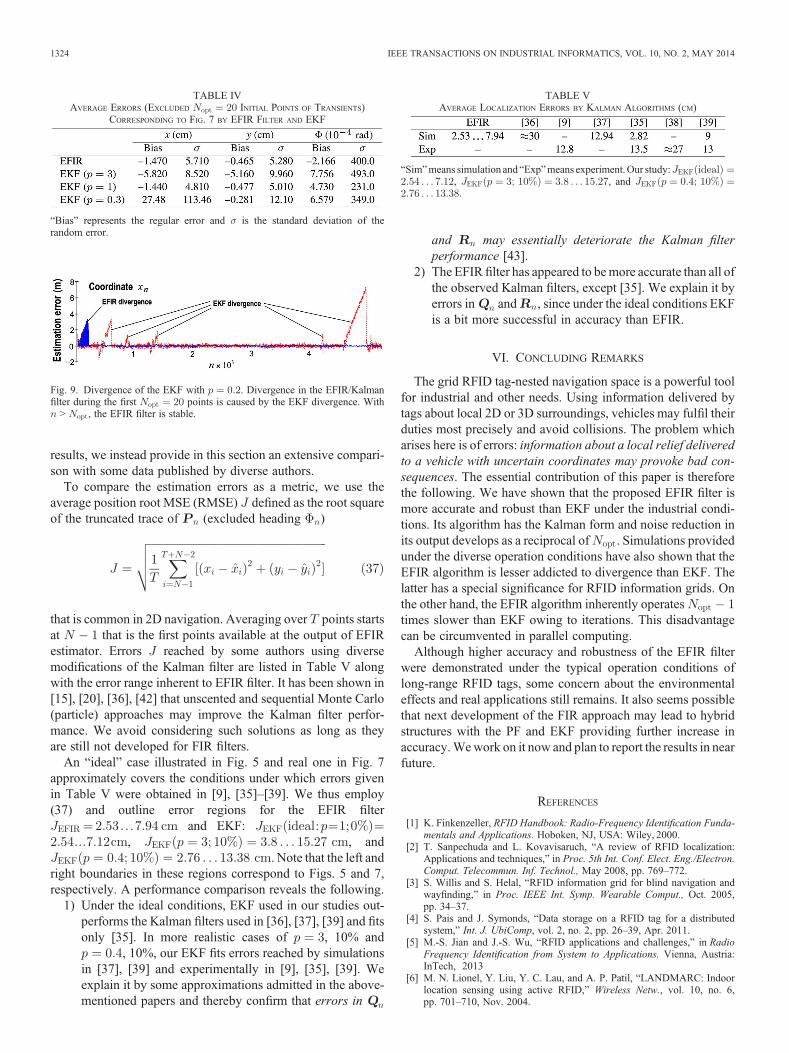
EFIR filter ( ) and EKF ( ). The first pointto notice is that the EKF filter diverges here when < . Fig. 9exhibits this effect and one infers that large errors in EKF occurwithin some intervals between the tags and that they maydisappear after the tags are switched out. This effect causes extraerrors in EKF when (Table IV). Note that the EFIR filterdivergence at the beginning stage is provoked by the EKF outputused as .
V. VERIFICATION
Experimental testing of the proposed EFIR filter by RFID tagswas unavailable at a moment of writing this paper. To verify the
Fig. 6. Typical errors of robot localization by the EFIR filter and EKF corre-sponding to Fig. 5 for and . (a) Coordinate . (b) Coordinate .(c) Heading .
Fig. 7. EKF and EFIR filtering estimates of robot localization over 5260 pointsfor and on a grid navigation floorspace nested with RFID tags.The planned path is dashed and the estimates fit the actual path corrected by noise(not shown).
TABLE IIIAVERAGE ERRORS (EXCLUDED POINTS OF TRANSIENTS)
CORRESPONDING TO FIG. 5 BY EFIR FILTER AND EKF
“Bias” represents the regular error and is the standard deviation of the randomerror.
Fig. 8. Typical estimation errors provided byEKF andEFIRfilter for the locationof a robot traveling free on a grid navigation floorspace corresponding to Fig. 7.(a) Coordinate . (b) Coordinate . (c) Heading angle .
POMÁRICO-FRANQUIZ AND SHMALIY: ACCURATE SELF-LOCALIZATION IN RFID TAG INFORMATION GRIDS 1323
results, we instead provide in this section an extensive compari-son with some data published by diverse authors.
To compare the estimation errors as a metric, we use theaverage position root MSE (RMSE) defined as the root squareof the truncated trace of (excluded heading )
that is common in 2D navigation. Averaging over points startsat that is the first points available at the output of EFIRestimator. Errors reached by some authors using diversemodifications of the Kalman filter are listed in Table V alongwith the error range inherent to EFIR filter. It has been shown in[15], [20], [36], [42] that unscented and sequential Monte Carlo(particle) approaches may improve the Kalman filter perfor-mance. We avoid considering such solutions as long as theyare still not developed for FIR filters.
An “ideal” case illustrated in Fig. 5 and real one in Fig. 7approximately covers the conditions under which errors givenin Table V were obtained in [9], [35]–[39]. We thus employ(37) and outline error regions for the EFIR filter
and EKF:, , and
. Note that the left andright boundaries in these regions correspond to Figs. 5 and 7,respectively. A performance comparison reveals the following.
1) Under the ideal conditions, EKF used in our studies out-performs the Kalman filters used in [36], [37], [39] and fitsonly [35]. In more realistic cases of , 10% and
, 10%, our EKF fits errors reached by simulationsin [37], [39] and experimentally in [9], [35], [39]. Weexplain it by some approximations admitted in the above-mentioned papers and thereby confirm that errors in
and may essentially deteriorate the Kalman filterperformance [43].
2) The EFIR filter has appeared to bemore accurate than all ofthe observed Kalman filters, except [35]. We explain it byerrors in and , since under the ideal conditions EKFis a bit more successful in accuracy than EFIR.
VI. CONCLUDING REMARKS
The grid RFID tag-nested navigation space is a powerful toolfor industrial and other needs. Using information delivered bytags about local 2D or 3D surroundings, vehicles may fulfil theirduties most precisely and avoid collisions. The problem whicharises here is of errors: information about a local relief deliveredto a vehicle with uncertain coordinates may provoke bad con-sequences. The essential contribution of this paper is thereforethe following. We have shown that the proposed EFIR filter ismore accurate and robust than EKF under the industrial condi-tions. Its algorithm has the Kalman form and noise reduction inits output develops as a reciprocal of . Simulations providedunder the diverse operation conditions have also shown that theEFIR algorithm is lesser addicted to divergence than EKF. Thelatter has a special significance for RFID information grids. Onthe other hand, the EFIR algorithm inherently operatestimes slower than EKF owing to iterations. This disadvantagecan be circumvented in parallel computing.
Although higher accuracy and robustness of the EFIR filterwere demonstrated under the typical operation conditions oflong-range RFID tags, some concern about the environmentaleffects and real applications still remains. It also seems possiblethat next development of the FIR approach may lead to hybridstructures with the PF and EKF providing further increase inaccuracy.Wework on it now and plan to report the results in nearfuture.
REFERENCES
[1] K. Finkenzeller, RFID Handbook: Radio-Frequency Identification Funda-mentals and Applications. Hoboken, NJ, USA: Wiley, 2000.
[2] T. Sanpechuda and L. Kovavisaruch, “A review of RFID localization:Applications and techniques,” in Proc. 5th Int. Conf. Elect. Eng./Electron.Comput. Telecommun. Inf. Technol., May 2008, pp. 769–772.
[3] S. Willis and S. Helal, “RFID information grid for blind navigation andwayfinding,” in Proc. IEEE Int. Symp. Wearable Comput., Oct. 2005,pp. 34–37.
[4] S. Pais and J. Symonds, “Data storage on a RFID tag for a distributedsystem,” Int. J. UbiComp, vol. 2, no. 2, pp. 26–39, Apr. 2011.
[5] M.-S. Jian and J.-S. Wu, “RFID applications and challenges,” in RadioFrequency Identification from System to Applications. Vienna, Austria:InTech, 2013
[6] M. N. Lionel, Y. Liu, Y. C. Lau, and A. P. Patil, “LANDMARC: Indoorlocation sensing using active RFID,” Wireless Netw., vol. 10, no. 6,pp. 701–710, Nov. 2004.
Fig. 9. Divergence of the EKF with . Divergence in the EFIR/Kalmanfilter during the first points is caused by the EKF divergence. With> , the EFIR filter is stable.
TABLE VAVERAGE LOCALIZATION ERRORS BY KALMAN ALGORITHMS (CM)
“Sim”means simulation and “Exp”means experiment.Our study:, , and
TABLE IVAVERAGE ERRORS (EXCLUDED INITIAL POINTS OF TRANSIENTS)
CORRESPONDING TO FIG. 7 BY EFIR FILTER AND EKF
“Bias” represents the regular error and is the standard deviation of therandom error.
1324 IEEE TRANSACTIONS ON INDUSTRIAL INFORMATICS, VOL. 10, NO. 2, MAY 2014
[7] H. D. Chon, S. Jun, H. Jung, and S. W. An, “Using RFID foraccurate positioning,” J. Global Position. Syst., vol. 3, no. 1/2,pp. 32–39, 2004.
[8] S. Park and S. Hashimoto, “Autonomous mobile robot navigation usingpassive RFID in indoor environment,” IEEE Trans. Ind. Electron., vol. 56,no. 7, pp. 2366–2373, Jul. 2009.
[9] S. S. Saab and Z. S. Nakad, “A standalone RFID indoor positioning systemusing passive tags,” IEEE Trans. Ind. Electron., vol. 58, no. 5,pp. 1961–1970, May 2011.
[10] C.W.Nielsen andM.A.Goodrich, “Comparing the usefulness of video andmap information in navigation tasks,” in Proc. 1st ACM SIGCHI/SIGARTConf. Human–Robot Interact. (HRI’06), Salt Lake City, UT, USA,Mar. 24, 2006, pp. 95–101.
[11] M. Luimula, K. Sääskilahti, T. Partala, S. Pieskä, and J. Alaspää, “Remotenavigation of a mobile robot in an RFID-augmented environment,” Pers.Ubiq. Comput., vol. 14, no. 2, pp. 125–136, Feb. 2010.
[12] O. Kubitz, M. O. Berger, M. Perlick, and R. Dumoulin, “Application ofradio frequency identification devices to support navigation of autonomousmobile robots,” in Proc. IEEE Veh. Technol. Conf., May 1997, vol. 1,pp. 126–130.
[13] Y. C. Chen and J. H. Chou, “Mobil robot localization by RFID method,”in Proc. 7th Int. Conf. Digit. Commun. (ICDT), 2012, pp. 33–38.
[14] R. Krigslund, P. Popovski, G. F. Pedersen, and K. Olesen, “Interferencehelps to equalize the read range and reduce false positives of passive RFIDtags,” IEEE Trans. Ind. Electron., vol. 59, no. 12, pp. 4821–4830,Dec. 2012.
[15] S. Park andH. Lee, “Self-recognition of vehicle position usingUHF passiveRFID tags,” IEEE Trans. Ind. Electron., vol. 60, no. 1, pp. 226–234,Jan. 2013.
[16] F.Reichenbach,A.Born,D. Timmermann, andR.Bill, “Adistributed linearleast Squares method for precise localization with low complexity inwireless sensor networks,” in Proc. Int. Conf. Distrib. Comput. Sens. Syst.,Jun. 2006, vol. 4026, pp. 514–528.
[17] A. Smaliagic and D. Kogan, “Location sensing and privacy in a context-aware computing environment,” IEEE Wireless Commun., vol. 9, no. 5,pp. 10–17, Oct. 2002.
[18] D. G. Seo and J. M. Lee, “Localization algorithm for a mobile robot usingiGS,” in Proc. 17th World Congr. Int. Fed. Autom. Control, Seoul, Korea,Jul. 6–11, 2008, pp. 742–747.
[19] S. Han, H. Lim, and J. Lee, “An efficient localization scheme for adifferential-driving mobile robot based on RFID system,” IEEE Trans.Ind. Electron., vol. 54, no. 6, pp. 3362–3369, Dec. 2007.
[20] J. Zhou and J. Shi, “RFID localization algorithms and applicationsareview,” J. Intell. Manuf., vol. 20, no. 6, pp. 695–707, Dec. 2009.
[21] K. Tanaka, Y. Kimuro, K. Yamano, M. Hirayama, E. Kondo, andM.Matsumoto, “A supervised learning approach to robot localization usinga short-range RFID sensor,” IEICE Trans. Inf. Syst., vol. E90D, no. 11,pp. 1762–1771, Nov. 2007.
[22] Y. Zhang, M. G. Amin, and S. Kaushik, “Localization and tracking ofpassive RFID tags based on direction estimation,” Int. J. Antennas Propag.,vol. 2007, pp. 1–9, 2007.
[23] A. Papapostolou and H. Chaouchi, “RFID-assisted indoor localization andthe impact of interference on its performance,” J. Netw. Comput. Appl.,vol. 34, no. 3, pp. 902–913, May 2011.
[24] K. Yamano, K. Tanaka, M. Hirayama, E. Kondo, Y. Kimuro, andM. Matsumoto, “Self-localization of mobile robots with RFID system byusing support vector machine,” in Proc. IEEE/RSJ Int. Conf. Intell. RobotsSyst., 2004, pp. 3756–3761.
[25] T. Tsukiyama, “Navigation system for mobile robots using RFID tags,”in Proc. Int. Conf. Adv. Robot. (ICAR), Coimbra, Portugal, 2003,pp. 1130–1135.
[26] H. Chae and K. Han, “Combination of RFID and vision for mobile robotlocalization,” in Proc. IEEE Int. Conf. Intell. Sens., Sens. Netw. Inf.Process., Dec. 2005, pp. 75–80.
[27] O. Matsumoto, K. Komoriya, T. Hatase, H. Nishimura, K. Toda, andS. Goto, “Autonomous traveling control of the ‘TAO Aidce’ intelligentwheelchair,” in Proc. IEEE/RSJ Int. Conf. Intell. Robots Syst., Beijing,China, Oct. 9–15, 2006, pp. 4322–4327.
[28] F. Viani, P. Rocca, G. Oliveri, D. Trinchero, and A. Massa, “Localization,tracking, and imaging of targets in wireless sensor networks: An invitedreview,” Radio Sci., vol. 46, no. RS5002, pp. 1–12, 2011.
[29] S. P. Subramanian, J. Sommer, S. Schmitt, andW. Rosenstiel, “RILreliableRFID based indoor localization for pedestrians,” in Proc. 16th Int. Conf.SoftCOM, Sep. 2008, pp. 218–222.
[30] B.-S. Choi, J.-W. Lee, J.-J. Lee, and K.-T. Park, “A hierarchical algorithmfor indoor mobile robot localization using RFID sensor fusion,” IEEETrans. Ind. Electron., vol. 58, no. 6, pp. 2226–2235, Jun. 2011.
[31] W. Gueaieb and M. S. Miah, “An intelligent mobile robot navigationtechnique using RFID technology,” IEEE Trans. Instrum. Meas., vol. 57,no. 9, pp. 1908–1917, Sep. 2008.
[32] T.Deyle,H.Nguyen,M. S.Reynolds, andC.C.Kemp, “RFIDguided robotsfor pervasive automation,” Pervasive Comput., vol. 9, no. 2, pp. 37–45,Apr./Jun. 2010.
[33] Y. Tang, H. Gao, J. Kurths, and J. Fang, “Evolutionary pinning control andits applications in UAV coordination,” IEEE Trans. Ind. Informat., vol. 8,no. 4, pp. 828–838, Nov. 2012.
[34] U. Klee, T. Gehrig, and J. McDonough, “Kalman filters for time delay ofarrival-based source localization,” EURASIP J. Appl. Signal Process.,vol. 2006, pp. 1–15, Jan. 2006.
[35] E. DiGiampaolo and F. Martinelli, “A passive UHF-RFID system for thelocalization of an indoor autonomous vehicle,” IEEE Trans. Ind. Electron.,vol. 59, no. 10, pp. 3961–3970, Oct. 2012.
[36] F. Martinelli, “Robot localization: Comparable performance of EKF andUKF in some interesting indoor settings,” in Proc. 16th Mediterr. Conf.Control Autom., Ajaccio, France, Jun. 25–27, 2008, pp. 499–504.
[37] T. Nick, J. Götze, W. John, and G. Stönner, “Localization of passive UHFRFID labels using an unscented Kalman filter with relative positioninformation,” in Proc. ITD-Fachbericht—RFID SysTech, Dresden,Germany, May 17–18, 2011, pp. 1–7.
[38] V. Savic, A. Athalye, M. Bolic, and P. M. Djuric, “Particle filtering forindoor RFID tag tracking,” in Proc. IEEE Stat. Signal Process. Workshop(SSP), Jun. 2011, pp. 193–196.
[39] M. Boccadoro, F. Martinelli, and S. Pagnotelli, “Constrained and quantizedKalman fltering for an RFID robot localization problem,” Auton. Robots,vol. 29, no. 3–4, pp. 235–251, Nov. 2010.
[40] D. Hahnel, W. Burgard, D. Fox, K. Fishkin, and M. Philipose, “Mappingand localization with RFID technology,” in Proc. IEEE Int. Conf. Robot.Autom., 2004, vol. 1, pp. 1015–1020.
[41] A. Howard, “Multi-robot simultaneous localization and mapping usingparticle filters,” Int. J. Robot. Res., vol. 25, no. 12, pp. 1243–1256,Dec. 2006.
[42] E. DiGiampaolo and F. Martinelli, “Mobile robot localization using thephase of passive UHF-RFID signals,” IEEE Trans. Ind. Electron., vol. 61,no. 1, pp. 365–376, Jan. 2014.
[43] B. Gibbs, Advanced Kalman Filtering, Least-Squares and Modeling.Hoboken, NJ, USA: Wiley, 2011.
[44] Y. S. Shmaliy, “An iterative Kalman-like algorithm ignoring noise andinitial conditions,” IEEE Trans. Signal Process., vol. 59, no. 6,pp. 2465–2473, Jun. 2011.
[45] R. J. Fitzgerald, “Divergence of the Kalman filter,” IEEE Trans. Autom.Control, vol. AC-16, no. 6, pp. 736–747, Dec. 1971.
[46] F. Daum, “Nonlinear filters: Beyond the Kalman filter,” IEEE A&E Syst.Mag., vol. 20, no. 8, pp. 57–69, Aug. 2005.
[47] W. H. Kwon and S. Han, Receding Horizon Control: Model PredictiveControl for State Models. New York, NY, USA: Springer, 2005.
[48] Y. S. Shmaliy, “Linear optimal FIR estimation of discrete time-invariantstate-space models,” IEEE Trans. Signal Process., vol. 58, no. 6,pp. 3086–3096, Jun. 2010.
[49] A. M. Bruckstein and T. Kailath, “Recursive limited memory filtering andscattering theory,” IEEE Trans. Inf. Theory, vol. IT-31, no. 3, pp. 440–443,May 1985.
[50] W. H. Kwon, Y. S. Suh, Y. I. Lee, and O. K. Kwon, “Equivalence of finitememory filters,” IEEE Trans. Aerosp. Electron. Syst., vol. 30, no. 8,pp. 968–972, Jul. 1994.
[51] A. H. Jazwinski, Stochastic Processes and Filtering Theory. New York,NY, USA: Academic, 1970.
[52] Y. S. Shmaliy, “Unbiased FIR filtering of discrete time polynomial statespacemodels,” IEEE Trans. Signal Process., vol. 57, no. 4, pp. 1241–1249,Apr. 2009.
[53] Y. S. Shmaliy, “Suboptimal FIR filtering of nonlinear models in additivewhite Gaussian noise,” IEEE Trans. Signal Process., vol. 60, no. 10,pp. 5519–5527, Oct. 2012.
[54] J. Hu, Z. Wang, B. Shen, and H. Gao, “Gain-constrained recursive filteringwith stochastic nonlinearities and probabilistic sensor delays,” IEEE Trans.Signal Process., vol. 61, no. 5, pp. 1230–1238, Mar. 2013.
[55] J. Hu, Z. Wang, B. Shen, and H. Gao, “Quantized recursive filtering for aclass of nonlinear systems with multiplicative noises and missing measure-ments,” Int. J. Control, vol. 86, no. 4, pp. 650–663, Apr. 2013.
[56] K. Komoriya and E. Oyama, “Position estimation of a mobile robot usingoptical fiber gyroscope,” in Proc. IEEE/RSJ/GI Int. Conf. Intell. RobotsSyst., 1994, vol. 1, pp. 143–149.
[57] F. Ramirez-Echeverria, A. Sarr, and Y. S. Shmaliy, “Optimal memory fordiscrete-time FIR filters in state space,” IEEE Trans. Signal Process.,vol. 62, no. 3, pp. 557–561, Feb. 2014.
POMÁRICO-FRANQUIZ AND SHMALIY: ACCURATE SELF-LOCALIZATION IN RFID TAG INFORMATION GRIDS 1325
Juan J. Pomárico-Franquizwas born in Venezuela,on August 12, 1988. He received the B.S. degree inelectrical engineering from the Technology Instituteof Irapuato, Irapuato, Mexico, in 2012. Currently, heis working toward his Master’s degree in electronicsengineering at the Universidad de Guanajuato,Salamanca, Mexico.He has co-authored several journals and conference
papers.
Yuriy S. Shmaliy (M’96–SM’00–F’11) received theB.S., M.S., and Ph.D. degrees in 1974, 1976, and1982, respectively, from the Kharkiv Aviation Insti-tute, Kharkiv, Ukraine, all in electrical engineering.In 1992, he received the D.Sc. degree in electricalengineering from the Kharkiv Railroad Institute,Kharkiv.He has been a Full Professor since 1986. From
1985 to 1999, he was with the Kharkiv MilitaryUniversity, Kharkiv. In 1992, he founded the Scien-tific Center “Sichron”, where he has been a Director
since 2002. Since 1999, he has been with the Guanajuato University, Salamanca,Mexico. He is the author of the following books: Continuous-Time Signals(Springer, 2006), Continuous-Time Systems (Springer, 2007), and GPS-BasedOptimal FIR Filtering of Clock Models (Nova Science Publishers,New York, 2009). He has published 341 journal and conference papers, andholds 81 patents. His research interests include optimal estimation, statisticalsignal processing, and stochastic system theory.Dr. Shmaliywas awarded the title of HonoraryRadio Engineer of the USSR, in
1991. He was listed in Outstanding People of the 20th Century, Cambridge,England, in 1999. Currently, he is an Associate Editor and Editorial BoardMember for several journals.
1326 IEEE TRANSACTIONS ON INDUSTRIAL INFORMATICS, VOL. 10, NO. 2, MAY 2014