
Laser Tag Glove 1 Introduction
10
Laser Tag Glove Team 8 - Keng Yan Lim, Alex Korfel, Carlos Lara ECE445 Project Proposal - Spring 2018 TA: Jacob Bryan 1 Introduction 1.1 Objective Our goal is to reduce price, increase portability, and boost the laser tag immersion. To do this, we plan to develop a glove that contains the laser, a vest to detect the laser, and a wrist gauntlet displaying game information. The intended equipment used to develop a player’s hardware will be designed with a limited budget in mind and a total price affordable to everyone. As each player will wear a laser glove and small vest, our game will be easily portable and ready to play anytime anyplace. The ability to play a game anywhere will boost immersion and the fact that the player needs to make a “finger gun” to fire their laser, will make the game more entertaining and noval. To sync all players into a game, a wireless transceiver will be used. 1.2 Background Laser tag is a great fast-paced game for all ages to pick up and enjoy. The usual hardware consists of a laser gun, a vest typically with four detection sensors, and a small screen displaying important game information. The point of the game is for players to use their laser to eliminate opponents by hitting their detection sensors and come out on top with the highest score or most lives remaining. Most laser tag games occur in a large dark maze at special facilities which can be expensive for each round and inconvenient to travel to. Adding to the inconvenience, the gun and vest themselves can be heavy and cumbersome to operate for older and younger players. There are home laser tag sets for sale online, however, these will include the guns only or, if a vest is included, they will cost over $150 for four people. 1.3 High-level Requirement List ● Each glove and vest should be as affordable as possible, preferably less than $80 a pair. ● We aim to have the laser beam with a large range, preferably a minimum of 20 ft. ● The glove and vest pair must be portable compared to those on the market, preferably more than four carried in a backpack.
-
Upload
khangminh22 -
Category
Documents
-
view
0 -
download
0
Transcript of Laser Tag Glove 1 Introduction
Laser Tag Glove Team 8 - Keng Yan Lim, Alex Korfel, Carlos Lara
ECE445 Project Proposal - Spring 2018 TA: Jacob Bryan
1 Introduction 1.1 Objective Our goal is to reduce price, increase portability, and boost the laser tag immersion. To do this, we plan to develop a glove that contains the laser, a vest to detect the laser, and a wrist gauntlet displaying game information. The intended equipment used to develop a player’s hardware will be designed with a limited budget in mind and a total price affordable to everyone. As each player will wear a laser glove and small vest, our game will be easily portable and ready to play anytime anyplace. The ability to play a game anywhere will boost immersion and the fact that the player needs to make a “finger gun” to fire their laser, will make the game more entertaining and noval. To sync all players into a game, a wireless transceiver will be used. 1.2 Background Laser tag is a great fast-paced game for all ages to pick up and enjoy. The usual hardware consists of a laser gun, a vest typically with four detection sensors, and a small screen displaying important game information. The point of the game is for players to use their laser to eliminate opponents by hitting their detection sensors and come out on top with the highest score or most lives remaining. Most laser tag games occur in a large dark maze at special facilities which can be expensive for each round and inconvenient to travel to. Adding to the inconvenience, the gun and vest themselves can be heavy and cumbersome to operate for older and younger players. There are home laser tag sets for sale online, however, these will include the guns only or, if a vest is included, they will cost over $150 for four people. 1.3 High-level Requirement List
● Each glove and vest should be as affordable as possible, preferably less than $80 a pair. ● We aim to have the laser beam with a large range, preferably a minimum of 20 ft. ● The glove and vest pair must be portable compared to those on the market, preferably
more than four carried in a backpack.
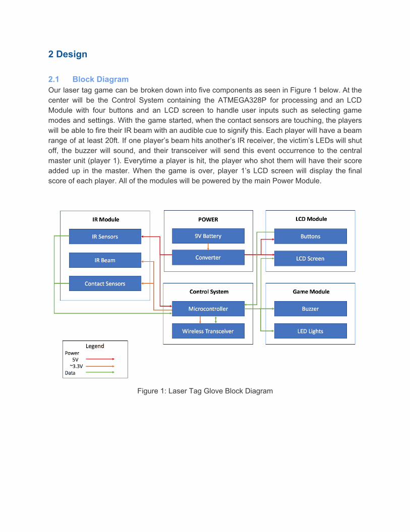
2 Design 2.1 Block Diagram Our laser tag game can be broken down into five components as seen in Figure 1 below. At the center will be the Control System containing the ATMEGA328P for processing and an LCD Module with four buttons and an LCD screen to handle user inputs such as selecting game modes and settings. With the game started, when the contact sensors are touching, the players will be able to fire their IR beam with an audible cue to signify this. Each player will have a beam range of at least 20ft. If one player’s beam hits another’s IR receiver, the victim’s LEDs will shut off, the buzzer will sound, and their transceiver will send this event occurrence to the central master unit (player 1). Everytime a player is hit, the player who shot them will have their score added up in the master. When the game is over, player 1’s LCD screen will display the final score of each player. All of the modules will be powered by the main Power Module.
Figure 1: Laser Tag Glove Block Diagram
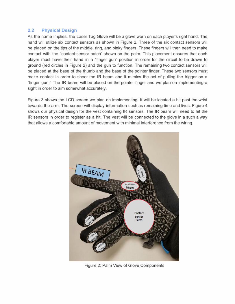
2.2 Physical Design As the name implies, the Laser Tag Glove will be a glove worn on each player’s right hand. The hand will utilize six contact sensors as shown in Figure 2. Three of the six contact sensors will be placed on the tips of the middle, ring, and pinky fingers. These fingers will then need to make contact with the “contact sensor patch” shown on the palm. This placement ensures that each player must have their hand in a “finger gun” position in order for the circuit to be drawn to ground (red circles in Figure 2) and the gun to function. The remaining two contact sensors will be placed at the base of the thumb and the base of the pointer finger. These two sensors must make contact in order to shoot the IR beam and it mimics the act of pulling the trigger on a “finger gun.” The IR beam will be placed on the pointer finger and we plan on implementing a sight in order to aim somewhat accurately. Figure 3 shows the LCD screen we plan on implementing. It will be located a bit past the wrist towards the arm. The screen will display information such as remaining time and lives. Figure 4 shows our physical design for the vest containing IR sensors. The IR beam will need to hit the IR sensors in order to register as a hit. The vest will be connected to the glove in a such a way that allows a comfortable amount of movement with minimal interference from the wiring.
Figure 2: Palm View of Glove Components
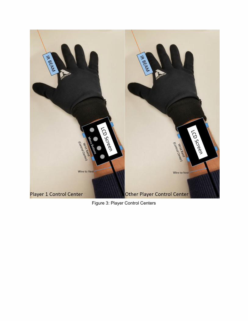
Figure 3: Player Control Centers
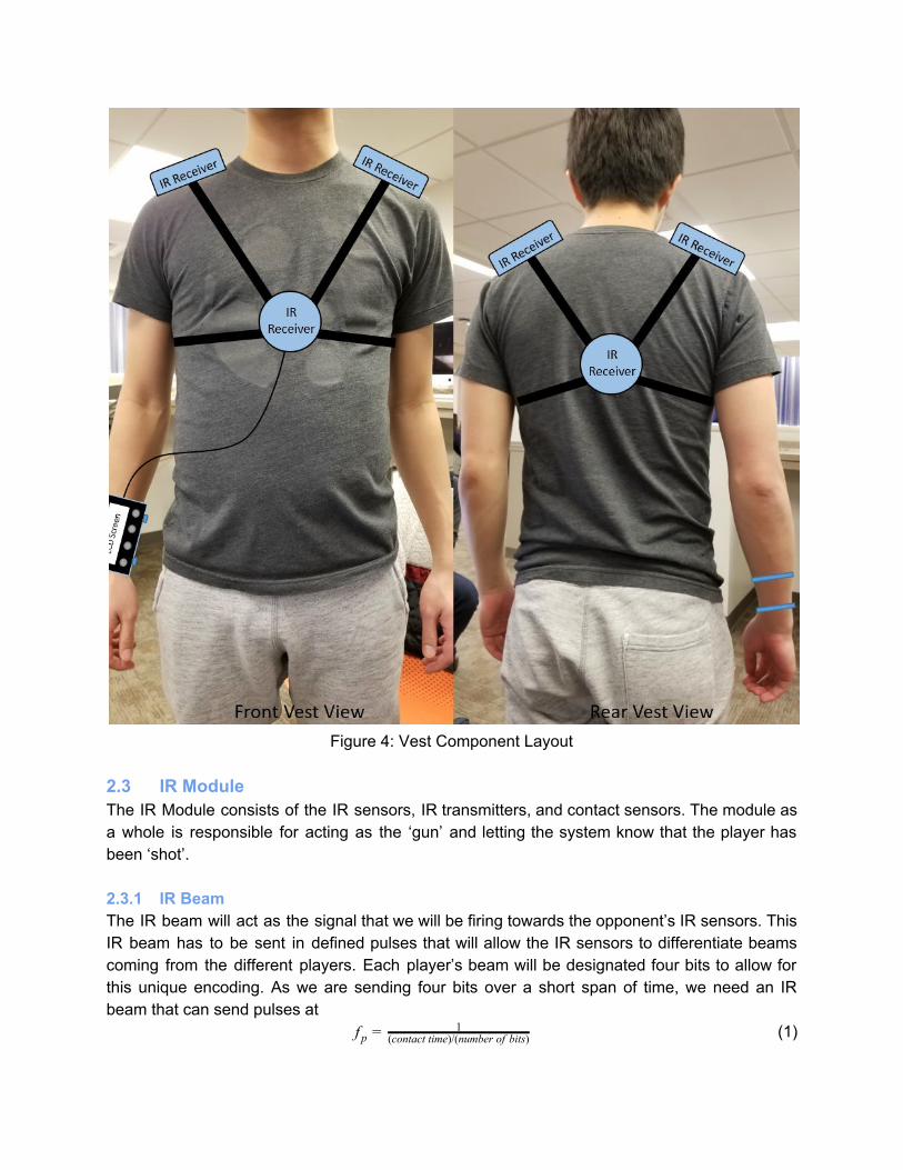
Figure 4: Vest Component Layout
2.3 IR Module The IR Module consists of the IR sensors, IR transmitters, and contact sensors. The module as a whole is responsible for acting as the ‘gun’ and letting the system know that the player has been ‘shot’. 2.3.1 IR Beam The IR beam will act as the signal that we will be firing towards the opponent’s IR sensors. This IR beam has to be sent in defined pulses that will allow the IR sensors to differentiate beams coming from the different players. Each player’s beam will be designated four bits to allow for this unique encoding. As we are sending four bits over a short span of time, we need an IR beam that can send pulses at
f p = 1(contact time)/(number of bits) (1)
where = time the beam is in contact with the IR sensor.ontact timec
Requirement 1: The IR beam has to have a range of at least 20 feet. Requirement 2: Needs to pulse IR beams at . For example, for a beam contact time of 0.1s, f p the bits must be sent at a frequency of = 40Hz.f p 2.3.2 IR Sensors These sensors will be responsible for receiving the pulsed IR beams mentioned above that indicate whether the player is shot. These pulses will be the players’ unique tag. As the IR beam will send pulses at , the IR sensor must sample atf p
= 2f s f p (2) to eliminate aliasing. Requirement 1: Has to be operated from 2.8V to 3.8V. Requirement 2: They should have a large field of view (at least 45 degrees). Requirement 3: Should be able to distinguish different players via the different pulses that are being transmitted at . For example, if the bits are being sent at =40Hz, the IR sensors must f p f p sample at Hz.0f s = 8 2.3.3 Contact Sensors The sensors on the palm will provide feedback to the microcontroller unit that the glove is in shooting mode (when 3 fingers are in contact with the palm). When in shooting mode, the user can fire a shot when the sensor on the thumb makes contact with the finger sensor. The sensor patches in red in Figure 2 will act as the ground for the circuit. When the sensors are not in contact, the microcontroller will be receiving a high input voltage. When the silver circles make contact with the red circles in Figure 2, that same microcontroller input will be pulled to ground. When this is read, the microcontroller will know to be in fire mode/shoot.
Requirement 1: Must be able to distinguish between open-circuit (sensors not touching) and closed-circuit (sensors touching). 2.4 Control System 2.4.1 Microcontroller Being the brain of the project, this module is responsible for powering the LEDs when necessary, having various displays on the LCD screen, powering the IR beam and buzzer depending on a series of signals from the IR sensors, contact sensors, and wireless transceiver.
Requirement 1: It has to be programmable and retain its state even after it has been turned off.
2.4.2 Wireless Transceiver The wireless transceiver in the control system is mainly used to relay current game information to the master (player 1) as the game is going on. When the game begins, each player will be synced to player 1’s set time limit. During the game, when a player has hit another player successfully, the wireless transceiver (on the person who was shot) will relay the information to the master to keep track of the score. Requirement 1: It must have transmission range of at least 20 feet.
2.5 LCD Module The LCD module presents to player 1 an interactive module where he can navigate a programmed game menu via the buttons. As for all the other players, the LCD screen displays important information such as the current health bar, time left in the game, and other game features that we can think of along the way. Requirement 1: The display has to show a decrease in the player’s health bar when he or she is being shot. Requirement 2: An interactive menu for player 1 to set game settings. Requirement 3: The menu has to show a response in less than 1s after a button is pressed. Requirement 4: Must be lit to permit gameplay in the dark. 2.6 Game Module The game module acts as the unit to provide visible and audible feedback to the player. This includes a piezo buzzer that buzzes for a quick moment whenever the user shoots a beam (triggered by the contact sensors) or dies (triggered by the microcontroller). It also has LED lights to act as a visual cue to the other players denoting their status.
Requirement 1: The buzzer has to buzz in less than 0.5s when a player fires his shot. Requirement 2: The LED lights have to be visible from 30 feet away. Requirement 3: The LED lights need to change color in less than 1 second when a player is shot. 2.7 Power Supply The power module will power the components in our design. The laser tag glove will be battery powered with regulation so that each component gets the necessary voltage and current to function. The power supply will be located near the vest with battery holders. 2.7.1 Battery Our power supply will utilize a 9V Alkaline battery in a battery holder. The components that require the most supply current are our laser module and LCD display. The batteries we have looked at purchasing are around 310 mAh battery capacity. When assuming maximum currents, we plan on the battery powering the laser tag glove for about 4 hours. If we find that the product
does not last long enough, we can implement a battery holder that holds two 9V batteries in order to extend the usage time. Requirement 1: 9V with around 310mAh battery capacity in order to power the device for 4 hours. 2.7.2 Converter The LCD display requires an input voltage of 5V while our microcontroller, buzzer, and laser module require around 3.3V. The remaining components such as the IR sensors operate at ranges of 2.5 to 5.5 volts. We plan on implementing separate buck converter in order to step-down the 9 volts from the battery to the appropriate levels for each device. The converters will need to have low voltage ripple in order for our devices to operate correctly and consistently. Requirement 1: The voltage has to be stepped-down to the appropriate values of 5V and 3.3V with minimal voltage ripple .±10%)( 2.8 Risk Analysis At the moment, we believe the IR laser module will pose the greatest risk to successfully completing our project. Our goal for the project is to make two working gloves. However, we want to implement a system that would allow more players to join. If we wish to have the ability to include more players, we need to be able to identify each glove. By identifying each glove, the players will be able to know who shot, got hit, and the overall score of the game per player. We plan on implementing this player identification with the laser beam. We need to drive the laser beam in such a way that it will be able to send information to the IR sensors. For example, we want to pulse the laser in a way where we could send four bits of information. In this situation, Player 1’s laser would send “0000.” Therefore, whenever Player 1 shoots another player, their IR sensor would detect the “0000” signal and keep track of their score by sending this result to the master. This system would allow us to implement more players since we can simply give another code to the additional player, such as “0001,” “0011,” etc. We thought of using this idea by researching similar concepts in laser tag and IR TV remotes [3]. For example, TV remotes send various sets of bits depending if you want to increase the volume or change the channel. While we are planning on implementing this concept, it seems to be one of the more difficult objectives to implement. Since our laser is a constant beam of light it might be difficult to pulse it in a certain pattern. We have two options. One would be to control the pulses using the digital output pins of the microcontroller to encode the pulse bits. Another would be to use a pulse-width modulation (PWM) system to give each laser a unique duty cycle that would allow for player identification.
A possible difficulty will be the communication between the IR laser and the IR sensors. Since each shot will only last for milliseconds, the IR sensors will have to have a sampling rate that will capture that information. Also, we have found that some lasers modules have issues with the fast switching a PWM would require. If this is the case, we would not be able to implement the PWM correctly and would switch to the digital output of the microcontroller. Hopefully this laser -
IR sensor communication will not become an issue since we are planning on using an IR laser module that is capable of fast switching. If this problem arises, however, we have the backup plan of using an IR diode as opposed to an IR laser module. The diode should have an easier time switching on and off rapidly. The main reason we are not initially going with an IR diode is because it is much weaker than the laser module. Since it is weaker, it’s range would be far too short for a fun game of laser tag. We would need to implement an optical system that utilizes lenses in order to focus and amplify the LED strength. There seems to be a lot of complexity when considering the IR laser module, but we are planning accordingly and considering multiple plans in order to be able to handle problems if they come up. 3 Ethics and Safety Many ethical and safety concerns must be considered when creating our project. An obvious issue that comes to mind is that the project revolves around the use of infrared light. While developing our project we must be mindful of the lasers since they can cause damage when pointed directly at one’s eyes [2]. Our project is not meant to cause harm to anyone, and it is only meant to be an enjoyable experience for those who use it. However, intentional misuse of the product could lead to severe eye damage such as blindness. This can occur if the laser is pointed directly at people, vehicles, or any living thing with their eyes exposed. In order “to hold paramount the safety, health, and welfare of the public,” we must design the project in a way which minimizes any safety hazards [1]. Since the laser portion of the project is a key component, we cannot simply make it safer or remove the hazards. We can minimize accidents where players point at each other’s eyes with our sensor location. For example, by placing the sensors below the shoulders, on the stomach, and on the back we make sure that one does not need to aim towards the face which limits exposure to the eyes. Another factor we considered was the power of our laser module. Lasers can cause eye damage even at low wattage, such as 5mW. A regular 60W light bulb uses more power, but the light is spread around making it much less dangerous than the concentrated laser. Due to this safety concern, we plan on using a 1mW IR laser module. At one milliwatt, the laser will need to hit the eye for seconds in order to cause damage. Our design will release the IR beam for a very short duration (milliseconds) when pressing the trigger, making it less likely to cause damage even if exposure to the eyes occurs for some reason. Lasers exist with various power outputs, ranging from harmless to strong enough to damage the body. Ideally we would want a completely harmless laser module, but it would severely limit the range of the game. Our 1mW laser will be safe if used as instructed while maintaining an enjoyable range of 20ft+. However, another danger of IR light is that it is not within the visible spectrum of human sight. Visible light can be seen, so it is much easier to avoid whenever you interact with it. During development of our product we must be aware where the laser module points at all times and consider factors such as reflection. This is a hazardous component of the product, since you might point towards someone’s eyes and not even know that it is occuring. We plan on reducing this hazard by placing a visible light sight so the player knows the general area of where they are aiming. Also, our product is intended for people of varying ages and
background. Therefore, many of them might not know of the dangers associated with lasers and IR light. The final product would come with safety warnings and information about lasers in order to notify them about proper usage of the product. Hopefully this reduces accidental misuage of the product and allows them to have fun in a safe manner. Another safety issue associated with our product is the contact with the human body and electrical equipment. Our laser tag glove is meant to be worn and it will contain electrical components within. We need to make sure that all of the circuitry is properly closed off in order to prevent current to travel through the person’s body. The player will likely be running around, so we need to make sure that bodily fluids such as sweat will not damage or short the electric components. Our soldering and connecting of the circuit has to be reliable since everything must stay in place regardless of each player’s movements. Also, since our product will be battery powered we must make sure each component is powered at its appropriate voltage and current ratings. This is necessary since we would not want components to blow up or heat up to dangerous levels. Minimizing these safety concerns is our primary goal, so we plan on considering all of these factors when designing and developing the laser tag glove. By regulating the current flowing through the circuit and carefully planning the product’s connections, we plan on our product being safe and reliable even through many uses. Overall, our project comes with safety hazards that must be considered. The hazards are unavoidable due to the need for electricity and lasers. However, we will consider and implement the proper methods to make the laser tag glove completely safe when used correctly. Our main goal for the project is to create a fun product and have others enjoy it. As engineers, it is our duty to implement our designs with the well being of others in mind. References [1] Ieee.org, "IEEE IEEE Code of Ethics", 2016. [Online]. Available: http://www.ieee.org/about/corporate/governance/p7-8.html [Accessed: 28- Jan- 2018]. [2] “Can a pocket laser damage the eye?” Scientific American, Available: www.scientificamerican.com/article/can-a-pocket-laser-damage/ [Accessed: 03-Feb-2018] [3] Layton, Julia. “How Remote Controls Work.” HowStuffWorks, HowStuffWorks, 10 Nov. 2005, Available: www.electronics.howstuffworks.com/remote-control. [Accessed: 03-Feb-2018]