Smart Deaf-Mute Glove - An-Najah Repository
52
Smart Deaf-Mute Glove May 7, 2017 By: Mana Lubbadeh and Aya Shashtari Supervised by: Dr. Raed Al-Qadi Engineering & Information Technology Faculty –Computer Engineering Department An-Najah National University – Nablus .Palestine Presented in partial fulfillment of the requirements for Bachelor degree in Computer Engineering
-
Upload
khangminh22 -
Category
Documents
-
view
1 -
download
0
Transcript of Smart Deaf-Mute Glove - An-Najah Repository
Smart Deaf-Mute
Glove
May 7, 2017
By:
Mana Lubbadeh and Aya Shashtari
Supervised by: Dr. Raed Al-Qadi
Engineering & Information Technology Faculty –Computer Engineering
Department An-Najah National University – Nablus .Palestine
Presented in partial fulfillment of the requirements for Bachelor degree in
Computer Engineering
1 | P A G E
Acknowledgment
We thank our God (SWT), our parents for the big support, love and care they gave us all the
time, and for always believing in us and trusting our judgment.
We also thank Dr. Raed Al-Qadi our supervisor, who gave us a big motivation every time we
felt down. We would also like to thank our teachers and friends.
2 | P A G E
Disclaimer Statement
This report was written by students Manal Lubbadeh and Aya Shashtari at the Computer
Engineering Department, Faculty of Engineering & Information Technology, An-Najah National
University. It has not been altered or corrected, other than editorial corrections, as a result of
assessment and it may contain language as well as content errors. The views expressed in it
together with any outcomes and recommendations are solely those of the student(s). An-Najah
National University accepts no responsibility or liability for the consequences of this report
being used for a purpose other than the purpose for which it was commissioned.
3 | P A G E
Table of Contents
I. Acknowledgment..................................................... 1
II. Disclaimer Statement.............................................. 2
III. Nomenclature .......................................................... 7
IV. Abstract ................................................................... 8
V. Chapter 1: Introduction ......................................... 1
Statement of the problem: ..................................................................................................... 1
Objectives and scope of the work: ........................................................................................ 2
Significance of the work: ...................................................................................................... 2
Organization of the report: .................................................................................................... 3
VI. Chapter 2: Constraints, Standards/ Codes and
Earlier course work ................................................ 4
2.1 Constraints: ........................................................................................................................... 4
12.2 Hardware and Standards Codes: ................................................................................... 4
Programs: ............................................................................................................................ 9
Libraries: ............................................................................................................................. 9
2.3 Earlier course work: .............................................................................................................. 9
VII. Chapter 3: Literature review ............................... 10
VIII. Chapter 4: Methodology ...................................... 11
Collecting Data: ................................................................................................................... 11
Data Analysis: ..................................................................................................................... 11
- Hand Compressions: ................................................................................................... 11
- Hand Gestures: ........................................................................................................... 12
- Contacts between fingers: ........................................................................................... 12
Connecting components: ........................................................................................................... 14
- Detector Module: ........................................................................................................ 14
- Translator Module: ..................................................................................................... 14
4 | P A G E
Code Flow: ................................................................................................................................ 15
Detector module code flow chart: .............................................................................. 15
Translator module code flow chart: ............................................................................ 17
IX. Chapter 5: Results and Discussion ...................... 18
X. Chapter 6: Conclusion .......................................... 30
XI. References .............................................................. 31
XII. Appendices ............................................................. 33
Appendix A: ........................................................................................................................ 33
Appendix B: ........................................................................................................................ 38
Appendix C: ........................................................................................................................ 43
5 | P A G E
Table of Figures
Figure 1: (Flex-sensor Interfacing with Arduino) (Jimb0, 2017) ................................................... 5
Figure 2: (GY-61 Accelerometer with Arduino) (Arduino d. , 2015) ............................................ 5
Figure 3: (Contact sensor basic circuit) .......................................................................................... 6
Figure 4: (TTs interfacing with Arduino) (Malec, 2012) ............................................................... 6
Figure 5:( HC-05interfacing with Arduino) (Currey, 2014) ........................................................... 7
Figure 6:( HC-06 interfacing with Arduino) (Arduino, 2015) ........................................................ 8
Figure 7: (Step up converter) .......................................................................................................... 8
Figure 8: (V and R representation problem) ................................................................................. 13
Figure 9: (Detector Module code flow chart) ............................................................................... 15
Figure 10:(detector module schematic) ........................................................................................ 18
Figure 11:(translator module schematic) ...................................................................................... 19
Figure 12:(PCB schematic) ........................................................................................................... 20
Figure 13:(PCB board) .................................................................................................................. 20
Figure 14: (Translator module final result) ................................................................................... 21
Figure 15:(Matlab- signal representations) ................................................................................... 21
Figure 16:( representing full sentence with both modes )............................................................. 29
Figure 17: (Flex sensor basic code) .............................................................................................. 33
Figure 18: (GY-61 Accelerometer basic code) ............................................................................. 34
Figure 19: (HC-05 basic code) ...................................................................................................... 35
Figure 20: (HC-06 basic code) ...................................................................................................... 36
Figure 21: (Matlab code) .............................................................................................................. 37
6 | P A G E
Table of tables
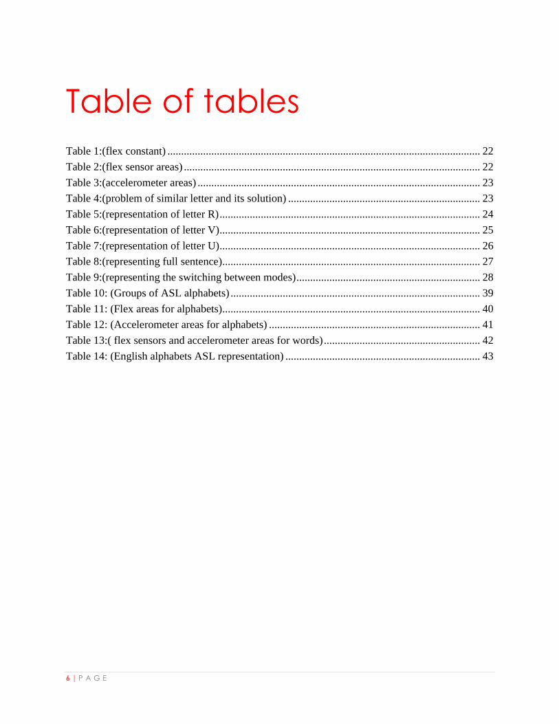
Table 1:(flex constant) .................................................................................................................. 22
Table 2:(flex sensor areas) ............................................................................................................ 22
Table 3:(accelerometer areas) ....................................................................................................... 23
Table 4:(problem of similar letter and its solution) ...................................................................... 23
Table 5:(representation of letter R) ............................................................................................... 24
Table 6:(representation of letter V) ............................................................................................... 25
Table 7:(representation of letter U) ............................................................................................... 26
Table 8:(representing full sentence).............................................................................................. 27
Table 9:(representing the switching between modes) ................................................................... 28
Table 10: (Groups of ASL alphabets) ........................................................................................... 39
Table 11: (Flex areas for alphabets).............................................................................................. 40
Table 12: (Accelerometer areas for alphabets) ............................................................................. 41
Table 13:( flex sensors and accelerometer areas for words) ......................................................... 42
Table 14: (English alphabets ASL representation) ....................................................................... 43
7 | P A G E
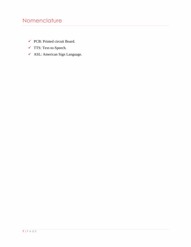
Nomenclature
PCB: Printed circuit Board.
TTS: Text-to-Speech.
ASL: American Sign Language.
8 | P A G E
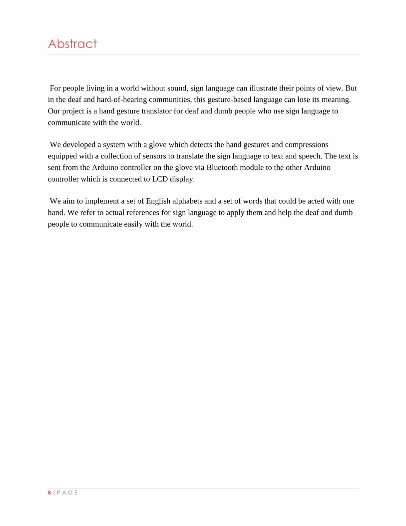
Abstract
For people living in a world without sound, sign language can illustrate their points of view. But
in the deaf and hard-of-hearing communities, this gesture-based language can lose its meaning.
Our project is a hand gesture translator for deaf and dumb people who use sign language to
communicate with the world.
We developed a system with a glove which detects the hand gestures and compressions
equipped with a collection of sensors to translate the sign language to text and speech. The text is
sent from the Arduino controller on the glove via Bluetooth module to the other Arduino
controller which is connected to LCD display.
We aim to implement a set of English alphabets and a set of words that could be acted with one
hand. We refer to actual references for sign language to apply them and help the deaf and dumb
people to communicate easily with the world.
1 | P A G E
Chapter 1: Introduction
Statement of the problem:
The level of care of people with special needs is a basic criterion for measuring the civilization of
the nations and their development. It is one of the priorities of contemporary states and
organizations, which stems from the legitimacy of the right of the person with special needs to
equal opportunities in all areas of life and to live in dignity and freedom.
The reality of the people with special needs in Palestine is a tragic reality. The vast majority feel
despair and loss of hope for life. They live in poverty, and this leads to a social imbalance,
because they feel that they are from another world and not have the right to survive and live in
the community.
The Palestinian society consists of 2.7% people with special needs. These people have difficulty
to communicate with the surrounding environment. Therefore, 37.6% are uneducated and 87.3%
are unemployed. People with special needs includes people with hearing and speech problems
which represent approximately third of the special needs population. These people are called
deaf-mute people.
Sign Language is the way that deaf-mute people communicates with others. However, sign
language is not widely spread between people in the society. Therefore, deaf-mute people needs
a way to communicate freely with the surroundings without difficulties. They need mediator
which translates their language into text and speech which could be easily understood by people
who don’t understand sign language.

2 | P A G E
Objectives and scope of the work:
Smart Deaf-Mute Glove focuses on the deaf-mute people. The project aims to integrate the deaf-
mute people with the society by helping them communicate easily with the surrounding
environment. This will increase the percentage of deaf-mute people in the education and
employment sectors.
It’s a smart glove prototype which could be used by the deaf-mute people. It consists of two
modules. The detector module which is a glove that detects the hand gestures and could be worn
by a deaf-mute person. The second module is the translator which translates the detected hand
gestures into English text and speech. The translator module could be used by non-deaf-mute
person and aims to help him/her understand the sign language. The two modules are connected
via Bluetooth. This will help the deaf-mute person communicate with others in a comfortable
atmosphere.
The smart glove prototype supports all English alphabets and a set of words that the deaf-mute
person will need to communicate with the surroundings. The set of words help the deaf-mute
person introduce himself/herself to others (e.g., my name is), express his/her emotions (e.g., I
like you), and greet others (e.g., I am glad to see you).
Significance of the work:
Smart Deaf-Mute Glove is mainly for deaf-mute people so that they use it to communicate easily
with surroundings in their everyday life. They can also use it to make presentations in front of
audience since the sign language is translated into text using LCD and speech.
Moreover, Smart Deaf-Mute Glove could be used in the field of education. A teacher now can
teach the students the sign language easily. This will help to spread out the sign language
learning in the society.
3 | P A G E
Organization of the report:
In this report, we illustrate the idea in its all details. Going through the report you can first see
the constraints we faced during our work including equipment, tools we used and earlier course
work. Then, you can read about similar systems to get a background about the topic being
discussed and what special features we have done upon other systems. After that, the
methodology of our work is extensively explained. Next chapter states our results and a
discussion to interpret and compare the results. Ending it up with the conclusion of the whole
work and what is our vision for future to improve our work.
4 | P A G E
Chapter 2: Constraints, Standards/ Codes and Earlier
course work
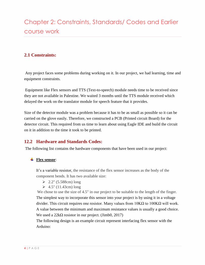
2.1 Constraints:
Any project faces some problems during working on it. In our project, we had learning, time and
equipment constraints.
Equipment like Flex sensors and TTS (Text-to-speech) module needs time to be received since
they are not available in Palestine. We waited 3 months until the TTS module received which
delayed the work on the translator module for speech feature that it provides.
Size of the detector module was a problem because it has to be as small as possible so it can be
carried on the glove easily. Therefore, we constructed a PCB (Printed circuit Board) for the
detector circuit. This required from us time to learn about using Eagle IDE and build the circuit
on it in addition to the time it took to be printed.
12.2 Hardware and Standards Codes:
The following list contains the hardware components that have been used in our project:
Flex sensor:
It’s a variable resistor, the resistance of the flex sensor increases as the body of the
component bends. It has two available size:
2.2" (5.588cm) long
4.5" (11.43cm) long
We chose to use the size of 4.5" in our project to be suitable to the length of the finger.
The simplest way to incorporate this sensor into your project is by using it in a voltage
divider. This circuit requires one resistor. Many values from 10KΩ to 100KΩ will work.
A value between the minimum and maximum resistance values is usually a good choice.
We used a 22kΩ resistor in our project. (Jimb0, 2017)
The following design is an example circuit represent interfacing flex sensor with the
Arduino:

5 | P A G E
Figure 1: (Flex-sensor Interfacing with Arduino) (Jimb0, 2017)
Refer to Appendix A to see the code of the controller which reads the resistance of the flex
sensor and convert it to angle using some calculations.
GY-61 DXL335 3-axis accelerometer module:
It’s a three-axis accelerometer sensor module based on ADXL335 integrated circuit. The
ADXL335 is a triple axis accelerometer with extremely low noise and power
consumption. (Robot Park, 2015)
The accelerometer works as a resistor whose resistance is relative to the acceleration of
the respective pin and axis
The figure below shows the design circuit that represents interfacing accelerometer
sensor with the Arduino:
Figure 2: (GY-61 Accelerometer with Arduino) (Arduino d. , 2015)
Refer to Appendix A to see the code of the controller which reads the values coming from
the accelerometer and convert them to degrees using some calculations.
6 | P A G E
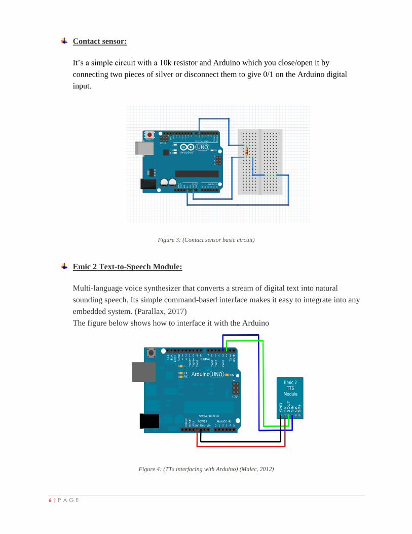
Contact sensor:
It’s a simple circuit with a 10k resistor and Arduino which you close/open it by
connecting two pieces of silver or disconnect them to give 0/1 on the Arduino digital
input.
Figure 3: (Contact sensor basic circuit)
Emic 2 Text-to-Speech Module:
Multi-language voice synthesizer that converts a stream of digital text into natural
sounding speech. Its simple command-based interface makes it easy to integrate into any
embedded system. (Parallax, 2017)
The figure below shows how to interface it with the Arduino
Figure 4: (TTs interfacing with Arduino) (Malec, 2012)
7 | P A G E
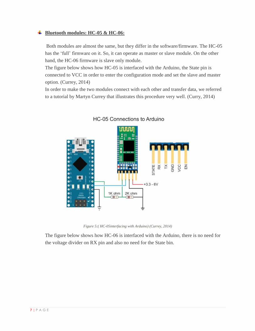
Bluetooth modules: HC-05 & HC-06:
Both modules are almost the same, but they differ in the software/firmware. The HC-05
has the ‘full’ firmware on it. So, it can operate as master or slave module. On the other
hand, the HC-06 firmware is slave only module.
The figure below shows how HC-05 is interfaced with the Arduino, the State pin is
connected to VCC in order to enter the configuration mode and set the slave and master
option. (Currey, 2014)
In order to make the two modules connect with each other and transfer data, we referred
to a tutorial by Martyn Currey that illustrates this procedure very well. (Curry, 2014)
Figure 5:( HC-05interfacing with Arduino) (Currey, 2014)
The figure below shows how HC-06 is interfaced with the Arduino, there is no need for
the voltage divider on RX pin and also no need for the State bin.
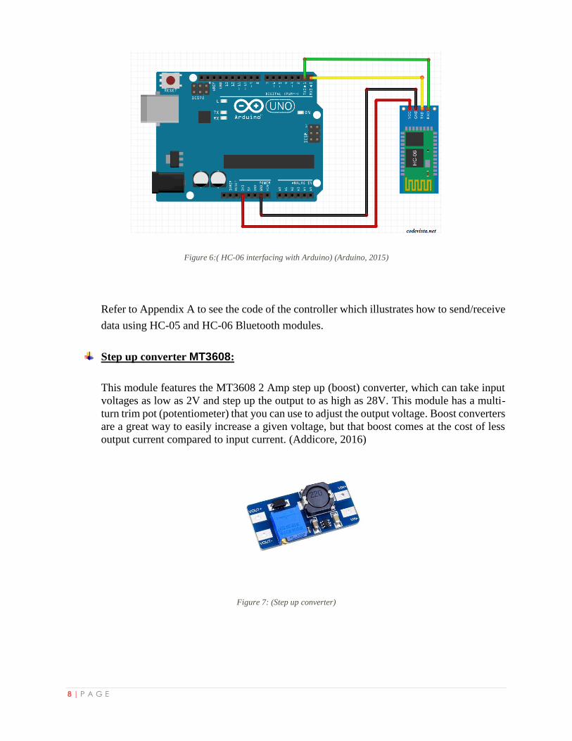
8 | P A G E
Figure 6:( HC-06 interfacing with Arduino) (Arduino, 2015)
Refer to Appendix A to see the code of the controller which illustrates how to send/receive
data using HC-05 and HC-06 Bluetooth modules.
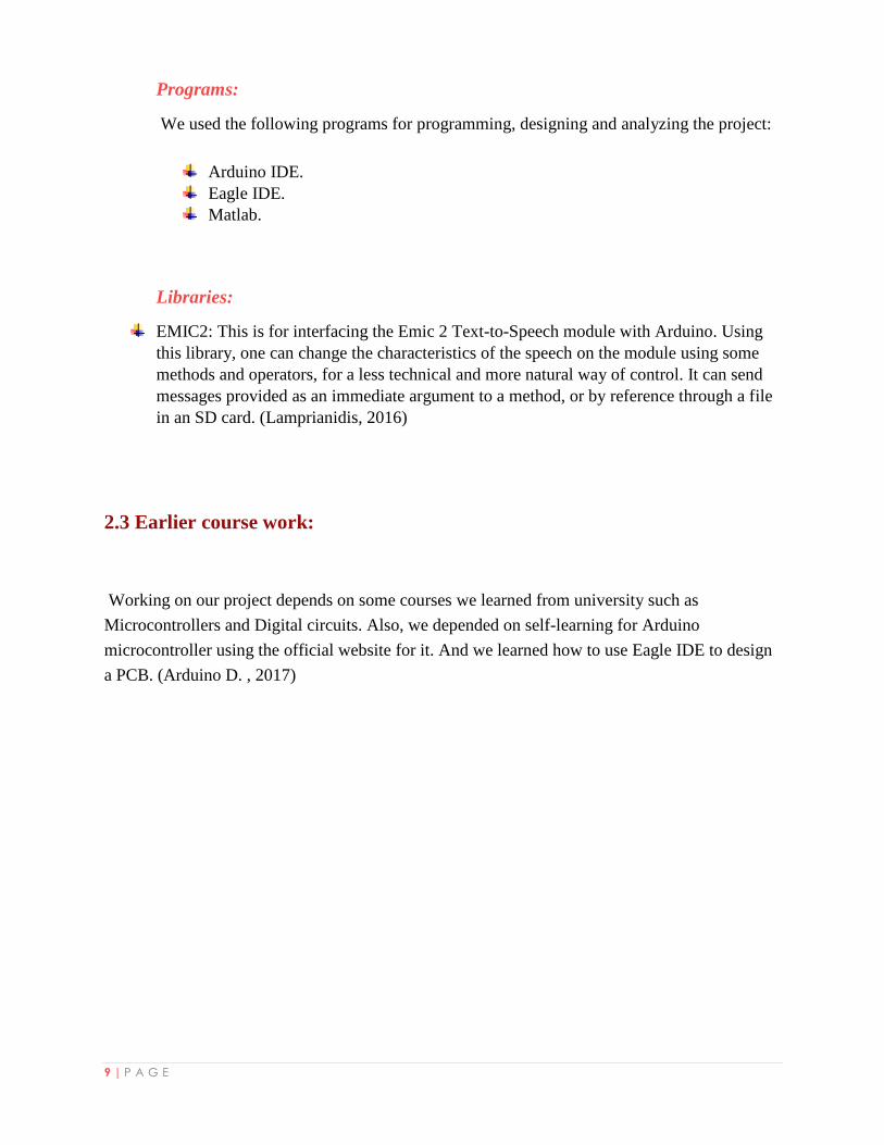
Step up converter MT3608:
This module features the MT3608 2 Amp step up (boost) converter, which can take input
voltages as low as 2V and step up the output to as high as 28V. This module has a multi-
turn trim pot (potentiometer) that you can use to adjust the output voltage. Boost converters
are a great way to easily increase a given voltage, but that boost comes at the cost of less
output current compared to input current. (Addicore, 2016)
Figure 7: (Step up converter)
9 | P A G E
Programs:
We used the following programs for programming, designing and analyzing the project:
Arduino IDE.
Eagle IDE.
Matlab.
Libraries:
EMIC2: This is for interfacing the Emic 2 Text-to-Speech module with Arduino. Using
this library, one can change the characteristics of the speech on the module using some
methods and operators, for a less technical and more natural way of control. It can send
messages provided as an immediate argument to a method, or by reference through a file
in an SD card. (Lamprianidis, 2016)
2.3 Earlier course work:
Working on our project depends on some courses we learned from university such as
Microcontrollers and Digital circuits. Also, we depended on self-learning for Arduino
microcontroller using the official website for it. And we learned how to use Eagle IDE to design
a PCB. (Arduino D. , 2017)
10 | P A G E
Chapter 3: Literature review
Sign Language Translator is an electrical glove which could be worn by a deaf-mute person. The
glove helps the deaf-mute person to translate his/her sign language into text and audio which
could be visualized and heard by people without a disability. Sign Language Translator
implements 7 English Letters (A, C, G, Q, B, F, L and X). The text is displayed on LCD
connected on the glove and the audio is outputted by a mobile phone. (Dweikat & Obaid, 2016)
SignAloud gloves, which can translate American Sign Language into speech or text. Two
undergraduate students at the University of Washington have worked to invent a new way to
communicate. Each of the SignAloud gloves has sensors that record movement and gestures then
transmit the info wirelessly to a central computer. The computer then looks at the data, and if it
matches a gesture, then the associated word or phrase is spoken through a speaker. The system is
based on machine learning algorithms that learn from a catalogue of signing examples. In
practice, if a hand gesture is a match then the appropriate sound is spoken by the computerized
voice through a speaker. (O'HARE, 2016) (Wanshel, 2016)
These projects and other projects in this field are concerned only with making the glove part and
the data is interpreted using existing components like a computer or a mobile phone. SignAloud
gloves transmits the data to the computer to be processed there and then translated to speech
whereas Smart Deaf-Mute Glove processes the data in the detector module and transmits it to the
translator module which we constructed it to interpret the data as text and speech.
11 | P A G E
Chapter 4: Methodology
Collecting Data:
First step was collecting data about similar projects in this field and what components are used
in this type of projects. Then After that, we studied each component separately to understand
how it works and what the values it gives are. Standard circuit for each component was built and
its results and output data were collected and saved in order to be analyzed and compared with
consistent component so that we can choose the best one that matches our needs.
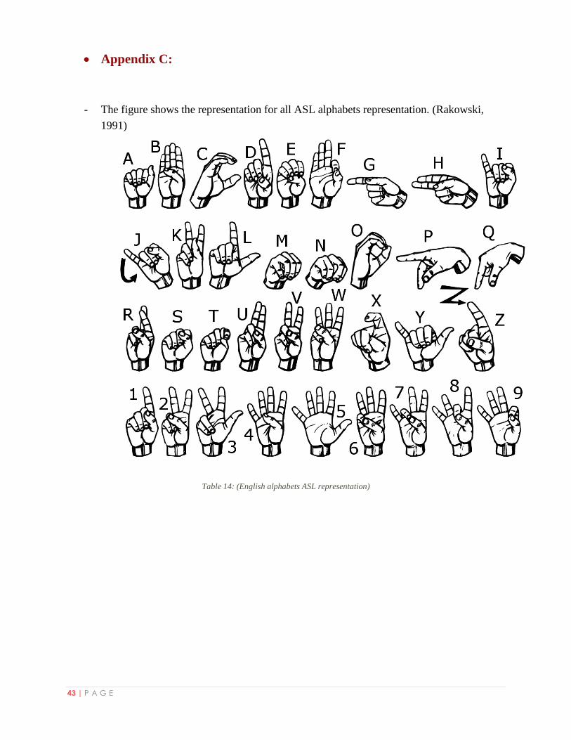
Second step was to study about ASL (American Sign Language) and how the English alphabets
are represented (Refer to Appendix C). Firstly, we distributed the alphabets to groups, each
group contains the alphabets that are generally similar in their sign language representation.
Then, for each group we made a table to distribute it to sub-groups of similar alphabets. Finally,
we differentiated between similar alphabets in each sub-group by deciding what sensors could be
used to do so. (Refer to Appendix B)
Data Analysis:
After the data collection process was done, it was necessary to analyze the collected data in
order to decide what we actually need to build the Smart Deaf-Mute Glove. From searching
about another projects and studying the ASL we noticed that the glove needs to detect the hand
gestures, fingers compressions and touches between some fingers.
- Hand Compressions: detection of hand compression in the vast majority of projects in this
field is done by using Flex-sensors. So, we decided to use five flex sensors for the five hand
fingers. A Flex-sensor is actually a variable resistor, so its output data is the resistor value
depending on the compression angle. In order to see the output of flex sensors and analyze it
better, we wrote a code using Matlab (Refer to Appendix A). We connected the flex sensors
to the analog inputs of the Arduino Nano. The code reads the analog value coming from the
analog inputs and represents it as analog signal for each flex. We noticed that the signal
changes over time depending on how much the flex sensor is compressed.
12 | P A G E
Analyzing values of this type and using them to represent a specific hand shape is hard.
Because it is almost impossible to strictly make the same alphabet representation and get the
same float values of the flex sensors resistors. To solve this issue we made the following
procedure:
For each flex-sensor we acted all the alphabets and recorded the flex value for each alphabet.
Depending on this, we specified the range for each flex sensor between its minimum and
maximum recorded values. Finally, we distributed these ranges into areas so that the flex value
for a specific alphabet can swing a little without interfering into another area. Note that, the
flex sensor value here means the flex sensor bend angle which is calculated depending on three
parameters which are the flex resistance value for this angle, flex resistance value when the
flex is straight and flex resistance value when the flex is bended to 90o. (Refer to Appendix B)
- Hand Gestures: hand gestures are detected by some types of sensors. At first, we took the
output date from connecting a gyroscope to Arduino but we noticed that it gives unstable
values and the result changes depending on the hand gestures and position. On the Other
hand, analyzing the output data from connecting GY-61 Accelerometer led us to the right
component to use since it detects the hand gestures in XYZ axes. So, we took the XYZ
values for all alphabets representation and distributed them into areas as like as we did in the
areas distribution of flex sensors. (Refer to Appendix B)
In this way we were able to distinguish between alphabets that have the same flex sensors
areas values.
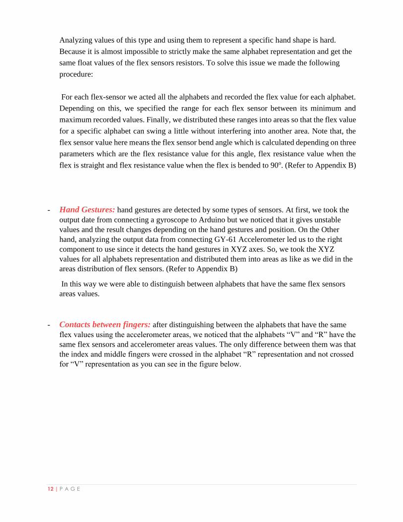
- Contacts between fingers: after distinguishing between the alphabets that have the same
flex values using the accelerometer areas, we noticed that the alphabets “V” and “R” have the
same flex sensors and accelerometer areas values. The only difference between them was that
the index and middle fingers were crossed in the alphabet “R” representation and not crossed
for “V” representation as you can see in the figure below.
13 | P A G E
Figure 8: (V and R representation problem)
In order to solve this, we designed contact sensors to detect the connection between the two
fingers by making a closed circuit when they are crossed and it is opened when they are not.
(The circuit design was described before in the Hardware part-Chapter 2).
After implementing all alphabets, we started to search for words which can be represented
with one hand and could be useful to construct meaningful sentences. These sentences helps
the user to introduce himself/herself, express his/her feelings and greet others.
Self-introduction sentences: My name is, I’m deaf, and I’m girl.
Expressing emotions sentences: I like you and I’m glad to see you.
Greetings sentences: Hello, You are welcome and good bye.
After choosing the words we used the areas of flex sensors and accelerometer to implement the
words. (Refer to Appendix B). The areas distribution procedure shorten the time and effort in
implementing the words.
Implementing the words required from us a way to distinguish between letters and words modes.
So we have recourse to use contact sensors again but now between index and ring fingers. By
touching them together the mode is toggled.
So, we have two uses of contact sensors. We decided to make the index finger to be connected to
VCC. Each one of the middle and ring fingers is connected to digital input pin on Arduino. This
way guarantees that the user can represent alphabets freely and the fingers can touch each other
during representation of letters/words without making any of previous functions of contact sensors
by mistake.
14 | P A G E
Connecting components:
Smart Deaf-Mute Glove consists of two modules. Detector and Translator module which are
connected with each other via Bluetooth. We designed the project in this way in order to provide
for the deaf-mute person his comfort zone while talking to others. Also, the glove circuit won’t
be heavy to be carried on hand. And to support this point more, we built it as a PCB to be as light
as possible on hand.
- Detector Module: we built this module to detect the hand compressions, gestures and
touches between fingers. We used five of 4.5 Inch Flex sensors, GY-61 Accelerometer and
the processor of the data was the Arduino Nano. In addition to the contact sensors circuits.
After processing the data, the output is an alphabet or a word which will be transmitted via
HC-05 Bluetooth module to the second module. The circuit of this module was designed
using eagle IDE in order to build a PCB. The supply voltage comes from a Lithium battery
which is connected to step up converter. We chose this way to supply voltage in order to get
the lightest weight.
- Translator Module: The translator module consists of 16*2 LCD, Text-To-Speech module,
speaker and HC-06 Bluetooth module connected to Arduino Mega. This module receives the
data from the detector module and displays it on the LCD and converts it to audio which is
outputted using a speaker. We supplied this module with voltage using a 9V battery
connected to the Vin pin of the Arduino.
As all components in both modules needs 5V to operate, we supplied the Arduinos with the
voltages on the Vin pins and supplied the components from the Arduino VCC pins. Taking into
account the maximum current each module consumes from the Arduino and how much current
can the Arduino supply on the VCC pins according to the documentation of Nano and Mega
Arduino’s. (LearnArduino, 2017)

15 | P A G E
Code Flow:
Detector module code flow chart:
Figure 9: (Detector Module code flow chart)
16 | P A G E
The first step in code is to initialize all the module’s components by specifying the pins numbers
and all necessary constants and variables. In setup, all required setups for each component are set
like setting the baud rate and specifying in/out pins which are implemented in the setup()
function block.
The second block which is the loop() function block. We started by reading the flex sensors
values by implementing a function “calculateAngle” which takes the input pin to read,
STRAIGHT_RESISTANCE and BEND_RESISTANCE constants as parameters and process
them and outputs the bend angle. We calculate the bend angle for each flex. Depending on the
output of the previous step, we calculate the area for each flex using a function for each flex that
takes the bend angle and tests it and returns the area number. The function general format is
“calculate[FlexNumber]Area(flex_[FlexNumber]_angle)”.
Then after that, we calculate the accelerometer axes values using the function
“calculateAccAngles” which returns a double array with the values of X, Y and Z axes. Using
these values, we calculate the area of each axis by the functions “calculateXArea,
calculateYArea and calculateZArea”.
The next step is to read the contact sensors values in order to determine two things. First, the
contact sensor value that distinguishes between letters “V” and “R”. Second, the contact that
distinguishes between modes “Word or Letter mode”.
Using the contact sensors “WordOrLetter” value, we determine which mode to enter. After
entering the right mode the letter/word is detected using a set of “if and else if” statements which
test the flex sensors areas values and if these values are similar for more than one letter/word we
enter another “if else if” statements that are based on accelerometer areas values. Note that, “V”
and “R” will enter the same if statements for flex sensors and accelerometer areas values, but
inside them there is if statement that distinguishes between them using the “V/R” contact sensors
value.
Finally, after the letter/word is detected, it will be sent via Bluetooth to the next module. Then,
we will go back to the beginning of the loop function.
17 | P A G E
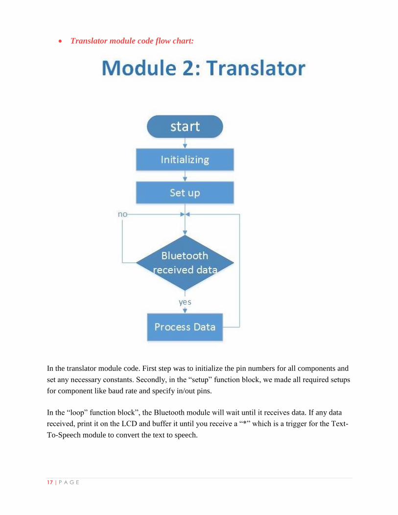
Translator module code flow chart:
In the translator module code. First step was to initialize the pin numbers for all components and
set any necessary constants. Secondly, in the “setup” function block, we made all required setups
for component like baud rate and specify in/out pins.
In the “loop” function block”, the Bluetooth module will wait until it receives data. If any data
received, print it on the LCD and buffer it until you receive a “*” which is a trigger for the Text-
To-Speech module to convert the text to speech.
18 | P A G E
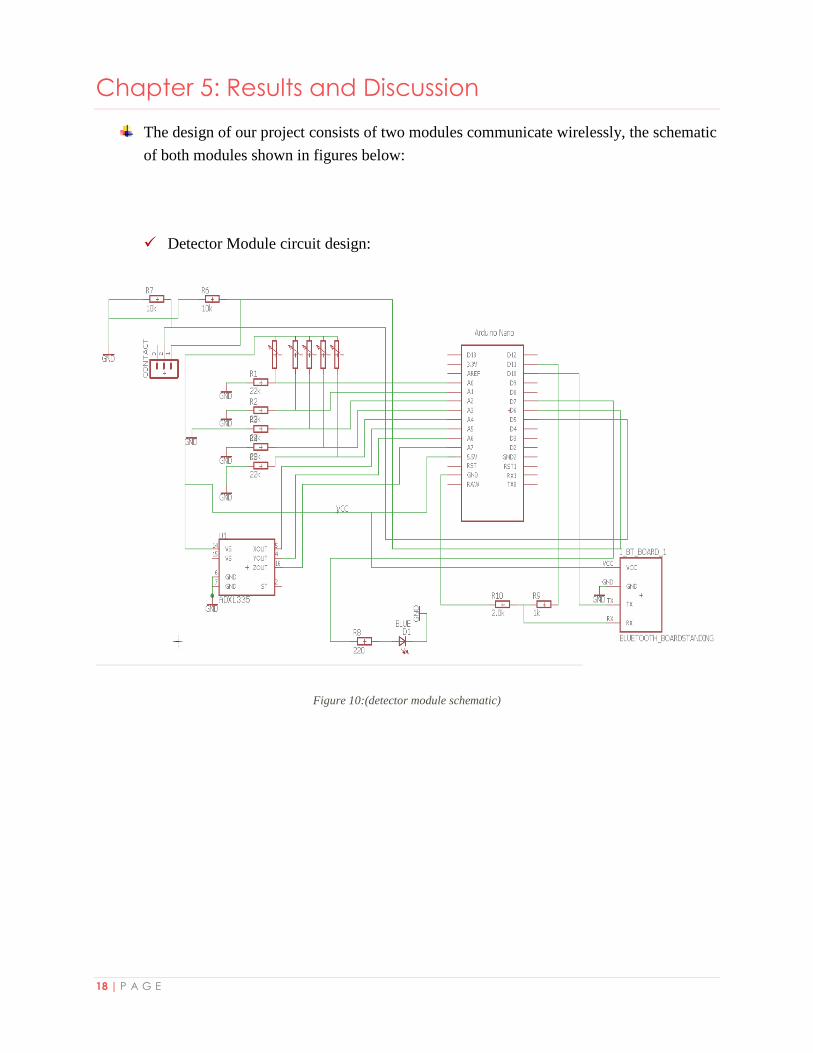
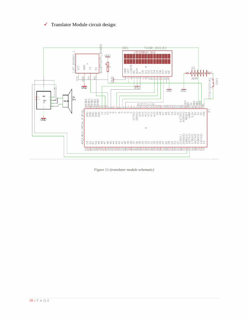
Chapter 5: Results and Discussion
The design of our project consists of two modules communicate wirelessly, the schematic
of both modules shown in figures below:
Detector Module circuit design:
Figure 10:(detector module schematic)
19 | P A G E
Translator Module circuit design:
Figure 11:(translator module schematic)
20 | P A G E
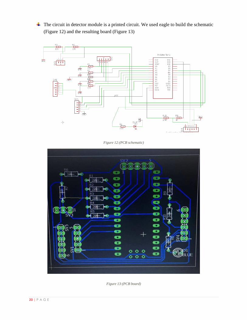
The circuit in detector module is a printed circuit. We used eagle to build the schematic
(Figure 12) and the resulting board (Figure 13)
Figure 12:(PCB schematic)
Figure 13:(PCB board)
21 | P A G E
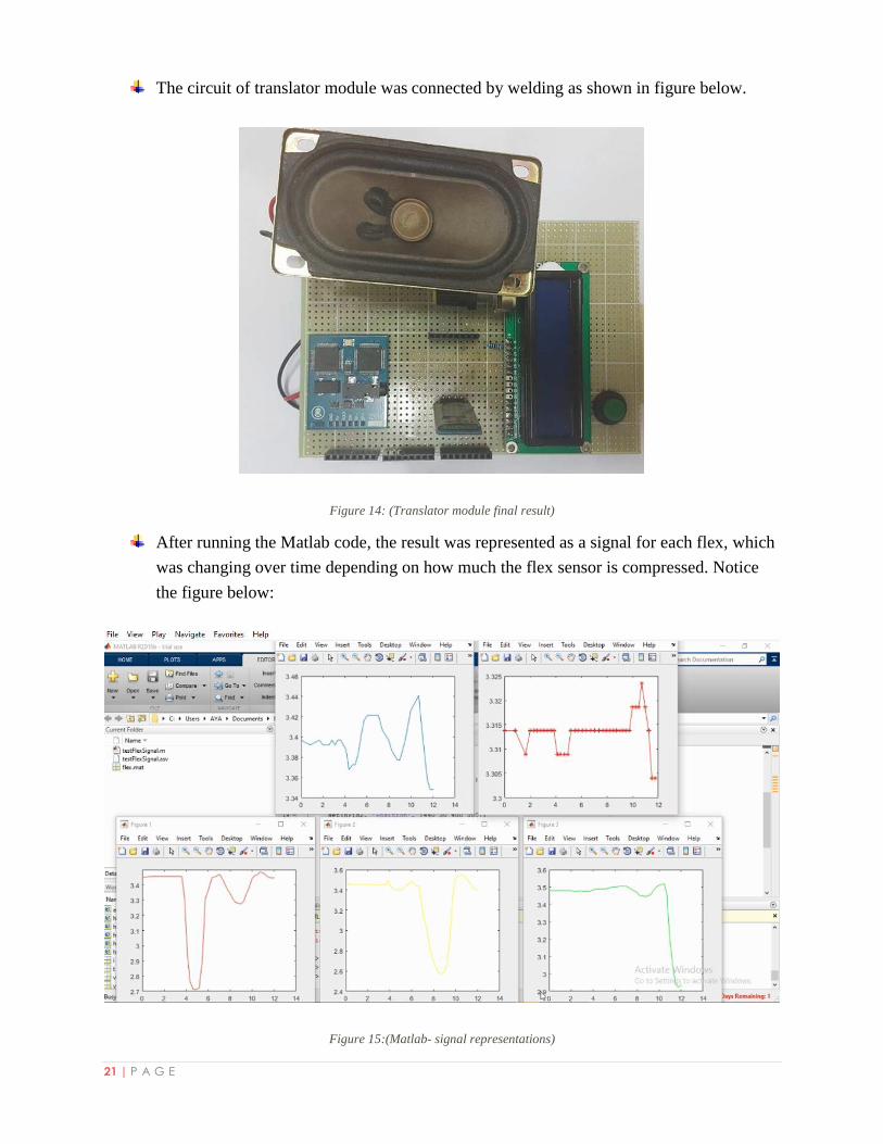
The circuit of translator module was connected by welding as shown in figure below.
Figure 14: (Translator module final result)
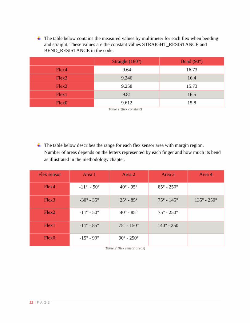
After running the Matlab code, the result was represented as a signal for each flex, which
was changing over time depending on how much the flex sensor is compressed. Notice
the figure below:
Figure 15:(Matlab- signal representations)
22 | P A G E
The table below contains the measured values by multimeter for each flex when bending
and straight. These values are the constant values STRAIGHT_RESISTANCE and
BEND_RESISTANCE in the code:
Straight (180°) Bend (90°)
Flex4 9.64 16.73
Flex3 9.246 16.4
Flex2 9.258 15.73
Flex1 9.81 16.5
Flex0 9.612 15.8
Table 1:(flex constant)
The table below describes the range for each flex sensor area with margin region.
Number of areas depends on the letters represented by each finger and how much its bend
as illustrated in the methodology chapter.
Flex sensor Area 1 Area 2 Area 3 Area 4
Flex4 -11° - 50° 40° - 95° 85° - 250°
Flex3 -30° - 35° 25° - 85° 75° - 145° 135° - 250°
Flex2 -11° - 50° 40° - 85° 75° - 250°
Flex1 -11° - 85° 75° - 150° 140° - 250
Flex0 -15° - 90° 90° - 250°
Table 2:(flex sensor areas)
23 | P A G E
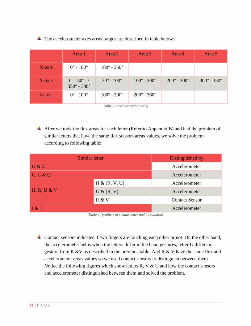
The accelerometer axes areas ranges are described in table below:
Area 1 Area 2 Area 3 Area 4 Area 5
X-axis 0° - 180° 180° - 350°
Y-axis 0° - 30° / 350° - 380°
30° - 100° 100° - 200° 200° - 300° 300° - 350°
Z-axis 0° - 100° 100° - 200° 200° - 360°
Table 3:(accelerometer areas)
After we took the flex areas for each letter (Refer to Appendix B) and had the problem of
similar letters that have the same flex sensors areas values, we solve the problem
according to following table:
Similar letter Distinguished by
D & Z Accelerometer
G, L & Q Accelerometer
H, R, U & V
H & (R, V, U) Accelerometer
U & (R, V) Accelerometer
R & V Contact Sensor
I & J Accelerometer
Table 4:(problem of similar letter and its solution)
Contact sensors indicates if two fingers are touching each other or not. On the other hand,
the accelerometer helps when the letters differ in the hand gestures, letter U differs in
gesture from R &V as described in the previous table. And R & V have the same flex and
accelerometer areas values so we used contact sensors to distinguish between them.
Notice the following figures which show letters R, V & U and how the contact sensors
and accelerometer distinguished between them and solved the problem.
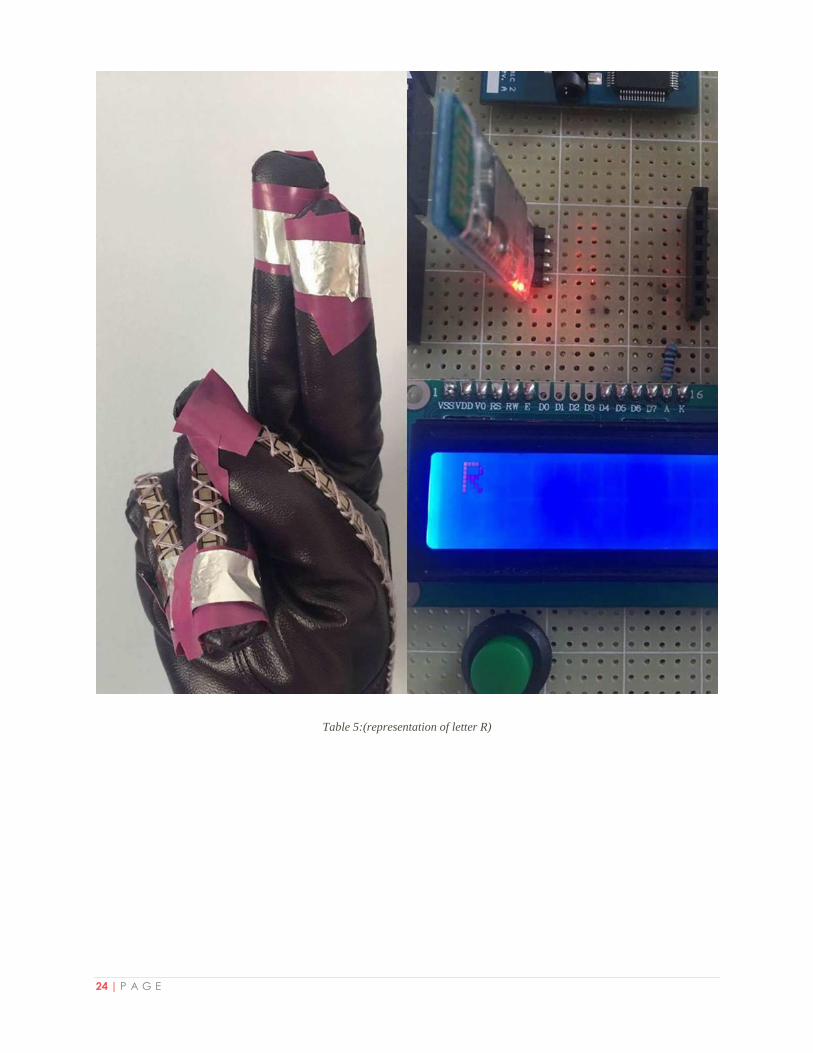
24 | P A G E
Table 5:(representation of letter R)
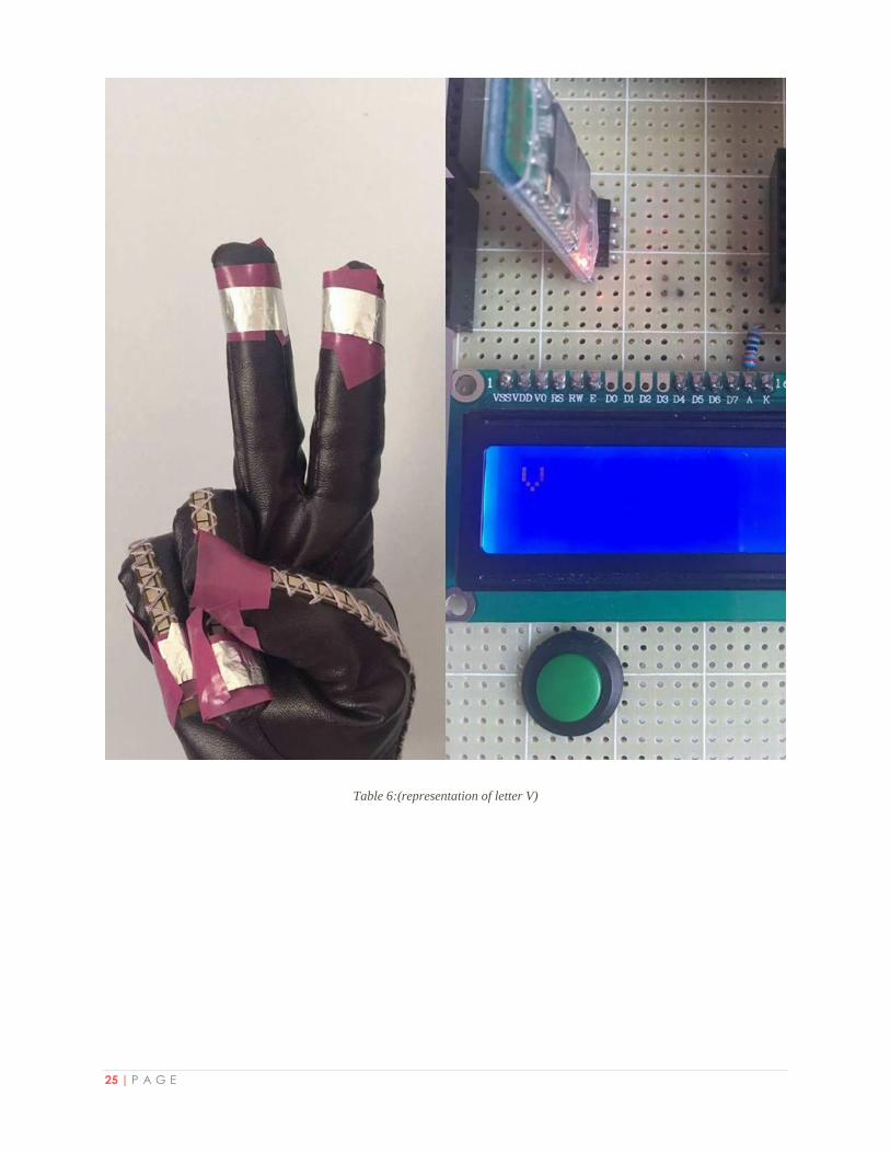
25 | P A G E
Table 6:(representation of letter V)
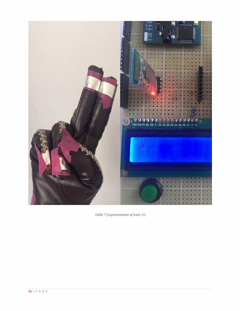
26 | P A G E
Table 7:(representation of letter U)
27 | P A G E
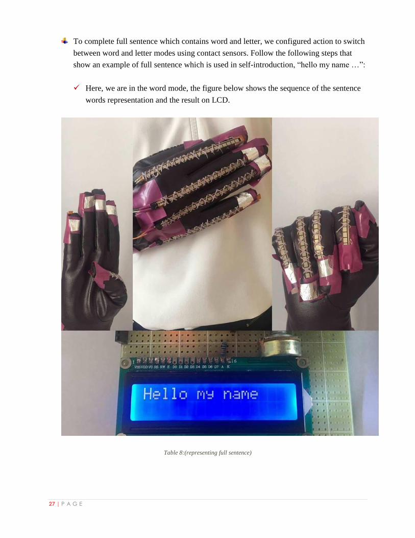
To complete full sentence which contains word and letter, we configured action to switch
between word and letter modes using contact sensors. Follow the following steps that
show an example of full sentence which is used in self-introduction, “hello my name …”:
Here, we are in the word mode, the figure below shows the sequence of the sentence
words representation and the result on LCD.
Table 8:(representing full sentence)
28 | P A G E
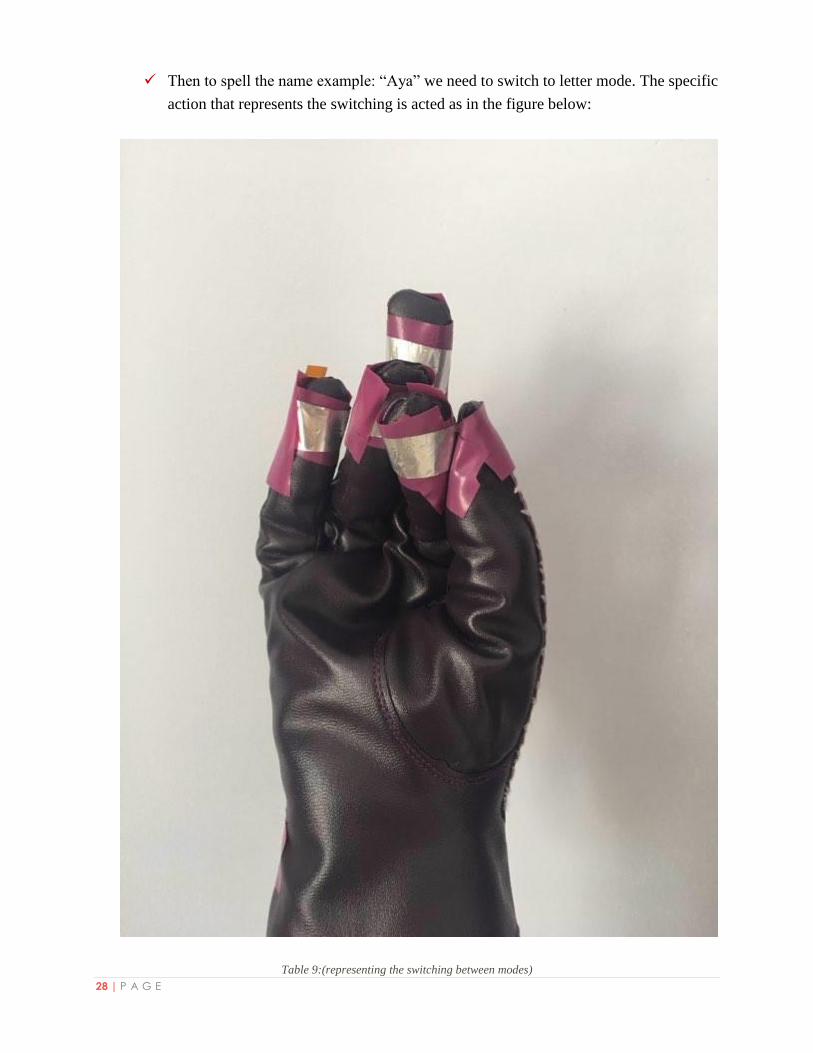
Then to spell the name example: “Aya” we need to switch to letter mode. The specific
action that represents the switching is acted as in the figure below:
Table 9:(representing the switching between modes)
29 | P A G E
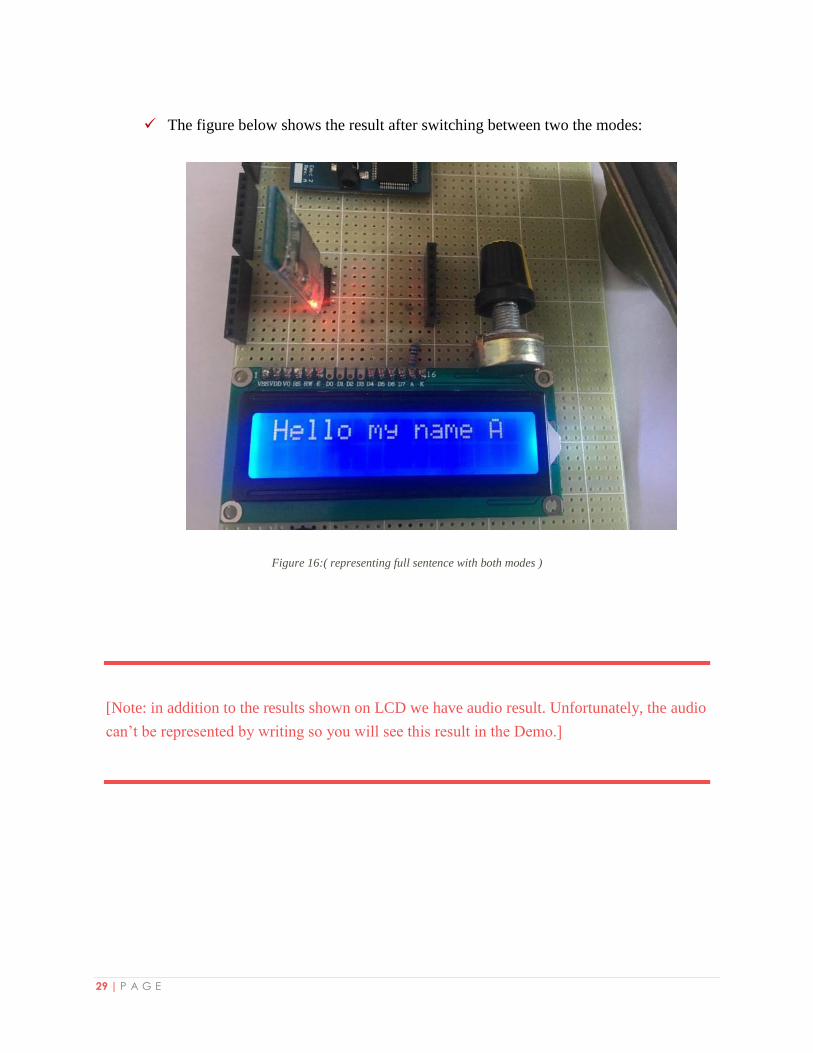
The figure below shows the result after switching between two the modes:
Figure 16:( representing full sentence with both modes )
[Note: in addition to the results shown on LCD we have audio result. Unfortunately, the audio
can’t be represented by writing so you will see this result in the Demo.]
30 | P A G E
Chapter 6: Conclusion
In Conclusion, Smart Deaf-Mute Glove is a prototype that helps deaf-mute people to get a better
communication life. It consists of two main parts that are a glove to detect the hand gestures and
compressions and the other to translate them into text and speech. Smart Deaf-Mute Glove
implements all English alphabets and some words that the user can construct a meaningful
sentence from them. Fortunately, we were able to achieve all our goals that were written in the
first proposal.
Basically, what makes our project special is the procedure we made and followed to build the
project. Starting from the deep studying of components in order to choose the components that
give the best results and meet the project requirements. Also, using the Matlab in studying and
illustrating the way the flex sensors works. In addition, the studying of the alphabets and
dividing them into groups and subgroups. Moreover, the scientific way we made to divide the
flex sensors and accelerometer values into areas which supports the scalability of the project
since these areas are a standard that we can refer to it in order to implement more words.
During our work we learned many new things about hardware components and how to connect
them together taking into account the calculations needed in order to avoid ruining any
component. We learned how to use Arduino and program it. Moreover, we learned how to design
a PCB using eagle.
However, we were limited by the time set by the university. But, for future work Smart Deaf-
Mute Glove will not stay a one hand glove. It can be extended easily to two gloves for both
hands and implement more ASL words that needs two hands to be represented. This step won’t
be a big challenge because we made a basic standard to follow in implementing any new words
but we were limited by the given period because some components needs time to arrive.
31 | P A G E
References
Addicore. (2016). MT3608-Boost-Converter-p/ad300.htm. Retrieved from
https://www.addicore.com: https://www.addicore.com/MT3608-Boost-Converter-
p/ad300.htm
Arduino. (2015, August 16). how-to-connect-bluetooth-module-hc-06-with-arduino-uno.
Retrieved from http://www.codevista.net/182: http://www.codevista.net/182/how-to-
connect-bluetooth-module-hc-06-with-arduino-uno
Arduino, d. (2015, August 23). index.php. Retrieved from https://forum.arduino.cc:
https://forum.arduino.cc/index.php?topic=343426.0
Arduino, D. (2017). /en/Guide/HomePage. Retrieved from https://www.arduino.cc:
https://www.arduino.cc/en/Guide/HomePage
Bilder, B. (2011, April 22). /2011/04/sensing-orientation-with-the-adxl335-arduino/. Retrieved
from http://bildr.org: http://bildr.org/2011/04/sensing-orientation-with-the-adxl335-
arduino/
Currey, M. (2014, October 28). /arduino-with-hc-05-bluetooth-module-at-mode/. Retrieved from
http://www.martyncurrey.com: http://www.martyncurrey.com/arduino-with-hc-05-
bluetooth-module-at-mode/
Curry, M. (2014, November 19). /connecting-2-arduinos-by-bluetooth-using-a-hc-05-and-a-hc-
06-easy-method-using-cmode/. Retrieved from http://www.martyncurrey.com:
http://www.martyncurrey.com/connecting-2-arduinos-by-bluetooth-using-a-hc-05-and-a-
hc-06-easy-method-using-cmode/
Dweikat, a., & Obaid, W. (2016). Sign Language Translator. Departement of Computer
engineering. Nablus: An-Najah National University.
Jimb0. (2017). flex-sensor-hookup-guide. Retrieved 2017, from https://learn.sparkfun.com:
https://learn.sparkfun.com/tutorials/flex-sensor-hookup-guide
Lamprianidis, N. (2016, August). shamyl/EMIC2_UART. Retrieved from https://github.com:
https://github.com/shamyl/EMIC2_UART
32 | P A G E
LearnArduino. (2017). /Main/ArduinoPinCurrentLimitations. Retrieved from
http://playground.arduino.cc:
http://playground.arduino.cc/Main/ArduinoPinCurrentLimitations
Malec, D. (2012, August 16). /how-to-using-an-arduino-and-the-emic-2-tts-module-to-read-
tweets/. Retrieved from https://blog.adafruit.com:
https://blog.adafruit.com/2012/08/16/how-to-using-an-arduino-and-the-emic-2-tts-
module-to-read-tweets/
O'HARE, R. (2016, April 25). /sciencetech/article-3557362/SignAloud-gloves-translate-sign-
language-movements-spoken-English.html. Retrieved from http://www.dailymail.co.uk:
http://www.dailymail.co.uk/sciencetech/article-3557362/SignAloud-gloves-translate-
sign-language-movements-spoken-English.html
Parallax. (2017). product/30016. Retrieved from https://www.parallax.com:
https://www.parallax.com/product/30016
Rakowski, D. (1991). /asl101/topics/wallpaper1.htm. Retrieved from http://lifeprint.com:
http://lifeprint.com/asl101/topics/wallpaper1.htm
Robot Park, D. (2015). GY-61-DXL335-3-Axis-Accelerometer-Module. Retrieved from
http://www.robotpark.com: http://www.robotpark.com/GY-61-DXL335-3-Axis-
Accelerometer-Module
Wanshel, E. (2016, April 28). /entry/navid-azodi-and-thomas-pryor-signaloud-gloves-translate-
american-sign-language-into-speech-text_us_571fb38ae4b0f309baeee06d. Retrieved
from http://www.huffingtonpost.com: http://www.huffingtonpost.com/entry/navid-azodi-
and-thomas-pryor-signaloud-gloves-translate-american-sign-language-into-speech-
text_us_571fb38ae4b0f309baeee06d
33 | P A G E
Appendices
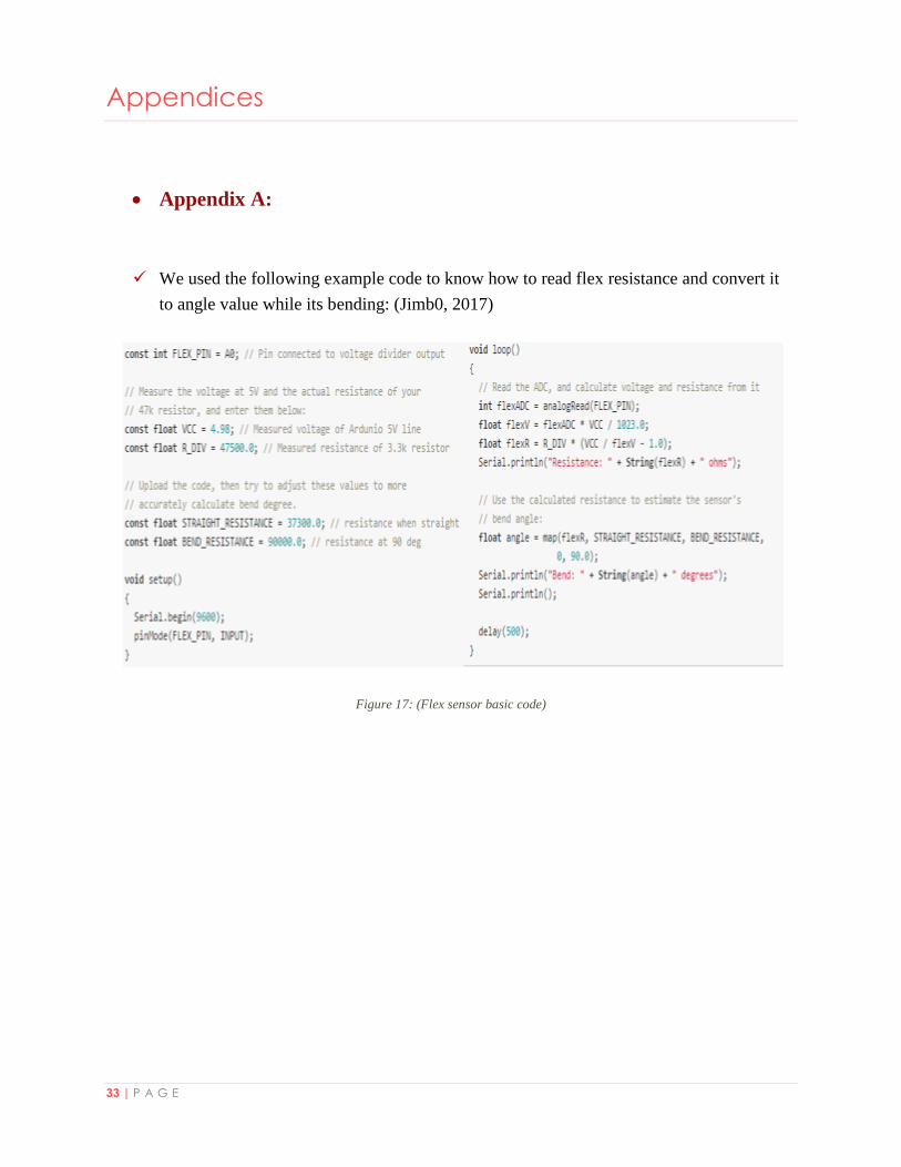
Appendix A:
We used the following example code to know how to read flex resistance and convert it
to angle value while its bending: (Jimb0, 2017)
Figure 17: (Flex sensor basic code)
34 | P A G E
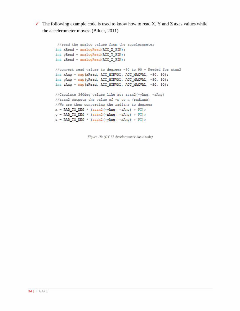
The following example code is used to know how to read X, Y and Z axes values while
the accelerometer moves: (Bilder, 2011)
Figure 18: (GY-61 Accelerometer basic code)
35 | P A G E
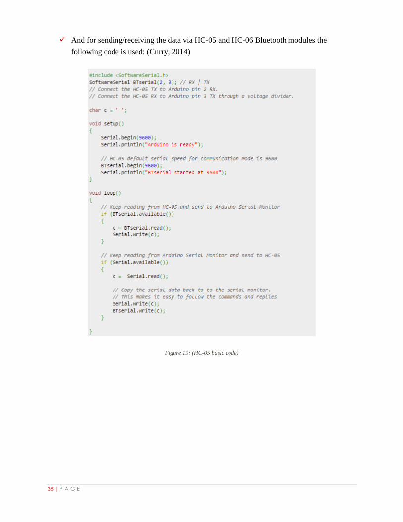
And for sending/receiving the data via HC-05 and HC-06 Bluetooth modules the
following code is used: (Curry, 2014)
Figure 19: (HC-05 basic code)
36 | P A G E
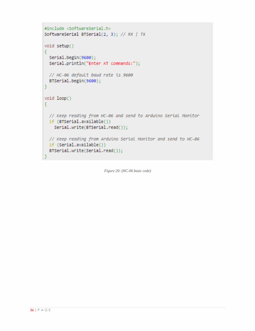
Figure 20: (HC-06 basic code)
37 | P A G E
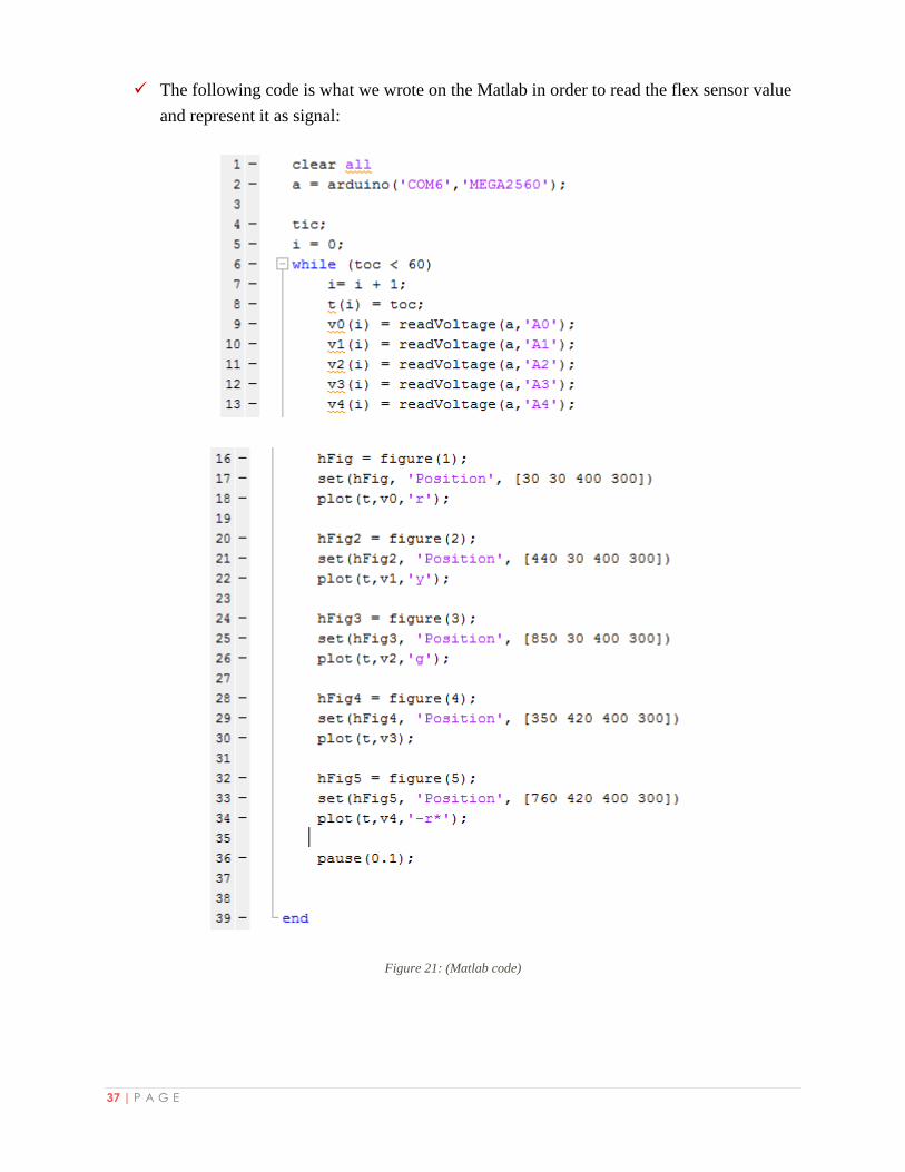
The following code is what we wrote on the Matlab in order to read the flex sensor value
and represent it as signal:
Figure 21: (Matlab code)
38 | P A G E
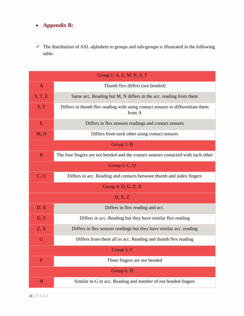
Appendix B:
The distribution of ASL alphabets to groups and sub-groups is illustrated in the following
table:
Group 1: A, E, M, N, S, T
A Thumb flex differs (not bended)
S, T, E Same acc. Reading but M, N differs in the acc. reading from them
S, T Differs in thumb flex reading with using contact sensors to differentiate them
from A
E Differs in flex sensors readings and contact sensors
M, N Differs from each other using contact sensors
Group 2: B
B The four fingers are not bended and the contact sensors contacted with each other
Group 3: C, O
C, O Differs in acc. Reading and contacts between thumb and index fingers
Group 4: D, G, Z, X
D, X, Z
D, X Differs in flex reading and acc.
D, Z Differs in acc. Reading but they have similar flex reading
Z, X Differs in flex sensors readings but they have similar acc. reading
G Differs from them all in acc. Reading and thumb flex reading
Group 5: F
F Three fingers are not bended
Group 6: H
H Similar to G in acc. Reading and number of not bended fingers
39 | P A G E
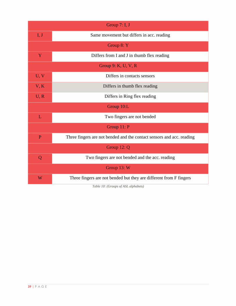
Group 7: I, J
I, J Same movement but differs in acc. reading
Group 8: Y
Y Differs from I and J in thumb flex reading
Group 9: K, U, V, R
U, V Differs in contacts sensors
V, K Differs in thumb flex reading
U, R Differs in Ring flex reading
Group 10:L
L Two fingers are not bended
Group 11: P
P Three fingers are not bended and the contact sensors and acc. reading
Group 12: Q
Q Two fingers are not bended and the acc. reading
Group 13: W
W Three fingers are not bended but they are different from F fingers
Table 10: (Groups of ASL alphabets)
40 | P A G E
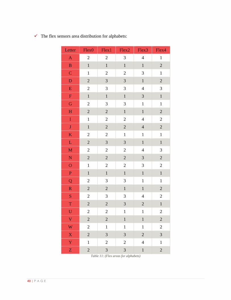
The flex sensors area distribution for alphabets:
Letter Flex0 Flex1 Flex2 Flex3 Flex4
A 2 2 3 4 1
B 1 1 1 1 2
C 1 2 2 3 1
D 2 3 3 1 2
E 2 3 3 4 3
F 1 1 1 3 1
G 2 3 3 1 1
H 2 2 1 1 2
I 1 2 2 4 2
J 1 2 2 4 2
K 2 2 1 1 1
L 2 3 3 1 1
M 2 2 2 4 3
N 2 2 2 3 2
O 1 2 2 3 2
P 1 1 1 1 1
Q 2 3 3 1 1
R 2 2 1 1 2
S 2 3 3 4 2
T 2 2 3 2 1
U 2 2 1 1 2
V 2 2 1 1 2
W 2 1 1 1 2
X 2 3 3 2 3
Y 1 2 2 4 1
Z 2 3 3 1 2
Table 11: (Flex areas for alphabets)
41 | P A G E
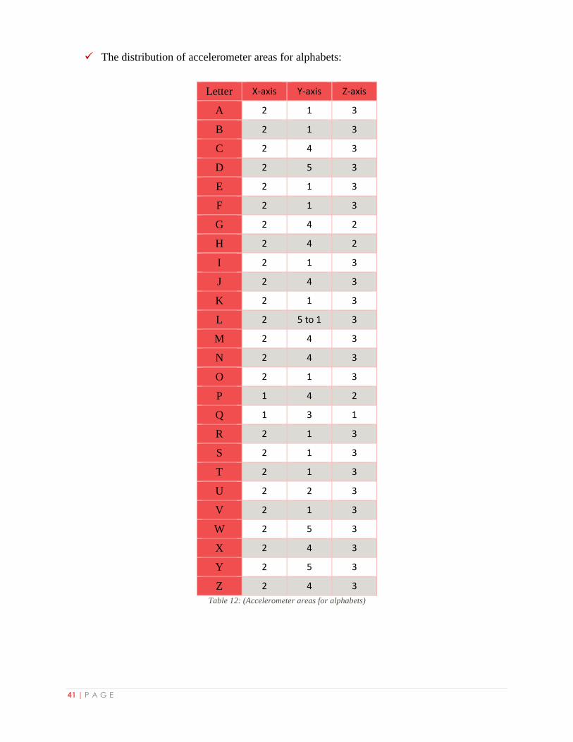
The distribution of accelerometer areas for alphabets:
Letter X-axis Y-axis Z-axis
A 2 1 3
B 2 1 3
C 2 4 3
D 2 5 3
E 2 1 3
F 2 1 3
G 2 4 2
H 2 4 2
I 2 1 3
J 2 4 3
K 2 1 3
L 2 5 to 1 3
M 2 4 3
N 2 4 3
O 2 1 3
P 1 4 2
Q 1 3 1
R 2 1 3
S 2 1 3
T 2 1 3
U 2 2 3
V 2 1 3
W 2 5 3
X 2 4 3
Y 2 5 3
Z 2 4 3
Table 12: (Accelerometer areas for alphabets)
42 | P A G E
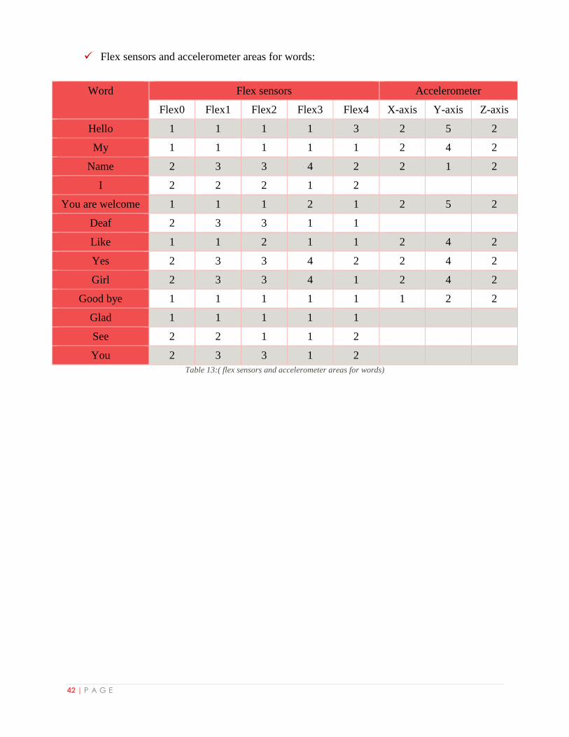
Flex sensors and accelerometer areas for words:
Word Flex sensors Accelerometer
Flex0 Flex1 Flex2 Flex3 Flex4 X-axis Y-axis Z-axis
Hello 1 1 1 1 3 2 5 2
My 1 1 1 1 1 2 4 2
Name 2 3 3 4 2 2 1 2
I 2 2 2 1 2
You are welcome 1 1 1 2 1 2 5 2
Deaf 2 3 3 1 1
Like 1 1 2 1 1 2 4 2
Yes 2 3 3 4 2 2 4 2
Girl 2 3 3 4 1 2 4 2
Good bye 1 1 1 1 1 1 2 2
Glad 1 1 1 1 1
See 2 2 1 1 2
You 2 3 3 1 2
Table 13:( flex sensors and accelerometer areas for words)
43 | P A G E
Appendix C:
- The figure shows the representation for all ASL alphabets representation. (Rakowski,
1991)
Table 14: (English alphabets ASL representation)


![Knobbelzwanen in de stad Groningen in strenge winters [in Dutch] (Mute Swans Cygnus olor in the city of Groningen, The Netherlands, during severe winters)](https://static.fdokumen.com/doc/165x107/631707a8c5ccb9e1fb03f5dc/knobbelzwanen-in-de-stad-groningen-in-strenge-winters-in-dutch-mute-swans-cygnus.jpg)