3D Virtual Glove for Data Logging and Pick and Place Robot
6
Copyright © 2014 IJECCE, All right reserved 319 International Journal of Electronics Communication and Computer Engineering Volume 5, Issue 2, ISSN (Online): 2249–071X, ISSN (Print): 2278–4209 3D Virtual Glove for Data Logging and Pick and Place Robot Prasanna Muley, Sagar Kulkarni, Raj Kurhekar, Shyam Thorat Department of Electronics and Telecommunication, ParvatibaiGenbaMoze College of Engineering, Wagholi, Pune; University of Pune, Maharashtra, India {prasannamu92, rajkurhekar, sagarkulkarni2222, shyam.thorat7}@gmail.com Abstract – Traditional interaction devices such as mouse and keyboard do not adapt very well to 3D environments, since they were not ergonomically designed for it [1]. The user may be standing or in movement and these devices were projected to work on desks. To solve such problems it has been designed a Accelerometer based 3D virtual glove which can be used in various robotic applications [1]. In this project it can be designed a Pick and Place robot which will follow the 3D glove worn by the user. User can design UP, DOWN, LEFT, RIGHT, PICK and PLACE actions via wireless glove. Moreover, in the current interaction model for immersive environments, which is based on wands and 3D mice, a change of context is necessary every time to execute a non-immersive task. These constant context changes from immersive to 2D desktops introduce a rupture in the user interaction with the application [3]. The objective of this work is to develop a device that maps a touch interface in a virtual reality immersive environment. In order to interact in3D virtual reality immersive environments a wireless glove (v-Glove) was created, which has two main functionalities: tracking the position of the user’s index finger and vibrate the fingertip when it reaches an area mapped in the interaction space to simulate a touch feeling. Quantitative and qualitative analysis were performed with users to evaluate the v-Glove, comparing it with a gyroscopic 3D mouse [2]. This project is ideally suited for critical applications such as Gas plants, Chemical Plants, Nuclear reactors and for hazardous applications such as Coal mines, Sulphur mines, under sea tunnels Oil mints etc Keywords – Sensor, MEMS Accelerometer, Controller, Zigbee, Robotic Arm, DC Motor, Camera. I. INTRODUCTION We have gone through many websites in search of a good project based on robotics and we came across some good projects. We even have gone through some videos which use latest technologies like “MEMS” and “ZIGBEE” for sensors and communication channels respectfully. When we came across a FPGA based 5-AXIS ROBOT ARM CONTROLLER That robot is basically a pick and place robot but has many future applications. 5 AXIS ROBOT uses sensors, DC motor for motion, VHDL programming is done and FPGA technology is been used for communication purpose.[3] The aim of us was to design a 3-AXIS ROBOTIC ARM instead of 5 AXIS but in a different manner by using different technologies and sensors [3]. Robots are designed to help humans. Space robots are of particular importance as they aid or replace humans in difficult possibly dangerous extravehicular activities. However, robot intelligence and autonomy are still limited [4]. Therefore, robots need to be supervised or directly teleported in order to accomplish complex tasks in diverse environments. The focus of this thesis is on wireless ARM control. The literature review introduces the reader to space robotics Industrial automation, Pick and place Systems, Video Scanning and other relevant achievements and prospects. The Main aim in our project is to control the movement of the ARM using Hand gesture. This idea was selected due to the draw backs in the switches used in the legacy systems. The switches contain the debouching error. So we selected some hand movement based systems. We select the motion sensor for the hand movement sensing. So we made the survey on the internet for the motion sensor. We found the MEMS technology for the sensor systems. There were three types of the sensor categories based on MEMS. Those were pressure sensor, accelerometer and gyro. The accelerometer is used in the different application for sensing X, Y and Z movement. We found application in Mobile, Vibration measurement of the motor etc. System description: Fig.1. Transmitter section Fig.2. Receiver Section
-
Upload
khangminh22 -
Category
Documents
-
view
4 -
download
0
Transcript of 3D Virtual Glove for Data Logging and Pick and Place Robot

Copyright © 2014 IJECCE, All right reserved319
International Journal of Electronics Communication and Computer EngineeringVolume 5, Issue 2, ISSN (Online): 2249–071X, ISSN (Print): 2278–4209
3D Virtual Glove for Data Logging and Pick and PlaceRobot
Prasanna Muley, Sagar Kulkarni, Raj Kurhekar, Shyam ThoratDepartment of Electronics and Telecommunication, ParvatibaiGenbaMoze
College of Engineering, Wagholi, Pune; University of Pune, Maharashtra, India{prasannamu92, rajkurhekar, sagarkulkarni2222, shyam.thorat7}@gmail.com
Abstract – Traditional interaction devices such as mouseand keyboard do not adapt very well to 3D environments,since they were not ergonomically designed for it [1]. Theuser may be standing or in movement and these devices wereprojected to work on desks. To solve such problems it hasbeen designed a Accelerometer based 3D virtual glove whichcan be used in various robotic applications [1].
In this project it can be designed a Pick and Place robotwhich will follow the 3D glove worn by the user. User candesign UP, DOWN, LEFT, RIGHT, PICK and PLACEactions via wireless glove. Moreover, in the currentinteraction model for immersive environments, which isbased on wands and 3D mice, a change of context isnecessary every time to execute a non-immersive task. Theseconstant context changes from immersive to 2D desktopsintroduce a rupture in the user interaction with theapplication [3]. The objective of this work is to develop adevice that maps a touch interface in a virtual realityimmersive environment. In order to interact in3D virtualreality immersive environments a wireless glove (v-Glove)was created, which has two main functionalities: tracking theposition of the user’s index finger and vibrate the fingertipwhen it reaches an area mapped in the interaction space tosimulate a touch feeling. Quantitative and qualitativeanalysis were performed with users to evaluate the v-Glove,comparing it with a gyroscopic 3D mouse [2].
This project is ideally suited for critical applications suchas Gas plants, Chemical Plants, Nuclear reactors and forhazardous applications such as Coal mines, Sulphur mines,under sea tunnels Oil mints etc
Keywords – Sensor, MEMS Accelerometer, Controller,Zigbee, Robotic Arm, DC Motor, Camera.
I. INTRODUCTION
We have gone through many websites in search of agood project based on robotics and we came across somegood projects. We even have gone through some videoswhich use latest technologies like “MEMS” and“ZIGBEE” for sensors and communication channelsrespectfully.
When we came across a FPGA based 5-AXIS ROBOTARM CONTROLLER That robot is basically a pick andplace robot but has many future applications. 5 AXISROBOT uses sensors, DC motor for motion, VHDLprogramming is done and FPGA technology is been usedfor communication purpose.[3]
The aim of us was to design a 3-AXIS ROBOTIC ARMinstead of 5 AXIS but in a different manner by usingdifferent technologies and sensors [3].
Robots are designed to help humans. Space robots are ofparticular importance as they aid or replace humans indifficult possibly dangerous extravehicular activities.
However, robot intelligence and autonomy are still limited[4]. Therefore, robots need to be supervised or directlyteleported in order to accomplish complex tasks in diverseenvironments. The focus of this thesis is on wireless ARMcontrol. The literature review introduces the reader tospace robotics Industrial automation, Pick and placeSystems, Video Scanning and other relevant achievementsand prospects.
The Main aim in our project is to control the movementof the ARM using Hand gesture. This idea was selecteddue to the draw backs in the switches used in the legacysystems. The switches contain the debouching error. Sowe selected some hand movement based systems.
We select the motion sensor for the hand movementsensing. So we made the survey on the internet for themotion sensor. We found the MEMS technology for thesensor systems. There were three types of the sensorcategories based on MEMS. Those were pressure sensor,accelerometer and gyro. The accelerometer is used in thedifferent application for sensing X, Y and Z movement.We found application in Mobile, Vibration measurementof the motor etc.System description:
Fig.1. Transmitter section
Fig.2. Receiver Section

Copyright © 2014 IJECCE, All right reserved320
International Journal of Electronics Communication and Computer EngineeringVolume 5, Issue 2, ISSN (Online): 2249–071X, ISSN (Print): 2278–4209
II. DESCRIPTION
The generalized block diagram of project is shown asabove. The block diagram can be divided into two partsfirst one is Master and second is slave.
This project shows there would be two section masterand slave. The slave part would contain the DC motor.The DC motor would be connected to ARMmicrocontroller. This ARM would be connected to theZIGBEE Module transceiver using UART.
The Master part would be connected to the MEMSsensor. The output of sensor is the analog voltage. Thisanalog output would be converted into digital using ADCwhich is inbuilt in the ARM microcontroller. The outputof ADC is processed and further given to The Zigbeemodule. This Zigbeemodule will convert the data in to RFand further it is received by the ZigbeeModule connectedto the slave part. Depending upon the X,Y or Z movementof the sensor the respective ARM for the X, Y or Z willmove. The Crystal will be used for clock frequencyGeneration.
III. RELATED WORK
To be able to apply the input at the transmitter sectionuser can use varieties of input applicationswhich may bewired or wireless. But to increase the efficiency andeffectiveness one can use wireless technology for theiroperation.
The given figure shows wireless accelerometer to givethe inputs for controller as it increases the efficiency.
As per the movement of accelerometer robot changestheir movement so as to achieve required goal.
1) Brief history of ARM :-ARM is short for Advanced Risc Machines Ltd.Founded
1990, owned by Acorn, Apple and VLSI Known beforebecoming ARM as computer manufacturerAcorn whichdeveloped a 32-bit RISC processor for it’s ownuse (usedin Acorn Archimedes)Processor cores: ARM6, ARM7,ARM9, ARM10, ARM11.
IV. LPC2148 – KEY FEATURES
16-bit/32-bit ARM7TDMI-S microcontroller in a tinyLQFP64 package.8 kB to 40 kB of on-chip static RAM and 32 kB to 512 kBof on-chip flash memory.128-bit wide interface/accelerator enables high-speed 60 MHz operation.In-System Programming/In-Application Programming(ISP/IAP) via on-chip boot loader software. Single flashsector or full chip erase in 400 ms and programming of256 bytes in 1 ms.
Embedded ICE RT and Embedded Trace interfaces offerreal-time debugging with the on-chip Real Monitorsoftware and high-speed tracing of instruction execution[3].USB 2.0 Full-speed compliant device controller with 2 kBof endpoint RAM. In addition, the LPC2146/48 provides 8kB of on-chip RAM accessible to USB by DMA.One or two (LPC2141/42 vs. LPC2144/46/48) 10-bitADCs provide a total of 6/14 analog inputs, withconversion times as low as 2.44 μs per channel.Single 10-bit DAC provides variable analog output(LPC2142/44/46/48 only).Two 32-bit timers/external event counters (with fourcapture and four compare channels each), PWM unit (sixoutputs) and watchdog.Low power Real-Time Clock(RTC) with independent power and 32 kHz clock input.
V. ZIGBEE
ZigBee, a technical overview of wireless technology:Zigbee uses wireless technology becauseThey claim it
saves costs because no wires need to be installed, savingon installation costs. This view is a bit short. Wirelessadds new problems! There can be many kind of problems:devices do not respond to each other, noise disturbance,neighbour interference, and many more. The biggestproblem however is that if it does works today, it mightgive you problems tomorrow. Most progress on thetechnical part has been in prevention of all possibleproblems. So at this moment my personal experience isthat it’s very good already. However, you really need ‘sitesurvey tooling’ to be able to pinpoint problems atcustomer locations. Remember that there are no wires tofollow and measure[1][2]!
What is Zigbee?Zigbee [6] is a wireless networkingstandard that is aimed at remote control and sensorapplications which is suitable for operation in harsh radioenvironments and in isolated locations. It builds on IEEEstandard 802.15.4 which defines the physical and MAClayers. Above this, Zigbee defines the application andsecurity layer specifications enabling interoperabilitybetween products from different manufacturers. In thisway Zigbee is a superset of the 802.15.4 specification[6].
Zigbee is organized within the Zigbee Alliance. Manycompanies (>150) already adapted this technology, to getan impression just look here. 9 companies are called‘promoters’ and they are the actual promoters of theZigbee standard. These companies are: BM Group,Chipcon, Ember, Freescale, Honeywell, Mitsubishi,Motorola, Philips and Samsung [6].
The 802.15.4 standard is primarily aiming at monitoringand control applications. Low power consumption is themost important feature that makes battery operated devicesoperate for a long time. The amount of data throughput(bandwidth) is relativily low compared to wireless lan forexample, but with 250kbps for many applications morethan enough. The distance between 2 nodes can be up to50 meters but be aware the each node can relay data to thenext making a very big network, covering significantdistances, possible[5][6].

Copyright © 2014 IJECCE, All right reserved321
International Journal of Electronics Communication and Computer EngineeringVolume 5, Issue 2, ISSN (Online): 2249–071X, ISSN (Print): 2278–4209
Fig.3. Zigbee Layers
a) Hardware (Physical and MAC layers)At the moment all solutions work on 2.4GHz but specifiedis also 915MHz for North America and 868MHz forEurope. The 2.4GHz frequency band is a license freeband, so a ZigBee product may be used all over the world.All current products seem to be using the 2.4GHz band atthe moment [5]. Take a look at the next table for a fewdifferences between the bands:
Table 1: Zigbee SpecificationFrequency 868 MHz 915 MHz 2.4GHz
Bandwidth 20 kbps 40 kbps 250 kbps
No. of channels 1 10 16
b) In all bands DSSS (Direct sequence spread spectrum)is used. 868 and 915 MHz are using Binary Phase ShiftKeying and 2.4GHz uses O-QPSK (Offset QuadraturePhase Shift Keying).[5]c) These license free frequencies are becoming more andmore crowded and noisy. The 802.15.4 specification hasmany feature to ensure a reliable operation under the worstenvironmental conditions. Some keywords: Clear ChannelAssesment, Quality Assesment and Receiver EnergyDetection. To prevent problems caused by itself, atechnique called Carrier Sense Multiple Access (CSMA) isused to only transmit when this does not cause problems(collisions)[6].d) Like in any network data is transmitted in packets.ZigBee's packets have a maximum size of 128 bytesincluding protocol overhead. In total there is room for amaximum of 104 bytes. Compared to ethernet this is rathersmall but for most applications that ZigBee will be usedfor this is more than enough (how many bytes do you needto switch on a light? (no, this is not a lightbulb joke)).e) For realtime features, ZigBee has the possibility todefine high priority messages. This is achieved by use of aguaranteed timeslot mechanism so that the high prioritymessages can be send as fast as possible.
f) ZigBee uses 2 kinds of addressing. There is a 64 bitIEEE address that can be compared to the IP address onthe internet. There is also a 16 bit short address. The shortaddresses are used once a network is setup so this makes atotal of 2^16 = ~64000 nodes within one network possible.This is enough for almost anything imaginable. If youneed more than you can offcourse design a gateway node.g) The ZigBee upper layers. The layers above that what802.15.4 specifies is what we call the ZigBee standard(look above for a graphical overview). Many aspect of thenetwork are specified in this layer, like: Applicationprofiles, security settings and the messaging.h) ZigBee is known because of it's mesh networkarchitecture but it does also support a star topology orcluster tree or hybrid architecture. Depending on theapplication or situation each kind of topology has it's ownadvantages and disadvantages. A star topology is verysimple, all nodes directly communicate with one centralnode (like a star...). The mesh topology is morecomplicated, each node may communicate with any othernode within range. It's easy to understand that this givesmany possible routes through the network, this makes it avery robust topology because bad performing routes canbe ignored. The cluster tree topology is basically acombination of star and mesh [5][6].
VI. MICRO ELECTRO MECHANICAL SYSTEM
Micro-Electro-Mechanical Systems (MEMS) is theintegration of mechanical elements, sensors, actuators, andelectronics on a common silicon substrate through microfabrication technology. While the electronics arefabricated using integrated circuit (IC) process sequences(e.g., CMOS, Bipolar, or BICMOS processes), themicromechanical components are fabricated usingcompatible "micromachining" processes that selectivelyetch away parts of the silicon wafer or add new structurallayers to form the mechanical and electromechanicaldevices[6].What are MEMS?Micro: Small size, micro fabricated structuresElectro:-Electrical signal/controlMechanical:-Mechanical functionalitySystems:-structures, Devices, Systems, controls
Fig.4. Pin Diagram of MEMS
Copyright © 2014 IJECCE, All right reserved322
International Journal of Electronics Communication and Computer EngineeringVolume 5, Issue 2, ISSN (Online): 2249–071X, ISSN (Print): 2278–4209
Table 2: Pin description of MEMS
The MEMSIC device is a complete dual-axisacceleration measurement system fabricated on amonolithic CMOS IC process. The device operation isbased on heat transfer by natural convection and operateslike other accelerometers having a proof mass except it isa gas in the MEMSIC sensor. A single heat source,centered in the silicon chip is suspended across a cavity.Equally spaced Aluminum/ poly-silicon thermopiles(groups of thermocouples) are located equidistantly on allfour sides of the heat source (dual axis).[6]
Under zero acceleration, a temperature gradient issymmetrical about the heat source, so that the temperatureis the same at all four thermopiles, causing them to outputthe same voltage. Acceleration in any direction willdisturb the temperature profile, due to free convection heattransfer, causing it to be asymmetrical.
The temperature, and hence voltage output of the fourthermopiles will then be different. The differential voltageat the thermopile outputs is directly proportional to theacceleration. There are two identical acceleration signalpaths on the accelerometer, one to measure acceleration inthe x axis and one to measure acceleration in the y-axis.Accelerometer Sensor
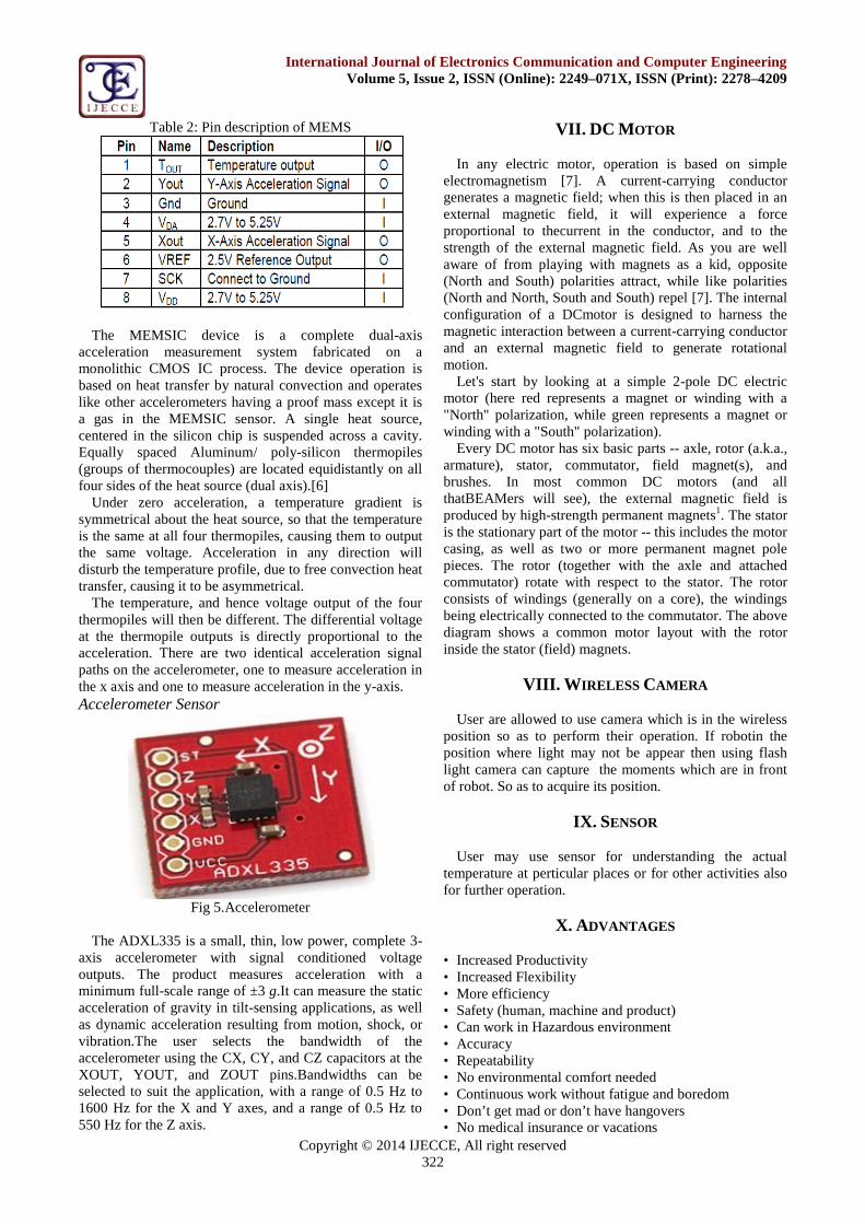
Fig 5.Accelerometer
The ADXL335 is a small, thin, low power, complete 3-axis accelerometer with signal conditioned voltageoutputs. The product measures acceleration with aminimum full-scale range of ±3 g.It can measure the staticacceleration of gravity in tilt-sensing applications, as wellas dynamic acceleration resulting from motion, shock, orvibration.The user selects the bandwidth of theaccelerometer using the CX, CY, and CZ capacitors at theXOUT, YOUT, and ZOUT pins.Bandwidths can beselected to suit the application, with a range of 0.5 Hz to1600 Hz for the X and Y axes, and a range of 0.5 Hz to550 Hz for the Z axis.
VII. DC MOTOR
In any electric motor, operation is based on simpleelectromagnetism [7]. A current-carrying conductorgenerates a magnetic field; when this is then placed in anexternal magnetic field, it will experience a forceproportional to thecurrent in the conductor, and to thestrength of the external magnetic field. As you are wellaware of from playing with magnets as a kid, opposite(North and South) polarities attract, while like polarities(North and North, South and South) repel [7]. The internalconfiguration of a DCmotor is designed to harness themagnetic interaction between a current-carrying conductorand an external magnetic field to generate rotationalmotion.
Let's start by looking at a simple 2-pole DC electricmotor (here red represents a magnet or winding with a"North" polarization, while green represents a magnet orwinding with a "South" polarization).
Every DC motor has six basic parts -- axle, rotor (a.k.a.,armature), stator, commutator, field magnet(s), andbrushes. In most common DC motors (and allthatBEAMers will see), the external magnetic field isproduced by high-strength permanent magnets1. The statoris the stationary part of the motor -- this includes the motorcasing, as well as two or more permanent magnet polepieces. The rotor (together with the axle and attachedcommutator) rotate with respect to the stator. The rotorconsists of windings (generally on a core), the windingsbeing electrically connected to the commutator. The abovediagram shows a common motor layout with the rotorinside the stator (field) magnets.
VIII. WIRELESS CAMERA
User are allowed to use camera which is in the wirelessposition so as to perform their operation. If robotin theposition where light may not be appear then using flashlight camera can capture the moments which are in frontof robot. So as to acquire its position.
IX. SENSOR
User may use sensor for understanding the actualtemperature at perticular places or for other activities alsofor further operation.
X. ADVANTAGES
• Increased Productivity• Increased Flexibility• More efficiency• Safety (human, machine and product)• Can work in Hazardous environment• Accuracy• Repeatability• No environmental comfort needed• Continuous work without fatigue and boredom• Don’t get mad or don’t have hangovers• No medical insurance or vacations

Copyright © 2014 IJECCE, All right reserved323
International Journal of Electronics Communication and Computer EngineeringVolume 5, Issue 2, ISSN (Online): 2249–071X, ISSN (Print): 2278–4209
• Scientific Discipline• Process multiple stimuli simultaneously.
XI. DISADVANTAGES
• Unemployment (major problem)• Economic problem (salary)• Dissatisfaction and resentment among workers.• Lack capability to respond in emergencies.
XII. APPLICATION
1) Controlling devices in unmanned places:-The places where man are unable to reach user can use
such robots for their further operation where thepossibility getting harmful of man can be avoided.2) Joystick/ Controller for games:-
Rather than using mouse or keyboard which is an wiredtechnology. They can use wireless technology asaccelerometer based sensor for giving command.3) Robotic ARM used as a pick and place robot.4) Bio-MEMS applications in medical and healthrelated technologies.
XIII. CONCLUSION
In this work, user proposed and developed an interactiondevice for immersive virtual reality environments, called v-Glove. The v-Glove is a glove that allows a user to interactwith virtual reality applications in a natural way throughthe movement of the hand in 3D space. The selection andmanipulation of objects is done by bringing the hand to atouch area mapped in the virtual space. As proof ofconcept, an application capable of interacting with CADdata was adapted for an immersive environment. User mayconduct a usability study of the glove with quantitativeand qualitative assessments with three groups of userswith different profiles of 3D knowledge. The use of glovesas an element of control pointer on the screen is moreintuitive than the mouse itself.
REFERENCES
[1] F. Bacim, D. Bowman, M. Pinho, "Wayfinding Techniques forMultiScale Virtual Environments," IEEE Symposium on 3DUser Interfaces, Louisiana, EUA, 2009.
[2] A. Kulik, J. Hochstrate, A. Kunert, B. Froelich, The Influence ofInput Device Characteristics on Spatial Perception in Desktop-Based 3D Applications. IEEE Symposium on 3D UserInterfaces, Louisiana, USA, 2009.
[3] S. Smith, S. Du’mont, Measuring the Effect of GamingExperience on Virtual Environment Navigation Tasks. IEEESymposium on 3D User Interfaces, Louisiana, EUA, 2009.
[4] D. Bowman, C. Wingrave, "Design and Evaluation of MenuSystems for Immersive Virtual Environments," IEEE VirtualReality Conference, Yokohama, Japan, 2001.
[5] C. Hand, A Survey of 3D Interaction Techniques. ComputerGraphics Forum, Volume 16, Issue 5, pages 269-281, December1997.
[6] R. Scheibe, M. Moehring, B. Froehlich, Tactile Feedback at theFinger Tips for Improved Direct Interaction in ImmersiveEnvironments. Virtual Reality Conference, Charlotte, NC, March2007.
[7] C.Bullion, H. Gurocak, Haptic Glove with MR Brakes forDistributed Finger Force Feedback, Presence: Teleoperators andVirtual Environments, Vol.18, No.6, Pages 421-433, February2010.
[8] Xbee,HTTP://WWW.digi.com/products/wireless/point-multi-point/xbee series 1-module.jsp/docs.accessed jan. 2011-13
[9] L.dipietro, A.sabatini,P.dario, A survey of glove-based systemsand their applications, IEEE TRANSACTION on systems, manand cybernetics, vol.38, no.4, july 2008.
[10] Tune Glove Diagram, http://www.flicker.com/photos/jtanenbaum/4156417140/.accessedjan. 2011
[11] Lowe, David G., Distinctive image features from scale- invariantkeypoints, international journal of computer vision, PP:91-110,springer Netherlands.
[12] bluecove, http://bluecove.org/.accessedjan 2011[13] T. Tullis, b.Albert 2008 measuring the user experience, Morgan[14] A. Raposo, I. Santos, L. Soares, G. Wagner, E. Corseuil,
M.gattass, Environ: Integrating VR and CADD Engineeringprojects, IEEE computer graphics and applications V.29, N. 6,P.91-95,2009.
AUTHOR’S PROFILE
Muley Prasanna HarishchandraEmail: [email protected]: MaleDate of birth: 16/10/1992Religion: HinduQualification: Bachelor of EngineeringPermanent Address: Near Water Tank/Civil Hospital,
Bhavaninagar, A/T:- Pusegaon Tal:-Khatav Dist: Satara State:Maharashtra, Country:- India, Pin Code:- 415502.Mobile No: 9860155168Achievements:-1) Participated in the “Dipex 2011” where INTERNATIONAL LevelProject Exhibition were held by ABVP, Aurangabad (Sambhajinagar),India2) Participated in JSPM college of Engineering for national level PaperPresentation held at Wagholi, Pune As Well as in Dr. D.Y. Patil Collegeof Engineering, Lohgaon, Pune.3) Participated in “Network Security” workshop held at ShriRamchandraCollege of Engineering, Pune4) Got 1 prize in “Robotics” Compitition Organised In P.G. Moze collegeof Engineering, Wagholi.
Raj Gajanan KurhekarEmail: [email protected] of Birth: 08/08/1990Contact Detail: Plot no.31 Godavari colony,M.I.D.C RoadTal: Amravati Dist: Amravati state: Maharashtracountry: India pin code: 444606
Mobile No: 9028386181Achievement:1) Participated in “network security” workshop held at Shri Ramchandracollege of Engg Pune.2) State level seminar competitor in LMIT COLG OF ENGG.Dhamangao.3) Got a second prize in” robotics” competition organised in P.G.MOZEcollege of Engg. Wagholi.
Shyam Ramrao ThoratEmail: [email protected]: MaleDate of birth: 17/11/1992Qualification: Bachelor of engineeringPermanent address: Ramkrushnanagar, NearDr.Welankar Hospital, Basmatroad, Parbhani. Tal:
Parbhani Dist: Parbhani Pin:431401.MobileNo: 8421028149Achievement:1) Paticipated in PS college of Engineering,Aurangabad for national levelRobotics competition.

Copyright © 2014 IJECCE, All right reserved324
International Journal of Electronics Communication and Computer EngineeringVolume 5, Issue 2, ISSN (Online): 2249–071X, ISSN (Print): 2278–4209
2) I had completed the Hardware and networking course of six monthfrom Netzen institute.3) Got 1 prize in “Robotics” Compitition Organised in P.G. Moze collegeof Engineering, Wagholi.
Sagar Manik KulkarniEmail: [email protected]: MaleDate of birth: 01/01/1992Religion: HinduQualification: Bachelor of engineeringPermanent address: M.N. Kulkarni, Behind Panchyat
Samiti Ground, Wakilwadi Colony. Kai Tal: KaijDist:Beed State:-Maharashtra, Country:- India, Pin Code:- 431123.Mobile no: 8484994797Achievement:1) I had completed the a CCNA course.2) Paticipated in JSPM college of Engineering for national level PaperPresentation held at Wagholi, Pune As Well as in Dr. D.Y. Patil Collegeof Engineering, Lohgaon, Pune.3) I had participated in project competition at JNECCOE, Aurangabad.