Glove Box Instrumentation Specifications
24
Glove Box Instrumentation Specifications April 11, 2006 The following is a brief list of the major technical specifications of the instru- mentation for the Glove Box (GB). The spec sheets for the various components are attached at the end of this document. 1 Oxygen Monitor The O 2 monitoring device was obtained from Advanced Micro Instruments (AMI). This monitor will be placed inside of the control box attached to the GB. The specs are as follows: • Anodized Aluminum body • Power Requirments: 7 - 28 VDC (250 mA @ 12 VDC) • Range: 0-25% O 2 • 1 4 ” Compression fittings (Swagelok or similar) • Dimensions: 1.8” diameter, 2.15” long 2 Check Valves CV1 and CV4 were purchased from Generant. They both have 303 SS bodies, Viton seals, and a crack pressure of 0.01 bar. 3 Pressure Transducers The pressure transducers used in the system are manufactured by WIKA, and are model number E-10. While all of the transducers we are using are the same basic model number, we have a few with different specs from the rest. The majority of them have the following specs: • Pressure Range: 30 inHg to +30 psig (Compound) • Output: 1-5 VDC 1
-
Upload
khangminh22 -
Category
Documents
-
view
1 -
download
0
Transcript of Glove Box Instrumentation Specifications
Glove Box Instrumentation Specifications
April 11, 2006
The following is a brief list of the major technical specifications of the instru-mentation for the Glove Box (GB). The spec sheets for the various componentsare attached at the end of this document.
1 Oxygen Monitor
The O2 monitoring device was obtained from Advanced Micro Instruments(AMI). This monitor will be placed inside of the control box attached to theGB. The specs are as follows:
• Anodized Aluminum body
• Power Requirments: 7 - 28 VDC (250 mA @ 12 VDC)
• Range: 0-25% O2
• 14” Compression fittings (Swagelok or similar)
• Dimensions: 1.8” diameter, 2.15” long
2 Check Valves
CV1 and CV4 were purchased from Generant. They both have 303 SS bodies,Viton seals, and a crack pressure of 0.01 bar.
3 Pressure Transducers
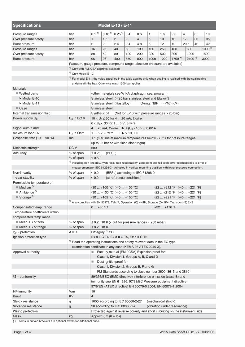
The pressure transducers used in the system are manufactured by WIKA, andare model number E-10. While all of the transducers we are using are the samebasic model number, we have a few with different specs from the rest. Themajority of them have the following specs:
• Pressure Range: 30 inHg to +30 psig (Compound)
• Output: 1-5 VDC
1
Steve Hardy
Crack pressure is 0.21 bar -- NOT 0.01 bar!!!!
4 VACUUM PUMPS 2
• Electrical Connection: 12” MNPT
• Pressure Connection: 14” FNPT
• Explosion Proof
The ones that are different have an operating pressure range of 0 - 100 psig,with all other specs remaining the same.
4 Vacuum Pumps
The two pumps in the system are identical, and were manufactured by AirDimensions Incorporated (ADI). They are double head diaphragm pumps, 316SS wetted parts, and 100% Teflon diaphragms. They operate on 12VDC, andhave 1
8” FNPT inputs.
5 Pressure Regulators
The regulators are Swagelok KLF series diaphragm sensing, pressure reducingregulators. The specs are as follows:
• Body Material: 316 SS
• Pressure Control Range: Two regulators at 0-2 psig, one at 0-10 psig
• Max Inlet Pressure: One regulator at 15 psig, two at 3600 psig
• Port sizes: 14” FNPT
• Seat Material: PCTFE
• Cv: 0.20
• Captured Vent
6 Solenoid Valves
All of the solenoid valves were manufactured by Asco Inc. All of the valvesoperate on 24VDC, have PTFE seals and discs, and 316 SS bodies.
7 Flow Meters
The flow meters were obtained from Sierra Instruments, and are in the 820sseries of their product line. The specs are as follows:
• Body and sensor mechanism made from 316 SS with Viton o-rings

7 FLOW METERS 3
• 14” compression fittings
• 24 VDC supply
• 0-5 VDC Linear output
• No Display
• Center Pressure: one at 75 psi, four at 6 psi

Oxygen Analyzers - Model 65 http://www.amio2.com/percent65.html
1 of 2 4/11/2006 5:01 PM
AMI guarantees higher quality andexceptional services at a lower price.
REQUEST QUOTE
The Model 65 is a perfect low cost, high performance solution for measuring percent levels of oxygen in avariety of OEM applications when displays, alarms, and multiple ranges are not required or become redundantin your system design.
The Model 65 employs a revolutionary long life zirconium oxide sensorlasting up to 10 years if used continuously and considerably longer if usedintermittently. This eliminates the need to purchase, stock, frequentlycalibrate or replace the standard galvanic type oxygen sensors, greatlyreducing overall costs.
This device uses state-of-the-art microprocessor based electronics for singlerange linear analog outputs of 0-2.5VDC full scale. It provides unmatchedstability and reliability even in rapid temperature swings from -4°F to+130°F.
The installation is simple, requires minimal space and a supply voltage of12-28VDC.
It requires no support or calibration gases and is suitable for single range applications from 0-2% up to 0-95%oxygen. Annual calibrations can easily be performed on ambient air or a suitable level calibration gas.
Single 0-25% range. Optionalranges available up to 0-95%Output: 0-2.5VDCMinimum detection:0.05% of range or 500ppmRepeatability: 0.05% oxygenOperating temperature: -4°F to 131°F (-20°C to 55°C)Diurnal temperaturespecification: < 1% over temperature range90% response: < 12 secPower requirements: 10-24 VDC, < 3 watts.
Area Classification: Generalpurpose Weight: < 1lbDimensions: 1.810"Dia. x 2.00
Single 0-25% range. Optionalranges available up to 0-95%Virtually unaffected by change intemperatureRFI protectedLinear long life zirconium oxidesensorRugged compact designUnaffected by change in flow rate(.1 to 5 SCFH)
Weather-tight 4-pininterconnection connector, plus cableBarbed sample gas in/out fittings (optional compression fittings)No calibration or support gasesnecessary2 year warranty
10-year life sensorLow original cost and virtuallymaintenance free over its entirelifeRequires no support orcalibration gases (other thanambient air calibration)No sensor replacement or shelflife issues

Inline Check Valve http://www.generant.com/cv.htm
1 of 3 4/11/2006 5:02 PM
Description
High flow, zero leak, low pressure drop check valve suitable for most fluid and gas applications. Fullyguided poppet with free floating O'ring design is extremely tolerant of particulate contamination. A metalto metal positive stop in both the open and checked position protects the O'ring and spring fromover-stress fatigue. Zero external leakage is achieved by utilization of a static O'ring seal with TFEbackup ring. When specified with the proper seal material, these valves are ideally suited to cryogenicsystem applications.
Technical Data
Nominal Crack Pressure: .15, 1, 3 & 8 Psig(0.01, 0.07, 0.21 & 0.55 bar)
Leakage: Zero to maximum operating pressure. TFE Seals may require back pressure to sealleak-tite
Temperature Rating:-320F - 450F (-195C to 232C)

Inline Check Valve http://www.generant.com/cv.htm
2 of 3 4/11/2006 5:02 PM
based on seal material
Maximum Operating Pressure to 300F (149C)
Materials of Construction
Dimensional / Flow Data
Ordering Information

���������
������� �����������
��������������� ������
�������������������������� ����������������
������� ���������� �������� ���������� ����� �������� ����������� ����� ����� ��������
�������������������� ������������������ � � ��������� �����������������������
������������������������������� � ���������� �����������������������
�������������������� ������ � � ��������� ����������������������!
����������
� ����������� ��! ��
� "�� � ��������!�#�� #��
� $��%�!��&������!�%���& &�� ��%
� '�%����%(!�����
������ ��������
� )*+�&&!�,��� -&��% ���&!������!�.��%%��
� , % ������/�!��(%���#�� ��%
� �0 1+�&&!�,���)����&!������!�����'� -������.
� �,� ��2���3 �������������4��+3 !���!�������5�64
�+3 !���(�&(��% ����%
� �� ���!������������!%�������%
� "��!�� �%����7��- %� ����&&� #�� ��%
�� ���� ������� ���������� ���� ! ���"
�� ������ ������� ���������� ���� ! ��� #��
�� ���� ������� ���������� ���� $���� %���& ! ��� #��
'��������
0��07&�%� +������� +����-&��% ���&!�����������&!���
&!�%%(!���!��%� ���!%��!��%&�# � #���7���% ���������������
�(!�2 � �7�����&�!��!���#��!�8( !�����%���� ��(%�! ��
�&&� #�� ��%�
0�%��&!�%%(!���!��%� ���!%�����(!����� ��(%�!7�%�����!�
�����������4��+3 !��% ������(�&(��9�&� �����% ������(�&(�
������5�6:4�; *���1�9�����:� ��!�%%�&!���#� ��4������!�
�-�!����7�!�% %��������, 2!�� ��4��� %�(!�� �%�!(% ������
&!�%%(!��%& <�%��0�7��!���&&� #�2�����!��# ����%
�&�� #�� ��%�������!���!����7�&!�, ����-�!��!�% %���#�
��� �%��%(�� ���%�!�%%�#!�#< ���3����-&�%��������%�%
#���� � ���%(�&(!�
0���!��%� ���!%��!����� ���!�����������.��%%���� , % ����
-&��% ���&!����&!���#� ����##�!� ������)*4�.���!
�����'� -������.��##�!� �������0 1���!� �%������ ��� �
�/�!��(%���, !������%�
�#��!��%� ���!�(���!���%��-���% ,��8(�� �7�#���!��
��%� �������#�� 2!�� �������# �,������##(!�#7����=���5�>�
������ � ��4���#�&!�%%(!���!��%� ���!� %����&�!��(!�
#��&��%���������%%(!���##(!�#7������������!��%��2 � �7
3����-&�%������%�,�!����2 �������&�!��(!��,�! �� ��%�
��������������� ���������������������������
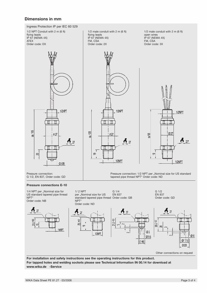
Specifications Model E-10 / E-11
Pressure ranges bar 0.1 1) 0.16 1) 0.25
1) 0.4 0.6 1 1.6 2.5 4 6 10
Over pressure safety bar 1 1.5 2 2 4 5 10 10 17 35 35
Burst pressure bar 2 2 2.4 2.4 4.8 6 12 12 20.5 42 42
Pressure ranges bar 16 25 40 60 100 160 250 400 600 1000 2)
Over pressure safety bar 80 50 80 120 200 320 500 800 1200 1500
Burst pressure bar 96 96 400 550 800 1000 1200 1700 3) 2400 3) 3000
{Vacuum, gauge pressure, compound range, absolute pressure are available}1) Only with FM, CSA approval available2) Only Model E-10.3) For model E-11: the value specified in the table applies only when sealing is realised with the sealing ring
underneath the hex. Otherwise max. 1500 bar applies.
Materials
� Wetted parts (other materials see WIKA diaphragm seal program)
� Model E-10 Stainless steel (> 25 bar stainless steel and Elgiloy®)
� Model E-11 Stainless steel {Hastelloy} O-ring: NBR {FPM/FKM}
� Case Stainless steel
Internal transmission fluid Synthetic oil (Not for E-10 with pressure ranges > 25 bar)
Power supply UB UB in DC V 10 < UB ≤ 30 for 4 ... 20 mA, 2-wire
6 < UB < 30 for 1 ... 5 V, 3-wireSignal output and 4 ... 20 mA, 2-wire RA ≤ (UB - 10 V) / 0.02 A
maximum load RA RA in Ohm 1 ... 5 V, 3-wire RA > 10,000
Response time (10 ... 90 %) ms ≤ 1 (≤ 10 ms at medium temperatures below -30 °C for pressure ranges
up to 25 bar or with flush diaphragm)
Dielectric strength DC V 500
Accuracy % of span ≤ 0.25 (BFSL)% of span ≤ 0.5 4)
4) Including non-linearity, hysteresis, non-repeatability, zero point and full scale error (corresponds to error of
measurement per IEC 61298-2). Adjusted in vertical mounting position with lower pressure connection.
Non-linearity % of span ≤ 0.2 (BFSL) according to IEC 61298-21-year stability % of span ≤ 0.2 (at reference conditions)
Permissible temperature of
� Medium 5) -30 ... +100 °C {-40 ... +105 °C} -22 ... +212 °F {-40 ... +221 °F}
� Ambience 5) -30 … +100 °C {-40 ... +105 °C} -22 …+212 °F {-40 ... +221 °F}
� Storage 5) -30 ... +105 °C {-40 ... +105 °C} -22 ... +221 °F {-40 ... +221 °F}5) Also complies with EN 50178, Tab. 7, Operation (C) 4K4H, Storage (D) 1K4, Transport (E) 2K3
Compensated temp. range 0 ... +80 °C +32 ... +176 °F
Temperature coefficients within
compensated temp range
� Mean TC of zero % of span ≤ 0.2 / 10 K (< 0.4 for pressure ranges < 250 mbar)� Mean TC of range % of span ≤ 0.2 / 10 K
d - protection ATEX Category 6) 2G
Ignition protection type Ex d II C T4, Ex d II C T5, Ex d II C T66) Read the operating instructions and safety relevant data in the EC-type
examination certificate in any case (KEMA 05 ATEX 2240 X).
Approval authority � Factury mutual (FM / CSA) Explosion proof for:
Class 1, Division 1, Groups A, B, C and D
� Dust ignitionproof for:
Class 1, Division 2, Groups E, F and G
FM Standards according to class number 3600, 3615 and 3810
a - conformitiy 89/336/EEC (EMC directive) interference emission (class B) and
immunity see EN 61 326, 97/23/EC Pressure equipment directive
97/9/EG (ATEX directive) EN 60079-0:2004, EN 60079-1:2004
HF-immunity V/m 10
Burst KV 4
Shock resistance g 1000 according to IEC 60068-2-27 (mechanical shock)
Vibration resistance g 20 according to IEC 60068-2-6 (vibration under resonance)
Wiring protection Protected against reverse polarity and short circuiting on the instrument side
Mass kg Approx. 0.2 (0.4 lbs){ } Items in curved brackets are optional extras for additional price.
�������������������������� ����������������
��� ���������� ��� �����( ���������� ��� ��� �������� ���������� ��� ��� �������
��� ������ ����� ��� %����� ���)��� ������ ��� �������� *��������� *+ �� �, ��� ��%����� ��
%%% %)� �� �������
�����;�0&�!�?;�� ����% /����!�@%�����!����&�!���& &���!���;�0A$!��!�#���B�;�
'���� ;����$!��!�#���B�'�
'���� ;����$!��!�#���B�'C
�!�%%(!��#����#� ��B'����4� ;����4�$!��!�#���B�'�
����;�0�.���( ��3 ������9����:��7 �������%������9; *���1:�0 1$!��!�#���B��1
�!�%%(!��#����#� ��B�����;�0�&�!�?;�� ����% /����!�@�%�����!���&�!���& &���!����;�0A�$!��!�#���B�;�
'������� � ��
������� ���������� ����
$��!�#����#� ��%����!�8(�%�
����;�0�&�!�?;�� ����% /����!@�%�����!����&�!���& &���!���;�0A$!��!�#���B�;C
���������#���( ��3 ������9����:��7 �������%������9; *���1:)*4�.�$!��!�#���B��1
���������#���( ��3 ������9����:�&���3 !�%������9; *���1:)*4�.�$!��!�#���B��1
���!�%%��!���#� ������&�!�� .����5�D

��������������� ���������������������������
-*.� ��������� -����� /�01 2 #� ./
���-����!+� �����+�!�E�� ��
��D��� �� ����2�!��'�!���7
���� 9F�D:�D��������+�
0�����- 9F�D:�D��������+���
+*� � %(&&�!�+�!�� #G3 <����
333�3 <����
&�# � #�� ��%������ ���% ��%�� ,��� ��� %���������!�&!�%�������%����������� ���! ���������� ������&! �� ���*�� � #�� ��%���7���<��&��#����������! ��%�%&�# � �����7�2��!�&��#���27����!%�3 ��(��&! �!���� #��
red
black
red
brown
black
screen / case(green with open wires)
screen / case(green with open wires)
Non hazardous area Hazardous (classified area)
D�
��
��
���
���
��
��'
C
�� ���� ����� +��� +���������� $��� #��&
�� ������ ����� +��� +���������� $���"&
�� ���� ����� *��3��� *������ ����
H�(�#����2�� ���(!��!� ���!��� ���9�����%���%4� �%�!(#� ��%4���#�:
, ���(!� ���!�������!�%%
333�3 <����
$��!�&!�%%(!���!��%� ���!%���!��/�!��(%��!��%
4�����5
-��� ������
��(�� ����� ! ���� %��� 6�%����(�� ����� ! ���� %��� 3�%��
������� ���������
$&�!�� �����%�!(#� ��%
������� ���������� ����� ����� ��������
'���C�3 ���+! ��9�����������������������2�!:$!��!�#���B��5
'�����C�3 ���+! ��9��������5��������������2�!:$!��!�#���B���
%��� ���! ��
���5�-����D�-���5
�+! ����5�-��
%��� ���! ��
�D���-��5���-����
�+! ������-��
Non hazardous area Hazardous (classified area)

TITLE
MODEL #
AIR DIMENSIONS INC.DEERFIELD BEACH, FL. USA 33442
WWW.AIRDIMENSIONS.COM
DWG NO
DATE
APPROVED BY
SHEET OF
Dbl Headed DC Brushless Micro
Bxx2-xx-Hx0
4/26/2001
Bxx2-xx-Hx0 1 2 FDM
1
1
2
2
3
3
4
4
A A
B B
C C
D D
.6 [16 mm]
1.9 [47 mm] 3.5 [90 mm]
6.6 [169 mm]
4.2 [108 mm]
8.4 [213 mm]
04/04 (0282)
RPM ADJUSTMENT ACCESS CAP
1/8-27 NPT PORTS
.9 [22 mm]
.4 [10 mm]
1.8 [44 mm]1.8 [44 mm]
2.4 [62 mm]4X 6-32 UNC 2A4.4 [113 mm]2.4 [60 mm]


%
^
#
)
Features
• Reliable, proven design with high flows.
• Small poppet valves for tight shutoff.
• Wide range of elastomers for specialty service.
• Mountable in any position.
• Brass and stainless steel constructions.
2.27 R3
Direct ActingGeneral Service Solenoid Valves
Brass or Stainless Steel Bodies1/8" to 3/8" NPT
NC
NO
2/2SERIES82628263
Solenoid Enclosures
Electrical
Nominal Ambient Temperature Ranges:AC: 32˚F to 125˚F (0˚C to 52˚C) DC: 32˚F to 104˚F (0˚C to 40˚C)Refer to Engineering Section for details.
Approvals:CSA certified. UL listed, as indicated. Normally ClosedValves FM approved. Meets applicable CE directives.Refer to Engineering Section for details.
Construction
Standard: Watertight, Types 1, 2, 3, 3S, 4, and 4X.Optional: Explosionproof and Watertight, Types 3, 3S, 4, 4X, 6, 6P, 7, and 9.
(To order, add prefix “EF” to catalog number)See Optional Features Section for other available options.
StandardCoil andClass of
Insulation
Watt Rating and Power Consumption Spare Coil Part No.
DCWatts
AC General Purpose Explosionproof
WattsVA
HoldingVA
Inrush AC DC AC DC
F 10.6 6.1 16 30 238210 238310 238214 238314
F 11.6 10.1 25 50 238610 238710 238614 238714
F 22.6 17.1 40 70 238610 238710 238614 238714
Standard Voltages 24, 120, 240, 480 volts AC, 60 Hz (or 110, 220 volts AC, 50 Hz). 6, 12, 24, 120, 240 volts DC. Must be specified when ordering. Other voltages available when required.
Valve Parts in Contact with Fluids
Body Brass 303/304 Stainless Steel Seals and Discs NBR or Cast UR Core Tube 305 Stainless Steel Core and Plugnut 430F Stainless Steel
Springs 302 Stainless Steel
Shading Coil Copper Silver Stem PA (Normally Open)
Note: All 1/8" NPT Normally Open valves contain CA. All 1/4" NPT Normally Open valves contain PA.
8263
4qwer
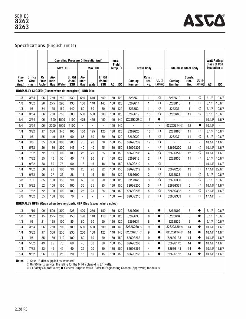
Specifications (English units)
4
2.28 R3
SERIES82628263
PipeSize(ins.)
OrificeSize(ins.)
CvFlow
Factor
Operating Pressure Differential (psi) Max. Fluid
Temp. ˚F Brass Body Stainless Steel Body
Watt Rating/Class of CoilInsulation ➁Max. AC Max. DC
Air-Inert Gas Water
Lt. Oil @ 300SSU
Air-Inert Gas Water
Lt. Oil @ 300SSU AC DC
CatalogNumber
Constr.Ref. No.
UL ➂ Listing
CatalogNumber
Constr.Ref. No.
UL ➂Listing AC DC
NORMALLY CLOSED (Closed when de-energized), NBR Disc
1/8 3/64 .06 750 750 530 650 640 550 180 120 8262G1 1 ❍ 8262G12 1 ❍ 6.1/F 10.6/F
1/8 3/32 .20 275 290 130 150 140 145 180 120 8262G14 1 ❍ 8262G15 1 ❍ 6.1/F 10.6/F
1/8 1/8 .34 155 180 140 80 80 80 180 120 8262G2 1 ❍ 8262G6 1 ❍ 6.1/F 10.6/F
1/4 3/64 .06 750 750 500 500 500 500 180 120 8262G19 16 ❍ 8262G80 11 ❍ 6.1/F 10.6/F
1/4 3/64 .06 1500 1500 1100 475 475 450 140 140 8262G200 ➀ 17 ● - - - 10.1/F 11.6/F
1/4 3/64 .06 2200 2000 1100 - - - 140 140 - - - 8262G214 ➀ 12 ● 10.1/F -
1/4 3/32 .17 360 340 160 150 125 125 180 120 8262G20 16 ❍ 8262G86 11 ❍ 6.1/F 10.6/F
1/4 1/8 .35 140 165 90 65 60 60 180 120 8262G22 16 ❍ 8262G7 11 ❍ 6.1/F 10.6/F
1/4 1/8 .35 300 300 200 75 70 70 180 150 8262G232 17 ❍ - - - 10.1/F 11.6/F
1/4 5/32 .50 180 200 145 40 40 45 180 150 8262G202 4 ❍ 8262G220 12 ❍ 10.1/F 11.6/F
1/4 7/32 .72 90 100 100 25 25 25 180 150 8262G208 4 ❍ 8262G226 12 ❍ 10.1/F 11.6/F
1/4 7/32 .85 40 50 40 17 20 21 180 120 8262G13 2 ❍ 8262G36 11 ❍ 6.1/F 10.6/F
1/4 9/32 .88 60 75 60 18 15 18 180 150 8262G210 4 ❍ - - - 10.1/F 11.6/F
1/4 9/32 .88 90 100 90 25 20 22 180 150 8262G212 6 ❍ 8262G230 13 ❍ 17.1/F 22.6/F
1/4 9/32 .96 27 36 28 15 16 16 180 120 8262G90 2 ❍ 8262G38 11 ❍ 6.1/F 10.6/F
3/8 1/8 .35 160 150 90 65 60 60 180 120 8263G2 3 ❍ 8263G330 3 ❍ 6.1/F 10.6/F
3/8 5/32 .52 100 100 100 35 35 35 180 150 8263G200 5 ❍ 8263G331 5 ❍ 10.1/F 11.6/F
3/8 7/32 .72 100 100 100 25 25 25 180 150 8263G206 5 ❍ 8263G332 5 ❍ 17.1/F 11.6/F
3/8 9/32 .85 100 100 70 - - - 180 — 8263G210 7 ❍ 8263G333 7 ❍ 17.1/F -
NORMALLY OPEN (Open when de-energized), NBR Disc (except where noted)
1/8 1/16 .09 500 300 225 400 250 150 180 120 8262G91 8 ● 8262G92 8 ● 6.1/F 10.6/F
1/8 3/32 .15 275 200 150 190 110 110 180 120 8262G93 8 ● 8262G94 8 ● 6.1/F 10.6/F
1/8 1/8 .21 125 100 85 80 60 50 180 120 8262G31 8 ● 8262G35 8 ● 6.1/F 10.6/F
1/4 3/64 .06 750 700 700 500 500 500 140 140 8262G260 ➀ 9 ● 8262G130 ➀ 14 ● 10.1/F 11.6/F
1/4 3/32 .17 300 250 230 200 150 125 140 140 8262G261 ➀ 9 ● 8262G134 ➀ 14 ● 10.1/F 11.6/F
1/4 1/8 .35 130 110 100 80 60 60 180 150 8262G262 9 ● 8262G138 14 ● 10.1/F 11.6/F
1/4 5/32 .49 85 75 60 45 30 30 180 150 8262G263 4 ● 8262G142 14 ● 10.1/F 11.6/F
1/4 7/32 .83 45 45 40 25 20 20 180 150 8262G264 4 ● 8262G148 14 ● 10.1/F 11.6/F
1/4 9/32 .96 30 25 20 15 15 15 180 150 8262G265 4 ● 8262G152 14 ● 10.1/F 11.6/F
Notes: ➀ Cast UR disc supplied as standard. ➁ On 50 hertz service, the rating for the 6.1/F solenoid is 8.1 watts. ➂ ❍ Safety Shutoff Valve; ● General Purpose Valve. Refer to Engineering Section (Approvals) for details.

2.30 R3
Dimensions: inches (mm)
Constr. Refs. 11-14, 16, 17
Constr. Refs. 1
Constr. Refs. 8
Constr. Refs. 2, 4, 6, 9
Mounting Details
Constr. Refs. 3, 5, 7
SERIES82628263
Constr.Ref. No. H K L P W
1 ins. 2.52 1.30 1.19 2.16 1.69mm 64 33 30 55 43
2 ins. 2.98 1.71 1.56 2.57 1.69mm 76 43 40 65 43
3 ins. 3.07 1.63 1.88 2.49 1.69mm 78 41 48 63 43
4 ins. 3.20 1.78 1.56 2.79 1.95mm 81 45 40 71 50
5 ins. 3.25 1.70 2.00 2.77 1.95mm 83 43 51 70 50
6 ins. 3.16 1.78 1.56 2.75 1.95mm 80 45 40 70 50
7 ins. 3.25 1.70 2.00 2.67 1.95mm 83 43 51 68 50
8 ins. 3.15 1.32 1.19 2.18 1.69
mm 80 34 30 55 439 ins. 3.23 1.67 1.25 2.81 1.95
mm 82 42 32 71 5011 ins. 2.94 1.71 1.56 2.57 1.69
mm 75 43 40 65 4312 ins. 3.12 1.78 1.56 2.75 1.95
mm 79 45 40 70 5013 ins. 3.12 1.78 1.56 2.75 1.95
mm 79 45 40 70 5014 ins. 3.16 1.65 1.56 2.79 1.95
mm 80 42 40 71 5016 ins. 3.01 1.73 1.25 2.59 1.69
mm 76 44 32 66 4317 ins. 3.19 1.80 1.25 2.77 1.95
mm 81 46 32 70 50
IMPORTANT: Valves may be mounted in any position.
4

%
)
Features• Wide range of pressure ratings, sizes, and resilient
materials provide long service life and low internal leakage.• High Flow Valves for liquid, corrosive, and air/inert
gas service.• Industrial applications include:
- Car wash - Laundry equipment- Air compressors - Industrial water control- Pumps
2.09 R4
Pilot OperatedGeneral Service Solenoid Valves
Brass or Stainless Steel Bodies3/8" to 2 1/2" NPT
NC
NO2/2SERIES
8210
Solenoid Enclosures
Electrical
Nominal Ambient Temperature Ranges:Red-Hat II/Red-Hat AC: 32˚F to 125˚F (0˚C to 52˚C) Red-Hat II DC: 32˚F to 104˚F (0˚C to 40˚C)Red-Hat DC: 32˚F to 77˚F (0˚C to 25˚C)
(104˚F/40˚C occasionally)Refer to Engineering Section for details.
Approvals:CSA certified. Red-Hat II meets applicable CE directives.Refer to Engineering Section for details.
Standard: Red-Hat II - Watertight, Types 1, 2, 3, 3S, 4, and 4X; Red-Hat - Type I.Optional: Red-Hat II - Explosionproof and Watertight, Types 3, 3S, 4, 4X, 6,
6P, 7, and 9; Red-Hat - Explosionproof and Watertight, Types 3, 4, 4X, 7, and 9.(To order, add prefix “EF” to catalog number, except Catalog Numbers 8210B57, 8210B58, and 8210B59. Valves not available with Explosionproof enclosures.) See Optional Features Section for other available options.
StandardCoil andClass of
Insulation
Watt Rating and Power Consumption Spare Coil Part Number
DCWatts
AC General Purpose Explosionproof
WattsVA
HoldingVA
Inrush AC DC AC DCF - 6.1 16 40 238210 - 238214 -
F 11.6 10.1 25 70 238610 238710 238614 238714
F 16.8 16.1 35 180 272610 97617 272614 97617F - 17.1 40 93 238610 - 238614 -F - 20 43 240 99257 - 99257 -F - 20.1 48 240 272610 - 272614 -H 30.6 - - - - 74073 - 74073H 40.6 - - - - 238910 238914
Standard Voltages: 24, 120, 240, 480 volts AC, 60 Hz (or 110, 220 volts AC, 50 Hz). 6, 12, 24, 120, 240 volts DC. Must be specified when ordering. Other voltages availablewhen required.
ConstructionValve Parts in Contact with Fluids
Body Brass 304 Stainless Steel
Seals and Discs NBR or PTFE
Disc-Holder PA
Core Tube 305 Stainless Steel
Core and Plugnut 430F Stainless Steel
Springs 302 Stainless Steel
Shading Coil Copper Silver
4qwer

Specifications (English units)
4SERIES
8210
2.10 R4
Pipe Size
(ins.)
OrificeSize(ins.)
Cv FlowFactor
Operating Pressure Differential (psi) Max. FluidTemp. ˚F Brass Body Stainless Steel Body
Watt Rating/Class of CoilInsulation ➆
Min.
Max. AC Max. DCAir-
InertGas Water
Light Oil@ 300SSU
Air-InertGas Water
Light Oil@ 300SSU AC DC
Catalog Number
Constr.Ref.No. ➃
UL ➄ Listing
CatalogNumber
Constr.Ref.No. ➃
UL ➄ Listing AC DC
NORMALLY CLOSED (Closed when de-energized), NBR or PTFE ➁ Seating 3/8 3/8 1.5 ➀ 150 125 - 40 40 - 180 150 8210G73 ➂ 1P ● 8210G36 ➂ 1P ● 6.1/F 11.6/F 3/8 5/8 3 0 150 150 - 40 40 - 180 150 8210G93 5D ❍ - - - 10.1/F 11.6/F 3/8 5/8 3 5 200 150 135 125 100 100 180 150 8210G1 6D ❍ - - - 6.1/F 11.6/F 3/8 5/8 3 5 300 300 300 - - - 175 - 8210G6 5D ❍ - - - 17.1/F - 1/2 7/16 2.2 ➀ 150 125 - 40 40 - 180 150 8210G15 ➂ 2P ● 8210G37 ➂ 2P ● 6.1/F 11.6/F 1/2 5/8 4 0 150 150 - 40 40 - 180 150 8210G94 5D ❍ - - - 10.1/F 11.6/F 1/2 5/8 4 0 150 150 125 40 40 - 175 150 - - - 8210G87 7D ● 17.1/F 11.6/F 1/2 5/8 4 5 200 150 135 125 100 100 180 150 8210G2 6D ❍ - - - 6.1/F 11.6/F 1/2 5/8 4 5 300 300 300 - - - 175 - 8210G7 5D ❍ - - - 17.1/F -1/2 3/4 4 5 - 300 - - 300 - 180 125 8210G227 5D ❍ - - - 17.1/F 40.6/H
3/4 5/8 4.5 0 150 150 125 40 40 - 175 150 - - - 8210G88 7D ● 17.1/F 11.6/F 3/4 3/4 5 5 125 125 125 100 90 75 180 150 8210G9 9D ❍ - - - 6.1/F 11.6/F 3/4 3/4 5 0 150 150 - 40 40 - 180 150 8210G95 8D ❍ - - - 10.1/F 11.6/F 3/4 3/4 6.5 5 250 150 100 125 125 125 180 150 8210G3 11D ❍ - - - 6.1/F 11.6/F 3/4 3/4 6 0 - - - 200 180 180 - 77 8210B26 ➁ ‡ 10P - - - - - 30.6/H 3/4 3/4 6 0 350 300 200 - - - 200 - 8210G26 ➁ ‡ 40P ● - - - 16.1F -
1 1 13 0 - - - 100 100 80 - 77 8210B54 ‡ 31D - 8210D89 15D - - 30.6/H1 1 13 0 150 125 125 - - - 180 - 8210G54 41D ● 8210G89 45D ● 16.1/F -1 1 13 5 150 150 100 125 125 125 180 150 8210G4 12D ❍ - - - 6.1/F 11.6/F1 1 13.5 0 300 225 115 - - - 200 - 8210G27 ‡ 42P ● - - - 20.1/F -1 1 13.5 10 300 300 300 - - - 175 - 8210G78 ➁ 13P - - - - 17.1/F -
1 1/4 1 1/8 15 0 - - - 100 100 80 - 77 8210B55 ‡ 32D - - - - - 30.6/H1 1/4 1 1/8 15 0 150 125 125 - - - 180 - 8210G55 43D ● - - - 16.1/F -1 1/4 1 1/8 15 5 150 150 100 125 125 125 180 150 8210G8 16D ❍ - - - 6.1/F 11.6/F1 1/2 1 1/4 22.5 0 - - - 100 100 80 - 77 8210B56 ‡ 33D - - - - - 30.6/H1 1/2 1 1/4 22.5 0 150 125 125 - - - 180 - 8210G56 ‡ 44D ● - - - 16.1/F -1 1/2 1 1/4 22.5 5 150 150 100 125 125 125 180 150 8210G22 18D ● - - - 6.1/F 11.6/F
2 1 3/4 43 5 150 125 90 50 50 50 180 150 8210G100 20P ● - - - 6.1/F 11.6/F2 1/2 1 3/4 45 5 150 125 90 50 50 50 180 150 8210G101 21P ● - - - 6.1/F 11.6/F
NORMALLY OPEN (Open when de-energized), NBR Seating (PA Disc-Holder, except as noted) 3/8 5/8 3 0 150 150 125 125 125 80 180 150 8210G33 23D ● - - - 10.1/F 11.6/F 3/8 5/8 3 5 250 200 200 250 200 200 180 180 8210G11 ➇ ➈ 39D ● - - - 10.1/F 11.6/F 1/2 5/8 4 0 150 150 125 125 125 80 180 150 8210G34 23D ● - - - 10.1/F 11.6/F 1/2 5/8 3 0 150 150 100 125 125 80 180 150 - - - 8210G30 37D ● 10.1/F 11.6/F 1/2 5/8 4 5 250 200 200 250 200 200 180 180 8210G12 ➇ ➈ 39D ● - - - 10.1/F 11.6/F 3/4 3/4 5.5 0 150 150 125 125 125 80 180 150 8210G35 25D ● - - - 10.1/F 11.6/F 3/4 5/8 3 0 150 150 100 125 125 80 180 150 - - - 8210G38 38D ● 10.1/F 11.6/F 3/4 3/4 6.5 5 - - - 250 200 200 - 180 8210C13 24D ● - - - - 16.8/F 3/4 3/4 6.5 5 250 200 200 - - - 180 - 8210G13 46D ● - - - 16.1/F -
1 1 13 0 125 125 125 - - - 180 - 8210B57 ➅ ➉ 34D ● - - - 20/F -1 1 13 5 - - - 125 125 125 - 180 8210D14 26D ● - - - - 16.8/F1 1 13 5 150 150 125 - - - 180 - 8210G14 47D ● - - - 16.1/F -
1 1/4 1 1/8 15 0 125 125 125 - - - 180 - 8210B58 ➅ ➉ 35D ● - - - 20/F -1 1/4 1 1/8 15 5 - - - 125 125 125 - 180 8210D18 28D ● - - - - 16.8/F1 1/4 1 1/8 15 5 150 150 125 - - - 180 - 8210G18 48D ● - - - 16.1/F -1 1/2 1 1/4 22.5 0 125 125 125 - - - 180 - 8210B59 ➅ ➉ 36D ● - - - 20/F -1 1/2 1 1/4 22.5 5 - - - 125 125 125 - 180 8210D32 29D ● - - - - 16.8/F1 1/2 1 1/4 22.5 5 150 150 125 - - - 180 - 8210G32 49D ● - - - 16.1/F -
2 1 3/4 43 5 - - - 125 125 125 - 150 8210103 30P ● - - - - 16.8/F2 1 3/4 43 5 125 125 125 - - - 180 - 8210G103 50P ● - - - 16.1/F -
2 1/2 1 3/4 45 5 - - - 125 125 125 - 150 8210104 27P ● - - - - 16.8/F2 1/2 1 3/4 45 5 125 125 125 - - - 180 - 8210G104 51P ● - 16.1/F -
Notes: ➀ 5 psi on Air; 1 psi on Water. ➁ Valve provided with PTFE main disc. ➂ Valve includes UItem (G.E. trademark) piston. ➃ Letter "D" denotes diaphragm construction; "P" denotes piston construction. ➄ ❍ Safety Shutoff Valve; ● General Purpose Valve. Refer to Engineering Section (Approvals) for details.
➅ Valves not available with Explosionproof enclosures. ➆ On 50 hertz service, the watt rating for the 6.1/F solenoid is 8.1 watts. ➇ AC construction also has PA seating. ➈ No disc-holder. ➉ Stainless Steel disc-holder. ‡ Must have solenoid mounted vertical and upright.

2.12 R4
Dimensions: inches (mm)
Constr. Refs. 1, 2
SERIES
8210
Constr. Refs. 5-9, 11, 20, 21, 23 , 25, 37,38
4
Constr.Ref. No. H K L P W
1* ins. 3.85 3.00 1.91 3.41 1.69mm 98 76 49 87 43
2* ins. 4.17 3.25 2.28 3.63 1.69mm 106 83 58 92 43
13 ins. 4.44 3.22 3.75 4.19 5.81mm 113 82 95 106 147
5 ins. 3.84 2.31 2.75 3.28 2.28mm 98 59 70 83 58
6* ins. 3.38 1.94 2.75 2.80 2.28mm 86 49 70 71 58
7 ins. 4.19 2.50 2.81 3.47 2.39mm 106 64 71 88 61
8 ins. 4.13 2.47 2.81 3.44 2.29mm 105 63 71 87 58
9* ins. 3.66 2.10 2.81 2.96 2.28mm 93 53 71 75 58
10*➀ ins. 5.25 X 2.81 4.59 2.31mm 133 X 71 117 59
11* ins. 4.16 2.66 3.84 3.52 2.75mm 106 68 98 89 70
12 ins. 5.64 3.15 3.75 4.01 3.36mm 143 80 95 102 85
15* ins. 5.34 X 3.75 4.47 3.84mm 136 X 95 114 98
16 ins. 5.64 3.15 3.66 4.01 3.56mm 143 80 93 102 90
18 ins. 6.11 3.30 4.38 4.16 3.92mm 155 84 111 106 100
20* ins. 7.33 3.71 5.06 4.57 4.87mm 186 94 129 116 124
21* ins. 7.33 3.71 5.50 4.57 4.87mm 186 94 140 116 124
23 ins. 4.35 2.65 2.75 3.79 2.28mm 110 67 70 96 58
24 ins. 5.06 X 3.78 4.44 2.75mm 129 X 96 113 70
25 ins. 4.64 2.81 2.81 3.94 2.28mm 118 71 71 100 58
26 ins. 6.53 X 3.75 4.91 3.19mm 166 X 95 125 81
27 ins. 8.22 X 5.50 5.47 4.87mm 209 X 140 139 124
28 ins. 6.53 X 3.66 4.91 3.19mm 166 X 93 125 81
29 ins. 7.03 X 4.38 5.06 4.40mm 179 X 111 129 112
➀ Valves must be mounted with solenoid vertical and upright. * DC dimensions slightly larger.
Constr. Ref. 13
L
W
P
K
H

Mass Flow Meters forCorrosive and Toxic Gases
� Direct monitoring of mass flow rate
eliminates need for ancillary
pressure and temperature sensing
� Stainless-steel flow body
accommodates most corrosive
and toxic gas applications
� Digital display of mass flow rate
on flow body or in remote version
for panel mounting
� Electronic output of mass flow
rate for control or data-logging
� Large, straight sensor tube
reduces contamination and
maintenance down-time
� Platinum sensor eliminates zero drift
and ensures long-term repeatability
� Primary standard calibration
ensures starting point accuracy
and NIST traceability
� CE Approved
Features
Description
ierra Instruments' Model 820-S Top-Trak™ is
designed for precise measurement of any process
gas in ranges from 0 to 10 sccm to 0 to 500 slpm. Because
all wetted materials are 316 stainless steel, the device
accommodates most clean gases, including corrosives.
The Model 820-S measures and displays the mass flow
rate directly in any user defined gas mass units. The instru-
ment display is tiltable over 180° for easy viewing and can
be removed for remote panel mounting. A 0–5 VDC or
4–20 mA linearly output signal proportional to gas mass
flow rate is provided for recording, data-logging or control.
Top-Trak's outstanding accuracy is a function of a
high-stability platinum flow sensor. This sensor has been
continuously tested for over two years. The maximum
deviation (drift) during that time was less than 0.5%. The
sensor's large internal diameter also prevents the clogging
and contamination often associated with capillary type
thermal mass flow meters.
Top-Trak's broad range of sizes, electronics, process
connections and input/output options provide flexibility,
versatility and ultimately, the ideal instrument package for
your specific application.
S
820-
S Ser
ies To
p-Tr
ak™
The information contained herein is subject to change without notice.
ISOREGISTERED
9001
5 Harris Court, Bldg. LMonterey CA 93940831/373-0200800/866-0200FAX: 831/373-4402www.sierrainstruments.com

Low Flow Body Medium Flow Body High Flow Body
Model 820-S—Side View
Model 820-S—Bottom View
Model 820-S—Outlet View
L
4.23(107.4)
5.21(132.3)
4.01(101.9)
without display
2.750(69.85)
3.00(76.20)
B ABA
(B) 6-32, 2PL(A) M4, 2PL
.12(3.0) .750
(19.1)
.13(3.3)
1.58(40.1)
.98(24.9)
.49(12.4)
.49(12.4)
1.13(28.7)
All dimensions are inches. Millimeters are in parentheses. Certified drawings are available on request.
Dim. L 4.84 or 5.0 4.60 4.90(122.9 or 127.0) (116.8) (124.5)
FITTING TYPE, .562-18 THREAD (1)
Compression VCO(male) VCR(male).125 or .25 .25 .25
Model 820-S—Side View
Model 820-S—Bottom View
Model 820-S—Outlet View
L
1.25(31.8)
4.23(107.4)
5.67(144.0)
4.47(113.5)
without display
1.25(31.8)
9.15(232.4)6.66
(169.2)
1.45(36.8)
L
1.9(48.3)
2.00(50.80)
4.25(108.0)
.23(5.8)
1.00(25.40)
(B) 8-32, 2PL
B A
BA
(A) M6, 2PL
2.05(52.1)
1.13(28.7)
1.45(36.8)
1.45(36.8)
.73(18.5)
.73(18.5)
Process .25 or .375 .25 or .375Tubing (6.4 or 9.5) (6.4 or 9.5)
FLOW RANGE, slm
0–15 0–100
Dim. L 6.27 or 6.39 5.81 or 6.25 6.13 or 6.43(159.3 or 162.3) (147.6 or 158.8) (155.7 or 163.3)
FITTING TYPE, .562-18 THREAD (1)
Compression VCO(male) VCR(male).25 or .375 .25 or .375 .25 or .375
Model 820-S—Side View
Model 820-S—Bottom View
Model 820-S—Outlet View
3.0(76.2)
9.75(247.7)
2.00(50.80)
(A) 10-34, 2PL(B) M6, 2PL
A
B A
B
.22(5.6)
2.00(50.80)
1.13(28.7)
2.44(62.0)
2.44(62.0)
1.22(31.0)
1.22(31.0)
Process .375 or .50 .50Tubing (9.5 or 12.7) (12.7)
FLOW RANGE, slm
0–100 0–500
Dim. L 11.89 or 12.17 11.75 12.19(302 or 309.1) (298.5) (309.6)
FITTING TYPE, .75-16 THREAD (1)
Compression VCO(male) VCR(male).375 or .50 .375 .375
Process .25 .25Tubing (6.4) (6.4)
FLOW RANGE
0–10 sccm 0–15 slm
Note: (1) Metric fittings are available, consult factory.

Performance Specifications
Accuracy± 1.5 of full scale including linearity over
15° to 25°C and 5 to 60 psia (0.3 to 4 bara) If the meter is mounted with a vertical (up or down) flow path
the folowing accuracy de-rating applies:
Notes: (1) Do not exceed 150 psig.(2) Difference between inlet pressure and calibrated pressure. Do not exceed ± 10 psig.
Repeatability± 0.5% of full scale
Temperature Coefficient0.08% of full scale per °F (0.15% of full scale per °C), or better
Pressure Coefficient0.01% of full scale per psi (0.15% of full scale per bar) or better
Response Time800 ms time constant; six seconds (typical) to within ± 2% of final value over 25 to 100% of full scale
Operating Specifications
GasesMost gases; check compatibility with wetted materials; specify when ordering
Mass Flow Rates0 to 10 sccm to 0 to 500 slpm; flow ranges specified are for an equivalent
flow of nitrogen at 760 mm Hg and 21°C (70°F); other ranges in otherunits are available (e.g., scfh or nm3/h)
Gas Pressure500 psig (34 barg) maximum;1000 psig (69 barg) maximum available for low flow bodies only uponrequest, please consult factory.30 psig (2 barg) optimum
Pressure Drop820-S (low) . . . . . . . . 0.08 psi (0.006 bar or 6 cm of water) differential max;
15 slpm: 1.5 psi (0.10 bar or 105 cm of water) differential max
820-S (med) . . . . . . . . 0.08 psi (0.006 bar or 6 cm of water) differential max;100 slpm: 1.5 psi (0.10 bar or 105 cm of water) differential max
820-S (high) . . . . . . . . 0.08 psi (0.006 bar or 6 cm of water) differential max;300, 400 and 500 slpm: 2 psi (0.14 bar or 140 cm of water) differential max
Gas & Ambient Temperature32 to 122°F (0 to 50°C)
Leak Integrity5 X 10-9 atm cc/sec of helium maximum
Power Requirements12 to 18 VDC, 15 VDC nominal, 100 mA maximum
24 VDC optional, specify when ordering
Output SignalLinear 0–5 VDC, 1000 ohms minimum load resistanceLinear 4–20 mA, 500 ohms maximum loop resistance
Display (optional)3.5 digit LCD (0.6 in H); removable for remote mounting
Physical Specifications
Wetted Materials316 stainless steel, Viton® “O”-rings standard
Neoprene® and 4079 Kal-Rez® “0”-rings optional
OptionsSee “Price List” for available CE options
® Viton, Neoprene, Kal-Rez, and Teflon are registered trademarks of DuPont.
± 1 psig ± 1.5% of ± 1.5% of ± 1.5% of full scale full scale full scale
± 5 psig ± 3.8% of ± 4.5% of ± 5.3% of full scale full scale full scale
± 10 psig ± 6% of ± 7.5% of ± 9% of full scale full scale full scale
OPERATING PRESSURE
Inlet PressureDeviation2 50 psig 100 psig 150 psig

ACCESSORIES (Consult Factory)
GAS, FLOW RATE
OPTIONSRD(ft) Remote Display (Cable Length in Feet)MP Medium Pressure Calibration, 40–100 psig (2.8–6.9 barg)HP High Pressure Calibration,100–500 psig (6.9–34.5 barg)A1 High Accuracy CalibrationLF Low Flow Calibration, (0–20 sccm or below)
OUTPUT SIGNALV1 0–5 VDC, LinearV4 4–20 mA, Linear
INPUT POWERPV1 12 to 15 VDCPV2 24 VDC
ELASTOMERSOV1 VitonON1 Neoprene (low, medium flow)ON2 Neoprene (high flow)OK1 Kal Rez (low flow)OK2 Kal Rez (medium flow)OK3 Kal Rez (high flow)
INLET/OUTLET FITTINGS1 1/8-inch Compression2 1/4-inch Compression3 3/8-inch Compression4 1/2-inch Compression5 1/4-inch VCO6 1/2-inch VCO (low, medium flow bodies)7 1/2-inch VCO (high flow bodies)8 1/4-inch VCR9 1/2-inch VCR10 6 mm Compression11 10 mm Compression12 12 mm Compression
FLOW BODYL Low FlowsM Medium FlowsH High Flows
PARENT NUMBER
822-S Mass Flow Meter with Display824-S Mass Flow Meter
Ordering the Model 820-S
5 Harris Court, Building L • Monterey, California • U.S.A. • (800) 866-0200 • (831) 373-0200 • Fax (831) 373-4402 • www.sierrainstruments.comSIERRA INSTRUMENTS b.v. Bijlmansweid 2 • 1934 RE Egmond a/d Hoef • The Netherlands • +31 (0) 72 5071400 • Fax +31 (0) 72 5071401
820-S—A 3M 08/03