Generalized instrumentation system
18
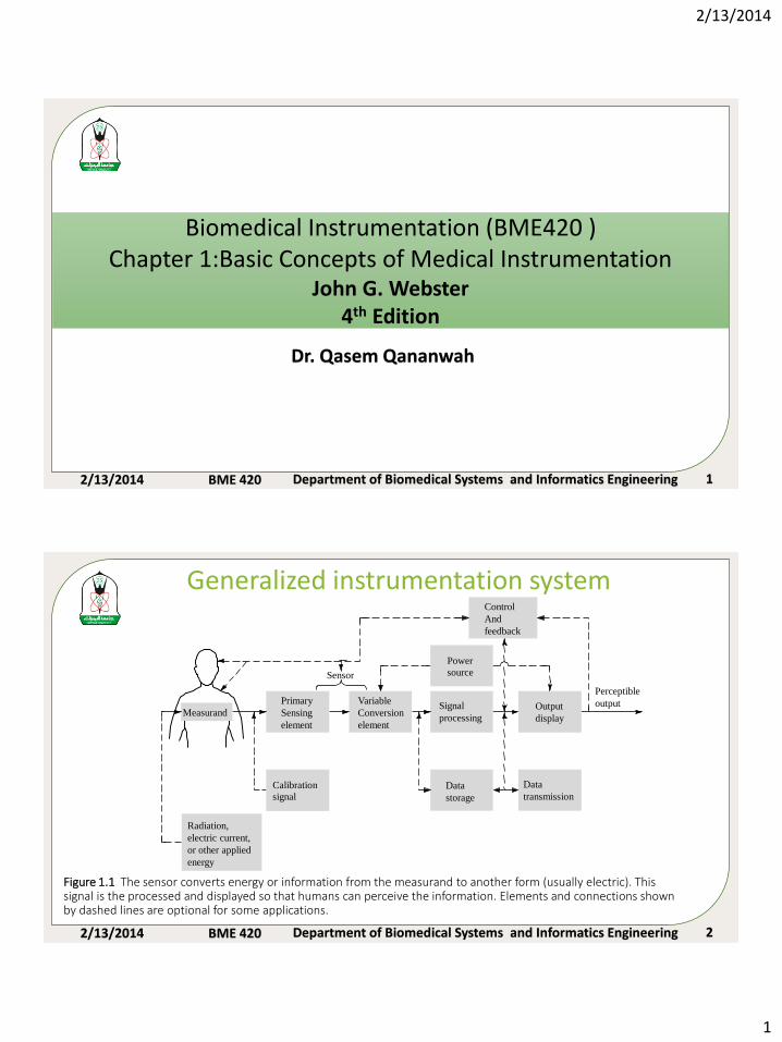
2/13/2014 1 2/13/2014 BME 420 Department of Biomedical Systems and Informatics Engineering 1 Biomedical Instrumentation (BME420 ) Chapter 1:Basic Concepts of Medical Instrumentation John G. Webster 4 th Edition Dr. Qasem Qananwah 2/13/2014 BME 420 Department of Biomedical Systems and Informatics Engineering 2 Perceptible output Output display Control And feedback Signal processing Data transmission Data storage Variable Conversion element Sensor Primary Sensing element Measurand Calibration signal Radiation, electric current, or other applied energy Power source Figure 1.1 The sensor converts energy or information from the measurand to another form (usually electric). This signal is the processed and displayed so that humans can perceive the information. Elements and connections shown by dashed lines are optional for some applications. Generalized instrumentation system
-
Upload
khangminh22 -
Category
Documents
-
view
0 -
download
0
Transcript of Generalized instrumentation system
2/13/2014
1
2/13/2014 BME 420 Department of Biomedical Systems and Informatics Engineering 1
Biomedical Instrumentation (BME420 )Chapter 1:Basic Concepts of Medical Instrumentation
John G. Webster4th Edition
Dr. Qasem Qananwah
2/13/2014 BME 420 Department of Biomedical Systems and Informatics Engineering 2
Perceptible
outputOutput
display
Control
And
feedback
Signal
processing
Data
transmissionData
storage
Variable
Conversion
element
Sensor
Primary
Sensing
element
Measurand
Calibration
signal
Radiation,
electric current,
or other applied
energy
Power
source
Figure 1.1 The sensor converts energy or information from the measurand to another form (usually electric). This signal is the processed and displayed so that humans can perceive the information. Elements and connections shown by dashed lines are optional for some applications.
Generalized instrumentation system
2/13/2014
2
2/13/2014 BME 420 Department of Biomedical Systems and Informatics Engineering 3
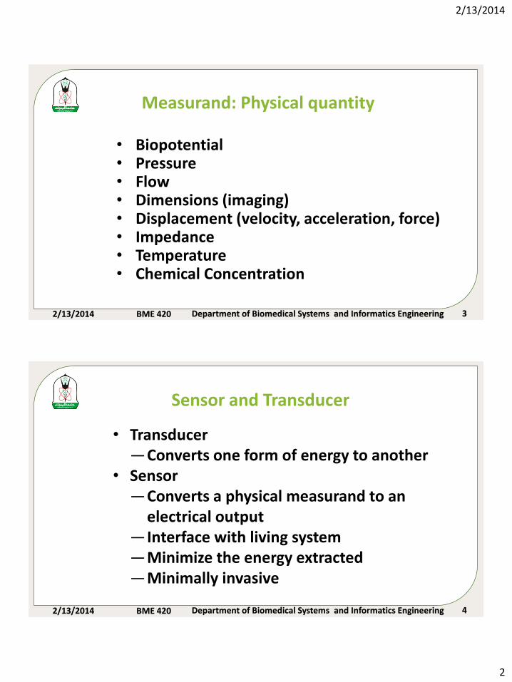
• Biopotential • Pressure• Flow• Dimensions (imaging)• Displacement (velocity, acceleration, force)• Impedance• Temperature• Chemical Concentration
Measurand: Physical quantity
2/13/2014 BME 420 Department of Biomedical Systems and Informatics Engineering 4
Sensor and Transducer
• Transducer—Converts one form of energy to another
• Sensor—Converts a physical measurand to an
electrical output— Interface with living system—Minimize the energy extracted—Minimally invasive
2/13/2014
3
2/13/2014 BME 420 Department of Biomedical Systems and Informatics Engineering 5
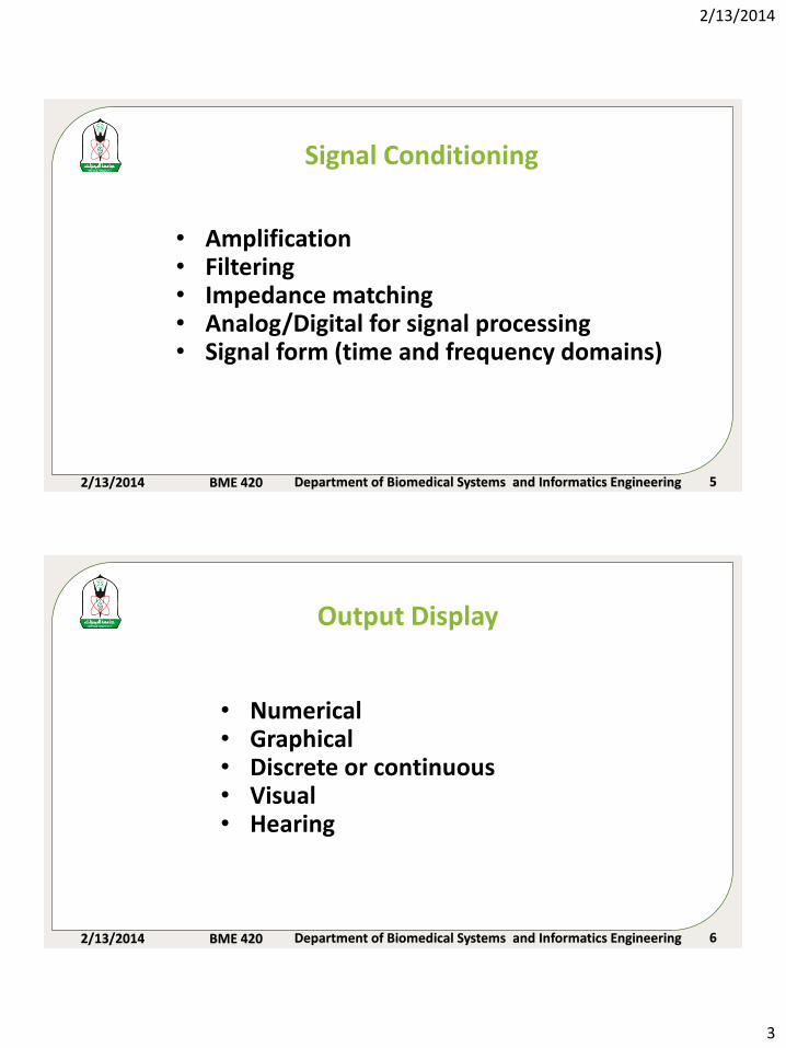
Signal Conditioning
• Amplification• Filtering• Impedance matching• Analog/Digital for signal processing• Signal form (time and frequency domains)
2/13/2014 BME 420 Department of Biomedical Systems and Informatics Engineering 6
Output Display
• Numerical• Graphical• Discrete or continuous• Visual• Hearing
2/13/2014
4
2/13/2014 BME 420 Department of Biomedical Systems and Informatics Engineering 7
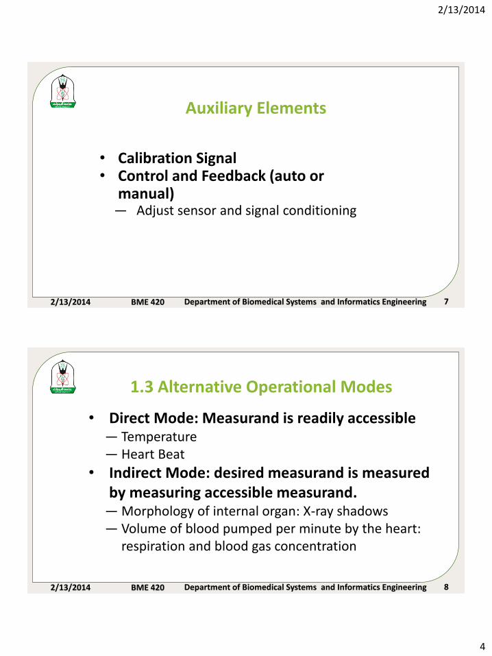
Auxiliary Elements
• Calibration Signal• Control and Feedback (auto or
manual)— Adjust sensor and signal conditioning
2/13/2014 BME 420 Department of Biomedical Systems and Informatics Engineering 8
1.3 Alternative Operational Modes
• Direct Mode: Measurand is readily accessible— Temperature— Heart Beat
• Indirect Mode: desired measurand is measured by measuring accessible measurand.
— Morphology of internal organ: X-ray shadows— Volume of blood pumped per minute by the heart:
respiration and blood gas concentration
2/13/2014
5
2/13/2014 BME 420 Department of Biomedical Systems and Informatics Engineering 9
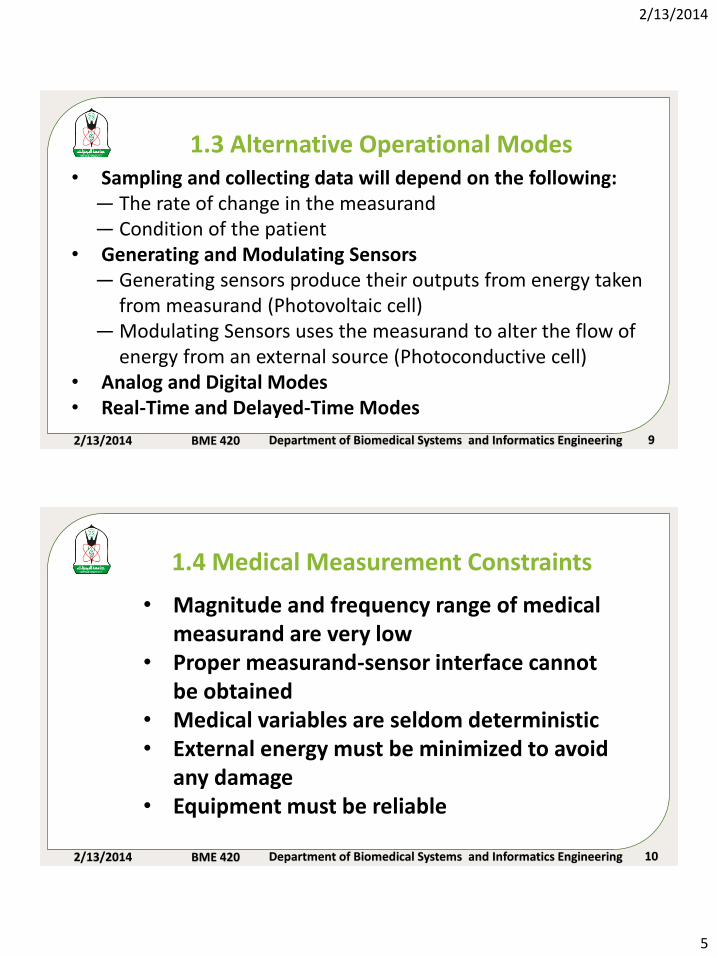
• Sampling and collecting data will depend on the following:— The rate of change in the measurand— Condition of the patient
• Generating and Modulating Sensors— Generating sensors produce their outputs from energy taken
from measurand (Photovoltaic cell)— Modulating Sensors uses the measurand to alter the flow of
energy from an external source (Photoconductive cell)• Analog and Digital Modes• Real-Time and Delayed-Time Modes
1.3 Alternative Operational Modes
2/13/2014 BME 420 Department of Biomedical Systems and Informatics Engineering 10
1.4 Medical Measurement Constraints
• Magnitude and frequency range of medical measurand are very low
• Proper measurand-sensor interface cannot be obtained
• Medical variables are seldom deterministic• External energy must be minimized to avoid
any damage• Equipment must be reliable
2/13/2014
6
2/13/2014 BME 420 Department of Biomedical Systems and Informatics Engineering 11
1.5 Classification of Medical Instrument
• Quantity that is sensed— pressure, flow, temp
• Principle of transduction— resistive, capacitive, electrochemical, ultrasound
• Organ system— cardiovascular, pulmonary, nervous
• Medicine specialties— pediatrics, cardiology, radiology
2/13/2014 BME 420 Department of Biomedical Systems and Informatics Engineering 12
1.6 Interfering and Modifying InputsDesired Inputs: measurands that the instrument is designed to isolate.
Interfering Inputs: quantities that unintentionally affect the instrument as a consequence of the principles used to acquire and process the desired inputs.
Modifying Inputs: undesired quantities that indirectly affect the output by altering the performance of the instrument itself.
2/13/2014
7
2/13/2014 BME 420 Department of Biomedical Systems and Informatics Engineering 13
1.6 Interfering and Modifying InputsElectrodes
50-Hz
ac magnetic
field
Displacement
currents
Differential
amplifier
+
-
+Vcc
Vcc
Z1
ZbodyZ2
vo
vecg
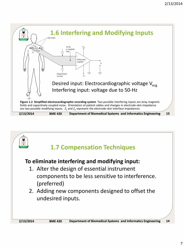
Desired input: Electrocardiographic voltage Vecg
Interfering input: voltage due to 50-Hz
Figure 1.2 Simplified electrocardiographic recording system Two possible interfering inputs are stray magnetic fields and capacitively coupled noise. Orientation of patient cables and changes in electrode-skin impedance are two possible modifying inputs. Z1 and Z2 represent the electrode-skin interface impedances.
2/13/2014 BME 420 Department of Biomedical Systems and Informatics Engineering 14
1.7 Compensation Techniques
To eliminate interfering and modifying input:1. Alter the design of essential instrument
components to be less sensitive to interference. (preferred)
2. Adding new components designed to offset the undesired inputs.
2/13/2014
8
2/13/2014 BME 420 Department of Biomedical Systems and Informatics Engineering 15
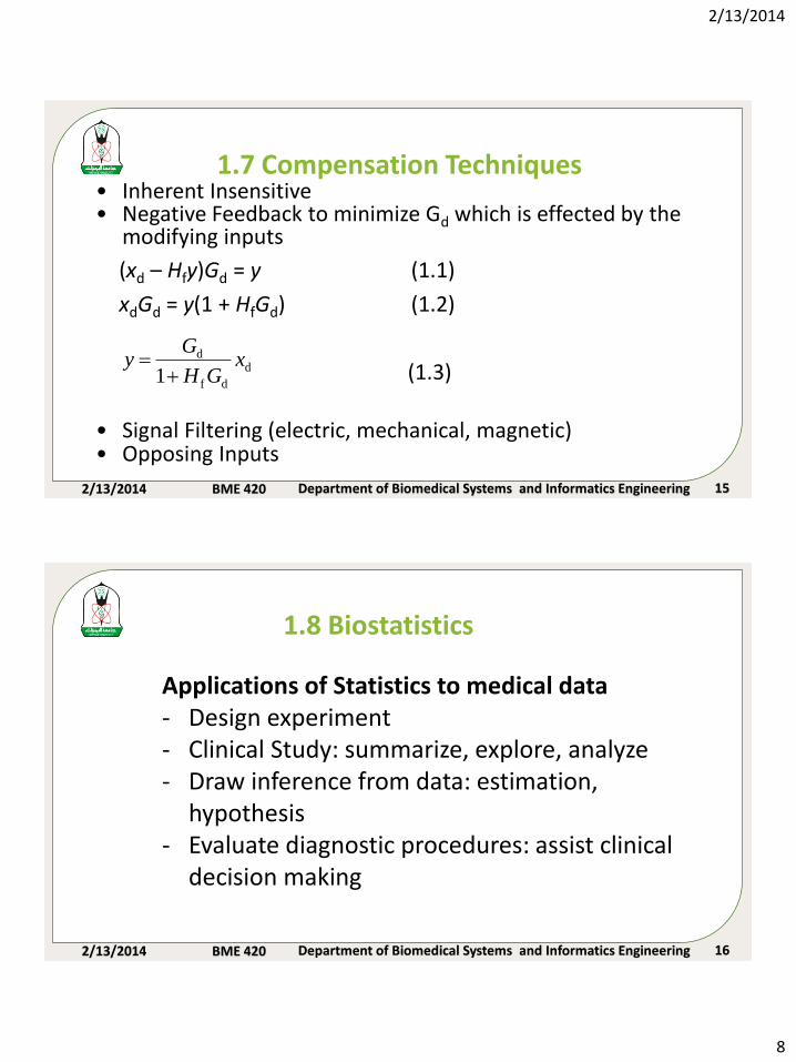
1.7 Compensation Techniques• Inherent Insensitive• Negative Feedback to minimize Gd which is effected by the
modifying inputs
(xd – Hfy)Gd = y (1.1)
xdGd = y(1 + HfGd) (1.2)
(1.3)
• Signal Filtering (electric, mechanical, magnetic)• Opposing Inputs
d
df
d
1x
GH
Gy
2/13/2014 BME 420 Department of Biomedical Systems and Informatics Engineering 16
Applications of Statistics to medical data- Design experiment- Clinical Study: summarize, explore, analyze- Draw inference from data: estimation,
hypothesis- Evaluate diagnostic procedures: assist clinical
decision making
1.8 Biostatistics
2/13/2014
9
2/13/2014 BME 420 Department of Biomedical Systems and Informatics Engineering 17
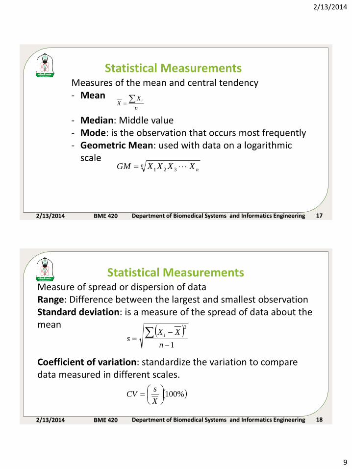
Statistical MeasurementsMeasures of the mean and central tendency- Mean
- Median: Middle value- Mode: is the observation that occurs most frequently- Geometric Mean: used with data on a logarithmic
scale
n
XX
i
nnXXXXGM 321
2/13/2014 BME 420 Department of Biomedical Systems and Informatics Engineering 18
Statistical MeasurementsMeasure of spread or dispersion of dataRange: Difference between the largest and smallest observationStandard deviation: is a measure of the spread of data about the mean
Coefficient of variation: standardize the variation to compare data measured in different scales.
1
2
-
-
n
XXs
i
%100
X
sCV
2/13/2014
10
2/13/2014 BME 420 Department of Biomedical Systems and Informatics Engineering 19
Statistical Measurements
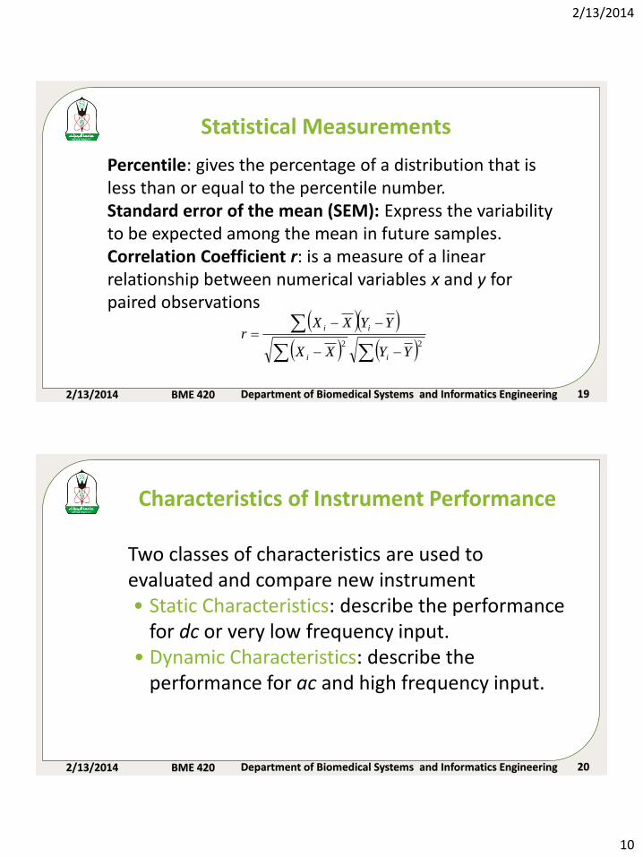
Percentile: gives the percentage of a distribution that is less than or equal to the percentile number.Standard error of the mean (SEM): Express the variability to be expected among the mean in future samples.Correlation Coefficient r: is a measure of a linear relationship between numerical variables x and y for paired observations
--
--
22
YYXX
YYXXr
ii
ii
2/13/2014 BME 420 Department of Biomedical Systems and Informatics Engineering 20
Characteristics of Instrument Performance
Two classes of characteristics are used to evaluated and compare new instrument• Static Characteristics: describe the performance
for dc or very low frequency input.• Dynamic Characteristics: describe the
performance for ac and high frequency input.
2/13/2014
11
2/13/2014 BME 420 Department of Biomedical Systems and Informatics Engineering 21
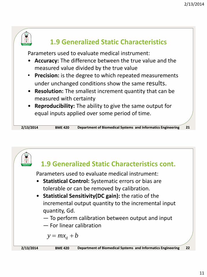
Parameters used to evaluate medical instrument:• Accuracy: The difference between the true value and the
measured value divided by the true value• Precision: is the degree to which repeated measurements
under unchanged conditions show the same results.• Resolution: The smallest increment quantity that can be
measured with certainty• Reproducibility: The ability to give the same output for
equal inputs applied over some period of time.
1.9 Generalized Static Characteristics
2/13/2014 BME 420 Department of Biomedical Systems and Informatics Engineering 22
Parameters used to evaluate medical instrument:• Statistical Control: Systematic errors or bias are
tolerable or can be removed by calibration.• Statistical Sensitivity(DC gain): the ratio of the
incremental output quantity to the incremental input quantity, Gd.— To perform calibration between output and input — For linear calibration
1.9 Generalized Static Characteristics cont.
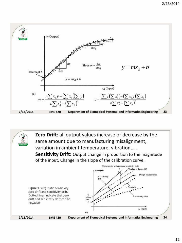
bmxy d
2/13/2014
12
2/13/2014 BME 420 Department of Biomedical Systems and Informatics Engineering 23
-
-
2
d
2
d
dd
xxn
yxyxnm
-
-
2
d
2
d
dd
2
d
xxn
xyxxyb
bmxy d
2/13/2014 BME 420 Department of Biomedical Systems and Informatics Engineering 24
Figure 1.3 (b) Static sensitivity: zero drift and sensitivity drift. Dotted lines indicate that zero drift and sensitivity drift can be negative.
Zero Drift: all output values increase or decrease by the same amount due to manufacturing misalignment, variation in ambient temperature, vibration,…. Sensitivity Drift: Output change in proportion to the magnitude of the input. Change in the slope of the calibration curve.
2/13/2014
13
2/13/2014 BME 420 Department of Biomedical Systems and Informatics Engineering 25
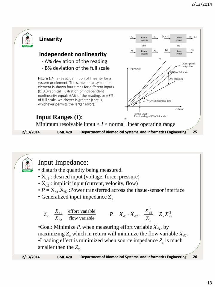
Figure 1.4 (a) Basic definition of linearity for a system or element. The same linear system or element is shown four times for different inputs. (b) A graphical illustration of independent nonlinearity equals A% of the reading, or B% of full scale, whichever is greater (that is, whichever permits the larger error).
xd (Input)
B% of full scale
A% of reading
Overall tolerance band
Least-squares
straight line
(b)
Point at whichA% of reading = B% of full scale
y (Output)
(a)
x1 (x1 + x2)y1
x2 Kx1 Ky1y2Linearsystem
Linearsystem
Linearsystem
Linearsystem
and and
(y1 + y2)Linearity
Independent nonlinearity- A% deviation of the reading- B% deviation of the full scale
Input Ranges (I): Minimum resolvable input < I < normal linear operating range
2/13/2014 BME 420 Department of Biomedical Systems and Informatics Engineering 26
variableflow
iableeffort var
d2
d1 X
XZ x
2
d2
2
d1
d2d1 XZZ
XXXP x
x
Input Impedance:• disturb the quantity being measured.
• Xd1 : desired input (voltage, force, pressure)
• Xd2 : implicit input (current, velocity, flow)
• P = Xd1.Xd2 :Power transferred across the tissue-sensor interface
• Generalized input impedance Zx
•Goal: Minimize P, when measuring effort variable Xd1, by
maximizing Zx which in return will minimize the flow variable Xd2.
•Loading effect is minimized when source impedance Zs is much
smaller then the Zx
2/13/2014
14
2/13/2014 BME 420 Department of Biomedical Systems and Informatics Engineering 27
)()( 0101 txbdt
dxb
dt
xdbtya
dt
dya
dt
yda
m
m
mn
n
n
)()( 0101 txbDbDbtyaDaDa m
m
n
n
01
01
)(
)(
aDaDa
bDbDb
Dx
Dyn
n
m
m
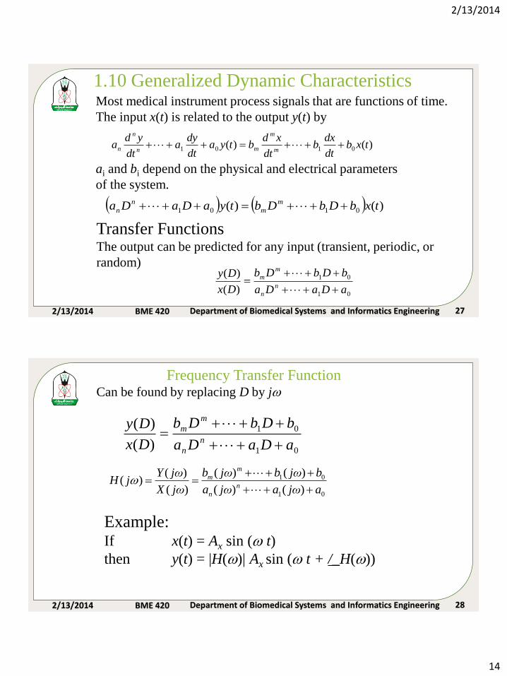
1.10 Generalized Dynamic CharacteristicsMost medical instrument process signals that are functions of time.
The input x(t) is related to the output y(t) by
ai and bi depend on the physical and electrical parameters
of the system.
Transfer FunctionsThe output can be predicted for any input (transient, periodic, or
random)
2/13/2014 BME 420 Department of Biomedical Systems and Informatics Engineering 28
01
01
)(
)(
aDaDa
bDbDb
Dx
Dyn
n
m
m
01
01
)()(
)()(
)(
)()(
ajωajωa
bjωbjωb
jωX
jωYjH
n
n
m
m
Frequency Transfer FunctionCan be found by replacing D by j
Example:If x(t) = Ax sin ( t)
then y(t) = |H()| Ax sin ( t + /_H())
2/13/2014
15
2/13/2014 BME 420 Department of Biomedical Systems and Informatics Engineering 29
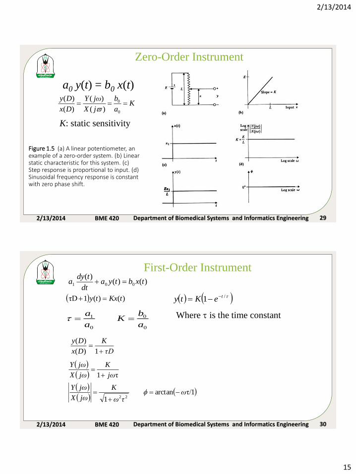
Figure 1.5 (a) A linear potentiometer, an example of a zero-order system. (b) Linear static characteristic for this system. (c) Step response is proportional to input. (d) Sinusoidal frequency response is constant with zero phase shift.
Zero-Order Instrument
a0 y(t) = b0 x(t)
Ka
b
jX
jωY
Dx
Dy
0
0
)(
)(
)(
)(
K: static sensitivity
2/13/2014 BME 420 Department of Biomedical Systems and Informatics Engineering 30
First-Order Instrument)()(
)(001 txbtya
dt
tdya
)()(1τD tKxty
τD
K
Dx
Dy
1)(
)(
1τ/arctan1
τ1
22ω
τω
K
jωX
jωY
jω
K
jωX
jωY
-
0
0
0
1
a
bK
a
a Where is the time constant
/1 teKty --
2/13/2014
16
2/13/2014 BME 420 Department of Biomedical Systems and Informatics Engineering 31
t
1
(c)
(a)
C
+
-
+
-
y(t)
Output y(t)
Input x(t)
Slope = K = 1
(b)
Y (j
X (j
Log
scale
1.0
0.707
Log scale
(d)
0°
- 45°
-90°
Log scale
t
1
0.63
LS
L
S
SL
L
S
x(t)
x(t)
y(t)
R
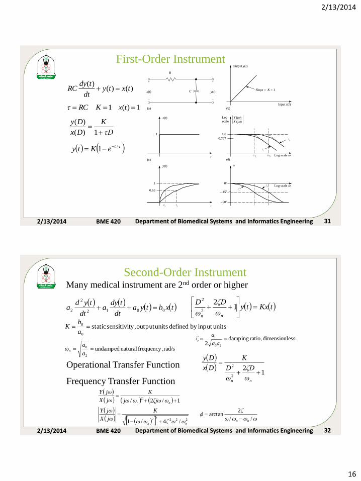
First-Order Instrument
τD
K
Dx
Dy
1)(
)(
/1 teKty --
)()()(
txtydt
tdyRC
1)(1 txKRC
2/13/2014 BME 420 Department of Biomedical Systems and Informatics Engineering 32
Second-Order Instrument
txbtya
dt
tdya
dt
tyda 0012
2
2 tKxtyω
ζD
ω
D
nn
1
22
2
unitsinput by defined unitsoutput y,sensitivit static0
0 a
bK
rad/s frequency, natural undamped 2
0 a
aωn
essdimensionl ratio, damping 2
ζ20
1 aa
a
12
2
2
nnω
ζD
ω
D
K
Dx
DyOperational Transfer Function
ωωωω
ζ
ωωζωω
K
jωX
jωY
ωζjωωjω
K
jωX
jωY
nnnn
nn
//
2arctan
/4/1
1/2/
22222
2
-
-
Frequency Transfer Function
Many medical instrument are 2nd order or higher
2/13/2014
17
2/13/2014 BME 420 Department of Biomedical Systems and Informatics Engineering 33
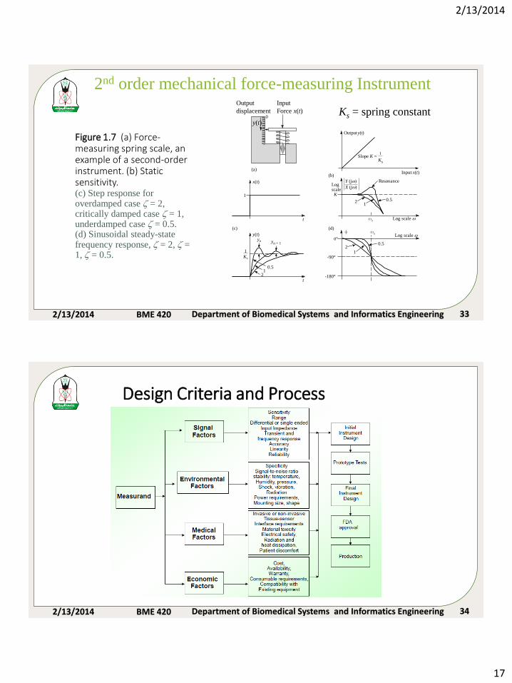
Figure 1.7 (a) Force-measuring spring scale, an example of a second-order instrument. (b) Static sensitivity.(c) Step response for overdamped case = 2, critically damped case = 1, underdamped case = 0.5. (d) Sinusoidal steady-state frequency response, = 2, = 1, = 0.5.
Output y(t)
(b)
(d)(c)
1
Ks
x(t)
y(t)yn yn + 1
Resonance
2
Logscale
1
2
-90°
0.51
2 -180°
1
0.5
0.5
Log scale
Log scale
K1
t
t
Input x(t)
Slope K =1
Ks
0°
n
n
Y (j
X (j
Output
displacement
(a)
Input
Force x(t)0
y(t)
2nd order mechanical force-measuring Instrument
Ks = spring constant
2/13/2014 BME 420 Department of Biomedical Systems and Informatics Engineering 34
Design Criteria and Process

2/13/2014
18
2/13/2014 BME 420 Department of Biomedical Systems and Informatics Engineering 35
Commercial Medical Instrumentation
Development Process
•Prototype development
•Testing on animals or human subjects
•Final design review (test results for, specifications, subject feedback,
cost)
•Production (packaging, manual and documents)
•Technical support