BIO–MEDICAL INSTRUMENTATION - Bharath Institute of ...
239
BIO–MEDICAL INSTRUMENTATION BEE 007 Unit: I ELECTROPHYSIOLOGY 1
-
Upload
khangminh22 -
Category
Documents
-
view
1 -
download
0
Transcript of BIO–MEDICAL INSTRUMENTATION - Bharath Institute of ...

BIO–MEDICAL INSTRUMENTATION
BEE 007
Unit: I
ELECTROPHYSIOLOGY
1

Cell and its structure
CELL: The fundamental unit of every animal or
plant is cells. Combination of cells is called
TISSUES. Every ORGAN in the body is made
up of combination of many tissues.
CELLS: All cells are same and they contain a
gelatinous substance made up of or composed
of water, protein, acids, fats, and various
minerals.
2

CELL MEMBRANE: Cell membrane protects the cell and
surrounds it that passes into and out of the cell.
•
NUCLEUS: The nucleus controls the structure of the cell.
Cell reproduction process is directed by the nucleus
only and which determines the function of the cell and
the structure of the cell.
CHROMOSOMES: These are rod-like structures inside
the cell. Human body cells (other than sex cells, the
egg, and sperm cells) contain 23 pairs of
chromosomes. Sex cells, such as sperm and egg cells
have 23 single chromosomes only. When one egg cell
unites with a sperm cell to for an embryo, then the
embryonic cell has 46 chromosomes i.e. 23
pairs...understand the difference...
3

Chromosomes contains the regions called GENES.
Thousands of genes are in an orderly sequence on each
chromosome. Gene is made up of a chemical substance
called DNA (deoxyribonucleic acid). DNA is an important
compound that regulates the activities of the cell in a
sequential order on each chromosome. The DNA is a series
of codes. When DNA activity carries out of the nucleus to
other parts of the cell, the activities of the cell i.e. cellular
reproduction and the manufacture of proteins are controlled
by DNA.
4

MITOCHONDRIA: It is called power center of the cell.
This is small and sausage-shaped bodies produce energy by
burning food in the presence of oxygen. This process is
called catabolism (cata-down, bol-to cast, -ism-process).
This process makes complex food particles into simpler
substances and energy is released after this action to do the
work of the cell
CYTOPLASM: It means cyto means cell, plasm means
formation. Cytoplasm carries the work of a cell i.e. nerve
cell conducts stimulation, muscle cell contracts. Cytoplasm
contains MITOCHODRIA and ENDOPLASMIC
RETICULUM.
5

ENDOPLASMIC RETICULUM: These like canal-like
structures-this is a network within the cell. These canals
contain a very small structures called RIBOSOMES like a
tunnel system in this proteins are produced for the use of
the cell. This process is called ANABOLISM (ana-up, bol-
to cast, -ism-process). After this process, complex proteins
are made up from the simpler parts of food.
Smaller proteins linked like a chain to become complex
proteins in this process. Both these catabolism and
anabolism in combination is called METABOLISM (meta-
change, bol-to cast, -ism- process) i.e total chemical
activities that occuring in a cell. In this process, the sugars
and fat in the food are used up and burned quickly and so
the ENERGY is released
6

Cell membrane. All cells
have a phospholipid based cell
membrane. The cell
membrane is selectively
permeable in that it allows
some materials to pass into or
out of the cell but not others.
7

Cytoplasm. Cells are filled with a complex collection
of of substances in a water based solution. This
substance is called cytoplasm. Across all cells there are
a number of common features to all cell cytoplasm. For
example all cells have ribosomes. Also, in all cells the
first steps in cellular respiration take place in the
cytoplasm.
8

DNA. All cells contain DNA. In the simplest cells, the
DNA is in one loop more loop like structures free in the
cytoplasm. In some cells such as those making up our
body the DNA is isolated from the cytoplasm in a special
structure called a nucleus. Remember not all cells have a
nucleus!
9

The Nervous System
A physical organ system like any other:
2 main kinds of cells
Neurons
Glia
10

▪ Basic units of the nervous system
▪ Receive, integrate, and transmit
information
▪ Operate through electrical impulses
▪ Communicate with other neurons
through chemical signals
Neurons
11

Glial cells
100 billion neurons
Glial cells
Support neurons (literally, provide physical
support, as well as nutrients)
Cover neurons with myelin
Clean up debris
12

Neurons
Axon of anotherneuron
Cell BodyDendrites
Axon
MyelinSheath
Dendrites of another neuron
13

Synapse
▪ junction between the
axon tip of the
sending neuron and
the dendrite or cell
body of the receiving
neuron.
▪ tiny gap at this
junction is called the
synaptic gap or cleft
14
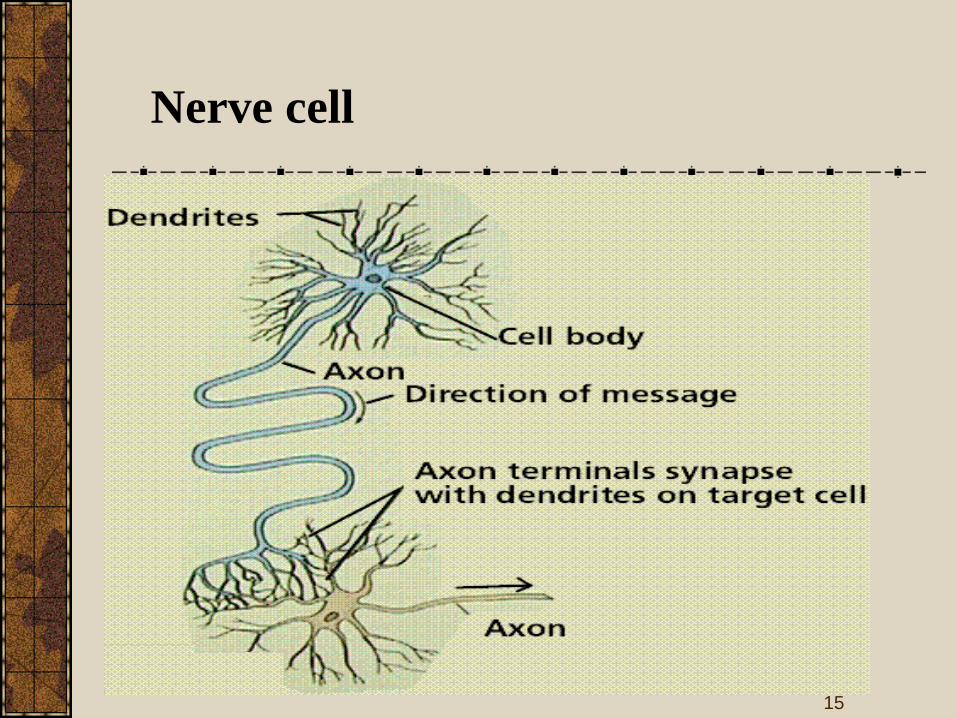
Nerve cell
15

Specific Parts: The Neuron
Function
Neurons = 3 functions: Reception, Conduction, Transmission
1.3.
2.
16

Synapse
17

The synapse is the connection between nerve cells
(neurons) in animals including humans. The synapse
joins the axons in one neuron to the dendrites in
another. Here is a diagram showing how the synapse
connects axons to dendrites:
The synapse consists of:
•The presynaptic terminal at the end of an axon.
This contains tiny vesicles which contain
neurotransmitters - the small molecules which
carry the nerve impulse from the sending neuron to
the receiving neuron.
•The synaptic cleft - a gap between the two
neurons across which the neurotransmitters
migrate.
•The postsynaptic terminal usually in the dendrites
of receiving neurons. This contains receiving sites
for the neurotransmitters.
18

Nerve impulses are transmitted down to the presynaptic
terminal in the axon of one neuron and across the
synaptic cleft to the postsynaptic terminal in the
dendrite of another neuron.
Synapses do not only join axons to dendrites
(axodendritic synapses) - they can also joins axons to
other axons (axoaxonic synapses) or to the soma - the
neuronal cell body - (axosomatic synapses).
19

Relay Race
Action Potential starts at dendrite
Through cell body
Down Axon
Axon Terminals
• How does it get to the next cell’s dendrites?
• Neurons don’t touch
Synapse = millionth inch gap
In synapse = vesicles w/ neurotransmitters
Chemical messengers that transmit info
20
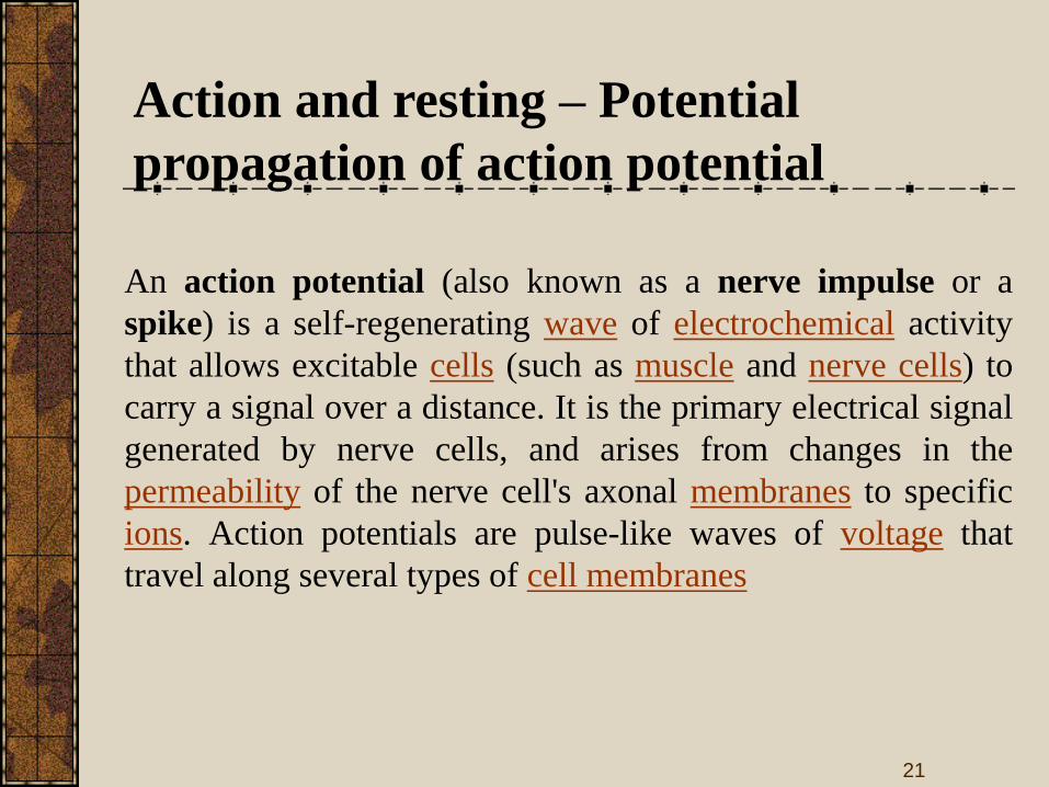
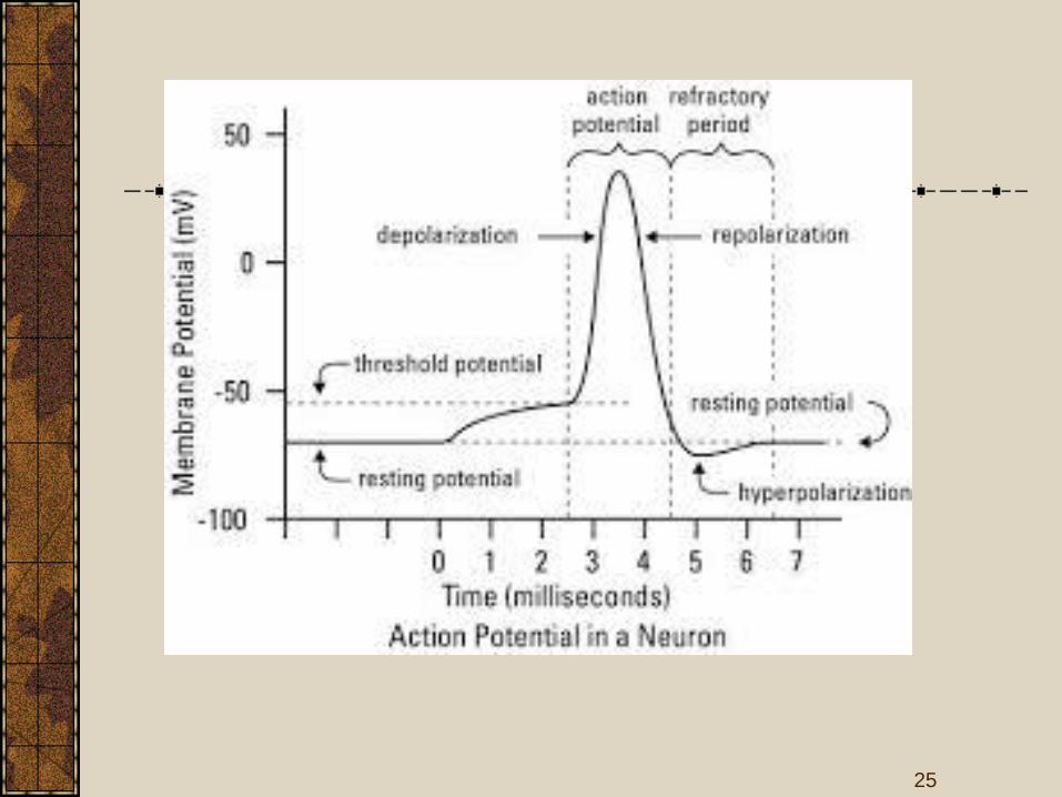
Action and resting – Potential
propagation of action potential
An action potential (also known as a nerve impulse or a
spike) is a self-regenerating wave of electrochemical activity
that allows excitable cells (such as muscle and nerve cells) to
carry a signal over a distance. It is the primary electrical signal
generated by nerve cells, and arises from changes in the
permeability of the nerve cell's axonal membranes to specific
ions. Action potentials are pulse-like waves of voltage that
travel along several types of cell membranes
21

Relatively static membrane potential of quiescent cells is
called resting membrane potential (or resting voltage), as
opposed to the specific dynamic electrochemical
phenomenona called action potential and graded membrane
potential.
22

23

24
25

Sodium pump
26

The process of active transport differs from diffusion in that
molecules are transported away from thermodynamic
equilibrium; hence, energy is required. This energy can come
from the hydrolysis of ATP, from electron movement, or from
light. The maintenance of electrochemical gradients in biologic
systems is so important that it consumes perhaps 30–40% of the
total energy expenditure in a cell. In general, cells maintain a low
intracellular Na+ concentration and a high intracellular K+
concentration, along with a net negative electrical potential
inside. The pump that maintains these gradients is an ATPase that
is activated by Na+ and K+ (Na+-K+ATPase).
27

The ATPase is an integral membrane protein and requires
phospholipids for activity. The ATPase has catalytic centers for
both ATP and Na+ on the cytoplasmic side of the membrane, but
the K+ binding site is located on the extracellular side of the
membrane. Ouabain or digitalis inhibits this ATPase by binding
to the extracellular domain. Inhibition of the ATPase by ouabain
can be antagonized by extracellular K+.
28
The intracellular Na+ concentration is lower than the
extracellular.To equalise the difference, Na+ automatically
flows into the cell via channels in the cell membrane, but it is
continuously pumped out again by means of the sodium-
potassium pump.
It is very important that the pump continuously maintains
the (unequal) intracellular and extracellular Na+ balance
because the flow of Na+ into a nerve cell forms the basis for
the nerve impulses that make it possible for us to move
29

Cardio pulmonary system
30

31

32

Physiology of heart and lungs
33

34

Circulation and respiration
Lower body
Upper body
Left
atrium
Right
atrium
Left
venticle
Right
venticle
Oxygenated
blood
Deoxygenated
blood
Lung
35

•It is the study of the electrical properties of
biological cells and tissues.
•It involves measurements of voltage change or electric
current on a wide variety of scales from single ion
channel proteins to whole organs like the heart.
• In neuroscience, it includes measurements of the
electrical activity of neurons, and particularly action
potential activity.
•Recordings of large-scale electric signals from the
nervous system such as electroencephalography, may also
be referred to as electrophysiological recordings.
ELECTROPHYSIOLOGY
36

Electrophysiology is the science and branch of physiology that
pertains to the flow of ions in biological tissues and, in
particular, to the electrical recording techniques that enable the
measurement of this flow.
Classical electrophysiology techniques involve placing
electrodes into various preparations of biological tissue. The
principal types of electrodes are:
• simple solid conductors, such as discs and needles (singles or
arrays, often insulated except for the tip).
• tracings on printed circuit boards, also insulated except for the
tip.
• hollow tubes filled with an electrolyte, such as glass pipettes
filled with potassium chloride solution or another electrolyte
solution.
37

Many particular electrophysiological readings have
specific names:
Electrocardiography - for the heart
Electroencephalography - for the brain
Electrocorticography - from the cerebral cortex
Electromyography - for the muscles
Electrooculography - for the eyes
Electroretinography - for the retina
Electroantennography - for the olfactory receptors in
arthropods
Audiology - for the auditory system
ELECTROPHYSIOLOGY
38

Cardiopulmonary Systems
39

Primary functions of respiratory system
are to supply oxygen and remove carbon
dioxide from the tissues.
The action of breathing is controlled by a
muscular action causing the volume of
the lung to increase and decrease to effect
a precise and sensitive control of the
tension of carbon dioxide in the arterial
blood.
Respiration rate
40

Cardiopulmonary System
41

Goal of The Cardiovascular SystemTo ensure delivery of oxygenated blood and
nutrients to all the organs and tissues of the
body.
To carry cellular waste products from the
area where they are produced to the kidneys
and liver where they are processed for
excretion by the body.
42

Blood Vessels
Three types of
blood vessels in
body:
~ Arteries: The large
blood vessels that lead
away from the heart.
Their walls are elastic,
and smaller branches
of the arteries are
called arterioles.
43

Blood Vessels
Veins: They take de-
oxygenated blood
back to the heart
and lungs to be re-
oxygenated. They
have thinner walls
than arteries, and
have valves within
their inner walls, to
keep blood moving
in one direction.
44

Blood Vessels
Capillaries:
Are delicate,
microscopic
vessels that are
very thin.
Oxygen and
nutrients can
pass through
them!
45

Blood Circulation
Three types:
Pulmonary
Cardiac
Systemic
46

Cardiac CirculationInferior/Superior Vena Cava
Right Atrium
Right Ventricle
Pulmonary Artery (to lungs)Pulmonary Vein
Left Atrium
Left Ventricle
Aorta (to rest of body)
47

Circulation
De-oxygenated blood flows through the venae cavae
(plural) Superior vena cava and Inferior vena cava
into the right side of the heart, through to pulmonary
artery which divides the blood to each lung.
And the branches keep getting smaller and smaller
until it reaches the lung capillaries. While the blood is
flowing through the lung capillaries, it picks up fresh
oxygen, and heads back to the heart via the
pulmonary veins.
This fresh, oxygen-rich blood goes back to the left
side of the heart where it is pumped out to the rest of
the body through the aorta.
48

Circulation
When blood flows out the aorta, it flows through
arteries to smaller vessels called arterioles and
to smaller vessels called capillaries.
At the capillary level, the fresh oxygen is
exchanged for carbon dioxide along with other
cellular waste products, and the blood begins to
return to the heart via the veins.
49

Circulation and respiration
Lower body
Upper body
Left
atrium
Right
atrium
Left
venticle
Right
venticle
Oxygenated
blood
Deoxygenated
blood
Lung
50

Cardiac AnatomyThe heart is a muscular pump,made up of four chambers:two atria (right and left) andtwo ventricles (right and left)
In between the atria (on top)and the ventricles (on thebottom) are valves.
On the right side of the heartthe valve is called thetricuspid valve.
On the left side of the heartthe valve is called the mitralvalve.
51
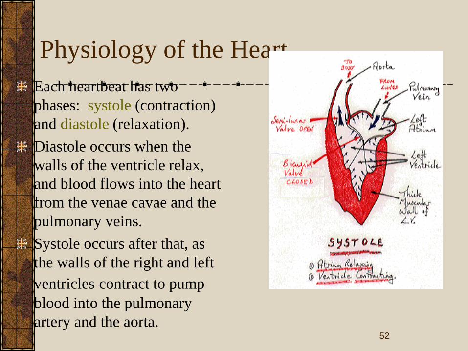
Physiology of the Heart
Each heartbeat has two
phases: systole (contraction)
and diastole (relaxation).
Diastole occurs when the
walls of the ventricle relax,
and blood flows into the heart
from the venae cavae and the
pulmonary veins.
Systole occurs after that, as
the walls of the right and left
ventricles contract to pump
blood into the pulmonary
artery and the aorta.52

Principles related to Cardiac Conduction
Heart muscle has properties that no other
muscle in body has: principle of
automaticity, meaning that heart muscle
actually initiates the impulse for the heart to
beat.
Specialized areas in the heart are
responsible for this beat initiation.
53
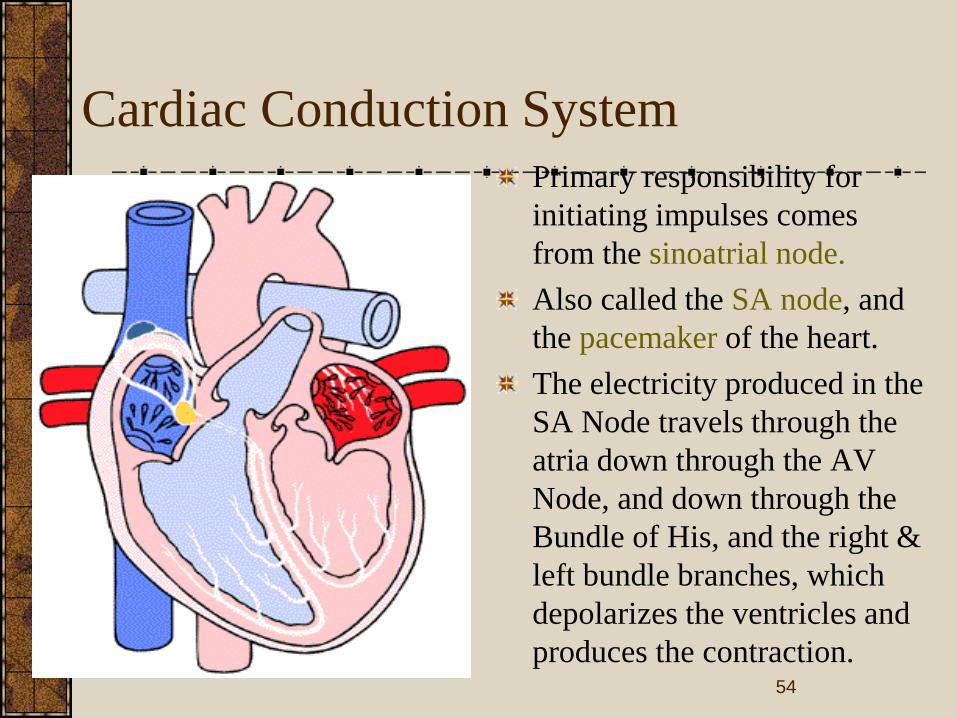
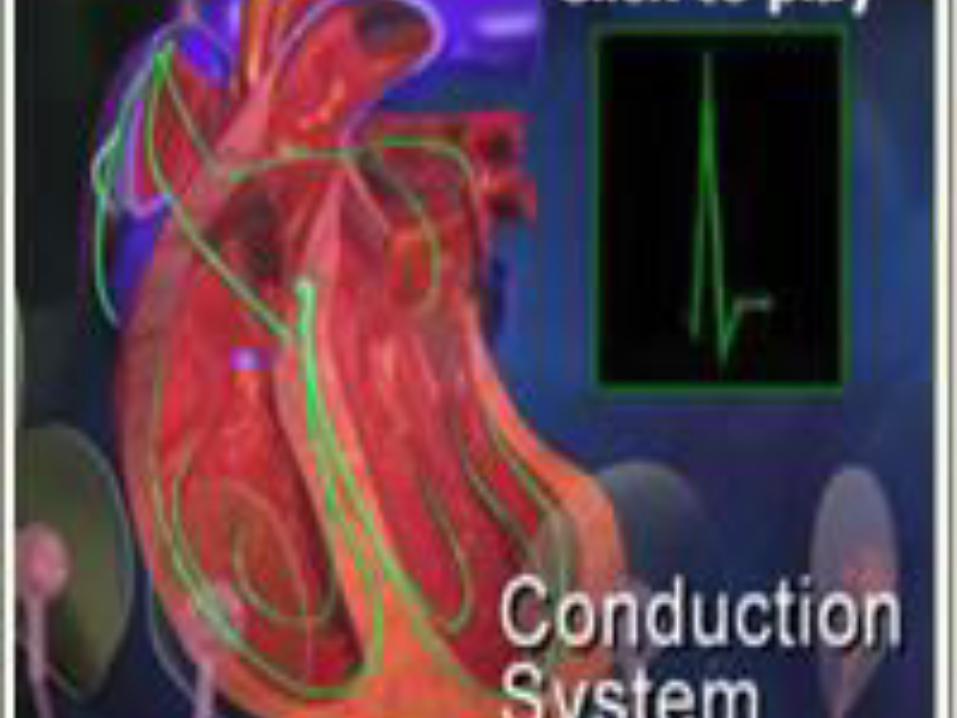
Cardiac Conduction System
Primary responsibility for
initiating impulses comes
from the sinoatrial node.
Also called the SA node, and
the pacemaker of the heart.
The electricity produced in the
SA Node travels through the
atria down through the AV
Node, and down through the
Bundle of His, and the right &
left bundle branches, which
depolarizes the ventricles and
produces the contraction. 54
Cardiac System
The cardiac system is a complex and unique
system. Nearly all changes that occur in the
body affect the cardiac system in some way.
It is a constantly adapting system!
55
Primary functions of respiratory system
are to supply oxygen and remove carbon
dioxide from the tissues.
The action of breathing is controlled by a
muscular action causing the volume of
the lung to increase and decrease to effect
a precise and sensitive control of the
tension of carbon dioxide in the arterial
blood.
Respiration
56

Nervous system
57

Central Nervous System (CNS)
58

The central nervous system (CNS) is the part of the
nervous system that functions to coordinate the activity
of all parts of the bodies of multicellular organisms. In
vertebrates, the central nervous system is enclosed in
the meninges. It contains the majority of the nervous
system and consists of the brain and the spinal cord.
Together with the peripheral nervous system it has a
fundamental role in the control of behavior. The CNS
is contained within the dorsal cavity, with the brain in
the cranial cavity and the spinal cord in the spinal
cavity. The brain is protected by the skull, while the
spinal cord is protected by the vertebrae.
59

Peripheral Nervous System (PNS)
60

The peripheral nervous system (PNS) resides or
extends outside the central nervous system (CNS),
which consists of the brain and spinal cord. The main
function of the PNS is to connect the CNS to the
limbs and organs. Unlike the central nervous system,
the PNS is not protected by bone or by the blood-
brain barrier, leaving it exposed to toxins and
mechanical injuries. The peripheral nervous system
is divided into the somatic nervous system,
autonomic nervous system and the sensory system
61

BIO–MEDICAL INSTRUMENTATION
BEE 007
Unit: II
SENSORS & RECORDERS
1

PHYSIOLOGICAL TRANSDUCERS
Medical science has traditionally contributed to accumulated
knowledge and guarded the health of men undertaking hazardous
missions. Bioastronautic research and operations is a continuation of
that responsibility and requires electronic techniques for crew
selection, evaluation of the biological adequacy of space vehicles, and
monitoring crew members during flight. Determining the optimum
physiological parameters to measure, developing techniques for the
transmission and intelligent analysis of multi-channel data, and
providing reliable transducers have been and still are major tasks.
Transducers for temperature, respiration, cardiac function and
performance measurements have been used for successfully completed
space programs. Thermistors, the electrical impedance pneumograph,
pulse wave velocity, and performance measurement will be
instrumentation techniques and devices of future bioastronautics
research and operations.
2

3

4

5
6

7

8

9

▪
10
11

BIO–MEDICAL INSTRUMENTATION
BEE 007
Unit: III
MODERN IMAGING SYSTEMS
1

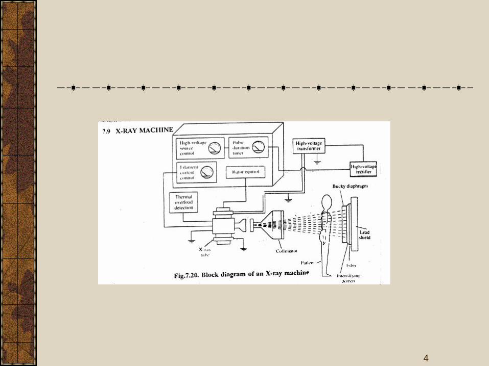
X-RAY MACHINE
2

The basic components of a diagnostic X-ray
machine are power supply arrangement,X-
ray tube aluminium filters,collimator,budey
diaphragm and lead shield.
The various components in the machine are
used to improve the quality of
image,increase the contrast between
different tissues,improve size resolution and
minimize the dose of X-rays used on the
patient. 3
4

A high voltage source is an autotransformer
which is used to get high voltages from 20
to 200kv in the X-ray machine.
To avoid over heating of tube there is a
temperature monitor.
If it exceeds a specified value, the high
voltage supply will be turned off
automatically.
HIGH VOLTAGE SOURCE
5

6

Eventhough X-ray tube requires a high d.c.
voltage, due to practical difficulties a high
d.c. voltage with small a.c. ripples is used.
A much better power output is provided by
three phase rectifiers in
High voltage rectifier
7

8

Skeletal structures
Respiratory organs
Circulatory organ
Digestive organ
Excretory organ
APPLICATIONS
9

10

MAGNETIC RESONANCE
IMAGING(MRI)
11

MAGNETIC RESONANCE
PHENOMENON
MRI makes use of the RF region of the electromagnetic spectra to provide an image.
Started by Felix Block in 1946,who won the Nobel prize for MRI.
Our body consists of millions of atoms of which 80% are hydrogen atoms.
Each H2 atom has a positively charged nucleus with only one proton. It spins and has a nuclear magnetic moment with it.
Normally this spinning of nuclei is random. But in the presence of large magnetic field, its axis of rotation is parallel about the applied
field.
12

MAGNETIC RESONANCE
PHENOMENON
• Radio waves,10,000 to 30,000 times stronger than the earth’s magnetic field are sent from the scanner into the patient’s body.
• The radio waves knock the protons from their position.
• When the burst of radio waves stops, the protons go back into position.
• They realign back to being in parallel with the magnetic field.
• As the protons realign, they emit tiny radio signals. This is called Nuclear
Magnetic Resonance Signal.
• These signals are detected by a receiving device in the scanner.
• The receiving device transmits the signals to a computer. 13

MAGNETIC RESONANCE IMAGING
14

MAGNETIC RESONANCE IMAGING
ADVANTAGES:
Superior contrast resolution
Direct multiplanar imaging, slices in the sagittal, coronal and oblique
directions can be obtained directly.
There is a total absence of harmful radiations like X-rays,gamma rays,
positrons etc. hence making it as a noninvasive imaging technique.
15

MAGNETIC RESONANCE IMAGING
MRI is the representation of the spatial distribution of the NMR signal
intensity and it is placed deliberately non-uniform magnetic field.
The purpose is to place different parts of the specimen with different
field strengths which represent different frequencies to be displayed.
It also provides additional diagnostic insights through relaxation
parameters, which are not possible from other imaging methods.
16

MAGNETIC RELAXATION AND MRI
PARAMETERS
Three principal MRI parameters are
SPIN DENSITY
SPIN-LATTICE(LONGITUDINAL) RELAXATION TIME,T1
SPIN-SPIN OR TRANSVERSE RELAXATION TIME,T2
17

1.SPIN DENSITY
One of the most important aspect of MRI is that the signal is proportional to the number of nuclei present.
In case of imaging,0 it is found that hydrogen is very tightly bound and creates no usable signal. Hence the signal should be arising from mobile hydrogen's, those nuclei which are loosely bound.
Example, is the bone which appears black because there are no protons and hence no detectable signal.
So, the measure of the concentration of mobile hydrogen nuclei available to produce an NMR signal is called Spin Density.
Higher the concentration of mobile hydrogen nuclei, stronger will be NMR signal and thus a better image.
18

T1 and T2 at a field strength of 1 tesla for various
tissues with the relative values of mobile hydrogen
19

2.SPIN-LATTICE(LONGITUDINAL)
RELAXATION TIME
The nuclei are disturbed from equilibrium by a process called Relaxation.
The 90 degree RF pulse rotates the net magnetization Mz with the
corresponding Mxy.
MD is the relaxation time describes the rate at which Mz returns to the
equilibrium and it happens due to the excited nuclei transferring their
energy to the surrounding called spin-lattice.
The recovery of magnetization is given by
Mz(t) = N(H)[1-exp(-t/T1)
20

2.SPIN-LATTICE(LONGITUDINAL)
RELAXATION TIME
N(H) – Hydrogen density.
t – Time elapsed from the start of free induction decay.
The constant repetition time (tr) establishes a steady state
magnetization, and hence shown in the XY plane as
Mxy = N(H)[1-exp(-t/T1)
21

2.SPIN-LATTICE(LONGITUDINAL)
RELAXATION TIME
22

3.SPIN-SPIN OR TRANSVERSE
RELAXATION TIME
T2 represents the time constant associated with the loss of
magnetization Mxy in the XY plane.
There is loss of energy because of interaction of nuclei.T2 is much
shorter and occurs due to inhomogenities in the magnetic field.
The relaxation of peak height of the spin echo at time te to the peak
height is
Mxy(te) = Mxy(0)exp[-t/T2]
The measurements of the relaxation times employs different pulse
sequences. It is the set of instructions to the magnet telling how to
make an image.
23

3.SPIN-SPIN OR TRANSVERSE
RELAXATION TIME
24

IMAGING PROCESS
The NMR signal produced through the use of pulse sequences cannot
be directly translated into an image.
It is necessary to convert from a frequency representation to a location
representation.
A digital computer performs these conversations. In the magnetic field
gradient the NMR signal yields 1-D distribution.
Of the two techniques, Projection Reconstruction Imaging and 2-D
Fourier Transforms imaging, the latter is preferable because of the fast
computational facility.
25

2D-FT METHOD
It samples one line at a time in only one direction of the frequency
representation.
The direction of sampling is determined by the direction of the phase-
encoding gradient while information along the line by the frequency
encoding gradient.
After the sampling of the entire frequency representation by repeated
cycles of the 2D FT process, it is finally converted into an image in the
computer by using the 2D Fourier transforms.
26

MRI SCAN OF THE BRAIN
27

MRI SCAN OF THE SPINAL CORD
28

MRI SCAN OF THE EXTERNAL EAR
29

MRI INSTRUMENTATION
30
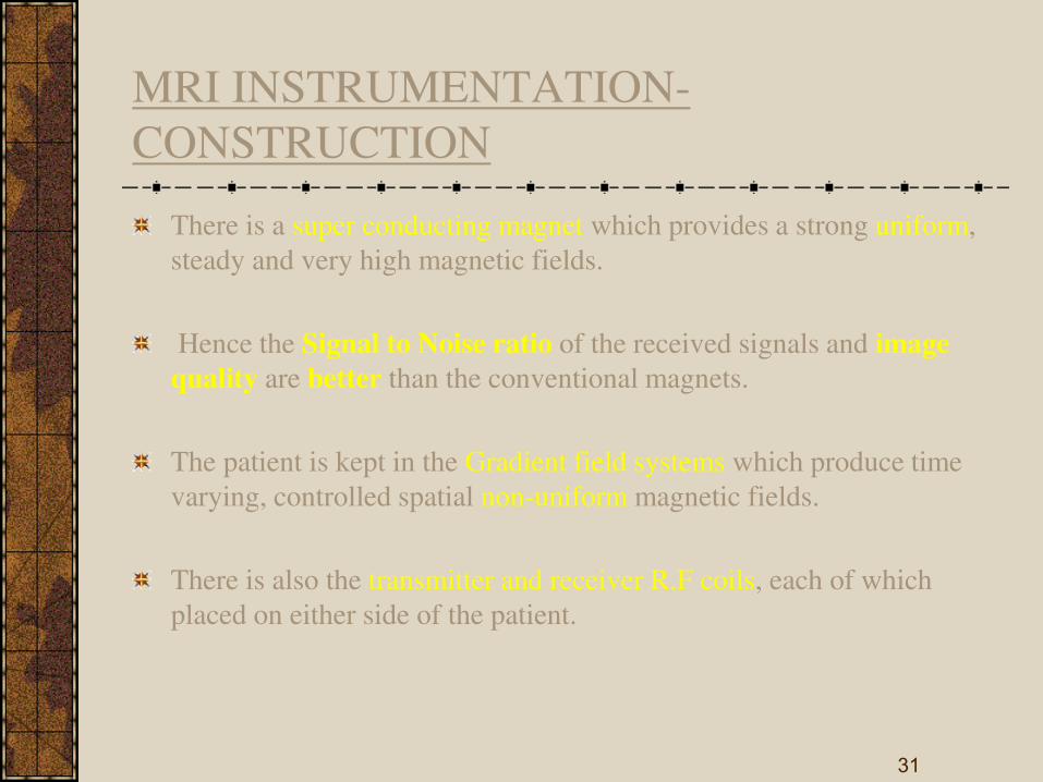
MRI INSTRUMENTATION-
CONSTRUCTION
There is a super conducting magnet which provides a strong uniform,
steady and very high magnetic fields.
Hence the Signal to Noise ratio of the received signals and image
quality are better than the conventional magnets.
The patient is kept in the Gradient field systems which produce time
varying, controlled spatial non-uniform magnetic fields.
There is also the transmitter and receiver R.F coils, each of which
placed on either side of the patient.
31

MRI INSTRUMENTATION - OPERATION
There is a superposition of a linear magnetic field gradient on to the uniform magnetic field applied to the patient.
When this superposition takes place, the resonance frequencies of the moving nuclei will depend primarily on the positions along the direction of the magnetic field gradient.
It produces a 1D projection, by taking a series of projections at different orientations using the X,Y and Z gradient coils 2D or 3D dimensional images can be obtained.
The transmitter produced RF pulses and the NMR signal is picked by receiver for signal processing. By 2D-FT this image is constructed and displayed.
32

RECENT TRENDS
The future of MRI and MRS looks promising in the field of medicine.
Multinuclear applications will be forthcoming with improvements in field strength & sensitivity,3D and 4D extensions.
Combination of the above techniques opens entirely new approaches in wide variety of medical problems.
33

THERMOGRAPHY
34

INTRODUCTION
Process of recording true thermal images of
the surface of objects under study
In medicine,thermography displays images
representing in thermal radiation of skin
area
Important diagnostic aid in many diseases
breast cancers and joint diseases 35

Based on detection of thermal radiation from skin areas, we can classify the thermography into three methods
Infrared thermography
Liquid crystal thermography
Microwave thermography
36

Infrared thermography
37

WORKING
Thermographic equipment is provided with
a special infrared camera that scans the
object and display unit for displaying
thermal picture.
The camera contain system in the of an
oscillating flat panel mirror which scans the
field at very high speed focuses collected
infrared radiation onto the chopper.
38

The chopper disc interrupts the infrared beam so that ac signals are produced and amplified and demodulated further .
The demodulated signals are given to the cathode ray tube in synchronisation with scanning mechanism.
Signals are displayed on the screen by intensity modulation which controls brightness and contrast with the strength of signal.
39

Liquid crystal Thermography Liquid crystal are a class of compounds which
exhibits colour temperature sensitivity in the cholesteric phase.
Scattering effects with the material give rise to iridescent colours.
High temperature sensitivity makes the cholesteric liquid crystals useful for thermal mapping.
Thermal contact between the skin surface and plate produce a colour change in the encapsulted liquid colour.
Red for relative low temperature & violet for high temperature.
40

41

System Features
thermVIEW™ is designed to be an accurate and easy to use temperature measurement system for scientific and engineering applications.
Some of the system’s features include:
Transient and steady state temperature measurement capabilities
Can be used for part (transistor) to board (PCB) level measurements
Spatial resolution to 1 Micron
Temperature accuracy to +/- 0.1oC
A completely optical system based on visible light-- independent of surface
emissivity
Fast response liquid crystal for temperature measurement and data processing
Uses thermCAL™ for precision color-temperature calibration of TLC materials
Flexible and versatile 3D traversing camera support
42

Microwave thermography
Microwave emission from the skin surface the intensity is very small
Modern microwave radiometer one can detect temperature range of 0.1k
Body tissues partially transparent to microwave radiation, temperature radiation originates from tissue volume extending from skin depth to several centimeters.
Microwave radiometer consisting of matched antennae placed in contact with skin surface for use at 1.3 G hz and3.3 G hz used to sense subcutaneous temp.
43

44

Medical application
Tumors
Inflammation
Diseases of peripheral vessels
Burns
Collagen diseases
Orthopedic diseases
Brain & nervous diseases
Harmone diseases
45

ULTRASONIC
DIAGNOSIS
46

47

48

49

50

51

52

53

BIO–MEDICAL INSTRUMENTATION
BEE 007
Unit: 4
DIAGNOSTIC EQUIPMENTS
1

MEASUREMENT OF HEART
SOUNDS
STETHOSCOPE (Chest – Examine) is simply
a device that carries sound energy from the
chest of the patient to the ear of the physician.
Improved ideas made available of amplified
heart sounds – electronic stethoscope has been
developed.
But they are trained with ordinary stethoscope
so they will use ordinary type in general.

Recording Instrument -
Phonocardiography
• Instruments graphically recording heart sounds are more successful, A graphic record of heart sound is called phonocardiogram.
• It uses microphone as transducer – frequency response ranging from below 5 Hz to above 1000 Hz.
• An amplifier in desired range – selective low pass filter – pen recorder and signals are recorded.

• The read out of a phonocardiography is high frequency chart recorder or oscilloscope.
• Pen recorder frequency falls – 100 to 200 Hz.
• Normal heart sounds fall within the range but murmurs have high freq – photographic device are used.
• Multi-channel physiological recording systems – microphone, amplifier and same as used in EMG.
• Even for special diagnosis a digital computer with high speed ADC is required.

Typical spectrum of Heart
Sounds

Some other devices as Vibrocardiograph and
the Apexcardiograph are also used to measure
and uses different types of microphones.

Measurement of respiration rate
Primary functions of respiratory system are
to supply oxygen and remove carbon
dioxide from the tissues.
The action of breathing is controlled by a
muscular action causing the volume of the
lung to increase and decrease to effect a
precise and sensitive control of the tension
of carbon dioxide in the arterial blood.

Methods of measurement of
respiration rate
Displacement Method • Respiratory cycle is accompanied by changes
in the thoracic volume.
• These changes can be sensed by means of a displacement transducer incorporating a strain gauge.
• Transducer held by elasticband – goes around the chest – respiratory movement causes changes in the resistance – wheatstone bridge detects the output.

Thermistor Method
• Air is warmed during its passage through the lungs and the respiratory tract, there is a detectable difference of temperature between inspired and expired air.
• This is sensed by using thermistor -- even thermistor heated initially – match with respiration rate.
• Unconscious patients – tendency blocking breathing system – cannot measured.

Impedance Pneumography • It is an indirect method for measurement of
respiration rate.
• Externally applied electrodes on the thorax, the impedance pneumograph measures the relationship between respiratory depth and thoracic impedance change.
• This method – passing a high frequency current through the appropriately placed electrodes on the surface of the body and detecting modulated signal.

Principle of Impedance
Pneumograph

The signal is modulated by changes in the
body impedance and accompanying the
respiratory cycle.
Electrode used is adhesive type.
To avoid the stimulation of sensory receptors,
nerves and muscles, currents higher in
frequency than 5 KHz must be used for the
measurement of Physiological events by
impedance, frequency less than 5 KHz are
hazardous.

Co2 Method of Respiration rate Measurement
Respiration rate can also be derived by
continuously monitoring the Co2 contained
in the alveolar air.(expired air)
The measurement is based on the absorption
property of infrared rays by certain gases.
Suitable filters are required to determine the
concentration of specific gases like Co2 ,CO
and NO2 constituting the expired air.

How it Works
• When Infrared rays are passed through the expired air containing a certain amount of Co2, some of the radiations are absorbed by it.
• There is a proportional loss of heat energy associated with the rays.
• The detector changes the loss in heating effect of the rays into an electrical signal.
• This signal is used to obtain the average respiration rate.


Working Procedure • Two beams of equal intensity of infrared
radiations – falls on one half of condenser microphone.
• The detector has two identical portions separated by a thin, flexible metal diaphragm.
• Detector is filled with a sample of pure CO2, because absorption of CO2 in the analysis cell, the beam falling on the test side is weaker.
• Diaphragm is pushed towards analysis side and Diaphragm forms one plate of a capacitor, the alternating signal is amplified, shaped and suitably integrated to give the respiration rate.

Apnoea detectors
Apnoea is the cessation of breathing which
may precede the arrest of the heart and
circulation in several clinical situations such
as head injury, drug overdose, anaesthetic
complications and respiratory diseases.
It occurs in premature babies – brain
damage occurs – apnoeic patients need
monitoring of respiratory activity.

• Several contactless methods are available for monitoring the respiration of infants.
• Mattress monitors – breathing redistributes infants weight – pressure sensitive pad or mattress senses and can be measured.
• Capacitance type pressure sensor in the form of a thin square pad is usually placed under or slightly above the infants head.
• Respiratory movement – pressure changes – alters capacitance between the electrode plates and it is measured.

Apnoea monitors

• It consist of an input amplifier circuit, motion and respiration channels, a motion/respiration discrimination circuit, and an alarm circuit.
• Input – from sensor pad to logic circuit.
• The sensor may be a strain gauge transducer.
• output of the amplifier is adjusted to zero volts with offset adjustment provided in the amplifier.
• The amplified signal goes to motion and respiration channels connected in parallel.

The output of the motion & respiration signals
are combined in comparator circuit, and gives
signals to indicate respiration.
Presence of respiration is indicated by a
flashing lamp.
Alarm is also provided.
Other alternating methods of detecting apnoea
is – electromagnetic induction & by using
Microwave energy.

ELECTROENCEPHALOGRAPHY
(EEG)
It deals with the recording and study of electrical activity of the brain.
Electrodes attached to the skull of a patient, the brain waves can be picked up and recorded.
The brain waves are summation of neural depolarizations in the brain due to stimuli from the five senses as well as from the thought process.

Due to propagation through skull bone - 1 to
100micro volt which are picked up by EEG
electrodes.
They are in the frequency range from 0.5 to
3000Hz.
The potentials vary with respect to position of
electrode on the surface of skull.
Electrodes are placed around the frontal,
parietal, temporal and occipital lobes of the
brain.
Origin of EEG EEG potentials originate within the
dendrite potentials of neurons in the brain.
Electric charges are transferred between
them (nerves & Dendrites) -
acetylcholine.
A great number of these potentials are then
summed to produce EEG rhythms.

Action Potentials of the brain
Progressive transient disturbances of the
resting potential along a nerve fiber is used
to transmit information from one end to the
other. – action potential – rapid change of
membrane permeability.
Propagated potential reaches the cell, the
cell fires and thus a spike wave produced.

If the transmitter substance is inhibitory, the
membrane potential of the receptor neuron increases
in a negative direction.
It is likely to discharge, this induced potential change
is called an inhibitory post synaptic potential
(IPSP)
If the transmitter substance is excitatory, the receptor
membrane potential increases in a positive direction,
so that the receptor neuron is more likely to discharge
and produce a spike potential. This induced change is
called an excitatory post synaptic potential (EPSP).

Evoked Potentials
Evoked potentials are the potentials
developed in the brain as the responses to
external stimuli like light, sound etc.,
The external stimuli are detected by the
sense organs which cause changes in the
electrical activity of the brain.
Now – it is called as ‘Event related potential’ – because it relates to an event.

Anatomy of the Brain.
Brain consists of three parts such as cerebrum,
cerebellum and the brain stem.
Cerebrum consists of two hemispheres
separated by a deep fissure.
The hemispheres divided into Frontal lobe,
parietal lobe, occipital lobe and temporal lobe.
The outer layer is called as cerebral cortex
which is the center of intellectual functions.


The frontal lobe is for intelligence.
Upper side of the temporal lobe consists -
hearing center.
Posterior part of occipital lobe - vision center
is situated.
Anterior part of the parietal lobe - sensory
center & Motor center.
Temporal lobes are for the storage process in
the long term memory.

BRAIN WAVES
Electrical recordings from the surface of the brain
demonstrates electrical activity of the brain.
The intensities of the brain waves on the surface
of the scalp range from 0-300micro volt.
Mostly brain waves are irregular and no general
pattern seen in ECG.
If abnormalities occur then pattern changes.
Alpha, Beta, Theta and Delta Waves - EEG


PLACEMENT OF
ELECTRODE
EEG Electrodes Are Placed In Standard
Positions On The Skull In An Arrangement
Called 10-20 System.
Position of electrodes are given by
International Federation of Societies of
EEG.


Position - Electrodes - Placing
Placing electrodes scalp is cleaned and electrode paste is applied between the skin & Electrode.
In Bipolar technique the difference in potential between two adjacent electrodes is measured.
In Monopolar technique potential of each electrode is measured with respect to a reference electrode attached to earlobe or nostrils.


Modern EEG – Recording Setup
8 channel EEG recorder.
Patient cable consists of 21 electrodes and
connected to 8 channel selector.
Ref fig 4.23 – distribution says right ear
electrode act as reference electrode for the
right brain electrodes & Vice Versa..
EEG signals frequency less than 30Hz. So
notch filters are used.


Amplifier is used to increase gain in signals.
Recorder or imaging crt is used to view output
– computer memory to further processing.
Normal paper chart speed is 30 mm/sec &
60mm/sec for higher frequency recording.

Analysis of EEG
EEG – helps physicians to diagnose the
level of consciousness, sleep disorders,
brain death, brain tumors, epilepsy and
multiple sclerosis.
REM – Rapid Eye Movement.
Epilepsy – symptom for brain damage.
{defect in birth or due accident}.


EMG


ERG

Measurement of Volume
The volume of gas flowing into and out of the
lungs is a factor of considerable importance in
investigation of lung function.
Volume of a single breath, or the total volume
expired in a given time can be measured by
continuously acting spirometers.
One method is to integrate the flow rate
electronically and record the resulting signals.

A simplified integrator set up is shown in fig for
flow and volume measurement

• It consists of an ‘autozero’ flowmeter with a threshold detector and an integrator.
• The threshold detector selects portion of flow signal is to be integrated.
• Here both inspiration or expiration can be measured depending upon flow head is connected.
• Tidal volume size of each breath.
• Cumulative volume with staircase waveform.
• High quality amplifiers have to be used if not integrator circuit shows drift and system shows fault readings.

Flow Volume Curve
It is a plot of instantaneous maximum
expiratory flow rate versus volume.
Patients with obstructive airway disease, the
shape of this curve is drastically altered.
Flow volume curve is a good early
indication of abnormality.
Typical MEFV curves are shown in fig.

Flow Volume Curve

Methods of producing the flow volume curve –
common practice is to record it on storage
oscilloscope & then permanent record by
photographing – time consuming & costly.
X-Y recorders are also not fast enough to
follow rapid changes in signals.
Special recorders are designed to meet the
requirements.
Lung abnormalities also detected by flow
volume curve.

A useful indicator of the relative degrees of
inspiratory and expiratory obstruction is the
MEF50% / MIF50% ratio.
Microcomputer is connected with the
instrument for further analysis.

Area of the Flow Volume Curve
Area under the maximum expiratory flow
volume curve is a sensitive indicator of lung
function impairment.
Area under the curve can be computed by
using a square & integrating circuit. In the
derivation of area the following equation is
used A = ∫ F dV.

Nitrogen Washout Technique
It is employed for the indirect determination
of RV, FRC and TLC.
Here the subject breathes 100% oxygen.
A nitrogen analyzer is placed near the
mouth piece to monitor the nitrogen
content.
The analyzer records nitrogen content
which decreases with each successive
expiration since it is progressively replaced
with oxygen.

The alveolar nitrogen concentration eventually
decreases to 1% when steady state is reached.
Nitrogen washout curves are plotted with time
on the X-axis and %N2 in the expired air on the
Y-axis.
A typical complete multi breath nitrogen
washout test would take about 10 minutes with
modern instruments

Single breath nitrogen washout test is another
index of alveolar ventilation in addition to
providing closing volume information.
Test is performed with the subject exhaling to
residual volume, making a maximal inspiration
of 100% oxygen and exhaling his vital
capacity slowly.
%N2 vs Volume during expiration -- fig

Single – breath N2 washout
curve.

Analysis
closing volume gives indication of small
airway disease.
Closing volume changes with age – lung
expands.

BIO–MEDICAL INSTRUMENTATION
BEE 007
Unit: 5
THERAPEUTIC INSTRUMENTS
1

PACEMAKER

Natural pacemaker:
The heart's "natural" pacemaker is called the sinoatrial (SA)
node or sinus node.
Artificial pacemaker:
It is a small, battery-operated device that helps the heart beat in a
regular rhythm. They can replace a defective natural pacemaker
or blocked pathway.

Energy required to excite heart muscle
The heart muscles can be stimulated with an electric
shock.
The min energy required to excite the heart muscle is
10µJ .For better simulation a pulse of 100µJ is applied.
Too high pulse may provoke ventricular fibrillation
(ventricles fail to fill).
The patient looses conscious and die in 10-15 seconds
and brain cells die within few minutes from O2
deficiency at 400µJ pulse.

They have pulse to space ratio 1:10000 and that
should be negatively going pulse to avoid
ionisation.

Temporary or External pacemakers
Internal or permanent pacemakers

Temporary or External pacemakers
Temporary pacemakers are used in emergency settings
or during overdose of medications to restart the normal
rhythm of the heart.
The pacemakers are placed outside the body.
The electrodes used are called ENDOCARDIAC
electrodes.
The battery can be easily replaced and defects in the
circuit can be easily made.

Internal or permanent pacemakers
They are used when the slow heart rate becomes
chronic or is believed to be irreversible.
The electrodes used are called MYCORDIAC
electrodes .ENDOCARDIAC electrodes are also
used.
It requires open heart minor surgery to place the
circuit.
The pacemaker is implanted into the chest or
abdomen, usually on the left side of the chest.


Attached to the generator are one or more leads, or wires,
generally made of platinum with an insulating coating of
either silicone or polyurethane. The leads carry the
electrical impulses from the generator.
At the tip of each lead is a tiny device called an electrode
that delivers the necessary electrical impulses to the heart.
Thus, the electric impulses are created by the generator,
carried by the leads and delivered by the electrodes to the
heart.

Different Modes of Operation
Ventricular asynchronous pacemaker
Ventricular synchronous pacemaker
Ventricular inhibited pacemaker
Atrial synchronous pacemaker
Atrial sequential ventricular inhibited pacemaker

Ventricular asynchronous pacemaker

Ventricular asynchronous pacemaker
The pacemaker can be used in atrium or ventricle.
It uses a simple astable multivibirator.
There may be competition between normal heart beat and
pacemaker beats, this is dangerous.
First blocking oscillator with transformer were used then
transistorized blocking oscillator with a pulse amplifier
were used.
But now a days fixed rate pacemaker is fabricated on a
single large scale integrated circuit.

It consists of a square wave generator and a positive
edge triggered monostable multivibrator.
T= -2RCln[(1-α)/(1+α)]
Where α is the feed back voltage such that
α= [R2/(R1+R2)] according to the figure pulse with period T=.8589secs.
pulse duration TD= [(R3R4)/(R3+R4)]5CC
TD= .437m secs

DISADVANTAGES:
Here the heart rate cannot be increased to match
greater physical effort.
This varies stroke volume of the heart which
cause some loss in cardiac output.

Ventricular synchronous pacemaker
They are preferred for short periods of AV block.
Using sensing electrode heart rate is detected & is given to
timing circuit of pacemaker.
If the heart rate is below a min rate then pacemaker is turned
on.

The lead used to detect the R wave is now used to stimulate the heart.
If natural contraction occurs then asynchronous pacer's timing circuit is reset so that it will tie its next pulse to detect the heart beat else produce pulse at its present rate.
ADVANTAGES:
To arrest the ventricular fibrillation, this circuit an be used.
Power consumption is reduced.
DISADVANTAGES:
Atrial and ventricular contraction are not synchronized.
The circuit is more sensitive to eternal electromagnetic interference .

Ventricular inhibited pacemaker

Ventricular inhibited or demand
pacemaker
This pacemaker also allows the heart to pace at its normal
rhythm when it is able to.
Only if the heart beat falls to min rate the pacemaker turns on
and hence called as DEMAND pacemaker.
The timing circuit consists of an RC network a reference
voltage source and a comparator which detects the basic rate
of the pulse generator.
The output of the timing circuit is fed into the RC network.
The pulse width determines the duration of the pulse
delivered to the heart. The output circuit provides proper
pulse to stimulate the heart.

Atrial synchronous pacemaker

Atrial synchronous pacemaker
It is used for young patients with mostly a stable block.
Used to terminate arterial flutter and paroxymal atrial
tachycardia and act as temporary pacemaker for atrial
fibrillation.
The atria activity is picked up by a sensing electrode.
The detected P wave is amplified and a delay of 0.12sec is
provided by the AV delay circuit.
This signal is used to trigger resetable multivbrator & the
output is given to the amplifier which produces the stimulus
to the heart.

Atrial sequential ventricular inhibited pacemaker
It has the capability of stimulating both the atria and
ventricle and adopts its method of stimulation to patient’s needs.
If atrial fails this pacemaker will stimulate the atrium and
the sense the ventricular beat.
A magnet is placed over the pacemaker on the skin of the
patient order to activate a reed switch ,which switches the
pacemaker to any modes.

Versatile electro diagnostic
M1 is the variable rate multivibrator. The output from it trugger the mono stable multivibrater M2 which sets the pulse width .
The output pulse from m2 provides interrupted galvanic pulse output .
M3 is another astable multivibrator, which produces short duration Faradic currents.
Faradic currents are modulated at the frequency set by multivibrator M1 in a mixer circuit M1.
Since the modulation of Faradic pulses takes place with
A slow rate of increase and decrease, the output of M4 is surged Faradic current.


By integrating the output of M2 the triangular
waveform is optained.
Waveforms can be selected through a selector
switch and fed either to an emitter
follower input.
The output of this unit is kept floating (or)
Isolated from earth.


Peripheral nerve stimulator The pulse generator which determines thepulse
repetition rate – trigger the monotable multivibrator.
The output of the monostable multivibrator drives an
emitter follower and a Transconductance amplifier.
The transformer is used to couple the stimulator
with suitable energy to stimulate the nerve trunk.

Implanted prosthetc stimulator In the case of electronic pacemakers, the pulses are
used to stimulate the ventricules or atria to maintain the normal heart beat in a defective heart.
Similarly there are certain stimulators to stimulate the defective organs in our body to work in a normal manner.
One of the implanted prosthetic stimulator is bladder stimulator which is used to stimulate the bladder muscles to discharge urine.
Similarly there is alsclmplanted prosthetic stimulator, which is implanted in the hand or leg to get the functioning of the finger movements.
These are adopted when the spinal cord’s signal is not propagated to muscle fibers.

Implanted prosthetc stimulator
There is a sensing electrode which picks up
the signal from, spinal cord and it is used to
trigger the pulse generator.
The pulse generator and amplifier in the
simulator develop the stimulating pulse with
suitable energy and shape to stimulate the
particular nerve so as to get the musucular
action.

Implanted prosthetc stimulator
Even if the signal is not obtained form the
spinal cord the pulse generator can
automatically work to initiate the nerve to
do muscular contraction with the required
amount.

External bladder stimulator
When the spinal cord is injured, there may be
immediate disturbance of the bladder function.
So there is incomplete evacuation of the urine in the
bladder.
Progressive renal damage usually results and the
patients often suffer ‘urinary misery’ through the rest of their lives or die of acute urinary sepsis or chronic
renal failure


External bladder stimulator
During that time, the function of the urinary bladder can be possible by electrical stimulation, unfortunaltely the bladder tissue.
Unlike the heart tissue, is not self excitatory.
A single excitation at one point does not propagate spontaneously through the whole structure.

External bladder stimulator
Thus higher power and /or multiple electrodes must be used to achieve a reasonable contraction.
Since most of the patients are not liking the implanted bladder stimulators, the non implantable vaginal plug and anal plug are newly developed as bladder stimulators.
By means of these the complete evacuation of urine in the bladder can be achived in an efficient manner.
External bladder stimulator

External bladder stimulator
Anal plug is used for correcting the urinary
incontinence in men and vaginal plug is used for
correcting the urinary incontinence in women.
Once the plug is inserted, there is an automatic
action of stimulation of the bladder muscles.
If the urine is discharged completely, then the plug
is removed and cleaned and can be kept in the
pocket.

External bladder stimulator
It consists of an astable multivibrator (T1
and T2) and a driver amplifier (T3)
The circuit is closed when it is inserted in
the area to be stimulated
The astable multivibrator is formed by
complementary transistor pair T1 and T2
where T1 and T2 are npn and pnp
transistors respectively.

External bladder stimulator
With these transistors, pulses with
extremely great pause duration ratio car
obtained.
The transistors should have the smallest
possible current thus causing an additional
direct current during pause.
By changing the resistors R4 and R2 it is
possible to adjust or pause durationn.

External bladder stimulator
The anal mucous tissue or vaginal pelvic floor
muscle in contact with the output electrodes gives
a load resistance of 100 ohms to several kilo
ohms with a parrallel capacitance upto 20uF
The circuit is available in the hybrid integrated
circuit form.
The driver amplifier is to get the pulse amplitude
in the favourable manner to get proper stimulation
of the bladder muscles.

External bladder stimulator Some dysfunctions of urinary tract, such as
incontinence, hyperreflexia of the detrusor, urine retention, etc. are successfully treated using this small size, reliable, nonimplantable bladder stimulators.
More difficult cases fo the urges incontinence are treated by acute maximal functional electrical stimulation (AMFES)
Here the frequency of the stimulation is around 20Hz and each pulse lasts 1 ms.
The pulse height is of 6 to 25 v and the current is of 20 to 70 mA


introduction
Ventilator is part of intensive care
Require assistance of breath 4 the patient
It is used to provide oxygen enriched
medicated air to a patient at controlled temp

Origins of ventilation
•Negative-pressure ventilators (“iron lungs”)
•Non-invasive ventilation first used in Boston
Children’s Hospital in 1928
•Used extensively during polio outbreaks in 1940s
– 1950s
•Positive-pressure ventilators
•Invasive ventilation first used at Massachusetts
General Hospital in 1955
•Now the modern standard of mechanical
The era of intensive care medicine began with positive-pressure ventilation
The iron lung created negative pressure in abdomen as well as the chest, decreasing cardiac output.
Iron lung polio ward at Rancho Los Amigos Hospital in 1953.


•Control Mode
• it receives a set number of breaths and cannot breathe between ventilator breaths
•Similar to Pressure Control
•Assist Mode
• it initiates all breaths, but ventilator cycles in at initiation to give a preset tidal volume
• it controls rate but always receives a full
•• pt’s
•
•Rapidly breathing pts can overventilate and induce severe respiratory alkalosis and
Ventilator delivers a fixed volume

Purpose of ventilator
Adequate ventilation:
supply enough oxygen and
right amount of co2 is eliminated
Elimination of respiratory work
Increased intrathoracic pressure :
it prevents
atlases is collapse portion of lung and
counteracts edema of the lung

PRESSURE LIMITED
VENTILATORS
It is based on the principle of insufflation is
terminated when the gaseous mixture
pumped into the patients lungs reaches pre-
set pressure.
It is driven by compressed gaseous mixture
used for ventilation.

VOLUME LIMITED
VENTILATOR
It is based on the principle that for each
breath the constant volume of air is
delivered.
During insufflation a constant volume of air
of air is sent to the lungs by appliying
pressure to a chamber containing of
constant volume.
It don’t give desired ventilation in cases where the pre-set max. pressure cant
completely empty the chamber.

Pressure ventilation vs. volume ventilation
Pressure-cycled modes deliver a fixed pressure at variable volume (neonates)
Volume-cycled modes deliver a fixed volume at variable pressure (adults)
Pressure-cycled modes
•Pressure Support Ventilation (PSV)
oPressure Control Ventilation (PCV)
Volume-cycled modes
Control
•Assist
•Assist/Control
Volume-cycled modes have the inherent risk of volutrauma.

SERVO CONTROLLED
VENTILATORS

This type of ventilators is controlled by feed
back circuits .
The electronic unit controls the amplifiers
and logic circuits which control the
ventilation.
It monitors the pressures ,activate alarms
and compute mechanical lung parameters.

Working
During the inspiration the air compressor draws room air through an air filter and passes it to the main solenoid.
Main solenoid forces the bottom inlet valve of the internal bellows chamber to open and the lower outlet valve to close.
O2 passed into the bellows chamber in a controlled manner by the control valve.
The high pressure in the below chamber compresses the bellows and forces the upper outlet valve open.

Humidifier –to prevent damage to the
patient lungs.
Nebulizer –nebulizer compressor produces
a fine spray of water or medication into the
patient inspired air in the form of aerosols.
Sensitivity controlled monitors
Spiro meter-to measure the volume of
exhaled air

MICROPROCESSOR BASED VENTILATOR

It is used to control the mechanical ventilator
It consist microprocessor with
RAM,EPROM,A/D converter and CRT
controller
The i/p signals to the microprocessor are
obtaind from co2 analyser,a lung machine,gas
analyser
The proper controlling signals are delivered to
the servo ventilator so as to get correct
ventilation with respect to patient metabolism