624eb39d8c545Advisory-on-Water-Meters-Instrumentation ...
69
-
Upload
khangminh22 -
Category
Documents
-
view
0 -
download
0
Transcript of 624eb39d8c545Advisory-on-Water-Meters-Instrumentation ...


Page 1 of 64
FOREWORD
PREFACE
EXECUTIVE SUMMARY
1.0 INTRODUCTION .................................................................................................. 5
2.0 SIZING OF WATER METERS ............................................................................. 6
3.0 CLASSIFICATION OF WATER METERS ............................................................ 6
4.0 DETAILED DESCRIPTION OF METERS AND APPLICATIONS ....................... 10
4.1 Mechanical Meters .......................................................................................... 11
4.1.1 Volumetric Meters ........................................................................................ 11
4.1.1.1 Rotary Piston Meters ............................................................................. 11
4.1.2 Inferential Meters ...................................................................................... 11
4.1.2.1 Single Jet Meters ................................................................................... 12
4.1.2.2 Multijet Meters ....................................................................................... 13
4.1.2.3 Woltman Meter ...................................................................................... 13
4.1.3 Combination Meters .................................................................................. 14
4.2 Electromagnetic Water Meters ........................................................................ 14
4.3 Ultrasonic Water Meters .................................................................................. 16
4.3.1 Transit Time Ultrasonic Flow Meters ........................................................ 16
4.3.2 Doppler Ultrasonic Flowmeters ................................................................. 17
4.3.3 Sensor Based Flow Meter......................................................................... 18
5.0 INSTALLATION & TESTING OF WATER METERS .......................................... 18
5.1 Installation of Water Meters ............................................................................ 18
5.2 Testing and Calibration of Water Meters ......................................................... 20
5.2.1 Procedure for Conducting the Test ........................................................... 22
6.0 REPAIRS, MAINTENANCE & TROUBLESHOOTING OF WATER METERS ... 24
6.1 Introduction ..................................................................................................... 24
6.1.1 Preventive Maintenance ........................................................................... 25
6.1.2 Breakdown Maintenance .......................................................................... 25
6.2 Prevention of Tampering of Water Meters ...................................................... 26
6.3 Trend of Replacement of Water Meters .......................................................... 27

Page 2 of 64
7.0 FLOW METERS ................................................................................................. 28
7.1 Methods for Metering Flow .............................................................................. 28
7.1.1 Accuracy ................................................................................................... 28
7.1.2 Range ....................................................................................................... 29
7.1.3 Rangeability/Turndown Ratio .................................................................... 29
7.1.4 Linearity .................................................................................................... 29
7.1.5 Resolution ................................................................................................. 29
7.1.6 Repeatability ............................................................................................. 29
7.2 Types of Flow Meter ....................................................................................... 29
7.3 Installation & Maintenance of Flow Meters...................................................... 32
7.3.1 Installation of Flow Meters ........................................................................ 32
7.3.2 Maintenance of Flow Meters ..................................................................... 33
7.4 Problems Encountered in Flow Meter Performance ........................................ 37
8.0 ONLINE MEASUREMENT INSTRUMENTATION .............................................. 39
8.1 Level Measurement ........................................................................................ 39
8.1.1 Introduction ............................................................................................... 39
8.1.2 Maintenance of Level Measuring Instruments .......................................... 40
8.2 Pressure Measurement ................................................................................... 41
8.2.1 Calibration of Pressure Measuring Instruments ........................................ 43
8.2.2 Preventive Maintenance ........................................................................... 44
8.2.3 Radar Level Transmitters.......................................................................... 46
8.3 Water Quality Parameter Monitoring ............................................................... 47
8.3.1 Turbidity Meter .......................................................................................... 48
8.3.1.1 Typical Specification for Online Measurement of Turbidity .................... 48
8.3.2 pH Meter ................................................................................................... 49
8.3.2.1 Typical Specification for Online Measurement of pH ............................. 50
8.3.3 Residual Chlorine Meter ........................................................................... 51
8.3.3.1 Typical Specification for Online Measurement of Chlorine..................... 51
9.0 TELEMETRY AND SCADA SYSTEMS .............................................................. 52
9.1 Manual Monitoring .......................................................................................... 52
9.2 Telemetry ........................................................................................................ 52
9.2.1 Data for Collection by Telemetry ............................................................... 53
9.2.2 Processing Data from Telemetry .............................................................. 53

Page 3 of 64
9.3 SCADA Systems ............................................................................................. 53
9.4 Smart Communication..................................................................................... 54
9.4.1 Meter Reading Systems ........................................................................... 54
9.4.2 Automatic Meter Reading (AMR) .............................................................. 55
9.4.3 Remote Register Meters ........................................................................... 57
9.4.4 Advanced Metering Interface (AMI) .......................................................... 58
9.5 Methods of Data Transmission ....................................................................... 59
9.6 Data Collected in SCADA/ Smart Metering System ........................................ 60
9.7 Analysis of Data from SCADA/Smart Metering ............................................... 60
9.8 Limitations of SCADA/Smart Metering/Communication .................................. 60
10.0 CONCLUSION ................................................................................................. 61
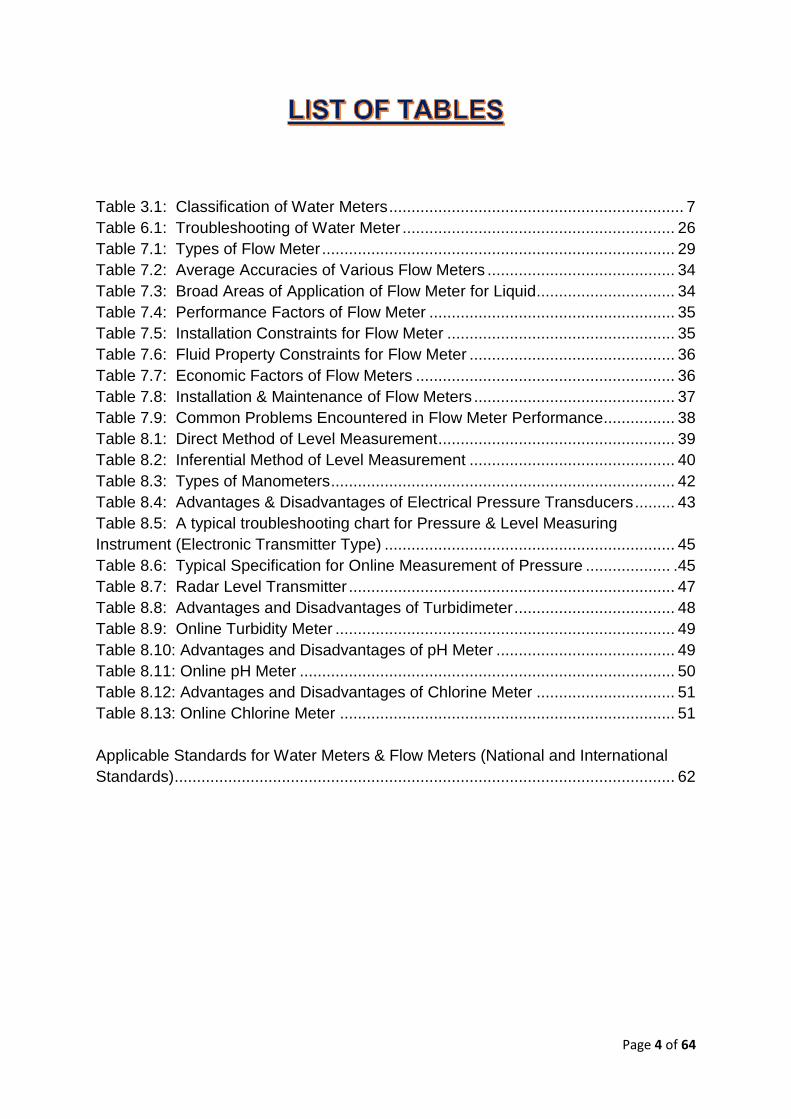
Page 4 of 64
Table 3.1: Classification of Water Meters .................................................................. 7
Table 6.1: Troubleshooting of Water Meter ............................................................. 26
Table 7.1: Types of Flow Meter ............................................................................... 29
Table 7.2: Average Accuracies of Various Flow Meters .......................................... 34
Table 7.3: Broad Areas of Application of Flow Meter for Liquid ............................... 34
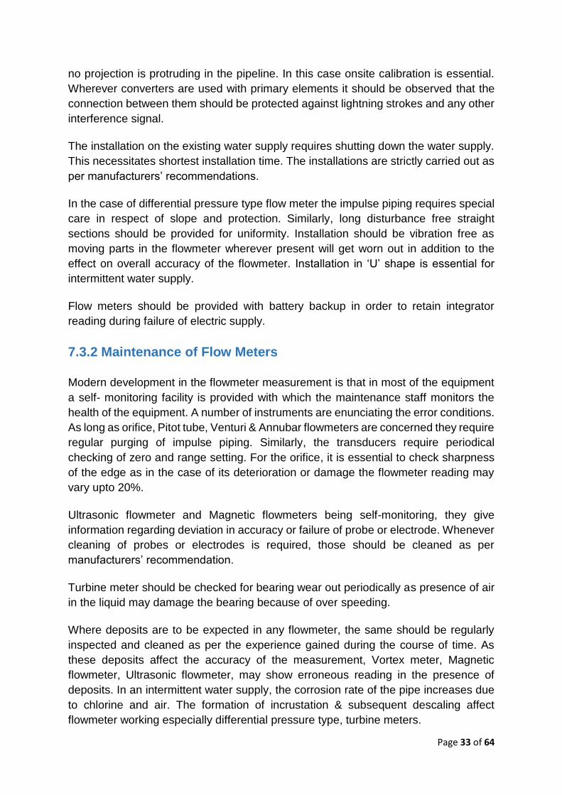
Table 7.4: Performance Factors of Flow Meter ....................................................... 35
Table 7.5: Installation Constraints for Flow Meter ................................................... 35
Table 7.6: Fluid Property Constraints for Flow Meter .............................................. 36
Table 7.7: Economic Factors of Flow Meters .......................................................... 36
Table 7.8: Installation & Maintenance of Flow Meters ............................................. 37
Table 7.9: Common Problems Encountered in Flow Meter Performance................ 38
Table 8.1: Direct Method of Level Measurement ..................................................... 39
Table 8.2: Inferential Method of Level Measurement .............................................. 40
Table 8.3: Types of Manometers ............................................................................. 42
Table 8.4: Advantages & Disadvantages of Electrical Pressure Transducers ......... 43
Table 8.5: A typical troubleshooting chart for Pressure & Level Measuring
Instrument (Electronic Transmitter Type) ................................................................. 45
Table 8.6: Typical Specification for Online Measurement of Pressure ................... .45
Table 8.7: Radar Level Transmitter ......................................................................... 47
Table 8.8: Advantages and Disadvantages of Turbidimeter .................................... 48
Table 8.9: Online Turbidity Meter ............................................................................ 49
Table 8.10: Advantages and Disadvantages of pH Meter ........................................ 49
Table 8.11: Online pH Meter .................................................................................... 50
Table 8.12: Advantages and Disadvantages of Chlorine Meter ............................... 51
Table 8.13: Online Chlorine Meter ........................................................................... 51
Applicable Standards for Water Meters & Flow Meters (National and International
Standards) ................................................................................................................ 62

Page 5 of 64
1.0 INTRODUCTION
A water meter is a scientific instrument for accurate measurement of quantity of water
distributed to the consumer and efficient management of urban water supply. It
provides real-time data on the volume of water being consumed by a consumer
(residential or bulk), thereby encouraging the consumer to use water more efficiently.
Flow meters are the instruments installed for the measurements of the volume of water
consumed or discharged from the source of water like a river or bore well or
dam/reservoir to Water Treatment Plant (WTP) and subsequent to the District
Metering Areas (DMA). Based on the requirement, some of the other features like
pressure, turbidity, and water quality parameters can also be measured by the flow
meter.
Management of water resources in a system is a function of the measurement of
quantity of water at source and its effective usage. They are indispensable for
understanding the quantity of water being distributed in a system and its usage. Flow
meters are used to measure the quantity of water entering into water supply systems,
from different sources such as water works, water treatment plants, or bulk water
suppliers, and water meters are used to measure the quantity of water that is delivered
to each metered consumer in the system.
Therefore, metering fulfils the need to know accurately the water produced and
distributed by clear understanding of water balance. A well-placed metering system in
the water distribution network shall also assist technical staff in identifying the location
where water loss /leakage is observed by comparing the water meter readings at the
point of release of water with the readings at the consumer end. By estimating the
level of water losses in a water supply system, unauthorized/ illegal connections can
also be identified.
The data obtained from an upright metering system also allows water managers to
make a decision matrix on capital investments, maintenance, staffing, and various
other aspects of the water supply systems. Therefore, water metering is an excellent
application of the principle “to measure, is to know”. The knowledge of how much water
is being used in the water distribution system is the key element in controlling the water
loss and revenue loss thereof.
The water tariffs based on the quantity of consumption can be used for increasing the
income of water supply agency, cross-subsidizing needy consumers, and managing
water consumption. However, a tariff policy cannot be implemented without a well-
established metering system. Therefore, it is very essential in water supply system for
installing a metering system in the cities/ULBs.
Water meter and flow meters consist of four basic components: (i) a sensor to detect
Page 6 of 64
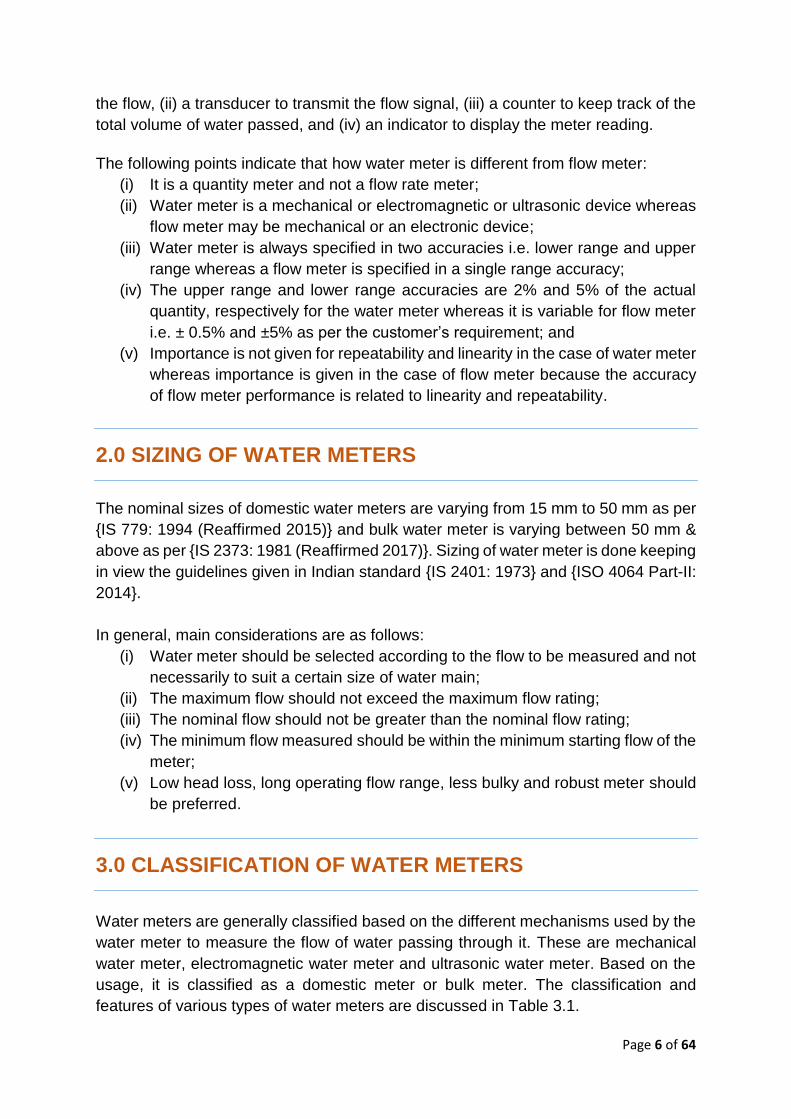
the flow, (ii) a transducer to transmit the flow signal, (iii) a counter to keep track of the
total volume of water passed, and (iv) an indicator to display the meter reading.
The following points indicate that how water meter is different from flow meter:
(i) It is a quantity meter and not a flow rate meter;
(ii) Water meter is a mechanical or electromagnetic or ultrasonic device whereas
flow meter may be mechanical or an electronic device;
(iii) Water meter is always specified in two accuracies i.e. lower range and upper
range whereas a flow meter is specified in a single range accuracy;
(iv) The upper range and lower range accuracies are 2% and 5% of the actual
quantity, respectively for the water meter whereas it is variable for flow meter
i.e. ± 0.5% and ±5% as per the customer’s requirement; and
(v) Importance is not given for repeatability and linearity in the case of water meter
whereas importance is given in the case of flow meter because the accuracy
of flow meter performance is related to linearity and repeatability.
2.0 SIZING OF WATER METERS
The nominal sizes of domestic water meters are varying from 15 mm to 50 mm as per
{IS 779: 1994 (Reaffirmed 2015)} and bulk water meter is varying between 50 mm &
above as per {IS 2373: 1981 (Reaffirmed 2017)}. Sizing of water meter is done keeping
in view the guidelines given in Indian standard {IS 2401: 1973} and {ISO 4064 Part-II:
2014}.
In general, main considerations are as follows:
(i) Water meter should be selected according to the flow to be measured and not
necessarily to suit a certain size of water main;
(ii) The maximum flow should not exceed the maximum flow rating;
(iii) The nominal flow should not be greater than the nominal flow rating;
(iv) The minimum flow measured should be within the minimum starting flow of the
meter;
(v) Low head loss, long operating flow range, less bulky and robust meter should
be preferred.
3.0 CLASSIFICATION OF WATER METERS
Water meters are generally classified based on the different mechanisms used by the
water meter to measure the flow of water passing through it. These are mechanical
water meter, electromagnetic water meter and ultrasonic water meter. Based on the
usage, it is classified as a domestic meter or bulk meter. The classification and
features of various types of water meters are discussed in Table 3.1.

Page 7 of 64
Table 3.1: Classification of Water Meters
S.No. Attributes Mechanical meters Electromagnetic meters Ultrasonic meters
1. Working principle
Paddle Wheel, Turbine or mechanical with moving counter
Electromagnetic induction principle Faraday’s Law measurement
Ultrasonic Measurement principle Time of Flight measurement
2. Build (i) Moving parts are present (ii) Mechanically & Magnetically
coupled meter (iii) Dry/ Wet Dial meter
(i) No moving parts (ii) Sensor in-build (iii) Dry Dial meter
(i) No moving parts. (ii) Sensor in-build (iii) Dry Dial meter (iv) Can be clamped on or inserted
in the pipe
3. Available sizes 15mm – 500mm 15mm - 3000mm 15mm - 4000mm
4. Application Preferred diameter size Domestic meter: 15mm to 40mm Bulk meter (Woltman): 50mm to 500mm
Preferred diameter size: Domestic meter: 15mm to 40mm Bulk meter: 50 mm to 3000 mm
Preferred diameter size: Domestic meter: 15mm to 40mm Bulk meter: 50 mm to 4000 mm
5. IS Code IS 4064 / 2373/ 779 IS 4064 IS 4064
6. Water conductivity & quality of water
Conductivity not necessary but highly critical with suspended impurity as it clogs the moving parts.
Only Conductive Fluids Conductivity not necessary but highly critical with suspended impurity & turbidity as it deposits on the sensor face.
7. Accuracy > 2%+ to 5%+ ± 0.5% or better ~ 0.5% to 2%
8. Field accuracy Practically impossible due to wear & tear of moving parts, chocking of strainer & filter, etc.
Achievable Achievable, but depends on a lot of variable factors and installation. Generally, field accuracy is not as good as other flowmeters
9. Wet calibration Possible Possible Possible if clamped and not possible if its inserted
10. Flow tube available
It has flow meter with the compulsory requirement of inlet filter /strainer
Yes Yes, for clamp-on and since, sensors are installed at the site by making holes in the running pipe in insertion type, no flow tube is available.
11. Installation perfection
Good but precision is based on-site layout and human error.
Good Good, but not so good
12. Field check Not Possible Possible Possible
13. Regular Very high as it regularly chocks with Less Less if clamped on but Regular

Page 8 of 64
S.No. Attributes Mechanical meters Electromagnetic meters Ultrasonic meters
maintenance required.
the suspended solids. cleaning of sensor is essential if inserted
14. Periodic maintenance
Very high as it has a lot of moving parts and wear & tear is a regular issue. We do not come to know wear and tear as no warning available other than the high-pressure drop.
Less & replacement of the sensor is a remote possibility due to its rugged construction. The expected life of the sensor is a minimum of 10 years. Hence the cost of ownership is very less.
Very Less & Very easy without any shutdown in case of clamp on. But insertion requires regular cleaning of the sensor and reduces signal strength due to irreversible deposition. The estimated life of the sensor is only 2-3 years & requires replacement.
15. Replacement / Removal of the sensor
Possible & requires very frequently. Generally, meters & dial requires replacement. The estimated life is only within 1 year.
Difficult / Time consuming & requires shutdown.
Easy and can be done without disturbing the process.
16. IP-68 Sensor availability
Available but a lot of failure due to moving parts.
Yes Yes
17. Wet calibration facility at the manufacturer’s place
Yes Yes Yes
18. Verification of accuracy at site
Not Possible. Possible Possible for clamp on, but insertion type, Wet calibration not possible
19. Lining No lining but has moving parts like a turbine, paddlewheel, etc.
PU lining available. Food grade coating with Drinking water certificate available for clamp on. No lining is required for insertion as it is installed in the running pipes
20. Operating at low velocity
Poor Good Moderate
21. Cost Low initial cost but the high cost of maintenance due to moving parts and more frequent replacements like jamming of rotating wheels, counters, etc.
Cost increases with diameter. Moderate. The sensors are clamped over the outer surface of pipe for diameters from DN500 to DN4000

Page 9 of 64
S.No. Attributes Mechanical meters Electromagnetic meters Ultrasonic meters
22. Advantages (i) Suitable for higher flows (ii) Can sustain hostile flow
conditions (iii) External & internal regulator
facilitates easy calibration (iv) Less Pressure loss (v) Robust construction (vi) Easy Maintenance
(i) Most sensitive 15 mm to 50 mm as per IS 779: 1994 and 15 mm to 100 mm as per ISO 4064
(ii) Less sensitive to flow disturbances and ready for Automatic Meter reading for water SCADA compliant
(iii) Straight reading cyclometer (iv) Do not measure the air in the
pipe (v) No Orientation issue. (vi) Life of meter 10 to 15 yrs.
(i) Most sensitive 15 mm to 50 mm as per IS 779:1994 and 15 mm to 100 mm as per ISO 4064
(ii) Less sensitive to flow disturbances and ready for Automatic Meter reading for water SCADA compliant
(iii) Straight reading cyclometer (iv) Do not measure the air in the
pipe (v) No Orientation issue. (vi) Life of meter 10 to 15 yrs.
23. Disadvantages (i) Less sensitive to low flow (ii) Approach conditioning piping is
required (iii) Not available in metrological
classes in BIS. (iv) Limited to higher flows. (v) Multi pointer meter (Analogue
type) (vi) Bush leak problems (vii) Air escape holes create a problem
during submergence.
(i) Costlier than mechanical meters
(ii) Water must be free from solid dirt particles
(i) Costlier than mechanical meters (ii) Water must be free from solid
dirt particles
24. Representation

Page 10 of 64
4.0 DETAILED DESCRIPTION OF METERS AND APPLICATIONS
Mechanical meters have moving parts that detect the flow, such as a piston or impeller.
They make up the vast majority of meters used in water distribution systems specially
to measure consumption and billing purpose at the domestic level. Electromagnetic
and ultrasonic meters have no moving parts but detect the flow through the meter
using electromagnetic waves and ultrasound waves, respectively. They are mostly for
bulk metering, such as in very large pipes and/or where a high accuracy metering is
required like DMA measurement.
Mechanical water meter like the single jet, multijet, piston type, and electromagnetic
and ultrasonic meters are used for domestic purposes. The preferred diameter size
for domestic metering is 15mm to 40mm. Bulk water meters are used to measure high
water consumption for billing /water audit purposes by bulk consumers like commercial
complexes, industries, etc. Generally, Woltman water meters (mechanical type),
electromagnetic and ultrasonic water meter is used for bulk metering. The preferred
diameter size for bulk metering is 50mm to 150mm. Sub classification of different
meters are as under:
Water Meters
Mechanical
Volumetric
Rotary Piston
Infrential
Radial Vane
Single Jet
Multijet
Helical Vane
Woltman
Combination
Electromagnetic Ultrasonic
Transit Time
Doppler

Page 11 of 64
4.1 Mechanical Meters
Mechanical meters are further classified in three categories i.e. volumetric, inferential,
and combination meters.
4.1.1 Volumetric Meters
Volumetric meters directly measure the volume of flow passing through them. Most
volumetric meters use a rotating disk to measure the flow and are known as rotating
piston meters. For application of volumetric meters, the TDS level in water should be
lower than 200 ppm.
4.1.1.1 Rotary Piston Meters
Rotary piston meters are positive displacement meters that use a rotating cylindrical
piston to measure ‘packets’ of water moving from
the inlet to the outlet of the meter. Positive
displacement meters are popular for their
accuracy, long life, and moderate cost and are
used for most domestic applications. Rotating
piston meters are sensitive to sand and/or other
suspended solids in the water that get clogged
between the piston and chamber wall, thereby
clogged the meter. These meters are also
sensitive to low flows and are particularly suitable for applications where the water flow
rates are low or where frequent on-site leakage occurs.
The main disadvantages of rotating piston meters are:
(i) being sensitive to suspended solids in the water;
(ii) prone to relatively high-pressure losses; and
(iii) bulky and expensive than other meter types
4.1.2 Inferential Meters
Inferential meters do not measure the volume of water passing through them directly
but infer the volumetric flow rate from the velocity of the water.
Two categories of inferential meters commonly used are:
(i) Meters using a radial vane impeller and
(ii) Meters using a helical vane impeller
Radial vane impeller meters are further classified into a single jet and multijet (also
known as multiple jets) meters. Helical vane impeller meters are also called Woltman
Page 12 of 64
meters and use a propeller-like vane to increase the water velocity. Multijet meters are
widely accepted in countries such as Brazil, Malaysia, Indonesia, India, Vietnam, etc.,
where the water supply system is intermittent.
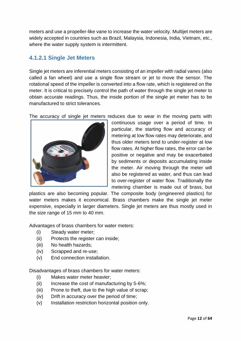
4.1.2.1 Single Jet Meters
Single jet meters are inferential meters consisting of an impeller with radial vanes (also
called a fan wheel) and use a single flow stream or jet to move the sensor. The
rotational speed of the impeller is converted into a flow rate, which is registered on the
meter. It is critical to precisely control the path of water through the single jet meter to
obtain accurate readings. Thus, the inside portion of the single jet meter has to be
manufactured to strict tolerances.
The accuracy of single jet meters reduces due to wear in the moving parts with
continuous usage over a period of time. In
particular, the starting flow and accuracy of
metering at low flow rates may deteriorate, and
thus older meters tend to under-register at low
flow rates. At higher flow rates, the error can be
positive or negative and may be exacerbated
by sediments or deposits accumulating inside
the meter. Air moving through the meter will
also be registered as water, and thus can lead
to over-register of water flow. Traditionally the
metering chamber is made out of brass, but
plastics are also becoming popular. The composite body (engineered plastics) for
water meters makes it economical. Brass chambers make the single jet meter
expensive, especially in larger diameters. Single jet meters are thus mostly used in
the size range of 15 mm to 40 mm.
Advantages of brass chambers for water meters:
(i) Steady water meter;
(ii) Protects the register can inside;
(iii) No health hazards;
(iv) Scrapped and re-use;
(v) End connection installation.
Disadvantages of brass chambers for water meters:
(i) Makes water meter heavier;
(ii) Increase the cost of manufacturing by 5-6%;
(iii) Prone to theft, due to the high value of scrap;
(iv) Drift in accuracy over the period of time;
(v) Installation restriction horizontal position only.

Page 13 of 64
4.1.2.2 Multijet Meters
Multijet meters are inferential water meters that use an impeller with radial vanes. The
operation of multijet meters is similar to that of single jet meters, except that multijet
meters use several jets to drive the impeller at multiple points. This implies that the
forces applied on the impeller are better balanced than in single jet meters, thereby
reducing wear on the moving parts and provides greater durability.
They are similar in construction to that of single jet meters although multijet meters
tend to be slightly larger in overall size. Multijet
meters are fitted with removable strainers on the
inlet side of the meter, to facilitate the cleaning
of the same. A second internal strainer often
covers the openings of the metering chamber.
The internal strainer, if clogged, can affect the
accuracy of the meter, thereby causing over-
registration of the flow.
They normally use an internal bypass with a
regulating screw to adjust the flow passing
through the impeller. This allows the manufacturer to adjust the meter’s error curve to
achieve the best accuracy before sealing the meter to prevent meter tampering.
Multijet meters use reliable and tested metering technology and normally have long
working lives due to the balanced forces on the impeller. They are not sensitive to the
velocity profile in the pipe and are tolerant of small suspended solids in the water.
The disadvantages of multijet meters are:
(i) Sensitivity to the installation position, thereby affecting accuracy;
(ii) Often bulkier than single jet meters;
(iii) Not being sensitive to low flow rates;
(iv) Starting flow rate can deteriorate significantly with time;
(v) Accuracy may be significantly affected by clogs in jet openings if any;
(vi) A brass body prone to theft, due to the high value of scrap;
(vii) Meter life 3-4 years.
4.1.2.3 Woltman Meter
The Woltman meter is an inferential meter that uses an impeller with helical vanes,
which resembles a fan or boat’s propeller. As water flows over the helical vanes, it
causes the impeller to rotate, and the rotation is then transmitted to the dial via
reduction gearing.
Page 14 of 64
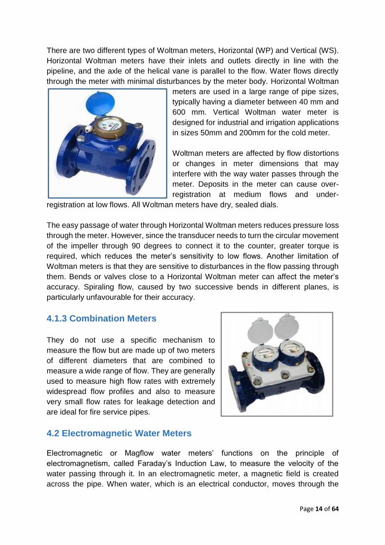
There are two different types of Woltman meters, Horizontal (WP) and Vertical (WS).
Horizontal Woltman meters have their inlets and outlets directly in line with the
pipeline, and the axle of the helical vane is parallel to the flow. Water flows directly
through the meter with minimal disturbances by the meter body. Horizontal Woltman
meters are used in a large range of pipe sizes,
typically having a diameter between 40 mm and
600 mm. Vertical Woltman water meter is
designed for industrial and irrigation applications
in sizes 50mm and 200mm for the cold meter.
Woltman meters are affected by flow distortions
or changes in meter dimensions that may
interfere with the way water passes through the
meter. Deposits in the meter can cause over-
registration at medium flows and under-
registration at low flows. All Woltman meters have dry, sealed dials.
The easy passage of water through Horizontal Woltman meters reduces pressure loss
through the meter. However, since the transducer needs to turn the circular movement
of the impeller through 90 degrees to connect it to the counter, greater torque is
required, which reduces the meter’s sensitivity to low flows. Another limitation of
Woltman meters is that they are sensitive to disturbances in the flow passing through
them. Bends or valves close to a Horizontal Woltman meter can affect the meter’s
accuracy. Spiraling flow, caused by two successive bends in different planes, is
particularly unfavourable for their accuracy.
4.1.3 Combination Meters
They do not use a specific mechanism to
measure the flow but are made up of two meters
of different diameters that are combined to
measure a wide range of flow. They are generally
used to measure high flow rates with extremely
widespread flow profiles and also to measure
very small flow rates for leakage detection and
are ideal for fire service pipes.
4.2 Electromagnetic Water Meters
Electromagnetic or Magflow water meters’ functions on the principle of
electromagnetism, called Faraday’s Induction Law, to measure the velocity of the
water passing through it. In an electromagnetic meter, a magnetic field is created
across the pipe. When water, which is an electrical conductor, moves through the

Page 15 of 64
magnetic field, a voltage is induced which is detected by electrodes in the body of the
meter. The voltage is directly proportional to the flow velocity, which allows the flow
rate to be calculated.
Domestic Electromagnetic meter DN15 to DN40
Bulk Electromagnetic meter DN50 to DN300
The voltage is measured by two electrodes placed at right angles to the magnetic field.
The sensor measurement is transmitted via an electric signal to an electronic counter,
which converts the velocity readings to volume. The flow rate is normally displayed on
an LCD screen, but can also be obtained as an electronic signal to a telemetry system
or flow logger.
Electromagnetic meters are accurate within their measuring range (generally from
0.3m/s to 10m/s) and their accuracies are normally stated as a sum of the percentage
of the reading and percentage of the full-scale value. Most electromagnetic meters are
configured for a fixed flow velocity range, typically from 0.5 m/s to 10 m/s. The meter
is only able to measure flow in the defined velocity range, and thus it is important to
select the correct meter for a given situation. Typical accuracy values range from 0.5%
to 0.1% but decrease at low flow rates.
Advantages of electromagnetic meters are as follows:
(i) No obstruction to flow;
(ii) No pressure loss;
(iii) No moving parts subject to wear, therefore there is hardly any maintenance
(iv) Highly accurate and immune to variations in fluid density, pressure,
viscosity, or temperature;
(v) Measures only water, no air;
(vi) No drift in accuracy over the product life;
(vii) Composite body, not prone to theft;
(viii) Very good low flow; and
(ix) Meter life more than 10 years R800 metrology Class D meters.
The accuracy of electromagnetic meters can however be affected by deposits forming
on the electrodes, air in the liquid, turbulence, and to an extent by, water hammer

Page 16 of 64
(pressure transients). These meters are also susceptible to damage from lightning
strikes if installed outside without canopy. Besides, the electromagnetic meters also
need an electrical connection or batteries to operate.
4.3 Ultrasonic Water Meters
Ultrasonic flow meters utilize the properties and behaviour of sound waves passing
through moving water. The ultrasonic meters are of two types depending on different
working mechanisms viz, Transit time meters and Doppler meters. The ultrasonic
meters are also available as clamp-on and insertion type.
4.3.1 Transit Time Ultrasonic Flow Meters
Transit time ultrasonic flow meters are based on the phenomenon that sound waves
slow down when moving through the water against the flow, and speed up when they
move with the flow. A transit time ultrasonic meter has two sound transducers mounted
at opposite sides of the pipe at an angle to the flow. Each of these sound transducers
will in turn transmit an ultrasound signal to the other transducer. The differences in the
transit times of the signals determine the flow velocity and flow rate.
Domestic Ultrasonic Meter DN15 to DN40
Bulk Ultrasonic Meter DN50 to DN300
The accuracy of the transit time ultrasonic meters depends on the ability of the meter
to accurately measure the time taken by the ultrasound signal to travel between the
sound transducers. Larger pipes have longer path lengths and thus the speed of the
signal, and the flow rate can be measured with higher accuracy. Transit time meters
work better in clean fluids and thus are ideal for drinking water pipes. They measure
the average velocity of fluid but are sensitive to the velocity profile in a pipe. In some
cases, multi-beam devices are used to improve meter accuracy.
Permanently installed transit time meters are often called wetted transducer meters
since their sound transducers are in direct contact with the fluid. These meters are
Page 17 of 64
very reliable and typically have relative errors between 0.25% and 1%. They can be
used on pipes ranging from 10 mm to greater than 2 m in diameter, although they are
not often used on small diameter water pipes. The ideal flow velocity range for good
accuracy is 0.5 to 10 m/s.
Clamp-on transit time meters use sound transducers that are clamped externally onto
the walls of a pipe to provide portable non-intrusive flow measurement. Practically,
they can be used on any pipe material including metals, plastics, fiber, cement and
lined or coated pipes. A disadvantage is that the ultrasonic pulses must traverse pipe
walls and coatings, and therefore the thicknesses and acoustic properties of these
elements must be known. Deposits on the inside pipe surface can affect signal
strength and performance.
Modern clamp-on meters incorporate microprocessors that allow mounting positions
and calibration factors to be calculated for each application and can provide
accuracies of 0.5% to 2%. The advantages of transit time flow meters include high
accuracy and reliability, which makes them cost-effective for use in large pipes. The
clamp-on version of the meter is easy to install without the need to shut down the pipe.
However, transit time flow meters are sensitive to distortions in the velocity profile of
a pipe, require an electricity supply, and are not suitable for dirty waters.
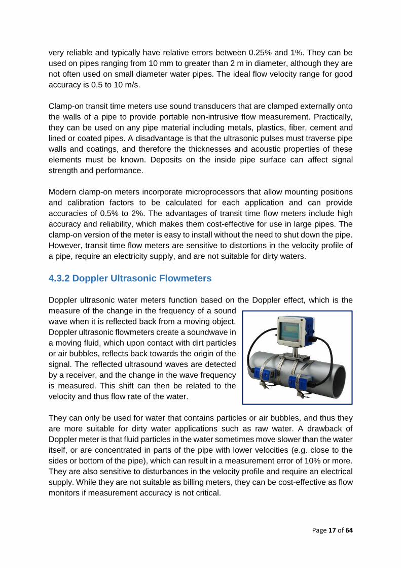
4.3.2 Doppler Ultrasonic Flowmeters
Doppler ultrasonic water meters function based on the Doppler effect, which is the
measure of the change in the frequency of a sound
wave when it is reflected back from a moving object.
Doppler ultrasonic flowmeters create a soundwave in
a moving fluid, which upon contact with dirt particles
or air bubbles, reflects back towards the origin of the
signal. The reflected ultrasound waves are detected
by a receiver, and the change in the wave frequency
is measured. This shift can then be related to the
velocity and thus flow rate of the water.
They can only be used for water that contains particles or air bubbles, and thus they
are more suitable for dirty water applications such as raw water. A drawback of
Doppler meter is that fluid particles in the water sometimes move slower than the water
itself, or are concentrated in parts of the pipe with lower velocities (e.g. close to the
sides or bottom of the pipe), which can result in a measurement error of 10% or more.
They are also sensitive to disturbances in the velocity profile and require an electrical
supply. While they are not suitable as billing meters, they can be cost-effective as flow
monitors if measurement accuracy is not critical.
Page 18 of 64
4.3.3 Sensor Based Flow Meter
Remote flow meter, for use on gravity fed and pressurized piped water systems, is
designed to monitor functionality and performances of water supply networks. The
pipe flow meter utilizes the Ultrasonic flow meter, microprocessor, and a body trace
chip to monitor water usage on piped systems. The sensor has a plastic enclosure
waterproof, anti-explosion, heat and cold resistant and utilizes food-compliant plastic.
After installation on the water pipe, when the water tap is opened, the flow of water
passing through the sensor results in the rotation of the internal turbine. The energy
of the fluid passing through it moves a rotor that have magnets on his blades; the
volume of the water is registered by monitoring the speed of the rotation of the
magnets passing by a metal point. This information is then transformed in digital data
by the microprocessor, and the data sent by the sim card embedded in the sensor.
The sensor transmits hourly flow data that can be uploaded on cloud platforms.
Dashboards have to be designed according to the user needs. This is an advance
technology and may be applied in water supply systems.
5.0 INSTALLATION & TESTING OF WATER METERS
5.1 Installation of Water Meters
In order to ensure proper working of the meters, BIS has given guidelines in IS-
2401:1973 and ISO 4064:2014 Part 5 for their installation as per the drawing given in
it. At the same time following guidelines should be borne in mind while installing the
meters.
(i) The water meter being a delicate instrument shall be handled with great
care. Rough handling including jerks or fall is likely to damage it and affects
its accuracy;
(ii) The meter shall be installed at a spot where it is readily accessible. To avoid
damages and overrun of the meter due to intermittent water supply system,
it is always advisable to install the meter, so that the top of the meter is
below the level of the communication pipes so that meters always contains
water, when there is no supply in the line. Also, the minimum straight length
condition as per the drawing shall be observed;
(iii) The meter shall preferably be housed in a chamber with the lid for
protection; it should never be buried underground nor installed in the open
nor under a water tap so that water may not directly fall on the meter. It
should be installed inside inspection pits, built out of bricks or concrete, and
covered with the lid. It should not be suspended;
(iv) The meter shall be installed so that the longitudinal axis is horizontal and

Page 19 of 64
the flow of water should be in the direction shown by the arrow cast on the
body;
(v) Before connecting the meter to the water pipe, it should be thoroughly
cleaned by installing in the place of the water meter a pipe of suitable length
and diameter and letting the passage of a fair amount of water flow through
the pipework to avoid the formation of air pockets. It is advisable that the
level of the pipeline where the meter is proposed to be installed should be
checked by a spirit level;
(vi) Before fitting the meter to the pipeline check the unions nuts in the tail pieces
and then insert the washers. Thereafter screw the tail pieces on the pipes
and install the meter in between the nuts by screwing. To avoid its rotation
during the operation, the meter should be kept fixed with suitable non-
metallic clamps. Care should be taken that the washer does not obstruct the
inlet and outlet flow of water;
(vii) The protective lid should normally be kept closed and should be opened
only for reading the dial;
(viii) The meter shall not run with free discharge to the atmosphere. Some
resistance should be given in the downside of the meter if static pressure
on the main exceeds 10 m head;
(ix) A meter shall be located where it is not liable to get the severe shock of
water hammer which might break the system of the meter;
(x) Owing to the fine clearance in the working parts of the meters they are not
suitable for measuring water containing sand or similar foreign matter and
in such cases a filter or dirt box of the adequate effective area shall be fitted
on the upstream side of the meter. It should be noted that the normal strainer
fitted inside a meter is not a filter and does not prevent the entry of small
particles, such as sand;
(xi) Where intermittent supply is likely to be encountered the meter may be
provided with a suitable air valve before the meter in order to reduce
inaccuracy and to protect the meter from being damaged. At higher altitude,
if the meter is installed as above, the problem will be eliminated;
(xii) Every user expects a problem-free installation of the meter and thereafter
only accurate reading. Regular monitoring is desirable in order to avoid
failures;
(xiii) The meter is installed in the pipeline using flanged or threaded connections
giving due consideration for conditioning sections. It should be seen that
stress-free installation is carried out in the pipeline;
(xiv) It is essential to install the flowmeter co-axially to the pipeline without
protruding any packing or gasket into the water flow stream. In the case of
ultrasonic meter, the probes are welded on the pipeline which requires care
to see that no projection is protruding in the pipeline;
(xv) Installation in ‘U’ shape is essential for intermittent water supply;
(xvi) Flow meters should be provided with battery backup in order to retain
integrator reading during the failure of electric supply.
Page 20 of 64
5.2 Testing and Calibration of Water Meters
(i) The testing & calibration of a water meter is essential before putting it into
use as it is a statutory requirement. It is also essential to test it periodically
in order to ascertain its performance as during the course of meter working
it is likely that its accuracy of measurement may deteriorate beyond
acceptable limits;
(ii) Full bore bi-directional electromagnetic flow meters shall be designed,
manufactured, and calibrated as per standard ISO/IEC 17025: 2005
(Reaffirmed 2017). Meters shall also have an actual flow rate & totalized
value for effective water management purposes. The accuracy shall be ±
0.5% of reading;
(iii) The supplier shall have full ISO 9000 series accreditation and fully traceable
calibration methods. The suppliers shall also have a testing facility in India
so that methodology and procedures can be verified. Each meter shall be
wet calibrated with 2-point calibration to verify performance in accordance
with the specification & submit the report for the same. The testing facility
shall be duly accredited in accordance with ISO/IEC 17025: 2005
(Reaffirmed 2017) standards. Bidders must upload/attach the certificate of
ISO/IEC 17025 from flow meter manufacturer as a mandatory requirement
of this enquiry/tender which is duly accredited according to ISO/IEC 17025:
2005 (Reaffirmed 2017) facilities in India;
(iv) The sensors shall be as per DVGW / ISO standard lengths (ISO
13359:1998) so that interchangeability can be carried out for the applicable
flow meter sizes. The sensor shall also have built-in grounding and empty
pipe detection electrodes of SS 316 for detecting partial flow conditions &
efficient operation purposes. The liner material shall be Polyurethane (PU)
or Hard Rubber suitable for media/ application/ service. The appropriate
certificate for drinking water approval shall be a part of it and the same shall
be uploaded or attached while bidding as a mandatory requirement of this
tender. The sensor & transmitter shall be capable of working in a tropical
environment. The meter body shall be available in flanged or with custom
connectors as specified in the datasheets;
(v) The sensors shall be rated IP 68. The transmitter shall be rated IP 67 in line
with local operating conditions. Installations shall be made with cables and
/or conduits that guarantee the integrity of the system under all operational
conditions. The transmitter/converter shall be the wall-mounted type with a
2-line display for the indication of an actual flow rate & totalized value. A
glass window within the protection enclosure with optical switches shall be
provided for local reading purposes. The non-corrosive, polycarbonate
housing material of the enclosure shall be sufficient to guarantee five years
of operational life. Magnetic flow meters should be supplied with built-in
software features to analyse and continuously monitor the health of the

Page 21 of 64
sensor, display errors in text format. The transmitter should be capable of
performing the verification program on-demand or on request without taking
meter off the line or without any additional external hardware/accessories;
(vi) The transmitter shall be capable of being fully programmable. It shall have
a set-up menu so that all relevant parameters may be user-set from the self-
prompting driven menu;
(vii) The transmitter shall have three (3) totalizer units and shall have one (1)
scalable pulse output & one (1) current i.e. 4-20mA HART output. The
current output shall be galvanically isolated. It shall be fitted with switched-
mode power supply capability 0-250V or 24 DC and 45-65Hz to cope with
power transients without damage. The totalizer value shall be protected by
EEPROM during a power outage and utilizes an overflow counter;
(viii) The transmitter shall be having the facility of indicating electrical conductivity
measurement. It shall be possible to separate the sensor and transmitters
up to 300 meters without the need for signal boosters or amplifiers;
(ix) The pulsed DC type flow sensors shall normally be installed remotely from
the transmitters and are to be subject to harsh environmental conditions. At
some locations, underground chambers shall be used and in such cases,
the operation under fully submerged conditions may occur. Thus, in either
case, a full IP68 design is necessary. The sensor shall, therefore, be made
from SS 304 materials with flanges of up to PN10 rating from carbon steel
as per EN 1092-1, suitably treated for the application. The sensor coil
housing shall be powder coated cast aluminium with NEMA 4X rating (IP
68) or painted steel. The paint shall be of durable anti-corrosion grade. The
tube liner shall be suitable for media/application/service;
(x) The manufacturer shall have a full system of local offices in India and full-
service capability in the metro-cities throughout the country. Full contact
details for key personnel, both national and local shall be furnished on
request. The supplier shall provide evidence of at least five years of
involvement in the manufacturing of meters worldwide;
(xi) The water flow meter manufacturer /supplier shall provide full data on each
meter required, including optimizing and sizing programs calculation sheet.
The proposed flow meter model number by the manufacturer shall be
available on their official website with a complete technical catalogue or
operating manual for flow meter (sensor /transmitter). The official latest
meter sizing program shall be available on the official website of the flow
meter supplier. The proposed model code shall be available and acceptable
globally;
(xii) A meter suspected to be malfunctioning is also tested for its accuracy of the
measurement. The testing is done as per {IS 6784: 1996 (Reaffirmed 2017)}
/ {ISO 4064-2014 part III}. A faulty meter, if found to be repairable, is
repaired and tested and calibrated for its accuracy before installation.

Page 22 of 64
The metering accuracy testing is carried out at as per {IS 779: 1994 (Reaffirmed 2015)}
Qmin/Q1, Qt/Q2 & Qn/Q3 separately. Where,
Qmin/Q1: Minimum/Lowest flow rate at which the meter is required to indicate within
the maximum permissible error tolerance. It is as mentioned in {IS 779: 1994
(Reaffirmed 2015)} and is determined in terms of the numerical value of meter
designation in the case of {ISO 4064:2014}.
Qt/Q2: The flow rate at which the maximum permissible error of the water meter
changes in value.
Qn/Q3: Half the maximum flow rate Q max/nominal flow rate.
Qmax/Q4: The highest flow rate at which the meter is required to operate in a
satisfactory manner for short periods of time without deterioration.
The accuracy of water meter is divided into two zones i.e. (1) Lower measurable limit
in which ±5% accuracy from minimum flow/Q1 to transitional flow/Q2 (exclusive) and
(2) Upper measurable limit in which ±2% accuracy from transitional flow/Q2 (inclusive)
to maximum flow/Q4.
5.2.1 Procedure for Conducting the Test
Water meter is fixed on a test bench horizontally or vertically or in any other position
for which it is designed and with the direction of flow as indicated by the arrow on its
body. By adjusting the position of regulating valve on the upstream side, the rate of
flow is adjusted. At the desired rate of flow, the difference in pressure gauge readings
fitted on the upstream and downstream side of the water meter is noted. The flow is
now stopped with regulating valve and the measuring chamber is emptied and zero
water levels on the manometer attached to the measuring chamber are correctly
adjusted. The initial reading of the water meter from its recording dial is noted. Now
the flow at the set rate is passed through the water meter and the discharge is collected
in the measuring chamber. After passing the desired quantity of water through the
meter, the flow is once again stopped. The discharge as recorded by the measuring
chamber is noted. The final reading of the water meter is noted. The difference
between the initial and final readings of water meter gives the discharge figure
recorded by the water meter. Now the discharge recorded by measuring tank is
treated as ideal. The discharge recorded by water meter is compared with this ideal
discharge. If the quantity recorded by water meter is more than the ideal, the meter
is called running fast or vice versa. The difference in the quantity recorded by the
meter from the ideal quantity is considered as an error. This error is expressed in
percentage.
If the limits of error for the meter exceed as specified in the IS concerned, the meter
is readjusted by the regulator if it is available in the meter. A change in position of

Page 23 of 64
the regulating screw will displace the error curve (calibration curve) in parallel to
the former position. With the closing of the regulating orifice, the curve will shift
upward while opening the same will lower the curve. If the curve does not get into
an acceptable limit the meter is not used. Some of the organizations are accepting
accuracy limit for repaired water meter double the value of new water meters at
respective zones i.e. for upper zone accuracy is ±4% & for lower zone accuracy is
±10%.
Flow calibration is essential to
(i) Confirm performance of flowmeter
(ii) Quality control
(iii) Comply with statutory or legal requirements
(iv) Provide traceability of measurement and confidence in resultant data.
The calibration is normally carried in the flow laboratory with the help of one of the
following methods.
(i) Gravimetric
(ii) Volumetric
(iii) Prover
(iv) Master or reference meter
(v) Tow tank – current meter calibration
There are two philosophies of flow meter calibration. One is that it is better to have a
fixed calibration system with all the associated technical back up and with the flow
meters being brought to the calibration system, the other favours calibrating in situ
leaving the flow meters in their installed condition and using a portable calibrator. The
former will generally provide the more accurate calibration but the latter has the
advantage that site-specific effects such as proximity to hydraulic disturbances can be
taken into account. It is necessary to decide carefully to adopt the option.
There is often no choice but to carry out in situ calibration where:
(i) Flow cannot be shut off
(ii) Site-specific conditions have to be accounted for
(iii) The meter is so large that removal, transport, and testing costs would be
prohibitive.
The major constraint with the in situ calibration technique is that the high accuracy
laboratory calibration cannot be matched in the field and accuracies of ± 2% to ± 5%
is all that can be achieved and such field tests are called confidence checks rather
than absolute calibrations. Such checks are often the precursor to the removal of flow
meter for laboratory calibration or replacement.
For field tests following methods can be used:
(i) Clamp on devices

Page 24 of 64
(ii) Thermodynamic method
(iii) Velocity area methods (insertion meters)
(iv) Tracer methods
(v) Flow simulators
Normally the manufacturers of the flowmeters provide laboratory calibration of the flow
meters in their works. Some of the Government agencies also provide laboratory
calibration vis. Fluid Control Research Institute (FCRI), Palghat, Central Water &
Power Research Station (CWPRS), Pune and Institute for Design of Electrical
Measuring Instruments (IDEMI), Mumbai.
6.0 REPAIRS, MAINTENANCE & TROUBLESHOOTING OF WATER METERS
6.1 Introduction
The water meters are mechanical devices, which normally deteriorate in performance
over time. The fact that a meter does not show outward signs of any damage and has
a register that appears to be turning does not mean that the meter is performing in a
satisfactory way. It is necessary to ascertain preventive care for water meter after
proper installation.
The flow meter manufacturer /supplier shall provide full data on each meter required,
including optimizing and sizing programs calculation sheet. The proposed flow meter
model number by the manufacturer shall be available on their official website with a
complete technical catalogue/operating manual for flow meter (sensor /transmitter).
The official latest meter sizing program shall be available on the official website of the
flow meter supplier. The proposed model code shall be available and acceptable
globally.
The orifice, Pitot tube, Venturi & Annubar flowmeters require regular purging of
impulse piping. Similarly, the transducers require periodical checking of zero and
range setting. For the orifice, it is essential to check the sharpness of the edge as in
the case of its deterioration or damage the flowmeter reading may vary up to 20%.
The Ultrasonic and Electromagnetic water meters’ accuracy performance is assured
for the life of the product. They are generally self-monitored and give information
regarding deviation in accuracy or failure of probe or electrode. Whenever cleaning of
probes or electrodes is required, those should be cleaned as per manufacturers’
recommendations.
Page 25 of 64
Turbine meter should be checked for bearing wear out periodically as the presence of
air in the liquid may damage the bearing because of over-speeding.
Where deposits are to be expected in any flowmeter, the same should be regularly
inspected and cleaned as per the experience gained during the course of time. As
these deposits affect the accuracy of the measurement, Vortex meter, Magnetic
flowmeter, Ultrasonic flowmeter, may show erroneous reading in the presence of
deposits. In an intermittent water supply, the corrosion rate of the pipe increases due
to chlorine and air. The formation of incrustation & subsequent descaling effect
flowmeter working especially differential pressure type, turbine meters.
6.1.1 Preventive Maintenance
(i) Proper handling, storage, and transportation of water meters
(ii) To clean the dirt box or strainer wherever installed
(iii) To replace the gaskets, if any
(iv) To clean the chamber in which the meter is installed and keep free from
flooding, & seepage
(v) To remove the meter for further internal repair/replacement if it does not
show the correct reading pattern
6.1.2 Breakdown Maintenance
The only basic breakdowns observed during the periodical inspection are replacement
of broken glass, lid, and fallen wiper wherever provided. If a meter found not working,
then it shall be removed immediately and sent to the meter service workshop. In meter
workshops normally following steps are performed to carry out the repairs.
(i) Disassembling of water meters including strainer, measuring unit, regulator,
registering the device, etc;
(ii) Clean all disassembled spare parts in detergent solution in warm water;
(iii) Inspect the cleaned parts and replace worn parts and gaskets, if any;
(iv) Inspect the meter body spur threads and cover threads;
(v) Inspect the sealing surface on the meter body and paint the meter body, if
necessary;
(vi) Inspect the vane wheel shaft pinion, bearing & pivot;
(vii) Inspect the vane wheel chamber;
(viii) Reassemble the water meter properly after reconditioning;
(ix) Calibrate & test the repaired water meter for leakage & accuracy as per IS
6784: 1996 (Reaffirmed 2017);
(x) Make entry in the life register of that water meter for keeping history records.
Page 26 of 64
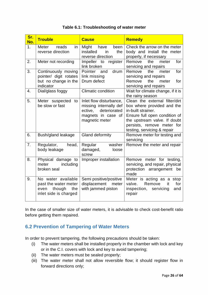
Table 6.1: Troubleshooting of water meter
Sr. No.
Trouble Cause Remedy
1. Meter reads in reverse direction
Might have been installed in the reverse direction
Check the arrow on the meter body and install the meter properly, if necessary
2. Meter not recording Impeller to register link broken
Remove the meter for servicing and repairs
3. Continuously moving pointer/ digit rotates but no change in the indicator
Pointer and drum link missing Drum defect
Remove the meter for servicing and repairs Remove the meter for servicing and repairs
4. Dial/glass foggy Climatic condition Wait for climate change, if it is the rainy season
5. Meter suspected to be slow or fast
Inlet flow disturbance, missing internally defective, deteriorated magnets in case of magnetic meter
Clean the external filter/dirt box where provided and the in-built strainer. Ensure full open condition of the upstream valve. If doubt persists, remove meter for testing, servicing & repair
6. Bush/gland leakage Gland deformity Remove meter for testing and servicing
7. Regulator, head, body leakage
Regular washer damaged, loose screw
Remove the meter and repair
8. Physical damage to meter including broken seal
Improper installation Remove meter for testing, servicing, and repair, physical protection arrangement be made
9. No water available past the water meter even though the inlet side is charged
Semi positive/positive displacement meter with jammed piston
Meter is acting as a stop valve. Remove it for inspection, servicing and repair
In the case of smaller size of water meters, it is advisable to check cost-benefit ratio
before getting them repaired.
6.2 Prevention of Tampering of Water Meters
In order to prevent tampering, the following precautions should be taken:
(i) The water meters shall be installed properly in the chamber with lock and key
or in the C.I. covers with lock and key to avoid tampering;
(ii) The water meters must be sealed properly;
(iii) The water meter shall not allow reversible flow; it should register flow in
forward directions only;
Page 27 of 64
(iv) The water meter dials should be easily readable without confusions;
(v) The lid, glass of water meters must be made up of tough materials as per IS
779: 1994 (Reaffirmed 2015) and shall be replaced timely;
(vi) The wiper or dial as far as possible is avoided;
(vii) In the case of magnetically coupled meters, the proper material to shield
magnets must be provided to avoid the tampering of such meter by outside
magnets in the vicinity of the meter;
(viii) Periodical inspection/checking at the site is essential to ensure the proper
working of the meter;
(ix) Special sealing arrangements may be necessary and provided for bulk meters
whereby unauthorized removal of the meter from the connection can be
detected.
Inspite of the above, to tackle the problems of tampering suitable penalty
provisions/clauses shall be there in the rules or the water supply agreement with the
consumer. This will also discourage the consumer tendencies of neglecting water
meter safety.
6.3 Trend of Replacement of Water Meters
At present, there is no specific Indian certification process of validating the accuracy
of water meters or flow meter. In general, if a water meter goes out of order due to any
physical damage or non-operation of the registration device and is beyond economical
repair, it should be replaced with immediate effect. In the Indian context, the
performance of water meter or flow meter depends upon:
(i) The quality of water meter produced by the manufacturer and it differs from
manufacturer to manufacturer;
(ii) The design of pipeline & fittings in line with the meter;
(iii) The workmanship & care when handling and installing the meter;
(iv) The pattern of water passing through the meter;
(v) The type of supply of water whether it is continuous or intermittent;
(vi) The meter maintenance, testing;
(vii) The proper selection of meter; and
(viii) Installation procedure as per {ISO 4064:2014 Part 5} to be followed
The performance of a water meter is required to be watched continuously with suitable
history sheets. Any abnormality noticed needs immediate action. Timely removed
faulty meter, & especially mechanical type meter, prevents cascade and cumulative
damages.
Looking at the number of transactions involved, bulk meters shall be given priority in
replacements. Based on the experience gained for a specification work, a well-planned
programme for periodical meter testing, servicing, repairs and replacement wherever
necessary shall be designed.

Page 28 of 64
7.0 FLOW METERS
The flow meter is the device used for the measurement of liquids in closed conduits.
This device differs on the type of liquid conductive or non-conductive, and also have
the other related aspects of the principle of operation. In water supply, mechanical,
electromagnetic, or ultrasonic types of flowmeters are used. However, those are
segregated depending on various points i.e., working principle, conductivity of liquid
and its quality, the basic and overall accuracy of the flowmeter, calibration possibility,
field or online, etc. The supply and delivery manufacturer should have ISO quality
standard (IS 9001:2015) certification and flow meter testing confirming to ISO 17025:
2005 (Reaffirmed 2017). There are installation standards that need to be adopted for
different flow meters.
Electromagnetic
flow meter
Ultrasonic Insertion
flow meter
Ultrasonic Clamp-on
flow meter
7.1 Methods for Metering Flow
Various methods are available for the metering flow rate and total flow. Each method
has its own specific characteristics, which are directed towards individual installation
requirements. In the water industry flow rate meter is termed as the flow meter and the
total flow meter is termed as the water meter. A wide range of standard terms is used
to describe the essential performance characteristics of instruments and sensors.
Some of these terms are as follows.
7.1.1 Accuracy
It is defined as the difference between the reading of an instrument and the true value
of the measured variable expressed as a percentage of either full scale or true value
of the measured variable i.e. either in terms of full scale or flow rate of the flow meter.
As far as possible the accuracy should be selected in terms of percentage of flow rate
as it remains constant within the rangeability irrespective of variation in flow rate.

Page 29 of 64
7.1.2 Range
The difference between the maximum and minimum values of the physical output over
which an instrument is designed to operate normally.
7.1.3 Rangeability/Turndown Ratio
Describes the relationship between the range and the minimum quantity that can be
measured.
7.1.4 Linearity
The degree to which the calibration curve of a device matches a straight line.
7.1.5 Resolution
The error associated with the ability to resolve the output signal to the smallest
measurable unit.
7.1.6 Repeatability
The quantity which characterizes the ability of a measuring instrument to give identical
indications or responses for repeated applications of the same value of the quantity
measured under stated conditions of use.
7.2 Types of Flow Meter
In water works, normally, the following types of flow meters are used. These are
classified with their advantages and disadvantages are described in the following
sections:
Table 7.1: Types of Flow Meters
Sr. No.
Types of Flow Meter
Advantages Disadvantages
A Differential Pressure/Head Flow Meter
1. Orifice Flow Meter
i. It can be used for all fluids except for some exceptions
ii. No moving parts iii. Flow rate, indication, integration is
easily obtained iv. It can be fitted in any configuration
of the pipeline v. Suitable for any pipe diameter vi. The signal can be transmitted to
long distance vii. Good accuracy
i. Rangeability 4: 1 ii. Energy cost in terms of
head loss iii. Ideal conditions are
required for good accuracy
iv. Suitable for a particular range of Reynolds number
v. Accuracy in terms of span

Page 30 of 64
Sr. No.
Types of Flow Meter
Advantages Disadvantages
viii. Suitable for extreme temperature and pressure
ix. Calculation possibilities for unusual situations
vi. Minimum slope for tapping piping has to be maintained i.e. 1:10
vii. Very long conditioning section required
viii. Intensive maintenance required
ix. Edge sharpness of the orifice must be assured.
x. It requires isolation of pipeline during installation
2. Venturi Meter
Advantages are similar to orifice flow meter, and less pressure loss and hence less energy cost.
Advantages are similar to Orifice flow meter metined at Sr. No. i, iii, iv, v, vi & x in addition to the high capital cost.
3. Pitot Tube i. As mentioned under orifice flow meter except at Sr. No. vii.
ii. It does not require isolation of pipeline for installation and comparatively capital cost of the flow meter is less.
iii. Head loss is also less.
As mentioned under orifice flow meter at Sr. No. i, iii, v, vi, vii with addition of inferiority in accuracy as it being point velocity measurement.
4. Annubar (Average Pitot Tube)
Similar as mentioned under pitot tube in addition to higher accuracy
Similar as mentioned under pitot tube except for inferiority in accuracy i.e. accuracy improves due to averaging of multi-ported pressures.
B Linear Flow Meter
1a Turbine Wheel Flow Meter (Full Bore or Inline)
i. Excellent accuracy, linearity, and repeatability
ii. Usable at extreme temperature and pressure
i. Suitable for only for low viscosity
ii. Moving parts and hence wear
iii. Sensitive to contamination
iv. Flow profile sensitive and needs conditioning section
v. Affected by overloading, the danger of over speeding
vi. Sensitive to vibration vii. Isolation of pipeline is
required for installation.
1b Turbine Wheel Flow Meter (Insertion Type)
i. Isolation of pipeline is not required ii. Low cost
i. Inferior accuracy because of point velocity measurement
ii. Suspended impurities can clog it.

Page 31 of 64
Sr. No.
Types of Flow Meter
Advantages Disadvantages
iii. In addition to the above, the disadvantages mentioned under the Turbine wheel flow meter (full bore) are also applicable.
2 Variable Area Flow Meter (Rotameter)
Variable Area Flow Meter (Rotameter)
i. Inexpensive ii. No power supply required for local
indication iii. No conditioning section iv. Easy maintenance
i. It requires vertical installation
ii. Affected by the density and temperature of the fluid
iii. Affected by vibration and pulsation
3 Vortex Flow Meter
3a Full Bore or Inline Type
i. No moving part ii. Robust construction iii. Unaffected by temperature,
pressure and density changes
i. Conditioning of long approached section
ii. Span limitation due to viscosity
iii. Shedding rate is nonlinear between 2000 and 10000 Reynolds’s number
iv. Available up to 400 mm size due to constraints of sensitivity
v. Isolation of pipeline is required for installation
3b Insertion Vortex Flow Meter
i. Isolation of pipeline for installation is not required
ii. Less costly than that of full bore iii. In addition to the above, the
advantages mentioned under full bore vortex flow meter are also applicable.
i. Inferior accuracy due to point velocity measurement
ii. In addition to the above, the disadvantages mentioned under full bore vortex meter are applicable except at Sr. No. V.
4 Magnetic Flow Meter
4a Full Bore (Inline) Flow Meter
i. Unobstructed flow passage ii. No moving parts iii. No additional pressure drop iv. Unaffected by changes in
temperature, density, viscosity, electrical conductivity
v. Flow range setting can be optimized
vi. Suitable for water containing suspended solids
vii. Short conditioning section is required as it is insensitive to flow profile
viii. Measures flow both the directions
i. Air or gas inclusion causes the error
ii. Minimum required conductivity of fluid 0.5 ms/cm.
iii. Isolation of pipeline is required for installation
iv. Vacuum creation may detach inner liner

Page 32 of 64
Sr. No.
Types of Flow Meter
Advantages Disadvantages
ix. Un- affected by contamination and deposit
x. Minimum maintenance xi. Good linearity xii. The smaller diameter flow meter
can be used on a bigger diameter pipe with the help of reducers having angle not more than 16 degrees.
4b Insertion Magnetic Flow Meter
i. Less costly than that of full bore ii. No isolation of pipe line for
installation iii. Advantages mentioned under Sr.
Nos. ii, iv, v, vi, viii, ix, x, xi of full bore (inline) magnetic flow meter is applicable.
i. Inferior accuracy due to point velocity measurement
ii. Long conditioning section is required
iii. Sensitive to vibration iv. Periodic cleaning of the
electrode is required
5 Ultrasonic Flow Meter
5a Doppler Type Ultrasonic Flow Meter
i. Unobstructed flow passage ii. No moving parts iii. No pressure drop iv. Measures flow in both directions v. Installations of individual elements
in existing pipe lines possible vi. Minimum maintenance vii. Economical for large diameter pipe viii. Suitable for turbid water
i. Not suitable for clear water
ii. Accuracy is inferior iii. It requires a long
conditioning section
5b Transit Time (Time of Flight) Ultrasonic Flow Meter
i. Advantages mentioned under Sr. nos. i, ii, iii, iv, v, vi, vii of Doppler type are applicable
ii. Accuracy is improved in multipath iii. Accuracy is superior in insertion
(wetted type) than that of clamp type.
i. It requires long conditioning section
ii. Not suitable for turbid water or carrying air/gas bubbles.
7.3 Installation & Maintenance of Flow Meters
7.3.1 Installation of Flow Meters Every user expects a problem-free installation of the meter and thereafter only
accurate reading. Regular monitoring is desirable in order to avoid failures.
The meter is installed in the pipeline using flanged or threaded connections giving due
consideration for conditioning sections. It should be seen that stress-free installation
is carried out in pipeline. It is essential to install the flowmeter co-axially to the pipeline
without protruding any packing or gasket into the water flow stream. In the case of
ultrasonic meter, the probes are welded on the pipeline which requires care to see that
Page 33 of 64
no projection is protruding in the pipeline. In this case onsite calibration is essential.
Wherever converters are used with primary elements it should be observed that the
connection between them should be protected against lightning strokes and any other
interference signal.
The installation on the existing water supply requires shutting down the water supply.
This necessitates shortest installation time. The installations are strictly carried out as
per manufacturers’ recommendations.
In the case of differential pressure type flow meter the impulse piping requires special
care in respect of slope and protection. Similarly, long disturbance free straight
sections should be provided for uniformity. Installation should be vibration free as
moving parts in the flowmeter wherever present will get worn out in addition to the
effect on overall accuracy of the flowmeter. Installation in ‘U’ shape is essential for
intermittent water supply.
Flow meters should be provided with battery backup in order to retain integrator
reading during failure of electric supply.
7.3.2 Maintenance of Flow Meters
Modern development in the flowmeter measurement is that in most of the equipment
a self- monitoring facility is provided with which the maintenance staff monitors the
health of the equipment. A number of instruments are enunciating the error conditions.
As long as orifice, Pitot tube, Venturi & Annubar flowmeters are concerned they require
regular purging of impulse piping. Similarly, the transducers require periodical
checking of zero and range setting. For the orifice, it is essential to check sharpness
of the edge as in the case of its deterioration or damage the flowmeter reading may
vary upto 20%.
Ultrasonic flowmeter and Magnetic flowmeters being self-monitoring, they give
information regarding deviation in accuracy or failure of probe or electrode. Whenever
cleaning of probes or electrodes is required, those should be cleaned as per
manufacturers’ recommendation.
Turbine meter should be checked for bearing wear out periodically as presence of air
in the liquid may damage the bearing because of over speeding.
Where deposits are to be expected in any flowmeter, the same should be regularly
inspected and cleaned as per the experience gained during the course of time. As
these deposits affect the accuracy of the measurement, Vortex meter, Magnetic
flowmeter, Ultrasonic flowmeter, may show erroneous reading in the presence of
deposits. In an intermittent water supply, the corrosion rate of the pipe increases due
to chlorine and air. The formation of incrustation & subsequent descaling affect
flowmeter working especially differential pressure type, turbine meters.

Page 34 of 64
Table 7.2: Average Accuracies of Various Flow Meters
Sr. No. Type of flow meter Accuracy %
1. 1. Square edge orifice ±1S
2. 2. Venturi ±1S
3. 3. Pitot ±2S
4. 4. Annubar ±1S
5. 5. Turbine ±0.5R
6. 6. Rotameter ±2S
7. 7. Vortex ±1R
8. 8. Magnetic ±0.5R
9. 9. Doppler ±2S
10. 10. Transit time ±1R
Legends: S: in terms of full scale; R: in terms of flow rate.
Table 7.3: Broad Areas of Application of Flow Meter for Liquid
Sr.
No. Type of flow meter A B C D
1. Orifice 0 (+) 0 0
2. Venturi 0 0 0
3. Variable Area 0 0
4. Annubar 0 0 0
5. Turbine 0 0 (*)
6. Insertion turbine 0 0 0
7. Vortex 0
8. Insertion Vortex 0 0 0
9. Electro Magnetic 0 0 0 0
10. Insertion Electro Magnetic 0 0 0
11. Doppler 0 (+) (+)
12. Transit time 0 (+) 0 0
Legends: 0: Suitable, generally applicable; C: Large liquid flows (> 1.7 x 10⁴ L /min.); (+) is worth considering, sometimes applicable; (*) is worth considering, limited availability or tends to be expensive; D: Large water pipes (> 500 mm dia); A blank indicates unsuitable; liquids (temp.>2000C) not applicable; A: General liquid application (< 50 CP); B: Low liquid flows (<2 L /min)
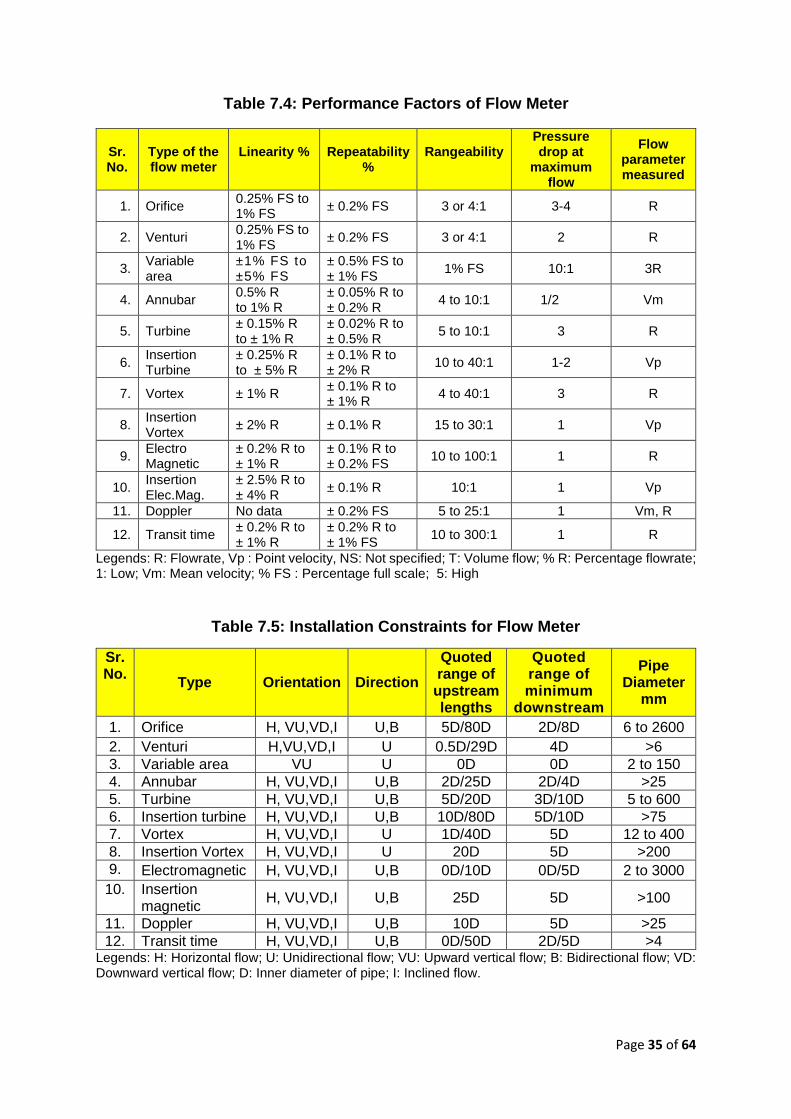
Page 35 of 64
Table 7.4: Performance Factors of Flow Meter
Sr. No.
Type of the flow meter
Linearity % Repeatability
%
Rangeability
Pressure drop at
maximum flow
Flow parameter measured
1. Orifice 0.25% FS to 1% FS
± 0.2% FS 3 or 4:1 3-4 R
2. Venturi 0.25% FS to 1% FS
± 0.2% FS 3 or 4:1 2 R
3. Variable area
±1% FS to ±5% FS
± 0.5% FS to ± 1% FS
1% FS 10:1 3R
4. Annubar 0.5% R to 1% R
± 0.05% R to ± 0.2% R
4 to 10:1 1/2 Vm
5. Turbine ± 0.15% R to ± 1% R
± 0.02% R to ± 0.5% R
5 to 10:1 3 R
6. Insertion Turbine
± 0.25% R to ± 5% R
± 0.1% R to ± 2% R
10 to 40:1 1-2 Vp
7. Vortex ± 1% R ± 0.1% R to ± 1% R
4 to 40:1 3 R
8. Insertion Vortex
± 2% R ± 0.1% R 15 to 30:1 1 Vp
9. Electro Magnetic
± 0.2% R to ± 1% R
± 0.1% R to ± 0.2% FS
10 to 100:1 1 R
10. Insertion Elec.Mag.
± 2.5% R to ± 4% R
± 0.1% R 10:1 1 Vp
11. Doppler No data ± 0.2% FS 5 to 25:1 1 Vm, R
12. Transit time ± 0.2% R to ± 1% R
± 0.2% R to ± 1% FS
10 to 300:1 1 R
Legends: R: Flowrate, Vp : Point velocity, NS: Not specified; T: Volume flow; % R: Percentage flowrate; 1: Low; Vm: Mean velocity; % FS : Percentage full scale; 5: High
Table 7.5: Installation Constraints for Flow Meter
Sr. No.
Type Orientation Direction
Quoted range of upstream lengths
Quoted range of minimum
downstream
Pipe Diameter
mm
1. Orifice H, VU,VD,I U,B 5D/80D 2D/8D 6 to 2600
2. Venturi H,VU,VD,I U 0.5D/29D 4D >6
3. Variable area VU U 0D 0D 2 to 150
4. Annubar H, VU,VD,I U,B 2D/25D 2D/4D >25
5. Turbine H, VU,VD,I U,B 5D/20D 3D/10D 5 to 600
6. Insertion turbine H, VU,VD,I U,B 10D/80D 5D/10D >75
7. Vortex H, VU,VD,I U 1D/40D 5D 12 to 400
8. Insertion Vortex H, VU,VD,I U 20D 5D >200
9. Electromagnetic H, VU,VD,I U,B 0D/10D 0D/5D 2 to 3000
10. Insertion magnetic
H, VU,VD,I U,B 25D 5D >100
11. Doppler H, VU,VD,I U,B 10D 5D >25
12. Transit time H, VU,VD,I U,B 0D/50D 2D/5D >4 Legends: H: Horizontal flow; U: Unidirectional flow; VU: Upward vertical flow; B: Bidirectional flow; VD: Downward vertical flow; D: Inner diameter of pipe; I: Inclined flow.

Page 36 of 64
Table 7.6: Fluid Property Constraints for Flow Meter
Sr. No.
Type Maximum pressure
(bar)
Temperature Range
(°C)
Minimum Reynold's number
More than one phase
(Gas or liquid)
1. Orifice 400 <650 3 x 10⁴ P
2. Venturi 400 <650 105 P
3. Variable area 700 -80 to + 400 No data N
4. Annubar 400 <540 104 N
5. Turbine 3500 -260 to +530 104 N
6. Insertion Turbine
70 to 250 -50 to +430 104 N
7. Vortex 260 -200 to +430 2 x 10⁴ P
8. Insertion Vortex 70 - 30 to +150 5 x 10³ N
9. Electromagnetic 300 -60 to +220 No limit S/P
10. Elect. Insertion 20 +5 to +25 No data N
11. Doppler Pipe
pressure -20 to +80 5 x 10³ S
12. Transit time 200 -200 to +250 5 x 10³ N/P Legends: S: Suitable; P: Possible; N: Not suitable
Table 7.7: Economic Factors of Flow Meters
Type Installation cost
Calibration cost
Operation cost
Maintenance cost
Spares cost
Orifice 2-4 1 3 2 1 Venturi 4 1-4 2 3 3 Variable area 1-3 2 2 1 1 Annubar 2 3 2 2 2 Turbine 3 4 3 4 4 Insertion Turbine
2 3 2 2 3
Vortex 3 3 3 3 3 Insertion Vortex
2 3 2 3 3
Electromagnetic 3 3 1 3 3 Insertion Ele. Mag.
2 3 2 3 2
Doppler 1-3 1 1 3 2 Transit time (time of flight)
1-3 3 1 3 2
Legends: 1: Low; 5: High

Page 37 of 64
The installation methods for various types of flow meters along with its maintenance
and service is discussed in Table 7.8.
Table 7.8: Installation & Maintenance of Flow Meters
Type Installation
Pipeline
ahead of
meter
Maintenance
during
operation
Self-
Monitoring Service
Turbine meter Flanged
connections
electrical
installation
Conditioning
section
Maintenance
free, monitor,
possible
foreign
lubrication
Not possible —
Vortex meter Flanged
connections
or water
installation,
electrical
Conditioning
section
installation
Maintenance
free
Error
monitoring
Electronic
monitor
functions and
test values
Differential
pressure
Meters
Primary in
flanges,
impulse
piping,
convertor
power supply
Long
conditioning
sections
Regular
monitoring
Not possible Direct
measurement
at primary
Variable area
meter
Flanged or
threaded
connections
No
restrictions
Maintenance
free
Constant
appearance
—
Electromagnetic
flow meter
Flanged
connections,
electrical
connections
No
conditioning
section
Maintenance
free
Monitoring
with error
announceme
nts
Electronic
control
functions &
test
simulator
Ultrasonic meter Flanged
connections
or welding
nipples,
electrical
installation.
Long
conditioning
section
Maintenance
free
Signals for
signal loss
-
7.4 Problems Encountered in Flow Meter Performance
There are many problems which are encountered during the life of the flow meter.
Some of the common performance-related issues/problems that are encountered
during its operation due to some causes along with remedial action are discussed in
Table 7.9.

Page 38 of 64
Table 7.9: Common Problems Encountered in Flow Meter Performance
Sr. No.
Problems Causes Flowmeter Remedial Action
1. Erratic reading
Operated below lower range having limited rangeability of flow meter
Differential pressure type
Replace flow meter
Operated below lower range having limited rangeability of flow meter
Linear flow meter
Change range setting
Less static pressure D.P. type Remove air trap
Clogged impulse piping D.P. type Clear the choke up
Air trapped in impulse piping
D.P. type Remove air trap
Frequent air trap in impulse piping
D.P. type Change impulse piping slope to minimum 1: 10, If still the problem persists change the flow meter
Damaged impulse piping D.P. type Rectify impulse piping
2. Unsteady reading : (oscillating)
β ratio of more than 0.65 D.P. type Redesign orifice
Pulsating flow D.P. & Linear type
Condition the flow
3. Inaccurate reading
Pipeline internally incrusted D.P. & Linear type
Clean the internal surface of pipeline
Scaling is formed at tapping points
D.P. type Clean the tapping points
Orifice edge gets blunt D.P. type Replace orifice plate
Flow meter downstream is opened within the range of 50 times dia pipe length
D.P. type Extend the downstream pipeline beyond 50 times dia length
Unsymmetrical formation of vena contract due to the large diameter of the throat in relation to static pressure
D.P. (orifice type)
Redesign the orifice
Mismatch between flow meter & pipeline
D.P. & Linear type
Remove the mismatch
Absence of sufficient conditioned approach pipeline
D.P. & Linear type
Provide sufficient conditional approach pipeline
Foreign particles such as pieces of concrete, bricks, debris. etc. are gathered at upstream of the orifice
D.P. (Orifice)
Remove them
Flanged coupling used with flow meter leaking
D.P. & Linear type
Rectify the leakage
The pipeline may not be cylindrical within the range of 0.3% of the diameter of the pipe
D.P. & Linear type
Replace the pipe length of 2 times dia immediate upstream of the flow meter
Pipeline partially filled D.P. & Linear type
Install valve downstream of the flow meter for throttling

Page 39 of 64
8.0 ONLINE MEASUREMENT INSTRUMENTATION
8.1 Level Measurement
8.1.1 Introduction
Whenever water parameters are considered, both water quantity and water quality
must be given equal weightage. Instrumentation facilitates the coordination of various
water parameters, which are essential for the optimization of water supply & treatment
plants. One of the important parameters amongst them is water level measurement,
which is carried out at various locations viz water reservoir, inlet chamber, open
channel, alum feeding tank, lime tank, filter beds, air vessel, sump well, etc.
This measurement is accomplished in waterworks by following two ways:
A. Direct Method
B. Inferential Method
Direct Method – Their merits, demerits as well as uses are given in brief below:
Table 8.1: Direct Method of Level measurement
Hook Type Level Indicator
Sight Glass Float Type Indicator
Advantages
i. Low cost ii. Simple
i. Inexpensive ii. Corrosion resistive iii. Simple
i. The level can be read at a convenient place
ii. Operates over large temperature range
iii. Very accurate
Disadvantages
i. Only local reading
ii. Human error may be encountered in reading
i. Only local reading ii. Accuracy and readability
depends on the cleanliness of glass and fluid
iii. It is fragile
i. They are tailored to tank geometry
ii. Requires a certain amount of mechanical equipment
Uses
i. Inlet channel level
i. Filter bed level ii. Reservoir level iii. Head loss in the filter
i. Filter bed ii. Final water reservoir iii. Sump well iv. Lime tank

Page 40 of 64
Inferential Method – Some specifications of the recent level transmitters as
mentioned below:
Table 8.2: Inferential Method of Level measurement
Hydrostatic Pressure
Gauge Type & Pressure Bulb Type
Displacer Level Type
Electrical Method
(Capacitance Type)
Ultrasonic
Advantages
i. Easy maintenance ii. Simple to adjust iii. With pressure,
bulb type remote reading possible
iv. Reasonably accurate
i. Excellent accuracy
ii. Possible at remote places
i. Good accuracy
ii. Possible at remote places
iii. Very sensitive iv. Suitable for
highly corrosive media
i. Good accuracy
ii. Possible at remote places
iii. Suitable for liquid as well as bulk products
Disadvantages
i. The instrument must be installed at base reference level for gauge type
ii. Pressure bulb type relatively costly
i. Limited range ii. High cost iii. Requires
stilling chamber iv. Requires a
significant amount of mechanical equipment
i. Affected by dirt & other contaminants
ii. Affected by temperature
i. Affected by foam
ii. Not suitable for high temperature & pressure
Uses
i. Delivery head of the pump (pressure gauge type)
ii. Clear or raw water reservoir
iii. Sump level
i. Clear water reservoir
ii. Raw water reservoir
i. Raw water reservoir
ii. Clear water reservoir
i. Raw water as well as clear water level i.e. inlet channel sump level etc.
ii. Lime tank iii. Sludge level
8.1.2 Maintenance of Level Measuring Instruments
Sight Glasses
After closing top and bottom valves remove the glass and clean with soap
water using the brush. Clean with fresh water. Assemble the parts again in
proper order.

Page 41 of 64
Float Operated Instrument
Guide cable wound round a pulley should be lubricated. Other moving parts
should also be lubricated;
Zero setting should be checked. Float should be checked from a corrosion
point of view.
Hydrostatic Pressure Instruments (Pressure Gauge Type)
Check for Zero settings after disconnecting from the system and purging
out;
Check for the leakages from the connection after reconnecting it .
Pressure Bulb Type
Check for zero settings. Check for air leakages from the bulb by applying
soap water;
Check coupling from a corrosion point of view;
Clean the bulb with fresh water;
Check for the correctness of the signal by moving the bulb in the water.
Displacer, Electrical or Ultrasonic Instrument
Clean the instrument and check for zero and range setting as per
manufacturer recommendations.
8.2 Pressure Measurement
In the water supply network pressure, parameter plays a very important role to get
sufficient water to the consumers. Similarly, in flow measurement by differential
pressure type flow meter, differential pressure measurement across the primary
element is the main physical parameter to interlink with flowing fluid. This pressure or
differential pressure measurement is accomplished with the help of following methods
in water works:
A. Manometers
B. Elastic Pressure Transducer
C. Electrical Pressure Transducer
The advantages and disadvantages of the instrument of pressure measurement
normally used in waterworks are given below:
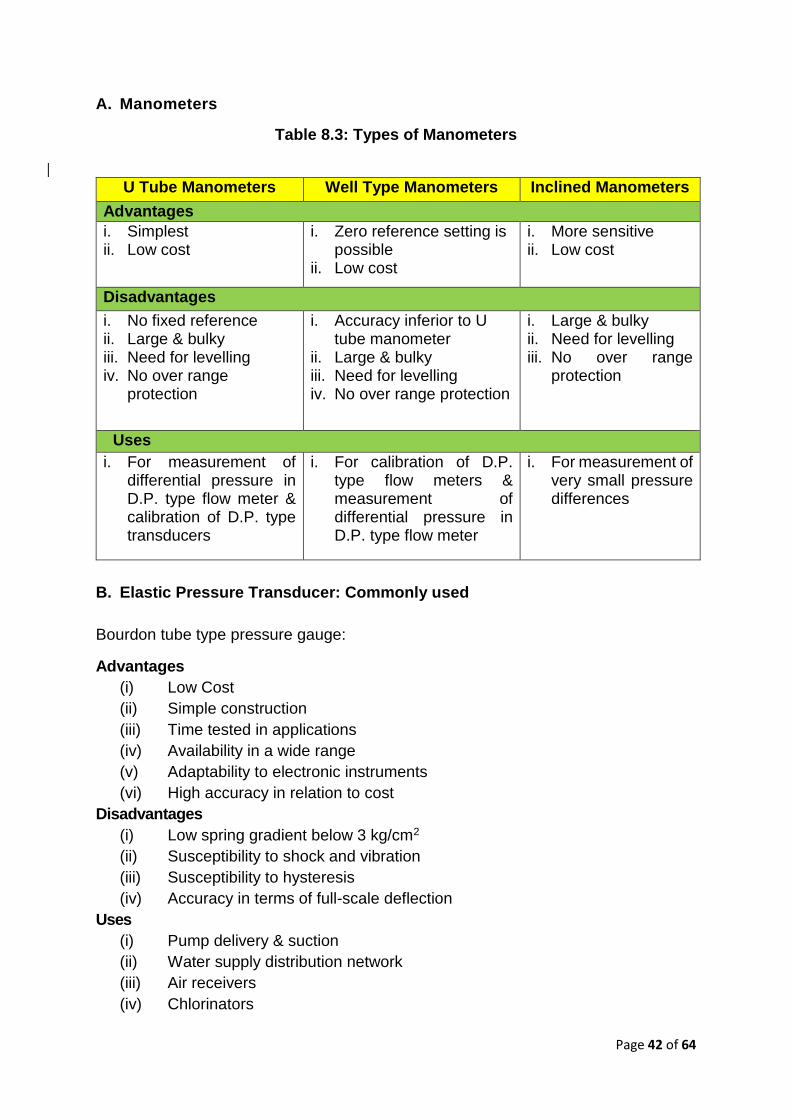
Page 42 of 64
A. Manometers
Table 8.3: Types of Manometers
U Tube Manometers Well Type Manometers Inclined Manometers
Advantages
i. Simplest ii. Low cost
i. Zero reference setting is possible
ii. Low cost
i. More sensitive ii. Low cost
Disadvantages
i. No fixed reference ii. Large & bulky iii. Need for levelling iv. No over range
protection
i. Accuracy inferior to U tube manometer
ii. Large & bulky iii. Need for levelling iv. No over range protection
i. Large & bulky ii. Need for levelling iii. No over range
protection
Uses
i. For measurement of differential pressure in D.P. type flow meter & calibration of D.P. type transducers
i. For calibration of D.P. type flow meters & measurement of differential pressure in D.P. type flow meter
i. For measurement of very small pressure differences
B. Elastic Pressure Transducer: Commonly used
Bourdon tube type pressure gauge:
Advantages
(i) Low Cost
(ii) Simple construction
(iii) Time tested in applications
(iv) Availability in a wide range
(v) Adaptability to electronic instruments
(vi) High accuracy in relation to cost
Disadvantages
(i) Low spring gradient below 3 kg/cm2
(ii) Susceptibility to shock and vibration
(iii) Susceptibility to hysteresis
(iv) Accuracy in terms of full-scale deflection
Uses
(i) Pump delivery & suction
(ii) Water supply distribution network
(iii) Air receivers
(iv) Chlorinators

Page 43 of 64
(v) Pump cooling water
C. Electrical Pressure Transducer
In this category following types are there:
(i) Strain gauge pressure transducer
(ii) Potentiometric pressure transducer
(iii) Capacitive pressure transducer
(iv) Variable reluctance pressure transducer
(v) Piezo electric pressure transducer
The advantages & disadvantages of electrical pressure transducers commonly used
in water works are as follows:
Table 8.4: Advantages & Disadvantages of Electrical Pressure Transducers
Potentiometric
Transducer
Capacitive Pressure
Transducer
Variable Reluctance
Type
Advantages
i. Widely used in
Industry as these are
simpler and less
expensive
ii. Easy compatibility
with the requirement
i. Short response time
ii. Vibration-proof
iii. Extremely sensitive
iv. It can measure static as
well as dynamic
changes
i. Excellent linearly
ii. Good repeatability
iii. Low hysteresis
iv. High sensitivity
Disadvantages
i. Finite resolution
ii. Wear out early
iii. Noise signal is
generated
i. Sensitivity changes
with temperature
i. Relatively large size
ii. More nos. of
components
iii. More maintenance
Uses
i. Where less accuracy
is required
i. Distribution network
ii. In process
instrumentation
i. Distribution network
ii. In process
instrumentation
8.2.1 Calibration of Pressure Measuring Instruments
Pressure instrument calibration is the process of adjusting the instruments output
signal to match a known range of pressure. All instruments tend to drift from their last
setting. This is because springs stretch, electronic components undergo slight
changes on the atomic level, and other working parts sag, bend or lose their elasticity.
The calibration procedure includes zero, span, and linearity adjustments. The pressure
is varied with the help of a pneumatic calibrator so as to give desired pressures to the
instrument. The settings are carried out on the instrument for zero and span

Page 44 of 64
adjustment on the basis of applied pressures. For carrying out linearity setting various
pressures between zero and maximum range of the instruments are applied and
adjusted the output of the measuring instrument with the help of controls provided in
the instrument.
In the case of pressure gauges, the calibration is carried out by means of dead weight
tester.
In absence of a pneumatic calibrator, the air can be supplied to the instrument with
proper pressure regulator, and pressure is measured with the help of a manometer so
as to calibrate the instrument.
The calibration should be checked every 3, 6 or 12 months depending upon the use
and accuracy expected, as per the manufacturer’s recommendation and latest ISO
standards.
Maintenance of pressure instruments is essential for their proper working and accurate
reading. It also improves the life and reliability of the instruments.
8.2.2 Preventive Maintenance
The manufacturer of the instrument gives the instructions in the manual supplied along
with the instruments. These instructions explain how to maintain the instrument.
Generally, these consist of the following categories:
1. Visual Inspection
Any damage to piping or wiring of the instrument observed should be immediately
rectified. It avoids the entry of foreign bodies into the system and further damage to
the instrument.
2. Venting or Blow down
Liquid lines are generally clogged subsequently if those are not vented periodically.
Similarly, air or gas in the liquid columns gives wrong readings. In order to avoid such
incidents, it is essential to blow down the instrument piping periodically on the basis of
experience gained in the field.
3. Cleaning and Lubrication
Instruments with mechanical linkages undergo wear and misalignment. Dirt may clog
the linkages, causing the mechanism to become less flexible. If not attended these
kinds of faults, the instrument may breakdown subsequently. This clogging can be
removed by cleaning, and the working of the instrument can be improved by lubrication
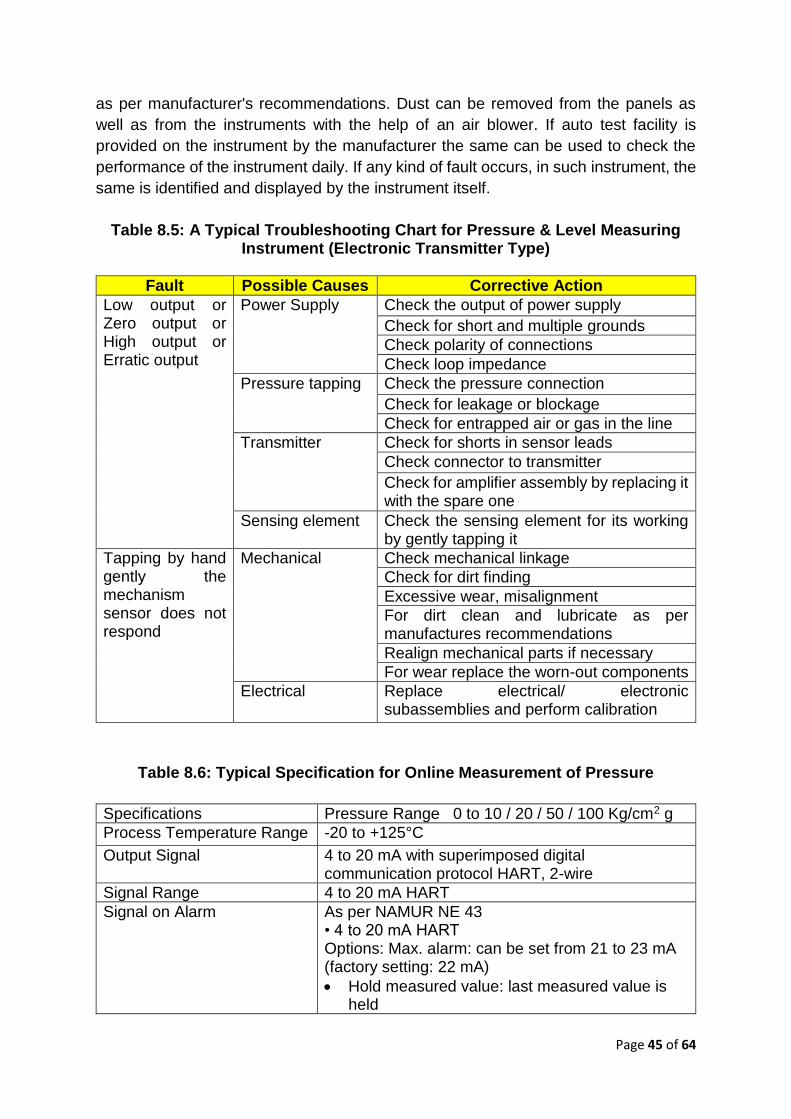
Page 45 of 64
as per manufacturer's recommendations. Dust can be removed from the panels as
well as from the instruments with the help of an air blower. If auto test facility is
provided on the instrument by the manufacturer the same can be used to check the
performance of the instrument daily. If any kind of fault occurs, in such instrument, the
same is identified and displayed by the instrument itself.
Table 8.5: A Typical Troubleshooting Chart for Pressure & Level Measuring Instrument (Electronic Transmitter Type)
Fault Possible Causes Corrective Action
Low output or Zero output or High output or Erratic output
Power Supply Check the output of power supply
Check for short and multiple grounds
Check polarity of connections
Check loop impedance
Pressure tapping Check the pressure connection
Check for leakage or blockage
Check for entrapped air or gas in the line
Transmitter Check for shorts in sensor leads
Check connector to transmitter
Check for amplifier assembly by replacing it with the spare one
Sensing element Check the sensing element for its working by gently tapping it
Tapping by hand gently the mechanism sensor does not respond
Mechanical Check mechanical linkage
Check for dirt finding
Excessive wear, misalignment
For dirt clean and lubricate as per manufactures recommendations
Realign mechanical parts if necessary
For wear replace the worn-out components
Electrical
Replace electrical/ electronic subassemblies and perform calibration
Table 8.6: Typical Specification for Online Measurement of Pressure
Specifications Pressure Range 0 to 10 / 20 / 50 / 100 Kg/cm2 g
Process Temperature Range -20 to +125°C
Output Signal 4 to 20 mA with superimposed digital communication protocol HART, 2-wire
Signal Range 4 to 20 mA HART
Signal on Alarm
As per NAMUR NE 43 • 4 to 20 mA HART Options: Max. alarm: can be set from 21 to 23 mA (factory setting: 22 mA)
Hold measured value: last measured value is held

Page 46 of 64
Min. alarm: 3.6 mA
Resolution
Current output: 1 microAmp Display: can be set (setting at the factory: presentation of the maximum accuracy of the transmitter)
Response Time <250 ms
Damping
Via local display, handheld terminal or PC with the operating program, continuous from 0 to 999 s Additionally, for HART: via DIP switch on the electronic insert, switch position "on" = value set in the 2 Sec As default
Supply Voltage 11.5 to 45 V DC
Residual Ripple
No influence on 4 to 20 mA signal up to ± 5 % residual ripple within the permitted voltage range [according to HART hardware specification HCF_SPEC-54 (DIN IEC 60381-1)
Influence of Power Supply < 0.0006% of URL/1 V
Reference Accuracy ± 0.075% of the set Span
Climate Class
Class 4K4H (air temperature: –20 to 55°C / –4 to +131°F, relative humidity: 4 to 100%) satisfied as per DIN EN 60721-3-4 – Seal Capsuled electronics.
Housing Die Cast Alu. Housing
Diaphragm Material Ceramic Dry measuring cell, Capacitive measuring cell
Display Operation 3 Key Push button for configuration without HART COMMUNICATOR. A 4-line liquid crystal display (LCD) is used for display and operation
Long Term Stability ± 0.25% URL/year for 1 year, 5 year
Turn Down 100:1
8.2.3 Radar Level Transmitters
They provide a non-contact type of level measurement in case of liquids in a metal
tank. They make use of EM i.e. electromagnetic waves usually in the microwave X-
band range which is near about 10 GHz. Hence, they can be also known as microwave
level measurement devices. However, there are some differences between radar and
microwave types. They are:
(i) Power levels in the case of radar systems are about 0.01 mW/cm2 whereas,
in the case of microwave systems, these levels range from 0.1 to 5 mW/cm2
(ii) Microwaves can work at higher energy levels; hence they are competent
enough to endure extra coating as compared to radar level detectors
A radar level detector includes:

Page 47 of 64
(i) A transmitter with an inbuilt solid-state oscillator
(ii) A radar antenna
(iii) A receiver along with a signal processor and an operator interface
The operation of all radar level detectors involves sending microwave beams emitted
by a sensor to the surface of the liquid in a tank. The electromagnetic waves after
hitting the fluid's surface return back to the sensor which is mounted at the top of the
tank or vessel. The time taken by the signal to return back i.e. Time of Flight (TOF) is
then determined to measure the level of fluid in the tank.
Table 8.7: Radar Level Transmitter
Radar – Microwave type
level transmitter
Service: Raw Water
(Non-Contact Type)
Transmitter
Type Microwave level measurement
Principle Pulse Time of Flight
Output 4-20 mA HART Current
Housing Die-Cast Aluminium
Electromagnetic
compatibility
Interference Immunity to EN 61326, Annex A
(Industrial) and NAMUR
Ingress protection IP65 / IP 66 / IP 67
Accuracy ±3 mm
Area classification Non-Hazardous
Display
4-line LCD Display. Menu guided operation. Display of
Envelope Curve.
Configuration Using the keypad on display
Sensor
Range Liquids 0 to 5m and 0 to 10m depending on Tank size
Temperature range -40°C ... +80°C
Max pressure 3 bar abs
Materials Sensor: PVDF Seal: EPDM
Antenna seal FKM Viton
Process connection Threaded or universal flange dependent on model
selection
Degree of protection IP65
8.3 Water Quality Parameter Monitoring
In water works, various treatment processes are carried out to supply potable water.
The parameters of the water which are normally used for monitoring are as follows:
(i) Turbidity
(ii) pH

Page 48 of 64
(iii) Residual Chlorine
These parameters are monitored either by means of on-line instruments or by
analytical laboratory instruments or both. Their relative advantages and disadvantages
are as follows:
8.3.1 Turbidity Meter
Table 8.8: Advantages and Disadvantages of Turbidity Meter
Online Laboratory Type
Advantages
i. Turbidity continuously monitored ii. Can be hooked up for automation iii. Can be set for giving an alarm if
minimum and maximum limits of turbidity are exceeded.
iv. Human error in sampling is eliminated
i. Low cost ii. Simple to use iii. Portable iv. Easy maintenance
Disadvantages
i. High cost ii. High maintenance is required iii. Periodical calibration is required iv. It is not portable
i. Does not monitor continuously ii. Human error may encounter iii. Low accuracy
Maintenance
i. Clean chamber & lense with fresh water
ii. Microprocessor based instrument has a self-calibration facility which is useful for periodical calibration
iii. Clean sources of light
i. Clean sampling tube with fresh water ii. Bulb, standard sample tubes and lense
should be cleaned with soft cotton iii. Calibrate before carrying out the
measurement iv. Calibrate with standard samples of 100
NTU, 10 NTU & 1 NTU or calibrate with formazin standard solution
8.3.1.1 Typical Specification for Online Measurement of Turbidity
Online sensor based on Nephelometric 90 degree scattering light method as per
ISO 7027. The sensor must be an easy plug and play with digital communication
based on inductive energy transfer with IP68 rating suitable for measuring range 0
to 9999 FNU /NTU with an accuracy of <2% of measured value or 0.1 FNU/NTU.
The sensor shall store on-board all the calibration data and other diagnostic
information. The sensor must have provision to store at least 5 user calibration
points. The offered transmitter shall be 4 wire digital with the possibility of
connecting multiple sensor inputs for additional parameters – referred to as
multichannel /multi parameter type. The transmitter shall be suitable for outdoor
installation with IP66/67 rating.

Page 49 of 64
Table 8.9: Online Turbidity Meter
Turbidity Measurement
Transmitter
Type Turbidity and suspended solids transmitter
Principle Nephelometric measuring principle 90° NIR scattered light according to ISO EN 27027
Output 4-20 mA HART current
Supply voltage 100 / 115 / 230 V AC +10 / –15%, 48 ... 62 Hz ; 24 V AC/DC +20 / –15%
Material Field Housing: ABS PC Non-corrosive type
Display LC display, two lines, with status indicators
Electromagnetic compatibility interference emission and interference immunity acc. to EN 61326-1:1998
Protection class of field housing IP 65
Ambient temperature – 20 to 60 °C
Self-Diagnostic feature Required
Sensor
Measurement range 0 – 9999 FNU / 0 - 3000 ppm / 0 – 3.0 g/L
Material Sensor shaft : PVC / PPS GF40 Optical window : sapphire Cable : TPEO
Max Process temperature 50°C
Max Process pressure 10 bar
Temperature sensor Integrated NTC temperature sensor
Connection Fixed cable connection
Ingress protection IP68
Additional Certifications Calibration certification
Resolution 0.001 FNU, 0.01 ppm, 0.1 g/l, 0.1%
Measurement error <2% of meas. value (min. 0.02 FNU)
8.3.2 pH Meter
Table 8.10: Advantages and Disadvantages of pH Meter
Online Laboratory Type
Advantages
i. Continuously monitored ii. Can be hooked up for automation iii. Can be set for giving alarm for
specified limits iv. Human error in sampling is eliminated
i. Low cost ii. Simple to use iii. Portable iv. Easy maintenance
Disadvantages
i. High cost ii. Periodical calibration is required iii. High maintenance cost (replacement
of electrodes) iv. It is not portable
i. Does not monitor continuously ii. Human error may encounter iii. Low accuracy

Page 50 of 64
Online Laboratory Type
Maintenance
i. Clean electrode with soap water or clean with 5% concentrated H2S04 and 6% concentrated H202
ii. Calibrate periodically with a standard solution of pH 4 and pH 7
iii. Replace electrodes if dried up
i. Clean sampling electrode with distilled water
ii. Calibrate the instrument with three standards samples i.e. pH 4, pH 7 & pH 9.2
iii. Prepare standard samples from readily available capsules
iv. Calibration may last from 4 days to 7 days
8.3.2.1 Typical Specification for Online Measurement of pH
Online pH sensor is based on potentiometric measurement using a glass sensor. The
sensor shall have digital communication based on inductive energy transfer. The
sensor shall have inbuilt memory to store calibration data and other additional
diagnostic information. The offered transmitter shall be 4 wire digital with the possibility
of connecting multiple sensor inputs for additional parameters – referred to as
multichannel /multi parameter type. The transmitter shall be suitable for outdoor
installation with IP66/67 rating.
Table 8.11: Online pH Meter
Transmitter
Type Glass electrode
Principle Glass electrode with dirt repellent PTFE diaphragm
Output 4-20 mA HART current
Supply voltage 100 / 115 / 230 V AC +10 / –15%, 48...62 Hz ; 24 V AC/DC +20 /–15%
Material Field Housing : ABS Polycarbonate non corrosive
Display LC display, two lines, with status indicators
Electromagnetic compatibility Interference emission and interference immunity acc. to EN 61326: 1997 / A1: 1998
Protection class of field housing
IP 68
Ambient temperature –20 ... +60 °C
Diagnostic feature Required
Sensor
Measurement range pH 0 - 14
Material Glass
Max Process temperature 130°C
Max Process pressure 6bar
Temperature sensor NTC / Pt100
Connection Inductive digital connection with Transmitter
Ingres protection IP68
Additional Certifications FM, ATEX, CSA
Resolution pH 0.01, Temp 0.1°C

Page 51 of 64
Measurement Error ± 0.5% of Measuring range
8.3.3 Residual Chlorine Meter
Table 8.12: Advantages and Disadvantages of Chlorine Meter
Online Laboratory Type (Lovibond Type)
Advantages
i. Continuously monitored ii. Can be hooked up for automation iii. Can be set for giving alarm for specified limits iv. Human error in sampling is eliminated
i. Low cost ii. Simple to use iii. Portable iv. Easy maintenance
Disadvantages
i. High cost ii. Periodical calibration is required iii. High maintenance cost (replacement of
membrane) iv. It is not portable v. It requires electricity of battery or solar
i. Does not monitor continuously
ii. Human error in sampling may encounter
iii. Low accuracy
Maintenance
i. Clean membrane if it gets clogged ii. If the membrane is damaged replace it with the
new one iii. Fill up/ DPD membrane /electrolyte if necessary iv. Calibrate it using Potentiometric electrode
i. Clean tubes with distilled water
ii. Calibration is not required as it is a comparator
8.3.3.1 Typical Specification for Online Measurement of Chlorine
Online chlorine analyzer is based on Amperometric / membrane-based measurement
of active chlorine converted to free chlorine by means of pH compensation. The sensor
shall have digital communication based on inductive energy transfer which will
withstand moisture, corrosion, and ensures reliable data transmission. Complete
measuring system includes chlorine sensor, pH sensor with suitable flow assembly for
mounting these sensors along with the transmitter. The offered transmitter must be
IP65, Interference emission & immunity as per EN 61326-1:2006.
Table 8.13: Online Chlorine Meter
Transmitter
Type Free chlorine
Principle Amperometric measurement of free chlorine
Output 4-20 mA HART current
Supply voltage 100 / 115 / 230 V AC +10 / –15%, 48 ... 62 Hz ; 24 V AC/DC +20 / –15%
Material Field housing: ABS PC Fr
Display LC display, two lines with status indicators

Page 52 of 64
Transmitter
Electromagnetic compatibility Interference emission and interference immunity acc. to ISO EN 61326: 1997 / A1: 1998
Protection class of field housing
IP 65
Ambient temperature -20….+60oC
Sensor
Measurement range 0.01 – 5ppm free chlorine
Material Sensor Shaft: PVC
Membrane: PTFE
Membrane cap: PBT (GF30); PVDF
Process temperature +2oC…..+45oC
Max process pressure 1 bar
Temperature sensor NTC/ Pt100
Connection Inductive digital connection with transmitter
Ingress protection IP 68
Resolution 0.01 mg/l
Measurement error ±0.5% of measuring range
9.0 TELEMETRY AND SCADA SYSTEMS
9.1 Manual Monitoring
Normally, the managers of O&M of water utilities monitored levels in service
reservoirs, pressures, and flows in a distribution system and on the operation of pumps
such as hours of pumping and failure of pumps and monitored water quality by
measuring residual chlorine. The manager usually used the telephone line or wireless
like VSAT or GPRS / GSM unit to gather the data, used his discretion gained with
experience, and took decisions to ensure that the system is operating with the required
efficiency. Manual collection of data and analysis is an outdated practice and may not
be helpful in large undertakings if water utilities have to aim at enhanced customer
service by improving water quality and service level with reduced costs. This is
possible if the management acquires operational data at a very high cost.
9.2 Telemetry
The inspection, monitoring, and control of O&M of a water utility can be automated
partially through telemetry. Telemetry enables regular monitoring of the above data on
a real-time basis and the data is provided to anyone in the organization who can review
the data and make a decision. In a telemetry system probes/sensors will be used which
will sense and generate signals for the level, pressure, flow, and water quality like pH,
turbidity, residual chlorines in a given unit and transmit the signals by radio/by
Page 53 of 64
telephone, VSAT, GSM / GPRS. Normally radio link is used and telephone line with
the modem is used as spare communication. Microwave satellite or fiber-optic
transmission systems are also used for data transmission. The water pumping stations
may communicate via a cable buried with the pipe. However, there may be locations
where the main power may not be available and hence solar panels with a battery
charger are used to power the remote terminal unit (RTU) and the radio, VSAT, GSM
/ GPRS. In urban areas, RTUs can communicate on cell phones and or packed radio
networks. For remote locations satellite technology is also available.
9.2.1 Data for Collection by Telemetry
The data includes levels in service reservoirs, pressures and flows in a distribution
system, flows/quantity and water quality like pH, turbidity, residual chlorines of delivery
into an SR and data on the operation of pumps such as voltage, amperes, energy
consumed, operating times and downtimes of pumps and chlorine residuals. In a
telemetry system up-to-the-minute real-time information is gathered from a remote
terminal unit located at the water treatment plant, reservoir, flow meter, pumping
station, etc. and transmitted to a central control station where the information is
updated, displayed and stored manually or automatically.
9.2.2 Processing Data from Telemetry
The meter readings from reservoirs are useful information for managing the
distribution system and help in preventing overflow from reservoirs. However, the
effectiveness of telemetry in pumping operations is dependent on the reliability of
instrumentation for measuring flows, pressures, KWh meters, etc. Standard practice
is to calculate pump efficiency and water audit calculations on a monthly basis.
Telemetry can also be used to supervise a water hammer protection system wherein
the pump failures are linked to initiate measures to prevent the occurrence of water
hammer.
9.3 SCADA Systems
Instead of manual review of data collected by telemetry and initiating action manually,
if telemetry is extended to include actions based on the data for remote control of
pumps and other equipment then such a system is known as SCADA. Supervisory
Control and Data Acquisition (SCADA) is a computer-aided system that collects,
stores, and analyses the data on all aspects of O&M. It gives a better understanding
of what is happening in terms of water quantity or water quality which is sourced and
supplied. SCADA can do any activity like on/off any equipment or start /stop.
The operating personnel can retrieve the data and control their operations and
sometimes the system itself is programmed to control the operations on the basis of
Page 54 of 64
the acquired data. SCADA enhances the efficiency of the O&M personnel who are
better informed about the system and hence are in full control of the operations.
Whether in a telemetry system or a SCADA system up-to-the-minute real-time
information is gathered from the remote terminal unit located at the water treatment
plant, reservoir, flow meter, pumping station, etc. and transmitted to a central control
station where the information is updated, displayed and stored manually or
automatically. In a SCADA system, the information is linked to a supervisory system
for local display, alarm annunciation, etc. which may be linked to remote control of
pumping operations or operation of valves, etc.
9.4 Smart Communication
The smart data and communication is more of revenue model and having better
control over NRW (Non-Revenue Water or UFW – Unaccounted for flow of water)
9.4.1 Meter Reading Systems
Water meter is a cash register of a water supply authority. Consumption-based water
rates require periodic reading of meters except in remote or automated meter reading
of meters. Except in remote or automated meter reading these readings are usually
done by meter readers visiting consumers premises one by one and noting down the
indicator reading by the meter. These readings are recorded manually in books or on
cards and later keyed manually to a customer accounting or billing system. In some
cases, meter readers use Handheld Data Entry Terminals to record meter readings.
Data from these devices are transferred electronically to a billing system. In other
cases, the key entry has been replaced by mark-sense card readers or optical
scanners.
The environment of meter reading usually is not favourable to the meter reader as
most of the water meters are installed in the underground chamber; these chambers
are filled in many cases with water, reptiles, or insects. Often access to these meters
is also obstructed when these meters are installed in the consumers’ premises.
Sometimes manual work is involved in opening the chamber covers. Some consumers
connect their electrical earth terminal to water utility pipe which endangers the safety
of the meter reader. If during the meter reading visit, the consumer premises are not
accessible, the meter reader will have to visit it again which increases the cost of meter
reading.
The solution to the above difficulties is to install an automatic system to read meters
and process the results by computer. Because of development in integrated circuit
technology and low powered radio trans receivers, this system to some extent is
simplified.

Page 55 of 64
The data can be captured by the meter readers from the meter in one of the following
ways.
(i) Manual entry into meter books;
(ii) Manual entry into the portable Handheld Entry Terminals or recorders;
(iii) Direct electronic entry from meter registers either into portable data
terminals or display units from which readings are transcribed in the field;
(iv) Telemetry link through radio, telephone.
9.4.2 Automatic Meter Reading (AMR)
AMR is a technology that automatically collects and transfers metering data to a
central database for analysis and billing purposes, generally called “smart meters”.
Data on detailed water usage can be collected at regular intervals (for example, every
30 minutes) and can be read remotely via an automated process. The usage data can
later be sent to the utility’s management and billing system. Readings from AMR can
be obtained by a simple walk-by or drive-by method, where the meter reader cruises
down the street automatically downloading the meter data. Alternatively, the AMR
through a one-way or two-way communication with the utility can transfer reading data.
Representation of Automatic Meter Reading (AMR)
AMR does not require an extensive installation plan or significant maintenance,
because the units that comprise AMR are not part of a larger physical network. It is a
fixed system that can offer improved customer service through frequent readings and
the ability to detect leaks and tampering. There is also an opportunity for additional
data collection such as GPS surveys, time-of-day rate systems, and system modelling.
However, since AMR is fixed, it requires employee drive-by visits, often conducted on
monthly basis. Because of the drive-by visits, AMR can be much safer for meter
readers since readers are not required to enter properties, which in turn reduces the
likelihood of injury. AMR systems can take reads as frequently as every 15 minutes;
however, the collected data will not be available until weeks after it is registered. As a

Page 56 of 64
result, any problems in the system may go unnoticed for a significant period unless
the utility retains a full staff of meter readers to collect data more frequently.
Maintaining or increasing the number of staff is likely to impact operational expenses.
Benefits ascribed to the installation of an AMR system:
(i) Increased revenue from previously unaccounted water;
(ii) Reduced meter reading costs including both regular cycle reading and
special reads;
(iii) Reduction in security issues - Reduced GHG;
(iv) Increased customer service;
(v) Identifying and locating losses (customer and system);
(vi) Theft detection;
(vii) Efficient billing;
(viii) Improved cash flow;
(ix) Conservation/Efficiency improvements;
(x) Provide outage management and detection;
(xi) Intangible benefits;
(xii) No human error.
An AMR system can provide:
(i) Readings as frequently as every 15 minutes or more, accurate and timely
billing;
(ii) Improved work efficiency and safety AMI and AMR System Primer 5;
(iii) Generate reports of unusual or outstanding events;
(iv) Tamper and reverse-flow alarms;
(v) Drastic reduction of estimated readings;
(vi) Utility-side leak detection by data collection and analysis;
(vii) Can estimate apparent & real losses in a water network.
Many utilities have used the AMR system as a stepping-stone between standard
metering and AMI systems. Some utilities made changes as technology became
available, while other utilities made system decisions for financial reasons, and a few
other utilities wanted to try out the technology before committing to an AMI system.
However, if the goal is to eventually have a full AMI system, then it is smart to explore
the cost-effectiveness of growing from AMR to AMI. A slow transition may lead to
setbacks or delays on the road to a complete AMI system and be more expensive.
AMR metering technology can
(i) Store and record data at regular intervals up to 180 data points;
(ii) Readings can be retrieved in a drive-by – walk-by or fixed network mode;
(iii) The utility can conduct daily water balance and estimate NRW;
(iv) Moreover, smart meters or AMR technology can perform the following:
a) 24 hours’ index
b) Leakage alarm (at consumer end)

Page 57 of 64
c) Backflow alarm
d) Tamper alarm
e) End of battery life indicator
f) Water Intelligence Alarms (backed up by additional analytical
tool/software)
Meter oversized
Meter undersized
Meter stopped
Peak flow
AMR data, if continuously analyzed on data intelligent platform can
help in finding leaks & water theft in distribution networks which
reduces manpower & operational cost
Hydraulic modelling simulations
9.4.3 Remote Register Meters
This system consists of a coiled spring mechanism wound by the register gears in the
meter. A small generator is attached to the spring which trips and upwind when the
meter reaches a certain consumption increment. The spinning of the generator sends
an electrical pulse to the remote display unit installed outside. This system is known
as electro-mechanical remote registering. The place of this system is being taken by
electronically encoded remote registering. In this type, small printed circuit boards are
installed between counter wheels of meter register, wiper blades attached to the
counter wheels contact discrete positions on the PCBs corresponding to meter reading
digits. A small microprocessor determines the positions of the wiper blades on PCB
and converts in serially coded output. Similarly, non-contact type optical-encoded
sensing technology is also being used.
In order to collect the data from the site Hand held Data Entry Terminal (HDET) is
used. This unit consists of a programmable microprocessor-based unit, with memory,
keypad, display unit, and battery power supply. It has an interface part so that
necessary meter reading route instructions can be down loaded to the unit from a host
computer and the meter readings themselves uploaded. The meter reader follows the
HDET’s instructions.
In a remote electronic meter reading system, the output from the encoded register
meter is captured through a probe attached to HDET. For reading a meter the probe
is connected to a receptacle on the outside of consumer’s premises.
Presently there are five different systems of automatic meter reading which are as
follows: -
1. Telephone dial outbound: In this system, a meter interface unit is installed on
the phone line in the consumer’s premises. The utility begins reading by calling
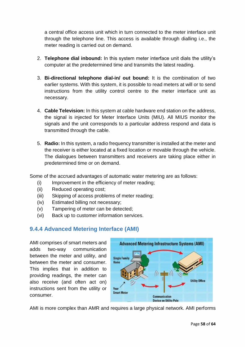
Page 58 of 64
a central office access unit which in turn connected to the meter interface unit
through the telephone line. This access is available through dialling i.e., the
meter reading is carried out on demand.
2. Telephone dial inbound: In this system meter interface unit dials the utility’s
computer at the predetermined time and transmits the latest reading.
3. Bi-directional telephone dial-in/ out bound: It is the combination of two
earlier systems. With this system, it is possible to read meters at will or to send
instructions from the utility control centre to the meter interface unit as
necessary.
4. Cable Television: In this system at cable hardware end station on the address,
the signal is injected for Meter Interface Units (MIU). All MIUS monitor the
signals and the unit corresponds to a particular address respond and data is
transmitted through the cable.
5. Radio: In this system, a radio frequency transmitter is installed at the meter and
the receiver is either located at a fixed location or movable through the vehicle.
The dialogues between transmitters and receivers are taking place either in
predetermined time or on demand.
Some of the accrued advantages of automatic water metering are as follows:
(i) Improvement in the efficiency of meter reading;
(ii) Reduced operating cost;
(iii) Skipping of access problems of meter reading;
(iv) Estimated billing not necessary;
(v) Tampering of meter can be detected;
(vi) Back up to customer information services.
9.4.4 Advanced Metering Interface (AMI)
AMI comprises of smart meters and
adds two-way communication
between the meter and utility, and
between the meter and consumer.
This implies that in addition to
providing readings, the meter can
also receive (and often act on)
instructions sent from the utility or
consumer.
AMI is more complex than AMR and requires a large physical network. AMI performs

Page 59 of 64
the function of data collection similar to an AMR system; however, instead of holding
the collected data until a meter reader can collect it, AMI relays the data to the owner
of the meter in real-time. Because AMI can relay data in real-time and has a physical
network, it has additional features.
Representation of Advanced Metering Interface (AMI)
An AMI system can perform the functions of an AMR system as well as:
(i) Daily, hourly, or 15-minute read increments without reading staff;
(ii) Improved customer service;
(iii) Customer web portals;
(iv) Quick and accurate replies to inquiries;
(v) Faster resolution of billing disputes;
(vi) Select billing date;
(vii) Real-time diagnostic operation and maintenance reports;
(viii) Targeted data collection and report generation;
(ix) Operational updates for the collector, repeaters, and endpoints;
(x) Faster leak detection in water network with analytical module.
Data is transmitted in AMI systems in the following ways: one-way, two-way, and quasi
two-way. The most appropriate option will largely depend on how much data is
collected and the requirement of the utility.
9.5 Methods of Data Transmission
Radio Technologies: Because of its reliability and cost-effectiveness, radio
frequency (RF) is the most common communication technology for AMI/AMR systems.
Antennas or transmitters are attached to the meter or register, and data is transmitted
from the meters and the data collectors by RF.
Non-Radio Technologies: Non Radio technologies for data transmission include
power lines, cable, cellular, satellite, telephone, GSM / GPRS, LoRA WAN , LAN,
NBIOT, IIOT, Optical Fiber Cable, etc.

Page 60 of 64
9.6 Data Collected in SCADA/ Smart Metering System
SCADA systems will have probes/sensors which will sense and generate signals for
the level, pressure, and flow in a given unit and transmit the signals for storage and
analysis on the computer. The signals are transmitted by radio, by telephone,
microwave satellite or fiber-optic transmission systems. SCADA systems can include
the network diagrams of the distribution system of which detailed sketches of a
particular area can be viewed by the operator if necessary to observe the current
operating data such as flow, pressure, level, or residual chlorine.
SCADA systems in Water distribution are programmed for the collection and
processing of the following information.
(i) To monitor levels in service reservoirs, pressures and flows in a distribution
system;
(ii) To monitor and store data on levels in SRs, or flows/quantity of delivered
into SR or pressures of the distribution system and generate alarms for
threshold values of levels, flows and pressures to initiate operation of valves
and pumps;
(iii) To monitor and store data on the operation of pumps such as voltage,
amperes, energy consumed, operating times and down times of pumps;
(iv) To measure and record chlorine residuals and generate alarms at thresh
hold values of residual chlorine in the distribution systems.
9.7 Analysis of Data from SCADA/Smart Metering
SCADA systems can be designed to analyze the data and provide daily, weekly,
monthly, and or annual reports or schedules. It also helps in monitoring the inventories
on spare parts and plan requirement of spares. Responses for different scenarios such
as seasonal changes or any emergencies can be programmed into SCADA. The
information stored in the SCADA can be easily retrieved and analyzed. Typical
information that could be generated in the system includes consumption patterns
linked to the weather conditions, plots on pressures against flows, electrical energy
consumption linked to consumer demands, record on system leaks, record on pump
failures, areas with fewer chlorine residuals, etc.
9.8 Limitations of SCADA/Smart Metering/Communication
Before installing a SCADA, the utility staff should visit facilities with SCADA and
discuss with the utility managers and then decide the scope of SCADA to be provided
in their utility. The objective of SCADA should be to make the job of operator easier,
more efficient, and safer to make their facilities performance more reliable and cost-
effective. There is no doubt that SCADA enables better capacity utilization and help in
improved service levels at low operating cost. SCADA designing calls for careful

Page 61 of 64
planning and requires a phased implementation, particularly dependent on appropriate
training of utility staff and their willingness to adopt the new technology.
The availability of power supply is very essential to the efficient functioning of the
system. Wherever possible the RTU for flow meter or pressure sensor and water
quality like pH, turbidity, residual chlorine is provided power from electricity mains via
a battery that acts as a buffer in case of mains failure. There may be metering locations
for flow and pressure sensors without any source of power close by. In such cases,
solar power may be one alternative. Initially installations at such locations may operate
well but they are always subject to poor after-sales service by vendors, vandalism,
and theft.
Ultimate improvement in the water supply distribution system cannot be achieved
through the advanced application of technology like SCADA. The utility staff should
have reached a reasonable level of managerial capabilities even with conventional
methods of monitoring and control by adopting a holistic approach when the SCADA
may further enhance their capabilities, but SCADA by itself is not the answer for poor
or inefficient management.
10.0 CONCLUSION
The present field measurement market which caters to the water quantity and quality
is open and there are many new technologies available based on the requirement of
the purchaser. If the right instrumentation for measurement and control like a water
meter, flow meter, etc. are selected and installed properly, the maintenance cost,
manpower cost, etc. will get reduced drastically and accuracy also will be maintained.
It is also pertinent to mention that there is no data available in the country regarding
the quantity of water drawn or abstracted from the source or treated in a treatment
plant or consumed by consumers. As the precious water resources are getting scarce
and depleted day by day, it is essential to adopt technologies for ensuring proper
measurement, maintaining quality and conservation. By adopting the necessary field
instrumentation devices, water balance, NRW, UFW, etc. can be known and
necessary steps may be taken for better management of water. The correct and
accurate measurement of inputs and outputs need to be given due weightage and
importance in all waterworks installations for effective and productive utilization of
precious potable water resources and water audit and effective energy audit of any
water utility.
Subsequently, the revenue generated by water usage billing is very essential for the
sustenance of any water supply project and the utility which is involved in its operation
and maintenance.

Page 62 of 64
Applicable Standards for Water Meters & Flow Meters
(National & International Standards)
Sr. No.
Standard / Reference Title/Description
General
1 BS: 7405:1991 confirmed year: 2017
Selection and application of flow meters for the measurement of fluid flow in closed conduits
2 BS: 5792:1980 Replaced by: BS EN ISO 20456:2019
Specification for Electro Magnetic flow meters
3 BS EN ISO: 6817:1997 Replaced by: BS EN ISO 20456:2019
Measurement of conductive liquid flow in closed conduits - Method using Electromagnetic flow meters
4 ISO Recommendation: R-541: 1967(E) Replaced by: ISO 5167-1:2003
Measurement of fluid flow by means of orifice plates and nozzles
5 ISO 9104:1991/ Revised by: ISO 20456:2017 BS 7526: 1991
Measurement of fluid flow in closed conduits — Method of evaluating the performance of electromagnetic flow meters for liquids
6 BS: 6199: 1991/ ISO 9368:1990 Confirmed Year:1998
Measurement of liquid flow in closed conduits by using weighing and volumetric methods
7 IS: 4477 Part-2: 1975 Reaffirmed Year : 2016
Methods of measurement of fluid flow by means of Venturi meters: Part-2 Compressible Liquids
8 IS 2951 Part I: 1965 Reaffirmed Year : 2017
Recommendations for estimation of flow of liquids in closed conduits Part I : Head loss in straight pipes due to frictional resistance
9 IS 14615 Part I: 1999 : 2018
Measurement of fluid flow by means of pressure differential devices — Part I : Orifice plates, nozzles and venturi tubes inserted in circular cross-section conduits running full
10 IS 9115: 1979 Reaffirmed Year : 2017
Method for estimation of incompressible fluid flow in closed conduits by Bend meters
11 IS 779: 1994 Reaffirmed Year : 2015
Water meters (Domestic type) – Specification (Sixth revision)
12 IS 2373: 1981 Reaffirmed Year: 2017
Specifications for water meters (Bulk type) (Third revision)
13 IS 6784: 1996 Reaffirmed Year : 2017
Methods for Performance Testing of Water Meters
14 BS 5728
Measurement of flow of cold potable water in closed conduits

Page 63 of 64
Sr. No.
Standard / Reference Title/Description
Part-I (1979): Specification for single meters Part-II (1980): Specification for installation requirements for single meters Part-III (1997): Methods for determining principal characteristics of single meters
15 ISO: 4064:2014 Confirmed Year: 2019
Water meters for cold potable water and hot water Part-1: Metrological and technical requirements Part-2: Test methods and equipment Part-5: Installation requirements
16 AWWA Manual 6 Water Meters - Selection, Installation, Testing and Maintenance
Closed Pipe Flow Measurements
1 ISO 1088: 2007 Confirmed Year: 2020
Velocity-area methods using current-meters — Collection and processing of data for determination of uncertainties in flow measurement
2 ISO 3354: 2008 Confirmed Year: 2017
Velocity-area method using current-meters in full conduits and under regular flow conditions
3 ISO 4006: 1991 Confirmed Year: 2019
Measurement of fluid flow in closed conduits — Vocabulary and symbols
4 ISO 4064-1: 2005 Replaced by: ISO 4064-1:2014
Measurement of water flow in fully charged closed conduits — Meters for cold potable water and hot water — Part 1: Specifications
5 ISO 4064-2: 2014 Confirmed Year: 2019
Water meters for cold potable water and hot water — Part 2: Test methods
6 ISO 4064-5: 2014 Confirmed Year: 2019
Water meters for cold potable water and hot water — Part 5: Installation requirements
7 ISO 4185: 1980 Confirmed Year: 2019
Measurement of liquid flow in closed conduits — Weighing method
8 ISO 5167-1: 2003 Confirmed Year: 2014 Status: Current
Flow Measurement via Differential Pressure Methods: General
9 ISO 5167-2: 2003 Confirmed Year: 2014
Flow Measurement via Differential Pressure Methods: Orifices
10 ISO 5167-3: 2003 Confirmed Year: 2014
Flow Measurement via Differential Pressure Methods: Nozzles
11 ISO 5167-4: 2003 Confirmed Year: 2014
Flow Measurement via Differential Pressure Methods: Venturis
12 ISO 5168: 2005 Reaffirmed 2015
Measurement of fluid flow — Procedures for the evaluation of uncertainties
13 ISO 6416: 2004 Revised by ISO 6416:2017
Measurement of discharge by ultrasonic (acoustic) method
14 ISO/TR 9464: 2008 Guidelines for the use of ISO 5167

Page 64 of 64
Sr. No.
Standard / Reference Title/Description
Confirmed Year: 2019
15 ISO 6817: 1992 Replaced by: ISO 20456:2017
Closed Pipe Flow Measurements: Electromagnetic Flowmeters
16 ISO 8316: 1987 Confirmed Year: 2019
Flow Measurement by Volumetric Tank Collection Method
17 ISO 9104: 1991 Replaced by: ISO 20456:2017
Methods of evaluating the performance of electromagnetic flow-meters for liquids
18 ISO/TR 9824: 2007 Measurement of Free Surface Flow in Closed Conduits
19 ISO 11631: 1998 Confirmed Year: 2014
Methods for Specifying Flowmeter Performance
20 ISO/NP 12242: 2012 Measurement of fluid flow in closed conduits — Ultrasonic transit-time meters for liquid
21 ISO 13359: 1998 Replaced by: ISO 20456:2017
Flanged Electromagnetic Flowmeters: Overall length
22 ISO/TS 25377: 2007 Confirmed Year: 2013
Hydrometric Uncertainty Guidance (HUG)