


Section 7 Pumps, Reels, Meters & Nozzles
108
Section 7 Pumps, Reels, Meters & Nozzles
-
Upload
khangminh22 -
Category
Documents
-
view
1 -
download
0
Transcript of Section 7 Pumps, Reels, Meters & Nozzles
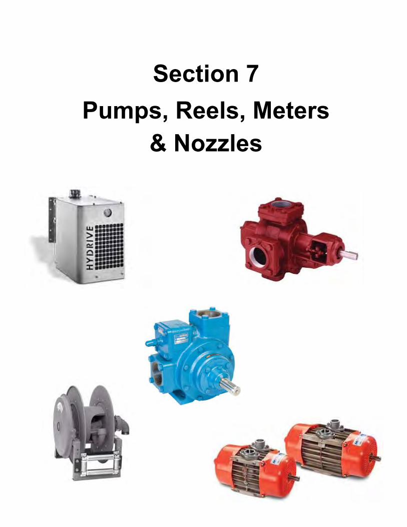
Section 7
Pumps, Reels, Meters
& Nozzles

Blackmer Pumps 2-42 Mouvex 43-65Hydraulic Motor Adaptor Kit 40 Enterprise Compressors 43-54Relief Valves 38-39 E140/E170 43-48Strainers 37 E56/E106/E156 (Obsolete) 49-54STX & STX-DEF 21-28 Hydraulic Coolers 55-65
STX1220A/STX1220A-DEF 23-24 2010 Cooler 57-62STX2A/STX2A-DEF 25-26 2020 Cooler 63-65STX3/STX3-DEF 27-28 Roper Pumps 66-73
TLGLF4 33-36 Safety Pumping Systems 74-75Transmax TX206A 31-32 Total Controls Sys. (TCS Meter) 92-105Troubleshooting 41 700-20/700-25 Meter 94-95TX & TXD Series 2-13 700-30/700-35 Meter 96-97
TX1.5 4-5 700-40/700-45 Meter 98-99TXDA2A/TX2A 6-7 720-20 Strainer 100-101TXD2.5A/TX2.5A 8-7 720-30 Strainer 102-103TXD3E/TX3E 10-11 730 Air Eliminator 104-105TX4A 12-13 Nozzles 106
TXD 1200 Series 14-19 Swivels 106TXD1125A 16-17TXD1230A 18-19
Blackmer/Mouvex Warranty Form 42Dixon Pumps 76Hannay Reels 77-85
Reel Parts Breakdown 77Reep Parts & Accessories 78-85
Liquid Controls (LC Meter) 86-91Meter Configuration Chart 86M-5 Parts Breakdown 87M-7 Parts Breakdown 88M-15 Parts Breakdown 89Air Eliminators & Strainers 90Flanges 90Registers & Printers 91
Section 7
Pumps, Reels, Meters & Nozzles

www.wertswelding.com7-1
nwerts
Typewritten text
CC20 Eccentric Disc Pump
nwerts
Typewritten text
Enterprise E140 & E170 Compressor
nwerts
Typewritten text
Hydrive 2010 & 2020 Hyrdaulic Cooler
nwerts
Typewritten text
Your headquarters for all things Mouvex!
Reliability
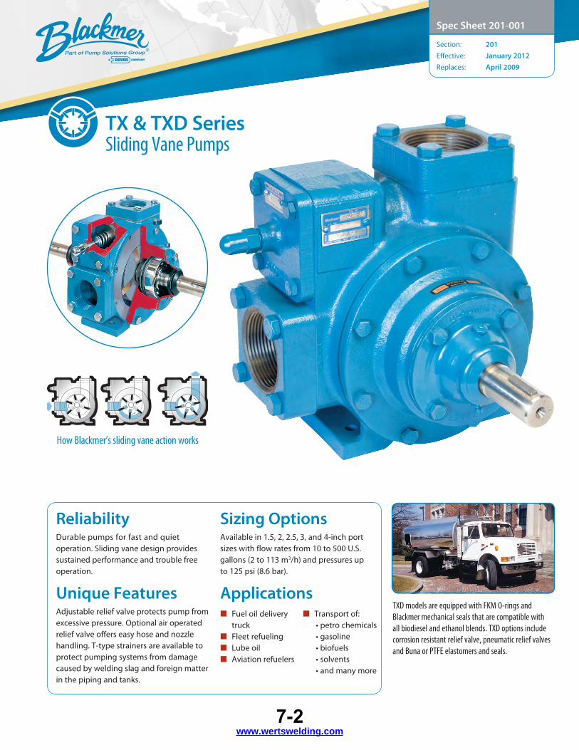
Durable pumps for fast and quiet operation. Sliding vane design provides sustained performance and trouble free operation.
Unique FeaturesAdjustable relief valve protects pump from excessive pressure. Optional air operated relief valve offers easy hose and nozzle handling. T-type strainers are available to protect pumping systems from damage caused by welding slag and foreign matter in the piping and tanks.
Sizing OptionsAvailable in 1.5, 2, 2.5, 3, and 4-inch port sizes with flow rates from 10 to 500 U.S. gallons (2 to 113 m3/h) and pressures up to 125 psi (8.6 bar).
Applications
TX & TXD Series Sliding Vane Pumps
How Blackmer’s sliding vane action works
TXD models are equipped with FKM O-rings and Blackmer mechanical seals that are compatible with all biodiesel and ethanol blends. TXD options include corrosion resistant relief valve, pneumatic relief valves and Buna or PTFE elastomers and seals.
■ Fuel oil delivery truck
■ Fleet refueling■ Lube oil■ Aviation refuelers
■ Transport of:• petro chemicals • gasoline• biofuels• solvents• and many more
Spec Sheet 201-001
Section: 201
Effective: January 2012
Replaces: April 2009
www.wertswelding.com7-2

2/12 - 1M
Process | Energy | Military & Marine
* Appropriate capacities and horsepower (hp) are based on a 100 ssu (22 cP) fluid a 50 psi (3.4 bar) delivered pressure. Refer to Characteristic Curves for flow rates and torque requirements at other pressures and viscosities.
Performance DataPump Model TX1.5 TXD2 TXD2.5 TXD3 TX4
RatedPump Speed
780 600 400 640 520 640 520 640 520 500 400
gpm 52 40 25 72 58 120 98 263 211 505 405
L/min 197 151 95 273 220 454 371 995 799 1,911 1,533
m3/h 12 9 6 16 13 27 22 60 48 115 92
hp 2.4 1.9 1.3 3.0 2.5 5.0 3.8 11.1 8.6 18.2 15
kW 1.8 1.4 1.0 2.2 1.9 3.7 2.8 8.3 6.4 13.6 11.2
Pump Model
NominalFlow rate
Pump Speed
ViscosityDifferential
PressureWorkingPressure
Temperature
gpm L/min rpm ssu cP psi bar psi bar °F °C
TX1.5 56 212 780 20,000 4,250 125 8.6 175 12.1 300 149
TXD2 87 329 780 20,000 4,250 125 8.6 175 12.1 300 149
TXD2.5 157 594 780 20,000 4,250 125 8.6 175 12.1 300 149
TXD3 270 1,022 640 20,000 4,250 125 8.6 175 12.1 300 149
TX4 505 1,911 500 20,000 4,250 125 8.6 175 12.1 240 116
Maximum Operating Limits
Model A B D E G K M Q S T AA BB DD TT Approx. Weight
TX1.5in. 1¹/8 ¹/4 713/16 51/16 31/8 61/2 4 81/2 7 39/16 – – 103/8 – 61 lbs.
mm – – 198 129 79 165 102 216 178 90 – – 264 – 28 kg11/4" HYD
Motor Shaft
1" HYDMotor Shaft
TXD2in. 1¹/8 ¹/4 8 51/4 31/2 61/2 4 811/16 61/8 37/8 83/4 85/16 107/8 109/16 121/8 70 lbs.
mm – – 203 133 89 165 102 221 156 98 222 211 276 268 308 32 kg
TXD2.5in. 1¹/8 ¹/4 83/4 6 47/8 7 4 95/8 613/16 315/16 91/2 811/16 115/8 115/16 135/16 94 lbs.
mm – – 222 152 124 178 102 244 173 100 241 221 295 287 338 43 kg
TXD3in. 1¹/8 ¹/4 95/8 67/16 43/8 71/4 53/8 1213/16 89/16 415/16 1011/16 97/16 123/8 153/8 152 lbs.
mm – – 244 164 111 184 137 325 217 125 271 240 314 391 69 kg
TX4in. 1¹/2 ³/8 11 81/4 7 91/2 63/8 151/2 81/2 63/8 – – – – 295 lbs.
mm – – 279 210 178 241 162 394 217 162 – – – – 134 kg
Dimensions
Options■ Buna or PTFE O-rings
■ Pneumatic relief valve
■ Hydraulic Motor Adapters
■ Strainers
Pump RotationBlackmer TXD models are equipped with a double-ended drive shaft for either clockwise (RH) or counterclockwise (LH) rotation. Standard rotation for the TX1.5 is counterclockwise (LH) when viewed from the drive shaft. Standard rotation for the TX4 model is clockwise (RH).
K
Q
S
BB
TT
G
M
D E
AA
www.wertswelding.com7-3

BLACKMER PARTS LIST 961223 Page 1 of 2
PARTS LIST201-A01
PUMP MODEL: TX1.5 Section 201 Effective Aug 2013
Keep with Instructions 201-A00 for Installation, Operation and Maintenance Replaces Jan 2012
Ref. No. Description
Parts Per
PumpPart No. Ref.
No. Description Parts Per
PumpPart No.
1 Cap – Relief Valve (R/V) 1 411453 21 Capscrews – Head 16 920331 2 Adjusting Screw – R/V 1 431401 24 Ball Bearing 2 1 903156 4 Cover – R/V 1 411469 26 Gasket- Bearing Cover 2 1 381406 5 Capscrew – R/V Cover 3 920316 27 Bearing Cover – Outboard 1 041433
5A Capscrew w / Hole – R/V Cover 1 920310 27A Bearing Cover – Inboard 1 041431 7 Spring Guide – R/V 1 423955 28 Capscrews – Bearing Cover 8 920285 8 Spring – R/V (36-50 psi) 1 471415 35 Key – Shaft Square 1 1, 2 909160 Spring – R/V (51-75 psi) 471420
72 O-Ring – Head (FKM)
2
1 702229 Spring – R/V (76-100 psi) (Std.) 471425 O-Ring – Head (Buna-N) 1 702228 Spring – R/V (101-125 psi) 471428 O-Ring – Head (PTFE) 702230
9 Valve – R/V 1 451416 73 Gage Plug 2 908198 Valve – R/V (Nickel Plated) 451414 76 Grease Fitting 2 317815
10 O-Ring – R/V Cover (FKM) 1 1 702212 76A Grease Relief Fitting 2 701992 O-Ring – R/V Cover (Buna-N) 1 702211 77 Push Rods 2 1 123305 O-Ring – R/V Cover (PTFE) 702213 88 Gasket – R/V Cap 1 1 701981
12 Cylinder 1 021203 104 Grease Seal 1 1 331918 13 Rotor & Shaft 1 261205 123A Dirt Shield 1 1 701480 14 Vane – Duravane (Std.) 4 1 091219 153 Mechanical Seal 2 See Backside
Vane – Bronze 093328 Kit – Maintenance, FKM 899179 20 Head 2 031207 Kit – Maintenance, Buna 898949
1 Included in Maintenance Kit 2 Maintenance Kit also includes Woodruff Key 909130 previously used
www.wertswelding.com7-4

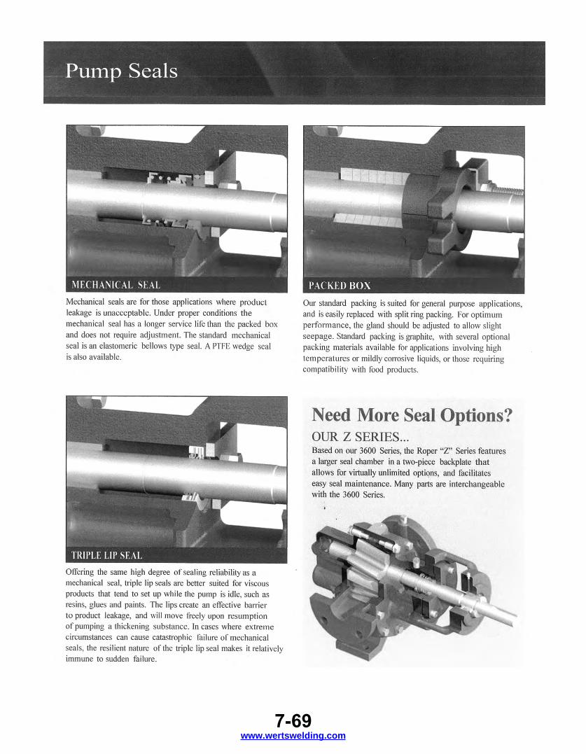
MECHANICAL SEALS
REF. NO. PART NAME
PARTS PER
PUMPPART NO.
153 Mechanical Seal Complete - Cast Iron Stationary Seat, Carbon Seal Face, FKM O-Rings. (IVCV)
2 1 331655
Mechanical Seal Complete - Cast Iron Stationary Seat, Carbon Seal Face, Buna-N O-Rings. (INCN)
1 331601
Mechanical Seal Complete - Cast Iron Stationary Seat, PTFE O-Ring, Carbon Seal Face w/ PTFE Seal Ring. (IACT)
331673
153D O-Ring - Stationary (Buna-N)
2 701934
O-Ring - Stationary (FKM) 701921 O-Ring - Stationary (PTFE) 702056
153L O-Ring - Rotating (Buna-N)
2 701922
O-Ring - Rotating (FKM) 701980 Seal Ring - Rotating (PTFE) **
1 Included in Maintenance Kit * * PTFE Rotating Seal Ring is not available as a separate part. OPTIONAL HYDRAULIC MOTOR ADAPTER PARTS
REF. NO. PART NAME
PARTS PER
PUMP
PART NO. 1”
Hyd Motor Shaft
PART NO. 1” H-Series Hyd Motor
Shaft
See Below Hydraulic Motor Adapter Kit *
See Below
891205 891464
26A Gasket – Hydraulic Motor Adapter 1 383940 383940
28A Capscrew – Hydraulic Motor Adapter / Head
4 920369 920369
34 Coupling w/ Setscrew – for 1” straight key hydraulic motor
1 906966 906966
76 Grease Fitting 1 317815 317815
76A Grease Relief Fitting 1 701992 701992
135 Hydraulic Motor Adapter – SAE A Flange
1 041827 041807
135A Capscrew – Adapter / Motor 2 920510 920510
www.wertswelding.com7-5

BLACKMER PARTS LIST 961415 Page 1 of 2
PARTS LIST201-A02
PUMP MODELS: TXD2A (Double Ended Shafts) Section 201
TX2A (Single Ended Shafts) Effective Mar 2012
Keep with Instructions 201-A00 for Installation, Operation and Maintenance Replaces Jan 2012
Ref. No. Description
Parts Per
PumpPart No. Ref.
No. Description Parts Per
PumpPart No.
1 Cap – Relief Valve (R/V) 1 411453 24B Lock washer - Bearing 2 4 903522 2 Adjusting Screw – R/V 1 431401 26 Gasket – Bearing Cover 1 - 2 1 381406 4 Cover – R/V 1 411401 27A Bearing Cover 1 - 2 041431 5 Capscrew – R/V Cover 3 920316 Bearing Cover – Outboard 0 - 1 041433
5A Capscrew w / Hole – R/V Cover 1 920310 28 Capscrews – Bearing Cover 8 920285 7 Spring Guide – R/V 1 423955 35 Key – Shaft Square 1 1, 6 9092098 Spring – R/V (36-50 psi) 1 471415 42 – Flanges, Flange Gaskets / O-rings, See Spring – R/V (51-75 psi) 471420 42C and Flange Capscrews Backside Spring – R/V (76-110 psi) (Std.) 471425 72 O-Ring – Head (FKM) 1 701914 Spring – R/V (111-125 psi) 471428 O-Ring – Head (Buna-N) 2 1 701947 9 Valve – R/V 5 1 451417 O-Ring – Head (PTFE) 702242 Valve – R/V (Ni Plated) 451415 73 Gage Plug 2 908198
10 Gasket – R/V Cover 1 1 531403 76 Grease Fitting 2 317815 12 Cylinder 1 021403 76A Grease Relief Fitting 2 701992
13A Rotor & Shaft – Double Ended 1 2 261411 77 Push Rod 2 1 123905 Rotor & Shaft – Single Ended 2 261426 88 Gasket – R/V Cap 1 1 701981
14 Vane – Duravane 4 1 091419 104 Grease Seal 1 - 2 1 331918 20 Head (Std.) 2 031425 123A Dirt Shield 1 - 2 1 701480 Head with Drain 031426 186 Shaft Protector 0 - 1 341601
21 Capscrews – Head 16 920331 Air Valve Kit 891454 24 Ball Bearing 2 1 903156 Tool - Locknut 903091
24A Locknut - Bearing 2 4 903521 Maintenance Kit, FKM 898956 Maintenance Kit, Buna 898950 1 Included in Maintenance Kit 2 Includes 24A & 24B
4 Earlier models were not fitted with locknuts and lock washers. The current rotor / shaft with locknuts and lock washers may be fitted in place of shafts without locknuts and lock washers. 5 For Piston Style Air Operated RV see IOM 201-G00, Diaphragm Air RV – 201-F00, DMX Diaphragm RV – 201B-B00. 6 Maintenance Kit also includes Woodruff Key 909130 used previously.
LOCKNUT TOOL
www.wertswelding.com7-6

MECHANICAL SEALS
REF. NO. PART NAME
PARTS PER
PUMPPART NO.
Mechanical Seal Complete - Cast Iron Stationary Seat, FKM O-Rings, Carbon Seal Face. (IVCV)
2 1 331655
153 Mechanical Seal Complete - Cast Iron Stationary Seat, Carbon Seal Face, Buna-N O-Rings. (INCN)
1 331601
Mechanical Seal Complete - Cast Iron Stationary Seat, PTFE O-Ring, Carbon Seal Face w/ PTFE Seal Ring. (IACT)
331673
153D O-Ring – Stationary (FKM)
2 701921
O-Ring – Stationary (Buna-N) 701934 O-Ring – Stationary (PTFE) 702056
153L O-Ring – Rotating (FKM)
2 701980
O-Ring – Rotating (Buna-N) 701922 Seal Ring – Rotating (PTFE) **
1 Included in Maintenance Kit ** PTFE Rotating Seal Ring is not available as a separate part. FLANGES
REF. NO. PART NAME
PARTS PER
PUMPPART NO.
42 Flange – 2" NPT 1 – 2 651411 Flange – 2" Weld 654405 Flange – 2" Victaulic 654408
42A Gasket – Flange, NPT and Weld 0 – 2 1 381421 42B Capscrews – 2" NPT Flange 4 – 8 920351
Capscrews – Victaulic Flanges 920331 42C O-Ring – Victaulic Flange (Buna-N) 0 – 2 702004
O-Ring – Victaulic Flange (FKM) 702086 O-Ring – Victaulic Flange (PTFE) 702078
OPTIONAL HYDRAULIC MOTOR ADAPTER
REF. NO. PART NAME
PARTS PER
PUMP
PART NO. 1-¼”
Hyd Motor Shaft
PART NO. 1”
Hyd Motor Shaft
PART NO. 1” H-Series Hyd Motor
Shaft
See Below
Hydraulic Motor Adapter Kit *
See Below
891458 891205 891464
26A Gasket – Hydraulic Motor Adapter
1 383940 383940 383940
28A Capscrew – Hydraulic Motor Adapter / Head
4 920369 920369 920369
34 Coupling w/ Setscrew – for straight key hyd. motor shaft
1 906967 906966 906966
35 Key – Coupling 1 909184 N/A N/A
76 Grease Fitting 1 317815 317815 317815
76A Grease Relief Fitting 1 701992 701992 701992
135 Hydraulic Motor Adapter – SAE A Flange
1 041828 041827 041807
135A Capscrew – Adapter / Motor 2 920510 920510 920510
www.wertswelding.com7-7

BLACKMER PARTS LIST 961615 Page 1 of 2
PARTS LIST201-A03
PUMP MODELS: TXD2.5A (Double Ended Shaft) Section 201
TX2.5A (Single Ended Shaft) Effective Aug 2014
Keep with Instructions 201-A00 for Installation, Operation and Maintenance Replaces Jan 2012
Ref. No.
Description
Parts Per
Pump Part No. Ref.
No. Description Parts Per
Pump Part No.
1 Cap – Relief Valve (R/V) 1 411453 28 Capscrews – Bearing Cover 8 920285 2 Adjusting Screw – R/V 1 431401 35 Key – Shaft Square 1 1,2 909209 4 Cover – Relief Valve 1 411607 42 Flanges 5 Capscrew – R/V Cover 3 920316 42A Gasket – Flange See
5A Capscrew w / Hole – R/V Cover 1 920310 42B Capscrews – Flange Backside 7 Spring Guide – R/V 1 423955 42C O-Ring – Victaulic Flanges 8 Spring – R/V (51-110 psi) (Std.) 1 471631 72 O-Ring – Head (FKM) 1 701914 Spring – R/V (111-125 psi) 471614 O-Ring – Head (Buna-N) 2 1 701947 9 Valve – R/V 3 1 451623 O-Ring – Head (PTFE) 702242 Valve – R/V (Nickel Plated) 451624 73 Gage Plug 2 908198
10 Gasket – R/V Cover 1 1 531603 76 Grease Fitting 2 317815 12 Cylinder – Pump 1 021605 76A Grease Relief Fitting 2 701992
13A Rotor & Shaft Asy. - Double Ended 4 1 261665 77 Push Rod 3 1 121607 Rotor & Shaft Asy. - Single Ended 4 261667 88 Gasket – R/V Cap 1 1 701981
14 Vane – Duravane 6 1 091619 104 Grease Seal 1 - 2 1 331918 20 Head (Std.) 2 031425 123A Dirt Shield 1 - 2 1 701480 21 Capscrews – Head 16 920331 186 Shaft Protector 1 341601 24 Ball Bearing 2 1 903156 Air Valve Kit – Piston Type (FKM) 891725
24A Locknut – Bearing 2 903521 Air Valve Kit – Diaphragm Type 891696 24B Lockwasher – Bearing 2 1 903522 Tool - Locknut 903091 26 Gasket – Bearing Cover 2 1 381406 Maintenance Kit (FKM) 898957
27A Bearing Cover 1 - 2 041431 Maintenance Kit (Buna-N) 898951 Bearing Cover – Outboard, SE shaft 0 - 1 041433
1 Included in Maintenance Kit 2 Maintenance Kit also includes Woodruff Key 909130 used previously 3 For Piston Style Air Operated RV see IOM 201-G00, Diaphragm Air RV – 201-F00, DMX Diaphragm RV – 201B-B00. 4 Includes Ref. Nos. 24A & 24B
LOCKNUT TOOL
www.wertswelding.com7-8
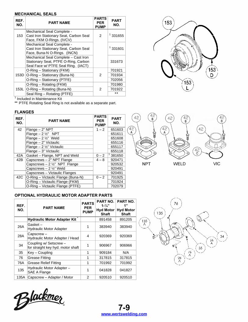
MECHANICAL SEALS REF. NO. PART NAME
PARTS PER
PUMPPART NO.
153 Mechanical Seal Complete - Cast Iron Stationary Seat, Carbon Seal Face, FKM O-Rings. (IVCV)
2 1 331655
Mechanical Seal Complete - Cast Iron Stationary Seat, Carbon Seal Face, Buna-N O-Rings. (INCN)
1 331601
Mechanical Seal Complete – Cast Iron Stationary Seat, PTFE O-Ring, Carbon Seal Face w/ PTFE Seal Ring. (IACT)
331673
153D O-Ring – Stationary (FKM)
2 701921
O-Ring – Stationary (Buna-N) 701934 O-Ring – Stationary (PTFE) 702056
153L O-Ring – Rotating (FKM)
2 701980
O-Ring – Rotating (Buna-N) 701922 Seal Ring – Rotating (PTFE) **
1 Included in Maintenance Kit ** PTFE Rotating Seal Ring is not available as a separate part. FLANGES REF. NO. PART NAME
PARTS PER
PUMPPART NO.
42 Flange – 2" NPT 1 – 2 651603 Flange – 2 ½" NPT 651611 Flange – 2 ½" Weld 651608 Flange – 2" Victaulic 655116 Flange – 2 ½" Victaulic 655117 Flange – 3" Victaulic 655118
42A Gasket – Flange, NPT and Weld 0 – 2 1 381650 42B Capscrews – 2" NPT Flange 4 – 8 920471
Capscrews – 2 ½" NPT Flange 920532 Capscrews – 2 ½" Weld 920491 Capscrews – Victaulic Flanges 920491
42C O-Ring – Victaulic Flange (Buna-N) 0 – 2 701925 O-Ring – Victaulic Flange (FKM) 701924 O-Ring – Victaulic Flange (PTFE) 702079
OPTIONAL HYDRAULIC MOTOR ADAPTER PARTS
REF. NO. PART NAME
PARTS PER
PUMP
PART NO.1-¼”
Hyd Motor Shaft
PART NO.1”
Hyd Motor Shaft
Hydraulic Motor Adapter Kit * 891458 891205
26A Gasket – Hydraulic Motor Adapter
1 383940 383940
28A Capscrew – Hydraulic Motor Adapter / Head
4 920369 920369
34 Coupling w/ Setscrew – for straight key hyd. motor shaft
1 906967 906966
35 Key – Coupling 1 909184 N/A
76 Grease Fitting 1 317815 317815
76A Grease Relief Fitting 1 701992 701992
135 Hydraulic Motor Adapter – SAE A Flange
1 041828 041827
135A Capscrew – Adapter / Motor 2 920510 920510
www.wertswelding.com7-9

BLACKMER PARTS LIST 961815 Page 1 of 2
PARTS LIST201-A04
PUMP MODELS: TXD3E (Double Ended Shafts) Section 201 TX3E (Single Ended Shafts) Effective Jan 2012
Keep with Instructions 201-A00 for Installation, Operation and Maintenance Replaces Apr 2009
Ref. No. Description
Parts Per
PumpPart No. Ref.
No. Description Parts Per
PumpPart No.
1 Cap – Relief Valve (R/V) 1 413957 26 Gasket – Bearing Cover 2 1 381817 2 Adjusting Screw – R/V 1 431808 27A Bearing Cover 1 - 2 041815 3 Locknut – Adjusting Screw 1 922923 Bearing Cover - Outboard 0 – 1 041817 4 Cover – R/V 1 411807 28 Capscrews – Bearing Cover 12 920285 5 Capscrew – R/V Cover 3 920331 35 Key – Shaft 1 1 909178
5A Capscrew w / Hole – R/V Cover 1 920330 42 – Flanges, Flange Gaskets / See 7 Spring Guide – R/V 1 421805 42C O-rings, and Flange Capscrews Backside8 Spring – R/V (51-75 & 76-110 psi) (Std.) 1 471806 O-Ring - Head (FKM) 2 1 711938 Spring – R/V (111-125 psi) 471809 72 O-Ring - Head (Buna-N) 1 701944
9 Valve - R/V 3 1 451807 O-Ring - Head (PTFE) 702233 Valve - R/V (Nickel Plated) 451808 73 Gage Plug 2 908198
10 Gasket – R/V Cover 1 1 531803 76 Grease Fitting 2 317815 12 Cylinder 1 021805 76A Grease Relief Fitting 2 701992
13A Rotor & Shaft Asy. - Double Ended 2 1 261837 77 Push Rod 3 1 121807 Rotor & Shaft Asy. - Single Ended 2 261839 88 Gasket - R/V Cap 1 1 533908
14 Vane – Duravane 6 1 091819 104 Grease Seal 1 - 2 1 331908 20 Head 2 031815 186 Shaft Protector 0 - 1 341801 21 Capscrews – Head 20 920369 Air Valve Kit 891798 24 Ball Bearing 2 1 903172 Tool - Locknut 903091
24A Locknut – Bearing 2 903523 Maintenance Kit, FKM 898958 24B Lockwasher - Bearing 2 1 903524 Maintenance Kit, Buna-N 898952
1 Included in Maintenance Kit 2 Includes ref. Nos. 24A & 24B 3 For Piston Style Air Operated RV see IOM 201-G00, Diaphragm Air RV – 201-F00, DMX Diaphragm RV – 201B-B00.
LOCKNUT TOOL
www.wertswelding.com7-10

MECHANICAL SEALS
REF. NO. PART NAME
PARTS PER
PUMP PART NO.
Mechanical Seal Complete - Cast Iron Stationary Seat, FKM O-Rings, Carbon Seal Face. (IVCV)
2 1 331883
153 Mechanical Seal Complete - Cast Iron Stationary Seat, Carbon Seal Face, Buna-N O-Rings. (INCN)
1 331880
Mechanical Seal Complete - Cast Iron Stationary Seat, PTFE O-Ring, Carbon Seal Face w/ PTFE Seal Ring. (IACT)
331873
153D O-Ring - Stationary (FKM) 711931 O-Ring - Stationary (Buna-N) 2 701936 O-Ring - Stationary (PTFE) 702080
153L O-Ring - Rotating (FKM) 701962 O-Ring - Rotating (Buna-N) 2 711912 Seal Ring - Rotating (PTFE) **
1 Included in Maintenance Kit ** PTFE Rotating Seal Ring is not available as a separate part. FLANGES
REF. NO. PART NAME
PARTS PER
PUMPPART NO.
42 Flange – 3" NPT 1 – 2 651803 Flange – 3" Weld 655102 Flange – 3" Victaulic 655120
42A Gasket – Flange, NPT and Weld 0 – 2 1 381816 42B Capscrews – NPT Flange 4 – 8 920532
Capscrews – Weld & Victaulic Flange 920510 42C O-Ring – Victaulic Flange (Buna-N) 0 – 2 702002
O-Ring – Victaulic Flange (FKM) 711931 O-Ring – Victaulic Flange (PTFE) 702080
OPTIONAL HYDRAULIC MOTOR ADAPTER
REF. NO.
PART NAME PARTS PER
PUMP
PART NO.1-¼”
Hyd Motor Shaft
PART NO.1”
Hyd Motor Shaft
Hydraulic Motor Adapter Kit * 895140 895143 26A Gasket – Hydraulic Motor
Adapter 1 381817 381817
28A Capscrew – Hydraulic Motor Adapter / Head
6 920369 920369
34 Coupling w/ Setscrew – straight key hydraulic motor
1 906967 906990
35 Key – Coupling 1 909184 909184 76 Grease Fitting 1 317815 317815
76A Grease Relief Fitting 1 701992 701992 135 Hydraulic Motor Adapter –
SAE A Flange 1 041831 041831
135A Capscrew – Adapter / Motor 2 920510 920510
www.wertswelding.com7-11
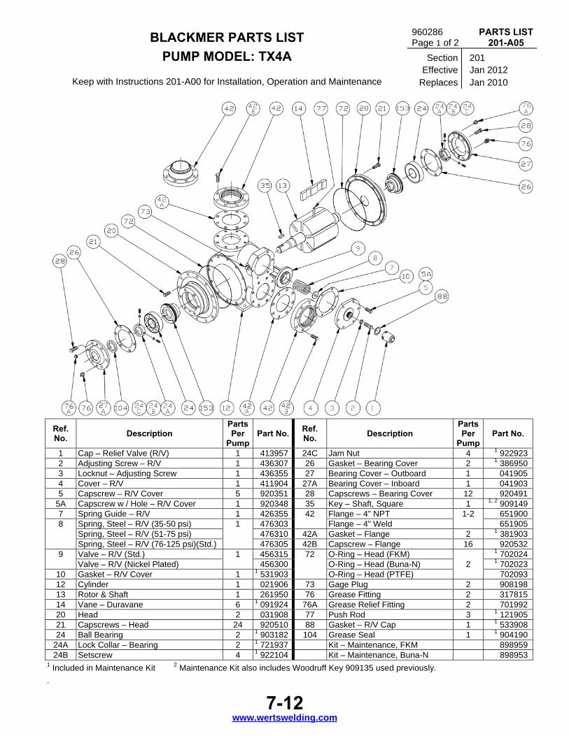
BLACKMER PARTS LIST 960286 Page 1 of 2
PARTS LIST201-A05
PUMP MODEL: TX4A Section 201 Effective Jan 2012
Keep with Instructions 201-A00 for Installation, Operation and Maintenance Replaces Jan 2010
Ref. No. Description
Parts Per
PumpPart No. Ref.
No. Description Parts Per
PumpPart No.
1 Cap – Relief Valve (R/V) 1 413957 24C Jam Nut 4 1 922923 2 Adjusting Screw – R/V 1 436307 26 Gasket – Bearing Cover 2 1 386950 3 Locknut – Adjusting Screw 1 436355 27 Bearing Cover – Outboard 1 041905 4 Cover – R/V 1 411904 27A Bearing Cover – Inboard 1 041903 5 Capscrew – R/V Cover 5 920351 28 Capscrews – Bearing Cover 12 920491
5A Capscrew w / Hole – R/V Cover 1 920348 35 Key – Shaft, Square 1 1, 2 909149 7 Spring Guide – R/V 1 426355 42 Flange – 4" NPT 1-2 651900 8 Spring, Steel – R/V (35-50 psi) 1 476303 Flange – 4" Weld 651905 Spring, Steel – R/V (51-75 psi) 476310 42A Gasket – Flange 2 1 381903 Spring, Steel – R/V (76-125 psi)(Std.) 476305 42B Capscrew – Flange 16 920532 9 Valve – R/V (Std.) 1 456315 72 O-Ring – Head (FKM) 1 702024 Valve – R/V (Nickel Plated) 456300 O-Ring – Head (Buna-N) 2 1 702023
10 Gasket – R/V Cover 1 1 531903 O-Ring – Head (PTFE) 702093 12 Cylinder 1 021906 73 Gage Plug 2 908198 13 Rotor & Shaft 1 261950 76 Grease Fitting 2 317815 14 Vane – Duravane 6 1 091924 76A Grease Relief Fitting 2 701992 20 Head 2 031908 77 Push Rod 3 1 121905 21 Capscrews – Head 24 920510 88 Gasket – R/V Cap 1 1 533908 24 Ball Bearing 2 1 903182 104 Grease Seal 1 1 904190
24A Lock Collar – Bearing 2 1 721937 Kit – Maintenance, FKM 898959 24B Setscrew 4 1 922104 Kit – Maintenance, Buna-N 898953
1 Included in Maintenance Kit 2 Maintenance Kit also includes Woodruff Key 909135 used previously.
.
www.wertswelding.com7-12

MECHANICAL SEALS – TX4A MODELS
REF. NO. PART NAME
PARTS PER
PUMPPART NO.
153
Mechanical Seal Complete - Cast Iron Stationary Seat, Carbon Seal Face w/ FKM O-Rings. (IVCV)
2
1 336982
Mechanical Seal Complete – Cast Iron Stationary Seat, Carbon Seal Face, Buna-N O-Rings. (INCN)
1 336958
Mechanical Seal Complete - Cast Iron Stationary Seat, PTFE O-Ring, Carbon Seal Face w/ PTFE Seal Ring. (IACT)
331973
Mechanical Seal Complete - Cast Iron Stationary Seat, Bronze Seal Face w/ FKM O-Rings. (IVBV)
336984
153D O-Ring - Stationary (FKM) 711932 O-Ring - Stationary (Buna-N) 2 701945 O-Ring - Stationary (PTFE) 702090
153L O-Ring - Rotating (FKM) 701967 O-Ring - Rotating (Buna-N) 2 701933 Seal Ring - Rotating (PTFE) **
1 Included in Maintenance Kit ** PTFE Rotating Seal Ring is not available as a separate part.
www.wertswelding.com7-13

TXD1200 Series High-Speed Sliding Vane Truck Pumps
How Blackmer’s sliding vane action works
Spec Sheet 201-002
Section: 201
Effective: May 2013
Replaces: June 2008
ReliabilityWith pump speeds of up to 1,200 RPM, the durable, high-speed TXD Series truck pumps provide fast and quiet operation, while the sliding vane design offers sustained performance and reliability.
Unique FeaturesAdjustable relief valve protects pump from excessive pressure. Optional air operated piston-style relief valve offers easy hose and nozzle handling. T-type strainers are available to protect pumping systems from damage caused by welding slag and foreign matter in the piping and tanks.
Sizing OptionsAvailable in 2, 2.5 and 3-inch port sizes with flow rates from 20 to 265 U.S. gallons (4 to 60 m3/H) and pressures up to 125 psi (8.6 bar).
Applicationsn Fuel oil delivery truck
n Fleet refueling
n Aviation refuelers
n Transport of:
– Petro Chemicals
– Gasoline
– Diesel Fuel
– Biofuels
– Home Heating Oil
– Solvents
– And many more
TXD1200 models are equipped with FKM elastomers that make the pump ideal for handling all types of light petroleum products, solvents and all Biodiesel and Ethanol blends.
TXD2 Sliding Vane Pump
7-14

5/13 - 500
Distributed By:
Printed in USA © 2013 Blackmer
Process | Energy | Military & Marine
World Headquarters1809 Century Avenue SW, Grand Rapids, MI 49503-1530 USA
T 616.241.1611 F 616.241.3752 www.blackmer.com
Performance Data
Maximum Operating Limits
Dimensions
* Appropriate capacities and horsepower (HP) are based on a 100 ssu (22 cSt) fluid a 50 PSI (3.4 bar) delivered pressureRefer to Characteristic Curves for flow rates and torque requirements at other pressures and viscosities.
Pump Model TXD1220 TXD1225 TXD1230Rated Pump Speed 1100 800 1100 800 800 640gpm 82 59 130 93 240 185L/min 310 223 492 352 908 700m3/h 18 13 29 21 54 42hp 4.2 2.9 6.6 4.7 10.8 8.1kW 3.1 2.1 4.9 3.5 8.0 6.0
Pump ModelNominal Flowrate Pump Speed Viscosity Differential Pressure Working Pressure Temperaturegpm L/min rpm ssu cSt psi bar psi bar ºF ºC
TXD1220 87 329 1200 100 22 125 8.6 175 12.1 300 149TXD1225 157 594 1200 100 22 125 8.6 175 12.1 300 149TXD1230 270 1,022 900 100 22 125 8.6 175 12.1 300 149
Model A B D E G K M Q S T AA BB
DD
TT Approx. Wt.11⁄4” HYDMotor Shaft
1” HYD Motor Shaft
TXD1220in. 11⁄8 1⁄4 8 51⁄4 31⁄2 61⁄2 4 811⁄16 61⁄8 37⁄8 83⁄4 85⁄16 107⁄8 109⁄16 121⁄8 70 lbs
mm – – 203 133 89 165 102 221 156 98 222 211 276 268 308 32 kg
TXD1225in. 11⁄8 1⁄4 8 3⁄4 6 4 7⁄8 7 4 9 5⁄8 6 13⁄16 3 15⁄16 9 1⁄2 8 11⁄16 11 5⁄8 11 5⁄16 13 5⁄16 94 lbs
mm – – 222 152 124 178 102 244 173 100 241 221 295 287 338 43 kg
TXD1230in. 11⁄8 1⁄4 9 5⁄8 6 7⁄16 4 3⁄8 7 1⁄4 5 3⁄8 12 13⁄16 8 9⁄16 4 15⁄16 10 11⁄16 9 7⁄16 12 3⁄8 15 3⁄8 152 lbs
mm – – 244 164 111 184 137 325 217 125 271 240 314 391 69 kg
TXD1200 Series High-Speed Sliding Vane Truck Pumps
Pump RotationBlackmer TXD models are equipped with a double-ended drive shaft for either clockwise (RH) or counterclockwise (LH) rotation.
Port Sizesn TXD1220 – 2"
n TXD1225 – 2.5"
n TXD1230 – 3"
Optionsn Pneumatic Relief Valve
n Hydraulic Motor Adapters
n Strainers
n Victaulic Flanges
™
7-15

BLACKMER PARTS LIST 961681 Page 1 of 2
PARTS LIST201-D03
PUMP MODELS: TXD1225A Section 201 Effective Dec 2008
Keep with Instructions 201-D00 for Installation, Operation and Maintenance Replaces June 2008
Ref. No.
Description
Parts Per
Pump Part No. Ref.
No. Description Parts Per
PumpPart No.
1 Cap – Relief Valve (R/V) 1 411453 26 Gasket – Bearing Cover 2 1 381406 2 Adjusting Screw – R/V 1 431401 27A Bearing Cover 2 041431 4 Cover – Relief Valve 1 411607 28 Capscrews – Bearing Cover 8 920285 5 Capscrew – R/V Cover 3 920316 35 Key – Shaft 1 1 909209
5A Capscrew w / Hole – R/V Cover 1 920310 42 Flanges 7 Spring Guide – R/V 1 423955 42A Gasket – Flange See 8 Spring – R/V (51-110 PSI) (Std.) 1 471631 42B Capscrews – Flange Backside Spring – R/V (111-125 PSI) 471614 42C O-Ring – Victaulic Flanges 9 Valve – R/V – Standard 3 1 451623 72 O-Ring – Head (FKM) 2 701914 Valve – R/V – Nickel Plated 1 451624 73 Gage Plug 2 908198
10 Gasket – R/V Cover 1 1 531603 76 Grease Fitting 2 317815 12 Cylinder (Note Series 1200 ID mark) 1 021680 76A Grease Relief Fitting 2 701992
13A Rotor & Shaft Assembly2 1 261680 88 Gasket – R/V Cap 1 1 701981 14 Vane – Duravane 6 1 091619 104 Grease Seal 2 1 331918 20 Head 2 031425 123A Dirt Shield 2 1 701480 21 Capscrews – Head 16 920331 186 Shaft Protector 1 341601 24 Ball Bearing 2 1 903156 Air Valve Kit – Piston Type (FKM) 891716
24A Locknut Assembly w/setscrew 24C 2 1 903583 Tool - Locknut 903091 24B Lockwasher – Bearing 2 1 903522 Kit – Maintenance (TXD1225A) 899181 24C Setscrew – Locknut (in 24A) 2 924060
1 Included in Maintenance Kit 2 Includes Ref. Nos. 24A, 24B, & 24C 3 For Piston Style Air Operated RV see IOM 201-G00.
LOCKNUT TOOL
www.wertswelding.com7-16

MECHANICAL SEALS REF. NO. PART NAME
PARTS PER
PUMPPART NO.
153 Mechanical Seal Complete - Cast Iron Stationary Seat, Carbon Seal Face, FKM O-Rings. (IVCV)
2 1 331655
153D O-Ring – Stationary (FKM) 2 701921
153L O-Ring – Rotating (FKM) 2 701980 1 Included in Maintenance Kit FLANGES REF. NO. PART NAME
PARTS PER
PUMPPART NO.
42 Flange – 2" NPT 1 – 2 651603 Flange – 2 ½" NPT 651611 Flange – 2 ½" Weld 651608 Flange – 2" Victaulic 655116 Flange – 2 ½" Victaulic 655117 Flange – 3" Victaulic 655118
42A Gasket – Flange, NPT and Weld 0 – 2 1 381650 42B Capscrews – 2" NPT Flange 4 – 8 920471
Capscrews – 2 ½" NPT Flange 920532 Capscrews – 2 ½" Weld 920491 Capscrews – Victaulic Flanges 920491
42C O-Ring – Victaulic Flange (FKM) 0 – 2 701924 OPTIONAL HYDRAULIC MOTOR ADAPTER PARTS
REF. NO. PART NAME
PARTS PER
PUMP
PART NO.1-¼”
Hyd Motor Shaft
PART NO.1”
Hyd Motor Shaft
Hydraulic Motor Adapter Kit 891458 891205
26A Gasket – Hydraulic Motor Adapter
1 383940 383940
28A Capscrew – Hydraulic Motor Adapter / Head
4 920369 920369
34 Coupling w/ Setscrew – for straight key hyd. motor shaft
1 906967 906966
35 Key – Coupling 1 909184 N/A
76 Grease Fitting 1 317815 317815
76A Grease Relief Fitting 1 701992 701992
135 Hydraulic Motor Adapter – SAE A Flange
1 041828 041827
135A Capscrew – Adapter / Motor 2 920510 920510
www.wertswelding.com7-17

BLACKMER PARTS LIST 961881 Page 1 of 2
PARTS LIST201-D04
PUMP MODEL: TXD1230A Section 201 Effective Oct 2008
Keep with Instructions 201-D00 for Installation, Operation and Maintenance Replaces New
Ref. No. Description
Parts Per
PumpPart No. Ref.
No. Description Parts Per
PumpPart No.
1 Cap – Relief Valve (R/V) 1 413957 24B Lockwasher - Bearing 2 1 903524 2 Adjusting Screw – R/V 1 431808 24C Setscrew – Locknut (in 24A) 2 924060 3 Locknut – Adjusting Screw 1 922923 26 Gasket – Bearing Cover 2 1 381817 4 Cover – R/V 1 411807 27A Bearing Cover 2 041815 5 Capscrew – R/V Cover 3 920331 28 Capscrews – Bearing Cover 12 920285
5A Capscrew w / Hole – R/V Cover 1 920330 35 Key – Shaft 1 1 9091787 Spring Guide – R/V 1 421805 42 – Flanges, Flange Gaskets / Orings, See
8 Spring – R/V (51-110 psi)(Std.) 1 471806 42C and Flange Capscrews Backside
Spring – R/V (111-125 psi) 471809 72 O-Ring - Head (FKM) 2 1 711938 9 Valve - R/V (Std.) 1 451807 73 Gage Plug 2 908198 Valve - R/V (Nickel Plated) 451808 76 Grease Fitting 2 317815
10 Gasket – R/V Cover 1 1 531803 76A Grease Relief Fitting 2 701992 12 Cylinder (Note Series 1200 ID mark) 1 021880 77 Push Rod 3 1 125110
13A Rotor & Shaft Asy. - Double Ended 2 1 261881 88 Gasket - R/V Cap 1 1 533908 14 Vane – Duravane 6 1 091819 104 Grease Seal 2 1 331908 20 Head 2 031815 186 Shaft Protector 1 341801 21 Capscrews – Head 20 920369 Air Valve Kit 891798 24 Ball Bearing 2 1 903172 Tool - Locknut 903091
24A Locknut – Bearing (Includes 24C) 2 903582 Kit – Maintenance (TXD1230A) 899182 1 Included in Maintenance Kit 2 Includes ref. Nos. 24A, 24B & 24C
LOCKNUT TOOL
www.wertswelding.com7-18
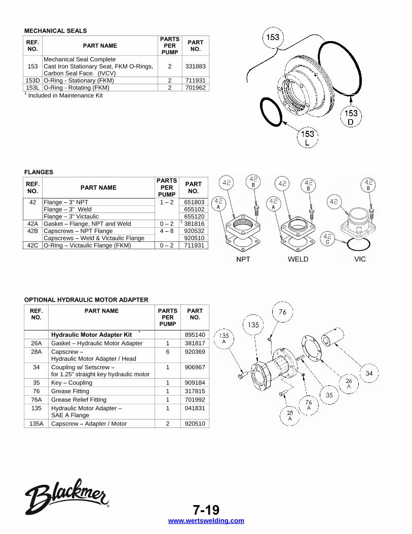
MECHANICAL SEALS
REF. NO. PART NAME
PARTS PER
PUMP PART NO.
153 Mechanical Seal Complete Cast Iron Stationary Seat, FKM O-Rings, Carbon Seal Face. (IVCV)
2 331883
153D O-Ring - Stationary (FKM) 2 711931 153L O-Ring - Rotating (FKM) 2 701962
1 Included in Maintenance Kit FLANGES
REF. NO. PART NAME
PARTS PER
PUMPPART NO.
42 Flange – 3" NPT 1 – 2 651803 Flange – 3" Weld 655102 Flange – 3" Victaulic 655120
42A Gasket – Flange, NPT and Weld 0 – 2 1 381816 42B Capscrews – NPT Flange 4 – 8 920532
Capscrews – Weld & Victaulic Flange 920510 42C O-Ring – Victaulic Flange (FKM) 0 – 2 711931
OPTIONAL HYDRAULIC MOTOR ADAPTER
REF. NO.
PART NAME PARTS PER
PUMP
PART NO.
Hydraulic Motor Adapter Kit * 895140 26A Gasket – Hydraulic Motor Adapter 1 381817
28A Capscrew – Hydraulic Motor Adapter / Head
6 920369
34 Coupling w/ Setscrew – for 1.25” straight key hydraulic motor
1 906967
35 Key – Coupling 1 909184
76 Grease Fitting 1 317815
76A Grease Relief Fitting 1 701992
135 Hydraulic Motor Adapter – SAE A Flange
1 041831
135A Capscrew – Adapter / Motor 2 920510
www.wertswelding.com7-19

www.wertswelding.com7-20
nwerts
Typewritten text
Call us for all of your Diesel Exhaust Fluid needs! Let us help you find the right pump for the job!
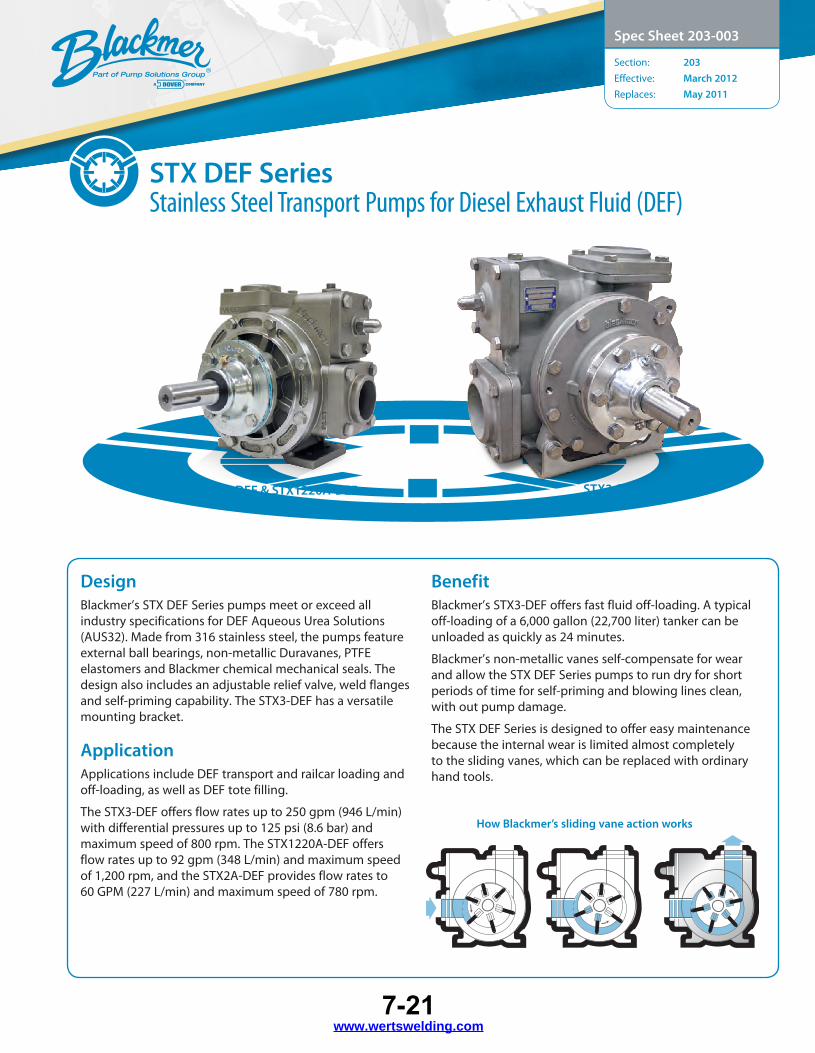
STX DEF SeriesStainless Steel Transport Pumps for Diesel Exhaust Fluid (DEF)
Spec Sheet 203-003
Section: 203
Effective: March 2012
Replaces: May 2011
STX3-DEFSTX2A-DEF & STX1220A-DEF
How Blackmer’s sliding vane action works
DesignBlackmer’s STX DEF Series pumps meet or exceed all industry specifications for DEF Aqueous Urea Solutions (AUS32). Made from 316 stainless steel, the pumps feature external ball bearings, non-metallic Duravanes, PTFE elastomers and Blackmer chemical mechanical seals. The design also includes an adjustable relief valve, weld flanges and self-priming capability. The STX3-DEF has a versatile mounting bracket.
ApplicationApplications include DEF transport and railcar loading and off-loading, as well as DEF tote filling.
The STX3-DEF offers flow rates up to 250 gpm (946 L/min) with differential pressures up to 125 psi (8.6 bar) and maximum speed of 800 rpm. The STX1220A-DEF offers flow rates up to 92 gpm (348 L/min) and maximum speed of 1,200 rpm, and the STX2A-DEF provides flow rates to 60 GPM (227 L/min) and maximum speed of 780 rpm.
BenefitBlackmer’s STX3-DEF offers fast fluid off-loading. A typical off-loading of a 6,000 gallon (22,700 liter) tanker can be unloaded as quickly as 24 minutes.
Blackmer’s non-metallic vanes self-compensate for wear and allow the STX DEF Series pumps to run dry for short periods of time for self-priming and blowing lines clean, with out pump damage.
The STX DEF Series is designed to offer easy maintenance because the internal wear is limited almost completely to the sliding vanes, which can be replaced with ordinary hand tools.
www.wertswelding.com7-21

Process | Energy | Military & Marine
3/12 - 1M
Pump Model
PumpSpeed
Pump Capacity @50 psid (3.45 bar) with
30 ssu (1 cSt) Fluid
Maximum FluidViscosity atrpm Shown
rpm US gpm L/min m3⁄h ssu cSt
STX2A-DEF780 50 189 11.3 30 1520 30 113 6.8 1,000 210350 16 60 3.6 4,600 970
STX1220A- DEF
1,200 82 310 18 100 221,000 72 273 16 100 22700 49 185 11 100 22
STX3-DEF800 250 946 57 500 105600 190 719 43 5,000 1,050400 125 473 28 20,000 4,250
Characteristic Flow Rates
Pump Model
PumpSpeed
30 ssu(1 cSt) Viscosity
50 ssu(13 cSt) Viscosity
rpm50 psi
(3.45 bar)100 psi
(6.9 bar)50 psi
(3.45 bar)100 psi
(6.9 bar)
STX2A-DEF780 2.4 4.3 – –520 1.5 2.9 1.7 3.1350 1 1.9 1.1 2.1
STX1220A- DEF
1,200 4.0 6.9 4.2 7.31,000 3.4 5.6 3.6 6.0700 2.3 3.8 2.4 4.1
STX3-DEF800 9.5 17.5 9.8 17.9600 6.7 12.8 6.9 13.2400 4.2 8.0 4.3 8.3
Pump Horsepower Requirements
Pump ModelNominal Flow Rate
Pump Speed
ViscosityDifferential
PressureTemperature
US gpm L/min m3 ⁄ h rpm ssu cSt psi bar °F °C
STX2A-DEF 60 227 13.6 780 4,600 970 125 8.6 240 115
STX1220A-DEF 92 348 21 1,200 100 22 125 8.6 240 115
STX3-DEF 250 946 57 800 20,000 4,250 125 8.6 240 115
Maximum Operating Limits
Refer to Blackmer Characteristic Curves for flow rates and torque requirements for your specific conditions.
Pump Dimensions
STX1220A-DEF & STX2A-DEF
STX3-DEF
Pump Model A B D E G K M Q S T AA BB
DD
TTApprox. Weight
11⁄4" HYD Motor Shaft
1" HYD
Motor Shaft
STX2A-DEF &STX1220A-
DEF
in. 11⁄8 1⁄4 8 51⁄4 31⁄2 61⁄2 4 811⁄16 61⁄8 37⁄8 83⁄4 85⁄16 107⁄8 109⁄16 121⁄8 70 lbs.
mm – – 203 133 89 165 102 221 156 98 222 211 276 268 308 32 kg
Pump Model A B C D E F G H J K L M N PApprox. Weight
STX3-DEFin. – – 2 1⁄8 9 1⁄8 5 11 1⁄8 6 1⁄8 6 1⁄4 5 1⁄4 3 3⁄4 5 3⁄8 8 4 5⁄8 2 1⁄4 132 lbs.
mm 35 10 54 242 127 283 155 159 133 95 137 203 118 57 60 kg
Pump RotationBlackmer’s STX pump models are equipped with a double- ended straight-keyed drive shaft for either clockwise (RH) or counterclockwise (LH) rotation.
www.wertswelding.com7-22
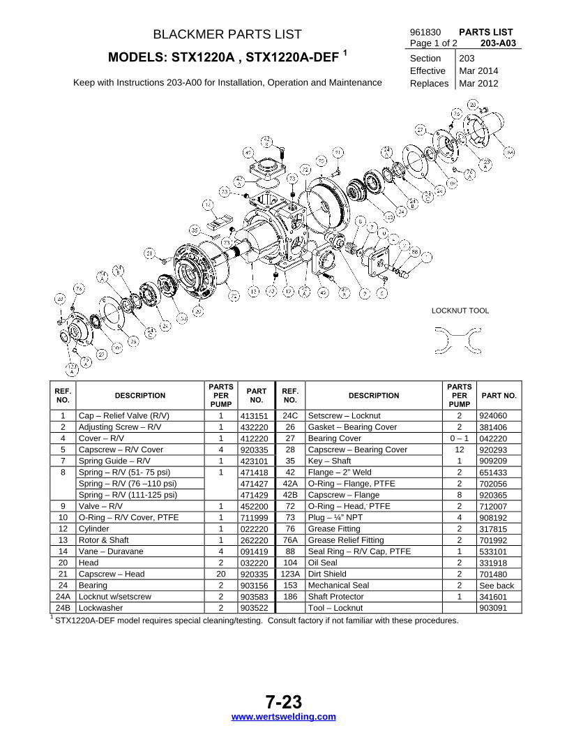
BLACKMER PARTS LIST 961830 PARTS LIST Page 1 of 2 203-A03
MODELS: STX1220A , STX1220A-DEF 1 Section 203 Effective Mar 2014
Keep with Instructions 203-A00 for Installation, Operation and Maintenance Replaces Mar 2012
REF. NO. DESCRIPTION
PARTS PER
PUMP
PART NO.
REF. NO. DESCRIPTION
PARTS PER
PUMP PART NO.
1 Cap – Relief Valve (R/V) 1 413151 24C Setscrew – Locknut 2 924060 2 Adjusting Screw – R/V 1 432220 26 Gasket – Bearing Cover 2 381406 4 Cover – R/V 1 412220 27 Bearing Cover 0 – 1 042220 5 Capscrew – R/V Cover 4 920335 28 Capscrew – Bearing Cover 12 920293 7 Spring Guide – R/V 1 423101 35 Key – Shaft 1 909209 8 Spring – R/V (51- 75 psi) 1 471418 42 Flange – 2” Weld 2 651433 Spring – R/V (76 –110 psi) 471427 42A O-Ring – Flange, PTFE 2 702056 Spring – R/V (111-125 psi) 471429 42B Capscrew – Flange 8 920365
9 Valve – R/V 1 452200 72 O-Ring – Head,, PTFE 2 712007 10 O-Ring – R/V Cover, PTFE 1 711999 73 Plug – ¼” NPT 4 908192 12 Cylinder 1 022220 76 Grease Fitting 2 317815 13 Rotor & Shaft 1 262220 76A Grease Relief Fitting 2 701992 14 Vane – Duravane 4 091419 88 Seal Ring – R/V Cap, PTFE 1 533101 20 Head 2 032220 104 Oil Seal 2 331918 21 Capscrew – Head 20 920335 123A Dirt Shield 2 701480 24 Bearing 2 903156 153 Mechanical Seal 2 See back
24A Locknut w/setscrew 2 903583 186 Shaft Protector 1 341601 24B Lockwasher 2 903522 Tool – Locknut 903091
1 STX1220A-DEF model requires special cleaning/testing. Consult factory if not familiar with these procedures.
LOCKNUT TOOL
www.wertswelding.com7-23

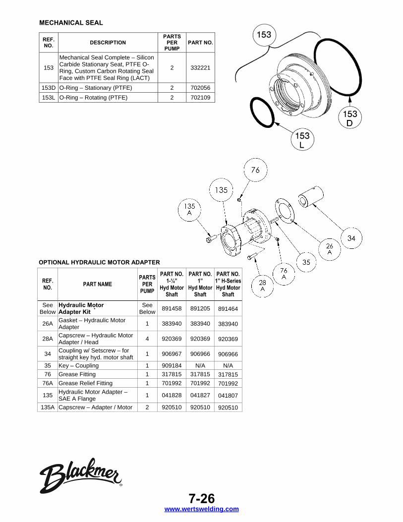
MECHANICAL SEAL
REF. NO. DESCRIPTION
PARTS PER
PUMP PART NO.
153
Mechanical Seal Complete – Silicon Carbide Stationary Seat, PTFE O-Ring, Custom Carbon Rotating Seal Face with PTFE Seal Ring (LACT)
2 332221
153D O-Ring – Stationary (PTFE) 2 702056
153L O-Ring – Rotating (PTFE) 2 702109
OPTIONAL HYDRAULIC MOTOR ADAPTER
REF. NO. PART NAME
PARTS PER
PUMP
PART NO. 1-¼”
Hyd Motor Shaft
PART NO. 1”
Hyd Motor Shaft
PART NO. 1” H-Series Hyd Motor
Shaft
See Below
Hydraulic Motor Adapter Kit *
See Below
891458 891205 891464
26A Gasket – Hydraulic Motor Adapter
1 383940 383940 383940
28A Capscrew – Hydraulic Motor Adapter / Head
4 920369 920369 920369
34 Coupling w/ Setscrew – for straight key hyd. motor shaft
1 906967 906966 906966
35 Key – Coupling 1 909184 N/A N/A
76 Grease Fitting 1 317815 317815 317815
76A Grease Relief Fitting 1 701992 701992 701992
135 Hydraulic Motor Adapter – SAE A Flange
1 041828 041827 041807
135A Capscrew – Adapter / Motor 2 920510 920510 920510
www.wertswelding.com7-24

BLACKMER PARTS LIST 961829 PARTS LIST Page 1 of 2 203-A04
MODELS: STX2A , STX2A-DEF 1 Section 203 Effective Mar 2014
Keep with Instructions 203-A00 for Installation, Operation and Maintenance Replaces Mar 2012
REF. NO. DESCRIPTION
PARTS PER
PUMP PART NO.
REF. NO. DESCRIPTION
PARTS PER
PUMP PART NO.
1 Cap – Relief Valve (R/V) 1 413151 24C Setscrew – Locknut 2 924060 2 Adjusting Screw – R/V 1 432220 26 Gasket – Bearing Cover 2 381406 4 Cover – R/V 1 412220 27 Bearing Cover 0 – 1 042220 5 Capscrew – R/V Cover 4 920335 28 Capscrew – Bearing Cover 12 920293 7 Spring Guide – R/V 1 423101 35 Key – Shaft 1 909209 8 Spring – R/V (51- 75 psi) 1 471418 42 Flange – 2” Weld 2 651433 Spring – R/V (76 –110 psi) 471427 42A O-Ring – Flange, PTFE 2 702056 Spring – R/V (111-125 psi) 471429 42B Capscrew – Flange 8 920365
9 Valve – R/V 1 452200 72 O-Ring – Head,, PTFE 2 712007 10 O-Ring – R/V Cover, PTFE 1 711999 73 Plug – ¼” NPT 4 908192 12 Cylinder 1 022220 76 Grease Fitting 2 317815 13 Rotor & Shaft 1 262221 76A Grease Relief Fitting 2 701992 14 Vane – Duravane 4 091419 77 Pushrod 2 123907 20 Head 2 032220 88 Seal Ring – R/V Cap, PTFE 1 533101 21 Capscrew – Head 20 920335 104 Oil Seal 2 331918 24 Bearing 2 903156 123A Dirt Shield 2 701480
24A Locknut w/setscrew 2 903583 153 Mechanical Seal 2 See back 24B Lockwasher 2 903522 186 Shaft Protector 1 341601
Tool – Locknut 903091 1 STX2A-DEF model requires special cleaning/testing. Consult factory if not familiar with these procedures.
LOCKNUT TOOL
www.wertswelding.com7-25
MECHANICAL SEAL
REF. NO. DESCRIPTION
PARTS PER
PUMP PART NO.
153
Mechanical Seal Complete – Silicon Carbide Stationary Seat, PTFE O-Ring, Custom Carbon Rotating Seal Face with PTFE Seal Ring (LACT)
2 332221
153D O-Ring – Stationary (PTFE) 2 702056
153L O-Ring – Rotating (PTFE) 2 702109
OPTIONAL HYDRAULIC MOTOR ADAPTER
REF. NO. PART NAME
PARTS PER
PUMP
PART NO. 1-¼”
Hyd Motor Shaft
PART NO. 1”
Hyd Motor Shaft
PART NO. 1” H-Series Hyd Motor
Shaft
See Below
Hydraulic Motor Adapter Kit *
See Below
891458 891205 891464
26A Gasket – Hydraulic Motor Adapter
1 383940 383940 383940
28A Capscrew – Hydraulic Motor Adapter / Head
4 920369 920369 920369
34 Coupling w/ Setscrew – for straight key hyd. motor shaft
1 906967 906966 906966
35 Key – Coupling 1 909184 N/A N/A
76 Grease Fitting 1 317815 317815 317815
76A Grease Relief Fitting 1 701992 701992 701992
135 Hydraulic Motor Adapter – SAE A Flange
1 041828 041827 041807
135A Capscrew – Adapter / Motor 2 920510 920510 920510
www.wertswelding.com7-26
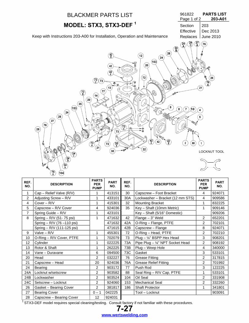
BLACKMER PARTS LIST 961822 PARTS LIST Page 1 of 2 203-A01
MODEL: STX3, STX3-DEF 1 Section 203 Effective Dec 2013
Keep with Instructions 203-A00 for Installation, Operation and Maintenance Replaces June 2010
REF. NO. DESCRIPTION
PARTS PER
PUMP
PART NO.
REF. NO. DESCRIPTION
PARTS PER
PUMP
PART NO.
1 Cap – Relief Valve (R/V) 1 413151 30 Capscrew – Foot Bracket 4 924071 2 Adjusting Screw – R/V 1 433101 30A Lockwasher – Bracket (12 mm STS) 4 909586 4 Cover – R/V 1 415301 32 Mounting Bracket 1 832225 5 Capscrew – R/V Cover 4 924036 35 Key – Shaft (10mm Metric) 1 909146 7 Spring Guide – R/V 1 423101 Key – Shaft (5/16” Domestic) 909206 8 Spring – R/V (51- 75 psi) 1 471632 42 Flange – 3” Weld 2 652201 Spring – R/V (76 –110 psi) 471632 42A O-Ring – Flange, PTFE 2 702101 Spring – R/V (111-125 psi) 471615 42B Capscrew – Flange 8 924071
9 Valve – R/V 1 455301 72 O-Ring – Head,, PTFE 2 702210 10 O-Ring – R/V Cover, PTFE 1 702079 73 Plug – ¼” BSPP Hex Head 3 908201 12 Cylinder 1 022225 73A Pipe Plug – ¼” NPT Socket Head 2 908192 13 Rotor & Shaft 1 262225 73B Plug – Weep Hole 4 340000 14 Vane – Duravane 6 094500 73C Gasket 3 533101 20 Head 2 032227 76 Grease Fitting 2 317815 21 Capscrew – Head 20 924036 76A Grease Relief Fitting 2 701992 24 Bearing 2 903172 77 Push Rod 3 122225
24A Locknut w/setscrew 2 903582 88 Seal Ring – R/V Cap, PTFE 1 533101 24B Lockwasher 2 903524 104 Oil Seal 2 331908 24C Setscrew – Locknut 2 924060 153 Mechanical Seal 2 332260 26 Gasket – Bearing Cover 2 381817 186 Shaft Protector 1 341801 27 Bearing Cover 0 – 1 042225 Tool – Locknut 903091 28 Capscrew – Bearing Cover 12 924031
1 STX3-DEF model requires special cleaning/testing. Consult factory if not familiar with these procedures.
LOCKNUT TOOL
www.wertswelding.com7-27

MECHANICAL SEAL
REF. NO. DESCRIPTION
PARTS PER
PUMP PART NO.
153
Mechanical Seal Complete – Silicon Carbide Stationary Seat, PTFE O-Ring, Custom Carbon Rotating Seal Face with PTFE Seal Ring (LACT)
2 332260
153D O-Ring – Stationary (PTFE) 2 702080
153L Seal Ring – PTFE 2 **
** 153L PTFE Seal Ring is not available as a separate part.
OPTIONAL HYDRAULIC MOTOR ADAPTER PARTS
REF. NO. PART NAME
PARTS PER
PUMP PART NO.
--- Hydraulic Motor Adapter Kit * See Below 892228
26A Gasket – Hydraulic Motor Adapter 1 381817
28A Capscrew – Hydraulic Motor Adapter / head
6 924037
34 Coupling w/ Setscrew – 1.25” straight key hyd. motor shaft
1 906969
35 Key – Coupling 1 909184
76 Grease Fitting 1 317815
76A Grease Relief Fitting 1 701992
135 Hydraulic Motor Adapter – SAE A Flange
1 041829
135A Capscrew – Adapter / Motor 2 920510
www.wertswelding.com7-28

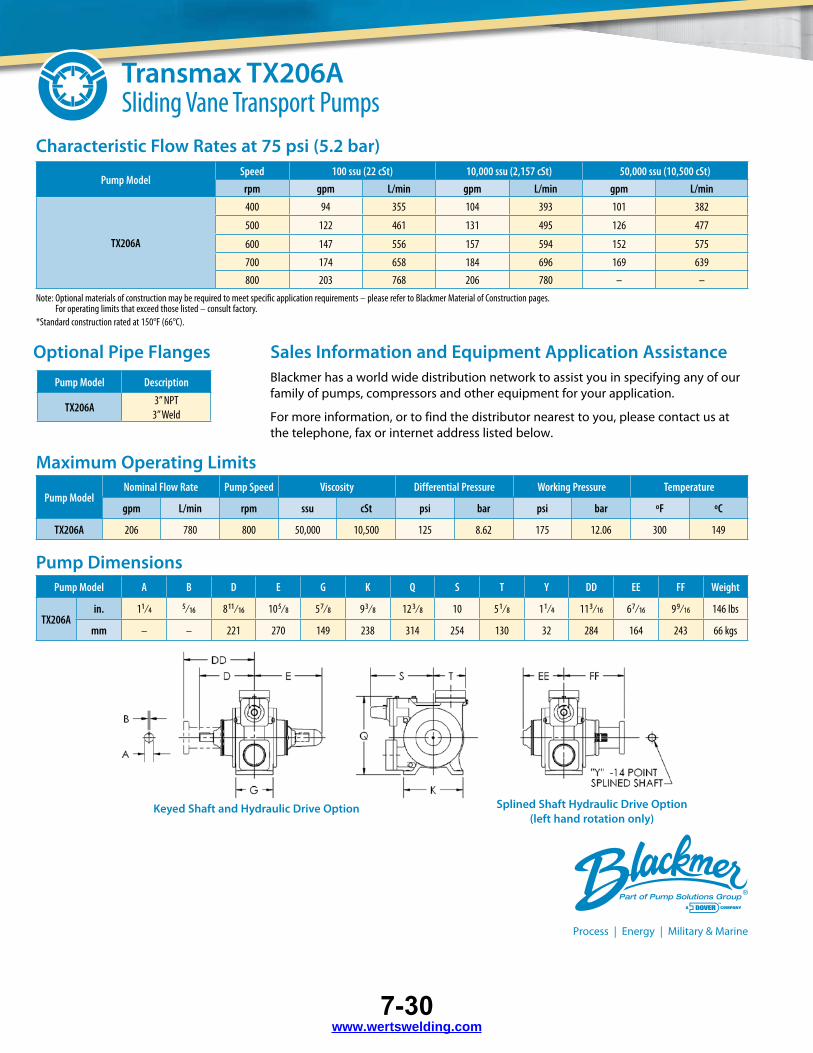
Transmax TX206ASliding Vane Transport Pumps
Spec Sheet 205-001
Section: 205
Effective: September 2012
Replaces: October 2005
How Blackmer’s sliding vane action works
DesignThe unique open rotor design makes the Transmax highly versatile. The sliding vane design provides sustained high-performance capabilities including self-priming and line clearing.
ApplicationThe TX206A is capable of pumping thin to thick liquids from 30 to 50,000 ssu (7 to 10,500 cP) with sustained performance at rated P.T.O. speeds, maximum 800 rpm.
BenefitThe Transmax is self-priming and capable of line clearing; these benefits are not found with existing gear pumps. Also, the Transmax is specifically designed for easy cleaning. Multiple drain ports allow for proper flushing in a variety of mounting positions.
Hydraulic Drive OptionsBlackmer offers fully-integrated hydraulic drive systems including pumps, motors, close coupled hydraulic motor adapters, control valves, P.T.O.’s and coolers.
Hydraulic Drive
PTO Drive
www.wertswelding.com7-29
Process | Energy | Military & Marine
Characteristic Flow Rates at 75 psi (5.2 bar)
Maximum Operating Limits
Pump Dimensions
Pump ModelSpeed 100 ssu (22 cSt) 10,000 ssu (2,157 cSt) 50,000 ssu (10,500 cSt)
rpm gpm L/min gpm L/min gpm L/min
TX206A
400 94 355 104 393 101 382
500 122 461 131 495 126 477
600 147 556 157 594 152 575
700 174 658 184 696 169 639
800 203 768 206 780 – –
Note: Optional materials of construction may be required to meet specific application requirements – please refer to Blackmer Material of Construction pages. For operating limits that exceed those listed – consult factory.
*Standard construction rated at 150°F (66°C).
Sales Information and Equipment Application AssistanceBlackmer has a world wide distribution network to assist you in specifying any of our family of pumps, compressors and other equipment for your application.
For more information, or to find the distributor nearest to you, please contact us at the telephone, fax or internet address listed below.
Optional Pipe Flanges
Pump Model Description
TX206A3” NPT
3” Weld
Pump ModelNominal Flow Rate Pump Speed Viscosity Differential Pressure Working Pressure Temperature
gpm L/min rpm ssu cSt psi bar psi bar ºF ºC
TX206A 206 780 800 50,000 10,500 125 8.62 175 12.06 300 149
Pump Model A B D E G K Q S T Y DD EE FF Weight
TX206Ain. 11⁄4 5⁄16 811⁄16 105⁄8 57⁄8 93⁄8 12 3⁄8 10 51⁄8 11⁄4 113⁄16 67⁄16 99⁄16 146 lbs
mm – – 221 270 149 238 314 254 130 32 284 164 243 66 kgs
Keyed Shaft and Hydraulic Drive Option Splined Shaft Hydraulic Drive Option (left hand rotation only)
Transmax TX206ASliding Vane Transport Pumps
www.wertswelding.com7-30

BLACKMER PARTS LIST 961817 Page 1 of 2
PARTS LIST205-B01
PUMP MODEL: TX206A Section 205 Effective Sept 2009
Keep with Instructions 205-B00 for Installation, Operation and Maintenance Replaces Sept 2007
Ref. No. Description
Parts per
PumpPart No. Ref.
No. Description Parts per
PumpPart No.
1 Cap – Relief Valve (R/V) 1 413957 27 Bearing Cover – Outboard, Splined Shaft 0-1 041817 2 Adjusting Screw – R/V 1 431808 27A Bearing Cover 1-2 041815 3 Locknut – Adjusting Screw 1 922923 28 Capscrew – Bearing Cover 12 920285 4 Cover – R/V 1 411807 35 Key – Shaft 1 909184 5 Capscrew – R/V 4 920331 Flange – 3” NPT - Std. 651803 7 Spring Guide – R/V 1 421805
42 Flange – 3” Weld
2 655102
8 SS Spring - R/V (76 -110 psi)-Std 1 471807 42A Gasket – Flange 2 381816 SS Spring - R/V (111-125 psi) 471808 Capscrews – NPT Flange 920532
9 Valve – R/V (Plated) 1 45180842B
Capscrews – Weld Flange 8
920510 10 Gasket – R/V Cover 1 531803 O-Ring – Head (FKM) - Std. 702121 12 Cylinder 1 021821
72 O-Ring – Head (PTFE)
2 702235
13 Rotor & Shaft (DE Keyed) 1 1 261830 73 Plug – ¼” NPT 6 908198 13A Splined SE Rotor & Shaft - LH Only 1 261831 76 Grease Fitting 2 317815 14 Vane – Duravane 6 091819 76A Grease Relief Fitting 2 701992 20 Head 2 031872 77 Push Rod 3 121813 21 Capscrew – Head 20 920331 88 Seal Ring – R/V Cap 1 533908 24 Bearing 2 903172 104 Oil Seal 2 331908
24A Locknut 2 903523 152 Lip Seal Assembly -Std. 2 335221 24B Lockwasher 2 903524 186 Shaft Protector 0-1 341801 26 Gasket – Bearing Cover 2 381817 Tool – Locknut 903091 Hydraulic Motor Adapter Kit (SAE A) See Backside
1 Includes 24A and 24B.
LOCKNUT TOOL
www.wertswelding.com7-31

LIP SEAL - STANDARD
Ref. No. Part Name
Parts Per
PumpPart No.
152 Lip Seal Complete 2 335221
152A Lip Seal– Stationary (Turcon) 2 331759
152B Housing - Lip Seal 2 335222
MECHANICAL SEAL - OPTIONAL
Ref. No. Part Name
Parts Per
PumpPart No.
153 Mechanical Seal Complete – Cast Iron Stationary Seat, Carbon Seal Face, FKM O-Rings. – IVCV
2 331883
153D O-Ring – Stationary (FKM) 2 711931
153L O-Ring – Rotating (FKM) 2 701962 OPTIONAL HYDRAULIC MOTOR ADAPTER PARTS
REF. NO. PART NAME
PARTS PER
PUMP
PART NO. STD
SHAFT
PART NO.SPLINED SHAFT
See Below
Hydraulic Motor Adapter Kit * See Below
895141 895142
26A Gasket – Hydraulic Motor Adapter 1 381817 381817
28A Capscrew – Hydraulic Motor Adapter / Head
6 920331 920331
Coupling w/ Setscrew – 1.25” straight key
906970 N/A 34
Coupling – 1.25”, 14 Point Splined Shaft
1 N/A 906009
35 Key – Coupling 1 909184 N/A
76 Grease Fitting 1 317815 317815
76A Grease Relief Fitting 1 701992 701992
135 Hydraulic Motor Adapter – SAE A Flange
1 041806 041803
135A Capscrew – Adapter / Motor 2 920510 920510
www.wertswelding.com7-32

Blackmer TLGLF3 and TLGLF4 pumps are designed to flange mount directly to a commercial internal control valve, in combination with the tank of a bobtail or transport. Direct mounting eliminates the need for inlet pipes, shut-off valve and external strainer which can restrict flow and cause vaporization problems. The result is smoother operation and longer pump life.
Both models are equipped with a double-ended drive shaft for clockwise or counterclockwise rotation by simply changing position of the pump. Each model also has an auxiliary intake port which can be used for emergency unloading of another tank or transport. In addition, these pumps have an internal relief valve, patented cavitation suppression liners to reduce noise, vibration and wear.
Standard construction materials for both models include Buna-N mechanical seals and Duravanes for handling both LP gas and anhydrous ammonia. The casing liner and end discs are replaceable for easy rebuilding of the pumping chamber if ever necessary.
The TLGLF3 is widely used on bobtails because of its compact mounting arrangement, with a 3-inch ANSI intake flange and 2-inch auxiliary intake and discharge ports. Capacities range from 60 to 129 U.S. gpm (227 to 488 L/min).
The TLGLF4 offers maximum output rates, and fast turnaround time for transports. It is designed with 4-inch ANSI intake flange, a 3-inch auxiliary intake port, and twin 2-inch discharge ports which permit the use of two hoses, if necessary, to reduce pressure loss when unloading into restrictive receiving systems. Capacities range from 200 to 350 U.S. gpm (757–1,325 L/min).
Maximum differential pressure for both models is 125 psi (8.62 bar).
TLGLF3 & TLGLF4 Pumps Flange Mounted Pumps for Bobtails and Transports
TLGLF3 cutaway
TLGLF4 cutaway
Cavitation Suppression Liners Reduce NoiseBlackmer TLGLF pumps feature noise suppression liners. This patented technology reduces noise at its source by reducing the amount of cavitation in the pump. Reducing the cavitation level also reduces vibration and wear.
The sudden collapse of vapor bubbles inside the pump is known as cavitation. By allowing a controlled amount of fluid at discharge pressure
to bleed back toward the suction of the pump, the vapor bubbles are collapsed over a longer period time. The net result is less noise, less vibration and less wear.
As shown in the chart, the reduction in noise level can be quite dramatic. Similar noise reductions have been measured in the TLGLF4 pumps.
Patent number: 6,030,191
Hydraulic Drive PackagesBlackmer offers complete Hydraulic Drive packages for all LPG mobile applications. The Hydrive cooler by Mouvex®, a Dover® Company, forms the heart of the system. The stainless steel cooler offers up to 26 HP (19.4 kW) of actual heat dissipation. Hydraulic motor adapter kits are available for all Blackmer LPG mobile pumps.
www.wertswelding.com7-33

3
Selection DataPump delivery and brake horsepower requirements are listed in the table below for various differential pressures. The same data for all pressures is provided in the performance curves below.
Performance Curves
LPG Pump Warranty – One Year Performance AssuranceShould any Blackmer LPG pump (LGL, TLGL, LG and LDF models) or bypass valve fail in the transfer of propane, butane and propane/butane mixture within one (1) year of the original installation or eighteen (18) months after shipment from the factory, regardless of cause (except for intentional or gross misuse), free replacement components will be provided to return the pump to as new performance.
This offer is limited to one claim per installation.
PLEASE NOTE: For the One Year Performance Assurance to be valid, a Blackmer Pump Warranty Registration must be supplied to Blackmer via web registration or postcard.
For additional information, see Blackmer LPG Pump Warranty page #001-004.
Available Companion Flanges and Flanged Elbows
Standard PumpPump Speed
rpm
Approximate Delivery of Propane at Differential Pressures and Pump Speeds Shown1
Maximum Differential
Pressure
Maximum Working Pressure2
ModelFactory
Relief Valve Setting
50 psi (3.45 bar) 100 psi (6.89 bar)
psi bar psi bargpm L/min BHp kW
Torquegpm L/min BHp kW
Torque
ft-lb Kg-m ft-lb Kg-m
TLGLF3150 psi
(10.34 bar)
870 129 488 6.5 4.8 45.9 6.3 119 450 10.9 8.1 72.5 10 125 8.62 350 24.13800 118 446 5.1 3.8 44.2 6.1 107 405 8.7 6.5 69.7 9.6 125 8.62 350 24.13650 93 352 4.3 3.2 40.4 5.6 83 314 7.9 5.9 63.7 8.8 125 8.62 350 24.13600 85 322 4 3 39.3 5.4 75 284 7.1 5.3 62.2 8.6 125 8.62 350 24.13500 70 265 3.6 2.7 37.4 5.2 68 257 6 4.5 61.5 8.5 125 8.62 350 24.13400 52 197 2.8 2.1 36.2 5 40 151 4.8 3.6 60.8 8.4 125 8.62 350 24.13
TLGLF4150 psi
(10.34 bar)
800 350 1,325 22 16 143 20 306 1,158 34 25 223 31 125 8.62 350 24.13650 280 1,060 15.5 11.6 125.2 17.3 245 927 25.0 18.6 201.9 27.9 125 8.62 350 24.13600 260 984 14.3 10.7 125.1 17.3 220 833 23.0 17.2 201.3 27.8 125 8.62 350 24.13500 210 795 11.9 8.9 125.0 17.3 170 644 19.0 14.2 199.5 27.6 125 8.62 350 24.13400 160 606 9.5 7.1 124.7 17.2 120 454 15.2 11.3 199.5 27.6 125 8.62 350 24.13
1 Check the pump’s delivery and brake horsepower requirements in the performance curves below. See footnote with the curves which explains the factors that can cause delivery to vary.2 Maximum rated working pressure is 350 psi (24.13 bar) for LPG and NH3 (limited by U.L. and N.F.P.A. 58).Note: Refer to back cover for external bypass valve information.
TLGLF3 TLGLF4
0 2 4BAR
DIFFERENTIAL PRESSURE PSI
6 8
0
4
2
6
8
10
12
0 20 40 60 80 100 120
400
500
600650800
870
BRAK
E HP
REQ
UIRE
D
RPM87080065060050040000
200100
300400500
4080
120160
LITE
RS /
MIN
.
U.S.
GAL
/ M
IN.
0 2 4BAR
DIFFERENTIAL PRESSURE PSI
6 8
0 20 40 60 80 100 120
350
520
420
640
800
0
4
8
12
16
20
24
28
32
36
40
BRAK
E HP
REQ
UIRE
D
RPM
800640520420350
00
400
800
1200
100200300400
LITE
RS /
MIN
.
U.S.
GAL
/ M
IN.
TLGLF3 TLGLF4
NOTE: Blackmer Characteristic Curves are based on Brake Horsepower (BHp). To determine Motor Horsepower, drive train inefficiencies must be added to the BHp.These curves are based on approximate delivery rates when handling propane or anhydrous ammonia at 80ºF (26.7ºC). Line restrictions such as excess flow valves, elbows, etc., will adversely effect deliveries. For propane at 32ºF (0ºC), actual delivery will be further reduced to about 80% of nominal. Delivery of butane at 80ºF (26.7ºC) will be 60 to 70% of these values, and may run as low as 35 to 45% at 32ºF (0ºC). This loss of delivery is not a pump characteristic but is caused by natural thermodynamic phenomena of liquefied gases.
Standard Pump Discharge Auxiliary Intake Intake
TLGLF3
2” NPT Flanged Elbow
2” NPT Flanged
3” 300 lb.
ANSIMounting
Flange
2” NPT Flanged Elbow
2” NPT Flanged Elbow
2” Weld Flanged Elbow
2” Weld Flanged
2” Weld Flanged Elbow
2” Weld Flanged Elbow
Twin 2” NPT Flanges
Blanking Flange
TLGLF4
Twin 2” NPT Flanges
3” NPT Flanged4”
300 lb.ANSI
Mounting Flange
Twin 2” Weld Flanges
3” Weld Flanged
Twin 2” NPT Flanges
Blanking Flange
Twin 2” NPT Flanges
4” Weld Flanged
www.wertswelding.com7-34

BLACKMER PARTS LIST 962011 Page 1 of 2
PARTS LIST501-E03
PUMP MODEL: TLGLF4B Section 501 Effective Jun 2011
Keep with 501-E00 for Installation, Operation and Maintenance Instructions Replaces Jan 2010
Ref. No. Description
Parts Per
Pump Part No. Ref.
No. Description Parts Per
Pump Part No.
1 Cap - Relief Valve (R/V) 1 413957 42A O-Ring – Aux. Inlet Flanges 1 701937 2 Adjusting Screw - R/V 1 436310 42B Capscrew - 3" NPT Flange 4 920663 3 Locknut - Adjusting Screw 1 432039 Capscrew - 3", 4" 920640 4 Cover - R/V 1 412001 Weld Flange; Blank Flange 5 Capscrews - R/V Cover 4 920663 TWIN DISCHARGE PORT OPTIONS 7 Spring Guide - R/V 1 426355 43 Flange - 2" NPT 2 652010 8 Spring - R/V 1 1 472039 Flange - 2" Slip-on Weld 652024 9 Valve - R/V 1 452001 43A O-Ring - 2" Discharge Flanges 2 1 702004
10 O-Ring - R/V Cover 1 1 701946 43B Capscrew - Discharge Flange 8 920491 12 Casing 1 012041 71 Disc 2 1 062039 13 Rotor & Shaft Asy. 1 2 262041 71A Machine Screw - Disc 8 2 920015
(includes Ref. No. 24A & 24B) 71B Lockwasher - Machine Screw 8 2 909634 14 Vane - Duravane 6 1 092019 72 O-Ring - Head 2 1 702039 20 Head 2 032041 73 Gage Plug 2 908198 21 Capscrews - Head 28 920532 74 Key - Liner 1 2 182040 24 Ball Bearing 2 1 903166 76 Grease Fitting 2 317815
24A Locknut - Bearing 2 2 903541 76A Grease Relief Fitting 2 701992 24B Lockwasher - Bearing 2 1 903542 77 Push Rod - Composite 3 1 122009 26 Gasket - Bearing Cover 2 1 385125 88 O-Ring - R/V Cap 1 1 701926 27 Bearing Cover 2 041815 104 Grease Seal 2 1 331908 28 Capscrews - Bearing Cover 12 920285 186 Shaft, Protector 1 341801 35 Key - Shaft 1 1 909183 Tool - Locknut 903092 41 Liner 1 2 182000 Kit – Maintenance 898922
AUXILIARY INLET OPTIONS Kit – Rebuild 899022 42 Flange - 3" NPT 1 652012
Flange - 4" Weld 652005 1 Included in Maintenance Kit and Rebuild Kit 2 Included in Rebuild Kit
Flange - 3" Weld 652007 Flange - Blank 652000
LOCKNUT TOOL
www.wertswelding.com7-35

MECHANICAL SEAL
Ref. No. Part Name
Parts Per
Pump Part No.
153 Mechanical Seal Assembly 2 1 332050
153A Stationary Seat (Hardened Steel) 2 **
153B Seal Face (Carbon) 2 **
153C Jacket Assembly 2 **
153D O-Ring - Stationary (Buna-N) 2 701934
153E O-Ring - Rotating (Buna-N) 2 711912 1 Included in Maintenance Kit and Rebuild Kit ** NOTE: Mechanical Seal Assy. (Ref. 153) is only sold as a complete assembly. Ref. Nos. 153A, 153B & 153C are not available as separate replacement parts. OPTIONAL HYDRAULIC MOTOR ADAPTER PARTS
Ref. No. Part Name
Parts Per
Pump Part No.
See Below
Hydraulic Motor Adapter Kit See Below
892037
26A Gasket – Hydraulic Motor Adapter 1 381817
28A Capscrew – Hydraulic Motor Adapter / Head
6 920369
34 Coupling w/ Setscrew – 1.25” straight key hyd. motor shaft
1 906970
35 Key – Coupling 1 909184
76 Grease Fitting 1 317815
76A Grease Relief Fitting 1 701992
135 Hydraulic Motor Adapter – SAE A Flange
1 041829
135A Capscrew – Adapter / Motor 2 920510
www.wertswelding.com7-36

BLACKMER PARTS LIST 960326 Page 1 of 2
PARTS LIST201-B00
With Installation and Maintenance Instructions Section 201
T-TYPE TRUCK PUMP STRAINERS Effective Oct 2006
FOR PUMP SIZES: 2″, 2.5″, 3″ Replaces July 2001
Ref. No. Description Qty. Part No. 2" Size
Part No 2.5" Size
Part No 3" Size
1 Strainer Assembly 1 740053 740056 740061
2 Strainer Basket 1 621608 621612 621801
42 Body Flange - Plain2 0 - 1 651411 651611 651803
42A Inlet Flange - Plain 1 651603 651611 651803
42C Strainer Cover 1 611431 611633 611831
43 Gasket - Inlet Flange, Strainer Cover 2 381650 381650 381816
43A Gasket - Body Flange 1 381421 381650 381816
44 Capscrew - Strainer Body1 0 - 4 920331 920471 920491
Capscrew - 2" Inlet Flange 920471 920471 —
44A Capscrew – 2 1/2" Inlet Flange 4 — 920532 —
Capscrew - 3" Inlet Flange — — 920532
44C Capscrew - Strainer Cover 4 920471 920471 920491
44D Mounting Bolt - Body Flange2 0 - 4 920381 920547 920547
44E Nut - Mounting Bolt2 0 - 4 922841 922850 922850 1 For direct pump mounting use Ref. Nos. 43A and 44. 2 For intake line mounting use Ref. Nos. 42, 43A, 44D and 44E.
www.wertswelding.com7-37

PARTS LIST
REF. NO. PART NAME
PARTS PER
VALVE
TXD2A-AVA PART NO.
TXD2.5A-AVA, TX200B-AVA
PART NO.
TXD3E-AVA PART NO.
TXH3A-AVA, PART NO.
1 Cap 1 411754 411754 411754 411753
2A Locknut 2 922923 922923 922923 922923
2C Adjustment Bushing 1 501701 501701 501701 501701
4 Cover 1 411406 411703 411705 411703
5 Capscrew 3-4 920444 920444 920444 920239
5A Machine Screw 2 922216 922216 922216 922216
5B Lockwasher 4 909649 909649 909649 909693
5C Capscrew w/ Hole 0-1 920433 920433 920433 —
6 Plate 1 701400 701735 701737 701735
6A Vent Plate 1 701418 701618 701818 701618
8 Spring 1 471429 471621 471806 471621
9 Valve ** 1 451417 451623 451807 451623
9C Diaphragm Assembly 1 871175 871180 871185 871180
10 Gasket 1 531403 531603 531803 531603
83 Snap Ring 1 903581 903581 903581 903581
88 O-Ring 1 711917 711917 711917 711917
A/V Conversion Kit ** — 891454 891696 891798 891799
* NOTE: The double diaphragm air valve assembly replaced the single diaphragm assembly in Aug. 1991. ** A/V Conversion Kit includes all above parts EXCEPT the Valve (ref. 9).
www.wertswelding.com7-38

PARTS LIST
Fig. 1
Table 3 PARTS LIST for Piston Air Valve Style 1
REF. NO. PART NAME PARTS
PER VALVE
PART NO.
1 Cap 1 411754
2C Adjustment Bushing 1 501703
4 Cover 1 411758
5 Capscrew 3 920448
5A Flat washer 4 909662
5B Lockwasher 4 909649
5C Capscrew w/ Hole 1 920465
7 U-cup packing 2 FKM 1 495030
7A Quad Ring Seal 2 FKM 1 495033
6 Breather vent 1 495029
8 Piston Assembly – includes 1 ea.: Piston, Adjusting Rod, Follower
1 891732
Valve 3 Standard 451623 9
Corrosion Resistant1
451624
10 Gasket 2 1 531603
88 O-Ring 2 FKM 1 701979
Conversion Kit 3 FKM — 891730
Seal Kit 2 FKM — 891713 1 Valves prior to May 2009 used two U-Cup packings (7), no Quad Ring Seal (7A) and a different Piston Assembly (8) construction. All parts as listed above may be used in the previous valves 2 Parts included in Seal Kit 3 Conversion Kit includes all above parts EXCEPT the Valve (ref. 9).
www.wertswelding.com7-39
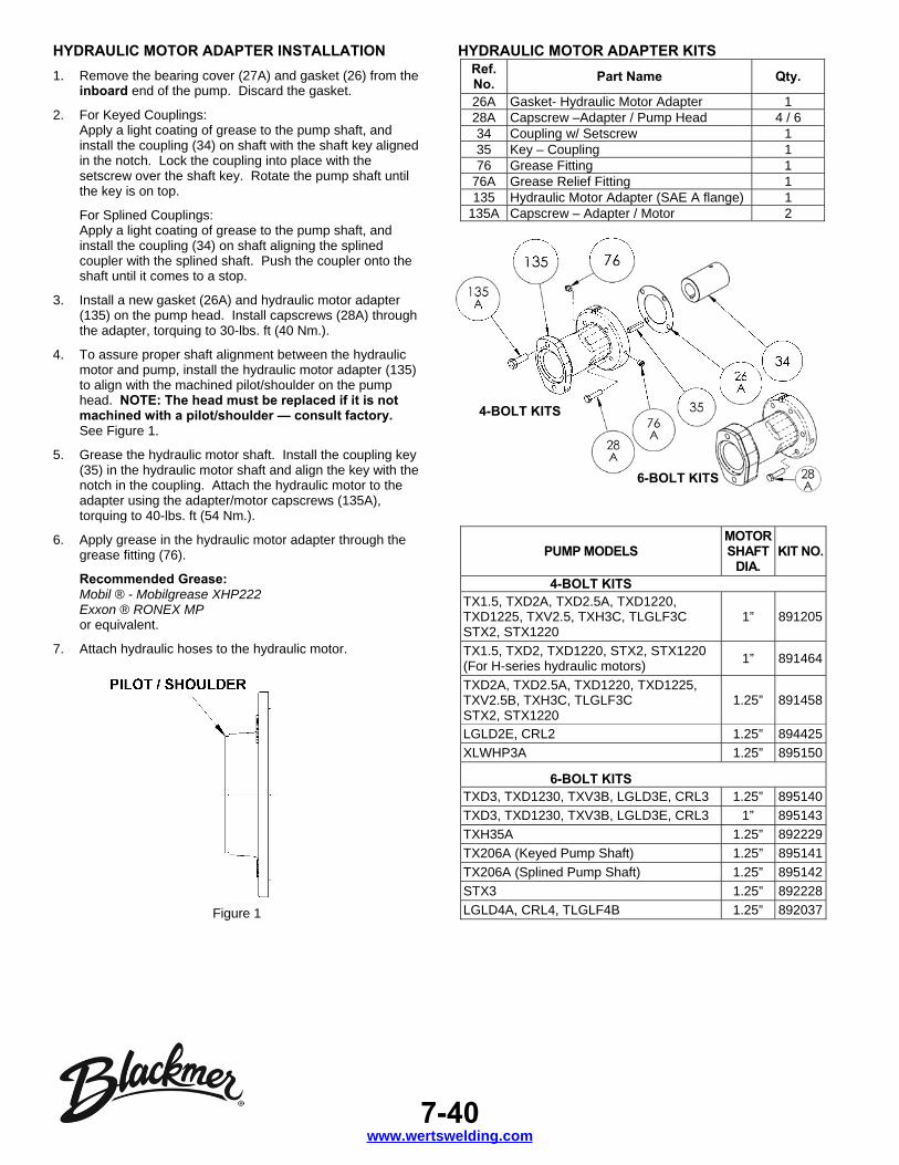
HYDRAULIC MOTOR ADAPTER INSTALLATION 1. Remove the bearing cover (27A) and gasket (26) from the
inboard end of the pump. Discard the gasket.
2. For Keyed Couplings: Apply a light coating of grease to the pump shaft, and install the coupling (34) on shaft with the shaft key aligned in the notch. Lock the coupling into place with the setscrew over the shaft key. Rotate the pump shaft until the key is on top.
For Splined Couplings: Apply a light coating of grease to the pump shaft, and install the coupling (34) on shaft aligning the splined coupler with the splined shaft. Push the coupler onto the shaft until it comes to a stop.
3. Install a new gasket (26A) and hydraulic motor adapter (135) on the pump head. Install capscrews (28A) through the adapter, torquing to 30-lbs. ft (40 Nm.).
4. To assure proper shaft alignment between the hydraulic motor and pump, install the hydraulic motor adapter (135) to align with the machined pilot/shoulder on the pump head. NOTE: The head must be replaced if it is not machined with a pilot/shoulder — consult factory. See Figure 1.
5. Grease the hydraulic motor shaft. Install the coupling key (35) in the hydraulic motor shaft and align the key with the notch in the coupling. Attach the hydraulic motor to the adapter using the adapter/motor capscrews (135A), torquing to 40-lbs. ft (54 Nm.).
6. Apply grease in the hydraulic motor adapter through the grease fitting (76).
Recommended Grease: Mobil ® - Mobilgrease XHP222 Exxon ® RONEX MP or equivalent.
7. Attach hydraulic hoses to the hydraulic motor.
Figure 1
HYDRAULIC MOTOR ADAPTER KITS Ref. No. Part Name Qty.
26A Gasket- Hydraulic Motor Adapter 1 28A Capscrew –Adapter / Pump Head 4 / 6 34 Coupling w/ Setscrew 1 35 Key – Coupling 1 76 Grease Fitting 1
76A Grease Relief Fitting 1 135 Hydraulic Motor Adapter (SAE A flange) 1
135A Capscrew – Adapter / Motor 2
PUMP MODELS MOTOR SHAFT
DIA. KIT NO.
4-BOLT KITS TX1.5, TXD2A, TXD2.5A, TXD1220, TXD1225, TXV2.5, TXH3C, TLGLF3C STX2, STX1220
1” 891205
TX1.5, TXD2, TXD1220, STX2, STX1220 (For H-series hydraulic motors)
1” 891464
TXD2A, TXD2.5A, TXD1220, TXD1225, TXV2.5B, TXH3C, TLGLF3C STX2, STX1220
1.25” 891458
LGLD2E, CRL2 1.25” 894425
XLWHP3A 1.25” 895150
6-BOLT KITS TXD3, TXD1230, TXV3B, LGLD3E, CRL3 1.25” 895140
TXD3, TXD1230, TXV3B, LGLD3E, CRL3 1” 895143
TXH35A 1.25” 892229
TX206A (Keyed Pump Shaft) 1.25” 895141
TX206A (Splined Pump Shaft) 1.25” 895142
STX3 1.25” 892228
LGLD4A, CRL4, TLGLF4B 1.25” 892037
4-BOLT KITS
6-BOLT KITS
www.wertswelding.com7-40

Spec Sheet 208-001 E Section: 200Effective: April 2014Replaces: September 2010
Historical partnerFrom the collaboration between HAMMOND and MOUVEX, the Enterprise series is the result of long experience that stands out today as the vane compressor of reference.
Legendary robustnessThe body and rotor are contructed of hard-coated cast iron to withstand harsh environmental and operating conditions, with strength unmatched in the industry.
Corrosion freeThe integral anticorrosion coating of the compressor and the check relief valve, combined with stainless steel flanges, guarantee peace of mind.
Quality of the accessoriesThe new, extra-long inlet connection kit allows for deporting the air filter and insures perfect waterproofing.
ENTERPRISE Series Vane Compressor for Liquids to 170 m3/h
E170 Vane Compressor
E140 Vane Compressor
Enterprise Check Relief Valve
E140: 1,000/1,750 rpm
E170: 1,000/1,600 rpm
Dimensions: L 490/570 x H 220 x l 220 mm
L 19/23 x H 9 x l 9 in.
Weight: 36 kg (79 lbs.) to 47 kg (104 lbs.)
www.wertswelding.com7-43
nwerts
Typewritten text
#519782.00
nwerts
Typewritten text
#519363.00
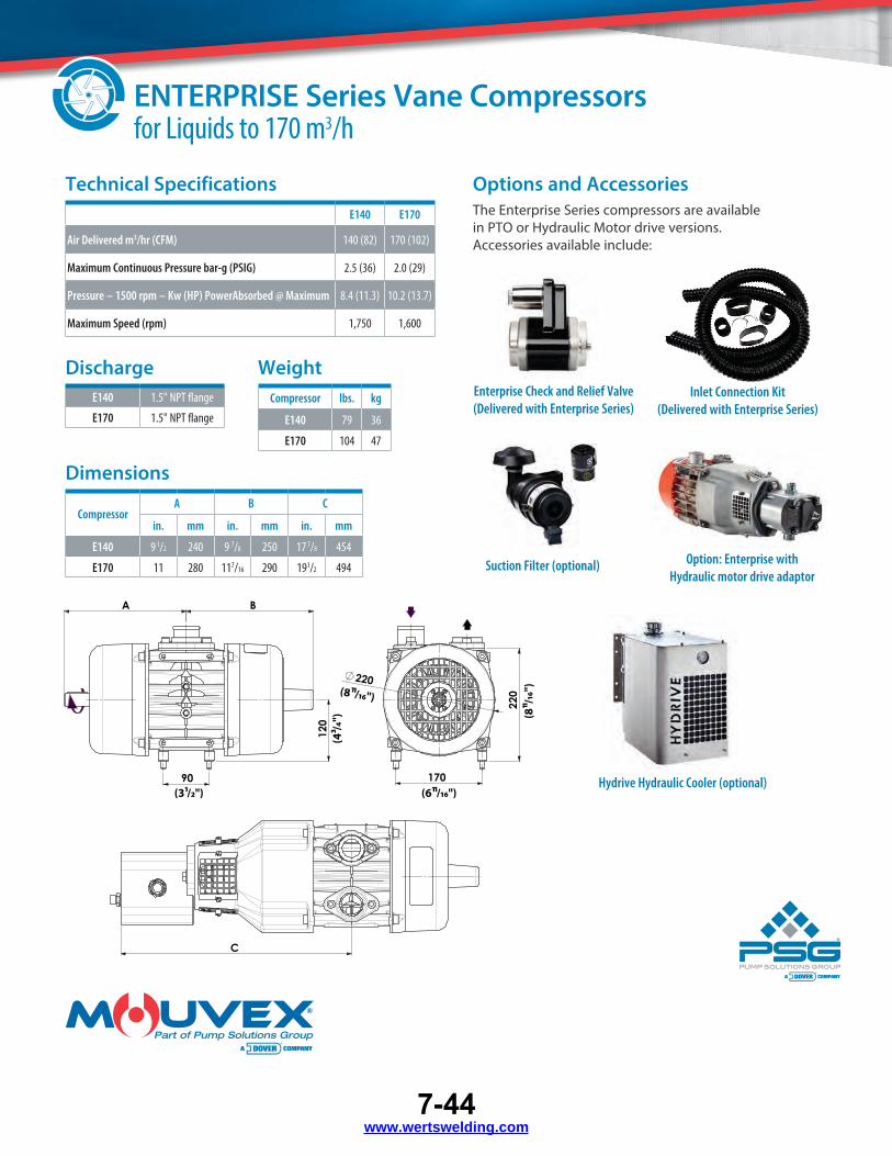
Dimensions
Technical Specifications
CompressorA B C
in. mm in. mm in. mm
E140 9 1/2 240 9 7/8 250 17 7/8 454
E170 11 280 117/16 290 191/2 494
WeightCompressor lbs. kg
E140 79 36
E170 104 47
E140 E170
Air Delivered m3/hr (CFM) 140 (82) 170 (102)
Maximum Continuous Pressure bar-g (PSIG) 2.5 (36) 2.0 (29)
Pressure – 1500 rpm – Kw (HP) PowerAbsorbed @ Maximum 8.4 (11.3) 10.2 (13.7)
Maximum Speed (rpm) 1,750 1,600
DischargeE140 1.5" NPT flange
E170 1.5" NPT flange
ENTERPRISE Series Vane Compressors for Liquids to 170 m3/h
(3¹/") (6¹¹/")
(8¹¹/
")
(4³/
")
(8¹¹/")
(3¹/") (6¹¹/")
(8¹¹/
")
(4³/
")
(8¹¹/")
Options and AccessoriesThe Enterprise Series compressors are available in PTO or Hydraulic Motor drive versions. Accessories available include:
Option: Enterprise with Hydraulic motor drive adaptor
Hydrive Hydraulic Cooler (optional)
Enterprise Check and Relief Valve (Delivered with Enterprise Series)
Suction Filter (optional)
Inlet Connection Kit (Delivered with Enterprise Series)
www.wertswelding.com7-44

ENTERPRISE E140 - E170
www.wertswelding.com7-45

www.wertswelding.com7-46
nwerts
Typewritten text
SIDE PLATE ASSEMBLY

www.wertswelding.com7-47
nwerts
Typewritten text
HYDRAULIC TRUNK & HYDRAULIC MOTOR
nwerts
Typewritten text
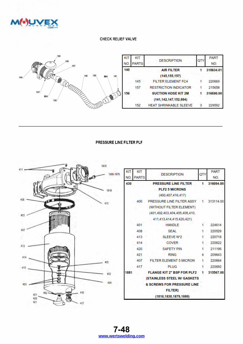
CHECK RELIEF VALVE
www.wertswelding.com7-48
nwerts
Typewritten text
PRESSURE LINE FILTER PLF
nwerts
Typewritten text
CHECK RELIEF VALVE

7
www.wertswelding.com7-49
nwerts
Typewritten text
OBSOLETE
nwerts
Typewritten text
OBSOLETE
nwerts
Typewritten text
OBSOLETE

7
www.wertswelding.com7-50
nwerts
Typewritten text
*SHAFT SIZE 25MM.
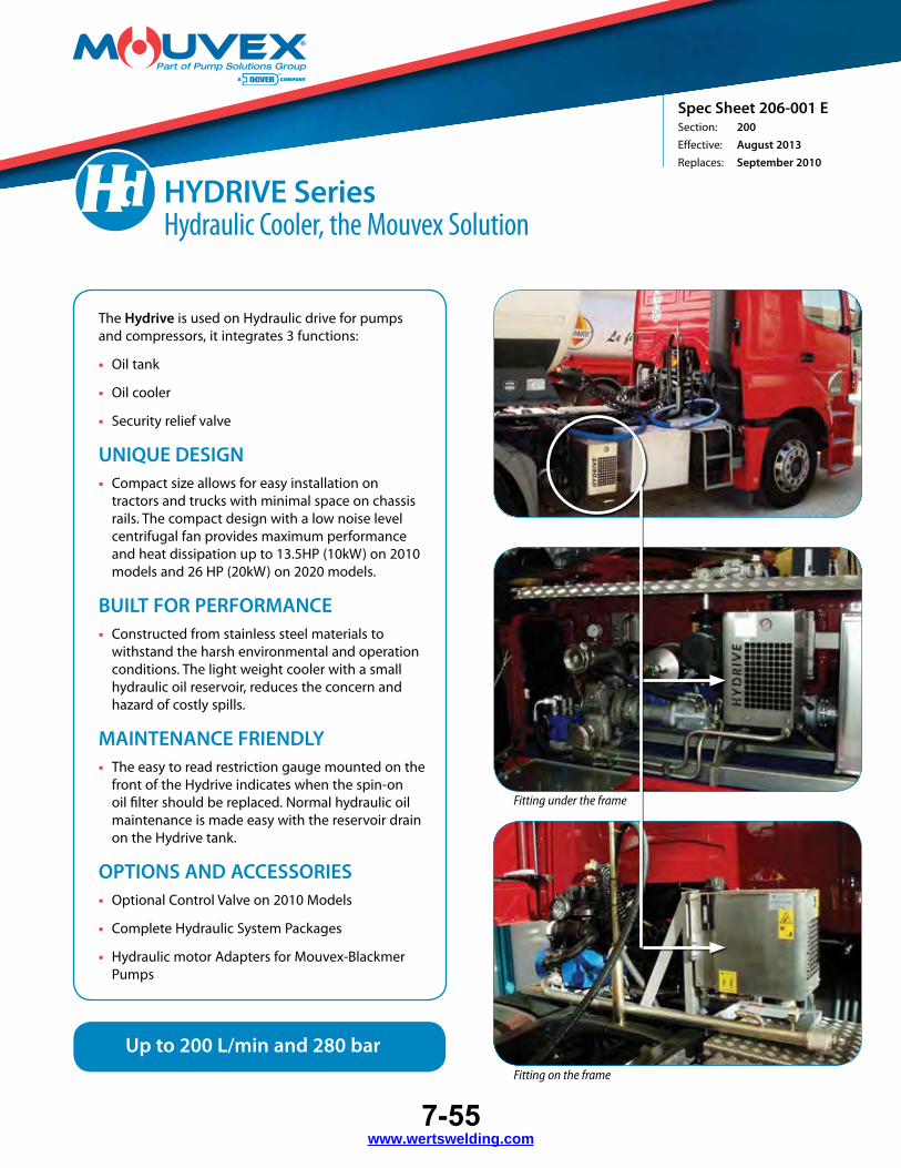
The Hydrive is used on Hydraulic drive for pumps and compressors, it integrates 3 functions:
• Oil tank
• Oil cooler
• Security relief valve
UNIQUE DESIGN• Compact size allows for easy installation on
tractors and trucks with minimal space on chassis rails. The compact design with a low noise level centrifugal fan provides maximum performance and heat dissipation up to 13.5HP (10kW) on 2010 models and 26 HP (20kW) on 2020 models.
BUILT FOR PERFORMANCE• Constructed from stainless steel materials to
withstand the harsh environmental and operation conditions. The light weight cooler with a small hydraulic oil reservoir, reduces the concern and hazard of costly spills.
MAINTENANCE FRIENDLY• The easy to read restriction gauge mounted on the
front of the Hydrive indicates when the spin-on oil filter should be replaced. Normal hydraulic oil maintenance is made easy with the reservoir drain on the Hydrive tank.
OPTIONS AND ACCESSORIES• Optional Control Valve on 2010 Models
• Complete Hydraulic System Packages
• Hydraulic motor Adapters for Mouvex-Blackmer Pumps
HYDRIVE SeriesHydraulic Cooler, the Mouvex Solution
Spec Sheet 206-001 E Section: 200
Effective: August 2013
Replaces: September 2010
Up to 200 L/min and 280 bar
Fitting under the frame
Fitting on the frame
www.wertswelding.com7-55

Sales Information and Equipment Application Assistance• Mouvex has a world wide distribution network to assist you in specifying any of our
family of pumps, compressors and other equipment for your application.
• For more information or to find the distributor nearest to you, please contact us as the telephone, fax or internet address listed below.
HYDRIVE SeriesHydraulic Cooler, the Mouvex Solution
Operations Parameters
Oil Flow Rate 15 - 32 US GPM 55 - 120 L/min
Circuit Pressure 725 - 4061 PSI 50 - 280 BAR
Fan Speed 2800 RPM
Return Pressure 15 - 75 PSI 1 - 5 BAR
Heat Dissipation 13,5 HP for 70° F Temp. Rise 10 kW for 40° C Temp. Rise
Fan Motor Flow 1.5 US GPM 5,5 L/min
Weight (dry) 53 Ibs 24 kg
Oil Tank Capacity 2.5 US Gallons 10 Liters
Hydrive 2010
Operations Parameters
Oil Flow Rate 15 - 53 US GPM 55 - 200 L/min
Circuit Pressure 725 - 4061 PSI 50 - 280 BAR
Fan Speed 2800 RPM
Return Pressure 15 - 75 PSI 1 - 5 BAR
Heat Dissipation 26 HP for 70° F Temp. Rise 20 kW for 40° C Temp. Rise
Fan Motor Flow 2.2 US GPM 8,2 L/min
Weight (dry) 77 Ibs 35 kg
Oil Tank Capacity 4.5 US Gallons 17 Liters
Hydrive 2020
1. Adjustable relief valve2. Fan speed control valve3. Return line filter4. Fan motor5. Filter by-pass valve6. Oil cooler radiator7. Fan8. System pressure gauge point9. Return pressure gauge point
------ Hydrive....... Valve block
3
2
6
7
4
8
5
1
9
High pressure line Return line
Cold startbypass
Oil tankHydraulicpump
Valve block
Suctionline
Hydrive A B C
2010 278 mm 526 mm 498 mm
2020 428 mm 559 mm 566 mm
www.wertswelding.com7-56

HYDRIVE 2010
www.wertswelding.com7-57
nwerts
Typewritten text
RADIATOR
www.wertswelding.com7-58
nwerts
Typewritten text
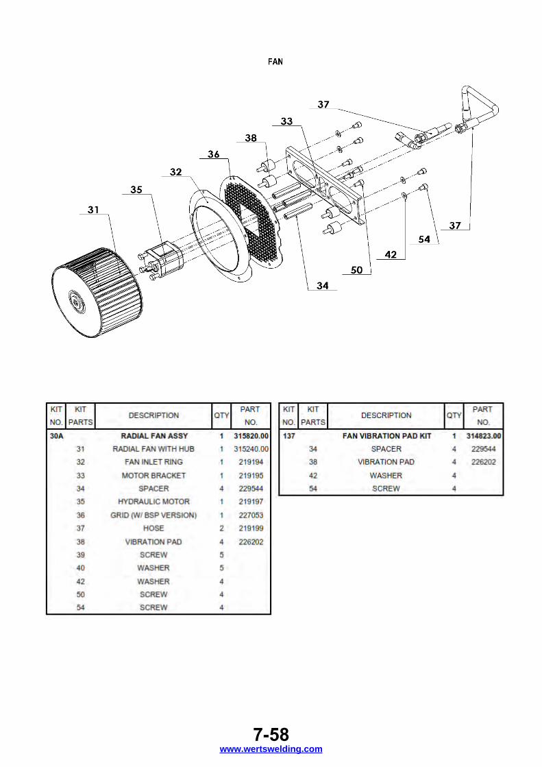
FAN
www.wertswelding.com7-59
nwerts
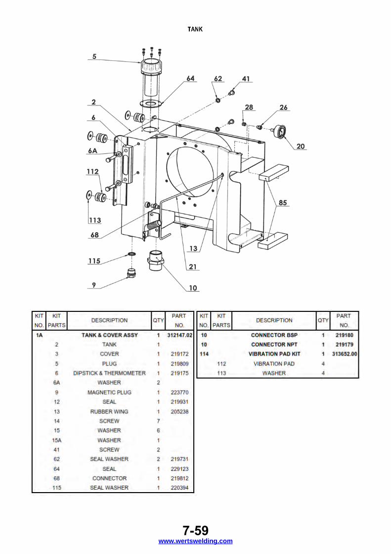
Typewritten text
TANK

www.wertswelding.com7-60
nwerts
Typewritten text
HYDRIVE 2010 HYDRAULIC BLOCK
nwerts
Typewritten text
170 BAR MAX
nwerts
Typewritten text
280 BAR MAX
nwerts
Typewritten text
WITH SELECTOR VALVE

www.wertswelding.com7-61
nwerts
Typewritten text
HYDRIVE 2010 HYDRAULIC BLOCK
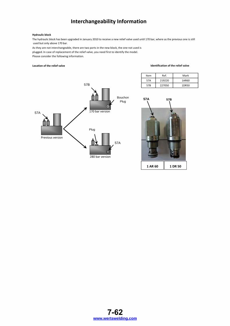
Location of the relief valve
Item Ref. Mark
57A 219220 1AR60
57B 227050 1DR50
Identification of the relief valve
57A
Bouchon Plug
280 bar version
57B
Plug
57A
170 bar version
57A 57B
1 DR 501 AR 60
Interchangeability Information
Hydraulic blockThe hydraulic block has been upgraded in January 2010 to receive a new relief valve used until 170 bar, where as the previous one is still used but only above 170 bar.As they are not interchangeable, there are two ports in the new block, the one not used is plugged. In case of replacement of the relief valve, you need first to identify the model.Please consider the following information.
Previous version
www.wertswelding.com7-62

HYDRIVE 2020
A
www.wertswelding.com7-63

Fan
www.wertswelding.com7-64
nwerts
Typewritten text
RADIATOR
nwerts
Typewritten text
FAN
www.wertswelding.com7-65
nwerts
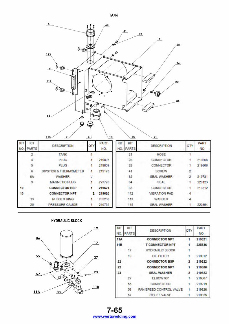
Typewritten text
TANK
nwerts
Typewritten text
HYDRAULIC BLOCK
7
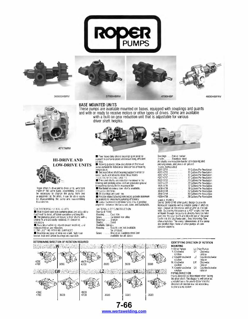
HI-DRIVE ANDLOW-DRIVE UNITS
www.wertswelding.com7-66

DR
IVE GEA
R, LH
G8-281 R
V A
DA
PTE
R
D1-2935 17 S
IZE
G49-24 W
AS
HE
R H
D C
AP
SC
RE
W (4)
N7-309 C
AR
BO
N, S
TDN
7-443 BR
Z, HI
D8-443 LO
CA
TOR
RIN
G
D828-41 R
V C
AP
GA
SK
ET
D441-755 LO
CK
NU
T (2)
D42-2 S
PR
ING
CLIP
DR
IVE SHA
FT
D83-5 G
HB
LIP S
EA
L
D6-907 11 S
IZE(2) G
41-108
D8-348 S
PR
ING
GU
IDE
PLU
S S
ST &
STD
RV
CO
MP
ON
EN
TS)
LOC
K &
SE
AL N
UT
(INC
LUD
ES
RV
FAC
EP
LATE
AS
M
RV FA
CEPLA
TE ASM
G43-65 TFE
D16-16 R
V P
OP
PE
T
D45-100 G
HB
SP
AC
ER
G41-20 R
ETA
ININ
G R
ING
G40-147 G
HB
BA
LL BR
GG
41-76 RE
TAIN
ING
RIN
G
D6-1289 17 S
IZE
D1-2594 11 S
IZE
D6-1188 22 S
IZE
HA
RD
WA
RE)
N7-735 C
AR
BO
N, H
I
PLAIN
FAC
EPLATE A
SM
G41-76 R
ETA
ININ
G R
ING
D11-339 C
AS
E G
AS
KE
T, ALU
M (3)
IDLER
GEA
R, R
H
IDLER
SHA
FT
G43-18 S
TD
G62-44 S
TD
D30-9 K
EY
(HB
)D
30-32 (GH
B &
BH
)D
48-34 DO
WE
L PIN
(4)
GH
B O
NLY
PKG
SET
D1-3009 22 S
IZE
(PK
G O
R M
EC
H)
HB
STE
EL
PAC
KIN
G O
NLY
P10-178 P
KG
GLA
ND
G67-043250 S
Q H
D B
OLT (2)
D441-755 LO
CK
NU
T (2)D
441-755 LOC
KN
UT (2)
G49-037100 H
EX
HD
CA
P S
CR
EW
(16)
G67-043125 S
Q H
D B
OLT (2)
MEC
H SEA
L
DR
IVE SHA
FT
G5-266 IR
ON
G5-267 IR
ON
G5-860 C
RB
N/G
LAS
S/TFE
ON
LY
P1-181 4x17 FLA
NG
ED
PO
RTS
BH
(P2-1557)
ELB
OW
N43-103 G
RA
PH
ITE FILA
ME
NT
D1-2990 11 S
IZE
N43-170 G
AR
LOC
K D
SA
G8-246 P
AC
KIN
G W
AS
HE
R
D1-2932 11 S
IZE
D8-443 LO
CA
TOR
RIN
G (B
H O
NLY
)
G44-062 H
EX
NU
T (8)
G41-10 R
ETA
ININ
G R
ING
D30-9 K
EY
(2)
MEC
H SEA
L ON
LY
G62-51 S
ST
RV A
SM (SST SPR
+ BR
GS)
D23-252 S
EA
L RE
TAIN
ER
HB
ON
LYG5-415 C
AR
BO
NG
5-258 BR
ZIN
CLU
DE
S S
HO
RT B
RG
S (1):
P6-430 22 S
IZEP
6-414 17 SIZE
P6-418 11 S
IZE
BH
SS
T
P17-110 R
V C
AP
P6-274 17 S
IZEP
6-276 11 SIZE
HB
/ GH
B S
TEE
L
DR
IVE GEA
R, LH
D1-2073 17 S
IZED
1-2072 11 SIZE
G67-043125 S
Q H
D B
OLT (2)
D1-2937 17 S
IZE
N7-938 C
RB
N/G
LAS
S/TFE
, HI
N7-937 C
RB
N/G
LAS
S/TFE
, STD
ww
w.roperpum
ps.com
LIP SEAL
(ALL B
H P
UM
PS
& H
B O
R G
HB
WITH
TFE S
EA
L)
(22 SIZE
ON
LY)
D1-2934 11 S
IZE
G10-429 S
ST, H
I PR
ES
S
N7-737 IR
ON
, STD
N7-442 B
RZ, S
TD
N7-830 IR
ON
, HI
HB
/ GH
B S
ST
P6-278 22 S
IZE
G56-12 P
IPE
PLU
G (2)
AD
JUS
TING
SC
RE
WR
V S
PR
ING
G10-363 S
ST, S
TD P
RE
SS
CA
SE
D11-338 C
AS
E G
AS
KE
T (2)
G4-65 TFE
/ VITO
N O
-RIN
G
G4-140 FLU
OR
OE
LAS
TOM
ER
& D
8-443 LOC
ATO
R R
ING
)
N43-151 TFE
/GR
AP
HITE
N43-101 P
UR
E TFE
N43-1 S
TDN
43-186 TFE IM
PR
EG
NA
TED
N14-23 3" N
PT E
L
D42-1 P
KG
GLA
ND
CLIP
(2)
N/A
3x22 TAP
PE
D P
OR
TSP
1-175 3x22 FLAN
GE
D P
OR
TS
RV
CO
MP
ON
EN
TS)
N3-200 B
RZ
TRIPLE LIP SEA
LD
RIVE SH
AFT
INC
LUD
ES
LON
G B
RG
S (1):
G5-257 B
RZ
G5-416 C
AR
BO
N
PKG
SET
MEC
H SEA
L
G4-101 S
TD
G63-1 LU
BE
FITTING
(HB
ON
LY)
D1-2991 17 S
IZED
1-2992 22 SIZE
BH
STE
EL
G17-232 LIP
SE
AL
GH
B S
ST
D1-2939 22 S
IZED
1-2936 17 SIZE
D1-2931 11 S
IZEG
HB
STE
EL
D1-3036 22 S
IZED
1-3035 17 SIZE
D1-3034 11 S
IZEB
H S
ST
D1-2940 22 S
IZE
N2-1313 C
AR
BO
NN
2-1314 IRO
NN
2-1566 CR
BN
/GLA
SS
/TFE
MO
D B
H (TFE
ME
CH
)N
/A
GH
B (P
2-141)N
2-406 BR
ZN
2-544 CA
RB
ON
N2-424 IR
ON
N14-24 4" N
PT E
L
RE
QU
IRE
S R
ET R
ING
P1-178 3x11 TA
PP
ED
PO
RTS
P1-401 3x11 FLA
NG
ED
PO
RTS
P1-170 4x11 FLA
NG
ED
PO
RTS
D1-2434 22 S
IZE
GH
B S
TEE
LD
1-2074 11 SIZE
D1-2075 17 S
IZED
1-2001 22 SIZE
GH
B S
ST
D1-1999 11 S
IZED
1-2000 17 SIZE
D1-2078 22 S
IZE
BH
STE
EL
D1-2424 11 S
IZED
1-2425 17 SIZE
D1-1998 22 S
IZE
HB
SS
T
P1-177 3x17 TA
PP
ED
PO
RTS
CA
SE
N2-X
XX
X C
RB
N/G
LAS
S/TFE
N2-1129 IR
ON
N2-1073 C
AR
BO
NN
2-1064 BR
Z(TFE
ME
CH
)M
OD
GH
B (P
2-1397)
N2-X
XX
X C
RB
N/G
LAS
S/TFE
BA
CK
PLATE A
SM
G10-355 S
TL, STD
PR
ES
SB
H S
ST
G10-375 S
TL, HI P
RE
SS
(DO
ES
NO
T INC
LUD
E
RV FA
CEPLA
TE ASM
D6-672 17 S
IZED
6-528 11 SIZE
RE
QU
IRE
S R
ET R
ING
(2) G41-108
IDLER
GEA
R, R
H
STEELP
6-275 11 SIZE
P6-273 17 S
IZEP
6-277 22 SIZE
SSTD
6-529 11 SIZE
D6-673 17 S
IZED
6-631 22 SIZE
D1-2592 17 S
IZE
IDLER
SHA
FT
G5-416 C
AR
BO
N
N3-633 C
RB
N/G
LAS
S/TFE
N3-179 IR
ON
N3-226 C
AR
BO
NN
3-177 BR
Z
PLAIN
FAC
EPLATE A
SM
BH
STE
EL
D6-630 22 S
IZE
G5-257 B
RZ
AN
D LO
NG
BR
GS
(2):IN
CLU
DE
S P
3-137
HB
STE
EL
G8-246 P
AC
KIN
G W
AS
HE
R
(RE
Q M
OD
BA
CK
PLA
TE
HB
SS
T
D1-2938 22 S
IZE
G5-859 C
RB
N/G
LAS
S/TFE
N2-1312 B
RZ
N3-218 C
AR
BO
N
AN
D LO
NG
BR
GS
(2):G
5-257 BR
ZG
5-416 CA
RB
ON
G5-266 IR
ON
G5-860 C
RB
N/G
LAS
S/TFE
G5-266 IR
ON
G5-860 C
RB
N/G
LAS
S/TFE
STEELD
1-1098 11 SIZE
D1-1100 17 S
IZED
1-1077 22 SIZE
SSTD
1-1099 11 SIZE
D1-860 17 S
IZED
1-1078 22 SIZE
P1-402 3x17 FLA
NG
ED
PO
RTS
P1-171 4x22 FLA
NG
ED
PO
RTS
N3-201 IR
ON
N3-634 C
RB
N/G
LAS
S/TFE
INC
LUD
ES
P3-200
D1-2076 11 S
IZED
1-2077 17 SIZE
D1-2027 22 S
IZE
D1-2426 22 S
IZE
EL = 90
G56-12 P
IPE
PLU
G (2)
D1-3007 11 S
IZED
1-3008 17 SIZE
3511-4722 HB
, BH
, GH
B TYPE 3
(22 SIZE
ON
LY)
G40-41 H
B B
ALL B
RG
N14-21 3" N
PT
D23-252 S
EA
L RE
TAIN
ER
BA
CK
PLATE A
SM (B
RG
S)
HB
(P2-144)
N2-403 B
RZ
N2-480 C
AR
BO
NN
2-422 IRO
NN
2-1355 CR
BN
/GLA
SS
/TFEN
2-1183 .003" OS
BR
Z
MO
D H
B (P
2-1398)(TFE
ME
CH
)N
2-1065 BR
ZN
2-1067 CA
RB
ON
N2-1166 IR
ON
N2-1290 C
RB
N/G
LAS
S/TFE
FLAN
GE K
IT (2 REQ
'D)
NO
T RE
Q'D
TO
BE
SA
ME
FOR
BO
TH
11 SIZE
N14-14 2" N
PT (S
TD)
N14-15 2" N
PT E
L (VE
RT)
N14-16 2" N
PT E
L (HO
R)
17 SIZE
N14-17 2" N
PT (S
TD)
N14-62 2-1/2" N
PT
N14-18 3" N
PT
N14-19 2" N
PT E
LN
14-20 3" NP
T EL
3x22 SIZE
N14-30 3" N
PT (S
TD)
N14-28 2" N
PT
N14-29 2-1/2" N
PT
N14-59 4" N
PT
N14-31 3" N
PT E
L
4x22 SIZE
N14-22 4" N
PT (S
TD 4x22)
N14-57 2" N
PT
FLAN
GE K
IT (2)(IN
CLU
DES O
NE EA
CH
:FLA
NG
E, GA
SKET,
BV FA
CEPLA
TE ASM
NO
V 2013
RV A
SM (STL SPR
+ BR
GS)
(INC
LUD
ES
RV
FAC
EP
LATE
AS
MP
LUS
STL &
STD
RV
CO
MP
ON
EN
TS)
N7-250 B
RZ, S
TDN
7-406 BR
Z, HI
N7-279 C
AR
BO
N, S
TDN
7-410 CA
RB
ON
, HI
N7-252 IR
ON
, STD
N7-638 IR
ON
, HI
N7-745 C
RB
N/G
LAS
S/TFE
, STD
N7-746 C
RB
N/G
LAS
S/TFE
, HI
RV O
NLY
BV
US
E (2) E
AC
H
BV FA
CEPLA
TE ASM
(INC
LUD
ES
RV
FAC
EP
LATE
AS
MP
LUS
STL &
STD
RV
CO
MP
ON
EN
TS)
N7-901 B
RZ, S
TDN
7-902 BR
Z, HI
N7-915 C
AR
BO
N, S
TDN
7-916 CA
RB
ON
, HI
N7-917 IR
ON
, STD
N7-918 IR
ON
, HI
(2) G49-24 N
OT R
EQ
'DU
SE
THESE PAR
TS INSTEAD
:(2) D
22-434 STU
D(2) G
44-037 NU
T(2) G
8-52 WA
SH
ER
www.wertswelding.com7-71

3548
, 364
8, 3
748
BH
, HB
, GH
B T
YPE
3
ww
w.ro
perp
umps
.com
SST
N2-
1075
BR
Z
D15
-42
(2)
N2-
xxxx
LU
BE
D B
RZ
KEY
G33
-6 R
V S
EA
L N
UT
G49
-050
600
(2)
D11
-397
STD
D11
-493
ALU
M
CA
SE
GA
SK
ET
(3)
CAS
EP
1-48
1
(2) G
10-3
83 +
(2) G
10-3
86 H
I(2
) G10
-383
STD
STEE
L R
V S
PR
ING
(HI R
EQ
BO
TH S
PR
ING
S -
FOU
R T
OTA
L)
BE
AR
ING
S:
FAC
EP
LATE
AS
SE
MB
LIE
S)
(TFE
ME
CH
)
(INC
LUD
ED
IN B
AC
KP
LATE
AN
D
G33
-6 R
V S
EA
L N
UT
(2)
N3-
553
LUB
ED
CR
BN
D30
-203
SS
T
RV
FAC
EPLA
TE O
NLY
N3-
478
CR
BN
N3-
479
LUB
ED
BR
Z
N3-
554
LUB
ED
CR
BN
N3-
413
IRO
N
N3-
xxx
LUB
ED
IRO
N
D16
-112
RV
PO
PP
ET
N3-
477
BR
Z
RV
SP
RIN
G (H
I RE
Q B
OTH
SP
RIN
GS
)
PLA
IN (P
3-67
5):
FAC
EPLA
TE A
SSE
MBL
Y
(DO
ES
NO
T IN
CLU
DE
RV
CO
MP
ON
EN
TS)
G10
-445
+ G
10-4
46 H
I
G44
-050
HE
X N
UT
N3-
405
BR
Z
G10
-445
STD
HEX
HD
CAP
SC
REW
D22
-122
STU
D
D30
-10
STL
RV
(P3-
618)
:
N3-
680
LUB
ED
IRO
N
D15
-42
G69
-21
VIT
ON
AD
JUS
TIN
G S
CR
EW
N3-
443
LUB
ED
BR
Z
G14
-485
BU
NA
N3-
412
CR
BN
O-R
ING
G14
-485
BU
NA
G69
-21
VIT
ON
STEE
LG
10-3
83 S
TDG
10-3
83 +
G10
-386
HI
SST
IDLE
R S
HAF
T
N3-
480
IRO
N
D1-
2087
STL
(QTY
ON
E IN
BA
CK
PLA
TE)
D1-
2088
SS
T
N2-
xxxx
LU
BE
D C
RB
NN
2-10
82 C
RB
N
N7-
953
CR
BN
STL
AN
D A
LL R
V C
OM
PO
NE
NTS
)
G41
-25
RE
TAIN
ING
RIN
G
N7-
956
IRO
N S
ST
(QTY
TW
O IN
FA
CE
PLA
TE)
N7-
xxx
LUB
ED
IRO
N S
ST
N7-
xxx
IRO
N S
ST
N7-
xxx
LUB
ED
IRO
N S
TLN
7-78
4 IR
ON
STL
O-R
ING
N7-
xxx
LUB
ED
CR
BN
SS
TN
7-xx
x C
RB
N S
ST
N7-
642
LUB
ED
CR
BN
STL
N7-
495
CR
BN
STL
N7-
xxx
LUB
ED
BR
Z S
ST
N7-
xxx
BR
Z S
ST
N7-
535
LUB
ED
BR
Z S
TLN
7-48
8 B
RZ
STL
BUN
A
HI P
RE
SS
UR
E
N7-
xxx
LUB
ED
IRO
N S
ST
N7-
749
IRO
N S
ST
N7-
xxx
LUB
ED
IRO
N S
TLN
7-49
6 IR
ON
STL
RV
FAC
EPLA
TE A
SSEM
BLY
N7-
xxx
LUB
ED
CR
BN
SS
TN
7-xx
x C
RB
N S
ST
N7-
641
LUB
ED
CR
BN
STL
N7-
494
CR
BN
STL
N7-
xxx
LUB
ED
BR
Z S
ST
N7-
xxx
BR
Z S
ST
N7-
534
LUB
ED
BR
Z S
TL
AN
D A
LL R
V C
OM
PO
NE
NTS
)
N7-
487
BR
Z S
TL
(INC
LUD
ES
FA
CE
PLA
TE A
SS
EM
BLY
STD
PR
ESSU
RE
G49
-050
125
(6)
RV
FAC
EPLA
TE A
SSEM
BLY
(2) G
10-4
45 +
(2) G
10-4
46 H
I(2
) G10
-445
STD
D16
-112
RV
PO
PP
ET
(4)
N7-
xxx
LUB
ED
BR
Z S
TL
N7-
xxx
BR
Z S
ST
N7-
xxx
IRO
N S
TL
N7-
xxx
LUB
ED
BR
Z S
ST
N7-
571
CR
BN
STL
N7-
xxx
LUB
ED
CR
BN
STL
N7-
796
LUB
ED
IRO
N S
TL
N7-
908
CR
BN
SST
N7-
xxx
LUB
ED
CR
BN
SS
T
N7-
xxx
IRO
N S
ST
N7-
xxx
LUB
ED
IRO
N S
ST
INC
LUD
ES
FLA
NG
E, G
AS
KE
T,
& H
ARD
WAR
E
FLA
NG
E K
IT
P6-
385
STL
D6-
xxxx
SS
T
IDLE
R G
EA
R, L
HP
6-38
3 S
TL
BV
FAC
EPLA
TE A
SSEM
BLY
D6-
1147
SS
T
N14
-57
2" N
PT
THR
UN
14-2
1 3
" NP
T TH
RU
N14
-22
4" N
PT
THR
U (S
TD)
(TW
O K
ITS
RE
Q'D
PE
R P
UM
P)
N14
-23
3" N
PT
ELB
OW
N14
-24
4" N
PT
ELB
OW
(INC
LUD
ES
FA
CE
PLA
TE A
SS
EM
BLY
N7-
501
BR
Z S
TL
DR
IVE
GE
AR
, RH
N43
-3 S
TD
N7-
xxx
LUB
ED
IRO
N S
ST
PKG
SET
HB
& G
HB
P6-
384
STL
MO
D G
HB
(P2-
1403
)
HI P
RE
SS
UR
E
D6-
1148
SS
TBH
KEY
D30
-10
STL
N2-
1675
LU
BE
D IR
ON
D30
-203
SS
T
N2-
1042
IRO
N
N2-
1040
BR
ZG
HB
(P2-
1360
)
N2-
xxxx
LU
BE
D IR
ON
N43
-174
GA
RLO
CK
DS
AN
43-1
81 G
RA
PH
ITE
FIL
AM
EN
TN
43-1
05 P
UR
E T
FEN
43-1
56 T
FE/G
RA
PH
ITE
N43
-187
TFE
IMP
RE
GN
ATE
D
N7-
xxx
LUB
ED
BR
Z S
ST
N7-
570
CR
BN
STL
D1-
2951
STL
D1-
xxxx
SS
T
VIT
ON
G48
-49
DO
WE
L P
IN (4
)
N7-
xxx
LUB
ED
CR
BN
STL
GH
B
D1-
2009
STL
G5-
270
IRO
N
BH
ON
LY:
BH
STD
PR
ESSU
RE
BUN
A
SEA
L O
NLY
GH
B O
NLY
PAC
KIN
G O
NLY
QTY
(16)
PU
MP
WIT
HO
UT
RV
N7-
947
BR
Z S
ST
N7-
949
CR
BN
SS
TN
7-94
8 C
RB
N S
TL
N7-
909
BR
Z S
TL
O-R
ING
D42
-3 S
PR
ING
CLI
P
BV
ASS
EMB
LY
N2-
1041
CR
BN
BH
N2-
1602
LU
BE
D B
RZ
N2-
1230
IRO
N
PA
CK
ING
WA
SH
ER
G8-
249
BAC
KPLA
TE A
SSEM
BLY
GH
BD
1-20
85 S
ST
HB
ON
LY
D45
-166
SE
AL
SP
AC
ER
P10
-179
PK
G G
LAN
D
D8-
444
LOC
ATO
R R
ING
D1-
2435
STL
D1-
2640
SS
T
D1-
2011
STL
D1-
2083
SS
T
TRIP
LE L
IP S
EA
L
G17
-234
TRIP
LE L
IP S
EA
L
QTY
(14)
PU
MP
WIT
H R
V
SE
AL
RE
TAIN
ER
G63
-1 L
UB
E F
ITTI
NG
(ALL
BH
PU
MP
S &
HB
OR
GH
B W
ITH
TFE
SE
AL)
N2-
1641
LU
BE
D C
RB
N
(HB
WIT
H N
ON
-TFE
SE
AL
ON
LY) P
AC
KIN
G W
AS
HE
R
G40
-35
BA
LL B
EA
RIN
G
D83
-9 L
IP S
EA
L
G41
-5 R
ETA
ININ
G R
ING
G40
-31
BA
LL B
EA
RIN
G
D45
-27
GH
B S
PA
CE
R
G41
-119
RE
TAIN
ING
RIN
G (2
)
N7-
907
CR
BN
SST
N7-
xxx
LUB
ED
CR
BN
SS
T
N7-
609
IRO
N S
TLN
7-79
5 LU
BE
D IR
ON
STL
N7-
xxx
IRO
N S
ST
O-R
ING
KEY
STD
PR
ESSU
RE
BH D30
-216
STL
D30
-226
SS
TH
B
N7-
500
BR
Z S
TL
D30
-11
STL
D30
- SS
TG
HB
N7-
xxx
LUB
ED
BR
Z S
TL
N7-
xxx
BR
Z S
ST
D30
-22
STL
D30
- SS
T
MEC
H S
EAL
TRIP
LE L
IP
O-R
ING
(2)
(DO
ES
NO
T IN
CLU
DE
RV
CO
MP
ON
EN
TS)
N7-
955
IRO
N S
TL
BV
(P3-
932)
LON
G B
RG
AD
JUS
TIN
G S
CR
EW
HEX
HD
CAP
SC
REW
N7-
954
CR
BN
SS
T
DR
IVE
SHAF
T
AN
D A
LL R
V C
OM
PO
NE
NTS
)
(TFE
ME
CH
)N
2-10
76 B
RZ
N2-
xxxx
LU
BE
D B
RZ
N2-
1182
CR
BN
N2-
xxxx
LU
BE
D C
RB
NN
2-14
27 IR
ON
N2-
xxxx
LU
BE
D IR
ON
MEC
H S
EAL
(INC
LUD
ES
FA
CE
PLA
TE A
SS
EM
BLY
G4-
112
STD
N7-
910
BR
Z S
TL
G4-
142
FLU
OR
OE
LAS
TOM
ER
N7-
952
BR
Z S
ST
G4-
165
TFE
/ V
ITO
N O
-RIN
G
(RE
Q M
OD
BA
CK
PLA
TE
& D
8-44
4 LO
CA
TOR
RIN
G O
UTB
OA
RD
TO
SE
AL
& D
O N
OT
US
E D
45-1
66 S
EA
L S
PA
CE
R)
PK
G/M
EC
H S
EA
L
D23
-267
SE
AL
RE
TAIN
ER
N7-
950
IRO
N S
TLN
7-95
1 IR
ON
SS
T
HI P
RE
SS
UR
E
HEX
HD
CAP
SC
REW
G49
-050
150
PA
CK
ING
SE
T
G8-
249
HB
MEC
H S
EAL
ON
LY
(QTY
ON
E IN
BA
CK
PLA
TE O
NLY
)
D1-
3043
SS
TD
1-29
50 S
TLH
B
G5-
264
BR
ZG
5-46
5 C
AR
BO
N
G5-
265
BR
ZG
5-46
6 C
AR
BO
NG
5-26
9 IR
ON
N3-
789
BR
ZN
3-84
3 C
RB
N
D1-
2952
STL
N3-
844
IRO
N
SH
OR
T B
RG
D8-
444
LOC
ATO
R R
ING
D23
-267
(BH
ON
LY)
D1-
3028
SS
T
BA
CK
PLA
TE A
SSEM
BLY
BH
(P2-
1558
)N
2-13
40 B
RZ
N2-
1445
LU
BE
D B
RZ
N2-
1341
CR
BN
N2-
1669
LU
BE
D C
RB
NN
2-13
42 IR
ON
N2-
xxxx
LU
BE
D IR
ON
MO
D B
H (T
FE M
EC
H) N
/A
HB
(P2-
1359
)N
2-10
36 B
RZ
N2-
1039
LU
BE
D B
RZ
N2-
1037
CR
BN
N2-
1224
LU
BE
D C
RB
NN
2-10
38 IR
ON
N2-
1432
LU
BE
D IR
ON
MO
D H
B (P
2-14
02)
BV
ASS
EMB
LY(IN
CLU
DE
S F
AC
EP
LATE
AS
SE
MB
LY
AN
D A
LL R
V C
OM
PO
NE
NTS
)V
ITO
N O
-RIN
G
STD
PR
ESSU
RE
N7-
957
BR
Z S
TLN
7-95
8 B
RZ
SS
TN
7-95
9 C
RB
N S
TLN
7-96
0 C
RB
N S
ST
N7-
961
IRO
N S
TLN
7-96
2 IR
ON
SS
T
HI P
RE
SS
UR
EN
7-96
3 B
RZ
STL
N7-
964
BR
Z S
ST
N7-
965
CR
BN
STL
N7-
966
CR
BN
SS
TN
7-96
7 IR
ON
STL
N7-
968
IRO
N S
ST
G67
-050
125
SQ
HD
BO
LT (2
)
G41
-155
RE
TAIN
ING
RIN
G
G67
-050
300
SQ
HD
BO
LT (2
)
G43
-12
LOC
KN
UT
(2)
D42
-4
PK
G G
LAN
D C
LIP
(2)
G67
-050
125
SQ
HD
BO
LT (2
)
G43
-12
LOC
KN
UT
(2)
G43
-12
LOC
KN
UT
(2)
www.wertswelding.com7-72

Petroleum Handling - Safety Pumping System Kits
SPSVRS - V3N VANE SYSTEM KIT Made in the U.S.A.
SPSZR - G4NTM GEAR SYSTEM KITMade in the U.S.A.
SPS pump systems offer a safe, simple driver friendly interface that improves driver safety and protects the environment. Our systems mount to pumps from leading manufacturers creating an engineered pump system. SPS systems are easy to install and operate. We do not manufacture the pump.
Select this model for refined liquid products in the combustible and flammable categories - Diesel, gasoline, avgas, alcohol, biodiesel, fuel additives, all lubricant oils, etc. and where high performance is required, up to 240 Gpm, truck mounted, curb side.
Compatible with 3 inch Blackmer TDX3E vane pump or equivalent.
Select this model for unrefined or highly viscous liquid products in the combustible and flammable categories - Crude oil, fracking fluids, asphalts and tars where ultra-high performance is required, up to 400 Gpm, hydraulic drive, trailer mounted. Can be configured for driver's side or curbside operation.
Compatible with 4 inch Roper 3648 gear pump or equivalent.
Item # Part Name
SPS100414 SPSVRS-V3N VANE SYS KIT
Item # Part Name
SPS100456 SPSZR-G4NTM GEAR SYS KIT
SPSZR - G4N GEAR SYSTEM KITMade in the U.S.A.
Select this model for unrefined or highly viscous liquid products in the combustible and flammable categories - Crude oil, fracking fluids, asphalts and tars where ultra-high performance is required, up to 400 Gpm, shaft or hydraulic drive, truck mounted, driver's or curbside.
Compatible with 4 inch Roper 3648 gear pump or equivalent.
Item # Part Name
SPS100415 SPSZR-G4N GEAR SYS KIT
www.wertswelding.com7-74

Petroleum Handling - Safety Pumping Systems Optional Fittings
A wide range of pump system configurations are possible by selecting optional fittings fothe inlet and outlet ports of the pump system.
Item # Part Name Description
SPS100052 SPS30VG ALUM FLG X GRV
3 inch Victaulic Groove X Flange,
Aluminum
Item # Part Name Description
SPS100026 SPS30NPTM ALUM FLGXNPTM
3 inch Male NPT X Flange,
Aluminum
Item # Part Name Description
( Crossover, 3 inch Crossover, 3 inch
Item # Part Name Description
SPS100416 SPS40VG ALUM FLG X GRV
4 inch Victaulic Groove X Flange,
Aluminum
Item # Part Name Description
SPS100418 SPS40NPTM AL FLG X NPTM
4 inch Male NPT X Flange,
Aluminum
Item # Part Name Description
SPS100420 SPS40A ELBOW AL FLG X ADAPT
4 inch Male Cam & Grv X Flange Elbow,
Aluminum
Item # Part Name Description
( Crossover 4 inch Crossover 4 inch
Item # Part Name Description
SPS100025 SPS30A ALUM FLG X ADAPT
3 inch Male Cam & Grv X Flange,
Aluminum
Item # Part Name Description
SPS100419 SPS30TTF ELBOW ALUM FLG
3 inch TTF Round Flange X Flange Elbow,
Aluminum
Item # Part Name DescriptionSPS100048 SPS30VG ELBOW AL
FLG X GRV (Vane Crossover)
SPS30VGX ELBOW AL FLG X GRV
SPS100086 SPS30VGX ELBOW AL FLG X VG (Extended
Length)
SPS30VGX ELBOW AL FLG X GRV
Item # Part Name Description
SPS100417 SPS40A ALUM FLG X ADAPT
4 inch Male Cam & Grv X Flange,
Aluminum
Item # Part Name Description
SPS100361 SPS40VG ELBOW AL FLG X GRV
4 inch Victaulic Groove X Flange Elbow, Aluminum
Item # Part Name Description
SPS100386 SPS40NPTM ELBOW AL NPTM
4 inch Male NPT X Flange Elbow, Aluminum
Item # Part Name Description
SPS100385 SPS40TTF ELBOW ALUM FLG
4 inch TTF Round Flange X Flange Elbow, Aluminum
Item # Part Name DescriptionSPS100002 SPS 4-Way
Valve, Aluminum
SPS 4-Way Valve, Aluminum (Truck Mount
System)SPS100408 SPS 4-Way
Valve, Aluminum
SPS 4-Way Valve, Aluminum (Trailer Mount System)
www.wertswelding.com7-75
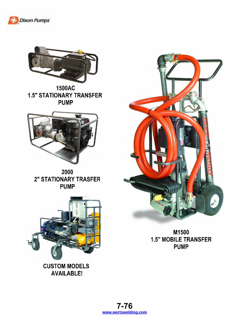
www.wertswelding.com7-76
nwerts
Typewritten text
1500AC 1.5" STATIONARY TRANSFER PUMP
nwerts
Typewritten text
2000 2" STATIONARY TRASFER PUMP
nwerts
Typewritten text
CUSTOM MODELS AVAILABLE!
nwerts
Typewritten text
M1500 1.5" MOBILE TRANSFER PUMP

ISO 18PARTS LIST
1-1/2" HOSE REELS
www.wertswelding.com7-77

7
PARTS LISTISO-18
1 1/2" Hose Reel
Item No. Description PART NUMBER Quantity1 Drum, 10-1/2" Diameter (Specify Model)............................................... 9905.3131 12 Front Disc, 19-20 Series ........................................................................ 9903.0821 12 Front Disc, 23-24 Series ........................................................................ 9903.1121 12 Front Disc, 25-26 Series ........................................................................ 9903.1321 12 Front Disc, 26-27 Series ........................................................................ 9903.1421 12 Front Disc, 28-29 Series ........................................................................ 9903.1521 12 Front Disc, 30-31 Series ........................................................................ 9903.1621 13 Back Disc, 19-20 Series ........................................................................ 9903.0821 13 Back Disc, 23-24 Series ........................................................................ 9903.1121 13 Back Disc, 25-26 Series ........................................................................ 9903.1321 13 Back Disc, 26-27 Series ........................................................................ 9903.1421 13 Back Disc, 28-29 Series ........................................................................ 9903.1521 13 Back Disc, 30-31 Series ........................................................................ 9903.1621 14 Front Frame (Up to 23-24)..................................................................... 9906.0031 14 Front Frame (Up to 30-31)..................................................................... 9906.5031 16 Back Frame (Up to 23-24) ..................................................................... 9906.0031 16 Back Frame (Up to 30-31) ..................................................................... 9906.5031 17 Front Foot (Specify Model) .................................................................... 9907.3000 19 Back Foot (Specify Model)..................................................................... 9907.3000 111 1-1/2" Flange Hub Only (Specify Model) ............................................... 9901.3640 112 1-1/2" FNPT Iron Pipe Riser Only.......................................................... 9901.3760 113 EH-936 Washer...................................................................................... 9965.0015 216 3/8"-16 Carriage Bolt w/Nut ................................................................... Specify Model 617 3/8" Spacer Pipes (Specify Model) ........................................................ 9904.3200 618 Back Bearing Complete ......................................................................... 9902.1400 118A Self-Aligning Pillow Block, Back ............................................................ 9902.2900 118B Self-Aligning Bearing Holder, Back........................................................ 9902.2800 119 Back Bearing Insert Only ....................................................................... 9902.1500 120 Front Bearing Complete......................................................................... 9902.1610 120A Bearing Holder (Bottom Strap), Front .................................................... 9902.2950 120B Bearing Holder (Top Strap), Front ......................................................... 9902.2955 121 Front Bearing Insert Only (With Grease Fitting) .................................... 9902.1700 122 Ring Gear, H-26 (Up to 25-26) .............................................................. 9914.0372 122 Ring Gear, H-28..................................................................................... 9914.0382 123 Pinion Gear, H-27 (Up to 25-26)............................................................ 9914.0393 123 Pinion Gear, H-29 .................................................................................. 9914.0404 123A Gear Guard ............................................................................................ 9914.0618 124 5/8"-18 SAE Hex Nut (ESNA)................................................................ 9904.5600 125 Pinion Shaft (Specify Model) ................................................................. 9914.0250 127 Side Pinion Bearing ............................................................................... 9914.0243 128 Collar & Set Screw................................................................................. 9914.0351 129 Crank Handle, H-18 Complete............................................................... 9914.0011 129A Hand Crank Handle ............................................................................... 9914.0506 129B Hand Crank Handle Bolt w/Nut.............................................................. 9914.0511 130 Brake Pad, H-3 ...................................................................................... 9914.0433 131 Vertical Rewind Bracket ......................................................................... 9914.0233 132 Brake Spring, H-31 ................................................................................ 9914.0451 133 Brake Wheel .......................................................................................... 9914.0413 134A Comet Brake Hub .................................................................................. 9947.0038 134B Comet Brake Strap only......................................................................... 9947.0091 134C Comet Brake Tention Adjuster (Bolt,Spring,Washer,Wing Nut) ............ 9947.0092 135 112T35 Disc Sprocket............................................................................ 9910.1321 135 138T35 Disc Sprocket ........................................................................... 9910.1423 135 180T35 Disc Sprocket ........................................................................... 9910.1526 136 Chain, #35.............................................................................................. Specify Model 138 Motor Sprocket, 11T35 x 1-5/16 ............................................................ 9910.1118 141 Motor, 12 Volt Explosion-Proof .............................................................. 9915.0003 142 1-1/2" 90 Deg. FxF Swivel Joint (STANDARD; Not for LPG) (Buna-N) 9930.4210 142 1-1/2" 90 Deg. FxFxvic Swivel Joint (viton seals).................................. 9930.4220 142 1-1/2" 90 Deg. FxF Swivel Joint (for LP GAS Applications) .................. 9930.0531 150 Gasket.................................................................................................... 9965.0021 159 Sprocket Spacer .................................................................................... 9954.0017 6103A 5/16"-18 x 1/2" Hex Head Bolt............................................................... 9904.1101 9103B 3/8"-16 x 3/4" Carriage Bolt w/Nut (w/o Comet Brake).......................... 9904.0201 2103B 3/8"-16 x 2" Carriage Bolt w/Nut (w/Comet Brake)................................ 9947.0093 1103C 3/8"-16 x 3/4" Spinlock Bolt ................................................................... 9904.2201 12103D 3/8"-16 x 1" Spinlock Bolt ...................................................................... 9904.2202 4103E 3/8"-16 Spinlock Nut .............................................................................. 9904.6200 16103F 1/2"-13 x 1" Hex Head Bolt.................................................................... 9904.1402 6103G 1/2" Lock Washer................................................................................... 9954.0030 6103H 1/2"-13 Hex Nut ..................................................................................... 9904.5400 4103J 3/8"-16 ESNA Nut .................................................................................. 9904.5201 1
BE SURE TO SPECIFY COMPLETE MODEL NUMBER and SERIAL NUMBER OF REEL.USE PART NUMBER!
When ordering parts
6M HP 5-08 H-623-PRev. 5
www.wertswelding.com7-78

SWIVEL JOINTS, RISERS, HUB ASSEMBLIES
HANNAY REELSPARTS ID GUIDE
ITEM
C1
C2
C4
C5
C6
C7
C8
C9
C10
C11
C12
C13
C14
C15
C16
C16
C17
PART
9927.8138
9929.8538
9927.8151
9929.8551
Specify
9930.4210
9930.4610
9936.0642
9930.5703
9936.0659
9929.0501
9930.0531
9901.1600
9901.3760
9965.0024
9965.0025
9901.2840
DESCRIPTION
1/2” 90° MxF BP Super Swivel
1” 90° FxF BP Super Swivel
1/2” 90° MxF Super Swivel (FxF also Avail.) 9927.8551
1” 90° FxF Super Swivel (Buna)
Super Swivel Repair Kit (Specify Size)
1-1/2” 90° FxFxV Swivel (WHJ1590)
1-1/2” Straight FxFxV Swivel(WHJ15180)
1-1/2” PK-1 BUNA-N Packing (Merkel)
1-1/2” Straight Victaulic H-5 Joint
H-5C Rope Packing Seal for H-5 Joint
1” 90° Full Circle Swivel
1-1/2” 90° FxF Full-Circle Swivel
1” FIPT Iron Welded Hub Assembly (Specify Model)
1-1/2” FIPT Iron Flanged Riser
O-Ring for 1-1/2” Risers (2-5/8” Diam.)
O-Ring for 3” Risers (3-3/4” Diam.)
1-1/2” Hub Assy Complete (Specify Model)
ITEM
E3
E4
E5
E6
E7
Not Shown
E8
E9
BEARINGSPART
9902.1200
9902.1300
9902.1400
9902.1500
9902.1610
9902.1620
9902.1700
9902.1730
DESCRIPTION
1/2” S.A. Ball Bearing Complete
1/2” S.A. Ball Bearing Insert
1” S.A. Ball Bearing Complete
1” S.A. Ball Bearing Insert
1-1/2” S.A. Bronze Bearing Complete (E-coated)
1-1/2” S.A. Bronze Bearing Complete (304 S.S.)
1-1/2” S.A. Bronze Bearing Insert
1” S.A. Bronze Bearing insert
C8
C9
C14
C15
C16
E5 E6
E7 E8
C17
C7
C1 C2
C5
C6
C13
C4
E3 E4
E9
C10
C12
Note - photos shown not actual size.
C11
www.wertswelding.com7-80

ITEM
A1A2
A3A5
A6
A7
A8
A9A9
A10A10A11
A12
Not Shown
A13A14A15A16A17
Not Shown
A18
MOTORS, SPROCKETS, CHAINPART
9915.00429915.0003
9915.00149916.0071
9916.0070
9923.0008
9923.0006
9912.00019912.00029912.00109912.00099910.1423
9910.3128
9910.1321
9910.11169910.11179910.11189910.11199910.2219
9910.2100
Specify
DESCRIPTION
12 Volt Flange Mount Non-Exp-Proof Motor12 Volt Flange Mount Explosion-ProofMotor12 Volt Base Mount Explosion-Proof MotorPair of Brushes for 12 Volt Non-Exp-ProofMotor (#572008)Two Pairs of Brushes for 12 Volt ExplosionProof Motor (#572000)Flange Mount Motor Plate for Non-Exp-Proof MotorP66A-00090 Motor Mounting Plate RightAngle for Non-Exp-Proof Motor10’ Length #35 Chain w/Connecting Link10’ Length #40 Chain w/Connecting LinkConnecting Link for #35 ChainConnecting Link for #40 Chain138T35 Disc Sprocket, 16-5/8” Diameter(E-Coated)146T40 Disc Sprocket, 23-1/2” Diameter(E - coated)112T35 Disc Sprocket, 13-3/8” Diameter(E-coated)11T35 Motor Sprocket, 3/4” Long11T35 Motor Sprocket, 1-1/16” Long11T35 Motor Sprocket, 1-5/16” Long11T35 Motor Sprocket, 1-3/4” LongDisc & Sprocket for Caliper Brake (#35Chain)Disc & Sprocket for Caliper Brake (#40Chain)Molded Chain Guard (left or right)
ITEMB1
B2
B4
B5
B6
B7
B8
B9
B10
B11
B12
B13
B14
SWITCHES AND ELECTRICALPART
9917.0001
9917.0014
9917.0061
9917.0062
9917.0063
9917.0025
Specify
9917.0024
9917.0006
9917.0008
9917.0200
9917.0207
9917.0208
DESCRIPTIONRed Dot EXPB-2A Switch (12 Volt)
Red Dot Internal Switch
Red Dot 5-Port Round Junction Box/Cover
#6 Wire Nut (For Red Dot Junction Box)
Insulated “Bug” Connector
12 Volt Solenoid (Diode-Suppressed)
SDLM Circuit Breaker (Specify Amperage)
CB-2 Mounting Bracket (for Circuit Breaker)
Push-Button 12 Volt Switch (Less Cap)
Rubber Cap (For Push Button Switch)
EPS-1 Switch (Used with Guidemaster)
EPS-2 Mounting Bracket (Used with EPS-1)
Extension Bracket for EPS-2
A2
A3
A1
A5
A6
A7
A8
A10
A11
A12
A15
A16
A17
B1
B5
B10 B11
B12
B14B13
B2
B6 B7B8
B4
A13
A14
A18
Non platedA9
B9
www.wertswelding.com7-81

ITEMD1D2D3D4D5D6D7D8D9
D10D11
D12aD12b
Not Shown
D13D14D15D16D17D18D19D20
D21
D22D23D24
D25aD25bD26
ROLLER ASSEMBLIES, CABLE GUIDES, HOSE STOPSPARTSpecify
9939.00429940.00129940.00029940.00059940.00069940.00079940.00089939.00629940.00769939.00039922.01119922.0200
9922.0210
9922.00129951.00099951.00109951.0012
SpecifySpecifySpecifySpecify
9940.0016
9940.00109940.00039940.00099940.00719940.00729939.1062
DESCRIPTIONTop Wind FH-3 Mtg. Brkt. (Specify Model)FH-3 Roller & Spool Assy. (Specify Model)FH-307 Delrin-Over-Steel Step BoltFH-309-P Black Plastic CapFH-301 SpoolFH-302 BlockFH-303-15 (1.5”) Trunnion BearingFH-303-2 (2”) Trunnion BearingUtility Hose Roller Assy. “C” (Spec. Model)EH-650 Mounting Block (Plated)EH-714 Roller AssemblyHS-3 Hose Stop (Specify OD of Hose)HS-35 Hose Stop For Single Hose(Specify OD of Hose)HS-35 Hose Stop For Twin Hoses(Specify OD of Hose) HS-45 Hose Stop (Specify OD of Hose)GR-4A Guide Arm PositionerGR-4 Guide ArmGR-5 Scoop Cable Guide“R200” Series Roller Assembly“N200” Series Roller Assembly“R300” Series Roller AssemblyRoller Mounting Arm (2) per reel(For “N” Series Spring Reels)FH-303 1 1/2“Trunnion Bearing (New Style)(No Through Hole)FH-305 2” SST Roller Tubing1 1/2” SST Roller TubingFH-304 Roller RodLEFT HAND roller mounting block (plated)RIGHT HAND roller mounting block (plated)Assy C2 Roller with 1 1/2” Diam. Roller(Style 2) (Specify Model)
ITEM
G1
G2
G3
G5
G6
G7
G8
G10
G11
G12
G15
G16
G17
G18
GUIDEMASTER PARTS AND BRACKETSPART
9945.0026
9945.0044
9945.0019
9944.0040
9945.0009
9945.0011
9945.1001
9945.1005
9945.1003
9945.1004
9945.0035
9945.0036
9945.0037
9939.0069
DESCRIPTION
GM Ball Bearing (For GM-609 Roller)
GM-108 Ball Bearing (For GM-109 Roller)
GM-609 Roller w/GM Bearing
GM-700 Guide Arm Body Assy w/Mtg. Yoke
GM Mounting Yoke w/Bronze Bushing
GM Oil-Impregnated Bronze Bushing
GM Roller Body w/Mtg. Bolts
GM Roller Mtg. Bolts
Pinlock assy for GM 700
GM Roller Bolt Mounting Plate
GM Cross Member Assembly (3 Pieces)(Specify Model)
GM Bottom-Wind Brackets (Pair)
GM Top-Wind Brackets (Pair)
Assy. “B” Roller for Bottom-WindGuidemaster Reels (specify model)
D1
D2
D3 D4
D5 D6
D7D8
D12a D13 D14D15
D16D17 D18
D19
D20
G1 G2 G3
G8
G10 G11
G12G15
G16
G17
D11
D10
G18
D21
G6G7
G5
D25a
D26
D25b
D12b
D22
D23
D24
D9
www.wertswelding.com7-82

REWIND ASSEMBLIES, BRAKES, RATCHETSITEM
F1F2F3F4F5F6F7F8F9
F10F11F12F13F14F15
Not Shown
F16F18F19F21F22F23F24
Not Shown
F25
Not Shown
F26
F27
F28
F29F30
F31
PARTSpecify
9914.02339914.03729914.03829914.03939914.0403
Spec. Model
9914.03519914.06189914.02439914.04139914.04519914.04339914.00119947.00209947.00019947.00249947.00369947.00389922.00159965.00309965.00369947.0090
9947.0043
9947.0130
9922.0008
9922.0301
9922.0302
9922.0311
9922.03129922.0321
9922.0322
DESCRIPTION30° Rewind Bracket (specify right or left)Vertical Rewind Bracket OnlyH-26 Ring GearH-28 Ring GearH-27 Pinion GearH-29 Pinion GearPinion ShaftPinion Shaft CollarPinion Gear Guard (E-Coated)H-2A Pinion Shaft BearingH-30A Brake WheelH-31 Brake SpringH-3 Brake PadH-18 Hand CrankAir Caliper BrakeManual Caliper BrakePair of Brake Pads (For Air Caliper Brake)Comet Brake Strap Only (IV Style)Comet Brake Iron Hub (IV Style)Ratchet Wheel (new 2 position)PL-1 PinlockPL-4 Pinlock with Extended Mounting EarsComet Brake Assembly(Bearing Mounted Style)
Comet Brake Assembly (Bearing Mounted Style with Stub Shaft)
Cam Lever Drag Brake Kit 3-Position Lever(including mounting hardware)
Ratchet Locking Spring
Left Hand Pawl & Pin (304 SST)
Right Hand Pawl & Pin (304 SST)
Left Hand Ratchet Locking Assy for HGR,SCR, SGCR, Reverse N-Series
Right Hand Ratchet Locking Assy for N-seriesLeft Hand Ratchet Locking Assy forRollform Reels
Right Hand Ratchet Locking Assy forReverse Rollform Reels
F1
F5 F6 F7 F8 F9
F10
F14
F15 F16
F18
F21F22 F23
F24
F11
F2 F3 F4
F12
F13
F25
F19
F26 F27
F28
F29F30
F31
www.wertswelding.com7-83
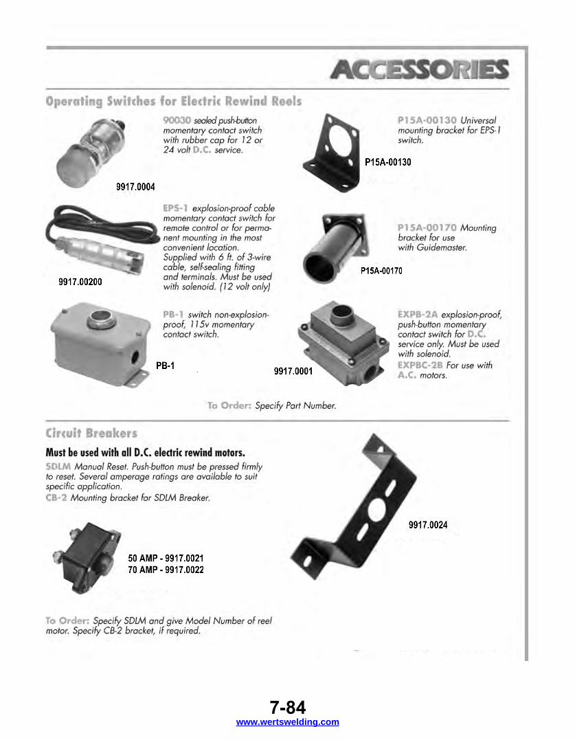
7
www.wertswelding.com7-84
nwerts
Typewritten text
9917.0004
nwerts
Typewritten text
9917.00200
nwerts
Typewritten text
9917.0001
nwerts
Typewritten text
9917.0024
nwerts
Typewritten text
50 AMP - 9917.0021 70 AMP - 9917.0022
nwerts
Typewritten text
P15A-00170
nwerts
Typewritten text
PB-1
nwerts
Typewritten text
P15A-00130

Model Numbering System
Standard accessory configurations A, C, I, K
Model number coding description
AccessoryConfiguration
A, C, I, K(see chart below)
ConstructionApplication Class
1, 2, 3, 10 etc.(see table on p. 6)
MSA-7-A-10
M / MA - 7 - AA = Meter with counter
M / MA - 7 - CC = Meter with counter, strainerand air eliminator
M / MA - 7 - II = Meter with counter, presetcounter and preset valve
M / MA - 7 - KK = Meter with counter, presetcounter and preset valve, strainerand air eliminator
Optional Accessories:Printer, Strainer Optional Accessories:
PrinterOptional Accessories:
Printer, StrainerOptional Accessories:
PrinterMounting arrangements
LC meters may be mounted in a varity of configurations, as shown below. Do not position the meter on its side, i.e., withcover plate face down or up.
Note: regardless of meter mounting configurations, accessories such as the air/vapor eliminator must always be mountedin a vertical orientation to permit proper operation of the float-actuated apparatus.
Working Pressure Blank = 150 psi AA = 285 psi A = 350 psi B = 720 psi C = 1440 psi
Case MaterialBlank = other than steelS = steel case
Meter TypeM = meter
Meter Size4 = 30 gpm 15 = 200 gpm 60 = 600 gpm5 = 60 gpm 25 = 300 gpm 75 = 700 gpm7 = 100 gpm 30 = 350 gpm 80 = 800 gpm10 = 150 gpm 40 = 450 gpm 120 = 1000 gpm
* ONLY AVAILABLE ON DIRECT MOUNT PULSER MODELS OR MODELS LESS RESETCOUNTER.
*
www.wertswelding.com7-86
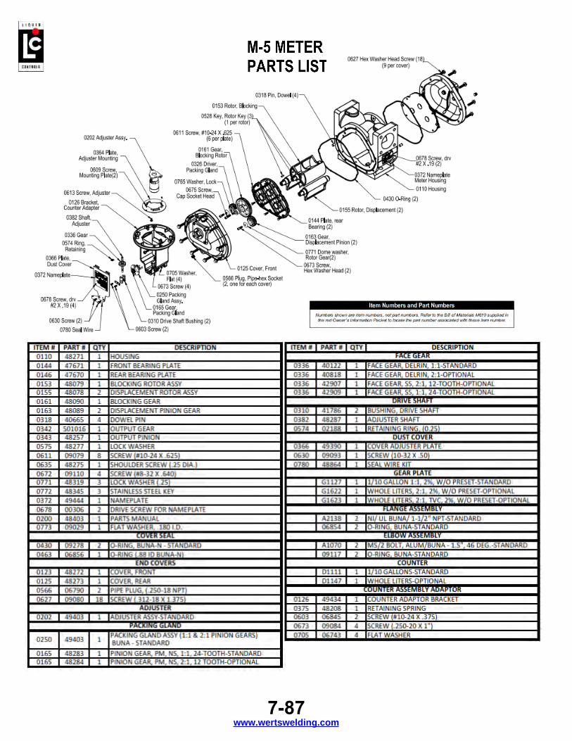
www.wertswelding.com7-87
nwerts
Typewritten text
M-5 METER PARTS LIST

7
www.wertswelding.com7-88
nwerts
Typewritten text
M-7 METER PARTS LIST

www.wertswelding.com7-89
nwerts
Typewritten text
M-15 METER PARTS LIST

7
www.wertswelding.com7-90
nwerts
Typewritten text
AIR ELIMINATOR
nwerts
Typewritten text
STRAINER ASSEMBLIES
nwerts
Typewritten text
HIGH CAPACITY STRAINER ASSEMBLY
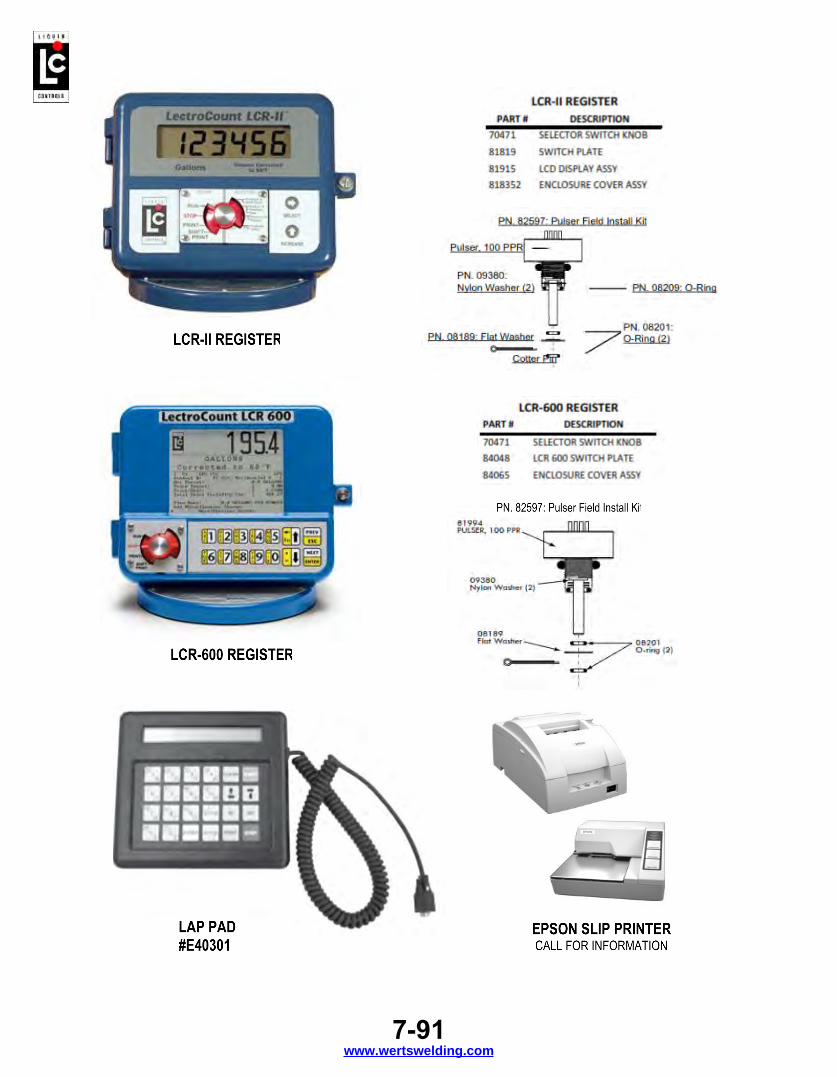
7
www.wertswelding.com7-91
nwerts
Typewritten text
PN. 82597: Pulser Field Install Kit
nwerts
Typewritten text
LCR-II REGISTER
nwerts
Typewritten text
LCR-600 REGISTER
nwerts
Typewritten text
LAP PAD #E40301
nwerts
Typewritten text
EPSON SLIP PRINTER CALL FOR INFORMATION

� � � � � � � � � � � � � � � � � � � � � � � �
� � �
� � � � � � � � � � � � � � � � � � � � � � � �� � � � � � � � � � � � � � � � � � � � � � ! �" # $ % & ' ( ) * + , ' + ) ( * ( - . / ( ) 0 1 2 3 . 4 . , * % 5 % 6 $ 7 8 & 9 : ' ; < % # = > ' ; ? @ ' A @ ' B A @ ' / A B C A @ @ D @ @ /E 9 9 % & F + * 2 G H ' + ) ( * ( - . / ( ) 0 1 2 3 . 4 . , * % 5 % 6 $ 7 8 " 9 : ' ; < $ $ E > ' ; ? @ ' A @ ' B A I ' D I J$ 9 $ 7 8 % 9 9 : ' ; < K # 9 > ' ; ? @ ' A @ ' B A @ ' / A I ' A I J A B C A @ @ D @ @ /$ &2” = 150 GPM (567 LPM)
@ ' B D @ ' /K 9 K 7 8 $ 9 9 : ' ; < E " 9 > ' ; ? @ ' A @ ' B A @ ' / A I ' A I J D B CK &3” = 300 GPM (1135 LPM)
@ ' B D @ ' /L 94” = 500 GPM (1893 LPM)
@ ' A @ ' B A @ ' / A I ' A I J D B CL &4” = 600 GPM (2271
> ' ; ? @ ' B D @ ' /� � � �@ ' @ * 2 , M 2 G M ' . * G + 1 . N 4@ ' B @ * 2 , M 2 G M ' . * G + 1 . N 4 < B - ( 2 * ( + , C N . 1 ?@ ' / @ * 2 , M 2 G M ' . * G + 1 . N 4 < / N 3 * ( 1 . I G + , ?I ' I , M N ) * G ( 2 1 ' G + M N 3 * ) OI J I , M N ) * G ( 2 1 ' G + M N 3 * ) P ( * Q J 2 G R + , : G 2 0 Q ( * . S . 2 G ( , T ) OB C B 1 1 C . G G + N )@ @ @ * 2 ( , 1 . ) ) @ * . . 1@ @ / @ * 2 ( , 1 . ) ) @ * . . 1 < / ( . ) . 1 U V Q 2 N ) * C 1 N ( M 6 B M R 1 N . ? W� � � � � � � � � � � � X � Y Z � � � � � �$ ; . * . G 2 , M F . T ( ) * . GK ; . * . G A F . T ( ) * . G 2 , M ' G ( , * . GL ; . * . G A F . T ( ) * . G 2 , M B ( G U 1 ( 4 ( , 2 * + G 6 @ * G 2 ( , . GL F ; . * . G A F . T ( ) * . G 2 , M B ( G U 1 ( 4 ( , 2 * + G 6 [ ( T Q \ + 1 N 4 . @ * G 2 ( , . G O WL @ ; . * . G A F . T ( ) * . G 2 , M U 1 . 3 * G + , ( 3 B ( G U 1 ( 4 ( , 2 * + G 6 @ * G 2 ( , . G OL \ ; . * . G A F . T ( ) * . G 2 , M U 1 . 3 * G + , ( 3 B ( G U 1 ( 4 ( , 2 * + G 6 [ ( T Q \ + 1 N 4 . @ * G 2 ( , . G O W& ; . * . G A F . T ( ) * . G 2 , M @ * G 2 ( , . G" ; . * . G A F . T ( ) * . G A ' G ( , * . G 2 , M B ( G U 1 ( 4 ( , 2 * + G 6 @ * G 2 ( , . G" F ; . * . G A F . T ( ) * . G A ' G ( , * . G 2 , M B ( G U 1 ( 4 ( , 2 * + G 6 [ ( T Q \ + 1 N 4 . @ * G 2 ( , . G O WE ; . * . G A F . T ( ) * . G A ' G ( , * . G 2 , M @ * G 2 ( , . G# ; . * . G A F . T ( ) * . G 2 , M ' G . ) . * \ 2 1 - .= ; . * . G A F . T ( ) * . G A ' G ( , * . G 2 , M ' G . ) . * \ 2 1 - .% 9 ; . * . G A F . T ( ) * . G A ' G . ) . * \ 2 1 - . 2 , M B ( G U 1 ( 4 ( , 2 * + G 6 @ * G 2 ( , . G% 9 F ; . * . G A F . T ( ) * . G A ' G . ) . * \ 2 1 - . 2 , M B ( G U 1 ( 4 ( , 2 * + G 6 [ ( T Q \ + 1 N 4 . @ * G 2 ( , . G O W% 9 @ ; . * . G A F . T ( ) * . G A ' G . ) . * \ 2 1 - . 2 , M U 1 . 3 * G + , ( 3 B ( G U 1 ( 4 ( , 2 * + G 6 @ * G 2 ( , . G O% 9 \ ; . * . G A F . T ( ) * . G ' G . ) . * \ 2 1 - . 2 , M U 1 . 3 * G + , ( 3 B ( G U 1 ( 4 ( , 2 * + G 6 [ ( T Q \ + 1 N 4 . @ * G 2 ( , . G O W% % ; . * . G A F . T ( ) * . G A ' G ( , * . G A ' G . ) . * \ 2 1 - . 2 , M B ( G U 1 ( 4 ( , 2 * + G 6 @ * G 2 ( , . G% % F ; . * . G A F . T ( ) * . G A ' G ( , * . G A ' G . ) . * \ 2 1 - . 2 , M B ( G U 1 ( 4 ( , 2 * + G 6 [ ( T Q \ + 1 N 4 . @ * G 2 ( , . G O W% $ ; . * . G A F . T ( ) * . G A ' G . ) . * \ 2 1 - . 2 , M @ * G 2 ( , . G% K ; . * . G A F . T ( ) * . G A ' G ( , * . G A ' G . ) . * \ 2 1 - . 2 , M @ * G 2 ( , . G� � � � � � � � � � � � � � � �B ; . * . G B ) ) . 4 R 1 H P ( * Q \ . . M . G F + + * F . T ( ) * G 2 * ( + ,S ; . * . G B ) ) . 4 R 1 H 1 . ) ) \ . . M . G F + + * F . T ( ) * G 2 * ( + ,J ; . * . G B ) ) . 4 R 1 H 2 , M / G ( - . J + N 0 1 . G ] + G N ) . P ( * Q ; ( M ^ J + 4 A \ . . M . G F + + * A > ( _ N ( M J + , * G + 1 ) A > ( _ N ( 0 A . * 3 `/ ; . * . G B ) ) . 4 R 1 H P ( * Q 2 / ( G . 3 * ; + N , * ' N 1 ) . a G 2 , ) 4 ( * * . G ( , = * + $ L \ / J @ * 2 , M 2 G M b & \ / J c 0 * ( + , 2 1U ; . * . G B ) ) . 4 R 1 H P ( * Q a J @ K 9 9 9 U 1 . 3 * G + , ( 3 F . T ( ) * G 2 * ( + ,–
E & / . T G . . ; + N , *C ; . * . G B ) ) . 4 R 1 H P ( * Q a J @ K 9 9 9 U 1 . 3 * G + , ( 3 F . T ( ) * G 2 * ( + ,–
= 9 / . T G . . ; + N , *: ; . * . G B ) ) . 4 R 1 H P ( * Q / ( G . 3 * ; + N , * ' N 1 ) . a G 2 , ) 4 ( * * . G 2 , M a J @ K 9 9 9 U 1 . 3 * G + , ( 3 F . T ( ) * G 2 * ( + ,–
F . 4 + * . ; + N , *� � Y � � � � � � � � �d e c F U : I @ a U F: % 6 % f ` @ ` : 2 1 1 + , ) < g [ c > U ?a % 6 % 9 f ` @ ` : 2 1 1 + , ) < a U e a [ @ ?> % 6 % > ( * . G )U % 6 % 9 > ( * . G )/ % 6 % / . h 2 1 ( * . G )I % 6 % I 4 0 . G ( 2 1 : 2 1 1 + , )' % 6 % ' + N , M )J % 6 % J N R ( 3 ; . * . G )i � � � � � � � � � � � � � � � � � � � � � � � � j � � � � � � � � � � � � � Z � ! � � X � � � � ! � � � k� � � � � � � � � � � � � � � � � � �� Z � � � � � � � � � � � � �5 e c e U% F . T ( ) * . G ; + N , * % ^ % / G H F . . M ' N 1 ) . G f > < ; . * . G c G ( . , * 2 * ( + , B ?$ F . T ( ) * . G ; + N , * % 9 ^ % / G H F . . M ' N 1 ) . G f > < ; . * . G c G ( . , * 2 * ( + , B ?K F . T ( ) * . G ; + N , * % 9 9 ^ % @ + 1 ( M @ * 2 * . ' N 1 ) . G f > < ; . * . G c G ( . , * 2 * ( + , B ?L F . T ( ) * . G ; + N , * % 9 9 ^ % @ + 1 ( M @ * 2 * . ' N 1 ) . G B a U d < ; . * . G c G ( . , * 2 * ( + , B ?� � � � � � �5 e c e UB B ( G / ( ] ] . G . , * ( 2 1 J Q . 3 h \ 2 1 - . O WJ S 2 3 h ' G . ) ) N G . J Q . 3 h \ 2 1 - . < @ 0 G ( , T > + 2 M . M g 2 ] . G a H 0 . ?a B N * + 4 2 * ( 3 a . 4 0 . G 2 * N G . J + 4 0 . , ) 2 * ( + , < B a J ? l ( * ^ F a / a . 4 0 . G 2 * N G . ' G + R . D a Q . G 4 + P . 1 1O m n n o p q r o s t u p v w x q x o p y u sW y p q r z r { u r | u x v { q } w x q x o q s ~ x � � � � � { x � x u x � } r � � q t u � { � � r � | u � x �7-93

700-20 / 700-25 Meter Assembly
7-94

� � � � � � � � � � � � � � � � � � � � � � � � � �� � � � � � � � � � � � � � � � � � � � � � � � �� � � � � � � � � � � � ! " � � � � # � � $ � � � � # � � $ � � � � # � � $ � � � � # � � $ � � � � # � � $ � � � � # � � $ � � � � # � � $ � � � � # � � $ � � � � # � � $ � � � � # � � $� � � % � � � � � � � � � & ' ( � � � � � � � � � � � � � � � � � � � � � � � � � � � � � � � � � � � � � � � � � � � � � � � � � � � � � � � � � � � � � �) � � * � � + , � � � � � � � $ � � � � � $ � � � � � $ � � � � � $ � � � � � $ � � � � � $ � � � � � $ � � � � � $ � � � � � $ � � � � � $- . � � / � � � � � � " � � � � � " � � � � � " � � � � � " � � � � � " � � � � � " � � � � � " � � � � � " � � � � � " � � � � � "� � � � � ( � � � 0 � � � � � � � � # � � � � � # � � � � � # � � � � � # � � � � � # � � � � � # � � � � � # � � � � � # � � � � � # � � � � � #" � � � � ( 1 � � + / � � � � � � � � � � � � � � � � � � � � � � � � � � � � � � � � � � � � � � � � � � � � � � � � � � � � � � � � � � � � �� � � % � � � � � � � * � � � ( � � � � � � � � � � � � � � � � � � � � � � � � � � � � � � � � � � � � � � � � � � � � � � � � � � � � � � � � � � � � � � �# � � ( 2 � � � � � � � # # - $ � � � � # # - $ � � � � # # - $ � � � � # # - $ � � � � # # - $ � � � � # # - $ � � � � # # - $ � � � � # # - $ � � � � # # - $ � � � � # # - $$ � � ( ( � � � � � � � � � ! � � � � � - � � � � � - � � � � � - � � � � � - � � � � � - � � � � � - � � � � � - � � � � � - � � � � � - � � � � � - �� � � � * � � + , � � � � � � � � � � � � � � � � � � � � � � � � � � � � � � � � � � � � � � � � � � � � � � � � � � � � � � � � � � � � � � � � � � �� � � � � 3 � � � � � � � ! - � � � � - � � � � � - � � � � � - � � � � � - � � � � � - � � � � � - � � � � � - � � � � � - � � � � � - � � � � � - �� � � � / � � � � � � � � � � � � � � � � � � � � � � � � � � � � � � � � � � � � � � � � � � � � � � � � � � � � � � � � � � � � � � � � � � � � � �� ) � � 4 / � � � / � ( � � � � � � � � � � � � � � � � � � � � � � � � � � � � � � � � � � � � � � � � � � � � � � � � � � � � � � � � � � � � � � �� - � � 5 � � � 4 / � � � ( � � � � � 6 7 � 8 � � � � � � � � � � � � � � � � � � � � � � � � � � � � � � � � � � � � � � � � � � � � � � � ) � � � � � � � � � � � � � �� - 1 � 5 � � � 4 / � � � ( � � � � � 6 � � � � � � � � � � � � � � � � � � � � � � � � � � � � � � � � � � � � � � � � � � � � � � � � � � � � � � � �� � � � 4 / 9 � � / � � � � � � $ � � � � � $ � � � � � � � � � � � � � � � � � � � � � � � � � � � � � � � � � # � $ � � � � � $ � � � � � �� " � ( � / � � � � � � - � � � � � - � � � � � - � � � � � - � � � � � - � � � � � - � � � � � - � � � � � - � � � � � - � � � � � -� � � � � � � � * � � � � � � � � � � � � � � � � � � � � ) � � � � � � � � � � � � � � � � � ) � � � � � � � � � � � - � � � � � � � � � � � )� # � � � � � � ! � " � � � � � " � � � � � " � � � � � " � � � � � " � � � � � " � � � � � " � � � � � " � � � � � " � � � � � " � � � � � "� # 1 � � ( ( � � � � � � � ! - � � � � � � " � � � � � � " � � � � � � " � � � � � � " � � � � � � " � � � � � � " � � � � � � " � � � � � � " � � � � � � " � � � � � � "� $ � � � � � * � � � � � � � � � � � � � � � � � � � � ) � � � � � � � � � � � � � � � � � ) � � � � � � � � � � � � � � � � � � � � � � � )� � � � � � � � � � � � � ! � � � � � � � - � � � � � - � � � � � - � � � � � - � � � � � - � � � � � - � � � � � - � � � � � - � � � � � - � � � � � -� � 1 � � / � ( � � � � � � � ) � � � � � ) � � � � � ) � � � � � ) � � � � � � � � � � � � � � � � � � � � � � � ) � � � � � � � � � � � � �� � � � * � � 9 � � / � � � � � � � � � � � � � � � � � � � � � � � � � � � � � � � � � � � � � � � � � � � � � � # � � � � � � � � � � � � � �� ) � � � � / � � � � � � � � � � � � � � � � � � � � � � � � � � � � � � � � � � � � � � � � � � � � � � � � - � � � � � � � � � � � �� - � ( � 2 � + � � # � � � � � # � � � � � # � � � � � # � � � � � # � � � � � # � � � � � # � � � � � # � � � � � # � � � � � # � � � � � #� � � � � � � � ! - � � � � � � � � � � � � � � � � � � � � � � � � � � � � � � � � � � � � � � � � � � � � � � � � � � � � � � � � � � � �� � 1 � � ( ( � � � � � � � ! - � � � � � � � � � � � � � � � � � � � � � � � � � � � � � � � � � � � � � � � � � � � � � � � � � � � � � � � � � � � � � � � � � � � � � �� " �Flange, 2” NPT
� � � � " � � � � � " � � � � � " � � � � � " � � � � � " � � � � � " � � � � � " � � � � � " � � � � � � " � � � � � " � �� " 1Flange, 2” BSPT
� � � � " � ) � � � " � ) � � � " � � � � � " � ) � � � " � ) � � � " � � � � � " � � � � � " � � � � � � " � ) � � � " � �� � � ( / � 9 � � / � � � � � � � � � � � � � � � � � � ) � � � � � ) � � � � � ) � � � � � ) � � � � � ) � � � # � � � � � � � � � � � � � )� # 1 ( � � 4 / 0 � � � � � � ) � � � � � ) � � � � � ) � � � � � ) � � � � � ) � � � � � ) � � � � � ) � � � � � ) � ) � � � ) � � � � � ) � �� $ � � � � � : � � 4 ; � � ) � � � � � � � � � � � � � � � � � � � � � � � � � � � � � � � � � � � � � � � � � � � � � � � � � � � � � � � � � � � �) � � � ( � � & � � 0 � � � � � � - � � � � � - � � � � � - � � � � � - � � � � � - � � � � � - � � � � � - � � � � � - � ) � � � - � � � � � - � �) � � � � � � < � � ) � � � � � # � � � � � # � � � � � # � � � � � # � � � � � # � � � � � # � � � � � # � � � � � # � � � � � # � � � � � #) � � � ( � � & � � � � � � � � � � � - � � � � � - � � � � � - � � � � � - � � � � � - � � � � � - � � � � � - � � � � � - � - � � � - � � � � � - � �) ) 1 ( � � 4 / � � � � � � � � � ) � � � � � ) � � � � � ) � � � � � ) � � � � � ) � � � � � ) � � � � � ) � � � � � ) � - � � � ) � � � � � ) � �) - : � � 4 2 � + � � - � � � � � � � � � � � � � � � � � � � � � � � � � � � � � � � � � � � � � � � � � � � � � � � � � � � � � � � � � � � �
700-20 / 700-25 Meter Assembly
7-95
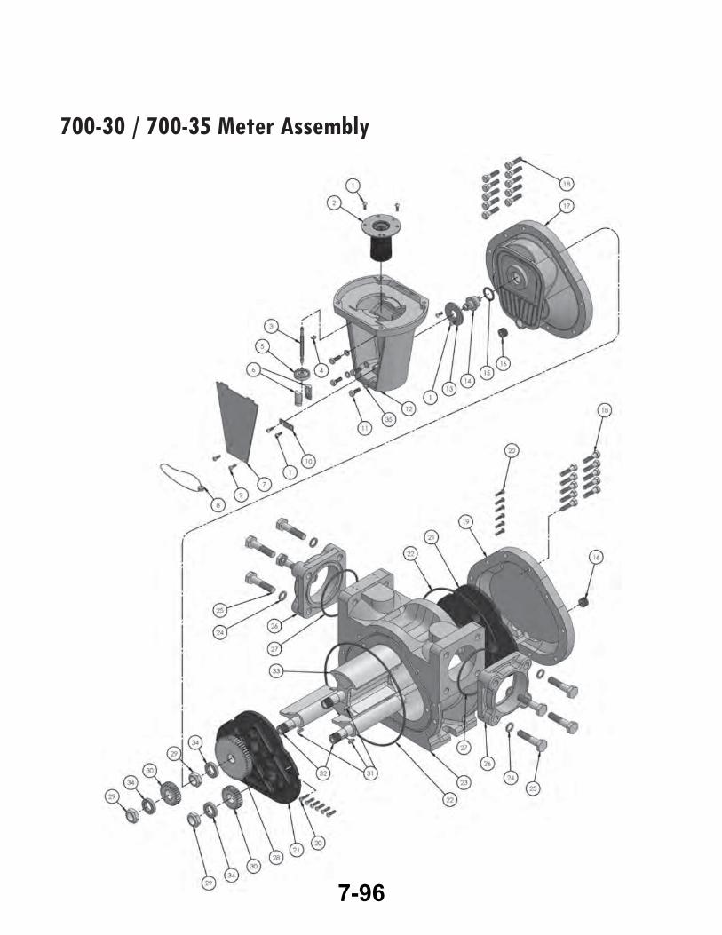
700-30 / 700-35 Meter Assembly
7-96

� � � � � � � � � � � � � � � � � � � � � � � � � �� � � � � � � � � � � � � � � � � � � �� � � � � ! " # $ % & " ' ( � ) � * + * , - � ) � * + * , - � ) � * + * , - � ) � * + * , - � ) � * + * , - � ) � * + * , - � ) � * + * , - � ) � * + * , -* . / � 0 1 " & . 0 0 " 2 3 4 5 � , 6 6 � 6 6 , 6 6 � 6 6 , 6 6 � 6 6 , 6 6 � 6 6 , 6 6 � 6 6 , 6 6 � 6 6 , 6 6 � 6 6 , 6 6 � 6 67 8 & 9 : " $ ; # < 1 � , 6 6 6 � - , 6 6 6 � - , 6 6 6 � - , 6 6 6 � - , 6 6 6 � - , 6 6 6 � - , 6 6 6 � - , 6 6 6 � -= > ) � 9 � ? � , 6 6 6 � ( , 6 6 6 � ( , 6 6 6 � ( , 6 6 6 � ( , 6 6 6 � ( , 6 6 6 � ( , 6 6 6 � ( , 6 6 6 � (@ . % " 1 # 4 A # % " B " # & � , 6 6 6 � + , 6 6 6 � + , 6 6 6 � + , 6 6 6 � + , 6 6 6 � + , 6 6 6 � + , 6 6 6 � + , 6 6 6 � +( . % " 1 # 4 C � 0 ; 9 � ? * , 6 6 6 * 6 , 6 6 6 * 6 , 6 6 6 * 6 , 6 6 6 * 6 , 6 6 6 * 6 , 6 6 6 * 6 , 6 6 6 * 6 , 6 6 6 * 6, . / � 0 1 " & D � : " & E 4 # 1 " � , 6 6 6 � , , 6 6 6 � , , 6 6 6 � , , 6 6 6 � , , 6 6 6 � , , 6 6 6 � , , 6 6 6 � , , 6 6 6 � ,+ $ " # 4 F 9 & " � � ) � � + + = - � ) � � + + = - � ) � � + + = - � ) � � + + = - � ) � � + + = - � ) � � + + = - � ) � � + + = - � ) � � + + = -- 8 & 9 4 4 " ! " # $ % & " ' * , 6 6 6 = * , 6 6 6 = * , 6 6 6 = * , 6 6 6 = * , 6 6 6 = * , 6 6 6 = * , 6 6 6 = * , 6 6 6 = *� 6 8 & 9 : " $ ; # < 1 � " 1 # 9 � " & � , 6 6 6 * * , 6 6 6 * * , 6 6 6 * * , 6 6 6 * * , 6 6 6 * * , 6 6 6 * * , 6 6 6 * * , 6 6 6 * *� � ! " # G � � � 1 $ % & " ' = , 6 6 6 = 6 , 6 6 6 = 6 , 6 6 6 = 6 , 6 6 6 = 6 , 6 6 6 = 6 , 6 6 6 = 6 , 6 6 6 = 6 , 6 6 6 = 6� * � " ? 9 0 1 " & $ � H H � & 1 � , 6 6 * 6 6 , 6 6 * 6 6 , 6 6 * 6 6 , 6 6 * 6 6 , 6 6 * 6 6 , 6 6 * 6 6 , 6 6 * 6 6 , 6 6 * 6 6� 7 E # % I 9 � ? � " 1 # 9 � 9 � ? E 4 # 1 " � , 6 6 6 � @ , 6 6 6 � @ , 6 6 6 � @ , 6 6 6 � @ , 6 6 6 � @ , 6 6 6 � @ , 6 6 6 � @ , 6 6 6 � @� = . * J � E # % I 9 � ? D # H 0 � 4 " . 0 0 5 K � , 6 6 � @ 6 , 6 6 � @ 6 , 6 6 � @ @ , 6 6 � @ @ , 6 6 � @ @ , 6 6 � @ @ , 6 6 � @ 6 , 6 6 � @ @� = C � J � E # % I 9 � ? D # H 0 � 4 " . 0 0 5 K � , 6 6 � , 6 , 6 6 � , 6 , 6 6 � , @ , 6 6 � , @ , 6 6 � , @ , 6 6 � , @ , 6 6 � , 6 , 6 6 � , @� @ E # % I 9 � ? L ) & 9 � ? � , 6 6 6 6 - , 6 6 6 6 - , 6 6 6 � 6 , 6 6 6 � 6 , 6 6 6 � 6 , 6 6 6 � 6 , 6 6 6 6 - , 6 6 6 � 6� ( E 4 � ? * , 6 6 6 * = , 6 6 6 * = , 6 6 6 * = , 6 6 6 * = , 6 6 6 * = , 6 6 6 * = , 6 6 6 * = , 6 6 6 * =� , A & � � 1 D � : " & � , 6 7 @ 6 6 , 6 7 @ 6 6 , 6 7 @ 6 7 , 6 7 @ 6 6 , 6 7 @ 6 6 , 6 7 @ 6 7 , 6 7 @ 6 6 , 6 7 @ 6 7� + . D # H $ % & " ' � ( , 6 7 6 � ( , 6 7 6 � ( , 6 7 6 � ( , 6 7 6 � ( , 6 7 6 � ( , 6 7 6 � ( , 6 7 6 � ( , 6 7 6 � (� + C 8 & 9 4 4 " D # H $ % & " ' = , 6 7 6 � ( 8 , 6 7 6 � ( 8 , 6 7 6 � ( 8 , 6 7 6 � ( 8 , 6 7 6 � ( 8 , 6 7 6 � ( 8 , 6 7 6 � ( 8 , 6 7 6 � ( 8� - � " # & D � : " & � , 6 7 @ @ 6 , 6 7 @ @ 6 , 6 7 @ @ 7 , 6 7 @ @ 6 , 6 7 @ @ 6 , 6 7 @ @ 7 , 6 7 @ @ 6 , 6 7 @ @ 7* 6 � � � � ! " # $ % & " ' � * , 6 * 6 � = , 6 * 6 � = , 6 * 6 � = , 6 * 6 � = , 6 * 6 � = , 6 * 6 � = , 6 * 6 � = , 6 * 6 � =* � C " # & 9 � ? E 4 # 1 " * , 6 7 * 7 6 , 6 7 * 7 @ , 6 7 * 7 @ , 6 7 * 7 6 , 6 7 * * @ , 6 7 * * @ , 6 7 * * @ , 6 7 * * @* * D � : " & L ) & 9 � ? * , 6 7 6 6 � , 6 7 6 6 � , 6 7 6 6 * , 6 7 6 6 * , 6 7 6 6 * , 6 7 6 6 * , 6 7 6 6 � , 6 7 6 6 ** 7 ! � � 0 9 � ? � , 6 7 � � 6 , 6 7 � � 6 , 6 7 � � 7 , 6 7 � � 6 , 6 7 � � 6 , 6 7 � � 7 , 6 7 � � 6 , 6 7 � � 7* = A 4 # 1 F # 0 ; " & + , 6 7 6 � + , 6 7 6 � + , 6 7 6 � + , 6 7 6 � + , 6 7 6 � + , 6 7 6 � + , 6 7 6 � + , 6 7 6 � +* @ D # H $ % & " ' + , 6 7 6 � , , 6 7 6 � , , 6 7 6 � , , 6 7 6 � , , 6 7 6 � , , 6 7 6 � , , 6 7 6 � , , 6 7 6 � ,* ( .Flange, 3” NPT
* , 6 7 ( 6 6 , 6 7 ( 6 6 , 6 7 ( � 7 , 6 7 ( 6 6 , 6 7 ( 6 6 , 6 7 ( � 7 , 6 7 ( 6 6 , 6 7 ( � 7* ( CFlange, 3” BSPT
* , 6 7 ( 6 7 , 6 7 ( 6 7 , 6 7 ( � � , 6 7 ( 6 7 , 6 7 ( 6 7 , 6 7 ( � � , 6 7 ( 6 7 , 6 7 ( � �* , A 4 # � ? " L ) & 9 � ? * , 6 7 6 � * , 6 7 6 � * , 6 7 6 � 7 , 6 7 6 � 7 , 6 7 6 � 7 , 6 7 6 � 7 , 6 7 6 � 7 , 6 7 6 � 7* + C 4 � % I 9 � ? � � 1 � & B " # & � , 6 7 7 @ � , 6 7 7 @ � , 6 7 7 @ � , 6 7 7 @ 6 , 6 7 7 @ 6 , 6 7 7 @ 6 , 6 7 7 @ � , 6 7 7 @ �* - � � 1 � & M � % I N � 1 7 , 6 7 6 � 6 , 6 7 6 � 6 , 6 7 6 � 6 , 6 7 6 � 6 , 6 7 6 � 6 , 6 7 6 � 6 , 6 7 6 � 6 , 6 7 6 � 67 6 8 9 0 H 4 # % " 2 " � 1 � � 1 � & B " # & * , 6 7 = @ � , 6 7 = @ � , 6 7 = @ � , 6 7 = @ 6 , 6 7 = @ 6 , 6 7 = @ 6 , 6 7 = @ � , 6 7 = @ �7 � � � 1 � & O " 5 7 , 6 7 6 6 + , 6 7 6 6 + , 6 7 6 6 + , 6 7 6 6 + , 6 7 6 6 + , 6 7 6 6 + , 6 7 6 6 + , 6 7 6 6 +7 * 8 9 0 H 4 # % " 2 " � 1 � � 1 � & * , 6 7 = 6 @ , 6 7 = 6 @ , 6 7 = * * , 6 7 = � 6 , 6 7 = � 6 , 6 7 = * @ , 6 7 = 6 @ , 6 7 = * *7 7 C 4 � % I 9 � ? � � 1 � & � , 6 7 7 6 @ , 6 7 7 6 @ , 6 7 7 * * , 6 7 7 � 6 , 6 7 7 � 6 , 6 7 7 * @ , 6 7 7 6 @ , 6 7 7 * *7 = B " # & $ H # % " & 7 , 6 7 7 @ @ , 6 7 7 @ @ , 6 7 7 @ @ , 6 7 7 @ @ , 6 7 7 @ @ , 6 7 7 @ @ , 6 7 7 @ @ , 6 7 7 @ @7 @ M � % I F # 0 ; " & = , 6 6 6 , � , 6 6 6 , � , 6 6 6 , � , 6 6 6 , � , 6 6 6 , � , 6 6 6 , � , 6 6 6 , � , 6 6 6 , �
700-30 / 700-35 Meter Assembly
7-97

700-40 / 700-45 Meter Assembly
7-98

� � � � � � � � � � � � � � � � � � � � � � � � � �� � � � � � � � � � � � � � � � � � � �� � � � � � � � � � � � ! " � � � # " # � $ � � � # " # � $ � � � # " # � $ � � � # " # � $ � � � # " # � $ � � � # " # � $ � � � # " # � $ � � � # " # � $# � � % � � � � � � � � � & ' ( � � � � � � � � � � � � � � � � � � � � � � � � � � � � � � � � � � � � � � � � � � � � � � � � � �) � � * � � + , � � � � � � � $ � � � � � $ � � � � � $ � � � � � $ � � � � � $ � � � � � $ � � � � � $ � � � � � $� - � � . � � � � � � / � � � � � / � � � � � / � � � � � / � � � � � / � � � � � / � � � � � / � � � � � /� � � � � � ( � � � 0 � � 1 # 2 � � � 3 . � � � � � � " � � � � � " � � � � � " � � � � � " � � � � � " � � � � � " � � � � � " � � � � � "� 4 � � � � ( � � � 0 � � 5 � 2 � � � 3 . � � � � � � " � � � � � " � � � � � " � � � � � " � � � � � " � � � � � " � � � � � " � � � � � "/ � � � � ( 4 � � + . # � � � � # � � � � � # � � � � � # � � � � � # � � � � � # � � � � � # � � � � � # � � � � � # �� � � % � � � � � � � * � � � ( � � � � � � / � � � � � / � � � � � � � � � � � / � � � � � / � � � � � � � � � � � / � � � � � � � �" � � ( 6 � � � � � � � " " � $ � � � � " " � $ � � � � " " � $ � � � � " " � $ � � � � " " � $ � � � � " " � $ � � � � " " � $ � � � � " " � $$ � � ( ( � � � � � � � � � ! # � � � � � # � � � � � � # � � � � � � # � � � � � � # � � � � � � # � � � � � � # � � � � � � # � � � � � � # �� � � � * � � + , � � � � � � � � � � � # # � � � � # # � � � � # # � � � � # # � � � � # # � � � � # # � � � � # # � � � � # #� � � � � 7 � � � � � � � ! � � � � � � � � � � � � � � � � � � � � � � � � � � � � � � � � � � � � � � � � � � � � � � � � �� # � � . � � � � � � � � � � � � � # � � � � � # � � � � � # � � � � � # � � � � � # � � � � � # � � � � � # � � � � � # � �� ) � � 3 . � � � . � ( � � � � � � � � � � � � � � � � � � � � � � � � � � � � � � � � � � � � � � � � � � � � � � � � � � �� � � # 2 � � � 3 . � � � ( � � � � � 8 � � � � � � � � � � � � � � � � � � � � � � � � � � � � � � � � � � � � � � � � � � � � � � � � �� � 4 � 2 � � � 3 . � � � ( � � � � � 8 � � � � � � � � � � � � � � � � � � � � � � � � � � � � � � � � � � � � � � � � � � � � � � � � �� � � � 3 . 9 � � . � � � � � � $ � � � � � $ � � � � � � � � � � � � � � � � � � � � � � � $ � � � � � � � � � � � $� / � ( � . # � � � � # � � � � � # � � � � � # � � � � � # � � � � � # � � � � � # � � � � � # � � � � � # �� � � � � � � � * � � � � � / � � � � � / � � � � � � � � ) � � / � � � � � / � � � � � � � � ) � � / � � � � � � � � )� " � � � � � � ! � " � � � � � / � � � � � / � � � � � / � � � � � / � � � � � / � � � � � / � � � � � / � � � � � /� " 4 � � ( ( � � � � � � � ! � � � � � � / � � � � � � / � � � � � � / � � � � � � / � � � � � � / � � � � � � / � � � � � � / � � � � � � / �� $ � � � � � * � � � � � � � � � � � � � � � � � � � � ) � � � � � � � � � � � � � � � � � ) � � � � � � � � � � � )# � � � � � � � � � � � � ! � / � � � � � � � � � � � � � � � � � � � � � � � � � � � � � � � � � � � � � � � � � � � � � � � �# � 4 � � . � ( � � # � � � # ) � � � � # ) � � � � # ) � � � � # ) � � � � # # � � � � # # � � � � # # � � � � # # �# # � � * � � 9 � � . # � � � � � � � � � � � � � � � � � � � � � � � # � � � � � # � � � � � # � � � � � � � � � � � �# ) � � � � . � � � � � � � � � � � � � � � � � � ) � � � � � � � � � � � � � � � � � ) � � � � � � � � � � � )# � � ( � 6 � + � � " � � � � � " � � � � � " � � � � � " � � � � � " � � � � � " � � � � � " � � � � � " � � � � � "# � � � � � � � ! � � � � � � � � � � � � � � � � � � � � � � � � � � � � � � � � � � � � � � � � � � � � � � � � �# � 4 � � ( ( � � � � � � � ! � � � � � � � � � � � � � � � � � � � � � � � � � � � � � � � � � � � � � � � � � � � � � � � � � � � � � � � � �# / �Flange; 4” NPT
# � � � / � � � � � / � � � � � / � ) � � � / � � � � � / � � � � � / � ) � � � / � � � � � / � )# / 4Flange; 4” BSPT
# � � � / � ) � � � / � ) � � � " � # � � � / � ) � � � / � ) � � � " � # � � � / � ) � � � " � ## � � ( . � 9 � � . # � � � � � # � � � � � # � � � � � # � � � � � ) � � � � � ) � � � � � ) � � � � � # � � � � � ## " 4 ( � � 3 . � � � � � 0 � � � � � � ) � � � � � ) � � � � � ) � � � � � ) � � � � � ) � � � � � ) � � � � � ) � � � � � ) � �# $ � � � � � : � � 3 ; � � ) � � � � � � � � � � � � � � � � � � � � � � � � � � � � � � � � � � � � � � � � � � � � � � � �) � � � ( � � & � � � � � � � 0 � � # � � � � � � � � � � � � � � � � � � � � � � � � � � � � � � � � � � � � � � � � � � � � � � � �) � � � � � � < � � ) � � � � � " � � � � � " � � � � � " � � � � � " � � � � � " � � � � � " � � � � � " � � � � � ") # � � ( � � & � � � � � � � # � � � � � � � � � � � � � � � � # # � � � � � � � � � � � � � � � � # � � � � � � � � � � � # #) ) 4 ( � � 3 . � � � � � � � � � ) � � � � � ) � � � � � ) # # � � � ) � � � � � ) � � � � � ) # � � � � ) � � � � � ) # #) � : � � 3 6 � + � � � � � � � � � � � � � � � � � � � � � � � � � � � � � � � � � � � � � � � � � � � � � � � � � � �
700-40 / 700-45 Meter Assembly
7-99

720-20 Strainer / 725-20 High Capacity Strainer Assembly
7-100

720-20 Strainer / 725-20 High Capacity Strainer Assembly � � � � � � � � � � � � � � � � � � � � � � � � � � �� � � � � � � � � � � � �� � �� � � � � � � � � � � � � � � � � � � � � � � � � � � � � � � � � � � � � � � � � � � � � � � �� � � � � �� � � � � � � � � � � � � � � � � � � � � � � � � � � � � � � � � � � � � � � � � � � � � � ! � � � � � � " � � � � � � � � � � � � � � � � � � � � � � � � � � � � � � � � � � � � � � � � � � � � � � � � � �# � � � � � � � � � $ � � % & � � � � � � � � � � � � � � � � � � � � � � � � � � � � � �� ' � � � � & � � � � ( � � � � � ) � � � � ) � � � � ) � � � � ) � � � � ) � � � � )� � � � )� � � � � � � � � * + � � � ( � � � � � � � � � � � � � � � � � � � � � � � � � # �� � � � � #�Basket Cover, Two 1/2” NPT Ports
� � � � � � � � � � � � � � � � � � � � � � � � � � ��� ! � � , � � � $ � � % � ' � � � � � � � � � � � � � � � � � � � � � � � � � � # �� � � � � #� � � � � - � � ( � � � � � # � � � � � � � � � � � � � � � � �� � � � #) � � . � � � � � � � � � � � ! � � , � � % � ' � � � � � � � � � � � � � � � � � � � ��) ! � / � � � � � � � � ! � � , � � % � ' � � � � � � � � � � � � � � � �� � � � � �) � � � / � � � � � � � � ! � � , � � � � � � � � � � � � � � � � ��) � � � � / � � � � � � � � ! � � , � � � � � � � � � � � � � � � � ��� � � � � � � � � � � � � � � � � � � � # � � ��� � � � � � � � � � � � � � � � � # � � ��� � ! � � � � � � " � � � � � � � � � � � � � � � # � � � �� � Basket Cover, Two 1/2” NPT Ports� � � � � � � # � � ��� # ! � � , � � � $ � � . � ' � � � � � � � � # � � ��� � � � � - � � ( � � � � � � � # � � #�� � � � / � � � � � � � � ! � � , � � % � ' � � � � � � � � # � � ��� � ! � � / � � � � � � � � ! � � , � � � � � � � � � # � � ��� � � � � � / � � � � � � � � ! � � , � � � � � � � � � # � � ��� � * � ( � � � � � � � � � � � � � � � * + � � � ( � � � � � � � � � � ��� � � � + ( � � � � � � � � � � � �� � � � � � ( � & � � � � ( � � � � � � � � � � � � � � � � � � # � � � � � # � � � � � # �� � � � � �� ) � � � � ( � & � � � � ( � � � � � � � � # � � ��� � �
Flange; 3” x 2” NPT � � � � � � � � # � � ��� � ! Flange; 3” x 2” BSPT � � � � � � � � � # � � �� �
3/8” x 1/2” NPT Thermowell� � � # � � � � � � � � # � � � � � � � � � � � � � # � �� � 1/2” x 1/2” NPT Thermowell� � � # � � � � � � � � # � � � � � � � � � � � � � # � �� #
Basket Cover, One 1/2” NPT Port� � � � � � � � � � � � � � � � � � � � � � � � � � � �� Basket Cover, One 1/2” NPT Port� � � � � � � � # � � �
7-101

720-30 Strainer & 725-30 High Volume Strainer Assembly
7-102
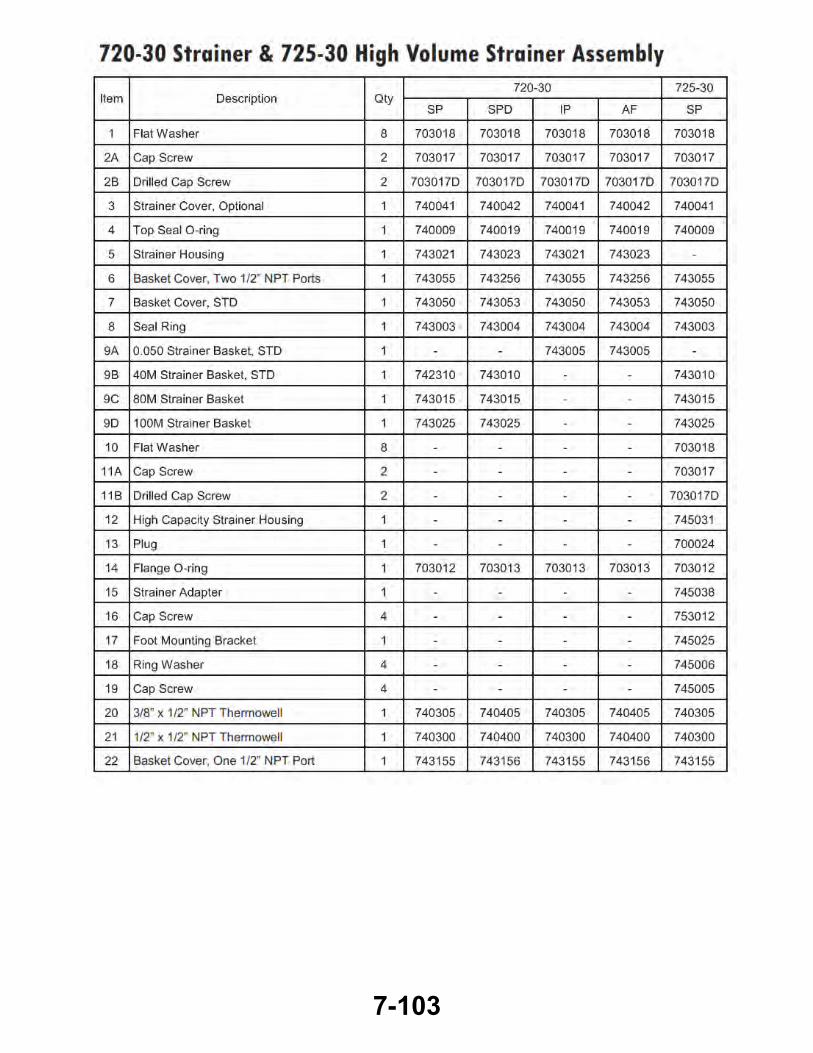
7-103

730 Air Eliminator Assembly; SP and SPD
7-104
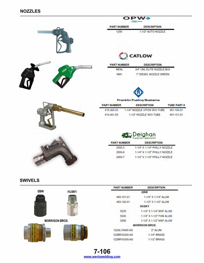
7SWIVELS
NOZZLES
www.wertswelding.com7-106
nwerts
Typewritten text
MORRISON BROS.
nwerts
Typewritten text
EBW
nwerts
Typewritten text
HUSKY