Dresser Meters & Instruments Model 5 Transfer Prover
104
Dresser Meters & Instruments Model 5 Transfer Prover Software Manual Dresser Meters & Instruments
-
Upload
khangminh22 -
Category
Documents
-
view
1 -
download
0
Transcript of Dresser Meters & Instruments Model 5 Transfer Prover
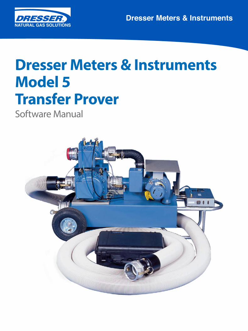
Dresser Meters & Instruments Model 5 Transfer ProverSoftware Manual
Dresser Meters & Instruments

ii | Dresser Natural Gas Solutions Meters & Instruments
Dresser Model 5 Prover Software Manual NGS.MI.0035 | iii
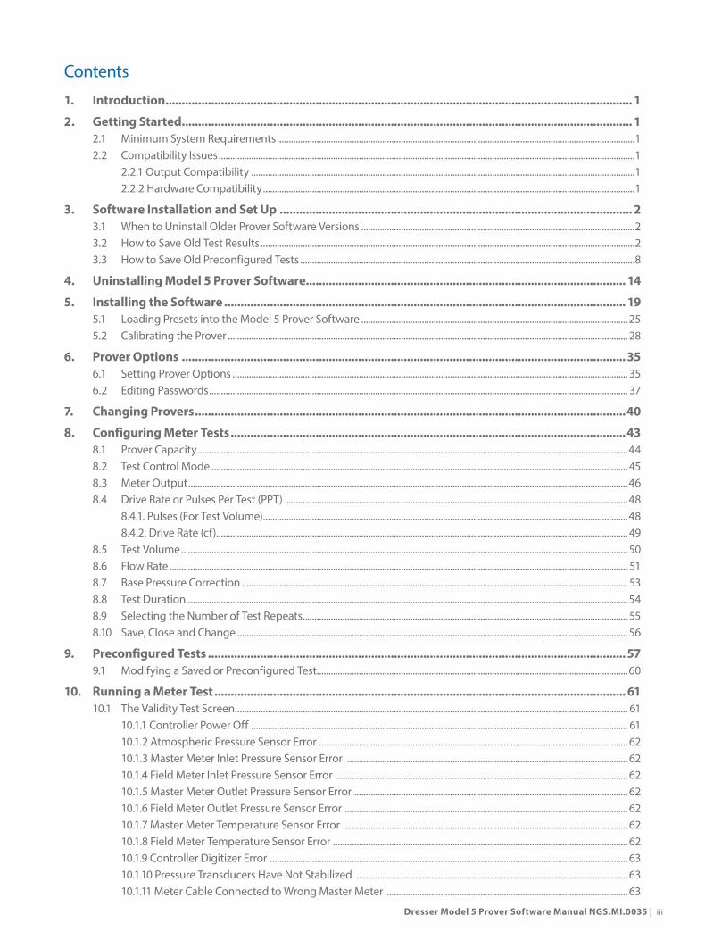
Contents
1. Introduction ............................................................................................................................................... 1
2. Getting Started .......................................................................................................................................... 12.1 Minimum System Requirements .........................................................................................................................................................12.2 Compatibility Issues ..................................................................................................................................................................................1
2.2.1 Output Compatibility ....................................................................................................................................................................12.2.2 Hardware Compatibility ...............................................................................................................................................................1
3. Software Installation and Set Up ............................................................................................................ 23.1 When to Uninstall Older Prover Software Versions .....................................................................................................................23.2 How to Save Old Test Results ................................................................................................................................................................23.3 How to Save Old Preconfigured Tests ...............................................................................................................................................8
4. Uninstalling Model 5 Prover Software.................................................................................................. 14
5. Installing the Software ........................................................................................................................... 195.1 Loading Presets into the Model 5 Prover Software ..................................................................................................................255.2 Calibrating the Prover ........................................................................................................................................................................... 28
6. Prover Options ........................................................................................................................................356.1 Setting Prover Options ......................................................................................................................................................................... 356.2 Editing Passwords ................................................................................................................................................................................... 37
7. Changing Provers ....................................................................................................................................40
8. Configuring Meter Tests .........................................................................................................................438.1 Prover Capacity ........................................................................................................................................................................................448.2 Test Control Mode .................................................................................................................................................................................. 458.3 Meter Output ............................................................................................................................................................................................468.4 Drive Rate or Pulses Per Test (PPT) ..................................................................................................................................................48
8.4.1. Pulses (For Test Volume) ............................................................................................................................................................488.4.2. Drive Rate (cf)................................................................................................................................................................................ 49
8.5 Test Volume ............................................................................................................................................................................................... 508.6 Flow Rate .................................................................................................................................................................................................... 518.7 Base Pressure Correction ..................................................................................................................................................................... 538.8 Test Duration.............................................................................................................................................................................................548.9 Selecting the Number of Test Repeats ........................................................................................................................................... 558.10 Save, Close and Change .......................................................................................................................................................................56
9. Preconfigured Tests ................................................................................................................................579.1 Modifying a Saved or Preconfigured Test.....................................................................................................................................60
10. Running a Meter Test .............................................................................................................................. 6110.1 The Validity Test Screen ........................................................................................................................................................................ 61
10.1.1 Controller Power Off ................................................................................................................................................................. 6110.1.2 Atmospheric Pressure Sensor Error .................................................................................................................................... 6210.1.3 Master Meter Inlet Pressure Sensor Error ........................................................................................................................ 6210.1.4 Field Meter Inlet Pressure Sensor Error ............................................................................................................................. 6210.1.5 Master Meter Outlet Pressure Sensor Error ..................................................................................................................... 6210.1.6 Field Meter Outlet Pressure Sensor Error ......................................................................................................................... 6210.1.7 Master Meter Temperature Sensor Error .......................................................................................................................... 6210.1.8 Field Meter Temperature Sensor Error .............................................................................................................................. 6210.1.9 Controller Digitizer Error ......................................................................................................................................................... 6310.1.10 Pressure Transducers Have Not Stabilized .................................................................................................................... 6310.1.11 Meter Cable Connected to Wrong Master Meter ....................................................................................................... 63

iv | Dresser Natural Gas Solutions Meters & Instruments
10.2 The Meter Test Screen ........................................................................................................................................................................... 6310.3 System Readouts ..................................................................................................................................................................................... 6510.4 Calculated Values .................................................................................................................................................................................... 67
11. Test Results and Reports ........................................................................................................................6811.1 Reviewing, Saving and Printing Test Results ...............................................................................................................................6811.2 The Report Manager .............................................................................................................................................................................. 6911.3 Changing Default Test File Location ............................................................................................................................................... 70
12. Prover Component Calibration .............................................................................................................7312.1 The Conversion Tool .............................................................................................................................................................................. 7312.2 How to Calibrate the Atmospheric Pressure Transducer ........................................................................................................ 7712.3 How to Calibrate the Master Meter Inlet Pressure Transducer ............................................................................................. 8212.4 How to Calibrate the Field Meter Inlet Pressure Transducer ................................................................................................. 8312.5 How to Calibrate the Master Meter Temperature Probe ........................................................................................................8412.6 How to Calibrate the Field Meter Temperature Probe ............................................................................................................ 8512.7 How to Calibrate the Master Meter Outlet Pressure Transducer .........................................................................................8612.8 How to Calibrate the Field Meter Outlet Pressure Transducer ............................................................................................. 87
13. Maintenance ............................................................................................................................................8913.1 Master Meter Hours of Operation .................................................................................................................................................... 8913.2 Prover Self Test .........................................................................................................................................................................................9013.3 Master Meter Differential Pressure Test ......................................................................................................................................... 9113.4 System Leak Test ..................................................................................................................................................................................... 9213.5 Meter Purge ............................................................................................................................................................................................... 9313.6 Maintenance Recommendations ..................................................................................................................................................... 9513.7 Maintenance Check List ....................................................................................................................................................................... 95
13.7.1 Master Meter Inlet Screen ....................................................................................................................................................... 9513.7.2 Master Meter(s) ............................................................................................................................................................................ 9513.7.3 P&T Adapter and the Field Meter Pressure Adapter and All Master Meter Pressure Adapters ................... 9513.7.4 Reference Meter Testing .......................................................................................................................................................... 9513.7.5 Blowers ...........................................................................................................................................................................................9613.7.6 Prover Cart .....................................................................................................................................................................................9613.7.7 Accessories ....................................................................................................................................................................................96
13.8 Common Operation Problems .......................................................................................................................................................... 9713.8.1 Prover doesn’t stabilize at the proper Flow Rate .......................................................................................................... 9713.8.2 The test stops shortly after the Blowers start (the Blowers start and then stop almost immediately) ...... 9713.8.3 The Prover software or the computer locks up ............................................................................................................. 9713.8.4 Accuracy is out of specification ........................................................................................................................................... 9713.8.5 Accuracy varies when conducting outdoor meter testing .......................................................................................98
13.9 Troubleshooting Error Messages ......................................................................................................................................................9813.9.1 “FAILURE TO REACH FLOW RATE” .........................................................................................................................................9813.9.2 “CAUTION: TEST DURATION BELOW RECOMMENDED 30 SECOND MINIMUM” ...............................................9813.9.3 “WARNING” ...................................................................................................................................................................................9813.9.4 “FATAL ERROR” .............................................................................................................................................................................9813.9.5 “COMMUNICATION ERRORS” .................................................................................................................................................9813.9.6 “A/C INPUT FREQUENCY TO HI/LOW” ...............................................................................................................................99
Contents (Continued)

Dresser Model 5 Prover Software Manual NGS.MI.0035 | 1
1. IntroductionThis manual serves as a reference for use with the Dresser Model 5 Transfer Prover software. This manual addresses procedures and requirements associated with the software. This manual does not address hardware components.
This manual was composed using software version 9.2 on a Windows 7 operating system. Different operating systems or software versions might present slightly different appearances. Please contact local IT personnel or Dresser Meters and Instruments technical support for questions.
2. Getting Started
2.1 Minimum System Requirements
The following criteria must be met in order to install and run the Prover software:
• RS232 port (USB to serial adapters): 1 for Prover. (Note: SmartproveTM interface for Microcorrectors will require additional RS232 connection)
• Processor: Pentium 4/M or equivalent• RAM: 1 GB• Screen Resolution: 1024 x 768 pixels• Operating System: Windows XP Professional SP3 (32-bit) or Windows 7 Professional (32- and 64-bit)• Disk Space: 1 GB
• Microsoft.NET Framework 4.0
2.2 Compatibility Issues
2.2.1 Output CompatibilityThe program will output test reports in a comma delimited text file format (comma separated values). Therefore, any program capable of reading this type of format will be able to view and manipulate the data easily and effectively.
2.2.2 Hardware CompatibilityDue to a vast number of personal computers to choose from, it is not feasible for Dresser Meters & Instruments to test all makes, models, or versions of PCs for operational compatibility with the Model 5 Transfer Prover software. Dresser Meters & Instruments has successfully tested the Prover software on a large number of well known, major brand name computers as well as non-major brand name PCs. Of those computers tested and currently utilized by Meters & Instruments and many of our customers, the majority have functioned perfectly, provided they met our recommended minimum requirements listed in Section 2.1.
Dresser Meters & Instruments does not guarantee all computer brands and models will run the Model 5 Prover Software without encountering problems. Before making a final purchase, inquire about the return policy, limitations, and restrictions. A limited trial policy that offers a money-back guarantee or exchange is recommended should the purchased computer not work with the Prover software.

2 | Dresser Natural Gas Solutions Meters & Instruments
3. Software Installation and Set Up
3.1 When to Uninstall Older Prover Software Versions
Before installing a new version of the Model 5 Prover software, a complete uninstall of the following programs is strongly recommended:
• Model 5 Transfer Prover• National Instruments• LabView™
See Section 4. Uninstalling Model 5 Prover Software for instructions.
3.2 How to Save Old Test Results
When installing a new version of Prover software on accounts with Admin privileges, the software will automatically move all files from the current version to a backup folder on the computer’s C: Drive. The files will not be deleted. If an additional back-up copy of the tests results is required, please follow the below procedure prior to installation of the software. Please note, this procedure assumes default folders and installation procedures were followed. If non-default locations were used, this procedure may not be successful.
1. Open the C: Drive. Search and open the folder named “Program Files (x86)”. If not present, open the folder named “Program Files” as shown in Figure 1.
Figure 1: Find “Program Files”

Dresser Model 5 Prover Software Manual NGS.MI.0035 | 3
2. Within the appropriate folder, select the folder named “Dresser Inc” as shown in Figure 2.
Figure 2: Find “Dresser Inc”
3. Within “Dresser Inc”, select the folder entitled “Model 5 Transfer Prover” as shown in Figure 3.
Figure 3: Find “Model 5 Transfer Prover”
3. Software Installation and Set Up (Continued)

4 | Dresser Natural Gas Solutions Meters & Instruments
4. Within the “Model 5 Transfer Prover” folder, select the folder entitled “data” as shown in Figure 4.
Figure 4: Find “data” folder
5. This folder contains the test data. Search for them by file name. The files are saved as .dat files. Please note, default naming convention follows a time stamp convention of Month, Date and ID. (MMDDXXXX). Refer to Figure 5 for an example.
Figure 5: Find Saved Test Files
3. Software Installation and Set Up (Continued)

Dresser Model 5 Prover Software Manual NGS.MI.0035 | 5
6. Highlight the files that are to be saved. (This can be done by single clicking on the name of the files while holding the “Ctrl” button.) Right click and select “Copy” as shown Figure 6.
Figure 6: Copy Test Files
7. Save files to the Desktop. Within the same window on the left-hand side, scroll up to reveal “Desktop”. Select “Desktop” as shown in Figure 7.
Figure 7: Select “Desktop”
3. Software Installation and Set Up (Continued)

6 | Dresser Natural Gas Solutions Meters & Instruments
8. After selecting “Desktop”, right click on the blank space. Select “New” and “Folder” as shown in Figure 8 below.
Figure 8: Select “New” and “Folder”
9. The system will prompt for a name for the new folder. Using the word “Backup” as well as the date will aid in future identification. Refer to Figure 9.
Figure 9: Name New Folder
3. Software Installation and Set Up (Continued)

Dresser Model 5 Prover Software Manual NGS.MI.0035 | 7
10. Double click the name of the new folder. In the blank space, right click and select “Paste” as shown in Figure 10.
Figure 10: Paste Files into Folder
A folder with copies of the preconfigured tests is now saved to the desktop.
3. Software Installation and Set Up (Continued)

8 | Dresser Natural Gas Solutions Meters & Instruments
3.3 How to Save Old Preconfigured Tests
When installing a new version of Prover software, the software will automatically move all files from the current version to a backup folder on the computer’s C: Drive. The files will not be deleted. If an additional copy of the preconfigured tests is required, please follow the below steps before installation. Please note, this procedure assumes default folders and installation procedures were followed. If non-default locations were used, this procedure may not be successful.
NOTE: Preconfigured Test used on the 5M/20M and created on 6.2 are not compatible with 9.2 and must be recreated.
11. Open the computer’s C: Drive. Search and open the folder entitled “Program Files (x86)”. If not present, open the folder entitled “Program Files” as shown in Figure 11.
Figure 11: Find “Program Files”
3. Software Installation and Set Up (Continued)

Dresser Model 5 Prover Software Manual NGS.MI.0035 | 9
12. Within the appropriate folder, select the folder named “Dresser Inc” as shown in Figure 12.
Figure 12: Find “Dresser Inc”
13. Within “Dresser Inc”, select the folder entitled “Model 5 Transfer Prover” as shown in Figure 13.
Figure 13: Find “Model 5 Transfer Prover”
3. Software Installation and Set Up (Continued)

10 | Dresser Natural Gas Solutions Meters & Instruments
14. Within “Model 5 Transfer Prover”, select “Preconfigured Tests” as shown in Figure 14.
Figure 14: Find “Preconfigured Tests”
15. Within “Preconfigured Tests”, the files and folders visible should match the files and folders typically seen when selecting to run a preconfigured test from the Prover software. Refer Figure 94 for reference window and Figure 15.
Figure 15: View Preconfigured Test Folders
3. Software Installation and Set Up (Continued)
Dresser Model 5 Prover Software Manual NGS.MI.0035 | 11
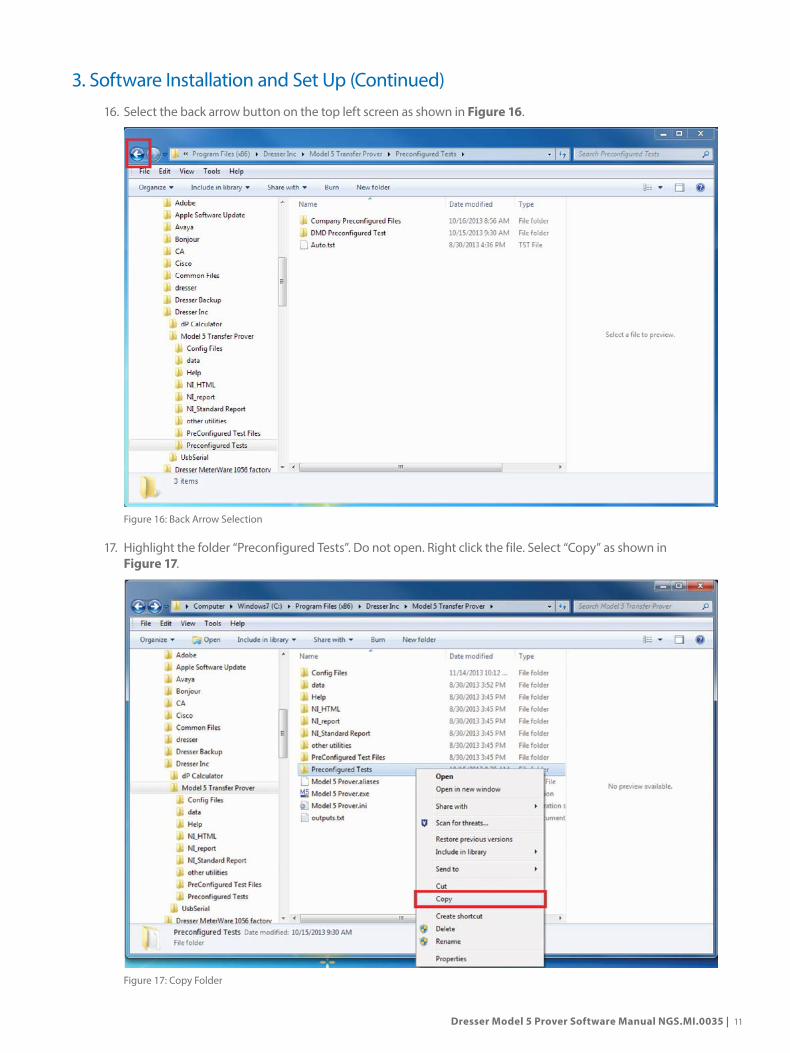
16. Select the back arrow button on the top left screen as shown in Figure 16.
Figure 16: Back Arrow Selection
17. Highlight the folder “Preconfigured Tests”. Do not open. Right click the file. Select “Copy” as shown in Figure 17.
Figure 17: Copy Folder
3. Software Installation and Set Up (Continued)

12 | Dresser Natural Gas Solutions Meters & Instruments
18. Within the same window on the left-hand side, scroll up to reveal “Desktop” as shown in Figure 18. Select or click “Desktop”.
Figure 18: Select “Desktop”
19. After selecting “Desktop”, right click on the blank space. Select “Paste” as shown in Figure 19.
Figure 19: Select “Paste”
3. Software Installation and Set Up (Continued)

Dresser Model 5 Prover Software Manual NGS.MI.0035 | 13
20. Upon selecting “Paste” the computer will begin to copy files. Once completed, a new folder will appear as shown in Figure 20.
Figure 20: Preconfigured Tests in Desktop
21. Rename the folder. Right click on the folder and select “Rename”. Enter another name for the folder. Using the word “Backup” and the date for easy identification in the future. Refer to Figure 21.
Figure 21: Insert New Folder Name
A copy of the preconfigured tests are now saved to the desktop.
3. Software Installation and Set Up (Continued)

14 | Dresser Natural Gas Solutions Meters & Instruments
4. Uninstalling Model 5 Prover SoftwareWhen upgrading software, it is strongly recommended that all components of the Model 5 Software as well as the National Instruments, and LabView software be completely removed. Prior to uninstalling, please back up all preconfigured files and test data. See Sections 3.2 and 3.3 for more information. Follow the below procedure for assistance:
1. On Windows 7 computers, open the Control Panel as shown in Figure 22.
Figure 22: Control Panel
2. Within the Control Panel, double click for “Programs and Features” as shown in Figure 23.
Figure 23: Programs and Features

Dresser Model 5 Prover Software Manual NGS.MI.0035 | 15
3. Search for the program entitled “Model 5 Transfer Prover”. Double click to uninstall. Refer to Figure 24.
Figure 24: Model 5 Transfer Prover Program
4. The computer may issue a warning regarding uninstalling the software. Refer to Figure 25. To continue with the uninstallation, select “Yes”.
Figure 25: Warning Window
5. The computer will begin to uninstall the software. The status bar noted in Figure 26 might appear. Do NOT click on cancel.
Figure 26: Status Window
4. Uninstalling Model 5 Prover Software (Continued)

16 | Dresser Natural Gas Solutions Meters & Instruments
6. Upon completion, confirm that the Model 5 Transfer Prover software has been successfully deleted. If the Model 5 Transfer Prover is no longer present in the “Programs and Features” window, search for “National Instruments Software” as shown in Figure 27.
Figure 27: National Instruments Software Program
7. A separate dialogue box will open. National Instruments Software must be uninstalled in components. Highlight a component on the left-hand side. Then select “Remove” as shown in Figure 28.
Figure 28: National Instruments Components
4. Uninstalling Model 5 Prover Software (Continued)

Dresser Model 5 Prover Software Manual NGS.MI.0035 | 17
8. Continue uninstalling each component.
9. Some components will have dependent components. An additional dialogue may appear as an alert. Select “Remove All” as shown in Figure 29.
Figure 29: Remove All Dependent Components
10. Again, the computer will begin to uninstall the software. The status bar noted in Figure 30 might appear. Do NOT click on cancel.
Figure 30: Status Window
4. Uninstalling Model 5 Prover Software (Continued)

18 | Dresser Natural Gas Solutions Meters & Instruments
11. Upon completion, confirm that both the Model 5 Transfer Prover software and the National Instruments software have been successfully deleted through the ”Programs and Features” as shown in Figure 31. Refer to Steps 1 – 3 for instructions.
Figure 31: Confirm Deletions
12. Restart the computer.
5. Installing the SoftwareUpon receiving new software, proper installation is critical to Prover functionality. Please follow the below procedure when upgrading software versions, or installing software for the first time.
1. Insert the Prover software installation media into the computer. The following screen will appear as shown in Figure 32.
Figure 32: Pre-installer Warning Dialogue Box
4. Uninstalling Model 5 Prover Software (Continued)

Dresser Model 5 Prover Software Manual NGS.MI.0035 | 19
2. From within the MDL5_Setup folder, select “Setup.exe” as shown in FIgure 33.
Figure 33: Select Setup.exe
3. The following screen will appear as shown in Figure 33. Select “OK”. By selecting “OK”, the former version of software will be moved into a backup folder.
NOTE: If not in the default directory select “Close” and manually copy the old Prover software into a different backup location first. Repeat Step 1. This backup step will only move files if the software was not previously uninstalled.
4. A Destination Directory screen will appear. Select “NEXT” and the software will install in the default directory as shown in Figure 34. Unless, it is absolutely critical, do not alter the installation default path.
Figure 34: Destination Directory Screen

20 | Dresser Natural Gas Solutions Meters & Instruments
5. A prompt asking for acceptance of the Licensing Agreement for the associated software will appear. Click on the “I accept” button and select “NEXT” to continue the installation as shown in Figure 35.
Figure 35: License Agreement Acceptance
6. Begin the Model 5 Prover software installation process by selecting “Next” as shown in Figure 36.
Figure 36: Installation Component Listing
5. Installing the Software (Continued)
Dresser Model 5 Prover Software Manual NGS.MI.0035 | 21
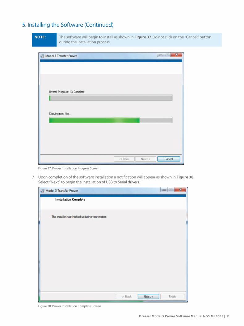
NOTE: The software will begin to install as shown in Figure 37. Do not click on the “Cancel” button during the installation process.
Figure 37: Prover Installation Progress Screen
7. Upon completion of the software installation a notification will appear as shown in Figure 38. Select “Next” to begin the installation of USB to Serial drivers.
Figure 38: Prover Installation Complete Screen
5. Installing the Software (Continued)

22 | Dresser Natural Gas Solutions Meters & Instruments
8. There will be a prompt to download the drivers for the Dresser USB to Serial Port cable as shown in Figure 39. Select “Yes” to begin the installation.
Figure 39: USB Drivers Prompt
9. On the next screen, select “Install” as shown in Figure 40. This will scan the computer to determine if USB drivers already exist on the computer.
Figure 40: USB Install Screen
5. Installing the Software (Continued)

Dresser Model 5 Prover Software Manual NGS.MI.0035 | 23
NOTE: IF THE PROPER USB TO SERIAL DRIVERS HAVE BEEN INSTALLED, STEP 9 WILL NOT APPLY. PLEASE SEE THE BELOW SUB-PROCEDURE.
If there are drivers already present on the computer, the software will issue a prompt for how to proceed.
Select “Cancel” as shown in Figure 41.
Figure 41: Driver Installation Prompt Do NOT Select “Remove” or “Modify”.
8. Upon the successful completion of the installation, the screen shown in Figure 42 will appear. Select “OK” to continue.
Figure 42: Drivers Successfully Installed
5. Installing the Software (Continued)

24 | Dresser Natural Gas Solutions Meters & Instruments
9. Upon completion, the InstallShield Wizard will appear and will prompt for a system restart. Select the “No, I will restart my computer later” option as shown in Figure 43. Then, click “Finish”.
Figure 43: InstallShield Wizard
10. The InstallShield will close and a second window will appear as shown in Figure 44. In this window, select “Restart” and the computer will reboot.
Figure 44: Restart Option Screen
11. After restart is complete, double click on the icon to start up the Prover software as shown in Figure 45. Upon opening, the Prover Main Screen will appear.
Figure 45: Model 5 Prover Icon
5. Installing the Software (Continued)

Dresser Model 5 Prover Software Manual NGS.MI.0035 | 25
The system will then require the Prover specific files, or Presets, to be loaded. Refer to Section 5.1 Loading Presets into the Model 5 Prover Software.
5.1 Loading Presets into the Model 5 Prover Software
Often when installing a new software version, the software will require presets to be loaded. If after installation a warning dialogue box appears (Figure 46) please follow the subsequent procedure.
Figure 46: Preset Warning Box
1. If upon opening the software Figure 46 appears, click “Begin”. If no message appears, on the upper left hand corner of the Prover main screen, go to “File” and Click “Add Prover”. Refer to Figure 47.
Figure 47: Prover Main Screen
5. Installing the Software (Continued)

26 | Dresser Natural Gas Solutions Meters & Instruments
2. A new window will open. With the media still in the computer, double click on the folder entitled “Presets” as shown in Figure 49. The prover ID number may be listed.
Figure 49: Select Media Location
3. Within the “Presets” folder, there will be another folder labeled with the Prover ID. It is possible for multiple folders to be present. In the bottom right hand corner, click “Current Folder” as shown in Figure 50.
Figure 50: “Current Folder” Location
4. Restart the Prover software.
5. Installing the Software (Continued)

Dresser Model 5 Prover Software Manual NGS.MI.0035 | 27
5. Upon reopening the software, the main screen will be populated with the serial numbers of the master meters as well as preset file dates. Refer to Figure 51.
Figure 51: Program with Presets Loaded
5. Installing the Software (Continued)
28 | Dresser Natural Gas Solutions Meters & Instruments
6. Verify that the serial number for each physical Master Meter matches the serial number displayed in the initial start up screen of the Model 5 Prover software.
5.2 Calibrating the Prover
It is often necessary to “Calibrate the A/D” card. This procedure should be done under the following circumstances:
• New software installation• New controller• New transducers or temperature probes• Switching computers or Provers• Controller digitizer error• At any point where communications errors seem to be present• New junction box
Procedure:
1. Connect communication cable to computer using the USB-to-Serial Port converter or 9 pin, Serial connection.
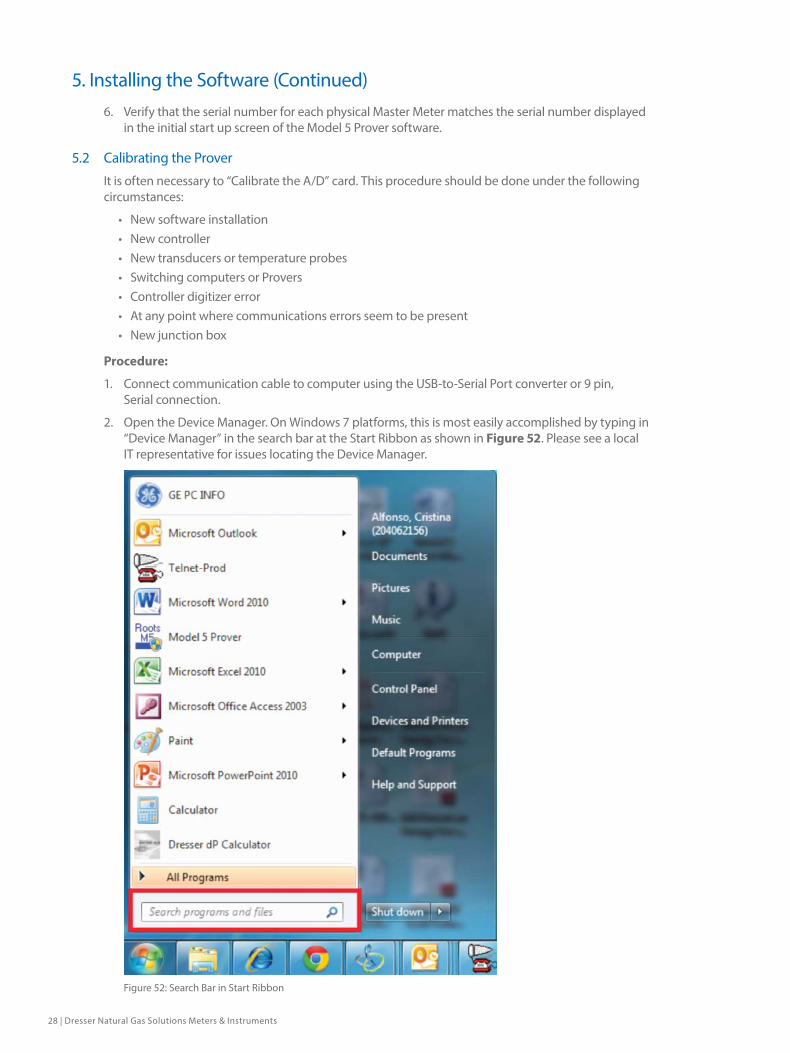
2. Open the Device Manager. On Windows 7 platforms, this is most easily accomplished by typing in “Device Manager” in the search bar at the Start Ribbon as shown in Figure 52. Please see a local IT representative for issues locating the Device Manager.
Figure 52: Search Bar in Start Ribbon
5. Installing the Software (Continued)

Dresser Model 5 Prover Software Manual NGS.MI.0035 | 29
3. Within the Device Manager, locate “Ports (Com & LPT)”. Take note of the communications port assigned to the Prover. Refer to Figure 53.
Figure 53: Device Manager. COM Port Location
4. Launch Model 5 Prover software.
5. From the main screen of the Model 5 Prover Software select “Prover Operations” as shown in Figure 54.
Figure 54: 9.1 Main Screen
5. Installing the Software (Continued)

30 | Dresser Natural Gas Solutions Meters & Instruments
6. From “Prover Operations”, select “Prover Set Up” as shown in Figure 55.
Figure 55: Prover Setup Selection
7. Upon selecting “Prover Setup” the system will prompt for a password as shown in Figure 56. The password is “ROOTS”. Capitalization is required. Click “OK.” Ensure that the communication cable is still installed.
Figure 56: Prover Setup Password
5. Installing the Software (Continued)

Dresser Model 5 Prover Software Manual NGS.MI.0035 | 31
8. A second window will appear as shown in Figure 57. Take note of the Control COM Port Field. Notice, only COM Ports in use are available for selection. Select the COM port (Refer to Step 2.)
Figure 57: Prover Setup Screen and Controller COM Port
9. When complete, click “Save and Close” as shown in Figure 58.
Figure 58: Save and Close
10. Repeat Step 5 and Step 6.
5. Installing the Software (Continued)

32 | Dresser Natural Gas Solutions Meters & Instruments
11. Click “Prover Operations”. Then click, “Calibrate Prover” as shown in Figure 59. The password is “DRESSER”.
Figure 59: Calibrate Prover
12. A third window will appear as shown in Figure 60. It will appear with the following message, “Caution, you are about to change the calibration of your Prover”. Click “OK”.
Figure 60: Calibration Warning Window
5. Installing the Software (Continued)

Dresser Model 5 Prover Software Manual NGS.MI.0035 | 33
13. The window will update. Wait several seconds. Observe on the right-hand side of the screen the box entitled “Digitized Counts”. Refer to Figure 61. This number will fluctuate a couple of digits and should be greater than 2000 but less than 2070.
Figure 61: Digitized Counts Box
5. Installing the Software (Continued)

34 | Dresser Natural Gas Solutions Meters & Instruments
14. Click “Accept” to accept the current calibration. Then, click “Close” as shown in Figure 62.
Figure 62: Prover Calibration Screen
15. Click “Save and Close” in the Set Prover Options window as shown in Figure 63. The Prover has now been successfully calibrated.
Figure 63: Save and Close
5. Installing the Software (Continued)

Dresser Model 5 Prover Software Manual NGS.MI.0035 | 35
6. Prover Options
6.1 Setting Prover Options
Use the following procedure to adjust Prover settings. From this screen, functions can be enabled by checking the box next to the option. Leaving a box unchecked will disable that function.
NOTE: Any changes made must be saved prior to exiting or changes will be lost. Changes made will only affect tests configured after the changes have been saved. Any previously saved tests will be unaffected. See Step 4 for more information.
1. On the upper, left-hand corner of the initial start up screen, select “Prover Operations” then “Prover Setup” as shown in Figure 64.
Figure 64: Prover Set Up Selection
2. A small dialog box will appear. Enter the password “ROOTS” as shown in Figure 65.
Figure 65: Password Dialogue Box

36 | Dresser Natural Gas Solutions Meters & Instruments
3. The “Set Prover Options” screen will appear as shown in Figure 66. The following functions can be enabled by checking the box to the left of the option. Leaving the box unchecked will disable that function.
Figure 66: Set Prover Options Screen
Functional Descriptions
a. Mandatory Meter Purge: Checking this option will force the user to run a meter purge before initiating an accuracy test (See Section 13.5 Meter Purge).
b. Mandatory Leak Test: This option requires a system leak test to pass before an accuracy test can be initiated (See Section 13.4 System Leak Test).
c. Double Field Meter Serial# Entry: This option allows the user to input two meter serial numbers for each test report.
d. Different Test Volume Selection For Each Flow Rate: This enables change of test volume for each flow rate if desired. If this option is not selected, then the test volume will default to the volume entered in the Test Volume Box for every flow rate. (See Section 8.5 Test Volume).
e. Configurable Repeat of Meter Tests: Check this option to allow the selection of a different number of repeats for each test point up to a maximum of 2 repeats (3 total tests). Not selecting this option will default to the entry in the Repeats box on the lower right portion of the Set Prover Options screen. (See Section 8.9 Selecting Repeats).
f. Configurable Limits: This option will allow the limits to be configurable for each flow rate when the test is being configured. Not selecting this box will cause the limits to default to the numbers entered in the high limit percent and low limit percent on the left portion of the Set Prover Options screen.
g. Extended Temperature Enable: Check this option to allow the Prover system to operate beyond the standard temperature limitations.
h. Date Format: Choose between two different date formats that will be shown on the screens and on test reports. Month/Day/Year or Day/Month/Year.
i. Controller COM Port: Choose which Controller COM setting will work best with the computer setup.
j. Low Limit: This configurable Pass/Fail limit is the maximum allowable deviation below 100%.
k. High Limit: This configurable Pass/Fail limit is the maximum allowable deviation above 100%. For example, if the Low Limit % is set to 2.00 and the High Limit is set to 1.00, then any test result accuracy falling between 98.00% and 101.00% will yield a ‘Test Pass’ indication, while any test accuracy result outside these limits will yield a ‘Test Fail’ indication.
l. Span Limit: This test limit defines the maximum allowable difference between the highest accuracy reported and the lowest accuracy.
6. Prover Options (Continued)

Dresser Model 5 Prover Software Manual NGS.MI.0035 | 37
m. Repeats: This number indicates a default number of tests that will be run in addition to the original test. A selection of 0 here will result in one test, while a selection of 1 repeat will result in 2 tests. Up to a maximum of 2 repeats.
4. Select “Save and Close,” as shown in Figure 67, to save existing changes prior to closing the screen or changes will be lost. Changes made will only affect test(s) configured after changes are saved. Any previously saved test(s) will be unaffected.
Figure 67: Save and Close Selection
6.2 Editing Passwords
The default Level 1 Password is “ROOTS”. The default Level 2 Password is “DRESSER”. In the event a change of password is necessary, follow the below procedure.
1. On the initial start up screen, Select “Prover Operations” and Prover Set up” as shown in Figure 68.
Figure 68: Prover Main Screen
6. Prover Options (Continued)

38 | Dresser Natural Gas Solutions Meters & Instruments
2. A small dialog box will appear as shown in Figure 69. Enter the Level 1 password “ROOTS.”
Figure 69: Password Dialogue Box
3. In the “Set Prover Options” screen, select “File” and “Edit Passwords” as shown in Figure 70.
Figure 70: Edit Password Selection
6. Prover Options (Continued)

Dresser Model 5 Prover Software Manual NGS.MI.0035 | 39
4. Enter the Level 2 Password of “DRESSER” as shown in Figure 71.
Figure 71: Password Dialogue Box
5. Enter and Re-enter the desired password as shown in Figure 72.
Figure 72: Change Password Dialogue Box
NOTE: Any single keyboard number or character may be used as part of a password. The maximum total number of characters in a password is 20. The passwords are case sensitive. A mix of capital and/or lower case letters may be used to generate different passwords.
LEVEL 1 PASSWORD: The LEVEL 1 PASSWORD restricts access to the PROVER SETUP and Units of Measure screens.
LEVEL 2 PASSWORD: The LEVEL 2 PASSWORD restricts access to the PASSWORD MENU and Calibration screen.
NOTE: Pressing the <ENTER> key without first typing some other key generates a password of twenty “space” characters. When an operator wishes to access a password protected menu, pressing the <ENTER> key once or the <SPACE BAR> twenty times will be accepted as a correct password and allow access to the password-protected menu.
6. Prover Options (Continued)
40 | Dresser Natural Gas Solutions Meters & Instruments
7. Changing ProversIf using Prover software 9.0 or higher, the same computer may be used to operate several different Provers. In order to accomplish this, the software must first have the presets of the new prover that is to be used. Please see the section titled, “5.1 Loading Presets into the Model 5 Prover Software” if this has not previously been accomplished.
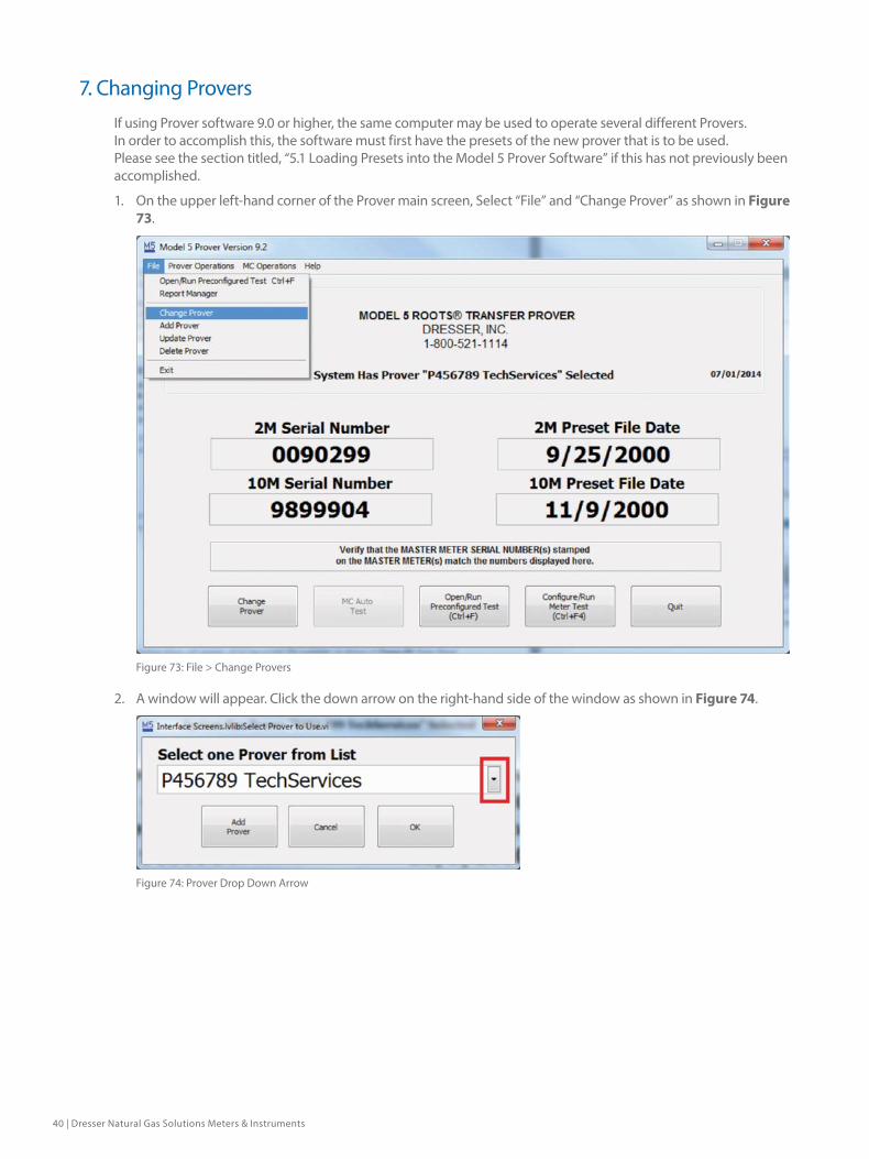
1. On the upper left-hand corner of the Prover main screen, Select “File” and “Change Prover” as shown in Figure 73.
Figure 73: File > Change Provers
2. A window will appear. Click the down arrow on the right-hand side of the window as shown in Figure 74.
Figure 74: Prover Drop Down Arrow

Dresser Model 5 Prover Software Manual NGS.MI.0035 | 41
3. A drop-down menu will appear of all the Prover IDs available as shown in Figure 75. Select the Prover ID that corresponds to the Prover that will be used. If the Prover ID is not present, its presets will need to be loaded. Please refer to Section 5.1 for instructions.
Figure 75: Drop Down Prover ID Selections
4. Upon clicking the proper Prover ID, the change will be reflected in the box as shown in Figure 76. Click “OK.”
Figure 76: Prover ID OK
7. Changing Provers (Continued)

42 | Dresser Natural Gas Solutions Meters & Instruments
5. The dialogue box will disappear. Confirm the procedure was successful by checking the Prover ID number reflected in the center of the screen, as shown in Figure 77.
Figure 77: New Prover ID Reflected
6. Recalibrate the Prover. Refer to Section 5.2 for instructions.
7. Changing Provers (Continued)
Dresser Model 5 Prover Software Manual NGS.MI.0035 | 43
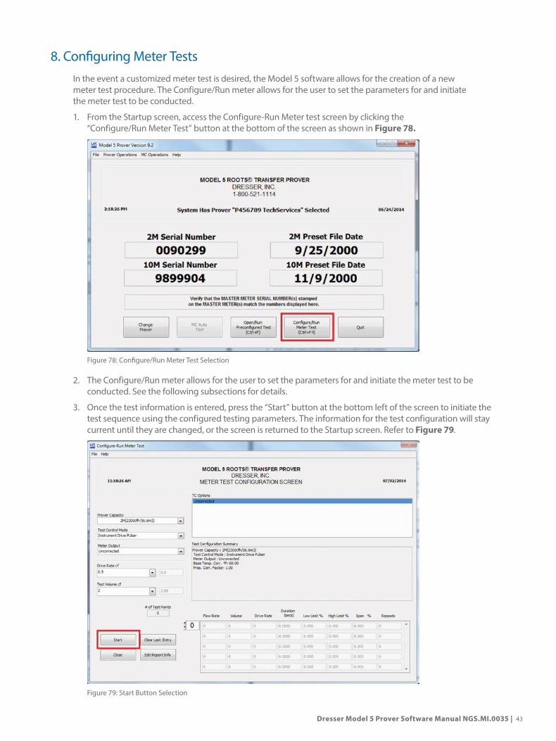
8. Configuring Meter TestsIn the event a customized meter test is desired, the Model 5 software allows for the creation of a new meter test procedure. The Configure/Run meter allows for the user to set the parameters for and initiate the meter test to be conducted.
1. From the Startup screen, access the Configure-Run Meter test screen by clicking the “Configure/Run Meter Test” button at the bottom of the screen as shown in Figure 78.
Figure 78: Configure/Run Meter Test Selection
2. The Configure/Run meter allows for the user to set the parameters for and initiate the meter test to be conducted. See the following subsections for details.
3. Once the test information is entered, press the “Start” button at the bottom left of the screen to initiate the test sequence using the configured testing parameters. The information for the test configuration will stay current until they are changed, or the screen is returned to the Startup screen. Refer to Figure 79.
Figure 79: Start Button Selection

44 | Dresser Natural Gas Solutions Meters & Instruments
NOTE: The Close button can be pressed at any time to cancel a test configuration and return to the Startup screen.
8.1 Prover Capacity
Prover Capacity indicates what master meter is being used for the particular test run.
1. Click on the black arrow in the right-hand side of the box to display the drop-down menu as shown in Figure 80. Select the appropriate Master Meter for the test.
Figure 80: Prover Capacity Drop Down Arrow
Keep in mind the master meter capacity. For details, refer to Table 1: Master Meter Flow Capacities below.
Master Meter Capacity (cfh/m3)
2M 2,300/65.1
5M 5,650/160
10M 10,000/283.2
20M 20,000/566.3
80M 80,000/2,265.3
Table 1: Master Meter Flow Capacities
NOTE: Only Master Meters for which presets are available can be selected. In the above example, the Prover in question is a 2M/10M Prover. Therefore, only the 2M and 10M master meters are available for selection.
8. Configuring Meter Tests (Continued)
Dresser Model 5 Prover Software Manual NGS.MI.0035 | 45
The Master Meter Cable and the Flexible Hose must be properly connected to the selected Master Meter before continuing. Refer to the Hardware Manual for information on connecting the Prover, and if applicable for connecting the type of meter to be tested. Older Provers that have not had the 2M Master Meter recertified since the increase from 2000 acfh to 2300 acfh will not be able to run higher than 2000 acfh unless recertified.
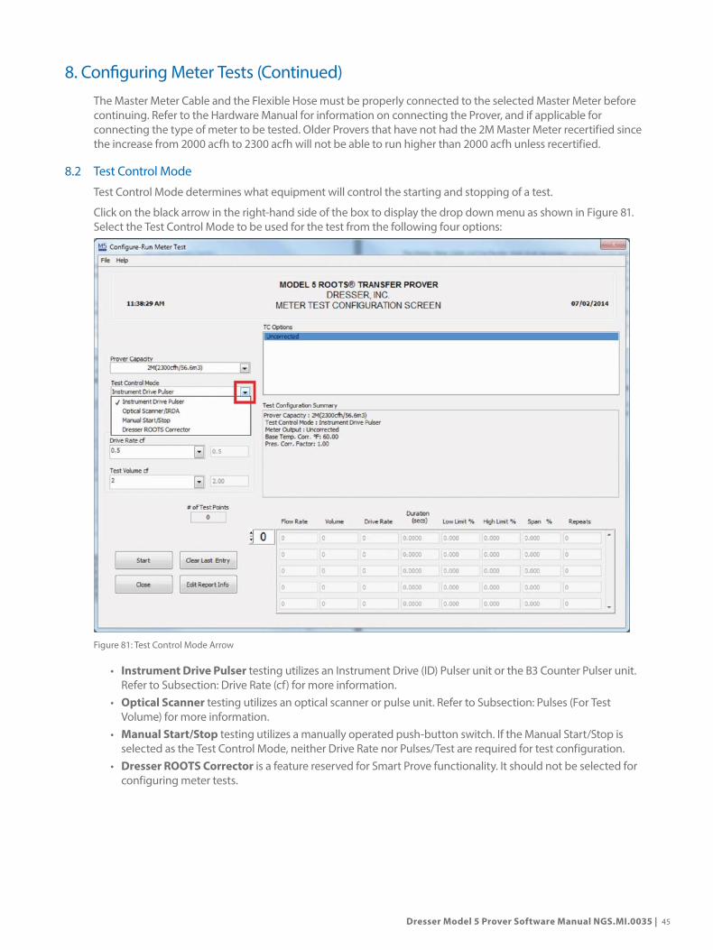
8.2 Test Control Mode
Test Control Mode determines what equipment will control the starting and stopping of a test.
Click on the black arrow in the right-hand side of the box to display the drop down menu as shown in Figure 81. Select the Test Control Mode to be used for the test from the following four options:
Figure 81: Test Control Mode Arrow
• Instrument Drive Pulser testing utilizes an Instrument Drive (ID) Pulser unit or the B3 Counter Pulser unit. Refer to Subsection: Drive Rate (cf) for more information.
• Optical Scanner testing utilizes an optical scanner or pulse unit. Refer to Subsection: Pulses (For Test Volume) for more information.
• Manual Start/Stop testing utilizes a manually operated push-button switch. If the Manual Start/Stop is selected as the Test Control Mode, neither Drive Rate nor Pulses/Test are required for test configuration.
• Dresser ROOTS Corrector is a feature reserved for Smart Prove functionality. It should not be selected for configuring meter tests.
8. Configuring Meter Tests (Continued)

46 | Dresser Natural Gas Solutions Meters & Instruments
8.3 Meter Output
Meter Output indicates what corrections have been applied to the meter, if any.
Click on the arrow at the right of the box to display the drop-down menu as shown in Figure 82. Select from one of the following modes of operation:
Figure 82: Meter Output Selection
• Uncorrected (UC): No correction is made for temperature or pressure. If using an Optical Scanner for test control, it will read the non-comp volume dial.
• Temperature Corrected (TC): A correction is made for temperature. If using an Optical Scanner for test control, it will read the Temperature Compensated volume odometer dial.
• Pressure Corrected (PC): A correction is made for pressure. If using an optical scanner for test control, it will read the Pressure Corrected volume Dial.
• Pressure and Temperature Corrected (PCTC): A correction is made for both pressure and temperature. If using an Optical Scanner for test control, it will read Pressure and Temperature Corrected volume dial.
If TC or PCTC is chosen, additional information will appear in the window labeled TC Options. Use the mouse and highlight the desired item on the list. TC Options are described on the next page and pictured in Figure 83.
8. Configuring Meter Tests (Continued)

Dresser Model 5 Prover Software Manual NGS.MI.0035 | 47
Figure 83: Available TC Options
TC options, when imperial units of measure are the default, include the following:
• Diaphragm TC: Click on Diaphragm TC when testing a diaphragm meter.
• ROOTS Mechanical TC: Click on ROOTS Mechanical TC when testing a Meter that is smaller than a 16M size.
• 16M Only ROOTS Mechanical TC: Click on ROOTS Mechanical TC when testing a 16M175 Meter.
• ROOTS Electronic VTC without Fixed Pressure Factor: Click on ROOTS Electronic VTC when testing the VTC.
TC options, when metric units of measure are the default, include the following:
• Diaphragm TC: Click on Diaphragm TC when testing a TC diaphragm meter.
• ROOTS Mechanical TC: 8C-3M – Click on ROOTS Mechanical TC when testing a ROOTS 8C, 11C, 15C, 2M or 3M meter.
• ROOTS Mechanical TC: 5M-16M – Click on ROOTS Mechanical TC when testing a ROOTS 5M, 7M, 11M or 16M meter.
• ROOTS Electronic VTC: Click on ROOTS Electronic VTC when testing the ROOTS VTC.
• ROOTS Electronic IMC: Click on ROOTS Electronic IMC when testing the ROOTS IMC.
NOTE: Test results may be affected below 40°F (4°C).
8. Configuring Meter Tests (Continued)
48 | Dresser Natural Gas Solutions Meters & Instruments
8.4 Drive Rate or Pulses Per Test (PPT)
Drive Rate/Pulses Per Test is a vital component in configuring a meter test. Please review the following sections for information regarding each of these categories.
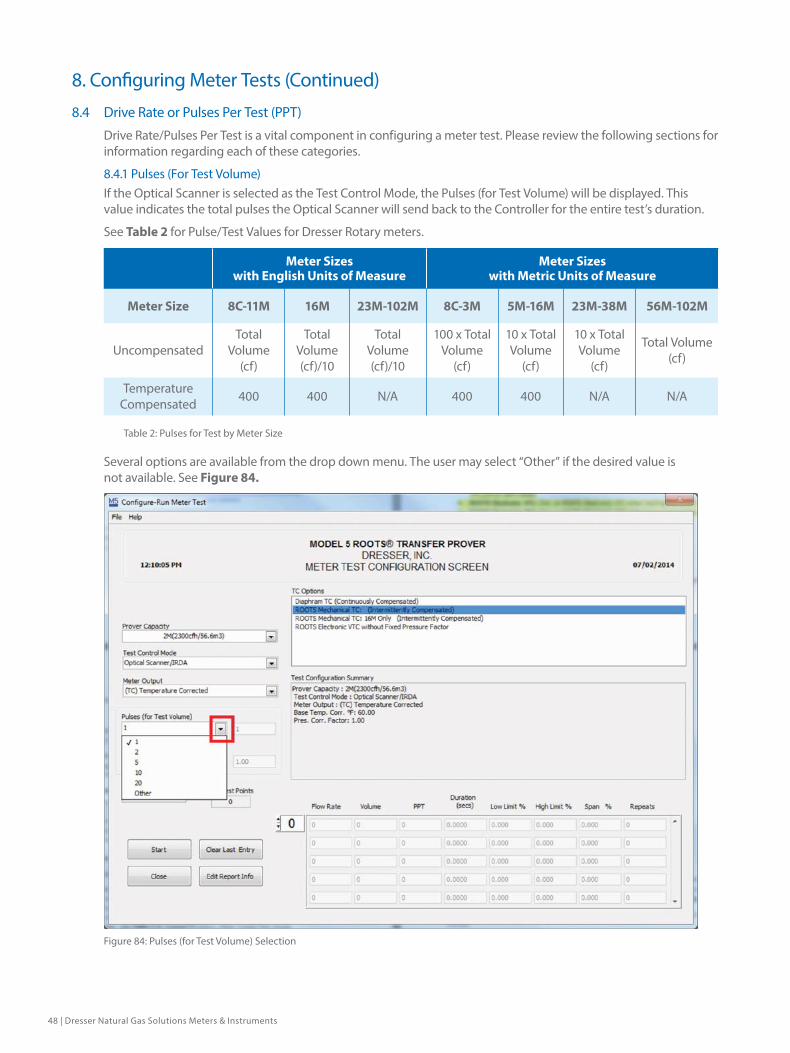
8.4.1 Pulses (For Test Volume)If the Optical Scanner is selected as the Test Control Mode, the Pulses (for Test Volume) will be displayed. This value indicates the total pulses the Optical Scanner will send back to the Controller for the entire test’s duration.
See Table 2 for Pulse/Test Values for Dresser Rotary meters.
Meter Sizes with English Units of Measure
Meter Sizes with Metric Units of Measure
Meter Size 8C-11M 16M 23M-102M 8C-3M 5M-16M 23M-38M 56M-102M
UncompensatedTotal
Volume (cf)
Total Volume (cf)/10
Total Volume (cf)/10
100 x Total Volume
(cf)
10 x Total Volume
(cf)
10 x Total Volume
(cf)
Total Volume (cf)
Temperature Compensated 400 400 N/A 400 400 N/A N/A
Table 2: Pulses for Test by Meter Size
Several options are available from the drop down menu. The user may select “Other” if the desired value is not available. See Figure 84.
Figure 84: Pulses (for Test Volume) Selection
8. Configuring Meter Tests (Continued)

Dresser Model 5 Prover Software Manual NGS.MI.0035 | 49
In order to test a Dresser meter, select “Other” and insert a value of “400” for the number of Pulses. See Figure 85.
Figure 85: Pulses for Test Volume Other Selection
NOTE: When testing a temperature compensated unit with the Optical Scanner, the volume required must be 200cf.
8.1.2 Drive Rate (cf)If Instrument Drive (ID) Pulser is selected as the Test Control Mode, the box labeled Drive Rate cf will be displayed on the Configure-Run Meter Test screen. Drive Rate is the volume of gas that passes through the meter for each revolution of the ID Pulser. The Drive Rate is typically specified on the drive, the meter, and/or the device mounted to the instrument drive unit. See Table 3 for Dresser Rotary Meter Drive Rates.
NOTE: Never use partial revolutions as erratic proofs may occur.
Meter Sizes with English Units of Measure
Meter Sizes with Metric Units of Measure
Meter Size 8C-11M 16M-102M 8C-3M 5M-38M 56M-102M
Uncompensated 10 100 0.1 1.0 10.0
Table 3: Drive Rates for TEST CONTROL = ID
NOTE: Temperature compensated Dresser Meters cannot be tested using the ID Pulser.
Important: The Pulses/Test must be a whole number, not a fraction.
8. Configuring Meter Tests (Continued)
50 | Dresser Natural Gas Solutions Meters & Instruments
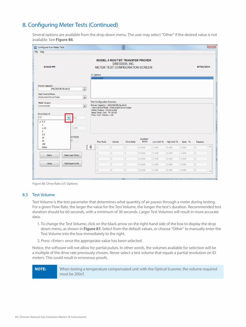
Several options are available from the drop down menu. The user may select “Other” if the desired value is not available. See Figure 86.
Figure 86: Drive Rate (cf ) Options
8.5 Test Volume
Test Volume is the test parameter that determines what quantity of air passes through a meter during testing. For a given Flow Rate, the larger the value for the Test Volume, the longer the test’s duration. Recommended test duration should be 60 seconds, with a minimum of 30 seconds. Larger Test Volumes will result in more accurate data.
1. To change the Test Volume, click on the black arrow on the right-hand side of the box to display the drop down menu, as shown in Figure 87. Select from the default values, or choose “Other” to manually enter the Test Volume into the box immediately to the right.
2. Press <Enter> once the appropriate value has been selected.
Notice, the software will not allow for partial pulses. In other words, the volumes available for selection will be a multiple of the drive rate previously chosen. Never select a test volume that equals a partial revolution on ID meters. This could result in erroneous proofs.
NOTE: When testing a temperature compensated unit with the Optical Scanner, the volume required must be 200cf.
8. Configuring Meter Tests (Continued)

Dresser Model 5 Prover Software Manual NGS.MI.0035 | 51
Figure 87: Meter Volume Pull Down
8.6 Flow Rate
Enter the desired Flow Rate for each test on the Flow Rate section of the table at the bottom of the Configure-Run Meter Test screen as shown in Figure 88.
Figure 88: Enter Desired Flow Rate
8. Configuring Meter Tests (Continued)

52 | Dresser Natural Gas Solutions Meters & Instruments
NOTE: Flow rates must be in descending order. Start with the highest and end with the lowest.
Notice that once a Flow Rate is entered, the Volume and the Drive Rate/PPT are populated based on previous selections. These numbers can be modified without issue. See Figure 89.
Figure 89: Populated Entry
If there is a typed value not within the expected range for the current test and Prover configuration settings, the software will change the value to the respective min/max value.
A single decimal point is optional when typing the values for Flow Rate. If zero is entered for a Flow Rate, the test will not be configured or run.
There can be up to three tests for each Flow Rate value. A value of ‘0’ in the repeat column will yield one test with no repeats; a value of ‘2’ will yield one test with two repeats.
If the Test Volume Selection for Each Flow Rate Option is enabled (Refer to Section 6.1), the volume will default to the initial setting but can be changed. Ensure that the Test Volume and Flow Rate settings are such that test duration is a minimum of 30 seconds. Recommended test duration is at least 60 seconds.
Important: The Flow Rate(s) should not exceed the maximum rated Flow Rate for the Field Meter.
8. Configuring Meter Tests (Continued)

Dresser Model 5 Prover Software Manual NGS.MI.0035 | 53
8.7 Base Pressure Correction
If PC or PCTC is selected for meter output, the box labeled “Pres. Corr. Factor” will appear. Manually enter the Fixed Pressure Correction Factor as shown in Figure 90.
Figure 90: Pressure Correction Factor Entry
NOTE: If within Prover Options Configurable Number of Repeats is not selected, the number of repeats will be fixed. The number of repeats will default to the value entered in the Repeats box on the bottom right portion of the Set Prover Options screen. See Section 6.1 Setting Prover Options for more information.
8. Configuring Meter Tests (Continued)
54 | Dresser Natural Gas Solutions Meters & Instruments
8.8 Test Duration
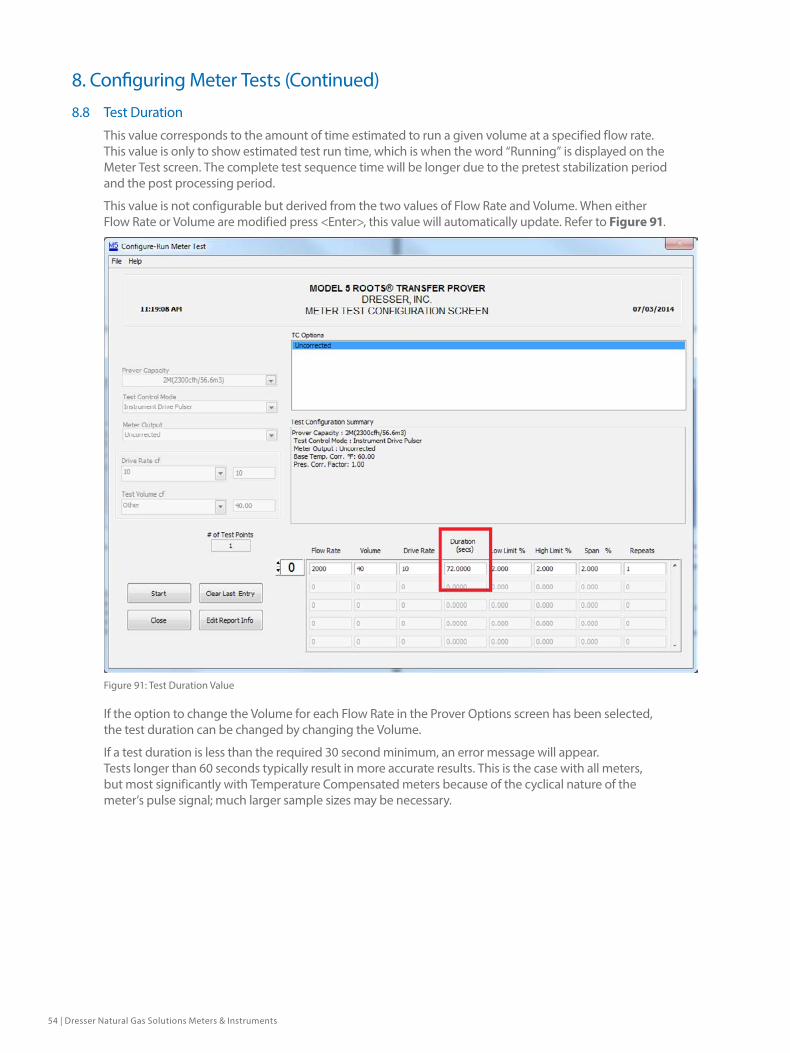
This value corresponds to the amount of time estimated to run a given volume at a specified flow rate. This value is only to show estimated test run time, which is when the word “Running” is displayed on the Meter Test screen. The complete test sequence time will be longer due to the pretest stabilization period and the post processing period.
This value is not configurable but derived from the two values of Flow Rate and Volume. When either Flow Rate or Volume are modified press <Enter>, this value will automatically update. Refer to Figure 91.
Figure 91: Test Duration Value
If the option to change the Volume for each Flow Rate in the Prover Options screen has been selected, the test duration can be changed by changing the Volume.
If a test duration is less than the required 30 second minimum, an error message will appear. Tests longer than 60 seconds typically result in more accurate results. This is the case with all meters, but most significantly with Temperature Compensated meters because of the cyclical nature of the meter’s pulse signal; much larger sample sizes may be necessary.
8. Configuring Meter Tests (Continued)
Dresser Model 5 Prover Software Manual NGS.MI.0035 | 55
8.9 Selecting the Number of Test Repeats
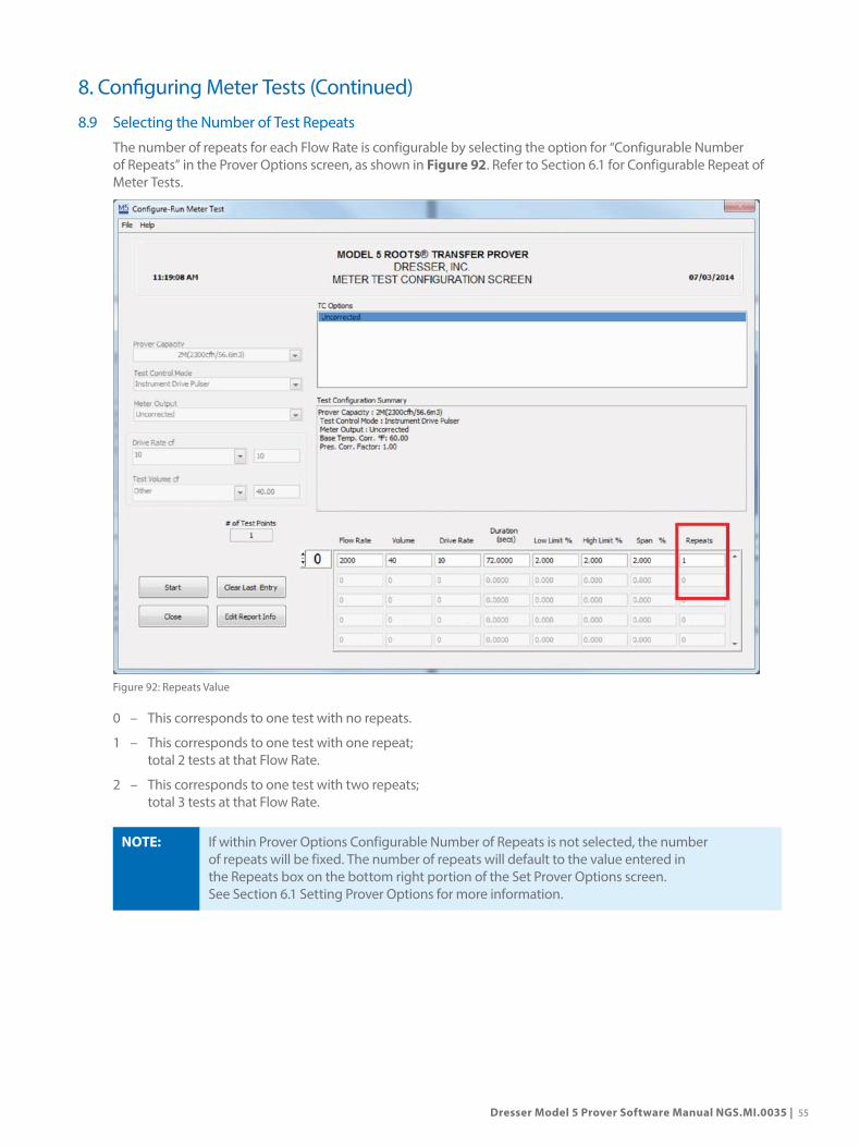
The number of repeats for each Flow Rate is configurable by selecting the option for “Configurable Number of Repeats” in the Prover Options screen, as shown in Figure 92. Refer to Section 6.1 for Configurable Repeat of Meter Tests.
Figure 92: Repeats Value
0 – This corresponds to one test with no repeats.
1 – This corresponds to one test with one repeat; total 2 tests at that Flow Rate.
2 – This corresponds to one test with two repeats; total 3 tests at that Flow Rate.
NOTE: If within Prover Options Configurable Number of Repeats is not selected, the number of repeats will be fixed. The number of repeats will default to the value entered in the Repeats box on the bottom right portion of the Set Prover Options screen. See Section 6.1 Setting Prover Options for more information.
8. Configuring Meter Tests (Continued)

56 | Dresser Natural Gas Solutions Meters & Instruments
8.10 Save, Close and Change
Once the configuration of the test has been completed, the test may be run immediately by clicking on the start button. There is also the option to save, close or change the test configuration. At the end of each test or upon selecting Exit Test in the Run screen, the test is ended and the screen returns to the Test Configuration screen.
The test’s configuration information will still be current and easily modified before running another test.
Select “File” and “Save Test Configuration” allows the user to name the test configuration and save it to the default directory, as shown in Figure 93. The save location can be changed if desired.
Figure 93: Save Test Configuration Selection
The “Close” button – will close the current screen and return the Startup screen. Any settings for a test configuration will be lost unless the test configuration is saved.
8. Configuring Meter Tests (Continued)

Dresser Model 5 Prover Software Manual NGS.MI.0035 | 57
9. Preconfigured TestsThe Model 5 Prover Software comes with a wide array of pre-established test settings that can be used instead of manually configuring a test scenario. These Preconfigured tests are not the manufacturer’s recommendation, but a suggested starting point that may be used or modified to meet company needs. Companies and individuals may create and save additional tests as desired. See the section entitled “8.10 Save, Close and Change” for more information. Dresser NGS provided Preconfigured tests were used for illustrative purposes.
1. From the Prover Main Screen, select “Open/Run Preconfigured Tests” as shown in Figure 94.
Figure 94: Open/Run Preconfigured Test Selection
2. A new window will appear. In the smaller window entitled “Select Meter Test”, select “DMD Preconfigured Test” as shown in Figure 95.
Figure 95: Select Meter Test Window
58 | Dresser Natural Gas Solutions Meters & Instruments
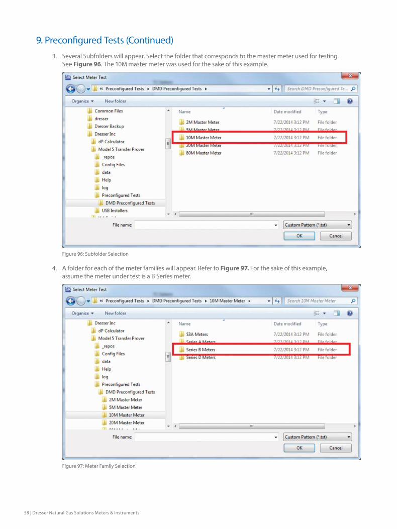
3. Several Subfolders will appear. Select the folder that corresponds to the master meter used for testing. See Figure 96. The 10M master meter was used for the sake of this example.
Figure 96: Subfolder Selection
4. A folder for each of the meter families will appear. Refer to Figure 97. For the sake of this example, assume the meter under test is a B Series meter.
Figure 97: Meter Family Selection
9. Preconfigured Tests (Continued)
Dresser Model 5 Prover Software Manual NGS.MI.0035 | 59
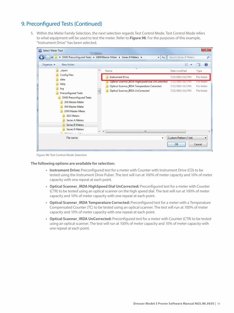
5. Within the Meter Family Selection, the next selection regards Test Control Mode. Test Control Mode refers to what equipment will be used to test the meter. Refer to Figure 98. For the purposes of this example, “Instrument Drive” has been selected.
Figure 98: Test Control Mode Selection
The following options are available for selection:
• Instrument Drive: Preconfigured test for a meter with Counter with Instrument Drive (CD) to be tested using the Instrument Drive Pulser. The test will run at 100% of meter capacity and 10% of meter capacity with one repeat at each point.
• Optical Scanner_IRDA HighSpeed Dial UnCorrected: Preconfigured test for a meter with Counter (CTR) to be tested using an optical scanner on the high speed dial. The test will run at 100% of meter capacity and 10% of meter capacity with one repeat at each point.
• Optical Scanner_IRDA Temperature Corrected: Preconfigured test for a meter with a Temperature Compensated Counter (TC) to be tested using an optical scanner. The test will run at 100% of meter capacity and 10% of meter capacity with one repeat at each point.
• Optical Scanner_IRDA UnCorrected: Preconfigured test for a meter with Counter (CTR) to be tested using an optical scanner. The test will run at 100% of meter capacity and 10% of meter capacity with one repeat at each point.
9. Preconfigured Tests (Continued)

60 | Dresser Natural Gas Solutions Meters & Instruments
6. Upon selecting the Test Control Mode, the next selection regards meter sizes. Select the appropriate meter size based on the meter to be tested. Click “OK” when ready. Refer to Figure 99.
Figure 99: Select Meter Size
9.1 Modifying a Saved or Preconfigured Test
To modify a previously saved test file, open the particular test. Refer to previous section.
Once the file is opened, make and save changes to a new file by Clicking “File” and “Save Test Configuration”.
The user may also modify and run a test without saving. Keep in mind, the changes to the test configuration will not be reflected in the future.
NOTE: Dresser Meters & Instruments preconfigured tests are protected. It is not possible to save them using the same name in the same location. Either rename, relocate, or do both.
9. Preconfigured Tests (Continued)

Dresser Model 5 Prover Software Manual NGS.MI.0035 | 61
10. Running a Meter Test
10.1 The Validity Test Screen
The computer makes a series of tests prior to beginning a test. If any errors are detected, one of up to 11 error messages will be displayed on the screen. A Validity Test screen will appear informing the user of test progress and any errors. Refer to Figure 100 for an example.
Figure 100: Validity Test Screen
All error messages must be removed by correcting the problem(s) before any meter proving can be attempted. Some computers may not display the Controller Power Off error message if nothing is connected to the computer’s serial port. So, if the 3 second indicator does not count down within thirty seconds, perform the same checks as for the Controller Power Off error message.
Electrical shorts, shorted temperature probes, or low levels of AC input power may cause the Controller’s microprocessor to stop communicating with the computer, causing data not to be received by the computer. This condition is indicated by data no longer being updated once a second during a test, or the Communication Errors message appearing in the Test Screen. It may appear as though the computer’s 3 second reasonability test has ceased to count down. If the computer’s serial port is not properly configured or powered this condition may occur also.
10.1.1 Controller Power Off “Controller Power Off” will appear if any of the following conditions exist:
• If 120 VAC is not plugged into the Controller.
• If the power switch on the Controller is not turned on.
• If the data cable from the Controller is not properly connected to the serial port of the computer that was selected in the Computer Setup Menu.
• If the serial port in the computer is not powered (see the computer’s operation manual for information about using serial ports). Some laptops require the enabling of power to their serial and/or parallel ports.
• If the cable from the Controller to the proper serial port is damaged.
• If the computer has a nonstandard RS-232 wiring pin out.
• If there is insufficient available RAM to allow the software to operate properly.

62 | Dresser Natural Gas Solutions Meters & Instruments
10.1.2 Atmospheric Pressure Sensor Error The atmospheric pressure sensor is located inside the Controller housing. This error has only a few possible causes:
• The calibration is corrupted.
• There is a communication failure between the Controller and the laptop.
• The sensor failed.
10.1.3 Master Meter Inlet Pressure Sensor Error Master Meter inlet and outlet pressure sensors are located inside the Controller housing and this error will appear if any of the following conditions exist:
• Pressure may be trapped by the quick disconnect if it is not properly seated and locked.
• The blower motors are still turning.
• Pressure still remains in the pressure lines from a previous test.
• The sensor failed.
Try briefly disconnecting the quick-disconnect connectors exposing them to atmospheric pressure. Wait several minutes, reselect Configure a test.
Try turning the Controller off, wait, then turn it back on again. Reselect Configure a test and see if the error message has gone away. The Master Meter’s pressure sensors are checked only for a near zero reading in the absence of any moving air (blowers turned on).
1. Field Meter Inlet Pressure Sensor Error The Field Meter’s inlet and outlet pressure sensors are located in the Field Meter Junction Box. See MASTER METER INLET PRESSURE SENSOR ERROR above for possible causes for this error.
2. Master Meter Outlet Pressure Sensor Error Master Meter inlet and outlet pressure sensors are located inside the Controller housing. See MASTER METER INLET PRESSURE SENSOR ERROR above for possible causes for this error.
3. Field Meter Outlet Pressure Sensor Error The Field Meter’s inlet and outlet pressure sensors are located in the Field Meter Junction Box. See MASTER METER INLET PRESSURE SENSOR ERROR above for possible causes for this error.
4. Master Meter Temperature Sensor Error This error appears only for the selected Master Meter used in the current test. Each Master Meter has its own temperature sensor, accessed by removing the access cover from the Master Meter Junction Box. If the Meter Cable is not connected to the Master Meter this message will appear.
5. Field Meter Temperature Sensor Error The temperature probe for the Field Meter plugs into the Field Meter Junction Box. This error will appear if any of the following conditions exist:
• Temperature Probe connector is damaged or not plugged in.
• Temperature Probe cable is damaged.
• Junction Box connector is damaged.
• Temperature Probe is damaged.
The lowest temperature the Prover will operate at is 20°F. A warning message will appear when the temperature drops below 35 °F. An extended temperature mode has been added for customers that require the ability to test meters below freezing. Dresser Meters & Instruments does not recommend operation at temperatures conducive to frost or moisture build-up in the system. Contact a local Dresser Meters & Instruments representative for details if required.
10. Running a Meter Test (Continued)

Dresser Model 5 Prover Software Manual NGS.MI.0035 | 63
6. Controller Digitizer Error This message appears if the digitizer varies by more than a few digits from the calibrated value. If the computer that was used to calibrate a specific Model 5 Prover is used with a different Model 5 Prover, this error message may appear. Make certain that the serial numbers of the Master Meter(s) match the serial numbers displayed when the Model 5 Prover computer program is first accessed. If this is true, try recalibrating the digitizer.
7. Pressure Transducers Have Not Stabilized This message will appear any time an attempt is made to restart a test before the Master Meter has had a chance to stop rotating.
Wait for a short period of time and the message will clear automatically. Other more rare occasions for this error message to remain on the screen are as follows:
• When testing in the pipeline, a valve is leaking.
• If there are strong winds with no pressure lines connected.
• The pressure line is pointed into the wind.
• There is a shorted triac in the blower control circuitry (the blowers remain on whenever power is connected to the Prover).
8. Meter Cable Connected to Wrong Master Meter This message may appear briefly when a test is started. As long as it clears it should not cause concern. If this message appears and does not clear, the Master Meter Cable is not connected to the proper Master Meter that was configured for the current test.
10.2 The Meter Test Screen
The meter test is initiated after the test has been configured properly and the automatic system check has been validated. This screen shows the system readouts as well as specifics on the Meter sensors. See Figure 101.
Figure 101: Meter Test Screen
10. Running a Meter Test (Continued)

64 | Dresser Natural Gas Solutions Meters & Instruments
The test sequence will initiate once the temperature is considered stable and the flow rate has reached the set point. The Test Status Lights (at the middle left portion of the Meter Test screen) indicate the test progress. The Test Status Lights include: Temp Stable, Test Run Started, and Test Run Completed.
Once the pretest criteria has been met (stable temperature and set flow), the Temp Stable indicator will turn green. This will correspond to the light on the Field Meter Junction Box turning on, signifying valid data. Once the test starts, the Test Run Started indicator will turn green and the light on the Field Meter Junction Box will start blinking. See Figure 102.
The range of temperature deviation is set on the Set Prover Options screen.
Stop, Restart, Exit or View
Test Controls
InformationBox
Test StatusLights
Error Box
Test Flow Box
Figure 102: Populated Meter Test Screen
HELP: Refer to Temperature Stability Settings in the Help Directory for more information.
NOTE: For optimal results, the system must not be disturbed during the pretest and testing portion of the proving cycle.
There are four buttons at the bottom right of the screen that are used to control the testing process:
• Stop Test – This will stop any current test but will also allow the user to reinitiate the testing with the Restart Test command.
• Restart Test – This will allow the user to restart the test sequence.• Exit Test – This command will stop testing and return the user to the Test Configuration screen.
• View Report – The report can be viewed at any time during and after a testing sequence, but the testing must be stopped either by issuing a Stop Test command or by waiting until the end of the test cycle.
NOTE: The test will start at the flow rate selected in the Test Flows box at the bottom of the screen and will continue the test sequences for all test points at and below the selected test point.
10. Running a Meter Test (Continued)

Dresser Model 5 Prover Software Manual NGS.MI.0035 | 65
WARNING:
Warning: (All Provers except 10M/2M) Restarting a test using the 80M, 20M, or Mobile 5 Master Meter of the Model 5 Prover will allow the user to restart a test before the main valve has fully closed. If the main blower starts before the main valve has fully closed, both the Master Meter and the connected Field Meter can be stressed/damaged due to the possibility of a sudden surge of air through the system. Always allow enough time for the main valve to fully close before making flow selection.
• The Information Box is located on the bottom right of the screen. It displays the current test information and also prompts the user for specific action, if required.
• The Error Box is located on the bottom left portion of the screen and displays any problems or errors that may arise (See Problem Identification and Resolution).
• The Test Flows Box shows the flow rates for this particular sequence of tests. This box is important when a Stop Test command is initiated. If no selection is made prior to the Restart Test command, then the test sequences will restart at the first flow entry. There is also the option to start at any other flow rate if desired; but the testing will start at the selected flow and continue for all other flows below it.
• The Repeat Box displays the number of times that the test will be repeated after the initial test. The number of repeats was determined when the test was configured (See section 8.9 Selecting the Number of Test Repeats).
10.3 System Readouts
While the system is running, the meter test screen will populate and update with the readings based on test progression. See Figure 103.
Figure 103: Populated System Readout Screen
10. Running a Meter Test (Continued)

66 | Dresser Natural Gas Solutions Meters & Instruments
1. Ambient Pressure – the reading of the absolute ambient pressure as read by the atmospheric pressure transducer located in the Model 5 Controller.
2. Master Flow – the current reading of the flow rate as indicated by the Master Meter.
NOTE: This flow must meet the current set flow rate as indicated in the status box at the lower right portion of the screen before the test started or an error “Failure to Reach Flow Rate” will appear.
3. Est. Test Time(s) – the estimated time of completion of the current test in progress. It does not indicate the total time of all the test sequences combined.
4. Master Meter Pressure (inch) – the reading of the pressure at the inlet of the Master Meter as read by a pressure transducer in the Model 5 Controller.
5. Master Meter Differential (inch) – the reading of the pressure drop or differential across the Master Meter as read by a pressure transducer in the Model 5 Controller (Must always be positive).
6. Master Volume (cf) – the current volume of air that has passed through the Master Meter for this test. Note that this is a raw number and has not been corrected with respect to Temp, Pressure, or Master Meter offset. The Model 5 system uses electronic pulses from the Field Meter to start and stop a test, therefore the final Master Volume readout is contingent on the system and Field Meter accuracies. If the system and Field Meter were both 100 percent accurate, then the Master Volume reading would match the preconfigured ‘Test Volume’ as shown on the middle right side of the Run screen.
7. Master Meter Temp. – the temperature of the air as read by a temperature probe inside the Master Meter.
8. Field Meter Pressure (inch) – the pressure at the inlet flange of the Field Meter (the meter under test). This reading comes from a pressure transducer located in the Field Meter Junction Box and connected to the Field Meter by a blue pressure tube.
9. Field Meter Differential (inch) - the pressure drop across the Field Meter or meter under test as read by a pressure transducer in the Field Meter Junction Box (Must always be positive).
10. Test Volume – the test volume that was entered during the test setup. This is the total volume run for each test.
11. Field Meter Temp. – the reading of the temperature probe placed in or near the Field Meter.
Help: For the correct positioning of the Field Meter temperature probe, see the HELP Directory documentation under “Connecting** Meters”.
10. Running a Meter Test (Continued)
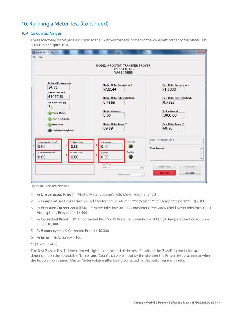
Dresser Model 5 Prover Software Manual NGS.MI.0035 | 67
10.4 Calculated Values
These following displayed fields refer to the six boxes that are located in the lower left corner of the Meter Test screen. See Figure 104.
Figure 104: Calculated Values
1. % Uncorrected Proof = (Master Meter volume*/Field Meter volume) x 100
2. % Temperature Correction = [(Field Meter temperature ° R**)/ (Master Meter temperature °R**) - 1] x 100
3. % Pressure Correction = {[(Master Meter Inlet Pressure + Atmospheric Pressure)/ (Field Meter Inlet Pressure + Atmospheric Pressure)] -1} x 100
4. % Corrected Proof = [(% Uncorrected Proof) x (% Pressure Correction + 100) x (% Temperature Correction + 100)] / 10,000
5. % Accuracy = (1/% Corrected Proof) x 10,000
6. % Error = % Accuracy – 100
** (°R = °F + 460)
The Test Pass or Test Fail indicator will light up at the end of the test. Results of the Pass/Fail conclusion are dependent on the acceptable ‘Limits’ and ‘Span’ that were input by the at either the Prover Setup screen or when the test was configured. Master Meter volume after being corrected by the performance Presets.
10. Running a Meter Test (Continued)

68 | Dresser Natural Gas Solutions Meters & Instruments
11. Test Results and Reports
11.1 Reviewing, Saving and Printing Test Results
Any of the completed individual test results are available for review after the test sequence is complete or after clicking the Stop Test button. Select the test flow and the appropriate repeat number from the selection boxes which appear at the bottom center of the Meter Test screen once all tests are completed and/or the Prover is stopped.
Additionally the user can view, save or print test results in a test report format. From the Meter Test Screen, click on the View report button to display the Meter Test Results screen.
All entries made to the text entry fields will be retained as defaults for subsequent reports until they are changed. See Figure 105.
Figure 105: Edit Report Info Screen
NOTE: If the Double Field Meter Serial Number Entry option in the Set Prover Options screen was selected, the user must type the Field Meter serial number twice and ensure that both entries match identically. If the user accepts the old value by pressing the <Enter> key before pressing any other keys, the second entry will also accept just the <Enter> key which causes no change to the Field Meter serial number.
Once the report headers have been filled in, the user may save test sequences by clicking on the Save Report button. This will create a time-stamped Model 5 Prover file with a .DAT extension to be saved in the current Default Directory. This test report file is saved in a comma-delimited format which can be accessed from this software or any database or program capable of reading this type of file.
Print test results by selecting the Print Report button at the bottom of the Meter Test Results screen.

Dresser Model 5 Prover Software Manual NGS.MI.0035 | 69
This program can access any properly configured printer either local or via network. A printer must be configured properly, paper loaded properly, cabled and powered properly in order to generate a printed report. The printer settings can be configured in the Windows printer configuration subroutine.
To exit the Meter Test Results screen, click on the Close button to return to the Meter Test screen. See Figure 106.
Figure 106: Meter Test Data Report
11.2 The Report Manager
This application is used to manage the test data that is generated by the Prover. From the Main Startup screen click on file and select Report Manager, or from the Set Prover Options screen, click on Prover Operations at the top left of the window and select Report Manager.
The Folder box shows the default path and directory where the test data files are saved. This path and directory can be changed to search for test report files in other directories by clicking on the “Change” button.
NOTE: When choosing a new directory, do not select the “Open” button but instead click on the Select Cur Dir (Select Current Directory) button. In the Show Report box, scroll through the various search criteria using the up/down arrow button.
• All Reports - lists all the test reports in the selected folder.
• By Date - enables the user to locate files generated between two dates. Enter start date [From (MM/DD)] and end date [To (MM/DD)] to narrow search to a certain time period.
• By Value - The files will be classified by one of the named fields on the test report (i.e. Location, Operators Name, Master Meter Type, etc.).
NOTE: The entry for ‘Value’ is not case sensitive and the search uses an automatic wildcard at the end of the entry. Therefore, a full entry description is not usually required.
11. Test Results and Reports (Continued)

70 | Dresser Natural Gas Solutions Meters & Instruments
Example: to search for LMM Gas Co. using the “Customer Name” query, the correct files will be found by entering the partial description “LMM”. The buttons along the bottom of the Report Manager Screen provide a variety of functions by which the user may handle the meter test data.
NOTE: Software Version 5.31 and above - printer settings permits the user to change margins and fonts for printed reports.
• Printer Settings – Location to change margins and font settings used when printing test reports.
CAUTION: Changing these Settings could adversely affect the printed report. Please use caution.
• Update List – When searching for test reports it sometimes becomes necessary to use limiting parameters to focus the search. If these parameters are used, once the search criterion has been input, select <Update List> and the list will be reevaluated using the new criteria. “Update List” will also update the names under the “Where” search criteria if changed under the “Edit Names” option.
• Print Report – This option will print the selected report.
• View Report – Once a report is selected, the user can view it using this option.
• Edit Names - This button will bring up the Report Customization subroutine. In this mode, the user can modify all the headings for the report generation categories. Click on the ‘Save’ button after each and every change before selecting the ‘Close’ button to implement the changes. If multiple changes are made, and the Save button is only clicked after the last change, only that last change will be saved.
NOTE: If there are any changes to the Edit Names subroutine, use Update List to update the names under the “Where” pull down menu. For example, the default heading “Operator’s Name or ID” can be modified to read “Prover Technician” on the test report. If the user selects the “Close” button before the “Save” button, no changes will be implemented in the “Edit Names” subroutine.
11.3 Changing Default Test File Location
To change the default path for future Prover test data, follow the below procedure:
1. Select “File” and Report Manager from the Prover Main Screen. See Figure 107.
Figure 107: Report Manager Selection
11. Test Results and Reports (Continued)

Dresser Model 5 Prover Software Manual NGS.MI.0035 | 71
2. Within the “Report Manager” Screen, select “Edit Names”. See Figure 108.
Figure 108: Edit Names Selection
3. The “Report Customization” window will open. The current default path is displayed. To change, select the file folder button to the right. See Figure 109.
Figure 109: Change Path Selection
11. Test Results and Reports (Continued)

72 | Dresser Natural Gas Solutions Meters & Instruments
4. A “Select Folder” window will open. Navigate to the desired path and click the button entitled “Select Folder”. See Figure 110.
Figure 110: Select Folder Selection
5. The new selection will be displayed. Select “Save” to finalize the change. See Figure 111.
Figure 111: Save Selection
6. Select “Close” to close the Report Customization window. The new path should now be displayed at the top of the Report Manager window.
11. Test Results and Reports (Continued)
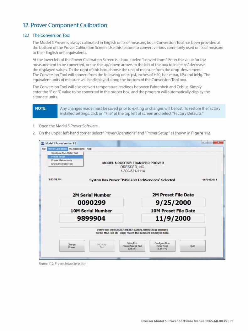
Dresser Model 5 Prover Software Manual NGS.MI.0035 | 73
12. Prover Component Calibration
12.1 The Conversion Tool
The Model 5 Prover is always calibrated in English units of measure, but a Conversion Tool has been provided at the bottom of the Prover Calibration Screen. Use this feature to convert various commonly used units of measure to their English unit equivalents.
At the lower left of the Prover Calibration Screen is a box labeled “convert from”. Enter the value for the measurement to be converted, or use the up/ down arrows to the left of the box to increase/ decrease the displayed values. To the right of this box, choose the unit of measure from the drop-down menu. The Conversion Tool will convert from the following units: psi, inches of H20, bar, mbar, kPa and inHg. The equivalent units of measure will be displayed along the bottom of the Conversion Tool box.
The Conversion Tool will also convert temperature readings between Fahrenheit and Celsius. Simply enter the °F or °C value to be converted in the proper box, and the program will automatically display the alternate units.
NOTE: Any changes made must be saved prior to exiting or changes will be lost. To restore the factory installed settings, click on “File” at the top left of screen and select “Factory Defaults.”
1. Open the Model 5 Prover Software.
2. On the upper, left-hand corner, select “Prover Operations” and “Prover Setup” as shown in Figure 112.
Figure 112: Prover Setup Selection

74 | Dresser Natural Gas Solutions Meters & Instruments
3. A small dialog box will appear. Enter the password “ROOTS” as shown in Figure 113.
Figure 113: Password Dialogue Box
4. A new window will open. Select “Prover Operations” and “Set Units of Measurement” as shown in Figure 114.
Figure 114: Set Units of Measurement Selection
12. Prover Component Calibration (Continued)

Dresser Model 5 Prover Software Manual NGS.MI.0035 | 75
5. A new window will appear, as shown in Figure 115. Review all the units of measurement available for change.
Figure 115: Units of Measurement Window
6. In this example the units of measure for differential meter pressure will be changed. Follow the same procedure for any of the listed drop-down menus. Select the down arrow to reveal available options, as shown in Figure 116. Click the desired unit.
Figure 116: Drop Down Selection
12. Prover Component Calibration (Continued)

76 | Dresser Natural Gas Solutions Meters & Instruments
7. The selection should be reflected as shown in Figure 117.
Figure 117: Changed Drop Down Selection
8. Click on the “Save and Close” button as shown in Figure 118. There will be a prompt to confirm the selection.
Figure 118: Save and Close
12. Prover Component Calibration (Continued)

Dresser Model 5 Prover Software Manual NGS.MI.0035 | 77
9. On the “Set Prover Operations” window, select “Save and Close” as shown in Figure 119.
Figure 119: Click “Save and Close”
10. Restart computer.
12.2 How to Calibrate the Atmospheric Pressure Transducer
1. From “Prover Operations”, select “Prover Set Up” as shown in Figure 120.
Figure 120: Prover Setup Selection
12. Prover Component Calibration (Continued)

78 | Dresser Natural Gas Solutions Meters & Instruments
2. Upon selecting “Prover Setup, there will be a prompt to enter a password as shown in Figure 121. The password is “ROOTS”. Capitalization is required. Press “OK.”
Figure 121: Prover Setup Password
3. A second window will appear as shown in Figure 122. Take note of the Control COM Port Field. Notice, only COM Ports in use are available for selection. Select the COM port (Refer to Step 2.)
Figure 122: Prover Setup Screen and Controller COM Port
12. Prover Component Calibration (Continued)

Dresser Model 5 Prover Software Manual NGS.MI.0035 | 79
4. When complete, click “Save and Close” as shown in Figure 123.
Figure 123: Save and Close
5. Repeat Step 1 and Step 2.
6. Click “Prover Operations”. Then click, “Calibrate Prover” as shown in Figure 124. The password is “DRESSER”.
Figure 124: Calibrate Prover
12. Prover Component Calibration (Continued)

80 | Dresser Natural Gas Solutions Meters & Instruments
7. A third window will appear as shown in Figure 125. It will warn the user with the following message, “Caution, you are about to change the calibration of your Prover”. Click “OK”.
Figure 125: Calibration Warning Window
HELP: Refer to Calibration and Preset Files in the Help Index for more information.
12. Prover Component Calibration (Continued)

Dresser Model 5 Prover Software Manual NGS.MI.0035 | 81
8. From the Prover Calibration Screen, select the pull down arrow and click “Calibrate Atmospheric Pressure Transducer” See Figure 126.
Figure 126: Select Calibrate Atmospheric Pressure Transducer Selection
The box labeled Count indicates a digitized value that represents the amount of pressure sent from the electronic Controller. Also displayed is the current ambient pressure, which was calculated using the value from the most recent Transducer calibration.
9. In the box labeled Enter Barometric Pressure (psia) enter a value that represents the current atmospheric pressure in pounds per square inch absolute. Press <Enter>.
NOTE: If pressure has been gauged with an instrument that uses units other than psia, use the Conversion Tool at the bottom of the screen to convert to psia units.
10. Click on the <Accept> button at the bottom of the screen to save the new calibration setting.
NOTE: The uncertainty of your pressure standard should be less than +_2 psia. A greater uncertainty factor can result in a poor calibration of the Atmospheric Pressure Transducer.
12. Prover Component Calibration (Continued)
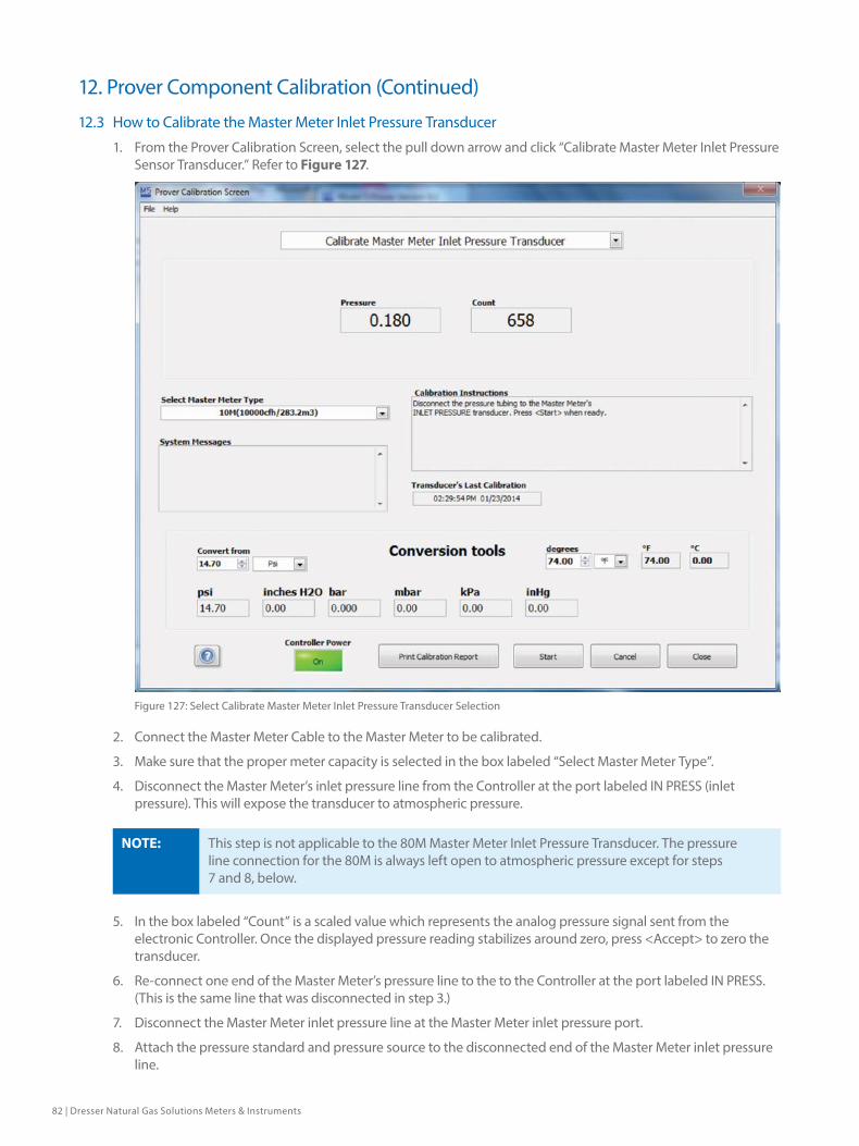
82 | Dresser Natural Gas Solutions Meters & Instruments
12.3 How to Calibrate the Master Meter Inlet Pressure Transducer
1. From the Prover Calibration Screen, select the pull down arrow and click “Calibrate Master Meter Inlet Pressure Sensor Transducer.” Refer to Figure 127.
Figure 127: Select Calibrate Master Meter Inlet Pressure Transducer Selection
2. Connect the Master Meter Cable to the Master Meter to be calibrated.
3. Make sure that the proper meter capacity is selected in the box labeled “Select Master Meter Type”.
4. Disconnect the Master Meter’s inlet pressure line from the Controller at the port labeled IN PRESS (inlet pressure). This will expose the transducer to atmospheric pressure.
NOTE: This step is not applicable to the 80M Master Meter Inlet Pressure Transducer. The pressure line connection for the 80M is always left open to atmospheric pressure except for steps 7 and 8, below.
5. In the box labeled “Count” is a scaled value which represents the analog pressure signal sent from the electronic Controller. Once the displayed pressure reading stabilizes around zero, press <Accept> to zero the transducer.
6. Re-connect one end of the Master Meter’s pressure line to the to the Controller at the port labeled IN PRESS. (This is the same line that was disconnected in step 3.)
7. Disconnect the Master Meter inlet pressure line at the Master Meter inlet pressure port.
8. Attach the pressure standard and pressure source to the disconnected end of the Master Meter inlet pressure line.
12. Prover Component Calibration (Continued)

Dresser Model 5 Prover Software Manual NGS.MI.0035 | 83
9. Use the pressure source to apply a 5.000 ±0.05 inch water column vacuum to the Master Meter inlet pressure line. The reading on the pressure standard will be approximately –5.000 inches and will appear in the box labeled “Pressure (inch)”. This is the current Meter pressure, and the negative value of the reading indicates the presence of a vacuum.
NOTE: The 80M Master Meter Inlet Pressure Transducer requires a positive pressure reading (+5 inches of water column). This positive pressure applies to the open fitting that is connected to both the 80M Inlet Pressure Transducer and the 80M Chamber Pressure Transducer.
10. After the displayed reading has stabilized, click on the <Accept> button at the bottom of the screen to complete and save the recalibration.
12.4 How to Calibrate the Field Meter Inlet Pressure Transducer
1. From the Prover Calibration Screen, select the pull down arrow and click “Calibrate Master Meter Inlet Pressure Sensor Transducer.” Refer to Figure 128.
Figure 128: Select Calibrate Field Meter Inlet Pressure Transducer
2. Disconnect the pressure line from the Field Meter inlet pressure port and from the Field Meter Junction Box at the port labeled IN PRESS (inlet pressure). This will expose the transducer to atmospheric pressure.
3. In the box labeled “Count” is a scaled value which represents the analog pressure signal sent from the electronic Controller. Once the displayed pressure reading stabilizes, press <Enter> to advance to the next step.
4. Re-connect one end of the pressure line to the Field Meter Junction Box at the port labeled IN PRESS. This is the same line that was disconnected in Step 2.
12. Prover Component Calibration (Continued)

84 | Dresser Natural Gas Solutions Meters & Instruments
5. Attach the pressure standard and pressure source to the open end of the Field Meter inlet pressure line.
6. Use the pressure source to apply a 5.000 ±0.05 inch water column vacuum to the Field Meter inlet pressure line. The reading on the pressure standard will be approximately –5.000 inches and will appear in the box labeled “Pressure (inch)”. This is the current Meter pressure, and the negative value of the reading indicates the presence of a vacuum.
7. After the displayed reading on the pressure standard and the count reading has stabilized, click on the <Accept> button at the bottom of the screen to complete and save the recalibration.
12.5 How to Calibrate the Master Meter Temperature Probe
All Master Meters except 80M:1. From the Prover Calibration Screen, select the pull down arrow and click “Calibrate Master Meter Temperature
Probe.” Refer to Figure 129.
Figure 129: Select Calibrate Master Meter Temperature Probe
2. Remove the four screws holding the cover plate on the Master Meter Junction Box.
All Master Meters:3. Connect the Master Meter cable to the Master Meter to be calibrated.
4. Make sure that the proper meter capacity is selected in the box labeled “Select Master Meter Type”.
5. Remove the Master Meter temperature probe from its well. Do not disconnect any wiring.
6. Using a rubber band, attach the Master Meter temperature probe to a sensing device that will serve as a temperature standard. Immerse both into a liquid container that is already at the temperature at which the test will be conducted. Make sure that the liquid is gently stirred to equalize the temperature throughout the container.
12. Prover Component Calibration (Continued)

Dresser Model 5 Prover Software Manual NGS.MI.0035 | 85
It is important that there is no greater than ±1°F difference between the temperature of the liquid in the container and the testing temperature. In addition, ensure that the temperature of the liquid in the container is extremely stable and that the temperature standard has an uncertainty of no more than ±0.20°F.
Before completing the next step, make sure that both the reference temperature and the value displayed in the box labeled Count have stabilized.
7. Type in the reference temperature as measured by the temperature standard, then click on the <Accept> button at the bottom of the screen.
8. The Calibration Instructions box on the screen now indicates to remove the Master Meter temperature probe and let it stabilize. Leave both the temperature probe and the temperature standard in the liquid container, and click on the <Accept> button at the bottom of the screen.The recalibration of the Master Meter temperature probe is now complete and the new setting and current date are saved.
9. Remove both the Master Meter temperature probe and the temperature standard from the liquid container. Remove the rubber band holding them together and carefully dry both probes.
10. Re-insert the Master Meter temperature probe into its well and secure it in place.
All Master Meters except 80M:11. Re-attach the Master Meter cover plate and tighten all four screws.
12.6 How to Calibrate the Field Meter Temperature Probe
1. From the Prover Calibration Screen, select the pull down arrow and click “Calibrate Field Meter Temperature Probe.” Refer to Figure 130.
Figure 130: Select Calibrate Field Meter Temperature Probe
2. Make sure that the Field Meter Junction Box cable is connected to the Controller.
12. Prover Component Calibration (Continued)

86 | Dresser Natural Gas Solutions Meters & Instruments
3. Connect the Field Meter temperature probe to the Field Meter Junction Box at the port labeled TEMP PROBE.
4. Using a rubber band, attach the Field Meter temperature probe to a sensing device that will serve as a temperature standard. Immerse both into a liquid container that is already at the temperature at which the test will be conducted. Make sure that the liquid is gently stirred to equalize the temperature throughout the container.
It is important that there is no greater than ±1°F difference between the temperature of the liquid in the container and the testing temperature. In addition, ensure that the temperature of the liquid in the container is extremely stable and that the temperature standard has an uncertainty of no more than ±0.20°F.
NOTE: Before completing the next step, make sure that both the reference temperature and the value displayed in the box labeled Count have stabilized.
5. Type in the reference temperature as measured by the temperature standard, then click on the <Accept> button at the bottom of the screen.
6. The Calibration Instructions box on the screen now indicates to remove the Field Meter temperature probe and let it stabilize. Leave both the temperature probe and the temperature standard in the liquid container, and click on the <Accept> button at the bottom of the screen. The recalibration of the Field Meter temperature probe is now complete and the new setting and current date are saved.
7. Remove both the Field Meter temperature probe and the temperature standard from the liquid container. Remove the rubber band holding them together and carefully dry both probes.
12.7 How to Calibrate the Master Meter Outlet Pressure Transducer
1. From the Prover Calibration Screen, select the pull down arrow and click “Calibrate Master Meter Outlet Pressure Sensor.” Refer to Figure 131.
Figure 131: Select Calibrate Master Meter Outlet Pressure Transducer
12. Prover Component Calibration (Continued)
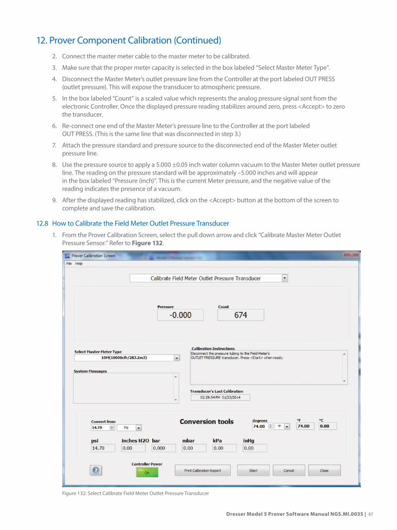
Dresser Model 5 Prover Software Manual NGS.MI.0035 | 87
2. Connect the master meter cable to the master meter to be calibrated.
3. Make sure that the proper meter capacity is selected in the box labeled “Select Master Meter Type”.
4. Disconnect the Master Meter’s outlet pressure line from the Controller at the port labeled OUT PRESS (outlet pressure). This will expose the transducer to atmospheric pressure.
5. In the box labeled “Count” is a scaled value which represents the analog pressure signal sent from the electronic Controller. Once the displayed pressure reading stabilizes around zero, press <Accept> to zero the transducer.
6. Re-connect one end of the Master Meter’s pressure line to the Controller at the port labeled OUT PRESS. (This is the same line that was disconnected in step 3.)
7. Attach the pressure standard and pressure source to the disconnected end of the Master Meter outlet pressure line.
8. Use the pressure source to apply a 5.000 ±0.05 inch water column vacuum to the Master Meter outlet pressure line. The reading on the pressure standard will be approximately –5.000 inches and will appear in the box labeled “Pressure (inch)”. This is the current Meter pressure, and the negative value of the reading indicates the presence of a vacuum.
9. After the displayed reading has stabilized, click on the <Accept> button at the bottom of the screen to complete and save the calibration.
12.8 How to Calibrate the Field Meter Outlet Pressure Transducer
1. From the Prover Calibration Screen, select the pull down arrow and click “Calibrate Master Meter Outlet Pressure Sensor.” Refer to Figure 132.
Figure 132: Select Calibrate Field Meter Outlet Pressure Transducer
12. Prover Component Calibration (Continued)
88 | Dresser Natural Gas Solutions Meters & Instruments
12. Prover Component Calibration (Continued)2. Connect the Field Meter cable to the Controller.
3. Disconnect the pressure line from the Field Meter outlet pressure port and from the Field Meter Junction Box at the port labeled OUT PRESS (outlet pressure). This will expose the transducer to atmospheric pressure.
4. In the box labeled “Count” is a scaled value which represents the analog pressure signal sent from the electronic Controller. Once the displayed pressure reading stabilizes around zero, press <Accept> to zero the transducer.
5. Re-connect one end of the pressure line to the Field Meter Junction Box at the port labeled OUT PRESS. This is the same line that was disconnected in Step 3.
6. Attach the pressure standard and pressure source to the open end of the Field Meter outlet pressure line.
7. Use the pressure source to apply a 5.000 ±0.05 inch water column vacuum to the Field Meter outlet pressure line. The reading on the pressure standard will be approximately –5.000 inches and will appear in the box labeled “Pressure (inch)”. This is the current Meter pressure, and the negative value of the reading indicates the presence of a vacuum.
8. After the displayed reading has stabilized, click on the <Accept> button at the bottom of the screen to complete and save the calibration.

Dresser Model 5 Prover Software Manual NGS.MI.0035 | 89
13. Prover MaintenanceClick on Prover Operations at the top of the Startup screen. Select Prover Maintenance (<Ctrl+F6>) from the drop-down menu to initiate the Maintenance screen. From this screen, several system checks may be performed that will help to ensure the best performance and safest operation of the Model 5 Prover. Refer to Figure 133.
Figure 133: Prover Maintenance Selection
In addition to performing service tests, the user can keep track of the operational hours since the Master Meter(s) were last serviced.
By default, the Prover Self Test will display first when the Maintenance screen is opened. Click on the up/down arrow keys at the left side of the Test box to scroll through and select the desired test.
13.1 Master Meter Hours of Operation
At the top of the Maintenance screen shows the hours of operation of each Master Meter. This important record can be used to monitor time periods between service functions or to initiate factory recertifications.
NOTE: Reinstalling the software resets the hours.
The hours of operation are activated when a meter test starts (any time the blowers turn on). With the mouse, click on the appropriate Master Meter.
NOTE: The hours of operation section does not take into account the speed or the cleanliness of the air or the environment with which the blowers and Master Meters must operate.
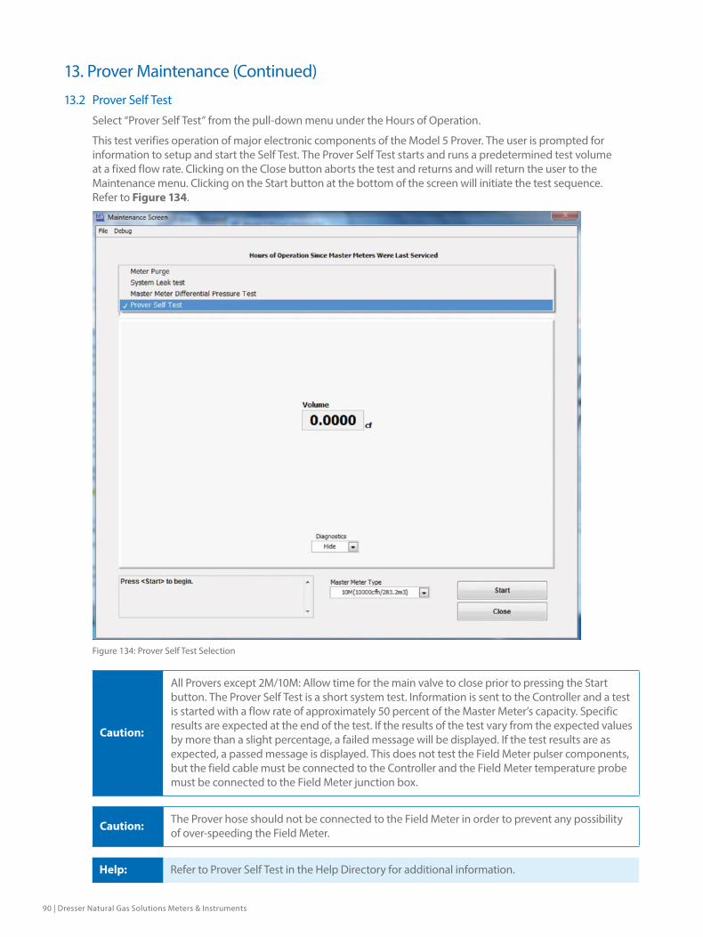
90 | Dresser Natural Gas Solutions Meters & Instruments
13.2 Prover Self Test
Select “Prover Self Test” from the pull-down menu under the Hours of Operation.
This test verifies operation of major electronic components of the Model 5 Prover. The user is prompted for information to setup and start the Self Test. The Prover Self Test starts and runs a predetermined test volume at a fixed flow rate. Clicking on the Close button aborts the test and returns and will return the user to the Maintenance menu. Clicking on the Start button at the bottom of the screen will initiate the test sequence. Refer to Figure 134.
Figure 134: Prover Self Test Selection
Caution:
All Provers except 2M/10M: Allow time for the main valve to close prior to pressing the Start button. The Prover Self Test is a short system test. Information is sent to the Controller and a test is started with a flow rate of approximately 50 percent of the Master Meter’s capacity. Specific results are expected at the end of the test. If the results of the test vary from the expected values by more than a slight percentage, a failed message will be displayed. If the test results are as expected, a passed message is displayed. This does not test the Field Meter pulser components, but the field cable must be connected to the Controller and the Field Meter temperature probe must be connected to the Field Meter junction box.
Caution: The Prover hose should not be connected to the Field Meter in order to prevent any possibility of over-speeding the Field Meter.
Help: Refer to Prover Self Test in the Help Directory for additional information.
13. Prover Maintenance (Continued)

Dresser Model 5 Prover Software Manual NGS.MI.0035 | 91
13.3 Master Meter Differential Pressure Test
Help: Refer to Master Meter Differential Pressure Test in the Help Directory for additional information.
Select “Master Meter Differential Pressure Test” from the pull-down menu under the Hours of Operation.
This test measures the differential pressure between the Master Meter inlet pressure transducer (blue 1/4” pressure line) and the Master Meter outlet pressure transducer (black 1/4” pressure line) at the entered flow rates. Normally this test is run with no hose or Field Meter connected to the Master Meter being tested.
The user will have the choice of running a factory preconfigured test sequence or a custom test in which the user will be prompted to enter the Prover capacity and desired flow rates manually. Enter these flow rates into the row of gray boxes that runs across the screen. The test will start and display the differential pressure between the inlet and the outlet of the selected Master Meter. The differential pressures are calculated for the approximate flow rates entered during the differential pressure test’s configuration and displayed on the left side of the computer’s screen. Differential pressure test results are dependent on how the meter is connected. Refer to Figure 135.
Figure 135: Master Meter Differential Pressure Test Selection
After successful completion of the differential test, a box will appear that will signal completion. At this point the user can print/save the data. The file will be stored in a comma delimited text file in the Data subdirectory under the Model 5 Transfer Prover directory that was created when this software was installed.
13. Prover Maintenance (Continued)

92 | Dresser Natural Gas Solutions Meters & Instruments
13.4 System Leak Test
Refer to Leak Test in the Help Directory for additional information. Select “System Leak Test” from the pull down menu directly under the Hours of Operation. Refer to Figure 136.
Figure 136: System Leak Test Selection
Perform a leak test to help determine if and where a leak is present in the Prover system. Leakage during a Field Meter test will result in a lower Accuracy (higher Corrected Proof) reading than that typically expected. The volume registered by the meter under test is compared to the volume registered by the Master Meter. In an Automatic test, the Field Meter starts and stops the test according to the test volume selected in the software configuration. Perform a leak test using either the automatic vacuum test or positive pressure method.
Important: Place a Dust Cap over the inlet of the Field Meter and secure in place. If a Dust Cap is not available, use a mating flange and gasket, or another method that will produce an air tight seal at the opening of the Field Meter inlet.
All Provers except 80MTo configure the Model 5 Prover 2M/10M for a leak test, connect the Prover as for testing a meter.
Select either the 10M/283.2m3 or the 2M/56.6m3 Prover capacity in the Master Meter Type drop down menu near the bottom-right of the Maintenance screen. Click on the Start button to initiate the 3-second reasonability test prior to starting the leak test. A Passed or Failed message is displayed on the computer screen, at the end of the test. The Controller will stop the test afterwards.
A Passed or Failed error message will be displayed at the end of each test. If the computer doesn’t receive the single pass/fail indicator from the Controller; the blowers may stop without any messages being displayed. If this condition occurs, restart the leak test by first selecting Cancel Test and then clicking on the Start button again. If the mandatory leak test option has been selected in the Prover options menu, the leak test must Pass before any
13. Prover Maintenance (Continued)

Dresser Model 5 Prover Software Manual NGS.MI.0035 | 93
other tests may be performed.
NOTE: 20M Provers only: Allow time for the main valve to close prior to pressing the start button.
10/80M Provers Auto leak Check
NOTE: This method requires a compatible Controller chip to operate.
1. Prepare the system before initiating the auto leak test sequence by making the following preparations:
2. The Main Butterfly valve mounted next to the 56 Master Meter must be in the closed position and leak tight.
3. Cap off the 8” diameter hose that is used to connect the test meter to the large resonance tank.
4. Connect the short 6’ hose from the small blowers to the 10M Master Meter.
5. Connect the 10M Master Meter to the small resonance tank.
6. Connect the long 24’ hose from the other end of the small resonance tank to the T connection right next to the 56M Master Meter.
7. Select the 10M/283.2m3 Prover capacity in the Master Meter Type drop down menu near the bottom-right of the Maintenance screen. Click on the Start button to initiate the three-second reasonability test prior to starting the leak test. The test will run for approximately four minutes before a Passed or Failed message is displayed on the computer screen. The Controller will stop the test after approximately four minutes. A Passed or Failed error message will be displayed at the end of each test.
8. If a leak is detected, then start with a fewer number of components in the test loop until the leak test passes; then systematically add one component at a time until the leak is identified.
9. The leak test sequence will apply a vacuum to the system for four minutes and in the last eight seconds will monitor the movement of the 10M impellers. An average frequency of 2Hz at –16” W.C. for the 10M meter is the maximum allowable leak rate.
NOTE: The 80M can also be leak tested using a manual test where the system is pressurized and then checked for a pressure loss.
13.5 Meter Purge
Select “Meter Purge” from the pull-down menu under the Hours of Operation.
Warning: An explosion may occur if the Prover is operated in the presence of explosive or flammable gases. Always purge the Field Meter and all associated piping prior to running any test. The Prover is not intrinsically safe.
The Field Meter and associated piping may be purged of all flammable gas with a hand-held blower or by using the blowers on the Model 5 Prover. Observe any and all applicable company safety procedures and rules for purging the meter and piping.
If the blowers on the Prover will be used for purging the Field Meter and associated piping, connect as follows:
All Provers except 80MIf the Prover has two Master Meters, make certain the quick-disconnect nipple cap is plugging the unused Master Meter’s inlet quick-disconnect nipple.
1. Isolate/remove the Field Meter from the gas line and allow any released gas to dissipate. The Field Meter must be open to atmosphere at both the inlet and the outlet.
2. Install a quick-disconnect nipple in the piping on the inlet side of the Field Meter, or directly to the inlet of the Field Meter if the Field Meter has been removed from all piping.
3. Connect one end of the flexible hose to the single exhaust/outlet male quick disconnect nipple
13. Prover Maintenance (Continued)
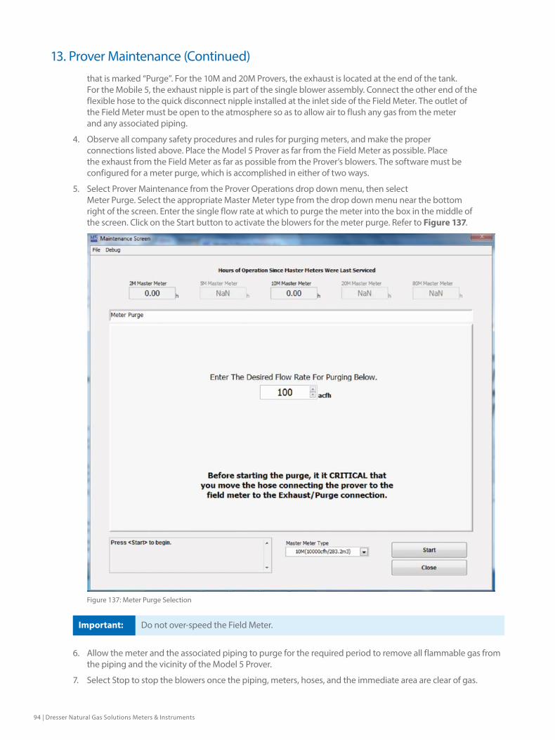
94 | Dresser Natural Gas Solutions Meters & Instruments
that is marked “Purge”. For the 10M and 20M Provers, the exhaust is located at the end of the tank. For the Mobile 5, the exhaust nipple is part of the single blower assembly. Connect the other end of the flexible hose to the quick disconnect nipple installed at the inlet side of the Field Meter. The outlet of the Field Meter must be open to the atmosphere so as to allow air to flush any gas from the meter and any associated piping.
4. Observe all company safety procedures and rules for purging meters, and make the proper connections listed above. Place the Model 5 Prover as far from the Field Meter as possible. Place the exhaust from the Field Meter as far as possible from the Prover’s blowers. The software must be configured for a meter purge, which is accomplished in either of two ways.
5. Select Prover Maintenance from the Prover Operations drop down menu, then select Meter Purge. Select the appropriate Master Meter type from the drop down menu near the bottom right of the screen. Enter the single flow rate at which to purge the meter into the box in the middle of the screen. Click on the Start button to activate the blowers for the meter purge. Refer to Figure 137.
Figure 137: Meter Purge Selection
Important: Do not over-speed the Field Meter.
6. Allow the meter and the associated piping to purge for the required period to remove all flammable gas from the piping and the vicinity of the Model 5 Prover.
7. Select Stop to stop the blowers once the piping, meters, hoses, and the immediate area are clear of gas.
13. Prover Maintenance (Continued)
Dresser Model 5 Prover Software Manual NGS.MI.0035 | 95
13.6 Maintenance Recommendations
To maintain a high standard of accuracy for the Prover, it is strongly recommend that the complete proving system be returned to the factory for Remanufacture & Recertification using one or more of the following criteria:
1. As dictated by State regulatory agency or Company procedure.
2. Every three to five years, depending upon Prover system condition and frequency of use.
3. Check the Master Meter differential against the original factory differential curve supplied with the new or recertified Master Meter. As long as the differential remains within the limit of 1.0” w.c. at 50% of flow (10,000 acfh) of the value shown on the original curve, the meter accuracy is considered unchanged. For the 5M, the differential should not exceed 0.5” w.c. at 50% of flow.
4. Return the Master Meter to the factory for Remanufacture & Recertification if any of the following conditions are applicable: The differential does not meet the criteria in item #3 (above) at any time or after completing the recommended maintenance procedures, or reference Meter tests results consistently exceed ± 0.5% as compared to the original curve.
13.7 Maintenance Check List
13.7.1 Master Meter Inlet ScreenInspect the Master Meter inlet screen prior to each test.
1. Use a vacuum cleaner to remove debris.
2. Always remove the screen from the Master Meter before cleaning with solvent or attempting to clean by blowing with air through the screen.
13.7.2 Master Meter(s)Visually inspect the impellers for damage and dirt build-up a minimum of once each month.
1. Remove from the Prover Cart before cleaning.
2. A clean lint free cloth may be used to wipe contamination from the impellers.
3. Do NOT use any type of solvent to flush dirt from the Master Meter.
4. Blow clean, dry compressed air through the Master Meter.
13.7.3 P&T Adapter and the Field Meter Pressure Adapter and All Master Meter Pressure AdaptersCheck at least once a month for dust, moisture or contamination.
1. Seal the non-quick disconnect end of the Adapter(s).
2. Apply a pressure of 10 inches of water column to the quick disconnect end of the Adapter(s).
3. Quickly open the sealed end of the Adapters and record time.
4. Record the time when the pressure in the previously sealed end is equal to ambient pressure.
5. If the time between steps 4 and 3 is less than two (2) minutes, the Adapter is in good condition. If the time is greater than two (2) minutes, replace the Adapter.
Reference Meter Testing
Caution: Unplug the extension cord from the Controller.
1. Use a Reference Meter as a standard to monitor the Prover system for changes that could affect test results. The documented history of performance is the baseline for continuous comparisons.
2. When inspecting and characterizing the performance of the Master Meter(s), compare and plot the results against the historical baseline with an acceptable tolerance (i.e., ± 0.55%)
3. Perform the Reference Meter test on an occasional basis (weekly, monthly, etc.) to ensure Proper prover system condition and repeatability. Run tests any time Field Meter tests are consecutively out of tolerance or there is the suspicion of problems.
13. Prover Maintenance (Continued)

96 | Dresser Natural Gas Solutions Meters & Instruments
4. The Reference Meter should be inspected and its performance characterized at least once every six (6) months by an independent verification agency to ensure the proper operation of the Model 5 Prover.
NOTE: The following Blower Inspection Instructions do not apply to the large blowers for the 20M or 80M Provers. Those blower motors should be inspected and maintained by fully trained and qualified personnel.
13.7.5 Blowers
Caution: Turn the Controller power “OFF” and remove Master Meter(s).
1. Inspect the tightness of the Blower armature brush caps at least once every three (3) months. Carefully re-tighten the brush caps if they are loose, or replace. Switch blower plug connection to the controller once a month to ensure equal wear on both blower brushes.
2. Inspect the armature brushes for wear at least every 400 hours of operation, or as required by apparent changes in sound and arcing. A significant increase in heat can be generated by brushes less than 1/2 inch in length, increasing current and resulting in a premature failure of the blower(s).
3. Remove brush and measure length of square carbon. It should be 1/2” or longer. If not it must be replaced.
4. Install the brush.
5. Re-attach the armature brush caps.
6. Exchange #1 blower to #2 blower each month for averaged usage on the main blower #1.
7. Turn each Blower off by moving its individual power switch to the “OFF” position.
8. Unplug each Blower power cord from the Blower ports (labeled “BLOWER 1” and “BLOWER 2”) on the Controller.
9. Plug each Blower power cord (one at a time) into a 120 VAC electrical power source.
10. Turn the corresponding Blower power switch to the “ON” position.
11. The Blower motor bearings are good if the motor sounds “smooth”.
12. Repeat the above steps (1 through 11) for the other Blower.
13.7.6 Prover Cart10M Only1. Check the air pressure in the Prover Cart’s tires at least once a year. Maintain tire pressure at 30 psig.
All Provers2. Clean the frame, wheels, tool box, and exterior surfaces of the Master Meter(s) with a damp cloth and
compressed air, as needed.
3. Inspect the inside of the Silencer(s) at least once every three (3) months for obstructions and loose noise absorbing material.
4. Inspect all cables for frays. Replace as required.
13.7.7 Accessories1. Inspect all flexible hoses, caps, and plugs for damage. Replace as required.
2. Clean the quick-disconnect couplings once every three (3) months using a degreaser. If the quick disconnect is removed from the Master Meter, apply a thin film of aluminum anti-seize compound on the male threads before reinstalling.
3. Once a month, inspect all electrical cables for damage and to ensure that the connectors are clean and pins/contacts are straight.
4. Inspect the Instrument Drive (ID) Pulser for damage prior to and after each use.
5. Inspect the Optical Scanner for damage prior to and after each use.
13. Prover Maintenance (Continued)
Dresser Model 5 Prover Software Manual NGS.MI.0035 | 97
13.8 Common Operation Problems
13.8.1 Prover doesn’t stabilize at the proper Flow Rate For 2M/10M, 10M portion of 80M SystemsThe most likely cause would be a problem with the valve mechanism. Some examples of this include a sticking solenoid, valve, or valve linkage; a worn, damaged, or improperly adjusted valve linkage; or an obstruction in the valve, valve piping, meter(s), silencer, or hose(s). A malfunction by the Blower or the Blower’s Controller may also be the cause. For suspected Blower problems, try swapping the Blower power cords where they connect into the Controller. Try turning the Controller off and then back on to reset the electronics. Then reconfigure or reselect the test settings, restart, and rerun the test. Flow Rate surging is typically due to insufficient back pressure in the system, which causes the valves to open too far. Blowers at maximum power usually means that there is a restriction somewhere in the system or that the solenoid-operated butterfly valve is not opening properly.
For Mobile 5M, 20M/5M and 80M portion of 10M/80M SystemsThe most likely cause is a malfunction in the motorized gate valve, slip clutch, or gear reduction mechanisms. Turning the power switch off and then back on causes the Controller to energize the valve positioning motor to close the gate valve. The slip clutch must not slip until the gate valve is fully closed. Once the valve closes, the slip clutch should slip for several seconds.
One or more of the Blowers comes on without initiating a test The Blower(s) are controlled by the electronics in the Controller. If one of the triacs controlling the Blower(s) operation shorts or leaks, the Blower may start or run faster than it is supposed to. Usually turning the Controller off, waiting a few seconds, then turning it back on will correct the problem. If the problem persists, contact the factory for assistance.
13.8.2 The test stops shortly after the Blowers start (the Blowers start and then stop almost immediately) If the Controller gets no indication that the Master Meter’s impellers have started rotating, the Controller will stop the test once the Blowers start. No error messages appear but the test ends with no indication other than that the Blowers have stopped. This commonly occurs after a Leak Test if the seal at the inlet of the Field Meter was not removed. The error could also occur upon initial start up if the shipping seals have not been removed from the Master Meter(s) and the air exhaust(s) port. It could also occur if debris or trash restricts air flow or locks up the Master Meter. Insufficient power can also cause this problem.
13.8.3 The Prover software or the computer locks upIf this happens, make note of where and how the malfunction occurred and what keys were pressed. Be able to describe exactly what appeared on the screen before and after the problem occurred. Try turning the computer and the Controller off, wait several seconds, and turn both of them back on again; then attempt to duplicate the problem. Make certain that at least 32 megabytes of RAM memory are available to the Prover software. Try opening other software programs that are installed on the computer (for example a spreadsheet or a word processing program) to verify that the computer is fully functional. If the computer itself does not appear to be the problem, try reinstalling the Prover software from the original disk (or the backup of the original disk). If the problem persists, contact the factory for assistance.
13.8.4 Accuracy is out of specification The accuracy will not be what it is supposed to if the Field Meter needs servicing. Factors that affect the accuracy of a transfer Prover include the length and volume of the hose, elbows, and transitions; the size and interaction between the Field and Master Meters; where the pressures and temperatures are measured; and the stability of the testing environment. Pressure pulsations commonly occur when transfer testing Field Meters. These pulsations or resonant points can be rather pronounced at certain flow rates under otherwise normal operating conditions. The effects of these resonant points can be minimized by increasing or decreasing the flow rate slightly. Acoustical filters are available to reduce or eliminate the effects of pulsations and resonance. Contact the factory for details.
13. Prover Maintenance (Continued)

98 | Dresser Natural Gas Solutions Meters & Instruments
13.8.5 Accuracy varies when conducting outdoor meter testingAn unstable operating environment can have a noticeable effect on meter test results. The most common effect can be seen when testing meters outside in direct sunlight. The sun’s warmth can heat the air traveling through the Flexible Hose so that by the time the air reaches the Master Meter, an increase of 20 degrees Fahrenheit is quite possible. The Master Meter may remain very close to the ambient air temperature and change only very slowly, while the temperature of the air traveling through the Flexible Hose fluctuates rapidly as clouds, wind, and/or shade affect it. The measured Master Meter temperature, even though situated in the center of the air stream, may not exactly match the actual temperature of the measured volume inside the Master Meter’s measuring chamber. These effects can be reduced significantly by shading the Flexible Hose and insulating it as much as possible from dramatic temperature changes above or below ambient conditions.
13.9 Troubleshooting Error Messages
“FAILURE TO REACH FLOW RATE”This error appears in the upper right corner of the test screen if the Controller has not reached the configured flow rate within a specified amount of time after the Master Meter temperature has stabilized. Possible causes are that the Blower(s) are not turned on or plugged into the Controller; or that there is a restriction in the piping, meters, the silencer, or the Flexible Hose(s). Check and clean the screens at the inlet of the Master Meter(s) regularly. Problems with the valves, the valve solenoid, or valve linkages may also generate this error. Make sure the connector plug from the valve solenoid is attached into the Controller at the connector labeled THROTTLE VALVE. Notice what the displayed flow rate actually is to determine whether or not a problem exists. The appearance of this message does not prevent the start of a test, nor does it necessarily mean there is a problem with the Prover. It merely indicates that it took longer than the typical amount of time to reach the desired flow rate.
“CAUTION: TEST DURATION BELOW RECOMMENDED 30 SECOND MINIMUM”This message displays any time a meter test is configured and/or completed where the test duration is less than 30 seconds. It is merely a reminder that the best results are obtained using tests that are configured to run for at least 30 seconds in duration. The test data is sampled once each second, so a test lasting at least 30 seconds yields better results than tests of a shorter duration.
“WARNING”This message appears under any one of the temperature or meter pressure transducer displays in the Meter Test Screen. If this error displays it means that the transducer’s output exceeded the “normal” limits of the transducer’s operation. If more than one Flexible Hose is connected between the Field and Master Meters, or if a restriction in the hose develops, etc., this message will appear. This is only an indication that a problem may exist, not that a transducer has failed. Once this message appears, it does not go away until the next configured test starts or until the current configured test is restarted. The test continues, and the results are calculated using the averaged test data regardless of the appearance of the message. Refer to Pressure Reasonability Settings in the Help Directory for additional information. Contact the factory for assistance if necessary.
“FATAL ERROR”This message appears under any one of the temperature or meter pressure transducer displays in the Meter Test Screen. This message will appear when the transducer’s value, immediately above the displayed message, is beyond the operable limits of the individual transducer. Once the message appears it forces the termination of the current test. The condition must be corrected before proper operation of the system may resume. Contact the factory for assistance if necessary.
“COMMUNICATION ERRORS”This message displays during the running of a test. The software monitors the data transmissions from the Controller to the computer. If for any reason even one of these one-second interval data transmissions is not received or is not processed properly, this message will appear in the middle of the screen. The message will remain on the screen, through the up to 6 individual test runs, until the software clears the currently displayed screen. The message appears and remains even if only one transmission was not processed out of hundreds. Occasional displays of this message can be considered acceptable. The test can continue and it should complete normally; however, Dresser Meters & Instruments recommends repeating tests where this message has appeared. Missed data transmissions that occur during an actual test will advance the error message’s counter, while the
13. Prover Maintenance (Continued)

Dresser Model 5 Prover Software Manual NGS.MI.0035 | 99
duration counter is incrementing. Data transmissions that occur outside of an actual test merely display the error message but do not increment the error message’s counter. One out of 30 transmissions should not affect the results significantly. If the error message appears frequently, the source of the problem should be identified and corrected. Contact the factory for assistance.
“A/C INPUT FREQUENCY TO HI/LOW” This message appears whenever the supply power’s frequency varies beyond specified limits. The warning message goes away automatically once the problem is no longer detected by the Controller’s electronic circuitry. This problem typically appears when generators are used as the Prover’s power source.
13. Prover Maintenance (Continued)
© 2018 Natural Gas Solutions North America, LLC – All rights reserved. Natural Gas Solutions reserves the right to make changes in specifications and features shown herein, or discontinue the product described at any time without notice or obligation. Contact your Dresser Natural Gas Solutions representative for the most current information. The Dresser Logo and all Trademarks containing the term “Dresser” are the property of Dresser, LLC, a subsidiary of Baker Hughes, a GE Company. www.dresserngs.com
Dresser Model 5 Prover Software Manual NGS.MI.003511.18
Dresser Meters & Instruments
16240 Port Northwest DriveHouston, TX 77041T: 1-800-521-1114F: 1-800-335-5224