Dresser Chatterbox-e Pulse Isolation Unit
12
Dresser Chatterbox-e + Pulse Isolation Unit Model 103 Operating and Installation Handbook
-
Upload
khangminh22 -
Category
Documents
-
view
0 -
download
0
Transcript of Dresser Chatterbox-e Pulse Isolation Unit

Dresser Chatterbox-e+ Pulse Isolation UnitModel 103 Operating and Installation Handbook

2

3
THESE INSTRUCTIONS PROVIDE THE CUSTOMER/OPERATOR WITH IMPORTANT PROJECT-SPECIFIC REFERENCE INFORMATION IN ADDITION TO THE CUSTOMER/OPERATOR’S NORMAL OPERATION AND MAINTENANCE PROCEDURES. SINCE OPERATION AND MAINTENANCE PHILOSOPHIES VARY, DRESSER NATURAL GAS SOLUTIONS (NGS) DOES NOT ATTEMPT TO DICTATE SPECIFIC PROCEDURES, BUT TO PROVIDE BASIC LIMITATIONS AND REQUIREMENTS CREATED BY THE TYPE OF EQUIPMENT PROVIDED.
THESE INSTRUCTIONS ASSUME THAT OPERATORS ALREADY HAVE A GENERAL UNDERSTANDING OF THE REQUIREMENTS FOR SAFE OPERATION OF MECHANICAL AND ELECTRICAL EQUIPMENT IN POTENTIALLY HAZARDOUS ENVIRONMENTS. THEREFORE, THESE INSTRUCTIONS SHOULD BE INTERPRETED AND APPLIED IN CONJUNCTION WITH THE SAFETY RULES AND REGULATIONS APPLICABLE AT THE SITE AND THE PARTICULAR REQUIREMENTS FOR OPERATION OF OTHER EQUIPMENT AT THE SITE.
THESE INSTRUCTIONS DO NOT PURPORT TO COVER ALL DETAILS OR VARIATIONS IN EQUIPMENT NOR TO PROVIDE FOR EVERY POSSIBLE CONTINGENCY TO BE MET IN CONNECTION WITH INSTALLATION, OPERATION OR MAINTENANCE. SHOULD FURTHER INFORMATION BE DESIRED OR SHOULD PARTICULAR PROBLEMS ARISE WHICH ARE NOT COVERED SUFFICIENTLY FOR THE CUSTOMER/OPERATOR’S PURPOSES THE MATTER SHOULD BE REFERRED TO DRESSER.
THE RIGHTS, OBLIGATIONS AND LIABILITIES OF DRESSER AND THE CUSTOMER/OPERATOR ARE STRICTLY LIMITED TO THOSE EXPRESSLY PROVIDED IN THE CONTRACT RELATING TO THE SUPPLY OF THE EQUIPMENT. NO ADDITIONAL REPRESENTATIONS OR WARRANTIES BY DRESSER REGARDING THE EQUIPMENT OR ITS USE ARE GIVEN OR IMPLIED BY THE ISSUE OF THESE INSTRUCTIONS.
THESE INSTRUCTIONS CONTAIN PROPRIETARY INFORMATION OF DRESSER, AND ARE FURNISHED TO THE CUSTOMER/OPERATOR SOLELY TO ASSIST IN THE INSTALLATION, TESTING, OPERATION, AND/OR MAINTENANCE OF THE EQUIPMENT DESCRIBED. THIS DOCUMENT SHALL NOT BE REPRODUCED IN WHOLE OR IN PART NOR SHALL ITS CONTENTS BE DISCLOSED TO ANY THIRD PARTY WITHOUT THE WRITTEN APPROVAL OF DRESSER.
4
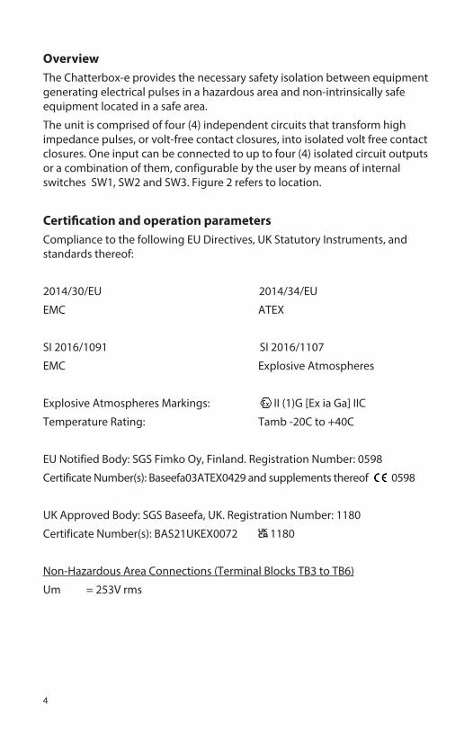
OverviewThe Chatterbox-e provides the necessary safety isolation between equipment generating electrical pulses in a hazardous area and non-intrinsically safe equipment located in a safe area.
The unit is comprised of four (4) independent circuits that transform high impedance pulses, or volt-free contact closures, into isolated volt free contact closures. One input can be connected to up to four (4) isolated circuit outputs or a combination of them, configurable by the user by means of internal switches SW1, SW2 and SW3. Figure 2 refers to location.
Certification and operation parametersCompliance to the following EU Directives, UK Statutory Instruments, and standards thereof:
2014/30/EU 2014/34/EU
EMC ATEX
SI 2016/1091 SI 2016/1107
EMC Explosive Atmospheres
Explosive Atmospheres Markings: II (1)G [Ex ia Ga] IIC
Temperature Rating: Tamb -20C to +40C
EU Notified Body: SGS Fimko Oy, Finland. Registration Number: 0598
Certificate Number(s): Baseefa03ATEX0429 and supplements thereof 0598
UK Approved Body: SGS Baseefa, UK. Registration Number: 1180
Certificate Number(s): BAS21UKEX0072 1180
Non-Hazardous Area Connections (Terminal Blocks TB3 to TB6)
Um = 253V rms

5
Hazardous Area Connections (Terminal Blocks TB1)
Uo = 3.9V Ui = 7.4VIo = 17mA Po = 17mW Co = 100µF Ci = 0Lo = 122mH Li = 0.5mHLo/Ro = 1500µH/Ω
InstallationMounting
The Chatterbox-e must be installed in a safe area and is suitable for
connection to equipment in hazardous areas Zone 0, 1 or 2.
The instrument can be wall or panel mounted. Tapped M6 panel mounting holes can be found on the rear of the enclosure. Mounting Hole Pattern figure 1 refers.
The instrument can also be fixed from the front. Remove the cover (4 off cap head screws, 3mm hex key) and use M4 screws or No.6 screws if fixing to wood, passing them through the tapped holes.
Alternatively “quick fix” brackets, Dresser part number MP136, can be attached to the rear of instrument allowing fitment without the need to pre-drill mounting holes or the removal of the front cover. Please note that using the “quick fix” brackets will add an additional 10mm to the overall depth of the instrument.
Figure 1 –Fixing dimensions
Fixing Dimensions (Standard enclosure) Fixing Dimensions (with optional ‘quick fix’ brackets) Please note the depth of the intallation increased by 10mm (3/8”)

6
Electrical ConnectivityMounted with the cable entry glands to the bottom, pass the multi-way input cable (from meter or corrector) through the left hand cable gland and connect to the Input (I/P) terminal block. It is recommended to use screened signal cables. Each I/P requires the equivalent of a contact closure between common and one of the I/P signal terminals marked 1 to 4. Unused I/P signal terminals should be left disconnected to minimise battery consumption.
WARNINGOnly positive voltages are permitted at inputs 1 to 4 when connecting active pulse devices.
Please note that some meter manufacturers short unused pins on their pulser unit. It is therefore advised that only the two wires relating to the LF switch are connected to the Chatterbox-e input circuit as described above, and any remaining wires from the manufacturers cable assembly are NOT connected, as connecting permanently shorted wiring will significantly decrease the battery life of the Chatterbox-e.
Using either or both of the remaining two cable glands, use multi-way cable to wire to the output (O/P) terminal blocks. Take the O/P signal pulses to the customers Logger/Energy Management System. Each Terminal block O/P 1 to 4 is an open collector type output. One I/P can be connected to up to four (4) isolated circuit O/P or a combination of them, configurable by the customer by means of internal switches SW1, SW2 and SW3. Figures 2 and 3 refer.
Figure 2 –Electrical Connectivity

7
Activated O/P
IP
1 1 1,2 1,2 1,2,3 1 1 1 1,2,3,4
2 2 – – – 2 2,3 2,3,4 –
3 3 3 3,4 – 3,4 – – –
4 4 4 – 4 – 4 – –
Switch
SW1 ▼ ▲ ▲ ▲ ▼ ▼ ▼ ▲
SW2 ▼ ▼ ▼ ▲ ▼ ▲ ▲ ▲
SW3 ▼ ▼ ▲ ▼ ▲ ▼ ▲ ▲
Switch Position
Figure 3 –
Note: Outputs marked “–” maybe active but repeat a connection already made and therefore not shown.
CommissioningCheck that incoming signals are connected correctly and switch positions are set to activate the desired outputs. Figures 2 and 3. Replace the cover.
MaintenanceThere are no replaceable / serviceable parts with exception of the batteries.
Battery type: Tadiran SL750/S ½ AA Lithium 3.6V cells. Part number EB025. Observe correct polarity and always replace as a pair. No alternatives are acceptable as this will invalidate the Intrinsic Safety approval for the device.

8
Technical Specifications
Intrinsic safety
Baseefa03ATEX0429, BAS21UKEX0072 II (1)G [Ex ia Ga] IIC. The Chatterbox-e must be installed in the safe area and is suitable for connection to equipment in hazardous areas Zone 0, 1 or 2.
Power
Tadiran SL750/S ½ AA Lithium cells. Part number EB025. Estimated battery life is in excess of 10 years based on all four channels operating and an input frequency of <1 Hz.
Enclosure
Weatherproof aluminium enclosure IP66 rated (equivalent to NEMA 4x) suitable for wall or panel mounting.
Size: 160mm Wide x 120mm High (including cable NG12 glands) x 62mm Deep.
Input Signal I/P
Each input is designed to interface with the current sinking telemetry outputs from Dresser converters and other manufacturers of gas flow converters. The input will also interface directly with a volt-free contact closure, i.e., directly to a gas meter output. Contact de-bouncing is standard.
WARNINGOnly positive voltages are permitted at inputs 1 to 4 when connecting active pulse devices.
Output Signal O/P
Each output is approximately a 220ms pulse, current sinking, capable of ac-cepting up to 30Vdc, 130mA. Circuit is open when off, approximately 100ohm during the pulse.
The O/P connection is not polarity sensitive.

9
!
O/PGND
INPUT
SHIELDGND
Chatterbox-e Logger/EMS
+
+
O/PGND
VDCINPUT
SHIELDGND
Chatterbox-e Logger/EMS
+10KOHMS
Figure 4
Example connection.
A user supplied 5Vdc Logger/Energy Management System (EMS) can be connected to the output.
It may be necessary to fit a pull up resistor, typically 10k, and voltage supply if such is not included as standard as part of the internal circuit of the Logger/EMS.
When the Chatterbox-e pulses, the switch is made and the current momentarily sinks which triggers the users Logger/EMS device to register. Figure 4 refer.

10
Dresser Micro Series Products
Other Dresser Electronic Products:
Micro Converter.
Dresser Utility Solutions also offers a wide range of Natural Gas Solutions products such as: Rotary Meters, Control and Regulation Valves, and Pipeline Products.
Please visit our website for further information.

11
12
Recycling and Disposal
Disposal instructions for old products.
The WEE directive (Waste Electrical and Electronic Equipment; 2012/19/EU) has been put in place to ensure that products are recycled using best available treatment, recovery and recycling techniques to ensure human health and high environmental protection.
The Model 103 Chatterbox-e is designed and manufacture with high quality materials and components, which can be recycled and re-used.
Do not dispose of the Model 103 Chatterbox-e in the general waste bin. Please find out about the local separate collection system for electrical and electronic products marked by this or a similar symbol:
Please use one of the following disposal options:
1. Dispose of the complete Model 103 Chatterbox-e in the designated WEEE collection facilities.
2. If you purchase a replacement Model 103 Chatterbox-e or similar product from Dresser Utility Solutions UK, send us your complete Model 103 Chatterbox-e back to us or distributor/agent who should accept it as required by the WEEE directive.
© 2021 Natural Gas Solutions North America, LLC – All rights reserved. Dresser Utility Solutions reserves the right to make changes in specifications and features shown herein, or discontinue the product described at any time without notice or obligation. Contact your Dresser Utility Solutions representative for the most current information. The Dresser Logo and all Trademarks containing the term “Dresser” are the property of Dresser, LLC, a subsidiary of Baker Hughes. www.dresserutility.com
Chatterbox-e Operating Handbook NGS.MI.0089d05.21
Dresser Utility Solutions UK201 Mere GrangeLeasideSt HelensMerseyside, UKWA9 5XH T: +44 (0) 3330 164 360E: [email protected]