Synchronization of pulse code modulation telemetry
82
Scholars' Mine Scholars' Mine Masters Theses Student Theses and Dissertations 1968 Synchronization of pulse code modulation telemetry Synchronization of pulse code modulation telemetry Lawrence J. Mueller Follow this and additional works at: https://scholarsmine.mst.edu/masters_theses Part of the Electrical and Computer Engineering Commons Department: Department: Recommended Citation Recommended Citation Mueller, Lawrence J., "Synchronization of pulse code modulation telemetry" (1968). Masters Theses. 5258. https://scholarsmine.mst.edu/masters_theses/5258 This thesis is brought to you by Scholars' Mine, a service of the Missouri S&T Library and Learning Resources. This work is protected by U. S. Copyright Law. Unauthorized use including reproduction for redistribution requires the permission of the copyright holder. For more information, please contact [email protected].
-
Upload
khangminh22 -
Category
Documents
-
view
1 -
download
0
Transcript of Synchronization of pulse code modulation telemetry

Scholars' Mine Scholars' Mine
Masters Theses Student Theses and Dissertations
1968
Synchronization of pulse code modulation telemetry Synchronization of pulse code modulation telemetry
Lawrence J. Mueller
Follow this and additional works at: https://scholarsmine.mst.edu/masters_theses
Part of the Electrical and Computer Engineering Commons
Department: Department:
Recommended Citation Recommended Citation Mueller, Lawrence J., "Synchronization of pulse code modulation telemetry" (1968). Masters Theses. 5258. https://scholarsmine.mst.edu/masters_theses/5258
This thesis is brought to you by Scholars' Mine, a service of the Missouri S&T Library and Learning Resources. This work is protected by U. S. Copyright Law. Unauthorized use including reproduction for redistribution requires the permission of the copyright holder. For more information, please contact [email protected].

SYNCHRONIZATION OF PULSE CODE
MODULATION TELEtvlilJI'RY
By
Lavrrence J. Muelle:;;. I 't39
A
THESIS
submitted to the £aculty of
THE UNIVERSITY OF :MISSOURI AT ROLLA
in partial fulfillment of the requirements for the
Degree of'
MASTER OF SCIENCE IN ELECTRICAL ENGINEERING
Rolla, Missouri
1968 • 1329j_O
Approved by

ii
~TRACT
Pulse Code Modulation (PCM) is one of the most widely utilized
radio telemetry techniques for the recovery of test data from aero-
space vehicles. Synchronization of the receiver with the transmitted
data is perhaps the prime requisite of a PCM telemetry system.
In this paper the frame synchronization process is analyzed by
developing equations which define the three modes of synchronizer
operation (SEARCH~ VERIFY, and LOCK) in terms of the relative proba-
· ·bilities of operation. The criteria employed to optimize the
synchronization process are the mean time to acquire true synchro-
nization~ the probability of true synchronization after verification
of the synchronization decision~ and the percentage of data lost due
to synchronization dropout (the dropout resulting from noise in the
received signal). The results of this analysis are used to derive
optimum synchronization system parameter settings for a hypothetical
telemetry system. The problem of deriving an optimum PCM synchroniza-
tion code is also presented. It is based on the criteria of minimum •
probability of false occurrence of the pattern in the received signal.
Prior to discussing the frame synchronization problem, a general
description of a typical airborne PC:M; telemetry system is made. Also~
a brief description of bit synchronization and data regeneration
techniques and their affect on the frame sync problem is included.
--iii
· TABLE OF CONTENTS
Abstract •. ....................................................... ii
Table of Contents •••••••••••••••••••••••••••••••••••••••••••• iii
List of Figures . ............................................. . iv
List o:r Tables • ............................................... v
I. Introduction ••••••••••••••• · •• . ....................... . l
II. General Description of a Typical PCM Airborne Te~emetry System .••••••.•••.•••••.••••.•.••.•••••••••• 4
A. Data Transmission ••• . . . . . . . . . . . . . . . ...... , .... . 4
B. Data Recovery •••••••••.•••••••••••••••••••.•••••• 19
III. Bit Synchronization ••••••••••••••••••••••••••••••••••• 22
IV • Frame Synchronization ••••••••••••••••••••••••••••••••• 29
A. SEARCH Mode Analysis. . ............................ . 3l
B. VERIFY Mode Analysis • . . . . . . . . . . . . . . . . . . . . . . . . . . . . 42
c. LOCK Mode Analysis •• . . . . . . . . . . . . . . . . . . . . . . . . . . . . . 48
v. Frame Sync Patterns ••••••••••••••••••• . .............. . 55
A. Primary Sync Hord Development •••••••••••••••••••• 57
B. Sub frame Sync "\-lord Considerations • . .............. . 70
VI. Concl.us ions • ............................................. 72
Bibliography . ................................................ . 74
Vita •......••.••.... ..•.•••..•......•..........•.•......•.....
Figure
J_
2
3
4
5
6
7
8
9
lO
ll
l2
"iy
LIST OF FIGURES
Typical PCM Airborne Telemetry System ••••••••••••••••• 5
Typical PCM Commutation Hatrix ......................... . 7
Analagous Mechanical Switch Representation of the Matrix of Figure 2 •••••••••••••••••••••••••••••••••••• 8
(a) Information Bearing Signal, g(t) ••••••••••••••••• 10
(b) The Sampling Train, s(t) ••••••••••••••••••••••••• 10
(c) Sampled Data Signal, h(t)........................ 10
(a) Fourier Transform of' g(t), G( w) ........ • ••••••••••
(b) Frequency Domain Representation . of s ~V ......... . (c) H(w) for w 0 >2Wl••••••••;••••••••••••••••••••••
(d) H( c.u ) for w 0 = 2"\.Vl ••• • • • • • • • • • • • • • • • • • • • • • • • • • • •
13
13
13
14
(e) H(w) for w 0 < 21·71 •••••••••••• •• • • • • • • • • • • •••••••• 14
(f) Transfer Function of Ideal Low Pass Filter....... 14
PCM Bit Code Representations ••••••••••••••••••••••••••
Theoretical Bit Error Probability vs S/N Ratio ••••••••
PCM Bit Syr.tchronizer •••••••••••••••••••••••••••••••••• •
Phase-Locked Oscillator Loop ••••••••••••••••••••••••••
Probability of' True Sync Detection (P c) and False Sync Detection in n Random Bits· (Pf) vs Number of Sync Pattern Bits ( n) and Allowable N1...1Iriber of ].!:r-rors ( E ) • • • • • • • • • • • • • • • • • .• • • • • • • • • • • • • • • • • • • • • • • •••
Replot of Figure lO with Variables Interchanged •••••••
Pf vs F and b .•••••••.••.••••••••••••••••••••.••••.•••
18
23
25
26
35
37

Table
I
III
v
VI
VII
VIII
X
XI
XII
LIST OF TABLES
Pf' - Probability of False Sync in .Any n Bit Random Data Word Allowing E Errors ••••••••••••••••••••• 34
SEARCH Mode Parameters (b = 479; ~ = 3, p = 0.1, PCM word length= 8 bits) •••••••••••••••••••••••••••••• 40
Error Tolerance in the SEARCH Mode (n = 24, b = 479, p = 0.~) ••••••••.••••..••.• ~ •••••••••••.•••••. 41
Error Tolerance f'or Varying Bit Error Probabilities 43 (n = 24, b = 479, p = o.ol, o.ool) •••••••••••••••••••••
R, Ratio of False to True VERIFY Mode Probabilities (n = 24, b = 479, E = 3, p = O.l) ........................ .
Pt , Probability of Leaving the SEARCH and VERIFY sc Modes with the True Sync Decision (n = 211-, b = 479, E = 3, p = 0.01) •.••.•..•••...••••••••••.•.•••••..••••.
LOCK Mode Analysis (n = 24, b = 479, p = 0.01, j = 2, Ev = 5)•••••••••••••••••••··~··••••••••••••••••• LOCK Mode Analysis with Varying Bit Error Rates (n = 24, b = 479, j = o, p = o.ol, 0.001) ••••••••••••••
Normalized False Sync Probabilities (p = 0.1) ••••••••••
Number of Conflicts Required :for Rm < 1.0 in Each Overlap Condition ••••••••••••••••••••••••••••••••••••••
Sync Pattern Bit Relationships for Co~licts in Each Degree of' Overlap •••••••••••••••••••••••••••••••••
Rm( ~ = 3) :for the Sync Word 663745248 •••••••••••••••••
46
48
52
54
60
64
v

I. INTRODUCTION
In PCM telemetry systems it is necessary to attain both bit and
frame synchronization (hereafter the word synchronization will
frequently be abbreviated as "syncu) before received data may be
identified. It is the primary purpose of' this thesis to:
A. Develop expressions which d~fine the three modes of' opera
tion (SEARCH, VERIFY, and LOCK) in acquiring frame sync.
l
B. Utilize these expressions to determine.optimum frame
synchronizer system parameters based. upon operating criteria
within each of the three operating modes.
C. Develop a set of equations required for determining frame
sync patterns for PCM telemetry systems.
Additionally~ in this thesis a typical PCM telemetry system and
the problem of bi.t sync will be discussed.
The subjects of PCM sync and frame sync code evaluation have
been presented in many technical papers. There has been lacking,
however J a uniform approach for handling a variety of such problems •
Also, a simple method of generating a gooq sync pattern has not been
presented to date.
These problems will be attacked from a system design engineering
standpoint. The results are intended to provide a guide which may

be used in telemetry ground station development or utilization.
Much of' the basic ground"7ork concerning frame sync and f'ram.e sync
patterns was presented at the 1961 and 1962 National Telemetry
Conferences. E. R. Rill and J. L. Weblemoe1 presented results and
recommendations from a comprehensive study. The significant conclu-
sions concerning frame sync are:
A. A single frame sync pattern in each frame is sufficient to
obtain frame sync. Word. sync patterns are unnecessary and
·tend to waste information capacity.
B. A dual-mode sync system containing a search and lock mode is
recommended.
M. W. Williard2 considered the problem of' S:YJlChronization using
both word and frame sync patterns and presented charts f'or calculat-
ing the probability of' sync pattern detection. In subsequent papers
Williard3' 4 developed equations f'or evaluating PCM sync in terms of'
the mean or average time required to acquire sync and the percentage •
data lost due to loss in pattern sync employing a dual-mode sync
system. He also presented. a paper outlining a method. of evaluation
of sync code patterns4 based on the criteria of mdnimum probability
of false occurrence of the pattern in the received signal.
G. E. Goode and J. L. Phillips5 discussed the group sync problem
with particular emphasis on the selection of' optimum sync codes for
correlation detection; In the,l,962.NT.C; Goode and Phillips6 gave a
description and the performance characteristics of a frame sync
pattern generator and recognizer which they had developed.
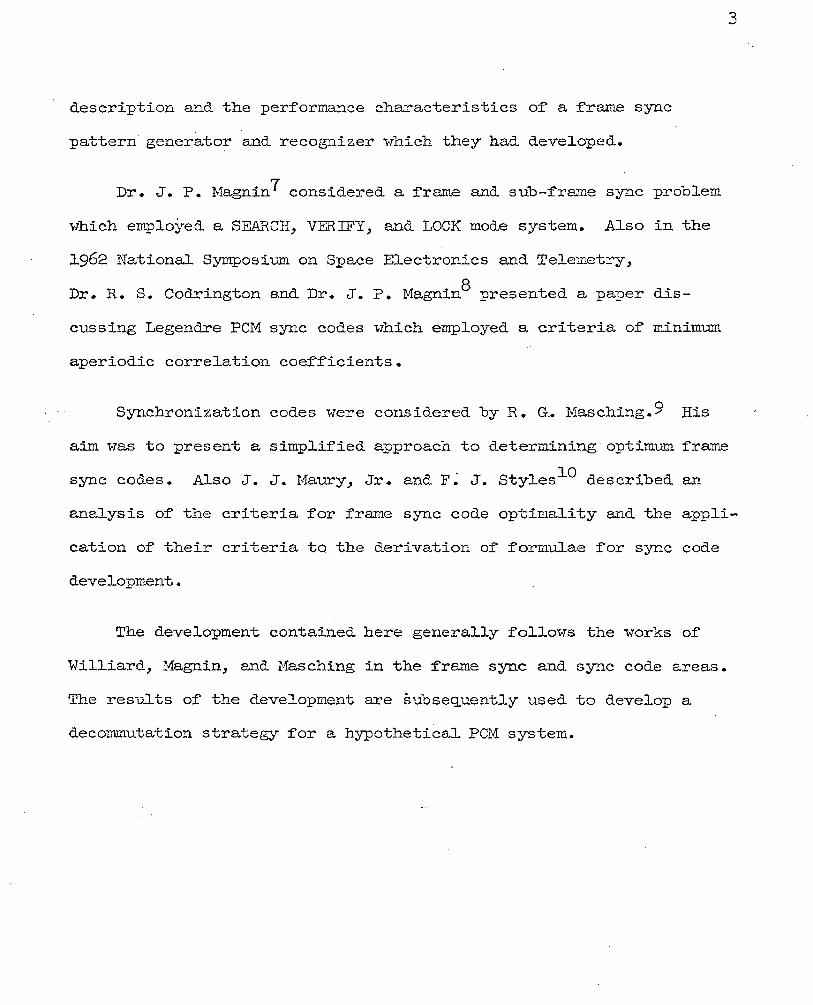
Dr. J. P. Magnin7 considered a frame and sub-frame sync problem
which employed a SEARCH, VERIFY, and LOCK mode system. Also in the
1962 National Symposium on Space Electronics and Telemetry,
Dr. R. s. Codrington and Dr. J. P. Magnin8 presented a paper dis-
cussing Legendre PCM sync codes which employed a criteria of minimum
aperiodic correlation coefficients.
3
Synchronization codes were considered by R. GA Masching.9 Ris
aim was to present a simplified approach to determining·optimum frame
sync codes. Also J. J. Maury, Jr. and F~ J. Styles10 described an
analysis of the criteria for frame sync code optimality and the appli
cation of their criteria to the derivation of formulae for sync code
development.
The development contained here generally follows the works of
Williard, Magnin, and Masching in the frame sync and sync code areas.
The results of the development are subsequently used to develop a
decommutation strategy for a hypothetical PCM system.

II. GENERAL DESCRIPTION OF A TYPICAL PCM A:rn:BORNE TELEMEl'RY SYSTEM
Telemetry is the process by which a quantitative measurement is
transmitted to a remote location. Pulse Code Modulation (PCM) telem-
etry has emerged as one of' the most popular telemetry forms during
recent years for acquiring test information from aerospace vehicles~
missile weapons systems, and aircra:f'-1?• In PC!-1 a group of binary
digits is used to represent the signal voltage output of a physical
sensor at a given instant of time.
~·
4
A typical PCM airborne telemetry and data recovery system is ·shown
in Figure l. It is composed of': airborne elements ••••• sensors,
conversion circuitry, commutation or multiplex circuitry~ analog-to-
digital converter, premodulation filter, transmitter and antenna;
·ground elements ••••• antenna~ receiver, tape recorder, signal condi-
tioner ~~d bit synchronizer~ frame synchronizer, format translator~
display and/or recording devices.
A. Data Transmission - The elements of the data transmission or
airborne telemetry system are briefly described in.the follow-
ing section.
l. Sensors - Sensors commonly used today are thermocouples~
resistance-bridge temperature sensors, pressure sensors,
strain gages, vibration sensors, accelerometers, gyros,
bio-medical transducers, radiation sensors, and various
other forms of instrumentation.

5
I ---- . -----
INSTR!./- .S!6NfJL f/Nf1L06 PRE- MOD. CONJMU- TO __ FILTER MENT _ ... _.. _ .. PROCESS- DIG/ Tf;L !tNO -- TfJTOR SENSORS lNG ·coNVERTER XMITTER
I
I ·- --8ECEJVER
}-~- -T--Dfl T/1
T!?ANSM/5510~
STORIJGE _S/GNf:JL -H FR/1!VJ£ H' BUFFER
1 t-.J. -COND/- _ · SYNCHRO- f}ND T!ONER NIZER FORM/lT
T/1/j/Yj L 1J TOR
7J75Pl7)Y I-I --c·~~l DC:J/ICE5
·L __ _ -
- -~OAT/1 RECOVERY_-- _ _j FIGURE 1 - Typical PCM Airborne Telemetry System

2. Signal Processing - Conversion circuitry is generally
employed to condition the outputs of' the ins·t.rument
sensors to allmr them to be compatible with the input
range of the analog-to-digital converter.
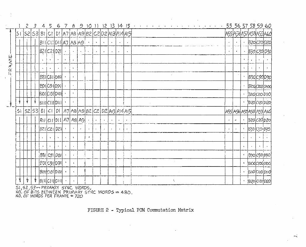
3· Commutation - Basic to a PCM telemetry system is the
multiplex and analog-to-digital conversion circuitry.
An example of' a commutation scheme for the PCM system to
be considered here is depicted in Figures 2 and 3·
Total word output of the system shown is 6000 words/ ~·
second. For an eight bits/word representationJ an over-
all bit rate of' 1~8Jooo bits/sec~md results.
The commutation matrix shm·m in Figure 2 is clarified by
examining the mechanical analog in Figu:re 3. The
primary commutator consists of' 60 segmentsJ each segu~nt
sampled 100 times/second. Thirty of the primary segments
are allocated for subcommutator use. Each subcommutator
consists of 100 segments, ~ach segment samples 10 times/
sec. Other rates between lO and lOO and higher than
100 samples/sec. may be attained by supercommutation,
i.e. symmetrically cross-vriring a parameter to more than
·one segment on a given commutator. The final output of'
primary commutator A is a pulse, amplitude-modulated
waveform (except during sync i·mrd times) • It serves as
an input to tpe analog-to-digital converter.
6
I 2 3 4 5 6 7 B 9 10 II 12 13 14 15
-.-Is !"js2fs31 sdc1l D! fA7fAafA91BzlczfD2~13,Al4,AI5 BIIICIIIDliiA71ABIA9· . I • I •
B2/IC211D21· . I •
(jj
~ ~--1"11 I I I · I · I · I' I · I I I I I I I ,':((
ti ' .1 ' I • I I
B2oiC20ID261
• I • I • ~30IC30ID3d
I): . 881 CSI DSI • I • . • B~C% D~
J 591 C91 091 · · · 6100~100 DlOO
BIOI CIDI DIOI • I • BI!Otl!O D!IO
. 1 BIIICIIIDIII • . I BI20ClZODI2Di
51 ISZ.I53I 81 jell Dl IA7IABIA9IBZ jczl DZIA\3IA14IA15 ..
8\/IC!IIDIIIA71ASIA9·. I. I. I. I.
132/ CZI DZl '
. . . . ..
. . ' I '
BSI CSI PSI . B:71.C91 D9l . i
SI,52)53=PRIMARY SYNC WORDS .. NO. 6F BIT.5 BETWeEN PRltflARY SYNC WORDS= 480. NO. OF WDROS PE.R f"R'AM'E. ~::: 72.0
'.
FIGURE 2 - Typical PCM Commutation Matrix
A55IA?~A57IA5BIA59IA6C
• • , • • 1B20IC201D2o
• I • I t 1B3D IC30 ID?O
I I -1o I •
I 'B'70IC9DI.V9D
• iBr£X1aodmoo • 1BIIOICI!OID1t0
• '8I(O]CI20/0J20
-..:

AS d
Ee
~c
~
~ '/)
~
// ~ ~O ,.--- --~ RPS \
f) . I
I Q I /20
~ SIJ8COMI'I). / SEGIViEI'ITS
• B ' ·~//
/'- --,"' . - -~ \ (.) 8./.RPS \ \t !J I
1 Q i;zo ~ St/8CO/'r?/'.-J, )sErpvJellr.s
& c / /
.. ~~----·/
...--- ··-·- -/ •.
l ~-;gR~ • I IZO
» St.IBCOMIYJ. )5Et:;Mcii'T.S 0 £) /
9 ,/ "'- /' ...,...-· -·-
. --1 ~OUTf>UT
. /"'~--:~·:;;~~iJ;;:~~iS:x':'-....... _ .. "·~ ~ .• .· ..... . ' \ ' • . 'II ' '• .. / . \ .
'""". 41 •, \ \ / .... co f(-' ..
'•tfta '.'\ /~ . •\ ~(', ~ '//'-& c _.., ///• ..---~,
:I • .._.,I : I • 100 I?PS • ; i '
""- •J:, ,,,., •,, '4-;-Q ... !, ~ f'f?IM/1/lY I? 8--f- i I
· \ 0 •M1MIJ71JTO ~-;-e; \ . . (().,,;'/,;' ~' •'\e Ll ,
\_\'\& n ~Ao :'. . '. v ..... '.'
\·~z-t~'tr·;~~> · ~ ..
FIGURE 3 - Analogous Mechanical Switch Representation of the Matrix of Figure 2 (X)
9
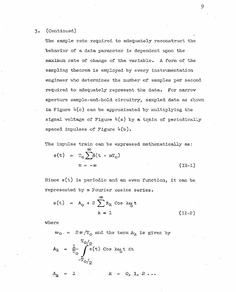
3· (Continued)
The sample rate reQuired to adequately reconstruct the
behavior of a data parameter is dependent upon the
maximum rate of change of the variable. A form of the
sampling theorem is employed by every instrumentation
engineer who determines the number of samples per second
required to adequately ~epresent the data. For narrow
aperture sample-and-hold circuitry, sampled data as sho~m
in Figure 4(c) can be approximated by multiplying the
signal voltage of Figure 4(a) by a t~~in of periodically
spaced impulses of Figure 4(b).
The impulse train can be expressed mathematically as: 00
s(t) = T0 L8(t - nT0 )
n = -oo (II-1)
Since s(t) is periodic and an even function, it can be
represented by a Fourier cosine series.
00
s(t) = A0 + 2 Ll\k Cos ktg t
k=l
where
cv0 . = 27T /T0 and the term Ak is given by
l =
A = .l . . ar
To/2 f s{t)
-To/2
Cos kw t dt 0
k . = q_, .1, 2 ......
(II-2)
lO
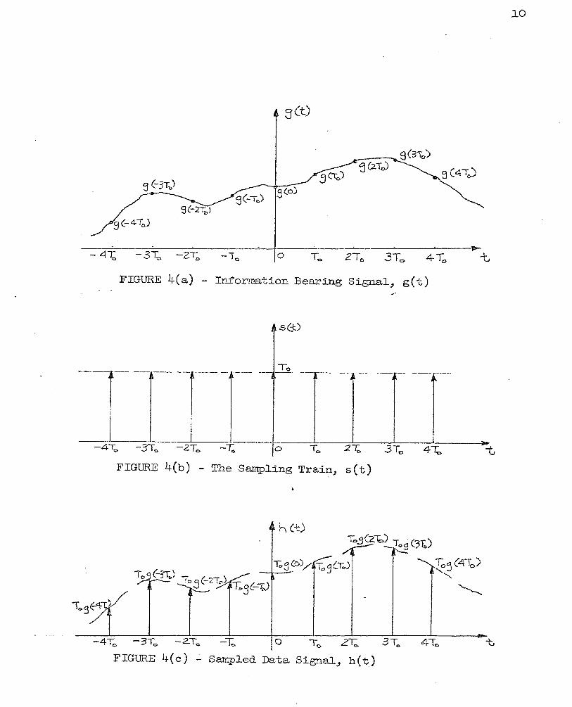
FIGURE 4(a) - Information Bearing Signal~ g(t) ...
s(j:)
--·--- ----- -··- To --r-- ---- ---r-- ---·-r·---· - - --
~ 1'-
.. -41;, -3To -2T0 -1;. 0 To 21;. 3Tc 4""fo
FIGURE 4(b) - The Sampling Train, s(t)
h(t)
-4T0 -3T.,. -2.To. -l: 0 T 0 2~ 3To 4To t
FIGURE 4 (c) .:.. Sampled Data Signal_, h ( t)

ll
3. (Continued)
Thus the function s(t) can be written as
00
s(t) = l + 2 L Cos kw 0 t
k=l (II-3)
For the purpose of this analysis let the information-
bearing signal~ g(t)~ of F.igure 4(a) be defined on the
double infinite interval - oo $ t ~ oo .. Also let its Fourier
·Transform G( w) be such that G( w) = 0 for lwl > "trll•
By sampling g(t) at times t = 0~ +T0 , +2T0~ •••• , the .
waveform h(t) of Figure 4(c) results, v7here
h(t) = g(t) • s(t)
Taking the Fourier Transform of h(t) gives
H(w) = l
27T
(II-4)
(II-5)
To find H( w) ~ the terms G( w) and S( w )/2TT must be
• determined and the indicated convolution performed.
In obtaining the term S ( w ) , the transform of s ( t) is
performed as follows:
S( w) = 00
1[s(t)J = .1f + 2 L Cos kw 0 t J k=l

3·
l2
(Continued) 00
S( w) = 27TS(w) + 2L27T[ S ( w +kw o) ~ S(~ -kwo)J
k=l 00 00
= 27T [ Z::::s(w+kw 0 ) +S (w) + I:s ( w -kw 0 )]
k = l k = l
-00 . 00
S(w) = 27T [ 2: s c w -k w 0 ) + s < w ) + LS(w-kwo)]
k = -l k=l
00
= 27T Z::::·S (w -kw 0 )
k= -oo
S( w) 00
= 2: 8 (w-kw 0 ) (II-6) 27T
k = -oo
This is illustrated in Figure 5(b).
The shape of G( w ). is not important to this analysis; it
is only necessary that G(w) = 0 for Jwf > Wl. A typical
G( w ) is therefore assumed for the remainder of the sam-
pling analysis (Refer to Figure 5(a)).
Combining equations (II-5) and (II-6)~ we have: ex.
R( w) = G( w) * L S ( w -k w 0 )
k=-oo
00
= L G( w -kw 0 )
k = -00 (II-7)

13
w
FIGURE 5(a) - Fourier Transform of g(t), G( w)
FIGURE 5(b) - Frequency Domain Representation of S(t)/2~
-ZG!...b 0 w,
-w"-liJt
--2w"' +-.1.11,
FIGURE '5(c) - H( w) f'or w0 >2wl

14
f-{Cw)
-zw. .i:) 0
FIGURE. 5(d)
-0
FIGURE 5(e) - H( w) f'or cu 0 < 2\-ll
K(w)
-W I 0
FIGURE 5(f') - Transfer Function of' Ideal Low Pass Filter

..
15
3. (Continued)
In general, G( w ) is a complex f'unction;J thus the summa
tion indicated :for H( w ) must be performed by complex
algebra. The difficulty of' performing the summation
depends upon the relationship . of w 0 and vT1• For
w 0 < 2w1 as shown in Figure 5(eL the adjacent
translated G(w) functions overlap. In the regions of'
overlap complex algebra must be employed to obtain the
resulting H( w ) •
~-
With a sample rate sufficiently high to avoid overlap in
the frequency domain;J it is a simple matter to reconstruct
the original data from the sampled data wavetrain. For
w 0 ~ 2vll the sampled data wavetrain, operated upon by a
low pass filter having a simplified transfer function as
shown in Figure 5(f) results in the output
8 ( w) = K( w) • H( w) = G( w) (Ii-8)
in the frequency domain, and
Q(t) = k(t) * h(t) = g(t) (II-9)
in the time domain. Here k(t) is equal to :;z.-l K( w) ,
the impulsive response of the low pass filter. Thus,
ideally, it can be stated that the sampled data can be
perfectly reconstructed with a linear low pass filter,
provided that the sampling frequency, w 0 , is at least
twice as great as \-11, the h:i:gb.est :frequency .:Present in
the sampled function.

lb
3. (Continued)
Practically speaking, this theorem is almost useless
since:
A. A function existing for a finite time cannot be said
to contain only frequency components below w1 , and
B. Filters cannot be physically realized which are
capable of perfect cut-off above a frequency w1 •
The theorem must therefore be tempered with ~ngineering
judgement. A sampling rate often used is five times the
highest significant frequency.
4. Analog-to-Digital Conversion - Much can be said about
analog-to-digital conversion processes. It is sufficient
to noteJ howeverJ that the sampled waveform previously
e~amined must be converted to a digital form in a PCM
telemetry systemJ and that the accuracy of the data as
recovered is dependent upon the number of bits used to
represent the analog data. For an 11 n" bit A/D conversion>-
there are 2n discrete outputs. These outputs correspond
to full scale input range between 0 and lOO)b. If each
discrete output level is set to correspond to the mid-
value of the equivalent 2nput interval, then the maximum
theoretical quantizing error is + •
For an 8 bit/word PCM system, the ~uantization error would
17
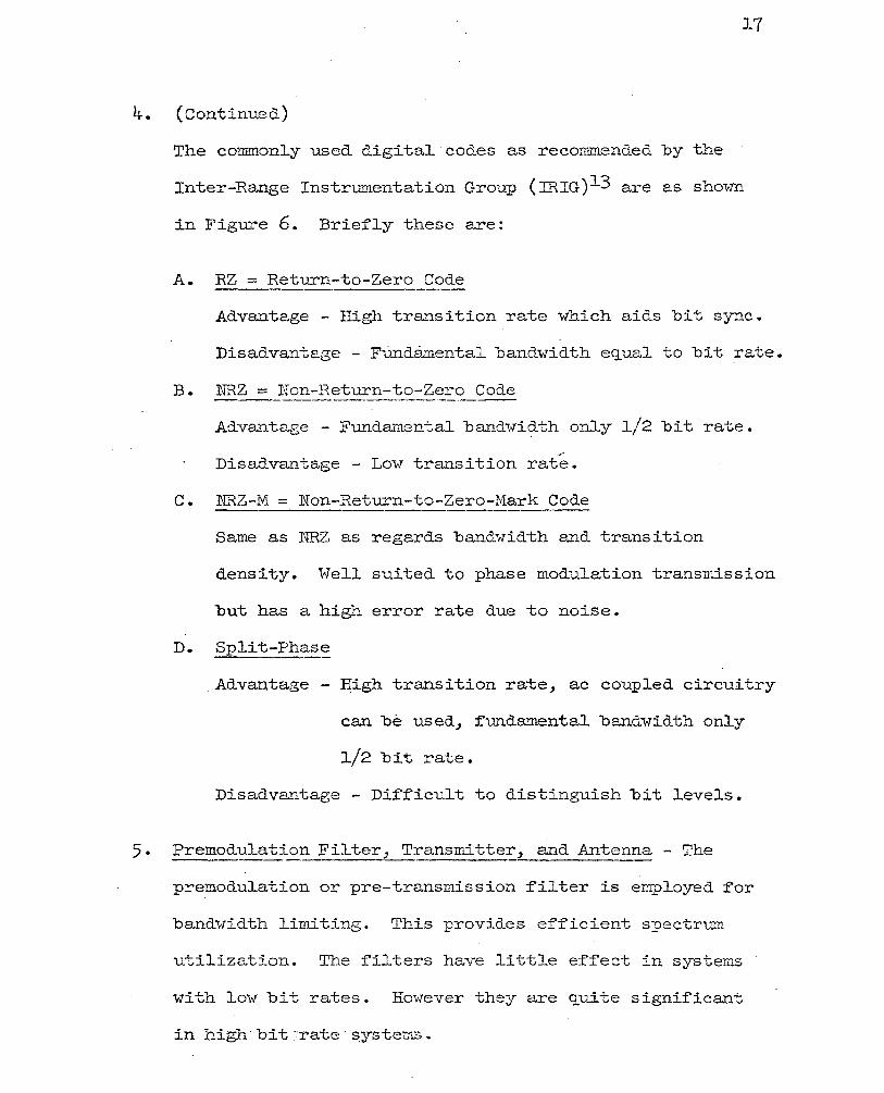
4. (Continued)
The commonly used digital codes as recommended by the
Inter-Range Instrumentation Group (IRIG)1 3 are as shown
in Figure 6. Briefly these are:
A. RZ = Return-to-Zero Code
Advantage - High transition rate which aids bit sync.
Disadvantage - FUndamental bandwidth equal to bit rate.
B. NRZ = Non-Return-to-Zero Code
Advantage - Fundamental bandwi?-th only 1/2 bit rate.
Disadvantage - Low transition rate.
C. NRZ-M = Non-Return-to-Zero-Mark Code
Same as ~~Z as regards bandwidth and transition
density. Well suited to phase modulation transmission
but has a high error rate due to noise.
D. Split-Phase
.Advantage- ~igh transition rate, ac coupled circuitry
can be used, :fundamental bandwidth only
l/2 bit rate.
Disadvantage - Difficult to distinguish bit levels.
5· Premodulatio~_Filter, Transmitter, and Antenna - The
premodulation or pre-transmission filter is employed for
bandwidth limiting. This provides efficient spectrum
utilization. The filters have little effect in systems
with low bit rates. However they are quite significant
·in h~gh·bit :'rate ···S;ystet."'J.S.

BIN8RY BIT S?;17E
=:coo£ TYPE
Rz··---
::tV
NRz-··
0
0 -----'
.f.V _NRZ-M
0 -----'
0
J I I 0 0 I
I
I
FIGURE 6 - PCM Bit Code Representations
0 _ I
19
5· (Continued.)
The transmitter (usually FM or PM f'or PCM telemetry) and.
antenna are vital to any telemetry system but are
mentioned. here only for completeness. They have no effect
on the analysis which follows.
B. Data Recovery - The basic elements which comprise a data
recovery system are briefly described in the following
sections.
· l. Receiving Antenna and Receiver - The Feceiving antenna and.
receiver are portions of a telemetry system which, while
also vital to the success of a data recovery system, are
only mentioned. in passing since they have little or no
effect upon the analyses which follows.
2. Tape Recorder - A tape recorder is employed in virtually
every telemetry system. They are used to provide a
permanent record of the received. data. After recording
received data various filtering techniques, d.ecommutation
strategies, etc., may be employed to recover as much
data as possible.
\ihile this represents an advantage of tape recorders,
there is also an inherent disadvantage; in the record and.
playback phases the signal-to-noise ratios are lowered.

20
2. (Continued)
Also effects of recorder rrwown and 1'flutter" can
introduce large bit rate fluctuations which aggrevate
the bit synchronization problem.
3. Signal Conditioner and Bit Synchronizer - Bit synchro-
nization is the first step in the synchronization of a
PCM signal. The process of' signal conditioning and bit
synchronization is employed in a PCM telemetry system
to define the temporal position and "one" or "zero"
value in the PCM serial wavetrain. This phase of PCM
synchronization is further discussed in Section III of
this thesis.
4. Frame Synchronizer - Frame synchronization of' a PCM
signal consists of identifying a specific bit position
in a data frame. Having identified a bit position within
a frame~ it is a simple matter to identify any bit or
word position within the data frame by counting bit •
times (pulses from the phase-locked oscillator in the bit
synchronizer). The process of identifying a bit position
within a frame is usually accomplished by inserting a
fixed bit pattern in the data train in periodic intervals.
A pattern recognizer may then be employed in the frame
synchronizer to detect the known pattern. This
establishes a reference bit position. The derivation of

21
4. (Continued)
optimUm. system parameters for the frame synchronization
problem is the main topic of this paper and is discussed
in Section IV.
5· Format Translation and Data Reduction - After obtaining
frame sync~ each word in the data frame is separated
from the PCM bit train~ identified~ and placed in a
buffer storage register in the decommutator. Upon storing
a complete data frame in the register~ the data time is
read from the tape., then the data and~·corresponding time
are rerecorded on another magnetic tape in a form suit
able for use as input to a digital computer. This
process is called format translation. The data tape., now
in the proper format., serves as input to a data reduction
program. This program accepts the raw data and in con
junction with instrument calibrations produces data
parameters in engineering units. These units represent
the input variations to the physical sensor in the
airborne instrumentation system. The data reduction
program thereby completes the telemetry process.
22
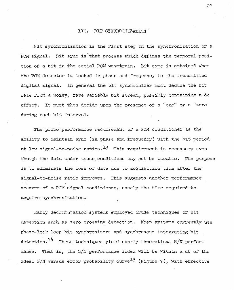
III. BIT SYNCHRONIZATION .
Bit synchronization is the first step in the synchronization of a
PCM signal. Bit sync is that process which defines the temporal posi-
tion of a bit in the serial PCM wavetrain. Bit sync is attained when
the PCM detector is locked in phase and frequency to the transmitted
digital signal. In general the bit synchronizer must deduce the bit
rate from a noisy7 rate variable bit stream7 possibly containing a de
offset. It must then decide upon the presence of' a 11 one n or a "zero n
during each bit interval. ~·
The prime performance requirement of a PCM conditioner is the
ability to maintain sync (in phase and frequency) with the bit period
at low signal-to-noise ratios. 13 This requirement is necessary even
though the data under these. conditions may not be useable. The purpose
is to eliminate the loss of' data due to acquisition time after the
signal-to-noise ratio improves. This suggests another performance
measure of a PCM signal conditione~7 namely the time required to
acquire synchronization.
Early decommutation systems employed crude techniques of bit
detection such as zero crossing detection. Most systems currently use
phase-lock loop bit synchronizers and synchronous integrating bit
detection.14 These techniques yield nearly theoretical S/N perfor
mance. That is 7 the S/N performance index will be within a db of' the
ideal S/N versus error probability curve13 (Figure 7)~ with effective

:>, ..p ·rl r-1 ·rl
-\ 10
7 ---·- ----- ------ - -··-·--· ·---- ·- -' ---~' -----
--··-·----]:--- · -- ---~--···· --·
<1 - --- - ---- - - - - -- ·-- - -----·- - - -·-·- ·- - --
2 - - \ - ------ ----- --·--·-···--- ···-- ------ -----··-· --·- - ___ \ ___________ _
-2 \() . ------ ---------- - -----------··· ---- -·-- - - - - ·--- --···-·-··- -----\ ---- -··-
7 -- ---- --- - --·--· -- -------- - --- -- · ----- -· ------- --·-- ·-- ------ ·- ·
4-~--
2 --- - - --- - - - - ·-----· ---------
~ 103 ----r -------- ------~ 7 - - - -- - -- ··· --- ---- -- - .. --
4-------------- - --·--· -·------ ----- -- - ·----- - ------------ ..
2 - -- - - -- -------- ---- - - - ---- ---·-- ----·· - ··- - ---- ····--- --- --------·--
-4 - 2 0 2 4 6 8 S/N Ratio ( db )
12..
·FIGU1-\E 7 - The orecica l Bit Erro r Prol)a.b i li.t~r v s. S /:N nc:.tio
23

synchronization extending as low as -3 db peak signal to RMS noise
voltage. Acquisition time for this method of operation is often
stated as being within 100 bit periods with 5o% or more transitions
under the s/N conditions previously stated. Block diagrams of a
typical phase-locked loop PCM bit synchronizer are shown in Figures
8 and 9.
24
The input signal is passed throtl.gh an Input Filter to remove noise
which lies outside the PCM signal frequency band. The filtered signal
is applied to the input of the Bit Detector. The Bit Detector extracts
a signal from the combination o:f signal plus noise and squares it.
The squared signal represents mid-amplitude signal transitions and is
used to sync the phase-locked oscillator to the incoming signal. The
Bit Detector employs a Positive Peak Detector~ Negative Peak Detector~
and a Floating Differential· Comparator. The two peak detectors per-
f'orm the function which their names imply. The instantaneous voltage
difference between the two is the signal peak-to-peak amplitude. As
de of'f'setJ signal amplitude) and sY-mmetry change~ the signal baseline
moves up and down. The peak detectors accurately track this varying
signal. The outputs of the two peak detectors) equally weighted~ a.re
summed to establish a de level midway bet1-1een the peaks. This level
is independent of offset) symmetry~ data content) and amplitude
variations. It is then used to establish a slicing voltage level.
The_sliced signal and summed reference voltage are then compared in
the Floating Differential Comparator which detects whether the signaJ..
is more positive or more negative than the reference voltage. The

G:'Re.oue.Ac'< -1-----BliDETECTORl l b'ErERJI/ltNtN6 I CDIV\PO N e; N TS I I I Sf.JAPED I PCM
ti\II>UT. i I $1-\Af'E.; P(M
I , I I I I I I
RESET INTE.6RATOR
I I 1 I J I I l I I I · I 1 1 I · _ _ _ _ _j L ____ c.ot~~PAI\410R _ _j__ I _L - -- -- T 1 I SIGNAL l I !.,.-.B-AND - _._ - ~- - -l I I I .SAI'<iPLE.R
"U\.. )ELE..C.TION +t ---- -~ PC.M
I SWITOI • LOOP I P-C·" t=tL1"E I I IYI
· · PtA~ DETCC10n ' j PHASE- LOCKE[) </>2
I TII(}E. C.DN5TM I I osc t L lATO F\ LClD p !-i -+---' LODP ~ I I Tll'<lECONST!t TL. __ · - _I
I lNTE0F).'\IOrrj ll J¢"3 1/'llE. U.:>I'ISTANfl! ''
L----~----· __ _j
'·
FIGURE 8 ~ PCM Bit Synchronizer
(\) \Jl

~----_ FR~UE.NCY -----------~
I . 0£TERMIN\N6 I COWl PON EI\JT,S
PI-\AS"' _ VCO Tlr.()E · 1 · DE..TEC.ToR CoNSTANT 1
. TIW)E
I CONSTANT I . ? 6AN.D SELcC.TION I I __ sv·rrrc r\ _ . . I ~~~i-j I ---rr-_-=._-_:: --------~
SHAPED Pc.M I D~~~~R fYI ~~ .. Loor L1 4-PHA<;e 11 AND FIL.TE.R - ·1 _ VGO CLOC..K
5HAPE.D PCM I :--OMPfiRAlOR I · l~ENE.r.vrroR I · I
I L J ¢4- ¢;, Cf>Z ¢I TO RE.SET -- - I -lNTE.0PATORS
I ~ · I _To s 1 G Na L I . I -5ANlPC..E.R
I i I ,
i I ' l I ; L- _· - __ - P.;A5E.-LOCKE.D O.SCILLATOF\ t..OOP _JI
' ---------------
FIGURE 9 - Phase-Locked Oscillator Loop
IHTERNAL FDI.JF<
. PHASE CLOCK
1\) 0'\

27
output is then controlled accordingly. The squared signal output
~rom this dynamic signal conditioning process is then fed to the input
of the Phase-Locked Oscillator Loop to establish bit sync. It is also
fed to the Reset Integrator to perform bit value decisions.
The Phase-Locked Oscillator Loop generates the output clock at a
frequency which is in phase with the incoming PCM signal. The loop
consists basically of a Phase Comparator, a Voltage-Controlled
Oscillator, and a Four-Phase Clock Generator.
The Phase Comparator compares the phase pulse~ (generated by the
signal transitions) with the local clock pulses. A voltage is then
generated which is proportional to the frequency dif~erence between
the incoming signal and the local clock. It is positive if the
incoming signal is higher t~an the clock in frequency, negative if
lower. This voltage drives the Voltage-Controlled Oscillator which
maintains the local oscillator at the same frequency and phase for·the
incoming signal. Thus bit sync is _thereby achieved.
The Shaped PCM and Shaped PCM dutputs of the Bit Detector are
then :fed to the Reset Integrator which makes a "one11 or "zero 11 deci
sion during each bit period. The bit period is determined by the
Phase-Locked Loop. More specifically, the squared signal and its
complement are :fed into two integrators. The integrators are each
set.to a reference potential at the beginning of a bit period.
Integrator I charges for a none" while Integrator II remains constant.
The converse operation results from a "zero". The presence of noise

28
on the input signal results (on the average) in both integrators
charging equaily. The Differential Comparator is utilized to deter
mine which.of the two is more positive. The bit decision is similarly
based. A Signal Sampler makes the bit decision at the end of the
bit period. The decision is based upon the value of the Differential
Comparator. This operation concludes the bit synchronization and
data regeneration process.
An alternate means o:f obtaining bit sync is called 11 carrier lock"
rather than "phase locku. In this scheme the frequency information
is obtained from the RF carrier and the phase information from the
video signal. The method is described by E. R. Hill.l4

29
Df. FRAME SYNCHRONIZATION.'
Frame synchronization of a PCM signal consists of identifying a
specific bit position in a frame or cyclic block of PCM data. It is
then an easy matter to identify any bit or word ~osition in the frame
by counting pulses generated by the phase-locked oscillator from the
identified bit position. Having established f'rame sync~ the decem
mutation process can be performed by use of simple sequential logic
circuitry.
The. method usually employed to obtain frame sync is to include
in each frame of data a specific bit pattern. When this pattern is
detected at the ground station by means of a npattern recognizer_, 11
a reference bit position is established.
In this section and the remainder of' this thesis_, it will be
assumed f'or the purpose of' analysis that bit synchronization has been
accomplished (ergo, a bit error rate is established) and that all bits
in .a frame other than those in the sync pattern ar~ random in nature.
Word synchronization will not be cortsidered in the subsequent develop
ment. Thus in attempting to obtain frame sync~ it will not be knmm
which groups of' bits comprise data words. This restriction further
renders it impossible to select a frame sync pattern which would be
unique within a frame. Even if the A/D converter in the system were
inhibited from accidentally generating the frame sync pattern_, it is
conceivable, and even likely, that portions of tw·o time-vrise adjacent
data words (with no word sync) would form the frame sync pattern.

30
As previously mentioned) a "pattern recognizer" is a device which
is used to identify a particular bit pattern. It is usually capable
of being programmed to allow no more than a given number of errors in
the pattern to be recognized. Several types of pattern recognizers
are presently in use~ the two most common are the analog recognizer
(linear matched-filter) and the digital recognizer (shift register
comparator). The analog variety have the advantage that the frame
sync pattern can be detected directly from the video signal without
previous bit detection. The digital variety requires bit detection
.. ·and data reconstruction before the frame sync patt~rn can be identified.
However, the probability of a false sync indication is so much smaller
for the digital recognizer than the analog~ that it is generally
preferred. Also the linear matched-filter is not flexible with
regard to the PCM bit rate. Conversely, the shift register recognizer
can be designed to handle a wide range of bit rates. The succeeding
development will be performed considering a shift register recognizer
(E. R. Hill12 has analyzed the frame sync problem using a linear
matched filter recognizer).
The frame sync problem will be analyzed here via the three sync
operating modes: SEARCH, VERIFY, and LOCK. As previously mentioned
it is assumed that bit sync has been ~ccomplished. Thus the bit error
rate has been established and will be considered here as an independent
variable. The analysis of the three modes of operation of a synchro
nizer will be considered independent of the sync pattern. The sync
pattern employed will have a "random" character with suitable
31
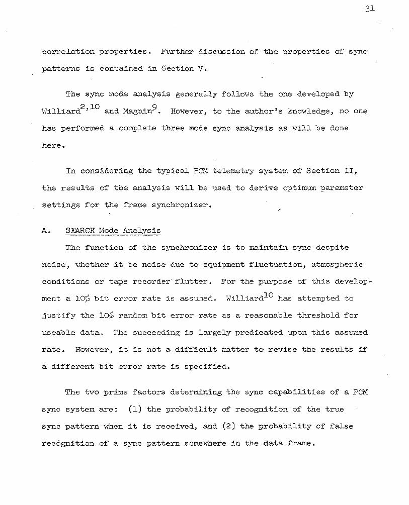
correlation properties. Further discussion of the properties of sync·
patterns is contained in Section v.
The sync mode analysis generally follows the one developed by
Williard2 ' 10 and Magnin9 However, to the author's knowledge, no one
has performed a complete three mode sync analysis as will be done
here.
In considering the typical PCM telemetry system of Section II,
the results of the analysis will be used to derive optimum parameter
settings for the frame synchronizer.
A. SEA.Rg_~~ode ~~alysis
The function of the synchronizer is to maintain sync despite
noise, whether it be noise due to equipment fluctuation, atmospheric
conditions or tape recorder"flutter. For the purpose of this develop
ment a laf:, bit error rate is assumed. 1-lilliard10 has attempted to
justify the lOJ, random bit error rate as a reasonable threshold for.
useable data. The succeeding is largely predicated upon this assumed
rate. However, it is not a difficult matter to revise the results if
a different bit error rate is specified.
The two prime factors determining the sync capabilities of a PCM
sync system are: (1) the probability of recognition of the true
sync pattern when it is received, and (2) the probability of false
recognition of a sync pattern somewhere in the data frame.

The probability of detecting a true sync pattern of length "n"
bits, allowing 11 e " bits to be in error, in a "p 11 bit error rate
environment is7
(n)( )n-e e •••• + E l-p •p
E . = L (~) (l-p )n-:L •pi .
i = 0 (IV-l)
The probability of recognizing a set of "n'·' random bits as a /
probable sync pattern under the same examining conditions is7
i = 0 (IV-2)
For a group of "n" random bits, "Pf" is the probability of a false
sync indication, and (l-Pf) is the probability of not receiving a
false sync indication. The probability of not receiving a false sync
indication in "b" sets of "n" random bits (b>>n) is (l-Pf)b. Then
the probability of a false sync indication in "b" sets of 11n" random
bits is
{IV-3)

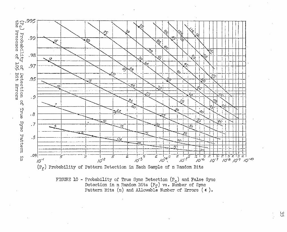
The probability of' false synchronization f'or a random word of
length ttnu allmving "e n errors is shown in Table I. A cross-plot of
"Pf'" versus "Pc" is shovm in Figure 10 f'rom liilliard2 f'or vario"L1.S
error rates and word lengths. The same information with a change of
variables is presented in Figure 1114• A plot of' 11 Fn versus "Prn and.
11b 11 , also from '·Tilliard2 , is given in Figure 12. The information
contained in these curves will be used in the ensuing calculations.
When a scan is begun at the beginning of a frame, the probability
of not obtaining a false decision before examin~ng the next true sync ~·
pattern is (l-F). The probability of a true sync decision on the ·
next sync pattern is then Pc(l-F). The probability of' no sync
decision when examining the first frame and sync pattern is then
(IV-4)
The probability of a true sync decision on the second sync pattern
is Pc(l-F) [Cl-Pc)(l-F)J and on the third is Pc(l-F) [Cl-Pc)(l-F)J2 •
The total probability, T, that the scanning decision is correct can
be expressed as
T = Pc(l-F) + P c(l-F) [(1-Pc){l-F)J + Pc(l-F) [(l-Pc)(l-F8 2
+ Pc(l:--F)[(l-Pc)(l-F)J3 + ••••
Summing this expression f'or an infinite number of terms
results in3
.T = 1 - (1-Pc) (1-F) (IV-5)
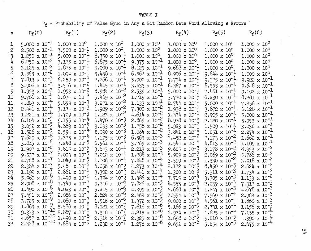
TABLE I
Pr - Probability of False Sync in Any n Bit Random Data Word Allowing E Errors
n Pr(o) Pr(l) Pr(2) Pr(3) Pr(4) Pr(5) Pr(6)
l 2
'3 4 5 6 7 8 9
lO 11 12 13 14 15 16 l7 18 19 ~0 21 22 2'3 ~4 25 26 27 28 29 30 31 32
5.000 X 10⁻¹ 1.000 X 10° 1.000 X 10° 2.500 X 10⁻¹ 7.500 X 10⁻¹ 1.000 X 10° 1.250 x 1o-1 5.ooo x 1o·1 8.750 x 1o-1 6.250 x 1o~2 3.125 x 1o·l 6.875 x 1o·1 3.125 x 1o-2 1.875 x 1o-1 5.ooo x lo-1 1.563 X 10⁻² 1.094 X 10⁻¹ 3.438 X 10⁻¹ 7.813 x 1o-3 6.250 x 1o-2 2.266 x lo-1 3.906 X 10"3 3.516 X 10•2 1.445 X 10•1 1.953 X 10·~ 1.953 X 10·2 8.984 X 10"2 9.766 X 10"' 1.074 X 10·2 5,469 X 10•2 4,883 X 10·t 5,859 X 10-3 3.271 X 10⁻² 2.441 X 10⁻⁴ 3.174 X l0-3 1.929 X 10-~ 1,221 X 10.. 1.709 X 10⁻³ 1,123 X 10· 6.104 x lo-55 9.155 ·x 1o·t 6.470 x lo-3 3.052 X 10• 4.883 X 10⁻⁴ 3.693 X 10⁻³ 1.526 X lo-5 2.594 X 10· E.090 X 10-3 7.629 X 10-~ 1,373 X 10-4 1.175 X 10⁻³⁴ 3.815 X 10⁻⁶ 7•248 X 10-5 6.561 X 10· 1.907 X 10.. 3.815 X 10-5 ·3.643 X 10-4 9.537 x lo-7 2.003 x 1o·S 2.012 x 1o-4 4.768 X 10~7 1.049 X 10·65 1.106 X 10⁻⁴ 2.384 X 10⁻⁷ 5.484 X 10⁻⁶ 6.056 X 10⁻⁵ 1.192 X 10⁻⁷ 2.861 X 10· 3.302 X 10-5 5.960 X 10-~ 1.490 X 10⁻⁶ 1.794 X 10-~ 2.908 X 10·8 7•749 X 10-7 9.716 X 10-1.490 X 10- 4,023 X 10-7 5,245 X 10-~ 7•451 X 10-9 2.086 X 10⁻⁷ 2.824 X 10• 3.725 X 10⁻⁹ 1.080 X 10-~ 1.516 X 10⁻⁶ 1.863 X lo·£0 5.588 X 10·8 8,121 x.1o-7 9.313 X 10·10 2.887 X 10·8 4.340 X 10⁻⁷ 4.657 X 10•1 1.490 X 10.. 2.314 X ·1o-7 2.328 X 10- O 7.683 X 10"'9 1.232 X 10⁻⁷
1.000 X 10° 1.000 X 10° 1.000 X 10° 9·375 x 10 .. 1 8.125 x 1o-1 6.562 x 1o-1 5.ooo x 1o-1 3.633 x 1o·1 2.539 X 10"'1 1.719 X 10-l 1.133 x 1o-1 7.300 x lo-2 4.614 x 1o·2 2.869 x 1o-2 1.758 x 1o·2 1.064 X 10·2 6.363 x 1o-3 3.769 x lo-3 2.213 x 1o-3 1.288 x lo-3 7.448 x 1o·t 4.273 X 10 .. 4 2.441 X 10·4 1.386 X 10 .. 7.826 x 1o-5 4.399 x lo-5 2.462 x lo-5 1.372 X 10-~ 7.618 x lo-6 4.215 X 10·6 2.325 X 10⁻⁶ 1.278 X 10~
1.000 X 10° 1.000 ·x 10° 1.000 ·x 10° 1.000 X 10° 9.688 x lo-1 8.906 x 1o-1 7·734 x lo-1 6.367 X 10""1 5.ooo x 1o-1 3·770 x 1o-1 2.744 x lo-1 1.938 x 1o-l 1.334 x 10⁻¹ 8.978 X 10"'~ 5.923 X 10-3.841 x 10 .. 2 2.452 X 10⁻² 1.544 x 1o-2 9.605 x 1o-3 5.909 x 1o-3 3-599 x lo-3 2.172 x lo-3 1.300-.x 10-~ 7.719 X 10·4 4.553 X 10-2.668 x 1o-4 1;554 x lo-4 9.ooo x lo-5 5.186 x lo-5 2.974 x 1o-5 1.698 X 10-~ 9.651 X 10 ..
1.000 X 10° 1.000 X 100 1.000 X 10° 1.000 X 10° 1.000 X 10° 9.844 x 1o·l 9•375 X 10 .. l 8.555 x 1o·1 7.461 x 1o·1 6.230 x 1o-1 5.000 X 10""1 3.872 x 1o-1 2.905 x 1o·1 2.120 x 1o-1 1.509 x lo-1 1.051 x 10⁻¹ 7.173 x 1o-2 4.813 x 1o-2 3.178 x 10⁻² 2.069 x 1o-2 1.330 x 1o·2 8.450 x lo-3 5.311 x 1o-3 3.305 x 1o-3 2.039 x 1o-3 1.247 X 10-~ 7.569 X 10·4 4.561 X 10⁻⁴ 2.731 X 10⁻⁴ 1.625 X 10"' 9.610 X 10""5 5.654 x 1o-5
1.000 X 10° 1.000 X 10° 1.000 X 10° 1.000 X 10° 1.000 X 10° 1.000 X 10° 9.922 X 10'"1 9.648 x 1o·1 9.102 x 1o-1 8.281 x lo-1 7.256 x lo-1 6.128 x 1o-1 5.ooo x 1o-1 3.953 X 10-i 3.036 X 10•1 2,274 X 10-1.662 x 1o·1 1.189 x 1o·1 8.353 x 10⁻² 5.766 x 10⁻² 3.918 x 1o·2 2.624 x lo-2 1.734 x 1o-2 1.133 x 1o·2 7.317 x lo-3 4.678 x 1o-3 2.962 x 1o-3 1.86o x 1o-3 1.158 X 10-~ 7.155 X 10·4 4.390 X 10'" 4 2.675 X 10•
VJ i=""
c+~.99C' P' 1-Q _.) (])()
1-d..__., 'i 1-Q (I) 'i C\9 en o .""/ (I) 0' g~ (]) 1-'•
l-' ~~ .98 l-"~ ~~ ,97 1Jjtj 1-'• (i) c+ c+ .'35
{j) t:tJo ~~ 0 0 li lJ 0 til •v
0 H)
1-3 'i
ffi
~ n t-el ~ c+ (I)
~ 1-'• ):j
.8
. 7
.s
.09
-------- -----------
'""" ~~ ' N l :
~ ' ~ ' ~ ~ ".9. l I
"' ~ i
I
0
~ I ~ """· .
~ "'111
~ ...... "' " ~~ ~ "
'~l !
~ " ~ I
' ..
~ ~ ......
' ~ ~ ~ 1"- ~c " !\..
~- "-... ...... ~0 "' ~~~ R'l I ....... 12 ~
............ ~ "" 16~1 "-.. ~ ~ i
' ~ ""-.. ~ ~ ~ ~ ~',, ' I ( I
?--. ~ f ' I
~ ~, f"--. "-t i"-.1 i "-, I' .fp-- I ! .. ~ I
......... ~ ~ i"'-. . ""i,C>' I~ j)(<P ['.. ! I --..._,0 .......... ,.........._% ~.!>. I"""'- ; i"""'-1 "'- '"-.i .... i ' .......;. ~~- ~Q=~~ c-l :"\.. I I .......... ! ............. ,........._ -"'· I'. i .. ' . I I .~ 1',.! 1
"' I .......... IX"' I ' ' I I -·~ -t· k"(' I" .............
~ . ~E I " ~ ~I" ~ ~~1: --...... 7
~~~ !"--i 'r--.. -.. ---...._ I ~~~ I '¥' I :< ,I I ~ r-....?o r-.,.l ; ......._
r-....... ~ 'N i' I ~ "'~ I I ; .......... ! . . -~ -....._ ~ " ~)I ,....., r-.... '¢51 ........
-.t_ -~ ... " l' & ........... ...... ..._, r-. r--.. ;-..... ,...... ! ~ ~I r-~ ~~ ,-... -..L ;-----r-./2.(2 -:~i.... bl"'l I ~. I i r-; ---..!2 i'--i-- I ! r-
1), -H-I .2:")
J I I l
c -::> c ~ 1:; :? ,; :::> ~ ? 52 5·2 52. 5 z io-' ..., ~ ;o·2 --- - ;(;-3... - ;64:..' ;o~s-- ;o-6 ;o-7 ;o-s ;d·9 ;o-'o (Pr) Probability of Pattern Detection in Each Sample of n Random Bits
FIGURE 10 - Probability of True Sync Detection (P0 ) and False Sync Detection inn Random Bits (Pr) vs. Number of Sync Pattern Bits (n) and Allowable Number of Errors ( E ) •
l.Al \J1

n
4S
40
~5
30
25
20
\5
to 11 1 !A 1 / 1/_,......- v i/ 1/ ,,v 1 ~"'"PROBABILITY OF RECOGNITION OF SYNC PATTERN
~=PROBABILITY OJ:" RANDOM GENERATION 0~ SYMC ' PATTERN .
5 1~c/ 1/. /.1 :;/ I "' I I I ,-n= NUMBER 01= BITS \N SYNC PATTERN
0 0 2 3 4 5 6
E;:: lv'lA~IMUif) ALLOWABLE ERRORS lt-J SYI\IC. PATTERN p =PROBABILITY OF ERROR IN A SINGLE. BlT=- O. I
7 8 9 \0 II 12. \3 14
FIGURE 11 ~ Replot of Figure 10 With Variables Interchanged lAJ a

]'(
(b) Nwnbe:c of' Non Sync: I'att;erns Bet11een 'l'rue Sync Patterr1s
'L, I"GT ,,-, r;• J r:, - ·o rc· 1·-r an c'l b J: •. L\.u • . c. J: f' \ o • -- ·-

Similarly, the probability, W, that the scanning decision is false
can be obtained by summing the probability of a. false sync decision in
each of' 11b" sets of' ttnl1 bits between true sync positions. This
process yields the following result:
w = F F + Pc(l-F)
(IV-6)
Logically W + T = l. This simply states that irrespective of the
value of F and Pc, a scan decision (whether right or wrong) is
always made. ..
The next part of this analysis deals with a development of an
expression for the mean number of frames needed to reach a true deci-
sion in the SEARCH mode. The probability that a decision ,.;ill be made
in the kth frame is
(IV-7)
Letting the term [ (l-Pc)(l-F)J be represented by "rn, Equation
(IV-7) can be expressed as
(1-r)rk-l (IV-8)
The total probability of a sync decision being made by the end
of the kth frame is3
Pk = (l-r) +(l-r)r + (l-r)r2 + •••• (l-r)rk-l
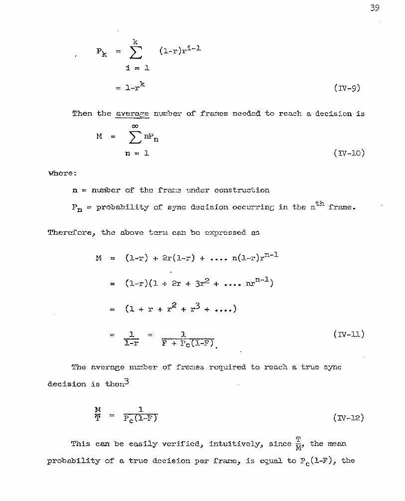
k pk = L: (~ ... r)ri-~
1 = ~
= 1-rk (IV-9)
Then the aver~e number of frames needed to reach a decision is
00
M = LnPn n=l (IV-10)
where:
n = number of the ~rame under construction
Pn = probability of sync decision occurring in the nth frame.
Therefore, the above term can be expressed as
M = (1-r) + 2r(l-r) + •••• n(l-r)rn-l
( )( ~ nrn-1) 1-r l + 2r + 3r- + ••••
= (1 + r + r 2 + r3 + •••• )
= 1 = l 1-r ~F-+-1-)c....,(~l--~F"<<"J
•
(IV-ll)
The average number of :frames required to reach a true sync
decision is then3
(IV-12)
This can be easily veriried~ intuitively~ since ~' the mean
probability of a true decision per frame~ is equal to Pc(l-F)~ the
39
40
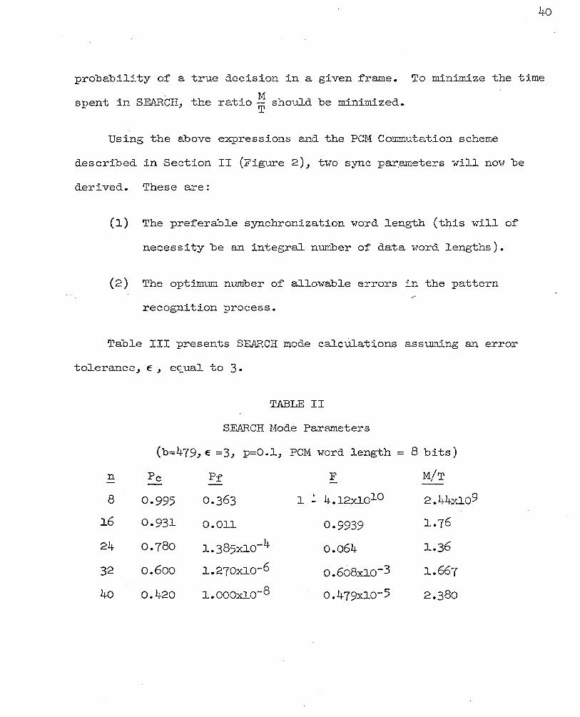
probability of a true decision in a given frame. To minimize the time
spent in SEARCH, the ratio ~ should be minimized.
Using the above expressions and the PCM Commutation scheme
described in Section II (Figure 2), two sync p~ameters will nm1 be
derived. These are:
(l) The preferable synchronization word length (t4is will of
necessity be an integral number of data word lengths).
(2) The optimum number of allowable errors in the pattern
recognition process.
Table III presents SEARCH mode calcUlations assuming an error
tolerance, E, equal to 3.
n
8
16
24
32
40
TABLE II
SEARCH Mode Parameters
(b=479,E =3, p=O.l, PCM word length= 8 bits)
Pc
0.995
0.931
0.78o
o.6oo
0.420
0.011
1.385xlo-4
1.270x1o-6
l.OOOxlo-8
F
1 :. 4.12xlolO
0.9939
0.064
o.6o8.xlo-3
o.479xlo-5
M/T
2.44:Xlo9
1.76
1.36
1.667
2.380

4l
TABLE III
Error Tolerance in the SEARCH Mode
(n = 24, b = 479., p.= O.l)
E Pc pf' F T
0 .0795 5.96 x 10⁻⁸ 2.85 x 1o-5 ·99961J2
1 .2916 1.49 x 10⁻⁶ 7.14 x 1o-1'- -997555
2 .5636 1.79 x 1o-5 8.59 x 1o-3 .98485
3 .7851 1.38 x 1o-4 6.43 x 1o-2 -91960
4 • 9).1~2 7.75 x 1o-4 3.09 x 10⁻¹ .6710
5 -9715 3.31 x 1o-3 7.95 x 10⁻¹ .20
6 -9926 1.13 x 1o-2 ·996 h.3 x lo-3
7 ·9983 3 .. 20 x 1o-2 ·99998 2.43 x lo-5
8 -9997 7.6o x 10-2 1-3.38 x lo-17 3.38 x 1o-17
E w M M/T H/T
0 3. 580 X 10-l~ 12.55 12.55 3.58x1o-4
2.445 x 1o-3 3-42 3.42 "J
1 2.445 X 10-.;
2 1.515 X 10⁻² 1.765 1.795 1.54 x 1o-2
3 8.o4o x 1o-2 1.250 1.360 8.74 x 10⁻²
4 .329 1.065 1.585 .1~9
5 .Boo 1.008 5-0 4.0
6 -9957 1.o+ 233-0 231.0
7 ·999976 1.o+ 4.11 X 10⁴ 4.11 X 10⁴
8 ·1.0- 1.o+ 2.96 X 10¹⁶ 2.96 X 10⁶
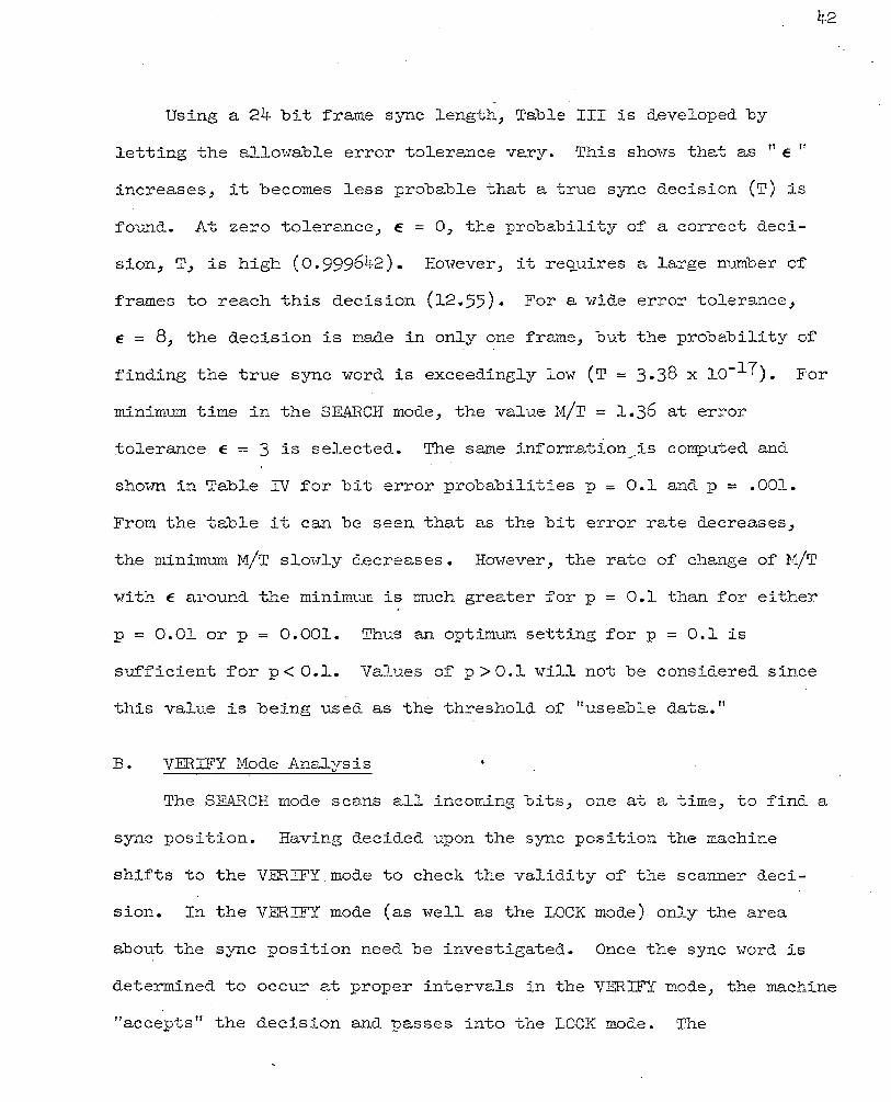
Using a 24 bit frame sync length, Table III is developed by
letting the allowable error tolerance vary. This shm7s that as " e 11
increases, it becomes less probable that a true sync decision (T) is
found. At zero tolerance, e = 0, the probability of a correct deci-
sion, T, is high (0.999642). However, it re~uires a large number of
frames to reach this decision (12.55). For a vlide error tolerance,
42
e = 8, the decision is made in only one frame, but the probability of
finding the true sync word is exceedingly low (T = 3.38 x lo-17). For
minimum time in the SEARCH mode, the value M/T = 1.36 at error
tolerance. e = 3 is selected. The same information is computed and . ~·
shown in Table IV for bit error probabilities p = 0.1 and p = .001.
From the table it can be seen that as the bit error rate decreases,
the minimum M/T slm·rly decreases. Hm·7ever, the rate of change of M/T
with e around the minimum is much greater for p = 0.1 than for either
p = 0.01 or p = 0.001. Thus an optimum setting for p = 0.1 is
sufficient for p < 0.1. Values of p > 0.1 will not be considered since
this value is being used as the threshold of rruseable data."
B. VERIFY Mode Analysis
The SEARCH mode scans all incoming bits, one at a time, to find a
sync position. Having decided upon the sync position the machine
shifts to the VERIFY mode to check the validity of the scanner deci-
sion. In the VERIFY mode (as well as the LOCK mode) only the area
about the sync position need be investigated. Once the sync word is
determined to occur at proper intervals in the VERIFY mode, the machine
"accepts" the decision and passes into the LOCK mode. The
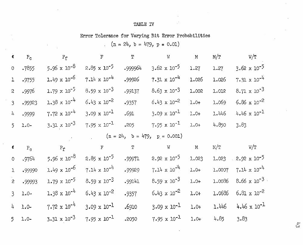
TABLE rv
Error Tolerance for Varying Bit Error Probabilities (n = 24, b = 4791 p = 0.01)
E Pc Pf F T 1if M M/T W/T
0 ·7855 5.96 x lo-8 2.85 x lo-5 ·999964 3.62 x 1o-5 1.27 1.27 3.62 x 10-5
l ·9755 1.49 x lo-6 7.14 x lo-4 .99926 7.31 X 10·4 1.026 1.026 7.31 x 1o-4
2 ·9976 . 1.79 x 1o-5 8.59 x 1o-3 ·99137 8.63 x lo-3 1.002 1.012 8.71 x lo-3
3 ·99923 1.38 X 10"'4 6.43 x lo-2 ·9357 6.43 x lo-2 1.0+ 1.069 6.86 x 1o·2
4 -9999 7.72 x 1o·4 3.09 X 10""1 .691 3.09 x 1o·1 1.0+ 1.446 4.46 x 1o·1
5 1.0- 3.31 x 1o-3 7•95 X 10-1 .205 7·95 x 1o-1 1.0+ 4.850 3·83
(n = 24, b = 479, P. = 0.001)
E Pc Pr F T w M M/T vT/T
0 ·9764 5.96 X 10⁻⁸ 2.85 x 1o-5 ·99971 2.92 x lo-5 1.023 1.023 . 2.92 X 10"'5
1 ·99990 1.49 X 10'"6 7.14 X 10-4 ·99929 7.14 x 1o·'4 1.0+ 1.0007 7,14 X 10⁻⁴
2 ·99993 1.79 x 1o-5 8.59 x 1o-3 ·99141 8.59 x 1o-3 1.0+ 1.0086 8.66 X 10⁻³ .
3 . 1.0- 1.38 X 10'"4 6.43 x 10-2 ·9357 6,43 X 10⁻² 1.0+ 1.0686 6.81 x lo-2
4 1.o ... 7,72 X 10'*4 3.09 x 1o·1 .6910 3.09 x 1o·l 1.0+ 1.446 4.46 x lo-1
5 l.o ... 3.31 x 1o-3 7.95 x 1o·1 .2050 7·95 x 1o-1 1.0+ 4.85 3.83 .r:-w

"proper intervals" are determinable, a priori" from the nature o:f the
commutation scheme employed.
A :few new expressions, applicable to the SEARCH mode, which are
useful in the verify mode analysis will now be developed.
The probability that the true sync word is recognized in the f'irst
frame of' data is
(IV-13)
and th~ ~robability that there will be no detection in one data
f'rame is
r = (l-Pc)(l-F)
Then the probability of' a :false sync decision in one :frame is F,
in two :frames is rF, in three f'rames is r 2F" etc. The accumulated
probability of a :false sync decision af'ter nk" :frames is then 7
pf'k =
=
=
F + rF + r 2F + ••••
k (l-r)ri-l. F I: 1-r
i = l
F(l-rk) (1-r)
+ ~-lF
(IV-l5)
In a similar manner the accumulated probability of' a true sync
decision after "k" :frames is7

= (IV-16)
and likewise the accumulated probability of no sync decision after
"k11 frames is7
(IV-17)
and
= l
45
The. above development is applicable to the S~CH mode of opera-.
tion. The remainder of this section will deal with the VERIFY
operation.
The probability of leaving the SEARCH and VERIFY modes with a
false sync decision a:f'ter "jtt check frames is7
(IV-18)
where 11 E v" is the allowable number of' errors in the VERIFY mode • •
This expression is also the probability of going into LOCK with a
false sync. Similarly, the probability of' leaving the SEARCH and
VERIFY modes with a true sync decision af'ter "j11 check frames is7
(IV-19)
The ratio of these two terms is of' interest and may be used as a
measure of' the check mode effectiveness. This ratio may be expressed
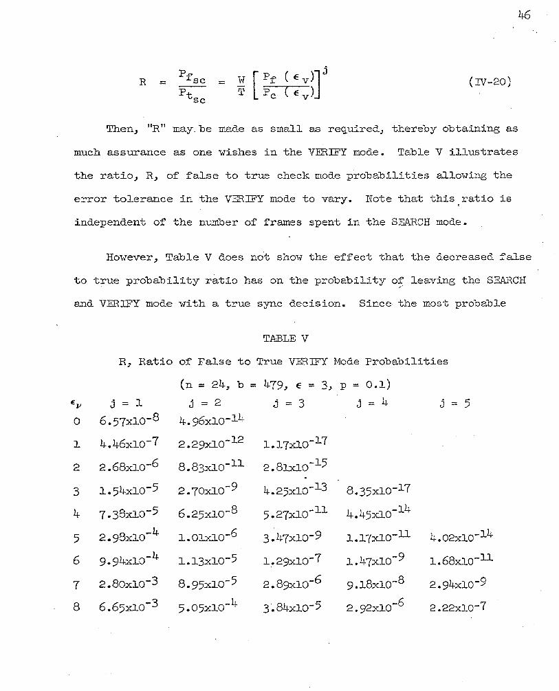
(IV-20)
Then, "R 11 may. be made as small as required_, thereby obtaining as
much assurance as one wishes in the VERIFY mode. Table V illustrates
the ratio_, R, of false to true check mode probabilities allowing the
error tolerance in the VERIFY mode to vary. Note that ·this ratio is
independent of the number of frames spent in the SEARCH mode.
However, Table V does not show the effect that the decreased false
to true probability ratio has on the probability of leaving the SE&~CH ~·
and VERIFY mode with a true sync decision. Since. the most probable
TABLE V
R, Ratio of False to True VERIFY Node Probabilities
(n = 24_, b = 479, E = 3, p = 0.1)
EV j = l j = 2 j = 3 j = 4 j = 5 0 6.57x1o-8 4.96xlo-lh
1 4.46:do-7 2.29xlo-12 1.17xlo-l7
2 2.68xlo-6 8.83xlo-11 2.81xl0-l5 •
3 l.54xlo-5 2.70xlo-9 4.25xlo-l3 8.35x1o-17
4 7.38x1o-5 6.25xlo-8 5·27xlo-11 4.45xlo-14
5 8 -4 2.9 xlO J..Olxlo-6 3-47xlo-9 l.l7xl0-11 4.02xlo-l4
6 9-94xlo-4 l.l3xlo-5 1~29xlo-7 1.47xlo-9 1.68xlo-11
7 2.8oxlo-3 8.95xlo-5 2.89;xl0-6 9.1.8x1o-8 2.94xlo-9
8 6.65x10⁻³ 5·05xl0-4 3·.84x1o-5 2.92xlo-6 2.22xlo-7

47
number of frames spent in SEARCH is M/T, the probabi~ity of leaving the
SEARCH and VERIFY modes with a true sync decision is
(IV-21)
Similar~y for a false sync decision
{IV-22)
It can be shown that
p = pfsc f'sc =
pt sc Ptsc
or
R = R (IV-23)
Therefore, Table V gives a description of the variation of R or
R as a function of n E tt for different v "j".
Tab~e VI then shows the probability of' ~eaving the SEARCH and
VERIFY modes with the true sync decision for the same variables
employed in Table V.
Final~y Tab~es V and VI can be examined to determine the CHECK
mode parameters. If' the chance of f'alse sync must be less than one in
a milli·on, it can be seen that there are five possible choices of' E v
and j as indicated by Tab~e V~ These-are (l> ~)> (5,2), (6~3),

(7,4) and (8,5) giving E and j in that order. From Table VI these v
combinations yield the follmving values of Pt respectively: 0.238, sc
0.775, 0.799, 0.816, 0.816. It appears that the best choices for the
VERIFY mode parameters are E v = 5, j = 2. This results in
- 6 -R = R = 1.0 x lO- and Ptsc = 0.775.
TABLE VI
Ptsc, Probability of Leaving the SEARCH and VERIFY Modes vJi th
The True Sync Decision (n = 24, b = 479, E = 3, p = O.l)
0
l
2
3
4
5
6
7
8
j = l
.Ob5
.238
.459
.640
-754
-791
.811
.816
.816
j = 2
.005
.o69
.258
.503
.68o
-770
.8o5
.816
.816
C. LOCK Mode Analysis
j = 3
.0004
.002
.146
-395
.621
.748
•799
.816
.816
j = 4
.00003
.0006
.08l6
.310
.568
-736
-794
.816
·.816
j = 5
.000003
.00018
.046
.244
.519
.706
.787
.816
.816
The function of the LOCK mode is to check the sync position of
each fraine 1-1hile the data is being processed. Bit counters which are
used to establish data words are also used to count the bits per
frame and d e termine the sync ·Hord position. Li k e the VERIFY mode,
48

only the sync word position need be checked for proper
synchronizat·ion.
Typically after the SEfu~CH and VERIFY criteria are satisfied,
the sync machinery switches to the LOCK mode. In this study, the
pattern recognizer is used to check the sync position. The error
tolerance can be increased at this point if desired, since the proba-
bility of :finding the correct sync word (by the time the LOCK mode
is entered) j_s high. If the ne\-1 number of' allov7able errors is E L'
then the sync pattern must appear during each frame in the proper posi-
tion 1vi th a maximum of' E L errors in order to maintain the LOCK mode
operation.
In the LOCK mode the two significant operational characteristics
which are significant are the mean number of frames required to reject
a false sync and the mean number of :frames required to reject a true
sync. If a :false sync decision was made in the SEARCH and VERIFY
modes, and operation passed to the LOCK mode, the probability of
rejecting the :false sync pattern is:
Frame l • . . • • • • • • • •
Frame 2 • . . . . . . . . . Frame 3 • • • . . . . . . . . •
•
•
Frame n • • • • • • • • • • •
(1-P:r')
(l-P:r' )P:r'
(1-P:r r) (Pf r )2
50
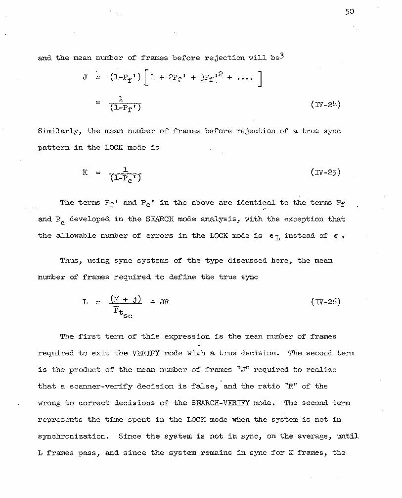
and the mean number of frames before rejection will be3
J = (l-Pf') [ l + 2Pf1 + 3Pf'2 + ••••. J l = {l-Pf') (IV-24)
Similarly, the mean number of frames before rejection of a true sync
pattern in the LOCK mode is
K = l (IV-25)
The terms P f' and P c 1 in the above are identical to the terms Pf'
and Pc developed in the SEARCH mode analysis, with the exception that
the allowable number of errors in the LOCK mode is E L instead of E •
Thus, using sync systems of the type discussed here, the mean·
number of frames required to define the true sync
L = +JR (IV-26)
The first term of' this expression is the mean number of frames
required to exit the VERIFY mode with a true decision. The second term
is the product of the mean number of frames "Jn required to realize
that a scanner-verify decision is false, and the ratio nRu of' the
wrong to correct dec is ions of' the SEARCH-VERIFY mode. The second term
represents the time spent in the LOCK mode when the system is not in
synchronization. Since the system is not in sync, on the average, until
L frames pass, and since the system remains in sync for K frames, the

51
time the system is out o~ sync is directly related to the percentage
o~ data lost; this is
'fo Data Lost - L L+K
100 (IV-27)
Table VII is data pertinent to the LOCK mode analysis of the
system as previously considered in the SEARCH and VERIFY modes. From
the table (note the E = 3 column) i:f the parameter E L is chosen to be
7, we see that less than lojo o:f the data. will be lost. This table
illustrates the need for the proper documentation strategy for a
specific· PCM system.
Table VIII is included to show the s.ame analysis for lo-v1er bit
error probabilities. As expected, decreasing bit error rates
increase the percentage of time spent in sync; the analysis :for
p = 0.1 is valid ~or lower bit error rates.

E Ptsc ·T
0 .61 -99964
1 .655 .99755
2 .720 ·98485
3 ·769 .9196
4 .623 .671
5 .189 .200
TABLE VII
LOCK Mode Analysis
(n = 241 b = 479, p = 0.1, j = 2, E v ~ 5)
W/T R M
3.580 X 10 -4 4.46 X 10"'9 12.55
2.445 X 10⁻³ 2.84 x 10⁻⁸ 3.42
4 -2 1.5 0 X 10 1.79 X 10 .. 7 1.765
8.740 X 10 .. 2 1.01 x lo-6 1.25
.49 5,69 X 10⁻⁶ 1.065
4:0 4.64 X 10 .. 5 1.008
Vl 1\)
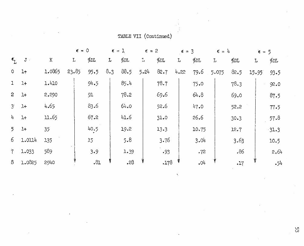
TABLE VII (Continued)
E:=O 6=1
~1 J.
0 lt
K L
1.0865 23.85
1 1+
2 1+
l 1+
4 l+
1.410
2.290
4.65
11.65
5 1+ 35
6 1.0114 135
1 1.033 589
8 1.0825 2940
I
~DL L %DL
95·5 8.3 88.5
94.5
91
83.6
67.2
40.5 ..
15
3·9
.81
85.4
78.2
64.0
41.6
19.2
5.8
1.39
.28
E = 2 ~ = 3
L %DL L %DL
5.24 82.7 4.22 79·6
78.7 75.0
69.6 64.8
52.6
31.0
13·3
3-76
·93
.178
\
47.0
26.6
10.75
3.04
·72
.04
E == 4
L ~DL
5·075 82.5
78.3
69.0
52.2
30·3
12.7
3.63
.86
.17
·e = 5
L %DL
15.95. 93·5
92.0
87.5
77·5
57·8
31.3
10.5
2.64
' ·54
\J1 UJ

TABLE VIII
LOCK Mode Analysis with Varying Bit Error Rate
(n = 21~, b = 479, p = 0.01, j = 0)
E = 0 E = 1 E = 2 E = 3 EL J K L ojoDL L ojoDL L %D1 1 %DL
0 1+ 4.66 1.27 21.4 1.0267 18.1 1.0207 18 1.1372 19.6
1 1+ 40.8 I 3.02 I 2.52 2.51 2.76
2 1+ 1~16 I .304 .246 .246 .212
3 1+ 1300 l .098 .079 .079 ~ .087
4 .
1+ 00- 0+ 0+ 0+ 0+
(n = 24, b = 479, p = 0.001, j = 0)
E = 0 E = 1 E = 2 E = 3
EL J K 1 cjoDL L %DL L %DL L o/oD1
0 1+ 42.4 1.023 2.36 1.001 2.31 1.017 2.35 1.136 2.61
1 1+ 104 I .0102 I .01001 .01017 .01136
2 1+ 00- I 0+ I . 0+ 0+ 0+
3 1+ oo- .Y 0+ y 0+ .l 0+ ' 0+
E ::: 4 1 cjoD1
1.892. 28.-8
4.42
.452
.145
0+
E = 4
L <JbDL
1.892 4.29
.01892
0+
' 0+
E::: 5 1 ~D~
8.68 65
l.7~5
. 2.04·
J .667
0+
E = 5
L %DL
8.68 17
I .086
~ 0+
0+
(Jl ~

V. FRAME SYNC PATTERNS .
Pulse Code .Modulation telemetry systems require that sync inf'orma-
tion be transmitted along with the coded data for sync purposes. In
this paper the frame sync problem has been considered, and in conjunc-
tion with this effort the development of optimum frame sync patterns
will be included here. A frame sync pattern consists of a number of
predetermined bits which are transmitted in a unique word position or
positions during each frame. A pattern recognizer or digital auto-
correlator is then employed in the receiving eq~ipment. Its purpose ~·
is to determine the sync position as part of the decommutation.process.
The foregoing frame sync analysis has assumed a random character
for the bits between sync positions. This assumes the frame sync
pattern has a random nature. The digital autocorrelation function of
a random word has a single large spike at the correlation position
and is therefore easy to detect.
A correlation function with several spikes or a broad, high-level
value near the correlation position•could lead to mistakes in
positioning the word. This is especially true in the presence of
noise.
The. choice of a sync word is more involved than merely choosing
a pattern with a good autocorrelation function. First, since the
·word is bracketed between data, the correlator (for certain search
· pos1-tions) "sees" some data bits and some pattern bits in the

56
correlator. This is known as an overlap condition. One degree of
overlap means· one pattern bit in the correlator~ two degrees· means
two bits, etc. The maximum degree of' overlap is n-1 bits f'or an 11nlf
bit sync pattern. During the overlap conditions, then, the sync
pattern must be such that correlation with parti"al data bits and a
partial sync pattern is ~~than with only random data bits.
Second, erroneous data bits due to noise must be considered. Some
ngood" autocorrelation words become qui!-e "bad" when a f'ew errors are
tolerated. A possible number of errors must then be considered in
.. .selecting the proper word.
There are almost two distinct schools of thought concerning the
specific choice of' a primary sync word. The f'irst could be called
the Phillips and Goode5' 8 approach. The second might be called the
Williard4 approach~ although his efforts were incomplete and were
further improved by Masching9. It is the second approach that will be
generally followed here.
The Phillips and Goode approach defines a sample variance which
is proportional to the square of' the dif'f'erence bet1r1een the number of
bit agreements and con~licts in an overlap condition. A code having
a minimum total sample variance (the sum of' the sample variances from
an overlap of' l to n-l) is considered optimum since it most greatly
resembles the autocorrelation of' a random word. Techniques f'or
generating pseudo-random Barker and Legendre codes generally generate
minimum. sample variance codes.

57
The Hilliard approach is based on minimizing the probabil:L ty of'
:false occurrence of' the pattern in the received signal. For a code
pattern of proper length there is a low probab-ility of false syr.tc in
the random ( clata) regj.on. The Hilliard approach is usec1 to make the
probability of' false sync in ~h degree of' pattern overlap less than
the ·probability of f'alse sync in the random region. The Phillips and
Goocle approach is to generate a minimum. total autocorrelation function
seg_uence. This does not necessarily give a pattern vlith a minimum
probability of false sync in a noisy d.ata stream for each degree of'
overlap.
The remainder of this section will be devoted to the development
of' an optimum code pattern utili?.ing the \Hlliard.~l<Iasching approach.
A. Prima~:[_E.~~Jiox:_d De~~=!:~p~ent
In Sectj.on rv the probability of a false sync indication in any
n-bit random v7ord" allm,;j.ng 11 En errors 1 v1as shovm to be
= (IV -2)
In Section IV the total number of bits bet,·reen sync positions
(recall that these v7ere treated as random bits) 'vas 11b 11 • There are
actualJ..y" holTever, only B = b-2(n-l) data bits, "Hhich may be considered
as rana.om. The remaining bj.ts are patter:1 "bits and are therefore
"f j_xed. "
The probabj.lity of a false s~rnc inclicat:i.on in pattern overlap
areas wilJ. now be, considered. :The.·probabilit;r of'. a- fa.lse .sync:
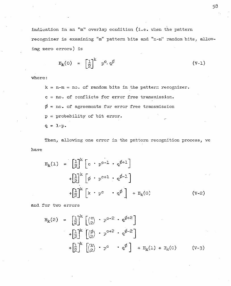
~ndicat~on ~n an "m" overlap condition (i.e. when the pattern
recognizer is examining '!mn pattern bits and "n-m" random bits, allow-
~ng zero errors) ~s
(V-l)
where:
k = n-m = no. of random bits in the pattern recognizer.
c = no. of conflicts for error free transmission.
¢ = no. of agreements for error free transmission
p = probability of bit error.
q = J.-p.
Then, allowing one error in the pattern recognition process, we
have
+[~]k [¢ • pc+l • <~-1 J
+[~]k [k • pC • q¢ J + Hk(o) (V-2)
and. for two errors
Hk(2) = [~Jk [(~) • pc-2 • q¢+2]
+[~]k [(~) • p c+2 • ct-2]
+t~Jk [(~) • PC • q¢ J + Hk(l) + Hk(O) (V-3)

59
Then for e errors k
q¢+e] Hk(e) = [~ J [ (~) P c- e • '
+[~]k [ (~)p c+ e q¢-e]
+[~Jk [(!)Pc • q¢]
(V-4)
Williard4 defines a term, Rm, which is t~e probability of false
sync in an· "mn overlap condition, allowing zero errors, normalized.
with respect to the probability of a false sync indication in "n n
random bits, allowing zero errors. It can be expressed as
Rm = Hk(O)
= [~] n-m • pc • qrf>
Pf'(o) J.n 2
= 2m pc . q¢ (V-5)
To satisfy the criteria that the probability of' false sync be
less in every degree of' overlap than in the random region, Rm must be
less than l.O for every "m.n
In Section IV the code length determined for the hypothetical
PCM system was 24 bits. To continue the development of that system,
Table IX. presents Rm for degrees ot overlap from l through 23 and
for enough bit conflicts to find a value of Rm< 1.0. It can be seen
that for l through 3 degrees of overlap, at least l conflict is
. required for Rm< l.O; for 4 through 7 degrees, at least 2 conflicts,

60
TABLE IX
Normalized False Sync Probabilities (p = 0.1)
Overlap Conf'1icts Rm Overlap Conf'licts Rm
0 0 l 11 0 642.654 1 71.1~06
1 0 1.8 2 7-934 1 0.2 3 0.8815
2 0 3.24 l2 0 1156-923 1 0.36 l 128.547
2 14.283 3 0 5·832 3 1.587
1 0.648 4 0.1763
4 0 10.494 13 0 2082.024 l 1.166 1 231.336· 2 0.1296 2 25-704
3 2.856 5 0 18.891 4 0.3173
1 2.099 2 0.2333 14 0 3747-789
1 416.~-21 6 0 34-911 2 46.269
1 3-779 3 5.141 2 0.4199 4 0.5712
1 0 61.218 15 0 6744.708. 1 6.802. 1 749.412 2 0.7558 2 83.268
3 9-252 8 0 110.241 4 1.028
1 12.249 5 0.1142 2 1.361 3 0.1512 16 0 12137.850
1 1348.650 9 0 198.369 2 149.850
1 22.041 3 16.650 2 2.449 4 1.850 3 0.2721 5 0.2056.
10 0 356.967 17 0 21848.130 1 39.663 l 2427 ·570 2 4.407 2 269-730 3 0.4897 3 29-970
4 3·330 5 0.370

61
TABLE IX (Continued)
Overlap Conflicts Rm
~8 0 39320.073 1 4368.897 2 485 .. 433 3 53-937 4 5·993 5 0.666
~9 0 70799-751 1 7866 .. 639 2 874.071 3 97-119 4 10.791 5 1.199 6 0.1332
20 0 127368.633 1 11~152.077 2 1572.453 3 171J.. 717 4 19.413 5 2.157 6 0.2397
21 0 229346.286 1 25482.924 2 2831.436 3 314.604 4 34.956 5 3.884 6 0.4315
22 0 413270.829 1 45918.981 2 5102.109 3 566.102. 4 62.901 5 6.989 6 0.7765
23 0 742954-518 1 82550.502 2 9172.278" 3 1019.142 4 113.238 5 12.582
·6 ··~~:t..398
:"J · .·o.-.1553

62
etc.· Table X summarizes the number· of conflicts required in each
degree of overlap :for Rm< 1.0.
n-l Williard further defined the quantity Rt = 2::: Rm and stated that
m=l a good. coc1e will have Rm< l.O in every degree of overlap. He also
stated. that an optimum code will have a minimumRt• However, he
developed no method., other than one of trial and error which requires
extensive computer evaluation, :for generating ngood." or "optimumn
codes.
A.method will now be developed. to generate a ~ood sync code by
using the required number of conflicts in the various degrees of over-
lap to establish relationships among the pattern bits. From these
relationships a pattern having correlation prope~ties better than
random data can be simply generated..
In Table XI the bit relationships for all possible conflicts
in each degree of overlap is listed. The number of conflicts .required
in each degree o:f overlap for Rm 1.0 is also repeated there. To
choose a code for which Rm< 1.0 for• each 11 m_, 11 the number of bit
relationships which must be satisfied. in each degree of overlap must
equal the required number of confl~cts. The code which is selected for
use in the sample system of Section Dl is 663711-524, expressed in
octal notation. This code satisfies the bit relationships in
Table XI which are denoted by asterisks. In passing, it is noted.
that the complement, reflection, and reflected complement of the above
code all have the same correlation properties and satisfy the same

63
Degree of' Overlap
0
1
2
3
4
5
6
7
8
9
10
11
l2
13
TABLE X
No. of' Coni'licts Required f'or Rm< 1.0 in Each Overlap Condition
No. of' Conf'licts Degree of' Required Overlap
0 14
1 15
1 16
1 17
2 18
2 19
2 20
2 21
3 22
3 23
3
3
4
4
No. of Conflicts Required
4
5
5
5
5 J.
6
6
6
6
7

TABLE XI
Sync Pattern Bit Relationships for
Conflicts in Each Degree of Overlap
Degree of Conflicts He-Overlap quired for Rm< 1.0
1 l
2 l
3 1
4 2
5 2
6 2
7 2
8 3
Bit Relationships For All Possible Conflicts
*B24=B1
*B23=E1 B24=B2
B22=BJ. *B23=B2
B24=B.3
*B21=B1 B22=B2 B23=B3
*B24=B4
B2o=B1 *~1=B2
*B22=B3
*Blg=Bl ~o=B2
B21'7B3
BJ.a=Bl *Blg=B2 *B2o=B3
*Bl(Bl BJ.a=B2
*B19=B3
B22=B4 *B23=B5
B21f=B6
B21=B4 B22=B5 B23=B6
B2o=B4 B2l=B5 B22=B6
~·
*-B23=B7 B24=Bs
61!-

TABLE XI (Continued)
Degree of' Conflicts Re- Bit Relationships Overlap quired for .B.m. < l. 0 For All Possible Conflicts ___ , __________
9 3 B16=B1 *Bl9=B4 B22=B7 *Bl7=B2 B2o=B5. *B23=B8
Bls=B3 B21=B6 B24=B9
lO 3 *Bl5=Bl -lC·J319=B5 B23=139 B16=B2 *B2o=B6 B24=B10 -B17=B3 B21=B7
B18=B4 1322=B8
ll 3 B14=B1 Bls=B5 B22=B9 *Bl5=B2 1319=B6 B23=B10
Bl6=B3 .*B2o=B7 B24=Bll *Bl7=B4 B21=Bs
l2 4 Bl3=Bl *B17=B5 *B2l=B9 *B14=B2 *B18=B6 B22=B10
1315=B3 Bl~B7 E23=B11 B16=B4 B2o=Bs B24=Bl2
13 4 *B12=B1 Bl7=B6 E22=B11 1313=B2 *Bl8=B7 1323=B12
Bl4~B3 *B19=B8 B24=B13
*B15=B4 B20=B9
BlbB5 B21=B10
14 4 B11=B1 B16=B6 B21=B11
*B12=B2 B17=B7 B22=B12
*B13=B3 B18=B8 B23=B13 *B14=B4 Bl9=B9 B24=B14
*B15=B5 B2o=131o

66
TABLE XI (Continued)
Degree of' Con:fl.icts Re- Bit Relationships Overla}Z qu~re._c!_!~__l!m~.l:.!.Q For All Possible Conflicts
-----------~--
15 5 *B1o=B1 B15=B6 B2o=B11 *Bll.=B2 *B16==B7 B2l=Bl2
B12=B3 *BrrBs B22=B13 B13=B4 Bl8=B9 1323=B14
*B14=B5 B19=B10 1324=B15
J.6 5 B9 =Bl B15=B7 1321=B13 *B1o=B2 B16=Ba B22=B14 B11=B3 *BlTB9
,;' B23=B15
*B12=B4 *B18=B10 B24=B16 B13=B5 Bl9=Bu
B14=B6 .*B2o=BJ.2
J.7 5 Bs =B1 *BJ..3=B6 *BJ.f3=Bl.J. B23=Bl6 B9 =B2 B14=B7 Bl9=Bl2 B24=B17 B1o=B3 *Bl5==Ba B2o=B13 *B11=B1~ Bl.6=B9 B21=B14 *B12=B5 B17=Bl.O B22=B15
J.8 5 *B.r =Bl. B12=B6 B17=B11 ~2=B16
B8 ~B2 *Bl.3=B7 B1a=B12 B23=B17 *B =B 9 _3 Bl.4=B8 B19=B13 B24=B18
*B10=B4 Bl.5=B9 132o=B14 *B11=B5 Bl.6=Bl.O B21=B15
l.9 6 *B6 =Bl B11=B6 *B1t>B11 B21=B16
*B7 =B2 B12=B7 Bl7=Bl2 B22=B17
*Bs =B3 Bl3=Bs B18=B13 B23=Bl.8
B9 =B4 *BJ.4=B9 B19=B14 B24=B1.9
*BJ.o=B5 Bl5=Bl.O B20=B15
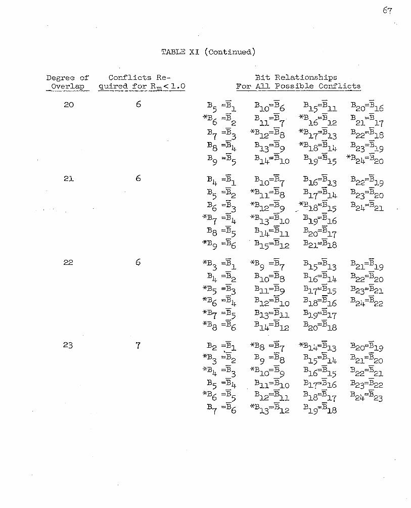
TABLE XI (Continued)
Degree o:f Con:flicts Re- Bit Relationships Ove~laL q uir':_~_f' o:r:~....m..:5 1. 0 For All Possible Conflicts
20 6 :B5 =Bl B10=B6 B15=B11 B20=B16
*B6 =B2 B =:B . 11 7
*B =B 1.6 1.2
:B =B 21_17
:B7 =B3 *B12=Ba *B17=B13 B22=B18
B8 =B4 B13=B9 *B18=B14 B23=B19·
B9 =B5 B14=B1.0 B19=B15 *B24=B20
21 6 B4 =Bl B10=B7 :Bl6:::::Bl3 B22=B19
B5 =B2 *B11=B8 Bly=Bl4 B23=B20
B6 =B3 *B12=B9 ~·*B18=B15 B24B21
*B7 =B4 *B13=B10 B19=B16
Bs =B5 B14=Bll B2o=B17
*B9 =B6 . Bl5=Bl2 B21=Bl8
22 6 *B3 =Bl *B9 =B7 B15=B13 B21=B19
B4 =B2 B1o=Ba B16=B14 B22=B20
*B5 =B3 Bll=B9 B17=B15 B23=B21
*B6 =B4 B12=B10 B18=B16 B24B22
*B7 =B5 Bl3=Bll . - B1.rB17 *B8 =B6 Bl4=Bl2 B2o=B18
23 7 B2 =Bl *B8 =B7 *B14=B13· B2o=B19 ·-*B3 =B2 B9 =B8 B15=B14 B21=B20
*B4 =B3 *Bl.o=B9 B1.6=B15 B22=B21
B5 =B4 B11=B10 B1{B16 B23=B22
*B6 =B5 Bl2=Bll B18=B17 B24=B23
B7 =B6 *B13=B12 B15fB18

bit ~elationships. It is through the process of satisfying the
required number of bit relationships in each degree of overlap that
a good sync code is generated. In generating the code above a bit
error rate of' 0.1 was used and no errors were allowed in the recogni-
tion process. A code which is better than another at E=O, however,
does not necessarily remain better as the error· tolerance is
increased. To insure that the code chosen is satisfactory under
allowable error conditions other than E=O, the probability of false
sync in the pattern region has to be evaluated under those conditions.
The term.Rm used in the previous work should prope;ly be termed
Rm ( 0) • To determine the quality of a code aJ..lm-ring n e" errors, it is
necessary to evaluate the term Rm(E) where
= {V-6)
It is also necessary to det~rmine that the probability of false sync
in the overlap region is still less in each degree of overlap .than
the probability of false sync in an 11 nn bit random word allowing
"e 11 errors. Table XII gives the values of Rm(E=3) for the sync code
663745248 and verifies the validity of this code under maximum
allowable error conditions.
An "optimumn code may be found by a trial and error approach
{as advocated by Masching9) by finding a minimum Rt(E). This
approach requires a great deal·of computer time, however, since
extensive calculations would have to be performed on each code, and

Ti\BLE XII
m Rm ( E =3) m .Rm ( E :o:3) ___ ..., _____ - --~--
1 7 • r(922 X 10-1 20 5 .1~906 x lo-2
2 1.0101 x 1o-3 21 3.9250 X 10_)_~
3 2.7922 x 1o-3 22 h. 5091~. x 1o-3
h 5-5700 x 1o-3 23 2.7056 x 1o-5
5 9.6681 x 1o-2
6 2.1501 x 1o-2
7 3.7085 x lo-2
8 2.2!603 .x lo-2
9 2.5036 x lo-3
10 2. J.14o x 10-2
11 2.7706 x 1o-1+
12 1.4791 x 1o-2
13 2.6623 x 1o-2
1lt- 1.4719 x 10⁻²
15 0.9524
16 1.5526 x l.o-1 -
17 5. oJ.1+4 x lo-2
18 . 2 1..691+8 X 10-
19 1..8038 x lo-5
the number of possible 24 bit codes is 224• The effort required for
obtaining an optimum code is hardly justified, since the probability
of false sync with a good code (developed as previously shown) is
less in each degree of overlap than in the random data region.
B. Subframe Sync 1-lo~d Considerations
The preceeding portion of this section concentrated on the
primary synchronization process. When subcommutation is employed as
is done in the "example" PCM system introduced in Section II, a form
70
of synchronization is required to position the subframe. The primary
sync process scanned each bit position to determine the sync posit-ion.
Given the primary sync word position and a prior information about
the location of the subframe sync word within the frame, it remains
only for the machine to detect the word by "looking" in the proper
word position.
This secondary process, then, does not necessitate the use of·a
word with any particular autocorrelation properties as tvas necessary
in the primary sync word case. However, during the primary sync •
process, while the machine is scanning for the primary sync word, the
subframe sync word will pass through the pattern recognizer. \ihen
this occurs, because the subf'rame sync word is not random and is
repetitive, it is necessary to select a subframe sync word that has· a
low probability of being mistaken for the primary sync word. That is,
the subframe sync word should have a low cross-correlation value when
·correlated with the primary sync word.

71
·A good subf'rame sync word is relatively easy to ge!lerate for a
system as considered here; since the primary criteria is that the
probability of false sync for any degree of overlap (of the primary
and subframe sync words) be less than the probability in a random
data region. It should be noted at this point that a subf'rame sync
word need not be of the same length as the primary sync word since it
is not employed in a scan operation.
For the PCM system of Section II, however, a subf'rame sync word
of' 24 bits will be used. Therefore it will be necessary for the
subframe sync word to have an Rm_< 1.0 for every "mn f'rom l to 24.
In this case 'tmn is the degree of overlap of the primary and the sub-
frame sync words. Under the same condition, i.e. p = 0.1, Tables IX,
X, and XI of this section are valid f'or the subframe sync process as
well as the primary. However, they do not contain the 24th degree
overlap condition.
Using the information contained in these tables, primarily
Table XI, a subfra.rne sync word was obtained by satisfying the required •
number of bit conflict relationships. The subframe sync word
571432248 thus has an Rm< 1.0 for every m from l to 24 when correlated
with the primary sync word 663745211-8·
72
VI. CONCLUSIONS
In this paper the f'ra.me sync process has been analyzed by the
development of' the equations defining the SEARCH, VERIFY, and LOCK
modes of' operation.
The SEARCH mode equations presented are sufficient to determine
the optimum synchronization word length and the optimum number of'
allowable errors in the SEARCH mode pattern recognition process for
a PCM telemetry system.
In the VERIFY mode development the equation ~·
R = W [ P:r ( E ) ] T Pc ( E )
{IV-20)
was ultimately derived and a means of determining the optimum numoer
of''allowable errors in the VERIFY mode was demonstrated. This was
accomplished by examining the behavior of' the terms nRn and "Pt n v.lith sc
the variations in " E n in Tables V and VI. v
Finally, in the LOCK mode analysis, the equation . L = + JR (IV-26)
was derived, which related the mean number of' frames to define the
true sync to the mean number of frames in the LOCK mode before rejec-
tion of' a false sync pattern. The percentage of' data lost in the
sync process was then presented as

73
'/o Data Lost = (100) (IV-27)
This equation was then shown to be instrumental in determining the
allowable number or errors in the LOCK mode.
The equations· presented and developed in the SEARCH, VERIFY, and
LOCK modes were used in Section IV to demonstrate the selection of
optimum frame sync parameters. This was accomplished using the
hypothetical PCM system described in Section II.
Additionally_, a primary and subframe sync word development was
presented in Section v. Equations (V-1) ·through (V-5) from Williard4
and Masching9, which are useful in determining the probability of
false sync in varying degrees of pattern overlap were included. Using
these equations an noptimum11 sync code can be generated via a digital
computer routine. However., a simple method "\vas presented in Section V
for deriving "good" primary and subframe sync codes by satisfying the
required number of relationships specified in Table XI.
Finally_, the method presented for deriving primary and subframe
sync codes was used in Section V to obtain a primary and subframe sync
code for the hypothetical PC:M system ?f Section II. Using the codes
obtained_, the probability of false sync in any pattern overlap condi-
tion was lower than in the random r·egion.
The equations presented here for deriving the sync system
)?arameters for the hypothetical system can easily be adapted to any
· · PGM telemetry system.
BIBLIOGRAPHY
l. E. R. Hill and J. L. l-Teblemoe, 11Synchronization ~1ethods for PCM Telemetry," Proceedings of the National Telemetry conrerence, 1961.
2. M. W. Williard, nPCM Telemetry Synchronization, 11 Proceedings of' National Telemetry Conference, 1961.
3. M. w. Williard, nMean Time to Establish PCM Synchronization, II Proceedings of the National Symposium on Space Electronics and Telemetry, 1962.
4. M. W. Williard, 1'0ptimum Code Patterns f'or PCM Synchronization, 11
Proceedings of the National Telemetry Conference, 1962.
5· G. E. Goode and J. L. Phillips, 110ptimum PCM Frame Synchronization ~odes and Correlation Detection," Proceedings of' the National Telemetry Conference, 1961.
6. G. E. Goode and J. L. Phillips, rrcorrelation Detection and Sequential Testing for PCI:-1 Group Synchronization, rr Proceedings of the National Telemetry Conference, 1962.
7. J. P. Magnin, "Digital Synchronization of PC!-1: Telemeters," Proceedings of' the NationaL Telemetry Conference, 1962.
8. J. P. Magnin and J. S. Codrington, "Legendre PCM Synchronization Codes," Proceedings of' the National Symposium on Space Electronics and Telemetry, 1962.
9· R. G. Masching, nA Simplified .Approach to Optimal PCM Frame Synchronization Formats,u Proceedings of the National Telemetry Conference, 1964.
10. J. J. Maury.:~ Jr. and F. J. Styles, "Development of' Optimwn Frame Synchronization Codes for Goddard Space Flight Center PCM Telemetry Standards, n Proceedings of' the National Telemetry Conference, 1964.
ll. L. W. G:ardenh:i..re, "The Use of Digital Data Systems, n Proceedi~gs of' ·the National Telemetry Conf'erence7 1963.
12. J. S. Mays, 11Pulse-Code I..fodulation, 11 Electro-Technology, November 1962.
74
~3. J. H. Crow, "PCM Signal-to-Noise Performance," Proceedings of the National Telemetry Conference, 1962.
14. E. R. Hill, 11Techniques for Synchronizing Pulse-CodeModulated Te~emetry," Proceedings of' the National Telemetry Conference, 1963.
75 -

76
VITA
The author ,.,as born on December 3, 1939 in St. Louis, Missouri.
He graduated from Mercy High School, University City, Nissouri in
Ju_~e, 1957. The author graduated from St. Louis University in
June, 1961 with a Bachelor of' Science Degree in Electrical Engineering.
He did graduate ·Hork at the University of Na.ryland from Septew.ber, 1961
to June, 1964.. He entered the University of Missouri at Rolla .in
January, 1965 to continue study for a Master of Science Degree in
Electrical Engineering.
The author is married to the former Virginia Ann Conway and
they are the parents of four children.
.13291_0