software engineering laboratory - Bharath Institute of Higher ...
41
SOFTWARE ENGINEERING LABORATORY (V semester of B.Tech) As per the curricullam and syllabus of Bharath Institute of Higher Education & Research SOFTWARE ENGINEERING LABORATORY PREPARED BY Mr. D .Bhaskar NEW EDITION
-
Upload
khangminh22 -
Category
Documents
-
view
0 -
download
0
Transcript of software engineering laboratory - Bharath Institute of Higher ...

1
SOFTWARE ENGINEERING
LABORATORY
(V semester of B.Tech)
As per the curricullam and syllabus
of
Bharath Institute of Higher Education & Research
SOFTWARE ENGINEERING
LABORATORY
PREPARED BY
Mr. D .Bhaskar
NEW EDITION

2
SCHOOL OF COMPUTING
DEPARTMENT OF COMPUTER SCIENCE & ENGINEERING
3
LAB MANUAL
SUBJECT NAME: SOFTWARE ENGINEERING
LABORATORY
SUBJECT CODE:BCS5L2
Regulation 2015
(2016-2017)
4
BCS5L2-SOFTWARE ENGINEERING LABORATORY
LIST OF EXPERIMENTS
1. Library System
2. Course Registration System
3. Quiz System
4. Student marks analyzing system
5. Online ticket reservation system
6. Stock maintenance
5
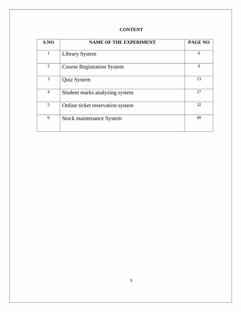
CONTENT
S.NO NAME OF THE EXPERIMENT PAGE NO
1 Library System 6
2 Course Registration System 9
3 Quiz System 13
4 Student marks analyzing system 27
5 Online ticket reservation system 32
6 Stock maintenance System 40
6
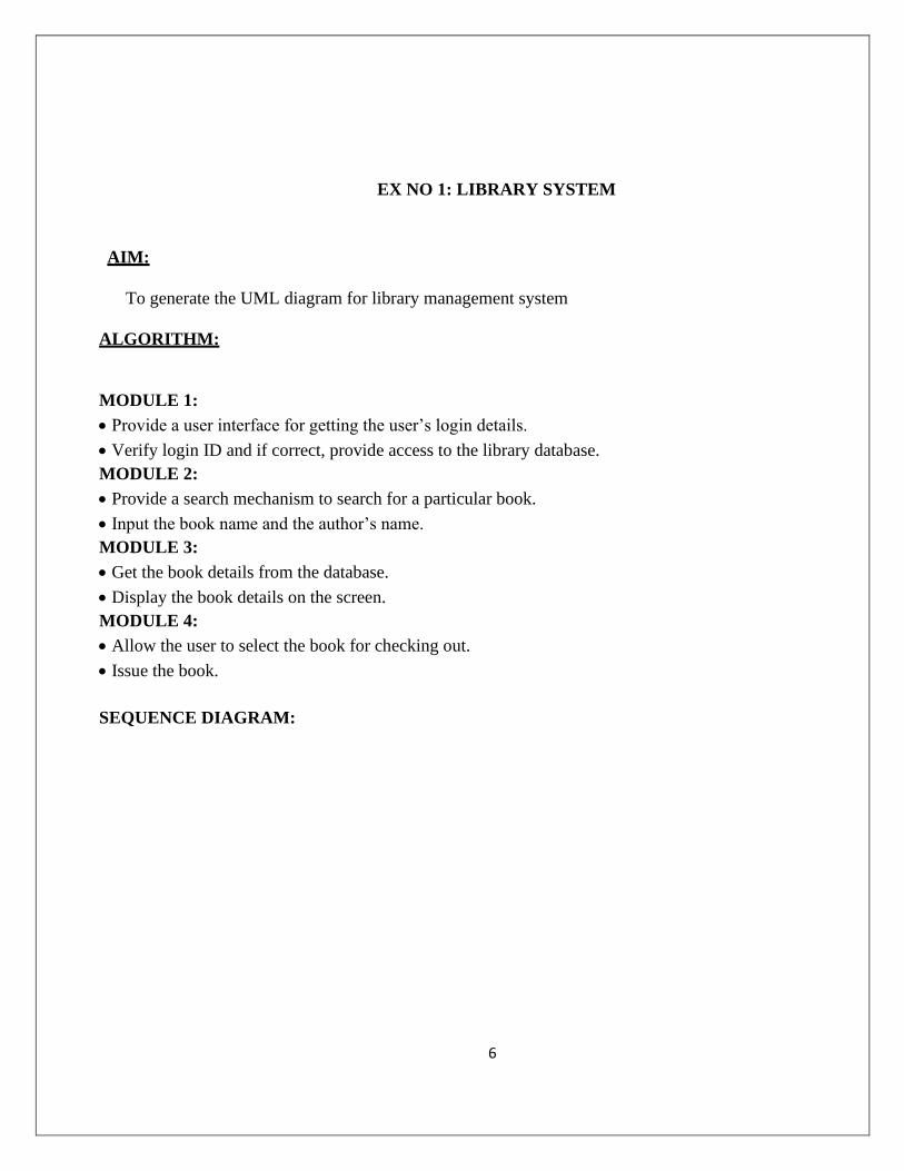
EX NO 1: LIBRARY SYSTEM
AIM:
To generate the UML diagram for library management system
ALGORITHM:
MODULE 1:
• Provide a user interface for getting the user’s login details.
• Verify login ID and if correct, provide access to the library database.
MODULE 2:
• Provide a search mechanism to search for a particular book.
• Input the book name and the author’s name.
MODULE 3:
• Get the book details from the database.
• Display the book details on the screen.
MODULE 4:
• Allow the user to select the book for checking out.
• Issue the book.
SEQUENCE DIAGRAM:
7
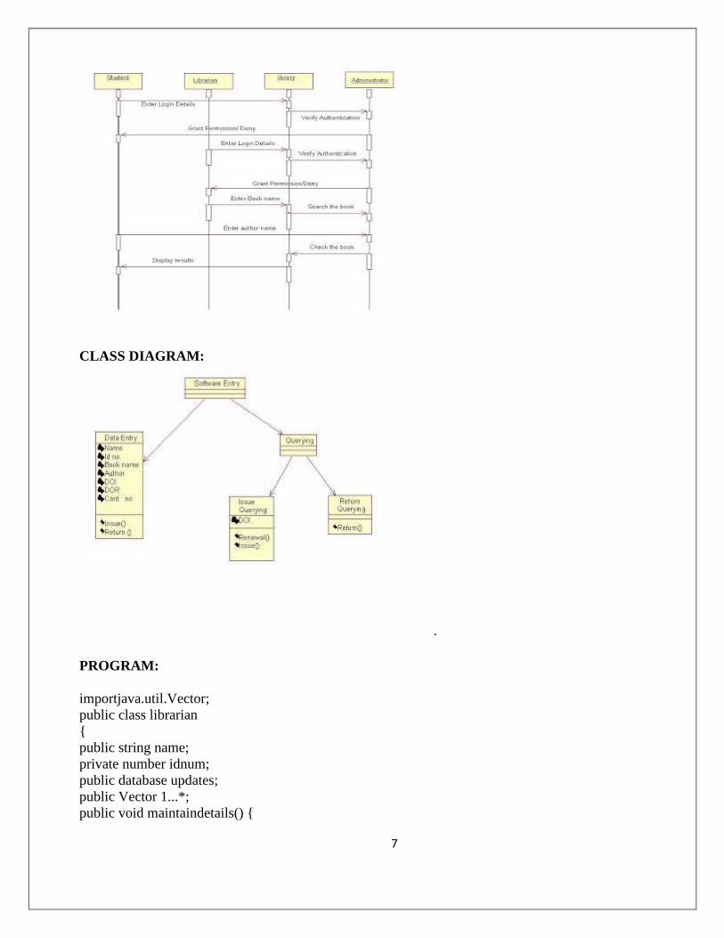
CLASS DIAGRAM:
.
PROGRAM:
importjava.util.Vector;
public class librarian
{
public string name;
private number idnum;
public database updates;
public Vector 1...*;
public void maintaindetails() {
8
}
}
Database.java
public class database {
public string bookname;
public string authorname;
public librarian updates;
public void updatedetails() {
}
public void maintainmembership() {
}
}
Cashier.java
importjava.util.Vector;
public class cashier { WWW.VIDYARTHIPLUS.COM
public string studentname;
public number membershipidnum;
public Vector mystudent;
/**
*
* @element-type student
*/
public Vector pays;
public void renewmembership() {
}
public void renewbook() {
}
}Student.java
importjava.util.Vector;
public class student {
public string name;
public number idnum;
public Vector mycashier;
public Vector 1;
public cashier pays;
public void borrowbook() {
}
public void returnbook() {
}
public void fine() {
}
RESULT:
The UML diagram for library management system was generated successfully
9
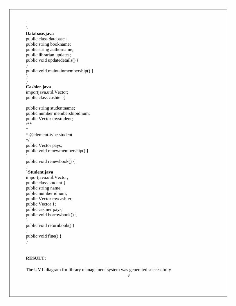
Ex No : 2 COURSE REGISTRATION SYSTEM
AIM:
To generate the UML diagram for course reservation system.
ALGORITHM:
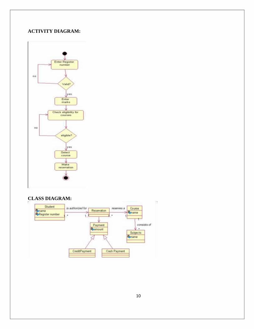
MODULE 1:
Student logs in.
Student selects the course.
MODULE 2:
It is decided whether the student is eligible to take up the course based on certain
criteria.
MODULE 3:
Student pays for course he selected.
The payment details are verified.
USECASE DIAGRAM:
10
ACTIVITY DIAGRAM:
CLASS DIAGRAM:
11
PROGRAM:
public class Student
{
public string name;
public string Registernumber;
Public Student()
{
}
}
Public class Reservation
{
Public Reservation ()
{
}
}
Public class Payment
{
public String amount;
Public Payment()
{
}
}
Public class CreditPayment extends Payment
{
WWW.VIDYARTHIPLUS.COM
34
Public CreditPayment ()
{
}
}
Public class CashPayment extends Payment
{
Public CashPayment()
{
}
}
public class Course
{
public string name
public void Course()
{
}
}
Public class subjects
{
Public String name;
Public void Subjects()
12
{
}
}
RESULT:
The UML diagram for Course reservation system was generated successfully.
13
Ex No : 3 QUIZ SYSTEM
AIM:
To generate the UML diagram for Quiz system.
ALGORITHM:
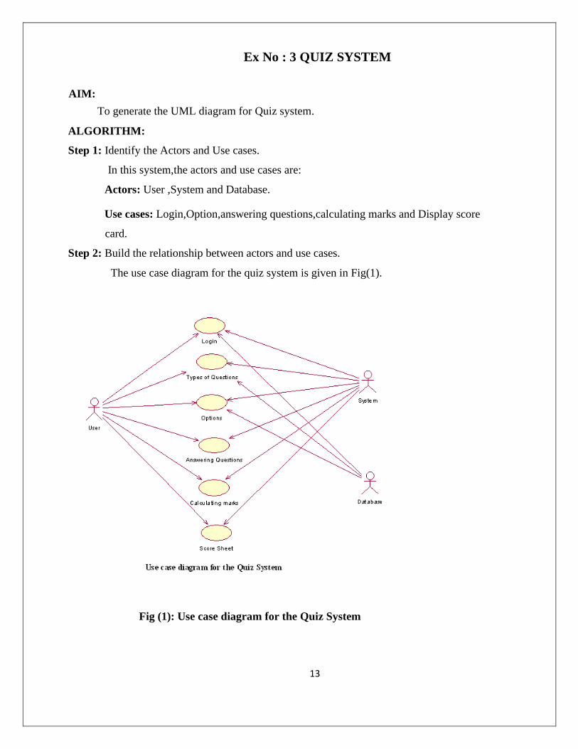
Step 1: Identify the Actors and Use cases.
In this system,the actors and use cases are:
Actors: User ,System and Database.
Use cases: Login,Option,answering questions,calculating marks and Display score
card.
Step 2: Build the relationship between actors and use cases.
The use case diagram for the quiz system is given in Fig(1).
Fig (1): Use case diagram for the Quiz System
14
ENTER THE LOGIN NAME
DISPLAY CATAGORIES FORM
SELECT ANY CATAGORIES
DISPLAY THE QUESTIONS
ANSWER THE QUESTIONS
DISPLAY THE SCORE
STORE THE SCORE
USER
DATABASE
SYSTEM
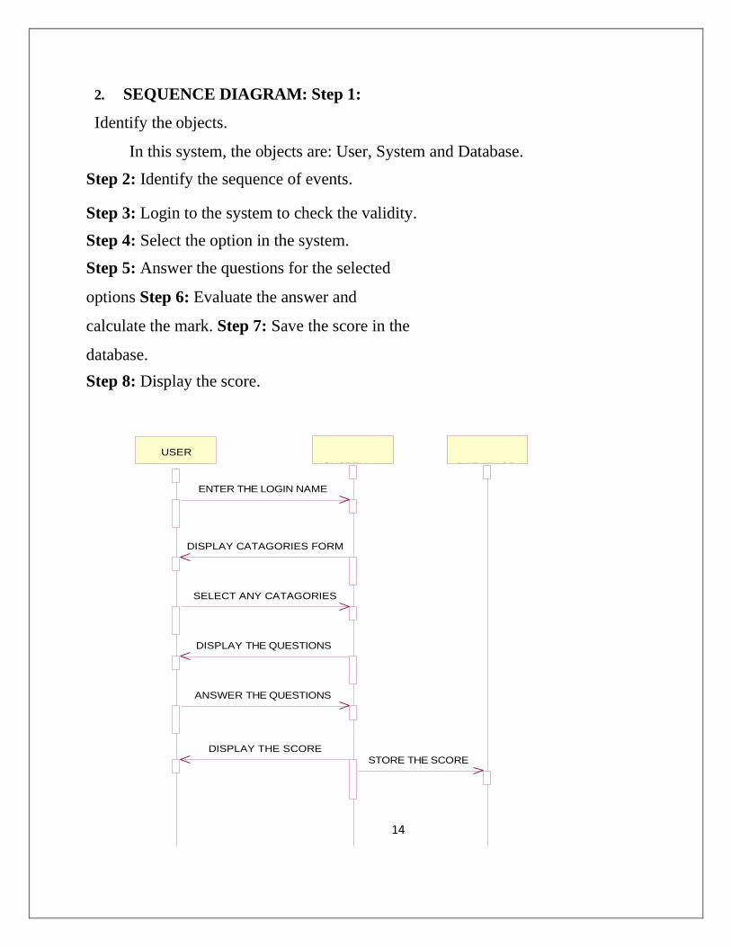
2. SEQUENCE DIAGRAM: Step 1:
Identify the objects.
In this system, the objects are: User, System and Database.
Step 2: Identify the sequence of events.
Step 3: Login to the system to check the validity.
Step 4: Select the option in the system.
Step 5: Answer the questions for the selected
options Step 6: Evaluate the answer and
calculate the mark. Step 7: Save the score in the
database.
Step 8: Display the score.
15
Fig(2): Sequence diagram for Quiz System
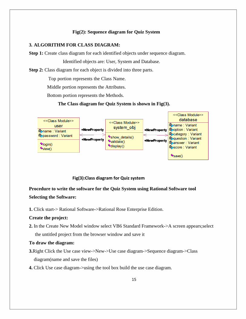
3. ALGORITHM FOR CLASS DIAGRAM:
Step 1: Create class diagram for each identified objects under sequence diagram.
Identified objects are: User, System and Database.
Step 2: Class diagram for each object is divided into three parts.
Top portion represents the Class Name.
Middle portion represents the Attributes.
Bottom portion represents the Methods.
The Class diagram for Quiz System is shown in Fig(3).
Fig(3):Class diagram for Quiz system
Procedure to write the software for the Quiz System using Rational Software tool
Selecting the Software:
1. Click start-> Rational Software->Rational Rose Enterprise Edition.
Create the project:
2. In the Create New Model window select VB6 Standard Framework->A screen appears;select
the untitled project from the browser window and save it
To draw the diagram:
3. Right Click the Use case view->New->Use case diagram->Sequence diagram->Class
diagram(name and save the files)
4. Click Use case diagram->using the tool box build the use case diagram.
16
5. Click Sequence diagram->using the tool box build the sequence diagram.
6. Click Class diagram-> using the tool box build the class diagram.
Generate the coding form:
7. Right click component view -> component diagram-> open specification -> select the
stereotype as DLL-> select the language as visual basic ->switch from general tab to realizes
tab-> select the classes you created in class diagram-> right click ->Assign->Ok.
8. Right click component view -> update code form model-> the tool window for converting
diagrams to code appears->next->finish->the skeleton code in VB is generated automatically
for the class diagram designed.
17
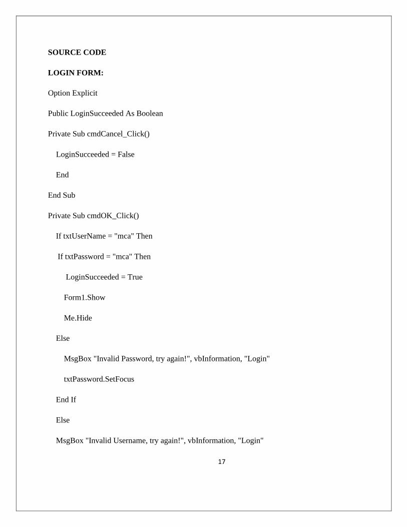
SOURCE CODE
LOGIN FORM:
Option Explicit
Public LoginSucceeded As Boolean
Private Sub cmdCancel_Click()
LoginSucceeded = False
End
End Sub
Private Sub cmdOK_Click()
If txtUserName = "mca" Then
If txtPassword = "mca" Then
LoginSucceeded = True
Form1.Show
Me.Hide
Else
MsgBox "Invalid Password, try again!", vbInformation, "Login"
txtPassword.SetFocus
End If
Else
MsgBox "Invalid Username, try again!", vbInformation, "Login"
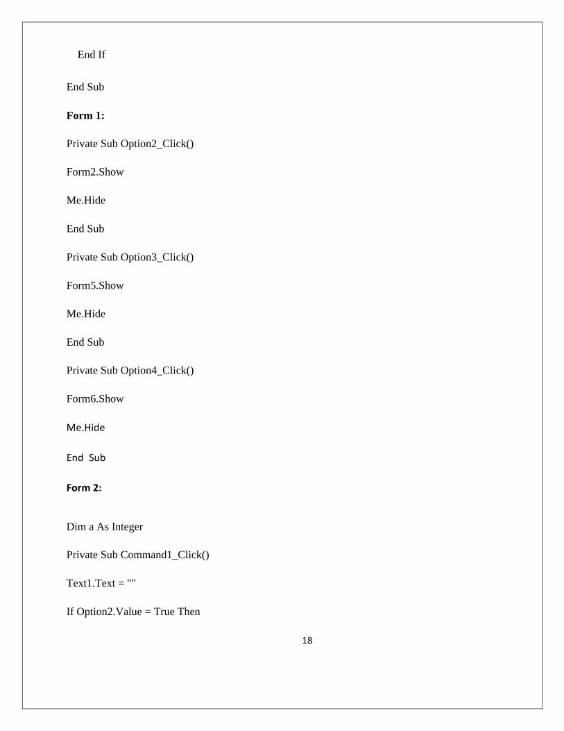
18
End If
End Sub
Form 1:
Private Sub Option2_Click()
Form2.Show
Me.Hide
End Sub
Private Sub Option3_Click()
Form5.Show
Me.Hide
End Sub
Private Sub Option4_Click()
Form6.Show
Me.Hide
End Sub
Form 2:
Dim a As Integer
Private Sub Command1_Click()
Text1.Text = ""
If Option2.Value = True Then
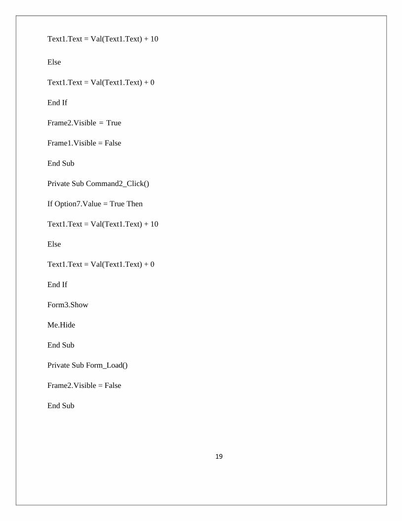
19
Text1.Text = Val(Text1.Text) + 10
Else
Text1.Text = Val(Text1.Text) + 0
End If
Frame2.Visible = True
Frame1.Visible = False
End Sub
Private Sub Command2_Click()
If Option7.Value = True Then
Text1.Text = Val(Text1.Text) + 10
Else
Text1.Text = Val(Text1.Text) + 0
End If
Form3.Show
Me.Hide
End Sub
Private Sub Form_Load()
Frame2.Visible = False
End Sub
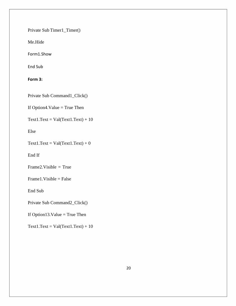
20
Private Sub Timer1_Timer()
Me.Hide
Form1.Show
End Sub
Form 3:
Private Sub Command1_Click()
If Option4.Value = True Then
Text1.Text = Val(Text1.Text) + 10
Else
Text1.Text = Val(Text1.Text) + 0
End If
Frame2.Visible = True
Frame1.Visible = False
End Sub
Private Sub Command2_Click()
If Option13.Value = True Then
Text1.Text = Val(Text1.Text) + 10
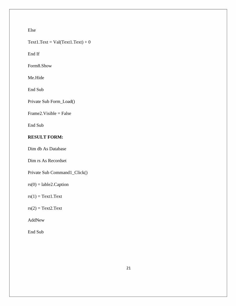
21
Else
Text1.Text = Val(Text1.Text) + 0
End If
Form8.Show
Me.Hide
End Sub
Private Sub Form_Load()
Frame2.Visible = False
End Sub
RESULT FORM:
Dim db As Database
Dim rs As Recordset
Private Sub Command1_Click()
rs(0) = lable2.Caption
rs(1) = Text1.Text
rs(2) = Text2.Text
AddNew
End Sub
22
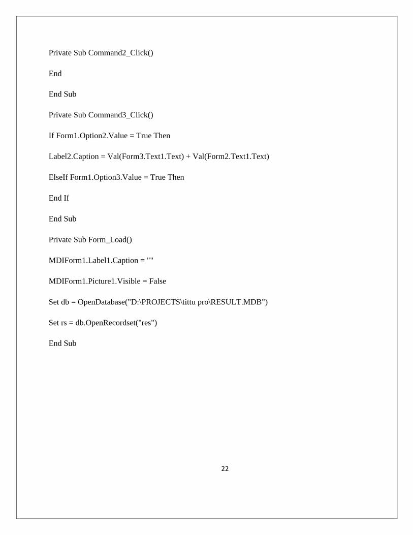
Private Sub Command2_Click()
End
End Sub
Private Sub Command3_Click()
If Form1.Option2.Value = True Then
Label2.Caption = Val(Form3.Text1.Text) + Val(Form2.Text1.Text)
ElseIf Form1.Option3.Value = True Then
End If
End Sub
Private Sub Form_Load()
MDIForm1.Label1.Caption = ""
MDIForm1.Picture1.Visible = False
Set db = OpenDatabase("D:\PROJECTS\tittu pro\RESULT.MDB")
Set rs = db.OpenRecordset("res")
End Sub
23
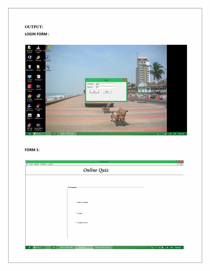
OUTPUT:
LOGIN FORM :
FORM 1:
24
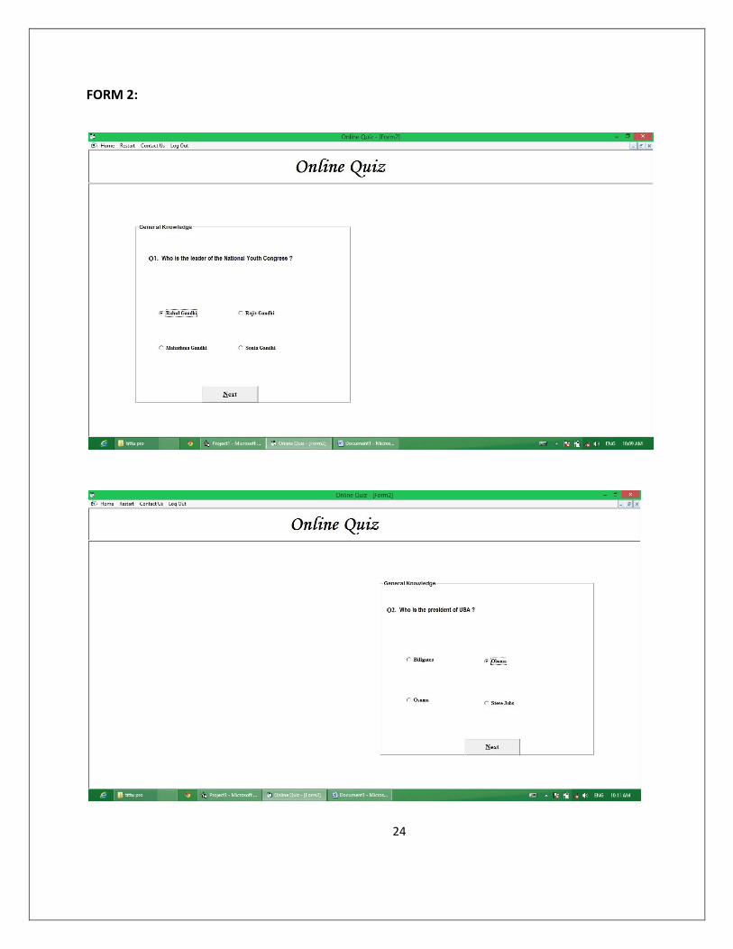
FORM 2:
25
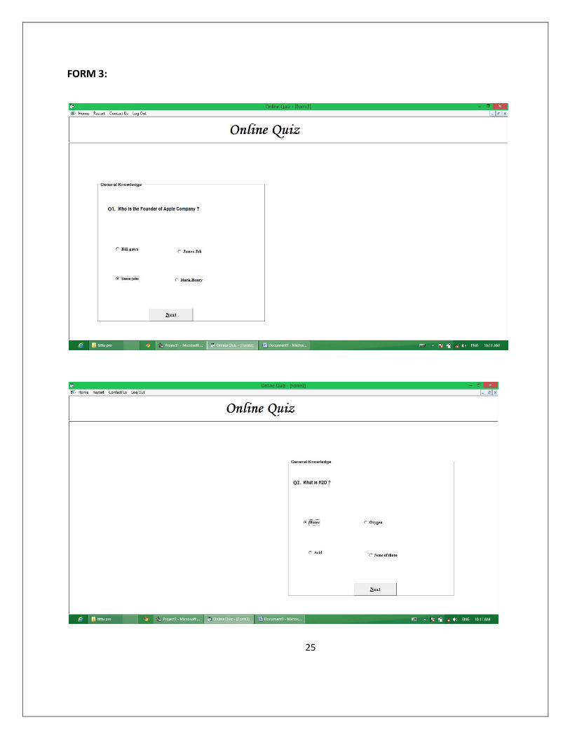
FORM 3:
26
26
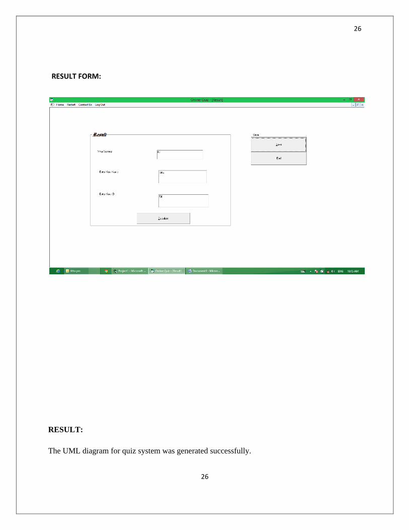
RESULT FORM:
RESULT:
The UML diagram for quiz system was generated successfully.

27
27
EX NO 4 STUDENT MARKS ANALYZING SYSTEM
AIM:
To generate the UML diagram for Student Mark Analyzing system.
ALGORITHM:
MODULE 1:
The system gets the application registration form.
The system gets the data from the user and checks for validity.
MODULE 2:
If the form is valid then the system checks for correction of data with respect to
the respective colleges database.
The form checks for eligibility criteria.
MODULE 3:
If the form is valid and eligible and there is no reduction in the given data then the
unique registration id, and hall ticket is issued to the applicant.
If the form entries are invalid then the application form is rejected.
USE CASE DIAGRAM:
28
28
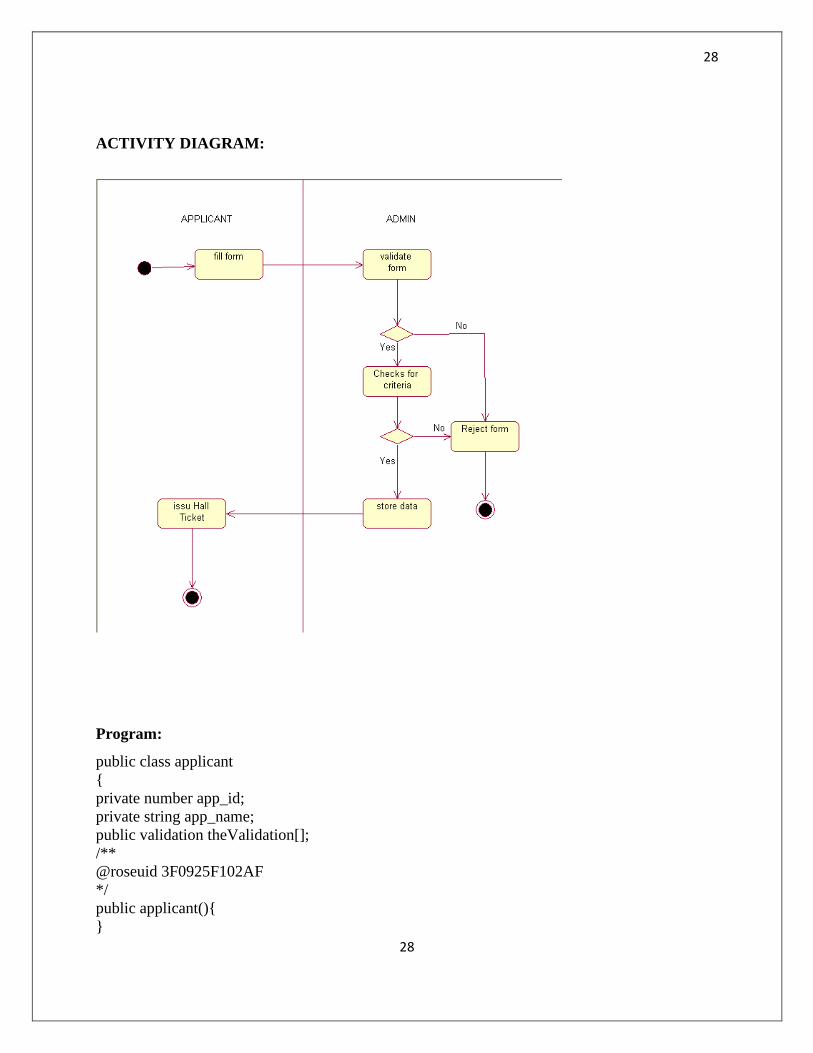
ACTIVITY DIAGRAM:
Program:
public class applicant
{
private number app_id;
private string app_name;
public validation theValidation[];
/**
@roseuid 3F0925F102AF
*/
public applicant(){
}
29
29
/** @roseuid 3F092385009C */
WWW.VIDYARTHIPLUS.COM
19
public void fill_form(){
}
}
public class validation {
private number phone_no;
private string address;
private number age;
private number mark;
public admin theAdmin[];
/**@roseuid 3F09267601C */
public validation() {
}
/**
@roseuid 3F0923F202BF
*/
public void valid_data() {
}
/**
@roseuid 3F09240A032C
*/
public void valid_criteria() {
}
}
public class admin
{
private string mail_id;
private number reg_no;
/**
@roseuid 3F0926830232
*/
public admin() {
}
/**
@roseuid 3F09246900BB
*/
public void issue_hall_ticket()
{
RESULT:
The UML diagram for Studen Marks Analyzing system was generated.
30
30
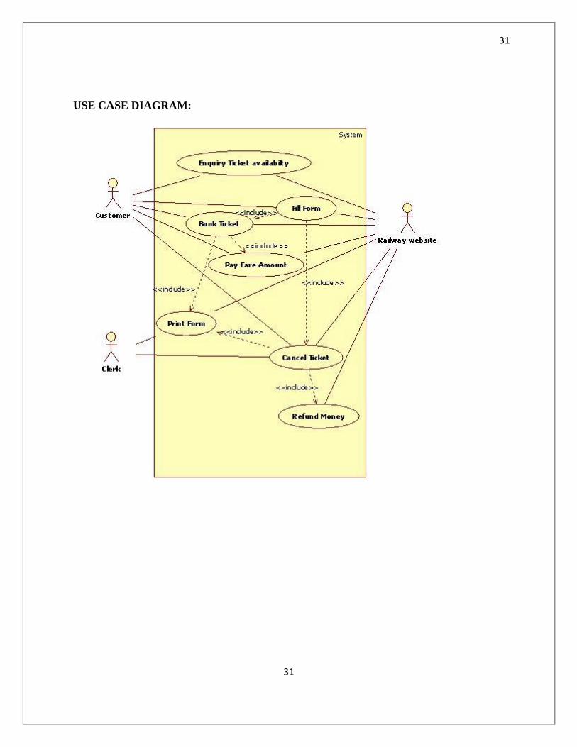
EX NO 5 ONLINE TICKET RESERVATION SYSTEM
AIM :
To generate the UML diagram for Online Ticket Reservation System
ALGORITHM:
MODULE 1:
The user logs into the website using their id and password.
If the user is a new user, create an id and password by filling the sign up form.
MODULE 2:
After logging the system displays the form in which the user is allowed to select
the destination and source place.
The user can also select the date.
The system displays available trains.
MODULE 3:
The user can select the required one and give the number of tickets, class.
The system check for the availability.
If it is available then book the ticket by filing the details about individuals such as
name, age, gender etc.
MODULE 4:
Make the payment either by card or through netbanking.
After booking the ticket, print the ticket.
31
31
USE CASE DIAGRAM:
32
32
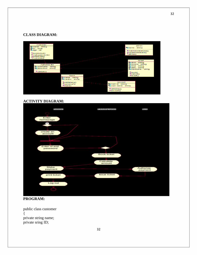
CLASS DIAGRAM:
ACTIVITY DIAGRAM:
PROGRAM:
public class customer
{
private string name;
private sring ID;
33
33
private int age;
public Authenticate theAuthenticate;
/**
@roseuid 3F0927D0031C
*/
public customer()
{
WWW.VIDYARTHIPLUS.COM
42
}
/**
@roseuid 3F09272A01A5
*/
public customer()
{
}
/**
@roseuid 3F0924600213
*/
public void bookticket()
{
}
/**
@roseuid 3F09246D0222
*/
public void makepayment()
{
}
/**
@roseuid 3F09247700EA
*/
public void printticket()
{
}
}
public class Authenticate
{
private string username;
private string password;
public admin theAdmin;
/**
@roseuid 3F0927E10196
*/
public Authenticate()

34
34
{
}
WWW.VIDYARTHIPLUS.COM
43
/**
@roseuid 3F0924A9009C
*/
public void validate()
{
}
}
public class Bank
{
private string name;
private string cardno;
public account theAccount[];
/**
@roseuid 3F0927E8004E
*/
public Bank()
{
}
/**
@roseuid 3F0924D7031C
*/
public void validateno()
{
}
/**
@roseuid 3F0924E400CB
*/
public void opname2()
{
}
}
public class account
{
private string cust_id;
private string cust_name;
/**
@roseuid 3F092808036B
*/
public account()
WWW.VIDYARTHIPLUS.COM
35
35
44
{
}
/**
@roseuid 3F09251100AB
*/
public void withdraw()
{
}
}
public class ticket
{
private string dest;
private string source;
private string time;
private string date;
private string trainname;
public Authenticate theAuthenticate;
public Bank theBank[];
/**
@roseuid 3F09281000EA
*/
public ticket()
{
}
/**
@roseuid 3F09259C000F
*/
public void book()
{
}
/**
@roseuid 3F09259F00BB
*/
public void cancel()
{
}
}
public class admin
{
WWW.VIDYARTHIPLUS.COM
45
private string name;
/**
36
36
@roseuid 3F092835003E
*/
public admin()
{
}
/**
@roseuid 3F0928150109
*/
public admin()
{
}
/**
@roseuid 3F09253C0271
*/
public void maintaindatabase()
{
}
/**
@roseuid 3F092550007D
*/
public void updatedatabase()
{
}
}
/**
void Admin.getdetails(){
}
*/
RESULT:
The UML diagram for Online ticket reservation system was generated successfully.
37
37
Ex No 6 STOCK MAINTENANCE SYSTEM
AIM:
To represent the stock management system using UML diagrams.The system
consists of three modules namely product supply, product storage and product order.
ALGORITHM
MODULE 1:
The supplier gets the list of products required from the warehouses.
The products are supplied based on the received list.
MODULE 2:
The warehouses stores the products sent by the supplier.
The warehouse manager is responsible for the mangement of the products in the
warehouses.
MODULE 3:
The supermarket sends a product order to the warehouses.
If the products are available, then the products are delivered to the supermarket.
38
38
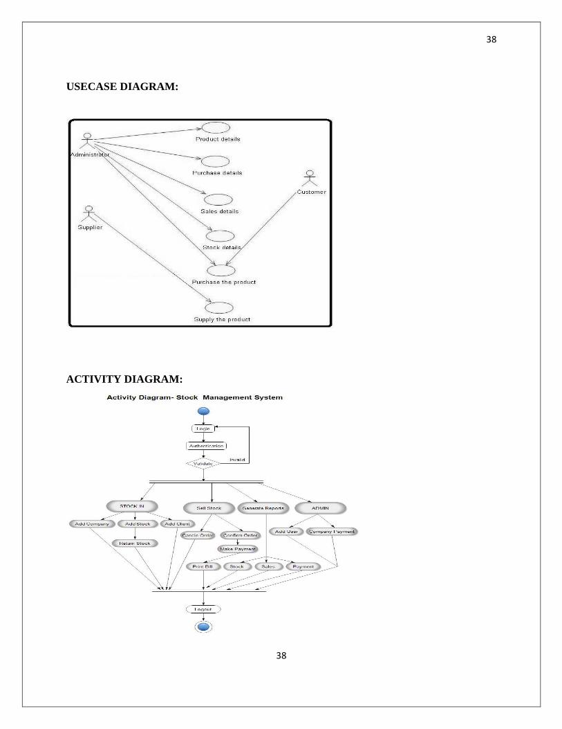
USECASE DIAGRAM:
ACTIVITY DIAGRAM:
39
39
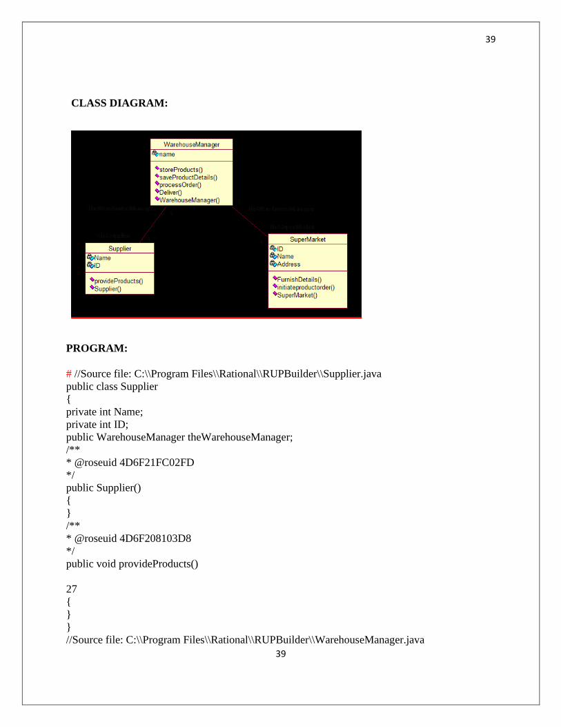
CLASS DIAGRAM:
PROGRAM:
# //Source file: C:\\Program Files\\Rational\\RUPBuilder\\Supplier.java
public class Supplier
{
private int Name;
private int ID;
public WarehouseManager theWarehouseManager;
/**
* @roseuid 4D6F21FC02FD
*/
public Supplier()
{
}
/**
* @roseuid 4D6F208103D8
*/
public void provideProducts()
WWW.VIDYARTHIPLUS.COM
27
{
}
}
//Source file: C:\\Program Files\\Rational\\RUPBuilder\\WarehouseManager.java
40
40
public class WarehouseManager
{
private int name;
public Supplier theSupplier[];
public SuperMarket theSuperMarket;
/**
* @roseuid 4D6F21FC031C
*/
public WarehouseManager() {
}
/**
* @roseuid 4D6F1FFF0128
*/
public void storeProducts() {
}
/**
* @roseuid 4D6F20240261
*/
public void saveProductDetails() {
}
/**
* @roseuid 4D6F200A004E
*/
public void processOrder() {
}
/**
* @roseuid 4D6F204C02DE
*/
public void Deliver() {
}
}
//Source file: C:\\Program Files\\Rational\\RUPBuilder\\SuperMarket.java
public class SuperMarket
{
private int ID;
private int Name;
WWW.VIDYARTHIPLUS.COM
28
private int Address;
public WarehouseManager theWarehouseManager;
/**
* @roseuid 4D6F21FC033C
*/
public SuperMarket() {
41
41
}
/**
* @roseuid 4D6F20BE0290
*/
public void FurnishDetails()
{
}
/**
* @roseuid 4D6F20C40261
*/
public void initiateproductorder()
{
}
}
RESULT:
The stock management system was successfully described using UML diagrams.