Industrial and embedded control, data acquisition, logging ...
60
• Ethernet Data Acquisition and Control • Embedded Controllers • Distributed I/O • Dataloggers • Simulink I/O targets • Avionics Interfaces Shaping the future of computer-based I/O TM Industrial and embedded control, data acquisition, logging and avionics I/O PRODUCT CATALOG Volume 14 NEW Video Library ueidaq.com/videos 10-YEAR AVAILABILITY GUARANTEE 10
-
Upload
khangminh22 -
Category
Documents
-
view
1 -
download
0
Transcript of Industrial and embedded control, data acquisition, logging ...
• Ethernet Data Acquisition and Control• Embedded Controllers• Distributed I/O• Dataloggers• Simulink I/O targets• Avionics
Interfaces
Shaping the future of computer-based I/OTM
Industrial and embedded control,
data acquisition, logging and avionicsI/O
PRODUCT CATALOG Volume 14
NEW Video Library ueidaq.com/videos
10-YEARAVAILABILITYGUARANTEE
10
iiwww.UEIDAQ.com United Electronic Industries, Inc.
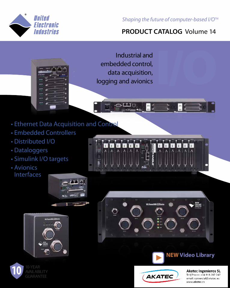
Founded in 1990, UEI is a leader in the computer-based data acquisition and control industry.
Serving customers world-wide, the company provides the highest quality hardware, software and services.
Our first products were ISA bus DAQ boards. PCI and PXI boards were added in the mid 90s and continue as an important part of our product offering today. In 2004, UEI introduced the PowerDNA Cube which can be configured as an Ethernet slave, UEILogger™, UEIPAC™, UEISIM™ or UEIModbus™. More recently, we released our RACKtangle chassis as well as GigE
versions of the Cube.
UEI holds a number of patents, including a patent on a UDP protocol that allows real-time monitor-ing and control of our PowerDNA cubes over Ethernet. Our products have received numerous awards including Test and Measurement World’s “Best in Test.”
All UEI products are developed and manufactured in the United States.
How to Order:To order products described in this catalog, please call us at (508) 921-4600. US customers may also order online at:
http://www.ueidaq.com/
Contact Us:
© 2015 United Electronic Industries, Inc. All product names listed are trademarks or trade names of their respective companies. Specifications listed are subject to change without notice as we continuously strive to improve our products. Printed in the U.S.A.
Warranty and Support:All hardware manufactured by UEI is warranted for two years to the original purchaser. Any product that fails will be repaired or replaced with the same or similar device, at the discretion of UEI. Warranty may be extended at the time of purchase to five years for 10% of a product’s cost. Technical support via telephone/email is free to all UEI cus-tomers. The latest revision of our soft-ware is available free of charge and may be downloaded from our web site.
About UEI:
UEI’s 19,000 square foot facility in Walpole, MA.
What’s new Welcome to our newcatalog and to UEI. For
25 years we have been a leading innovator in the data acquisition and control marketplace. Our Cube, RACKtangle and FLATRACK I/O chassis set the standard for high performance, high density, rugged Ethernet and stand-alone I/O.
This catalog contains a host of new and enhanced products. One of the major announcements in this volume is the 12-slot, DNR-MIL chassis. All connections to this new chassis are through 38999 style round connectors. Though our existing connector technology is ultra reliable, we recognize that 38999 connectors are preferred in many applications and even mandated in others. The new “MIL” RACKtangle has also been designed to meet various aspects of MIL-STD-461 (including all power supply requirements.), MIL-STD-810, and at least IP65 sealing requirements.
This catalog also introduces the UEINet chassis. The UEINet is an ultra-compact (2.7" x 4" x 4") chassis that is designed to contain a single DNA-series I/O board. The UEINet is an ideal solution for small, rugged distributed I/O and communications gateway systems.
Of course we’re always working on new I/O boards. New I/O boards in this volume include the DNx-VR-608 variable reluctance input board, the DNx-AO-318 and AO-318-020 fully isolated D/A boards with voltage current read-back and the DNx-AI-248-230 high density -2 to + 30 Volt input A/D board and the DNx-DIO-463 high current solid-state relay board.
If you don’t see a product or capability your application requires, please don’t hesitate to contact us with your request. Most of our new products are based on requests from our valued customers.
For those of you who are already UEI customers, I thank you for your business. For those new to UEI and investigating our offerings, I encourage you to call or email us regarding your application. Our applications engineering group is staffed with data acquisition and control experts who will answer your questions and help you configure the ideal system for your application. We are focused on your success and how we can make you another happy UEI customer.
Sincerely,
Shaun MillerPresident & Founder
A Letter from the President
Long Term (10-year) Availability Guarantee:UEI guarantees the availability of all RACKtangle/Cube series products (including DNA, DNR, DNF, UEIPAC, UEISIM, UEILogger and UEIModbus chassis and compatible I/O boards) for a minimum of 10 years. Unless you are specifically notified at the time of purchase, all DNA and DNR series products will be available for repurchase for at least 10 years. We understand the investment you make by using our products and we en-sure long-term product availability. Protecting customers from product obsolescence issues is nothing new at UEI. We still sell ISA bus boards. Now our excellent long-term support is backed up by our written prom-ise. As of the printing date of this catalog, ALL RACK/Cube series prod-ucts in the catalog will be available for 10+ years!
30-Day Evaluation Period: All hardware manufactured by UEI and shipped within the USA is available for evaluation. In fact, any order for standard product with a total value less than $10,000 is automatically covered by our 30-day evaluation policy and may be returned within 30 days of shipment without restocking fees.
www.UEIDAQ.com United Electronic Industries, Inc.Tel: (508) 921-4600 Fax: (508) 668-23501
Featured Products
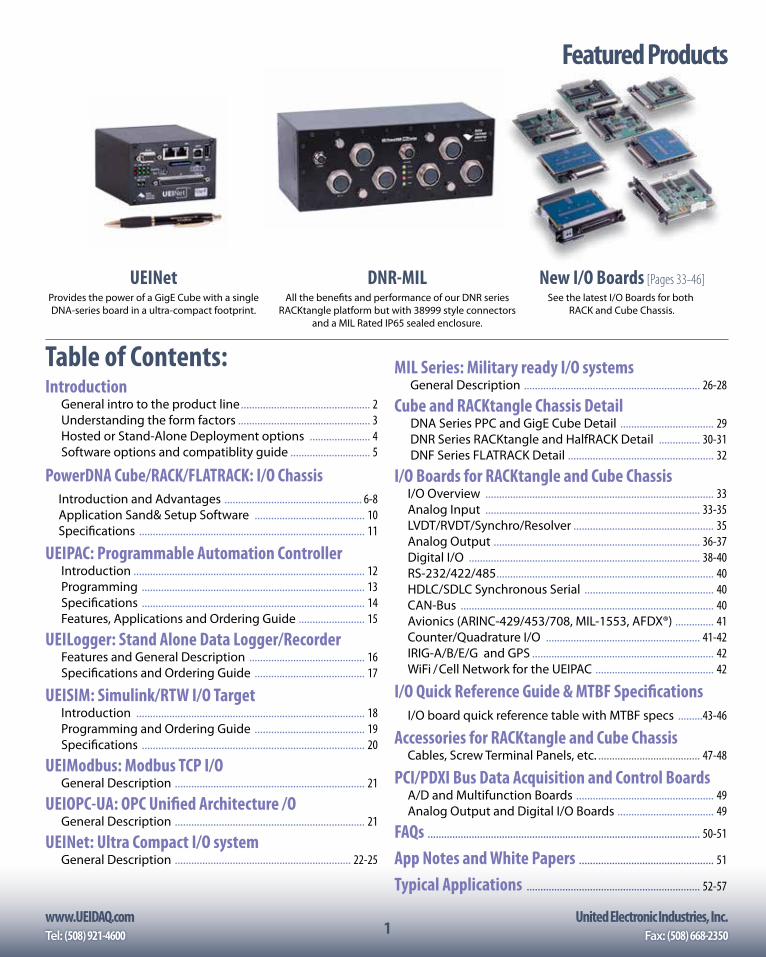
Table of Contents:Introduction
General intro to the product line ............................................... 2Understanding the form factors ................................................ 3Hosted or Stand-Alone Deployment options ...................... 4Software options and compatiblity guide ............................. 5
PowerDNA Cube/RACK/FLATRACK: I/O Chassis Introduction and Advantages .................................................. 6-8
Application Sand& Setup Software ........................................ 10 Specifications .................................................................................. 11
UEIPAC: Programmable Automation Controller Introduction .................................................................................... 12 Programming ................................................................................. 13 Specifications ................................................................................. 14
Features, Applications and Ordering Guide ........................ 15
UEILogger: Stand Alone Data Logger/RecorderFeatures and General Description .......................................... 16 Specifications and Ordering Guide ........................................ 17
UEISIM: Simulink/RTW I/O Target Introduction ................................................................................... 18
Programming and Ordering Guide ........................................ 19 Specifications ................................................................................. 20
UEIModbus: Modbus TCP I/OGeneral Description ..................................................................... 21
UEIOPC-UA: OPC Unified Architecture /OGeneral Description ..................................................................... 21
UEINet: Ultra Compact I/O systemGeneral Description ................................................................ 22-25
MIL Series: Military ready I/O systemsGeneral Description ................................................................ 26-28
Cube and RACKtangle Chassis Detail DNA Series PPC and GigE Cube Detail .................................. 29 DNR Series RACKtangle and HalfRACK Detail ............... 30-31 DNF Series FLATRACK Detail ..................................................... 32
I/O Boards for RACKtangle and Cube ChassisI/O Overview ................................................................................... 33 Analog Input .............................................................................. 33-35
LVDT/RVDT/Synchro/Resolver ................................................... 35 Analog Output ........................................................................... 36-37 Digital I/O .................................................................................... 38-40
RS-232/422/485 ............................................................................... 40HDLC/SDLC Synchronous Serial ............................................... 40
CAN-Bus ............................................................................................ 40 Avionics (ARINC-429/453/708, MIL-1553, AFDX®) .............. 41Counter/Quadrature I/O ........................................................ 41-42IRIG-A/B/E/G and GPS .................................................................. 42WiFi / Cell Network for the UEIPAC ........................................... 42
I/O Quick Reference Guide & MTBF SpecificationsI/O board quick reference table with MTBF specs .........43-46
Accessories for RACKtangle and Cube ChassisCables, Screw Terminal Panels, etc. ..................................... 47-48
PCI/PDXI Bus Data Acquisition and Control BoardsA/D and Multifunction Boards .................................................. 49 Analog Output and Digital I/O Boards ................................... 49
FAQs ................................................................................................... 50-51
App Notes and White Papers ................................................. 51
Typical Applications ............................................................... 52-57
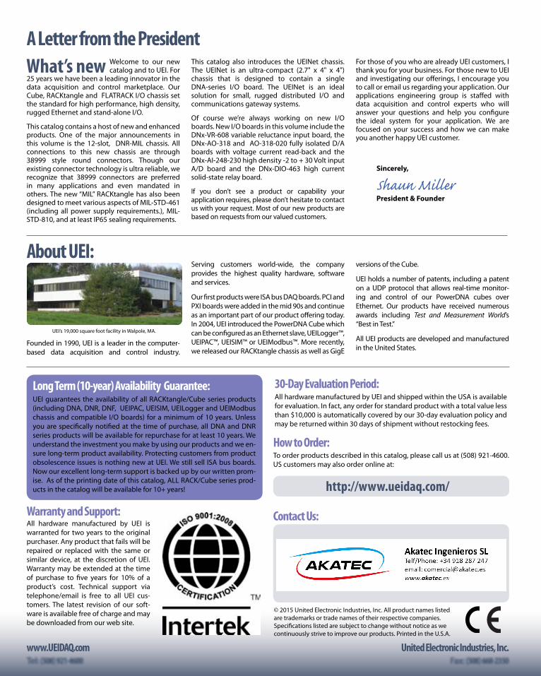
Provides the power of a GigE Cube with a single DNA-series board in a ultra-compact footprint.
UEINetAll the benefits and performance of our DNR series
RACKtangle platform but with 38999 style connectors and a MIL Rated IP65 sealed enclosure.
DNR-MILSee the latest I/O Boards for both
RACK and Cube Chassis.
New I/O Boards [Pages 33-46]

2www.UEIDAQ.com United Electronic Industries, Inc.
2
Form Factor UEI offers a wide vavriety of different chassis styles. The electronics in all of these is identical COTS technology. This is an often misun-destood concept so it is worth stating again:
Whether you choose a Cube, RACKTangle, FLATRACK, UEINet or MIL chassis, the internal electronics, software support and compatible I/O boards are identical.
• The 3U RACKTangles are easily mounted in standard 19" racksor against any bulkhead.
• The 1U FLATRACK allows up to 4 I/O boards to be installed in an AC or DC powered 1U chassis.
• Cubes are compact and rugged. They are available in low pow-er 100Base-T or standard GigE formats.
• The MIL series RACKs and Cubes are ideal for military or rugge-dized commercial applications with all connections throughstandard military 38999 connectors.
• The UEINet is a new single I/O slot chassis that fits an entire I/O system in an ultra compact 2.7" x 4" x 4" chassis.
For more info on the various form factors please refer to the overview on page 3 or see the detailed information contained later in this catalog.
Operating System and Programming OptionsThough most customers consider UEI a “hardware” company, we never underesti-mate the value of software in our products. We know that none of our hardware is of any value whatsoever without software. In fact, in both our design team and support team, we have more software engineers than hardware.
Our goal is to provide you with the software support you desire, regardless of what programming language, application or operating system you wish to use.
Almost everyone in the industry has good Windows support and UEI is no exception. You’ll find our support, including our UEIDAQ Framework is the most robust, simplest to use interface available. Whether you’re programing in C, VB, any of the .NET languages or application such as LabVIEW and MATLAB our support is unequaled.
However, where UEI really differentiates itself is in the support of Linux, VxWorks, QNX, RTX, INTime and languages outside the Windows world. We never leave our customers looking to bulletin boards or open source for drivers. Everything is written and fully tested by our software team.
For more info on the software support available on our various hardware platforms, please refer to page 5.
Hosted versus Standalone Deployment optionsDepending on your application, you may wish to have the UEI I/O hardware controlled by a host PC, run standalone DAQ/control ap-plications, or work in a SCADA configuration. The hardware (chassis and I/O boards) are identical in each of these deployment options. Only the firmware and the software is differ-ent. As with the Form Factor discussion, this is an often missed point and is worth stating again:
The chassis/electronics for each of the deployment options descibed below is identical. Only the firmware/software differentiates the functionality of the various options.
UEI chassis slaved to a host PC over EthernetWe refer to this as PowerDNA mode. Standalone Linux or VxWorks based embedded systemThis deployment option is known as the UEIPAC.Standalone datalogger with no programming required
This deployment option is the UEILogger.Simulink target
This option is referred to as the UEISIM.Modbus TCP I/O system
This option is referred to as the UEIModbus.OPC-UA compatible, embedded I/O system
This option is referred to as the UEIOPC-UAMore details on these options are on page 4.
I/O Board Selection With well over 60 different I/O boards avail-
able, UEI is sure to have just what your appli-cation needs. We understand that connecting
to 98% of the signals in your system is simply not enough. Our goal is to have 100% of what you
need. Beyond that, our goal is also to connect directly to what your system provides without the need for exter-
nal signal conditioning. Our product line includes:• Analog inputs (VIn, IIn, TCs, RTDs, Strain, ICP/IEPE etc.)• Analog outputs (Vout to 115VDC, 4-20 mA, etc.)• Logic level DIO• Industrial and high voltage DIO• Counters, Timers, IRIG timing• Avionics (ARINC 429/708/453, MIL-1553, AFDX etc.)• Serial Communications (Async and Synchronous)• RVDT/LVDT/Synchro/Resolver (input and simulated out)• Quadrature encoder input• Variable Relectance input• CAN-bus input (including J-1939 and .DBC)• WIFI and GSM wireless interfaces• Function generator outputs
For more info on our extensive line of I/O boards, please see pages 33-46. Note that all of our I/O boards are compatible with our entire line of chassis!
The Four Dimensions of your UEI System.
44 HOSTED OR STANDALONE FO
RM FA
CTOR OPTIONS
OS / PROGRAMMING I/O BOARD SELECT
ION
www.UEIDAQ.com United Electronic Industries, Inc.Tel: (508) 921-4600 Fax: (508) 668-23503
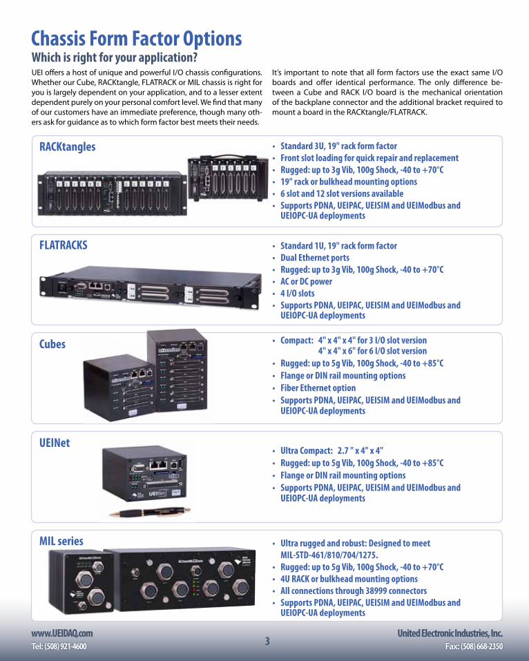
Chassis Form Factor OptionsWhich is right for your application?UEI offers a host of unique and powerful I/O chassis configurations. Whether our Cube, RACKtangle, FLATRACK or MIL chassis is right for you is largely dependent on your application, and to a lesser extent dependent purely on your personal comfort level. We find that many of our customers have an immediate preference, though many oth-ers ask for guidance as to which form factor best meets their needs.
It’s important to note that all form factors use the exact same I/O boards and offer identical performance. The only difference be-tween a Cube and RACK I/O board is the mechanical orientation of the backplane connector and the additional bracket required to mount a board in the RACKtangle/FLATRACK.
FLATRACKS • Standard 1U, 19" rack form factor• Dual Ethernet ports• Rugged: up to 3g Vib, 100g Shock, -40 to +70°C• AC or DC power• 4 I/O slots• Supports PDNA, UEIPAC, UEISIM and UEIModbus and
UEIOPC-UA deployments
Cubes • Compact: 4" x 4" x 4" for 3 I/O slot version 4" x 4" x 6" for 6 I/O slot version
• Rugged: up to 5g Vib, 100g Shock, -40 to +85°C• Flange or DIN rail mounting options• Fiber Ethernet option• Supports PDNA, UEIPAC, UEISIM and UEIModbus and
UEIOPC-UA deployments
RACKtangles • Standard 3U, 19" rack form factor• Front slot loading for quick repair and replacement• Rugged: up to 3g Vib, 100g Shock, -40 to +70°C• 19" rack or bulkhead mounting options• 6 slot and 12 slot versions available• Supports PDNA, UEIPAC, UEISIM and UEIModbus and
UEIOPC-UA deployments
MIL series • Ultra rugged and robust: Designed to meet MIL-STD-461/810/704/1275.• Rugged: up to 5g Vib, 100g Shock, -40 to +70°C• 4U RACK or bulkhead mounting options• All connections through 38999 connectors• Supports PDNA, UEIPAC, UEISIM and UEIModbus and
UEIOPC-UA deployments
UEINet• Ultra Compact: 2.7 " x 4" x 4" • Rugged: up to 5g Vib, 100g Shock, -40 to +85°C• Flange or DIN rail mounting options• Supports PDNA, UEIPAC, UEISIM and UEIModbus and
UEIOPC-UA deployments
4www.UEIDAQ.com United Electronic Industries, Inc.
4
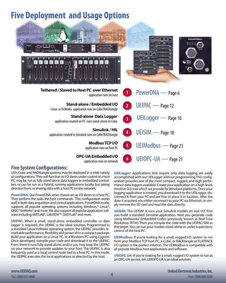
UEI’s Cube and RACKtangle systems may be deployed in a wide variety of configurations. They will function as I/O slaves under control of a host PC, may be run as fully stand-alone data loggers or embedded control-lers, or can be run as a hybrid, running applications locally, but taking direction from, or sharing data with a host PC on the network.
PowerDNA: Our PowerDNA series chassis act as I/O slaves to a host PC. They perform the tasks the host commands. This configuration works well in both data acquisition and control applications. PowerDNA mode, supports all popular operating systems including Windows,® Linux®, QNX,® VxWorks® and more. We also support all popular application soft-ware including MATLAB®, LabVIEWTM, DASYLab® and more.
UEIPAC: When a small, stand-alone embedded controller or data logger is required, the UEIPAC is the ideal solution. Programmed in a standard Linux VxWorks operating system, the UEIPAC provides re-markable performance, flexibility and power all in a compact package. Build your application on a Linux PC, or a Windows PC using Cygwin. Once developed, compile your code and download it to the UEIPAC. From there it runs fully stand-alone, and/or you may keep the UEIPAC on your network to provide updates to your host. The UEIPAC is also frequently used as a local control node tied to a host PC. In this mode, the UEIPAC executes the local applications as directed by the host.
Five System Configurations:
1Tethered / Slaved to Host PC over Ethernet application runs on host PowerDNA — Page 6
Stand-alone Data Loggerapplication created on PC, runs stand-alone on Cube
UEILogger — Page 16 3
2Stand-alone / Embedded I/OLinux or VxWorks application runs on Cube/RACKtangle
UEIPAC — Page 12
4Simulink / HIL application created in Simulink runs on Cube/RACKtangle UEISIM — Page 18
5Modbus TCP I/O application runs on host PC UEIModbus — Page 21
Five Deployment and Usage Options
UEILogger: Applications that require only data logging are easily accomplished with our UEILogger without programming This config-uration provides one of the most compact, rugged, and high perfor-mance data loggers available. Create your application on a high-level, intuitive GUI tool which we provide for Windows platforms. Once your logging application is created, you download it to the UEILogger, dis-connect it from your PC and are free to place it in location. After the data is acquired, you either reconnect to your PC via Ethernet, or sim-ply remove the SD card and read the data directly.
UEISIM: The UEISIM is runs your Simulink models on real I/O. First you build a standard Simulink application. Next you generate code using Mathworks’ Embedded Coder–previously known as Real-Time Workshop (RTW). Then you compile the code with the UEIPAC/SIM as the target. You can run your models stand-alone or under supervisory control of the host PC.
UEIModbus: If you’re looking for a small, rugged I/O system to run from your Modbus TCP host PC, a Cube, or RACKtangle or FLATRACK I/O system is the perfect solution. The UEIModbus is compatible with all popular Modbus host applications and software.
UEIOPC-UA: If you’re looking for a small, rugged I/O system to run as an OPC-UA servier, teh UEIOPC-UA is an ideal solutoin.
6OPC-UA Embedded I/O application runs on network UEIOPC-UA — Page 21
www.UEIDAQ.com United Electronic Industries, Inc.Tel: (508) 921-4600 Fax: (508) 668-23505
Software options
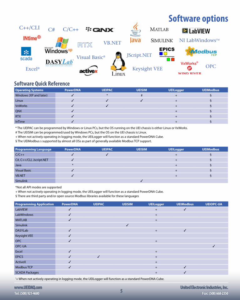
Software Quick ReferenceOperating Systems PowerDNA UEIPAC UEISIM UEILogger UEIModbus
Windows (XP and later) ✓ * # + §
Linux ✓ ✓ ✓ + §
VxWorks ✓ ✓ + §
QNX ✓ + §
RTX ✓ + §
InTime ✓ + §
* The UEIPAC can be programmed by Windows or Linux PCs, but the OS running on the UEI chassis is either Linux or VxWorks.# The UEISIM can be programmed/used by Windows PCs, but the OS on the UEI chassis is Linux.+ When not actively operating in logging mode, the UEILogger will function as a standard PowerDNA Cube.§ The UEIModbus s supported by almost all OSs as part of generally available Modbus TCP support.
Programming Language PowerDNA UEIPAC UEISIM UEILogger UEIModbus
C/C++ ✓ ✓ + §
C#, C++/CLI, Jscript.NET ✓ + §
Java * + §
Visual Basic ✓ + §
VB.NET ✓ + §
Simulink ✓
*Not all API modes are supported+ When not actively operating in logging mode, the UEILogger will function as a standard PowerDNA Cube.§ There are third party and/or open source Modbus libraries available for these languages
Programming Application PowerDNA UEIPAC UEISIM UEILogger UEIModbus UEIOPC-UA
LabVIEW ✓ + ✓
LabWindows ✓ +
MATLAB ✓ +
Simulink ✓
DASYLab ✓ + ✓
Keysight VEE ✓
OPC ✓ +
OPC-UA ✓
Excel ✓ +
EPICS ✓ ✓ +
ActiveX ✓ +
Modbus TCP ✓ + ✓
SCADA Packages + ✓
‘+ When not actively operating in logging mode, the UEILogger will function as a standard PowerDNA Cube.
RTX
C/C++C#C++/CLI
JScript.NETVisual Basic®
Excel®
NI LabWindowsTM
VB.NET
Keysight VEE OPC
SIMULINK
®
®
MATLAB
SIMULINK
®
®
MATLAB
6www.UEIDAQ.com United Electronic Industries, Inc.
6
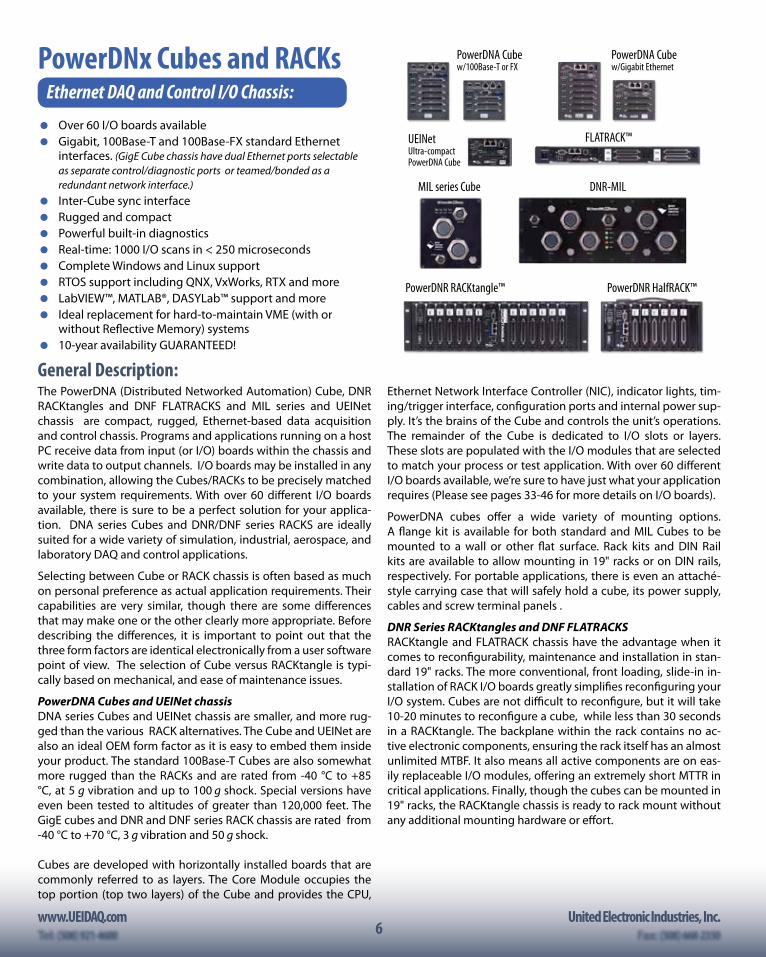
PowerDNx Cubes and RACKsEthernet DAQ and Control I/O Chassis:
Over 60 I/O boards available Gigabit, 100Base-T and 100Base-FX standard Ethernet
interfaces. (GigE Cube chassis have dual Ethernet ports selectable as separate control/diagnostic ports or teamed/bonded as a redundant network interface.)
Inter-Cube sync interface Rugged and compact Powerful built-in diagnostics Real-time: 1000 I/O scans in < 250 microseconds Complete Windows and Linux support RTOS support including QNX, VxWorks, RTX and more LabVIEW™, MATLAB®, DASYLab™ support and more Ideal replacement for hard-to-maintain VME (with or
without Reflective Memory) systems 10-year availability GUARANTEED!
General Description:The PowerDNA (Distributed Networked Automation) Cube, DNR RACKtangles and DNF FLATRACKS and MIL series and UEINet chassis are compact, rugged, Ethernet-based data acquisition and control chassis. Programs and applications running on a host PC receive data from input (or I/O) boards within the chassis and write data to output channels. I/O boards may be installed in any combination, allowing the Cubes/RACKs to be precisely matched to your system requirements. With over 60 different I/O boards available, there is sure to be a perfect solution for your applica-tion. DNA series Cubes and DNR/DNF series RACKS are ideally suited for a wide variety of simulation, industrial, aerospace, and laboratory DAQ and control applications.
Selecting between Cube or RACK chassis is often based as much on personal preference as actual application requirements. Their capabilities are very similar, though there are some differences that may make one or the other clearly more appropriate. Before describing the differences, it is important to point out that the three form factors are identical electronically from a user software point of view. The selection of Cube versus RACKtangle is typi-cally based on mechanical, and ease of maintenance issues.
PowerDNA Cubes and UEINet chassisDNA series Cubes and UEINet chassis are smaller, and more rug-ged than the various RACK alternatives. The Cube and UEINet are also an ideal OEM form factor as it is easy to embed them inside your product. The standard 100Base-T Cubes are also somewhat more rugged than the RACKs and are rated from -40 °C to +85 °C, at 5 g vibration and up to 100 g shock. Special versions have even been tested to altitudes of greater than 120,000 feet. The GigE cubes and DNR and DNF series RACK chassis are rated from -40 °C to +70 °C, 3 g vibration and 50 g shock.
Cubes are developed with horizontally installed boards that are commonly referred to as layers. The Core Module occupies the top portion (top two layers) of the Cube and provides the CPU,
Ethernet Network Interface Controller (NIC), indicator lights, tim-ing/trigger interface, configuration ports and internal power sup-ply. It’s the brains of the Cube and controls the unit’s operations. The remainder of the Cube is dedicated to I/O slots or layers. These slots are populated with the I/O modules that are selected to match your process or test application. With over 60 different I/O boards available, we’re sure to have just what your application requires (Please see pages 33-46 for more details on I/O boards).
PowerDNA cubes offer a wide variety of mounting options. A flange kit is available for both standard and MIL Cubes to be mounted to a wall or other flat surface. Rack kits and DIN Rail kits are available to allow mounting in 19" racks or on DIN rails, respectively. For portable applications, there is even an attaché-style carrying case that will safely hold a cube, its power supply, cables and screw terminal panels .
DNR Series RACKtangles and DNF FLATRACKSRACKtangle and FLATRACK chassis have the advantage when it comes to reconfigurability, maintenance and installation in stan-dard 19" racks. The more conventional, front loading, slide-in in-stallation of RACK I/O boards greatly simplifies reconfiguring your I/O system. Cubes are not difficult to reconfigure, but it will take 10-20 minutes to reconfigure a cube, while less than 30 secondsin a RACKtangle. The backplane within the rack contains no ac-tive electronic components, ensuring the rack itself has an almost unlimited MTBF. It also means all active components are on eas-ily replaceable I/O modules, offering an extremely short MTTR incritical applications. Finally, though the cubes can be mounted in19" racks, the RACKtangle chassis is ready to rack mount withoutany additional mounting hardware or effort.
PowerDNA Cubew/100Base-T or FX
UEINetUltra-compact PowerDNA Cube
PowerDNA Cubew/Gigabit Ethernet
PowerDNR RACKtangle™ PowerDNR HalfRACK™
DNR-MIL
FLATRACK™
MIL series Cube
www.UEIDAQ.com United Electronic Industries, Inc.Tel: (508) 921-4600 Fax: (508) 668-23507
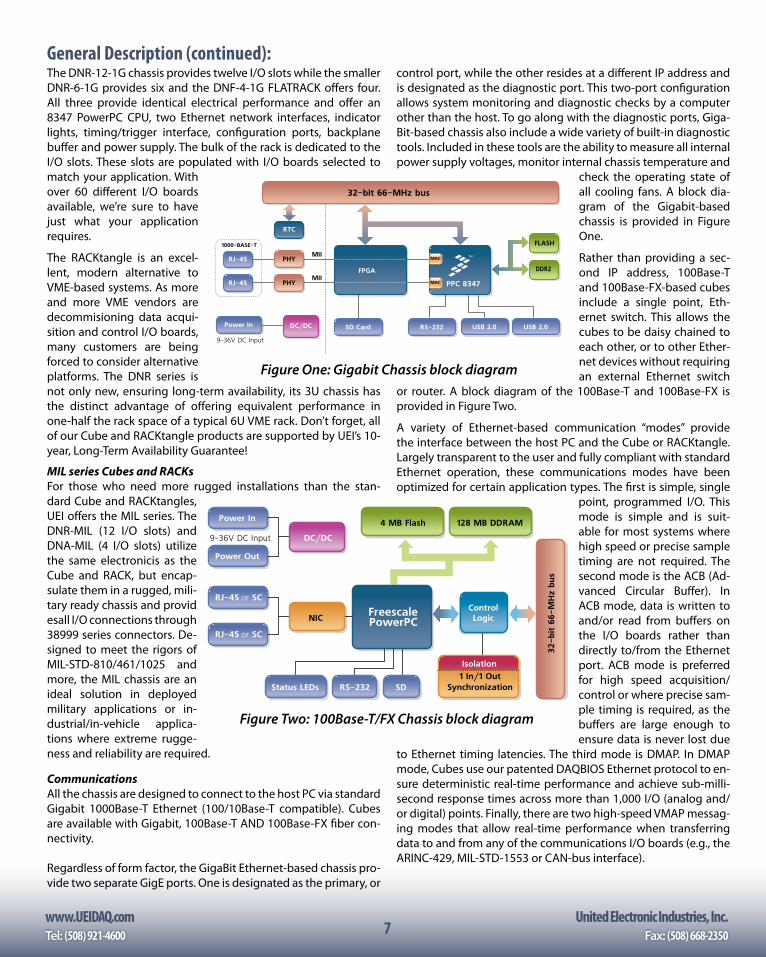
The DNR-12-1G chassis provides twelve I/O slots while the smaller DNR-6-1G provides six and the DNF-4-1G FLATRACK offers four. All three provide identical electrical performance and offer an 8347 PowerPC CPU, two Ethernet network interfaces, indicator lights, timing/trigger interface, configuration ports, backplane buffer and power supply. The bulk of the rack is dedicated to the I/O slots. These slots are populated with I/O boards selected to match your application. With over 60 different I/O boards available, we’re sure to have just what your application requires.
The RACKtangle is an excel-lent, modern alternative to VME-based systems. As more and more VME vendors are decommisioning data acqui-sition and control I/O boards, many customers are beingforced to consider alternative platforms. The DNR series is not only new, ensuring long-term availability, its 3U chassis has the distinct advantage of offering equivalent performance in one-half the rack space of a typical 6U VME rack. Don’t forget, all of our Cube and RACKtangle products are supported by UEI’s 10-year, Long-Term Availability Guarantee!
MIL series Cubes and RACKsFor those who need more rugged installations than the stan-dard Cube and RACKtangles, UEI offers the MIL series. The DNR-MIL (12 I/O slots) and DNA-MIL (4 I/O slots) utilizethe same electronicis as the Cube and RACK, but encap-sulate them in a rugged, mili-tary ready chassis and provid esall I/O connections through 38999 series connectors. De-signed to meet the rigors of MIL-STD-810/461/1025 and more, the MIL chassis are an ideal solution in deployed military applications or in-dustrial/in-vehicle applica-tions where extreme rugge-ness and reliability are required.
CommunicationsAll the chassis are designed to connect to the host PC via standard Gigabit 1000Base-T Ethernet (100/10Base-T compatible). Cubes are available with Gigabit, 100Base-T AND 100Base-FX fiber con-nectivity.
Regardless of form factor, the GigaBit Ethernet-based chassis pro-vide two separate GigE ports. One is designated as the primary, or
control port, while the other resides at a different IP address and is designated as the diagnostic port. This two-port configuration allows system monitoring and diagnostic checks by a computer other than the host. To go along with the diagnostic ports, Giga-Bit-based chassis also include a wide variety of built-in diagnostic tools. Included in these tools are the ability to measure all internal power supply voltages, monitor internal chassis temperature and
check the operating state of all cooling fans. A block dia-gram of the Gigabit-based chassis is provided in Figure One.
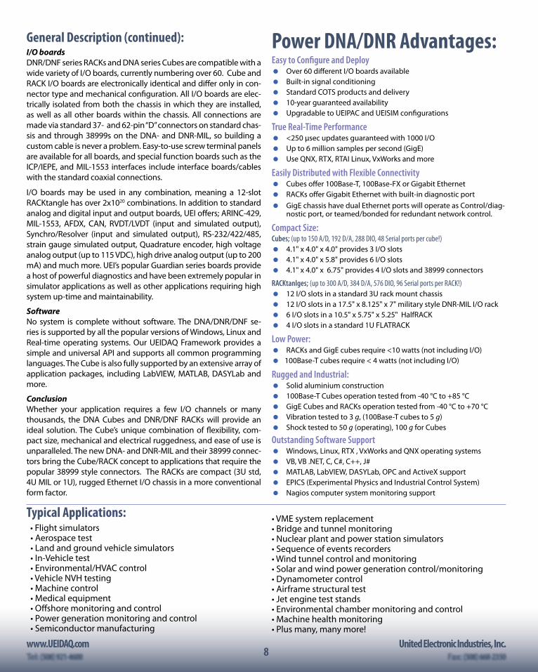
Rather than providing a sec-ond IP address, 100Base-T and 100Base-FX-based cubes include a single point, Eth-ernet switch. This allows the cubes to be daisy chained to each other, or to other Ether-net devices without requiring an external Ethernet switch
or router. A block diagram of the 100Base-T and 100Base-FX is provided in Figure Two.
A variety of Ethernet-based communication “modes” provide the interface between the host PC and the Cube or RACKtangle. Largely transparent to the user and fully compliant with standard Ethernet operation, these communications modes have been optimized for certain application types. The first is simple, single
point, programmed I/O. This mode is simple and is suit-able for most systems where high speed or precise sample timing are not required. The second mode is the ACB (Ad-vanced Circular Buffer). In ACB mode, data is written to and/or read from buffers on the I/O boards rather than directly to/from the Ethernet port. ACB mode is preferred for high speed acquisition/control or where precise sam-ple timing is required, as the buffers are large enough to ensure data is never lost due
to Ethernet timing latencies. The third mode is DMAP. In DMAP mode, Cubes use our patented DAQBIOS Ethernet protocol to en-sure deterministic real-time performance and achieve sub-milli-second response times across more than 1,000 I/O (analog and/or digital) points. Finally, there are two high-speed VMAP messag-ing modes that allow real-time performance when transferring data to and from any of the communications I/O boards (e.g., the ARINC-429, MIL-STD-1553 or CAN-bus interface).
MAC
MAC
PPC 8347
DC/DC
9-36V DC Input
Power In SD Card RS-232
32-bit 66-MHz bus
RJ-45
RJ-45
PHY
PHY
RTC
DDR2
FLASH
MII1000-BASE-T
MIIFPGA
USB 2.0 USB 2.0
Figure One: Gigabit Chassis block diagram
General Description (continued):
ControlLogic
4 MB Flash 128 MB DDRAM
DC/DC
Synchronization1 In/1 Out
NIC
9-36V DC Input
Isolation
Power Out
Power In
32-b
it 6
6-M
Hz
bus
RJ-45 or SC
RJ-45 or SC
FreescalePowerPC
Status LEDs SDRS-232
Figure Two: 100Base-T/FX Chassis block diagram
8www.UEIDAQ.com United Electronic Industries, Inc.
8
I/O boardsDNR/DNF series RACKs and DNA series Cubes are compatible with a wide variety of I/O boards, currently numbering over 60. Cube and RACK I/O boards are electronically identical and differ only in con-nector type and mechanical configuration. All I/O boards are elec-trically isolated from both the chassis in which they are installed, as well as all other boards within the chassis. All connections are made via standard 37- and 62-pin “D” connectors on standard chas-sis and through 38999s on the DNA- and DNR-MIL, so building a custom cable is never a problem. Easy-to-use screw terminal panels are available for all boards, and special function boards such as the ICP/IEPE, and MIL-1553 interfaces include interface boards/cables with the standard coaxial connections.
I/O boards may be used in any combination, meaning a 12-slot RACKtangle has over 2x10²⁰ combinations. In addition to standard analog and digital input and output boards, UEI offers; ARINC-429, MIL-1553, AFDX, CAN, RVDT/LVDT (input and simulated output), Synchro/Resolver (input and simulated output), RS-232/422/485, strain gauge simulated output, Quadrature encoder, high voltage analog output (up to 115 VDC), high drive analog output (up to 200 mA) and much more. UEI’s popular Guardian series boards provide a host of powerful diagnostics and have been extremely popular in simulator applications as well as other applications requiring high system up-time and maintainability.
SoftwareNo system is complete without software. The DNA/DNR/DNF se-ries is supported by all the popular versions of Windows, Linux and Real-time operating systems. Our UEIDAQ Framework provides a simple and universal API and supports all common programming languages. The Cube is also fully supported by an extensive array of application packages, including LabVIEW, MATLAB, DASYLab and more.
ConclusionWhether your application requires a few I/O channels or many thousands, the DNA Cubes and DNR/DNF RACKs will provide an ideal solution. The Cube’s unique combination of flexibility, com-pact size, mechanical and electrical ruggedness, and ease of use is unparalleled. The new DNA- and DNR-MIL and their 38999 connec-tors bring the Cube/RACK concept to applications that require the popular 38999 style connectors. The RACKs are compact (3U std, 4U MIL or 1U), rugged Ethernet I/O chassis in a more conventional form factor.
Typical Applications:• Flight simulators• Aerospace test• Land and ground vehicle simulators• In-Vehicle test• Environmental/HVAC control• Vehicle NVH testing• Machine control• Medical equipment• Offshore monitoring and control• Power generation monitoring and control• Semiconductor manufacturing
Power DNA/DNR Advantages:Easy to Configure and Deploy Over 60 different I/O boards available Built-in signal conditioning Standard COTS products and delivery 10-year guaranteed availability Upgradable to UEIPAC and UEISIM configurations
True Real-Time Performance <250 µsec updates guaranteed with 1000 I/O Up to 6 million samples per second (GigE) Use QNX, RTX, RTAI Linux, VxWorks and more
Easily Distributed with Flexible Connectivity Cubes offer 100Base-T, 100Base-FX or Gigabit Ethernet RACKs offer Gigabit Ethernet with built-in diagnostic port GigE chassis have dual Ethernet ports will operate as Control/diag-
nostic port, or teamed/bonded for redundant network control.
Compact Size:Cubes; (up to 150 A/D, 192 D/A, 288 DIO, 48 Serial ports per cube!) 4.1" x 4.0" x 4.0" provides 3 I/O slots 4.1" x 4.0" x 5.8" provides 6 I/O slots 4.1" x 4.0" x 6.75" provides 4 I/O slots and 38999 connectors
RACKtanlges; (up to 300 A/D, 384 D/A, 576 DIO, 96 Serial ports per RACK!) 12 I/O slots in a standard 3U rack mount chassis 12 I/O slots in a 17.5" x 8.125" x 7" military style DNR-MIL I/O rack 6 I/O slots in a 10.5" x 5.75" x 5.25" HalfRACK 4 I/O slots in a standard 1U FLATRACK
Low Power: RACKs and GigE cubes require <10 watts (not including I/O) 100Base-T cubes require < 4 watts (not including I/O)
Rugged and Industrial: Solid aluminium construction 100Base-T Cubes operation tested from -40 °C to +85 °C GigE Cubes and RACKs operation tested from -40 °C to +70 °C Vibration tested to 3 g, (100Base-T cubes to 5 g) Shock tested to 50 g (operating), 100 g for Cubes
Outstanding Software Support Windows, Linux, RTX , VxWorks and QNX operating systems VB, VB .NET, C, C#, C++, J# MATLAB, LabVIEW, DASYLab, OPC and ActiveX support EPICS (Experimental Physics and Industrial Control System) Nagios computer system monitoring support
• VME system replacement• Bridge and tunnel monitoring• Nuclear plant and power station simulators• Sequence of events recorders• Wind tunnel control and monitoring• Solar and wind power generation control/monitoring• Dynamometer control• Airframe structural test• Jet engine test stands• Environmental chamber monitoring and control• Machine health monitoring• Plus many, many more!
General Description (continued):
www.UEIDAQ.com United Electronic Industries, Inc.Tel: (508) 921-4600 Fax: (508) 668-23509
Whether using our DNA Cubes, DNR/DNF RACKs (or PowerDAQ PCI and PDXI boards), programming your data acquisition and control system has never been easier.
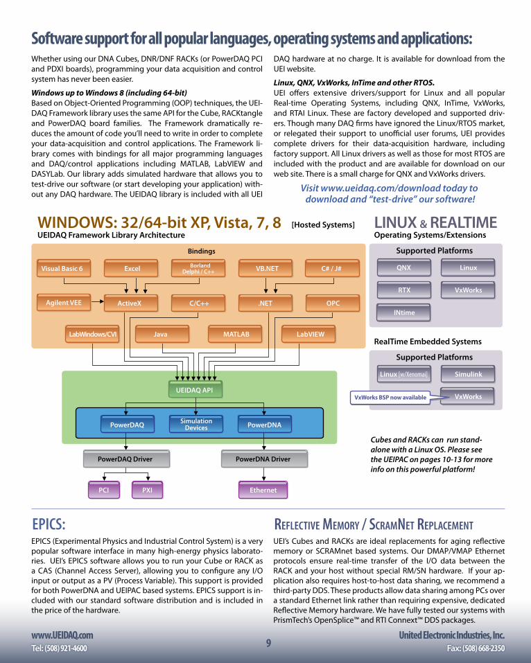
Windows up to Windows 8 (including 64-bit)Based on Object-Oriented Programming (OOP) techniques, the UEI-DAQ Framework library uses the same API for the Cube, RACKtangle and PowerDAQ board families. The Framework dramatically re-duces the amount of code you’ll need to write in order to complete your data-acquisition and control applications. The Framework li-brary comes with bindings for all major programming languages and DAQ/control applications including MATLAB, LabVIEW and DASYLab. Our library adds simulated hardware that allows you to test-drive our software (or start developing your application) with-out any DAQ hardware. The UEIDAQ library is included with all UEI
DAQ hardware at no charge. It is available for download from the UEI website.
Linux, QNX, VxWorks, InTime and other RTOS.UEI offers extensive drivers/support for Linux and all popular Real-time Operating Systems, including QNX, InTime, VxWorks, and RTAI Linux. These are factory developed and supported driv-ers. Though many DAQ firms have ignored the Linux/RTOS market, or relegated their support to unofficial user forums, UEI provides complete drivers for their data-acquisition hardware, including factory support. All Linux drivers as well as those for most RTOS are included with the product and are available for download on our web site. There is a small charge for QNX and VxWorks drivers.
Visit www.ueidaq.com/download today to download and “test-drive” our software!
Software support for all popular languages, operating systems and applications:
WINDOWS: 32/64-bit XP, Vista, 7, 8 LINUX & REALTIME[Hosted Systems]
RealTime Embedded Systems
Supported Platforms
Supported Platforms
UEIDAQ Framework Library Architecture Operating Systems/Extensions
LabWindows/CVI JavaLabWindows/CVI MATLAB LabVIEW
UEIDAQ API
PowerDAQ PowerDNASimulationDevices
PowerDAQ Driver PowerDNA Driver
EthernetPCI PXI
Linux
RTX
INtime
VxWorks
VxWorks
QNX
SimulinkLinux [w/Xenomai]
Bindings
ActiveX C/C++ .NETAgilent VEE OPC
BorlandDelphi / C++ VB.NETExcelVisual Basic 6 C# / J#
VxWorks BSP now available
Cubes and RACKs can run stand-alone with a Linux OS. Please see the UEIPAC on pages 10-13 for more info on this powerful platform!
EPICS:EPICS (Experimental Physics and Industrial Control System) is a very popular software interface in many high-energy physics laborato-ries. UEI’s EPICS software allows you to run your Cube or RACK as a CAS (Channel Access Server), allowing you to configure any I/O input or output as a PV (Process Variable). This support is provided for both PowerDNA and UEIPAC based systems. EPICS support is in-cluded with our standard software distribution and is included in the price of the hardware.
REflECtIvE MEMoRy / SCRaMNEt REPlaCEMENtUEI’s Cubes and RACKs are ideal replacements for aging reflective memory or SCRAMnet based systems. Our DMAP/VMAP Ethernet protocols ensure real-time transfer of the I/O data between the RACK and your host without special RM/SN hardware. If your ap-plication also requires host-to-host data sharing, we recommend a third-party DDS. These products allow data sharing among PCs over a standard Ethernet link rather than requiring expensive, dedicated Reflective Memory hardware. We have fully tested our systems with PrismTech’s OpenSplice™ and RTI Connext™ DDS packages.
10www.UEIDAQ.com United Electronic Industries, Inc.
10
Ordering Guide:Ultra Compact Gigabit Ethernet I/O modulesPart Number Description (Includes Chassis, Power Supply, Ethernet and Serial cables and software CD)DNA-PPC5 100Base-T 3-slot I/O Cube, PowerPC CPU, sync interface, (upgradable to UEIPAC/UEILogger/UEISIM/UEIModbus)DNA-PPC8 100Base-T 6 slot I/O Cube, PowerPC CPU, sync interface, (upgradable to UEIPAC/UEILogger/UEISIM/UEIModbus)DNA-FPPC5 100Base-FX fiber-based I/O Cube, 3 I/O slots, PowerPC CPU, sync interface, (upgradable to UEIPAC/UEISIM/UEIModbus)DNA-FPPC8 100Base-FX fiber-based I/O Cube, 6 I/O slots, PowerPC CPU, sync interface, (upgradable to UEIPAC/UEISIM/UEIModbus)DNA-PPC5-1G Gigabit Ethernet Cube, 3 I/O slots, PowerPC CPU, sync interface, (upgradable to UEIPAC/UEISIM/UEIModbus configuration)DNA-PPC8-1G Gigabit Ethernet Cube, 6 I/O slots, PowerPC CPU, sync interface, (upgradable to UEIPAC/UEISIM/UEIModbus configuration)DNA-MIL Gigabit Ethernet Cube, 4 I/O slots, 38999 connectors, PowerPC CPU, sync interface, (upgradable to other configurations)UEINet Two Gigabit (1000/100/10Base-T) 1-slot I/O Cube, PowerPC CPU, sync interface, (upgradable to UEIPAC/UEILogger/UEISIM/UEIModbus)DNF-4-1G Gigabit Ethernet 1U FLATRACK, 4I/O slots, PowerPC CPU, sync interface, (upgradable to other configurations)DNR-6-1G Gigabit Ethernet RACKtangle, 6 I/O slots, PowerPC CPU, sync interface, (upgradable to UEIPAC/UEISIM/UEIModbus)DNR-12-1G Gigabit Ethernet RACKtangle, 12 I/O slots, PowerPC CPU, sync interface, (upgradable to UEIPAC/UEISIM/UEIModbus)DNR-MIL Gigabit Ethernet RACK, 12 I/O slots, 38999 connectors, PowerPC CPU, sync interface, (upgradable to other configurations)
For I/O boards (layers), see pages 33-46. For accessories including cables, screw terminal boards and mounting options, see page 47.
Diagnostic and set-up softwareUEI’s PowerDNx systems provide outstanding operating system, program-ming language and application package support, but that is far from the end of the story. All UEI Cubes and RACKs also include a host of helpful and powerful system setup, diagnostics and test software.
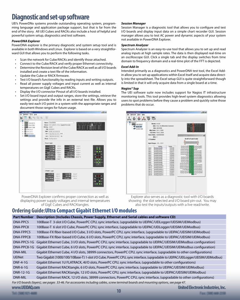
PowerDNA ExplorerPowerDNA explorer is the primary diagnostic and system setup tool and is available in both Windows and Linux. Explorer is based on a very straightfor-ward GUI that allows you to perform the following tasks.
• Scan the network for Cube/RACKs and identify those attached. • Connect to the Cube/RACK and verify proper Ethernet connectivity. • Determine the Revision level of the Cube/RACK as well as all I/O boards
installed and create a text file of the information. • Update the Cube or RACK firmware. • Test I/O board‘s functionality by reading inputs and writing outputs. • Read all power supply voltages and input current as well as internal
temperatures on GigE Cubes and RACKs. • Display the I/O connector Pinout of all I/O boards installed. • Set I/O board input and output ranges, store the settings, retrieve the
settings and provide the info in an external text file. Allows you to easily test each I/O point in a system with the appropriate ranges and document those ranges for future usage.
Session ManagerSession Manager is a diagnostic tool that allows you to configure and test I/O boards and display input data on a simple chart recorder GUI. Session manager allows you to test AC power and dynamic aspects of your system not available in PowerDNA Explorer.
Spectrum AnalyzerSpectrum Analyzer is an easy-to-use tool that allows you to set up and read analog inputs at high sample rates. The data is then displayed real-time on an oscilloscope GUI. Click a single tab and the display switches from time domain to frequency domain and a real-time plot of the FFT is depicted.
Excel Add-InIntended primarily as a diagnostics and PowerDNA test tool, the Excel Add-in allow you to set up applications within Excel itself and acquire data direct-ly into the spreadsheet. The Excel setup GUI is quite straightforward though is limited in that it will only acquire data from a single board at a time.
Nagios® Sup The UEI software suite now includes support for Nagios IT infrastructure monitoring tools. This tool provides high-level system diagnostics allowing users to spot problems before they cause a problem and quickly solve those problems that do occur.
PowerDNA Explorer confirms proper connection as well as displaying power supply voltages and internal temperatures
of GigE Cubes and RACKtangles.
Explorer also serves as a diagnostic tool with I/O boards showing the slot selected and I/O board pin-out. You may
also test the inputs/outputs with a live read/write.
www.UEIDAQ.com United Electronic Industries, Inc.Tel: (508) 921-4600 Fax: (508) 668-235011
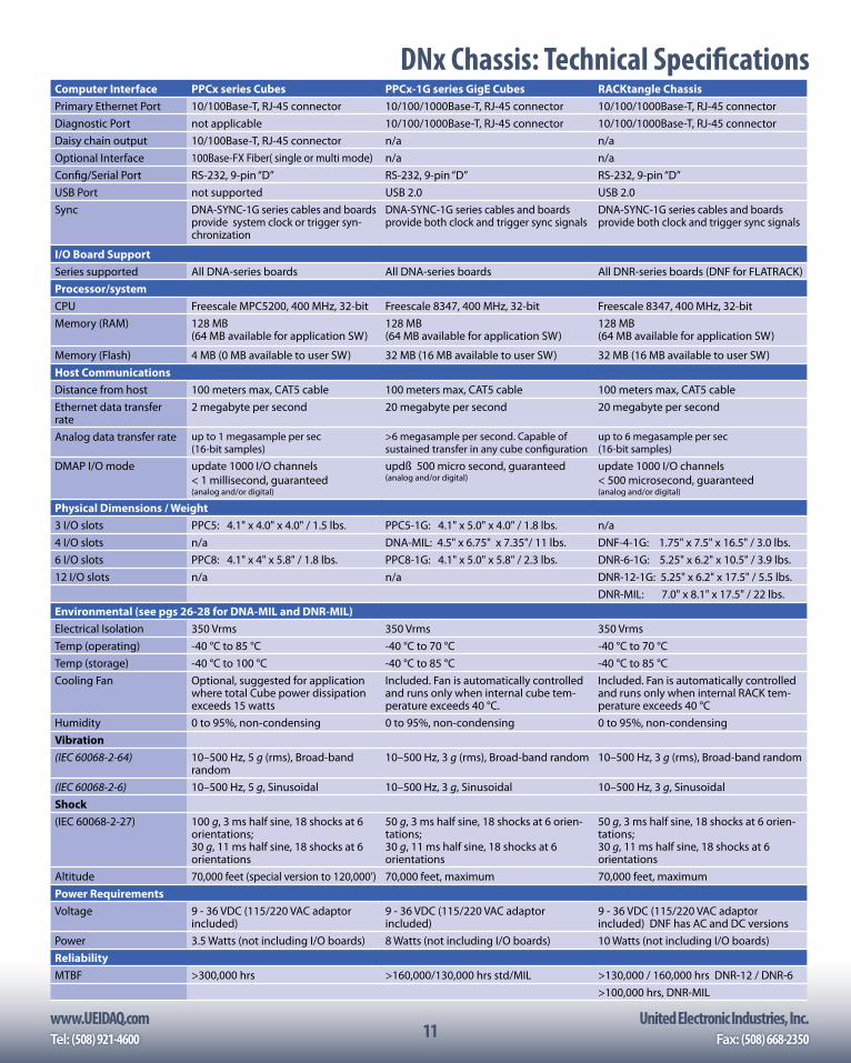
DNx Chassis: Technical SpecificationsComputer Interface PPCx series Cubes PPCx-1G series GigE Cubes RACKtangle ChassisPrimary Ethernet Port 10/100Base-T, RJ-45 connector 10/100/1000Base-T, RJ-45 connector 10/100/1000Base-T, RJ-45 connectorDiagnostic Port not applicable 10/100/1000Base-T, RJ-45 connector 10/100/1000Base-T, RJ-45 connectorDaisy chain output 10/100Base-T, RJ-45 connector n/a n/aOptional Interface 100Base-FX Fiber( single or multi mode) n/a n/aConfig/Serial Port RS-232, 9-pin “D” RS-232, 9-pin “D” RS-232, 9-pin “D”USB Port not supported USB 2.0 USB 2.0Sync DNA-SYNC-1G series cables and boards
provide system clock or trigger syn-chronization
DNA-SYNC-1G series cables and boards provide both clock and trigger sync signals
DNA-SYNC-1G series cables and boards provide both clock and trigger sync signals
I/O Board SupportSeries supported All DNA-series boards All DNA-series boards All DNR-series boards (DNF for FLATRACK)Processor/system CPU Freescale MPC5200, 400 MHz, 32-bit Freescale 8347, 400 MHz, 32-bit Freescale 8347, 400 MHz, 32-bitMemory (RAM) 128 MB
(64 MB available for application SW)128 MB (64 MB available for application SW)
128 MB (64 MB available for application SW)
Memory (Flash) 4 MB (0 MB available to user SW) 32 MB (16 MB available to user SW) 32 MB (16 MB available to user SW)Host CommunicationsDistance from host 100 meters max, CAT5 cable 100 meters max, CAT5 cable 100 meters max, CAT5 cableEthernet data transfer rate
2 megabyte per second 20 megabyte per second 20 megabyte per second
Analog data transfer rate up to 1 megasample per sec (16-bit samples)
>6 megasample per second. Capable of sustained transfer in any cube configuration
up to 6 megasample per sec (16-bit samples)
DMAP I/O mode update 1000 I/O channels < 1 millisecond, guaranteed (analog and/or digital)
updß 500 micro second, guaranteed (analog and/or digital)
update 1000 I/O channels < 500 microsecond, guaranteed (analog and/or digital)
Physical Dimensions / Weight3 I/O slots PPC5: 4.1" x 4.0" x 4.0" / 1.5 lbs. PPC5-1G: 4.1" x 5.0" x 4.0" / 1.8 lbs. n/a4 I/O slots n/a DNA-MIL: 4.5" x 6.75" x 7.35"/ 11 lbs. DNF-4-1G: 1.75" x 7.5" x 16.5" / 3.0 lbs.6 I/O slots PPC8: 4.1" x 4" x 5.8" / 1.8 lbs. PPC8-1G: 4.1" x 5.0" x 5.8" / 2.3 lbs. DNR-6-1G: 5.25" x 6.2" x 10.5" / 3.9 lbs.12 I/O slots n/a n/a DNR-12-1G: 5.25" x 6.2" x 17.5" / 5.5 lbs.
DNR-MIL: 7.0" x 8.1" x 17.5" / 22 lbs.Environmental (see pgs 26-28 for DNA-MIL and DNR-MIL)Electrical Isolation 350 Vrms 350 Vrms 350 VrmsTemp (operating) -40 °C to 85 °C -40 °C to 70 °C -40 °C to 70 °CTemp (storage) -40 °C to 100 °C -40 °C to 85 °C -40 °C to 85 °CCooling Fan Optional, suggested for application
where total Cube power dissipation exceeds 15 watts
Included. Fan is automatically controlled and runs only when internal cube tem-perature exceeds 40 °C.
Included. Fan is automatically controlled and runs only when internal RACK tem-perature exceeds 40 °C
Humidity 0 to 95%, non-condensing 0 to 95%, non-condensing 0 to 95%, non-condensingVibration(IEC 60068-2-64) 10–500 Hz, 5 g (rms), Broad-band
random10–500 Hz, 3 g (rms), Broad-band random 10–500 Hz, 3 g (rms), Broad-band random
(IEC 60068-2-6) 10–500 Hz, 5 g, Sinusoidal 10–500 Hz, 3 g, Sinusoidal 10–500 Hz, 3 g, SinusoidalShock(IEC 60068-2-27) 100 g, 3 ms half sine, 18 shocks at 6
orientations; 30 g, 11 ms half sine, 18 shocks at 6 orientations
50 g, 3 ms half sine, 18 shocks at 6 orien-tations; 30 g, 11 ms half sine, 18 shocks at 6 orientations
50 g, 3 ms half sine, 18 shocks at 6 orien-tations; 30 g, 11 ms half sine, 18 shocks at 6 orientations
Altitude 70,000 feet (special version to 120,000’) 70,000 feet, maximum 70,000 feet, maximumPower RequirementsVoltage 9 - 36 VDC (115/220 VAC adaptor
included)9 - 36 VDC (115/220 VAC adaptor included)
9 - 36 VDC (115/220 VAC adaptor included) DNF has AC and DC versions
Power 3.5 Watts (not including I/O boards) 8 Watts (not including I/O boards) 10 Watts (not including I/O boards)ReliabilityMTBF >300,000 hrs >160,000/130,000 hrs std/MIL >130,000 / 160,000 hrs DNR-12 / DNR-6
>100,000 hrs, DNR-MIL
12www.UEIDAQ.com United Electronic Industries, Inc.
12
The UEIPAC offers an unprecedented combination of flexibility, high performance, low cost and small size. The unit is an ideal solution in a wide variety of measurement and control applica-tions including: Temperature control, Remote/unmanned ve-hicle control, Hardware in-the-loop (HIL) and more. The UEIPAC is an ideal solution for a host of embedded DAQ applications as it allows systems to be developed without the cost or the addi-tional space required by an external host computer. The UEIPAC is now supporting the VxWorks and Linux operating systems.
Linux Systems• Uses standard Linux kernel with
Xenomai real-time support• Program in standard C• Eclipse IDE support• Develop on Linux PC or Windows
PC in the Cygwin environment VxWorks Systems• Use your existing development
license• Obtain your run-time license from
WindRiver• Our BSP provides everything else
you need including examples• One-time charge for BSP regard-
less of number of systems deployed
The UEIPAC is supported by all UEI DNA/DNR/DNF and UEINet series chassis and uses the same I/O boards. There are currently over 60 different I/O boards available including analog input (with up to 24 bit resolution), analog output, digital I/O, MIL-STD-1553, AFDX, ARINC 429/453/708, Serial and CAN commu-nications, counter/timer, quadrature encoder input and more. With this many different I/O boards available, there is sure to be a configuration perfect for your application.
A key advantage of the UEIPAC is its standalone application deployment. In PowerDNA systems, the software application is written for, and runs on a host PC that is connected to one or more UEI chassis via Ethernet. In UEIPAC systems, the Linux/Vx-Works application runs directly on the UEI RACK or Cube. There is no need for a separate host PC, though you can certainly con-nect one in a monitoring or supervisory role. This allows smaller, faster, more reliable and higher performance systems. It also eliminates the cost of a dedicated host PC and guarantees long term availability of the identical hardware. This is critical when certifying products through CE or FDA, etc.
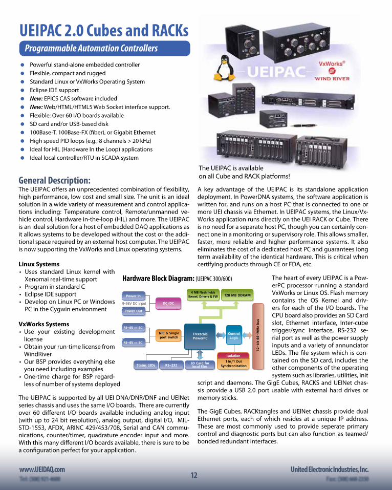
The heart of every UEIPAC is a Pow-erPC processor running a standard VxWorks or Linux OS. Flash memory contains the OS Kernel and driv-ers for each of the I/O boards. The CPU board also provides an SD Card slot, Ethernet interface, Inter-cube trigger/sync interface, RS-232 se-rial port as well as the power supply inputs and a variety of annunciator LEDs. The file system which is con-tained on the SD card, includes the other components of the operating system such as libraries, utilities, init
script and daemons. The GigE Cubes, RACKS and UEINet chas-sis provide a USB 2.0 port usable with external hard drives or memory sticks.
The GigE Cubes, RACKtangles and UEINet chassis provide dual Ethernet ports, each of which resides at a unique IP address. These are most commonly used to provide seperate primary control and diagnostic ports but can also function as teamed/bonded redundant interfaces.
General Description:
FreescalePowerPC
ControlLogic
128 MB DDRAM
DC/DC
Synchronization1 In/1 Out
NIC & Singleport switch
9-36V DC Input
Isolation
Status LEDsSD Card forlocal files
Power Out
Power In
RS-232
32-bit 6
6-M
Hz
bus
RJ-45 or SC
RJ-45 or SC
4 MB Flash holdsKernel, Drivers & FW
UEIPAC 2.0 Cubes and RACKsProgrammable Automation Controllers Powerful stand-alone embedded controller Flexible, compact and rugged Standard Linux or VxWorks Operating System Eclipse IDE support New: EPICS CAS software included New: Web/HTML/HTML5 Web Socket interface support. Flexible: Over 60 I/O boards available SD card and/or USB-based disk 100Base-T, 100Base-FX (fiber), or Gigabit Ethernet High speed PID loops (e.g., 8 channels > 20 kHz) Ideal for HIL (Hardware In the Loop) applications Ideal local controller/RTU in SCADA system
Hardware Block Diagram: (UEIPAC 300/600)
The UEIPAC is available on all Cube and RACK platforms!
www.UEIDAQ.com United Electronic Industries, Inc.Tel: (508) 921-4600 Fax: (508) 668-235013
Linux ProgrammingYour application runs as a regular Linux process giving you ac-cess to the standard POSIX API provided by the GNU C runtime library (glibc) as well as any other library that can be compiled for Linux (for example: libxml, libaudio file…).
New software provided with the UEIPAC includes an EPICS (Ex-perimental Physics and Industrial Control System) Channel Access Server (CAS). Our new LibSharedData software allows easy con-nection of the UEIPAC to HTML/HTML5 browsers via Web Sockets or other PCs via TCP/IP Sockets.
Whether your application requires a few I/O channels or a few thousand, the UEIPAC is an ideal solution. The UEIPAC’s unique combination of Linux operating system, real-time Xenomai sup-port, I/O flexibility, compact size, mechanical and electrical rug-gedness, and ease of use is unparalleled.
UEIPAC Linux TK Programmer’s ToolkitThe programmer’s toolkit provides the software tools neces-sary to create an embedded application targeting Linux on the UEIPAC’s PowerPC processor. This includes most popular ver-sions of Linux such as Fedora and Suse. The development en-vironment runs on a Linux PC or in the Cygwin environment on a Windows PC. The UEIPAC is also supported by the popular Eclipse IDE. Applications requiring hard real-time functionality are possible using the Xenomai Linux extension.
The UEIPAC development environment includes:• GCC to cross-compile an application targeting the
UEIPAC PPC module• GNU toolchain tools such as make• Standard Linux libraries such as glibc• UEIPAC library for the various I/O boards/devices
The UEIPAC Linux TK is not included with the UEIPAC and must be purchased as a separate item. Only one Linux toolkit must be purchased, regardless of the number of UEIPAC systems you will deploy.
The toolkit uses the same API as our popular PowerDNA Cubes, allowing you to reuse existing programs that were designed to run with a PowerDNA Cube over the network. This allows you to develop your application on your desktop, working directly with a “slaved” PowerDNA Cube. Once you are satisfied with your sys-tem, you may port the programs to run directly on the UEIPAC Cube with few modifications.
After the UEIPAC power-up, you have a ready to go Linux oper-ating system with FTP and web servers as well as a command line shell accessible from either the serial port or telnet and SSH over the network. You can configure the UEIPAC I/O module to execute your application after booting-up.
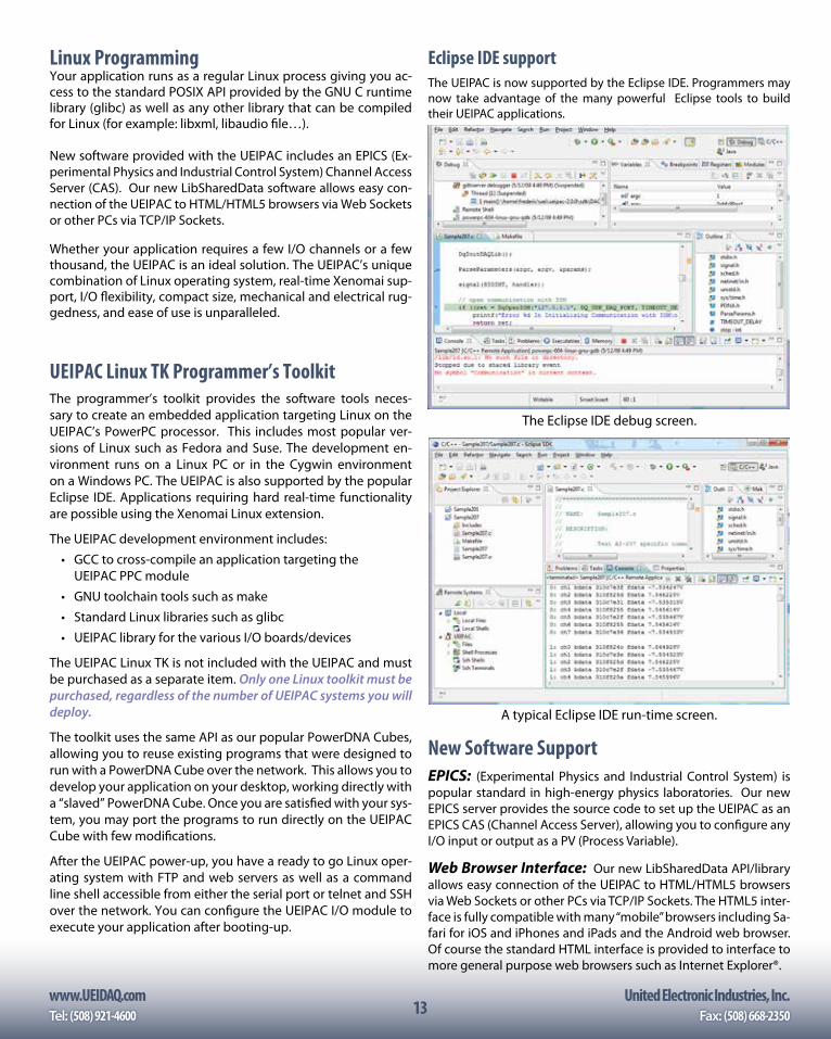
Eclipse IDE supportThe UEIPAC is now supported by the Eclipse IDE. Programmers may now take advantage of the many powerful Eclipse tools to build their UEIPAC applications.
The Eclipse IDE debug screen.
A typical Eclipse IDE run-time screen.
New Software SupportEPICS: (Experimental Physics and Industrial Control System) is popular standard in high-energy physics laboratories. Our new EPICS server provides the source code to set up the UEIPAC as an EPICS CAS (Channel Access Server), allowing you to configure any I/O input or output as a PV (Process Variable).
Web Browser Interface: Our new LibSharedData API/library allows easy connection of the UEIPAC to HTML/HTML5 browsers via Web Sockets or other PCs via TCP/IP Sockets. The HTML5 inter-face is fully compatible with many “mobile” browsers including Sa-fari for iOS and iPhones and iPads and the Android web browser. Of course the standard HTML interface is provided to interface to more general purpose web browsers such as Internet Explorer®.
14www.UEIDAQ.com United Electronic Industries, Inc.
14
VxWorks ProgrammingYou may now take advantage of all the hardware advantages of UEI’s popular UEIPAC chassis and continue to develop your applications in VxWorks. This powerful combination provides hard real-time performance, an extremely robust and reliable operating system, allows you to develop your application in a familiar environment and last, but not least, allows you to preserve a great deal of previously written code! To deploy a UEIPAC application running VxWorks you’ll need the following.
1. A UEIPAC (any version with GigE Ethernet ports)
2. The “UEIPAC VxW BSP”. You only need to purchase the BSP once, regardless of the number of systems you deploy
3. A VxWorks v 6.9.x development system (from Wind River)
4. A VxWorks run-time license for each UEIPAC deployed (also purchased from Wind River)
Though it’s beyond the scope of the datasheet to provide de-tails on how to configure and program the UEIPAC in VxWorks, the following is the table shows the chapters included in the current revision of the VxWorks UEIPAC user manual. The steps mentioned should be familiar to existing VxWorks program-mers and should help the reader understand the process.
1 Configuring and building a VxWorks kernel for UEIPAC1.1 Installing Software1.2 Building a VxWorks kernel for UEIPAC1.3 Booting VxWorks kernel on UEIPAC
2 Programming with PowerDNA API 2.1 Building PowerDNA library2.2 Building an example as a kernel module
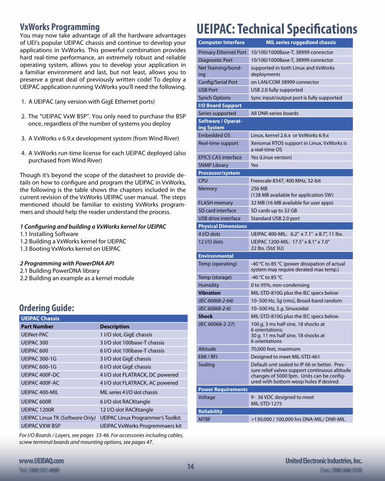
UEIPAC: Technical SpecificationsComputer Interface MIL series ruggedized chassis
Primary Ethernet Port 10/100/1000Base-T, 38999 connectorDiagnostic Port 10/100/1000Base-T, 38999 connectorNet Teaming/bond-ing
supported in both Linux and VxWorks deployments
Config/Serial Port on LAN/COM 38999 connectorUSB Port USB 2.0 fully supportedSynch Options Sync input/output port is fully supportedI/O Board SupportSeries supported All DNR-series boardsSoftware / Operat-ing SystemEmbedded OS Linux, kernel 2.6.x or VxWorks 6.9.xReal-time support Xenomai RTOS support in Linux, VxWorks is
a real-time OSEPICS CAS interface Yes (Linux version)SNMP Library YesProcessor/system CPU Freescale 8347, 400 MHz, 32-bitMemory 256 MB
(128 MB available for application SW)FLASH memory 32 MB (16 MB available for user apps)SD card interface SD cards up to 32 GBUSB drive interface Standard USB 2.0 portPhysical Dimensions4 I/O slots UEIPAC 400-MIL: 6.2” x 7.1" x 8.7", 11 lbs.12 I/O slots UEIPAC 1200-MIL: 17.5" x 8.1" x 7.0"
22 lbs. (Std 3U)EnvironmentalTemp (operating) -40 °C to 85 °C (power dissipation of actual
system may require derated max temp.)Temp (storage) -40 °C to 85 °CHumidity 0 to 95%, non-condensingVibration MIL-STD-810G plus the IEC specs below(IEC 60068-2-64) 10–500 Hz, 5g (rms), Broad-band random(IEC 60068-2-6) 10–500 Hz, 5 g, SinusoidalShock MIL-STD-810G plus the IEC specs below(IEC 60068-2-27) 100 g, 3 ms half sine, 18 shocks at
6 orientations; 30 g, 11 ms half sine, 18 shocks at 6 orientations
Altitude 70,000 feet, maximumEMI / RFI Designed to meet MIL-STD-461Sealing Default unit sealed to IP 66 or better. Pres-
sure relief valves support continuous altitude changes of 5000 fpm. Units can be config-ured with bottom weep holes if desired.
Power RequirementsVoltage 9 - 36 VDC designed to meet
MIL-STD-1275ReliabilityMTBF >130,000 / 100,000 hrs DNA-MIL/ DNR-MIL
Ordering Guide:UEIPAC ChassisPart Number DescriptionUEINet-PAC 1 I/O slot, GigE chassisUEIPAC 300 3 I/O slot 100base-T chassisUEIPAC 600 6 I/O slot 100base-T chassisUEIPAC 300-1G 3 I/O slot GigE chassisUEIPAC 600-1G 6 I/O slot GigE chassisUEIPAC 400F-DC 4 I/O slot FLATRACK, DC poweredUEIPAC 400F-AC 4 I/O slot FLATRACK, AC powered
UEIPAC 400-MIL MIL series 4 I/O slot chassis
UEIPAC 600R 6 I/O slot RACKtangleUEIPAC 1200R 12 I/O slot RACKtangleUEIPAC Linux TK (Software Only) UEIPAC Linux Programmer’s Toolkit.UEIPAC VXW BSP UEIPAC VxWorks Progremmaers kit
For I/O Boards / Layers, see pages 33-46. For accessories including cables, screw terminal boards and mounting options, see pages 47.
www.UEIDAQ.com United Electronic Industries, Inc.Tel: (508) 921-4600 Fax: (508) 668-235015
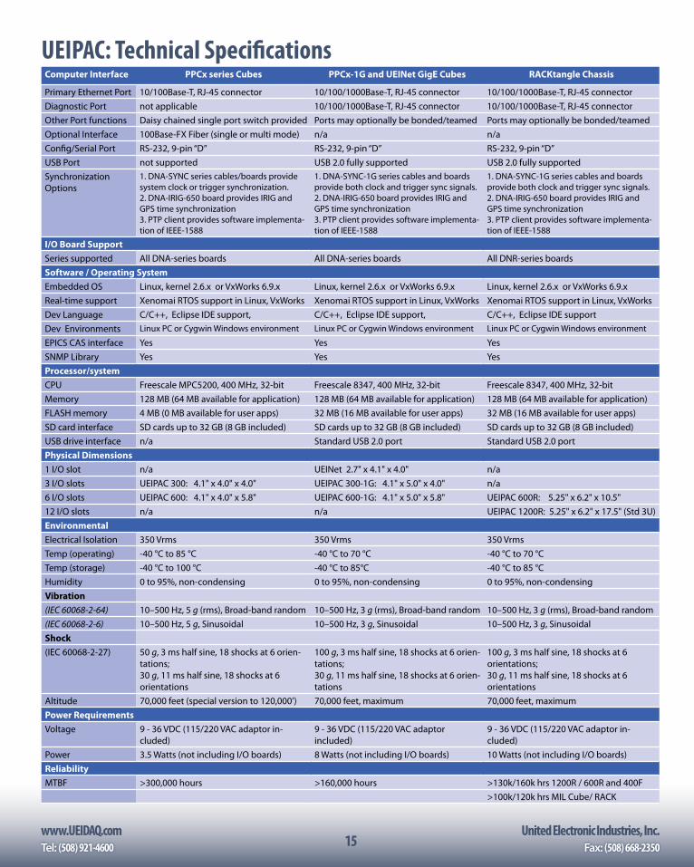
UEIPAC: Technical SpecificationsComputer Interface PPCx series Cubes PPCx-1G and UEINet GigE Cubes RACKtangle Chassis
Primary Ethernet Port 10/100Base-T, RJ-45 connector 10/100/1000Base-T, RJ-45 connector 10/100/1000Base-T, RJ-45 connectorDiagnostic Port not applicable 10/100/1000Base-T, RJ-45 connector 10/100/1000Base-T, RJ-45 connectorOther Port functions Daisy chained single port switch provided Ports may optionally be bonded/teamed Ports may optionally be bonded/teamedOptional Interface 100Base-FX Fiber (single or multi mode) n/a n/aConfig/Serial Port RS-232, 9-pin “D” RS-232, 9-pin “D” RS-232, 9-pin “D”USB Port not supported USB 2.0 fully supported USB 2.0 fully supportedSynchronization Options
1. DNA-SYNC series cables/boards provide system clock or trigger synchronization. 2. DNA-IRIG-650 board provides IRIG and GPS time synchronization3. PTP client provides software implementa-tion of IEEE-1588
1. DNA-SYNC-1G series cables and boards provide both clock and trigger sync signals.2. DNA-IRIG-650 board provides IRIG and GPS time synchronization3. PTP client provides software implementa-tion of IEEE-1588
1. DNA-SYNC-1G series cables and boards provide both clock and trigger sync signals.2. DNA-IRIG-650 board provides IRIG and GPS time synchronization3. PTP client provides software implementa-tion of IEEE-1588
I/O Board SupportSeries supported All DNA-series boards All DNA-series boards All DNR-series boardsSoftware / Operating SystemEmbedded OS Linux, kernel 2.6.x or VxWorks 6.9.x Linux, kernel 2.6.x or VxWorks 6.9.x Linux, kernel 2.6.x or VxWorks 6.9.xReal-time support Xenomai RTOS support in Linux, VxWorks Xenomai RTOS support in Linux, VxWorks Xenomai RTOS support in Linux, VxWorks Dev Language C/C++, Eclipse IDE support, C/C++, Eclipse IDE support, C/C++, Eclipse IDE supportDev Environments Linux PC or Cygwin Windows environment Linux PC or Cygwin Windows environment Linux PC or Cygwin Windows environment
EPICS CAS interface Yes Yes YesSNMP Library Yes Yes YesProcessor/system CPU Freescale MPC5200, 400 MHz, 32-bit Freescale 8347, 400 MHz, 32-bit Freescale 8347, 400 MHz, 32-bitMemory 128 MB (64 MB available for application) 128 MB (64 MB available for application) 128 MB (64 MB available for application)FLASH memory 4 MB (0 MB available for user apps) 32 MB (16 MB available for user apps) 32 MB (16 MB available for user apps)SD card interface SD cards up to 32 GB (8 GB included) SD cards up to 32 GB (8 GB included) SD cards up to 32 GB (8 GB included)USB drive interface n/a Standard USB 2.0 port Standard USB 2.0 portPhysical Dimensions1 I/O slot n/a UEINet 2.7" x 4.1" x 4.0" n/a3 I/O slots UEIPAC 300: 4.1" x 4.0" x 4.0" UEIPAC 300-1G: 4.1" x 5.0" x 4.0" n/a6 I/O slots UEIPAC 600: 4.1" x 4.0" x 5.8" UEIPAC 600-1G: 4.1" x 5.0" x 5.8" UEIPAC 600R: 5.25" x 6.2" x 10.5"12 I/O slots n/a n/a UEIPAC 1200R: 5.25" x 6.2" x 17.5" (Std 3U)EnvironmentalElectrical Isolation 350 Vrms 350 Vrms 350 VrmsTemp (operating) -40 °C to 85 °C -40 °C to 70 °C -40 °C to 70 °CTemp (storage) -40 °C to 100 °C -40 °C to 85°C -40 °C to 85 °CHumidity 0 to 95%, non-condensing 0 to 95%, non-condensing 0 to 95%, non-condensingVibration(IEC 60068-2-64) 10–500 Hz, 5 g (rms), Broad-band random 10–500 Hz, 3 g (rms), Broad-band random 10–500 Hz, 3 g (rms), Broad-band random(IEC 60068-2-6) 10–500 Hz, 5 g, Sinusoidal 10–500 Hz, 3 g, Sinusoidal 10–500 Hz, 3 g, SinusoidalShock(IEC 60068-2-27) 50 g, 3 ms half sine, 18 shocks at 6 orien-
tations; 30 g, 11 ms half sine, 18 shocks at 6 orientations
100 g, 3 ms half sine, 18 shocks at 6 orien-tations; 30 g, 11 ms half sine, 18 shocks at 6 orien-tations
100 g, 3 ms half sine, 18 shocks at 6 orientations; 30 g, 11 ms half sine, 18 shocks at 6 orientations
Altitude 70,000 feet (special version to 120,000’) 70,000 feet, maximum 70,000 feet, maximumPower RequirementsVoltage 9 - 36 VDC (115/220 VAC adaptor in-
cluded)9 - 36 VDC (115/220 VAC adaptor included)
9 - 36 VDC (115/220 VAC adaptor in-cluded)
Power 3.5 Watts (not including I/O boards) 8 Watts (not including I/O boards) 10 Watts (not including I/O boards)ReliabilityMTBF >300,000 hours >160,000 hours >130k/160k hrs 1200R / 600R and 400F
>100k/120k hrs MIL Cube/ RACK
16www.UEIDAQ.com United Electronic Industries, Inc.
16
The UEILogger is a powerful, flexible and easy-to-use data log-ger/recorder suitable for use in a wide variety of applications including flight test, industrial monitoring, aerospace, automo-tive/in-vehicle, and laboratory applications. Based upon UEI’s popular Cube architecture, the UEILogger maintains all of the PowerDNA’s flexibility and adds a powerful stand-alone data logging/recording capability.
The UEILogger Cube contains the controller, network and SD card interface, and power supply as well as either three or six I/O slots (UEILogger 300 or 600 respectively). Configure your logger by selecting the I/O boards required to match your application. With over 40 different I/O boards available, there’s sure to be a configuration to meet your needs. (Please see pages 33-46 for details on the I/O boards.)
PerformanceThe UEILogger supports sample rates up to 250,000 samples per second total, spread across the entire Cube. For example, a 6 slot Logger, full of 16-channel AI-217 boards has 96 input channels. The logger will log all 96 channels at up to 2,604 S/sec, for an ag-gregate sample rate of 250,000 S/sec.
Data is stored on standard SD Cards up to 32 Gigabyte (8 Gig SD Card included). Logged data may be retrieved via the unit’s Ethernet port or the SD Card may be removed from the logger and read by any SD Card reader. A 32 Gigabyte SD Card holds over 8 billion 24-bit A/D readings, enough to sample 96 analog inputs at 100 Hz for over nine days, or 96 channels at 1 Hz for over sixty months!
Simple and Flexible SetupDeveloping the data logging application is simple with the intuitive, Windows-based application provided. There is ab-solutely no programming required. The software allows you to set input, sample/update rates, signal conditioning, etc., all from simple pull down menus. The software allows you to se-lect automatic conversion of inputs into engineering units. Use the logger’s built-in conversions or create your own Y = mX + b linearization either by providing “m” and “b” directly or taking advantage of our automatic two-point scaling util-ity, which allows you to build the complete scaling from any two known states of your input. You may also set alarm/trig-ger conditions for each input channel that will control out-puts, sound an audible alarm and/or flash an LED. Please see the screen captures on the following page for more info or download a copy of the UEILogger application and try it out. (visit: www.ueidaq.com/UEIloggerdemo)
The UEILogger software converts data on the SD Card (including all configuration information) into formats used by popular DAQ and analysis applications. The software also allows you to review the logged data graphically.
The data logging program may be loaded onto the UEILogger two ways: The logger configuration file may be downloaded via the unit’s Ethernet port or it may be written directly to an SD Card. This allows Logger applications to be modified or initiated and data to be extracted by removing/installing an SD card.
General Description:
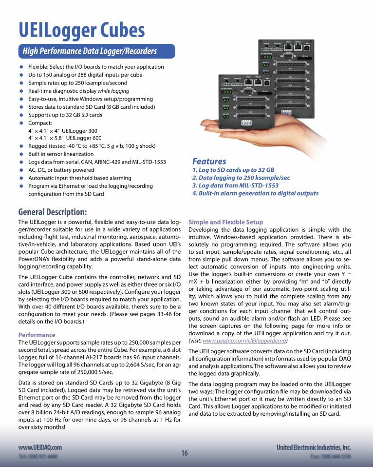
UEILogger CubesHigh Performance Data Logger/Recorders Flexible: Select the I/O boards to match your application Up to 150 analog or 288 digital inputs per cube Sample rates up to 250 ksamples/second Real-time diagnostic display while logging Easy-to-use, intuitive Windows setup/programming Stores data to standard SD Card (8 GB card included) Supports up to 32 GB SD cards Compact: 4" × 4.1" × 4" UEILogger 300
4" × 4.1" × 5.8" UEILogger 600 Rugged (tested -40 °C to +85 °C, 5 g vib, 100 g shock) Built in sensor linearization Logs data from serial, CAN, ARINC-429 and MIL-STD-1553 AC, DC, or battery powered Automatic input threshold based alarming Program via Ethernet or load the logging/recording configuration from the SD Card
Features1. Log to SD cards up to 32 GB2. Data logging to 250 ksample/sec3. Log data from MIL-STD-15534. Built-in alarm generation to digital outputs
www.UEIDAQ.com United Electronic Industries, Inc.Tel: (508) 921-4600 Fax: (508) 668-235017
Typical Applications: • Flight test • In-vehicle automotive test • In-vehicle off-road test • Environmental/HVAC monitor • Quality assurance monitor • Temperature monitor • Power generation monitor • Structure stress/strain logging • Manufacturing process monitor • Environmental chamber monitor
Software / Programming:The data logger application is very intuitive. The initial screen allows you to select the particular Logger Cube (if there are more than one on the net-work) as well as the I/O boards you wish to include in your logging applica-tion. You configure your application by making selections in Channels, Clock and Trigger, Alarms and Data Tabs. You may view logged data in the View tab.
Ordering Guide:UEILogger Order Information (including all software, 8 GByte SD Card, Universal Power Supply and full documentation)Part Number DescriptionUEILogger 300 5-layer enclosure; room for 3 I/O layers; CPU (PowerPC) + 100Base-T NIC; 24V power supply; installation CDUEILogger 600 8-layer enclosure; room for 6 I/O layers; CPU (PowerPC) + 100Base-T NIC; 24V power supply; installation CD
UEILogger UPG (software only) Upgrade to UEILogger package for PowerPC series Cubes; required software/firmware,
For I/O Boards / Layers, see pages 33-46. For accessories including cables, screw terminal boards and mounting options, see pages 47.
Specifications:
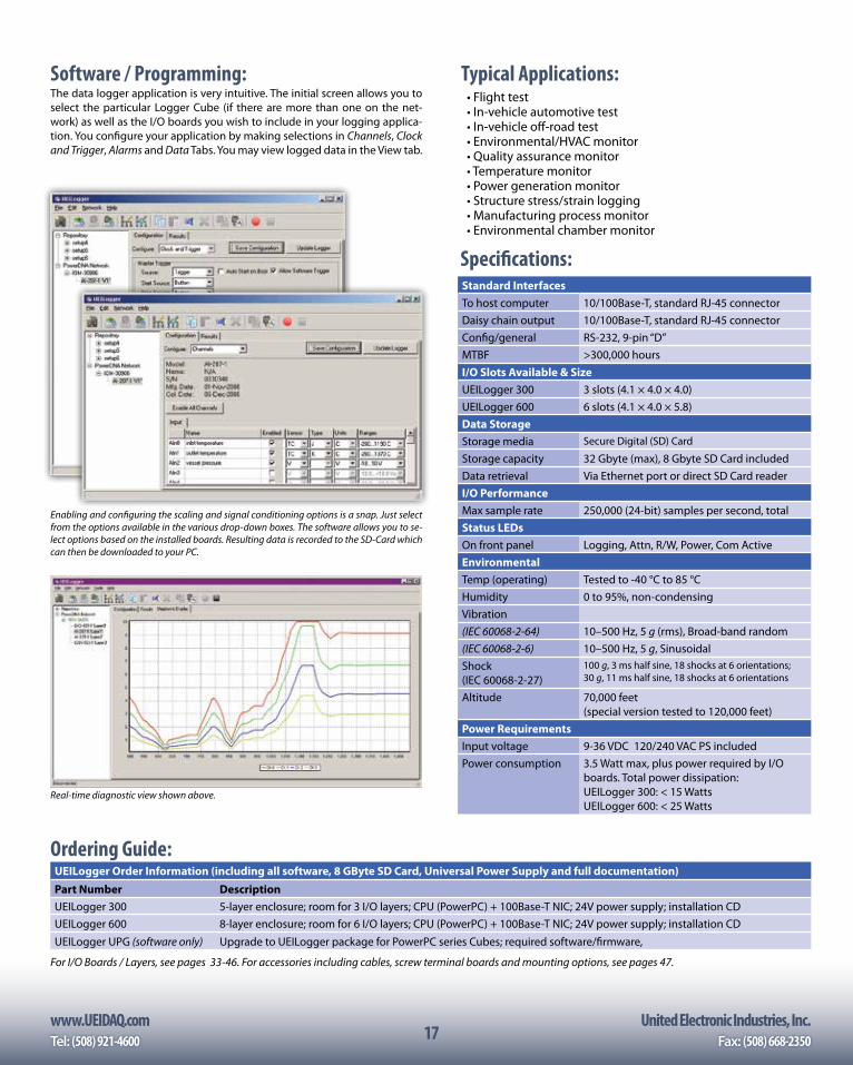
Enabling and configuring the scaling and signal conditioning options is a snap. Just select from the options available in the various drop-down boxes. The software allows you to se-lect options based on the installed boards. Resulting data is recorded to the SD-Card which can then be downloaded to your PC.
Standard InterfacesTo host computer 10/100Base-T, standard RJ-45 connectorDaisy chain output 10/100Base-T, standard RJ-45 connectorConfig/general RS-232, 9-pin “D”MTBF >300,000 hoursI/O Slots Available & SizeUEILogger 300 3 slots (4.1 × 4.0 × 4.0)UEILogger 600 6 slots (4.1 × 4.0 × 5.8)Data StorageStorage media Secure Digital (SD) Card
Storage capacity 32 Gbyte (max), 8 Gbyte SD Card includedData retrieval Via Ethernet port or direct SD Card readerI/O PerformanceMax sample rate 250,000 (24-bit) samples per second, totalStatus LEDsOn front panel Logging, Attn, R/W, Power, Com ActiveEnvironmentalTemp (operating) Tested to -40 °C to 85 °CHumidity 0 to 95%, non-condensingVibration(IEC 60068-2-64) 10–500 Hz, 5 g (rms), Broad-band random(IEC 60068-2-6) 10–500 Hz, 5 g, SinusoidalShock(IEC 60068-2-27)
100 g, 3 ms half sine, 18 shocks at 6 orientations; 30 g, 11 ms half sine, 18 shocks at 6 orientations
Altitude 70,000 feet (special version tested to 120,000 feet)
Power RequirementsInput voltage 9-36 VDC 120/240 VAC PS includedPower consumption 3.5 Watt max, plus power required by I/O
boards. Total power dissipation:UEILogger 300: < 15 WattsUEILogger 600: < 25 Watts
Real-time diagnostic view shown above.

18www.UEIDAQ.com United Electronic Industries, Inc.
18
UEISIM Cubes and RACKsSimulink® and RTW I/O Targets
Now supporting Cube, GigE Cube, and RACKtangle chassis! Powerful, compact and rugged Flexible: Over 60 I/O boards available including A/D, D/A,
Digital I/O, Counter/Timer, Quadrature encoder, Serial, CAN and ARINC 429 communications.
Standard Linux OS (2.6.x Kernel) Standard Ethernet 100Base-T or GigE interface Supports up to 5,000 “loops” per second Ideal for HIL (Hardware-In-the-Loop) applications Ideal for development, prototype and production
General Description:The UEISIM offers Simulink users a powerful, flexible I/O target. Models built in Simulink are deployed directly on the UEISIM using Embedded Coder. The combination creates a powerful solution for developing and tuning real-time (and non-real-time) appli-cations including model verification, rapid prototyping, and HIL testing. The UEISIM is rugged, flexible, and expandable enough not only to be a great solution while in your development cycle, but also the ideal solution for your production hardware.
To use the UEISIM, simply: 1) Build your Simulink ap-plication. 2) Open MATLAB and select Simulink/Em-bedded target for UEISIM. 3) Convert your model to use the UEISIM I/O blocks (if you had not used them in your original model). 4) Create an executable via Embedded Coder, (former-ly RTW). 5) Connect the UEI-SIM in “external mode” (if you wish to remotely mon-itor the application while running on the UEISIM). 6) Start your simulation. Six easy steps and your simulation is run-ning live on real hardware.
The UEISIM 300/600 are 4" × 4.1" × 4" / 4" x 4.1" x 5.8" and offer three or six I/O slots respectively. GigE versions of the UEISIM Cubes are designated as the UEISIM 300-1G and UEISIM 600-1G, while four and twelve-slot versions with 38999 connectors are designated the UEISIM 400-MIL and UEISIM-1200-MIL respectively. The RACKtan-
gle-based UEISIM 1200R and UEISIM 600R offer 12 and six slots re-spectively while the UEISIM 400F is a 4 slot FLATRACK. The -SIM op-tion also allows UEISim functionality on the new UEINet series. The UEISIM uses the same I/O boards as our popular PowerDNA family and includes analog input analog output (up to 32 channels PER BOARD), digital I/O, Serial and CAN communications, ARINC-429 networking, counter/timer, quadrature encoder input and more. With 60+ different I/O boards available, there is sure to be a configu-
ration perfect for your application.
The heart of the UEISIM is a Pow-erPC processor running a stan-dard (2.6.x) Linux OS kernel. Flash memory contains the OS Kernel and drivers for each of the I/O boards. The CPU/NIC provides an SD Card slot, Ethernet interface, Intercube trigger/sync interface, RS-232 port, power supply inputs and a variety of annunciator LEDs. The file system is contained on the SD card. It includes the other components of the operating sys-tem such as libraries, utilities, init script and daemons.
The UEISIM is rugged and robust. With 100Base-T Cubes tested from -40 °C to +85 °C, at 100 g shock, 5 g vibration and altitudes up to 70,000 feet (special version to 120,000 feet) and GigE-based chassis tested from -40 °C to +70 °C, 50 g shock, and 3 g vibration, the UEISIM is tough enough for the most challenging applica-tions. All I/O is isolated from the controller, so the UEISIM is im-mune to the glitches/spikes common in industrial environments.
FreescalePowerPC
ControlLogic
128 MB DDRAM
DC/DC
Synchronization1 In/1 Out
NIC & Singleport switch
9-36V DC Input
Isolation
Status LEDsSD Card forlocal files
Power Out
Power In
RS-232
32-b
it 6
6-M
Hz
bus
RJ-45 or SC
RJ-45 or SC
4 MB Flash holdsKernel, Drivers & FW
UEISIM Hardware Block Diagram:
The UEISIM is available on PPC Cube, GigE Cube and RACKtangle platforms!
The UEISIM UI allows you to remotely monitor signals and tune parameters on a model while it is executing on the UEISIM.
www.UEIDAQ.com United Electronic Industries, Inc.Tel: (508) 921-4600 Fax: (508) 668-235019
Ordering Guide:UEISIM Chassis (includes installed Linux OS, Universal AC power supply, Serial and Ethernet cables and 2 Gbyte SD Card)
Part Number Description
UEINet-SIM Linux-based, Simulink/RTW I/O target with 1 available I/O slots
UEISIM 300 Linux-based, Simulink/RTW I/O target with 3 available I/O slots
UEISIM 600 Linux-based, Simulink/RTW I/O target with 6 available I/O slot
UEISIM 300-1G Gigabit Ethernet, Linux-based, Simulink/RTW I/O target with 3 available I/O slots
UEISIM 600-1G Gigabit Ethernet, Linux-based, Simulink/RTW I/O target with 6 available I/O slots
UEISIM 400-MIL Gigabit Ethernet, Linux-based, Simulink/RTW I/O target with 4 available I/O slots and 38999 connectivityUEISIM 400R-AC Gigabit Ethernet, Linux-based, Simulink/RTW I/O target, FLATRACK with 4 available I/O slots, AC poweredUEISIM 400R-DC Gigabit Ethernet, Linux-based, Simulink/RTW I/O target, FLATRACK with 4 available I/O slots, DC powered
UEISIM 600R Gigabit Ethernet, Linux-based, Simulink/RTW I/O target, RACKtangle with 6 available I/O slots
UEISIM 1200R Gigabit Ethernet, Linux-based, Simulink/RTW I/O target, RACKtangle with 12 available I/O slots
UEISIM 1200-MIL Gigabit Ethernet, Linux-based, Simulink/RTW I/O target with 12 available I/O slots and 38999 connectivity
For I/O Boards / Layers, see pages 33-46. For accessories including cables, screw terminal boards and mounting options, see pages 47.
General Description: (continued)
The UEISIM I/O blocks provided are both powerful and easy to use.
The UEISIM appears as a standard Real-Time-Workshop target.
The UEISIM cubes offer a wide variety of mounting options. A flange kit allows the Cubes to be mounted to a wall or other flat surface. Rack kits and DIN Rail kits are available to allow mount-ing in 19” racks or on DIN rails respectively. UEISIM RACKtangles include flexible mounting ears that allow the RF or portable ap-plications, an attaché style carrying case that will safely hold a cube, its power supply, cables and screw terminal panels. RACK-tangle-based UEISIMs include rubber feet for desktop use as well as mounting brackets that allow the RACKtangle and FLATRACK
to be mounted directly into 19-inch racks. The brackets may be mounted on the rear of the RACKtangle allowing the chassis to be mounted on any flat surface or bulkhead.
Whether your application requires a few I/O channels or a few thousand, the UEISIM is an ideal solution. The Cube’s unique com-bination of clean and simple Simulink/RTW target compatible Linux operating system, I/O flexibility, compact size, mechanical and electrical ruggedness, and ease of use are unparalleled.
Monitoring and Tuning Feature!The new UEISIM UI feature allows remote signal monitoring and parameter tuning while a model is executing on the UEISIM.
It is similar to running the model in external mode under the su-pervision of Simulink running on a host PC. Use the language of your choice to create the monitoring client application.
Remote monitoring uses the libshareddata.so library included with UEISIM and UEIPAC 2.5.0 or greater (Upgrades are available to cur-rent UEISIM/PAC owners at no charge.) This library eases data com-munication between a program running on UEIPAC and clients running on network hosts through a simple C or javascript API.
The graphical UI can be programmed on the client side using any language capable of calling functions exported by a C library. In addition, bindings are provided for the following languages: C#, VB.NET, Python and LabVIEW.
The graphical UI can also be implemented as a web application with UEISIM model and Web browser communicating using web-sockets. The HTML behind the UI is served by the UEISIM built-in web server. Signals and parameters can then be monitored from any web browsing device, including smartphones and tablets.
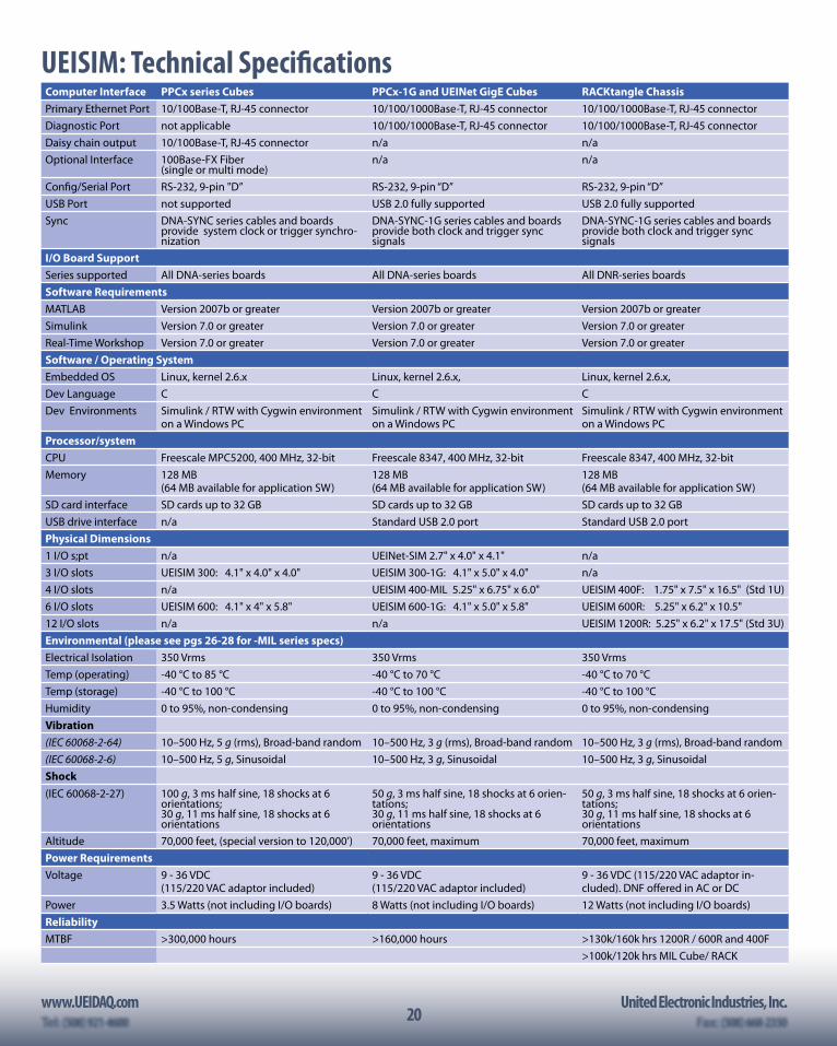
20www.UEIDAQ.com United Electronic Industries, Inc.
20
UEISIM: Technical SpecificationsComputer Interface PPCx series Cubes PPCx-1G and UEINet GigE Cubes RACKtangle ChassisPrimary Ethernet Port 10/100Base-T, RJ-45 connector 10/100/1000Base-T, RJ-45 connector 10/100/1000Base-T, RJ-45 connectorDiagnostic Port not applicable 10/100/1000Base-T, RJ-45 connector 10/100/1000Base-T, RJ-45 connectorDaisy chain output 10/100Base-T, RJ-45 connector n/a n/aOptional Interface 100Base-FX Fiber
(single or multi mode)n/a n/a
Config/Serial Port RS-232, 9-pin "D” RS-232, 9-pin “D” RS-232, 9-pin “D”USB Port not supported USB 2.0 fully supported USB 2.0 fully supportedSync DNA-SYNC series cables and boards
provide system clock or trigger synchro-nization
DNA-SYNC-1G series cables and boards provide both clock and trigger sync signals
DNA-SYNC-1G series cables and boards provide both clock and trigger sync signals
I/O Board SupportSeries supported All DNA-series boards All DNA-series boards All DNR-series boardsSoftware RequirementsMATLAB Version 2007b or greater Version 2007b or greater Version 2007b or greaterSimulink Version 7.0 or greater Version 7.0 or greater Version 7.0 or greaterReal-Time Workshop Version 7.0 or greater Version 7.0 or greater Version 7.0 or greaterSoftware / Operating SystemEmbedded OS Linux, kernel 2.6.x Linux, kernel 2.6.x, Linux, kernel 2.6.x,Dev Language C C CDev Environments Simulink / RTW with Cygwin environment
on a Windows PCSimulink / RTW with Cygwin environment on a Windows PC
Simulink / RTW with Cygwin environment on a Windows PC
Processor/system CPU Freescale MPC5200, 400 MHz, 32-bit Freescale 8347, 400 MHz, 32-bit Freescale 8347, 400 MHz, 32-bitMemory 128 MB
(64 MB available for application SW)128 MB (64 MB available for application SW)
128 MB (64 MB available for application SW)
SD card interface SD cards up to 32 GB SD cards up to 32 GB SD cards up to 32 GBUSB drive interface n/a Standard USB 2.0 port Standard USB 2.0 portPhysical Dimensions1 I/O s;pt n/a UEINet-SIM 2.7" x 4.0" x 4.1" n/a3 I/O slots UEISIM 300: 4.1" x 4.0" x 4.0" UEISIM 300-1G: 4.1" x 5.0" x 4.0" n/a4 I/O slots n/a UEISIM 400-MIL 5.25" x 6.75" x 6.0" UEISIM 400F: 1.75" x 7.5" x 16.5" (Std 1U)6 I/O slots UEISIM 600: 4.1" x 4" x 5.8" UEISIM 600-1G: 4.1" x 5.0" x 5.8" UEISIM 600R: 5.25" x 6.2" x 10.5"12 I/O slots n/a n/a UEISIM 1200R: 5.25" x 6.2" x 17.5" (Std 3U)Environmental (please see pgs 26-28 for -MIL series specs)Electrical Isolation 350 Vrms 350 Vrms 350 VrmsTemp (operating) -40 °C to 85 °C -40 °C to 70 °C -40 °C to 70 °CTemp (storage) -40 °C to 100 °C -40 °C to 100 °C -40 °C to 100 °CHumidity 0 to 95%, non-condensing 0 to 95%, non-condensing 0 to 95%, non-condensingVibration(IEC 60068-2-64) 10–500 Hz, 5 g (rms), Broad-band random 10–500 Hz, 3 g (rms), Broad-band random 10–500 Hz, 3 g (rms), Broad-band random(IEC 60068-2-6) 10–500 Hz, 5 g, Sinusoidal 10–500 Hz, 3 g, Sinusoidal 10–500 Hz, 3 g, SinusoidalShock(IEC 60068-2-27) 100 g, 3 ms half sine, 18 shocks at 6
orientations; 30 g, 11 ms half sine, 18 shocks at 6 orientations
50 g, 3 ms half sine, 18 shocks at 6 orien-tations; 30 g, 11 ms half sine, 18 shocks at 6 orientations
50 g, 3 ms half sine, 18 shocks at 6 orien-tations; 30 g, 11 ms half sine, 18 shocks at 6 orientations
Altitude 70,000 feet, (special version to 120,000’) 70,000 feet, maximum 70,000 feet, maximumPower RequirementsVoltage 9 - 36 VDC
(115/220 VAC adaptor included)9 - 36 VDC (115/220 VAC adaptor included)
9 - 36 VDC (115/220 VAC adaptor in-cluded). DNF offered in AC or DC
Power 3.5 Watts (not including I/O boards) 8 Watts (not including I/O boards) 12 Watts (not including I/O boards)ReliabilityMTBF >300,000 hours >160,000 hours >130k/160k hrs 1200R / 600R and 400F
>100k/120k hrs MIL Cube/ RACK
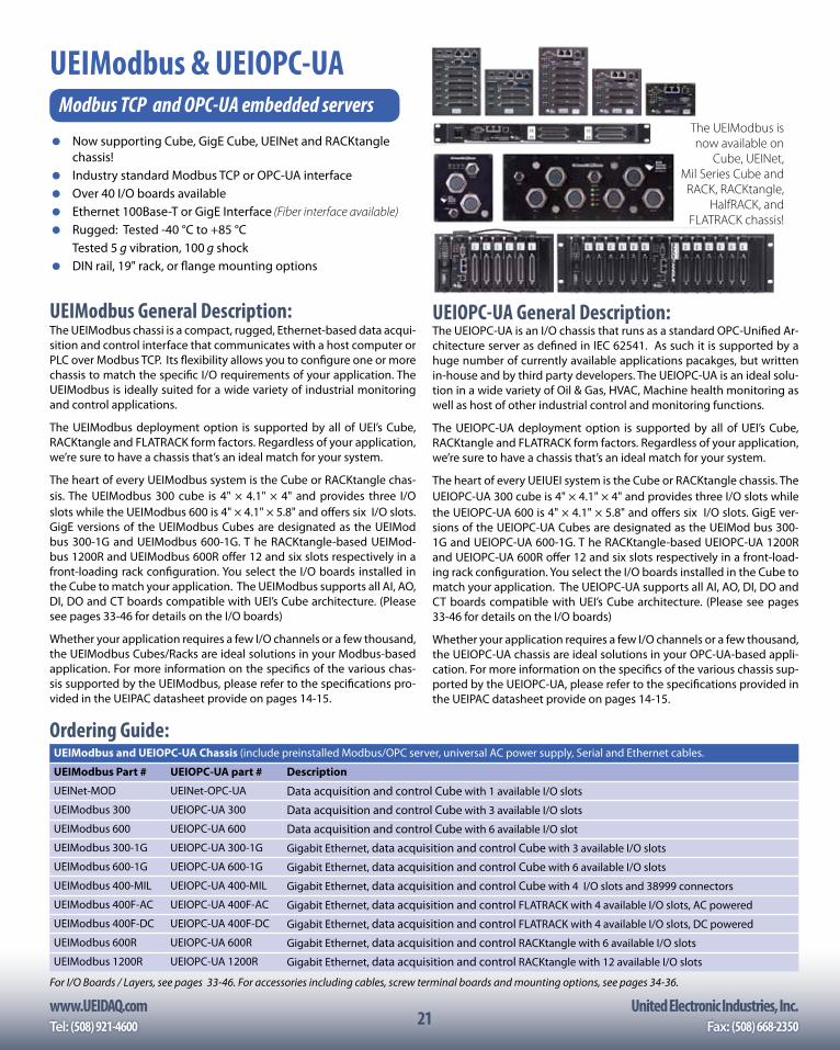
www.UEIDAQ.com United Electronic Industries, Inc.Tel: (508) 921-4600 Fax: (508) 668-235021
UEIModbus & UEIOPC-UAModbus TCP and OPC-UA embedded servers
Now supporting Cube, GigE Cube, UEINet and RACKtangle chassis!
Industry standard Modbus TCP or OPC-UA interface Over 40 I/O boards available Ethernet 100Base-T or GigE Interface (Fiber interface available) Rugged: Tested -40 °C to +85 °C Tested 5 g vibration, 100 g shock DIN rail, 19" rack, or flange mounting options
UEIModbus General Description:The UEIModbus chassi is a compact, rugged, Ethernet-based data acqui-sition and control interface that communicates with a host computer or PLC over Modbus TCP. Its flexibility allows you to configure one or more chassis to match the specific I/O requirements of your application. The UEIModbus is ideally suited for a wide variety of industrial monitoring and control applications.
The UEIModbus deployment option is supported by all of UEI’s Cube, RACKtangle and FLATRACK form factors. Regardless of your application, we’re sure to have a chassis that’s an ideal match for your system.
The heart of every UEIModbus system is the Cube or RACKtangle chas-sis. The UEIModbus 300 cube is 4" × 4.1" × 4" and provides three I/O slots while the UEIModbus 600 is 4" × 4.1" × 5.8" and offers six I/O slots. GigE versions of the UEIModbus Cubes are designated as the UEIMod bus 300-1G and UEIModbus 600-1G. T he RACKtangle-based UEIMod-bus 1200R and UEIModbus 600R offer 12 and six slots respectively in a front-loading rack configuration. You select the I/O boards installed in the Cube to match your application. The UEIModbus supports all AI, AO, DI, DO and CT boards compatible with UEI’s Cube architecture. (Please see pages 33-46 for details on the I/O boards)
Whether your application requires a few I/O channels or a few thousand, the UEIModbus Cubes/Racks are ideal solutions in your Modbus-based application. For more information on the specifics of the various chas-sis supported by the UEIModbus, please refer to the specifications pro-vided in the UEIPAC datasheet provide on pages 14-15.
The UEIModbus is now available on
Cube, UEINet, Mil Series Cube and
RACK, RACKtangle, HalfRACK, and
FLATRACK chassis!
Ordering Guide:UEIModbus and UEIOPC-UA Chassis (include preinstalled Modbus/OPC server, universal AC power supply, Serial and Ethernet cables.
UEIModbus Part # UEIOPC-UA part # Description
UEINet-MOD UEINet-OPC-UA Data acquisition and control Cube with 1 available I/O slots
UEIModbus 300 UEIOPC-UA 300 Data acquisition and control Cube with 3 available I/O slots
UEIModbus 600 UEIOPC-UA 600 Data acquisition and control Cube with 6 available I/O slot
UEIModbus 300-1G UEIOPC-UA 300-1G Gigabit Ethernet, data acquisition and control Cube with 3 available I/O slots
UEIModbus 600-1G UEIOPC-UA 600-1G Gigabit Ethernet, data acquisition and control Cube with 6 available I/O slots
UEIModbus 400-MIL UEIOPC-UA 400-MIL Gigabit Ethernet, data acquisition and control Cube with 4 I/O slots and 38999 connectors
UEIModbus 400F-AC UEIOPC-UA 400F-AC Gigabit Ethernet, data acquisition and control FLATRACK with 4 available I/O slots, AC powered
UEIModbus 400F-DC UEIOPC-UA 400F-DC Gigabit Ethernet, data acquisition and control FLATRACK with 4 available I/O slots, DC powered
UEIModbus 600R UEIOPC-UA 600R Gigabit Ethernet, data acquisition and control RACKtangle with 6 available I/O slots
UEIModbus 1200R UEIOPC-UA 1200R Gigabit Ethernet, data acquisition and control RACKtangle with 12 available I/O slots
For I/O Boards / Layers, see pages 33-46. For accessories including cables, screw terminal boards and mounting options, see pages 34-36.
UEIOPC-UA General Description:The UEIOPC-UA is an I/O chassis that runs as a standard OPC-Unified Ar-chitecture server as defined in IEC 62541. As such it is supported by a huge number of currently available applications pacakges, but written in-house and by third party developers. The UEIOPC-UA is an ideal solu-tion in a wide variety of Oil & Gas, HVAC, Machine health monitoring as well as host of other industrial control and monitoring functions.
The UEIOPC-UA deployment option is supported by all of UEI’s Cube, RACKtangle and FLATRACK form factors. Regardless of your application, we’re sure to have a chassis that’s an ideal match for your system.
The heart of every UEIUEI system is the Cube or RACKtangle chassis. The UEIOPC-UA 300 cube is 4" × 4.1" × 4" and provides three I/O slots while the UEIOPC-UA 600 is 4" × 4.1" × 5.8" and offers six I/O slots. GigE ver-sions of the UEIOPC-UA Cubes are designated as the UEIMod bus 300-1G and UEIOPC-UA 600-1G. T he RACKtangle-based UEIOPC-UA 1200R and UEIOPC-UA 600R offer 12 and six slots respectively in a front-load-ing rack configuration. You select the I/O boards installed in the Cube to match your application. The UEIOPC-UA supports all AI, AO, DI, DO and CT boards compatible with UEI’s Cube architecture. (Please see pages 33-46 for details on the I/O boards)
Whether your application requires a few I/O channels or a few thousand, the UEIOPC-UA chassis are ideal solutions in your OPC-UA-based appli-cation. For more information on the specifics of the various chassis sup-ported by the UEIOPC-UA, please refer to the specifications provided in the UEIPAC datasheet provide on pages 14-15.
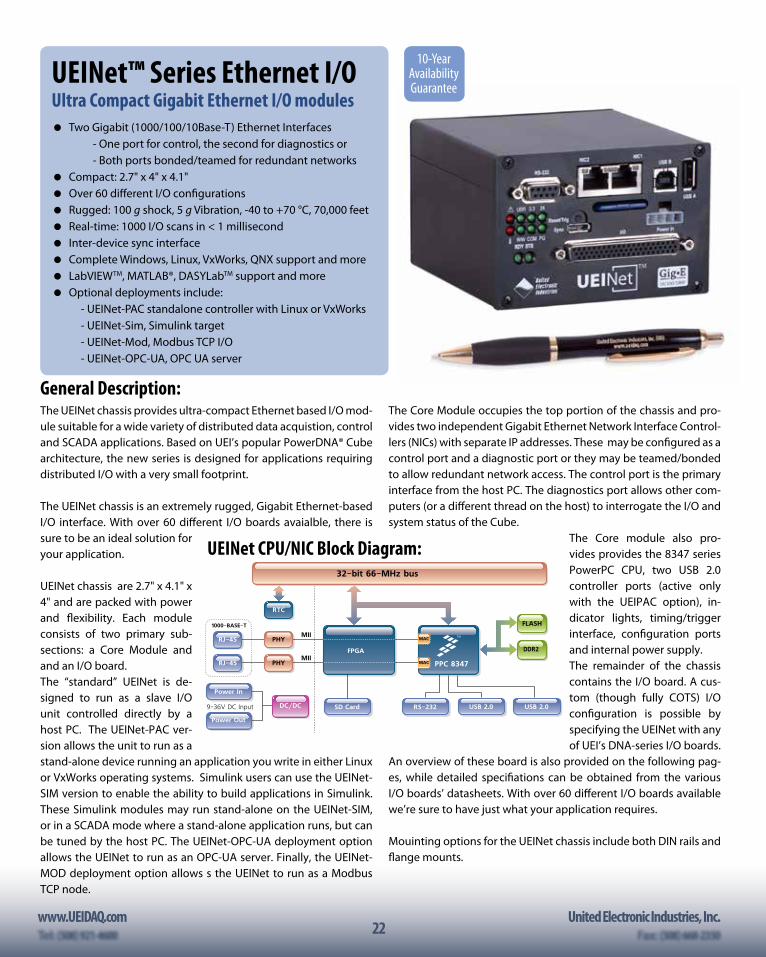
22www.UEIDAQ.com United Electronic Industries, Inc.
22
UEINet™ Series Ethernet I/OUltra Compact Gigabit Ethernet I/O modules Two Gigabit (1000/100/10Base-T) Ethernet Interfaces - One port for control, the second for diagnostics or - Both ports bonded/teamed for redundant networks Compact: 2.7" x 4" x 4.1" Over 60 different I/O configurationsRugged: 100 g shock, 5 g Vibration, -40 to +70 °C, 70,000 feet Real-time: 1000 I/O scans in < 1 millisecond Inter-device sync interface Complete Windows, Linux, VxWorks, QNX support and more LabVIEWTM, MATLAB®, DASYLabTM support and more Optional deployments include: - UEINet-PAC standalone controller with Linux or VxWorks - UEINet-Sim, Simulink target - UEINet-Mod, Modbus TCP I/O - UEINet-OPC-UA, OPC UA server
General Description:The UEINet chassis provides ultra-compact Ethernet based I/O mod-ule suitable for a wide variety of distributed data acquistion, control and SCADA applications. Based on UEI’s popular PowerDNA® Cube architecture, the new series is designed for applications requiring distributed I/O with a very small footprint.
The UEINet chassis is an extremely rugged, Gigabit Ethernet-based I/O interface. With over 60 different I/O boards avaialble, there is sure to be an ideal solution for your application.
UEINet chassis are 2.7" x 4.1" x 4" and are packed with power and flexibility. Each module consists of two primary sub-sections: a Core Module and and an I/O board. The “standard” UEINet is de-signed to run as a slave I/O unit controlled directly by a host PC. The UEINet-PAC ver-sion allows the unit to run as a stand-alone device running an application you write in either Linux or VxWorks operating systems. Simulink users can use the UEINet-SIM version to enable the ability to build applications in Simulink. These Simulink modules may run stand-alone on the UEINet-SIM, or in a SCADA mode where a stand-alone application runs, but can be tuned by the host PC. The UEINet-OPC-UA deployment option allows the UEINet to run as an OPC-UA server. Finally, the UEINet-MOD deployment option allows s the UEINet to run as a Modbus TCP node.
The Core Module occupies the top portion of the chassis and pro-vides two independent Gigabit Ethernet Network Interface Control-lers (NICs) with separate IP addresses. These may be configured as a control port and a diagnostic port or they may be teamed/bonded to allow redundant network access. The control port is the primary interface from the host PC. The diagnostics port allows other com-puters (or a different thread on the host) to interrogate the I/O and system status of the Cube.
The Core module also pro-vides provides the 8347 series PowerPC CPU, two USB 2.0 controller ports (active only with the UEIPAC option), in-dicator lights, timing/trigger interface, configuration ports and internal power supply.The remainder of the chassis contains the I/O board. A cus-tom (though fully COTS) I/O configuration is possible by specifying the UEINet with any of UEI’s DNA-series I/O boards.
An overview of these board is also provided on the following pag-es, while detailed specifiations can be obtained from the various I/O boards’ datasheets. With over 60 different I/O boards available we’re sure to have just what your application requires.
Mouinting options for the UEINet chassis include both DIN rails and flange mounts.
10-Year Availability Guarantee
UEINet CPU/NIC Block Diagram:
MAC
MAC
PPC 8347
DC/DC9-36V DC Input
Power Out
Power In
SD Card RS-232
32-bit 66-MHz bus
RJ-45
RJ-45
PHY
PHY
RTC
DDR2
FLASH
MII1000-BASE-T
MIIFPGA
USB 2.0 USB 2.0
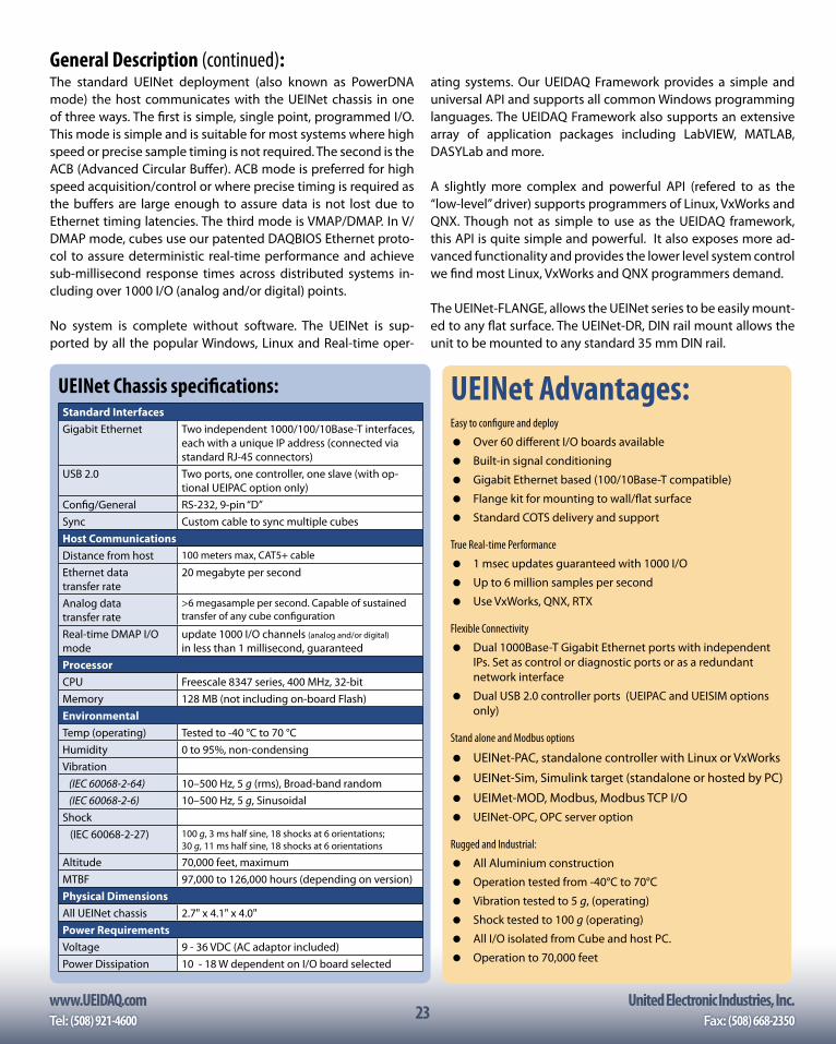
www.UEIDAQ.com United Electronic Industries, Inc.Tel: (508) 921-4600 Fax: (508) 668-235023
UEINet Advantages:Easy to configure and deploy
Over 60 different I/O boards available
Built-in signal conditioning
Gigabit Ethernet based (100/10Base-T compatible)
Flange kit for mounting to wall/flat surface
Standard COTS delivery and support
True Real-time Performance
1 msec updates guaranteed with 1000 I/O
Up to 6 million samples per second
Use VxWorks, QNX, RTX
Flexible Connectivity
Dual 1000Base-T Gigabit Ethernet ports with independent IPs. Set as control or diagnostic ports or as a redundant network interface
Dual USB 2.0 controller ports (UEIPAC and UEISIM options only)
Stand alone and Modbus options
UEINet-PAC, standalone controller with Linux or VxWorks
UEINet-Sim, Simulink target (standalone or hosted by PC)
UEIMet-MOD, Modbus, Modbus TCP I/O UEINet-OPC, OPC server option
Rugged and Industrial:
All Aluminium construction
Operation tested from -40°C to 70°C
Vibration tested to 5 g, (operating)
Shock tested to 100 g (operating)
All I/O isolated from Cube and host PC.
Operation to 70,000 feet
The standard UEINet deployment (also known as PowerDNA mode) the host communicates with the UEINet chassis in one of three ways. The first is simple, single point, programmed I/O. This mode is simple and is suitable for most systems where high speed or precise sample timing is not required. The second is the ACB (Advanced Circular Buffer). ACB mode is preferred for high speed acquisition/control or where precise timing is required as the buffers are large enough to assure data is not lost due to Ethernet timing latencies. The third mode is VMAP/DMAP. In V/DMAP mode, cubes use our patented DAQBIOS Ethernet proto-col to assure deterministic real-time performance and achieve sub-millisecond response times across distributed systems in-cluding over 1000 I/O (analog and/or digital) points.
No system is complete without software. The UEINet is sup-ported by all the popular Windows, Linux and Real-time oper-
UEINet Chassis specifications:Standard InterfacesGigabit Ethernet Two independent 1000/100/10Base-T interfaces,
each with a unique IP address (connected via standard RJ-45 connectors)
USB 2.0 Two ports, one controller, one slave (with op-tional UEIPAC option only)
Config/General RS-232, 9-pin “D”Sync Custom cable to sync multiple cubesHost CommunicationsDistance from host 100 meters max, CAT5+ cable
Ethernet data transfer rate
20 megabyte per second
Analog data transfer rate
>6 megasample per second. Capable of sustained transfer of any cube configuration
Real-time DMAP I/O mode
update 1000 I/O channels (analog and/or digital)
in less than 1 millisecond, guaranteedProcessorCPU Freescale 8347 series, 400 MHz, 32-bitMemory 128 MB (not including on-board Flash)EnvironmentalTemp (operating) Tested to -40 °C to 70 °CHumidity 0 to 95%, non-condensingVibration (IEC 60068-2-64) 10–500 Hz, 5 g (rms), Broad-band random (IEC 60068-2-6) 10–500 Hz, 5 g, SinusoidalShock (IEC 60068-2-27) 100 g, 3 ms half sine, 18 shocks at 6 orientations;
30 g, 11 ms half sine, 18 shocks at 6 orientations
Altitude 70,000 feet, maximumMTBF 97,000 to 126,000 hours (depending on version)Physical DimensionsAll UEINet chassis 2.7" x 4.1" x 4.0"Power RequirementsVoltage 9 - 36 VDC (AC adaptor included)Power Dissipation 10 - 18 W dependent on I/O board selected
General Description (continued):ating systems. Our UEIDAQ Framework provides a simple and universal API and supports all common Windows programming languages. The UEIDAQ Framework also supports an extensive array of application packages including LabVIEW, MATLAB, DASYLab and more.
A slightly more complex and powerful API (refered to as the “low-level” driver) supports programmers of Linux, VxWorks and QNX. Though not as simple to use as the UEIDAQ framework, this API is quite simple and powerful. It also exposes more ad-vanced functionality and provides the lower level system control we find most Linux, VxWorks and QNX programmers demand.
The UEINet-FLANGE, allows the UEINet series to be easily mount-ed to any flat surface. The UEINet-DR, DIN rail mount allows the unit to be mounted to any standard 35 mm DIN rail.

24www.UEIDAQ.com United Electronic Industries, Inc.
24
UEINet 1553 Technical I/O Specifications:General SpecificationsNumber channels/ports 2, Independent, Dual redundant
interfacesSpecification compliance MIL-STD-1553a or b including
notices 1 & 2Configuration Bus Controller (BC), Remote Terminal
(RT) or Bus Monitor (BM). Either chan may be BC, RT or BM
Interface (software selecta-ble) [measured at connector]
Transformer or direct coupled
Isolation 350 VrmsPower Consumption 13 W (not including load)System Data Update Rates (for higher rates please see the DNx-1553-553-900)
Operation in a standard real-time host-based loop
1 mS min (host-1553-host or 1553-host-1553 round trip)
Operation in asynch 1553 host-based control mode
200 uS typical
Bus Controller (BC) SpecsConfiguration Independent PortsCommunication support BC to RT, RT to BC, RT to RTMessaging protocols Standard Mode Codes, Broadcast
messagesMessage timing Scheduled or asynch with 2 levels
of priorityProgrammability Major/minor frame timing, intermes-
sage gap times, time out and late response, BC retries
Error handling Automatic error detection and recovery.
Remote Terminal (RT) SpecsModes Single or multiple RT emulator (up
to 31 different RTs) RT - RT xfers with simulated RTs may be imple-mented with user software.
RT/BM joint mode Allows the unit to act as an RT while logging data as an BM
Error handling Automatic error detection and insertion.
Bus Monitor (BM) SpecsMonitor modes Full or selective monitoring by RT
addressMonitored parameter In addition to bus data, BM mode
time tags data and capture Word/Message/Error status and RT re-sponse time
EnvironmentalOperating Temp. (tested) -40°C to +70°COperating Humidity 0 - 95%, non-condensingMTBF >100,000 hours
UEINet 429 Technical I/O Specifications:Channel ConfigurationsNumber of channels 6 TX and 6 RXARINC Compliance Fully compliant with ARINC 429Digital outputs 1 current sinking, FET basedDigital output drive 350 mA max, (500 mA resettable
fuse)Receive SpecificationsData rate 100 kHz or 12.5 kHz selectable per
portFIFO size up to 256 32-bit words, user se-
lectableReceive filter size 1 to 255 labels or disabledSDI filter enabled or disabledNew data only filter enabled or disabled by label or
globallyParity checking enabled or disabledDate/Time stamping enabled or disabled by label or
globallyTransmit SpecificationsData rate 100 kHz or 12.5 kHz selectable per
portFIFO size 256 wordsTransmit modes Scheduled or asynchronousScheduler specifications timing resolution 100 microseconds table size Schedule up to 256 labels per
channelAsynchronous TX modes High priority transmit immediately upon comple-
tion of current transmission regard-less of schedule
Standard priority transmit when no scheduled data FIFO based transmit when no scheduled,
standard or high priority data is being sent
General SpecificationsLoop back testing Internal loop back connections on
the DNx-429-566 allow automatic self-test
Operating temperature tested -40 °C to +70 °CVibration IEC 60068-2-6 IEC 60068-2-64
5 g, 10-500 Hz, sinusoidal 5 g (rms), 10-500 Hz, broad-band random
Shock IEC 60068-2-27 100 g, 3 ms half sine, 18 shocks @ 6 orientations30 g, 11 ms half sine, 18 shocks @ 6 orientations
Humidity 0 to 95%, non-condensingMTBF >115,000 hoursPower consumption 13 Watt, maximum
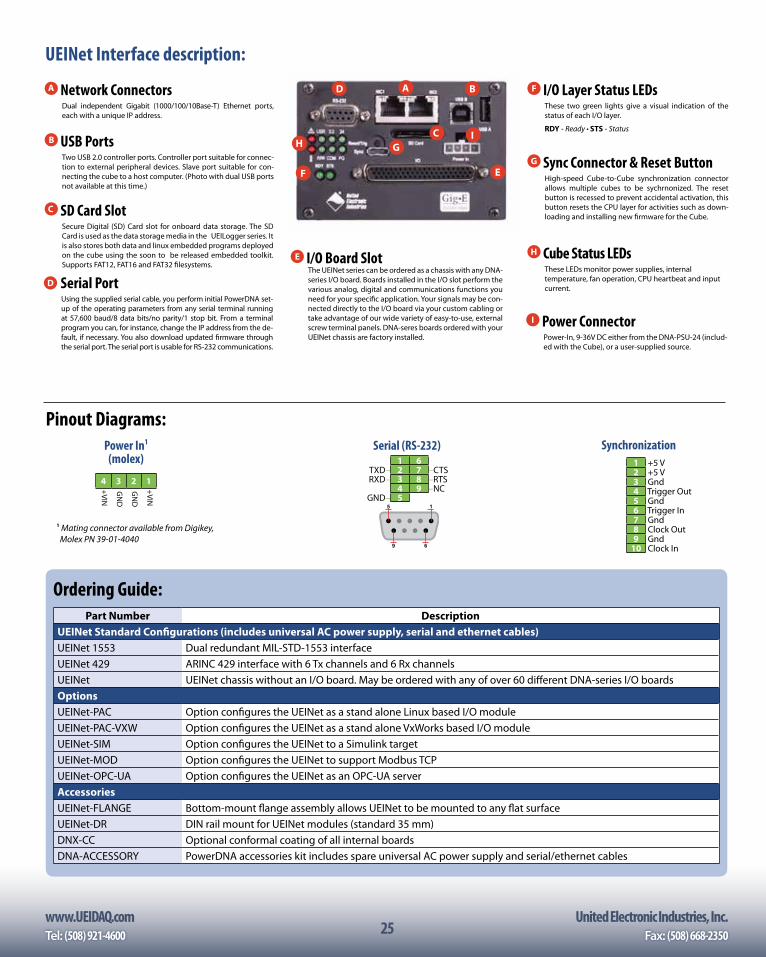
www.UEIDAQ.com United Electronic Industries, Inc.Tel: (508) 921-4600 Fax: (508) 668-235025
I Power ConnectorPower-In, 9-36V DC either from the DNA-PSU-24 (includ-ed with the Cube), or a user-supplied source.
B USB PortsTwo USB 2.0 controller ports. Controller port suitable for connec-tion to external peripheral devices. Slave port suitable for con-necting the cube to a host computer. (Photo with dual USB ports not available at this time.)
C SD Card SlotSecure Digital (SD) Card slot for onboard data storage. The SD Card is used as the data storage media in the UEILogger series. It is also stores both data and linux embedded programs deployed on the cube using the soon to be released embedded toolkit. Supports FAT12, FAT16 and FAT32 filesystems.
A Network ConnectorsDual independent Gigabit (1000/100/10Base-T) Ethernet ports, each with a unique IP address.
H Cube Status LEDsThese LEDs monitor power supplies, internal temperature, fan operation, CPU heartbeat and input current.
D Serial PortUsing the supplied serial cable, you perform initial PowerDNA set-up of the operating parameters from any serial terminal running at 57,600 baud/8 data bits/no parity/1 stop bit. From a terminal program you can, for instance, change the IP address from the de-fault, if necessary. You also download updated firmware through the serial port. The serial port is usable for RS-232 communications.
E I/O Board SlotThe UEINet series can be ordered as a chassis with any DNA-series I/O board. Boards installed in the I/O slot perform the various analog, digital and communications functions you need for your specific application. Your signals may be con-nected directly to the I/O board via your custom cabling or take advantage of our wide variety of easy-to-use, external screw terminal panels. DNA-seres boards ordered with your UEINet chassis are factory installed.
Ordering Guide:Part Number Description
UEINet Standard Configurations (includes universal AC power supply, serial and ethernet cables)UEINet 1553 Dual redundant MIL-STD-1553 interfaceUEINet 429 ARINC 429 interface with 6 Tx channels and 6 Rx channelsUEINet UEINet chassis without an I/O board. May be ordered with any of over 60 different DNA-series I/O boardsOptionsUEINet-PAC Option configures the UEINet as a stand alone Linux based I/O moduleUEINet-PAC-VXW Option configures the UEINet as a stand alone VxWorks based I/O moduleUEINet-SIM Option configures the UEINet to a Simulink targetUEINet-MOD Option configures the UEINet to support Modbus TCPUEINet-OPC-UA Option configures the UEINet as an OPC-UA serverAccessoriesUEINet-FLANGE Bottom-mount flange assembly allows UEINet to be mounted to any flat surfaceUEINet-DR DIN rail mount for UEINet modules (standard 35 mm)DNX-CC Optional conformal coating of all internal boardsDNA-ACCESSORY PowerDNA accessories kit includes spare universal AC power supply and serial/ethernet cables
Pinout Diagrams:
4 3 2 1 +VIN
GN
D
GN
D
+VIN
Power In1 (molex)
1 Mating connector available from Digikey, Molex PN 39-01-4040
1 6TXD– 2 7 –CTSRXD– 3 8 –RTS
4 9 –NCGND– 5 10
Serial (RS-232)
UEINet Interface description:
1 +5 V2 +5 V3 Gnd4 Trigger Out
5 Gnd6 Trigger In7 Gnd8 Clock Out9 Gnd
10 Clock In
Synchronization
A B
C
D
G
F
HI
EG Sync Connector & Reset Button
High-speed Cube-to-Cube synchronization connector allows multiple cubes to be sychrnonized. The reset button is recessed to prevent accidental activation, this button resets the CPU layer for activities such as down-loading and installing new firmware for the Cube.
F I/O Layer Status LEDsThese two green lights give a visual indication of the status of each I/O layer.
RDY - Ready • STS - Status
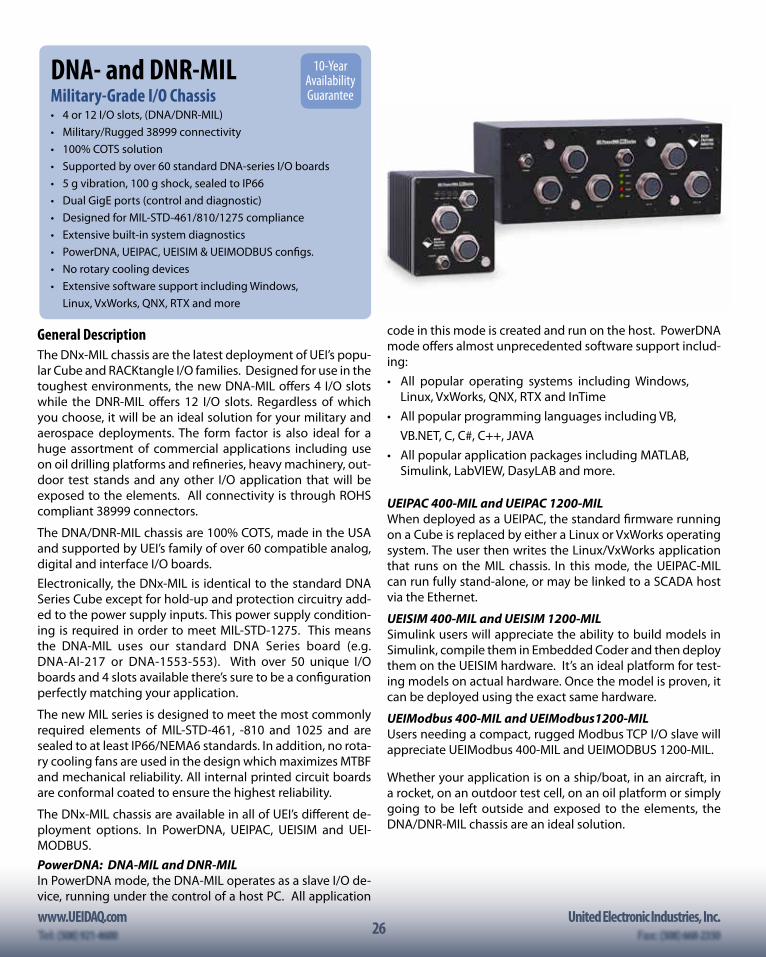
26www.UEIDAQ.com United Electronic Industries, Inc.
26
General DescriptionThe DNx-MIL chassis are the latest deployment of UEI’s popu-lar Cube and RACKtangle I/O families. Designed for use in the toughest environments, the new DNA-MIL offers 4 I/O slots while the DNR-MIL offers 12 I/O slots. Regardless of which you choose, it will be an ideal solution for your military and aerospace deployments. The form factor is also ideal for a huge assortment of commercial applications including use on oil drilling platforms and refineries, heavy machinery, out-door test stands and any other I/O application that will be exposed to the elements. All connectivity is through ROHS compliant 38999 connectors.
The DNA/DNR-MIL chassis are 100% COTS, made in the USA and supported by UEI’s family of over 60 compatible analog, digital and interface I/O boards. Electronically, the DNx-MIL is identical to the standard DNA Series Cube except for hold-up and protection circuitry add-ed to the power supply inputs. This power supply condition-ing is required in order to meet MIL-STD-1275. This means the DNA-MIL uses our standard DNA Series board (e.g. DNA-AI-217 or DNA-1553-553). With over 50 unique I/O boards and 4 slots available there’s sure to be a configuration perfectly matching your application.
The new MIL series is designed to meet the most commonly required elements of MIL-STD-461, -810 and 1025 and are sealed to at least IP66/NEMA6 standards. In addition, no rota-ry cooling fans are used in the design which maximizes MTBF and mechanical reliability. All internal printed circuit boards are conformal coated to ensure the highest reliability.
The DNx-MIL chassis are available in all of UEI’s different de-ployment options. In PowerDNA, UEIPAC, UEISIM and UEI-MODBUS.PowerDNA: DNA-MIL and DNR-MILIn PowerDNA mode, the DNA-MIL operates as a slave I/O de-vice, running under the control of a host PC. All application
code in this mode is created and run on the host. PowerDNA mode offers almost unprecedented software support includ-ing: • All popular operating systems including Windows,
Linux, VxWorks, QNX, RTX and InTime• All popular programming languages including VB, VB.NET, C, C#, C++, JAVA• All popular application packages including MATLAB,
Simulink, LabVIEW, DasyLAB and more.
UEIPAC 400-MIL and UEIPAC 1200-MILWhen deployed as a UEIPAC, the standard firmware running on a Cube is replaced by either a Linux or VxWorks operating system. The user then writes the Linux/VxWorks application that runs on the MIL chassis. In this mode, the UEIPAC-MIL can run fully stand-alone, or may be linked to a SCADA host via the Ethernet.
UEISIM 400-MIL and UEISIM 1200-MILSimulink users will appreciate the ability to build models in Simulink, compile them in Embedded Coder and then deploy them on the UEISIM hardware. It’s an ideal platform for test-ing models on actual hardware. Once the model is proven, it can be deployed using the exact same hardware.
UEIModbus 400-MIL and UEIModbus1200-MILUsers needing a compact, rugged Modbus TCP I/O slave will appreciate UEIModbus 400-MIL and UEIMODBUS 1200-MIL.
Whether your application is on a ship/boat, in an aircraft, in a rocket, on an outdoor test cell, on an oil platform or simply going to be left outside and exposed to the elements, the DNA/DNR-MIL chassis are an ideal solution.
DNA- and DNR-MILMilitary-Grade I/O Chassis• 4 or 12 I/O slots, (DNA/DNR-MIL)• Military/Rugged 38999 connectivity• 100% COTS solution • Supported by over 60 standard DNA-series I/O boards• 5 g vibration, 100 g shock, sealed to IP66• Dual GigE ports (control and diagnostic)• Designed for MIL-STD-461/810/1275 compliance• Extensive built-in system diagnostics• PowerDNA, UEIPAC, UEISIM & UEIMODBUS configs.• No rotary cooling devices• Extensive software support including Windows, Linux, VxWorks, QNX, RTX and more
10-Year Availability Guarantee
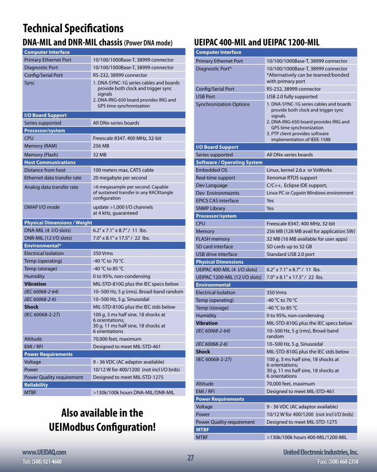
www.UEIDAQ.com United Electronic Industries, Inc.Tel: (508) 921-4600 Fax: (508) 668-235027
DNA-MIL and DNR-MIL chassis (Power DNA mode)Computer InterfacePrimary Ethernet Port 10/100/1000Base-T, 38999 connectorDiagnostic Port 10/100/1000Base-T, 38999 connectorConfig/Serial Port RS-232, 38999 connectorSync 1. DNA-SYNC-1G series cables and boards
provide both clock and trigger sync signals
2. DNA-IRIG-650 board provides IRIG and GPS time synchronization
I/O Board SupportSeries supported All DNx-series boardsProcessor/system CPU Freescale 8347, 400 MHz, 32-bitMemory (RAM) 256 MB
Memory (Flash) 32 MB Host CommunicationsDistance from host 100 meters max, CAT5 cableEthernet data transfer rate 20 megabyte per second
Analog data transfer rate >6 megasample per second. Capable of sustained transfer in any RACKtangle configuration
DMAP I/O mode update >1,000 I/O channels at 4 kHz, guaranteed
Physical Dimensions / WeightDNA-MIL (4 I/O slots) 6.2" x 7.1" x 8.7" / 11 lbs.DNR-MIL (12 I/O slots) 7.0" x 8.1" x 17.5" / 22 lbs.Environmental*Electrical Isolation 350 VrmsTemp (operating) -40 °C to 70 °CTemp (storage) -40 °C to 85 °CHumidity 0 to 95%, non-condensingVibration MIL-STD-810G plus the IEC specs below(IEC 60068-2-64) 10–500 Hz, 5 g (rms), Broad-band random(IEC 60068-2-6) 10–500 Hz, 5 g, SinusoidalShock MIL-STD-810G plus the IEC stds below(IEC 60068-2-27) 100 g, 3 ms half sine, 18 shocks at
6 orientations; 30 g, 11 ms half sine, 18 shocks at 6 orientations
Altitude 70,000 feet, maximumEMI / RFI Designed to meet MIL-STD-461Power RequirementsVoltage 9 - 36 VDC (AC adaptor available)Power 10/12 W for 400/1200 (not incl I/O brds)Power Quality requirement Designed to meet MIL-STD-1275ReliabilityMTBF >130k/100k hours DNA-MIL/DNR-MIL
UEIPAC 400-MIL and UEIPAC 1200-MILComputer Interface
Primary Ethernet Port 10/100/1000Base-T, 38999 connectorDiagnostic Port* 10/100/1000Base-T, 38999 connector
*Alternatively can be teamed/bonded with primary port
Config/Serial Port RS-232, 38999 connectorUSB Port USB 2.0 fully supportedSynchronization Options 1. DNA-SYNC-1G series cables and boards
provide both clock and trigger sync signals.
2. DNA-IRIG-650 board provides IRIG and GPS time synchronization
3. PTP client provides software implementation of IEEE-1588
I/O Board SupportSeries supported All DNx-series boardsSoftware / Operating SystemEmbedded OS Linux, kernel 2.6.x or VxWorksReal-time support Xenomai RTOS supportDev Language C/C++, Eclipse IDE support, Dev Environmeznts Linux PC or Cygwin Windows environment
EPICS CAS interface YesSNMP Library YesProcessor/system CPU Freescale 8347, 400 MHz, 32-bitMemory 256 MB (128 MB avail for application SW)FLASH memory 32 MB (16 MB available for user apps)SD card interface SD cards up to 32 GBUSB drive interface Standard USB 2.0 portPhysical DimensionsUEIPAC 400-MIL (4 I/O slots) 6.2" x 7.1" x 8.7" / 11 lbs.UEIPAC 1200-MIL (12 I/O slots) 7.0" x 8.1" x 17.5" / 22 lbs.EnvironmentalElectrical Isolation 350 VrmsTemp (operating) -40 °C to 70 °CTemp (storage) -40 °C to 85 °CHumidity 0 to 95%, non-condensingVibration MIL-STD-810G plus the IEC specs below(IEC 60068-2-64) 10–500 Hz, 5 g (rms), Broad-band
random(IEC 60068-2-6) 10–500 Hz, 5 g, SinusoidalShock MIL-STD-810G plus the IEC stds below(IEC 60068-2-27) 100 g, 3 ms half sine, 18 shocks at
6 orientations; 30 g, 11 ms half sine, 18 shocks at 6 orientations
Altitude 70,000 feet, maximumEMI / RFI Designed to meet MIL-STD-461Power RequirementsVoltage 9 - 36 VDC (AC adaptor available)Power 10/12 W for 400/1200 (not incl I/O brds)Power Quality requirement Designed to meet MIL-STD-1275MTBFMTBF >130k/100k hours 400-MIL/1200-MIL
Technical Specifications
Also available in the UEIModbus Configuration!
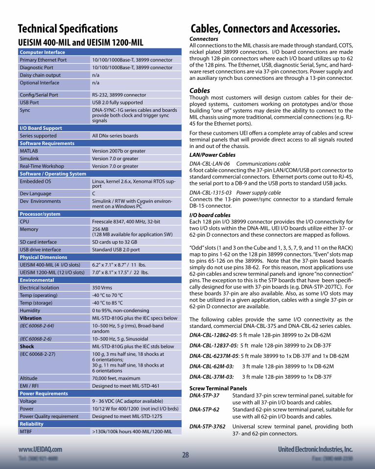
28www.UEIDAQ.com United Electronic Industries, Inc.
28
UEISIM 400-MIL and UEISIM 1200-MILComputer InterfacePrimary Ethernet Port 10/100/1000Base-T, 38999 connectorDiagnostic Port 10/100/1000Base-T, 38999 connectorDaisy chain output n/aOptional Interface n/a
Config/Serial Port RS-232, 38999 connectorUSB Port USB 2.0 fully supportedSync DNA-SYNC-1G series cables and boards
provide both clock and trigger sync signals
I/O Board SupportSeries supported All DNx-series boardsSoftware RequirementsMATLAB Version 2007b or greaterSimulink Version 7.0 or greaterReal-Time Workshop Version 7.0 or greaterSoftware / Operating SystemEmbedded OS Linux, kernel 2.6.x, Xenomai RTOS sup-
portDev Language CDev Environments Simulink / RTW with Cygwin environ-
ment on a Windows PCProcessor/system CPU Freescale 8347, 400 MHz, 32-bitMemory 256 MB
(128 MB available for application SW)SD card interface SD cards up to 32 GBUSB drive interface Standard USB 2.0 portPhysical DimensionsUEISIM 400-MIL (4 I/O slots) 6.2" x 7.1" x 8.7" / 11 lbs.UEISIM 1200-MIL (12 I/O slots) 7.0" x 8.1" x 17.5" / 22 lbs.EnvironmentalElectrical Isolation 350 VrmsTemp (operating) -40 °C to 70 °CTemp (storage) -40 °C to 85 °CHumidity 0 to 95%, non-condensingVibration MIL-STD-810G plus the IEC specs below(IEC 60068-2-64) 10–500 Hz, 5 g (rms), Broad-band
random(IEC 60068-2-6) 10–500 Hz, 5 g, SinusoidalShock MIL-STD-810G plus the IEC stds below(IEC 60068-2-27) 100 g, 3 ms half sine, 18 shocks at
6 orientations; 30 g, 11 ms half sine, 18 shocks at 6 orientations
Altitude 70,000 feet, maximumEMI / RFI Designed to meet MIL-STD-461Power RequirementsVoltage 9 - 36 VDC (AC adaptor available)Power 10/12 W for 400/1200 (not incl I/O brds)Power Quality requirement Designed to meet MIL-STD-1275ReliabilityMTBF >130k/100k hours 400-MIL/1200-MIL
Technical Specifications Cables, Connectors and Accessories.ConnectorsAll connections to the MIL chassis are made through standard, COTS, nickel plated 38999 connectors. I/O board connections are made through 128-pin connectors where each I/O board utilizes up to 62 of the 128 pins. The Ethernet, USB, diagnostic Serial, Sync, and hard-ware reset connections are via 37-pin connectors. Power supply and an auxiliary synch bus connections are through a 13-pin connector.
CablesThough most customers will design custom cables for their de-ployed systems, customers working on prototypes and/or those building “one of” systems may desire the ability to connect to the MIL chassis using more traditional, commercial connections (e.g. RJ-45 for the Ethernet ports).
For these customers UEI offers a complete array of cables and screw terminal panels that will provide direct access to all signals routed in and out of the chassis.LAN/Power CablesDNA-CBL-LAN-06 Communications cable6 foot cable connecting the 37-pin LAN/COM/USB port connector to standard commercial connectors. Ethernet ports come out to RJ-45, the serial port to a DB-9 and the USB ports to standard USB jacks.
DNA-CBL-1315-03 Power supply cableConnects the 13-pin power/sync connector to a standard female DB-15 connector.
I/O board cablesEach 128 pin I/O 38999 connector provides the I/O connectivity for two I/O slots within the DNA-MIL. UEI I/O boards utilize either 37- or 62-pin D connectors and these connectors are mapped as follows.
“Odd” slots (1 and 3 on the Cube and 1, 3, 5, 7, 9, and 11 on the RACK) map to pins 1-62 on the 128 pin 38999 connectors. “Even” slots map to pins 65-126 on the 38999s. Note that the 37-pin based boards simply do not use pins 38-62. For this reason, most applications use 62-pin cables and screw terminal panels and ignore “no connection” pins. The exception to this is the STP boards that have been specifi-cally designed for use with 37-pin boards (e.g. DNA-STP-207TC). For these boards 37-pin are also available. Also, as some I/O slots may not be utilized in a given application, cables with a single 37-pin or 62-pin D connector are available.
The following cables provide the same I/O connectivity as the standard, commercial DNA-CBL-37S and DNA-CBL-62 series cables.
DNA-CBL-12862-05: 5 ft male 128-pin 38999 to 2x DB-62M DNA-CBL-12837-05: 5 ft male 128-pin 38999 to 2x DB-37F
DNA-CBL-6237M-05: 5 ft male 38999 to 1x DB-37F and 1x DB-62M
DNA-CBL-62M-03: 3 ft male 128-pin 38999 to 1x DB-62M
DNA-CBL-37M-03: 3 ft male 128-pin 38999 to 1x DB-37F
Screw Terminal PanelsDNA-STP-37 Standard 37-pin screw terminal panel, suitable for
use with all 37-pin I/O boards and cables.DNA-STP-62 Standard 62-pin screw terminal panel, suitable for
use with all 62-pin I/O boards and cables.
DNA-STP-3762 Universal screw terminal panel, providing both 37- and 62-pin connectors.
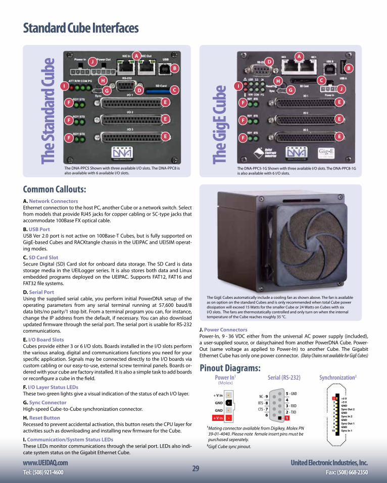
www.UEIDAQ.com United Electronic Industries, Inc.Tel: (508) 921-4600 Fax: (508) 668-235029
Standard Cube Interfaces
A. Network ConnectorsEthernet connection to the host PC, another Cube or a network switch. Select from models that provide RJ45 jacks for copper cabling or SC-type jacks that accommodate 100Base FX optical cable.
B. USB PortUSB Ver 2.0 port is not active on 100Base-T Cubes, but is fully supported on GigE-based Cubes and RACKtangle chassis in the UEIPAC and UEISIM operat-ing modes.
C. SD Card SlotSecure Digital (SD) Card slot for onboard data storage. The SD Card is data storage media in the UEILogger series. It is also stores both data and Linux embedded programs deployed on the UEIPAC. Supports FAT12, FAT16 and FAT32 file systems.
D. Serial PortUsing the supplied serial cable, you perform initial PowerDNA setup of the operating parameters from any serial terminal running at 57,600 baud/8 data bits/no parity/1 stop bit. From a terminal program you can, for instance, change the IP address from the default, if necessary. You can also download updated firmware through the serial port. The serial port is usable for RS-232 communications.
E. I/O Board SlotsCubes provide either 3 or 6 I/O slots. Boards installed in the I/O slots perform the various analog, digital and communications functions you need for your specific application. Signals may be connected directly to the I/O boards via custom cabling or our easy-to-use, external screw terminal panels. Boards or-dered with your cube are factory installed. It is also a simple task to add boards or reconfigure a cube in the field.
F. I/O Layer Status LEDsThese two green lights give a visual indication of the status of each I/O layer.
G. Sync ConnectorHigh-speed Cube-to-Cube synchronization connector.
H. Reset ButtonRecessed to prevent accidental activation, this button resets the CPU layer for activities such as downloading and installing new firmware for the Cube.
I. Communication/System Status LEDsThese LEDs monitor communications through the serial port. LEDs also indi-cate system status on the Gigabit Ethernet Cube.
A
B
CDG
E
F
HI
J
E
E
F
F
The G
igE Cu
be
A
B
C
D
G
E
F
HI J
E
E
F
F
The S
tand
ard C
ube
The DNA-PPC5-1G Shown with three available I/O slots. The DNA-PPC8-1G is also available with 6 I/O slots.
The GigE Cubes automatically include a cooling fan as shown above. The fan is available as on option on the standard Cubes and is only recommended when total Cube power dissipation will exceed 15 Watts for the smaller Cube or 24 Watts on Cubes with six I/O slots. The fans are thermostatically controlled and only turn on when the internal temperature of the Cube reaches roughly 35 °C.
The DNA-PPC5 Shown with three available I/O slots. The DNA-PPC8 is also available with 6 available I/O slots.
Pinout Diagrams:
Common Callouts:
1 +5 V 2 +5 V 3 GND 4 Sync Out 2 5 GND 6 Sync In 2 7 GND 8 Sync Out 1 9 GND 10 Sync In 1
+ V in
GND
GND
+ V in
Power In1 (Molex)
Synchronization2
12 - TXD3 - RXD45 - GND
6CTS - 7RTS - 8NC - 9
Serial (RS-232)
1 Mating connector available from Digikey, Molex PN 39-01-4040. Please note female insert pins must be purchased seperately.
2 GigE Cube sync pinout.
J. Power ConnectorsPower-In, 9 - 36 VDC either from the universal AC power supply (included), a user-supplied source, or daisychained from another PowerDNA Cube. Power-Out (same voltage as applied to Power-In) to another Cube. The Gigabit Ethernet Cube has only one power connector. (Daisy Chains not available for GigE Cubes)
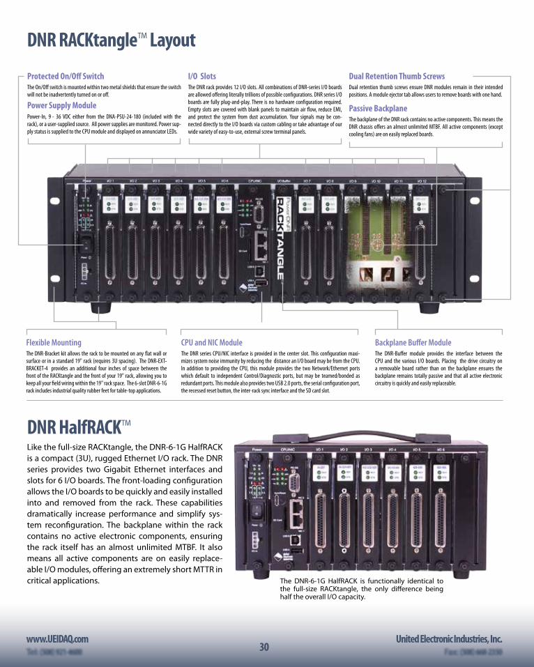
30www.UEIDAQ.com United Electronic Industries, Inc.
30
Dual Retention Thumb ScrewsDual retention thumb screws ensure DNR modules remain in their intended positions. A module ejector tab allows users to remove boards with one hand.
Power Supply ModulePower-In, 9 - 36 VDC either from the DNA-PSU-24-180 (included with the rack), or a user-supplied source. All power supplies are monitored. Power sup-ply status is supplied to the CPU module and displayed on annunciator LEDs.
I/O SlotsThe DNR rack provides 12 I/O slots. All combinations of DNR-series I/O boards are allowed offering literally trillions of possible configurations. DNR series I/O boards are fully plug-and-play. There is no hardware configuration required. Empty slots are covered with blank panels to maintain air flow, reduce EMI, and protect the system from dust accumulation. Your signals may be con-nected directly to the I/O boards via custom cabling or take advantage of our wide variety of easy-to-use, external screw terminal panels.
Passive BackplaneThe backplane of the DNR rack contains no active components. This means the DNR chassis offers an almost unlimited MTBF. All active components (except cooling fans) are on easily replaced boards.
CPU and NIC ModuleThe DNR series CPU/NIC interface is provided in the center slot. This configuration maxi-mizes system noise immunity by reducing the distance an I/O board may be from the CPU. In addition to providing the CPU, this module provides the two Network/Ethernet ports which default to independent Control/Diagnostic ports, but may be teamed/bonded as redundant ports. This module also provides two USB 2.0 ports, the serial configuration port, the recessed reset button, the inter-rack sync interface and the SD card slot.
Backplane Buffer ModuleThe DNR-Buffer module provides the interface between the CPU and the various I/O boards. Placing the drive circuitry on a removable board rather than on the backplane ensures the backplane remains totally passive and that all active electronic circuitry is quickly and easily replaceable.
Flexible MountingThe DNR-Bracket kit allows the rack to be mounted on any flat wall or surface or in a standard 19" rack (requires 3U spacing). The DNR-EXT-BRACKET-4 provides an additional four inches of space between the front of the RACKtangle and the front of your 19" rack, allowing you to keep all your field wiring within the 19" rack space. The 6-slot DNR-6-1G rack includes industrial quality rubber feet for table-top applications.
Protected On/Off SwitchThe On/Off switch is mounted within two metal shields that ensure the switch will not be inadvertently turned on or off.
DNR RACKtangle™ Layout
DNR HalfRACK™Like the full-size RACKtangle, the DNR-6-1G HalfRACK is a compact (3U), rugged Ethernet I/O rack. The DNR series provides two Gigabit Ethernet interfaces and slots for 6 I/O boards. The front-loading configuration allows the I/O boards to be quickly and easily installed into and removed from the rack. These capabilities dramatically increase performance and simplify sys-tem reconfiguration. The backplane within the rack contains no active electronic components, ensuring the rack itself has an almost unlimited MTBF. It also means all active components are on easily replace-able I/O modules, offering an extremely short MTTR in critical applications. The DNR-6-1G HalfRACK is functionally identical to
the full-size RACKtangle, the only difference being half the overall I/O capacity.
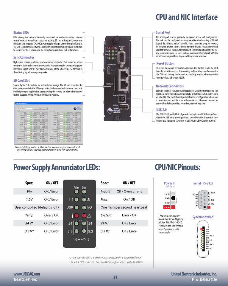
www.UEIDAQ.com United Electronic Industries, Inc.Tel: (508) 921-4600 Fax: (508) 668-235031
Reset ButtonRecessed to prevent accidental activation, this button resets the CPU layer for activities such as downloading and installing new firmware for the DNR rack. It may also be used to start/stop logging when the rack is configured as a UEILogger 1200R.
Network ConnectorsEach NIC interface includes two independent Gigabit Ethernet ports. The 1000Base-T interface allows the rack to be installed up to 100 Meters from your host PC. The two Ethernet ports default to a configuration where one is the control port and the other a diagnostic port. However, they can be teamed/bonded to provide a redundant network interface.
Serial PortThe serial port is used primarily for system setup and configuration. The rack may be configured from any serial terminal running at 57,600 baud/8 data bits/no parity/1 stop bit. From a terminal program you can, for instance, change the IP address from the default. You also download updated firmware through the serial port. The serial port is usable for RS-232 communications. For users without a convenient serial port, a USB to serial converter provides a simple and inexpensive interface.Sync Connector
High-speed chassis to chassis synchronization connector. This connector allows triggers or clocks to be shared among racks. Two racks may be connected together directly or larger systems may take advantage of the DNA-SYNC-1G interface to share timing signals among many racks.
Status LEDsLEDs display the status of internally monitored parameters including: Internal temperature, system self-test status, bus activity, SD card activity and provide con-firmation that required CPU/NIC power supply voltages are within specifications. The USR LED is controlled by the application program allowing a service technician to confirm he/she is working on the correct rack in multiple rack installations.
USB 2.0The DNR-12-1G and DNR-6-1G provide two high speed USB 2.0 interfaces. One of the USB ports is configured as a controller while the other is con-figured as a slave port. (Available in UEISIM and UEIPAC configurations)
CPU and NIC Interface
SD Card SlotSecure Digital (SD) card slot for onboard data storage. The SD card is used as the data storage media in the UEILogger series. It also stores both data and Linux em-bedded programs deployed on the rack using the soon to be released embedded toolkit. Supports FAT12, FAT16 and FAT32 file systems.
Power Supply Annunciator LEDs: CPU/NIC Pinouts:
Spec: ON / OFF
Input I OK / Overcurrent
Fans On / Off
One flash per second heartbeat
System Error / OK
24 V† OK / Error
3.3 V† OK / Error
Spec: ON / OFF
Vin OK / Error
1.5V OK / Error
User controlled (default is off)
Temp Over / OK
24 V* OK / Error
3.3 V* OK / Error
I/O
24
3.3
Vin
1.5
USR
24
3.3
7-121-6
*24 V & 3.3 V for slots 1-6 on the RACKtangle, and 4-6 on the HalfRACK
†24 V & 3.3 V for slots 7-12 on the RACKtangle and 1-3 on the HalfRACK
Powerful diagnostics software (shown above) can monitor all system power supplies, temperatures and fan operations.
1 Mating connector available from Digikey,Molex PN 39-01-4040. Please note the female insert pins are sold separately.
1 +5 V 2 +5 V 3 GND 4 Sync Out 2 5 GND 6 Sync In 2 7 GND 8 Sync Out 1 9 GND 10 Sync In 1
+ V in
GND
GND
+ V in
Power In1 (Molex)
Synchronization2
12 - TXD3 - RXD45 - GND
6CTS - 7RTS - 8NC - 9
Serial (RS-232)
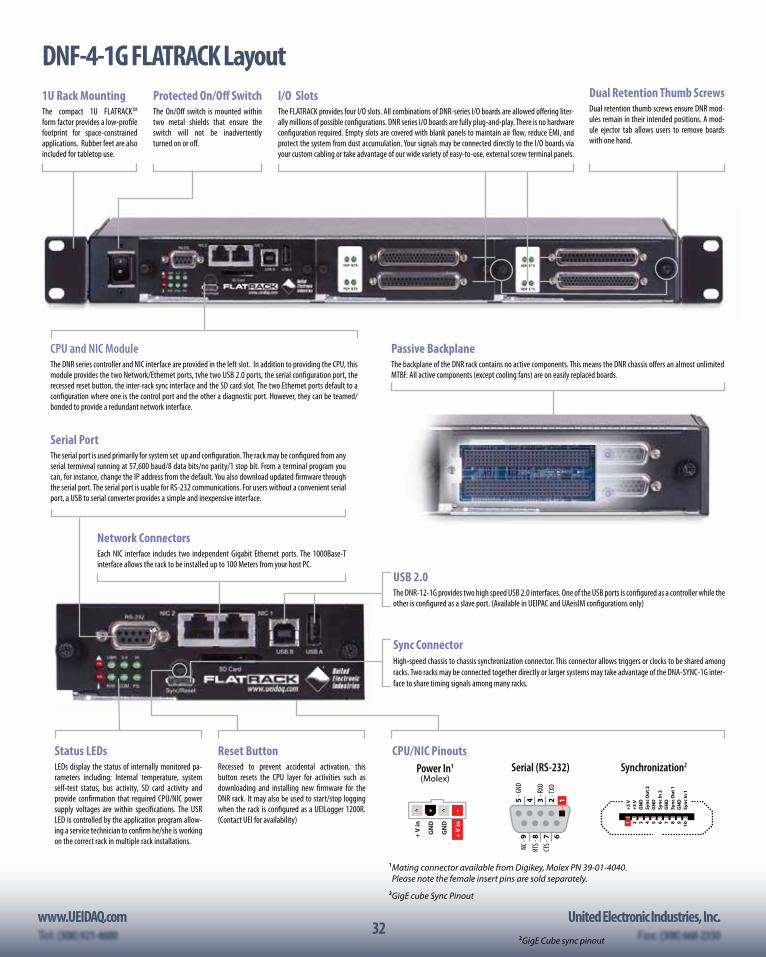
32www.UEIDAQ.com United Electronic Industries, Inc.
322GigE Cube sync pinout
Passive BackplaneThe backplane of the DNR rack contains no active components. This means the DNR chassis offers an almost unlimited MTBF. All active components (except cooling fans) are on easily replaced boards.
DNF-4-1G FLATRACK LayoutDual Retention Thumb ScrewsDual retention thumb screws ensure DNR mod-ules remain in their intended positions. A mod-ule ejector tab allows users to remove boards with one hand.
CPU and NIC ModuleThe DNR series controller and NIC interface are provided in the left slot. In addition to providing the CPU, this module provides the two Network/Ethernet ports, tvhe two USB 2.0 ports, the serial configuration port, the recessed reset button, the inter-rack sync interface and the SD card slot. The two Ethernet ports default to a configuration where one is the control port and the other a diagnostic port. However, they can be teamed/bonded to provide a redundant network interface.
I/O SlotsThe FLATRACK provides four I/O slots. All combinations of DNR-series I/O boards are allowed offering liter-ally millions of possible configurations. DNR series I/O boards are fully plug-and-play. There is no hardware configuration required. Empty slots are covered with blank panels to maintain air flow, reduce EMI, and protect the system from dust accumulation. Your signals may be connected directly to the I/O boards via your custom cabling or take advantage of our wide variety of easy-to-use, external screw terminal panels.
1U Rack MountingThe compact 1U FLATRACKTM
form factor provides a low-profile footprint for space-constrained applications. Rubber feet are also included for tabletop use.
Protected On/Off SwitchThe On/Off switch is mounted within two metal shields that ensure the switch will not be inadvertently turned on or off.
Reset ButtonRecessed to prevent accidental activation, this button resets the CPU layer for activities such as downloading and installing new firmware for the DNR rack. It may also be used to start/stop logging when the rack is configured as a UEILogger 1200R. (Contact UEI for availability)
Network ConnectorsEach NIC interface includes two independent Gigabit Ethernet ports. The 1000Base-T interface allows the rack to be installed up to 100 Meters from your host PC.
Serial PortThe serial port is used primarily for system set up and configuration. The rack may be configured from any serial termivnal running at 57,600 baud/8 data bits/no parity/1 stop bit. From a terminal program you can, for instance, change the IP address from the default. You also download updated firmware through the serial port. The serial port is usable for RS-232 communications. For users without a convenient serial port, a USB to serial converter provides a simple and inexpensive interface.
Status LEDsLEDs display the status of internally monitored pa-rameters including: Internal temperature, system self-test status, bus activity, SD card activity and provide confirmation that required CPU/NIC power supply voltages are within specifications. The USR LED is controlled by the application program allow-ing a service technician to confirm he/she is working on the correct rack in multiple rack installations.
USB 2.0The DNR-12-1G provides two high speed USB 2.0 interfaces. One of the USB ports is configured as a controller while the other is configured as a slave port. (Available in UEIPAC and UAeisIM configurations only)
CPU/NIC Pinouts
1 Mating connector available from Digikey, Molex PN 39-01-4040. Please note the female insert pins are sold separately.
2 GigE cube Sync Pinout
Power In1 (Molex)
Synchronization2
+ V
in
GN
D
GN
D
+ V
in 1
+5 V
2
+5 V
3
GN
D
4 Sy
nc O
ut 2
5
GN
D
6 Sy
nc In
2
7 G
ND
8
Sync
Out
1
9 G
ND
10
Sy
nc In
1
12 - T
XD3
- RXD
45 - G
ND
6CT
S - 7
RTS -
8NC
- 9
Serial (RS-232)
Sync ConnectorHigh-speed chassis to chassis synchronization connector. This connector allows triggers or clocks to be shared among racks. Two racks may be connected together directly or larger systems may take advantage of the DNA-SYNC-1G inter-face to share timing signals among many racks.
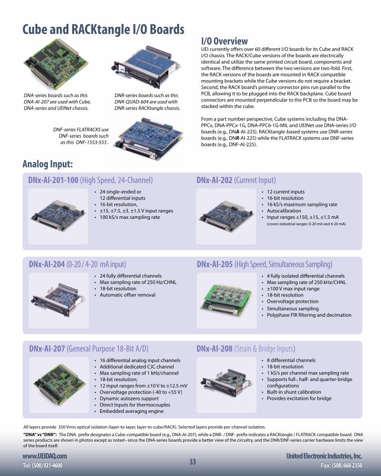
www.UEIDAQ.com United Electronic Industries, Inc.Tel: (508) 921-4600 Fax: (508) 668-235033
Cube and RACKtangle I/O BoardsI/O OverviewUEI currently offers over 60 different I/O boards for its Cube and RACK I/O chassis. The RACK/Cube versions of the boards are electrically identical and utilize the same printed circuit board, components and software. The difference between the two versions are two-fold. First, the RACK versions of the boards are mounted in RACK compatible mounting brackets while the Cube versions do not require a bracket. Second, the RACK board’s primary connector pins run parallel to the PCB, allowing it to be plugged into the RACK backplane. Cube board connectors are mounted perpendicular to the PCB so the board may be stacked within the cube.
From a part number perspective, Cube systems including the DNA-PPCx, DNA-PPCx-1G, DNA-PPC6-1G-MIL and UEINet use DNA-series I/O boards (e.g., DNA-AI-225). RACKtangle-based systems use DNR-series boards (e.g., DNR-AI-225) while the FLATRACK systems use DNF-series boards (e.g., DNF-AI-225).
DNR-series boards such as this DNR-QUAD-604 are used with DNR-series RACKtangle chassis.
DNA-series boards such as this DNA-AI-207 are used with Cube, DNA-series and UEINet chassis.
(DNR-AI-208 Shown)
Analog Input:
• 12 current inputs• 16-bit resolution• 16 kS/s maximum sampling rate• Autocalibration• Input ranges ±150, ±15, ±1.5 mA (covers industrial ranges: 0-20 mA and 4-20 mA)
DNx-AI-202 (Current Input) • 24 single-ended or
12 differential inputs• 16-bit resolution, • ±15, ±7.5, ±3, ±1.5 V input ranges• 100 kS/s max sampling rate
DNx-AI-201-100 (High Speed, 24-Channel)
DNF-series FLATRACKS use DNF-series boards such as this DNF-1553-553 .
All layers provide 350 Vrms optical isolation (layer-to-layer, layer-to-cube/RACK). Selected layers provide per-channel isolation.
“DNA” vs “DNR”: The DNA- prefix designates a Cube-compatible board (e.g., DNA-AI-207), while a DNR- / DNF- prefix indicates a RACKtangle / FLATRACK-compatible board. DNA series products are shown in photos except as noted– since the DNA-series boards provide a better view of the circuitry, and the DNR/DNF-series carrier hardware limits the view of the board itself.
• 8 differential channels• 18-bit resolution• 1 kS/s per channel max sampling rate• Supports full-, half- and quarter-bridge
configurations• Built-in shunt calibration• Provides excitation for bridge
DNx-AI-208 (Strain & Bridge Inputs)• 16 differential analog input channels • Additional dedicated CJC channel• Max sampling rate of 1 kHz/channel• 18-bit resolution; • 12 input ranges from ±10 V to ±12.5 mV• Overvoltage protection (-40 to +55 V)• Dynamic autozero support• Direct Inputs for thermocouples• Embedded averaging engine
DNx-AI-207 (General Purpose 18-Bit A/D)
DNx-AI-204 (0-20 / 4-20 mA input)• 24 fully differential channels• Max sampling rate of 250 Hz/CHNL• 18-bit resolution• Automatic offser removal
• 4 fully isolated differential channels• Max sampling rate of 250 kHz/CHNL• ±100 V max input range• 18-bit resolution• Overvoltage protection• Simultaneous sampling• Polyphase FIR filtering and decimation
DNx-AI-205 (High Speed, Simultaneous Sampling)
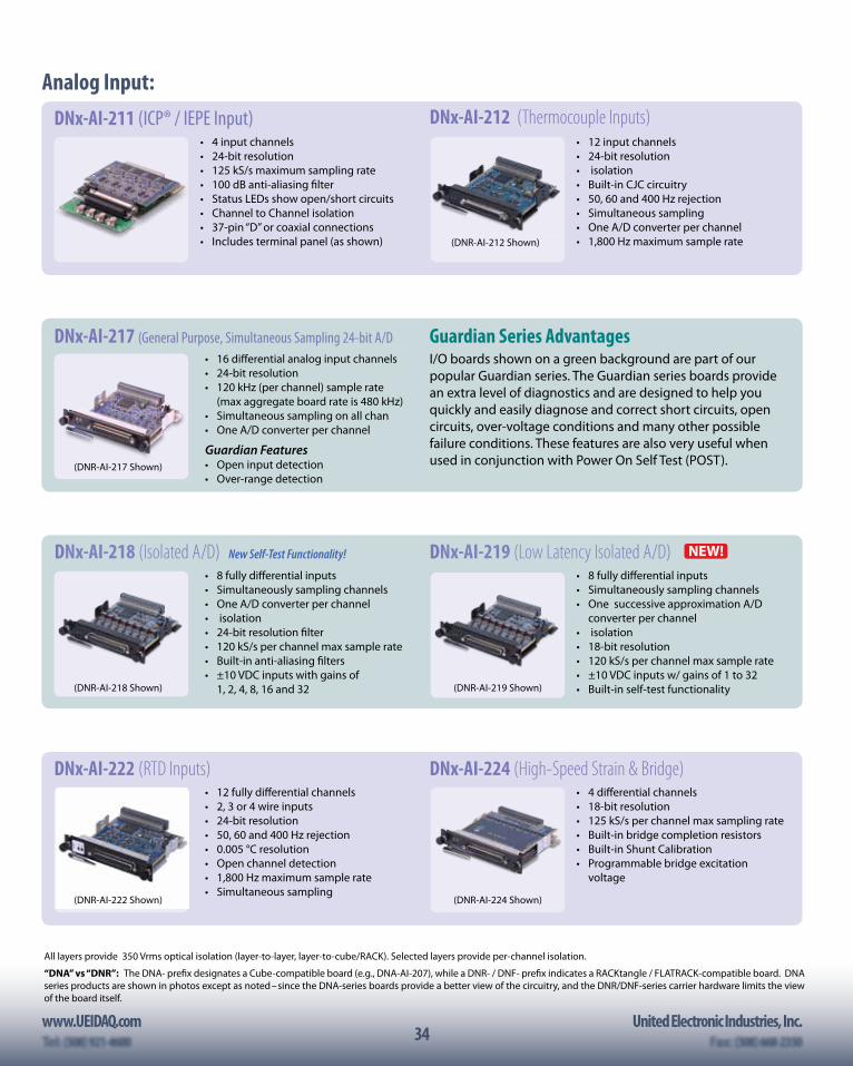
34www.UEIDAQ.com United Electronic Industries, Inc.
34
Analog Input:
All layers provide 350 Vrms optical isolation (layer-to-layer, layer-to-cube/RACK). Selected layers provide per-channel isolation.
“DNA” vs “DNR”: The DNA- prefix designates a Cube-compatible board (e.g., DNA-AI-207), while a DNR- / DNF- prefix indicates a RACKtangle / FLATRACK-compatible board. DNA series products are shown in photos except as noted– since the DNA-series boards provide a better view of the circuitry, and the DNR/DNF-series carrier hardware limits the view of the board itself.
• 4 input channels• 24-bit resolution• 125 kS/s maximum sampling rate• 100 dB anti-aliasing filter• Status LEDs show open/short circuits• Channel to Channel isolation• 37-pin “D” or coaxial connections• Includes terminal panel (as shown)
DNx-AI-211 (ICP® / IEPE Input)• 12 input channels• 24-bit resolution• isolation• Built-in CJC circuitry• 50, 60 and 400 Hz rejection• Simultaneous sampling• One A/D converter per channel• 1,800 Hz maximum sample rate
DNx-AI-212 (Thermocouple Inputs)
(DNR-AI-212 Shown)
• 16 differential analog input channels • 24-bit resolution• 120 kHz (per channel) sample rate
(max aggregate board rate is 480 kHz)• Simultaneous sampling on all chan• One A/D converter per channel
Guardian Features• Open input detection• Over-range detection
DNx-AI-217 (General Purpose, Simultaneous Sampling 24-bit A/D Guardian Series AdvantagesI/O boards shown on a green background are part of our popular Guardian series. The Guardian series boards provide an extra level of diagnostics and are designed to help you quickly and easily diagnose and correct short circuits, open circuits, over-voltage conditions and many other possible failure conditions. These features are also very useful when used in conjunction with Power On Self Test (POST).(DNR-AI-217 Shown)
• 8 fully differential inputs• Simultaneously sampling channels• One A/D converter per channel• isolation• 24-bit resolution filter• 120 kS/s per channel max sample rate• Built-in anti-aliasing filters• ±10 VDC inputs with gains of 1, 2, 4, 8, 16 and 32
DNx-AI-218 (Isolated A/D) New Self-Test Functionality! NEW!
• 8 fully differential inputs• Simultaneously sampling channels• One successive approximation A/D
converter per channel• isolation• 18-bit resolution• 120 kS/s per channel max sample rate• ±10 VDC inputs w/ gains of 1 to 32• Built-in self-test functionality
DNx-AI-219 (Low Latency Isolated A/D)
(DNR-AI-218 Shown) (DNR-AI-219 Shown)
• 4 differential channels• 18-bit resolution• 125 kS/s per channel max sampling rate• Built-in bridge completion resistors• Built-in Shunt Calibration• Programmable bridge excitation
voltage
DNx-AI-224 (High-Speed Strain & Bridge)• 12 fully differential channels• 2, 3 or 4 wire inputs• 24-bit resolution• 50, 60 and 400 Hz rejection• 0.005 °C resolution• Open channel detection• 1,800 Hz maximum sample rate• Simultaneous sampling
DNx-AI-222 (RTD Inputs)
(DNR-AI-222 Shown) (DNR-AI-224 Shown)
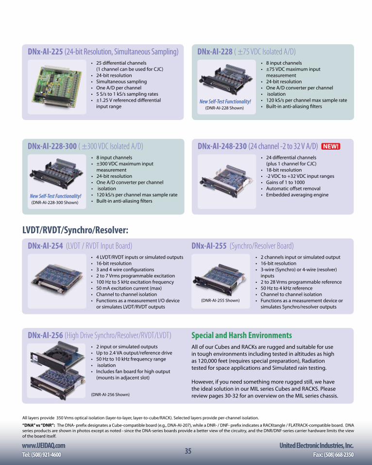
www.UEIDAQ.com United Electronic Industries, Inc.Tel: (508) 921-4600 Fax: (508) 668-235035
All layers provide 350 Vrms optical isolation (layer-to-layer, layer-to-cube/RACK). Selected layers provide per-channel isolation.
“DNA” vs “DNR”: The DNA- prefix designates a Cube-compatible board (e.g., DNA-AI-207), while a DNR- / DNF- prefix indicates a RACKtangle / FLATRACK-compatible board. DNA series products are shown in photos except as noted– since the DNA-series boards provide a better view of the circuitry, and the DNR/DNF-series carrier hardware limits the view of the board itself.
• 2 input or simulated outputs• Up to 2.4 VA output/reference drive• 50 Hz to 10 kHz frequency range• isolation• Includes fan board for high output
(mounts in adjacent slot)
DNx-AI-256 (High Drive Synchro/Resolver/RVDT/LVDT)All of our Cubes and RACKs are rugged and suitable for use in tough environments including tested in altitudes as high as 120,000 feet (requires special preparation), Radiation tested for space applications and Simulated rain testing.
However, if you need something more rugged still, we have the ideal solution in our MIL series Cubes and RACKS. Please review pages 30-32 for an overview on the MIL series chassis.
Special and Harsh Environments
(DNR-AI-256 Shown)
LVDT/RVDT/Synchro/Resolver:
• 2 channels input or simulated output• 16-bit resolution• 3-wire (Synchro) or 4-wire (resolver)
inputs• 2 to 28 Vrms programmable reference• 50 Hz to 4 kHz reference• Channel to channel isolation• Functions as a measurement device or
simulates Synchro/resolver outputs
DNx-AI-255 (Synchro/Resolver Board)• 4 LVDT/RVDT inputs or simulated outputs• 16-bit resolution• 3 and 4 wire configurations• 2 to 7 Vrms programmable excitation• 100 Hz to 5 kHz excitation frequency• 50 mA excitation current (max)• Channel to channel isolation• Functions as a measurement I/O device
or simulates LVDT/RVDT outputs
DNx-AI-254 (LVDT / RVDT Input Board)
(DNR-AI-255 Shown)
• 8 input channels• ±300 VDC maximum input
measurement• 24-bit resolution• One A/D converter per channel• isolation• 120 kS/s per channel max sample rate• Built-in anti-aliasing filters
DNx-AI-228-300 ( ±300 VDC Isolated A/D)
• 25 differential channels (1 channel can be used for CJC)• 24-bit resolution• Simultaneous sampling• One A/D per channel• 5 S/s to 1 kS/s sampling rates• ±1.25 V referenced differential
input range
DNx-AI-225 (24-bit Resolution, Simultaneous Sampling)
New Self-Test Functionality!(DNR-AI-228-300 Shown)
• 24 differential channels (plus 1 channel for CJC)• 18-bit resolution• -2 VDC to +32 VDC input ranges• Gains of 1 to 1000• Automatic offset removal• Embedded averaging engine
DNx-AI-248-230 (24 channel -2 to 32 V A/D)
• 8 input channels• ±75 VDC maximum input
measurement• 24-bit resolution• One A/D converter per channel• isolation• 120 kS/s per channel max sample rate• Built-in anti-aliasing filters
DNx-AI-228 ( ±75 VDC Isolated A/D)
New Self-Test Functionality!(DNR-AI-228 Shown)
NEW!
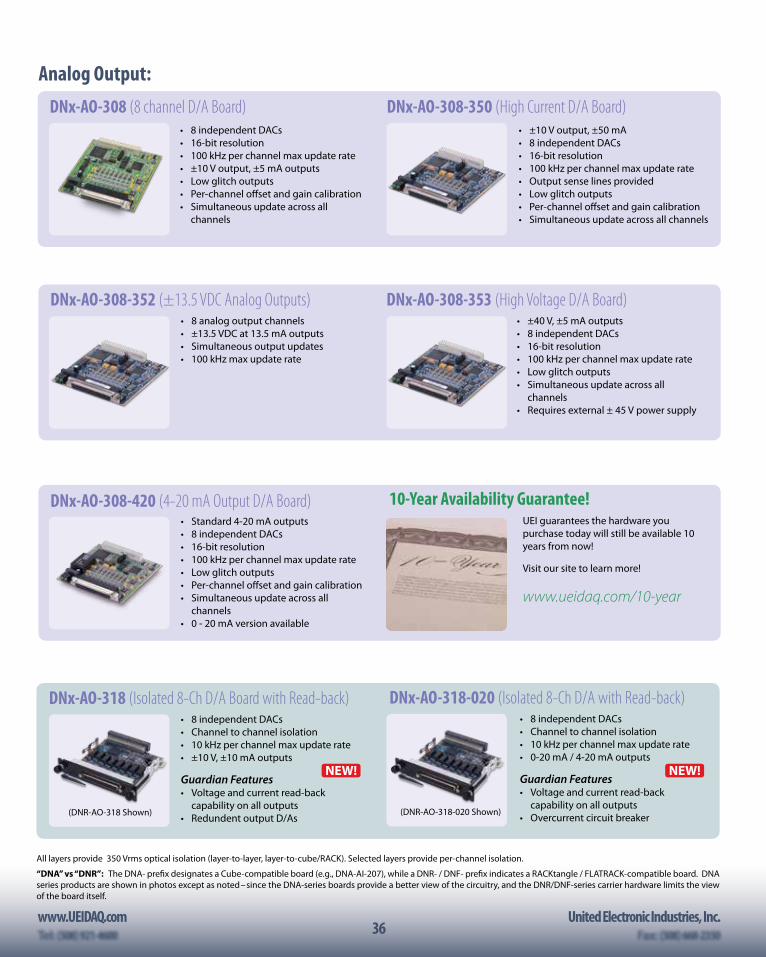
36www.UEIDAQ.com United Electronic Industries, Inc.
36
• Standard 4-20 mA outputs• 8 independent DACs• 16-bit resolution• 100 kHz per channel max update rate• Low glitch outputs• Per-channel offset and gain calibration• Simultaneous update across all
channels• 0 - 20 mA version available
DNx-AO-308-420 (4-20 mA Output D/A Board)
All layers provide 350 Vrms optical isolation (layer-to-layer, layer-to-cube/RACK). Selected layers provide per-channel isolation.
“DNA” vs “DNR”: The DNA- prefix designates a Cube-compatible board (e.g., DNA-AI-207), while a DNR- / DNF- prefix indicates a RACKtangle / FLATRACK-compatible board. DNA series products are shown in photos except as noted– since the DNA-series boards provide a better view of the circuitry, and the DNR/DNF-series carrier hardware limits the view of the board itself.
• 8 analog output channels• ±13.5 VDC at 13.5 mA outputs• Simultaneous output updates• 100 kHz max update rate
DNx-AO-308-352 (±13.5 VDC Analog Outputs) • ±40 V, ±5 mA outputs• 8 independent DACs• 16-bit resolution• 100 kHz per channel max update rate• Low glitch outputs• Simultaneous update across all
channels• Requires external ± 45 V power supply
DNx-AO-308-353 (High Voltage D/A Board)
Analog Output:
• 8 independent DACs• 16-bit resolution• 100 kHz per channel max update rate• ±10 V output, ±5 mA outputs• Low glitch outputs• Per-channel offset and gain calibration• Simultaneous update across all
channels
DNx-AO-308 (8 channel D/A Board)• ±10 V output, ±50 mA• 8 independent DACs• 16-bit resolution• 100 kHz per channel max update rate• Output sense lines provided• Low glitch outputs• Per-channel offset and gain calibration• Simultaneous update across all channels
DNx-AO-308-350 (High Current D/A Board)
• 8 independent DACs• Channel to channel isolation• 10 kHz per channel max update rate• ±10 V, ±10 mA outputs
Guardian Features• Voltage and current read-back
capability on all outputs• Redundent output D/As
DNx-AO-318 (Isolated 8-Ch D/A Board with Read-back)
(DNR-AO-318 Shown)
UEI guarantees the hardware you purchase today will still be available 10 years from now!
Visit our site to learn more!
www.ueidaq.com/10-year
10-Year Availability Guarantee!
• 8 independent DACs• Channel to channel isolation• 10 kHz per channel max update rate• 0-20 mA / 4-20 mA outputs
Guardian Features• Voltage and current read-back
capability on all outputs• Overcurrent circuit breaker
DNx-AO-318-020 (Isolated 8-Ch D/A with Read-back)
(DNR-AO-318-020 Shown)
NEW!NEW!
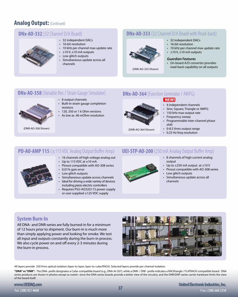
www.UEIDAQ.com United Electronic Industries, Inc.Tel: (508) 921-4600 Fax: (508) 668-235037
• 32 independent DACs• 16-bit resolution• 10 kHz per channel max update rate• ±10 V, ±10 mA outputs
Guardian Features• On-board A/D converter provides
read-back capability on all outputs
DNx-AO-333 (32 Channel D/A Board with Read-back)
(DNR-AO-333 Shown)
• 8 output channels• Built-in strain gauge completion
resistors• 120, 350 or 1 k Ohm versions• As low as .46 mOhm resolution
DNx-AO-358 (Variable Res / Strain Gauge Simulator)
(DNR-AO-358 Shown)
System Burn-InAll DNA- and DNR-series are fully burned-in for a minimum of 12 hours prior to shipment. Our burn-in is much more than simply applying power and looking for smoke. We test all input and outputs constantly during the burn-in process. We also cycle power on and off every 2-3 minutes during the burn-in process.
• 16 channels of high voltage analog out• Up to 115 VDC at ±10 mA• Pinout compatible with AO-308 series• 0.01% gain error• Low glitch outputs• Simultaneous update across channels• Ideal for driving a wide variety of devices
including piezo electric controllers• Requires PSU-AO32G115 power supply
or user supplied ±125 VDC supply
PD-AO-AMP 115 (±115 VDC Analog Output Buffer Amp)• 8 channels of high current analog
output• Up to ±250 mA output at ±10 V• Pinout compatible with AO-308 series• Low glitch outputs• Simultaneous update across all
channels
UEI-STP-AO-200 (250 mA Analog Output Buffer Amp)
Analog Output: (Continued)
• 4 independent channels• Sine, Square, Triangle or AWFG• 150 kHz max output rate• Frequency sweep• Programmable inter-channel phase
shift• 0-8.5 Vrms output range• 0.25 Hz freq resolution
DNx-AO-364 (Function Generator / AWFG) NEW!
All layers provide 350 Vrms optical isolation (layer-to-layer, layer-to-cube/RACK). Selected layers provide per-channel isolation.
“DNA” vs “DNR”: The DNA- prefix designates a Cube-compatible board (e.g., DNA-AI-207), while a DNR- / DNF- prefix indicates a RACKtangle / FLATRACK-compatible board. DNA series products are shown in photos except as noted– since the DNA-series boards provide a better view of the circuitry, and the DNR/DNF-series carrier hardware limits the view of the board itself.
(DNR-AO-364 Shown)
• 32 independent DACs• 16-bit resolution• 10 kHz per channel max update rate• ±10 V, ±10 mA outputs• Low glitch outputs• Simultaneous update across all
channels
DNx-AO-332 (32 Channel D/A Board)
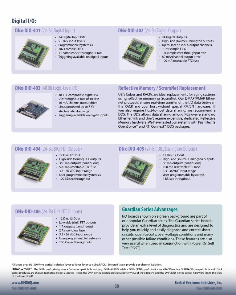
38www.UEIDAQ.com United Electronic Industries, Inc.
38
DNx-DIO-404 (24-Bit DIO, FET Outputs) • 12 Din, 12 Dout• High-side (source) FET outputs • 350 mA outputs (continuous)• 500 mA resettable PTC fuse• 3.3 - 36 VDC input range• User-programmable hysteresis • 100 kS/sec throughput
• 12 Din, 12 Dout • High-side (source) Darlington outputs • 80 mA outputs (continuous)• 100 mA resettable PTC fuse• 3.3 - 36 VDC input range• User-programmable hysteresis • 1 kS/sec throughput
DNx-DIO-405 (24-Bit DIO, Darlington Outputs)
• 12 Din, 12 Dout• Low-side (sink) FET outputs • 1 A outputs (continuous)• 2 A slow-blow fuse• 3.3 - 36 VDC input range• User-programmable hysteresis • 100 kS/sec throughputs
DNx-DIO-406 (24-Bit DIO, FET Outputs) Guardian Series AdvantagesI/O boards shown on a green background are part of our popular Guardian series. The Guardian series boards provide an extra level of diagnostics and are designed to help you quickly and easily diagnose and correct short circuits, open circuits, over-voltage conditions and many other possible failure conditions. These features are also very useful when used in conjunction with Power On Self Test (POST).
All layers provide 350 Vrms optical isolation (layer-to-layer, layer-to-cube/RACK). Selected layers provide per-channel isolation.
“DNA” vs “DNR”: The DNA- prefix designates a Cube-compatible board (e.g., DNA-AI-207), while a DNR- / DNF- prefix indicates a RACKtangle / FLATRACK-compatible board. DNA series products are shown in photos except as noted– since the DNA-series boards provide a better view of the circuitry, and the DNR/DNF-series carrier hardware limits the view of the board itself.
• 24 Digital Input bits• 5 - 36 V input levels• Programmable hysteresis• 1024 sample FIFO• 1 k samples/sec throughput rate• Triggering available on digital inputs
DNx-DIO-401 (24-Bit Digital Input)• 24 Digital Outputs• High-side (source) Darlington outputs• Up to 36 V on input/output channels• 1024 sample FIFO• 1 k samples/sec throughput rate• 80 mA/channel output drive• 100 mA resettable PTC fuse
DNx-DIO-402 (24-Bit Digital Output)
Digital I/O:
• 48 TTL-compatible digital I/O• I/O throughput rate of 10 kHz • 16 mA/channel output drive• Lines protected up to 7 kV
electrostatic discharge • Triggering available on digital inputs
DNx-DIO-403 (48 Bit Logic-Level I/O) Reflective Memory / ScramNet ReplacementUEI’s Cubes and RACKs are ideal replacements for aging systems using reflective memory or ScramNet. Our DMAP/VMAP Ether-net protocols ensure real-time transfer of the I/O data between the RACK and your host without special RM/SN hardware. If you also require host-to-host data sharing, we recommend a DDS. The DDS allows data sharing among PCs over a standard Ethernet link and don’t require expensive, dedicated Reflective Memory hardware. We have tested our systems with PrismTech’s OpenSplice™ and RTI Connext™ DDS packages.
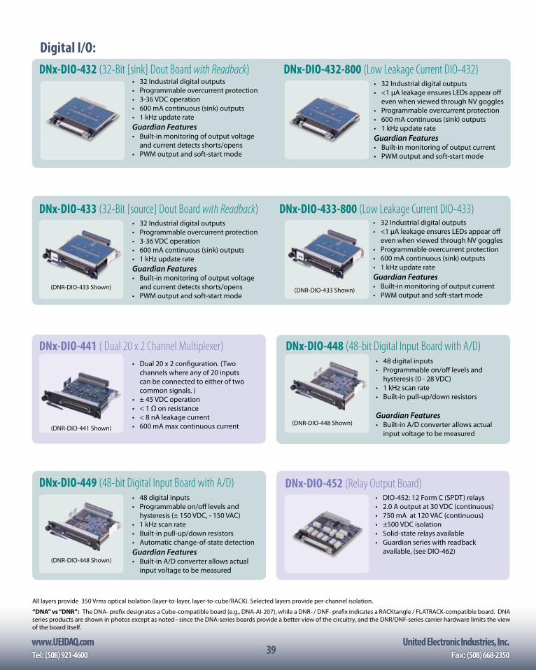
www.UEIDAQ.com United Electronic Industries, Inc.Tel: (508) 921-4600 Fax: (508) 668-235039
• 32 Industrial digital outputs• Programmable overcurrent protection• 3-36 VDC operation• 600 mA continuous (sink) outputs• 1 kHz update rateGuardian Features• Built-in monitoring of output voltage
and current detects shorts/opens• PWM output and soft-start mode
DNx-DIO-432 (32-Bit [sink] Dout Board with Readback)
• 32 Industrial digital outputs• Programmable overcurrent protection• 3-36 VDC operation• 600 mA continuous (sink) outputs• 1 kHz update rateGuardian Features• Built-in monitoring of output voltage
and current detects shorts/opens• PWM output and soft-start mode
DNx-DIO-433 (32-Bit [source] Dout Board with Readback)
(DNR-DIO-433 Shown)
• 32 Industrial digital outputs• <1 µA leakage ensures LEDs appear off
even when viewed through NV goggles• Programmable overcurrent protection• 600 mA continuous (sink) outputs• 1 kHz update rateGuardian Features• Built-in monitoring of output current• PWM output and soft-start mode
DNx-DIO-433-800 (Low Leakage Current DIO-433)
(DNR-DIO-433 Shown)
• 32 Industrial digital outputs• <1 µA leakage ensures LEDs appear off
even when viewed through NV goggles• Programmable overcurrent protection• 600 mA continuous (sink) outputs• 1 kHz update rateGuardian Features• Built-in monitoring of output current• PWM output and soft-start mode
DNx-DIO-432-800 (Low Leakage Current DIO-432)
• 48 digital inputs• Programmable on/off levels and
hysteresis (0 - 28 VDC)• 1 kHz scan rate• Built-in pull-up/down resistors
Guardian Features• Built-in A/D converter allows actual
input voltage to be measured
DNx-DIO-448 (48-bit Digital Input Board with A/D)
DNx-DIO-452 (Relay Output Board) • DIO-452: 12 Form C (SPDT) relays• 2.0 A output at 30 VDC (continuous)• 750 mA at 120 VAC (continuous)• ±500 VDC isolation• Solid-state relays available• Guardian series with readback
available, (see DIO-462)
(DNR-DIO-448 Shown)
DNx-DIO-441 ( Dual 20 x 2 Channel Multiplexer) • Dual 20 x 2 configuration. (Two
channels where any of 20 inputs can be connected to either of two common signals. )
• ± 45 VDC operation• < 1 Ω on resistance• < 8 nA leakage current• 600 mA max continuous current
• 48 digital inputs• Programmable on/off levels and
hysteresis (± 150 VDC, - 150 VAC)• 1 kHz scan rate• Built-in pull-up/down resistors• Automatic change-of-state detectionGuardian Features• Built-in A/D converter allows actual
input voltage to be measured
DNx-DIO-449 (48-bit Digital Input Board with A/D)
(DNR-DIO-448 Shown)
All layers provide 350 Vrms optical isolation (layer-to-layer, layer-to-cube/RACK). Selected layers provide per-channel isolation.
“DNA” vs “DNR”: The DNA- prefix designates a Cube-compatible board (e.g., DNA-AI-207), while a DNR- / DNF- prefix indicates a RACKtangle / FLATRACK-compatible board. DNA series products are shown in photos except as noted– since the DNA-series boards provide a better view of the circuitry, and the DNR/DNF-series carrier hardware limits the view of the board itself.
Digital I/O:
(DNR-DIO-441 Shown)
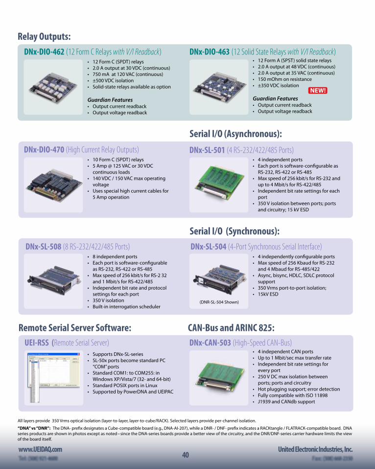
40www.UEIDAQ.com United Electronic Industries, Inc.
40
Serial I/O (Asynchronous):
• 4 independent ports• Each port is software-configurable as
RS-232, RS-422 or RS-485• Max speed of 256 kbit/s for RS-232 and
up to 4 Mbit/s for RS-422/485• Independent bit rate settings for each
port• 350 V isolation between ports; ports
and circuitry; 15 kV ESD
DNx-SL-501 (4 RS-232/422/485 Ports)
• 8 independent ports• Each port is software-configurable
as RS-232, RS-422 or RS-485• Max speed of 256 kbit/s for RS-2 32
and 1 Mbit/s for RS-422/485• Independent bit rate and protocol
settings for each port• 350 V isolation• Built-in interrogation scheduler
DNx-SL-508 (8 RS-232/422/485 Ports)
CAN-Bus and ARINC 825:
• 4 independent CAN ports• Up to 1 Mbit/sec max transfer rate• Independent bit rate settings for
every port• 250 V DC max isolation between
ports; ports and circuitry• Hot plugging support; error detection• Fully compatible with ISO 11898• J1939 and CANdb support
DNx-CAN-503 (High-Speed CAN-Bus)
Serial I/O (Synchronous):
• 4 independently configurable ports• Max speed of 256 Kbaud for RS-232
and 4 Mbaud for RS-485/422• Async, bisync, HDLC, SDLC protocol
support• 350 Vrms port-to-port isolation; • 15kV ESD
DNx-SL-504 (4-Port Synchronous Serial Interface)
(DNR-SL-504 Shown)
Remote Serial Server Software:
• Supports DNx-SL-series• SL-50x ports become standard PC
“COM” ports• Standard COM1: to COM255: in
Windows XP/Vista/7 (32- and 64-bit) • Standard POSIX ports in Linux • Supported by PowerDNA and UEIPAC
UEI-RSS (Remote Serial Server)
All layers provide 350 Vrms optical isolation (layer-to-layer, layer-to-cube/RACK). Selected layers provide per-channel isolation.
“DNA” vs “DNR”: The DNA- prefix designates a Cube-compatible board (e.g., DNA-AI-207), while a DNR- / DNF- prefix indicates a RACKtangle / FLATRACK-compatible board. DNA series products are shown in photos except as noted– since the DNA-series boards provide a better view of the circuitry, and the DNR/DNF-series carrier hardware limits the view of the board itself.
• 10 Form C (SPDT) relays• 5 Amp @ 125 VAC or 30 VDC
continuous loads• 140 VDC / 150 VAC max operating
voltage• Uses special high current cables for
5 Amp operation
DNx-DIO-470 (High Current Relay Outputs)
Relay Outputs:DNx-DIO-462 (12 Form C Relays with V/I Readback)
• 12 Form C (SPDT) relays• 2.0 A output at 30 VDC (continuous)• 750 mA at 120 VAC (continuous)• ±500 VDC isolation• Solid-state relays available as option
Guardian Features• Output current readback • Output voltage readback
DNx-DIO-463 (12 Solid State Relays with V/I Readback)• 12 Form A (SPST) solid state relays• 2.0 A output at 48 VDC (continuous)• 2.0 A output at 35 VAC (continuous)• 150 mOhm on resistance• ±350 VDC isolation
Guardian Features• Output current readback • Output voltage readback
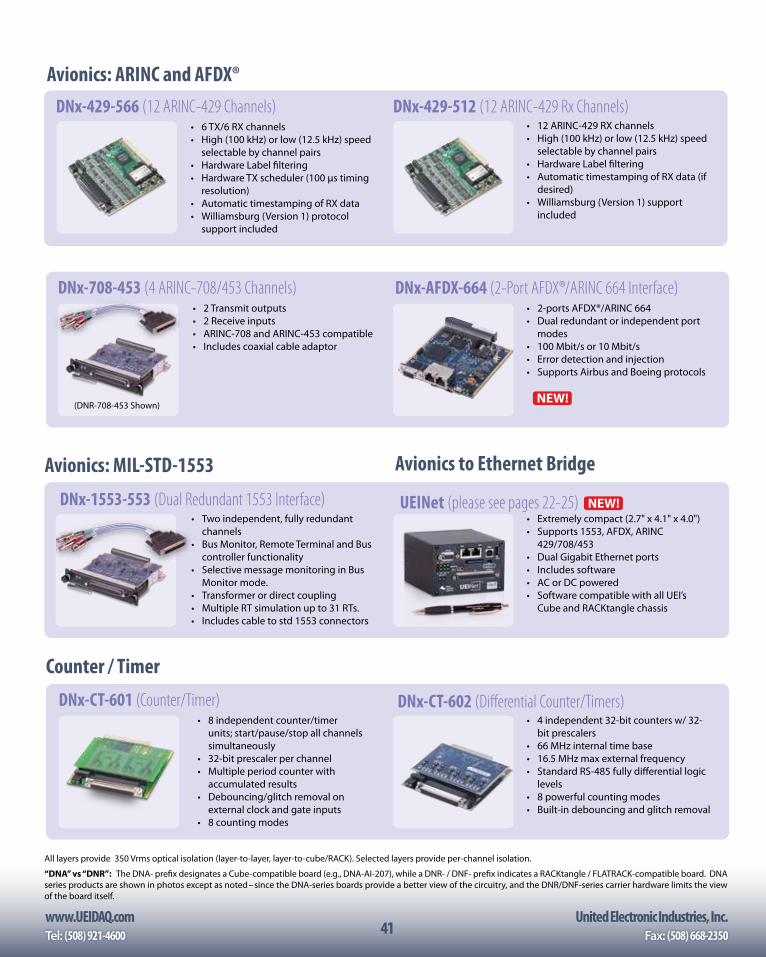
www.UEIDAQ.com United Electronic Industries, Inc.Tel: (508) 921-4600 Fax: (508) 668-235041
Avionics: ARINC and AFDX®
• 6 TX/6 RX channels• High (100 kHz) or low (12.5 kHz) speed
selectable by channel pairs• Hardware Label filtering• Hardware TX scheduler (100 µs timing
resolution)• Automatic timestamping of RX data• Williamsburg (Version 1) protocol
support included
DNx-429-566 (12 ARINC-429 Channels)• 12 ARINC-429 RX channels• High (100 kHz) or low (12.5 kHz) speed
selectable by channel pairs• Hardware Label filtering• Automatic timestamping of RX data (if
desired)• Williamsburg (Version 1) support
included
DNx-429-512 (12 ARINC-429 Rx Channels)
(DNR-1553-553 Shown)
Avionics: MIL-STD-1553
• Two independent, fully redundant channels
• Bus Monitor, Remote Terminal and Bus controller functionality
• Selective message monitoring in Bus Monitor mode.
• Transformer or direct coupling• Multiple RT simulation up to 31 RTs.• Includes cable to std 1553 connectors
DNx-1553-553 (Dual Redundant 1553 Interface)
Counter / Timer
DNx-CT-601 (Counter/Timer)• 8 independent counter/timer
units; start/pause/stop all channels simultaneously
• 32-bit prescaler per channel• Multiple period counter with
accumulated results• Debouncing/glitch removal on
external clock and gate inputs• 8 counting modes
All layers provide 350 Vrms optical isolation (layer-to-layer, layer-to-cube/RACK). Selected layers provide per-channel isolation.
“DNA” vs “DNR”: The DNA- prefix designates a Cube-compatible board (e.g., DNA-AI-207), while a DNR- / DNF- prefix indicates a RACKtangle / FLATRACK-compatible board. DNA series products are shown in photos except as noted– since the DNA-series boards provide a better view of the circuitry, and the DNR/DNF-series carrier hardware limits the view of the board itself.
• 2 Transmit outputs• 2 Receive inputs• ARINC-708 and ARINC-453 compatible• Includes coaxial cable adaptor
• 2-ports AFDX®/ARINC 664• Dual redundant or independent port
modes• 100 Mbit/s or 10 Mbit/s• Error detection and injection• Supports Airbus and Boeing protocols
DNx-708-453 (4 ARINC-708/453 Channels) DNx-AFDX-664 (2-Port AFDX®/ARINC 664 Interface)
(DNR-708-453 Shown)
• 4 independent 32-bit counters w/ 32-bit prescalers
• 66 MHz internal time base• 16.5 MHz max external frequency• Standard RS-485 fully differential logic
levels• 8 powerful counting modes• Built-in debouncing and glitch removal
DNx-CT-602 (Differential Counter/Timers)
Avionics to Ethernet Bridge
• Extremely compact (2.7" x 4.1" x 4.0")• Supports 1553, AFDX, ARINC
429/708/453• Dual Gigabit Ethernet ports• Includes software• AC or DC powered• Software compatible with all UEI’s
Cube and RACKtangle chassis
UEINet (please see pages 22-25)
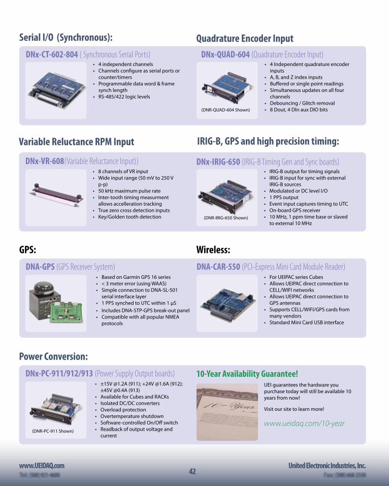
42www.UEIDAQ.com United Electronic Industries, Inc.
42
Power Conversion:
• ±15V @1.2A (911); +24V @1.6A (912); ±45V @0.4A (913)
• Available for Cubes and RACKs• Isolated DC/DC converters• Overload protection• Overtemperature shutdown• Software-controlled On/Off switch• Readback of output voltage and
current
DNx-PC-911/912/913 (Power Supply Output boards)
(DNR-PC-911 Shown)
• 4 Independent quadrature encoder inputs
• A, B, and Z index inputs• Buffered or single point readings• Simultaneous updates on all four
channels• Debouncing / Glitch removal• 8 Dout, 4 DIn aux DIO bits
DNx-QUAD-604 (Quadrature Encoder Input)
(DNR-QUAD-604 Shown)
(DNR-SL-508 Shown)
• IRIG-B output for timing signals• IRIG-B input for sync with external
IRIG-B sources• Modulated or DC level I/O• 1 PPS output• Event input captures timing to UTC• On-board GPS receiver• 10 MHz, 1 ppm time base or slaved
to external 10 MHz
DNx-IRIG-650 (IRIG-B Timing Gen and Sync boards)
(DNR-IRIG-650 Shown)
Quadrature Encoder Input
IRIG-B, GPS and high precision timing:
GPS: Wireless:
• Based on Garmin GPS 16 series• < 3 meter error (using WAAS)• Simple connection to DNA-SL-501
serial interface layer• 1 PPS synched to UTC within 1 µS • Includes DNA-STP-GPS break-out panel• Compatible with all popular NMEA
protocols
• For UEIPAC series Cubes• Allows UEIPAC direct connection to
CELL/WIFI networks• Allows UEIPAC direct connection to
GPS antennas• Supports CELL/WIFI/GPS cards from
many vendors • Standard Mini Card USB interface
DNA-GPS (GPS Receiver System) DNA-CAR-550 (PCI-Express Mini Card Module Reader)
• 8 channels of VR input• Wide input range (50 mV to 250 V
p-p)• 50 kHz maximum pulse rate• Inter-tooth timing measurment
allows accelleration tracking• True zero cross detection inputs• Key/Golden tooth detection
DNx-VR-608(Variable Reluctance Input))
Variable Reluctance RPM Input
UEI guarantees the hardware you purchase today will still be available 10 years from now!
Visit our site to learn more!
www.ueidaq.com/10-year
10-Year Availability Guarantee!
• 4 independent channels• Channels configure as serial ports or
counter/timers• Programmable data word & frame
synch length• RS-485/422 logic levels
DNx-CT-602-804 ( Synchronous Serial Ports)
Serial I/O (Synchronous):
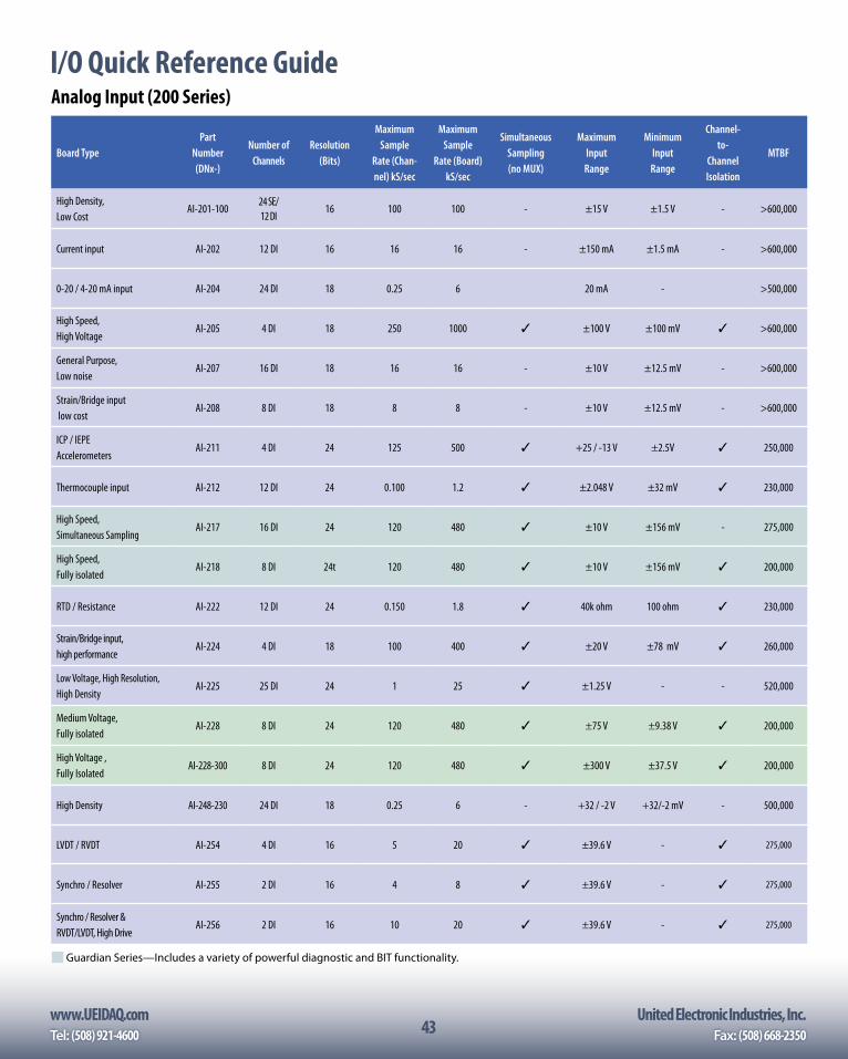
www.UEIDAQ.com United Electronic Industries, Inc.Tel: (508) 921-4600 Fax: (508) 668-235043
I/O Quick Reference GuideAnalog Input (200 Series)
Board TypePart
Number (DNx-)
Number of Channels
Resolution (Bits)
Maximum Sample
Rate (Chan-nel) kS/sec
Maximum Sample
Rate (Board) kS/sec
Simultaneous Sampling (no MUX)
Maximum Input Range
Minimum Input Range
Channel-to-
Channel Isolation
MTBF
High Density, Low Cost
AI-201-10024 SE/ 12 DI
16 100 100 - ±15 V ±1.5 V - >600,000
Current input AI-202 12 DI 16 16 16 - ±150 mA ±1.5 mA - >600,000
0-20 / 4-20 mA input AI-204 24 DI 18 0.25 6 20 mA - >500,000
High Speed, High Voltage
AI-205 4 DI 18 250 1000 ✓ ±100 V ±100 mV ✓ >600,000
General Purpose, Low noise
AI-207 16 DI 18 16 16 - ±10 V ±12.5 mV - >600,000
Strain/Bridge input low cost
AI-208 8 DI 18 8 8 - ±10 V ±12.5 mV - >600,000
ICP / IEPE Accelerometers
AI-211 4 DI 24 125 500 ✓ +25 / -13 V ±2.5V ✓ 250,000
Thermocouple input AI-212 12 DI 24 0.100 1.2 ✓ ±2.048 V ±32 mV ✓ 230,000
High Speed, Simultaneous Sampling
AI-217 16 DI 24 120 480 ✓ ±10 V ±156 mV - 275,000
High Speed, Fully isolated
AI-218 8 DI 24t 120 480 ✓ ±10 V ±156 mV ✓ 200,000
RTD / Resistance AI-222 12 DI 24 0.150 1.8 ✓ 40k ohm 100 ohm ✓ 230,000
Strain/Bridge input, high performance
AI-224 4 DI 18 100 400 ✓ ±20 V ±78 mV ✓ 260,000
Low Voltage, High Resolution, High Density
AI-225 25 DI 24 1 25 ✓ ±1.25 V - - 520,000
Medium Voltage, Fully isolated
AI-228 8 DI 24 120 480 ✓ ±75 V ±9.38 V ✓ 200,000
High Voltage , Fully Isolated
AI-228-300 8 DI 24 120 480 ✓ ±300 V ±37.5 V ✓ 200,000
High Density AI-248-230 24 DI 18 0.25 6 - +32 / -2 V +32/-2 mV - 500,000
LVDT / RVDT AI-254 4 DI 16 5 20 ✓ ±39.6 V - ✓ 275,000
Synchro / Resolver AI-255 2 DI 16 4 8 ✓ ±39.6 V - ✓ 275,000
Synchro / Resolver & RVDT/LVDT, High Drive
AI-256 2 DI 16 10 20 ✓ ±39.6 V - ✓ 275,000
Guardian Series —Includes a variety of powerful diagnostic and BIT functionality.
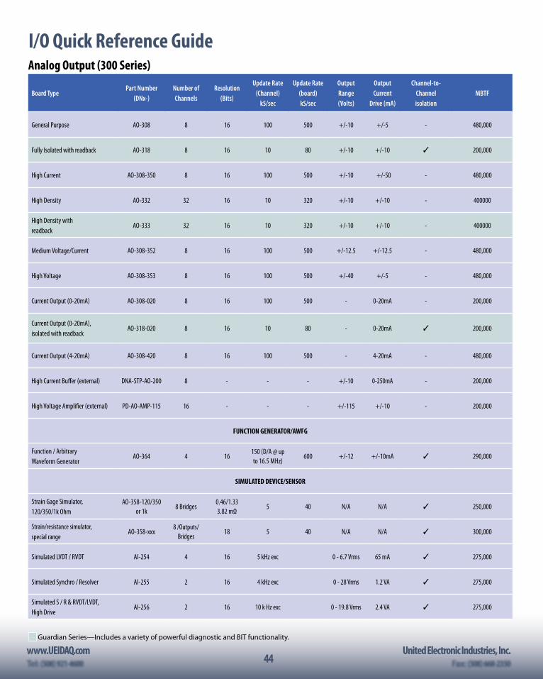
44www.UEIDAQ.com United Electronic Industries, Inc.
44
I/O Quick Reference GuideAnalog Output (300 Series)
Board TypePart Number
(DNx-)Number of Channels
Resolution (Bits)
Update Rate (Channel)
kS/sec
Update Rate (board) kS/sec
Output Range (Volts)
Output Current
Drive (mA)
Channel-to- Channel isolation
MBTF
General Purpose AO-308 8 16 100 500 +/-10 +/-5 - 480,000
Fully Isolated with readback AO-318 8 16 10 80 +/-10 +/-10 ✓ 200,000
High Current AO-308-350 8 16 100 500 +/-10 +/-50 - 480,000
High Density AO-332 32 16 10 320 +/-10 +/-10 - 400000
High Density with readback
AO-333 32 16 10 320 +/-10 +/-10 - 400000
Medium Voltage/Current AO-308-352 8 16 100 500 +/-12.5 +/-12.5 - 480,000
High Voltage AO-308-353 8 16 100 500 +/-40 +/-5 - 480,000
Current Output (0-20mA) AO-308-020 8 16 100 500 - 0-20mA - 200,000
Current Output (0-20mA), isolated with readback
AO-318-020 8 16 10 80 - 0-20mA ✓ 200,000
Current Output (4-20mA) AO-308-420 8 16 100 500 - 4-20mA - 480,000
High Current Buffer (external) DNA-STP-AO-200 8 - - - +/-10 0-250mA - 200,000
High Voltage Amplifier (external) PD-AO-AMP-115 16 - - - +/-115 +/-10 - 200,000
FUNCTION GENERATOR/AWFG
Function / Arbitrary Waveform Generator
AO-364 4 16150 (D/A @ up to 16.5 MHz)
600 +/-12 +/-10mA ✓ 290,000
SIMULATED DEVICE/SENSOR
Strain Gage Simulator, 120/350/1k Ohm
AO-358-120/350or 1k
8 Bridges0.46/1.33 3.82 mΩ
5 40 N/A N/A ✓ 250,000
Strain/resistance simulator, special range
AO-358-xxx8 /Outputs/
Bridges18 5 40 N/A N/A ✓ 300,000
Simulated LVDT / RVDT AI-254 4 16 5 kHz exc 0 - 6.7 Vrms 65 mA ✓ 275,000
Simulated Synchro / Resolver AI-255 2 16 4 kHz exc 0 - 28 Vrms 1.2 VA ✓ 275,000
Simulated S / R & RVDT/LVDT, High Drive
AI-256 2 16 10 k Hz exc 0 - 19.8 Vrms 2.4 VA ✓ 275,000
Guardian Series —Includes a variety of powerful diagnostic and BIT functionality.
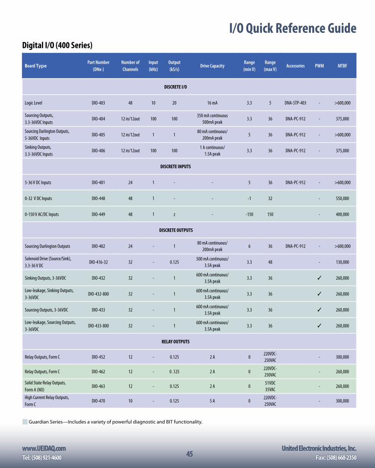
www.UEIDAQ.com United Electronic Industries, Inc.Tel: (508) 921-4600 Fax: (508) 668-235045
Analog Output (300 Series)
Board TypePart Number
(DNx-)Number of Channels
Resolution (Bits)
Update Rate (Channel)
kS/sec
Update Rate (board) kS/sec
Output Range (Volts)
Output Current
Drive (mA)
Channel-to- Channel isolation
MBTF
General Purpose AO-308 8 16 100 500 +/-10 +/-5 - 480,000
Fully Isolated with readback AO-318 8 16 10 80 +/-10 +/-10 ✓ 200,000
High Current AO-308-350 8 16 100 500 +/-10 +/-50 - 480,000
High Density AO-332 32 16 10 320 +/-10 +/-10 - 400000
High Density with readback
AO-333 32 16 10 320 +/-10 +/-10 - 400000
Medium Voltage/Current AO-308-352 8 16 100 500 +/-12.5 +/-12.5 - 480,000
High Voltage AO-308-353 8 16 100 500 +/-40 +/-5 - 480,000
Current Output (0-20mA) AO-308-020 8 16 100 500 - 0-20mA - 200,000
Current Output (0-20mA), isolated with readback
AO-318-020 8 16 10 80 - 0-20mA ✓ 200,000
Current Output (4-20mA) AO-308-420 8 16 100 500 - 4-20mA - 480,000
High Current Buffer (external) DNA-STP-AO-200 8 - - - +/-10 0-250mA - 200,000
High Voltage Amplifier (external) PD-AO-AMP-115 16 - - - +/-115 +/-10 - 200,000
FUNCTION GENERATOR/AWFG
Function / Arbitrary Waveform Generator
AO-364 4 16150 (D/A @ up to 16.5 MHz)
600 +/-12 +/-10mA ✓ 290,000
SIMULATED DEVICE/SENSOR
Strain Gage Simulator, 120/350/1k Ohm
AO-358-120/350or 1k
8 Bridges0.46/1.33 3.82 mΩ
5 40 N/A N/A ✓ 250,000
Strain/resistance simulator, special range
AO-358-xxx8 /Outputs/
Bridges18 5 40 N/A N/A ✓ 300,000
Simulated LVDT / RVDT AI-254 4 16 5 kHz exc 0 - 6.7 Vrms 65 mA ✓ 275,000
Simulated Synchro / Resolver AI-255 2 16 4 kHz exc 0 - 28 Vrms 1.2 VA ✓ 275,000
Simulated S / R & RVDT/LVDT, High Drive
AI-256 2 16 10 k Hz exc 0 - 19.8 Vrms 2.4 VA ✓ 275,000
Guardian Series —Includes a variety of powerful diagnostic and BIT functionality.
I/O Quick Reference GuideDigital I/O (400 Series)
Board TypePart Number
(DNx-)Number of Channels
Input (kHz)
Output (kS/s)
Drive CapacityRange (min V)
Range (max V)
Accessories PWM MTBF
DISCRETE I/O
Logic Level DIO-403 48 10 20 16 mA 3.3 5 DNA-STP-403 - >600,000
Sourcing Outputs, 3.3-36VDC Inputs
DIO-404 12 in/12out 100 100350 mA continuous
500mA peak3.3 36 DNA-PC-912 - 375,000
Sourcing Darlington Outputs, 5-36VDC Inputs
DIO-405 12 in/12out 1 180 mA continuous/
200mA peak5 36 DNA-PC-912 - >600,000
Sinking Outputs, 3.3-36VDC Inputs
DIO-406 12 in/12out 100 1001 A continuous/
1.5A peak3.3 36 DNA-PC-912 - 375,000
DISCRETE INPUTS
5-36 V DC Inputs DIO-401 24 1 - - 5 36 DNA-PC-912 - >600,000
0-32 V DC Inputs DIO-448 48 1 - - -1 32 - 550,000
0-150 V AC/DC Inputs DIO-449 48 1 z - -150 150 - 400,000
DISCRETE OUTPUTS
Sourcing Darlington Outputs DIO-402 24 - 180 mA continuous/
200mA peak6 36 DNA-PC-912 - >600,000
Solenoid Drive (Source/Sink), 3.3-36 V DC
DIO-416-32 32 - 0.125500 mA continuous/
3.5A peak3.3 48 - 130,000
Sinking Outputs, 3-36VDC DIO-432 32 - 1600 mA continuous/
3.5A peak3.3 36 ✓ 260,000
Low-leakage, Sinking Outputs, 3-36VDC
DIO-432-800 32 - 1600 mA continuous/
3.5A peak3.3 36 ✓ 260,000
Sourcing Outputs, 3-36VDC DIO-433 32 - 1600 mA continuous/
3.5A peak3.3 36 ✓ 260,000
Low-leakage, Sourcing Outputs, 3-36VDC
DIO-433-800 32 - 1600 mA continuous/
3.5A peak3.3 36 ✓ 260,000
RELAY OUTPUTS
Relay Outputs, Form C DIO-452 12 - 0.125 2 A 0220VDC-250VAC
- 300,000
Relay Outputs, Form C DIO-462 12 - 0 .125 2 A 0220VDC-250VAC
- 260,000
Solid State Relay Outputs, Form A (NO)
DIO-463 12 - 0.125 2 A 051VDC 35VAC
- 260,000
High Current Relay Outputs, Form C
DIO-470 10 - 0.125 5 A 0220VDC-250VAC
- 300,000
Guardian Series —Includes a variety of powerful diagnostic and BIT functionality.
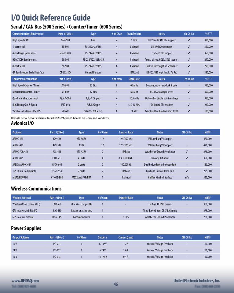
46www.UEIDAQ.com United Electronic Industries, Inc.
46
I/O Quick Reference GuideSerial / CAN Bus (500 Series) • Counter/Timer (600 Series)
Communications Bus Protocol Part # (DNx-) Type # of Chan Transfer Rate Notes Ch-Ch Iso MBTF
High Speed CAN CAN-503 CAN 4 1 Mbit J1939 and CAN .dbc support ✓ 350,000
4-port serial SL-501 RS-232/422/485 4 2 Mbaud J1587/J1708 support ✓ 350,000
4-port high speed serial SL-501-804 RS-232/422/485 4 4 Mbaud J1587/J1708 support ✓ 350,000
HDLC/SDLC Synchronous SL-504 RS-232/422/423/485 4 4 Mbaud Async, bisync, HDLC, SDLC support ✓ 290,000
8-port serial SL-508 RS-232/422/485 8 1 Mbaud Built-in Interrogation Scheduler ✓ 290,000
GP Synchronous Serial Interface CT-602-804 General Purpose 4 16Mbaud RS-422/485 logic levels, Tx, Rx, ✓ 350,000
Counter/timer function Part # (DNx-) Type # of chan Clock Rate Notes ch-ch Iso MBTF
High Speed Counter / Timer CT-601 32 Bits 8 66 MHz Debouncing on ext clock & gate - 350,000
Differential Counter / Timer CT-602 32 Bits 4 66 MHz RS-422/485 logic levels ✓ 350,000
Quadrature Encoder Input QUAD-604 A,B, & Z inputs 4 16.5 MHz Buffered or Single point readings - 350,000
IRIG Timing Gen & Synch IRIG-650 A/B/E/G type 4 1, 5, 10 MHz On-board GPS receiver ✓ 240,000
Variable Reluctance RPM/RPS VR-608 50 mV - 250 V p-p 8 50 kHz Adaptive threshold w/index tooth ✓ 180,000
Remote Serial Server available for all RS232/422/485 boards on Linux and Windows.
Avionics I/OProtocol Part #(DNx-) Type # of Chan Transfer Rate Notes CH-CH Iso MBTF
ARINC-429 429-566 6TX / 6RX 12 12.5/100 kHz Williamsburg V1 Support - 470,000
ARINC-429 429-512 12RX 12 12.5/100 kHz Williamsburg V1 Support - 470,000
ARINC-708/453 708-453 2TX / 2RX 2 1 Mbaud Weather or Ground Prox Radar ✓ 275,000
ARINC-825 CAN-503 4 Ports 4 83.3-1000 kb Sensors, Actuators ✓ 350,000
AFDX & ARINC-664 AFDX-664 2 ports 2 100,000 kb Dual Redundant or Independent - 130,000
1553 (Dual Redundant) 1553-553 2 ports 2 1 Mbaud Bus Cont, Remote Term, or B ✓ 275,000
M272/PRF/PIM CT-602-808 M272 and PRF/PIM 1 1 Mbaud Hellfire Missile Interface n/a 350,000
Wireless CommunicationsWireless Protocol Part # (DNx-) Type # of Chan Transfer Rate Notes CH-CH Iso MBTF
Wireless (GSM, CDMA, WIFI) CAR-550 PCIe Mini Compatible 1 - For GigE UEIPAC chassis - 300,000
GPS receiver and IRIG I/O IRIG-650 Passive or active ant. 1 - Time derived from GPS/IRIG string - 275,000
GPS Receiver module DNA-GPS Garmin 16 series 1 1 PPS Weather or Ground Prox Radar - 200,000
Power SuppliesOutput Voltage Part # (DNx-) # of Chan Output V Current (max) Notes CH-CH Iso MBTF
15 V PC-911 1 +/- 15V 1.2 A Current/Voltage Feedback - 150,000
24 V PC-912 1 +24 V 1.6 A Current/Voltage Feedback - 150,000
45 V PC-913 1 +/- 45V 0.4 A Current/Voltage Feedback - 150,000
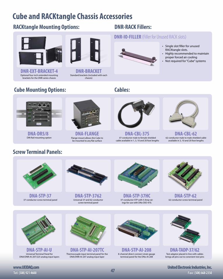
www.UEIDAQ.com United Electronic Industries, Inc.Tel: (508) 921-4600 Fax: (508) 668-235047
Cube and RACKtangle Chassis Accessories
DNA-STP-AI-UUniversal Terminal Panel for
DNA/DNR-AI-207/225 analog input layers
DNA-STP-AI-207TCThermocouple input terminal panel for the
DNA/DNR-AI-207 analog input layer
DNA-STP-AI-2088-channel direct-connect strain gauge
terminal panel for hte DNx-AI-208
DNA-TADP-37/62Test adaptor placed in-line with cables
brings all pins out to conenient test pins
Cube Mounting Options: Cables:
DNA-DR5/8DIN Rail mounting option
DNA-FLANGEFlange mount allows the Cube to
be mounted to any flat surface
DNA-CBL-37S37-conductor male to female shielded
cable available in 1, 3, 10 and 20 foot lengths
DNA-CBL-6262-conductor male to male shielded cable
available in 3, 10 and 20 foot lengths
Screw Terminal Panels:
DNA-STP-3737-conductor screw terminal panel
DNA-STP-3762Universal 37 and 62-conductor
screw terminal panel
DNA-STP-37HC37-conductor STP with 5 Amp rat-
ings for use with DNx-DIO-470.
DNA-STP-6262-conductor screw terminal panel
RACKtangle Mounting Options:
DNR-EXT-BRACKET-4 DNR-BRACKETOptional four inch extended mounting
brackets for the DNR-series chassisStandard brackets (included with each
chassis)
DNR-RACK Fillers:
• Single slot filler for unused RACKtangle slots.
• Highly recommended to maintain proper forced air cooling
• Not required for “Cube” systems
DNR-IO-FILLER (Filler for Unused RACK slots)
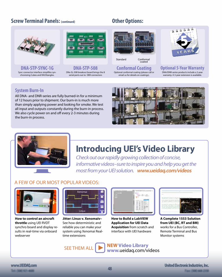
48www.UEIDAQ.com United Electronic Industries, Inc.
48
DNA-STP-SYNC-1GSync connector interface simplifies syn-
chronizing Cubes and RACKtangles.
DNA-STP-508DNx-SL-508 breakout board brings the 8
serial ports out to DB9 connectors
Conformal Coating Optional 5-Year WarrantyOptional conformal coating (please call or
email us for details on coatings).DNA/DNR-series products include a 2-year warranty. A 3-year extension is available.
YEARS
5Standard Conformal
coated
Other Options:Screw Terminal Panels: (continued)
Introducing UEI’s Video LibraryCheck out our rapidly growing collection of concise, informative videos–sure to inspire you and help you get the most from your UEI solution. www.ueidaq.com/videos
System Burn-InAll DNA- and DNR-series are fully burned-in for a minimum of 12 hours prior to shipment. Our burn-in is much more than simply applying power and looking for smoke. We test all input and outputs constantly during the burn-in process. We also cycle power on and off every 2-3 minutes during the burn-in process.
NEW Video Library www.ueidaq.com/videosSEE THEM ALL
A FEW OF OUR MOST POPULAR VIDEOS:
How to control an aircraft throttle using UEI RVDT synchro board and display re-sults in real-time via onboard webserver
Jitter: Linux v. Xenomaiv–See how deterministic and reliable you can make your system using Xenomai Real-time extensions
How to Build a LabVIEW Application for UEI Data Acquisition from scratch and interface with UEI hardware
A Complete 1553 Solution from UEI (BC, RT and BM) works for a Bus Controller, Remote Terminal and Bus Monitor systems
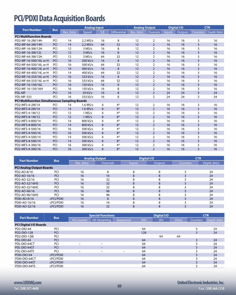
www.UEIDAQ.com United Electronic Industries, Inc.Tel: (508) 921-4600 Fax: (508) 668-235049
Part Number BusAnalog Input Analog Output Digital I/O CTR
Res. (bits) Speed S.E. Differential Res. (bits) Channels Inputs Outputs Counters Depth (bits)PCI Multifunction BoardsPD2-MF-16-2M/14H PCI 14 2.2 MS/s 16 8 12 2 16 16 3 16PD2-MF-64-2M/14H PCI 14 2.2 MS/s 64 32 12 2 16 16 3 16PD2-MF-16-3M/12H PCI 12 3 MS/s 16 8 12 2 16 16 3 16PD2-MF-16-3M/12L PCI 12 3 MS/s 16 8 12 2 16 16 3 16PD2-MF-64-3M/12H PCI 12 3 MS/s 64 32 12 2 16 16 3 16PD2-MF-16-500/16L or H PCI 16 500 kS/s 16 8 12 2 16 16 3 16PD2-MF-64-500/16L or H PCI 16 500 kS/s 64 32 12 2 16 16 3 16PD2-MF-16-400/14L or H PCI 14 400 kS/s 16 8 12 2 16 16 3 16PD2-MF-64-400/14L or H PCI 14 400 kS/s 64 32 12 2 16 16 3 16PD2-MF-16-333/16L or H PCI 16 333 kS/s 16 8 12 2 16 16 3 16PD2-MF-64-333/16L or H PCI 16 333 kS/s 64 32 12 2 16 16 3 16PD2-MF-16-150/16L PCI 16 150 kS/s 16 8 12 2 16 16 3 16PD2-MF-16-150/16H PCI 16 150 kS/s 16 8 12 2 16 16 3 16PDL-MF PCI 16 50 kS/s 16 8 12 2 24 24 3 24PDL-MF-333 PCI 16 333 kS/s 16 8 12 2 24 24 3 24PCI Multifunction Simultaneous Sampling BoardsPD2-MFS-4-2M/14 PCI 14 1.6 MS/s 4 4* 12 2 16 16 3 16PD2-MFS-8-2M/14 PCI 14 1.6 MS/s 8 8* 12 2 16 16 3 16PD2-MFS-4-1M/12 PCI 12 1 MS/s 4 4* 12 2 16 16 3 16PD2-MFS-8-1M/12 PCI 12 1 MS/s 8 8* 12 2 16 16 3 16PD2-MFS-4-800/14 PCI 14 800 kS/s 4 4* 12 2 16 16 3 16PD2-MFS-8-800/14 PCI 14 800 kS/s 8 8* 12 2 16 16 3 16PD2-MFS-4-500/16 PCI 16 500 kS/s 4 4* 12 2 16 16 3 16PD2-MFS-8-500/16 PCI 16 500 kS/s 8 8* 12 2 16 16 3 16PD2-MFS-4-500/14 PCI 14 500 kS/s 4 4* 12 2 16 16 3 16PD2-MFS-8-500/14 PCI 14 500 kS/s 8 8* 12 2 16 16 3 16PD2-MFS-4-300/16 PCI 16 300 kS/s 4 4* 12 2 16 16 3 16PD2-MFS-8-300/16 PCI 16 300 kS/s 8 8* 12 2 16 16 3 16
Part Number BusSpecial Functions Digital I/O CTR
HS Counter HS Streaming Sequencer DIO DIn DOut Counters Depth (bits)PCI Digital I/O BoardsPD2-DIO-64 PCI 64 3 24PD2-DIO-128 PCI 128 3 24PD2-DIO-128i PCI 64 64PDL-DIO-64 PCI 64 3 24PDL-DIO-64CT PCI • • 64 3 24PDL-DIO-64ST PCI • 64 3 24PDL-DIO-64TS PCI • • • 64 3 24PDXI-DIO-64 cPCI/PDXI 64 3 24PDXI-DIO-64CT cPCI/PDXI 64 3 24PDXI-DIO-64ST cPCI/PDXI 64 3 24PDXI-DIO-64TS cPCI/PDXI 64 3 24
Part Number BusAnalog Output Digital I/O CTR
Res. (bits) Channels Inputs Outputs Counters Depth (bits)PCI Analog Output BoardsPD2-AO-8/16 PCI 16 8 8 8 3 24PD2-AO-16/16 PCI 16 16 8 8 3 24PD2-AO-32/16 PCI 16 32 8 8 3 24PD2-AO-32/16HS PCI 16 32 8 8 3 24PD2-AO-32/16HC PCI 16 32 8 8 3 24PD2-AO-96/16 PCI 16 96 8 8 3 24PD2-AO-96/16HS PCI 16 96 8 8 3 24PDXI-AO-8/16 cPCI/PDXI 16 8 8 8 3 24PDXI-AO-16/16 cPCI/PDXI 16 16 8 8 3 24PDXI-AO-32/16 cPCI/PDXI 16 32 8 8 3 24
PCI/PDXI Data Acquisition Boards
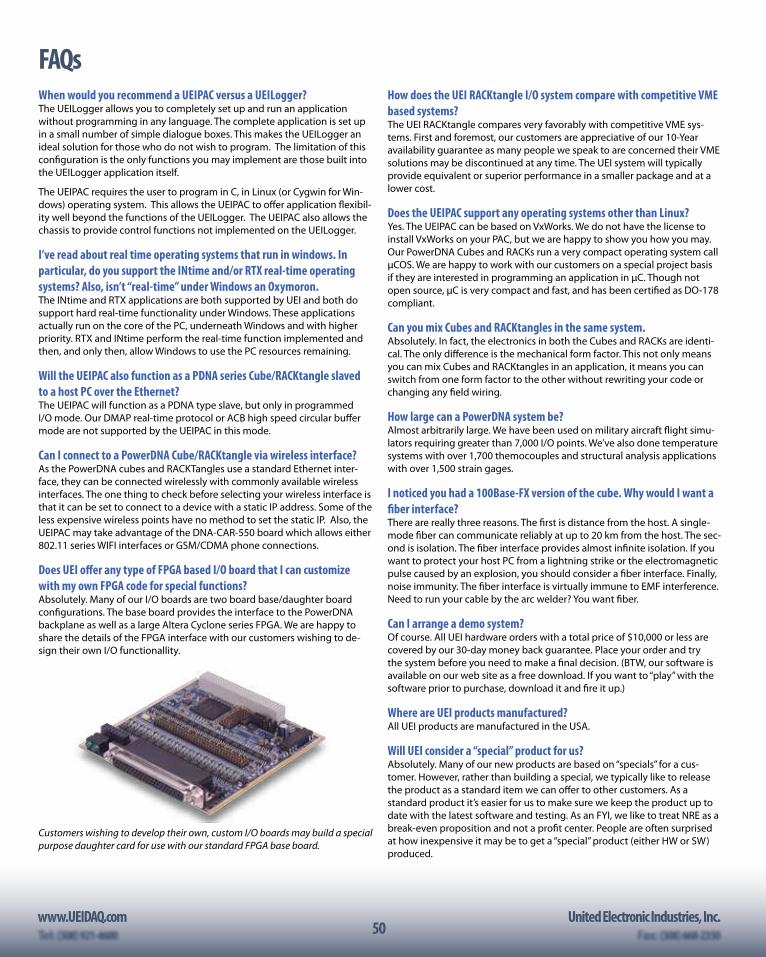
50www.UEIDAQ.com United Electronic Industries, Inc.
50
FAQsWhen would you recommend a UEIPAC versus a UEILogger?The UEILogger allows you to completely set up and run an application without programming in any language. The complete application is set up in a small number of simple dialogue boxes. This makes the UEILogger an ideal solution for those who do not wish to program. The limitation of this configuration is the only functions you may implement are those built into the UEILogger application itself.
The UEIPAC requires the user to program in C, in Linux (or Cygwin for Win-dows) operating system. This allows the UEIPAC to offer application flexibil-ity well beyond the functions of the UEILogger. The UEIPAC also allows the chassis to provide control functions not implemented on the UEILogger.
I’ve read about real time operating systems that run in windows. In particular, do you support the INtime and/or RTX real-time operating systems? Also, isn’t “real-time” under Windows an Oxymoron.The INtime and RTX applications are both supported by UEI and both do support hard real-time functionality under Windows. These applications actually run on the core of the PC, underneath Windows and with higher priority. RTX and INtime perform the real-time function implemented and then, and only then, allow Windows to use the PC resources remaining.
Will the UEIPAC also function as a PDNA series Cube/RACKtangle slaved to a host PC over the Ethernet?The UEIPAC will function as a PDNA type slave, but only in programmed I/O mode. Our DMAP real-time protocol or ACB high speed circular buffer mode are not supported by the UEIPAC in this mode.
Can I connect to a PowerDNA Cube/RACKtangle via wireless interface?As the PowerDNA cubes and RACKTangles use a standard Ethernet inter-face, they can be connected wirelessly with commonly available wireless interfaces. The one thing to check before selecting your wireless interface is that it can be set to connect to a device with a static IP address. Some of the less expensive wireless points have no method to set the static IP. Also, the UEIPAC may take advantage of the DNA-CAR-550 board which allows either 802.11 series WIFI interfaces or GSM/CDMA phone connections.
Does UEI offer any type of FPGA based I/O board that I can customize with my own FPGA code for special functions?Absolutely. Many of our I/O boards are two board base/daughter board configurations. The base board provides the interface to the PowerDNA backplane as well as a large Altera Cyclone series FPGA. We are happy to share the details of the FPGA interface with our customers wishing to de-sign their own I/O functionallity.
Customers wishing to develop their own, custom I/O boards may build a special purpose daughter card for use with our standard FPGA base board.
How does the UEI RACKtangle I/O system compare with competitive VME based systems?The UEI RACKtangle compares very favorably with competitive VME sys-tems. First and foremost, our customers are appreciative of our 10-Year availability guarantee as many people we speak to are concerned their VME solutions may be discontinued at any time. The UEI system will typically provide equivalent or superior performance in a smaller package and at a lower cost.
Does the UEIPAC support any operating systems other than Linux?Yes. The UEIPAC can be based on VxWorks. We do not have the license to install VxWorks on your PAC, but we are happy to show you how you may. Our PowerDNA Cubes and RACKs run a very compact operating system call µCOS. We are happy to work with our customers on a special project basis if they are interested in programming an application in µC. Though not open source, µC is very compact and fast, and has been certified as DO-178 compliant.
Can you mix Cubes and RACKtangles in the same system.Absolutely. In fact, the electronics in both the Cubes and RACKs are identi-cal. The only difference is the mechanical form factor. This not only means you can mix Cubes and RACKtangles in an application, it means you can switch from one form factor to the other without rewriting your code or changing any field wiring.
How large can a PowerDNA system be?Almost arbitrarily large. We have been used on military aircraft flight simu-lators requiring greater than 7,000 I/O points. We’ve also done temperature systems with over 1,700 themocouples and structural analysis applications with over 1,500 strain gages.
I noticed you had a 100Base-FX version of the cube. Why would I want a fiber interface?There are really three reasons. The first is distance from the host. A single-mode fiber can communicate reliably at up to 20 km from the host. The sec-ond is isolation. The fiber interface provides almost infinite isolation. If you want to protect your host PC from a lightning strike or the electromagnetic pulse caused by an explosion, you should consider a fiber interface. Finally, noise immunity. The fiber interface is virtually immune to EMF interference. Need to run your cable by the arc welder? You want fiber.
Can I arrange a demo system?Of course. All UEI hardware orders with a total price of $10,000 or less are covered by our 30-day money back guarantee. Place your order and try the system before you need to make a final decision. (BTW, our software is available on our web site as a free download. If you want to “play” with the software prior to purchase, download it and fire it up.)
Where are UEI products manufactured?All UEI products are manufactured in the USA.
Will UEI consider a “special” product for us?Absolutely. Many of our new products are based on “specials” for a cus-tomer. However, rather than building a special, we typically like to release the product as a standard item we can offer to other customers. As a standard product it’s easier for us to make sure we keep the product up to date with the latest software and testing. As an FYI, we like to treat NRE as a break-even proposition and not a profit center. People are often surprised at how inexpensive it may be to get a “special” product (either HW or SW) produced.
www.UEIDAQ.com United Electronic Industries, Inc.Tel: (508) 921-4600 Fax: (508) 668-235051
Application Notes and White Papers for DownloadCheck out these and more, available online:Case Study: Why FlightSafety International has Standardized on the RACKtangle for SimI/ODiscover why FlightSafety International has switched from VME to UEI’s Gigabit Ethernet RACKtangle™ I/O chassis a Modern Alternative — www.ueidaq.com/simio
White Paper: A Modern Alternative to Reflective Memory and VMELearn about the use of UEI unique Ethernet I/O chassis as a modern alternative to Reflective VME systems — www.ueidaq.com/modern-alternative
White Paper: Introduction to Data Acquisition Parts 1 and 2This series of white papers, begins in part one by introducing data acquisition technology in general, and then dives into analog inputs specifically, while part two introduces less common forms of I/O — www.ueidaq.com/daq-intro2
Application Note: Advanced In-Flight Data RecorderTaking advantage of the PowerDNA Cube and associated I/O modules, Cessna has designed, built, and tested their new in-flight DAQ in record time — www.ueidaq.com/ifdr
Application Note: Using Accelerometers in a Data Acquisition SystemFind out how to use Accelerometers in data acquisition system Using Accelerometers in a Data Acquisition System — www.ueidaq.com/accelerometers
Application Note: PowerDNA Hardware at Tinker Air Force BasePowerDNA hardware helps Tinker US Air Force Base achieve design goals for its new engine test cell. — www.ueidaq.com/tinker
Application Note: Rocket Test Stand with PowerDNA Cube, and AI-225Research facility uses PowerDNA cubes, and AI-225 layers with strain-gage sensors to measure high-speed dynamic data from a rocket test stand. — www.ueidaq.com/rocket-test
Does the UEIPAC offer “hard” real-time capability?Yes. The UEIPAC supports Linux’s Xenomai real-time functionality. Also, should you want to use VxWorks, we can show you how to load and run it on your UEIPAC.
What options are available for mounting the Cube?Though some customers simply count on gravity to keep the cube on their table-top, most customers take advantage of either the DNA-FLANGE flange mount or DNA-DR series DIN rail mounts. Please see page 35 or visit our web site for details.
Do you offer the option to run your Cubes and RACKtangles from DC Power?Yes. All Cubes/RACKs are designed to run from any DC power source between 9 and 36 VDC. We also include a universal (120/240 VAC) AC power adaptor with each chassis.
Do any of your I/O boards offer isolation?Yes. In fact all of our I/O boards except the DNx-429-5xx series provide 350 Vrms of isolation between the board’s I/O connections and the chassis (as well as all other I/O boards installed).
Can I add a new board to my Cube in the field or do Cube reconfigura-tions need to be done by UEI.You are free to add, change or remove boards from your Cube. It typically takes 15 minutes or so as there are a number of screws to remove and then reinstall. If you anticipate frequently reconfiguring your system we highly recommend you consider the RACKtangle form factor where board replacement takes only a matter of seconds.
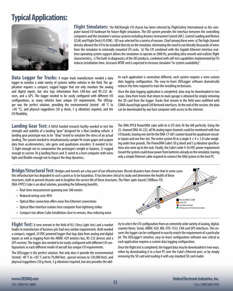
52www.UEIDAQ.com United Electronic Industries, Inc.
52
PowerDNA CUBEHost PCAccelerometerUltrasonic 3D Anemometer
Bridge/Structural Test: Bridges and tunnels are a key part of our infrastructure. Recent disasters have shown that in some cases this infrastructure has degraded to such a point as to be hazardous. It has become critical to study and determine the health of these structures, both to prevent disaster and to lengthen the service life of these structures. The Fiber-optic-based (100Base-FX) DNA-FPPC5 Cube is an ideal solution, providing the following benefits.
• Real-time measurement spanning over 500 meters• Reduced wiring costs 90%• Optical fiber connection offers noise free Ethernet connections• Optical fiber interface isolates host computer from lightning strikes• Compact size allows Cube installation close to sensors, thus reducing noise
Typical Applications:
Data Logger for Trucks: A major truck manufacturer needed a data logger to monitor a wide variety of systems within vehicles in the field. The ap-plication requires a compact, rugged logger that not only monitors the analog and digital inputs, but also logs information from CAN-bus and RS-232 de-vices, and a GPS. The logger needed to be easily configured with different I/O configurations, as many vehicles have unique I/O requirements. The UEILog-ger was the perfect solution, providing the environmental (tested: -40 °C to +85 °C), and physical ruggedness (50 g shock, 5 g vibration) required, and the I/O flexibility.
As each application is somewhat different, each system requires a semi-custom data logging configuration. The easy-to-learn UEILogger software dramatically reduces the time required to train the installing technicians.Once the data logging application is completed, data may be downloaded in two ways. Data from trucks that return to main garage is obtained by simply removing the SD card from the logger. Trucks that remain in the field were outfitted with CDMA-based high speed Cell Network interfaces. At the end of the session, the data can be downloaded by any host computer with access to the internet.
Landing Gear Test: A NASA funded research facility needed to test the strength and stability of a landing “gear” designed for a Mars landing vehicle. A landing gear prototype was to be “drop” tested to simulate the stress of an actual landing. The system needed to simultaneously sample 96 strain gages and acquire data from accelerometers, rate gyros and quadrature encoders. It needed to be: 1) light enough not to compromise the prototype’s weight or balance, 2) rugged enough to survive 30 g landing forces and 3) wired to a host computer with wires light and flexible enough not to impact the drop dynamics.
The DNA-PPC8 PowerDNA cube with its 6 I/O slots fit the bill perfectly. Using the 25-channel DNA-AI-225, all 96 analog input channels could be monitored with four I/O boards, leaving one slot for the DNA-CT-601 counter board for quadrature encod-er inputs and one free slot. The entire system fit in a single 4 × 4 × 5.8 cube weigh-ing under four pounds. The PowerDNA Cube’s 50 g shock and 5 g vibration specifica-tions also were up to the task. Finally, the Cube’s wide 9-36 VDC power requirement meant the system could draw power from batteries already on the simulator, leaving only a simple Ethernet cable required to connect the DAQ system to the host PC.
Flight Test: A new entrant in the field of VLJ (Very Light Jets) and a market leader in manufacture of business jets had very similar requirements. Both needed a compact, rugged, 24 VDC powered logger that logs data from analog and digital inputs as well as logging from the ARINC-429 avionics bus, RS-232 devices and a GPS receiver. The logger also needed to be easily configured with different I/O con-figurations as each different model of aircraft has unique I/O requirements.The UEILogger is the perfect solution. Not only does it provide the environmental (tested: -40 °C to +85 °C and to 70,000 feet...special versions to 120,000 feet), and physical ruggedness (50 g shock, 5 g vibration) required, but also provides the abil-
ity to select the I/O configuration from an extremely wide variety of analog, digital, counter/timer, Serial, ARINC-429, MIL-STD-1553, CAN and GPS interfaces. This en-sures the logger can be configured to exactly match the requirement of a particular jet. The UEILogger’s intuitive, easy-to-learn configuration software was critical as each application requires a custom data logging configuration.Once the flight test is completed, the logged data may be downloaded in two ways, either by downloading it to a host PC over the Cube’s Ethernet port, or by simply removing the SD card and reading it with any standard SD card reader.
Flight Simulators: The RACKtangle I/O chassis has been selected by FlightSafety International as the com-puter-based I/O hardware for future flight simulators. The UEI system provides the interface between the controlling computers and the simulator’s various systems including Avionics Instrument Control (AIC), Control Loading and Motion (CLM) and Flight Deck I/O (FDK). UEI was selected for a variety of reasons. Chief among these were: a) The high channel density allowed the I/O to be installed directly on the simulator, eliminating the need to run literally thousands of wires from the simulator to externally mounted I/O racks. b) The I/O combined with the Gigabit Ethernet interface real-time operating system support allows the simulators to operate at 2000 Hz, providing ultra smooth and realistic flight characteristics, c) The built-in diagnostics of the UEI products, combined with self-test capabilities implemented by FSI reduces installation time, increases MTBF and is expected to increase simulator “in-system availability”.
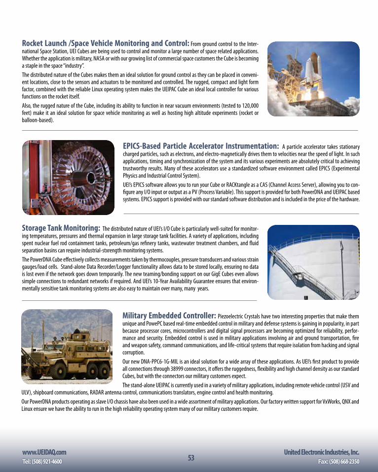
www.UEIDAQ.com United Electronic Industries, Inc.Tel: (508) 921-4600 Fax: (508) 668-235053
Rocket Launch /Space Vehicle Monitoring and Control: From ground control to the Inter-national Space Station, UEI Cubes are being used to control and monitor a large number of space related applications. Whether the application is military, NASA or with our growing list of commercial space customers the Cube is becoming a staple in the space “industry”.The distributed nature of the Cubes makes them an ideal solution for ground control as they can be placed in conveni-ent locations, close to the sensors and actuators to be monitored and controlled. The rugged, compact and light form factor, combined with the reliable Linux operating system makes the UEIPAC Cube an ideal local controller for various functions on the rocket itself.Also, the rugged nature of the Cube, including its ability to function in near vacuum environments (tested to 120,000 feet) make it an ideal solution for space vehicle monitoring as well as hosting high altitude experiments (rocket or balloon-based).
EPICS-Based Particle Accelerator Instrumentation: A particle accelerator takes stationary charged particles, such as electrons, and electro-magnetically drives them to velocities near the speed of light. In such applications, timing and synchronization of the system and its various experiments are absolutely critical to achieving trustworthy results. Many of these accelerators use a standardized software environment called EPICS (Experimental Physics and Industrial Control System). UEI’s EPICS software allows you to run your Cube or RACKtangle as a CAS (Channel Access Server), allowing you to con-figure any I/O input or output as a PV (Process Variable). This support is provided for both PowerDNA and UEIPAC based systems. EPICS support is provided with our standard software distribution and is included in the price of the hardware.
Storage Tank Monitoring: The distributed nature of UEI’s I/O Cube is particularly well-suited for monitor-ing temperatures, pressures and thermal expansion in large storage tank facilities. A variety of applications, including spent nuclear fuel rod containment tanks, petroleum/gas refinery tanks, wastewater treatment chambers, and fluid separation basins can require industrial-stxrength monitoring systems.The PowerDNA Cube effectively collects measurements taken by thermocouples, pressure transducers and various strain gauges/load cells. Stand-alone Data Recorder/Logger functionality allows data to be stored locally, ensuring no data is lost even if the network goes down temporarily. The new teaming/bonding support on our GigE Cubes even allows simple connections to redundant networks if required. And UEI’s 10-Year Availability Guarantee ensures that environ-mentally sensitive tank monitoring systems are also easy to maintain over many, many years.
Military Embedded Controller: Piezoelectric Crystals have two interesting properties that make them unique and PowePC based real-time embedded control in military and defense systems is gaining in popularity, in part because processor cores, microcontrollers and digital signal processors are becoming optimized for reliability, perfor-mance and security. Embedded control is used in military applications involving air and ground transportation, fire and weapon safety, command communications, and life-critical systems that require isolation from hacking and signal corruption.Our new DNA-PPC6-1G-MIL is an ideal solution for a wide array of these applications. As UEI’s first product to provide all connections through 38999 connectors, it offers the ruggedness, flexibility and high channel density as our standard Cubes, but with the connectors our military customers expect.The stand-alone UEIPAC is currently used in a variety of military applications, including remote vehicle control (USV and
ULV), shipboard communications, RADAR antenna control, communications translators, engine control and health monitoring.Our PowerDNA products operating as slave I/O chassis have also been used in a wide assortment of military applications. Our factory written support for VxWorks, QNX and Linux ensure we have the ability to run in the high reliability operating system many of our military customers require.
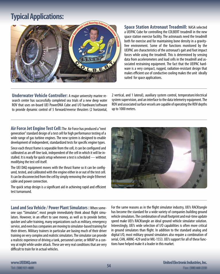
54www.UEIDAQ.com United Electronic Industries, Inc.
54
Typical Applications:Space Station Astronaut Treadmill: NASA selected a UEIPAC Cube for controlling the COLBERT treadmill in the new space station exercise facility. The astronauts need the treadmill both for exercise and for maintaining bone density in a gravity-free environment. Some of the functions monitored by the UEIPAC are characteristics of the astronaut’s gait and foot impact forces while using the treadmill. This is determined by sensing data from accelerometers and load cells in the treadmill and as-sociated restraining equipment. The fact that the UEIPAC hard-ware is a very compact, rugged, radiation-resistant design that makes efficient use of conductive cooling makes the unit ideally suited for space applications.
Underwater Vehicle Controller: A major university marine re-search center has successfully completed sea trials of a new deep water ROV that uses on-board UEI PowerDNA Cube and I/O hardware/software to provide dynamic control of 5 forward/reverse thrusters (2 horizontal,
2 vertical, and 1 lateral), auxiliary system control, temperature/electrical system supervision, and an interface to the data telemetry equipment. The ROV and associated surface vessels are capable of operating the ROV depths up to 1000 meters.
Air Force Jet Engine Test Cell: The Air Force has produced a “next generation” standard design of a test cell for high performance testing of a wide range of gas turbine engines. The new system is designed to enable development of independent, standardized tests for specific engine types.Since each thrust frame is separable from the cell, it can be configured and calibrated as an off-line task, independent of the cell in which it will be in-stalled. It is ready for quick setup whenever a test is scheduled — without modifying the test cell itself.The UEI DAQ equipment moves with the thrust frame so it can be config-ured, tested, and calibrated with the engine either in or out of the test cell. It can be disconnected from the cell by simply removing the single Ethernet cable and power connection.The quick setup design is a significant aid in achieving rapid and efficient test turnaround.
Land and Sea Vehicle / Power Plant Simulators : When some-one says “Simulator”, most people immediately think about flight simu-lators. However, in an effort to save money, as well as to provide better, quicker and safer training, many organizations such as military, emergency service, and even bus companies are moving to simulator-based training for their drivers. Military trainers in particular are basing much of their driver training on very complex and realistic simulators. The simulator can provide a realistic experience of driving a tank, personnel carrier, or MRAP in a con-voy at night while under attack. These are very real conditions that are very difficult to train for in actual vehicles.
For the same reasons as in the flight simulator industry, UEI’s RACKtangle has become the standard for a wide variety of companies building ground vehicle simulators. The combination of small footprint and real-time update speed make UEI’s RACKtangle an ideal ground vehicle simulator solution. Interestingly, UEI’s wide selection of I/O capabilities is often more critical in ground simulators than flight. In addition to the standard analog and digital I/O, most military ground simulators also require a combination of serial, CAN, ARINC-429 and/or MIL-1553. UEI’s support for all of these func-tions have helped make it a leader in this market.
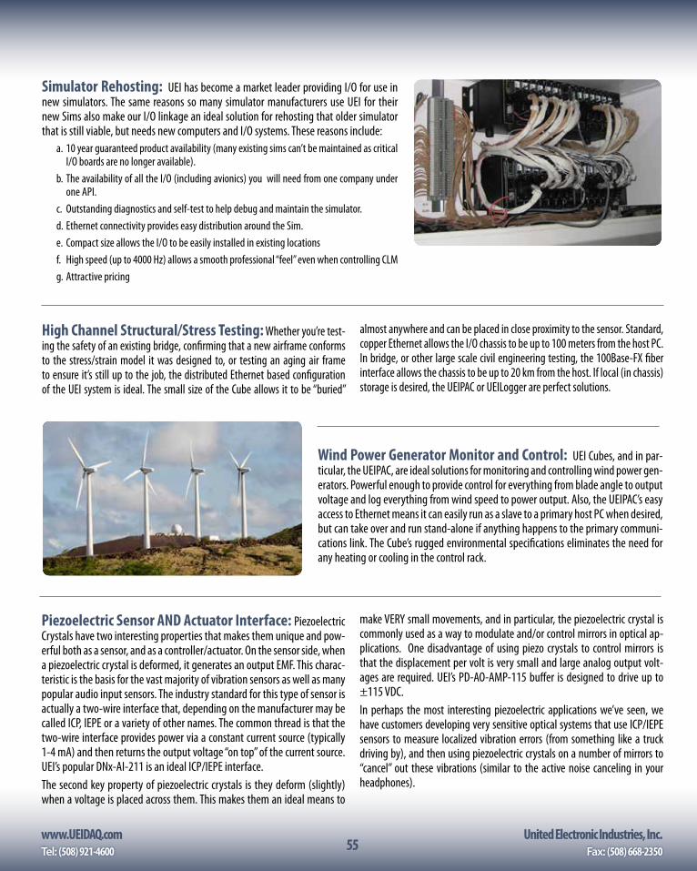
www.UEIDAQ.com United Electronic Industries, Inc.Tel: (508) 921-4600 Fax: (508) 668-235055
Simulator Rehosting: UEI has become a market leader providing I/O for use in new simulators. The same reasons so many simulator manufacturers use UEI for their new Sims also make our I/O linkage an ideal solution for rehosting that older simulator that is still viable, but needs new computers and I/O systems. These reasons include:
a. 10 year guaranteed product availability (many existing sims can’t be maintained as critical I/O boards are no longer available).
b. The availability of all the I/O (including avionics) you will need from one company under one API.
c. Outstanding diagnostics and self-test to help debug and maintain the simulator.d. Ethernet connectivity provides easy distribution around the Sim.e. Compact size allows the I/O to be easily installed in existing locationsf. High speed (up to 4000 Hz) allows a smooth professional “feel” even when controlling CLMg. Attractive pricing
High Channel Structural/Stress Testing: Whether you’re test-ing the safety of an existing bridge, confirming that a new airframe conforms to the stress/strain model it was designed to, or testing an aging air frame to ensure it’s still up to the job, the distributed Ethernet based configuration of the UEI system is ideal. The small size of the Cube allows it to be “buried”
almost anywhere and can be placed in close proximity to the sensor. Standard, copper Ethernet allows the I/O chassis to be up to 100 meters from the host PC. In bridge, or other large scale civil engineering testing, the 100Base-FX fiber interface allows the chassis to be up to 20 km from the host. If local (in chassis) storage is desired, the UEIPAC or UEILogger are perfect solutions.
Wind Power Generator Monitor and Control: UEI Cubes, and in par-ticular, the UEIPAC, are ideal solutions for monitoring and controlling wind power gen-erators. Powerful enough to provide control for everything from blade angle to output voltage and log everything from wind speed to power output. Also, the UEIPAC’s easy access to Ethernet means it can easily run as a slave to a primary host PC when desired, but can take over and run stand-alone if anything happens to the primary communi-cations link. The Cube’s rugged environmental specifications eliminates the need for any heating or cooling in the control rack.
Piezoelectric Sensor AND Actuator Interface: Piezoelectric Crystals have two interesting properties that makes them unique and pow-erful both as a sensor, and as a controller/actuator. On the sensor side, when a piezoelectric crystal is deformed, it generates an output EMF. This charac-teristic is the basis for the vast majority of vibration sensors as well as many popular audio input sensors. The industry standard for this type of sensor is actually a two-wire interface that, depending on the manufacturer may be called ICP, IEPE or a variety of other names. The common thread is that the two-wire interface provides power via a constant current source (typically 1-4 mA) and then returns the output voltage “on top” of the current source. UEI’s popular DNx-AI-211 is an ideal ICP/IEPE interface. The second key property of piezoelectric crystals is they deform (slightly) when a voltage is placed across them. This makes them an ideal means to
make VERY small movements, and in particular, the piezoelectric crystal is commonly used as a way to modulate and/or control mirrors in optical ap-plications. One disadvantage of using piezo crystals to control mirrors is that the displacement per volt is very small and large analog output volt-ages are required. UEI’s PD-AO-AMP-115 buffer is designed to drive up to ±115 VDC.In perhaps the most interesting piezoelectric applications we’ve seen, we have customers developing very sensitive optical systems that use ICP/IEPE sensors to measure localized vibration errors (from something like a truck driving by), and then using piezoelectric crystals on a number of mirrors to “cancel” out these vibrations (similar to the active noise canceling in your headphones).
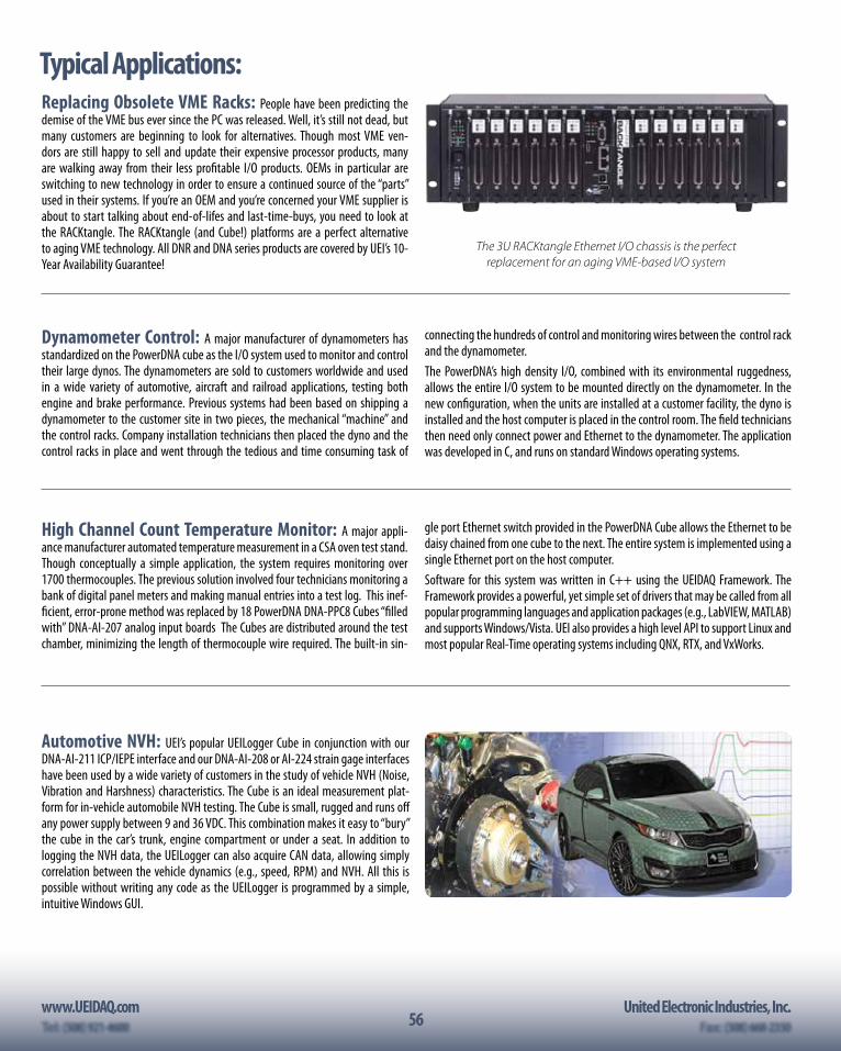
56www.UEIDAQ.com United Electronic Industries, Inc.
56
Replacing Obsolete VME Racks: People have been predicting the demise of the VME bus ever since the PC was released. Well, it’s still not dead, but many customers are beginning to look for alternatives. Though most VME ven-dors are still happy to sell and update their expensive processor products, many are walking away from their less profitable I/O products. OEMs in particular are switching to new technology in order to ensure a continued source of the “parts” used in their systems. If you’re an OEM and you’re concerned your VME supplier is about to start talking about end-of-lifes and last-time-buys, you need to look at the RACKtangle. The RACKtangle (and Cube!) platforms are a perfect alternative to aging VME technology. All DNR and DNA series products are covered by UEI’s 10-Year Availability Guarantee!
The 3U RACKtangle Ethernet I/O chassis is the perfect replacement for an aging VME-based I/O system
Typical Applications:
High Channel Count Temperature Monitor: A major appli-ance manufacturer automated temperature measurement in a CSA oven test stand. Though conceptually a simple application, the system requires monitoring over 1700 thermocouples. The previous solution involved four technicians monitoring a bank of digital panel meters and making manual entries into a test log. This inef-ficient, error-prone method was replaced by 18 PowerDNA DNA-PPC8 Cubes “filled with” DNA-AI-207 analog input boards The Cubes are distributed around the test chamber, minimizing the length of thermocouple wire required. The built-in sin-
gle port Ethernet switch provided in the PowerDNA Cube allows the Ethernet to be daisy chained from one cube to the next. The entire system is implemented using a single Ethernet port on the host computer.Software for this system was written in C++ using the UEIDAQ Framework. The Framework provides a powerful, yet simple set of drivers that may be called from all popular programming languages and application packages (e.g., LabVIEW, MATLAB) and supports Windows/Vista. UEI also provides a high level API to support Linux and most popular Real-Time operating systems including QNX, RTX, and VxWorks.
Dynamometer Control: A major manufacturer of dynamometers has standardized on the PowerDNA cube as the I/O system used to monitor and control their large dynos. The dynamometers are sold to customers worldwide and used in a wide variety of automotive, aircraft and railroad applications, testing both engine and brake performance. Previous systems had been based on shipping a dynamometer to the customer site in two pieces, the mechanical “machine” and the control racks. Company installation technicians then placed the dyno and the control racks in place and went through the tedious and time consuming task of
connecting the hundreds of control and monitoring wires between the control rack and the dynamometer.The PowerDNA’s high density I/O, combined with its environmental ruggedness, allows the entire I/O system to be mounted directly on the dynamometer. In the new configuration, when the units are installed at a customer facility, the dyno is installed and the host computer is placed in the control room. The field technicians then need only connect power and Ethernet to the dynamometer. The application was developed in C, and runs on standard Windows operating systems.
Automotive NVH: UEI’s popular UEILogger Cube in conjunction with our DNA-AI-211 ICP/IEPE interface and our DNA-AI-208 or AI-224 strain gage interfaces have been used by a wide variety of customers in the study of vehicle NVH (Noise, Vibration and Harshness) characteristics. The Cube is an ideal measurement plat-form for in-vehicle automobile NVH testing. The Cube is small, rugged and runs off any power supply between 9 and 36 VDC. This combination makes it easy to “bury” the cube in the car’s trunk, engine compartment or under a seat. In addition to logging the NVH data, the UEILogger can also acquire CAN data, allowing simply correlation between the vehicle dynamics (e.g., speed, RPM) and NVH. All this is possible without writing any code as the UEILogger is programmed by a simple, intuitive Windows GUI.
www.UEIDAQ.com United Electronic Industries, Inc.Tel: (508) 921-4600 Fax: (508) 668-235057
Unmanned Land Vehicle (ULV) Control: A large military op-eration in the development of an Unmanned Land Vehicle needed a rugged, low power, high density controller for the vehicle, as well as a comprehensive and flex-ible system to handle all of the unit’s I/O. The unit also needed to be very flexible, as depending on the end application of the ULV, many different types of sensors and controls would be installed. Finally, in order to preserve experience with other vehicles and to ensure fast and robust system operation, the unit was required to be Linux-based.
The UEIPAC Programmable Automation Controller was the perfect solution. It pro-vides the environmental (tested: -40 °C to +85 °C), and physical ruggedness (50 g shock, 5 g vibration) required and allows the installation of up to 6 I/O boards in a single 4" × 4" × 5.8" Cube. It runs a standard Linux operating system and has the ability to be easily configured with a wide variety of analog, digital, counter/timer, quadrature encoder, Serial and GPS interfaces. The software is written on a standard Linux PC (or may be written in a Windows environment under Cygwin) using UEI’s powerful and yet simple API.
Other applications include:• Power plant efficiency testing• High channel count medical instrumentation• Modernization of Modbus-based I/O systems• Machine health monitoring• Wind turbine automation• Jet engine test• Metal rolling and forming monitoring and control• Building security monitoring and access control• HVAC control• Environmental chamber monitoring and control• Hardware in-the-loop testing• Embedded machine control• Semiconductor manufacturing
Portable and Field Test Units: UEI’s Cube and RACKtangle chassis has been the basis for a variety of compact, powerful field test units. The combination of small size, high shock and vibe immunity, wide temperature ranges and low power make them ideal sub-systems in larger, turn-key test systems. Of course that we now have over 60 different I/O boards is also critical as we know that you can’t test only 98% of the system. With our huge variety of I/O, we’re sure to have everything your system requires, not only to measure your inputs, but to provide all of your required excitation signals. The UEIPAC is the perfect platform for a fully stand-alone test system. All the software runs locally on the Cube or RACKtangle so there is not host PC required. This makes the system more efficient, more reliable and eliminates the need for an expensive ruggedized laptop host. In some systems, it’s impor-tant to keep the host PC as the controller and using our PowerDNA/DNR chassis allows tight, real-time control of the test system even from a remote host. Finally, some customers use the UEIPAC as a local controller that runs under the guidance of a local host. The actual test is run on the UEIPAC, but the host PC selects which test is to be run. The UEIPAC’s web interface provides an interface where the supervi-sory computer need only provide a web browser in order to control the tests.
In-Vehicle Health Monitoring: Whether your supporting or design-ing a military or commercial aircraft, a truck, bus, tractor, train, ship or submarine, it’s always better to identify a pending system failure before it fails. It’s safer, sim-pler and less expensive to correct a problem on the ground, at the maintenance barn, or in port, than it is to deal with a failure while the vehicle is “out”. We have a variety of customers using our UEILogger or UEIPAC Cubes to monitor the health of various aircraft, ground vehicles, ships or boats. Applications range from very simple, obvious measurements to those based upon complex highly proprietary analysis. On the simple end of the spectrum, we have customers with systems that simply monitoring a truck or bus CAN network, or aircraft ARINC-429 or MIL-STD-1553 and look for trends in operating temperature, pressure or fuel flow.In more complex applications, we have customers running very complex vibration
analysis to identify degradation in bearings, transmissions and/or turbines. This data can then be correlated with other information acquired allowing the imple-mentation of a very powerful predictive maintenance program.In simpler applications, the health monitor simply logs data to a local SD card which is then downloaded periodically and analyzed as a post-acquisition process. In more complex or critical applications the UEIPAC is configured to provide real-time analysis of the various data inputs and identify problems or possible pending failures while the vehicle is in the field. This data can then be displayed locally, to inform the pilot/driver/captain of the issue allowing him/her to plan accordingly. Finally, we have customers using our UEIPAC with the CAR-550 communications interface to provide WIFI or Cell Phone interfaces that send real-time data, and warnings of problems to a central maintenace facility so the support team is pre-pared for any required maintenance or repairs.
Remote Serial Communications: We have a number of customers who use UEI’s Cubes and RACKtangles as remote communications links. Applica-tions for remote serial communications include:
• Power plants where the host needs to communicate with devices on the other side of the plant.
• Shipboard where a host PC needs to communicate with a series of devices in other cabins and even other decks within the ship.
• Simulators where the host PC needs to control a variety of serial devices in the cockpit.
• Wind farms where the system needs to consolidate RS-485 data from a se-ries of turbines and send the data to the supervisory computer.
The UEI systems are an ideal solution for wide variety of reasons. 1. They’re rugged and can be installed where most commercially available
serial solutions will not survive.2. We can provide up to 96 serial ports in a single chassis and locate it up to 100
meters from the host.3. Using our DNA-FPPC8 series fiber optic cubes, you can locate your remote
serial ports up to 20 km from the host.4. Our powerful UEI-RSS allows you to program each com port like any standard
COM port in your Windows or Linux PC. There is NO PROGRAMMING required to connect to a remote serial port!
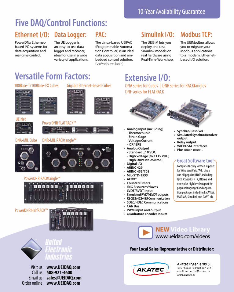
Great Software too!Complete factory written support for Windows/Vista/7/8, Linux and all popular RTOS’s including QNX, VxWorks, RTX, INtime and more plus high level support for popular languages and applica-tion packages including LabVIEW, MATLAB, Simulink and DASYLab.
Versatile Form Factors: Extensive I/O:
Five DAQ/Control Functions:Ethernet I/O: Data Logger: PAC: Simulink I/O: Modbus TCP:PowerDNx Ethernet-based I/O systems for data acquisition and real-time control.
The UEILogger is an easy-to-use data logger and recorder, ideal for use in a wide variety of applications.
The Linux-based UEIPAC (Programmable Automa-tion Controller) is an ideal data acquisition and em-bedded control solution.(VxWorks available)
The UEISIM lets you deploy and test Simulink models on real hardware using Real-Time-Workshop.
The UEIModbus allows you to migrate your Modbus applications to a modern, Ethernet-based I/O solution.
• Analog Input (including)- Thermocouple- Strain Gage- Voltage/Current- ICP/IEPE
• Analog Output- Standard ±10 VDC- High Voltage (to ±115 VDC)- High Drive (to 250 mA)
• Digital I/O• ARINC 429• ARINC 453/708• MIL-STD-1553• AFDX®• Counter/Timers• IRIG B sources/slaves• LVDT/RVDT Input• Simulated RVDT/LVDT outputs• RS-232/422/485 Communication• SDLC/HDLC Communications• CAN Bus• PWM input and output• Quadrature Encoder inputs
DNA series for Cubes | DNR series for RACKtangles DNF series for FLATRACK
Visit us www.UEIDAQ.com Call us 508-921-4600
Email us [email protected] Order online www.UEIDAQ.com
10-Year Availability Guarantee
Your Local Sales Representative or Distributor:
PowerDNR FLATRACK™
Gigabit Ethernet-based Cubes100Base-T/100Base-FX Cubes
PowerDNR HalfRACK™
UEINet
PowerDNR RACKtangle™
DNR-MIL RACKtangle™ DNA-MIL Cube
NEW Video Library www.ueidaq.com/videos
• Synchro/Resolver• Simulated Synchro/Resolver
output• Relay output• WIFI/GSM interfaces• Plus much more...