Reference Ontology and (ONTO)2 Agent: The Ontology Yellow Pages
Upload
nottinghamCategory
view
2download
0
Int J Flex Manuf Syst (2006) 17:301–314
DOI 10.1007/s10696-006-9030-0
Equipment ontology for modular reconfigurableassembly systems
Niels Lohse · Hitendra Hirani · Svetan Ratchev
C© Springer Science + Business Media, LLC 2006
Abstract Evolvable and Reconfigurable Assembly Systems (RAS) enable enterprisesto rapidly respond to changes in today’s increasingly volatile and dynamic global mar-kets. One of the key success factors for the effective use of RAS is methods and toolsthat can rapidly configure and reconfigure assembly systems driven by changing re-quirements. The focus of this paper is the development of a suitable equipment modelto support the effective design of reconfigurable assembly systems. The work has beenmotivated by the need to provide solutions for increasing product customisation andvolume changes over the product life-cycle that directly impact on the final productassembly. The paper proposes a comprehensive equipment ontology to enable effec-tive decision-making during the design and evaluation of new RAS configurations.The proposed ontology is based on the function-behaviour-structure paradigm, and isformalised to facilitate its application in distributed web-enabled decision-making en-vironments. The equipment configuration and reconfiguration approach and prototypedecision-making environment are illustrated using system design examples.
Keywords Assembly devices model · Function-behaviour-structure · Knowledgeontology
1. Introduction
Increasing product customisation and volume changes over a product’s life-cyclehave a direct impact on the final product assembly. It is therefore vital for currentand future assembly system solutions to effectively deal with highly dynamic andcomplex changes, while at the same time remaining cost effective. Evolvable and
N. Lohse (�) · H. Hirani · S. RatchevPrecision Manufacturing Group, School of Manufacturing, Mechanical, and Materials Engineering,University of Nottingham, University Park, Nottingham, NG7 2RD, United Kingdome-mail: [email protected]
Springer

302 N. Lohse et al.
Reconfigurable Assembly Systems (RAS) enable enterprises to rapidly respond tothose changes in today’s increasingly volatile and dynamic global markets, withouthaving to commit substantial investment into excess flexibility (Koren et al., 1999;Onori et al., 2002). One of the main enabling technologies for RAS is the availabilityof (1) well defined modular equipment solutions and (2) methodologies to rapidly planand facilitate their initial design and subsequent reconfigurations (Koren and Ulsoy,2002). The foundation of any such methodology is a suitable model that can captureall the required aspects of the reconfiguration process and cater for the different needsof globally dispersed stakeholders in the reconfiguration process.
A significant research and development effort has been directed towards creatingsuitable system architectures for RAS (Boer et al., 2001; Giusti et al., 1994; Chen, 2001;Hollis and Quaid, 1995; Gaugel et al., 2004; Lastra, 2004). Their focus has mainlybeen on the physical structure and control aspects that enable reconfiguration, andthey highlight modular equipment solutions as one of the fundamental requirementsfor RAS. The design and decision-making aspects needed for requirement-drivenrapid reconfiguration were mostly outside the scope of these works. Several exam-ples of modular assembly systems are already commercially available as reported inAlsterman (2004). They fulfil the basic structural requirements for RAS but still fallshort on the control and design side. This shows the current trend towards a reconfig-uration based school of thought, but also highlights the necessity for further researchinto enabling technologies especially on the design side.
Several design approaches have been developed that demonstrate the principlefeasibility of computer aided and knowledge based assembly systems design (Bleyet al., 1994; Boer et al., 2001, Travaini et al., 2002; Lohse et al., 2006). The reportedapproaches only focus on some decision-making aspects and do not yet address thespecific modelling needs for rapid RAS configuration and reconfiguration.
The focus of an equipment definition ontology has to be on the functional capa-bilities of the equipment so that it can be selected and integrated effectively (Vos,2001). Several approaches have been reported for the definition of device or modulecapabilities. Zha et al. (2001) use knowledge intensive Petri net for the modelling andanalysis of assembly equipment and systems. A language representation of function-behaviour-structure for mechanical devices has been introduced by Sasajima et al.(1995) based on ontological engineering principles (Mizoguchi and Kitamura 2000).Their main focus is on understanding the functional capability of devices based ontheir behaviour and structure. Umeda et al. (1996) and Tomiyama et al. (1993) usequalitative physics to define the relation between structure, behaviour and functions.Sasajima et al. (1995), Mizoguchi et al. (2000), Umeda et al. (1996), Tomiyama et al.(1993) all define behaviour based on physical phenomena.
A number of domain specific equipment models have also been reported that focuson different aspects and levels of abstraction of the equipment characteristics. Zhanget al. (2000) have developed a model that focuses on the representation of robotsand their working environment. Zhang and van der Werff (1993) and Neville andJoskowicz (1992) report models for the specification of mechanisms focused on theirmechanical/kinematic aspect. Gausemeier et al. (2001) and Craig et al. (1999) addressthe need for integrated mechatronic device models. Schafer and Lopez (1999) definedan object oriented model of the control capability in a manufacturing system. Seligerand Bollmann (1990), Meijer et al. (2003), and Zhang et al. (2003) report function
Springer

Equipment ontology for modular reconfigurable assembly systems 303
models for the design of devices and systems. All of these reported models focusonly on specific aspects of the equipment characteristics. None of them consider theconsequences of modularity in the definition or application of their models.
Despite these significant developments, the reported equipment models do not yetfully address the specific knowledge and modelling requirements needed to supporteffective RAS configuration and reconfiguration decisions. They are either too genericor only focus on specific aspects of equipment representation. They do not provide aholistic view of how assembly equipment can be represented to support the design ofmodular reconfigurable production systems.
The paper reports on a holistic equipment ontology that addresses the specific needsof the RAS design and reengineering process. The ontology defines assembly equip-ment modules following the functions, behaviour and structure paradigm, and includesseparate formalisms for the specification of module capability and interfacing require-ments. The specific requirements for a suitable equipment model are outlined throughthe analysis of their role during the RAS design process. The proposed equipmentdefinition ontology is then introduced including a review of fundamental modellingchoices. Finally the intended application of the ontology is demonstrated using anelaborate case study.
2. Assembly system configuration and reconfiguration methodology
A knowledge enriched web-enabled assembly system design framework was reportedin Lohse et al. (2004). The methodology includes five concurrent steps that correspond
Fig. 1 Assembly system design methodology (Lohse et al., 2004)
Springer
304 N. Lohse et al.
to the agents in the system framework (see Fig. 1): obtaining the product characteristics(project specification during requirements engineering); generation and specificationof process plans (process decomposition agent); generation and specification of con-ceptual design solutions (conceptual design agents); selection and configuration ofsystem alternatives (embodiment design agents); and evaluation of concepts and sys-tem alternatives (service agents). Each step is supported by relevant procedural anddeclarative knowledge.
Three main roles of stakeholders in the design process have been identified: cus-tomers who potentially require a new system; system integrators who design andbuild assembly systems; and equipment suppliers who design and manufacture theequipment modules that constitute assembly systems. The customers define the re-quirements for the assembly system in the form of a product model, project, process,and equipment constraints. The system integrator has the key task of defining assem-bly systems that fulfil the requirements of the customer, using commercially availableequipment modules and solutions from different vendors. This involves the specifi-cation of the required assembly process, conceptual design of the assembly system,equipment selection, configuration, and evaluation. The equipment suppliers provideand suggest suitable equipment solutions.
The key stages of the design process are implemented as independent applicationmodules (agents) that contain their own decision logic, communication facilities anddomain knowledge. The framework deploys a representative agent for each participat-ing stakeholder according to their role. These agents provide basic facilities to managethe design process and the interaction with other stakeholders, including sending andreceiving of messages as well as initialisation and coordination of relevant designtasks. Each distinctive design task within the stakeholders’ role is deployed as a sepa-rate agent ensuring a high degree of concurrency and a clear separation of the requiredknowledge during the design process.
The agent based design framework is defined in such a manner as to enable thechange of any of the input requirements and to allow the resulting change to be prop-agated through the decision making process. This aspect, combined with a require-ments specification methodology that takes into account possible future requirementschanges (Hirani, 2004), enables the framework to quickly configure either new systemsor reconfigure existing assembly systems according to changed demands.
3. General domain ontology model
One of the crucial factors for the success of the proposed RAS design framework is awell defined model that supports the decision-making process. The model needs to bestandardised in order to exchange information and knowledge between different stake-holders. At the same time it needs to be extendable to deal with future requirementsand provide customisation to cater for the specific needs of the different stakeholders.Furthermore, the model needs to be equally suitable for human as well as machineinterpretation since the decision makers could be either one or both. There is also aspecific need for the model to cope with incomplete and not fully defined models. Sincethe purpose of the ontology is to model modular assembly equipment it is importantthat the resulting model for each equipment module is self contained. Finally the model
Springer

Equipment ontology for modular reconfigurable assembly systems 305
Knowledge Representation Level
Ontology Concept Level
Generic Domain Ontology Concepts
User Specific Ontology Concepts
Assembly Domain Concepts
Pro
du
ctC
on
cep
ts
Pro
cess
Co
nce
pts
Eq
uip
ment
Co
nce
pts
Ontology Instance Level
Fun
ctio
nC
on
cep
ts
Be
havi
our
Co
nce
pts
Classes, Slots, Facets, Instances
Axioms
Inference Rules
hier
arch
y
ab
stra
ctio
n
relationships
hier
arch
y
ab
stra
ctio
n
relationships
Domain Ontology Concept Structure:
Fig. 2 Equipment ontology structure
needs to provide the means to trace the decision-making process and allow decisionmakers to reassess critical decisions at a later stage during the design process.
An ontology is concerned with the study of being or existence and their basiccategories and relationships, to determine what entities and what types of entitiesexist. It therefore has strong implications for conceptions of reality (Wikipedia, 2006).This is particularly important for the study and definition of equipment models sincethey have to reflect physical existing entities. An ontology based approach is thereforeappropriate for representing the morphology of complex manufacturing systems.
To support the decision making, an ontology model is proposed that include threerepresentation levels: the underlying knowledge representation level, the ontologyconcept level and the instantiation level (see Fig. 2 left side). The knowledge repre-sentation level defines how the different concepts, attributes, constraints, and rules areimplemented. A frame based knowledge representation has been chosen to define theconcepts and their attributes in an object oriented manner. The specific model con-straints are expressed as axioms and the design decisions are modelled as inferencerules.
On the ontology level all the specific domain concepts, attributes, constraints, andrules are defined. The domain ontologies are divided into generic and user specificconcepts. This allows all the design decisions to be based on generic concepts while atthe same time providing a mechanism to enable different stakeholders to define theirown specific terminology and concept interpretation.
The basic model is defined along three axes: relationships, hierarchy, and abstraction(see Fig. 2 right side). The relationships define how the concepts within an ontology arerelated to each other. For example, equipment modules can be connected to each other.The hierarchy aspect deals with the readability of the model. By defining differentlevels of detail it becomes much easier to define complex structures. The hierarchy isdefined by grouping lower level concepts to form higher level concepts. Abstractionis defined using a super/sub-class structure and allows a gradual specification of moreand more concrete models. For example at an early design stage it might only be
Springer
306 N. Lohse et al.
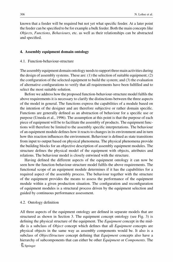
known that a feeder will be required but not yet what specific feeder. At a later pointthe feeder can be specified to be for example a bulk feeder. Both the main concepts likeObjects, Functions, Behaviours, etc. as well as their relationships can be abstractedand specified.
4. Assembly equipment domain ontology
4.1. Function-behaviour-structure
The assembly equipment domain ontology needs to support three main activities duringthe design of assembly systems. These are: (1) the selection of suitable equipment; (2)the configuration of the selected equipment to build the system; and (3) the evaluationof alternative configurations to verify that all requirements have been fulfilled and toselect the most suitable solution.
Before we address how the proposed function-behaviour-structure model fulfils theabove requirements it is necessary to clarify the distinctions between the three aspectsof the model in general. The functions express the capabilities of a module based onthe intention of the designer and are therefore subjective or rather domain specific.Functions are generally defined as an abstraction of behaviour for a specific use orpurpose (Umeda et al., 1996). The assumption at this point is that the purpose of eachpiece of equipment will be to facilitate the assembly of products. The equipment func-tions will therefore be limited to the assembly specific interpretations. The behaviourof an equipment module defines how it reacts to changes in its environment and in turnhow this reaction influences the environment. Behaviour is defined as state transitionsfrom input to output based on physical phenomena. The physical phenomena providethe building blocks for an objective description of assembly equipment modules. Thestructure defines the physical model of the equipment with objects, attributes andrelations. The behaviour model is closely entwined with the structure.
Having defined the different aspects of the equipment ontology it can now beseen how the function-behaviour-structure model fulfils the above requirements. Thefunctional scope of an equipment module determines if it has the capabilities for arequired aspect of the assembly process. The behaviour together with the structureof the equipment provides the means to assess the performance of the equipmentmodule within a given production situation. The configuration and reconfigurationof equipment modules is a structural process driven by the equipment selection andguided by continuous performance assessment.
4.2. Ontology definition
All three aspects of the equipment ontology are defined in separate models that arestructured as shown in Section 3. The equipment concept ontology (see Fig. 3) isdefining the physical structure of the equipment. The Equipment concept in the mid-dle is a subclass of Object concept which defines that all Equipment concepts arephysical objects in the same way as assembly components would be. It also is asubclass of ObjectStructure concept defining that Equipment concepts also have ahierarchy of subcomponents that can either be other Equipment or Components. The
Springer

Equipment ontology for modular reconfigurable assembly systems 307
Equipment
Behaviour
ComponentFunctionComponentConnection
Interface
InterfaceConnectionInterfacePort
relationBetween*
hasRelations*hasBehaviours*hasFunctions*
interface
hasSubcomponents*
System
Cell
Workstation
Unit
Device
Element
isA
isA
isA
isA
isA
isA
isA
Module module
hasRelations*
Object ObjectStructurehasSubcomponents*
isAhasBehaviours*
realisedBy*
hasSubfunctions*
hasSubbehaviours*
Fig. 3 Equipment module ontology concept overview
relationships between the subcomponents of an Equipment concept are defined eitherby ComponentConnections or by InterfaceConnections. The difference between thetwo types of relationships is that InterfaceConnections define the connection betweentwo InterfacePorts which have to adhere to an Interface definition while Compo-nentConnections define the connection between two Objects without any specificinterfacing constraints. This approach has been chosen to cover not only modularEquipment but also non-modular equipment that could be used inside an equipmentmodule. Equipment concepts have also been hierarchically ordered into more spe-cific subtypes: system, cell, workstation, unit, device, and element. The order is indecreasing functional complexity.
For the configuration and reconfiguration of equipment modules it is importantto understand the connection constraints between different equipment modules.The proposed mechanism for the realisation of these constraints is two-fold. Firstis the hierarchical definition of assembly equipment and constraints placed on the<hasSubcomponents> attribute associated to the different levels. For example aWorkstation can only have Units, Devices, and Elements as subcomponents. Secondis a mechanism to provide the standard definition of the module framework chosenfor the implementation of the RAS. The modular structure is defined through thedefinition of its modules and interfaces (Bi and Zhang 2001; Koren et al., 1999; Ulrichand Tung 1991; Pahl and Beitz 1996). The Module and Interface concepts providedefinitions of how equipment modules need to be defined in order to participate withina modular framework. A Module concept defines the Functions and InterfacePortsthat need to be implemented by a specific type of module. The Interface conceptdefines the connectivity constraints between InterfacePorts of the same interface type.
Each Equipment concept is directly linked to its Functions and Behaviours via its<hasBehaviour> and <hasFunctions> attributes. This enables the modelling of eachpiece of equipment as a self-contained instance. As mentioned above, there is a closerelationship between the physical structure and the behaviour of the equipment model.For instance, an InterfacePort is a behaviour that at the same time enables the definitionof the physical relationships between equipment modules. The relationship between
Springer

308 N. Lohse et al.
PerformTask
PerformOperation
PerformAction
FunctionisA
isA
isA
PerformAssemblyTask
hasSubfunctions*
hasSubfunctions*
PerformAssemblyOperation
PerformFeedingOperation
PerformMoveAction
PerformHandlingOperation
PerformHoldAction
...
...
...
PerformInsertionOperation
PerformPressOperation
PerformScrewOperation
isA
isA
isA
isA
isA
isA
isA
isA
isA
Fig. 4 Assembly activity function classification structure
System
Cell
Workstation
Unit
Device
Element
PerformTask
PerformOperation
PerformAction
hasFunctions >> 1
hasFunctions > 1
hasFunctions >= 1
hasFunctions < 1
hasFunctions >= 1
hasFunctions < 1
hasFunctions >= 1
hasFunctions < 1
FunctionisA
Equipment
isA
isA
isA
isA
isA
isA
isA
isA
Fig. 5 Relation between function concepts and equipment concepts
Functions and Behaviour defines how each function is realised through the behaviourof the Equipment. Functions as well as Behaviours are like Equipment concepts struc-tured hierarchically through their <hasSubfunctions> and <hasSubbehaviours> at-tributes respectively. They also have subclasses that define more specialised functionsand behaviours.
It has been assumed that the intended purpose of the modelled equipment is thefacilitation of assembly activities. Consequently, the classification of the equipmentfunctions has been closely modelled to follow our process classification structureas introduced in (Ratchev and Lohse, 2003). The main sub-function concepts arethe execution of the main activity types: task, operation, and action (see Fig. 4).Tasks constitute the highest level of activities by defining the sequence in which thecomponents are being assembled to form the final product. Operations define on anintermediate level the steps required to put the components together including feeding,handling, assembly, etc. Actions on the lowest level define the individual motions andother hardware and control related activities. The relation between the sub-functionconcepts and the different classes of equipment are shown in Fig. 5. For more detaileddefinition of the Function and Behaviour concepts see also (Lohse et al., 2004).
Springer

Equipment ontology for modular reconfigurable assembly systems 309
Fig. 6 Equipment module instance definition
5. Illustrative example
The proposed equipment ontology has been applied in several industrial and virtualuse cases. To illustrate its application a simple assembly scenario has been chosenthat includes the definition of a modular device, its integration into a wider functionalsystem, and its replacement with another module of similar functional capability.Figure 1 shows the principle definition of a standard SCARA-type robot. The robothas two primary ports to connect with other equipment modules: a table or base port(P1) and a tool port (P2). Its main function (F1) can be defined as moving somethingconnected to port (P2). This function can be specialised for this robot to point to point(F1.1), rotary (F1.2), linear (F1.3), or circular (F1.4) motions. The functional definitionof the robot is completed with a temporal constraint that specifies that the motionfunctions can only occur sequentially (Fig. 6).
The functional definition is directly linked to the kinematic behaviour of the robot.The behaviour can generally be defined as SCARA type kinematic structure (B1)which always breaks down into three rotary (BR1, BR2, and BR3) and a translatory jointbehaviour (BT 1). Joint behaviours normally transform electric energy into kinematicenergy. The kinematic motion space is defined through the accumulated kinematicenergies of the joint behaviours based on their links (Fig. 1). The defined structurecould theoretically be interpreted in such a way that the base of the robot would moverelative to the tool port, should the tool port be held in place. However, this is not reallypractical since the drives of a robot are optimised for this specific kinematic structureand can be restricted through the definition of port roles. Finally, the structure of therobot can be defined through four components (C1 to C4) that are joined with threeconnections (L1 to L3). The different joint behaviours are linked to the connectionsthey drive.
Springer

310 N. Lohse et al.
So far the specification was only focused on the general description of the robot. Inorder for the robot to become a module its definition needs to fulfil the requirementsof at least one Module definition of the domain it is intended to be used in. Themodule definitions impose constraints on the functional and connection capability ofthe equipment. In the case of the robot the most common constraint is placed on itsinterface ports. The functional capability is normally quite generic for this type ofequipment.
The main purpose of the proposed equipment ontology is to make it easier to inte-grate equipment into higher level functional systems. The following example illustratesthe advantage of the definition. For the example the robot module should be used toassemble two components. Its move function does not suffice for the task on its own.It needs to be combined with two other modules that can hold both components duringthe assembly. Additionally one of the holding devices needs to be connected to oneport of the robot and the other to the other port, because the two components need tomove relative to each other. Figure 2 shows how the robot could be combined with agripper and a fixture to achieve the overall desired insertion operation function. Therecognition of the overall function from a set of lower level functions is based onactivity composition patterns (Lohse et al., 2005). From the connectivity constraints itcan be recognised that some additional structural element will be required to connectall three modules. This general approach can be used for assembly process drivenequipment configuration as well as for the assessment of functional capabilities thatresult from the connection of equipment modules. Each module takes responsibilityfor a part of the overall assembly operation.
6. Prototype implementation
The frame based assembly equipment domain ontology has been defined using Protege2.0.1 (Protege 2004). Protege is a domain ontology definition tool, which definesclasses, slots, relationships, facets, and instances based on the Open Knowledge BaseConnectivity (OKBC) protocol (Chaudhri et al., 1998). The constraints are expressedas axioms defined in the Protege Axiom Language (PAL) plug-in (Grosso 2004). Thesyntax of PAL is a variant of the Knowledge Interchange Format (KIF) (Genesereth andFikes 1992). PAL constraints are defined by a variable range and a logical statementdefining the condition that needs to hold for the defined variable range. The inferencerules have been defined using the definitions of the Java Expert System Shell (JESS)(Friedman-Hill, 2004). Each rule has the form of if-then statements that match existingfacts to new facts to be asserted or actions to be executed.
The proposed assembly equipment ontology has been implemented as part of aprototype web-enabled decision-making environment for the distributed design ofmodular assembly systems (E-Race 2004). The aim of the prototype implementationis to test the completeness of the domain ontologies and the design methodology. Allsteps of the design process are initially supported by human centred decision-makingagents, i.e. agents providing decision-making interfaces and initial advisory support.The human centred agents interact via dynamic web pages with the different users. Theagent platform provides all the required data and knowledge storage facilities as wellas message transport protocols. Fig. 7 shows the user interface for the embodiment
Springer

Equipment ontology for modular reconfigurable assembly systems 311
Fig. 7 Integration of modules into higher level functional systems
design aspect of an assembly system with the underlying knowledge models definedin Protege.
7. Discussion and conclusions
The reported research addresses the need for a comprehensive equipment ontologyto support effective decision making during the configuration and reconfigurationof reconfigurable assembly systems. A new equipment ontology has been proposedfor design of reconfigurable assembly systems based on the function-behaviour-structure paradigm. The structure of the ontology is tailored to support key designactivities such as equipment selection, system configuration, and performance eval-uation. It also facilitates seamless integration and matching between assembly pro-cess requirements and equipment capabilities in developing new assembly systemsolutions.
One of the main advantages of the proposed approach is that it allows all the detailsof individual equipment modules to be encapsulated into autonomous representationsthat can be communicated over the Internet. The proposed formalization approachmeets the specific requirements to support distributed web-enabled system specifi-cation and design, and can be used in both human driven and computer supporteddecision making. It is expected that the proposed model will help to significantlyreduce the design effort and increase the quality of new assembly system designs.
The approach is considered especially important for successfully developing andutilising truly modular reconfigurable equipment solutions. It also addresses someof the current limitations that prevent available equipment solutions from being for-malised and represented at the required level of detail. Moreover,, the approach canpotentially lead to a radical rethinking of the current design and sales practices ofreconfigurable manufacturing systems and modules.
Our future research focus will be on a closer analysis of the proposed modellingapproach in more complex system scenarios. Further research will be conducted toadvance the understanding on how to effectively utilize the ontology within computeraided concurrent and distributed design environments.
Springer

312 N. Lohse et al.
Fig
.8W
eben
able
dem
bo
dim
ent
des
ign
inte
rfac
e
Springer

Equipment ontology for modular reconfigurable assembly systems 313
Acknowledgements The reported work is partially funded by the Department of Trade and Industry inthe United Kingdom as part of the EUREKA Factory E!2851 E-RACE project, the support of which isgratefully acknowledged.
References
Alsterman H (2004) Strategic issues for achieving sustainable automatic assembly - towards evolvableassembly systems, PhD thesis, Royal Institute of Technology, ISSN 1650–1888
Bi ZM, Zhang WJ (2001) Modularity technology in manufacturing: taxonomy and issues. I J Adv ManuTechnol. Springer-Verlag, London Ltd. 18:381–390
Bley H, Dietz S, Roth N, Zintl G (1994) Knowledge of selecting assembly cell components and its distri-bution to CAD and an expert system for processing. Ann CIRP 43(1):5–8
Boer CR, Pedrazzoli P, Sacco M, Rinaldi R, De Pascale G, Avai A (2001) Integrated computer aided designfor assembly systems. Ann CIRP 50(1):17–20
Chaudhri VK, Farquhar A, Fikes R, Karp PD, Rice JP (1998) Open knowldge base connectivity 2.0.3. SRIinternational, California, USA, available at: www.ai.sri.com/∼okbc/
Chen I-M (2001) Rapid response manufacturing through a rapidly reconfigurable robotic workcell. Roboticsand computer integrated manufacturing, vol. 17. Elsevier Science Ltd., pp 199–213
Craig K, De Vito M, Mattice M, La Vigna C, Teolis C (19–23 September, 1999) Mechatronic integrationmodeling. IEEE/ASME International Conference on Advanced Intelligent Mechatronics, Atlanta, USA
E-Race (2004) E-Space for collaborative manufacture of re-configurable assembly cells. Available at:www.e-race.info,
Friedman-Hill E (2004) Java expert system shell. Sandia National Laboratories, Livermore, California,USA, available at: herzberg.ca.sandia.gov/jess/
Gaugel T, Bengel M, Malthan D (2004) Building a mini-assembly system from a technology constructionkit. Assembly Automation, Emerald Group Publishing Ltd., 24(1):43–48
Gausemeier J, Flath M, Mohringer S (8–12 July, 2001) Conceptual design of mechatronic systems sup-ported by semi-formal specification. IEEE/ASME International Conference on Advanced IntelligentMechatronics, Como, Italy
Genesereth MR, Fikes RE (1992) Knowledge interchange format version 3.0 reference manual. ComputerScience Department, Stanford University, Stanford, California, USA
Giusti F, Santochi M, Dini G, Arioti A (1994) A reconfigurable assembly cell for mechanical products. AnnCIRP 43(1):1–4
Grosso W (2004) PAL Constraints and queries tabs. Available at: protege.stanford.edu/plugins/paltabs/PAL tabs.html
Hirani H (2004) Knowledge enriched requirements specification for reconfigurable assembly systems, PhDThesis, University of Nottingham
Hollis RL, Quaid A (October 1995) An architecture for agile assembly. society of precision engineering,10th Annual Meeting, Austin, Texas, USA, 15–19
Koren Y, Heisel U, Jovane F, Moriwaki T, Pritchow G, Van Brussel H, Ulsoy AG (1999) Reconfigurablemanufacturing systems. CIRP Ann 48(2)
Koren Y, Ulsoy AG (2002) Vision, principles and impact of reconfigurable manufacturing systems. Power-train Int, pp 14–21
Lastra Jose LM (2004) Reference mechatronic architecture for actor-based assembly system, PhD thesis,Tampere University of Technology, ISBN 952-15-1210-5
Lohse N, Hirani H, Ratchev S, Turitto M (July 19–21, 2005) An ontology for the definition and validationof assembly processes for evolvable assembly systems. The 6th IEEE international symposium onassembly and task planning, Montreal, Canada
Lohse N., Ratchev S., Chrisp A. (2004) Function-behaviour-structure model for modular assembly equip-ment. In: Proceedings of the International Precision Assembly Seminar 2004, 11–13 February, BadHofgastein, Austria, pp 167–174
Lohse N, Ratchev S, Valtchanov G (2004) Towards web-enabled design of modular assembly systems.Assembly Automation, Emerald Group Publishing Ltd. 24(3):270–279
Lohse N, Schafer C, Ratchev S (2006) Towards an integrated assembly process decomposition and modularequipment configuration. Precision Assembly Technologies for Mini and Micro Products, S. Ratchev(ed.), Springer, New York, ISBN 0-387-31276-5
Springer

314 N. Lohse et al.
Meijer BR, Tomiyama T, van der Holst BHA, van der Werff K (2003) Knowledge structuring for functiondesign. Ann CIRP, CIRP 52(1):89–92
Mizoguchi R, Kitamura Y (2000) Foundation of knowledge systematization: role of ontological engineer-ing. In: Roy R(ed) Industrial knowledge management: a micro-level approach. Springer-Verlag Ltd.,London, ISBN 1852333391
Neville D, Joskowicz L, (June 23, 1992) A representation language for conceptual mechanism design.International Qualitative Reasoning Workshop
Onori M, Barata de Oliveira JA, Lastra J, Tichem M (2002) European precision assembly roadmap 2012.The Assembly-NET Consortium
Pahl G, Beitz W (1996) Translated by: ken wallace, engineering design—a systematic approach, 2nd edn.Springer-Verlag, London, ISBN 3-540-19917-9
Protege (2004) Stanford University, Stanford University School of Medicine, Stanford Medical Informatics,California, USA, available at: protege.stanford.edu
Ratchev, Svetan, Lohse (2003) Data modelling for web enabled design of modular precision assemblydevices. Proceedings of the International Precision Assembly Seminar, 17-19 March 2003, Hofgastein,Austria, pp 149–156
Sasajima M, Kitamura Y, Ikeda M, Mizoguchi R (August 21, 1995) FBRL: A function and behavior rep-resentation language. Fourteenth International Joint Conference on Artificial Intelligence (IJCAI’95),Montreal, Canada
Schafer C, Lopez O (1999) An object-oriented robot model and its integration into flexible manufacturingsystems. In: Imam IF, Kodratoff Y, El-Dessouki A, Ali M (eds) Multiple approaches to intelligent sys-tems: 12th international conference on industrial and engineering applications of artificial intelligenceand expert systems. Springer, ISBN 3540660763
Seliger G, Bollmann O (1990) Knowledge-based diagnosis in flexible automated assembly. Ann CIRP,CIRP 39(1):9–14
Tomiyama T, Yoshikawa H, Kiriyama T (1993) Conceptual design of mechanisms: a qualitative physicsapproach. In: Kusiak A (ed) Concurrent engineering: automation, tools, and techniques, John Wileyand Sons, Inc., ISBN 0-471-55492-8
Travaini E, Pedrazzoli P, Rinaldi R, Boer CR (2002) Methodological approach and reconfiguration tool forassembly systems. Ann CIRP 51(1):9–13
Ulrich K, Tung K (1991) Fundamentals of product modularity. Issues in Design Manufacturing/IntegrationUmeda Y, Ishii M, Yoshioka M, Shimomura Y, Tetsuo T (1996) Supporting conceptual design based
on the function-behavior-state modeler. Artificial intelligence for engineering design, analysis andmanufacturing, vol. 10. Cambridge University Press, pp 275–288
Vos Jeroen AWM (2001) Module and system design in flexibly automated assembly, PhD thesis, TechnischeUniversiteit Delft, ISBN 90-407-2785706
Wikipedia (2006) The Free Encyclopaedia, available at: www.wikipedia.orgZha XF, Du H, Lim YE (2001) Knowledge intensive Petri net framework for concurrent intelligent design
of automatic assembly systems. Robotics and computer integrated manufacturing, vol. 17. ElsevierScience Ltd., pp 379–398
Zhang M, Fisher W, Webb P, Tarn T-J (14–19 September, 2003) Functional model based object-orienteddevelopment framework for mechatronic systems. IEEE international conference on robotics & au-tomation, Taipei, Taiwan
Zhang WJ, Liu SN, Li Q (2000) Data/knowledge representation of modular robot and its working environ-ment. Robotics and computer integrated manufacturing, vol. 16. Elsevier Science Ltd., pp 143–159
Zhang W, van der Werff K (1993) A Generic mechanism model for use in a CIM environment for thedevelopment of mechanized production machines. Ann CIRP, CIRP 42(1):135–138
Springer
Copyright © 2022 FDOKUMEN