Estimating Arribada Size Using a Modified Instantaneous Count Procedure
702 IEEE TRANSACTIONS ON POWER ELECTRONICS, VOL. 26, NO. 3, MARCH 2011
Improved Instantaneous Average Current-SharingControl Scheme for Parallel-Connected Inverter
Considering Line Impedance Impact inMicrogrid Networks
Azrik M. Roslan, Khaled H. Ahmed, Member, IEEE, Stephen J. Finney, and Barry W. Williams
Abstract—A new control scheme for parallel-connected invert-ers taking into account the effect of line impedance is presented.The system presented here consists of two single-phase invertersconnected in parallel. The control technique is based on instan-taneous average current-sharing control that requires intercon-nections among inverters for information sharing. A generalizedmodel of a single-phase parallel-connected inverter system is de-rived. The model incorporates the detail of the control loops thatuse a proportional-resonant controller, but not the switching action.The voltage- and current-controller design and parameters selec-tion process are discussed. Adaptive gain scheduling is introducedto the controller to improve the current and power sharing for acondition, where the line impedance is different among the invert-ers. The simulation results show that the adaptive gain-schedulingapproaches introduced improve the performance of conventionalcontroller in terms of current and power sharing between invert-ers under difference line impedance condition. The experimentsvalidate the proposed system performance.
Index Terms—Distribution generation, gain scheduling, inverter,microgrid.
I. INTRODUCTION
M ICROGRIDS are defined as systems that have at leastone distributed energy resource (DER) and associated
loads, and can form intentional islands in electrical distributionsystems [1]. Microgrid technology can offer improved servicereliability [2], better economics, and a reduced dependency onthe local utility [3]. An important research area for microgridis the proper controller strategy to ensure current and powersharing of each generating unit under different load and systemconditions.
Manuscript received July 1, 2010; revised November 26, 2010; acceptedDecember 9, 2010. Date of current version May 13, 2011. Recommended forpublication by Associate Editor J. M. Guerrero.
A. M. Roslan, S. J. Finney, and B. W. Williams are with the Departmentof Electronic and Electrical Engineering, Strathclyde University, GlasgowG1 1XW, UK (e-mail: [email protected]; [email protected];[email protected]).
K. H. Ahmed is with the Electrical Engineering Department, Facultyof Engineering, Alexandria University, Alexandria 21526, Egypt (e-mail:[email protected]).
Color versions of one or more of the figures in this paper are available onlineat http://ieeexplore.ieee.org.
Digital Object Identifier 10.1109/TPEL.2010.2102775
Many control techniques have been introduced in the pastdecades to solve the problem of load sharing in parallel opera-tion. A well-established control method is frequency and voltagedroop [4]–[7]. This technique tries to mimic the parallel opera-tion of large-scale power system that will droop the frequencyof the ac generator when its output power increases. It requiresno extra interconnection among inverters, therefore giving itadvantages in terms of high modularity and good reliability.However, there is a well-known limitation, in which an inherenttradeoff exists between the output voltage regulation and powersharing accuracy. In recent years, many researchers focused onimproving the droop control method for a demanding micro-grid application. Some proposed the modified droop [8]–[13],combined droop [14], [15] and adaptive droop [16]–[18] controlschemes. In [8], the power derivative integral term is introducedto the conventional droop equation to improve the transient re-sponse. In [9], a supplementary loop is proposed around theconventional droop control of each distributed generation (DG)converter to stabilize the system and ensure satisfactory loadsharing. However, this can only cater for a specified range ofoperation. A combined droop method and average power con-trol method that requires a communication channel is proposedin [14], which significantly improves the load-sharing capabil-ity. In [16], the author introduces the impedance voltage dropsestimation function and employs online reactive power offsetestimation to improve the reactive power sharing in low-voltagenetwork.
To achieve proper current sharing and voltage regulation inparallel system, some information needs to be shared amongparallel-connected inverters. Many control techniques utilizethe communication among the DERs, for example, the ac-tive load-sharing schemes [19]–[31]. These schemes employdifferent mechanisms to share information among the invert-ers. The reported active load-sharing schemes can be classifiedas: the circular-chain current-programming method [19], [20],master–slave current-programming method [21]–[25], and av-erage current-programming method [26]–[31]. In the circular-chain current-programming method, successive inverter mod-ules track the current of the previous inverter to achieve anequal current distribution. The first module tracks the last toform a circular chain connection. However, a problem occurswhen there is a damaged or failed inverter in the loop. If thisis not detected and isolated quickly, it will impact the perfor-mance of the overall system, and in the worse case, can cause
0885-8993/$26.00 © 2010 IEEE
ROSLAN et al.: IMPROVED INSTANTANEOUS AVERAGE CURRENT-SHARING CONTROL SCHEME 703
total system failure. Another variant of the 3C control strategyis current limitation control. There is a master module that con-trols the load voltage and the slave modules will only supplythe load current. A slave module will receive the reference cur-rent command from the previous module. The control circuit’sconnection forms a circular chain such that every module maybecome the master.
In the master–slave current-sharing configuration, the masterinverter regulates the voltage and frequency, and other invertersslave to it. In other words, the master module acts as a voltagesource inverter, while the slaves operate as a current source in-verter. There are some variants to this control technique, whichdepend on the selection of the master module. In a dedicatedscheme, one fixed module is selected as the master unit. Thereis also a rotary scheme, in which the master is arbitrary cho-sen. In another variant, the module that produces maximumrms current is selected as the master module. For the averagecurrent-programming scheme, all the inverters in the microgridtake part in the voltage, frequency, as well as the current reg-ulation, demonstrating the democratic nature of this controller.This scheme is implemented using a single wire, which conveysthe average current information based on a resistor connectedto the current sensor in each module. The current of all modulesis averaged by means of a common current bus. The averagecurrent becomes the reference for each module. The democraticnature of this scheme makes this controller reliable. A more de-tail discussion of the previously mentioned control techniquesis presented in [32].
In all active load-sharing schemes, the output current of theinverters is regulated at each switching cycle. These schemeshave good performance, both on current sharing and voltageregulation, but do not consider the effect of the line impedance.In an actual distributed system, the line impedance of one unitcan be significantly different from the impedance of anotherunit. The load sharing will be affected by the connecting lineimpedance variations [33]. More important, the X/R ratio of lineimpedance will affect the stability margin of a microgrid [34]. Ifthe system is informed of the line impedance value, then its effectcan be compensated. Without this information, the controller isunable to compensate the voltage drop and power loss due to theline impedance. A few researchers have considered the effect ofline impedance in the design of the control scheme [35]–[37]. In[35], the author proposed a combined droop method and poweradjusting mechanism. A small ac voltage signal is injected intothe system as a control signal. The quantity to be shared controlsthe frequency of this control signal.
As far as the instantaneous current-sharing control schemeis concerned, only [26] discussed the issue of the effect of lineimpedance on controller performance. This paper explores thisarea. The performance of conventional instantaneous averagecurrent sharing (IACS) with line impedance effect is studied.Improvements to the IACS control scheme are proposed to en-able the parallel-connected inverters to have current and powersharing under different line impedance condition. This improve-ment is based on an adaptive gain-scheduling approach. Twogain schedulers are added to the conventional controller. Thefirst gain scheduler adjusts the modulation index of the con-
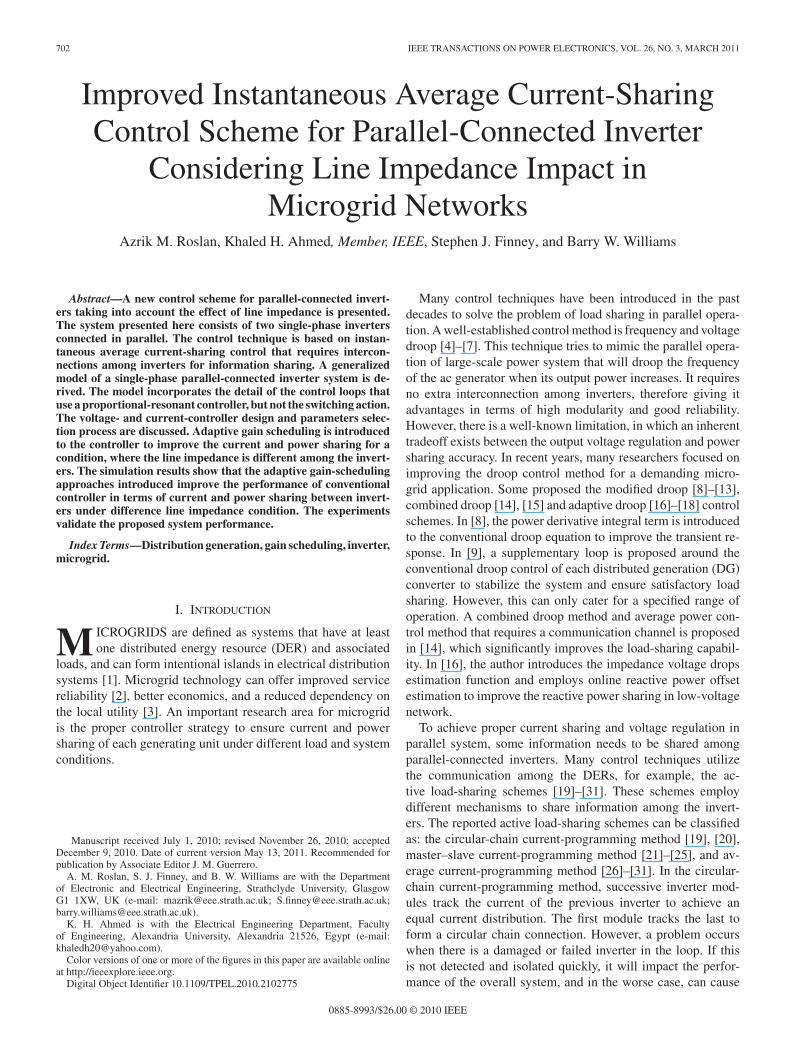
Fig. 1. Block diagram of an inverter.
trolled signal, while the other adjusts the gain of the current-sharing loop. These adjustments have an impact on the changeof current output from each inverter. Simulation and practicalexperiments using two parallel-connected inverters confirm theeffectiveness of the proposed controller under difference lineimpedance conditions.
II. PARALLEL INVERTER SYSTEM CONFIGURATION
A. Single Inverter Construction
A typical inverter consists of a dc power source, a bridge-typeinverter, and an interfacing LC filter, as shown in Fig. 1. Assum-ing an ideal source from the DG side, the dc bus dynamic canbe neglected. The inverter converts the dc input to an ac outputbased on the modulation signal from the sinusoidal pulsewidthmodulation (SPWM) modulator. Lf , Rf , and Cf represent theinductance, resistance, and capacitance of the output filter, re-spectively. The line impedance between the inverter and the loadnetwork is the equivalent impedance due to the connecting linesor cables. This line impedance can be inductive or resistive. Theload can be resistive, inductive, capacitive, or linear or nonlinear.
B. Parallel Inverter System
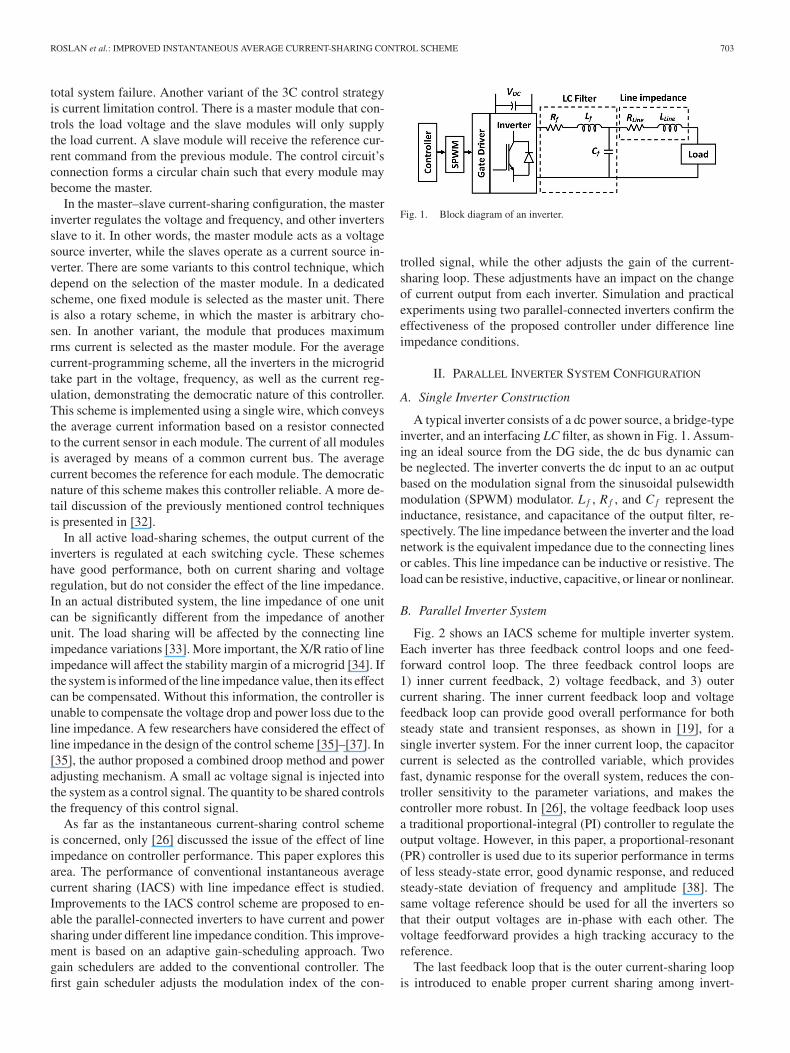
Fig. 2 shows an IACS scheme for multiple inverter system.Each inverter has three feedback control loops and one feed-forward control loop. The three feedback control loops are1) inner current feedback, 2) voltage feedback, and 3) outercurrent sharing. The inner current feedback loop and voltagefeedback loop can provide good overall performance for bothsteady state and transient responses, as shown in [19], for asingle inverter system. For the inner current loop, the capacitorcurrent is selected as the controlled variable, which providesfast, dynamic response for the overall system, reduces the con-troller sensitivity to the parameter variations, and makes thecontroller more robust. In [26], the voltage feedback loop usesa traditional proportional-integral (PI) controller to regulate theoutput voltage. However, in this paper, a proportional-resonant(PR) controller is used due to its superior performance in termsof less steady-state error, good dynamic response, and reducedsteady-state deviation of frequency and amplitude [38]. Thesame voltage reference should be used for all the inverters sothat their output voltages are in-phase with each other. Thevoltage feedforward provides a high tracking accuracy to thereference.
The last feedback loop that is the outer current-sharing loopis introduced to enable proper current sharing among invert-
704 IEEE TRANSACTIONS ON POWER ELECTRONICS, VOL. 26, NO. 3, MARCH 2011
Fig. 2. IACS scheme for multiple inverter system.
ers. Each parallel-connected inverter will deliver its measuredoutput current value to the current-sharing bus from which thereference current is generated. This reference current becomesthe reference for the outer current-sharing loop of each inverter.The error between this reference and the output current of anindividual inverter is fed to the current controller, and the highgain of this controller provides an adequate corrective signal thatis added to the modulating signal. In other word, the current-sharing controller tries to increase the current if its output currentis less than the reference current, and decreases it when the out-put current is more than the reference current by adjusting theinverter output voltage.
III. IMPROVED IACS CONTROLLER
A. Conventional IACS Controller
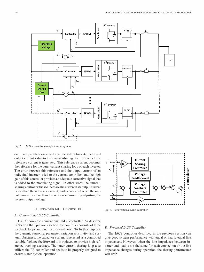
Fig. 3 shows the conventional IACS controller. As describein Section II-B, previous section, the controller consists of threefeedback loops and one feedforward loop. To further improvethe dynamic response, parameter variation sensitivity, and sys-tem robustness, the capacitor current is selected as a controlledvariable. Voltage feedforward is introduced to provide high ref-erence tracking accuracy. The outer current-sharing loop alsoutilizes the PR controller and needs to be properly designed toensure stable system operation.
Fig. 3. Conventional IACS controller.
B. Proposed IACS Controller
The IACS controller described in the previous section cangive good system performance with equal or nearly equal lineimpedances. However, when the line impedance between in-verter and load is not the same for each connection or the lineimpedance changes during operation, the sharing performancewill drop.
ROSLAN et al.: IMPROVED INSTANTANEOUS AVERAGE CURRENT-SHARING CONTROL SCHEME 705
Fig. 4. Gain-scheduling principle.
Fig. 5. Proposed IACS controller.
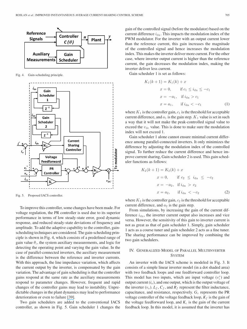
To improve this controller, some changes have been made. Forvoltage regulation, the PR controller is used due to its superiorperformance in terms of low steady-state error, good dynamicresponse, and reduced steady-state deviations of frequency andamplitude. To add the adaptive capability to the controller, gain-scheduling techniques are considered. The gain-scheduling prin-ciple is shown in Fig. 4, which consists of a predefined range ofgain value θi , the system auxiliary measurements, and logic fordetecting the operating point and varying the gain value. In thecase of parallel-connected inverters, the auxiliary measurementis the difference between the reference and inverter currents.With this approach, the line impedance variation, which affectsthe current output by the inverter, is compensated by the gainvariation. The advantage of gain scheduling is that the controllergains respond at the same rate as the auxiliary measurementsrespond to parameter changes. However, frequent and rapidchanges of the controller gains may lead to instability. Unpre-dictable changes in the plant dynamics may lead to performancedeterioration or even to failure [39].
Two gain schedulers are added to the conventional IACScontroller, as shown in Fig. 5. Gain scheduler 1 changes the
gain of the controlled signal (before the modulator) based on thecurrent difference idn . This impacts the modulation index of thePWM modulator. For the inverter with an output current lowerthan the reference current, this gain increases the magnitudeof the controlled signal and hence increases the modulationindex. This makes the inverter deliver more current. For the othercase, where inverter output current is higher than the referencecurrent, the gain decreases the modulation index, making theinverter deliver less current.
Gain scheduler 1 is set as follows:
K1(k + 1) = K1(k) + x
x = 0, if c1 ≤ idn ≤ −c1
x = −a1 , if idn > c1
x = a1 , if idn < −c1 (1)
where K1 is the controller gain, c1 is the threshold for acceptablecurrent difference, and a1 is the gain step. K1 value is set in sucha way that it will not make the peak-controlled signal value toexceed the vdc value. This is done to make sure the modulationindex will not exceed 1.
Gain scheduler 1 alone cannot ensure minimal current differ-ence among parallel-connected inverters. It only minimizes thedifference by adjusting the modulation index of the controlledsignal. To further reduce the current difference and hence im-prove current sharing, Gain scheduler 2 is used. This gain sched-uler functions as follows:
K2(k + 1) = K2(k) + x
x = 0, if c2 ≤ idn ≤ −c2
x = −a2 , if idn > c2
x = a2 , if idn < −c2 (2)
where K2 is the controller gain, c2 is the threshold for acceptablecurrent difference, and a2 is the gain step.
From simulations, by increasing the gain of the current dif-ference idn , the inverter current output also increases and viceversa. However, the sensitivity of this gain to inverter current isnot as great as that of gain scheduler 1. Simply, gain scheduler1 acts as a course tuner and gain scheduler 2 acts as a fine tuner.The sharing performance can be improved by combining thetwo gain schedulers.
IV. GENERALIZED MODEL OF PARALLEL MULTIINVERTER
SYSTEM
An inverter with the IACS scheme is modeled in Fig. 3. Itconsists of a simple linear inverter model (in a dot shaded area)with two feedback loops and one feedforward controller loop.This model has two inputs, which are input voltage (v∗
i ) andoutput current (io ), and one output, which is the output voltage ofthe inverter (vo ). Lf , Cf , and Rf represent the filter inductance,capacitance, and resistance, respectively. Gv represents the PRvoltage controller of the voltage feedback loop, Kf is the gain ofthe voltage feedforward loop, and Kc is the gain of the currentfeedback loop. In this model, it is assumed that the inverter has
706 IEEE TRANSACTIONS ON POWER ELECTRONICS, VOL. 26, NO. 3, MARCH 2011
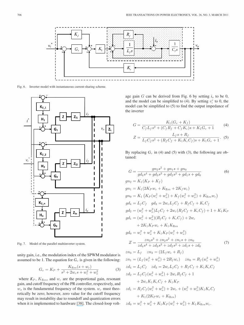
Fig. 6. Inverter model with instantaneous current-sharing scheme.
Fig. 7. Model of the parallel multiinverter system.
unity gain, i.e., the modulation index of the SPWM modulator isassumed to be 1. The equation for Gv is given in the following:
Gv = KP +KRes(s + wc)
s2 + 2wcs + w2c + w2
o
(3)
where KP , KRes , and wc are the proportional gain, resonantgain, and cutoff frequency of the PR controller, respectively, andwo is the fundamental frequency of the system. wc must theo-retically be zero; however, zero value for the cutoff frequencymay result in instability due to roundoff and quantization errorswhen it is implemented to hardware [38]. The closed-loop volt-
age gain G can be derived from Fig. 6 by setting io to be 0,and the model can be simplified to (4). By setting v∗
i to 0, themodel can be simplified to (5) to find the output impedance ofthe inverter
G =K1(Gv + Kf )
Cf Lf s2 + (Cf Rf + Cf Kc)s + K1Gv + 1(4)
Z =Lf s + Rf
Lf Cf s2 + (Rf Cf + K1KcCf )s + K1Gv + 1. (5)
By replacing Gv in (4) and (5) with (3), the following are ob-tained:
G =gn2s
2 + gn1s + gn0
gd4s4 + gd3s3 + gd2s2 + gd1s + gd0(6)
gn2 = K1(KP + Kf )
gn1 = K1(2KP wc + KRes + 2Kf wc)
gn0 = K1(KP (w2
c + w2o ) + Kf (w2
c + w2o ) + KReswc
)
gd4 = Lf Cf gd3 = 2wcLf Cf + Rf Cf + KcCf
gd2 = (w2c + w2
o )Lf Cf + 2wc(Rf Cf + KcCf ) + 1 + K1KP
gd1 = (w2c + w2
o )(Rf Cf + KcCf ) + 2wc
+ 2K1KP wc + K1KRes
gd0 = w2c + w2
o + K1KP (w2c + w2
o )
Z =zn3s
3 + zn2s2 + zn1s + zn0
zd4s4 + zd3s3 + zd2s2 + zd1s + zd0(7)
zn3 = Lf zn2 = (2Lf wc + Rf )
zn1 = (Lf (w2c + w2
o ) + 2Rf wc) zn0 = Rf (w2c + w2
o )
zd4 = Lf Cf zd3 = 2wcLf Cf + Rf Cf + K1KcCf
zd2 = Lf Cf (w2c + w2
o ) + 2wcRf Cf + 1
+ 2wcK1KcCf + K1KP
zd1 = Rf Cf (w2c + w2
o ) + 2wc + (w2c + w2
o )K1KcCf
+ K1(2KP wc + KRes)
zd0 = w2c + w2
o + K1KP (w2c + w2
o ) + K1KReswc.
ROSLAN et al.: IMPROVED INSTANTANEOUS AVERAGE CURRENT-SHARING CONTROL SCHEME 707
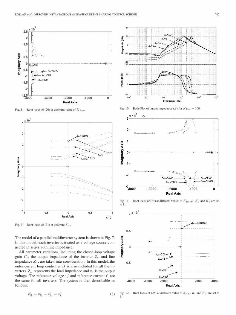
Fig. 8. Root locus of (20) at different value of KRes .
Fig. 9. Root locus of (21) at different KP .
The model of a parallel multiinverter system is shown in Fig. 7.In this model, each inverter is treated as a voltage source con-nected in series with line impedance.
All parameter variations, including the closed-loop voltagegain Gi , the output impedance of the inverter Zi , and lineimpedance Zli , are taken into consideration. In this model, theouter current loop controller H is also included for all the in-verters. ZL represents the load impedance and vo is the outputvoltage. The reference voltage v∗
i and reference current i∗ arethe same for all inverters. The system is then describable asfollows:
v∗i1 = v∗
i2 = v∗in = v∗
i (8)
Fig. 10. Bode Plot of output impedance (Z ) for KRes = 100.
Fig. 11. Root locus of (24) at different values of KResH . K 1 and K 2 are setto 1.
Fig. 12. Root locus of (25) at different value of KP H . K1 and K 2 are set to1.
708 IEEE TRANSACTIONS ON POWER ELECTRONICS, VOL. 26, NO. 3, MARCH 2011
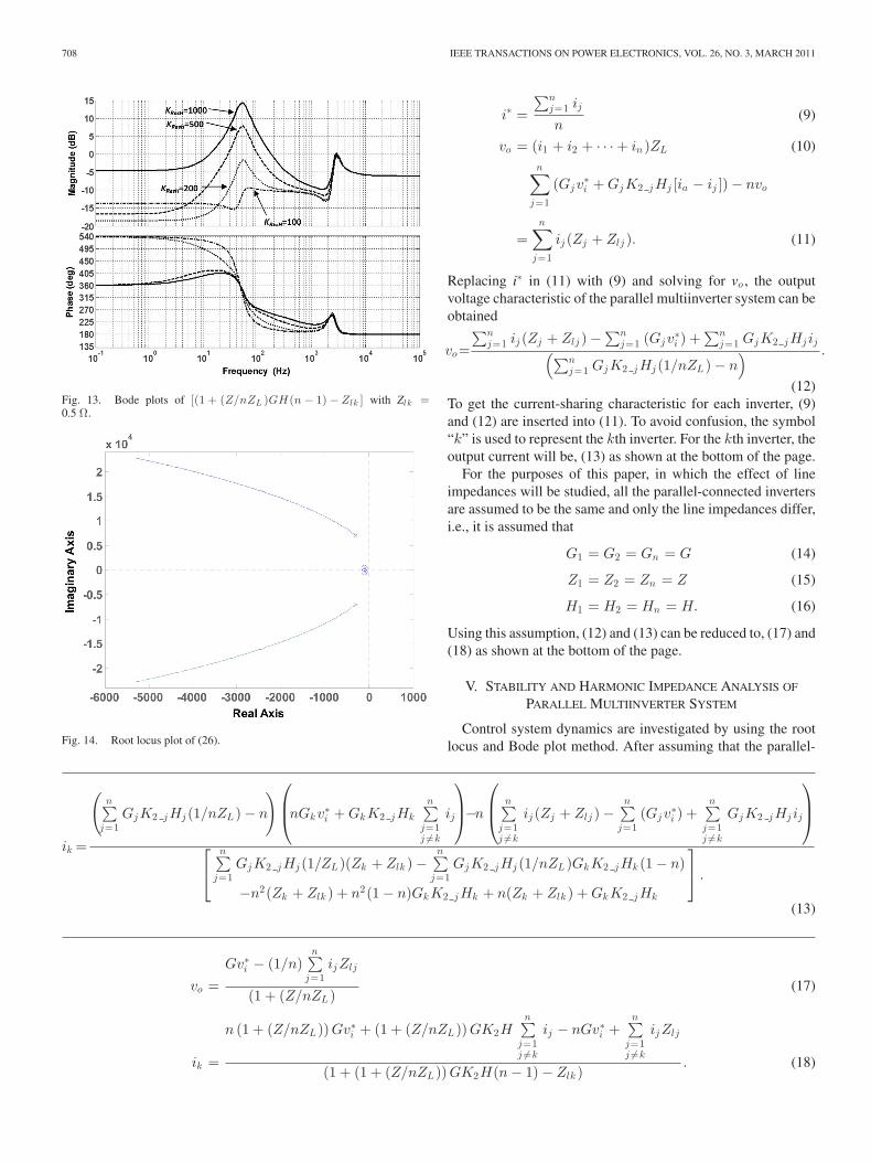
Fig. 13. Bode plots of [(1 + (Z/nZL )GH (n − 1) − Zlk ] with Zlk =0.5 Ω.
Fig. 14. Root locus plot of (26).
i∗ =
∑nj=1 ij
n(9)
vo = (i1 + i2 + · · · + in )ZL (10)n∑
j=1
(Gjv∗i + GjK2 jHj [ia − ij ]) − nvo
=n∑
j=1
ij (Zj + Zlj ). (11)
Replacing i∗ in (11) with (9) and solving for vo , the outputvoltage characteristic of the parallel multiinverter system can beobtained
vo=
∑nj=1 ij (Zj + Zlj ) −
∑nj=1 (Gjv
∗i ) +
∑nj=1 GjK2 jHj ij(∑n
j=1 GjK2 jHj (1/nZL ) − n) .
(12)To get the current-sharing characteristic for each inverter, (9)and (12) are inserted into (11). To avoid confusion, the symbol“k” is used to represent the kth inverter. For the kth inverter, theoutput current will be, (13) as shown at the bottom of the page.
For the purposes of this paper, in which the effect of lineimpedances will be studied, all the parallel-connected invertersare assumed to be the same and only the line impedances differ,i.e., it is assumed that
G1 = G2 = Gn = G (14)
Z1 = Z2 = Zn = Z (15)
H1 = H2 = Hn = H. (16)
Using this assumption, (12) and (13) can be reduced to, (17) and(18) as shown at the bottom of the page.
V. STABILITY AND HARMONIC IMPEDANCE ANALYSIS OF
PARALLEL MULTIINVERTER SYSTEM
Control system dynamics are investigated by using the rootlocus and Bode plot method. After assuming that the parallel-
ik =
(n∑
j=1GjK2 jHj (1/nZL ) − n
)⎛
⎜⎝nGkv∗
i + GkK2 jHk
n∑
j=1j �=k
ij
⎞
⎟⎠−n
⎛
⎜⎝
n∑
j=1j �=k
ij (Zj + Zlj ) −n∑
j=1(Gjv
∗i ) +
n∑
j=1j �=k
GjK2 jHj ij
⎞
⎟⎠
⎡
⎣
n∑
j=1GjK2 jHj (1/ZL )(Zk + Zlk ) −
n∑
j=1GjK2 jHj (1/nZL )GkK2 jHk (1 − n)
−n2(Zk + Zlk ) + n2(1 − n)GkK2 jHk + n(Zk + Zlk ) + GkK2 jHk
⎤
⎦ .
(13)
vo =Gv∗
i − (1/n)n∑
j=1ijZlj
(1 + (Z/nZL )(17)
ik =
n (1 + (Z/nZL )) Gv∗i + (1 + (Z/nZL )) GK2H
n∑
j=1j �=k
ij − nGv∗i +
n∑
j=1j �=k
ijZlj
(1 + (1 + (Z/nZL )) GK2H(n − 1) − Zlk ). (18)
ROSLAN et al.: IMPROVED INSTANTANEOUS AVERAGE CURRENT-SHARING CONTROL SCHEME 709
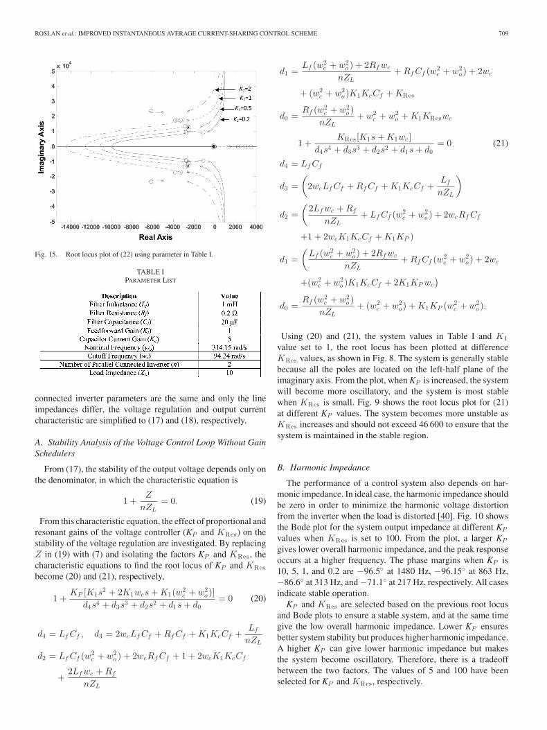
Fig. 15. Root locus plot of (22) using parameter in Table I.
TABLE IPARAMETER LIST
connected inverter parameters are the same and only the lineimpedances differ, the voltage regulation and output currentcharacteristic are simplified to (17) and (18), respectively.
A. Stability Analysis of the Voltage Control Loop Without GainSchedulers
From (17), the stability of the output voltage depends only onthe denominator, in which the characteristic equation is
1 +Z
nZL= 0. (19)
From this characteristic equation, the effect of proportional andresonant gains of the voltage controller (KP and KRes) on thestability of the voltage regulation are investigated. By replacingZ in (19) with (7) and isolating the factors KP and KRes , thecharacteristic equations to find the root locus of KP and KResbecome (20) and (21), respectively,
1 +KP [K1s
2 + 2K1wcs + K1(w2c + w2
o )]d4s4 + d3s3 + d2s2 + d1s + d0
= 0 (20)
d4 = Lf Cf , d3 = 2wcLf Cf + Rf Cf + K1KcCf +Lf
nZL
d2 = Lf Cf (w2c + w2
o ) + 2wcRf Cf + 1 + 2wcK1KcCf
+2Lf wc + Rf
nZL
d1 =Lf (w2
c + w2o ) + 2Rf wc
nZL+ Rf Cf (w2
c + w2o ) + 2wc
+ (w2c + w2
o )K1KcCf + KRes
d0 =Rf (w2
c + w2o )
nZL+ w2
c + w2o + K1KReswc
1 +KRes[K1s + K1wc ]
d4s4 + d3s3 + d2s2 + d1s + d0= 0 (21)
d4 = Lf Cf
d3 =(
2wcLf Cf + Rf Cf + K1KcCf +Lf
nZL
)
d2 =(
2Lf wc + Rf
nZL+ Lf Cf (w2
c + w2o ) + 2wcRf Cf
+1 + 2wcK1KcCf + K1KP )
d1 =(
Lf (w2c + w2
o ) + 2Rf wc
nZL+ Rf Cf (w2
c + w2o ) + 2wc
+(w2c + w2
o )K1KcCf + 2K1KP wc
)
d0 =Rf (w2
c + w2o )
nZL+ (w2
c + w2o ) + K1KP (w2
c + w2o ).
Using (20) and (21), the system values in Table I and K1value set to 1, the root locus has been plotted at differenceKRes values, as shown in Fig. 8. The system is generally stablebecause all the poles are located on the left-half plane of theimaginary axis. From the plot, when KP is increased, the systemwill become more oscillatory, and the system is most stablewhen KRes is small. Fig. 9 shows the root locus plot for (21)at different KP values. The system becomes more unstable asKRes increases and should not exceed 46 600 to ensure that thesystem is maintained in the stable region.
B. Harmonic Impedance
The performance of a control system also depends on har-monic impedance. In ideal case, the harmonic impedance shouldbe zero in order to minimize the harmonic voltage distortionfrom the inverter when the load is distorted [40]. Fig. 10 showsthe Bode plot for the system output impedance at different KP
values when KRes is set to 100. From the plot, a larger KP
gives lower overall harmonic impedance, and the peak responseoccurs at a higher frequency. The phase margins when KP is10, 5, 1, and 0.2 are −96.5◦ at 1480 Hz, −96.15◦ at 863 Hz,−86.6◦ at 313 Hz, and −71.1◦ at 217 Hz, respectively. All casesindicate stable operation.
KP and KRes are selected based on the previous root locusand Bode plots to ensure a stable system, and at the same timegive the low overall harmonic impedance. Lower KP ensuresbetter system stability but produces higher harmonic impedance.A higher KP can give lower harmonic impedance but makesthe system become oscillatory. Therefore, there is a tradeoffbetween the two factors. The values of 5 and 100 have beenselected for KP and KRes , respectively.
710 IEEE TRANSACTIONS ON POWER ELECTRONICS, VOL. 26, NO. 3, MARCH 2011
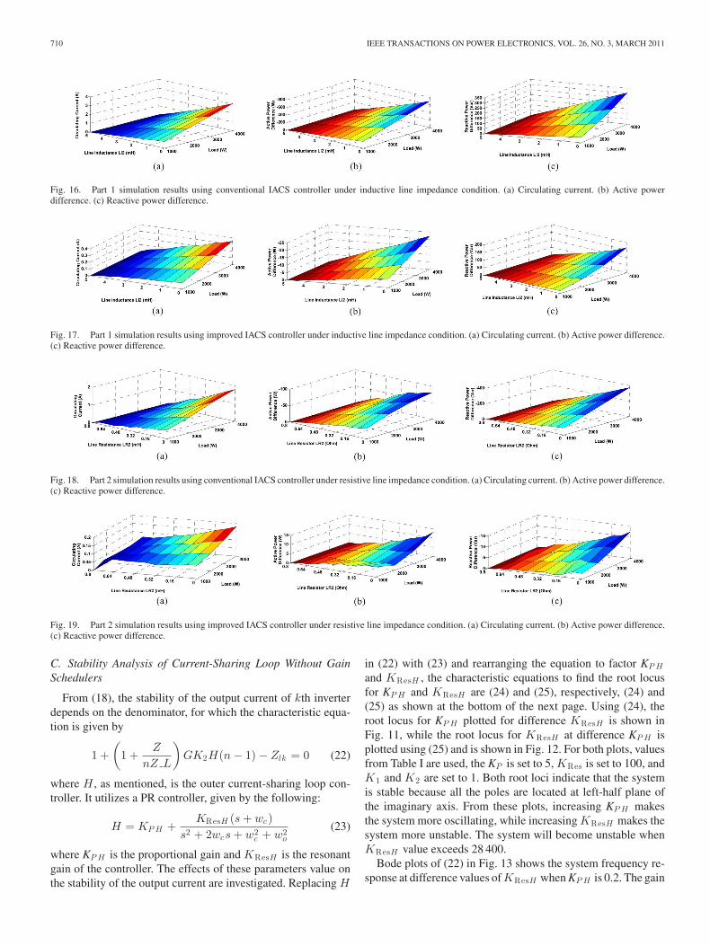
Fig. 16. Part 1 simulation results using conventional IACS controller under inductive line impedance condition. (a) Circulating current. (b) Active powerdifference. (c) Reactive power difference.
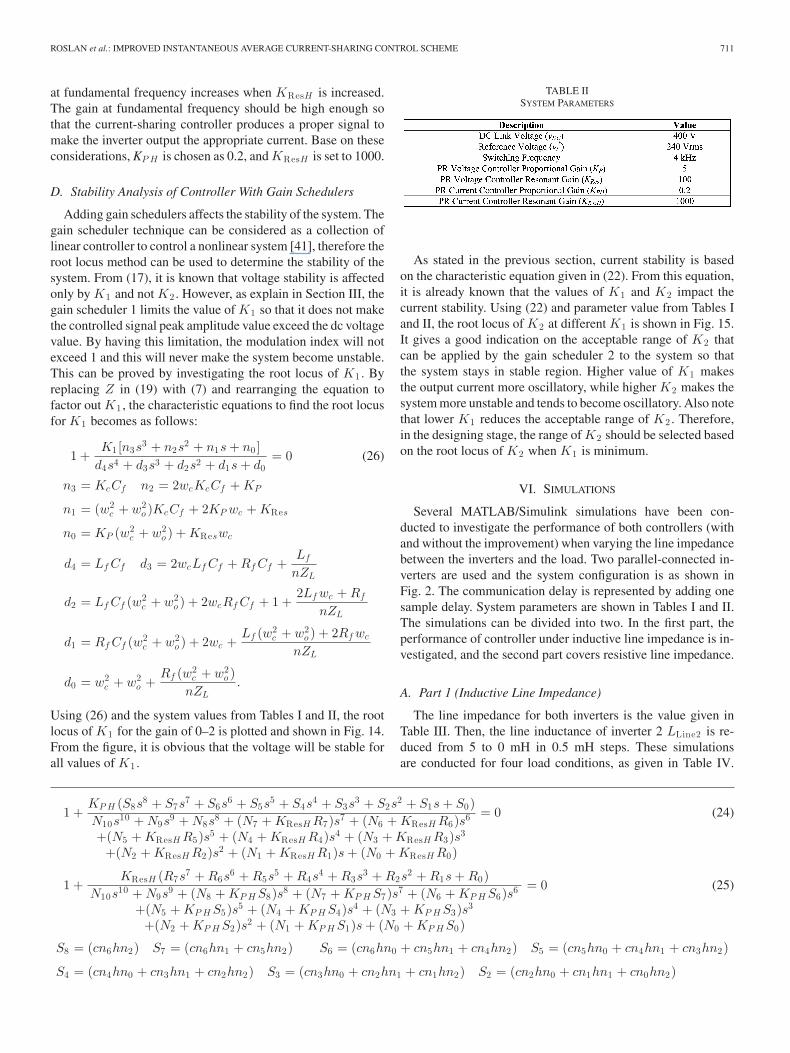
Fig. 17. Part 1 simulation results using improved IACS controller under inductive line impedance condition. (a) Circulating current. (b) Active power difference.(c) Reactive power difference.
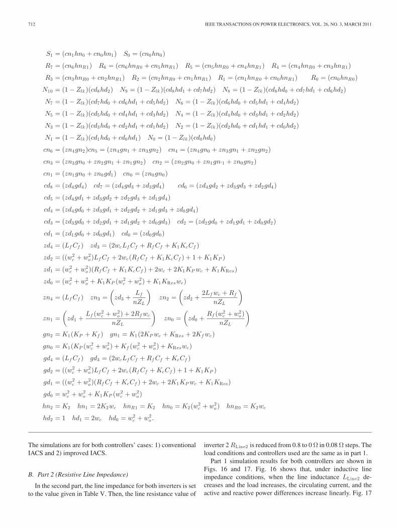
Fig. 18. Part 2 simulation results using conventional IACS controller under resistive line impedance condition. (a) Circulating current. (b) Active power difference.(c) Reactive power difference.
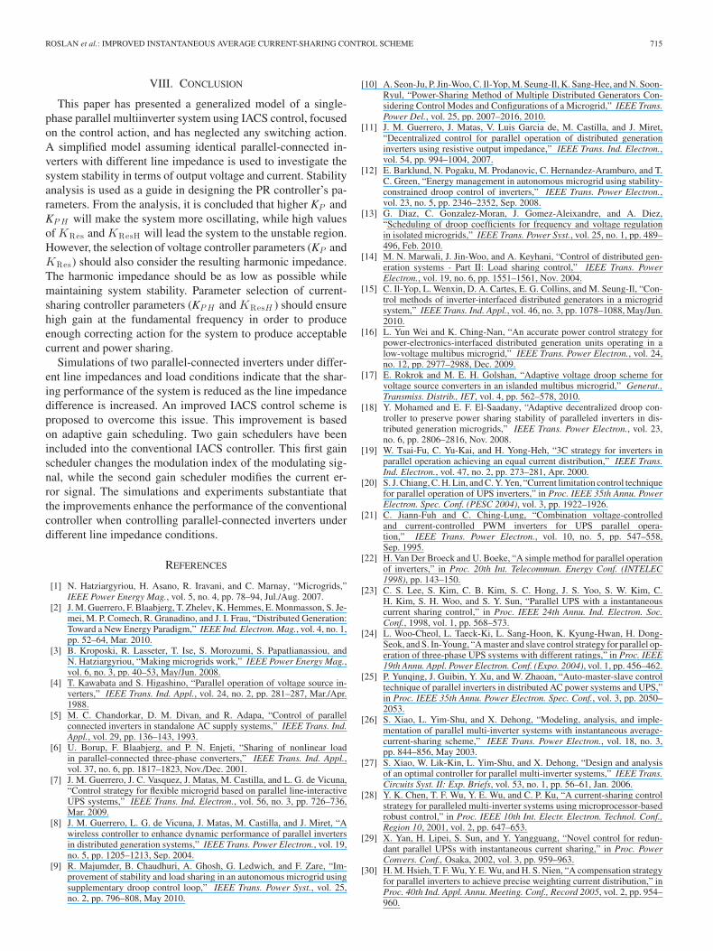
Fig. 19. Part 2 simulation results using improved IACS controller under resistive line impedance condition. (a) Circulating current. (b) Active power difference.(c) Reactive power difference.
C. Stability Analysis of Current-Sharing Loop Without GainSchedulers
From (18), the stability of the output current of kth inverterdepends on the denominator, for which the characteristic equa-tion is given by
1 +(
1 +Z
nZ L
)GK2H(n − 1) − Zlk = 0 (22)
where H , as mentioned, is the outer current-sharing loop con-troller. It utilizes a PR controller, given by the following:
H = KP H +KResH (s + wc)
s2 + 2wcs + w2c + w2
o
(23)
where KP H is the proportional gain and KResH is the resonantgain of the controller. The effects of these parameters value onthe stability of the output current are investigated. Replacing H
in (22) with (23) and rearranging the equation to factor KP H
and KResH , the characteristic equations to find the root locusfor KP H and KResH are (24) and (25), respectively, (24) and(25) as shown at the bottom of the next page. Using (24), theroot locus for KP H plotted for difference KResH is shown inFig. 11, while the root locus for KResH at difference KP H isplotted using (25) and is shown in Fig. 12. For both plots, valuesfrom Table I are used, the KP is set to 5, KRes is set to 100, andK1 and K2 are set to 1. Both root loci indicate that the systemis stable because all the poles are located at left-half plane ofthe imaginary axis. From these plots, increasing KP H makesthe system more oscillating, while increasing KResH makes thesystem more unstable. The system will become unstable whenKResH value exceeds 28 400.
Bode plots of (22) in Fig. 13 shows the system frequency re-sponse at difference values of KResH when KP H is 0.2. The gain
ROSLAN et al.: IMPROVED INSTANTANEOUS AVERAGE CURRENT-SHARING CONTROL SCHEME 711
at fundamental frequency increases when KResH is increased.The gain at fundamental frequency should be high enough sothat the current-sharing controller produces a proper signal tomake the inverter output the appropriate current. Base on theseconsiderations, KP H is chosen as 0.2, and KResH is set to 1000.
D. Stability Analysis of Controller With Gain Schedulers
Adding gain schedulers affects the stability of the system. Thegain scheduler technique can be considered as a collection oflinear controller to control a nonlinear system [41], therefore theroot locus method can be used to determine the stability of thesystem. From (17), it is known that voltage stability is affectedonly by K1 and not K2 . However, as explain in Section III, thegain scheduler 1 limits the value of K1 so that it does not makethe controlled signal peak amplitude value exceed the dc voltagevalue. By having this limitation, the modulation index will notexceed 1 and this will never make the system become unstable.This can be proved by investigating the root locus of K1 . Byreplacing Z in (19) with (7) and rearranging the equation tofactor out K1 , the characteristic equations to find the root locusfor K1 becomes as follows:
1 +K1 [n3s
3 + n2s2 + n1s + n0 ]
d4s4 + d3s3 + d2s2 + d1s + d0= 0 (26)
n3 = KcCf n2 = 2wcKcCf + KP
n1 = (w2c + w2
o )KcCf + 2KP wc + KRes
n0 = KP (w2c + w2
o ) + KReswc
d4 = Lf Cf d3 = 2wcLf Cf + Rf Cf +Lf
nZL
d2 = Lf Cf (w2c + w2
o ) + 2wcRf Cf + 1 +2Lf wc + Rf
nZL
d1 = Rf Cf (w2c + w2
o ) + 2wc +Lf (w2
c + w2o ) + 2Rf wc
nZL
d0 = w2c + w2
o +Rf (w2
c + w2o )
nZL.
Using (26) and the system values from Tables I and II, the rootlocus of K1 for the gain of 0–2 is plotted and shown in Fig. 14.From the figure, it is obvious that the voltage will be stable forall values of K1 .
TABLE IISYSTEM PARAMETERS
As stated in the previous section, current stability is basedon the characteristic equation given in (22). From this equation,it is already known that the values of K1 and K2 impact thecurrent stability. Using (22) and parameter value from Tables Iand II, the root locus of K2 at different K1 is shown in Fig. 15.It gives a good indication on the acceptable range of K2 thatcan be applied by the gain scheduler 2 to the system so thatthe system stays in stable region. Higher value of K1 makesthe output current more oscillatory, while higher K2 makes thesystem more unstable and tends to become oscillatory. Also notethat lower K1 reduces the acceptable range of K2 . Therefore,in the designing stage, the range of K2 should be selected basedon the root locus of K2 when K1 is minimum.
VI. SIMULATIONS
Several MATLAB/Simulink simulations have been con-ducted to investigate the performance of both controllers (withand without the improvement) when varying the line impedancebetween the inverters and the load. Two parallel-connected in-verters are used and the system configuration is as shown inFig. 2. The communication delay is represented by adding onesample delay. System parameters are shown in Tables I and II.The simulations can be divided into two. In the first part, theperformance of controller under inductive line impedance is in-vestigated, and the second part covers resistive line impedance.
A. Part 1 (Inductive Line Impedance)
The line impedance for both inverters is the value given inTable III. Then, the line inductance of inverter 2 LLine2 is re-duced from 5 to 0 mH in 0.5 mH steps. These simulationsare conducted for four load conditions, as given in Table IV.
1 +KP H (S8s
8 + S7s7 + S6s
6 + S5s5 + S4s
4 + S3s3 + S2s
2 + S1s + S0)N10s
10 + N9s9 + N8s
8 + (N7 + KResH R7)s7 + (N6 + KResH R6)s6
+(N5 + KResH R5)s5 + (N4 + KResH R4)s4 + (N3 + KResH R3)s3
+(N2 + KResH R2)s2 + (N1 + KResH R1)s + (N0 + KResH R0)
= 0 (24)
1 +KResH (R7s
7 + R6s6 + R5s
5 + R4s4 + R3s
3 + R2s2 + R1s + R0)
N10s10 + N9s
9 + (N8 + KP H S8)s8 + (N7 + KP H S7)s7 + (N6 + KP H S6)s6
+(N5 + KP H S5)s5 + (N4 + KP H S4)s4 + (N3 + KP H S3)s3
+(N2 + KP H S2)s2 + (N1 + KP H S1)s + (N0 + KP H S0)
= 0 (25)
S8 = (cn6hn2) S7 = (cn6hn1 + cn5hn2) S6 = (cn6hn0 + cn5hn1 + cn4hn2) S5 = (cn5hn0 + cn4hn1 + cn3hn2)
S4 = (cn4hn0 + cn3hn1 + cn2hn2) S3 = (cn3hn0 + cn2hn1 + cn1hn2) S2 = (cn2hn0 + cn1hn1 + cn0hn2)
712 IEEE TRANSACTIONS ON POWER ELECTRONICS, VOL. 26, NO. 3, MARCH 2011
S1 = (cn1hn0 + cn0hn1) S0 = (cn0hn0)
R7 = (cn6hnR1) R6 = (cn6hnR0 + cn5hnR1) R5 = (cn5hnR0 + cn4hnR1) R4 = (cn4hnR0 + cn3hnR1)
R3 = (cn3hnR0 + cn2hnR1) R2 = (cn2hnR0 + cn1hnR1) R1 = (cn1hnR0 + cn0hnR1) R0 = (cn0hnR0)
N10 = (1 − Zlk )(cd8hd2) N9 = (1 − Zlk )(cd8hd1 + cd7hd2) N8 = (1 − Zlk )(cd8hd0 + cd7hd1 + cd6hd2)
N7 = (1 − Zlk )(cd7hd0 + cd6hd1 + cd5hd2) N6 = (1 − Zlk )(cd6hd0 + cd5hd1 + cd4hd2)
N5 = (1 − Zlk )(cd5hd0 + cd4hd1 + cd3hd2) N4 = (1 − Zlk )(cd4hd0 + cd3hd1 + cd2hd2)
N3 = (1 − Zlk )(cd3hd0 + cd2hd1 + cd1hd2) N2 = (1 − Zlk )(cd2hd0 + cd1hd1 + cd0hd2)
N1 = (1 − Zlk )(cd1hd0 + cd0hd1) N0 = (1 − Zlk )(cd0hd0)
cn6 = (zn4gn2)cn5 = (zn4gn1 + zn3gn2) cn4 = (zn4gn0 + zn3gn1 + zn2gn2)
cn3 = (zn3gn0 + zn2gn1 + zn1gn2) cn2 = (zn2gn0 + zn1gn‘1 + zn0gn2)
cn1 = (zn1gn0 + zn0gd1) cn0 = (zn0gn0)
cd8 = (zd4gd4) cd7 = (zd4gd3 + zd3gd4) cd6 = (zd4gd2 + zd3gd3 + zd2gd4)
cd5 = (zd4gd1 + zd3gd2 + zd2gd3 + zd1gd4)
cd4 = (zd4gd0 + zd3gd1 + zd2gd2 + zd1gd3 + zd0gd4)
cd3 = (zd3gd0 + zd2gd1 + zd1gd2 + zd0gd3) cd2 = (zd2gd0 + zd1gd1 + zd0gd2)
cd1 = (zd1gd0 + zd0gd1) cd0 = (zd0gd0)
zd4 = (Lf Cf ) zd3 = (2wcLf Cf + Rf Cf + K1KcCf )
zd2 = ((w2c + w2
o )Lf Cf + 2wc(Rf Cf + K1KcCf ) + 1 + K1KP )
zd1 = (w2c + w2
o )(Rf Cf + K1KcCf ) + 2wc + 2K1KP wc + K1KRes)
zd0 = (w2c + w2
o + K1KP (w2c + w2
o ) + K1KReswc)
zn4 = (Lf Cf ) zn3 =(
zd3 +Lf
nZL
)zn2 =
(zd2 +
2Lf wc + Rf
nZL
)
zn1 =(
zd1 +Lf (w2
c + w2o ) + 2Rf wc
nZL
)zn0 =
(zd0 +
Rf (w2c + w2
o )nZL
)
gn2 = K1(KP + Kf ) gn1 = K1(2KP wc + KRes + 2Kf wc)
gn0 = K1(KP (w2c + w2
o ) + Kf (w2c + w2
o ) + KReswc)
gd4 = (Lf Cf ) gd3 = (2wcLf Cf + Rf Cf + KcCf )
gd2 = ((w2c + w2
o )Lf Cf + 2wc(Rf Cf + KcCf ) + 1 + K1KP )
gd1 = ((w2c + w2
o )(Rf Cf + KcCf ) + 2wc + 2K1KP wc + K1KRes)
gd0 = w2c + w2
o + K1KP (w2c + w2
o )
hn2 = K2 hn1 = 2K2wc hnR1 = K2 hn0 = K2(w2c + w2
o ) hnR0 = K2wc
hd2 = 1 hd1 = 2wc hd0 = w2c + w2
o .
The simulations are for both controllers’ cases: 1) conventionalIACS and 2) improved IACS.
B. Part 2 (Resistive Line Impedance)
In the second part, the line impedance for both inverters is setto the value given in Table V. Then, the line resistance value of
inverter 2 RLine2 is reduced from 0.8 to 0 Ω in 0.08 Ω steps. Theload conditions and controllers used are the same as in part 1.
Part 1 simulation results for both controllers are shown inFigs. 16 and 17. Fig. 16 shows that, under inductive lineimpedance conditions, when the line inductance LLine2 de-creases and the load increases, the circulating current, and theactive and reactive power differences increase linearly. Fig. 17

ROSLAN et al.: IMPROVED INSTANTANEOUS AVERAGE CURRENT-SHARING CONTROL SCHEME 713
TABLE IIISIMULATION PART 1 LINE IMPEDANCE VALUE
TABLE IVLOAD CONDITION FOR SIMULATION PART 1 AND PART 2
TABLE VSIMULATION PART 2 LINE IMPEDANCE VALUE
TABLE VIPARAMETERS FOR HARDWARE IMPLEMENTATION
shows that the improved IACS controller reduces the circulat-ing current from 3 to below 0.35 A. Active power difference isalso reduced from nearly 700 to only 22 W, and reactive powerdifference is improved by 45%. These results indicate that theadaptive mechanism of the controller is able to improve thesharing performance of the inverters.
Part 2 simulation results using conventional IACS and im-proved IACS controllers are shown in Figs. 18 and 19, respec-tively. With resistive line impedances, the conventional IACScontroller system produces the same pattern of circulating cur-rent, and active and reactive power differences, when the lineresistance RLine2 and the load change, as shown in Fig. 18. FromFig. 19, the improved IACS controller manages to reduce thecirculating current by more than 90%, reduce the active powerdifference by nearly 83%, and improve the reactive power dif-ference by more than 96%.
Fig. 20 shows inverters 1 and 2 waveforms for the simulationin part 2 using conventional IACS controller, while Fig. 21shows the waveforms when the improved IACS is used. From
Fig. 20. Simulation waveforms of inverters 1 and 2 (part 1) using improvedIACS controller when RLine2 is 0.8 Ω and load is 2000 W 800 Var. (a) Invertervoltage. (b) Inverter current. (c) Active power. (d) Reactive power.
Fig. 21. Simulation waveforms of inverters 1 and 2 (part 1) using improvedIACS controller when RLine2 is set at 0.8 Ω and load is 2000 W 800 Var. (a)Inverter voltage. (b) Inverter current. (c) Active power. (d) Reactive power.
these figures, the current and power sharing have improved bymodification to the controller.
VII. HARDWARE IMPLEMENTATION
A microgrid consisting of two single-phase insulated gatebipolar transistor inverter and a local load is built to confirmthe effectiveness of the proposed improved IACS controller.The hardware arrangement is shown in Fig. 22. Each inverter iscontrolled by Infineon TriCore TC1796B (DSP). The switchingfrequency for both inverters is 4.2 kHz. The LC output filter andother system parameters are listed in Table VI.
The communication link in this hardware setup utilized thecommunication area network interface. The IACS control is im-plemented by having another DSP to receive the output currentinformation from both inverters and then calculate the averagecurrent before sending it back to each inverter. This signal is thenconverted back to analog by digital-to-analog converter circuit.

714 IEEE TRANSACTIONS ON POWER ELECTRONICS, VOL. 26, NO. 3, MARCH 2011
Fig. 22. Hardware arrangement.
Fig. 23. Inverter 1 output current, inverter 2 output current, load current, andcirculating current. (a) Conventional IACS. (b) Improved IACS.
Fig. 24. Inverter 1 output voltage, inverter 2 output voltage, and load voltage.
Experiments are conducted for both conventional and improvedIACS controller.
The results for conventional IACS controller are shown inFig. 23(a), while Fig. 23(b) shows the results of the improvedIACS controller. From the results, it is obvious that the con-ventional IACS is unable to compensate the difference of lineimpedance value among inverters, while the improved IACScontroller is able to reduce the circulating current through itsadaptive action. From Fig. 24, it can be shown that there is asmall phase and amplitude difference between inverters 1 and 2output voltages. This indicates the controller capability to adjustthe output voltage to compensate the line impedance difference.
ROSLAN et al.: IMPROVED INSTANTANEOUS AVERAGE CURRENT-SHARING CONTROL SCHEME 715
VIII. CONCLUSION
This paper has presented a generalized model of a single-phase parallel multiinverter system using IACS control, focusedon the control action, and has neglected any switching action.A simplified model assuming identical parallel-connected in-verters with different line impedance is used to investigate thesystem stability in terms of output voltage and current. Stabilityanalysis is used as a guide in designing the PR controller’s pa-rameters. From the analysis, it is concluded that higher KP andKP H will make the system more oscillating, while high valuesof KRes and KResH will lead the system to the unstable region.However, the selection of voltage controller parameters (KP andKRes) should also consider the resulting harmonic impedance.The harmonic impedance should be as low as possible whilemaintaining system stability. Parameter selection of current-sharing controller parameters (KP H and KResH ) should ensurehigh gain at the fundamental frequency in order to produceenough correcting action for the system to produce acceptablecurrent and power sharing.
Simulations of two parallel-connected inverters under differ-ent line impedances and load conditions indicate that the shar-ing performance of the system is reduced as the line impedancedifference is increased. An improved IACS control scheme isproposed to overcome this issue. This improvement is basedon adaptive gain scheduling. Two gain schedulers have beenincluded into the conventional IACS controller. This first gainscheduler changes the modulation index of the modulating sig-nal, while the second gain scheduler modifies the current er-ror signal. The simulations and experiments substantiate thatthe improvements enhance the performance of the conventionalcontroller when controlling parallel-connected inverters underdifferent line impedance conditions.
REFERENCES
[1] N. Hatziargyriou, H. Asano, R. Iravani, and C. Marnay, “Microgrids,”IEEE Power Energy Mag., vol. 5, no. 4, pp. 78–94, Jul./Aug. 2007.
[2] J. M. Guerrero, F. Blaabjerg, T. Zhelev, K. Hemmes, E. Monmasson, S. Je-mei, M. P. Comech, R. Granadino, and J. I. Frau, “Distributed Generation:Toward a New Energy Paradigm,” IEEE Ind. Electron. Mag., vol. 4, no. 1,pp. 52–64, Mar. 2010.
[3] B. Kroposki, R. Lasseter, T. Ise, S. Morozumi, S. Papatlianassiou, andN. Hatziargyriou, “Making microgrids work,” IEEE Power Energy Mag.,vol. 6, no. 3, pp. 40–53, May/Jun. 2008.
[4] T. Kawabata and S. Higashino, “Parallel operation of voltage source in-verters,” IEEE Trans. Ind. Appl., vol. 24, no. 2, pp. 281–287, Mar./Apr.1988.
[5] M. C. Chandorkar, D. M. Divan, and R. Adapa, “Control of parallelconnected inverters in standalone AC supply systems,” IEEE Trans. Ind.Appl., vol. 29, pp. 136–143, 1993.
[6] U. Borup, F. Blaabjerg, and P. N. Enjeti, “Sharing of nonlinear loadin parallel-connected three-phase converters,” IEEE Trans. Ind. Appl.,vol. 37, no. 6, pp. 1817–1823, Nov./Dec. 2001.
[7] J. M. Guerrero, J. C. Vasquez, J. Matas, M. Castilla, and L. G. de Vicuna,“Control strategy for flexible microgrid based on parallel line-interactiveUPS systems,” IEEE Trans. Ind. Electron., vol. 56, no. 3, pp. 726–736,Mar. 2009.
[8] J. M. Guerrero, L. G. de Vicuna, J. Matas, M. Castilla, and J. Miret, “Awireless controller to enhance dynamic performance of parallel invertersin distributed generation systems,” IEEE Trans. Power Electron., vol. 19,no. 5, pp. 1205–1213, Sep. 2004.
[9] R. Majumder, B. Chaudhuri, A. Ghosh, G. Ledwich, and F. Zare, “Im-provement of stability and load sharing in an autonomous microgrid usingsupplementary droop control loop,” IEEE Trans. Power Syst., vol. 25,no. 2, pp. 796–808, May 2010.
[10] A. Seon-Ju, P. Jin-Woo, C. Il-Yop, M. Seung-Il, K. Sang-Hee, and N. Soon-Ryul, “Power-Sharing Method of Multiple Distributed Generators Con-sidering Control Modes and Configurations of a Microgrid,” IEEE Trans.Power Del., vol. 25, pp. 2007–2016, 2010.
[11] J. M. Guerrero, J. Matas, V. Luis Garcia de, M. Castilla, and J. Miret,“Decentralized control for parallel operation of distributed generationinverters using resistive output impedance,” IEEE Trans. Ind. Electron.,vol. 54, pp. 994–1004, 2007.
[12] E. Barklund, N. Pogaku, M. Prodanovic, C. Hernandez-Aramburo, and T.C. Green, “Energy management in autonomous microgrid using stability-constrained droop control of inverters,” IEEE Trans. Power Electron.,vol. 23, no. 5, pp. 2346–2352, Sep. 2008.
[13] G. Diaz, C. Gonzalez-Moran, J. Gomez-Aleixandre, and A. Diez,“Scheduling of droop coefficients for frequency and voltage regulationin isolated microgrids,” IEEE Trans. Power Syst., vol. 25, no. 1, pp. 489–496, Feb. 2010.
[14] M. N. Marwali, J. Jin-Woo, and A. Keyhani, “Control of distributed gen-eration systems - Part II: Load sharing control,” IEEE Trans. PowerElectron., vol. 19, no. 6, pp. 1551–1561, Nov. 2004.
[15] C. Il-Yop, L. Wenxin, D. A. Cartes, E. G. Collins, and M. Seung-Il, “Con-trol methods of inverter-interfaced distributed generators in a microgridsystem,” IEEE Trans. Ind. Appl., vol. 46, no. 3, pp. 1078–1088, May/Jun.2010.
[16] L. Yun Wei and K. Ching-Nan, “An accurate power control strategy forpower-electronics-interfaced distributed generation units operating in alow-voltage multibus microgrid,” IEEE Trans. Power Electron., vol. 24,no. 12, pp. 2977–2988, Dec. 2009.
[17] E. Rokrok and M. E. H. Golshan, “Adaptive voltage droop scheme forvoltage source converters in an islanded multibus microgrid,” Generat.,Transmiss. Distrib., IET, vol. 4, pp. 562–578, 2010.
[18] Y. Mohamed and E. F. El-Saadany, “Adaptive decentralized droop con-troller to preserve power sharing stability of paralleled inverters in dis-tributed generation microgrids,” IEEE Trans. Power Electron., vol. 23,no. 6, pp. 2806–2816, Nov. 2008.
[19] W. Tsai-Fu, C. Yu-Kai, and H. Yong-Heh, “3C strategy for inverters inparallel operation achieving an equal current distribution,” IEEE Trans.Ind. Electron., vol. 47, no. 2, pp. 273–281, Apr. 2000.
[20] S. J. Chiang, C. H. Lin, and C. Y. Yen, “Current limitation control techniquefor parallel operation of UPS inverters,” in Proc. IEEE 35th Annu. PowerElectron. Spec. Conf. (PESC 2004), vol. 3, pp. 1922–1926.
[21] C. Jiann-Fuh and C. Ching-Lung, “Combination voltage-controlledand current-controlled PWM inverters for UPS parallel opera-tion,” IEEE Trans. Power Electron., vol. 10, no. 5, pp. 547–558,Sep. 1995.
[22] H. Van Der Broeck and U. Boeke, “A simple method for parallel operationof inverters,” in Proc. 20th Int. Telecommun. Energy Conf. (INTELEC1998), pp. 143–150.
[23] C. S. Lee, S. Kim, C. B. Kim, S. C. Hong, J. S. Yoo, S. W. Kim, C.H. Kim, S. H. Woo, and S. Y. Sun, “Parallel UPS with a instantaneouscurrent sharing control,” in Proc. IEEE 24th Annu. Ind. Electron. Soc.Conf., 1998, vol. 1, pp. 568–573.
[24] L. Woo-Cheol, L. Taeck-Ki, L. Sang-Hoon, K. Kyung-Hwan, H. Dong-Seok, and S. In-Young, “A master and slave control strategy for parallel op-eration of three-phase UPS systems with different ratings,” in Proc. IEEE19th Annu. Appl. Power Electron. Conf. (Expo. 2004), vol. 1, pp. 456–462.
[25] P. Yunqing, J. Guibin, Y. Xu, and W. Zhaoan, “Auto-master-slave controltechnique of parallel inverters in distributed AC power systems and UPS,”in Proc. IEEE 35th Annu. Power Electron. Spec. Conf., vol. 3, pp. 2050–2053.
[26] S. Xiao, L. Yim-Shu, and X. Dehong, “Modeling, analysis, and imple-mentation of parallel multi-inverter systems with instantaneous average-current-sharing scheme,” IEEE Trans. Power Electron., vol. 18, no. 3,pp. 844–856, May 2003.
[27] S. Xiao, W. Lik-Kin, L. Yim-Shu, and X. Dehong, “Design and analysisof an optimal controller for parallel multi-inverter systems,” IEEE Trans.Circuits Syst. II: Exp. Briefs, vol. 53, no. 1, pp. 56–61, Jan. 2006.
[28] Y. K. Chen, T. F. Wu, Y. E. Wu, and C. P. Ku, “A current-sharing controlstrategy for paralleled multi-inverter systems using microprocessor-basedrobust control,” in Proc. IEEE 10th Int. Electr. Electron. Technol. Conf.,Region 10, 2001, vol. 2, pp. 647–653.
[29] X. Yan, H. Lipei, S. Sun, and Y. Yangguang, “Novel control for redun-dant parallel UPSs with instantaneous current sharing,” in Proc. PowerConvers. Conf., Osaka, 2002, vol. 3, pp. 959–963.
[30] H. M. Hsieh, T. F. Wu, Y. E. Wu, and H. S. Nien, “A compensation strategyfor parallel inverters to achieve precise weighting current distribution,” inProc. 40th Ind. Appl. Annu. Meeting. Conf., Record 2005, vol. 2, pp. 954–960.
716 IEEE TRANSACTIONS ON POWER ELECTRONICS, VOL. 26, NO. 3, MARCH 2011
[31] H. Zhongyi, X. Yan, and H. Yuwen, “Low cost compound current sharingcontrol for inverters in parallel operation,” in Proc. IEEE 35th Annu.Power Electron. Spec. Conf., 2004, vol. 1, pp. 222–227.
[32] J. M. Guerrero, L. Hang, and J. Uceda, “Control of distributed uninterrupt-ible power supply systems,” IEEE Trans. Ind. Electron., vol. 55, no. 8,pp. 2845–2859, Aug. 2008.
[33] L. Corradini, P. Mattavelli, M. Corradin, and F. Polo, “Analysis of paralleloperation of uninterruptible power supplies loaded through long wiringcables,” IEEE Trans. Power Electron., vol. 25, no. 4, pp. 1046–1054, Apr.2010.
[34] S. V. Iyer, M. N. Belur, and M. C. Chandorkar, “A generalized computa-tional method to determine stability of a multi-inverter microgrid,” IEEETrans. Power Electron., vol. 25, no. 9, pp. 2420–2432, Sep. 2010.
[35] A. Tuladhar, J. Hua, T. Unger, and K. Mauch, “Control of parallel invertersin distributed AC power systems with consideration of line impedanceeffect,” IEEE Trans. Ind. Appl., vol. 36, no. 1, pp. 131–138, Jan./Feb.2000.
[36] Y. Wei, C. Min, J. Matas, J. M. Guerrero, and Q. Zhao-Ming, “Design andanalysis of the droop control method for parallel inverters considering theimpact of the complex impedance on the power sharing,” IEEE Trans.Ind. Electron., vol. 58, no. 2, pp. 576–588, Feb. 2011.
[37] C. Tsung-Po, “Dual-modulator compensation technique for parallel invert-ers using space-vector modulation,” IEEE Trans. Ind. Electron., vol. 56,pp. 3004–3012, 2009.
[38] A. Hasanzadeh, O. C. Onar, H. Mokhtari, and A. Khaligh, “A proportional-resonant controller-based wireless control strategy with a reduced numberof sensors for parallel-operated UPSs,” IEEE Trans. Power Del., vol. 25,no. 1, pp. 468–478, Jan. 2010.
[39] P. A. Ioannou and J. Sun, Robust Adaptive Control. Englewood Cliffs,NJ: Prentice-Hall, 1996.
[40] K. H. Ahmed, A. M. Massoud, S. J. Finney, and B. W. Williams,“Autonomous adaptive sensorless controller of inverter-based islanded-distributed generation system,” Power Electronics, IET, vol. 2, pp. 256–266, 2009.
[41] F. Blanchini, “The gain scheduling and the robust state feedback sta-bilization problems,” IEEE Trans. Automat. Control, vol. 45, no. 11,pp. 2061–2070, Nov. 2000.
Azrik M. Roslan received the B.Sc. degreefrom PETRONAS University of Technology, Perak,Malaysia, in 2006. He is currently working towardthe Ph.D. degree in electrical engineering at the De-partment of Electrical and Electronic Engineering,Strathclyde University, Glasgow, U.K.
His research interests include digital control ofpower electronic systems, microgrids, distributedgeneration, and power quality.
Khaled H. Ahmed received the B.Sc. (first classhonors) and M.Sc. degrees from the Faculty of Engi-neering, Alexandria University, Alexandria, Egypt, in2002 and 2004, respectively, and the Ph.D. degree inelectrical engineering from the Department of Elec-trical Engineering, Strathclyde University, Glasgow,U.K., in 2008.
Since 2008, he has been a Lecturer at the ElectricalEngineering Department, Alexandria University. Heis the author or coauthor of more than 19 publishedtechnical papers in refereed journals and conferences.
His research interests inlcude digital control of power electronic systems, powerquality, microgrids, and distributed generation.
Dr. Khaled is a reviewer for the IEEE TRANSACTIONS ON POWER DELIVERY
and several IEEE conferences.
Stephen J. Finney received the M.Eng. degree fromLoughborough University of Technology, Loughbor-ough, U.K., in 1988, and the Ph.D. degree fromHeriot-Watt University, Edinburgh, U.K., in 1995.
For two years, he was with the Electricity Coun-cil Research Centre Laboratories, Chester, U.K. Heis currently a Reader at the Department of ElectricalEngineering, Strathclyde University, Glasgow, U.K.His areas of research interest include soft-switchingtechniques, power semiconductor protection, energyrecovery snubber circuits, and low-distortion rectifier
topologies.
Barry W. Williams received the M.Eng.Sc. degreefrom the University of Adelaide, S.A., Australia, in1978, and the Ph.D. degree from Cambridge Univer-sity, Cambridge, U.K., in 1980.
After seven years as a Lecturer at Imperial Col-lege, University of London, London, U.K., he wasappointed to a Chair of Electrical Engineering atHeriot-Watt University, Edinburgh, U.K., in 1986.He is currently a Professor at Strathclyde University,Glasgow, U.K. His teaching covers power electron-ics (in which he has a free internet text) and drive
systems. His research activities include power semiconductor modeling andprotection, converter topologies, soft-switching techniques, and applicationof application-specified integrated circuits and microprocessors to industrialelectronics.
Copyright © 2022 FDOKUMEN