Implementation of the high order asymptotic models of linings and coatings to the SAW spectra...
6
Implementation of the high order asymptotic models of linings and coatings to the SAW spectra evaluation D. Zakharov, A. Shuvalov and O. Poncelet LMP, UMR CNRS 5469, Universit´ e Bordeaux I, 351, cours de la Lib´ eration, 33405 Talence, France [email protected] Acoustics 08 Paris 1979
-
Upload
univ-bordeaux -
Category
Documents
-
view
0 -
download
0
Transcript of Implementation of the high order asymptotic models of linings and coatings to the SAW spectra...

Implementation of the high order asymptotic models oflinings and coatings to the SAW spectra evaluation
D. Zakharov, A. Shuvalov and O. Poncelet
LMP, UMR CNRS 5469, Universite Bordeaux I, 351, cours de la Liberation, 33405 Talence,France
Acoustics 08 Paris
1979
High order asymptotic models of the relatively thin linings and coatings are used to reduce the problem dimension when dealing with a reasonable frequency range. The essential point consists in the use of asymptotic expansion for the internal stress and strain state of a laminate, subjected to the tight conditions at least on one of its faces, i.e., the conditions formulated for the displacements. The respective algorithm, based on it, is shorter than for the direct evaluation of the SAW spectra. It can be implemented to the calculation of Rayleigh waves or Lamb waves in layered media. Numerical examples are presented with both asymptotical and numerical evaluation of error.
1 Introduction
Many researchers in NDE, seismology, electronic devices and other applications investigate the ultrasonic wave propagation in layered solids. Despite the existence of the general solution to this problem (e.g., see [1]) for the variety of applications dealing with the limited frequency band the consuming full analysis is not required. When the layer half-thickness h is much smaller than the minimal scale of process L (wavelength), i.e. 1<<= Lhε , the approximate model may accelerate the calculations with the satisfactory accuracy. In particular, the influence of lining or coating can be replaced by introducing the impedance boundary conditions (IBC) on the interface. Such low order IBC for anisotropic layer in between two solids are constructed in [2,3] by expanding the transfer matrix in power series. Below the alternative way to deduce IBC of high order is suggested. The displacements and stresses are sought in the form of asymptotic ε -power series with successive asymptotic integration of 3D dynamic boundary value problem of viscoelasticity. This method is well developed in the theory of thin plates and shells and provides an efficient way to deduce the relations of any order. A simplified version of a similar method with expansion in power series of transversal coordinate is applied in [4] for 2D problem of isotropic piezoelectric coating with a stress-free surface within the third order asymptotic accuracy. Another method to approximate waves propagating as ( )TkXie ω− in layered solids is based on the recursive relations to deduce transfer matrices or stiffness matrices using Padé approximation together with Magnus expansion [5,6]. Our results differ from those in [5,6] by the high order terms [7] and provide the uniform asymptotic accuracy. We also apply the suggested method in the case of dissipative materials including non traditional nematic elastomers [8].
2 Formulation and scaling
Consider a laminate where each j th anisotropic ply occupies a region ∞<<−∞ 21, XX , 1+≤≤ jj ZZZ
( )NjZZH jjj ,,2,1,1 K=−= + . Let us denote its mass
density by jρ and stiffness matrix by jpgj g=G
( )12,13,23,33,22,11~6,5,4,3,2,1, =qp . We assume that the
longitudinal displacements ( )Tjjj UU 21 ,≡U , normal
deflection jj UW 3≡ and stresses pqjσ satisfy the 3D equations of dynamic elasticity and conditions of full
contact on the interfaces. On the faces 1ZZ =− ,
1++ = NZZ ( )hZZ 2=− −+ the tight boundary conditions
are assumed, i.e., their formulation includes the explicit displacement term −
pU or +pU . Using small parameter ε
perform the normalization LXx = ( )( )21, XX=X ,
hZz = and 0TTt = ( )00001
0 , ρετ EccLT ≡= − . Here
0ρ and 0E are the reference mass density and stiffness, and τ is a parameter. Introduce the dimensionless quantities and operators
j
j
uuw
⎥⎥⎥
⎦
⎤
⎢⎢⎢
⎣
⎡=
1
2d ,
jz
z
zz
zj⎥⎥⎥
⎦
⎤
⎢⎢⎢
⎣
⎡=
1
2
σσσ
t ,
j
xj⎥⎥⎥
⎦
⎤
⎢⎢⎢
⎣
⎡=
22
12
11
σσσ
t ,
−=− = zz1dd , +=
+ = zzNdd , −=− = zzzz 1tt ,
+=+ = zzzNz tt , ( )−+
± ±= ddd21 , ( )−+
± ±= zz ttt21
jj zz =− , 1z ++ = jj z , ( )−+ += jjj zzz
210 ,
11, +≡ Nzzzm , ∑∑−
=−≡
1
1,
j
k ∑∑
+=+ ≡
N
jk 1,
⎥⎥⎥
⎦
⎤
⎢⎢⎢
⎣
⎡ ∂∂∂
∂∂
∂=
00
00
0
0000 12
2
2
1
1
D , ( )jj3453450 GG = ,
( )jj162345GG =∗ , ( )jj
16245162GG =⊥ , ( )jj
16245345|| GG = ,
TTjjj DGDGD ||||1 += , ( ) T
jj DGDD 16245162452 = ,
10||−= jjj GDGN , jt
jj 2
2
0DA −∂=
ρρ
, jjjjj 11
01 DGDAB −+= .
The desired displacements and stresses for the internal stress and strain state is sought in the form of asymptotic series
{ }jj h ...10 ++= uuU εε λ , { }jj wwhW ...10 ++= εε λ , (1)
{ }jpqpqpqj E 10
0 K++= εσσεσ λ , (2)
with undetermined power λ . The Hooke law, elasticity equations and interface conditions yield
1−∂= sj
sj uααααε )2,1,( =βα , s
jzszzj w∂=ε ,
112
12112
−− ∂+∂= sj
sj
sj uuγ , s
jzsj
szj uw αααγ ∂+∂= −1 ,
sjzj
sj
TTj
szj dGdDGt ∂+= −
01
|| , sjzj
sj
TTj
sxj dGdDGt ∂+= −
⊥ *1 ,
( )211
10
2 −−− +∂−=∂ sjj
sjzjj
sjz dAdDGd ,
Acoustics 08 Paris
1980
szj
szj 1+= tt , s
jsj 1+= dd ( )1,....,2,1;1 −== + Njzz j ,
sz
sz
+= λδ0, mm tt , 1
0, ++= ss λδmm dd ( )mzz = .
( αβδ is a Kronecker delta). It is easily to check that this
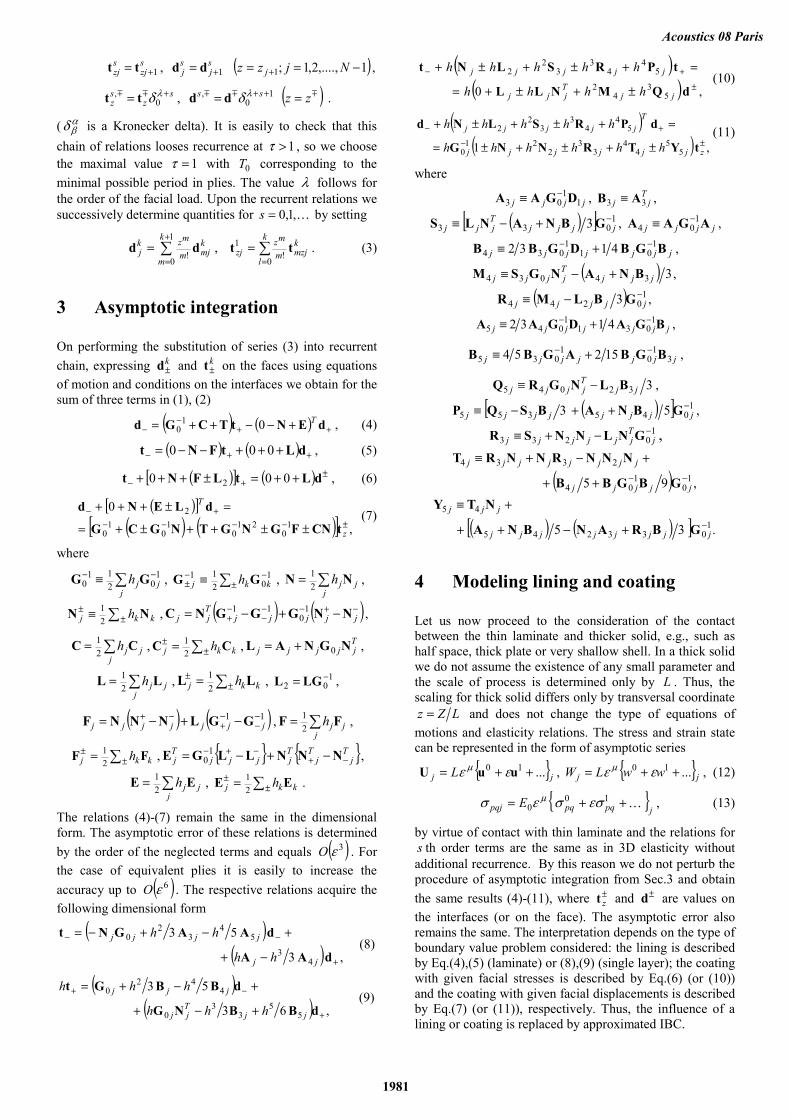
chain of relations looses recurrence at 1>τ , so we choose the maximal value 1=τ with 0T corresponding to the minimal possible period in plies. The value λ follows for the order of the facial load. Upon the recurrent relations we successively determine quantities for K,1,0=s by setting
∑+
==
1
0!
k
m
kmjm
mzkj dd , ∑
==
k
l
kmzjm
mzzj
0!
1 tt . (3)
3 Asymptotic integration
On performing the substitution of series (3) into recurrent chain, expressing k
±d and k±t on the faces using equations
of motion and conditions on the interfaces we obtain for the sum of three terms in (1), (2)
( ) ( ) ++−
− +−−++= dENtTCGd T010 , (4)
( ) ( ) ++− +++−−= dLtFNt 000 , (5)
( )[ ] ( ) ±+− ++=±+++ dLtLFNt 000 2 , (6)
( )[ ]( ) ( )[ ] ,
01
021
01
01
0
2±−−−−
+−
±±++±+=
=±+++
z
T
tCNFGNGTNGCG
dLENd (7)
where
∑ −− ≡j
jjh 102
110 GG , ∑±
−−± ≡ 1
0211
kkj h GG , ∑=j
jjh NN21 ,
∑±± ≡ kkj h NN
21 , ( ) ( )−+−−
−−+ −+−= jjjjj
Tjj NNGGGNC 1
011 ,
∑=j
jjh CC21 , ∑±
± = kkj h CC21 , T
jjjjj NGNAL 0+= ,
∑=j
jjh LL21 , ∑±
± = kkj h LL21 , 1
02−= LGL ,
( ) ( )11 −−
−+
−+ −+−= jjjjjjj GGLNNNF , ∑=j
jjh FF21 ,
∑±± = kkj h FF
21 , { } { }T
jT
jTjjjj
Tj −+
−+− −+−= NNNLLGE 10 ,
∑=j
jjh EE21 , ∑±
± = kkj h EE21 .
The relations (4)-(7) remain the same in the dimensional form. The asymptotic error of these relations is determined by the order of the neglected terms and equals ( )3εO . For the case of equivalent plies it is easily to increase the accuracy up to ( )6εO . The respective relations acquire the following dimensional form
( )( ) , 3
5 3
43
54
32
0
+
−−
−+
+−+−=
dAA
dAAGNt
jj
jjjj
hh
hh (8)
( )( ) , 63
5 3
55
33
0
442
0
+
−+
+−+
+−+=
dBBNG
dBBGt
jjTjj
jjj
hhh
hhh (9)
( )( ) , 0
53
42
54
43
32
2
±
+−
±+±+=
=+±+±+
dQMNLL
tPRSLNt
jjTjjj
jjjjj
hhhh
hhhhh (10)
( )( ) , 1
55
44
33
221
0
54
43
32
2
±−
+−
±+±+±=
=+±+±+
zjjjjjj
Tjjjjj
hhhhhh
hhhhh
tYTRNNG
dPRSLNd (11)
where
jjjj 11
03 DGAA −≡ , Tjj 33 AB ≡ ,
( )[ ] 1033 3 −+−≡ jjjj
Tjjj GBNANLS , jjjj AGAA 1
04−≡ ,
jjjjjjj BGBDGBB 101
1034 41 32 −− +≡ ,
( ) ,3 34034 jjjTjjjj BNANGSM +−≡
( ) ,3 10244−−≡ jjjjj GBLMR
jjjjjjj BGADGAA 1031
1045 4132 −− +≡ ,
jjjjjjj 31
01
035 152 54 BGBAGBB −− +≡ ,
332045 jjTjjjj BLNGRQ −≡ ,
( )[ ] 1045355 5 3 −++−≡ jjjjjjjj GBNABSQP ,
10233−−+≡ j
Tjjjjjj GNLNNSR ,
( ) ,95 10
104
2334
−−++
+−+≡
jjjjj
jjjjjjjj
GBGBB
NNNRNNRT
( ) ( )[ ] . 3 5 1033245
45
−+−++
+≡
jjjjjjjj
jjj
GBRANBNA
NTY
4 Modeling lining and coating
Let us now proceed to the consideration of the contact between the thin laminate and thicker solid, e.g., such as half space, thick plate or very shallow shell. In a thick solid we do not assume the existence of any small parameter and the scale of process is determined only by L . Thus, the scaling for thick solid differs only by transversal coordinate
LZz = and does not change the type of equations of motions and elasticity relations. The stress and strain state can be represented in the form of asymptotic series
{ }jj L ...10 ++= uuU εε μ , { }jj wwLW ...10 ++= εε μ , (12)
{ }jpqpqpqj E 10
0 K++= εσσεσ μ , (13)
by virtue of contact with thin laminate and the relations for s th order terms are the same as in 3D elasticity without additional recurrence. By this reason we do not perturb the procedure of asymptotic integration from Sec.3 and obtain the same results (4)-(11), where ±
zt and ±d are values on the interfaces (or on the face). The asymptotic error also remains the same. The interpretation depends on the type of boundary value problem considered: the lining is described by Eq.(4),(5) (laminate) or (8),(9) (single layer); the coating with given facial stresses is described by Eq.(6) (or (10)) and the coating with given facial displacements is described by Eq.(7) (or (11)), respectively. Thus, the influence of a lining or coating is replaced by approximated IBC.
Acoustics 08 Paris
1981

5 Dissipative materials
The results (4)-(11) are obtained for pure elasticity. Assume now that the energy dissipation is allowed. A simplest case is the Kelvin-Voight model of linear viscoelasticity
{ } qjtj
pqj
pqpj gg εσ ∂′′+′=
( )12,13,23,33,22,11~6,5,4,3,2,1, =qp
where jpqg ′ is a stiffness tensor and j
pqg ′′ is a viscosity
tensor. The viscosity coefficients are supposed to be small and the relaxation time 1<<′′′= j
pqj
pqjpq ggτ , so for the time
harmonic problem tie ω− , ωit −∂ ~ up to frequency
( )12 0 OTjpq
jpq == πτωτ ,
( ) ( )121 0 Ohcigg jpq
jpq
jpg =−′= τπε .
This estimate holds even for the order 0~ cLjpqτ . The
asymptotic consideration is similar to the previous one and it is sufficient to set ( )ωjj GG = and qj
jpqpj g εσ = in (4)-
(11). The deduction logic remains the same for more complicated case of complex modulii
K+++= 2210jjjj GGGG εε .
Thus, in (4)-(11) the nonlinear viscosity is also possible at least for small enough ε . As an example of non traditional material let us consider the lining and coating made of liquid crystalline nematic elastomer [6]. Under wide assumptions such material can be treated as compressible, transversely isotropic with main “director” axis denoted by
3x and having additional degrees of freedom ( )T21,θθ=θ , describing the relative rotation of director n and material point. The rotation angle satisfies the quasistatic equation
( ) ( )[ ] 011 2211 =⋅∂++×∂+× εnθnn tt DD ττ ,
where 21 , DD and 21,ττ are the rotational stiffnesses and relaxation times. For the time harmonic problem
⎥⎦
⎤⎢⎣
⎡−−−=⎥
⎦
⎤⎢⎣
⎡
13
23
1
2
1
2
2
1
11
εε
ωτωτ
θθ
ii
DD .
The stiffness tensor are expressed via elastic constants kc ( )5,,1K=k of transversal isotropy which yields stresses
4920
3234
192
2211 2 ccccgg ++−=′=′ ,
4916
3234
192
12 2 ccccg −+−=′ ,
494
3232
194
2313 2 ccccgg −++−=′=′ ,
498
3238
198
33 2 ccccg +++=′ , 55544 2cgg =′=′ , 466 2cg =′ ,
( )( )3332221111 εεεωτσ pppRpp gggi ′+′+′−= ( )3,2,1=p
( ) 23443 1 γωτσ RRq gi−= , ( )2,1=q , ( ) 126612 1 γωτσ gi R ′−= ,
( ) ( )( )( ) ,11
18 1
22
1
22
54421
5R
RR
iii
DDcgc
ωτωτωτω−−
−−==
with the bulk relaxation time Rτ satisfying inequality
115222 8 τττ RDcD ≤ . The ideal nematic with ( ) 005 ==ωRc
is closer to liquid. As seen the procedure from above is applicable for nematics under ( ) 1,,max 21 <<Rτττω and relations (4)-(11) remain in force.
6 Numerical validation
As the numerical tests it is reasonable to consider the simplest partial waves for which the exact solution is easily to obtain for comparison. The typical results for waves falling from the top isotropic half space “+” and propagating through the two layered lining ( )21 HH = into bottom half space “-“ are presented in Figs.1,4,7. The relative error e is introduced as follows
[ ]∑−+
−=SP
exas MMe,;,
22 1 41 ,
where exM runs the exact complex magnitudes and asM runs the approximates values of the wave magnitudes in half-spaces obtained by using IBC. For the top coated half-space (see Figs.2,3,5,6,8,9) the error is chosen as
[ ]∑−+
−=SP
exas MMe,;,
22 1 21 ,
for magnitudes of the reflected waves. The materials are: Al (aluminium), Po (polystyrene), Eg (orthotropic E-glass). The curve number corresponds to the asymptotic order of the truncation in IBC (4)-(7).
Fig.1 Error for S-wave falling at the angle 70o to the interface of Al-Eg0o/90o-Po against 2211 LHLHR += .
Fig.2 Error for S-wave falling at 70o to the interface of Al-Eg0o/90o (stress free coating face).
Acoustics 08 Paris
1982

As seen the error is maximal for the free face, minimal for the clamed face and the interval of 1% model error is about 10-2. This value is similar to the validity interval of the classical theory of plates. The accuracy is much better when the lining (or coating) becomes a single layer, for which the results are shown in Figs.4-6. As one can see the third order model has a validity interval 0.1 and the high order model is valid till 0.25, which reminds us the analogue with the high order classical plate theories. The improvement by third order is explained by the appearance of the wave operator in (4)-(11), since the less order models are quasistatic.
Fig.3 Error for S-wave falling at 70o to the interface of Al-Eg0o/90o (clamped coating face).
Fig.4 Error for S-wave falling at 80o to the interface of Al-Eg0o-Po ( L is a min shear wavelength in E-glass).
Fig.5 Error for S-wave falling at 80o to the interface of Al-Eg0o (stress free coating face).
The tests for a single layer nematic coating and lining are shown in Figs.7-9. The parameters of non-ideal nematic are
( ) QArrD 002
01 1 μμ +−= , ( ) rrD 202 1−= μ ( 01.00 =A
is a deviation coefficient) with the anisotropy parameter of molecular chain 3≈r and 3.015.0 TQ = under
temperature C37o=T ; 310=ρ [kg/m3], 01.01 =τ , 5
2 105 −×=τ , 610−=Rτ [sec], ( ) rrc 81 205 += μ , 9
3 10=c , 5
0421 1022 ==== μccc [N/m2].
Fig.6 Error for S-wave falling at 80o to the interface of Al-Eg0o (clamped coating face).
Fig.7 Error for S-wave falling at the angle 70o to the interface of Al-Ne0o-Po.
Fig.8 Error for S-wave falling at the angle 70o to the interface of Al-Ne0o (stress free coating face).
Fig.9 Error for S-wave falling at the angle 70o to the interface of Al-Ne0o (clamped coating face).
Acoustics 08 Paris
1983

The director orientation is chosen along z -axis but the error remains stable for other orientations. As one can see the validity interval is approximately the same as previously. Since the surface and guided waves are composed of partial waves the expected accuracy should be of the same order. Note, that from the viewpoint of the thicker solid our model can be not low frequency. In Figs.10,11 the fundamental bending mode (B0) and first mode (B1) are presented for a three layered plate made of two aluminium layers and a lining of one layer of epoxy which is ten times thinner than each Al-ply. The curves are evaluated directly and using IBC (8),(9); the latter are marked by numbers as previously and Sc is the speed of shear wave in aluminium.
Fig.10 Fundamental bending mode.
Fig.11 First bending mode.
As shown the agreement is achieved not only for small frequency but for more than twice the total cut-off frequency. Of course, the most general situation depends on the limit behaviour of dispersion curves and on the energy flow between the layer and substrate (see, e.g., [9]).
7 Conclusion
The asymptotic high order theory of relatively thin lining and coating is suggested. The main result consists in replacing the lining (coating) by IBC which reduces the dimension of the respective boundary value problem. The physical reason of this fact is the absence of the fundamental mode in the spectrum of laminate under tight conditions on its faces. The obtained model is generally low frequency but possibly not long wave. It is applicable to the wide class of advanced composed materials, including those with energy dissipation and with non classical
behaviour. As shown, the nematic liquid crystalline elatomers can be approximated in such a way. Besides the consideration of the full interface contact one can similarly deduce the respective IBC for a slipping interface, frictional contact, etc.
References
[1] A.L. Knopoff, “A matrix method for elastic wave problem”, Bull. of Seism. Soc. of America 54, 431-438 (1964).
[2] S.L. Rokhlin, Y.J. Wang, “Ultrasonic wave interaction with a thin anisotropic layer between two anisotropic solids: exact and asymptotic – boundary – condition method”, J. Acoust. Soc. Am. 92, 1729-1742 (1992).
[3] S.L. Rokhlin, W. Huang, “Ultrasonic wave interaction with a thin anisotropic layer between two anisotropic solids. II Second order asymptotic boundary conditions”, J. Acoust. Soc. Am. 94, 3405-3420 (1993).
[4] L. Wang, S.L. Rokhlin, “Modeling of wave propagation in layered piezoelectric media by a recursive asymptotic method”, IEEE Trans. Ultrason. Ferroelectrics Frequency Control, 51(9), 1060-1071 (2004).
[5] L. Wang, S.L. Rokhlin, “Recursive geometric integrators for wave propagation in a functionally-graded multilayered elastic medium”, J. Mech. Phys. Solids 52(11), 2473-2506 (2004).
[6] L.J. Fradkin, I.V. Kamotski, E.M. Terentjev, D.D. Zakharov, “Low frequency acoustic waves in nematic elastomers”, Proc. Roy. Soc. Lon. A. 459, 2627-2642 (2003).
[7] D.D. Zakharov, “High-order approximate low frequency theory of elastic anisotropic lining and coating”, J. Acoust. Soc. Am. 119, 1961-1970 (2006).
[8] G. Johansson, A.J. Niklasson, “Approximate dynamic boundary conditions for a thin piezoelectric layer”, Int. J. Solids Struct. 40, 3477-3492 (2003).
[9] A.L. Shuvalov, A.G. Every, “Some properties of surface acoustic waves in anisotropic-coated solids, studied by the impedance method”, Wave Motion 36, 257-273 (2002).
Acoustics 08 Paris
1984