Development and Application of SAW Filter - MDPI
15
Citation: Chen, P.; Li, G.; Zhu, Z. Development and Application of SAW Filter. Micromachines 2022, 13, 656. https://doi.org/10.3390/ mi13050656 Academic Editors: Ridong Wang and Zhihua Pu Received: 10 March 2022 Accepted: 27 March 2022 Published: 20 April 2022 Publisher’s Note: MDPI stays neutral with regard to jurisdictional claims in published maps and institutional affil- iations. Copyright: © 2022 by the authors. Licensee MDPI, Basel, Switzerland. This article is an open access article distributed under the terms and conditions of the Creative Commons Attribution (CC BY) license (https:// creativecommons.org/licenses/by/ 4.0/). micromachines Review Development and Application of SAW Filter Pu Chen 1,2 , Guangxi Li 1, * and Zhiyuan Zhu 2, * 1 Henan Province Engineering Research Center of Ultrasonic Technology Application, Pingdingshan University, Pingdingshan 467000, China; [email protected] 2 College of Electronic and Information Engineering, Southwest University, Chongqing 400715, China * Correspondence: [email protected] (G.L.); [email protected] (Z.Z.) Abstract: With the in-depth advancement of the fifth generation (5G) mobile communication technol- ogy, the technical requirements for filters are also constantly improving. Surface acoustic wave (SAW) filters are widely used in home TV, mobile communications, radio frequency filters and radar due to their simple structure, few mask layers, easy miniaturization, and low cost. Through the continuous improvement of communication technology, SAW has developed into various high-performance acoustic filters from bulk SAW with the support of some new architectures, new materials and advanced modeling techniques. This paper analyzes and reviews the research situation of SAW filter technology. Keywords: component; SAW; filter; RF; 5G 1. Introduction The rapid development of wireless communication applications has put forward urgent requirements for broad band and high-speed data transmission. From a technical and economic point of view, mobile communication is a key element in realizing a platform in the form of social innovation services and user applications. The overall demand for mobile broad band data services is growing, mobile traffic has been experimenting with exponential growth every year, and will continue to rise in the future driven by ubiquitous demand. In the field of mobile communication, the fifth generation (5G) technology is a new technology after 4G. Compared with 3G and 4G, the transmission rate and data carrying capacity of 5G network have been greatly improved, the utilization rate of spectrum resources is high, and the communication protocol is complex. To meet the bandwidth needs, more new frequency bands have been released for mobile communications, and today, more than 30 frequency bands are used, and this number is increasing, or has been liberated from other applications such as analog TV, and dedicated to this A new purpose. In addition, more efficient transmission standards such as LTE (Long Term Evolution) and LTE-A (Long Term Evolution-Advanced) have been adopted [1]. Acoustic filtering is attractive because typical acoustic wavelengths are about five orders of magnitude smaller than electromagnetic wavelengths at the same frequency, making submillimeter-sized resonators or even complete filters suitable for mobile applications possible. The exact width of the strips that make up the IDT and the exact metal thickness of the IDT both affect the performance and frequency stability of the filter as well as the bandwidth, which is required for high lateral precision. Availability of a portfolio of filters and duplexers to easily create highly integrated modules combining filter solutions for a wide variety of frequency bands and regions, minimum size requirements, and customer preferences. For nearly 40 years, surface acoustic wave devices have been key components of wireless data transmission systems. It was first widely used in intermediate frequency (IF) filters of television receivers. Because the frequency bands are so close together, the filter’s passband skirt must be very steep to ensure sufficient stopband attenuation in adjacent frequency bands. Micro-acoustics works by exploiting a variety of different propagation Micromachines 2022, 13, 656. https://doi.org/10.3390/mi13050656 https://www.mdpi.com/journal/micromachines
-
Upload
khangminh22 -
Category
Documents
-
view
2 -
download
0
Transcript of Development and Application of SAW Filter - MDPI
�����������������
Citation: Chen, P.; Li, G.; Zhu, Z.
Development and Application of
SAW Filter. Micromachines 2022, 13,
656. https://doi.org/10.3390/
mi13050656
Academic Editors: Ridong Wang
and Zhihua Pu
Received: 10 March 2022
Accepted: 27 March 2022
Published: 20 April 2022
Publisher’s Note: MDPI stays neutral
with regard to jurisdictional claims in
published maps and institutional affil-
iations.
Copyright: © 2022 by the authors.
Licensee MDPI, Basel, Switzerland.
This article is an open access article
distributed under the terms and
conditions of the Creative Commons
Attribution (CC BY) license (https://
creativecommons.org/licenses/by/
4.0/).
micromachines
Review
Development and Application of SAW FilterPu Chen 1,2, Guangxi Li 1,* and Zhiyuan Zhu 2,*
1 Henan Province Engineering Research Center of Ultrasonic Technology Application,Pingdingshan University, Pingdingshan 467000, China; [email protected]
2 College of Electronic and Information Engineering, Southwest University, Chongqing 400715, China* Correspondence: [email protected] (G.L.); [email protected] (Z.Z.)
Abstract: With the in-depth advancement of the fifth generation (5G) mobile communication technol-ogy, the technical requirements for filters are also constantly improving. Surface acoustic wave (SAW)filters are widely used in home TV, mobile communications, radio frequency filters and radar due totheir simple structure, few mask layers, easy miniaturization, and low cost. Through the continuousimprovement of communication technology, SAW has developed into various high-performanceacoustic filters from bulk SAW with the support of some new architectures, new materials andadvanced modeling techniques. This paper analyzes and reviews the research situation of SAWfilter technology.
Keywords: component; SAW; filter; RF; 5G
1. Introduction
The rapid development of wireless communication applications has put forwardurgent requirements for broad band and high-speed data transmission. From a technicaland economic point of view, mobile communication is a key element in realizing a platformin the form of social innovation services and user applications. The overall demand formobile broad band data services is growing, mobile traffic has been experimenting withexponential growth every year, and will continue to rise in the future driven by ubiquitousdemand. In the field of mobile communication, the fifth generation (5G) technology is a newtechnology after 4G. Compared with 3G and 4G, the transmission rate and data carryingcapacity of 5G network have been greatly improved, the utilization rate of spectrumresources is high, and the communication protocol is complex. To meet the bandwidthneeds, more new frequency bands have been released for mobile communications, andtoday, more than 30 frequency bands are used, and this number is increasing, or has beenliberated from other applications such as analog TV, and dedicated to this A new purpose.In addition, more efficient transmission standards such as LTE (Long Term Evolution)and LTE-A (Long Term Evolution-Advanced) have been adopted [1]. Acoustic filtering isattractive because typical acoustic wavelengths are about five orders of magnitude smallerthan electromagnetic wavelengths at the same frequency, making submillimeter-sizedresonators or even complete filters suitable for mobile applications possible. The exactwidth of the strips that make up the IDT and the exact metal thickness of the IDT bothaffect the performance and frequency stability of the filter as well as the bandwidth, whichis required for high lateral precision. Availability of a portfolio of filters and duplexers toeasily create highly integrated modules combining filter solutions for a wide variety offrequency bands and regions, minimum size requirements, and customer preferences.
For nearly 40 years, surface acoustic wave devices have been key components ofwireless data transmission systems. It was first widely used in intermediate frequency (IF)filters of television receivers. Because the frequency bands are so close together, the filter’spassband skirt must be very steep to ensure sufficient stopband attenuation in adjacentfrequency bands. Micro-acoustics works by exploiting a variety of different propagation
Micromachines 2022, 13, 656. https://doi.org/10.3390/mi13050656 https://www.mdpi.com/journal/micromachines
Micromachines 2022, 13, 656 2 of 15
velocities: the technology is highly relevant in the radio frequency (RF) field, ranging fromtens of megahertz to several gigahertz. In this case, at the system TEM level, duplexersand multiplexers are key elements. The number of service and roaming frequency bandsaround the world continues to grow, and RF filters have been rapidly developed to bettermeet the growing demand [2]. On the other hand, the minimization of filter footprint is alsoa very important task in filter design while improving simultaneous filtering performance.This puts more emphasis on the latest developments in size and advanced LTE carriers,carrier aggregation (which allows data transmission to perform tasks on multiple frequencybands simultaneously) [3].The emergence of LTE-Carrier Aggregation (CA) as a meansof increasing data rates in mobile device communications has resulted in a paradigmshift in acoustic filter design due to the eager acceptance of users, the need to stream HDvideo at high data rates and other innovations. The q-factors of lumped-unit lc filtersand transmission line filter designs are often not high enough to replace acoustic filters,but they are still used with acoustic filters. For example, most antenna-side multiplexers,which separate low, mid, and high frequency bands, are partially or fully based on LC filterdesigns. Low loss, high isolation, high linearity multiplexing capability will continue tobe a differentiating factor in this market. To be successful, it is absolutely essential thatfiltering technology allows and supports these needs [4]. The market for discrete filtercomponents is getting smaller as the RF front-end of mobile phones becomes more complex,which includes more and more RF filters/duplexers to allow mobile phones to operatein different frequency bands. Integrating RF filters/duplexers in RF front-end modulesis standard in today’s smartphones. RFSAW filters use two different filtering techniques.One is the so-called DMS filter technique, which is a tandem structure of input and outputtransducers with the addition of a reflective grating on the outside of the acoustic structure.The second filtering technique is the trapezoidal filtering technique [5].
In the future, the required steep passband skirts can only be achieved by interconnect-ing filters composed of high-q single-port resonators, but the fabrication tolerances andtemperature sensitivity of the devices will have to be reduced. So further challenges are toreduce filter passband ripple, reduce passband attenuation, reduce non-linearity [6] (whichis necessary because CA brings many hybrid products into the usable band), whatever thenew filter looks like, must help to increase the effective data rate and functional density ofdigital communication systems. This paper analyzes and reviews the research situation ofSAW filter technology.
2. SAW
Research on SAW dates back to 1885, when Lord Rayleigh predicted its mode oftransmission and propertiest [7,8]. In 1965, R.M. White and F.W. volmer invented theInterdigital Transducer (IDT) [9]. The SAW on the piezoelectric single crystal substrate canbe well excited by IDT, and surface acoustic wave (SAW) filtering technology has graduallyattracted people’s attention since then. The basic IDT consists of a three-port structureconsisting of two acoustic ports and one electrical port, usually the transducer metal ischosen for chemical inertness or acoustic matching with piezoelectric materials [10]. Theworking mechanism of SAW is that when alternating current is applied to the input IDT,a periodic electric field will be generated [11]. When the period of the IDT is close tothe wavelength of the SAW, it will resonate and generate a SAW of a certain frequency.Subsequently, the SAW propagates along the piezoelectric substrate, passing through Delayto reach another IDT output terminal, and convert the sound wave signal into an electricalsignal output through the piezoelectric effect [12]. The orientation of the crystal, thethickness of the piezoelectric material and the geometry of the metal transducer determinethe type of sound waves produced [12]. Different types of sound waves are used to achievedifferent filtering effects required.
The current success of SAW filters is attributed to their small size, low insertion loss(IL), and superior out-of-band rejection [13]. However, with the rapid increase in thecomplexity of the communication network, the number of RF circuits in the RF front-end
Micromachines 2022, 13, 656 3 of 15
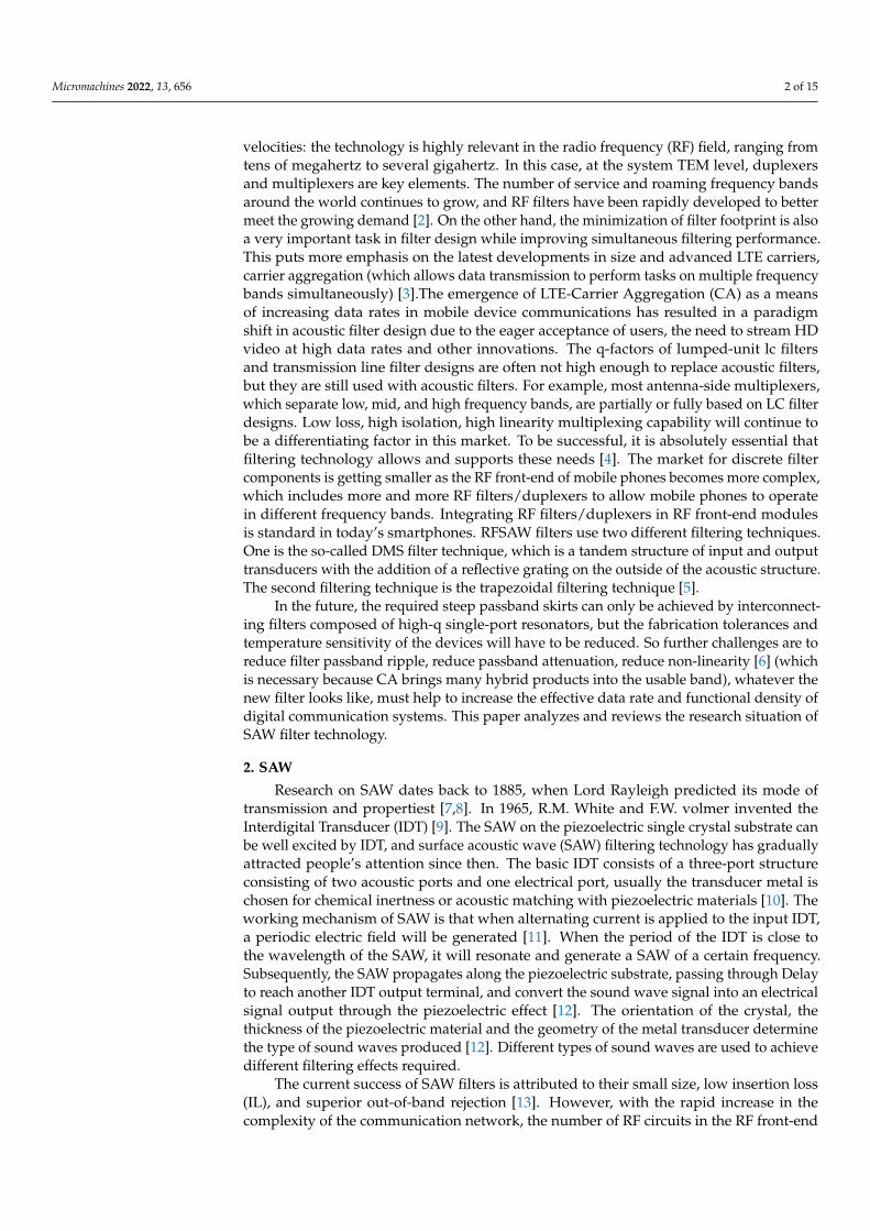
of the mobile phone also increases at the same time. Current BAW (Bulk Acoustic Wave)devices, such as thin film bulk acoustic resonators (FBARs) are also widely used in RF front-ends because of their higher power supply durability and lower losses, however multimodeRF BAW filters are difficult to mass-produce because Tricky mechanisms require couplingtuning, which is an extremely difficult process. SAWs are widely used as receive filters andas the receiving part of duplexers, allowing us to arrange multiple resonant locations byappropriate, known as dual-mode SAW (DMS) filters, by combining multiple single-moderesonators, and setting Appropriate resonant frequency and setting of clamping capacitorshave the possibility of realizing multimode filters [14]. But at the same time, with theaddition of carrier aggregation technology, SAW duplexer and other technologies, therequirements for the linearity specifications of the device are becoming more and morestrict, and the nonlinearity and severe distortion of the SAW device will reduce the signalquality at the front end of the radio frequency. Min, etc., have seriously hindered itsdevelopment, so it is necessary to continuously solve the factors that make the filter non-linear, such as the influence of temperature and power on it. After solving these problems,SAW will go further in the communication RF front end [15].The application and frequencyband allocation of RF filtering technology in the current market are shown in Figure 1.
Micromachines 2022, 13, x FOR PEER REVIEW 3 of 16
the mobile phone also increases at the same time. Current BAW (Bulk Acoustic Wave)
devices, such as thin film bulk acoustic resonators (FBARs) are also widely used in RF
front‐ends because of their higher power supply durability and lower losses, however
multimode RF BAW filters are difficult to mass‐produce because Tricky mechanisms re‐
quire coupling tuning, which is an extremely difficult process. SAWs are widely used as
receive filters and as the receiving part of duplexers, allowing us to arrange multiple res‐
onant locations by appropriate, known as dual‐mode SAW (DMS) filters, by combining
multiple single‐mode resonators, and setting Appropriate resonant frequency and setting
of clamping capacitors have the possibility of realizing multimode filters [14]. But at the
same time, with the addition of carrier aggregation technology, SAW duplexer and other
technologies, the requirements for the linearity specifications of the device are becoming
more and more strict, and the nonlinearity and severe distortion of the SAW device will
reduce the signal quality at the front end of the radio frequency. Min, etc., have seriously
hindered its development, so it is necessary to continuously solve the factors that make
the filter non‐linear, such as the influence of temperature and power on it. After solving
these problems, SAW will go further in the communication RF front end [15].The applica‐
tion and frequency band allocation of RF filtering technology in the current market are
shown in Figure 1.
Figure 1. Market Application and Frequency Band Allocation of RF Filtering Technology [2].
3. SAW Filter Technology
3.1. Bulk SAW
Bulk SAW devices have been around for more than 30 years, are low cost and are
easy to manufacture. However, bulk SAW devices have poor power handling and tem‐
perature coefficient of frequency (TCF) and relatively poor Q.
TV‐IF (television intermediate frequency) SAW filters began mass production in the
mid‐70 s [16] Surface acoustic wave resonators change the relative size and elastic prop‐
erties of the substrate due to external mechanical vibrations, which changes the acoustic
wave propagation speed of the device [17]. In 1992, Morita et al. proposed a low‐loss filter
in the literature, which can achieve wide bandwidth in different LiTaO3 tangential directions.
This filter technology is realized by using two different longitudinal acoustic modes in a cou‐
pled filter structure, which is composed of Consists of an inline structure and an IDT backed
by two reflectors. DMS filter has very special function, it can realize balun function and im‐
pedance transformation [18]. The typical frequency response of a DMS filter is shoulder be‐
havior in the higher stopband and excellent far‐end out‐of‐band rejection [19]. At the 1998
Figure 1. Market Application and Frequency Band Allocation of RF Filtering Technology [2].
3. SAW Filter Technology3.1. Bulk SAW
Bulk SAW devices have been around for more than 30 years, are low cost and are easyto manufacture. However, bulk SAW devices have poor power handling and temperaturecoefficient of frequency (TCF) and relatively poor Q.
TV-IF (television intermediate frequency) SAW filters began mass production in themid-70 s [16] Surface acoustic wave resonators change the relative size and elastic propertiesof the substrate due to external mechanical vibrations, which changes the acoustic wavepropagation speed of the device [17]. In 1992, Morita et al. proposed a low-loss filter inthe literature, which can achieve wide bandwidth in different LiTaO3 tangential directions.This filter technology is realized by using two different longitudinal acoustic modes in acoupled filter structure, which is composed of Consists of an inline structure and an IDTbacked by two reflectors. DMS filter has very special function, it can realize balun functionand impedance transformation [18]. The typical frequency response of a DMS filter isshoulder behavior in the higher stopband and excellent far-end out-of-band rejection [19].At the 1998 IEEE International Symposium on Frequency Control, Kinsmann presentedan overview of crystal filters, including trapezoidal and lattice structures, in his invitedpaper [20].
Micromachines 2022, 13, 656 4 of 15
One of the low-cost bandpass filter architectures is a ladder topology, which consists ofmultiple replicas of SAW resonators of series and parallel type. The filter set based on thisstructure is limited due to layout and materials used, so that the acoustic resonator cannothave any electromechanical coupling coefficient. Most SAW-based achievable bandwidth(BW) RF filters are limited by electromechanical coupling by the coefficient k2t of thepiezoelectric substrate. For example, based on conventional acoustic wave resonator filterdesign techniques (lattice and ladder-type SAW filter design), the achievable 3 dB fractionalbandwidth (FBW) is only 0.4 and 0.8 times that of the SAW resonator k2t. In 2020, TingCai, put a lot of effort into increasing the bandwidth of filters based on SAW resonators, toachieve bandwidth that is not constrained by the electromechanical coupling coefficientsthey employ. A novel dual narrowband BPF design is based on a hybrid resonator oftransmission line TFS and high-Q SAW, the achievable bandwidth of the filter is notconstrained by the electromechanical coupling coefficients it adopts, the SAW resonatorand its transmission characteristics, the filter can be flexible control [21]. In the same year,Runqi Zhang, proposed a hybrid low-cost bandpass filter. This new filter topology is basedon a two-path coupling scheme. Unlike traditional SAW-based low-cost bandpass filters,it adopts a single SAW The resonator BVD model can effectively reduce the cost of thedesign, optimization and manufacturing process; and the design has been constructed andtested with two BPF prototypes centered at 418 MHZ. The measured results are close to thepredicted results [22].
Currently in SAW resonators and filters in RF front-end modules for mobile communi-cations, LiNbO3 and LiTaO3 are still the most widely used materials [23]. However, theoperating frequencies of most SAW devices based on these traditional piezoelectric materi-als are below 3 GHZ, and in many applications, SAWs, if limited in the GHZ frequencyrange, will result in an inability to meet the growing demand for high operating frequenciesfrom advanced mobile communications. system frequency. The speed of sound in thesubstrates is usually fixed, setting the gap width between the substrates is very complicated,unlike the case of conventional SAW filters (with 0.5 metallization ratio), the excitationof surface acoustic waves in the GHZ range on GaAs, its SAW retardation The operatingfrequency of the wire does not decrease the fabrication pitch size, but increases by adoptingthe IDT geometry, which has never been adopted on GaAs, 2017, Silvia Rizzato, MarcoScigliuzzo, by acting on the IDT between the finger width and the pitch Metallizationratios, without the use of expensive sbmicron/nanofabrication techniques, demonstrate theexcitation of surface acoustic waves in the GHZ range on GaAs and facilitate the generationof higher harmonic modes [24]. In 2018, Qi Li, Su-Lei Fu, found that when using Ni as thesubstrate, the thickness of Ni will directly affect the Al interdigital transducer, and foundthat when the thickness is 6 nm, the Al(111) texture of the Ni substrate is The structureis the strongest, the surface is the flattest, and the electromigration test lifetime is nearly10 times longer than that of the Al(111) texture without Ni substrate. The power durabilityof the 1.5 GHZ SAW filter with Al thin film added on 6 nm Ni substrate is also improvedby 29.0~32.5 dB compared with the 1.5 GHZ SAW filter without Ni substrate added [13].
3.2. TC-SAW
When the ambient temperature changes, acoustic devices typically experience a fre-quency shift that increases approximately linearly with temperature. It can be characterizedby the temperature coefficient of frequency (TCF) [25], which is usually in the range of−30 to −45 ppm/K for LiTaO3 [26], although today’s SAW filter technology is very mature,but in RF Driven by front-end market demand, it has continued to develop in recent years.Temperature stability is characterized by the temperature coefficient of frequency (TCF),which varies as a fraction of the temperature T at a particular frequency [27].
TCF =1f
∂f∂T
= TCV − CTE, (1)
Micromachines 2022, 13, 656 5 of 15
TCV =1V
∂V∂T
(2)
With the increasing communication requirements, the standard surface acoustic wave(SAW) filter has a high temperature drift frequency, which produces nonlinear frequencychanges to temperature changes, which seriously affects the filter performance and cannotmeet certain strict requirements [28]. specifications, so BAW filters including thin-film bulkacoustic resonators and solid-mounted resonator filters have been developed to meet thisrequirement. However, BAW filters are generally more expensive and larger than SAWfilters [29]. TC-SAW (Temperature compensated SAW) is widely used in mobile phoneRF front-end modules today due to its low TCF, low insertion loss, high rejection level,and high roll rate. The current TC-SAW has two commonly used structures [1]: One is anattached silicon dioxide (SiO2) structure on lithium niobate deposited on the inter-digitalsensor (IDT) on a substrate [30]. Commonly used materials such as LN and LT becomesoft under the action of T, and the TCF is negative. Since SiO2 has no obvious temperaturechange, the TCF is positive. In this way, the absolute value of the overall (TCF) is reduced.However, since the amorphous SiO2 is non-piezoelectric [31], the infiltration will also leadto a decrease in the electromechanical coupling coefficient of the propagating SAW, and thedeposition of SiO2 will also affect the reflection characteristics of the surface acoustic wave.The other is a lithium tantalate (LT) structure on sapphire/Si/other materials [32], Sapphireitself has good temperature compensation and a large Young’s modulus. It is very difficultto manufacture and requires careful control of electrode thickness and oxide film thickness.
The current temperature compensation technology is generally divided into two types 1.Silica wrap (SiO2 capping layer is deposited on a high voltage substrate. IDT(s) is placed onthe boundary between the two) [33–37] 2. Wafer bonding technology (A thin piezoelectricplate is bonded to another thick substrate) [27,38]. Japan’s Murata and Panasonic companiesuse these two technologies. Murata uses SiO2 with flat top surface, Panasonic uses SiO2 andconvex top surface, and Taiyo Yuden uses room temperature wafer bonding technology toprovide frequency temperature compensation for SAW devices, so that the absolute valueof TCF of the device decreases [27].
3.2.1. SiO2 Overlay
In 2005, Michio KADOTA, by combining a flat silicon dioxide film and a relativelythick LiTaO3 substrate [39], first developed large reflection coefficient, optimal electrome-chanical coupling coefficient and good mechanical resonance Q value suitable for US-PCSduplex [40–42]. In 2007, Michio et al. used Love wave to combine flat SiO2 film, high-density metal (Cu) electrode and YX-LiNbO3 substrate to fabricate a small surface acousticwave duplexer, and obtained good resonance Q value, TCF and The best electromechanicalcoupling coefficient [43]. Hiroyuki, in 2008, fabricated a miniature SAW duplexer usinga SiO2 capping layer/thick Al electrode/rotating y-cut LiNbO3 substrate structure [44].In 2011, S. Matsuda, M. Hara observed that fluorine-doped silicon oxide (SiOF) has a goodtemperature elasticity coefficient by using Fourier transform infrared spectroscopy [45],and applied it in radio frequency SAW to compensate its temperature coefficient. With theincrease of fluorine content r in silicon (SiOF), the negative TCF of LiNbO3 will increase,so that its absolute value decreases, and the quality factor does not change significantly.From the Fourier transform infrared spectrum, fluorine-doped silicon oxide (SiOF) hasbetter temperature compensation ability than SiO2. In 2015, Yiliu Wang et al. adopted apiston-type modal sensor, which reduced the TCF by increasing the silicon oxide thickness,and designed a frequency band 13 duplexer, which was the first in the market to meet theNS07 suppression specification. 13 Band SAW Duplexer [46].
Nowadays, finite element analysis (FEM) can be used to simulate surface acousticwaves, but due to the limitation of calculation time and storage space, as well as thelimitation of a large number of degrees of freedom. The finite element method is notsuitable for 3D models to simulate actual SAW devices [25]. Julius Koskela proposeda two-dimensional algorithm hierarchical cascading technique (HCT) [47]. Through the
Micromachines 2022, 13, 656 6 of 15
periodic structure of the surface acoustic device, the device is divided into small areas,which can greatly reduce the calculation time and ensure the accuracy. On this basis, MarcSolal used HTC to simulate the full 3D surface wave resonator [48]. It is proved that thismethod can not only solve two-dimensional problems, but also allows to solve the wholethree-dimensional problems, and the calculation time is also within a reasonable range. Itcan be applied to leaky surface acoustic wave resonators and temperature compensatedsurface acoustic wave resonators on lithium tantalate. Through further developmentin 2019, Xinyi Li et al. applied graphics processing unit (GPGPU) to HCT, which cansignificantly accelerate HCT, especially in large-scale scenes. In 2020, Naoto Matsuoka,studied the excessive scattering loss of SiO2/128-LN TC-SAW resonator on HCT finiteelement method. The simulation results show that the figure of merit decreases significantlywith the increase of the number of acoustic scattering mechanisms, but the estimated valueQ is still much higher than the actual value, indicating that acoustic scattering at structuraldiscontinuities is not the main loss mechanism [49].
3.2.2. Wafer Bonding
A thin piezoelectric plate is combined with another thick base substrate. If the thick-ness of the plate is greater than several SAW wavelengths, the plate through which theSAW propagates is equivalent to a semi-infinite plate. Bonding suppresses top surfacethermal expansion for SAW propagation when the substrate is a rigid material and the CTEis small [27].
A “new” substrate for temperature compensated SAW ladder filters was published in2003 by Kadota et al. [42]. In 2004, M. Miura used the combination of sapphire and lithiumtantalate substrates in [23], which greatly suppressed the thermal expansion of LiTaO3.Due to the large thermal conductivity and small dielectric constant of sapphire, Miura et al.proposed the use of lithium tantalate (LiTaO3)/sapphire bonded substrate technology ina personal communication service (PCS) band 2 duplexer, suitable for 1.9 GHZ US-PCSband with sufficient power endurance and good temperature coefficient of frequency(TCF). In [50] in 2004, O. Kawachi, N. Taniguchi et al. used the same technique to de-velop an 8-band (900 MHZ) duplexer. Good insertion loss without spurious response, andgood temperature coefficient over frequency are obtained. Recently, 2nd generation (2G)Global System for Mobile communications (GSM), Code Division Multiple Access (CDMA),3rd generation (3G) W-CDMA (Wideband CDMA), 4th generation (4G) Long Term Evolu-tion (Mobile communication systems such as LTE) show a trend of diversification [51]. In2010, H, Kobayashi, K. Tohyama found that a hybrid substrate composed of a thin layer ofLiTaO3 combined with a low thermal expansion coefficient support material could replacethe traditional LiTaO3 bulk substrate to improve the temperature coefficient of frequency(TCF) of surface acoustic wave devices. Using a thinner LiTaO3 layer reduces the TCFsignificantly [25], but on the other hand, also results in a larger spurious response in thefilter characteristics. The bottom of the LiTaO3 layer is rough enough that this problem canbe effectively alleviated. Correct choice of support material can further suppress spuriousresponses. Bonding to LiTaO3 (LT) and LiNbO3 (LN) wafers using spinel by bonding anddirect bonding techniques has also been studied [52]. 2021 R. Ruby designs a novel lithiumlithium tantalate (LT) bonded to a silicon hybrid substrate (SiSAW) [29].
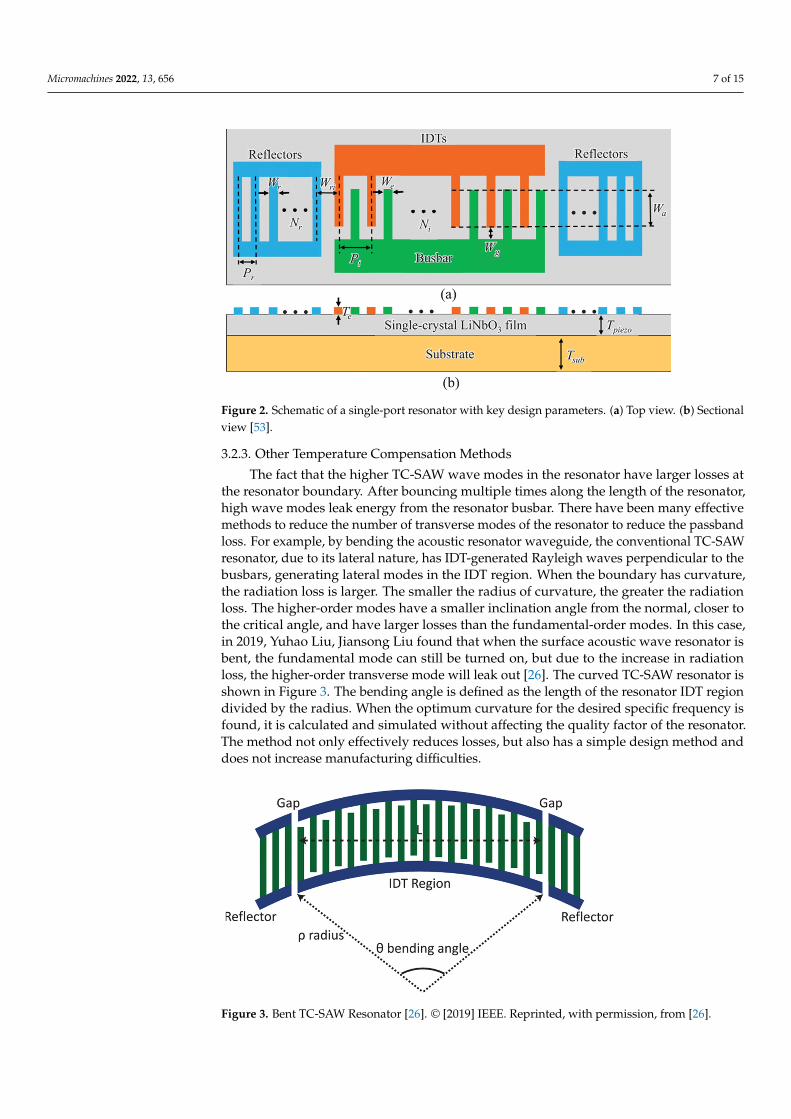
In 2020, Shibin Zhang prepared single-crystal X-cut LiNbO3 thin films on 4H-SiCsubstrates by ion cutting and wafer bonding processes [53]. The schematic diagram ofthe single-port resonator is shown in Figure 2 with a high electromechanical couplingcoefficient of 26.9% and a high Q value of 1226, with a center frequency of 2.29 G, theinsertion loss is 1.38 DB, and it has a low temperature coefficient. Although the powerhandling is limited by arc discharge and IDT, it still shows that the acoustic device platformon LiNbO3 on SiC has great potential in RF applications.
Micromachines 2022, 13, 656 7 of 15
Micromachines 2022, 13, x FOR PEER REVIEW 7 of 16
limited by arc discharge and IDT, it still shows that the acoustic device platform on
LiNbO3 on SiC has great potential in RF applications.
Figure 2. Schematic of a single‐port resonator with key design parameters. (a) Top view. (b) Sec‐
tional view [53].
3.2.3. Other Temperature Compensation Methods
The fact that the higher TC‐SAW wave modes in the resonator have larger losses at
the resonator boundary. After bouncing multiple times along the length of the resonator,
high wave modes leak energy from the resonator busbar. There have been many effective
methods to reduce the number of transverse modes of the resonator to reduce the pass‐
band loss. For example, by bending the acoustic resonator waveguide, the conventional
TC‐SAW resonator, due to its lateral nature, has IDT‐generated Rayleigh waves perpen‐
dicular to the busbars, generating lateral modes in the IDT region. When the boundary
has curvature, the radiation loss is larger. The smaller the radius of curvature, the greater
the radiation loss. The higher‐order modes have a smaller inclination angle from the nor‐
mal, closer to the critical angle, and have larger losses than the fundamental‐order modes.
In this case, in 2019, Yuhao Liu, Jiansong Liu found that when the surface acoustic wave
resonator is bent, the fundamental mode can still be turned on, but due to the increase in
radiation loss, the higher‐order transverse mode will leak out [26]. The curved TC‐SAW
resonator is shown in Figure 3. The bending angle is defined as the length of the resonator
IDT region divided by the radius. When the optimum curvature for the desired specific
frequency is found, it is calculated and simulated without affecting the quality factor of
the resonator. The method not only effectively reduces losses, but also has a simple design
method and does not increase manufacturing difficulties.
Figure 2. Schematic of a single-port resonator with key design parameters. (a) Top view. (b) Sectionalview [53].
3.2.3. Other Temperature Compensation Methods
The fact that the higher TC-SAW wave modes in the resonator have larger losses atthe resonator boundary. After bouncing multiple times along the length of the resonator,high wave modes leak energy from the resonator busbar. There have been many effectivemethods to reduce the number of transverse modes of the resonator to reduce the passbandloss. For example, by bending the acoustic resonator waveguide, the conventional TC-SAWresonator, due to its lateral nature, has IDT-generated Rayleigh waves perpendicular to thebusbars, generating lateral modes in the IDT region. When the boundary has curvature,the radiation loss is larger. The smaller the radius of curvature, the greater the radiationloss. The higher-order modes have a smaller inclination angle from the normal, closer tothe critical angle, and have larger losses than the fundamental-order modes. In this case,in 2019, Yuhao Liu, Jiansong Liu found that when the surface acoustic wave resonator isbent, the fundamental mode can still be turned on, but due to the increase in radiationloss, the higher-order transverse mode will leak out [26]. The curved TC-SAW resonator isshown in Figure 3. The bending angle is defined as the length of the resonator IDT regiondivided by the radius. When the optimum curvature for the desired specific frequency isfound, it is calculated and simulated without affecting the quality factor of the resonator.The method not only effectively reduces losses, but also has a simple design method anddoes not increase manufacturing difficulties.
Micromachines 2022, 13, x FOR PEER REVIEW 8 of 16
Figure 3. Bent TC‐SAW Resonator [26]. © [2019] IEEE. Reprinted, with permission, from [26].
In TC‐SAW filters, Cu is widely used as an IDT electrode because Cu has a larger
reflection coefficient than Al. However, unlike Al, Cu film is limited by strain energy and
boundary. In 2021 Rongxuan Su, Sulei Fu proposed Ti(1)/Cu(1)/Ti(2)/Cu(2)/Ti(3) 5 Lay‐
ered electrode structure [54] to improve the power durability of the TC‐SAW filter. The
results show that the IDT electrode can not only withstand a high power of 34.3 dBm, but
also can increase the failure time to about 104 times that of the 3‐layer electrode. Further‐
more, with the help of finite element simulations and TEM characterizations, the behavior
of TC‐SAW filters at high powers is deeply investigated. The fine‐grain strengthening of
the bottom edge of the electrode improves the stress resistance of the electrode. Therefore,
the use of 5‐layer electrodes is a simple and effective method to improve the power dura‐
bility of TC‐SAW filters, which is suitable for mass production.
At present, the design of surface acoustic wave devices is entirely done through com‐
puter simulation, and the accuracy of which has a great influence on the achievable device
performance. The modal coupling (COM) model has been widely used in acoustic simu‐
lation and its applicability has been widely recognized. In TC‐SAW devices, lateral modes
also cause stray resonances, and their suppression is also critical. The traditional COM
model deals with one‐dimensional surface acoustic waves, which is inaccurate for trans‐
verse mode simulation, while the two‐dimensional COM model is computationally com‐
plex and time‐consuming. The COM model is applied to the simulation of each transverse
modal resonance, by accumulating all The response yields the overall characteristics of
the device [39]. Simplified calculation time and cost. At the same time, the simulation ac‐
curacy is verified by experiments, and the transverse mode frequency and excitation rep‐
lication obtained from the specific experiments can be correctly matched.
3.3. Hybrid Substrate SAW
Hybrid substrates with large impedance ratios (high Q), spurious free properties up
to 14 GHZ, and almost 0 TCF (2 ppm K–1 at series resonance) [55–58].This technology is
still in its infancy, the substrates are very expensive, At the same time, the resonant mode
is accelerated (the frequency is increased), and the substrate linearity, resistivity, thermal
conductivity [55], and CMOS (Complementary Metal‐Oxide‐Semiconductor) electronic
compatibility are also the difficulties of this technology.
3.3.1. IHP
In 2016, Tsutomu Takai et al. adopted a thin LT plate in [59] to propagate LSAW on
a Si substrate, and demonstrated a figure of merit of 4000, a TCF of −8 ppm/°C, and this
SAW resonator duplexer with low insertion loss and very narrow transition band. Known
as IHP‐SAW(Incredibly high performance SAW). In the same year, Tsutom Takai used
IHP‐SAW in [60] to design a high‐performance Band4‐Band25 multiplexer. Using these
Figure 3. Bent TC-SAW Resonator [26]. © [2019] IEEE. Reprinted, with permission, from [26].
Micromachines 2022, 13, 656 8 of 15
In TC-SAW filters, Cu is widely used as an IDT electrode because Cu has a largerreflection coefficient than Al. However, unlike Al, Cu film is limited by strain energyand boundary. In 2021 Rongxuan Su, Sulei Fu proposed Ti(1)/Cu(1)/Ti(2)/Cu(2)/Ti(3)5 Layered electrode structure [54] to improve the power durability of the TC-SAW filter.The results show that the IDT electrode can not only withstand a high power of 34.3 dBm,but also can increase the failure time to about 104 times that of the 3-layer electrode. Further-more, with the help of finite element simulations and TEM characterizations, the behaviorof TC-SAW filters at high powers is deeply investigated. The fine-grain strengthening of thebottom edge of the electrode improves the stress resistance of the electrode. Therefore, theuse of 5-layer electrodes is a simple and effective method to improve the power durabilityof TC-SAW filters, which is suitable for mass production.
At present, the design of surface acoustic wave devices is entirely done throughcomputer simulation, and the accuracy of which has a great influence on the achievabledevice performance. The modal coupling (COM) model has been widely used in acousticsimulation and its applicability has been widely recognized. In TC-SAW devices, lateralmodes also cause stray resonances, and their suppression is also critical. The traditionalCOM model deals with one-dimensional surface acoustic waves, which is inaccurate fortransverse mode simulation, while the two-dimensional COM model is computationallycomplex and time-consuming. The COM model is applied to the simulation of each trans-verse modal resonance, by accumulating all The response yields the overall characteristicsof the device [39]. Simplified calculation time and cost. At the same time, the simulationaccuracy is verified by experiments, and the transverse mode frequency and excitationreplication obtained from the specific experiments can be correctly matched.
3.3. Hybrid Substrate SAW
Hybrid substrates with large impedance ratios (high Q), spurious free properties upto 14 GHZ, and almost 0 TCF (2 ppm K–1 at series resonance) [55–58].This technology isstill in its infancy, the substrates are very expensive, At the same time, the resonant modeis accelerated (the frequency is increased), and the substrate linearity, resistivity, thermalconductivity [55], and CMOS (Complementary Metal-Oxide-Semiconductor) electroniccompatibility are also the difficulties of this technology.
3.3.1. IHP
In 2016, Tsutomu Takai et al. adopted a thin LT plate in [59] to propagate LSAW on a Sisubstrate, and demonstrated a figure of merit of 4000, a TCF of −8 ppm/◦C, and this SAWresonator duplexer with low insertion loss and very narrow transition band. Known as IHP-SAW(Incredibly high performance SAW). In the same year, Tsutom Takai used IHP-SAWin [60] to design a high-performance Band4-Band25 multiplexer. Using these technologies,various multiplexers for other frequency bands (such as high frequency bands, etc.) canalso be developed. In frequency division duplex (FDD) CA, the acoustic multiplexer is themost important key device, which can be improved by out-of-band reflection to allow theuse of this IHP ladder filter for carrier aggregation. For higher frequencies above 3 GHZ,BAW filters are considered a better solution than SAW filters because of their increasedelectrode resistance. In 2017, Tsutomu Takai et al. adopted the single-port resonator ofI.H.P. to fabricate SAW after optimizing the multilayer structure [61]. Experimental resultsshow that the Bode-Q value successfully exceeds 6000 at 0.9 GHZ to over 1900 at 3.5 GHZ,which is more than 3 times higher than the conventional 42YX-LT SAW resonator. A verysmall TCF of −8 ppm/◦C is also achieved, along with wider bandwidth and excellentthermal performance. Developed a new Wi-Fi filter with very narrow adjacent gap and anew Band 25/66/30 hexaplexer, one of the most difficult multiplexers, using I.H.P. In thesame year, a new multilayer structure was developed using SiO2 as the low-resistance layerand AlN as the high-resistance layer under the thin LT layer. A single-port resonator wasfabricated using the new substrate, and the experimental results showed that the developedresonator has a Bode-Q of over 4000 and a TCF of −8 ppm/◦C, which are 4 times and
Micromachines 2022, 13, 656 9 of 15
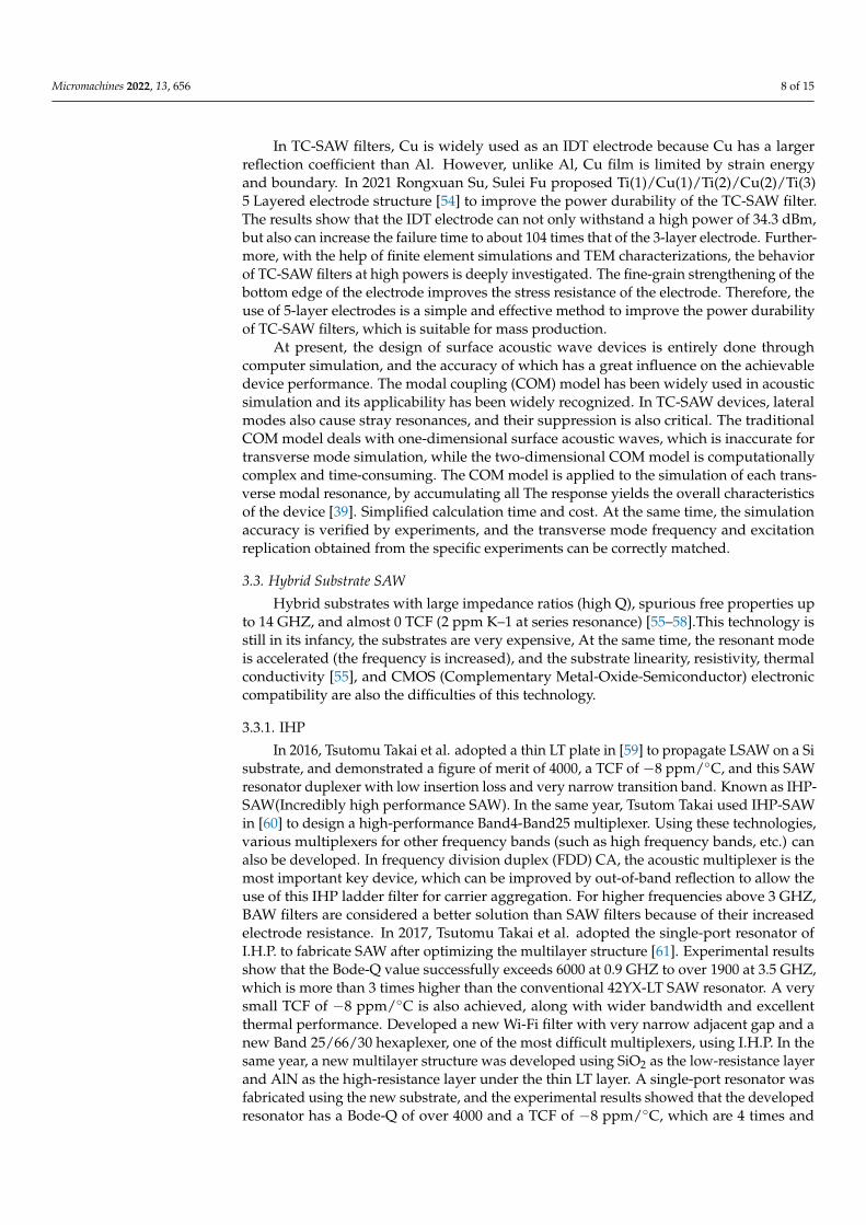
1/5 of the former, respectively. The same as the conventional 4◦ YX-LT SAW resonators,respectively. Using this technology, a 25-band duplexer with extremely narrow duplexgap has been successfully developed [62], which has extremely low insertion loss, steepcut-off characteristics and stable temperature characteristics. In 2018, Yuichi Takamine,Tsutomu Takai, a novel SAW device using a very thin piezoelectric layer with surface energyconfinement effect and achieving ultra-high Q greater than or equal to BAW. 3.5 GHZ centerfrequency I.H.P. surface acoustic wave resonator, test performance shows low passbandloss and good transition band steepness [63] Then in 2019, the triple-layer LT/SiO2/AlNstructure was adopted in [64] to simplify the double-layer structure on the Si substrate.Three-layer structure, simplified structure, compared with standard 42YX-LT substrate, asshown in Figure 4.
Micromachines 2022, 13, x FOR PEER REVIEW 9 of 16
technologies, various multiplexers for other frequency bands (such as high frequency
bands, etc.) can also be developed. In frequency division duplex (FDD) CA, the acoustic
multiplexer is the most important key device, which can be improved by out‐of‐band re‐
flection to allow the use of this IHP ladder filter for carrier aggregation. For higher fre‐
quencies above 3 GHZ, BAW filters are considered a better solution than SAW filters be‐
cause of their increased electrode resistance. In 2017, Tsutomu Takai et al. adopted the
single‐port resonator of I.H.P. to fabricate SAW after optimizing the multilayer structure
[61]. Experimental results show that the Bode‐Q value successfully exceeds 6000 at 0.9
GHZ to over 1900 at 3.5 GHZ, which is more than 3 times higher than the conventional
42YX‐LT SAW resonator. A very small TCF of −8 ppm/°C is also achieved, along with
wider bandwidth and excellent thermal performance. Developed a new Wi‐Fi filter with
very narrow adjacent gap and a new Band 25/66/30 hexaplexer, one of the most difficult
multiplexers, using I.H.P. In the same year, a new multilayer structure was developed
using SiO2 as the low‐resistance layer and AlN as the high‐resistance layer under the thin
LT layer. A single‐port resonator was fabricated using the new substrate, and the experi‐
mental results showed that the developed resonator has a Bode‐Q of over 4000 and a TCF
of −8 ppm/°C, which are 4 times and 1/5 of the former, respectively. The same as the con‐
ventional 4° YX‐LT SAW resonators, respectively. Using this technology, a 25‐band du‐
plexer with extremely narrow duplex gap has been successfully developed [62], which
has extremely low insertion loss, steep cut‐off characteristics and stable temperature char‐
acteristics. In 2018, Yuichi Takamine, Tsutomu Takai, a novel SAW device using a very
thin piezoelectric layer with surface energy confinement effect and achieving ultra‐high
Q greater than or equal to BAW. 3.5 GHZ center frequency I.H.P. surface acoustic wave
resonator, test performance shows low passband loss and good transition band steepness
[63] Then in 2019, the triple‐layer LT/SiO2/AlN structure was adopted in [64] to simplify
the double‐layer structure on the Si substrate. Three‐layer structure, simplified structure,
compared with standard 42YX‐LT substrate, as shown in Figure 4.
Figure 4. The basic structure of I.H.P (a) three‐layer structure, (b) two‐layer structure, (c) standard
42YX‐LT substrate [64]. © [2019] IEEE. Reprinted, with permission, from [64].
The piezoelectric thin plate multilayer structure is called IHP SAW. When the acous‐
tic wave propagates near the boundary of the low‐velocity area and the high‐velocity area,
it will be confined in the low‐velocity area. As shown in Figure 4a, the surface acoustic
wave generated by the piezoelectric layer will be confined in the piezoelectric layer and
the low‐velocity layer, reducing the loss and thus Improved quality factor Q. On this basis,
Tsutomu Takai reduced the number of layers from 3 to 2 layers, AIN and Si. The phase
velocities of AIN and Si are not much different in SH‐mode and both are much larger than
the SiO2 phase velocity, so AIN is extracted. The propagation of SAW on the surface is
analyzed by FEM (finite element method), and compared with the three‐layer structure.
The results show that in the double‐layer structure, the acoustic energy of the surface
acoustic wave is confined to the surface of the substrate, and still has a high Q value, and
Figure 4. The basic structure of I.H.P (a) three-layer structure, (b) two-layer structure, (c) standard42YX-LT substrate [64]. © [2019] IEEE. Reprinted, with permission, from [64].
The piezoelectric thin plate multilayer structure is called IHP SAW. When the acousticwave propagates near the boundary of the low-velocity area and the high-velocity area,it will be confined in the low-velocity area. As shown in Figure 4a, the surface acousticwave generated by the piezoelectric layer will be confined in the piezoelectric layer andthe low-velocity layer, reducing the loss and thus Improved quality factor Q. On this basis,Tsutomu Takai reduced the number of layers from 3 to 2 layers, AIN and Si. The phasevelocities of AIN and Si are not much different in SH-mode and both are much larger thanthe SiO2 phase velocity, so AIN is extracted. The propagation of SAW on the surface isanalyzed by FEM (finite element method), and compared with the three-layer structure.The results show that in the double-layer structure, the acoustic energy of the surfaceacoustic wave is confined to the surface of the substrate, and still has a high Q value, andfurther calculated the correlation between thickness and cutting angle, and determined theoptimal TCF and K2 values.
IHP/POI devices are hybrid SAW devices, bonded to silicon (or sapphire or quartz)using thick (>3 µm) LT. These devices show good TCF and power handling, with Q rangingfrom 1600 to 2300, and the advantage of silicon carrier wafers compared to sapphire orquartz is the heat extraction properties of silicon. Silicon conducts heat ~4 times better thansapphire and ~16 times better than quartz [29]. Excellent thermal extraction is the key to Txfilter applications.
3.3.2. HAL
Heterogeneous acoustic layer (HAL) SAW device is a new type of SAW device [65],which adopts solid-mounted single crystal piezoelectric thin plate, and can obtain veryhigh impedance ratio (ZR) and small temperature coefficient of frequency (TCF) at thesame time [1].
In 2018, Michio Kadota and Yoshimi Yunoki reported a new type of hetero acousticlayer (HAL) surface acoustic wave (SAW) resonator with high impedance ratio and qualityfactor Q [66]. 2020 Michio Kadota, Yoshimi Ishii, in [67], prototyped parallel and seriestype band-stop filters at 0.9 GHZ using LT/quartz HAL SAW resonators. Due to its large
Micromachines 2022, 13, 656 10 of 15
impedance ratio in the stopband, it has a steep attenuation at the junction of the passbandand stopband. In the passband frequency, the attenuation is very small, which will be usedin carrier aggregation technology and IoT systems.
3.3.3. LLSAW
Longitudinal leaky surface acoustic wave (LLSAW) mode has faster phase velocityand electromechanical coupling coefficient than Rayleigh wave, but its decay speed is muchlarger than other SAW modes on unimorphic piezoelectric substrates.
In 2013, Tetsuya Kimura and Katsuya Daimon designed 2.4 GHZ LLSAW in [68].The substrate consists of a thin LiNbO3 plate and a SiO2/AlN reflector stacked on a glasssubstrate. Although the reflector suppresses energy leakage to a certain extent, but due to itslow reflectivity, the final impedance ratio and bandwidth are 60 dB and 6.4%, respectively.In 2018, Tetsuya Kimura used platinum instead of AlN as the LLSAW resonator of thecomposite substrate reflector in X, which significantly improved the emissivity. In thecase of 3.5 GHZ, the final experimental impedance and bandwidth were 71 dB and 9.5%,respectively [69]. Tetsuya Kimura, Masashi Omura 2018 Apply the inter-digital transducercycle of 3.5 GHZ utilizing IHP SAW to another new SAW device LLSAW [70], and theresults show that good transducer performance can still be obtained in the 5 GHZ range. In2019, Masashi Suzuki and Naoya Sawada found that LLSAW propagating on a high-voltageelectrical ScAlN layer/sapphire or quartz substrate also has high phase velocity, high K2,and low attenuation [71].
3.3.4. Other Types
In 2000, Jun Tsutsumi formed a new type of reflection filter using SAW waveguidetechnology in [72], realizing a compact IF filter. In the second year, in 2001, Jun Tsutsumistudied the acoustic energy loss of the grating waveguide SAW filter. Based on the experi-ment, it was concluded that by increasing the thickness of the aluminum film, the insertionloss of the mirror filter using the SAW grating waveguide could be reduced by 2 dB [73].For the layered surface acoustic wave device, it is not only affected by the substrate, butalso affected by the interdigitated metal electrodes. In 2018, Qi Li, Sulei Fu, in [74] prepared2.1 GHZ surface acoustic wave filters with Al/Ti/Cu/Ti four-layer electrodes with differentCu thicknesses. With Al (111 nm)/Ti (5 nm)/Cu (15 nm)/Ti (5 nm) electrodes, the powerendurance was improved from 24.5 dBm to 28 dBm. In 2019, Qi Li and Sulei Fu prepareda series of 2.7 GHZ surface acoustic wave filters using Al/Cu/Ti three-layer electrodes.In the high-power load test, this Cu-doped α-Al and θ-CuAl2 structure can handle thestress of the finger well, so as to obtain higher anti-acoustic radiation performance, whichprovides a kind of high-power surface acoustic wave filter. promising solution [75].
In [76] 2020 studied the design of SH-SAW resonators based on LiNbO3/SiO2/Sifunctional substrates. It is proposed that the multi-frequency SH-SAW resonator canbe realized based on the LiNbO3/SiO2/Si wafer structure with smaller wavelength andoptimal film thickness. Junyao Shen, Sulei Fu, 2021, in [77] Design and Fabricate 15◦
Y-X LiNbO3/SiO2/SiC Multilayer Substrate, Using SH-mode to Suppress Spurious Re-sponses including Rayleigh Mode and Transverse Mode. The manufactured filters havewell-balanced properties. The center frequency is 1.28 GHZ, and the 3 dB FBW reaches16.65%, which is a high-performance surface acoustic wave device.
In 2013, Songbin Gong et al. designed and fabricated the first laterally vibrating mi-croresonator using ion-sliced X-cut LN thin films. High (0002) oriented ZnO piezoelectricfilms were deposited on high-sonic velocity SiC substrates by conventional photolithogra-phy. The frequency is in the 5–7 GHZ range. Has a large K2 value, and Q (146~549) [78].In 2019, Youquan Yan, using piezoelectric thin films instead of piezoelectric substrates toprepare surface acoustic wave resonators, can obtain higher quality factor (Q) and lowertemperature coefficient of frequency (TCF). As shown in Figure 5, (A typical ion cuttingprocess was used to prepare a 42◦ rotated y-cut LT single-crystal thin film substrate. Theprocess flow for transferring LT thin films) First, the LT sample was implanted at 75 kev H+,
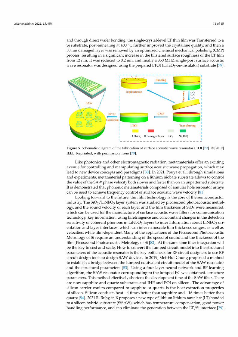
Micromachines 2022, 13, 656 11 of 15
and through direct wafer bonding, the single-crystal-level LT thin film was Transferred to aSi substrate, post-annealing at 400 ◦C further improved the crystalline quality, and then a30 nm damaged layer was removed by an optimized chemical mechanical polishing (CMP)process, resulting in a significant increase in the blistered surface roughness of the LT filmfrom 12 nm. It was reduced to 0.2 nm, and finally a 350 MHZ single-port surface acousticwave resonator was designed using the prepared LTOI (LiTaO3-on-insulator) substrate [79].
Micromachines 2022, 13, x FOR PEER REVIEW 11 of 16
stress of the finger well, so as to obtain higher anti‐acoustic radiation performance, which pro‐
vides a kind of high‐power surface acoustic wave filter. promising solution [75].
In [76] 2020 studied the design of SH‐SAW resonators based on LiNbO3/SiO2/Si func‐
tional substrates. It is proposed that the multi‐frequency SH‐SAW resonator can be real‐
ized based on the LiNbO3/SiO2/Si wafer structure with smaller wavelength and optimal
film thickness. Junyao Shen, Sulei Fu, 2021, in [77] Design and Fabricate 15° Y‐X
LiNbO3/SiO2/SiC Multilayer Substrate, Using SH‐mode to Suppress Spurious Responses
including Rayleigh Mode and Transverse Mode. The manufactured filters have well‐bal‐
anced properties. The center frequency is 1.28 GHZ, and the 3 dB FBW reaches 16.65%,
which is a high‐performance surface acoustic wave device.
In 2013, Songbin Gong et al. designed and fabricated the first laterally vibrating mi‐
croresonator using ion‐sliced X‐cut LN thin films. High (0002) oriented ZnO piezoelectric
films were deposited on high‐sonic velocity SiC substrates by conventional photolithog‐
raphy. The frequency is in the 5–7 GHZ range. Has a large K2 value, and Q (146~549) [78].
In 2019, Youquan Yan, using piezoelectric thin films instead of piezoelectric substrates to
prepare surface acoustic wave resonators, can obtain higher quality factor (Q) and lower
temperature coefficient of frequency (TCF). As shown in Figure 5, (A typical ion cutting
process was used to prepare a 42° rotated y‐cut LT single‐crystal thin film substrate. The
process flow for transferring LT thin films) First, the LT sample was implanted at 75 kev
H+, and through direct wafer bonding, the single‐crystal‐level LT thin film was Trans‐
ferred to a Si substrate, post‐annealing at 400 °C further improved the crystalline quality,
and then a 30 nm damaged layer was removed by an optimized chemical mechanical pol‐
ishing (CMP) process, resulting in a significant increase in the blistered surface roughness
of the LT film from 12 nm. It was reduced to 0.2 nm, and finally a 350 MHZ single‐port
surface acoustic wave resonator was designed using the prepared LTOI (LiTaO3‐on‐insu‐
lator) substrate [79].
Figure 5. Schematic diagram of the fabrication of surface acoustic wave resonator LTOI [79]. ©
[2019] IEEE. Reprinted, with permission, from [79].
Like photonics and other electromagnetic radiation, metamaterials offer an exciting
avenue for controlling and manipulating surface acoustic wave propagation, which may
lead to new device concepts and paradigms [80]. In 2021, Pouya et al., through simulations
and experiments, metamaterial patterning on a lithium niobate substrate allows to control
the value of the SAW phase velocity both slower and faster than on an unpatterned sub‐
strate. It is demonstrated that phononic metamaterials composed of annular hole resona‐
tor arrays can be used to achieve frequency control of surface acoustic wave velocity [81].
Looking forward to the future, thin film technology is the core of the semiconductor
industry. The SiO2/LiNbO3 layer system was studied by picosecond photoacoustic metrol‐
ogy, and the sound velocity of each layer and the film thickness of SiO2 were measured,
Figure 5. Schematic diagram of the fabrication of surface acoustic wave resonator LTOI [79]. © [2019]IEEE. Reprinted, with permission, from [79].
Like photonics and other electromagnetic radiation, metamaterials offer an excitingavenue for controlling and manipulating surface acoustic wave propagation, which maylead to new device concepts and paradigms [80]. In 2021, Pouya et al., through simulationsand experiments, metamaterial patterning on a lithium niobate substrate allows to controlthe value of the SAW phase velocity both slower and faster than on an unpatterned substrate.It is demonstrated that phononic metamaterials composed of annular hole resonator arrayscan be used to achieve frequency control of surface acoustic wave velocity [81].
Looking forward to the future, thin film technology is the core of the semiconductorindustry. The SiO2/LiNbO3 layer system was studied by picosecond photoacoustic metrol-ogy, and the sound velocity of each layer and the film thickness of SiO2 were measured,which can be used for the manufacture of surface acoustic wave filters for communicationtechnology. key information, using birefringence and concomitant changes in the detectionsensitivity of coherent phonons in LiNbO3 layers to infer information about LiNbO3 ori-entation and layer interfaces, which can infer nanoscale film thickness ranges, as well asvelocities, while film-dependent Many of the applications of the Picosecond PhotoacousticMetrology of Si require an understanding of the speed of sound and the thickness of thefilm [Picosecond Photoacoustic Metrology of Si [82]. At the same time filter integration willbe the key to cost and scale. How to convert the lumped circuit model into the structuralparameters of the acoustic resonator is the key bottleneck for RF circuit designers to use RFcircuit design tools to design SAW devices. In 2019, Mei-Hui Chung proposed a methodto establish a bridge between the lumped equivalent circuit model of the SAW resonatorand the structural parameters [83]. Using a four-layer neural network and BP learningalgorithm, the SAW resonator corresponding to the lumped EC was obtained. structureparameters. This method effectively shortens the development time of the SAW filter. Thereare now sapphire and quartz substrates and IHP and POI on silicon. The advantage ofsilicon carrier wafers compared to sapphire or quartz is the heat extraction propertiesof silicon. Silicon conducts heat ~4 times better than sapphire and ~16 times better thanquartz [84]. 2021 R. Ruby, in X proposes a new type of lithium lithium tantalate (LT) bondedto a silicon hybrid substrate (SiSAW), which has temperature compensation, good powerhandling performance, and can eliminate the generation between the LT/Si interface [29].
Micromachines 2022, 13, 656 12 of 15
stray mode. This mode can integrate the required filters on one module, and provides asolution for the sharp rise in the number of RF front-end filters.
4. Conclusions
In this era of information explosion, the success of mobile communication plays anirreplaceable role, and the continued success of mobile communication is related to thegrowing demand for higher transmission data rates. With the standardization of newfrequency bands, the designation of new carrier aggregation combinations, the need toincrease edge steepness, and generally the need for wider bandwidth and smaller size,this presents a huge challenge for designers. I believe that with the continuous supportof various technologies and the integration of filters, the performance of SAW filters willcontinue to improve, and there will be higher frequency bands. And the proportion ofmobile phones and other electronic devices will also increase, bringing more convenienceto our lives.
Author Contributions: Conceptualization, P.C. and G.L.; writing —original draft preparation, P.C.;writing—review and editing, P.C.; supervision, Z.Z.; project administration, G.L. All authors haveread and agreed to the published version of the manuscript.
Funding: This research was funded by Henan Province Engineering Research Center of UltrasonicTechnology Application grant number No. PXY-JXKFJJ-202104.
Conflicts of Interest: No conflict of interest.
References1. Bauer, T.; Eggs, C.; Wagner, K.; Hagn, P. A Bright Outlook for Acoustic Filtering. IEEE Microw. Mag. 2015, 16, 73–81. [CrossRef]2. Liu, Y.; Cai, Y.; Zhang, Y.; Tovstopyat, A.; Liu, S.; Sun, C.L. Materials, Design, and Characteristics of Bulk Acoustic Wave Resonator:
A Review. Micromachines 2020, 11, 630. [CrossRef] [PubMed]3. Gimenez, A.; Verdu, J.; Sanchez, P.D. General Synthesis Methodology for the Design of Acoustic Wave Ladder Filters and
Duplexers. IEEE Access 2018, 6, 47969–47979. [CrossRef]4. Fattinger, G.G.; Volatier, A.; Al-Joumayly, M.; Yusuf, Y.; Aigner, R.; Khlat, N.; Granger-Jones, M. Carrier aggregation and its
challenges—Or: The golden age for acoustic filters. In Proceedings of the 2016 IEEE MTT-S International Microwave Symposium(IMS), San Francisco, CA, USA, 22–27 May 2016; pp. 1–4. [CrossRef]
5. Ruppel, C.C.W. Acoustic Wave Filter Technology–A Review. IEEE Trans. Ultrason. Ferroelectr. Freq. Control. 2017, 64, 1390–1400.[CrossRef] [PubMed]
6. Delsing, P.; Cleland, A.N.; Schuetz, M.J.A.; Knorzer, J.; Giedke, G.; Cirac, J.I.; Srinivasan, K.; Wu, M.; Balram, K.C.; Bauerle, C.;et al. The 2019 surface acoustic waves roadmap. J. Phys. D Appl. Phys. 2019, 52, 353001. [CrossRef]
7. Rayleigh, L. On waves propagated along the plane surface of an elastic solid. Proc. Lond. Math. Soc. 1885, 1, 4–11. [CrossRef]8. Xiaojuan, F.; Yi, H.; Bingjun, W.; Shuwen, C. Research on dynamic response of single pile to Rayleigh wave in saturated soil based
on Winkler model. Chin. J. Appl. Mech. 2010, 27, 303–309, 440.9. White, R.M.; Voltmer, F.W. Direct piezoelectric coupling to surface elastic waves. Appl. Phys. Lett. 1965, 7, 314–316. [CrossRef]10. Arnau, A. Piezoelectric Transducers and Applications; Springer: Berlin/Heidelberg, Germany, 2004; Volume 2004.11. Drafts, B. Acoustic wave technology sensors. IEEE Trans. Microw. Theory Tech. 2001, 49, 795–802. [CrossRef]12. Malocha, D.C. Evolution of the SAW transducer for communication systems. In Proceedings of the IEEE Ultrasonics Symposium,
Montreal, QC, Canada, 23–27 August 2004; Volume 301, pp. 302–310. [CrossRef]13. Li, Q.; Fu, S.L.; Song, C.; Wang, G.Y.; Zeng, F.; Pan, F. Improved resistance to electromigration and acoustomigration of Al
interdigital transducers by Ni underlayer. Rare Met. 2018, 37, 823–830. [CrossRef]14. Huang, Y.; Bao, J.; Tang, G.; Wang, Y.; Omori, T.; Hashimoto, K.-Y. Multimode filter composed of single-mode surface acoustic
wave/bulk acoustic wave resonators. Jpn. J. Appl. Phys. 2017, 56, 07JD10. [CrossRef]15. Tian, Y.H.; Wang, L.T.; Wang, Y.Y.; Li, Y.; Wu, H.X.; Qian, L.R.; Li, H.L.; Wu, J.H.; Wang, J. Research in Nonlinearity of Surface
Acoustic Wave Devices. Micromachines 2021, 12, 1454. [CrossRef] [PubMed]16. Tobolka, G.; Faber, W.; Albrecht, G.; Pilz, D. High Volume TV-IF Filter Design, Fabrication, and Applications. In Proceedings of
the IEEE 1984 Ultrasonics Symposium, Dallas, TX, USA, 14–16 November 1984; pp. 1–12. [CrossRef]17. Maskay, A.; Hummels, D.M.; da Cunha, M.P. In-Phase and Quadrature Analysis for Amplitude and Frequency Modulations Due
to Vibrations on a Surface-Acoustic-Wave Resonator. IEEE Trans. Ultrason. Ferroelectr. Freq. Control 2019, 66, 91–100. [CrossRef][PubMed]
18. Morita, T.; Watanabe, Y.; Tanaka, M.; Nakazawa, Y. Wideband low loss double mode SAW filters. In Proceedings of the IEEE 1992Ultrasonics Symposium Proceedings, Tucson, AZ, USA, 20–23 October 1992; Volume 101, pp. 95–104. [CrossRef]

Micromachines 2022, 13, 656 13 of 15
19. Beaudin, S.; Damphousse, S.; Cameron, T. Shoulder Suppressing Technique for dual mode SAW resonators. In Proceedingsof the 1999 IEEE Ultrasonics Symposium Proceedings, International Symposium (Cat. No. 99CH37027), Tahoe, NV, USA,17–20 October 1999; Volume 381, pp. 389–393. [CrossRef]
20. Kinsman, R.G. A history of crystal filters. In Proceedings of the 1998 IEEE International Frequency Control Symposium (Cat.No. 98CH36165), Pasadena, CA, USA, 29 May 1998; pp. 563–570. [CrossRef]
21. Cai, T.; Chen, C.; Zhang, X.; Lin, F.J.; Zhang, H.L. A Hybrid Transmission-Line/SAW-Resonator Analog Signal-InterferenceDual-Band Bandpass Filter. IEEE Microw. Wirel. Compon. Lett. 2020, 30, 27–30. [CrossRef]
22. Zhang, R.Q.; Abdelfattah, M.; Yang, L.; Gomez-Garcia, R.; Peroulis, D. A Hybrid Low-Cost Bandpass Filter with SAW Resonatorsand External Lumped Inductors Using a Dual-Coupling Scheme. IEEE Trans. Microw. Theory Tech. 2020, 68, 2289–2299. [CrossRef]
23. Miura, M.; Matsuda, T.; Satoh, Y.; Ueda, M.; Ikata, O.; Ebata, Y.; Takagi, H. Temperature compensated LiTaO3 sapphire bondedSAW substrate with low loss and high coupling factor suitable for US-PCS application. In Proceedings of the IEEE UltrasonicsSymposium, Montreal, QC, Canada, 23–27 August 2004; Volume 1322, pp. 1322–1325. [CrossRef]
24. Rizzato, S.; Scigliuzzo, M.; Chiriacò, M.S.; Scarlino, P.; Monteduro, A.G.; Maruccio, C.; Tasco, V.; Maruccio, G. Excitation and timeresolved spectroscopy of SAW harmonics up to GHz regime in photolithographed GaAs devices. J. Micromech. Microeng. 2017,27, 125002. [CrossRef]
25. Kobayashi, H.; Tohyama, K.; Hori, Y.; Iwasaki, Y.; Suzuki, K. A study on temperature-compensated hybrid substrates forsurface acoustic wave filters. In Proceedings of the 2010 IEEE International Ultrasonics Symposium, San Diego, CA, USA,11–14 October 2010; pp. 637–640. [CrossRef]
26. Liu, Y.H.; Liu, J.S.; Wang, Y.L.; Lam, C.S. A Novel Structure to Suppress Transverse Modes in Radio Frequency TC-SAW Resonatorsand Filters. IEEE Microw. Wirel. Compon. Lett. 2019, 29, 249–251. [CrossRef]
27. Hashimoto, K.; Kadota, M.; Nakao, T.; Ueda, M.; Miura, M.; Nakamura, H.; Nakanishi, H.; Suzuki, K. Recent development oftemperature compensated SAW Devices. In Proceedings of the 2011 IEEE International Ultrasonics Symposium, Orlando, FL,USA, 18–21 October 2011; pp. 79–86. [CrossRef]
28. Matsuoka, N.; Li, X.; Omori, T.; Hashimoto, K.-Y. Study of loss mechanisms in temperature compensated surface acoustic wavedevices based on finite element method analysis using hierarchical cascading technique. Jpn. J. Appl. Phys. 2020, 59, SKKC06.[CrossRef]
29. Ruby, R.; Gilbert, S.; Lee, S.K.; Nilchi, J.; Kim, S.W. Novel Temperature-Compensated, Silicon SAW Design for Filter Integration.IEEE Microw. Wirel. Compon. Lett. 2021, 31, 674–677. [CrossRef]
30. Yamanouchi, K.; Kotani, K.; Odagawa, H.; Cho, Y.S. Theoretical analysis of surface acoustic wave propagation characteristicsunder strained media and applications for high temperature stable high coupling surface acoustic wave substrates. Jpn. J. Appl.Phys. 2000, 39, 3032–3035. [CrossRef]
31. Matsuda, S.; Hara, M.; Miura, M.; Matsuda, T.; Ueda, M.; Satoh, Y.; Hashimoto, K. Correlation Between Temperature Coefficientof Elasticity and Fourier Transform Infrared Spectra of Silicon Dioxide Films for Surface Acoustic Wave Devices. IEEE Trans.Ultrason. Ferroelectr. Freq. Control. 2011, 58, 1684–1687. [CrossRef] [PubMed]
32. Abbott, B.; Chen, A.; Daniel, T.; Gamble, K.; Kook, T.; Solal, M.; Steiner, K.; Aigner, R.; Malocha, S.; Hella, C.; et al. Temperaturecompensated saw with high quality factor. In Proceedings of the 2017 IEEE International Ultrasonics Symposium (IUS),Washington, DC, USA, 6–9 September 2017; pp. 1–7. [CrossRef]
33. Saleh, A.N.; Attar, A.A.; Ahmed, O.K.; Mustafa, S.S. Improving the thermal insulation and mechanical properties of concreteusing Nano-SiO2. Results Eng. 2021, 12, 100303. [CrossRef]
34. Lee, S.A.; Yang, J.W.; Choi, S.; Jang, H.W. Nanoscale electrodeposition: Dimension control and 3D conformality. In Exploration;Wiley Online Library: Hoboken, NJ, USA, 2021; p. 20210012.
35. Liu, Y.; Shi, B.; Liang, X.J. Exploration: Explore a better future with advanced science and technology. In Exploration; Wiley OnlineLibrary: Hoboken, NJ, USA, 2021; Volume 1, pp. 6–8.
36. Yujun, Z.; Fanxiu, L.; Jianjun, Z.; Liangxian, C. Technique of preparing diamond films on poly-substrate by DC-arc plasma jetCVD for surface acoustic wave devices. J. Univ. Sci. Technol. Beijing 2008, 30, 544–547. [CrossRef]
37. Xue, P.J.; Liu, S.L.; Bian, J.J. Effects of polymorphic form and particle size of SiO2 fillers on the properties of SiO2–PEEK composites.J. Adv. Dielectr. 2021, 11, 2150021. [CrossRef]
38. Balani, S.B.; Ghaffar, S.H.; Chougan, M.; Pei, E.J.; Sahin, E. Processes and materials used for direct writing technologies: A review.Results Eng. 2021, 11, 100257. [CrossRef]
39. Goto, R.; Nakamura, H.; Hashimoto, K. The modeling of the transverse mode in TC-SAW using SiO2/LiNbO3 structure. Jpn. J.Appl. Phys. 2019, 58, Sggc07. [CrossRef]
40. Kadota, M.; Nakao, T.; Taniguchi, N.; Takata, E.; Mimura, M.; Nishiyama, K.; Hada, T.; Komura, T. Surface acoustic wave duplexerfor US personal communication services with good temperature characteristics. Jpn. J. Appl. Phys. 2005, 44, 4527–4531. [CrossRef]
41. Kovacs, G.; Ruile, W.; Jakob, M.; Rosler, U.; Maier, E.; Knauer, U.; Zoul, H. A SAW duplexer with superior temperaturecharacteristics for US-PCS. In Proceedings of the IEEE Ultrasonics Symposium, Montreal, QC, Canada, 23–27 August 2004;Volume 972, pp. 974–977. [CrossRef]
42. Kadota, M.; Nakao, T.; Taniguchi, N.; Takata, E.; Mimura, M.; Nishiyama, K.; Hada, T.; Komura, T. SAW duplexer for PCS in USwith excellent temperature stability. In Proceedings of the IEEE Symposium on Ultrasonics, Honululu, HI, USA, 5–8 October 2003;Volume 2102, pp. 2105–2109. [CrossRef]
Micromachines 2022, 13, 656 14 of 15
43. Kadota, M.; Nakao, T.; Nishiyama, K.; Kido, S.; Kato, M.; Omote, R.; Yonekura, H.; Takada, N.; Kita, R. Small surface acousticwave duplexer for wide-band code-division multiple access full-band system having good temperature characteristics. Japanese J.Appl. Phys. 2007, 46, 4714–4717. [CrossRef]
44. Nakamura, H.; Nakanishi, H.; Tsurunari, T.; Matsunami, K.; Iwasaki, Y.; Hashimoto, K.; Yamaguchi, M. Miniature SurfaceAcoustic Wave Duplexer Using SiO2/Al/LiNbO3 Structure for Wide-Band Code-Division Multiple-Access System. Jpn. J. Appl.Phys. 2008, 47, 4052–4055. [CrossRef]
45. Matsuda, S.; Hara, M.; Miura, M.; Matsuda, T.; Ueda, M.; Satoh, Y.; Hashimoto, K. Application of fluorine doped SiO2 films fortemperature compensated SAW devices. In Proceedings of the 2011 IEEE International Ultrasonics Symposium, Orlando, FL,USA, 18–21 October 2011; pp. 76–78. [CrossRef]
46. Wang, Y.; Solal, M.; Kook, T.; Briot, J.; Abbott, B.; Chen, A.; Daniel, T.; Malocha, S.; Qin, K.; Steiner, K. A zero TCF band 13 SAWduplexer. In Proceedings of the 2015 IEEE International Ultrasonics Symposium (IUS), Taipei, Taiwan, 21–24 October 2015;pp. 1–4. [CrossRef]
47. Koskela, J.; Plessky, V.; Willemsen, B.; Turner, P.; Hammond, B.; Fenzi, N. Hierarchical Cascading Algorithm for 2-D FEMSimulation of Finite SAW Devices. IEEE Trans. Ultrason. Ferroelectr. Freq. Control. 2018, 65, 1933–1942. [CrossRef]
48. Solal, M.; Gallagher, M.; Tajic, A. Full 3D simulation of SAW resonators using hierarchical cascading FEM. In Proceedings of the2017 IEEE International Ultrasonics Symposium (IUS), Washington, DC, USA, 6–9 September 2017; pp. 1–5. [CrossRef]
49. Li, X.; Bao, J.; Qiu, L.; Matsuoka, N.; Omori, T.; Hashimoto, K.-Y. 3D FEM simulation of SAW resonators using hierarchicalcascading technique and general purpose graphic processing unit. Jpn. J. Appl. Phys. 2019, 58, SGGC05. [CrossRef]
50. Tsutsumi, J.; Inoue, S.; Iwamoto, Y.; Miura, M.; Matsuda, T.; Satoh, Y.; Nishizawa, T.; Ueda, M.; Ikata, O. A miniaturized 3 × 3-mmSAW antenna duplexer for the US-PCS band with temperature-compensated LiTaO3 sapphire substrate. In Proceedings of theIEEE Ultrasonics Symposium, Montreal, QC, Canada, 23–27 August 2004; Volume 952, pp. 954–958. [CrossRef]
51. Kawachi, O.; Taniguchi, N.; Tajima, M.; Nishizawa, T. A study of optimum material for SAW bonded wafer. In Proceedings of the2012 IEEE International Ultrasonics Symposium, Dresden, Germany, 7–10 October 2012; pp. 1260–1263. [CrossRef]
52. Geshi, K.; Teraoka, K.; Kinoshita, S.; Nakayama, M.; Imagawa, Y.; Nakayama, S.; Hashimoto, K.; Tanaka, S.; Totsu, K.; Takagi, H.Wafer bonding of polycrystalline spinel with LiNbO3/LiTaO3 for temperature compensation of RF surface acoustic wave devices.In Proceedings of the 2012 IEEE International Ultrasonics Symposium, Dresden, Germany, 7–10 October 2012; pp. 2726–2729.[CrossRef]
53. Zhang, S.; Lu, R.; Zhou, H.; Link, S.; Yang, Y.; Li, Z.; Huang, K.; Ou, X.; Gong, S. Surface Acoustic Wave Devices Using LithiumNiobate on Silicon Carbide. IEEE Trans. Microw. Theory Tech. 2020, 68, 3653–3666. [CrossRef]
54. Su, R.; Fu, S.; Shen, J.; Lu, Z.; Xu, H.; Yang, M.; Zeng, F.; Song, C.; Wang, W.; Pan, F. Power Durability Enhancement and FailureAnalysis of TC-SAW Filter with Ti/Cu/Ti/Cu/Ti Electrodes. IEEE Trans. Device Mater. Reliab. 2021, 21, 365–371. [CrossRef]
55. Ballandras, S.; Courjon, E.; Bernard, F.; Laroche, T.; Clairet, A.; Radu, I.; Huyet, I.; Drouin, A.; Butaud, E. New generation of SAWdevices on advanced engineered substrates combining piezoelectric single crystals and Silicon. In Proceedings of the 2019 JointConference of the IEEE International Frequency Control Symposium and European Frequency and Time Forum (EFTF/IFC),Orlando, FL, USA, 14–18 April 2019; pp. 1–6. [CrossRef]
56. Tang, I.T.; Chen, H.J.; Hwang, W.C.; Wang, Y.C.; Houng, M.P.; Wang, Y.H. Applications of piezoelectric ZnO film deposited ondiamond-like carbon coated onto Si substrate under fabricated diamond SAW filter. J. Cryst. Growth 2004, 262, 461–466. [CrossRef]
57. Assouar, M.; Elmazria, O.; Rioboo, R.J.; Sarry, F.; Alnot, P. Modelling of SAW filter based on ZnO/diamond/Si layered structureincluding velocity dispersion. Appl. Surf. Sci. 2000, 164, 200–204. [CrossRef]
58. Georgel, V.; Verjus, F.; van Grunsven, E.C.E.; Poulichet, P.; Lissorgues, G.; Pellet, C.; Chamaly, S.; Bourouina, T. A SAW filterintegrated on a silicon passive substrate used for system in package. Sens. Actuators A Phys. 2008, 142, 185–191. [CrossRef]
59. Takai, T.; Iwamoto, H.; Takamine, Y.; Yamazaki, H.; Fuyutsume, T.; Kyoya, H.; Nakao, T.; Kando, H.; Hiramoto, M.; Toi, T.; et al.Incredible high performance SAW resonator on novel multi-layerd substrate. In Proceedings of the 2016 IEEE InternationalUltrasonics Symposium (IUS), Tours, France, 18–21 September 2016; pp. 1–4. [CrossRef]
60. Takai, T.; Iwamoto, H.; Takamine, Y.; Wada, T.; Hiramoto, M.; Koshino, M.; Nakajima, N. Investigations on design technologiesfor SAW quadplexer with narrow duplex gap. In Proceedings of the 2016 IEEE MTT-S International Microwave Symposium(IMS), San Francisco, CA, USA, 22–27 May 2016; pp. 1–4. [CrossRef]
61. Takai, T.; Iwamoto, H.; Takamine, Y.; Fuyutsume, T.; Nakao, T.; Hiramoto, M.; Toi, T.; Koshino, M.I.H.P. SAW technology and itsapplication to microacoustic components (Invited). In Proceedings of the 2017 IEEE International Ultrasonics Symposium (IUS),Washington, DC, USA, 6–9 September 2017; pp. 1–8. [CrossRef]
62. Takai, T.; Iwamoto, H.; Takamine, Y.; Yamazaki, H.; Fuyutsume, T.; Kyoya, H.; Nakao, T.; Kando, H.; Hiramoto, M.; Toi, T.; et al.High-Performance SAW Resonator on New Multilayered Substrate Using LiTaO3 Crystal. IEEE Trans. Ultrason. Ferroelectr. Freq.Control 2017, 64, 1382–1389. [CrossRef]
63. Takamine, Y.; Takai, T.; Iwamoto, H.; Nakao, T.; Koshino, M. A Novel 3.5 GHz Low-Loss Bandpass Filter Using I.H.P. SAW Res-onators. In Proceedings of the 2018 Asia-Pacific Microwave Conference (APMC), Kyoto, Japan, 6–9 November 2018; pp. 1342–1344.[CrossRef]
64. Takai, T.; Iwamoto, H.; Takamine, Y.; Fuyutsume, T.; Nakao, T.; Hiramoto, M.; Toi, T.; Koshino, M. High-Performance SAWResonator with Simplified LiTaO3/SiO2 Double Layer Structure on Si Substrate. IEEE Trans. Ultrason. Ferroelectr. Freq. Control2019, 66, 1006–1013. [CrossRef]
Micromachines 2022, 13, 656 15 of 15
65. Kadota, M.; Tanaka, S. Improved quality factor of hetero acoustic layer (HAL) SAW resonator combining LiTaO3 thin plateand quartz substrate. In Proceedings of the 2017 IEEE International Ultrasonics Symposium (IUS), Washington, DC, USA,6–9 September 2017; pp. 1–4. [CrossRef]
66. Kadota, M.; Yunoki, Y.; Shimatsu, T.; Uomot, M.; Tanaka, S. Near-Zero TCF of HAL SAW Resonator with LiTaO3-on-QuartzStructure. In Proceedings of the 2018 IEEE International Frequency Control Symposium (IFCS), Olympic Valley, CA, USA,21–24 May 2018; pp. 1–4. [CrossRef]
67. Kadota, M.; Ishii, Y.; Tanaka, S. A spurious-free, steep band rejection filter using a LiTaO3/quartz heteroacoustic layer surfaceacoustic wave resonator. Jpn. J. Appl. Phys. 2020, 59, Skkc11. [CrossRef]
68. Kimura, T.; Daimon, K.; Ogami, T.; Kadota, M. S0Mode Lamb Wave Resonators Using LiNbO3 Thin Plate on Acoustic MultilayerReflector. Jpn. J. Appl. Phys. 2013, 52, 07HD03. [CrossRef]
69. Kimura, T.; Kishimoto, Y.; Omura, M.; Hashimoto, K. 3.5 GHz longitudinal leaky surface acoustic wave resonator using amultilayered waveguide structure for high acoustic energy confinement. Jpn. J. Appl. Phys. 2018, 57, 07ld15. [CrossRef]
70. Kimura, T.; Omura, M.; Kishimoto, Y.; Hashimoto, K.Y. Applicability Investigation of SAW Devices in the 3 to 5 GHz range.In Proceedings of the 2018 IEEE/MTT-S International Microwave Symposium—IMS, Philadelphia, PA, USA, 10–15 June 2018;pp. 846–848. [CrossRef]
71. Suzuki, M.; Sawada, N.; Kakio, S. Analysis of longitudinal leaky surface acoustic wave propagation characteristics on apiezoelectric ScAlN layer/sapphire or quartz substrate. Jpn. J. Appl. Phys. 2019, 58, Sggc08. [CrossRef]
72. Tsutsumi, J.; Matsuda, T.; Ikata, O.; Satoh, Y. A novel reflector-filter using a SAW waveguide directional coupler. IEEE Trans.Ultrason. Ferroelectr. Freq. Control 2000, 47, 1228–1234. [CrossRef] [PubMed]
73. Tsutsumi, J.; Ikata, O.; Satoh, Y. Experimental Studies on Acoustic Energy Loss in Surface Acoustic Wave Filters Using GratingWaveguides. Jpn. J. Appl. Phys. 2001, 40, L62. [CrossRef]
74. Li, Q.; Fu, S.L.; Wang, R.; Song, C.; Zeng, F.; Pan, F. Enhanced power durability of surface acoustic wave filter with Al/Ti/Cu/Tielectrodes. J. Alloy. Compd. 2018, 740, 222–228. [CrossRef]
75. Li, Q.; Fu, S.L.; Lu, Z.T.; Qian, L.R.; Wang, R.; Chen, T.J.; Song, C.; Zeng, F.; Wang, W.B.; Pan, F. Behavior of Al/Cu/Ti electrodesin surface acoustic wave filter at high power. Curr. Appl. Phys. 2019, 19, 363–369. [CrossRef]
76. Hsu, T.H.; Tseng, K.J.; Li, M.H. Large Coupling Acoustic Wave Resonators Based on LiNbO3/SiO2/Si Functional Substrate. IEEEElectron Device Lett. 2020, 41, 1825–1828. [CrossRef]
77. Shen, J.Y.; Fu, S.L.; Su, R.X.; Xu, H.P.; Lu, Z.T.; Xu, Z.B.; Luo, J.T.; Zeng, F.; Song, C.; Wang, W.B.A.; et al. High-PerformanceSurface Acoustic Wave Devices Using LiNbO3/SiO2/SiC Multilayered Substrates. IEEE Trans. Microw. Theory Tech. 2021, 69,3693–3705. [CrossRef]
78. Gong, S.B.; Piazza, G. Design and Analysis of Lithium-Niobate-Based High Electromechanical Coupling RF-MEMS Resonatorsfor Wideband Filtering. IEEE Trans. Microw. Theory Tech. 2013, 61, 403–414. [CrossRef]
79. Yan, Y.Q.; Huang, K.; Zhou, H.Y.; Zhao, X.M.; Li, W.Q.; Li, Z.X.; Yi, A.L.; Huang, H.; Lin, J.J.; Zhang, S.B.; et al. Wafer-ScaleFabrication of 42 degrees Rotated Y-Cut LiTaO3-on-Insulator (LTOI) Substrate for a SAW Resonator. ACS Appl. Electron. Mater.2019, 1, 1660–1666. [CrossRef]
80. Zeighami, F.; Palermo, A.; Marzani, A. Rayleigh waves in locally resonant metamaterials. Int. J. Mech. Sci. 2021, 195, 106250.[CrossRef]
81. Pouya, C.; Nash, G.R. Sub-and supersonic elastic waves in an annular hole phononic metamaterial. Commun. Mater. 2021, 2, 55.[CrossRef]
82. Brick, D.; Emre, E.; Grossmann, M.; Dekorsy, T.; Hettich, M. Picosecond Photoacoustic Metrology of SiO2 and LiNbO3 LayerSystems Used for High Frequency Surface-Acoustic-Wave Filters. Appl. Sci. 2017, 7, 822. [CrossRef]
83. Chung, M.H.; Huang, H.C.; Hwang, R.C.; Huang, P.F.; Wang, S.M.T. Synthesis of Ladder-type Radio Frequency Surface AcousticWave Filter Based on Lumped Circuit Model by Using Neural Network. Sens. Mater. 2019, 31, 2225–2236. [CrossRef]
84. Yang, S.; Ai, Y.J.; Cheng, Z.; Zhang, L.A.; Jia, L.F.; Dong, B.Y.; Zhang, B.H.; Wang, J.X.; Zhang, Y. Method of the out-of-bandrejection improvement of the AlN based surface acoustic wave filters. Ultrasonics 2019, 91, 30–33. [CrossRef]