Skid-Steer Rock Saw Modification - Oklahoma State University
146
1 Skid-Steer Rock Saw Modification Kelly Hogue Kristen Tucker Matt Gassen Buck Melton BAE 4022 Senior Design May 04, 2007
-
Upload
khangminh22 -
Category
Documents
-
view
2 -
download
0
Transcript of Skid-Steer Rock Saw Modification - Oklahoma State University

1
Skid-Steer Rock Saw
Modification
Kelly Hogue
Kristen Tucker
Matt Gassen
Buck Melton
BAE 4022
Senior Design
May 04, 2007

2
Redesign of Skid-Steer Mounted Rock Saw
Kelly Hogue Kristen Tucker Matt Gassen Buck Melton
Biosystems & Agricultural Engineering Department
Oklahoma State University
Submission Date: May 04, 2007
__________________________________ ___________ Kelly Hogue Biomechanical Option Tulsa, Ok December 2007
__________________________________ ___________ Kristen Tucker Biomechanical Option Midwest City, Ok December 2007
__________________________________ ___________ Matt Gassen Biomechanical Option El Reno, Ok December 2007
__________________________________ ___________ Buck Melton Biomechanical Option Lawton, Ok December 2007
__________________________________ ___________
Dr. Paul Weckler Senior Design Advisor
__________________________________ ___________
Dr. Ronald L. Elliott BAE Department Head

3
Abstract
A rock saw is a skid-steer attachment used to cut non-reinforced concrete and asphalt as well
as other pavement surfaces. One of the many uses for this rock saw is making trenches for laying
plumbing or wiring under existing roads and sidewalks. In addition, the rock saw may be used to
make a smooth edge along asphalt roadways for the addition of cement curbs. This saw is versatile
because it can be powered by a variety of other machines. CONEQTEC Universal produces rock
saws capable of various cutting depths. However, their production model is axially driven which
limits the depth of cut to less than the blade radius. In order to increase the depth of cut without
increasing the blade diameter, the manufacturer designed a prototype in which the blade was rim-
driven via a modified ring and pinion gear set. Four senior level students from the Biosystems and
Agricultural Engineering Department (BAE) of Oklahoma State University (OSU) have formed a
consulting team, Blue Diamond Machinery (BDM), to facilitate the completion of their capstone
senior design project under the direction of Dr. Paul Weckler. Blue Diamond Machinery's objective
was to modify the CONEQTEC rock saw prototype with the goal of increasing the time between
maintenance periods from 50 hours to over 100 hours as well as preventing debris from contacting
the motors. To reduce wear, BDM modified the gear set to a circular rack and pinion. Further
testing is needed to determine if this gear mesh increased the useful life of the machine. As a result
of altering the gear set, the motors were mounted above the blade where they cannot come into
contact with debris.
Figure 1: Left to Right - Production Model, CONEQTEC Prototype, BDM Prototype
(CONEQTEC 1)

4
Acknowledgements
Gary Cochran – CONEQTEC Universal Dennis Skraba– CONEQTEC Universal Dr. Paul Weckler – Oklahoma State University - Biosystems and Agricultural Engineering
Associate Professor and Senior Design Advisor
Wayne Kiner – Oklahoma State University - Biosystems and Agricultural Engineering
Laboratory Manager
Bobby Flores, Robert Harrington, and Robert Harshman – Oklahoma State University -
Biosystems and Agricultural Engineering Laboratory
Stillwater Steel – Fabrication Steve Miller – Interstate Tool – Fabrication Railroad Yard – Fabrication Jana Moore - Oklahoma State University - Biosystems and Agricultural Engineering Dr. John Solie – Oklahoma State University - Biosystems and Agricultural Engineering – Professor
5
Table of Contents
Problem Statement ..............................................................................................................7 Statement of Work ..............................................................................................................7 Patent Research ...................................................................................................................7 Design Specifications: CONEQTEC Universal ..................................................................9 Design Specifications: Blue Diamond Machinery ............................................................14 Quantitative Analysis ........................................................................................................18 Recommendations .............................................................................................................21
Design and Manufacturing Alternatives ........................................................................................21 Testing............................................................................................................................................23 Safety..............................................................................................................................................23
Budget ...............................................................................................................................24 Works Cited.......................................................................................................................25 Patents ...............................................................................................................................25 Appendix 1 ........................................................................................................................26 Appendix 2 ........................................................................................................................28 Appendix 3 ........................................................................................................................31 Appendix 4 ........................................................................................................................32

6
Table of Figures and Tables Figure 1: Left to Right - Production Model, CONEQTEC Prototype, BDM Prototype......................3 Figure 2: Production Model Rock Saw ................................................................................................9 Figure 3: CONEQTEC Prototype ......................................................................................................10 Figure 4: CONEQTEC Prototype – Fully Descended .......................................................................11 Figure 5: CONEQTEC Prototype Gear Mesh....................................................................................11 Figure 6: Front View of CONEQTEC Prototype Blade. ...................................................................12 Figure 7: Worn Ring Gear Teeth........................................................................................................13 Figure 8: Side View of CONEQTEC Rock Saw................................................................................13 Figure 9: Hub Assembly and Axle of CONEQTEC Rock Saw. ........................................................14 Figure 10: The Progression of BDM Gear Hole Inserts.....................................................................15 Figure 11: Left - Circular Rack Gear with Retainer Plates ................................................................15 Figure 12: Close Up of Bolt on Retainer Plates and Retaining Bolt..................................................16 Figure 13: Autodesk Drawing of Gear Configuration on New Wheel Design ..................................17 Figure 14: View of BDM’s Prototype Gear Mesh .............................................................................17 Figure 15: View of Motors and Hydraulic Shafts and Gear Mesh in Relation to Blade. ..................18 Figure 16: Pinion Gear Specifications ...............................................................................................20 Figure 17: Final BDM Prototype – Full Assembly ............................................................................20 Figure 18: OMT Wheel Mount Flange Motor (Sauer Danfoss 1)......................................................21 Figure 19: Visual of Recommendations Channel Frame Assembly. .................................................22 Figure 20: Visual of the Channel Frame Motor Mount Assembly. ...................................................22 Figure 21: Total BDM Prototype Assembly with Safety Flap Location............................................24
Table 1: Patent List ..............................................................................................................................9 Table 2: Fluids and Strengths Analysis..............................................................................................19 Table 3: BDM In-House Budget. .......................................................................................................24

7
Problem Statement
CONEQTEC Universal designed a prototype of a skid-steer mounted rock saw. While this
prototype functioned, the manufacturer required a gear set with a longer design life for the saw to
become a production model. When the saw descended to the maximum cutting depth, the motors
were forced to run in debris created by the cut. The manufacturer requested that the rock saw be
modified to increase the design life of the gear set as well as to prevent debris from contacting the
motors.
Statement of Work
In order to increase design life, BDM changed the ring and pinion gear set to a circular rack
and pinion gear set. This altered gear set necessitated the relocation of the motors to above the blade
thereby preventing debris from coming into contact with the motors.
Patent Research
The patent search revealed a few designs similar to the prototype. While rock saw devices
were found, none were driven from the rim of the cutting blade. All the designs found were driven
from the central axis of the blade. Most of these designs were intended for cutting concrete or, in
the case of one patent held by Mr. Cochran, for cutting slots in pavement. Though some rim driven
blades were found, their intended application was in the logging industry to trim either harvested or
fallen trees for transport. The scope of application was found to have a more important role in
patent approval than the method in which the machine is operated. US Patent No. 3494389 refers to
slashing and loading timber. The machine is designed to lift a load of logs off of a stack and place
them on a truck for transport after cutting them to a desired length.
US Patent No. 3915209 refers to the process of harvesting trees and brushwood and an
improved saw design for the removal of trees or brushwood. Additionally, Patent No. 3915209

8
refers to a German and U.S. patent that describes a ring and pinion drive which has a U-shaped
frame. However, Patent No. 3915209 states that these patent designs are insufficient due to their
limited depth of the cut and the gear configuration is not protected. This design has two plates
mounted together to house the ring and pinion drive train and form the saw blade. This assembly
results in the gear being easily hindered by wood debris and not easily repairable when damage
occurs.
US Patent No. 4738291 describes a tree saw run by a ring and pinion configuration which
the saw blade can double as a platform to allow the cut tree to be dumped where the operator
chooses instead of allowing the tree to fall where it was cut down. This design appears to have
some importance due to the saw blade having intentions to be a load bearing surface as well as
having an assembled blade design protected from debris, which could easily be maintained. These
patents, while unrelated to our products industry, are still potentially important due to their
similarities to our drive train concept. This observation could pose a problem in the new design
because of patent infringement. It was deduced from these patents that the driving mechanism is
not patentable in and of itself; therefore, the scope of the patent holds higher authority than the drive
train design making patent infringement less of an issue.
Patent No. US 7,073,495 B1 describes the method and apparatus for removing concrete
debris during operation. The device is powered by a small engine, and the blade is contained in a
separate housing. Outside the housing is a set of at least two nozzles that use pressurized gas to
produce a stream directed toward the lower support during the use of the saw. This stream is used
to help clear debris from the saw decreasing wear on the blade and skids. The streams of gas are
directed toward the rear of the housing and toward the front of the blade rather than in the plane of
the cutting blade. This configuration should not affect the potential design of a debris removal
mechanism for the rock saw because the debris weighs too much to push away with a stream.

9
Table 1: Patent List
Design Specifications: CONEQTEC Universal
CONEQTEC Universal of Wichita, Kansas manufactures attachments for skid-steer loaders
to substitute for the standard bucket attachment. One of their attachments is a rock saw which is
used to cut non-reinforced concrete and asphalt as well as other pavement surfaces. CONEQTEC's
production model of the rock saw is axially driven by a hydraulic motor through a planetary gear set
which limits the depth of cut to about 35% of the blade diameter which is slightly less than the
radius of the blade.
Figure 2: Production Model Rock Saw (CONEQTEC 1)
In order to increase the depth of cut to greater than the radius of the blade, CONEQTEC developed
a prototype in which the blade was driven at the rim of the blade via a modified ring and pinion gear
set rather than at the axle. The CONEQTEC prototype achieves a maximum cutting depth of 18
Patent Number Issued to Concept Applicability to
project
3494389 Standard Alliance Industries
Slasher Loader Ring & Pinion Gears
3915209 CEMETSA Tree Harvester Saw Blade
4738291 Reggald E. Isley Power Saw Gear, Blade
7,073,495 B1 Soff-Cut Int., Inc. Cutting Concrete Removal of Debris

10
inches with a 32 inch total diameter blade, i.e. the depth of cut is about 55% of the blade diameter.
Therefore, if both the CONEQTEC prototype and the production model had the same blade size, the
prototype would have a 20% deeper depth of cut.
Figure 3: CONEQTEC Prototype
Ring gear teeth were mounted directly to each face near the perimeter of the wheel. The pinion gear
was composed of 5 free-turning cylindrical teeth attached to a disk.

11
Figure 4: CONEQTEC Prototype – Fully Descended
Figure 5: CONEQTEC Prototype Gear Mesh
According to the manufacturer, the major limiting factor was the lower than expected design life of
the ring gear teeth. Due to the fact this gear mesh was not sealed, lubrication was not advantageous
Ring Tooth
Pinion Tooth
Pinion Gear
Cutting Teeth (Picks)
Flat Head Socket Cap Screws

12
and was, therefore, neglected. The meshing tolerances were somewhat loose, resulting in some
impact/abrasive wear on the contact surfaces of the ring and pinion teeth. However, since the ring
gear teeth protruded out to the cutting breadth of the picks, the high rate of wear was caused by
abrasion on the outer face of the ring gear teeth as they scraped against the slot being cut by the
saw. As shown in Figure 6. The ring gear teeth were attached with flat head socket cap screws (1/2
in – 20, 1.5 in long). Wear was expected on the cutting teeth, or picks. The design life of the
cutting teeth was acceptable; therefore, BDM was asked to not focus on improving the cutting teeth.
Figure 6: Front View of CONEQTEC Prototype Blade.
A corner from each ring gear tooth was ground down to allow for better clearance when meshing
with the pinion gear. On some teeth, the wear was displayed in a very slight arc.
Ring Gear Teeth
Cutting Teeth

13
Figure 7: Worn Ring Gear Teeth.
In the production model, one hydraulic motor was mounted directly to the axle of the blade. In the
CONEQTEC prototype, they added an additional motor to distribute the rotational force to each
side of the blade (See Figure 1). These hydraulic motors were mounted directly to the pinion gears,
and a crescent shaped slot was cut into each side plate to allow the motors to descend with the
blade. A brace was installed at the top of each slot for reinforcement.
Figure 8: Side View of CONEQTEC Rock Saw Showing Motor Location, Brace, and Shot in
Outer Housing.
Brace
Motor
Slot

14
Special brackets were designed to hold the wheel and the motors in place. The wheel was then able
to freely rotate around the axle on two sets of tapered-roller bearings installed in the hub. See the
Quantitative Analysis section for motor and hydraulic system details.
Figure 9: Hub Assembly and Axle of CONEQTEC Rock Saw.
Design Specifications: Blue Diamond Machinery
In order to increase the working life of the saw, BDM altered the gear mesh. The ring gear
teeth were replaced with a circular rack composed of gear holes; the pinion gear with cylindrical
teeth was replaced with an acme pinion gear. After several iterations in the design process, BDM
decided on using three inch tall pieces of ¾ inch diameter round stock and ¼ x ¾ inch bar stock as
inserts for each gear hole in the wheel for the pinion gears to press against when driving the blade.
Brackets
Axle
Wheel Hub Assembly
Bearings

15
Figure 10: The Progression of BDM Gear Hole Inserts.
Figure 11: Left - Circular Rack Gear with Retainer Plates
Right - Circular Rack Gear without Retainer Plates
The inserts prevent wear on the wheel itself and are easily replaceable. To improve the ease of
maintenance in replacing the round and bar stock, twenty removable retainer plates were bolted to
one side of the wheel with 3/4” x 3/8”-16 flat head socket cap screws and twenty were welded to the
opposite side. These plates allow the stock inserts to be replaced three sets at a time. The initial
wheel and gear hole dimensional calculations did not allow space for the rim-to-wheel weld.
Therefore, the outer retainer plates were made shorter in heighth. Later modifications to the Gear
Calculator should have fixed this issue.

16
Figure 12: Close Up of Bolt on Retainer Plates and Retaining Bolt.
The recommended material for the round and bar stock is 440C stainless steel. Any strong material
will function; a softer, less corrosion resistant material may be less expensive initially, but these
inserts will require replacement more often due to the decreased design life. The pinion gears
consisted of a set of two acme gears which were designed to mesh into the cutting wheel. These
gears were stacked with ¼ of an inch of clearance between the two gears and the wheel to prevent
buildup of debris in the gear holes. Due to the curvature of the circular rack, the top pinion gear has
a slightly larger diameter than the bottom pinion gear. The stacking was accomplished by making
the gear shafts two different lengths.
Bar Stock
Key Stock
Retainer Plate
Flat Heat Socket Cap
Screw
17
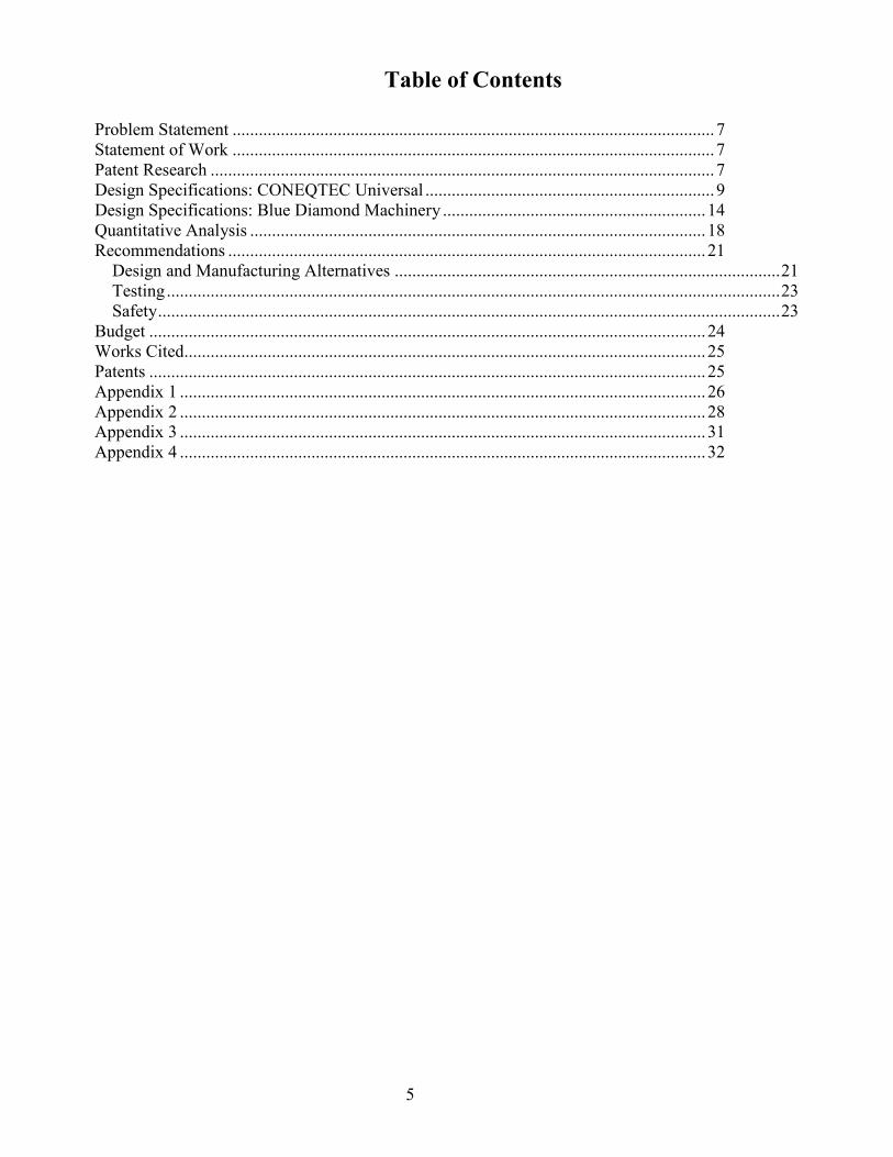
Figure 13: Autodesk Drawing of Gear Configuration on New Wheel Design
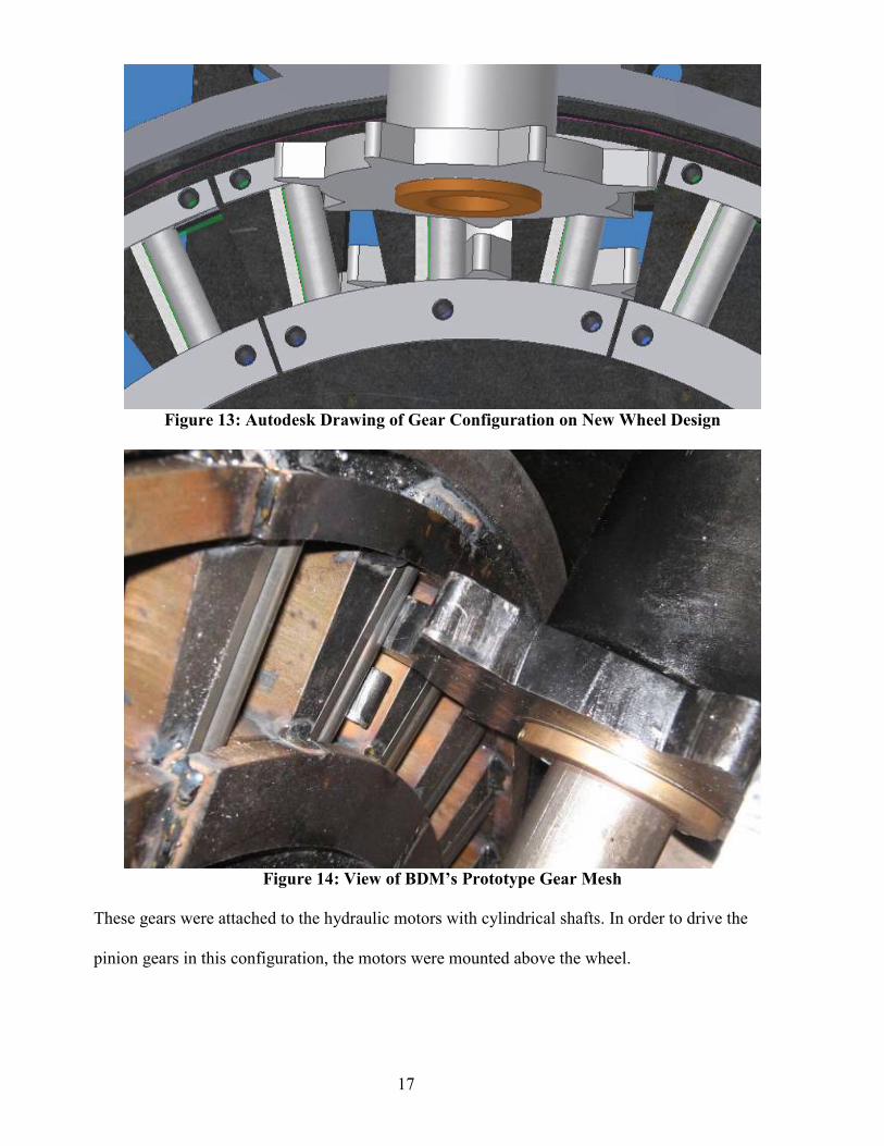
Figure 14: View of BDM’s Prototype Gear Mesh
These gears were attached to the hydraulic motors with cylindrical shafts. In order to drive the
pinion gears in this configuration, the motors were mounted above the wheel.

18
Figure 15: View of Motors and Hydraulic Shafts and Gear Mesh in Relation to Blade.
This modification also eliminated the issue of debris piles adversely affecting the motors. The new
prototype's overall blade diameter was increased in size to 32.5 inches, or 38 inches including the
rim and cutting teeth. This increase in diameter increased the cutting depth to approximately 23
inches which is about 5% deeper than the CONEQTEC prototype. The outer housing increased in
width to 19 inches, in length to 48 inches, and in height to 40 inches in order to accommodate the
larger blade. The skid dimensions were increased to fit the new outer housing. In addition, the
channel frame assembly was widened to allow room for the gear shafts. The pivot bar was
lengthened to accommodate the wider outer housing and channel frame. The hydraulic piston
mounting locations and bushing dimensions were modified to accommodate these design changes.
No changes were made to the internal workings of the wheel hub and axle.
Quantitative Analysis
The rock saw prototype was designed to function with the most powerful of CONEQTEC
Universal’s high flow skid steer hydraulic kits. BDM used the same hydraulic system, motors, and
pistons as the CONEQTEC prototype. The CONEQTEC Universal super high flow kit allows the
skid steer to produce 89 hp, a flow of 34gpm, and a pressure of 4,500 psi. The prototype uses two

19
hydraulic motors to drive the saw. The motors are Sauer Danfoss, 400cc displacement, OMT
orbital hydraulic motors. This provides 44.6 hp per motor operating at 160 rpm, producing 1,457
ft/lbs of torque from each motor.
Table 2: Fluids and Strengths Analysis
Hydraulic power kit A B C
Flow (gpm) 34.00 40.00 33.00 Pressure (psi) 4500.00 3200.00 4060.00 Power (hhp) 89.26 74.68 78.17
Hydraulic Motor Power (hhp) 44.63 37.34 39.08 Number of Motors 2.00 2.00 2.00 Displacement (cc) 200.00 200.00 200.00 Displacement (gal) 0.05 0.05 0.05 RPM 321.76 378.54 312.30 Torque (ft lbs) 728.52 518.06 657.29 Total Force (lbs) 452.90 322.06 408.62
Cutting wheel RPM 75.08 88.33 72.87
Torque (ft lbs) 3122.24 2220.26 2816.96 Diameter (ft) 2.67 2.67 2.67 Force (lbs) 8325.98 5920.69 7511.88
Driving teeth
Shear Strength (psi) 1006.44 715.69 908.03
Pinion Gear Diameter1 (ft) 0.32 0.32 0.32 Diameter2 (ft) 0.30 0.30 0.30 Shear Strength (psi) 301.93 214.71 272.41 Fatigue Load (psi) 41247
This power is transferred from the hydraulic motors with acme gears meshing into the gear holes on
the saw blade. The pinion gear teeth apply 450 lbs of force to the replaceable ¾ inch round stock.
The gear ratio is 30 driving holes to 7 gear teeth making it 4.3:1. The motors apply approximately
89 hp as well as 2,914 ft-lbs of torque at the picks at 75 rpm. In a wheel made from A36 mild steel
with an ultimate strength of 140 ksi, the 1.57 inch minimum spacing between gear holes and 1.0
inch width base of the pinion gear teeth will withstand the maximum possible forces. The shear
force experienced between the gear holes is 1000 psi. The shear force experienced at the base of the

20
pinion gear teeth is 300 psi. Both of these values are considerably less than the fatigue load strength
of 41,000 psi, therefore, preventing failure.
Figure 16: Pinion Gear Specifications
Figure 17: Final BDM Prototype – Full Assembly
Left: Fully Descended. Right: Fully Retracted.

21
Recommendations
Design and Manufacturing Alternatives
In order to reduce cost, BDM recommends the use of different motors. The current motors can be
replaced with motors that have the wheel mount flange housing. The wheel mount flange motors
are the same as the current motors with an alternative mounting location.
Figure 18: OMT Wheel Mount Flange Motor (Sauer Danfoss 1)
Instituting this type of motor with make the pinion gears easier to replace and will make the gear
retainer parts obsolete. BDM also recommends that an x-y-z adjustable motor mounting system be
developed. The combination of using the alternative motors and the adjustable motor mounts may
eliminate the costly production of the gear shafts as well as ease the assembly process. BDM would
also like to recommend some alternative manufacturing methods. The ear cylinder and plate2
should be one part. The pivot boss inner should be increased to 13 ¼ inches to allow for welding.
This part should also have a piece removed from its middle to allow for lubrication.

22
Figure 19: Visual of Recommendations to Make Manufacture Easier on the Channel
Frame Assembly.
The next recommendation is to either thread the motor mount instead of plate2, or move the motor
mount to the other side of plate2 and then lengthen the mount wheel shaft bracket top, leaving the
bolt holes referenced to the inside edge. (Motor mount is a misnomer. It now describes the part the
gears protrude through.) If the gear shafts are replaced by conforming to the previous
recommendations, the parts in the following picture do not need to be changed. More suitable part
names or part numbers should be instituted to avoid confusion during production.
Figure 20: Visual of the Channel Frame Motor Mount Assembly.
These two parts
should be one piece.
This part should be at least 1.5 inches longer.
Plate 2
Motor Mount

23
Testing
BDM recommends a complete endurance test for the rock saw. This test may include
analyzing different materials for the gear hole inserts as well as the pinion gear material. Since the
there are 10 retainer plates which retain 3 sets of 2 gear hole inserts, BDM recommends testing up
to 10 different materials for a broad wear comparison. The materials BDM recommends for testing
range from low carbon steel to highly corrosion and abrasion resistant stainless steels. BDM also
recommends testing some exotic materials such as titanium or a Kevlar/ceramic material. These
alternatives may be expensive initially; however, a cost benefit analysis may show the exotic inserts
to be less expensive if their design life is extended to over a few hundred hours. This test will
determine the optimum operational life before replacement of the ring gear teeth. A similar test can
be done for the pinion gear. However, a hardened, corrosion resistant stainless steel should be
sufficient. The mounting locations of the hydraulic cylinders on the outer housing may need
adjustment in order to achieve the maximum depth of cut.
Safety
The last set of recommendations by BDM refers to the addition of safety devices to increase
the overall safety of the rock saw. The first would be the addition of a detachable flap to the front
opening of the outer housing.

24
Figure 21: Total BDM Prototype Assembly with Safety Flap Location
This flap may prevent other equipment or appendages from coming into contact with the blade. A
hole could but cut in the outer housing to reduce weight and increase serviceability. A hinged or
detachable flap could be added in place of the hole to ensure safety.
Budget
Table 3: BDM In-House Budget.
Materials $1,623.38
Fasteners $112.27
Tools $36.40
Total $1,772.05
Safety Flap
Location
Location of Service Hole

25
Works Cited
CONEQTEC Universal. 2007 <http://www.coneqtecuniversal.com/> Hibbeler R.C. Mechanics of Materials 6th Edition. New Jersey: Upper Saddle River, 2005. pg 114,
874-875. Sauer Danfoss. March 2006 <http://domweb.sauer-
danfoss.com/domdb/SauerLit.nsf/1526f939eb2e202286256c5b0062ff21/9F7E710E5145FD08C1256B7B004DDE86/$file/520L0407_OMS-T-V_TI_Mar%202006_Rev%20D1.pdf>
Shigley, Joseph E., and Mischke, Charles R., and Budynas, Richard G. 2004. Mechanical Engineering Design. 7th ed. New York, NY. McGraw-Hill Companies, Inc.
Patents
Markley, Charles E. 2006. Method and Apparatus for Cleaning Concrete During Cutting. US Patent No. 7073497 B1
Cook, Eugene. 2001. Attachable Road Cutting Apparatus. US Patent No. 6203112 B1 Thibodeau, John L. 1970. Slasher-Loader. US Patent No. 3494389 Denis, Bernard. 1975. Machine for Harvesting Trees and Brushwood. US Patent No. 3915209 Isley, Reggald E. 1988. Power Saw Including Removable Circular Cutting Element and Holder.
US Patent No. 4738291

26
Appendix 1
Parts List

27
Item Part Number BOM Structure Unit QTY QTY
1 base frame assembly 2 Normal 1 1
1.1 plate back Normal 1 1
1.2 outer_frame Normal 1 2
1.3 pivot boss outer frame Normal 1 2
1.4 pivot pin boss Normal 1 2
2 pivot boss outer frame cylinder Normal 1 2
3 motor mount asm to channel asm Normal 1 1
3.1 channel frame assembly Normal 1 1
3.1.1 top channel frame Inseparable 1 1
3.1.1.1 top channel frame top Normal 1 1
3.1.1.2 top channel frame side Normal 1 2
3.1.2 front channel frame Normal 1 1
3.1.3 plate2 new Normal 1 2
3.1.4 ear_cylinder_right Normal 1 1
3.1.5 pivot boss inner Normal 1 1
3.1.6 pivot boss outer frame carriage Normal 1 2
3.1.7 bolt_bar Normal 1 2
3.1.8 ear_cylinder_left Normal 1 1
3.2 wheel_assembly Normal 1 1
3.2.1 wheel disk Normal 1 1
3.2.2 wheel_rim Normal 1 1
3.2.3 .25_in_flatstock Normal 1 30
3.2.4 .75_in_roundbar Normal 1 30
3.2.5 inner rim sections 2 Normal 1 10
3.2.6 outter rim sections Normal 1 10
3.2.7 inner rim sections 2_MIR Normal 1 10
3.2.8 outter rim sections_MIR Normal 1 10
3.2.9 ring outer seal Normal 1 2
3.2.10 ring inner seal Normal 1 2
3.3 mount wheel shaft assembly Normal 1 2
3.3.1 mount wheel shaft Normal 1 1
3.3.2 motor mount Normal 1 1
3.3.3 mount wheel shaft bracket Normal 1 1
3.3.4 mount wheel shaft bracket top Normal 1 1
3.4 motor mount plate Normal 1 1
3.5 Motor Normal 1 2
3.6 gear shaft Normal 1 2
3.7 Top Gear 7 teeth Normal 1 1
3.8 Bottom Gear 7 teeth Normal 1 1
3.9 shaft wheel Normal 1 1
3.10 cap wheel shaft Normal 1 1
3.11 gear bearing assembly Normal 1 1
3.11.1 bearing retainer Normal 1 1
3.11.2 gear bearing Normal 1 1
3.12 gear bearing assembly wide Normal 1 1
3.12.1 bearing retainer wide Normal 1 1
3.12.2 gear bearing Normal 1 1
4 Cylinder Normal 1 2
5 piston shaft Normal 1 2

28
Appendix 2
Gantt Charts

29
Fall 2006

30
Spring 2007

31
Appendix 3
Gear Calculator

32
Appendix 4
Fire Protection Safety Report

33

34

35

36

37

38

39

40

41

42

43
APPENDIX A
Silicosis

44
Search NIOSH | NIOSH Home | NIOSH Topics | Site Index | Databases and Information Resources | NIOSH Products | Contact Us
NIOSH Publication No. 2004-108:
Silicosis: Learn the Facts!
August
2004
This document presents information in an easy to read format describing silica exposures, the effects of silicosis, and methods to protect against silicosis.
Contents
Disclaimer
Acknowledgements Safety Information Learn the Facts! Description of Silicosis Are YOU breathing silica dust? Who is at Risk? Types of Silicosis Symptoms Silicosis has Affected many Workers and their Families Did you know? What Can I Do to Protect Myself and My Family? What Type of Respirator Should I Use? References
Related
Resources/Publications:
NIOSH Safety and Health Topic Page - Silica
This document is also
available in PDF format.
The print version contains
both the English and
Spanish texts.
English Version: 2004-108.pdf 20 pages, 1748kb
Spanish Version:
2004-108sp.pdf 20 pages, 1748kb

45
Disclaimer
Mention of any company or product does not constitute endorsement by the
National Institute for Occupational Safety and Health (NIOSH). In addition,
citations to Web sites external to NIOSH do not constitute NIOSH endorsement of
the sponsoring organizations or their programs and products. Furthermore,
NIOSH is not responsible for the content of these Web sites.
This document is in the public domain and may be freely copied or reprinted.
ORDERING INFORMATION
To receive documents or more information about occupational safety and health
topics, contact NIOSH at:
NIOSH -- Publications Dissemination
4676 Columbia Parkway
Cincinnati, OH 45226-1998
Telephone: 1-800-35-NIOSH (1-800-356-4674)
Fax: 513-533-8573
E-mail: [email protected]
or visit the NIOSH Web site at www.cdc.gov/niosh
DHHS (NIOSH) Publication No. 2004-108
August 2004
Acknowledgements
NIOSH wishes to thank the International Union of Painters and Allied Trades and the Laborers' International Union of North America, who provided significant and valuable assistance with this document. We

46
also thank the New Jersey Department of Health and Senior Services for providing photographs and the Occupational Safety and Health Administration (OSHA) for providing technical assistance.
The principal contributors to this brochure were Charles E. Williams, III, Dorothy Tan-Wilhelm, Rene D. Massengale, Crystal Ellison, Catherine Inman, Marieli Moreta-Medero, and Laine Hall. We would also like to recognize Don Eggerth, Chris Hawkins, Nancy Bollinger, Jennifer Welbourne, Tanya Headley, Sybil Buzzard Ott, Steve Booth-Butterfield, and Laura Blanciforti for their contributions and technical assistance. The document reviewers include Robert Castellan, Paul Hewett, Kenneth Linch, Lee Petsonk, Susan Feldmann, Faye Rice, Hector Ortega, Janie Gittleman, Stew Burkhammer, and Bill Perry. We extend a special thanks to Brian Day, Ken Linch, Joe Cocalis, William Eschenbacker, Robert Stein, Roland Berry Ann, Hector Ortega, John Parker, and Jesus Deleon for providing photographs and technical assistance. Kimberly Clough Thomas provided the cover design, layout, and photographs for the document.
Safety Information
For more information on silicosis and how it can affect you and your family, visit our Web site at:
http://www.cdc.gov/niosh/topics/silica
For more information or for answers to questions about any safety and health regulatory matters, contact the Occupational Safety and Health Administration (OSHA)
U.S. Department of Labor Occupational Safety & Health Administration 200 Constitution Avenue Washington, D.C. 20210
1-800-321-OSHA (6742) (Spanish speaking staff available)
Silicosis: Learn the Facts!
Do you work in construction or do abrasive blasting?
If so, here are some important facts you need to know:
• Since 1968, more than 14,000 workers in the U.S. have died from a disease called silicosis.
• In the U.S. each year more than 200 workers die with this disease while hundreds more become disabled.

47
• Many workers with silicosis are only in their thirties; some are as young as 22 years old. Many of them are unable to take care of themselves and their families.
What is silicosis and how can you avoid or prevent it?
This booklet will give you information about silicosis, what causes it, the symptoms, and the ways you can avoid developing the disease.
WARNING!
Silicosis IS NOT CURABLE, but it IS PREVENTABLE. Learn the
facts and know how to protect yourself. Silicosis affects both your
health AND the welfare of your family.
Description of Silicosis
Silicosis is a disabling and often fatal lung disease caused by breathing dust that has very small pieces of crystalline silica in it. Crystalline silica is found in concrete, masonry, sandstone, rock, paint, and other abrasives. The cutting, breaking, crushing, drilling, grinding, or abrasive blasting of these materials may produce fine silica dust. It can also be in soil, mortar, plaster, and shingles. The very small pieces of silica dust get in the air that you breathe and become trapped in your lungs. Even the very small pieces of dust that you cannot see will harm you. As the dust builds up in your lungs, the lungs are damaged and it becomes harder to breathe.
Are YOU breathing silica dust?
48
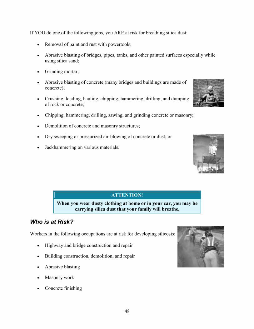
If YOU do one of the following jobs, you ARE at risk for breathing silica dust:
• Removal of paint and rust with powertools;
• Abrasive blasting of bridges, pipes, tanks, and other painted surfaces especially while using silica sand;
• Grinding mortar;
• Abrasive blasting of concrete (many bridges and buildings are made of concrete);
• Crushing, loading, hauling, chipping, hammering, drilling, and dumping of rock or concrete;
• Chipping, hammering, drilling, sawing, and grinding concrete or masonry;
• Demolition of concrete and masonry structures;
• Dry sweeping or pressurized air-blowing of concrete or dust; or
• Jackhammering on various materials.
ATTENTION!
When you wear dusty clothing at home or in your car, you may be
carrying silica dust that your family will breathe.
Who is at Risk?
Workers in the following occupations are at risk for developing silicosis:
• Highway and bridge construction and repair
• Building construction, demolition, and repair
• Abrasive blasting
• Masonry work
• Concrete finishing

49
• Drywall finishing
• Rock drilling
• Mining
• Sand and gravel screening
• Rock crushing (for road base)
ATTENTION!
If you work near dust clouds like the ones in these photos, you
might be exposed to silica. You may be exposed even when dust is
not visible.
Types of Silicosis
There are three types of silicosis:
1. Chronic silicosis: Usually occurs after 10 or more years of exposure to crystalline silica at low levels. This is the most common type of silicosis.
2. Accelerated silicosis: Results from exposure to higher levels of crystalline silica and occurs 5 to 10 years after exposure.

50
3. Acute silicosis: Can occur after only weeks or months of exposure to very high levels of crystalline silica. Death occurs within months. The lungs drown in their own fluids.
Healthy Lung Diseased Lung
Symptoms
Symptoms may not appear in the early stages of chronic silicosis. In fact, chronic silicosis may go undetected for 15 to 20 years after exposure. As silicosis progresses, symptoms may include:
• Shortness of breath
• Severe cough
• Weakness
Because the body's ability to fight infections may be weakened by silica in the lungs, other illnesses (such as tuberculosis) may result and can cause:
• Fever
• Weight loss
• Night sweats
• Chest pains
• Respiratory failure
These symptoms can become worse over time, leading to death.
WARNING!
Victims of silicosis are also at risk for getting lung infections such as
tuberculosis (TB). TB is a disease that can be spread by coughing,

51
sneezing, or talking around your spouse, children, and other loved
ones.
Silicosis Has Affected Many Workers and Their Families
The following is based on a true story of a construction worker from Central Texas who died at age 35, leaving behind his wife and four children, ages 10, 14, 16, and 17.
"When I first started working, I was very young and full of energy. I was anxious about starting
my first real job in the United States and being able to support my wife and children like I
wanted. Sandblasters made quite a bit of money. I noticed that there was a lot of dust, but I never
thought that it would hurt me. I wore a bandana everyday to cover my mouth and nose. Everyone
said that this was good and that I would be fine. Well, I guess that wasn't so true after all. Now
I'm 35 years old, and I have silicosis. No one ever told me about silicosis. My wife noticed that I
was doing a lot of coughing and wheezing at night and she was very concerned. Now I get tired
very easily, and I have a hard time enjoying the things I used to do like playing games with my
children and taking them places. I am often depressed and it bothers me a lot that I'm not able to
take care of my family. My doctor said that I have advanced silicosis and probably will die in a
few years. Silicosis really changes your life and affects your family. I never pictured myself dying
this young and not seeing my children grow up. I wish that I would have known this before it was
too late."
Silicosis cases in Texas
In November 1988, 10 cases of silicosis were reported in west Texas. All of the workers were sandblasters employed at a company that sandblasted oil-well drilling pipes. Each had been exposed to silica dust and had high levels of silica in their lungs. Their job included the use of sandblasting machinery that was in poor condition and leaked silica dust into the air. All of the workers were Hispanic males with an average age of 31 years. One of the workers died from silicosis at the age of 34 [CDC 1990].
Did you know?
• Over 1 million U.S. workers are at risk of developing silicosis.
• Hundreds die of silicosis each year.
• The construction industry has one of the highest numbers of deaths due to silicosis.
Individual cases
A tile-installer was diagnosed with advanced silicosis, emphysema, and asthma at age 49. Although he didn't directly perform risky tasks, he worked near sandblasting and was exposed to silica dust (tile installers can also be directly exposed to silica dust when cutting tile). He did not wear a respirator [NIOSH

52
1996].
A 39-year-old sandblaster was diagnosed with progressive silicosis and tuberculosis in 1993. He had reported shortness of breath, wheezing, and lack of energy. He had worked for 22 years sandblasting welds during water tank construction. He wore a charcoal filter respirator while sandblasting, but it was the wrong type and did not protect him. Two brothers and three nephews who worked with him all tested positive for tuberculosis as well [NIOSH 1996].
A 36-year-old man in Texas died in 1995 from advanced silicosis after working as a sandblaster for 11 years. He had been exposed to silica dust for only three years while sandblasting oil field pipes and tanks [CDC 1998].
A 30-year-old sandblaster in Texas died 10 years after his first exposure to silica dust. He had been exposed to silica dust for only four years [CDC 1998].
What Can I Do to Protect Myself and My Family?
Silicosis is a disabling and often fatal disease that prevents hundreds of workers from being able to care for their families. It could also prevent you from providing for your family. If your work causes you to breathe silica dust, there are things you can do to prevent silicosis from happening to you.
• Be aware of the health effects of breathing air that has silica dust in it.
• Avoid working in dust whenever possible.
• Know what causes silica dust at your workplace.
• Remember if there is no visible dust, you could be at risk. If there is visible dust, you are almost definitely at risk.
• Reduce the amount of silica dust by doing the following:
o Use water sprays and ventilation when working in confined structures. For example:
� Use a water hose to wet dust before it becomes airborne.
� Use saws that add water to the blade.
� Use drills that add water through the stem or have dust collection systems.
� Use blast cleaning machines or cabinets to control dust.

53
• When water sprays and ventilation alone are not enough to reduce silica dust levels, your employer MUST provide you with a properly fitted and selected respirator (e.g. particulate filter or airline supplied air respirator) designated for protection against crystalline silica.
• Changes should not be made to the respirator.
• Workers who use tight-fitting respirators cannot have beards or mustaches because they do not let the respirator properly seal to the face.
• Take health (or lung screening) programs offered by your employer.
• Sandblasting or abrasive blasting requires the highest level of protection, which is a type CE abrasive blasting respirator (see photo 7).
• Practice good personal hygiene at the workplace:
• Do not eat, drink, or use tobacco products in dusty areas.
o Wash hands and face before eating, drinking, or smoking outside dusty areas.
o Park cars where they will not be contaminated with silica.
o Change into disposable or washable work clothes at the worksite.
o Shower (if possible) and change into clean clothes before leaving the worksite to prevent contamination of other work areas, cars, and homes.
• It is your employers' legal responsibility to provide a safe workplace. If you think you are not protected call OSHA

54
at 1-800-321-OSHA (6742) or go to the OSHA Web site: www.osha.gov.
Your employer must make sure that you have the proper protective equipment for reducing silica dust levels; but, it's up to you to use them!
Taking time to protect yourself on the job is worth it.
AFTER ALL, NOTHING IS MORE IMPORTANT THAN YOUR HEALTH AND THE
HEALTH OF YOUR FAMILY!
REMEMBER!
If you are a construction worker, you may be exposed to silica dust.
To protect you and your family, remember to follow these
recommendations each and every time you may be exposed.
Silicosis IS NOT CURABLE, but it IS PREVENTABLE—to live a
long and healthy life, learn the facts and know how to protect
yourself and your family.
What Type of Respirator Should I Use?
Choosing the right respirator that fits you snugly is important for protecting your health. Your employer will help you choose the type of respirator you need. ALWAYS USE NIOSH-APPROVED RESPIRATORS. The type of respirator you need depends on:
• The amount of silica dust to which you are exposed, and
• The kind of work you need to do.
• If you must do abrasive blasting, use only a type CE pressure demand abrasive blasting respirator (see photo 7).
Respirators used for protection from crystalline silica should not cause undue discomfort. If you have problems with your respirators, report immediately to your supervisor.
Photo 4
Photo 3
Photo 2
Photo 1
Model Advantage 1000

55
Covering your face
with a cloth such
as a bandana or T-
shirt WILL NOT
protect you.
These are filtering facepiece
respirators.
• Disposable
• N-95 Type or higher
• Provide minimal
protection
Model Advantage 200
Photo courtesy of MSA.
Half-face mask air-purifying
respirator with replaceable N-
95 (or higher) filters.
Photo courtesy of MSA.
Full-face mask air-purifying
respirator with replaceable N-
95 (or higher) filters.
No Protection . . . . . . . . . . . . . . . . . . . . . . . . . . . . . . . . . . . . . . . . . . . . . . . . . . . . . . . . . . Least Protection
Photo 7
Photo 6
Photo 5
Model MM2K
Photo courtesy of MSA.
Type CE abrasive-blasting
respirator (SAR), operated
in a pressure demand or
other positive pressure

56
Powered air purifying
respirator (PAPR)
equipped with:
• Full facepiece
• High efficiency
particulate filters
NOTE: Uses battery-
powered motor to filter the
air.
Supplied-air respirator
(SAR) equipped with:
• Full facepiece
• Pressure-demand
or other positive
pressure mode.
mode.
NOTE: A tight-fitting
mask is worn under the
blasting hood.
This is the only respirator
that can be used for
abrasive blasting.
More Protection . . . . . . . . . . . . . . . .. . . . . . . . . . . . . . . . . . . . Most Protection
References
The following sources were used in preparing this brochure:
CDC (Centers for Disease Control and Prevention) [1990]. Silicosis: cluster in sandblasters _ Texas, and occupational surveillance for silicosis. MMWR 39(25):433-437. www.cdc.gov/mmwr/preview/mmwrhtml/00001654.htm
CDC (Centers for Disease Control and Prevention) [1998]. Silicosis deaths among young adults _ United States, 1968-1994. MMWR 47(16):331-335. www.cdc.gov/mmwr/preview/mmwrhtml/00052482.htm
Morris J [1992]. "Dusty Trades" victimize Mexican immigrants. Houston Chronicle, Oct (reprint); pull-out sect. 4.
NIOSH [1992 a]. NIOSH Alert: Request for assistance in preventing silicosis and deaths from sandblasting. U.S. Department of Health and Human Services, Public Health Service (PHS), Centers for Disease Control, National Institute for Occupational Safety and Health, DHHS Publication No. 92-102. www.cdc.gov/niosh/92-102.html
NIOSH [1992 b]. NIOSH Alert: Request for assistance in preventing silicosis and deaths in rock drillers. U.S. Department of Health and Human Services, Public Health Service (PHS), Centers for Disease Control, National Institute for Occupational Safety and Health, DHHS (NIOSH) Publication No. 92-107. www.cdc.gov/niosh/92-107.html
NIOSH [1996]. NIOSH Alert: Request for assistance in preventing silicosis and deaths in construction workers. U.S. Department of Health and Human Services, Public Health Service, Centers for Disease Control, National Institute for Occupational Safety and Health, DHHS (NIOSH) Publication No. 96-112. www.cdc.gov/niosh/consilic.html
NIOSH [1999]. Hazard Controls (HC 30): Control of Drywall Sanding Dust Exposures. U.S. Department of Health and Human Services, Public Health Service, Centers for Disease Control,

57
National Institute for Occupational Safety and Health, DHHS (NIOSH) Publication No. 99-113. www.cdc.gov/niosh/hc30.html
NIOSH [2002]. NIOSH Hazard Review: Health Effects of Occupational Exposures to Respirable Crystalling Silica. U.S. Department of Health and Human Services, Public Health Service, Centers for Disease Control, National Institute for Occupational Safety and Health, DHHS (NIOSH) Publication No. 2002-129. www.cdc.gov/niosh/02-129A.html
NIOSH Home | NIOSH Search | Site Index | Topic List | Contact Us
Courtesy of <http://www.cdc.gov/niosh/docs/2004-108/default.html>

58
APPENDIX B
Dangers of Hydraulics

59
04/05/200504/05/2005 WMMICWMMIC
OSHA FATAL FACTSOSHA FATAL FACTS
Hydraulic PressureHydraulic Pressure
04/05/200504/05/2005 WMMICWMMIC
Fatal Facts Fatal Facts -- Hydraulic Pressure Hydraulic Pressure and the Dangersand the Dangers
�� Description of the Accident:Description of the Accident:
�� A machine operator was fatally injured while A machine operator was fatally injured while he was attempting to bleed trapped air from a he was attempting to bleed trapped air from a hydraulic cylinder located on an automated hydraulic cylinder located on an automated forming machine. The injuries occurred when forming machine. The injuries occurred when he opened a bleedhe opened a bleed--toto--atmosphere type airatmosphere type air--bleed valve located on a hydraulic cylinder, bleed valve located on a hydraulic cylinder, causing high pressure hydraulic oil to be causing high pressure hydraulic oil to be injected into his hand. injected into his hand.

60
04/05/200504/05/2005 WMMICWMMIC
The Dangers of Hydraulic The Dangers of Hydraulic
PressurePressure�� Injection InjuriesInjection Injuries
�� Dangerous properties of fluid (toxic)Dangerous properties of fluid (toxic)
�� Contact with hot fluidContact with hot fluid
�� Other material movement (explosion, Other material movement (explosion,
whipping hose, etc.)whipping hose, etc.)
04/05/200504/05/2005 WMMICWMMIC
High Pressure Injection High Pressure Injection InjuriesInjuries

61
04/05/200504/05/2005 WMMICWMMIC
What is an High Pressure What is an High Pressure
Injection Injury?Injection Injury?�� Fluid at pressure that punctures and Fluid at pressure that punctures and
penetrates the skin and body tissue.penetrates the skin and body tissue.
�� injected substance passes rapidly thru the injected substance passes rapidly thru the
subcutaneous tissue and enters the subcutaneous tissue and enters the
tendons and deep spaces of hand/body.tendons and deep spaces of hand/body.
04/05/200504/05/2005 WMMICWMMIC
High Pressure Injection InjuryHigh Pressure Injection Injury
�� A pinhole leak in a hydraulic hose thatA pinhole leak in a hydraulic hose that’’s s under pressure can release toxic fluid at a under pressure can release toxic fluid at a speed of 600+ feet per second.speed of 600+ feet per second.
�� Close to the muzzle velocity of a gun.Close to the muzzle velocity of a gun.
�� Sufficient to penetrate protective Sufficient to penetrate protective equipment depending upon velocity.equipment depending upon velocity.
�� Penetration recorded in distances of up to Penetration recorded in distances of up to four inches between fluid source and skin.four inches between fluid source and skin.

62
04/05/200504/05/2005 WMMICWMMIC
Where Do You Find?Where Do You Find?
�� Some type of fluid (water, paint, oilSome type of fluid (water, paint, oil--based based
solvents, etc.) or airsolvents, etc.) or air
�� Measured in force exerted upon a surface Measured in force exerted upon a surface
per unit areaper unit area
�� Usually pounds per square inch (PSI)Usually pounds per square inch (PSI)
04/05/200504/05/2005 WMMICWMMIC
Where Do You Find?Where Do You Find?
�� hydraulic lineshydraulic lines
�� airless paint sprayers,airless paint sprayers,
�� fluid 100 PSI or above fluid 100 PSI or above
�� highhigh--pressure fuel pressure fuel injection injection
�� highhigh--pressure air linespressure air lines
�� highhigh--pressure grease pressure grease guns,guns,
�� high pressure grease high pressure grease and paint guns most and paint guns most common causecommon cause
�� 60% paint60% paint
�� 25% grease/oil25% grease/oil

63
04/05/200504/05/2005 WMMICWMMIC
High PressureHigh Pressure
�� 100 PSI to puncture skin100 PSI to puncture skin
�� 30003000--10000 PSI10000 PSI
�� <2000 PSI <2000 PSI -- 40% amputation40% amputation
�� >2000 PSI >2000 PSI -- 50% amputation50% amputation
�� <7000 PSI <7000 PSI -- non prognosticnon prognostic
�� >7000 PSI >7000 PSI -- 100% amputation100% amputation
�� Amputation rates vary between 16Amputation rates vary between 16--48%48%
04/05/200504/05/2005 WMMICWMMIC
Severity/Prognostic FactorsSeverity/Prognostic Factors
�� Material injectedMaterial injected
�� grease grease -- fibrosisfibrosis
�� paint paint -- necrosisnecrosis
�� gangrenegangrene
�� Paint/paint thinners Paint/paint thinners -- pain and swelling in few pain and swelling in few hourshours
�� greases/oils/hydraulic fluid greases/oils/hydraulic fluid -- pain in a day or pain in a day or twotwo

64
04/05/200504/05/2005 WMMICWMMIC
ToxicologyToxicology
�� Absorption into systemAbsorption into system
�� Organic solventOrganic solvent
�� Water basedWater based
04/05/200504/05/2005 WMMICWMMIC
Injury Info Injury Info
�� Injection typically occurs when operator is Injection typically occurs when operator is
trying to wipe clear a blocked nozzle or trying to wipe clear a blocked nozzle or when operator is attempting to steady the when operator is attempting to steady the
gun with a free hand during the testing or gun with a free hand during the testing or
operation of equipmentoperation of equipment
�� Pad of thumb or index finger (most common)Pad of thumb or index finger (most common)
�� Palm and long finger (second most frequent)Palm and long finger (second most frequent)
�� non dominant handnon dominant hand
�� Usually pin hole size Usually pin hole size
�� Men between 21Men between 21--5959

65
04/05/200504/05/2005 WMMICWMMIC
04/05/200504/05/2005 WMMICWMMIC

66
04/05/200504/05/2005 WMMICWMMIC
Burn InjuriesBurn Injuries
�� Complex injuriesComplex injuries
�� Burns effect kidney, liver and cardiovascular Burns effect kidney, liver and cardiovascular function.function.
04/05/200504/05/2005 WMMICWMMIC
Degree of BurnDegree of Burn
�� First DegreeFirst Degree
�� Outer layer of skinOuter layer of skin
�� Second DegreeSecond Degree
�� First and second layer of skinFirst and second layer of skin
�� Third DegreeThird Degree
�� All layers of skinAll layers of skin
�� Most seriousMost serious

67
04/05/200504/05/2005 WMMICWMMIC
Injection BurnsInjection Burns
�� Hot liquid injected into bodyHot liquid injected into body
�� Bypassed skin as protective deviceBypassed skin as protective device
�� Debreeing of burn must be surgicalDebreeing of burn must be surgical
�� Toxicity of chemicalToxicity of chemical
04/05/200504/05/2005 WMMICWMMIC
22ndnd & 3& 3rdrd Degree Tar BurnDegree Tar Burn

68
04/05/200504/05/2005 WMMICWMMIC
How to Avoid Injection InjuriesHow to Avoid Injection Injuries
�� To check a hose for leaks while To check a hose for leaks while
pressurized, run a piece of cardboard or pressurized, run a piece of cardboard or paper along the hose, wear gloves, long paper along the hose, wear gloves, long
sleeves, and safety glassessleeves, and safety glasses
�� DonDon’’t t ““crackcrack”” high pressure connectors or high pressure connectors or
lines to lines to ““checkcheck”” for pressure and/or flowfor pressure and/or flow
04/05/200504/05/2005 WMMICWMMIC
How to Avoid Injection InjuriesHow to Avoid Injection Injuries
�� Shut down all equipment when looking for Shut down all equipment when looking for
leaksleaks
�� Relieve pressures (Hose, etc.)Relieve pressures (Hose, etc.)
�� Check to ensure pressure relievedCheck to ensure pressure relieved
�� Lockout/tagout Lockout/tagout -- deactivation to zero deactivation to zero
energyenergy
Courtesty of <www.wmmic.com/Safety%20Shorts/Hydraulic%20Safety.ppt>

69
APPENDIX C
Death By Moving Machinery Parts

70
OKFACE Report #03-OK-096-01
SUBJECT: A Concrete Saw Operator was Killed when He was Pinned between the Boom and the rear of a Backhoe
SUMMARY
A 56-year old concrete saw operator died on December 31, 2003, from asphyxiation and compression injuries received when he was pinned between the boom and the rear end of a backhoe. The decedent was working alone at a roadway construction site. He was working in the late evening and early morning hours to finish saw cutting newly poured concrete. The decedent was using a rubber-tired front-end loader and backhoe for lighting and to transport the concrete saws to the maintenance building. The backhoe, which did not have a boom swing lock pin installed, was left running to maintain a charged battery. After completing the work, the victim laid a handheld portable concrete saw on the floor of the backhoe through the opening in the rear. The saw was placed on the right boom swing pedal, causing the boom to swing to the side, pinning the victim between the boom arm and the rear of the backhoe. The decedent was found later that morning by the superintendent and pronounced dead at a local hospital.
Oklahoma Fatality Assessment and Control Evaluation (OKFACE) investigators concluded that to prevent similar occurrences, employers should:
• Ensure that machine guarding is in place, and that any additional safeguards needed to eliminate hazards are utilized prior to equipment operation.
• Ensure that all employees receive documented training on existing and potential hazards on or around mobile and stationary equipment.
• Ensure that special work procedures are in place for all employees working alone, including training on any unique hazards that exist.
• Review modifications or additions to equipment with the manufacturer and obtain authorization from the manufacturer prior to alteration.
INTRODUCTION
A 56-year old concrete saw operator employed by a construction contracting company died on December 31, 2003, from asphyxiation and compression injuries received when he was pinned between the boom arm and the rear end of a backhoe (Figure 1). OKFACE investigators reviewed the death certificate and reports from the Occupational Safety and Health Administration (OSHA), the Medical Examiner, the investigating police officer, and emergency medical services (EMS). An incident site visit and an interview with a company official at the home office were conducted on March 17, 2004.

71
Figure 1. Backhoe model involved in incident
The contracting company that employed the decedent had been in business for 18 years and, at the time of the incident, employed 65 people. The decedent had worked for the company for five years and had five years of experience as a concrete saw operator. However, he had not been trained on the backhoe’s operator’s manual or on safe operating procedures, since it was not a part of his normal work duties. When the incident occurred, the victim had worked all day and into the early morning hours in order to complete saw cuts in concrete poured that afternoon.
The company had a management safety and health committee and a written comprehensive safety and health program in place. Also, there were machine-specific safe operating instructions for all equipment used. Training for specific tasks was completed through on-the-job training and equipment manufacturer and company videos. Employees were required to attend weekly safety meetings. Machinery operators were required to be tested for proficiency before they were allowed to operate company equipment.
INVESTIGATION
At the time of the incident, the ground was dry and the temperature was approximately 34 degrees Fahrenheit. The decedent was working into the early morning hours on a level surface of concrete that had been poured the previous afternoon. The decedent was assigned the task of sawing the concrete road surface and was allowed to use a rubber-tired front-end loader and backhoe for lighting and transport of two concrete saws. The backhoe, which was left running to maintain a charged battery, was missing the operator’s manual, the boom lock pin, and the swing lock pin. With the engine running, the hydraulic system remained active to the boom and could not be disabled. Installation of the boom swing lock pin and boom lock pin were necessary to prevent movement of the boom. The decedent, who was last seen alive around 2:30 a.m. by a co-worker leaving the site, continued working alone.

72
Sometime between 2:30 a.m. and 6:30 a.m., the decedent finished sawing the concrete and began to load the backhoe with his tools. From the rear of the backhoe, he proceeded to lay the handheld portable concrete saw on the floor of the cab. The saw was placed on top of the right boom swing foot pedal. With the engine running and the boom swing lock pin not installed, the boom was activated and free to move. The boom swung to the right and crushed the victim between it and the rear of the backhoe. With no witnesses to the incident, the decedent was pinned for an undetermined amount of time. The superintendent, who arrived to work around 6:30 a.m., found the victim.
The decedent was found in a standing position pinned between the boom arm and the back of the vehicle. The superintendent contacted the police, and three officers responded immediately. CPR was initiated and administered until EMS personnel arrived. The victim was transported to a local hospital where he was pronounced dead 35 minutes after being found.
During the investigation, it was determined that the backhoe’s factory equipped foot pedal controls had been modified to accommodate an additional set of hand lever controls. When this process was performed, the foot controls were still present and operable; however, the original foot controls became easier to press down than before the installation. With nothing to keep an employee from placing equipment into the operator compartment through the openings on either side of the boom, it remained very easy to actuate the foot pedals with the weight of the equipment or materials.
CAUSE OF DEATH
The Medical Examiner listed the cause of death as asphyxiation due to a compression injury.
RECOMMENDATIONS
Recommendation #1: Employers should ensure that machine guarding is in place, and that
any additional safeguards needed to eliminate hazards are utilized prior to equipment
operation.
Discussion: The equipment in use at the time of the incident was not equipped with the required lock pins, which would have kept the boom arm from swinging. The model-specific operator’s manual specifies to install boom and swing lock pins when use of the backhoe boom is complete. Furthermore, removal, installation, and storage procedures for the pins are outlined in the manual.
Recommendation #2: Employers should ensure that all employees receive documented
training on existing and potential hazards on or around mobile and stationary equipment.
Discussion: Utilization of manufacturer’s specification manuals and operator’s manuals can help to identify hazards that exist around equipment. Also a competent person, defined by OSHA as knowledgeable and experienced in the use of the equipment and the hazards that can be produced, could evaluate the equipment, site, or processes to determine the need for additional

73
hazard controls. Employees should be properly trained on all equipment they operate, and all training should be documented and kept on file with the company.
Recommendation #3: Employers should ensure that special work procedures are in place
for all employees working alone, including training on any unique hazards that exist.
Discussion: It is the company’s responsibility to provide procedures and training on any specific hazards to which the employee might be exposed. This training might include special procedures for use of equipment when working alone, or when working at a time or place when very few other individuals will be present or in the general vicinity.
Recommendation #4: Employers should review modifications or additions to equipment
with the manufacturer and obtain authorization from the manufacturer prior to alteration.
Discussion: It is important to consult with manufacturers prior to making equipment modifications in order to anticipate potential hazards and possible additional safeguards. Some hazards, such as the foot pedals becoming easier to depress with hand lever installation, are known and can be controlled prior to use. All upgrades or alterations should be authorized by the manufacturer and should meet all mandatory safety guidelines established for the upgrading or alteration.
REFERENCES
• 29 CFR 1926.602 Earthmoving Equipment, Occupational Safety and Health Administration
• Association of Equipment Manufacturer’s Safety Manual, Backhoe/Loader, 1989.1 • Equipment specific operator’s manual • Operating Techniques for the Tractor, Loader, & Backhoe, Ober Publishing, Northridge,
California • 29 CFR 1910.211-.219 Machine(ry) Guarding, Occupational Safety and Health
Administration
The Oklahoma Fatality Assessment and Control Evaluation (OKFACE) is an occupational fatality surveillance project to determine the epidemiology of all fatal work-related injuries and identify and recommend prevention strategies. FACE is a research program of the National Institute for Occupational Safety and Health (NIOSH), Division of Safety Research.
These fatality investigations serve to prevent fatal work-related injuries in the future by studying the work environment, the worker, the task the worker was performing, the tools the worker was using, the energy exchange resulting in injury, and the role of management in controlling how these factors interact.
For more information on fatal work-related injuries, please contact:

74
Oklahoma State Department of Health Injury Prevention Service 1000 NE 10th Street Oklahoma City, OK 73117-1299 [email protected]
1-800-522-0204 or 405-271-3430 www.health.state.ok.us/program/injury
Courtesy of <http://www.health.state.ok.us/program/injury/okface/Backhoe.htm>

75
APPENDIX D
Jammed Saw Blade

76
NO. 30 USE OF CONCRETE CUTTING SAWS June 2001 OBJECTIVE:
The object of this alert is to highlight one of the dangers associated with the use of concrete cutting equipment.
BACKGROUND:
In January 2001 an employee died as a result of injuries he received when the concrete saw he was using became uncontrollable, striking him in the throat area. This accident follows a similar accident that occurred in Western Australia in September 2000 that also resulted in a fatality. In both of these accidents the cause was attributed to the jamming of the blade followed by instantaneous reactive forces that caused the saw to become uncontrollable. The jamming of the blade occurred while cutting of a length of concrete that was only supported at one end. When the beam/pipe was nearly cut through, the downward force distorted the beam pinching the blade.
STATUTORY REQUIREMENTS:
Under section 19 of the Occupational Health, Safety and Welfare Act 1986 an employer is required to provide and maintain a safe working environment and safe systems of work. Division 1.3 of the Occupational Health, Safety and Welfare Regulations 1995 require employers to take appropriate steps to identify all reasonable foreseeable hazards arising from work which may affect the health or safety of employees or other persons. PREVENTATIVE MEASURES: 1. Care should be taken when selecting the saw and cutting wheel. 2. Hold the concrete saw firmly in two hands. 3. Maintain good balance and footing at all times. Never cut while standing on a ladder.

77
4. Do not cut any material with a blade that is not suitable. 5. Do not overreach. 6. Do not cut above shoulder height. 7. Be especially alert for reactive forces exerted by the saw. 8. Be alert to shifting of the work piece or anything that could cause the cut to close and pinch the wheel. 9. Release the pressure on the concrete saw as you reach the end of the cut. Too much pressure may cause the operator to lose control of the saw when the blade completes the cut. 10. Use extreme caution when re-entering a cut and do not turn the wheel at an angle or push the wheel into the cut as this may result in a pinching of the wheel.
FURTHER INFORMATION:
For further information in relation to the contents of this Alert, please contact; Department for Administrative and Information Services
Workplace Services
GPO Box 465, ADELAIDE SA 5001 Ph: 1300 365 255 Mobile and Interstate callers Ph: (08) 8303 0400
Website: http://www.eric.sa.gov.au
Courtesy of <http://www.safework.sa.gov.au/uploaded_files/hazaler30i.pdf>

Skid-Steer Rock Saw
Drive Train Modification
Team Members
Kelly Hogue Kristen Tucker
Matthew Gassen Buck Melton
by
Prepared for CONEQTEC Universal and Senior Design - BAE 4022

Project Sponsor
• CONEQTEC Universal
• Skid steer attachment manufacturer
• President Gary Cochran

Mission Statement
• Blue Diamond Machinery strives to
improve products by implementing high
quality designs, increasing efficiency, and
surpassing the demands of our clients.

Production Model
• Cutting depth is less
than the wheel radius
• To increase depth of
cut, the diameter of
the blade must
increase, therefore,
increasing the overall
dimensions and
weight of the
attachmentProvided by CONEQTEC

Patent Search
• Slashing Loader – Ring & Pinion Gears
• Tree Harvester – Saw Blade
• Power Saw – Gears, Blade
• Concrete Saw – Debris Removal

CONEQTEC Rock Saw Prototype
Provided by Coneqtec

Features of CONEQTEC Prototype
• Depth of cut > wheel radius
– 18 inches deep, 2.5 inches wide
• Powered by hi-flow hydraulic system
– 89 hhp input to attachment
• Attachment is laterally adjustable

Hydraulic System Specifications
Hydraulic Power Kits A B C
Flow (gpm) 34 40 33
Pressure (psi) 4500 3200 4060
Power (hhp) 89 75 78
Hydraulic Motor
Displacement (cc) 200 200 200
RPM 320 380 310
Torque (ft lbs) 730 520 660
Total Force (lbs) 450 320 410

Uses
• More versatile than a trencher
• Cut anything other than reinforced
concrete
• Install fiber optics, plumbing, etc…. Under
existing roadways/sidewalks
• Install cement curbs on asphalt roadways

CONEQTEC Prototype
Demonstration

Problem Statement
• Increase cutting depth to greater than
blade radius
• Modify CONEQTEC prototype to
increase useful life
• Prevent hydraulic motors from running in
debris piles

Statement of Work
• Increase useful life of the saw from less than
50 hrs to over 100 hrs.
• Current limiting factor is the high rate of wear
on the ring gear teeth.

Statement of Work:
Gear Mesh
Redesign gear mesh
• Initial design
– Protruding ring gear
teeth mesh with
cylindrical pinion gear
teeth.
• Alternative design
– Acme pinion gears
mesh into ring gear
holes.

Gear Mesh Calculator
• Used to calculate
gear sizes, gear
ratios, and gear hole
spacing
• Three independent
variables chosen by
user
• Warning/Approval
messages indicate if
gear hole spacing is
sufficient

Gear Specifications
• 2 Gears – 7 teeth
• 3/4” thick steel
• 1/4” spacing between gears
• Top Gear– Dedendum circle diameter
(D): 6.16”
– Addendum circle diameter (A): 8.08”
• Bottom Gear– Dedendum circle diameter
(D): 5.76”
– Addendum circle diameter (A): 7.62”
D
A

Wheel and Gear Specifications
Hydraulic Power Kits A B C
Cutting Wheel
RPM 75 88 73
Torque (ft lbs) 3100 2200 2800
Force (lbs) 8300 5900 7500
Ring Gear Holes
Shear Force (psi) 1000 720 910
Pinion Gear
Shear Force (psi) 300 220 270
Fatigue Load (psi) 41,000

Ring Gear Evolution
CONEQTEC PROTOTYPE BDM PROTOTYPE
BDM PROTOTYPE INSERT PROGRESSION

Final Ring Gear Design
• Gear holes cut into the
wheel
• Inserts used to prevent
wear on gear holes
– Bar Stock: 3/4” x 3”
– Key Stock: 1/4” x 3/4” x 3”
– Retainer plates – 3/8” thick
– Bolted on one side
– Welded on opposite side
– Flat head socket cap screws
3/8” x 3/4”

BDM Gear Mesh Demonstration

Statement of Work: Motors
• Prevent hydraulic motors from running in
debris

Motor Repositioning
Rotate motors into a vertical position
by mounting above the wheel.
CONEQTEC Prototype BDM Prototype

BDM Rock Saw Prototype
Fully Descended Fully Recessed

Budget
Materials $1,623
Fasteners $112
Tools $36
Total $1,772

Recommendations
• Replace gear shafts by using hydraulic motors with wheel mount flange
• Make motors vertically and laterally adjustable to allow for gear adjustability
• Attach a front debris flap for added safety
• Holes could be added to outer frame to reduce weight and increase ease of maintenance

Recognitions
• Gary Cochran – CONEQTEC Universal
• Dennis Skraba – CONEQTEC Universal
• Dr. Paul Weckler – OSU BAE Senior Design Professor and Advisor
• Wayne Kiner – OSU BAE Laboratory Manager
• Bobby Flores, Robert Harrington,
and Robert Harshman – OSU BAE Laboratory
• Stillwater Steel – Fabrication
• Steve Miller – Interstate Tool – Fabrication
• Railroad Yard – Fabrication

Questions?

BAE 4012
12/5/06
Design Team: Kelly Hogue
Kristen Tucker
Matt Gassen
Buck Melton
Mission Statement
Blue Diamond Machinery strives to improve products by implementing high quality
designs, increasing efficiency, and surpassing the demands of our clients.

- 2 -
Table of Contents
Problem Introduction ...................................................................................................... - 3 -
Statement of Work .......................................................................................................... - 3 -
Patent Research ............................................................................................................... - 5 -
Definition of Customer Requirements ............................................................................ - 8 -
Design Concepts ............................................................................................................. - 9 -
Appendix A-Gantt Chart ............................................................................................... - 13 -
Appendix B- Three Dimensional Modeling Pictures .................................................... - 14 -
Appendix C-Budget ...................................................................................................... - 18 -
References ..................................................................................................................... - 19 -
Table of Figures and Tables
Figure 1 .......................................................................................................................... - 4 -
Table 1 ........................................................................................................................... - 8 -
Figure 2 ........................................................................................................................... - 9 -
Figure 3 .......................................................................................................................... - 10-

- 3 -
Problem Introduction
Implementation of the skid steer loader has greatly advanced the capability and
efficiency of the construction industry. Many attachments are now available to enable a
single skid steer to perform different tasks. Four senior level students from the
Biosystems and Agricultural Engineering department (BAE) of Oklahoma State
University (OSU) have formed a consulting team, Blue Diamond Machinery (BDM), to
facilitate the completion of their capstone senior design project under the direction of Dr.
Paul Weckler. BDM has chosen to redesign a skid steer mounted rock saw driven by a
high flow hydraulic system in order to increase the saw’s useful life to longer than its
predecessor designed by CONEQTEC Universal.
Statement of Work
CONEQTEC Universal, of Wichita, Kansas, manufactures attachments for skid-
steer loaders to substitute for the standard bucket attachment. CONEQTEC Universal
has recently redesigned their existing rock saw to achieve a deeper cut via a ring and
pinion drive mechanism powered by a hydraulic motor in order to reduce the size of the
cutting blade. This project was suspended when CONEQTEC Universal observed that
the new design does not have the same useful life as the original, larger diameter design
driven by a center mounted hydraulic motor.

- 4 -
After BDM met with CONEQTEC Universal, to observe the working prototype,
potential issues with their design were observed. One problem CONEQTEC Universal
would like to resolve is the high rate of wear on the ring gear teeth produced during
standard operation. The other problem is to prevent the hydraulic motors used to drive
the blade from descending into and being operated in the debris piles created during
operation.
Several possible solutions have been devised to reduce the wear on the teeth:
The first solution is to increase the tolerances of the gear mesh
between the pinion gear attached to the hydraulic motor and the
ring gear teeth attached to the saw blade.
The second solution is to perform a surface treatment and/or add a
surface coating to the gear teeth in order to increase their resistance
to wear.
The third solution is to manufacture the teeth out of a tougher more
resilient material.
Figure 1: Left- The production rock saw. Right- the prototype rock saw.

- 5 -
The fourth solution is to eliminate the ring gear teeth by designing
a new gear configuration which meshes directly into strengthened
rectangular holes cut into the blade.
The fifth solution is to institute a combination of two or more of
the preceding solutions.
Two methods to prevent the hydraulic motors from descending into the debris piles
during operation include the following:
Install a guard on each hydraulic motor to force the debris away
from the motors.
Reduce the range of motion of the motors by changing the depth
gage on the side of the rock saw. This solution, however, will
require a larger blade size to obtain the same depth of cut that is
currently reached by the prototype and by the current production
design.
Patent Research
The patent search revealed some designs similar to the prototype. While rock saw
devices were found, none were rim driven. All the designs found were driven from the
center of the blade. Most of these designs were intended for cutting concrete or, in the
case of one patent held by Mr. Cochran, for cutting slots in pavement. Though some rim
driven blades were found, their intended application was in the logging industry to trim
either harvested or fallen trees for transport. The scope of application was found to have

- 6 -
a more important role in patent approval than the method in which the machine is
operated.
During a portion of the patent search, several patents were found with designs
which drive the saw blade in a similar manner as instituted in the rock saw prototype
design. These patents, however, are intended for use in the logging industry for either
cutting down trees or sizing logs for a transport crane. All of the designs have a ring and
pinion configuration for the driving mechanism; however, the intended use is different.
US Patent No. 3494389 refers to the slashing and loading of timber. The machine is
designed to lift a load of logs off of a stack and place them on a truck for transport after it
cuts them to a desired length. US Patent No. 3915209 refers to the process of harvesting
trees and brushwood as well as an improved saw design for the removal of trees or
brushwood. Patent 3915209 also refers to older patents that utilize different sawing
methods. Patent No. 3915209 also refers to another US patent that uses a similar method
of harvesting trees Patent No. 3915209 also refers to a German and US patent that
describes a ring and pinion drive which has a U-shaped frame. Patent No. 3915209 states
that these patent designs are insufficient due to their limited depth of the cut and the ring
and pinion gear configuration is not protected. In this design, there are two plates
mounted together to house the ring and pinion drive train and form the saw blade. This
results in the gear assembly being easily hindered by wood debris and not easily
repairable when damage occurs.
US Patent No. 4738291 describes a tree saw run by a ring and pinion
configuration. However, this patent differs from the previous patent in that it has a full
disk blade. Also, the saw blade can double as a platform to allow the tree to be dumped

- 7 -
where the operator chooses instead of allowing the tree to fall where it was cut down.
This design appears to be more appropriate than the previous two patents because the saw
blade is intended to be a load bearing surface as well as being an assembled blade design
protected from debris, which could easily be maintained. These patents, while unrelated
in scope, are still potentially important due to their similarities to our drive train concept.
This observation could pose a problem in the new design because of patent infringement.
From these patents, however, it was deduced that the driving mechanism is not patentable
in and of itself; therefore, the scope of the patent holds higher authority than the drive
train design making patent infringement less of an issue.
Patent No. US 6,203,112 B1 describes a road cutting apparatus that can be
installed to the front end of a self-propelled machine. The design uses an engine that
includes a power take-off (PTO) mounted on the apparatus. The PTO is connected to a
belt drive connected to a driving pulley. This pulley turns the circular cutting blade. The
road cutting apparatus has a blade diameter of 36”. The engine used is powered by gas,
diesel, or electricity. To help clean and cool the blade, a spray nozzle is mounted at the
inner surface of the blade housing. As an extra feature, there is a laser alignment device
to ensure cutting accuracy. This apparatus differs from the rock saw prototype by using a
belt driven system. No hydraulic motors are used for power, and the driving shaft to the
circular cutting blade is located at the center of the blade. Our main constraint from this
patent is the laser alignment device for accuracy, if we would like to have a guided
system.
Patent No. US 7,073,495 B1 describes the method and apparatus for removing
concrete debris during operation. The device is powered by a small engine, and the blade

- 8 -
is contained in a separate housing. Outside the housing is a set of at least two nozzles
that use pressurized gas to produce a stream directed toward the lower support during the
use of the saw. This stream is used to help clear the debris from the saw to decrease wear
on the blade and the skids. The streams of gas are directed toward the rear of the housing
and toward the front of the blade rather than in the plane of the cutting blade. This
configuration should not affect the potential design of a debris removal mechanism for
the rock saw due to the weight of the materials that will be cut with the prototype.
Table 1: Patent List
Definition of Customer Requirements
CONEQTEC’s major objective is to increase the useful life of the gear teeth on
the saw. The current high rate of wear on the gear teeth could be caused by the
accumulation of debris on the teeth of the ring and pinion gear configuration. When this
debris enters the gear mesh, it abrasively wears the teeth. In addition to increasing the
useful life of the teeth, CONEQTEC would like to prevent the motor from descending
into the debris when cutting at the maximum depth.
Patent Number Issued to Concept Applicability to
project
3494389 Standard Alliance
Industries
Slasher Loader Ring & Pinion Gears
3915209 CEMETSA Tree Harvester Saw Blade
4738291 Reggald E. Isley Power Saw Gear, Blade
6,203,112 B1 Amer. Standards
Const. Co.
Road Cutting
Apparatus
Gear System
7,073,495 B1 Soff-Cut Int., Inc. Cutting Concrete Removal of Debris

- 9 -
Design Concepts
The alternative design concept is to remove the current ring system and replace it
with sleeves that insert into rectangular holes in the blade. These holes allow the pinion to
mesh directly into the blade, thus, forcing the blade to rotate. This alternative design
replaces the ring teeth attached to the blade used to drive the gear with the gear guard
sleeves. These sleeves should be easier to replace when worn out and should not wear in
the same manner or at the same high rate as the current teeth setup. This gear
configuration consists of a miter gear set with connects the hydraulic motor to the pinion
gear. In the following figure, the alternative drive train is illustrated.
Mechanical Engineering Design has aided in the redesign of the gear configuration [1].
The alternative design will retain the same ratings as the current prototype while
increasing the useful life of the gear assembly. One of the problems evident in the
Figure 2: The alternative design for the new gear mesh. Use of miter
gears to drive the new pinion gears in the new design of the ring gear.

- 10 -
current gear configuration is the clanking of the gears during normal operation which
indicates a need for an increase in the tolerances to remove the unnecessary shear and
impact stress as well as amplify abrasiveness. In the pinion and ring gears, bending, wear,
ultimate strength, hardness, and factor of safety will be accounted for in the selection of
the gear material.
CONEQTEC Universal would like to increase the useful life of the rock saw
prototype from approximately 50 hours to over 100 hours. The current prototype uses a
40 horsepower supply from the skid steer via a high flow hydraulic system. One of the
major issues BDM must address is the durability of the current gear teeth. Mr. Cochran,
President of CONEQTEC Universal, informed the team that the gear teeth were wearing
out at a fast enough rate to prevent the product from being marketable. The rock saw
currently has a ring and pinion gear configuration. The pinion consists of round roller
teeth which mesh with teeth attached near the outer perimeter of the saw.
Figure 3: Prototype Gear Mesh.

- 11 -
The gear material needs to withstand the high levels of wear due to contact with
abrasive debris while in use [1]. The most common solution to gear wear is lubrication.
However, in this case, the gear teeth are subjected to debris and earthen material. This
factor eliminates the possibility of using liquid lubricants due to the lubricant's tendency
to absorb contaminants. If abrasive material adheres to the gear teeth, this will only
exacerbate the problem of gear wear. The possibility of using a solid lubricant may be a
better idea than using a liquid lubricant, but it still presents some issues regarding
longevity. Since the gear teeth are in a harsh environment, constantly being worn by
abrasive material, the solid lubricant would be removed too quickly to make this
possibility feasible. Therefore, the only other alternative found was to perform a surface
treatment and/or apply a surface coating to the gear teeth. While researching this new
prospect, several possibilities for surface treatments were found. The following is a list of
some of the possible surface treatments and coatings researched: shot, water-jet, and laser
peening as well as roller burnishing, explosive hardening, cladding, mechanical plating,
case hardening, hard facing, thermal spraying, surface texturing, ceramic coating,
Speedliner coating, vapor deposition, diffusion coating, electroplating, electroless plating,
electroforming, anodizing, conversion coating, coloring, hot dipping, porcelain
enameling, organic coating, ceramic coatings, painting, ion implantation, diamond
coating, and diamond-like carbon. Since there are many options for surface coatings,
more research needs to be completed before the proper treatment and/or coating can be
decided upon [3]. Instituting one of these treatments and or coatings should greatly
decrease the wear on the gear teeth, therefore, extending the useful life of the gear.

- 12 -
Some factors must be taken into consideration when analyzing additional
treatments, coatings, or change of materials including the following: mechanical
properties, physical properties, protective properties, bond strength between coating and
base metal, wear resistance, fatigue failure, breaking strength, and stresses [2]. In the few
months, testing and evaluation of the surface treatment and the surface coating can be
done by attaching the teeth to a mock blade and running them through a box containing
several different types of rock and sand determine if durability increased after the
treatments or coatings are applied. The alternative design concept can be run through a
modeling program or by building and running a prototype which will be tested in a
similar manor to the testing of the treated teeth.

- 13 -
Appendix A-Gantt Chart

- 14 -
Appendix B-Three Dimensional Modeling Pictures
Figure B1: Current design of saw teeth (ring gear).
Figure B2: Hydraulic driving gear (pinion gear).

- 15 -
Figure B3: Current gear mesh.
Figure B4: Skid plate (ski) mounted on a mock hydraulic motor.

- 16 -
Figure B5: Gear guard in inserting position.
Figure B6: Gear guard in expanded position.

- 17 -
Figure B7: Implementation of alternate design of the gear guard.

- 18 -
Appendix C-Budget
Materials
gear guards $ 100.00
driving gears $ 214.00
miter gears $ 156.00
Treatments
Speedliner coating $60.00
surface treatments TBD
Testing
motor $ 200.00
testing debris $ 20.00
testing container $ 15.00
testing plate $ 70.00
Total Cost (approximately) $ 835.00

- 19 -
References
[1] Shigley, Joseph E., and Mischke, Charles R., and Budynas, Richard G. 2004.
Mechanical Engineering Design. 7th ed. New York, NY. McGraw-Hill
Companies, Inc.
[2] Tushinksy, Leonid., and Kovensky, Illiya., and Polkhov, Alexandr., and
Sindeyev, Victor., and Reshedko. 2002. Coated Metal: Structure and
Properties of Metal-Coating Compositions. Germany. Springer-Verlag
Berlin Heidelberg.
[3] Kalpakjian, Serope, and Schmid, Stephen R. 2003. Manufacturing Processes for
Engineering Materials. 4th ed. Upper Saddle River, NJ. Pearson
Education, Inc
Patents
Markley, Charles E. 2006. Method and Apparatus for Cleaning Concrete During
Cutting. US Patent No. 7073497 B1
Cook, Eugene. 2001. Attachable Road Cutting Apparatus. US Patent No. 6203112 B1
Thibodeau, John L. 1970. Slasher-Loader. US Patent No. 3494389
Denis, Bernard. 1975. Machine for Harvesting Trees and Brushwood. US Patent No.
3915209
Isley, Reggald E. 1988. Power Saw Including Removable Circular Cutting Element and
Holder. US Patent No. 4738291

Redesign of Driving Teeth to Improve
Performance
Team Members:
Kelly Hogue
Kristen Tucker
Matthew Gassen
Buck Melton
Prepared for CONEQTEC Universal and BAE 4012
by

Mission statement
• Blue Diamond Machinery strives to
improve products by implementing high
quality designs, increasing efficiency, and
surpassing the demands of our clients.

Project sponsor
• CONEQTEC Universal
• Manufacturer of skid steer attachments
• President Gary Cochran

Production Model
• Minimal cutting depth
• To increase depth of
cut, the diameter of
the blade must
increase, therefore,
increasing the weight
of the attachment.
Provided by CONEQTEC

Problem Statement
• Increase cutting depth to greater than
blade radius
• Improve prototype to increase useful life
• Prohibit hydraulic motor from descending
into debris piles

Features of prototype
• Depth of cut is close to blade diameter
– 18 inches deep. 2.5 inches wide
• Powered by hi-flow hydraulic system
– 40 hp input to hydraulic motors
• Laterally adjustable
• CONEQTEC patented design

Rock Saw Prototype
Provided by Coneqtec

Statement of Work
• Increase useful life of
gear teeth from less
than 50 hrs to over
100 hrs.

Statement of Work (cont’d)
• Prevent hydraulic
motors from
descending into
debris

Statement of Work (cont’d)
The longevity problem
of the rock saw is due
to wear on the gear
teeth attached to the
saw blade.
Options:
• Redesign gear mesh
• Increase wearability
of gear teeth

Statement of Work (cont’d)
Test for increase in wearability of gear teeth
after instituting the following:
• Surface treatments
• Surface coatings
• Harder material

Statement of work (cont’d)
Prevent hydraulic motors from descending into debris
•Install a ski guard on
motors
•Install a stop on depth
control

Research
• Patents– Rim driven
– Cutting (Concrete)
• Literature– Track Trenchers
– Rock Saws
– Surface Treatments
– Surface Coatings
– Gear configurations

Research (cont’d)
• CONEQTEC Patents
– Slot cutter depth control
– Auxiliary implements attachments

Possible Solutions
Increase useful life of gear teeth
• Change gear tooth material
• Increase tolerance of gear mesh
• Surface treatments
• Surface coatings

Prototype Ring Gear Teeth

Prototype Gear Mesh

Possible Solutions (cont’d)
Institute Alternative Design
• New gears mesh into blade eliminating current
ring teeth wear
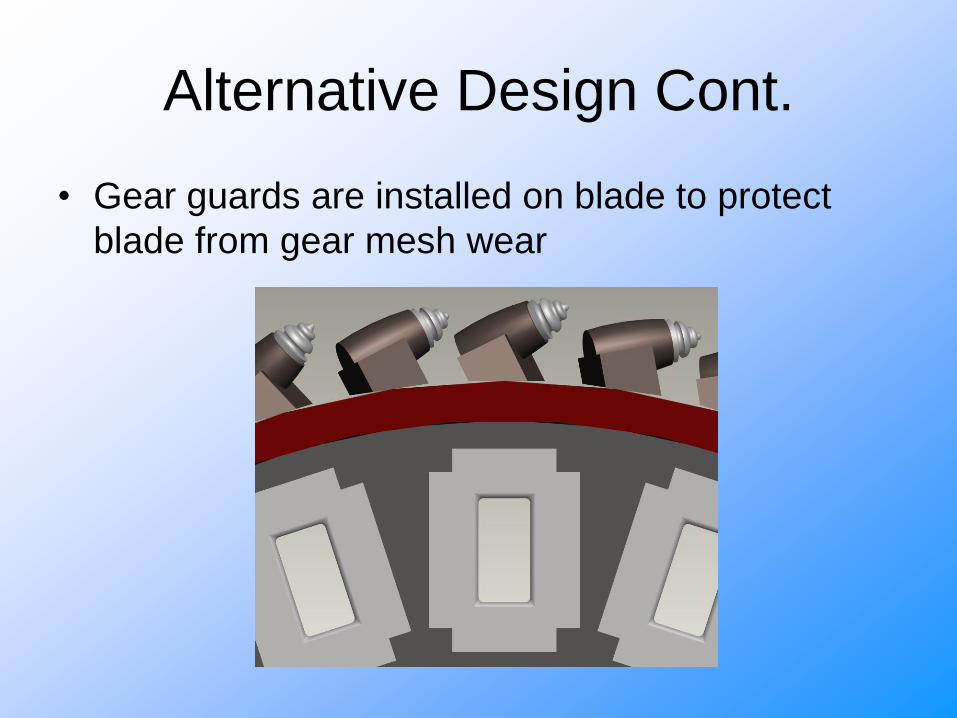
Alternative Design Cont.
• Gear guards are installed on blade to protect
blade from gear mesh wear

Alternative Gear Mesh Design

Proposed BudgetMaterials
gear guards $ 100.00
driving gears $ 214.00
miter gears $ 156.00
Treatments
speedliner coating $60.00
surface treatments TBD
Testing
motor $ 200.00
testing debris $ 20.00
testing container $ 15.00
testing plate $ 70.00
Total Cost (approximately) $ 835.00

Project Schedule
• Fall Semester
– Patent Search
– Design Concepts
• Spring Semester
– Fabrication
– Testing
– Final Design

Thank You
• Gary Cochran and CONEQTEC
• Dr. Paul Weckler
• Jana Moore
• BAE Lab

At this time
we would like
to open the floor to
any
QUESTIONS?