I-7550E Quick Start - ICP DAS USA
8
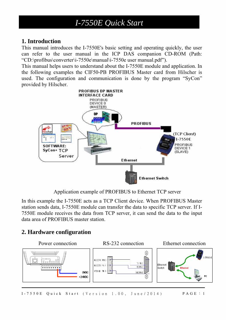
I-7550E Quick Start (Version 1.00, June/2014) PAGE : 1 1. Introduction This manual introduces the I-7550E's basic setting and operating quickly, the user can refer to the user manual in the ICP DAS companion CD-ROM (Path: “CD:\profibus\converter\i-7550e\manual\i-7550e user manual.pdf”). This manual helps users to understand about the I-7550E module and application. In the following examples the CIF50-PB PROFIBUS Master card from Hilscher is used. The configuration and communication is done by the program “SyCon” provided by Hilscher. Application example of PROFIBUS to Ethernet TCP server In this example the I-7550E acts as a TCP Client device. When PROFIBUS Master station sends data, I-7550E module can transfer the data to specific TCP server. If I- 7550E module receives the data from TCP server, it can send the data to the input data area of PROFIBUS master station. 2. Hardware configuration Ethernet connection RS-232 connection Power connection I-7550E Quick Start
-
Upload
khangminh22 -
Category
Documents
-
view
0 -
download
0
Transcript of I-7550E Quick Start - ICP DAS USA
I - 7 5 5 0 E Q u i c k S t a r t ( V e r s i o n 1 . 0 0 , J u n e / 2 0 1 4 ) P A G E : 1
1. Introduction This manual introduces the I-7550E's basic setting and operating quickly, the user can refer to the user manual in the ICP DAS companion CD-ROM (Path: “CD:\profibus\converter\i-7550e\manual\i-7550e user manual.pdf”). This manual helps users to understand about the I-7550E module and application. In the following examples the CIF50-PB PROFIBUS Master card from Hilscher is used. The configuration and communication is done by the program “SyCon” provided by Hilscher.
Application example of PROFIBUS to Ethernet TCP server
In this example the I-7550E acts as a TCP Client device. When PROFIBUS Master station sends data, I-7550E module can transfer the data to specific TCP server. If I-7550E module receives the data from TCP server, it can send the data to the input data area of PROFIBUS master station. 2. Hardware configuration
PROFIBUS connection
Ethernet connectionRS-232 connectionPower connection
I-7550E Quick Start
I - 7 5 5 0 E Q u i c k S t a r t ( V e r s i o n 1 . 0 0 , J u n e / 2 0 1 4 ) P A G E : 2
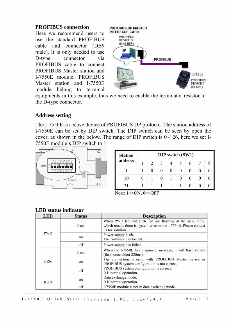
PROFIBUS connection Here we recommend users to use the standard PROFIBUS cable and connector (DB9 male). It is only needed to use D-type connector via PROFIBUS cable to connect PROFIBUS Master station and I-7550E module. PROFIBUS Master station and I-7550E module belong to terminal equipments in this example, thus we need to enable the terminator resistor in the D-type connector.
Address setting
The I-7550E is a slave device of PROFIBUS DP protocol. The station address of I-7550E can be set by DIP switch. The DIP switch can be seen by open the cover, as shown in the below. The range of DIP switch is 0~126, here we set I-7550E module’s DIP switch to 1.
LED status indicator LED Status Description
flash When PWR led and ERR led are flashing at the same time, which means there is system error in the I-7550E. Please contact us for solution.
on Power supply is ok. The firmware has loaded.
PWR
off Power supply has failed.
flash When the I-7550E has diagnostic message, it will flash slowly (flash once about 220ms).
on The connection is error with PROFIBUS Master device or PROFIBUS system configuration is not correct. ERR
off PROFIBUS system configuration is correct. It is normal operation.
on Data exchange mode. It is normal operation. RUN
off I-7550E module is not in data exchange mode.
DIP switch (SW1) Station address 1 2 3 4 5 6 7 8
1 1 0 0 0 0 0 0 010 0 1 0 1 0 0 0 031 1 1 1 1 1 0 0 0
Note: 1=>ON, 0=>OFF
I - 7 5 5 0 E Q u i c k S t a r t ( V e r s i o n 1 . 0 0 , J u n e / 2 0 1 4 ) P A G E : 3
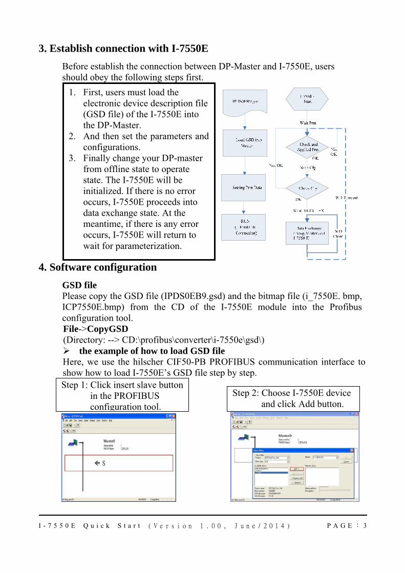
3. Establish connection with I-7550E Before establish the connection between DP-Master and I-7550E, users should obey the following steps first.
4. Software configuration
GSD file Please copy the GSD file (IPDS0EB9.gsd) and the bitmap file (i_7550E. bmp, ICP7550E.bmp) from the CD of the I-7550E module into the Profibus configuration tool. File->CopyGSD (Directory: --> CD:\profibus\converter\i-7550e\gsd\)
the example of how to load GSD file Here, we use the hilscher CIF50-PB PROFIBUS communication interface to show how to load I-7550E’s GSD file step by step.
1. First, users must load the electronic device description file (GSD file) of the I-7550E into the DP-Master.
2. And then set the parameters and configurations.
3. Finally change your DP-master from offline state to operate state. The I-7550E will be initialized. If there is no error occurs, I-7550E proceeds into data exchange state. At the meantime, if there is any error occurs, I-7550E will return to wait for parameterization.
Step 2: Choose I-7550E device and click Add button.
Step 1: Click insert slave button in the PROFIBUS configuration tool.
I - 7 5 5 0 E Q u i c k S t a r t ( V e r s i o n 1 . 0 0 , J u n e / 2 0 1 4 ) P A G E : 4
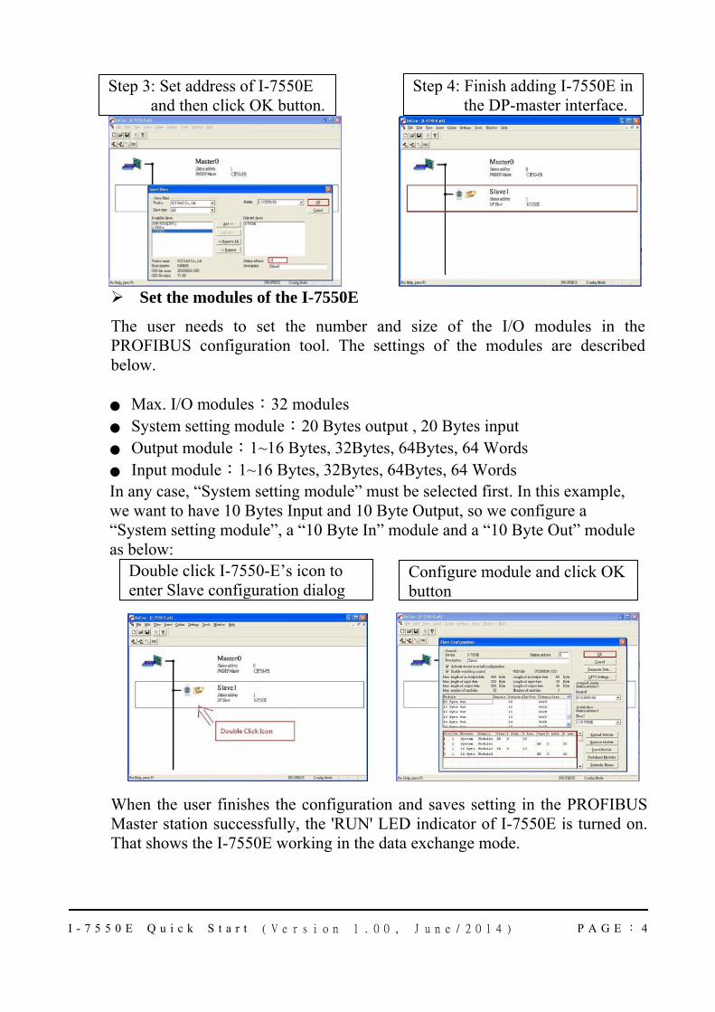
Set the modules of the I-7550E
The user needs to set the number and size of the I/O modules in the PROFIBUS configuration tool. The settings of the modules are described below.
● Max. I/O modules:32 modules ● System setting module:20 Bytes output , 20 Bytes input ● Output module:1~16 Bytes, 32Bytes, 64Bytes, 64 Words ● Input module:1~16 Bytes, 32Bytes, 64Bytes, 64 Words In any case, “System setting module” must be selected first. In this example, we want to have 10 Bytes Input and 10 Byte Output, so we configure a “System setting module”, a “10 Byte In” module and a “10 Byte Out” module as below:
When the user finishes the configuration and saves setting in the PROFIBUS Master station successfully, the 'RUN' LED indicator of I-7550E is turned on. That shows the I-7550E working in the data exchange mode.
Configure module and click OK button
Double click I-7550-E’s icon to enter Slave configuration dialog
Step 4: Finish adding I-7550E in the DP-master interface.
Step 3: Set address of I-7550E and then click OK button.
I - 7 5 5 0 E Q u i c k S t a r t ( V e r s i o n 1 . 0 0 , J u n e / 2 0 1 4 ) P A G E : 5
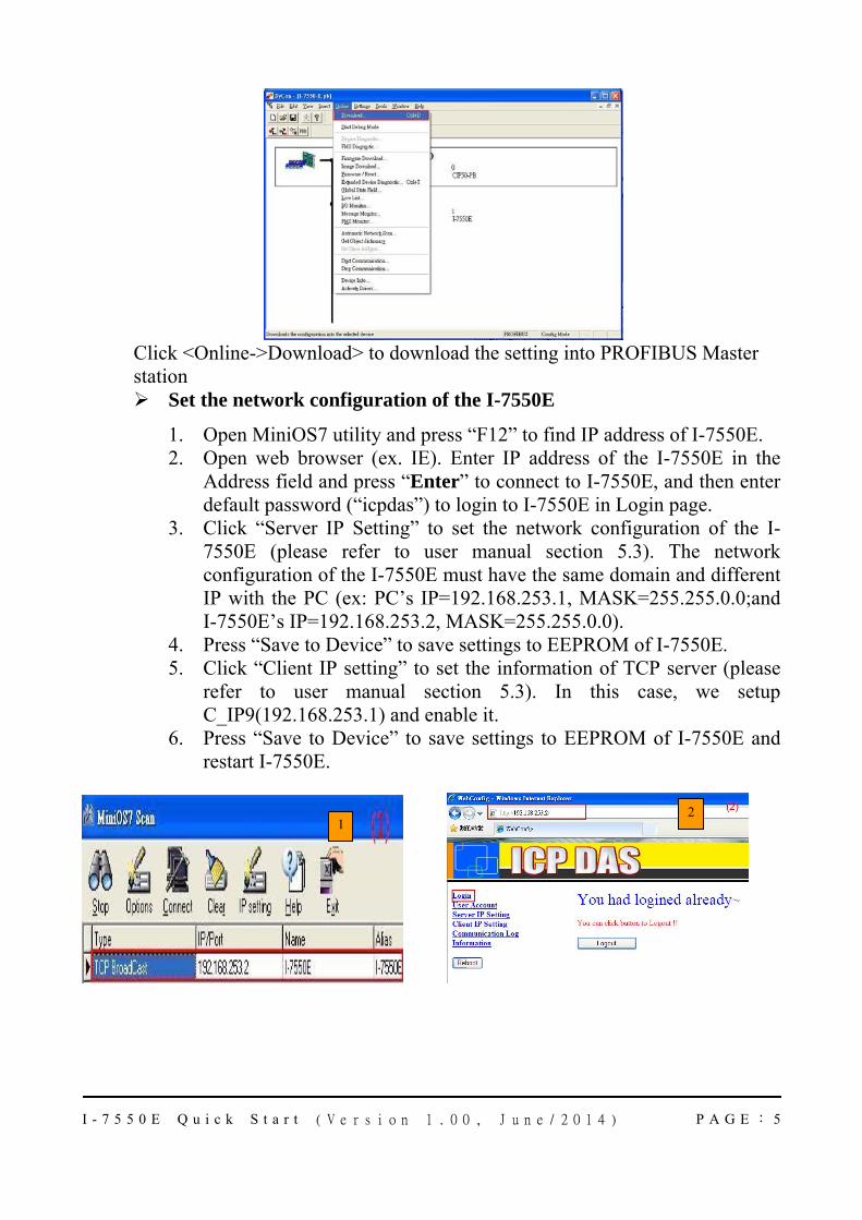
Click <Online->Download> to download the setting into PROFIBUS Master station
Set the network configuration of the I-7550E
1. Open MiniOS7 utility and press “F12” to find IP address of I-7550E. 2. Open web browser (ex. IE). Enter IP address of the I-7550E in the
Address field and press “Enter” to connect to I-7550E, and then enter default password (“icpdas”) to login to I-7550E in Login page.
3. Click “Server IP Setting” to set the network configuration of the I-7550E (please refer to user manual section 5.3). The network configuration of the I-7550E must have the same domain and different IP with the PC (ex: PC’s IP=192.168.253.1, MASK=255.255.0.0;and I-7550E’s IP=192.168.253.2, MASK=255.255.0.0).
4. Press “Save to Device” to save settings to EEPROM of I-7550E. 5. Click “Client IP setting” to set the information of TCP server (please
refer to user manual section 5.3). In this case, we setup C_IP9(192.168.253.1) and enable it.
6. Press “Save to Device” to save settings to EEPROM of I-7550E and restart I-7550E.
12
I - 7 5 5 0 E Q u i c k S t a r t ( V e r s i o n 1 . 0 0 , J u n e / 2 0 1 4 ) P A G E : 6
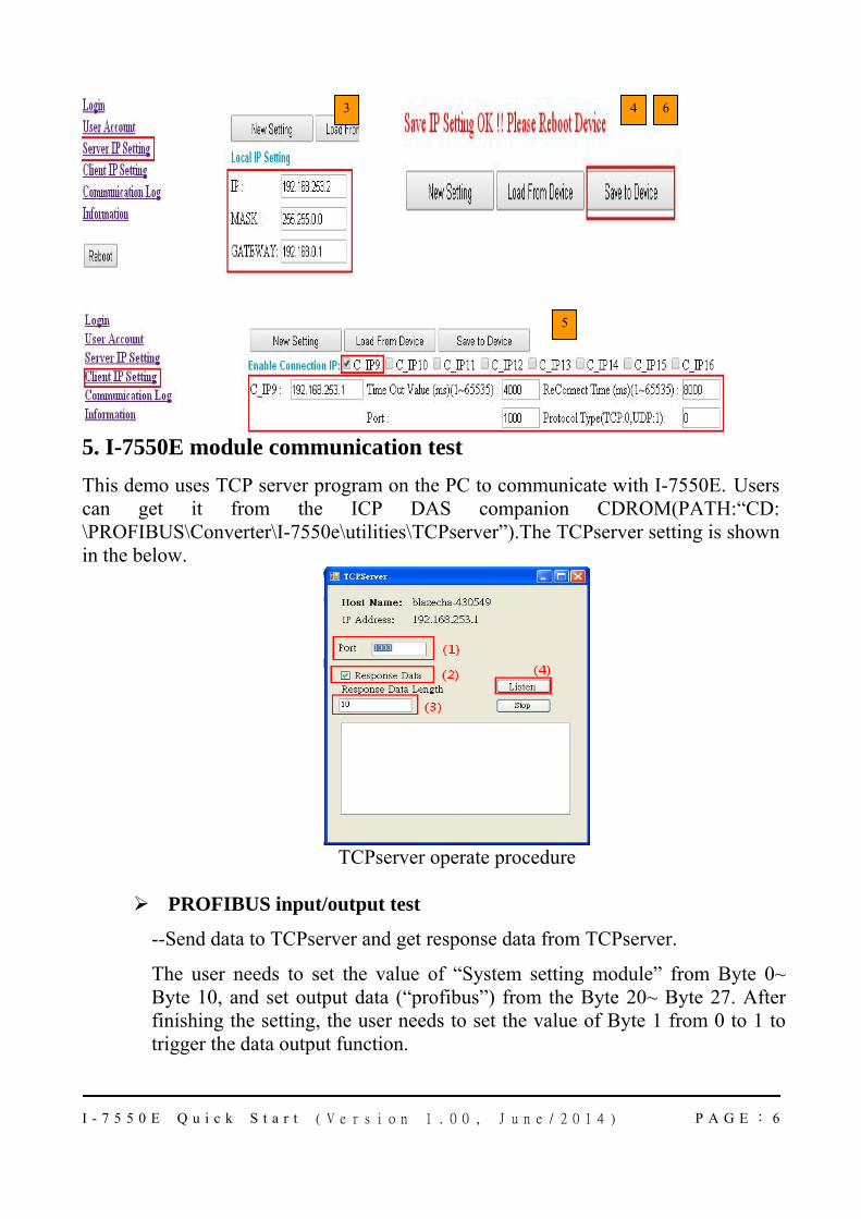
5. I-7550E module communication test This demo uses TCP server program on the PC to communicate with I-7550E. Users can get it from the ICP DAS companion CDROM(PATH:“CD: \PROFIBUS\Converter\I-7550e\utilities\TCPserver”).The TCPserver setting is shown in the below.
TCPserver operate procedure
PROFIBUS input/output test
--Send data to TCPserver and get response data from TCPserver.
The user needs to set the value of “System setting module” from Byte 0~ Byte 10, and set output data (“profibus”) from the Byte 20~ Byte 27. After finishing the setting, the user needs to set the value of Byte 1 from 0 to 1 to trigger the data output function.
3 6
5
4
I - 7 5 5 0 E Q u i c k S t a r t ( V e r s i o n 1 . 0 0 , J u n e / 2 0 1 4 ) P A G E : 7
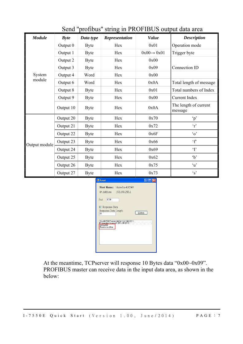
Send ''profibus'' string in PROFIBUS output data area Module Byte Data type Representation Value Description
Output 0 Byte Hex 0x01 Operation mode
Output 1 Byte Hex 0x00→ 0x01 Trigger byte
Output 2 Byte Hex 0x00
Output 3 Byte Hex 0x09 Connection ID
Output 4 Word Hex 0x00
Output 6 Word Hex 0x0A Total length of message
Output 8 Byte Hex 0x01 Total numbers of Index
Output 9 Byte Hex 0x00 Current Index
System module
Output 10 Byte Hex 0x0A The length of current message
Output 20 Byte Hex 0x70 ‘p’
Output 21 Byte Hex 0x72 ‘r’
Output 22 Byte Hex 0x6F ‘o’
Output 23 Byte Hex 0x66 ‘f’
Output 24 Byte Hex 0x69 ‘I’
Output 25 Byte Hex 0x62 ‘b’
Output 26 Byte Hex 0x75 ‘u’
Output module
Output 27 Byte Hex 0x73 ‘s’
At the meantime, TCPserver will response 10 Bytes data “0x00~0x09”. PROFIBUS master can receive data in the input data area, as shown in the below:
I - 7 5 5 0 E Q u i c k S t a r t ( V e r s i o n 1 . 0 0 , J u n e / 2 0 1 4 ) P A G E : 8
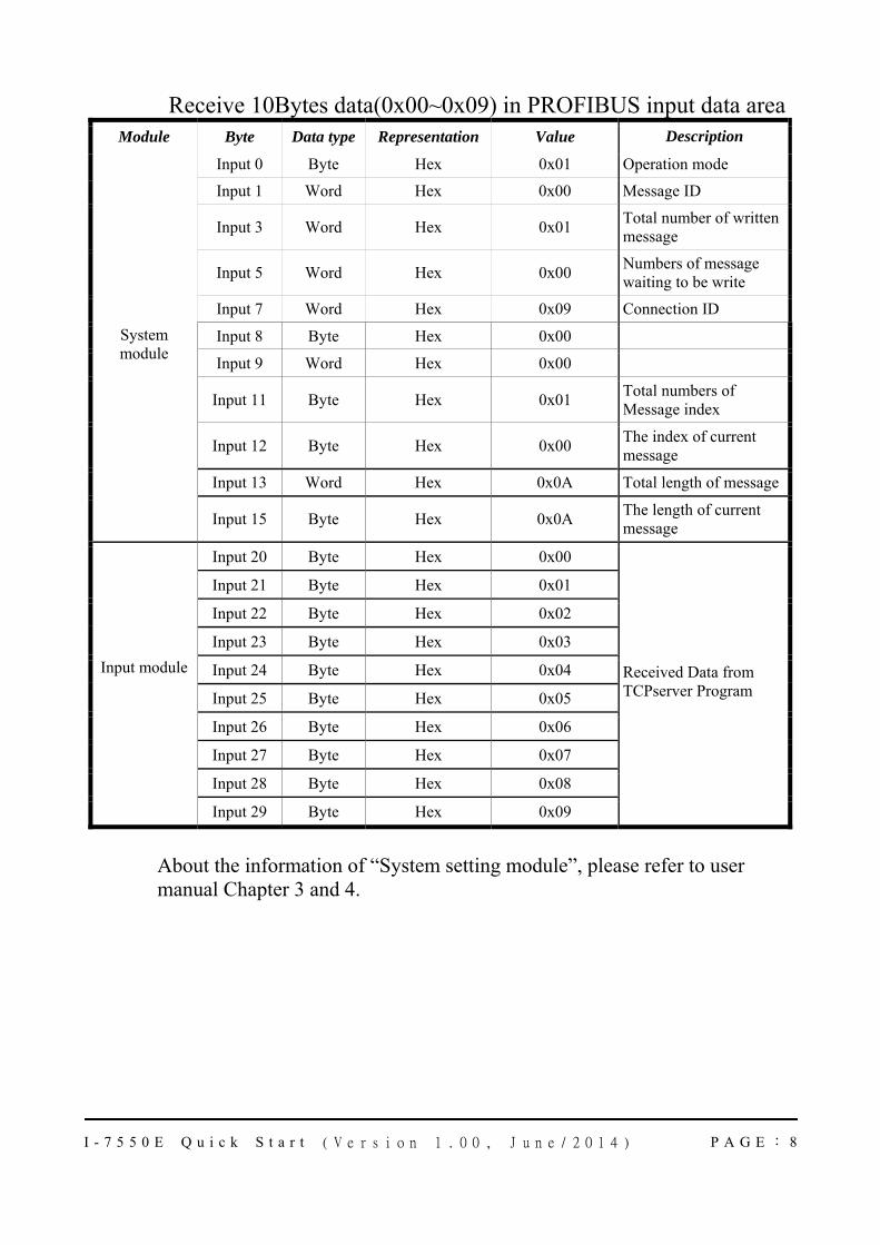
Receive 10Bytes data(0x00~0x09) in PROFIBUS input data area Module Byte Data type Representation Value Description
Input 0 Byte Hex 0x01 Operation mode
Input 1 Word Hex 0x00 Message ID
Input 3 Word Hex 0x01 Total number of written message
Input 5 Word Hex 0x00 Numbers of message waiting to be write
Input 7 Word Hex 0x09 Connection ID
Input 8 Byte Hex 0x00
Input 9 Word Hex 0x00
Input 11 Byte Hex 0x01 Total numbers of Message index
Input 12 Byte Hex 0x00 The index of current message
Input 13 Word Hex 0x0A Total length of message
System module
Input 15 Byte Hex 0x0A The length of current message
Input 20 Byte Hex 0x00
Input 21 Byte Hex 0x01
Input 22 Byte Hex 0x02
Input 23 Byte Hex 0x03
Input 24 Byte Hex 0x04
Input 25 Byte Hex 0x05
Input 26 Byte Hex 0x06
Input 27 Byte Hex 0x07
Input module
Input 28 Byte Hex 0x08
Input 29 Byte Hex 0x09
Received Data from TCPserver Program
About the information of “System setting module”, please refer to user manual Chapter 3 and 4.