
HL-LHC-new-triplets-splices_14April2020.pdf - CERN Indico
22
logo area Overview of HL-LHC Superconducting Wire and Cable Splice Designs C. Scheuerlein Acknowledgements: F. Meuter, E. Tsolakis, R. Principe, D. Etiembre, L. Favier, A. Milanese, H. Prin, E. Todesco, A. Foussat, F. Rodriguez Mateos 14 April 2020
-
Upload
khangminh22 -
Category
Documents
-
view
1 -
download
0
Transcript of HL-LHC-new-triplets-splices_14April2020.pdf - CERN Indico

logo
area
Overview of HL-LHC Superconducting
Wire and Cable Splice Designs
C. Scheuerlein
Acknowledgements: F. Meuter, E. Tsolakis, R. Principe, D. Etiembre, L. Favier, A. Milanese, H. Prin, E. Todesco, A. Foussat, F. Rodriguez Mateos
14 April 2020

logo
area
Outline
Splice requirements and recommendations
MQXF 18 kA circuit splices1) lead cable to flat busbar (double cable)
2) flat busbar to flat busbar
3) round busbar cable to lead cable
4) round busbar cable to flat busbar cable
5) Cu cable to flat busbar cable
MCBXFB and MCBXFA 2 kA circuit splices5) Lead cable to round busbar cable
6) flat lead cable to flat lead cable
D1 and D2 13 kA circuit splices7) Lead cable to flat busbar (double cable or single cable with addiional Cu?)
8) Flat busbar cable to round busbar
MQXF CLIQ lead splices
200 A wire splice
MBH 11 T dipole trim wire to main bus splices
To edit speaker name go to Insert > Header & Footer and apply to all slides except title page 2

logo
area
Splice requirements Splice mechanical integrity and robustness (define number of thermal and
powering cycles for fatigue testing, where needed)
Additional Cu stabilizer continuity
Splice resistance Huge margin of acceptable heating power when operating Nb-Ti/Cu splices in
liquid He.
The splice resistance and its reproducibility is a useful indicator of the reliability of the splice manufacturing processes.
Splice resistance specification [1] E. Todesco, L. Bottura, H. Prin, Y. Leclerc., S. Feher, “BUSBARS FOR WP3 CONNECTED TO DFX”,
Maximum current imbalance in the conductor introduced by resistance variations of the individual wire or cable resistances
Splice insulation dielectric requirements
Splice, insulation and tooling dimensions
Possibility to disconnect and reconnect the splices in the LHC tunnel with standard tools
To edit speaker name go to Insert > Header & Footer and apply to all slides except title page 3
Parameter (units) Triplet D1 MCBXFA/B
Design current (kA) 18.0 13.0 1.73
Operating temperature (K) 1.9 1.9 1.9
Joint resistance (per joint) (nΩ) 1 1 3

logo
area
Splice design recommendations
Robust splice design
As similar as possible to proven LHC splice designs
Easy and reproducible splice manufacturing processes (all
WP3 splices are soft soldered lap splices)
Possibility of in situ non destructive testing
Have big critical current conductor margin
Ideally Cu cross section in the conductor is sufficient, and
no additional stabiliser splices are required
To have good current sharing between all wires
Equal resistance between all cables of a splice
Splice overlap length equals the cable transposition pitch length, or
multiples of it
To edit speaker name go to Insert > Header & Footer and apply to all slides except title page 4

logo
area
Magnet coil conductors
https://espace.cern.ch/HiLumi/WP3/SitePages/Home.aspx
To edit speaker name go to Insert > Header & Footer and apply to all slides except title page 5

logo
area
MQXF 18 kA lead cable and busbars
MQXF lead cable produced by MSC-
SCD
18.15 mm width and 1.92 mm height (not
keystoned)
Transposition pitch=120 mm is made of 34
pre-tinned Nb-Ti wires LHC type 01
(=1.065 mm, Cu/Sc ratio=1.65, RRR>150,
Ic (10T,1.9 K)>515 A)
18 kA flat busbar is made of two MQXF
Nb-Ti lead cables soldered together
(busbar 18.15 mm × 3.84 mm)
Is the 18 kA Cu cable already defined?
To edit speaker name go to Insert > Header & Footer and apply to all slides except title page 6

logo
area
18 kA round busbar cable
18 kA round cable produced by MSC-SCD.
35 LHC type 01 wires around a 11 mm
diameter multi-filamentary Cu core
Transposition pitch?, Ic?, Cu cross section ?
To edit speaker name go to Insert > Header & Footer and apply to all slides except title page 7

logo
area
18 kA circuit splices
18 kA splice types:
1) lead cable to flat busbar (double cable)
2) flat busbar to flat busbar
3) round busbar cable to lead cable
4) round busbar cable to flat busbar cable
5) Cu cable to flat busbar cable
5 splice types, assuming no “triple” splice
Maximum length of a lead cable without additional stabiliser?
How are the diodes connected to the Cu cable ?
To edit speaker name go to Insert > Header & Footer and apply to all slides except title page 8
Figure 1 — Conceptual design of the busbar segments in the 18 kA circuit [1] E. Todesco, L.
Bottura, H. Prin, Y. Leclerc., S. Feher, “BUSBARS FOR WP3 CONNECTED TO DFX”,
<< << <<
Q1a Q1b Q2a Q2b Q3a Q3b CP D1
DFXLine N1
magnet leads flat busbar round busbar
DCM

logo
area
Flat busbar to flat busbar splice
Three different lap splice configurations possible
FNAL soldered both busbars directly, resistances of four splices
ranged from 0.14 nΩ to 0.42 nΩ
Resistance of splice and current homogeneity can be improved
when cables are interleaved.
To edit speaker name go to Insert > Header & Footer and apply to all slides except title page 9
From M. Baldini et al, IEEE
Trans Appl. Supercond. 30(4),
2020, Art No. 4003305
logo
area
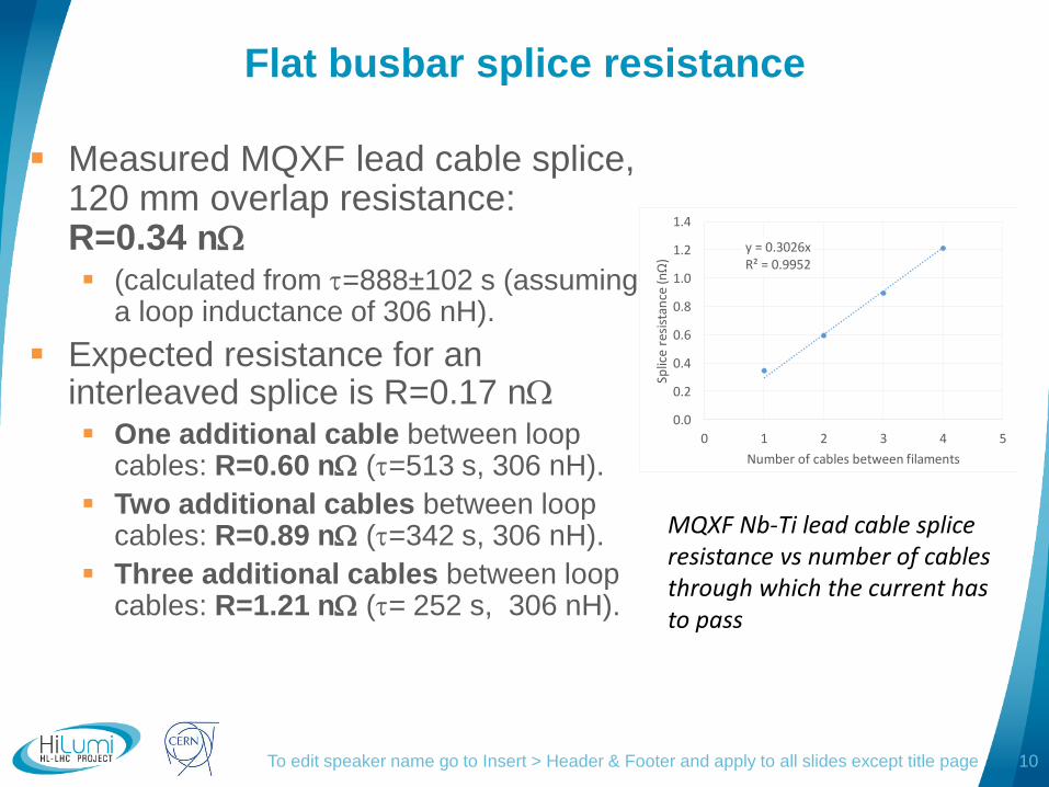
Flat busbar splice resistance
Measured MQXF lead cable splice, 120 mm overlap resistance: R=0.34 n (calculated from =888±102 s (assuming
a loop inductance of 306 nH).
Expected resistance for an interleaved splice is R=0.17 n One additional cable between loop
cables: R=0.60 n (=513 s, 306 nH).
Two additional cables between loop cables: R=0.89 n (=342 s, 306 nH).
Three additional cables between loop cables: R=1.21 n (= 252 s, 306 nH).
To edit speaker name go to Insert > Header & Footer and apply to all slides except title page 10
MQXF Nb-Ti lead cable splice resistance vs number of cables through which the current has to pass
y = 0.3026xR² = 0.9952
0.0
0.2
0.4
0.6
0.8
1.0
1.2
1.4
0 1 2 3 4 5
Splic
e re
sist
ance
(nΩ)
Number of cables between filaments

logo
area
MQXF Nb-Ti Rutherford lead cable to round
18 kA trim cable splice design
To edit speaker name go to Insert > Header & Footer and apply to all slides except title page 11
Photograph of 18 kA trim cable to Rutherford cable splice prototype.

logo
area
MCBXFB and MCBXFA circuit conductors
2 kA Nb-Ti lead cable, Rutherford cable made of 34 wires Ø=0.48
mm, 4.37 mm-wide, 0.845 mm-mid-thickness, transposition pitch 33
mm
Round cable is extracted from LHC conductor (made of three round 6
kA cables).
Each 6 kA cable is made of 13 Nb-Ti wires (Ø=0.85 mm) and 7 Cu
wires in the core.
Flat 2 kA bus? Is it a double lead cable?
To edit speaker name go to Insert > Header & Footer and apply to all slides except title page 12
µ-CT cross section of LHC 6 kA cable. EDMS No. 2215669
logo
area
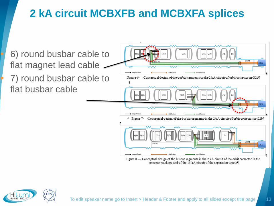
2 kA circuit MCBXFB and MCBXFA splices
6) round busbar cable to
flat magnet lead cable
7) round busbar cable to
flat busbar cable
To edit speaker name go to Insert > Header & Footer and apply to all slides except title page 13

logo
area
13 kA conductors
13 kA lead cable is LHC type 2 Rutherford cable (36 wires 0.825 mm,
15.1 mm 1.48 mm mid-thickness, keystoned, transposition pitch 100
mm)
13 kA flat busbar is soldered together with a keystoned Cu stabiliser.
Is there a round 13 kA cable, or will the round 18 kA cable be used?
To edit speaker name go to Insert > Header & Footer and apply to all slides except title page 14

logo
area
13 kA D1 circuit splices
8) Rutherford lead cable to flat busbar
9) Flat busbar cable to round busbar
To edit speaker name go to Insert > Header & Footer and apply to all slides except title page 15
<< << <<
Q1a Q1b Q2a Q2b Q3a Q3b
DFXLine N1
magnet leads flat busbar round busbar
<< << <<
Q1a Q1b Q2a Q2b Q3a Q3b D1
Line N1
magnet leads flat busbar round busbar
CP
DCM

logo
area
600 A wire splice resistance (correctors)
Nb-Ti/Cu wire
Ø1.6mm, (Nb-
Ti/Cu ratio=0.1)
3.86±0.72 nΩ
(crimp and solder)
2.52±0.19 nΩ (with
Cu profiles
soldered)
3.00.2 nΩ (US
welded)
To edit speaker name go to Insert > Header & Footer and apply to all slides except title page 16

logo
area
Splice voltage taps
Should splice voltage tap connections be included in the splice
summary?
To edit speaker name go to Insert > Header & Footer and apply to all slides except title page 17

logo
area
MBH 11 T dipole trim line main busbar splices
Trim cables made of 4 Nb-Ti/Cu wires Ø1.6mm, (Nb-Ti/Cu
ratio=0.1) see specification EDMS No. 366575.
Wires are soldered to the main busbars at a groove in the main
splice Cu profile
To edit speaker name go to Insert > Header & Footer and apply to all slides except title page 18
logo
area
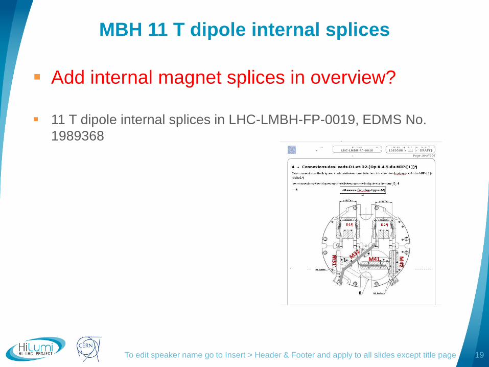
MBH 11 T dipole internal splices
Add internal magnet splices in overview?
11 T dipole internal splices in LHC-LMBH-FP-0019, EDMS No.
1989368
To edit speaker name go to Insert > Header & Footer and apply to all slides except title page 19

logo
area
Questions concerning the conductor
Is the 18 Cu conductor to the diode module already defined?
Are the splices to the diodes already defined, are there bolted pressure splices?
Is it foreseen to have a 13 kA round cable, is there already a design of this cable, or will the 18 kA round cable also be used in the 13 kA circuit?
Is the flat 13 kA bus a LHC double cable, or a single cable with additional Cu stabiliser?
Is the flat 2 kA busbar a double cable?
To edit speaker name go to Insert > Header & Footer and apply to all slides except title page 20

logo
area
Next
Functional splice specification
Get all info on the layout of conductors that have to be
interconnected
Get all info on already existing splice development work
Develop splice designs
Develop interconnection tools
Produce laboratory splices and perform validation tests.
Develop NDT tests
Develop and validate splice insulation systems
Develop splice production procedures and test them in
situ in mock- ups
To edit speaker name go to Insert > Header & Footer and apply to all slides except title page 21

logo
area
References
E. Todesco, L. Bottura, H. Prin, Y. Leclerc., S. Feher, “BUSBARS FOR WP3 CONNECTED TO DFX”,
E. Todesco et al, Busbars for Q1 to D1 magnets”, https://indico.cern.ch/event/830202/contributions/3476759/attachments/1867092/3070601/et_busbar_2019-06-21.pdf
M. Baldini et al, “Characterization of NbTi busbar for HL LHC Interaction Region Quadrupoles”, IEEE Trans Appl. Supercond. 30(4), 2020, Art No. 4003305
Nb3Sn-Nb-Ti splice tests https://edms.cern.ch/ui/#!master/navigator/document?D:1814373709:1814373709:subDocs
H. Prin, “How are the splices made between the trim bus bars (11T MBH), the k-mod and the CLIQ feeders (QXF), as well as the trim bus bars to the magnet leads (QXF) at the level of the cold mass?”, https://indico.cern.ch/event/835702/contributions/3560659/attachments/1905099/3146122/2019-09-10_Int._Circuit_review_closed_session_HP.pdf
H. Prin, “Busbars integration in the cold masses” https://indico.cern.ch/event/477759/contributions/1156018/attachments/1246170/1835566/2016-03_Busbars_routing_inside_the_cold_masses.pdf
R. Bossert, “Status of bus and interconnect“, at 8th HL-LHC collaboration meeting, (2018), https://indico.cern.ch/event/742082/contributions/3141508/attachments/1734744/2805370/Bus_and_Int_-_Hi-Lumi_oct_2018.pdf
R. Herzog, LHC-DCA-CI-0002, EDMS No. 366575 , “Technical Specification for the manufacture of the superconducting 600 A multi-conductor cables for the LHC”, (2002) https://edms.cern.ch/ui/file/366575/1/IT3140TechSpec.pdf
J. Fleiter, https://indico.cern.ch/event/689576/contributions/2831218/attachments/1582569/2501211/Cable_design_approach_and_experience_at_CERN_J._Fleiter_V2.pdf
S. Heck, FEM investigation of the influence of electrical properties and geometric shape on the resistance of soldered cable-around-conduit conductor joints , EDMS Nr:1150055
To edit speaker name go to Insert > Header & Footer and apply to all slides except title page 22