Highly zone-dependent synthesis of different carbon nanostructures using plasma-enhanced arc...
9
RESEARCH PAPER Highly zone-dependent synthesis of different carbon nanostructures using plasma-enhanced arc discharge technique Rajesh Kumar • Rajesh Kumar Singh • Pawan Kumar Dubey • Ram Manohar Yadav • Dinesh Pratap Singh • R. S. Tiwari • O. N. Srivastava Received: 23 July 2014 / Accepted: 18 December 2014 Ó Springer Science+Business Media Dordrecht 2015 Abstract Three kinds of carbon nanostructures, i.e., graphene nanoflakes (GNFs), multi walled carbon nanotubes (MWCNTs), and spherical carbon nano- particles (SCNPs) were comparatively investigated in one run experiment. These carbon nanostructures are located at specific location inside the direct current plasma-assisted arc discharge chamber. These carbon nanomaterials have been successfully synthesized using graphite as arcing electrodes at 400 torr in helium (He) atmosphere. The SCNPs were found in the deposits formed on the cathode holder, in which highly curled graphitic structure are found in majority. The diameter varies from 20 to 60 nm and it also appears that these particles are self-assembled to each other. The MWCNTs with the diameter of 10–30 nm were obtained which were present inside the swelling portion of cathode deposited. These MWCNTs have 14–18 graphitic layers with 3.59 A ˚ interlayer spacing. The GNFs have average lateral sizes of 1–5 lm and few of them are stacked layers and shows crumpled like structure. The GNFs are more stable at low temperature (low mass loss) but SCNPs have low mass loss at high temperature. Keywords Graphene nanoflakes Zone dependent temperature Arc discharge Local defect Introduction Carbon nanomaterials have a number of current and potential future applications due to their highly stable physicochemical properties, low cost, good conduc- tivity, and high porous surface area. These carbon nanomaterials present a wide range of applications R. Kumar (&) Department of Materials Science & Engineering, Yonsei University, Seoul 120-749, Republic of Korea e-mail: [email protected] R. Kumar R. S. Tiwari O. N. Srivastava Department of Physics, Banaras Hindu University, Varanasi 221005, India R. K. Singh (&) Department of Applied Physics, Indian Institute of Technology, Banaras Hindu University, Varanasi 221005, India e-mail: [email protected] P. K. Dubey Nanotechnology Application Centre, University of Allahabad, Allahabad 211002, India R. M. Yadav Department of Materials Science and Nano Engineering, Rice University, Houston, TX 77005, USA D. P. Singh Departamento de Fı ´sica, Universidad de Santiago de Chile, Avenida Ecuador 3493, Estacio ´n Central, 9170124 Santiago, Chile 123 J Nanopart Res (2015) 17:24 DOI 10.1007/s11051-014-2837-9
-
Upload
independent -
Category
Documents
-
view
0 -
download
0
Transcript of Highly zone-dependent synthesis of different carbon nanostructures using plasma-enhanced arc...
RESEARCH PAPER
Highly zone-dependent synthesis of different carbonnanostructures using plasma-enhanced arc dischargetechnique
Rajesh Kumar • Rajesh Kumar Singh • Pawan Kumar Dubey •
Ram Manohar Yadav • Dinesh Pratap Singh •
R. S. Tiwari • O. N. Srivastava
Received: 23 July 2014 / Accepted: 18 December 2014
� Springer Science+Business Media Dordrecht 2015
Abstract Three kinds of carbon nanostructures, i.e.,
graphene nanoflakes (GNFs), multi walled carbon
nanotubes (MWCNTs), and spherical carbon nano-
particles (SCNPs) were comparatively investigated in
one run experiment. These carbon nanostructures are
located at specific location inside the direct current
plasma-assisted arc discharge chamber. These carbon
nanomaterials have been successfully synthesized
using graphite as arcing electrodes at 400 torr in
helium (He) atmosphere. The SCNPs were found in
the deposits formed on the cathode holder, in which
highly curled graphitic structure are found in majority.
The diameter varies from 20 to 60 nm and it also
appears that these particles are self-assembled to each
other. The MWCNTs with the diameter of 10–30 nm
were obtained which were present inside the swelling
portion of cathode deposited. These MWCNTs have
14–18 graphitic layers with 3.59 A interlayer spacing.
The GNFs have average lateral sizes of 1–5 lm and
few of them are stacked layers and shows crumpled
like structure. The GNFs are more stable at low
temperature (low mass loss) but SCNPs have low mass
loss at high temperature.
Keywords Graphene nanoflakes � Zone dependent
temperature � Arc discharge � Local defect
Introduction
Carbon nanomaterials have a number of current and
potential future applications due to their highly stable
physicochemical properties, low cost, good conduc-
tivity, and high porous surface area. These carbon
nanomaterials present a wide range of applications
R. Kumar (&)
Department of Materials Science & Engineering, Yonsei
University, Seoul 120-749, Republic of Korea
e-mail: [email protected]
R. Kumar � R. S. Tiwari � O. N. Srivastava
Department of Physics, Banaras Hindu University,
Varanasi 221005, India
R. K. Singh (&)
Department of Applied Physics, Indian Institute of
Technology, Banaras Hindu University, Varanasi 221005,
India
e-mail: [email protected]
P. K. Dubey
Nanotechnology Application Centre, University of
Allahabad, Allahabad 211002, India
R. M. Yadav
Department of Materials Science and Nano Engineering,
Rice University, Houston, TX 77005, USA
D. P. Singh
Departamento de Fısica, Universidad de Santiago de
Chile, Avenida Ecuador 3493, Estacion Central,
9170124 Santiago, Chile
123
J Nanopart Res (2015) 17:24
DOI 10.1007/s11051-014-2837-9
including fuel cells, field emission devices, hydrogen
storage, supercapacitors, sensors, and battery elec-
trodes (Endo et al. 2001; Milne et al. 2004; Yoshitake
et al. 2002). Among many methods that have been
applied to obtain carbon materials are arc discharge
method (Subrahmanyam et al. 2009), laser ablation
method, solvothermal method (Choucair et al. 2009),
and chemical vapor deposition (Wang et al. 2009).
Among these available methods, the arc discharge
method is most widely used because of its simplicity
and cost-effective technology compared to other more
expensive ones (Gattia et al. 2007; Li et al. 2010). In arc
discharge method, arc current, ambient gas, and
ambient pressure inside the arcing chamber are the
important parameters for synthesis of different carbon
nanostructures (Kim et al. 2012). The direct current
(DC) arc supplies sufficient energy in form of temper-
ature to electrode causing the evaporation and forma-
tion of arc plasma. A high influx of plasma species and
high temperature play key role in the growth of carbon
nanostructures. Economically feasible large-scale pro-
duction and purification techniques still have to be
developed for the synthesis of carbon nanostructures.
Different types of carbon related nanostructure such as
nanotubes (Liang et al. 2012; Sun et al. 2013), carbon
nanoparticles (Borgohain et al. 2014; Xing et al. 2007),
graphene nanoflakes (GNFs) (Li et al. 2013; Wu et al.
2010) and other types of carbon nanostructure mate-
rials e.g., fullerenes (Churilov 2008) can be produced
using arc discharge method.
It is widely recognized that plasma enhance arc
discharge method will be one of the most promising
means for the production of carbon-based nanostruc-
tures. Therefore, a simple and systematic study,
dealing with the identification of key parameters that
allow to control the carbon-based nanostructure, is
required. Some studies (Bagiante et al. 2010; Scalese
et al. 2010; Scuderi et al. 2009) have shown that the
electrode shape and size, ambient pressure and the
arcing current greatly influence the nature or type and
quality of carbon-based nanostructure.
In this work, we have investigated the effect of
temperature on the carbon product synthesized after
arcing the graphite electrode in helium (He) atmo-
sphere. Soot samples were collected from different
axial and top locations inside the arc discharge
chamber to study soot structure, size, graphitization,
and agglomeration using transmission electron
microscopy (TEM) and HRTEM. Furthermore, by
investigating the morphologies and microstructures of
the cathode deposits and evaporated soot, we have
found that different carbon nanostructures have been
formed at different locations and similar nanostruc-
tures were formed at specific locations. A suitable
mechanism has been provided for the different carbon
nanomaterials formed.
Experimental section
Synthesis of carbon-based nanostructures
The direct current (DC) arc discharge of graphite
electrode was carried in the same apparatus as reported
previously (Kumar et al. 2013). The cylindrical
cathode rod was (L = 15 mm, Ø = 5 mm) sharp end
toward the anode in order to decrease the formation of
cathode deposition. The anode rod was rectangular
(20 9 8 9 8 mm3) for large amount of carbon shoot
evaporation. The cathode was fixed in the apparatus,
and the anode can be moved toward the cathode. This
method creates soots through arc-vaporization of two
graphitic rods placed end to end, separated by approx-
imately 1 mm, in an enclosure that is usually filled with
inert gas (helium, argon) at low pressure (between 50
and 700 mbar). The anode gets evaporated after
ignition of the plasma due to the high heat flux from
the DC arc discharge. The electric arc was generated
(30 V, 100 A) in a helium atmosphere at 400 torr.
During the arcing, the distance between two graphite
electrodes was maintained constant by continuously
translating the anode rod toward cathode. After the
complete evaporation, the black carbon shoots like
materials were collected from different regions of the
experimental apparatus and were characterized.
Characterization
Black carbon shoots like materials were characterized
using X-ray diffractometer (XRD) (Philips PW 1710),
scanning electron microscopy (SEM) (Philips XL 20),
transmission electron microscopy (HRTEM) (Tecnai
20 G2), and Raman spectroscopy. Sample for TEM
studies were prepared by dispersing a small amount of
material in ethanol with sonication for 5 min. Drops of
the dispersion were placed onto a holey carbon grid
and dried. Raman spectrum of as-grown sample was
measured by Raman spectrometer (Renishaw, model
24 Page 2 of 9 J Nanopart Res (2015) 17:24
123
no. H 45517) using an argon ion laser (k = 514 nm).
The thermal stability of different carbon nanostruc-
tures formed was measured by the thermal gravimetry
analysis (TGA) (STA 449F3) from 32 to 850 �C at the
rate of 10 �C/min under oxygen ambience.
Result and discussion
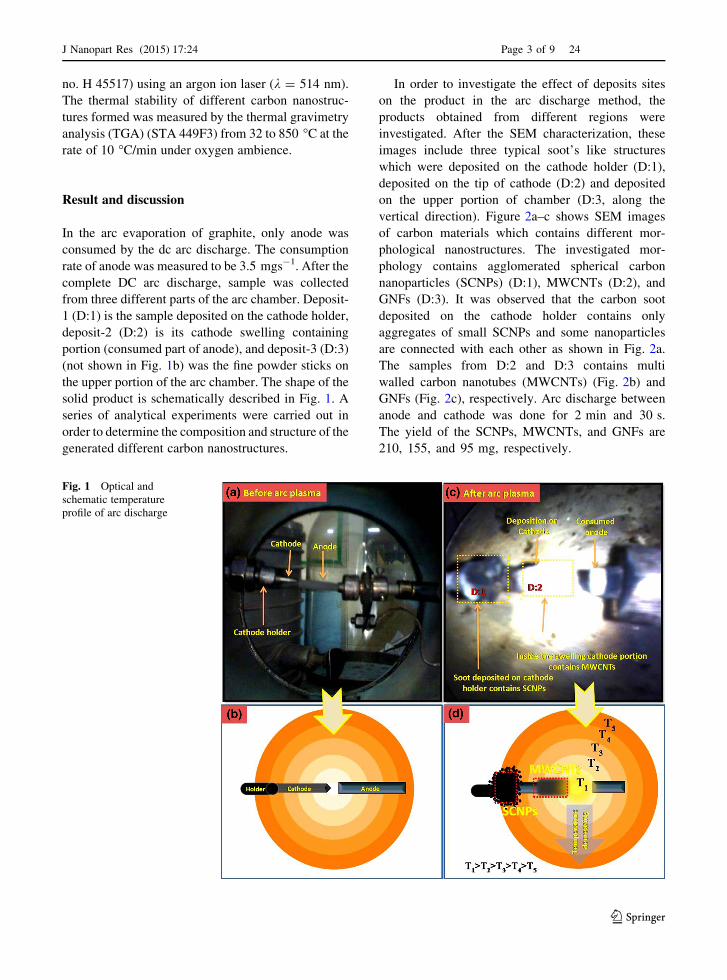
In the arc evaporation of graphite, only anode was
consumed by the dc arc discharge. The consumption
rate of anode was measured to be 3.5 mgs-1. After the
complete DC arc discharge, sample was collected
from three different parts of the arc chamber. Deposit-
1 (D:1) is the sample deposited on the cathode holder,
deposit-2 (D:2) is its cathode swelling containing
portion (consumed part of anode), and deposit-3 (D:3)
(not shown in Fig. 1b) was the fine powder sticks on
the upper portion of the arc chamber. The shape of the
solid product is schematically described in Fig. 1. A
series of analytical experiments were carried out in
order to determine the composition and structure of the
generated different carbon nanostructures.
In order to investigate the effect of deposits sites
on the product in the arc discharge method, the
products obtained from different regions were
investigated. After the SEM characterization, these
images include three typical soot’s like structures
which were deposited on the cathode holder (D:1),
deposited on the tip of cathode (D:2) and deposited
on the upper portion of chamber (D:3, along the
vertical direction). Figure 2a–c shows SEM images
of carbon materials which contains different mor-
phological nanostructures. The investigated mor-
phology contains agglomerated spherical carbon
nanoparticles (SCNPs) (D:1), MWCNTs (D:2), and
GNFs (D:3). It was observed that the carbon soot
deposited on the cathode holder contains only
aggregates of small SCNPs and some nanoparticles
are connected with each other as shown in Fig. 2a.
The samples from D:2 and D:3 contains multi
walled carbon nanotubes (MWCNTs) (Fig. 2b) and
GNFs (Fig. 2c), respectively. Arc discharge between
anode and cathode was done for 2 min and 30 s.
The yield of the SCNPs, MWCNTs, and GNFs are
210, 155, and 95 mg, respectively.
Fig. 1 Optical and
schematic temperature
profile of arc discharge
J Nanopart Res (2015) 17:24 Page 3 of 9 24
123

TEM characterization also indicates that the main
products observed were SCNPs, MWCNTs, and
GNFs. The typical transmission electron microscope
image of the SCNPs can be seen in Fig. 3a, b. The
diameter of SCNPs was found in nano dimension
(Fig. 3a, b) and it shows that some particles are
agglomerated and some are connected to each other.
From the micrographs, it is also possible to estimate
the SCNPs size which varies from 20 to 60 nm and all
SCNPs are having the similar structures. The histo-
gram in the inset of Fig. 3b shows the diameter
distribution of SCNPs. These SCNPs aggregate
Fig. 2 SEM micrographs of a SCNPs, b MWCNTs, and c GNFs
Fig. 3 TEM micrographs at different magnifications as a–c SCNPs, d–f MWCNTs, and g–i GNFs
24 Page 4 of 9 J Nanopart Res (2015) 17:24
123
linearly and form chained structures and also appears
as necklace type chain which contains SCNPs. The
growth process takes place at a relatively low plasma
temperature as comparison to MWCNTs and GNFs.
This induces the nearly isotropic growth of SCNPs.
These spheres are crystalline, as shown in HRTEM
images (Fig. 3c). The crystalline nature has been also
confirmed by the electron diffraction pattern in the
inset of Fig. 3b. Figure 3d, shows the D:2 type of
carbon soot which mainly contain MWCNTs nano-
structure. These MWCNTs are entangled and having
non-aligned structure as seen in TEM micrographs.
The MWCNTs have nearly uniform diameter in the
range of 5–20 nm. The representative high-resolution
TEM (HRTEM) image of MWCNT shows 14 gra-
phitic layer and more crystalline and nearly defects
free structure as compared to SCNPs. Figure 3g–i
show the typical TEM images of GNFs. Figure 3g,
indicates that the third kind of deposition which was
found on the dome was GNFs. The surface of the
GNFs is not perfectly flat and shows different levels of
transparency, which is similar to those synthesized by
arc discharge in various environments (Chen et al.
2012; Hagino et al. 2012; Scuderi et al. 2012). Inset of
Fig. 3h, shows the selected-area electron diffraction
(SAED) pattern which indicates that GNFs is poly-
crystalline. In our experiment, it is indicated that these
GNFs in the as-obtained sample consist of multi-layer
graphene sheets. In addition, the average interlayer
separations of the graphene sheets were 3.35 A as
determined by measuring the spacing of the dark
fringes.
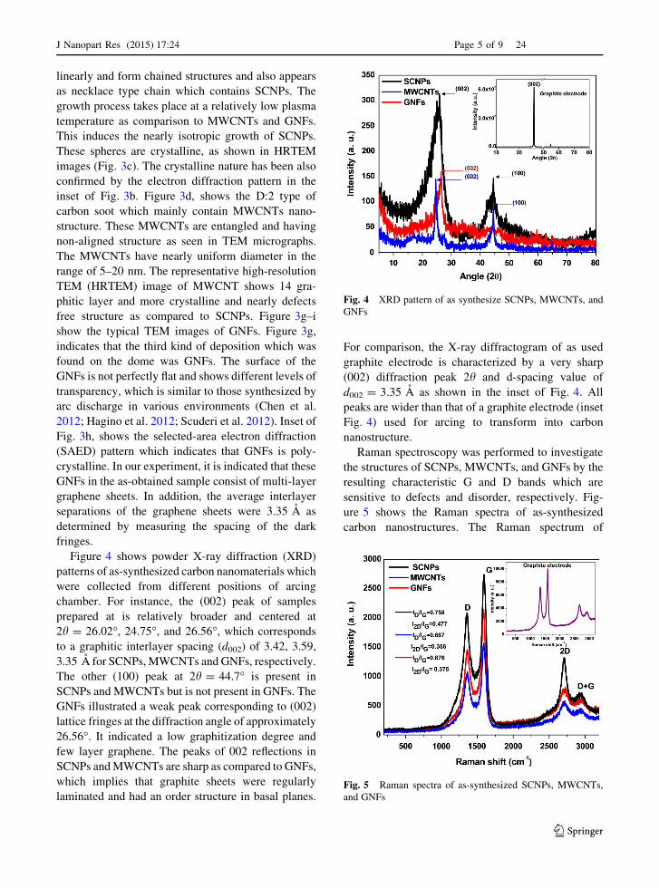
Figure 4 shows powder X-ray diffraction (XRD)
patterns of as-synthesized carbon nanomaterials which
were collected from different positions of arcing
chamber. For instance, the (002) peak of samples
prepared at is relatively broader and centered at
2h = 26.02�, 24.75�, and 26.56�, which corresponds
to a graphitic interlayer spacing (d002) of 3.42, 3.59,
3.35 A for SCNPs, MWCNTs and GNFs, respectively.
The other (100) peak at 2h = 44.7� is present in
SCNPs and MWCNTs but is not present in GNFs. The
GNFs illustrated a weak peak corresponding to (002)
lattice fringes at the diffraction angle of approximately
26.56�. It indicated a low graphitization degree and
few layer graphene. The peaks of 002 reflections in
SCNPs and MWCNTs are sharp as compared to GNFs,
which implies that graphite sheets were regularly
laminated and had an order structure in basal planes.
For comparison, the X-ray diffractogram of as used
graphite electrode is characterized by a very sharp
(002) diffraction peak 2h and d-spacing value of
d002 = 3.35 A as shown in the inset of Fig. 4. All
peaks are wider than that of a graphite electrode (inset
Fig. 4) used for arcing to transform into carbon
nanostructure.
Raman spectroscopy was performed to investigate
the structures of SCNPs, MWCNTs, and GNFs by the
resulting characteristic G and D bands which are
sensitive to defects and disorder, respectively. Fig-
ure 5 shows the Raman spectra of as-synthesized
carbon nanostructures. The Raman spectrum of
Fig. 4 XRD pattern of as synthesize SCNPs, MWCNTs, and
GNFs
Fig. 5 Raman spectra of as-synthesized SCNPs, MWCNTs,
and GNFs
J Nanopart Res (2015) 17:24 Page 5 of 9 24
123
carbon-based material is usually characterized by two
main features: the G band (usually observed at
1,575 cm-1) and D band (1,350 cm-1). The G band
arises from the first order scattering of the E1g phonon
of sp2 C atoms, while the D mode is a breathing mode
of j-point photons of A1g symmetry (Chipara et al.
2013; Voronov and Street 2010). Thus, the G band is
the result of vibration of sp2 C atoms and the D band
arises from the disorder and defect intensity of the
crystal structure (Dresselhaus et al. 2004). An addi-
tional Raman line, found at about 2,709 cm-1 has
been tentatively assigned as a G0 band (or the D* band
or 2D band) (Dresselhaus et al. 2004). This is an
overtone (2 phonon process) of the D band located
between 2,450 and 2,950 cm-1, and characterized by a
width of about 81, 100 and 109 cm-1, corresponds to
SCNPs, GNFs, and MWCNTs. The intensity ratio of D
and G band (ID/IG) can be used to quantify the relative
content of defects and the sp2 domain size. Figure 5
shows the Raman spectra of SCNPs, MWCNTs, and
GNFs carbon-based nanostructures. A broad D and G
band are present in all of them. The ID/IG for SCNPs,
MWCNTs, and GNFs is *0.758, 0.687 and 0.676,
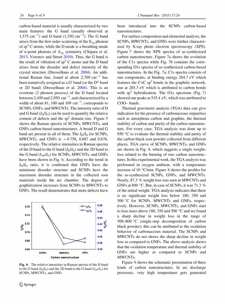
respectively. The relative intensities in Raman spectra
of the D band to the G band (ID/IG) and the 2D band to
the G band (I2D/IG) for SCNPs, MWCNTs, and GNFs
have been shown in Fig. 6. According to the trend in
ID/IG ratio, it is confirmed that GNFs have the
minimum disorder structure and SCNPs have the
maximum disorder structure in the collected soot
materials inside the arc chamber. The degree of
graphitization increases from SCNPs to MWCNTs to
GNFs. The result demonstrates that more defects have
been introduced into the SCNPs carbon-based
nanostructures.
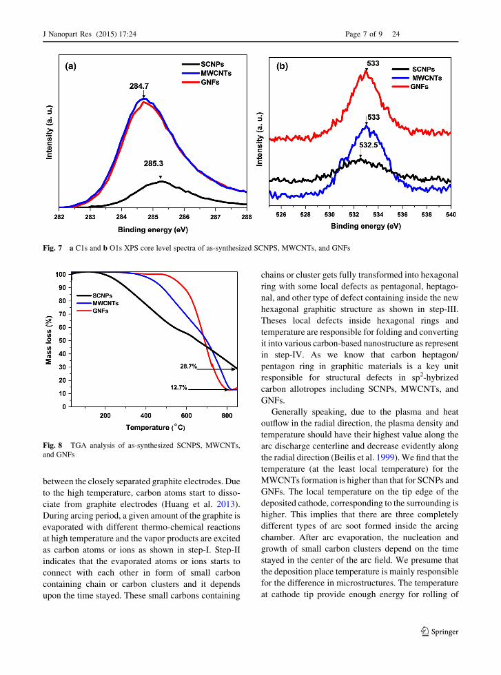
For surface composition and elemental analysis, the
SCNPs, MWCNTs, and GNFs were further character-
ized by X-ray photo electron spectroscopy (XPS).
Figure 7 shows the XPS spectra of as-synthesized
carbon nanostructure. Figure 7a shows the evolution
of the C1s spectra while Fig. 7b contains the corre-
sponding O1s spectra of as-synthesized carbon-based
nanostructures. In the Fig. 7a, C1s spectra consists of
one components, at binding energy 284.7 eV which
features the C=C sp2 bonds in the graphitic network,
one at 285.3 eV which is attributed to carbon bonds
with sp3 hybridization. The O1s spectrum (Fig. 7)
showed one peaks at 535.4 eV, which was attributed to
COO– bands.
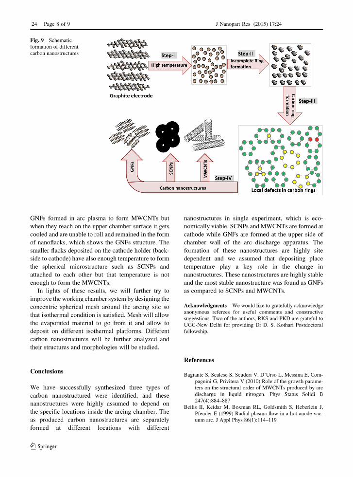
Thermal gravimetri analysis (TGA) data can give
indication for the presence of carbonaceous impurities
such as amorphous carbon and graphite, the thermal
stability of carbon and purity of the carbon nanostruc-
ture. For every case, TGA analysis was done up to
850 �C to evaluate the thermal stability and purity of
the carbon black soot powder collected from different
places. TGA curve of SCNPs, MWCNTs, and GNFs
are shown in Fig. 8, which suggests a single weight-
loss related to the burning of raw carbon nanostruc-
tures. In this experimental work, the TGA analysis was
performed in oxygen ambient, with a temperature
increase of 10 �C/min. Figure 8 shows the profiles for
the as-synthesized SCNPs, GNFs, and MWCNTs.
Nearly, 87.3 % weight loss was seen in MWCNTs and
GNFs at 800 �C. But, in case of SCNPs, it was 71.3 %
of the initial weight. TGA analysis indicates that there
is no significant weight loss below 180, 350 and
500 �C for SCNPs, MWCNTs and GNFs, respec-
tively. However, SCNPs, MWCNTs, and GNFs start
to lose mass above 180, 350 and 500 �C and we found
a sharp decline in weight loss in the range of
500–800 �C (single-step decomposition of carbon
black powder); this can be attributed to the oxidation
behavior of carbonaceous material. The SCNPs and
MWCNTs do not shows the sharp decline in weight
loss as compared to GNFs. The above analysis shows
that the oxidation temperature and thermal stability of
GNFs are higher as compared to SCNPs and
MWCNTs.
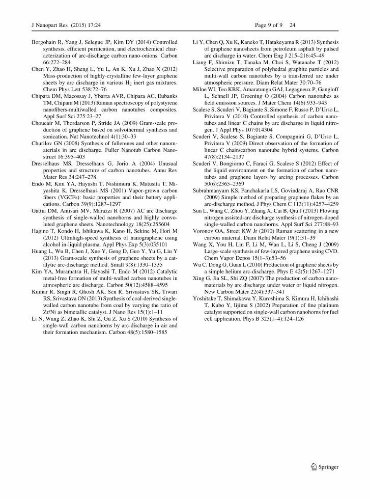
Figure 9 shows the schematic presentation of three
kinds of carbon nanostructures. In arc discharge
processes, very high temperature gets generated
Fig. 6 The relative intensities in Raman spectra of the D band
to the G band (ID/IG) and the 2D band to the G band (I2D/IG) for
SCNPs, MWCNTs, and GNFs
24 Page 6 of 9 J Nanopart Res (2015) 17:24
123
between the closely separated graphite electrodes. Due
to the high temperature, carbon atoms start to disso-
ciate from graphite electrodes (Huang et al. 2013).
During arcing period, a given amount of the graphite is
evaporated with different thermo-chemical reactions
at high temperature and the vapor products are excited
as carbon atoms or ions as shown in step-I. Step-II
indicates that the evaporated atoms or ions starts to
connect with each other in form of small carbon
containing chain or carbon clusters and it depends
upon the time stayed. These small carbons containing
chains or cluster gets fully transformed into hexagonal
ring with some local defects as pentagonal, heptago-
nal, and other type of defect containing inside the new
hexagonal graphitic structure as shown in step-III.
Theses local defects inside hexagonal rings and
temperature are responsible for folding and converting
it into various carbon-based nanostructure as represent
in step-IV. As we know that carbon heptagon/
pentagon ring in graphitic materials is a key unit
responsible for structural defects in sp2-hybrized
carbon allotropes including SCNPs, MWCNTs, and
GNFs.
Generally speaking, due to the plasma and heat
outflow in the radial direction, the plasma density and
temperature should have their highest value along the
arc discharge centerline and decrease evidently along
the radial direction (Beilis et al. 1999). We find that the
temperature (at the least local temperature) for the
MWCNTs formation is higher than that for SCNPs and
GNFs. The local temperature on the tip edge of the
deposited cathode, corresponding to the surrounding is
higher. This implies that there are three completely
different types of arc soot formed inside the arcing
chamber. After arc evaporation, the nucleation and
growth of small carbon clusters depend on the time
stayed in the center of the arc field. We presume that
the deposition place temperature is mainly responsible
for the difference in microstructures. The temperature
at cathode tip provide enough energy for rolling of
Fig. 7 a C1s and b O1s XPS core level spectra of as-synthesized SCNPS, MWCNTs, and GNFs
Fig. 8 TGA analysis of as-synthesized SCNPS, MWCNTs,
and GNFs
J Nanopart Res (2015) 17:24 Page 7 of 9 24
123
GNFs formed in arc plasma to form MWCNTs but
when they reach on the upper chamber surface it gets
cooled and are unable to roll and remained in the form
of nanoflacks, which shows the GNFs structure. The
smaller flacks deposited on the cathode holder (back-
side to cathode) have also enough temperature to form
the spherical microstructure such as SCNPs and
attached to each other but that temperature is not
enough to form the MWCNTs.
In lights of these results, we will further try to
improve the working chamber system by designing the
concentric spherical mesh around the arcing site so
that isothermal condition is satisfied. Mesh will allow
the evaporated material to go from it and allow to
deposit on different isothermal platforms. Different
carbon nanostructures will be further analyzed and
their structures and morphologies will be studied.
Conclusions
We have successfully synthesized three types of
carbon nanostructured were identified, and these
nanostructures were highly assumed to depend on
the specific locations inside the arcing chamber. The
as produced carbon nanostructures are separately
formed at different locations with different
nanostructures in single experiment, which is eco-
nomically viable. SCNPs and MWCNTs are formed at
cathode while GNFs are formed at the upper side of
chamber wall of the arc discharge apparatus. The
formation of these nanostructures are highly site
dependent and we assumed that depositing place
temperature play a key role in the change in
nanostructures. These nanostructures are highly stable
and the most stable nanostructure was found as GNFs
as compared to SCNPs and MWCNTs.
Acknowledgments We would like to gratefully acknowledge
anonymous referees for useful comments and constructive
suggestions. Two of the authors, RKS and PKD are grateful to
UGC-New Delhi for providing Dr D. S. Kothari Postdoctoral
fellowship.
References
Bagiante S, Scalese S, Scuderi V, D’Urso L, Messina E, Com-
pagnini G, Privitera V (2010) Role of the growth parame-
ters on the structural order of MWCNTs produced by arc
discharge in liquid nitrogen. Phys Status Solidi B
247(4):884–887
Beilis II, Keidar M, Boxman RL, Goldsmith S, Heberlein J,
Pfender E (1999) Radial plasma flow in a hot anode vac-
uum arc. J Appl Phys 86(1):114–119
Fig. 9 Schematic
formation of different
carbon nanostructures
24 Page 8 of 9 J Nanopart Res (2015) 17:24
123
Borgohain R, Yang J, Selegue JP, Kim DY (2014) Controlled
synthesis, efficient purification, and electrochemical char-
acterization of arc-discharge carbon nano-onions. Carbon
66:272–284
Chen Y, Zhao H, Sheng L, Yu L, An K, Xu J, Zhao X (2012)
Mass-production of highly-crystalline few-layer graphene
sheets by arc discharge in various H2 inert gas mixtures.
Chem Phys Lett 538:72–76
Chipara DM, Macossay J, Ybarra AVR, Chipara AC, Eubanks
TM, Chipara M (2013) Raman spectroscopy of polystyrene
nanofibers-multiwalled carbon nanotubes composites.
Appl Surf Sci 275:23–27
Choucair M, Thordarson P, Stride JA (2009) Gram-scale pro-
duction of graphene based on solvothermal synthesis and
sonication. Nat Nanotechnol 4(1):30–33
Churilov GN (2008) Synthesis of fullerenes and other nanom-
aterials in arc discharge. Fuller Nanotub Carbon Nano-
struct 16:395–403
Dresselhaus MS, Dresselhaus G, Jorio A (2004) Unusual
properties and structure of carbon nanotubes. Annu Rev
Mater Res 34:247–278
Endo M, Kim YA, Hayashi T, Nishimura K, Matusita T, Mi-
yashita K, Dresselhaus MS (2001) Vapor-grown carbon
fibers (VGCFs): basic properties and their battery appli-
cations. Carbon 39(9):1287–1297
Gattia DM, Antisari MV, Marazzi R (2007) AC arc discharge
synthesis of single-walled nanohorns and highly convo-
luted graphene sheets. Nanotechnology 18(25):255604
Hagino T, Kondo H, Ishikawa K, Kano H, Sekine M, Hori M
(2012) Ultrahigh-speed synthesis of nanographene using
alcohol in-liquid plasma. Appl Phys Exp 5(3):035101
Huang L, Wu B, Chen J, Xue Y, Geng D, Guo Y, Yu G, Liu Y
(2013) Gram-scale synthesis of graphene sheets by a cat-
alytic arc-discharge method. Small 9(8):1330–1335
Kim YA, Muramatsu H, Hayashi T, Endo M (2012) Catalytic
metal-free formation of multi-walled carbon nanotubes in
atmospheric arc discharge. Carbon 50(12):4588–4595
Kumar R, Singh R, Ghosh AK, Sen R, Srivastava SK, Tiwari
RS, Srivastava ON (2013) Synthesis of coal-derived single-
walled carbon nanotube from coal by varying the ratio of
Zr/Ni as bimetallic catalyst. J Nano Res 15(1):1–11
Li N, Wang Z, Zhao K, Shi Z, Gu Z, Xu S (2010) Synthesis of
single-wall carbon nanohorns by arc-discharge in air and
their formation mechanism. Carbon 48(5):1580–1585
Li Y, Chen Q, Xu K, Kaneko T, Hatakeyama R (2013) Synthesis
of graphene nanosheets from petroleum asphalt by pulsed
arc discharge in water. Chem Eng J 215–216:45–49
Liang F, Shimizu T, Tanaka M, Choi S, Watanabe T (2012)
Selective preparation of polyhedral graphite particles and
multi-wall carbon nanotubes by a transferred arc under
atmospheric pressure. Diam Relat Mater 30:70–76
Milne WI, Teo KBK, Amaratunga GAJ, Legagneux P, Gangloff
L, Schnell JP, Groening O (2004) Carbon nanotubes as
field emission sources. J Mater Chem 14(6):933–943
Scalese S, Scuderi V, Bagiante S, Simone F, Russo P, D’Urso L,
Privitera V (2010) Controlled synthesis of carbon nano-
tubes and linear C chains by arc discharge in liquid nitro-
gen. J Appl Phys 107:014304
Scuderi V, Scalese S, Bagiante S, Compagnini G, D’Urso L,
Privitera V (2009) Direct observation of the formation of
linear C chain/carbon nanotube hybrid systems. Carbon
47(8):2134–2137
Scuderi V, Bongiorno C, Faraci G, Scalese S (2012) Effect of
the liquid environment on the formation of carbon nano-
tubes and graphene layers by arcing processes. Carbon
50(6):2365–2369
Subrahmanyam KS, Panchakarla LS, Govindaraj A, Rao CNR
(2009) Simple method of preparing graphene flakes by an
arc-discharge method. J Phys Chem C 113(11):4257–4259
Sun L, Wang C, Zhou Y, Zhang X, Cai B, Qiu J (2013) Flowing
nitrogen assisted-arc discharge synthesis of nitrogen-doped
single-walled carbon nanohorns. Appl Surf Sci 277:88–93
Voronov OA, Street KW Jr (2010) Raman scattering in a new
carbon material. Diam Relat Mater 19(1):31–39
Wang X, You H, Liu F, Li M, Wan L, Li S, Cheng J (2009)
Large-scale synthesis of few-layered graphene using CVD.
Chem Vapor Depos 15(1–3):53–56
Wu C, Dong G, Guan L (2010) Production of graphene sheets by
a simple helium arc-discharge. Phys E 42(5):1267–1271
Xing G, Jia SL, Shi ZQ (2007) The production of carbon nano-
materials by arc discharge under water or liquid nitrogen.
New Carbon Mater 22(4):337–341
Yoshitake T, Shimakawa Y, Kuroshima S, Kimura H, Ichihashi
T, Kubo Y, Iijima S (2002) Preparation of fine platinum
catalyst supported on single-wall carbon nanohorns for fuel
cell application. Phys B 323(1–4):124–126
J Nanopart Res (2015) 17:24 Page 9 of 9 24
123