Graphene-Based Saturable Absorber for Single-Longitudinal-Mode Operation of Highly Doped...
10
Graphene-Based Saturable Absorber for Single-Longitudinal-Mode Operation of Highly Doped Erbium-Doped Fiber Laser Volume 4, Number 2, April 2012 F. D. Muhammad M. Z. Zulkifli A. A. Latif S. W. Harun H. Ahmad DOI: 10.1109/JPHOT.2012.2190498 1943-0655/$31.00 ©2012 IEEE
-
Upload
independent -
Category
Documents
-
view
1 -
download
0
Transcript of Graphene-Based Saturable Absorber for Single-Longitudinal-Mode Operation of Highly Doped...

Graphene-Based Saturable Absorber for Single-Longitudinal-Mode Operation of Highly Doped Erbium-Doped Fiber LaserVolume 4, Number 2, April 2012
F. D. MuhammadM. Z. Zulkifl iA. A. LatifS. W. HarunH. Ahmad
DOI: 10.1109/JPHOT.2012.21904981943-0655/$31.00 ©2012 IEEE

Graphene-Based Saturable Absorber forSingle-Longitudinal-Mode Operation ofHighly Doped Erbium-Doped Fiber Laser
F. D. Muhammad,1 M. Z. Zulkifli,1 A. A. Latif,1 S. W. Harun,1;2 and H. Ahmad1
1Photonics Research Centre, Department of Physics, University of Malaya,50603 Kuala Lumpur, Malaysia
2Department of Electrical Engineering, Faculty of Engineering, University of Malaya,50603 Kuala Lumpur, Malaysia
DOI: 10.1109/JPHOT.2012.21904981943-0655/$31.00 �2012 IEEE
Manuscript received February 9, 2012; revised March 3, 2012; accepted March 6, 2012. Date ofpublication March 9, 2012; date of current version April 2, 2012. This work was supported by theUniversity of Malaya under HIR Grant (Terahertz, UM.C/HIR/MOHE/SC/01) and by MOHE.Corresponding author: H. Ahmad (e-mail: [email protected]).
Abstract: In this paper, a conventional wavelength band (C-band) fiber laser with a tunablesingle-longitudinal-mode (SLM) output using multilayer graphene as a saturable absorber isdemonstrated. The proposed fiber laser uses a short length of highly doped erbium-dopedfiber (EDF) as the gain medium and a fiber ferrule with graphene flakes adhered to it by indexmatching gel (IMG) that acts as the saturable absorber. The fiber laser is able to generate anadjustable wavelength output between 1547.88 and 1559.88 nmwith an average peak powerof �6.48 dBm with a measured signal-to-noise ratio between 66.0 and 68.3 dB. The SLMoutput is verified by the absence of frequency beating in the radio frequency (RF) spectrumoutput and by a measured linewidth of 206.25 kHz using the self-heterodyne technique. Thedeposition of graphene flakes on the fiber ferrule using the IMG is a new and effectivetechnique to generate SLM operation in the fiber laser.
Index Terms: Graphene, saturable absorber, single-longitudinal mode, Erbium-doped fiberlaser.
1. IntroductionErbium-doped fiber (EDF) has emerged as one of the strong candidates to be employed as the gainmedium in a fiber laser. Consequently, by exciting its Erbium ions, it can provide amplification ofsignals at wavelength attractive for optical communication, which is around 1550 nm withoutintroducing any effects of gain narrowing [1], [2]. Nevertheless, EDF ring lasers usually suffer fromhomogeneous gain broadening, mode hopping, mode competition, and multimode oscillation [3]. Inaddition, the issue of multimode output that rises from fiber ring laser due to mode hopping, longercavity length, and very narrow longitudinal mode spacing restricts the fiber lasers from obtainingsingle-longitudinal-mode (SLM) operation, which results in formation of noises in frequency domain[4]. In this regard, SLM output in EDF-based fiber lasers have become an important criteria formultitude of operations including fiber optic sensors, modern instrumentation, wavelength-division-multiplexing (WDM) communications, and microwave photonics system [5]. In the past, many workspertaining to SLM generation have been demonstrated [6]–[15]; however, most employ highlycomplex techniques such as multiple ring cavity structures [16], tunable ring resonators [17], externallight injection [18], unidirectional loop mirrors [19], acousto-optic tunable filters [20], and fiber Fabry–Perot filter (FFPF) [21]. Simpler configurations have also been demonstrated using unpumped EDFs
Vol. 4, No. 2, April 2012 Page 467
IEEE Photonics Journal Graphene-Based Saturable Absorber for EDF

as a saturable absorber [22], though at the cost of performance due to high insertion losses and,therefore, requiring high pump powers. Nowadays, graphene has been attaining much interest andattention in both photonics and optoelectronics application due to its outstanding and uniquefeatures, including high mobility, good optical transparency, and ultrawideband tunability, whicharises from the zero bandgap energy, which itself is a consequence of the linear dispersion of Diracelectrons [23]. There are numerous journal papers that have reported recently on graphene forvarious potential significance, for instance, a graphene-based saturable absorber for mode-lockedfiber laser [24]–[26]. In this paper, a stable and inexpensive tunable SLM C-band fiber laser isproposed and demonstrated. The fiber laser uses a short length of highly doped EDF as the activegain medium and multilayer graphene acting as a saturable absorber. SLM lasing in a simple cavitydesign with the tuning range between 1547.88 and 1559.88 nm is obtained. The deposition processof graphene on the surface end of the fiber ferrule is done by using a novel technique employingindex matching gel (IMG) to adhere the graphene flakes onto the fiber ferrule. In addition, thecharacteristics of output power, wavelength, signal-to-noise ratio (SNR), and radio frequency (RF)spectrum are performed and analyzed.
2. Deposition of GrapheneIMG is used to adhere graphene flakes onto the surface of the fiber ferrule as an alternativeapproach. The graphene flakes used are suspended in a solution as obtained from GrapheneResearch Ltd. The IMG used has an index of refraction that closely approximates to that of the silicaoptical fiber, which has a value of 1.463. Normally, the IMG is used to reduce Fresnel reflection atthe end surfaces of the fiber connectors. The other benefit of IMG is that it has a very hightransparency, low evaporation, excellent adhesion, and good mechanical shear stability. In thispaper, the IMG is used in a unique manner, whereby it is used to provide adhesion of the grapheneflakes onto the ferrule.
In the deposition process, the IMG is firstly spread thoroughly onto the surface end of the fiberferrule. Then, the fiber ferrule with the attached IMG is immersed into the graphene solution. Afterthis, the attached graphene as well as the IMG is dried at room temperature. Fig. 1 shows theschematic illustration of the fiber ferrule with the deposited graphene on its surface end. The thicklayer of graphene appears finely dispersed around the surface of the fiber ferrule without excessiveclustering of the graphene.
The result of the deposition method is microscopically examined by Raman spectroscopy(Renishaw) as to measure the Raman spectrum of the sample. The Raman spectrum is acquired bylaser excitation at 532 nm (2.33 eV) with an exposure time of 10 s using a 1800-lines/mm grating.The incident power and the depth of field are set to be 5 mW and 1 �m, respectively. The detectorused in this Raman spectroscopy is a charge-coupled device camera. Using a 100� objective lenswith a numerical aperture NA of 0.85, we obtain a spot size of 0.5 �m. The spot size is defined as thediameter of the laser spot on the sample.
The Raman spectrum of the deposited graphene is shown in Fig. 2, which exhibits the intensitypeaks at Raman shift of approximately 1350, 1580, and 2700 cm�1. The most intense features inRaman spectrum of graphene are the two prominent peaks, one located around the Raman shift of1580 cm�1, commonly called the G peak, and the other one located around the Raman shift of2700 cm�1, namely 2-D peak [27], [28]. The peak profile of the Raman spectrum obtained in Fig. 2matches the specified peak profile of graphene in the Raman spectrum, as stated above, and as
Fig. 1. Schematic representation of the fiber ferrule deposited with graphene using index matching gel(IMG: Index Matching Gel; FF: Fiber Ferrule; G: Graphene).
IEEE Photonics Journal Graphene-Based Saturable Absorber for EDF
Vol. 4, No. 2, April 2012 Page 468

reported previously in other works [27]–[29]. This indicates that graphene is well deposited on thefiber ferrule in this work.
In defected graphene, another peak will be observed around the Raman shift of 1350 cm�1,historically named D peak, and its relative signal strength (compared with the G peak) dependsstrongly on the amount of disorder in the graphitic material, which originates from the grapheneedge [28]. The width of the 2-D peak can be used to determine the number of graphene layers(whereby the width is larger as the number of graphene layers increase). This effect reflects thechange in the electron bands through a double resonant Raman process based on the electronicstructure and the phonon dispersion [27], [28]. Besides that, another way to distinguish the singlelayer graphene from multilayer graphene is by calculating the intensity ratio of G peak over 2-Dpeak. Single-layer graphene is indicated by the low intensity ratio of G/2-D, which is generallylower than 0.5, whereas multilayer graphene is identified by a high intensity ratio of G/2-D, which islarger than or close to 1 [29]. In our work, the calculated intensity ratio of G/2-D from Fig. 3exceeds the value of 1 (1.04499), thus signifying that the deposited graphene is multilayer. Theestimated thickness of the graphene layer, based on the above value, is approximately about 0.712 nm.
From the comprehensive explanation of Fig. 2, it can be concluded that the multilayer graphene issuccessfully and properly deposited on the fiber ferrule. The noise in the Raman spectrumobserved from the figure is most probably attributed by the Raman shift of the IMG. In Fig. 3, thespot image of the deposited thick layer graphene viewed under Raman spectroscopy is presented.
The advantage of this method is its low complexity and cost effectiveness, as no other optical,chemical, or electrical methods are needed. The IMG also has the additional advantage of having
Fig. 3. Spot image of the deposited graphene under Raman spectroscopy.
Fig. 2. Raman spectrum of the thick layer graphene deposited on the fiber ferrule.
IEEE Photonics Journal Graphene-Based Saturable Absorber for EDF
Vol. 4, No. 2, April 2012 Page 469
minimal optical loss. This has been proven experimentally by checking the power loss using a TLS,a patchcord with IMG applied onto its ferrule end, and an optical power meter. Moreover, by usingthis method, a very thick graphene layer can be deposited at a time. The basic operation ofgraphene as the saturable absorber is described in the other section of this paper.
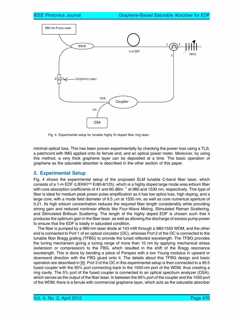
3. Experimental SetupFig. 4 shows the experimental setup of the proposed SLM tunable C-band fiber laser, whichconsists of a 1-m EDF (LIEKKIi Er80-8/125), which is a highly doped large mode area erbium fiberwith core absorption coefficients of 41 and 80 dBm�1 at 980 and 1530 nm, respectively. This type offiber is ideal for medium peak power pulse amplification as it has low splice loss, high doping, and alarge core, with a mode field diameter of 9.5 �m at 1550 nm, as well as core numerical aperture of0.21. Its high erbium concentration reduces the required fiber length considerably while providingstrong gain and reduced nonlinear effects like Four-Wave Mixing, Stimulated Raman Scattering,and Stimulated Brillouin Scattering. The length of the highly doped EDF is chosen such that itproduces the optimum gain in the fiber laser, as well as allowing the discharge of excess pump powerto ensure that the EDF is totally in saturated condition.
The fiber is pumped by a 980-nm laser diode at 143 mW through a 980/1550 WDM, and the otherend is connected to Port 1 of an optical circulator (OC), whereas Port 2 of the OC is connected to thetunable fiber Bragg grating (TFBG) to provide the tuned reflected wavelength. The TFBG providesthe tuning mechanism giving a tuning range of more than 10 nm by applying mechanical stress(extension or compression) to the FBG, which resulted in the shift of the Bragg resonancewavelength. This is done by bending a piece of Perspex with a low Young modulus in upward ordownward direction with the FBG glued onto it. The details about this TFBG design and basicoperation are described in [6]. Port 3 of the OC in this experimental setup is then connected to a 95:5fused coupler with the 95% port connecting back to the 1550-nm port of the WDM, thus creating aring cavity. The 5% port of the fused coupler is connected to an optical spectrum analyzer (OSA),which serves as the output of the fiber laser. In between the 95% port of the coupler and the 1550 portof the WDM, there is a ferrule with commercial graphene layer, which acts as the saturable absorber
Fig. 4. Experimental setup for tunable highly Er-doped fiber ring laser.
IEEE Photonics Journal Graphene-Based Saturable Absorber for EDF
Vol. 4, No. 2, April 2012 Page 470

to generate SLM output in this fiber laser. The basic principle of the graphene-based saturableabsorber is described in the section below.
4. Graphene as Saturable AbsorberThe photonic properties of graphene are significant. Graphene, which is composed of a single layerfrom 3-D graphitic crystalis, is one of the carbon allotropes. It consists of one-atom-thick planarsheets of sp2-bonded carbon atoms that are densely packed in a honeycomb crystal lattice. Its 2-Dsheet, which differs from Carbon Nanotubes (CNT), reveals its uniqueness. The CNT, which iscommonly used as saturable absorber, and the principles are clearly explained in [23], [30], and[31]. In achieving SLM laser operation, the saturable absorber is used to suppress themultilongitudinal mode and noises in a fiber laser. In the case of low intensity light incident,photons are highly absorbed, and the electrons in the valence band are excited up to conductionband of the saturable absorber material. In the case of high intensity light incident, some photonsare not absorbed due to the occupation of electrons in the conduction band, which are excited bythe photons from the low intensity light. Therefore, only high intensity light can pass through thesaturable absorber with very low loss and vice versa. In principle, the optical absorption of graphenelayers is proportional to the number of layers, each absorbing A � 1� T � � � 2:3% over thevisible spectrum [23]. Hence, it can be concluded that the thicker the graphene deposited, the moreoptical absorption it exhibits.
5. Results and DiscussionFig. 5 shows the experimental tunability of the SLM C-band fiber laser using a highly doped 1-m-long EDF taken from an Ando OSA (AQ6317) with a spectral resolution of 0.02 nm. The indicatedtuning range of this fiber laser spans from 1547 to 1560 nm, and this is not limited as the tuningrange can exceed above 1560 nm and below 1547 nm, respectively. By using a differentialmicrometer head, the tuning resolution can be further improved [6].
The lasing wavelengths are observed to be of a SLM and can be tuned continuously over thedesired wavelength region. No mode hoping is observed as the wavelengths are tuned, and this canbe attributed to the single wavelength lasing allowed by the FBG.
As opposed to other earlier works [6]–[22], the graphene-based saturable absorber mechanismused in this experiment experiences lower insertion loss, which leads to higher and stable outputpower. From the figure, there is a very low output power variation over the entire wavelength range,with peak amplitudes ranging from �5.65 to �7.18 dBm. The maximum peak amplitude, which isabout �5.6 dBm, is at 1553.88 nm, varying slightly among all the other wavelengths in the figure.This is plotted in Fig. 6, which shows the variation of the peak amplitude power against the tunedSLM wavelengths. In addition, the SNR, which is an important characteristic for a fiber laser, isalso shown in Fig. 6. From the plot of the SNR against the tuned SLM wavelength, it can be seen
Fig. 5. Output spectra versus wavelengths in the tuning range of 1547.88 to 1559.88 nm.
IEEE Photonics Journal Graphene-Based Saturable Absorber for EDF
Vol. 4, No. 2, April 2012 Page 471

that the distribution of SNR is obtained between 66.0 and 68.3 dB. An excellent SNR profile isobserved with the highest SNR value of 68.25 dB at 1553.88 nm, and the corresponding outputpower is �5.65 dBm. The low deviation of the SNR values across the whole wavelength range inthe figure indicates that the quality of the proposed fiber laser is of very high, as opposed to thatin the earlier work [6].
To realize and investigate the stabilities of output power and output wavelength in the proposedfiber laser, a short-term stability measurement is carried out, and the result is shown in Fig. 7. Theobservation time is over 60min. at 1552.09 nmwith an output power of�5.71 dBm initially. The powerand wavelength variations are observed to be less than 0.04 dB and 0.12 nm, respectively. Thisproved that the output stability of the proposed fiber laser is well maintained over time.
The verification of theSLM ismeasured using a high-speed photodetector (HP53440B, 6GHz) andan RF spectrum analyzer (Anritsu 2683A), which are generally used to show SLM behavior. Theresult is shown in Fig. 8. From the figure, it is observed that there is no beat detected in the RFspectrum. In a fiber laser, the beating can occur when there is more than one mode oscillating in thecavity. Thus, SLM laser operation can be indicated by zero beating, as observed in the RF spectrum.
Fig. 7. Output stability measurements of the fiber laser over 60 min observation time.
Fig. 6. Output power and SNR versus wavelength.
IEEE Photonics Journal Graphene-Based Saturable Absorber for EDF
Vol. 4, No. 2, April 2012 Page 472

In this paper, apart from Fig. 8, further verification of SLM operation is reaffirmed using a delayedself-heterodyne RF spectrum technique. The basic setup consists of a 3 dB (1 � 2) coupler withone port connecting to a 500-m-long single-mode fiber (SMF), which functions as the delay line,and the other port is connected to the Acousto Optic Modulator (AOM), is then recombined using a3 dB (2 � 1) coupler [6]. In this basic setup, the input coupler divides the signal from the fiber laserinto two portions of the same power, with one portion propagating into the 500 m long SMF, whilethe other portion propagates into the AOM, which operates at 80 MHz. Both signals are thenrecombined at the output coupler [32]. The measured line-width from the RF spectrum is shown inFig. 7, and this equals 206.25 kHz, which proves that the output of the fiber laser operates in SLM.The proposed setup using a short length of highly doped erbium fiber in a ring cavity configurationwith graphene as saturable absorber is capable to produce SLM operation. To the best of theauthors’ knowledge, this is the first report of graphene-based saturable absorber providing SLMoperation in a tunable fiber laser. The RF spectrum of delayed self-heterodyne signal is shown inFig. 9, while the linewidth measurement for 13 tuning wavelengths is shown in Fig. 10. Only smalllinewidth variations are observed for different wavelengths in Fig. 10.
Fig. 8. RF spectrum of the output laser.
Fig. 9. RF spectrum of delayed self-heterodyne signal.
IEEE Photonics Journal Graphene-Based Saturable Absorber for EDF
Vol. 4, No. 2, April 2012 Page 473

6. ConclusionAs a summary, the proposed graphene-based saturable absorber for tunable EDF laser with anSLM operation using a short length of 1 m of highly doped EDF as the gain medium has beendemonstrated. The graphene flakes are deposited mechanically as multiple layers using IMG on thefiber ferrule, which is verified by intensity peaks at Raman shifts of approximately 1350, 1580, and2700 cm�1. Being the gain medium in the ring cavity laser, a 1-m EDF has core absorptioncoefficients of 41 and 80 dBm�1 at 980 and 1530 nm, respectively, and is used in conjunction withthe saturable absorber and is used to suppress the multilongitudinal mode and noises in a fiberlaser, thus giving SLM operation. Verification of SLM operation is done by detecting the RF spec-trum, which in this case shows no frequency beating and using the delayed self-heterodynetechnique. The measured linewidth is 206.25 kHz and clearly indicates SLM operation. Tunability ofthe fiber laser is obtained by the inclusion of a TFBG, which gives a wavelength output of between1547.88 and 1559.88 nm with an average peak power of �6.48 dBm. The tuning can be furtherenhanced by having an improved TBFG design. The measured SNR is between 66.0 and 68.3 dBand reaches its maximum value of 68.25 dB at 1553.88 nm with corresponding output powerof �5.65 dBm. The result confirms that the graphene-based saturable absorber by the simpledeposition method using IMG is applicable to give a good performance of the SLM tunable fiberlaser.
References[1] F. D. Mahad and S. Abu, BEDFA gain optimization for WDM system,[ Elektrika, vol. 11, no. 1, pp. 34–37, 2009.[2] P. C. Becker, N. A. Olsson, and J. R. Simpson, Erbium-Doped Fiber Amplifiers Fundamentals and Technology,
San Diego, CA: Academic, 1999.[3] K. Zhang and J. U. Kang, BC-band wavelength-swept single-longitudinal mode erbium-doped fiber ring laser,[Opt. Exp.,
vol. 16, no. 18, pp. 14 173–14 179, Sep. 2008.[4] S. Pan and J. Yao, BA wavelength switchable single longitudinal mode dual-wavelength erbium doped fiber laser for
switchable microwave generation,[ Opt. Exp., vol. 17, no. 7, pp. 5414–5419, Mar. 2009.[5] C. H. Yeh, C. W. Chow, and Y. C. Chang, BWavelength selection erbium fiber laser with single mode operation using
simple ring design,[ Laser Phys., vol. 20, no. 4, pp. 830–833, Apr. 2010.[6] H. Ahmad, M. Z. Zulkifli, A. A. Latif, M. H. Jemangin, S. S. Chong, and S. W. Harun, BTunable single longitudinal mode
S-band fiber laser using a 3 m length of erbium doped fiber,[ J. Modern Opt., vol. 59, no. 3, pp. 268–273, 2011.[7] J. Liu, J. P. Yao, J. Yao, and T. H. Yeap, BSingle longitudinal mode multiwavelength fiber ring laser,[ IEEE Photon.
Technol. Lett., vol. 16, no. 4, pp. 1020–1022, Apr. 2004.[8] J. Zhang, C. Yue, G. W. Schinn, W. R. L. Clements, and J. W. Y. Lit, BStable single-mode compound-ring erbium-doped
fiber laser,[ J. Lightw. Technol., vol. 14, no. 1, pp. 104–109, Jan. 1996.[9] X. Chen, J. Yao, F. Zeng, and Z. Deng, BSingle-longitudinal-mode fiber ring laser employing an equivalent phase-
shifted fiber Bragg grating,[ IEEE Photon. Technol. Lett., vol. 17, no. 7, pp. 1390–1392, Jul. 2005.[10] X. P. Cheng, P. Shum, C. H. Tse, J. L. Zhou, M. Tang, W. C. Tan, R. F. Wu, and J. Zhang, BSingle-longitudinal-mode
erbium-doped fiber ring laser based on high finesse fiber Bragg grating Fabry–Perot etalon,[ IEEE Photon. Technol.Lett., vol. 20, no. 12, pp. 976–978, Jun. 2008.
Fig. 10. Linewidth measurement versus wavelength.
IEEE Photonics Journal Graphene-Based Saturable Absorber for EDF
Vol. 4, No. 2, April 2012 Page 474

[11] C. H. Yeh and C. W. Chow, BBroadband wavelength-tunable single-longitudinal mode erbium-doped fiber ring laserusing saturable-absorber filter,[ Laser Phys. Lett., vol. 7, no. 2, pp. 158–163, Feb. 2010.
[12] Y. W. Song, S. A. Havstad, D. Starodubov, Y. Xie, A. E. Willner, and J. Feinberg, B40 nm wide tunable fiber ring laser witha single mode operation using a highly stretchable FBG,[ IEEE Photon. Technol. Lett., vol. 13, no. 11, pp. 1167–1169,Nov. 2001.
[13] C. H. Yeh and C. W. Chow, BSingle longitudinal mode erbium doped fiber laser with novel scheme utilizing fiber Bragggrating inside ring cavity,[ Laser Phys., vol. 20, no. 2, pp. 512–515, Feb. 2010.
[14] D. Chen, H. Fu, and W. Liu, BSingle longitudinal mode erbium doped fiber laser based on a fiber Bragg grating Fabry–Perot filter,[ Laser Phys., vol. 17, no. 10, pp. 1246–1248, Sep. 2007.
[15] Z. Dai, J. Li, X. Zhang, Z. Ou, and Y. Liu, BStable single longitudinal mode fiber laser using PM FBG F-P etalon and PMfiber saturable absorber,[ Opt. Quantum Electron., vol. 41, no. 14/15, pp. 1033–1040, Dec. 2009.
[16] C. H. Yeh, T. T. Huang, H. C. Chien, C. H. Ko, and S. Chi, BTunable S-band erbium doped triple ring laser with singlelongitudinal mode operation,[ Opt. Exp., vol. 15, no. 2, pp. 382–386, Jan. 2007.
[17] P. L. Scrivener, E. J. Tarbox, and P. D. Maton, BNarrow linewidth tunable operation of Er-doped single mode fiberlaser,[ Electron. Lett., vol. 25, no. 8, pp. 549–550, Apr. 1989.
[18] X. Zhang, N. H. Zhu, L. Xie, and B. X. Feng, BA stabilized and tunable single-frequency erbium-doped fiber ring laseremploying external injection locking,[ J. Lightw. Technol., vol. 25, no. 4, pp. 1027–1033, Apr. 2007.
[19] C. R. Cochlain and R. J. Mears, BBroadband tunable single frequency diode-pumped erbium doped fiber laser,[Electron. Lett., vol. 28, no. 2, pp. 124–126, Jan. 1992.
[20] M. S. Kang, M. S. Lee, J. C. Yong, and B. Y. Kim, BCharacterization of wavelength-tunable single-frequency fiber laseremploying acousto-optic tunable filter,[ J. Lightw. Technol., vol. 24, no. 4, pp. 1812–1823, Apr. 2006.
[21] S. Pan, X. Zhao, and C. Lou, BSwitchable single longitudinal mode dual wavelength fiber ring laser using hybrid gainmedium,[ Proc. Laser and Electro-Optics Conf., 2008 and 2008 Conference on Quantum Electronics and LaserScience (CLEO/QELS 2008), Paper JThA42, May 4–9, 2008.
[22] X. He, D. N. Wang, and C. R. Liao, BTunable and switchable dual wavelength single longitudinal mode erbium dopedfiber lasers,[ J. Lightw. Technol., vol. 29, no. 6, pp. 842–849, Mar. 2011.
[23] F. Bonaccorso, Z. Sun, T. Hasan, and A. C. Ferrari, BGraphene photonics and optoelectronics,[ Nat. Photon., vol. 4,no. 9, pp. 611–622, Sep. 2010.
[24] Y. W. Song, S. Y. Jang, W. S. Han, and M. K. Bae, BGraphene mode lockers for fiber lasers functioned with evanescentfield interaction,[ App. Phys. Lett., vol. 96, no. 5, pp. 051122-1–051122-3, Feb. 2010.
[25] H. Zhang, D. Tang, R. J. Knize, L. Zhao, Q. Bao, and K. P. Loh, BGraphene mode locked, wavelength tunable,dissipative, soliton fiber laser,[ App. Phys. Lett., vol. 96, no. 11, pp. 111112-1–111112-3, Mar. 2010.
[26] D. Popa, Z. Sun, T. Hasan, F. Torrisi, F. Wang, and A. C. Ferrari, BGraphene Q-switched, tunable fiber laser,[ Appl.Phys. Lett., vol. 98, no. 7, pp. 073106-1–073106-3, Feb. 2011.
[27] A. C. Ferrari, J. C. Meyer, V. Scardaci, C. Casiraghi, M. Lazzeri, F. Mauri, S. Piscanec, D. Jiang, K. S. Novoselov, S. Roth,and A. K. Geim, BRaman spectrum of graphene and graphene layers,[ Phys. Rev. Lett., vol. 97, no. 18, pp. 187401-1–187401-4, Nov. 2006.
[28] D. Graf, F. Molitor, K. Ensslin, C. Stampfer, A. Jungen, C. Hierold, and L. Wirtz, BSpatially resolved Raman spectros-copy of single and few layer graphene,[ Nano Lett., vol. 7, no. 2, pp. 238–242, Feb. 2007.
[29] S. Chen, L. Brown, M. Levendorf, W. Cai, S. Y. Ju, J. Edgeworth, X. Li, C. W. Magnusson, A. Velamakanni, R. D. Piner,J. Kang, J. Park, and R. S. Ruoff, BOxidation resistance of graphene coated Cu and Cu/Ni alloy,[ Amer. Chem. Soc.,vol. 5, no. 2, pp. 1321–1327, Feb. 2011.
[30] Q. Bao, H. Zhang, B. Wang, Z. Ni, C. H. Y. X. Lim, Y. Wang, D. Y. Tang, and K. P. Loh, BBroadband graphenepolarizer,[ Nat. Photon., vol. 5, no. 7, pp. 411–415, Jul. 2011.
[31] B. Shuve and J. H. Thywissen, BEnhanced Pauli blocking of light scattering in a trapped Fermi gas,[ J. Phys. B, At. Mol.Opt. Phys., vol. 43, no. 1, p. 015301, 2010.
[32] D. Derikson, Fiber Optic Test and Measurement. Englewood Cliffs, NJ: Prentice–Hall, 1998.
IEEE Photonics Journal Graphene-Based Saturable Absorber for EDF
Vol. 4, No. 2, April 2012 Page 475