Grafting poly(4-vinylpyridine) onto gold nanorods toward functional plasmonic core–shell...
8
Grafting poly(4-vinylpyridine) onto gold nanorods toward functional plasmonic core–shell nanostructures† DongXiang Li, ab Yu Jin Jang, a Jieun Lee,‡ a Ji-Eun Lee, a Saji Thomas Kochuveedu a and Dong Ha Kim * a Received 14th July 2011, Accepted 18th August 2011 DOI: 10.1039/c1jm13302k Ligand exchange of CTAB-protected gold nanorods (AuNRs) with disulfide initiator was found to usually cause nanorod aggregation, but such aggregation could be prevented under the steric hindrance of pre-anchored poly(ethylene glycol) thiol. The obtained initiator-modified AuNRs were well- dispersed and could initiate the in situ atom-transfer radical polymerization (ATRP) of 4-vinylpyridine, resulting in poly(4-vinylpyridine)-grafted AuNRs as core–shell structures (AuNR@PVP). These polymer/Au nanocomposites displayed pH-responsive surface plasmon resonance changes because of the protonation and deprotonation of pyridine groups. The coordinative polymer shells allowed these structures to be employed as nanosupports for transition metal ions such as platinum ions, which could be reduced to Pt nanoparticles embedded on the surfaces of the AuNRs. Bimetallic nanostructures of Pt-decorated AuNR@PVP nanocomposites exhibited typical catalytic activity for methanol oxidation. 1. Introduction Core–shell polymer-functionalized gold nanoparticles (AuNPs) have been studied for use in electronics, optics, catalysis and biology due to their unique surface plasmon resonances (SPRs). 1–3 Polymer shells grafted onto the surfaces of AuNPs can greatly enhance the nanoparticles’ stability through steric hindrance and can allow the engineering of various functional properties in the resulting composite NPs. AuNPs modified by stimuli-responsive polymers have been shown to demonstrate significantly enhanced properties. 4,5 For example, AuNPs modified with poly(N-isopropyl acrylamide) showed highly temperature-dependent optical transmittance, SPR band shift and steric occupation. 6–8 AuNPs have displayed pH-dependent morphologies after modification with pH-sensitive poly(4- vinylpyridine) (PVP). 9 Solvent- and salt- responsive polymer- modified AuNPs have also been reported. 10,11 The existence of two distinct transverse and longitude SPR modes in asymmetric gold nanorods (AuNRs), a unique type of low-dimensional Au nanomaterial, results in the particles having interesting and useful properties. 12 They have been employed in a range of applications such as optical contrast agents for dark fields, 13–15 drug release controllers for biodelivery, 16,17 near- infrared fluorescence diagnostic imaging 18,19 and photothermal/ photodynamic therapy. 20,21 They have also been employed as modulated photothermal recording media and two-photon- fluorescence reading materials for data storage. 22 Poly(ethylene glycol) is usually used as a biocompatible protecting agent to modify AuNRs in biological systems, 23–25 and polystyrene has been used to as a modifier to allow the assembly of well-defined nanostructures. 26,27 Poly(N-isopropyl acrylamide)-grafted AuNRs have been reported to be sensitive to heat and near- infrared-light for photothermal-controlled drug release, 28,29 and an amphiphilic block copolymer of PVP-b-polystyrene(PS)-b- PVP was also employed to cap AuNRs for interfacial entrap- ment. 30 However, a rational approach to the design and fabri- cation of pH-sensitive and coordinative PVP-grafted AuNRs has not yet been reported. This work reports the fabrication of poly(4-vinylpyridine)- grafted AuNRs (AuNR@PVP) through the immobilization of disulfide initiator and surface-initiated atom-transfer radical polymerization (ATRP) on the surfaces of AuNRs (Scheme 1). Dense hexadecyltrimethylammonium bromide (CTAB) bilayers on the nanorod surfaces would hinder the ligand exchange and lead to the nanorod aggregation in the direct ligand-exchange with disulfide initiator. To solve this problem, poly(ethylene glycol) (PEG) thiol was first introduced to aqueous AuNRs to produce PEG-modified AuNRs (AuNR@PEG). This allowed the NRs to be well-dispersed in organic solvents and provided steric hindrance during subsequent initiator modification. The disulfide initiator could penetrate into the PEG chains in organic solvent, first replacing the CTAB layer under polymeric hindrance before replacing the PEG chains, resulting in initiator- modified AuNRs (AuNR@initiator). Subsequent ATRP of 4- vinylpyridine (4VP) was performed on the NRs’ surfaces under a Department of Chemistry and Nano Science, Ewha Womans University, 52, Ewhayeodae-gil, Seodaemun-gu, Seoul, 120-750, Korea. E-mail: [email protected] b College of Chemistry and Molecular Engineering, Qingdao University of Science and Technology, Qingdao, China † Electronic supplementary information (ESI) available. See DOI: 10.1039/c1jm13302k ‡ Current address: Battery Research & Development, LG Chem, Ltd., Daejeon 305-380, Korea. This journal is ª The Royal Society of Chemistry 2011 J. Mater. Chem., 2011, 21, 16453–16460 | 16453 Dynamic Article Links C < Journal of Materials Chemistry Cite this: J. Mater. Chem., 2011, 21, 16453 www.rsc.org/materials PAPER Published on 19 September 2011. Downloaded by Ewha Womens University on 14/08/2013 08:37:29. View Article Online / Journal Homepage / Table of Contents for this issue
-
Upload
independent -
Category
Documents
-
view
2 -
download
0
Transcript of Grafting poly(4-vinylpyridine) onto gold nanorods toward functional plasmonic core–shell...
Dynamic Article LinksC<Journal ofMaterials Chemistry
Cite this: J. Mater. Chem., 2011, 21, 16453
www.rsc.org/materials PAPER
Publ
ishe
d on
19
Sept
embe
r 20
11. D
ownl
oade
d by
Ew
ha W
omen
s U
nive
rsity
on
14/0
8/20
13 0
8:37
:29.
View Article Online / Journal Homepage / Table of Contents for this issue
Grafting poly(4-vinylpyridine) onto gold nanorods toward functionalplasmonic core–shell nanostructures†
DongXiang Li,ab Yu Jin Jang,a Jieun Lee,‡a Ji-Eun Lee,a Saji Thomas Kochuveedua and Dong Ha Kim*a
Received 14th July 2011, Accepted 18th August 2011
DOI: 10.1039/c1jm13302k
Ligand exchange of CTAB-protected gold nanorods (AuNRs) with disulfide initiator was found to
usually cause nanorod aggregation, but such aggregation could be prevented under the steric hindrance
of pre-anchored poly(ethylene glycol) thiol. The obtained initiator-modified AuNRs were well-
dispersed and could initiate the in situ atom-transfer radical polymerization (ATRP) of 4-vinylpyridine,
resulting in poly(4-vinylpyridine)-grafted AuNRs as core–shell structures (AuNR@PVP). These
polymer/Au nanocomposites displayed pH-responsive surface plasmon resonance changes because of
the protonation and deprotonation of pyridine groups. The coordinative polymer shells allowed these
structures to be employed as nanosupports for transition metal ions such as platinum ions, which could
be reduced to Pt nanoparticles embedded on the surfaces of the AuNRs. Bimetallic nanostructures of
Pt-decorated AuNR@PVP nanocomposites exhibited typical catalytic activity for methanol oxidation.
1. Introduction
Core–shell polymer-functionalized gold nanoparticles (AuNPs)
have been studied for use in electronics, optics, catalysis and
biology due to their unique surface plasmon resonances
(SPRs).1–3 Polymer shells grafted onto the surfaces of AuNPs can
greatly enhance the nanoparticles’ stability through steric
hindrance and can allow the engineering of various functional
properties in the resulting composite NPs. AuNPs modified by
stimuli-responsive polymers have been shown to demonstrate
significantly enhanced properties.4,5 For example, AuNPs
modified with poly(N-isopropyl acrylamide) showed highly
temperature-dependent optical transmittance, SPR band shift
and steric occupation.6–8 AuNPs have displayed pH-dependent
morphologies after modification with pH-sensitive poly(4-
vinylpyridine) (PVP).9 Solvent- and salt- responsive polymer-
modified AuNPs have also been reported.10,11
The existence of two distinct transverse and longitude SPR
modes in asymmetric gold nanorods (AuNRs), a unique type of
low-dimensional Au nanomaterial, results in the particles having
interesting and useful properties.12 They have been employed in
a range of applications such as optical contrast agents for dark
fields,13–15 drug release controllers for biodelivery,16,17 near-
aDepartment of Chemistry and Nano Science, Ewha Womans University,52, Ewhayeodae-gil, Seodaemun-gu, Seoul, 120-750, Korea. E-mail:[email protected] of Chemistry and Molecular Engineering, Qingdao University ofScience and Technology, Qingdao, China
† Electronic supplementary information (ESI) available. See DOI:10.1039/c1jm13302k
‡ Current address: Battery Research & Development, LG Chem, Ltd.,Daejeon 305-380, Korea.
This journal is ª The Royal Society of Chemistry 2011
infrared fluorescence diagnostic imaging18,19 and photothermal/
photodynamic therapy.20,21 They have also been employed as
modulated photothermal recording media and two-photon-
fluorescence reading materials for data storage.22 Poly(ethylene
glycol) is usually used as a biocompatible protecting agent to
modify AuNRs in biological systems,23–25 and polystyrene has
been used to as a modifier to allow the assembly of well-defined
nanostructures.26,27 Poly(N-isopropyl acrylamide)-grafted
AuNRs have been reported to be sensitive to heat and near-
infrared-light for photothermal-controlled drug release,28,29 and
an amphiphilic block copolymer of PVP-b-polystyrene(PS)-b-
PVP was also employed to cap AuNRs for interfacial entrap-
ment.30 However, a rational approach to the design and fabri-
cation of pH-sensitive and coordinative PVP-grafted AuNRs has
not yet been reported.
This work reports the fabrication of poly(4-vinylpyridine)-
grafted AuNRs (AuNR@PVP) through the immobilization of
disulfide initiator and surface-initiated atom-transfer radical
polymerization (ATRP) on the surfaces of AuNRs (Scheme 1).
Dense hexadecyltrimethylammonium bromide (CTAB) bilayers
on the nanorod surfaces would hinder the ligand exchange and
lead to the nanorod aggregation in the direct ligand-exchange
with disulfide initiator. To solve this problem, poly(ethylene
glycol) (PEG) thiol was first introduced to aqueous AuNRs to
produce PEG-modified AuNRs (AuNR@PEG). This allowed
the NRs to be well-dispersed in organic solvents and provided
steric hindrance during subsequent initiator modification. The
disulfide initiator could penetrate into the PEG chains in organic
solvent, first replacing the CTAB layer under polymeric
hindrance before replacing the PEG chains, resulting in initiator-
modified AuNRs (AuNR@initiator). Subsequent ATRP of 4-
vinylpyridine (4VP) was performed on the NRs’ surfaces under
J. Mater. Chem., 2011, 21, 16453–16460 | 16453
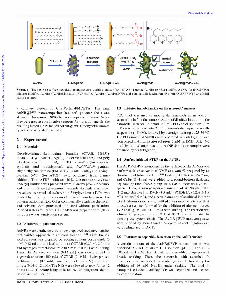
Scheme 1 The stepwise surface modification and polymer grafting strategy from CTAB-protected AuNRs to PEG-modified AuNRs (AuNR@PEG),
initiator-modified AuNRs (AuNR@initiator), PVP-grafted AuNRs (AuNR@PVP) and nanoparticle-loaded AuNRs (AuNR@PVP-NP) core@shell
nanostructures.
Publ
ishe
d on
19
Sept
embe
r 20
11. D
ownl
oade
d by
Ew
ha W
omen
s U
nive
rsity
on
14/0
8/20
13 0
8:37
:29.
View Article Online
a catalytic system of CuBr/CuBr2/PMDETA. The final
AuNR@PVP nanocomposites had soft polymer shells and
showed pH-responsive SPR changes in aqueous solutions. When
they were used as coordinative supports for transition metals, the
resulting bimetallic Pt-loaded AuNR@PVP nanohybrids showed
typical electrocatalytic activity.
2. Experimental
2.1 Materials
Hexadecyltrimethylammonium bromide (CTAB, H9151),
HAuCl4$3H2O, NaBH4, AgNO3, ascorbic acid (AA), and poly
(ethylene glycol) thiol (Mw ¼ 5000 g mol�1) (for nanorod
synthesis and modification), and N,N,N0,N0,N0 0-pentam-
ethyldiethylenetriamine (PMDETA), CuBr, CuBr2 and 4-vinyl-
pyridine (4VP) (for ATRP), were purchased from Sigma-
Aldrich. The ATRP initiator bis[2-(2-bromoisobutyryloxy)
undecyl] disulfide was prepared from 11-mercapto-1-undecanol
and 2-bromo-2-methylpropionyl bromide through a modified
procedure reported elsewhere.31 4-Vinylpyridine (4VP) was
treated by filtrating through an alumina column to remove the
polymerization resistor. Other commercially available chemicals
and solvents were purchased and used without purification.
Purified water (resistance > 18.2 MU) was prepared through an
ultrapure water purification system.
2.2 Synthesis of gold nanorods
AuNRs were synthesized by a two-step, seed-mediated, surfac-
tant-assisted approach in aqueous solution.32–34 First, the Au
seed solution was prepared by adding sodium borohydride (5
mM, 0.48 mL) to a mixed solution of CTAB (0.20 M, 2.0 mL)
and hydrogen tetrachloroaurate (0.5 mM, 2.0 mL) with stirring.
Then, the Au seed solution (0.12 mL) was slowly added to
a growth solution (100 mL) of CTAB (0.10 M), hydrogen tet-
rachloroaurate (0.5 mM), ascorbic acid (0.6 mM) and silver
nitrate (0.04–0.12 mM). The NRs were allowed to grow for ca. 12
hours at 27 �C before being collected by centrifugation, decan-
tation and redispersion.
16454 | J. Mater. Chem., 2011, 21, 16453–16460
2.3 Initiator immobilization on the nanorods’ surfaces
PEG thiol was used to modify the nanorods in an aqueous
suspension before the immobilization of disulfide initiator on the
nanorods’ surfaces. In detail, 2.0 mL PEG thiol solution (0.25
mM) was introduced into 2.0 mL concentrated aqueous AuNR
suspension (�5 nM), followed by overnight stirring at 25–30 �C.The PEG-modified AuNRs were separated by centrifugation and
redispersed in 4 mL initiator solution (2 mM) in DMF. After 3–5
h of ligand exchange reaction, AuNR@initiator samples were
obtained by centrifugation.
2.4 Surface-initiated ATRP on the AuNRs
The ATRP of 4VP monomers on the surfaces of the AuNRs was
performed in co-solvents of DMF and water/2-propanol by an
elsewhere published method.35–38 In detail, CuBr (14.3–57.2 mg)
and CuBr2 (1–4 mg) were added to a round-bottom flask and
degassed by three freeze–pump–thaw cycles under an N2 atmo-
sphere. Then, a nitrogen-purged mixture of AuNR@initiator
(1–2 mg) dissolved in DMF (3.5 mL), PMDETA (0.208–0.416
mL), water (0.5 mL), and a certain amount of sacrificial initiator
(ethyl a-bromoisobutyrate, 1–10 mL) was injected into the flask
through a syringe, followed by the addition of nitrogen-purged
4VP (2.10 g) in DMF (1.0 mL) with stirring. The reaction was
allowed to progress for ca. 24 h at 40 �C and terminated by
opening the system to air. The AuNR@PVP nanocomposites
were purified by more than three cycles of centrifugation and
were redispersed in DMF.
2.5 Platinum nanoparticle formation on the AuNR surface
A certain amount of the AuNR@PVP nanocomposites was
dispersed in 2 mL of dilute HCl solution (pH 3.0) and 0.01–
0.05 mL of 1 mM H2PtCl6 solution was added dropwise with
drastic shaking. Then, the nanorods with adsorbed Pt
precursor were separated by centrifugation, followed by the
addition of 10 mM NaBH4 under shaking. The final Pt
nanoparticle-loaded AuNR@PVP was separated and cleaned
by centrifugation.
This journal is ª The Royal Society of Chemistry 2011
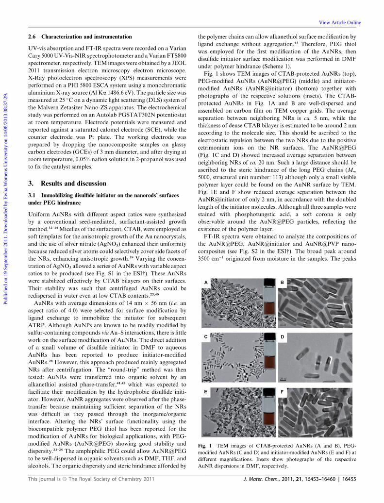
Fig. 1 TEM images of CTAB-protected AuNRs (A and B), PEG-
modified AuNRs (C and D) and initiator-modified AuNRs (E and F) at
different magnifications. Insets show photographs of the respective
AuNR dispersions in DMF, respectively.
Publ
ishe
d on
19
Sept
embe
r 20
11. D
ownl
oade
d by
Ew
ha W
omen
s U
nive
rsity
on
14/0
8/20
13 0
8:37
:29.
View Article Online
2.6 Characterization and instrumentation
UV-vis absorption and FT-IR spectra were recorded on a Varian
Cary 5000UV-Vis-NIR spectrophotometer and aVarianFTS800
spectrometer, respectively. TEM imageswere obtained by a JEOL
2011 transmission electron microscopy electron microscope.
X-Ray photoelectron spectroscopy (XPS) measurements were
performed on a PHI 5800 ESCA system using a monochromatic
aluminium X-ray source (Al Ka 1486.6 eV). The particle size was
measured at 25 �C on a dynamic light scattering (DLS) system of
the Malvern Zetasizer Nano-ZS apparatus. The electrochemical
study was performed on an Autolab PGSTAT302N potentiostat
at room temperature. Electrode potentials were measured and
reported against a saturated calomel electrode (SCE), while the
counter electrode was Pt plate. The working electrode was
prepared by dropping the nanocomposite samples on glassy
carbon electrodes (GCEs) of 3 mm diameter, and after drying at
room temperature, 0.05% nafion solution in 2-propanol was used
to fix the catalyst samples.
3. Results and discussion
3.1 Immobilizing disulfide initiator on the nanorods’ surfaces
under PEG hindrance
Uniform AuNRs with different aspect ratios were synthesized
by a conventional seed-mediated, surfactant-assisted growth
method.32–34 Micelles of the surfactant, CTAB, were employed as
soft templates for the anisotropic growth of the Au nanocrystals,
and the use of silver nitrate (AgNO3) enhanced their uniformity
because reduced silver atoms could selectively cover side facets of
the NRs, enhancing anisotropic growth.39 Varying the concen-
tration of AgNO3 allowed a series of AuNRs with variable aspect
ratios to be produced (see Fig. S1 in the ESI†). These AuNRs
were stabilized effectively by CTAB bilayers on their surfaces.
Their stability was such that centrifuged AuNRs could be
redispersed in water even at low CTAB contents.25,40
AuNRs with average dimensions of 14 nm � 56 nm (i.e. an
aspect ratio of 4.0) were selected for surface modification by
ligand exchange to immobilize the initiator for subsequent
ATRP. Although AuNPs are known to be readily modified by
sulfur-containing compounds viaAu–S interactions, there is little
work on the surface modification of AuNRs. The direct addition
of a small volume of disulfide initiator in DMF to aqueous
AuNRs has been reported to produce initiator-modified
AuNRs.28 However, this approach produced mainly aggregated
NRs after centrifugation. The ‘‘round-trip’’ method was then
tested: AuNRs were transferred into organic solvent by an
alkanethiol assisted phase-transfer,41,42 which was expected to
facilitate their modification by the hydrophobic disulfide initi-
ator. However, AuNR aggregates were observed after the phase-
transfer because maintaining sufficient separation of the NRs
was difficult as they passed through the inorganic/organic
interface. Altering the NRs’ surface functionality using the
biocompatible polymer PEG thiol has been reported for the
modification of AuNRs for biological applications, with PEG-
modified AuNRs (AuNR@PEG) showing good stability and
dispersity.23–25 The amphiphilic PEG could allow AuNR@PEG
to be well-dispersed in organic solvents such as DMF, THF, and
alcohols. The organic dispersity and steric hindrance afforded by
This journal is ª The Royal Society of Chemistry 2011
the polymer chains can allow alkanethiol surface modification by
ligand exchange without aggregation.43 Therefore, PEG thiol
was employed for the first modification of the AuNRs, then
disulfide initiator surface modification was performed in DMF
under polymer hindrance (Scheme 1).
Fig. 1 shows TEM images of CTAB-protected AuNRs (top),
PEG-modified AuNRs (AuNR@PEG) (middle) and initiator-
modified AuNRs (AuNR@initiator) (bottom) together with
photographs of the respective solutions (insets). The CTAB-
protected AuNRs in Fig. 1A and B are well-dispersed and
assembled on carbon film on TEM copper grids. The average
separation between neighboring NRs is ca. 5 nm, while the
thickness of dense CTAB bilayer is estimated to be around 2 nm
according to the molecule size. This should be ascribed to the
electrostatic repulsion between the two NRs due to the positive
cetrimonium ions on the NR surfaces. The AuNR@PEG
(Fig. 1C and D) showed increased average separation between
neighboring NRs of ca. 20 nm. Such a large distance should be
ascribed to the steric hindrance of the long PEG chains (Mw
5000, structural unit number: 113) although only a small visible
polymer layer could be found on the AuNR surface by TEM.
Fig. 1E and F show reduced average separation between the
AuNR@initiator of only 2 nm, in accordance with the doubled
length of the initiator molecules. Although all three samples were
stained with phosphotungstic acid, a soft corona is only
observable around the AuNR@PEG particles, reflecting the
existence of the polymer layer.
FT-IR spectra were obtained to analyze the compositions of
the AuNR@PEG, AuNR@initiator and AuNR@PVP nano-
composites (see Fig. S2 in the ESI†). The broad peak around
3500 cm�1 originated from moisture in the samples. The peaks
J. Mater. Chem., 2011, 21, 16453–16460 | 16455
Publ
ishe
d on
19
Sept
embe
r 20
11. D
ownl
oade
d by
Ew
ha W
omen
s U
nive
rsity
on
14/0
8/20
13 0
8:37
:29.
View Article Online
between 2960 and 2820 cm�1 represent the asymmetric stretching
bands of CH3 and CH2 groups, respectively. For the AuNR@
PEG sample, the large peak at 1086 cm�1 corresponds to char-
acteristic ether (C–O–C) bond stretching of PEG,31 while the one
centered at 1466 cm�1 is related to the dasym(C–H) and dsym(C–H)
of CH3–N+ moiety in CTAB.40 The whole profile of the
AuNR@PEG sample seems to be a combination of PEG and
CTAB, possibly reflecting a coexistence of these two compo-
nents. Obviously, the FT-IR profile of the AuNR@initiator
spectrum is very similar to that of the pure initiator, especially
focused on the characteristic absorbance of the ester carbonyl
stretching at 1736 cm�1, indicating the presence of the initiator on
the nanorods’ surfaces.
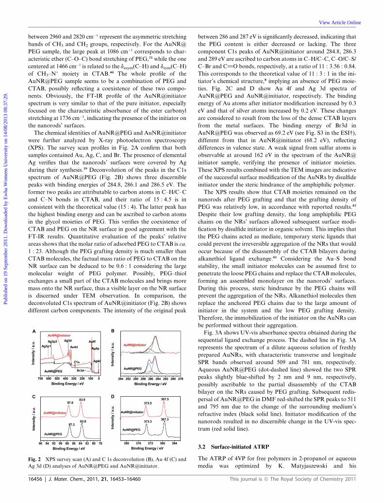
The chemical identities of AuNR@PEG and AuNR@initiator
were further analyzed by X-ray photoelectron spectroscopy
(XPS). The survey scan profiles in Fig. 2A confirm that both
samples contained Au, Ag, C, and Br. The presence of elemental
Ag verifies that the nanorods’ surfaces were covered by Ag
during their synthesis.39 Deconvolution of the peaks in the C1s
spectrum of AuNR@PEG (Fig. 2B) shows three discernible
peaks with binding energies of 284.8, 286.1 and 286.5 eV. The
former two peaks are attributable to carbon atoms in C–H/C–C
and C–N bonds in CTAB, and their ratio of 15 : 4.5 is in
consistent with the theoretical value (15 : 4). The latter peak has
the highest binding energy and can be ascribed to carbon atoms
in the glycol moieties of PEG. This verifies the coexistence of
CTAB and PEG on the NR surface in good agreement with the
FT-IR results. Quantitative evaluation of the peaks’ relative
areas shows that the molar ratio of adsorbed PEG to CTAB is ca.
1 : 23. Although the PEG grafting density is much smaller than
CTAB molecules, the factual mass ratio of PEG to CTAB on the
NR surface can be deduced to be 0.6 : 1 considering the large
molecular weight of PEG polymer. Possibly, PEG–thiol
exchanges a small part of the CTAB molecules and brings more
mass onto the NR surface, thus a visible layer on the NR surface
is discerned under TEM observation. In comparison, the
deconvoluted C1s spectrum of AuNR@initiator (Fig. 2B) shows
different carbon components. The intensity of the original peak
Fig. 2 XPS survey scan (A) and C 1s deconvolution (B), Au 4f (C) and
Ag 3d (D) analyses of AuNR@PEG and AuNR@initiator.
16456 | J. Mater. Chem., 2011, 21, 16453–16460
between 286 and 287 eV is significantly decreased, indicating that
the PEG content is either decreased or lacking. The three
component C1s peaks of AuNR@initiator around 284.8, 286.3
and 289 eV are ascribed to carbon atoms in C–H/C–C, C–O/C–S/
C–Br and C]O bonds, respectively, at a ratio of 11 : 3.56 : 0.84.
This corresponds to the theoretical value of 11 : 3 : 1 in the ini-
tiator’s chemical structure,8 implying an absence of PEG moie-
ties. Fig. 2C and D show Au 4f and Ag 3d spectra of
AuNR@PEG and AuNR@initiator, respectively. The binding
energy of Au atoms after initiator modification increased by 0.3
eV and that of silver atoms increased by 0.2 eV. These changes
are considered to result from the loss of the dense CTAB layers
from the metal surfaces. The binding energy of Br3d in
AuNR@PEG was observed as 69.2 eV (see Fig. S3 in the ESI†),
different from that in AuNR@initiator (68.2 eV), reflecting
differences in valence state. A weak signal from sulfur atoms is
observable at around 162 eV in the spectrum of the AuNR@
initiator sample, verifying the presence of initiator moieties.
These XPS results combined with the TEM images are indicative
of the successful surface modification of the AuNRs by disulfide
initiator under the steric hindrance of the amphiphilic polymer.
The XPS results show that CTAB moieties remained on the
nanorods after PEG grafting and that the grafting density of
PEG was relatively low, in accordance with reported results.43
Despite their low grafting density, the long amphiphilic PEG
chains on the NRs’ surfaces allowed subsequent surface modi-
fication by disulfide initiator in organic solvent. This implies that
the PEG chains acted as mediate, temporary steric ligands that
could prevent the irreversible aggregation of the NRs that would
occur because of the disassembly of the CTAB bilayers during
alkanethiol ligand exchange.43 Considering the Au–S bond
stability, the small initiator molecules can be assumed first to
penetrate the loose PEG chains and replace the CTABmolecules,
forming an assembled monolayer on the nanorods’ surfaces.
During this process, steric hindrance by the PEG chains will
prevent the aggregation of the NRs. Alkanethiol molecules then
replace the anchored PEG chains due to the large amount of
initiator in the system and the low PEG grafting density.
Therefore, the immobilization of the initiator on the AuNRs can
be performed without their aggregation.
Fig. 3A shows UV-vis absorbance spectra obtained during the
sequential ligand exchange process. The dashed line in Fig. 3A
represents the spectrum of a dilute aqueous solution of freshly
prepared AuNRs, with characteristic transverse and longitude
SPR bands observed around 509 and 781 nm, respectively.
Aqueous AuNR@PEG (dot-dashed line) showed the two SPR
peaks slightly blue-shifted by 2 nm and 9 nm, respectively,
possibly ascribable to the partial disassembly of the CTAB
bilayer on the NRs caused by PEG grafting. Subsequent redis-
persal of AuNR@PEG in DMF red-shifted the SPR peaks to 511
and 795 nm due to the change of the surrounding medium’s
refractive index (black solid line). Initiator modification of the
nanorods resulted in no discernible change in the UV-vis spec-
trum (red solid line).
3.2 Surface-initiated ATRP
The ATRP of 4VP for free polymers in 2-propanol or aqueous
media was optimized by K. Matyjaszewski and his
This journal is ª The Royal Society of Chemistry 2011
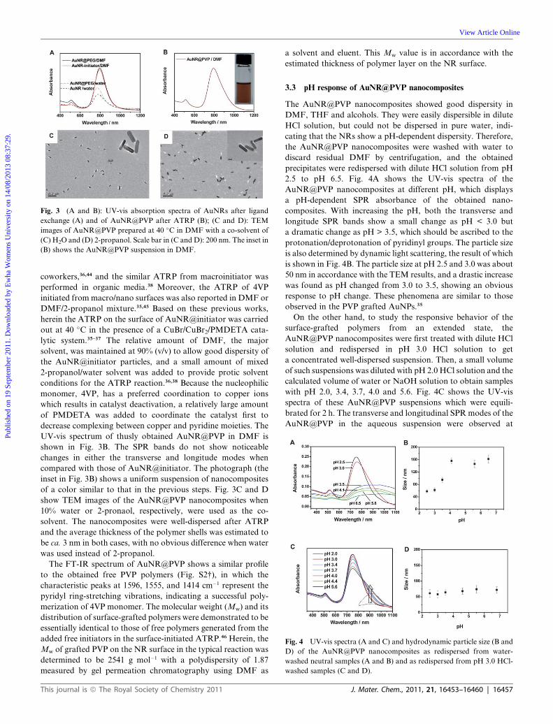
Fig. 3 (A and B): UV-vis absorption spectra of AuNRs after ligand
exchange (A) and of AuNR@PVP after ATRP (B); (C and D): TEM
images of AuNR@PVP prepared at 40 �C in DMF with a co-solvent of
(C) H2O and (D) 2-propanol. Scale bar in (C and D): 200 nm. The inset in
(B) shows the AuNR@PVP suspension in DMF.
Fig. 4 UV-vis spectra (A and C) and hydrodynamic particle size (B and
D) of the AuNR@PVP nanocomposites as redispersed from water-
washed neutral samples (A and B) and as redispersed from pH 3.0 HCl-
washed samples (C and D).
Publ
ishe
d on
19
Sept
embe
r 20
11. D
ownl
oade
d by
Ew
ha W
omen
s U
nive
rsity
on
14/0
8/20
13 0
8:37
:29.
View Article Online
coworkers,36,44 and the similar ATRP from macroinitiator was
performed in organic media.38 Moreover, the ATRP of 4VP
initiated from macro/nano surfaces was also reported in DMF or
DMF/2-propanol mixture.35,45 Based on these previous works,
herein the ATRP on the surface of AuNR@initiator was carried
out at 40 �C in the presence of a CuBr/CuBr2/PMDETA cata-
lytic system.35–37 The relative amount of DMF, the major
solvent, was maintained at 90% (v/v) to allow good dispersity of
the AuNR@initiator particles, and a small amount of mixed
2-propanol/water solvent was added to provide protic solvent
conditions for the ATRP reaction.36,38 Because the nucleophilic
monomer, 4VP, has a preferred coordination to copper ions
which results in catalyst deactivation, a relatively large amount
of PMDETA was added to coordinate the catalyst first to
decrease complexing between copper and pyridine moieties. The
UV-vis spectrum of thusly obtained AuNR@PVP in DMF is
shown in Fig. 3B. The SPR bands do not show noticeable
changes in either the transverse and longitude modes when
compared with those of AuNR@initiator. The photograph (the
inset in Fig. 3B) shows a uniform suspension of nanocomposites
of a color similar to that in the previous steps. Fig. 3C and D
show TEM images of the AuNR@PVP nanocomposites when
10% water or 2-pronaol, respectively, were used as the co-
solvent. The nanocomposites were well-dispersed after ATRP
and the average thickness of the polymer shells was estimated to
be ca. 3 nm in both cases, with no obvious difference when water
was used instead of 2-propanol.
The FT-IR spectrum of AuNR@PVP shows a similar profile
to the obtained free PVP polymers (Fig. S2†), in which the
characteristic peaks at 1596, 1555, and 1414 cm�1 represent the
pyridyl ring-stretching vibrations, indicating a successful poly-
merization of 4VP monomer. The molecular weight (Mw) and its
distribution of surface-grafted polymers were demonstrated to be
essentially identical to those of free polymers generated from the
added free initiators in the surface-initiated ATRP.46 Herein, the
Mw of grafted PVP on the NR surface in the typical reaction was
determined to be 2541 g mol�1 with a polydispersity of 1.87
measured by gel permeation chromatography using DMF as
This journal is ª The Royal Society of Chemistry 2011
a solvent and eluent. This Mw value is in accordance with the
estimated thickness of polymer layer on the NR surface.
3.3 pH response of AuNR@PVP nanocomposites
The AuNR@PVP nanocomposites showed good dispersity in
DMF, THF and alcohols. They were easily dispersible in dilute
HCl solution, but could not be dispersed in pure water, indi-
cating that the NRs show a pH-dependent dispersity. Therefore,
the AuNR@PVP nanocomposites were washed with water to
discard residual DMF by centrifugation, and the obtained
precipitates were redispersed with dilute HCl solution from pH
2.5 to pH 6.5. Fig. 4A shows the UV-vis spectra of the
AuNR@PVP nanocomposites at different pH, which displays
a pH-dependent SPR absorbance of the obtained nano-
composites. With increasing the pH, both the transverse and
longitude SPR bands show a small change as pH < 3.0 but
a dramatic change as pH > 3.5, which should be ascribed to the
protonation/deprotonation of pyridinyl groups. The particle size
is also determined by dynamic light scattering, the result of which
is shown in Fig. 4B. The particle size at pH 2.5 and 3.0 was about
50 nm in accordance with the TEM results, and a drastic increase
was found as pH changed from 3.0 to 3.5, showing an obvious
response to pH change. These phenomena are similar to those
observed in the PVP grafted AuNPs.35
On the other hand, to study the responsive behavior of the
surface-grafted polymers from an extended state, the
AuNR@PVP nanocomposites were first treated with dilute HCl
solution and redispersed in pH 3.0 HCl solution to get
a concentrated well-dispersed suspension. Then, a small volume
of such suspensions was diluted with pH 2.0 HCl solution and the
calculated volume of water or NaOH solution to obtain samples
with pH 2.0, 3.4, 3.7, 4.0 and 5.6. Fig. 4C shows the UV-vis
spectra of these AuNR@PVP suspensions which were equili-
brated for 2 h. The transverse and longitudinal SPRmodes of the
AuNR@PVP in the aqueous suspension were observed at
J. Mater. Chem., 2011, 21, 16453–16460 | 16457

Publ
ishe
d on
19
Sept
embe
r 20
11. D
ownl
oade
d by
Ew
ha W
omen
s U
nive
rsity
on
14/0
8/20
13 0
8:37
:29.
View Article Online
around 510 nm and 750 nm, respectively. However, only
a shoulder peak around 900 nm emerged with increasing pH as
a result of the AuNRs’ aggregation, which might represent a slow
aggregation of a small part of the nanocomposites. Such a pH
response of the well dispersed nanocomposites at low pH where
the grafted PVP chains are on the extended state is much
different to the pH-dependent dispersity of the aggregated
nanocomposites at a neutral condition where the grafted PVP
chains are collapsed on the NR surface. Moreover, such a pH-
response behavior in a well-dispersed state was much smaller
than that of the PVP-grafted AuNPs.9 This reduction in the
degree of the pH response of the well-dispersed AuNR@PVP
nanocomposites should be mainly attributed to the low molec-
ular weight of the grafted PVP chains, which will make it difficult
for the NRs to connect together and form aggregates. In addi-
tion, the more complex nature of the rod assembly than the
spherical particle assembly may also be partially responsible for
such observations. Correspondingly, the particle size change
detected by DLS in Fig. 4D is in accordance with the UV-vis
results.
TEM images of the AuNR@PVP nanocomposites redispersed
from a neutral condition were shown in Fig. 5. At pH 2.5 and 3.0,
similar well-dispersed morphologies of the assembled NRs were
observed (Fig. 5A and B). At pH 3.5, the majority of the NRs
were aggregated (Fig. 5C). At a higher pH from 4.1 to 6.5, many
similar larger aggregates were observed as shown in Fig. 5D.
These aggregates are much larger than the particle size indicated
by DLS measurements, so they should be formed during the
sample drying due to the collapsed hydrophobic polymer shells.
Such pH-responses explored by several means including SPR
change, particle size variation, and TEM morphology should be
attributed to the protonation and deprotonation of the pyridinyl
groups in the PVP shells. The protonation of pyridine groups at
low pH forms pyridinium ions, rendering positive charge to the
polymer chains,47,48 thus the nanocomposites are well-dispersed
through the electrostatic repulsion. As pH increases, the depro-
tonation of the pyridinium ions leaves uncharged pyridine
groups and allows the nanocomposites to aggregate due to the
absence of electrostatic repulsion. Such pH-responsive
morphologies are in agreement with the SPR response as shown
in Fig. 4A and B. However, TEM morphologies of the
Fig. 5 TEM images of AuNR@PVP nanocomposites redispersed in
aqueous HCl solutions at pH 2.5 (A), 3.0 (B), 3.5 (C), and 4.1 (D).
16458 | J. Mater. Chem., 2011, 21, 16453–16460
AuNR@PVP samples redispersed from pH 3.0 suspensions did
not show much difference from pH 2.0 to 4.0, and at a higher pH
of 5.6 many large aggregates of NRs were found according to the
UV-vis and DLS results.
3.4 Potential applications as nanosupports
AuNRs were considered as an especially unique material for
multi-functional nanostructure assembly. Similar to the near-
infrared-light heating and controlling of AuNRs in cancer
therapy,28,29 the adjustable-light-wave controlled nanodevices
could be expected based on the modulatable longitudinal SPR
absorbance of the AuNRs with different aspect ratios. Particu-
larly, the AuNR@PVP nanostructures can likely be used as
efficient nanosupports for many transition metal catalysts due to
the coordinative pyridyl shells, and thus should have significant
impact on potential future catalytic applications. Herein, the
pyridyl-containing shells of the AuNR@PVP nanocomposites
were employed as coordinative supports for transition metal ions
and nanoparticles. Chloroplatinic acid solution was incubated
with the AuNR@PVP nanocomposites, allowing Pt ions to
penetrate the PVP shells. After subsequent reduction with
sodium borohybride, bimetallic Pt NP-loaded AuNR@PVP
nanocomposites (AuNR@PVP-Pt) resulted. TEM images
(Fig. 6A and B) of these bimetallic nanocomposites show that
2–3 nm Pt NPs were densely decorated on the AuNRs’ surfaces.
Such bimetallic Au–Pt nanostructures have been reported to be
significant electrocatalytic materials in direct methanol fuel
Fig. 6 (A and B): TEM images of nano-Pt-loaded AuNR@PVP nano-
composites at different magnifications; (C–F): cyclic voltammograms of
glass-carbon electrodes modified with AuNR@PVP (C and E) and Pt
NPs-decorated AuNR@PVP nanocomposites (D and F) in 0.5 M H2SO4
solution in the absence (C and D) and presence (E and F) of 1 M
methanol. Scale bars in (A) and (B) are 100 nm and 10 nm, respectively.
This journal is ª The Royal Society of Chemistry 2011
Publ
ishe
d on
19
Sept
embe
r 20
11. D
ownl
oade
d by
Ew
ha W
omen
s U
nive
rsity
on
14/0
8/20
13 0
8:37
:29.
View Article Online
cells.49–51 Therefore, the electrocatalytic activity of the
AuNR@PVP nanocomposites before and after being decorated
with Pt NPs was compared. The cyclic voltammetry curves of the
glassy carbon electrodes (GCEs) modified with the AuNR@PVP
nanocomposites and Pt NPs-decorated AuNR@PVP nano-
composites were recorded in 0.5 M H2SO4 at a scan rate range of
25–200 mV s�1 as shown in Fig. 6C and D, respectively. The
typical increase in peak currents was observed with respect to the
scan rate. A small reduction peak around 0.8 V (vs. SCE) was
observed for the AuNR@PVP-modified GCE, indicative of the
reduction of gold oxide on the nanorods’ surfaces; while this
peak was not observed in the case of Pt NPs-decorated
AuNR@PVP nanocomposite and a higher peak emerged around
0.5 V, corresponding to Pt oxide reduction.51,52 The disappear-
ance of the Au oxide reduction peak may suggest that the Au
nanorods’ surfaces were almost completely covered by the small
Pt NPs. Furthermore, the cyclic voltammograms in Fig. 6E and
F showed markedly different results between the AuNR@PVP
and the Pt NPs-decorated AuNR@PVP nanocomposites. The
AuNR@PVP nanocomposites did not exhibit noticeable elec-
trocatalytic activity for the methanol oxidation reaction, while
the Pt NPs-decorated AuNR@PVP nanocomposites showed
typical catalytic behavior for the electro-oxidation of methanol
as indicated by the appearance of an oxidation current in the
positive potential region. The onset potential for the electro-
catalytic oxidation is around 0.34 V (vs. SCE). The current peak
at ca. 0.65 V in the forward scan is attributable to electrocatalytic
methanol oxidation on the surfaces of the bimetallic nano-
composites. In the reverse scan, an oxidation peak is also
observed at ca. 0.44 V, probably associated with the removal of
residual carbon species formed during the forward scan. The
ratio of the forward oxidation current peak (If) to the reverse
current peak (Ib), If/Ib, indicates the catalyst’s tolerance to the
poisoning species, Pt]C]O.53 Higher ratios suggest the effec-
tive removal of the poisoning species from the catalyst’s surface.
The average If/Ib ratio calculated for the AuNR@PVP-Pt
nanocomposites at different scan rates was 2.25, markedly higher
than that of the E-TEK catalyst (0.74).53 The presence of nano-
size Au clusters on Pt catalysts has been reported to be able to
stabilize Pt electrocatalytic activity in fuel cell reactions,52 sug-
gesting an extra advantage of supported Pt NP catalysts on
AuNRs. As an expectation for the catalytic Pt-loaded
AuNR@PVP nanostructure, the AuNRs could be utilized as
irradiation sensors to perform locally photo-thermal heating via
remote irradiation and as such the local heating-controlling of
the catalyst center might be meaningful for some special reaction
system.
4. Conclusion
Surface modification of AuNRs with disulfide initiator was
successfully performed under the steric hindrance of amphiphilic
PEG polymer chains. The PEG moieties acted as mediating
ligands and facilitated the dispersion of the modified NRs in
organic solvents and provided steric hindrance to prevent the
nanorods’ aggregation during subsequent ligand exchange
with alkanethiol. The initiator immobilized on the nanorods’
surfaces could subsequently initiate the ATRP of 4VP to
form poly(4-vinylpyridine)-grafted AuNRs. The AuNR@PVP
This journal is ª The Royal Society of Chemistry 2011
nanocomposites displayed systematic pH-sensitive surface plas-
mon resonance changes and assembly behavior. AuNR@PVP-Pt
bimetallic nanocomposites displayed viable electrocatalytic
activity for methanol oxidation, a typical reaction in direct
methanol fuel cells. Thus, such core–shell nanostructures with
coordinative pyridine shells can be employed as versatile nano-
supports for transition metal catalysts or plasmonic nanodevices.
Acknowledgements
This work was supported by the Mid-career Researcher Program
(20110029409), International Research & Development Program
(2010-00134), SRC Program (20110001334) and the Converging
Research Center Program (2011K000630) through National
Research Foundation of Korea Grant funded by the Korean
Government. D. Li thanks for the financial support by the
National Natural Science Foundation of China (no. 21073102).
References
1 K. Ohno, K. Koh, Y. Tsujii and T. Fukuda, Angew. Chem., Int. Ed.,2003, 42, 2751–2754.
2 J. Shan and H. Tenhu, Chem. Commun., 2007, 4580–4598.3 C. B. Anna, E. Todd and P. R. Thomas, Science, 2006, 314, 1107–1110.
4 J. Shan, J. Chen, M. Nuopponen and H. Tenhu, Langmuir, 2004, 20,4671–4676.
5 D.X.Li,Q.Heand J.B.Li,Adv.Colloid InterfaceSci., 2009,149, 28–38.6 M. Q. Zhu, L. Q. Wang, G. J. Exarhos and A. D. Q. Li, J. Am. Chem.Soc., 2004, 126, 2656–2657.
7 D. J. Kim, S. M. Kang, B. Kong, W. J. Kim, H. J. Paik, H. Choi andI. S. Choi, Macromol. Chem. Phys., 2005, 206, 1941–1946.
8 D. X. Li, Q. He, Y. Cui, K. W. Wang, X. M. Zhang and J. B. Li,Chem.–Eur. J., 2007, 13, 2224–2229.
9 D. X. Li, Q. He, Y. Yang, H. M€ohwald and J. B. Li,Macromolecules,2008, 41, 7254–7256.
10 Z. B. Ge, Y. J. Kang, T. A. Taton, P. V. Braun andD. G. Cahill,NanoLett., 2005, 5, 531–535.
11 E. W. Edwards, M. Chanana, D. Wang and H. M€ohwald, Angew.Chem., Int. Ed., 2008, 47, 320–323.
12 K. Liu, Z. H. Nie, N. N. Zhao, W. Li, M. Rubinstein andE. Kumacheva, Science, 2010, 329, 197–200.
13 X. H. Huang, I. H. El-Sayed, W. Qian and M. A. El-Sayed, NanoLett., 2007, 7, 1591–1597.
14 H. Ding, K. T. Yong, I. Roy, H. E. Pudavar, W. C. Law, E. J. Bergeyand P. N. Prasad, J. Phys. Chem. C, 2007, 111, 12552–12557.
15 C. X. Yu, H. Nakshatri and J. Irudayaraj, Nano Lett., 2007, 7, 2300–2306.
16 Y. Z. Min, C. Q. Mao, D. C. Xu, J. Wang and Y. Z. Liu, Chem.Commun., 2010, 46, 8424–8426.
17 M. Eghtedari, A. V. Liopo, J. A. Copland, A. A. Oraevslty andM. Motamedi, Nano Lett., 2009, 9, 287–291.
18 L. Tong, Q. S. Wei, A. Wei and J. X. Cheng, Photochem. Photobiol.,2009, 85, 21–32.
19 N. J. Durr, T. Larson, D. K. Smith, B. A. Korgel, K. Sokolov andA. Ben-Yakar, Nano Lett., 2007, 7, 941–945.
20 X. H. Huang, I. H. El-Sayed, W. Qian and M. A. El-Sayed, J. Am.Chem. Soc., 2006, 128, 2115–2120.
21 B. Jang, J.-Y. Park, C.-H. Tung, I.-H. Kim and Y. Choi, ACS Nano,2011, 5, 1086–1094.
22 P. Zijlstra, J. W. M. Chon and M. Gu, Nature, 2009, 459, 410–413.23 T. Niidome, M. Yamagata, Y. Okamoto, Y. Akiyama, H. Takahashi,
T. Kawano, Y. Katayama and Y. Niidome, J. Controlled Release,2006, 114, 343–347.
24 G. von Maltzahn, J. H. Park, A. Agrawal, N. K. Bandaru, S. K. Das,M. J. Sailor and S. N. Bhatia, Cancer Res., 2009, 69, 3892–3900.
25 B. C. Rostro-Kohanloo, L. R. Bickford, C. M. Payne, E. S. Day,L. J. E. Anderson, M. Zhong, S. Lee, K. M. Mayer, T. Zal,L. Adam, C. P. N. Dinney, R. A. Drezek, J. L. West andJ. H. Hafner, Nanotechnology, 2009, 20, 434005.
J. Mater. Chem., 2011, 21, 16453–16460 | 16459
Publ
ishe
d on
19
Sept
embe
r 20
11. D
ownl
oade
d by
Ew
ha W
omen
s U
nive
rsity
on
14/0
8/20
13 0
8:37
:29.
View Article Online
26 L. L. He, L. X. Zhang, Y. S. Ye and H. J. Liang, J. Phys. Chem. B,2010, 114, 7189–7200.
27 D. Fava, Z. Nie, M. A. Winnik and E. Kumacheva, Adv. Mater.,2008, 20, 4318–4322.
28 Q. S. Wei, J. Ji and J. C. Shen, Macromol. Rapid Commun., 2008, 29,645–650.
29 T. Kawano, Y. Niidome, T. Mori, Y. Katayama and T. Niidome,Bioconjugate Chem., 2009, 20, 209–212.
30 B. Y. Du, X. J. Chen, B. Zhao, A. X. Mei, Q. Wang, J. T. Xu andZ. Q. Fan, Nanoscale, 2010, 2, 1684–1689.
31 D. X. Li, Y. Cui, K. W. Wang, Q. He, X. H. Yan and J. B. Li, Adv.Funct. Mater., 2007, 17, 3134–3140.
32 B. Nikoobakht and M. A. El-Sayed, Chem. Mater., 2003, 15, 1957–1962.
33 X. T. Bai, Y. A. Gao, H. G. Liu and L. Q. Zheng, J. Phys. Chem. C,2009, 113, 17730–17736.
34 L. F. Gou and C. J. Murphy, Chem. Mater., 2005, 17, 3668–3672.35 D. X. Li, Q. He, Y. Cui and J. B. Li,Chem.Mater., 2007, 19, 412–417.36 N. V. Tsarevsky, W. A. Braunecker, S. J. Brooks and
K. Matyjaszewski, Macromolecules, 2006, 39, 6817–6824.37 H. Chen, L. F. Chen, Z. H. Hao, X. M. Fu and Z. X. Lu, J.
Macromol. Sci., Part A: Pure Appl. Chem., 2009, 46, 832–836.38 J. Pieterasik and N. V. Tsareysky, Eur. Polym. J., 2010, 46, 2333–
2340.39 F. Giannici, T. Placido, M. L. Curri, M. Striccoli, A. Agostiano and
R. Comparelli, Dalton Trans., 2009, 10367–10374.
16460 | J. Mater. Chem., 2011, 21, 16453–16460
40 B. Nikoobakht and M. A. El-Sayed, Langmuir, 2001, 17, 6368–6374.41 A. Wijaya and K. Hamad-Schifferli, Langmuir, 2008, 24, 9966–9969.42 M. Jebb, P. K. Sudeep, P. Pramod, K. G. Thomas and P. V. Kamat, J.
Phys. Chem. B, 2007, 111, 6839–6844.43 B. Thierry, J. Ng, T. Krieg and H. J. Griesser, Chem. Commun., 2009,
1724–1726.44 J. H. Xia, X. Zhang andK.Matyjaszewski,Macromolecules, 1999, 32,
3531–3533.45 L. Li, G. P. Yan, Z. Y. Cheng, J. Y. Wu, X. H. Yu and Q. Z. Guo,
Surf. Interface Anal., 2009, 41, 69–74.46 K. Ohno, T. Morinaga, K. Koh, Y. Tsujii and T. Fukuda,
Macromolecules, 2005, 38, 2137–2142.47 A. Mansri, K. I. Benabadji, J. Desbrieres and J. Francois,
Desalination, 2009, 245, 95–107.48 M. Shibata, Y. Kimura and D. Yaginuma, Polymer, 2004, 45, 7571–
7577.49 S. J. Guo, Y. X. Fang, S. J. Dong and E. K. Wang, J. Phys. Chem. C,
2007, 111, 17104–17109.50 S. J. Guo, J. Li, S. J. Dong and E. K. Wang, J. Phys. Chem. C, 2010,
114, 15337–15342.51 S. Y. Wang, N. Kristian, S. P. Jiang and X. Wang, Electrochem.
Commun., 2008, 10, 961–964.52 J. Zhang, K. Sasaki, E. Sutter and R. R. Adzic, Science, 2007, 315,
220–222.53 Y. Mu, H. Liang, J. Hu, L. Jiang and L. Wan, J. Phys. Chem. B, 2005,
109, 22212–22216.
This journal is ª The Royal Society of Chemistry 2011