Controllable Valley Polarization and Strain Modulation in 2D ...
Upload
independentCategory
view
2download
0
Highly controllable near-surface swimming of magnetic Janus nanorods: application to
payload capture and manipulation
This article has been downloaded from IOPscience. Please scroll down to see the full text article.
2011 J. Phys. D: Appl. Phys. 44 125001
(http://iopscience.iop.org/0022-3727/44/12/125001)
Download details:
IP Address: 152.2.133.187
The article was downloaded on 13/05/2011 at 15:53
Please note that terms and conditions apply.
View the table of contents for this issue, or go to the journal homepage for more
Home Search Collections Journals About Contact us My IOPscience
IOP PUBLISHING JOURNAL OF PHYSICS D: APPLIED PHYSICS
J. Phys. D: Appl. Phys. 44 (2011) 125001 (9pp) doi:10.1088/0022-3727/44/12/125001
Highly controllable near-surfaceswimming of magnetic Janus nanorods:application to payload capture andmanipulationLamar O Mair1, Benjamin Evans2, Adam R Hall3, Jerome Carpenter1,Adam Shields4, Kris Ford5, Michael Millard5 and Richard Superfine4
1 Curriculum in Applied Sciences and Engineering, University of North Carolina at Chapel Hill,NC 27599, USA2 Department of Physics, Elon University, Elon, NC 27244, USA3 Joint School of Nanoscience and Nanoengineering, University of North Carolina at Greensboro,NC 27401, USA4 Department of Physics and Astronomy, University of North Carolina at Chapel Hill, NC 27599, USA5 Department of Biomedical Engineering, University of North Carolina at Chapel Hill, NC 27599, USA
E-mail: [email protected]
Received 3 December 2010, in final form 2 January 2011Published 10 March 2011Online at stacks.iop.org/JPhysD/44/125001
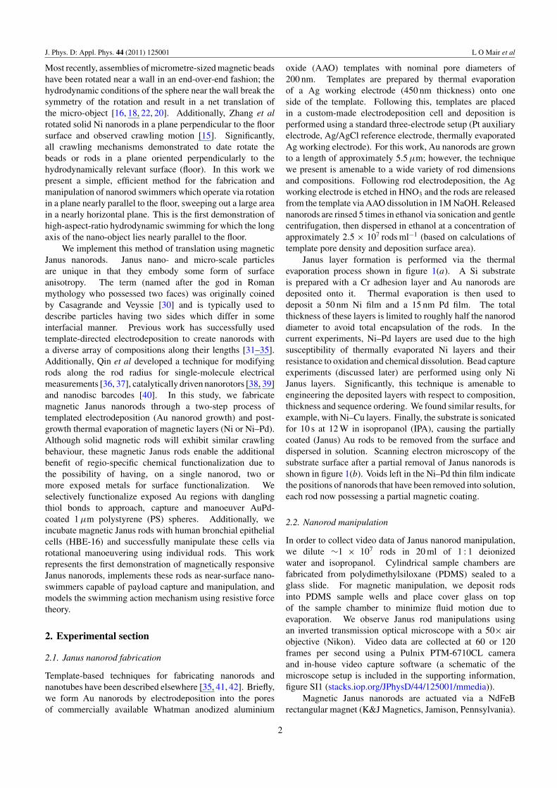
AbstractDirected manipulation of nanomaterials has significant implications in the field ofnanorobotics, nanobiotechnology, microfluidics and directed assembly. With the goal ofhighly controllable nanomaterial manipulation in mind, we present a technique for thenear-surface manoeuvering of magnetic nanorod swimmers and its application to controlledmicromanipulation. We fabricate magnetic Janus nanorods and show that the magnetic rotationof these nanorods near a floor results in predictable translational motion. The nanorod plane ofrotation is nearly parallel to the floor, the angle between rod tilt and floor being expressed by θ ,where 0◦ < θ < 20◦. Orthogonal magnetic fields control in-plane motion arbitrarily. Ourmodel for translation incorporates symmetry breaking through increased drag at the no-slipsurface boundary. Using this method we demonstrate considerable rod steerability.Additionally, we approach, capture, and manipulate a polystyrene microbead as proof ofprinciple. We attach Janus nanorods to the surfaces of cells and utilize these rods to manipulateindividual cells, proving the ability to manoeuver payloads with a wide range of sizes.
S Online supplementary data available from stacks.iop.org/JPhysD/44/125001/mmedia
(Some figures in this article are in colour only in the electronic version)
1. Introduction
Producing micro- and nano-scale machines capable of directedlocomotion and payload manipulation is a principal goalof nanotechnology [1–12]. Specifically, micro- and nano-scale motors and machines capable of directed locomotionand payload manipulation in a variety of low Reynoldsnumber (low-Re) solutions hold potential for manipulatingand assembling objects at the nano-scale by makinguse of hydrodynamic methods of self-propulsion [13–20].
Magnetically driven devices capable of being guided byexternally applied magnetic fields [17, 21] are particularlyuseful, as these micro-objects can perform complexmanoeuvers without carrying any onboard fuel [18, 20, 22].Swimming in a low Reynolds number environment requiresa mechanism which breaks the symmetry of the swimmer’smotion [23, 24]. Many different types of swimmers have beenproposed and demonstrated, such as three-bead swimmers [23,25, 26], rotating helices [14, 17], linked-bead swimmers [21],flexible magnetic filaments [27, 28] and membranes [29].
0022-3727/11/125001+09$33.00 1 © 2011 IOP Publishing Ltd Printed in the UK & the USA
J. Phys. D: Appl. Phys. 44 (2011) 125001 L O Mair et al
Most recently, assemblies of micrometre-sized magnetic beadshave been rotated near a wall in an end-over-end fashion; thehydrodynamic conditions of the sphere near the wall break thesymmetry of the rotation and result in a net translation ofthe micro-object [16, 18, 22, 20]. Additionally, Zhang et alrotated solid Ni nanorods in a plane perpendicular to the floorsurface and observed crawling motion [15]. Significantly,all crawling mechanisms demonstrated to date rotate thebeads or rods in a plane oriented perpendicularly to thehydrodynamically relevant surface (floor). In this work wepresent a simple, efficient method for the fabrication andmanipulation of nanorod swimmers which operate via rotationin a plane nearly parallel to the floor, sweeping out a large areain a nearly horizontal plane. This is the first demonstration ofhigh-aspect-ratio hydrodynamic swimming for which the longaxis of the nano-object lies nearly parallel to the floor.
We implement this method of translation using magneticJanus nanorods. Janus nano- and micro-scale particlesare unique in that they embody some form of surfaceanisotropy. The term (named after the god in Romanmythology who possessed two faces) was originally coinedby Casagrande and Veyssie [30] and is typically used todescribe particles having two sides which differ in someinterfacial manner. Previous work has successfully usedtemplate-directed electrodeposition to create nanorods witha diverse array of compositions along their lengths [31–35].Additionally, Qin et al developed a technique for modifyingrods along the rod radius for single-molecule electricalmeasurements [36, 37], catalytically driven nanorotors [38, 39]and nanodisc barcodes [40]. In this study, we fabricatemagnetic Janus nanorods through a two-step process oftemplated electrodeposition (Au nanorod growth) and post-growth thermal evaporation of magnetic layers (Ni or Ni–Pd).Although solid magnetic rods will exhibit similar crawlingbehaviour, these magnetic Janus rods enable the additionalbenefit of regio-specific chemical functionalization due tothe possibility of having, on a single nanorod, two ormore exposed metals for surface functionalization. Weselectively functionalize exposed Au regions with danglingthiol bonds to approach, capture and manoeuver AuPd-coated 1 µm polystyrene (PS) spheres. Additionally, weincubate magnetic Janus rods with human bronchial epithelialcells (HBE-16) and successfully manipulate these cells viarotational manoeuvering using individual rods. This workrepresents the first demonstration of magnetically responsiveJanus nanorods, implements these rods as near-surface nano-swimmers capable of payload capture and manipulation, andmodels the swimming action mechanism using resistive forcetheory.
2. Experimental section
2.1. Janus nanorod fabrication
Template-based techniques for fabricating nanorods andnanotubes have been described elsewhere [35, 41, 42]. Briefly,we form Au nanorods by electrodeposition into the poresof commercially available Whatman anodized aluminium
oxide (AAO) templates with nominal pore diameters of200 nm. Templates are prepared by thermal evaporationof a Ag working electrode (450 nm thickness) onto oneside of the template. Following this, templates are placedin a custom-made electrodeposition cell and deposition isperformed using a standard three-electrode setup (Pt auxiliaryelectrode, Ag/AgCl reference electrode, thermally evaporatedAg working electrode). For this work, Au nanorods are grownto a length of approximately 5.5 µm; however, the techniquewe present is amenable to a wide variety of rod dimensionsand compositions. Following rod electrodeposition, the Agworking electrode is etched in HNO3 and the rods are releasedfrom the template via AAO dissolution in 1M NaOH. Releasednanorods are rinsed 5 times in ethanol via sonication and gentlecentrifugation, then dispersed in ethanol at a concentration ofapproximately 2.5 × 10⁷ rods ml−1 (based on calculations oftemplate pore density and deposition surface area).
Janus layer formation is performed via the thermalevaporation process shown in figure 1(a). A Si substrateis prepared with a Cr adhesion layer and Au nanorods aredeposited onto it. Thermal evaporation is then used todeposit a 50 nm Ni film and a 15 nm Pd film. The totalthickness of these layers is limited to roughly half the nanoroddiameter to avoid total encapsulation of the rods. In thecurrent experiments, Ni–Pd layers are used due to the highsusceptibility of thermally evaporated Ni layers and theirresistance to oxidation and chemical dissolution. Bead captureexperiments (discussed later) are performed using only NiJanus layers. Significantly, this technique is amenable toengineering the deposited layers with respect to composition,thickness and sequence ordering. We found similar results, forexample, with Ni–Cu layers. Finally, the substrate is sonicatedfor 10 s at 12 W in isopropanol (IPA), causing the partiallycoated (Janus) Au rods to be removed from the surface anddispersed in solution. Scanning electron microscopy of thesubstrate surface after a partial removal of Janus nanorods isshown in figure 1(b). Voids left in the Ni–Pd thin film indicatethe positions of nanorods that have been removed into solution,each rod now possessing a partial magnetic coating.
2.2. Nanorod manipulation
In order to collect video data of Janus nanorod manipulation,we dilute ∼1 × 10⁷ rods in 20 ml of 1 : 1 deionizedwater and isopropanol. Cylindrical sample chambers arefabricated from polydimethylsiloxane (PDMS) sealed to aglass slide. For magnetic manipulation, we deposit rodsinto PDMS sample wells and place cover glass on topof the sample chamber to minimize fluid motion due toevaporation. We observe Janus rod manipulations usingan inverted transmission optical microscope with a 50× airobjective (Nikon). Video data are collected at 60 or 120frames per second using a Pulnix PTM-6710CL cameraand in-house video capture software (a schematic of themicroscope setup is included in the supporting information,figure SI1 (stacks.iop.org/JPhysD/44/125001/mmedia)).
Magnetic Janus nanorods are actuated via a NdFeBrectangular magnet (K&J Magnetics, Jamison, Pennsylvania).
2
J. Phys. D: Appl. Phys. 44 (2011) 125001 L O Mair et al
20 µm
bSiSiO2
Cr
AUnanorod
Ni film
Pd film
Janusnanorod
a
300 nm
c
d
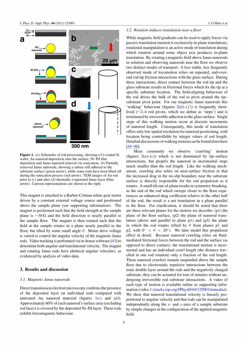
Figure 1. (a) Schematic of rod processing, showing a Cr-coated Siwafer, Au nanorod deposition onto the surface, Ni–Pd filmdeposition and Janus nanorod removal via sonication. (b) Partiallyremoved Janus nanorods, showing a subset still adhered to thesubstrate surface (green arrow), while some rods have been lifted offduring the sonication process (red arrow). TEM images of Au rodprior to (c) and after (d) thermally evaporated Janus layer (bluearrow). Cartoon representations are shown to the right.
This magnet is attached to a Barber-Colman inline gear motordriven by a constant external voltage source and positionedabove the sample plane (see supporting information). Themagnet is positioned such that the field strength at the sampleplane is ∼30 G and the field direction is nearly parallel tothe sample floor. The magnet is then rotated such that thefield at the sample rotates in a plane nearly parallel to thefloor, but tilted by some small angle θ . Motor drive voltageis varied to control the angular velocity of the magnetic Janusrods. Video tracking is performed via in-house software [43] todetermine both angular and translational velocity. The magnetand rotating Janus rods have identical angular velocities, asevidenced by analysis of video data.
3. Results and discussion
3.1. Magnetic Janus nanorods
Direct transmission electron microscopy confirms the presenceof the deposited layer on individual rods compared withuntreated Au nanorod material (figures 1(c) and (d)).Approximately 60% of each nanorod’s surface area (excludingrod faces) is covered by the deposited Ni–Pd layer. These rodsexhibit ferromagnetic behaviour.
3.2. Rotation induces translation near a floor
While magnetic field gradients can be used to apply forces viapassive translation (motion is exclusively in-plane translation),rotational manipulation is an active mode of translation duringwhich rotation around some object axis produces in-planetranslation. By rotating a magnetic field above Janus nanorodsin solution and observing nanorods near the floor we observetwo distinct modes of transport. A less stable, less frequentlyobserved mode of locomotion relies on repeated, end-over-end rod tip friction interactions with the glass surface. Duringthese interactions, direct contact between the rod tip and theglass substrate results in frictional forces which fix the tip at aspecific substrate location. The field-aligning behaviour ofthe rod drives the bulk of the rod to pivot around the tip–substrate pivot point. For our magnetic Janus nanorods this‘walking’ behaviour (figures 2(d)–(f )) is frequently short-lived (∼2–4 rod pivots, which we define as ‘steps’) and isterminated by irreversible adhesion to the glass surface. Singlesteps of this walking motion occur at discrete incrementsof nanorod length. Consequently, this mode of translationoffers only low spatial resolution for nanorod positioning, withlocation being controllable by integer values of rod length.Detailed discussions of walking motion can be found elsewhere[44–46].
More commonly we observe ‘crawling’ motion(figures 2(a)–(c)) which is not dominated by tip–surfaceinteractions, but propels the nanorod in incremental stepsmuch smaller than the rod length. Like the walking mech-anism, crawling also relies on near-surface friction in thatthe increased drag in the no-slip boundary near the substratesurface is directly responsible for the rod propulsion as itrotates. A small tilt out-of-plane results in symmetry-breaking,as the end of the rod which sweeps closer to the floor expe-riences an enhanced drag coefficient relative to the other halfof the rod; the result is a net translation in a plane parallelto the floor. For clarification, it should be noted that thereare three relevant planes for the motion we describe: (p1) theplane of the floor surface, (p2) the plane of nanorod trans-lation (above and parallel to plane p1) and (p3) the planein which the rod rotates (tilted by θ from planes p1 andp2, with 0◦ < θ < 20◦). We later model this propulsioneffect in detail. Because nanorod crawling relies on fluid-mediated frictional forces between the rod and the surface (asopposed to direct contact), the translational motion is incre-mental and has an individual crawl length (the distance trav-elled in one rod rotation) only a fraction of the rod length.These nanorod crawlers remain suspended above the samplefloor due to electrostatic repulsive interactions between theionic double layer around the rods and the negatively chargedsubstrate; they can be actuated for tens of minutes without un-dergoing irreversible rod–substrate interactions. A video ofeach type of motion is available online as supporting infor-mation (video 1 (stacks.iop.org/JPhysD/44/125001/mmedia)).We show that nanorod translational velocity is linearly pro-portional to angular velocity and that rods can be manipulatedindependently along the x- and y-axes of a sample substrateby simple changes in the configuration of the applied magneticfield.
3
J. Phys. D: Appl. Phys. 44 (2011) 125001 L O Mair et al
Step-1 Step-2
crawl-1 crawl-2 crawl-3 crawl-4
a b c
d e f
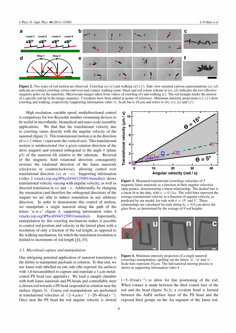
Figure 2. Two types of rod motion are observed. Crawling (a)–(c) and walking (d)–(f ). Side view oriented cartoon representations (a), (d)indicate no-contact crawling versus end-over-end contact walking (note: black and red colour scheme in (a), (d) indicates the two effectivemagnetic poles on the nanorod). Microscope images taken from videos of crawling (b) and walking (e). The red triangle tracks the motionof a specific rod tip in the image sequence. Crosshairs have been added as points of reference. Minimum intensity projections (c), (f ) showcrawling and walking, respectively (supporting information video 1). Scale bar is 10 µm and refers to (b), (c), (e) and (f ).
High resolution, variable speed, multidirectional controlis compulsory for low Reynolds number swimming devices tobe useful in microfluidic, biomedical and nano-scale assemblyapplications. We find that the translational velocity dueto crawling varies directly with the angular velocity of thenanorod (figure 3). This translational motion is in the directionof ω× z where z represents the vertical axis. This translationalmotion is unidirectional (for a given rotation direction of thedrive magnet) and oriented orthogonal to the angle θ (planep3) of the nanorod tilt relative to the substrate. Reversalof the magnetic field rotational direction consequentlyreverses the rotational direction of the Janus nanorods(clockwise or counterclockwise), allowing control overtranslational direction (+x or −x). Supporting information(video 2 (stacks.iop.org/JPhysD/44/125001/mmedia)) showstranslational velocity varying with angular velocity, as well asdirected translation in +x and −x. Additionally, by changingthe orientation (and therefore the orthogonal direction) of themagnet we are able to induce translation in any arbitrarydirection. In order to demonstrate this control of motion,we manipulate a single nanorod along the path of theletters ‘u–n–c’ (figure 4, supporting information video 4(stacks.iop.org/JPhysD/44/125001/mmedia)). Importantly,manipulation by this crawling mechanism makes it possibleto control rod position and velocity in the lateral plane with aresolution of only a fraction of the rod length, as opposed tothe walking mechanism, for which the translation resolution islimited to increments of rod length [44, 45].
3.3. Microbead capture and manipulation
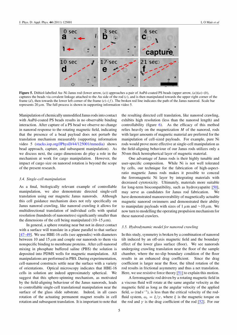
One intriguing potential application of nanorod translation isthe ability to manipulate payloads in solution. To that end, weuse Janus rods labelled on one side (the exposed Au surface)with 1,6-hexanedithiol to capture and translate a 1 µm metal-coated PS bead (see appendix). We load a sample chamberwith both Janus nanorods and PS beads and controllably steera chosen rod towards a PS bead suspended in solution near thesurface (figure 5). Coarse rod manipulations are performedat translational velocities of ∼2–4 µm s−1 (∼20–40 rad s−1).Once near the PS bead the rod angular velocity is slowed
0 10 20 30 40Angular velocity (rad / s)
0
2
4
6
8
10
Tran
slat
ion
al v
elo
city
(m
/ s)
= 15º
= 5º
Figure 3. Measured translational (crawling) velocities of 5magnetic Janus nanorods as a function of their angular velocities(data points), demonstrating a linear relationship. The dashed line isa linear fit to the data, with νt = 0.11ω. The solid lines represent theaverage translational velocity as a function of angular velocity, aspredicted by our model, for rods with θ = 15◦ and 5◦. Theserelationships are calculated for rods sitting h0 = 0.9 µm above theglass floor, as determined by the average of 9 rod heights.
u cn
Figure 4. Minimum intensity projection of a single nanorod(crawling) manipulation, spelling out the letters ‘u’, ‘n’ and ‘c’.Scale bars represent 10 µm. The full nanorod steering process isshown in supporting information video 4.
(∼5–10 rad s−1) to allow for fine positioning of the rod.When contact is made between the thiol coated face of therod and the bead (figure 5(c)), a covalent bond is formedbetween the AuPd surface layer of the PS bead and theexposed thiol groups on the Au segment of the Janus rod.
4
J. Phys. D: Appl. Phys. 44 (2011) 125001 L O Mair et al
capture
a b c
d e f
Figure 5. Dithiol-labelled Au–Ni Janus rod (lower arrow, (a)) approaches a pair of AuPd-coated PS beads (upper arrow, (a))(a)–(b),captures the beads via covalent linkage attached to the Au side of the rod (c), and is then manipulated towards the upper right corner of theframe (d), then towards the lower left corner of the frame (e)–(f ). The broken red line indicates the path of the Janus nanorod. Scale barrepresents 20 µm. The full process is shown in supporting information video 5.
Manipulation of chemically unmodified Janus rods into contactwith AuPd-coated PS beads results in no observable bindinginteraction. After capture of a PS bead we observe no changein nanorod response to the rotating magnetic field, indicatingthat the presence of a bead payload does not perturb thetranslation mechanism measurably (supporting informationvideo 5 (stacks.iop.org/JPhysD/44/125001/mmedia) showsbead approach, capture, and subsequent manipulation). Aswe discuss next, the cargo dimensions do play a role in themechanism at work for cargo manipulation. However, theimpact of cargo size on nanorod rotation is beyond the scopeof the present research.
3.4. Single-cell manipulation
As a final, biologically relevant example of controllablemanipulation, we also demonstrate directed single-celltranslation using our magnetic Janus nanorods. Althoughthis cell guidance mechanism does not rely specifically onJanus nanorod crawling, like nanorod crawling it allows formultidirectional translation of individual cells with spatialresolution (hundreds of nanometres) significantly smaller thanthe dimensions of the cell being manipulated (10–15 µm).
In general, a sphere rotating near but not in direct contactwith a surface will translate in a plane parallel to that surface[47–49]. We use HBE-16 cells (see appendix) with diametersbetween 10 and 15 µm and couple our nanorods to them vianonspecific binding to membrane proteins. After cell-nanorodmixing in phosphate buffered saline (PBS) the solution isdeposited into PDMS wells for magnetic manipulation. Allmanipulations are performed in PBS. During experimentation,cell-nanorod constructs settle near the surface with a varietyof orientations. Optical microscopy indicates that HBE-16cells in solution are indeed approximately spherical. Wesuggest that this sphere-spinning mechanism, as motivatedby the field-aligning behaviour of the Janus nanorods, leadsto controllable single-cell translational manipulation near thesurface of the glass slide substrate. Indeed, in all casesrotation of the actuating permanent magnet results in cellrotation and subsequent translation. It is important to note that
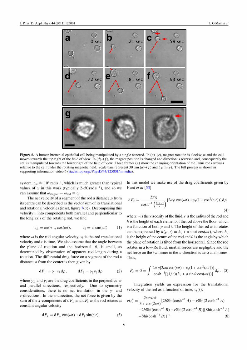
the resulting directed cell translation, like nanorod crawling,exhibits high resolution (less than the nanorod length) andcontrollability (figure 6). As the efficacy of this methodrelies heavily on the magnetization M of the nanorod, rodswith larger amounts of magnetic material are preferred for themanipulation of cell-sized payloads. For example, pure Nirods would prove more effective at single-cell manipulation asthe field-aligning behaviour of our Janus rods utilizes only a50 nm thick hemispherical layer of magnetic material.
One advantage of Janus rods is their highly tunable anduser-specific composition. While Ni is not well toleratedby cells, our technique for the fabrication of high-aspect-ratio magnetic Janus rods makes it possible to concealthe ferromagnetic Ni layer by integrating materials withdecreased cytotoxicity. Ultimately, materials more suitablefor long-term biocompatibility, such as hydroxyapatite [50],may serve as candidates for Janus rod fabrication. Wehave demonstrated manoeuverability of magnetically actuablemagnetic nanorod swimmers and demonstrated their abilityto manipulate payloads with sizes of 1 µm and ∼10 µm. Wenow turn to modelling the operating propulsion mechanism forthese nanorod crawlers.
3.5. Hydrodynamic model for nanorod crawling
In this study, symmetry is broken by a combination of nanorodtilt induced by an off-axis magnetic field and the boundaryeffect of the lower glass surface (floor). We see nanorodsundergoing crawling translation near the floor of the samplechamber, where the no-slip boundary condition of the floorresults in an enhanced drag coefficient. Since the dragcoefficient is larger near the floor, the tilted rotation of therod results in frictional asymmetry and thus a net translation.Here, we use resistive force theory [51] to explain this motion.
A ferromagnetic rod driven by a rotating magnetic field ina viscous fluid will rotate at the same angular velocity as themagnetic field as long as the angular velocity of the appliedfield, ω (rad s−1), is less than the critical velocity of the rod-fluid system, ωc = ξ/γ , where ξ is the magnetic torque onthe rod and γ is the drag coefficient of the rod [52]. For our
5
J. Phys. D: Appl. Phys. 44 (2011) 125001 L O Mair et al
a b c
fed
g
Figure 6. A human bronchial epithelial cell being manipulated by a single nanorod. In (a)–(c), magnet rotation is clockwise and the cellmoves towards the top right of the field of view. In (d)–(f ), the magnet position is changed and direction is reversed and, consequently thecell is manipulated towards the lower right of the field of view. Three frames (g) show the changing orientation of the Janus rod (arrows)relative to the cell under the rotating magnetic field. Scale bars represent 30 µm (a)–(f ) and 5 µm (g). The full process is shown insupporting information video 6 (stacks.iop.org/JPhysD/44/125001/mmedia).
system, ωc ≈ 104 rad s−1, which is much greater than typicalvalues of ω in this work (typically 2–50 rad s−1), and so wecan assume that ωmagnet = ωrod ≡ ω.
The net velocity of a segment of the rod a distance ρ fromits centre can be described as the vector sum of its translationaland rotational velocities (inset, figure 7(a)). Decomposing thisvelocity ν into components both parallel and perpendicular tothe long axis of the rotating rod, we find
ν⊥ = ωρ + νt cos(ωt), ν‖ = νt sin(ωt) (1)
where ω is the rod angular velocity, νt is the rod translationalvelocity and t is time. We also assume that the angle betweenthe plane of rotation and the horizontal, θ , is small, asdetermined by observation of apparent rod length during arotation. The differential drag force on a segment of the rod adistance ρ from the center is then given by
dF⊥ = γ⊥ν⊥dρ, dF‖ = γ‖ν‖ dρ (2)
where γ⊥ and γ‖ are the drag coefficients in the perpendicularand parallel directions, respectively. Due to symmetryconsiderations, there is no net translation in the y- andz-directions. In the x-direction, the net force is given by thesum of the x-components of dF⊥ and dF‖ as the rod rotates atconstant angular velocity
dFx = dF⊥ cos(ωt) + dF‖ sin(ωt). (3)
In this model we make use of the drag coefficients given byHunt et al [53]
dFx = 2πη
cosh−1(
h(ρ,t)
r
) [2ωρ cos(ωt) + νt(1 + cos2(ωt))] dρ
(4)
where η is the viscosity of the fluid, r is the radius of the rod andh is the height of each element of the rod above the floor, whichis a function of both ρ and t . The height of the rod as it rotatescan be expressed by h(ρ, t) = h0 + ρ sin θ cos(ωt), where h0
is the height of the centre of the rod and θ is the angle by whichthe plane of rotation is tilted from the horizontal. Since the rodrotates in a low-Re fluid, inertial forces are negligible and thenet force on the swimmer in the x-direction is zero at all times.Thus,
Fx = 0 =∫
2πη[2ωρ cos(ωt) + νt(1 + cos2(ωt))]
cosh−1[(1/r)(h0 + ρ sin θ cos(ωt))]dρ. (5)
Integration yields an expression for the translationalvelocity of the rod as a function of time, νt(t):
ν(t) = 2ωcscθ
3 + cos(2ωt)[2hShi(cosh−1 A) − rShi(2 cosh−1 A)
−2hShi(cosh−1 B) + rShi(2 cosh−1 B)][Shi(cosh−1 A)
−Shi(cosh−1 B)]−1 (6)
6
J. Phys. D: Appl. Phys. 44 (2011) 125001 L O Mair et al
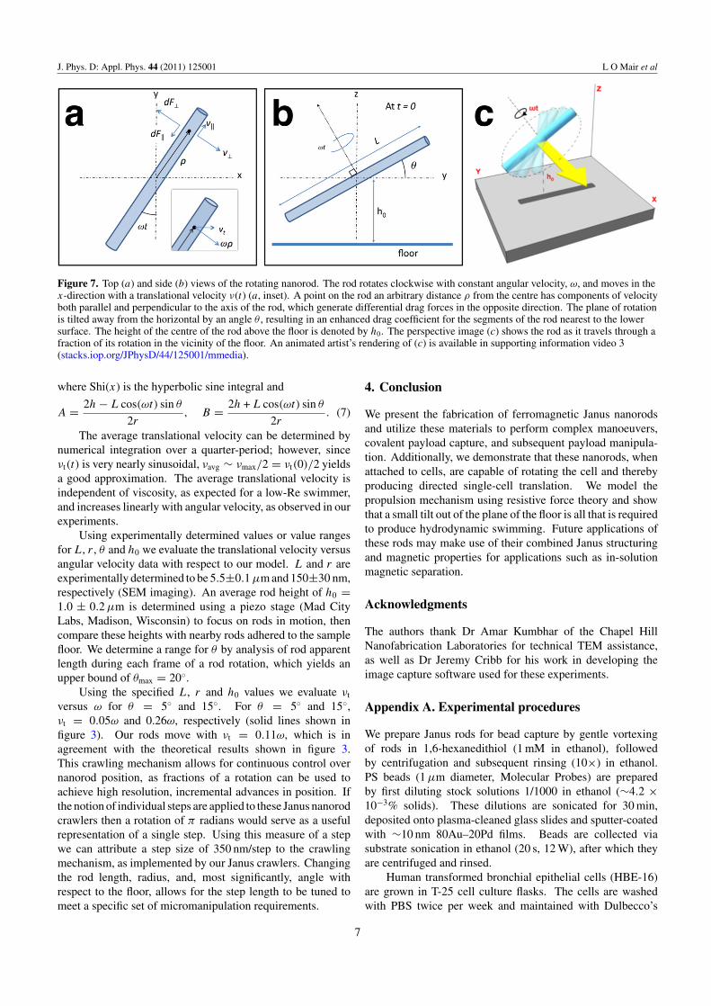
Figure 7. Top (a) and side (b) views of the rotating nanorod. The rod rotates clockwise with constant angular velocity, ω, and moves in thex-direction with a translational velocity ν(t) (a, inset). A point on the rod an arbitrary distance ρ from the centre has components of velocityboth parallel and perpendicular to the axis of the rod, which generate differential drag forces in the opposite direction. The plane of rotationis tilted away from the horizontal by an angle θ , resulting in an enhanced drag coefficient for the segments of the rod nearest to the lowersurface. The height of the centre of the rod above the floor is denoted by h0. The perspective image (c) shows the rod as it travels through afraction of its rotation in the vicinity of the floor. An animated artist’s rendering of (c) is available in supporting information video 3(stacks.iop.org/JPhysD/44/125001/mmedia).
where Shi(x) is the hyperbolic sine integral and
A = 2h − L cos(ωt) sin θ
2r, B = 2h + L cos(ωt) sin θ
2r. (7)
The average translational velocity can be determined bynumerical integration over a quarter-period; however, sinceνt(t) is very nearly sinusoidal, νavg ∼ νmax/2 = νt(0)/2 yieldsa good approximation. The average translational velocity isindependent of viscosity, as expected for a low-Re swimmer,and increases linearly with angular velocity, as observed in ourexperiments.
Using experimentally determined values or value rangesfor L, r , θ and h0 we evaluate the translational velocity versusangular velocity data with respect to our model. L and r areexperimentally determined to be 5.5±0.1 µm and 150±30 nm,respectively (SEM imaging). An average rod height of h0 =1.0 ± 0.2 µm is determined using a piezo stage (Mad CityLabs, Madison, Wisconsin) to focus on rods in motion, thencompare these heights with nearby rods adhered to the samplefloor. We determine a range for θ by analysis of rod apparentlength during each frame of a rod rotation, which yields anupper bound of θmax = 20◦.
Using the specified L, r and h0 values we evaluate νt
versus ω for θ = 5◦ and 15◦. For θ = 5◦ and 15◦,νt = 0.05ω and 0.26ω, respectively (solid lines shown infigure 3). Our rods move with νt = 0.11ω, which is inagreement with the theoretical results shown in figure 3.This crawling mechanism allows for continuous control overnanorod position, as fractions of a rotation can be used toachieve high resolution, incremental advances in position. Ifthe notion of individual steps are applied to these Janus nanorodcrawlers then a rotation of π radians would serve as a usefulrepresentation of a single step. Using this measure of a stepwe can attribute a step size of 350 nm/step to the crawlingmechanism, as implemented by our Janus crawlers. Changingthe rod length, radius, and, most significantly, angle withrespect to the floor, allows for the step length to be tuned tomeet a specific set of micromanipulation requirements.
4. Conclusion
We present the fabrication of ferromagnetic Janus nanorodsand utilize these materials to perform complex manoeuvers,covalent payload capture, and subsequent payload manipula-tion. Additionally, we demonstrate that these nanorods, whenattached to cells, are capable of rotating the cell and therebyproducing directed single-cell translation. We model thepropulsion mechanism using resistive force theory and showthat a small tilt out of the plane of the floor is all that is requiredto produce hydrodynamic swimming. Future applications ofthese rods may make use of their combined Janus structuringand magnetic properties for applications such as in-solutionmagnetic separation.
Acknowledgments
The authors thank Dr Amar Kumbhar of the Chapel HillNanofabrication Laboratories for technical TEM assistance,as well as Dr Jeremy Cribb for his work in developing theimage capture software used for these experiments.
Appendix A. Experimental procedures
We prepare Janus rods for bead capture by gentle vortexingof rods in 1,6-hexanedithiol (1 mM in ethanol), followedby centrifugation and subsequent rinsing (10×) in ethanol.PS beads (1 µm diameter, Molecular Probes) are preparedby first diluting stock solutions 1/1000 in ethanol (∼4.2 ×10⁻³% solids). These dilutions are sonicated for 30 min,deposited onto plasma-cleaned glass slides and sputter-coatedwith ∼10 nm 80Au–20Pd films. Beads are collected viasubstrate sonication in ethanol (20 s, 12 W), after which theyare centrifuged and rinsed.
Human transformed bronchial epithelial cells (HBE-16)are grown in T-25 cell culture flasks. The cells are washedwith PBS twice per week and maintained with Dulbecco’s
7
J. Phys. D: Appl. Phys. 44 (2011) 125001 L O Mair et al
Modified Eagle Medium/F12 (DMEM/F12) with 5% fetalbovine serum. HBE-16 cells are routinely passaged uponreaching confluence. In preparation for Janus nanorodmanipulation, these cells are trypsinized, spun into a pelletand resuspended in DMEM/F12 at a concentration ofabout 2 million cells/ml. Cells are incubated with Janusnanorods under gentle vortex mixing for 1 h prior to magneticmanipulation. The manipulation experiments presented heremake use of nonspecific cell-nanorod binding [54], whichmechanically couples the cell membrane to the rods. Althoughnot all cell-nanorod interactions result in irreversible cellbinding and particle adhesion, successfully bound nanorodsremain intact for the duration of these cell manipulationexperiments.
References
[1] Ebbens S J and Howse J R 2010 In pursuit of propulsion at thenanoscale Soft Matter 6 726–738
[2] Ozin G A, Manners I, Fournier-Bidoz S and Arsenault A 2005Dream nanomachines Adv. Mater. 17 3011–8
[3] Sundararajan S, Lammert P E, Zudans A W, Crespi V H andSen A 2008 Catalytic motors for transport of colloidal cargoNano Lett. 8 1271–6
[4] Sundararajan S, Sengupta S, Ibele M E and Sen A 2010Drop-off of colloidal cargo transported by catalytic pt–aunanomotors via electrochemical stimuli Small 6 1479–82
[5] Burdick J, Laocharoensuk R, Wheat P M, Posner J D andWang J 2008 Synthetic nanomotors in microchannelnetworks: directional microchip motion and controlledmanipulation of cargo J. Am. Chem. Soc. 130 8164–5
[6] Kline T R, Paxton W F, Mallouk T E and Sen A 2005 Catalyticnanomotors: remote-controlled autonomous movement ofstriped metallic nanorods Angew. Chem. Int. Edn 44 744–6
[7] Mallouk T E, Sen A and Paxton W F 2005 Catalyticmovement of nanoscale objects Chem. Eur. J. 11 6462–70
[8] Mirkovic T, Zacharia N S, Scholes G D and Ozin G A 2010Fuel for thought: chemically powered nanomotorsout-swim nature’s flagellated bacteria ACS Nano 4 1782–9
[9] Paxton W F, Sundararajan S, Mallouk T E and Sen A 2006Chemical locomotion Angew. Chem. Int. Edn 45 5420–9
[10] Paxton W F, Kistler K C, Olmeda C C, Sen A, St Angelo S K,Cao Y, Mallouk T E, Lammert P E and Crespi V H 2004Catalytic nanomotors: autonomous movement of stripednanorods J. Am. Chem. Soc. 126 13424–31
[11] Valadares L F, Tao Y-G, Zacharia N S, Kitaev V, Galembeck F,Kapral R and Ozin G A 2010 Catalytic nanomotors:self-propelled sphere dimers Small 6 565–72
[12] Zacharia N S, Sadeq Z S and Ozin G A 2009 Enhanced speedof bimetallic nanorod motors by surface roughening Chem.Commun. 2009 5856–8
[13] Zhang L, Abbott J J, Dong L, Peyer K E, Kratochvil B E,Zhang H, Bergeles C and Nelson B J 2009 Characterizingthe swimming properties of artificial bacterial flagella NanoLett. 9 3663–7
[14] Zhang L, Abbott J J, Dong L, Kratochvil B E, Bell D andNelson B J 2009 Artificial bacterial flagella: fabraction andmagnetic control Appl. Phys. Lett. 94 064107
[15] Zhang L, Petit T, Lu Y, Kratochvil B E, Peyer K E, Pei R,Lou J and Nelson B J 2010 Controlled propulsion and cargotransport of rotating nickel nanowires near a patterned solidsurface ACS Nano 4 6228–34
[16] Sing C E, Schmid L, Schneider M F, Franke T andAlexander-Katz A 2010 Controlled surface-induced flowsfrom the motion of self-assembled colloidal walkers Proc.Natl Acad. Sci. USA 107 535–40
[17] Ghosh A and Fischer P 2009 Controlled propulsion of artificialmagnetic nanostructured propellers Nano Lett. 9 1922–33
[18] Tierno P, Golestanian R, Pagonabarraga I and Sagues F 2008Controlled swimming in confined fluids of magneticallyactuated colloidal rotors Phys. Rev. Lett. 101 218304
[19] Garstecki P, Tierno P, Weibel D B, Sagues F andWhitesides G M 2009 Propulsion of flexible polymerstructures in a rotating magnetic field J. Phys.: Condens.Matter 21 204110
[20] Tierno P, Guell O, Sagues F, Golestanian R andPagonabarraga I 2010 Controlled propulsion in viscousfluids of magnetically actuated colloidal doublets Phys.Rev. E 81 011402
[21] Baudry J, Fermigier M, Bibette J, Dreyfus R, Stone H A andRoper M L 2005 Microscopic artificial swimmers Nature437 862
[22] Tierno P, Golestanian R, Pagonabarraga I and Sagues F 2008Magnetically actuated colloidal microswimmers J. Phys.Chem. B 112 16525–8
[23] Purcell E M 1977 Life at low Reynolds number Am. J. Phys.45 3–11
[24] Childress S 1981 Mechanics of Swimming and Flying(Cambridge: Cambridge University Press)ISBN 0521280710
[25] Najafi A and Golestanian R 2004 Simple swimmer at lowReynolds number: Three linked spheres Phys. Rev. E69 062901
[26] Becker L E, Koehler S A and Stone H A 2003 Onself-propulsion of micro-machines at low Reynoldsnumber: Purcells three-link swimmer J. Fluid Mech.490 15–35
[27] Keaveny E E and Maxey M R 2008 Spiral swimming of anartificial micro-swimmer J. Fluid Mech. 598 293–319
[28] Belovs M and Cebers A 2009 Ferromagnetic microswimmerPhys. Rev. E 79 051503
[29] Najafi A and Golestanian R 2005 Propulsion at low Reynoldsnumber J. Phys.: Condens. Matter 17 S1203–8
[30] Casagrande C and Veyssie M 1988 Janus beads—realizationand 1st observation of interfacial properties C. R. Acad. Sci.306 1423–5
[31] Attenborough K, Hart R, Lane S J, Alper M andSchwarzacher W 1995 Magnetoresistance inelectrodeposited Ni–Fe–Cu/Cu multilayers J. Magn. Magn.Mater. 148 335–6
[32] Elnathan R, Kantaev R and Patolsky F 2008 Synthesis ofhybrid multicomponent disklike nanoparticles Nano Lett.8 3964–72
[33] Wang L, Yu-Zhang K, Metrot A, Bonhomme P and Troyon M1996 Tem study of electrdeposited ni/cu multilayers in theform of nanowires Thin Solid Films 288 86–9
[34] Wildt B, Mali P and Searson P C 2006 Electrochemicaltemplate synthesis of multisegment nanowires: Fabricationand protein functionalization Langmuir 22 10528–34
[35] Hurst S J, Payne E K, Qin L and Mirkin C A 2006Multisegmented one-dimensional nanorods prepared byhard-template synthetic methods Angew. Chem. Int. Edn45 2672–92
[36] Qin L D, Park S, Huang L and Mirkin C A 2005 On-wirelithography Science 309 113–5
[37] Martin C R and Baker L A 2005 Expanding the molecularelectronics toolbox Science 309 67–8
[38] Qin L D, Banholzer M J, Xu X Y, Huang L and Mirkin C A2007 Rational design and synthesis of catalytically drivennanorotors J. Am. Chem. Soc. 129 (48) 14870–1
[39] Wang Y, Fei S-T, Byun Y-M, Lammert P E, Crespi V H, Sen Aand Mallouk T E 2009 Dynamic interactions between fastmicroscale rotors J. Am. Chem. Soc. 131 9926–7
[40] Qin L, Banholzer M J, Millstone J E and Mirkin C A 2007Nanodisk codes Nano Lett. 7 3849–53
8
J. Phys. D: Appl. Phys. 44 (2011) 125001 L O Mair et al
[41] Hangarter C M, Rheem Y, Yoo B, Yang E H and Myung N V2007 Hierarchical magnetic assembly of nanowiresNanotechnology 18 205305
[42] Hangarter C M and Myung N V 2005 Magnetic alignmentof nanowires Chem. Mater. 17 1320–4
[43] Taylor R M 2009 Video spot trackerhttp://cismm.cs.unc.edu/downloads/?dl cat=3
[44] Zhao Y and Zeng H 2009 Rotational maneuver offerromagnetic nanowires for cell manipulation IEEE Trans.Nanobiosci. 8 226–36
[45] Zeng H, Ebel J and Zhao Y 2009 Rapid cell manipulationby rotating nanowires Mater. Res. Soc. Symp. Proc.1139 25–30
[46] Morimoto H, Ukai T, Nagaoka Y, Grobert N and Maekawa T2008 Tumbling motion of magnetic particles on a magneticsubstrate induced by a rotational magnetic field Phys. Rev. E78 021403 8
[47] Blake J R 1971 A note on the image system for a stokesletin a no-slip boundary Proc. Camb. Phil. Soc. 70 303–10
[48] Goldman A J, Cox R G and Brenner H 1967 Slowviscous motion of a sphere parallel to a plane wall:
I. Motion through a quiescent fluid Chem. Eng. Sci.22 637–51
[49] Reichert M and Stark H 2004 Hydrodynamic coupling of tworotating spheres trapped in harmonic potentials Phys. Rev. E69 031407
[50] Balasundaram G, Sato M and Webster T J 2006 Usinghydroxyapatite nanoparticles and decreased crystallinity topromote osteoblast adhesion similar to functionalizing withrgd Biomaterials 27 2798–805
[51] Gray J and Hancock G J 1955 The propulsion of sea-urchinspermatozoa J. Exp. Biol. 32 802–14
[52] Urena E B, Mei Y, Coric E, Makarov D, Albrecht M andSchmidt O G 2009 Fabrication of ferromagnetic rolled-upmicrotubes for magnetic sensors on fluids J. Phys. D: Appl.Phys. 42 055001
[53] Hunt A J, Gittes F and Howard J 1994 The force exerted by asingle kinesin molecule against a viscous loadBiophysical J. 67 766–81
[54] Hultgren A, Tanase M, Chen C S, Meyer G J and Reich D H2003 Cell manipulation using magnetic nanowires J. Appl.Phys. 93 7554–6
9
Copyright © 2022 FDOKUMEN