On the spectral and wave propagation properties of the surface Maryland model
Upload
independentCategory
view
0download
0
K. L. Johnson1
Department of Mechanical Engineering,
Center for Advanced Vehicular Systems (CAVS),
Mississippi State University,
Mississippi State, MS 39762
M. W. TrimNaval Surface Warfare Center,
9500 MacArthur Blvd,
Bethesda, MD 20817
M. F. HorstemeyerDepartment of Mechanical Engineering,
Center for Advanced Vehicular Systems (CAVS),
Mississippi State University,
Mississippi State, MS 39762
N. LeeCenter for Advanced Vehicular Systems (CAVS),
200 Research Blvd,
Mississippi State, MS 39762;
Agriculture and Biological Engineering,
Mississippi State University,
Mississippi State, MS 39762
L. N. WilliamsAgriculture and Biological Engineering,
Mississippi State University,
Mississippi State, MS 39762
J. LiaoAgriculture and Biological Engineering,
Mississippi State University,
Mississippi State, MS 39762
H. RheeCenter for Advanced Vehicular Systems (CAVS),
200 Research Blvd,
Mississippi State, MS 39762
R. PrabhuCenter for Advanced Vehicular Systems (CAVS),
Agriculture and Biological Engineering,
200 Research Blvd,
Mississippi State, MS 39762
Geometric Effects on StressWave PropagationThe present study, through finite element simulations, shows the geometric effects of abioinspired solid on pressure and impulse mitigation for an elastic, plastic, and visco-elastic material. Because of the bioinspired geometries, stress wave mitigation becameapparent in a nonintuitive manner such that potential real-world applications in humanprotective gear designs are realizable. In nature, there are several toroidal designs thatare employed for mitigating stress waves; examples include the hyoid bone on the back ofa woodpecker’s jaw that extends around the skull to its nose and a ram’s horn. This studyevaluates four different geometries with the same length and same initial cross-sectionaldiameter at the impact location in three-dimensional finite element analyses. The geome-tries in increasing complexity were the following: (1) a round cylinder, (2) a round cylin-der that was tapered to a point, (3) a round cylinder that was spiraled in a twodimensional plane, and (4) a round cylinder that was tapered and spiraled in a two-dimensional plane. The results show that the tapered spiral geometry mitigated the great-est amount of pressure and impulse (approximately 98% mitigation) when compared tothe cylinder regardless of material type (elastic, plastic, and viscoelastic) and regardlessof input pressure signature. The specimen taper effectively mitigated the stress wave as aresult of uniaxial deformational processes and an induced shear that arose from its ge-ometry. Due to the decreasing cross-sectional area arising from the taper, the local uni-axial and shear stresses increased along the specimen length. The spiral induced evengreater shear stresses that help mitigate the stress wave and also induced transverse dis-placements at the tip such that minimal wave reflections occurred. This phenomenonarose although only longitudinal waves were introduced as the initial boundary condition(BC). In nature, when shearing occurs within or between materials (friction), dissipationusually results helping the mitigation of the stress wave and is illustrated in this studywith the taper and spiral geometries. The combined taper and spiral optimized stresswave mitigation in terms of the pressure and impulse; thus providing insight into theram’s horn design and woodpecker hyoid designs found in nature.[DOI: 10.1115/1.4026320]
Keywords: guided wave propagation, elastic wave interaction and reflection, finite ele-ment analysis, dispersion in waveguides, stress wave mitigation, bioinspired design, geo-metric effects
Introduction
The inspiration for this study stems from the curious geometriesoften found in biological structures that are subjected to dynamicloads. One such geometry is the natural spiral. Examples of theappearance of the spiral in natural shock absorbing systemsinclude the ram’s horn, seashells, and the woodpecker’s hyoidbone. Does the reoccurrence of this curious shape throughout na-ture have some significance in regards to energy dissipation andshock absorption abilities inherent to its geometry? We seek to an-swer the following question: Can geometries affect stress wavesto change the energy states and in the end the forces (or stresses)?
The fundamentals of the physics of stress waves have been wellstudied [1–3]. As a premise, the context of shock wave physics iswarranted. If one were to neglect surface waves, then two maintypes of waves can propagate through isotropic solids: longitudi-nal waves and shear waves. Longitudinal (also called dilatational,pressure, primary, or P-) waves propagate with a characteristicwave speed and represent a volumetric change. Their motion isparallel to the direction of the wave propagation. Shear (alsocalled secondary, S-, or distortional) waves represent no volumechange and propagate at a slower wave speed with respect to lon-gitudinal waves. Their motion is normal to the direction of propa-gation [4,5]. When either a longitudinal or shear wave impingeson a boundary, new waves are generated due to the reflective na-ture of waves. In a solid body with finite dimensions, these wavesbounce back and forth between the bounding surfaces and interactwith one another. These interactions can lead to wave amplifica-tion, cancellation, and other wave distortions.
1Corresponding author.Contributed by the Bioengineering Division of ASME for publication in the
JOURNAL OF BIOMECHANICAL ENGINEERING. Manuscript received September 5, 2013;final manuscript received December 13, 2013; accepted manuscript postedDecember 24, 2013; published online February 5, 2014. Editor: Beth Winkelstein.
Journal of Biomechanical Engineering FEBRUARY 2014, Vol. 136 / 021023-1Copyright VC 2014 by ASME
Downloaded From: http://biomechanical.asmedigitalcollection.asme.org/ on 03/21/2014 Terms of Use: http://asme.org/terms
The pressure wave can be integrated over time leading to animpulse. The impulse is equal to the change in momentum of thebody. It is possible for a very brief force, due to a shock, to producea larger impulse when compared to a smaller force acting over alarger time period. Therefore, it is important to consider the tran-sient forces, particularly those associated with wave phenomena.
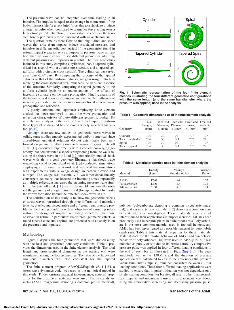
The question remains then: How do the longitudinal and shearwaves that arise from impacts induce associated pressures andimpulses in different solid geometries? If the geometries found innatural impact scenarios serve a purpose in pressure wave mitiga-tion, then we would expect to see different geometries admittingdifferent pressures and impulses in a solid. The four geometriesincluded in this study comprise a cylindrical bar, a tapered cylin-drical bar, a spiral with a circular cross section, and a tapered spi-ral (also with a circular cross section). The cylindrical bar servesas a “base-line” case. By comparing the response of the taperedcylinder to that of the uniform cylinder, we gain insight into howreducing the cross-sectional area influences the transient responseof the structure. Similarly, comparing the spiral geometry to theuniform cylinder leads to an understanding of the effects ofincreasing curvature on the wave propagation. Finally, analysis ofthe tapered spiral allows us to understand the coupled influence ofincreasing curvature and decreasing cross-sectional area on wavepropagation and reflection.
A purely computational approach employing finite elementanalysis has been employed to study the wave propagation andreflection characteristics of these different geometric bodies. Fi-nite element analysis is the most efficient technique to performthese types of studies and has become a widely accepted analysistool [6–10].
Although there are few studies on geometric stress waves insolids, some studies (mostly experimental and/or numerical sinceclosed-form analytical solutions do not exist) have been per-formed on geometric effects on shock waves in gases. Setchellet al. [11] conducted experiments with a conical converging ge-ometry that demonstrated a shock strengthening from the walls fo-cusing the shock wave in air. Lind [12] numerically studied shockwaves with air in a cowl geometry illustrating that shock waveweakening could occur. Bond et al. [13] conducted simulationsemploying an Eulerian framework and validated the simulationswith experiments with a wedge design in carbon dioxide andnitrogen. The wedge was essentially a two-dimensional linearlyconvergent geometry that focused the incoming shock repeatedlyas multiple reflections increased the incoming pressure wave simi-lar to the Setchell et al. [11] results. Inoue [14] numerically stud-ied the geometry of a logarithmic spiral (log-spiral) duct to clarifythe vortex formation behind the reflected shock wave in air.
The contribution of this study is to show the geometric effectson stress waves transmitted through three different solid materials(elastic, plastic, and viscoelastic) and different input pressure pro-files as the loading condition with an objective of garnering infor-mation for design of impulse mitigating structures like thoseobserved in nature. In particular two different geometric effects, around tapered cone and a spiral, are presented with an analysis onthe pressures and impulses.
Methodology
Figure 1 depicts the four geometries that were studied alongwith the load and prescribed boundary conditions. Table 1 pro-vides the dimensions used in the finite element analysis. The totallength and cross-sectional diameters at the starting end weremaintained among the four geometries. The ratio of the large- andsmall-end diameters was also consistent for the taperedgeometries.
The finite element program ABAQUS/Explicit v6.11 [15], astress wave dynamics code, was used as the numerical model inthis study. To demonstrate material independence, material prop-erties for three different materials were used. The materials aremetal (AM30 magnesium denoting a common plastic material),
polymer (polycarbonate denoting a common viscoelastic mate-rial), and ceramic (silicon carbide (SiC) denoting a common elas-tic material) were investigated. These materials were also ofinterest due to their applications in impact scenarios. SiC has beenpreviously used in ceramic plates in bulletproof vests. Polycarbon-ate is the most common material used in football helmets, andAM30 has been investigated as a possible material for automobilecrash rails. Table 2 lists material properties for these materials.Material data for the plastic behavior of AM30 and viscoelasticbehavior of polycarbonate [16] were used in ABAQUS. SiC wasmodeled as purely elastic due to its brittle nature. A compressivepressure pulse was applied in four different loading conditions tothe end of each bar as illustrated in Figs. 2(a)–2(d). The peakamplitude was set as 130 MPa and the duration of pressureapplication was calculated to ensure the area under the pressureversus time curve (impulse) remained consistent between all fourloading conditions. These four different loading applications werestudied to ensure that impulse mitigation was not dependent on asingle loading condition. For brevity, all results other than normal-ized impulse and maximum transverse displacement were foundusing the consecutive increasing and decreasing pressure pulse.
Fig. 1 Schematic representation of the four finite elementmeshes illustrating the four different geometric configurationswith the same length (and the same bar diameter where thepressure was applied) used in the analysis
Table 1 Geometric dimensions used in finite element analysis
Geometry
TotalLength, L
(mm)
Fixed-endDiameter,d1 (mm)
Free-endDiameter,d2 (mm)
Fixed-endArea,
A1 (mm2)
Free-endArea, A2
(mm2)
Cylinder 704 30 30 707 707Tapered cylinder 704 30 5.3 707 22Spiral 704 30 30 707 707Tapered spiral 704 30 5.3 707 22
Table 2 Material properties used in finite element analysis
MaterialDensity(kg/m3)
Young’sModulus (GPa)
Poisson’sRatio
AM30 1780 44 0.35Polycarbonate 1200 2.4 0.37Silicon carbide 3100 410 0.14
021023-2 / Vol. 136, FEBRUARY 2014 Transactions of the ASME
Downloaded From: http://biomechanical.asmedigitalcollection.asme.org/ on 03/21/2014 Terms of Use: http://asme.org/terms
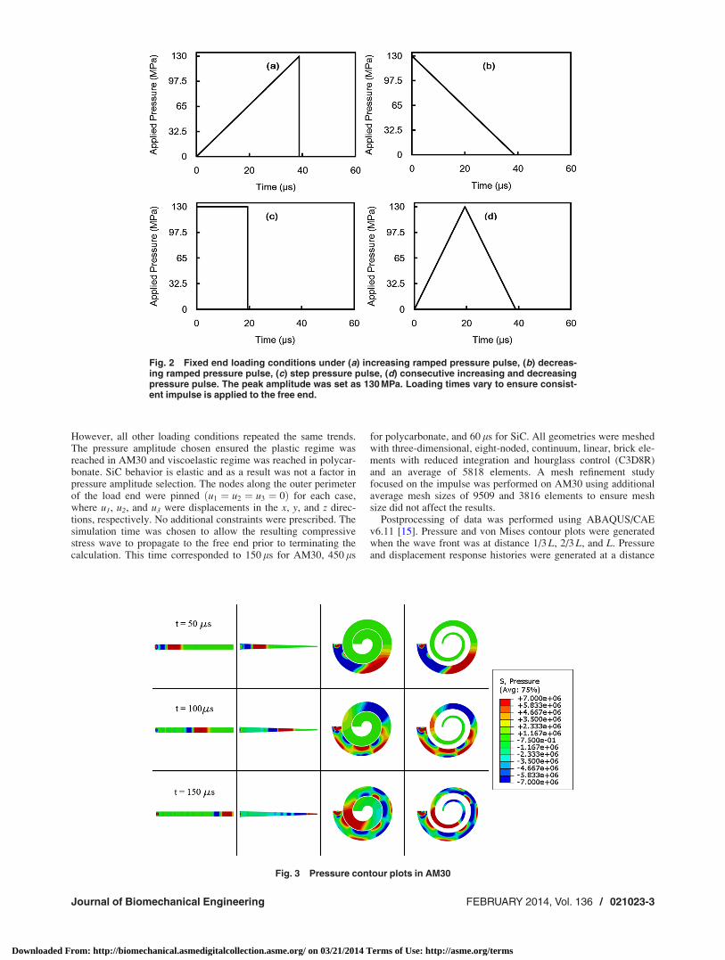
However, all other loading conditions repeated the same trends.The pressure amplitude chosen ensured the plastic regime wasreached in AM30 and viscoelastic regime was reached in polycar-bonate. SiC behavior is elastic and as a result was not a factor inpressure amplitude selection. The nodes along the outer perimeterof the load end were pinned u1 ¼ u2 ¼ u3 ¼ 0ð Þ for each case,where u1, u2, and u3 were displacements in the x, y, and z direc-tions, respectively. No additional constraints were prescribed. Thesimulation time was chosen to allow the resulting compressivestress wave to propagate to the free end prior to terminating thecalculation. This time corresponded to 150 ls for AM30, 450 ls
for polycarbonate, and 60 ls for SiC. All geometries were meshedwith three-dimensional, eight-noded, continuum, linear, brick ele-ments with reduced integration and hourglass control (C3D8R)and an average of 5818 elements. A mesh refinement studyfocused on the impulse was performed on AM30 using additionalaverage mesh sizes of 9509 and 3816 elements to ensure meshsize did not affect the results.
Postprocessing of data was performed using ABAQUS/CAEv6.11 [15]. Pressure and von Mises contour plots were generatedwhen the wave front was at distance 1/3 L, 2/3 L, and L. Pressureand displacement response histories were generated at a distance
Fig. 3 Pressure contour plots in AM30
Fig. 2 Fixed end loading conditions under (a) increasing ramped pressure pulse, (b) decreas-ing ramped pressure pulse, (c) step pressure pulse, (d) consecutive increasing and decreasingpressure pulse. The peak amplitude was set as 130 MPa. Loading times vary to ensure consist-ent impulse is applied to the free end.
Journal of Biomechanical Engineering FEBRUARY 2014, Vol. 136 / 021023-3
Downloaded From: http://biomechanical.asmedigitalcollection.asme.org/ on 03/21/2014 Terms of Use: http://asme.org/terms

of 0.1 m away from the free end to avoid edge effects. The dis-tance corresponded to a rotation of 180 deg from the free end onthe spiraled geometries. The pressure histories were created byaveraging the respective output of each node lying on the crosssection at the specified offset from the free end. The impulsecaused by the initial compressive wave was found by multiplyingthe offset cross-section pressure history by the respective cross-sectional area of each geometry, followed by integration of theresulting force-time history. The impulse values of the cylinderwere used to normalize the results. The maximum shear stressesand maximum transverse displacement, which is considered per-pendicular to the longitudinal axis, were also found at the offsetcross section. For the tapered spiral, the change in strain energybetween the elements at the loading location and the elements atthe target location, 0.1 m from the free end, was investigated toinclude shear stresses and further verify dissipative properties forthis geometry. By examining the strain energy, the possibility of
mistaking a very low impulse for an average of equal and oppositepressures in the same plane would be minimized. The strainenergy at the loading location was used to normalize the results.The time was also doubled to allow the responding oscillationsand vibrations affect the wave as it returned through the bar.
Results
Figures 3–5 show the pressure contour plots for the cylinder,tapered cylinder, spiral, and tapered spiral using AM30, polycar-bonate, and SiC material properties when the wave front is at dis-tance 1/3 L, 2/3 L, and L. These plots illustrate the differences inthe pressure wave propagating through each of the geometries de-spite all of the geometries having the same length, initial diameter,and initial BCs. In the cylinder and tapered cylinder, the initialcompressive wave shape remained mostly unchanged, although
Fig. 4 Pressure contour plots in polycarbonate
Fig. 5 Pressure contour plots in silicon carbide
021023-4 / Vol. 136, FEBRUARY 2014 Transactions of the ASME
Downloaded From: http://biomechanical.asmedigitalcollection.asme.org/ on 03/21/2014 Terms of Use: http://asme.org/terms
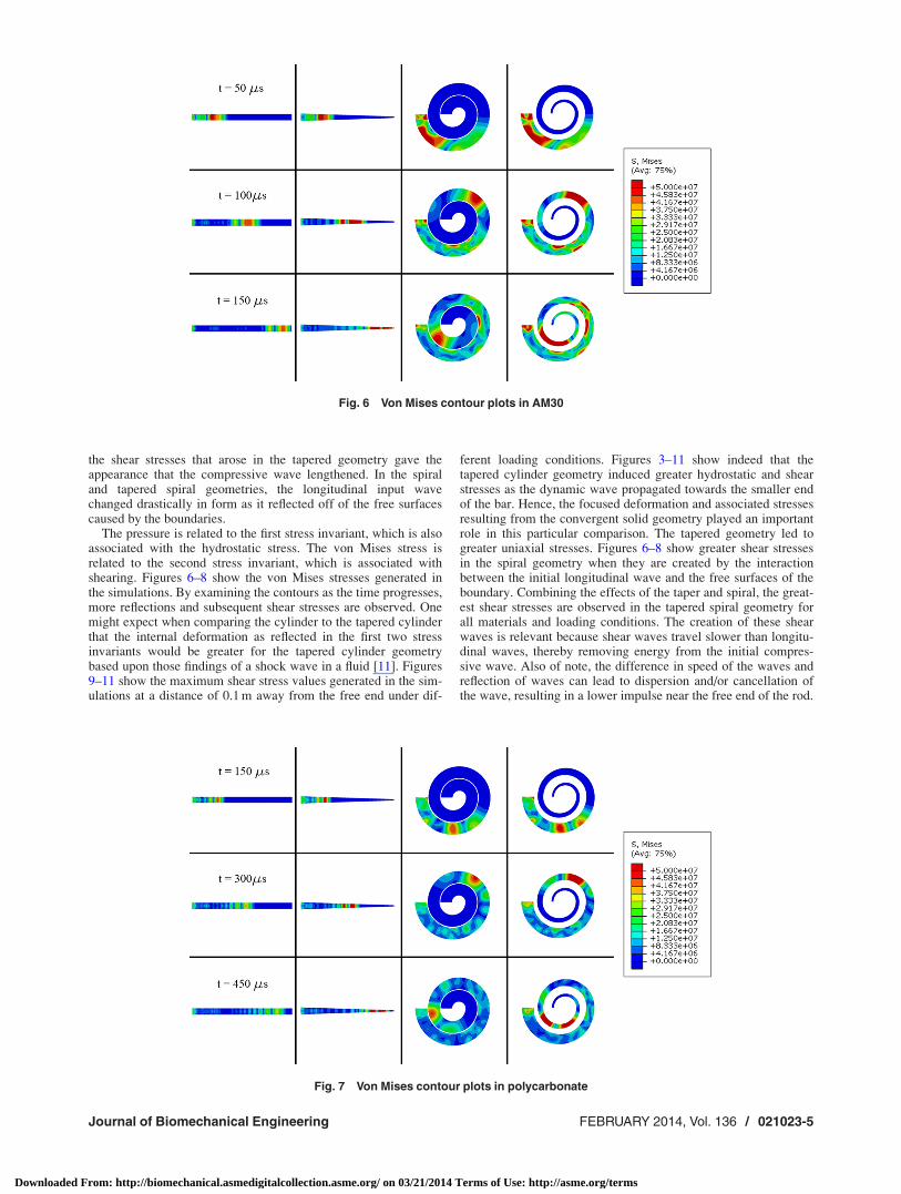
the shear stresses that arose in the tapered geometry gave theappearance that the compressive wave lengthened. In the spiraland tapered spiral geometries, the longitudinal input wavechanged drastically in form as it reflected off of the free surfacescaused by the boundaries.
The pressure is related to the first stress invariant, which is alsoassociated with the hydrostatic stress. The von Mises stress isrelated to the second stress invariant, which is associated withshearing. Figures 6–8 show the von Mises stresses generated inthe simulations. By examining the contours as the time progresses,more reflections and subsequent shear stresses are observed. Onemight expect when comparing the cylinder to the tapered cylinderthat the internal deformation as reflected in the first two stressinvariants would be greater for the tapered cylinder geometrybased upon those findings of a shock wave in a fluid [11]. Figures9–11 show the maximum shear stress values generated in the sim-ulations at a distance of 0.1 m away from the free end under dif-
ferent loading conditions. Figures 3–11 show indeed that thetapered cylinder geometry induced greater hydrostatic and shearstresses as the dynamic wave propagated towards the smaller endof the bar. Hence, the focused deformation and associated stressesresulting from the convergent solid geometry played an importantrole in this particular comparison. The tapered geometry led togreater uniaxial stresses. Figures 6–8 show greater shear stressesin the spiral geometry when they are created by the interactionbetween the initial longitudinal wave and the free surfaces of theboundary. Combining the effects of the taper and spiral, the great-est shear stresses are observed in the tapered spiral geometry forall materials and loading conditions. The creation of these shearwaves is relevant because shear waves travel slower than longitu-dinal waves, thereby removing energy from the initial compres-sive wave. Also of note, the difference in speed of the waves andreflection of waves can lead to dispersion and/or cancellation ofthe wave, resulting in a lower impulse near the free end of the rod.
Fig. 6 Von Mises contour plots in AM30
Fig. 7 Von Mises contour plots in polycarbonate
Journal of Biomechanical Engineering FEBRUARY 2014, Vol. 136 / 021023-5
Downloaded From: http://biomechanical.asmedigitalcollection.asme.org/ on 03/21/2014 Terms of Use: http://asme.org/terms

The transverse displacement induced in the different geometriesis another significant difference. The transverse displacement isconsidered perpendicular to the longitudinal axis of the geometry.Charts in Figs. 12–14 show the maximum transverse displace-ments found in the elements 0.1 m from the free end of each ge-ometry. The cylinder and tapered cylinder show small transversedisplacements as the wave remained parallel to the linear longitu-dinal axis. The spiral and tapered spiral, however, show signifi-cant transverse displacements, independent of loading conditionsor choice of material type. The introduction of the shear wavesand reflection of the longitudinal wave with the free surfacescaused the large transverse displacements. The tapered spiral ge-ometry incurred dramatically more transverse displacement
amplitudes than just the spiral geometry due to the focusing of thewaves by the taper.
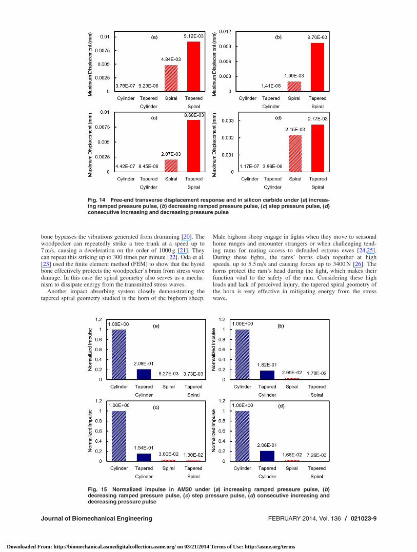
Figures 15–17 show a comparison of the normalized impulse ata distance of 0.1 m away from the free end under different loadingconditions. The impulse values of the cylinder are used to normal-ize the results and provide a simple comparison. The cylindergeometry admitted the greatest impulse throughout the wavemotion. The tapered geometry reduced the impulse when com-pared to the cylinder. The spiral geometry dramatically reducedthe impulse, even when compared to the tapered cylinder geome-try. Consequently, when both the taper and spiral geometries wereadded together, the most impulse mitigating geometry arose,reducing impulse by an average of 98.3% across all materials and
Fig. 8 Von Mises contour plots in silicon carbide
Fig. 9 Maximum shear stress in AM30 under (a) increasing ramped pressure pulse, (b)decreasing ramped pressure pulse, (c) step pressure pulse, (d) consecutive increasing anddecreasing pressure pulse
021023-6 / Vol. 136, FEBRUARY 2014 Transactions of the ASME
Downloaded From: http://biomechanical.asmedigitalcollection.asme.org/ on 03/21/2014 Terms of Use: http://asme.org/terms

loading conditions. This result was repeated in all four loadingconditions shown in Fig. 2, as well as all three material types.Figure 18 shows the normalized strain energies at the loadinglocation, labeled Initial in the figure, and at the location 0.1 mfrom the free end, labeled Final, of the tapered spiral for all mate-rials and loading conditions. Because the loading location strainenergy was used to normalize the values, the Final value for eachmaterial and loading condition represents the percentage of initialstrain energy that traveled down the bar. When comparing the
strain energy in Fig. 18 to the impulse for the three materials inFigs. 15–17, we see identical trends for both metrics (strain energyand impulse) in which more dissipation occurs in the tapered spi-ral geometry. As such, the averaging procedure for determiningthe impulse through the cross section works well. Figure 19shows the normalized impulse in AM30 using one smaller andone larger mesh size. The same impulse reduction occurred inboth cases, demonstrating mesh size independence. Interestingly,an inverse correlation exists between the impulse and transverse
Fig. 10 Maximum shear stress in polycarbonate under (a) increasing ramped pressure pulse,(b) decreasing ramped pressure pulse, (c) step pressure pulse, (d) consecutive increasingand decreasing pressure pulse
Fig. 11 Maximum shear stress in SiC under (a) increasing ramped pressure pulse, (b)decreasing ramped pressure pulse, (c) step pressure pulse, (d) consecutive increasing anddecreasing pressure pulse
Journal of Biomechanical Engineering FEBRUARY 2014, Vol. 136 / 021023-7
Downloaded From: http://biomechanical.asmedigitalcollection.asme.org/ on 03/21/2014 Terms of Use: http://asme.org/terms

displacement. As the value of impulse decreased, transverse dis-placement increased, with the tapered spiral producing both thelowest impulse and highest transverse displacement.
Discussion
Bioinspired design has received a great deal of interest in recentliterature [17–19]. The bioinspired design movement hasprompted investigation into biological shock absorbing systems.
As previously mentioned, the woodpecker’s hyoid bone and hornof the bighorn sheep are two tapered spiral systems. The bighornsheep horn is made of keratin, which is highly similar to theviscoelastic polycarbonate used in this simulation in terms of ma-terial properties and behavior. This study replicated these naturaldesigns using similar materials and geometries to reveal how thesesystems are so effective.
The woodpecker hyoid bone, not observed in other birds, aidsthe woodpecker in evenly distributing incident mechanical excita-tions from drumming and to reinforce the head, i.e., the hyoid
Fig. 12 Free-end transverse displacement response and in AM30 under (a) increasingramped pressure pulse, (b) decreasing ramped pressure pulse, (c) step pressure pulse, (d)consecutive increasing and decreasing pressure pulse
Fig. 13 Free-end transverse displacement response and in polycarbonate under (a) increas-ing ramped pressure pulse, (b) decreasing ramped pressure pulse, (c) step pressure pulse, (d)consecutive increasing and decreasing pressure pulse
021023-8 / Vol. 136, FEBRUARY 2014 Transactions of the ASME
Downloaded From: http://biomechanical.asmedigitalcollection.asme.org/ on 03/21/2014 Terms of Use: http://asme.org/terms
bone bypasses the vibrations generated from drumming [20]. Thewoodpecker can repeatedly strike a tree trunk at a speed up to7 m/s, causing a deceleration on the order of 1000 g [21]. Theycan repeat this striking up to 300 times per minute [22]. Oda et al.[23] used the finite element method (FEM) to show that the hyoidbone effectively protects the woodpecker’s brain from stress wavedamage. In this case the spiral geometry also serves as a mecha-nism to dissipate energy from the transmitted stress waves.
Another impact absorbing system closely demonstrating thetapered spiral geometry studied is the horn of the bighorn sheep.
Male bighorn sheep engage in fights when they move to seasonalhome ranges and encounter strangers or when challenging tend-ing rams for mating access to defended estrous ewes [24,25].During these fights, the rams’ horns clash together at highspeeds, up to 5.5 m/s and causing forces up to 3400 N [26]. Thehorns protect the ram’s head during the fight, which makes theirfunction vital to the safety of the ram. Considering these highloads and lack of perceived injury, the tapered spiral geometry ofthe horn is very effective in mitigating energy from the stresswave.
Fig. 14 Free-end transverse displacement response and in silicon carbide under (a) increas-ing ramped pressure pulse, (b) decreasing ramped pressure pulse, (c) step pressure pulse, (d)consecutive increasing and decreasing pressure pulse
Fig. 15 Normalized impulse in AM30 under (a) increasing ramped pressure pulse, (b)decreasing ramped pressure pulse, (c) step pressure pulse, (d) consecutive increasing anddecreasing pressure pulse
Journal of Biomechanical Engineering FEBRUARY 2014, Vol. 136 / 021023-9
Downloaded From: http://biomechanical.asmedigitalcollection.asme.org/ on 03/21/2014 Terms of Use: http://asme.org/terms

With the reoccurrence of the tapered spiral in some of the mostextreme cases of impact in the woodpecker’s hyoid bone andram’s horn, clearly there is a correlation between geometry andstress wave mitigation. Designers should take these findings intoconsideration when creating products for impact protection andwave mitigation. A manmade successful example is the anechoicchamber. Anechoic chambers also use wedges to form soundproof rooms [27]. The sound waves travel in between thesewedges and are absorbed. The wedge of air closely resembles thetapered cylinder from this study, which has been shown in theresults to reduce impulse by focusing the wave and creating shear
stresses that can lead to dispersion. The tapered spiral is alsofound in many forms of seashells. Taking cues from these biologi-cal structures, if a designer were to choose a geometry to allowfor the greatest transfer of the pressure and impulse based on theaforementioned simulations, then one would choose the cylinder,the most simple geometry. However, if the designer were tochoose a geometry that allowed for the greatest dissipation of thepressure and impulse, then one would choose the tapered spiral.What caused the tapered spiral to incur the greatest dissipation?Two things: First, the tapered geometry admitted greater internaldeformations as the convergent boundary focused the pressure
Fig. 16 Normalized impulse in polycarbonate under (a) increasing ramped pressure pulse,(b) decreasing ramped pressure pulse, (c) step pressure pulse, (d) consecutive increasingand decreasing pressure pulse
Fig. 17 Normalized impulse in SiC under (a) increasing ramped pressure pulse, (b) decreas-ing ramped pressure pulse, (c) step pressure pulse, (d) consecutive increasing and decreas-ing pressure pulse
021023-10 / Vol. 136, FEBRUARY 2014 Transactions of the ASME
Downloaded From: http://biomechanical.asmedigitalcollection.asme.org/ on 03/21/2014 Terms of Use: http://asme.org/terms

and it introduced some shear stresses, and second, the spiralinduced intense shearing that introduced fairly large transversedisplacements. One might expect additional stress wave mitiga-tion if there was a three-dimensional toroidal (conical helix) ge-ometry, like the ram’s horn or woodpecker hyoid bone, since theother shear stresses would be introduced into the wave dispersion.Future work might include investigating this shape and also thethree-dimensional helical design of the ram’s horn previously dis-cussed to determine the differences compared to the taperedspiral.
Conclusions
The following conclusions can be made regarding this study:
• A tapered geometry will lower the pressure and impulse dueto the convergent boundary and a continually decreasingcross-sectional area such that greater uniaxial stresses and sub-sequent axial deformation arises. Furthermore, the tapered ge-ometry introduces small shear stresses that also help lower theimpulse by removing energy from the initial longitudinal wave.
• A spiral geometry will lower the impulse due to the introduc-tion of shear stresses along the length of the spiral. These
shear stresses introduce transverse displacements that helpreduce the pressure and impulse.
• When both the tapered and spiral geometry are included in adesign, their synergistic effects multiplicatively reduce thepressure and impulse.
• Although different materials admit different wave speeds, thisimpulse reduction was repeated in the three material types(elastic, plastic, and viscoelastic) and loading conditions.
With this new knowledge of how designs in nature defendagainst stress waves as inspiration, work is currently underway tofind novel ways to develop advanced technologies to mitigateshock in high impact events.
Acknowledgment
This work was supported by the Center of Advanced VehicularSystems (CAVS) at Mississippi State University. Also, the authorsgratefully acknowledge funding support through the DOE South-ern Regional Center for Lightweight Innovative Design awardDE-FC26-06NT42755 to carry out a portion of this researchwork, as well as Dassault Systems Simulia Corporation for the useof Abaqus licensing.
Fig. 18 Normalized strain energy at loading location (Initial) and 0.1 m from free end (Final)under (a) increasing ramped pressure pulse, (b) decreasing ramped pressure pulse, (c) steppressure pulse, (d) consecutive increasing and decreasing pressure pulse
Fig. 19 Normalized impulse in AM30 under consecutive increasing and decreasing pressure pulse with aver-age mesh sizes of (a) 9509 and (b) 3816 elements
Journal of Biomechanical Engineering FEBRUARY 2014, Vol. 136 / 021023-11
Downloaded From: http://biomechanical.asmedigitalcollection.asme.org/ on 03/21/2014 Terms of Use: http://asme.org/terms
References[1] Zukas, J. A., Nicholas, T., Swift, H. F., Greszczuk, L. B., and Curran, D. R.,
1992, Impact Dynamics, Krieger Publishing Co., Malabar, FL.[2] Zukas, J. A., and Walters, W. P., 1998, Explosive Effects and Applications,
Springer-Verlag, Inc., New York.[3] Meyers, M. A., 1994, Dynamic Behavior of Materials, John Wiley & Sons,
Inc., New York.[4] Davis, J. L., 1988, Wave Propagation in Solids and Fluids, Springer-Verlag,
Inc., New York.[5] Achenbach, J. D., 1993, Wave Propagation in Elastic Solids, North-Holland,
Amsterdam, Netherlands.[6] Hayashi, T., Song, W. J., and Rose, J. L., 2003, “Guided Wave Dispersion
Curves for a Bar With an Arbitrary Cross-Section, a Rod and Rail Example,”Ultrasonics, 41(3), pp. 175–183.
[7] Demma, A., Cawley, P., Lowe, M., and Pavlakovic, B., 2005, “The Effect ofBends on the Propagation of Guided Waves in Pipes,” ASME J. Press. VesselTech., 127(3), pp. 328–335.
[8] Gavric, L., 1995, “Computation of Propagative Waves in Free Rail Using aFinite Element Technique,” J. Sound Vib., 185(3), pp. 531–543.
[9] Treyssede, F., 2008, “Elastic Waves in Helical Waveguides,” Wave Motion,45(4), pp. 457–470.
[10] Mace, B. R., Duhamel, D., Brennan, M. J., and Hinke, L., 2005, “Finite Ele-ment Prediction of Wave Motion in Structural Waveguides,” J. Acoust. Soc.Am., 117(5), pp. 2835–2843.
[11] Setchell, R. E., Storm, E., and Sturtevant, B., 1972, “Investigation of ShockStrengthening in a Conical Convergent Channel,” J. Fluid Mech., 56(3), pp.505–522.
[12] Lind, C. A., 1997, “Effect of Geometry on the Unsteady Type-IV Shock Inter-action,” J. Aircraft, 34(1), pp. 64–71.
[13] Bond, C., Hill, D. J., Meiron, D. I., and Dimotakis, P. E., 2009, “Shock Focus-ing in a Planar Convergent Geometry: Experiment and Simulation,” J. FluidMech., 641, pp. 297–333.
[14] Inoue, O., Takahashi, N., and Takayama, K., 1993, “Shock Wave Focusing in aLog-Spiral Duct,” AIAA J., 31(6), pp. 1150–1152.
[15] ABAQUS, 2011, v6.11 User Documentation, Dassault Systemes Simulia Corp.,Providence, RI.
[16] Horstemeyer, M. F., Carino, R. L., Hammi, Y., Solanki, K. N., “MSU InternalState Variable Plasticity-Damage Model 1.0 Calibration, DMGfit ProductionVersion Users Manual,” MSU.CAVS.CMD.2009-R0010. Mississipi StateUniversity: CAVS, 2009.
[17] McKittrick, J., Chen, P. Y., Tombolato, L., Novitskaya, E. E., Trim, M. W.,Hirata, G. A., Olevsky, E. A., Horstemeyer, M. F. and Meyers, M. A., 2010,“Energy Absorbent Natural Materials and Bioinspired Design Strategies: AReview,” Mat. Sci. Eng. C, 30(3), pp. 331–342.
[18] Mohammed, J. S., and Murphy, W. L., 2009, “Bioinspired Design of DynamicMaterials,” Adv. Mat., 21(23), pp. 2361–2374.
[19] Munch, E., Launey, M. E., Alsem, D. H., Saiz, E., Tomsia, A. P., and Ritchie, R. O.,2008 “Tough, Bio-Inspired Hybrid Materials,” Science, 322(5907), pp. 1516–1520.
[20] Sang-Hee, Y., and Sungmin, P., 2011, “A Mechanical Analysis of Woodpecker Drum-ming and Its Application to Shock-Absorbing systems,” Bioinspir. Biomimet., 6(1).
[21] May, P. R. A., Fuster, J. M., Haber, J., and Hirschman, A., 1979, “WoodpeckerDrilling Behavior. An Endorsement of the Rotational Theory of Impact BrainInjury,” Arch. Neurol., 36(6), pp. 370–373.
[22] Backhouse, F., 2005, Woodpeckers of North America, Firefly Books, New York.[23] Oda, J., Sakamoto, J., and Sakano, K., 2006, “Mechanical Evaluation of the
Skeletal Structure and Tissue of the Woodpecker and Its Shock Absorbing Sys-tem,” JSME Int. J. A, Solid Mech. Mat. Eng., 49(3), pp. 390–396.
[24] Geist, V., Mountain Sheep, 1971, University of Chicago, Chicago, IL.[25] Hogg, J., 1984, “Mating in Bighorn Sheep: Multiple creative Male Strategies,”
Science 225(4661), pp. 526–529.[26] Kitchener, A., 1988, “An Analysis of the Forces of Fighting of the Blackbuck
(Antilope cervicapra) and the Bighorn sheep (Ovis canadensis) and the Me-chanical Design of the Horns of Bovids,” J. Zoology, 214(1), pp. 1–20.
[27] Beranek, L. L., and Sleeper, H. P., 1946 “The Design and Construction ofAnechoic Sound Chambers,” J. Acoust. Soc. Am., 18(1), pp. 140–150.
021023-12 / Vol. 136, FEBRUARY 2014 Transactions of the ASME
Downloaded From: http://biomechanical.asmedigitalcollection.asme.org/ on 03/21/2014 Terms of Use: http://asme.org/terms
Copyright © 2022 FDOKUMEN