Research on the Model of the Radio Wave Propagation in ...
7
Research on the Model of the Radio Wave Propagation in Granary Using Ray-Tracing Algorithm Chunhua Zhu 1,a , Jinkui Yao 2,b* 1 College of Information Science and Engineering, Henan University of Technology, Zhengzhou, 450001, China 2 College of Information Science and Engineering, Henan University of Technology, Zhengzhou, 450001, China a email:[email protected], b email:[email protected] Keywords: ray-tracing; amplitude; delay; angle of arrival; path loss Abstract. The radio wave propagation model in granary can provide technical support for the design and application of wireless grain situation monitoring and foreign-body detection in granary. The propagation of radio waves in granary with wheat is studied in this paper. Firstly, transmitting and receiving antennas are fixed in grain bulk. Then the parameters of multipath delay and received power at receiver are calculated by using ray-tracing algorithm, and the wave propagation model is established. The results show that only the direct and one-reflection paths of larger amplitude are considered in the wheat grain bulk. Finally, the path losses of simulation at different distances are compared with the theoretical value of the literature, the accuracy of the simulation results is verified and the effect of reflection is reflected. Introduction In recent years, granary monitoring system in temperature and humidity based on wireless sensor network [1], [2] and foreign-body detection sensor system in granary based on GPR(ground penetrating radar) [3], [4] gradually to the development of automation and intelligent, have become a hot topic in the field of grain information processing. The accurate electric wave propagation model and the optimization of physical layer data transmission mode in grain can improve the reliability of the wireless transmission system mentioned above. Nelson S.O [5] researched the feasibility of the pest control in grain storage by using radio waves of different frequency bands in the 1990s, and obtained the attenuation formula of the radio signal transmit in grain. Armstrong Paul [6] studied the feasibility of using the wireless node instead of the traditional scheme of cable in grain monitoring system, the results showed that the signal of 915MHz in the power consumption of 1mW in the grain reliably transmit about 2 meters. Zhang Fenghui [7] of Beijing University of Posts and Telecommunications obtained the energy attenuation value per meter of 780MHz wireless sensor nodes in wheat grain bulk by using the method of evaluating the energy attenuation of radio waves and statistic of the data packet loss rate. The method and results are of guiding significance for the placement of wireless sensor nodes in wheat grain bulk. The research findings above only consider the large scale fading characteristics at the partial frequency points, the complete wave propagation model is not constructed, and the research method is based on measurement, which is a daunting task and the applicability is bad. In this paper, the ray-tracing algorithm is used to establish the wave propagation model of the horizontal warehouse environment by calculating the amplitude, delay and angle of arrival of each ray at the receiver under the condition that transmitting and receiving antennas are fixed in the wheat grain bulk. Modeling process Environmental characteristics of granary This paper takes the horizontal warehouse as the research object, because the effects of the top can be ignored, the cuboid that long is 4 meters, wide is 3 meters and high is 2.5 meters can be used to simulate the environment. The walls of the four sides and the bottom of the warehouse are 5th International Conference on Measurement, Instrumentation and Automation (ICMIA 2016) © 2016. The authors - Published by Atlantis Press 296
-
Upload
khangminh22 -
Category
Documents
-
view
0 -
download
0
Transcript of Research on the Model of the Radio Wave Propagation in ...

Research on the Model of the Radio Wave Propagation in Granary Using Ray-Tracing Algorithm
Chunhua Zhu1,a, Jinkui Yao2,b*
1College of Information Science and Engineering, Henan University of Technology, Zhengzhou, 450001, China
2College of Information Science and Engineering, Henan University of Technology, Zhengzhou, 450001, China
aemail:[email protected], bemail:[email protected]
Keywords: ray-tracing; amplitude; delay; angle of arrival; path loss
Abstract. The radio wave propagation model in granary can provide technical support for the design
and application of wireless grain situation monitoring and foreign-body detection in granary. The
propagation of radio waves in granary with wheat is studied in this paper. Firstly, transmitting and
receiving antennas are fixed in grain bulk. Then the parameters of multipath delay and received
power at receiver are calculated by using ray-tracing algorithm, and the wave propagation model is
established. The results show that only the direct and one-reflection paths of larger amplitude are
considered in the wheat grain bulk. Finally, the path losses of simulation at different distances are
compared with the theoretical value of the literature, the accuracy of the simulation results is verified
and the effect of reflection is reflected.
Introduction
In recent years, granary monitoring system in temperature and humidity based on wireless sensor
network [1], [2] and foreign-body detection sensor system in granary based on GPR(ground
penetrating radar) [3], [4] gradually to the development of automation and intelligent, have become a
hot topic in the field of grain information processing. The accurate electric wave propagation model
and the optimization of physical layer data transmission mode in grain can improve the reliability of
the wireless transmission system mentioned above. Nelson S.O [5] researched the feasibility of the
pest control in grain storage by using radio waves of different frequency bands in the 1990s, and
obtained the attenuation formula of the radio signal transmit in grain. Armstrong Paul [6] studied the
feasibility of using the wireless node instead of the traditional scheme of cable in grain monitoring
system, the results showed that the signal of 915MHz in the power consumption of 1mW in the grain
reliably transmit about 2 meters. Zhang Fenghui [7] of Beijing University of Posts and
Telecommunications obtained the energy attenuation value per meter of 780MHz wireless sensor
nodes in wheat grain bulk by using the method of evaluating the energy attenuation of radio waves
and statistic of the data packet loss rate. The method and results are of guiding significance for the
placement of wireless sensor nodes in wheat grain bulk. The research findings above only consider
the large scale fading characteristics at the partial frequency points, the complete wave propagation
model is not constructed, and the research method is based on measurement, which is a daunting task
and the applicability is bad.
In this paper, the ray-tracing algorithm is used to establish the wave propagation model of the
horizontal warehouse environment by calculating the amplitude, delay and angle of arrival of each
ray at the receiver under the condition that transmitting and receiving antennas are fixed in the wheat
grain bulk.
Modeling process
Environmental characteristics of granary
This paper takes the horizontal warehouse as the research object, because the effects of the top can
be ignored, the cuboid that long is 4 meters, wide is 3 meters and high is 2.5 meters can be used to
simulate the environment. The walls of the four sides and the bottom of the warehouse are
5th International Conference on Measurement, Instrumentation and Automation (ICMIA 2016)
© 2016. The authors - Published by Atlantis Press 296
cement-concrete material, with the dielectric constant 6 and conductivity 0.001S/m. The warehouse is
full of wheat, high is 2m. Strictly speaking, the density of different grain layer is different, the closer
to the bottom of the warehouse, the greater the density. The temperature and humidity in different
storage locations are quite different, the dielectric constant will also change with it, which leads to the
extremely complex wave propagation characteristics in granary. In order to simplify the calculation,
the grain bulk is treated as a homogeneous medium in this paper. The water content of wheat in
granary is about 10%, and corresponding dielectric constant is set to 2.6, the electrical conductivity is
0.01S/m.
Establish a 3 coordinate system with the origin at the bottom of the warehouse, The receiving and
transmitting antennas are embedded in the grain bulk. The coordinate of transmitting antenna is set to
(1, 1, 1), the signal frequency used is 780MHz, while the coordinate of receiving antenna is set to (1,
3, 1). Transmitting and receiving antennas are ideal omnidirectional antennas with a gain of 1.
Propagation path analysis
In the medium of the grain, radio wave propagation modes between the transmitting antenna and
the receiving antenna mainly include direct, reflection, diffraction and scattering, and the main mode
is reflection after considering the grain bulk as the homogeneous medium. Taking into account the
effect of reflection losses, the paths with four or more reflections have little contribution to the
received field strength, so only 1~3 reflections are considered in this paper. All reflections are
regarded as specular reflection, i.e., not consider the impact of roughness. According to the principle
of images, there are 6 first order images, 30 second order images, 150 third order images for
transmitting point, corresponding to the images, there are 6 paths with one-reflection, 30 paths with
two-reflections, and 150 paths with three-reflections, add to a direct path, the theoretical value is 187.
Parameters calculation
The model of ray-tracing propagation [8] is generally expressed as
1
( ) ( )exp( )N
n n n
n
h t A t j
.
(1)
where )(th denotes the channel impulse response; N is the total number of rays received; n is the
multipath delay of the n ray; nA and n are the amplitude and phase of the n ray, respectively.
So we can get that in order to get the channel impulse response ( )h t , n , nA and n of each ray are
required to calculate respectively. When the transmitted power is fixed, nA is determined by the
received power.
Received power calculation
Received power can be directly calculated from the received field strength. In a lossy medium, the
received field strength is related to the propagation constant.
(1) Field strength
For the direct ray, the electric field strength is calculated using the following formulas:
0
d
DE E e .
(2)
where 0E is electric field strength at a point of reference, d is propagation path length and is
propagation constant, which is a complex quantity:
j . (3)
where is attenuation constant(Np/m), is phase constant(rad/m). The expressions are given by
[9]
2
1 12
. (4)
297
2
1 12
. (5)
where is the dielectric constant, is the conductivity, is the magnetic
permeability, 2 f , f is the signal frequency.
For low loss medium like grain, loss tangent 1T
, (4) and (5) can be rewritten as
2
. (6)
. (7)
When the incident electromagnetic wave incident upon the interface of the medium of wheat and
the wall or air, part of the power is reflected back to the wheat, and the rest is transmitted. The field
strength of the reflected wave is usually calculated by the reflection coefficient, which is defined as
the ratio of the field strength of the incident wave and reflected wave, mainly related to the dielectric
constant, the electromagnetic wave polarization modes and the angle of incidence. Polarization
modes of electromagnetic wave include horizontal and vertical polarization. When the electric field
of incident wave is perpendicular to the incident plane, it is called TE (Transverse Electric) wave, also
known as s or horizontal polarization wave; when the electric field of incident wave is parallel with
the incident plane, it is called TM (Transverse Magnetic) wave, also known as p or vertical
polarization wave. In different polarization modes, the reflection coefficients have different
expression. The expressions of S-P component of Fresnel reflection coefficient [10] are
1 2
1 2
cos cos
cos cos
i ts
i t
n nR
n n
.
(8)
2 1
2 1
cos cos
cos cos
i tp
i t
n nR
n n
.
(9)
where 1n and 2n are the refractive index of the incident and the refractive medium respectively;
i and t are the angle of incidence and refraction respectively.
Using refraction law 1 2sin sini tn n to eliminate the angle of refraction t , the expression
above can be changed to 2
2
cos sin
cos sin
i R i
s
i R i
R
. (10)
2
2
cos sin
cos sin
R i R i
p
R i R i
R
.
(11)
where 60R r j , r is the ratio of the dielectric constant of the incident and refractive
medium, is the special conductivity of the reflecting surface.
For the plane harmonic of the general polarization, it can be decomposed into vertical and
horizontal polarized waves, the field strength [9] of the reflected rays can be written as
// //R D s D pE E e R e E e R e .
(12)
where e and / /e are the reflection unit vector of horizontal and vertical polarization respectively.
(2) Received power
Received power can be calculated as[12].
er APDP . (13)
where PD is the radiation power density of the transmitting antenna, 2 2PD E ;
298
is the inherent impedance of the medium, ;
eA is the effective area of the receiving antenna,
2
4
Re
GA
;
RG is the gain of receiving antenna.
So received power is given by 2 2
8
Rr
E GP
. (14)
Delay and arrival angle calculation
The value of delay is the difference between the time of propagation of the reflected path and the
direct path. The angle of arrival is defined as the angle formed by the paths that reach the receiving
point and the projection of the direct path in the Z plane.
In the medium of wheat, propagation velocity of electromagnetic wave is no longer the speed of
light, but related to the relative permittivity of the medium .
1 cv
.
(15)
The total length of each path with arbitrary number of reflections is the distance between the
receiving point and the corresponding highest order image, which can calculate the propagation time.
Then the multipath delay can be obtained by subtracting the propagation time of direct path.
Results and analysis
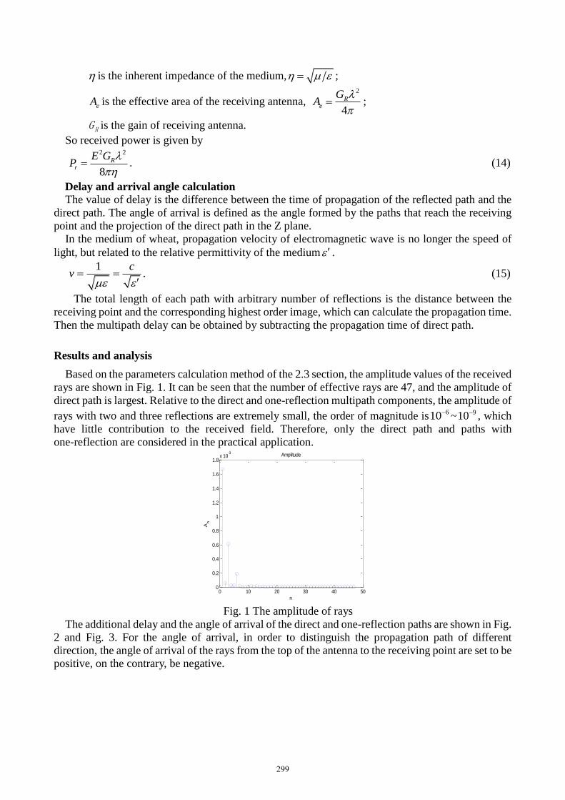
Based on the parameters calculation method of the 2.3 section, the amplitude values of the received
rays are shown in Fig. 1. It can be seen that the number of effective rays are 47, and the amplitude of
direct path is largest. Relative to the direct and one-reflection multipath components, the amplitude of
rays with two and three reflections are extremely small, the order of magnitude is610~ 910 , which
have little contribution to the received field. Therefore, only the direct path and paths with
one-reflection are considered in the practical application.
0 10 20 30 40 500
0.2
0.4
0.6
0.8
1
1.2
1.4
1.6
1.8x 10
-3
n
An
Amplitude
Fig. 1 The amplitude of rays
The additional delay and the angle of arrival of the direct and one-reflection paths are shown in Fig.
2 and Fig. 3. For the angle of arrival, in order to distinguish the propagation path of different
direction, the angle of arrival of the rays from the top of the antenna to the receiving point are set to be
positive, on the contrary, be negative.
299

1 2 3 4 5 6 70
5
10
15
n
n(n
s)
Delay
1 2 3 4 5 6 7
- 2 0 0
- 1 5 0
- 1 0 0
- 5 0
0
50
n
n
AoA
Fig. 2 Multipath delay Fig.3 Angle of arrival
In literature [5], the attenuation formula of radio signal in grain is presented:
0
8.686
dB/m.
(16)
where represents the signal attenuation, and are the real and imaginary parts of dielectric
constant of grain, 0/ .
Since the power dissipated is proportional to 2E , the path loss LP can be given by
0
10 1010log 20logtL
r tot
EPP
P E
. (17)
where totE is the total received field which is vector addition of field strength of all components.
Change the position coordinates of the receiving antenna from (1, 1.1, 1) to (1, 2.5, 1) at 0.1m
intervals. The 15 total field strength values can be obtained. The path loss of the 15 positions are
calculated, and then compare them with (16), the result is shown in Fig. 4. It can be seen that the
simulative value is almost identical with the theoretical value within 1.5m and less than the
theoretical value in the distance between 1.5m to 2m. The reason for the result of incomplete
coincidence is that the theoretical value is based on the premise that the grain bulk is regarded as an
infinite uniform space, only direct path is considered, while the simulation environment of this paper
is the space of limited shape, and considering both direct and reflected paths. Thus the fluctuation of
the simulation curve with respect to the theoretical curve is caused by the reflection of the walls of the
warehouse, and when the distance is more than 1.5m, the effect of reflection on the results is more
obvious.
0 0.5 1 1.5 20
5
10
15
20
25
Distance(m)
Path
loss(d
B)
simulative value
theoretical value
Fig.4 Comparison of simulative and theoretical path loss
300
Conclusions
In this paper, the radio wave propagation characteristics in the horizontal warehouse with wheat are
studied by using ray-tracing algorithm, the calculation method of the field strength, received power,
delay and arrival angle of the multipath components in the receiving point are given in detail.
Through the amplitude of multipath components, we can see that the paths with two-reflections and
three-reflections have a very small contribution to the receiving field, so that only the direct path and
paths with one-reflection are considered, which shows the high loss of electromagnetic wave in the
grain bulk. At the same time, by comparing the simulative path loss with the theoretical value in the
literature, the accuracy of the simulation is verified and the effect of reflection is reflected. Compared
with the attenuation formula in the literature, the simulation results of this paper have more reference
value. It is worth noting that the model of wave propagation in the medium of wheat in this paper is
under the assumption that the granary environment is specific and electromagnetic properties are
uniform, the characteristics of radio wave propagation in the medium of wheat in different granary
need to be further studied.
Acknowledgement
This work was supported by National food industry commonweal special scientific research
projects (201413001) and Key Science and Technique Project of He’nan Educational Committee
(14A510014) and the National Natural Science Foundation of China under Grant (61601170).
References
[1] Huang Zhihua. The design and research of intelligent grain situation monitoring system in grain
depot. University Of Anhui, 2015.
[2] Yi Cuiping. Research on granary monitoring system in temperature and humidity based on
Wireless Sensor Network. Changchun University of Science and Technology, 2012.
[3] Lian Feiyu, Fu Maixia. Research on foreign-body detection in granary using ground penetrating
radar technique. Journal of Henan University of Technology (Natural Science Edition),
2008,29(4),50~55.
[4] Liu Hua, Chen Xianxiang. GprMax simulation of microwave detection sensor system of foreign
matter in grain depot. Journal of Henan University of Technology (Natural Science Edition),
2008,29(6),60~64.
[5] Nelson S O. Review and assessment of radio frequency and microwave energy for stored grain
insect control. Transactions of the ASAE, 1996, 39(4): 1475-1484.
[6] Armstrong Paul. Wireless data transmission of networked sensors in grain storage[C]//The
2003 ASAE Annual International Meeting. July27- 30 2003, Riviera Hotel and Convention Center
Las Vegas, Nevada, USA: ASABE2003: 1-12.
[7] Zhang Fenghui, Zhou Huiling, Zhang Fengying, Zhou Xiaoguang. Reliable communication of
wireless sensor nodes in grain bulk. Journal of Henan University of Technology (Natural Science
Edition), 2010,31(4): 54~57.
[8] R.A Valenzuela. A Ray Tracing Approach to Predicting Indoor Wireless Transmission.
Proceeding 43rd IEEE vehicular Technology Conference, 1993:214~218.
[9] Frank Gross. Smart antennas for wireless communications. Beijing: Publishing House of
Electronics Industry, 2009.
301

[10] Wei Lihong. The relationship between the S component and P component of the Fresnel
reflection coefficient and the incident angle. Songliao Journal(Natural Science Edition),1988, 3:74~75.
[11] Dikshitulu K. Kalluri. Electromagnetic waves. Beijing: China Machine Press, 2014.
[12] Larry Burgess. Measuring radiated power and field strength from UHF ISM transmitters.
Electronic technology application. 2007,(11), 89~90.
302