GEOLOGICAL DISPOSAL OF SPENT FUEL AND HIGH ...
504
GEOLOGICAL DISPOSAL OF SPENT FUEL AND HIGH LEVEL AND ALPHA BEARING WASTES PROCEEDINGS OF A SYMPOSIUM, ANTWERP, 19-23 OCTOBER 1992
-
Upload
khangminh22 -
Category
Documents
-
view
3 -
download
0
Transcript of GEOLOGICAL DISPOSAL OF SPENT FUEL AND HIGH ...

GEOLOGICAL DISPOSAL OF SPENT FUEL AND HIGH LEVEL AND ALPHA BEARING WASTESPROCEEDINGS OF A SYMPOSIUM, ANTWERP, 19-23 OCTOBER 1992

The cover photograph shows an experimental gallery of the HADES Underground Research Facility at a depth of 225 m at
the Mol site in Belgium.
By courtesy of NIRAS/ONDRAF and SCK/CEN. Photograph: X. Douley.

GEOLOGICAL DISPOSAL OF SPENT FUEL AND HIGH LEVEL AND ALPHA BEARING WASTES


PROCEEDINGS SERIES
GEOLOGICAL DISPOSAL OF SPENT FUEL AND HIGH LEVEL AND ALPHA BEARING WASTES
PROCEEDINGS OF AN INTERNATIONAL SYMPOSIUM ON GEOLOGIC DISPOSAL OF SPENT FUEL,
HIGH LEVEL AND ALPHA BEARING WASTES JOINTLY ORGANIZED BY THE
INTERNATIONAL ATOMIC ENERGY AGENCY,THE COMMISSION OF THE EUROPEAN COMMUNITIES
AND THE OECD NUCLEAR ENERGY AGENCY AND HELD IN ANTWERP, 19-23 OCTOBER 1992
INTERNATIONAL ATOMIC ENERGY AGENCY VIENNA, 1993

Permission to reproduce or translate the information contained in this publication may be obtained by writing to the International Atomic Energy Agency, Wagramerstrasse 5, P.O. Box 100, A-1400 Vienna, Austria.
© IAEA, 1993
VIC Library Cataloguing in Publication Data -
International Symposium on Geologic Disposal of Spent Fuel, High Level and Alpha Bearing Wastes (1992 : Antwerp, Belgium) .
Geological disposal of spent fuel and high level and alpha bearing wastes : proceedings of an International Symposium on Geologic Disposal of Spent Fuel, High Level and Alpha Bearing Wastes jointly organized by the International Atomic Energy Agency, the Commission of the European Communities and the OECD Nuclear Energy Agency and held in Antwerp, 19-23 October 1992. — Vienna : The Agency, 1993.
p. ; 24 cm. — (Proceedings series, ISSN 0074-1884)STI/PUB/907ISBN 92-0-000193-9Includes bibliographical references.
1. Radioactive waste disposal in the ground. 2. Spent reactor fuels— Storage. I. International Atomic Energy Agency. П. Commission of the European Communities. III. OECD Nuclear Energy Agency. IV. Title. V. Series: Proceedings series (International Atomic Energy Agency).
VICL 93-00055
Printed by the IAEA in Austria April 1993
■ STI/PUB/907

FOREWORD
The International Symposium on Geologic Disposal of Spent Fuel, High Level and Alpha Bearing Wastes, organized jointly with the Commission of the European Communities and the OECD Nuclear Energy Agency, was held in Antwerp, Belgium, from 19 to 23 October 1992.
The symposium was attended by nearly two hundred participants from 25 countries and four international organizations. There were 35 oral presentations o f papers and 2 0 poster papers related to the symposium theme: progress towards the demonstration of safe disposal. The keynote address, “ Progress towards the demonstration of safe disposal o f spent fuel and high level radioactive waste: A critical issue for nuclear pow er” , was presented by B. Semenov, Deputy Director General, Head o f the Department o f Nuclear Energy and Safety o f the IAEA.
Seven technical sessions dealt with: progress in programmes of international organizations; progress in site characterization programmes and methods; progress in repository design concepts, construction techniques and engineered barrier design; high level and alpha bearing waste characterization and waste acceptance; repository concepts for direct disposal o f spent fuel; progress in developing, testing and validating repository performance assessment models; and progress in national and international programmes for disposal. The technical presentations addressed disposal in all the principal geological media currently under consideration: clay, crystalline rock, salt and volcanic tuff. Presentations ranged from descriptions of very broad national screening activities by Member States very early in their repository development programmes to descriptions of very detailed investigations being performed in underground test facilities by Member States with relatively advanced programmes.
On the final day a panel discussion was held to summarize what was learned during the symposium. The panel was chaired by F. Decamps, General Manager of ONDRAF/NIRAS, the Belgian radioactive waste management organization, and panel members consisted of co-chairmen of the individual technical sessions. In summarizing the accomplishments of the symposium, Mr. Decamps stated:
“ The results of the work reported in this symposium reflect the sense of responsibility of scientists towards the necessity to develop safe solutions for the nuclear waste issue. You, the scientists, are the real ecologists. Although every scientific community you represent may have its own approach and may work on different host rocks, at the end the objective is the same: safe final disposal.
“ In spite of this variety of approaches, the technical problems to attain the objective are now well identified, and the studies and research and development programmes are concentrating on them. I firmly believe that confidence in the geological disposal option is justified. Chances are good that deep geological disposal facilities will be operational somewhere in the next century.
“ The challenge now consists in translating this confidence into understandable and convincing statements to the authorities and the public. If we do not succeed in this task, our efforts will be for nothing, while our solutions will not be recognized as such. International co-operation, exemplified in symposia like this one, is an extremely important tool for that purpose.”
It is hoped that the proceedings will constitute an important source of information to the wide community of scientists, decision makers and representatives of government-and industrial organizations dealing with geological disposal of spent fuel and high level and alpha bearing wastes. The IAEA, CEC and OECD/NEA wish to express their gratitude to the Belgian authorities and, in particular, to ONDRAF/NIRAS and to CEN/SCK, the Belgian Nuclear Research Centre, for their assistance and support in organizing this symposium.
EDITORIAL NOTE
The Proceedings have been edited by the editorial staff o f the IAEA to the extent considered necessary fo r the reader's assistance. The views expressed remain, however, the responsibility o f the named authors or participants. In addition, the views are not necessarily those o f the governments o f the nominating Member States or o f the nominating organizations.
Although great care has been taken to maintain the accuracy o f information contained in this publication, neither the IAEA nor its Member States assume any responsibility for consequences which may arise from its use.
Throughout the text names o f Member States are retained as they were when the text w a s compiled.
The use o f particular designations o f countries or territories does not imply any judgement by the publisher, the IAEA, as to the legal status o f such countries or territories, o f their authorities and institutions or o f the delimitation o f their boundaries.
The mention o f names o f specific companies or products (whether or not indicated as registered) does not imply any intention to infringe proprietary rights, nor should it be construed as an endorsement or recommendation on the part o f the IAEA.
The authors are responsible fo r having obtained the necessary permission fo r the IAEA to reproduce, translate or use material from, sources already protected by copyrights.
Material prepared by authors who are in contractual relation with governments is copyrighted by the IAEA, as publisher, only to the extent permitted by the appropriate national regulations.

CONTENTS
Progress towards the demonstration of safe disposal o f spent fuel andhigh level radioactive waste: A critical issue for nuclear power ............... 3B. Semenov, M. Bell
PROGRAMMES OF INTERNATIONAL ORGANIZATIONS (Session 1)
25 years of CEC support to geological disposal: Progress andfuture outlook (IAEA-SM-326/66) .................................................................... 11S. Orlowski
The IAEA programme on management and disposal ofhigh level waste (IAEA-SM-326/67) ................................................................. 21D.E. Saire
NEA activities in. the field of high level and long lived wastemanagement (IAEA-SM-326/68) ........................................................................ 31J.-P. Olivier, E.S. Patera, C. Pescatore, B. Riiegger
SITE CHARACTERIZATION PROGRAMMES AND METHODS(Session 2)
From conceptual design to site specific planning and licensing inGermany (IAEA-SM-326/26) .............................................................................. 41H. Röthemeyer, L.E. von Börstel, A.G. Herrmann, H.J. Engelmann,W. Jaritz, R. Storck, B. Stribmy
Deriving input data for solute transport models from deep boreholeinvestigations: An approach for crystalline rocks (IAEA-SM-326/31) .... 55M. Mazurek, A. Gautschi, S. Vomvoris
Geological disposal of radioactive waste in Czechoslovakia(IAEA-SM-326/4) ................................................................................................... 69L. Nachmilner, M. Vanècek, M. Lukaj
Characterization of some geological formations for possible selection ofdisposal sites in Egypt (IAEA-SM-326/21) ..................................................... 75A.A. Abdel-Monem, T.A. Sayyah, A.A. Ammar, M.E. Moustafa
KEYNOTE ADDRESS

The ARCHIMEDE-ARGILE project: Acquisition and Regulation of the Water Chemistry in a Clay Formation, within the geochemical programme of ANDRA for geological disposal o f high level radioactivewastes (IAEA-SM-326/60) .................................................................................. 87T. Merceron, R. Andre-Jehan, C. Fouillac, J.F. Sureau, J.C. Petit,P. Toulhoat
REPOSITORY DESIGN CONCEPTS, CONSTRUCTION TECHNIQUES AND ENGINEERED BARRIER DESIGN (Session 3)
Design bases of the Belgian repository for vitrified heat producingradioactive wastes (IAEA-SM-326/64) ............................................................ 101J. Van Miegroet
Développement de techniques de remplissage pour puits de stockagede déchets radioactifs en roche dure (IAEA-SM-326/45) ............................ 109M. Ollagnier, P. Bouniol
Thermal Simulation of Drift Emplacement: Experiment to demonstratedirect disposal in the Asse salt mine (IAEA-SM-326/29) ............................ 121J.U. Schneefuss, S.R. Heusermann
On the possible continuous operation of an intergranular process ofradiation damage anneal in rock salt repositories (IAEA-SM-326/18) .... 133 A. García Celma, C. de las Cuevas, P. Teixidor, L. Miralles,H. Donker
Engineered blast feasibility study using low shock energy explosives(IAEA-SM-326/44) ..............!................................................................................ 145J. -M. Potier, J. -M. Hoorelbeke, G. W. Kuzyk, B. Mohanty, Y. Sifre
Waste package and engineered barrier system design concepts for the direct disposal of spent fuel in the potential United Statesrepository at Yucca Mountain, Nevada (IAEA-SM-326/54) ...................... 161D.J. Harrison, D. Stahl
CHARACTERIZATION AND ACCEPTANCE OF HIGH LEVEL AND ALPHA BEARING WASTES (Session 4)
Important aspects of waste characterization and quality assurance and control in the European Communities’ research programmeon management of radioactive waste (IAEA-SM-326/69) ........................... 173T. McMenamin
Qualification and characterization programmes for disposal o f a glass product resulting from high level waste vitrification in the PAMELAinstallation of BELGOPROCESS (IAEA-SM-326/62) .................................. 189A. De Goeyse, A.K. De, M. Demonie, P. Van Iseghem
Industrial HLW immobilization in glass in France: Vitrified wastecharacterization and quality control programme (IAEA-SM-326/42) ....... 201J.L. Desvaux, D. Jean, L. Baillif
The interaction between HLW glass and Boom clay host rock(IAEA-SM-326/36) ................................................................................................ 209P. Van Iseghem, K. Lemmens
Criticality investigations regarding final disposal o f alpha bearing waste(IAEA-SM-326/17) ........................................................................................... 225H.P. Berg, P. Brennecke, B. Gmal
REPOSITORY CONCEPTS FOR DIRECT DISPOSAL OF SPENT FUEL (Session 5)
Swedish developments of concepts for direct disposal of spent fuel(IAEA-SM-326/25) ................................................................................................ 239C. Svemar
Conceptual designs for a Spanish deep geological repository forhigh level waste in different media (IAEA-SM-326/53) ................................ 25.1F. Huertas, J.M. Gravalos
The TVO concept for direct disposal of spent fuel (IAEA-SM-326/39) ......... 263J. -P. Salo
Status of direct disposal of spent fuel in Germany (IAEA-SM-326/33) .......... 273K.D. Closs, H.J. Engelmann, H. Spilker, H.O. Willax
DEVELOPING, TESTING AND VALIDATING REPOSITORY PERFORMANCE ASSESSMENT MODELS (Session 6)
Scenario selection procedures in the framework of the CEC EVERESTproject (IAEA-SM-326/57) .................................................................................. 285P. Raimbault, S. Lidove, P. Escalier des Orres, J. Marivoet,K. Martens, J. Prij
Kristallin-I performance assessment: First results from sensitivity studies(IAEA-SM-326/32) ................................................................................................ 297M.J. Niemeyer, M. Hugi, P. Smith, P. Zuidema
Final disposal of spent nuclear fuel in Sweden: The importance ofthe geology of the site for long term safety (IAEA-SM-326/24) ................ 309T. Papp, N. Kjellbert
Validation of performance assessment model by large scale in situmigration experiments (IAEA-SM-326/37) ..................................................... 319M.J. Put, P. De Cannière, H. Moors, A. Fonteyne, P. De Preter
DECOVALEX: A multidisciplinary project in the field of thermohydromechanical processes (IAEA-SM-326/20) ................................... .......327F. Kautsky, O. Stephansson, Lanru Jing
NATIONAL AND INTERNATIONAL PROGRAMMES (Session 7)
Scientific bases of the SCK/CEN programme on radioactive waste disposal in argillaceous formations: Contributions to the success and progress of national, foreign and international programmes(IAEA-SM-326/38) ...............,................................................................................. 339A. Bonne, G. Collard
The Swedish programme for siting of a deep geological repository forspent nuclear fuel (IAEA-SM-326/23) ......... .................................................... 353C. Thegerström
Swiss strategy for developing a high level waste disposal system(IAEA-SM-326/30) ................................................................................. ............. 365C. McCombie, A. Lambert, I.G. McKinley
Objectives of the disposal related R&D programme of the German Federal Ministry for Research and Technology(IAEA-SM-326/48) ..................................................... !......................................... 375H.G. Riotte, D. Lummerzheim, S. Meuresch, K.D. Closs
Règle fondamentale de sûreté sur le stockage définitif de déchetsradioactifs en formation géologique profonde (IAEA-SM-326/58) ............ 381R.H. Bosser
Overview of research related to disposal of long lived radioactive wastesupported by the CEC (IAEA-SM-326/70) .......... ..................................... . 405K.H. Schaller, N. Cadelli, B. Haijtink
POSTER PRESENTATIONS
Gamma ray generator for geophysical research (IAEA-SM-326/3P) ....... . 417A.A. Mozelev
Selected theoretical calculations for safety assessment of spent fuel andradioactive waste disposal (IAEA-SM-326/5P) ................ ............... ............ 418M. Hron
Study on migration properties of U, 90Sr and l37Cs on zeolites(IAEA-SM-326/7P) .................................. ............................................................. 419Guoqing Xu, Jifang Gu, Zhichao Du, Xuanlin Fan
LWR spent fuel characterization by non-destructive assay(IAEA-SM-326/9P) ......... .................................... ............................. .................... 422G. Nicolaou, H. Würz, L. Koch
Measurement of gamma ray dose rates from spent fuel at the VVR-Sresearch reactor (IAEA-SM-326/10P) ......................................... ........ . 423D.M. Farcaçiu, О.M. Farcaçiu, R. Dumitrescu, V. Bohm, D. Beloiu
Preliminary conceptual design study of disposal packages forspent PWR and CANDU fuels (IAEA-SM-326/1 IP) ............ ....................... 425K.S. Chun, H.S. Park
Disposal of radioactive waste packages in vertical boreholes in afinal repository in a salt dome (IAEA-SM-326/13P) ................ .................. 427H. Brücher, E. Bamert, K. Kroth, D. Niephaus
Plug replacement and leak testing for spent HTR fuel canisters:A step towards the Retrievable Emplacement Test of radioactive wastepackages in salt (IAEA-SM-326/14P) ..........................................................................: ............. 429D. Niephaus, H. Wetzler, R. Printz
Heat induced and gamma radiation induced generation of gasesfrom rock salt (IAEA-SM-326/19P) ............................... ........................... 432N. Akram, M.T. Gaudez, P. Toulhoat, M. Raynal, J.M. Palut,J. Mönig
Calculation of hydrogen distributions and pressures in open and waste filled boreholes for ILW and HTR fuel elements(IAEA-SM-326/22P) ............................................................................................. 434G . M orlock, C. G ronem eyer
Method for determining gas release during drilling of deep emplacementboreholes in rock salt (IAEA-SM-326/27P) .................................................... 436N. Jockwer
Gas release from rock salt at ambient and elevated temperatures(IAEA-SM-326/28P) ........................................................... ................................. 438J. Mönig, N. Jockwer, T. Rothfuchs
The MEGAS project: Modelling and Experiments on Gas Migrationin Repository Host Rocks (IAEA-SM-326/35P) ............................................ 440G. Volckaert, K. Bateman, V. Fioravante, M. Impey, K. Worgan
Evaluation of a proposed repository for transuranic waste in the USA(IAEA-SM-326/41P) ............................................................................................. 442L. Chaturvedi, R.H. Neill
Caractérisation des mouvements sismiques pour les sites destockage profond de déchets radioactifs (IAEA-SM-326/43P) ................... 445J.C. Gariel, B. Mohammadioun

Méthodologie développée à l ’ANDRA pour la démonstration de sûretérelative aux sites profonds (IAEA-SM-326/46P) ........................................... 448P. Raimbault, C. Ringeard
Détermination et localisation des mouvements actuels du sol par la comparaison de nivellements: L ’exemple de la Belgique(IAEA-SM-326/51 P) ............................................................................................. 451A. Demoulin, J, Moxhet, A. Pissart, N. Lenôtre
Development of a comprehensive information base for characterizinga high level waste repository site (IAEA-SM-326/56P) ............................... 454C.M. Newbury
Etude par différentes approches expérimentales du comportement thermo-hydro-mécaniçue en champ proche de l ’argile de Boom à partir de l ’installation souterraine HADES à Mol(IAEA-SM-326/59P) ............................................................................................. 458M. Raynal, B. Neerdael
Tests de sismique réflexion en prévision d ’une campagne dereconnaissance de haute définition dans le nord-est de la Belgique(IAEA-SM-326/63P) ............................................................................................. 461P. Lalieux, P. Manfroy, M. Dusar, E. Gillot
Chairmen of Sessions and Secretariat o f the Symposium ................................ 465List of Participants .......................................................... ........................................... 467Author Index ................................................................................................................ 485Index o f Papers and Posters by Number .............................................................. 487

KEYNOTE ADDRESS

KEYNOTE ADDRESS
PROGRESS TOWARDS THE DEMONSTRATION OF SAFE DISPOSAL OF SPENT FUEL AND HIGH LEVEL RADIOACTIVE WASTE:
A CRITICAL ISSUE FOR NUCLEAR POWER
B. SemenovDeputy Director General,
Department of Nuclear Energy and Safety,International Atomic Energy Agency
M. BellDivision of Nuclear Fuel Cycle and Waste Management,
International Atomic Energy Agency
Vienna
Presented by B. Semenov
I am pleased to be here with you today to provide the keynote address for this important international symposium. As you know, the absence of a demonstrated method to dispose of spent fuel and high level waste is perceived by many members of the public and political decision makers as an insurmountable obstacle to the development of nuclear power. In my remarks today, I would like to examine the existing situation, consider the progress being made by countries and international organizations in demonstrating safe disposal of radioactive wastes, and make some recommendations for actions by Member States and international organizations to address this critical issue.
Current status
At the end of 1991 there were 420 nuclear power plants operating worldwide, supplying 17% of the world’s electricity needs. Another 77 plants are under construction worldwide, bringing the total number of plants operating and being built to almost 500. In four countries, more than half o f the electricity needs are supplied by nuclear power, while 13 countries obtain at least 20% of their power from this source.
More than thirty years have elapsed since the first commercial nuclear electricity generation, and during this period approximately 125 000 tonnes of spent nuclear fuel have been generated. The International Atomic Energy Agency estimates that
3

4 SEMENOV and BELL
this amount will grow to approximately 200 000 tonnes by the year 2000. Some 25 to 30% of this spent fuel is expected to be reprocessed, with the remainder being stored either at the nuclear power plant sites or at specially constructed storage facilities.
Despite this reliance on nuclear electricity generation and the quantities of wastes which have been produced, to date no country has been able to begin construction of a repository for spent fuel or high level waste, and the earliest a repository is projected to be in operation in any country is the year 2 0 1 0 .
Most countries using nuclear electricity generation have programmes under way to dispose safely of the waste arisings. Technical alternatives for disposal of spent fuel and high level waste have been assessed by several countries and international organizations, and scientific consensus exists that geological disposal using a system of natural and engineered barriers is the preferred method. In contrast to the situation with chemically hazardous industrial wastes, the much smaller volumes of spent fuel and high level waste make containment and isolation a feasible disposal option, and their radiological hazard will decrease with time. Generic studies of geological disposal conducted by the Swedish Nuclear Fuel Safety Project (KBS), the Commission of the European Communities and others have concluded that geological disposal systems can achieve an acceptable level of safety to protect future generations from the radiological hazards associated with these wastes.
During 1991 experts advising the IAEA, the OECD Nuclear Energy Agency and the CEC provided, on behalf of these organizations, an ‘international collective opinion’ that methods exist “ to evaluate adequately the potential long term radiological impacts of a carefully designed waste disposal system” and “ that appropriate use of these safety assessment methods, coupled with sufficient information from proposed disposal sites, can provide the technical basis to decide whether specific disposal systems offer society a satisfactory level of safety for both current and future generations” .
What is needed now is data from candidate disposal sites that can be used to perform site specific safety assessments to determine the suitability of these sites for development of repositories. However, in almost all countries repository programmes encounter public and political resistance to the selection of sites for investigation.
There are several reasons for the gap in confidence in disposal technologies between waste management specialists and the general public, which feels that waste disposal presents unacceptable hazards and environmental risks. The public has understandable apprehensions concerning the effects of ionizing radiation associated with the peaceful uses of atomic energy, and these are sometimes aggravated because the public perceives the risks associated with radioactive waste disposal to be similar to those of reactor accidents. The fact that some of the radionuclides present in the wastes have very long half-lives for which it is impossible to provide absolute proof of repository performance is perceived as a problem that cannot be mastered. The public’s apprehensions are also caused by a lack of perspective in judging radiation
KEYNOTE ADDRESS 5
risk in comparison with the risk from other sources, such as chemically toxic wastes* which present similar hazards. Thé public generally does not recognize that the nuclear industry has been working for decades to develop the technology to safely manage radioactive wastes, a task which has only recently begun to receive attention for other kinds of hazardous wastes, and that the technology for radioactive waste disposal is much more advanced. A typical product of such concerns is the ‘not in my backyard’ (NIMBY) syndrome, causing a priori refusal of disposal in one’s own region, other regions always being preferred. Unfortunately, disposal programmes in many Member States lack effective public information programmes to address these apprehensions of the public.
In the interim, spent fuel and high level waste continue to be stored while countries consider how to proceed with repository development. How serious a problem is it for the quantities of spent fuel and high level waste I identified earlier to be stored for several decades? Fortunately, this situation presents no public health and safety problem, for the technology exists to store these wastes safely for many decades, and while they are in storage their radioactivity and heat generation rates will decrease as the result of radioactive decay. However, a fundamental principle of radioactive waste management is that the burden of disposing of the wastes should not be left to future generations but should be borne by the generation that benefited from the activities that produced the wastes; in the current situation the public concerns are preventing this principle from being met. Furthermore, some countries have laws that require solution of the waste disposal problem as a prerequisite to further development of nuclear power. In such cases, the impasse over waste disposal may lead to rejection of a viable alternative for the generation of electrical power and the selection of technologies which damage the environment by contribution of greenhouse gases and acid rain.
Recent progress
Fortunately, there have been some recent positive developments related to public acceptance of radioactive waste disposal. Earlier this year the Centre de l ’Aube began operation in France and the VLJ repository for reactor operating waste began operation at Olkiluoto in Finland. The El Cabril low and intermediate level waste site in Spain is now constructed and is expected to begin operation later this year. While these facilities are all for disposal of low and intermediate level wastes, they do indicate that a disposal facility will be accepted by the public if the facility is properly sited, if appropriate communication with the public occurs, and if adequate compensation is made to local communities for the environmental impact of the facility.
While progress in high level waste disposal has not reached the point of an operational facility, there have been promising developments here as well. In France, a new law on radioactive waste management research has been promulgated,

6 SEMENOV and BELL
outlining a programme for obtaining site specific data in underground research laboratories and specifying mechanisms for public interaction in the site investigation process. In the United States of America, favourable decisions by the Supreme Court have enabled the Department of Energy to begin site specific investigations at Yucca Mountain that are needed to determine its suitability as the location for a repository for spent fuel and high level waste. In Sweden an innovative repository siting strategy is being considered in which a small repository would first be constructed early in the twenty-first century and which would allow the host community to decide whether the repository should be expanded or shut down. This approach has been received well by some local communities because of the flexibility it gives them.
In Germany excavation of the exploratory shafts at the Gorleben site have resumed after delays of several years. Research continues in underground laboratories in Belgium, Canada, Germany, Sweden and Switzerland. The international research project in the former Stripa mine, which operated for more than ten years, has concluded successfully. Within national programmes many studies have been completed that bring these programmes a step closer to the ultimate goal o f safe long term isolation. During this week’s meeting we will hear of many of these results first-hand from the investigators doing the work. I hope you will learn much that will prove useful to you in your own national programmes and that this meeting will contribute to improving public confidence that safe long term isolation of spent fUel and high level waste is achievable and that appropriate techniques exist to investigate sites, design the repositories, condition the wastes and assess repository performance.
International co-operation
There is no single solution that will remove all o f the negative perceptions associated with radioactive waste and its disposal. However, by showing that international consensus regarding many aspects of waste management and disposal exists, and by establishing consensus where it does not yet exist, we would certainly create a more favourable climate for.building public confidence, which is a prerequisite for making real progress in the disposal of radioactive waste. In the field of radioactive waste management, international co-operation and collaboration is not a new concept. For many countries and international organizations, information and technology exchanges and joint R&D efforts have been an integral aspect of their programmes for many years.
There have been three main modes of international co-operation in radioactive waste management: ( 1 ) through bilateral arrangements between countries and/or organizations; (2) on a regional level; and (3) in the international arena through international organizations. These forms of co-operation, with emphasis on information and technology exchange, including joint research and development and demonstration projects, have been very successful. This type of co-operation has many benefits

KEYNOTE ADDRESS 7
and is extremely practical for several reasons. First, it makes good economic sense to share the cost of large scale and/or long term projects with other organizations. Second, joint activities or exchanges allow organizations to share and learn from each other’s experiences, and compare future strategies. The resulting benefit is that it prevents some duplication of effort. International organizations such as the CEC, the OECD/NEA and the IAEA play a major role in this area by facilitating information and technology exchange and transfer. Third, joint projects create a support network and a system of formal and informal peer reviews. This external review process enhances and adds technical credibility and validity to national approaches and methodologies. And, finally, co-operation and exchange are required and used by countries as a means of checking their own progress — a sort o f calibration.
International symposia such as the one we are participating in this week are an example of the kind of activity international organizations can sponsor to- help Member States further their national programmes. Nearly two hundred participants representing 25 countries and four international organizations are here to share information and ideas on their programmes in geological disposal. During the week, you will learn of the results being obtained and the progress being made in many aspects o f repository research and development through the presentations of more than fifty researchers from some twenty countries. Later this morning you will hear representatives of the CEC, the IAEA and the OECD/NEA describe in more detail their organizations’ activities to assist Member States in these programmes. The assistance provided by these organizations includes development of international consensus standards, the organization of international peer reviews and international research projects, and the funding of research.
Recommendations for national strategies
These actions by international organizations, while providing valuable assistance to Member States, cannot by themselves resolve the political and public acceptance issues surrounding radioactive waste disposal. What is needed is the development of sound national strategies to bridge the gap between the confidence that specialists have regarding the safety of the geological disposal concept and the impression that the public and many national decision makers have that such disposal will result in unacceptable hazards and environmental risks to the current and future generations. Some of the elements of such a strategy would involve: (1) agreement on, and articulation of, sound policies and objectives for radioactive waste disposal;(2 ) development of sound, scientifically based programmes that are implemented with technical integrity; (3) provision of information to, and effective communication with, the public by the developer; and (4) independent oversight and peer reviews by outside organizations. Taking such measures, which have the goal of improving public understanding of the issues involved and enhancing the credibility
8 SEMENOV and BELL
of disposal programmes and disposal programme implementers, will make an important contribution to allowing disposal programmes to proceed.
In communicating with the public about disposal programmes, the economic benefits to the community from the construction and operation of a new facility should also be addressed. In some cases, economic benefits to the local population have overcome concerns about the risk of nuclear facilities. I note that the new radioactive waste management law that was promulgated by the French Parliament late in 1991 contains provisions for consultation with the local government and members of the public on the formation of public interest groups within the local communities, and for financial compensation of property owners.
Conclusion
In summary, public,and political opposition to disposal of spent fuel and high level waste remains a critical obstacle to the growth of nuclear power. Progress towards the demonstration of safe disposal must be made in the near future if the nuclear option is to remain viable. While international organizations have an important role to play in achieving public and political acceptance of the nuclear option, countries need to develop effective national strategies to bridge the credibility gap between the waste management specialists and the public. Development of sound national policies, scientifically based repository development programmes, effective communication with the public, and use of independent oversight and peer review are a few of the measures that can contribute to progress in this area.
PROGRAMMES OF INTERNATIONAL ORGANIZATIONS
(Session 1)
Chairmen
F. DECAMPSBelgium
C.M. MALBRAINBelgium


IAEA-SM-326/66
25 YEARS OF CEC SUPPORT TO GEOLOGICAL DISPOSAL Progress and future outlook
S. ORLOWSKICommission of the European Communities,Brussels
Abstract
25 YEARS OF CEC SUPPORT TO GEOLOGICAL DISPOSAL: PROGRESS AND FUTURE OUTLOOK.
After recalling the historical background of the geological disposal concept and the early development o f its basic principles, the paper describes the evolution and progress of the R&D activities o f the Commission of the European Communities in the field. The very first research contract was signed in 1966 to support the development of the Asse salt mine, closed in 1964, as a possible underground repository for German waste. The first comprehensive multiannual research programme o f the European Community was launched in the early 1970s in response to the production o f reactor and reprocessing waste and the rising concern for environmental protection. Since then, multiannual R&D programmes have been renewed several times by the EC Council o f Ministers with full approval of the EC Parliament. A clear picture appears over these years, reflecting the progress made: most, if not all, of the potential problems have been identified and tackled, a huge amount o f experimental results and data have been collected, and models o f phenomena as well as safety assessment methodology have been developed; construction and operation o f underground pilot facilities are continuing. The present programme (1990-1994) aims at validating and completing the accumulated knowledge in the following sectors: long term behaviour of waste packages and engineered barriers; basic and experimental research on radionuclide migration; and safety assessment, construction and operation of underground facilities. In addition, some studies are being performed under contract to examine, using fresh data, the potential o f transmutation strategies for enhancing the long term safety of geological disposal. Finally, the EC Council o f Ministers renewed in June 1992 the EC Plan of Action on radioactive waste for the period 1993-1999, which has provided since 1980 a framework for co-operation in various fields related to waste disposal, such as regulatory matters and public information.
1. HISTORICAL BACKGROUND (1950-1980)
Progress in geological disposal is slow; many issues at stake are related to natural sciences; however, the methodology of the so-called ‘exact’ sciences, which says that theory shall be confirmed by experiments, does not fully apply to the geological disposal concept. Geological disposal is to be judged by inferences, not by direct evidence, at least as far as its long term safety is concerned.
11

12 ORLOWSKI
Progress in geological disposal cannot therefore be appreciated over two or three years, but should be looked at over a decade or more. Qualitative measurements of progress may be expressed in terms of how much data have been accumulated and verified as pointing to the same results and solutions; this agreement is required for ‘building the case’ of geological disposal and advocating it before the safety authorities, the decision makers and the public.
Although progress has been slow, as expected, it has been continuous and rather impressive.
In the 1950s, the United States National Academy of Sciences recommended terrestrial disposal by confinement and discouraged disposal by dilution/dispersion in the ocean [1]; the “ fixation of liquid waste in some solid form” was recommended [2]. The use of abandoned mines for disposal purposes was proposed at the first Conference on the Peaceful Uses of Nuclear Energy (Geneva, 1955).
In 1963, the US project Salt Vault started in a salt mine near Lyons, Kansas, with a view to using it as a national repository for solidified waste; the project was cancelled some years later because of water intrusion and salt plugging problems due to the numerous pre-existing galleries.
In 1964, the Federal Republic of Germany took over a salt mine, recently closed at Asse, to study, develop and perform waste disposal in salt. The Commission of the European Communities (at that time Euratom) gave its support to the project by signing a contract as early as 1966.
In 1967, the International Atomic Energy Agency held a symposium on the Disposal of Radioactive Wastes into the Ground.
In 1970, the CEC held its first symposium on Health Implications of the Storage of Radioactive Substances on and in the Ground [3]. Disposal was mainly looked at in relation to the waste production of the nuclear research centres (as an example, in 1965, 85% of the German nuclear waste arisings came from research centres, 15% from non-nuclear industry, and nearly 0 % from the nuclear industry). The possibility of liquid waste disposal by injection at great depth, notably in salt, was under study in France and in the Federal Republic of Germany. As far as the safety of disposal was concerned, attention was focused on the monitoring of surface facilities during operation.
In the early 1970s, the number of nuclear power plants in the European Community was increasing rapidly. For the first time, radioactive wastes were being produced in large quantities by industrial plants, frequently privately owned, and these became the first industrial nuclear wastes. Industrial reprocessing, the main source of high level and alpha wastes, was also under development.
Comprehensive R&D programmes were performed in many countries, and investigated mainly design and engineering, questions [4]:
— Possible alternatives for geological disposal; liquid or solid waste disposal;in situ melting; etc.
IAEA-SM-326/66 13
— Heat and radiation effects.Technologies to emplace the waste underground.
— Properties of geological media: salt and crystalline rocks were favoured; clay was seen as a poor foundation rock, which commonly ‘flows’ under loading; its low permeability and excellent ion exchange properties were, however, noted.
— The movement of radionuclides through the geosphere: this was recognized as a problem needing further study (cations, anions, colloids, etc.); however, safety studies were limited to some fault tree analysis and the barriers were mainly seen as mechanical.
— Basic principles for geological disposal: solidification of the waste before disposal was recommended, as well as the embedding of liquid high level waste in glassy or microcrystalline solids.
In 1975, the CEC launched its first comprehensive EC shared cost research programme (1975-1979) on radioactive waste, to be performed with the laboratories, industries and universities of its Member States. This programme evolved as a broad enlargement of the programme carried out since 1973 at the CEC Joint Research Centre at Ispra.
The technical objectives related to disposal in this first EC programme were:
— To develop matrices to immobilize liquid waste, capable of ensuring long term confinement of the radionuclides contained in the waste;
— To identify suitable geological formations and develop methods to dispose of solidified waste in such formations (salt, clay and crystalline rock).
In 1979, at the end of the programme, the situation was described as follows:
“ The existence in the Community of suitable geologic formations and the technical feasibility of deep disposal facilities have been established. Safety studies give grounds for cautious optimism; actual service conditions will have to be tested; pilot facilities will be essential for such a purpose.” [5]
To summarize, the proper foundations were laid down at the end of the 1970s for the detailed study of the feasibility and safety of geological disposal, opening the way for large R&D programmes and the construction of several underground laboratories.
2. THE CEC PROGRAMME IN THE FIELD OF RADIOACTIVE WASTE MANAGEMENT AND DISPOSAL (1990-1994)
The present CEC R&D programme in the field of radioactive waste management and disposal is the fourth of its kind; the proceedings of the EC conferences,
14 ORLOWSKI
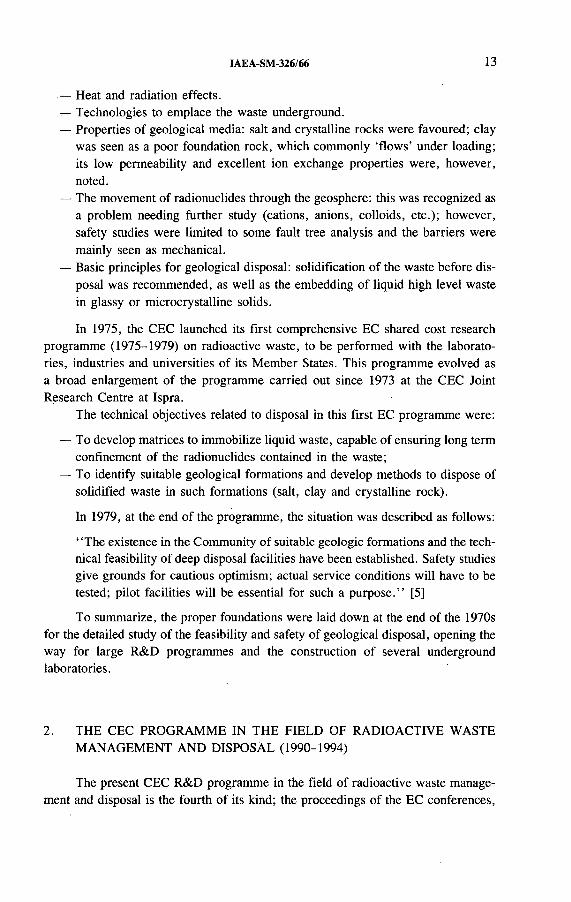
FIG. 1. The European Community ’s research programme on radioactive waste management.
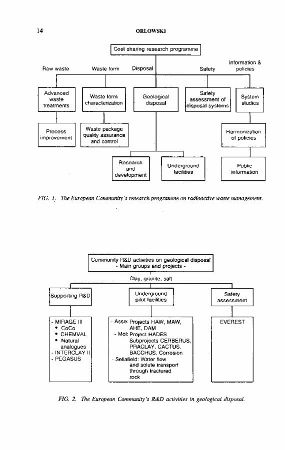
FIG. 2. The European Community 's R&D activities in geological disposal.
IAEA-SM-326/66 15
held in Luxembourg at the end of each five year programme, have provided information about the achievements since 1975 [5-7].
On average, some 60% of the programme’s budget has been devoted to geological disposal; the overall financial contribution of the CEC to the development of geological disposal since 1975 amounts to some 120 M ECU 1, divided in nearly equal parts between supporting research and investigations in underground pilot facilities. The present trend is to increase the share of the overall budget for geological disposal and, especially, the budget allocated to underground facilities. This trend is counterbalanced, however, by the many delays occurring in this sector, as a result of non-technical factors. In this context it must be noted that funds have been foreseen since 1980 in the successive CEC programme budgets to support pilot underground facilities in Belgium, France, Germany and the United Kingdom. However, owing to the delays mentioned above, the first research contract in the UK (Sellafield project) was signed only in 1991; it is improbable that a similar contract concerning a French project could be signed within the framework of the present programme (1990-1994).
The structure of the programme is shown in Figs 1 and 2.
3. RESEARCH TO BACK UP THE DEVELOPMENT OF UNDERGROUNDREPOSITORIES
Research is being carried out in support of multidisciplinary co-ordinated projects to improve the general knowledge and understanding of the long term isolation properties of potential rock formations envisaged for the disposal of radioactive waste in deep geological structures.
Specific theoretical, experimental and modelling studies of the migration and retardation behaviour of radionuclides from a repository through its far field (geosphere) play a key role. Some of these activities started in the previous, third, research programme, and are structured as a multinational co-ordinated project called MIRAGE (Migration of Radionuclides in the Geosphere), which is being continued.
Some design aspects of the construction and operation of underground repositories in different rock formations (such as clay, salt and granite) are covered by research projects to evaluate their feasibility and safety.
The following research topics are being dealt with.
1 T h e o v e ra l l b u d g e t o f th e E C p r o g r a m m e is a p p ro x im a te ly tw ic e th is a m o u n t ,
b e c a u s e th e p r o g r a m m e is im p le m e n te d b y m e a n s o f s h a r e d c o s t c o n t r a c ts , o n a m o re o r le ss
f i f ty - f i f ty b a s is .

16 ORLOW SKI
3.1. Sites and their characterization
This research topic deals with the development of site characterization techniques concerning calibration and intercomparison of adequate techniques for assuring relevant properties of groundwater chemistry and groundwater flow on selected reference sites (Sellafield, UK, for fractured rocks; underground experiment at Tournemire, France, for sediments with low permeability).
Studies are also being carried out concerning:
— Rock mechanics or rheology of clay (INTERCLAY П project), granite (DECOVALEX international project) and salt, as a follow-up of the COSA project, to improve the understanding of large scale rock mass behaviour through adequate laboratory or in situ tests, to develop and test suitable calculation tools, and to predict their material behaviour;
— Geoforecasting studies to predict future climate changes, including simulation of the effects of climate change on groundwater flow in the Netherlands and palaeoclimatological revision of climate evolution during the last 2 million years in the western Mediterranean region.
3.2. Design, construction and operation of underground repositories
This topic focuses on studies and experiments to support projects mainly carried out in underground facilities (see below) concerning the backfilling and/or sealing of boreholes in salt, clay and fractured crystalline rock. Various research efforts in the field of gas generation, gas release and gas migration through host rocks, in particular clay and salt, have started, and have been grouped together in a co-ordinated project called PEGASUS (Project on the Effects of Gas in Underground Storage Facilities).
3.3. Radionuclide migration in the geosphere
This topic is the largest one and was initiated in 1980 as MIRAGE phase I. The present research is performed as MIRAGE phase Ш; it concentrates on large integrated multinational subprojects already started in the previous MIRAGE phases, such as:
— Studies of the role of colloids, organic substances and complexes (CoCo activities).
— Migration experiments in clay and fractured crystalline rocks.— Natural analogues: the study of migration processes for understanding the long
term behaviour of geological isolation systems (El Berrocal (Spain) and Oklo (Gabon) projects); international exchange of information via the Natural Analogue Working Group (NAWG).
IAEA-SM-326/66 17
— Geochemical modelling of radionuclide migration, and a thermodynamic database for use in transport models: these are covered in a large project called CHEM VAL 2.
3.4. Modelling in the presence of uncertainties and management of data on inhomogeneous systems
The overall objective with respect to this topic is to study alternative methodologies and concepts for the modelling and handling of data in the presence of uncertainty in radionuclide transport modelling. Advanced studies are focused on:
— Investigation of methodologies for the treatment of uncertainty with reference to modelling studies (e.g. fuzzy sets, expert judgement and information theory);
— Treatment of uncertainties in radionuclide transport modelling;— Methods of handling inhomogeneities (e.g. dispersion) at different scales in
transport models.
Finally, safety studies are being pursued, following the completion of the PAGIS [8] and PACOMA projects, through the EVEREST project. This project is aimed at evaluating the impacts of uncertainties (in phenomena, data and scenarios) on the safety assessment results.
4. UNDERGROUND FACILITIES OPEN TO COMMUNITY JOINT ACTIVITIES
Research performed in an underground facility of an EC country could be supported by the CEC under the provision that this facility would be open to joint R&D activities of other EC countries. This is actually the case as far as the two main facilities participating in the CEC programme, i.e. the Asse salt mine in Germany and the HADES facility at Mol, Belgium, are concerned.
Projects at the pilot underground facility in the Asse salt mine are listed below:
— HAW project: test disposal for high level vitrified waste (participation of French, Spanish and Dutch partners);
— MAW project: test disposal for medium level waste, including HTR spent fuel;— AHE project: active handling experiment with neutron sources (participation
of French partners);— DAM project: in situ investigation of the long term sealing system as a compo
nent of a dam construction (participation of French and Spanish partners).

18 ORLOWSKI
The following projects are under way at the HADES underground research facility in the Boom clay at Mol:
— CERBERUS: experiment with radiation in the Belgian repository;— PRACLAY : preliminary demonstration of the possibility of HLW disposal in
clay;— CACTUS: hydrothermomechanical test in clay;— BACCHUS: demonstration of the in situ application of an industrial clay based
backfill material;— Corrosion: in situ test on the corrosion behaviour of potential canister and
structural materials;— Mine-by test: monitoring of the long term behaviour of the test drift and its
surroundings.
In addition, the CEC is participating in experiments on water flow and solute transport through fractured rocks at the Sellafield site.
More detailed information about this work is given in the paper by Schaller et al. at this symposium [9].
5. PRESENT SITUATION AND FUTURE TRENDS
The amount of scientific knowledge accumulated by means of the national and EC programmes is considerable and indicates that geological disposal is feasible and should be safe.
The present challenge is to build convincing cases for the licensing of future underground repositories, knowing that direct evidence of their long term safety cannot be provided.
A consequence for the EC research programme is that its support of in situ experiments and the construction and operation of pilot underground facilities should be maintained and, if possible, increased. More specifically, the following topics of the current EC programme are especially relevant:
— Testing and development of methods of investigation to be used for siting purposes;
— Technology of construction;— Functions of the engineered barriers in a realistic environment, including
backfilling and sealing materials.
However, it is well recognized that decision makers are confronted not only with technical questions but also with public attitudes towards nuclear matters. In this context, two activities are being performed within the present EC research programme on radioactive waste:

IAEA-SM-326/66 19
— Studies aiming at ‘decategorization’ of alpha waste by means of efficient decontamination methods or by separation processes using new chemical extractants; the ideal result should be a stream of low level, short lived waste and some highly active and long lived residues to be vitrified with the high level waste.
— Studies aiming at decreasing the inventory of long lived radionuclides to be disposed of in a deep repository: these studies pertain to the ‘partitioning and transmutation strategies’.
Last but not least, methods and means to inform the public must be studied and developed, making use of the best and most modern tools for communication and education such as interactive devices and videotapes.
A new Community Plan of Action in the field of radioactive waste (1993-1999) [10], which continues the present one (1980-1992), was approved by the EC Council of Ministers in June 1992; it will provide, for the years to come, the necessary framework for making technical and non-technical advances in the field of waste disposal within the EC.
The plan asks for, inter alia:
— Further and increased co-operation between EC countries on deep disposal;— Consultation between safety authorities with a view to establishing recommen
dations and criteria in the field of disposal safety;— A parallel and co-ordinated development of the disposal techniques and of the
relevant measures of a regulatory character;— An increasing and co-ordinated effort to inform the public;— The development of an international consensus on the management and
disposal of nuclear waste, in liaison with international bodies such as the International Atomic Energy Agency and the OECD Nuclear Energy Agency.
REFERENCES
[1 ] T h e D is p o s a l o f R a d io a c t iv e W a s te o n L a n d , P u b l ic a t io n 5 1 9 , N a t l A c a d e m y o f
S c ie n c e s , N a t l R e s e a r c h C o u n c i l , W a s h in g to n , D C (1 9 5 7 ) .
[2] H A T C H , L . P . , U l t im a te d is p o s a l o f ra d io a c t iv e w a s te , A m . S e i. 4 1 (1 9 5 3 ) 4 1 0 - 4 2 1 .
[3 ] H e a l th I m p l ic a t io n s o f th e S to r a g e o f R a d io a c t iv e S u b s ta n c e s o n a n d in th e G ro u n d
(P ro c . C o llo q u iu m , C h e r b o u r g - L a H a g u e , 1 9 7 0 ) , E U R 4 7 3 6 E , C E C , L u x e m b o u r g
(1 9 7 0 ) .
[4 ] H ig h L e v e l R a d io a c t iv e W a s te M a n a g e m e n t A l te r n a t iv e s , R e p . B N W L -1 9 0 0 , B a t te l le
P a c if ic N o r th w e s t L a b . , R ic h la n d , W A (1 9 7 4 ) .
[5 ] S I M O N , R . , O R L O W S K I , S . (E d s ) , R a d io a c t iv e W a s te M a n a g e m e n t a n d D is p o s a l
(P ro c . C o n f . L u x e m b o u r g , 1 9 8 0 ) , E U R 6 8 7 1 , H a rw o o d A c a d e m ic , N e w Y o r k (1 9 8 0 ) .
[6 ] S I M O N , R . ( E d .) , R a d io a c t iv e W a s te M a n a g e m e n t a n d D is p o s a l ( P r o c . C o n f . L u x e m
b o u r g , 1 9 8 5 ) , E U R 1 0 1 6 3 , C a m b r id g e U n iv . P r e s s , C a m b r id g e (1 9 8 6 ) .
20 ORLOWSKI
[7] C E C I L L E , L . ( E d .) , R a d io a c t iv e W a s te M a n a g e m e n t a n d D is p o s a l (P ro c . C o n f .
L u x e m b o u r g , 1 9 9 0 ) , E U R 1 3 3 8 9 , E l s e v ie r A p p lie d S c ie n c e , A m s te r d a m (1 9 9 1 ) .
[8] C A D E L L I , N . , e t a l . , P e r f o r m a n c e A s s e s s m e n t o f G e o lo g ic a l I s o la t io n S y s te m s fo r
R a d io a c t iv e W a s te — S u m m a r y , E U R 1 1 7 7 5 , C E C , L u x e m b o u r g (1 9 8 8 ) .
[9 ] S C H A L L E R , K .H . , C A D E L L I , N . , H A U T IN K , B . , I A E A - S M - 3 2 6 /7 0 , th e s e
P r o c e e d in g s .
[1 0 ] C o u n c i l R e s o lu t io n o f 15 J u n e 1 9 9 2 c o n c e r n in g th e r e n e w a l o f th e C o m m u n ity P la n o f
A c t io n in th e f ie ld o f r a d io a c t iv e w a s te , E C O ff . J . N o . С 1 5 8 /3 (1 9 9 2 ) .

I AE A-SM-326/67
THE IAEA PROGRAMME ON MANAGEMENT AND DISPOSAL OF HIGH LEVEL WASTE
D.E. SAIREDivision of Nuclear Fuel Cycle and Waste Management,International Atomic Energy Agency,Vienna
Abstract
T H E IA E A P R O G R A M M E O N M A N A G E M E N T A N D D IS P O S A L O F H IG H L E V E L
W A S T E .
T h e p a p e r p r e s e n ts th e m a jo r a c t iv i t ie s o f th e I n te rn a t io n a l A to m ic E n e r g y A g e n c y in
th e f ie ld o f th e m a n a g e m e n t a n d d is p o s a l o f h ig h le v e l r a d io a c t iv e w a s te , a n d d e s c r ib e s th e
ro le o f th e IA E A in a s s is t in g M e m b e r S ta te s in a c c o m p lis h in g n a t io n a l p r o g r a m m e s . T h e 114
M e m b e r S ta te s o f th e IA E A r e p r e s e n t a w id e ra n g e o f in te r e s ts a n d n e e d s in th e f ie ld o f r a d io
a c t iv e w a s te m a n a g e m e n t . In v ie w o f th e v a r ie ty o f w a s te s to b e d is p o s e d o f in a g e o lo g ic a l
re p o s i to r y ( i . e . w a s te s f r o m re p ro c e s s in g o f s p e n t fu e l , c o n d i t io n e d s p e n t f u e l , r e s e a r c h r e a c
to r s p e n t fu e l a n d s p e n t r a d iu m s o u rc e s ) , a v e ry la rg e p e rc e n ta g e o f th e IA E A M e m b e r S ta te s
h a v e a n in te r e s t in th e s u b je c t . T h is is p a r t ic u la r ly t r u e f o r m a n y M e m b e r S ta te s w ith o u t
n u c le a r p o w e r p r o g r a m m e s th a t h a v e a la r g e n u m b e r o f s p e n t r a d iu m n e e d le s w h ic h , b e c a u s e
o f th e r a d io lo g ic a l to x ic i ty a n d h a lf - l i f e o f r a d iu m , w ill r e q u i r e d is p o s a l in a d e e p g e o lo g ic a l
r e p o s i to r y . T h e ro le o f th e I A E A in c o -o rd in a t in g w a s te m a n a g e m e n t a c t iv i t ie s th a t le n d th e m
s e lv e s to in te rn a t io n a l c o l la b o r a t io n is d e s c r ib e d . E x a m p le s o f p r o g r a m m e s to fo s te r r e s e a r c h
a n d d e v e lo p m e n t a n d m e c h a n is m s u s e d to e n h a n c e th e e x c h a n g e o f in fo r m a t io n a r e d e ta ile d .
T h e w o r k o f th e R a d io a c t iv e W a s te S a fe ty S ta n d a rd s (R A D W A S S ) p r o g r a m m e in th e a r e a o f
d e e p g e o lo g ic a l d is p o s a l is p r o v id e d a s a n e x a m p le o f IA E A e f f o r ts to e s ta b l is h in te rn a t io n a l
c o n s e n s u s o n th e s a fe m a n a g e m e n t a n d d is p o s a l o f r a d io a c t iv e w a s te . R A D W A S S d o c u m e n ts
a r e p la n n e d o n v a r io u s a s p e c ts o f H L W m a n a g e m e n t a n d d is p o s a l . O th e r IA E A a c t iv i t ie s ,
in c lu d in g in te rn a t io n a l p e e r r e v ie w s e r v ic e s a n d s p e c ia l p r o je c ts , a r e a ls o d is c u s s e d in th e
p a p e r .
1. INTRODUCTION
Within its mandate to assist Member States in the development and implementation of nuclear energy and application technologies, the International Atomic Energy Agency has developed an effective programme for fostering international collaboration in the field of waste management. The objectives of this paper are:
(a) To provide information on the activities that make up the IAEA’s high level waste management programme, and
21
2 2 SA K E
(b) To raise the awareness level o f the international waste management community with respect to certain issues and opportunities in the area of regional and/or global co-operation in this field.
It would be fair to say that the implementation of plans for the final disposal of high level waste remains the largest issue to resolve for the continued operation and further growth of nuclear power. Thus, at a time when the environment is threatened by waste products from fossil fuels, the ability to enhance the use of the environmentally clean technology of nuclear energy is apparently being impaired as a result of the concerns surrounding the siting of HLW repositories. At the IAEA, we are continually occupied with the question of what can be done to assist Member States in this area. While the answer is not always completely clear, the IAEA does have mechanisms which can be effectively used by Member States to help resolve some of the issues. Before these mechanisms are described, an illustration is given below of why the IAEA is interested and involved in this area.
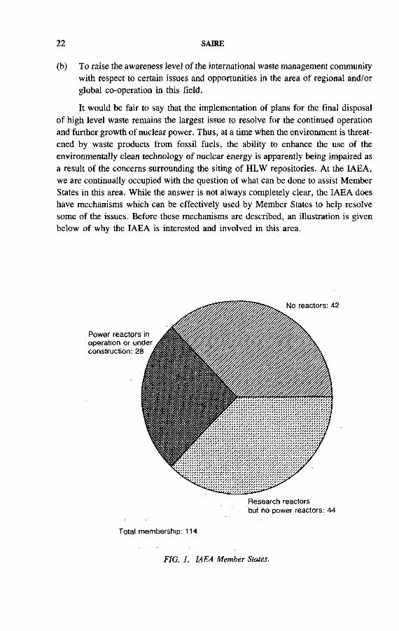
Research reactors but no power reactors: 44
Total membership: 114
FIG. 1. IAEA Member States.

IAEA-SM-326/67 23
As shown in Fig. 1, the IAEA has 114 Member States of which 28 have operating nuclear power plants or plants under construction. Thirteen of the 28 are also members of the OECD Nuclear Energy Agency. Since it is recognized that a deep geological repository will also be needed for the final disposal of spent research reactor fuel and long lived spent radiation sources (i.e. Am and Ra sources), the number of IAEA Member States that have an interest in deep geological disposal increases dramatically. This can be seen in Fig. 1, which also shows the number of Member States with research reactors but no power reactors. Thus, while other forums exist for regional or international co-operation in this field, the IAEA has the largest number of Member States with an interest in this subject. Even though most of the IAEA Member States may not actually build a repository they have an interest and/or a need to participate in a repository project.
2. THE IAEA PROGRAMME IN HLW DISPOSAL
IAEA efforts in the management and disposal of HLW consist of five main activities:
— Information exchange— International safety standards— Fostering R&D— Advisory services— Special projects.
Through these activities, the IAEA offers Member States a forum which provides. benefits in terms of economics, sharing of experience, consensus and programme credibility. In addition, in some Member States, activities performed by the IAEA will be the catalyst which leads to direct solutions for the disposal of their radioactive wastes.
3. INFORMATION EXCHANGE
The main purpose of the formation of the IAEA was to provide a forum where experience in the peaceful uses of the atom could be shared by its Members. Information exchange and distribution have therefore been a major part of this experience sharing mandate from the very beginning of the IAEA, which continues to function as an international clearing-house. This is clearly illustrated in HLW management by the impressive number of technical reports and technical documents published by the IAEA in this field.
T he information exchange is both ‘horizontal’ and ‘vertical’: horizontal in that it provides a sharing of experience between Member States that are at the same level
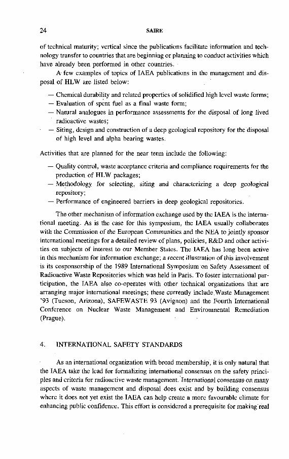
24 SAIRE
of technical maturity; vertical since the publications facilitate information and technology transfer to countries that are beginning or planning to conduct activities which have already been performed in other countries.
A few examples of topics of IAEA publications in the management and disposal of HLW are listed below:
— Chemical durability and related properties of solidified high level waste forms;— Evaluation of spent fuel as a final waste form;— Natural analogues in performance assessments for the disposal of long lived
radioactive wastes;— Siting, design and construction of a deep geological repository for the disposal
of high level and alpha bearing wastes.
Activities that are planned for the near term include the following:
— Quality control, waste acceptance criteria and compliance requirements for the production of HLW packages;
— Methodology for selecting, siting and characterizing a deep geological repository;
— Performance of engineered barriers in deep geological repositories.
The other mechanism of information exchange used by the IAEA is the international meeting. As is the case for this symposium, the IAEA usually collaborates with the Commission of the European Communities and the NEA to jointly sponsor international meetings for a detailed review of plans, policies, R&D and other activities on subjects of interest to our Member States. The IAEA has long been active in this mechanism for information exchange; a recent illustration of this involvement is its cosponsorship of the 1989 International Symposium on Safety Assessment of Radioactive Waste Repositories which was held in Paris. To foster international participation, the IAEA also co-operates with other technical organizations that are arranging major international meetings; these currently include Waste Management ’93 (Tucson, Arizona), SAFEWASTE 93 (Avignon) and the Fourth International Conference on Nuclear Waste Management and Environmental Remediation (Prague).
4. INTERNATIONAL SAFETY STANDARDS
As an international organization with broad membership, it is only natural that the IAEA take the lead for formalizing international consensus on the safety principles and criteria for radioactive waste management. International consensus on many aspects of waste management and disposal does exist and by building consensus where it does not yet exist the IAEA can help create a more favourable climate for enhancing public confidence. This effort is considered a prerequisite for making real

IAEA-SM-326/67 25
Subject areas:1. Planning for a national radioactive waste management system2. Pre-disposal management3. Near surface disposal4. Deep geological disposal5. Management of radioactive waste from mining and milling ore6. Decommissioning
FIG. 2. RADWASS structure and publication areas.
progress in the disposal of HLW. A significant step was taken in this direction in 1991 when the IAEA announced the start o f the Radioactive Waste Safety Standards (RADWASS) programme.
The purpose of the RADWASS programme is to demonstrate that there is harmonization in the approaches to safe management of radioactive waste on an international level. The programme objectives are as follows:
— To document the existence of international consensus for safe waste management and disposal;

26 SAIRE
— To create a mechanism or forum to establish consensus where it does not exist;— To provide Member States with a series of documents to complement, or form
the basis of, national standards and criteria.
Within the RADWASS programme a set of safety documents will be produced, organized in a hierarchical structure of four levels (Fig. 2). The highest level will comprise a single Safety Fundamentals document which will provide basic safety principles and criteria that must be incorporated into a national waste management programme. The lower levels, in descending order, comprise Safety Standards, Sàfety Guides and Safety Practices. The RADWASS programme is divided into six subject areas, one of which is deep geological disposal (Fig. 2). In this area, a Safety Standard and two Safety Guides are planned. It is hoped that the guide on siting of geological disposal facilities will be published in the first phase of the RADWASS programmé, which is scheduled to be completed by the end of 1994. The success of the RADWASS programme depends on the IAEA having not only sufficient resources to commit to this challenging and high priority project, but the full cooperation and support of the international waste management community.
5. FOSTERING R&D
In supporting and fostering research and development in the field of HLW disposal the IAEA has been active in two areas, namely, the performance of HLW forms and engineered barriers under repository conditions, and the geochemistry of long lived transuranic actinides and fission products. W ork in each research area was conducted under an IAEA co-ordinated research programme (CRP). A CRP is implemented when a number of Member States identify a subject of common interest for performing research and sharing results and experience. The research is conducted at laboratories or institutes within each participating country and is reported at Research Co-ordination Meetings attended by investigators holding research agreements or contracts with the IAEA. These meetings are usually held about once every 18 months to report on research progress and review the work being carried out.
A summary of the research activities that formed the scope of the CRP on the Performance of High Level Waste Forms and Engineered Barriers under Repository Conditions is presented below:
— Studies of solidified HLW forms and spent fuel,— Studies of the interaction of canister materials and waste forms with repository
materials,— Repository system and geochemical modelling studies.
Ten countries (12 institutes) took part in this programme. Waste forms studied included glass, Synroc and conditioned spent fuel.
IAEA-SM-326/67 27
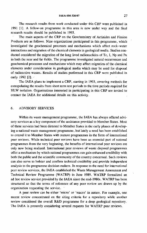
The research results from work conducted under this CRP were published in 1991 [1]. A follow-on programme in this area is now under way and the final research results should be published in 1995.
The main aspects of the CRP on the Geochemistry of Actinides and Fission Products are as follows. Nine organizations participated in this programme, which investigated the geochemical processes and mechanisms which affect rock-water interactions and migration of the chemical elements in geological media. Studies conducted considered the migration of the long lived radionuclides of Tc, I, Np and Pu in both the near and far fields. The programme investigated natural occurrences and geochemical processes and mechanisms which may affect migration of the chemical elements under consideration in geological media which may be used for disposal of radioactive wastes. Results of studies performed in this CRP were published in early 1992 [2].
The IAEA plans to implement a CRP, starting in 1993, covering methods for extrapolating the results from short term test periods to the time periods required for HLW isolation. Organizations interested in participating in this CRP are invited to contact the IAEA for additional details on this activity.
6 . ADVISORY SERVICES
Within its waste management programme, the IAEA has always offered advisory services as a key component o f the assistance provided to Member States. Most of these services had been directed to Member States in the early phases of developing a national waste management programme, but lately a need has been established to extend it to Member States with mature programmes in the form of international peer reviews. While technical peer reviews have been an essential part of national programmes from the very beginning, the benefits of international peer reviews are only now being realized. International peer reviews of waste disposal programmes offer a mechanism by which national programmes can gain enhanced credibility with both the public and the scientific community of the country concerned. Such reviews can also serve to bolster and confirm technical credibility and provide independent analysis to the programme decision makers. In response to the need for international peer review services, the IAEA established the Waste Management Assessment and Technical Review Programme (WATRP) in June 1989. WATRP formalized an ad hoc review service provided by the IAEA since the mid-1980s. WATRP has been structured so that the terms of reference of any peer review are drawn up by the organization requesting the service.
A peer review can be either ‘micro’ or ‘macro’ in nature. For example, one recent review concentrated on the siting criteria for a repository while another review considered the overall R&D programme for a deep geological repository. The IAEA is presently considering several requests for WATRP peer reviews.
28 SAIRE
The IAEA has a number of ‘special projects’ which cover different aspects of waste management activities. For example, a special project on a Waste Processing and Storage Facility for Member States with waste arising from nuclear applications is reaching completion in that the reference design of such a facility will be available soon for use by Member States. Another special project under development concerns the ‘regional deep geological repository concept’.
The idea of a regional radioactive waste disposal repository has been considered in the international community on a few occasions as an interesting concept from the safety, technical and economic standpoints. However, political constraints and the general public attitude of ‘not in my backyard’ have prevented international efforts in this direction from being actively pursued. Indeed, some countries have passed legislation which prohibits the acceptance of waste from other countries. However, with the recognition that there are a number of countries that have small nuclear power programmes and share common boundaries, and considering the problem that exists with the disposal of spent research reactor fuel and old radium sources, the opportunity to revisit this idea appears logical. The IAEA strategy for regional repositories has been based on the view that if the IAEA could achieve some degree of success in one regional project, it would stimulate interest for the concept in other regions.
The IAEA has identified four potential regions as possible candidates for a regional repository. These are eastern Europe, Latin America, Africa, and the Asia and Pacific region. The issues are slightly different in each region but the resulting benefits are the same. A lengthy and challenging path to reaching the objective of a regional repository is foreseen but the IAEA is convinced that the safety, technical and economic arguments supporting such a concept justify the efforts involved.
7. SPECIAL PROJECTS
8 . CONCLUSIONS
The next ten years will be a crucial period for countries requiring a deep geological repository for the disposal of high level waste. It will be a period when important decisions will have to be made and significant resources committed. International organizations such as the IAEA can help remove the uncertainty and reduce difficulties associated with national decision making processes by building consensus in key policy and technical areas and facilitating collaboration and cooperation between countries. The problems facing the waste management community are challenging and complex. However, by working together we can accomplish the goal of safe final disposal of high level radioactive wastes.
IAEA-SM-326/67 29
REFEREN CES
[1] I N T E R N A T I O N A L A T O M IC E N E R G Y A G E N C Y , P e r f o r m a n c e o f H ig h L e v e l
W a s te F o r m s a n d E n g in e e r e d B a r r ie r s u n d e r R e p o s i to r y C o n d it io n s , IA E A -
T E C D O C - 5 8 2 , V ie n n a (1 9 9 1 ) .
[2 ] I N T E R N A T I O N A L A T O M IC E N E R G Y A G E N C Y , G e o c h e m is t ry o f L o n g L iv e d
T r a n s u r a n ic A c t in id e s a n d F is s io n P r o d u c ts , I A E A - T E C D O C - 6 3 7 , V ie n n a (1 9 9 2 ) .


IAEA-SM-326/68
NEA ACTIVITIES IN THE FIELD OF HIGH LEVEL AND LONG LIVED WASTE MANAGEMENT
J.-P. OLIVIER, E.S. PATERA,C. PESCATORE, B. RÜEGGER
. OECD Nuclear Energy Agency,Issy-les-Moulineaux
Abstract
N E A A C T IV IT IE S I N T H E F I E L D O F H IG H L E V E L A N D L O N G L I V E D W A S T E
M A N A G E M E N T .
T h e a c t iv i t ie s o f th e O E C D N u c le a r E n e rg y A g e n c y (N E A ) in th e f ie ld o f ra d io a c t iv e
w a s te m a n a g e m e n t a r e fo c u s e d m o s t ly o n th e d is p o s a l o f h ig h le v e l a n d lo n g l iv e d w a s te s a n d
a r e o r g a n iz e d u n d e r th e g u id a n c e o f its R a d io a c t iv e W a s te M a n a g e m e n t C o m m itte e . T h e la t te r
is c o m p o s e d o f s e n io r re p re s e n ta t iv e s f r o m th e im p le m e n tin g a n d r e g u la to r y a g e n c ie s o f th e
M e m b e r c o u n tr ie s . T h e N E A m e m b e rs h ip a n d s t r u c tu r e p r o v id e a u s e f u l f r a m e w o r k f o r th e
M e m b e r c o u n tr ie s to p ro m o te c o m m o n p r o c e d u r e s a n d v ie w p o in ts o n th e v a r io u s a s p e c ts o f
w a s te d is p o s a l a s w e l l a s th e id e n t i f ic a t io n a n d g a th e r in g o f b a s ic to o ls a n d in fo r m a t io n in s u p
p o r t o f th e s a fe ty e v a lu a t io n a n d s i te in v e s t ig a t io n p r o g r a m m e s o f th e s e c o u n tr ie s . F o r th is p u r
p o s e , th e N E A a c t iv i t ie s a r e s u b d iv id e d in to tw o g ro u p s . T h e f i r s t g r o u p in v o lv e s th e in p u t
o f s i te c h a r a c te r iz a t io n e x p e r ts a n d is c a r r ie d o u t u n d e r th e s u p e r v is io n o f th e C o -o rd in a t in g
G r o u p o n S ite E v a lu a t io n a n d D e s ig n o f E x p e r im e n ts f o r R a d io a c t iv e W a s te D is p o s a l . T h e
s e c o n d g ro u p o f a c t iv i t ie s in v o lv e s p e r f o r m a n c e a s s e s s m e n t e x p e r ts a n d is c o -o rd in a te d b y th e
P e r f o r m a n c e A s s e s s m e n t A d v is o ry G ro u p . T h e p a p e r d is c u s s e s in d e ta i l th e r e c e n t a c c o m
p l is h m e n ts a n d n e a r te r m p la n s o f th e N E A a n d its w o rk in g g ro u p s .
1, INTRODUCTION
Since the late 1970s, the activities of the OECD Nuclear Energy Agency (NEA) in the field of radioactive waste management have been devoted almost exclusively to waste disposal issues. This deliberate choice was dictated, amongst other reasons, by the need to avoid duplication with the programmes of work of the Commission of the European Communities and the International Atomic Energy Agency, which both give a great deal of attention to the on-site management of nuclear waste, notably to treatment, conditioning and interim storage aspects. Disposal raises technical and non-technical challenges relatively different from those met during the routine operations of nuclear facilities. It was felt that the NEA, given its membership
31

32 OLIVIER et al.
and the relatively advanced stage of development of national programmes in this field, could provide a useful contribution at three main levels:
— Joint discussions of fundamental issues raised by the management of radioactive waste, and the promotion of safe and practicable policies for its disposal. In particular, these discussions, which have involved countries committed to significant nuclear programmes and countries still undecided or even opposed to the generation of nuclear electricity, have confirmed that there is at present no practical alternative to the disposal o f long lived radioactive waste into deep and stable geological formations. While the NEA programme focuses largely on geological disposal issues, some attention is devoted to possible future alternatives or techniques which may contribute to a safer and more economical management of the waste. In this context non-technical aspects have to be considered.
— The evaluation of potential disposal sites located in various types of geological media, with a view to promoting the development and use of appropriate site characterization techniques and methodologies, and to discussing problems of mutual concern such as the design of in situ experiments and the interpretation of field data.
— The long term safety aspects, which include detailed modelling of the long term performance of radioactive waste repositories. In this area the work of the NEA is almost exclusively devoted to high level and long lived waste repositories located deep underground, but the methodologies used can be applied, and indeed are applied, as well to surface or shallow repositories for low level, short lived waste.
2. WASTE MANAGEMENT POLICIES
The general discussion of waste management policies and approaches takes place at the level of the NEA Radioactive Waste Management Committee (RWMC), which is composed of managers of national agencies responsible for the implementation of disposal programmes, and senior representatives from safety authorities. The RWMC acts as a forum for the exchange of information and experience and promotes the development of common philosophies of approach with regard to the various possible waste management strategies and alternatives. One of its most important functions is to contribute to a common understanding of the basic issues involved between regulators and implementors of waste repositories. Such issues include the definition of disposal criteria and compliance aspects in general, the consideration of non-technical factors, and the priorities in the R&D field. The RWMC also decides the broad orientations of the NEA programme and, on the basis of the achievements at national and international levels, issues ‘collective opinions’ such as
IAEA-SMf326/68 33
the one published in 1991 on the availability of long term safety assessment methods for waste disposal, jointly with the CEC and the IAEA [1].
Under the broad mandate of the RWMC and its subgroups, the Co-ordinating Group on Site Evaluation and Design of Experiments for Radioactive Waste Disposal (SEDE) and the Performance Assessment Advisory Group (PAAG), the NEA can sponsor specific international.activities and initiatives contributing to the enhance-, ment of technical and scientific knowledge in the field. Peer reviews of specific national activities are also made on request, such as the one recently conducted by the NEA on Project-90 of the Swedish Nuclear Power Inspectorate.
3. SITE CHARACTERIZATION ACTIVITIES
The NEA site characterization activities, are carried out under the supervision of the SEDE. The membership of the SEDE comprises experts and.managers of site characterization programmes from the Member countries. The SEDE has a wide range, of ongoing activities. . , -
The first meeting of the SEDE took place in October 1990. The programme of work which was established at that meeting includes: information exchange through reporting on progress on site characterization activities within the Member programmes; topical discussions at SEDE meetings; a list of topics for future technical workshops; reporting o f progress in the international Stripa project; and the establishment of a Working Group on Measurement and Physical Understanding of Groundwater Flow Through Argillaceous Media.
The SEDE has already sponsored two workshops. The first workshop, in 1990, was devoted to the heterogeneity of groundwater flow [2]. The workshop discussed the methods that can be used to obtain the understanding and data required for modelling of such flow systems, as well as the adequacy and appropriateness of the modelling techniques. The second workshop, in 1991, was on the topic of Long Term Observations of the Geological Environment: Needs and Techniques [3]. Long term in this context means the period from site characterization to repository closure, which could represent several decades. The needs discussed included monitoring programmes for hydrological parameters, seismic data and chemical changes. A third workshop is to be held in conjunction; with the third meeting of the SEDE in November 1992 and is on the use of palaeohydrogeological information in evaluating the hydrological system of disposal sites. The workshop will address the methods available: for collecting palaeohydrogeological evidence and review and discuss specific applications of these methods to site investigations.
Iii addition to the above mentioned workshops the SEDE has .collaborated with the PAAG on issues of mutual interest. Gas Generation and Release from Radioactive Waste Repositories was the topic of a joint workshop in.September 1991 [4].

34 OLIVIER et al.
Research on this topic has started only recently and there is a rapidly growing information base which will be used in performance, assessment. The gas workshop covered both modelling and experimental aspects of gas generation and migration. The most obvious potential long term issue brought.up at the meeting was overpresr surization, which may cause stresses within the repository. The greatest concern applies to intermediate level and transuranic wastes because a great deal of gas may be generated .not only by corrosion of iron containers but also by the degradation of organic materials. As an outcome of the workshop it was recommended that gas generation and release be taken into account in the design requirements of the engineered barriers and in performance assessment calculations. The SEDE will pursue this topic in a discussion at its third meeting.
The SEDE and the PAAG are jointly organizing a workshop on the treatment of conceptual model uncertainty to be held in early 1993. This topic is discussed further in Section 4.
The SEDE has also established a working group to address the subject of groundwater flow through argillaceous media in greater detail. The working group is composed of experts from the Member countries that are considering siting radioactive waste disposal repositories in a variety of argillaceous rock units. The working group members report on progress in characterization o f these rocks and,discuss problems associated with characterizing their hydrology. During its first meeting the group agreed to share information on the different rock units under study. At its second meeting the group focused its attention on understanding of the physics of fluid flow in these impermeable rocks. The group agreed to propose to the SEDE a workshop on this topic and to explore the possibility of preparing a report on this subject.
Finally, it.should be mentioned that the Stripa project, which was set up under the auspices of the NEA in 1980, completed its research activities in the middle of 1991 and the drafting of a final report is to be completed in 1992. The results achieved during the Stripa project were reported at a symposium jointly organized and sponsored by the Swedish Nuclear Fuel and Waste Management Co. (SKB) and the NEA and held in Stockholm from 14 to 16 October 1992.
4. PERFORMANCE ASSESSMENT ACTIVITIES
' The NEA activities in support of performance assessment are under the supervision of the PAAG. The latter fulfils its advisory role to the RWMC. The PAAG membership is reserved to senior performance assessment managers from the regular, tory authorities and implementing agencies of the Member countries, who take this opportunity to discuss subjects of current interest and to further the development of emerging topics in the field of performance assessment.
IAEA-SM-326/68 35
The PAAG has recently started a debate on the treatment of the uncertainty, associated with the existence of potential alternative conceptualizations of a system,i.e. conceptual model uncertainty (CMU). Conceptual models are formulated even before site characterization activities are initiated and before a mathematical description is formalized. In this context, a given amount of data may be'accommodated by several .mathematical models, whereas in the past only one mathematical model has been usually utilized for safety assessment. This entails a certain degree of uncertainty in the safety assessment of radioactive waste sites. The PAAG is proceeding to deal with this topic by organizing a topical session at its next meeting and then a topical workshop in conjunction with thé SEDE. If the subject of CMU treatment is found to warrant further elaboration and analysis, an ad hoc working group will be established. ; ,
The above example also illustrates the modus operandi of the PAAG, that is, through topical sessions, topical workshops and working groups. In particular, the' working groups are the operating arms of the PAAG. They are set up on topics which are judged of the utmost priority and of interest to the majority of Member countries. At present the PAÀG is sponsoring two working groups: the Probabilistic Safety Assessment Group (PSAG) arid the working group on human intrusion.
4.1; Probabilistic safety assessment
The PS AG is composed of representatives of Member countries with hands-on experience of code development and probabilistic safety assessment (PSA). In the past the PSAG has undertaken code intercomparison exercises (PSACOÍN) and has promoted the adoption and development of PSA techniques in the Member countries. The PSAG has published the results of. its activities and has produced a brochure on PSA to put its work in perspective and to stress the value of PSA techniques in the context of thé long term safety assessments of waste repositories. The PSAG has contributed also to the general debate on the subject through its own internal topical sesr sions. The latest topical session examined the new subject of probabilistic validation of models. While this subject is in its infancy, it was observed that the deterministic validation.of models in the strict sense of the word may not be possible. The current focus ón GMU within the PAAG may reflect the same general observation.-At present the PSAG is in the process of undertaking its level 2 joint exercise. The latter revolves around the Waste Isolation Pilot Project (WIPP) database developed at Sandia National Laboratories in the United States of America and.addresses the potential release of contaminants following an inadvertent borehole intrusion into the repository. In the first stage of the exercise work will be done on the treatment of the CMU associated with the modelling of contaminant transport.

36 OLIVIER et al.
4.2. Human intrusion
In June 1989, the NEA organized its first international workshop on Risks Associated with Human Intrusion at Radioactive Waste Disposal Sites. As a follow- up action the RWMC, on the basis of a proposal by the PAAG, formed a working group to assess the effects o f future human actions at radioactive waste disposal sites. The group provides a forum for a broad information exchange regarding this issue. Potentially the most useful contribution it could make is to reach some common ground concerning the general philosophy regarding reasonable approaches to assessing future human actions at disposal sites. The.group has met twice and will hold its third meeting in December 1992. The group will produce a report on the subject. In order to accomplish this task the group established a list of issues on which consensus should be reached and a list o f issues which needed further work before consensus could be reached. Some of the consensus issues already agreed to are as follows:
— Human intrusion actions must be considered in safety assessments.— Indefinite administration controls cannot be relied upon.— Intrusions or actions taken affecting the disposal system where the actors are
cognizant of the risks can be ignored.— Efforts should be considered to lessen the likelihood of future inadvertent
actions.
. Issues that require further discussion and consideration before consensus can be reached include the following:
— Should human intrusion be treated the same as other potentially disruptive events?
— How can probability estimates be assigned?— How can analogues be used in the analysis of human intrusion?— How can cost-benefit analysis be applied in assessing future human actions?
4.3. Scenario development :
Following earlier work done at the NEA on scenario development, the potential organization of a database of ‘features, events and processes’ (FEPs) will be further investigated. The availability of one such database as the product of contributions from experts worldwide would help resolve the issue of completeness of the analysis of potential events external to the system. This issue is especially important to the regulators. At the same time the preparatory work leading to the database could identify a consensus for eliminating some of the most unlikely or least applicable FEPs. This would help address the issue of sufficiency, which is very important to implementors.

IAEA-SM-326/68 37
4.4. Thermochemical database
A continuing NEA effort in the area of performance assessment is the preparation of a quality assured thermochemical database (TDB) which the Member countries could utilize for their geochemical calculations. A report on the element uranium has been published recently [5], and contains carefully selected data for 299 uranium compounds and their complexes and 98 reactions, as well as for 214 auxiliary species and 37 auxiliary reactions. Good progress has been made on technetium and americium; neptunium and plutonium will be the next elements to be treated. Because of the long lead time needed to set up an appropriate expert group that would assemble data of suitable quality to be incorporated in the TDB, the RWMC has decided to create an ad hoc working group to recommend future priorities. It is planned that this working group will recommend priorities that would match the needs of all members of the waste disposal community. The group will also discuss other issues such as the potential inclusion of organic complexes, the portability of the TDB and the relevant software, as well as resources, management and financial aspects of the project.
4.5. Other PAAG activities
Other recent initiatives of the PAAG were the workshop on gas generation at disposal sites (September 1991) organized jointly with the SEDE (see above) and a workshop on radionuclide sorption (October 1991) [6 ].
The objectives of the sorption workshop were to evaluate critically the way sorption processes are incorporated in performance assessment models and to discuss the results o f an intercalibration study. It was observed that the determination of sorption coefficients, mainly by the ‘batch sorption method’, will continue to be required as the current database for some óf the key radionuclides is still sparse. With regard to generalizing the laboratory data for application to fiéld conditions, it was observed that it is extremely difficult to vary the redox conditions in the laboratory and that it is still a problem to apply to intact rock sorption data obtained with unconsolidated materials. The workshop identified the lack of documentation for the selection of the stored data as one of the major shortcomings associated with the available sorption databases. It was also observed that, ideally, the development of sorption databases should rely on the mechanistic understanding of the sorption processes. A forum has been created within the NEA in order to develop a consensus on the best applicable mechanistic models. Finally, the results o f a sorption intercalibration exercise sponsored by the NEA were considered satisfactory. In this context, it is recalled further that a sorption database (SDB) is available from the NEA. The SDB contains most of the sorption data presently available in the Member countries.
38 OLIVIER et al.
The PAAG also receives regular briefings on ongoing national and international research programmes in the field of performance assessment. Among the latter are the INTRAVAL a¡nd BIOMOVS projects and the Alligátor Rivers Analogue Project, in which the NEA is involved at different levels:
5. CONCLUDING REMARKS
The NEA programme of work in the field of radioàctivè waste management is not exhaustive, but it tries to Cover the major issues with which Member countries are faced and avoid duplication with the programmes of other international organizations. Its main interest is the open and objective debate that takes placé within the permanent or ad hoc NEA committees arid groups, Composed of managers and experts from the most advanced countries, which continuously review the state of the art in their respective fields and identify and discuss priority issues. Their conclusions are widely-publicized and enjóy a certain degree o f credibility which benefits directly national programmes, both at the policy level and on technical aspects. Consensus views resulting from international co-operation activities do in general carry a certain weight, and may assist considerably in current national debates on the implementation of national radioactive waste programmes.
REFERENCES
[1 ] D is p o s a l o f .R a d io a c t iv e W a s te : C a n L o n g - T e r m S a fe ty B e E v a lu a te d ? A n I n te rn a t io n a l
C o l le c t iv e O p in io n , O E C D /N E A , P a r is (1 9 9 1 ) .
[2 ] H e te ro g e n e ity , o f G r o u n d w a te r ;F lo w a n d S ite E v a lu a t io n (P ro c . W o r k s h o p , P a r is ,
. 1 9 9 0 ) , O E C D /N E A , P a r is (1 9 9 1 ) . . . . . . .
[3 ] . L o n g T e r n i O b s e rv a t io n s o f th e G e o lo g ic a l E n v i ro n m e n t : N e e d s a n d T e c h n iq u e s (P ro c .
W o r k s h o p , H e ls in k i , 1 9 9 1 ) , O E C D /N E A , P a r is ( in p r e s s ) .
[4 ] G a s G e n e r a t io n a n d R e le a s e f r o m R a d io a c t iv e W a s te R e p o s i to r ie s ( P r o c . W o r k s h o p ,
A ix - e n - P r o v e n c e , 1 9 9 1 ) , O È C D /N E À , P a r i s (1 9 9 2 ) .
[ 5 ] ' W A N N E R , H . , F O R E S T , I . ( E d s ) , C h e m ic a l T h e r m o d y n a m ic s o f U r a n iu m , N ö r th :
H o lla n d E ls e v ie r S c ie n c e P u b l i s h e r s , A m s te r d a m (1 9 9 2 ) .
[6] R a d io n u c l id e S o r p t io n f r o m th e S a fe ty E v a lu a t io n P e r s p e c t iv e (P ro c . W o r k s h o p , I n te r
la k e n , 1 9 9 1 ) , Ö E C D /N E A , P a r i s (1 9 9 2 ) .

SITE CHARACTERIZATION PROGRAMMES AND METHODS
(Session 2)
Chairmen
L. REITERUnited States of America
H. RÖTHEMEYERGermany

IAEA-SM-326/26
FROM CONCEPTUAL DESIGN TO SITE SPECIFIC PLANNING AND LICENSING IN GERMANY
H. RÖTHEMEYER Bundesamt fur Strahlenschutz,Salzgitter
L.E. VON BÖRSTEL, A.G. HERRMANN Technische Universität Clausthal,Clausthal-Zellerfeld
H.J. ENGELMANNDeutsche Gesellschaft zum Bau und Betrieb
von Endlagern für Abfallstoffe mbH,Peine
W. JARITZBundesanstalt für Geowissenschaften und Rohstoffe,Hanover
R. STORCKGSF-Forschungszentrum für Umwelt und Gesundheit GmbH,Braunschweig
B. STRIBRNYBundesministerium für Umwelt, Naturschutz
und Reaktor Sicherheit,Bonn
Germany
Abstract
F R O M C O N C E P T U A L D E S IG N T O S I T E S P E C I F I C P L A N N I N G A N D L I C E N S IN G IN
G E R M A N Y .
T w o r e p o s i to r ie s , K o n ra d a n d G o r le b e n , a r e b e in g d e v e lo p e d in G e rm a n y f o r s p e n t fu e l
a n d h ig h le v e l a n d /o r a lp h a b e a r in g w a s te s . F o r th e K o n ra d r e p o s i to r y p r o je c t th e a p p l ic a t io n
d o c u m e n ts w e r e s u b m it te d in 1 9 8 6 . R e v is e d v e r s io n s w e re d e c l a r e d s u f f ic ie n t f o r p u b lic
p a r t ic ip a t io n in 1 9 9 0 a n d m a d e a v a i la b le to th e p u b l ic in 1 9 9 1 . A b o u t 2 8 9 0 0 0 p e o p le h a v e
r a is e d 9 5 0 0 o b je c t io n s in 3 6 3 0 le t te r s . T h e G o r le b e n s i te w a s s u c c e s s fu l ly in v e s t ig a te d f ro m
a b o v e g ro u n d m a in ly b e tw e e n 1 9 7 9 a n d 1 9 8 5 . S u p p le m e n ta ry w o r k w il l c o n t in u e d u r in g th e
n e x t fe w y e a r s . T h e s t r a t ig ra p h y a n d c h e m ic a l c o m p o s i t io n o f th e fo r m a t io n s a s w e l l a s th e
f lu id s a n d g a s e s e n c o u n te r e d in th e s a l t d o m e a r e w e l l k n o w n . T h e s t r u c tu r a l h is to ry o f th e
s a l t d o m e , s u b ro s io n p r o c e s s e s a n d th e c a p ro c k g e n e s is w e re a n a ly s e d a n d c o r r e la te d to th e
g e o lo g ic a l t im e - s c a le . T w o s h a f ts h a v e b e e n l in d e r c o n s t r u c t io n s in c e 1 9 8 6 a n d w ill b e
f in is h e d in 1 9 9 5 . T h e c o n c e p tu a l d e s ig n h a s b e e n r e p la c e d b y d e s ig n a l te rn a t iv e s ta k in g in to
41
42 RÖTHEMEYER et al.
a c c o u n t th e p r e s e n t s i te s p e c if ic k n o w le d g e , d i f f e r e n t e m p la c e m e n t m e th o d s a n d p re s u m e d
r a t io s o f r e p r o c e s s e d w a s te s to s p e n t fu e l d is p o s e d o f d i r e c t ly . H ig h le v e l w a s te a n d s p e n t fu e l
a r e b e in g c o n s id e re d f o r e m p la c e m e n t in d e e p b o r e h o le s f o r d ru m s a n d c a n i s te r s o r a l te r n a
t iv e ly in d r i f t s f o r lo s t s h ie ld e d c o n ta in e r s (P O L L U X c a s k s ) . R e c e n t s a f e ty a s s e s s m e n ts in v e s
t ig a te d th e s e d e s ig n a l te rn a t iv e s , d e m o n s t r a t in g th e i r fe a s ib i l i ty in th e G o r le b e n s a l t d o m e . T h e
in v e s t ig a t io n o f f lu id in c lu s io n s f r o m th e d e p th o f th e p la n n e d d is p o s a l a r e a p r o v e d th a t th e y
a r e r e p r e s e n ta t iv e f o r s o lu t io n s w h ic h h a v e n o t b e e n a l te r e d s in c e th e i r f o r m a t io n 2 5 0 m il l io n
y e a r s a g o ( Z e c h s te in ) . F lu id in c lu s io n s o f m in e ra ls b e n e a th th e c a p r o c k , h o w e v e r , s h o w d i s
t in c t in f lu e n c e s o f s u b ro s io n f r o m th e o v e r ly in g s t r a ta . T h u s th e q u a n t i ta t iv e c h e m ic a l c o m p o
s i t io n o f s in g le f lu id in c lu s io n s s u p p l ie s im p o r ta n t a n d h i th e r to u n k n o w n in fo r m a t io n f o r th e
ju d g e m e n t o f lo n g te r m s a fe ty o f u n d e r g r o u n d r e p o s i to r ie s in s a l t d o m e s .
1. INTRODUCTION
Low level and short lived wastes have been disposed of in the Morsleben repository since 1981. The Morsleben salt dome is located within the territory of the former German Democratic Republic. From February 1991 to June 1992 the emplacement of waste was interrupted mainly for legal reasons ànd is now being resumed with the alpha activity being limited to 40 MBq/m3...
Two repositories are at present being developed for spent fuel and high level and/or alpha bearing wastes: one in the Gorleben salt dome at depths of about 840-1200 m, in which all types of solid radioactive waste mainly from a presumed nuclear capacity of 2500 M W -a are planned to be emplaced (total activity about 1021 Bq, alpha activity about 1019 Bq); and another in the abandoned Konrad iron ore mine, into which waste is to be emplaced which exerts a negligible thermal influence on the host rock (total activity 5 X 10¹⁸ Bq, alpha activity 1.5 X 10¹⁷ Bq).
The Fourth Amendment of 1976 to the German Atomic Energy Act generally requires reprocessing of used nuclear fuel. On the basis of a decision of the Prime Ministérs o f the German states (Länder) and the Federal Chancellor, the feasibility of direct disposal has been investigated since 1979. The status of these investigations is presented in another paper at this symposium [1]. Presently, major changes of the atomic law áre planned, including a wider legal base for direct disposal. Therefore, the suitability of the Gorleben salt dome is discussed below with this waste management alternative taken into account as well.
2. STATUS OF KONRAD REPOSITORY PROJECT
The major technical aspects of the Konrad project (planning, safety analyses, preliminary waste acceptance requirements and quality control) have been published
IAEA-S1VM26/26 43
elsewhere [2, 3]. Criticality considerations are presented in another paper at this symposium [4]. Therefore this paper concentrates on the presentation of the first results from the current public involvement period.
The application documents were submitted in 1986. Revised versions were declared sufficient for public participation in 1990 by the plan approval authority (licensing authority) and made available to the public in 1991. About 289 000 people have raised 9500 objections in 3630 different letters. O f the issues raised, 21% are of a general/fundamental and 2 2 % of a formal/legal nature while 9% refer to off-site transportation. Technical issues which are directly related to the application documents fall into the following categories: alternative forms o f disposal and sites (2%), site (3%), operational period (28%), post-operational period (10%) and waste/ quality control (5%).
The plan approval authority has to discuss the objèctions with the applicant and those who raised them. The meeting was scheduled to begin on 25 September 1992 and may last six to eight weeks.
The plan approval order (licence) is expected in mid-1994. Operation could then start, after a construction period of three yèars, in 1997. Based on this time schedule total costs will have added up to 1800 million,DM, with nearly 50% spent so far. Operating costs will be 45 million DM/a.
3. GORLEBEN PROJECT
3.1. Site investigation from above ground
3.1.1. Survey programme
For the investigation of the geology and hydrogeology of the Gorleben site the following work was carried out between 1979 and 1985:
— 4 boreholes, each about 2000 m deep, for investigation of the salt dome;— 44 boreholes for investigation of the cap rock and the underlying salt beds;— 2 preliminary boreholes for the shafts Gorleben 1 and Gorleben 2;— 156 km of seismic profiles;— 145 investigation drillings into the Cenozoic cover;— 326 drillings for the installation of piezometers;— 4 long time pumping tests (pumping time about three weeks for each test);— 1 borehole for investigations of the Palaeogene in the rim syncline.
Furthermore, numerous investigations were done, e.g. geoelectrical and geothermal studies as well as gravimetry, seismology, geochemistry, isotope geochemistry and micropalaeontology.
44 RÔTHEMÉYER et al.
The investigation of the site from above ground will be continued for a few more years. To replace assumptions and preliminary data in the hydrogeological modelling of the site, the former territory of the GDR (65 km 2 out of a total öf 350 km2) north of the River Elbe will now be included in the site investigation.
3.1.2. Results and conclusions
All -the beds of the Zechstein in the salt dome (Staßfurt sequence z2, Leine sequence z3 and Aller sequence z4) are very well known [5]. More than 500 chemical analyses show that the rock salt beds consist of about 95 % halite and about 5 % anhydrite. Intercalated are beds of claystone, carbonate rock (in general magnesite), anhydrite and potassium-magnesium salts. Parts of the rock salt contain hydrocarbon gases and condensates of hydrocarbons. The hydrocarbons derive from the Kupferschiefer at the base of the Zechstein [6 ].
Magnesium chloride is the main component of brines found in the four deep boreholes [7]. There are no pathways between the brine pockets and the cover of the salt dome.
Epeirogenic and halokinetic movements of the structure of the salt dome and its surroundings were quantitatively analysed [8 ]. The initial thickness of the Zechstein was about 1400 m. The structural history began with the salt pillow in the time from the Upper Bunter to the Muschelkalk. The structure entered its diapiric stage during the period of the Malm to the early Cretaceous. The maximum average velocity of salt uplift at the top of the dome was nearly 0.7 mm/a during the Cretaceous. The post-diapiric uplift was reduced to about 0.02 mm/a during the time from the Miocene to the present (the time-scale is discussed in Ref. [9]).
The main part of the cap rock was built up in the Cretaceous. The cap rock has a characteristic succession, the various parts being well distinguished by different textures. At the end of the Upper Cretaceous and the beginning of the Tertiary, parts of the cap rock were karstified and were backfilled later in the Palaeogene. During the Elster glaciation the cap rock was partly brecciated. The post-Elsterian part o f the cap rock (Geschichtetes Gips-/Anhydritgestein) indicates an average subrosion rate of about 0.04 mm/a during the last 300 000 years [5, 10].
Also well understood is the Cenozoic cover of the salt dome. It comprises clayey and silty sediments of the Palaeogene, sands of the Miocene and gravels, sands, clays and tills of the Quaternary period. An erosional channel above the dome, originated during the Elsterian period of glaciation, crosses the salt dome and reaches the cap rock or the salt in some places.
The fresh water is underlain by saline groundwater which reaches sáturátion at depths greater than 200 m below mean sea level. A groundwater flow model has been established [11]. The groundwater flow is from south to northwest.
IAEA-SM-326/26 45
Model calculations for fresh water were used to determine the groundwater movements. Starting at selected points at the base of the aquifer system, the paths end in the lowlands with travel times of 4000-17 000 years.
The results of the site investigation confirm that the Gorleben salt dome is favourable for a repository for all kinds of solid and solidified radioactive waste. A final judgement, however, has to be based mainly on the results o f the underground investigations.
3.2. Geoscientific site investigation from underground
The objective of the exploration from underground is to acquire all information needed to evaluate the operational and long term safety of the planned repository. This has to be achieved while keeping disadvantages of potential damage to the geological barriers as low as reasonably achievable.
The shafts Gorleben 1 and Gorleben 2 have been under construction since 1986. They have both been sunk through the Cenozoic cover and the cap rock to the rock salt at depths (as of August 1992) of 337 and 274 m respectively. In 1995 both shafts will be finished. After that, at 840 m below the surface two pairs of exploratory drifts will be driven to the northeast and southwest, respectively, connected by eight cross-cuts. From there numerous exploratory wells (in total about 60 km) will be drilled horizontally and vertically up to about the outer boundary of the prospective repository fields.
The stratigraphy and structure of the salt dome will be investigated by geological, geophysical and pétrographie methods in such detail that all continuous bodies of rock salt which may be suitable for the different types of radioactive waste will be known. Also, the positions of the more problematic layers, such as the main anhydrite and the Staßfurt potash seam, as well as brine pockets and gas-bearing salt bodies, will have to be determined exactly for proper risk assessment (Section 3.5).
The mechanical behaviour of the different parts of the salt dome will be investigated by extended laboratory and in situ tests. The correlation of these results with the geological structure will allow the determination of those homogeneous parts of the salt dome which can be used as a host rock for the wastes envisaged for disposal.
3.3. Planning
Underground planning was first based on a site independent generic model of a repository within a salt dome, reflecting the known size, shape and depth of the Gorleben salt dome only [12]. The conceptual design has been replaced by module-like design alternatives taking into account the present site specific knowledge, different emplacement methods and presumed ratios of reprocessed wastes to spent fuel disposed of directly [1]. High level waste and spent fuel are

4ь0\
main anhydrite or carnallite
FIG. 1. Model o f emplacement area showing emplacement module. The model may differ considerably from the fina l emplacement area; its planning must be based on the results o f the underground investigation.
RÖTHEMEYER
et<al.
IAEA-SM-326/26 47
being considered for emplacement in deep boreholes for drums and canisters or alternatively in drifts for lost shielded containers (POLLUX casks) [13]. Figure 1 shows the present model of the prospective disposal area.
After emplacement the openings will be backfilled immediately. All temperature calculations based on these design alternatives indicate that the design temperature of 200°C maximum will not be exceeded (Fig. 2). The indicated procedure provides the necessary flexibility to adjust, in an iterative manner, the planning to the results of the underground investigations and the type and amount of waste finally destined for the Gorleben repository.
If the underground exploration yields positive results the Gorleben salt dome could possibly be ready to receive waste by 2008. Present costs add up to 1100 million DM. The expected total costs of the entire ‘Project Gorleben’ (site investigation, planning, licensing and construction) would be 3750 million DM.
3.4. Long term safety analyses
To evaluate the long term safety of the overall disposal system the radiological consequences of various potential evolutionàry paths of the disposal system for individuals in the distant future are being estimated. Several safety analyses have been carried out over the last few years for the planned repository site at Gorleben, utilizing repository designs of that time and up to date information from the site investigation programme. These safety analyses gave first impressions of the feasibility of the site, and the results are beneficial in steering the site investigation and the scientific research programmes.
The first analysis (Projekt Sicherheitsstudien Entsorgung, PSE) was carried out in 1984 for all types of radioactive waste from the reprocessing of spent fuel [14]. First results from the site investigation were used together with the site independent conceptual design mentioned above. The investigated scenario was the altered evolution of the site caused by intrusion of brine from the outside of the salt dome via a pathway in the main anhydrite into backfilled areas of the mine. Applying conservative input data as far as possible, dose rates for future individuals as a function of time are calculated in a deterministic way. Results from a recalculation of this analysis employing current versions of computer codes are shown in Fig. 3. The radiological consequences are attributable to releases from disposal areas with low and medium level, but not high level, wastes. This is due to the improved sealing capabilities o f salt at elevated temperatures:.
A second safety analysis (Performance Assessment of Geological Isolation Systems for Radioactive Waste, PAGIS) was carried out for a purely high level waste repository in the course of a European study in 1988 [15]. The scenario considered was supplemented by brine intrusions from undetected limited inclusions in the surrounding salt rock. Using more advanced methodological tools, uncertainties of input data were also considered by way of a probabilistic safety analysis. The major
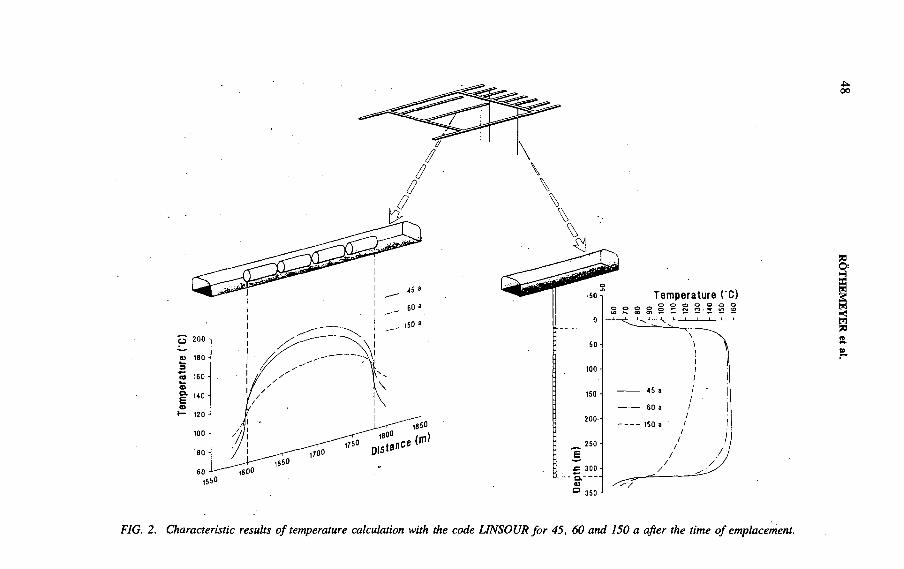
Tem
pera
ture
( C
)
00
•50-
0 -
50 -
100 -
150 -
200—
250 -
1550
Temperature СО
FIG. 2. Characteristic results o f temperature calculation with the code LINSOUR fo r 45, 60 and 150 a after the time o f emplacement.
RÖTHEM
EYER et al.

IAEA-SM-326/26 49
Time (a)
FIG. 3. Total dose rate versus time fo r three safety analyses fo r the Gorleben site.
result was the demonstration of the fact that intruding brine did not reach the waste in the backfilled disposal rooms for most sets of input parameters, even for best estimate data. In the case of a conservative assumption for the time of brine intrusion, the brine from the outside of the salt dome contacts the waste and releases of radionuclides could occur. Resulting dose rates for this case are included in Fig. 3.
The latest safety analysis, in 1991, considered various design alternatives for the disposal of heat producing waste arising from the reprocessing of spent fuel and the direct disposal of spent fuel (Systemanalyse Mischkonzept, SAM) [16]. This included, among other things, the storage of thin wàlled high level waste containers in boreholes and the storage of thick walled spent fuel containers in drifts. For all design alternatives no brine from the outside of the salt dome came into contact with the wastes when best estimate data were used in deterministic assessments and when heat producing medium level wastes were stored together with the high level wastes. Results from probabilistic assessments indicated that uncertainties in calculated dose rates resulting from variabilities of input data are higher than differences from design alternatives. Hence, these analyses provide no reasons in favour of one of the design alternatives at present. For comparison with the other safety studies, Fig. 3 shows results for a conservative case of common borehole and drift storage, where elevated values were used for the volume of limited brine inclusions.
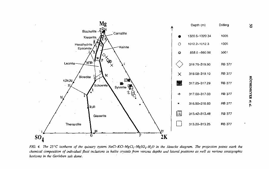
Mgt
о
©
X
+
□
Depth (m)
1320.5-1320.34
1012.2-1012.3
858.6 -860.96
319.75-319.90
319.08-319.10
317.25-317.29
317.00-317.03
316.90-316.93
313.42-313.48
313.20-313.25
Drilling
1005
1005
5001
RB 377
RB 377
RB 377
RB 377
RB 377
RB 377
RB 377
О
FIG. 4. The 25 ° C isotherm o f the quinary system NaCl-KCl-M gCl2-M g S 0 4-H 20 in the Jänecke diagram. The projection points mark the chemical composition o f individual flu id inclusions in halite crystals from various depths and lateral positions as, well as various stratigraphie horizons in the Gorleben salt dome.
RÖTHEMEYER
et al.

IAEA-SM-326/26 51
All current safety analyses demonstrate the suitability of salt formations for the safe disposal of radioactive waste and indicate the feasibility o f the site under consideration. Maximum dose rates of all analyses are below, and later analyses even well below, the German licensing criterion of 0.3 mSv/a. Disposal concepts which partly include thé direct disposal o f spent fuël do not affect the long term safety of the repository, as is indicated by the results o f the latest safety analysis. Radionuclides of major importance are mobile fission products, such as 99Tc, 129I and 135Cs, followed by the less mobile actinides, such as 237Np and the uranium isotopes. All safety analyses up to now have helped to direct site investigation as well as research and development work. Safety analysis is also a guiding tool for the design and optimization of an underground repository.
3.5. Fluid inclusions and long term safety
Variable ¿mounts of solution (ranging from millilitres to several thousand cubic metres) can be trapped during the crystallization o f evaporites from concentrated sea water and during the recrystallization of salt rocks (e.g. solution metamorphism). These solutions are stored in fractures and caverns, and as fluid inclusions (ranging in size from micrometres to several hundred micrometres). In addition to these saline solutions, gases and fluid hydrocarbons are also trapped in evaporite rocks.
In the following, initial results o f recent geochemical research on fluid inclusions for assessing the long tèrm safety of underground repositories in salt domes are presented.
The fluid inclusions analysed were found in halite crystals from various stratigraphie and lateral positions in the Gorleben salt dome. The samples were taken from rock salt located at cracks in shaft preparatory drilling 5001 in the centre of the salt dome (Leine rock salt, 859-861 m depth; 600 m under the salt wash surface), from rock salt in deep drilling 1005 (Leine rock salt, 1012 and 1320 m depth; 700 and 1 0 0 0 m under the salt wash surface) and from the rock salt to sylvinite transition zone of the solution-metamorphosed Staßfurt potash seam in drilling 377 (shaft 1 ; 313 and 319 m depth; 56-63 m under the salt wash surface).
3.5.1. Results and conclusions
There are significant differences in the fluid composition o f the inclusions, depending on lateral position, depth and stratigraphie horizon within the Gorleben salt dome (Fig. 4). The chemical compositions of the fluid inclusions in rock salt from depths between 860 and 1320 m are marked by high concentrations of MgCl2, which lie on the crystallization path between the equilibrium solutions of points R and Z in the 25°C isotherm of the Jänecke diagram. In addition to MgCl2, fluid inclusions from great depth also contained CaCl2 and lacked M gS04.
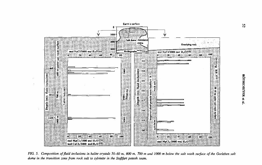
Earth's surface ^
FIG. 5. Composition o f fluid inclusions in halite crystals 50-60 m, 600 m, 700 m and 1000 m below the salt wash surface o f the Gorleben salt dome in the transition zone from rock salt to sylvinite in the Staßfurt potash seam.
Drilling
RB Л77
J# m
undl,r „
ash sllrfai4.

IAEA-SM-326/26 53
Geochemical equilibrium calculations and mineral reactions for the primary components and bromide contents of the solutions clearly show that these fluid inclusions are residual solutions of concentrated, chemically altered sea water of the former Zechstein basin. For the past 250 Ma these solutions have not been chemically altered by other solutions. This means that the chemical composition of these portions of the rock salt beds at 800-1000 m (planned depth of repository) has not been altered by aqueous solutions (e.g. formation water) despite their mechanical deformation during the salt dome formation. On the basis o f natural analogy, such geochemical findings can be used as safety indicators for the site specific assessment o f the long term safety of an underground repository.
This is not the case for fluid inclusions in salt minerals found only 50-60 m below the present salt wash surface. As seen in Fig. 4, the solutions are in the sylvinite field in the 25°C isotherm of the Jänecke diagram. The solutions contain significantly less MgCl2 and more NaCl and KC1 than the solutions from deeper parts of the salt dome.
Figure 5 clearly shows how the MgCl2 content of the solutions in the fluid inclusions increases with decreasing NaCl content and with greater depth below the salt wash surface. This means that the quantitative analysis of fluid inclusion composition can provide clear evidence regarding the depth to which the processes of subrosion were active and regarding the boundaries of zones of chemically altered rock salts. Hence, such analysis is obviously of great importance for assessing the long term safety of underground repositories.
3.6. Suitability of Gorleben site
The evaluation of the results from
— The site investigations from above ground,— Long term safety analysis,— Fluid inclusions as site specific natural analogues
gives evidence of the potential suitability of the Gorleben site to host a repository for high level and alpha bearing wastes and spent fuel. A final judgement, however, has to be based mainly on the results from the underground investigations.
REFERENCES
[1 ] C L O S S , K .D . , E N G E L M A N N , H . J . , S P IL K E R , H . , W I L L A X , H .O . , IA E A -
S M -3 2 6 /3 3 , th e s e P r o c e e d in g s .
[2 ] F in a l d is p o s a l in th e K o n ra d r e p o s i to r y , K e rn te c h n ik 5 1 2 (1 9 8 7 ) 8 1 - 1 1 3 .
[3 ] R Ö T H E M E Y E R , H . ( E d .) , E n d la g e ru n g r a d io a k t iv e r A b fa l le — W e g w e is e r
v e ra n tw o r tu n g s b e w u ß te r E n ts o rg u n g in d e r I n d u s t r ie g e s e l l s c h a f t , V C H , W e in h e im a n d
N e w Y o r k (1 9 9 1 ) .
54 RÖTHEMEYER et al.
[4] B E R G , H . P . , B R E N N E C K E , P . , G M A L , В . , I A E A - S M - 3 2 6 /1 7 , th e s e P r o c e e d in g s .
[5 ] B O R N E M A N N , О . , Z u r G e o lo g ie d e s S a lz s to c k s G o r le b e n n a c h d e n B o h re rg e b n is s e n ,
m i t e in e m B e i tr a g v o n R . F is c h b e c k , B fS - S c h r if te n 4 /9 1 , B u n d e s a m t f ü r S t r a h le n
s c h u tz , S a lz g i t te r (1 9 9 2 ) .
[6] G E R L I N G , P . , B E E R , N . , B O R N E M A N N , O . , G a s fö r m ig e K o h le n w a s s e r s to f f e in
E v a p o r i te n d e s d e u ts c h e n Z e c h s te in s , K a l i .S te in s a lz 1 0 - 1 1 (1 9 9 1 ) 3 7 6 - 3 8 3 .
[7 ] B U N D E S A M T F Ü R S T R A H L E N S C H U T Z , F o r ts c h r e ib u n g d e s z u s a m m e n fa s s e n d e n
Z w is c h e n b e r ic h te s ü b e r b is h e r ig e E r g e b n is s e d e r S ta n d o r tu n te r s u c h u n g G o r le b e n v o m
M a i 1 9 8 3 , B fS , S a lz g i t te r (1 9 9 0 ) .
[8] Z I R N G A S T , M . , D ie E n tw ic k lu n g s g e s c h ic h te d e s S a lz s to c k s G o r le b e n — E r g e b n is
e in e r s t ru k tu rg e o lo g is c h e n B e a rb e i tu n g , G e o l . J a h r b . , R e ih e А 1 3 2 (1 9 9 1 ) 3 - 3 1 .
[9 ] O D I N , G S . , T h e p h a n e r o z o ic t im e s c a le r e v is i te d , E p is o d e s 3 (1 9 8 2 ) 3 - 9 .
[1 0 ] B O R N E M A N N , О . , F I S C H B E C K , R . , A b la u g u n g u n d H u tg e s te in s b i ld u n g a m S a lz
s to c k G o r le b e n , Z . D ts c h . G e o l . G e s . 1 3 7 (1 9 8 6 ) 7 1 - 8 3 .
[1 1 ] J A R I T Z , W . , B O R N E M A N N , O . , G I E S E L , W . , V I E R H U F F , H . , “ G e o s c ie n t i f ic
in v e s t ig a t io n o f th e G o r le b e n s i t e ” , S i t in g , D e s ig n a n d C o n s t r u c t io n o f U n d e r g r o u n d
R e p o s i to r ie s f o r R a d io a c t iv e W a s te s (P ro c . S y m p . H a n o v e r , 1 9 8 6 ) , IA E A , V ie n n a
(1 9 8 6 ) 3 7 1 - 3 8 4 .
[1 2 ] R Ö T H E M E Y E R , H . , “ S ite in v e s t ig a t io n s a n d c o n c e p tu a l d e s ig n f o r th e r e p o s i to r y in
th e n u c le a r ‘E n t s o r g u n g s z e n t r u m ’ o f th e F e d e r a l R e p u b l ic o f G e r m a n y ” , U n d e rg ro u n d
D is p o s a l o f R a d io a c t iv e W a s te s (P ro c . S y m p . O ta n ie m i , 1 9 7 9 ), V o l . 1 , I A E A , V ie n n a
(1 9 8 0 ) 2 9 7 - 3 1 0 .
[1 3 ] B R Ü C H E R , H . , B A R N E R T , E . , K R O T H , K . , N I E P H A U S , D . , I A E A - S M - 3 2 6 /1 3 P ,
th e s e P r o c e e d in g s .
[1 4 ] “ D e v e lo p m e n t o f a s a fe ty a s s e s s m e n t m e th o d o lo g y f o r th e g e o lo g ic a l r e p o s i to ry fo r
ra d io a c t iv e w a s te in a s a lt d o m e ” , P r o je k t S ic h e rh e i ts s tu d ie n E n ts o r g u n g (P S E ) : S u m
m a r iz e d F in a l R e p o r t , H a h n - M e i tn e r I n s t . , B e r l in (1 9 8 5 ) C h . 4 .
[1 5 ] S T O R C K , R . , A S C H E N B A C H , J . , H I R S E K O R N , R . P . , N I E S , A . , S T E L T E , N . ,
P e r f o r m a n c e A s s e s s m e n t o f G e o lo g ic a l I s o la t io n S y s te m s f o r R a d io a c t iv e W a s te D is
p o s a l in S a l t F o r m a t io n s , E U R 1 1 7 7 8 E N , G S F - B e r . 2 3 /8 8 , C E C , L u x e m b o u r g , a n d
G e s e l l s c h a f t f ü r S tr a h le n - u n d U m w e l t fo r s c h u n g m b H M ü n c h e n (1 9 8 8 ) .
[1 6 ] B U H M A N N , D . , N IE S , A . , S T O R C H , R . , A n a ly s e d e r L a n g z e i t s ic h e r h e i t v o n
E n d la g e rk o n z e p te n f ü r w ä r m e e r z e u g e n d e r a d io a k t iv e A b fä l le , G S F - B e r . 2 7 /9 2 ,
G S F - F o r s c h u n g s z e n t r u m f ü r U m w e lt u n d G e s u n d h e i t G m b H , B ra u n s c h w e ig (1 9 9 1 ) .
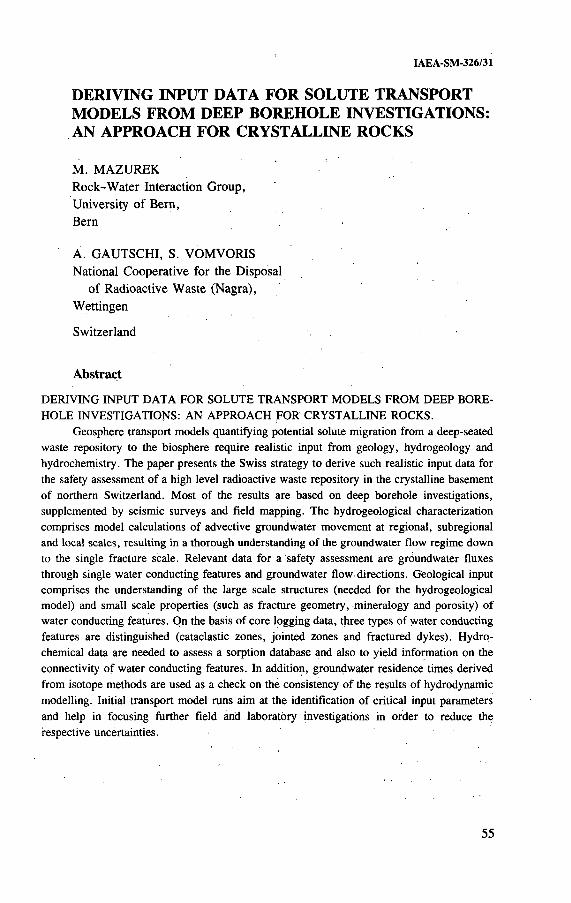
IAEA-SM-326/31
DERIVING INPUT DATA FOR SOLUTE TRANSPORT MODELS FROM DEEP BOREHOLE INVESTIGATIONS: AN APPROACH FOR CRYSTALLINE ROCKS
M. MAZUREK Rock-W ater Interaction Group,University o f Bern,Bern
A. GAUTSCHI, S. VOM VORIS National Cooperative for the Disposal
of Radioactive Waste (Nagra),Wettingen
Switzerland
Abstract
D E R I V I N G I N P U T D A T A F O R S O L U T E T R A N S P O R T M O D E L S F R O M D E E P B O R E
H O L E IN V E S T IG A T IO N S : A N A P P R O A C H F O R C R Y S T A L L I N E R O C K S .
G e o s p h e re t r a n s p o r t m o d e ls q u a n t i fy in g p o te n t ia l s o lu te m ig r a t io n f r o m a d e e p - s e a te d
w a s te r e p o s i to ry to th e b io s p h e r e r e q u i r e r e a l is t ic in p u t f r o m g e o lo g y , h y d ro g e o lo g y a n d
h y d r o c h e m is t r y . T h e p a p e r p r e s e n ts th e S w is s s t r a te g y to d e r iv e s u c h r e a l i s t ic in p u t d a ta fo r
th e s a fe ty a s s e s s m e n t o f a h ig h le v e l r a d io a c t iv e w a s te r e p o s i to r y in th e c ry s ta l l in e b a s e m e n t
o f n o r th e r n S w itz e r la n d . M o s t o f th e re s u l ts a r e b a s e d o n d e e p b o r e h o le in v e s t ig a t io n s ,
s u p p le m e n te d b y s e is m ic s u rv e y s a n d f ie ld m a p p in g . T h e h y d ro g e o lo g ic a l c h a r a c te r iz a t io n
c o m p r is e s m o d e l c a lc u la t io n s o f a d v e c t iv e g r o u n d w a te r m o v e m e n t a t r e g io n a l , s u b re g io n a l
a n d lo c a l s c a le s , r e s u l t in g in a th o r o u g h u n d e r s ta n d in g o f th e g r o u n d w a te r f lo w r e g im e d o w n
to th e s in g le f r a c tu r e s c a le . R e le v a n t d a ta f o r a s a f e ty a s s e s s m e n t a r e g r o u n d w a te r f lu x e s
th ro u g h s in g le w a te r c o n d u c t in g f e a tu r e s a n d g r o u n d w a te r f lo w d i r e c t io n s . G e o lo g ic a l in p u t
c o m p r is e s th e u n d e r s ta n d in g o f th e l a r g e s c a le s t ru c tu re s (n e e d e d f o r th e h y d ro g e o lo g ic a l
m o d e l) a n d s m a l l s c a le p r o p e r t i e s ( s u c h a s f r a c tu r e g e o m e try , m in e r a lo g y a n d p o ro s i ty ) o f
w a te r c o n d u c t in g f e a tu re s . O n th e b a s is o f c o r e lo g g in g d a ta , th r e e ty p e s o f w a te r c o n d u c t in g
fe a tu re s a r e d is t in g u is h e d (c a ta c la s t ic z o n e s , jo in te d z o n e s a n d f r a c tu r e d d y k e s ) . H y d r o
c h e m ic a l d a ta a r e n e e d e d to a s s e s s a s o rp t io n d a ta b a s e a n d a ls o to y ie ld in f o r m a t io n o n th e
c o n n e c t iv i ty o f w a te r c o n d u c t in g f e a tu re s . In a d d i t io n , g r o u n d w a te r r e s id e n c e t im e s d e r iv e d
f r o m is o to p e m e th o d s a r e u s e d a s a c h e c k o n th e c o n s is te n c y o f th e re s u l t s o f h y d ro d y n a m ic
m o d e l l in g . In i t ia l t r a n s p o r t m o d e l ru n s a im a t th e id e n t if ic a t io n o f c r i t ic a l in p u t p a ra m e te r s
a n d h e lp in fo c u s in g f u r th e r f ie ld a rid la b o r a to r y in v e s t ig a t io n s in o r d e r to r e d u c e th e
re s p e c t iv e u n c e r ta in t ie s .
55
56 MAZUREK et al.
1. INTRODUCTION
1.1. Aims of paper
In most geological repository concepts for radioactive waste, the most likely route to the biosphere for repository derived radionuclides (and solutes in general) is via groundwater transport. Predictive modelling of solute transport through the geosphere is based on a large number of geological, hydrological and hydrochemical input data derived from field and laboratory studies. The present paper describes the techniques and procedures applied to derive such a database for the crystalline basement of northern Switzerland, which is a potential site of a high level radioactive waste repository. Whereas the data themselves are site specific, the methodology could be applicable to most other waste disposal programmes.
Geosphere transport models are part of the repository far field performance assessment. Safety relevant aspects of the near field (i.e. the engineered barriers isolating the waste) and an assessment of the geosphere are discussed in a companion paper [1]. The full safety assessment comprises a model chain [2] accounting for radionuclide migration processes in the near field and the far field and, after release into the biosphere, transport into the food chain and dose calculations. The final result o f a safety assessment is the quantification of maximum radiation doses to which man might be exposed in the far future.
1.2. Overview of available field data
The crystalline basement of northern Switzerland is covered by sedimentary rocks of several hundred metres’ thickness. Therefore, most field data have been collected from six deep boreholes, which yielded almost 6 km of core profile length in the crystalline basement to a maximum depth of 2500 m below the surface. All boreholes have been subjected to extensive hydraulic testing (hydraulic packer tests, fluid logging and long term monitoring), and numerous groundwater samples have been taken for hydrochemical studies. Geological, geochemical and petrophysical data have been derived from the cores, and standard geophysical logging has been performed in all boreholes.
Borehole studies performed by the National Cooperative for the Disposal of Radioactive Waste (Nagra) provided detailed geological characterization of small scale water conducting features. Information on regional geological structure and its effect on groundwater fluxes, gradients and flow vectors had to be supplemented by data from other boreholes, seismic surveys and field mapping in the nearby Black Forest area, where the basement rocks crop out or are accessed by mines.
IAEA-SM-326/31 57
1.3. Need to simplify
Small scale geological, hydrological and hydrochemical features parameters are highly variable in nature. However, transport models must rely on simple concepts (e.g. water flow through a channel with constant water chemistry, hydraulic gradient, wall rock mineralogy and porosity across the whole flow path) and the natural complexity needs to be reduced to simple patterns (e.g. flow path geometry on all scales). Some degree of averaging is also necessary (e.g. hydraulic gradients, transmissivities and mineralogy). Overall, the attempt has been made to provide reference data for the transport models that are simple enough to conform with the required input, but still adequately represent the geosphere.
2. HYDROGEOLOGICAL CHARACTERIZATION
2.1. Different scales
The first step of hydrogeological characterization is the development o f a hydrogeological conceptual model that integrates input from many disciplines, such as geology, geophysics, geochemistry and hydrogeology. The conceptual model (shown in Fig. 1 for the region of interest) must be compatible with field observations and field test results that cover a wide range of scales, ranging from surface mappings and geophysical surveys to detailed tests in boreholes and cores. The model represents the result of an iterative process, during which alternative hypotheses are constantly tested and revised until they no longer contradict any of the available data. The hydrogeological conceptual model must cover a wide range of scales from regional to microscopic because geosphere transport calculations also rely on small scale properties of the rock.
The strategy for hydrodynamic modelling is to begin with a regional scale model and place the model boundaries along features where boundary conditions can be derived (e.g. water divides and no-flow boundaries). Results o f the large scale model are then used to define boundary conditions for progressively smaller scales of model areas. Depending on the scale of interest, different features in the conceptual model are included explicitly in the model runs. The procedures, with an accompanying list of references, are documented in Refs [3] and [4].
2.2. Choice of appropriate models as a function of scale
The hydrogeological conceptual model shown in Fig. 1 includes the large scale structural features (faults) in the region of interest as distinct elements. The model also distinguishes two layers in the crystalline basement with different geological and hydraulic properties, as observed directly from the Nagra deep boreholes. For a

Conceptual model Scales & numerical models Numericalrepresentations
Top of crystalline basement
Equivalentporousmedium
Hybrid (faults and equivalent
porous medium)
Fracturenetwork
<_л00
FIG. 1. Hydrogeological conceptual model o f the crystalline basement, represented in schematic vertical profiles.
MA
ZU
RE
K
et al.
IAEA-SM-326/31 59
first, regional scale modelling exercise, all structural features are modelled as an equivalent porous medium with appropriate hydraulic properties. At a subregional scale (area of the order of 50 km2), the large scale faults shown in Fig. 1 are modelled explicitly as three- or two-dimensional elements, whereas blocks of intervening rock that contain permeable features of smaller extent are modelled as equivalent porous media. This is a hybrid model, comprising discrete features embedded in a porous matrix. Finally, at a smaller scale (area of about 0.5 km2), such as in the vicinity of waste emplacement caverns, water conducting features similar to the ones observed in the boreholes are predominant and are modelled explicitly in a fracture network model. At this scale, it is justified to ignore the transmissivity of the crystalline matrix between water conducting features (i.e. to assume that no advection occurs in the matrix, while diffusive transport is possible).
2.3. Comparison of results with Field data
The results o f the regional scale groundwater flow model were compared with:(i) head observations made in multi-packer, long term monitoring systems installed in the deep boreholes; and (ii) groundwater residence times estimated from hydrochemical analyses of samples obtained during testing in the deep boreholes. The groundwater circulation patterns simulated by the model [3] are consistent with these observations, i.e. water infiltrates in the southern Black Forest and slowly — on the order of thousands to tens of thousands of years — migrates towards the River Rhine. The results also indicate the possible existence of a groundwater divide in the model area, which was not postulated in the original hydrogeological conceptual model — a good example of the iterative procedure mentioned previously.
2.4. Input for solute transport models
The regional scale groundwater flow model provided the basis for obtaining the boundary conditions at smaller scales. In particular, the model assisted in determining the overall groundwater flux expected in different regions, as well as its general direction. At the site scale, utilizing fracture network models, one can distribute the flux derived from the larger scale models to the ‘transmissive elements’ (water conducting features, e.g. small scale faults and joints) that may be encountered in the vicinity of emplacement caverns. Results indicate that the average spacing of these elements in a tunnel is expected to be about 25 m (which is consistent with geological evidence). The mean transmissivity of these elements is6 X 10 ' 10 m 2/s [3]. Individual transmissive elements are expected to transport between 5 x 10~ 12 and 2 X 10“9 m 3/s of water (average: 2 x 10~ 10 m 3/s) according to the hydrodynamic model calculations; this flux is one of the required inputs for the transport models.
60 MAZUREK et al.
3. SMALL SCALE GEOLOGICAL CHARACTERIZATION OFGROUNDWATER FLOW PATHS
3.1. Identification of water conducting features in boreholes
The first stage of flow path characterization is identification of zones in which advective flow occurs. Exact locations of water conducting features (‘inflow points’) in boreholes were identified using fluid logging methods [5]. These methods comprise measurements of electrical conductivity, temperature and vertical flow in the water column in the borehole following an artificial head change (pumping or artesian outflow). Prior to the fluid logging, drilling fluid is replaced by deionized water or a brine to ensure a large electrical conductivity contrast to the formation water. Consequently, inflow points appear as peaks or discontinuities in the conductivity logs. Using these methods, a total of 136 discrete inflow points were identified in the crystalline sections of the boreholes, corresponding to water conducting features with transmissivities exceeding the detection limit o f about 10“9 m 2 /s. The average frequency of inflow points was therefore one every 43 m down-hole. Using appropriate statistical tools, this frequency can be recalculated in terms of planar permeable structures of given length.
On the basis of core logging, the frequency of potentially water conducting features in boreholes could be roughly estimated. This frequency value exceeds that of water conducting features actually identified by fluid logging tools by at least one order of magnitude, indicating some degree of channelling/heterogeneity and the widespread presence of fractures that are disconnected from the present day flow system (a not unusual feature, cf. Ref. [6 ]).
3.2. Geological characterization of water conducting features
Owing to their precise identification in fluid logs, most o f the inflow points could be correlated with permeable structures encountered in the core material. These core sections have been investigated in detail in order to define the geometry and mineralogy of the water conducting fractures, the wall rock porosities accessible to diffusing species and various genetic aspects.
This systematic investigation has shown that inflow points can always be correlated with core sections in which the rock suffered significant brittle deformation that postdates the emplacement o f the primary rock types. In most inflow points, a complex, interconnected system o f several fracture planes has been identified rather than a single fracture, reflecting the long tectonic history of the crystalline basement. In general, the intensity of brittle deformation (and therefore permeability) does not depend on primary rock type (mainly granites and various gneisses). The only important exceptions are aplite and pegmatite dykes (sheet-like magmatic bodies

IAEA-SM-326/31 61
cross-cutting both granites and gneisses), where deformation is concentrated (this is discussed below).
Phases of brittle deformation are invariably accompanied by significant hydro- thermal alteration of the wall rocks caused by fluid circulation in the brittle structures. Three major tectonohydrothermal phases can be distinguished:
(a) High temperature phase (300-400°C): deformation associated with hydro- thermal alteration to greenschist facies parageneses;
(b) Low temperature phase (<100°C ): deformation associated with argillic alteration;
(c) Formation of vugs/channels by groundwater leaching of fracture material (n o . deformation).
Both the high and low temperature phases comprise cataclastic shear deformation as well as purely tensile jointing. The attribution of brittle structures to the high or low temperature phase is based on the contrasting mineralogies of fracture infills and altered wall rock rims, while no geometrical distinction could be made between the phases on the basis of bore core data. In a few cases, systematic variation of structure orientations between the phases could be identified, but they do not result in a consistent regional pattern. Hydrothermal alteration may penetrate up to several metres into the wall rock. Fractures are quite often healed by hydrothermal infill or cataclastic matrices. Younger events quite often reactivate pre-existing structures, resulting in complex interference patterns. Vugs/channels, for example, are only formed in pre-existing fracture coatings and cataclastic matrices.
In spite of the complex geological relationships, a systematic pattern of water conducting features could be derived on a regional scale, on the basis o f the above observations. All advective water flow in the basement occurs in three types of water conducting features:
(1) Cataclastic zones(2) Jointed zones(3) Fractured aplite and pegmatite dykes.
Geometrical, hydrological and hydrochemical information shows that the three types are all interconnected and form a three dimensional network of flow paths.
In this paper, the discussion is restricted to the fractured aplite and pegmatite dykes in order to further illustrate the procedure. Previous calculations [2] have shown that fractured dykes probably are the most critical type of water conducting features in terms of contaminant transport:
— Aplite/pegmatite dykes represent more or less planar mechanical discontinuities in the rock body and are fractured preferentially because of their highly brittle nature.

counlr Y rockgranite gneiss
MINERALOGYquartzplagioriaseK-feldsparbiotit«muscovitesiflimanite
30 vol.* 30 30 8 2
25 vol.« 30 10 15 15 5
POROSITY 0.25 vd.% lvd.%
fracture in fill
MINERALOGYquartzfeldsparsmuscoviteilliteill/sm ML kaolinite caidte
55 vol.% 5 '51.51130
POROSITY
2 vol.% •
w e a k ly a l t e r e d d y k e
MINER*ALOGY
quartz 32 vol.%plagioclase 26K-feldspar 31biotite 0.5muscovite 5chlorite 2illite 1.5ill/sm ML 1kaolinite 1
POROSITY
u n a l t e r e d d y k e
MINERALOGY
quartzptagioclaseK-feldsparbiotitemuscovite
32 vol.% 32 31
3 2
POROSITY
0.5 vol.%
FIG. 2. Illustration o f a fractured aplite dyke in reality and a model simplification. Photographs are from the Leuggern granite, northern Switzerland. (ill/sm ML: illite/smectite mixed-layer phase.)
IAEA-SM-326/31 63
— Owing to their mineralogy (dominated by quartz and Na-K-feldspars), hydrothermal alteration affects the dykes to a lesser degree than any other rock type. Wall rock alteration is less well developed and limits the extent of interconnected porosity available for matrix diffusion as well as the quantity of alteration products that might seal open fractures. Highly sorbing minerals such as micas and clays are less common than in other rock types.
3.3. Conceptual model for fractured aplite/pegmatite dykes
The thickness of aplite/pegmatite dykes ranges from a few centimetres to several metres. There is a strong positive correlation between thickness and hydraulic significance: more than 50% of all dykes thicker than 1.5 m contain water inflow points identified in fluid logs, whereas those thinner than 0.5 m are mostly ‘dry’. The lateral extensions of the dykes cannot be determined from borehole information, but some dykes in outcropping parts of the basement (Black Forest) are known to extend over at least 1 km (but probably are displaced by faults and therefore discontinuous).
Figure 2 illustrates the small scale structure of an actual fractured dyke and a model simplification. On the basis of pétrographie evidence, , four domains with different properties can be distinguished:
(1) Unaltered country rock (granite or gneiss) hosting the dyke(2) Unaltered aplite/pegmatite dyke(3) Weakly altered aplite/pegmatite dyke (alteration rims adjacent to fractures)(4) Fracture infill and vugs/channels.
Figure 2 shows the ranges of the geometrical parameters chosen for all domainsas well as the reference mineralogical compositions and open (i.e. diffusion-accessible) porosities; which were derived in an averaging process.
Fracturing of the dykes is compléx in nature and results in an interconnected system of several fracture planes. Each fracture is only partially filled by a quartz- calcite rich infill, while large parts remain open to water flow (vugs/channels in Fig. 2). Alteration rims in the wall rock adjacent to fracture planes invariably are present but generally are thin and contain only small amounts of alteration products. Diffusion-accessible porosity of the altered rims is about 1 vol.% , which is at least twice as much as in the unaltered dyke.
3.4. Significance of matrix diffusion
Matrix diffusion, i.e. the diffusive transport of solute contaminants from the open fractures into the interconnected porosity of the wall rock, is a major retardation process for contaminant transport through the geosphere [7, 8 ]. Matrix diffusion and sorption in the wall rock can only operate if the wall rock has an interconnected
64 MAZUREK et al.
porosity which is not isolated from the open fractures by sealing hydrothermal coatings. Numerous pétrographie (impregnated thin sections) and porosimetric (Hg intrusion) data have been collected, indicating that some limited wall rock porosity is always present and not disconnected from the open fractures. However, analytical artefacts cannot be fully excluded because samples may have suffered mechanical damage during drilling, sawing and sample preparation. The only firm indications demonstrating groundwater-wall rock interaction (and therefore the presence of matrix diffusion) are the results o f investigations o f natural decay series disequilibria (U and Th chains) in wall rock samples adjacent to water bearing fractures. Results of analyses performed on fractured aplite/pegmatite dykes indicate that recent water-rock interactions have taken place (and probably still do today). While disequilibria in 234U /238U activities are restricted to fracture coatings and about7 mm of adjacent wall rock, disequilibria in 230T h/234U extend at least 40 mm into the wall rock and indicate 234U leaching from the rock during the last 400 000 a. Natural decay series measurements therefore corroborate pétrographie and porosimetric evidence and suggest that aplites and pegmatites have at least a limited diffusion-accessible wall rock porosity (see also Ref. [9]).
4. INPUT FROM HYDROCHEMISTRY
A sorption database comprising distribution coefficients and isotherms for all contaminants relevant to repository safety is an essential prerequisite for solute transport modelling [10]. Sorption properties of contaminants depend not only on the mineralogy of the fracture surfaces and of the wall rocks but also on the groundwater chemistry, particularly Eh, pH and ionic strength. Therefore, a ‘reference groundwater chemistry’ had to be derived in addition to the ‘reference mineralogy’ given in Fig. 2, in order to define the geochemical water-rock system. The reference groundwater chemistry is defined as the best estimate of in situ hydrochemical conditions in the undisturbed aquifer.
Groundwater sampling inevitably gives rise to problems associated with contamination by drilling fluid, air or sampling/drilling tool corrosion. Therefore, the hydrochemical raw data had to be subjected to thorough consistency checks, corrections and geochemical modelling before a reference groundwater chemistry could be derived. This procedure is described for groundwaters from the crystalline basement of northern Switzerland in Refs [11, 12]. Two types of ‘reference groundwaters’, a reducing, low mineralized N a-S 0 4 -(C 1)-(H C 0 3 ) type and a reducing, highly mineralized N a-(C a)-C l-(S04) type, have been derived from numerous chemical analyses of groundwater samples from the deep boreholes.
In addition, hydrochemical data (especially the isotopic compositions of dissolved solids and gases) can be used as consistency checks on hydrodynamic models. Estimates of groundwater residence times based on isotopic methods and constraints
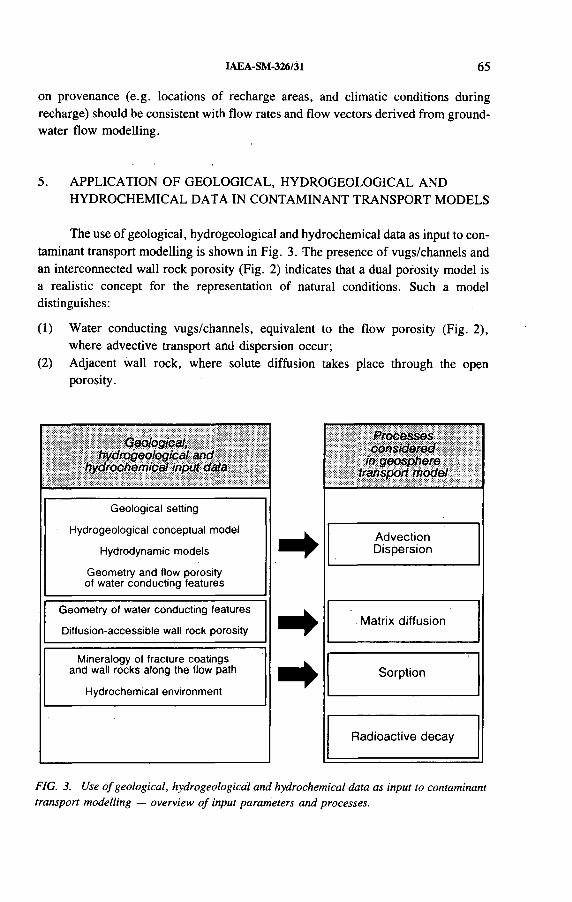
IAEA-SM-326/31 65
on provenance (e.g. locations of recharge areas, and climatic conditions during recharge) should be consistent with flow rates and flow vectors derived from groundwater flow modelling.
5. APPLICATION OF GEOLOGICAL, HYDROGEOLOGICAL ANDHYDROCHEMICAL DATA IN CONTAMINANT TRANSPORT MODELS
The use of geological, hydrogeological and hydrochemical data as input to contaminant transport modelling is shown in Fig. 3. The presence of vugs/channels and an interconnected wall rock porosity (Fig. 2) indicates that a dual porosity model is a realistic concept for the representation of natural conditions. Such a model distinguishes:
(1) Water conducting vugs/channels, equivalent to the flow porosity (Fig. 2), where advective transport and dispersion occur;
(2) Adjacent wall rock, where solute diffusion takes place through the open porosity.
Geological, hydrogeological and
hydrochemical input data
Processes considered
in geosphere transport model
t tt
Geological setting
Hydrogeological conceptual model
Hydrodynamic models
Geometry and flow porosity of water conducting features
AdvectionDispersion
Geometry of water conducting features
Diffusion-accessible wall rock porosityMatrix diffusion
Mineralogy of fracture coatings and wall rocks along the flow path
Hydrochemical environmentSorption
Radioactive decay
FIG. 3. Use o f geological, hydrogeological and hydrochemical data as input to contaminant transport modelling — overview o f input parameters and processes.

6 6 MAZUREK et al.
Sorption of migrating species can occur on the surfaces of the vugs/channels as well as in the open wall rock pores. On the basis of the mineralogical compositions given in Fig. 2 and taking into account groundwater chemistry and redox state, distribution coefficients for sorption of solute contaminants can be assessed for all rock domains. Hydrological input data to the transport model comprise Darcy velocities of groundwater through the transmissive elements (water conducting features) and geometrical characteristics of the groundwater field (e.g. length of the flow path in the geosphere). Initial model runs aim at the identification of critical parameters and help to focus further field and laboratory.investigations in order to reduce uncertainties.
An application of the geosphere data set derived in this paper is demonstrated in the companion paper [1], where the entire model chain comprising processes in the near field (engineered barriers), in the far field (geosphere) and in the biosphere is presented.
ACKNOWLEDGEMENTS
We would like to thank the following colleagues for constructive discussions and reviews of the manuscript: W .R. Alexander, T. Peters, P.A. Smith, M. Thury, W .E. Wilson and P. Zuidema.
REFERENCES
[1 ] N I E M E Y E R , M .J . , H U G I , M . , S M IT H , P . , Z U I D E M A , P . , IA E A - S M - 3 2 6 /3 2 , th e s e
P r o c e e d in g s .
[2 ] N A T I O N A L E G E N O S S E N S C H A F T F Ü R D I E L A G E R U N G R A D I O A K T IV E R
A B F Ä L L E , P r o je c t G e w ä h r 1 9 8 5 — N u c le a r W a s te M a n a g e m e n t in S w itz e r la n d :
F e a s ib i l i ty S tu d ie s a n d S a fe ty A n a ly s e s , P r o je c t G e w ä h r R e p . N G B 8 5 -0 9 , N a g ra ,
B a d e n , S w itz e r la n d (1 9 8 5 ) .
[3 ] V O M V O R IS , S . , V O B O R N Y , O . , W I L S O N , W . , H Ü R L I M A N N , W . , A N D R E W S ,
R .W . , H y d ro d y n a m ic S y n th e s is o f C r y s ta l l in e R o c k s o f N o r th e r n S w itz e r la n d :
S u m m a r y o f R e s u lts R e le v a n t to S a fe ty A n a ly s is , R e f e r e n c e A r e a W e s t , T e c h n ic a l
R e p o r t , N a g r a , W e t t in g e n , S w itz e r la n d ( in p re p a ra t io n ) .
[4 ] T H U R Y , M . , e t a l . , G e o lo g y a n d H y d ro g e o lo g y o f th e C r y s ta l l in e B a s e m e n t o f
N o r th e r n S w itz e r la n d , T e c h . R e p . 9 3 -0 1 , N a g ra , W e t t in g e n , S w i tz e r la n d ( in
p re p a ra t io n ) .
[5 ] N A T I O N A L E G E N O S S E N S C H A F T F Ü R D IE L A G E R U N G R A D I O A K T IV E R
A B F Ä L L E , F lu id L o g g in g , T e c h . R e p . N T B 8 5 -1 0 , N a g ra , B a d e n , S w itz e r la n d
(1 9 8 8 ) .
[6] R A S M U S O N , A . , N E R E T N I E K S , I . , R a d io n u c l id e t r a n s p o r t in fa s t c h a n n e ls in
c ry s ta l l in e ro c k , W a te r R e s o u rc e s R e s . 2 2 (1 9 8 6 ) 1 2 4 7 -1 2 5 6 .
[7 ] N E R E T N I E K S , I . , D if f u s io n in th e r o c k m a tr ix : A n im p o r ta n t f a c to r in r a d io n u c l id e
r e ta rd a t io n ? J . G e o p h y s . R e s . 8 5 (1 9 8 0 ) 4 3 7 9 - 4 3 9 7 .

IAEA-SM-326/31 67
[8] H A D E R M A N N , J . , R O E S E L , F . , R a d io n u c l id e C h a in T r a n s p o r t in I n h o m o g e n e o u s
C r y s ta l l in e R o c k s : L im ite d M a tr ix D if f u s io n a n d E f fe c t iv e S u r fa c e S o r p t io n , T e c h .
R e p . N T B 8 5 -4 0 , N a g r a , B a d e n , S w itz e r la n d (1 9 8 5 ) .
[9 ] A L E X A N D E R , W .R . , M a c K E N Z I E , A .B . , S C O T T , R .D . , M c K I N L E Y , I . G . ,
N a tu r a l A n a lo g u e S tu d ie s in C r y s ta l l in e R o c k : T h e In f lu e n c e o f W a te r - b e a r in g
F r a c tu r e s o n R a d io n u c l id e I m m o b i l iz a t io n in a G ra n i t ic R o c k R e p o s i to r y , T e c h . R e p .
N T B 8 7 -0 8 , N a g r a , B a d e n , S w i tz e r la n d (1 9 9 0 ) .
[1 0 ] S T E N H O U S E , M .J . , C o m p ila t io n a n d R e v ie w o f E x p e r im e n ta l S o r p t io n D a ta w ith
R e c o m m e n d e d K d V a lu e s , T e c h n ic a l R e p o r t , N a g r a , W e t t in g e n , S w itz e r la n d ( in
p r e p a r a t io n ) .
[1 1 ] P E A R S O N , F . J . , L O L C A M A , J . L . , S C H O L T IS , A . , C h e m is t r y o f W a te r s in th e B ö tt-
s te in , W e ia c h , R in ik e n , S c h a f is h e im , K a is te n a n d L e u g g e r n B o re h o le s : A H y d ro -
c h e m ic a l ly C o n s is te n t D a ta S e t , T e c h . R e p . N T B 8 6 -1 9 , N a g r a , B a d e n , S w itz e r la n d
(1 9 8 9 ) .
[1 2 ] P E A R S O N , F . J . , S C H O L T IS , A . , R e f e r e n c e W a te r s f o r th e C r y s ta l l in e B a s e m e n t o f
N o r th e r n S w itz e r la n d , T e c h n ic a l R e p o r t , N a g r a , W e t t in g e n , S w itz e r la n d ( in
p re p a ra t io n ) .

IAEA-SM-326/4
GEOLOGICAL DISPOSAL OF RADIOACTIVE WASTE IN CZECHOSLOVAKIA
L. NACHMILNER, M. VANÈCEK Nuclear Research Institute,Rez
M. LUKAJ Geological Survey,Banská Bystrica
Czechoslovakia
Abstract
G E O L O G I C A L D IS P O S A L O F R A D I O A C T I V E W A S T E IN C Z E C H O S L O V A K I A .
T h e S ta te c o - o r d in a te d p r o g r a m m e o n d e e p g e o lo g ic a l d is p o s a l o f r a d io a c t iv e w a s te w a s
in i t ia te d in 1 9 9 2 b y th e F e d e r a l M in is t r y o f E c o n o m y . T h is fo l lo w s s e v e ra l s tu d ie s p e r fo r m e d
in B o h e m ia a n d S lo v a k ia b y v a r io u s b o d ie s in th e c o u r s e o f th e la s t d e c a d e . T h e p a p e r p re s e n ts
b a s ic in fo r m a t io n a b o u t th e w o r k d o n e s o f a r , s u m m a r iz e s th e m a in re s u l t s a n d in d ic a te s a n
a p p r o p r ia te d i r e c t io n th a t c o i i ld b e ta k e n to w a r d s th e d e v e lo p m e n t o f a d e e p g e o lo g ic a l d i s
p o s a l fa c il i ty .
1. INTRODUCTION
During the last two decades Czechoslovak nuclear utilities have focused on the solution of problems of final disposal of short lived and low level reactor wastes. According to an intergovernmental agreement all spent fuel was to be transported to the USSR and therefore a programme of geological disposal was postponed. Nevertheless, some studies of deep disposal systems were initiated during that time. As a result a good overview o f the methodology of system development as well as of the basic safety approach to evaluation of an underground facility was obtained.
Much of the work was performed without co-ordination between different institutions. To prevent any possible duplication o f effort in the future and to concentrate financial resources on a solution regarding the principal steps of waste management, the Federal Ministry of Economy has recently adopted several vital decisions:
— To elaborate a detailed programme for R&D activities dealing with a geological repository;
— To clarify the relations between waste producers, licensing bodies and repository operators;
69

70 NACHMILNER et al.
— To create a fund that, would cover all back end activities of the nuclear fuel cycle;
— To bridge over the period until an effective R&D system (financially, technically and institutionally) has been created;
— To designate a general co-ordination body responsible , for implementation of the programme (currently the Nuclear Research Institute - WATRAD, Rez).
2. REVIEW OF MAIN PROJECTS
2.1. Well type deep repository (1984-1988)
Purpose: Construction of a repository in granitic rock at the Temelin nuclear power plant site for low and intermediate level reactor wastes with a capacity of 20 000 m 3. It was planned to be in the shape of a well or silo with a diameter of8 m and a depth of 700 m. The wastes would form a pseudomonolith rising to 200 m below'the surface [1]. At the same time, the structure would serve as a pilot plant facility'for development of an HLW repository (underground laboratory).
Completed activities: Drilling of two structural boreholes (200 and 731 m deep)' geophysical survey of a broader region [2 ] and basic safety evaluation of a hypothetical repository [3].
Results and benefits: The project was cancelled owing to the lack of interest of power plant management and to public opposition. Identification of the problem scope, use of site investigation results for power plant construction, and experience with public involvement were beneficial.
2.2. Model repository design (1990-1993)
Purpose: Definition of geological repository systems, their interrelationships and alternatives valid for each system; initiation of co-operation with specialized institutions (personnel training); introduction of a systematic approach to replace the originally uncoordinated attempts to create the facility.
' Completed activities: Proposal for a standard repository system containing a central facility for spent fuel storage [4]; study of waste transport and handling variants [5].
Results and benèfits: Establishment of a co-ordinated procedure for repository development; education of laymen in central organizations; definition of possible variants (elevated or deep facility, subhorizontal or vertical material transport) irrespective. of waste form (spent fuel or HLW); determination of necessary organizational and technical precautions, including their relation to the schedule for the repository; and initiation of relevant work (e.g. near; and far.field effects and safety analyses).
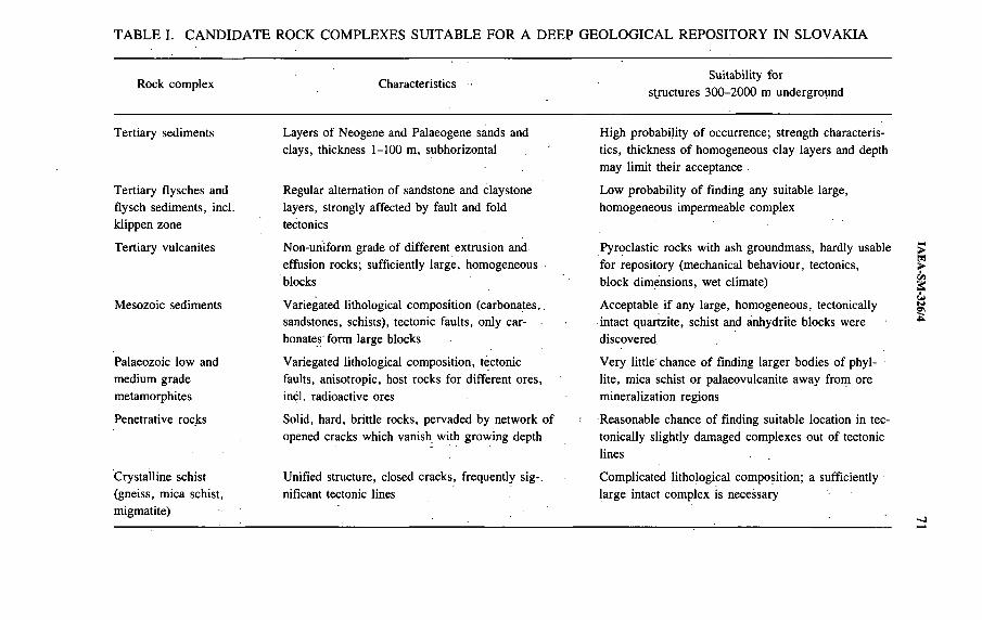
TABLE I. CANDIDATE ROCK COMPLEXES SUITABLE FOR A DEEP GEOLOGICAL REPOSITORY IN SLOVAKIA
R o c k c o m p le x C h a r a c te r is t ic s ■S u ita b il i ty f o r
s t r u c tu r e s 3 0 0 - 2 0 0 0 m u n d e r g r o u n d
T e r t i a r y s e d im e n ts L a y e r s o f N e o g e n e a n d P a la e o g e n e s a n d s a n d H ig h p r o b a b i l i ty o f o c c u r r e n c e ; s t r e n g th c h a r a c te r i s
c la y s , th ic k n e s s 1-100 m , s u b h o r iz o n ta l t ic s , th ic k n e s s o f h o m o g e n e o u s c la y la y e r s a n d d e p th
m a y l im i t th e i r a c c e p ta n c e .
T e r t i a r y f ly s c h e s a n d R e g u la r a l te rn a t io n o f s a n d s to n e a n d c la y s to n e L o w p r o b a b i l i ty o f f in d in g a n y s u i ta b le la rg e ,
f ly s c h s e d im e n ts , in c l . la y e r s , s t ro n g ly a f fe c te d b y f a u l t a n d fo ld h o m o g e n e o u s im p e r m e a b le c o m p le x
k l ip p e n z o n e te c to n ic s
T e r t i a r y v u lc a n i te s N o n -u n if o rm g ra d e o f d i f f e r e n t e x t r u s io n a n d P y r o c la s t ic r o c k s w ith a s h g r o u n d m a s s , h a rd ly u s a b le
e f fu s io n r o c k s ; s u f f ic ie n tly la r g e , h o m o g e n e o u s f o r r e p o s i to r y ( m e c h a n ic a l b e h a v io u r , te c to n ic s ,
b lo c k s b lo c k d im e n s io n s , w e t c l im a te )
M e s o z o ic s e d im e n ts V a r ie g a te d l i th o lo g ic a l c o m p o s i t io n ( c a r b o n a te s , . A c c e p ta b le i f a n y la r g e , h o m o g e n e o u s , te c to n ic a l ly
s a n d s to n e s , s c h is ts ) , te c to n ic f a u l t s , o n ly c a r in ta c t q u a r tz i t e , s c h is t a n d a n h y d r i te b lo c k s w e re
b o n a te s f o r m la r g e b lo c k s d is c o v e r e d
P a la e o z o ic lo w a n d V a r ie g a te d l i th o lo g ic a l c o m p o s i t io n , te c to n ic V e r y l i t t l e c h a n c e o f f in d in g la r g e r b o d ie s o f p h y l-
m e d iu m g r a d e fa u lts , a n is o t ro p ic , h o s t ro c k s f o r d i f f e r e n t o r e s , l i te , m ic a s c h is t o r p a la e o v u lc a n i te a w a y f r o m o r e
m e ta m o rp h i te s in c l . r a d io a c t iv e o re s m in e r a l iz a t io n re g io n s
P e n e t r a t iv e ro c k s S o lid , h a rd , b r i t t le ro c k s , p e r v a d e d b y n e tw o r k o f R e a s o n a b le c h a n c e o f f in d in g s u i ta b le lo c a t io n in te c
o p e n e d c ra c k s w h ic h v a n is h w ith g r o w in g d e p th to n ic a l ly s l ig h t ly d a m a g e d c o m p le x e s o u t o f te c to n ic
l in e s _ -
C r y s ta l l in e s c h is t U n if ie d s t ru c tu re , c lo s e d c r a c k s , f r e q u e n t ly s ig - . C o m p l ic a t e d l i th o lo g ic a l c o m p o s i t io n ; a s u f f ic ie n t ly
( g n e is s , m ic a s c h is t , n if ic a n t te c to n ic lin e s l a r g e in ta c t c o m p le x is n e c e s s a ry
m ig m a ti te )
IAE
A-S
M-326/4
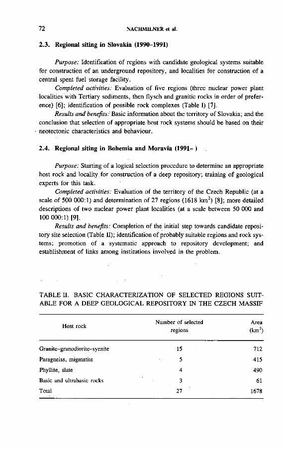
72 NACHMILNER et al.
2.3. Regional siting in Slovakia (1990-1991)
Purpose: Identification of regions with candidate geological systems suitable for construction of an underground repository, and localities for construction of a central spent fuel storage facility.
Completed activities: Evaluation of five regions (three nuclear power plant localities with Tertiary sediments, then flysch and granitic rocks in order of preference) [6 ]; identification of possible rock complexes (Table I) [7].
Results and benefits: Basic information about the territory of Slovakia; and the conclusion that selection of appropriate host rock systems should be based on their
- neotectonic characteristics and behaviour.
2.4. Regional siting in Bohemia and Moravia (1991- )
Purpose: Starting of a logical selection procedure to determine an appropriate host rock and locality for construction of a deep repository; training of geological experts for this task.
Completed activities: Evaluation of the territory of the Czech Republic (at a scale of 500 000:1) and determination of 27 regions (1618 km2) [8 ]; more detailed descriptions of two nuclear power plant localities (at a scale between 50 000 and 100 000:1) [9].
Results and benefits: Completion of the initial step towards candidate repository site selection (Table II); identification of probably suitable regions and rock systems; promotion of a systematic approach to repository development; and establishment of links among institutions involved in the problem.
TABLE II. BASIC CHARACTERIZATION OF SELECTED REGIONS SUITABLE FOR A DEEP GEOLOGICAL REPOSITORY IN THE CZECH MASSIF
H o s t ro c kN u m b e r o f s e le c te d
re g io n s
A re a
( k m 2)
G r a n i te - g r a n o d io r i t e - s y e n i te 15 7 1 2
P a r a g n e is s , m ig m a ti te 5 4 1 5
P h y l l i te , s la te 4 4 9 0
B a s ic a n d u l t r a b a s ic ro c k s 3 61
T o ta l 2 7 1 6 7 8
IAEA-SM-326/4 73
The paper shows that certain starting phases of deep geological repository development have begun in Czechoslovakia during the last decade. Basic legislation as well as organizational changes were initiated to ensure that the final result will be of the highest quality.
The first federally co-ordinated step towards construction of a geological repository was made by acceptance of a programme to bridge over some uncertainties in the evolution of relations between the Czech and Slovak Republics. This programme is supposed to incorporate the results of past activities as well as to deal with the following issues:
— Missing legislation,— Basic concepts of possible solutions for final safe management of spent fuel and
high level and alpha bearing wastes,— Siting of storage and disposal facilities,— Verification o f a candidate host rock system and technologies in an under
ground laboratory,— Design of waste transportation and handling systems,— Studies of near and far field effects,— Quality assurance,— Public involvement.
Czechoslovakia has submitted its application to the ‘exclusive club’ of countries performing active research and investigation aimed at opening a deep geological repository for high level waste and spent fuel. It is believed that our experts and institutions will join relevant international projects, that they will enter into informal relations with more developed foreign bodies dealing with the matter, and that existing contacts will be extended.
Czechoslovak scientists are prepared to share programmes and facilities with scientists from other countries in proving the feasibility of nuclear energy use and the reliability of precautions adopted to demonstrate the permanent safety of radioactive waste disposal systems.
3. SUMMARY
REFERENCES
[1 ] L A S T O V IC K A , Z . , e t a l . , S tu d y o f a n U n d e r g r o u n d R e p o s i to r y in T e m e l in , C o n tr a c t
N o . 4 0 - 6 8 8 9 - 7 1 - 0 0 7 , E G P P r a g u e (1 9 8 8 ) ( in C z e c h ) .
[2 ] B a s e s f o r D e c is io n o n T e m e l in U n d e r g r o u n d R e p o s i to r y , R e p . U S P - R V T -
A 0 1 - 1 5 9 -8 1 2 , N u c le a r R e s e a r c h I n s t . , R e z (1 9 8 7 ) ( in C z e c h ) .
74 NACHMILNER et ai.
[3 ] L I E T A V A , P . , L A S T O V K A , J . , N A C H M I L N E R , L . , V A N È C E K , M . , “ N u m e r is c h e
S im u la t io n v o n h y d ro g e o lo g is c h e n B e d in g u n g e n in d e r U m g e b u n g v o n t ie fe n E i n
la g e ru n g e n r a d io a k t iv e r A b fa l le im K r is ta l l in ” , p a p e r p re s e n te d a t K o n g r . U m w e l tw is
s e n s c h a f t l ic h e F a c h ta g e , G r a z , 1 9 9 0 .
[4 ] N A C H M I L N E R , L . , V A N È C E K , M . , P r o p o s a l o f a M o d e l T e c h n ic a l C o n c e p t io n o f
a D e e p R e p o s i to r y f o r H L W a n d S p e n t F u e l , R e p . 9 4 9 2 C h , N u c le a r R e s e a r c h I n s t . ,
R e z (1 9 9 1 ) ( in C z e c h ) .
[5 ] A B a s ic C o n c e p t o f P o s s ib le T r a n s p o r t a n d M a n ip u la t io n S y s te m s in a D e e p G e o lo g ic a l
R e p o s i to r y , Im a d o s (M S B L o g is t ic ) , P r a g u e (1 9 9 1 ) ( in C z e c h ) .
[6] V A N È C E K , M '., e t a l . , G e o lo g ic a l S i tu a t io n o f S o m e R e g io n s o f S lo v a k ia C h o s e n f o r
P u r p o s e s o f G e o lo g ic a l D is p o s a l , R e p . 0 1 -9 0 - 0 1 2 2 , G e o in d u s t r ia , P r a g u e (1 9 9 0 ) ( in
C z e c h ) .
[7 ] K N E S L , J . , L U K A J , M . , “ P o s s ib i l i t ie s o f s to ra g e a n d p e rm a n e n t d is p o s a l o f H L W in
g e o lo g ic a l s t r u c tu r e s o f S lo v a k ia ” , p a p e r p r e s e n te d a t S e m . o n G e o lo g y in E n v i r o n
m e n t , B ra t is la v a , 199 2 ( in S lo v a k ) .
[8] K R Í Z , J . , e t a l . , G e o lo g ic a l R e s e a r c h o f S a fe D is p o s a l o f H L W , S te p I : D e te r m in a t io n
o f P r o s p e c t iv e R e g io n s w i th in th e C z e c h M a s s i f , R e p . C G U 3 3 0 8 , C z e c h G e o lo g ic a l
I n s t ; , P r a g u e (1 9 9 1 ) ( in C z e c h ) .
[9 ] V A N E C E K , M . , e t a l . , E v a lu a t io n o f D u k o v a n y a n d T e m e lin R e g io n s f o r P u r p o s e s o f
G e o lo g ic a l D is p o s a l o f H L W , R e p . 9 1 -0 0 - 3 3 ; G M S P r a g u e (1 9 9 2 ) ( in C z e c h ) .
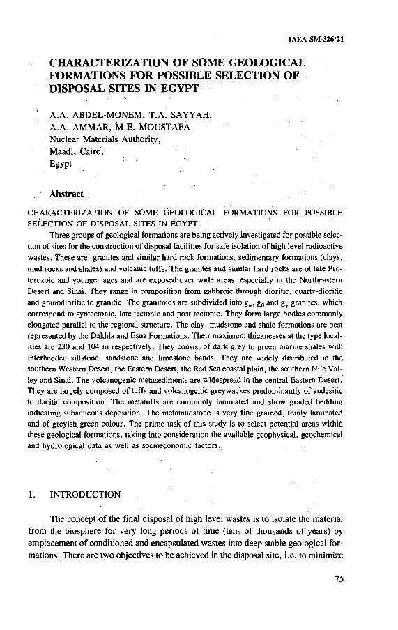
IAEA-SM-326/21
CHARACTERIZATION OF SOME GEOLOGICAL FORMATIONS FOR POSSIBLE SELECTION OF DISPOSAL SITES IN EGYPT
' A.A. ABDEL-MONEM, T.A. SAYYAH,A.A. AMMAR, M .E. MOUSTAFA Nuclear Materials Authority,Maádi, Cairo,Egypt
Abstract
C H A R A C T E R I Z A T I O N O F S O M E G E O L O G I C A L F O R M A T IO N S F O R P O S S IB L E
S E L E C T IO N O F D IS P O S A L S I T E S I N E G Y P T .
T h r e e g r o u p s o f g e o lo g ic a l f o r m a t io n s a r e b e in g a c t iv e ly in v e s t ig a te d f o r p o s s ib le s e le c
t io n o f s i te s f o r th e c o n s t r u c t io n o f d is p o s a l fa c i l i t ie s f o r s a fe is o la t io n o f h ig h le v e l r a d io a c t iv e
w a s te s . T h e s e a re : g ra n i te s a n d s im i la r h a r d r o c k fo r m a t io n s , s e d im e n ta ry fo r m a t io n s ( c la y s ,
m u d ro c k s a n d s h a le s ) a n d v o lc a n ic tu f f s . T h e g r a n i te s a n d s im ila r h a r d r o c k s a r e o f la te P r o -
te r o z o ic a n d y o u n g e r a g e s a n d a r e e x p o s e d o v e r w id e a r e a s , e s p e c ia l ly in th e N o r th e a s te rn
D e s e r t a n d S in a i. T h e y r a n g e in c o m p o s i t io n f r o m g a b b ro ic th r o u g h d io r i t ic , q u a r tz -d io r i t ic
a n d g r a n o d io r i t ic to g r a n i t ic . T h e g r a n i to id s a r e s u b d iv id e d in to g a , g ß a n d g.r g ra n i te s , w h ic h
c o r r e s p o n d to s y n te c to n ic , la te te c to n ic a n d p o s t - te c to n ic . T h e y fo r m l a r g e b o d ie s c o m m o n ly
e lo n g a te d p a ra l le l to th e r e g io n a l s t r u c tu r e . T h e c la y , m u d s to n e a n d s h a le f o r m a t io n s a r e b e s t
re p r e s e n te d b y th e D a k h la a n d E s n a F o r m a t io n s . T h e i r m a x im u m th ic k n e s s e s a t th e ty p e lo c a l
i t ie s a r e 2 3 0 a n d 10 4 m re s p e c t iv e ly . T h e y c o n s is t o f d a r k g re y to g r e e n m a r in e s h a le s w ith
in te rb e d d e d s i l ts to n e , s a n d s to n e a n d l im e s to n e b a n d s . T h e y a re w id e ly d is t r ib u te d in th e
s o u th e r n W e s te r n D e s e r t , th e E a s te r n D e s e r t , th e R e d S e a c o a s ta l p la in , th e s o u th e r n N ile V a l
le y a n d S in a i. T h e v o lc a n o g e n ic m e ta s e d im e n ts a r e w id e s p r e a d in th e c e n t r a l E a s te r n D e s e r t .
T h e y a r e la rg e ly c o m p o s e d o f tu f f s a n d v o lc a n o g e n ic g re y w a c k e s p r e d o m in a n t ly o f a n d e s i t ic
to d a c i t ic c o m p o s i t io n . T h e m e ta tu f f s a r e c o m m o n ly la m in a te d a n d s h o w g ra d e d b e d d in g
in d ic a t in g s u b a q u e o u s d e p o s i t io n . T h e m e ta m u d s to n e is v e ry f in e g r a in e d , th in ly la m in a te d
a n d o f g re y is h g r e e n c o lo u r . T h e p r im e ta s k o f th is s tu d y is to s e le c t p o te n t ia l a r e a s w ith in
th e s e g e o lo g ic a l fo r m a t io n s , ta k in g in to c o n s id e r a t io n th e a v a i la b le g e o p h y s ic a l , g e o c h e m ic a l
a n d h y d ro lo g ic a l d a ta a s w e l l a s s o c io e c o n o m ic f a c to r s .
1. INTRODUCTION
The concept o f the final disposal of high level wastes is to isolate the material from the biosphere for very long periods of time (tens of thousands of years) by emplacement of conditioned and encapsulated wastes into deep stable geological formations. There are two objectives to be achieved in the disposal site, i.e. to minimize
75
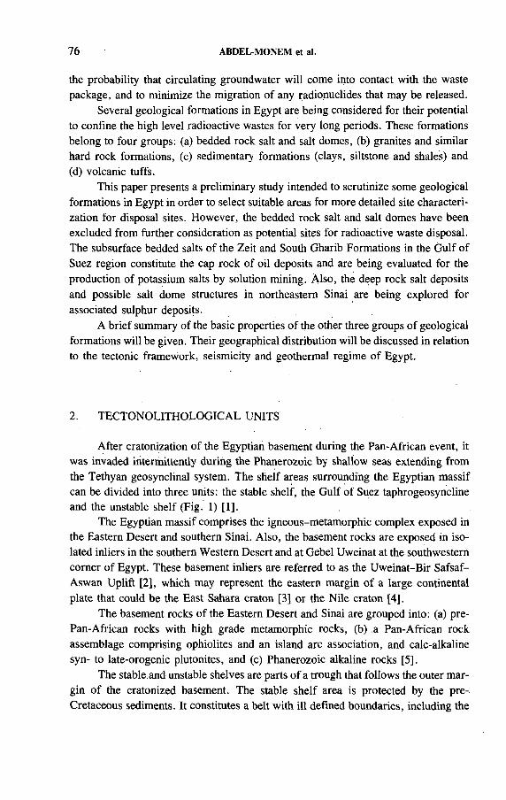
76 ABDEL-MONEM et al.
the probability that circulating groundwater will come into contact with the waste package, and to minimize the migration of any radionuclides that may be released.
Several geological formations in Egypt are being considered for their potential to confine the high level radioactive wastes for very long periods. These formations belong to four groups: (a) bedded rock salt and salt domes, (b) granites and similar hard rock formations, (c) sedimentary formations (clays, siltstone and shales) and(d) volcanic tuffs.
This paper presents a preliminary study intended to scrutinize some geological formations in Egypt in order to select suitable areas for more detailed site characterization for disposal sites. However, the bedded rock salt and salt domes have been excluded from further consideration as potential sites for radioactive waste disposal. The subsurface bedded salts of the Zeit and South Gharib Formations in the Gulf of Suez region constitute the cap rock of oil deposits and are being evaluated for the production of potassium salts by solution mining. Also, the deep rock salt deposits and possible salt dome structures in northeastern Sinai are being explored for associated sulphur deposits.
A brief summary of the basic properties of the other three groups of geological formations will be given. Their geographical distribution will be discussed in relation to the tectonic framework, seismicity and geothermal regime of Egypt.
2. TECTONOLITHOLOGICAL UNITS
After cratonization of the Egyptian basement during the Pan-African event, it was invaded intermittently during the Phanerozöic by shallow seas extending from the Tethyan geosynclinal system. The shelf areas surrounding the Egyptian massif can be divided into three units: the stable shelf, the Gulf of Suez taphrogeosyncline and the unstable shelf (Fig. 1) [1].
The Egyptian massif comprises the igneous-metamorphic complex exposed in the Eastern Desert and southern Sinai. Also, the basement rocks are exposed in isolated inliers in the southern Western Desert and at Gebel Uweinat at the southwestern corner of Egypt. These basement inliers are referred to as the Uweinat-Bir Safsaf- Aswan Uplift [2], which may represent the eastern margin o f a large continental plate that could be the East Sahara craton [3] or the Nile craton [4].
The basement rocks of the Eastern Desert and Sinai are grouped into: (a) pre- Pan-African rocks with high grade metamorphic rocks, (b) a Pan-African rock assemblage comprising ophiolites and an island arc association, and calc-alkaline syn- to late-orogenic plutonites, and (c) Phanerozoic alkaline rocks [5].
The stable and unstable shelves are parts o f a trough that follows the outer margin of the cratonized basement. The stable shelf area is protected by the pre- Cretaceous sediments. It constitutes a belt with ill defined boundaries, including the
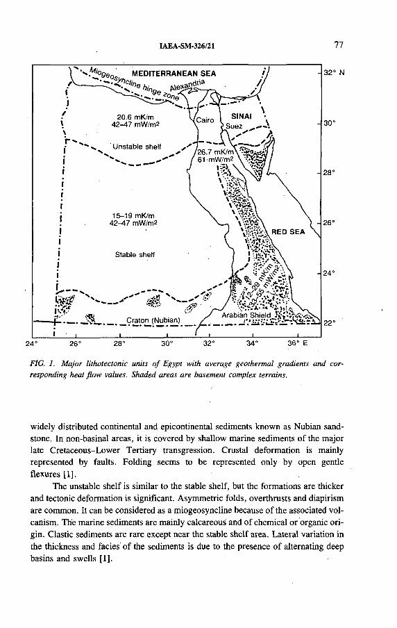
IAEA-SM-326/21 77
32° N
30°
28°
26°
24«
22°
24° 26° 28° 30° 32° 34° 36° E
FIG. 1. Major lithotectonic units o f Egypt with average geothermal gradients and corresponding heat flow values. Shaded areas are basement complex terrains.
widely distributed continental and epicontinental sediments known as Nubian sandstone. In non-basinal areas, it is covered by shallow marine sediments of the major late Cretaceous-Lower Tertiary transgression. Crustal deformation is mainly represented by faults. Folding seems to be represented only by open gentle flexures [1 ].
The unstable shelf is similar to the stable shelf, but the formations are thicker and tectonic deformation is significant. Asymmetric folds, overthrusts and diapirism are common. It can be considered as a miogeosyncline because of the associated vol- canism. The marine sediments are mainly calcareous and of chemical or organic origin. Clastic sediments are rare except near the stable shelf area. Lateral variation in the thickness and facies of the sediments is due to the presence of alternating deep basins and swells [1 ].
7/Ooen MEDITERRANEAN SEA
20.6 mK/m 42-47 rriW/m2
Unstable shelf
!— .
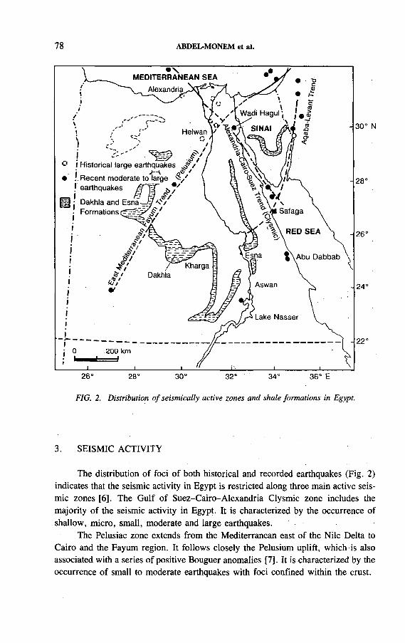
78 ABDEL-MONEM et al.
FIG. 2. Distribution o f seismically active zones and shale formations in Egypt.
3. SEISMIC ACTIVITY
The distribution of foci o f both historical and recorded earthquakes (Fig. 2) indicates that the seismic activity in Egypt is restricted along three main active seismic zones [6 ]. The Gulf of Suez-Cairo-Alexandria Clysmic zone includes the majority of the seismic activity in Egypt. It is characterized by the occurrence of shallow, micro, small, moderate and large earthquakes.
The Pelusiac zone extends from the Mediterranean east of the Nile Delta to Cairo and the Fayum region. It follows closely the Pelusium uplift, which is also associated with a series of positive Bouguer anomalies [7]. It is characterized by the occurrence of small to moderate earthquakes with foci confined within the crust.

IAËA-SM-326/21 79
The Levant-Aqaba zone is the extension of the Levant active fault system along the Gulf o f Aqaba in a southwesterly direction, where it intersects the Clysmic zone near the port of Safaga. In addition, outside these seismic zones several areas are known to be seismically active, such as Lake Nasser, Abu Dabbab and Wadi Hagul. The activity in these areas is o f a very local nature [6 ].
4. THE GEOTHERMAL REGIME
The geothermal gradients and heat flow data available in Egypt have been reviewed recently [8 ] and the averages are shown in Fig. 1. In the northern Western Desert and Nile Delta, the mean geothermal gradient of 20.6 mK/m corresponds to a heat flow of 42-47 mW /m2. These low heat flow values are consistent with the low heat flow values of the eastern Mediterranean region [9], compared with the world average of 61.5 mW /m 2 [10]. The data from the southern Western Desert indicate low geothermal gradients (15-19 mK/m), extending the low heat flow province of the eastern Mediterranean south to 26° N.
The average geothermal gradient in the Gulf o f Suez area is 26.7 mK/m. This higher geothermal gradient has been attributed to the high thermal conductivity of the thick evaporite deposits in the local geological section. Northern and southwestern Sinai have geothermal gradients of 21.9-27.3 mK/m. West central Sinai is characterized by higher geothermal gradients (36.5-72.9 mK/m) [11].
In the Eastern Desert, the geothermal gradients show some variations owing to both lithology and distance from the Red Sea. The geothermal gradient ranges are: 8 .2 -Í8 .8 mK/m in gabbroic areas, 12-28.9 mK/m in granitic areas and 30-50 mK/m in Tertiary sediments. The heat flow well away from the Red Sea (30-40 km) is in the range of 35-55 mW /m2, which is similar to the ranges of stable tectonic areas. The heat flow along the Red Sea coast and adjacent areas increases to 75-100 mW /m2.
5. THE GRANITES AND SIMILAR HARD ROCKS
The granites and similar hard rocks are of late Proterozoic and early Palaeozoic ages and are exposed over wide areas, especially in the northern Eastern Desert and Sinai (Fig. 3). They range in composition from gabbro through diorite, quartz diorite, granodiorite and normal granite to alkaline granite. The granitoids are subdivided into:
(a) ëa granites comprising syntectonic intrusions showing significant foliation and deformation, and ranging in composition from quartz diorite to granodiorite with minor granites;
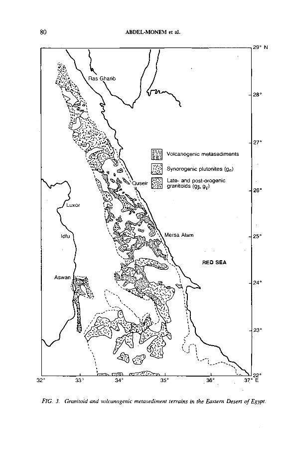
80 ABDEL-MONEM et al.
29° N
FIG. 3. Granitoid and volcanogenic metasediment terrains in the Eastern Desert o f Egypt.

IAE A-SM-326/21 81
(b) gp granites comprising late tectonic intrusions with minor or no foliation, and ranging in composition from granodiorite to normal calc-alkaline monzo- to syenogranites;
(c) gT granites comprising a small group of post-kinematic intrusions ranging in composition from alkali feldspar granite to quartz syenite [5].
In the following a brief description of the characteristics of each rock type will be given.
5.1. The gabbroic rocks
Gabbroic intrusions have limited distribution in the Eastern Desert and Sinai. They form small layered masses or sills, .with sharp contacts with the country rocks, including ga type granites. They comprise unmetamorphosed olivine gabbro, norite and troctolite. Rare pyroxenites and peridotites are present, possessing cumulate texture.
5.2. Calc-alkaline granite, g„
These granites comprise late Proterozoic and younger granites and are exposed over wide areas, especially in the Northeastern Desert and Sinai. They correspond to the ‘grey’, ‘older’ and ‘synorogenic’ granites and granitoids. They range in composition from quartz diorite to granodiorite and locally monzogranite. They commonly occur in the form of large bodies, elongated parallel to the regional structure. The more basic early members are of dark grey colour, commonly foliated and rich in hornblende and endogenic mafic xenoliths. The more acidic late members are commonly structureless, of pale grey to pinkish grey colour and poorer in endogenic xenoliths. This type of granite is easily weathered and occupies low lying terrains.
5.3. Calc-alkaline granite, gß
This second group of granitoids comprises the calc-alkaline members of the ‘pink’ or ‘younger’ granites. They occur in intrusive bodies conformable with the regional setting. Their compositions range from monzogranites to normal granites. They are generally massive, homogeneous, pink in colour and relatively poor in ferromagnesian minerals and endogenic xenoliths. They are more resistant to weathering and occupy terrains of low to moderate relief.
5.4. Subalkaline to peralkaline granite and quartz syenite, g7
This group of granites comprises post-kinematic intrusions. They include quartz syenite, alkali feldspar granites and alkaline granites. They were intruded near
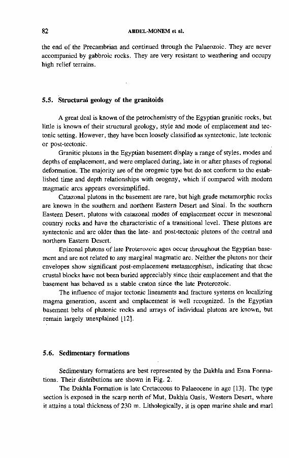
82 ABDEL-MONEM et al.
the end of the Precambrian and continued through the Palaeozoic. They are never accompanied by gabbroic rocks. They are very resistant to weathering and occupy high relief terrains.
5.5. Structural geology of the granitoids
A great deal is known of the petrochemistry of the Egyptian granitic rocks, but little is known of their structural geology, style and mode of emplacement and tectonic setting. However, they have been loosely classified as syntectonic, late tectonic or post-tectonic.
Granitic plutons in the Egyptian basement display a range of styles, modes and depths of emplacement, and were emplaced during, late in or after phases of regional deformation. The majority are of the orogenic type but do not conform to the established time and depth relationships with orogeny, which if compared with modern magmatic arcs appears oversimplified.
Catazonal plutons in the basement are rare, but high grade metamorphic rocks are known in the southern and northern Eastern Desert and Sinai. In the southern Eastern Desert, plutons with catazonal modes of emplacement occur in mesozonal country rocks and have the characteristic of a transitional level. These plutons are syntectonic and are older than the late- and post-tectonic plutons of the central and northern Eastern Desert.
Epizonal plutons of late Proterozoic ages occur throughout the Egyptian basement and are not related to any marginal magmatic arc. Neither the plutons nor their envelopes show significant post-emplacement metamorphism, indicating that these crustal blocks have not been buried appreciably since their emplacement and that the basement has behaved as a stable craton since the late Proterozoic.
The influence of major tectonic lineaments and fracture systems on localizing magma generation, ascent and emplacement is well recognized. In the Egyptian basement belts of plutonic rocks and arrays of individual plutons are known, but remain largely unexplained [1 2 ].
5.6. Sedimentary formations
Sedimentary formations are best represented by the Dakhla and Esna Formations. Their distributions are shown in Fig. 2.
The Dakhla Formation is late Cretaceous to Palaeocene in age [13]. The type section is exposed in the scarp north of Mut, Dakhla Oasis, Western Desert, where it attains a total thickness of 230 m. Lithologically, it is open marine shale and marl

IAEA-SM-326/21 83
with interbedded siltstone, sandstone and limestone. The shale is dark grey at the base.
It is widely spread over the central and southern parts of the Western and Eastern Deserts and along the Red Sea in downfaulted blocks. To the north it changes facies into limestones and chalk of the Khoman and Sudr Formations. To the south of Kharga its Palaeocene part is totally or partially replaced by Palaeocene limestones. To the west o f Dakhla major intervals of its shale and marl are replaced by sandstone.
The Esna Formation is late Palaeocene to early Eocene in age [14]. The type section is exposed at Gebel Oweina, Esna, Nile Valley, where it attains a total thickness of 104 m. Lithologically, it is green shale and marl enclosing carbonate intercalations, with more calcareous bands towards the top. It is of a marine depositional environment with certain exinic intervals. Stratigraphically, it overlies the Tarwan Formation and underlies the Thebes Formation with gradational contact.
It is widely distributed in the southern Western Desert, Eastern Desert, Nile Valley, Safaga-Quseir region of the Red Sea, and Sinai. It changes from marl-shale facies to the predominantly carbonate facies of the Garra Formation in the southern Western Desert and of the Ain Dalla Formation in West Farafra.
5.7. Volcanic clastic metasediments
The volcanogenic metasediments are widespread in the central Eastern Desert and correspond to the schist-mudstone-grey wacke series [15] or the immature sediments [16]. They conformably overlie a sequence of old metavolcanics of pillowed basalts ( 1 km thick) and are succeeded by another series of young metavolcanics of andesitic to dacitic composition. Siltstones, greywackes and breccias, are the fundamental components of the sequence, forming 85-95% with the banded iron formation making up the rest.
These metasediments show distinct primary sedimentary features, including lamination, graded bedding and flame structure, indicating subaqueous deposition. Individual sedimentary laminae may be 0.5-10 cm thick. Slump structures and olistostromatic intraformational breccias are common owing to intense tectonic activity accompanying sedimentation.
Mineral and lithic grains are indicative of the provenance of the sediments. The greywackes contain angular monocrystalline quartz and plagioclase set in and alternating with layers of finer material. The breccias are composed o f ill sorted volcanic and hypabyssal fragments. Andesitic porphyries dominate the clast population, but basalts and felsic volcanics are also common. Grain size of the volcanogenic sediments is finer in the east and coarser in the west, which suggests that the western exposures were closer to the source regions.
84 ABDEL-MONEM et al.
The many factors that should be considered in selecting a geological site for disposal are summarized as follows:
(a) Regions with a very low frequency of tectonic activity and low geothermal gradient,
(b) Regions with stable geological, geochemical and hydrological environments,(c) Regions with very low potential for natural gas, oil or minerals,(d) Socioeconomic impacts.
Applying such factors to the regions where the described potential geological formations for disposal site selection are exposed, it appears that the shaded areas in Fig. 2 have more potential than others and future detailed site characterization studies should be concentrated there.
6. DISCUSSION
REFERENCES
[1 ] S A ID , R . , T h e G e o lo g y o f E g y p t , E l s e v ie r , A m s te r d a m (1 9 6 2 ) 3 7 7 p p .
[2 ] R I C H T E R , A . , S C H A N D E L M E I E R , H . , “ P r e c a m b r ia n b a s e m e n t in l ie r s o f W e s te rn
D e s e r t g e o lo g y , p e tro lo g y a n d s t r u c tu r a l e v o lu t io n ” , T h e G e o lo g y o f E g y p t (S A I D , R . ,
E d . ) , B a lk e m a , R o t te rd a m (1 9 9 0 ) 1 8 5 -2 0 0 .
[3 ] B E R T R A N D , J . M . L . , C A B Y , M . , G e o d y n a m ic e v o lu t io n o f th e P a n -A f r ic a n o ro g e n ic
b e l t : A n e w in te rp r e ta t io n o f th e H o g g a r S h ie ld ( A lg e r ia n S a h a ra ) , G e o l . R u n d s c h . 67 (1 9 7 8 ) 3 3 7 - 3 3 8 .
[4 ] R O C C I , G . , E s s a i d ’in te r p r é ta t io n d e s m e s u r e s g é o c h r o n o lo g iq u e s . L a s t ru c tu re d e
l ’o u e s t A f r ic a in , S e i. T e r r e 10 ( 1 9 6 5 ) 4 6 1 - 4 7 9 .
[5 ] E L G A B Y , S . , e t a l . , “ G e o lo g y , e v o lu t io n a n d m e ta l lo g e n e s is o f th e P a n -A f r ic a n b e l t
in E g y p t” , T h e P a n - A f r ic a n B e l t o f N o r th e a s t A f r i c a a n d A d ja c e n t A r e a s (E L G A B Y ,
S . , G R E I L I N G , R .O . , E d s ) , B ra u n -S c h w e ig ( V ie w e g ) , B e r l in (1 9 8 8 ) 1 7 - 6 8 .
[6 ] K E B E A S Y , R .M . , “ S e is m ic i ty ” , T h e G e o lo g y o f E g y p t (S A ID , R . , E d . ) , B a lk e m a ,
R o t te rd a m (1 9 9 0 ) 5 1 - 5 9 .
[7 ] K A M E L , H . , “ G ra v i ty m a p ” , i b id . , p p . 4 5 - 5 0 .
[8 ] B O U L O S , F . K . , “ S o m e a s p e c ts o f th e g e o p h y s ic a l r e g im e o f E g y p t in re la t io n to h e a t
f lo w , g r o u n d w a te r a n d m ic r o e a r th q u a k e s ” , ib id . , p p . 6 1 - 8 9 .
[9 ] R A Y A N , W .B .F . , e t a l . , “ T h e te c to n ic s a n d g e o lo g y o f th e M e d i t e r r a n e a n S e a ” , T h e
S e a , V o l. 2 (M A X W E L L , A .E . , E d . ) , In te r s c ie n c e , N e w Y o rk (1 9 7 0 ) 3 8 7 - 4 9 2 .
[1 0 ] L E E , W .H . K . , O n th e g lo b a l v a r ia t io n s o f te r r e s t r i a l h e a t f lo w , P h y s . E a r th P la n e t.
I n te r . 2 (1 9 7 0 ) 3 3 2 - 3 4 1 .
[1 1 ] IS S A R , A . , e t a l . , F o r m a t io n w a te r , h o t s p r in g s a n d m in e ra l iz a t io n p h e n o m e n a a lo n g
e a s te r n s h o r e o f th e G u l f o f S u e z , B u ll . In t . A s s o c . S e i . H y d ro l . 1 6 (1 9 7 1 ) 2 5 - 4 4 .
[1 2 ] E L R A M L Y , M .F . , A n e w g e o lo g ic a l m a p f o r th e b a s e m e n t ro c k s in th e E a s te r n a n d
S o u th w e s te r n D e s e r t , s c a le 1 :1 ,0 0 0 ,0 0 0 , A n n . G e o l . S u r v . E g y p t 2 (1 9 7 2 ) 1 - 1 8 .
IAEA-SM-326/2Í 85
[1 3 ] S A ID , R . , T e c to n ic f r a m e w o r k o f E g y p t a n d its in f lu e n c e o n d is t r ib u t io n o f
f o r a m in i f e r a , B u ll . A m . A s s o c . P e t r o l . G e o l. 4 5 (1 9 6 1 ) 1 9 8 -2 1 8 .
[1 4 ] S A ID , R . , P la n k to n ic fo r a m in i f e r a f r o m th e T h e b e s F o r m a t io n , L u x o r , M ic r o p a l e o n
to lo g y 6 (1 9 6 0 ) 2 7 7 - 2 8 6 .
[1 5 ] A K A A D , M .K . , E L R A M L Y , M .F . , G e o lo g ic a l H is to ry a n d C la s s i f ic a t io n o f th e
B a s e m e n t R o c k s o f th e C e n t r a l E a s te r n D e s e r t o f E g y p t , G e o l . S u r v . E g y p t , P a p . 9
( 1 9 6 0 ) 2 4 p p .
[1 6 ] S T E R N , R .J . , L a te P r e c a m b r ia n E n s im a tic V o lc a n is m in th e C e n t r a l E a s te r n D e s e r t o f
E g y p t , P h D T h e s is , U n iv . o f C a l i f o r n ia , S a n D ie g o (1 9 7 9 ) .


IAEA-SM-326/60
THE ARCHIMEDE-ARGILE PROJECT: ACQUISITION AND REGULATION OF THE WATER CHEMISTRY IN A CLAY FORMATION, WITHIN THE GEOCHEMICAL PROGRAMME OF ANDRA FOR GEOLOGICAL DISPOSAL OF HIGH LEVEL RADIOACTIVE WASTES
T. MERCERON, R. ANDRE-JEHAN Agence nationale pour la gestion
des déchets radioactifs,Fontenay-aux-Roses
C. FOUILLAC, J.F . SUREAUBureau de recherches géologiques et minières,Orléans
J.C. PETIT, P. TOULHOATCEA, Centre d ’études de Fontenay-aux-Roses,Fontenay-aux-Roses
France
Abstract
T H E A R C H I M E D E - A R G I L E P R O J E C T : A C Q U I S IT IO N A N D R E G U L A T I O N O F T H E
W A T E R C H E M I S T R Y I N A C L A Y F O R M A T I O N , W IT H I N T H E G E O C H E M I C A L
P R O G R A M M E O F A N D R A F O R G E O L O G I C A L D IS P O S A L O F H IG H L E V E L
R A D I O A C T I V E W A S T E S .
C la y fo r m a t io n s a r e c a n d id a te h o s t e n v i ro n m e n ts f o r h ig h le v e l r a d io a c t iv e w a s te
d is p o s a l . T h e r a d io e le m e n ts c o u ld b e p a r t ia l ly re le a s e d f r o m th e w a s te in to th e h o s t g e o lo g ic a l
fo r m a t io n a f te r a v e r y lo n g t im e . U n d e r s ta n d in g th e b e h a v io u r o f th e n a tu ra l e le m e n ts is
c o n s id e re d a fu n d a m e n ta l p r e r e q u is i te to s tu d y in g th e d is tu rb e d s y s te m . A d d it io n a l l a b o ra to ry
s tu d ie s a r e a ls o e s s e n t ia l in o r d e r to f o r e c a s t , b y a n a lo g y , th e b e h a v io u r o f r a d io e le m e n ts
r e le a s e d f r o m th e w a s te r e p o s i to r y . T h e A R C H I M E D E - A R G I L E p r o je c t h a s tw o m a in g o a ls .
T h e f i r s t is to g a in a n u n d e r s ta n d in g o f th e m e c h a n is m s o f a c q u is i t io n a n d r e g u la t io n o f th e
w a te r c h e m is tr y in a c la y e n v i r o n m e n t . T h is s te p is e s s e n t ia l to p re d ic t in g b o th th e b e h a v io u r
a n d th e m ig r a t io n in s o lu t io n o f a r t i f ic ia l e le m e n ts w h ic h a r e in i t ia l ly a b s e n t in th e c la y
f o r m a t io n . T h e s e c o n d is to te s t a n d v a l id a te in c la y th e m e a s u re d p h y s ic o c h e m ic a l p a ra m e te r s
w h ic h a re th e b a s is f o r th e g e o c h e m ic a l m o d e l l in g o f th e b e h a v io u r o f n a tu r a l a n d a r t i f ic ia l
r a d io e le m e n ts . T h e p a p e r p r e s e n ts th e m a in re s u l ts p r e v io u s ly o b ta in e d o n g r a n i t ic w a te r s a n d
th e r e s e a r c h s t r a te g y e s ta b l is h e d f o r th e p r o je c t .
87
88 MERCERON et al.
1. INTRODUCTION
Various types of rock, e.g. granite and clay, are candidate host environments for high level radioactive waste disposal. The radioelements could be partially released from the waste into the host geological formation after a very long time. The different studies performed in the field of high level radioactive wastes are intended to contribute to the evaluation of the possibilities of radionuclide transfer from the waste repository over time and space. While hydrogeological models describe the motion of water in natural systems, the aim of geochemical studies is to determine which part of the released radionuclides can be carried by the water. The main difficulty for geochemists is to describe the behaviour of non-naturally occurring chemical species once they are released into nature.
A few years ago, the Agence nationale pour la gestion des déchets radioactifs (ANDRA) pointed out the necessity of understanding the behaviour of natural major and trace elements before the disturbed system is studied. Moreover, it is well known that some natural trace elements have a behaviour similar to that of artificial radionuclides. Additional theoretical and laboratory investigations were also undertaken in order to forecast, by analogy, the behaviour o f artificial radioelements released from a radioactive waste repository. We have recently established our knowledge about acquisition and regulation mechanisms concerning the chemical composition of waters circulating in granites.
The joint project of the Commission of the European Communities and ANDRA known as ARCHIMEDE-ARGILE (Acquisition et régulation de la chimie des eaux en milieu argileux) was initiated using the same technical basis as for earlier work on granite, but applied to clay formations. This project has been designed in order, firstly, to develop methodologies for rock and water sampling in deep clay formations, and, secondly, to generate data to aid our general understanding of water chemistry in such geological environments. After a satisfactory description of the mechanisms involved in determining the chemical composition of water has been obtained, it is intended to predict the chemical behaviour of the water in the presence of added radionuclides.
2. CHEMISTRY OF DEEP WATERS IN GRANITIC ENVIRONMENTS
As for geology and hydrogeology, our ability to perform any predictive work and its reliability will depend on our capacity to understand and to describe the actual site. A few years ago, a first project was initiated on waste disposal sites in granite [1]. Analyses performed on over two hundred waters sampled from deep closed granitic systems led to generic models. The aim was to understand the mechanisms governing how water coming into contact with granite acquires its chemical composition, and then how this composition is governed. With a small
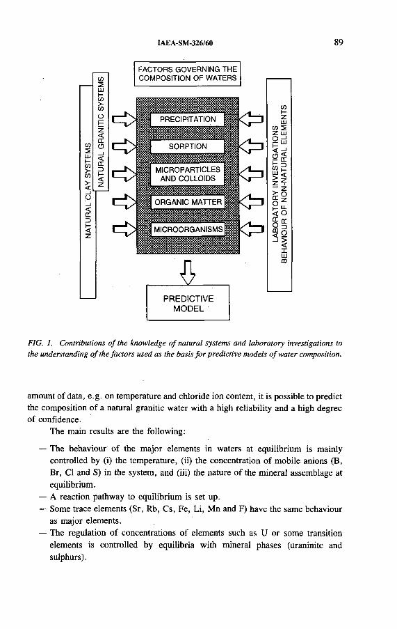
IAEA-SM-326/60 89
FACTORS GOVERNING THE
PREDICTIVEMODEL
FIG. 1. Contributions o f the knowledge o f natural systems and laboratory investigations to the understanding o f the factors used as the basis fo r predictive models o f water composition.
amount of data, e.g. on temperature and chloride ion content, it is possible to predict the composition of a natural granitic water with a high reliability and a high degree o f confidence.
The main results are the following:
— The behaviour of the major elements in waters at equilibrium is mainly controlled by (i) the temperature, (ii) the concentration of mobile anions (B, Br, Cl and S) in the system, and (iii) the nature o f the mineral assemblage at equilibrium.
— A reaction pathway to equilibrium is set up.— Some trace elements (Sr, Rb, Cs, Fe, Li, Mn and F) have the same behaviour
as major elements.— The regulation of concentrations of elements such as U or some transition
elements is controlled by equilibria with mineral phases (uraninite and sulphurs).
90 MERCERON et al.
— Some chemically non-controlled elements such as La, Ce, Nd, Sm, Eu, Tb, Yb, Lu, Th, Ta, Sc, Sb, Zr, H f and Ba are present in particular phases (e.g. colloids) of the waters. The origin (deep or superficial) and the accurate composition of these suspensions have not yet been determined. Any solid-solution fractionation can be observed for this group of elements. Concentration limits and empirical laws concerning regulation levels of these elements in natural waters have been estimated and determined from real cases.
For all these elements, the levels of regulation have been established with a variable degree of confidence, depending on the nature of the element, in the case of a water at equilibrium with granite [1 ].
It was shown that, depending upon the chemical species, different mechanisms are involved in governing the composition of the water, e.g. precipitation, sorption on minerals and formation of microparticles or colloids. Theoretical and laboratory investigations were then undertaken in order to analyse the behaviour in water of non-naturally occurring elements. In order to verify the interaction mechanisms between minerals and waters, tests are being carried out on both phases and mass balances are being performed. Figure 1 illustrates the contributions of the knowledge of natural systems and laboratory investigations to the understanding of the factors which govern the composition o f waters and which are the basis for predictive models.
3. ARCHIMEDE-ARGILE PROJECT
The ARCHIMEDE-ARGILE project was developed in 1991 with the support o f the CEC within its fourth R&D programme on Management and Storage of Radioactive Waste (1990-1994). In addition to the high complexity of the mineralogical system in a clay environment, special attention is being given to the role of organic matter, not only for its complexing capability but also as a buffer in redox conditions, and the role of microorganisms in conditions at different locations and in transport.
The Underground Research Facility (URF) in the Boom clay formation at Mol, Belgium, has been selected to collect fluid and solid samples that are as undisturbed and as representative as possible.
The project consists o f three steps:
— Field sampling and in situ measurements in the URF,— Laboratory investigations and analyses,— Modelling.
Three main topics are being investigated and will allow a global geochemical model to be built:

IAEA-SM-326/60 91
— Geochemical characterization and properties of the solid phases in the Boom clay,
— Geochemical characterization of the fluids in the clay formation,— Microbial characterization and properties of the clay-claywater system.
Specific methods are being developed to assess the different properties; for example:
— Not only will the bacteria be studied, but also a new approach based upon the genetic signature of the system will be set up;
— Water will be sampled by different methods, including local microfreezing or direct squeezing through the core samples.
Four scientific teams are in charge of the different phases of the project under the co-ordination of ANDRA (Division d ’études des sites): the French Geological Survey (BRGM), the CEN/SCK in Belgium, and the Commissariat à l ’énergie atomique (Direction du cycle du combustible, CEA/DCC) and Guigues recherche appliquée en microbiologie (GRAM SA), France. Laboratories of the Centre national de la recherche scientifique (CNRS) as well as the British Geological Survey (BGS) have also been committed for this project. The ARCHIMEDE-ARGILE project will last three years (1992-1994). The total budget is 2.72 million ECU (at 1991 values), 53% of which will be provided by ANDRA and 47% by the CEC.
3.1. Field sampling and in situ measurements in the URF
Six drill holes will be made in 1992 in the sliding ribs gallery (Fig. 2):
— A 20 m long horizontal borehole was cored out in March 1992 to collect solid samples, interstitial fluids (by lixiviation and squeezing) and gases.
— Two 15 m long piezometers have been installed to collect interstitial fluids, using independent cells for each piezometer nest in order to analyse the evolution of chemistry with distance from the main gallery. Two cells will be used to analyse dissolved sulphurs and sulphates. Microbial investigations will also be carried out on these interstitial fluids. One piezometer will be monitored to accurately measure pH by using fibre optic techniques (developed by the CEA for ANDRA).
— Three experimental drill holes will be devoted to in situ and test experiments using specific instrumentation for the geochemical characterization of the clay (pH, Eh, cation exchange capacity, retention factor, dialysis and lixiviation experiments). One drill hole is reserved for an in situ microfreezing experiment to collect interstitial fluids by centrifuging and freeze drying.
Additionally, it will be possible to sample the clay formation during the next sinking of a shaft and during driving operations at the extremity of the ANDRA
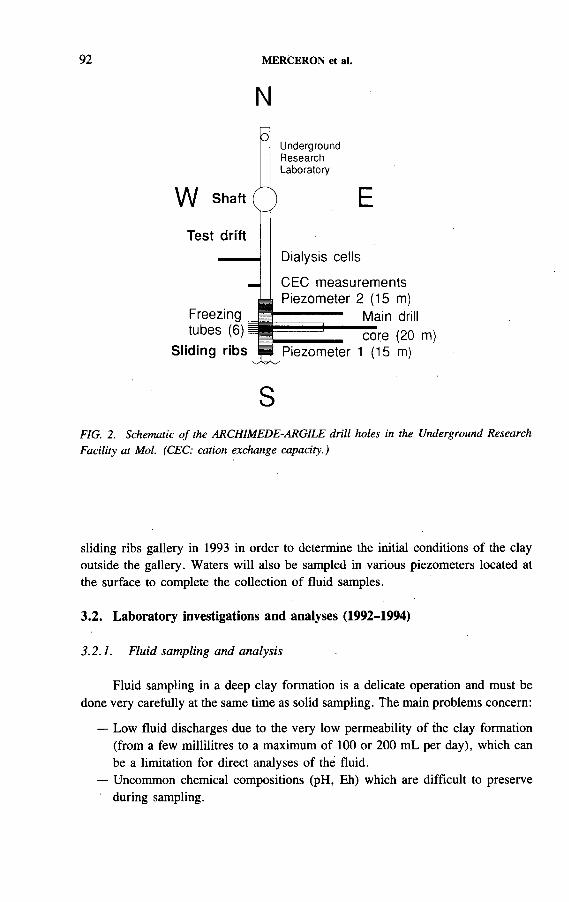
92 MERCERON et al.
NO
U n d erg ro u n dResearchL a b o ra to ry
W Shaft Q ETest drift
Dialysis cells
Freezing
CEC measurements Piezometer 2 (15 m)
Main drilltubes (6)i
Sliding ribs Piezometer 1 (15 m)core (20 m)
SFIG. 2. Schematic o f the ARCHIMEDE-ARGILE drill holes in the Underground Research Facility at Mol. (CEC: cation exchange capacity.)
sliding ribs gallery in 1993 in order to determine the initial conditions of the clay outside the gallery. Waters will also be sampled in various piezometers located at the surface to complete the collection of fluid samples.
3.2. Laboratory investigations and analyses (1992-1994)
3.2.1. Fluid sampling and analysis
Fluid sampling in a deep clay formation is a delicate operation and must be done very carefully at the same time as solid sampling. The main problems concern:
— Low fluid discharges due to the very low permeability of the clay formation (from a few millilitres to a maximum of 100 or 200 mL per day), which can be a limitation for direct analyses of the fluid.
— Uncommon chemical compositions (pH, Eh) which are difficult to preserve ' during sampling.
IAEA-SM-326/60 93
— The possible existence o f different types of water (free, structural, inter- granular, adsorbed, etc.). Their chemical compositions are dependent on the clay mineralogy and intimate equilibria can be broken down during sampling.
— The presence o f organic colloid phases which can carry trace elements (Al, Fe, transition elements and natural radionuclides).
In situ measurements are required for some parameters such as pH, Eh, Fe (in situ calorimetry) and total alkalinity; the last is generally considered as a conservative parameter but can be modified by residual biological activity in the samples. Dissolved sulphur species (sulphurs, polysulphurs, thiols, thiosulphates and sulphites) are very sensitive to oxidation but they are very useful for estimating redox conditions of the fluid. The temperature of the fluid is also a very important parameter to measure.
Specific devices will be tested during the ARCHIMEDE-ARGILE project. A system to sample and analyse interstitial fluids will be connected to a dialysis cell, specially designed by the CEA for transition metals, which are very difficult to analyse using piezometers because these instruments contain metallic materials. Fibre optics will also be tested and used to accurately measure pH with a precision o f less than 0.1 pH unit. In the near future, other useful in situ parameters such as C 0 2 and Fe concentrations will also be measured in such a medium in which interstitial fluids are difficult to collect.
Fluid analyses will be made using ionic chromatography, polarography, atomic absorption spectrometry, capillary electrophoresis, laser spectrofluorometry, inductively coupled plasma-atomic emission spectrometry, inductively coupled plasma-mass spectrometry (ICP-MS), mass spectrometry, neutron activation and alpha spectrometry. The analyses will be performed in two steps: the first step is to collect about a dozen fluid samples and analyse major elements, redox and pH. The second step will be pérformed on only the best samples; analyses will be focused on trace elements, natural actinides, inorganic anions, stable isotopes (ô180 , ôD, ô 13C, ô34S), tritium, 14C and the Rb/Sr ratio.
Gas analyses are also very important for reaction equilibria and redox conditions. The main gases to be analysed are H2, 0 2, N2, C 0 2, CH4, H2S and hydrocarbons. Gas Fourier transform infrared spectrometry will be used to complement mass spectrometry and gas chromatography to detect gas traces. In situ gas distribution profiles of He and Rn will also be obtained with gas sampling techniques during drilling.
3.2.2. Solid sampling and analysis
Solid sampling is performed using a cutting curb technique to collect cores that are as undisturbed and as representative as possible. Core samples are packaged in an aluminium bag previously sterilized and filled with nitrogen to prevent oxidation

94 MERCERON et al.
and bacterial contamination from the air. Additionally, three storage procedures have been applied to preserve these samples:
— Freezing at -2 0 ° C in sterile and anaerobic conditions— Storage in confinement cells— Storage after freeze drying.
Solid samples are being collected systematically (about one sample per metre) and locally near major heterogeneities such as carbonated and pyrite nodules. The samples will be stored at 4°C for a maximum of one year. After this time, further sampling will be done to perform new chemical analyses for comparison with the first data set. This information should allow us to determine the evolution and alteration of the geochemical parameters with time during the sample storage.
Mineralogical investigations will be performed on clay minerals using classical X ray diffraction (XRD) and eventually a linear localization detector to increase the sensitivity of the method to X rays at low angles of diffraction for mixed-layer and clay minerals. Clay microparticle morphology will be studied using electron microscopy combined with microparticle chemical analyses to determine clay populations at equilibrium with the system.
Solid analyses will be carried out using X ray fluorescence spectrometry (XRF), ICP, ICP-MS and MS to determine major element and main trace element concentrations. Rare earth elements and natural actinides (U, Th) will also be analysed. In addition, stable isotopes will be analysed (D/H, 160 / 180 , 87S r/86Sr, 13C /12C) and dating performed (К/Ar, Rb/Sr, U/Th) for specific samples to determine the origin and conditions of formation of (new) solid phases and related fluids. Organic geochemistry will also be studied to determine and characterize total organic carbon, dissolved organic carbon and their maturation states.
Gases will be extracted using classical methods and in situ thermogravimetric techniques (combined with quadrupolar spectrometry).
3.2.3. Microbial sampling and analysis
The ARCHIMEDE-ARGILE project was designed for interdisciplinary investigations and, as mentioned above, special attention is given in solid and fluid sampling to the prevention of oxidation and contamination from the air, especially for microbial studies. The main topics of study are the evolution of the microbial population and the impact on the chemistry of formation.
Three core samples (40 cm long) have been collected for detailed investigations at 1 , 1 0 and 2 0 m depth along the main drill core, which was obtained entirely with sterilized cutting curbs to preserve the core samples from external microbial contamination. One of the piezometers was sterilized before emplacement with the same procedure as was used for the drill core to collect fluid samples for microbial and chemical purposes. As for solid sampling, three piezometric filters are used at
IAEA-SM-326/60 95
increasing depth to collect fluid samples representative of the Boom clay. Microbe counting will be carried out after ultrafiltration.
Classical microbial ecology techniques and some innovative molecular biology will be applied to count and characterize the microflora resident in the Boom clay and those present in the underground gallery since its construction. The new approach of the molecular biology is based upon the genetic signature (16 RNAr) of bacteria. This method makes it possible to characterize every bacterium present in the system and to build nucleic acid ‘probes’ for each bacterium population. These probes will be used later to identify in situ microbial populations directly after sampling.' The method will be very useful for determining which proportion of the total microbial population can be characterized in situ by classical microbial ecology techniques.
3.3. Modelling (1994)
Geochemical modelling will be performed in two steps. The first step, concerning global equilibria of the system, will be developed by the CEA using an initial framework based upon spéciation calculations and saturation indices of the main mineral species. This approach, using the redox status at equilibrium of the main mineral phases, allows one to model the following:
— The influence of clay minerals on the chemical composition of water and the possible influence of other aluminosilicates,
— The influence of ion exchange processes on the mineralogical control of w ater-rock interactions.
A similar approach will be applied to trace elements. Some of them (alkali metals and alkaline earth metals) have behaviours similar to those of. major elements but the others are influenced by co-precipitation, sorption or transport effects. This first modelling will allow a predictive long term model to be set up for waters at equilibrium with the system.
The second modelling step is restricted to local equilibria which possibly control regulation mechanisms in a clay formation. This kind o f modelling will be performed by the BRGM using thermodynamic models of equilibrium states, such as EQ3/6 or CEQCSY. This approach will allow the different microsystems of the clay formation to be described and their influence on the water geochemistry to be determined. A mesh network assembling all the representative microsystems will be set up to model the clay system at a larger scale. Then, a better knowledge of the system will permit a simulation o f the behaviour of the clay formation in response to various conditions, such as the addition of artificial radionuclides into the system. A specific simulator (NEPTUNIX@) made for the BRGM by the Compagnie internationale de services en informatique will be used with a geochemical code generator to create the various models.

96 MERCERON et al.
The first results gained during the first half of 1992 concern the sampling methodologies described above (aseptic and anaerobic procedures) and in situ experiments [2]. A piezometric nest was installed at the beginning of March; the first fluids collected are being analysed by the CEA. The 20 mjlong drill hole was also cored out in March 1992. Water content as a function of depth was recorded just after drilling. The values are very similar, with an average of 24.43% + 1.56% (dry weight) (19.64% + 0.16% , total weight). Several laboratory experiments were tested in order to develop reliable field methods based on infrared thermogravimetric balance, microwave oven, gravimetric balance and gamma densimetric techniques. In particular, all these complementary techniques allowed the determination of the water extraction kinetic from clay. The variation in cation exchange capacity for solid sartiples was also measured according to various procedures. Trivalent cobalt ion was used for these determinations. The average value is 30.3 + 5.6 meq/100 g for fresh samples, but only 23.7 + 3.5 meq/100 g for samples in contact with air. These values are very similar to those previously obtained by the CEN/SCK for other exchange cations (in meq/100 g): Ag, 30.0 ± 3.9; Sr, 24.4 ± 3.4; and Ca, 23.3 + 3.1 [2]. Ammonium and caesium will be used in future determinations of cation exchange capacity.
The ARCHIMEDE-ARGILE project was designed from our knowledge of the water chemistry in granitic environments. However, the acquisition and regulation mechanisms of the water chemistry in a clay formation are much more complex to investigate because of the numerous problems discussed above. The only way to solve them is to involve interdisciplinary sciences such as fluid and solid geochemistry and microbiology to study natural systems. This approach should help us to reach the next step of constructing predictive models to assess the behaviour of artificial radionuclides which are initially absent in a clay formation. The aim is to determine the major parameters which control the behaviour of these radioelements. Finally, it will be necessary to verify the application limits o f our future models. New developments, including, for example, laboratory experiments and natural analogue studies, are also planned in order to enrich the approach as defined by ANDRA.
4. RESULTS AND CONCLUSION
ACKNOWLEDGEMENTS
The authors would like to thank all the members of the ARCHIMEDE- ARGILE project for their critical comments and suggestions. This study is supported by the CEC (contract No. FI2W-CT92-0117).

IAEA-SM-326/60 97
REFERENCES
O U Z O U N I A N , G . , A L A U X - N E G R E L , G . , A c q u is i t io n e t r é g u la t io n d e la c h im ie d e s
e a u x e n m il ie u g r a n i t iq u e . A p p lic a t io n a u x s i te s d e s to c k a g e d e s d é c h e ts ra d io a c t i f s ,
R e p . 9 2 - 0 1 , A N D R A , F o n te n a y -a u x -R o s e s (1 9 9 2 ) .
M E R C E R O N , T . , e t a l . , P r o je t A R C H I M E D E - A R G I L E — A c q u is i t io n e t r é g u la t io n
d e la c h im ie d e s e a u x e n m il ie u a r g i le u x , R e p . С С Е /A N D R A 9 2 - 0 1 , C E C , B ru s s e ls
(1 9 9 2 ) .

REPOSITORY DESIGN CONCEPTS, CONSTRUCTION TECHNIQUES AND
ENGINEERED BARRIER DESIGN
(Session 3)
C hairm en
A. BONNEB e l g i u m
C. DEL OLM OS p a i n

IAEA-SM-326/64
DESIGN BASES OF THE BELGIAN REPOSITORY FOR VITRIFIED HEAT PRODUCING RADIOACTIVE WASTES
J. VAN MIEGROET ONDRAF/NIRAS,Brussels, Belgium
Abstract
D E S IG N B A S E S O F T H E B E L G I A N R E P O S IT O R Y F O R V I T R I F I E D H E A T P R O D U C
IN G R A D I O A C T I V E W A S T E S .
O n th e b a s is o f e x p e r im e n ta l d a ta g a th e re d d u r in g th e f i r s t y e a r s o f th e r e s e a rc h
p r o g r a m m e c e n t r e d o n th e B o o m c la y a t M o l , a p r e l im in a r y s a fe ty a n a ly s is o f a r e p o s i to ry
w a s c a r r ie d o u t a s p a r t o f th e P e r f o r m a n c e A s s e s s m e n t o f G e o lo g ic a l I s o la t io n S y s te m s
(P A G IS ) p ro je c t . T h e c o n c lu s io n s w e re a s fo llo w s : “ th e c a lc u la te d m a x im u m ra d io n u c l id e
c o n c e n tr a t io n s . . . a r e v e ry s e n s i t iv e to t h r e e p a r a m e te r s r e la te d to th e c la y la y e r : th e e f fe c t iv e
th ic k n e s s ; th e d i f f u s io n c o e f f ic ie n t ; th e r e ta rd a t io n f a c to r . ” O n th e o th e r h a n d , “ th e v e ry
e f f ic ie n t c o n f in e m e n t ( . . . p ro v id e d b y th e c la y la y e r . . . ) m a s k s th e c o n t r ib u t io n s o f th e
e n g in e e r e d b a r r i e r s ” . A s a c o n s e q u e n c e , th e d e s ig n o f th e r e p o s i to r y is b e in g b a s e d o n th e
fo l lo w in g tw o m a in p r in c ip le s , a ls o s t r e s s e d in P A G IS : “ th e m in e d r e p o s i to r y s h o u ld b e k e p t
a s f la t a s p o s s ib le to a v o id th a t a c o n s id e r a b le f r a c t io n o f th e th ic k n e s s o f th e c la y la y e r s h o u ld
b e d is tu r b e d b y th e r e p o s i to r y c o n s t r u c t io n ; th e s t ro n g in f lu e n c e o f th e c la y l a y e r e m p h a s iz e s
th e im p o r ta n c e o f th e l im i ta t io n o f n e a r f ie ld e f fe c ts w h ic h c o u ld d a m a g e th e f i r s t m e te r s o f
th e c la y la y e r a ro u n d th e r e p o s i to r y g a l l e r i e s . ” T h e s e c o n c lu s io n s a n d p r in c ip le s h a v e b e e n
tr a n s la te d in to a s e t o f d e s ig n c r i te r ia .
1. INTRODUCTION
Nuclear power generation in Belgium relies upon operation of seven reactors of the PWR type, representing a total installed capacity of 5.5 GW(e) that accounts for nearly two thirds of the annual electrical output country-wide. The Belgian utilities having elected years ago to recover the fissile material from the spent fuel, several reprocessing contracts have since been signed with the French company Cogéma for a current total of 630 t uranium metal. As a result of these contracts slightly less than five hundred canisters will be generated, wherein the most active wastes produced at the La Hague facility are ‘frozen’ in a glass matrix. More contracts are likely to be signed in the future, in line with the continuing operation of the reactors.
This paper deals with the most significant design bases of the geological repository section that will have to accommodate these vitrified heat producing wastes.
101
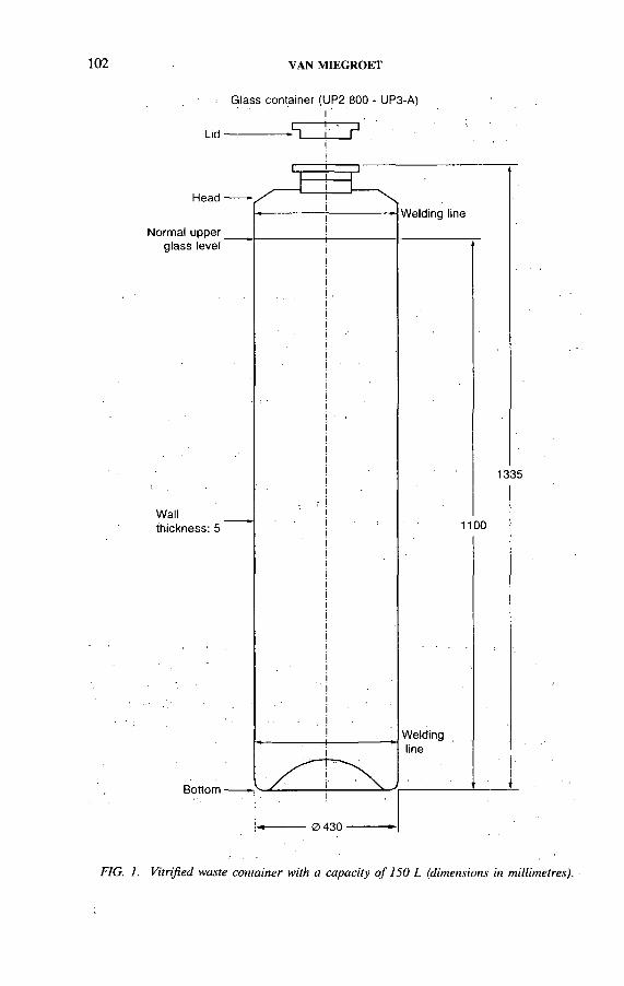
102 VAN MIEGROET
Glass container (UP2 800 - UP3-A)
FIG. 1. Vitrified waste container with a capacity o f 150 L (dimensions in millimetres).
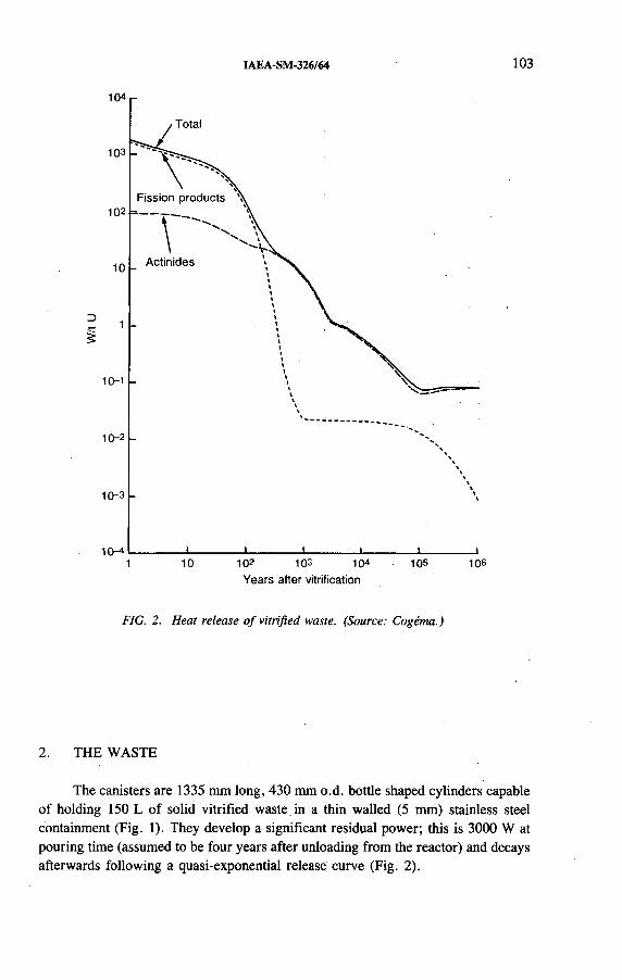
IAEA-SM-326/64 103
Years after vitrification
FIG. 2. Heat release o f vitrified waste. (Source: Cogéma.)
2. THE WASTE
The canisters are 1335 mm long, 430 mm o.d. bottle shaped cylinders capable of holding 150 L of solid vitrified waste in a thin walled (5 mm) stainless steel containment (Fig. 1). They develop a significant residual power; this is 3000 W at pouring time (assumed to be four years after unloading from the reactor) and decays afterwards following a quasi-exponential release curve (Fig. 2).

104 VAN MIEGROET
Nearly two decades ago, the Belgian Nuclear Research Centre (CEN/SCK) at Mol started a major investigation aimed at identifying and quantifying the geological formations with the potential to ultimately house a deep disposal facility for high activity radioactive waste. The CEN/SCK soon came to the conclusion that the Boom clay layer which extends, at various depths, over a large fraction of north Belgium displays such potential. Taking advantage of the presence of the 90 m thick, 230 m deep layer beneath its own site, the CEN/SCK initiated an important R&D programme aimed at characterizing the material both from above ground and in situ.
That effort culminated in the early 1980s with the installation of an underground research laboratory (URL) where the bulk of the High Activity Disposal Experimental Site (HADES) programme has since been performed. On the basis of experimental data gathered during the first years of the programme, a preliminary safety analysis o f a repository housing the vitrified heat conducting waste was carried out in 1986-1988, as part of the Performance Assessment of Geological Isolation Systems (PAGIS) project [1] initiated and financed by the European Communities. The main conclusions were as follows (pp. D -l-D -12):
“ The deterministic local sensitivity study ... shows that the calculated maximum radionuclide concentrations in the well water are very sensitive to three parameters related to the clay layer:
— the effective thickness— the diffusion coefficient— the retardation factor.
The effective thickness of the aquifer and its Darcy velocity have also some influence on the calculated concentrations.”
On the other hand, “ the very efficient confinement (... provided by the clay layer ...) masks the contributions of the engineered barriers in the systems performance evaluations.”
As a consequence, the design of the repository will be based on the following two main principles, also stressed in PAGIS (p. E-5):
— “ the mined repository should be kept as flat as possible to avoid that a considerable fraction of the thickness of the clay layer should be disturbed by the repository construction;
— the strong influence of the clay layer emphasizes the importance of the limitation of near field effects which could damage the first meters of the clay layer around the repository galleries.”
3. HIGHLIGHTS OF SAFETY ANALYSIS

IAEA-SM-326/64 105
Those principles have since been translated into a set of design criteria:
(1) Waste disposal will take place in horizontal galleries.(2) Temperatures will not be allowed to exceed certain maximum levels (still
being developed)(a) inside the glass matrix(b) in the clay layer(c) in the aquifer above the disposal facility.Geological disposal o f the waste canisters will therefore not be permitted soon after the vitrification year; they will instead have to be stored temporarily in a surface built facility where the generated heat can be released to the atmosphere. The storage time compatible with sufficient reduction of the power release will be close to 50 years.
(3) The heat producing waste will be buried, away from all other waste types, in a segregated region of the underground facility: combining various waste types in a single gallery or in nearby galleries would reduce the possible degree of near field fine tuning because of the conflicting requirements that would have to be met.
(4) The diameter o f the disposal galleries will be minimized to reduce the extent of the mechanically disturbed zone around the excavated region: the ideal configuration, a pipe-jacked tunnel nearly identical in diameter to the waste canistèr, was, however, found unfeasible under the prevailing technological conditions.
(5) Gas production and the ensuing pressure buildup will be held to a minimum for protection of the clay layer integrity. Gas sources (from anaerobic corrosion), such as the huge (25 cm thick) radioprotective metal shielding needed for underground transportation of the canisters, will thus not be permanently allowed in the repository.
(6 ) While some amount of residual ‘void’ has to be accepted in the final configuration of the disposal galleries (the canisters themselves contain more than 1 0 % of unfilled space), no effort will be spared to maximize the backfill ratio: since none of the artificial support structures is expected to last more than a few thousand years, the free volumes will eventually alter the structure and properties of the inner clay region.
(7) In view of the severely enhanced leaching rates of the vitrified waste at temperatures of 1 0 0 °С and above, some type of watertight protection, with a lifetime of several hundred years, is deemed necessary to postpone contact with the clay water until after the early, hot period. The current design calls for a ‘thin’ metal shroud (pipe) surrounding the canisters in the disposal galleries, to be installed in advance of the waste itself.
4. DESIGN CRITERIA
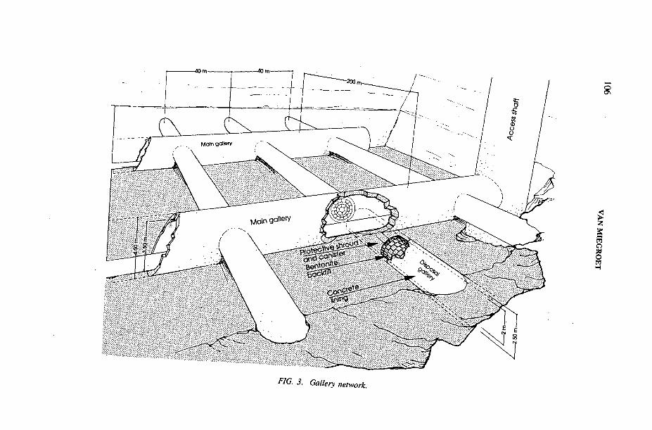
FIG. 3. Gallery network.

0 2.0
0 m
IAEA-SM-326/64 107
FIG. 4. Cross-section o f disposal gallery.
The metal shroud plays another, even more important role (though unrelated to the above mentioned ‘main principles’), i.e. to provide for complete separation of the gallery construction phase from the waste loading procedure, thus allowing the construction steps (excavation and lining, installation of the metal shroud, and backfilling) to be carried out without the need for radioprotection.
(8 ) In line with the quoted excerpts from the PAGIS report, the engineered barriers (near field) are to be designed not for the sake of the additional protection they create — a few thousand years are insignificant compared with the time for which protection is needed — but as a means for minimization of the disturbances to the geological medium. By the same token, there is no point in attempting to accurately model the multiple chemical, thermal, mechanical and hydraulic interactions of the multilayered near field, other than to assess how deep into the clay the material has become unfit to play its barrier role.

108 VAN MIEGROET
The criteria listed above, combined with state of the art techniques, have now tentatively resulted in the following list o f disposal features:
Gallery network (Fig. 3)
The 2 m wide (i.d.) disposal galleries are to be driven parallel to one another over a length of approximately 200 m, perpendicular to the 3.5 m wide main galleries. The interaxial distance between neighbouring. disposal galleries will be 40 m.
Cross-sectional layout (Fig. 4)
The cross-sectional layout of a disposal gallery includes the following:
— The 430 mm o.d. canister;— A 450 mm i.d. cylindrical carbon steel shroud;— An annular shaped, bentonite based material filling the 750 mm space between
the shroud and the gallery lining;— A 250 mm thick concrete lining.
Most of these features will be made part o f the PRACLAY experiment now under preparation in the URL at Mol.
REFERENCE
[1] MARIVOET, J ., BONNE, A ., Performance Assessment o f Geological Isolation Systems for Radioactive Waste Disposal in Clay Formations, EUR 11776, CEC, Luxembourg (1988).

IAEA-SM-326/45
DEVELOPPEMENT DE TECHNIQUES DE REMPLISSAGE POUR PUITS DE STOCKAGE DE DECHETS RADIOACTIFS EN ROCHE DURE
M. OLLAGNIER Agence nationale pour la gestion
des déchets radioactifs
P. BOUNIOLCEA, Direction du cycle du combustible
Fontenay-aux-Roses, France
Abstract-Résumé
DEVELOPMENT OF FILLING TECHNIQUES FOR RADIOACTIVE WASTE DISPOSAL SHAFTS IN HARD ROCK.
The choice of material to fill disposal shafts is determined by the nature o f the waste, the waste conditioning and the function ascribed to the engineered buffer barrier that it creates. One of the options studied in France is to surround vitrified high level waste packages with sand and alpha bearing waste packages with mortar. Since these materials are to be inserted into a narrow ring shaped space between the waste containers and the wall o f the shaft, they require particular characteristics, and tests to validate the techniques used therefore need to be carried out on models which simulate actual storage conditions. The paper describes the results obtained from inserting sand and mortar by gravitational flow. This method yielded an acceptable level o f compactness for sand fill and a very compact mortar fill with low permeability. The techniques proposed take into account protection of personnel from ionizing radiation and the risks associated with underground work.
DEVELOPPEMENT DE TECHNIQUES DE REMPLISSAGE POUR PUITS DE STOCKAGE DE DECHETS RADIOACTIFS EN ROCHE DURE.
Le choix des matériaux de remplissage des puits de stockage est effectué en fonction de la nature des déchets, de leur conditionnement et du rôle attribué à la barrière ouvragée de voisinage qu’ils constituent. L ’une des options étudiées en France est de bloquer les colis de déchets de haute activité vitrifiés par un sable et les colis de déchets émetteurs alpha par un mortier. La mise en place de ces matériaux dans un espace annulaire étroit compris entre les conteneurs et la paroi du puits impose des caractéristiques précises à ces matériaux et nécessite des essais de validation des techniques retenues sur des maquettes simulant les conditions réelles de stockage. L ’article présente une synthèse des résultats obtenus par la mise en place de sable et de mortier par écoulement gravitaire. Cette méthode a attribué une compacité acceptable au remplissâge de sable et une forte compacité associée à une faible perméabilité au mortier. La protection du personnel contre les rayonnements ionisants et contre les risques liés au travail souterrain est prise en compte dans les techniques envisagées.
109
110 OLLAGNIER et BOUNIOL
1. INTRODUCTION
Quatre types de formations géologiques sont envisagés en France pour le stockage des déchets radioactifs à vie longue: le granite, le schiste, l ’argile et le sel. Cette présentation est plus particulièrement orientée vers les roches dures: granite et schiste. Dans ces roches, le stockage de déchets de haute activité vitrifiés pourra s’effectuer dans des puits verticaux de grande profondeur ( 1 0 0 m environ) et celui des déchets émetteurs alpha faiblement exothermiques dans des tranchées [1 ] ou silos (fig. 1). Les tranchées sont occupées par une structure de béton où sont aménagées des alvéoles de stockage de 15 m de hauteur utile, leur partie supérieure étant réservée aux équipements de manutention des colis.
Le confinement des déchets repose sur trois barrières constituées par les colis de déchets, l ’ensemble des matériaux de remplissage et de scellement des excavations (barrière ouvragée) et la formation géologique hôte. D ’une manière générale, la barrière ouvragée contribue à limiter l ’arrivée de l’eau au contact des colis et retarde le transfert des radioéléments vers la biosphère.
La barrière ouvragée située au voisinage des colis permet en particulier lé contrôle des effets associés à la formation des gaz et le blocage des colis: Le choix des matériaux constitutifs est effectué en fonction de la nature et du mode de conditionnement des déchets ainsi que du rôle attribué à cette barrière ouvragée de voisinage.
La loi sur la gestion dés déchets radioactifs à vie longue, votée en France en décembre 1991, stipule que les études de stockage porteront sur des concepts réversibles permettant la reprise des colis et sur des concepts irréversibles. Les contraintes de reprise de colis ne seront néanmoins pas prises en compte ici, celles-ci faisant l ’objet d ’études spécifiques.
2. TECHNIQUE DE REMPLISSAGE DE PUITS DE STOCKAGEDE DECHETS DE HAUTE ACTIVITE VITRIFIES
2.1. Choix du matériau de remplissage
La recherche de matériaux a d ’abord été orientée vers des matériaux ayant une perméabilité du même ordre de grandeur que celle de la roche hôte et a abouti au choix d ’argile gonflante de forte densité [2]. Les incertitudes relatives au comportement à long terme d ’une argile placée au contact de colis exothermiques ainsi que la complexité des interactions chimiques verre/argile conduisent à examiner parallèlement d ’autres matériaux de remplissage. L ’Agence nationale pour la gestion des déchets radioactifs (ANDRA) a ainsi envisagé de remplir l ’espace annulaire étroit et compris entre la paroi du puits et la pile de colis par un sable de quartz et d ’effectuer une coupure des écoulements hydrauliques en des points particuliers
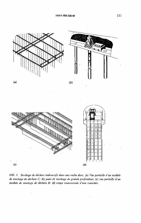
IAEA-SM-326/45 111
(a) .(M
7 } \
>/
>ГТ1и ГГ) m rT hr t tT т т TT Т т ГГ~r Ti t h-T т т ГГT Т1 t i [rT ÍT! t rrГг -п tГг i f TL J .
(c) (d)
FIG. 1. Stockage de déchets radioactifs dans une roche dure, (a) Vue partielle d ’un module de stockage de déchets C; (b) puits de stockage de grande profondeur; (c) vue partielle d ’un module de stockage de déchets B; (d) coupe transversale d ’une tranchée.

112 OLLAGNIER et BOUNIOL
(par exemple à la tête des puits de stockage ou encore dans les galeries). Le sable, matériau anhydre, présente l ’avantage de supporter sans modification une température élevée et celui de ne pas interagir chimiquement avec le verre des colis.
2.2. Eléments de sélection du sable
Deux des fonctions du matériau de remplissage (maintenir mécaniquement les colis; inhibiter les éventuels risques d ’explosion associés à une production d ’hydrogène par la radiolyse de l’eau) impliquent un remplissage de forte compacité. Ceci oriente le choix des principales caractéristiques du sable.
(a) La finesse des grains:
Les matériaux fins (grains inférieurs à 0,1 mm) sont le siège de phénomènes électrostatiques et d ’adsorption d ’air qui s’opposent à un arrangement compact des particules. Il est donc raisonnable d ’orienter l ’étude vers un sable grossier dont le grain est limité au dixième de l ’espace annulaire moyen de 35 mm.
(b) La distribution granulométrique:
La mise en place du matériau par écoulement gravitaire entraîne une ségrégation des éléments. Le matériau a donc une distribution unimodale étroite.
(c) L ’angularité des grains:
Pour éviter que l ’écoulement du sable dans l’espace annulaire étroit ne soit arrêté par la formation de voûtes, il est préférable de choisir un sable roulé.
(d) Les contraintes de protection radiologique:
La conception du stockage évite la dispersion de particules radioactives dans les galeries, en particulier en cas de chute de colis dans le puits, lors de leur mise en place. Pour ce faire, il est prévu de maintenir sous dépression les puits de stockage au cours de leur remplissage, avec une possibilité de filtration de l ’air extrait [3]. Afin de ne pas colmater prématurément les filtres installés en tête de puits, il convient de limiter la quantité de particules fines du sable (inférieures à 0 , 1 mm). De plus, le bon fonctionnement de ces filtres est incompatible avec un dégagement important de vapeur d ’eau. Le sable sera donc séché au four.
2.3. Caractérisation de quatre sables
Des essais de caractérisation mécanique ont été pratiqués sur les quatre sables industriels extrasiliceux, séchés au four, suivants:
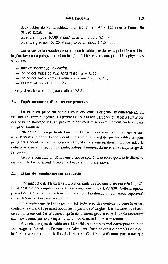
IAEA-SM-326/45 113
— deux sables de Fontainebleau, l ’un très fin (0,060-0,125 mm) et l ’autre fin(0,080-0,250 mm),
— un sable moyen (0,100-3 mm) avec un mode à 0,3 mm,— un sable grossier (0,125-3 mm) avec un mode à 1,8 mm.
Ces essais de laboratoire montrent que le sable grossier est a priori le matériau le plus favorable puisqu’il attribue les plus faibles valeurs aux propriétés physiques suivantes:
— surface spécifique: 23 cm 2/g,— indice des vides en vrac (non tassé): u = 0,55,— indice des vides après tassement maximal: ut = 0,40,— Tassement potentiel de 10%.
Lorsqu’il est tassé sa compacité atteint 72%.
2.4. Expérimentation d’une trémie prototype
La mise en place du sable autour des colis s’effectue gravitairement, en utilisant une trémie spéciale. La trémie assure à la fois l ’amenée du sable à l ’intérieur des puits de stockage jusqu’à proximité des colis et son déversement contrôlé dans l’espace annulaire.
Elle comprend en particulier un cône diffuseur à sa base dont le réglage permet de déterminer le débit d ’écoulement. On a en effet constaté que les sables les plus grossiers s’écoulent plus rapidement et qu’il existe une relation univoque entre le débit massique et la section passante, indépendamment du niveau de remplissage de la trémie.
Le cône constitue un déflecteur efficace apte à faire correspondre le diamètre du voile de l’écoulement à celui de l’espace annulaire moyen.
2.5. Essais de remplissage sur maquette
Une maquette de Plexiglas simulant un puits de stockage a été réalisée (fig. 2); il est possible d ’y empiler jusqu’à trois conteneurs inox UP2-800. Cette maquette permet de faire varier la hauteur de chute libre (au-dessus du conteneur supérieur) et la hauteur de l’espace annulaire.
Le remplissage de la maquette a été testé avec des conteneurs centrés et des conteneurs excentrés prenant appui sur la paroi de Plexiglas. Les mesures de niveau de remplissage ont été effectuées après écoulement gravitaire puis après tassement stabilisé obtenu par une vingtaine de chocs successifs sur la maquette.
Pour chaque type de sable on a identifié un débit maximal correspondant à un «bourrage» à l’entrée de l ’espace annulaire dont l ’origine est une compétition entre le flux de sable entrant et le flux d ’air sortant. Ce débit est d ’autant plus faible que
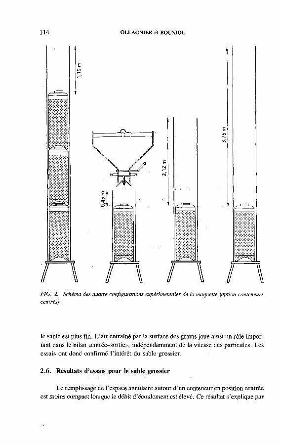
114 OLLAGNIER et BOUNIOL
тщ
Eо
FIG. 2. Schéma des quatre configurations expérimentales de la maquette (option conteneurs centrés).
le sable est plus fin. L’air entraîné par la surface des grains joue ainsi un rôle important dans le bilan «entrée-sortie», indépendamment de la vitesse des particules. Les essais ont donc confirmé l’intérêt du sable grossier.
2.6. Résultats d’essais pour le sable grossier
Le remplissage de l’espace annulaire autour d ’un conteneur en position centrée est moins compact lorsque le débit d ’écoulement est élevé. Ce résultat s ’explique par
IAEA-SM-326/45 115
FIG. 3. Evolution de l ’indice des vides du sable grossier en fonction du débit d ’écoulement pour deux configurations de chute avant tassement (a) et après tassement (b). 0 Hauteur de chute libre: 1,23 m — espace annulaire: 3 , 7 7 m; + hauteur de chute libre: 3,75 m — espace annulaire: 1,25 m. ,
une «décompaction» des grains liée à l ’air expulsé. Pour les débits les plus faibles, de quelques kilogrammes par seconde, le tassement par vibration est nul. Cependant, l ’indice des vides obtenu sur la maquette, ut = 0,432, reste supérieur à celui obtenu en laboratoire, u t = 0,400. La compacité est peu affectée par la hauteur de chute libre dont l’optimum apparaît se situer aux environs de deux mètres. La figure 3 montre qüe la hauteur de l’espace annulaire ne semble pas déterminante. Cependant, à faible débit l ’accroissement de la hauteur de chute dans l ’espace annulaire tend à diminuer la compacité du remplissage. La position excentrée des trois conteneurs contribue, elle aussi, à diminuer-la compacité du remplissage de 15 à 20%. Des lentilles de vides se forment à l ’aplomb des zones de contact entre la paroi de la maquette et les conteneurs.
Dans des conditions proches de la réalité (conteneur excentré) la compacité obtenue est de l’ordre de 65%.
2.7. Essais de remplissage par un mélange binaire
Dans le but d ’accroître sa compacité, le remplissage de l ’espace annulaire a été exécuté en deux temps à l ’aide de deux fractions granulométriques éloignées, en faisant percoler im sable fin au travers d ’un sable grossier. Cette technique n ’est envisageable qu’avec des matériaux très secs dont l ’état de surface et le contraste granulométrique sont compatibles.
116 OLLAGNIER et BOUNIOL
En utilisant deux sables siliceux quasi monogranulaires et dont le rapport des diamètres de grains est de 40 environ, les essais de laboratoire fournissent une compacité de 77%.
Néanmoins, le temps de percolation du sable fin s’est révélé difficilement compatible avec l ’exploitation industrielle d ’un stockage.
3. REMPLISSAGE D ’ALVEOLES DE STOCKAGE DE DECHETS ALPHA PAR UN MORTIER
3.1. Objectif et critères de choix de matériau
Pour remplir des alvéoles de stockage de déchets émetteurs alpha, l ’ANDRA et le CEA ont étudié la formulation et le mode de mise en place d ’un mortier; celui-ci est injecté gravitairement dans un espace annulaire de faible épaisseur (25 mm pour les essais). Les propriétés recherchées pour ce mortier sont les suivantes:
— pour le mortier frais: injectabilité (et fluidité), homogénéité, maintien de l ’ouvrabilité;
— pour le matériau durci: compacité (globale), faible perméabilité (de la pâte et du matériau), faible retrait.
Il est à noter qu’il existe un certain antagonisme entre les trois principales propriétés que sont le retrait, la fluidité et la compacité. De ces propriétés, on peut déduire des critères de sélection des constituants du mortier:
— La géométrie: la taille des granulats est inférieure à 5 mm, le mode granulaire limité à 2 mm.
— La rhéologie: la fluidité exigée implique le choix d ’un modèle de formulation qui détermine l ’encombrement du squelette sableux (limité à 70-75% du volume du matériau), et l ’emploi d ’un fluidifiant.
— L ’ouvrabilité qui prend en compte les contraintes de mise en place en milieu souterrain.
— L ’homogénéité: le matériau devant être pompé, il ne doit présenter, sous peine de blocage, ni ressuage ni décantation ( 1 % au maximum).
— La compacité: la teneur en solides (sable, ciment) est la plus forte possible afin de limiter la fraction liquide responsable de la porosité.
— La perméabilité: la recherche d ’une capillarité de pâte fine entraîne le choix d ’un ciment à haute surface spécifique (supérieure à 4000 cm 2/g). De plus, le rapport massique liquide-ciment (équivalent e/c) est limité à 0,4.
— Le retrait thermique: pour limiter réchauffement du mortier en cours de durcissement, le dosage en ciment est inférieur à 700 kg/m 3.

IAEA-SM-326/45 117
— Le retrait intrinsèque (ou autogène) mesuré sur des éprouvettes conservées 28 jours dans des sacs étanches doit être inférieur à 250 X 10“6 m/m, afin d ’éviter la fissuration.
3.2. Choix des constituants du mortier candidat
Les constituants suivants ont été retenus:
— sable extrasiliceux présentant l ’avantage d ’être non poreux et chimiquement inerte; sa granulométrie est comprise entre 0,1 et 5 mm; les grains ont un faciès roulé;
— ciment: CLC comprenant le clinker, du laitier (25%) et des cendres volantes (24%) avec une surface spécifique de 4100 cm2/g Blaine;
— fluidifiant: type naphthalène sulfonate formaldéhyde, par exemple le pozzolith 400 N à effet secondaire de retardateur de prise.
3.3. Détermination des principaux paramètres du modèle
La conception du mortier est effectuée à l ’aide d ’un modèle de formulation inspiré de la méthode VALETTE. Les valeurs moyennes des paramètres du modèle sont fournies par l’expérimentation.
L ’optimisation du matériau vise, dans un premier temps, à obtenir simultanément un maximum de compacité et de fluidité. Ces propriétés sont régies par les deux paramètres suivants dont il convient de fixer la valeur:
— le volume apparent d ’encombrement du sable,— le coefficient de mouillage du sable.
3.4. Optimisation de la granulométrie du sable ;
Le volume absolu de la fraction sableuse étant fixé, les propriétés du mortier reposent principalement sur les caractéristiques du squelette sableux et notamment:
— l’indice des vides du granulat u s (lié à l ’aptitude à la compaction),— la surface spécifique des grains Ss (liée à la demande en eau de mouillage).
Pour une étendue granulaire donnée, on recherchera le sable présentant simultanément de faibles valeurs de u s et de S s. En effet, la première condition, en assurant une diminution de la quantité de pâte, limite réchauffement pendant la prise et le retrait. La seconde, en diminuant le rapport eau-ciment, favorise l’homogénéité et une faible perméabilité.
Certains sables comportant une quantité insuffisante d ’éléments grossiers ont révélé des «consommations» de ciment trop importantes, d ’où des risques de fragilité et de retrait élevé.

118 OLLAGNIER et BOUNIOL
FIG. 4. Courbes de distribution et de répartition granulométrique du mélange de sables naturels utilisé pour l ’exécution du mortier de la maquette.

IAEA-SM-326/45 119
D ’autres (sables binaires) impliquent des rapports eau-ciment trop élevés posant a priori un problème de durabilité.
Les sables comportant une fraction de fines insuffisante sont, quant à eux, sujets à une sédimentation granulaire au sein de la pâte.
Finalement, un mélange de deux sables naturels est apparu particulièrement favorable; ses courbes, de distribution et de répartition granulométrique sont présentées à la fig. 4.
3.5. Essais sur maquette
Una maquette de Plexiglas a été construite pour expérimenter l ’injection du mortier. Cette maquette comprend deux viroles coaxiales, ménageant un espace annulaire de 25 mm. La hauteur de la maquette est de 2 m.
La formulation du mortier mis en œuvre, se rapproche de celle d ’un microbéton. Le dosage en fluidifiant (1,3 g pour 100 g de ciment) prend en compte la modification rhéologique du mortier lors du pompage: le temps d ’écoulement au cône de Marsh est divisé par 1,6 après pompage.
L ’essai montre que le mortier s’écoule facilement dans l’espace annulaire avec un débit de pompage de 21 L/min en un seul point d ’injection (deux points d ’injection seraient préférables). Le caractère dilatant du squelette sableux impose un pompage continu du matériau. Après la coulée, le sommet de l’espace annulaire est rempli d ’eau sur quelques centimètres. La cure est maintenue pendant 28 jours: après durcissement, l ’eau est remplacée par un produit de cure définitif.
Après durcissement, des coupes transversales ont été pratiquées. Aucune décantation de sable n ’a été décelée dans la partie inférieure de l ’ouvrage; les bulles d ’air visibles en surface n ’ont pas d ’équivalent dans l’épaisseur du mortier. Les essais exécutés sur des éprouvettes conservées 28 jours en sacs étanches fournissent les résultats satisfaisants suivants:
— retrait autogène: 190 x 10~6 m/m,— module d ’élasticité: 39 240 MPa,— résistance au fendage: 5 MPa,— résistance à la compression: 51 MPa,— perméabilité à l’azote: 5 x 10⁻² 0 m 2.
4. CONCLUSIONS
Ces premières réflexions sur le remplissage des puits de stockage par desmatériaux tels que le sable et le mortier sont prometteuses. Les essais de mise en place de ces matériaux dans des maquettes représentatives d ’un puits de stockage se sont révélés instructifs et ont atteint les objectifs fixés (remplissage de sable de

120 OLLAGNIER et BOUNIOL
compacité acceptable et mortier de forte compacité associée à une faible perméabilité).
Les futures études porteront sur l’évolution de ces matériaux soumis à une élévation de température et à un flux d’irradiation élevé dans le cas du stockage de déchets vitrifiés. En particulier, ces études évalueront les conséquences de la génération d ’hydrogène par radiolyse des matériaux et préciseront le besoin éventuel de révision de certaines caractéristiques imposées au mortier comme, par exemple, sa très faible perméabilité.
R E F E R E N C E S
[1 ] P O T I E R , J .M . , “ D is p o s a i c o n c e p ts f o r H L W a n d T R U w a s te in F r a n c e ” , P r o c . 1 9 8 9
J o in t In te rn a t io n a l W a s te M a n a g e m e n t C o n f e r e n c e , K y o to , V o l. 2 , A m e r ic a n S o c . o f
M e c h a n ic a l E n g in e e r s , N e w Y o r k (1 9 8 9 ) 4 1 1 - 4 1 6 .
[2 ] P L A S , F . , e t a l . , “ W h a t w i l l b e th e e n g in e e r e d b a r r i e r s f o r d e e p d is p o s a l o f h ig h le v e l
ra d io a c t iv e w a s te s in th e f u tu r e ? ” , H ig h L e v e l R a d io a c t iv e W a s te M a n a g e m e n t (P ro c .
C o n f . L a s V e g a s , 1 9 9 0 ) , V o l . 1 , A m e r ic a n N u c le a r S o c . , N e w Y o r k (1 9 9 0 ) 6 5 0 - 6 5 7 .
[3 ] H O O R E L B E K E , J .M . , P O T I E R , J .M . , “ D e s ig n a n d o p e ra t in g c r i t e r i a o f th e F r e n c h
d e e p r e p o s i to r y f o r h ig h le v e l ra d io a c t iv e w a s te ” , H ig h L e v e l R a d io a c t iv e W a s te
M a n a g e m e n t (P ro c . C o n f . L a s V e g a s , 1 9 9 1 ) , V o l. 1, A m e r ic a n N u c le a r S o c . ,
N e w Y o r k (1 9 9 1 ) 3 3 4 - 3 3 9 .
IAEA-SM-326/29
THERMAL SIMULATION OF DRIFT EMPLACEMENT: EXPERIMENT TO DEMONSTRATE DIRECT DISPOSAL IN THE ASSE SALT MINE
J.U . SCHNEEFUSS Institut für Tieflagerung,GSF-Forschungszentrum für Umwelt und Gesundheit GmbH,Braunschweig
S.R. HEUSERMANNBundesanstalt für Geowissenschaften und Rohstoffe,Hanover
Germany
Abstract
T H E R M A L S I M U L A T IO N O F D R I F T E M P L A C E M E N T : E X P E R I M E N T T O D E M O N
S T R A T E D I R E C T D IS P O S A L I N T H E A S S E S A L T M IN E .
A c c o r d in g to th e G e r m a n r e f e r e n c e c o n c e p t f o r th e d i r e c t d is p o s a l o f s p e n t L W R fu e l ,
s e l f - s h ie ld e d P O L L U X c a s k s c o n ta in in g fu e l ro d s w il l b e e m p la c e d o n th e f lo o r o f d r i f t s in
a d e e p g e o lo g ic a l r e p o s i to ry in h a l i te . F o l lo w in g e m p la c e m e n t , th e d r i f t s w il l b e b a c k f i l le d
w ith c r u s h e d r o c k s a lt . W ith r e s p e c t to th e r e fe r e n c e c o n c e p t , a d e m o n s t r a t io n e x p e r im e n t
c a l le d T h e r m a l S im u la t io n o f D r i f t E m p la c e m e n t (T S D E ) is b e in g c a r r ie d o u t o n th e 8 0 0 m
le v e l o f th e A s s e s a l t m in e . T h e e x p e r im e n t is a j o in t p r o je c t o f th e B u n d e s a n s ta l t f ü r G e o w is
s e n s c h a f te n u n d R o h s to f f e , D e u ts c h e G e s e l ls c h a f t z u m B a u u n d B e t r ie b v o n E n d la g e r n f ü r
A b fa l l s to f f e , F o r s c h u n g s z e n t r u m f ü r U m w e l t u n d G e s u n d h e i t a n d K e m f o r s c h u n g s z e n tr u m
K a r ls r u h e , a n d is fu n d e d b y th e B u n d e s m in is te r iu m f ü r F o r s c h u n g u n d T e c h n o lo g ie . T h e m a in
o b je c t iv e s a r e to p r o v id e a d a ta b a s e o n th e th e rm a l a n d th e rm o m e c h a n ic a l b e h a v io u r o f th e
h o s t r o c k a n d b a c k f i l l u n d e r r e p o s i to r y c o n d i t io n s , to v a l id a te th e r e s u l ts o f f in i te e le m e n t c a l
c u la t io n s m a d e f o r t h e p r e d ic t io n o f te m p e r a tu r e , d e f o r m a t io n a n d s t r e s s in th e p la n n e d r e p o s i
t o r y , a n d to s e le c t a n d d e m o n s t r a te a s u i ta b le m e th o d f o r b a c k f i l l in g e m p la c e m e n t d r i f t s . T h e
te s t f ie ld in c lu d e s tw o p a r a l le l te s t d r i f t s , b o r e h o le s , s e v e ra l a c c e s s d r i f t s a n d a b o u t 200 o b s e r
v a t io n b o re h o le s . In e a c h d r i f t t h r e e h e a t e r c a s k s a r e e m p la c e d . T h e te s t p r o g r a m m e in c lu d e s
th e m e a s u re m e n t o f t e m p e r a tu r e , d e f o r m a t io n , d r i f t c lo s u r e , in i t ia l s t r e s s , s t r e s s c h a n g e , d e n
s i ty , c o m p a c t io n a n d p e rm e a b i l i ty in th e s u r r o u n d in g r o c k a n d th e b a c k f i l l . T h e m e a s u re m e n ts
w e r e s ta r te d in 1 9 8 7 . T h e h e a t in g p e r io d b e g a n in S e p te m b e r 1 9 9 0 . S o f a r , te m p e r a tu r e s h a v e
in c re a s e d to 8 0 ° C in th e h o s t ro c k . A s a c o n s e q u e n c e o f th e h e a t in g th e r o c k d e f o r m a t io n a n d
d r i f t c lo s u r e w e re a c c e le r a te d . T h e th e rm a l ly in d u c e d c h a n g e in r o c k s t r e s s r o s e d u r in g th e
f i r s t m o n th s o f h e a t in g . L a te r , a s l ig h t d e c r e a s e w a s o b s e r v e d in th e v ic in i ty o f t h e te s t d r i f t s .
A t p r e s e n t , th e b a c k f i l l p r e s s u r e s h o w s a s l ig h t ly a c c e le ra te d in c r e a s e d u e to h e a t in g . T h e te s t
w ill b e c o n t in u e d u n t i l th e o b s e r v e d d a ta in d ic a te th a t a s te a d y s ta te h a s b e e n r e a c h e d .
121

122 SCHNEEFUSS and HEUSERMANN
1. INTRODUCTION
For the emplacement of heat generating radioactive wastes in a deep geological repository in halite two reference concepts have been developed in Germany. According to the reference concept for high level wastes canisters containing vitrified HLW will be emplaced in vertical boreholes, 300 m in length, drilled in the floor of drifts in a mined repository. For the direct disposal of spent LWR fuel the reference concept includes the emplacement of fuel rods from eight PWR fuel assemblies in self-shielding POLLUX casks on the floor of emplacement drifts in a repository[1]. Following emplacement the drifts will be backfilled with crushed rock salt. The drifts will be several hundred metres long and can accommodate up to 30 casks.
With regard to the concept of direct disposal, a large scale demonstration experiment called Thermal Simulation of Drift Emplacement (TSDE) is being carried out at the Asse salt mine. The experiment is a joint project of the Bundesanstalt für Geowissenschaften und Rohstoffe (BGR), Deutsche Gesellschaft zum Bau und Betrieb von Endlagern für Abfallstoffe (DBE), Forschungszentrum für Umwelt und Gesundheit (GSF) and Kemforschungszentrum Karlsruhe (KfK). It is performed under the terms of a research project funded by the Bundesministerium für Forschung und Technologie (BMFT). An essential objective of the experiment is to provide a reliable database for the assessment of the thermal and thermomechanical behaviour of the host rock and backfill under repository conditions, and to validate the results of finite element calculations made for the long term prediction of temperature, deformation and stress of host rock and backfill as well as for the design and safety assessment of the planned repository. Furthermore, the experiment was intended to select and to demonstrate a suitable method for the backfilling of emplacement drifts.
2. DESCRIPTION OF TEST FIELD AND INSTRUMENTATION
2.1. Test field
The TSDE test field is located on the 800 m level of the Asse salt mine a little to the north of the main Asse anticline within the upper Staßfurt Main Salt, Na2/3[2]. In the near field of the test drifts the Staßfurt Main Salt forms a typically monotonous sequence of halite and anhydrite, dipping slightly to the southeast. The test field includes two parallel test drifts containing the heater casks, several access and observation drifts on the 800 and 750 m levels, and a total of about 200 observation boreholes with a total length of about 2700 m. The length of the test drifts is about 70 m, the height is 3.5 m and the width is 4.3 m. Each test drift contains three heater casks, 5.5 m in length and 1.5 m in diameter, with a weight of 65 t. These heater casks correspond to the POLLUX casks planned for direct disposal with respect to size, weight and heat generation.

IAEA-SM-326/29 123
FIG. 1. View o f the TSDE test field.
Figure 1 shows a three dimensional schematic view of the test drifts, observation drifts, some of the measurement boreholes, and some special cuts (CN1-CN4 and MN) containing the data acquisition equipment and the electricity supply system. After installation of the heater casks, measuring devices and control equipment, the test drifts were backfilled with crushed rock salt.
2.2. Test programme and instrumentation
To study the thermal and thermomechanical behaviour of the host rock and backfill the following geomechanical test programme has been carried out:
— Measurement of temperatures at the heater casks, in the backfill and in the host rock;
— Measurement of backfill density, compiaction and pressure buildup;— Measurement of drift closure and deformation in the host rock;— Measurement of stress and stress change in the test field;— Measurement of permeability in the backfill and host rock.
The following measuring devices and techniques were used: temperature gauges; a superconducting, gravimeter for measuring the backfill density; pressure

124 SCHNEEFUSS and HEUSERMANN
cells to observe the increase of pressure between the roof, wall and floor of the test drifts and the backfill; extensometers and inclinometers for measuring the host rock deformation; convergence measuring devices to observe the drift closure; overcoring, dilatometer and slot cutting methods for stress release measurements to determine the initial stress field; large flatjacks and stress monitoring probes consisting of four to eight borehole pressure cells to measure the thermally induced stress change in the host rock; and vacuum probes to determine the permeability in the vicinity of the test drifts and in the backfill. Altogether, more than a thousand measuring devices were installed in boreholes to observe the long term response of host rock and backfill. This paper describes some typical results of temperature, deformation and stress measurements.
3. TEMPERATURE IN BACKFILL AND ROCK
Subsequent to preliminary measurements which served to register the ‘zero state’ since 1987, heating began on 25 September 1990, with a power output of 6.4 kW per heater. This power output can be taken as a representative value for eight PWR fuel elements, corresponding to a certain duration of interim storage and burning height. Five months later a maximum value of approximately 210°C was reached at the cask surface (Fig. 2).
Days
FIG. 2. Variation o f temperature at the surface o f the heater casks.

IAEA-SM-326/29 125
Metres
FIG. 3. Measured temperature field after 550 days o f heating (initial rock temperature 35 °C).
Owing to increasing compaction and conductivity of the backfilling material the temperatures decreased gradually at the surface of the containers while the power output remained constant, and reached values between 185 and 200 °C after one year of heating. Short term variations in the measurement curves are a result of functional errors of the heater control.
The isolines of Fig. 3 show the temperature distribution in the backfill and the rock. Temperature differences at measuring locations at equal distances from the heaters were observed in the near field of the test drifts only. At distances from approximately 1 0 m onwards there is a more or less homogeneous temperature distribution (e.g. the 60°C isotherm).

126 SCHNEEFUSS and HEUSERMANN
FIG. 4. Variation of horizontal and vertical drift closure.
FIG. 5. Variation o f settlement of backfill.
4. DEFORMATION OF BACKFILLED DRIFTS AND SURROUNDING ROCK
Heating of the rock surrounding the test drifts leads to a distinct acceleration of drift closure. During the first three months after the start of heating, drift closure increased by a factor of 8-10 relative to the unheated rock mass. After one year the
IAEA-SM-326/29 127
increasing support from the backfill had lowered the drift closure by a factor of 3-4 (Fig. 4). The measured drift closure is considerably lower (by approximately a factor of 3) than that predicted in preliminary model calculations.
The compaction of the backfill is shown in Fig. 5. As is the case with the drift closure, a different behaviour of the unheated as compared with the heated rock mass can be clearly observed. In the unheated area the drift closure did not manage to close the gap in the roof, which had an initial width of 35 mm during the first year of heating. On the other hand, in the heated area the gap in the roof had already closed within one month. The rates of backfill settlement in the unheated area take a linear course after one year of heating, while those in the heated area are already regressive because of increasing compaction.
5. ROCK STRESS AND BACKFILL PRESSURE
5.1. Initial stress
To obtain the initial stress state in the test field the following techniques developed by the BGR were used [3]:
— Borehole stress release method using overcoring probes,— Borehole dilation method using a dilatometer,— Slot cutting release method using a chain saw.
Overcoring and dilatometer tests were made in a vertical borehole and in five horizontal boreholes. A preliminary evaluation of the overcoring data measured in a horizontal borehole indicates a vertical stress of about 14 MPa and a horizontal stress of 11 MPa. Compared with the theoretical overburden pressure of about 18.5 MPa, the measured stresses are significantly lower. This difference must be due to the special conditions of the Asse mine: large, old galleries and the associated stress relaxation reaching a considerable distance into the rock mass. Slot cutting tests were carried out at three locations. Two horizontal slots were cut in the pillar between the test drifts and a third one was cut in the wall of an access drift.
As an example, the vertical stress gradient measured in a slot cutting test is compared with the results o f model calculations in Fig. 6 . The plot shows that a maximum vertical stress of 17.5 MPa was measured at a distance of 3.0 m to the wall. The theoretical stress gradient was calculated for different periods after drift excavation, assuming the initial stress to be 15 MPa. The maximum vertical stress moves into the rock mass as time elapses and after 1 0 0 days, for example, is approximately 5 m from the wall of the drift. The qualitative agreement between the theoretical stress gradient (i = 10 d) and the measured stress is remarkably good. However, the measured stresses are slightly lower, indicating an initial stress of about 14 MPa.

128 SCHNEEFUSS and HEUSERMANN
Distance to drift wall (m)
FIG. 6. Calculated and measured vertical stresses in the wall o f the access drift.
5.2. Thermally induced stress change
To observe the thermally induced stress change during the heating stage, a total of 60 borehole stress monitoring probes equipped with Glötzl type hydraulic pressure cells were used. Several types of probes were installed: four component, seven component and eight component probes consisting of four to eight pressure cells arranged in different directions. The four component probes were used to measure stress change in a few selected directions (e.g. vertical, inclined at 45°, horizontal parallel to the drift axis and horizontal orthogonal to the drift axis) with respect to the expected orientation of thermally induced loading of the rock. These probes were installed in the roof, wall and floor of the test drifts at different distances from the heating sources. The seven component and eight component probes primarily served to determine all components of the spatial stress field. They were installed halfway between the observation drifts on the 750 m level and the test drifts on the 800 m level, as well as in the roof and floor of the test drifts and in the pillar between the test drifts.
Following installation of the probes, the boreholes were backfilled with a special saltcrete consisting of salt, a special cement (magnesite) and brine. In order to provide a full contact of pressure cells, saltcrete and rock as well as prestressing of the cells, epoxy resin was injected into the boreholes using perforated injection lines.

IAEA-SM-326/29 129
\
W / A V / / A \ 7
North
dMeasuring point
North .- - ^ - F ^ - - p r r q - - - i ^ r b -
Heater
South r — EZZ3---EZZ3— G Z3--------
FIG. 7. Variation of stress changes caused by the excavation of test drifts and heating.
The variation of stress components measured with a four component monitoring probe over a period of about 3.5 years is plotted in Fig. 7. The probe is located in the pillar between the test drifts at a distance of 1 . 0 m to the wall of the northern test drift. The diagram shows an increase of measured stress up to 5 MPa at the beginning of 1989. It is caused by prestressing of the probe. This is followed by a phase of decreasing stress which may be caused by shrinking or creep of the injected epoxy resin. During excavation of the test drifts a distinct increase of all stress components can be observed. A phase of more or less slight change in stress follows as a result of stress relaxation. The start of heating in September 1990 again causes an increase in all directions. A maximum is reached a few months after the beginning of heating. It is followed by a phase of decreasing stress caused by creep and stress relaxation. The observed change in stress has not yet reached a steady state.
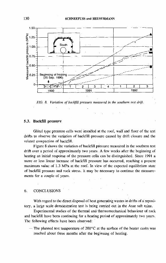
130 SCHNEEFUSS and HEUSERMANN
FIG. 8. Variation of backfill pressure measured in the southern test drift.
5.3. Backfill pressure
Glötzl type pressure cells were installed at the roof, wall and floor of the test drifts to observe the variation of backfill pressure caused by drift closure and the related compaction of backfill.
Figure 8 shows the variation of backfill pressure measured in the southern test drift over a period of approximately two years. A few weeks after the beginning of heating an initial response of the pressure cells can be distinguished. Since 1991 a more or less linear increase of backfill pressure has occurred, reaching a present maximum value of 1.3 MPa at the roof. In view of the expected equilibrium state of backfill pressure and rock stress, it may be necessary to continue the measurements for a couple of years.
6 . CONCLUSIONS
With regard to the direct disposal of heat generating wastes in drifts of à repository, a large scale demonstration test is being carried out in the Asse salt mine.
Experimental studies of the thermal and thermomechanical behaviour of rock and backfill have been continuing for a heating period of approximately two years. The following effects have been observed:
— The planned test temperature of 200° С at the surface of the heater casks; wasreached about three months after the beginning of heating.

IAEA-SM-326/29 131
— The rock temperature has reached about 80°C.— Compared with the period before heating, the measured drift closure and rock
deformation were significantly accelerated.— Distinct changes in thermally induced stress have been observed around and
between the test drifts. Most of the measuring locations showed a maximum stress change a few months after the beginning of heating.
— The backfill pressure has increased slightly.— Most of the measured data indicate that no steady state has yet been reached.— The measurement of initial stress indicates low values compared with the theo
retical overburden pressure.
For the time being, the test has been planned for an initial period of three years (until the end of 1993). However, the technical components are designed in such a way that the test can be prolonged by another three years, if this is required to reach steady state conditions of the observed rock and backfill behaviour.
REFERENCES
[1 ] K E R N F O R S C H U N G S Z E N T R U M K A R L S R U H E , D e v e lo p m e n t S ta tu s o f D ir e c t D is
p o s a l in th e F e d e ra l R e p u b l ic o f G e r m a n y , R e p . A E 2 3 E , P r o je k tg r u p p e A n d e re E n t
s o rg u n g s te c h n ik e n , K fK , K a r ls r u h e (1 9 8 9 ) .
[2] H A N IS C H , J . , K L A R R , K ., “ D ie E n ts te h u n g d e r S c h m a ls ä t te l A s s e u n d H a r l i ” , p a p e r
p re s e n te d a t 1 4 1 s t H a u p tv e r s a m m lu n g d e r D e u ts c h e n G e o lo g is c h e n G e s e l ls c h a f t ,
B r a u n s c h w e ig , 19 8 9 .
[3] P A H L , A . , H E U S E R M A N N , S . , “ D e te r m in a t io n o f s t r e s s in ro c k s a l t ta k in g t im e -
d e p e n d e n t b e h a v io r in to c o n s id e r a t io n ” , P r o c . 7 th In t . C o n g r . o n R o c k M e c h a n ic s ,
A a c h e n , 1 9 9 1 , V o l. 3 (W IT T K E , W ., E d . ) , B a lk e m a , R o t te rd a m ( in p re s s ) .


IAEA-SM-326/18
ON THE POSSIBLE CONTINUOUS OPERATION OF AN INTERGRANULAR PROCESS OF RADIATION DAMAGE ANNEAL IN ROCK SALT REPOSITORIES
A. GARCIA CELMANetherlands Energy Research Foundation ECN,Petten, Netherlands
C. DE LAS CUEVAS, P. TEIXIDOR, L. MIRALLES Saline Formations Research Laboratory*,Faculty of Geology,University of Barcelona,Barcelona, Spain
H. DONKERInstitute of Earth Sciences,State University of Utrecht,Utrecht, Netherlands
Abstract
O N T H E P O S S IB L E C O N T I N U O U S O P E R A T IO N O F A N IN T E R G R A N U L A R P R O C E S S
O F R A D I A T IO N D A M A G E A N N E A L IN R O C K S A L T R E P O S IT O R IE S .
F lu id a s s is te d r e c r y s ta l l iz a t io n (F A R ) is k n o w n to e l im in a te r a d ia t io n d a m a g e in N a C l
p o ly c r y s ta ls . B r in e m u s t b e p r e s e n t f o r F A R to p r o c e e d b u t i t a lw a y s ta k e s p la c e p ro v id e d th a t
a t le a s t 0 .0 5 w t% o f b r in e is p r e s e n t a t th e g r a in b o u n d a r y v o id s . O n ly tw o re a s o n s h a v e b e e n
p r o p o s e d a s to w h y F A R m ig h t b e s to p p e d f r o m ta k in g p la c e c o n t in u o u s ly : b r in e is c o m p le te ly
t r a n s f o r m e d in to v a p o u r a n d is u s e d u p b y d e c o m p o s i t io n d u r in g F A R . D e c o m p o s i t io n o f
b r in e w a s u n t i l n o w th e o n ly p r o o f o f F A R o p e ra t io n . T h r e e ty p e s o f e x p e r im e n ts h a v e b e e n
c o m b in e d to s h o w th a t t h e r e is n o r e a s o n to a s s u m e th a t F A R w ill n o t ta k e p la c e c o n t in u o u s ly .
E x p e r im e n ts o n s o lu t io n o f i r r a d i a te d s a l t in H 20 s h o w e d th a t th e p r e s e n c e o f c o l lo id s is
r e q u ir e d in o r d e r to d e c o m p o s e H 20 . E x p e r im e n ts c o n s is t in g o f h e a t in g s a l t p o ly c ry s ta ls a t
1 5 0 ° C a n d a tm o s p h e r ic p r e s s u r e p r o d u c e d g r a in g r o w th , i .e . r e c r y s ta l l iz a t io n a ls o o c c u r s
u n d e r th e s e c o n d it io n s . L a s t ly , i r r a d i a t io n e x p e r im e n ts o n s a l t p o ly c r y s ta ls a r e p re s e n te d in
w h ic h th e o p e r a t io n o f r e c r y s ta l l iz a t io n d u r in g i r r a d i a t io n is p r o v e n b y c o m p a r in g p r e
i r r a d i a t io n a n d p o s t - i r r a d i a t io n g r a in s iz e s . F r o m th e r e la t io n s h ip b e tw e e n th e a m o u n t o f b r in e
a n d th é e x te n s io n o f g r a in g r o w th i t is in f e r r e d th a t r e c r y s ta l l iz a t io n w a s f lu id a s s is te d .
C o m b in a t io n o f g r a in g r o w th m e a s u re m e n ts a n d im a g e a n a ly s is o f th e s a m p le s s h o w e d th a t
c o m p le te r e c r y s ta l l iz a t io n to o k p la c e m o r e th a n o n c e .
* Under contract with the National Waste Management Company of Spain (ENRESA).
133

134 GARCIA CELMA et al.
Gamma irradiation damages NaCl crystals by creating lattice defects such as F and H centres. F centres can precipitate, forming sodium metal particles of colloidal size and properties. In order for a colloid to develop, a sufficient concentration o f F centres is necessary. A crystal containing F centres and small quantities of colloidal sodium ( < 10~5 molar fraction) becomes yellow. Higher amounts of colloidal sodium in the NaCl lattice turn the rock salt blue. The energy stored in these lattice defects is of concern to policy makers considering salt rocks as host environments for radioactive waste [1, 2]. However, radiation damage can be eliminated in polycrystals through the operation of fluid assisted recrystallization (FAR) [3].
FAR consists of the solution of crystals in the intergranular fluid contained at grain boundary voids, the transport of the species in solution and the reprecipitation of the dissolved species either in crystallographic continuity with existing crystals (whose grain boundaries then migrate) or as new crystals which nucleate and grow. Lattice defects present in the material prior to dissolution are o f course eliminated in the process.
Garcia Celma et al. [3] showed that FAR takes place extensively (after irradiation) in heavily irradiated samples and eliminates radiation damage. In their experiments FAR operation was proven by the existence of fluid inclusions containing H2
and decorating the growth surfaces of the recrystallized grains. Hydrogen is produced by the reaction:
2Na + 2H20 - 2NaOH + H2
which takes place during solution of the sodium colloids at the grain boundary void.In 1987 the Brine Migration Test (BMT) experiment at the Asse mine (Remlin
gen, Germany) was finished [4] and the microstructures and extent of radiation damage in the salt formation were studied [5]. The BMT experiment consisted of in situ irradiation of salt rock by cobalt sources placed in boreholes [4]. The results o f the BMT could not be explained without assuming that FAR had taken place, but the operation of FAR could not be proven because thè original position of the grain boundaries in the mine was obviously unknown and H2 was not found.
The question then arose as to whether recrystallization could proceed without decomposing brine and/or with brine in the vapour phase. Consequently the following questions had to be answered:
— Whether recrystallization can take place when brine is in the vapour phase;— Whether recrystallization can take place in irradiated material without the
production of H2;— Whether extensive recrystallization takes place during irradiation (without the
hydrogen proof), by comparing the pre- and post-experimental positions of grain boundaries;
— Whether, after completion, recrystallization starts again.
1. INTRODUCTION

IAEA-SM-326/18 135
These questions have been answered, and the way in which this was accomplished is presented in this article.
2 EXPERIMENT ON PRODUCTION OF H2 BY SOLUTION OFIRRADIATED NaCl
A salt sample from the Potasas del Llobregat mine (Spain) was gamma irradiated using a 60Co source which allowed dose rates between 3.7 and 17 kGy/h at 40°C. The sample received an integrated dose of 2 kGy. After irradiation, low mechanical damage petrological thin sections were made and the number of colour centres was measured by light absorption (LA) with a double beam UV-visible spectrophotometer. The scanned region was between 300 and 900 nm.
Determination of the H2 obtained by solution of the sample was performed by grinding 500 mg of the sample to a grain size of around 3 mm diameter and placing it in a glass vial (V = 5 mL) which was closed with an open-hole screw cap and a septum. Afterwards the salt sample was dissolved in 1.5 mL of distilled water (Milli- pore quality). A gas sample was taken via a gas-tight syringe and H2 analysis performed immediately by gas chromatography.
By LA only F centres were detected, in an amount corresponding to 10“4
molar fraction. The detection limit of LA for colloids corresponds to 10" 6 molar fraction. Therefore the colloid molar fraction of the sample is 10~6 or lower. Thé H2 yield obtained by solution of the sample corresponded to 10~7 molar fraction of the dissolved salt.
It can thus be assumed that F centres and associated defects (H centres and dislocations) do not cause NaCl to irreversibly decompose H20 when dissolving. The H2 produced (10~7 molar fraction) is comparable to that which could be produced by a non-detected amount of colloids.
3. EXPERIMENTS ON GRAIN GROWTH IN H20 VAPOUR
Samples of pressed powder containing 0.1 wt% brine were prepared by cold pressing of analytical quality NaCl powder, as supplied by Merck, to which the corresponding weight of double-distilled water was added before pressing. The samples so obtained were placed in closed Teflon containers in which they lay loosely , andintroduced into a furnace where they remained for 30 months at a temperature of 150°C. Under these conditions the samples were not pressurized.
Grain sizes were measured in ordinary petrological thin sections by the intersection method, consisting of dividing the length of a line by the number of grain boundaries it intersects. These measurements consistently produce grain sizes lower than the true sizes but provided that all measurements are performed in the same way the results can be compared.

TABLE I. EXPERIMENTAL CONDITIONS AND RESULTS OF STORED ENERGY ÄND MICROSTRUCTURAL ANALYSIS £IN PRESSED POWDER SAMPLES **(pressed p o w d e r (PP) sam ples irrad ia ted a t 15 ± 5 kGy/h an d 100°C )
S a m p le N o . A d d e d b r in e
(w t% )
P r e s s u r e
(b a r)3T im e u n d e r p r e s s u r e
(d )
I r r a d ia t io n t im e
(h )
I n te g r a te d d o s e
(M G y )
S E
( P P ) b
(J /g )
c S E
(P P )°
(J /g )
S E
( J L ) d
(J /g )
D ia m e te r 6( / im )
1 7 P P 0.2 200 4 0 1 .3 0.02 4 .5 0 .3 0 .1 2 5 142
7 P P 0.2 200 15 1 3 .3 0.2 4 .8 0.6 0 .8 7 5 125
1 0 P P 0.2 1 1 3 .3 0.2 6:6 2 .4 0 .8 7 5 1 39
9 P P 0.6 200 15 1 3 .3 0.2 7 .0 2.8 0 .8 7 5 15 4
8P P 0.8 200 15 1 3 .3 0.2 5 .4 5 1 .2 5 0 .8 7 5 165
1 8 P P 0.2 200 2 6 1 9 .3 0 .3 3 .6 - 0.6 0 .8 7 5 197
1 6 P P 0.2 200 2 7 2 6 .6 0 .4 4 .0 - 0.2 0 .8 7 5 1 3 0
3 P P 0.2 200 16 1 7 3 .3 2.6 7 .5 3 .3 1 .1 2 5 111 0 .9 9
6P P 0.2 1 1 7 3 .3 2.6 7 .3 3 .1 1 .1 2 5 78 0 .9 6
5 P P 0.6 200 16 1 7 3 .3 2.6 6.1 1 .9 5 1 .1 2 5 3 4 0 0 .9 2
4 P P 0.8 200 16 1 7 3 .3 2.6 3 .7 - 0 . 5 1 .1 2 5 2 6 9 0 .7 5
1 1 P P 0.2 200 2 6 2 6 6 .6 4 . 0 6 .4 2.2 1 .1 2 5 128 0 .7 7
1 4 P P 0.2 1 2 6 6 .6 4 . 0 6 .5 2 .3 1 .1 2 5 101 0 .9 7
1 3 P P 0.6 200 2 6 2 6 6 .6 4 . 0 4 .8 0.6 1 .1 2 5 3 0 0 0 .9 1
1 2 P P 0.8 200 2 6 2 6 6 .6 4 . 0 5 .3 5 1 .1 5 1 .1 2 5 4 1 0 0 .9 8
GARCIA CELM
A et
al.
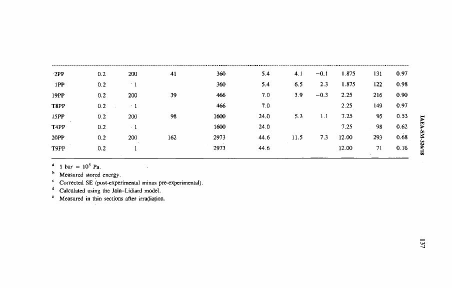
2 P P 0.2 200 41 3 6 0
1 P P 0.2 1 3 6 0
1 9 P P 0.2 200 3 9 4 6 6
T 8P P 0.2 1 4 6 6
1 5 P P 0.2 200 9 8 1 6 0 0
T 4 P P 0.2 1 1 6 0 0
2 0 P P 0.2 200 162 2 9 7 3
T 9 P P 0.2 1 2 9 7 3
á 1 b a r = 10s P a .
b M e a s u r e d s to r e d e n e r g y .
c C o r r e c te d S E ( p o s t- e x p e r im e n ta l m in u s p re -e x p e r im e n ta l) .
d C a lc u la te d u s in g th e J a in - L id ia r d m o d e l.
e M e a s u r e d in th in s e c t io n s a f te r i r r a d ia t io n .
5 .4 4 .1 - 0.1
5 .4 6 .5 2 .3
7 .0 3 .9 - 0 . 3
7 .0
2 4 .0 5 .3 1.1
2 4 .0
4 4 .6 1 1 .5 7 .3
4 4 .6
1 .8 7 5 131 0 .9 7
1 .8 7 5 122 0 .9 8
2 .2 5 2 1 6 0 .9 0
2 .2 5 149 0 .9 7
7 .2 5 9 5 0 .5 3
7 .2 5 98 0 .6 2
12.00 2 9 3 0.68
12.00 71 0 .1 6
u>-j
IAE
A-S
M-326/18
138 GARCIA CELMA et al.
Before the experiment the samples presented a mean diameter of 6 6 ^m, as measured by the intersection method. After the experiments mean grain diameters of up to 180 i*m were measured.
At 150°C and atmospheric pressure, water is in the vapour state; therefore solution, transport and reprecipitation of NaCl (FAR) took place in the presence of water vapour.
Samples similarly produced but not subjected to the experiment did not show any microstructural changes.
4. IRRADIATION EXPERIMENTS
Gamma irradiation experiments which only differ from each other in their duration, thereby giving rise, to different integrated doses, were performed using spent fuel elements of the High Flux Reactor (Petten). The dose rate was planned to be 15 kGy/h; however, owing to the decay of the activity in the fuel elements a deviation in the planned dose rate of 5 kGy/h maximum was measured. The temperature was maintained at 100°C and the samples reported here were subjected either to a pressure of 200 bar (20 MPa) or to atmospheric pressure during the experiment.
Samples of cold pressed NaCl powder o f analytical quality to which 0.2, 0.6 or 0 . 8 wt% brine was added were irradiated simultaneously in three of the experiments, while in the rest only samples to which 0 . 2 wt% brine had been added were irradiated (Table I).
The stored energy of the samples was measured in a SET ARAM (DSC-111) calorimeter. The stored energy developed by irradiation (corrected stored energy in Table I) is considered equal to the stored energy present in the samples after the experiments minus the stored energy present before irradiation as measured in equivalent samples not subjected to the experiment.
Comparing the measured stored energy with the total dose received by each sample in each experiment (Table I) shows that the amount of damage does not always increase with irradiation time.
The amount o f recrystallized material (in the cases in which colloids could develop) was measured by image analysis (Interactief Beeid Analyse Systeem, IBAS) [3] of thin sections of the same samples. IBAS consists of measuring the areas of different darkness in a thin section with the help of a video camera and a computer. As colloids are blue, and the darkness o f the sample (for equal thickness) corresponds to the amount of damage, it is possible to determine in this way the portion of a sample which is most damaged. Since the samples are of homogeneous chemical composition, they ought to be homogeneously blue if anneal did not take place. All parts of a sample which are lighter were produced during the experiment, so they were subjected to the effect o f radiation for a shorter time. This does not mean that the most damaged areas were present from the start of the experiment, but only that
IAEA-SM-326/18 139
they are the oldest. The portion of the sample which is not the darkest is assumed to be the portion of recrystallized material (Xv), or the portion o f re-recrystallized material after one or more complete recrystallizations (1 + Xv, 2 + Xv, etc.).
Grain sizes were measured by the intersection method, as indicated above. The diameters measured after the experiments are given in Table I. Since all samples at the beginning of the experiment had a mean grain diameter of 6 6 ^m, it is evident that grain growth took place in all o f them. Moreover, dark patches are always situated in the interior o f the individual salt crystals.
For short experiments (up to 4.0 MGy) the samples to which more brine had been added developed bigger grain sizes, except for sample 4PP. Therefore it appears that brine enhances grain boundary migration. Comparing the data on grain growth with the data on stored energy for each experiment, it is found that grain growth is accompanied by a reduction of stored energy.
In a comparison between some pairs of samples corresponding to experiments of different lengths (e.g. 2PP and 19PP, and 3PP and 11PP in Table I), FAR is proven by grain growth, while there was a decrease in the portion of recrystallized material measured. Therefore it has to be accepted that the oldest material determined by IBAS for samples 19PP and 11PP was newer than that corresponding to samples 2PP and 3PP, respectively. The measured portion of recrystallized material has to be increased at least by a unit between each of these two pairs o f samples.
All volumetric (re)crystallization theories have in common that the natural logarithm of the total volume [6 ] minus the recrystallized portion when plotted against time has to present the characteristics of Fig. 1. Figure 1 has been constructed from the measured data of the recrystallized portion with a unit added each time a longer experiment resulted in a smaller recrystallized portion. Total recrystallization is thus assumed to have taken place four times during our experiment. The total volume which can recrystallize must then be represented by 5; instead of the usual 1 .
Comparing Fig. 1 with Fig. 2, it is observed that the assumption of recrystallization taking place more than once is also justified by the behaviour of the stored energy measured in the samples. The stored energy diminishes with increasing irradiation time during the first 20 days of the experiment. After 20 days, the stored energy increases with irradiation time but does not reach the values expected on the basis o f the Jain-Lidiard model (Fig. 2). This agrees with recrystallization being slower after 20 days, as shown in Fig. 1. The Jain-Lidiard calculations were performed by W. Soppe (personal communication, 1990) for the conditions of each experiment.
5. DISCUSSION
Firstly, it has been shown that the solution of irradiated NaCl in H20 , which is the process responsible for brine decomposition during FAR, only decomposes the
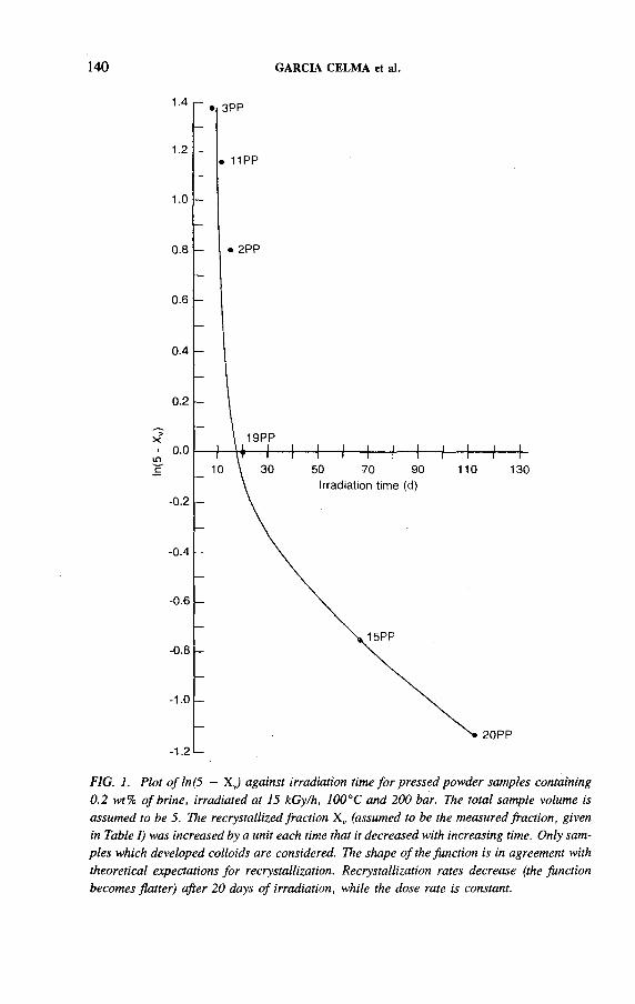
140 GARCIA CELMA et al.
FIG. 1. Plot ofln (5 — X J against irradiation time fo r pressed powder samples containing 0.2 wt% o f brine, irradiated at 15 kGy/h, 100°C and 200 bar. The total sample volume is assumed to be 5. The recrystallized fraction X v (assumed to be the measured fraction, given in Table I) was increased by a unit each time that it decreased with increasing time. Only samples which developed colloids are considered. The shape o f the function is in agreement with theoretical expectations fo r recrystallization. Recrystallization rates decrease (the function becomes flatter) after 20 days o f irradiation, while the dose rate is constant.

IAEA-SM-326/18 141
FIG. 2. Plot o f stored energy against irradiation timé fo r pressed powder samples containing 0.2 wt% o f brine, irradiated at 15 kGy/h, 100°C and 200 bar (same samples and time-scale as fo r Fig. 1). Circles correspond to the stored energy as measured in the irradiated samples by differential thermal analysis. Crosses correspond to the stored energy (SE) produced by irradiation (post-irradiation SE minus pre-irradiation SE). Triangles correspond to the stored energy which would be contained in the colloids as predicted by the Jain-Lidiard model for each o f the experiments. The stored energy abruptly decreases during the first 20 days o f the experiment in spite o f constant irradiation. After 20 days the stored energy produced by irradiation (crosses) increases but stays lower than predicted (triangles). Compare with the rate o f volumetric recrystallization as expressed by the variation o f In (5 — X J with time (Fig. 1).

142 GARCIA CELMA et al.
H20 in the presence of sodium colloids. Therefore, as long as colloids have not developed, FAR can proceed while the amount o f brine at the grain boundary is maintained.
Secondly, it has been shown that the solution and reprecipitation of NaCl, which is per definition FAR, takes place at 150°C and atmospheric pressure, in which conditions brine has to be in a vapour state. Therefore FAR can take place even in the presence of H20 vapour. Since samples not subjected to this temperature did not recrystallize, the enhancement of FAR by temperature is proven.
And lastly, the occurrence of FAR during irradiation has also been proven since, in order to produce variations in grain sizes, the grain boundaries have to migrate and grain boundary migration is per definition recrystallization.
The recrystallization which took place in the samples and experiments described here was evidently enhanced by brine; this justifies the conclusion that it was fluid assisted recrystallization.
It could be argued, with reason, that recrystallization was partially due to initial differential stresses produced by the pressurizing method and enhanced by the starting sample microstructure. However, it has been shown in Ref. [7] that confinement of these samples was reached in the experiments before 16 days of pressurizing elapsed. In Fig. 1 and Table I it can be seen that recrystallization was completed and restarted at least once after confinement was reached.
It is interesting to note that the results presented here support the assumption that the Brine Migration Test microstructures [4, 5] are produced by recrystallization before the development of the colloids.
If brine transport towards the radioactive sources, in whichever physical state, takes place during the first 500 years o f emplacement in a repository, the amount of damage present after 500 years can be disregarded in safety estimates, as shown by De Haas and Helmholdt [8]. The next question is whether, even if brine transport does not take place, recrystallization would take place, at least during the first 500 years.
If volumetric recrystallization is quicker than colloid development, colloids will never develop. Since a certain concentration of F centres is needed in order to develop sodium colloids, a situation can be envisaged in which by continuous dissolution of irradiated salt containing F centres and reprecipitation of radiation damage free NaCl (by FAR), colloids would be unable to develop. As a consequence, brine would not decompose and cyclic recrystallization could take place in a repository in the same way as it took place in our experiments.
In the situation in which volumetric recrystallization is significantly slower than colloid development, brine would be decomposed during FAR operation, and then the quéstion is whether there would be enough brine left for FAR to proceed during the first 500 years.
Colloids did develop in our experiments, but the dose rate used was at least 102 higher than the highest to be expected in repositories, while the temperature
IAEA-SM-326/18 143
was lower. A temperature higher than 100°C hinders damage formation [1] while it enhances recrystallization. On the other hand, the volumetric recrystallization rates displayed by the pressed powder samples could, in the worst case [9], if only the microstructure is taken into account, be higher than the true rates by a factor of 106. The recrystallization rates obtained here must, however, be considered to be close to the recrystallization rates that crushed-salt backfill would display. However, given the complicated relationships between all the factors of importance both in damage development and in FAR, rather elaborate computational procedures are needed in order to predict the real situation. Most hope is placed in the HAW field experiments [10] since they can directly produce both the required volumetric recrystallization rates and the amounts of H2 generated in different samples and repository conditions.
6 . CONCLUSIONS
(1) Fluid assisted recrystallization of NaCl can take place during irradiation and does not decompose the intergranular brine as long as colloids have not yet developed.
(2) FAR can also take place if the brine is in the vapour phase.(3) FAR continues to take place even when the whole sample has already been
recrystallized.(4) It. will depend on the rate of volumetric recrystallization and that of colloid
development whether brine will or will not be decomposèd by recrystallization in a repository.
(5) The relative rates of colloid development and volumetric recrystallization deserve much more attention. The HAW field experiments, however, have been planned to give direct answers to these questions, and it is of great importance that they be carried out.
ACKNOW LEDGEM ENTS
This work is one of the results of the collaboration between ENRESA (Spain) and the ECN (Netherlands) under the auspices of the Commission of the European Communities. It was performed under contract No. FI1W/0235, and is co-financed by the CEC and the Dutch and Spanish Ministries of Economic Affairs. The State University of Utrecht and the University of Barcelona are thanked for housing the researchers during this period. A. Nolten, P. Snip, H. van Wees and W. Feliks are warmly thanked for all technical support. Without them this work would not have
144 GARCIA CELMA et al.
been possible. Special thanks are due to W. Soppe, whose Jain-Lidiard calculations have been used in Table I and Fig. 2. M. Kersten helped with the preparation of the manuscript.
REFERENCES
[1 ] G R O O T E , J . , W E E R K A M P , H .R . , R a d ia t io n D a m a g e in N a C l S m a ll P a r t i c le s , P h D
T h e s is , S ta te U n iv . o f G ro n in g e n (1 9 9 0 ) 2 7 0 p p .
[2 ] P R IJ , J . , O n th e D e s ig n o f a R a d io a c t iv e W a s te R e p o s i to r y , P h D T h e s is , U n iv . o f
E n s c h e d e (1 9 9 1 ) 2 2 7 p p .
[3 ] G A R C IA C E L M A , A . , U R A I , J .L . , S P IE R S , C . J . , A L a b o ra to r y I n v e s t ig a t io n in to
th e In te ra c t io n o f R e c ry s ta l l iz a t io n a n d R a d ia t io n D a m a g e E f fe c ts in P o ly c ry s ta l l in e
S a l t R o c k s , E U R 1 1 8 4 9 E N , C E C , L u x e m b o u r g (1 9 8 8 ) 125 p p .
[4 ] R O T H F U C H S , T . , W I E C Z O R E K , K . , M c N U L T Y , E . G . , G U P T A , S .K . ,
C L A R K , D . , “ T h e B r in e M ig r a t io n T e s t — A n u c le a r w a s te r e p o s i to r y s im u la t io n
e x p e r im e n t a t th e A s s e s a l t m in e ” , in S c ie n t i f ic B a s is f o r N u c le a r W a s te M a n a g e
m e n t X I I ( L U T Z E , W . , E W I N G , R .C . , E d s ) , M a te r . R e s . S o c . , S y m p . P r o c . , V o l .
1 2 7 , M a te r ia ls R e s e a r c h S o c . , P i t t s b u r g h , P A (1 9 8 9 ) .
[5 ] G A R C IA C E L M A , A . , V A N K R IE K E N , P . , “ M ic r o s t r u c tu r a l a n a ly s is o f th e B r in e
M ig r a t io n T e s t s a m p le s ” , in E C N -8 9 - 2 4 , O P L A R e p . N o . 2 4 , M in is t ry o f E c o n o m ic
A f f a i r s , T h e H a g u e (1 9 8 9 ) .
[6 ] H U G H E S , A .E . , J A I N , S . C . , M e ta l c o l lo id s in io n ic c r y s ta l s , A d v . P h y s . 2 8 (1 9 7 9 )
7 1 7 - 8 2 8 .
[7 ] G A R C IA C E L M A , A . , D O N K E R , H . , S to r e d E n e rg y in I r r a d ia t e d S a l t S a m p le s ,
P r o g r e s s R e p o r t , E C N , P e t te n ( in p re s s ) .
[8 ] D E H A A S , J .B .M . , H E L M H O L D T , R .B . , S tr a l in g s c h a d e ro n d K S A -c o n ta in e r s in
S te e n z o u t , E C N -8 9 - 2 3 , O P L A R e p . N o . 2 3 , M in is t ry o f E c o n o m ic A f f a i r s , T h e H a g u e
(1 9 8 9 ) 4 5 p p .
[9 ] S C H U T J E N S , P . M . T . M . , I n te r g r a n u la r P r e s s u r e S o lu t io n in H a l i te A g g re g a te s a n d
Q u a r tz S a n d s : A n E x p e r im e n ta l I n v e s t ig a t io n , P h D T h e s is , S ta te U n iv . o f U tre c h t
(1 9 9 1 ) .
[1 0 ] M Ö N I G , J . , e t a l . , T h e H A W P r o je c t : T e s t D is p o s a l o f H ig h -L e v e l W a s te in th e A s s e
S a lt M in e . In te rn a t io n a l T e s t - P l a n f o r I r r a d ia t io n E x p e r im e n ts , E U R 1 2 9 4 6 E N , C E C ,
L u x e m b o u r g (1 9 9 0 ) .
IAEA-SM-326/44
ENGINEERED BLAST FEASIBILITY STUDY USING LOW SHOCK ENERGY EXPLOSIVES
J.-M . POTIER, J.-M . HOORELBEKE ANDRA,Fontenay-aux-Roses, France
G.W . KUZYK AECL Research,Pinawa, Manitoba,Canada
B. MOHANTY ICI Explosives Canada,McMasterville, Quebec,Canada
Y. SIFRE YSO Consultants,Orsay, France
A bstract
E N G I N E E R E D B L A S T F E A S IB IL IT Y S T U D Y U S IN G L O W S H O C K E N E R G Y
E X P L O S IV E S .
A ra d io a c t iv e w a s te r e p o s i to r y c o n s t r u c te d in a g e o lo g ic a l fo r m a t io n w il l c o n s is t o f
a r e a s w h e r e th e w a s te c o n ta in e r s a r e d is p o s e d o f , s e r v ic e tu n n e ls a n d o th e r e x c a v a t io n s th a t
c o n n e c t to th e s u r f a c e fa c i l i t ie s . W h e n c lo s in g th e r e p o s i to r y , i t w il l b e n e c e s s a ry to s ea l th e s e
e x c a v a t io n s w ith m a te r ia ls h a v in g lo w h y d r a u l ic c o n d u c t iv i ty to p r e v e n t th e r e m o v a l o f r a d io
a c t iv e w a s te b y g r o u n d w a te r f lo w . M a n y s tu d ie s h a v e b e e n in i t ia te d to d e v e lo p a n d d e m o n
s tr a te s e a ls m a d e f r o m c la y , b i tu m e n , c o n c r e te o r f ly a s h . H o w e v e r , a n y e f f o r t to s e a l th e
c a v i t ie s w ill b e je o p a r d iz e d i f th e w a te r h a s a p o te n t ia l f lo w p a th th r o u g h o p e n f r a c tu re s
c r e a te d in th e r o c k m a s s a d ja c e n t to th e e x c a v a t io n w a lls . T h is is s u e is a t th e ro o t o f tw o
f u r th e r r e s e a r c h a re a s : th e in je c t io n o f g r o u t in to th e f r a c tu r e d z o n e s , a n d th e m in im iz a t io n
o f b la s t d a m a g e d u r in g e x c a v a t io n . T h e p a p e r a d d r e s s e s th e o p t im iz a t io n o f b la s t d e s ig n s to
m in im iz e b la s t in d u c e d d a m a g e to th e r o c k m a s s s u r ro u n d in g th e e x c a v a t io n w a lls . A b la s t in g
p r o c e d u r e b a s e d o n th e u s e o f lo w s h o c k e n e r g y e x p lo s iv e s w a s te s te d in 1991 b y th e A g e n c e
n a t io n a le p o u r la g e s t io n d e s d é c h e ts r a d io a c t i f s (A N D R A ) , w ith p a r t ic ip a t io n o f A to m ic
E n e rg y o f C a n a d a L im i te d , a t t h e U n d e r g r o u n d R e s e a r c h L a b o r a to r y n e a r W in n ip e g ,
M a n ito b a . T h e p r o c e d u r e in v o lv e d th e im p le m e n ta t io n o f b la s t d e s ig n s to r e d u c e b la s t in d u c e d
d a m a g e to th e f in a l w a lls in a n u n d e r g r o u n d tu n n e l . T h e te s t s p e r f o r m e d in C a n a d a m a d e i t
p o s s ib le to a s s e s s in s i tu th e f e a s ib i l i ty o f th e b la s t in g p r o c e d u r e a n d c h a r a c te r iz e th e d a m a g e
z o n e u s in g g e o p h y s ic a l m e th o d s , in c lu d in g m ic ro s e is m ic a n d ‘p s e u d o f r e q u e n c y ’ s u rv e y s .
145
146 POTIER et al.
An underground radioactive waste repository will consist of disposal facilities, where the waste packages will be placed, and other excavations such as access shafts, ramps and service tunnels, required to access the disposal facilities [1]. When the vault is closed, it will be necessary to install seals with a low hydraulic conductivity to minimize any eventual release of radioactive materials that might be carried out of the vault by groundwater flow. This is particularly true for excavations that connect the bottom of the vault to the surface and possibly form a preferential pathway for groundwater to bypass the natural geological barrier. Therefore, experiments are currently in progress to develop effective seals from materials such as clay, bitumen, concrete and fly ash.
However, the effort to provide effective seals will be jeopardized if the water has a potential flow path through open fractures created in the rock mass adjacent to the excavation walls. This issue is at the root of two further research areas: the injection of grout into the fractured zones, and the minimization of blast damage to the rock mass during excavation. This paper presents a new blasting procedure intended to minimize blast induced damage to the rock mass surrounding the excavation walls. This method, using CIS ALITE, had been initially developed for the construction of road slopes. It is based on the use of low shock energy explosives to cut the rock [2]. The method, previously assessed on the surface, had to be adapted to underground mining.
The new blasting procedure was tested at the Underground Research Laboratory (URL) of AECL Research near Winnipeg, Manitoba, under the Cooperative Agreement between the Agence nationale pour la gestion des déchets radioactifs (ANDRA) and AECL. The URL is a major geotechnical research facility developed by , AECL as part of the Canadian Nuclear Fuel Waste Management Program to assess the concept of nuclear fuel waste disposal in a vault deep in stable plutonic rock of the Canadian Shield [3]. Figure 1 shows the URL and the general arrangement of the 240 Level excavations where the test drift is located.
The purpose of the.test was to demonstrate:
— The importance of energy partitioning in the blasting mechanism and the capability of the low shock energy explosives to reduce blast damage to the rock mass surrounding an excavation;
— The effectiveness of geophysical methods, including microseismic logging, for evaluating the extent of blast damage to the rock mass around an excavation.
The test consisted of nine blast rounds carried out during June 1991. The first blast round was excavated to advance the tunnel face away from the influence of existing openings. The second and third rounds were excavated with a blast design previously used at the URL. The remaining blast rounds utilized low shock energy explosives. Figure 2 shows the general arrangement of the engineered blasting test.
1. INTRODUCTION

IAEA-SM-326/44 147
FIG. 1. View o f the URL.
Several groups supported ANDRA in the blasting tests; YSO Consultants, France, provided blast design consultation support. The Laboratoire régional des ponts et chaussées de Clermont-Ferrand, France, carried out geophysical evaluations consisting of microseismic and ‘pseudofrequency’ surveys and analysis of the damage zone after each blast. ICI Explosives Canada (ICI) provided:
— A computer blasting code to assist with the selection of explosives and the preparation of blast designs;
— Electronic detonators with remotely programmable detonation equipment;— Monitoring during each blast to produce a record of explosive performance.
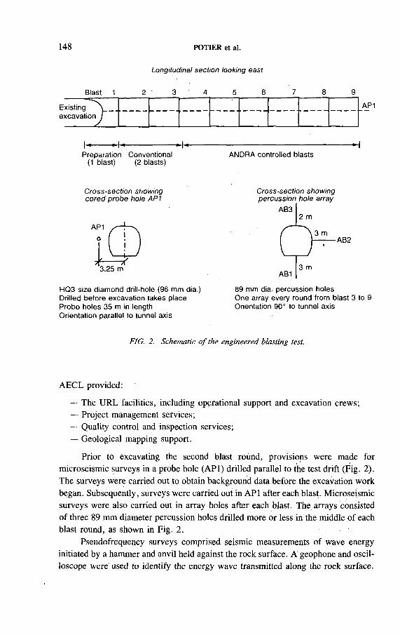
148
Longitudinal section looking east
Blast 1 2 3 4 5 6 7 8 9
POTIER et al.
Existing . excavation Г
A P 1
Preparation (1 blast)
Conventional (2 blasts)
ANDRA controlled blasts
Cross-section showing cored probe hole AP1
Cross-section showing percussion hole array
3.25 m
HQ3 size diamond drill-hole (96 mm dia.) Drilled before excavation takes place Probe holes 35 m in length Orientation parallel to tunnel axis
89 mm dia. percussion holesOne array every round from blast 3 to 9Orientation 90° to tunnel axis
FIG. 2. Schematic o f the engineered blasting test.
AECL provided:
— The URL facilities, including operational support and excavation crews;— Project management services;— Quality control and inspection services;— Geological mapping support.
Prior t o . excavating the second blast round, provisions were made for microseismic surveys in a probe hole (API) drilled parallel to the test drift (Fig. 2). The surveys were carried out to obtain background data before the excavation work began. Subsequently, surveys were carried out in API after each blast. Microseismic surveys were also carried out in array holes after each blast. The arrays consisted of three 89 mm diameter percussion holes drilled more or less in the middle of each blast round, as shown in Fig. 2.
Pseudofrequency surveys comprised seismic measurements of wave energy initiated by a hammer and anvil held against the rock surface. A geophone and oscilloscope were used to identify the energy wave transmitted along the rock surface.
IAEA-SM-326/44 149
Measurements were carried out at four stations located on the crown, walls and floor of the test tunnel for each blast round. Seismic measurements were recorded for four sources at each station.
2. GEOLOGY OF THE TEST SITE
The URL is located in the Lac du Bonnet batholith, which is considered to be typical of many granitic intrusions of the Precambrian Canadian Shield [4]. The batholith is an elongated body with a surface area of about 75 km by 25 km and a depth of 10 km. It lies in the Winnipeg River plutonic complex of the western Superior Province, and has been dated as of Late Kenoran age (2680 ± 8 1 Ma). At the URL, the batholith is made up of five main rock units: pink (altered) or grey (unaltered) granite that comprises the main ground mass of the batholith, xenolithic inclusions of various compositions, leucocratic granitic segregations and subvertical granodiorite and pegmatite dykes [5].
The intersection of Rooms 206 and 210 on the 240 Level óf the URL was selected to be the location of the tunnel for the test blasts (Fig. 1). The 240 Level was preferred because the rock properties and in situ stress conditions more closely represented potential granite disposal sites that might be used in France. Also, it was considered that it would be beneficial to compare the results with controlled blasting already carried out on the 240 Level. Geological and geomechanical properties of the rock in the test site have already been characterized and described in detail [6 - 8 ].
The predominant rock type in the test tunnel (Room 214) is a gneissic grey granite, medium grained and relatively homogeneous. Some flow layering and granodiorite dykes are present. One thin (20 mm) pegmatite dyke occurs in the extreme southwest com er, and a large xenolith (1280 mm by 175Ó mm) occurs on the southeast wall near the start of Room 214. There were no fractures intersected in Room 214. All contacts between the rock types described are tight, with no evidence of aperture, alteration or seepage.
It was found from laboratory tests that the grey granite has a Young’s modulus of 55.3 GPa, a Poisson’s ratio o f 0.18, a specific gravity of 2.68, a uniaxial compressive strength of 167.0 MPa and a tensile strength of 11.1 MPa. The maximum principal stress is 30 MPa, oriented at an azimuth of 217° and a plunge of 18° from the horizontal. The test tunnel was horizontal and oriented parallel to the direction of maximum principal stress. The other principal stresses are 11 MPa and 9 MPa.
3. BLAST DESIGNS
The principal objective of the controlled blasting tests was to demonstrate that explosives having a reduced partitioning of shock energy (energy associated with
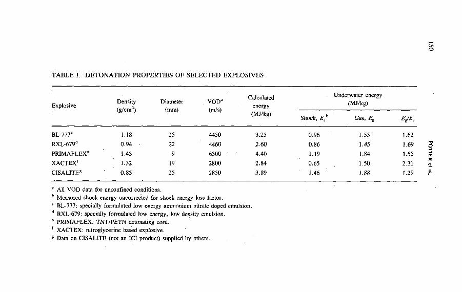
L/lО
TABLE I. DETONATION PROPERTIES OF SELECTED EXPLOSIVES
E x p lo s iv eD e n s i ty
( g / c m 3)
D ia m e te r
(m m )
V O D a
(m /s )
C a lc u la te d
e n e r g y
( M J /k g )
U n d e r w a te r e n e r g y
(M J /k g )
Shock, E * G a s , Eg Eg/Es
B L - 7 7 7 c 1 :1 8 2 5 4 4 5 0 3 .2 5 0 .9 6 1 .5 5 1 .6 2
R X L - 6 7 9 d 0 .9 4 22 4 4 6 0 2 .6 0 0.86 1 .4 5 1 .6 9
P R I M A F L E X 6 1 .4 5 9 6 5 0 0 4 .4 0 1 .1 9 1 .8 4 1 .5 5
X A C T E X f 1 .3 2 19 2 8 0 0 2 .8 4 0 .6 5 1 .5 0 2 .3 1
C I S A L I T E 8 0 .8 5 2 5 2 8 5 0 3 .8 9 1 .4 6 1.88 1 .2 9
a A ll V O D d a ta f o r u n c o n f in e d c o n d it io n s .
b M e a s u r e d s h o c k e n e r g y u n c o r r e c te d f o r s h o c k e n e r g y lo s s fa c to r .
c B L -7 7 7 : s p e c ia l ly f o r m u la te d lo w e n e r g y a m m o n iu m n i t r a te d o p e d e m u ls io n .
d R X L -6 7 9 : s p e c ia l ly fo r m u la te d lo w e n e r g y , lo w d e n s ity e m u ls io n .
6 P R I M A F L E X : T N T /P E T N d e to n a t in g c o rd .
f X A C T E X : n i t r o g ly c e r in e b a s e d e x p lo s iv e .
8 D a ta o n C I S A L I T E (n o t a n IC I p ro d u c t) s u p p lie d b y o th e rs .
POTIER et al.
IAEA-SM-326/44 151
detonation and the instantaneous elevation of pressure and temperature) would be more effective in controlling damage to the rock mass surrounding the test tunnel. Such explosives would be characterized by having a higher proportion of the blast energy release associated with the formation of gaseous products. Other characteristics of low shock energy explosives are a lower detonation pressure and velocity.
To prepare for the tests, the ICI computer blasting code SABREX 3 [9] was used to identify blasting products that would exhibit the desired characteristic of a low shock energy explosive. Since this identification required the pressure, volume and temperature (PVT) data for the explosives, it was decided that ICI products would be used for the tests. The candidate explosives, suitable for the blasting consisted of:
— BL-777, an emulsion with low shock energy characteristics, containing ammonium nitrate prills;
— BL-790, an emulsion with low shock energy characteristics;— XACTEX, a low density nitroglycerine product;— PRIMAFLEX, a TNT/PETN (60/40) detonating cord with high shock energy
characteristics;— DETAGEL, a water gel with low shock energy characteristics;— RXL-679, an emulsion with low shock energy characteristics;— DYNASHEAR, an explosive designed to cut ornamental stone.
Both experimental and theoretical characterization of selected explosives products were carried out. The former involved velocity of detonation (VOD) measurements, investigation of the ‘channel effect’ for a selected explosive considered to be particularly susceptible to such phenomena, and the standard underwater explosion test. Four of these products (BL-777, RXL-679, XACTEX and PRIMAFLEX) were selected.
The underwater test was. employed to measure energy release and derive the energy partitioning between the shock wave and gas released from the selected explosives. It is an established test for measuring the shock energy and the subsequent gas energy (as represented by the diameter of the explosion gas bubble or its periodicity) following detonation of a representative explosive charge in a test pond. The resulting energy release characteristics of the candidate explosives áre shown in Table I. XACTEX appears to have the highest ratio of gas to shock energy. This is essentially a confirmation of existing blasting practice in Canada where XACTEX has been the preferred explosive for perimeter blasting.
The blast rounds were about 3.5 m wide and 3.5 m high and varied in length from 3.0 to 3.7 m. The blast-holes had a diameter of 38 mm. The number of holes drilled for the rounds varied between 6 6 and 71, but most rounds used 70 holes. All rounds used a cut design based on three 89 mm diameter relief holes.
In blast rounds 214-2 to 214-8, all charges were primed with an electronic delay detonator and one or two 25 mm X 200 mm cartridges of Forcite 75 %, a

152 POTIER et al.
FIG. 3. Typical configuration o f blast rounds. (The diagram shows Blast No. 214-6.)
L e g e n d T y p e o f h o leN u m b e r
o f h o le sL o a d in g
T y p e o f d e to n a to r :
e le c t r o n ic
100 m s in te rv a l
D r i l l in g : le n g th 3 .0 m
P e r im e te r h o le
l o o k o u t 2 .5 °
о P e r im e te r
с C u s h io n
• P r o d u c t io n
R e l ie f
T o ta l
21
6
18
22
3
7 0
R X L -6 7 9 (2 2 m m ) tr a c e d , 6 7 % o f c h a r g e
R X L -6 7 9 (2 2 m m ) tr a c e d ,
200 m m c o l la r
R X L -6 7 9 (2 2 m m ) t r a c e d ,
200 m m c o l la r
A M E X П c o l la r s o f:
200 m m f o r c u t
200 m m f o r e a s e r s
200 m m f o r p r o d u c t io n
O n e 2 5 m m X 2 0 0 m m
F o r c i t e 7 5 % in to e o f
a l l b la s t -h o le s
8 9 m m re a m e d h o le

IAEA-SM-326/44 153
nitroglycerine based explosive. The electronic detonators provided precise timing (within 0 . 1 ms) and a large number of blasting sequence possibilities compared with only 19 delays that would have been available if the more conventional Nonel system had been used. The Forcite 75% cartridges ensured good initiation of the explosive charge and additional energy at the toe of the blast-hole, where confinement is greatest.
High shock energy explosives were used in the production holes to achieve maximum productivity in the central part o f the blast. It was considered that the production holes, located in the central portion of the blast rounds, were far enough from the perimeter of the blast to limit any damage to the final wall. Forcite 75% was used in the production holes in the first four blasts. The Forcite cartridges were fully tamped to obtain maximum column density. This product was changed in the fifth and subsequent blast rounds to AMEX II, an ammonium nitrate and fuel oil blasting agent. The AMEX II was pneumatically loaded with a blast-hole charger.
BL-777 was designated for the cushion holes, whereas RXL-679, XACTEX and PRIMAFLEX were designated for the perimeter holes in the blast rounds. RXL-679 was the only explosive that was side initiated (i.e. the 25 mm diameter explosive column of cartridges was traced with a continuous length of detonating cord). Figure 3 shows the configuration of Blast No. 214-6, which is a typical blast round configuration.
4. BLAST MONITORING
Each blast test was instrumented to monitor the performance of the explosive. The detonation velocity in each blast was monitored by incorporating a thin resistive probe in the explosive column. In addition, some individual holes were fitted with special ‘time markers’ to provide an independent reference for ascertaining the exact delay sequence in the blast.
Accelerometers served as the primary diagnostic sensors in the tests. The resonant frequency of these accelerometers was above 25 kHz, and the acceleration range was 50g to 500g. There were a total of four surface mounted seismic stations and one in-hole station. Each seismic station consisted of three orthogonally mounted accelerometers along with associated signal conditioners. The distance from the blast face to these stations ranged from 7 to 75 m. All data were recorded on wideband (DC to 45 kHz) FM recorders. The analog data were played back in the laboratory through high speed digital data acquisition equipment.
In the analysis of the blasts, consideration was given to:
— Performance of the explosives in the blast-hole,. — Accuracy of the firing time of individual charges,
— Blast results.

154 POTIER et al.
The detonation velocity in the blast-hole is an accurate measure of the quality and reproducibility of the explosive charge. The accuracy of firing time of 200 individual charges is an integral component of the measure of blasting performance and overall blast results.
4.1. Velocity of detonation
At least two holes, including the first hole to detonate (delay period No. 1), were monitored for VOD. Subsequent analysis of the results of all blasts showed that the VOD could be recorded accurately only in the blast-hole containing the No. 1 delay period detonator. All other signal cables from the VOD probes were assumed to be damaged by flying rock fragments from the previous blast-holes.
4.2. Accuracy of firing time
A typical accelerometer record, with all three components, is shown in Fig. 4. This record, for Blast No. 214-4, was made at a distance of 40 m from the blast.
100 m s
FIG. 4. Triaxial accelerometer record o f the delay sequence with electronic detonators from Blast No. 214-4.
IAEAtSM-326/44 155
The event corresponding to initiation of the blast (‘start time’) is also shown for reference. The reproduction of the delay sequence of each detonator for the whole blast is remarkably accurate. The actual firing times of the delay periods compared with the specified delay times for the electronic detonators were consistently within 2 ms, even at the highest period (2800 ms). This was essentially the limit of the resolution of the recording system.
The delay sequénce observed in Blast No. 214-9 was very different from the previous blasts. This blast used two Nonel detonators with the same delay period in each blast-hole. The record varied a great deal in detail compared with the electronic detonators. A total of at least 45 events could be identified, compared with the 18 events expected (if all detonators fired accurately). However, even a small dispersion in firing time of a Nonel detonator would result in a much larger number of seismic events than the nominal delay period. These dispersions are characteristic of all pyrotechnic detonators.
4.3. Blast results
Nine blast rounds were excavated for the engineered blast feasibility study. Table II summarizes some of the characteristics of each round. All blasts, except Blasts Nos 214-1 and 214-9, required reblasting because of various difficulties encountered in this experimental work.
The quantity expressed as percentage half-barrels in Table П is a visual indication of the blast quality. The percentage half-barrels is determined by dividing the total length of drill-hole traces or ‘half-barrels’ left on the tunnel walls after the blast by the total length of perimeter holes drilled. Since this method does not consider the extent o f fracturing or microcracking of the rock mass by the blast-hole charges, the method is not considered to be as effective as geophysical surveys in determining the extent of blast damage. The percentage half-barrels ranged from 67 to 8 6 % for the blasts using low shock energy explosives, which is similar to the findings of previous work done at the 240 Level of the URL.
5. GEOPHYSICS
Microseismic logging was carried out in diamond drill-hole API and the array holes after each blast. The microseismic logging equipment consisted of a.transmitter and two receivers located 0.34 m from the transmitter. The equipment measured the P wave velocity within a radius of 10 to 50 cm from the drill-hole wall.
Repeated microseismic surveys in API did not indicate significant velocity variations between the blasts. This was possibly because API was outside the damage zone, being drilled about 1.5 m from the east wall of the test tunnel.
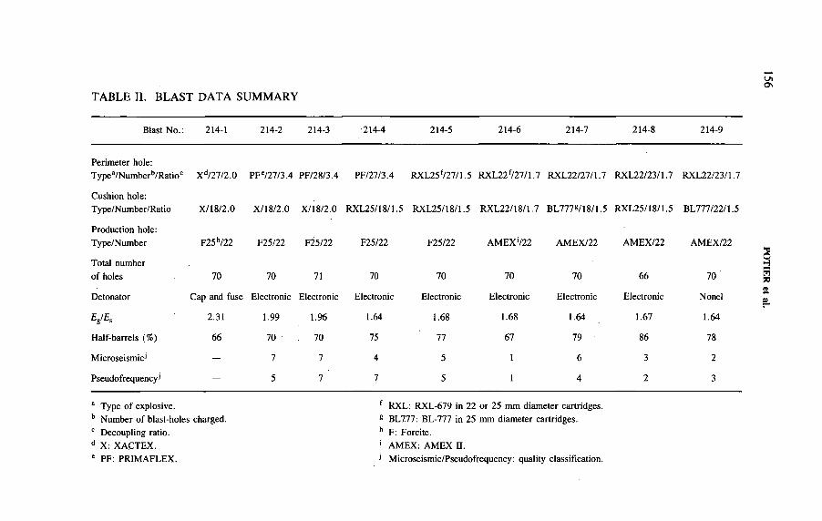
LnOs
TABLE II. BLAST DATA SUMMARY
Blast No. : 214-1 214-2 214-3 •214-4 214-5 214-6 214-7 214-8 214-9
Perimeter hole:T ypea/Numberb/Ratioc Xd/27/2.0 PFe/27/3.4 PF/28/3.4 PF/27/3.4 RXL25f/27/1.5 RXL22f/27/1.7 RXL22/27/1.7 RXL22/23/1.7 RXL22/23/1.7
Cushion hole:T ype/Number/Ratio X/18/2.0 X/18/2.0 X/18/2.0 RXL25/18/1.5 RXL25/18/1.5 RXL22/18/1.7 BL777g/18/1.5 RXL25/18/1.5 BL777/22/1.5
Production hole: Type/Number F25h/22 F25/22 F25/22 F25/22 F25/22 AMEX‘/22 AMEX/22 AMEX/22 AMEX/22
Total number of holes 70 70 71 70 70 70 70 66 70
Detonator Cap and fuse Electronic Electronic Electronic Electronic Electronic Electronic Electronic Nonel
Eg/Es 2.31 1.99 1.96 1.64 1.68 1.68 1.64 1.67 1.64
Half-barrels (%) 66 70 70 75 77 67 79 86 78
Microseismic1 - 7 7 4 5 1 6 3 2
Pseudofrequency1 - 5 7 7 5 1 4 2 3
a Type of explosive. f RXL: RXL-679 in 22 or 25 mm diameter cartridges.b Number of blast-holes charged. g BL7.77: BL-777 in 25 mm diameter cartridges.c Decoupling ratio. h F: Forcite.d X: XACTEX. ' AMEX: AMEX П.e PF: PRIMAFLEX. 1 Microseismic/Pseudofrequency: quality classification.
POTIER et
al.
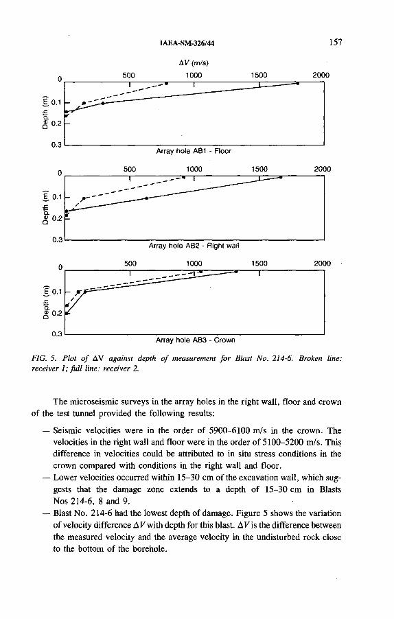
IAEA-SM-326/44 157
AV (m/s)
FIG. 5. Plot o f AV against depth o f measurement fo r Blast No. 214-6. Broken line: receiver 1; fu ll line: receiver 2.
The microseismic surveys in the array holes in the right wall, floor and crown of the test tunnel provided the following results:
— Seismic velocities were in the order of 5900-6100 m/s in the crown. The velocities in the right wall and floor were in the order of 5100-5200 m/s. This difference in velocities could be attributed to in situ stress conditions in the crown compared with conditions in the right wall and floor.
— Lower velocities occurred within 15-30 cm of the excavation wall, which suggests that the damage zone extends to a depth of 15-30 cm in Blasts Nos 214-6, 8 and 9.
— Blast No. 214-6 had the lowest depth of damage. Figure 5 shows the variation of velocity difference A V with depth for this blast. A V is the difference between the measured velocity and the average velocity in the undisturbed rock close to the bottom of the borehole.

158 POTIER et al.
The pseudofrequency wall survey was carried out after each test blast at locations on all four sides (walls, floor and crown) using a hammer source and a standard geophone. Four sets of readings, each taken about 1 m from the source, were recorded for each location. The first-arrival times and rise time to the first peak of surface waves were observed on an oscilloscope.
A plot of the signal velocity with respect to the signal rise time was used to give a qualitative estimate of the blast induced damage. This analysis showed that Blast No. 214-6 had the lowest degree of fracturing on the tunnel walls, as determined by measurement of the surface waves. Blasts Nos 214-8 and 214-9 had the next lowest degree of fracturing.
Table П also lists the quality classification of the test rounds for microseismic and pseudofrequency surveys. The classification is based on numbers from 1 to 10, with 1 0 being the best result.
6 . CONCLUSIONS
The blasting tests demonstrated that consideration should be given to the energy partition of explosives and to the type of detonator used in the blast design. Blast monitoring can be very useful in the development and optimization of blast designs.
Geophysical methods can be used to determine:
— The effectiveness of blast designs in reducing the damage to the rock mass surrounding the tunnel walls in a disposal vault,
— The optimum design to minimize blast damage in a series of tests.
Further work might be focused on the reproducibility of the blasting mechanism and procedure using low shock energy explosives, as well as its productivity within an industrial application.
ACKNOWLEDGEMENTS
The authors wish to acknowledge the support received during the study from AECL staff, T.N. Hagan (Golder Associates), H. Heraud and staff (Laboratoire régional des ponts et chaussées de Clermont-Ferrand), and staff, M. Alain in particular, from ICI Explosives Canada.
The URL is an important part of the Canadian Nuclear Fuel Waste Management Program, which is funded jointly by AECL Research and Ontario Hydro under the auspices of the CANDU Owners Group.
IAEA-SM-326/44 159
REFEREN CES
[1] HOORELBEKE, J .-M ., POTIER, J .-M ., “ Design and operating criteria o f the French deep repository for high level radioactive waste” , High Level Radioactive Waste Management (Proc. Conf. Las Vegas, 1991), Vol. 1, American Nuclear Soc., La Grange Park, IL (1991) 334-339.
[2] SIFRE, Y ., REBEYROTTE, A ., HERAUD, H ., Réalisation de talus rocheux — Résultats obtenus à partir de deux types d ’énergie explosives, Mines et carrières — Les techniques (M ay-Jun. 1988).
[3] DORMUTH, K .W ., GILLESPIE, P .A ., Nuclear Fuel Waste Disposal in Canada — The Generic Research Program, Rep. AECL-10183, Atomic Energy o f Canada Ltd(1990).
[4] DAVISON, C .C ., BROWN, A ., SOONAWALA, N .M ., “ Preconstruction site evaluation program at the Canadian Underground Research Laboratory” , Proc. 14th Information Mtg of Canadian Nuclear Fuel Waste Management Program (1982 General Meeting), Technical Record TR-207, Atomic Energy of Canada Ltd (1982) 162-187.
[5] EVERITT, R .A ., BROWN, A ., “ Subsurface geology of the Underground Research Laboratory: An overview of recent developments” , Proc. 20th Information Mtg of Canadian Nuclear Fuel Waste Management Program, Technical Record TR-375, Atomic Energy o f Canada Ltd (1986) 146-181.
[6] LANG, P .A ., EVERITT, R .A ., KOZAK, E .T ., DAVISON, C .C ., Underground Research Laboratory Room 209 Instrument Re-excavation Information for Modellers, Rep. AECL-9566-1, Atomic Energy of Canada Ltd (1988).
[7] LANG, P .A ., et al., Underground Research Laboratory Room 209 Instrument Array: Numerical M odellers’ Predictions o f the Rock Mass Response to Excavation, Rep. AECL-9566-2, Atomic Energy of Canada Ltd (1989).
[8] MARTIN, C .D ., SIMMONS, G .R ., “ The AECL Underground Research Laboratory: An overview o f geomechanics characterization” , Comprehensive Rock Engineering, Vol. 3 , Pergam on Press, N ew Y ork (1991).
[9] KIRBY, I .J . , HARRIES, G .H ., TIDMAN, J .P ., “ Computer blasting model SABREX— Basic principles and capabilities” , Proc. 13th Conf. on Explosives and Blasting Technique, Soc. o f Explosives Engineers, Las Vegas, NV (1987) 184-198.

IAEA-SM-326/54
WASTE PACKAGE AND ENGINEERED BARRIER SYSTEM DESIGN CONCEPTS FOR THE DIRECT DISPOSAL OF SPENT FUEL IN THE POTENTIAL UNITED STATES REPOSITORY AT YUCCA MOUNTAIN, NEVADA
D.J. HARRISONYucca Mountain Site Characterization Project Office,United States Department of Energy
D. STAHLB&W Fuel Company,Civilian Radioactive Waste Management System
Management and Operating Contractor
Las Vegas, Nevada,United States of America
Abstract
WASTE PACKAGE AND ENGINEERED BARRIER SYSTEM DESIGN CONCEPTS FOR THE DIRECT DISPOSAL OF SPENT FUEL IN THE POTENTIAL UNITED STATES REPOSITORY AT YUCCA MOUNTAIN, NEVADA.
The goal o f the United States Department o f Energy’s Yucca Mountain Site Characterization Project (YMP) waste package design programme is to develop a design for a waste package and associated engineered barrier system that meets the applicable regulatory requirements for safe disposal o f spent nuclear fuel and solidified high level waste in a geological repository. Attainment o f this goal relies on a multibarrier approach, the unsaturated nature o f the Yucca Mountain site, consideration of technical alternatives, and the sufficient resolution o f technical and regulatory uncertainties. To accomplish this, an iterative system engineering approach will be used. This will involve selection o f candidate designs and materials, evaluation of the designs against performance requirements, and then selection of one or two preferred designs for further detailed evaluation and final design. The reference design of the waste package described in the YMP Site Characterization Plan is a thin walled, vertical, borehole emplaced package with an air gap between the package and the rock wall. Several design concepts being evaluated during the advanced conceptual design phase of the programme include more robust designs such as small, drift emplaced packages and higher capacity, drift emplaced packages, both partially and totally self-shielded. Metallic as well as ceramic materials are being considered.
161
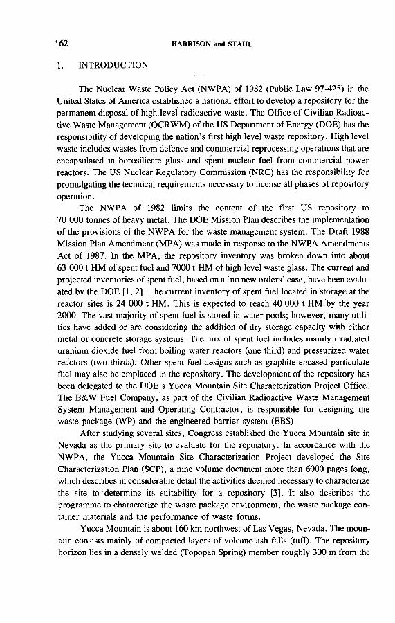
162 HARRISON and STAHL
The Nuclear Waste Policy Act (NWPA) of 1982 (Public Law 97-425) in the United States of America established a national effort to develop a repository for the permanent disposal of high level radioactive waste. The Office of Civilian Radioactive Waste Management (OCRWM) of the US Department of Energy (DOE) has the responsibility of developing the nation’s first high level waste repository. High level waste includes wastes from defence and commercial reprocessing operations that are encapsulated in borosilicate glass and spent nuclear fuel from commercial power reactors. The US Nuclear Regulatory Commission (NRC) has the responsibility for promulgating the technical requirements necessary to license all phases of repository operation.
The NWPA of 1982 limits the content of the first US repository to 70 000 tonnes of heavy metal. The DOE Mission Plan describes the implementation of the provisions of the NWPA for the waste management system. The Draft 1988 Mission Plan Amendment (MPA) was made in response to the NWPA Amendments Act of 1987. In the MPA, the repository inventory was broken down into about 63 0 0 0 1 HM of spent fuel and 70001 HM of high level waste glass. The current and projected inventories of spent fuel, based on a ‘no new orders’ case, have been evaluated by the DOE [1 ,2 ]. The current inventory of spent fuel located in storage at the reactor sites is 24 000 t HM. This is expected to reach 40 000 t HM by the year 2000. The vast majority of spent fuel is stored in water pools; however, many utilities have added or are considering the addition of dry storage capacity with either metal or concrete storage systems. The mix of spent fuel includes mainly irradiated uranium dioxide fuel from boiling water reactors (one third) and pressurized water reactors (two thirds). Other spent fuel designs such as graphite encased particulate fuel may also be emplaced in the repository. The development of the repository has been delegated to the DOE’s Yucca Mountain Site Characterization Project Office. The B&W Fuel Company, as part of the Civilian Radioactive Waste Management System Management and Operating Contractor, is responsible for designing the waste package (WP) and the engineered barrier system (EBS).
After studying several sites, Congress established the Yucca Mountain site in Nevada as the primary site to evaluate for the repository. In accordance with the NWPA, the Yucca Mountain Site Characterization Project developed the Site Characterization Plan (SCP), a nine volume document more than 6000 pages long, which describes in considerable detail the activities deemed necessary to characterize the site to determine its suitability for a repository [3]. It also describes the programme to characterize the waste package environment, the waste package container materials and the performance of waste forms.
Yucca Mountain is about 160 km northwest of Las Vegas, Nevada. The mountain consists mainly of compacted layers of volcano ash falls (tuff). The repository horizon lies in a densely welded (Topopah Spring) member roughly 300 m from the
1. INTRODUCTION
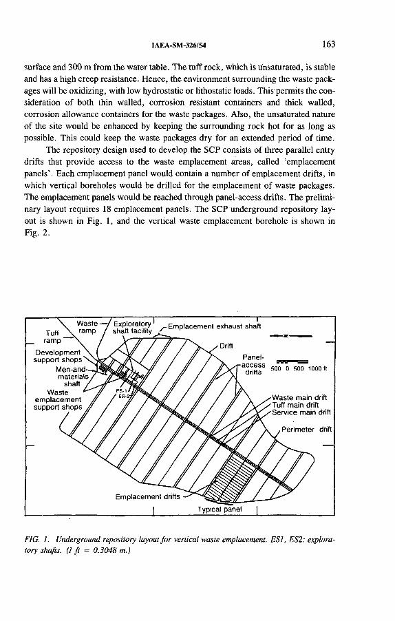
IAEA-SM-326/54 163
surface and 300 m from the water table. The tuff rock, which is unsaturated, is stable and has a high creep resistance. Hence, the environment surrounding the waste packages will be oxidizing, with low hydrostatic or lithostatic loads. This permits the consideration of both thin walled, corrosion resistant containers and thick walled, corrosion allowance containers for the waste packages. Also, the unsaturated nature of the site would be enhanced by keeping the surrounding rock hot for as long as possible. This could keep the waste packages dry for an extended period of time.
The repository design used to develop the SCP consists o f three parallel entry drifts that provide access to the waste emplacement areas, called ‘emplacement panels’. Each emplacement panel would contain a number of emplacement drifts, in which vertical boreholes would be drilled for the emplacement of waste packages. The emplacement panels would be reached through panel-access drifts. The preliminary layout requires 18 emplacement panels. The SCP underground repository layout is shown in Fig. 1, and the vertical waste emplacement borehole is shown in Fig. 2.
FIG. 1. Underground repository layout fo r vertical waste emplacement. ESI, ES2: exploratory shafts, ( l f t — 0.3048 m.)
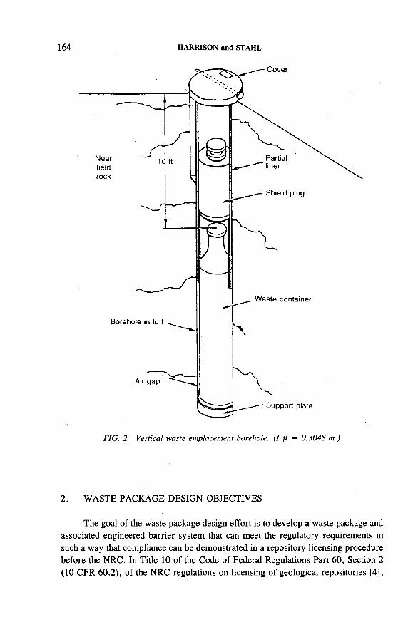
164 HARRISON and STAHL
FIG. 2. Vertical waste emplacement borehole. (1 f t = 0.3048 m.)
2. WASTE PACKAGE DESIGN OBJECTIVES
The goal of the waste package design effort is to develop a waste package and associated engineered barrier system that can meet the regulatory requirements in such a way that compliance can be demonstrated in a repository licensing procedure before the NRC. In Title 10 of the Code of Federal Regulations Part 60, Section 2 (10 CFR 60.2), of the NRC regulations on licensing of geological repositories [4],
IAEA-SM-326/54 165
the waste package is defined as “ the waste form and any containers, shielding, packing, and other absorbent materials immediately surrounding an individual waste container. ’ ’ The engineered barrier system is defined as ‘ ‘the waste package and the underground facility” which includes “ the underground structure, including openings and backfill materials, but excluding, shaft, boreholes, and their seals.” In 10 CFR 60.113, two specific performance objectives for the WP and EBS after the closure period of the repository are defined which divide the post-closure period into two time periods, conventionally referred to as the ‘containment’ and ‘controlled release’ periods. The EBS must be designed such that containment “ within the waste packages will be substantially complete for a period ... not less than 300 nor more than 1000 years after permanent closure of the geological repository.” The controlled release requirement applies to the EBS, which includes the WPs. The release from the EBS “ following the containment period shall not exceed one part in 1 0 0 0 0 0 per year of the inventory of that radionuclide calculated to be present at 1 0 0 0 years following permanent closure.”
The overall system performance requirement in 10 CFR 60.112 relates to limits on the releases of radioactive materials to the accessible environment following permanent closure as established by the Environmental Protection Agency. Other requirements from 10 CFR Part 60 also need to be addressed. These include: 10 CFR 60.21(c)(l)(ii)(D) on comparative evaluation of alternative designs that would provide longer radionuclide containment and isolation; 10 CFR 60.137 and 10 CFR 60 Subpart F on performance confirmation data that could affect the long term prediction of WP and EBS performance; and 10 CFR 60.135, which defines specific design criteria for the WP and its components. These latter criteria include constraints on the general performance of the package, its chemical reactivity, and provisions for its handling and labelling, as well as design criteria for the waste form.
3. WASTE PACKAGE DESIGN
As discussed above, the goal of the design effort is to achieve a conservative, licensable design that meets the regulatory requirements with sufficient margin for uncertainty. Attainment of this goal relies on a multibarrier approach, the unsaturated nature of the Yucca Mountain site, consideration of technical alternatives, and the sufficient resolution of technical and regulatory uncertainties. An iterative system engineering approach will be exercised. This approàch involves selection of candidate designs and materials, evaluation of the designs against the performance requirements, both from 10 CFR Part 60 and elsewhere, and selection of one or two preferred designs for evaluation in greater detail.
This reference design of the W P-EBS that was described in the SCP involves the use of thin walled, vertically emplaced WPs with an air gap between the packages and the rock wall. The design contained three pressurized water reactor and four
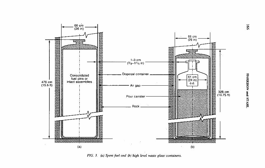
476 cm(15.6 ft)
O nOs
vw *#<« * 328 cm
(10.75 ft)
EC>IVIОZ»
слH
(a)>W >*«VW «4VW »*>W VW »W W ^»W »V«W <*>V4*>VW W M «SW< VVVV4V*VV444VV»V»W «V*VÍÍ4VV<VVV4VV«VV4V4S*«VVVV
(b)
F / G . 5 . (a) Spent fuel and (b) high level waste glass containers.

IAEA-SM-326/54 167
boiling water reactor assemblies in consolidated form. The design local thermal loading was 57 kW/acre ( —14 W /m 2). Materials studies performed by Lawrence Livermore National Laboratory extensively evaluated six alloys, including austenitic stainless steels AISI 304L and AISI 316L, austenitic nickel based Alloy 825, high purity copper CD A 102, copper-nickel alloy CD A 715 and aluminium bronze CDA 613. Nickel based Alloy C-4 and titanium Grade 12 were added to the candidate list and also evaluated extensively. Through the application of a set of selection criteria, titanium Grade 12, Alloy C-4 and Alloy 825 were found to be suitable candidates for the thin wall design. A schematic diagram of the container reference designs for both spent fuel and high level waste glass is shown in Fig. 3.
The reference design included the lowering of the waste packages via shafts to the repository level. However, more recently, the reference design has been modified to accommodate the use of ramps for waste emplacement. This, and other factors, has meant that the W P-EBS design can include consideration of larger packages that could contain more waste and allow the use of additional barriers. The larger packages could be drift rather than borehole emplaced. As a result, several concepts are being explored for more detailed evaluation during the advanced conceptual design (ACD) phase of the programme. In the ACD phase, more robust designs will be evaluated, including: small, vertical, borehole emplaced packages; small, drift emplaced packages; and higher capacity, drift emplaced packages, both partially and totally self-shielded. Metallic as well as ceramic materials are being considered. Figure 4 shows a conceptual layout of waste packages placed in an emplacement drift.
Both corrosion resistant and corrosion allowance materials will be evaluated in the ACD phase for the more robust designs. The corrosion resistant materials are likely to be those that have been identified above. The corrosion allowance materials include both iron based and copper based alloys. The iron based materials seem appropriate to the spent fuel designs. Potential material choices include low carbon structural steels, weathering (low copper) steels, low alloy steels, cast irons and coated (aluminized or galvanized) steels. Degradation mode surveys are being performed to evaluate this class of materials. The surveys will also identify gaps in the information base and provide guidance to the materials testing programme, which will run in parallel with the model development effort. The dominant degradation mode for these materials is likely to be general corrosion, so that predicting performance over the containment and post-containment periods will be simplified. However, this will be confirmed by the degradation mode surveys recently initiated. Some natural analogues, such as ore bodies and metallic artefacts, exist for these materials that can support model validation. Figure 5 shows a view of one concept that contains 2 1 pressurized water reactor fuel assemblies in a drift emplaced package with both corrosion allowance and corrosion resistant containment barriers.
Drift emplacement permits the package spacing to vary, as opposed to borehole emplacement which fixes the emplacement holes prior to emplacement, and

168 HARRISON and STAHL
FIG. 4. Horizontal emplacement o f waste packages in a drift.
FIG. 5. Multibarrier candidate waste package: exploded view o f container for 21 pressurized water reactor fuel assemblies. (1 in = 25.4 mm.)

IAEA-SM-326/54 169
therefore a range of areal heat loadings can be achieved by controlling the package spacing. A system study to evaluate the benefits of low versus high thermal loadings is currently under way. Low thermal loadings have minimal impact on the properties of the host rock, but would require a larger area for emplacement of the 70 000 t HM of waste stipulated in the NWPA. Higher thermal loadings have a greater impact on rock properties and would reduce the area required. Higher thermal loadings would keep the waste hot and the area surrounding the waste dry for a very long period of time. However, the mechanism for the condensation of water vapour and the possible return of water to the waste packages is currently not well understood. In situ coupled heater tests are planned to examine these effects. Drift emplacement also permits the use of engineered backfill materials, both above and below the waste packages. Various backfill concepts have been explored by Lawrence Livermore National Laboratory for the reference design. However, the consideration of these concepts for the design of the EBS using drift emplaced packages is just being initiated.
The WP containers will be loaded with spent fuel or high level waste canisters in the surface facility. An internal structure will be designed, in the case of spent nuclear fuel, to minimize movement of the spent fuel assemblies and to prevent damage to the container and the spent fuel. An internal chemical buffer may also be incorporated into the container to create reducing conditions within the WP. The lid of the container will be positioned and a full penetration weld will be made. Several methods have been explored for the final closure weld of the container. Of these, electron beam welding, tungsten inert gas welding, plasma welding, laser beam welding and friction welding are being further evaluated. Friction welding has been found to be suitable for Alloy 825 and copper-nickel, but not for high purity copper. Ultrasonic inspection has been selected for the non-destructive evaluation of the closure weld. This has been found to give reasonably good results for all of the welding processes under consideration.
The current design approach requires that the number of concepts be reduced during the ACD phase, which began on 1 October 1992, with the final selection being made early in the licence application design (LAD) phase of the programme, which is scheduled to begin in June 1996. The LAD will depend on inputs from other activities, including site characterization and in situ tests. Performance assessments will be made of the concepts being considered for the final selection and in greater detail for the final design. As noted above, natural analogues will be utilized, if appropriate, to partially validate the waste package performance models.
4. SUMMARY
The current efforts of the DOE’s Yucca Mountain Site Characterization Project (YMP) to design a waste package and associated engineered barrier system
170 HARRISON and ST AHI,
that meet the applicable regulatory requirements for safe disposal of spent nuclear fuel and solidified high level waste in a geological repository have been described. The reference design of the waste package described in the YMP Site Characterization Plan is a thin walled, vertical, borehole emplaced package with an air gap between the package and the rock wall. Several design concepts being evaluated during the advanced conceptual design phase of the programme include, in addition to the reference design, more robust designs such as small, drift emplaced packages and higher capacity, drift emplaced packages, both partially and totally self-shielded. Metallic as well as ceramic materials are being considered. The use of drift emplaced packages permits larger capacity packages, with higher thermal loadings, and the potential for engineering the backfill space. Higher thermal loadings would keep the waste hot and the area surrounding the waste dry for an extended period of time. However, the higher loadings may have an impact on rock properties, which requires that the mechanism for the condensation of water vapour and its possible return to the waste package be better understood. Planning for such studies is currently under way.
ACKNOWLEDGEMENT
This paper was prepared by the Yucca Mountain Site Characterization Project Office and the Civilian Radioactive Waste Management System Management and Operating Contractor as part of the Civilian Radioactive Waste Management Program. The Yucca Mountain Site Characterization Project is managed by the Office of Civilian Radioactive Waste Management of the US Department of Energy.
REFERENCES
[1 ] In te g r a te d D a ta B a s e f o r 1 9 9 1 : U S S p e n t F u e l a n d R a d io a c t iv e W a s te I n v e n to r ie s ,
P r o je c t io n s , a n d C h a r a c te r is t ic s , D O E /R W - 0 0 0 6 , R e v . 7 , D O E , W a s h in g to n , D C
(1 9 9 1 ) .
[2 ] C h a r a c te r i s t ic s o f P o te n t ia l R e p o s i to r y W a s te s , D O E /R W - 0 1 8 4 - R 1 , D O E , W a s h in g
to n , D C (1 9 9 2 ) .
[3 ] S ite C h a r a c te r iz a t io n P la n , Y u c c a M o u n ta in S i te , N e v a d a R e s e a r c h a n d D e v e lo p m e n t
A r e a , N e v a d a , D O E /R W - 0 1 9 8 , D O E , W a s h in g to n , D C (1 9 8 8 ) .
[4 ] N U C L E A R R E G U L A T O R Y C O M M IS S IO N , D is p o s a l o f H ig h -L e v e l W a s te s in G e o
lo g ic R e p o s i to r ie s ; L ic e n s in g P r o c e d u r e s , 10 C F R P a r t 6 0 , U S G o v t P r in t in g O ff ic e ,
W a s h in g to n , D C (1 9 8 8 ) .
CHARACTERIZATION AND ACCEPTANCE OF HIGH LEVEL AND ALPHA BEARING WASTES
(Session 4)
Chairmen
F. GERAItaly
L. JOHNSONUnited Kingdom

IAEA-SM-326/69
IMPORTANT ASPECTS OF WASTE CHARACTERIZATION AND QUALITY ASSURANCE AND CONTROL IN THE EUROPEAN COMMUNITIES’ RESEARCH PROGRAMME ON MANAGEMENT OF RADIOACTIVE WASTE
T. McMENAMINCommission of the European Communities,Brussels
Abstract
I M P O R T A N T A S P E C T S O F W A S T E C H A R A C T E R I Z A T I O N A N D Q U A L IT Y
A S S U R A N C E A N D C O N T R O L IN T H E E U R O P E A N C O M M U N I T I E S ’ R E S E A R C H
P R O G R A M M E O N M A N A G E M E N T O F R A D I O A C T I V E W A S T E .
T e s t in g a n d e v a lu a t io n o f h ig h le v e l a n d a lp h a w a s te fo r m s h a v e b e e n e n c o u r a g e d a n d
s u p p o r te d b y th e C o m m is s io n o f th e E u r o p e a n C o m m u n it ie s a s p a r t o f i ts v a r io u s p r o g r a m m e s
o n ra d io a c t iv e w a s te m a n a g e m e n t . T h e p a p e r s u m m a r iz e s th e m a jo r o b je c t iv e s w i th in th e
v a r io u s to p ic s o f r e s e a r c h w h ic h h a v e b e e n e x a m in e d in t h e f r a m e w o r k o f th e c u r r e n t
p r o g r a m m e . P r o je c ts h a v e b e e n c a r r ie d o u t b y á n u m b e r o f E u r o p e a n o rg a n iz a t io n s w o rk in g
e i th e r in d e p e n d e n tly o r in c o -o rd in a t io n w ith o th e r s . I n v e s t ig a t io n s o f v a r io u s to p ic s h a v e b e e n
m a d e , ra n g in g f r o m s tu d ie s o f b a s ic c o r r o s io n m e c h a n is m s in ‘s im p le ’ s o lu t io n s to m u lt ip le
p a r a m e te r in v e s t ig a t io n s w h ic h m i r r o r th e a c tu a l s i tu a t io n in a g e o lo g ic a l r e p o s i to r y . E f fo r ts
a r e b e in g d e v o te d to s tu d ie s a im e d a t c o m p le t in g a n d e n h a n c in g lo n g r u n n in g p ro je c ts w h ic h
w o u ld p r o v id e u s e f u l in p u t to th e lo n g te r m m o d e l l in g r e q u i r e d f o r s a fe ty a s s e s s m e n ts . A t th e
s a m e t im e c o n s id e ra t io n is b e in g g iv e n to th e e f f e c t o f c h a n g e s in th e c o n s t i tu e n ts o f th e g la s s
o r th e p r e s e n c e o f e x t r a n e o u s m a te r ia l s u c h a s m e ta l lo id s o n th e lo n g t e r m s ta b i l i ty . P r o je c ts ,
m a in ly o f a m u lt in a t io n a l c h a r a c te r , h a v e fo c u s e d o n p ro c e s s c o n tro ls b u t m a jo r e f f o r ts a r e
b e in g d e v o te d a ls o to th e n o n -d e s t ru c t iv e e x a m in a t io n o f w a s te p a c k a g e s f o r q u a l i ty a s s u ra n c e
a n d q u a l i ty c o n t ro l p u r p o s e s . E x a m in a t io n s ra n g e f r o m th e a s s a y o f n u c l id e in v e n to r ie s to th e
d e te rm in a t io n o f p h y s ic a l c h a r a c te r i s t ic s s u c h a s th e p re s e n c e o f c r a c k s , v o id s o r in c lu s io n s
w h ic h m ig h t a f f e c t th e in te g r i ty o f th e p a c k a g e s .
1. INTRODUCTION
As explained in detail in other papers presented at this symposium the Commission of the European Communities has been operating a series of shared cost action programmes in the field of radioactive waste management since 1975. These programmes have financially supported and encouraged research projects aimed at developing methods of safe isölation which would protect the public and the environment against the potential hazards of radioactive waste.
173
174 McMENAMIN
The choice and topics of the programmes have depended largely on thé work being carried out by those Membér States operating nuclear programmes, both small and sizeable. The CEC has acted as a catalyst in encouraging and promoting cross- border co-operation by providing support to extend national projects.
Part of the current CEC programme involves the characterization and qualification of waste forms, packages and their environment and has the following objectives:
— To determine the relevant properties and performance of waste forms and their environment (characterizations),
— To develop and validate models and databases describing the long term evolution of disposed waste,
— To improve the control of radioactivity in the waste and the quality of waste products and packages.
A number of papers, not only on these topics, were presented at the conference organized by the CEC in Luxembourg in September 1990, held to mark the completion of the third five year R&D programme on Management and Storage of Radioactive Waste [1]. Since then a number of relevant projects have been completed and the results published in final reports in the EUR series produced by the CEC. The major part of the following overview will highlight the main objectives and summarize the important conclusions reached.
Although the current, fourth, five year programme has been operational since 1991 a number of projects did not commence until well into the latter part of that year. Nevertheless thë main objectives are presented as a guide to the range of topics covered by the CEC programme. As a consequence very few results are available for publication at this stage.
2. TESTING AND EVALUATION OF HIGH LEVEL AND ALPHAWASTE FORMS
It is generally accepted that one scenario for disposal of HLW glass is that after vitrification it will be cast in stainless steel canisters. These canisters will then be stored until the heat output of the waste has decreased to an acceptable level, after which time the canister will be placed in metal overpacks whose thickness will vary, depending on the material chosen. At this stage it is probable that the containers will be placed in a deep underground repository where an additional barrier will be provided by the inclusion of a ‘backfill’ material such as clay or cementitious material.
The main geological environments being considered for a repository in the European Community are granite, clay and salt.
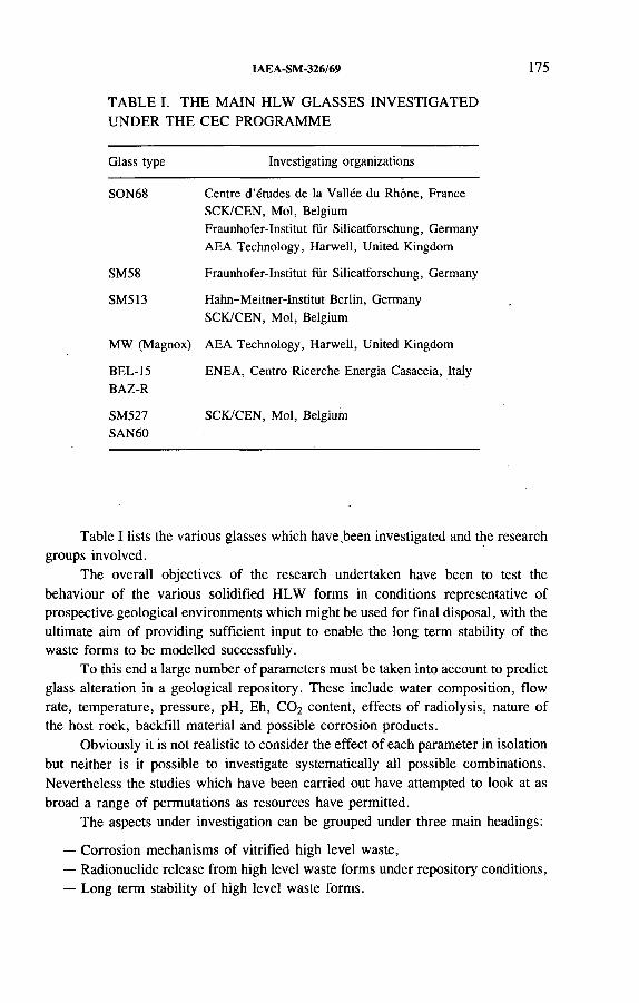
IAEA-SM-326/69 175
TABLE I. THE MAIN HLW GLASSES INVESTIGATED UNDER THE CEC PROGRAMME
G la s s ty p e I n v e s t ig a t in g o r g a n iz a t io n s
S O N 68 C e n t r e d ’é tu d e s d e la V a l lé e d u R h ô n e , F r a n c e
S C K /C E N , M o l , B e lg iu m
F r a u n h o f e r - I n s t i tu t f ü r S i l ic a t fo r s c h u n g , G e rm a n y
A E A T e c h n o lo g y , H a r w e l l , U n ite d K in g d o m
S M 5 8 F r a u n h o f e r - I n s t i tu t f ü r S i l ic a tfo r s c h u n g , G e rm a n y
S M 5 1 3 H a h n - M e i tn e r - I n s t i tu t B e r l in , G e rm a n y
S C K /C E N , M o l , B e lg iu m
M W (M a g n o x ) A E A T e c h n o lo g y , H a r w e l l , U n ite d K in g d o m
B E L - 15
B A Z -R
E N E A , C e n t r o R ic e r c h e E n e r g i a C a s a c c ia , I ta ly
S M 5 2 7
S A N 6 0
S C K /C E N , M o l , B e lg iu m
Table I lists the various glasses which have been investigated and the research groups involved.
The overall objectives of the research undertaken have been to test the behaviour of the various solidified HLW forms in conditions representative of prospective geological environments which might be used for final disposal, with the ultimate aim of providing sufficient input to enable the long term stability of the waste forms to be modelled successfully.
To this end a large number of parameters must be taken into account to predict glass alteration in a geological repository. These include water composition, flow rate, temperature, pressure, pH, Eh, C 0 2 content, effects of radiolysis, nature of the host rock, backfill material and possible corrosion products.
Obviously it is not realistic to consider the effect of each parameter in isolation but neither is it possible to investigate systematically all possible combinations. Nevertheless the studies which have been carried out have attempted to look at as broad a range of permutations as resources have permitted.
The aspects under investigation can be grouped under three main headings:
— Corrosion mechanisms of vitrified high level waste,— Radionuclide release from high level waste forms under repository conditions,— Long term stability of high level waste forms.
176 McMENAMIN
2.1. Corrosion mechanisms of vitrified high level waste
On the whole the main efforts have been devoted to laboratory studies directed at the following specific areas:
— To facilitate studies on the long term corrosion mechanisms in solutions, powdered glass samples to provide high surface area to volume (SA/V) ratios, and/or high temperatures have been used as accelerating parameters;
— Using standard monolithic glass samples, the corrosion mechanisms in solutions in contact with geological material such as clay have been investigated.
Several laboratories have been involved in efforts to examine the basic corrosion mechanisms in solutions.
The Centre d ’études de la Vallée du Rhône (CEA-Valrhô) in Marcoule, France [2], using granitic groundwater and a temperature of 90°C, examined monolithic glass pieces with SA/V = 400 m “ 1 and powdered samples to provide SA/V ratios of 2000, 8000 and 20 000 m '1.
The Fraunhofer-Institut für Silicatforschung in Würzburg, Germany [3], has studied corrosion of SON6 8 in three types of salt brine, two of which were MgCl2
based and the other NaCl based. The results indicate that the influence of the basic composition of the leachate should be considered carefully as adsorption processes obviously retard the diffusion of alkalis out o f the glass.
The SCK/CEN in Mol, Belgium [4], has been involved in this programme and has carried out a wide ranging series of experiments which have included studies of corrosion mechanisms in clay based environments. The results of this project are the subject of another paper in this session [5].
2.2. Radionuclide release from high level waste forms under repository conditions
The rationale behind the provision of the different barrier layers mentioned above is to retard the ingress of water to the glass surface for as long as possible and therefore delay the transport of radioactive material into the geological environment and ultimately into the biosphere.
At the outset the main isotopes of concern are 137Cs and 90Sr but as they have half-lives of 30 years they will have decayed to negligible levels after several hundred years. For the period covering thousands to a few tens of thousands of years most of the potential hazard will emanate from the isotopes of Am and Pu, which will be superseded by 237Np and 99Tc for the very long term.
The behaviour of an HLW glass in a repository has been considered from the point of view of its leaching behaviour, which covers three main aspects:

IAEA-SM-326/69 177
— The extent of glass alteration, which governs the quantity of actinides mobilized through corrosion;
— The amount of actinide retention in the altered glass film;— The degree to which the engineered barrier retains the actinides released,
e.g. by adsorption.
2.2.1. Repository conditions
A comprehensive set of tests were carried out at the CEA-Valrhô [6 ] to study the effect of environmental materials on the leaching of transuranium nuclides. The material used was a glass pellet of SON6 8 doped with 237Np, 239Pu or 238Pu/241Am placed in contact with one of seven environmental media mixtures. The tests were carried out on samples with SA/V = 50 rrT1 at a temperature of 90°C for periods of 3, 6 , 9 and 12 months.
Although it can be said that the lower the quantity of actinide in solution the more satisfactory the medium, it is even more desirable if the actinides remaining are contained in the glass or at least in the alteration film rather than in the barrier materials.
Therefore, taking this into consideration, it can be said from the various results obtained that the most satisfactory geological medium appears to be, in terms of overall performance, bentonite (clay), followed by granite and sand.
Experiments at AEA Technology, Harwell, United Kingdom [7], used mainly MW glass which was doped with isotopes of Te, Np, Pu and Am, although SON6 8
was also used for some of the tests. In this series the majority of the backfill materials tested tended to be cementitious.
The main results which have been obtained show that the presence of ordinary Portland cement reduced the leach rate of the glass rather than increasing it as might have been expected with the high pH. In addition, with backfill containing ordinary Portland cement and under reducing conditions, Np and Am were sorbed more efficiently than in bentonite.
An understanding of the basic mechanisms of aqueous corrosion is absolutely essential in developing models to describe the long term effects. Nevertheless further integral experiments examining multiple parameter effects of a geological repository have to be carried out to examine what takes place under realistic conditions.
In France, considerable work has been put into integral tests [6 ] whereby, using specially designed leaching cells, SON6 8 glass blocks have been in contact with the different geological media of granite, salt and clay. The cells are so constructed that the glass is in contact with materials representative of the host rock and engineered barrier, with small oxidized metal fragments simulating the canister overpacks and with an aqueous medium typical of the environment under investigation.
From these tests it could be seen that glass was only slightly altered in salt and granite media whereas a major alteration was observed in the clay medium itself. The
178 McMENAMIN
reason for the latter effect has been postulated as being due to the high clay mass to glass surface area which prolongs the time required to reach saturation.
2.3. Long term stability of high level waste forms
In addition to aqueous corrosion, long term stability can be affected by several other major factors such as mechanical, thermal and radiation processes.
2.3.1. Mechanical stability
It must be accepted that the stresses imposed on a full scale HLW glass block during the cooling process will lead to the formation of cracks and fractures. The CEA-Valrhô [8 ] has conducted a series of studies on various cooling scenarios to assess and examine the full impact of this cracking, which has been estimated to result in a leachable surface area 10-15 times greater than the geometrical area.
Although it is always desirable to limit the formation of cracks it was found that there are no significant gains to be made by prolonging the cooling period. It has also been found that even after two years’ leaching at 90°C the surface area remains 1 0 - 1 2 times the geometrical area.
2.3.2. Thermal stability
Investigations into the effects of crystallization have been carried out by the Hahn-Meitner-Institut Berlin [9] on PAMELA HLW glass SM513LW11 and SON6 8 . For. the compositions in current use the effect of crystallization on the long term integrity was insignificant in both cases.
2.3. 3. Radiation stability
High radiation levels will be present in a repository or storage facility and could have an effect on the waste matrix. To investigate this both HLW glass [7] and ceramics [1 0 ] have been examined by preparing samples which incorporate large amounts of short lived actinides in order to simulate in a few years the dose which would accumulate from decay over many centuries or longer.
Investigations were made of the effects on density, leaching and mechanical properties. In general although minor changes were detected, in particular with the ceramics, none were great enough to indicate: that they would have significant impact on the long term integrity.

IAEA-SM-326/69 179
2.4. Current projects
As mentioned before considerable work has gone into the study of SON6 8
glass in a wide variety of conditions. The Kernforschungszentrum Karlsruhe [11] is currently undertaking a project which complements previous work by examining the chemical durability of ‘real’ waste glass material in a concentrated Mg rich salt solution as a function of time and temperature.
The results from previous work on inactive samples will be completed by investigating the release of Tc and the actinide elements Pu, Am and Np into solution and their precipitation or inclusion in secondary phases, the solubility of which could control the solution concentrations of the elements under examination.
An extensive programme of long term experiments is planned as the corrosion rates are expected to be low ( < 1 0 ~ 3 g -nT 2 -d_1) and a time dependence of the rate can'only be derived if a substantial number of data from an extended period of time are available.
The overall aim is to obtain an improved source term for the vitrified waste which may be used in the frame of safety studies for a repository in Germany.
The CEA-Valrhô [12] is working on a basic research programme to determine the influence of the composition of the glass on its long term behaviour in a geological repository as variations in the chemical composition of the glass matrices affect their aqueous corrosion resistance.
Magnesium oxide may be present in fission product solutions from spent fuel reprocessing plants designed for vitrification. For example, some glass compositions used in the United States of America contain from 0.2 to 1.6 wt% MgO. Numerous results are available on the short and long term behaviour in water of SON6 8
reference glass, which contains no magnesium. It is therefore worth while to determine to what extent the long term behaviour of SON6 8 can be applied to other nuclear glass compositions which generally contain magnesium.
Comparisons are being made of the stability of glass compositions differing mainly in their MgO content and network former content. The results from these studies will be used to assess the effects that such variations will have on significant model parameters, i.e. dissolution rate, equilibrium pH and solubility limit, and the role of newly formed phases.
Preliminary results indicate that increasing the concentration of fluxing elements and decreasing the quantity of silica in a glass reduce its stability in water. Similarly, small quantities of MgO added to SON6 8 and other glass types reduce the stability of the glass in water at 90 and 100°C.
A programme being carried out by ONDRAF/NIRAS in Brussels [13] in co-operation with the SCK/CEN on the interaction between HLW glasses and the Boom clay disposal medium is a continuation of work which was started in the second CEC programme and which will be discussed in detail elsewhere [5]. The
180 McMENAMIN
results from the present project should finalize this extended programme and be used in long term predictive modelling.
Another aspect which is being investigated by the CEA-Valrhô [14] is the feasibility of incorporating in glass the extremely small particulate matter, known as ‘fines’, still present after the clarification step of centrifugation in the PUREX process.
These fines are micrometre-scale particles and are likely to consist mainly of fission products. Of special interest are the platinoids Ru, Rh and Pd, which are not soluble in glass. In particular, Ru and Rh are likely to pose the most problems as they are highly radioactive and release appreciable amounts of heat. It is thought that ‘hot spots’ generated by the presence of these particles in the glass matrix could lead to sites of crystallization with the possible repercussions of alteration and resultant degradation of the glass.
The project aims at characterization of glass samples containing authentic fines to ascertain the likely distribution of the particles and to assess the degree of crystallization and to what extent it may affect the containment properties.
In addition to HLW glass and other forms of conditioned waste there is the possibility that, after encapsulation in canisters, unprocessed irradiated fuel will also be eventually placed in underground repositories. Therefore basic research is needed for understanding and modelling the long term performance of the fuel under disposal conditions.
At the Kernforschungszentrum Karlsruhe [15] a research programme is under way which aims at the characterization and qualification of the chemical durability of unprocessed high burnup U 0 2 fuel as a barrier against radionuclide release for disposal sites in salt formations. The reaction behaviour of the fuel in saline brines will be studied as a function of time, temperature, redox potential and surface area to obtain information on the corrosion mechanisms and sources of radionuclide release.
As U 0 2 solubility may play a role in the degradation of the fuel matrix the solubility of unirradiated U 0 2 in salt brines is being studied for comparison with the reaction behaviour of the irradiated material in order to identify radiolysis and bumup effects.
The ultimate aim is to provide a basis for modelling to bridge the gap between experimental results and performance assessment for long term storage of the fuel in a repository in a salt formation in the event o f brine intrusion.
3. QUALITY ASSURANCE AND QUALITY CONTROL
Quality assurance and quality control as applied to conditioned waste and packages cover a wide range of topics and involve many different steps or procedures.

IAEA-SM-326/69 181
To qualify for final disposal in a repository, waste packages have to fulfil a number of requirements, compliance with which constitutes the basis for the specification of the waste as defined by the producer and is the primary objective of quality assurance.
A number of the more technical aspects o f evaluating the physical characteristics or the chemical nature of the finished product, which can be looked upon as the quality control of a product to ensure achievement of predetermined specifications, are the focus of various projects. These have involved the development up to industrial level o f methods and techniques which would allow the verification of the radionuclide contents and characteristics of waste packages with regard to meeting the safety requirements formulated by the authorities responsible for disposal.
3.1. Process control
The process control project is a tripartite co-operative effort co-ordinated by the Keuring van Electrotechnische Materialen (КЕМA) in Arnhem, Netherlands, with the Forschungszentrum Jülich, Germany, and LABORELEC in Linkebeek, Belgium, in association with the Centre d ’ètudes de Cadarache in Saint-Paiil-lez- Durance, France [16]. The research concerns process control during radioactive waste conditioning on an industrial scale of wastes from BWR and PWR power stations.
The project consists of three main topics, which can be summarized as follows:
— Inventories will be made, in the countries of the partners, of waste management routes based on cementation, and of the quality actions and requirements of the authorities, the results o f which will be presented in flow charts.
— Chemical characterization of the various waste streams will be carried out in order to assess the effects of the constituents on the choice of waste handling and waste conditioning, processes (e.g. cement poisons).
— Radiological test methods and methods to qualify the cementation process will be developed for practical use at sites of nuclear power plants.
After validation of the tests and procedures under realistic conditions the results from the project will be evaluated and standard test methods and procedures will be recommended as a general approach for process control.
3.2. Radionuclide inventory of main waste streams
W ork on this theme involves a six sided project which is being jointly co-ordinated by the CEA-Cadarache and the Gesellschaft für Reaktorsicherheit, Cologne, Germany, with the participation of ONDRAF/NIRAS, the Centro Ricerche Energia Saluggia of the ENEA in Italy, ENRESA in Spain and AEA Technology in Dounreay, United Kingdom [17].
182 McMENAMIN
The aim of this project is the characterization of the radionuclide inventory of the isotopes of critical importance for the safety of storage and disposal from the main radioactive waste streams of the participating countries.
The study has three main objectives:
— Checking and standardization of existing analytical methods for application toreal samples from the main waste streams,
— Development of new alternative analytical methods for long lived nuclides,— Establishing of correlations for criticál radionuclides to easily measurable key
nuclides.
Samples of each of the waste streams will be analysed for both easily measurable key nuclides and critical isotopes as determined by the national safety assessments.
Since the necessary analytical techniques to determine all of these radionuclides are not fully available at present, a large part of this programme is devoted to the development o f new procedures.
For the measurement results and the parameters necessary for their interpretation data banks will be established and evaluated for the correlation exercise.
3.3. Non-destructive assay of radionuclide inventories in solid waste
One of the main requirements for a disposal facility will be a procedure for checking the radionuclide inventory of a waste package on receipt at the repository. An extensive programme involving both theoretical arid experimental research has been undertaken in laboratories supported by the European Communities to identify equipment and technology which can enable these tests to be carried out, with particular attention being placed on non-destructive methods.
A joint project undertaken by the CEA-Cadarache and AEA-Harwell [18] provided a detailed survey of most of the relevant alpha contaminated solid waste arisings in six of the Member States of the CEC. The countries involved and a summary of the survey are presented in Table II. The non-destructive analysis (NDA) techniques used and a measure of their frequency'of use are also summarized.
In parallel with this project and from the results of previous studies it was realized that there were a number of shortcomings in the measuring capabilities of some establishments. To overcome this the concept of a mobile NDA facility incorporating a variable geometry system has been examined and at the end of the 1985-1989 programme the conceptual design was well advanced [19].
At present one of the main methods used to determine fissile material in high density waste drums is active neutron interrogation based on the counting of high energy fission neutrons induced in the fissile material by a radioactive source such as Sb-Be. Such a system can be used to determine directly the fissionable nuclides 233U, 235U, 239Pu and 241 Pu but needs a shielded site for operation.

IAEA-SM-326/69 183
TABLE II. SUMMARY OF SURVEY OF ALPHA CONTAMINATED SOLID WASTE ARISINGS
C o u n tr ie s
S to c k
A n n u a l p ro d u c t io n
D e n s i ty ra n g e
A v e ra g e d e n s i ty
M a tr ix
E x is t in g N D A s y s te m s :
f r e q u e n c y o f u s e a
A n tic ip a te d m e th o d s
B e lg iu m , F r a n c e ,
F e d e r a l R e p u b l ic o f G e rm a n y ,
I t a ly , .S p a in , U n ite d K in g d o m
6 0 0 0 0 m 3 (4 0 0 0 0 m 3 in c e m e n t) ,
e q u iv a le n t to 5 0 0 0 0 0 d r u m s
(2 2 0 L )
11 000 m 3, e q u iv a le n t to
5 0 0 0 0 d r u m s (2 2 0 L )
,0 . 1-2
0 .3 (8 0 % o f th e c o u n tr ie s )
0 .7 (m e a n v a lu e f r o m a r is in g s )
P V C , p a p e r , r e s in , c e m e n t , m e ta l ,
a s h
H R G S : 3 5 %
P N C C : 3 2 %
L R G S : 1 3 %
P N T C : 1 3%
A N T : 7 %
A N T
H R G S
P N C C
H R G S : h ig h r e s o lu t io n g a m m a s p e c tro s c o p y ;
P N C C : p a s s iv e n e u t ro n c o u n tin g w ith c o in c id e n c e ;
L R G S : lo w re s o lu t io n g a m m a s p e c tro s c o p y ;
P N T C : p a s s iv e n e u t r o n , to tá l c o u n t in g ;
A N T : a c t iv e n e u t ro n te c h n iq u e .
The Forschungszentrum Jülich, in co-operation with the SCK/CEN [20], has started a project with the aim of optimizing the existing design assay system for large volume matrices.
Neutron transport calculations are being carried out at Mol to develop a theoretical understanding, e.g. of neutron transport properties in high density matrices, and assess improvements o f the assay system.
184 McMENAMIN
Experiments are being carried out at Jülich to characterize alternative neutron sources, such as Am -Li, which would lead to an improved assay system with reduced dose rates and avoid the disadvantages of the short half-life and the high gamma shielding requirements of 124Sb.
3.4. Non-destructive examination of physical characteristics
In the field of non-destructive testing significant progress has been achieved. For example, high resolution computer tomography has been applied to the investigation of HLW glass blocks by the AEA-Harwell [21] and the Bundesanstalt für Materialprüfung (BAM) in Berlin [22]. They have shown that computerized tomography and X ray absorptiometry form one of the best methods for the comprehensive non-destructive characterization of conditioned and sealed waste packages in a range of matrix materials such as bitumen, concrete, ceramic and glass. Using an external source of radiation and an array of detectors cross-sectional images are obtained in line by line fashion as shadowgraphs or digital radiographs.
Although the potential and feasibility of the method were clearly demonstrated it was realized that with the systems used the measuring time was quite slow. A project is currently under way at the BAM [23] with the main objective of achieving a maximum measuring time of 10 min for a 200 L drum of cemented waste. To achieve this a new detector and array are being designed which will be controlled by improved computer software which has been written specially for this system and is at present in the test phase.
The non-destructive investigation to be carried out will focus on drums of cemented waste, glass in stainless steel containers and microcomputerized tomography of cored samples.
As far as HLW glass blocks are concerned the method is particularly suited to detecting cracks or voids, the extent o f which would be indicative of the cooling scenario to which the package had been subjected.
In conjunction with the CEA-Valrhô a parallel project is being carried out with the goal of using tomographic investigation to qualify and quantify the principal defects which occur during fabrication of the vitrified waste. These are recognized as being:
— Formation of cracks and cavities, which increases the surface area whichwould be exposed to water;
— Formation of molybdic inclusions, which are water soluble.
The main aim is to develop a non-destructive method which would provide accurate knowledge of the condition of the glass.
As mentioned above it has been demonstrated that computerized tomography can be used for a number of applications, but systems have not been developed specifically to accommodate highly radioactive and/or large (encapsulated) waste

IAEA-SM-326/69 185
packages. The AEA-Harwell [24], as co-ordinator, is collaborating with the BAM in a project with the acronym HEAT (High Energy Accelerator Tomography).
The aim of this project is to investigate techniques specifically matched to gamma ray transmission tomography of highly active and/or very large objects. It is proposed to use apparatus which is intrinsically insensitive to the background radiation by employing Cerenkov counters, which have a gamma ray energy response that exhibits a low energy threshold and a non-linear response up to gamma ray energies o f several megaelectronvolts. The technique is based on the measurement of gamma ray transmissions with electron bremsstrahlung from a linear accelerator as the photon source.
Development of this method of NDA would have the following advantages:
— The insensitivity of the detectors to the background of low energy scattered gamma rays from the accelerator should relax the shielding requirements for the detectors.
— The intrinsically greater sensitivity of the detectors to the higher energy gamma rays of the electron bremsstrahlung than to the relatively low energy gamma radiation from radioactive waste packages will produce a significant improvement in signal to background ratio in tomographic measurements. This should enable high quality tomograms of even the highest activity waste packages to be obtained.
4. CONCLUSION
By no means have all of the projects involving participation of the CEC been mentioned here but it is quite obvious from the range of topics that the CEC, by supporting financially and encouraging multinational co-operation through its programme of radioactive waste management, is actively involved in the development of methods and techniques for the control and safe disposal of radioactive waste.
REFERENCES
[1 ] C E C I L L E , L . ( E d .) , R a d io a c t iv e W a s te M a n a g e m e n t a n d D is p o s a l ( P r o c . C o n f .
L u x e m b o u r g , 1 9 9 0 ) , E U R 1 3 3 8 9 , E l s e v ie r A p p lie d S c ie n c e , A m s te r d a m (1 9 9 1 ) .
[2 ] V E R N A Z , E . , D U S S O S S O Y , J . L . , B a s ic M e c h a n is m s o f A q u e o u s C o r r o s io n o f
N u c le a r W a s te G la s s e s , E U R 1 3 6 0 5 , C E C , L u x e m b o u r g (1 9 9 1 ) .
[3] R O G G E N D O R F , H . , S E B A S T IA N , K . , C O N R A D T , R . , O S T E R T A G , R . , In v e s t ig a
t io n o f th e L o n g - T e r m B e h a v io u r o f H L W G la s s u n d e r C o n d i t io n s R e le v a n t to F in a l
S to r a g e , E U R 1 3 6 0 9 , C E C , L u x e m b o u r g (1 9 9 2 ) .
186 McMENAMIN
[4 ] V A N IS E G H E M , P . , B E R G H M A N , K . , L E M M E N S , K . , T I M M E R M A N S , W .,
W A N G , L ia n , L a b o ra to r y a n d in S itu In te ra c t io n b e tw e e n S im u la te d W a s te G la s s e s a n d
C la y , E U R 1 3 6 0 7 , C E C , L u x e m b o u r g (1 9 9 2 ) .
[5] V A N I S E G H E M , P . , L E M M E N S , K . , IA E A - S M -3 2 6 /3 6 , th e s e P r o c e e d in g s .
[6] G O D O N , N . , A N D R I A M B O L O L O N A , Z . , M E S T R E , J . P . , V E R N A Z , E . , R a d io
a c t iv e S O N 6 8 1 8 1 7 L 1 C 2 A 2 Z 1 G la ss In te ra c t io n w ith E n v i ro n m e n ta l M a te r ia ls ,
E U R 1 3 6 1 3 , C E C , L u x e m b o u r g (1 9 9 2 ) .
[7 ] B O U L T , K .A . , e t a l . , R a d io n u c l id e R e le a s e f r o m S o lid if ie d H ig h L e v e l W a s te ,
E U R 1 3 6 0 4 , C E C , L u x e m b o u r g (1 9 9 1 ) .
[8] M O N C O U Y O U X , J . , A U R E , A . , L A D IR A T , C . , In v e s t ig a t io n o f F u l l -S c a le H ig h -
L e v e l W a s te C o n ta in m e n t G la s s B lo c k s , E U R 1 3 6 1 2 , С Е С ,- L u x e m b o u r g (1 9 9 1 ) .
[9] M A L O W , G . , B E H R E N D , U . , S C H U B E R T , P . , C h a r a c te r iz a t io n o f H L W G la s s
S a m p le s , E U R 1 3 6 0 8 , C E C , L u x e m b o u r g (1 9 9 1 ) .
[1 0 ] L O I D A , A . , P E IS A , R . , L o n g - T e rm B e h a v io u r o f T R U -W a s te -B e a r in g C e r a m ic s ,
E U R 1 3 6 0 2 , C E C , L u x e m b o u r g (1 9 9 1 ) .
[1 1 ] L U T Z E , W ., K A H L , L . , R e te n t io n o f P u , A m , N p a n d T c in th e C o r r o s io n o f C o g é m a
G la s s R 7 T 7 in S a l t S o lu t io n s , C E C C o n tra c t C T - F I 2 W - 0 0 1 2 , P r o g r e s s R e p o r t , 1 9 9 1 .
[1 2 ] J A C Q U E T - F R A N C I L L O N , N . , A q u e o u s C o r r o s io n o f N u c le a r G la s s e s — In f lu e n c e
o f D is p o s a l C o n d it io n s , C E C C o n tra c t C T - F I 2 W - 0 0 2 7 , P r o g r e s s R e p o r t , 1 9 9 1 .
[1 3 ] S W E N N E N , R . , L E M M E N S , K . , T h e C o r r o s io n o f N u c le a r W a s te G la s s e s in a C la y
E n v i r o n m e n t — M e c h a n is m s a n d M o d e ll in g , C E C C o n tr a c t C T - F I 2 W - 0 0 3 1 , P r o g r e s s
R e p o r t , 19 9 1 .
[1 4 ] J A C Q U E T - F R A N C I L L O N , N . , E f fe c t o f In s o lu b le A c t iv e D is s o lu t io n F in e s o n F i s
s io n P r o d u c t G la s s e s , C E C C o n tr a c t C T - F I 2 W - 0 0 2 8 , P r o g r e s s R e p o r t , 1 9 9 1 .
[1 5 ] G R A M B O W , B ., D E P A B L O , J . , C h e m is tr y o f th e R e a c t io n o f F a b r ic a te d a n d H ig h
B u rn u p S p e n t U 0 2 F u e l w ith S a lin e B r in e s , C E C C o n tra c t C T - F I 2 W - 0 0 5 5 , P r o g re s s
R e p o r t , 1 9 9 1 .
[1 6 ] C O R N E L I S S E N , H .A . W . , T e s ts fo r P r o c e s s C o n tro l D u r in g T r e a tm e n t o f L o w a n d
M e d iu m R a d io a c t iv e W a s te in P r a c t ic e , C E C C o n tra c t C T - F I 2 W - 0 0 1 9 , P r o g re s s
R e p o r t , 19 9 1 .
[1 7 ] R A Y M O N D , A . , In v e n to ry a n d C h a r a c te r iz a t io n o f I m p o r ta n t R a d io n u c l id e s f o r S a fe ty
a n d S to r a g e — C o r r e la t io n to K e y N u c l id e s E a s y to M e a s u re in W a s te T y p e s , C E C
C o n tra c ts C T -F I2 W -0 0 3 4 a n d 1 0 9 , P r o g r e s s R e p o r t , 1 9 9 1 .
[1 8 ] B R E M N E R , W .B . , A D A W A Y , D .W . , Y A T E S , A . , S u rv e y o f E E C S o lid W a s te
A r is in g s a n d P e r f o r m a n c e o f N o n -D e s t r u c t iv e A s s a y S y s te m s , E U R 1 3 9 1 8 , C E C ,
L u x e m b o u r g (1 9 9 2 ) .
[1 9 ] R O M E Y E R D H E R B E Y , J . , B E R O U D , Y . , S tu d y , D e f in i t io n a n d R e a l iz a t io n o f a
M o b ile M o n i to r in g U n i t f o r R a d io a c t iv e W a s te s , E U R 1 3 8 8 1 , C E C , L u x e m b o u r g
(1 9 9 2 ) .
[2 0 ] F I L ß , P . , V A N IS E G H E M , P . , C o n s t r u c t io n a n d T e s t in g o f a C o m p u te r T o m o g ra p h y
A s s e m b ly f o r R o u tin e O p e r a t io n , C E C C o n tr a c t C T -F I2 W -0 0 0 9 , P r o g r e s s R e p o r t ,
1 9 9 1 .
[2 1 ] H U D D L E S T O N , J . , e t a l . , E v a lu a t io n o f N o n -D e s t r u c t iv e M e th o d s f o r Q u a l i ty C h e c k
in g o f V i t r i f ie d H ig h -L e v e l W a s te , E U R 1 3 8 7 4 , C E C , L u x e m b o u r g (1 9 9 2 ) .

IAEA-SM-326/69 187
[2 2 ] R E I M E R S , P . , Q u a l i ty A s s u r a n c e o f R a d io a c t iv e W a s te P a c k a g e s b y C o m p u te r iz e d
T o m o g r a p h y , E U R 1 3 8 7 9 , C E C , L u x e m b o u r g (1 9 9 2 ) .
[2 3 ] R E I M E R S , P . , N o n - D e s t r u c t iv e C h a r a c te r is a t io n o f R a d io a c t iv e W a s te P a c k a g e s b y
A d v a n c e d R a d io m e tr ic M e th o d s , C E C C o n t r a c t C T - F I 2 W - 0 0 2 3 , P r o g r e s s R e p o r t ,
1 9 9 1 .
[2 4 ] S E Ñ É , M .R . , H ig h E n e rg y A c c e le r a to r T o m o g r a p h y , C E C C o n tr a c t C T - F I 2 W - 0 1 0 7 ,
P r o g r e s s S u m m a r y , 1 9 9 1 .


IAEA-SM-326/62
QUALIFICATION AND CHARACTERIZATION PROGRAMMES FOR DISPOSAL OF A GLASS PRODUCT RESULTING FROM HIGH LEVEL WASTE VITRIFICATION IN THE PAMELA INSTALLATION OF BELGOPROCESS
A. DE GOEYSE NIRAS/ONDRAF,Brussels, Belgium
A.K. DE*Wiederaufarbeitungsanlage Karlsruhe
Betriebsgesellschaft mbH,Karlsruhe, Germany
M. DEMONIE - BELGOPROCESS,Dessel, Belgium
P. VAN ISEGHEM SCK/CEN,Mol, Belgium
Abstract
Q U A L I F I C A T I O N A N D C H A R A C T E R I Z A T I O N P R O G R A M M E S F O R D IS P O S A L O F A
G L A S S P R O D U C T R E S U L T IN G F R O M H IG H L E V E L W A S T E V I T R I F I C A T I O N I N
T H E P A M E L A IN S T A L L A T I O N O F B E L G O P R O C E S S .
In th e f r a m e w o r k o f a g e n e r a l q u a l i ty a s s u r a n c e a n d q u a l i ty c o n t ro l (Q A /Q C )
p r o g r a m m e , th e q u a l i ty o f a c o n d i t io n e d w a s te p r o d u c t is a c h ie v e d in tw o p h a s e s . T h e f i r s t
p h a s e is th e d e s ig n o f a p ro c e s s a n d f a c i l i ty w h ic h w ill e n s u r e th e r e q u i r e d q u a l i ty o f th e
p r o d u c t . I n th e s e c o n d p h a s e th e c o n f o r m a n c e o f th e p r o d u c t w ith th e p r e s e t r e q u i r e m e n ts is
v e r if i e d . N I R A S /O N D R A F , a s th e a g e n c y r e s p o n s ib le f o r th e m a n a g e m e n t o f a l l r a d io a c t iv e
w a s te in B e lg iu m ( in c lu d in g t r e a tm e n t , c o n d i t io n in g , s to ra g e a n d d is p o s a l ) , c o n tro ls c o m p l i
a n c e w ith th e q u a l i ty re q u i r e m e n ts d u r in g b o th p h a s e s . T h e p u r p o s e o f th e p a p e r is to d e s c r ib e
th e d i f f e r e n t p h a s e s o f th is g e n e r a l p r o c e d u r e in th e c a s e o f a v i t r i f ie d H L W p r o d u c t r e s u l t in g
f r o m a v i t r i f ic a t io n c a m p a ig n in th e P A M E L A fa c i l i ty a t th e B E L G O P R O C E S S s ite . T h e
a c t iv e g la s s p r o d u c t o f ty p e S M 5 2 7 p r o d u c e d d u r in g th e v i t r i f ic a t io n o f h ig h ly e n r ic h e d w a s te
c o n c e n t r a te (H E W C ) ( r e s u l t in g f r o m th e r e p r o c e s s in g o f h ig h ly e n r ic h e d u ra n iu m fu e l) h a s
* P r e s e n t a d d re s s : W ie d e r a u f a rb e i tu n g s a n la g e K a r ls r u h e B e t r ie b s g e s e l l s c h a f t m b H ,
c /o B E L G O P R O C E S S , G r a v e n s t r a a t 7 3 , B -2 4 8 0 D e s s e l , B e lg iu m .
189

190 DE GOEYSE et al.
b e e n s e le c te d f o r i l lu s tr a t io n . D u r in g th e p r o c e s s q u a l i f ic a t io n p h a s e , th e D e u ts c h e G e s e l l
s c h a f t f ü r W ie d e r a u f a rb e i tu n g v o n K e r n b r e n n s to f f e n m b H , r e s p o n s ib le f o r th e d e v e lo p m e n t
o f th e v i t r i f ic a t io n p ro c e s s o f P A M E L A , d e f in e d a n d p e r f o r m e d a n R & D p r o g r a m m e f o r e a c h
g la s s p r o d u c t o r ig in a t in g f r o m th e v i t r i f ic a t io n o f th e d i f f e r e n t H E W C s o lu tio n s s to re d a t th e
B E L G O P R O C E S S s ite . A t th e e n d o f th is q u a l i f ic a t io n p h a s e a d a ta c a ta lo g u e w a s p r e p a r e d .
I n o r d e r to e n s u r e th a t th e a c t iv e g la s s p r o d u c t c o r r e s p o n d s w ith th e s e le c te d p r o d u c t f r o m
th e d a ta c a ta lo g u e , th e Q A /Q C h a n d b o o k f o r th e v i t r i f ic a t io n p ro c e s s d e s c r ib e s a l l m e a s u re s
to b e ta k e n b y th e w a s te p r o d u c e r , B E L G O P R O C E S S , d u r in g th e v i t r i f ic a t io n . F in a l ly , v e r i f i
c a t io n a n a ly s e s a r e p e r f o r m e d b y th e c h a r a c te r iz a t io n o f in a c t iv e a n d a c t iv e s a m p le s b y a n
in d e p e n d e n t la b o r a to r y . T h is p h a s e is c a l le d th e p r o d u c t q u a li ty v e r i f i c a t io n p h a s e . T h e d e ta i ls
o f th e c h a r a c te r iz a t io n p r o g r a m m e s p e r f o r m e d d u r in g th e d i f f e r e n t p h a s e s a n d th e i r re s u l ts
a r e g iv e n .
1. INTRODUCTION
From the start of active vitrification operations in October 1986 until the end of 1991, the different kinds of high level waste solutions produced during the reprocessing activities of the former EUROCHEMIC plant were successfully vitrified in the PAMELA installation at the BELGOPROCESS site at Dessel.
In order to provide the necessary confidence that the quality of the vitrified waste forms and packages was acceptable, a complete quality assurance and quality control (QA/QC) programme was implemented and followed up by NIRAS/ONDRAF, the Belgian national agency for radioactive waste and fissile material.
In order to illustrate the different phases of this programme, starting with process qualification and ending with characterization of the active product by a third laboratory, the active glass product of type SM527 produced during the vitrification o f highly enriched waste concentrate (HEWC) (resulting from the reprocessing of highly enriched uranium fuel) is taken as an example.
The details o f each phase of the programme are given together with the scope and results of the corresponding characterization tests.
2. PROCESS QUALIFICATION PHASE
Vitrification of high level waste always requires a basic glass. The composition of this basic glass, known as glass frit, depends on the type of waste. The glass frit composition reflects a compromise between the durability and the technical feasibility o f the final glass product. The technical feasibility is determined by the

IAEA-SM-326/62 191
(a) CaO
SI0249.97%
(b) CaO3.87%
B A21.70%
3.10%
S¡0238.75%
Waste22.50%
Main components in waste
Al20 388.71%
Na20 0.49% Others 10.80%
FIG. 1. Compositions ,(wt%) o f (a) glass frit SM527FR and (b) the glass product with 22.5 wt% HEWC simulate (Fig not included). .
melting temperature (1150°C), viscosity, electrical conductivity and waste loading. On the other hand, the glass product should show properties acceptable for final disposal.
Several glass frits have been developed and melted with HEWC simulated w asteland the properties of the glass products then investigated. In Fig. 1 the compositions of glass frit SM527FR and of the glass product with 22.5 wt% of HEWC simulate are given, The HEWC contains more than 8 8 wt% A120 3 and the remaining 1 2 wt% consists of more than thirty other components.
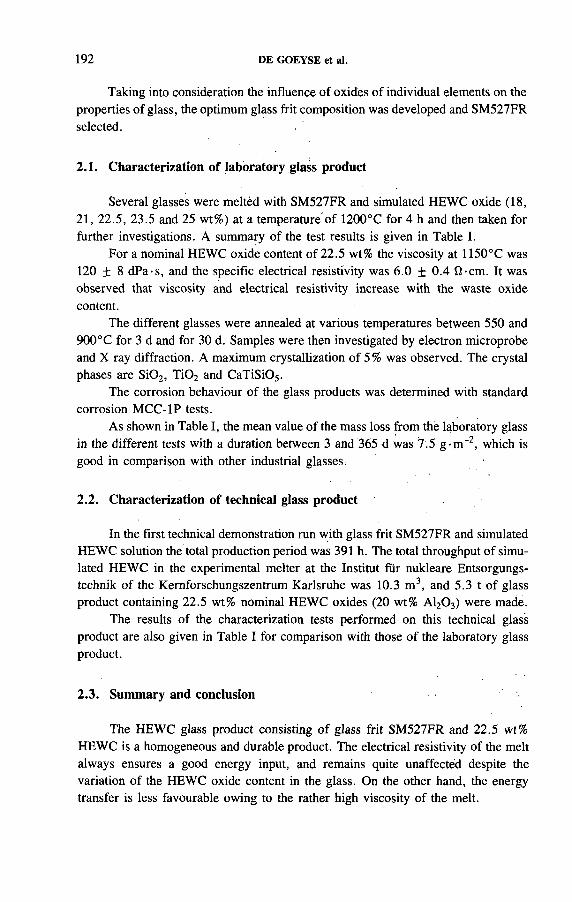
192 DE GOEYSE et al.
Taking into consideration the influence of oxides of individual elements on the properties of glass, the optimum glass frit composition was developed and SM527FR selected.
2.1. Characterization of laboratory glass product
Several glasses were melted with SM527FR and simulated HEWC oxide (18, 21, 22.5, 23.5 and 25 wt%) at a temperature of 1200°С for 4 h and then taken for further investigations. A summary of the test results is given in Table I.
For a nominal HEWC oxide content of 22.5 wt% the viscosity at 1150°C was 120 ± 8 dPa-s, and the specific electrical resistivity was 6.0 ± 0.4 fi-cm . It was observed that viscosity and electrical resistivity increase with the waste oxide content.
The different glasses were annealed at various temperatures between 550 and 900° С for 3 d and for 30 d. Samples were then investigated by electron microprobe and X ray diffraction. A maximum crystallization of 5% was observed. The crystal phases are S i0 2, T i0 2 and CaTiSi05.
The corrosion behaviour of the glass products was determined with standard corrosion MCC-1P tests.
As shown in Table I, the mean value of the mass loss from the laboratory glass in the different tests with a duration between 3 and 365 d was 7.5 g-m "2, which is good in comparison with other industrial glasses.
2.2. Characterization of technical glass product
In the first technical demonstration run with glass frit SM527FR and simulated HEWC solution the total production period was 391 h. The total throughput of simulated HEWC in the experimental melter at the Institut für nukleare Entsorgungstechnik of the Kernforschungszentrum Karlsruhe was 10.3 m 3, and 5.3 t o f glass product containing 22.5 wt% nominal HEWC oxides (20 wt% A120 3) were made.
The results o f the characterization tests performed on this technical glass product are also given in Table I for comparison with those o f the laboratory glass product.
2.3. Summary and conclusion
The HEWC glass product consisting o f glass frit SM527FR and 22.5 wt% HEWC is a homogeneous and durable product. The electrical resistivity of the melt always ensures a good energy input, and remains quite unaffected despite the variation of the HEWC oxide content in the glass. On the other hand, the energy transfer is less favourable owing to the rather high viscosity of the melt.

IAEA-SM-326/62 193
T A B L E I . C H E M I C A L A N D
A N D T E C H N I C A L G L A S S
S I M U L A T E
P H Y S I C A L P R O P E R T I E S
P R O D U C T S M 5 2 7 W I T H
O F L A B O R A T O R Y
2 2 . 5 w t % H E W C
P r o p e r ty L a b o ra to r y g la s s T e c h n ic a l g la s s
V is c o s i ty ( d P a - s )
- a t 1 1 5 0 ° C 120 ± 8 1 4 0 ± 10
- a t 9 5 0 ° C 1 1 5 0 ± 100 1 3 5 0 ± 120
S p e c if ic e le c t r ic a l r e s is t iv i ty ( f l - c m )
- a t 1 1 5 0 ° C 6 .0 ± 0 .4 5 .8 + 0 .5
- a t 9 5 0 ° С 1 6 .0 ± 1.2 1 5 .0 ± 1 .2
T r a n s f o r m a t io n te m p e r a tu r e ( ° C ) 4 9 8 ± 2 4 9 6 ± 2
D e n s i ty ( g - с п Г 3) 2 .4 3 ± 0 .0 2 2 .4 2 ± 0 .0 2
C o r r o s io n in d is t i l le d w a te r :
a v e r a g e m a s s lo s s (g - m ~ 2)
( M C C - 1 P te s t) 7 .5 ± 0 .2 7 .8 ± 0 .2
C r y s ta l l iz a t io n b e h a v i o u r : a
— a f te r 3 d 6 0 0 ° C — —
6 5 0 ° C — H a iiy n e , T i 0 2
7 0 0 ° С — H a ü y n e , T i 0 2
— a f te r 3 0 d 6 0 0 ° C X ТЮ2, X
6 5 0 ° C T i 0 2, X H a iiy n e , T i 0 2, X
7 0 0 ° С Tio2 H a iiy n e , T i 0 2
a X: u n id e n t i f ie d L i - A l s i l ic a te ; T i 0 2: ru t i le c ry s ta l s t ru c tu re ;
H a iiy n e : ( N a ,C a ) 8( A lS i0 4)6( S 0 4)2.
As shown in Table I, the characteristics of the laboratory glasses and the technical glasses are quite comparable and lie within acceptable ranges.
A data catalogue was prepared by the Deutsche Gesellschaft für Wiederaufarbeitung von Kernbrennstoffen mbH (DWK), which takes into account the results of all the investigations from both the laboratory and the technical demonstration. This is used as the basis for further active industrial vitrification.

FIG. 2. Basic flow sheet o f the PAMELA installation, including production control steps fo r quality assurance. Process steps 1 to 11 are described
in Table II.
DE G
OEY
SE et
al.
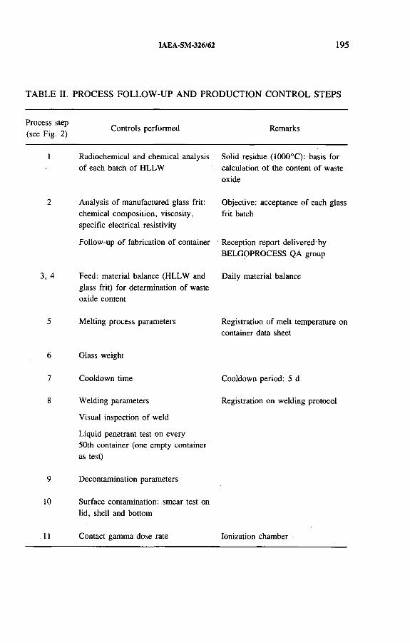
IAEA-SM-326/62 1 95
TABLE II. PROCESS FOLLOW-UP AND PRODUCTION CONTROL STEPS
P r o c e s s s te p
( s e e F ig . 2 )C o n tr o ls p e r f o r m e d R e m a r k s
1 R a d io c h e m ic a l a n d c h e m ic a l a n a ly s is
o f e a c h b a tc h o f H L L W
A n a ly s is o f m a n u fa c tu re d g la s s f r i t :
c h e m ic a l c o m p o s i t io n , v is c o s i ty ,
s p e c if ic e le c t r ic a l r e s is t iv i ty
F o llo w - u p o f f a b r ic a t io n o f c o n ta in e r
3 , 4 F e e d : m a te r ia l b a la n c e (H L L W a n d
g la s s f r i t ) f o r d e te rm in a t io n o f w a s te
o x id e c o n te n t
5 M e lt in g p ro c e s s p a ra m e te r s
S o lid re s id u e ( 1 0 0 0 ° C ) : b a s is fo r
c a lc u la t io n o f th e c o n te n t o f w a s te
o x id e
O b je c t iv e : a c c e p ta n c e o f e a c h g la s s
f r i t b a tc h
R e c e p t io n r e p o r t d e l iv e re d b y
B E L G O P R O C E S S Q A g r o u p
D a ily m a te r ia l b a la n c e
R e g is t r a t io n o f m e lt te m p e r a tu r e o n
c o n ta in e r d a ta s h e e t
6 G la s s w e ig h t
7 C o o ld o w n t im e
8 W e ld in g p a r a m e te r s
V is u a l in s p e c t io n o f w e ld
L iq u id p e n e t r a n t te s t o n e v e r y
5 0 th c o n ta in e r (o n e e m p ty c o n ta in e r
a s te s t)
9 D e c o n ta m in a t io n p a r a m e te r s
10 S u r fa c e c o n ta m in a t io n : s m e a r te s t o n
lid , s h e ll a n d b o t to m
C o o ld o w n p e r io d : 5 d
R e g is t r a t io n o n w e ld in g p r o to c o l
11 C o n ta c t g a m m a d o s e ra te Io n iz a t io n c h a m b e r

196 DE GOEYSE et al.
3. PROCESS FOLLOW-UP AND PRODUCTION CONTROL PHASE
3.1. Purpose
All measures to be taken during active production to ensure that the HEWC high level liquid waste (HLLW) is transformed into a qualified glass product corresponding with the selected product from the data catalogue are described in the QA/QC operation manual. The QA/QC measures described in this manual have to be strictly followed and documented in the conformity file for each glass canister.
3.2. Description of process follow-up and production control
The consecutive QA/QC steps which are taken can be divided into four groups:
(a) Control of input streams(b) Control of process treatment steps(c) Control of glass product(d) Control of instruments and equipment.
3.2.1. Control o f input streams and process treatment steps
The process steps taken to make a qualified glass product are shown in Fig. 2. All data relevant to the different controls performed during production are recorded on an individual glass canister data sheet. This sheet is used as a certificate for the canister.
Table II summarizes the QA measures performed for the various process steps (1-11) shown in Fig. 2.
3.2.2. Control o f glass product
The glass composition is calculated on the basis of the mass balance made over a period of 24 h. Taking into account the glass frit composition and the HLLW analysis, the glass product composition is calculated as well as the alpha and beta activity per kilogram of glass.
From every tenth glass container two samples are taken, from which one is analysed for waste oxide content (wt%) as well as alpha, beta and gamma activity. The second sample, which is at the disposition of NIRAS/ONDRAF for further verification, is put in a special storage rack.
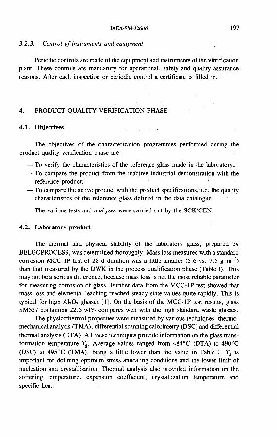
IAEA-SM-326/62 197
3.2.3. Control o f instruments and equipment
Periodic controls are made of the equipment and instruments of the vitrification plant. These controls are mandatory for operational, safety and quality assurance reasons. After each inspection or periodic control a certificate is filled in.
4. PRODUCT QUALITY VERIFICATION PHASE
4.1. Objectives
The objectives of the characterization programmes performed during the product quality verification phase are:
— To verify the characteristics of the reference glass made in the laboratory;— To compare the product from the inactive industrial demonstration with the
reference product;— To compare the active product with the product specifications, i.e. the quality
characteristics of the reference glass defined in the data catalogue.
The various tests and analyses were carried out by the SCK/CEN.
4.2. Laboratory product
The thermal and physical stability of the laboratory glass, prepared by BELGOPROCESS, was determined thoroughly. Mass loss measured with a standard corrosion MCC-1P test of 28 d duration was a little smaller (5.6 vs. 7.5 g-rrT2) than that measured by the DWK in the process qualification phase (Table I). This may not be a serious difference, because mass loss is not the most reliable parameter for measuring corrosion of glass. Further data from the MCC-1P test showed that mass loss and elemental leaching reached steady state values quite rapidly. This is typical for high A120 3 glasses [1]. On the basis o f the MCC-1P test results, glass SM527 containing 22.5 wt% compares well with the high standard waste glasses.
The physicothermal properties were measured by various techniques: thermomechanical analysis (TMA), differential scanning calorimetry (DSC) and differential thermal analysis (DTA). All these techniques provide information on the glass transformation temperature Tg. Average values ranged from 484°С (DTA) to 490°С (DSC) to 495°С (TMA), being a little lower than the value in Table I. Tg is important for defining optimum stress annealing conditions and the lower limit of nucléation and crystallization. Thermal analysis also provided information on the softening temperature, expansion coefficient, crystallization temperature and specific heat.
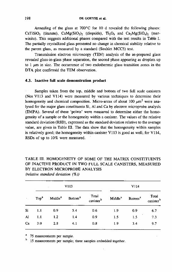
198 DE GOEYSE et al.
Annealing of the glass at 700°C for 10 d revealed the following phases: CaTiSi05 (titanate), CaM g(Si03) 2 (diopside), Ti50 9 and Ca3M g(Si04) 2 (mer- winite). This suggests additional phases compared with the test results in Table I. The partially crystallized glass presented no change in chemical stability relative to the parent glass, as measured by a standard (Soxhlet MCC5) test.
Transmission electron microscopy (ТЕМ) analysis of the as-prepared glass revealed glass-in-glass phase separation, the second phase appearing as droplets up to 1 ¡xm in size. The occurrence of two endothermie glass transition zones in the DTA plot confirmed the ТЕМ observation.
4.3. Inactive full scale demonstration product
Samples taken from the top, middle and bottom of two full scale canisters (Nos V I13 and V I14) were measured by various techniques to determine their homogeneity and chemical composition. Micro-areas of about 100 цm 2 were analysed for the major glass constituents Si, Al and Ca by electron microprobe analysis (EMPA). Several of these ‘points’ were measured to determine either the homogeneity of a sample or the homogeneity within a canister. The values of the relative standard deviation (RSD), expressed as the standard deviation relative to the average value, are given in Table HI. The data show that the homogeneity within samples is relatively good; the homogeneity within canister V I13 is good as well; for V I14, RSDs of up to 10% were measured.
TABLE HI. HOMOGENEITY OF SOME OF THE MATRIX CONSTITUENTS OF INACTIVE PRODUCT IN TWO FULL SCALE CANISTERS, MEASURED BY ELECTRON MICROPROBE ANALYSIS (relative standard deviation (%))
V 1 1 3 V 1 1 4
T o p 3 M id d le 3 B o tto m 3T o ta l
c a n i s te r bM id d le 3 B o tto m 3
T o ta l
c a n i s te r *5
S i 1.1 0 .9 5 .4 0.6 1 .9 0 .9 6 .7
A l 1.1 1.2 1 .4 0 .9 1 .5 1 .5 7 .3
C a 3 .0 2.8 4 .1 0.8 1 .9 3 .4 9 .7
3 7 5 m e a s u re m e n ts p e r s a m p le .
b 15 m e a s u re m e n ts p e r s a m p le ; th r e e s a m p le s e m b e d d e d to g e th e r .

IAEA-SM-326/62 199
The difference in homogeneity of the two canisters was confirmed by bulk chemical analysis using inductively coupled plasma-mass spectrometry (ICP-MS) of the samples as well. Boron presented the largest RSDs of the matrix constituents: 6 % (V I13) and 19% (V I14). Deviation of the as-measured average composition was also largest for boron, reaching as much as 20%. For the other glass matrix constituents, deviations were smaller than 10%. These results must include a component due to sampling and analytical errors which may reach 10% for ICP-MS analysis of boron and a lower value for EMPA.
4.4. Active samples
Ten samples taken at the bottom outlet o f the PAMELA glass furnace were characterized in terms of homogeneity and composition. The samples, each of 1 to 2 g, could not be used for thermal or chemical stability studies, since they were cooled differently from the glass in the container.
TABLE IV. RESULTS OF ANALYSES OF ACTIVE SAMPLES
M a x . R S D p e r s a m p le R S D fo r a v e r a g e c o n c n s
(% ) in a ll s a m p le s (% )
(a ) H o m o g e n e i ty o f s o m e o f t h e m a t r i x c o n s t i t u e n t s ,
m e a s u r e d b y e l e c t r o n m i c r o p r o b e a n a l y s i s
S i 2.0 1 .4
A l 1 .7 4 .3
N a 5 .3 5 .8
(b ) C o n c e n t r a t i o n s o f m a i n r a d i o n u c l i d e s (Bq/g glass)*
C s -1 3 7 ( 8 .9 6 ± 2 .5 9 ) x 1 0 7
S r -9 0 (9 .2 5 ± 3 .8 3 ) x 1 0 7
T o ta l ß e m it te r s (2 .5 7 ± 0 .7 0 ) X 1 0 8
T o ta l a e m i t t e r s 1* ( 3 .6 9 ± 1 .0 5 ) x 1 0 s
a B a s e d o n d a ta f o r s ix s a m p le s .
b A b o u t 8 0 % P u - 2 3 8 /A m - 2 4 1 , 10% P u - 2 3 9 /P u - 2 4 0 , 10%
C m - 2 4 2 /C m - 2 4 3 /C m - 2 4 4 .

200 DE GOEYSE et al.
Ruthénium-rhodium segregations up to 10 /¿m in size were observed in the active samples using scanning electron microscopy and energy dispersive X ray analysis. The results on homogeneity within and between samples, based on the matrix elements Si, Al and Na, are presented in Table IV.
The homogeneity of individual samples (microhomogeneity) is comparable to that.of inactive samples from the full scale canisters. Alpha and beta/gamma radiography showed that both kinds of radionuclides are incorporated in the glass network in a homogeneous way. The homogeneity between samples (macrohomogeneity), based on the inactive glass components, can hardly be compared with the data for the inactive full scale canisters, since the data for the two full scale canisters are very different. The data from the radiochemical analysis (Table IV) show deviations of up to 30% among samples for the main radionuclides included. These results must include components due to sampling and analytical errors (estimated at 1 0 % maximum) and the differences in waste oxide content between the samples (less than 1 0 %).
R EFEREN CE
[1 ] V A N I S E G H E M , P . , T I M M E R M A N S , W . , D E B A T IS T , R . , “ P a r a m e tr ic s tu d y o f
th e c o r r o s io n b e h a v io u r in s ta t ic d is t i l le d w a te r o f s im u la te d E u r o p e a n r e fe r e n c e h ig h
le v e l w a s te g la s s e s ” , S c ie n t i f ic B a s is f o r N u c le a r W a s te M a n a g e m e n t V II I ( J A N T Z E N ,
C . , S T O N E , J . , E W IN G , R . , E d s ) , M a te r . R e s . S o c . S y m p . P r o c . , V o l. 4 4 , M a te r ia ls
R e s e a r c h S o c . , P i t t s b u r g h , P A (1 9 8 5 ) 5 5 - 6 2 .

IAEA-SM-326/42
INDUSTRIAL HLW IMMOBILIZATION IN GLASS IN FRANCE: VITRIFIED WASTE CHARACTERIZATION AND QUALITY CONTROL PROGRAMME
J.L. DES VAUX, D. JEAN Cogéma,La Hague
L. BAILLIF NUSYS,Paris
France
Abstract
IN D U S T R I A L H L W IM M O B I L I Z A T I O N IN G L A S S IN F R A N C E : V I T R I F I E D W A S T E
C H A R A C T E R I Z A T I O N A N D Q U A L IT Y C O N T R O L P R O G R A M M E .
T h e la r g e a m o u n t o f d a ta c o l le c te d d u r in g fo r m u la t io n a n d c h a r a c te r iz a t io n s tu d ie s le d
to a s p e c if i c a t io n f o r R 7 T 7 g la s s . T h e q u a l i ty o f th e f in a l p r o d u c t is d e m o n s t r a te d b y th e
r e s u l ts o f th e s e s tu d ie s . T h e v i t r i f ie d w a s te s p e c if i c a t io n s d e f in e ‘g u a ra n te e d p a r a m e te r s ’ , s u c h
a s c h e m ic a l c o m p o s i t io n , ra d io a c t iv e in v e n to ry , a c t in id e c o n te n t , c o o l in g p r o c e d u r e , c a n i s te r
c h a r a c te r i s t ic s , s u r f a c e c o n ta m in a t io n o f th e c a n i s te r a n d th e rm a l r e le a s e . T h e s e s p e c if ic a t io n s
h a v e b e e n a p p ro v e d b y th e F r e n c h s a fe ty a u th o r i t ie s a n d a c c e p te d b y th e s a f e ty a u th o r i t ie s o f
th e fo r e ig n c u s to m e r s o f C o g é m a (B e lg iu m , G e r m a n y , J a p a n , th e N e th e r la n d s a n d S w i tz e r
la n d ) . F o r th e g la s s p r o d u c e r , th e r e q u i r e m e n t is th a t a f in a l p r o d u c t b e o b ta in e d w h o s e p r o p e r
t ie s c o m p ly w ith th e v i t r i f ie d w a s te s p e c if ic a t io n s a n d p a r t ic u la r ly th e g u a r a n te e d p a r a m e te r s .
T h is is a c h ie v e d b y th e s t r ic t c o n t r o l o f th e g la s s c o m p o s i t io n , w h ic h is p e r f o r m e d fo r e a c h
p ro c e s s s te p h a v in g a n in f lu e n c e o n th e f in a l p r o d u c t q u a l i ty , a n d b y a s t r i c t q u a l i ty c o n tro l
p r o g r a m m e a n d q u a l i ty a s s u r a n c e p la n . T h e p a p e r d e s c r ib e s th e c o n tr o l le d p a r a m e te r s , p a r t i c
u la r ly th o s e r e la t in g to th e c h e m ic a l c o m p o s i t io n o f th e g la s s . I t d e m o n s t r a te s h o w th e q u a li ty
o f th e v i t r i f ie d h ig h le v e l w a s te is e n s u r e d .
1. INTRODUCTION
The 1989 startup of the R7 vitrification facility at La Hague and the pending startup of its twin, T7, mark the industrial culmination of over thirty years of research and development in high level waste immobilization in France. Both facilities will routinely vitrify fission products separated in the UP3 and UP2-800 reprocessing plants operated by Cogéma, which have a combined annual capacity of
201

202 DESVAUX et al.
1600 t o f commercial LWR fuels. After a period o f cooling in dry storage facilities at La Hague, the vitrified waste from foreign fuels will be returned to the owners, located in Europe and Japan, for further storage or for disposal in geological repositories. French waste will remain in dry storage pending availability of a repository.
To demonstrate that the glass product is suitable for final disposal, a waste acceptance process was set up in which there are three principal steps: ( 1) develop and characterize a reference glass formulation and variations thereof; (2 ) demonstrate that process variations can be detected and corrected without affecting glass quality; and (3) control the quality of the glass by controlling process parameters in both normal and upset operating situations. The successful completion of the first two steps in the waste acceptance process resulted in the establishment of glass specifications which have been accepted by the French regulatory authorities and by Cogéma’s baseload customers. As the operator of the vitrification facilities, Cogéma has as its principal concern to ensure that the quality of the final glass product complies with these specifications in every respect. Quality control, the third step of the waste acceptance process, is the principal means of demonstrating compliance. After a brief review of the glass characterization programme, this paper will describe Cogéma’s quality control programme for vitrified HLW.
2. WASTE ISOLATION SYSTEM
The HLW disposal concept relies on multiple barriers for waste isolation, including the waste form, the engineered barrier and the geological barrier, with each barrier contributing to the containment of radioactive materials. The vitrified waste form is the primary barrier in the waste isolation system. The fission products are immobilized in a highly leach resistant glass matrix chosen for its ability to contain radioactive materials for very long periods of time. The stringent performance requirements for the final product necessitated an extensive development programme to define a glass formulation capable of producing reproducible waste forms acceptable for long term disposal and to characterize the final product.
3. GLASS CHARACTERIZATION PROGRAMME
The glass formulations used today in the R7 and T7 vitrification facilities at the La Hague reprocessing plants are the result o f over fifteen years of development and testing in both inactive and active test facilities. The principal criteria for the formulations were chemical stability, thermal stability, radiation resistance and radioactive containment.
Characterization testing was conducted in both inactive and active conditions to determine the principal properties of the reference glass composition. Inactive

IAEA-SM-326/42 203
characterization testing focused on the physical, thermal and mechanical properties o f the glass; on its homogeneity; on the thermal stability of the glass in a temperature range of 500-1200°C; on its leach resistance; and on glass volatility, i.e. weight loss as a function of temperature. Active characterization testing was conducted on hundreds of active glass formulations using alpha and beta doped glasses to determine radiation resistance, leach rates and the thermal stability and volatility o f the glass.
In addition, tests were performed to assess glass quality sensitivity to variations in process parameters and to qualify a broad range of acceptable glass-waste compositions. For example, variations in waste feed and glass frit components, fluxing and refractory components and frit to glass ratios were tested, and tests were conducted in which all glass components were varied simultaneously. A total o f ninety glasses were characterized in this manner.
In parallel with glass sensitivity studies, tests were conducted to determine the sensitivity of the melter to variations in process parameters, such as melting temperature, the period between glass pours, and glass to frit or frit to calcine ratio.
A range of acceptable glass compositions was defined on the basis of the results of the sensitivity tests, and failure modes and effects analyses were performed to identify fault conditions that would influence glass quality, including chemical composition, homogeneity, cracking rate and propensity to crystallize.
Moreover, fifteen years of active operation of the AVM facility at Marcoule have provided significant industrial experience with this process.
4. R7T7 GLASS SPECIFICATIONS
On the basis of the results of the glass characterization programme, the most suitable glass composition for fission products separated at the La Hague reprocessing plants was identified, and glass specifications were drawn up for vitrified HLW produced at the R7 and T7 facilities. In February 1986, the glass specifications were submitted to an independent commission of scientists and nuclear experts, to the DSIN (formerly SCSIN), the French nuclear regulatory authority, and to ANDRA, the French agency in charge of radioactive waste disposal. The specifications were approved by the French authorities in July 1986 and subsequently by baseload customers in Belgium, Germany* Japan, the Netherlands and Switzerland, all o f which ship spent fuel to Cogéma’s La Hague plants for reprocessing.
The specifications contain ‘guaranteed parameters’, which define the quality of the final glass product. Cogéma guarantees the chemical composition of the glass; the per canister radioactivity concentrations for 137Cs (< 1 8 0 kCi (6.7 PBq)) and ^ S r (< 1 2 5 kCi (4.6 PBq)); the per canister actinide concentrations (< 4 5 0 0 g for uranium, < 110 g for plutonium, < 9 0 g for 244Cm); and certain canister characteristics, including canister dimensions, materials of construction, surface contami-

204 DESVAUX et al.
nation (< 10 4 fiCi/cm 2 (37 kBq/m2) for emitters) and heat release ( < 2 kW). Cogéma also specifies the canister fill rate and the glass cooling procedure.
5. OBTAINING GLASS QUALITY
Since the quality of the final glass product is defined as conformance to glass specifications and particularly to the guaranteed processing parameters, process control is an important aspect of vitrification operations and the most effective means of demonstrating product quality on a real time basis. Materials entering the vitrification process and process parameters affecting glass quality are subject to quality control, and are controlled at each stage of the process to ensure that they are within the specified range. QC activities for entering materials and for process parameters are described in the following paragraphs, with special emphasis on parameters relating to the chemical composition of the glass.
5.1. Glass composition: QC of entering materials
5.1.1. Waste feed
Before the waste stream is fed to the process, the fission product solutions and clarification fines, each contained in separate feed make-up tanks, are sampled. The fission product solutions are analysed for free acid, dry extract, precipitate dissolution, plutonium and neptunium concentrations, heat release, radionuclide concentrations and chemical composition. The fines are rinsed, weighed and chemically dissolved, and are analysed for plutonium, uranium, molybdenum, technetium and zirconium concentrations and for heat release. On the basis o f analytical results and using glass composition correspondence tables for guidance, the solutions and fines are adjusted as necessary to remain within the specified range for waste feed composition.
5.1.2. Raw materials
The glass frit and chemical reagents used in the vitrification process must conform to specifications and are subject to QC prior to acceptance. The frit is sampled and analysed for oxides, aluminium, calcium, zirconium, potassium and elemental chloride.
5.2. Glass composition: QC of process parameters
Process control is performed both directly, by monitoring and measuring operating parameters at various stages in the process (flow rate, temperature, pressure,
IAEA-SM-326/42 205
density, weight, welding parameters, canister labelling and canister transfer to storage), and indirectly, by corroborating operating parameters through analyses or comparisons of inlet and outlet materials balances. Process parameters affecting the quality o f the final product are waste feed homogeneity, waste feed rate, calciner tube rotation rate, glass frit feed rate, melter temperature, glass mixing, glass pour rate, canister closure timing, canister seal-welding, canister contamination, canister cooling and canister tracking.
5.2.1. Waste feed homogeneity
The waste feed is mechanically stirred in the feed make-up tank at a specified rotation speed. If stirring is interrupted, the waste would not be homogeneous, and waste feed to the calciner is therefore stopped.
5.2.2. Waste feed rate
Waste is continuously fed to the calciner by a measuring wheel. Several direct parameters are monitored to ensure that the feed rate is within the specified range, including the rotation speed of the measuring wheel and the level of waste solutions in the seal pot and in the feed tube. Indirect parameters to determine waste feed rate are the heat supplied to the calciner and the expansion of the calciner tube.
5.2.3. Calciner tube rotation rate
The waste is evaporated and dried to a powder in a rotary calciner. The rotation speed of the calciner tube must fall within a specified range to obtain the desired product quality, and is monitored both directly and indirectly.
5.2.4. Glass fr it feed rate
The feed rate or weight o f glass frit supplied to the melter is an important process parameter for glass quality. A robot is used to feed the frit and to detect operating conditions outside the specified range. Non-conforming parameter values trigger a shutdown o f the feed mechanism and a switch from high activity feed to water feed for the calciner. The frit feed rate is indirectly verified by hourly weighing of the frit.
5.2.5. QA documentation on the filled canister
Each canister of glass is accompanied by complete quality assurance documentation containing all of the pertinent data relating to its production, including analyti-
206 DESVAUX et al.
cal results on the adjusted feed solution, the glass composition calculation sheet, and a description of processing operations for the corresponding glass batch.
5.2.6. Canister tracking
Glass canisters are identified with a five digit number on the lid and are tracked with a video monitoring system and by the operating control system.
5.3. Other control parameters
5.3.1. Glass canister procurement
The refractory stainless steel and weld filler metal used in the fabrication of glass canisters must conform to specifications, as must the fabrication process itself and the finished canisters. All are subject to QC.
5.3.2. Melter temperature
The average temperature of the melter walls must be approximately 1100° С to ensure glass quality. Melter temperatures at various areas on the melter are monitored directly with thermocouples, and glass pouring cannot be initiated at temperatures below 1040°C. Melter temperatures can be indirectly verified through electrical measurements of the inductors and by comparing temperature recordings at various points in time.
5.3.3. Glass mixing
Glass mixing in the melter is an important factor in obtaining a homogeneous glass product. Glass pouring is not initiated until a mixing rate of 150 to 200 L/h has been achieved for a minimum of 0.5 h.
5.3.4. Glass pour rate
Glass pouring is initiated once the nominal glass weight has been reached in the melter. Two glass pours are required to fill the canister. The canister is continuously weighed during pouring. The glass pour rate, currently set at 200 kg/h (boundary value for a determined melting pot geometry), is an important process parameter for the quality of the final product.
5.3.5. Canister closure timing
The canister must be seal-welded within 24 h of the second glass pour.
IAEA-SM-326/42 207
5.3.6. Canister seal-welding
Cooled canisters are sealed by plasma arc welding. Welding torches are subject to QC, and welding operation parameters are continuously recorded to control their conformance to specifications for voltage, current, cycles, plasma gas flow rate and welding rate. If operating parameters exceed the specified tolerances, the welding cycle is automatically interrupted.
5 .3 .7. Smear test swab and shuttle
The swab used for the canister smear test and the shuttle to transfer the swab to the analytical laboratory must also conform to specifications for fabrication, testing, packaging, shipment to La Hague and assembly.
5.3.8. Canister contamination
An automated smear test is performed on the entire surface of the canister to verily that surface contamination is less than 10~4 /nCi/cm2. Factors that determine the quality of the smear test are the automated control mechanisms and the degree o f compliance with operating procedures.
5.3.9. Canister cooling
Glass canisters are stored in dry storage wells. The cooling system of the storage facility must guarantee a glass temperature at the centreline of less than 510°C, or 100°C less than the glass recrystallization temperature. The outlet temperature of cooling air is monitored to verify the efficacy of the cooling system; an alarm is triggered if the temperature exceeds 90°C, and an extra fan is started. In the case of loss of electrical power supply, natural convection cooling is used if the situation is not corrected within 30 min.
6 . QA/QC ORGANIZATION
Each glass canister is accompanied by detailed QA documentation which is thoroughly reviewed by Cogéma; if it complies with the glass specifications and can be shown to have been produced and stored in accordance with the company’s QA plan, it is certified by Cogéma for shipment and disposal. An independent quality assurance auditing company, Bureau Veritas, acting on behalf of Cogéma’s clients, verifies the quality of the final product through inspections and audits. Cogéma’s Quality Control Department is responsible for verifying that the QC programme and the QA plan established for vitrification operations are effectively implemented, and
208 DESVAUX et al.
acts as an interface between the facility operator and Bureau Veritas. The specific responsibilities of the Quality Control Department include QC of raw materials used in the process and of the final product, as well as preparation of all QA related documentation.
7. CONCLUSION
Vitrified high level waste must be of a high quality in view of the requirement to isolate the radioactive materials that it contains for very long periods of time. Over thirty years of work have gone into developing and characterizing stable glass formulations in France, fifteen of which have seen the full scale operation of the AVM vitrification facility at Marcoule. The startup of the R7 and T7 facilities at La Hague is the culmination of an extensive glass formulation development and characterization programme which resulted in the selection and acceptance of the most suitable glass composition for fission products generated by LWR fuel reprocessing. A comprehensive QA/QC programme ensures that the requisite quality is consistently achieved in the final product at all stages in the vitrification process.
IAEA-SM-326/36
THE INTERACTION BETWEEN HLW GLASS AND BOOM CLAY HOST ROCK
P. VAN ISEGHEM, K. LEMMENS SCK/CEN,Mol, Belgium
Abstract
THE INTERACTION BETWEEN HLW GLASS AND BOOM CLAY HOST ROCK.The interaction between the high level waste glasses of interest to Belgium (DWK
PAMELA glasses SM513 and SM527, ànd Cogéma AVH glass SON68) and the candidate Boom clay repository host rock has been investigated. Experiments of up to five years’ duration have been finished. Basically static conditions, high surface area to solution volume ratio and negative Eh were applied in the tests to simulate the anticipated disposal situation. The roles of the clay concentration, container corrosion products, temperature and test duration were investigated parametrically. Either inactive or Pu and Am doped glasses were used. Typical conclusions for the experiments of one to two years’ duration are as follows: in pure synthetic interstitial claywater, glasses dissolve proportionally with (time) 'л; in clay- claywater slurries, glass dissolution increases with clay concentration; in wet clay, dissolution is almost proportional to time (yielding dissolution rates of about 50 /xm/year at 90°C; in a diluted slurry, a long term dissolution rate of a few micrometres per year at 90°C may be expected); the presence of Fe20 3 corrosion products in a concentrated slurry strongly reduces glass dissolution; at 40°C, dissolution kinetics are slower by about a factor of 10 than at 90°C; leaching of Pu and Am is characterized by their very large sorption on clay; a minor fraction is leached in a mobile form ( < 105 molecular weight units), corresponding with average concentrations of 10“9 mol/L (239Pu) and 10' 11 mol/L (241Am). These concentrations decrease further when Fe20 3 corrosion products are present in the clay. As a result of this five year programme, there are arguments to conclude that glass will certainly act as a first barrier against radionuclide dissipation. Other observations from this work are as follows: the basic mechanism of corrosion of the glasses in clay media is diffusion controlled leaching rather than congruent dissolution; the longer term results reveal leaching resumption processes related with secondary phase formation, the influence of which on the glass dissolution is not very clear yet; both glass composition and the presence of clay determine the glass dissolution kinetics.
1. INTRODUCTION
Between 1986 and 1990 an experimental programme was carried out, in the laboratory as well as in the field, to investigate on, a parametric basis the interaction between reference high level waste glasses and the potential Boom clay host rock.
209

210 VAN ISEGHEM and LEMMENS
The objective was to identify the dissolution mechanisms acting on the glass and the leaching behaviour of the main radionuclides of interest. This information is needed to evaluate the barrier function of the HLW glass in the multibarrier disposal concept, and to optimize the other engineered barriers. In addition, the radioactive degradation products formed during the glass dissolution should be well characterized, because they are the source term which may migrate to the biosphere [1].
Because clay (bentonite, smectite, Boom clay, etc.) is acknowledged to enhance waste glass corrosion [2-4], attention was focused in the experimental programme on the presence of Boom clay. Various mixtures of the Boom clay with synthetic clay water were considered. Other parameters studied were the concentration of container corrosion products, the external gamma irradiation field [5] and the temperature.
This paper reports on results of corrosion tests with some simulated waste glasses of interest to Belgium, in solutions containing various Boom clay concentrations; The glasses are: SON68 (the Cogéma AVH reference glass), SM513 and SM527 (the DWK PAMELA reference glasses for the low and high enriched waste concentrates resulting from the EUROCHEMIC reprocessing activities). All laboratory tests were carried out in static conditions, at a reference surface area to solution volume ratio (SA/V) of 100 m-1, and in controlled atmosphere conditions. Maximal experimental durations reached were as much as five years.
2. EXPERIMENTAL
The composition of the waste glasses can be found in the literature [5]. Glasses SON68 and SM513 are ‘common’ HLW borosilicate glasses, but SM527 has an unusually large A120 3 concentration (about 20 wt%). The glasses used in the active corrosion tests were prepared by adding about 50 MBq Pu solutions simultaneously to inactive glass pellets of about 40 g total mass. The Pu tracer consists mainly of 239Pu, but minor fractions of other isotopes, including 241Pu — producing 241 Am by beta decay — are present as well.
The corrosion tests were performed in static media by enclosing the components glass, water and clay in Teflon or stainless steel Teflon lined cups of about5 x 10“6 m3 inner volume. Thin glass plates with a surface area of 5 x 10"4 m2 and finely ground clay were used. In all experiments, SA/V was kept at 100 m “1. The clay (‘Boom’ clay sampled at the repository site) to water ratio was 10 or 500 (diluted or concentrated clay-synthetic interstitial claywater mixture (DCSICM or CCSICM)). The composition of SIC is given in Ref. [5]. Boom clay rendered more plastic by adding a few droplets of claywater was also used in the tests (‘wet clay’).
All laboratory experiments discussed in this paper were conducted in reducing conditions similar to those in the clay repository. Therefore, all test preparations were carried out in glove box conditions, yielding less than 2 vppm 0 2; the Eh of
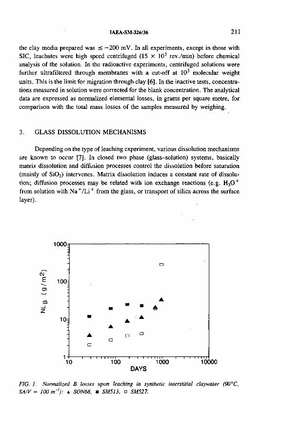
IAEA-SM-326/36 211
the clay media prepared was < -2 0 0 mV. In all experiments, except in those with SIC, leachates were high speed centrifuged (15 x 103 rev./min) before chemical analysis of the solution. In the radioactive experiments, centrifuged solutions were further ultrafiltered through membranes with a cut-off at 105 molecular weight units. This is the limit for migration through clay [6]. In the inactive tests, concentrations measured in solution were corrected for the blank concentration. The analytical data are expressed as normalized elemental losses, in grams per square metre, for comparison with the total mass losses of the samples measured by weighing.
3. GLASS DISSOLUTION MECHANISMS
Depending on the type of leaching experiment, various dissolution mechanisms are known to occur [7]. In closed two phase (glass-solution) systems, basically matrix dissolution and diffusion processes control the dissolution before saturation (mainly of Si02) intervenes. Matrix dissolution induces a constant rate of dissolution; diffusion processes may be related with ion exchange reactions (e.g. H30 + from solution with N a+/L i+ from the glass, or transport of silica across the surface layer).
DAYS
FIG. 1. Normalized В losses upon leaching in synthetic interstitial claywater (90°С, SA/V = 100 m '1): a SON68, m SM513, □ SM527.
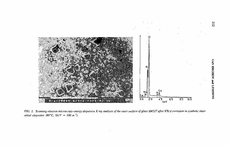
FIG. 2. Scanning electron microscopy-energy dispersive X ray analysis o f the outer surface o f glass SM527 after 970 d corrosion in synthetic interstitial claywater (90°C, SA/V = 100 m~!).
212 VAN
ISEGHEM
and LEM
MEN
S
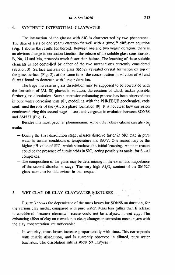
IAEA-SM-326/36 213
The interaction of the glasses with SIC is characterized by two phenomena. The data of tests of one year’s duration fit well with a (time)'A diffusion equation (Fig. 1 shows the results for boron). Between one and two years’ duration, there is an obvious change in corrosion kinetics: the release of the soluble glass constituents,B, Na, Li and Mo, proceeds much faster than before. The leaching of these soluble elements is not controlled by either of the two mechanisms currently considered (Section 3). Surface analysis of glass SM527 revealed crystal formation on top of the glass surface (Fig. 2); at the same time, the concentration in solution of Al and Si was found to decrease with longer duration.
The huge increase in glass dissolution may be supposed to be correlated with the formation of (Al, Si) phases in solution, the creation of which makes possible further glass dissolution. Such a corrosion enhancing process has been observed too in pure water corrosion tests [8]; modelling with the PHREEQE geochemical code confirmed the role of the (Al, Si) phase formation [9]. It is not clear how corrosion continues during this second stage — see the divergence in evolution between SON68 and SM527 (Fig. 1).
Besides this most peculiar phenomenon, some other observations can also bemade:
— During the first dissolution stage, glasses dissolve faster in SIC than in pure water in similar conditions of temperature and SA/V. One reason may be the higher pH value of SIC, which stimulates the initial leaching. Another reason could be the presence of humic acids in SIC, acting possibly as nuclei for Si-Al complexes.
— The composition of the glass may be determining in the extent and importance of the second dissolution stage. The very high A120 3 content of the SM527 glass seems to be deleterious in this respect.
4. SYNTHETIC INTERSTITIAL CLAYWATER
5. WET CLAY OR CLAY-CLAYWÁTER MIXTURES
Figure 3 shows the dependence of the mass losses for SON68 on duration, for the various clay media, compared with pure water. Mass loss rather than В release is considered, because elemental release could not be analysed in wet clay. The enhancing effect of clay on corrosion is clear; changes in corrosion mechanisms with the clay concentration are noticeable:
— In wet clay, mass losses increase proportionally with time. This corresponds with matrix dissolution, and is currently ■ observed in diluted, pure water leachates. The dissolution rate is about 50 /¿m/year.

214 VAN ISEGHEM and LEMMENS
DAYS
FIG. 3. Mass losses upon leaching o f glass SON68 in: ■ wet clay, clay-claywater slurries (A CCSICM, • DCSICM) and ♦ distilled water (90°C, SA/V = 100 m ‘).
— In the concentrated clay solution, the mass loss data reveal a double phased time dependence in the first three years. During the first few weeks, mass losses increase proportionally with time, whereas afterwards the increase is proportional to (time)14. The initial corrosion behaviour appears to correspond with the ‘normal’ glass matrix dissolution observed in pure water. Sorption of relatively insoluble glass constituents onto the clay (e.g. rare earths and transition metals) may slightly increase glass mass losses. Once the surrounding clay is saturated with respect to sorption, diffusion through the clay could be supposed to become the rate determining factor. Indeed, the surface ‘gel’ layers formed upon corrosion do not control the corrosion rate, as was concluded from another series of tests [5]. This two phase corrosion confirms conclusions by Lanza [2]; but diffusion coefficients calculated from the mass loss data — between 0.3 x 10"17 m 2/s (SM513) and 4.0 x 1 0 '17 m2/s (SM527) — are more typical for solids such as glass than for a clay solution [10].
— In the diluted clay solution, kinetics generally are slower than in the concentrated clay solution. The main difference with the tests in CCSICM is that the clay particles seem to saturate with respect to sorption. Indeed, the leaching data (e.g. mass loss (ML) and normalized boron loss (NLB)) are similar to
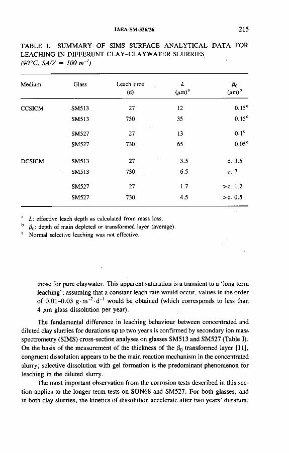
IAEA-SM-326/36 215
TABLE I. SUMMARY OF SIMS SURFACE ANALYTICAL DATA FOR LEACHING IN DIFFERENT CLAY-CLAYWATER SLURRIES (90°C, SA/V = 100 m-')
Medium Glass Leach time (d)
L(д т )а
ßo(мт )ь
CCSICM SM513 27 12 0.15е
SM513 730 35 0.15е
SM527 27 13 0 . 1е
SM527 730 65 0.05е
DCSICM SM513 27 3.5 с. 3.5
SM513 730 6.5 с. 7
SM527 27 1.7 > с. 1.2
SM527 730 4.5 > с. 0.5
a L: effective leach depth as calculated from mass loss. b ß0: depth of main depleted or transformed layer (average). c Normal selective leaching was not effective.
those for pure claywater. This apparent saturation is a transient to a ‘long term leaching’; assuming that a constant leach rate would occur, values in the order of 0.01-0.03 g -m “2-d_1 would be obtained (which corresponds to less than 4 ¿im glass dissolution per year).
The fundamental difference in leaching behaviour between concentrated and diluted clay slurries for durations up to two years is confirmed by secondary ion mass spectrometry (SIMS) cross-section analyses on glasses SM513 and SM527 (Table I). On the basis of the measurement of the thickness of the j80 transformed layer [11], congruent dissolution appears to be the main reaction mechanism in the concentrated slurry; selective dissolution with gel formation is the predominant phenomenon for leaching in the diluted slurry.
The most important observation from the corrosion tests described in this section applies to the longer term tests on SON68 and SM527. For both glasses, and in both clay slurries, the kinetics of dissolution accelerate after two years’ duration.
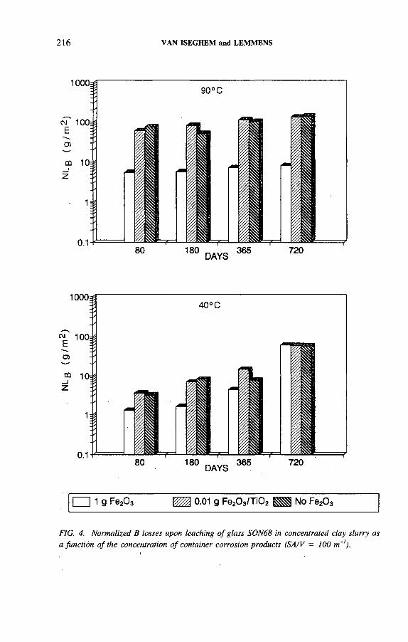
216 VAN ISEGHEM and LEMMENS
FIG. 4. Normalized В losses upon leaching o f glass SON68 in concentrated clay slurry as a function o f the concentration o f container corrosion products (SA/V = 100 m~]).

IAEA-SM-326/36 217
The difference in dissolution between the two media decreases. This acceleration is very significant for SM527. For both glasses, the enhanced dissolution is accompanied by a decrease in solution of Al and Si. On this basis, it may be assumed that the resumption of the glass dissolution in clay slurries is similar to the behaviour in claywater.
6. CLAY-CLAYWATER SLURRY LOADED WITH CORROSIONPRODUCTS
When only small amounts of Fe203 are mixed with the clay (0.01 g Fe203 with 2 g clay), the glass dissolution is not influenced. The glass dissolution is clearly different in the presence of large Fe203 concentrations (1 g Fe203 for 2 g clay), as shown in Fig. 4. In general, dissolution is strongly reduced, by up to 50 times. This phenomenon does not seem to be permanent, however: the data from tests of two years’ duration show a significant increase in leaching in a number of cases.
The — probably temporary — strongly reduced glass dissolution due to the presence of large concentrations of Fe203 may be contradictory. Indeed, Fe in solution is known to enhance glass dissolution because of the formation of iron silicates[12]. In our experiments, the major mechanism should therefore be related with the clay fraction of the leachate; the sorptive capacity of clay might be reduced by the presence of Fe203.
7. INFLUENCE OF TEMPERATURE (CCSICM)
On the basis of data from tests of up to one year’s duration, a relatively stable dissolution behaviour is observed at 40°C, with В release proportional to (time) 'A (Fig. 5). This suggests that diffusion processes are controlling the dissolution. Throughout the one year sequence, the difference in dissolution between 40 and 90°C remains quite stable for all glasses at a factor of about 10.
The dissolution behaviour at 150°C is, in contrast, different for the glasses (Fig. 5). Kinetics for SON68 are almost the same at 150 and 90°C. For SM527 and SM513, on the basis of В release, kinetics are almost proportional to time. This leads to the following hypothesis, supported by the observation that the one month dissolution data for all glasses are nearly equal at 90 and 150°C: the dissolution kinetics are the same at 90 and 150°C, and are proportional to time until the surrounding clay becomes saturated. This seems to happen for SON68, but no clay saturation seems to occur for SM527 and SM513, at least at 150°C.
The dissolution data at the various temperatures appear very puzzling. The activation energy is very different between 40 and 90°C, and between 90 and 150°C.
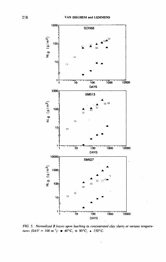
218 VAN ISEGHEM and LEMMENS
egE
m- jz
CME
ш_iz
10 100
DAYS1000 10000
DAYS
FIG. 5. Normalized В losses upon leaching in concentrated clay slurry at various temperatures (SA/V = 100 m '): m 40°C, □ 90°C, a 150°C.
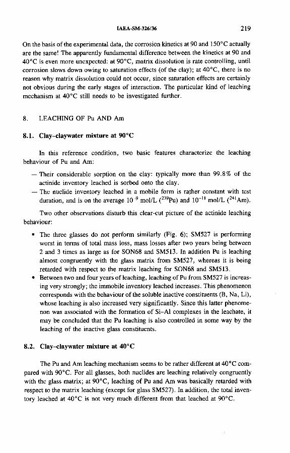
IAEA-SM-326/36 219
On the basis of the experimental data, the corrosion kinetics at 90 and 150°C actually are the same! The apparently fundamental difference between the kinetics at 90 and 40°С is even more unexpected: at 90°C, matrix dissolution is rate controlling, until corrosion slows down owing to saturation effects (of the clay); at 40°C, there is no reason why matrix dissolution could not occur, since saturation effects are certainly not obvious during the early stages of interaction. The particular kind of leaching mechanism at 40°С still needs to be investigated further.
8. LEACHING OF Pu AND Am
8.1. Clay-claywater mixture at 90°C
In this reference condition, two basic features characterize the leaching behaviour of Pu and Am:
— Their considerable sorption on the clay: typically more than 99.8% of the actinide inventory leached is sorbed onto the clay.
— The nuclide inventory leached in a mobile form is rather constant with test duration, and is on the average 10-9 mol/L (239Pu) and 10-11 mol/L (241Am).
Two other observations disturb this clear-cut picture of the actinide leaching behaviour:
• The three glasses do not perform similarly (Fig. 6); SM527 is performing worst in terms of total mass loss, mass losses after two years being between 2 and 3 times as large as for SON68 and SM513. In addition Pu is leaching almost congruently with the glass matrix from SM527, whereas it is being retarded with respect to the matrix leaching for SON68 and SM513.
• Between two and four years of leaching, leaching of Pu from SM527 is increasing very strongly; the immobile inventory leached increases. This phenomenon corresponds with the behaviour of the soluble inactive constituents (B, Na, Li), whose leaching is also increased very significantly. Since this latter phenomenon was associated with the formation of Si-Al complexes in the leachate, it may be concluded that the Pu leaching is also controlled in some way by the leaching of the inactive glass constituents.
8.2. Clay-claywater mixture at 40°C
The Pu and Am leaching mechanism seems to be rather different at 40° С compared with 90°C. For all glasses, both nuclides are leaching relatively congruently with the glass matrix; at 90°C, leaching of Pu and Am was basically retarded with respect to the matrix leaching (except for glass SM527). In addition, the total inventory leached at 40°С is not very much different from that leached at 90°C.
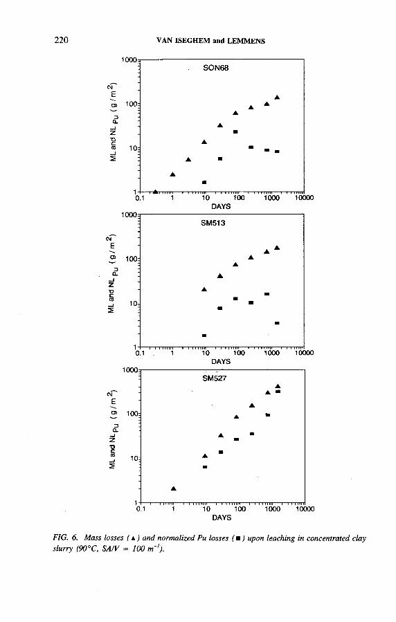
ML
and
NLp
u ( g
/ m 2)
ML
and
N>-
Pu ( g
/ m ¿
) ML
an
d NL
Pu
( g / m
220 VAN ISEGHEM and LEMMENS
DAYS
DAYS
FIG. 6. Mass losses ( a ) and normalized Pu losses ( я ) upon leaching in concentrated clay slurry (90°C, SA/V = 100 т~‘).

IAEA-SM-326/36 221
27 240DAYS
FIG. 7. Normalized Pu losses upon leaching o f glass SON68 in concentrated clay slurry as a function o f the presence o f container corrosion products (SA/V = 100 m 1).

222 VAN ISEGHEM and LEMMENS
8.3. Nuclide leaching in the presence of corrosion products
In a similar way to the total glass dissolution, Pu and Am leach much more slowly when corrosion products are present in the clay (Fig. 7). Both mobile and immobile inventories leached are smaller by a factor of 10 or more.
9. CONCLUSIONS
The corrosion experiments in various clay solutions have identified a number of more or less expectable phenomena, considering our general knowledge of corrosion mechanisms:
— Diffusion or dissolution controlled leaching kinetics of the matrix constituents; slowing down of the leach rate with increasing duration; the existence of long term dissolution kinetics.
— Strong sorption of Pu and Am onto the clay; the nuclide inventory leached in a mobile form is relatively constant with time.
On the basis of these dissolution mechanisms a full glass block would be dissolved in a repository environment only within extremely long periods of time at 90° С [13]. Lower temperature and the presence of corrosion products would further increase the glass block lifetime.
However, from the present results for extended test durations, glass dissolution seems to speed up in later stages. This resumption of the dissolution is most important for glass SM527, and is associated with (Al, Si) phase formation in solution. Leaching of Pu and Am also strongly increased in these conditions. Resumption of dissolution for glasses SON68 and SM513 is less important than for SM527.
As a conclusion of this experimental programme, no clear-cut long term glass dissolution mechanism can be proposed which would enable us to extrapolate the long term performance in repository conditions. Further work needs to focus on these long term dissolution phenomena.
ACKNOWLEDGEMENTS
This work was carried out partly under contracts FI1W-0100 and FI1W-0179 with the Commission of the European Communities, and partly under contracts CCHO-90/123-1 and CCHO-90/123-2 with NIRAS/ONDRAF. The authors acknowledge technical support from B. Gielen and R. Vercauter and analytical support from D. Huys, C. Hurtgen and L. Vandevelde. The SIMS analyses were carried out by A. Lodding (Chalmers University of Technology, Göteborg, Sweden).
IAEA-SM-326/36 223
REFERENCES
[1] LUTZE, W., GRAMBOW, В., The effects of glass corrosion on near field chemistry, Radiochim. Acta (in press).
[2] LANZA, F., RONSECCO, C., in Scientific Basis for Radioactive Waste Management V (LUTZE, W., Ed.), Mater. Res. Soc. Symp. Proc., Vol. 11, North-Holland, Amsterdam (1982) 125-133.
[3] CHRISTENSEN, H., HERMANSSON, H.P., CLARK, D.E., WERME, L., in Advances in Ceramics 8 (WICKS, G., ROSS, W., Eds), American Ceramic Soc., Columbus, OH (1984) 346-357.
[4] GODON, N., VERN AZ, E., THOM ASSIN, J.H ., TOURA Y, J . С ., in Scientific Basis for Nuclear Waste Management XII (LUTZE, W., EWING, R.C., Eds), Mater. Res. Soc. Symp. Proc., Vol. 127, Materials Research Soc., Pittsburgh, PA (1989) 97-104.
[5] VAN ISEGHEM, P., BERGHMAN, K., LEMMENS, K., TIMMERMANS, W., WANG, Lian, Laboratory and in Situ Interaction between Simulated Waste Glasses and Clay, EUR 13607, CEC, Luxembourg (1992).
[6] HENRION, P., MONSECOUR, M., FONTEYNE, A., “ Application of sorption data to the evaluation of radioelement migration in the Boom clay formation” , paper presented at CEC Scientific Seminar on Application of Distribution Coefficients to Radiological Assessment Models, Louvain-la-Neuve, Belgium, 1985.
[7] LUTZE, W ., in Radioactive Waste Forms for the Future (LUTZE, W ., EWING, R .C ., Eds), North-Holland, Amsterdam (1988) 1-160.
[8] VAN ISEGHEM, P., TIMMERMANS, W., DE BATIST, R., “ Parametric study of the corrosion behaviour in static distilled water of simulated European reference high level waste glasses” , Scientific Basis for Nuclear Waste Management VIII (JANTZEN, C., STONE, J., EWING, R., Eds), Mater. Res. Soc. Symp. Proc., Vol. 44, Materials Research Soc., Pittsburgh, PA (1985) 55-62.
[9] VAN ISEGHEM, P., GRAMBOW, B., in Scientific Basis for Nuclear Waste Management XI (APTED, M .J., WESTERMAN, R.E., Eds), Mater. Res. Soc. Symp. Proc., Vol. 112, Materials Research Soc., Pittsburgh, PA (1988) 631-639.
[10] TAKATA, M., TOMOZAWA, M. WATSON, E.B., Effect of water content on transport in Na20 .3 S i0 2 glass, J. Am. Ceram. Soc. 65 (1982) 91-93.
[11] LODDING, A., ENGSTROM, E.U., ODELIUS, H., “ Elemental profiling by SIMS of leached layers in repository tested SRL waste glass” , Testing of High Level Waste Forms under Repository Conditions (McMENAMIN, T., Ed.), EUR 12017, CEC, Luxembourg (1989) 127-139.
[12] McVAY, G.L., BUCKWALTER, C.Q., Effect of iron on waste glass leaching, J. Am. Ceram. Soc. 66 (1983) 170-174.
[13] LEMMENS, K., VAN ISEGHEM, P., “ The long-term dissolution behaviour of the Pamela borosilicate glass SM527 — Application of SA/V as accelerating parameter” , paper presented at 15th Int. Symp. on Scientific Basis for Nuclear Waste Management, Strasbourg, 1991.

IAEA-SM-326/17
CRITICALITY INVESTIGATIONS REGARDING FINAL DISPOSAL OF ALPHA BEARING WASTE
H.P. BERG, P. BRENNECKE Bundesamt für Strahlenschutz,Salzgitter
В. GM ALGesellschaft für Anlagen- und Reaktorsicherheit mbH,Munich
Germany
Abstract
CRITICALITY INVESTIGATIONS REGARDING FINAL DISPOSAL OF ALPHA BEARING WASTE.
In the abandoned Konrad iron ore mine, it is intended to dispose of those radioactive wastes which have a negligible thermal influence upon the host rock. The Gorleben salt dome is being investigated for its suitability for all kinds of radioactive waste. The waste acceptance criteria of both planned repositories allow the emplacement of alpha bearing waste. As this waste may contain non-negligible quantities of fissionable radionuclides, criticality considerations must form part of the site specific safety assessment for a waste repository, whereby the different operational and post-operational conditions of the facility are examined. According to the German Atomic Energy Act, the radionuclides 239Pu, 241Pu, 233U and 235U are special fissile materials. Hence, these alpha emitters are relevant to the criticality safety assessment. The requirements for their disposal resulting from the safety asséssment calculations are described. Other fissionable actinides are less important for these analyses; nevertheless, appropriate mass limitations have been determined. Concerning the disposal of spent fuel elements, some preliminary criticality calculations have been performed.
1. INTRODUCTION
Some radioactive wastes, such as those originating from fuel element fabrication or from reprocessing of spent fuel elements, which are to be delivered to a repository, and spent fuel elements for direct disposal contain considerable quantities of alpha emitters, in particular, fissile materials in solid form.
Radionuclides are described as fissile materials if they can be fissioned by interaction with thermal neutrons. According to the German Atomic Energy Act [1] , the radionuclides 239Pu, 241Pu, 233U and 235U are regarded as ‘special fissile
225
226 BERG et al.
material’. In the German transport regulations [2] the radionuclide 238Pu is additionally mentioned; this is, however, only fissioned by fast neutrons. Moreover, in considering criticality special fissionable actinides, e.g. some Cm isotopes, are discussed although they are of secondary importance among the radionuclides occurring in the radioactive wastes.
The German concept for disposing of radioactive waste in deep underground repositories does not require a commitment concerning a fixed conservative upper limit for the content of long lived alpha emitters in any waste form, such as the widely discussed value of 370 Bq/g. However, criticality prevention considerations must be taken into account as well as results derived from a site specific safety assessment, leading to a total amount of emplaceable activity of alpha emitters in a repository.
For the planned Konrad repository, where radioactive wastes with negligible heat generation are to be disposed of in a deep geological formation, it has been investigated within the framework of a comprehensive safety assessment whether critical assemblies in the buffer hall or in an emplacement room could occur during the operational phase of this facility or whether a criticality incident could be caused in the post-operational phase by water access to the emplaced waste packages and by leaching of the whole fissile material inventory.
Concerning the disposal of spent nuclear fuel, some preliminary criticality investigations have been performed regarding the behaviour of fuel element bundles in the cases of direct disposal and disposal of bundles disassembled into single rods. A more detailed criticality analysis will be part of the safety assessment for the planned Gorleben repository which may be performed at the end of the 1990s.
Generally, criticality calculations depend very much on the boundary conditions chosen (e.g. supposed scenario, geometry of fissile material zone, reflection and moderation). Thus, in order to simplify the calculations, a model and very conservative boundary conditions have been chosen, e.g. a fissile material zone with spherical geometry and a reflector with a strong backscattering effect, with reference to the post-operational phase.
It should be pointed out that in the planned Konrad repository in general only radioactive waste will be disposed of which has been discharged from the fissile material safeguards system. The permissible values derived in the following sections for this repository reflect only the necessary requirements resulting from considerations of criticality safety.
Owing to the less advanced state of planning, such requirements do not yet exist for the planned Gorleben repository, where also heat generating waste and spent fuel elements will be disposed of.
The third waste repository project in Germany is the abandoned salt mine at Morsleben in the new Federal state of Saxony-Anhalt, which had been operated by the former German Democratic Republic since 1979. The waste acceptance criteria of this repository include as a general requirement that the activity concentration of
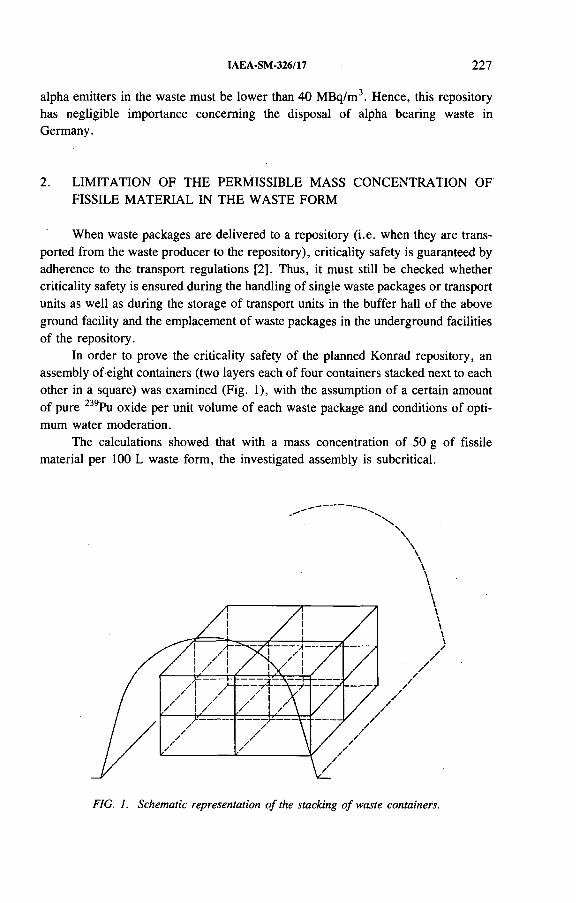
IAEA-SM-326/17 227
alpha emitters in the waste must be lower than 40 MBq/m3. Hence, this repository has negligible importance concerning the disposal of alpha bearing waste in Germany.
2. LIMITATION OF THE PERMISSIBLE MASS CONCENTRATION OFFISSILE MATERIAL IN THE WASTE FORM
When waste packages are delivered to a repository (i.e. when they are transported from the waste producer to the repository), criticality safety is guaranteed by adherence to the transport regulations [2]. Thus, it must still be checked whether criticality safety is ensured during the handling of single waste packages or transport units as well as during the storage of transport units in the buffer hall of the above ground facility and the emplacement of waste packages in the underground facilities of the repository.
In order to prove the criticality safety of the planned Konrad repository, an assembly of eight containers (two layers each of four containers stacked next to each other in a square) was examined (Fig. 1), with the assumption of a certain amount of pure 239Pu oxide per unit volume of each waste package and conditions of optimum water moderation.
The calculations showed that with a mass concentration of 50 g of fissile material per 100 L waste form, the investigated assembly is subcritical.
FIG. I. Schematic representation o f the stacking o f waste containers.
228 BERG et al.
3. LIMITATION OF THE PERMISSIBLE MASS OF FISSILE MATERIAL
In addition to the above mentioned limitation of mass concentration, a mass limitation of fissile materials in the cross-section of an emplacement room and per waste package is necessary and has been derived within the safety assessment performed for the planned Konrad repository.
As far as uranium is concerned, it is reasonable to examine separately uranium of lower and higher enrichment, that is, < 5 wt% and > 5 wt% 233U or 235U.
3.1. Permissible mass of fissile material in the cross-section of an emplacementroom
Conservative boundary conditions were chosen for the assessment of criticality safety during the post-operational phase. For instance, a reflector of normal concrete 30 cm thick, and hence a strong reflector of neutrons, is assumed in the criticality calculations. A sphere and also a hemisphere have been assumed for the shape of the fissile material zone. Only the salt content of the mine water, which has the effect of decreasing the reactivity owing to its content of chlorine and which has been determined by measurements, has been considered in the calculations.
Additionally the calculations are based on selective leaching of the whole of the fissile material from the waste package matrix by water access and its accumulation and concentration in the area of an assumed hollow in the emplacement room level.
Assuming a spherical geometry of the fissile material zone, the criticality calculations have shown that the infinite multiplication factor kx is below 1 in the case of low enriched U 02 with a mass of 13 kg 235U, and in the case of high enriched U 02 with a mass of 2 kg 235U. The relevant mass for low enriched 233U is 4 kg, for high enriched 233U 1.1 kg, for 241Pu 0.55 kg and for 239Pu 1.1 kg. With regard to the above mentioned boundary conditions, these values are limiting for the masses of wastes to be emplaced in the cross-section of an emplacement room (i.e. for a stacking section) and are therefore used to formulate requirements on the waste packages.
3.2. Permissible masses of fissile material per waste package
Table I presents data on the standardized waste packagings which should be used for the disposal of radioactive wastes in the Konrad repository; their volumes vary between 0.7 and 10.9 m3. Hence, the number of waste packages which can be stacked in the cross-section of an emplacement room depends upon the dimensions of the respective container type.
Thus, taking into account the maximum number of waste packages in the cross- section of an emplacement room, the next step is to calculate the permissible masses
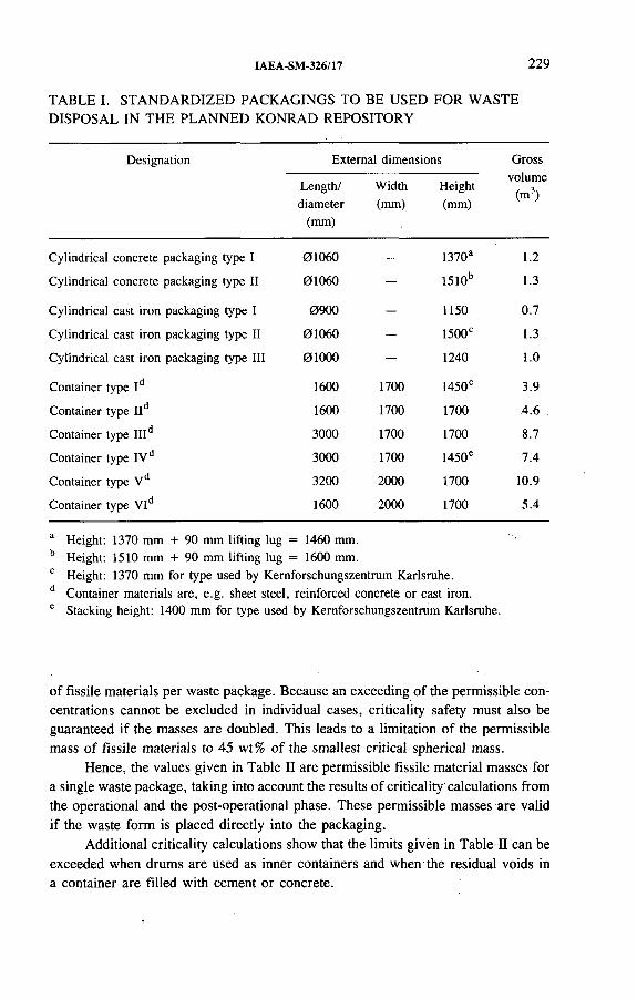
IAEA-SM-326/17 229
TABLE I. STANDARDIZED PACKAGINGS TO BE USED FOR WASTE DISPOSAL IN THE PLANNED KONRAD REPOSITORY
Designation External dimensions Grossvolume
(m3)Length/diameter
(mm)
Width(mm)
Height(mm)
Cylindrical concrete packaging type I 01060 — 1370a 1.2
Cylindrical concrete packaging type II 01060 — 1510b 1.3
Cylindrical cast iron packaging type I 0900 — 1150 0.7
Cylindrical cast iron packaging type II 01060 - 1500° 1.3
Cylindrical cast iron packaging type III 0 1 0 0 0 — 1240 1.0
Container type Id 1600 1700 1450e 3.9
Container type IId 1600 1700 1700 .4.6
Container type IIId 3000 1700 1700 8.7
Container type IVd 3000 1700 1450e 7.4
Container type Vd 3200 2000 1700 10.9
Container type VId 1600 2000 1700 5.4
a Height: 1370 mm + 90 mm lifting lug = 1460 mm.b Height: 1510 mm + 90 mm lifting lug = 1600 mm.0 Height: 1370 mm for type used by Kernforschungszentrum Karlsruhe.d Container materials are, e.g. sheet steel, reinforced concrete or cast iron.e Stacking height: 1400 mm for type used by Kernforschungszentrum Karlsruhe.
of fissile materials per waste package. Because an exceeding of the permissible concentrations cannot be excluded in individual cases, criticality safety must also be guaranteed if the masses are doubled. This leads to a limitation of the permissible mass of fissile materials to 45 wt% of the smallest critical spherical mass.
Hence, the values given in Table II are permissible fissile material masses for a single waste package, taking into account the results of criticality'calculations from the operational and the post-operational phase. These permissible masses are valid if the waste form is placed directly into the packaging.
Additional criticality calculations show that the limits given in Table II can be exceeded when drums are used as inner containers and when the residual voids in a container are filled with cement or concrete.

230 BERG et al.
TABLE II. PERMISSIBLE MASSES OF FISSILE MATERIALS RESULTING FROM CRITICALITY SAFETY ANALYSIS (values in grams per waste package)
WasteU-233 U-235 Pu-239 Pu-241
packaging < 5 wt% > 5 wt% < 5 wt% > 5 wt%
Cylindrical concrete packaging:
Type I 125 38 210 69 38 19Type II 125 38 210 69 38 19
Cylindrical cast iron packaging:
Type I 70 28 120 50 28 14Type П 125 38 210 69 38 19Type 1П 125 35 210 65 35 17
Container:
Type I 250 90 425 170 90 45Type II 250 100 425 175 100 50Type III 500 220 850 350 220 110
Type IV 500 180 850 330 180 90Type V 500 220 850 350 220 110Type VI 250 110 425 175 110 55
In order to keep the boundary requirement concerning the concentration limit described in Section 2, a content of not more than 100 g of fissile materials in a 200 L drum is guaranteed.
As the fission and absorption cross-sections of the several isotopes of an element are very different, the isotopic composition in a system of fissile material can have a great influence on the reactivity value. Therefore, larger amounts of 239Pu and 241Pu in a waste package are permissible if a uniquely determined plutonium nuclide composition vector is chosen which contains a low percentage of fissile plutonium isotopes. However, in using a plutonium vector the concentration limit is still valid.
As described above, mainly water and concrete have been taken into consideration as moderator and reflector materials in the analyses concerning the criticality safety of the planned Konrad repository. The influence of materials such as steel,
IAEA-SM-326/17 231
iron ore and cast iron is covered by the above assumptions on reflector material and thickness owing to the restriction of the admissible mass per waste package.
However, certain materials, such as D20 , graphite and beryllium, used as moderators and/or reflectors may lead to smaller critical masses than in the case of water or concrete. Therefore, the masses for such materials are limited in a waste package to 275 kg D20 , 420 kg graphite and 360 kg beryllium, although these materials are not really expected in the waste. For the derivation of these values, it was assumed that these materials are not mixed with the fissile material. If they are mixed, specific criticality calculations have to be performed by the Bundesamt für Strahlenschutz (BfS) in order to check individual cases.
3.3. Limitation of special fissionable actinides
Although a significant amount of special fissionable actinides in the radioactive waste cannot be expected, limitations per waste package have been introduced in order to ensure a criticality-safe repository even in hypothetical cases.
The limiting values (Table Ш) are determined as 1/50 of the subcritical limits given by the American National Standards Institute [3]. These values can be exhausted simultaneously and independently from the masses of 233U, 235U, 239Pu and 241Pu. An exceeding of the values in Table in requires an additional criticality calculation by the BfS based on the same boundary conditions as mentioned earlier to check the specific case.
3.4. Limitation of the emplaceable alpha activity
On the basis of model data made available by the waste producers for repository purposes, the expected cumulative activity at the end of the operational phase of the planned Konrad repository was calculated. Table IV shows the activities of specific radionuclides and the total alpha content in the radioactive waste.
Within the framework of the licensing procedure for the planned Konrad repository these values are expected to be determined as an upper limit for the emplacement of these radionuclides and the total activity of alpha and beta/gamma emitters. The balancing with respect to nuclide content and the emplacement strategy based on it have to guarantee that these values are not exceeded.
4. DERIVATION OF A SUMMATION CRITERION
Radioactive waste usually consists of a radioisotopic mixture, while the mass limitations refer to the case where only 233U, 235U, 239Pu or 241Pu is contained in the waste.
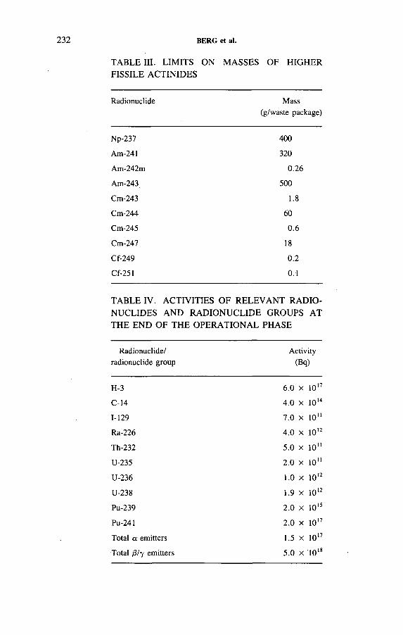
232
TABLE III. LIMITS ON MASSES OF HIGHER FISSILE ACTINIDES
BERG et al.
Radionuclide Mass (g/waste package)
Np-237 400
Am-241 320
Am-242m 0.26
Am-243 500
Cm-243 1.8
Cm-244 60
Cm-245 0.6
Cm-247 18
Cf-249 0.2
Cf-251 0.1
TABLE IV. ACTIVITIES OF RELEVANT RADIONUCLIDES AND RADIONUCLIDE GROUPS AT THE END OF THE OPERATIONAL PHASE
Radionuclide/ radionuclide group
Activity(Bq)
H-3 6.0 x 1 0 17
C-14 4.0 x 10¹⁴
1-129 7.0 X 10"
Ra-226 4.0 x 10¹²
Th-232 5.0 X 10"
U-235 2.0 x 1 0“
U-236 1.0 x 1 0 12
U-238 1.9 x 10¹²
Pu-239 2.0 x 1 0 15
Pu-241 2.0 x 10 17
Total a emitters 1.5 x IO17
Total /З/7 emitters 5.0 x 10¹⁸

IAEA-SM-326/17 233
Therefore, a summation formula for these four radionuclides has to be developed for a radionuclide mixture in a waste package. Not only a mixture of these radionuclides in a waste package, but also the mixture of waste packages in the cross- section of an emplacement room has to be considered.
4.1. Summation criterion for a radionuclide mixture in a waste package
In analogy to the procedures for assumed incidents [4] and for the thermal influence upon the host rock [5], a summation formula must be applicable to any mixture of the four radionuclides, so that the permissible mass of fissile material per waste package is not exceeded.
The summation value is calculated with the help of the formula
„ M,SK(B) = Y — !---- < 1
Y M* {В, à)
where
Sk(B) is the summation value (K is the criticality index),M¡ is the mass of radionuclide i in the waste package,M*(B, a) is the permissible mass of radionuclide i for container В and, possibly,
degree of enrichment a.
4.2. Summation criterion for the mixed emplacement of waste packages
Of the total amount of radioactive waste expected for disposal, only a small amount containing a considerable quantity of fissile material will arise; exhaustion of the permissible masses of fissile material per waste package presented in Table II is thus to be expected only in individual cases. One typical example is the waste arising from reprocessing in France and the United Kingdom, whose high alpha content nearly exhausts the limits resulting from criticality considerations.
However, as a great number of waste packages contain only a very low amount of fissile materials, it should be possible to mix waste packages in the cross-section of an emplacement room to ensure criticality safety. In analogy to Ref. [5], waste packages with summation values greater than 1 can be emplaced together with waste packages having low summation values. Weighted according to the number of packages, the summation values are to be averaged. If the averaged summation value is below 1, an emplacement is possible. In any case, delivery to the repository of waste packages for which the summation value exceeds 1 requires the approval of theBfS.
234 BERG et al.
5. DETERMINATION OF LIMITING VALUES OF ACTIVITY
Generally, statements on criticality safety are based on the existing mass of fissile materials. The requirements developed for the planned Konrad repository comprise — besides general requirements on waste packages — requirements on the waste form, the packagings of radioactive waste and permissible activities. Thus, also for the requirements resulting from the assessment concerning criticality safety it is reasonable to derive a relation for converting these to permissible activities. By means of a uniform procedure, the mass limits given in Table П are directly converted into limiting values of activity using the specific activity per gram. The specific activities may be taken, for instance, from the KORIGEN computer code [6].
6. APPLICATION OF THE SUMMATION CRITERION
The following conditions should be observed when applying the summation criterion:
— If the mass of a radionuclide exceeds 1 wt% of the permissible mass, this mass is to be stated and to be taken into account when applying the summation criterion.
— If the mass of a radionuclide falls below 1 wt%, the mass of this radionuclide need neither be stated nor taken into account when applying the summation criterion.
When using activities, the summation formula in Section 4.1 is to be transformed so as to relate the activity of the radionuclide in the waste package to the limiting value. The 1 wt% rule is also valid when using activity data.
When the activity is balanced in the Konrad repository, it must be observed with regard to mixing waste packages in the cross-section of an emplacement room that the 1 wt% value is calculated in those cases where no masses or activities are given.
The special fissionable actinides discussed in Section 3.3 must not be taken into account in applying the summation formula because of their low permissible masses or activities.
Generally, as in other considerations of requirements, the limits on the mass or activity concentration in the waste form and on the permissible mass or activity of fissile substances in the waste package must be'kept individually and the most restrictive requirement must be fulfilled.
The fulfilment of the requirements on the concentration limitation and on the maximum permissible masses or activities in the waste package is checked within the framework of the waste package quality control.
IAEA-SM-326/17 235
7. CRITICALITY SAFETY CONSIDERATIONS CONCERNING DISPOSALOF SPENT FUEL
General criticality with regard to the direct disposal of spent fuel elements was examined several years ago within investigations financed by the Federal Minister of Research and Technology. It has been shown that, from the criticality safety point of view, direct disposal is a possible option.
Another option which is part of the disposal strategy for the planned Gorleben repository is the emplacement of rods (i.e. disassembled fuel bundles) packaged in canisters. For preliminary criticality considerations it is assumed that the rods remain structurally intact such that the enclosure of the radioactive material is ensured. A tight package of fuel rods influences the essential parameters for criticality safety.
The criticality considerations were restricted to the determination of the infinite multiplication factor; water flooding of the fuel rods was assumed, conservatively neglecting the fact that the realistic moderator in the repository is a salt solution.
As a result it has been calculated that the fuel elements are more reactive than close packed bundles of fuel rods owing to the near optimal moderator to fuel ratio [7]. Hence, the disassembling of the fuel elements and the tight package of the rods may be favourable in respect of criticality safety.
Lower values of the multiplication factor may be achieved if the bumup of 235U is taken into account.
On the other hand, there do not yet exist experimental data for such assemblies of critical masses which would allow a comparison of the calculated data with measurements [7]. Therefore, these preliminary criticality calculations only have an orientational character and need further verification. This may also be achieved by the use of different computer codes if the calculations lead to comparable results.
REFERENCES
[1] “ Gesetz über die friedliche Verwendung der Kernenergie und den Schutz gegen ihre Gefahren (Atomgesetz)” , Atomgesetz mit Verordnungen, 12th edn, Nomos-Verlag, Baden-Baden (1991).
[2] RIDDER, K., Gefahrgut-Handbuch, Loseblatt-Ausgabe, Grundwerk, 3rd edn, Verlag Moderne Industrie, Munich (1987).
[3] AMERICAN NATIONAL STANDARDS INSTITUTE, American National Standard for Nuclear Criticality, Control of Special Actinide Elements, ANSI/ANS-8.15-1981, New York (1981).
[4] ILLI, H., Safety analyses for the planned Konrad repository, Kerntechnik 51 2 (1987) 91-97.
236 BERG et al.
[5] PIEFKE, F., Berechnungen zur thermischen Einwirkung von Schwachwärmeentwickelnden radioaktiven Abfällen auf das Wirtsgestein in der Schachtanlage Konrad, PTB-Bericht SE 10, Physikalisch-Technische Bundesanstalt, Braunschweig (1986).
[6] FISCHER, U., WIESE, H.W ., Verbesserte konsistente Berechnung des nuklearen Inventars abgebrannter DWR-Brennstoffe auf der Basis von Zell-Abbrand-Verfahren mit KORIGEN, KfK-Bericht 3014, Kernforschungszentrum Karlsruhe (1983).
[7] HEINICKE, W., Kritikalitätsberechnung für kompaktierte Leichtwasserreaktor- Brennstäbe, Schriftenreihe Reaktorsicherheit und Strahlenschutz, BMU-1991-286, Bundesministerium für Umwelt, Naturschutz und Reaktorsicherheit, Bonn (1991).

REPOSITORY CONCEPTS FOR DIRECT DISPOSAL OF SPENT FUEL
(Session 5)
Chairmen
L. VAN DE VATENetherlands
C. McCOMBIESwitzerland


IAEA-SM-326/25
SWEDISH DEVELOPMENTS OF CONCEPTS FOR DIRECT DISPOSAL OF SPENT FUEL
C. SVEMARSwedish Nuclear Fuel and
Waste Management Company,Stockholm, Sweden
Abstract
SWEDISH DEVELOPMENTS OF CONCEPTS FOR DIRECT DISPOSAL OF SPENT FUEL.
The feasibility of direct disposal of spent nuclear fuel was demonstrated in Sweden in 1984, when the Swedish Government declared that the KBS-3 system fulfilled the safety and radiation protection requirements set forth in the law. Since then several different disposal systems have been evaluated in parallel with the ongoing development work on the KBS-3 system. These systems consider disposal at great depth, between 2 and 4 km, horizontal disposal in full face bored drifts and compact disposal in the centre of a cave which is totally surrounded by technical barriers (WP-Cave system). A systematic comparison between the alternative systems and the KBS-3 system have shown on the one hand that several systems are judged feasible for development to meet high safety standards, and on the other hand that the features of the KBS-3 system still make this system the most advantageous one. Future R&D which aims at demonstration of the disposal operation at full scale will be concentrated on the KBS-3 principle. The paper presents the different disposal alternatives studied and highlights the main reasons behind the selection of the KBS-3 system.
1. INTRODUCTION
The development of concepts for encapsulation and final disposal of high level waste started in Sweden in the mid-1970s. The work has increasingly concentrated on direct disposal of spent fuel in copper canisters at a depth of about 500 m in Swedish crystalline bedrock (granite). The feasibility of the method was demonstrated in the 1980s, when the Swedish legislation required a method for safe handling and disposal of the nuclear waste before a charging permit could be granted to the two nuclear power reactors Oskarshamn 3 and Forsmark 3. The concept, named KBS-3 [1], was presented to the authorities and scrutinized in national and international peer reviews. Eventually, in 1984, the Government declared the method to be ‘ ‘a system which in all essential matters can be accepted with respect to safety and radiation protection” .
239

240 SVEMAR
In parallel with the subsequent development of the KBS-3 concept the following alternative designs have been evaluated:
— Emplacement of many canisters in a central rock mass, which is surrounded by a bentonite-sand barrier and a ‘hydraulic cage’: this concept is called WP-Cave [2].
— Disposal at a depth of between 2 and 4 km below the surface: this concept is called Very Deep Holes (VDH) [3].
— Disposal of relatively large canisters in the centre of long horizontal drifts: this concept is called Very Long Holes (VLH) [4].
— Disposal of KBS-3 size canisters in the centre of horizontal parallel drifts: this concept is called Medium Long Holes (MLH) [5].
This paper presents the different repository systems as well as the results of their comparison and their ranking.
ifilliig p,l l l l l j fi
CONCRETE -
TITANIUM —
STEEL
COPPER
LE A D -
COMPACTCOPPER
COPPER -
STEEL COPPER
................ ..... .............
FIG. 1. Some canister alternatives analysed in the Project Alternative Systems Study (PASS). Vertical: titanium-concrete (VDH), copper-steel, compact copper and copper-lead (KBS-3 and MLH). Horizontal: copper-steel (VLH). Titanium-concrete: 4 BWR assemblies, weight 3 t; copper-steel (vertical): 12 BWR assemblies, weight 14 t, empty volume 1 m3; compact copper: 12 BWR assemblies, weight 20 t; copper-lead: 12 BWR assemblies, weight 23 t; copper-steel (horizontal): 24 BWR assemblies, weight 48 t, empty volume 6 m3.

IAEA-SM-326/25 241
2.1. KBS-3
The KBS-3 concept is based on the emplacement of canisters in the centre of vertical holes bored from the floor of drifts, with one canister per hole. Different canister alternatives have been considered. Three with copper as protection against corrosion are shown in Fig. 1. In a separate analysis the composite design using a copper-steel canister was selected as the prime canister alternative [5].
The canisters are surrounded by a highly compacted swelling bentonite clay. The canister position is shown in Fig. 2 and the layout of the drifts is illustrated in Fig. 3. The drifts are planned to be parallel and located within blocks of rock separated by major discontinuities. These discontinuities are designated to accommodate future seismic activity, if any, so that the blocks maintain their integrity.
The pattern of holes for the canisters is dependent on how high a temperature the bentonite clay can stand, but the holes may not be placed so close that hydraulic connections are created between holes. It is considered that bentonite maintains its beneficial properties up to a temperature of at least 130° С [6]. In order to retain a proper margin the design limit has been set to a maximum of 100°C. Considering only the temperature criterion, canisters with 12 BWR assemblies (40 years after being discharged from the reactor) or an equivalent thermal load of PWR assemblies might be placed in holes with a centre to centre spacing of about 5 m in disposal drifts with a centre to centre distance of 25 m [7]. In order to avoid hydraulic interference between holes, however, a distance of 6 m was set originally. For the time being a spacing of 6 m is maintained.
With these assumptions about 25 000 m of disposal drifts and 28 000 m of disposal holes would be required for the Swedish spent fuel programme.
2.2. WP-Cave
While the KBS-3 concept represents a system with dispersed distribution of canisters, the WP-Cave concept represents a concentrated distribution system. The design is illustrated in Fig. 4. Canisters with the spent fuel are placed in the centre of the cave. Canister design was not a major topic in the WP-Cave study because the dimensions had only a limited impact on the design of the cave. The size considered could hold 16 BWR assemblies with a potential capacity of 25 BWR assemblies. The outer diameter would be 1.3 m in the case of a steel canister [2] and about 1.4 m if a copper cover were added.
Figure 4 shows a design where inclined channels host three canisters in a row. These channels are bored in levels from a central shaft, forming a tree-like pattern. The central part is totally surrounded by a slot filled with a mixture of bentonite and sand, and a ‘hydraulic cage’ structure.
2. DISPOSAL CONCEPTS

242 SVEMAR
FIG. 2. Evaluated repository systems in PASS. Left: KBS-3 and Medium Long Holes; right: Very Deep Holes and Very Long Holes.
FIG. 3. A rtist’s view o f a KBS-3 repository.
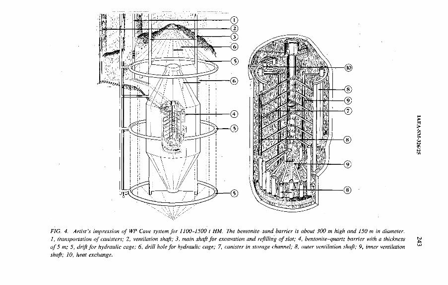
FIG. 4. A rtist’s impression o f WP-Cave system for 1100-1500 t HM. The bentonite-sand barrier is about 300 m high and 150 m in diameter.1, transportation o f canisters; 2, ventilation shaft; 3, main shaft fo r excavation and refilling o f slot; 4, bentonite-quartz barrier with a thickness o f 5 m; 5, drift fo r hydraulic cage; 6, drill hole for hydraulic cage; 7, canister in storage channel; 8, outer ventilation shaft; 9, inner ventilation shaft; 10, heat exchange.
243
244 SVEMAR
Each canister channel is connected at both ends to ventilation shafts. Cool air is distributed to each channel via the outer shaft. The air passes between the canister and the wall of the channel and rises in the inner shaft. After heat exchange the air is recirculated. This process is required owing to the high initial thermal load inside the cave.
The major design parameters are the temperature restriction for the bentonite and the temperature restriction (150°C) in the inner part of the cave after closure. The rationale for the chosen maximum of 150° С is the lack of high temperature dissolution data on radionuclides. Even if a copper protected canister is chosen, an early failure in a canister resulting in dissolution of the fuel during the high temperature phase may not be ruled out.
Assuming a 40 year interim storage period for spent fuel (Swedish case), the structure in Fig. 4 has a capacity of some 1100 t HM if the cave is ventilated for about 100 years before being closed and filled with water. Seven such caves are required for the Swedish programme. If a temperature of 200°С could be accepted in the central part instead of 150° С the capacity would increase to about 1500 t HM when other parameters are maintained the same. The 15001 capacity could also meet the 150°С criterion if the ventilation period were extended to about 150 years.
The structure outside the bentonite-sand barrier, the hydraulic cage, has two functions. During the excavation and ventilation phases it drains the rock mass inside. When the cave has been closed and the groundwater table has risen above the cave, the cage has a lower piezometric head upstream and attracts the water, leading it past the outside of the bentonite-sand barrier to the downstream side. This function is comparable to that of the Faraday cage (electricity).
Emplacement of the canisters is planned to be made from the central shaft in the cave.
2.3. Very Deep Holes
It is a general opinion among seismologists that the Earth’s crust in Scandinavia becomes more homogeneous below about 1500-2000 m. This opinion has partly been confirmed by the deep drillings conducted down to and below that depth in crystalline rock in Sweden, the Russian Federation and Ukraine. It has also been observed in those drillings that the groundwater salinity increases with depth [8, 9].
The VDH disposal method is based on the experience from oil well drilling and from the deep drilling carried out to explore the theory of deep gas in the Earth in central Sweden. It is considered feasible to drill holes for spent nuclear fuel disposal to a depth of 4000 m. Canisters are assumed to be placed in a stack up to the 2000 m level. A bentonite suspension is used during drilling and more bentonite is added as part of the disposal process. The possible diameter of the drill holes at depth limits the canister outer diameter to 0.50 m. The prime canister alternative is a titanium-concrete design as shown in Fig. 1. The upper 2 km of each
IAEA-SM-326/25 245
hole are plugged. About 35 holes (500 m apart) would be required for the Swedish programme.
Because of a higher ambient temperature at depth than at the 500 m level the temperature criterion of 100°C in the bentonite would make the method uneconomical. Instead a limit of about 120°С in the bottom of the holes would be accepted; this is not judged to cause any damage to the bentonite as the elevated temperature is maintained only for a short time.
2.4. Very Long Holes
The hydraulic gradient is small in the bedrock offshore. In addition the water migration is low in the crystalline bedrock which is covered by sediments offshore. These features are the reasons behind the design of the VLH, although long tunnels also could be excavated on land, as is assumed in the reference concept analysed in the comparison.
The VLH principle is illustrated in Fig. 2. The canister is deployed in the centre of a full face bored drift and surrounded by highly compacted bentonite blocks.
One objective was to design a canister with a high load of spent nuclear fuel with the temperature criterion for the bentonite providing a limit on the canister dimensions. The result was a canister with a diameter of 1.6 m, which has twice the loading capacity of the KBS-3 canister. The favoured design is the copper-steel alternative shown in Fig. 1. The bentonite thickness has been set to 0.40 m. This canister, with a weight of 48 t (about 60 t if the internal void is filled with glass sand), is considered to be in the upper range of what is practical to handle in a repository.
About 13 000 m o f disposal drifts would be required for the Swedish program m e.
2.5. Medium Long Holes
The present knowledge of the disturbed zone around a drill-and-blast drift and the results from the latest safety assessment analysis made by the Swedish Nuclear Fuel and Waste Management Company (SKB) [10] indicate that the zone has a negligible effect on the long term performance of the repository. Thus an alternative to KBS-3 would be to place the KBS-3 size canisters horizontally in parallel drifts. This system is named Medium Long Holes (Fig. 2).
The repository consists of parallel drifts with a diameter of 1.6 m. They are excavated by the use of raise boring equipment but in a horizontal mode. In order to gain access to the back part of each drift for adapting the reamer head, side drifts are required as well.
246 SVEMAR
With the same temperature requirement in the bentonite as for the other systems at 500 m depth and a bentonite thickness of 0.35 m, the canisters could be placed with a spacing of about 5 m.
About 22 000 m of disposal drifts would be required for the Swedish programme.
3. COMPARISON OF DISPOSAL CONCEPTS
Two separate comparisons between alternative systems and the KBS-3 system were conducted: between KBS-3 and WP-Cave in 1987-1989 [11], and between KBS-3 and VDH, VLH and MLH in 1990-1992 [5].
3.1. KBS-3 versus WP-Cave
The analysis resulted in the conclusion that the WP-Cave design could also be developed into a system that may satisfy high safety requirements. However, the safety potential and the uncertainties in the long term performance of the technical barriers, which are induced by the high temperature inside the cave, were considered to be major disadvantages. The WP-Cave system is also more expensive than the KBS-3 system.
Consequently the KBS-3 system was preferred to the WP-Cave system.
3.2. KBS-3 versus VDH, VLH and MLH
3.2.1. Comparison methodology
One concern was the large number of differences between the concepts, which are of varying importance in the comparison. These differences made it necessary to use a systematic approach in the analysis. The selected methodology was based on:
(1) Separation of the comparison into three sub-analyses:— Technology for excavation/construction, disposal, backfilling and sealing;— Long term performance and safety (after sealing);— Costs.
(2) Structuring of the problems in a hierarchical system containing several levels, with each problem separated into more and more detailed elements on each lower level (made for the sub-analyses on technology and long term performance and safety).
IAEA-SM-326/25 247
3.2.2. Alternatives in the comparison
One reference design has been selected for each of the repository systems studied. Each design was based on the same set of basic parameters in order to make the four systems as comparable as possible and still preserve the important distinguishing features of each.
One important question in this context is the combination of repository systems and canister alternatives. Each possible combination would have introduced a large number of alternatives in the comparison. Therefore a combination of the reference repository design and the preferred canister alternative was chosen to limit the number of alternatives to four. The preferred canister alternatives for KBS-3, MLH and VLH are based on the same design principles and the selection of canisters therefore does not incorporate differences between the 500 m level repository systems. The VDH system is combined with the canister having the lowest cost.
The comparison was conducted for the following combinations (canister types are shown in Fig. 1):
— KBS-3 and copper-steel canister— MLH and copper-steel canister— VLH and copper-steel canister— VDH and titanium-concrete canister.
3.2.3. Result o f comparison
On the basis of the results of each of the three sub-comparisons for technology, long term performance and safety, and costs a ranking list was produced. The merging of the lists into one, with each sub-list given the same weight, resulted in the following grouping:
— Top: KBS-3 (first)MLH (second)
-M id d le : VLH— Bottom: VDH.
3.2.3.1. KBS-3 versus MLH
Both systems were ranked highest. A comparison between them was based on an evaluation of technology and costs. The analysis of long term performance and safety presented no significant difference between the systems and demonstrated that both fulfil very high safety requirements.
KBS-3 is considered to be more favourable than MLH with respect to technology. The major reason for this is the advantage in the disposal process. In KBS-3 the bentonite blocks can be handled in a simpler way and even placed manually

248 SVEMAR
before the canister is lowered. The alignment and adjustment of a vertically hanging canister is easier than that for a horizontally pushed canister. In addition the emplacement of each canister is a completed process, which permits flexibility with respect to interruptions and planned stops.
In the MLH system the bentonite buffer is supposed to be placed with remotely operated equipment in rather small drifts. The canister is emplaced in the centre of the bentonite buffer in a horizontal position. The disposal of canisters in one drift has to be carried out in one sequence because the bentonite starts to swell as soon as the clay is wetted.
The MLH system is about 20% cheaper than KBS-3 with respect to total underground costs. The total underground costs are, however, only a minor part of the total back end costs for the Swedish programme. The difference represents only 1 % of these costs, and has consequently no major influence on the fee on nuclear power for funding the back end processes.
The conclusion of the analysis is that the technological merits of the KBS-3 system are of greater importance than the economic potential of the MLH system.
3.2.3.2. VLH
This system was considered to be less favourable than the two top ranked systems with respect to technology. Regarding long term performance and safety, the VLH was found equal to the KBS-3 and MLH systems, i.e. it fulfilled high safety standards. The costs are about the same for VLH and KBS-3, and are thus somewhat higher for VLH than for MLH.
The basic problem of the VLH system is the large and heavy canister. With a bentonite thickness of 0.40 m the available space during disposal is limited. The operation is based on remote emplacement of bentonite blocks and canisters in about 4 km long tunnels. The technology is different from the one proposed for the MLH system owing to the fact that the differences in canister size (1.6 m diameter versus0.88 m for MLH) and tunnel diameter (2.4 m versus 1.6 m) require two different methods. The proposed VLH equipment is more complex but has a higher transportation speed. The two methods have relative advantages as well as disadvantages. The deciding factor in the ranking of technology is the size and weight of the canister. Consequently VLH is ranked lower than MLH (and KBS-3).
In the cost comparison of VLH and MLH, the advantage of VLH due to the smaller volume of excavated rock is cancelled by the much higher costs for the canisters. The metal weight of the VLH canister per unit of spent fuel is almost twice that of the MLH/KBS-3 canister. This places VLH behind MLH with respect to costs. In comparison with KBS-3 the VLH system has no cost benefits.
In addition the KBS-3 and MLH systems have a larger potential for improving the canister barrier. Only the smaller canister size is considered feasible to fill with cast lead.
IAEA-SM-326/25 249
This system has the lowest ranking in all three sub-analyses. The analyses of technology and costs showed VDH to be distinctly inferior. With respect to long term performance and safety the judgement is more uncertain. The lower ranking is mainly caused by the fact that the safety of the system is highly dependent on the properties and performance of one barrier, the bedrock, which is relatively unexplored in Sweden to the proposed depths.
It might be possible to improve the technical barriers but the costs would then increase. The costs for the proposed VDH system are, however, already much higher than the costs for the other three systems.
3.2.3.3. VDH
4. CONCLUDING REMARKS
The development of a method for final disposal of high level waste, which started in the mid-1970s in Sweden, considered a number of different alternatives. The selected design principle was developed into what is now known as the KBS-3 system. This system was declared by the Swedish Government in 1984 to fulfil the safety and radiation protection requirements set forth in the law. Since then several of the other alternatives considered in the mid-1970s have been evaluated and compared with the KBS-3 system. Two major conclusions have been made in this work. One is that several methods have the potential for meeting high safety standards. The second is that the features of the KBS-3 method still make this system the most advantageous one.
The evaluation and comparison of different disposal systems presented in this paper completes the planned work on alternatives. The main objective of future R&D activities is to demonstrate the final disposal process at full scale in Sweden. This work will be concentrated on the KBS-3 principle.
REFERENCES
[1] SVENSK KÄRNBRÄNSLEFÖRSÖRJNING/KÄRNBRÄNSLESÄKERHET, Final Storage of Spent Nuclear Fuel — KBS-3, 4 vols, SKBF/KBS, Stockholm (1983).
[2] SKAGIUS, K ., SVEMAR, C ., Performance and Safety Analysis of WP-Cave Concept, Technical Report 89-26, SKB, Stockholm (1989).
[3] JUHLIN, C., SANDSTEDT, H., Storage of Nuclear Waste in Very Deep Boreholes. Feasibility Study and Assessment of Economical Potential, Technical Report 89-39, SKB, Stockholm (1989).

[4] SANDSTEDT, H., BÖRGESSON, L., WICHMANN, C., PUSCH, R., LÖNNER- BERG, B., Storage of Nuclear Waste in Long Boreholes, Technical Report 91-35, SKB, Stockholm (1991).
[5] SVENSK KÄRNBRÄNSLEHANTERING, Project Alternative Systems Study (PASS). Final Report, SKB, Stockholm (1992) (in Swedish, pending translation into English).
[6] PUSCH, R., KARNLAND, О., HÖKMARK, H., SANDÉN, T., BÖRGESSON, L., Final Report on the Rock Sealing Project — Sealing Properties and Longevity of Smectite Clay Grouts, Stripa Project Technical Report 91-30, SKB, Stockholm (1991).
[7] THUNVIK, R ., BRAESTER, С ., Heat Propagation from a Radioactive Waste Repository. SKB 91 Reference Canister, Technical Report 91-61, SKB, Stockholm (1991).
[8] JUHLIN, C., et al., Scientific Summary Report of the Deep Gas Drilling Project in the Siljan Ring Impact Structure, Rep. No. U688/89-TE30, Swedish State Power Board, Stockholm (1991).
[9] SCIENTIFIC INDUSTRIAL COMPANY ON SUPERDEEP DRILLING AND COMPREHENSIVE INVESTIGATION OF THE EARTH’S INTERIOR (NEDRA), Characterization of Crystalline Rocks in Deep Boreholes. The Kola, Krivoy Rog and Tyrnauz Boreholes, SKB, Stockholm (in press).
[ 10] SVENSK KÄRNBRÄNSLEHANTERING, SKB 91 - Final Disposal of Spent Nuclear Fuel. Importance of the Bedrock for Safety, Technical Report 92-20, SKB, Stockholm (1992).
[11] SVENSK KÄRNBRÄNSLEHANTERING, WP-Cave — Assessment of Feasibility, Safety and Development Potential, Technical Report 89-20, SKB, Stockholm (1989).
250 SVEMAR

IAEA-SM-326/53
CONCEPTUAL DESIGNS FOR A SPANISH DEEP GEOLOGICAL REPOSITORY FOR HIGH LEVEL WASTE IN DIFFERENT MEDIA
F. HUERTAS, J.M. GRAVALOSEmpresa Nacional de Residuos Radiactivos, SA,Madrid, Spain
Abstract
CONCEPTUAL DESIGNS FOR A SPANISH DEEP GEOLOGICAL REPOSITORY FOR HIGH LEVEL WASTE IN DIFFERENT MEDIA.
Studies undertaken by the Empresa Nacional de Residuos Radiactivos, SA (ENRESA), during the last two years have been recently concluded with the selection of a reference repository concept for the final disposal of spent fuel and other high activity wastes in deep geological formations. Two non-site-specific preliminary designs, at a conceptual level, have been elaborated: one considers granite as the host rock and the other rock salt formations. The Spanish General Radioactive Waste Plan also considers clay as a potential host rock for deep disposal of HLW; conceptualization for a deep repository in clay is in its initial phase of development. The guiding principles followed for the selection of the reference concepts and repository designs have been to: ensure high safety performance of the repository during the operational phase; ascertain long term performance based on the multiple barrier principle; use proven techniques and methods for the design, wherever possible; devise repository facilities flexible enough to be easily adapted to possible variations in waste quantities, waste forms and repository operational time schedules; and optimize the global cost of the back end of the nuclear fuel cycle. The granite repository concept contemplates the disposal of the HLW in carbon steel canisters, embedded in a 0.8 m thick buffer of swelling smectite clay, in the drifts of an underground facility excavated at a depth of 500 m. The salt repository concept contemplates the disposal of the HLW in self-shielding casks emplaced in the drifts of an underground facility excavated at a depth of 850 m.
1. INTRODUCTION
The most reliable hypotheses forecast that Spain will have produced, by the year 2019, about 11 500 m3 of LWR spent fuel and 180 m3 of vitrified wastes. Thestrategy adopted in the Spanish General Radioactive Waste Plan (GRWP) for the disposal of long lived high level wastes is, following a period of intermediate storage, to transport these wastes to a facility for their encapsulation and final storage in a deep geological formation.
251

252 HUERTAS and GRAVALOS
Within the framework of the GRWP the Empresa Nacional de Residuos Radiactivos, SA (ENRESA), has launched the AGP (Almacenamiento Geológico Profundo) Project. The aim of the AGP Project is to delineate ways for the safe management and disposal of the HLW arising from the operation of nuclear power plants in Spain. This can be achieved in accordance with today’s state of technology by deep geological disposal.
The safety aim may be expressed in terms of two basic safety objectives:
— To ensure long term protection against ionizing radiation of both man and the environment, in accordance with currently accepted radiation protection principles;
— To isolate HLW from the human environment over long time-scales without relying on future generations to maintain the integrity of the disposal system.
The deep geological disposal of HLW to achieve permanent radionuclide isolation relies on the multiple barrier principle, a redundant system made up of:
— Waste form— Waste container— Backfilling and sealing material— Host rock formation.
This system of three man-made barriers and one natural barrier is designed so as to ensure that the failure of one or more of them at a given time does not compromise the safety of the system. Besides ensuring long term isolation, the redundant barrier system significantly improves safety during the operational phase of the repository.
The studies described below have been performed with the assistance of the Instituto Nacional de Industria y Tecnología (INITEC) from Spain and the Swedish Nuclear Fuel and Waste Management Company (SKB) for the repository in granite and the firms Empresarios Agrupados from Spain and the Deutsche Gesellschaft zum Bau und Betrieb von Endlagern für Abfallstoffe mbH (DBE) from Germany for the repository in salt. The GRWP also considers clay as a potential host rock for deep disposal of HLW ; conceptualization for a deep repository in clay is in its initial phase of development.
The guiding principles followed for the selection of the reference concepts and repository designs have been:
— To ensure high safety performance of the repository during the operational phase;
— To ascertain long term performance based on the multiple barrier principle;— To use proven techniques and methods for the design, wherever possible;— To devise repository facilities flexible enough to be easily adapted to possible
variations in waste quantities, waste forms and repository operational time schedules;
— To optimize the global cost of the back end of the nuclear fuel cycle.

IAEA-SM-326/53 253
Since salt and granite are considered as alternative host media, two different disposal concepts have been designed. The only factors that the concepts have in common are the waste form and the safety principles and criteria.
The facilities of the two repositories have been planned to accept a total of 11 850 PWR and 8150 BWR spent fuel elements, 50 vitrified waste canisters and about 4200 m 3 of other long lived wastes. The total of 20 000 spent fuel elements exceeds by approximately 25 % the waste production forecast in the GRWP for the year 2019, which is the scheduled date for the phase-out of the Spanish nuclear programme.
To simplify design calculations a PWR fuel element has been considered as reference; three BWR fuel assemblies are assumed to correspond to one PWR assembly. With this assumption the total spent fuel inventory to be disposed of should consist of 14 567 PWR fuel assemblies or about 6900 t U.
The main data for the PWR reference fuel assembly are as follows:
— Geometry (fuel rods) 17 X 17— Dimensions (m) 0.21 X 0.21 x 4.06— Total weight (kg) 668.6— Weight of uranium (kg) 461.4— Initial enrichment (% 235U) 4.1— Average burnup (MW-d/t U) 40 000
Due consideration has been given during the design to the following issues:
High safety performance during the operational phase: The system of radiological protection as stated in Publication 60 of the International Commission on Radiological Protection has been applied to the AGP design since final disposal of the radioactive waste is a necessary step of the nuclear fuel cycle and, therefore, is justified in view of the net benefit of power generation. Likewise the ALARA and individual dose and risk limitation principles have been applied because the repository operational phase does not differ" from the usual practice at other kinds of installations involving ionizing radiation.
Long term performance: With respect to post-closure safety the approach followed is to demand for future human beings at least the same degree of protection as currently considered adequate for individuals of the general public. In accordance with this philosophy the Spanish Nuclear Safety Council has made a statement on the risk and dose limits considered adequate for final disposal of HLW, establishing an individual risk limit lower than 10“6 per year, which is equivalent to the risk associated with an effective dose for members of the critical group of 0.1 mSv per year.
Constructibility and operability: The constructibility and operability of the repository shall be ensured. As far as possible, proven technology and methodology
2. DESIGN BASIS

254 HUERTAS and GRAVALOS
should be applied in all steps of the design. This requirement of technical feasibility should cover not only the construction and operation of the facility, but also the investigational phase before construction, as well as post-closure monitoring of the repository.
Flexibility: The conceptual design of a repository shall be flexible to accommodate the local configuration and outstanding features of the host rock. Likewise, to respond to modifications of the waste generation scenario and/or operational time schedule the design should be easily adaptable.
Retrievability: Retrievability should not be a prerequisite in the design.Cost efficiency: In comparing design alternatives, an assessment should be
made of whether a higher cost is justified by advantages regarding safety and/or technical feasibility/suitability.
3. THE REFERENCE CONCEPT
Following the establishment of the design basis outlined above, a system analysis of several concept variants of a final repository for HLW was performed for both granite and rock salt media.
3.1. Granite
For the granite option the following specific assumptions were considered:
Depth o f repository: The repository is assumed to be located at a depth of 500 m, judged to ensure reducing conditions and sufficiently low groundwater flow rates as well as a reasonable protection against human intrusion.
Distance to fracture zones: Fracture zones may represent rapid pathways for contaminated groundwater. It has therefore been assumed that the minimum distance from any canister in the repository to any fracture zone should be at least 100 m. The distance of the repository to any local regional fracture zone should not be less than 1000 m.
Buffer material and temperatures: The sole buffer material considered is compacted bentonite clay. In order not to jeopardize the favourable long term properties of the bentonite it has been a prerequisite for the design that the temperature in the bentonite buffer should not exceed 100°C at any point. To achieve the intended functions of the buffer as a diffusion barrier and for protection of the canister against rock movements it should have a thickness of approximately 0.8 m.
Canister: The service life of the canister should not be less than 1000 years, which corresponds to a period at the end of which the activity of the short lived radionuclides in the fuel will have decayed to innocuous levels.
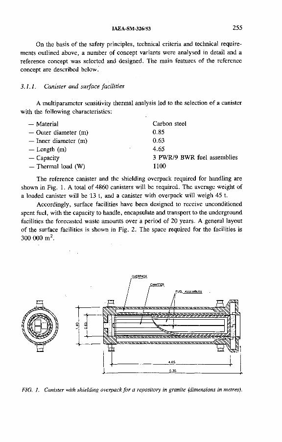
IAEA-SM-326/53 255
On the basis of the safety principles, technical criteria and technical requirements outlined above, a number of concept variants were analysed in detail and a reference concept was selected and designed. The main features of the reference concept are described below.
3.1.1. Canister and surface facilities
A multiparameter sensitivity thermal analysis led to the selection of a canister with the following characteristics:
— Material Carbon steel— Outer diameter (m) 0.85— Inner diameter (m) 0.63— Length (m) 4.65— Capacity 3 PWR/9 BWR fuel assemblies— Thermal load (W) 1100
The reference canister and the shielding overpack required for handling are shown in Fig. 1. A total of 4860 canisters will be required. The average weight of a loaded canister will be 13 t, and a canister with overpack will weigh 45 t.
Accordingly, surface facilities have been designed to receive unconditioned spent fuel, with the capacity to handle, encapsulate and transport to the underground facilities the forecasted waste amounts over a period of 20 years. A general layout of the surface facilities is shown in Fig. 2. The space required for the facilities is 300 000 m2.
FIG. 1. Canister with shielding overpack fo r a repository in granite (dimensions in metres).

256 HUERTAS and GRAVALOS
preparation Central shaft
FIG. 2. General layout o f surface facilities fo r a repository in granite.
3.1.2. Underground facilities
The disposal concept selected contemplates a mine type repository excavated at a depth of 500 m in granite and consisting of an array of full face drilled drifts of 2.4 m diameter. A thermal analysis performed indicates that with a spacing of 35 m between disposal drifts and 1 m between canisters in a drift, each canister being embedded in a buffer of about 0.8 m thick compacted bentonite clay, and with the space between canisters also filled with compacted bentonite, the temperature at any point in the buffer never exceeds 100°C.
The maximum length for disposal in the drifts will be 500 m. Main access to the facility will be by ramp. One central auxiliary shaft and at least two others for ventilation are considered. The design also includes room for testing and other ancillary installations. The total underground space required is about 1 km2. A general layout of the repository and relevant features are shown in Fig. 3.
3.2. Salt
The specific assumptions considered for the salt repository option are as follows:
Host rock: The repository is to be constructed in the middle of a layer of fairly pure halite with a minimum thickness of 150 m.
Temperature: The maximum temperature at the container-rock interface should not exceed 100°C.
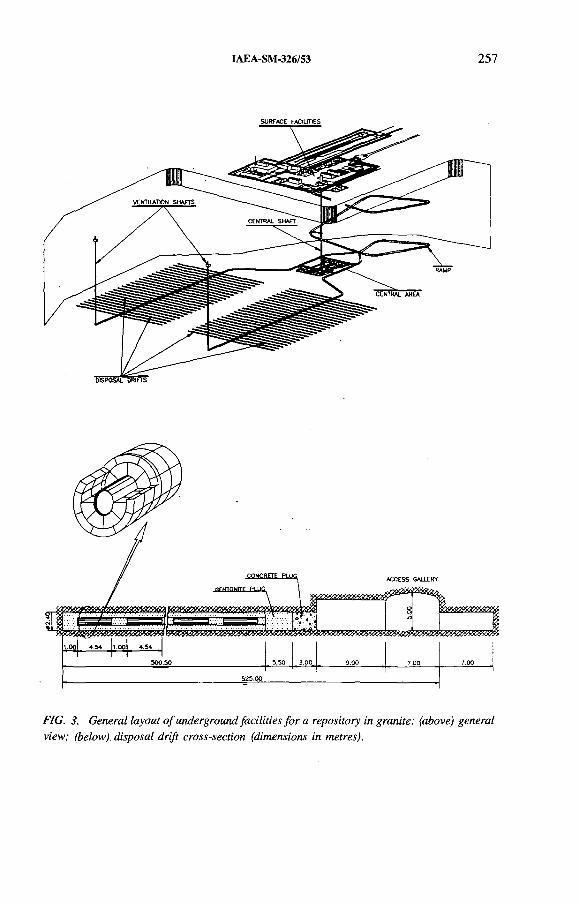
f*2
.4Û
IAEA-SM-326/53 257
SURFACE FACILITIES
FIG. 3. General layout o f underground facilities fo r a repository in granite: (above) general view; (below), disposal drift cross-section (dimensions in metres).
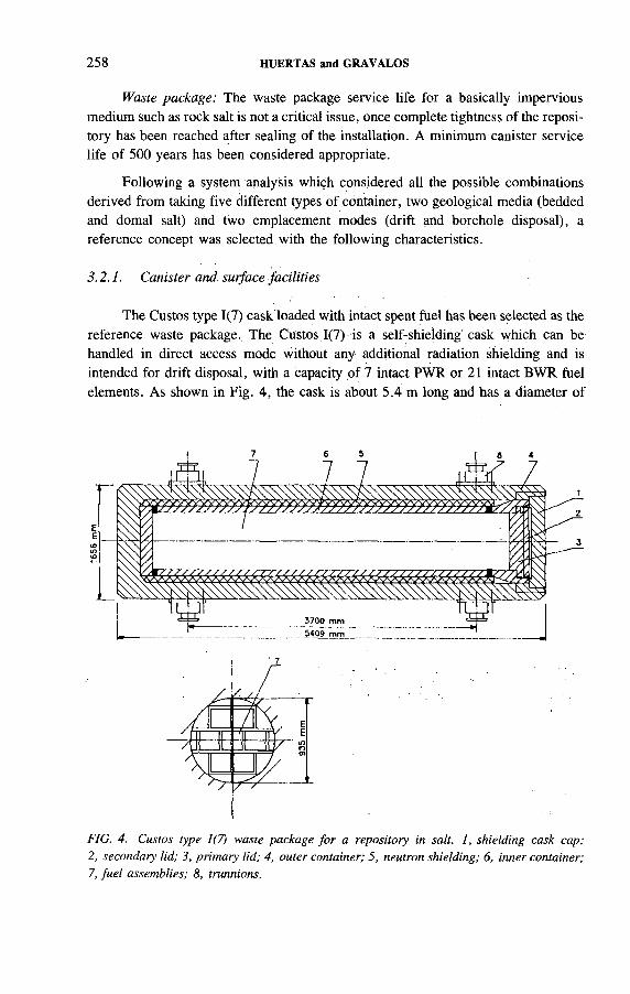
258 HUERTAS and GRAVALOS
Waste package: The waste package service life for a basically impervious medium such as rock salt is not a critical issue, once complete tightness of the repository has been reached after sealing of the installation. A minimum canister service life of 500 years has been considered appropriate.
Following a system analysis which considered all the possible combinations derived from taking five different types of container, two geological media (bedded and domal salt) and two emplacement modes (drift and borehole disposal), a reference concept was selected with the following characteristics.
3.2.1. Canister and surface facilities
The Custos type 1(7) cask loaded with intact spent fuel has been selected as the reference waste package.. The Custos 1(7) is a self-shielding' cask which can be handled in direct access mode without any additional radiation shielding and is intended for drift disposal, with a capacity of 7 intact PWR or 21 intact BWR fuel elements. As shown in Fig. 4, the cask is about 5.4 m long and has a diameter of
FIG. 4. Custos type 1(7) waste package fo r a repository in salt. 1, shielding cask cap;2, secondary lid; 3, primary lid; 4, outer container; 5, neutron shielding; 6, inner container; 7, fuel assemblies; 8, trunnions.

IAEA-SM-326/53 259
FIG. 5. A rtis t’s view o f surface facilities fo r a repository in salt.
around 1.65 m and a weight (loaded) of about 70 t. The total number of casks required for the whole programme is about 2090, which will be disposed of during a period of 25 years.
Surface facilities have been designed to condition the HLW in Custos type 1(7) casks at a rate of about 80 casks per year either in a continuous way or by campaigns, increasing the flexibility of the design so as to be easily adaptable to possible variations in the waste generation scenario. Figure 5 displays an artist’s view of the surface facilities. The total space needed for the surface facilities amounts to 290 000 m2, including the rock salt dump.
3.2.2. Underground facilities
From the different variants evaluated, a mine type repository at a depth of about 850 m has been selected, consisting of a central area for the mining and nuclear infrastructure, an emplacement field for medium activity waste (MAW) and four HLW emplacement fields. The HLW emplacement fields consist of an array of parallel drifts with a cross-sectional area of about 16 m2; the disposal casks will be placed directly in the centre of the drift. The spacing between drifts is 19 m, with6 m between casks. After cask deposition the empty space will be backfilled with crushed salt. The space required for the underground facilities is approximately
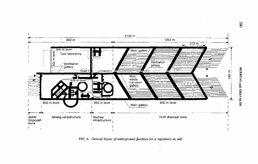
FIG. 6. General layout o f underground facilities fo r a repository in salt.
IAEA-SM-326/53 261
0.8 km2. The layout of the underground facilities is shown in Fig. 6. The repository geometry is optimized particularly with regard to the HLW decay heat in order to limit the mechanical stress of the host rock as much as possible. The repository is assumed to have a safety distance of at least 75 m to the over- and underlying non- saliniferous strata, and 300 m to the rock salt flanks. The increment in temperature at both ends of the salt seam induced by the waste decay heat must not exceed 25 °C.
Thermomechanical analysis performed with the above mentioned boundary conditions proves the design to be consistent with the imposed safety regulations; the maximum temperature in the salt, slightly under 100°C, is reached in the midpoint of a central drift about 60 years after emplacement.

IAEA-SM-326/39
THE TVO CONCEPT FOR DIRECT DISPOSAL OF SPENT FUEL
J.-P. SALOTeollisuuden Voima Oy,Helsinki, Finland
Abstract
THE ÍV O CONCEPT FOR DIRECT DISPOSAL OF SPENT FUEL.Teollisuuden Voima Oy (TVO) is responsible for the ■ management of spent fuel
produced by the Olkiluoto power plant. TVO’s current programme of spent fuel management is based on the guidelines and time schedule set by the Finnish Government. TVO has studied a final disposal concept in which the spent fuel bundles are encapsulated in copper canisters and emplaced in Finnish bedrock. According to the plan the final repository for spent fuel will be in operation by 2020. TVO’s updated technical plans for the disposal of spent fuel together with a performance analysis (TVO-92) will be submitted to the authorities by the end of 1992. The paper describes TVO’s new encapsulation process, canister design and repository layout.
1. INTRODUCTION
The waste producer is responsible for the safe management; of radioactive wastes in Finland. Teollisuuden Voima Oy (TVO), which operates two. BWRs (2 X 710 MW(e)), is making preparations for the final disposal of the spent fuel in Finnish crystalline bedrock. TVO’s current programme of spent fuel management is based on the guidelines and time schedule set by the Finnish Government. Accordingly, TVO is preparing to have a final repository for spent fuel operating by 2020. Until then, spent fuel will be stored at the reactors and at the interim storage facility operating at the power plant site since 1987.
In accordance with the Government guidelines, TVO is running a preliminary site investigation programme. Since 1987 five sites (Fig. 1) have been the subject of studies to examine their suitability for hosting a repository. According to the time schedule, the results from these studies will be available by the end of 1992, whereupon two or three sites will be selected for further charactërization. The final selèc- tion of the host site will take place in 2000, allowing the start of construction of the repository in the 2010s. For the construction permit the Nuclear Energy Act requires that both the regulatory body (Finnish Centre for Radiation and Nuclear Safety) and the local community accept the planned repository.
263

264 SALO
FIG. 1. Sites o f preliminary investigations fo r final disposal o f spent nuclear fue l in Finland.
Parallel to the site investigation programme, an R&D programme has been run with the aim of developing the technology for encapsulation and disposal and extending the database and modelling capabilities needed in performance assessment of the chosen technical concept. According to the guidelines, updated technical plans together with the performance analysis of spent fuel disposal (TVO-92) must be submitted to the authorities by the end of 1992.
IAEA-SM-326/39 265
The TVO-92 performance analysis will be made for a repository located at a reference site. This site bears the characteristics of one of the actual investigation sites, but, through sensitivity studies, the analysis will be extended to cover the characteristics of all five sites. In general, the analysis of performance of the geological barrier is based on the field data from the site investigations.
This paper will describe the updated technical plans for TVO’s spent fuel disposal, which also forms a basis for TVO-92. The spent fuel is encapsulated by a cold process technique [1] in advanced cold process (ACP) canisters [2]. The repository design [3] was completed in 1989.
In TVO’s disposal plan the total spent fuel amount is estimated to be 1840 t U, corresponding to approximately 1200 ACP canisters. The manufacture of 1200 final disposal canisters would require around 8000 t of copper and 5000 t of steel.
2. CANISTER DESIGN
The ACP canister is presented in Fig. 2. The design consists of an inner steel canister as a load bearing element and an outer corrosion shield of oxygen free copper. The diameter of the ACP canister is 0.8 m and the height 4.5 m. The wall thickness for the copper shell is 60 mm and for the steel shell 55 mm. One canister can accommodate nine BWR fuel assemblies without fuel boxes. The total weight of a loaded and sealed canister is between 14 000 and 19 000 kg, depending on the canister design and filling material to be used.
The mechanical design does not depend on the mechanical properties of the filling material. The main function of the filling material is simply to diminish the empty volume inside the canister. The canister filling material can be, e.g., lead shot, glass beads or quartz sand. Laboratory tests have been performed with lead shot and quartz sand.
The outer copper lid is to be sealed using electron beam welding. At present, this method requires a vacuum atmosphere at welding. To speed up the vacuum formation process and to prevent the possible discharge of radioactive gases during the welding process, the internal steel shell containing the fuel assemblies must be made leaktight against the 1 bar (0.1 MPa) internal overpressure caused by the outside vacuum. This leaktightness can be achieved by a thread joint or by a bolted flange joint and a soft gasket in the steel lid. The bolted design is easier to install.
The maximum design temperature on the outer surface is limited to 100° С because of the chemical stability of the highly compacted bentonite in the deposition hole. The highest temperature inside the canister is assumed to be less than 150°C.
The maximum dose rate on the surface of the canister is about 100 mSv/h. This requires that the maximum burnup of the fuel assemblies is limited to 45 MW-d/kg U if the shortest cooling time after removal from the reactor core is 15 years.
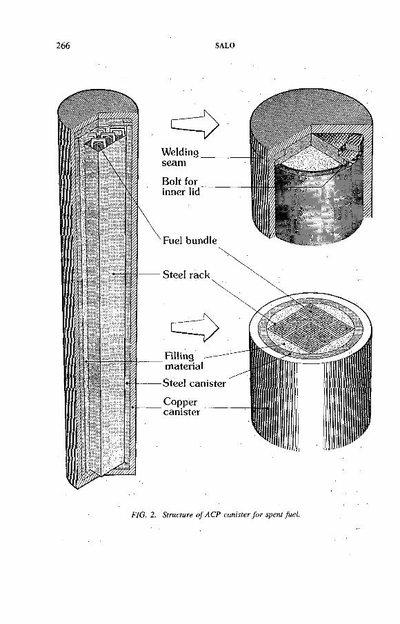
266 SALO
FIG. 2. Structure o f A C P canister fo r spent fuel.
IAEA-SM-326/39 267
The mechanical design load for the canister is 15 MPa external pressure. The maximum design pressure is distributed evenly and acts on each face of the vessel. Thermal transient loads are not significant. Temperature can vary between environmental temperature and the highest operation temperature (15.0°C). All of the mechanical pressure load is carried by the internal steel shell structure. The maximum tensile strain in copper material is limited to 1 %.
The outside shell made of oxygen free copper is designed only for corrosion protection and leaktightness. The inside steel shell is designed to be leaktight only during the electron beam welding of the Outer copper shell.
Extensive research work, in collaboration with the Swedish Nuclear Fuel and Waste Management Company (SKB), has been done in evaluating the performance of the canister in the anticipated service conditions [4]. The canister development programme included, among other things, copper creep evaluations and mechanical and radiation calculations. Within the limits of design pressures it was found that the inner shell could be produced commercially out of cast or pressure vessel steels.
The fabrication technology and costs of various manufacturing alternatives to make large copper canisters were examined [5]. The study showed that several feasible manufacturing routes already exist. The routes are based either on hot extrusion or on hot rolling. In order to gain experience of hot extrusion a quarter-scale model of a copper canister was manufactured.
3. ENCAPSULATION
The final repository and the encapsulation plant will be situated at the same site (area on the surface 740 m X 500 m). The repository will be situated in the rock underneath the encapsulation station, several hundred metres below the surface. The fuel assemblies will be transported from the interim storage facility at Olkiluoto to the encapsulation plant in transport casks.
TVO’s technical plan for encapsulation of spent nuclear fuel is based on a cold process technique [1]. By the use of this method with the ACP canister elevated temperatures are not required for producing a canister of sufficient structural stability. By replacing the molten lead casting of the earlier concept with a granular filling material, the design and operation of the encapsulation plant cán be simplified, thus resulting in increased safety and improved economics.
The preliminary design of the encapsulation plant [1] includes the handling systems, process systems, buildings and site layout. The total volume of the building is 99 610 m 3. The main stages of encapsulation are shown in Fig: 3.
Special attention has been paid to the safety of the handling process and to the optimal use of space. Possible incidents and accidents in the handling process and their impacts on safety have been taken into account in the design. In optimizing the handling spaces the doses for operating personnel at different operating stages were analysed in detail.
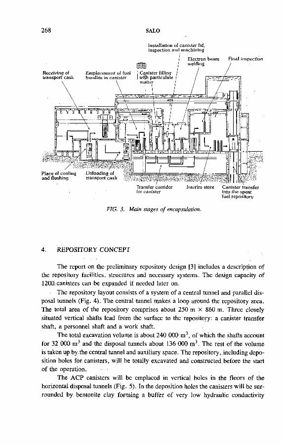
268 SALO
Installation of canister lid, inspection and machining
fuel repository
FIG. 3. Main stages of encapsulation.
4. REPOSITORY CONCEPT
The report on the preliminary repository design [3] includes a description of the repository facilities, structures and necessary systems. The design capacity of 1200. canisters can be expanded if needed later on.
The repository layout consists of a system of a central tunnel and parallel disposal tunnels (Fig. 4). The central tunnel makes a loop around the repository area. The total area of the repository comprises about 250 m x 860 m. Three closely situated vertical shafts lead from the surface to the repository: a canister transfer shaft, a personnel shaft and a work shaft.
The total excavation volume is about 240 000 m3, of which the shafts account for 32 000 m3 and the disposal tunnels about 136 000 m3. The rest of the volume is taken up by the central tunnel and auxiliary space. The repository, including deposition holes for canisters, will be totally excavated and constructed before the start of the operation.
The ACP canisters will be emplaced in vertical holes in the floors of the horizontal disposal tunnels (Fig. 5). In the deposition holes the canisters will be surrounded by bentonite clay forming a buffer of very low hydraulic conductivity
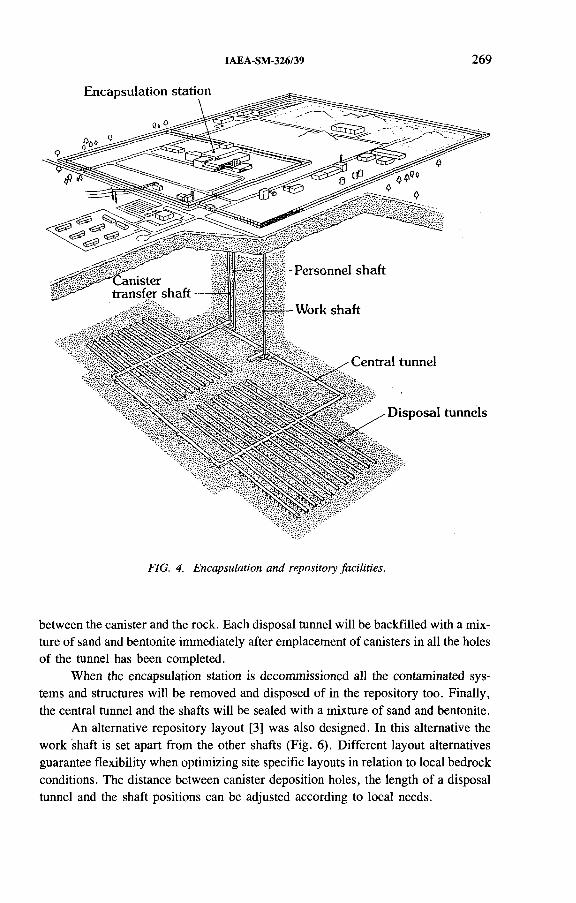
IAEA-SM-326/39 269
FIG. 4. E ncapsulation and. repository facilities.
between the canister and the rock. Each disposal tunnel will be backfilled with a mixture of sand and bentonite immediately after emplacement of canisters in all the holes of the tunnel has been completed.
When the encapsulation station is decommissioned all the contaminated systems and structures will be removed and disposed of in the repository too. Finally, the central tunnel and the shafts will be sealed with a mixture of sand and bentonite.
An alternative repository layout [3] was also designed. In this alternative the work shaft is set apart from the other shafts (Fig. 6). Different layout alternatives guarantee flexibility when optimizing site specific layouts in relation to local bedrock conditions. The distance between canister deposition holes, the length of a disposal tunnel and the shaft positions can be adjusted according to local needs.
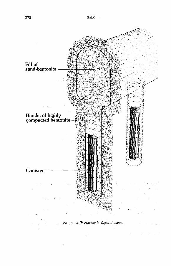
270 SALO
Fill ofsand-bentonite
Blocks of highly compacted bentonite
Canister
FIG. 5. ACP canister in disposal tunnel.

IAEA-SM-326/39 271
FIG. 6. Alternative layout fo r spent fu e l repository.
5. COSTS
At the cost level of 1992 the costs of encapsulation of TVO spent fuel are estimated to be 1720 million markkaa (FIM). This total includes the costs of construction, operation and decommissioning of the encapsulation plant as well as 1140 ACP canisters. The costs for repository construction, operation and final closure amount to 1030 million FIM. Encapsulation and final disposal operations at the site will provide employment for approximately one hundred people for several decades.
REFERENCES
[1] MAYER, E., VÄLIMÄKI, P., KUKKOLA, T., TVO Encapsulation Plant, Preliminary Design of Cold-Process Plant, TVO/KPA Safety and Technology WorkRep. 89-1, Imatran Voima Oy, Helsinki (1989).
[2] RAIKO, H., SALO, J.-P., The Design Analysis of ACP-Canister for Nuclear WasteDisposal, Rep. YJT-92-05, Nuclear Waste Commission of Finnish Power Companies, Helsinki (1992).
[3] SALO, J.-P., KUKKOLA, T., PÖLLÄNEN, L., RIEKKOLA, R., SAANIO, T.,KPA Spent Fuel Repository, Preliminary Design, Teollisuuden Voima Oy, Helsinki (1990) (in Finnish).
272 SALO
[4] WERME, L., Near-Field Performance of the Advanced Cold Process Canister, Rep. YJT-90-20, Nuclear Waste Commission of Finnish Power Companies, Helsinki (1990).
[5] RAJAINMÄKI, H., NIEMINEN, M., LAAKSO, L., Production Methods and Costs of Oxygen Free Copper Canisters for Nuclear Waste Disposal, Rep. YJT-92-I7, Nuclear Waste Commission of Finnish Power Companies, Helsinki (1992).
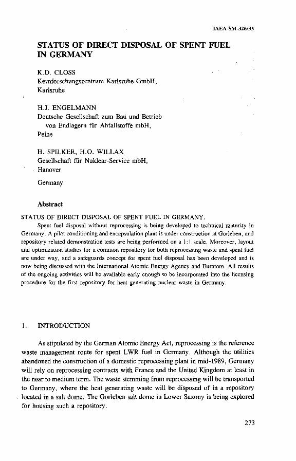
IAEA-SM-326/33
STATUS OF DIRECT DISPOSAL OF SPENT FUEL IN GERMANY
K.D. CLOSSKernforschungszentrum Karlsruhe GmbH,Karlsruhe
H.J. ENGELMANNDeutsche Gesellschaft zum Bau und Betrieb
von Endlagern für Abfallstoffe mbH,Peine
H. SPILKER, H.O. WILLAXGesellschaft für Nuklear-Service mbH,Hanover
Germany
Abstract
STATUS OF DIRECT DISPOSAL OF SPENT FUEL IN GERMANY.Spent fuel disposal without reprocessing is being developed to technical maturity in
Germany. A pilot conditioning and encapsulation plant is under construction at Gorleben, and repository related demonstration tests are being performed on a 1:1 scale. Moreover, layout and optimization studies for a common repository for both reprocessing waste and spent fuel are under way, and a safeguards concept for spent fuel disposal has been developed and is now being discussed with the International Atomic Energy Agency and Euratom. All results of the ongoing activities will be available early enough to be incorporated into the licensing procedure for the first repository for heat generating nuclear waste in Germany.
1. INTRODUCTION
As stipulated by the German Atomic Energy Act, reprocessing is the reference waste management route for spent LWR fuel in Germany. Although the utilities abandoned the construction of a domestic reprocessing plant in mid-1989, Germany will rely on reprocessing contracts with France and the United Kingdom at least in the near to medium term. The waste stemming from reprocessing will be transported to Germany, where the heat generating waste will be disposed of in a repository located in a salt dome. The Gorleben salt dome in Lower Saxony is being explored for housing such a repository.
273
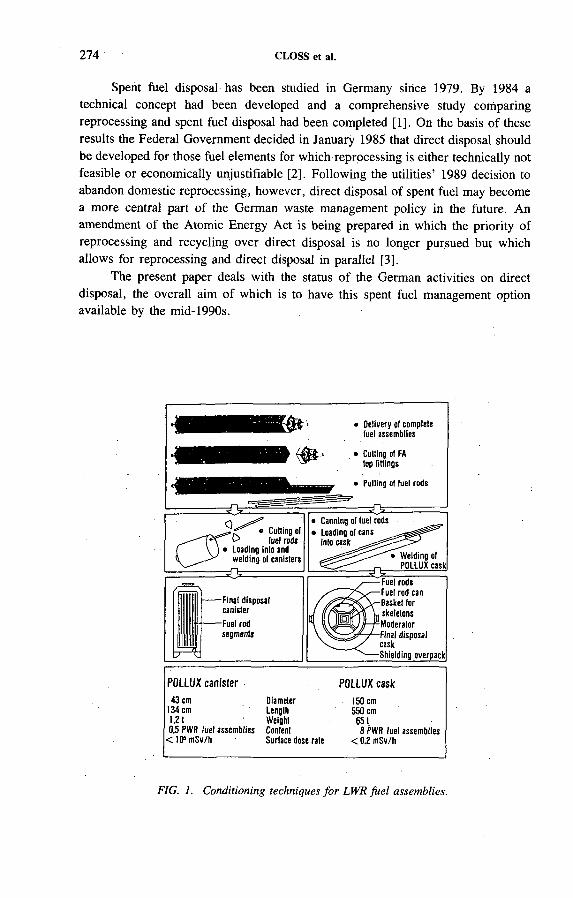
274 CLOSS et al.
Spent fuel disposal has been studied in Germany since 1979. By 1984 a technical concept had been developed and a comprehensive study comparing reprocessing and spent fuel disposal had been completed [1]. On the basis of these results the Federal Government decided in January 1985 that direct disposal should be developed for those fuel elements for which reprocessing is either technically not feasible or economically unjustifiable [2]. Following the utilities’ 1989 decision to abandon domestic reprocessing, however, direct disposal of spent fuel may become a more central part of the German waste management policy in the future. An amendment of the Atomic Energy Act is being prepared in which the priority of reprocessing and recycling over direct disposal is no longer pursued but which allows for reprocessing and direct disposal in parallel [3].
The present paper deals with the status of the German activities on direct disposal, the overall aim of which is to have this spent fuel management option available by the mid-1990s.
Cutting ol
Í V ) • Loading Into andwelding ol canisters
= 0
Final disposal canisterFuel rod segments
Canning ot tue! rods Loading ol cans Into cask
Fuel rods Fuel rod can Basket for skeletons Moderator Final disposal caskShielding overpack
POLLUX canister POLLUX cask43 cm Diameter . 150 cm
134 cm Length 550 cm1.21 Weight 6510.5 PWR fuel assemblies Content 8 PWR fuel assemblies
<10* mSv/h Surface dose rate < 0.2 mSv/h
FIG. 1. Conditioning techniques fo r LWR fue l assemblies.
IAEA-SM-326/33 275
Two variants for spent fuel conditioning and disposal are being pursued:
— POLLUX casks for disposal in drifts (reference concept)— POLLUX canisters for disposal in boreholes (backup concept).
The spent fuel conditioning and encapsulation techniques for both variants are schematically shown in Fig. 1.
The process starts with disassembly of the fuel assemblies. In the reference concept (shown on the right hand side of Fig. 1) intact consolidated rods are placed into the disposal cask, which is surrounded by a shielding overpack. Such a package is called a POLLUX cask and is designed for transport as well as for interim storage and disposal. The cask is approximately 5.5 m long, has a diameter of approximately1.5 m, and weighs some 65 t in its loaded state. It will be disposed of in a drift of a repository.
2. TECHNICAL CONCEPTS
FIG. 2. Emplacement procedure fo r POLLUX casks.
276 CLOSS et al.
Since handling such heavy and large casks in a repository mine had not been demonstrated in 1985, a backup solution for spent fuel conditioning and encapsulation resulting in smaller spent fuel packages is being pursued. This concept is shown on the left hand side of Fig. 1. The POLLUX canisters have the same outer dimensions as the canisters for vitrified reprocessing waste. In this case the disassembled fuel pins have to be cut into pieces about 1 m in length. A POLLUX canister can hold the chopped fuel rods of half a PWR fuel assembly. Handling and, if necessary, intermediate storage of the POLLUX canisters require additional shielded casks designed for this purpose. The advantage of this concept is that the handling and emplacement techniques in the repository are the same as for vitrified reprocessing waste, namely the emplacement of the canisters into 300 m deep boreholes drilled in the floor of the disposal drifts.
The handling and emplacement procedure for POLLUX casks at the repository is shown in Fig. 2. After having been shipped by rail or road to the surface facilities, the cask passes through the entrance control in the transfer hall. Next, it is placed on a railroad car which is conveyed to the shaft and pushed into the shaft cage. After hoisting, the loaded railroad car is pulled from the hoisting cage at the shaft landing. There, the car is transferred along the access drift to the emplacement drift by a mine locomotive. At the emplacement position, the cask is lifted from the railroad car by an emplacement device which is designed for lifting and depositing the cask on the floor after removal of the car. The car is pulled out of the emplacement drift all the way back to the surface for reloading. The drift section accommodating the emplaced cask is backfilled immediately with crushed salt.
3. SPENT FUEL CONDITIONING AND PACKAGING
Cask and spent fuel conditioning technologies are to be developed by the industry, i.e. the utilities now represented by the Gesellschaft für Nuklear-Service. The atomic licence application for a pilot plant for spent fuel conditioning and encapsulation was submitted to the licensing authority in May 1986. The site selected is at Gorleben in Lower Saxony and is directly adjacent to the 1500 t away-from- reactor interim storage facility, which is licensed for storage of spent fuel in special transport/storage casks, e.g. CASTOR casks.
The first partial construction permit (building) was granted in January 1990. The concrete works for the building are in an advanced stage. The walls of the building have reached a height of 3 m above ground.
The second partial construction permit (components) is expected in early 1993, and hot operation is planned for early 1996. All newly developed components for the plant have been built and tested inactively.
The pilot plant is designed as a multipurpose facility, in which the conditioning and encapsulation technology for various forms of radioactive waste will be
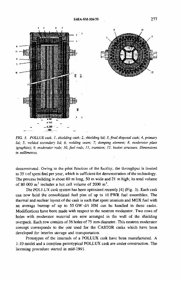
IAEA-SM-326/33 277
FIG. 3. POLLUX cask. 1, shielding cask; 2, shielding lid; 3, final disposal cask; 4, primary lid; 5, welded secondary lid; 6, welding seam; 7, damping element; 8, moderator plate (graphite); 9, moderator rods; 10, fu e l rods; 11, trunnion; 12, basket structure. Dimensions in millimetres.
demonstrated.. Owing to the pilot function of the facility, the throughput is limited to 35 t of spent fuel per year, which is sufficient for demonstration of the technology. The process building is about 60 m long, 50 m wide and 21 m high; its total volume of 80 000 m3 includes a hot cell volume of 2000 m3.
The POLLUX cask system has been optimized recently [4] (Fig. 3). Each cask can now hold the consolidated fuel pins of up to 10 PWR fuel assemblies. The thermal and nuclear layout of the cask is such that spent uranium and MOX fuel with an average burnup of up to 55 GW-d/t HM can be handled in these casks. Modifications have been made with respect to the neutron moderator. Two rows of holes with moderator material are now arranged in the wall of the shielding overpack. Each row consists of 36 holes of 75 mm diameter. This neutron moderator concept corresponds to the one used for the CASTOR casks which have been developed for interim storage and transportation.
Prototypes of the internals of a POLLUX cask have been manufactured. A 1:10 model and a complete prototypical POLLUX cask are under construction. The licensing procedure started in mid-1991.

278 CLOSS et al.
The repository related R&D work is being supported by the Federal Ministry of Research and Technology and co-ordinated by thé management group PTE at the Kernforschungszentrum Karlsruhe (KfK). Major contributions to the programme are being made by the Deutsche Gesellschaft zum Bau und Betrieb von Endlagern für Abfallstoffe, the Forschungszentrum für Umwelt und Gesundheit, the Bundesanstalt für Geowissenschaften and Rohstoffe and the KfK. Most of thè work is concentrated on demonstrating the safe and reliable handling of the POLLUX casks in a repository on a 1:1 scale. Emphasis is also being laid on the investigation of special thermal and rock mechanics aspects of the drift emplacement concept as well as on the layout and optimization of a repository for both reprocessing waste and spent fuel.
4.1. Demonstration tests
The first demonstration test deals with the shaft transport of the POLLUX cask. A test rack with the most important components of the hoisting system has been established in the former turbine hall of a power plant at Landesbergen, Lower Saxony (Fig. 4). The loading and unloading of the hoisting cage with an inactive 1:1 POLLUX cask weighing 65 t on a railroad car has been simulated there [5]. The test started in July 1991 and lasted until early 1992. The results proved the safe transport of payloads up to 85 t (POLLUX cask plus railroad car) in the shaft and indicated the licensability of the shaft hoisting system. .
In another test, the handling of a POLLUX cask in the limited space of a repository mine is to be demonstrated (Fig. 5). For this purpose the railroad car and the emplacement device have been designed and built. Major development efforts were devoted to minimizing the height of the car and the emplacement device in order to minimize drift cross-sections as well as to allow a railroad car with a small track radius in order to utilize the given salt volume as well as possible. Most of the components for the railroad car and the emplacement device are state of the art, but they had to be adapted to the special conditions of a repository mine in a salt formation. The test started in September 1992.
An in situ test that studies the properties and behaviour of both crushed salt and rock salt is being conducted at the Asse mine. Two parallel drifts have been excavated at a depth of 800 m. In each drift, three electrically heated dummy containers of the dimensions and weights of POLLUX casks have been installed and backfilled with crushed salt [6] (Fig. 6). This test serves to validate constitutive models developed to predict material responses in the, repository near field. The test started in September 1990 and will take at least three years. The results obtained up to now from this test demonstrate that the temperatures in the repository can be predicted very well, but thére are still some discrepancies in the predicted and measured stress and strain fields.
4. SPENT FUEL DISPOSAL ACTIVITIES
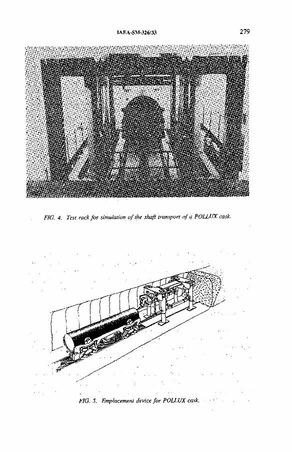
IAEA-SM-326/33 279
FIG. 5. Emplacement device fo r POLLUX cask.
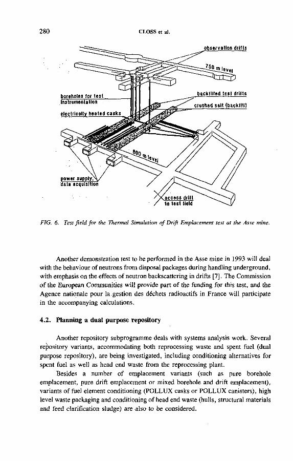
280 CLOSS et al.
FIG. 6. Test field fo r the Thermal Simulation o f Drift Emplacement test at the Asse mine.
Another demonstration test to be performed in the Asse mine in 1993 will deal with the behaviour of neutrons from disposal packages during handling underground, with emphasis on the effects of neutron backscattering in drifts [7]. The Commission o f the European Communities will provide part of the funding for this test, and the Agence nationale pour la gestion des déchets radioactifs in France will participate in the accompanying calculations.
4.2. Planning a dual purpose repository
Another repository subprogramme deals with systems analysis work. Several repository variants, accommodating both reprocessing waste and spent fuel (dual purpose repository), are being investigated, including conditioning alternatives for spent fuel as well as head end waste from the reprocessing plant.
Besides a number of emplacement variants (such as pure borehole emplacement, pure drift emplacement or mixed borehole and drift emplacement), variants of fuel element conditioning (POLLUX casks or POLLUX canisters), high level waste packaging and conditioning of head end waste (hulls, structural materials and feed clarification sludge) are also to be considered.

IAEA-SM-326/33 281
One major finding is that cost differences are not due to differences in emplacement concepts (i.e. drift or borehole emplacement) and repository layout. They aré mainly caused by the changing types and numbers of containers that accompany a change of the emplacement concept [8].
Spent fuel disposal requires implementation of additional safeguards measures. A safeguards concept has been developed which mainly relies on dual containment and surveillance methods [9]. This concept is now being discussed with the IAEA and Euratom. One interesting technical feature of the safeguards concept is that the packaging, handling and disposal concepts for materials subjected to safeguards and materials not subjected to safeguards are completely different, so that identification is very easy: spent fuel is encapsulated into heavily shielded casks and disposed of in drifts of a repository whereas radioactive waste which is no longer under IAEA safeguards uses thin walled canisters which are disposed of in boreholes.
5. OUTLOOK
The date of implementation of direct disposal in Germany is determined by the commissioning of the Gorleben repository, which will not happen before 2008. The underground exploration of the Gorleben salt dome is likely to be finished between 1995 and 1999. This will be followed by the plan approval procedure.
All findings of the programme will be available before the beginning of the approval procedure so that the direct disposal strategy can be taken into account in the licensing procedure. If direct disposal of spent LWR fuel is to be included in the future waste management concept, a large conditioning and encapsulation plant has to be built. To minimize transport of radioactive material, it would be desirable to build the plant on the site of the future repository. Whether the Gorleben salt dome is the proper site for a repository will be known by the turn of the century. By then sufficient experience will also be available from the operation of the pilot conditioning plant to make a decision on the construction of a large conditioning plant. The plant could be commissioned prior to the commissioning of a repository. No earlier decision to build and no earlier commissioning of a large conditioning plant will be needed.
REFERENCES
[1] Systems Study of Alternative Spent Fuel Management Technology, Main Volume, KWA-2190/1, Kernforschungszentrum Karlsruhe (1986) (in German) [English translation: ORNL/TR-86/31, Oak Ridge Nad Lab., TN (1986)].
[2] Construction of a reprocessing plant, Bull. German Fed. Govt No. 8, Presse- und Informationsamt der Bundesregierung, Bonn (1985) 66 (in German).
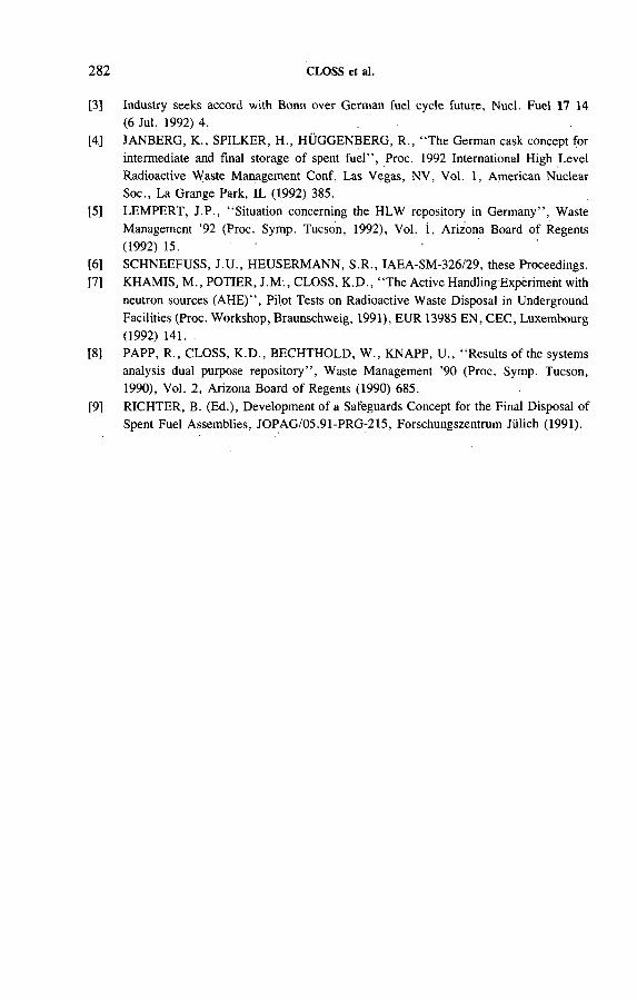
282 CLOSS et al.
[3] Industry seeks accord with Bonn over German fuel cycle future, Nucl. Fuel 17 14(6 Jul. 1992) 4. .
[4] JANBERG, K., SPILKER, H., HÜGGENBERG, R., “ The German cask concept for intermediate and final storage of spent fuel” , Proc. 1992 International High Level Radioactive Waste Management Conf. Las Vegas, NV, Vol. 1, American Nuclear Soc., La Grange Park, IL (1992) 385.
[5] LEMPERT, J.P., “ Situation concerning the HLW repository in Germany” , WasteManagement ’92 (Proc. Symp. Tucson, 1992), Vol. 1, Arizona Board of Regents (1992) 15. 1
[6] SCHNEEFUSS, J.U., HEUSERMANN, S.R., IAEA-SM-326/29, these Proceedings.[7] KHAMIS, M., POTIER, J.M ., CLOSS, K.D., “ The Active Handling Expèriment with
neutron sources (AHE)” , Pilot Tests on Radioactive Waste Disposal in Underground Facilities (Proc. Workshop, Braunschweig, 1991), EUR 13985 EN, CEC, Luxembourg (1992) 141.
[8] PAPP, R., CLOSS, K.D., BECHTHOLD, W., KNAPP, U., “ Results of the systems analysis dual purpose repository” , Waste Management ’90 (Proc. Symp. Tucson, 1990), Vol. 2, Arizona Board of Regents (1990) 685.
[9] RICHTER, B. (Ed.), Development of a Safeguards Concept for the Final Disposal of Spent Fuel Assemblies, JOPAG/Q5.91-PRG-215, Forschungszentrum Jülich (1991).

DEVELOPING, TESTING AND VALIDATING REPOSITORY PERFORMANCE ASSESSMENT MODELS
(Session 6)
Chairmen
P. ESCALIER DES ORRESFrance
C. PESCATOREOECD/NEA

IAEA-SM-326/S7
SCENARIO SELECTION PROCEDURES IN THE FRAMEWORK OF THE CEC EVEREST PROJECT*
P. RAIMBAULT, S. LIDOVE Agence nationale pour la gestion
des déchets radioactifs,Fontenay-aux-Roses, France
P. ESCALIER DES ORRESInstitut de protection et de sûreté nucléaire,Commissariat à l’énergie atomique,Fontenay-aux-Roses, France
J. MARIVOET CEN/SCK,Mol, Belgium
K. MARTENSGesellschaft für Reaktorsicherheit mbH,Cologne, Germany
J. PRUEnergieonderzoek Centrum Nederland,Petten, Netherlands
Abstract
SCENARIO SELECTION PROCEDURES IN THE FRAMEWORK OF THE CEC EVEREST PROJECT.
In the framework of the EVEREST project directed by the Commission of the European Communities, five organizations involved in waste management have harmonized their methodologies for selecting a final set of scenarios to be considered for sensitivity analysis studies associated with safety assessment of deep nuclear waste repositories. Three types of rock formation are being considered: clay, granite and salt. The systematic scenario approach in its different forms has been chosen by the regulatory authorities of most countries involved in the project. This approach recommends a detailed and well documented step by step procedure leading to a limited set of well characterized scenarios covering all aspects of the possible future events or combinations of events affecting the repository site. Following this general line, different logical schemes have been chosen and used by the parties involved in the
* Work performed within the framework of the CEC programme on Management andStorage of Radioactive Waste.
285
286 RAIMBAULT et al.
project. The independent initiating event methodology (Agence nationale, pour la gestion des déchets radioactifs and Institut de,protection et de sûreté nucléaire, France) is based on the production of a limited list o f about twenty independent initiating events with associated induced events and processes. The PROSA methodology (Energieonderzoek Centrum Nederland; CEN/SCK, Belgium), which is based on a variant of the ‘top-down’ approach, starts from a comprehensive list of about 150 features, events and processes which can be associated with specific states of the barriers composing the system. The transport mechanism methodology approach (Gesellschaft für Reaktorsicherheit, Germany) is based on the sélection of nuclide transport mechanisms combined with the entities which have an influence on these mechanisms. These schemes result in a final list of scenarios which are quite similar for the same site and rock formation. In the framework of EVEREST these scenarios are treated in a qualitative or semiquantitative manner or are analysed in detail with the associated sensitivity analysis studies.
1. INTRODUCTION
The EVEREST project is a co-operative effort between five organizations of the European Community involved in waste management: the Agence nationale pour la gestion des déchets radioactifs (ANDRA, France), CEN/SCK (Belgium), the Energieonderzoek Centrum Nederland (ECN, Netherlands), the Gesellschaft für Reaktorsicherheit (GRS, Germany), and the. Institut de protection et de. sûreté nucléaire (IPSN, France) as co-ordinator.
In this project, the work consists in the evaluation of the sensitivity of the radiological consequences associated with deep nuclear waste disposal systems to the different elements of the performance assessment (scenario characteristics, phenomena and physicochemical parameter values). This work covers three types of geological formation (clay, granite and salt) and the different sites studied by. the participants.
The project has four steps: ,
— Methodolbgy elaboration,— Model description and data collection,— Calculations,
, — Interpretation of results and drawing up of the final report.
The contractual period is from April 1991 to September 1994. The methodological part of the work has been carried out by three different working groups (WGs).
The role of WG1 is to identify the main features controlling radionuclide transfer to the human environment for each site and scenario. Depending on advances in model development, WG1 will select those features which will be explicitly considered in the project calculations. The group should specify as well the output data
IAEA-SM-326/57 287
which will be relevant for sensitivity analysis (dose, activity rate of certain radionuclides coming out of the geosphere, maximum value of the output parameter, and value at prescribed dates) .
The role of WG3 is to examine the different approaches and techniques which may be used for quantifying the sensitivity in the following areas:
— Parameter sensitivity analysis,— Sensitivity to models,— Sensitivity to scenarios.
WG2 deals with scenario development and is in charge of:
— Reporting the scenario selection procedures developed by each participating organization and identifying common backgrounds,
— Setting up a list of the scenarios to be considered in the project and producing a synthesis of this work.
The conclusions from this working group are reported here.
2. BACKGROUNDS OF SCENARIO SELECTION PROCEDURES
In preparing a performance assessment, the objective of the scenario development is to establish the framework for calculating the radiological consequences, taking into account the uncertainties in the components of the system, for the different combinations of events which have the potential to impair the capabilities of the disposal system to confine the waste.
In the general review of scenario selection procedures, reported by a working group of the OECD Nuclear Energy Agency [1], three main types of approach are identified:
(1) Judgemental,(2) Based on event tree or fault tree analysis,(3) Systematic.
Approach 1 was extensively used in previous safety evaluations and is mainly based on expert opinion. Approach 2 is sometimes used but seems more relevant to reactor safety. The last approach is mostly favoured in recent safety assessment methodologies. It is recognized that all approaches, in a more or less explicit manner, involve a large component of expert opinion that the selection procedure should identify and document.
An alternative to the approach in which scenarios are predefined is environmental simulation, which is based on integrated modelling of the repository system where all phenomena and processes are systematically included and each scenario derives from a sampled set of input parameters. A continuous response is thus

288 RAIMBAULT et al.
obtained which, by means of incremental probabilities, allows a global risk to be defined. It is not clear whether this approach leads to a better understanding of the future development of the disposal system than the one that can be reached with the application of scenario analysis.
In PAGIS [2] and P АСОМ A [3], efforts were already devoted to the definition of common terms and methodologies for selection and classification of scenarios. In the framework of EVEREST, it is intended to proceed one step further in producing as far as possible a systematic and well documented approach, where all important events or combinations of events are accounted for and a justification is given for the scenarios which are screened out.
The EVEREST teams have agreed to carry out this procedure, which will result in the definition of a limited set of scenarios considered as important for each type of rock formation; from this set those scenarios which are the most relevant to sensitivity analysis may be selected for detailed evaluation or for partial treatment.
One major difficulty in defining a common approach for scenario selection at the international level is related to the fact that scenario procedures have already been developed and applied. These procedures actually often reflect guidance and rules set up by national safety authorities or practices in use in different countries. A complete harmonization in the framework of the project would therefore be difficult and, possibly, not desirable. On the other hand, the comparison of the results from different approaches will provide important indications about the sensitivity of the selected procedures. Therefore, it has been decided to apply those procedures which are already in use in the participating organizations.
The general steps for carrying out the selection procedure are the following:
— A comprehensive set of events is first selected. This set is completed by a list of processes relevant to the selected events, the waste form, the rock formation, the repository, the biosphere and their interactions.
— Classification and screening are then performed in order to reject events with too low probability or consequences, or events irrelevant to the site.
— Events are combined to produce scenarios and associated with the relevant processes derived from the initial list.
— Scenarios are selected by taking into account their overall probability and possible consequences to produce a final set of scenarios for consequence analysis.
Following this general line, three logical schemes have been chosen and used by the parties involved in the project. The independent initiating event (HE) methodology (ANDRA, IPSN) is based on the production of a limited list of about twenty IIEs with associated induced events and processes. The PROSA methodology (ECN, CEN/SCK) starts from a comprehensive list of about 150 features, events and processes (FEPs) and selected FEPs are associated with specific states of the barriers composing the system. The transport mechanism methodology (TMM) (GRS) is based on the selection of nuclide transport mechanisms combined with the entities

IAEA-SM-326/57 289
which have an influence on these transport mechanisms. All schemes result in similar final lists of scenarios. The only differences originate from the type of rock formation considered.
Depending on the expected severity of their consequences, these scenarios can be treated in the framework of EVEREST in a qualitative or semiquantitative manner or can be analysed in detail with the associated sensitivity analysis studies.
The scenarios may occur at quite different time-scales which will be specified for each scenario:
— 0-500 years: a period where records on the existence of the repository may be assumed to subsist.
— 500-10 000 years: where a certain tectonic stability can be predicted, but where human intrusion cannot be excluded.
— 10 000-60 000 years: ending with a Würm type glaciation.— >60 000 years: where several glaciations are to be expected.
3. DESCRIPTION OF SCENARIO SELECTION PROCEDURES
3.1. Independent initiating event methodology
The methodology for scenario selection was established in France by a collaboration between the safety authorities, the IPSN and ANDRA [4]. This resulted in a list of scenarios included in the Basic Safety Rule for the Deep Geological Disposal of Long Lived Nuclear Waste [5] issued in June 1991 by the Ministry of Industry and Foreign Trade.
The safety evaluation of French nuclear waste disposals is based on a deterministic approach. It consists in studying a limited number of representative situations of the different families of events or sequences of events for which the associated consequences are the highest of the situations of the same family.
The scenario selection proceeds therefore in four steps.
3 .1 .1 . F irs t step: L is tin g o f lIE s a n d a ssoc ia ted induced events
Only independent and initiating events are considered here since it is not reasonable to combine artificially events which are related in a logical way.
The initiating events examined in the HE methodology are:
— Phenomena of natural origin— External geodynamics— Tectonics— Diapirism— Meteorite impact
290 RAIMBAULT et al.
‘ — Phenomena of human origin— Non-detected features— Sealing defects— Involuntary human intrusions— Human induced climate changes (greenhouse effect)— Voluntary human intrusion— War.
External geodynamics considers climatic reconstructions, based on the Milankovitch theory, which indicate a glacial episode at 60 000 years, comparable to the Würm period, and a more modest cooling period at 20 000 years. These climatic variations may lead in France to an extension of the ice sheets, variations of sea level corresponding to cycles of erosion and sedimentation and the presence of permafrost with modifications of deep groundwater flows.
Tectonic activity, represented in particular by vertical movements (subsidence or uplift), also induces topographical deformations which might possibly be accentuated by the resulting erosion. These displacements may also influence the distribution of hydraulic heads in the surface aquifers and the hydraulic boundary conditions of the systems that will be studied, and thus the deep groundwater flows.
3.1.2. Second step: Selection of events
This step consists first in eliminating events that will not be considered in site safety assessment studies. These events are of too low probability, have negligible consequences or are not relevant.
The events eliminated are the following:
— Meteorite impact, magmatic activity, voluntary human intrusions, war and human induced climate change;
— The following types of involuntary human intrusion: geothermal energy production and mining activity;
— The following types of sealing defect: waste package defects and abandonment of an unsealed repository.
3.1.3. Third step: Construction of scenarios
The processes associated with the initiating events and the induced events are described. Scenarios are constructed from one initiating event or from the combination of several initiating events if the resulting probability is high enough.

IAEA-SM-326/57 291
3.1.4. Fourth step: Defining families o f scenarios
Families of scenarios and their envelopes, which correspond to the scenario of the family with the highest consequences, are defined and detailed descriptions are given.
3.2. PROSA methodology
In the Dutch project PROSA (Probabilistic Safety Assessment) and within the Belgian performance assessment programme at the CEN/SCK it has been decided to apply a systematic procedure for scenario selection [6, 7]. The method used to determine and select the scenarios is based on the idea that the repository is a multibarrier system whose evolution can be characterized by means of the state of the barriers. The primary FEPs that directly affect the barrier state are used to define scenarios. This approach to scenario formation is called the ‘top-down’ approach. This implies that for each FEP one has to decide whether it is of importance and if so, what its role will be and in which part of the repository the FEP is operating.
The method used to select the scenarios and to find the processes needed in the consequence analysis consists of the following steps: ■
(1) Production of a list o f FEPs which might influence the state of the barriers and the release and transport of radionuclides: The list contains 63 natural phenomena, 48 human induced phenomena and 36 waste and repository induced phenomena.
(2) Screening of the list o f FEPs: The screening is performed with respect to the site, probability of occurrence or a specific criterion (human intrusion, operation and closure).
(3) Classification into primary and secondary FEPs: A primary FEP attacks or bypasses one or more of the barriers from the multibarrier system. This implies that the primary FEPs áre defining the state or evolution of the repository. The secondary FEPs influence the transport of, the radionuclides or boundary conditions for a given state or evolution of the repository and should be included in the transport model or code.
(4) Definition of possible barrier states: In the definition of the states or evolutionof the barriers in the multibarrier system a simple division into present or by-
; passed is proposed. Here a relatively small number of essential barriers areproposed: the engineered barriers, the host rock, the overburden and the
. - aquifers. Combination of thè.barrier states leads to eight possible states for the . multibarrier system.
(5) Determination of the primary FEPs for each of the barrier states: In the deter- , mination of the primary FEPs one has to take into account that some processescan attack more than one barrier.
292 RAIMBAULT et al.
(6) Determination of the secondary FEPs: This is a straightforward procedure.(7) Screening of the primary and secondary FEPs for each of the barrier states:
In this screening a classification with respect to the time in which the individual FEPs are active can be very helpful.
(8) Selection o f the scenarios to be analysed further: This step also includes the selection of the processes to be taken into account in the consequence analysis.
3.3. Transport mechanism methodology
The release of nuclides from a repository is a consequence of transport phenomena. Therefore the GRS scenario selection approach, called the transport mechanism methodology, is based on these transport mechanisms.
The definition of the scenario used in this procedure is a reflection of this methodology: “ A scenario represents a combination of a transport mechanism and the involved entities that have the potential for radiological effects on the biosphere.”
The selection procedure and the subsequent modelling of such scenarios aré treated as one unit. The selection procedure consists of several steps:
(i) The transport mechanisms are selected for an actual repository at a selected location. Within the scope of the scenario selection procedure, transport mechanisms are understood as processes which lead to a decrease in distance between stored nuclides and human beings; for example, they include nuclide transport into the biosphere as well as movement of human beings towards the stored nuclides as a result of human intrusion. Such transport mechanisms are also called ‘release mechanisms’.
(ii) The entities are identified which have an effect on the corresponding release mechanisms.
(iii) The scenarios are constructed from the combination of transport mechanisms and the corresponding entities. They are weighted according to the event probabilities of the pertinent transport mechanisms. Scenarios with extremely small event probabilities are excluded.
For adequate modelling of these scenarios in consequence analyses the entities which influence the respective transport mechanism are divided, depending on the size of the model area, into internal and external ones.
Owing to the deficiency of knowledge about the post-closure period of a repository the quantitative evaluation of the long term behaviour has to be performed such that the entire range of possible conditions of the barriers and other parameters is considered. Possible conditions of parameters and barriers (e.g. containers, dams, seals and plugs) are described by a distribution function.
The consequences of human intrusion into the repository are divided into two categories:

IAEA-SM-326/57 293
— The nuclides are transported directly into the biosphere by the intrusive activities.
— The human activities determine the initial conditions and possibly also the type of migration pathway. However, the transport itself is determined by locally inherent physical processes.
4. FINAL LIST OF SCENARIOS
The three methodologies, being neither site nor host rock specific, were then applied to each formation.
TABLE I. CLAY SCENARIOS
ScenarioType of analysis3
No. CEN/SCK IPSN ANDRA
1 Normal evolution (including Würm type glaciation)
TT TT TT
2 Riss type glaciation (leading to erosion, hydrogeological changes)
TT PT PT
3 Earthquake/neotectonics (inner geodynamics)Belgium: near field effects and fault activation France: fault activation
TT PT PT
4 Exploratory drilling PT PT PT
5 Exploitation drilling TT TT TT
6 Geological barrier bypassed Belgium: nón-detected faults France: sand lenses
PT PT PT
7 Sealing failure TT PT PT
a TT: totâl treatment (evaluation including radiological consequences); PT: partial treatment (qualitative or semiquantitative evaluation, or justification).
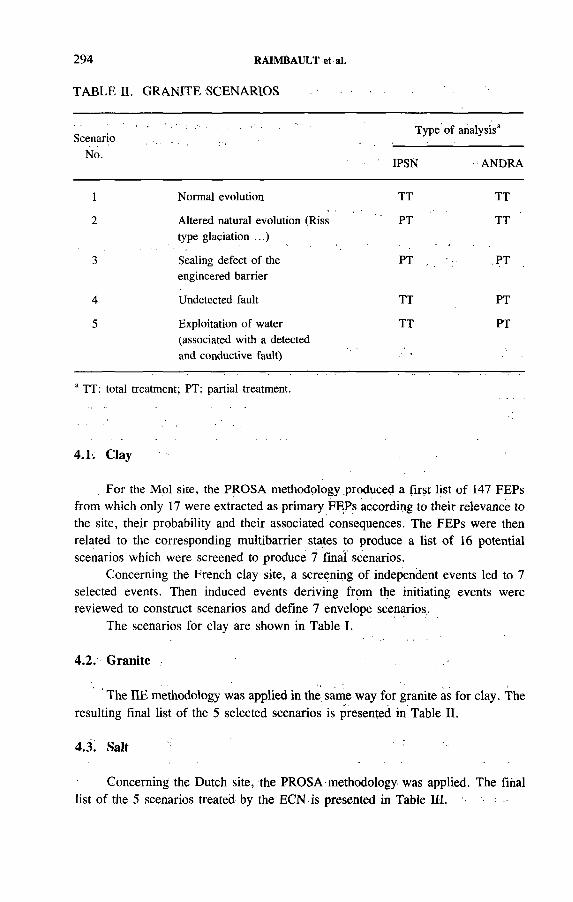
294 RAIMBAULT et al.
TABLE II. GRANITE SCENARIOS
ScenarioNo.
Type of analysis3
IPSN ANDRA
1 Normal evolution TT TT
2 Altered natural evolution (Riss type glaciation ...)
PT TT
3 Sealing defect of the engineered barrier
PT PT
4 Undetected fault TT PT
5 Exploitation of water (associated with a detected and conductive fault)
TT PT
a TT: total treatment; PT; partial treatment.
4.1. Clay
For the Mol site, the PROSA methodology produced a first list of 147 FEPs from which only 17 were extracted as primary FEPs according to their relevance to the site, their probability and their associated consequences. The FEPs were then related to the corresponding multibarrier states to produce a list of 16 potential scenarios which were screened to produce 7 final scenarios.
Concerning the French clay site, a screening of independent events led to 7 selected events. Then induced events deriving from the initiating events were reviewed to construct scenarios and define 7 envelope scenarios..
The scenarios for clay are shown in Table I.
4.2. Granite
The HE methodology was applied in the same way for granite as for clay. The resulting final list of the 5 selected scenarios is presented in Table II.
4.3. Salt
Concerning the Dutch site, the PROSA methodology was applied. The final list of the 5 scenarios treated by the ECN is presented in Table Ш. '

IAEA-SM-326/57 295
TABLE III. SALT SCENARIOS
ScenarioType of analysis3
No.GRS ECN IPSN ANDRA
1 Normal evolution:— Diapirism— Subrosion ■
TT/pT : TT PT PT
2 Altered natural evolution TT TT PT PT ■!
3 Water intrusion:— Anhydrite vein— Sealing defect
TT PT TT TT
4 Water intrusion and brine pocket
.TT PT None None
5 Solution mining for salt consumption
None None TT PT
6 Solution mining, abandoned cavity
TT/PT PT PT TT
7 Exploratory drilling None , None PT . PT
3 TT: total treatment; PT: partial treatment.
For the French site, the application of the HE methodology produced a final list of 6 scenarios treated by ANDRA and the IPSN and presented in Table III.
Concerning the German site, the transport mechanism methodology provided a list of four types of release mechanism which could lead to a decrease in distance between stored nuclides and human beings. The methodology led to 5 representative scenarios treated by the GRS and presented in Table III. ■
5: CONCLUSIONS '
The work described in this paper is an effort to harmonize the methodology for scenario selection procedures used in different organizations involved in performance assessment in the framework of a European Community project.

296 RAIMBAULT et al.
All parties in the project have chosen the scenario approach, which has the advantage of leading to a transparent safety demonstration where expert judgement can be accounted for and which allows the adaptation of the complexity of the model to the scenario considered.
Every party in the project has made an effort towards setting up a systematic and well documented procedure where each step is fully described. The procedure remains, however, specific to the country since it reflects guidance issued by national safety authorities and is sometimes more adapted to a specific type of rock formation.
It is, nevertheless, encouraging that irrespective of the approach the selection produces the same final list of scenarios for a specific rock formation.
Another conclusion is that even though it is important to make reference to a complete list of events, the relation between events cannot be ignored and leads to a hierarchical ordering of these events which has to be taken into account in the selection process.
The final conclusion which can be drawn is that scenario development is an ongoing process which will become more precise as the performance assessment progresses.
REFERENCES
[1] Systematic Approaches to Scenario Development, A Preliminary Report of the NEA Working Group on the Identification and Selection of Scenarios for Performance Assessment of Nuclear Waste Disposal, PAAG/DOC(88)2, OECD/NEA, Paris (1992).
[2] MARIVOET, J., BONNE, A., Performance Assessment of Geological Isolation Systems for Radioactive Waste Disposal in Clay Formations, EUR 11776, CEC, Luxembourg (1988).
[3] MARIVOET, J., ZEEVAERT, T., Performance Assessment of the Geological Disposal of Medium Level and Alpha Waste in a Clay Formation in Belgium, EUR 13042, CEC, Luxembourg (1990).
[4] ESCALIER DES ORRES, P., DEVILLERS, C.; CERNES, A., IZABEL, C., Détermination des scénarios à prendre en compte dans l’appréciation de la sûreté d ’un site pour le stockage des déchets radioactifs en formation géologique profonde” , paper
•presented at Symp. on Safety Assessment of Radioactive Waste Repositories, Paris, .1989:
[5] Basic Safety Rule for the Deep Geological Disposal of-Long Lived Nuclear Waste, RFS-III.2.f, Ministère de l ’industrie et du commerce extérieur, Paris (1991).
[6] PRIJ, J., et al., PROSA: Scenario Selection, interim report, ECN, Petten, 1991.[7] BRONDERS, J., PATYN, J., MARIVOET, J., Events, Features and Processes Poten
tially Relevant to Radioactive Waste Disposal in the Boom Clay Layer at the Mol Site, CEN/SCK, Mol (in preparation).

IAEA-SM-326/32
KRISTALLIN-I PERFORMANCE ASSESSMENT: FIRST RESULTS FROM SENSITIVITY STUDIES
M.J. NIEMEYER, M. HUGIColenco Power Consulting Ltd,Baden
P. SMITHPaul Scherrer Institute,Würenlingen and Villigen
P. ZUIDEMANational Cooperative for the Disposal
of Radioactive Waste (Nagra),Wettingen
Switzerland
Abstract
KRISTALLIN-I PERFORMANCE ASSESSMENT: FIRST RESULTS FROM SENSITIVITY STUDIES.
The first results of a sensitivity study for the assessment of the performance of an HLW repository located in the crystalline basement of northern Switzerland are presented. The repository is designed around the multibarrier concept. The performance of the individual barriers, as well as their combined effect, is examined. A model chain is employed, incorporating the engineered barriers of the near field, the natural barriers provided by the geological setting and the biosphere. Sensitivity studies are necessitated by the uncertainty and variability in parameter values. The results will help to define minimum requirements for the different system components in order to meet safety goals.
1. INTRODUCTION
Kristallin-I is an integrated analysis of the disposal of HLW in the crystalline basement of northern Switzerland, which incorporates the findings of the Phase I (regional) geological investigations [1]. The main aims of the Kristallin-I synthesis are:
— To quantify the achievable levels of safety (dose calculations)— To identify potential sites for further investigations— To define the requirements for further fieldwork at such sites.
297
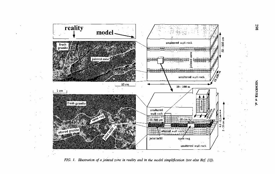
FIG. 1. Illustration o f a jointed zone in reality and in the model simplification (see also Ref. [3]).
298 NIEM
EYER et
al.
IAEA-SM-326/32 299
The repository concept and performance assessment methodology for Kristallin-I are essentially the same as those in the earlier Project Gewähr study [2], although many of the models and databases have been developed further in the past seven years. In particular, more credit is now taken for the engineered barriers. A model chain has been established, consisting of near field, far field and biosphere components, which enables deterministic dose calculations to be made. The distribution of migrating radionuclides within the various engineered and natural barriers can be used to give an indication of their relative importance. There is, however, a high degree of uncertainty in several parameter values. Studies have therefore been performed to analyse the sensitivity of the model results to parameter variations. The results enable key processes and critical parameters contributing to repository safety to be identified. These then help to focus future geological investigations, which should aim to reduce the uncertainties in the critical parameters. This paper presents the first findings of the sensitivity analyses.
2. HIGH LEVEL WASTE REPOSITORY CONCEPT
2.1. Background and site characterization
The present planning of the Swiss disposal concept for HLW is based on the actual nuclear energy production capacity of 3 GW(e) over a time period of 40 years and the reprocessing of all spent fuel. After an interim storage interval of 40 years, steel canisters containing the vitrified waste will be emplaced in an underground system of tunnels located at a depth of approximately 1000 m below the surface in the crystalline basement of northern Switzerland. The repository will also comprise a number of separate silos to receive alpha bearing intermediate level waste originating primarily from reprocessing.
Broad geological investigations have yielded a characterization of the potential host rock, from which preliminary model specific input data are currently being derived. The crystalline basement is dissected by faults of first and second order. In the proposed concept, the repository is located in a low. permeability domain, lying between these features, which contains zones of higher order faults, joints and fractured magmatic dykes. These are interconnected and form three distinct water conducting systems with different geometrical and mineralogical characteristics [3]. Jointed zones are shown in Fig. 1 for illustration. The zones have a complex internal structure, containing a system of several subparallel, partially filled fractures with water conducting openings. However, for the application of the far field transport model (Section 3.3) this geometry has been considerably simplified.
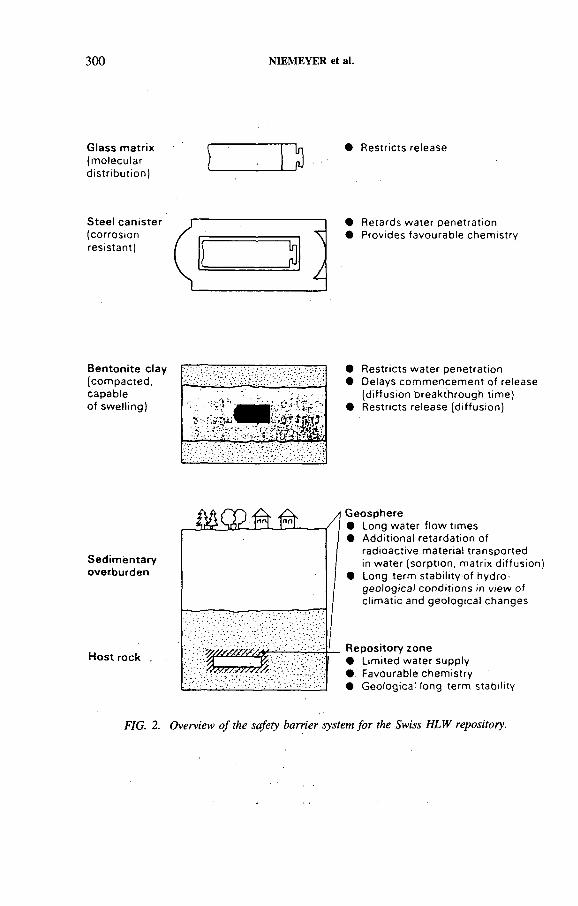
300 NIEMEYER et al.
Glass matrix(m o le cu la rd is tr ib u tio n )
• R estric ts re lease
Steel canister(corros ionres is tan t)
• R etards w a te r pen e tra tio n• Provides favourab le ch e m is try
Bentonite clay(com p a c te d , capab le o f sw e llin g )
É § í | ;
• R estric ts w a te r pen e tra tio n• Delays co m m e n ce m e n t o f release
(d iffu s io n b re a k th rou g h tim e)• R estric ts re lease (d iffu s io n )
Sedimentaryoverburden
Host rock .
Geosphere• Long w a te r f lo w tim es• A d d itio n a l re ta rd a tion o f
rad ioactive m a te ria l tra n sp o rte din w a te r (sorp tio n , m a trix d iffu s io n )
• Long te rm s ta b ility o f hydro- g e o log ica l co n d itio n s in v iew of c lim a tic and g e o lo g ica l changes
Repository zone• L im ited w a te r supp ly• Favourable ch e m is try• G eo log ica l long te rm s ta b ility
FIG. 2. Overview o f the safety barrier system fo r the Swiss H LW repository.
IAEA-SM-326/32 301
2.2. Multibarrier concept
The adopted disposal scheme is based on a multibarrier concept and comprises the following system components within the near field, far field and biosphere and their corresponding safety relevant functions (Fig. 2):
N e a r f ie ld
— HLW in vitrified form yielding a slow, corrosion controlled release;— Steel canisters giving complete confinement over a period of 1000 years after
disposal, and later, due to their corrosion products, favourable chemical conditions with regard to Eh (solubility limitation);
— Surrounding layer of compacted bentonite to delay and restrict nuclide migration by low permeability and by sorption.
F a r f ie ld
— Low permeability host rock and overlying geological units for limited groundwater flow and long migration paths, retardation by sorption and matrix diffusion, long term stability of hydrogeological conditions, mechanical protection of the engineered barriers and protection from human intrusion.
B iosphere
— Groundwater aquifers and/or surface waters to provide high dilution.
3. PERFORMANCE ASSESSMENT MODELLING
3.1. Model chain
A model chain has been established for performance assessment, comprising near field, far field and biosphere components. Each model contributes input data, in the form of radionuclide fluxes, for the next member of the chain. The final result is an individual dose.
3.2. Near field model
In the near field model [4], it is assumed that the steel canisters remain intact for 1000 years after emplacement, during which only radioactive decay and ingrowth are accounted for. The canisters are assumed to fail completely then, offering no further restriction to radionuclide migration. The radionuclides are released congruently from the glass matrix into the pore water of the bentonite surrounding the glass as

302 NIEMEYER et ai.
a result of corrosion over a period in the order of 150 000 years. The radionuclide concentration in this pore volume determines the boundary condition for the diffusive transport through the bentonite buffer. If the elemental solubility limit is exceeded, precipitation occurs and the isotopic concentrations are set according to the ratio of the individual isotope mass to the total element mass.
It can be assumed that the bentonite is water saturated long before the canister failure time. The fully saturated bentonite has a low permeability and radionuclides are transported by diffusion alone. Sorption, decay and ingrowth are accounted for in the bentonite. The model further assumes axial symmetry, with no interaction between adjacent canisters.
3.3. The far field model
The dual porosity concept is considered to provide a suitable basis for the description of solute transport within the far field [5]. The porosity of the rock is divided between discrete conduits (water conducting openings) within which the transport is by advection, and matrix porosity accessible only by diffusion (Fig. 1). In the far field model, water conducting openings are treated as either parallel-walled or cylindrical features. Advection is simulated as a one dimensional process, with the different path lengths and their differing transmissivities through the three dimensional network accounted for by longitudinal dispersion. The Darcy velocity along the mean flow path is taken from hydrological modelling. The average geometrical properties of the'flow system under consideration yield an advective velocity from the Darcy velocity. Instantaneous reversible sorption may occur on the surfaces of water conducting openings and matrix pores, with sorption coefficients determined by the rock mineralogy and groundwater chemistry. Radioactive decay and ingrowth are also modelled.
3.4. Biosphere model
A new biosphere model [6] is presently under development for Kristallin-I, which allows a more complete characterization of the processes involved. The transport submodel is based on a compartment structure (where for example topsoil, deep soil, local aquifer, river water and river water sediments are represented as individual compartments) and takes into account both liquid and solid material transport.
The exposure pathway submodel used in the calculation of the dose arising from the exposure to the environmental concentration of radionuclides calculated by the transport model includes in the usual way the exposure from the ingèstion of contaminated food and drinking water and from inhalation of dust as well as direct exposure.

IAEA-SM-326/32 303
4.1. Overview
Firstly, in order to demonstrate the working of the multibarrier concept and the achievable level of safety, the results of a single deterministic calculation are: presented, in which the complete model chain has been employed. To demonstrate the sensitivity of the system to parameter variations and to identify key parameters the specific example of the geosphere is considered in more detail.
As representative examples of safety relevant, long lived nuclides the barely soluble, strongly sorbing 237Np and the highly soluble, moderately sorbing 135Cs have been selected to illustrate the performance of the multibarrier system.
4.2. Confinement in the near field
In Fig. 3 the distribution of the nuclides between the components of the near field and the far field as a function of time is shown. The isotopes show contrasting behaviour: while most of the 237Np remains as precipitate at the glass-bentonite interface, most of the 135Cs is confined within the bentonite. In both cases only a fraction of the initial inventory is released into the far field.1
4.3. Comparison of near field and far field barriers
Figure 4 shows the effectiveness of the near and far field barriers. Three cases are illustrated: the flux due to the corrosion of the glass matrix, the flux from the bentonite buffer into the far field and the flux from the far field into the biosphere. Again there is a contrast in the behaviour of the two example nuclides, with the far field barrier having a pronounced effect on the flux of 237Np, while for 135Cs the bentonite barrier is the more significant.1
More generally, it can be concluded that, depending upon the nuclide, one or other component of the multibarrier system is the most effective. The combined effect of all the barriers is therefore expected to yield a high degree of overall safety. It is emphasized, however, that within the present disposal concept the performance of the near field alone (i.e. engineered barriers in an adequate geological environment) is sufficient to provide the required level of repository safety.
4. RESULTS
1 At this stage, the non-linear sorption behaviour of Cs in the far field has not been considered.

Inve
ntor
y (m
ol)
T ime after em placem ent (years) T ime after em placem ent (years)
FIG. 3. Time history o f the distribution o f 237Np and ,35Cs inventories among the safety barrier components: ........prec ip ita te ,--------- sorbed within b en to n ite ,----------- fa r field , — • ------- total inventory.
glass,
NIEMEYER
et al.
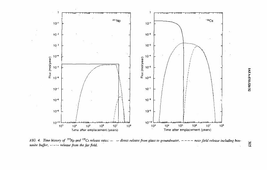
Flux
(m
ol/y
ear)
T ime after emplacement (years) T ime after em placem ent (years)
FIG. 4. Time history o f 237Np and l35Cs release ra tes:------- direct release from glass to groundw ater,--------- — near fie ld release including bentonite b u ffe r ,------- release from the fa r field.
306 NIEMEYER et al.
4.4. Radiation dose estimates
In accordance with previous studies [2] two alternative biosphere scenarios for northern Switzerland are considered: the first scenario refers to the release of activity into a large groundwater aquifer adjacent to the River Rhine, while for the second scenario release into a small groundwater body of a small valley is considered.
For the present purposes, the steady state solutions of the biosphere transport model have been used to convert the annual releases from the far field to the biosphere into annual individual doses. The upper limits for the radiation exposure due to the safety relevant radionuclides were derived assuming preliminary values for the data sets used to characterize the near field, far field and biosphere.
For the release of radionuclides into the groundwater aquifer adjacent to the Rhine the estimated nuclide specific dose rate maxima from ingestion of contaminated food are far below the regulatory safety goal of 0.1 mSv/year. Owing to the difference in the dilution potential, the resulting radiation exposure for the more conservative biosphere scenario (small valley) is higher roughly by a factor of 20.
4.5. Sensitivity to parameter variations
The broad behaviour of the system observed in the course of parameter variation studies can generally be understood in terms of highly simplified models, including only a subset of transport processes, which help in the identification of key processes contributing to safety. As an example, it has been shown that, for 237Np, where release from the near field occurs over a prolonged period, far field transport is approximated well by analytical, steady state solutions to the governing equations for solute migration in a dual porosity medium. This allows the barrier efficiency of the far field to be predicted readily with parameters varied continuously across the range of interest. The barrier efficiency is a measure of how effectively the radionuclide flux is reduced by its passage through the far field and gives some insight as to why the behaviour of the far field is sensitive to the values of certain parameters. For the isotope 237Np, Fig. 5 illustrates the dependency of the barrier efficiency on groundwater Darcy velocity, fracture intensity (expressed as the total trace length of water conducting features intersecting the repository plane) and the flow path length. The solute transport system adopted in the analysis is depicted in Fig. 1.
The multiparameter representation shows that the barrier efficiency of the far field always decreases with increasing groundwater flow rate. Also, as the fracture intensity increases, the barrier efficiency approaches an upper limit, which depends on the groundwater flow rate. This maximum occurs at a fracture intensity in which the volume of the diffusion-accessible rock matrix equals the total volume of the block matrix. In addition, as the flow path becomes longer and radioactive decay is more effective, the barrier efficiency of the far field is enhanced.

IAEA-SM-326/32 307
FIG. 5. The barrier efficiency r/ o f the fa r fie ld fo r 237Np, plotted as a function o f Darcy velocity and-the total trace length o f water conducting fractures intersecting the repositoryplane, fo r three different values o f the flow path length L: — -------90% contour o f ц , ---------99% contour o f -q.
5. SUMMARY AND CONCLUSIONS
The results of the sensitivity analyses for the different system components and the preliminary calculations with the complete model chain lead to the following conclusions for an HLW repository in the crystalline basement of northern Switzerland:
— Based on the currently available data set, the calculations indicate that adequate levels of safety are achievable; the predicted doses are well below the regulatory limits.
— The sensitivity analyses indicate that the system of engineered barriers is extremely powerful — as long as the geology in the immediate surroundings of the caverns provides a suitable environment, i.e. sufficiently low groundwater flow, beneficial groundwater chemistry and the absence of short circuits.
— The analyses indicate also that, under certain circumstances, the low levels of nuclide releases from the near field will decay completely during their transport through the geosphere — this, however, requires sufficiently low groundwater fluxes, no extreme channelling, sufficient sorption of key nuclides and sufficiently long transport pathways through rock with these qualities.
308 NIEMEYER et al.
— On the basis of this study it will be possible to define more clearly the minimum requirements on a block of crystalline host rock to provide an adequate environment for an HLW repository in northern Switzerland.
REFERENCES
[1] THURY, M., GAUTSCHI, A., “ Testing programme in deep boreholes drilled in sediment-covered rocks in northern Switzerland” , 2nd International Conference on Radioactive Waste Management (Proc. Conf. Winnipeg, 1986), Canadian Nuclear Soc., Toronto (1986) 293.
[2] NATIONALE GENOSSENSCHAFT FÜR DIE LAGERUNG RADIOAKTIVER ABFÄLLE, Project Gewähr 1985 — Nuclear Waste Management in Switzerland: Feasibility Studies and Safety Analyses, Project Gewähr Rep. NGB 85-09, Nagra, Baden, Switzerland (1985).
[3] MAZUREK, M., GAUTSCHI, A., VOMVORIS, S., IAEA-SM-326/31, these Proceedings.
[4] GRINDROD, P., WILLIAMS, M., GROGAN, H., IMPEY, M., STRENG: A Source Term Model for Vitrified High-level Waste, Tech. Rep. NTB 90-48, Nagra, Baden, Switzerland (1990).
[5] HADERMANN, J., ROESEL, F ., Radionuclide Chain Transport in Inhomogeneous Crystalline Rock: Limited Matrix Diffusion and Effective Surface Sorption, Rep. PSI 551, Tech. Rep. NTB 85-40, Nagra, Baden, Switzerland (1985).
[6] KLOS, R.A., MÜLLER-LEMANS, H., VAN DORP, F., BAEYENS, B., The Terrestrial-Aquatic Model of the Environment — TAME, Technical Report, Nagra, Baden, Switzerland (in preparation).

IAEA-SM-326/24
FINAL DISPOSAL OF SPENT NUCLEAR FUEL IN SWEDEN: THE IMPORTANCE OF THE GEOLOGY OF THE SITE FOR LONG TERM SAFETY
T. PAPP, N. KJELLBERT Swedish Nuclear Fuel and
Waste Management Company,Stockholm, Sweden
Abstract
FINAL DISPOSAL OF SPENT NUCLEAR FUEL IN SWEDEN: THE IMPORTANCE OF THE GEOLOGY OF THE SITE FOR LONG TERM SAFETY.
A safety assessment, SKB 91, has recently been made in Sweden. It considers a repository for spent nuclear fuel in crystalline rock. The fuel is to be encapsulated in copper canisters and deposited at a depth of 600 m. The purpose of the assessment was to shed light on the importance of the geological features of the site forpost-closure safety. The assessment shows that the encapsulated fuel will, in all likelihood, be kept isolated from the groundwater for millions of years. This is considerably longer than is required for the toxicity of the waste to decline to a level equivalent to that of rich uranium ores. However, in order to be able to study the role of the rock as a barrier to the dispersal of radioactive materials, calculations have been carried out under the assumption that some canisters are faulty. The results show that the safety of a carefully designed repository is only affected to a smáll extent by the ability of the rock to retain the escaping radionuclides. The primary role of the rock is to provide stable mechanical and chemical conditions in the repository over a long period of time so that the function of the engineered barriers is not jeopardized. .
1. BACKGROUND
One of the responsibilities of the Swedish Nuclear Fuel and Waste Management Company (SKB) is to make recommendations as to how and where the final disposal of Sweden’s radioactive waste should be arranged. It has been ruled that, after review and approval by the regulatory authorities, the SKB shall design and build the necessary facilities and carry out final disposal of the waste.
Between 1977 and 1983 the SKB published a series of reports examining the feasibility of final disposal of spent nuclear fuel in Swedish bedrock. After extensive review of the reports by Swedish and foreign experts, the Government found in 1984 that the method could be accepted with regard to safety and radiation protection.
, During the 1980s the understanding of processes important for long term safety grew and the data and models to quantify them improved. This has given further strength to the view that it is possible to isolate the fuel from the groundwater over
309
310 PAPP and KJELLBERT
a long period of time by encapsulating it in copper canisters. In a suitable environment, this isolation can be maintained over such a time that the toxicity of the waste will decline to a level equivalent to that of rich uranium ores. The granitic bedrock in Sweden at a depth below a few hundred metres exhibits suitable chemical conditions for long lasting canisters.
A principle of repository safety in Sweden is that the repository shall be based on multiple barriers, i.e. that the safety of the repository shall not be dependent on one single barrier. Accordingly, even if the copper canister is capable 'of isolating the waste from the groundwater for a very long time, it is also important to study the role of the bedrock in the case where radionuclides nevertheless escape from the repository.
2. PURPOSE AND DELIMITATIONS
According to SKB plans, system selection and siting for a final repository will begin during the 1990s. The safety assessment known as SKB 91 examines how the long term safety in a repository is affected by the geological characteristics of the site, i.e. how the rock barrier performs if radionuclides are released from the repository. The report is a part of the background material required for the siting of a final repository for spent nuclear fuel.
The following questions are explored in SKB 91:
— What is the role of the bedrock and the hydrological regime of the site for overall post-closure safety?
— What relative importance do different site specific characteristics have for long term performance?
— How can the placement and design of the repository be adapted to conditions on the site in order to take advantage of the safety barriers offered by the bedrock?
3! MAIN FEATURES OF THE REPOSITORY
3.1. Principles
The following principles have served as a basis for the design:
— Final disposal is done in crystalline rock at a depth that protects the repository against disturbances from the surface (i.e. 300-700 m) in one or more blocks of rock surrounded by structurally weak zones.

IAEA-SM-326/24 311
— The waste is encapsulated in canisters that are handled as separate units. Their fuel content, size and geometrical placement pattern in the repository are chosen so that the temperature on the surface of the canister is limited to well under 100°C.
— The waste is surrounded by several different barriers to isolate the waste from surrounding groundwater and prevent or delay the dispersal of radionuclides from the deposited waste.
— The repository is arranged so that it is not dependent for its safety function onlong term surveillance and inspection. ,
3.2. Repository site and design
The topography, geology and other site specific characteristics of the repository site are those of the Finnsjön area in northern Uppland. The area was chosen as an example since an extensive body of data is available from the area. In earlier assessments it was judged to be a possible site for locating a final repository, though less favourable than some of the other study sites.
Deposition is arranged as shown in Fig. 1. The spent fuel is placed in copper canisters that are deposited in holes drilled in the floor of a system of drifts in the
FIG. 1. Schematic design o f a fina l repository fo r spent nuclear fu e l in a crystalline basement. '
312 PAPP and KJELLBERT
rock. The space between canister and rock is filled with bentonite clay. The layout is assumed to be regular.with 25 m between the drifts and 6 m between the holes. The quantity of fuel is 7800 t U, obtained from the Swedish nuclear programme through to the year 2010. At closure of the repository, all cavities are backfilled. Drifts and shafts can be sealed with plugs to block potential transport pathways for the groundwater.
4. REPOSITORY SAFETY
4.1. Probable conditions
The chemical environment in deep granitic bedrock is such that the 6 cm copper walls of the canisters will not be. penetrated by corrosion until possibly after several tens of millions of years.
The lead filled canisters will act as solid bodies in the. rock and will withstand the prevailing pressures, including those that can arise in the event of a future glaciation. Possible rock movements caused by changes in rock stress after a glaciation will occur in the regional fracture zones that surround the repository and are structurally weak parts of the bedrock. Rock movements of such magnitude that the canister would be sheared off will only occur in fracture zones with a length of 10 km or more. Such structures can be identified during the construction of a repository and no canisters will be deposited there.
One possible cause of loss of integrity of a canister is pressure buildup due to the production of helium in the canister by alpha decay in the fuel. This pressure will not reach the level of the yield limit of the copper canister until some 10 million years or so after encapsulation.
Thus, the copper canister is expected to isolate the spent fuel for a very longtime.
4.2. Reference scenario
To substantiate the safety assessment, the impact of the repository on the environment has also been studied for less probable cases. One assumption is that faulty canisters have been deposited owing to the fact that defects during manufacture have not been detected in the quality control. In the reference scenario 0.1% of the deposited canisters have initial defects. Fuel dissolution, transport of radionuclides from the barriers in the near field throügh the bedrock to the biosphere and the dose to man have been calculated for this scenario.
The release of radionuclides from a defective canister is limited strongly by the slow dissolution of the fuel and by the size of the initial defect. The calculations show that if the radionuclides escaping from a damaged canister travel directly to
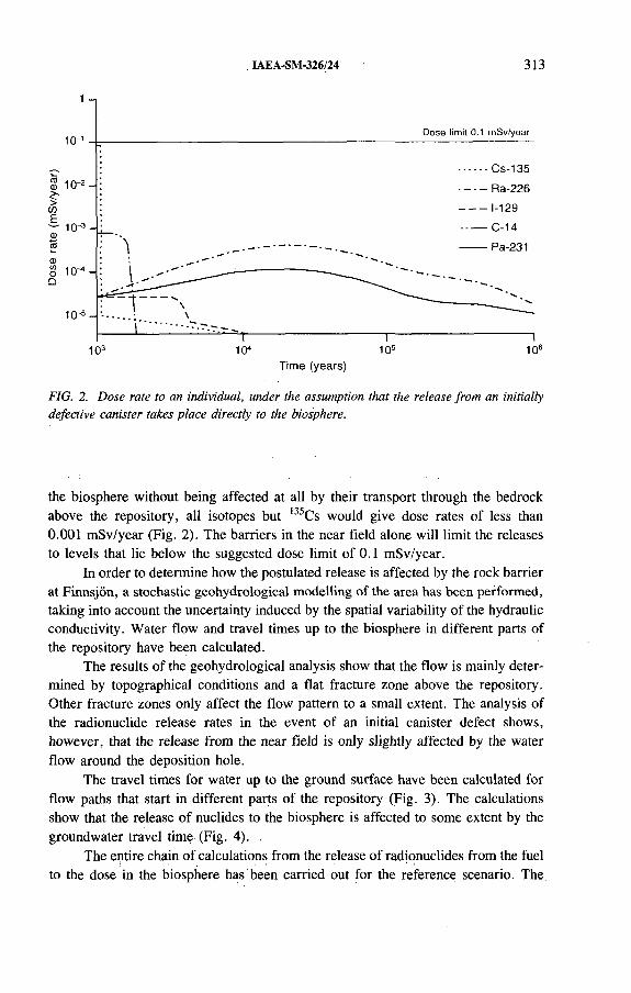
IAEA-SM-326/24 313
103 10“ 105 106Time (years)
FIG. 2. Dose rate to an individual, under the assumption that the release from an initially defective canister takes place directly to the biosphere.
the biosphere without being affected at all by their transport through the bedrock above the repository, all isotopes but 135Cs would give dose rates of less than0.001 mSv/year (Fig. 2). The barriers in the near field alone will limit the releases to levels that lie below the suggested dose limit of 0.1 mSv/year.
In order to determine how the postulated release is affected by the rock barrier at Finnsjön, a stochastic geohydrological modelling of the area has been performed, taking into account the uncertainty induced by the spatial variability of the hydraulic conductivity. Water flow and travel times up to the biosphere in different parts of the repository have been calculated.
The results of the geohydrological analysis show that the flow is mainly determined by topographical conditions and a flat fracture zone above the repository. Other fracture zones only affect the flow pattern to a small extent. The analysis of the radionuclide release rates in the event of an initial canister defect shows, however, that the release from the near field is only slightly affected by the water flow around the deposition hole.
The travel times for water up to the ground surface have been calculated for flow paths that start in different parts of the repository (Fig. 3). The calculations show that the release of nuclides to the biosphere is affected to some extent by the groundwater travel time (Fig. 4). .
The entire chain of calculations from the release of radionuclides from the fuel to the dose in the biosphere has been carried out for the reference scenario. The
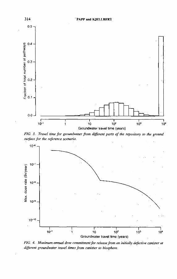
314
0.5-1
' PAPP and KJELLBERT
S 0.4-(0SгоО.
I I I I I : I10 '1 1 10 1 02 1 03 1 04
Groundwater travel time (years)
FIG. 3. Travel time fo r groundwater from different parts o f the repository to the ground surface fo r the reference scenario.
Groundwater travel time (years)
FIG. 4. Maximum annual dose commitment fo r release from an initially defective canister at different groundwater travel times from canister to biosphere.
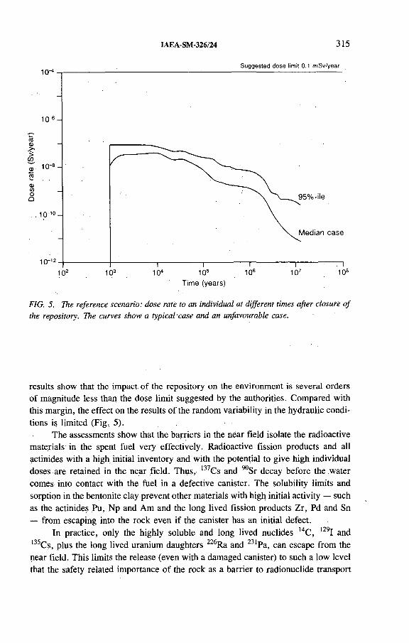
IAEA-SM-326/24 315
Time (years)
FIG. 5. The reference scenario: dose rate to an individual at different times after closure o f the repository. The curves show a typical 'case and an unfavourable case.
results show that the impact of the repository on the environment is several orders of magnitude less than the dose limit suggested by the authorities. Compared with this margin, the effect on the results of the random variability in the hydraulic conditions is limited (Fig, 5).
The assessments show that the barriers in the near field isolate the radioactive materials in the spent fuel very effectively. Radioactive fission products and all actinides with a high initial inventory and with the potential to give high individual doses are retained in the near field. Thus, 137Cs and 90Sr decay before the water comes into contact with the fuel in a defective canister. The solubility limits and sorption in the bentonite clay prevent other materials with high initial activity — such as the actinides Pu,, Np and Am and the long lived fission products Zr, Pd and Sn— from escaping into the rock even if the canister has an initial defect.
In practice, only the highly soluble and long lived nuclides 14C, 129I and 135Cs, plus the long lived uranium daughters 226Ra and 231Pa, can escape from the near field. This limits the release (even with a damaged canister) to such a low level that the safety related importance of the rock as a barrier to radionuclide transport

316 PAPP and KJELLBERT
is very limited. The principal requirement on the rock is therefore that it should provide a mechanically stable environment where canisters can be emplaced without being situated in potential zones of movement, and that it should provide a chemically stable reducing environment for the near field.
5. THE ROCK AS A BARRIER — VARIATION CALCULATIONS
The safety of a repository is to be based on several passive barriers. Thus, even if it is not necessary on the basis of dose limits to find the geologically most favourable site for a repository in Sweden, it is reasonable to make effective use of the chosen site as a barrier against radionuclide migration.
The chemical environment in the Swedish bedrock, and the stability that rock blocks being considered for the repository can be credited with, differ very little from place to place. The factor that most readily summarizes the barrier potential of a given rock volume is the distribution of groundwater travel times from the repository to the biosphere.
To shed light on how this property, i.e. the distribution of travel times shorter than 10 000 years, is affected by different site specific characteristics and parameters, some fifteen variations of the geohydrological features of the site were studied in the reference scenario. The variations cover:
— Properties of the rock mass in the repository area,— Properties of steeply dipping fracture zones,— Properties of near horizontal fracture zones,— The size of regional and local hydraulic gradients.
Other variations were performed to demonstrate the importance of the contact area between flowing groundwater and rock, dispersion and matrix diffusion, or the importance of salinity stratification in the groundwater.
The studies showed that the flow pattern and groundwater travel time from the repository to the biosphere are changed to a relatively small extent by most of the variations of hydrogeological characteristics that were performed. Significant changes are mainly caused by flat-lying, highly conductive zones, which can create both more and less favourable conditions than in the reference case by isolating the repository from groundwater gradients at the ground surface or by routing the water that passes the repository quickly up into a nearby discharge area. However, even in these cases, as a result of the engineered barriers the dose is not affected by more than an order of magnitude or so, i.e. less than the margin to the recommended dose limit values.
If a high salinity in the groundwater around the repository persists for a longtime, a lower groundwater flux will be obtained at the same time as wells with deepgroundwater are saline.
IAEA-SM-326/24 317
The effect of many of the variations discussed above is naturally dependent on the local conditions chosen for the reference scenario. Even if there is a great similarity between future candidate sites, conclusions drawn from the results for one site may only be applied to other sites with caution.
6. REPOSITORY CONFIGURATION - ADAPTATION TO LOCALCONDITIONS
Provided that the site is sufficiently large, the concept makes it possible to adapt the layout of drifts and deposition holes in response to new information on the local properties of the host rock as this is obtained.
The variations covering zones above and below the repository show that a distance of around 100 m between major flat-lying fracture zones and the nearest canister positions is warranted. A change in the depth of the repository by 100 m up or down affects the travel times by a factor of 2.
Thus, the geometrical configuration of the repository can be adapted to effectively utilize the potential of the local bedrock to act as a safety barrier. However, the difference does not appear to be of such a magnitude that it would be decisive in determining whether a site is acceptable or not.
7. CONCLUSIONS
The'SKB 91 safety assessment shows that a repository constructed deep in the crystalline basement with engineered barriers possessing long term stability fulfils the safety requirements with an ample margin. The safety of such a repository is only slightly dependent on the ability of the surrounding rock to retard and sorb radioactive materials. The primary function of the rock is to provide stable mechanical and chemical conditions over a long period of time so that the long term performance of the engineered barriers is not jeopardized.
SKB 91 has shown that the safety related requirements on a site where a final repository is to be built are such that they are probably met by most sites that the SKB has investigated in Sweden. The assessment has also shown that there are some factors that can influence how the bedrock performs as an extra safety barrier. An example is the presence and location of flat-lying structures and their hydraulic conductivity.


IAEA-SM-326/37
VALIDATION OF PERFORMANCE ASSESSMENT MODEL BY LARGE SCALE IN SITU MIGRATION EXPERIMENTS
M.J. PUT, P. DE CANNIÈRE,H. MOORS, A. FONTEYNE SCK/CEN,Mol
P. DE PRETER NIRAS/ONDRAF,Brussels
Belgium
Abstract
VALIDATION OF PERFORMANCE ASSESSMENT MODEL BY LARGE SCALE IN SITU MIGRATION EXPERIMENTS.
Large scale three dimensional in situ migration experiments in the Boom clay formation below Mol for the validation of performance assessment models are reported. The experiments involve multipiezometer nests in which radionuclides are injected in one filter and the concentration evolution in the neighbouring filters is measured and compared with the model prediction. A large scale injection experiment with tritiated water is reported. The agreement between the predictions and the experiment is quite good. A large scale injection experiment with 125I, using both vertical and horizontal injection, is reported. The aim of this experiment is to validate the anisotropic concept of the performance assessment model. The results of the predictions are given and the experimental results are expected within a few months.
1. INTRODUCTION
Performance assessment models are used to predict the confinement characteristics of a repository for the geological disposal of high level radioactive waste. To gain sufficient confidence in the predictions the models have to be validated. Validation is carried out by comparison of the model predictions with independent field observations and experimental measurements. A model can be considered validated for the purpose for which it has been designed when sufficient testing has been performed to ensure an acceptable level of predictive accuracy.
In 1982 the SCK/CEN built an underground research laboratory (URL) at a depth of 220 m in the Boom clay formation underlying the Belgian nuclear research facilities at Mol in order to do in situ testing of this formation. Of the tests that are
319

320 PUT et al.
currently proceeding, two large scale three dimensional in situ migration experiments are presented. The purpose of these experiments is twofold: to validate the migration model which is used in the performance assessment calculations and to validate the values of the model parameters obtained from small scale laboratory experiments on clay samples.
2. DESCRIPTION OF EXPERIMENTS
Two large scale in situ migration experiments are described. The first consists of the injection of tritiated water (НТО) in a single hole piezometer nest. The second experiment consists of the injection of 125I in two single hole piezometer nests, one oriented vertically and one horizontally.
2.1. НТО migration experiment
Figure 1 gives a conceptual view of the experimental arrangement. It consists of an all-stainless-steel piezometer nest containing nine cylindrical sintered metal filters separated by 0.9 m long tubes. The centre to centre distance between the filters is 1 m. Each filter is connected to the mined gallery of the URL with a thin standpipe which allows for the sampling of claywater, the injection of НТО and the measurement of porewater pressure.
+ - 2 m _ » j
FIG. 1. Arrangement o f the horizontal piezometer nest fo r the in situ injection experiment with НТО.

IAEA-SM-326/37 321
The piezometer nest was installed on 22 May. 1986 in a single hole bored horizontally from the URL in the clay formation. On 20 January 1988 a quantity of 1.25 GBq of НТО was injected into the clay formation through the central filter (CPI/5), which is 6 m from the gallery lining. For more than 4.5 years the surrounding filters have been sampled at regular time intervals to follow the migration evolution of the injected НТО [1, 2]. This experiment is continuing and is part of the test cases for the international INTRAVAL Phase 2 validation project.
FIG. 2. Configuration o f the vertical and horizontal piezometer nests fo r the in situ injection experiment with l2SI.

322 PUT et al.
2.2. I25I migration experiment
The configuration of the second experiment is shown in Fig. 2. The experimental set-up consists of two identical single hole all-stainless-steel piezometer nests, with one hole bored, vertically and the other horizontally (i.e. parallel to the stratification of the formation). The installation dates were, respectively, 12 and 13 December 1988. The aim of this experiment is to study the anisotropic behaviour of the migration of radionuclides through the Boom clay. Each piezometer nest contains nine filters. The injection of 125I was made on 22 June 1992 in filter 8. The distances to the nearest filters, 6, 7 and 9, from the injection point are, respectively, 0.85, 0.35 and 0.65 m. The injected quantities were, according to the specifications of the tracer supplier, 0.209 GBq for the vertical piezometer nest and 0.257 GBq for the horizontal nest. The concentration evolution will be followed by liquid sampling of filters 6-9 at regular intervals of two months.
3. DISCUSSION OF RESULTS
For the design of the experiments, three dimensional simulations have been done with the migration model (MICOF program [3]) to verify whether the large scale in situ migration experiment was possible within a reasonable time-scale. The values of the model parameters used are those obtained from small scale laboratory experiments [4-7].
3.1. НТО migration experiment
For the predictive calculations of the migration of НТО in the in situ injection experiment the values of the model parameters used were as follows: a Darcy velocity of 6 x 10'11 m/s in the direction of the piezometer nest, a diffusion accessible porosity of 0.35, a retardation constant of 1, a vertical component of the dispersion constant of 2 x 10“10 m2/s and a horizontal component of 4 x 10"10 m2/s.
The results of the predictive calculations are given in Fig. 3 for the injection filter and the sampling filters at centre to centre distances of 1 and 2 m. Since the experiment began, 23 concentration measurements of НТО in the interstitial liquid have been obtained (Fig. 3). НТО concentrations in the liquid of the sampling filters at a distance of 2 m from the injection filter are still below the detection limit, as predicted by the model calculations. Figure 3 indicates that the predictions are in very good agreement with the experimental results up to now.
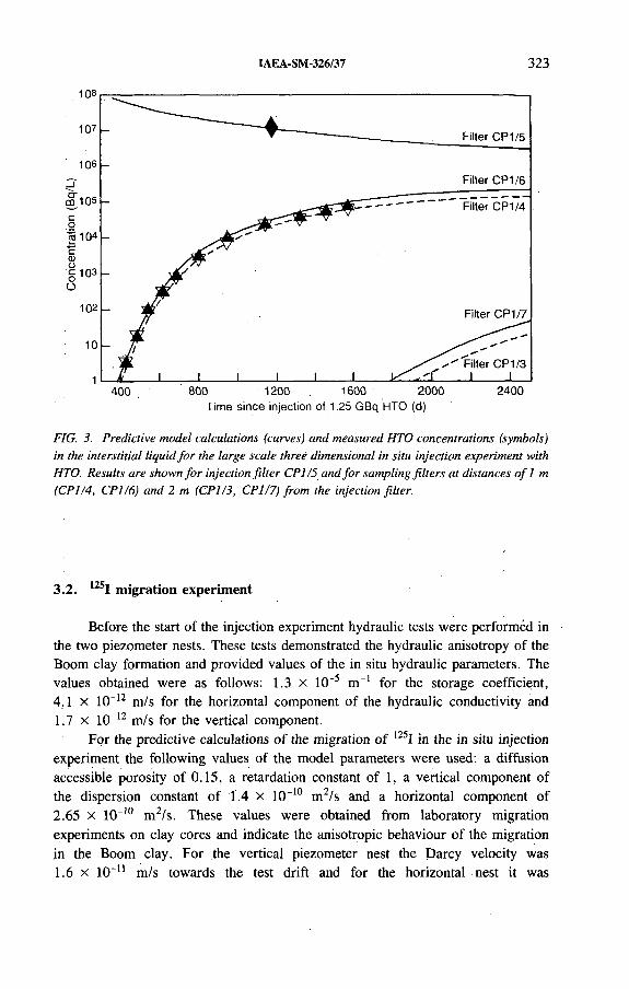
IAEA-SM-326/37 323
Time since injection of 1.25 GBq НТО (d)
FIG. 3. Predictive model calculations (curves) and measured НТО concentrations (symbols) in the interstitial liquid fo r the large scale three dimensional in situ injection experiment with НТО. Results are shown fo r injection filter CP 1/5 and fo r sampling filters at distances o f 1 m (CPI/4, C P I/6) and 2 m (CPI/3, C P I/7) from the injection filter.
3.2. 125I migration experiment
Before the start of the injection experiment hydraulic tests were performed in the two piezometer nests. These tests demonstrated the hydraulic anisotropy of the Boom clay formation and provided values of the in situ hydraulic parameters. The values obtained were as follows: 1.3 X 1СГ5 m_1 for the storage coefficient, 4.1 X 10“12 m/s for the horizontal component of the hydraulic conductivity and1.7 x 10-12 m/s for the vertical component.
For the predictive calculations of the migration of l25I in the in situ injection experiment the following values of the model parameters were used: a diffusion accessible, porosity of 0.15, a retardation constant of 1, a vertical component of the dispersion constant of 1.4 X 10⁻¹⁰ m2/s and a horizontal component of 2.65 x 10“10 m2/s. These values were obtained from laboratory migration experiments on clay cores and indicate the anisotropic behaviour of the migration in the Boom clay. For the vertical piezometer nest the Darcy velocity was1.6 X 10~n m/s towards the test drift and for the horizontal nest it was

Con
cent
ratio
n in
liqui
d (B
q/L)
C
once
ntra
tion
in liq
uid
(Bq/
L)
324 PUT et al.
Time since injection of 0.209 GBq 1-125 (d)
Time since injection of 0.257 GBq 1-125 (d)
FIG. 4. Results o f the predictive model calculations o f the 1251 concentration evolution in the liquid o f the injection filter and o f the sampling filter at a distance ofO. 35 m from the injection filte r fo r (a) the vertical piezometer nest, (b) the horizontal piezometer nest.
IAEA-SM-326/37 325
7.6 x IO'11 m/s. The data of the predictive calculations for the concentration evolution in the injection and sampling filters at a distance of 0.35 m from the injection filter are given in Fig. 4 for the vertical and horizontal piezometer nests. A comparison shows that the maximum concentration in the filters at a distance of 0.35 m is about 50 times higher for the horizontal than for the vertical piezometer nest. This is due to the effect of the anisotropy of the Boom clay formation as indicated before. The experiment will last for about three years. No experimental results are available yet.
4. CONCLUSIONS
Large scale three dimensional in situ migration experiments for the validation of a performance assessment model were reported. The results show the usefulness of the in situ experiments for the validation procedure. Both the parameter values and the model itself may be validated for the in situ use for which they are intended.
For the НТО injection experiment there is a quite good agreement between the predictions and the experiment. For the 125I injection experiment the anisotropy of the formation is important. The results of the predictive calculations were reported and the first experimental results are expected within a few months.
REFERENCES
[1] MONSECOUR, М., PUT, M., FONTEYNE, A., YOSHIDA, H., “ Migration experiments in the underground facility at Mol to validate safety assessment model” , GEOVAL 1990 (Proc. Symp. Stockholm, 1990), OECD/NEA, Paris (1991) 344-351.
[2] PUT, M., “ Three-dimensional in-situ migration experiment in the Boom clay formation at the Mol site in Belgium” , INTRAVAL Phase 2: Test Case Description, internal report, Statens Kärnkraftinspektion, Stockholm, 1991.
[3] PUT, M ., A unidirectional analytical model for the calculation of the migration of radionuclides in a porous geological medium, Radioact. Waste Manage. Nucl. Fuel Cycle 6 3-4 (1985) 361-390.
[4] PUT, M., HENRION, P., An improved method to evaluate radionuclide migration model parameters from flow-through diffusion tests in reconsolidated clay plugs, Radiochim. Acta 44/45 (1988) 343-347.
[5] PUT, M., An improved mathematical model for the interpretation of the flow-through type diffusion test with influence of filterplates, Radioact. Waste Manage. Nucl. Fuel Cycle 16 1 (1991) 69-81.

326 PUT et al.
[6] HENRION, P., PUT, M., VAN GOMPEL; M:, The influence of compaction on the diffusion of non-sorbed species in Boom clay, Radioact. Waste Manage. Nucl. Fuel Cycle 16 1 (1991) 1-14.
[7] PUT, M., MONSECOUR, M., FONTEYNE, A., YOSHIDA, H., in Scientific Basis for Nuclear Waste Management XIV,.Mater. Res. Soc. Symp. Proc., Vol. 212, Materials Research Soc., Pittsburgh, PA (1991) 823-829.

IAEA-SM-326/20
DECOVALEX: A MULTIDISCIPLINARY PROJECT IN THE FIELD OF THERMOHYDROMECHANICAL PROCESSES
F. KAUTSKYSwedish Nuclear Power Inspectorate
O. STEPHANSSON, Lanru JING Division of Engineering Geology,Royal Institute of Technology
Stockholm, Sweden
Abstract
DECOVALEX: A MULTIDISCIPLINARY PROJECT IN THE FIELD OF THERMO- HYDRÖMECHANICAL PROCESSES.
A multidisciplinary interactive and co-operative research effort in the field of thermohydromechanical (THM) processes for nuclear waste isolation has started under the DECOVALEX project. The overall objective of DECOVALEX is to increase the understanding of various THM processes of importance for radionuclide release and transport from a repository to the biosphere and how they can be described by mathematical models. In the DECOVALEX project, mathematical models will be established to simulate the coupled processes and be validated against test cases and benchmark tests. In the first phase of DECOVALEX, two benchmark tests and one test case have been selected for modelling. More test cases and benchmark tests will be studied for the,second phase of the project.
1. BACKGROUND
The Swedish Nuclear Power Inspectorate (SKI) has initiated a new international co-operative project to support the development of mathematical models for coupled processes and their validation against experiments in nuclear waste isolation. DECOVALEX, the International Co-operative Project for the Development of Coupled Models and their Validation against Experiments in Nuclear Waste Isolation, started in 1991 and is intended to run for three years. It is focused on crystalline basement rocks.
In order to evaluate the various geological media considered for disposal of nuclear waste it is necessary to obtain adequate data on the characteristics of different host rocks and to consider different repository designs. It is also important to develop conceptual models and reliable computer codes to evaluate the performance of the disposal systems. An important part of the performance'assessment is an assessment
327

328 KAUTSKY et al.
Fullyuncoupledprocess
Uncoupled processes M H
Sequentialcouplingprocess
M
One way coupling process
Coupled processes T M H
Two waycouplingprocess(feedbackcoupling)
M H
FIG. 1. Diagrams o f uncoupled and coupled THM processes (revised after Ref. f l j ) .
of the coupling effects of rock mass stability, groundwater flow through the repository, external stresses and thermal loading. For problems in jointed rock masses, the following questions also need to be addressed: (a) scale effects; (b) representative elementary volume for flow, deformability and strength; (c) variability of properties in time and space; (d) damage öf discontinuity surfaces; and (è) thermohydromechanical (THM) processes in multiphase systems. To meet these requirements, it is necessary to develop mathematicál models describing the coupled phenomena.

IAEA-SM-326/20 329
The rock mass response to storage of radioactive waste and spent nuclear fuel is a coupled phenomenon involving thermal (T), hydrological (H), mechanical (M) and chemical (C) processes. Coupled processes imply that one process affects another and that the rock mass response to waste storage cannot be predicted by considering each process separately. Researchers have to extend their efforts beyond their own disciplines and to learn from and co-operate with others in related fields. Such multidisciplinary interactions and investigations have been fruitful in the past when studying hydromechanical (HM), thermohydrological (TH) and thermomechanical (TM) processes. The state of the art and possible directions of future research in the field of coupled processes are described in Ref. [1]. Figure 1 illustrates the relationship between uncoupled, partially coupled and fully coupled THM processes.
To better understand and evaluate the various conceptual and mathematical models describing groundwater flow and radionuclide transport for performance assessment of nuclear waste repositories, the SKI has initiated and organized three highly successful international co-operative projects over the last ten years: INTRACOIN (1981-1986), HYDROCOIN (1984-1990) and INTRAVAL (Phases I and II) [2-4]. The results of these projects have been well received by the participating organizations and research teams and have significantly increased confidence in our ability to describe mathematically many important processes in radionuclide transport in a wide range of geological media. The work within DECOVALEX can be looked upon as an extension of these efforts within the field of THM processes and how these may affect the performance assessment.
2. GOALS AND M EANS OF D ECOVALEX
The goals of DECOVALEX include the following: (a) to increase the basic understanding of coupled THM processes; (b) to support the development of computer codes for THM modelling for jointed rock masses; (c) to investigate and apply suitable algorithms for THM modelling; (d) to investigate the capabilities of different codes in describing laboratory experiments and to perform verification of codes; (e) to exchange experimental data; and (f) to design validation experiments by means of THM model studies. Some of the phenomena to be studied in DECOVALEX are listed in Table I. The sequence of the components in Table I does not represent any ranking, nor should it be considered complete. It only represents some of the factors which need to be considered in the development and validation of the THM models.
The computer codes applied in DECOVALEX can be classified into two cátegories: (i) continuum based methods (finite element method (FEM), boundary element method (BEM) and hybrid FEM and BEM); and (ii) discrete element methods (DEMs). The former category assumes the rock mass to be a continuum and

330 KAUTSKY et al.
TABLE I. PHENOMENA TO BE STUDIED IN DECOVALEX
Physicomechanical processes Thermal expansionThermal diffusion ConvectionFluid flow in joints/fractures and matrix Matrix diffusion Phase changes ChannellingDeformation of joints/fractures and matrix Failure of rock mass
Fracture networkFracture properties (aperture, roughness, filling,
conductivity, storability)PorosityFlow rate, flow velocity Time and scale dependence Variability Representativity
Temperature TractionDisplacement (rollers)Stress (boundary elements)Flow Pressure
the làtter represents the rock mass as an assemblage of rock blocks separated by discontinuities. The computer codes applied in the DECOVALEX projeót are listed below:
(1) FEM codes: ROCMAS I, П, 3-D; THAMES 2-D, 3-D; JOBFEM; JRTEMP; TRIO; CASTEM.
(2) BEM and hybrid FEM/BEM code: GENASYS.(3) DEM codes: UDEC; 3DEC; DDA 2-D.
The capability of modelling THM processes is at a very early stage of development in comparison with geosphere transport models: The DECOVALEX project is intended to act as a catalyst to help and focus the ongoing research in THM modelling with respect to nuclear waste disposal. The results of the project should lead to a stage at which mathematical models can be applied to studies of large scale rock masses and near field regions of a repository.
Geometrical factors and properties
Boundary conditions
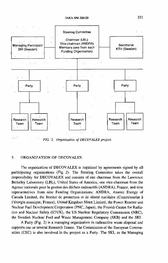
IAEA-SM-326/20 331
FIG. 2. Organization o f DECOVALEX project.
3. ORGANIZATION OF DECOVALEX
The organization of DECOVALEX is regulated by agreements signed by all participating organizations (Fig. 2). The Steering Committee takes the overall responsibility for DECOVALEX and consists of one chairman from the Lawrence Berkeley Laboratory (LBL), United States of America, one vice-chairman from the Agence nationale pour la gestion des déchets radioactifs (ANDRA), France, and nine representatives from nine Funding Organizations: ANDRA, Atomic Energy of Canada Limited, the Institut de protection et de sûreté nucléaire (Commissariat à l’énergie atomique, France), United Kingdom Nirex Limited, the Power Reactor and Nuclear Fuel Development Corporation (PNC, Japan), the Finnish Centre for Radiation and Nuclear Safety (STUK), the US Nuclear Regulatory Commission (NRC), the Swedish Nuclear Fuel and Waste Management Company (SKB) and the SKI.
A Party (Fig. 2) is a managing organization in radioactive waste disposal and supports one or several Research Teams. The Commission of the European Communities (CEC) is also involved in the project as a Party. The SKI, as the Managing

332 KAUTSKY et al.
Participant, is responsible for both the project economy and matters of agreements between the Funding Organizations and Parties. The Division of Engineering Geology of the Royal Institute of Technology (KTH), Sweden, hosts the Project Secretariat and provides administrative and technical assistance to the Steering Committee and Research Teams. Identical problems of benchmark tests and test cases are selected by the Steering Committee and are modelled by Research Teams in parallel. The results are compared at workshops organized by the Steering Committee. Design of new experiments will follow at the end of the project.
4. BENCHMARK TESTS AND TEST CASES FOR DECOVALEX PHASE I
Two benchmark tests (BMTs) and one test case (TC) are being investigated in Phase I of DECOVALEX: a far field THM model, a multiple fracture THM model and a coupled stress-flow test case.
4.1. Far field THM model, BMT1
BMT1 is a two dimensional BMT designed to simulate the THM processes in a large jointed rock mass with a repository located at a depth of about 500 m. The objective is to examine the thermal, hydraulic and mechanical effects of the repository on its far field environment. The model measures 3000 m x 1000 m and contains two intersecting sets of mutually perpendicular discontinuities (Fig. 3). Three
Constant temperature
o. m 5.2K i- " 3
t t t t t t t t t t t t t t tGeothermal heat flux, no flow
■*--------------------------------------------- 3000 m --------------------------------------------- »
ё'.н 1 «
* 'Sя
FIG. 3. Definition o f fa r field THM model, BMT1.

IAEA-SM-326/20 333
different spacings of the discontinuity sets are specified for the model. A non- uniform hydraulic head is imposed on the top (ground) surface and zero hydraulic flux is imposed on the lateral boundaries and at the bottom. The heat flux from the repository is assumed to decay exponentially with time. A constant initial temperature is specified within the model, including the top surface. Zero thermal flux and geothermal flux conditions are imposed on the lateral and bottom boundaries, respectively. The initial stresses inside the model and the boundary stresses acting on the lateral boundaries increase with depth owing to gravity. The displacement at the bottom of the model is fixed at zero. The thermal loading time is 500 years.
4.2. Multiple fracture THM model, BMT2
BMT2 is a two dimensional BMT consisting of nine rock blocks, separated by two vertical and two horizontal discontinuities (Fig. 4). The model measures0.75 m x 0.50 m and is confined along all boundaries with zero displacement. Constant normal stresses, temperature and hydraulic head are specified within the model. Zero hydraulic flux is imposed on the top and bottom, and different hydraulic pressures are imposed on the two lateral boundaries to stimulate the flow. Zero
J S C -
Adiabatic, no flow
— - ____
>Cl
*9 ЙГ
2 g1 3 c <» x
T0.2 m
-----
Adiabatic, no flow
0.3 ш 0.3 m*
a fi2 S0 Vi2L « S a ~ сtu 2а %1 § O °U
J.0.05 m
0.4 m
0.05 m
T
FIG. 4. Definition o f multiple fracture THM model, BMT2.

334 KAUTSKY et al.
thermal flux is imposed on the top and bottom boundaries of the model. Constant heat flux and constant temperature are imposed on the left and right hand vertical boundaries, respectively. The aim of this model is to investigate, the coupled behaviour of discontinuities and intact rock under a fully coupled THM process. The thermal loading time is 107 s.
4.3. Test case of coupled stress-flow model, TCI
To obtain the experimental data needed to quantify the effects of deformation and hydraulic conductivity of discontinuities, a laboratory testing facility has been built to test samples of rock discontinuities with a bilateral loading frame, supplying boundary stresses by flat jacks (Fig. 5). Discontinuities can be deformed in normal and tangential directions under controlled conditions while fluid flow is conducted through the discontinuities. Deformations, stresses and flow rates of the discontinuities can be recorded simultaneously. The coupled stress-flow model has input data
10 mm 220 mm260 mmM- •>
FIG. 5. Definition o f stress-flow test case 1. I , water injection point; E, water outlet point.
IAEA-SM-326/20 335
derived from recent field studies in the Stripa project, and different constitutive models for the rock discontinuities are given with different loading conditions. The aim of this test case is to verify different computer codes against the test results.
ACKNOWLEDGEMENT
The authors wish to thank all participating organizations of DECOVALEX.
REFERENCES
[1] TSANG, C.F. (Ed.), Coupled Processes Associated with Nuclear Waste Repositories, Academic Press, San Diego, CA (1987).
[2] CO-ORDINATING GROUP OF THE HYDROCOIN PROJECT, SWEDISH NUCLEAR POWER INSPECTORATE, The International HYDROCOIN Project, Summary Report, OECD/NEA, Paris (1992).
[3] SWEDISH NUCLEAR POWER INSPECTORATE, INTRACOIN, International Nuclide Transport Code Intercomparison Study, Final Report, Level 1: Code Verification, Tech. Rep. SKI TR 84:3, Stockholm (1984).
[4] SWEDISH NUCLEAR POWER INSPECTORATE, INTRAVAL Phase-1, Executive Summary, SKI, Stockholm (in press).


NATIONAL AND INTERNATIONAL PROGRAMMES
(Session 7)
Chairmen
S. ORLOWSKICEC
T. PAPPSweden


IAEA-SM-326/38
SCIENTIFIC BASES OF THE SCK/CEN PROGRAM M E ON RADIOACTIVE WASTE DISPOSAL IN ARGILLACEOUS FORMATIONSContributions to the success and progress o f national, foreign and international programmes
A. BONNE, G. COLLARD SCK/CEN,Mol, Belgium
Abstract
SCIENTIFIC BASES OF THE SCK/CEN PROGRAMME ON RADIOACTIVE WASTE DISPOSAL IN ARGILLACEOUS FORMATIONS: CONTRIBUTIONS TO THE SUCCESS AND PROGRESS OF NATIONAL, FOREIGN AND INTERNATIONAL PROGRAMMES.
In the almost twenty year long waste disposal investigation programme of SCK/CEN, the principal guidance towards the achievement of its objectives has been built essentially upon scientific principles. The SCK/CEN programme is basically scientific in selecting the issues, in performing the research and in evaluating the results and achievements. A strong position concerning the credits of argillaceous formations was built by SCK/CEN (with the support of the Commission of the European Communities) by rigorous scientific work in the first decade of its research programme. In recent years several partners have reinforced this position further by funding or actively taking part in this programme or by strengthening their efforts in investigating the clay option and thus enhancing the integration of different scientific and technological skills and approaches. Nowadays the programme is an integrated programme, covering almost the entire spectrum of key issues from basic research to technological developments. The programme is built on a multidisciplinary, multitask and multiobjective approach. The following main issues are dealt with in the programme. (1) Waste package: Characterization of the various candidate waste packages and their components and assessment of their compatibility with the argillaceous environment with a view to formulating the source term for performance assessments. (2) Near field: Assessment of the near field responses and effects and of their importance as factors influencing the behaviour of the source term, the structural components and the host rock. (3) Host rock: Assessment of the retention capabilities of the Boom clay and its permeation by fluids. (4) Surrounding geologies: Investigation on a regional scale of the overall hydrogeological system surrounding the Boom clay and the Mol site and identification of potential pathways of released radionuclides within the multilayered sequence of stratiform sedimentary deposits. (5) Design and operation related support studies: Specific components of the system may require research in order to assess their application in the implementation phase. (6) Long term safety and performance studies: Development of tools, acquisition of representative values and building of relevant expertise for carrying out safety and performance assessments. These issues are handled in various ways: theoretically, in the laboratory, in situ, on the local scale, regionally by field investigations, by modelling, by validation, by demonstration and by studying analogues.
339

340 BONNE and COLLARD
1. INTRODUCTION
As the first activities at SCK/CEN in the field of final disposal of radioactive wastes were launched almost twenty years ago, in 1974, an overview of the past activities, of what was learned and of which partners participated in these activities is a means for evaluating our programme performance. As a consequence a historical overview is the first part of this paper.
Since that early beginning many things have changed: the waste types and streams are different, science and technology have made progress, expertise has grown, management approaches have been adapted and strengthened, responsibilities have been allocated, the public position has changed and of course the people involved in waste research and waste management have also changed. It means that emphases in the present programme are different from those in the past. A description of our current programme is the second part of this contribution.
This presentation on past and present activities includes, where applicable, references to our co-operative research and an overview will show the diversity of topics shared in national, foreign and international contexts.
2. HISTORICAL OVERVIEW
2.1. The first five years
On the basis of what could be learned from studies performed in other countries, such as Germany, Italy and the United States of America, and of what was known about the Belgian geology it was evident in the beginning of the research on final disposal that the choice of potential host rock types in Belgium would be limited.
However, the Belgian Geological Survey pointed out that below the SCK/CEN site itself favourable argillaceous formations might be encountered. The principal aim of the first activities became to verify whether the characteristics and properties of clayey formations and, more specifically, the Boom clay were really promising for hosting a geological repository.
First drillings, focusing on the Tertiary sediments and especially the Boom clay, were performed on the SCK/CEN site from 1975 onwards and analyses of cores and samples were made. Lithological, chemical, mineralogical, ion exchange and geomechanical properties of the Boom clay and surrounding strata were determined.
Geohydrological studies were undertaken to determine the geohydrological situation at and around the site. A preliminary repository design and a probabilistic risk assessment methodology were developed. At the same time a catalogue of all potential host formations occurring in the country was established. Almost all of
IAEA-SM-326/38 341
these actions were financially supported by the Commission of the European Communities and substantial scientific and technical support was obtained from various scientific bodies in Belgium and from the CEC Joint Research Centre at Ispra.
The conclusions of these first studies were [1] that the Boom clay, for the application being investigated, satisfied the expectations. The samples and the analyses showed that the material has good sorption characteristics, that it is chemically and mineralogically stable, that it provides sufficient heat conductance, that it has a low permeability and that it is self-healing because of its plastic properties. The last property did, however, raise a very important question about the in situ behaviour of the clay: would it be possible to construct a repository in it?
The need to answer that question, and to develop methods and tools to confirm under in situ conditions a number of observations on the promising characteristics of the Boom clay, brought about the decision to build àn underground research laboratory (URL).
Since the first probabilistic evaluations of containment potentials of thé Boom clay at the Mol site showed that the site has a low probability of being disturbed by disruptive natural events and direct human intrusions [2], the incentive to strengthen and develop our capabilities in the area of deterministic safety assessment grew.
2.2. The second five years
Most of these research needs could be satisfied in the framework of the second CEC five year programme on waste management and disposal. The construction of the URL (HADES laboratory), the development of new tools for the safety assessment and design related studies were again supported financially by the CEC.
The URL was built according to specifications which were inspired by very pessimistic hypotheses (afterwards found to be unrealistic) about the plasticity and perviousness of the Boom clay. The full volume of clay in which the URL had to be constructed was conditioned by freezing to lower the convergence of the clay and the lining chosen for the whole structure was impervious and of very low permeability locally [3]. 1 ;
The approach became fully site and formation specific, and at the same time the site of Mol and the Boom clay were put in a larger geohydrological context. A regional hydrological observation network and model, covering about 2000 km2 around the Mol site, were launched under contract with the CEC and in co-operation with the Belgian Geological Survey and the Ecole des mines of Paris.
The site, the Boom clay and the surrounding geology were intensively investigated from various scientific perspectives (e.g. geochemical, geomechanical, hydrological and geophysical). The Boom clay formation at the Mol site came progressively to be a reference case because an increasing amount of information became available. The Boom clay at Mol was dealt with in feasibility studies undertaken in Italy [4], geomechanical and backfill studies made in the United Kingdom

342 BONNE and COLLARD
[5], and migration and safety assessment studies performed by the Joint Research Centre at Ispra [6]
In the period of the. second five year programme authorities responsible for managing radioactive waste were installed in several countries. In Belgium, NIRAS/ONDRAF was established in 1981 and it soon defined the national waste management programme, including its research programme. Several SCK/CEN programme items became part of the NIRAS/ONDRAF approach. Collaboration between SCK/CEN and the Agence nationale pour la gestion des déchets radioactifs (ANDRA) in France on the critical issue of geomechanics and constructibility in clay was started a few years after the establishment of ANDRA.
The digging of a small experimental shaft and gallery in unconditioned terrain in parallel with a mine-by test made jointly with ANDRA at the end of the construction of the URL was conclusive: there was no major problem, neither from the technical point of view nor from the cost perspective, in excavating and tunnelling in the plastic Boom clay.
2.3. Since the first ten years
In the mid-1980s the construction of the URL was completed and it was ready for in situ, experiments in various fields, including corrosion behaviour of waste package components, hydraulics, migration, geomechanics and characterization of clay, and for testing different experimental approaches.
In the same period the CEC launched its programme on demonstration and pilot facilities. The new and challenging field of demonstration, testing and evaluation (DT&E) was opened: namely the investigation of the behaviour of the system and its components under repository conditions.
. The HADES URL was extended by tunnelling a test drift for demonstration purposes. At the same time this test drift offered the opportunity to perform more tests, conceived to be. under conditions close to those expected in and around a final repository [7]. ,
In addition, validation exercises for the modelling of several processes were launched (INTERCLAY [8], INTRAVAL) and extensive performance assessment exercises were carried out in which SCK/CEN participated (PAGIS [9], PACOMA HOI).
In 1990, an international commission of experts formed by the Belgian Secretary of State for Energy evaluated a Safety Assessment and Feasibility Interim Report (SAFIR) on th e , geological disposal of radioactive waste, prepared by NIRAS/ONDRAF. The results of the research carried out by SCK/CEN on final disposal in Boom clay were the main contribution to this report.
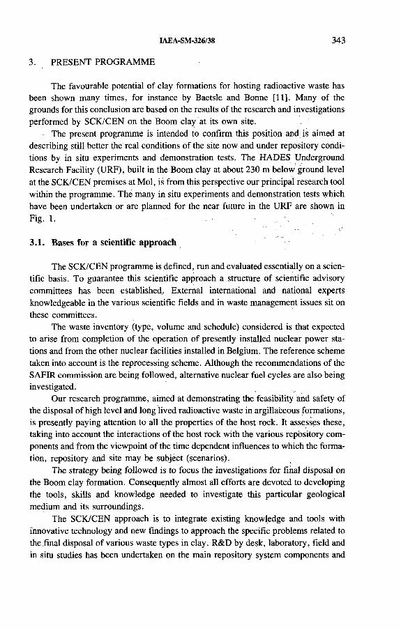
IAEA-SM-326/38 343
The favourable potential of clay formations for hosting radioactive waste has been shown many times, for instance by Baetsle and Bonne [11]. Many of the grounds for this conclusion are based on the results of the research and investigations performed by SCK/CEN on the Boom clay at its own site.
The present programme is intended to confirm this position and is aimed at describing still better the real conditions of the site now and under repository conditions by in situ experiments and demonstration tests. The HADES Underground Research Facility (URF), built in the Boom clay at about 230 m below ground level at the SCK/CEN premises at Mol, is from this perspective our principal research tool within the programme. The many in situ experiments and demonstration tests which have been undertaken or are planned for the near future in the URF are shown in Fig. 1.
3.1. Bases for a scientific approach
The SCK/CEN programme is defined, run and evaluated essentially on a scientific basis. To guarantee this scientific approach a structure of scientific advisory committees has been established.. External international and national experts knowledgeable in the various scientific fields and in waste management issues sit on these committees.
The waste inventory (type, volume and schedule) considered is that expected to arise from completion of the operation of presently installed nuclear power stations and from the other nuclear facilities installed in Belgium. The reference scheme taken into account is the reprocessing scheme. Although the recommendations of the SAFIR commission are being followed, alternative nuclear fuel cycles are also being investigated.
Our research programme, aimed at demonstrating the feasibility and safety of the disposal of high level and long lived radioactive waste in argillaceous formations, is presently paying attention to all the properties of the host rock. It assesses these, taking into account the interactions of the host rock with the various repository components and from the viewpoint of the time dependent influences to which the formation, repository and site may be subject (scenarios).
The strategy being followed is to focus the investigations for final disposal on the Boom clay formation. Consequently almost all efforts are devoted to developing the tools, skills and knowledge needed to investigate this particular geological medium and its surroundings.
The SCK/CEN approach is to integrate existing knowledge and tools with innovative technology and new findings to approach the specific problems related to the final disposal of various waste types in clay. R&D by desk, laboratory, field and in situ studies has been undertaken on the main repository system components and
3. PRESENT PROGRAMME
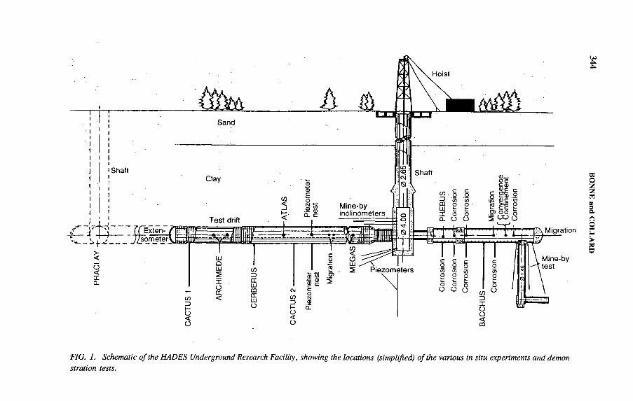
PR
AC
LAV
FIG. 1. Schematic o f the HADES Underground Research Facility, showing the locations (simplified) o f the various in situ experiments and demonstration tests.
BON
NE
and C
OL
LA
RD

IAEA-SM-326/38 345
TechnologyAssessm ent
Im ple menta tio n
FIG. 2. The process o f scientific and technological integration leading to demonstration.
on the most important issues and problems. DT&E activities have been dealing with the development of new tools and technologies, validation, reduced or full scale simulations, and performance and technology assessment. From this perspective the programme may be called an integrated R&D and DT&E programme.
The SCK/CEN programme can be considered as an integrated programme also for other reasons. The implementation of final disposal and the related research both require the development of adequate skills and technologies. The technology development is performed by integrating knowledge from basic and applied research with innovative technologies and combining these in specific test implementations (demonstrations). Figure 2 illustrates this integration process. The dual objective of the programme, namely to demonstrate the feasibility and safety of the final disposal of radioactive wastes in the Boom clay, forces SCK/CEN to investigate all relevant issues in a manner which allows the objective to be achieved in a coherent manner. This interaction between performance assessment and technology demonstration is dealt with in an integrated way. For many of the issues to be investigated one can follow various routes to final demonstration. None of them alone can produce the final and ultimate demonstration, but in combination they can provide sufficient confidence in the demonstration: for example, theoretical approaches, laboratory simulation, modelling, studies of analogues and in situ testing all combined contribute to the demonstration issue. All these approaches are followed in the SCK/CEN programme.

346 BONNE and COLLARD
3.2. Main R&D activities
In our R&D the principal system components are systematically investigated.
3.2.1. Waste package
This issue covers the characterization of the various candidate waste packages and their components (Cogéma vitrified glass, PAMELA vitrified glass, concrete, bitumen, asbestos cement, Synroc, Hastelloy, carbon steel, stainless.steel, etc.) and assessment of their compatibility with the argillaceous environment with a view to formulating the source term for the performance assessments. Examples of such work are: leaching tests in the laboratory, in situ corrosion tests and modelling of corrosion. The majority of the research related to waste packages is performed under contract with NIRAS/ONDRAF, the CEC and BELGOPROCESS. Collaboration in this field has been undertaken with the Forschungszentrum Jülich (KFA), the Kernforschungszentrum Karlsruhe (KfK), the French Commissariat à l’énergie atomique (CEA), the Comitato Nazionale per la Ricerca e per lo Sviluppo dell’Energia Nucleare e delle Energie Alternative (ENEA, Italy), the Australian Nuclear Science and Technology Organisation (ANSTO), Sandia National Laboratories (USA), Kärnbränslesäkerhet (KBS, Sweden), Chalmers University (Sweden) and many others.
3.2.2. Near field
The interactions between the repository and the immediately surrounding host rock and their importance as factors disturbing or even improving the source term, the structural components and the geological host rock are investigated under this programme item. Work performed includes the many tests and modelling exercises regarding excavation responses, heating, oxygenation of the host rock, backfilling and radiation. Research contracts have been concluded for this issue with NIRAS/ONDRAF, the CEC (e.g. for the in situ ATLAS experiment), ANDRA (e.g. for the in situ PHEBUS experiment) and the Empresa Nacional de Residuos Radiactivos, SA (ENRESA, Spain). The CEA (France), the Geotechnical Consulting,Group (UK), ISMES (Italy) and the University of Leuven (Belgium) have been collaborating in this field.
3.2.3. Host rock
Characterization of the Boom clay from various perspectives (e.g. geochemi- cally, physicochemically, mineralogically, lithologically, by sampling techniques and by composition) and assessment of its retention capabilities and of its permeation by fluids are the main activities in this field. Work includes laboratory and in situ
IAEA-SM-326/38 347
tests related to the migration of radionuclides, laboratory and in situ gas permeation tests, modelling of such processes and methodological investigations related to sampling of clay or pore water. Research in this area is performed under contract with NIRAS/ONDRAF, the CEC, ANDRA, the Power Reactor and Nuclear Fuel Development Corporation (PNC, Japan) and ENRESA. INTERA (UK) and several universities (University of Leuven, University of Cataluña, University of Ghent and University of Wales, Cardiff) have been collaborating with SCK/CEN on characterization studies of Boom clay, migration of radionuclides and permeation of gas.
3.2.4. Surrounding geologies
The objective in this research issue is to investigate the overall groundwater system in the multilayered stratiform series of sedimentary layers at and around the Mol site and to identify potential pathways of released radionuclides within it. Work includes regional and local hydrological studies, macropermeability tests, modelling of the present groundwater flow system and predictive geological modelling. NIRAS/ONDRAF is the main contracting party in this area. Collaboration in this field has been undertaken with the Belgian Geological Survey, the Ecole des mines of Paris and the University of Brussels.
3.2.5. Design and operation related support studies
Design and operation related support studies have been undertaken on issues where new developments are required. Typical examples are studies related to backfilling and sealing, wherein various candidate materials are being investigated together with the manufacturing and emplacement techniques. Collaboration in the field of backfilling (BACCHUS experiment) has been undertaken with ANDRA, the CEA, ENRESA and ISMES. Another area, mentioned here as an example, is modelling to estimate the permissible thermal loading.
3.3. Main DT&E activities
A basic principle in the DT&E activities of the SCK/CEN programme is to rely on present day technology or technology which will be readily available within a short time. One takes the position that while present skills are applied to demonstrate and evaluate the performance, impact and feasibility of the final situation or option, the finally applied techniques and assessments will be better than those of today.
348 BONNE and COLLARD
3.3.1. Long term performance and safety assessment
Various reprocessing waste types and their long term impacts have been assessed stepwise. Most of this assessment work is being done and published in the framework of the CEC’s safety and performance studies.
The standard methodology consists of a structured scenario selection and analysis, and best estimate calculations followed by sensitivity and uncertainty analysis. The assessments are systematically upgraded through gradual improvement of the methodology or components of it by introducing new tools and approaches, e.g. in the selection of input parameters and parameter sampling techniques and procedures, and by updating the input data.
All results obtained up to now and the evaluations of performance assessment methods themselves are providing reassuring bases for an attitude of confidence in the option and the approach. Results for the spent fuel disposal option are not yet available, but are expected to be within two years. Our involvement includes participation in actions of the CEC, such as PAGIS [9], PACOMA [10] and EVEREST (in collaboration with ANDRA and the Institut de protection et de sûreté nucléaire (IPSN) in France and the Energieonderzoek Centrum Nederland (ECN)), and in actions of the International Atomic Energy Agency, e.g. BIOMOVS, and of the Organisation for Economic Co-operation and Development, e.g. PSAC.
3.3.2. Constructibility demonstration
SCK/CEN proposed to demonstrate directly the tunnelling capabilities under representative conditions and obtained the requisite financial support from NIRAS/ONDRAF and the CEC. Tunnelling according to both a stiff lining principle for long lasting gallery structures and a converging lining principle for deeper and shorter lasting gallery structures has been demonstrated (the latter upon the initiative and demand of ANDRA) by the construction of a test drift. The construction of the section with a stiff lining was done in parallel with a mine-by test which allowed monitoring of the behaviour of the structure and the surrounding clay during the construction and afterwards.
3.3.3. Combined effects
A series of in situ tests have been performed, and more are planned for the future, in order to demonstrate combined effects expected to occur in a final repository. Several of these tests are performed in the context of the CEC programme on demonstration and pilot facilities.
In 1989, a combined heating and radiation test, called the CERBERUS test (under contract with NIRAS/ONDRAF), was set up in the Boom clay in the floor of the test drift of the HADES URF, with the aim of creating by simulation a very

IAEA-SM-326/38 349
local near field similar to the one expected from a high level waste canister (of Cogéma type after a 50 year cooling time). The simulating sources are a 60Co source (of about 444 TBq at the time of emplacement) combined with two heaters each with a thermal output of 362 W. The test is described elsewhere and is planned to last until 1996. In the near field of this test, monitoring is done of radiation level, moisture content and composition, and corrosion and migration test devices can be emplaced in this field as well. Evidence of the performance of Boom clay based backfill material placed in the near field will be available in the mid-1990s. First indications point towards a change in the characteristics of the interstitial fluid.
In the HADES URF a series of simulation tests (CACTUS tests) have been undertaken for ANDRA in order to investigate and demonstrate the hydrothermomechanical response of a clay host rock to the emplacement of heat generating HLW. The emplacement concept is representative for the concept of disposing of HLW canisters in stacks in the floor of the disposal galleries. Two test configurations have been installed (according to two different emplacement scenarios) and are planned to last until 1993-1994.
3.3.4. PRACLAYtest
A large scale demonstration test for tunnelling, HLW emplacement simulation and backfilling was initiated by NIRAS/ONDRAF in 1990. The emplacement configuration envisaged for this test corresponds to disposal of HLW canisters in the full section of the galleries. For the time being efforts are devoted to a number of feasibility studies related to specific test issues, to general design activities concerning the test, to the assessment of technologies available for performing and monitoring the test, and to the preparation for the construction of a new emergency shaft since the mining authorities require such a structure before licensing for the new test can be obtained.
4. CO-OPERATION
Many examples of SCK/CEN co-operative research in the field of geologicaldisposal were mentioned above in the overview of its programme. In addition, otherpresentations made during this symposium will provide further examples [12-15].
A recent demonstration of the international significance of our research can befound in a new report about the state of the art of the disposal of radioactive wastein deep argillaceous formations [16]. This report, released by ENRESA of Spain,was prepared by our Italian colleagues. About twenty per cent of the references citedreferred directly or indirectly to the research on the Boom clay at Mol.
The SCK/CEN programme on final disposal in clay, and more specifically theHADES project, has never been promoted as an international project, but as a result

350 BONNE and COLLARD
of its acceptance in the CEC research programme on final disposal and management of radioactive waste it has become a highly developed and well integrated programme and has benefited from international collaboration.
Since the establishment of NIRAS/ONDRAF in Belgium, the backbone of our programme has been formed by the NIRAS/ONDRAF research programme and priority is given to it. Faithful to its scientific mandate, SCK/CEN supports NIRAS/ONDRAF in many respects and continuously takes initiatives to trigger new research and development in the fields where the need for scientific progress is identified.
In this respect the SCK/CEN programme is open for collaboration with all organizations devoting R&D or DT&E efforts to disposal in clay. SCK/CEN is prepared to share its scientific assets and to explore new domains and issues in this field.
5. CONCLUSIONS
Nearly all important issues related to the final disposal of radioactive waste in a clay formation are dealt with in SCK/CEN’s integrated R&D and DT&E programme.
Because of a systematic and integrated site and formation specific approach and as a result of important funding provided by the authorities initially, by NIRAS/ONDRAF and by the CEC, and through contributions from many research partners, SCK/CEN has been able to develop an expertise and build unique facilities which now serve for all interested parties.
The SCK/CEN programme, which includes in situ research in its HADES URF and advanced performance assessment studies for various waste types, as well as experience in waste package characterization and waste package-host rock interaction studies, was not initiated as an international programme, but has become de facto a contributor to the programmes of many foreign and international organizations.
REFERENCES
[1] BONNE, A., HEREMANS, R., MANFROY, P., DEJONGHE, P., “ Investigations entreprises pour préciser les caractéristiques du site argileux de Mol comme lieu de rejet souterrain pour les déchets radioactifs solidifiés” , Underground Disposal of Radioactive Wastes (Proc. Symp. Otaniemi, 1979), Vol. 2, IAEA, Vienna (1980) 41-58.
[2] D ’ALESSANDRO, M., BONNE, A., Radioactive Waste Disposal in a Plastic Clay Formation — A Site Specific Exercise of Probabilistic Assessment of Geological Containment, Harwood Academic, London (1981) 150 pp.
IAEA-SM-326/38 351
[3] BONNE, A ., HEREMANS, R ., MANFROY, P ., VAN HALEWUN, R ., Construction of an Underground Facility for ‘In Situ’ Experimentation in the Boom Clay, EUR 10177, CEC, Luxembourg (1986).
[4] CHAPMAN, N. A ., TASSONI, E ., Feasibility Studies for a Radioactive Waste Repository in a Deep Clay Formation, EUR 10061, CEC, Luxembourg (1985).
[5] HORSEMAN, S.T., et al., Geotechnical Characterization of Boom Clay in Relation to the Disposal of Radioactive Waste, Rep. FLPU 86-12, Inst, of Geological Sciences, Harwell (1986).
[6] BERTOZZI, G., et al., Radioactive waste disposal into a plastic clay formation: Risk analysis for probabilistic scenarios, Eur. Appl. Res. Rep. 6 (1985) 631-1002.
[7] BONNE, A., et al., The HADES Demonstration and Pilot Project on Radioactive Disposal in a Clay Formation, EUR 13851, CEC, Luxembourg (1992).
[8] CÔME, B. (Ed.), The CEC Benchmark INTERCLAY on Rheological Models for Clays, EUR 12791, CEC, Luxembourg (1990).
[9] MARIVOET, J., BONNE, A., Performance Assessment of Geological Isolation Systems for Radioactive Waste Disposal in Clay Formations, EUR 11776, CEC, Luxembourg (1988).
[10] MARIVOET, J., ZEEVAERT, T., Performance Assessment of the Geological Disposal of Medium Level and Alpha Waste in a Clay Formation in Belgium, EUR 13042, CEC, Luxembourg (1990).
[11] BAETSLE, L.H., BONNE, A., “ Disposal of radioactive wastes into clay layers the most natural option” , Waste Management ’90 (Proc. Symp. Tucson, 1990), Arizona Board of Regents, Tucson (1990) 907.
[12] RAYNAL, M., NEERDAEL, B., IAEA-SM-326/59P, these Proceedings.[13] VOLCKAERT, G., et al., IAEA-SM-326/35P, ibid.[14] RAIMBAULT, P.A., et al., IAEA-SM-326/57, ibid.[15] MERCERON, T., et al., IAEA-SM-326/60, ibid.[16] GERA, F ., et al., State of the Art Report: Disposal of Radioactive Waste in Deep Argil
laceous Formations, Publicación Técnica 01/92, ENRESA, Madrid (1992).

IAEA-SM-326/23
THE SWEDISH PROGRAMME FOR SITING OF A DEEP GEOLOGICAL REPOSITORY FOR SPENT NUCLEAR FUEL
C. THEGERSTRÖM Swedish Nuclear Fuel and
Waste Management Company,Stockholm, Sweden
Abstract
THE SWEDISH PROGRAMME FOR SITING OF A DEEP GEOLOGICAL REPOSITORY FOR SPENT NUCLEAR FUEL.
The paper summarizes the Swedish plans for siting of a deep geological repository for demonstration disposal of spent nuclear fuel. The rationale for a demonstration facility is presented. By implementing demonstration disposal a first step towards final disposal of all long lived waste will be taken while keeping the option for alternative solutions. Demonstration of a disposal system in practice is believed to broaden the consensus regarding deep geological disposal as a safe and rational way of taking care of high level waste. Siting of a repository for deep disposal will be done in stages. After overview studies and preliminary studies of potential candidate areas two candidate sites will be selected for site investigations. Selected sites will have to meet all relevant safety, technical, societal and legal requirements. Many sites in Sweden are believed to have the necessary characteristics to be able to meet such requirements. Local political and public opinion will therefore be of great importance in site selection. The construction and operation of a deep repository must be done with positive and active local participation if the project is to be successful. According to the timetable a deep repository for demonstration disposal could be ready to receive encapsulated spent nuclear fuel in about 15-20 years’ time, i.e. around the year 2010.
1. INTRODUCTION
Siting of the facilities needed for final disposal of spent nuclear fuel and other types of long lived wastes is one of the most important remaining tasks within the Swedish nuclear waste management programme. According to Swedish law the responsibility for all necessary research and development work as well as siting and construction of treatment and disposal facilities lies fully with the nuclear waste producers. The Swedish Nuclear Fuel and Waste Management Company (SKB), a company formed and owned by the nuclear utilities in Sweden, is charged with the task to perform all the necessary measures to ensure the safe management and disposal of all types of radioactive waste.
353
354 THEGERSTRÖM
2. OVERALL PLAN FOR IMPLEMÈNTATION OF DEEP GEOLOGICAL DISPOSAL
In accordance with the requirements of the law the SKB has recently presented a programme for research, development and demonstration, called RD&D Programme 92 [1, 2]. The programme is presently being reviewed by the authorities and following this review the Government is expected to express its opinion during autumn 1993. In its decision about the earlier R&D Programme 89 the Government stated that
“ one basic element of the continuation of the research and development work should be that a repository for nuclear waste and spent fuel can be taken into operation in a stepwise fashion with control stations and possibilities for adjusting measures. SKB should in its next R&D programme study the possibilities of letting a demonstration scale repository form one step of the work with constructing a final repository.”
Following the request by the Government, the SKB has studied the issue of a stepwise implementation and construction of a deep geological repository. The SKB has found that starting nuclear waste disposal on an industrial scale with a repositoiy for demonstration of spent fuel disposal will be very appropriate in many ways. In the RD&D Programme 92 it is therefore proposed that the research, development and demonstration work that was started about 15 years ago now be concluded by constructing a deep geological repository for demonstration disposal of some 10% (500 t) of the projected total amount of Swedish spent nuclear fuel.
By constructing a repository for demonstration disposal of spent nuclear fuel it will be possible to demonstrate the following:
— The siting process with all the associated technical, administrative and political decisions;
— Site investigations and site characterization methodologies for a real repository site;
— Systems design and construction of necessary facilities;— Encapsulation of spent nuclear fuel;— Handling and transportation of encapsulated spent fuel;— Licensing of all systems and facilities, including long term safety analysis;— Retrieval of disposed waste (if so decided).
It will not be possible to demonstrate the long term safety of a repository. Acceptance in this respect will always have to be based upon an integrated assessment of the long term behaviour of the disposal system.
The planning of a demonstration of disposal should not be seen as a sign of doubt about the feasibility of deep geological disposal. The main purpose of the plan is to demonstrate in practice all the necessary measures and thereby to gain a broad

IAEA-SM-326/23 355
Retrieval, alternative "*■
FIG. 1. The overall plan fo r proceeding towards disposal o f all Swedish long lived waste. This includes demonstration disposal (phase 1), evaluation and final disposal (phase 2). The process fo r siting and construction will proceed in stages as shown under each main phase. NRL: Natural Resources Act; KTL: Nuclear Activities Act.
consensus about deep geological disposal as a safe and rational way of taking care of nuclear waste.
The overall plan in Sweden for proceeding towards disposal of all waste is illustrated in Fig. 1. The work will be done in two phases: demonstration disposal and final disposal. The decision to go from demonstration disposal to final disposal will be taken after the demonstration disposal has been completed and the experiences have been evaluated. Evaluation of other alternatives will also be considered before a decision is taken to either continue and complete the deep geological disposal as started or alternatively to retrieve the canisters.
The siting of the demonstration disposal facility will be done so that the facility could be expanded to a complete repository for all Swedish long lived waste.

356 THEGERSTRÖM
In Sweden there is now more than 15 years’ experience of R&D work concerned with the safe disposal of spent nuclear fuel. This experience encompasses, for example:
— Geological site investigations at several study sites during the period 1976-1984;
— Disposal system concept development and evaluation of alternatives (KBS-1,2, 3 and PASS [3]);
— Development and testing of site characterization methods, testing of engineered barrier performance, and radionuclide migration experimentation/modelling within the international Stripa project;
— Major integrated safety assessment studies (KBS-3 and SKB 91 [4]);— Ongoing construction and R&D work at the Äspö Hard Rock Laboratory [5].
Given the level of knowledge and experience that has been obtained over these years, the time has now come to proceed systematically towards an actual implementation of a system to demonstrate safe disposal in practice.
Figure 2 provides a schematic illustration of siting goals and prerequisites. An assessment of the prerequisites will identify the requirements that have to be fulfilled as well as the flexibility in attaining the goals and indicate under what circumstances there would be a risk of being blocked.
3. BASIS FOR SITING PROGRAMME
P R E R E Q U I S I T E S O B J E C T I V E S
Law
Science
Technology
Social planning
Politics
Public opinion
Safety
Constructibility
Economy
FIG. 2. Schematic illustration o f siting goals and prerequisites.
IAEA-SM-326/23 357
3.1. Legal prerequisites
The Swedish law clearly defines responsibilities and financing requirements for nuclear waste management. Siting of industrial facilities is done under the Natural Resources Act. Nuclear installations are regulated under the Nuclear Activities Act and the Radiation Protection Act. An Environmental Impact Statement (EIS) is required by several laws. An EIS should be put together at an early stage and then be updated and made more detailed as the siting and design work proceeds . The EIS will be an important licensing document but equally important is that it will serve as an instrument for providing clear and comprehensive information to the public.
Efficient co-ordination between the SKB and the national authorities, regional authorities, local communities and the Government will be needed throughout the siting process.
3.2. Scientific and technical prerequisites
The R&D work done over the past 15 years includes, for instance, site and field studies all over Sweden (Fig. 3) and several integrated safety assessment studies by the SKB [6, 4] or the Swedish Nuclear Power Inspectorate (SKI) [7]. Some major conclusions from this work are as follows:
— The Swedish bedrock provides good geological conditions for a deep repository system. It is therefore possible to find suitable sites in many parts of the country.
— The best way to proceed is to select, investigate and evaluate specific candidate sites.
3.3. Societal, political and public opinion prerequisites
The investigations and the facilities planned will imply use of land, create jobs and influence local industry and services. They will also influence the environment, both visually and as a result of transport, drilling, excavation and construction work. All these aspects have to be described and discussed with authorities and the local communities. Provision of information to and good co-óperation with local communities will be essential.
In summary, the SKB has concluded that societal, political and public opinion aspects are very important in site selection as well as during investigations and facility construction.

358 THEGERSTRÖM
Limited investigations ■ AKA
FIG. 3. Sites where field studies have taken place in order to gain knowledge in general about the Swedish bedrock as a host medium fo r nuclear waste disposal and/or to develop and test investigation techniques. The final repository site will not necessarily be selected from among these sites, but the siting programme is based upon the knowledge gained from studies at these sites. AKA: Swedish Government Committee on Radioactive Waste (1973-1976); PRAV: National Council fo r Radioactive Waste.
IAEA-SM-326/23 359
The siting of a deep repository is a long and stepwise process. It encompasses overview studies covering the whole country or regions, as well as detailed focusing on particular areas or potential sites. The selection of candidate sites will be made in accordance with the fundamental requirements that will have to be fulfilled. One must be able to show convincingly, with the help of a site specific safety assessment, that the safety requirements of the authorities can be fulfilled. One must be able to construct the repository and technically perform the disposal as intended. One must perform the siting, the investigations and the construction so that all relevant legal and other requirements are met. Finally, one must do all this in collaboration, as appropriate, with the local community and the people affected by the project.
4. SITING PROCESS
4.1. Main stages of siting process
On the basis of technical considerations as well as legal requirements and statements by the Government concerning the formal licensing procedure, siting will be performed in the following main stages.
Stage 1: Overview studies and assessment of siting factors; preliminary studies of potential candidate communities; selection of candidate areas; site investigations at two sites; facility design work; technical and socioeconomic studies; evaluation of results; preparation of licence application for detailed site characterization, including a prelim inary EIS and a first safety assessment.
Stage 2: Detailed site characterization, including construction and investigations from a tunnel and/or a shaft down to planned repository level; evaluation of results; Preliminary Safety Report; EIS; detailed facility design; siting application according to the Natural Resources Act and application for construction of a repository according to the Nuclear Activities Act.
Stage 3: Repository construction and installation of handling equipment; Final Safety Report; application for operation of the repository.
Stage 4: Start of operations; demonstration disposal of encapsulated spent nuclear fuel.
In parallel with this siting process there will be programmes for R&D work supporting the safety assessments and studies of systems for transportation of encapsulated spent fuel as well as techniques for possible retrieval of disposed canisters. Development of investigation methods and inactive testing of handling and disposal techniques will be done at the Äspö Hard Rock Laboratory.
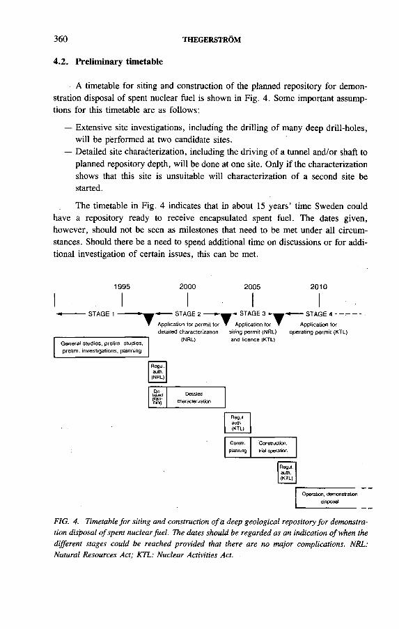
360 THEGERSTRÖM
4.2. Preliminary timetable
A timetable for siting and construction of the planned repository for demonstration disposal of spent nuclear fuel is shown in Fig. 4. Some important assumptions for this timetable are as follows:
— Extensive site investigations, including the drilling of many deep drill-holes, will be performed at two candidate sites.
— Detailed site characterization, including the driving of a tunnel and/or shaft to planned repository depth, will be done at one site. Only if the characterization shows that this site is unsuitable will characterization of a second site be started.
The timetable in Fig. 4 indicates that in about 15 years’ time Sweden could have a repository ready to receive encapsulated spent fuel. The dates given, however, should not be seen as milestones that need to be met under all circumstances. Should there be a need to spend additional time on discussions or for additional investigation of certain issues, this can be met.
1995 2000 2005 2010
STAGE 1
General studies, prelim, studies, prelim, investigations, planning
------ STAGE 2 •
Application for permit for detailed characterization
(NRL)
Regul.auth.(NRL)
^ STAGE 3
▼ Application for ▼ siting permit (NRL) and licence (KTL)
«-------STAGE 4 ----------
Application for operating perm it (KTL)
Detailedpfenning
Detailedcharacterisation
Regul.auth.(KTL)
Constr. Construction,planning trial operation
Regul.auth.(KTL)
Operation, demonstration disposât
FIG. 4. Timetable fo r siting and construction o f a deep geological repository for demonstration disposal o f spent nuclear fuel. The dates should be regarded as an indication o f when the different stages could be reached provided that there are no major complications. NRL: Natural Resources Act; KTL: Nuclear Activities Act.

IAEA-SM-326/23 361
For each potential site and local community the feasibility of constructing a safe repository and the potential effects for the community will be studied. Such studies will include:
— Technical issues, e.g. transportation of the waste and other materials, andeffects on the local and regional infrastructure of a repository;
— Societal issues, e.g. effects on local life, tourism and the economy;— Geoscientific issues, e.g. geological, hydrological and geochemical conditions
in the region and at particular sites.
Studies will preferably be done in co-operation with local groups from the very start. Before regular site investigations are begun, the overall possibilities for a repository within a community will be assessed in a preliminary study. Such a study will cover all aspects (technical, social, legal and geoscientific) of constructing and operating a deep geological repository within the community and will take about one year. On the basis of such a study, the SKB as well as the community can gain a preliminary indication of the possibilities as well às potential effects, benefits and remaining questions.
5.1. Geoscientific site investigations
Geoscientific site investigations will be performed according to a well defined programme. This programme is presently being prepared. It will be based upon the experience obtained from investigations at study sites, Stripa and Äspö. Foreign experience, in particular in Finland, will also provide input to the programme. The results of safety studies such as SKB 91 will give guidance on what data are needed to satisfy performance assessment needs. Design studies as well as assessment of repository construction issues further need to be considered in the programme. An efficient integration of different needs will have to be ensured by the programme. The necessary co-ordination and integration between different elements of the site investigations and the users of the results are illustrated in Fig. 5.
The field investigations will be done in the following main phases:
Regional characterization: The purpose of this phase is to gain knowledge about large scale geological and geohydrological conditions in the region in which the potential site is situated.
Localizing investigations: These investigations will provide a more detailed picture of the conditions at a few sites within the area(s) of interest. On the basis of the results one potential repository site will be selected for further study.
Basic site investigations: This phase forms the major part of the field studies during which most of the detailed data are collected. It includes the drilling of several
5. PROGRAMME FOR SITE INVESTIGATIONS
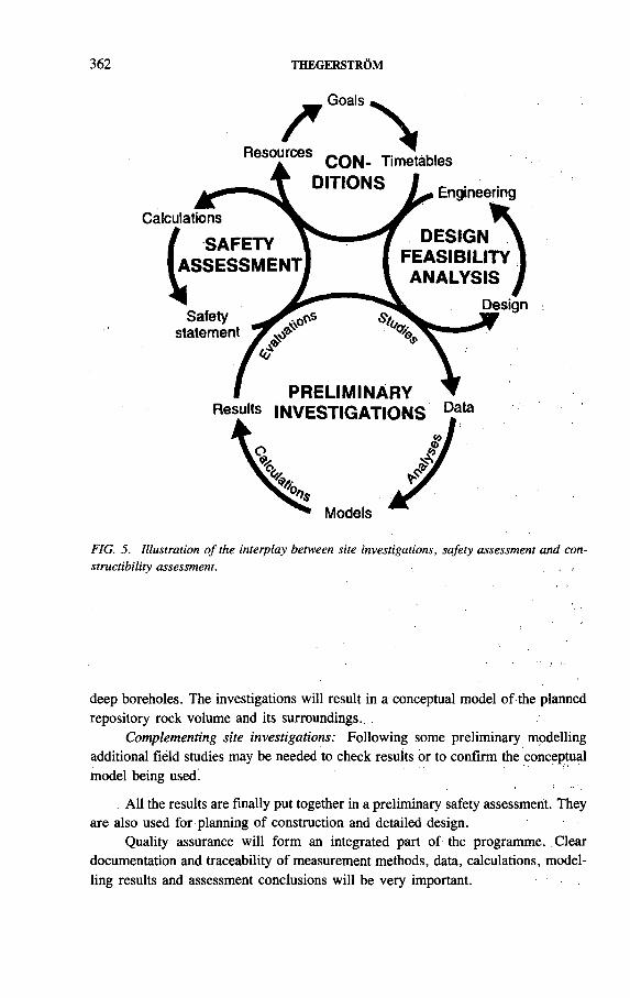
362 THEGERSTRÖM
Resources
Goals
i г о л е ^CON- Timetables
Calculations
( SAFETY ASSESSMENT
Safety statement
Engineering
DESIGN FEASIBILITY ANALYSIS I
Design
PRELIMINARYResults in v e s tig a tio n s D.ata
Models
FIG. 5. Illustration o f the interplay between site investigations, safety assessment and con- structibility assessment. .■
deep boreholes. The investigations will result in a conceptual model of the planned repository rock volume and its surroundings..
Complementing site investigations: Following some preliminary modelling additional fiéld studies may be needed to check results br to confirm the conceptual model being used!
. All the results are finally put together in a preliminary safety assessment. They are also used for planning of construction and detailed design.
Quality assurance will form an integrated part of the programme. Clear documentation and traceability of measurement methods, data, calculations, modelling results and assessment conclusions will be very important.

IAEA-SM-326/23 363
REFERENCES
[1] SVENSK KÄRNBRÄNSLEHANTERING, RD&D Programme 92, Treatment and Final Disposal of Nuclear Wastes. Programme for Research, Development, Demonstration and Other Measures, SKB, Stockholm (1992).
[2] SVENSK KÄRNBRÄNSLEHANTERING, Background Report to RD&D Programme 92, Treatment and Final Disposal of Nuclear Wastes. Siting of a Deep Repository, SKB, Stockholm (1992).
[3] SVENSK KÄRNBRÄNSLEHANTERING, Project Alternative Systems Study (PASS), Final Report, SKB, Stockholm (1992).
[4] SVENSK KÄRNBRÄNSLEHANTERING, SKB 91, Final Disposal of Spent Nuclear Fuel. Importance of the Bedrock for Safety, SKB, Stockholm (1992).
[5] SVENSK KÄRNBRÄNSLEHANTERING, Background Report to RD&D Programme 92, Treatment and Final Disposal of Nuclear Wastes, Äspö Hard Rock Lab. (1992).
[6] SVENSK KÄRNBRÄNSLEFÖRSÖRJNING/KÄRNBRÄNSLESÄKERHET, Final Storage of Spent Nuclear Fuel — KBS-3, 4 vols, SKBF/KBS, Stockholm (1983).
[7] STATENS KÄRNKRAFTINSPEKTION, Project 90, SKI, Stockholm (1992).

IAEA-SM-326/30
SWISS STRATEGY FOR DEVELOPING A HIGH LEVEL W ASTE DISPOSAL SYSTEM
C. McCOMBIE, A. LAMBERT, I.G. McKINLEY National Cooperative for the Disposal
of Radioactive Waste (Nagra),Wettingen, Switzerland
Abstract
SWISS STRATEGY FOR DEVELOPING A HIGH LEVEL WASTE DISPOSAL SYSTEM.Switzerland has established a flexible long term strategy for the development of a high
level waste disposal system. The aim is to ensure that a range of options are maintained as long as is necessary (to increase the probability of a successful choice of site and design) but that this range is narrowed down as soon as is technically justifiable (to minimize costs and manpower conflicts). The paper reviews the evolution of this strategy, the current status of the HLW programme and the main milestones in the future progress towards implementation of a repository.
1. INTRODUCTION
In absolute terms, Switzerland has a rather small nuclear power programme ( — 3 GW(e)) but this, in fact, corresponds to about 40% of Swiss electricity generation. With an expected reactor lifetime of 40 years and assuming reprocessing of all spent fuel ( — 3000 t), the total volume of high level waste from the existing programme will amount to only around 500 m 3. It is planned to store vitrified HLW or spent fuel for at least 40 years prior to disposal (to allow radiogenic thermal output to decrease) and specific projects are under way to provide the required intermediate storage facilities.
As the volume of HLW is rather small, storage times could readily be extended even further and there is no urgent technical requirement for a national HLW disposal facility. Indeed, given the small quantity of HLW, it can be argued that disposal as part of a joint (international) project would be more attractive on economic and technical grounds and this option is expressly left open at present. Nevertheless, an extensive national HLW programme is being conducted with the aim of demonstrating that, if required, a repository providing the necessary levels of long term safety could be constructed at at least one site within Switzerland.
Demonstration of the feasibility of safe nuclear waste disposal is required by the amended Swiss nuclear law of 1979. Coupling of the granting of continued operation licences for the nuclear plants to demonstration of safety and feasibility was an
365
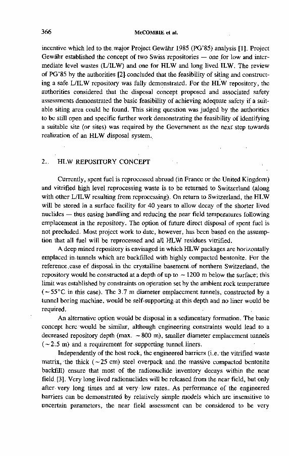
366 McCOMBIE et al.
incentive which led to the.major Project Gewähr 1985 (PG’85) analysis [1]. Project Gewähr established the concept of two Swiss repositories — one for low and intermediate level wastes (L/ILW) and one for HLW and long lived ILW. The review of PG’85 by the authorities [2] concluded that the feasibility of siting and constructing a safe L/ILW repository was fijlly demonstrated. For the HLW repository, the authorities considered that the disposal concept proposed and associated safety assessments demonstrated the basic feasibility of achieving adequate safety if a suitable siting area could be found. This siting question was judged by the authorities to be still open and specific further work demonstrating the feasibility of identifying a suitable site (or sites) was required by the Government as the next step towards realization of an HLW disposal system.
2. HLW REPOSITORY CONCEPT
Currently, spent fuel is reprocessed abroad (in France or the United Kingdom) and vitrified high level reprocessing waste is to be returned to Switzerland (along with other L/ILW resulting from reprocessing). On return to Switzerland, the HLW will be stored in a surface facility for 40 years to allow decay of the shorter lived nuclides — thus easing handling and reducing the near field temperatures following emplacement in the repository. The option of future direct disposal of spent fuel is not precluded. Most project work to date, however, has been based on the assumption that all fuel will be reprocessed and all HLW residues vitrified.
A deep mined repository is envisaged in which HLW packages are horizontally emplaced in tunnels which are backfilled with highly compacted bentonite. For the reference, case of disposal.in the crystalline basement.of northern Switzerland, the repository would be constructed at a depth of up to ~ 1200 m below the surface; this limit was established by constraints on operation set by the ambient rock temperature ( ~55°C in this case). The 3.7 m diameter emplacement tunnels, constructed by a tunnel boring machine, would be self-supporting at this depth and no liner would be required.
An alternative option would be disposal in a sedimentary formation. The basic concept here would be similar, although engineering constraints would lead to a decreased repository depth (max. -8 0 0 m), smaller diameter emplacement tunnels ( — 2.5 m) and a requirement for supporting tunnel liners.
Independently of the host rock, the engineered barriers (i.e. the vitrified waste matrix, the thick ( - 2 5 cm) steel overpack and the massive compacted bentonite backfill) ensure that most of the radionuclide inventory decays within the near field [3]. Very long lived radionuclides will be released from the near field, but only after very long times and at very low rates., As performance of the engineered barriers can be demonstrated by relatively simple models which are insensitive to uncertain parameters, the near field assessment can be considered to be very
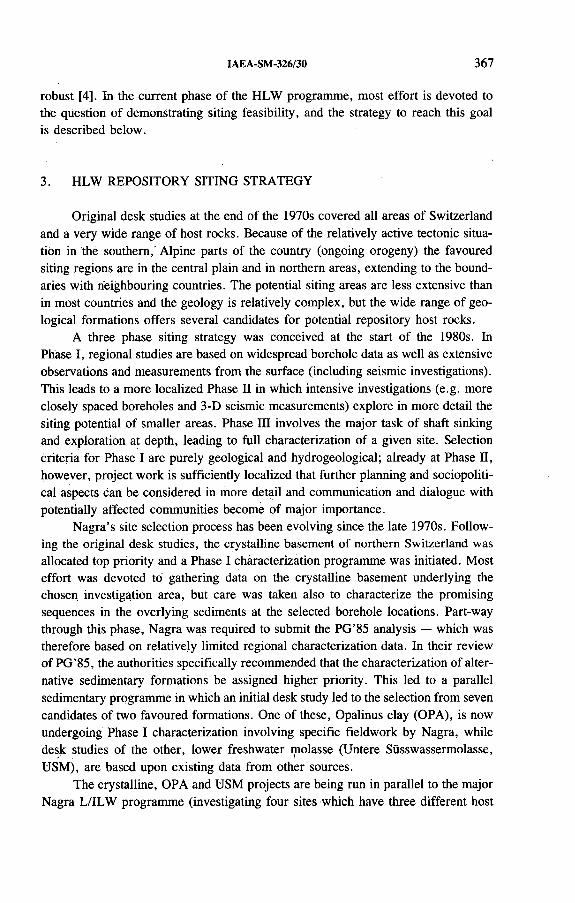
IAEA-SM-326/30 367
robust [4]. In the current phase of the HLW programme, most effort is devoted to the question of demonstrating siting feasibility, arid the strategy to reach this goal is described below.
3. HLW REPOSITORY SITING STRATEGY
Original desk studies at the end of the 1970s covered all areas of Switzerland and a very wide range of host rocks. Because of the relatively active tectonic situation in the southern, Alpine parts of the country (ongoing orogeny) the favoured siting regions are in the central plain and in northern areas, extending to the boundaries with neighbouring countries. The potential siting areas are less extensive than in most countries and the geology is relatively complex, but the wide range of geological formations offers several candidates for potential repository host rocks.
A three phase siting strategy was conceived at the start of the 1980s. In Phase I, regional studies are based on widespread borehole data as well as extensive observations and measurements from the surface (including seismic investigations). This leads to a more localized Phase II in which intensive investigations (e.g. more closely spaced boreholes and 3-D seismic measurements) explore in more detail the siting potential of smaller areas. Phase IQ involves the major task of shaft sinking and exploration at depth, leading to full characterization of a given site. Selection criteria for Phase I are purely geological and hydrogeological; already at Phase П, however, project work is sufficiently localized that further planning and sociopolitical aspects can be considered in more detail and communication and dialogue with potentially affected communities become of major importance.
Nagra’s site selection process has been evolving since the late 1970s. Following the original desk studies, the crystalline basement of northern Switzerland was allocated top priority and a Phase I characterization programme was initiated. Most effort was devoted to gathering data on the crystalline basement underlying the chosen investigation area, but care was taken also to characterize the promising sequences in the overlying sediments at the selected borehole locations. Part-way through this phase, Nagra was required to submit the PG’85 analysis — which was therefore based on relatively limited regional characterization data. In their review of PG’85, the authorities specifically recommended that the characterization of alternative sedimentary formations be assigned higher priority. This led to a parallel sedimentary programme in which an initial desk study led to the selection from seven candidates of two favoured formations. One of these, Opalinus clay (OPA), is now undergoing Phase I characterization involving specific fieldwork by Nagra, while desk studies of the other, lower freshwater molasse (Untere Süsswassermolasse, USM), are based upon existing data from other sources.
The crystalline, OPA and USM projects are being run in parallel to the major Nagra L/ILW programme (investigating four sites which have three different host
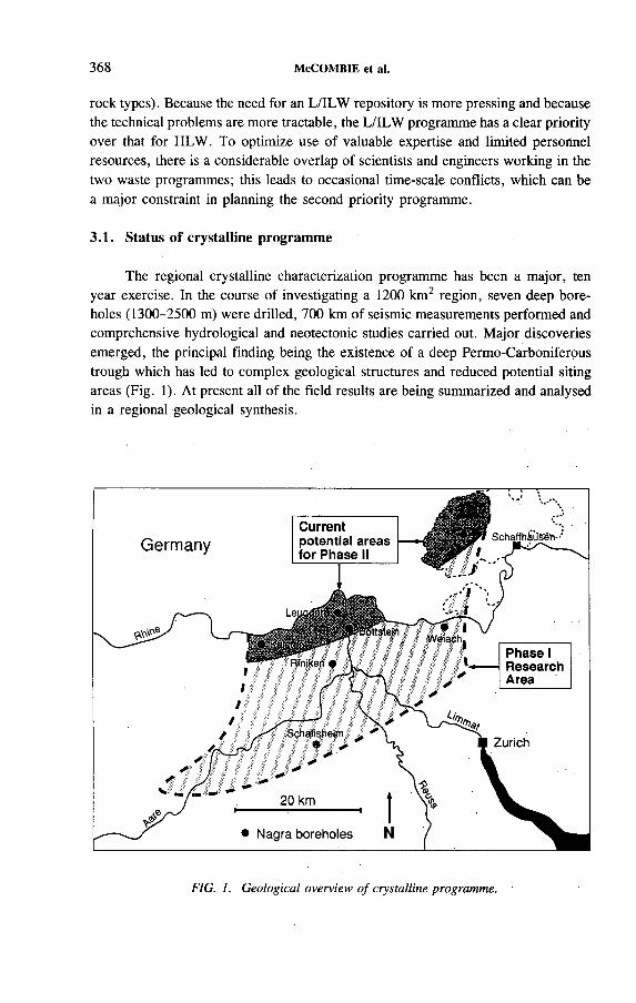
368 McCOMBIE et al.
rock types). Because the need for an L/ILW repository is more pressing and because the technical problems are more tractable, the L/ILW programme has a clear priority over that for HLW. To optimize use of valuable expertise and limited personnel resources, there is a considerable overlap of scientists and engineers working in the two waste programmes; this leads to occasional time-scale conflicts, which can be a major constraint in planning the second priority programme.
3.1. Status of crystalline programme
The regional crystalline characterization programme has been a major, ten year exercise. In the course of investigating a 1200 km2 region, seven deep boreholes (1300-2500 m) were drilled, 700 km of seismic measurements performed and comprehensive hydrological and neotectonic studies carried out. Major discoveries emerged, the principal finding being the existence of a deep Permo-Carboniferous trough which has led to complex geological structures and reduced potential siting areas (Fig. 1). At present all of the field results are being summarized and analysed in a regional geological synthesis.
FIG. 1. Geological overview o f crystalline programme.

IAEA-SM-326/30 369
The geological synthesis [5] has involved integration of information published in a series of technical summary reports (on isotope hydrology, hydrochemistry, tectonics, hydrodynamic modelling, etc.) which are, themselves, based on data from hundreds of technical reports produced during the regional characterization. Close collaboration of the earth scientists performing this synthesis with those responsible for assessing repository safety performance is intended to ensure that the key projectrelevant conclusions are clearly distilled from the background geological supporting information.
The geological synthesis is part of an overall review (Kristallin-I) which has the following main aims:
— Updating of the assessment of the crystalline repository concept presented inPG’85,
— Selection of the most promising crystalline area(s) for site specific studies anddevelopment of an appropriate exploration concept for Phases II and III.
Kristallin-I will not alone allow the siting feasibility for a HLW repository to be conclusively demonstrated, but will provide the basis for estimation of the costs of Phase П and Ш studies to be carried out at a specific site (or sites) and an evaluation of the probability that such work will confirm the acceptability of the site chosen. The further increase in.confidence that a suitable crystalline site is available,i.é. the required demonstration of siting feasibility, is judged to require further, more localized exploration work from the surface (Phase П).
Because of the manpower constraints mentioned above, the geological synthesis has taken longer than initially planned and the performance assessment has been explicitly limited to issues which have a direct impact on the question of siting feasibility (e.g. there has been no detailed consideration of HLW (or spent fuel), operational phase safety, or shaft and tunnel sealing). Thus, even after completion of the Kristallin-I study, continued work on the crystalline concept is required in order to provide further input for the choice between crystalline and sediment host rock options.
3.2. Status of sedimentary programmes
Already in early work around 1980, the favoured sedimentary formation was the OPA which lies under much of the northern part of Switzerland in a relatively homogeneous, low permeability layer of rather restricted thickness (80-120 m). As mentioned earlier, intensified sediment studies in 1986-1987 evaluated seven potential formations which were narrowed down to two candidates (Fig. 2) [6] — the original OPA and the USM. USM formations can be up to 4 km thick and, although heterogeneous, can contain areas with high clay content and low hydrological permeabilities.
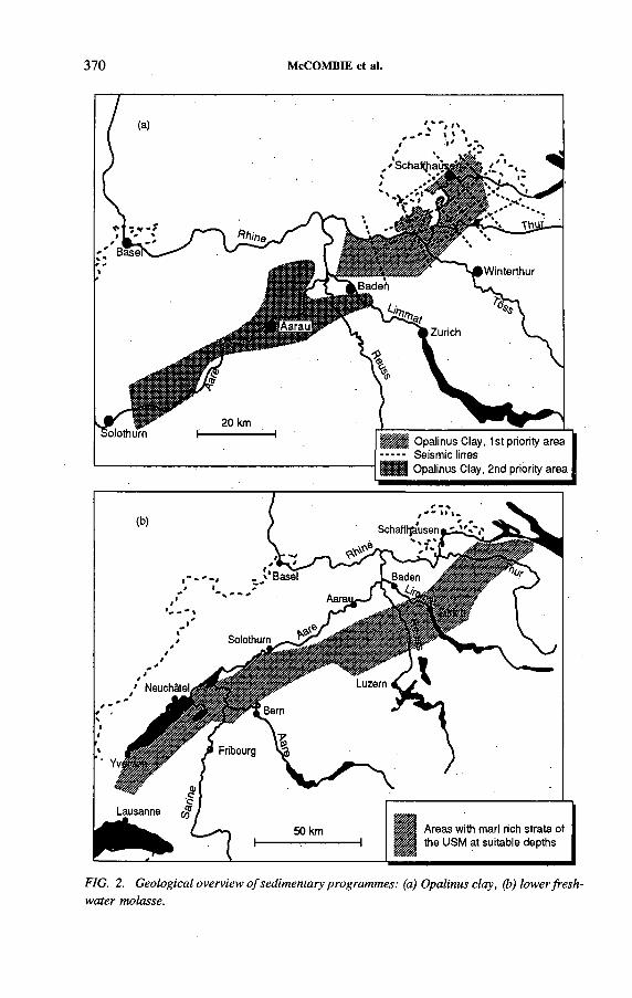
370 McCOMBIE et al.
- - - - - Seismic linesfffUff Opalinus Clay, 2nd priority area
FIG. 2. Geological overview o f sedimentary programmes: (a) Opalinus clay, (b) lower freshwater molasse.
IAEA-SM-326/30 371
In an intermediate step, Nagra assigned the OPA first priority for regional characterization based, predominantly, on the relative simplicity of the structure of this formation and proposed focusing in upon this one sedimentary option. In their review of this sediment assessment, however, the authorities considered that the potentially favourable characteristics of the USM (predominantly its greater thickness and lateral extent) justified continued studies of this option. Further desk studies are therefore being carried out at present for both formations [7], with particular emphasis on the ability to characterize the hydrology of USM formations from the surface (Phase I or П).
For the OPA option, a new field campaign involving some 250 km of seismic measurements complementing existing data was carried out by Nagra during the winter of 1991-1992. Currently, the results of these new seismic measurements are being analysed. For the USM, extensive seismic data were gathered during exploration for hydrocarbons. These data are currently being reinterpreted in order to reassess the resolution of modern seismic methods when investigating a heterogeneous rock such as molasse and to identify the most promising areas for field investigation should difficulties be encountered during the OPA programme.
3.3. Milestones for future work in the HLW programme
A schematic plan illustrating the development of the HLW programme up to the middle of the next century is presented in Fig. 3. In the near future, key milestones are the completion of the Kristallin-I analysis in 1993 and the first part of the OPA Phase I programme at about the same time. Further fieldwork, including deep drilling, will be carried out in the OPA if the current analyses are positive or in the USM if the OPA studies reveal serious difficulties. The long delays resulting from the complex procedures for permitting geological exploration work imply that it may not be possible to postpone further surface work in crystalline rock until completion of the OPA boreholes, assuming that the target of the year 2000 for a siting feasibility project remains valid. Accordingly, a part of the Phase II field programme in crystalline rock may be initiated earlier. This leads up to the choice in 1997 of a crystalline or sediment site for a full Phase II analysis, which should provide the basis for a demonstration of siting feasibility at the turn of the century. At this date, the current moratorium on new nuclear plants in Switzerland will expire. Any subsequent debate on the future of the nuclear option will certainly include discussion of the waste disposal issue; accordingly, it is important that specific progress be made here in order to improve the decision basis for future planning purposes.
Together with the development of plans for a specific Swiss HLW repository, Nagra will also consider potential international disposal options and a formal appraisal of possibilities will take place at the turn of the century. If such options are not practical for political or economic reasons, the intention would be to initiate,

372 McCOMBIE et al.
FIG. 3. Development o f HLW disposal strategy.

IAEA-SM-326/30 373
at an appropriate time, Phase III characterization of the favoured host rock with construction of an access shaft and an underground laboratory facility. An extensive period of subterranean characterization will lead to proposals for the detailed layout and operation plan and application for required licences to commence operation sometime after 2020. Assuming no changes in the Swiss nuclear power programme, the repository would have to operate until around 2070 — at which time decommissioning of all plants would be complete and all waste from their operation would have cooled sufficiently after reprocessing for disposal to be allowed. Optimization of disposal in an economic sense would lead to a delay in the start of operations and thus minimize the operational lifetime of the facility.
Naturally, long term plans are very open and extremely susceptible to technical and political developments. Because of the small waste volumes and the lack of time pressure, the HLW programme is deliberately designed to maximize flexibility to make certain that disposal occurs in a way which ensures safety yet minimizes financial costs/risks and constraints set on other parts of the Swiss nuclear fuel cycle.
REFERENCES
[1] NATIONALE GENOSSENSCHAFT FÜR DIE LAGERUNG RADIOAKTIVER ABFÄLLE, Project Gewähr 1985 — Nuclear Waste Management in Switzerland: Feasibility Studies and Safety Analyses, Project Gewähr Rep. NGB 85-09, Nagra, Baden, Switzerland (1985).
[2] HAUPTABTEILUNG FÜR DIE SICHERHEIT DER KERNANLAGEN, Gutachten zum Projekt Gewähr 1985 der Nationalen Genossenschaft für die Lagerung radioaktiver Abfälle (Nagra), HSK 23/28, Würenlingen, Switzerland (1986).
[3] McCOMBIE, C., McKINLEY, LG., ZUIDEMA, P., “ How much must the geological barrier contribute to safe HLW disposal?” , Proc. 1991 Int. High Level Waste Management Conf. Las Vegas, American Nuclear Soc., La Grange Park, IL (1991) 291-295.
[4] McCOMBIE, C., ZUIDEMA, P., McKINLEY, I.G., “ Sufficient validation: The value of robustness in performance assessment and system design” , GEOVAL 1990 (Proc. Symp. Stockholm, 1990), OECD/NEA, Paris (1991) 598-610.
[5] THURY, M., et al., Geologie und Hydrogeologie des Kristallins der Nordschweiz, Tech. Rep. NTB 93-01, Nagra, Baden, Switzerland (in preparation).
[6] NATIONALE GENOSSENSCHAFT FÜR DIE LAGERUNG RADIOAKTIVER ABFÄLLE, Sedimentstudie, Zwischenbericht 1988 — Möglichkeiten zur Endlagerung langlebiger radioaktiver Abfälle in den Sedimenten der Schweiz, Tech. Rep. NTB 88-25, Nagra, Baden, Switzerland (1988).
[7] NATIONALE GENOSSENSCHAFT FÜR DIE LAGERUNG RADIOAKTIVER ABFÄLLE, Sedimentstudie, Zwischenbericht 1990 — Zusammenfassende Übersicht der Arbeiten von 1988 bis 1990 und Konzept für das weitere Vorgehen, Tech. Rep. NTB 91-19, Nagra, Baden, Switzerland (1991).

IAEA-SM-326/48
OBJECTIVES OF THE DISPOSAL RELATED R&D PROGRAM M E OF THE GERMAN FEDERAL MINISTRY FOR RESEARCH AND TECHNOLOGY
H.G. RIOTTE, D. LUMMERZHEIM, S. MEURESCH Bundesministerium für Forschung und Technologie,Bonn
K.D. CLOSSKernforschungszentrum Karlsruhe GmbH,Karlsruhe
Germany
Abstract
OBJECTIVES OF THE DISPOSAL RELATED R&D PROGRAMME OF THE GERMAN FEDERAL MINISTRY FOR RESEARCH AND TECHNOLOGY.
In Germany, R&D for geological disposal'is shared by different governmental organizations, of which the Federal Ministry for Research and Technology (BMFT) is responsible for managing generic, i.e. site and facility independent, work. For this type of R&D in the last 25 years about 1100 million Deutschmarks have been spent, which has led to substantial progress on test disposal of LLW, development of disposal techniques for all kinds of radioactive wastes (borehole technique for HLW and ILW and direct disposal of spent fuel), develop^ ment of sealing devices and improvements in underground drilling techniques. In addition, extensive programmes on long term safety assessment have laid the basis for the safety analyses presented in the licensing process of the Konrad repository project for LLW and ILW. As the Gorleben repository, which is foreseen for disposal of HLW, proceeds towards more detailed planning some of the R&D work which is financed by the BMFT and is still necessary is extending beyond the objectives of generic research. In addition it is considered thát research for deep underground disposal of toxic non-radioactive wastes — for which also salt formations are envisaged in Germany — may gain from synergistic effects of a common programme. This is leading to a new concept in the BMFT research programme which will combine R&D för final disposal of radioactive and hazardous wastes, whereby the generic research issues are emphasized and less will be spent on technical developments and demonstration projects. With respect to the final disposal of radioactive waste, BMFT sponsored research will focus on specific problems of long term safety, assessment of uncertainties and reduction of conservative assumptions, performance assessment of geotechnical measures, and assessment of the safety margins of codes and methods used for evaluation of repositories in salt. It will include further work on methodologies for safety evaluation and scenarios, improved modelling of rock salt and thermomechanical repository performance under special conditions, more detailed analysis of physicochemical effects in the near field, and improvement of groundwater modelling and nuclide migration. As a general topic the programme will also address the problems of verification and validation of models and codes arid assessment and improvement of databases.
375

376 RIOTTE et al.
1. LEGAL BACKGROUND
In Germany, discussions about the back end of the fuel cycle began in the early 1960s in parallel with the development of nuclear energy use. In 1959 the Atomic Energy Act, by which the radioactive field is legally governed, was promulgated. By the Fourth Amendment in 1976 a legal framework was established for the back end of the fuel cycle and the disposal of radioactive wastes was fixed in its present form. This demands the orderly removal of wastes, giving the responsibility for construction and operation of disposal facilities to the federation.
In addition to this legal framework the Federal Government and the governments of the Länder agreed in 1979 on a uniform waste management concept, which proposes final disposal in deep geological formations and the use of salt formations for the disposal of HLW.
In contrast to the situation in many other countries, the responsibility for the realization of the back end of the fuel cycle in Germany is shared by Länder and federal authorities, governmental agencies and industry.
The Atomic Energy Act gives the responsibility for the provision of final repositories to the Federal Office of Radiation Protection (BfS). The BfS acts under the supervision of the Federal Ministry for Environment, Nature Conservation and Reactor Safety (BMU) and involves an industrial partner for planning and operation. Licensing will be performed by the government of the Land in which the repository is situated. At present the Morsleben facility (for non-alpha-bearing LLW and ILW) is in operation, the Konrad repository (LLW and ILW) is at the licensing stage and the underground investigation of the planned Gorleben repository (LLW, ILW and HLW) is still under way.
In so far as R&D for final disposal is closely linked to the repository projects and involves site and facility related aspects it is managed by the BfS and, according to the Atomic Energy Act, financed by the waste producers (utilities).
The utilities take part in the development of direct disposal facilities, i.e. they carry out R&D in the field of conditioning and cask development. They are not actively involved in the development of disposal techniques.
In this framework the Federal Ministry for Research and Technology (BMFT) manages and funds the generic reseärch for final disposal, i.e. R&D which is site independent and not explicitly linked to any repository project. The BMFT is responsible in this way for the development of new methods, devices, procedures and codes which are essential for the realization of disposal concepts. Partners in this task are the national research centres, governmental agencies and industry.
2. TOPICS OF PAST R&D
For about 25 years (the Asse mine was acquired in 1964 for use as an in situ laboratory) the BMFT has sponsored research by funding the budgets of national

IAEA-SM-326/48 377
research laboratories as well as individual research projects. Since the 1960s the BMFT has spent about 1100 million Deutschmarks for research on waste disposal, with 75 % being spent in the last decade. About 30% has been spent in the framework of regular budget funding of the national research laboratories (Forschungszentrum Jülich, Kernforschungszentrum Karlsruhe and GSF-Forschungszentrum für Umwelt und Gesundheit, Munich), another 40% for individually financed projects in industry and research laboratories and 30% for the operation of the Asse mine.
During the first large scale R&D project about 125 000 drums of LLW and alpha bearing waste were disposed of in the Asse mine and various disposal techniques were proved. This work was finished in 1978.
With regard to the different disposal techniques the BMFT concentrated its R&D efforts on the development of the borehole technique for HLW and ILW in canisters or drums and on the technique of direct disposal of spent fuel elements in heavily shielded casks in the drifts of a repository. The development of both techniques proceeded from the initial conceptual design to the design and construction of prototypes and will be concluded with the demonstration of the feasibility of the respective technique in full scale demonstration tests within the HAW, MAW and direct disposal projects. Most of the technical equipment is now ready and has undergone extensive test operation. The actual test disposals for HAW and MAW have still to be licensed before the hot demonstration can be started. The R&D programme for direct disposal is in its final stage; most of its major objectives have already been established.
Drilling techniques have been improved and adapted to the special needs of borehole disposal in salt.
Sealing techniques for geological repositories in salt were studied and evaluated during the flooding of a conventional mine. This test showed the necessity of new concepts for dams suitable to meet the high requirements of long term safety of nuclear repositories. As a consequence new materials and techniques for the construction of dams have been developed and are going to be demonstrated at full scale in the Asse mine.
In the area of safety evaluation the basis was laid by the BMFT’s Projekt Sicherheitsstudien Entsorgung (PSE, 1978-1984). In the PSE, basic tools and codes were developed which allow deterministic assessment of the impact of the repository on the biosphere. The methodologies were used by the BfS in the safety analysis for the Konrad repository and are the basis for further improvement and development of probabilistic assessments. ^
The state of the art in the field of safety analysis of an HLW repository in salt was reviewed in 1988 and — in co-operation with German R&D institutions — still existing R&D questions have been compiled and will subsequently be dealt with.
The R&D efforts of the BMFT in waste disposal have contributed to the expert knowledge which gave rise to the ‘collective opinion’ on long term safety presented by the Radioactive Waste Management Committee of the OECD Nuclear Energy
378 RIOTTE et al.
Agency, the International Radioactive Waste Management Advisory Committee of the International Atomic Energy Agency and experts from the Commission of the European Communities.
3. THE NEW R&D PROGRAMME OF THE BMFT
In accomplishing its R&D objectives, the BMFT has always been advised by the BfS to ensure that the results of experiments and the codes suited the needs of the repository projects. As the Gorleben repository project proceeds towards site investigation from underground and thus enters a new stage, some of the R&D work which is still necessary is extending beyond the objectives of generic, site independent research and requires closer co-ordination by the BfS. The Fourth Amendment to the Atomic Energy Act and a related ordinance regulate that this kind of R&D, which is tightly linked to the Gorleben project, can be funded by financial contributions paid in advance by the utilities for the Gorleben repository project. This is leading the BMFT to concentrate its R&D resources on more generic questions, leaving further development of technical aspects, where necessary, to the BfS as constructor/designer of the repositories.
To obtain a comprehensive approach to the remaining generic questions a revised R&D programme is currently in discussion. With regard to this programme, it is considered that research for deep underground disposal of toxic non-radioactive wastes — for which also salt formations are envisaged in Germany — may gain from synergistic effects of a common programme. This is leading to a new concept in the BMFT research programme for final disposal, which will cover both radioactive and hazardous wastes, whereby the generic research issues are emphasized and less will be spent on technical developments and demonstration projects.
The new BMFT programme covers R&D needed for
— Design and planning of a repository— Construction and operation— The decommissioning and post-operational phase
and defines projects which will be applicable to both radioactive and non-radioactive disposal.
With regard to the design and planning phase the programme concentrates on evaluation and comparison of specific disposal concepts and strategies as well as on the improvement of the scientific basis for safety requirements and on the design requirements for technical components. This involves special studies with respect to thermodynamic behaviour, hydrogeology, geochemistry and geotechnical analysisof sealing devices.
In the field of construction and operation the main efforts are being put into further development and improvement of techniques for disposal and backfilling. In
IAEA-SM-326/48 379
addition, technical improvements are needed for drilling and handling equipment and for backfilling methods, including tests of various materials and properties.
A better understanding of dispersion and propagation of gas and aerosols in the underground atmosphere can help in the assessment and reduction of hazards to personnel under normal and accident conditions.
The main topic of the new BMFT R&D programme will be the decommissioning and post-operational phase, i.e. long term safety and safety analysis. The main objective is to sustain a more detailed and realistic modelling of physicochemical phenomena, transport mechanisms and boundary conditions, thus reducing uncertainties and eliminating conservative assumptions due to the lack of detailed knowledge. R&D in this field is a key issue for raising confidence in the safe disposal of radioactive wastes.
Further improvement of long term safety assessment can, for example, be obtained by more realistic modelling of groundwater transportation of radionuclides in complex geological systems. This could be done by introducing 3-D modelling and variable density into the codes used.
In general, for R&D in long term safety assessment emphasis is laid on validation and quality assurance of codes as well as on assessment of uncertainties and safety margins. This includes development of validation strategies for all important phenomena which occur in safety analysis. Moreover, laboratory and field studies as well as information drawn from natural analogues will be tested for their applicability to the real physicochemical environment of the repository.
In order to contribute to the solution of these problems the BMFT programme will be open to the participation of all countries interested in this R&D, independent of their national disposal concept.

IAEA-SM-326/58
REGLE FONDAM ENTALE DE SURETE SUR LE STOCKAGE DEFINITIF DE DECHETS RADIOACTIFS EN FORM ATION GEOLOGIQUE PROFONDE
R.H. BOSSERMinistère de l ’industrie et du commerce extérieur,Direction de la sûreté des installations nucléaires,Fontenay-aux-Roses, France
Abstract-Résumé
BASIC SAFETY REGULATION FOR THE DISPOSAL OF RADIOACTIVE WASTE IN DEEP GEOLOGICAL FORMATIONS.
The purpose of the basic safety regulations issued to nuclear installation operators by the Directorate for Nuclear Installation Safety is to set out in detail the conditions which need to be met to conform with French regulatory practice. Their aim is to facilitate safety assessments and communication between those dealing with nuclear safety matters. The aim of the regulation set out in the paper is to specify the objectives regarding the disposal of radioactive waste in deep geological formations which need to be taken into account in the study and implementation phases to ensure safety beyond the operational period of the repository. After defining its scope — the waste involved (waste which cannot be disposed of on the surface), the biosphere, the containment system (three barrier system: package, engineered barriers, geological barrier) and the situations to be considered (design basis situation and hypothetical situations or scenarios) — the regulation deals with the following aspects. Firstly, the basic objective of the disposal facility is to ensure protection of people and the environment without the need for long term institutional monitoring. The ALARA principle and recommendations of the International Commission on Radiological Protection are applied to define the disposal concept. Safety assessments will include determination of individual exposures expressed as a dose equivalent on the assumption that the characteristics of the individual remain constant with time. For the design basis situation, the individual dose equivalents should not exceed 0.25 mSv/year. For hypothetical situations corresponding to stochastic events, individual exposures should be maintained at levels far enough below those capable of causing deterministic effects. Secondly, the regulation sets out the conceptual bases for the safety of facilities. The site and the engineered containment barriers should play a dual role: firstly, to protect the waste from the action of water and human interference; secondly, to limit and slow down, for,the period required for the radionuclides to decay sufficiently, the transfer to the biosphere of any radioactive material that might be released from the waste. The technical criteria of greatest importance in site selection concern the long term stability of the site and its hydrogeology (very low hydraulic gradient). The main.criteria are the mechanical and thermal properties, the geochemical properties, minimum depth and the absence of underground resources. Site investigations should be carried out according to strict protocols, adapted to the requirements of quantitative models and the site specifications. The disposal concept is described in broad terms for crystalline and sedimentary media. The third aspect
381

382. BOSSER
dealt with relates to the methodology for demonstrating safety. The events and processes which make up the situations used in the safety assessment should be modelled and characterized. In view of the importance of modelling, particular attention should be paid to validating models and data. The codes and the data management system developed will be subjected to quality assurance procedures. General guidelines for the site investigations to be carried out (on the surface and in underground laboratories) are set forth in Annex 1. The question of selecting the situations to be taken into account in safety assessments is dealt with in Annex 2.
REGLE FONDAMENTALE DE SURETE SUR LE STOCKAGE DEFINITIF DE DECHETS RADIOACTIFS EN FORMATION GEOLOGIQUE PROFONDE.
Les règles fondamentales de sûreté notifiées aux exploitants d ’installations nucléaires par la Direction de la sûreté des installations nucléaires sont destinées à expliciter les conditions dont le respect est jugé comme valant conformité avec la pratique réglementaire technique française. Elles ont pour but de faciliter les analyses de sûreté et la compréhension entre les personnes ayant à traiter les questions relatives à la sûreté nucleaire. L ’objet de la présente règle est de définir, pour le stockage définitif des déchets radioactifs en formation géologique profonde, les objectifs qui doivent être retenus dès les phases d’études et de travaux pour permettre d ’assurer la sûreté après la période d’exploitation du stockage. Après la définition de son cadre d ’exploitation: les déchets concernés (déchets non stockables en surface), la biosphère, le système de confinement (à trois barrières: colis, barrières ouvragées, barrière géologique), les situations prises en compte (situation de référence et situations hypothétiques ou scénarios), la règle traite des aspects décrits çi-après. En premier lieu, l ’objectif fondamental du centre de stockage est d ’assurer la protection des personnes et de l’environnement sans dépendre à long terme d’un contrôle institutionnel. Le principe ALARA et les recommandations de la Commission internationale de protection radiologique sont appliqués pour définir le concept du stockage. Les évaluations de sûreté comprendront la détermination des expositions individuelles exprimées en équivalent de dose en supposant la constance des caractéristiques de l’homme au cours du temps. En situation de référence, les équivalents de dose individuelle devront être limités à 0,25 mSv/an. En situation hypothétique correspondant à des. événements aléatoires, les expositions individuelles devront être maintenues suffisamment faibles par rapport aux niveaux susceptibles d’induire des effets déterministes. En second lieu, les bases de conception liées à la sûreté sont développées. Le site et les barrières artificielles de confinement devront jouer un double rôle: a) premièrement, protéger les déchets contres les actions de l’eau et les actions humaines intrusives, b) deuxièmement, limiter et retarder, pendant le délai nécessaire à une décroissance suffisante des radionucléides concernés, le transfert vers la biosphère des substances radioactives éventuellement relancées par les déchets. Les critères techniques essentiels de choix de site concernent la stabilité à long terme du site et son hydrogéologie (très faible perméabilité et faible gradient hydraulique). Les critères importants sont les propriétés mécaniques et thermiques, les propriétés géochimiques, une profondeur minimale, l’absence de ressources souterraines. Les investigations à mener sur les sites devront être guidées par des protocoles rigoureux ajustés aux exigences des modélisations quantitatives et des spécifications des sites. Le concept du stockage est précisé dans ses grandes lignes pour les milieux cristallins et sédimentaires. Le troisième aspect traite de la méthodologie de démonstration de la sûreté du stockage. Les événements et processus constitutifs des situations retenues dans le cadre de l’analyse de sûreté devront

IAEA-SM-326/58 383
être modélisés et caractérisés. Compte tenu de l’importance de la modélisation, un soin particulier devra être porté à la validation des modèles et des données. L ’élaboration des codes et la gestion des données feront l’objet de procédures d ’assurance de la qualité. Les orientations générales relatives aux investigations à mener sur les sites (en surface et en laboratoires souterrains) sont développées en annexe 1. La sélection des situations à prendre en compte dans le cadre de l ’analyse de sûreté fait l’objet de l’annexe 2.
1. OBJET DE LA REGLE
j L ’objet de la présente règle est de définir, pour le stockage définitif des déchets radioactifs en formation géologique profonde, les objectifs qui doivent être retenus dès les phases d’études et de travaux pour permettre d’assurer la sûreté après la période d’exploitation du stockage.
Elle traite des points suivants:
objectif fondamental de sûreté du stockage,— bases de conception du stockage liées à la sûreté,— méthodologie de démonstration de la sûreté du stockage.
Elle prend en compte les recommandations émises par les organisations internationales techniquement compétentes (Commission internationale de protection radiologique (CIPR), Agence internationale de l ’énergie atomique (AIEA), Agence de l’énergie nucléaire de l’Organisation de coopération et de développement économiques (OCDE)) et par le groupe de travail présidé par le Professeur Goguel à la demande des ministres chargés de l’industrie et de l’énergie. Elle reprend également les réflexions menées entre la Direction de la sûreté des installations nucléaires (DSIN), l’Institut de protection et de sûreté nucléaire (IPSN) et de l ’Agence nationale de gestion des déchets radioactifs (ANDRA), notamment dans le cadre du groupe de travâil sur le choix des situations à étudier pour la démonstration de sûreté.
L’opérateur chargé des études et de la réalisation du stockage devra rendre compte à la Direction de la sûreté des installations nucléaires, des conditions d’application de la règle.
2. DEFINITIONS
2.1. Déchets concernés
Le stockage de déchets radioactifs en formation géologique profonde est destiné à recevoir:
— les déchets B, qui sont des déchets de faible et moyenne activité massiquecontenant des quantités significatives de radionucléides de période longue ne

384 BOSSER
permettant pas leur stockage en centre de surface conformément à la Règle fondamentale de sûreté (RFS) 1.2.,
— les déchets C, qui sont des déchets de haute activité pouvant contenir également des quantités significatives de radionucléides à vie longue.
2.2. La biosphère
La biosphère est constituée de la partie de l’environnement facilement accessible aux activités de l ’homme et susceptible d’être une voie de transfert de laradioactivité entraînant une exposition interne (inhalation, ingestion) ou une exposition externe.
La biosphère peut comprendre:
a) la zone d’exhaure des eaux souterraines susceptibles d’avoir été affectées par le stockage,
b) le système d’écoulement superficiel de ces eaux,c) les sols susceptibles d’êtres irrigués ou inondés,d) la production végétale ou animale destinée à la consommation humaine,e) l’atmosphère.
2.3. Le système de confinement
Au sens le plus général, le système de confinement est constitué par unensemble de moyens ou de dispositifs interdisant ou limitant, à un niveau spécifié, tel qu’il sera précisé au chapitre 3, le transfert des matières radioactives vers la biosphère.
Dans le cas du stockage en formation géologique profonde, le système de confinement est constitué des trois barrières suivantes:
a) les colis de déchets: constitués en général d ’une matrice dans laquelle lesdéchets sont incorporés, l ’ensemble étant disposé dans un conteneur etéventuellement dans un surconteneur;
b) les barrières ouvragées: constituées des matériaux de rebouchage des cavités de stockage et des forages, de remblayage des galeries et de scellement des puits d’accès;
c) la barrière géologique: constituée par les formations géologiques du site.
Les barrières du système de confinement jouent des rôles complémentaires, la barrière géologique assurant un rôle essentiel en particulier à long terme.
IAEA-SM-326/58 385
2.4. Situations prises en compte
Dans le cadre de l’analyse de sûreté, on retient:
a) une situation de référence, correspondant à l’évolution prévisible du stockage au regard des événements certains ou très probables. Elle doit être caractérisée par une grande stabilité de la formation géologique et des écoulements d’eaux souterraines très faibles, voire une absence d’écoulement.
b) des situations hypothétiques correspondant à l ’occurrence d’événements aléatoires, d ’origine naturelle ou associées à des actions humaines, qui se superposent à la situation de référence et qui peuvent conduire à des transferts préférentiels de radionucléides entre le stockage et la biosphère.
Ces situations sont précisées dans le chapitre 5 et l’annexe 2.
3. OBJECTIF FONDAMENTAL
3.1. Objectif
La protection des personnes et de l’environnement à court et à long terme constitue l ’objectif fondamental assigné à un centre de stockage de déchets en formation géologique profonde.
. Elle doit être assurée envers les risques liés à la dissémination de substances radioactives dans toutes les situations prises en compte sans dépendre d’un contrôle institutionnel sur lequel on ne peut pas se reposer de façon certaine au-delà d’une période limitée (voir paragraphe 5.2 et annexe 2).
A cet égard, le concept retenu pour le centre de stockage devra permettre de «limiter l’impact radiologique à des niveaux aussi faibles qu’on puisse raisonnablement atteindre compte tenu des facteurs techniques, économiques et sociaux» (principe ALARA de la CIPR).
Les caractéristiques du site retenu, l ’implantation du stockage, la conception des barrières artificielles (colis, barrières ouvragées) et la qualité de leur réalisation constituent le fondement de la sûreté du stockage.
Au regard de la démonstration de la sûreté, il conviendra de s’assurer de leur adéquation à l ’objectif et au principe précités. A cette fin, des évaluations de l’impact radiologique seront effectuées pour vérifier que l ’objectif est bien atteint dans toutes les situations prises en compte.
3.2. Critères de radioprotection
Les évaluations de sûreté comprendront la détermination des expositions individuelles exprimées en équivalents de dose. On supposera la constance des
386 BOSSER
caractéristiques de l ’homme (sensibilité aux rayonnements, habitudes alimentaires, conditions de vie, connaissances générales sans prise en compte de progrès scientifique, notamment dans les domaines technique et médical).
Il faut distinguer les expositions pouvant résulter du stockage en conditions d ’évolution normale de référence et les expositions potentielles susceptibles de résulter d’événements aléatoires venant perturber l ’évolution du stockage.
3.2.1. Situation de référence
a) Les équivalents de dose individuels devront être limités à 0,25 mSv/an pour des expositions prolongées liées à des événements certains ou très probables. Cette valeur correspond à une fraction de la limite annuelle d’exposition du public en situation normale.
b) Les évaluations seront fondées sur une modélisation de l’évolution du stockage, en particulier des barrières, et sur une modélisation de la circulation des eaux souterraines et du transfert des radionucléides.
c) Pour une période qui doit être égale au moins à 10 000 ans, la stabilité (qui englobe une évolution limitée et prévisible) de la barrière géologique doit être démontrée. La valeur des résultats des prévisions pourra alors être attestée de façon objective, notamment sur la base d’études d’incertitudes explicites. La limite de 0,25 mSv/an sera retenue pour juger du caractère acceptable des conséquences radiologiques.
d) Au-delà de cette période de stabilité de la barrière géologique, les incertitudes sur l ’évolution du stockage augmentent progressivement avec le temps; l ’activité des déchets aura notablement décru. Des estimations quantifiées majorantes des équivalents de dose individuels devront alors être faites. Elles seront éventuellement complétées par des appréciations plus qualitatives des résultats de ces estimations, au regard des facteurs d’évolution de la barrière géologique, de façon à vérifier que le relâchement des radionucléides ne conduit pas à un équivalent de dose individuel inacceptable. Dans cette vérification, la limite de 0,25 mSv/an précédemment citée sera conservée comme référence.
3.2.2. Situations hypothétiques correspondant à des événements aléatoires
Certains événements aléatoires, d’origine naturelle ou associés à des actions humaines, peuvent perturber l ’évolution du stockage et éventuellement conduire à des expositions individuelles plus élevées que celles associées à l’évolution de référence du stockage.
Pour maintenir une cohérence entre la limitation des expositions dans la situation de référence et le traitement des expositions potentielles liées à des situations hypothétiques, il peut être envisagé d’utiliser la notion de risque (produit de
IAEA-SM-326/58 387
la probabilité d’occurrence de l ’événement pàr l’effet de l’exposition associée) pour tenir compte de la probabilité d’occurrence de chaque situation donnant lieu à une exposition.
Cependant, la définition d’un critère basé sur une limitation du risque individuel ne peut pas se faire sans précautions, dans la mesure où il impliquerait une équivalence discutable entre réduction de la probabilité et réduction des expositions. En outre, il faut s’attendre à des difficultés, voir des impossibilités, dans l ’estimation des probabilités des événements pouvant conduire à des expositions.
Dans ces conditions, le caractère acceptable des expositions individuelles associées à l’occurrence d’événements aléatoires sera apprécié en tenant compte du choix des caractéristiques des situations prises en considération, de la durée et de la nature des transferts de substances radioactives dans la biosphère, des caractéristiques des voies d’atteinte de l’homme et de l’importance des groupes exposés.
Par ailleurs, la possibilité d’interventions éventuelles en vue de limiter les conséquences, au cas où des situations du type considéré viendraient à se produire, ne doit évidemment pas être retenue pour la conception du stockage.
C’est pourquoi les expositions individuelles, exprimées en équivalents de dose, associées aux situations hypothétiques dont il apparaît qu’elles doivent être retenues pour la conception du stockage devront être maintenues suffisamment faibles par rapport aux niveaux susceptibles d ’induire des effets déterministes.
4. BASES DE CONCEPTION LIEES A LA SURETE
4.1. Remarques préliminaires
Le site et les barrières artificielles de confinement devront jouer un doublerôle:
a) protéger les déchets en s’opposant à la fois aux circulations de l ’eau au contact des déchets et aux actions humaines intrusives,
b) limiter et retarder, pendant le délai nécessaire à une décroissance radioactive suffisante des radionucléides concernés, le transfert vers la biosphère des substances radioactives éventuellement relâchées par les déchets.
Le concept multi-barrières a pour mérite de ne pas faire reposer la sûreté du stockage sur une barrière unique, dont la défaillance pourrait, à elle seule,' compromettre gravement les deux rôles assignés au stockage rappelés ci-dessus. Les barrières jouent, à cet égard, des rôles complémentaires. Néanmoins, à long terme et après décroissance d’une partie importante de la radioactivité contenue dans les déchets, la barrière géologique et les matériaux de scellement des puits devront pouvoir assurer à eux seul le confinement.

388 BOSSER
Toutefois, des objectifs quantitatifs pour les performances de confinement des différentes barrières ne pourront valablement être fixés qu’à l’issue d’un processus itératif, intégrant l ’expérience acquise au cours de l ’étude de la sûreté des stockages. C ’est pourquoi une approche prudente est retenue, consistant à choisir ou concevoir chacune des barrières aussi efficace que raisonnablement possible compte tenu, d ’une part de son rôle dans la sûreté globale du stockage, d’autre part de l’état des connaissances, des techniques disponibles et des facteurs économiques.
4.2. Le colis de déchets
La conception des colis de déchets doit permettre d’assurer, d ’une part la sûreté des phases préalables au stockage définitif (entreposage, manutention, transport), d’autre part une pérennité suffisante des caractéristiques du colis de déchets ou des matériaux dans lesquels il est placé (températures limites à ne pas dépasser, tenue à l ’irradiation,...).
La toxicité chimique éventuelle des déchets radioactifs devra être examinée. Les déchets devront être conditionnés sous forme non dispersable. Les colis
devront comporter le moins possible de volumes vides. Ils ne devront pas contenir de produits susceptibles d’accroître significativement la mobilité des radionucléides au travers des barrières de confinement, tels par exemple des produits organiques sous forme liquide.
4.2.1. Connaissance des caractéristiques et des propriétés des colis de déchets
La connaissance des caractéristiques des colis de déchets en cours de fabrication ou dont la fabrication est prévue est nécessaire pour que l’on puisse apprécier leur qualité, disposer de données pour la conception du stockage et la démonstration de sa sûreté, et adapter l’architecture du stockage et des barrières ouvragées aux caractéristiques des colis concernés.
Tout producteur de colis de déchets destinés à un stockage en formation géologique profonde devra réaliser, d’une part des essais de caractérisation, d’autre part des mesures ou des évaluations sur les colis produits et établir un dossier de spécifications par famille de colis. Les essais de caractérisation seront effectués, selon le cas, sur des colis, actifs ou inactifs, ou sur des échantillons représentatifs d’un processus industriel bien défini. Les essais, mesures et évaluations ont pour but:
a) , de déterminer les caractéristiques radioactives des colis de déchets, en particulier l ’inventaire de leur contenu radioactif; il est notamment important d’avoir une bonne évaluation de l’activité des radionucléides à période longue, ainsi que de celle des radionucléides volatils;
b) de connaître le contenu chimique des colis de déchets afin, notamment, de vérifier qu’ils ne contiennent pas de produits pouvant accroître la solubilité des
IAEA-SM-326/58 389
radionucléides ou pouvant en complexer une fraction notable, altérant ainsi la rétention des radionucléides par les barrières de confinement qu’ils traversent;
c) de connaître la nature et les quantités de gaz produits du fait de phénomènes de radiolyse, de corrosion, et d’altération du colis sous irradiation ou sous l’effet des micro-organismes;
d) d ’évaluer les caractéristiques physiques des colis de déchets: densité, homogénéité, taux de remplissage, pourcentage d’eau incorporée, conductibilité et capacité thermiques, températures caractéristiques, caractéristiques mécaniques...;
e) de connaître les propriétés des colis, notamment celles associées à leur capacité initiale de confinement de la radioactivité, et leur évolution:
— taux de lixiviation par les eaux souterraines,— taux de dégazage,— tenue mécanique dans des conditions de pression représentatives de stockages,— effets d’interactions chimiques (déchets/matrice, déchets ou matrice/matériaux
des barrières ouvragées...),— effets thermiques (températures maximales admissibles, gradients de tempé
rature maximaux admissibles),— effets de l ’irradiation alpha ou bêta-gamma,— effets des micro-organismes.
Des études de comportement à long terme des déchets en présence des différentes agressions susceptibles de les affecter (interactions notamment avec les matériaux des barrières ouvragées et avec la roche, effets de rayonnements ou des micro-organismes) devront être effectuées en vue de déterminer, en particulier, leur taux de dégradation en fonction du temps, la nature des produits de dégradation et les interactions entre ces produits de dégradation et les radionucléides à période longue contenus dans ces colis (colloïdes, complexes...).
Des études devront être menées pour déterminer les formes chimiques stables des radionucléides dans les conditions existant localement (pH, Eh, pC 02...), ainsi que les relations entre leur solubilité et les caractéristiques du milieu.
L’objectif de ces études est, d’une part de permettre l ’évaluation de la capacité de confinement du colis et de fournir les éléments nécessaires à la démonstration de sûreté, d’autre part d ’estimer l ’influence du colis sur la capacité de confinement des autres barrières.
4.2.2. Déchets C
Pour les déchets C, le colis devra, pendant la période où l ’activité des radionucléides à vie courte ou moyenne est dominante, viser à éviter la dissémination des radionucléides qu’il contient, notamment en cas d’occurrence d’un événement
390 BOSSER
aléatoire entraînant la création d ’un «court-circuit» de la barrière géologique et survenant pendant cette période.
Au-delà de cette période, les caractéristiques de confinement des colis telles qu’elles auront été caractérisées devront contribuer à la limitation de la dissémination des radionucléides.
Pour ce qui concerne les déchets vitrifiés, si les caractéristiques de la matrice placée dans son environnement de stockage étaient susceptibles d’être altérées de façon importoite pendant la phase d’activité thermique des déchets, il faudrait protéger cette matrice des effets de cette altération, le cas échéant par une barrière efficace résistant notamment à la corrosion et à la pression pendant cette durée.
4.2.3. Déchets B
Le colis de déchets B devra limiter la dissémination de substances radioactives qu’il contient en cas d’occürrence d’un événement aléatoire entraînant la création d ’un «court-circuit» de la barrière géologique et survenant pendant une période à définir, après la fermeture du stockage. Ainsi, l’évolution des caractéristiques de confinement devra être évaluée pour une durée suffisante au regard de la décroissance des produits de fission à vie courte ou moyenne.
4.3. Les barrières ouvragées
Après remplissage des ouvrages, les vides créés lors de la réalisation du stockage devront être comblés pour rétablir autant que possible l ’étanchéité du milieu et éviter que les ouvrages ne constituent des drains préférentiels pour les eaux souterraines et, le cas échéant, pour éviter des tassements préjudiciables aux couches géologiques surmontant la formation d’accueil. Les dispositions prévues à cet égard devront être précisées et justifiées. Par ailleurs, les forages de reconnaissance devront être efficacement scellés dès qu’ils ne seront plus utiles pour la connaissance ou la surveillance du site. Les puits d’accès devront faire l’objet d’un rebouchage assurant une étanchéité d’excellente qualité. Il importe que cette préoccupation soit intégrée dès leur conception.
Ces différents objectifs seront atteints grâce à la mise en place de barrières ouvragées.
On distingue deux types de barrières ouvragées:
a) les barrières dites «de voisinage» ont pour rôle d’assurer le comblement des vides entre les colis et la roche d’accueil. Les barrières ouvragées de voisinage sont constituées par le matériau de comblement des cavités de stockage (espace colis/paroi de cavité et espace entre colis) et les bouchons éventuels en tête de cavité. Ces barrières sont particulièrement nécessaires pour les roches dures,

IAEA-SM-326/58 391
la capacité de fluage des formations sédimentaires permettant d’atteindre naturellement cet objectif,
b) les barrières dites de «remplissage» ont pour rôle principal de rétablir au mieux l’isolement entre la zone de stockage et la surface; elles sont constituées du (ou des) matériau(x) de remblayage des forages, des galeries de desserte et des puits d’accès, des serrements éventuels en galeries, des serrements en puits d’accès.
Dans le choix des barrières ouvragées de voisinage, il faudra tenir compte des caractéristiques intervenant au regard des fonctions suivantes:
— évacuation de la chaleur dégagée par les déchets,— réduction de l’intensité de contraintes mécaniques engendrées,— comportement physico-chimique au regard de la corrosion des conteneurs' et
de la migration des radionucléides.
Il faudra veiller à ce qu’aucun matériau constitutif de ces barrières n’engendre, par sa présence, des effets négatifs importants sur les performances de confinement de la barrière géologique et des colis de déchets.
Les barrières ouvragées de remplissage, en particulier celles assurant le scellement des puits d ’accès, devront avoir une qualité et une longévité en rapport avec le rôle qui leur sera assigné vis-à-vis de la barrière qu’elles sont censées restaurer et compte tenu de la décroissance radioactive des déchets avec le temps.
En particulier, pour les roches sédimentaires, on pourrait compter sur une cicatrisation des vides de la barrière géologique et des barrières ouvragées par fluage de la roche; l’évolution de cette cicatrisation devra être évaluée.
Par ailleurs, il faudra tenir compte, dans les études de conception du stockage, du devenir et de l ’influence des volumes d’air ou de gaz enfermés dans les ouvrages, notamment l ’air contenu dans le matériau de remplissage ainsi que les gaz (hydrogène notamment) produits par radiolyse, corrosion et effets de microorganismes.
Compte tenu de ces considérations, les performances des barrières ouvragées devront être définies et justifiées.
4.4. La barrière géologique — critères techniques de choix du site
La barrière géologique doit assurer, à long terme, une capacité d’isolation suffisante des radionucléides. Ses caractéristiques dépendent du site du stockage.
Les investigations à mener sur les sites devront être guidées par des protocoles rigoureux ajustés aux exigences des modélisations quantitatives et des spécificités des sites, mettant en œuvre les méthodes et outils disponibles les mieux adaptés. A cet égard, l’annexe 1 présente des orientations générales relatives aux investigations à mener sur les sites, depuis la surface et en laboratoire souterrain.
392 BOSSER
4.4.1. Critères essentiels
Ces critères concernent, d’une part, la stabilité du site et, d’autre part, son hydrogéologie.
a) Stabilité
La stabilité du site devra être telle que les éventuelles modifications des conditions initiales dues aux phénomènes géologiques qui peuvent survenir (glaciation, sismicité, mouvements néotectoniques) restent acceptables au regard de la sûreté du stockage.
En particulier, pour une période qui doit être égale au moins à 10 000 ans, la stabilité (qui englobe une évolution limitée et prévisible) doit être démontrée.
Ces phénomènes devront être évalués, pour chaque site reconnu, de façon qualitative et quantitative en se reportant à la situation actuelle, au passé proche (historique) et surtout au passé plus ancien (Quaternaire et, éventuellement, fin du Tertiaire). Ceci permettra d’apprécier les valeurs des paramètres les caractérisant ainsi que leurs variations, et d’en examiner l ’influence. Pour cela, il sera en règle générale nécessaire de considérer l’environnement géologique régional de chaque site.
b) Hydrogéologie
L’hydrogéologie du site devra être caractérisée par une très faible perméabilité de la formation hôte et un faible gradient de charge hydraulique. Un faible gradient régional hydraulique sera par ailleurs recherché de préférence pour les formations environnantes de la formation hôte.
Des mesures hydrogéologiques devront être réalisées sur une zone beaucoup plus large que le site de stockage de façon à bâtir des modèles d’écoulement prenant en compte les flux depuis les zones d’alimentation jusqu’aux exutoires. Ces schémas régionaux devront permettre de simuler Г intensité et la direction des circulations souterraines.
Il faudra prendre en compte les discontinuités ou les hétérogénéités dont la nature et la géométrie pourraient tendre à amoindrir significativement l ’efficacité de la barrière géologique. Ces objets devront donc être repérés et caractérisés avec la plus grande attention, de façon, s’il y a lieu, à les éviter au niveau du site.
4.4.2. Critères importants
a) Propriétés mécaniques et thermiques
. Elles conditionnent la faisabilité du stockage, c ’est-à-dire la possibilité de concevoir un stockage n’altérant pas significativement la barrière géologique.

IAEA-SM-326/58 393
En outre, le milieu de stockage choisi doit permettre une conception des cavités de stockage ne nécessitant pas d’interventions pour reprise du gabarit pendant leur remplissage.
Des études, notamment à l ’aide d’une modélisation couplée des phénomènes thermiques et mécaniques, devront être effectuées pour étudier l ’influence du mode et des séquences de mise en place des déchets sur les effets mécaniques dans le stockage et, en particulier, du temps de refroidissement préalable et de la densité du stockage des déchets. Ces études spécifiques devront permettre de déterminer les paramètres physiques correspondants et de préciser l ’influence de ces phénomènes.
b) Propriétés géochimiques
Elles jouent un rôle important dans la sûreté à long terme d ’un stockage de déchets radioactifs parce qu’elles peuvent avoir un effet sur l’altération des barrières artificielles et qu’elles gouvernent les phénomènes de rétention des radionucléides éventuellement relâchés.
Une description quantitative des propriétés géochimiques du système devra être établie pour l’analyse des conditions de transfert des radionucléides.
Des analyses minéralogiques des matériaux de la formation hôte devront être effectuées et leur évolution géochimique modélisée en fonction de la température et de l ’irradiation. On étudiera particulièrement le rôle des minéraux argileux.
c) Respect d’une profondeur minimale
Le site devra être choisi de façon que la profondeur envisagée pour le stockage garantisse que les performances de confinement de la barrière géologique ne seront pas affectées de façon significative par les phénomènes d’érosion (notamment à la suite d ’une glaciation), par l ’effet d’un séisme, ou par les suites d ’une intrusion «banale».
On devra considérer que l’épaisseur de la zone superficielle pouvant être ainsi perturbée est de l’ordre de 150 à 200 mètres.
d) Absencé de stérilisation de ressources souterraines
Au plan de la gestion du sous-sol, le site devra être choisi de façon à éviter des zones dont l’intérêt connu ou soupçonné présente un caractère exceptionnel.
4.5. Le concept de stockage
L’implantation du stockage dans la formation géologique devra se situer:
a) dans les milieux cristallins, au sein d’un bloc-hôte exempt de grandes failles,celles-ci étant susceptibles de constituer des secteurs de circulation hydraulique
394 BOSSER
privilégiée. Les modules de stockage devront être réalisés à l’abri de la fracturation moyenne, celle-ci pouvant toutefois être traversée par les ouvrages d’accès.
b) dans les roches sédimentaires, au sein d’un milieu exempt de grandes hétérogénéités et à une distance suffisante des aquifères environnants.
La présence des déchets (charge thermique) et des matériaux rapportés et de remplissage ne doit pas affecter significativement les propriétés de confinement des barrières.
A cet égard, lors des travaux de caractérisation des différentes barrières, la détermination des valeurs limites admissibles des températures et des déformations devra faire l ’objet d’une attention particulière.
Les perturbations résultant du creusement des ouvrages devront être réduites autant que possible. La conception et l’implantation des puits d’accès devront, d ’une part permettre de limiter le risque de circulation des eaux, d’autre part prendre en compte l ’objectif d’un scellement efficace en fin d’exploitation.
5. DEMONSTRATION DE LA SURETE DU STOCKAGE
5.1. Remarques préliminaires
Afin de vérifier que les objectifs de conception du stockage sont atteints, l ’évaluation de la sûreté post-fermeture devra porter sur les trois aspects complémentaires suivants:
a) justification du caractère favorable des performances de chacune des barrières de confinement, et du concept de stockage vis-à-vis de la sûreté globale du stockage;
b) évaluation des perturbations apportées par la création du stockage et vérification que ces perturbations restent acceptables vis-à-vis du niveau de qualité choisi pour chacune des barrières, en particulier de la barrière géologique; on considérera notamment les perturbations liées au creusement du stockage, et aux effets thermiques, thermomécaniques et hydrogéologiques àssociés à la charge thermique des colis ainsi que les modifications éventuelles des écoulements et des caractéristiques chimiques de la formation géologique;
c) évaluation du comportement futur du stockage et vérification que les expositions individuelles sont acceptables. L’approche retenue consistera à étudier un nombre limité de situations représentatives des différentes familles d’événements et telles que les conséquences associées soient les plus élevées parmi celles des situations de la même famille. Les familles d ’événements ou de séquences d ’événements retenues sont celles considérées comme envisageables dans l ’ensemble de celles a priori possibles.

IAEA-SM-326/58 395
5.2. Considérations générales sur les évaluations des expositions individuelles
L’évaluation des expositions individuelles consiste à estimer le comportement futur prévisible du stockage à partir de l’état initial du site tel que défini à l’issue du programme de reconnaissance, et compte tenu de sa présence, les effets éventuellement induits sur l’homme, dans les différentes situations précisées en paragraphe 5.3 et en annexe 2.
Les évaluations des expositions individuelles à long terme nécessitent de disposer des éléments suivants:
a) ensemble des données décrivant le stockage: inventaire de l’activité stockée, caractéristiques des différentes barrières, architecture du stockage, biosphère, conditions aux limites. Ces données doivent être soit des données pessimistes, soit des données moyennes (ou probables) complétées par des fourchettes d’incertitudes et des estimations de la variation possible avec le temps;
b) données de base telles que celles nécessaires à l’identification des espèces relâchées (spéciation) et à l’évaluation de leurs effets radiologiques sur
■ l’homme;c) liste et caractéristiques des situations à prendre en compte, ou scénarios;d) modèles de calcul.
La présentation des résultats devra permettre d’apprécier:
a) les expositions individuelles associées au stockage pour les différentes situations étudiées,
b) les paramètres et phénomènes, importants,c) les performances des différentes barrières (notamment en matière de confi
nement de la radioactivité) vis-à-vis du rôle.qui leur est assigné.
5.3. Situations prises en compte
Les événements et processus constitutifs des situations retenues dans le cadre de Г analyse de sûreté devront être modélisés et caractérisés. Cette caractérisation sera largement itérative dans la mesure, en particulier, où la définition des situations considérées est susceptible d’être affinée en fonction de l’évolution des connaissances sur les barrières et leur comportement.
En ce qui concerne la localisation dans le temps de ces situations, on se référera aux périodes suivantes:
a) une période «initiale» de 500 ans, correspondant à la conservation de lamémoire du stockage, permettant de rendre extrêmement peu probable l’intrusion humaine dans la zone du stockage. Elle correspond par ailleurs à une décroissance importante de l’activité des radionucléides à vie courte ou moyenne;
396 BOSSER
b) une période intermédiaire de 50 000 ans, caractérisée par l’absence de glaciation majeure;
c) la période postérieure à 50 000 ans dans laquelle on prendra en compte notamment l’occurrence de glaciations majeures.
5 . 3 . 1 . S i t u a t i o n d e r é f é r e n c e
Les événements à considérer sont:
a) les événements liés à la présence du stockage: l’impact de ce dernier se traduira par la mise en jeu de processus associés à l’émission de chaleur, à des modifications mécaniques, physico-chimiques ou encore à la désaturation du milieu naturel autour du stockage. L’ensemble des processus de dégradation progressive des barrières artificielles (corrosion des conteneurs et des matrices de confinement, vieillissement des barrières ouvragées et des scellements,...) devra être considéré.
b) un ensemble d’événements naturels très probables (changements climatiques, subsidence et surrection). Les changements climatiques (géodynamique externe) s’accompagnent de processus tels que les cycles d’érosion/sédimentation, les modifications de l’hydrologie de surface et des circulations en profondeur.
5 . 3 . 2 . S i t u a t i o n s h y p o t h é t i q u e s c o r r e s p o n d a n t à d e s é v é n e m e n t s a l é a t o i r e s
Les événements aléatoires pris en compte dans ces situations seront, soit des événements de même nature que ceux retenus dans la situation de référence, mais d’ampleur exceptionnelle, soit des événements très incertains quant à leur date d’occurrence et leur déroulement. Ces événements seront répartis en deux catégories, ceux d’origine naturelle et ceux liés à l’activité humaine:
a) les événements d’origine naturelle à considérer seront au moins les suivants: changements climatiques majeurs, activité sismique, subsidence et surrection exceptionnelles, diapirisme, activité magmatique, chute de météorites. Certains de ces événements pourront, selon les sites, ne pas être retenus après analyse justificative.
Concernant l’activité sismique, il sera retenu un niveau d’activité sismique susceptible d’être rencontré au cours des diverses périodes étudiées. Des incertitudes existent sur les niveaux sismiques possibles sur des périodes sensiblement supérieures à la période historique. L’existence d’une borne physique des niveaux sismiques dans une région pourrait constituer une donnée limite à considérer, compte tenu du contexte sismo-tectonique.
b) les événements liés à l’activité humaine concernant les intrusions humaines directes ou indirectes (forages, mines, cavités, constructions de surface ou de

IAEA-SM-326/58 397
sub-surface), les défauts de colis (aléas sur les conditions de dégradation ou manque de respect de spécifications), les défauts de barrières ouvragées (défauts de scellement liés au manque de respect de spécifications de mise en place, de fabrication, défauts conceptuels), les changements climatiques liés à l’activité humaine (effet de serre), les défauts de la barrière géologique se traduisant par des anomalies de cette barrière (aléas sur la connaissance du site, intrusions anciennes,...).
Les situations à retenir pour chacun des types de site envisagés (granite, schiste, sel, argile) seront au moins celles qui figurent dans l’annexe 2 .
5.4. Modélisation
Le comportement du stockage est déterminé par le comportement des différents sous-systèmes qui le constituent et qui sont interdépendants. A cet égard, il est habituel de distinguer les différents sous-systèmes ou champs suivants:
a) le champ proche, qui comprend les colis, les matériaux de remplissage des cavités, des galeries et des puits (barrières ouvragées) et la partie de la barrière géologique directement affectée par le stockage de déchets,
b) le champ lointain, qui est la partie de la barrière géologique non directement affectée par la présence du stockage,
c) la biosphère.
Les modèles sont des représentations simplifiées des phénomènes réels: il devra être montré, d’une part que ces représentations ne laissent pas de côté des phénomènes importants, d’autre part que les simplifications des phénomènes ont un caractère suffisamment pessimiste. L’ensemble des simplifications effectuées devra être justifié.
Compte tenu de l’importance de la modélisation, un soin particulier devra être porté à la validité des modèles et des données. Pour cela, il sera en particulier nécessaire de participer à des intercomparaisons de modèles.
Dans le domaine de la biosphère, il n’apparaît pas possible de prévoir l’évolution locale de l’environnement sur de très longues périodes; par contre, les grands événements climatiques régionaux prévisibles pourront être pris en compte en faisant appel à la notion de biosphères-types, représentatives des différents états que pourrait prendre à plus grande échelle la biosphère, compte tenu de ces événements.
Par ailleurs, pour la modélisation de la biosphère, on retiendra des groupes critiques hypothétiques, représentatifs des individus susceptibles de recevoir les doses les plus élevées parmi lesquels des individus vivent au moins partiellement en autarcie.
398 BOSSER
5.5. Etudes de sensibilité des évaluations des expositions individuelles
L’évaluation des expositions individuelles devra être accompagnée de fourchettes d’incertitude ou de tout élément pertinent visant à démontrer son caractère pessimiste. Des études de sensibilité devront par ailleurs être effectuées afin de mettre en évidence les paramètres les plus importants et de justifier les hypothèses simplificatrices effectuées pour l’évaluation des conséquences radiologiques.
Les analyses de sensibilité permettent d’identifier les points sur lesquels devrait porter en priorité l’effort de définition (situations prises en compte), de compréhension et de hiérarchisation des processus mis en jeu (modèles) ou de caractérisation (paramètres) pour accroître la crédibilité des résultats des évaluations.
Elles contribuent à l’appréciation de l’incertitude sur les résultats des évaluations des expositions individuelles à partir des incertitudes sur l’ensemble des facteurs (scénarios, modèles, techniques numériques, valeurs des paramètres,...) entrant dans la démarche ayant conduit à ces résultats.
6 . ASSURANCE DE LA QUALITE
Les opérations relatives à la conception, à l’évaluation et à la réalisation des barrières de confinement feront l’objet de procédures d’assurance de la qualité. En particulier, il faudra veiller à:
a) se doter de moyens de contrôle adéquats concernant les colis de déchets,b) mener, suivant les règles de l’assurance de la qualité, les études de conception
des barrières ouvragées compte tenu du rôle qui leur sera assigné dans la sûreté,
c) mener les opérations de caractérisation de sites suivant des protocoles d’études, d’analyse et d’essais bien définis.
Dans le cadre de l’élaboration de la démonstration de sûreté et des évaluations des expositions individuelles, l’élaboration des codes et la gestion des données nécessaires aux évaluations feront l’objet de procédures d’assurance de la qualité.

IAEA-SM-326/58 399
Annexe 1
ORIENTATIONS GENERALES RELATIVES AUX INVESTIGATIONS A MENER SUR LES SITES
1. INVESTIGATIONS A MENER EN SURFACE
Les objectifs fondamentaux doivent être, pour chaque site:
a) de déterminer en premier lieu ses caractéristiques lithologiques, structurales, pétrographiques, hydrogéologiques, thermomécaniques, géochimiques et techniques afin, en particulier, de le situer par rapport aux critères de choix de site (paragraphe 4.4),
b) de rassembler les éléments contribuant à la modélisation du site en vue de l’évaluation de sa sûreté.
Ces objectifs pourront être atteints de façon complémentaire par des investigations de surface, des forages de reconnaissance, et par l’étude des matériaux extraits de ces forages (eau, gaz et roche).
Les investigations de surface devront notamment permettre:
— de confirmer la géométrie des formations géologiques du site et de son environnement,
— de reconnaître les grandes failles éventuelles du milieu,— d’affiner l’étude néotectonique locale,— de déterminer la nature, la position et les caractéristiques des exutoires
potentiels.
2. INVESTIGATIONS A MENER DANS LE LABORATOIRE SOUTERRAIN
Les objectifs du laboratoire souterrain devront notamment être:
a) d’effectuer des mesures sur les roches en place ou sur des fluides aussi peu perturbés que possible par les conditions de l’expérience,
b) de déterminer, par des expériences à caractère plus global, le comportement des différentes roches et des fluides, en prenant en compte les phénomènes naturels et les modifications provoquées par la réalisation du stockage,
c) de reconnaître le milieu, notamment sa variabilité dans l’espace, pour évaluer la capacité du site, puis l’emplacement possible des galeries et futurs ouvrages,
d) de déterminer les méthodes de creusement, de rebouchage et de scellement des cavités.

400 BÖSSER
Des mesures auront lieu en site et sur échantillons pour confirmer ou préciser les valeurs des paramètres.
Une instrumentation de mesure pour le suivi de l’évolution du site pendant l’exploitation du stockage sera mise en place dès que possible.
Des recommandations particulières sont faites pour les différents types de sites envisagés en France (granitique, schisteux, salifère, argileux).
Annexe 2
SELECTION DE SITUATIONS A PRENDRE EN COMPTE DANS LE CADRE DE L’ANALYSE DE SURETE
La méthode retenue pour apprécier la qualité des sites sur le plan de la sûreté est de type déterministe. Elle consiste à étudier un nombre limité de situations représentatives des différentes familles d’événements ou de séquences d’événements tel que les conséquences associées soient les plus élevées de celles des situations de là même famille. Cette approche repose sur une sélection d’événements considérés comme raisonnablement envisageables.
Elle comporte les étapes suivantes: identification des événements susceptibles d’intervenir, classement des événements en fonction de leur probabilité ou de leur origine (le dépôt, l’homme, les processus naturels), tri des événements selon des critères faisant intervenir leur probabilité, les effets induits par rapport à d’autres événements de probabilité comparable, ou de l’importance de l’impact radiologique, combinaison d’événements, pour former des scénarios, tri des scénarios.
Cette méthode a conduit à la première sélection de situations à prendre en compte qui est présentée ci-dessous:
1. SITUATION DE REFERENCE
Les événements à considérer seront:
a) les événements liés à la présence du stockage: l’impact de ce dernier se traduira par la mise enjeu de processus associés à l’émission de chaleur, à des modifications mécaniques, physico-chimiques ou encore à la désaturation du milieu naturel autour du stockage. L’ensemble des processus de dégradation progressive des barrières artificielles (corrosion des conteneurs et des matrices de confinement, vieillisement des barrières ouvragées et des scellements,...) devra être considéré;
IAEA-SM-326/58 401
b) un ensemble d’événements naturels très probables (changements climatiques, subsidence et surrection). Les changements climatiques (géodynamique externe) s’accompagnent de processus tels que les cycles érosion/sédimentation, les modifications de l’hydrologie de surface et des circulations en profondeur.
Dans un premier temps, une évaluation des expositions individuelles pourra être effectuée en supposant une absence d’évolution des caractéristiques des barrières de confinement et un régime permanent des écoulements.
L’étude de l’évolution du système due à la présence du stockage et aux événements naturels certains devra alors montrer que les conséquences de cette évolution sont suffisamment faibles pour que l’on puisse raisonnablement estimer que les résultats obtenus sans la prendre en compte sont pertinents pour juger du caractère acceptable des expositions individuelles.
Cette étude prendra en compte les événements et processus présentés ci-après.
1.1. Situation évolutive du système due à la présence du stockage
a) Effets des travaux de creusement des cavités de stockage sur les propriétés hydrauliques de la roche,
b) Influence des effets transitoires autour des ouvrages sur le comportement hydraulique,
c) Effets du dégagement thermique des déchets:— déformation et contraintes induites sur la formation hôte,— conséquences sur les écoulements et la migration des radionucléides,— thermoconvection éventuelle,— conséquences des effets thermiques sur les formations sus-jacentes pour les
sites argileux et salifères,— déshydratation des minéraux argileux,— gradients de température.
1.2. Situation évolutive du système due aux événements naturels
L’évolution prise en compte dans la situation de référence correspond à celle due aux événements naturels prévus sur une période de 1 0 0 0 0 0 ans, celle ultérieure étant considérée comme relevant des scénarios aléatoires d’origine naturelle.
a) Changements climatiques:
— glaciation du type Würm à 60 000 ans,— présence d’un pergélisol,— baisse du niveau des mers ( 1 0 0 m environ).
402 BOSSER
b) Mouvements verticaux:
— subsidence et surrection (évaluation de l’amplitude et des effets sur les écoulements souterrains).
2. SITUATIONS HYPOTHETIQUES CORRESPONDANT A L’OCCURRENCE D’EVENEMENTS ALEATOIRES D’ORIGINE NATURELLE
a) Changements climatiques majeurs:
— glaciation de type Riss ancien après 160 000 ans.
b) Mouvements verticaux exceptionnels:
— évalués à partir de données correspondant à des périodes d’activité paroxystique observées au cours du plioquaternaire.
c) Activité sismique:
— recherche des caractéristiques d’un séisme maximal physiquement possible sur la base du contexte tectonique des sites et évaluation des perturbations envisageables sur les système hydraulique.
3. SITUATIONS HYPOTHÉTIQUES CORRESPONDANT A L’OCCURRENCE D’EVENEMENTS ALEATOIRES DE CARACTERE CONVENTIONNEL
a) Intrusion humaine (au-delà de 500 ans après fermeture):Hypothèses: a) perte de la connaissance de l’existence du stockage, b) niveau
de technologie identique à celui d’aujourd’hui.
— Forage exploratoire traversant le stockage (avec extraction des carottes)— Exploitation d’une mine (site salifère uniquement)— Forage exploratoire abandonné et mal scellé traversant le stockage— Forage d’exploitation d’eau à usage alimentaire ou agricole dans un aquifère
profond— Géothermie et stockage de chaleur (non retenue car les sites retenus ne doivent
pas présenter d’intérêt particulier)— Pour un site salifère seulement:
• création d’une cavité par dissolution interceptant le stockage et utilisation du sel à des fins alimentaires.
• cavité lessivée ayant intercepté le stockage et abandonnée.
IAEA-SM-326/58 403
b) Défaut d’une barrière:
— Barrière géologique: zone de fracture importante dans les sites cristallins, lentilles de sable dans un site argileux, poches de saumure dans un site salifère.
— Barrière ouvragée: défaillance du scellement des puits d’accès et des galeries, subrosion au toit du sel
— Colis de déchets: défaut de conditionnement.
c) Changements climatiques liés à l’activité humaine: effet de serre avec remontée du niveau des eaux des mers (étudié dans le cadre des changements climatiques d’origine naturelle).

IAEA-SM-326/70
OVERVIEW OF RESEARCH RELATED TO DISPOSAL OF LONG LIVED RADIOACTIVE WASTE SUPPORTED BY THE CEC
K.H. SCHALLER, N. CADELLI, B. HADTINK Commission of the European Communities,Brussels
Abstract
O V E R V IE W O F R E S E A R C H R E L A T E D T O D IS P O S A L O F L O N G L I V E D R A D I O
A C T I V E W A S T E S U P P O R T E D B Y T H E C E C .
T h e s h a r e d c o s t r e s e a r c h p r o g r a m m e o n M a n a g e m e n t a n d S to r a g e o f R a d io a c t iv ë W a s te
o f th e C o m m is s io n o f th e E u r o p e a n C o m m u n i t ie s s u p p o r ts th e d e v e lo p m e n t o f a fu ll w a s te
m a n a g e m e n t s y s te m , w h ic h in c lu d e s th e w a s te p a c k a g e , s to ra g e f a c i l i ty , d is p o s a l f a c il i ty a n d
n e a r a n d f a r f ie ld s o f th e w a s te re p o s i to ry . A f te r a s h o r t d e s c r ip t io n o f th e c o n te n t o f th e
p r o g r a m m e , a s u m m a ry is g iv e n o f s y s te m s tu d ie s c o n c e rn in g th e a s s e s s m e n t o f im p lic a t io n s
o f d i r e c t d is p o s a l o f s p e n t fu e l a s c o m p a r e d w ith th o s e o f th e m a n a g e m e n t ro u te , w h ic h
in v o lv e s r e p ro c e s s in g o f th e s p e n t fu e l f o l lo w e d b y v i t r i f ic a t io n o f th e h ig h ly a c t iv e r e s id u e s .
T h e m a in b o d y o f th e o v e r v ie w is d e v o te d to r e s e a r c h in u n d e r g r o u n d p i lo t f a c i l i t ie s , a im e d
a t d e m o n s t r a t in g th e te c h n ic a l fe a s ib i l i ty o f d e e p g e o lo g ic a l d is p o s a l o f r a d io a c t iv e w a s te . T h e
C E C h a s b e e n c o n c e n tr a t in g o n s p e c if ic r e s e a r c h p r o je c ts w h ic h a r e o f in te r e s t n o t o n ly to
p a r t i c u la r n a t io n a l w a s te m a n a g e m e n t p r o g r a m m e s b u t a ls o to o th e r o rg a n iz a t io n s in th e E u r o
p e a n C o m m u n i ty . P i lo t d e m o n s t r a t io n te s t s w h ic h a r e b e in g p e r f o r m e d a t th e A s s e s a l t m in e
in G e rm a n y a n d a t th e u n d e r g r o u n d f a c il i ty in c la y a t M o l , B e lg iu m , a r e s u p p o r te d b y th e
C E C , w ith f in a n c ia l c o m m itm e n ts to th e c u r r e n t f iv e y e a r p r o g r a m m e h a v in g a l r e a d y r e a c h e d
2 0 m il l io n E C U . F in a l ly , a f t e r n o t in g th a t in th e f ie ld o f s a fe ty s tu d ie s to a s s e s s th e p e r f o r
m a n c e o f r e p o s i to r ie s in d e e p g e o lo g ic a l fo r m a t io n s lo n g te r m c o n s e q u e n c e s o f d is p o s a l o f
h ig h le v e l , m e d iu m le v e l a n d a lp h a w a s te s h a v e b e e n e v a lu a te d , th e o v e rv ie w m e n tio n s
o n g o in g a d d i t io n a l a c t iv i t ie s in th e s a fe ty a s s e s s m e n t f ie ld .
1. THE SHARED COST RESEARCH PROGRAMME ON RADIOACTIVE WASTE MANAGEMENT OF THE EUROPEAN COMMUNITY
Important research and development programmes on radioactive waste management and disposal have been carried out at the national and European Community levels for many years. The amount of knowledge accumulated is considerable and gives no ground for doubting that waste could be managed and disposed of safely on an industrial scale. Current programmes are therefore more and more of a resèarch, development and demonstration character and oriented towards the optimization of waste management and the validation of the deep underground disposal concept already under development.
405

406 SCHALLER et al.
A special emphasis is being given to the following topics:
— Minimization of the waste volumes to be disposed of, especially those containing long lived radionuclides (alpha waste);
— Reduction of releases of radioactivity into the environment to well below existing discharge limits;
— Development of deep underground repositories;— Safety of disposal.
At the EC level, research and development on long lived radioactive waste have been performed at the Joint Research Centres of the Commission of thé European Communities and through shared cost actions, whereby activities in laboratories of the Member States are supported financially within the EC programme. The fourth five year shared cost research programme (1990-1994) on Management and Storage of Radioactive Waste is currently running.. . Decision 89/644 of the Council of the European Communities [1] defines in an annex the technical content of the programme. In the preceding programme a large effort was made to study the long term behaviour of waste forms and the safety of disposal in various host rocks; outstanding results were achieved in the overall safety studies with a performance assessment of geological isolation systems.
Within the present programme, radioactive waste management is treated as a system, with the waste package, storage facility, disposal facility and near and far fields of the repository being its components. The priorities of the programme are:
— With regard to the waste:• the reduction of waste arisings and of waste releases into the environment.
— With regard to disposal:• the demonstration of the feasibility of deep geological disposal, through
activities in underground demonstration facilities;• the confirmation of safety, through the continuation of EC projects related
to the study of migration of radionuclides through the geosphere, to the development of engineered barriers and to safety studies.
— With regard to the whole system:• the continuing promotion of the CEC as a framework for exchange of infor
mation and opinion between the different researchers in the EC, permitting among other things the search for a European consensus on common approaches and the harmonization of practices if needed. Within the programme the CEC also promotes scientific and technological co-operation between Member States, which is a source of efficiency and economy.
In the context of geological disposal of long lived waste, two fields of research are .of particular interest: in situ experiments and investigations in underground pilot facilities, and the assessment of the safety of disposal.

IAEA-SM-326/70 407
The EC programme has devoted an important part of its funding to in situ investigations. Sites for these investigations included Mol and Terhagen in Belgium, Auriat and Fanay-Augères in France, Altnabreac and Troon in the United Kingdom, Asse and Konrad in Germany and several sites in Italy, in particular Pasquasia.
At present, two underground pilot facilities are operational in EC countries; these are located in the Asse salt mine and in the Boom clay beneath the nuclear research site at Mol. A description of CEC supported research in these facilities will be given below. More details may be found in Ref. [2].
2. SYSTEM STUDIES ON DISPOSAL ROUTES FOR SPENT FUEL
In a joint study a group of contractors has assessed, on the basis of cost and radiological impact, the implications of the two waste management options available for disposal of spent fuel: reprocessing (or delayed reprocessing) of spent fuel followed by disposal of the wastes produced (with required storage periods for heat generating waste); and direct disposal (including long term storage before disposal) of the spent fuel after conditioning. The main results have been reported elsewhere [3]; the complete reports are now available, covering:
— Scenarios for direct disposal of spent fuel, particularly in a salt dome repository [4];
— Reprocessing of spent fuel in accordance with actual industrial experience and disposal of wastes [5];
— The impact from long lived reprocessing wastes as well as from spent fuel after disposal [6 ].
An additional study has analysed management of waste linked to the mixed oxide fuel cycle [7].
In comparing the management routes, the joint study found a clear cost advantage for the direct disposal option. However, the costs of reprocessing, which is already done on a commercial basis, are better known than those of conditioning for final disposal, which is still at the experimental level. Additionally, reprocessing leads to recovery of uranium and plutonium, which may be reused. Concerning the radiological impact on the public in the very long term, a higher impact to the public has been calculated for spent fuel disposal. This difference is mainly linked to the release scenario for 99Tc, and a more detailed investigation would be useful.
3. RESEARCH IN UNDERGROUND PILOT FACILITIES
Building and operating an underground experimental facility is expensive, and it would therefore be a waste of money and manpower if, within the EC, numerous facilities were created in each of the potential host rock formations.

408 SCHALLER et al.
As mentioned above, two underground facilities are currently operational in EC countries. Within the R&D programme of the EC, co-operation has therefore been stimulated and the possibility offered to organizations from all Member States to participate in research projects or to perform, if acceptable to the host country, specific research activities in those facilities. The contribution of the CEC in its radioactive waste management programme, which has rather limited resources, has been directed at specific research projects which are also of interest to other organizations within the EC; consequently, co-financirig of drilling and excavation work and of purely site specific activities has been excluded.
The total EC contribution during the third programme (1985-1989) reached 21.5 million ECU for pilot demonstration tests at Asse and Mol, whereas in the current, fourth, programme a total of 20 million ECU has already been committed.
3.1. CEC supported research at the Asse salt mine
3 . 1 . 1 . H A W : T e s t d i s p o s a l o f h i g h l y r a d i o a c t i v e s o u r c e s
In order to demonstrate the feasibility of the concept for HLW disposal in boreholes drilled into salt formations, the complete technical system of an underground repository will be simulated. To satisfy the test objectives, thirty radioactive sources containing the radionuclides 137Cs and 90Sr in quantities sufficient to cover the energy ranges of heat generation and gamma radiation attributable to genuine HLW áre envisaged to be emplaced in six boreholes located in two test galleries at the 800 m level of the Asse salt mine.
For handling of the radioactive sources and their emplacement into the boreholes a system consisting of a transport cask, a transport vehicle, a disposal machine and a borehole slider has been developed and constructed. The scientific investigation programme is based on the estimation and observation of the thermal, radiation induced and mechanical interaction between the radioactive sources and the rock salt.
Thirty test sources, consisting of steel canisters containing 60 L blocks of borosilicate glass spiked with 137Cs and 90Sr, have been fabricated by Battelle Pacific Northwest Laboratories and are stored temporarily in the United States of America .awaiting shipment. Transport to Germany and the actual emplacement at Asse are subject to agreement by licensing authorities.
In the meantime, handling tests with dummy canisters are taking place. The emplacement procedure has been demonstrated and the transport and handling system has been approved by the mining authorities. Since 1988, two electrically heated boreholes have been operated as inactive reference experiments. These experiments áre aimed in particular at investigating the thcrmomechanical behaviour of rock salt and the experimental data will permit validation of the computer codes. The data
IAEA-SM-326/70 409
gained up to now in general are in the range of the predicted values; however, some particular differences require further investigation.
Furthermore, much emphasis is being put on accompanying laboratory experiments on the effects of radiation on salt. In an irradiation facility at the Centre d’études de Saclay in France, radiolysis effects on salt have been investigated, while at the Netherlands Energy . Research Foundation (ECN) in Petten radiation damage effects are being analysed on salt samples irradiated in a gamma radiation facility at the High Flux Reactor [8 ].
3 . 1 . 2 . M A W / R E V : R e t r i e v a b l e e m p l a c e m e n t e x p e r i m e n t w i t h i n t e r m e d i a t e l e v e l
r a d i o a c t i v e w a s t e a n d s p e n t f u e l o f t h e H T R
In order to demonstrate safe handling of intermediate level radioactive waste in (unlined) boreholes (1 m in diameter and 1 0 m deep) in a salt formation and safe operation of such boreholes, six 200 L drums with cemented cladding hulls, fuel hardware and dissolver sludge produced at the WAK pilot reprocessing plant at Karlsruhe, and four 200 L stainless steel canisters each containing 950 spherical spent fuel elements from the AVR high temperature reactor (HTR) will be emplaced for a maximum of five years. The temperatures will range up to 70°C and dose rates from 1 to 100 Gy/h, thus representing real conditions for this type of waste. Two of the boreholes were put into operation in 1989 for an accompanying geotechnical measurement programme.
All the components and devices needed for the transport, handling, emplacement arid retrieval of the waste packages have been manufactured and tested. Nevertheless, complete implementation of the emplacement test is still lacking owing to licensing problems.
3 . 1 . 3 . A H E : A c t i v e h a n d l i n g e x p e r i m e n t w i t h n e u t r o n s o u r c e s
Dose rates at the surface of a shielded storage and disposal container, such as the POLLUX container developed for direct disposal of spent fuel, correspond to the sum of exposures due to gamma and neutron radiation. Storage in a surface facility over some decades considerably decreases the gamma dose rates, whilst the neutron radiation remains almost at the same level. Monte Carlo calculations indicate that, as a consequence of neutron backscattering at the drift walls, dose rates near the surface of waste packages are much higher in a repository than in a surface storage facility. The aim of the AHE experiment is to check and validate the calculations.
A shielded container is to be loaded with a 252Cf source to simulate the neutron spectra of spent LWR fuel and of HLW; the shielding will be comparable to the POLLUX container shielding. The main, activities are:
— Measurement of neutron dose rates in air and after emplacement in the saltformation,
410 SCHALLER et al.
— Studies of the effects of irregularities in the container shielding,— Comparison and validation of calculations,— Determination of relevant data in order to achieve minimization of occupa
tional exposure.
The calculations are being carried out by the Deutsche Gesellschaft zum Bau und Betrieb von Endlagern für Abfallstoffe mbH (DBE) in Germany and by the Commissariat à l’énergie atomique (CEA) and the Agence nationale pour la gestion des déchets radioactifs (ANDRA) in France. The test demonstration is scheduled to take place in 1993.
3 . 1 . 4 . D A M / L T S : I n s i t u i n v e s t i g a t i o n o f a l o n g t e r m s e a l i n a d a m c o n s t r u c t i o n
In a repository for radioactive waste, access galleries and drifts have to be closed and sealed after emplacement of the waste. The German project Dam Construction in Salt Formations provides for the construction and testing of a full scale dam suitable for a repository. The EC supported research is limited to a subproject, the development of the long term seal (LTS). The seal will be made up of salt bricks joined by a special mortar and will be pressurized up to 6 MPa, and the developing permeability for gas and brine will be measured.
The salt bricks have been characterized at laboratories in France and Germany . In situ tests will be performed first at reduced scale in boreholes of 1 m diameter and 2-3 m length, followed by full scale tests at the 945 m level of the Asse salt mine. A similar test, using only brine, will be performed in the Amélie potash mine in France. The two phase flow will be modelled by the Universidad Politécnica de Cataluña in Barcelona.
3.2. CEC supported research at the HADES facility, Mol
3 . 2 . 1 . P R A C L A Y : P r e l i m i n a r y d e m o n s t r a t i o n t e s t f o r c l a y d i s p o s a l o f h i g h l y
r a d i o a c t i v e w a s t e
The PRACLAY demonstration test for disposal of HLW canisters in horizontal tunnels features a full scale simulation of emplacement of vitrified HLW as planned in the Belgian programme. The HLW will be simulated by electrical heaters (thus there will be no radiation). A feasibility study has been performed on the excavation arid lining techniques for the new test gallery and the connecting chamber to the present gallery. The concept of using ‘mini-tunnels’, obtained by driving metal tubes, appeared not to be very feasible. An alternative would be to use a tunnelling machine for the excavation of a 2 0 0 m long, 2 m diameter gallery and have a lining consisting of concrete segments. The heaters would be emplaced in a metallic shroud with a diameter of about 0.5 m in the centre of the gallery. Moreover, a review study

IAEA-SM-326/70 411
has been made on suitable instrumentation (heaters, pressure measuring devices, etc.). Owing to delays, the original scheduled date for switching on the heaters at the beginning of 1995 is in doubt [9]
3 . 2 . 2 . C E R B E R U S : C o n t r o l E x p e r i m e n t w i t h R a d i a t i o n o f t h e B e l g i a n R e p o s i t o r y
f o r U n d e r g r o u n d S t o r a g e
The CERBERUS test monitors the in situ response of the clay mass to controlled exposure to heat and radiation. After drilling and a waiting time for attenuation of the excavation effects, a combined source of heat (electrical resistance heating) and radiation (397 TBq 60Co source) was installed, which represents a container of vitrified HLW after a cooling period of 50 years. Measurements are being made of the near field cover temperature, porewater pressure, Eh/pH and dose rates. This test, which was fully operational at the end of 1989, also allows the behaviour of the backfill material, waste matrix, overpack and canister material to be monitored.
The data are being used for the validation of the computer codes TEMPPRES and DOSEGEO. The test is scheduled to last five years [10].
3 . 2 . 3 . C A C T U S : C h a r a c t e r i z a t i o n o f C l a y u n d e r T h e r m a l L o a d i n g f o r
U n d e r g r o u n d S t o r a g e
The CACTUS project aims at the investigation of the thermohydromechanical behaviour of Boom clay by simulating vertical borehole emplacement. Two tests in two boreholes with different near field configurations are running.
The electrical heaters in CACTUS-1 were switched on in September 1990 and after'an interruption between November 1990 and March 1991, due to failure, were switched off in January 1992. The surface temperature of the heaters (1200 W capacity) attained a maximum of about 125°C. The second, cooling, phase is under observation. The installation of the CACTUS-2 experimental cell was achieved in December 1991 and the heaters were switched on in mid-February 1992. The effects are being compared with those observed with CACTUS-1 [11].
3 . 2 . 4 . B A C C H U S : B a c k f i l l e x p e r i m e n t
The aim of the BACCHUS project is the optimization and demonstration of emplacement procedures for backfill materials with a view to their fabrication on an industrial scale and their in situ application.
In a first phase the BACCHUS I probe, used in a backfill experiment performed in a previous programme which failed because of an unexplained heating interruption, will be recovered. In a second phase a new experiment will be performed using precompacted Boom clay pellets as backfill material [12].
412 SCHALLER et al.
3 . 2 . 5 . P H E B U S : P h e n o m e n o l o g y o f H y d r o l o g i c a l E x c h a n g e s B e t w e e n
U n d e r g r o u n d A t m o s p h e r e a n d S t o r a g e H o s t R o c k
The PHEBUS project concerns the study of the hydrological behaviour of a clay formation around ventilated excavations.
A first test will be carried out on a laboratory mock-up using recompacted saturated clay from Mol. A circular opening will be created under stress to simulate the gallery. Air circulation with constant relative humidity will be forced into this opening and the water extracted from the clay will be evaluated. The second phase of the project, an in situ test, will be carried out in the underground facility at Mol in an opening previously used for corrosion experiments.
3 . 2 . 6 . A R C H 1 M E D E - A R G I L E
The ARCHIMEDE-ARGILE project has been designed in order, firstly, to develop methodologies for rock and water sampling in deep clay formations and, secondly, to generate data that will help improve the understanding of water chemistry in argillaceous environments. The project consists of field sampling and measurements in the Mol underground facility, laboratory investigations and analyses, and modelling. The topics investigated include the geochemical characteristics and properties of the solid phases and of the fluids in the clay formation and microbiological characterization of the system [13].
4. SAFETY PERFORMANCE OF REPOSITORIES FOR DEEP DISPOSAL
As far as studies related to safety are concerned, two projects, PAGIS and P АСОМ A, were undertaken in order to assess the performance of repositories in deep geological formations where HLW and MLW, respectively, would be stored. The results have shown that there will be no radioactive release to the biosphere for many thousands of years and, thereafter, in all the cases examined the peak dose rates to the members of the most exposed groups would remain some orders of magnitude below the natural exposures. The exposure, if any, would occur in the very far future, with the exception of that due to a very small number of radionuclides (such as 129I and 99Tc) which could reach the accessible environment in the medium term ( 2 0 0 0 0 to 1 0 0 0 0 0 years), though with even lower dose rates than those due to the actinides.
A complementary study has been launched,. essentially covering the safety evaluation of spent fuel disposal in a deep repository in clay. The major activity is now devoted, however, to a systematic sensitivity analysis of the possible health effects with respect to the various parameters, models and phenomena used in safety evaluation [13].
IAEA-SM-326/70 413
In parallel to these evaluations, the main features of disposal sites which are essential for the long term safety of deep geological disposal have been examined.
REFERENCES
[1 ] C o u n c i l D e c is io n 8 9 /6 6 4 o f 15 D e c e m b e r 1 9 8 9 a d o p tin g a s h a r e d - c o s t R & D
P r o g r a m m e in th e F ie ld o f M a n a g e m e n t a n d S to r a g e o f R a d io a c t iv e W a s te , E C O ff .
J . N o . L 3 5 9 /2 8 (1 9 8 9 ) .
[2 ] H A U T I N K , B . ( E d .) , P i lo t T e s ts o n R a d io a c t iv e W a s te D is p o s a l in U n d e r g r o u n d F a c i l
i t ie s ( P r o c . W o r k s h o p , B ra u n s c h w e ig , 1 9 9 1 ) , E U R 1 3 9 8 5 , C E C , L u x e m b o u r g (1 9 9 2 ) .
[3 ] S C H A L L E R , K .H . , e t a l . , “ A s s e s s m e n t o f ra d io a c t iv e w a s te m a n a g e m e n t s c e n a r io s
f o r l ig h t - w a te r r e a c t o r s p e n t f u e l” , R a d io a c t iv e W a s te M a n a g e m e n t a n d D is p o s a l
( P r o c . C o n f . L u x e m b o u r g , 1 9 9 0 ) ( C E C I L L E , R . , E d . ) , E U R 1 3 3 8 9 , E l s e v ie r , A m s te r
d a m (1 9 9 1 ) 5 3 .
[4 ] A S H T O N , P . , M E H L I N G , O . , M O H N , R . , W I N G E N D E R , H . J . , A n a ly s is o f
S c e n a r io s f o r th e D i r e c t D is p o s a l o f S p e n t N u c le a r F u e l — D is p o s a l C o n d it io n s a s
E x p e c te d in G e r m a n y , E U R 1 2 9 5 3 , C E C , L u x e m b o u r g (1 9 9 0 ) .
[5 ] M A L H E R B E , J . , M a n a g e m e n t o f R a d io a c t iv e W a s te f r o m R e p r o c e s s in g in c lu d in g D is
p o s a l A s p e c ts , E U R 1 3 1 1 6 , C E C , L u x e m b o u r g (1 9 9 1 ) .
[6] M O B B S , S .F . , H A R V E Y , M .P . , M A R T I N , J . S . , M A Y A L L , A . , J O N E S , M .E . ,
C o m p a r is o n o f th e W a s te M a n a g e m e n t A s p e c ts o f S p e n t F u e l D is p o s a l a n d R e p r o c e s s
in g : P o s t -D is p o s a l R a d io lo g ic a l Im p a c t , E U R 1 3 5 6 1 , C E C , L u x e m b o u r g (1 9 9 1 ) .
[7] M A L H E R B E , J . , e t a l . , C h a r a c te r i s t ic s a n d M a n a g e m e n t o f W a s te P r o d u c e d b y th e
M O X F u e l C y c le in L ig h t - W a te r R e a c to r s , E U R 1 3 0 8 2 , C E C , L u x e m b o u r g (1 9 9 0 ) .
[8] G A R C IA C E L M A , A . , D E L A S C U E V A S , C . , T E I X I D O R , P . , M I R A L L E S , L . ,
D O N K E R , H . , I A E A - S M - 3 2 6 /1 8 , th e s e P r o c e e d in g s .
[9] VAN MIEGROET, J., IAEA-SM-326/64, ibid.[1 0 ] B O N N E , A . , C O L L A R D , G . , I A E A - S M - 3 2 6 /3 8 , ib id .
[1 1 ] R A Y N A L , M . , N E E R D A E L , B . , IA E A - S M - 3 2 6 /5 9 P , ib id .
[1 2 ] M E R C E R O N , T . , e t a l . , I A E A - S M - 3 2 6 /6 0 , ib id .
[1 3 ] R A IM B A U L T , P . , e t a l . , I A E A - S M - 3 2 6 /5 7 , ib id .


POSTER PRESENTATIONS


POSTER PRESENTATIONS
GAMMA RAY GENERATOR FOR GEOPHYSICAL RESEARCH
A.A. MOZELEV ‘RADIKAL’ Small Scale Research
and Production Company,Moscow, Russian Federation
IAEA-SM-326/3P
A vast number of up to date instruments for geophysical analysis based on fluorescence energy dispersive spectrometry use radioisotopic sources (145Sm, 24IAm, 109Cd, etc.). Nowadays, the environmental safety requirement for geophysical devices with radioisotope sources is stimulating investigations of other kinds of sources. In this connection, non-radioactive sources of gamma radiation represent an attractive alternative. A principal advantage of this kind of source in gamma logging applications is the possibility of remote handling without the risk of radioactive contamination of the environment in the case of an accident.
Preliminary computation and mathematical simulation have revealed that the gamma ray generator has advantages over the traditional radioisotopic sources in respect of technical characteristics. The remote control of physical parameters (intensity, energy of gamma quanta, etc.) would allow the gamma ray generator to be used in different areas of science and technology.
In the course of investigations a working model of such a generator was created. Research with this model has shown the expediency of investigations made using the generator and confirmed theoretical computations regarding its operation.
As a result of the research the following parameter values were determined for the generator:
— Dimensions:Diameter: 90 or 70 mm Length: 300 mm Weight: 4 or 2 kg
— Temperature: < 120°С— Precision of measured parameters: ±10% at speed of 500 m/h— Electron source specifications:
Kinetic energy: 1 MeV or 500 keV Electron beam current density: 0.1-10 A/cm2
Pulse duration: 0.1-10 p s
Beam diameter: 0.1-20 cm Pulse frequency: 0.5-50 Hz.
417

418 POSTER PRESENTATIONS
When coupled with a high speed detector, the gamma ray generator can be used in geophysical investigations, the study of defects in borehole casing columns, rock density measurements, etc.
The data acquisition and process control system is PC based. There are data acquisition and control cards housed within the PC, with leads extending to remote sensors. The icon based programming environment provides great flexibility in acquiring data, logging the data to disk and producing graphics.
IA E A -S M -3 2 6 /5 P
SELECTED THEORETICAL CALCULATIONS FOR SAFETY ASSESSMENT OF SPENT FUEL AND RADIOACTIVE WASTE DISPOSAL
M. HRONNuclear Research Institute,Rez, Czechoslovakia
One of the first problems encountered when preparing for an evaluation of the basic safety properties of any kind of spent fuel storage method, including geological disposal, is that of sufficient subcriticality of the corresponding fuel assembly system. The specific aspects of the fuel assembly design being used in the PWRs of the WWER type which are being operated or prepared for operation in Czechoslovakia have to be taken into account. In this connection, the experience obtained during the process of performing complex (neutronic) calculations of the spent fuel systems has been collected and analysed.
Another very important contribution to the investigation of geological disposal of spent fuel and radioactive waste is a post-closure probabilistic risk assessment of a proposed site. Owing to the long half-lives of many important nuclides present in both spent fuel and radioactive waste it is necessary to model the corresponding disposal systems over periods of up to 106 years and sometimes more. It is obvious that not only technological but also environmental systems are not static over this time-scale.
In considering such a long period, a series of substantial changes in the rate and nature of processes and in the systems upon which those processes operate have to be taken into account in order to assess the safety of proposed sites. To provide detailed information which would be useful for further site safety analysis, suitable calculational codes are being used which model the long term evolution of the environment. The convenience of such computer codes for the specific conditions of

POSTER PRESENTATIONS 419
several proposed sites being investigated in Czechoslovakia has been proven and some of them are being used within the framework of the standard procedure of safety assessment of proposed sites for radioactive waste disposal in Czechoslovakia.
IA E A -S M -3 2 6 /7 P
STUDY ON MIGRATION PROPERTIES OF U, ^Sr AND 137Cs ON ZEOLITES
Guoqing XU, Jifang GU,Zhichao DU, Xuanlin FANBeijing Research Institute of Uranium Geology,Beijing, China
Research on inorganic sorbents as backfill materials is of importance in the geological disposal of radioactive wastes. Bentonite has been considered as a good backfill material. Zeolites are usually associated with bentonite. Therefore, mor- denite and clinoptilolite taken from the Jingyun deposit in Zhejiang province, China, were chosen for study. This research work was part of a research programme sponsored by the International Atomic Energy Agency from 1986 to 1991.
The study was performed using batch and column tests, the results of which are summarized below.
Batch tests
D e t e r m i n a t i o n s o f K d and Rj
The results of the determinations of distribution coefficient K d and retardation factor R f are presented in Table I.
I n f l u e n c i n g f a c t o r s
(a) The sorption equilibria of 137Cs, 90Sr and U on the zeolites were reached in 3-6, 8-9 and 2-3 d, respectively.
(b) The K d values increased with decreasing particle size and solid/liquid ratio.(c) With the increase of pH, the K d values for 90Sr increased slightly. The
pH value had no apparent effect on the sorption of U. At pH7.2 the lowest K d
for,137Cs was obtained.(d) The K d values of 137Cs and U decreased as their concentrations increased.
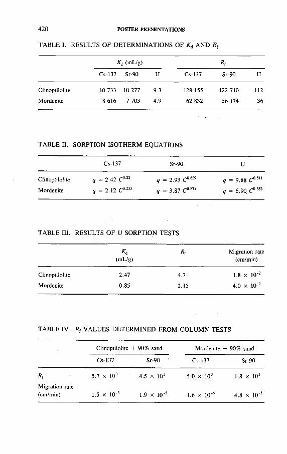
4 2 0 POSTER PRESENTATIONS
TABLE I. RESULTS OF DETERMINATIONS OF Kd A ND Rf
K¿ (m L /g ) Rf
C s - 1 3 7 S r -9 0 U C s -1 3 7 S r -9 0 U
C lin o p t i lo l i te
M o rd e n i te
10 7 3 3 1 0 2 7 7
8 6 1 6 7 7 0 3
9 .3 128 155
4 .9 6 2 8 3 2
1 2 2 7 1 0 112
5 6 17 4 3 6
TABLE II. SORPTION ISOTHERM EQUATIONS
C s - 1 3 7 S r -9 0 U
C lin o p t i lo l i te
M o rd e n i te
q = 2 .4 2 C ° '22
q = 2 .1 2 C 0233
q = 2 .9 3 C 0 629
q = 3 .8 7 C 0 831
q = 9 .8 8 C 0511
q = 6 .9 0 C ° 382
TABLE III. RESULTS OF U SORPTION TESTS
(m L /g )
Rf M ig r a t io n ra te
( c m /m in )
C lin o p t i lo l i te
M o rd e n i te
2 .4 7
0 .8 5
4 .7
2 .1 5
1 .8 X 1 0 '2
4 . 0 X 1 0 '2
TABLE IV. R f VALUES DETERMINED FROM COLUMN TESTS
C lin o p t i lo l i te + 9 0 % s a n d M o rd e n i te + 9 0 % s a n d
C s -1 3 7 S r -9 0 C s -1 3 7 S r -9 0
R f
M ig r a t io n ra te
(c m /m in )
5.1 x 1 0 3
1 .5 x 1 0 -5
4 .5 x 1 0 3
1 .9 x 10~5
5 .0 x 1 0 3
1.6 x 1 0 ’ 5
1.8 x 1 0 3
4 .8 x 1 0 ‘5
POSTER PRESENTATIONS 421
S o r p t i o n i s o t h e r m s
The results show that the sorption isotherms of 137Cs, 90Sr and U on the zeolites are consistent with the Freundlich isotherm. The isotherm equations relating sorption capacity q to concentration С are presented in Table II.
Column tests
Uranium sorption tests on the zeolites were carried out using elution curves. The results are presented in Table III.
In the cases of 137Cs and 90Sr, although 90% sand was added to the columns, no radionuclides were eluted. R { values were determined on the basis of the distribution in the columns. The results are given in Table IV.
Conclusion
Clinoptilolite and mordenite showed a strong sorption of 137Cs and 90Sr. The К л values of 137Cs and 90Sr were all on the order of 103-104 mL/g. Migration of l37Cs and 90Sr in columns was very slow, on the order of 10“5 cm/min.
The sorption of U was very weak. The migration rate of U in columns was larger than the rates of 137Cs and 90Sr, and was on the order of 10"2 cm/min.

422 POSTER PRESENTATIONS
IAEA-SM-326/9P
LWR SPENT FUEL CHARACTERIZATION BY NON DESTRUCTIVE ASSAY
G. NICOLAOU*, H. WÜRZ**, L. KOCH*
Commission of the European Communities,Joint Research Centre,Institute for Transuranium Elements
Kernforschungszentrum Karlsruhe GmbH
Karlsruhe, Germany
Within the nuclear waste programme at the Institute for Transuranium Elements, non-destructive assay is being developed for the characterization of individual spent fuel pins. The aim of spent fuel characterization is twbfold:
(a) To verify the declared burnup and determine its axial distribution,(b) To determine the radiotoxicity content of the fuel in connection with leaching
studies concerning the option of direct disposal of spent fuel.
T o d e t e r m i n e t h e a b o v e p a r a m e t e r s , t h e s p e n t f u e l i s c h a r a c t e r i z e d , i n s i d e a
h o t c e l l , b y p a s s i v e n e u t r o n i n t e r r o g a t i o n [1 ] a n d i s o t o p i c c o r r e l a t i o n s [ 2 ] .
Passive neutron interrogation is performed by an array of neutron detectors embedded, parallel to the fuel pin axis, in a polyethylene moderator. The counting unit is installed inside a ß - y hot cell and rests on a metrology bench. The nuclear electronic modules are situated outside the cell and the whole procedure is controlled by a PC. The fuel can be moved on the bench and is scanned as it passes through the neutron counting unit. Thus the required information is obtained as a function of distance along the fuel length.
Following the non-destructive measurement of the neutron emission produced by spontaneous fission of the fuel, mainly due to 242Cm and 244Cm, isotopic correlations possibly complemented by gamma spectroscopy are used to extrapolate from these measurements the information sought for the characterization of the spent fuel pins. Isotopic correlations have been calculated using the computer code KORIGEN [3]. Segments of the fuel already analysed non-destructively are dissolved for subsequent analysis by isotope dilution mass spectrometry for calibration of the non-destructive assay method.
The distribution of neutron emission by spontaneous fission, and hence burnup, along the fuel active length has been obtained for U02 spent fuel pins

POSTER PRESENTATIONS 423
(burnups 20-50 GW-d/t U). A first assessment of the non-destructive analysis shows that the average burnup of the fuel pins was determined to within 6 % of that declared by the operators.
REFERENCES
[1 ] H S U E , S .T . , M e th o d s f o r th e n o n -d e s t ru c t iv e a s s a y o f i r r a d i a te d n u c le a r fu e ls fo r
s a f e g u a rd s , A t . E n e rg y R e v . 1 6 (1 9 7 8 ) 8 9 - 1 2 8 .
[2 ] K O C H , L . , “ T h e is o to p ic c o r r e la t io n e x p e r im e n t” , P r o c . 2 n d E S A R D A S y m p . o n
S a fe g u a rd s a n d N u c le a r M a te r i a l M a n a g e m e n t , E d in b u r g h , 1 9 8 0 , C E C J o in t R e s .
C e n t r e , I s p r a (1 9 8 0 ) 3 9 2 .
[3 ] F I S C H E R , U . , W I E S E , H . W . , I m p r o v e d C o n s is te n t C a lc u la t io n o f th e N u c le a r In v e n
to ry o f S p e n t L W R F u e l A s s e m b l ie s U s in g th e B u rn u p C o d e K O R I G E N , K fK -3 0 1 4 ,
K e r n f o r s c h u n g s z e n t r u m K a r l s r u h e (1 9 8 3 ) .
IAEA-SM-326/10P
MEASUREMENT OF GAMMA RAY DOSE RATES FROM SPENT FUEL AT THE VVR-S RESEARCH REACTOR
D.M. FARCA§IU, O.M. FARCA§IU, R. DUMITRESCU,V. BOHM, D. BELOIUI n s t i t u t e f o r P h y s i c s a n d N u c l e a r E n g i n e e r i n g ,
Bucharest, Romania
P resen ted by A .I .D . C oroianu
Instrumentation was built to perform non-destructive measurements of gamma ray dose rates from spent fuel cassettes in storage at the VVR-S research reactor in Bucharest. These measurements are required within the framework of safeguards monitoring performed by inspectors from the International Atomic Energy Agency.
The measuring device designed and constructed in our institute is a beta- gamma dose rate meter, which consists of a portable digital instrument (DBG 84), a Geiger-Müller gamma ray probe and a 6.5 m long cable. The device has a power supply switch for the electronic measuring block and a ‘zero’ button to cancel the number of impulses for measuring the absorbed dose and start a new measuring cycle. The measuring block converts the impulse rate into absorbed dose rate in air (Gy/h) and presents this on a four digit liquid crystal display panel. The measuring
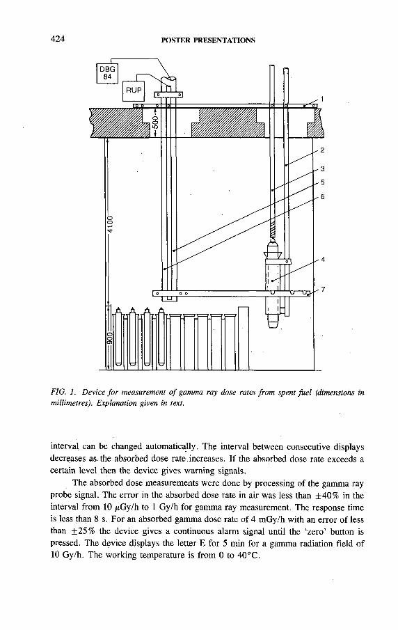
424 POSTER PRESENTATIONS
FIG. 1. Device fo r measurement o f gamma ray dose rates from spent fuel (dimensions in millimetres). Explanation given in text.
interval can be changed automatically. The interval between consecutive displays decreases as. the absorbed dose rate increases. If the absorbed dose rate exceeds a certain level then the device gives warning signals.
The absorbed dose measurements were done by processing of the gamma ray probe signal. The error in the absorbed dose rate in air was less than +40% in the interval from 10 p G y / h to 1 Gy/h for gamma ray measurement. The response time is less than 8 s. For an absorbed gamma dose rate of 4 mGy/h with an error of less than +25% the device gives a continuous alarm signal until the ‘zero’ button is pressed. The device displays the letter E for 5 min for a gamma radiation field of10 Gy/h. The working temperature is from 0 to 40°C.
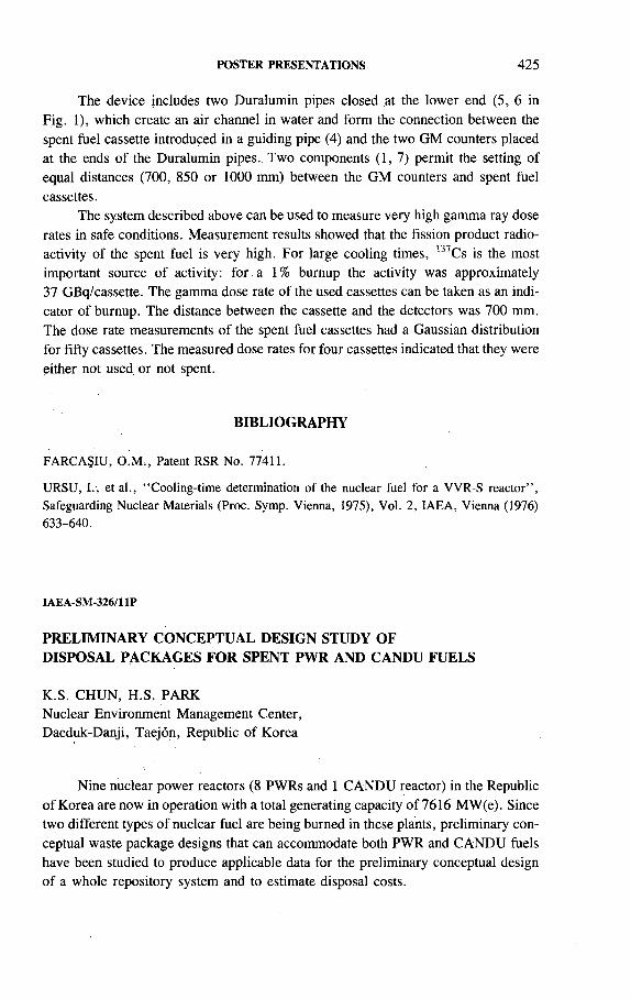
POSTER PRESENTATIONS 425
The device includes two Duralumin pipes closed at the lower end (5, 6 in Fig. 1), which create an air channel in water and form the connection between the spent fuel cassette introduced in a guiding pipe (4) and the two GM counters placed at the ends of the Duralumin pipes.. Two components (1,7) permit the setting of equal distances (700, 850 or 1000 mm) between the GM counters and spent fuel cassettes.
The system described above can be used to measure very high gamma ray dose rates in safe conditions. Measurement results showed that the fission product radioactivity of the spent fuel is very high. For large cooling times, B7Cs is the most important source of activity: for a 1 % burnup the activity was approximately 37 GBq/cassette. The gamma dose rate of the used cassettes can be taken as an indicator of burnup. The distance between the cassette and the detectors was 700 mm. The dose rate measurements of the spent fuel cassettes had a Gaussian distribution for fifty cassettes. The measured dose rates for four cassettes indicated that they were either not used, or not spent.
BIBLIOGRAPHY
F A R C A S I U , O .M . , P a te n t R S R N o . 7 7 4 1 1 .
U R S U , I . , e t a l . , “ C o o l in g - t im e d e te rm in a t io n o f th e n u c le a r fu e l f o r a V V R - S r e a c t o r ” ,
S a fe g u a rd in g N u c le a r M a te r ia ls (P ro c . S y m p . V ie n n a , 1 9 7 5 ) , V o l. 2 , IA E A ; V ie n n a (1 9 7 6 )
6 3 3 - 6 4 0 .
IAEA-SM-326/11P
PRELIMINARY CONCEPTUAL DESIGN STUDY OF DISPOSAL PACKAGES FOR SPENT PWR AND CANDU FUELS
K.S. CHUN, H.S. PARKNuclear Environment Management Center,Daeduk-Danji, Taejon, Republic of Korea
Nine nuclear power reactors ( 8 PWRs and 1 CANDU reactor) in the Republic of Korea are now in operation with a total generating capacity of 7616 MW(e). Since two different types of nuclear fuel are being burned in these plants, preliminary conceptual waste package designs that can accommodate both PWR and CANDU fuels have been studied to produce applicable data for the preliminary conceptual design of a whole repository system and to estimate disposal costs.

426 POSTER PRESENTATIONS
The principal structural performance criterion is that the package must withstand, over its design lifetime, the stresses imposed by the hydrostatic pressure that will develop in a repository that eventually resaturates with groundwater, i.e. ~ 9 MPa at a depth of 900 m. Another potential source of external loading on the package within the disposal environment is the swelling of the bentonite clay based buffer that will be emplaced around the container. It has been shown that such swelling could impose a further 1.0-2.5 MPa pressure load on the package shell. The surface temperature of the container shell will be - 120°C.
Two different options for the direct disposal of spent fuel are being considered, based on the spent PWR fuel assemblies or consolidated fuel rods loaded into a disposal package. The package is to be designed to accommodate both PWR and CANDU fuels, the decay heat of which remains low enough that the surface temperature of the shell does not exceed the permissible level within the disposal environment.
Three PWR fuel assemblies can be loaded into three rectangular baskets, and 24 CANDU fuel bundles into three cylindrical tubes between the baskets in the Korean Fuel Assembly Disposal Package (KFADP) shown in Fig. 1(a). Each tube can hold eight CANDU bundles vertically stacked. This unique package is designed to withstand the hydrostatic and buffer swelling pressure and provide a corrosion resistant layer for at least 500 years after emplacement into a repository. The other design in Fig. 1 is the Korean Consolidated Rod Disposal Package (KCRDP), which has the same loading capacity as the KFADP. In addition, the central compartment,
FIG. 1. (a) Korean Fuel Assembly Disposal Package, (b) Korean Consolidated Rod Disposal Package.

POSTER PRESENTATIONS 427
a triangular core basket, would hold cut and compacted skeletons from three PWR fuel assemblies, and would therefore reduce the excavation requirements at the repository. Each basket would hold consolidated fuel rods from one PWR fuel assembly.
IAEA-SM-326/13P
DISPOSAL OF RADIOACTIVE WASTE PACKAGES IN VERTICAL BOREHOLES IN A FINAL REPOSITORY IN A SALT DOME
H. BRÜCHER, E. BARNERT, .K. KROTH, D. NIEPHAUS Forschungszentrum Jülich GmbH,Jülich, Germany
In Germany, radioactive wastes with non-negligible heat generation are to be finally disposed of in vertical boreholes 300 m deep in a repository in a salt dome. The wastes include cemented cladding hulls, fuel hardware and dissolver sludges from LWR fuel element reprocessing, and spent spherical HTR fuel elements, which are to be directly disposed of without reprocessing. The disposal technology for these wastes has been developed in the framework of the MHV Project, Intermediate Level Waste and Spent HTR Fuel Element Test Disposal in Boreholes. Figure 1 outlines the concept.
The packages are individually removed from a transfer cask equipped with a bottom slide and are placed on a shielding slide at the top of the borehole. The hoisting cable of the emplacement machine is coupled to a grapple integrated in the transfer cask. After the opening of both slides the emplacement machine lowers the package into the unlined borehole and sets it down. By a similar procedure, a backfill container is then lowered into the borehole to backfill the space around the package with crushed salt so that the package is covered by a minimum layer of a few tens of centimetres. The air in the borehole is filtered and directly ventilated into the exhaust shaft. The filled borehole is closed by a plug.
This borehole disposal technique with crushed salt backfill is applicable to vari-. ous package sizes, e.g. to large Cogéma containers with a volume of 1500 L as well as to 200 L drums.
Crushed salt backfilling has various advantages in borehole disposal. One of these is its capability to divert the stacking forces into the borehole wall. Laboratory experiments and modelling have indicated that embedding in crushed salt will help to keep the mechanical stresses on the thin walled waste packages within acceptable limits.
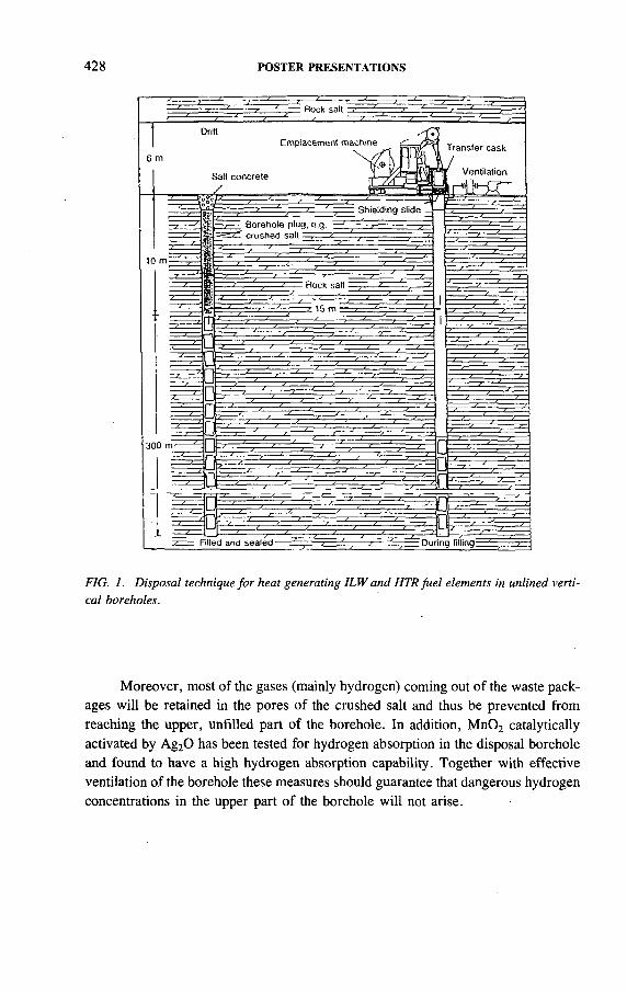
428 POSTER PRESENTATIONS
FIG. 1. Disposal technique for heat generating ILW and HTR fuel elements in unlined vertical boreholes.
Moreover, most of the gases (mainly hydrogen) coming out of the waste packages will be retained in the pores of the crushed salt and thus be prevented from reaching the upper, unfilled part of the borehole. In addition, Mn02 catalytically activated by Ag20 has been tested for hydrogen absorption in the disposal borehole and found to have a high hydrogen absorption capability. Together with effective ventilation of the borehole these measures should guarantee that dangerous hydrogen concentrations in the upper part of the borehole will not arise.

POSTER PRESENTATIONS 429
PLUG REPLACEMENT AND LEAK TESTING FOR SPENT HTR FUEL CANISTERS:A STEP TOWARDS THE RETRIEVABLE EMPLACEMENT TEST OF RADIOACTIVE WASTE PACKAGES IN SALT
D. NIEPHAUS, H. WETZLER Forschungszentrum Jülich GmbH
R. PRINTZWissenschaftlich-Technische Ingenieurberatung
Jülich, Germany
IAEA-SM-326/14P
In the Retrievable Emplacement Test (REV) subproject of the MHV Project, Intermediate Level Waste and Spent HTR Fuel Element Test Disposal in Boreholes, which has been under way since 1983 at the Forschungszentrum Jülich (KFA), apart from six steel drums of ILW four spent HTR fuel canisters are to be emplaced for a maximum of five years in unlined boreholes (Fig. 1) at the 800 m level of the Asse salt mine.
The transport of the spent fuel canisters, containing 950 HTR fuel elements each, from the KFA to the Asse mine and back as well as surface and underground transport and handling in the mine itself are carried out using an AVR shipping cask which, in conjunction with the canister itself, is designed as a type В package. The canister ensures the leaktight confinement of the radioactive inventory. The leaktight closure is made with a canister plug which is pressed into the filling aperture. Two horizontal elastomer О rings arranged in series serve to seal the gap between plug and canister neck.
Prior to each canister transport the leaktightness of the canister closure must be demonstrated according to a type В licensing requirement. In order to fulfil this requirement, a special unit was conceived and built for plug replacement on the AVR-TL canisters as well as determination of the leak rate on canister plugs by He leaktightness testing.
This plug replacement and leak testing unit was installed and cold tested in a KFA hot cell (Fig. 2). A second unit of almost identical design is currently under construction; it will be installed in the ‘hot cell’ of the Asse mine and kept ready for canister retrieval at the end of the emplacement test.

430 POSTER PRESENTATIONS
gas analysis'H, 3H, 14C, 85Kr
shielding slide
data recording(distance, temperature, inclination)
shielding collar
liner
distance meter (3 each on 5 levels)
storage rack
jacket heater
AVR spent fuel canister
FIG. 1. Equipment o f the EV2 borehole fo r retrievable emplacement o f HTR fuel elements.
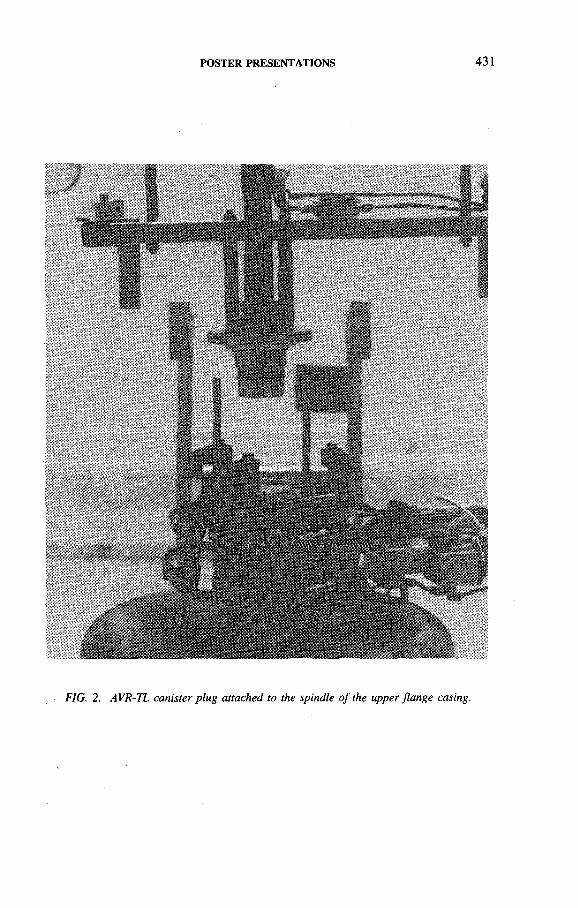
POSTER PRESENTATIONS 431
FIG. 2. AVR-TL canister plug attached to the spindle o f the upper flange casing.
432 POSTER PRESENTATIONS
HEAT INDUCED AND GAMMA RADIATION INDUCED GENERATION OF GASES FROM ROCK SALT
N. AKRAM, M.T. GAUDEZ, P. TOULHOAT CEA, Centre d’études de Fontenay-aux-Roses, Fontenay-aux-Roses, France
M. RAYNAL, J.M. PALUT Agence nationale pour la gestion
des déchets radioactifs,Fontenay-aux-Roses, France
J. MÖNIGGSF-Institut für Tieflagerung,Braunschweig, Germany
IAEA-SM-326/19P
Rock salt formations are envisaged as host rock for the disposal of heat producing high level radioactive waste. Exposure of rock salt to heat and 7 radiation, however, results in the release of gases already present in the salt and, possibly, in the formation of new gaseous components. Since the formation of gases could have implications for the design of the final repository and its operational safety as well as the assessment of the long term safety, knowledge about the chemical nature and the quantity of these gas components is of paramount importance.
Therefore, an experimental programme was jointly established by the GSF- Forschungszentrum für Umwelt und Gesundheit and the Agence nationale pour la gestion des déchets radioactifs (ANDRA) in order to determine the amount of gases formed by the combined action of heat and 7 radiation and an attempt was made to identify the most important parameters for gas production. In this programme about 250 salt samples were irradiated and the influence of a variety of parameters, including integrated dose, dose rate, irradiation temperature, grain size of the crushed salt and initial composition of the gas phase, was studied in detail. The irradiations were carried out using spent fuel elements of the OSIRIS reactor in Saclay. This facility allows salt samples to be exposed at dose rates of up to 105 Gy/h and at temperatures ranging from 50 to 250° С.
The two main gases observed after irradiation of salt samples in an air atmosphere were C02 and N20 . In addition, small quantities of CH4, H2, CO and, in some cases, C02, Cl2 and HC1 were detected. Increasing radiation dose leads to an increase in the yields of the two major gases. However, the C 0 2 yield seems to

POSTER PRESENTATIONS 433
approach an upper limit. The N20 was conclusively shown to be produced by radiolysis of the gas atmosphere, while the results suggest that at least some of the C02
was of organic origin and was formed by stepwise radiation induced oxidation of CH4. Thus, a 100-fold increase in the CH4 yield with a concomitant decrease in C02 was observed when the irradiations were performed under an inert argon atmosphere. The CO is an intermediate product in this two step oxidation process, as is shown by the dependence of the CO yield on the irradiation dose and the initial gas atmosphere.
The gas production does not seem to depend very much on the irradiation temperature. A moderate increase by a factor of about 3 is observed for C 02 between 50 and 250°C, while the other gases are hardly affected at all. However, in previous investigations the dependence of C02 on the irradiation temperature was more pronounced. Hardly any dependence of the product yields on the dose rate was observed. Samples were irradiated at 50°С to a total dose of 106 Gy with dose rates ranging from 103 to 105 Gy/h. These results corroborate previous findings.
The influence of the grain size on the gas yields was investigated for the first time using crushed salt samples irradiated at ambient temperature to 106 Gy. Several grain size fractions ranging from 0.125-0.25 mm to 4-8 mm in diameter were studied in addition to rock salt drilling cores. For all gases the same tendency was apparent, i.e. there was a decrease of gas production with an increase in grain size. There are two possible reasons for this observation. Firstly, the probability for gases to diffuse to the grain surface is higher with small particles. Secondly, the absorption of radiation energy may be more uniformly distributed and thus more complete in small particles; the gas production may consequently be higher.
The formation of sodium colloids was determined by measuring the amount of H2 produced upon dissolution of the salt. For doses ranging from 103 to 107 Gy a correlation between the amount of colloidal sodium and the integrated dose D
according to the exponential equation [Na] = K D 0 64 was observed for samples irradiated at 50°C and a dose rate of 104 Gy/h. At an integrated dose of 106 Gy the H2 yield depends on the irradiation temperature and is a maximum between 100 and 150°C. This finding is in qualitative.agreement with the predictions of the Jain- Lidiard theory and with other experimental findings. However, the absolute yield of colloidal sodium is much smaller than previously reported by other investigators.
Molecular chlorine was found as one of the irradiation products by gas chromatography-mass spectrometry techniques. The Cl2 was unequivocally identified by the unique isotopic distribution pattern of its molecular ion. Although only a qualitative measurement was carried out and the product was only observed at high radiation doses, this provides one of the few examples where direct evidence for the formation of this product is available. In most cases the formation of Cl2 upon irradiation of rock salt was either established indirectly by dissolving the salt and measuring the resulting products (ОСГ or I3 in iodide containing solutions) or inferred from experimental data using other alkali halides.

434 POSTER PRESENTATIONS
The results of this study corroborate in several aspects previous findings regarding radiation induced gas generation in and gas release from rock salt. Most importantly, the absolute gas yields are fairly low. On the basis of these results it may therefore be concluded that a significant pressure increase in a sealed borehole due to the radiation induced generation of gases and release of gases from rock salt seems unlikely. However, it is important to determine quantitatively the yield of toxic and corrosive gas components, such as Cl2 and NO*, and of colloidal sodium.
IAEA-SM-326/22P
CALCULATION OF HYDROGEN DISTRIBUTIONS AND PRESSURES IN OPEN AND WASTE FILLED BOREHOLES FOR ILW AND HTR FUEL ELEMENTS
G. MORLOCK, C. GRONEMEYER Gesellschaft für Reaktorsicherheit mbH,Cologne, Germany
The production of gases, mainly hydrogen, by ILW and burnt-up HTR fuel elements implies some safety related problems during the operational phase as well as after closure of a repository. During the operational phase flammable concentrations must be prevented in open spaces. Furthermore gas production may induce a transport mechanism for gaseous radionuclides released from the waste. After closure of the borehole and in the post-operational phase possible gas pressure buildup has to be investigated, especially when rather tight host formations such as salt domes are considered, as in the case of the German repository planned for high and intermediate level waste forms in Gorleben.
A model which predicts the distribution of gases and gaseous radioactivity in the pore spaces of the backfill material of a partially filled borehole has been constructed. The model has been implemented in a computer code called GORWA. The model simulates the emplacement procedure by means of which the borehole is progressively filled and the gas concentrations for the filled part are evaluated. Gas transport mechanisms considered are convection due to displacement by the gas formation, convection due to pressure fluctuations in the mine atmosphere, and diffusion. As previous investigations have shown pressure calculations can be omitted since the pressure is nearly constant along the waste column. The results are gas flow rates from the filled into the open part of the borehole which make it possible to evaluate the conditions and the time at which critical concentrations are reached.

POSTER PRESENTATIONS 435
Since previous results could not demonstrate that critical concentrations in open parts of a borehole are impossible for the waste categories investigated, another model had to be developed. In the open part of the borehole there is nearly no gas flow resistance. Therefore small differences in gas density can cause a convective flow. Such small density differences can be due to local fluctuations of the hydrogen concentration or temperature gradients. For this reason a complete three dimensional calculation is necessary for the gas flow and gas distribution. The corresponding model was realized on the basis of the commercial fluid dynamic code PHOENICS. Modification of the code was performed in three steps. In each step a stationary case was first calculated, followed by a number of test cases which will be checked by an experiment planned for the near future in the Asse salt mine.
As an example, gas concentration and gas velocity distributions were calculated in the following case. At the bottom of a closed borehole, and slightly off- centre, a helium source with a constant helium injection rate is placed. On one side of the borehole cover gas is sucked out. On the other side, 10 nvbelow the upper surface, He free air is flowing in. The calculated results of this borehole venting show that the upward gas transport is very. fast. Under steady state conditions the open part of the borehole contains less gas than was released from the filled part during one day. The rest continuously escapes to the disposal drift.
After closure of the borehole gas pressure buildup is the primary concern. For this case gas transport into the host rock was investigated assuming a tight borehole seal and neglecting borehole convergence: Gas pressures were calculated using the gas formation rate and host rock permeability as parameters. The results show a nearly linear pressure rise at the beginning followed by a decrease of the slope to very small values in the course of time. The rate of the initial pressure buildup mainly depends on-the gas source term while maximum pressures are additionally influenced by the permeability of the host rock.
436 POSTER PRESENTATIONS
METHOD FOR DETERMINING GAS RELEASE DURING DRILLING OF DEEP EMPLACEMENT BOREHOLES IN ROCK SALT
N. JOCKWERGSF-Institut für Tieflagerung,Braunschweig, Germany
IAEA-SM-326/27P
In Germany and in the Netherlands it is planned to dispose of heat generating high level waste in rock salt formations. For optimal use of the volume of the salt dome it is planned to drill deep emplacement boreholes at a level of approximately 800 m in the repository mine.
In the Asse salt mine a dry drilling technique has been developed in order to obtain emplacement boreholes of a diameter of between 0 . 6 and 1 . 0 m and a depth of up to 600 m from the underground level of the mine.
The rock salt of potential disposal horizons may have areas where gas is stored under high pressure (up to 100 bar (10 MPa)) in its pore volume. In the past this caused various accidents in the mine when such areas were encountered during mining activities. Therefore the present concept of the licensing authorities is to make reconnaissance drillings prior to drilling of the entire borehole in order to ensure that areas with a high gas content are not pierced when drilling an emplacement borehole of large diameter.
The reconnaissance drillings are disadvantageous with respect to long term safety as they are developed with brine which penetrates and perforates the whole emplacement area, thus increasing the probability of corrosion of the waste package and the formation of pathways for the release of radionuclides.
The main question from the beginning in developing the drilling technique for these large and deep emplacement boreholes was whether it would be possible to reduce the number of reconnaissance drillings by employing a surveillance method. This method would be used to monitor the gas release from the salt during drilling of the emplacement borehole in order to introduce countermeasures at an early stage.
Previous investigations of potential disposal horizons have shown that the average amounts of the main gas components in rock salt are:
— C02: in the region of 20 NL/m3 salt— H2S: in the region of 5 NL/m3 salt— CH4: in the region of 100 NL/m3 salt.
In small layers of high porosity (anhydrite layers) the content of these components is much higher.

POSTER PRESENTATIONS 437
With the assumption of a drilling volume of 0.5 m3 salt per hour and a flushing air rate of 1 0 0 0 m3/h for transportation of the drilling fines, the concentrationsof the main components in the air are:
— C02: 100 NmL/m3 air = 100 vpm— H2S: 2.5 NmL/m3 air = 2.5 vpm— CH4: 50 NmL/m3 air = 50 vpm.
For the analysis of these components in the flushing air special equipment has been developed, consisting of:
— A flame ionization detector for determination of hydrocarbons in the range between 0 . 0 0 1 and 1 0 vol.%,
— An infrared adsorption detector for determination of C 02 in the range between 0 . 0 2 and 2 0 vol.%,
— A semiconductor detector for determination of H2S in the range between 0.1and 1 0 0 vpm, •
— A semiconductor detector for determination of the relative humidity in the range between 20 and 90%.
The equipment and the method worked very well so that layers with higher gas content could be recognized instantaneously during drilling. This means that the number of reconnaissance drillings can be reduced in a repository when drilling the emplacement boreholes.
In addition to the on-line determination of gas release during drilling, representative samples of drilling fines were taken each metre for mineralogical and chemical analyses in the laboratory.
BIBLIOGRAPHY
H A M I L T O N , L . F . M . , P R I J , J . , J O C K W E R , N . , T h e 6 0 0 m B o re h o le P r o je c t o f th e C E C
P r o g r a m m e o n M a n a g e m e n t a n d S to r a g e o f R a d io a c t iv e W a s te , F in a l R e p o r t , P h a s e 1, A u g .
1 9 8 6 - D e c . 1 9 9 0 , R e p . N o . E C N - C .9 1 - 0 6 8 , N e th e r la n d s E n e rg y R e s e a r c h F o u n d a t io n , P e t te n
(1 9 9 1 ) .
J O C K W E R , N . , M Ö N I G , J . , R O T H F U C H S , T . , “ In s i tu g a s r e le a s e o b s e r v e d in th e te s t
f i e ld ” , P i lo t T e s ts o n R a d io a c t iv e W a s te D is p o s a l in U n d e rg ro u n d F a c i l i t ie s (P ro c . W o r k
s h o p , B ra i in s c h w e ig , 1 9 9 1 ), E U R 1 3 9 8 5 , C E C , L u x e m b o u r g (1 9 9 2 ) 5 5 - 6 5 .

438 POSTER PRESENTATIONS
IAEA-SM-326/28P
GAS RELEASE FROM ROCK SALT AT AMBIENT AND ELEVATED TEMPERATURES
J. MÖNIG, N. JOCKWER, T. ROTHFUCHS GSF-Institut für Tieflagerung,Braunschweig, Germany
In Germany, deep geological salt formations are envisaged as a suitable medium for the disposal of heat producing high level radioactive waste. One of the important effects for repository safety is the generation and release of gases. Several mechanisms, such as corrosion of the waste forms, outgassing of the host rock and radiolysis, account for this gas generation and are interrelated. In general, the formation of gases could have implications for the design of the final repository and its operational safety as well as the assessment of the long term safety. For example, gas formation may lead to a pressure buildup above the frac pressure of the salt in seàled boreholes. In addition, corrosive or explosive gas mixtures may be generated. Quantitative data are required for each of the conceivable gas formation mechanisms: This presentation is mainly concerned with the outgassing of natural gases from rock salt at ambient and elevated temperatures.
I n t h e A s s e m i n e s e v e r a l i n s i t u t e s t s h a v e b e e n c o n d u c t é d o r a r e c u r r e n t l y i n
p r o g r e s s i n w h i c h t h e g a s r e l e a s e i n t o s e a l e d b o r e h o l e s i s q u a n t i f i e d . T h e o b j e c t i v e
i s t o p r o v i d e e v e n t u a l l y a d a t a b a s e i n o r d e r t o m a k e p o s s i b l e t h e c o m p u t e r m o d e l l i n g
o f g a s r e l e a s e f r o m r o c k s a l t i n c o n d i t i o n s a s s o c i a t e d w i t h h i g h l e v e l w a s t e d i s p o s a l .
Gas release from rock salt into sealed bdreholes at ambient temperatures is being determined in situ in about fifty boreholes located in different stratigraphie horizons in the Asse mine. In addition two special boreholes have been drilled through several different salt horizons, with each specific layer being sealed independently by means of gas-tight packers.
From our data we have reached the following conclusions.Under normal circumstances, C02 is the gas which is released most abun
dantly from older halite, i.e. Na2-Staßfurt rock salt, at ambient temperature. The C02 concentration detected under a variety of conditions is fairly low and almost invariant. The gas phase concentrations are found to be normally below 0.1 vol.%.
Methane and higher hydrocarbons are also observed in most boreholes, with CH4 accounting in most cases for more than 90% of the volatile organic hydrocarbons. However, compared with C 02 the distribution of CH4 is much more heterogeneous within a given stratigraphie horizon and may differ by one to two orders of magnitude. The CH4 release seems to depend somewhat on the content of the

POSTER PRESENTATIONS 439
minor minerals, polyhalite and anhydrite, in rock salt. The CH4 release from younger halite (Na3-Leine rock salt) or from carnallitic rock salt is higher by about an order of magnitude.
In a few boreholes H2S is also observed. However, the distribution of this corrosive gas is extremely heterogeneous, even within the same stratigraphie horizon. Concentrations may reach very high values of up to 0.6 vol. % in the borehole gas phase. Apparently, the salt contains small pockets with H2S inclusions, from which the gas is released upon relaxation of the lithostatic pressure due to excavation of galleries or boreholes.
Evidence has been found that an equilibrium is established between the intergranular pore volume and the borehole gas phase. Therefore, release from rock salt proceeds until this equilibrium is reached. If the partial pressure of a gas is deliberately lowered, the equilibrium is re-established subsequently. The data also show that the reverse process, i.e. uptake of gases from the gas phase, occurs.
In general, elevated temperatures enhance the gas release. It is observed that release of C02 follows the temperature rise closely. After some time a new equilibrium level is established, with the level being dependent upon the salt temperature. Again, significant differences in the CH4 release are noted in similar boreholes exposed to the same experimental conditions, while the equilibrium levels for C 02 are very similar. However, the database is still fairly small.
The measurements in sealed boreholes determine only the equilibrium partial pressure of the respective gas component under the prevalent boundary conditions. Under experimental conditions it is impossible to estimate the volume of salt from which gas release into the borehole occurs. Hence, these equilibrium partial pressures do not allow calculation of the initial gas content of the rock salt. Nevertheless, the data provide a modelling test case, since any computer model should correctly predict both the absolute equilibrium level and the time profile for the establishment of the equilibrium.

440 POSTER PRESENTATIONS
THE MEGAS PROJECT: MODELLING AND EXPERIMENTS ON GAS MIGRATION IN REPOSITORY HOST ROCKS
G. VOLCKAERT SCK/CEN,Mol, Belgium
K. BATEMANFluid Process Research Group,British Geological Survey,Keyworth, Nottingham,United Kingdom
V. FIORAVANTE ISMES,Bergamo, Italy
M. IMPEY, K. WORGAN INTERA,Henley-on-Thames,Oxfordshire,United Kingdom
IAEA-SM-326/35P
The MEGAS project was designed to study the impact of gas generation from a radioactive waste repository on an argillaceous host rock. Modelling and experimental work have been concentrated on studying the transport of gases through a dense, low permeability clay such as the Boom clay, which has been chosen as a potential host rock in Belgium.
A comprehensive review of available literature on the transport and dispersal of gas through clays has been performed by INTERA. On the basis of this review and taking into account a range of realistic gas generation rates, some order of magnitude calculations were performed. These have shown that diffusion alone is not able to transport the generated hydrogen and that a separate gas phase will be formed. Consequently, two phase flow can be expected as the main transport mechanism. INTERA developed a number of two phase flow models to estimate the influence of gas generation rate on the rate at which the gas-water interface would move through Boom clay. In addition INTERA made a review of existing two phase flow codes. As a result of this review a new code, TOPAZ, was developed. In
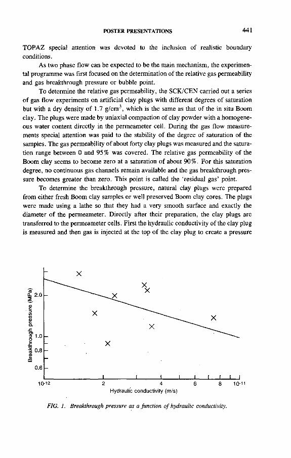
POSTER PRESENTATIONS 441
TOPAZ special attention was devoted to the inclusion of realistic boundary conditions.
As two phase flow can be expected to be the main mechanism, the experimental programme was first focused on the determination of the relative gas permeability and gas breakthrough pressure or bubble point.
To determine the relative gas permeability, the SCK/CEN carried out a series of gas flow experiments on artificial clay plugs with different degrees of saturation but with a dry density of 1.7 g/cm3, which is the same as that of the in situ Boom clay. The plugs were made by uniaxial compaction of clay powder with a homogeneous water content directly in the permeameter cell. During the gas flow measurements special attention was paid to the stability of the degree of saturation of the samples. The gas permeability of about forty clay plugs was measured and the saturation range between 0 and 95% was covered. The relative gas permeability of the Boom clay seems to become zero at a saturation of about 90%. For this saturation degree, no continuous gas channels remain available and the gas breakthrough pressure becomes greater than zero. This point is called the ‘residual gas’ point.
To determine the breakthrough pressure, natural clay plugs were prepared from either fresh Boom clay samples or well preserved Boom clay cores. The plugs were made using a lathe so that they had a very smooth surface and exactly the diameter of the permeameter. Directly after their preparation, the clay plugs are transferred to the permeameter cells. First the hydraulic conductivity of the clay plug is measured and then gas is injected at the top of the clay plug to create a pressure
Hydraulic conductivity (m/s)
FIG. 1. Breakthrough pressure as a function o f hydraulic conductivity.
442 POSTER PRESENTATIONS
difference lower than 1 MPa. The pressure difference is gradually increased until breakthrough occurs. The measured breakthrough pressure varied between 0.9 and 2.9 MPa, which is still well below the lithostatic pressure of 4 MPa for the Boom clay at Mol. From the breakthrough pressures, the maximum pore diameter was estimated as between 40 and 110 nm. Figure 1 clearly shows that there is a relationship between hydraulic conductivity and breakthrough pressure.
To study the influence of the thermomechanical conditions of the host rock on gas migration, experiments with triaxial stress conditions are under development. The British Geological Survey has developed an experimental set-up using a modified pressure vessel with which gas injection experiments at room temperature will be performed. These experiments will test the different concepts of gas transport. To be able to perform experiments at higher temperature, ISMES has modified its HITEP triaxial cell. In this experimental set-up, gas will be injected in the centre of a clay core using a needle.
IAEA-SM-326/41P
EVALUATION OF A PROPOSED REPOSITORY FOR TRANSURANIC WASTE IN THE USA
L. CHATURVEDI, R.H. NEILLNew Mexico Environmental Evaluation Group,Albuquerque, New Mexico,United States of America
A large volume of defence transuranic (TRU) waste has accumulated in the United States of America as a by-product of nuclear weapons production during the past half-century. The waste has been produced during reactor fuel assembly, weapons fabrication and reprocessing operations and consists of a wide variety of trash (protective clothing, equipment, tools, sludges, etc.) contaminated by alpha particle emitting radioisotopes heavier than uranium. The waste that is contaminated with alpha emitting transuranium nuclides with half-lives greater than 2 0 years and concentrations greater than 100 nCi/g waste (3.7 kBq/g) is classified as TRU waste. While such waste was disposed of in shallow trenches until 1970, the waste subsequently produced by defence activities has been carefully stored in 55 gal (208 L) mild carbon steel drums and boxes. About 60 000 m3 of TRU waste are retrievably stored at present.

POSTER PRESENTATIONS 443
The Waste Isolation Pilot Plant (WIPP) in the southeastern part of the State of New Mexico is under construction as a potential repository for the permanent isolation of TRU waste. The repository is located in Permian age salt beds at a level of 655 m below the ground surface. Currently the site is at an advanced stage of investigation and performance assessment work is in progress to assess the compliance of the site with the appropriate standards for long term safety. It is anticipated that a decision to use WIPP as a repository for permanent isolation of defence TRU waste can be made before the end of the century.
The progress made by the WIPP project is at least in part due to the wisdom displayed by the political leaders in the State of New Mexico and the Federal Government in creating a group of scientists and engineers to perform independent technical evaluation of the project. The New Mexico Environmental Evaluation Group (EEG) was established in 1978 by the State of New Mexico with funds provided by the US Department of Energy (DOE) for the sole purpose of providing an interdisciplinary, multifaceted technical review of the WIPP project, its potential impact on the health and safety of the people of New Mexico, and its. projected integrity in isolating the radioactive waste from the biosphere. To achieve the objective of technical independence, the group was made a technically autonomous part of a state university, the New. Mexico Institute of Mining and Technology. This administrative set-up and the adoption of. a rigorously objective and technically defensible stance by the group have fostered public trust in the findings of the group.
The DOE is authorized to regulate itself in the disposal of defence TRU waste and is required to demonstrate compliance with the US Environmental Protection Agency (EPA) standards for geological isolation of TRU and high level wastes. The EPA containment standards are based on probabilistic risk analysis of potential releases of radionuclides to the environment for 1 0 0 0 0 years and apply equally to both high level and TRU waste repositories. The New Mexico Environment Department is authorized to regulate WIPP for the non-radioactive chemically hazardous components of the waste. The EEG has no licensing or regulatory authority. Nevertheless, the EEG has exercised considerable influence over the WIPP project owing to its objective, unbiased and technically robust analyses and findings. The DOE has mostly accepted the validity of EEG analyses and recommendations, and has made major changes in the programme during the past 14 years of the EEG’s work. The EEG recommendations accepted by the DOE include: a change in the location of the repository; new design and certification by the US Nuclear Regulatory Commission (NRC) of a shipping container (TRUPACT-II) for transportation of contact handled TRU waste; additional geotechnical and geohydrological studies; initiation of rigorous performance assessment work even though the EPA standards were vacated by the courts and are yet to be repromulgated with revisions; and redesign of the air exhaust and exhaust monitoring system for the repository. Naturally, there have been differences in the course of interactions between the EEG and DOE, but mostly the relationship has been professional and productive.

444 POSTER PRESENTATIONS
The EEG has remained a relatively small group, currently consisting of ten professional staff members representing geotechnical, health physics, risk analysis, chemical engineering and environmental monitoring specialties, and support staff and occasional consultants. The group evaluates DOE reports, assesses compliance with various health and safety regulations, performs independent analyses of operational and long term safety, conducts scientific meetings and field trips to reach scientific consensus, independently conducts effluent and environmental monitoring programmes, provides technical input to decision makers at the state and Federal levels and the US Congress, and disseminates its findings through published reports and papers and presentations at scientific and public meetings.
Public acceptance of nuclear waste repositories is a worldwide concern. The EEG has succeeded in providing reliable evaluation of the first deep geological repository in the USA as an independent and credible scientific review group. Such evaluation has played an important part in providing reliable information to the public and the decision makers and has helped advance a programme for geological isolation of radioactive waste. It is hoped that this information will be found useful by other agencies in various countries that are trying to find the best ways to foster public understanding and acceptance of similar projects.
The EEG has published 50 technical reports and 25 technical papers related to WIPP in journals and conference/symposium proceedings, to offer its own work for critical review.

POSTER PRESENTATIONS 445
CARACTERISATION DES MOUVEMENTS SISMIQUES POUR LES SITES DE STOCKAGE PROFOND DE DECHETS RADIOACTIFS
J.C. GARIEL, B. MOHAMMADIOUN Institut de protection et de sûreté nucléaire,Département de protection de l’environnement
et des installations,Bureau d’évaluation des risques sismiques
pour la sûreté des installations nucléaires,CEA,Fontenay-aux-Roses, France
IAEA-SM-326/43P
Les études de sûreté des sites de stockage profond nécessitent la prise en compte des événements sismiques. Ceux-ci ont des conséquences, d’une part, sur la stabilité de la barrière ouvragée et, d’autre part, sur le milieu hôte. En particulier, les mouvements sismiques peuvent induire des mouvements le long des fractures préexistantes et, par conséquence, des modifications dans le régime hydraulique du massif. Il est donc nécessaire d’avoir une bonne connaissance des caractéristiques (contenu fréquentiel, pic d’amplitude, durée) du mouvement sismique en profondeur qui interviendra tant pour le dimensionnement des installations que pour les études de conséquences au niveau du massif hôte.
Il n’existe, à l’heure actuelle, que très peu de données concernant les mouvements sismiques en profondeur. Des études de synthèses récentes [1,2] ont montré que, si un certain nombre d’observations ont été faites dans des ouvrages souterrains (mines, tunnels, etc.) à l’occasion de grands tremblements de terre, elles ne permettent pas de tirer des conclusions aboutissant à une caractérisation physique du mouvement à grandes profondeurs.
Du point de vue expérimental, la plupart des réseaux verticaux de capteurs accélérométriques (situés principalement au Japon et aux Etats-Unis) ont été conçus pour étudier l’influence des couches géologiques superficielles sur les mouvements de surface et n’atteignent donc pas des profondeurs similaires à celles envisagées pour les sites de stockage profond (plusieurs centaines de mètres). Seuls, quelques réseaux situés au Japon ont permis d’acquérir des accélérogrammes à ces profondeurs.
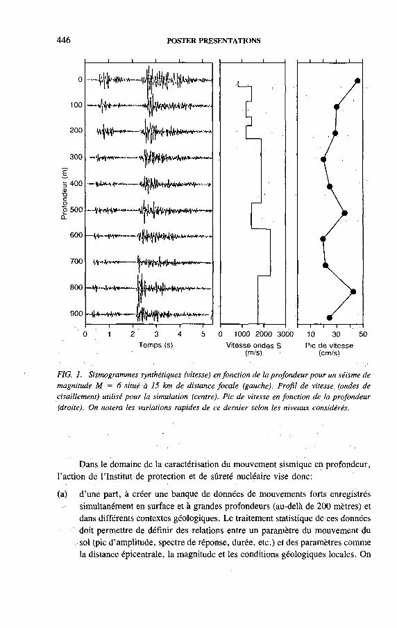
446 POSTER PRESENTATIONS
100
200
300
ш■ос
о 500 £
600
700
800
900
— fW-'--
-VV—Y v—----
№ *k**+ -----г % 4 * \Ы « * * » ' ~■■
||4V^W*frviMr-'
3
Temps (s)
i — i— i— Г 0 1000 2000 3000 10 30 50
Vitesse ondes S Pic de vitesse (m/s) 1 (cm/s)
FIG. 1. Sismogrammes synthétiques (vitesse) en fonction de la profondeur pour un séisme de magnitude M = 6 situé à 15 km de distance focale (gauche). Profil de vitesse (ondes de cisaillement) utilisé pour la simulation (centre). Pic de vitesse en fonction de la profondeur (droite). On notera les variations rapides de ce dernier selon les niveaux considérés.
Dans le domaine de la caractérisation du mouvement sismique en profondeur, l’action de l’Institut de protection et de sûreté nucléaire vise donc:
(a) d’une part, à créer une banque de données de mouvements forts enregistrés simultanément en surface et à grandes profondeurs (au-delà de 2 0 0 mètres) et dans différents contextes géologiques. Le traitement statistique de ces données doit permettre de définir des relations entre un paramètre du mouvement du sol (pic d’amplitude, spectre de réponse, durée, etc.) et des paramètres comme la distance épicentrale, la magnitude et les conditions géologiques locales. On
POSTER PRESENTATIONS 447
sera ainsi en mesure de qualifier et de quantifier les différences (dans- le domaine tant spectral que temporel) entre sites de surface (où les connaissances sont importantes) et sites en profondeur;
(b) d’autre part, à développer des techniques de simulations numériques permettant de modéliser le champ d’ondes sismiques en profondeur issu de sources sismiques variées. On sera ainsi en mesure d’effectuer des études paramétriques permettant d’isoler les paramètres les plus influents (mécanisme de la faille, chute de contrainte, caractéristiques mécaniques du milieu hôte, etc.) sur la sollicitation sismique. Différentes techniques de simulation basées soit sur des modèles théoriques, soit sur des méthodes semi-empiriques sont en cours de développement, et seront comparées et validées par comparaison avec des enregistrements issus de la banque de données. Les premiers résultats indiquent cependant que le contraste d’impédance entre les différentes couches géologiques jouera un rôle très important dans la détermination des caractéristiques fréquentielles et temporelles du mouvement à une profondeur donnée (Fig. 1).
REFERENCES
[1 ] G O D E F R O Y , P . , E tu d e g é o p r o s p e c t iv e d ’u n s i te d e s to c k a g e : L a p r i s e e n c o m p te d e
l ’a c t iv i té s is m iq u e , r a p p o r t B R G M 83 S G N 30 1 G E G (1 9 8 3 ) .
[2 ] M O H A M M A D I O U N , B . , V e r s u n e a p p r o c h e d u c a lc u l d u m o u v e m e n t s is m iq u e d e
r é f é r e n c e s u r le s s i te s d e s in s ta l la t io n s n u c lé a i r e s d e b a s e a p p l ic a b le a u c a s d e s s i te s d e
s to c k a g e p r o f o n d , n o te te c h n iq u e S A S C /8 7 /5 4 5 , IP S N (1 9 8 3 ) .
)

448 POSTER PRESENTATIONS
IAEA-SM-326/46P
METHODOLOGIE DEVELOPPEE A L’ANDRA POUR LA DEMONSTRATION DE SURETE RELATIVE AUX SITES PROFONDS
P. RAIMBAULT, C. RINGEARD Agence nationale pour la gestion
des déchets radioactifs,Fontenay-aux-Roses, France
1. LE CADRE REGLEMENTAIRE ET LEGISLATIF
(a) La loi du 31 décembre 1991:
(i) Un opérateur unique, l’Agence nationale pour la gestion des déchets radioactifs (ANDRA),
(ii) Trois voies de recherche: l’incinération, l’entreposage de longue durée, le stockage définitif en couche géologique profonde,
(iii) Réalisation de deux laboratoires de site pour valider les options techniques d’un stockage éventuel en couche géologique profonde,
(iv) Présentation d’un dossier préliminaire de sûreté vers 2006.
(b) La Règle fondamentale de sûreté III-2f:
Elle définit les objectifs de sûreté sur la base d’un critère de dose et les situations à prendre en compte pour la démonstration de sûreté.
2. LA METHODOLOGIE ANDRA
(a) Sélection d’un nombre limité de scénarios représentatifs prenant en compte les événements pouvant se produire sur le site;
(b) Modélisation des phénomènes associés à ces événements avec, en particulier, la description des mécanismes de relâchement des radionucléides et des voies de transfert associées;
(c) Définition et mise en œuvre de programmes expérimentaux pour approfondir la connaissance des mécanismes identifiés dans chacun de ces scénarios, et validation expérimentale de ces phénomènes en laboratoire puis en vraie grandeur dans le cadre du programme d’expérimentation du laboratoire souterrain;
(d) Elaboration des modèles de sûreté par une simplification, après justification, des modèles phénoménologiques;
POSTER PRESENTATIONS 449
(e) Enrichissement du modèle de sûreté en fonction des acquis du programme expérimental et de l’amélioration des modèles phénoménologiques;
(f) Contribution, par des études de sensibilité ou d’incertitude, à la définition et à la hiérarchisation des études de recherche et développement;
(g) Aide au choix des concepts de réalisation des stockages profonds: optimisation des implantations des ouvrages, définition de critères intermédiaires (température limite admissible, garde entre ouvrages ...), etc.
3. LES MODELES EXISTANTS
Un ensemble des modèles numériques permettant de calculer les conséquences radiologiques associées aux différents scénarios retenus ont été étudiés par Г ANDRA.
Cet ensemble, développé par différents sous-traitants, comprend:
(a) DIMITRIO — cristallin
Calcul de l’activité à l’exutoire d’un site de stockage en milieu cristallin à partir d’un terme source-puits (déchets vitrifiés ou déchets B) et du transport, dans un milieu poreux équivalent, pouvant comprendre des fractures majeures discrétisées;
(b) DIMITRIO — argile
Calcul de l’activité relâchée dans l’aquifère de surface ou un aquifère profond à partir d’un terme source, déchets vitrifiés ou déchets B, distribué sur l’emprise du stockage et transport dans l’argile;
(c) AQUAFOR
Calcul des conséquences radiologiques associées au scénario forage exploratoire dans un stockage en site argile;
(d) AQUASEL
Calcul des conséquences radiologiques associées à un scénario d’intrusion humaine dans un massif salifère correspondant à la création d’une cavité de dissolution interceptant un module de stockage déchets C ou déchets B;
(e) AQUADEF
Calcul des conséquences radiologiques associées au scénario défaut de scellement des barrières ouvragées dans un stockage en site sel ou argile;

450 POSTER PRESENTATIONS
(f) STORMS
Calcul de la thermomigration des inclusions fluides dans un site de stockage en massif salifère;
(g) MIGRAN
Calcul de migration des éléments dans le champ proche d’un puits de stockage déchets vitrifiés (transport 1-D dans la roche). Application aux conséquences associées à la présence d’une fracture conductrice non détectée;
(h) AQUAGAZ
Calcul des effets de production de gaz dans le champ proche, pour un stockage en milieu granitique;
(i) AQUABIOS
Suivi de l’activité transportée par les différentes voies de transfert de la biosphère permettant, à partir de l’activité relâchée aux exutoires, de calculer la dose ingérée par un individu d’un groupe critique;
(j) PREP et SPOP
Algorithmes pour les études de sensibilité et les analyses d’incertitudes mul- tiparamétriques. PREP génère un ensemble de jeux de données à partir d’un tirage aléatoire. SPOP réalise les tests statistiques en analysant les corrélations entre résultats et données d’entrée.
4. LES COOPERATIONS INTERNATIONALES
(a) Participation au programme EVEREST (Evaluation des éléments responsables de l’équivalent de dose associé à un stockage de déchets radioactifs). Ce programme comprend quatre phases: élaboration d’une méthodologie, description des modèles, calculs, interprétation des résultats et rédaction du rapport final;
(b) Participation au programme PEGASE sur l’étude des conséquences associées à la production des gaz dans un stockage géologique.

POSTER PRESENTATIONS 451
DETERMINATION ET LOCALISATION DES MOUVEMENTS ACTUELS DU SOL PAR LA COMPARAISON DE NIVELLEMENTS:L’EXEMPLE DE LA BELGIQUE
A. DEMOULIN*, J. MOXHET, A. PISSART Laboratoire de géomorphologie et de géologie du Quaternaire,Université de Liège,Liège, Belgique
N. LENÔTREBureau de recherches géologiques et minières,Orléans, France
Les données de nivellements de précision de l’Institut géographique national (IGN) de 1946-48 et 1972-80 ont été comparées le long des lignes de premier ordre du réseau de nivellement. Sur l’ensemble du territoire belge, 1769 des 3115 repères installés eh 1946-48 étaient toujours intacts lors de la réitération du nivellement en 1972-80 et ont donc pu à nouveau être nivelés correctement. La fiabilité des repères de comparaison a systématiquement été vérifiée sur le terrain; de plus, tous les repères dont la variation d’altitude entre 1948 et 1980 était supérieure à 10 cm ont été écartés d’office. La majorité des affaissements importants d’origine minière sont ainsi exclus de la comparaison. Les erreurs standard sur les mesures sont du même ordre de grandeur pour les deux nivellements: 1,76 mm/km en 1948 et 1,25 mm/km en 1980; les traitements d’ajustement et de compensation sont également identiques.
La méthode de comparaison utilisée est celle décrite par Fourniguet en 1987 [1]. Elle considère les variations entre les deux nivellements des dénivelées entre repères successifs et fournit des profils suivant les lignes de nivellement de premier ordre. L’erreur standard e sur la variation de dénivelée entre deux repères consécutifs est donnée par
e = ± V(e2 ± e f y ' l k
e x et e 2 étant les erreurs standard des nivellements de 1948 et 1980 et k , la distance en km entre les deux repères. L’interprétation des profils est effectuée empiriquement par la définition d’une droite moyenne constituée de segments approchant au
IAEA-SM-326/51P
* F o n d s n a t io n a l d e la r e c h e r c h e s c ie n t i f iq u e .

FIG. 1. connus.
Légende
2one d'influence anthroplque
Ruptur« d* pent* avec direction dea mouvements relatif* * /"
Accroissement da pant* d'un compartiment entra 1948 et 1980 an mm/km - supérieur au m u H d» algnlflcatlon f— » 0.6
- Inférieur au seuil da signification —
D iscontinu ité* déduite» dea nlvallemanta très probable — probable possib le - - - _
Faille connue /
Epicentre des tremblement» da terra recensés antre 1900 et 1989 < (7ramblemenf d» i*rr# d« "Tlrlomonr 1828 • auivenf i* catalogue d» l'Observatoire)
Flexura daa aurlacea d'éroaion Urtlelrea Ш
0 .10 20 30 40 50 km
Découpage en compartiments structuraux indiqué par la comparaison des profils de nivellement et rapport avec des éléments tectoniques
452 POST
ER
PR
ES
EN
TA
TIO
NS
POSTER PRESENTATIONS 453
mieux le profil réel et correspondant à des zones de comportement différents. Les jonctions entre segments successifs sont soit graduelles, signalant la présence de flexures, soit brutales, avec un décalage indiquant le mouvement d’une faille. Un tel mouvement peut également être renseigné pâr des points aberrants dans le tracé du profil.
L’analyse des profils de comparaison des nivellements (Fig. 1) amène à diviser la Belgique en cinq régions à comportements néotectoniques distincts. Deux d’entre elles, la Flandre d’une part, le Condroz et l’Ardenne centrale d’autre part, sont stables. Une troisième région comprend tout le sud et le sud-est du pays, depuis Furnes jusqu’à Athus, qui se soulève actuellement, au sud d’une large flexüre NO-SE. La partie centrale du massif de Brabant et son avant-pays en Campine anversoise constituent une autre région géodynamique, parcourue par une série de cassures NE-SO dont le jeu actuel détermine un affaissement en escaliers vers le sud-est. Les mouvements observés sur ces cassures atteignent 1,7 cm en 30 ans. Enfin, l’est du pays, depuis la Campine limbourgeoise jusqu’en Ardenne nord-orientale, est la région tectoniquement la plus active à l’heure actuelle. On y observe une série de fractures NO-SE délimitant des blocs basculés vers l’est ou le nord-est et pour lesquelles le mouvement entre 1948 et 1980 est de l’ordréde 1,4 à 1,7 cm (et probablement plus dans le sud de la Campine).
Par ailleurs, les discontinuités décelées sur les profils de nivellement coïncident remarquablement avec des failles connues, à savoir les failles carto- graphiées par Legrand en 1968 [2] pour le massif de Brabant, et les failles transversales bien connues de l’est de la Belgique, dont l’activité cénozoïqùe est liée à la subsidence du rift rhénan [3-5].
La comparaison de nivellements de précision constitue ainsi un outil irremplaçable pour la localisation des mouvements actuels du sol et la détermination de leur nature et de leur ampleur. Dans 1’example de la Belgique, elle permet de définir, dans la région où l’argile rupélienne de Boom est envisagée pour accueillir un site de stockage définitif de déchets de haute activité,, les zones parcourues par des failles à activité actuelle (failles d’orientation rhénane à l’est jusqu’à proximité de Mol, failles NNE-SSO dans le sud de la Campine anversoise).
REFERENCES
[1 ] F O Ù R N I G U E T , J . , G é o d y n a m iq u e a c tu e l le d a n s le n o rd e t le n o r d - e s t d e la F r a n c e ,
M é m . B R G M , 1217 (1 9 8 7 ) 16 0 p .
[2 ] L E G R A N D , R . , L e m a s s i f d e B ra b a n t . M é m o i r e p o u r s e r v i r à l ’e x p l ic a t io n d e s c a r te s
g é o lo g iq u e s e t m in iè r e s d e l a B e lg iq u e , M é m . S e rv . g é o l. B e lg . , 9 (1 9 6 8 ) 148 p .
[3 ] T Y S , E . , D e g e o lo g is c h e s t r u k tu u r v a n h e t s te e n k o le n - te r r e in te n n o o r d e n v a n h e t
• o n tg in n in g s g e b ie d d e r K e m p e n s e m i jn e n , P r o f . P a p . S e rv . g é o l . B e lg : , 17 9 (1 9 8 0 )
■ 4 3 p .

454 POSTER PRESENTATIONS
[4 ] D E M O U L I N , A . , C e n o z o ic te c to n ic s o n th e H a u te s F a g n e s p la te a u (B e lg iu m ) ,
• T e c to n o p h y s ic s 1 4 5 (1 9 8 8 ) 3 1 - 4 1 . ■ . .
[5 ] V A N D E N V E N , G . , E x p l ic a t io n s .d e la c a r te g é o lo g iq u e d u s y n c l in o r iu m d e l ’E i fe l
( r é g io n d e G o u v y - S a n k t V i th - E ls e n b o r n ) , A n n . S o c . g é o l. B e lg . 1 1 3 (1 9 9 0 ) 1 0 3 -1 1 3 .
IAEA-SM-326/56P
DEVELOPMENT OF A COMPREHENSIVE INFORMATION BASE FOR CHARACTERIZING A HIGH LEyEL WASTE REPOSITORY SITE
C.M. NEWBURYYucca Mountain Site Characterization Project Office, United States Department of Energy,Las Vegas, Nevada,United States of America
1. INTRODUCTION
' In characterizing Yucca Mountain, Nevada, as a potential repository for high level radioactive waste, it is necessary to provide a, readily accessible storage and retrieval system for the scientific and engineering information collected on the site. The United States Department of Energy (DOE) has developed a three tiered approach to the storage, reporting and dissemination of the information collected in support of site characterization at Yucca Mountain.
2. TRACING THE DATA
First, it is imperative that the data collected for site characterization be reported to other investigators on the programme, as well as to stakeholders and outside observers. This is accomplished through an electronic tracking system which contains information about the data that have been collected. Interested parties can receive a quarterly listing of the data collected on-site and in the laboratory. This catalogue gives a brief description of the data, the method of collection, dates of collection and the tracking number assigned to each data package. Investigators on the Yucca Mountain project can obtain on-line access to the system to review the most
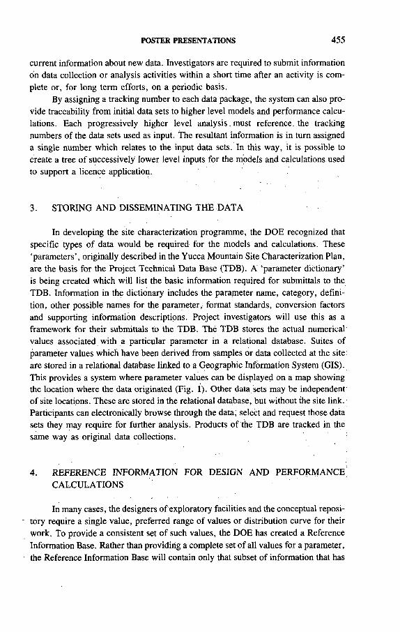
POSTER PRESENTATIONS 455
current information about new data. Investigators are required to submit information on data collection or analysis activities within a short time after an activity is complete or, for long term efforts, on a periodic basis.
By assigning a tracking number to each data package, the system can also provide traceability from initial data sets to higher level models and performance calculations. Each progressively higher level analysis must reference, the tracking numbers of the data sets used as input. The resultant information is in turn assigned a single number which relates to the input data sets. In this way, it is possible to create a tree of successively lower level inputs for the models and calculations used to support a licence application.
3. STORING AND DISSEMINATING THE DATA
In developing the site characterization programme, the DOE recognized that specific types of data would be required for the models and calculations. These ‘parameters’, originally described in the Yucca Mountain Site Characterization Plan, are the basis for the Project Technical Data Base (TDB). A ‘parameter dictionary’ is being created which will list the basic information required for submittals to the TDB. Information in the dictionary includes the parameter name, category, definition, other possible names for the parameter, format standards, conversion factors and supporting information descriptions. Project investigators will use this as a framework for their submittals to the TDB. Thé TDB stores the actual numerical values associated with a particular parameter in a relational database. Suites of parameter values which have been derived from samples or data collected at the site; are stored in a relational database linked to a Geographic Information System (GIS). This provides a system where parameter values can be displayed on a map showing the location where the data originated (Fig. 1). Other data sets may be independent of site locations. These are stored in the relational database, but without the site link. Participants can electronically browse through the data, select and request those data sets they may require for further analysis. Products of the TDB are tracked in the same way as original data collections.
4. REFERENCE INFORMATION FOR DESIGN AND PERFORMANCECALCULATIONS
In many cases, the designers of exploratory facilities and the conceptual reposi- ' tory require a single value, preferred range of values or distribution curve for their
work. To provide a consistent set of such values, the DOE has created a Reference Information Base. Rather than providing a complete set of all values for a parameter, the Reference Information Base will contain only that subset of information that has
GIS ATTRIBUTE L INKS
D R IL L LOG A TTRIBUT E TABLE
COVERAGE: E X IS T IN G D R ILL H O L E S
A C T IV I T Y ID : A C T I V I T Y TYPE: STUDY T Y P E : X-COORD:Y-COORD:GROUND ELEV: TOTAL DEPTH: DATE COMPLETED: USER:SOURCE:
USW H - l HYDROLOGIC HOLE SATURATED ZONE 5 6 5 , 3 8 7 . 9 6 0 0 0 7 7 0 , 2 5 4 . 3 2 0 0 0 4 2 7 4 . 4 6 0 0 0 1 / 2 5 / 8 1 ,USGSHitN A S - B U I L T
ATTRIBUTE TABLE
COVERAGE: EXISTING DRILLHOLES
BULK DENSITY GRAIN DENSITY TRANSMISSIVITY MATRIX POTENTIAL STORAGE COEFFICIENT DATES OF MEASUREMENTS HYDRAULIC CONDUCTIVITY NATURAL-STATE POREWATER MATER ELEVATIONS ANO DEPTH THERMAL/MECHANICAL STRATI GRAPH I С UNITS
TEST CONDITIONSLITHOLOGYPOROS ITYPORE SATURATIONPUMPING CONDITIONS
FIG. 1. Within the Technical Data Base, point, line and areal locations can be related to a series o f attribute tables containing data values from those locations.
456 PO
STER
P
RE
SE
NT
AT
ION
S
POSTER PRESENTATIONS 457
been agreed upon as the preferred set for design of performance calculations. The information is maintained as textual material with appropriate short tables or graphs. Included with the basic information is a description of how that particular information was derived, the assumptions used, references to the more complete sets in the TDB, and references to the reports used as source materials.
5. SUMMARY
The approach to storing and disseminating information for use in the programme provides that the information can be aggregated and disseminated at differing levels for differing purposes. The tracking system represents the lowest level of aggregation, where all information is reported and from which any data can be obtained. The Technical Data Base represents an intermediate level of aggregation, where data related to prescribed parameters are maintained for use in models and analyses. The Reference Information Base represents the highest degree of aggregation, where selected data sets or models are reported as those preferred for use in design or performance assessment.
458 POSTER PRESENTATIONS
ETUDE PAR DIFFERENTES APPROCHÉS EXPERIMENTALES DU COMPORTEMENT THERMO-HYDRO-MECANIQUE EN CHAMP PROCHE DE L’ARGILE DE BOOM A PARTIR DE L’INSTALLATION SOUTERRAINE HADES A MOL
M.RAYNALAgence nationale pour la gestion
des déchets radioactifs,Fontenay-aux-Roses, France
B. NEERDAEL HADES Project,CEN/SCK,Mol, Belgique
IAEA-SM-326/59P
Divers essais mécaniques et thermo-mécaniques ont été réalisés in situ à partir du laboratoire souterrain de Mol dans l’argile de Boom, qui pourrait constituer une formation d’accueil pour le stockage de déchets radioactifs de haute activité et à vie longue en Belgique.
Ces essais, dont la plupart a reçu le soutien financier de la Commission des communautés européennes (CCE), permettent d ’étudier le comportement réel de l’argile dans des conditions simulées d’un stockage et de vérifier la validité de certains modèles rhéologiques proposés. Ces essais permettent en outre de tester des méthodologies, des procédures et des appareils de mesures mis au point spécialement pour ces besoins. La conception et la nature de ces essais tiennent compte des contraintes spécifiques à la nature de ce projet, telles que la géométrie et la profondeur considérée, la température imposée par les colis et les circulations naturelles (eau) ou imposées (air) qui s’expriment par des échanges entre les ouvrages et la roche hôte.
1. ESSAIS PRENANT EN COMPTE LES CONTRAINTES D’ORDRE GEOMETRIQUE ET MECANIQUE SEULES
Compte tenu de la profondeur d’un stockage, les aspects géotechniques, la stabilité et le comportement à long terme des ouvrages sont de première importance pour juger de la faisabilité du projet. On s’est donc efforcé dans un premier temps de tester par une approche en contrainte totale où le matériau est considéré comme monophasique, le comportement purement mécanique des différents types
POSTER PRESENTATIONS 459
d ’ouvrages circulaires, de dimensions variables et généralement confortés par un soutènement. Les nombreuses mesures réalisées en forages (dilatomètre, convergen- cemètre, extensomètre) et en galeries (cintres coulissants ou claveaux) montrent une bonne reproductibilité des phénomènes observés, aux différentes échelles observées, pour autant, que les ouvrages .ne soient pas soumis à d’autres sollicitations que la décharge due au creusement [1, 2]. Le modèle rhéologique élaboré, du tÿpe.élasto- viscoplastique non linéaire avec écrouissage, rend bien compte des effets différés de la roche. .
2. ESSAIS OU EST PRISE EN COMPTE LA SOLLICITATION THERMIQUE
L’une des particularités essentielles d’un dépôt de déchets radioactifs issus du retraitement étant de dégager de la chaleur, il est naturel de vouloir s’intéresser à l ’influence de la température considérée comme une contrainte supplémentaire sur la roche et sur son contenu hydrique, et de vouloir ainsi étudier les comportements couplés thermo-mécaniques et thermo-hydrauliques du milieu. On s’est donc attaché à mettre en œuvre une simulation la plus proche de la réalité en réalisant avec l ’expérience «CACTUS» [3] deux forages équipés de sondes chauffantes, dont la puissance thermique imposée correspond au dégagement de chaleur produit par des déchets de type Cogéma refroidis 50 ans en surface.
Dans un premier forage [3, 4] on a fait subir au terrain deux cycles successifs de chauffe et refroidissement. On observe clairement les principales phases évolutives, qu’il s’agisse du transitoire thermique ou encore de la croissance suivie de la décroissance des pressions interstitielles et des contraintes. Les champs de température, déplacement, pression et contrainte sont mesurés dans le champ proche de la source thermique avec beaucoup de précision et l ’ensemble de ces mesures montre une très bonne cohérence entre elles. Les mesures de la deuxième sonde qui a démarré avec un cycle de chauffe plus rapide dans le deuxième forage semblent suivre les mêmes évolutions . [5].
Ces essais sont précieux pour connaître les irréversibilités éventuelles qu’apporte un tel cycle chauffage-refroidissement sur le milieu, éléments importants à connaître pour l’étude de sûreté d’un stockage. Ces travaux doivent également condüire à la validation dé modèles où les couplages thermo-hydro-mécaniques peuvent être pris en compte en milieu poreux peu perméable et peu fissuré.
3. ESSAIS OU LES TRANSFERTS HYDRIQUES DANS LE MASSIF SONTPRIS EN COMPTE
Un nouvel essai, essai «PHEBUS», sur le point de se mettre en place [6], vise à permettre l’évaluation des échanges hydriques existant entre le massif argileux d’accueil et les excavations où circule l’air de l ’aérage des ouvrages.

460 POSTER PRESENTATIONS
Le projet proposé constitue une approche originale de l’étude du comportement hydrique des milieux argileux de forte densité, par rapport à l’approche classique (eau libre, perméabilité). En effet, il vise à prendre en compte la physique réelle de l’eau dans les espaces poreux pour acquérir une meilleure compréhension des phénomènes et présenter une modélisation adéquate des transferts hydriques qui traduise l’effet de l’ouverture et de l ’aérage des ouvrages de stockage sur le milieu argileux (désaturation, resaturation).
Dans une première phase, actuellement en cours [7], on vise à acquérir une méthodologie d’essais de laboratoire spécifiques sur des échantillons d ’argiles de site reconstituées de façon à bien maîtriser l’histoire hydro-mécanique du matériau. Une maquette permet de mesurer des profils hydriques autour d’une galerie simulée.
L’objectif de la deuxième phase, qui sera menée in situ dans le laboratoire de Mol, est de valider les résultats acquis sur maquette. Cette phase permet, par une instrumentation adéquate, d ’approcher certains paramètres inaccessibles sur maquette et leur évolution dans le temps. L ’échelle réduite permet aussi d’évaluer l’utilité d’un essai de ventilation à l ’échelle d’une galerie et sa faisabilité technique: système de conditionnement d ’air, conception d’un soutènement poreux, séquence- ment des opérations.
REFERENCES
[1] BONNE, A., et al., The HADES Demonstration and Pilot Project on Radioactive Waste Disposal in a Clay Formation (Final Report), Contrat CCE n° FI1W/0004B, EUR 13851 EN, CCE, Luxembourg (1992) 280 p.
[2] BERNAUD, D., RÖUSSET, G., Dimensionnement du soutènement des galeries creusées dans l’argile profonde (Rapport final), Contrat CCE n° FI1W/0112, EUR 13267 FR, CCE, Luxembourg (1991) 194 p.
[3] Essai hydro-thermo-mécanique dans une argile profonde (Mol, Belgique), Essai CACTUS, Contrat CCE n° FI2W-0001-FCCD, Rapport d ’avancement n° 1 (1991).
[4] Essai hydro-thermo-mécanique dans une argile profonde (Mol, Belgique), Essai CACTUS, Contrat CCE n° FI2W-0001-FCCD, Rapport d ’avancement n° 2 (1991).
[5] Essai hydro-thermo-mécanique dans une argile profonde (Mol, Belgique), Essai CACTUS, Contrat CCE n° FI2W-0001-FCCD, Rapport d’avancement n° 3 (1992).
[6] Evaluation des transferts hydriques entre le massif argileux et les excavations (Projet PHEBUS), Contrat CCE n° FI2W-CT91-0116 (1992).
[7] Evaluation des transferts hydriques entre le massif argileux et les excavations (Projet PHEBUS), Rapport n° 1, 697RP et 92001 (1992).

POSTER PRESENTATIONS 461
TESTS DE SISMIQUE REFLEXION EN PREVISION D’UNE CAMPAGNE DE RECONNAISSANCE DE HAUTE DEFINITION DANS LE NORD EST DE LA BELGIQUE
P. LALIEUX, P. MANFROY ONDRAF/NIRAS,Bruxelles, Belgique
M. DUSARService géologique de Belgique,Bruxelles, Belgique
E. GILLOTCompagnie générale de géophysique,Paris, France
IAEA-SM-326/63P
L’argile de Boom (Oligocène, Tertiaire), présente dans le nord-est de la Belgique sous le site nucléaire de Mol/Dessel à une profondeur comprise entre 200 et 300 m et épaisse de 80 à 100 m, constitue pour ce pays la formation géologique de référence pour l’enfouissement des déchets radioactifs conditionnés de moyenne et haute activité.
Afin de définir les caractéristiques géométriques et afin d’évaluer l’homogénéité de cette couche et des formations encaissantes, l’ONDRAF a décidé de recourir à la sismique réflexion de haute résolution (2-D).
Plusieurs contraintes particulières — et parfois antagonistes — rendaient le choix des paramètres sismiques délicat:
— faible profondeur de l’objectif;— présence éventuelle d’accidents tectoniques de faible rejet;— nécessité d’une image sismique claire entre 100 et environ 1000 m de profon
deur, afin de pouvoir suivre les accidents tectoniques depuis les terrains paléozoïques indurés profonds jusqu’aux terrains meubles tertiaires;
— faiblesse des contrastes lithologiques dans les terrains tertiaires (succession de sables et d ’argiles avec zones de transition);
— nécessité de prévoir une acquisition en zone à forte urbanisation.
Afin d’optimiser les paramètres sismiques, il a été décidé de procéder à des tests préalables sur la zone nucléaire de Mol/Dessel. Ces tests ont été réalisés en octobre 1991 par la Compagnie générale de géophysique.

462 POSTER PRESENTATIONS
Le profil réalisé est court (1,6 km) et orienté OSO-ENE normalement à la direction régionale des faille connues. Après divers essais de sources (dynamite et vibrateur) et de récepteurs (géophone 10 et 30 Hz, hydrophone, triphorie), les dispositifs d’acquisition choisis, couvrant tous le même profil, étaient les suivants:
— Ondes P: dispositif centré, 120 traces de 10 m, géophones de 30 Hz, couverture 60, 2 s d’enregistrement, pas d’échantillonnage de 2 ms, 2 x 100 g de dynamite à 3 m de profondeur ou 1 vibrateur, sweep logarithmique,de 15 à 140 Hz, niveau de force de 40 à 60%.
— Ondes P converties Sv: tirs transposés, 30 traces de 10 m, triphones de 10 Hz, couverture 60, 4 s d’enregistrement, pas d’échantillonnage de 2 ms, 1 vibrateur, sweep linéaire de 10 à 100 Hz, niveau de force de 40 à 60%.
Pour les ondes P, les principaux enseignements de ces tests sont:
— c’est la dynamite qui conduit à la plus haute définition (résolution verticale de quelques mètres au niveau de l’argile de Boom);
— le revêtement en plaques de béton de la route le long du profil provoque des problèmes de couplage avec le vibrateur dans les hautes fréquences;
— l’utilisation de géophones 30 Hz permet une amélioration de la réponse enhautes fréquences; par contre, les signaux obtenus avec des hydrophones sont très bruités; ,
— on observe au sein de l’argile de Boom une série de réflexions nettes dont la corrélation avec des unités lithologiques connues n’a pas encore été démontrée;
— les traitements de déconvolution et d’inversion stratigraphiques ont été rendus difficiles par l ’absence de données soniques et de densité, mais on a montré leur utilité, notamment pour l ’analyse des hétérogénéités lithologiques;
— la grande qualité du profil dynamite a permis une interprétation tectonique et stratigraphique fine. Aucun accident ne recoupe Î’argile de Boom sur le profil. Les failles observées dans le Paléozoïque s’atténuent dans le Crétacé et la base du Tertiaire où elles se transforment en flexures. Il existe une très bonne continuité latérale des structures dans l’argile de Boom;
— la haute résolution et la qualité constante des réflexions permettent d’établir une stratigraphie séquentielle (transgression-régression) et de reconnaître l ’évolution dynamique du bassin sédimentaire'(tilting, onlap, épaississement);
— il subsiste des problèmes de calage dans les argiles du Tertiaire inférieur;— comme on peut le voir, il sera indispensable, lors des campagnes de reconnais
sance proprement dites, de prévoir au moins un sondage jusqu’au Crétacé (600 m de profondeur) avec l’ensemble des diagraphies électriques, nucléaires et sismiques nécessaires à une corrélation entre les réflexions et la lithologie.
Pour ce qui est des ondes converties, on observe de très nombreuses réflexions dans la zone de transition qui surplombe l ’argile de Boom ainsi qu’une diminution rapide de l’information avec la profondeur. Une interprétation fine du profil est

POSTER PRESENTATIONS 463
impossible en l’absence de données de puits. Ni l ’analyse des rapports entre les vitesses des ondes P et Sv ni l’étude des anisotropies ne semblent donner des résultats aisément interprétables. On observe en effet une faible anisotropie au sein de l ’argile de Boom dont les directions ne correspondent pas aux directions tectoniques régionales.
La réalisation de ces tests atteint tous les objectifs qui leur étaient assignés et a montré la très grande utilité de mesures préalables pour optimiser les paramètres des campagnes ultérieures.

CHAIRMEN OF SESSIONS
Session 1 F. DECAMPS BelgiumC.M. MALBRAIN Belgium
Session 2 L. REITER United States of AmericaH. RÖTHEMEYER Germany
Session 3 A. BONNE BelgiumC. DEL OLMO Spain
Session 4 F. GERA ItalyL. JOHNSON United Kingdom
Session 5 L. VAN DE VATE NetherlandsC. McCOMBIE Switzerland
Session 6 P. ESCALIER DES ORRES FranceC. PESCATORE OECD/NEA
Session 7 S. ORLOWSKI CECT. PAPP Sweden
SECRETARIAT OF THE SYMPOSIUM
M. BELL H. SCHMID S.P. FLITTON M. HAMENDE
Scientific Secretary Symposium Organizer Proceedings Editor French Editor
465

LIST OF PARTICIPANTS
Abdel-Monem, A.A.
Abreu, A.
Alexandre, D.C.
Antseleve Oyima, A.
Ayatollahi, M.S.
Baetsle, L.H.
Balteau, B.
Béguin, P.
Berg, H.P.
Bonne, A.
Research Division,Nuclear Materials Authority,P.O. Box 530, Maadi,Cairo, Egypt
Empresa Nacional de Residuos Radiactivos, SA, С/ Emilio Vargas 7,E-28043 Madrid, Spain
CEA, Centre d’études de Cadarache,F -13108 Saint-Paul-lez-Durance, France
Ministère des mines, de l’énergie et des ressources hydrauliques,
B.P. 1172,Libreville, Gabon
Atomic Energy Organization of Iran,P.O. Box 14155-1339,Tehran, Islamic Republic of Iran
CEN/SCK,Boeretang 200,B-2400 Mol, Belgium
RTBF,Passage de la Bourse,B-6000 Brussels, Belgium
TRACTEBEL,Avenue Ariane 7,B-1200 Brussels, Belgium
Bundesamt für Strahlenschutz,Postfach 10 01 49,D-W 3320 Salzgitter 1, Germany
SCK/CEN,Boeretang 200,B-2400 Mol, Belgium
467
468 LIST OF PARTICIPANTS
Bosser, R. Direction de la sûreté des installations nucléaires, Ministère de l’industrie et du commerce extérieur, Centre d ’études de Fontenay-aux-Roses,B.P. 6 ,F-92265 Fontenay-aux-Roses, France
Bouko, P. Administration des mines, Cité administrative de l’Etat, B-7000 Mons, Belgium
Bragg, K. Atomic Energy Control Board, P.O. Box 1046, Station B,270 Albert Street,Ottawa, Ontario, Canada KIP 5S9
Bretheau, F. ANDRA,Route du Panorama Robert Schuman,B.P. 38,F-92266 Fontenay-aux-Roses Cedex, France
Brücher, H. Forschungszentrum Jülich GmbH, Postfach 1913,D-W 5170 Jülich, Germany
Bruggeman, M. CEN/SCK,Boeretang 200, B-2400 Mol, Belgium
Castañón, A. Empresa Nacional de Residuos Radiactivos, SA, С/ Emilio Vargas 7,E-28043 Madrid, Spain
Cauwenbergh, C. ISIB,Rue Royale 158,B-1000 Brussels, Belgium
Certes, C. CEA/IPSN,Centre d ’études de Fontenay-aux-Roses,B.P. 6 ,F-92265 Fontenay-aux-Roses Cedex, France
Chaturvedi, L. New Mexico Environmental Evaluation Group, 7007 Wyoming Boulevard NE, Suite F-2, Albuquerque, NM 87111,United States of America
LIST OF PARTICIPANTS
Chun, K.S.
Ciallella, N.R.
Claes, J.
Closs, K.D.
Coroianu, A.I.D.
De, A.K.
De Cannière, P.
De Goeyse, A.
de las Cuevas, C.
De Preter, P.
Nuclear Environment Management Center, P.O. Box 7,Daeduk-Danji, Taejön, Republic of Korea
Comisión Nacional de Energía Atómica, Avenida del Libertador 8250,1429 Buenos Aires, Argentina
BELGOPROCESS,Gravenstraat 73,B-2480 Dessel, Belgium
Kernforschungszentnim Karlsruhe GmbH, Postfach 3640,D-W 7500 Karlsruhe, Germany
Commission nationale pour le contrôle des activités nucléaires,
Bulevardul Libertatii No. 12, Sector 5, Bucharest, Romania
Wiederaufarbeitungsanlage Karlsruhe Betriebsgesellschaft mbH,
c/o BELGOPROCESS,Gravenstraat 73,B-2480 Dessel, Belgium
SCK/CEN,Boeretang 200,B-2400 Mol, Belgium
NIRAS/ONDRAF,Place Madou 1, Boîtes 24-25,В-1030 Brussels, Belgium
Department of Geochemistry,University of Barcelona,Marti i Franques S/N,E-08028 Barcelona, Spain
NIRAS/ONDRAF,Place Madou 1, Boîtes 24-25,B-1030 Brussels, Belgium
470 LIST OF PARTICIPANTS
Decamps, F. ONDRAF/NIRAS,Place Madou 1, Boîtes 24-25, В-1030 Brussels, Belgium
Deconinck, F. BELGOPROCESS, Gravenstraat 73,B-2480 Dessel, Belgium
del Olmo, С. Empresa Nacional de Residuos Radiactivos, SA, С/ Emilio Vargas 7,E-28043 Madrid, Spain
Démazy, G. Service Retraitement et déchets, Synatom,Avenue Marnix 13,B-1050 Brussels, Belgium
Demonie, M. BELGOPROCESS, Gravenstraat 73,B-2480 Dessel, Belgium
Demoulin, A. Laboratoire de géomorphologie et de . géologie du Quaternaire,
Université de Liège,7, place du 20 août,B-4000 Liège, Belgium
Desvaux, J.L. Cogéma - La Hague,F-50444 Beaumont-Hague Cedex, France
Détilleux, E. ONDRAF/NIRAS,Place Madou 1, Boîtes 24-25, B-1030 Brussels, Belgium
Donker, H. Institute of Earth Sciences,State University of Utrecht, Budapestlaan 4, P.O. Box 80021, NL-3508 TA Utrecht, Netherlands
Dozol, M. CEA, Centre d ’études de Cadarache, B.P. 1,F-13108 Saint-Paul-lez-Durance, France
LIST OF PARTICIPANTS
Dusar, M.
Eggermont, G.
Engelmann, H.J.
Escalier des Orres, P.
Eschrich, H.
Espejo, J.M.
Fabre, J.C.
Fan, Xuanlin
Fernique, J.-C.
Ferreyra, R.E.
Service géologique de Belgique,Rue Jenner 13,В-1040 Brussels, Belgium
ONDRAF/NIRAS,Place Madou 1, Boîtes 24-25,B-1030 Brussels, Belgium
Deutsche Gesellschaft zum Bau und Betrieb von Endlagern für Abfallstoffe mbH,
Woltorfer Strasse 74,D-W 3150 Peine, Germany
CEA/IPSN,Centre d ’études de Fontenay-aux-Roses,B.P. 6 ,F-92265 Fontenay-aux-Roses Cedex, France
CEN/SCK,Engelandlaan 1,B-2440 Geel, Belgium
Empresa Nacional de Residuos Radiactivos, SA, С/ Emilio Vargas 7,E-28043 Madrid, Spain
CEA, Centre d ’études de la Vallée du Rhône, B.P. 171,F-30205 Bagnols-sur-Cèze Cedex, France
Beijing Research Institute of Uranium Geology, P.O. Box 764,Beijing 100029, China
ANDRA,Route du Panorama Robert Schuman,B.P. 38,F-92266 Fontenay-aux-Roses Cedex, France
Comisión Nacional de Energía Atómica,Avenida del Libertador 8250,1429 Buenos Aires, Argentina
472 LIST OF PARTICIPANTS
Flament, P.
Fuchs, H.
Fujiwara, A.
Fukutomi, Y.
Garcia Celma, A.
Gariel, J.C.
Gera, F.
Ghannadi-Maragheh, M.
Gillon, L.
ANDRA,Route du Panorama Robert Schuman,B.P. 38,F-92266 Fontenay-aux-Roses Cedex, France
Gesellschaft für Nuklear-Service mbH,Lange Laube 7,D-W 3000 Hanover 1, Germany
Radioactive Waste Management Center,No. 15, Mori Building,2-8-10 Toranomon, Minato-ku,Tokyo, Japan
Nuclear Power Division,Kandenko Co. Ltd,1938, 11, 17,4-7-5 Tsurumaki, Setagaya-ku,Tokyo, Japan
Netherlands Energy Research Foundation ECN, Westerduinweg 3, P.O. Box 1,NL-1755 ZG Petten, Netherlands
CEA/IPSN,Centre d ’études de Fontenay-aux-Roses,B.P. 6 ,F-92265 Fontenay-aux-Roses Cedex, France
ISMES SpA,Via dei Crociferi 44,1-00187 Rome, Italy
Jaber Ibn Hayan Laboratories,Atomic Energy Organization of Iran,P.O. Box 11365-8486,Tehran, Islamic Republic of Iran
CEN/SCK,Boeretang 200,B-2400 Mol, Belgium
LIST OF PARTICIPANTS 473
Godman, R.
Goffart, J.
Gomit, J.-M.
Haijtink, B.
Harrison, D.J.
Havard, P.L.V.
Hecq, W.
Heremans, R.
Heusermann, S.R.
Hoorelbeke, J.-M.
TRW Environmental Safety Systems Inc.,2650 Park Tower Drive, Suite 800,Vienna, VA 22180,United States of America
Université de Liège,Boulevard E. de Laveleye 50,B-4020 Liège, Belgium
CEA/IPSN,Centre d ’études de Fontenay-aux-Roses,B.P. 6 ,F-92265 Fontenay-aux-Roses Cedex, France
Commission of the European Communities,Rue de la Loi 200,B-1049 Brussels, Belgium
Yucca Mountain Site Characterization Project Office, United States Department of Energy,P.O. Box 98608,Las Vegas, NV 89193-8608,United States of America
ELECTROBEL,Boulevard du Régent 8 ,B-1000 Brussels, Belgium
Université libre de Bruxelles,44, Avenue Jeanne 1,B-1050 Brussels, Belgium
ONDRAF/NIRAS,Place Madou 1, Boîtes 24-25,B-1030 Brussels, Belgium
Bundesanstalt für Geowissenschaften und Rohstoffe, Stilleweg 2, Postfach 51 01 53,D-W 3000 Hanover 51, Germany
ANDRA,Route du Panorama Robert Schuman,B.P. 38,F-92266 Fontenay-aux-Roses Cedex, France
474 LIST OF PARTICIPANTS
Hron, M. Nuclear Research Institute, CS-250 68 Rez, Czechoslovakia
Huertas, F. Empresa Nacional de Residuos Radiactivos, SA, С/ Emilio Vargas 7,E-28043 Madrid, Spain
Janssens, H. Industríele Hogeschool Mol, Chrysantenlaan 10,B-2400. Mol, Belgium
Jean, D.
Jockwer, N..
Cogéma - La Hague,F-50444 Beaumont-Hague Cedex, France
Institut für Tieflagerung,Abteilung für Endlagersicherheit, GSF-Forschungszentrum für Umwelt und
Gesundheit GmbH, Theodor-Heuss-Strasse 4,
iD-W 3300 Braunschweig, Germany
Johnson, L.
Kautsky, F.
British Nuclear Fuels pic,Sellafield, Seascale,Cumbria CA20 IPG, United Kingdom
Swedish Nuclear Power Inspectorate, Box 27106,S-102 52 Stockholm, Sweden
Kuzyk, G.W. AECL Research,Whiteshell Laboratories,Pinawa, Manitoba, Canada ROE 1L0
Lacrosse, B. Ministère des affaires étrangères, Avenue Belliard 65,B-1040 Brussels, Belgium
Lalieux, P. ONDRAF/NIRAS,Place Madou 1, Boîtes 24-25, B-1030 Brussels, Belgium
Langer, M. Bundesanstalt für Geowissenschaften und Rohstoffe, Stilleweg 2, Postfach 51 01 53,D-W 3000 Hanover 51, Germany
LIST OF PARTICIPANTS 475
Leclère, R.
Lemmens, K.
Ministère des affaires économiques, Square de Meeus 23,В-1040 Brussels, Belgium
SCK/CEN,.Boeretang 200 ,B-2400 Mol,'Belgium
Lind, N.C. Federal Environmental Assessment Review Office, Fontaine Building,Hull, Quebec, Canada K1A 0H3
Lonsták, L.
López García, A.
Lukács, E.
Hungarian Geological Survey,Stefánia Utca 14,H-1143 Budapest, Hungary
Empresa Nacional de Residuos Radiactivos, SA, С/ Emilio Vargas 7,E-28043 Madrid, Spain
Republic Administration for Nuclear Safety, Ministry of Environment and Physical Planning, Kardeljeva Ploscad 24,61113 Ljubljana, Slovenia
Lukaj, M.
Malasek, E.
Geological Survey,Kyncelová 10,CS-974 00 Banská Bystrica, Czechoslovakia
Czechoslovak Atomic Energy Commission; Slezská 9,
• CS-120 29 Prague 2, Czechoslovakia
Malbrain, C.M.
Manfroy, P.
CEN/SCK,Boeretang 200,B-2400 Mol, Belgium
: ONDRAF/NIRAS,‘ Place Madou 1, Boîtes 24-25,
B-1030 Brussels, Belgium
Marivoet, J. CEN/SCK,Boeretang 200, B-2400 Mol, Belgium
476 LIST OF PARTICIPANTS
Mathieu, P.
Mazurek, M.
McCombie, C.
McMenamin, T.
Méndez Martín, F.J.
Merceron, T.
Merz, E.R.
Michel, J.-P.
Minon, J.P.
Institut de mécanique,Université de Liège,Rue Ernest Solvay 21,B-4000 Liège, Belgium
Geological Institute,University of Bern,Baltzerstrasse 1,CH-3012 Bern, Switzerland
National Cooperative for the Disposal of Radioactive Waste (Nagra),
Hardtstrasse 73,CH-5430 Wettingen, Switzerland
Commission of the European Communities, Rue de la Loi 200,B-1049 Brussels, Belgium
CIEMAT,Edificio 8-9,Avenida Complutense 22,E-28040 Madrid, Spain
ANDRA,Route du Panorama Robert Schuman,B.P. 38,F-92266 Fontenay-aux-Roses Cedex, France
Forschungszentrum Jülich GmbH,Postfach 1913,D-W 5170 Jülich, Germany
TRACTEBEL,Avenue Ariane 7,B-1200 Brussels, Belgium
ONDRAF/NIRAS,Place Madou 1, Boîtes 24-25,B-1030 Brussels, Belgium

LIST OF PARTICIPANTS 477
Mönig, J.
Morlock, G.
Morton, C.
Mouty, M.
Mozelev, A.A.
Nachmilner, L.
Nakamura, H.
Neerdael, B.
Newbury, C.M.
Institut für Tieflagerung, . ,Abteilung für Endlagersicherheit, GSF-Forschungszentrum für Umwelt und
Gesundheit GmbH,Theodor-Heuss-Strasse 4,D-W 3300 Braunschweig, Germany
.Gesellschaft für Reaktorsicherheit mbH,, Maarweg 128,
D-W 5000 Cologne 30, Germany
Euratom Safeguards Directorate,Commission of the European Communities, Bâtiment Cube,Plateau du Kirchberg,L-2920 Luxembourg, Luxembourg
Atomic Energy Commission,P.O. Box 6091,Damascus, Syrian Arab Republic
‘RADIKAL’ Small Scale Research and Production Company,
Box 118,Dubna 5, Moscow Region, Russian Federation
Nuclear Research Institute,CS-250 68 Rez, Czechoslovakia
Radioactive Waste Management Center,No. 15, Mori Building,2-8-10 Toranomon, Minato-ku,Tokyo, Japan
CEN/SCK,Boeretang 200,B-2400 Mol, Belgium
Yucca Mountain Site Characterization Project Office, United States Department of Energy,P.O. Box 98608,Las Vegas, NV 89193-8608,United- States of America
478 LIST OF PARTICIPANTS
Nicolaou, G. Commission of the European Communities, Joint Research Centre,Institute for Transuranium Elements, Postfach 2340,D-W 5700 Karlsruhe, Germany
Niemeyer, M.J. Colenco Power Consulting Ltd, Mellingerstrasse 207,CH-5405 Baden, Switzerland
Niephaus, D. Forschungszentrum Jülich GmbH, Postfach 1913,D-W 5170 Jülich, Germany
Nishiyama, A. Kendenko Co. Ltd,4-8-33 Shibaura, Minato-ku, Tokyo, Japan
Ochi, E. Japan Nuclear Fuel Co. Ltd, Simitomo Suidobashi Building, 7-8 Sarugaku-cho, 2-chome, Chiyoda-ku, Tokyo, Japan
Ohta, T. Japan Nuclear Fuel Co. Ltd, Simitomo Suidobashi Building, 7-8 Sarugaku-cho, 2-chome, Chiyoda-ku, Tokyo, Japan
Ollagnier, M. ANDRA,Route du Panorama Robert Schuman, *B.P. 38,F-92266 Fontenay-aux-Roses Cedex, France
Orlowski, S. Commission of the European Communities, Rue de la Loi 200,B-1049 Brussels, Belgium
Papp, T. Swedish Nuclear Fuel and Waste Management Co. Box 5864, -S-102 48 Stockholm, Sweden
Pasquini, S. CEA, Centre d ’études de Cadarache, F-13108 Saint-Paul-lez-Durance, France
LIST OF PARTICIPANTS 479
Peaudecerf, P. Bureau de recherches géologiques et minières, B.P. 6009,F-45060 Orléans Cedex 2, France
Pescatore, C. OECD Nuclear Energy Agency,Le Seine Saint Germain,12, boulevard des Iles,F-92130 Issy-les-Moulineaux, France
Poliakov, A. Ail-Union Science Research Institute of Inorganic Materials,
5 -Rogov Street,Moscow, Russian Federation
Poncelet, J.P. ONDRAF/NIRAS,Place Madou 1, Boîtes 24-25, В-1030 Brussels, Belgium
Portal, R. Service Combustibles,Electricité de France,23 bis, avenue de Messine, F-75384 Paris Cedex 08, France
Potier, J.-M. ANDRA,Route du Panorama Robert Schuman,B.P. 38,F-92266 Fontenay-aux-Roses Cedex, France
Put, M.J. SCK/CEN;Boeretang 200, B-2400 Mol, Belgium
Raimbault, P. ANDRA,Route du Panorama Robert Schuman,B.P. 38,F-92266 Fontenay-aux-Roses Cedex, France
Rasilainen, K.O. Nuclear Engineering Laboratory, Technical Research Centre of Finland, P.O. Box 208,SF-02151 Espoo, Finland
480 LIST OF PARTICIPANTS
Ray nal, M .
Reiter, L.
Richter, D.
Ringeard, C.
Riotte, H .G .
Rodriguez Beceiro, A.
Röthemeyer, H.
Rothfuchs, T.
Saire, D .E .
A N DRA ,
Route du Panorama Robert Schuman,
B.P. 38,
F-92266 Fontenay-aux-Roses Cedex, France
Nuclear Waste Technical Review Board,
1100 Wilson Boulevard, Suite 910,
' Arlington, VA 22209,
United States o f America
■ Gesellschaft für Nuklear-Service mbH,
Lange Laube 7,
D-W 3000 Hanover 1, Germany
A N DRA ,
Route du Panorama Robert Schuman,
B.P. 38,
F-92266 Fontenay-aux-Roses Cedex, France
. Bundesministerium für Forschung und Technologie,
Heinemannstrasse 2,
D-W 5300 Bonn 2, Germany
Empresa Nacional de Residuos Radiactivos, S A ,’
i Cl Emilio Vargas 7,
E-28043 Madrid, Spain
Bundesamt für Strahlenschutz,
Albert-Schweitzer-Strasse 18,
D-W 3320 Salzgitter 1, Germany
Institut für Tieflagerung,
Abteilung für Endlagersicherheit,
GSF-Forschungszentrum für Umwelt und
Gesundheit GmbH,
. Theodor-Heuss-Strasse 4,
D-W 3300 Braunschweig, Germany
,, Division o f Nuclear Fuel Cycle and
Waste Management,
International Atomic Energy Agency,
Wagramerstrasse 5, P .O . Box 100,
A-1400 Vienna, Austria

LIST OF PARTICIPANTS 481
Salo, J.-P. Teollisuuden Voima Oy,
Annankatu 42 C,
SF-00100 Helsinki, Finland
Saverot, P. NUSYS,
14, rue du Printemps,
F-75017 Paris, France
Sayyah, T.A. Nuclear Materials Authority,
El Maâdi, P .O . Box 530,
Cairo, Egypt
Schaller, K .H .
Schmidt, G.
Commission of the European Communities,
Rue de la Loi 200,
B-1049 Brussels, Belgium
Öko-Institut,
Bunsenstrasse 14,
D-W 6100 Darmstadt, Germany
Schneefuss, J.U . Institut für Tieflagerung,
Abteilung für Endlagersicherheit,
GSF-Forschungszentrum für Umwelt und
Gesundheit GmbH,
Theodor-Heuss-Strasse 4,
D-W 3300 Braunschweig, Germany
Semenov, В. Department o f Nuclear Energy and Safety,
International Atomic Energy Agency,
Wagramerstrasse 5, P .O . Box 100,
A-1400 Vienna, Austria
Smith, P.
Sneyers, A.
Paul Scherrer Institute,
CH-5232 Villigen PSI, Switzerland
CEN/SCK,
Boeretang 200,
B-2400 M ol, Belgium
Stallaert, P. Ministère d ’emploi et de sécurité du travail,
Avenue Belliard 53,
B-1040 Brussels, Belgium

482 LIST OF PARTICIPANTS
Startchenko, V. V .G . Khlopiri Radium Institute,
Kuna 2-310,
St. Petersburg, Russian Federation
Steininger, W . Kernforschungszentrum Karlsruhe GmbH,
Postfach 3640,
D-W 7500 Karlsruhe, Germany
Storck, R. GSF-Forschungszentrum für Umwelt und
Gesundheit GmbH,
Theodor-Heuss-Strasse 4,
D-W 3300 Braunschweig, Germany
Stribrny, B. Bundesministerium für Umwelt, Naturschutz
• ■ und Reaktorsicherheit,
Postfach 12 06 29,
D-W 5300 Bonn 1, Germany
Svemar, C. Swedish Nuclear Fuel and Waste Management Co.
Box 5864,
S-102.48 Stockholm, Sweden
Takeuchi, H.
Thegerström, С.
Nippon Electric Glass Co. Ltd,
2-7-1 Seiran, Otu-shi,
Osaka, Japan
Swedish Nuclear Fuel and Waste Management Co.
Box 5864,
S-102 48 Stockholm, Sweden
Tondeur, F. ISIB,
Rue Royale 158,
В-1000 Brussels, Belgium
Tosh, G .C . Scottish Nuclear,
Redwood Crescent,
Peel Park,
East Kilbride, United Kingdom
Tupí, P. Geological Survey,
Kyncelová 10,
CS-974 00 Banská Bystrica, Czechoslovakia
LIST OF PARTICIPANTS
Ulibarri, A.
Unzeitig, M .
Valkiainen, M .
Van Averbeke, J.
Van Brabant, R.
Van Cotthem, A.
Van de Maele, J.
Van de Vate, L.
Van Herch, T.
Van Iseghem, P.
Van Miegroet, J.
Empresa Nacional de Residuos Radiactivos, SA,
С / Emilio Vargas 7,
E-28043 Madrid, Spain
Ministry ó f Environment o f the Czech Republic,
Nad A leji 16,
CS-162 00 Prague 6, Czechoslovakia
Reactor Laboratory,
Technical Research Centre o f Finland,
Otakaari ЗА , P .O . Box 200,
SF-02151 Espoo, Finland
BELGON U CLEA IRE ,
Avenue Ariane 4,
B-1200 Brussels, Belgium
BELGOPROCESS,
Gravenstraat 73,
B-2480 Dessel, Belgium
TRACTEBEL,
Avenue Ariane 7,
B-1200 Brussels, Belgium
CEN/SCK,
Boeretang 200,
B-2400 M ol, Belgium
Geological Survey of the Netherlands,
Ministry ó f Economic Affairs,
P .O . Box 157,
NL-2000 A D Haarlem, Netherlands
Ministry o f Economic Affairs,
Rue De Moite 30,
B-1400 Brussels, Belgium
SCK/CEN,
Boeretang 200,
B-2400 Mol,. Belgium
O N DRAF/N IRAS,
Place Madou 1, Boîtes 24-25,
В-1030 Brussels, Belgium
484 LIST OF PARTICIPANTS
Vermeiren, P. Industríele Hogeschool Mol,
Chrysantenlaan 10,
B-2400 M ol, Belgium
Veyer, C. NUSYS,
14, rue du Printemps,
F-75017 Paris, France
Vidal, H. CEA , Centre d ’études de Cadarache,
B.P. 1,
F-13108 Saint-Paul-lez-Durance, France
Volckaert, G. SCK/CEN,
Boeretang 200,
B-2400 M ol, Belgium
Vreys, H. Ministère de la santé publique,
■Vesaliusgebouw,
B-1010 Brussels, Belgium
Wemaere, I. CEN/SCK,
Boeretang 200,
B-2400 M ol, Belgium
Wieland, В. Office fédéral de l ’énergie,
CH-3003 Bern, Switzerland
Wilson, J. HM Industrial Pollution Inspectorate,
Scottish Office,
Environment Department,
27 Perth Street,
Edinburgh, United Kingdom
Yearsley, R .A . Her Majesty’s Inspectorate o f Pollution,
Room A5.02, Romney House,
43 Marsham Street,
London SW1P 3PY, United Kingdom
Yui, M . Power Reactor and Nuclear Fuel Development
Corporation,
Tokai, Ibaraki 319-11, Japan
Zurkinden, A. Nuclear Safety Inspectorate,
CH-5232 Villigen HSK, Switzerland
AUTHOR INDEX
Abdel-Monem, A.A.: 75 Akram, N.: 432 Ammar, A.A.: 75 Andre-Jehan, R.: 87 Baillif, L.: 201 Barnert, E.: 427 Bateman, K.: 440 Bell, M.: 3 Beloiu, D.: 423 Berg, H.P.: 225 Bohm, V.: 423 Bonne, A.: 339 Bosser, R.H.: 381 Bouniol, P.: 109 Brennecke, P.: 225 Brücher, H.: 427 Cadelli, N.: 405 Chaturvedi, L.: 442 Chun, K.S.: 425 Closs, K.D.: 273, 375 Collard, G.: 339 De, A.K.: 189 De Cannière, P.: 319 De Goeyse, A.: 189 de las Cuevas, C.: 133 De Preter, P.: 319 Demonié, M.: 189 Demoulin, A.: 451 Desvaux, J.L.: 201 Donker, H.: 133 Du, Zhichao: 419 Dumitrescu, R.: 423 Dusar, M.: 461 Engelmann, H.J.: 41, 273 Escalier des Orres, P.: 285 Fan, Xuanlin: 419 Farcaçiu, D.M.: 423 Farcaçiu, О .M.: 423 Fioravante, V.: 440
Fonteyne, A.: 319 Fouillac, C.: 87 García Celma, A.: 133 Gariel, J.C.: 445 Gaudez, M.T.: 432 Gautschi, A.: 55 Gillot, E.: 461 Gmal, B.: 225 Grávalos, J.M.: 251 Gronemeyer, C.: 434 Gu, Jifang: 419 Haijtink, B.: 405 Harrison, D.J.: 161 Herrmann, A.G.: 41 Heusermann, S.R.: 121 Hoorelbeke, J.-M.: 145 Hron, M.: 418 Huertas, F.: 251 Hugi, M.: 297 Impey, M.: 440 Jaritz, W.: 41 Jean, D.: 201 Jing, Lanru: 327 Jockwer, N.: 436, 438 Kautsky, F.: 327 Kjellbert, N.: 309 Koch, L.: 422 Kroth, K.: 427 Kuzyk, G.W.: 145 Lalieux, P.: 461 Lambert, A.: 365 Lemmens, K.: 209 Lenôtre, N.: 451 Lidove, S.: 285 Lukaj, M.: 69 Lummerzheim, D.: 375 Manfroy, P.: 461 Marivoet, J.: 285 Martens, K.: 285
Mazurek, M.: 55 McCombie, C.: 365 McKinley, I.G.: 365 McMenamin, T.: 173 Merceron, T: : 87 Meuresch, S.: 375 Miralles, L.: 133 Mohammadioun, B.: 445 Mohanty, B.: 145 Mönig, J.: 432, 438 Moors, H.: 319 Morlock, G.: 434 Moustafa, M.E.: 75 Moxhet, J.: 451 Mozelev, A.A.: 417 Nachmilner, L.: 69 Neerdael, B.: 458 Neill, R.H.: 442 Newbury, C.M.: 454 Nicolaou, G.: 422 Niemeyer, M.J.: 297 Niephaus, D.: 427, 429 Olivier, J.-P.: 31 Ollagnier, M.: 109 Orlowski, S.: 11 Palut, J.M .: 432 Papp, T.: 309 Park, H.S.: 425 Patera, E.S.: 31 Pescatore, C.: 31 Petit, J.C.: 87 Pissart, A.: 451 Potier, J.-M.: 145 Prij, J.: 285 Printz, R.: 429 Put, M.J.: 319 Raimbault, P.: 285, 448 Ray nal, M.: 432, 458 Ringeard, C.: 448
485
486 AUTHOR INDEX
Riotte, H.G.: 375 Röthemeyer, H.: 41 Rothfuchs, T.: 438 Riiegger, В.: 31 Saire, D.E.: 21 Salo, J.-P,: 263 Sayyah, T.A.: 75 Schaller, K.H.: 405 Schneefuss, J.U.: 121 Semenov, В.: 3 Sifre, Y.: 145 Smith, P.: 297
Spilker, H.: 273 Stahl, D.: 161 Stephansson, О.: 327 Storck, R.: 41 Stribrny, В.: 41 Sureau,.J.F.: 87 Svemar, C.: 239 Teixidor, P.: 133 Thegerström, C.: 353 Toulhoat, P.: 87, 432 Van Iseghem, P.: 189, 209 Van Miegroet, J.: 101
Vanécek, M.: 69 Volckaert, G.: 440 Vomvoris, S.: 55 von Börstel, L.E.: 41 Wetzler, H.: 429 Willax, H.O.: 273 . Worgan, K.: 440 Würz, H.: 422 Xu, Guoqing: 419 Zuidema, P .:.297

INDEX OF PAPERS AND POSTERS BY NUMBER
IAEA-SM-326/ Page
4 .................... ; ............................... 6917 ................... , ................................ 22518 ............................... ...................... 13320 ......:........ :..................... :......... .-. 32721 ...................................................... 7523 ............................................. . 35324 ..................................................... 30925 ....... ....................................... . 23926 ..................... : ..............;.............. 4129 ...................................................... 12130 .......... ........................................... 36531 ...................................................... 5532 .................................. ..............29733 ..................................... ................ 27336 ...................................................... 20937 ........................ : ......... :........ . 31938 ......:............................. ............ 339
IAEA-SM-326/ Page
3P .................................................. 4175P ..................................... ............. 4187P ............................................ . 4199P ................'....... . ....................... 422
10P .................................................. 423IIP ................................................... 42513P ............. ...........; . . . ................... 42714P ................ .......................... 42919P .................................................. 43222P ..! ............... ,......... •........, ........ 434
Papers
IAEA-SM-326/ Page
39 . . . . . . . ...................... :.......... 263
42 ........................................................ 201
44 ........................................................ 145
45 ........................................................ 109
48 ........................................................ 375
53 ..............................:....................... 251
54 ......... ............................................... 161
57 ....................................................... 285
58 ................... : .................................. 381
.60 ........................................................ 87
62 .................................... .................... 189
64 ........................................................ 101
66 ........................................................ 11
67 . . . . . ' ................................................ 21
68 ...................... ................................. 31
6 9 ............................................................ . . : . 173
70 ........................ ............................... 405
Posters
IAEA-SM-326/ Page
27P ..................................................... 436
28P .................................................... 438
35P :............. ..................................... 440
41P : ............................ ; .................... 442
43P ..................................................... 445
46P ..................................................... 448
: 51P :.......... ........ r .. ; . . . ; ..........v...... >451
56P ..................................................... 454
59P .................................................... 458
63P ........................................................461
487

HOW TO ORDER IAEA PUBLICATIONS
■ An exclusive sales agent for IAEA publications, to whom all orders and inquiries should be addressed, has been appointed for the following countries:
CANADAUNITED STATES OF AMERICA UNIPUB, 4611-F Assembly Drive, Lanham, MD 20706-4391, USA
In the following countries IAEA publications may be purchased from the sales agents or booksellers listed or through major local booksellers. Payment can be made in local currency or with UNESCO coupons.
ARGENTINA
AUSTRALIABELGIUM
CHILE
CHINA
FRANCE
HUNGARYINDIA
ISRAELITALY
JAPANPAKISTAN
POLAND
ROMANIA RUSSIAN FEDERATION
SLOVAK REPUBLIC SOUTH AFRICA
SPAIN
SWEDEN
UNITED KINGDOM
YUGOSLAVIA
Comisión Nacional de Energía Atómica, Avenida del Libertador 8250, RA-1429 Buenos AiresHunter Publications, 58 A Gipps Street, Coilingwood, Victoria 3066 Service Courrier UNESCO, 202, Avenue du Roi, B-1060 Brussels Comisión Chilena de Energía Nuclear, Venta de Publicaciones, Amunategui 95, Casilla 188-D, Santiago IAEA Publications in Chinese:China Nuclear Energy Industry Corporation, Translation Section,P.O. Box 2103, BeijingIAEA Publications other than in Chinese:China National Publications Import & Export Corporation,Deutsche Abteilung, P.O. Box 88, BeijingOffice International de Documentation et Librairie, 48, rue Gay-Lussac, F-75240 Paris Cedex 05Librotrade Ltd., Book Import, P.O. Box 126, H-1656 Budapest Oxford Book and Stationery Co., 17, Park Street, Calcutta-700 016 Oxford Book and Stationery Co., Scindia House, New Delhi-110 001 YOZMOT Literature Ltd., P.O. Box 56055, IL-61560 Tel Aviv Librería Scientifica Dott. Lucio di Biasio "AEIOU",Via Coronelli 6, 1-20146 MilanMaruzen Company, Ltd, P.O. Box 5050, 100-31 Tokyo International Mirza Book Agency, 65, Shahrah Quaid-e-Azam, P.O. Box 729, Lahore 3 Ars Polona, Foreign Trade Enterprise, .Krakowskie Przedmieécie 7, PL-00-068 Warsaw llexim, P.O. Box 136-137, Bucharest Mezhdunarodnaya Knlga, Sovinkniga-EA,Dimitrova 39, SU-113 095 MoscowAlfa, Publishers, Hurbanovo námestie 3, 815 89 BratislavaVan Schaik Bookstore (Pty) Ltd, P.O. Box 724, Pretoria 0001Díaz de Santos, Lagasca 95, E-28006 MadridDíaz de Santos, Balmes 417, E-08022 BarcelonaAB Fritzes Kungl. Hovbokhandel, Fredsgatan 2, P.O. Box 16356,S-103 27 StockholmHMSO, Publications Centre, Agency Section,51 Nine Elms Lane, London SW8 5DRJugoslovenska Knjiga, Terazije 27, P.O. Box 36, YU-11001 Belgrade
Orders from countries where sales agents have not yet been appointed and requests for information should be addressed directly to:
0)9
Division of PublicationsInternational Atomic Energy AgencyWagramerstrasse 5, P.O. Box 100, A-1400 Vienna, Austria