Geological Disposal of Carbon Dioxide and Radioactive Waste in the Geotectonically Active Country of...
38
1 Geological Disposal of Carbon Dioxide and Radioactive Waste in the Geotectonically Active Country of Japan Hitoshi Koide* CC Geosystem Laboratory 2-6-1-602 Higashi-Ikebukuro, Toshima Tokyo, 170-0013 Japan [email protected] Kinichiro Kusunose Geological Survey of Japan, AIST 1-1-1 Higashi Tsukuba, 305-8567 Japan [email protected] * Corresponding author Abstract In Japan, site selection for geological disposal of radioactive waste (RW) and carbon dioxide (CO 2 ) is very important because of the large regional differences in tectonic activity. Assessment of the long-term stability of geological environments is key to geological RW disposal in Japan. A comprehensive system of long-term prediction of crustal movement and the groundwater regime around the virtual RW disposal sites has been developed in Japan. CO 2 is naturally abundant, but geological disposal of the gigantic volumes of CO 2 may have big impacts on the environment. One of the adverse effects of underground fluid injection is that it may induce earthquakes. Underground carbon microbubble injection accelerates advanced geological disposal mechanisms. The autogenously sealed ‘CO 2 capsules’ can be formed in large basaltic sheets, ophiolite complex and oceanic crust. Sub-seabed aquifers under the deep sea floor can provide very safe and virtually limitless CO 2 disposal. Different disposal strategies for CO 2 and RW are needed because of the extreme difference in their toxicity and volume. The dispersion and dilution principle is possible for the CO 2 disposal, while RW is strictly contained by the multiple barrier system. The stability of the geological environment is important for both CO 2 and RW disposal. Keywords Geological prediction, induced earthquake, microbubbles, tectonic stability, site selection 1 Introduction Despite a lengthy history of meticulous research into the geological disposal of radioactive waste (RW) and carbon dioxide (CO 2 ), Japan has yet to successfully implement either geological disposal of high-level radioactive waste or full-scale
Transcript of Geological Disposal of Carbon Dioxide and Radioactive Waste in the Geotectonically Active Country of...

1
Geological Disposal of Carbon Dioxide and Radioactive Waste in the Geotectonically Active Country of Japan
Hitoshi Koide*
CC Geosystem Laboratory 2-6-1-602 Higashi-Ikebukuro, Toshima
Tokyo, 170-0013 Japan
Kinichiro Kusunose Geological Survey of Japan, AIST
1-1-1 Higashi Tsukuba, 305-8567
Japan [email protected]
* Corresponding author Abstract In Japan, site selection for geological disposal of radioactive waste (RW) and carbon dioxide (CO2) is very important because of the large regional differences in tectonic activity. Assessment of the long-term stability of geological environments is key to geological RW disposal in Japan. A comprehensive system of long-term prediction of crustal movement and the groundwater regime around the virtual RW disposal sites has been developed in Japan. CO2 is naturally abundant, but geological disposal of the gigantic volumes of CO2 may have big impacts on the environment. One of the adverse effects of underground fluid injection is that it may induce earthquakes. Underground carbon microbubble injection accelerates advanced geological disposal mechanisms. The autogenously sealed ‘CO2 capsules’ can be formed in large basaltic sheets, ophiolite complex and oceanic crust. Sub-seabed aquifers under the deep sea floor can provide very safe and virtually limitless CO2 disposal. Different disposal strategies for CO2 and RW are needed because of the extreme difference in their toxicity and volume. The dispersion and dilution principle is possible for the CO2 disposal, while RW is strictly contained by the multiple barrier system. The stability of the geological environment is important for both CO2 and RW disposal. Keywords Geological prediction, induced earthquake, microbubbles, tectonic stability, site selection 1 Introduction Despite a lengthy history of meticulous research into the geological disposal of radioactive waste (RW) and carbon dioxide (CO2), Japan has yet to successfully implement either geological disposal of high-level radioactive waste or full-scale
Koide
ノート
Hitoshi Koide , Kinichiro Kusunose (2011):Geological Disposal of Carbon Dioxide and Radioactive Waste in the Geotectonically Active Country of Japan, (Draft for) Ferenc L. Toth ed., Geological Disposal of Carbon Dioxide and Radioactive Waste: A Comparative Assessment , in Advances in Global Change Research, ISBN: 978-90-481-8711-9 (Print) 978-90-481-8712-6 (Online), p.539-567
2
underground disposal of CO2. The Japanese, having experienced at first hand natural disasters such as earthquakes and also nuclear disasters, are particularly sensitive to events such as these. Indeed, many Japanese people have major concerns about the safety of radioactive facilities, especially as Japan is an earthquake-prone country with many active faults. The arcuate islands of Japan were formed along plate boundaries between two major oceanic plates and two continental plates. Many earthquakes, active fault lines and active volcanoes are concentrated in and around the Japanese islands. Subduction of the oceanic plates under the continental plates dominates tectonic deformation on the Japanese islands. Volcanic activity and faults are concentrated along the volcanic fronts, but no active volcanoes and few active fault lines are located between the volcanic front and the subduction zone (Sugimura and Uyeda 1973). Site selection for geological disposal of RW and CO2 is very important because of the large regional differences in tectonic activity in Japan (see Figure 1). It is also important to win public confidence in the long-term safety of RW disposal. Accurate assessment of the long-term stability of the geological environment is crucial to the geological disposal of RW and CO2 in Japan. < insert Figure 1 about here > 2 Current Status and Issues of Geological Disposal of CO2 in Japan 2.1 Geological Disposal of CO2 in Saline Aquifers and in Gas- and Oilfields Japan has a long history of research into carbon capture and storage (CCS) in geological sites. The first paper on CO2 disposal in saline aquifers appeared in 1990 (in Japanese). Koide (1990) proposed the pumping up of deep saline groundwater using naturally dissolved methane, separating the methane from the groundwater and then reinjecting the groundwater and anthropogenically produced CO2 into the aquifers. A voluntary CCS R&D team from national research institutes and some companies led by H. Koide presented the first comprehensive report on the disposal of CO2 in saline aquifers at the First International Conference on Carbon Dioxide Removal, held in Amsterdam, the Netherlands, in March 1992 (Koide et al. 1992). They suggested that the relevant technologies were generally available, disposal costs were reasonable (about US$22/t CO2) and disposal capacity was adequate (with at least a 319 gigatonnes of CO2 (Gt CO2) disposal capacity in solution in aquifers worldwide) (Koide et al. 1993). Koide (1999) revised his estimate of world subsurface disposal potential in saline aquifers to 3*1012 t in CO2 solution, as he considered his first estimate to be far too conservative. This voluntary study was expanded to a CCS R&D project within the Engineering Advancement Association of Japan (ENAA). ENAA’s CCS team estimated the CO2 disposal potential of Japan on a systematic basis. It found the disposal capacity of CO2 supercritical fluid in Japan to be 2 Gt CO2 in oil/gas deposits (category I) and 1.5 Gt CO2 in dome structures (category II), and the disposal capacity of CO2 in solution in Japan to be 16 Gt CO2 in onshore saline aquifers (category III) and 72 Gt CO2 in offshore saline aquifers (category IV) (see Figure 2 and Tanaka et al. 1995). The total aquifer disposal potential in Japan was estimated to be as much as 92 Gt CO2.
3
Recently, the Research Institute of Innovative Technology for the Earth (RITE) revised the estimated disposal capacity of CO2 in Japan (Takahashi et al. 2009). Supercritical CO2 may be stored as follows: 3.5 Gt CO2 in oil/gas deposits; 5.2 Gt CO2 in probable dome structures; and 21.4 Gt CO2 in possible dome structures, mainly in offshore sedimentary basins around Japan. Additional CO2 may be stored in solution — as much as 22 Gt CO2 in onshore saline aquifers and 94 Gt CO2 in offshore saline aquifers. The total CO2 aquifer disposal potential was estimated at 146 Gt CO2; this is enough to accommodate more than 100 years of industrial CO2 emissions in Japan. Although the generic potential for CO2 aquifer disposal is enough to accommodate Japan’s anthropogenic CO2 emissions, Japan needs to refine the concept further to adapt it to its actual and industrial environments. This should be done in the next few years for Japan to fulfil its obligations under the Kyoto Protocol. The refinement of the concept depends on the answers to the following questions: (1) How much CO2 can be stored in Japan? (2) Where? (3) How? (4) At what cost? and (5) How safely can it be stored? Japan’s dense population and urbanization make the transportation of RW and CO2 on land costly, if not prohibitive. Most of the big CO2 emitters are near the coast for convenience of transportation. It is expected that the RW and CO2 will most probably be disposed of geologically underground on the coast or, alternatively, in offshore sub-seabed rocks. Li et al. (2005) rank CO2 disposal sites in terms of potential capacity and supply of CO2, both of which significantly affect the economics of disposal (Figure 2). They preliminarily selected 11 premier-ranking candidate sites recommended for early deployment in five regions: Kanto, Joban, Niigata, Toyama and south-west Hokkaido. < insert Figure 2 about here > In 2000 RITE began a systematic R&D project on the geological disposal of CO2 with support from Japan's Ministry of Economy, Trade and Industry (METI) (Kaya et al. 2001). RITE started underground injection of supercritical CO2 at a depth of 1,100 m into a saline sandy aquifer above the natural gas reservoirs in Nagaoka, Niigata Prefecture, on 7 July 2003. The underground injection ended on 11 January 2005, although monitoring continued up to 2007. During the injection, the Chuetsu earthquake, which registered 6.8 on the Richter scale, occurred 15 km south-east of the test site. The earthquake was caused by the movement of a major active fault system running through the Nagaoka area along a branch fault. The shock of the earthquake immediately stopped the injection operation, but no other effects were observed in the test wells. The triggering of the Chuetsu earthquake seems to have been unrelated to the underground injection of CO2, as the active faults near the test site were dormant. In May 2008, the Japan Petroleum Exploration Co. Ltd. (JAPEX) and other major companies in the country co-founded the Japan Carbon Capture & Sequestration (JCCS) Company Limited. The 32 co-founders of JCCS included 11 major electric power companies, five oil distributors and three oil developers, as of June 2009. In July 2009, JCCS, on behalf of METI, began a field survey for a feasibility project along the planned CO2 pipeline route connecting the Integrated Gasification Combined Cycle (IGCC) power plant at Iwaki City in the Fukushima Prefecture and the offshore Iwaki-oki gasfield. JCCS also started a preliminary field survey at the
4
offshore Tomakomai-oki site in Hokkaido. METI and JCCS intend to make a preliminary geological investigation at four offshore sites, including Iwaki-oki and Tomakomai-oki, for a larger second-phase underground CO2 injection test of possibly around 100,000 t/yr rate classes. 2.2 Geological Disposal of CO2 in Coal Seams The General Environmental Technos Co. Ltd., Kansai Electric (KEPCO), Japan Coal Energy Center (JCOAL) and other institutions began the Japan ‘CO2 Geodisposal in Coal Seams’ Project in 2002 with support from METI (Koide et al. 2003). From November 2004 to 2007 they injected a total of 884 t CO2 into a 5.6 m thick coal seam at a depth of 890–895 m and recovered 150,672 normal m3 of methane from the coal seam. Nitrogen injection effectively enhanced injectivity damaged by coal swelling. The CO2 disposal capacities of coalfields in Japan were estimated from old geological and experimental data (Koide et al. 2005). The remaining coal seams in old coal mines in Japan are estimated to be able to adsorb about 600 million tonnes of CO2 (Mt CO2). Explored but untapped coal seams are suitable for the early application of CO2 disposal. A preliminary field test on using CO2 for enhanced coalbed methane (CO2 ECBM) is being carried out for untapped coal seams in the coalbed methane-rich Ishikari coalfield in Hokkaido. It is possible that the main untapped coalfields in Japan can store 380 Mt CO2 and produce 84*109 m3 of coalbed methane in total. All the major conventional coalfields in Japan can sequestrate about 1 Gt CO2 and produce 240*109 m3 of coalbed methane from the coalbeds remaining in old coal mines and in untapped coalfields, combined. Nearshore coalfields in the Kyushu district can provide cost-effective disposal for CO2. Systematic exploration for oil and natural gas by the Japan National Oil Corporation and other oil companies has revealed that there are huge coal seam volumes in the depths of the Palaeogene and Cretaceous sedimentary basins in central Hokkaido, off the Pacific coast of north-eastern Honshu, and north-west of Kyushu in and around Japan (Koide and Kuniyasu 2006). Deep unmineable coal seams and coaly shale layers provide a possible sink for CO2 disposal and a source of coalbed methane. In Japan there are unmineable coal seams deeper than 1,200 m and shallower than 3,000 m that exceed 300 Gt capacity and could store 10 Gt CO2 as well as producing 3*1012 m3 of coalbed methane. Very deep (over 3,000 m) unmineable coal seams in Japan are estimated to exceed 3*1012 t capacity and could contain some 24*1012 m3 of coalbed methane. The CO2 disposal potential in very deep unmineable coal seams (deeper than 3,000 m) is more than 100 Gt in Japan. The total capacity of deep unmineable coalbeds is between 10 and 100 times greater than the shallow coal reserves that are mineable using conventional drift mining or open-cut mining practices. The huge volumes of deep unmineable coal seams are potential sinks for CO2 and also enormous untapped energy resources. When pure CO2 is injected, it at once behaves as a supercritical fluid around injection wells in deep coal seams. Supercritical CO2-enhanced coal seam gas recovery and in situ fire-free microbial gasification of coal can turn deep unmineable coal seams into CO2 sinks and methane sources for a CO2 emission-free closed-circuit power plant. A new type of ‘coal mine’ using borehole mining is proposed for the development of ‘deep unmineable coalbeds’ (Koide and Yamazaki 2001).

5
In June 2009, the Agency for Natural Resources and Energy (ANRE) of METI proposed a new and environmentally friendly coal policy that includes: (1) the ‘CoolGen’ project for the zero emission coal-fired power plant feasibility study, and (2) the ‘Clean Coal for Earth’ project for international cooperation by Japan’s cutting-edge clean coal technologies. 2.3 Natural Analogues for Geological Disposal of CO2 A natural analogue study for safe disposal of CO2 is very important in the tectonically active islands of Japan. A series of small earthquakes, the Matsushiro swarm earthquakes, began in the Matsushiro area of Nagano City in central Japan in August 1965, culminating in April 1966. The Matsushiro swarm earthquakes were accompanied by a combined eruption of CO2 and brine from a double en echelon system of numerous new small cracks. The earthquake activity quickly declined after large volumes of water and CO2 were released from newly formed surface cracks. The surface cracks increased in number to form a double en echelon system of numerous small cracks filled with CO2-rich brine. The double en echelon system of cracks indicates an underlying left-lateral strike-slip fault: the Matsushiro earthquake fault zone (Koide 1971). A large amount of CO2 and brine cascaded from cracks in and around the earthquake fault zone. Mechanical and chemical analyses suggest that CO2 bubbles caused an increase in fluid pressure in the shallower tips of cracks and that this eventually triggered the swarm earthquakes (see Figure 3 and Koide et al. 2006). Large underground CO2 bubbles of supercritical fluid and gas can induce fault instability and small earthquakes under critical tectonic stress states (see Figures 4 and 5). Although CO2-driven earthquakes tend to be very small, careful investigation of faults, in situ stresses, crustal deformation and seismicity need to be carried out before a large amount of CO2 can be stored underground. Mechanical analyses indicate that CO2 solution and CO2 microbubbles do not induce such a large underground mechanical instability as big bubbles of CO2 supercritical fluid and CO2 gas (Koide and Xue 2009). < insert Figure 3 about here > < insert Figure 4 about here > < insert Figure 5 about here > Although an estimated 100,000 t CO2 were released with about 10 million tonnes (Mt) of brine from cracks and cascades during the Matsushiro swarm earthquakes, there were no casualties, as the water-rich surface condition buffered the adverse effect of CO2 release. About 40 years later, shallow fresh groundwater has almost completely covered the deep CO2-rich brine except for a few spots where a few small bubbles sporadically rise in an area with a thin and shallow groundwater cover. Shallow groundwater covers the deep CO2-rich brine, almost completely in contrast to the monoclinal geological structure of the Isobe natural CO2 reservoir in Annaka City, Gunma Prefecture, central Japan. CO2-rich volcanic gas (72–95% CO2) gushes from some ten vents on the sea floor at depths of about 78 m and 200 m in the northern Kagoshima bay, south-western Japan. The northern part of Kagoshima bay is an almost closed sea basin, divided from the main part of Kagoshima bay by the active Sakura-jima volcano. It was formed mainly by the volcanic Aira caldera. The total amount of CO2 released is estimated at around
6
20–100 t CO2 per day. Most of the CO2 is in gas bubbles which dissolve into the seawater within several metres above the vents, while CO2-free gas bubbles appear on the sea surface. The deep seawater is acidified in the summer. However, the deep block of acidic seawater disappears in winter when the convection of seawater becomes active. The shallow water is important for the safety of underground CO2 disposal, acting as a buffer against the adverse effects of CO2. 2.4 Advanced Methods of Geological CO2 Disposal Using advanced methods for swift and secure underground storage of CO2 is also very important in unstable regions. Small-scale CO2 injection tests were conducted for the study of underground geochemical CO2 fixation in a serpentine body in Hidaka, Hokkaido (Yajima et al. 2005; Okamoto et al. 2006) and in a geothermal granite body in Ogati, in Akita Prefecture (Wakahama et al. 2008). Serpentine (mainly composed of the serpentine Mg3Si2O5(OH)4) is a type of ultramafic rock, which is derived from the Earth’s mantle and occurs at collision plate boundaries like the Japanese islands. A preliminary field study showed that the estimated capacity of CO2 mineralization in serpentine massif all over Japan is about 700 Mt (Yajima et al. 2005). The CO2 injection makes the groundwater acidic near the injection well, and this dissolves some of the rock-forming minerals in the CO2-rich acidic groundwater. However, the chemical reaction between the CO2 and the rocks makes the groundwater alkaline. If CO2 encounters an alkaline groundwater rich in metallic cations such as calcium ions, magnesium ions, ferrum ions, etc., the carbonate minerals precipitate and clog the pores and fissures in the rocks. Thus, while CO2 injection induces partial dissolution of rocks, thereby increasing the porosity of rocks near the injection well, it also precipitates as carbonates in pores in alkaline groundwater far from the injection well (see Figure 6). Autogenous sealing of CO2 occurs in cation-rich alkaline aquifers, especially around ultramafic and mafic rock bodies such as peridotite, serpentine, basalt, tuff, ophiolite and oceanic crust (Koide 2001). < insert Figure 6 about here > The in situ geophysical and geochemical observations and related laboratory experiments during the first Japanese project on CO2 geological disposal at the Nagaoka site revealed some interesting behaviours on the part of deep saline aquifers in Japan (Xue et al. 2009; Mito et al. 2008). The results of time-lapse cross-well seismic tomography indicate an area of P-wave velocity decrease due to CO2 saturation, while the CO2-bearing zone near the injection well expands clearly along the formation to the updip direction during CO2 injection. The presence of CO2 was also identified by induction, sonic and neutron logging at the observation wells. Changes in the composition of the formation water sampled by the Cased Hole Dynamics Tester (CHDT) tool after the CO2 injection suggest that solubility trapping is an important mechanism in geological disposal of CO2. Dissolution of plagioclase and chlorite has great potential for enhancing neutralization of the acidified formation water (Mito et al. 2008). Numerical simulation using TOUGHREACT software has shown that more than 20 Mt CO2 can be stored for a period up to 10,000 years in the young sedimentary aquifers of the Tokyo Bay area (Okuyama et al. 2009). Carbonate precipitation occurs extensively on the periphery of expanding areas of carbonated water, forming a shell

7
that encloses the CO2. The distribution of dawsonite is predicted to be dependent on the dissolution of plagioclase, which is present in abundance in the sandstones of the Tokyo Bay area and in the young sedimentary strata of the Japanese islands, suggesting its potential importance in the mineral trapping of CO2 (Okuyama et al. 2009). A novel technology for generating numerous microbubbles of CO2 and/or other gases in water in underground injection wells (Figure 6) allows greenhouse gases to be emplaced in the tiny pores of saline aquifers and narrow cracks of fractured rock bodies (Koide and Xue 2008). Carbon microbubbles of less than several 10 micrometres in diameter tend to shrink and quickly dissolve in water. As these microbubbles have hardly any buoyancy, they do not merge to form large bubbles with a large buoyant force in groundwater. The capillary effect traps many carbon microbubbles as residual gas in rock pores (Figures 6 and 7). As the CO2 solution is heavier than the original water, the dispersion of CO2 into underground rocks as microbubbles prevents the rising upwards of plumes of large CO2 (gas or supercritical fluid) bubbles in underground aquifers. The injection of underground carbon microbubbles accelerates geological disposal mechanisms such as capillary trapping, solubility trapping, ionization trapping, mineral trapping and microbial trapping by dispersion and quick dissolution (Figure 7). < insert Figure 7 about here > The combined effect of the very weak buoyant force of carbon microbubbles, heavy CO2 solution and various trapping mechanisms makes the underground injection of carbon microbubbles stable across a wide geological range, even where there are some structural imperfections such as depleted oil/gas reservoirs with abandoned wells, faulted domes, saline aquifers with incomplete caprocks in young unfolded sedimentary basins, large horizontal aquifers with unproven caprocks, synclinal sedimentary basins, fractured large basalt layers, faulted serpentine bodies, etc. (Koide and Xue 2008). The flexibility of site selection makes source–sink matching much easier for subsurface injection of carbon microbubbles than for conventional direct injection. As suitable sites for sinks can be found near many of the main sources of CO2, the subsurface injection of carbon microbubbles is a practical energy saving and cost-effective greenhouse gas reduction method in many regions. CO2 injection under gas hydrate-filled or permafrost layers may achieve greenhouse gas mitigation and recovery of unused natural gas. Autogenous sealing of CO2 in deep (>300 m) and cool (<5°C) aquifers assures virtually complete and practically unlimited subsurface containment of CO2 (Koide et al. 1997). Sediments under the deep sea floor are very cool because the deep oceanic water usually only has a temperature of a few degrees centigrade. CO2 hydrate is formed in sediments under wide areas of ocean floor deeper than about 300 m. Virtually complete isolation of huge amounts of CO2 is made possible by deep sub-seabed disposal. Liquid CO2 with heavy suspension intrudes laterally under light, unconsolidated sediments at sea floor depths of under around 3,700 m. Using the lateral intrusion technique for the super-deep sub-seabed disposal of CO2 can protect the ecology of the sea floor. Virtually unrestricted volumes of CO2 can be sequestered in the sediments and oceanic crusts under the deep sea floor around the Japanese islands.
8
Chemoautotrophic microbes fix CO2 in deep underground aquifers even in the absence of sunlight. Thermophilic methanogens can convert the CO2 into methane in anoxic and hot aquifers (Koide 1997). Biogenic restoration of subsurface hydrocarbon deposits may be possible in CO2-injected aquifers, probably after decades. Microbiological recycling of CO2 in aquifers is an attractive possibility for energy-poor countries such as Japan (Koide and Yamazaki 2001). The key to underground CO2 recycling is hydrogen supply, that is, energy sources from microbial decomposition of organic matter, from geochemical water–rock interaction and from deep geothermal activity. In view of the wide diversity of underground microorganisms, an extensive search for favourable species and ecosystems is needed. The natural gas and/or oil reservoirs in and around Japan are relatively small-scale and distant from major CO2 emitters. However, the CO2 disposal potential of saline aquifers has been estimated at as much as 146 Gt CO2 — enough to accommodate more than a century of industrial CO2 emissions in Japan. The real problem is the geotectonic instability (earthquakes, faults and geothermal activity) of the Japanese islands. Advanced scientific studies are anticipated to develop secure CO2 disposal technologies and underground microbial carbon recycling. 3 Current Status and Issues of Geological Disposal of Radioactive Waste in Japan 3.1 Geological Disposal of High-Level Radioactive Waste in Japan Since 1955 Japan has been promoting the use of nuclear energy for strictly peaceful purposes. The establishment of the nuclear fuel cycle is the fundamental policy for nuclear energy development and utilization in Japan, with spent fuel from nuclear power generation being chemically processed at fuel reprocessing plants to recover uranium and plutonium which can be recycled as fuel for electricity generation. After the reprocessing of spent radioactive fuel and the recovery of the uranium and plutonium, the resultant high-level radioactive liquid waste is mixed with raw materials, then vitrified into a solid glass form to ensure physical and chemical stability. The vitrified high-level waste (HLW) is encapsulated in stainless steel containers and placed into temporary disposal for 30 to 50 years to cool. It is subsequently placed in a deep underground, geological disposal repository, at a depth greater than 300 m. Japan has a much longer history of research into geological disposal of RW than into CCS. The national R&D project on geological disposal of HLW started along Atomic Energy Commission (AEC) of Japan guidelines published in 1976 and in 1980 (AEC 1976, 1980). The Special Committee of the AEC indicated a stepwise procedure for geological disposal of HLW as outlined below (AEC 1980): Phase 1 Research on potential geological environments; Phase 2 Research on suitable geological environments; Phase 3 In situ experiments with mocked-up vitrified waste forms; Phase 4 In situ experiments with vitrified waste forms; Phase 5 Demonstration of disposal.
9
The Power Reactor and Nuclear Fuel Development Corporation (PNC, later JNC) compiled the R&D achievements of Japan in a first progress report (PNC 1992). In November 1999, the Japan Nuclear Cycle Development Institute (JNC) submitted a second progress report entitled H12: Project to Establish the Scientific and Technical Basis for HLW Disposal in Japan (H12 Report, for short) (JNC 2000a, b, c, d) to the AEC for an official review. The H12 Report consists of the Project Overview Report (JNC 2000a); Supporting Report 1 — Geological Environment in Japan (JNC 2000b); Supporting Report 2 — Repository Design and Engineering Technology (JNC 2000c); Supporting Report 3 — Safety Assessment of the Geological Disposal System (JNC 2000d); and Supplementary Report — Background of Geological Disposal. The Japanese Government enacted the Specified Radioactive Waste Final Disposal Act (Final Disposal Act) in May 2000 to establish a framework for the final disposal of high-level radioactive waste. The Final Disposal Act established the Nuclear Waste Management Organization of Japan (NUMO) as the responsible organization by private initiative. In the same year the Nuclear Safety Commission (NSC) issued the Basic Policy for Safety Regulations for High-Level Radioactive Waste (First Report). In December 2002, NUMO began an open solicitation process to invite municipalities to volunteer for preliminary investigation sites. Although since December 2002 some ten municipalities have shown interest in being voluntary NUMO ‘preliminary investigation sites’, none have been able to obtain the consensus of local residents to be able to apply officially. Many Japanese people are deeply concerned about the safety of radioactive facilities from earthquakes and active faults. It is important to gain public confidence in the long-term safety of RW disposal. Until the H12 Report, research on the long-term stability of the geological environment was conducted mainly to show that there is a wide range of stable geological environments in Japan that are suitable for RW geological disposal. The potential and scale of future events can be discussed based on the trends and frequency of occurrence of natural phenomena in the past. After the H12 Report, in addition to continuing academic research such as nationwide data acquisition and studies on individual events and their mechanisms, the emphasis was placed more on the development of appropriate investigation and assessment technologies. In September 2005, JNC published the report entitled H17: Development and Management of the Technical Knowledge Base for the Geological Disposal of HLW (H17 Report, for short) (JNC 2005a, b, c, d). The H17 Report consists of the Knowledge Management Report (JNC 2005a); Supporting Report 1 — Geoscience Study (JNC 2005b); Supporting Report 2 — Repository Engineering Technology (JNC 2005c); and Supporting Report 3 — Safety Assessment Methods (JNC 2005d). Disposal technology is a multidisciplinary field about which a wide range of information is needed to develop safety scenarios. Knowledge, both explicit and tacit, obviously increases with time and is essential to all stakeholders, including implementers, regulators, political decision makers and the general public. Although essential for developing a project, a structured approach to assuring that all relevant knowledge is available is particularly critical at times when major project decisions have to be made. The Japan Atomic Energy Agency (JAEA) was established in October 2005 by merging the Japan Atomic Energy Research Institute (JAERI) and JNC. JAEA carries

10
out geoscientific research into actual deep geological environments at the Mizunami Underground Research Laboratory (granite, hard rock, fresh groundwater) in Gifu Prefecture and at the Horonobe Underground Research Laboratory (sedimentary rock, soft rock, saline groundwater) in Hokkaido. In 1992, low-level waste (LLW) disposal and, in 1995, vitrified HLW storage began at the Rokkasyo, Aomori Prefecture. The LLW disposal centre has a total capacity of 80,000 m3 (400,000 drums of 200 litres) and an ultimate future capacity of 600,000 m3. The vitrified waste (HLW) storage centre has a storage capacity of 1,440 canisters and ultimate future capacity of 2,880 canisters. In Japan, except for eliminating unconsolidated rocks, potential geological formations for HLW disposal have not yet been identified. Both crystalline and sedimentary rocks are being investigated generically. The long-term stability of the geological environment and groundwater regime is being investigated carefully for the long-term isolation of RW (Marui and Kusunose 2008). 3.2 Prediction of Long-Term Stability of the Geological Environment for the Safe Disposal of Radioactive Waste 3.2.1 Methods of Geological Prediction The long-term stability of the geological environment is essential for the safe geological disposal of RW (Koide 1991). Long-term crustal movement must be predicted to evaluate the stability of geological repositories of RW and neighbouring rock mass during an assessment period. As a case study, a numerical analysis method for the prediction of crustal movement in Japan, which was studied using three-dimensional elastic analysis by the finite element method (FEM) for the geological block structure of the Kinki region and the Awaji-Rokko (Kobe) area, is presented (Sasaki et al. 2000). Stability analysis for a disposal cavern was also investigated. Geological modelling, based on geophysical and drilling information, including information on the surface structure, is performed to delineate the subsurface structure (Kouda and Murakami 2002). The Kinki region and the Awaji-Rokko (Kobe) area are not candidate sites for the geological disposal of RW, as they are geotectonically unstable areas with a high earthquake risk. They were studied for convenience of evaluation of the prediction of long-term crustal movement. There are various methods of predicting crustal movement, such as research and model testing of past crustal movement patterns. In these methods, the establishment of a computer-based model is indispensable for quantitative prediction. The computational techniques involved in simulating the crustal movement for about 10,000 years were proposed and the numerical results compared with the features of surveyed crustal movement. Geological prediction methods are generally classified as follows (Koide 1991, 1997):
1. Prediction by extrapolation: the fundamental method for geological prediction is especially effective in steady slow phenomena, and is also applicable to periodic and cyclical ones. The prediction should be made based on detailed observations over a sufficiently longer time span than the prediction period,
11
and the possibility of changes in tendency should be checked by other prediction methods.
2. Prediction by analogy: the future prediction is carried out by identifying
similar past phenomena. This method, known as the natural analogue method, is an effective approach for crustal movement phenomena, and the only reliable method of validating conceptual and numerical models for long-term prediction for RW disposal.
3. Prediction by experiment: the phenomena are artificially modelled, and the
prediction is then carried out using the experimental model. The method is necessary for understanding the mechanism of geological phenomena, as the conditions can be precisely controlled. Long-term quantitative prediction using this method is difficult, however.
4. Prediction by probability: statistical research is indispensable for assessing the
risk of some catastrophic events; however, statistically fine data of geological phenomena are difficult to obtain.
5. Prediction by conceptual model: the plate tectonic model is useful for
predicting tectonic movements in a plate boundary region such as the Japanese archipelago.
6. Prediction by numerical simulation model: as past phenomena cannot exactly
equate to present ones, a complicated underground environment cannot be simulated, even experimentally. Numerical calculations by computer are necessary to quantitatively predict changes in crustal movement phenomena in which various factors interact. Mechanical stability and seepage analyses are carried out to evaluate the performance of current geological disposal.
7. Prediction by safety assessment model: simplified safety assessment models
are useful for analysing the overall performance of a complex disposal system. The safety assessment requires the development of synthetic models, scenario analyses and consequence analyses. Long-term geological prediction should be performed and cross-checked by the different methods.
A systematic approach with several prediction methods, as mentioned above for the prediction of long-term tectonic stability, is more practical. 3.2.2 Outline of Crustal Movement in Japan The disposal of RW in deep geological formations is a safer, viable technology at present. However, as the Japanese archipelago is close to the plate boundary, crustal movements and associated active faults are more intense than in continental areas (Koide 1992). Thus, volcanoes are not evenly distributed. There is no volcanic activity between the volcanic front and the oceanic trench where the plate sinks, but much volcanic activity concentrated in the continental vicinity of the volcanic front (Sugimura and Uyeda 1973). Uneven distribution by region is also noteworthy in relation to the active faults. There are regions characterized by few active faults between the volcanic front and the oceanic trench (see Figure 1).

12
Up to about 10 km underground, earth pressure and temperature, as well as rock strength, all increase with depth. However, deeper than 10 km underground the strength of the rock decreases drastically, as the high geothermal temperature makes the rock ductile. Near the volcanic front, the temperature is high because of magma rising from the mantle. Hence, in the volcanic front region the crust with high rigidity is very thin, while in the region between the oceanic plate and the volcanic front, the crust with high rigidity is thick because of the relatively low temperature caused by plate subduction. As a result, crust deformation is concentrated near the volcanic front region with the thin crust, whereas the crust with high rigidity between the volcanic front and oceanic trench is relatively stable (Figure 1). The region where crust upheaval is greatest is concentrated near the plate boundary and volcanic front. In the region of maximum upheaval the rate is about several mm/yr on average. In most regions, crustal upheaval or subsidence rates are within 1 mm/yr. The average displacement rate is several mm/yr, even in an active fault. Such active faults are distributed near the plate boundary, volcanic front and the median tectonic line. The average slip rate of the majority of active faults in other regions is less than 1 mm/yr. To evaluate the long-term stability of disposal sites, it is essential to estimate the magnitude of future geological events. 3.2.3 Crustal Movement Prediction Analysis Japan is located in a particularly complex geological region, being close to four major plates. North-eastern Japan is primarily compressed between two converging plate boundaries. The north-east is characterized by the east–west horizontal compression and the north–south trend of reverse faults. On the other hand, the strike-slip faults represented by the major median tectonic line develop in the part of western Japan that is affected by the oblique subduction of the Philippine Sea Plate at the Tokai-Nankai Trough under the Eurasian Plate. The north–south trend of many short reverse faults in the Kinki district is related to the bends in major strike-slip faults. In western Japan, the Kinki district has been chosen as a region for large-scale modelling. The Kinki district is divided geologically into several blocks by active faults. A qualitative evaluation by lateral slip, upheaval and subsidence behaviour around the Osaka block is carried out by three-dimensional linear elastic FEM (Sasaki et al. 2000). In the depth direction it is modelled to the lower-limit plane depth (estimated from the hypocentral depth distribution) of the upper crust. The lower crust is treated mechanically as a distribution of springs. The inclination of the block boundary is also considered. The compressive strain in the east–west direction is considered by giving an enforcement displacement (30 m/1,000 years), referring to the horizontal strain of the Kinki district over the past 100 years measured by the Geographical Survey Institute. This result simulates the lateral slip behaviour of the fault, generated over the past 10,000 years. In addition, a medium-scale model has been developed. The purpose of the medium-scale model is to establish the analytical conditions of the vicinity model around the virtual RW disposal vault. In the medium-scale model, minor active faults that are not considered in the large-scale model have been modelled. The boundary conditions for the enforcement displacement are given, and the value of displacement is obtained

13
from large-scale model analysis. The mechanical properties of the rock mass and faults are assumed to be linear elastic as in the large-scale model. Figure 8 compares the analytical results for the relative slip rate vector with those surveyed. It appears that the analytical results qualitatively match the survey results. This result shows that the strain is concentrated around the Awaji-Kobe-Rokko active faults. The disastrous 1995 Kobe earthquake (which measured 7.2 on the Richter scale) occurred along the active faults with a large slip rate during the mechanical analysis (Koide 1997). The analytical results provide useful suggestions on the relation between the fault geometry and earthquake-fault stability. < insert Figure 8 about here > Research on crustal movement prediction techniques is required for underground RW disposal sites for long periods exceeding 1,000 years. Although there are various prediction methods, computational simulation techniques are necessary to quantitatively predict crustal movement. One of the problems in crustal movement prediction is that there is little information regarding the deep underground. The long-term prediction of crustal movement for geological disposal sites and an example of the procedure and modelling technique using FEM have been proposed. To improve the accuracy of crustal movement prediction, more precise modelling of the fault is required. It is also important to judge synthetically the result of the numerical analysis using geological and rock engineering knowledge, as crustal movement prediction involves many uncertain and complicated factors. The validity of the model must be verified by comparison with crustal movements in the past. Assessment of the long-term stability of geological environments is the key issue for geological RW disposal in Japan. The comprehensive system of long-term prediction of crustal movement and the groundwater regime around the virtual RW disposal sites has been developed through long and painstaking efforts in Japan. 4 Comparison of CO2 and Radioactive Waste Geological Disposal 4.1 Extreme Differences in Toxicity and Volume Although RW is extremely toxic, its volume is much smaller than that of CO2 (see Table 1). As the radionuclides in RW do not exist in nature, they should not be dispersed into the environment. Hence the disposal strategy for RW is long-term containment. Although the radioactivity of HLW rapidly decreases, it is still highly toxic for up 10,000 years and toxic for up to 100,000 years. LLW has low toxicity after 300 years; however, some LLW may be weakly toxic for up to 10,000 years. That is why RW is stored in carefully mined tunnels and/or vault systems in multiple natural and engineered barrier systems (EBSs). < insert Table 1 about here > Almost 800 Gt CO2 have accumulated in the atmosphere since the industrial revolution — enough to cover the whole earth with an 80 cm thick layer. The annual emission of CO2 is about 1.3 Gt in Japan and about 27 Gt worldwide. A single major fossil fuel power plant can emit several Mt CO2 per year. It is virtually impossible to
14
construct a big enough tunnel and/or vault system to accommodate such a gigantic amount of CO2. Containment by EBSs used in RW disposal is too costly for the disposal of a huge amount of CO2. Cost-effective CO2 disposal uses injection of CO2 through drilled wells into the natural underground rock pore system and natural containment mechanisms. Natural gas and/or oil reservoirs are ideal reservoirs for the CO2 disposal. However, many natural gas and/or oil reservoirs are still occupied by valuable resources. Some available reservoirs are too far from large CO2 emission sources to be economically feasible. Disposal in saline aquifers and other advanced options for geological disposal of CO2 are being investigated to provide a wider range of CO2 reduction options. While a CO2 density in air of under 1% is not toxic to humans, CO2 that is denser than 0.04% (current level) has too high a greenhouse effect. On the other hand, CO2 density that is under 0.03% is dangerously low for plants and has too low a greenhouse effect, leading to potential global cooling. The natural density of CO2 in the air (about 0.03%) is not only harmless but also necessary for human health and for the global climate. Using CO2 microbubble injection as a strategy to disperse and dilute CO2 may provide the safest disposal option, in terms of avoiding a large underground accumulation of a high density of CO2. 4.2 Underground Injection of CO2 Fluid and Emplacement of Solidified Radioactive Waste The impact of RW disposal on the environment is limited. While CO2 is naturally abundant, the geological disposal of CO2, through the injection of huge volumes of CO2 directly into the pore system of underground rocks, may have huge environmental impacts (Table 1). One of the adverse effects of underground fluid injection is to induce earthquakes (Sminchak et al. 2001). The rapid underground injection of a large amount of CO2 may cause the formation of a CO2 plume, that is, a large underground CO2 bubble; this penetrates the pore spaces of the reservoir rocks until they are more or less filled by CO2. The pure CO2 fluid may be gas, liquid or supercritical fluid, depending on the pressure and temperature conditions in the reservoir. As the CO2 fluid (gas, liquid or supercritical fluid) is lighter than the groundwater at the normal underground combination of pressure and temperature, a big underground CO2 bubble acquires a large buoyant force (see Figures 4 and 5). The plume-like rising upwards of a large CO2 bubble was observed seismically in the highly permeable sandy aquifer in the first large-scale CO2 disposal project at the Norwegian Sleipner Field in the North Sea (Arts et al. 2001). For the safe disposal of a large buoyant body of CO2 fluid, a perfect cover for an underground geological structure such as a caprock dome is necessary (Figures 4 and 5). Natural gas and oil deposits have long-term geological traps that have contained the buoyant fluids for longer than several million years. It has also been suggested that undetected small gaps of shale layers provided pathways for the CO2 plume in the Sleipner aquifer (SACS 2003). No effective technologies have yet been developed to check the integrity of caprocks that has not been proven naturally. Moreover, abandoned production wells, exploration boreholes or artificial fractures caused by subsidence resulting from extraction may form pathways for CO2 leakage, even in naturally proven caprocks.
15
Because of the difference in density between the inside and outside of the underground bubble, there is a big build-up of excess fluid pressure at the top of it (Figure 4). The CO2 fluid (gas, liquid or supercritical fluid) inside the bubble is lighter than the groundwater outside it at normal underground pressure and temperature. Pressure instability is inevitable around the large buoyant bubble. Pressure in the CO2 reservoir cannot exceed the interfacial threshold pressure for the CO2 breakthrough of caprocks (Figure 5). The fluid fracturing of caprocks and fluid-induced earthquakes may occur at the top of a large CO2 bubble if the excess pressure due to the buoyancy effect reduces the effective stress enough to cause the shear instability of underground rocks (Figure 5). Fluid fracturing and induced earthquakes are unlikely around microbubbles, as the very small excess fluid pressure only builds up at the top of the microbubbles. Koide and Xue (2008) proposed a carbon microbubble injection technology that can drastically reduce the size of CO2 bubbles. The novel carbon microbubble injection technology (Figure 6) can generate numerous tiny uniform bubbles of CO2 and/or other greenhouse gases smaller than several 10 micrometres in diameter in water. The carbon microbubbles of diameters of less than several 10 micrometres tend to shrink and quickly dissolve in water. The greenhouse gas microbubbles possess hardly any buoyancy and do not tend to join together to form large bubbles that have large buoyant force in groundwater. Tiny CO2 microbubbles percolate deep into tiny pores and cracks in the aquifer rocks (Figure 6). Interfacial force and the capillary effect trap many carbon microbubbles in pores of rocks as residual gas (Figure 7). With the underground high pressure, CO2 microbubbles rapidly dissolve in the groundwater. As the CO2 solution is heavier than the primary groundwater, the CO2 solution tends to flow downwards. The dispersion of CO2 into underground rocks as microbubbles prevents the plume-like rising upwards of large CO2 (gas or supercritical fluid) bubbles in partially confined aquifers and even in unconfined aquifers. The carbon microbubble injection accelerates the residual gas (interfacial and capillary effects) trapping, dissolution trapping and ionization trapping of CO2 for stable saline aquifer disposal of CO2. The natural methane solution deposits (in Chiba, Niigata and Miyazaki prefectures) and natural CO2 solution deposits (in the Isobe and Izumi districts) in unconfined saline aquifers indicate that long-term CO2 disposal in solution is possible in young semi-open unfolded sedimentary basins because of dissolution, ionizing and residual gas trapping (Koide et al. 1992). The disposal of CO2 in saline aquifers is the most economically favourable option for geological carbon disposal, with a huge disposal potential of three trillion tonnes of CO2 in solution in sedimentary basins worldwide (Koide 1999). The sequestration of carbon microbubbles in saline aquifers provides an economic option for CCS for many urban and industrial areas. The extreme differences in toxicity and volume of CO2 and RW result in different disposal strategies. The dispersion and dilution principle is possible for CO2 disposal, while RW is strictly contained by multiple barrier systems. The large volume of CO2 fluid injection may destabilize the underground geological environment, while the effect of RW is restricted to near the repository. The stability of the geological environment is important for both CO2 and RW disposal. The NIMBY (Not In My Backyard) syndrome, as a manifestation of public wariness with respect to disposal sites for both CO2 and RW, is also common.
16
5 Conclusions The geological disposal of high-level radioactive waste and full-scale underground disposal of CO2 have not yet been realized in spite of the lengthy and painstaking history of research on geological disposal of RW and CO2 in Japan. Site selection for geological disposal of RW and CO2 is very important because of the large regional differences in tectonic activity in Japan. The natural gas and/or oil reservoirs in and around Japan are relatively small-scale and distant from major CO2 emitters. However, the CO2 disposal potential of saline aquifers has been estimated to be as much as 146 Gt CO2: enough to accommodate more than 100 years of industrial CO2 emissions in Japan. The real problem is the geotectonic instability (earthquakes, faults and geothermal activities) of the Japanese islands. Assessment of the long-term stability of geological environments is the key issue for geological RW disposal in Japan. The comprehensive system of long-term prediction of crustal movement and the groundwater regime around the virtual RW disposal sites has been developed after long and meticulous efforts in Japan. Future geological predictions should be cross-checked by several different methods. However, only historical geological evidence can verify long-range predictions for the subterranean containment of waste. Plate interactions form complex geologic structures and cause serious tectonic instability. Frequent earthquakes and numerous active faults clearly indicate severe deformations of the Earth’s crust in Japan. Long-term stability of the geological environment is an important factor in the disposal of RW in Japan. The density of active faults and volcanoes shows dramatic regional variations. There are few active faults and no volcanoes in stable regions between the subduction zone and volcanic fronts in the island arc region. While RW is extremely toxic, it has a much smaller volume than CO2. RW contains radionuclides not found in nature, but it is stable when placed in solid assemblies and carefully buried in deep repositories. The impact of RW on the environment is restricted. CO2 is naturally abundant, but injecting huge volumes of CO2 directly into a pore system of underground rocks may have enormous impacts on the Earth. One of the adverse effects of underground fluid injection is that it may induce earthquakes. The fluid fracturing of caprocks and fluid-induced earthquakes may occur at the top of large CO2 bubbles if the excess pressure due to the buoyancy effect reduces the effective stress enough to cause shear instability in underground rocks. However, the combined effect of the very weak buoyant force of greenhouse gas microbubbles, the heavy CO2 solution and various trapping mechanisms makes the subsurface injection of carbon microbubbles stable in a wide variety of geological conditions, even where there are structural imperfections such as depleted oil/gas reservoirs with abandoned wells, barren geological domes with unproven caprocks, faulted anticlines of sedimentary formations, saline aquifers with incomplete caprocks, large horizontal or monoclinal formations, synclinal sedimentary basins, fractured basalt layers, fractured serpentine bodies, fractured igneous bodies, etc. Although a mixed injection of CO2 microbubbles and water reduces the availability of definite pore spaces, greater varieties of pores become available as a result of the carbon microbubble injection. Carbon microbubble sequestration in saline aquifers provides safe and economic options for CCS for many urban and industrial areas, as closer, shallower and bigger aquifers are available for most CO2 emission sources.

17
The underground injection of carbon microbubbles accelerates advanced geological disposal mechanisms such as residual gas trapping, dissolution trapping, ionization trapping, mineral trapping, microbial trapping and methanogenesis by dispersion and quick dissolution into groundwater in deep tiny pores in underground rocks. Autogenously sealed ‘CO2 capsules’ can be formed in large basaltic sheets, ophiolite complex and oceanic crust. A cool temperature lower than 5°C and hydrostatic pressure greater than 3MPa in sediments directly below the seabed at depths over 300m are sufficient to form CO2 hydrate in the sub-seabed sediments. Sub-seabed aquifers under the deep sea floor around the Japanese islands can provide very safe and virtually limitless CO2 disposal. The selection of geologically stable disposal sites is essential for the extremely toxic but very small volume of RW. On the other hand, the forthcoming geological disposal of huge volumes of CO2 from widespread numerous sources in the carbon-constrained world may have greater impacts on the environment. The development of advanced environmentally friendly disposal technologies is important for the geological disposal of CO2. The extreme difference in toxicity and volume of CO2 and RW entails different disposal strategies. The dispersion and dilution principle can be used for CO2 disposal, while RW is strictly contained by multiple barrier systems. The large volume of CO2 fluid injection may destabilize the underground geological environment, while the possible adverse effect of RW is restricted to the vicinity of the repository. The stability of the geological environment is important for both CO2 and RW disposal. The NIMBY (Not In My Back Yard) syndrome is common, making public confidence in long-term safety assessments and disposal practices extremely important. References AEC (Atomic Energy Commission) (1976). Report on radioactive waste management in Japan. Japan Atomic Energy Commission, Tokyo [in Japanese]. AEC (Atomic Energy Commission) (1980). Promotion of research and development on the disposal of high-level radioactive waste. Special Committee on Radioactive Waste Management, Japan Atomic Energy Commission, Tokyo [in Japanese]. Arts, R., Brevik, I., Eiken, O., Sollie, R., Causse, E. and van der Meer, B. (2001). Geophysical methods for monitoring marine aquifer CO2 storage — Sleipner experiences. In D. J. Williams, R. A. Durie, P. McMullan, C. A. J. Paulson and A. Y. Smith (Eds), Greenhouse Gas Control Technologies: Proceedings of the Fifth International Conference on Greenhouse Gas Control Technologies (pp. 366–371). CSIRO Publishing, Collingwood. JNC (Japan Nuclear Cycle Development Institute) (2000a). H12: Project to establish the scientific and technical basis for HLW disposal in Japan. Project overview report. Report JNC TN1410 2000-001. Japan Nuclear Cycle Development Institute, Tokai-mura.
18
JNC (Japan Nuclear Cycle Development Institute) (2000b). H12: Project to establish the scientific and technical basis for HLW disposal in Japan. Supporting report 1: Geological environment in Japan. Report JNC TN1410 2000-002. Japan Nuclear Cycle Development Institute, Tokai-mura. JNC (Japan Nuclear Cycle Development Institute) (2000c). H12: Project to establish the scientific and technical basis for HLW disposal in Japan. Supporting report 2: Repository design and engineering technology. Report JNC TN1410 2000-003. . Japan Nuclear Cycle Development Institute, Tokai-mura. JNC (Japan Nuclear Cycle Development Institute) (2000d). H12: Project to establish the scientific and technical basis for HLW disposal in Japan. Supporting report 3: Safety assessment of the geological disposal system. Report JNC TN1410 2000-004. Japan Nuclear Cycle Development Institute, Tokai-mura. JNC (Japan Nuclear Cycle Development Institute) (2005a). H17: Development and management of the technical knowledge base for the geological disposal of HLW. Knowledge management report. Report JNC TN1400 2005-020. Japan Nuclear Cycle Development Institute, Tokai-mura [in Japanese]. JNC (Japan Nuclear Cycle Development Institute) (2005b). H17: Development and management of the technical knowledge base for the geological disposal of HLW. Supporting report 1: Geoscience study. Report JNC TN1400 2005-014. Japan Nuclear Cycle Development Institute, Tokai-mura [in Japanese]. JNC (Japan Nuclear Cycle Development Institute) (2005c). H17: Development and management of the technical knowledge base for the geological disposal of HLW. Supporting report 2: Repository engineering technology. Report JNC TN1400 2005-015. Japan Nuclear Cycle Development Institute, Tokai-mura [in Japanese]. JNC (Japan Nuclear Cycle Development Institute) (2005d). H17: Development and management of the technical knowledge base for the geological disposal of HLW. Supporting report 3: Safety assessment method. Report JNC TN1400 2005-016. Japan Nuclear Cycle Development Institute, Tokai-mura [in Japanese]. Kaya, Y., Koide, H., Nakaya, S., Ohsumi, H., Takita, K. and Yohimura, S. (2001). Underground sequestration of carbon dioxide in tectonically active areas. In D. J. Williams, R. A. Durie, P. McMullan, C. A. J. Paulson and A. Y. Smith (Eds), Greenhouse Gas Control Technologies: Proceedings of the Fifth International Conference on Greenhouse Gas Control Technologies (pp. 296–298). CSIRO Publishing, Collingwood. Koide, H. (1971). Fractures aligned en echelon and fracture patterns. In Y. Takeuchi (Ed.), Proceedings of the IMA-IAGOD meetings ’70. Society of Mining Geologists of Japan, Special Issue No. 3 (IAGOD volume), 107–114. Koide, H. (1990). Underground gas disposal. In H. Komiyama (Ed.), Global warming handbook (pp. 345–347). Industrial Publishing & Consulting, Tokyo [in Japanese].

19
Koide, H. (1991). Geologic problems of radioactive waste disposal in Japan. Episodes, 14, 299–302. Koide, H. (1992). Prediction of tectonic stability in an island arc region for waste disposal. In Koide, H. (Ed.), Waste disposal and geology: Scientific perspectives (pp. 409–421). Proceedings of the Workshop WC-1 of the 29th International Geological Congress. Committee of the Workshop WC-1 of the 29th International Geological Congress, Tokyo. Koide, H. (1997). Geotechnical challenges to geological hazard and protection of environment. Keynote paper. In T. Fuji (Ed.), Proceedings of the 8th International Congress on Rock Mechanics (pp. 1005–1012). A. A. Balkema, Rotterdam. Koide, H. (1999). Geological sequestration and microbiological recycling of CO2 in aquifers. In B. Eliasson, P. W. F. Riemer and A. Wokaun (Eds), Greenhouse Gas Control Technologies: Proceedings of the 4th International Conference on Greenhouse Gas Control Technologies (pp. 201–205). Pergamon, Oxford. Koide, H., (2001). Subsurface biogeochemical carbon recycling: CO2-EGR with microbial methanogenesis in geochemically sealed aquifers. In D. J. Williams, R. A. Durie, P. McMullan, C. A. J. Paulson and A. Y. Smith. (Eds), Greenhouse Gas Control Technologies: Proceedings of the Fifth International Conference on Greenhouse Gas Control Technologies (pp. 578–582). CSIRO Publishing, Collingwood. Koide, H. and Kuniyasu, M. (2006). Deep unmineable coalbeds in Japan: Potential CO2 sink and untapped energy resource. In J. J.Gale, N. Røkke, P. Zweigel and H. Svenson (Eds), Proceedings of the 8th International Conference on Greenhouse Gas Technologies. Elsevier, Oxford. CD-ROM. Koide, H. and Xue, Z. (2009). Carbon microbubbles sequestration: A novel technology for stable underground emplacement of greenhouse gases into wide variety of saline aquifers, fractured rocks and tight reservoirs. In J. Gale, H. Herzog and J. Braitsch (Eds), Proceedings of the 9th International Conference on Greenhouse Gas Control Technologies. Energy Procedia, 1, 3655–3662. Koide, H. and Yamazaki, K. (2001). Subsurface CO2 disposal with enhanced gas recovery and biogeochemical carbon recycling. Environmental Geosciences, 8(3), 218–224. Koide, H., Tazaki, Y., Noguchi, Y., Nakayama, S., Iijima, M., Ito, K. and Shindo, Y. (1992). Subterranean containment and long-term storage of carbon dioxide in unused aquifers and in depleted natural gas reservoirs. Energy Conversion and Management, 33(5–8), 619–626. Koide, H., Tazaki, Y., Noguchi, Y., Iijima, M., Ito, K. and Shindo, Y. (1993). Underground storage of carbon dioxide in depleted natural gas reservoirs and unused aquifers. Engineering Geology, 34, 175–179.
20
Koide, H., Shindo, Y., Tazaki, Y., Iijima, M., Ito, K., Kimura, N. and Omata, K. (1997). Deep sub-seabed disposal of CO2 — The most protective storage. Energy Conversion and Management, 38, Supplement, 253–258. Koide, H., Nishimura, S., Satsumi, S., Xue, Z. and Li, X. (2003). Carbon sequestration in coal seams in Japan and biogeochemical carbon cycle in tertiary sedimentary basins. In J. J. Gale and Y. Kaya (Eds), Greenhouse Gas Control Technologies: Proceedings of the 6th International Conference on Greenhouse Gas Control Technologies, vol. 1 (pp. 703–708). Elsevier Science, Amsterdam. Koide, H., Yamazaki, T., Kuniyasu, M., Aso, K. and Chinju, J. (2005). Possibility of CO2 sequestration into coal seams in Japan. In M. Wilson, T. Morris, J. J. Gale and K. Thambimuthu (Eds), Greenhouse Gas Control Technologies: Proceedings of the 7th International Conference on Greenhouse Gas Control Technologies, vol. 2 (2209–2212). Elsevier, Oxford. Koide, H., Yamamoto, K., Todaka, N. Nakanishi, S. and Tosha, T. (2006). Mechanical interaction of CO2-rich brine and the multiple echelons Matsushiro earthquake fault — Matsushiro swarm earthquakes as natural analogues for geological storage of CO2. Chikyu Monthly, 28, 801–808. Kouda, R. and Murakami, Y. (2002). Subsurface 3D solid modeling for areas of earthquake active faults, active volcanoes, and a hyper-scale subsurface construction of neutrino detectors. Terra Nostra, 4, 21–23. Li, X., Ohsumi, T., Koide, H. Akimoto, K. and Kotsubo, H. (2005). Near-future perspective of CO2 aquifer storage in Japan: Site selection and capacity. Energy, 30(11–12), 2360–2369. Marui, A. and Kusunose, K. (2008). Stability and buffering capacity of the geosphere for long-term isolation of radioactive waste: Application to crystalline rock. In A. Marui, J. S. Ahn, Q. He and N. Ito (Eds), Proceedings of the 36th Congress of the International Association of Hydrogeologists. International Association of Hydrogeologists, Reading. CD-ROM. Mito, S., Xue, Z. and Ohsumi, T. (2008). Case study of geochemical reactions at the Nagaoka CO2 injection site, Japan. In A. Busch, M. Kühn and D. Etheridge (Eds), EGU General Assembly 2007: Advances in CO2 Storage in Geological Systems — EGU (2007). International Journal of Greenhouse Gas Control, 2(3), 309–318. Okamoto, I., Mizuichi, Y., Ninomiya, A., Kato, T., Yajima, T. and Ohsumi, T. (2006). In situ test on CO2 fixation by serpentinite rock mass in Japan. In J. J.Gale, N. Røkke, P. Zweigel and H. Svenson (Eds), Proceedings of the 8th International Conference on Greenhouse Gas Technologies. Elsevier, Oxford. CD-ROM. Okuyama, Y., Sasaki, M., Nakanishi, S., Todaka, N. and Ajima, S. (2009). Geochemical CO2 trapping in open aquifer storage — The Tokyo Bay model. In J. Gale, H. Herzog and J. Braitsch (Eds), Proceedings of the 9th International Conference on Greenhouse Gas Control Technologies. Energy Procedia, 1, 3253–3258.
21
PNC (Power Reactor and Nuclear Fuel Development Corporation) (1992). Research and development on geological disposal of high-level radioactive waste. First progress report (H-3). Report PNC TN 1410 93059. Power Reactor and Nuclear Fuel Development Corporation, Tokyo. SACS (Saline Aquifer CO2 Storage Project) (2003). Saline aquifer CO2 storage project (SACS) best practise manual. Report Number PH4/21. IEA Greenhouse Gas R&D Programme, Trondheim. Sasaki, T., Morikawa, S., Tabei, K., Koide, H. and Tashiro, T. (2000). Prediction of long term crustal movement for geological disposal of radioactive waste. In Proceedings of the 4th International Conference on Supercomputing in Nuclear Applications (pp. 92–101). SNA2000 Office, Japan Atomic Energy Research Institute, Tokyo. Sminchak, J., Gupta, N., Byrer, C. and Bergman, P. (2001). Issues related to seismic activity induced by the injection of CO2 in deep saline aquifers. In Proceedings of the First National Conference on Carbon Sequestration. National Energy Technology Laboratory, US Department of Energy. http://www.netl.doe.gov/publications/proceedings/01/carbon_seq/p37.pdf Sugimura, A. and Uyeda, S. (1973). Island arcs. Elsevier, Amsterdam. Takahashi, T., Ohsumi, T., Nakayama, K., Koide, K. and Miida, H. (2009). Estimation of CO2 aquifer storage potential in Japan. In J. Gale, H. Herzog and J. Braitsch (Eds), Proceedings of the 9th International Conference on Greenhouse Gas Technologies. Energy Procedia, 1, 2631–2638. Tanaka, S., Koide, H., and Sasagawa, A. (1995). Possibility of CO2 underground sequestration in Japan. Energy Conversion and Management, 36, 527–530. Wakahama, H., Mito, S., Ohsumi, T., Ueda, A., Yajima, T., Satoh, H., Sugiyama, T., Ozawa, A., Ajima, S., Todaka, N., Sato, T., Kato, M., Kaji, Y., Tokumarui, T., Kaieda, H. and Kubota, K. (2008). A concept of CO2 georeactor sequestration at the Ogachi HDR site, NE Japan. In J. Gale, H. Herzog and J. Braitsch (Eds), Proceedings of the 9th International Conference on Greenhouse Gas Control Technologies. Energy Procedia, 1, 3683–3689. Xue, Z., Mito, S., Kitamura, K. and Matsuoka, T. (2009). Case study: Trapping mechanisms at the pilot-scale CO2 injection site, Nagaoka, Japan. In J. Gale, H. Herzog and J. Braitsch (Eds), Proceedings of the 9th International Conference on Greenhouse Gas Control Technologies. Energy Procedia, 1, 2057–2062. Yajima, T., Ohsumi, T., Mizuochi, Y., Ninomiya A. and Takayuki K. (2005). Field study on CO2 fixation by serpentinite rock-bed. In M. Wilson, T. Morris, J. J. Gale and K. Thambimuthu (Eds), Greenhouse Gas Control Technologies: Proceedings of the 7th International Conference on Greenhouse Gas Control Technologies, vol. 2 (pp. 2027–2030). Elsevier, Oxford.

22
Table 1 Comparison of CO2 and radioactive waste disposala.
Characteristic or attribute
CO2 disposal Radioactive waste disposal
Characteristics of the geological media 1. Tectonic stability
Tectonic stability preferred: • Avoid active volcanoes • Avoid major active faults • Avoid underlying large unstable faults (so as not to induce large earthquakes) • Avoid rapid uplift zones
Tectonic stability preferable, prediction of long-term stability (>100,000 years) is required: • Avoid volcanic activity • Avoid major active faults • Avoid geothermally active areas • Avoid rapid uplift zones • Avoid plate boundary zones • Avoid continental vicinity of volcanic fronts
2. Past stability Investigate past seismic
activity Important to understand and demonstrate past physical and chemical stability to increase confidence that such stability will continue into the future
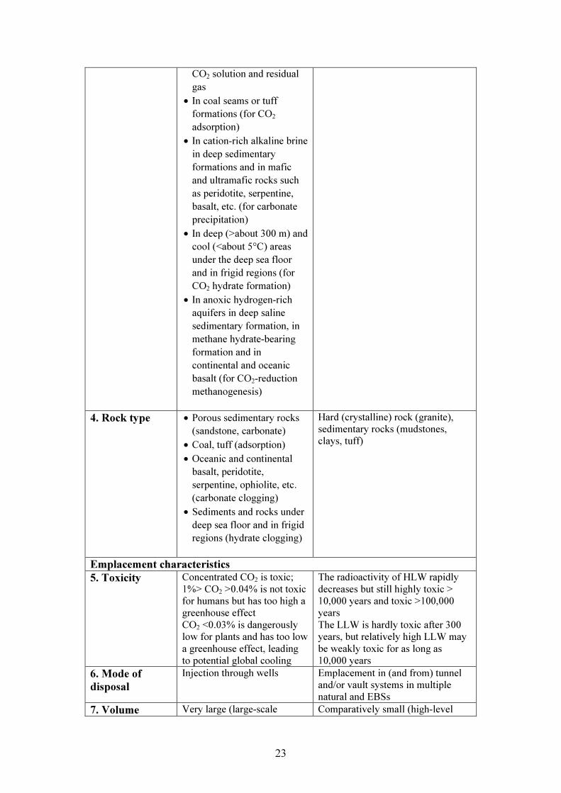
3. Geological environment
• In folded sedimentary basins that: have formations of sufficient porosity (for capacity) and permeability (for injectivity) and domal or other confining structures of impermeable (clay or shale) covers (caprocks) that can trap a buoyant plume of CO2 gas and/or CO2 supercritical fluid • In less folded flat or synclinal sedimentary basins that: have formations of sufficient porosity and permeability and less permeable (clay or shale) covers that can prevent the upward flow of saline groundwater, CO2 solution and residual gas • In sedimentary basins with imperfect caprocks and/or damaged (by drilling and/or extraction subsidence) caprocks that can still prevent the upward flow of saline groundwater,
• Groundwater fluxes at depth are sufficiently low
• Sufficient volume of host rock to house repository
• Host rock has suitable geotechnical properties for underground construction
• Geological complexity is acceptably low
• Geotectonically stable to assure no possibility of adverse disturbances of repository over the next hundred thousand years
• No underground igneous activity and acceptably low geothermal activity over the next hundred thousand years
23
CO2 solution and residual gas • In coal seams or tuff formations (for CO2 adsorption) • In cation-rich alkaline brine in deep sedimentary formations and in mafic and ultramafic rocks such as peridotite, serpentine, basalt, etc. (for carbonate precipitation) • In deep (>about 300 m) and cool (<about 5°C) areas under the deep sea floor and in frigid regions (for CO2 hydrate formation) • In anoxic hydrogen-rich aquifers in deep saline sedimentary formation, in methane hydrate-bearing formation and in continental and oceanic basalt (for CO2-reduction methanogenesis)
4. Rock type • Porous sedimentary rocks
(sandstone, carbonate) • Coal, tuff (adsorption) • Oceanic and continental basalt, peridotite, serpentine, ophiolite, etc. (carbonate clogging) • Sediments and rocks under deep sea floor and in frigid regions (hydrate clogging)
Hard (crystalline) rock (granite), sedimentary rocks (mudstones, clays, tuff)
Emplacement characteristics 5. Toxicity Concentrated CO2 is toxic;
1%> CO2 >0.04% is not toxic for humans but has too high a greenhouse effect CO2 <0.03% is dangerously low for plants and has too low a greenhouse effect, leading to potential global cooling
The radioactivity of HLW rapidly decreases but still highly toxic > 10,000 years and toxic >100,000 years The LLW is hardly toxic after 300 years, but relatively high LLW may be weakly toxic for as long as 10,000 years
6. Mode of disposal
Injection through wells
Emplacement in (and from) tunnel and/or vault systems in multiple natural and EBSs
7. Volume Very large (large-scale Comparatively small (high-level

24
deployment > some Mt/yr/project, possibly several Gt/yr in Japan, many smaller disposal sites and test projects are also possible)
vitrified radioactive waste in some hundred thousand canisters in Japan: about 1.3m high, about 40cm in diameter, 500 kg total weight)
8. Depth • CO2 supercritical fluid: > 800 m • CO2 solution: >50m
HLW disposal: >300 m and probably <2,000 m Relatively high LLW: >50 m and <100 m LLW: <50 m
9. Physical state • Gas at the well top, mostly supercritical fluid at the well bottom, occasionally liquid or gas at the injection points • In some options, CO2 solution or WAG or mixture of water and small CO2 bubbles (microbubbles or nanobubbles of CO2 supercritical fluid or gas or liquid)
Glass (high-level vitrified radioactive waste) in a stainless steel canister
10. Containment mode
• CO2 supercritical fluid and gas need completely confining caprocks (natural barriers: shale, clay, tuff, coal) • Dissolved CO2 is likely dispersed and diluted in aquifers under restricting aquitards, groundwater flux and chemistry • Quasi-natural barriers (autogenous sealing: carbonate precipitation clogging, hydrate precipitation clogging)
Multiple natural and engineered barrier system Geological barrier always acting in tandem with an EBS
11. Timescale of interest
Two timescales: • Associated with global
warming (greater than centuries)
• Associated with local risks posed by injection and possible leakage (decades)
Detailed, quantitative calculations required for 100,000 years, less quantitative for longer, possibly up to 1 million years
12. Containment period
Depends on disposal concept Concentrated CO2 should be contained for several centuries, up to millennia Small amounts of seepage of diluted CO2 are harmless
Depends on disposal concept and waste types HLW should be contained for 105 years or longer; LLW should be monitored for several hundred years, but some relatively high LLW

25
requires longer evaluation of safety depending on the characteristics of the waste
Effects of emplacement and potential migration from the disposal site 13. Direct effects of disposal
• Pressure increase (swell, fluid fracturing) • Thermal effects • Well integrity (breakthrough) • Geochemical reactions with groundwater (pH and Eh change) • Groundwater displacement • Buoyancy effect of CO2 gas and/or CO2 supercritical fluids
• Thermal effects due to radioactive decay (for heat emitting waste) • Geochemical reactions and processes in both the near and far fields • Biochemical processes in both the near and far fields • Geomechanical effects due to repository construction
14. Effects on the natural barrier
No significant structural modifications to the geological environment caused by the engineered systems (wells), but the CO2 itself may have adverse effects on barrier integrity • Geochemical reactions in the presence of groundwater and host rocks (dissolution and precipitation of carbonates, weathering effect of silicate minerals in both the near and far fields) • Geomechanical effects as a result of pressure increase and stresses (swell, fault instability, induced earthquakes) • Caprock integrity (breakthrough, fluid fracturing, leaching) • Decomposition and formation of gas hydrates in Arctic regions and under deep sea floors (>300m)
The construction of the repository and the EBS employed will directly affect the natural barrier (although probably only locally); also, heat emitting waste will directly affect the natural barrier, although any effects will be limited to a few thousand years, at most
15. Transport mechanisms of CO2 or radionuclides
The CO2 injection pressure: • Buoyancy effect of bubbles of CO2 gas and/or CO2 supercritical fluids (upward rising plume, pressure instability) • Groundwater regime and
Mainly via groundwater (advective and diffusional transport), but to a lesser extent via gas (produced by a variety of geochemical and biochemical processes in the near field and by radioactive decay) Transport of radionuclides can also take place in colloidal form

26
gravity flow of CO2-dissolved water
16. Return to the biosphere, hydrosphere and atmosphere
There are, in effect, no engineered barriers, and leaky wells, fractures and other local geological features may provide a pathway for the return of CO2 • Upward rising plume of CO2 gas and/or CO2 supercritical fluids • Breakthrough, fluid-fracturing and/or leaching of caprocks. • ‘Bathtub effect’ • ‘Champagne effect’ • Sand wedging and mud volcanoes with earthquakes • Seepage along faults
A considerable amount of the long-lived waste is encapsulated within containers that will remain intact for a considerable time; even in the event of canister failure, the EBS will delay the release of radionuclides for a time Geotectonical disturbances (earthquakes, fault activity, igneous or sand dike intrusion, hydrothermal intrusion, etc.) may affect the containment of radionuclides in the long term
Site activities 17. Site characterization
Currently based only on the existing geological data for oil and gas exploration. Original geological investigations for CO2 disposal are anticipated.
Very comprehensive and lengthy investigation programme on the test-only sites (Mizunami and Horonobe) and on the generic geological situation of Japan
18. Monitoring Monitoring (land surface deformation, gas seepage, groundwater regime, groundwater chemistry, pressure, stress, seismic activity, etc.) required for baseline conditions (site selection), during injection, and decreasingly after cessation of injection for site closure and ensuring long-term safety of the system Monitoring of underground CO2 behaviour and surface ‘watchdog’ monitoring
All disposal concepts have extensive barrier systems; thus, although monitoring will be a requirement, no releases are likely to be detected for a considerable time (i.e. several millennia) after closure
19. Future access, intrusion or penetration
Penetration by future wells drilled for other purposes (e.g. groundwater and mineral water tapping, geothermal wells, exploration and production of oil, gas and other mineral resources) is quite possible
Sites will be selected only in areas where the intrusion risk is considered low (i.e. no mineral resources)
EBS Engineered barrier system HLW High-level waste LLW Low-level waste
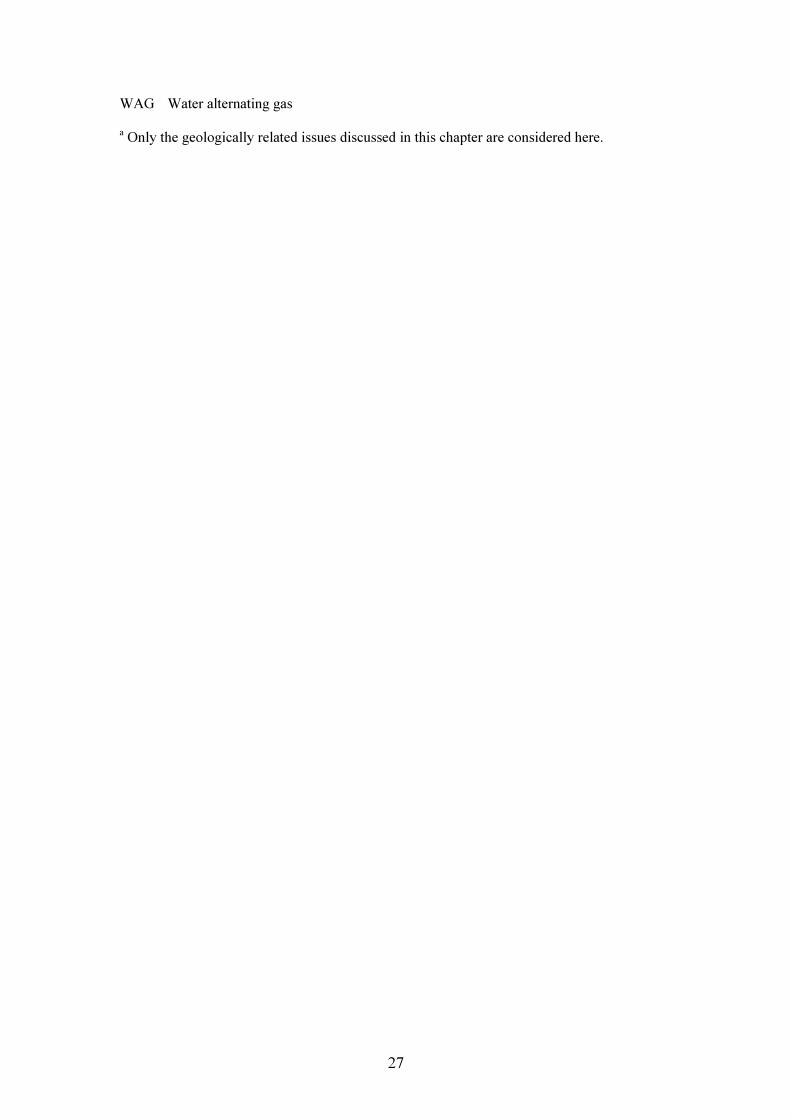
27
WAG Water alternating gas a Only the geologically related issues discussed in this chapter are considered here.
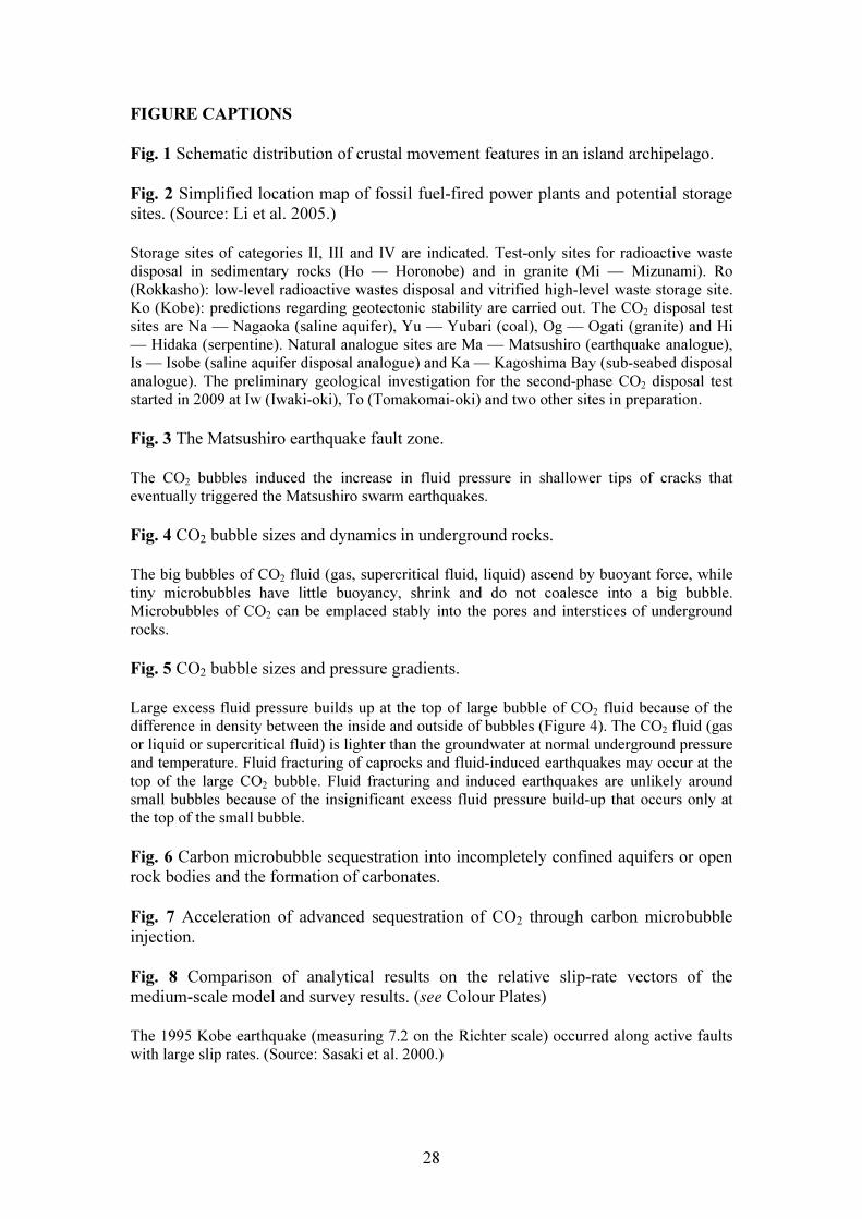
28
FIGURE CAPTIONS Fig. 1 Schematic distribution of crustal movement features in an island archipelago. Fig. 2 Simplified location map of fossil fuel-fired power plants and potential storage sites. (Source: Li et al. 2005.) Storage sites of categories II, III and IV are indicated. Test-only sites for radioactive waste disposal in sedimentary rocks (Ho — Horonobe) and in granite (Mi — Mizunami). Ro (Rokkasho): low-level radioactive wastes disposal and vitrified high-level waste storage site. Ko (Kobe): predictions regarding geotectonic stability are carried out. The CO2 disposal test sites are Na — Nagaoka (saline aquifer), Yu — Yubari (coal), Og — Ogati (granite) and Hi — Hidaka (serpentine). Natural analogue sites are Ma — Matsushiro (earthquake analogue), Is — Isobe (saline aquifer disposal analogue) and Ka — Kagoshima Bay (sub-seabed disposal analogue). The preliminary geological investigation for the second-phase CO2 disposal test started in 2009 at Iw (Iwaki-oki), To (Tomakomai-oki) and two other sites in preparation. Fig. 3 The Matsushiro earthquake fault zone. The CO2 bubbles induced the increase in fluid pressure in shallower tips of cracks that eventually triggered the Matsushiro swarm earthquakes. Fig. 4 CO2 bubble sizes and dynamics in underground rocks. The big bubbles of CO2 fluid (gas, supercritical fluid, liquid) ascend by buoyant force, while tiny microbubbles have little buoyancy, shrink and do not coalesce into a big bubble. Microbubbles of CO2 can be emplaced stably into the pores and interstices of underground rocks. Fig. 5 CO2 bubble sizes and pressure gradients. Large excess fluid pressure builds up at the top of large bubble of CO2 fluid because of the difference in density between the inside and outside of bubbles (Figure 4). The CO2 fluid (gas or liquid or supercritical fluid) is lighter than the groundwater at normal underground pressure and temperature. Fluid fracturing of caprocks and fluid-induced earthquakes may occur at the top of the large CO2 bubble. Fluid fracturing and induced earthquakes are unlikely around small bubbles because of the insignificant excess fluid pressure build-up that occurs only at the top of the small bubble. Fig. 6 Carbon microbubble sequestration into incompletely confined aquifers or open rock bodies and the formation of carbonates. Fig. 7 Acceleration of advanced sequestration of CO2 through carbon microbubble injection. Fig. 8 Comparison of analytical results on the relative slip-rate vectors of the medium-scale model and survey results. (see Colour Plates) The 1995 Kobe earthquake (measuring 7.2 on the Richter scale) occurred along active faults with large slip rates. (Source: Sasaki et al. 2000.)
29
Fig. 1 Schematic distribution of crustal movement features in an island archipelago.
Oceanic plateVolcanic front
few volcanoesfew faults
many volcanoesmany faultsmany earthquakes no volcanoes
few faultsfew earthquakes
many earthquakes
CrustOceanic trench
Mantle Mantle
Subduction of plate
Oceanic plateVolcanic front
few volcanoesfew faults
many volcanoesmany faultsmany earthquakes no volcanoes
few faultsfew earthquakes
many earthquakes
CrustOceanic trench
Mantle Mantle
Subduction of plate
30
Ho
HiYu
NaMa
Og
Ko
Iw
To
Mi
Ka
Is
Ro
Ho
HiYu
NaMa
Og
Ko
Iw
To
Mi
Ka
Is
Ho
HiYu
NaMa
Og
Ko
Iw
To
Mi
Ka
Is
Ro

31
Storage sites of categories II, III and IV are indicated. Test-only sites for radioactive waste disposal in sedimentary rocks (Ho — Horonobe) and in granite (Mi — Mizunami). Ro (Rokkasho): low-level radioactive wastes disposal and vitrified high-level waste storage site. Ko (Kobe): predictions regarding geotectonic stability are carried out. The CO2 disposal test sites are Na — Nagaoka (saline aquifer), Yu — Yubari (coal), Og — Ogati (granite) and Hi — Hidaka (serpentine). Natural analogue sites are Ma — Matsushiro (earthquake analogue), Is — Isobe (saline aquifer disposal analogue) and Ka — Kagoshima Bay (sub-seabed disposal analogue). The preliminary geological investigation for the second-phase CO2 disposal test started in 2009 at Iw (Iwaki-oki), To (Tomakomai-oki) and two other sites in preparation. Fig. 2 Simplified location map of fossil fuel-fired power plants and potential storage sites. (Source: Li et al. 2005.)
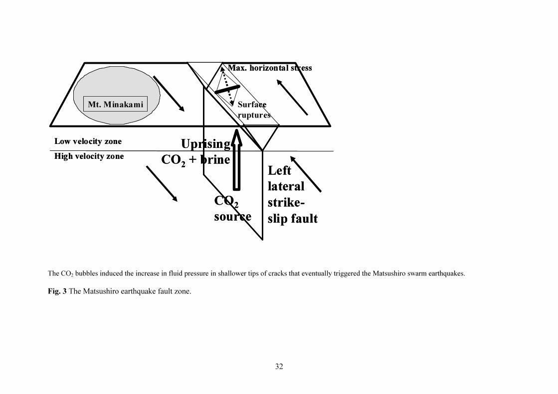
32
The CO2 bubbles induced the increase in fluid pressure in shallower tips of cracks that eventually triggered the Matsushiro swarm earthquakes. Fig. 3 The Matsushiro earthquake fault zone.
Mt. Minakami
Low velocity zone
Left lateralstrike-slip fault
High velocity zone
CO2source
Surface ruptures
UprisingCO2 + brine
Max. horizontal stress
Mt. Minakami
Low velocity zone
Left lateralstrike-slip fault
High velocity zone
CO2source
Surface ruptures
UprisingCO2 + brine
Max. horizontal stress
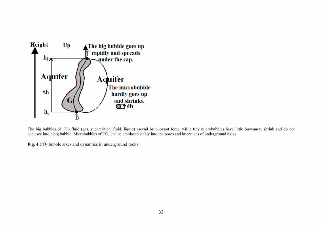
33
The big bubbles of CO2 fluid (gas, supercritical fluid, liquid) ascend by buoyant force, while tiny microbubbles have little buoyancy, shrink and do not coalesce into a big bubble. Microbubbles of CO2 can be emplaced stably into the pores and interstices of underground rocks. Fig. 4 CO2 bubble sizes and dynamics in underground rocks.
Height UpHeight Up

34
Dept
h
Extensional fluid fracture zone
Lithostatic stress
Pore fluid pressure in aquifer Excess pressure at the top of bubble
Pressure gradient in big bubble
Pressure gradient in small bubble
Rock stress/Fluid pressure
Shear fracture zone
Caprock

35
Large excess fluid pressure builds up at the top of large bubble of CO2 fluid because of the difference in density between the inside and outside of bubbles (Figure 4). The CO2 fluid (gas or liquid or supercritical fluid) is lighter than the groundwater at normal underground pressure and temperature. Fluid fracturing of caprocks and fluid-induced earthquakes may occur at the top of the large CO2 bubble. Fluid fracturing and induced earthquakes are unlikely around small bubbles because of the insignificant excess fluid pressure build-up that occurs only at the top of the small bubble. Fig. 5 CO2 bubble sizes and pressure gradients.

36
Fig. 6 Carbon microbubble sequestration into incompletely confined aquifers or open rock bodies and the formation of carbonates.

37
Fig. 7 Acceleration of advanced sequestration of CO2 through carbon microbubble injection.
Adsorptiontrap
Hydratetrap
Carbonate trap
MethanogenesisMicrobial trap
Advanced TrapAcceleration by microbubbles injection
Capillary micro-trap
Caprockphysical trap
Ion trap
Solubility trap
Underground CO2 injection
Adsorptiontrap
Hydratetrap
Carbonate trap
MethanogenesisMicrobial trap
Advanced TrapAcceleration by microbubbles injection
Capillary micro-trap
Caprockphysical trap
Ion trap
Solubility trap
Underground CO2 injection
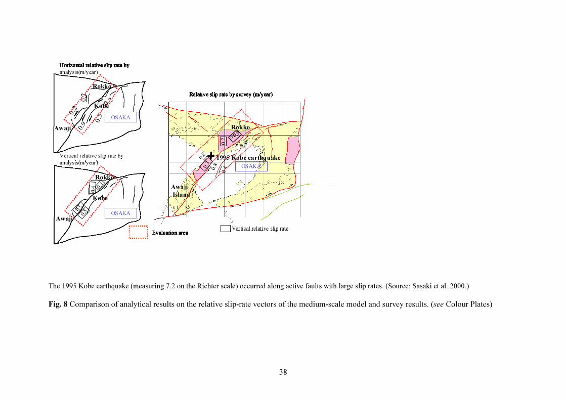
38
The 1995 Kobe earthquake (measuring 7.2 on the Richter scale) occurred along active faults with large slip rates. (Source: Sasaki et al. 2000.) Fig. 8 Comparison of analytical results on the relative slip-rate vectors of the medium-scale model and survey results. (see Colour Plates)
0 .2
0. 2
0. 20 .5
0 .9
OSAKA
0 . 50 . 5
0 . 10. 4
大阪湾
0 .40 .8
0 . 88 5 ゚
0. 8> 0 .
3
0 .2
0 . 3OSAKA
OSAKA
Evaluation area Vertical relative slip rate
Horizontal relative slip rate by analysis(m/year)
Vertical relative slip rate by analysis(m/year)
Relative slip rate by survey (m/year)0 .2
0. 2
0. 20 .5
0 .9
OSAKA
0 . 50 . 5
0 . 10. 4
大阪湾
0 .40 .8
0 . 88 5 ゚
0. 8> 0 .
3> 0 .
3
0 .2
0 . 3OSAKA
OSAKA
Evaluation area Vertical relative slip rate
Horizontal relative slip rate by analysis(m/year)
Vertical relative slip rate by analysis(m/year)
Relative slip rate by survey (m/year)
+ 1995 Kobe earthquake
AwajiIsland
Rokko
Kobe
Kobe
Awaji
Awaji
Rokko
Rokko
0 .2
0. 2
0. 20 .5
0 .9
OSAKA
0 . 50 . 5
0 . 10. 4
大阪湾
0 .40 .8
0 . 88 5 ゚
0. 8> 0 .
3
0 .2
0 . 3OSAKA
OSAKA
Evaluation area Vertical relative slip rate
Horizontal relative slip rate by analysis(m/year)
Vertical relative slip rate by analysis(m/year)
Relative slip rate by survey (m/year)0 .2
0. 2
0. 20 .5
0 .9
OSAKA
0 . 50 . 5
0 . 10. 4
大阪湾
0 .40 .8
0 . 88 5 ゚
0. 8> 0 .
3> 0 .
3
0 .2
0 . 3OSAKA
OSAKA
Evaluation area Vertical relative slip rate
Horizontal relative slip rate by analysis(m/year)
Vertical relative slip rate by analysis(m/year)
Relative slip rate by survey (m/year)
+ 1995 Kobe earthquake
AwajiIsland
Rokko
Kobe
Kobe
0 .2
0. 2
0. 20 .5
0 .9
OSAKA
0 . 50 . 5
0 . 10. 4
大阪湾
0 .40 .8
0 . 88 5 ゚
0. 8> 0 .
3
0 .2
0 . 3OSAKA
OSAKA
Evaluation area Vertical relative slip rate
Horizontal relative slip rate by analysis(m/year)
Vertical relative slip rate by analysis(m/year)
Relative slip rate by survey (m/year)0 .2
0. 2
0. 20 .5
0 .9
OSAKA
0 . 50 . 5
0 . 10. 4
大阪湾
0 .40 .8
0 . 88 5 ゚
0. 8> 0 .
3> 0 .
3
0 .2
0 . 3OSAKA
OSAKA
Evaluation area Vertical relative slip rate
Horizontal relative slip rate by analysis(m/year)
Vertical relative slip rate by analysis(m/year)
Relative slip rate by survey (m/year)
+ 1995 Kobe earthquake
0 .2
0. 2
0. 20 .5
0 .9
OSAKA
0 . 50 . 5
0 . 10. 4
大阪湾
0 .40 .8
0 . 88 5 ゚
0. 8> 0 .
3
0 .2
0 . 3OSAKA
OSAKA
Evaluation area Vertical relative slip rate
Horizontal relative slip rate by analysis(m/year)
Vertical relative slip rate by analysis(m/year)
Relative slip rate by survey (m/year)0 .2
0. 2
0. 20 .5
0 .9
OSAKA
0 . 50 . 5
0 . 10. 4
大阪湾
0 .40 .8
0 . 88 5 ゚
0. 8> 0 .
3> 0 .
3
0 .2
0 . 3OSAKA
OSAKA
Evaluation area Vertical relative slip rate
Horizontal relative slip rate by analysis(m/year)
Vertical relative slip rate by analysis(m/year)
Relative slip rate by survey (m/year)
+ 1995 Kobe earthquake
AwajiIsland
Rokko
Kobe
Kobe
Awaji
Awaji
Rokko
Rokko