Disposal of Radioactive Grouts into Hydraulically Fractured ...
130
WELLHEAD TOWER WASTE STORAGE TANKS-, •ÖK.5 •BULK STORAGE TANKS ] ' . 5 Ç " * - i S O L i oe FEED JANK MIXER CELL I INJECTION PUMPS EMERGENCY WASTE PIT BLENDING TANKS INJECTION WELL- 1&V« GROUT SHEETS OBSERVATION WELL- ( TYPICAL life. - T E C H N I C A L R E P O R T S S E R I E S N o . 232 Disposal of Radioactive Grouts into Hydraulically Fractured Shale INTERNATIONAL ATOMIC ENERGY AGENCY, VIENNA, 1983
-
Upload
khangminh22 -
Category
Documents
-
view
0 -
download
0
Transcript of Disposal of Radioactive Grouts into Hydraulically Fractured ...

WELLHEAD TOWER
WASTE STORAGE TANKS-,
• Ö K . 5 •BULK STORAGE TANKS ] ' .
5 Ç " * - i S O L i œ FEED JANK
MIXER CELL
I INJECTION PUMPS EMERGENCY WASTE PIT
BLENDING TANKS
INJECTION WELL-
1&V«
GROUT SHEETS
OBSERVATION WELL-( TYPICAL l i f e . -
T E C H N I C A L R E P O R T S S E R I E S N o . 2 3 2
Disposal of Radioactive Grouts
into Hydraulically Fractured Shale
INTERNATIONAL ATOMIC ENERGY AGENCY, V IENNA, 1983


DISPOSAL OF RADIOACTIVE GROUTS INTO HYDRAULICALLY FRACTURED SHALE

T h e fo l lowing S ta tes are Member s of t he In t e rna t iona l A t o m i c Energy Agency :
A F G H A N I S T A N A L B A N I A A L G E R I A A R G E N T I N A A U S T R A L I A A U S T R I A B A N G L A D E S H B E L G I U M B O L I V I A B R A Z I L B U L G A R I A B U R M A B Y E L O R U S S I A N S O V I E T
S O C I A L I S T R E P U B L I C C A N A D A C H I L E C O L O M B I A C O S T A R I C A CUBA C Y P R U S C Z E C H O S L O V A K I A D E M O C R A T I C K A M P U C H E A D E M O C R A T I C P E O P L E ' S
R E P U B L I C O F K O R E A D E N M A R K D O M I N I C A N R E P U B L I C E C U A D O R E G Y P T EL S A L V A D O R E T H I O P I A F I N L A N D F R A N C E G A B O N G E R M A N D E M O C R A T I C R E P U B L I C G E R M A N Y , F E D E R A L R E P U B L I C O F G H A N A G R E E C E G U A T E M A L A HAITI H O L Y S E E
H U N G A R Y I C E L A N D INDIA I N D O N E S I A I R A N , ISLAMIC R E P U B L I C O F IRAQ I R E L A N D I S R A E L ITALY IVORY C O A S T J A M A I C A JAPAN J O R D A N K E N Y A K O R E A , R E P U B L I C O F KUWAIT L E B A N O N LIBERIA LIBYAN A R A B J A M A H I R I Y A L I E C H T E N S T E I N L U X E M B O U R G M A D A G A S C A R MALAYSIA MALI M A U R I T I U S MEXICO MONACO M O N G O L I A M O R O C C O NAMIBIA N E T H E R L A N D S NEW Z E A L A N D N I C A R A G U A N I G E R N I G E R I A N O R W A Y P A K I S T A N P A N A M A P A R A G U A Y P E R U
PHILIPPINES P O L A N D P O R T U G A L Q A T A R R O M A N I A S A U D I A R A B I A S E N E G A L S I E R R A L E O N E S I N G A P O R E S O U T H A F R I C A SPAIN S R I L A N K A SUDAN SWEDEN S W I T Z E R L A N D S Y R I A N A R A B R E P U B L I C T H A I L A N D T U N I S I A T U R K E Y U G A N D A U K R A I N I A N S O V I E T S O C I A L I S T
R E P U B L I C UNION O F S O V I E T SOCIALIST
R E P U B L I C S U N I T E D A R A B E M I R A T E S U N I T E D K I N G D O M O F G R E A T
B R I T A I N A N D N O R T H E R N I R E L A N D
U N I T E D R E P U B L I C O F C A M E R O O N
U N I T E D R E P U B L I C O F T A N Z A N I A
U N I T E D S T A T E S O F A M E R I C A U R U G U A Y V E N E Z U E L A V I E T NAM Y U G O S L A V I A Z A I R E ZAMBIA
T h e Agency ' s S t a t u t e was approved on 23 O c t o b e r 1956 by the C o n f e r e n c e on the S t a tu t e of the IAEA held at Un i t ed Nat ions Headqua r t e r s , New Y o r k : it e n t e r e d in to force on 29 July 1957. T h e Headqua r t e r s of the Agency are s i tua ted in Vienna . Its pr incipal objec t ive is " t o accelera te and enlarge the c o n t r i b u t i o n of a t o m i c energy t o peace , h e a l t h and p rosper i ty t h r o u g h o u t the w o r l d " .
© IAEA, 1983
Permission t o r e p r o d u c e or t rans la te the i n f o r m a t i o n con t a ined in this pub l ica t ion m a y be ob t a ined by writ ing t o t he In t e rna t iona l A t o m i c Energy Agency, Wagramerstrasse 5 , P.O. Box 100, A - 1 4 0 0 Vienna , Austr ia .
Pr in ted by the IAEA in Aus t r ia D e c e m b e r 1983

TECHNICAL REPORTS SERIES No. 232
DISPOSAL OF RADIOACTIVE GROUTS
INTO HYDRAULICALLY FRACTURED SHALE
INTERNATIONAL ATOMIC ENERGY AGENCY VIENNA, 1983

DISPOSAL OF RADIOACTIVE GROUTS INTO HYDRAULICALLY FRACTURED SHALE
IAEA, VIENNA, 1983 STI/DOC/10/232
ISBN 9 2 - 0 - 1 2 5 4 8 3 - 0

FOREWORD
The present report deals with an original method of disposal of radio-active wastes which was developed and has been in use in the United States of America for almost two decades.
In this method, radioactive waste effluents in the form of a slurry con-taining hydraulic binders (grouts) are injected by means of fracturing into a deep underground formation considered to be isolated from the surface. The composition of the grout is carefully chosen so that the slurry thus injected solidifies in situ, ensuring fixation of the waste and rendering this type of disposal final in character.
The originality of the technique lies in the fact that a single operation combines:
(a) Preparation of the repository, since the placement of the waste is done by hydraulically fracturing the surrounding rock;
(b) Waste conditioning, since a thick consistency is imparted to the waste by the hydraulic binders incorporated in it;
(c) Containment, which is ensured by the intrinsic qualities of the surrounding rock and the properties of the grout.
This advantage is accompanied by an economic factor, for liquid wastes can be disposed of directly without going through the stages of intensive recon-centration and evaporation or solidification, packaging, transport or extensive site monitoring. A cost-benefit analysis shows that in some cases the method of disposal by hydraulic fracturing would, for this very reason, be at least ten times more economical than the competing techniques.
The method of waste grout injection by hydraulic fracturing was tried out for the first time in 1959—60 at Oak Ridge National Laboratory with 137Cs-labelled slurries. The success of the operation led to repeating the first experi-ments with actual radioactive effluents. Subsequently, the process was adopted for routine disposal of waste solutions at ORNL. Between 1966 and 1979, 8800 m 3 of grout containing 5400 m 3 of waste solution with a total activity of 640 000 Ci (23 680 000 GBq) were injected into a single well at depths between 200 and 300 m.
The success of these tests and injections established that bedding-plane fractures would be formed by injections in shales at ORNL. This matter had

been of concern because the applications of hydraulic fracturing in oil produc-tion and geothermics have underlined the risk of vertical fracturing of the surrounding rock. For waste disposal applications such a fracture orientation would be detrimental to proper containment of the grout. Rock mechanics theory suggests that bedding-plane fractures would be the preferred orientation at relatively shallow depths (up to 1000 m), but acceptance of this theory is limited.
Mindful of these reservations concerning a promising technique, the USAEC instructed ORNL and the US Geological Survey to carry out a supple-mentary research programme at other sites, and to consider in particular
The effect of the nature and texture of the surrounding rock on fracture propagation; The preferred test method for determining the fracture orientation; Site studies.
On the basis of these activities it was concluded that the operations carried out at the Oak Ridge site could also be developed at other sites, provided they had the required lithological, structural and tectonic charac-teristics, and if the siting, the type of borehole, and the design, surveillance and safety of the facilities satisfied specific conditions.
By this time the ORNL fracturing facility was nearing the limit of its useful life. Although the facility had been improved several times during this period, extensive modifications would have been needed to satisfy the require-ments for continued use, and these considerations led to the decision to construct a new facility at a new site rather than to modify and retrofit the old one. The new facility has improved shielding and containment to accommodate wastes of higher specific activity than could be handled in the old facility.
The effectiveness of this technique having thus been established, the IAEA Technical Review Committee (TRC) on Underground Disposal in its first meeting in December 1978 requested the Agency to acquaint the scientific community with the main features of the method, planning initially to cover it by a series of IAEA publications.
For this purpose the IAEA Secretariat sought help from the United States authorities. The latter strongly encouraged the project and arranged for the US Geological Survey to prepare for the Agency the first document dealing with the problems of site selection and assessing experience to date and operations in progress1.
1 SUN, R.J., Site Selection and Investigation for Subsurface Disposal of Radioactive Wastes in Hydraulically Induced Fractures, US Geological Survey, Open-file Report 80-450, USGS, Reston, VA (1980) 241 pp.

Taking into account the maturity of this technique and its potential interest established through this first document, the TRC-UD's third meeting (November 1980) recommended that all aspects of its application should be covered in a single publication.
At the request of the Agency, the US Government arranged for that pur-pose an IAEA consultants' meeting in June 1981 at the Oak Ridge National Laboratory with experts from US scientific organizations involved in the subject, and R.J. Sun (USGS), author of the previous report, to prepare a general review of the contents of the publication. The consultants were:
R.J. Sun, USGS, Reston, VA D.R. Brown, DOE-ORO Waste Management Programs J.H. Coobs, ORNL Operations Div., Waste Management Program S.C. Haase, ORNL Environmental Sciences Div. T. Tamura, ORNL Environmental Sciences Div. H.O. Weeren, ORNL Chemical Technology Div. J. Molinari, IAEA Scientific Secretary
From the decisions of this meeting and on the advice of A.F. Perge, Assistant for International and Institutional Activities, Office of Nuclear Energy, DOE, the final draft of the document in the form of an ORNL report2 was prepared by:
H.O. Weeren, ORNL Chemical Technology Div. J.H. Coobs, ORNL Operations Div., Waste Management Program S.C. Haase, ORNL Environmental Sciences Div. R.J. Sun, USGS, Reston, VA T. Tamura, ORNL Environmental Sciences Div.
Finalization of this report for publication in the IAEA Technical Reports Series was made by consultation at IAEA Headquarters with H.O. Weeren (ORNL) in August 1982, J. Molinari being the IAEA Scientific Secretary.
The IAEA, gratefully acknowledging the US authorities and US scientists who authorized and prepared this document, hopes that this report will be of value in helping Member States to consider the possibility of the disposal of radioactive waste grouts into hydraulically fractured shale as an alternative method for disposing of radioactive wastes.
2 WEEREN, H.O., COOBS, J.H., HAASE, S.C., SUN, R.J., TAMURA, T., Disposal of Radioactive Wastes by Hydraulic Fracturing, Rep. ORNL/CF-81/245, Oak Ridge National Laboratory, Oak Ridge, Tennessee (May 1982) 143 pp.

CONTENTS
1. INTRODUCTION 1 1.1. Description of process 3 1.2. Host rock considerations 4 1.3. Wastes suitable for disposal 6 1.4. History of the process 6 1.5. Structure and emphasis of the report 7
2. SITE SELECTION CONSIDERATIONS 8 2.1. Geology; suitability of various lithologies for hydraulic fracturing
and waste injection 8 2.1.1. Shales and shale-rich rocks 9 2.1.2. Sandstone and limestone 10 2.1.3. Crystalline igneous and metamorphic rocks 10
2.2. Geomorphic considerations 11 2.2.1. Texture 11 2.2.2. Tectonics 12
2.3. Geochemical considerations: interaction of the injection formation and the grout sheet 13
2.4. Hydrology and hydrogeology 13 2.5. Facility siting 15 2.6. Resource recovery considerations 15 2.7. Environmental and social considerations 16 2.8. Summary 16
3. SITE INVESTIGATIONS 18 3.1. Drilling and tests for exploration wells 18
3.1.1. Well logging 18 3.1.2. Core analysis 19 3.1.3. Strike and dip of injection rock 19
3.2. Hydraulic fracturing tests 19 3.2.1. Water injection 19 3.2.2. Grout injection tests 21
3.3. Interpretation of hydraulic fracturing test data 21 3.3.1. Interpretation of pressure decay data 21 3.3.2. Interpretation of fracture orientation 27
3.4. Conclusions 28

4. MIX DEVELOPMENT 29 4.1. Characteristics of ORNL waste solution 29 4.2. Required properties of grout 29 4.3. Mix formulation 31 4.4. Proportioning of mix and waste 32 4.5. Testing procedures 32 4.6. Leach tests 34 4.7. Caesium fixers 37
5. DESIGN AND CONSTRUCTION OF FACILITY 38 5.1. Wells 38 5.2. Buildings 40 5.3. Blending and storage of solids 42 5.4. Waste flow and grout mixing 43 5.5. Grout injection 44 5.6. Process control 46 5.7. Washup equipment 46 5.8. Slotting equipment 47 5.9. Emergency waste pit 48
6. OPERATION 49 6.1. Preparation for injection 49
6.1.1. Solids blending 49 6.1.2. Mix compatibility testing 51 6.1.3. Slotting 52 6.1.4. Fracture initiation 56
6.2. Injection 56 6.3. Monitoring and post-injection operations 58
6.3.1. Monitoring during injection 58 6.3.2. Post-injection monitoring 59 6.3.3. Bleedback 62
6.4. Operational history 62 6.5. Active life of injection well 63
7. SAFETY ASSESSMENT 65 7.1. Safety of normal operations 65
7.1.1. Thermal effects 65 7.1.2. Groundwater movement 67 7.1.3. Leach rates from grouts 70 7.1.4. Radionuclide migration 71 7.1.5. Well drilling 71 7.1.6. Facility operations 72

7.2. Accident situations 72 7.2.1. Rupture of process piping 72 7.2.2. Wellhead rupture 72 7.2.3. Vertical fracture 73 7.2.4. Grout movement along well 74 7.2.5. Risk to operating personnel 75
7.3. Long-term considerations 75 7.3.1. Generation of earthquakes 75 7.3.2. Required isolation time 76 7.3.3. Potential for exhumation of wastes 76
8. OTHER PROCESS CONSIDERATIONS 78 8.1. Cost-benefit considerations 78 8.2. Research and development work on process extension 80
8.2.1. Slurries 80 8.2.2. Gases 81 8.2.3. Pelletized wastes 81 8.2.4. Organics 82
8.3. Process limitations 82
APPENDIX 1. CASE HISTORIES 83 1. Preliminary experiments at Oak Ridge National Laboratory
( 1 9 5 9 - 6 6 ) 83 1.1. Process proof tests 83 1.2. Water injection tests 85 1.3. Experimental injection series 87
2. Site test at West Valley, New York ( 1 9 6 9 - 7 1 ) 89 3. Operational waste disposal injections at ORNL 90 4. Site proof test at ORNL 92
APPENDIX 2. THEORY OF HYDRAULICALLY INDUCED FRACTURES 95
1. Theory of fracture mechanics 95 1.1. Vertical earth stress 96 1.2. Horizontal earth stress 96 1.3. Tectonic stress 97
2. Propagation of fracture 97 2.1. Fracturing in cemented and cased holes 97 2.2. Fracturing in bedded rocks 98 2.3. Fracturing in fractured and jointed bedded rocks 100
APPENDIX 3. GLOSSARY 105

1. INTRODUCTION
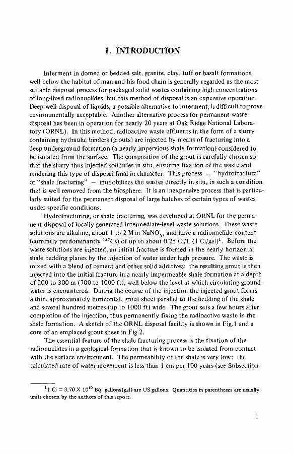
Interment in domed or bedded salt, granite, clay, tuff or basalt formations well below the habitat of man and his food chain is generally regarded as the most suitable disposal process for packaged solid wastes containing high concentrations of long-lived radionuclides, but this method of disposal is an expensive operation. Deep-well disposal of liquids, a possible alternative to interment, is difficult to prove environmentally acceptable. Another alternative process for permanent waste disposal has been in operation for nearly 20 years at Oak Ridge National Labora-tory (ORNL). In this method, radioactive waste effluents in the form of a slurry containing hydraulic binders (grouts) are injected by means of fracturing into a deep underground formation (a nearly impervious shale formation) considered to be isolated from the surface. The composition of the grout is carefully chosen so that the slurry thus injected solidifies in situ, ensuring fixation of the waste and rendering this type of disposal final in character. This process — "hydrofracture" or "shale fracturing" — immobilizes the wastes directly in situ, in such a condition that is well removed from the biosphere. It is an inexpensive process that is particu-larly suited for the permanent disposal of large batches of certain types of wastes under specific conditions.
Hydrofracturing, or shale fracturing, was developed at ORNL for the perma-nent disposal of locally generated intermediate-level waste solutions. These waste solutions are alkaline, about 1 to 2 M in NaN0 3 , and have a radionuclide content (currently predominantly 137Cs) of up to about 0.25 Ci/L (1 Ci/gal)1. Before the waste solutions are injected, an initial fracture is formed in the nearly horizontal shale bedding planes by the injection of water under high pressure. The waste is mixed with a blend of cement and other solid additives; the resulting grout is then injected into the initial fracture in a nearly impermeable shale formation at a depth of 200 to 300 m (700 to 1000 ft), well below the level at which circulating ground-water is encountered. During the course of the injection the injected grout forms a thin, approximately horizontal, grout sheet parallel to the bedding of the shale and several hundred metres (up to 1000 ft) wide. The grout sets a few hours after completion of the injection, thus permanently fixing the radioactive waste in the shale formation. A sketch of the ORNL disposal facility is shown in Fig. 1 and a core of an emplaced grout sheet in Fig.2.
The essential feature of the shale fracturing process is the fixation of the radionuclides in a geological formation that is known to be isolated from contact with the surface environment. The permeability of the shale is very low: the calculated rate of water movement is less than 1 cm per 100 years (see Subsection
1 1 Ci = 3.70 X 10¹⁰ Bq; gallons(gal) are US gallons. Quantities in parentheses are usually units chosen by the authors of this report.
1

WELLHEAD TOWER
WASTE STORAGE TANKS
FIG.l. Oak Ridge National Laboratory hydrofracture facility.
7.1.2.4). The process has additional features that would provide continued isola-tion of the radionuclides even if the low permeability of the disposal formation were not considered. For example, the leach rates of significant radionuclides from the set grout are quite low. In addition, any radionuclides that might be leached from a grout sheet would be retained in the disposal zone by the high ion-exchange capacity of the shale. Therefore, this process offers an exceptionally favourable approach to permanent disposal of radioactive wastes. These features are discussed further in Section 7.
The operational cost of a hydrofracture injection will vary somewhat with injection volume and other factors. For the most recent (June 1982) injection at the ORNL disposal facility this cost was $0.17/L ($0.63/gal)2. The cost of the
2 Dollars ($) are US dollars.
2

FIG.2. Core sample of grout sheet.
new facility was $5.4 million; a pro-rated cost distribution over the expected life-time capacity of 40 million litres (10 million gallons) gives a capital cost of S0.14/L ($0.54/gal). The total cost, therefore, is about S0.30/L ($1,20/gal).
1.1. DESCRIPTION OF PROCESS
The process is operated as a large-scale batch process; each injection is, however, a continuous operation. Each injection disposes of an annual accumula-tion of waste solution of about 380 000 L (100 000 gal). During an injection, waste solution is pumped to the mixed and mixed with a stream of dry solids.
3

The resulting grout is pumped down the injection well and out into the shale formation at an injection pressure of about 20 MPa (3000 lbf/in2 ).
The normal grout injection rate is about 1000 L/min (250 gal/min); an injection requires about 8 to 10 h to complete. At the end of the injection, the well is flushed with water so that the slot in the injection well will be free of grout and can be re-used for the next injection. A valve then shuts the well until the grout has set. Several injections are made through the same slot and form grout sheets that are generally parallel to the first. After several injections (about four) have been made through the slot, the bottom of the well is plugged, a new slot is cut in the casing of the well 3 m (10 f t) above the old slot, and a new series of injections is made at the higher elevation. In this manner, maximum utilization of the disposal formation is achieved.
There are two reasons for the operation of the hydrofracture facility as a large-scale batch process. The primary reason is to maximize the useful life of the injection well, which is strongly dependent on the number of injections that are made and relatively independent of the individual injection volume. By increasing the volume of each injection (and thereby reducing the total number of injections required to inject a volume of grout) the life of the well network is prolonged. A second incentive for making large injections is to minimize the cost; a significant fraction of the operating cost is the fixed cost required to assemble the operating crews and is independent of the injection volume. Factors that limit the individual injection volume include limited waste storage tank capacity, limited solids storage capacity, and operator fatigue. For the ORNL disposal facility, a waste injection volume of 380 000 L (100 000 gal) has been found to be an acceptable compromise.
1.2. HOST ROCK CONSIDERATIONS
The properties of the host rock formations into which the injections are made should be such that the radionuclides will be completely contained for periods of several centuries. The most important of these properties is that the formation should have an extremely low permeability and should be located well away from any zones of circulating water. These two requirements will ensure that the radio-nuclides will not be leached from the grout and returned to the biosphere.
For the hydrofracture process, the orientation of the fracture formed in the host rock during the grout injection is important. It is now generally agreed that the orientation of hydraulically induced fractures is controlled primarily by the state-of-stress in the earth at the point of fracturing. In the absence of other factors, the fracture will always be oriented perpendicular to the direction of the least compressive principal stress [ 1, 2). This feature is illustrated in Fig.3. The upper figure shows the three principal triaxial stresses where the least compressive
4

FIG.3. The effect of earth stress on fracture orientation.
stress is horizontal. In this case, a hydraulically induced fracture will be oriented vertically. The lower half of Fig.3 shows that a horizontal fracture will be developed only when the vertical stress is less than the two horizontal stresses. This funda-mental point can be more easily visualized if it is recalled that in hydraulic frac-turing the fluid pressure will be doing the least amount of work only when it pushes the rocks apart against the least stress.
The implication of this theory is that the formation of horizontal fractures is probably limited to relatively shallow depths. The deeper the injection horizon, the higher the vertical stress, and the greater the probability of forming a vertical fracture.
Another factor that could have a major effect on fracture orientation is the existence of bedding planes in certain rock types. At relatively shallow depths (up to about 400 m (1300 ft)), the fractures will tend to follow bedding planes despite an unfavourable overall earth stress pattern. This factor is discussed further in Section 2 and Appendix 2.
5

Other considerations that are relevant to host rock suitability are:
(1) Radionuclide retention by the host rock (a high retention for radionuclides will increase the isolation time for radionuclides and could compensate, to some extent, for conditions in which rock is not as impermeable as desired);
(2) Temperature stability if waste of high specific activity is to be injected; and (3) Low seismic and tectonic activity.
1.3. WASTES SUITABLE FOR DISPOSAL
The hydrofracture process was developed to dispose of intermediate-level waste solutions generated at ORNL, but an extrapolation of the ORNL experience suggests that other waste forms could be disposed of by this technique. The probable limitations are:
(1) A slurry with particle sizes smaller than 1 mm; (2) A neutral or alkaline pH; (3) Chemical compatibility with both the cement in the solids mix and the
disposal formation; (4) A waste specific activity that is low enough to be handled in the surface
facility and low enough that the heat generated underground will dissipate at a temperature that will not cause formation damage; and
(5) A transuranic concentration that does not exceed administrative limits.
1.4. HISTORY OF THE PROCESS
The process was developed at ORNL in a series of experiments between the middle of 1959 and the middle of 1965; the experimental facility was modified in 1966 for the routine disposal of waste solutions. Since 1966, this facility has been used for 18 operational injections. More than 8 million litres (2 million gal) of waste grout containing over 600 000 Ci of radionuclides have been injected. Although operational problems have been experienced, most have been compara-tively minor and none have been severe; the general experience has been quite good.
The potential suitability of the hydrofracture process for other sites was investigated in a series of test studies at West Valley, New York, 1969 to 1971 inclusive. These tests demonstrated the generation of horizontal fractures in the shale beds at this site and suggested methods for site verification at other sites.
By this time the ORNL facility was nearing the limit of its useful life. Although the facility had been improved several times during the period of opera-tion, extensive modifications to the surface equipment would have been needed to
6

satisfy the requirements for continued use; this consideration led to the decision to construct a new facility at a new site rather than to modify and retrofit the old one.
The modified experimental facility was retired from service in 1980 and has been replaced by a new facility, which began operating in June 1982.
1.5. STRUCTURE AND EMPHASIS OF THE REPORT
Some sections of this report are concerned with the general aspects of the hydrofracture process. Other sections are site specific and discuss the development of the process at ORNL and the operating experience with the ORNL facility. Sections 2 and 3 are concerned with the general aspects of site selection and are not site specific. Sections 4, 5, 6 and 8 are concerned with operating experience at ORNL and are site specific. Section 7 (safety assessment) is based on ORNL experience, but the considerations that are discussed in this section have general application.
Details of the operating experience with the process at ORNL and West Valley are given in Appendix 1. Appendix 2 is a brief treatment of the theory of fracture mechanics.
REFERENCES
[1] HOWARD, G.C., FAST, C.R., Hydraulic Fracturing, Vol.2, Henry L. Doherty Series, AIME, New York (1970).
[2] HUBBERT, M.K., WILLIS, D.G., Mechanics of hydraulic fracturing, Trans. AIME 210 (1957) 153.
7

2. SITE SELECTION CONSIDERATIONS
This section covers general site selection criteria and considerations relevant to the first phase of the site selection process. Detailed application of the criteria to the evaluation of a specific site are treated in Section 3.
Generally, sites that would be considered most suitable for waste disposal by hydraulic fracturing would be within those sedimentary basins where thick shale sequences are present. Such sites are relatively common, and, for example, they underlie substantial areas of the continental United States of America. In this country, the potentially suitable basins include, among others, the Appalachian, Illinois and Michigan basins, most of the Gulf Coast, and the Pierre and Mancos shale of Colorado and adjacent areas [1 ].
Careful study and evaluation of geological, hydrological and environmental aspects of a potential hydraulic fracturing waste disposal site are essential. Such studies must include not only a detailed examination of the immediate area that will house the plant facilities, but also a regional evaluation that will allow the detailed site-specific data to be placed into the correct geological context. Such studies should be directed towards the selection of a particular site where subse-quent tests (see Section 3) can demonstrate that the proposed site will meet the three basic requirements of site selection for waste disposal by hydraulic fracturing. These requirements are: (1) the existence of a suitable geological formation at depth to serve as a disposal zone, (2) a formation that will produce near horizon-tally oriented hydraulic fractures, and (3) a hydrologically isolated disposal zone [ 2 - 4 ] .
The major geological considerations are the determination that a suitable host rock is sufficiently extensive throughout the proposed plant site and the determination that the current stress distribution and structural character of the proposed injection formation would promote the formation of fractures that are within about 30° of horizontal. Other considerations are the determination that the tectonic history of the site area and region are suitable for the safe operation of the hydraulic fracturing process, and the determination that the thermal and chemical interactions of the injected grout sheet and associated fluids with the host rock will be minimal, and will not adversely alter the characteristics of the host rock. Factors to be considered in making these determinations are discussed in Subsections 2.1—2.3.
2.1. GEOLOGY; SUITABILITY OF VARIOUS LITHOLOG1ES FOR HYDRAULIC FRACTURING AND WASTE INJECTION
The host rock should have an areal extent large enough to ensure complete containment and isolation of the injected grout sheets. Because the areal extent
8

of grout sheets is variable (depending on local plant operating conditions and probably on subsurface geology), a general area criterion is difficult to establish. Operational experience at ORNL has shown that the grout sheets do not extend more than 200 m (700 ft) from the injection well. Based on this experience, a requirement that the injection zone should extend at least 600 m (2000 ft) from the injection well appears reasonable.
The injection formation should also have very small intrinsic and fracture permeability (less than 10"6 darcy)3 so that in the immediate vicinity of the injection zone, movement of fluids such as connate water (water entrapped in sediments at the time of their deposition), deep circulating meteoric water (water that falls as rain or snow), or excess fluids from the injection process is extremely slow (< 5 mm/a). The host rock should be characterized by appreciably lower tensile strength in the direction normal to, rather than parallel to, bedding planes. Such a situation greatly aids the production of bedding-plane fractures by hydraulic fracturing (Appendix 2, Subsection 2.3). In addition, the mineralogical composition of the host formation should provide high adsorption capacities for the radionuclides contained in the waste material. Taking into account these factors, the suitability of various litho-logies (character of a rock formation expressed in terms of structure or mineral composition) for use as host rocks is discussed in Subsections 2.1.1.—2.1.3.
2.1.1. Shales and shale-rich rocks
Permeabilities measured for massive to bedded shale without closely spaced fractures or joints are very low — generally from 10"6 to 10~9 darcy [5—7],
Such low permeabilities make shale well suited for consideration as an injection host. Furthermore, the observation that layered and thinly bedded (individual beds < 10 cm thick) shales and shale-rich lithologies have highly directionally dependent tensile strengths is of great significance [8]. In well-bedded shales and shale-rich lithologies, the difference in tensile strength between the directions normal to and parallel to bedding planes is much greater than in other types of poorly bedded or massive sedimentary rocks [8]. The importance of this directional dependence of tensile strength is that it helps to promote the formation of the bedding-plane fractures during hydraulic fracturing (Subsection 2.2 and Appendix 2).
Field evidence indicates that the frequency and magnitude of joints and small-scale fractures in well-bedded shale and shale-rich lithologies typically decrease at bedding contacts [9], Well-cemented, more competent (clay-poor) beds typically have more numerous and better developed joints than less competent (clay-rich) beds; thus, joints in shale and shale-rich lithologies vary in number and magnitude from bed to bed, depending on the competency of a particular bed [9].
3 The darcy is the unit of permeability used in this report (see Appendix 3: Glossary). The S.I. equivalent unit is (metres)2 and is obtained by multiplying darcies by 9.87 X 10"13. This unit is not yet in widespread use.
9

This condition generally prohibits the formation of a single joint that cuts across more than just a few individual beds, as demonstrated for the Pumpkin Valley Shale Formation of the Conasauga Group at the ORNL locality [9]. This behaviour in interbedded shales and shale-rich lithologies can reduce the continuity of joints and thereby reduce the permeability caused by the presence of joints [9].
Shales contain large amounts of clay minerals such as illite, smectite, chlorite and kaolinite, some of which typically have large adsorption capacities for radio-nuclides. If radionuclides are leached out of the grout sheet, the constituent minerals of the shale may readily retard their movement by adsorbing radionuclides from the leaching solution before it has migrated any substantial distance [2, 10].
In summary, shales and shale-rich lithologies typically provide the following properties favourable for radioactive waste disposal by hydraulic fracturing:
(1 ) Susceptibility to the induction of bedding-plane fractures, (2) Bedding plane and lithology characteristics that probably inhibit the extension
of existing small-scale fractures and joints, (3) Low porosity and permeability, and (4) Mineralogical composition that will adsorb most radionuclides leached from
the grout.
It can be concluded that well-bedded shales and shale-rich lithologies are very favourable candidates for host rocks for disposal of radioactive wastes by hydraulic fracturing.
2.1.2. Sandstone and limestone
Permeabilities of sandstone and limestone are highly variable but typically range between 10"1 and 10"4 darcy, which is about five orders of magnitude greater than the permeabilities of most shales [6]. Furthermore, the difference between the tensile strength in the directions normal to and parallel to bedding planes in sandstone and limestone is much less than in most bedded shales [8]. Therefore, under identical stress conditions, massive to bedded sandstone and limestone should exhibit much less tendency to form bedding-plane fractures during hydraulic frac-turing [3]. Finally, the mineralogical compositions of these lithologies are not rich in clay minerals, and therefore sandstones and limestones typically do not exhibit high adsorption capacities for radionuclides. Because of these factors, sandstones and limestones are not generally recommended as host rocks for disposal of radio-active wastes by hydraulic fracturing.
2.1.3. Crystalline igneous and metamorphic rocks
Permeabilities of most crystalline igneous and metamorphic rocks are probably of the same order of magnitude or perhaps even lower than most shale permeabili-ties [6]. Except for well-banded metasedimentary rocks and well-foliated schists
10

and gneisses, the difference in directional tensile strength as related to bedding plane characteristics is greatly diminished in most cases. In all cases, the directional nature of rock tensile strength variations is much more complex and difficult to evaluate for igneous and metamorphic crystalline rocks than it is for most sedi-mentary rocks. This is partly because of the more complex geologic history experienced by igneous and especially metamorphic rocks.
Many crystalline igneous rocks have well-developed, complex fracture patterns related to the particular cooling history of the rock. Nearly horizontal fractures in such lithologies probably can be induced hydraulically only in the areas with the least principal earth stress in the vertical direction. Unless field evidence or other data, such as in-situ stress measurements, indicate that the least principal earth stress is in the vertical direction and the rock is without closely spaced vertical fractures, crystalline igneous rocks should not be considered as host rocks for disposal of active waste disposal by hydraulic fracturing. A similar, if not more complex, situation is true for metamorphic rocks. Such lithologies can have complex fabrics that are typically spatially very heterogeneous. Because of this, most metamorphic rocks would be likely to make poor candidates for the produc-tion of reasonably uniform horizontal hydraulic fracture patterns.
2.2. GEOMORPH1C CONSIDERATIONS
2.2.1. Texture
The principal structural-geology consideration is that the potential injection formation should have a current stress distribution and bedding planes or a particu-lar fabric element that will cause the induced fractures to be oriented nearly hori-zontally (within approximately 30° of the horizontal). McClain discussed this consideration and concluded:
"It is now generally agreed that the orientation of hydraulically induced fractures is controlled primarily by the state-of-stress in the earth at the point of fracturing. In the absence of other factors, the fracture will always be oriented perpendicular to the direction of the least compressive principal stress . . . [11]. This fundamental point can be more easily visualized if it is recalled that, in hydraulic fracturing, the fluid pressure will be doing the least amount of work only when it pushes the rocks apart against the least stress . . . . The fracture orientation control exercised by the earth stresses is modified by a number of factors. The most important of these is the strength aniso-tropy of the rock being fractured . . . . It is apparent that horizontal frac-tures are possible even when the vertical component of earth stress is larger
11

than the horizontal components, provided the difference in the earth stresses is less than the difference in the tensile strengths. Because of the difficulty in estimating the earth stresses, the strength anisotropy of bedded formations, especially shales, should be utilized whenever possible." [3]
This point is discussed further in Appendix 2, Subsection 2.2.
2.2.2. Tectonics
It is desirable that the injection formation should be almost undeformed. Lack of deformational features, under favourable circumstances, can permit reasonably reliable prediction of induced fracture behaviour. Any geologic structures involving the injection formation ideally should be very simple: very broad, low amplitude flextures; monoclines; or slight regional tilting of the strata.
Under certain circumstances, it may be practical to consider moderately deformed units as acceptable host rocks if the lithology is suitable. Experience at ORNL with injections into the supposedly undeformed Pumpkin Valley Shale [3] indicate totally satisfactory results to date even though the injection formation is pervasively jointed and much more deformed than indicated by preliminary studies [9]. In the ORNL example, the lithologie character of the injection forma-tion appears to be much more important in determining the suitability of a forma-tion for use as a host rock than is the deformational character. The ORNL experience indicates that if the past deformation of a potential host formation is not excessively intense, the lithologie character of a formation is the most important suitability criterion. This observation may become a generalized selection factor if substantiated by data from other sites.
Past regional geological events such as folding and faulting episodes, volcanism, diapirism, glaciation and seismicity that have affected the locality surrounding the proposed hydraulic fracturing facility can be used to provide a context for inter-pretation of the structural and tectonic history and, more important, to provide some means of estimating the nature and timing of future tectonic events on a regional basis. Localities that have been affected by major tectonic events such as faulting (high seismicity), volcanism or folding within the past 10 million years must be evaluated on a site-by-site basis to determine the time scale on which such activity operates and whether or not all such activity has ceased. Localities that have only very slight evidence of tectonic activity for the past 50 million years are the best choice for hydraulic fracturing facilities and are the most likely to be geologically stable during the period required for containment of the injected waste (Subsection 7.3.2).
12

2.3. GEOCHEMICAL CONSIDERATIONS: INTERACTION OF THE INJECTION FORMATION AND THE GROUT SHEET
The possibilities of chemical and physical changes in the characteristics of the injection formation caused by waste injection must be considered. Character-istics of most shales will not be altered by waste injection as long as radioactive decay within grout sheets will not raise temperatures above ~100°C [12]. Such temperatures are characteristic of (or somewhat less than) those attained during typical shale diagenesis; the mineralogy of most shales therefore equilibrated at similar temperatures and would probably not be susceptible to thermally induced recrystallization caused by waste-generated heat in this temperature range. If higher temperatures are attained (200—400°C), however, most shales would undergo several recrystallization reactions that may release substantial amounts of water and, if the shale is carbonate-bearing, carbon dioxide. Such reactions will significantly alter the original shale mineralogy and, depending on the particular recrystallization reactions involved, may make the shale more susceptible to waste migration. Under different conditions, other reactions could occur that actually render the shale a better migration barrier. A careful assessment of the thermal effects of grout injection may be needed, depending on the particular operating parameters of the proposed facility.
Given the alkaline composition of the grouts, significant chemical reactions between the host rock and the injected grout are improbable. This possibility should be checked, however, as a part of the mix development programme (see Section 4).
2.4. HYDROLOGY AND HYDROGEOLOGY
The major concern about hydrology relative to disposal of radioactive wastes by hydraulic fracturing is that the injection formation must be isolated from both near-surface and deep-aquifer groundwater movement. Ultimately, it is essential to have detailed knowledge of the regional and local groundwater flow regimes within the host rock. Based on this information, pathways and the average travel times for the groundwater flow regimes from recharge areas to discharge points can be established. Procedures that are detailed in Section 3 will provide data for this evaluation.
Surface runoff and streamflow are major sources to and sinks from near-surface groundwater flow. The magnitude and scale of interaction between stream-flow and groundwater should ultimately be determined. Interaction ideally should be limited to approximately the upper few tens of metres below the ground surface, whereas the injection rock would be at a depth of at least several hundreds of metres.
13

I I I I I I I I I I I I I 6 0 0 4 0 0 2 0 0 0 2 0 0 4 0 0 6 0 0 (m)
OUTWARD DISTANCE FROM CENTRAL POINT
FIG. 4. Surface uplift at ORNL shale fracturing facility.

The presence and character of any deep-seated meteoric or connate water should be determined. Areas that contain deep ( > 2 0 0 m) regional aquifers should be eliminated from consideration! Similarly, formations that contain abundant connate water should be very carefully investigated.
2.5. FACILITY SITING
Factors to be considered in siting á hydraulic fracturing facility are:
(1 ) Suitable topography, such as a flat or low-relief building site for the surface structures and surrounding wells of the facility;
(2) Elevation of the proposed site above maximum recorded historic flood plain and sufficient lateral distance from streams, rivers and waterways (for safety, in case of one of the improbable accidents discussed in Section 7);
(3) Proximity to the waste source so that the length of the waste transfer pipeline is minimized; and
(4) Sufficient distance from any facilities that may be influenced by the surface uplift caused by the injection of the grout sheets.
Disposal operations at ORNL have resulted in measurable surface uplifts as far as 480 m (1600 ft) from the injection well (Fig.4). Thus, for a hydraulic fracturing facility with operational characteristics similar to those of the ORNL plant, the proposed site should be at least 500 m from any other facility that could be sensitive to surface uplift effects.
2.6. RESOURCE RECOVERY CONSIDERATIONS
A chronic concern related to the selection and use of a disposal site for radioactive waste is that such use could prohibit or interfere with eventual recovery of a valuable resource. Because the area affected by the hydraulic fracturing facility would be small ( < 5 km 2 ) it seems likely that resources beneath the injection zone could be developed after the completion of waste disposal operations provided the appropriate precautions are taken. After solidification, the grout sheet becomes an integral part of the host rock, and migration of appre-ciable amounts of radiation caused by resource recovery activities can be avoided by sealing off the injection zone wherever it is penetrated by boreholes or mine shafts. If substantial uncertainty remains about the acceptability of localized penetration through the injection zone, the future value of potential resources must be weighed against the benefits of disposal of the radioactive wastes at that particular locality.
15

2.7. ENVIRONMENTAL AND SOCIAL CONSIDERATIONS
Major factors of environmental and social concern are:
(1 ) Disruption of established communities by injection facility construction and operation;
(2) Disruption of valuable land-use activities by construction and operation of a hydraulic fracturing waste disposal facility at a particular locality;
(3) Destruction of culturally or historically valuable sites by plant construction and activities;
(4) Destruction and endangerment of rare flora and fauna by plant construction activities.
Each of these factors is highly site specific and must be evaluated on a case-by-case basis. The relatively small surface area occupied by a typical hydraulic fracturing plant would probably minimize the environmental impacts. Complete co-ordination with local communities and identification of appropriate compensation strategies must be a key aspect of hydrofracture siting.
2.8. SUMMARY
Well-bedded, slightly deformed shale and shale-rich lithologies with nearly horizontally oriented bedding planes are preferred host injection formations. Low porosity and permeability, lack of deep aquifers, lack of communication with near-surface groundwater flow regimes, and absence of known fault(s) or closely spaced joint sets and fractures are highly desirable properties of potential host injection formations.
To promote the induction of nearly horizontal hydraulic fractures, areas are preferred with simple stress distribution patterns that have the least principal stress axis oriented nearly vertically, with simple geologic structures and with flat topo-graphy. Regions with high topographic relief, complex geologic conditions and recent tectonic activity should be avoided if possible.
REFERENCES
[1] WINAR, R.M., TREVORROW, L.E., STEINDLER, M.J., Feasibility of Underground Storage/Disposal of Noble Gas Fission Products, Rep. ANL-78-81, Argonne National Laboratory, Illinois (1978); (based on a feasibility study by Dames and Moore (Draft), Park Ridge, Illinois).
16

[2] USERDA, Management of Intermediate-level Radioactive Waste, Oak Ridge National Laboratory, Oak Ridge, Tennessee — Final Environmental Statement, Rep. ERDA-1553, US Energy Research and Development Administration, Washington, D.C. (1977).
[3] McCLAIN, W.C., Disposal of radioactive wastes by hydraulic fracturing, Part V: Site evaluations, Nucl. Eng. Des. 9 (1969) 315.
[4] DeLAGUNA, W., TAMURA, T., WEEREN, H.O., STRUXNESS, E.G., McCLAIN, W.C., SEXTON, R.C., Engineering Development of Hydraulic Fracturing as a Method for Permanent Disposal of Radioactive Wastes, Rep. ORNL-4259, Oak Ridge National Laboratory, Oak Ridge, Tennessee (1968).
[5] MAGARA, K., Compaction and Fluid Migration — Practical Petroleum Geology, Elsevier, New York (1978).
[6] DAVIS, S.N., "Porosity and permeability of natural materials", Flow through Porous Media (ROGER, J.M., DeWIEST, R.J.M., Eds), Academic Press, New York (1969) 53.
[7] YOUNG, A., LAW, P.F., McLATCHIE, A.S., Permeability studies of argillaceous rocks, J. Geophys. Res. 69 (1964) 4237.
[8] HOBBS, D.W., The tensile strength of rocks, Int. J. Rock Mech. Min. Sei. 1 (1964) 385. [9] SLEDZ, J.J., HUFF, D.D., Computer Model for determining Fracture Porosity and
Permeability in the Conasauga Group, Rep. ORNL-TM-7695, Oak Ridge National Laboratory, Oak Ridge, Tennessee ( 1980).
[10] TAMURA, T., "Sorption phenomena significant in radioactive waste disposal", Under-ground Waste Management and Environmental Implication (COOK, T.D., Ed.), American Association of Petroleum Geologists, Mem. 18 (1971) 318.
[11] HUBBERT, M.K., WILLIS, D.G., Mechanics of hydraulic fracturing, Trans. AIME 210 ( 1 9 5 4 ) 1 5 3 .
[12] BREDEHOEFT, J.D., ENGLAND, A.W., STEWART, D.B., TRASK, N.J., WINOGRAD, I.J., "Geologic disposal of high-level radioactive wastes", Earth Sciences Perspectives, US Geol. Survey Circular 779, Washington, D.C. (1978) 15p.
17

3. SITE INVESTIGATIONS
This section describes the tests that are considered necessary and sufficient for the selection of a site for a hydrofracture disposal facility. The sequence consists of preliminary tests to provide sufficient information for the selection of a specific site, and a test injection or injections to verify the suitability of the selected site.
3.1. DRILLING AND TESTS FOR EXPLORATION WELLS
At least one cored well is needed to obtain geophysical logs that will yield data on on-site subsurface geology, including rock types, and the frequency and condition of joints or fractures. The subsurface geological information obtained from the analysis of the cores and logs of the core hole should be closely correlated with the geological information obtained during the site selection (Section 2). More than one cored well may be required if the subsurface geology is complex.
If substantial volumes of subsurface fluids (water or brines) are encountered at depths near that of the proposed disposal zone, drilling should be halted and the fluid sampled. The age of the fluid should be determined (from isotopic ratio analyses) so that the extent of interaction between this fluid and near-surface waters can be estimated. The cores should be analysed (Subsection 3.1.2) and the well should be logged (Subsection 3.1.1).
3.1.1. Well logging
A complete series of geophysical logs, including neutron, electrical, gamma-ray and borehole deviation logs, should be run in the test well. A similar series should be run in any test wells that are drilled subsequently (Subsection 3.2.1). The electrical logs indicate the presence of fluids in the rocks. The neutron and gamma-ray logs give indications of the rock type, based on composition. The deviation logs can be used to calculate the horizontal displacement of the well at any depth of interest.
These initial geophysical logs are used not only to identify and characterize rock units and any subsurface fluids but also to provide baseline information of the natural gamma radiation of the rock. This baseline information will be compared with the logs made after a test injection to aid in the determination of the location and depth of the induced fractures in the vicinity of the observation wells (Sub-section 3.2.1).
18

3.1.2. Core analysis «
Cores obtained from a test drilling should be used for petrological studies to determine the distribution of rock types, the diagenetic and postdiagenetic history, and the geochemical properties of the host formation (such as exchange capacity). Permeability tests (in both vertical and horizontal directions) should be run on selected core samples.
3.1.3. Strike and dip of injection rock
Any site that is to be seriously considered for the disposal of radioactive wastes by hydrofracturing must yield nearly horizontal fractures. A fracture at any steep angle (greater than about 30° from the horizontal plane) is not desirable because the likelihood of some interaction between the grout sheet and circulating groundwater near the upper edge of the grout sheet is increased as the angle of dip increases. Experience with shale at ORNL indicates that the fractures induced by hydraulic fracturing will tend to follow the bedding planes of the formation. Therefore, the strike and dip of the formation bedding of the site being considered for disposal operations must be determined during the early stages of the site investigation programme. This strike and dip information can be used for prediction and confirmation of induced fractures during test injections.
3.2. HYDRAULIC FRACTURING TESTS
At this point in the site investigation, a specific site must be selected. The site tests described in this section require a network of at least five wells and one or more large-volume test injections. Evaluation of data obtained up to this time should, therefore, be as complete as possible.
3.2.1. Water injection
The final or near final test of a selected site is a large-volume water injection of about 400 m3 (100 000 gal). Before this test, an injection well and four observation wells must be drilled, logged, cased-and cemented. If the test is successful, these wells will be used as part of the well network for a future disposal facility; these wells, therefore, should be constructed with this use in mind. Details of construction for both types of wells are given in Subsection 5.1. It may be desirable to obtain cores from some or all of these wells so that the sub-surface geology can be more accurately defined.
19

The observation wells should be about 45 to 60 m (J,50 to 200 ft) from the injection well and spaced as equidistant from each other as the terrain allows. The core hole (Subsection 3.1) may be converted into one of the wells. If not converted, it must be plugged completely so that it will not provide a possible pathway for injected fluid to reach an elevation above the disposal zone.
The injection well must be slotted at the desired depth. At ORNL, this was done by pumping a slurry of sand in water through a jet at the bottom of a tubing string to erode the casing and cement to the necessary depth. This technique is described in Subsections 5.8 and 6.1.3. (An alternative technique is the use of explosive charges to slot the casing, a technique that is in widespread use in the oil-well service industry. A preliminary evaluation was made at ORNL; the test was successful, but no clear advantage over the sand slotting technique was perceived.)
One of the purposes of the test injection is to verify the bedding plane orientation of the fractures formed during an injection. This is accomplished by adding a suitable radioactive tracer to the injected water and the subsequent detection of this radioactivity by a probe in the observation wells. The selected tracer should emit a gamma sufficiently energetic to be detected through the casing of the observation well, the concentration should be high enough for detection in the observation well to be unambiguous, and the half-life should be short enough to minimize any long-term contamination that might result from an accidental spill. At ORNL, the tracer used was 198Au (0.4 MeV ô, T [ / 2 = 65 h) and the quantity used was about 30 Ci in about 400 m 3 (100 000 gal).4 It is also necessary to add a small amount (0.012 kg/L (0.1 lb/gal)) of clay to the water that is injected. This clay adsorbs the radionuclide tracer and keeps it in suspension during the injection. If the clay were not present, the tracer would be quickly adsorbed on the fracture surfaces and would not reach the observation wells.
The injection rate for water injections has generally been about 1000 L/min (250 gal/min). This is approximately the capacity of a truck-mounted cementing pump that is normally rented for these injections. The injection rate is probably not critical, but the test has not been tried at either very low rates or very high rates, and the effect of this variable is not known.
After the injection is completed, the well is valved shut. The pressure in the well is recorded at short ( 10 min) intervals for the first several hours and less fre-quently for several days thereafter. Each of the observation wells is logged to determine the elevation of the fracture intersection.
4 To avoid contamination of the main injection pump, the tracer should be added down-
stream of this pump with a small, high-pressure metering pump.
2 0

3.2.2. Grout injection tests
Under certain circumstances a grout injection may be desirable. Grouts have viscosities that are considerably higher than that of water, and the fracture thick-ness during a grout injection would be correspondingly greater and the extent of the fracture would be proportionally less. The underground behaviour of a grout injection would thus be very nearly identical with that of waste injection and some-what different from that of a water injection. The differences are not believed to be critical to a site evaluation, however, and a successful water injection is probably all that is required to verify the suitability of a site. If, however, the water injection is unsuccessful in some manner that can be attributed to the thinness of the frac-ture, a grout injection may be desirable. This situation could arise, for example, if no fractures were detected in any of the observation wells. Such a failure of detection could be caused by the relative thinness of the water injection fracture, and a consequent failure of the injected fluid to transport sufficient tracer material near enough to the well to be detectable. In this case, a grout injection would be necessary.
The total volume of a grout injection should be about 400 m 3 (100 000 gal). Conditions are generally the same as for a water injection (Subsection 3.2.1), but additional equipment must be provided for the blending of the dry solids consti-tuents of the mix, and for the proportioning and mixing of the water and dry solids to form the grout.
3.3. INTERPRETATION OF HYDRAULIC FRACTURING TEST DATA
Injection pressure and pressure decay data from a water test injection will yield indirect evidence of the orientation of induced fractures and the permeability of the rock at the injection depth. Gamma-ray logs made in observation wells before and after each injection will yield the orientation of induced fractures within the area between the injection well and the observation well.
3.3.1. Interpretation of pressure decay data
The purpose of a water injection is to ascertain whether the injected shale has very low permeability and no interconnecting fractures, and to measure the vertical earth stress, which may or may not be the weight of overburden at the site.
A typical pressure decay curve is given in Fig.5. These data were obtained from the site proof test at ORNL [ 1 ]. For this curve, P is the pressure in the injection well at 332 m (1090 ft). This is the measured wellhead pressure plus the hydraulic head of water in the well. The pore pressure, p 0 , is determined from the equilibrium head of water in a cased well that is open to the formation
21

t, TIME AFTER END OF INJECTION (min)
FIG.5. Pressure decay versus time, injection at 332 m depth, 30 Oct. 1975; proposed disposal site, Oak Ridge National Laboratory, Oak Ridge, Tennessee.
at the injection depth. If the rate of pressure decay after the water injection test is very slow (as shown in Fig.5), it indicates that the injection rock is sufficiently impermeable to groundwater movement. Details of this calculation are given in Subsection 7.1.2. If nearly horizontal bedding-plane fractures have been induced, as indicated by gamma-ray logs made in observation wells after the injection, the vertical earth stress can be calculated from the pressure decay-time data. The theory of this calculation is given below and its development is presented in Appendix 2.
When the injection well is slotted and fractured before the water test injection, the fracturing pressure should be noted. During the water test injection, the injec-tion pressure, rate of injection and volume of injection should be observed at the wellhead of the injection well. Immediately after completing the injection, the instantaneous shut-in pressure should be noted. This is the pressure at the instant the injection pump is stopped. At this time, no fluid is entering the injection well, therefore the flow resistance in the induced fracture is zero. In practice, this pressure is difficult to determine accurately; it is an inflection point on a constantly falling pressure curve and is a largely subjective judgement. After the injection is completed, the wellhead pressure is noted at frequent intervals for the first several hours and less frequently thereafter.
An empirical relationship between the pressure in the fracture and time has been found during field experiments at West Valley, New York [2], and at ORNL. The relationship is given by:
P - p0 = Ct"k
2 2

where P is the observed pressure at a particular time t and p0 is the formation fluid pressure at the injection depth; C and k are constants. A log-log relationship between (P — p0 ) and t should be straight if k remains unchanged. However, if the geometry of the induced fractures changes, then the value of k will change.
When the well is shut in, the fluid pressure in the induced fracture is much higher than the fluid pressure in the formation surrounding the fracture, thus water starts to flow from the induced fracture into the formation despite the low per-meability of the host rock. Fluid pressure in the induced fractures declines, and the plot of the observed (P - p0 ) against t will fall on a single line. As soon as the fluid pressure in the induced fracture is reduced to a value that is less than the effective earth stress normal to the fracture plane, the fluid pressure will no longer hold the fracture open. At this point, the pressure decay in the induced fracture is not only affected by water leaking out of the fracture but also by the change of the fracture geometry, therefore the slope of the line of (P — p 0 ) versus t will change. If the evidence obtained from gamma-ray logs made in observation wells after the injection indicates that nearly horizontal bedding-plane fractures have been induced, then the vertical earth stress, 6Z, can be estimated as the pressure at the discontinuity point shown by the (P — p0) and t curve (Fig.5).
If a nearly horizontal bedding-plane fracture has been induced, the tensile strength of the rock can be estimated from the expression
where T§z is the tensile strength in the direction normal to bedding planes; 6Z
the vertical earth stress and P¿ is the breakdown pressure. After the tensile strength and the vertical earth stress have been determined, the cohesive force at the tip of the nearly horizontal bedding-plane fracture also can be calculated and is given by
where f T§z is the cohesive force and Pp is the instantaneous shut-in pressure (see Appendix 2, Subsection 2.1).
The data from the 1975 water injection test at ORNL provide an example of the method for carrying out these calculations [3]. The depth of the fracture was 332 m (1090 ft), the observed fracturing pressure was 18.3 MPa (2650 lbf/ in2) , and the instantaneous shut-in pressure was 16.8 MPa (2440 lbf/in2). Both these pressures were wellhead measurements; at the fracture depth, the fracturing pressure would be 21.6 MPa (3130 lbf/in2) and the shut-in pressure would be 20.8 MPa (3020 lbf/in2). The pressure decay readings for this test are shown in Fig.5. All points appear to fall on two straight lines. The two lines intersect at t = 130 min and ( P - P o ) = 13.0 MPa (1885 lbf/in2). The pore pressure at 332m (1090 f t )
2 3

TABLE I. FRACTURING AND SHUT-IN PRESSURES FOR SELECTED INJECTIONS (in MPa (lbf/in2 ))
Injection 5a 6B ILW-lb ILW-8C ILW-12 ILW-16 ILW-18 Site proof
Injection depth (m) 271 266 266 254 251 248 241 332
(ft) (890) (872) (872) (832) (822) (812) (792) (1090)
Wellhead fracturing 26.2 24.1 41.4 24.1 37.9 23.5 18.3 pressure (3800) (3500) (6000) (3500) (5500) (3400) (2650)
Formation fracturing 28.9 26.7 43.9 26.6 40.4 25.8 21.6 pressure (4186) (3878) (6360) (3856) (5852) (3743) (3130)
Wellhead shut-in 10.3 10.3 8.3 11.7 15.2 19.3 12.8 16.8 pressure (1500) (1500) (1200) (1700) (2200) (2800) (1850) (2440)
Formation shut-in 13.0 14.3 12.2 14.2 ' 18.9 23.0 16.3 20.8 pressure (1880) (2067) (1767) (2060) (2734) (3228) (2365) (3020)
a Shut-in pressure measured in annulus with injection in progress, k Injected into existing slot. c Shut-in pressure measured in annulus.

CONTOURS SHOWING
OBSERVED UPL IFT
a B E N C H M A R K S
0 . 7 6 c m » GROUT SHEET INTERSECTED
BY TEST W E L L , AND THICKNESS
OF GROUT SHEET WHERE
MEASURED IN CORE (cm)
FIG. 6. Second fracturing experiment; observed surface uplift caused by injection of lower
grout sheet.
depth was found to be 3.12 MPa (452 lbf /m 2 ) . Therefore, the earth stress in the direction normal to the fracture plane is 16.12 MPa (13.0 + 3.12) (or 2337 lbf/in2). The overburden pressure estimated from the density of rock at ORNL is 8.78 MPa (1270 lbf/in2). The tensile strength of the shale is estimated to be 5.48 MPa (21.6—16.12) (or 795 lbf/in2) , and the cohesive force at the fracture tip is 4.68 MPa (20 .8-16 .12) (or 679 lbf/in2).
These values for the rock properties appear reasonable, although the value for the vertical earth stress is considerably higher than the overburden pressure calculated on the basis of rock density. Pressure readings taken during injections at ORNL are not reconcilable with this theory; the reason or reasons for these discrepancies is(are) not apparent at this time. There are at least two points of conflict:
(1) Implicit in the theory is the assumption that the fracturing pressure will be essentially constant for successive injections with only a slight variation with
injection depth. Experience at ORNL has indicated no such constancy (Table I).
Û GRID A
N O R T H TRUE
&
2 5

GRID N O R T H TRUE
OUTER L IM IT OF U P L I F T
CONTOURS SHOWING O B S E R V E D U P L I F T
a B E N C H M A R K S
0 . 8 5 « GROUT S H E E T I N T E R S E C T E D BY T E S T W E L L , AND T H I C K N E S S OF GROUT S H E E T W H E R E M E A S U R E D IN C O R E ( c m )
0 4 0 8 0 120 M E T R E S 1 200 4 0 0 F E E T
FIG. 7. Second fracturing experiment; observed surface uplift caused by injection of upper grout sheet.

(2) A shut-in pressure at the fracture that is less than the vertical earth stress is presumably a warning of abnormal conditions in the disposal formation, and possibly may indicate the formation of vertical fractures. Experience at ORNL, however, has included several injections with a low shut-in pressure but with fractures oriented along the bedding planes (Table I) [ 3 - 7 ] . At least four of the injections listed in the table had shut-in pressures less than the calculated vertical stress of 16.12 MPa (2337 lbf/in2). The significance of this observation is not now known.
3.3.2. Interpretation of fracture orientation
The orientation of the fracture that is produced by the water injection test is determined from logs of the surrounding observation wells. Single or multiple fractures may be found, but they should be at an elevation that is consistent with the strike and dip of the formation and the deviation of the wells. If the disposal formation is relatively uniform and with little or no dip, a fracture that is sym-metric round the injection well will probably be formed. If these conditions do not exist, however, the fracture can be quite asymmetric and off-centre. Figures 6 and 7 show the fracture patterns that were determined for two grout injections at ORNL. If such fracture patterns should be formed by the site test injection, clearly not all observation wells will be intersected by the fracture, and the results of the test will require interpretation and perhaps further study.
The criteria that will be used by administrators and regulators to determine the acceptability of a test injection are not established. It seems probable, however, that the intersection of one observation well would not be considered to be suffi-cient verification of the formation of bedding-plane fractures, and that the inter-section of all observation wells at the predicted depths would be quite conclusive. If only two wells are intercepted, more verification may be required. This addi-tional verification could be attempted by several techniques.
(1) Additional wells could be drilled and logged to obtain an increased number of grout sheet intercepts. These wells could subsequently be converted into additional observation wells.
(2) Additional test injections could be made. If these additional injections exhibited asymmetry similar to the first injection, the problem of interpre-tation of results might not be simplified.
(3) An additional volume of water and tracer could be injected into the same fracture. This increased injection volume could propagate a fracture in a somewhat different direction from the original fracture and result in more observation-well interceptions.
27

(4) A second in jec t ion cou ld be m a d e wi th viscosi ty-increasing addi t ives ( such as b e n t o n i t e ) . This h igher viscosity f lu id would p r o b a b l y fo rm a f r a c t u r e p a t t e r n m o r e l ike tha t of a g rou t sheet (which m a y or m a y n o t i n t e r cep t m o r e observa t ion wells).
3 .4 . C O N C L U S I O N S
T h e tes ts descr ibed in this sec t ion c o m p l e t e t he site select ion process . If successful ly c o n c l u d e d , t h e y will have d e m o n s t r a t e d tha t bedding-plane f r ac tu re s will b e f o r m e d in t h e disposal zone , and t h a t t he f o r m a t i o n is su f f i c ien t ly imper-m e a b l e t h a t t h e r a t e of mig ra t ion of wa te r in t h e disposal z o n e is min ima l . Develop-m e n t of a su i tab le g rou t m ix , a sa fe ty analysis , and design and c o n s t r u c t i o n of a sur face faci l i ty are t h e n e x t sub jec t s t o be descr ibed .
R E F E R E N C E S
[1 ] SUN, R.J., Site Selection and Investigation for Sub-surface Disposal of Radioactive Wastes in Hydraulically Induced Fractures, US Geological Survey, Professional Paper 1215, Washington, D.C. (1982).
[2] SUN, R.J., MONGAN, C.E., Hydraulic Fracturing in Shale at West Valley, New York: A Study of Bedding-plane Fractures induced in Shale for Waste Disposal, US Geological Survey, Open-file Report 74-365, USGS, Washington, D.C. (1974).
[3] DeLAGUNA, W., TAMURA, T., WEEREN, H.O., STRUXNESS, E.G., McCLAIN, W.C., SEXTON, R.C., Engineering Development of Hydraulic Fracturing as a Method for Permanent Disposal of Radioactive Wastes, Rep. ORNL-4259, Oak Ridge National Laboratory, Oak Ridge, Tennessee (1968).
[4] WEEREN, H.O., Shale Fracturing Injections at ORNL: 1972 Series, Rep. ORNL-TM-4467, Oak Ridge National Laboratory, Oak Ridge, Tennessee (June 1974).
[5] WEEREN, H.O., Shale Fracturing Injections at ORNL: 1975 Series, Rep. ORNL-TM-5545, Oak Ridge National Laboratory, Oak Ridge, Tennessee (August 1976).
[6] WEEREN, H.O., Shale Fracturing Injections at ORNL: 1977-1979 Series, Rep. ORNL-TM-7421, Oak Ridge National Laboratory, Oak Ridge, Tennessee (September 1980).
[7] WEEREN, H.O., BRUNTON, G.D., DeLAGUNA, W., MOORE, J.G., Hydrofracture Site Proof Study at ORNL, Rep. ORNL-TM-4713, Oak Ridge National Laboratory, Oak Ridge, Tennessee (November 1974).
2 8
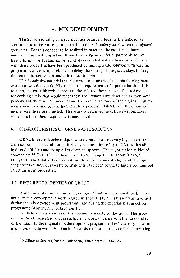
4. MIX DEVELOPMENT
The hydrofracturing concept is attractive largely because the radioactive constituents of the waste solution are immobilized underground when the injected grout sets. For this concept to be realized in practice, the grout must have a number of unusual properties. It must be inexpensive, fluid, pumpable for at least 8 h, and must retain almost all of its associated water when it sets. Grouts with these properties have been produced by mixing waste solution with varying proportions of cement, a retarder to delay the setting of the grout, clays to keep the cement in suspension, and other constituents.
The descriptive material that follows is an account of the mix development work that was done at ORNL to meet the requirements of a particular site. It is to a large extent a historical account; the mix requirements and the techniques for devising a mix that would meet these requirements are described as they were perceived at the time. Subsequent work showed that some of the original require-ments were excessive for the hydrofracture process at ORNL, and these require-ments were therefore omitted. This work is described here, however, because in some situations these requirements may be valid.
4.1. CHARACTERISTICS OF ORNL WASTE SOLUTION
ORNL intermediate-level liquid waste contains a relatively high amount of chemical salts. These salts are principally sodium nitrate (up to 2 M), with sodium hydroxide (0.2 M) and many other chemical species. The major radionuclides of concern are 137Cs and 90Sr; their concentration ranges up to about 0.2 Ci/L (1 Ci/gal). The total salt concentration, the caustic concentration and the con-centrations of individual waste constituents have been found to have a pronounced effect on grout properties.
4.2. REQUIRED PROPERTIES OF GROUT
A summary of desirable properties of grout that were proposed for the pre-liminary mix development work is given in Table II [ 1, 2]. This list was modified during the mix development programme and during the experimental injection programme (Appendix 1, Subsection 1.3).
Consistency is a measure of the apparent viscosity of the grout. The grout is a non-Newtonian fluid and, as such, its "viscosity" varies with the rate of shear of the fluid. In the original mix development programme, the "viscosity" measure-ments were made with a Halliburton5 consistometer — a device for determining
s Halliburton Services, Duncan, Oklahoma, United States of America.
29

TABLE II. PRELIMINARY SPECIFICATIONS FOR GROUT
Consistency
Pumping time
10 units (maximum)'
8 h (minimum)
,a
Setting time
Compressive strength
Fluid lossb
7 d (maximum)
700 kPa ( 100 lbf/in2)
60 cm3/30 mill (maximum)
a See text. ''Based on American Petroleum Institute test for oil-well cements API RP 10B.
pumping time that also indicates an apparent viscosity at a low rate of shear. The results are reproducible but not translatable into more orthodox units.
Pumping time (also called thickening time) is the interval during which the slurry must remain pumpable (i.e. be capable of being pumped down the injection well and out into the fracture). This time was set by the time required to inject a complete batch of waste (plus a margin for possible delays).
Setting time, as used here, means the formation of an immobile matrix after pumping has stopped. The maximum setting time of 7 d was an arbitrary choice; a setting time of less than 7 d is obviously acceptable if there is sufficient delay in thickening so that all the slurry can be pumped into the fracture. High compres-sive strength was not considered necessary for this process; the value of 700 kPa (100 lbf/in2 ) means little more than that the mix will set into a cohesive solid.
The specification of acceptable fluid loss6 was a stringent one. Lack of knowledge of the rate of the possible escape of fluid from the slurry into the shale formation suggested the selection of a value of less than 60 cm3 in 30 min at 700 kPa (100 lbf/in2), which is about ten times lower than that considered acceptable in conventional cement-water slurries. It was thought that a high loss of fluid to the formation would thicken the slurry and prevent its spread out into the formation. This requirement for a low fluid loss was subsequently- eliminated when field tests showed that the rock itself was sufficiently impervious to prevent fluid from escaping (Appendix 1, Subsection 1.2).
6 A standard test used in the petroleum industry to measure the rate at which fluid leaks out of the cement grouts used in oil-well construction. A gelatinous precipitate like ferrous hydroxide would have a low fluid loss, sand and water a high fluid loss.
3 0
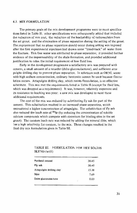
4.3. MIX FORMULATION
The primary goals of the mix development programme were to meet specifica-tions listed in Table II; other specifications were subsequently added that included the reduction of mix cost, the reduction of the leachability of radionuclides from the set grout, and the elimination of phase separation during the setting of the grout. The requirement that no phase separation should occur during setting was imposed after the first experimental injections had shown some "bleed-back" of water from the fracture. This free water was attr ibuted to phase separation; it provided further evidence of the impermeability of the shale formation, and provided additional justification to relax the initial requirement of low fluid loss.
Early in the development programme a satisfactory mix was prepared with cement, a small amount of a retarder (delta gluconolactone), and sufficient atta-pulgite drilling clay to prevent phase separation. In solutions such as ORNL waste with high sodium concentration, ordinary bentonite cannot be used because floccu-lation occurs. Attapulgite drilling clay, which resists flocculation, is an effective substitute. This mix met the requirements listed in Table II (except for fluid loss, which was dropped as a requirement). It was, however, relatively expensive and its resistance to leaching was poor; a new mix was developed to meet these additional requirements.
The cost of the mix was reduced by substituting fly ash for part of the cement. This substitution resulted in an increased phase separation, which necessitated a higher concentration of attapulgite. The substitution of fly ash also reduced the leach rate of 9 0Sr (by reducing the concentration of soluble calcium compounds which compete with strontium for binding sites in the set grout). The caesium leach rate was reduced by adding the mineral illite, which has a high selectivity for caesium, to the mix. These changes resulted in the final dry mix formulation given in Table III.
TABLE III. FORMULATION FOR DRY SOLIDS BLEND (wt%)
Portland cement
Fly ash
Attapulgite drilling clay
Illite
Delta gluconolactone
38.45 38.45
15.38
0.03 7.69
31

One further addition to the waste grout has been found to be necessary. Early experiments showed that both the waste solution and the waste grout retained entrapped air bubbles for at least several minutes. Such entrainment would cause difficulties in accurate mix proportioning and in obtaining smooth operation of the injection pump, and was considered to be intolerable. Two defoaming agents, tributyl phosphate (TBP) and silicone, were tested, and TBP was found to be the more effective. A concentration of 250 to 400 ppm was found to be sufficient. Because TBP is a liquid, it could not easily be added with the dry solids blend; instead, it was added at the suction side of the waste pump.
4.4. PROPORTIONING OF MIX AND WASTE
The properties of the waste grout will clearly be a function of the formulation of the dry solids blend and the amount of blend that is mixed with a unit volume of waste solution. This mix ratio can be (and frequently is) varied during an injec-tion to accommodate different batches of waste solution or batches of dry solids with different properties. The procedure for the determination of the proper mix ratio is described in Subsection 6.1.2; the procedure for the control of the mix ratio during an injection is described in Subsection 5.6.
4.5. TESTING PROCEDURES
The initial mix development work for the hydrofracturing process was carried out with mixes that contained a very high percentage of cement. Accordingly, API test methods for cement grouts were used to prepare test grouts and to evaluate mixes. During the late stages of the programme, it seemed that the mixes then under consideration (with less than 50% cement) were much more shear sensitive than high cement mixes, and that the API grout preparation method imparted more shear to the test grouts than the facility operation imparted to the actual grouts. During one of the experimental injections, three samples were taken of the grout in the mixing tub and compared with laboratory-mixed samples of the same density (solids content) [ 1 ]. The tub samples had a much higher phase separa-tion than the laboratory-mixed samples; the test procedure was adjusted to subject the test samples to less shear.
The site proof-test injection offered the opportunity to determine the effect on a test grout of the shear imparted by the injection pump and the subsequent flow through about 240 m (800 ft) of tubing. Six grout samples were taken during the injection — three from the mixing tub and three from the end of the tubing string. Density, rhéologie properties and phase separations were determined. These properties diverged considerably from those obtained in the pre-injection labora-tory tests [3], This divergence was attributed to excessive shear given to the
32

FIG. 8. Rheology of hydrofracture grout.
laboratory test samples to simulate the high pressure pumping operation. The test procedure was again adjusted to subject the test grouts to less shear.
In the original mix development programme, the pumping time and "viscosity" of the grout were measured on a Halliburton consistometer, which measures the shearing force necessary to rotate a paddle in a grout sample at a relatively low speed. The measurements obtained are related to the rhéologie properties of the grout but are not directly translatable. Subsequently, a more complete determina-tion of rhéologie properties was done with a Fann7 viscosimeter, which measures the shear stress on a grout sample at several different shear rates; the results are plotted to obtain the rhéologie properties of the sample. This procedure is quick and simple, and has completely eliminated the use of the consistometer except for an occasional pumping time determination.
The rhéologie properties of cement slurries generally can be expressed by the power law:
shear stress = K' (shear rate)"
where K' and n' are constants for a particular slurry. For a Fann viscosimeter, the shear rate is proportional to the rev/min of a rotating bob, and the shear stress is proportional to the dial reading (which measures the torque of the rotating bob). Readings are obtained at several speeds and are plotted on log-log paper as in Fig.8. On this plot, K' is the shear stress at a shear rate of unity and n' is the slope
Fann Instrument Corporation, Houston, Texas, United States of America.
3 3

of the line. These two numbers characterize the rhéologie behaviour of the slurry over a wide range of shear rates (cement slurries deviate from power law behaviour at very low shear rates, however). They can be used to calculate pressure drops in piping and to estimate other viscosity-related behaviour. The "apparent viscosity" of a non-Newtonian slurry is defined as the viscosity of a Newtonian fluid (n' = 1) that has the same viscosity as the non-Newtonian slurry at a shear rate of 511 s"1. It is a convenient single number that can be used for the superficial comparison of similar slurries; it should not be used for more exacting analyses.
Phase separation is measured by pouring 250 mL of a test grout in a graduated cylinder and determining the percentage of clear liquid that has separated from the grout after 3 h. Because the amount of separation is a function of the height of the test specimen, this test greatly exaggerates the phase separation that would occur underground where the grout seam is about 1 cm (0.5 in) thick.
4.6. LEACH TESTS
The rate at which various radionuclides are leached from hydrofracture grouts has been extensively studied; the results are reported in Refs [4, 5].
The leach rates of radionuclides from a set grout are quite low (i.e. approxi-mately equivalent to those from a borosilicate glass). The leach behaviour of the set grout has been determined for caesium, strontium,plutonium and curium. A modification of the proposed IAEA test method was used in these studies [6], The leach rates were diffusion controlled and followed the relationship
£ a n / A 0 is the fraction of the radionuclide leached in time tn(s)
V is the specimen volume, cm3
S is the surface area exposed to leaching, cm2
De is a diffusion coefficient, cm2/s.
Observed values of the diffusion coefficient for caesium leached from grouts containing one of the better caesium fixers (pottery clay or Conasauga shale) were between 10"12 and 10~14 cm 2 / s . A typical diffusion coefficient for strontium was 5 X 10'12 ; coefficients for curium and plutonium were approximately 10~16 and 10"n respectively.
1/2
where
3 4

icr3
e
z . o I 0 " 4
o UJ </) < m w I -< tc X o <J UJ
I 0 " 5
ICT6
0 4 0 8 0 120 160 T IME , days
FIG.9. Leach rates of niCs from grouts with various mix additives.
The De values can be used to calculate a leach rate in more familiar units if the ratio V/S, the grout density and the leach time are specified. These quantities are substituted in the above expression to calculate the total fraction leached after a given time. The leach rate can be determined from the fraction leached at two different times divided by the time interval between and multiplied by the density and the V/S ratio. For example, if the ratio V/S is 5 and the grout density is 1.44, the leach rate at 100 d that is equivalent to a De of 1 X 10~10 would be the fraction leached in 101 d (6.667 X 10"3) minus the fraction leached in 100 d (6.633 X 10"3) multiplied by 1.44 and by 5. This would be 2.4 X 10~4 g/cm2 per day.
3 5

TABLE IV. MINERALOGICAL ANALYSIS OF CLAYS
Size fraction
> 5 0 / i m 50-20/Jm 2 0 - 2 Aim < 2 pm Total
Grundite
Percentage of total 8.8 6.6 38.4 44.2
Quartz 9 0 - 9 5 8 5 - 9 5 8 0 - 9 0 < 1 0 50%
Feldspar3 5 - 1 0 5 - 1 0 5 - 1 0 < 1 0 <5
Micab 1 - 5 5 - 1 0 < 1 0 < 5
Other < 1 <1
Kaolinite 7 0 - 8 5 35
Illite 1 5 - 3 0 10
Free iron (Fe 2 0 3 ) 0.24%
Indian Red
Percentage of total 7.0 13.0 51 29
Quartz 6 0 - 7 5 7 5 - 9 0 8 0 - 9 5 60
Feldspar3 5 - 1 0 5 - 1 0 5 - 1 0 5
Micab 1 - 5 1 - 5 1 - 5
Other c c c
Glauconite 2 0 - 3 0 5 - 1 5 1 - 1 0 < 5
Illite 7 5 0 - 7 0 20
Kaolinite 7 1 5 - 3 0 10
Vermiculite ? 5 - 1 5 < 5
Chlorite 7 5 - 1 5 <5
Free iron 2.94%
3 Seritized (partially weathered to clay minerals). ^Includes biotite, muscovite and phlogopite. c Trace.
3 6

4.7. CAESIUM FIXERS
In 1974 a new source of illite had to be found because production at the original mine ended. Several possible substitutes were evaluated, largely on the basis of caesium retention during leach tests. The best substitute was Conasauga shale (the rock into which the injections are made), but a pottery clay was found to be nearly equivalent. Both were at least an order of magnitude more leach resistant than Grundite (the caesium fixer used previously). The results of these leach tests are shown in Fig.9. The pottery clay, available in a more convenient form than the Conasauga shale and almost as effective, has been used in all injec-tions since 1974.
The pottery clays that have been found effective as caesium fixers are:
(1) Indian Red pottery clay, American Art Clay Company, Indianapolis, Indiana; (2) Clay 67-D, Cedar Heights Clay Company, Cedar Heights, Ohio.
The reason for the effectiveness of these clays as caesium fixers is not known. Table IV gives the results of an X-ray analysis of Grundite (the illite used before 1974) and Indian Red pottery clay. The differences in analysis do not seem great enough to account for a difference in leach rate of a factor of 20.
REFERENCES
[1] DeLAGUNA, W., TAMURA, T., WEEREN, H.O., STRUXNESS, E.G., McCLAIN, W.C., SEXTON, R.C., Engineering Development of Hydraulic Fracturing as a Method for Permanent Disposal of Radioactive Wastes, Rep. ORNL-4259, Oak Ridge National Laboratory, Oak Ridge, Tennessee (1968).
[2] TAMURA, T., Disposal of radioactive wastes by hydraulic fracturing, Part IV: Chemical development of waste-cement mixes, Nucl. Eng. Des. 5 (1967) 477.
[3] WEEREN, H.O., BRUNTON, G.D., DeLAGUNA, W., MOORE, J.G., Hydrofracture Site Proof Study at Oak Ridge National Laboratory, Rep. ORNL-TM-4713, Oak Ridge National Laboratory, Oak Ridge, Tennessee (November 1974).
[4] MOORE, J.G., GODBEE, H.W., KIBBEY, A.H., JOY, O.S., Development of Cementi-tious Grouts for the Incorporation of Radioactive Wastes, Rep. ORNL-4962, Oak Ridge National Laboratory, Oak Ridge, Tennessee (April 1975).
[5] MOORE, J.G., Development of Cementitious Grouts for the Incorporation of Radioactive Wastes, Part 2: Continuation of Cesium and Strontium Leach Studies, Rep. ORNL-5142, Oak Ridge National Laboratory, Oak Ridge, Tennessee (September 1976).
[6] HESPE, E.D., Ed., Leach testing of immobilized radioactive waste solids, a proposal for a standard method, At. Energy Rev. 9 1 (1971) 195.
3 7

5. DESIGN AND CONSTRUCTION OF FACILITY
The descriptive material that follows is based on the new hydrofracture facility at ORNL. This facility was designed to handle certain specific wastes, and its process details were determined to some extent by the properties of these wastes. A disposal facility designed to handle different wastes at a different site might be quite different in detail.
The ORNL hydrofracture facility is designed to inject about 530 000 L (140 000 gal) of grout per injection. Because of this large injection volume, the facility is operated as a large-scale batch process; one injection a year suffices to dispose of ORNL's accumulation of intermediate-level waste solution. The design injection rate is 950 L/min (250 gal/min); the expected injection pressure is 14 to 28 MPa (2000 to 4000 lbf/in2). These design parameters have been adopted with little change from the experimental shale fracturing facility. The design solids storage capacity has been increased by about 20%, but the injection rate remains the same. The shielding for the new facility has been increased to allow the injection of wastes with a specific activity of up to 6.6 Ci/L (25 Ci/gal). This has required thicker shielding walls and more careful design of equipment for washup operations. The design pressure has been increased from 34 to 69 MPa (5000 lbf/in2 to 10 000 lbf/ in2) because the 34 MPa (5000 lbf/in2) limit of the experimental facility was occasionally found to be marginal.
An injection facility consists of the injection well, a network of observation and monitoring wells, storage tanks for the waste solution, storage bins for the dry solids mix, a mixer, a mixing tub, and an injection pump and its associated high-pressure piping. A standby injection pump is required for each injection to clear grout from the injection well and from other high-pressure piping in the event of failure of the main injection pump. Because the standby pump need not pump contaminated solutions, it may be rented for the injection. A flow diagram of an injection facility is shown in Fig. 10. An aerial view and a site view of the new hydrofracture facility are shown in Figs 11 and 12 respectively.
5.1. WELLS
Three types of wells were used at the shale fracturing facility. The same types are used at the new facility — an injection well for the injection of waste grout, observation wells for the determination of the orientation of the grout sheet, and rock cover monitoring wells for verification of the continued imper-meability of the shale above the grout sheets. A sketch of these well types is given in Fig. 13. All waste injections are made through slots cut in the casing and surrounding cement of the injection well. As the grout sheet spreads from the injection well, it intersects the cemented casing of one or more observation
38
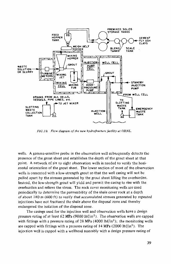
PREMIXED SOLIOS STORAGE TANKS
DRAINS FROM ALL CELLS, VESSELS, PIPE LINES, «»c.
j r » -TO JET MIXER SLOTTING WASTE COLLECTION TANK
FIG. 10. Flow diagram of the new hydrofracture facility at ORNL.
wells. A gamma-sensitive probe in the observation well subsequently detects the presence of the grout sheet and establishes the depth of the grout sheet at that point. A network of six to eight observation wells is needed to verify the hori-zontal orientation of the grout sheet. The lower section of most of the observation wells is cemented with a low-strength grout so that the well casing will not be pulled apart by the stresses generated by the grout sheet lifting the overburden. Instead, the low-strength grout will yield and permit the casing to rise with the overburden and relieve the stress. The rock cover monitoring wells are used periodically to determine the permeability of the shale cover rock at a depth of about 180 m (600 ft) to verify that accumulated stresses generated by repeated injections have not fractured the shale above the disposal zone and thereby endangered the isolation of the disposal zone.
The casings used for the injection well and observation wells have a design pressure rating of at least 62 MPa (9000 lbf/m2) . The observation wells are capped with fittings with a pressure rating of 28 MPa (4000 lbf/in2); the monitoring wells are capped with fittings with a pressure rating of 14 MPa (2000 lbf/in2). The injection well is capped with a wellhead assembly with a design pressure rating of
3 9

FIG.l 1. Aerial view of the new hydrofracture facility at ORNL. The new facility is in the foreground and the shale fracturing facility is in the middle of the picture. The main facilities are located just beyond the upper left boundary of the picture.
69 MPa (10 000 lbf/in2 ). The observation wells are spaced about the injection well at a distance of 60 to 120 m (200 to 400 ft). The spacing of the monitoring wells is similar.
5.2. BUILDINGS
The building housing the ORNL hydrofracture facility contains a cell bank of three cells having reinforced concrete walls and ceilings 0.76 m (2^ ft) thick and related operating and service areas. A high bay section directly above the injection cell will be used for introducing and removing the injection tubing string, and will provide secondary containment during slotting operations (Subsection 5.8).
4 0
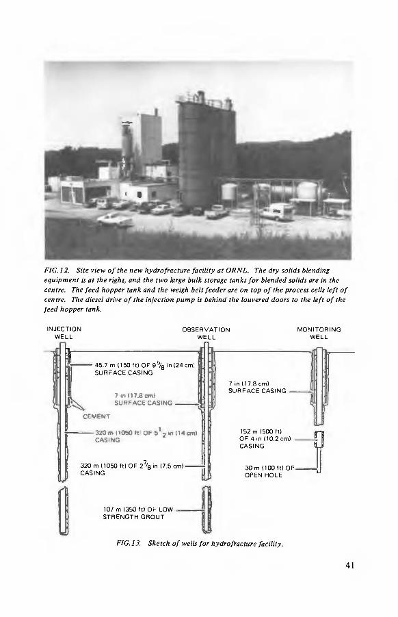
FIG. 12. Site view of the new hydrofracture facility at ORNL. The dry solids blending equipment is at the right, and the two large bulk storage tanks for blended solids are in the centre. The feed hopper tank and the weigh belt feeder are on top of the process cells left of centre. The diesel drive of the injection pump is behind the louvered doors to the left of the feed hopper tank.
I N J E C T I O N O B S E R V A T I O N M O N I T O R I N G W E L L W E L L W E L L
I 45.7 m (150 f t ) O F 9 ö / g in (24 cm: S U R F A C E C A S I N G
7 in (17 .8 cm) S U R F A C E C A S I N G
152 m (500 f t ) O F 4 in (10 .2 cm) C A S I N G 0
3 2 0 m (1050 f t ) O F 2 7 / 8 in (7 .5 c m ) C A S I N G
3 0 m (100 f t ) O F O P E N H O L E
J
107 m (350 f t ) O F L O W S T R E N G T H G R O U T
FIG. 13. Sketch of wells for hydrofracture facility.
41

Immediately over the injection well is a cell that accommodates the wellhead, the valve manifold to direct flows for injection, slotting and cleanup operations, and related high-pressure piping. The pump cell is big enough to house the head-ends of two Halliburton HT-400 triplex pumps; only one pump is installed at present. Only the pump head is inside the shielded cell; a shielding barrier is installed immediately behind the pump head so that the gear train and diesel drive motor are outside the shielding barrier and are accessible during operation.
The mixing cell houses a solids-liquids mixer, a mixing tub and associated piping. Cement and other solids are pneumatically conveyed into a metering tank above the mixing cell, and then fall into the solids-liquids mixer, where they are combined with the liquid waste stream to form the grout. The grout flows into the mixing tub, which serves as a de-aerator and as a feed vessel for the injection pumps.
The well cell, pump cell and mixing cell have stainless-steel liners to facilitate cleanup after any spill. Air from all three cells is exhausted through a filter bank and a short stack. Drain lines from all three cells go to the slotting waste collection tank (Subsection 5.7).
Instrumentation and electrical controls are located in a control room adjacent to the shielding cells. Viewing windows are provided between the control room and the three cells to permit direct observation of the cell operations. A compressor room houses air compressors and driers.
Outside the shielded cells is a valve pit that contains instrumentation and valving for the waste stream, the slotting waste tank and much of the piping for the washup system. This pit has a stainless-steel liner and a connection to the off-gas system.
The waste storage tanks are installed in a vault adjacent to the fracturing facility. The waste transfer pumps are installed near the waste storage tanks.
5.3. BLENDING AND STORAGE OF SOLIDS
The dry solids constituents of the waste grout mix are blended before the injection and stored in two bulk storage tanks. The dry solids — cement, fly ash, Attapulgite 150 (a water-retaining clay), a pottery clay (for caesium retention) and a retarder — are brought to the fracturing site in bags or in pneumatic trans-porter trucks. A batch of these mix ingredients (about 18 000 kg (40 000 lb)) is proportioned by weight into a weigh tank. The weigh tank is pressurized and the dry solids are blown to an adjacent tank. The adjacent tank is pressurized and the solids are blown to a third tank; pressurized transfer between tanks thoroughly blends the solids mix. The blended mix is blown from the third tank into the solids storage bins. A new batch of solids is then charged to the weigh tank and the blending cycle is repeated. As many as 25 batches of dry solids may be needed for an injection.
4 2

Each of the dry solids storage tanks, which can hold up to 220 000 kg (500 000 lb) of solids, is provided with weigh cells (to measure the weight of the tank contents), aeration pads and a rotary discharge valve. During an injection, solids are discharged from the storage tanks and transferred pneumatically into a feed hopper tank mounted above the mixing cell. From the feed hopper tank, solids flow through a rotary feed valve on to a weigh belt feeder and are discharged at a controlled rate into the mixing hopper in the mixing cell.
5.4. WASTE FLOW AND GROUT MIXING
The waste (solution or slurry) is pumped from the adjacent waste storage tanks to the fracturing facility. The waste pumps are progressive-cavity positive-displacement pumps. The discharge pressure is about 1.4 MPa (200 lbf/ in2) at a flow rate of about 640 L/min (170 gal/min); the flow rate can be varied. Either of the two waste pumps will supply the necessary flow; the second pump can be a spare or both pumps can be run at reduced speed.
A small volume of tributylphosphate (TBP) is added by a small positive-displacement pump to the waste solution on the suction side of the waste pumps. A concentration of about 400 X 10"6 ppm is needed as discussed in Subsection 4.3. This additive increases the rate of de-aeration of the grout in the mixing tub. (Grout that is not de-aerated is difficult for the injection pump to handle.)
4 3

The waste stream is pumped through a flowmeter (a turbine flowmeter for solution and a magnetic flowmeter for slurry) to the jet mixer, which mixes the waste solution and the solids. As the waste solution is pumped through the mixer, the solids drop into the mixer and are subsequently picked up by the jet stream and thoroughly mixed with the waste. The resulting grout is continuously dis-charged into the mixing tub. A sketch of the mixer operation is shown in Fig. 14.
The mixing tub provides surge capacity so that the flows of the waste transfer pump and the injection pump can be synchronized during an injection. An operator, who controls both pumps, observes the level of grout in the mixing tub either by means of a mirror-and-window arrangement on the top of the tub or by observing a float-type level gauge. He adjusts the flow rate of one or the other of the pumps as the grout level fluctuates. By providing a holdup time of about 2 min, the mixing tub also allows sufficient time for de-aeration of the freshly mixed grout to occur. The mixing tub is vented to the filtered off-gas system.
5.5. GROUT INJECTION
The grout flows from the mixing tub by gravity to the suction side of the injection pump. The injection pump8 is capable of operating over a range of pressures and flow rates between 41.4 MPa (6000 lbf/ in2) and 400 L/min (105 gal/min) and 6.9 MPa (1000 lbf/in2) and 2650 L/min (700 gal/min). A steel splash plate fitted around the head of the pump and extending to the walls, floor and roof of the cell isolates the pump head within the cell.
A standby injection pump9, similar to the main injection pump, is rented for each waste injection. During an injection it is connected, via the wellhead manifold, to the injection well to provide a means for flushing the well free of grout if the main injection pump fails. This pump is not required to transfer radioactive fluids.
A piping manifold connects the injection pump, the injection well, the standby injection pump and the slotting waste tank. This manifold contains plug valves, check valves, pressure relief valves (set at up to 62.1 MPa (9000 lbf/ in2)) and pressure gauge connections. The components of the manifold are rated at 69 MPa (10 000 lbf/in2). Extra high-pressure swivel joints are used between the injection pump and the piping manifold and between the piping manifold and the wellhead to damp vibration between the pumps and the wellhead. The piping manifold and wellhead at the new hydrofracture facility are shown in Fig. 15.
The waste grout is injected down a 6.3 cm (21- in) tubing string that is hung in the injection well and extends to within 3 m (10 ft) of the slot that
8 A Halliburton HT-400 triplex positive-displacement pump. 9 A standard truck-mounted Halliburton positive-displacement pump.
4 4

FIG. 15. Wellhead and high-pressure manifold at the new hydrofracture facility, ORNL. The wellhead is on the right. The assembly is topped by a remotely operated shutoff valve and a remotely operated plug container. The height of the top of the shutoff valve is about 2.5 m (8 ft). The connection to the standby pump comes through the wall (near the centre of the picture) and is connected to the manifold left of centre. The high-pressure manifold connects the injection pump and the standby pump with the central tubing in the wellhead, the annulus of the wellhead and the slotting waste collection tank. The valves in the manifold are remotely operated.
has been cut in the injection well (Subsection 5.8). The annulus between the casing of the injection well and the tubing string is filled with water, and the waste grout is injected at a rate of up to 1000 L/min (250 gal/min) down the tubing string and out through the slot into the shale formation.
At the end of an injection, a wiper plug is released from a fitting on the wellhead and pumped down the tubing string with water to wipe surplus grout from the inside of the tubing string. The used plug remains in the bottom of the well.
4 5

5.6. PROCESS CONTROL
Control of the proportions at which solids and waste solution are mixed in the fracturing plant is necessary. If the proportion of solids is too high, the resulting grout will be viscous, difficult to pump and subject to premature setting. If the proportion of solids is too low, the grout will fail to retain all the associated liquid and will exhibit "phase separation" on setting. This is undesirable because some small fraction of the radionuclides (<ÍC 1%) will remain with the water and thus will not be immobilized. The desirable operating range between these two extremes is fairly narrow; the average variation from the desired proportion should not exceed 10% for any extended period and should be kept within 5% if possible. During a waste injection, this mix ratio is determined from separate measurements of the flow rates of the waste stream and the dry solids stream, and a manual or automatic calculation of their ratio. The solids addition rate is measured by the weigh belt feeder that is installed immediately below the feed hopper tank. A check on this measurement is provided by measuring the weight of dry solids remaining in the two bulk storage tanks and the feed hopper tank. The flow rate of the waste solution or slurry is measured by a turbine or magnetic flowmeter. During an injection, the mix ratio can be varied by a manual adjustment of either the solids or the waste flow rate. Generally, the solids flow rate is adjusted.
5.7. WASHUP EQUIPMENT
A considerable volume of water is required for operations such as slotting the casing of the injection well and washing equipment after an injection. Because this water will become contaminated, it must ultimately be injected with the waste solution. Water must be re-used, where feasible, to prevent the contaminated water from constituting a large fraction of the waste being injected. The slotting waste tank is an 11 000 L (3000 gal) tank that is used as a collection tank for contaminated solutions, grout and sand that are generated during facility operations. A pump is provided so that the contents of this tank can periodically be pumped to the jet mixer, mixed with solids and injected.
Remotely operated spray nozzles are in the mixing tub so that at the end of an injection the walls and other interior surfaces can be washed to dislodge grout residues. These grout residues and additional residues that are dislodged during washing of the high pressure piping are drained to the slotting waste collection tank. During this operation and for 24 h afterwards, the contents of the slotting waste tank are agitated. Under such conditions, the grouts used in hydrofracture operations will set in the form of fine sand-like particles that can then be allowed to settle in the slotting waste tank. They can be resuspended by agitation and be injected with the contaminated solutions in the waste tank.
4 6

FIG.16. Flow diagram of slotting operation.
5.8. SLOTTING EQUIPMENT
Four injections are normally made into a single slot in the injection well. Before the next series of four injections, the old slot is plugged with cement and a fresh slot is cut in the injection well casing 3 m (10 ft) above the previous one. The well casing is cut by pumping a slurry of sand and water down the string of tubing hanging in the injection well and out through a jet at the bottom of the tubing string to impinge on the casing at that point. The erosive action of the sand cuts the casing and the surrounding cement and shale to a sufficient depth to make subsequent initiation of the desired fracture relatively easy. The spent slurry is brought to the surface through the annulus between the tubing and the casing,
4 7

the degraded sand is allowed to settle in the slotting waste tank and the water is recirculated so that the volume of contaminated water produced by the slotting operation can be kept to a minimum. A sketch of this operation is shown in Fig. 16. The tubing string is slowly rotated by a hydraulic power swivel so that a complete cut of the casing is made.
When the slotting operation is judged to be complete, flow in the injection well is reversed (down the annulus and up the tubing string) to dislodge the jet from the bottom of the tubing string. The jet is pumped up the tubing and is caught at the wellhead in a special fitting. Reversed circulation is continued to remove excess sand. After about 20 min, flow is stopped and the wellhead assembly is re-rigged for injection operation.
5.9. EMERGENCY WASTE PIT
An emergency waste pit is provided as a precaution against the unlikely possibility that late in the course of a waste injection the wellhead might rupture and allow the injected grout to flow back up the well. In such an event the grout would flow from the wellhead cell through a 30 cm (12 in) line to the 150 000 L (40 000 gal) waste pit where it would set. The basis on which the capacity of this pit was estimated is discussed in Subsection 7.2.2.
4 8

6. OPERATION
The descriptive material that follows is based on the shale fracturing facility in use at Oak Ridge National Laboratory, Oak Ridge, Tennessee, from December 1966 to May 1979. This facility was designed to handle certain specific wastes, and the details of its process were determined to some extent by the properties of these wastes. A disposal facility designed to handle different wastes at a different site might be quite different in detail. The changes in operating methods that are expected in the new hydrofracturing facility at ORNL are noted where applicable.
6.1. PREPARATION FOR INJECTION
The ORNL shale fracturing facility has been operated as a large-scale batch process; one injection, lasting about 10 h, has sufficed to dispose of a one-year accumulation of ORNL waste. This mode of operation requires extensive preparations for each injection. Solids blending, mix compatibility tests, some-times a slotting operation, and a fracture initiation are required.
6.1.1. Solids blending
The requirements of the hydrofracture process at ORNL set several stringent criteria for the properties of the grouts that can be injected. They must be compatible with the waste solutions that are injected, must be pumpable for extended periods of time (at least 8 h) and must retain virtually all the associated water when they set. Another desirable characteristic is a relatively low leach rate. The blend of solids that, when mixed with ORNL waste solutions, has been found to produce grouts with these properties contains cement, a retarder to delay the setting of the grout, attapulgite drilling clay to retain excess water, a second clay (pottery clay) to retain caesium, and fly ash to retain strontium. The proportions of the different ingredients can be adjusted to allow for variations in the composition or concentration of the waste solution being injected. In practice, however, essentially the same mix composition has been used for 15 years. A typical range of compositions used in a recent series of injections is given in Table V [1 ]. The variations that are shown resulted from variations in component weights as delivered by the suppliers of the ingredients.
The cement is Type 1 Portland cement, and is delivered in pneumatic transporter trucks. Occasionally, cements from different suppliers have been observed to have significantly different properties when made into a grout. In consequence, a mix compatibility test (Subsection 6.1.2) is always run on a cement sample before placing the order.
4 9

TABLE V. COMPOSITION RANGE OF DRY SOLIDS MIX (wt%)
Ingredient
Cement (Type 1) Fly ash Drilling clay Pottery clay Retarder
35.2-41.4 (38.5 desired) 33.2-44.1 (38.5 desired) 13.2-16.9(15.4 desired) 7 . 1 - 8.5 (7.7 desired)
0.04-0.045 (0.05 desired)
The fly ash (a pozzolanic material) is obtained from one of the local coal-fired steam plants as a dry, fine ( ~ 200 mesh)10 powder. It is delivered to the site in a pneumatic transporter truck. The effectiveness of the fly ash in the grout mix has not been observed to vary with either the supplier or time.
The drilling clay used is Attapulgite-150, a trade name of a clay product from the polygorskite group of clay minerals. Its function is to keep the other mix components in suspension in the grout. This material is obtained in 50 lb bags11. The pottery clay (Subsection 4.7) is a caesium retainer. It is obtained in 50 lb bags. The retarder is a sugar, delta gluconolactone. It is bought by the drum.
The blending operation for each injection normally requires five days to complete. It is done in a series of 15 batch operations, in each of which 18 000 to 20 000 kg (40 000 to 45 000 lb) of dry solids are proportioned, blended and moved to storage. This blending process is described in Subsection 5.3. In this operation, over 280 m3 (10 000 f t 3 ) (STP) of compressed air at 340 kPa (50 lbf/in2) is used to blend and transfer one 18 000 kg (40 000 lb) batch of dry solids. During operations at the shale fracturing facility, this air was not dried before use and, depending on the humidity during the blending operation, could have contained an appreciable amount of water. A comparison of samples of blended solids that were blended on days of high humidity with samples that were blended when the humidity was low nevertheless showed no consistent difference in properties [2]. For short-term (one to two weeks) storage of the blended solids, the use of dried air is apparently not necessary.
The proportions of the various dry solids in the mix can vary considerably from the desired proportions (Table V). Such variations occur because the Oak Ridge facility has no solids storage capacity for unblended solids. As a result,
10 Mesh: the coarseness or fineness of screens is expressed as the number of such openings per linear inch.
11 1 lb = 0.454 kg.
5 0

the quantity of cement (or fly ash) that is brought to the site on a particular day is the quantity that must be blended on that day. Only if the amount of cement is grossly less than what is needed is the delay involved in obtaining more cement deemed worthwhile. Generally, minor discrepancies are ignored during the blending operation. Some compensation for such discrepancies can be provided by increasing or decreasing the mix ratio (Subsection 6.1.2).
Recent tests at the new fracturing facility have indicated that the small quantity of retarder that is used is not well distributed in the other dry solids components by the blending operation. This results in non-uniform behâviour. Consequently, the blending procedure has been modified to omit the addition of retarder during the blending operation; this material is added instead as a concentrated solution to the waste in the waste storage tanks. It is subsequently mixed with the waste solution by extensive agitation.
6.1.2. Mix compatibility testing
The grout that is injected by the hydrofracture process must be fluid enough to pump easily, have a sufficiently long pumping time to proceed far into the shale formation before setting or gelling occurs, and have a low phase separation before or during setting (so that the volume of free water, which will contain some radio-nuclides, will be minimized). The process variables that are known to affect these grout properties include the waste solution composition, the composition of the dry solids blend, the mix ratio (the weight of solids per unit volume of waste solution) and the amount of shear imparted to the grout during mixing and pumping. All of these variables except the mix ratio are essentially constant during an injection; therefore, the properties of grout can be adjusted during an injection only by controlling the mix ratio. The particular mix ratio that is required to produce a grout with the desired properties could be determined by two methods:
(1 ) Continuously monitor some characteristic property or properties of the grout, and vary the mix ratio to keep this property at a constant desired value; or
(2) Predetermine the mix ratio that will produce a grout with the desired properties, and maintain this ratio constant during the injection.
Method ( 1 ) has several inherent difficulties. First, it is quite difficult to monitor continuously any property of a grout. The grout tends to be non-homogeneous in the mixing tub, it tends to gel on instruments (giving false readings) and it is quite difficult to wash from instruments at the end of an injection. When the grout contains radionuclides, all these problems are compounded. A second and more fundamental difficulty is that the significant time-dependent grout properties of phase separation and pumping time are not necessarily predicted by any measurable property of the freshly mixed grout.
51

Method (2) is the approach that has been used in the hydrofracture process from the beginning. The procedure that has evolved consists of several sequential steps:
(1 ) Sample the waste solution and analyse for major chemical constituents. Prepare a non-radioactive solution with a similar composition.
(2) Sample the dry solids mix that has been blended for the injection. (3) In a series of laboratory tests, determine the phase separation and rhéologie
properties of grouts prepared from mixes of synthetic waste solution and dry solids samples at different mix ratios (pumping time does not appear to vary appreciably with changes in the mix ratio and is generally not measured). In these tests, the solution and dry solids are mixed in a Waring blender12 for a time and mixing speed (rev/min) that are selected to approximate the amount of shear that will be imparted to the grout during the disposal injection.
(4) The lowest mix ratio that will produce a grout with a low apparent viscosity and low phase separation is chosen for the injection.
In general, this procedure seems to have worked fairly well. The only system for direct measurement of grout properties that has been tried (a viscosity meter in the mixing tub) was only partially successful [3]. Until a successful version of some such system has been developed, some type of mix compatibility test must therefore be used to determine the proper mix ratio to be used in each injection.
6.1.3. Slotting
Early in the experimental development programme for hydrofracture, a preliminary analysis was made of the underground stresses that would be likely to result from repeated grout injections [4]. This analysis indicated that these induced stresses would be minimized by spacing the injections vertically in the disposal zone. Carried to the extreme, such spacing would require a new slot in the injection well for each injection, and either a close spacing of each slot or a considerably reduced well capacity. These conflicting requirements have been compromised by adopting an operating procedure of making four consecutive injections into a single slot of the injection well, plugging this slot, and cutting a new slot 3 m (10 f t) higher in the injection well for the next series of four injections. This procedure spaces the injections in the injection zone without requiring a large number of slotting operations. The four injections per slot and the 3 m ( 10 f t) between slots are, however, rather arbitrarily chosen numbers. Further experience or a more detailed stress analysis may suggest the desirability of modifying one or both.
12 Waring Products Division, New Hartford, Connecticut, United States of America.

FIG. 17. Wellhead assembly.
5 3
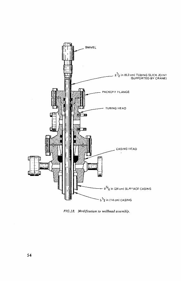
j e s S W I V E L
2 1 / 2 In (6 .3 cm) T U B I N G S L I C K J O I N T ( S U P P O R T E D B Y C R A N E )
P A C K O F F F L A N G E
T U B I N G H E A D
C A S I N G H E A D
9 ' 8 in (24 cm) S U R F A C E C A S I N G
• 5 1 / 2 in (14 cm) C A S I N G
FIG.18. Modification to wellhead assembly.
5 4

Occasionally it is necessary to make fewer than four injections into a single slot. If the volume of overflush water (Subsection 6.2) used at the end of an injection is too small or if the shutoff valve leaks a small volume of water before the grout has set, the slot used in the previous injection will not be clear. In such a case, it is necessary to cut a new slot. As an early preliminary step to all injections (except for those in which a slotting operation is already scheduled), the injection well is pressurized to establish that the existing slot is clear and will accept fluid.
If this slot is open, the first step in a slotting operation is to plug the existing slot. This is done by preparing a cement grout and pumping this grout down the tubing in the injection well and through the existing slot into the formation. The pumped volume of the cement grout is carefully noted. After a precalculated volume has been pumped, it is followed by a water wash that clears the tubing string. The operation ends with the batch of cement grout plugging the existing slot. The shutoff valve on the wellhead is then closed and the plug allowed to set overnight.
The plug is tested to confirm that it will not leak at a pressure of 35 MPa (5000 lbf/in2). If a leak is observed, the plugging operation is repeated. The existing slot must be plugged to ensure that the fracture that will be formed after the subsequent slotting operation will be at the elevation of the newly cut slot and not at the elevation of the old slot.
The depth of the top of the plug is determined next by lowering the known length of the tubing string in the well until contact with the plug is made. This operation requires a modification to the wellhead assembly (which is required in any event for the subsequent slotting operation). This modification is accomplished by unbolting the tubing head adaptor on the normal wellhead configuration (Fig. 17) and lifting this adaptor and the attached tubing string with a crane. The tubing string is held in position with wedges and the tubing head adaptor is unscrewed and lifted off. A 9 m (30 f t) length of tubing (the slick joint) with an attached packoff flange is screwed to the tubing string and, while the assembly is supported by the crane, the wedges are removed and the tubing string is lowered until the packoff flange can be bolted to the wellhead. The tubing string, still supported by the crane, can then be lowered to make contact with the new plug. The modification to the wellhead assembly is shown in Fig. 18.
If the top of the plus is too far above the old slot, the top layers of the plug are removed by dropping a jet down the tubing string to seat on a fitting on the bottom. A stream of water is pumped through this jet to erode the cement plug to the desired depth.
The slotting operation, described in Subsection 5.8, is almost the same for both the old and the new hydrofracture facilities. The only significant difference is that in the new facility the spent sand is collected in the slotting waste tank and sub-sequently injected with the next waste injection; in the old facility the spent sand was collected in a waste pit and no attempt at subsequent disposal was made.
55

The slotting operation typically requires about 1 h of slurry pumping time [ 1 ]. The operating pressure is between 17 and 31 MPa (2500 to 4500 lbf/in2) and the sand concentration is approximately 0.06 kg per litre (0.5 lb per gal). These parameters have been established by operating experience; a shorter time might be sufficient, but it is much easier to run the slotting operation longer than necessary than it is to rework the wellhead assembly an additional time (the adequacy of the fracture cannot be tested without rebuilding the wellhead to the configuration shown in Fig. 17). The size of the slot that is cut by this operation has not been determined, but estimates of tubing stretch caused by pressure fluctuations suggest that a band as much as 5 cm (2 in) wide is eroded to a greater or lesser degree.
6.1.4. Fracture initiation
When the slotting operation is judged to be complete, the well is washed free of residual sand. The wellhead assembly is then disassembled and rebuilt in the configuration shown in Fig. 17. The well is slowly pressurized by water injection until the formation fractures. This fracturing is signalled by a sudden, sharp drop in wellhead pressure. The initiated fracture is then enlarged by gradually increasing the flow rate. About 1900 L (500 gal) of water is pumped into the fracture at this time. The fracturing pressure is quite variable; in the last three fracturing operations this pressure ranged from 23 to 38 MPa (3400 to 5500 lbf/in2).
6.2. INJECTION
The waste injection operations at ORNL have been performed under contract by the Halliburton Company, with assistance and overall supervision by ORNL. For each injection Halliburton supplies a standby truck-mounted injection pump, engineering assistance and an operating crew.
The first injection operation is to pressurize the injection well to verify that the fracture will accept fluid. The fracture typically reopens at approximately the same pressure as the fracturing pressure noted during initiation of the original fracture.
The injection is started with contaminated waste water (from the waste pit in the experimental fracturing facility or from the slotting waste tank in the new fracturing facility). The flow of solids is started; the resulting grout is pumped down the well and into the shale formation. As soon as operating con-ditions have stabilized (usually within 5 min), the waste pump valving is switched so that waste solution instead of waste water is pumped. An adjustment to the mix ratio may be made at this time if the mix compatibility tests (Subsection 6.1.2) have indicated the need. From this point until very near the end of the injection, operation should be almost continuous.
5 6

Waste injections at the facility are planned for the continuous injection of about 530 000 L (140 000 gal) of waste grout. This injection volume was selected for the reasons given at the beginning of Section 5: maximization of well life, minimization of operating cost and limitation of operator fatigue. The approximate maximum grout injection rate with existing equipment is 1000 L/min (250 gal/min); at this rate an injection will be completed in a little over nine hours.
The process operations during an injection are described in Subsections 5.3 to 5.7 inclusive. This description is based on operation of the new ORNL hydro-fracture facility, which is generally similar to the operation at the experimental facility. The major operating differences between the two facilities are the result of better process instrumentation and better control of solids flow in the new facility. In both facilities, the flow of waste solution to the mixer is synchronized with the rate of grout injection by maintaining an approximately constant level in the mixer tub. In both facilities the mix ratio is monitored throughout the injection by several independent instrumentation systems, and is adjusted as necessary to keep this ratio within the limits indicated by the mix compatibility tests. In both facilities there is a continual observation of the injection pump and all process piping so that any malfunction or leaks may be detected quickly.
Data that are recorded or noted during an injection include the following:
( 1 ) Weight of solids in solids head tank and bulk storage tanks, (2) Mass flow of solids, (3) Waste flow rate, (4) Grout injection rate, (5) Mix ratio (mass flow of solids/waste flow rate), (6) Volume ratio (grout injection rate/waste flow rate), (7) Grout density in mix tub, and (8) Injection pressure (wellhead and annulus).
Blended solids that are stored for an extended time tend to cake and flow from storage bins with difficulty. For this reason it is desirable to consume all the solids that have been blended for an injection. Therefore, about 10 min before all the solids have been consumed, valves on the waste pumps are reset so that water is pumped instead of waste solution. If a significant volume of waste water remains for disposal, this switch to water flow would start earlier and the waste water would be disposed of at this time. This period of operation with water instead of waste solution, but with solids flow continuing, serves partially to decontaminate the process piping and equipment. When the last of the stored solids are exhausted, flow is continued for a minute or two to flush most of the remaining grout down the well. The injection is then halted. The wiper plug is released and pumped down the well. A careful observation of wellhead pressure and pumped volume indicates when the wiper plug clears the tubing
57

string. A small additional volume of water is then pumped to force the last of the grout through the slot, and the well is valved closed.
The facility is washed to remove residues of grout from piping and equipment. This operation is described in Subsection 5.7.
6.3. MONITORING AND POST-INJECTION OPERATIONS
6.3.1. Monitoring during injection
No monitoring of the observation wells is done during an injection because of the danger that the passage of a grout sheet by a well that is being monitored would stress the tubing string sufficiently to rupture the tubing and provide a pathway for the grout to the surface environment. These wells are capped during each injection.
The wellhead pressure, which is monitored during each injection, fluctuates over a range of a few MPa (several hundred lbf/ in2) as the rate of injection is increased or decreased. During pauses in each of the injections and at the conclusion of every injection, the observed pressure at zero flow (when corrected to the bot tom hole pressure) has been well above the overburden pressure. Any decrease in this zero flow pressure below the overburden pressure would be a signal of a probable abnormality in the system.
The radiation exposure of the operational crew is regularly monitored during all phases of an injection - preparation, injection and post-injection cleanup. For each injection at the experimental facility, these exposures averaged about 200 man-rem per injection. About 10% of this exposure was received during the injection and about 5% during the slotting operation (when one was carried out). Most of the exposure (85 to 90%) was received during the pre-injection maintenance operations [2]. The new facility was designed to minimize both maintenance and operating exposures and during the first waste injection at this facility these exposures were substantially less; the average exposure was less than 50 man-rem.
The rock cover monitoring wells are filled with water and capped. The indicated pressure at the surface of these wells is noted at intervals during each injection [1—3]. This pressure has been observed to vary during the course of an injection, sometimes substantially (up to 0.7 MPa (100 lbf/in2). It is postulated that a grout sheet that passes directly below one of these wells compresses the overburden and squeezes a small volume of water from the shale, creating a rise in pressure. The underground path of the grout sheet would be indicated by the pressure increases in these wells. This potential monitoring technique is still being investigated.
58

FIG.19. Sequence of gamma-ray logs in observation well 19; MSL = mean sea level.
6.3.2. Post-injection monitoring
A few days after the completion of the injection, the orientation of the grout sheet is determined by logging the network of observation wells that surrounds the facility (these are cased wells that extend to the bottom of the disposal formation). A gamma-sensitive probe lowered into these wells detects the presence of both old and new grout sheets. Comparison of the new log with earlier logs will then indicate the part of the response that is a result of the most recent injection. A representative series of logs is shown in Fig. 19. This technique permits the depth of a grout sheet to be established for a single well; repetition of this logging operation in other wells permits verification of the bedding plane orientation of the grout sheet and a tentative indication of the direction of movement. A very large number of observation wells would be required to provide more information because the logging results obtained to date indicate that the grout sheets are asymmetric and have not moved in the same direction.
After several injections have been completed, the cumulative surface uplift around the injection well is determined by measuring the change in elevation of a network of bench marks. This uplift averages 0.4 cm (0.15 in) per injection at the injection well and decreases regularly to near zero at about 400 m (1300 ft) from the well. This uplift is shown in Fig. 4 for an injected grout volume of 11.7 million litres (3.1 million gal). These measurements were originally made to determine whether grout sheet orientation could be inferred from observed discrepancies in the surface uplift. No such discrepancies were noted, and the significance of the measurements appeared dubious. Consequently, no such measurements are made at the new facility.
5 9

On o
TABLE VI. SUMMARY OF INJECTION PARAMETERS
Injection Date Depth Waste Waste- Grout Mix ratio 9 0 Sr 137Cs 244 Cm 2 3 9 p u
number (m) volume plus-water volume kg solid (Ci) (Ci) (Ci) (Ci) (litres) volume (litres) -
(litres) litres liquid
Experimental injections 1 - 7 Feb. 1 9 6 4 -
Aug. 1965 288-266 1 731 000 2 566 000 1 436 5 237
Operational injections
ILW-IA 12 Dec. 1966 266 136 260 264 700 360 000 ILW-IB 13 Dec. 1966 266 94 410 0.74 3 19 950 NA3 NA ILW-2A 20 Apr. 1967 263 325 500 623 800 872 100 ILW-2B 24 Apr. 1967 263 234 700 0.73 1 050 58 500 NA NA ILW-3A 28 Nov. 1967 263 117 300 374 900 555 500 ILW-3B 29 Nov. 1967 263 0.66 9 000 17 000 NA NA

13 Dec. 1967 260 ILW-4A 3 Apr. 1968 260 ILW-4B 4 Apr. 1968 260 ILW-5 30 Oct. 1968 257 ILW-6 11 June 1969 257 ILW-7 23 Sep. 1970 257 ILW-8 29 Sep. 1972 254 ILW-9 17 Oct. 1972 254 ILW-10 8 Nov. 1972 254 ILW-11 5 Dec. 1972 254 ILW-12 24 Jan. 1975 251 ILW-13 29 Apr. 1975 251 ILW-14 20 June 1975 251 ILW-15 30 June 1977 251 ILW-16 17 Nov. 1977 248 ILW-17 1 Sep. 1978 244 ILW-18 18 May 1979 241
Total ILW
Water test
169 200 90 900 235 400 367 500 494 600 309 600 329 700 435 900 300 300 347 300 478 200 314 200 407 400 551 400 275 200 308 100 411 100 258 500 286 100 431 500 320 800 354 200 503 300 286 800 310 800 475 000 97 300 113 900 159 300 306 600 325 100 477 300 314 000 350 000 525 000 344 400 393 600 549 000 208 900 224 100 300 900 311 500 338 800 520 400 314 200 368 800 526 100
5 397 600 6 258 000 8 796 000
a NA = not analysed.
0.61 4 300 51 900 NA 1.10 0.67 500 69 400 NA 1.15 0.65 8 900 89 000 NA 0.24 0.66 2 747 44 833 19.2 1.77 0.88 45 28 000 0.20 0.13 0.94 231 23 400 6.51 None 0.85 1 330 18 800 26.67 0.37 0.86 1 100 23 500 155.74 None 0.79 1 324 12 752 1.02 None 0.76 3 368 35 750 17.83 0.03 0.80 2 874 30 592 3.58 None 0.66 138 26 390 None 0.66 0.86 1 618 14 964 None None 0.80 90 22 270 2.27 0.07 0.77 28 16 880 0.19 0.29
38 640 603 881

About every fifth injection, the rock cover wells are checked to verify the . continued impermeability of the overburden. This is done by determining the rate at which the open hole below the cased section of the well will accept water at a constant surface pressure of 0.52 MPa (75 lbf/in2). A low and near-constant acceptance rate, which has been the position since the wells were first tested, indicates that the continued uplift of this formation is not opening pathways in the shale through which water could migrate to or from the waste disposal zone.
6.3.3. Bleedback
Small volumes of free water can be formed in the disposal zone by phase separation of the injected grout before it sets. In addition, some unbound water that is held in the pore spaces of freshly injected grout can be squeezed from these pore spaces by the weight of the overburden if the pressure on the well is relieved before the grout has developed final strength. The water from these sources contains only a small fraction of the radionuclides that have been injected (much less than 1%) [2], but it is thought desirable to remove these relatively mobile radionuclides from the formation. This is done after each injection or series of injections. The wellhead shutoff valve is opened, and as much recoverable free water as may exist is bled back through the injection well and collected. Ultimately, this recovered water is pumped back to the waste col-lection system for concentration and incorporation into a subsequent batch of waste. The volume of bleedback water, before concentration, does not exceed 10% of the injected waste volume and is usually very much less. The measured water volume is inversely proportional to the elapsed time before bleedback is started (probably because the grout strength is directly proportional).
6.4. OPERATIONAL HISTORY
The operating history of the ORNL shale fracturing facility is given in Appendix 1, Subsection 1.3 and Section 3. A summary of some of the injection parameters of the series of operational injections is given in Table VI. The general experience has been quite good. A summary of the major operational problems is given below.
Most of the operating problems have not been serious enough to force the termination or major delay of an injection; they have required, at most, a relatively short (up to three hours) shutdown of the injection while repairs were being made. These difficulties included:
( 1 ) Eroded check valves in the injection pump, (2) A plugged drain line from the injection pump sump, (3) A ruptured solids supply-line connection,
6 2

(4) Loss of prime in the waste pump, (5) Jamming of the clutch of the injection pump, (6) Bridging of solids in the feed hopper, and (7) A leak past the sealing ring in one of the high-pressure valves.
Each incident was an isolated occurrence and none caused serious difficulty. One injection delay of two days resulted from the failure of a packing seal
in the injection pump (1 ). In this case, the facility and well were washed free of grout with the standby pump, repairs were made and the injection was resumed. In another injection, the drain valves on the high-pressure valve rack were eroded by leakage of grout through the valves and the valves would no longer hold pressure ( 1 ). The injection was halted, the facility and well were washed free of grout, repairs were made and the injection was resumed two days later.
One terminated injection resulted from an attempt to use blended solids that had been stored for several months (3). The flowability of these solids was poor, and the injection was shut down after about one third of the waste had been injected. Another injection was terminated when the diesel engine of the injection pump threw a connecting rod through the engine block (1 ). The facility and well were washed with the standby pump.
General experience with the shale fracturing facility in 7 experimental and 18 operating injections has been quite good. Large volumes of waste solution have been continuously mixed with dry solids in the desired proportions and injected into the isolated shale bed. Cleanup of small waste spills has been found to be feasible, as has the direct maintenance of the injection pump [5].
6.5. ACTIVE LIFE OF INJECTION WELL
The life of an injection well could be limited by any of several factors:
(1) The total quantity of radionuclides injected. The decay energy of the emplaced radionuclides could be sufficient to heat the grout sheets and the surrounding disposal formation to an unacceptable temperature. This effect is discussed in Subsection 7.1.1.
(2) The filling of the available disposal zone with grout sheets. This limit is a function of the thickness of the disposal formation and the spacing of the grout sheets. The first of these factors is site specific; the second is discussed in Subsection 6.1.3.
(3) The generation of sufficient localized stress in the disposal zone to result in abnormal injection behaviour: the formation of a vertically orientated fracture or an increase in the permeability of the overlying zone.
(4) A wellhead rupture and subsequent grout flowback. This is discussed in Subsection 7.2.2. This event could leave the well in salvageable condition but could also render the well quite unusable.
6 3

(5) Obsolescence of the surface facility. Changing requirements, more rigorous regulations, or equipment improvements that cannot easily be retrofitted, could necessitate a major modification of the surface facility. In such a case, a complete rebuilding at a new site may be a better option.
Factor (5) was the primary reason for the shutdown of the shale fracturing facility at ORNL. No underground temperature problem existed, no wellhead failure had occurred and no evidence of abnormal stress generation in the disposal zone had been observed. Nearly 30 m (100 f t) of usable disposal zone remained -sufficient for perhaps 20 to 40 injections. The surface facility was obsolescent, however, and a new facility was clearly needed.
REFERENCES
[1] WEEREN, H.O., Shale Fracturing Injections at ORNL: 1977-1979 Series, Rep. ORNL-TM-7421, Oak Ridge National Laboratory, Oak Ridge, Tennessee (September 1980).
[2] WEEREN, H.O., Shale Fracturing Injections at ORNL: 1972 Series, Rep. ORNL-TM-4467, Oak Ridge National Laboratory, Oak Ridge, Tennessee (June 1974).
[3] WEEREN, H.O., Shale Fracturing Injections at ORNL: 1975 Series, Rep. ORNL-TM-5545, Oak Ridge National Laboratory, Oak Ridge, Tennessee (August 1976).
[4] DeLAGUNA, W., TAMURA, T., WEEREN, H.O., STRUXNESS, E.G., McCLAIN, W.C., SEXTON, R.C., Engineering Development of Hydraulic Fracturing as a Method for Permanent Disposal of Radioactive Wastes, Rep. ORNL-4259, Oak Ridge National Laboratory, Oak Ridge, Tennessee (1968).
[5] WEEREN, H.O., "Waste disposal by shale fracturing at Oak Ridge National Laboratory", Underground Disposal of Radioactive Wastes (Proc. Symp. Otaniemi, 1979) Vol.1, IAEA, Vienna (1980) 171.
6 4

7. SAFETY ASSESSMENT
The essential feature of the hydrofracturing process is the fixation of radio-nuclides in a geological formation that is known to be isolated from contact with the surface environment. Because the principal constituents of wastes that have been injected to date are relatively short-lived radionuclides (137Cs and 90Sr) with only a low concentration of long-lived radionuclides, the required isolation time is approximately a few hundred years. It is expected, however, that the actual isolation time for wastes disposed of by this process will be measured in millenniums. An analysis of the safety of this process for an environmental impact state-ment [ 1 ] concluded that normal operations would have a very low safety impact, that the accident situations were quite improbable, and that the accidents that might occur would result in little or no ultimate release of radionuclides.
The safety assessment discussed in this chapter is based on the particular features of the ORNL site and operations. Details would differ for other sites and for different methods of operation; the same considerations would apply, however.
7.1. SAFETY OF NORMAL OPERATIONS
In general, it is convenient to consider separately the safety of normal operations and of accident situations. The safety impacts of normal operation of a hydrofracturing facility will be discussed first. The normal releases of radionuclides from the surface facility in solid, liquid and gaseous streams have been estimated and found to be small [1]. The major potentially significant impacts of normal operation are the thermal effects from emplaced radionuclides and possible migration of radionuclides from the emplaced grout sheets.
7.1.1. Thermal effects
The temperature distribution in the shale that would result from the decay of injected radionuclides is a function of the specific activity of the waste, the orientation of the grout sheets, the total volume of waste injected, the thermal conductivity of the shale and the injection frequency. This temperature distribution has been calculated for a set of conditions that represents an extreme upper limit of the possible operating conditions for the ORNL facility: simultaneous injection of all waste, a uniform and circular grout sheet orientation, and the injection of only waste with a 6.6 Ci/L (25 Ci/gal) specific activity [ 1 ].
65

FIG.20. Maximum temperature rise from radioactive decay heat.

The results of the calculation for this set of upper-limit conditions are shown in Fig. 20. The temperature at the centre of the injection.zone rises a maximum of 37°C (67°F) above the 21 °C (70°F) base temperature after 50 years and afterwards declines slowly. The temperatures at other points are lower and reach their maximums long af ter the temperature of the centre has begun to decline. The ground-surface temperature rise, for instance, reaches its maximum of 0.72°C (1,3°F) af ter about 600 years. The maximum allowable shale temperature is not known exactly. However, a mineralogical analysis of core samples and other lines of evidence indicate that a temperature of at least 100°C (210°F), and most probably much higher, can be tolerated. This limiting temperature is discussed in Subsection 2.3.
The maximum temperature that has been calculated for the ORNL operations is well below the 100°C (210°F) limit estimated for the shale and grout temperature. In practice, the specific activity of the injected waste would average much below that postulated for this calculation, and the temperature rise would be pro-portionally lower. As an example, the maximum temperature rise would be 5.6°C (10°F) for a more probable average waste specific activity of 0.4 Ci/L (1.5 Ci/gal) of 137Cs and/or 90 Sr. A temperature rise of this magnitude would have a negligible impact.
7.1.2. Groundwater movement
The attractiveness of the hydrofracture process results f rom the high degree of isolation of the wastes that is achieved. This isolation could conceivably be breached in certain circumstances by migrating groundwater. Considerable evidence has been accumulated at ORNL to indicate that the rate of groundwater movement in deep beds of Conasauga shale, if it occurs at all, is extremely slow.
7.1.2.1. Permeability of shale
Examination of the rock cores recovered during the drilling of the injection well for the shale fracturing facility shows that the shale is neither very porous nor very permeable [2]. Measured permeabilities of cores of the disposal formation have values of 31 X 10~6 millidarcies in a vertical direction. These permeabilities are localized measurements and do not include the effect of possible fractures elsewhere in the rock on the overall formation permeability. Two sets of tests, described below, have been made at ORNL providing more general measurements tha t tend t o confirm the core measurements and suggest that fractures, if any, have only localized effects in this formation. On the basis of this confirmation and some pressure gradient assumptions, the core permeability values are used to calculate a possible groundwater flow rate in the disposal zone. This rate is very low (see extrapolation to operating conditions).
67
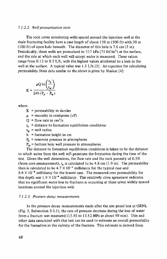
7.1.2.2. Well pressurization tests
The rock cover monitoring wells spaced around the injection well at the shale fracturing facility have a case length of about 150 m (500 f t ) with 30 m (100 f t ) of open hole beneath. The diameter of this hole is 7.6 cm (3 in). Periodically, these wells are pressurized to 517 kPa (75 lbf / in2) at the surface, and the rate at which each well will accept water is measured. These values range f rom 0.12 to 8.5 L/h, with the highest values attributed to a leak in the well at the surface. A typical value was 1.5 L/h [3]. An equation for calculating permeability f rom data similar to the above is given by Muskat [4]:
K = permeability in darcies H = viscosity in centipoise (cP) Q = flow rate in cm 3 /s re = distance to formation equilibrium conditions rw = well radius h = formation height in cm Pe = reservoir pressure in atmospheres Pw = bo t tom hole well pressure in atmospheres. The distance to formation equilibrium conditions is taken to be the distance
to which water f rom the well will penetrate the formation during the time of the test. Given the well dimensions, the flow rate and the rock porosity of 0.5% ( f rom core measurement), re is calculated to be 4.8 cm (1.9 in). The permeability then is calculated to be 4.7 X 10~3 millidarcy for the typical case and 8.4 X 10~4 millidarcy for the lowest case. The measured core permeability for this depth was 1.9 X 10 - 4 millidarcy. This relatively close agreement indicates that no significant water loss to fractures is occurring at these seven widely spaced locations around the injection well.
7.1.2.3. Pressure decay measurements
In the pressure decay measurements made af ter the site proof test at ORNL (Fig. 5, Subsection 3.3.1), the rate of pressure decrease during the loss of water f rom a fracture was measured (15.93 to 13.12 MPa in about 90 min). This and other data associated with this test can be used to estimate an overall permeability for the formation in the vicinity of the fracture. This estimate is derived f rom
K = 27rh (Pe - P w )
where
68

approximations of several other factors - fracture area, fluid loss rate and pressure gradient.
The volume injected in the site proof test was 208 000 L (55 000 gal). Formulas for calculating the fracture thickness are given in the literature; the one used here is that of Perkins and Kern [5]:
T ~\ ! /4
where W = fracture width (in) Q = pumping rate (bbl/min) = 6.2 for this tes t 1 3
p = viscosity (cP) E = Young's modulus (assumed to be 2 X 10⁶ lbf/in2) C = fracture radius (ft).
Substitution in the above equation gives a fracture width of 0.12 cm (0.048 in) and a fracture radius of 230 m (760 ft).
The pressure decay curve (Fig. 5) indicates that the fracture had partially closed after about 110 min (the slope of the pressure decay curve changed appreciably at that time). The volume of water that had leaked from the fracture by that time cannot be established, but a maximum value can be suggested with the full knowledge that it is probably a high value. Bleedback tests after large-volume water injections that have been conducted at ORNL [1 ] have shown that at least one half the injected water remains in the fracture for up to two months after the injection (and can be recovered). Of the one half of the water that cannot be recovered, some fraction is lost by flow into the formation. In this calculation it is assumed that 50% of this unrecoverable one half is so lost. This assumption greatly overestimates the loss (an assumption that the loss is pro-portional to both pressure and time suggests that less than 2% of the one half of the water that is lost is lost in the first 110 min). It is assumed here, however, to set an upper limit on this loss. For this exaggerated loss and a fracture radius of 230 m (760 ft), the average velocity of fluid loss would be 2.38 X 10"6cm/s (1 X 10~7 for the more likely case). This calculation assumes a single fracture with a simple configuration; this assumption has very little effect on the conclusions that are reached.
The pressure in the fracture until the time the fracture partially closed averaged 17.6 MPa (2550 lbf/in2). The distance to formation equilibrium conditions is calculated to be 0.83 cm, which gives a pressure gradient of 100 atm/cm.
13 The barrel (bbl) used in this equation is the US petroleum barrel of 42 US gallons (1 US gallon = 3.78S L), consequently such a barrel represents about 159 L.
69
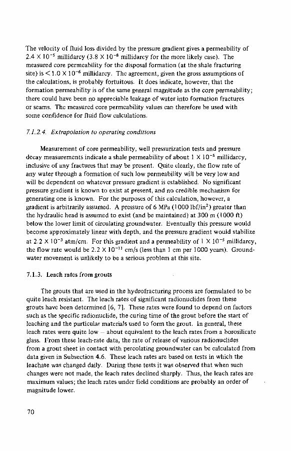
The velocity of fluid loss divided by the pressure gradient gives a permeability of 2.4 X 10~5 millidarcy (3.8 X 10"8 millidarcy for the more likely case). The measured core permeability for the disposal formation (at the shale fracturing site) is < 1.0 X 10"6 millidarcy. The agreement, given the gross assumptions of the calculations, is probably fortuitous. It does indicate, however, that the formation permeability is of the same general magnitude as the core permeability; there could have been no appreciable leakage of water into formation fractures or seams. The measured core permeability values can therefore be used with some confidence for fluid flow calculations.
7.1.2.4. Extrapolation to operating conditions
Measurement of core permeability, well pressurization tests and pressure decay measurements indicate a shale permeability of about 1 X 10~5 millidarcy, inclusive of any fractures tha t may be present. Quite clearly, the flow rate of any water through a formation of such low permeability will be very low and will be dependent on whatever pressure gradient is established. No significant pressure gradient is known to exist at present, and no credible mechanism for generating one is known. For the purposes of this calculation, however, a gradient is arbitrarily assumed. A pressure of 6 MPa (1000 lbf / in2) greater than the hydraulic head is assumed to exist (and be maintained) at 300 m (1000 f t ) below the lower limit of circulating groundwater. Eventually this pressure would become approximately linear with depth, and the pressure gradient would stabilize at 2.2 X 10~3 atm/cm. For this gradient and a permeability of 1 X 10"5 millidarcy, the f low rate would be 2.2 X 10~ n cm/s (less than 1 cm per 1000 years). Ground-water movement is unlikely t o be a serious problem at this site.
7.1.3. Leach rates f rom grouts
The grouts that are used in the hydrofracturing process are formulated to be quite leach resistant. The leach rates of significant radionuclides f rom these grouts have been determined [6, 7]. These rates were found to depend on factors such as the specific radionuclide, the curing time of the grout before the start of leaching and the particular materials used t o form the grout. In general, these leach rates were quite low — about equivalent to the leach rates f rom a borosilicate glass. F rom these leach-rate data, the rate of release of various radionuclides f rom a grout sheet in contact with percolating groundwater can be calculated f rom data given in Subsection 4.6. These leach rates are based on tests in which the leachate was changed daily. During these tests it was observed that when such changes were not made, the leach rates declined sharply. Thus, the leach rates are maximum values; the leach rates under field conditions are probably an order of magnitude lower.
7 0

From the leach data in Subsection 4.6, the maximum quantity of activity that could be leached from a single grout sheet can be calculated. This sheet would have a surface area of about 46 000 m2 (500 000 f t 2 ) on one side and could contain as much as 500 000 Ci of 90Sr (if the design limit waste concentration of 6.6 Ci/L (25 Ci/gal) is assumed) and an equal amount of 137Cs. If the entire grout sheet surface would be exposed to water flow, a maximum of 31 Ci per month o f 1 3 7 Cs and 850 Ci per month of 90Sr would be leached.
This calculation assumes a single fracture with a simple configuration. Given the uncertainty of leaching conditions, however, this simplification has very little consequence for this analysis.
7.1.4. Radionuclide migration
At the ORNL site, the shale surrounding the grout sheets has considerable ion exchange capacity for caesium, strontium and transuranic radionuclides. The migration rate of these radionuclides through the shale would be slower than the water percolation rate, and can be calculated from data from soil-column percolation tests. The results indicate that the rate of movement of all leached radionuclides through the shale would be so low that these nuclides would be transmuted by radioactive decay long before they approached the surface. The rate of movement of 90Sr would be less than that of the water flow by a factor of 700 to 12 000 (depending on the pH of the water). The rate of movement of the 137Cs would be lower by a factor of 14 000, and the rate of movement of any 239Pu would be lower by a factor of 300 000. An example of these calculations is given in Ref. [ 1 ]. Because the water-flow rate would be extremely slow in any case (Subsection 7.1.2.1 ), the rate of radionuclide movement would be infinitesimal.
7.1.5. Well drilling
A special case of the above situation would be one in which a deep-well drilling operation in the near vicinity of the disposal facility would breach the overlying shale containment of the waste grout, and perhaps expose some part of one or more grout sheets to severe washing. This is probably a more severe test of the permanence of disposal of the waste radionuclides than any that would be encountered in the normal course of events. Even under such harsh treatment, however, the loss of radionuclides from the disposal formation is small. In 1972, a new observation well was drilled near the existing disposal site; this well inter-sected the grout sheet from at least one previous injection. The drill washings were collected and analysed for radionuclide content. A total of 10 mCi of activity was recovered — approximately the amount that would have been in the portion of the grout sheet that was pulverized by the drilling operation.
71

7.1.6. Facility operations
The operators of the facility are exposed to some radiation from process fluids during normal operations. This exposure is not large (see Subsection 6.3.1). The operators are also exposed to a very small concentration of radioactive particulates from the filtered off-gas stream. This concentration is estimated to be less than 7 X 1 CT14 //Ci/cm3 beta-gamma activity [8]. The applicable standard is 1 X 10"10 /uCi/cm3. The noise levels around the ORNL shale fracturing facility were measured and found to be high in the vicinity of the injection pump: 0.5 h permissible exposure per 8-h shift [8], This effect would, of course, be quite specific to each facility. All other exposures that have been identified below are in the category of accident situations.
7.2. ACCIDENT SITUATIONS
Accident situations that could occur at a hydrofracturing facility are generally limited to those situations that occur before the setting of the grout, and that result in some escape of the fluid grout beyond the facility containment. These situations include such possibilities as a rupture of process piping, a break at the wellhead, or an unexpected underground dispersion such that some part of the grout is ejected at the surface or in contact with surface water.
7.2.1. Rupture of process piping
A rupture of process piping is always possible, but this piping is contained inside a process cell, or is doubly contained when outside the cell, and the activity associated with the discharge would be contained and cleaned up with little or no dispersion of activity outside the control area.
7.2.2. Wellhead rupture
A wellhead rupture is a special case of the pipe rupture situation. The problem arises if the rupture occurs toward the end of an injection and the break is below the shutoff valve on the wellhead. Under these conditions, some of the grout that had been injected would be squeezed from the formation by the weight of the overburden and would flow back up the well and into the well cell with no possibility of shutting off the flow. The volume of bleedback under such conditions is not precisely predictable, but a comparison with water bleedback tests [2] suggests an upper limit. In these tests, volumes of up to 190 000 L (50 000 gal) were injected and then bled back. After 48 h, the recovered volumes were between 30 000 and 38 000 L (8000 and 10 000 gal); even after 60 days, less
7 2

than 50% of the injected volume had been recovered. Grout has a much higher viscosity than water and would set after a few tens of hours. These differences would probably result in smaller fractions of the injected grout volume being forced out of the shale formation than was the case with water. This volume would therefore probably be less than 95 000 L (25 000 gal); and most likely it would be a great deal less. To handle any such volume of grout that might emerge unexpectedly into the well cell, the design of the facility includes a 150 000 L (40 000 gal) emergency waste pit and a large-diameter line connecting this pit to the well cell. If such an accident occurred, the grout would be discharged to the emergency pit and allowed to set.
An alternative approach to this potential problem would be to install blow-out preventers on the wellhead to provide a positive shutoff capability below the shutoff valve. For the ORNL hydrofracture facility the emergency waste pit was considered a more reliable (and much less complicated) system.
7.2.3. Vertical fracture
The expected underground grout sheet orientation is along the bedding plane of the shale. It is possible, however, for a different orientation to occur. The predominant current theory is that the fracture orientation will be perpendicular to the least stress in the formation. In tectonically relaxed areas, this least stress will be approximately horizontal and the fracture orientation will be vertical. In areas of tectonic compression, this least stress will be vertical and the fracture orientation will be horizontal [9, 10]. This is discussed in Section 1. At shallow depths the overburden pressure will be relatively low; the least stress would tend to be vertical, and horizontal fractures would be expected to predominate.
The tensile strength of the host rock would also have an effect on fracture orientation. The least stress (that determines fracture orientation) is the sum of the earth stress and the tensile strength of the host rock. If the rock is bedded, a fracture will tend to be along the bedding planes, even though the earth stress may favour an alternative orientation (Subsection 2.2. and Appendix 2, Subsection 2.2).
Nearly 30 fractures have been made in the bedded shale at ORNL, all of which have been essentially horizontal and have followed the bedding planes in the shale with only a small deviation. Before a vertical fracture will form and propagate, the horizontal stresses must decrease or the vertical stress (essentially the weight of the overburden) must increase until it is the principal stress. Such changes in formation stress usually occur very slowly (over geologic eras) and seem unlikely to affect waste disposal operations at the ORNL site.
There is another factor that virtually ensures that no fracture will reach the surface. The fracture thickness, as measured from cores and as calculated from rock and grout properties, is about 1 to 1.3 cm ( | to \ in). For a grout
7 3

volume of 530 000 L (140 000 gal) and a fracture thickness of 1 cm ( | in), the area of the grout sheet would be about 55 000 m2 (600 000 f t 2 ) . A grout sheet of this extent would not reach the surface unless several rather improbable conditions were met; it would have to be rather asymmetrical, the major axis would have to point almost directly at the surface, there could be little or no side branching and the vertical fracture would have to originate close to the wellhead. The maximum detected distance from the wellhead of any of the three grout sheets at ORNL whose extent has been measured did not exceed 200 m (700 ft) [2]. A vertical fracture of this extent that originated at the new injection well would still be far underground.
If, despite expectations, a vertical fracture did occur, and if (again, despite expectations) the fracture reached the surface, a grout spill of some magnitude would occur. If the vertical fracture occurred toward the end of an injection of 530 000 L (140 000 gal) of grout, some fraction of this volume would be squeezed out as the fracture closed. The volume squeezed out would probably be no larger than the 95 000 L (25 000 gal) that was postulated for a wellhead rupture, since the pressures involved and the resistance to be overcome are similar.
The consequences of a spill of 95 000 L (25 000 gal) of waste grout at the surface would depend on weather conditions and the exact location and nature of the spill. These consequences were estimated for the ORNL site for grout spills that could occur under four circumstances:
( 1 ) A spill that forms a horizontal fracture just below the surface and in contact with ground water,
(2) A spill on the dry land surface, (3) A spill that intersects a creek with little agitation of the grout, and (4) A spill that intersects a creek with much agitation of the grout.
The consequences of each circumstance were considered for a grout made from a waste solution of the maximum specific activity that the facility would handle. For none of these cases were the consequences found to be truly hazardous [1]. The most probable location of a grout spill would be on the land surface, where any mobile radionuclides could be contained and subsequently removed. The probability of an eruption of a grout sheet into a watercourse is slight; but should this occur, the worst consequence would be a temporary increase in the 90Sr concentration in a local river to approximately twice the concentration guide [11], The rate of leaching of radionuclides from a just-underground grout sheet would be low, and those radionuclides that were leached would be retained by the shale until they decayed to innocuous forms.
7.2.4. Grout movement along well
The observation wells that surround a facility penetrate to the disposal zone. These wells, therefore, provide a possible pathway for waste grout to reach the
7 4

surface. This pathway could be alongside the well if the cementing job were particularly poor or up the well if the casing were pulled apart by the stresses generated by the grout sheet.
Grout flow alongside a well is not considered a likely event. The well grouting would have to be particularly poor for a pathway of significant size to be left uncemented. Also, a flow of grout alongside a well would be largely self limiting. The grout viscosity would be relatively high and the cross-sectional area for flow would be small; the flow of grout would therefore be quite slow, and after a few hours would stop as the grout set. The set grout would seal, the path-way and prevent future flow. No migration alongside the well has been observed in any of the wells at the hydrofracturing facility.
Most of the observation wells at the facility were constructed of standard pipe and were cemented to the well along their entire length. Most of these wells have failed in service. Three wells, however, were constructed of oil field tubing and had the bottom 90 m (300 ft) cemented with a low-strength compound that would yield when a grout sheet passed nearby and relieve the stress on the tubing string. None of these wells has failed. This well design has been used for the wells at the new hydrofracture facility. It is believed that this design is entirely safe. As a precaution, however, the wells will be capped before every injection to ensure that no path to the surface will be provided, even if the tubing string should be ruptured.
7.2.5. Risk to operating personnel
During an accident situation, the operating personnel are exposed to the potential hazards of radiation from process fluids and missiles from the sudden rupture of high-pressure equipment. These risks have been minimized, where possible, by enclosing equipment and piping that contain high-pressure or radioactive fluids, providing washdown equipment for the cleanup of spills and restricting access to high-pressure equipment that cannot be enclosed (the standby pump).
7.3. LONG-TERM CONSIDERATIONS
7.3.1. Generation of earthquakes
In 1966, an unusual series of earthquakes near Denver, Colorado, was correlated with deep-well waste disposal operations at the Rocky Mountain Arsenal. There is little similarity between the hydrofracturing disposal process and the disposal operation used at Denver. At the Denver site, several million gallons per month of liquid waste were pumped down a 3600 m (12 000 ft) well into crystalline rocks that had a high tectonic stress. The injected liquid waste
75

apparently built up the pore pressure in the rocks, which effectively weakened the rocks to the point that the existing stresses could no longer be resisted. Failure or slippage of these rocks then generated earthquakes.
The tectonic stresses at ORNL are much lower; the waste volume is much smaller; and the waste is injected as a high viscosity grout, not a low viscosity liquid, into rocks with essentially zero porosity. None of the rather unique conditions that caused the series of earthquakes near Denver exist at the hydrofracturing facility at ORNL, and the likelihood of generating earthquakes by the mechanism postulated for the Rocky Mountain Arsenal is non-existent. The dissimilarities between the two situations have been analysed in more detail in Refs [12, 13]. Both studies concluded that neither the method nor the ORNL site is such that the generation of an earthquake would be at all likely.
7.3.2. Required isolation time
In the hydrofracture process the radioactive wastes are fixed in a cement matrix and embedded in a shale formation that is well removed from the biosphere. Under the conditions that exist at ORNL, the isolation time is expected to be very long - at least several hundred thousand years (Subsections 7.1.2—7.1.4). This is far in excess of the required isolation time for the ORNL site because the major components of the waste at ORNL are 137Cs and 90Sr - radionuclides that will decay to innocuous concentrations in a few hundred years.
This characteristic of the ORNL facility is an essential requirement for any disposal facility: the isolation time for each radionuclide in the injected waste should be long enough that radioactive decay will reduce the concentration in any discharge from the isolation zone to an acceptable level. This required isolation time will be different for each radionuclide in the waste stream as a function of the original concentration, half-life and acceptable discharge level.
7.3.3. Potential for exhumation of wastes
The injected wastes will become an integral part of the shale after solidification of grout and so remain as long as the shale is not disturbed or subject to erosion. Therefore, consideration should be given to the factors involved in eroding eroding and possibly exposing the injected wastes. At the ORNL site this problem does not exist; the erosion rate is relatively slow, the disposal zone is far below the surface and the principal waste constituents have relatively rapid decay rates. At other sites and for other wastes, however, a problem could exist.
On the basis of the dissolved and suspended sediment loads of streams, the climate, topographic and geologic type, and the size of the drainage areas, Schümm [14] concludes that denudation rates are an exponential function of the drainage relief and length ratio. The denudation rate of the drainage basin
7 6

at O R N L is e s t ima ted t o be 0 . 0 4 m pe r 1000 years [ 15]. Wastes are t o b e in j ec t ed i n t o P u m p k i n Valley shale t h a t is a b o u t 2 1 3 m b e l o w t h e surface . Using t h e e s t ima ted d e n u d a t i o n rate , it would t a k e 5 .4 X 106 years t o expose t he was te in jec ted in t h e u p p e r m o s t pa r t of t he P u m p k i n Valley shale by eros ion . This t i m e interval wou ld b e su f f i c i en t f o r the rad ionuc l ides con t a ined in t he wastes t o decay to harmless rad ia t ion-emiss ion levels, and t h u s t he possibi l i ty of the i r c o n t a m i n a t i n g the b iosphere b y eros ion processes is negligible.
R E F E R E N C E S
[1] USERDA, Management of Intermediate-Level Radioactive Waste, Oak Ridge National Laboratory, Oak Ridge, Tennessee — Final Environmental Statement, Rep. ERDA-1553, US Energy Research and Development Administration, Washington, D.C. (1977).
[2] DeLAGUNA, W., TAMURA, T., WEEREN, H.O., STRUXNESS, E.G., McCLAIN, W.C., SEXTON, R.C., Engineering Development of Hydraulic Fracturing as a Method for Permanent Disposal of Radioactive Wastes, Rep. ORNL-4259, Oak Ridge National Laboratory, Oak Ridge, Tennessee (1968).
[3] WEEREN, H.O., Shale Fracturing Injections at ORNL: 1977-1979 Series, Rep. ORNL-TM-7421, Oak Ridge National Laboratory, Oak Ridge, Tennessee (September 1980).
[4] MUSKAT, M., The Flow of Homogeneous Fluids through Porous Media, J.W. Edwards, New York - London (1946).
[5] PERKINS, T.K., KERN, L.R., Widths of hydraulic fractures, J. Pet. Technol. 13 (1961) 937. [6] MOORE, J.G., GODBEE, H.W., KIBBEY, A.H., JOY, O.S., Development of Cementitious
Grouts for the Incorporation of Radioactive Wastes, Rep. ORNL-4962, Oak Ridge National Laboratory, Oak Ridge, Tennessee (April 1975).
[7] MOORE, J.G., Development of Cementitious Grouts for the Incorporation of Radioactive Wastes, Part 2: Continuation of Cesium and Strontium Leach Studies, Rep. ORNL-5142, Oak Ridge National Laboratory, Oak Ridge, Tennessee (1976).
[8] WEEREN, H.O., Shale Fracturing Injections at ORNL: 1972 Series, Rep. ORNL-TM-4467, Oak Ridge National Laboratory, Oak Ridge, Tennessee (June 1974).
[9] HOWARD, G.C., FAST, C.R., Hydraulic Fracturing, Vol. 2, Henry L. Doherty Series, AIME, New York (1970).
[10] HUBBERT, M.K., WILLIS, D.G., Mechanics of hydraulic fracturing, Trans. AIME 210 (1957) 153.
[11] USAEC, "Standards for radiation protection", AEC Manual, Chap. 0524, Annex A, USAEC, Washington, D.C. (1968).
[12] McCLAIN, W.C., On Earthquakes induced by Underground Fluid Injections, Rep. ORNL-TM-3154, Oak Ridge National Laboratory, Oak Ridge, Tennessee (1970).
[13] SUN, R.J., Possibility of triggering earthquakes by injection of radioactive wastes in shale at Oak Ridge National Laboratory, J. Res. U.S. Geol. Surv. 5 (1977) 253.
[14] SCHÜMM, S.A., The Disparity between Present Rates of Denudation and Orogeny, US Geological Survey, Professional Paper 454H (1963).
[15] SUN, R.J., Site Selection and Investigation for Subsurface Disposal of Radioactive Wastes in Hydraulically Induced Fractures, US Geological Survey, Professional Paper 1215, Washington, D.C. (1982).
77

8. OTHER PROCESS CONSIDERATIONS
8.1. COST-BENEFIT CONSIDERATIONS
The operational cost of an injection of about 380 000 L (100 000 gal) of waste solution at the ORNL shale fracturing facility was approximately $50 000 in 1977. About $10 000 of this was the cost of the dry solids, about $25 000 was the service charge of an oil well cementing company (Halliburton) for making the injection, and the remaining $ 15 000 was for various maintenance and operational charges [ 1 ]. The operational cost of the first ILW injection at the new facility (June 1982) was approximately $93 000 for 600 000 L (150 000 gal). The dry solids cost $36 000, the service charge was $37 000, and the maintenance and operational charges were $20 000. This is an average of $0.17/L ($0.63/gal).
In the environmental impact statement for the new hydrofracturing facility at ORNL, estimated capital and operating costs for several waste handling and disposal processes were given [2]. These estimated costs are shown in Table VII. These costs are processing and disposal costs for waste generated or currently stored at ORNL. The various options that were considered in these estimates included tank storage, hydrofracture, fixation in glass, "shale cement" and "caesium strip".
"Shale cement" is a conceptual process in which the waste is mixed in a cement-based matrix, cast in drums, stored on site temporarily and shipped to a repository. "Caesium strip" is a conceptual process in which an ion exchange process removes most of the radionuclides in the waste. The concentrated radionuclides are shipped to a repository; the decontaminated residue is disposed of by hydrofracture or by some alternative process for very low-level waste disposal. This residue is assumed to be sufficiently decontaminated that the method of disposal used for this side stream would not significantly influence process costs or feasibility.
The capital cost estimates for all processes except tank storage were based on preliminary facility designs; the estimate for tank storage was based on recent costs for similar tanks being installed at ORNL. The lowest estimated capital cost is for tank storage. This tank storage cost estimate included no charge for the ultimate disposal of the stored wastes. The estimated cost for a hydrofracture facility is somewhat higher; the estimated cost for a shale cement or caesium strip facility is much higher. A glass fixation facility is the most costly option considered.
The lowest estimated operating cost for disposal is for hydrofracture. Tank storage is considerably more expensive; shale cement, caesium strip, and glass fixation are all much more expensive. A big factor in the operating expense of each of these last three alternatives will be the terminal storage charge for wastes
78

TABLE VII. ESTIMATED COSTS (1977) FOR MANAGEMENT OF ORNL WASTE SOLUTION AND SLUDGE ($ 106)
Hydro- Shale Caesium Glass Tank fracturing cement strip storage
Capital cost 5.4 46 55 74 4.0
Anual cost
Operating 0.1a 0.6 1.1 3.5 0.1
Shipping 0 0.9 1.0 1.0 0
Terminal storage 0 0 . 6 - 5 . 3 b 0 .4 -3 .4 b 0 .4 -2 .0 b 0
New construction 0 0 0 0 1.0
Total annual 0.1 2 .1-6.8 2.1-4.1 4 .6-6 .2 1.1
a For liquid disposal only. Sludge disposal will cost an additional estimated $ 1 million over a two-three year interval.
b Range reflects uncertainty in terminal storage charges from $1800/m3 to $14 000/m3
(S50/ft3 to $400/ft3).
TABLE VIII. ENVIRONMENTAL IMPACT COMPARISON
Hydro- Shale Caesium Glass fracturing cement strip
Crew exposure a,b
(man-rem/a) 3 16 31 55
Shipping exposure (man-rem/a) None 0.031 0.031 0.031
Discharged with solid waste (a/a) < 1 1 - 5 3 - 1 0 100-500
Discharged with gaseous waste (Ci/a) 2X10" 4 0.001-0.4 0 .001-0.4 0 .01-0.6
A man-rem is a measure of cumulative exposure to all crew (see Appendix 3). Comparative allowable exposures are 5 rem/a per person for occupational, 0.5 i person for non-occupational, 0.1 rem/a per person for normal background.
79

shipped to a Federal repository. Estimates of terminal storage charges vary considerably and a range of values is given in Table VII. This range is so wide that differences in other operating costs are obscured.
A summary of selected environmental costs for the various alternative processes is given in Table VIII. The estimated exposure to the population resulting from the shipment of solidified wastes is quite small in all cases in which this is a factor. The estimated operator exposure and the expected normal releases of radionuclides in solid and gaseous wastes increase according to the sequence: shale fracture, shale cement, caesium strip and glass fixation. This is also the sequence of increasing process complexity.
The cost-benefit ratio of any perceived aspect of hydrofracture has been determined to be exceedingly favourable. The process would remove large volumes of potentially hazardous radioactive wastes from the existing surface storage facilities, and would fix these wastes in impermeable shale formations (well removed from the biosphere). All major incident situations postulated are considered quite improbable, and the analysis of each case indicates that the ultimate release of radionuclides to the environment would be very small.
8.2. RESEARCH AND DEVELOPMENT WORK ON PROCESS EXTENSION
Experience with the hydrofracture process has been limited to the disposal of concentrated waste solutions generated at ORNL. These solutions are typically 1 to 2 M NaN03 and 0.2 M NaOH. The radionuclide concentration has been about 0.13-0.26 Ci/L (0.5—1 Ci/gal). Extension of this process to the disposal of slurries is imminent; much development work on the handling of slurries in the facility and the incorporation of these slurries in the hydrofracture grouts has been done. In addition, proposals have been made to use the hydrofracture process for the disposal of radioactive gas, pulverized solid wastes, organics, etc. Most of these applications have been given only cursory study. The status of these applications is summarized below.
8.2.1. Slurries
The slurries that will be injected by the new hydrofracturing facility at ORNL will consist of a mixture of particles of many chemical species. The particle size is from 1 — 100 jum, and microphotographs indicate that the individual particles are mostly discrete crystals or agglomerates of crystals [3]. These solids are currently in the form of a settled sludge in six existing waste storage tanks. During 1982 and 1983, these sludges were to be reslurried in a bentonite suspension and
8 0
pumped to the hydrofracture facility for disposal. The waste particle concentra-tion in the bentonite suspension was to be about 15 wt%; the apparent viscosity was expected to be between 5 and 15 cP.
The solids blend that will be used for injection of the suspended slurries will be about 46% cement, 46% fly ash and 8% pottery clay. No attapulgite will be needed in this mix because the bentonite in the slurry suspension will be an adequate substitute. A mix ratio of about 0.60 kg/L (5 lb/gal) will be required. The exact ratio that will be used will be determined from the apparent viscosity of the suspension and an experimentally determined correlation that relates this viscosity to the required mix ratio.
8.2.2. Gases
A proposal has been made that8 5 Kr be disposed of by injecting this gas into the high-pressure grout stream during a hydrofracture injection [4]. The dissolved and entrained gas would be injected with the grout into the shale formation, and would most probably be trapped in the grout matrix when the grout sets. The 85 Kr not held by the grout would be retained in solution in the pore water, which has a very low migration rate (Subsection 7.1.2.4).
An engineering study has been made to determine the process modifications that would be required for the injection of 300 m3/a (STP) of gas containing 16 million curies of 85Kr. Safety considerations were also studied. The report concludes that the safety aspects of the above-ground handling would be manageable (the underground aspects were not considered), and the required process modifications would not be major [5]. A laboratory study is currently in progress to determine the solubility of krypton in grout at high pressure. It has been found that this solubility is about three times the solubility in water at the same pressure.
8.2.3. Pelletized wastes
Hydrofracture has been proposed as a disposal process for shredded burnable solid wastes (paper, plastics, wood and cloth). Such shredded waste is not pumpable except at very low concentration, which would not be cost effective. Pelletization of the shredded waste was tested to determine whether a reasonable concentration could be pumped in this manner. Pellets (about 3 mm ( | in) dia. and 6 mm (£ in) long) were prepared using an asphalt base emultion. Experi-mentation with these pellets showed that they could be pumped. Successful disposal by hydrofracture was considered possible although the pellet size was not much smaller than the probable fracture size. Two tests of the process resulted in prompt plugging of the injection well in both cases (either the slot or more probably the adjoining fracture). No further work has been done on this concept.
81

8.2.4. Organics
A few tests have been made to determine the effect of up to 1% organic (AMSCO)14 in the hydrofracture grout. At this concentration, the organics had no effect on phase separation, viscosity or setting time.
8.3. PROCESS LIMITATIONS
The only major process limitation that has been observed is the limitation on particle size (Subsection 8.2.3). Clearly, the particle size must be small enough to move readily into the slot and fracture. Halliburton has routinely injected 1 mm (20 mesh) sand in a disposal operation at Duncan, Oklahoma; their personnel believe that 1.7 mm (10 mesh) particles can probably be injected with-out difficulty. The pellets that could not be injected (Subsection 8.2.3) were about a factor of 2 to 5 larger. Thus, unless the process conditions are consider-ably different from those used at ORNL (much higher viscosity or much higher flowrate, either of which would enlarge the fracture), 1.7 mm (10 mesh) approximately spherical particle is probably the largest particle that can be injected.
REFERENCES
[1] WEEREN, H.O., "Waste disposal by shale fracturing at Oak Ridge National Laboratory", Underground Disposal of Radioactive Wastes (Proc. Symp. Otaniemi, 1979) Vol. 1, IAEA, Vienna (1980) 171.
[2] USERDA, Management of Intermediate-Level Radioactive Waste, Oak Ridge National Laboratory, Oak Ridge, Tennessee — Final Environmental Statement, Rep. ERDA-1553, US Energy Research and Development Administration, Washington, D.C. (1977).
[3] WEEREN, H.O., MACKEY, T.S., Waste Sludge Resuspension and Transfer, Development Program, Rep. ORNL-TM-7125, Oak Ridge National Laboratory, Oak Ridge, Tennessee (1980).
[4] SHAFFER, J.H., BLOMEKE, J.O., Hydraulic Fracturing as a Method for the Disposal of Volatile Radioactive Wastes, Rep. ORNL-TM-6931, Oak Ridge National Laboratory, Oak Ridge, Tennessee (1979).
[5] PERETZ, F.J., MULLER, M.E., PAN, P.Y., Krypton-85 Hydrofracture Engineering Feasibility and Safety Evaluation, Rep. ORNL/ENG/TM-22, Oak Ridge National Laboratory, Oak Ridge, Tennessee (1981).
14 American Sterilizer Company.
8 2

Appendix 1
CASE HISTORIES
The technique of waste disposal by hydraulic fracturing was developed over a period of more than ten years. Laboratory studies, experimental injections and large-scale tests were made at ORNL and West Valley, New York. References to these tests and the conclusions derived from them are made in many places in this report. In these appendices, a brief description of the more important of these tests and the general conclusions reached from each are given. Specific references for each test are also given. These case histories are presented in approximately chronological order.
1. PRELIMINARY EXPERIMENTS AT OAK RIDGE NATIONAL LABORATORY (1959-66)
1.1. Process proof tests
The first tests of the process for radioactive waste disposal by hydraulic fracturing were carried out in 1959 and 1960 at ORNL. The purposes of these tests were to (1) establish process feasibility, (2) verify the orientation of the fractures that were formed, and (3) test monitoring methods.
The first test injection was made in 1959 to establish that conformable (bedding-plane) fractures could be formed in the shale formations at ORNL, and to test the proposed method for determining the fracture orientation. About 102 000 L (27000 gal) of grout with 137Cs tracer were injected at a depth of 88 m (290 ft). Twenty-two core holes were subsequently drilled, and from inspection of those cores and gamma-ray logs of the core holes the approximate extent (about 120 m (400 ft)) and orientation (near horizontal) of the grout sheet were determined.
The next two test injections were made in 1960 at a site about 1.5 km (1 mile) southeast of the site of the first test injection. These injections were made to establish fracture orientation at greater depths, determine the feasibility of relatively large (380 000 L 100 000 gal)) injections and evaluate monitoring techniques. A view of the second injection of this series is shown in Fig. 21. The depth of the first injection was 285 m (934 ft), and the grout volume was 346 000 L (91 500 gal). The second injection was made seven days later at a depth of 212 m (694 ft). The grout volume of this injection was 503 000 L (132 800 gal). Twenty-four core holes were subsequently drilled to establish the extent and orientation of the grout sheets. Both grout sheets were found to have
8 3

FIG.21. The second test injection at ORNL. Bentonite is stored in sacks to the right of the water tank in the centre background. It is being mixed with water by the white-coated workers immediately in front of the water tank. Cement is stored in a bin in the foreground. The cement and the bentonite suspension are mixed by the pump truck on the right. The mixed grout is injected by the pumps on the truck in the left foreground.
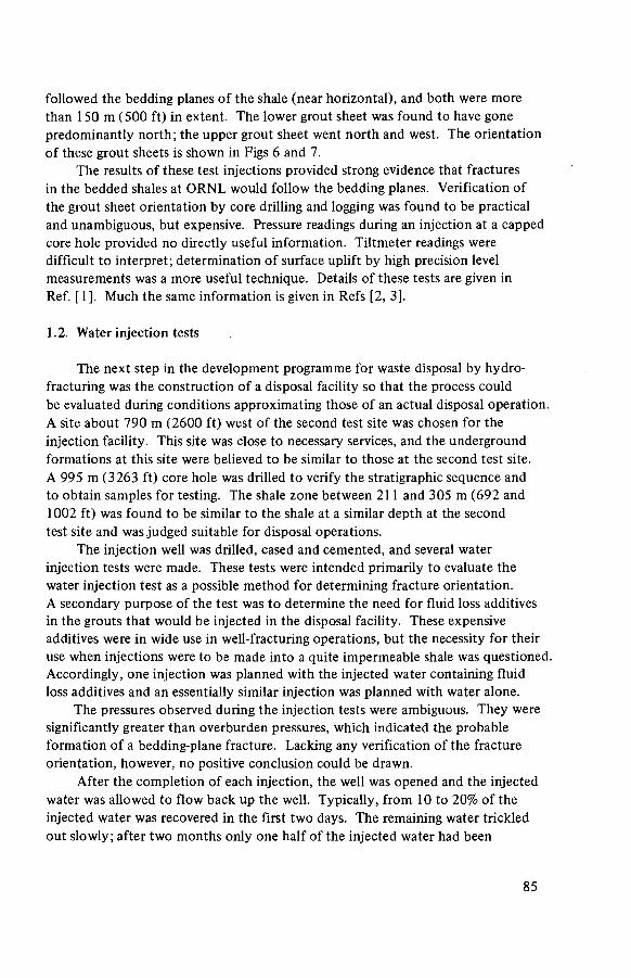
followed the bedding planes of the shale (near horizontal), and both were more than 150 m (500 ft) in extent. The lower grout sheet was found to have gone predominantly north; the upper grout sheet went north and west. The orientation of these grout sheets is shown in Figs 6 and 7.
The results of these test injections provided strong evidence that fractures in the bedded shales at ORNL would follow the bedding planes. Verification of the grout sheet orientation by core drilling and logging was found to be practical and unambiguous, but expensive. Pressure readings during an injection at a capped core hole provided no directly useful information. Tiltmeter readings were difficult to interpret; determination of surface uplift by high precision level measurements was a more useful technique. Details of these tests are given in Ref. [ 1 ]. Much the same information is given in Refs [2, 3].
1.2. Water injection tests
The next step in the development programme for waste disposal by hydro-fracturing was the construction of a disposal facility so that the process could be evaluated during conditions approximating those of an actual disposal operation. A site about 790 m (2600 ft) west of the second test site was chosen for the injection facility. This site was close to necessary services, and the underground formations at this site were believed to be similar to those at the second test site. A 995 m (3263 ft) core hole was drilled to verify the stratigraphie sequence and to obtain samples for testing. The shale zone between 211 and 305 m (692 and 1002 ft) was found to be similar to the shale at a similar depth at the second test site and was judged suitable for disposal operations.
The injection well was drilled, cased and cemented, and several water injection tests were made. These tests were intended primarily to evaluate the water injection test as a possible method for determining fracture orientation. A secondary purpose of the test was to determine the need for fluid loss additives in the grouts that would be injected in the disposal facility. These expensive additives were in wide use in well-fracturing operations, but the necessity for their use when injections were to be made into a quite impermeable shale was questioned. Accordingly, one injection was planned with the injected water containing fluid loss additives and an essentially similar injection was planned with water alone.
The pressures observed during the injection tests were ambiguous. They were significantly greater than overburden pressures, which indicated the probable formation of a bedding-plane fracture. Lacking any verification of the fracture orientation, however, no positive conclusion could be drawn.
After the completion of each injection, the well was opened and the injected water was allowed to flow back up the well. Typically, from 10 to 20% of the injected water was recovered in the first two days. The remaining water trickled out slowly; after two months only one half of the injected water had been
85
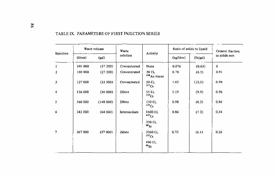
00 o
TABLE IX. PARAMETERS OF FIRST INJECTION SERIES
Injection Waste volume
Waste Activity
Ratio of solids to liquid Cement fraction
Injection (litres) (gal)
solution Activity
(kg/litre) (lb/gal) in solids mix
1 141 000 (37 300) Concentrated None 0.076 (0.63) 0
2 103 000 (27 300) Concentrated 30 Ci, 1 9 8Au tracer
0.78 (6.5) 0.91
3 127 000 (33 500) Concentrated 50 Ci, 137Cs
1.62 (13.5) 0.98
4 136 000 (36 000) Dilute 55 Ci, 137Cs
1.19 (9.9) 0.96
5 560 000 (148 000) Dilute 150 Ci, 137Cs
0.98 (8.2) 0.86
6 242 000 (64 000) Intermediate 1600 Ci, 137Cs
330 Ci, " S r
0.86 (7.2) 0.34
7 367 000 (97 000) Dilute 3360 Ci, 137Cs
490 Ci, 9 0 Sr
0.73 (6.1) 0.26

recovered. Virtually no difference was observed between the injection with fluid loss additives and the test without. No further consideration was given to incorporating these additives in the grout mix. Details of these tests are given in Ref. [1],
1.3. Experimental injection series
One cased observation well was installed at the chosen site and a disposal facility was built. Several mixes suitable for use with a variety of possible waste solutions were developed, and a series of five injections was planned to test the suitability of these different mixes and to evaluate the performance of the disposal facility.
The first injection was made to check the operation of the surface plant and to evaluate a non-setting mix. All subsequent injections were made with setting mixes. Various mix compositions and concentrations were used, and concentrated and dilute waste solutions were injected. The average specific activity of the waste solutions varied from tracer level to 0.008 Ci/L (0.03 Ci/gal), with occasional periods when the activity was as high as 0.13 Ci/L (0.5 Ci/gal). The first four injections were of approximately 150 000 L (40 000 gal) each; in the fifth injection 560 0000 L (148 000 gal) were injected to test the surface plant during an extended (11 h) disposal operation and to observe the underground behaviour of large injections.
Following the injections the formations were cored. The grout sheets of all injections were found to be essentially horizontal and parallel with the bedding planes.
Results of the first injection series, an analysis of operating costs and mix development studies indicated that the amount of cement used in a mix could probably be reduced without adversely affecting the effectiveness of the mix. Such a reduction would lead to a reduction in operating cost because the mix cost at this time was a substantial fraction of the total. Other data indicated the desirability of substituting fly ash (a silicious material) for some of the cement in the mix so that the efficiency of strontium retention would be improved. A new mix was therefore developed - one with a low cement content and a low proportion of total solids to waste.
Modifications were made to the injection facility to improve the control of the solids-liquid proportioning, and all core holes were converted into observation wells by cementing a string of pipe in each. In 1965, two injections were made to evaluate the new mix, check the plant modifications and determine the feasibility of making more than one injection into the same slot in the casing — a technique that, if successful, would probably greatly extend the well life.
These injections were successfully completed; the new mix was satisfactory, the facility modifications worked well and the technique of making multiple
87

FIG.22. The shale fracturing facility at ORNL. The four large bins near the centre are used for the storage of blended dry solids. The large tank on the right is a water storage tank. The diesel and gear train of the injection pump is under the shed at right centre. The concrete block structure in front of the large bins is the cell that houses the wellhead and high-pressure piping manifold.
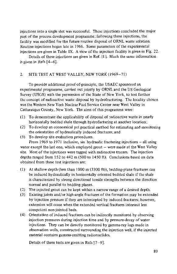
injections into a single slot was successful. These injections concluded the major part of the process development programme; following these injections, the facility was modified for the future routine disposal of ORNL waste solution. Routine injections began late in 1966. Some parameters of the experimental injections are given in Table IX. A view of the injection facility is given in Fig. 22.
Details of these injections are given in Ref. [1 ]. Much the same information is given in Refs [4-6].
2. SITE TEST AT WEST VALLEY, NEW YORK (1969-71 )
To provide additional proof-of-principle, the USAEC sponsored an experimental programme, carried out jointly by ORNL and the US Geological Survey (USGS) with the permission of the State of New York, to test further the concept of radioactive waste disposal by hydrofracturing. The locality chosen was the Western New York Nuclear Fuel Service Center near West Valley in Cattaraugus County, New York. The aims of this programme were:
( 1 ) To demonstrate the applicability of disposal of radioactive waste in nearly horizontally bedded shale through hydrofacturing at another location;
(2) To develop an economical yet practical method for estimating and monitoring the orientation of hydraulically induced fractures; and
(3) To develop site evaluation procedures. From 1969 to 1971 inclusive, six hydraulic fracturing injections — all using
water except the last one, which employed grout - were made at the West Valley site. Most of the injections were tagged with radioactive tracers. The injection depths ranged from 152 to 442 m (500 to 1450 ft). Conclusions based on data obtained from these test injections are:
(1) At shallow depth (less than 1000 m (3300 ft)), bedding-plane fractures can be induced hydraulically in horizontally oriented bedded shale if the shale is characterized by strong directional tensile strengths between the direction normal and parallel to bedding planes.
(2) The injected grout can be kept within a narrow range of a desired depth. (3) Existing joints and/or high-angle fractures of the formation may be extended
by injection pressure if they are intercepted by induced fractures; however, extension will cease when the extended vertical fractures intersect less competent non-jointed beds.
(4) Orientation of induced fractures can be indirectly monitored by observing injection pressures during injection time and by pressure-decay of water injections. They can be directly monitored by gamma-ray logs made in observation wells, constructed surrounding the injection well, if the injected material contains gamma-emitting radionuclides.
Details of these tests are given in Refs [7—9].
89

3. OPERATIONAL WASTE DISPOSAL INJECTIONS AT ORNL
After the last of the experimental injections at the ORNL disposal site, the facility was converted into an operational facility for the routine disposal of concentrated intermediate-level waste solution. This solution is an alkaline solution that is approximately 1 M in NaN03. The predominant radionuclide is 137Cs; its specific activity is about 0.26 Ci/L (1 Ci/gal). About 300 000 L/a (80 000 gal/a) is produced.
A number of modifications and improvements were made to improve various phases of the plant operation. Two additional waste storage tanks with a combined capacity of 178 000 L (47 000 gal) were installed. This increased the total on-site waste storage capacity to 340 000 L (90 000 gal). A dry solids weigh tank was installed to improve the dry solids blending system.
From 1966 to 1970, this modified facility was used for a series of seven injections that disposed of 3 750 000 L (990 200 gal) of waste grout containing 350 000 Ci of 137Cs and 26 500 Ci of 90Sr. Some of the parameters of these injections are given in Table VI.
In 1971, the operation of the facility was reviewed. This review foresaw no hazard from continued operation of the existing facility if the horizontal orientation of the grout sheets formed by each injection were periodically verified, and if the unbound water that might result from each injection were regularly bledback through the injection well and returned to the ORNL waste system.
As part of the preparation for the next series of injections, two new observation wells were drilled and cemented. A new benchmark survey was made to determine the surface uplift. Portions of the high-pressure piping manifold were replaced, and strain gauges were mounted on the wellhead to obtain stress and displacement measurements in order to determine the likelihood of fatigue failure. Arrangements were made to obtain seismic measurements during the injection for possible correlation with grout sheet orientation.
In the autumn of 1972, four waste injections were made (ILW-8, ILW-9, ILW-10 and ILW-11). These injections disposed of 1.82 million L (481 000 gal) of waste grout containing 93 700 Ci of 137Cs and 2700 Ci of 90 Sr. Some parameters of these injections are given in Table VI.
The grout sheets were logged after each injection and were found to have generally followed the bedding planes. No meaningful seismic signals were obtained from any of the injections. The strain gauge readings that were made on the wellhead indicated that the stresses were small, and that fatigue failure is probably not a matter for serious concern.
In 1975, an additional three injections were made (ILW-12, ILW-13 and ILW-14). These injections disposed of 1.16 million L (306 900 gal) of waste grout containing 79 100 Ci of 137Cs and 7600 Ci of 90Sr.
9 0

S - 2 2 0 NE-125
INJECTION N-10Q N-150 SURFACE
5 0
50
100
150
200
F 150 u u z < t-w o
200
\
\ \
\ \
' - T s
5 0 0 lu o 5 5 0 «
in 5
600
6 5 0
7 0 0
7 5 0 SEA LEVEL
2 5 0
FIG.23. Schematic representation of grout sheet monitoring results.
In 1977, 1978 and 1979, four more waste injections were made (ILW-15 to ILW-18 inclusive). These injections disposed of 1.9 million L (502 000 gal) of waste grout containing 80 500 Ci of 137Cs and 1900 Ci of 90Sr. A summary of all the operational waste injections is given in Table VI.
General experience with the hydrofracturing facility in 18 operating injections has been quite good. Large volumes of waste solution have been continuously mixed with dry solids in the desired proportions and injected into the isolated shale bed. The cleanup of small waste spills has been found to be feasible, as has the direct maintenance of mechanical equipment. Observed shortcomings in the process include:
( 1 ) Improper location of some equipment (with consequent difficulty of maintenance);
(2) Difficulty in obtaining a steady flow of solids under all conditions; and (3) Marginally effective control of solids-to-liquid proportioning.
9 1

These shortcomings are not serious and could be alleviated or corrected in a new facility. A schematic representation of the results obtained from the logging of the cased observation wells after the last four injections is shown in Fig. 23. The pattern of the grout sheets is similar to that determined after previous injections - grout sheets that generally follow the bedding planes (i.e. slope about 15° to the north) but occasionally cross over other grout sheets and go down-dip. Multiple grout sheets from the same injection are observed. The grout sheet orientation is clearly not symmetric; some injections go predominantly north, others go south or west. None has gone east.
The facility is clearly approaching the end of its useful life. The number of usable observation wells is near a minimum, and several malfunctions that could be attributed to worn equipment occurred during the last several injections. Extensive reconditioning would be required if further use of the facility were planned.
Details of these injections are given in Refs [10-13].
4. SITE PROOF TEST AT ORNL
A proposed site for a new hydrofracturing facility was situated about 240 m (800 ft) south-west of the existing facility. Because of its close proximity to the existing facility, it was expected that the underground strata at the proposed new site would be similar to that at the existing facility, and that it would be suitable for hydrofracturing disposal operations. To verify that the proposed site was suitable, a site proof study was undertaken during 1973 and 1974. This study consisted of drilling and installing an injection well and four observation wells, and making a series of test injections to determine the orientation of the fractures and to verify the absence of any interconnected fractures in this formation. In addition, one of the wells that was drilled for the site proof test was cored in the depth interval between 210 and 335 m (700 and 1100 ft) for comparison with the geologic structure that had been obtained from similar cores at the existing site. Examination of these core samples and of gammà logs of the injection well and the observation well at the new site shows that the stratigraphy is essentially the same as that at the existing hydrofracture site, with the main difference being that the dip of the red shale in the disposal formation is somewhat flatter, 4° to 10° to the south-east, at the new site than at the old site.
The new injection well was slotted at a depth of about 332 m (1090 ft). The red shale formation fractured at a pressure of about 18.3 MPa (2650 lbf/in2), and the fracture could be propagated at a pressure of about 15.2 MPa (2200 lbf/in2). The test injection, consisting of about 380 000 L (100 000 gal) of grout tagged with 20 Ci of 198Au (half-life of 2.7 d) and about 1 Ci of 137Cs (half-life of 33 years) was made on 14 June 1974. The injection rate averaged 935 L/min
9 2

(247 gal/min) at an average pressure at the pump of 20 MPa (2900 lbf/in2) and at the wellhead of about 16.5 MPa (2400 lbf/in2). After the completion of the test injection, the four observation wells were logged promptly with a gamma-sensitive probe. The grout sheet resulting from the injection was found in the south and west wells. It appeared to have followed the bedding planes as was expected. The interpretation of the log of the north well was complicated by the presence of residual radioactivity from injections made at the existing disposal facility, and no certain indication of activity from the test injection could be distinguished. No evidence of the grout sheet was found during the logging of the east well, which did not extend quite to the bottom of the disposal formation. Subsequently, a water injection was made to obtain pressure decay data. This test indicated that no extensive interconnected fractures and joints exist at the disposal site, and that at the injection depth the shale permeability is very low. Recently the east observation well was deepened and logged. Evidence of residual activity was noted, but no typical peak (such as would be generated by a grout sheet) was seen. A fifth observation well was drilled about 43 m (140 ft) east-south-east of the injection well. Logs of this well showed a definite peak at a depth consistent with a bedding fracture. The results of these studies indicate that the site is suitable for hydrofracturing disposal operations.
Details of this site proof test are given in Ref. [14].
REFERENCES
[1] DeLAGUNA, W„ TAMURA, T., WEEREN, H.O., STRUXNESS, E.G., McCLAIN, W.C., SEXTON, R.C., Engineering Development of Hydraulic Fracturing as a Method for Permanent Disposal of Radioactive Wastes, Rep. ORNL-4259, Oak Ridge National Laboratory, Oak Ridge, Tennessee (1968).
[2] DeLAGUNA, W., Disposal of radioactive wastes by hydraulic fracturing, Part I: General concept and first field experiments, Nucl. Eng. Des. 3 (1966) 338.
[3] DeLAGUNA, W., Disposal of radioactive wastes by hydraulic fracturing, Part II: Mechanics of fracture formation and design of observation and monitoring wells, Nucl. Eng. Des. 3 (1966) 432.
[4] WEEREN, H.O., Disposal of radioactive wastes by hydraulic fracturing, Part III: Design of ORNL's shale fracturing plant, Nucl. Eng. Des. 4 (1966) 108.
[5] TAMURA, T., Disposal of radioactive wastes by hydraulic fracturing, Part IV: Chemical development of waste-cement mixes, Nucl. Eng. Des. S (1967) 477.
[6] McCLAIN, W.C., Disposal of radioactive wastes by hydraulic fracturing, Part V: Site evaluations, Nucl. Eng. Des. 9 (1969) 315.
[7] DeLAGUNA, W., Hydraulic Fracturing Test at West Valley, New York, Rep. ORNL-4827, Oak Ridge National Laboratory, Oak Ridge, Tennessee (1972).
[8] SUN, R.J., MONGAN, C.E., Hydraulic Fracturing in Shale at West Valley, New York: A Study of Bedding-plane Fractures induced in Shale for Waste Disposal, US Geological Survey, Open-file Report 74-365, Washington, D.C. (1974).
9 3

[9] SUN, R.J., Site Selection and Investigation for Subsurface Disposal of Radioactive Wastes in Hydraulically Induced Fractures, US Geological Survey, Professional Paper 1215, Washington, D.C. (1982).
[10] DeLAGUNA, W„ WEEREN, H.O., BINFORD, F.T., WITKOWSKI, E.J., STRUXNESS, E.G., Safety Analysis of Waste Disposal by Hydraulic Fracturing at Oak Ridge, Rep. ORNL-4665, Oak Ridge National Laboratory, Oak Ridge, Tennessee (1971).
[11] WEEREN, H.O., Shale Fracturing Injections at ORNL: 1972 Series, Rep. ORNL-TM-4467, Oak Ridge National Laboratory, Oak Ridge, Tennessee (June 1974).
[12] WEEREN, H.O., Shale Fracturing Injections at ORNL: 1975 Series, Rep. ORNL-TM-5545, Oak Ridge National Laboratory, Oak Ridge, Tennessee (August 1976).
[13] WEEREN, H.O., Shale Fracturing Injections at ORNL: 1 9 7 7 - 1 9 7 9 Series, Rep. ORNL-TM-7421, Oak Ridge National Laboratory, Oak Ridge, Tennessee (September 1980).
[14] WEEREN, H.O., BRUNTON, G.D., DeLAGUNA, W., MOORE, J.G., Hydrofracture Site Proof Study at ORNL, Rep. ORNL-TM-4713, Oak Ridge National Laboratory, Oak Ridge, Tennessee (November 1974).
9 4

Appendix 2
THEORY OF HYDRAULICALLY INDUCED FRACTURES
The theory of fracture mechanics will be discussed only briefly here because it is well developed and has been discussed by many investigators [1—9].
Hydraulically induced fractures are extension fractures, which are separations of rock across a surface normal to the direction of the least principal stress without movement parallel to the fracture surface. Extension fractures involve loss of cohesion, separation into two parts and release of stored elastic strain energy [10]. Two stages are involved in the formation of extension fractures, namely fracture initiation and fracture propagation.
In the initiation of extension fractures, work must be done against the stress normal to the fracture plane and the cohesive force of the grains at the fracture tip. As the hydraulic pressure increases, the pre-existing fracture in the rock does not extend until a certain pressure is reached. This pressure overcomes the sum of the normal stress and the maximum cohesive force (the tensile strength at the fracture tip), and the fracture begins to extend. The propagation pressure required to extend a fracture is only that required to overcome the stress normal to the fracture plane and a small fraction of the cohesive force.
1. THEORY OF FRACTURE MECHANICS
The mechanics of hydraulic fracturing are well documented [9, 11 — 16], and only the conditions needed for inducing bedding-plane fractures are discussed here.
From lithologie characteristics of an injection formation, fracture walls can be classified in two categories: (1) both walls are relatively impermeable (fractures formed in a thick shale) or (2) one or both walls are permeable (fractures formed along the interface of shale and sandstone or within sandstone). For disposal of radioactive wastes, one of the required conditions is to minimize the possibility of grout leaching by groundwater and to reduce the potential for grout dilution by groundwater during injection; therefore, a formation with low permeability would be selected as injection host rocks.
In the propagation of a fracture induced hydraulically, the applied pressure within the fracture must overcome the stress normal to the fracture plane and the cohesive force at the fracture tip. During hydraulic fracturing, the status of earth stresses normal to the fracture plane must be considered. The earth stress at a given point generally results from three types of stress components: gravitational stress, tectonic stress and fluid pressure within the rock. Gravitational stress results
95

fundamentally from the weight of overlying strata. Two aspects of this stress need to be differentiated: (1 ) stress effects that result from present topographic conditions and (2) stress effects that result from past topographic conditions. Tectonic stresses are induced by mobility of the earth's crust resulting from various influences such as temperature and geochemical effects. Fluid pressure is caused by fluid such as oil, gas or water in pores.
1.1. Vertical earth stress
Stress analysis indicates that in a relatively flat area with simple geologic structure or in an area where rock has been thoroughly relaxed by creep over long periods of time, the vertical earth stress at the depth of interest can be estimated by the weight of overlaying strata per unit area (overburden pressure). However, in a topographically irregular area or in a region having complex geologic structures, the vertical earth stress may or may not be the overburden pressure alone [9, 17].
1.2. Horizontal earth stress
No adequate analytical models are available to estimate horizontal stresses; however, experiences in soil mechanics can be used to help explain the relationship between horizontal and vertical stresses. Consider the simple case of sedimentary accumulation of clastic sediments (made of fragments of pre-existing rocks) subject to a principal stress solely derived from overburden pressure. The stress-strain relationship is a function of the mobilized friction coefficients between individual clastic particles and the structural arrangement of the particles. The ratio of horizontal and vertical intergranular stresses corresponding to a condition of zero lateral strain is called the coefficient of "earth pressure at rest" and denoted by K0 [18]. The empirical relationship is given by
K0 = 0.95 - sin <j>
where <j> is an angle of internal friction of the clastic sediments [18, 19]. It should be emphasized that very small strains have a marked effect on the
value of horizontal stress. It was found that strains of the order of 10"3 are sufficient to fully mobilize the shear strength, that is, to reduce the ratio of horizontal to vertical stress to the coefficient of "active earth pressure" Ka [18], where
Ka = (1 - sin 0)/( 1 + sin <p)
Very little is known about the precise nature of lateral restraint to be found on the geological scale. It is believed that horizontal strains may, in fact, vanish
9 6

for certain types of sedimentary basins [18]. The horizontal stress coefficient K, which is defined as oh /ay , must lie between the limiting values of the "active earth pressure" and "earth pressure at rest" 15 and is given by
(1 - sin 0)/(l + sin 0) < oh/ffy <(0.95 - sin c¡>)
In general, the angle of internal friction, 0, is 27 to 30° for unjointed hard sedimentary rocks such as sandstone and limestone, and 0 to 20° for soft sedimentary rocks such as shale and clay [4, 20-22]. Then, the ratio of horizontal to vertical stresses, oh /av , can be considered to be between 0.33 and 0.55 for hard sedimentary rocks and between 0.49 and 0.95 for soft sedimentary rocks.
Laboratory experiments show that a hysteresis effect exists during loading and unloading of rocks [18, 19], thus horizontal stress is higher during unloading than loading [18, 19]. If this hysteresis effect exists in areas that have experienced significant denudation or ice sheeting unloading in the Quaternary period, horizontal stress probably would be higher than that calculated on the basis of the present overburden pressure.
1.3. Tectonic stress
The earth stresses discussed above are a result of gravitational stresses only. In addition to these stresses, rocks are also subjected to tectonic stresses. It should be noted that regions subjected to current tectonic stresses are not limited to seismically active regions. Unfortunately no analytical theory is available to estimate tectonic stresses. Thus, geologic structures can be used only as guides in studying the current earth stresses, which can only be determined in place.
2. PROPAGATION OF FRACTURE
2.1. Fracturing in cemented and cased holes
In this situation, the injection well is cased and cemented along its full length. Before injection, a horizontal cut (360°) is made by hydraulic sand-jetting. The cut, which extends into the host rock, serves as a plane of weakness. During an injection, the injection fluid enters the cut and creates vertical stresses.
Because of additional tensile strength (at least several tens of mega pascals) provided by the casing and cement of the well and by a weak horizontal plane (the precut slot) at the well face, the induced fracture initially propagates in the horizontal direction. At least this is so when the fracture is at a moderate depth
15 a h and oy are respectively "horizontal" earth stress and "vertical" earth stress.
9 7

(up to several thousands of metres) in spite of any possible horizontal direction of the least principal stress. However, at a greater depth, the additional tensile strength provided by the casing and cementing may be overcome by the great overburden pressure, and thus a vertical fracture could be induced at cemented and cased wells.
In areas where the least stress (sum of the earth stress and the cohesive force at the fracture tip) is in one of the horizontal directions, the induced fracture will probably turn vertical when the fracture propagates away from the injection well even if the fracture initiated at the well face is horizontal. The plane of the fracture will be normal to the least stress, and the required work to rupture the rock is minimal.
The breakdown pressure to initiate a horizontal fracture is equal to or greater than the sum of the vertical stres (oz) and the tensile strength of the rocks in the vertical direction1®. The mathematical expression is given by
Pi>^ + T 0z
The propagation pressure is
Pp>az + fTa^ + F(Q,r,W)
where T„ is the tensile strength of the rock in the vertical direction, fT„ z z
is a fraction of tensile strength at the fracture tip (0 < f < 1 ), and F(Q,r,W) is the fluid frictional loss in the fracture and is a function of injection rate, Q, the radial distance, r, and the opening, W, of the fracture.
2.2. Fracturing in bedded rocks
Experimental results and geological observations show that bedded rocks have directional tensile strength. Because of low cohesion between bedding planes and the lineation of clay mineral and microfractures parallel to bedding planes, bedded rocks frequently have the smallest tensile strength in a direction normal to bedding planes, and have the greatest tensile strength in the direction parallel to bedding planes. Laboratory data indicate that the value of tensile strength of bedded rocks, such as shale, in the direction normal to bedding planes ranges from about 20 to 80% of the values in a direction parallel to bedding planes; in most cases, the value is of the order of 30% [23—26].
16 <7Z is the vertical earth stress which may or may not be equal to the overburden pressure, depending on whether the hysteresis effect exists at the site [9],
9 8

Let ax, CT2 and CT3 be three principal stresses of different magnitudes. The order of magnitude is represented by subscript numbers, and a3 represents the least stress. If the stress condition that is most favourable for producing vertical fractures is assumed, the maximum principal stress, a, , should be in the vertical direction and the least stress, CT3, lies in one of the horizontal directions. Assume the bedding planes of the host rock make an angle of GJ with the well axis, and the stresses along the bedding planes, aa , normal to bedding planes, a n , and the shear stress can be estimated by Mohr's stress circle and are given by
A A = ( C T I + O 3 ) / 2 + [ ( A 1 - O 3 ) / 2 ] C O S 2 C J ( 1 )
an = (aj + o3)/2 + [(<7i - o3)/2] cos 2œ (2)
ran = [(°i - °3)/2]sin 2co
Pressure required to initiate a fracture along or normal to bedding planes should be equal or greater than the sum of the stress given by Eq.( l ) or Eq.(2) and the tensile strength of the rock in the direction parallel (Ta) or normal to the bedding bedding planes (Tn). The mathematical expressions are given by
Pi > ( a , + ff3)/2 + [ f a - CT3)/2] c o s 2 w - T a
for a fracture initiated in the direction normal to the bedding planes and by
P¿ > (O, + ff3)/2- [ f a - ff3)/2] cos 2OJ- Tn
for a fracture initiated in the direction parallel to bedding planes. Pressure required to propagate a fracture along or normal to bedding planes
should be equal or greater than the sum of the stress given by Eq.(l) or Eq.(2), the cohesive force at the fracture tip and fluid frictional loss in the fracture. The mathematical expressions are
Pp > (AX + O 3 ) / 2 + [ (AI - O 3 ) / 2 ] COS 2CO - fTa + (F(Q,r,W)
for a fracture extending in the direction normal to bedding planes, and
Pp > (a. + o3)/2 - [ f a - a3)/2] cos 2 w - fTn + F(Q,r,W)
for a fracture extending in the direction parallel to bedding planes. The condition for extending a bedding-plane fracture is
FA + A 3 ) ¡ 2 - [erJ - CT3)/2] C O S 2co - fTn < ( A J +o3)/2
+ [ K + a3)/2] cos 2 w - fTe
9 9

TABLE X. DEPTHS FOR EXTENSION OF BEDDING-PLANE FRACTURES
Angle between well axis and bedding plane Maximum depth for extension of bedding-
( in degrees) plane fractures (m)
Oto 45 > 1 8 0 0
50 < 1 8 0 0
60 < 640
75 < 370
90 (horizontal bedding) < 329
When io is equal or less than 45°, a bedding plane is always extended. However, when co is greater than 45°, the condition for extending a bedding-plane fracture is
(03 - a¡) cos 2oj < f(Tn - Ta)
Typical results that are obtainable from this theory are presented in Table X. Probable values are assumed for the various factors and the depths at which bedding-plane fractures would be extended (despite an earth stress orientation that favours vertical fractures) are calculated.
Assumed are:
f = 0.3 (Refs [7, 9, 27])
— =0.7 (Appendix 2, Subsection 1.2)
Ta = 10 MPa Tn = 2 MPa (Ref. [9]) CTv = 25 MPa/km (Ref. [28]).
2.3. Fracturing in fractured and jointed bedded rocks
Virtually all rocks (including even glacial tills) have fractures or joints. Some investigators believe that the hydraulic pressure in the injection well causes joints or existing fractures to extend [29—31]. The orientation of hydraulically induced fractures is controlled by joints or by existing natural fractures, and can be
1 0 0

FIG.24. Tensile stresses on a fracture plane of a natural fracture and bedding plane of rock
with respect to axis of injection well.
predicted by studying the surface joint patterns [32]. However, laboratory studies have shown that the orientation of hydraulically induced fractures would be determined primarily by the orientation of the least principal stress; hence hydraulic fractures can extend across pre-existing joints or fractures . The location of an existing plane of weakness, such as joints and fractures, does not alter the orientation of induced fractures appreciably [33].
It is assumed that (1) the dominant principal stress a¡ is in the vertical direction and the least principal stress a3 lies in one of the horizontal directions; and (2) the existing fracture or joint plane makes an angle ft and the bedding planes make an angle co with the well axis (Fig. 24). Under such conditions the pressure required to propagate an existing fracture is given by
Pp > (0! + CT3)/2- [(CJJ - CT3)/2] COS 2ß- fT n cos (CO- ß)
- fT a s in (c j - |3 ) + F(Q,r,W) (3)
The pressure required to extend a bedding-plane fracture is given by
Pp > ( 0 l + O3)/2 - [(0 l - CT3)/2] cos 2GJ- fTn + F(Q,r,W) (4)
The condition for propagating a bedding-plane fracture without extending an existing fracture is that the value of Pp calculated by Eq.(4) should be less than the value calculated by Eq.(3). The result is given by
[(a3 - a,)/2] cos 2 w - fTn < [(a3 - a,)/2] cos 2ß - fTn C O S ( G J - ß)- fTa s i n ( w - ß ) (5)
101

TABLE XI. DEPTHS FOR NON-EXTENSION OF JOINTS IN BEDDING-PLANE FRACTURES
Angle between well axis and bedding plane (in degrees)
Maximum depth for non-extension of joints (m)
0 all depths
< 1500
a
15
30 750
510
400
45
60
75 350
90 320
Bedding plane coincides with joints, therefore joints are extended at all depths.
In the case of vertical joints, that is, ß = 0°, Eq.(5) can be written as
[(o3 - CT!)/2]cos 2w - fTn CTi)/2- fTncos w- fT a s in co
In the case of horizontal bedding planes with vertical joints, that is, GJ = 90° and ß = 0°, then Eq.(5) can be reduced and is given by
Using the same values assumed for Table X, Table XI summarizes the conditions under which joints would not be extended by the bedding-plane fractures. It can be concluded from these values that at a shallow depth (less than 400 m), joints would not be extended in a formation with strong directional tension strength, even in an area where the maximum principal stress is in the vertical direction.
[ 1 ] BARENBLATT, G.I., "The mathematical theory of equilibrium cracks in brittle fracture", Advances in Applied Mechanics (DRYDEN, H.L., VON KARMAN, T., Eds), Academic Press, New York (1962) 55.
[2] DRYDEN, H.L., COTTRELL, A.H., The Mechanical Properties of Matter, John Wiley, New York (1964).
al - a3 < f ( T n - Ta)
REFERENCES
1 0 2

[3] GOODIER, J.N., Mathematical Theory of Equilibrium Cracks in Fractures (LEIBOWITZ, H., Ed.) Vol.2, Academic Press, New York (1968) 1.
[4] JAEGER, J.C., COOK, N.G.W., Fundamentals of Rock Mechanics, Methuen, London (1969).
[5] KENNY, P., CAMPBELL, J.D., Fracture toughness, Prog. Mater. Sei. 13 (1967) 181. [6] KUNZ, V.J., The fundamentals of crack mechanics - a critical review, Technica
(Basel) 17 (1971) 1535. [7] PERKINS, T.K., KRECH, W.W., The energy balance concept of hydraulic fracturing,
Soc. Pet. Eng. J. 8 1 (1968) 1. [8] RICE, J.R., "Plastic yielding at a crack tip", 1st Int. Conf. on Fracture, Japan, Vol.1,
(1965) 283. [9] SUN, R.J., Site Selection and Investigation for Subsurface Disposal of Radioactive
Wastes in Hydraulically Induced Fractures, US Geological Survey, Professional Paper 1215, Washington, D.C. (1982).
10] BADGLEY, P.C., Structural and Tectonic Principles, Harper & Row, New York (1965). 11] HOWARD, G.C., FAST, C.R., Hydraulic Fracturing, Vol.2, Henry L. Doherty Series,
AIME, New York (1970). 12] HUBBERT, M.K., WILLIS, D.G., Mechanics of hydraulic fracturing, Trans. AIME 210
(1957) 153. 13] HAIMSON, B., Hydraulic Fracturing in Porous and Nonporous Rock and Its Potential
for determining In-situ Stresses, Ph.D. dissertation, University of Minnesota, Minneapolis (1968).
14] HAIMSON, B., FAIRHURST, C„ Hydraulic fracturing in porous permeable materials, J. Pet. Technol. 21 (1969) 811.
15] DANESHY, A.A., Initiation and extension of hydraulic fractures in rocks, J. Pet. Engs (Sep. 1967) 310.
16] JOURNAL OF PETROLEUM ENGINEERS, A study of inclined hydraulic fractures, J. Pet. Engs (April 1973) 61.
17] HOWARD, J.H., Vertical normal stress in the earth and the weight of overburden, Geol. Soc. Am., Bull. 77 (1966) 657.
18] VOIGHT, B., "Interpretation of in-situ stress measurement", International Society of Rock Mechanics (Proc. 1st Congress, Lisbon) Vol.3 (1966) 332.
19] BROOKER, E.W., IRELAND, H.O., Earth pressure at rest related to stress history, Can. Geotech. J. 2 1 (1965) 1.
20] FENNER, R., Investigation on analysis of rock pressure, Glückauf 74 (1938) 681. 21] HARRISON, E., KIESCHNICK, W.F., Jr., McGUIRE, W.J., The mechanics of fracture
induction and extension, Trans. AIME 201 (1954) 252. 22] PERKINS, T.K., "Application of rock mechanics in hydraulic fracturing theories",
Proc. 7th World Petroleum Congress, Mexico, Vol.3 (1967) 75. 23] HOBBS, D.W., The tensile strength of rocks, Int. J. Rock Mech. Min. Sei. 1 (1964) 385. 24] CHENEVERT, M.E., GATLIN, C., Mechanical anisotropies of laminated sedimentary
rocks, J. Pet. Engs 5 1 (1965) 67. ' 25] YOVASH, Y.Y., Experimental Deformation of Layered Rocks, Ph.D. disertation,
Austin University, Austin, Texas (1965). 26] OBERT, L., DUVALL, W.I., Rock Mechanics and the Design of Structures in Rock,
John Wiley, New York (1967). 27] SUN, R.J., MONGAN, C.E., Hydraulic Fracturing in Shale at West Valley, New York:
A Study of Bedding-plane Fractures induced in Shale for Waste Disposal, US Geological Survey, Open-file Report 74-365, USGS, Washington, D.C. (1974).
1 0 3

[28] HUBBERT, M.K., Reply to REYNOLDS, J. J., COFFER, H.F., Discussion on mechanics of hydraulic fracturing by M.K. Hubbert and D.G. Willis, 1957, Trans. AIME 210 (1957) 153, 167.
[29] BUGBEE, J.M., Discussion of rock rupture as affected by fluid properties by P.P. Scott, Jr., W.G. Bearden and G.E. Howard, Trans. AIME 198 (1953) 111.
[30] HECK, E.T., Fractures and joints, Producers Mon. (Feb. 1955) 20. [31] HECK, E.T., Hydraulic fracturing in light of geologic conditions, Producers Mon.
(Sep. 1960) 12, 16. [32] OVERBEY, W.K., Jr., ROUGH, R.L., Surface studies predict orientation of induced
formation fractures, Producers Mon. (June 1968) 16. [33] LAMONT, N., JESSEN, F.W., The effects of existing fractures in rocks on the extension
of hydraulic fracturing, Trans. AIME 228 (1963) 203.
1 0 4
Appendix 3
GLOSSARY
aeration pads. Equipment commonly used in solids storage bins for the discharge of air into the solids to increase flowability.
age (of water)17. The length of time that water in a formation has been' isolated from the surface.
anisotropic. Having physical properties that vary in different directions.
annulus. The space between two concentric pipes.
apparent viscosity. The viscosity of a non-Newtonian fluid at a specific rate of shear (generally 511 s-1). See Subsection 4.5.
batch operation. An intermittent operation. The materials that are to be used are stored before the operation and consumed without replenishment during the operation.
bedding contacts. The surfaces of contact between different beds in a formation.
bedding plane orientation. Orientation parallel to the bedding planes of a formation.
bedding planes. The surfaces in which the beds of a formation lie.
benchmark survey. An operation to determine the relative levels of a set of benchmarks with high precision.
bleedback. An operation in which water that has been injected into a formation, either as water or as a constituent of a grout, is subsequently withdrawn.
blending (of solids). An operation in which the various dry solids used in an injection are mixed.
blowout preventers. Devices that are designed to seal a well against internal pressure in the event of wellhead failure.
borehole. A well that has not been cased or cemented.
bottom hole. The bottom of a well.
breakdown pressure. The pressure (usually surface pressure) at which a formation first fractures.
1 7 Residence time would be a more convenient definition.
1 0 5

bridging (of solids). The formation of a stable arch in supposedly free-flowing solids that prevents further flow from a storage bin.
caesium strip process. A conceptual process in which an ion exchange process removes most of the radionuclides in the waste. The concentrated radio-nuclides are shipped to a repository and the decontaminated residue is disposed of by hydrofracture. See Subsection 8.1.
cement base mix. A blend of solids with cement as a major ingredient.
cemented beds. Rocks with chemically precipitated minerals in the spaces among the individual grains that bind the grains together as a rigid mass.
clastic. Consisting of fragments of rocks or of organic structures that have been moved individually from their places of origin.
cohesive force. A force holding grains of rock together.
competent (beds). Having the ability to withstand deformation.
Conasauga shale. A series of thick shale beds at ORNL.
connate water. Water entrapped in sediments at the time of their deposition.
consistency. A measure of the apparent viscosity of a non-Newtonian fluid. See Subsection 4.2.
core holes, cored well. A well from which cores have been taken along part or all of its length.
darcy. A measure of the permeability of a rock. One darcy equals a permeability such that one millilitre of fluid, having a viscosity of one centipoise, flows in one second under a pressure differential of one atmosphere through a porous material having a cross-sectional area of one square centimetre and a length of one centimetre.
deformational character. The nature of the deformational features of a particular rock.
delay of injection. A pause in an injection of greater than about 4 h. Pauses of this length usually will require a second day of operation to complete the injection.
denudation. The divestation of covering, as by erosion.
diagenesis. All the changes or transformations undergone by a sediment after its initial deposition.
diapirism. The process of piercing or uplifting overlying rocks by core material heated to the plastic state.
106

dip. The angle at which a stratum or any planar feature is inclined from the horizontal.
disposal zone, disposal formation. The underground formation into which waste grout has been or will be injected.
fabrics. The sum of all structural and textural features of a rock.
fault. A fracture or zone of rupture in a rock along which there has been measurable displacement of the rocks on either side relative to one another, parallel to the fracture.
fixation (of radionuclides). Immobilization.
flexure. Fold.
flowability (of solids). A characteristic of discrete solid particles to flow easily without sticking or bridging.
fly ash. The small airborne particles that result from the combustion of coal. Typically, a sodium aluminium silicate.
fold. A bend in strata or any geological structure.
foliated. A general term for a planar arrangement of textural or structural features in any type of rock.
fracture (noun). A break in a rock formation.
fracture (verb). The breaking of a rock formation.
fracture orientation. The angle of the plane of a fracture with respect to the rock bedding or to the horizontal, the pattern formed by a fracture with respect to compass directions.
fracture permeability. A measure of the ease of fluid flow through both a fracture and porous rocks.
gel. A jellylike material formed by the thickening or coagulation of a suspension, in the present case a grout that has partially set and has a very high viscosity.
geophysical logs. Recordings of various properties of an uncased well as a function of depth.
glacial tills. Unstratified glacial drift consisting of intermingled clay, sand, gravel and boulders.
gneiss. A coarse-grained metamorphic rock in which bands rich in granular minerals alternate with bands in which schistose minerals predominate.
107

grout. A relatively low-viscosity slurry of water with cement and other solids.
grout sheet. The form taken by the grout injected by the hydrofracture process.
host rock. A geological formation in which a repository is located.
hydraulic head. The pressure exerted by the weight of water in a well.
hysteresis. A delay in the* reversal of an effect when the cause is removed.
igneous rock. Rock formed by solidification of hot mobile material formed within the upper mantle of the earth, termed magna.
intermediate-level waste. Waste of a lower activity level and heat output than high-level waste, but which still requires shielding during handling and transport. The term is used generally to refer to all wastes not defined as either high-level or low-level.
isolation time. The time for which radionuclides are kept apart from the biosphere.
joint continuity. A property that measures the spatial connection of joints.
joint sets. A regional pattern of groups of parallel joints.
leachate. Solution that has been in contact with soluble material.
lineation. An arrangement of lines or markings.
lithology. (i) The general characteristics of sediments, i.e. unconsolidated material forming sedimentary rocks,
(ii) The physical and mineralogical characteristics of rocks present in a stratigraphie subdivision, based on macroscopic features.
logging. The determination of various properties of a well or the surrounding formation as a function of depth.
man-rem. (i) Man-rem is a unit of the effective collective dose equivalent commitment, dose received by each individual multiplied by the total individuals in a given population group,
(ii) Man-rem is the old unit and should be replaced by man-sievert (1 sievert (Sv) = 102 rem = 1 J/kg).
metamorphic rock. A rock which has formed in the solid state in response to pronounced changes of temperature, pressure and chemical environment that take place, in general, at depths below the shells of weathering and cementation.
metasedimentary. A metamorphic rock of sedimentary origin,
meteoric water. Water that has fallen as rain or snow.
108

mix. The mixture of dry solids and waste solution that forms the waste grout.
mix compatibility. The extent to which undesirable interactions between the solids and the waste solution are absent. Such interactions can affect the grout viscosity, phase separation and pumping time.
mix ratio. The proportion at which solids and waste solution are mixed.
observation well. One of the three types of well used at the ORNL hydrofracture facility. These wells are used to determine the grout sheet orientation. See Subsection 5.1.
orientation. See "fracture orientation".
overburden pressure. The pressure in a formation that is caused by the weight of the overlying rocks.
overflush water. The volume of water used at the end of a hydrofracture injection to flush the remaining grout from the slot in the injection well.
packoff flange. A wellhead fitting used in slotting operations. See Fig. 18.
percolating groundwater. Groundwater that seeps through rock strata.
permeability (of rock). The capacity of a porous or pervious rock for transmitting a fluid (see "darcy").
petrological. Study of the origin, history, occurrence, structure, chemical composition and classification of rocks.
phase separation. The separation of water from a stagnant grout.
pneumatic transporter trucks. Trucks used for the delivery of large quantities of bulk solids. These trucks are unloaded pneumatically.
pore pressure. The fluid pressure in the pores of a rock.
porosity. The ratio of the aggregate volume of interstices in a rock or soil to its total volume.
pozzolanic. Reacting chemically with lime to form a cementitious compound.
pressure gradient. The pressure change per unit length.
prime (loss of). The air-binding of a pump's suction line.
propagation pressure. The pressure required to extend an existing fracture.
pumping time (of grouts). The interval during which the grout must remain pumpable.
109

recharge areas. An area in which water is absorbed that eventually reaches one or more aquifers.
regional evaluation. A study of the geology of a relatively large region from the point of view of the spatial distribution of stratigraphie units, structural features and surface forms.
retarder. A chemical that will delay the setting of a cement.
rhéologie properties. The variation of shear stress of a fluid with shear rate. See Subsection 4.5.
rock cover monitoring wells. One of the three types of well used at the ORNL hydrofracture facility. These wells are used to determine the permeability of the formation above the disposal zone. See Subsection 5.1.
schist. A metamorphic banded rock with a predominance of bedded mica minerals.
sedimentary basins. A large area underlain by thick beds of sedimentary rocks.
set (verb). To become rigid or harden.
shale cement process. A conceptual process in which the waste is mixed in a cement-based matrix, cast into drums, stored on-site temporarily and shipped to a repository. See Subsection 8.1.
shear. A stress that causes two parts of a body to slide parallel to their plane of contact relatively to each other.
short shutdown. A pause during a hydrofracture injection that lasts less than about 4 h.
sink. A closed depression formed by solution of the surface limestone.
slot. A 360° cut in the horizontal plane in the casing and surrounding cement of the injection well.
slotting. The operation required to cut a slot. See Subsection 6.1.3.
slurry. A suspension of solid particles in a fluid.
solids blend. The mixture of dry solids used in the hydrofracture process.
solids blending. The operation required to prepare a solids blend. See Subsection 6.1.1.
specific activity, (i) The activity per unit mass of a pure radionuclide. (ii) The activity of a radioisotope per unit mass of that element
present in the material. (iii) The activity per unit mass or volume of any sample of
radioactive material.
110

stratigraphie sequence. A succession of sedimentary rocks that is essentially without interruption.
strike. The direction that a structural surface takes as it intersects the horizontal.
surface uplift. The elevation of the ground surface that is caused by grout injections.
suspension. Non-settling.
swivel joints. Piping fittings that are free to rotate in one or more planes.
tectonic. Pertaining to the rock structure, i.e. the external forms resulting from the deformation of the earth's crust during the periods of mountain formation.
tectonic history. Study and characterization of the chronology of the tectonic cycles of an area.
tectonically relaxed. A region free of tectonic activity or forces.
termination (of injection). Complete shutdown until the next injection in the series.
tiltmeter. A device that measures a change in the angle of the earth's surface.
tubing head adapter. A wellhead fitting used in slotting operations. See Fig. 17.
tubing string. The joined lengths of tubing that are hung in the injection well of a hydrofracture facility.
viscosity. The resistance to flow of a fluid. See "apparent viscosity" and "rhéologie properties".
waste grout. The grout prepared from a waste solution containing radionuclides.
900

The following conversion table is provided for the convenience of readers
F A C T O R S F O R C O N V E R T I N G S O M E O F T H E M O R E C O M M O N U N I T S
T O I N T E R N A T I O N A L S Y S T E M O F U N I T S ( S I ) E Q U I V A L E N T S
NOTES: (1 ) SI base units are the metre (m), kilogram (kg), second <s>, ampere (A), kelvin (K), candela (cd) and mole (mol). (2) ^ indicates SI derived units and those accepted for use with SI;
^ indicates additional units accepted for use with SI for a limited time. [For further information see the current edition of The International System of Units (SU, published in English by HMSO, London, and National Bureau of Standards, Washington, DC, and International Standards ISO-1000 and the several parts of IS0-31, published by ISO, Geneva.]
(3) The correct symbol for the unit in column 1 is given in column 2. (41 * indicates conversion factors given exactly; other factors are given rounded, mostly to 4 significant figures:
= indicates a definition of an SI derived unit: [ ] in columns 3+4 enclose factors given for the sake of completeness.
Column 1 Column 2 Column 3 Column A
Multiply data given in: by: to obtain data in:
Radiation units
^ becquerel 1 Bq (has dimensions of s 1 ) disintegrations per second (= dis/s) 1 s"1 = 1 .00 X 10° Bq *
> curie 1 Ci = 3 . 7 0 X 10 1 0 Bq * > roentgen 1 R [= 2 . 5 8 X 10" 4 C/kgJ *
• gray 1 G y [ = 1 .00 X 10° J /kg) * > rad 1 rad = 1 .00 X 10"2 Gy * • sievert (radiation protection only) 1 Sv I 1 . 00 X 10° J /kg] * > rem (radiation protection only) 1 rem = 1 .00 X 10" 2 Sv *
Mass
• unif ied atomic mass unit ( i^ of the mass of 1 2 C) 1 u [ = 1 . 6 6 0 5 7 X 10" 2 7 kg, approx. ]
• tonne (= metr ic ton) 1 t U 1 .00 X 10 3 kg] *
pound mass (avoirdupois) 1 Ibm = 4 . 5 3 6 X 10" ' kg
ounce mass (avoirdupois) 1 o z m = 2 . 8 3 5 X 10 ' 9 ton (long) (= 2 2 4 0 Ibm) 1 ton = 1 .016 X 10 3 kg
ton (short) (= 2 0 0 0 Ibm) 1 short ton = 9 . 0 7 2 X 10² kg
Length
statute mile 1 mile = 1 . 6 0 9 X 10° k m
> nautical mi le ( international) 1 n mile = 1 .852 X 10° k m *
yard 1 y d = 9 . 1 4 4 X 10" 1 m *
foot 1 f t = 3 . 0 4 8 X 10" ' m *
inch 1 in = 2 .54 X 10 ' m m *
mil (= 10" 3 in) 1 mil = 2 . 5 4 X 10" 2 m m • *
Area
t> hectare 1 ha [ = 1 .00 X 10" m 2 ] *
> barn (effective cross-section, nuclear physics) 1 b [= 1 .00 X 10~2 8 m 2 ] *
square mile, (statute mi le ) 2 1 mi le 2 = 2 . 5 9 0 X 10° km 2
acre 1 acre = 4 . 0 4 7 X 10 3 m 2
square yard 1 y d 2 = 8 . 3 6 1 X 1 0 " ' m 2
square foot 1 f t 2 = 9 . 2 9 0 X 10" 2 m 2
square inch 1 in2 = 6 . 4 5 2 X 10 2 m m 2
Volume
• litre 1 I or 1 L [ = 1 .00 X 10" 3 m 3 ] *
cubic yard 1 y d 3 = 7 . 6 4 6 X 10" ' m 3
cubic foot 1 f t 3 = 2 . 8 3 2 X 10" 2 m 3
cubic inch 1 in3 = 1 .639 X 10" m m 3
gallon ( imperial) 1 gal ( U K ) = 4 . 5 4 6 X 10" 3 m 3
gallon (US l iquid) 1 gal (US) = 3 . 7 8 5 X 10" 3 m 3
This table has been prepared by E. R. A. Beck for use by the Oivision of Publications of the IAEA. While every effort has been made to ensure accuracy, the Agency cannot be held responsible for errors arising f rom the use of this table.

C o l u m n 1
Multiply data given in: C o l u m n 2 C o l u m n 3 C o l u m n 4
by: to obtain data in:
Velocity, acceleration
foot per second (= fps) 1 ft/s = 3.048 X 10"' m/s * foot per minute 1 f t /min = 5.08 X 10"3 m/s *
1 mile/h Í4.470 X 10"' m/s
mile per hour (= mph) 1 mile/h \ l . 6 0 9 X 10° km/h
[> knot (international) 1 knot = 1.852 X 10° km/h * free fall, standard, g = 9.807 X 10° m/s2
foot per second squared 1 ft /s1 = 3.048 X 10"' m/s2 *
Density, volumetric rate
pound mass per cubic inch 1 lbm/in3 = 2.768 X 10⁴ kg/m3
pound mass per cubic foot 1 lbm/ft3 = 1.602 X 10' kg/m3
cubic feet per second 1 f t 3 /s = 2.832 X 10"2 m3/s cubic feet per minute 1 f t 3 /min = 4.719 X 10"4 m 3 /s
Force
> newton dyne kilogram force (= kilopond (kp)) poundal pound force (avoirdupois) ounce force lavoirdupois)
1 N [ s 1.00 X 10° m* kg-s 1 dyn = 1.00 X 10"5 N 1 kgf = 9.807 X 10° N 1 pdl = 1.383 X 10"' N 1 Ibf = 4 .448 X 10° N 1 ozf = 2.780 X 10"' .N
Pressure, stress
> pascala
atmosphere'', standard > bar
centimetres of mercury (0°C) dyne per square centimetre feet of water (4°C) inches of mercury (0°C) inches of water (4°C) kilogram force per square centimetre pound force per square foot pound force per square inch (= psi)e
torr (0°C) (= mmHg)
1 Pa [ = 1.00 X 10° N / m 2 ] * 1 atm = 1.013 25 X 105 Pa * 1 bar = 1.00 X 10s Pa * 1 cmHg = 1.333 X 10³ Pa 1 dyn/cm2 = 1.00 X 10"' Pa * 1 f t H j O = 2.989 X 10³ Pa 1 inHg = 3 .386 X 103 Pa 1 i n H 2 0 = 2.491 X 10² Pa 1 kgf/cm2 = 9.807 X 10" Pa 1 Ibf / f t 2 = 4 .788 X 10' Pa 1 Ibf/ in2 = 6 .895 X 103 Pa 1 torr = 1.333 X 10² Pa
Energy, work, quantity of heat
> joule. ( = W s) 1 J [ = 1.00 X 10° N - m ] * • electronvolt 1 eV [= 1.602 19 X 10"'9 J, approx.)
British thermal unit (International Table) 1 Btu = 1.055 X 10³
calorie (thermochemical) 1 cal = 4.184 X 10° J * calorie (International Table) 1 cal I T = 4.187 X 10° erg 1 erg = 1.00 X lO"1 J *
foot-pound force 1 f t - Ib f = 1.356 X 10° kilowatt-hour 1 k W h = 3 .60 X 106 J * kiloton explosive yield (PNE) (= 10 ' 2 g-cal) 1 kt yield = 4.2 X 10'2
a Pa(g): pascals gauge ö atm (g) (= atü): atmospheres gauge c lbf/ in2 (g) (= psig): gauge pressure Pa abs: pascals absolute atm abs (= ata): atmospheres absolute lbf / in2 abs (= psia): absolute pressure

Column 1 Column 2 Column 3 Column 4
Multiply data given in: by: to obtain data in:
Power, radiant flux
• watt 1 W [ s 1.00 X 10° J/s] British thermal unit (International Table) per second 1 Btu/s = 1.055 X 10³ w calorie (International Table) per second 1 cal1T/s = 4.187 x 10° w foot pound force/second 1 ft- Ibf/s = 1.356 x 10° w horsepower (electric) 1 hp = 7.46 x 101 w horsepower (metric) (= ps) 1 ps = 7.355 x 10² w horsepower (550 ft- Ibf/s) 1 hp = 7.457 x 10² w
Temperature
• kelvin _ K • degrees Celsius, t t = T - T 0
where T is the thermodynamic temperature in kelvin and T 0 is defined as 273.15 K
degree Fahrenheit toF - 32 degree Rankirte T 0 R
temperature difference'' A T » r (= At„ F ) gives
t Un degrees Celsius) * T (in kelvin) * AT (= Atl *
Thermal conductivity ^
1 B t u i n / ( f t 2 - s ° F ) (International Table Btu) = 5.192 X 1 0 2 W m"' K" 1 B t u / ( f r s - ° F ) (International Table Btu) = 6 .231 X 103 W-m~' • « "
°C> = 4.187 X 1 0 2 W m"' K"
Miscellaneous quantities
litre per mole per centimetre (1 M/cm =) 1 L m o f ' cm"' = 1.00 X 10"' m 2 /mol * {molar extinction coefficient or molar absorption coefficient) G-value, traditionally quoted per 100 eV
of energy absorbed 1 X 10"1 e \ T ' = 6.24 X 1 0 1 6 J"' (radiation yield of a chemical substancel m
mass per unit area 1 g/cm2 [= 1.00 X 10' kg /m 2 ] * (absorber thickness and mean mass range}
^ A temperature interval or a Celsius temperature difference can be expressed in degrees Celsius as well as in kelvins.

HOW TO ORDER IAEA PUBLICATIONS An exclusive sales agent for IAEA publications, to whom all orders
and inquiries should be addressed, has been appointed in the following country:
UNITED STATES OF AMERICA UNIPUB, P.O. Box 433, Murray Hill Station, New York, N Y 10157
In the following countries IAEA publications may be purchased from the sales agents or booksellers listed or through your major local booksellers. Payment can be made in local currency or with UNESCO coupons.
A R G E N T I N A
A U S T R A L I A BELGIUM
CZECHOSLOVAKIA
FRANCE
H U N G A R Y
INDIA
ISRAEL
I T A L Y
JAPAN NETHERLANDS
PAKISTAN POLAND
ROMANIA SOUTH AFRICA
SPAIN
SWEDEN
UNITED K INGDOM
U.S.S.R. Y U G O S L A V I A
Comisión Nacional de Energía Atómica, Avenida'del Libertador 8250, RA-1429 Buenos Aires Hunter Publications, 58 A Gipps Street, Collingwood, Victoria 3066 Service Courrier UNESCO, 202, Avenue du Roi, B-1060 Brussels S.N.T.L., Spálená 51, CS-113 02 Prague 1 Alfa, Publishers. Hurbanovo námestie 6. CS-893 31 Bratislava Office International de Documentation et Librairie, 48, rue Gay-Lussac, F-75240 Paris Cedex 05 Kultura, Hungarian Foreign Trading Company P.O. Box 149, H-1389 Budapest 62 Oxford Book and Stationery Co.. 17, Park Street, Calcutta-700 016 Oxford Book and Stationery Co., Scindia House, New Delhi-110 001 Heiliger and Co., Ltd., Scientific and Medical Books, 3, Nathan Strauss Street, Jerusalem 94227 Libreria Scientifica, Dott. Lucio de Biasio "aeiou", Via Meravigli 16, 1-20123 Milan Maruzen Company, Ltd., P.O. Box 5050, 100-31 Tokyo International Martinus Nijhoff B.V., Booksellers, Lange Voorhout 9-11, P.O. Box 269, NL-2501 The Hague Mirza Book Agency, 65, Shahrah Quaid-e-Azam, P.O. Box 729, Lahore 3 Ars Polona-Ruch, Céntrala Handlu Zagranicznego, Kr.akowskie Przedmiescie 7, PL-00-068 Warsaw llexim, P.O. Box 136-137, Bucarest Van Schaik's Bookstore (Pty) Ltd., Libri Building, Church Street, P.O. Box 724, Pretoria 0001 Diaz de Santos, Lagasca 95, Madrid-6 Dia2 de Santos, Balmes 417, Barcelona-6 AB C.E. Fritzes Kungl. Hovbokhandel, Fredsgatan 2, P.O. Box 16356, S-103 27 Stockholm Her Majesty's Stationery Office, Publications Centre P.O. Box 276, London SW8 5DR Mezhdunarodnaya Kniga, Smolenskaya-Sennaya 32-34, Moscow G-200 Jugoslovenska Knjiga, Terazije 27, P.O. Box 36, YU-11001 Belgrade
Orders from countries where sales agents have not yet been appointed and requests for information should be addressed directly to:
. A . Division of Publications <EP | International Atomic Energy Agency
Wagramerstrasse 5, P.O. Box 100, A-1400 Vienna, Austria

I N T E R N A T I O N A L SUBJECT GROUP: II ATOMIC ENERGY AGENCY Nuclear Safety and Environmental Protection/Waste Management V IENNA, 1983 PRICE: Austrian Schillings 2 6 0 -