Variability of Pennsylvanian-Permian Carbonate Associations ...
Upload
upg-ploiestiCategory
view
3download
0
Move & More.
SPE EUROPEC 4-7 June 2012
Catalin Paraschiv OMV E&P
Joseph Abdev OMV E&P
Torsten Clemens OMV E&P
SPE 153349
Condensate Recovery from a
Fractured Carbonate Field

2 SPE153349, C. Paraschiv, J. Abdev, T. Clemens
Overview
Reservoir type
Fractured gas condensate reservoir
What was investigated
Condensate recovery for depletion cases and gas injection cases keeping
the pressure above dew point with and without diffusion option activated
What parameters were changed during runs
Fracture spacing, fracture permeability
Matrix porosity
Gas injection type, gas injection rate
Main conclusion
Neglecting diffusion in fractured reservoirs can results in errors in the
condensate recovery of more than 50%

3 SPE153349, C. Paraschiv, J. Abdev, T. Clemens
Outline
Basic parameters of the fluid and reservoir
Numerical model
Simulation results for depletion and gas injection cases with and
without diffusion
4 SPE153349, C. Paraschiv, J. Abdev, T. Clemens
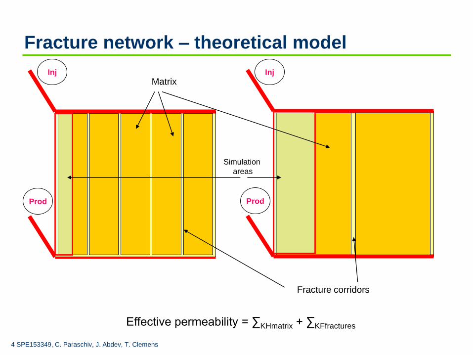
Fracture network – theoretical model
Effective permeability = ∑KHmatrix + ∑KFfractures
Inj
Prod
Inj
Prod
Fracture corridors
Matrix
Simulation
areas

5 SPE153349, C. Paraschiv, J. Abdev, T. Clemens
Diffusion law
Diffusion is described by Fick’s law:
J – mass flux (moving of objects from one
point to another in a given time)
D – Diffusivity (the constant that describe
how fast or slow an object diffuse)
C – Concentration (the amount of mass in a
given volume)
X – Distance (refer to the distance the object
is diffusing)
x
CDJ
*

6 SPE153349, C. Paraschiv, J. Abdev, T. Clemens
Basic reservoir and fluid parameters
Reservoir location: Middle East
Reservoir type : Fractured carbonates reservoir
Hydrocarbon type: Gas condensate
Permeability :
from cores: 0.2 - 1 mD
from well test: 10 mD
Porosity (avg): 6.5%
Initial reservoir pressure: 360bar
Saturation pressure: 342 bar
Maximum liquid drop out: 37%
Reservoir temp: 121°C
7 SPE153349, C. Paraschiv, J. Abdev, T. Clemens
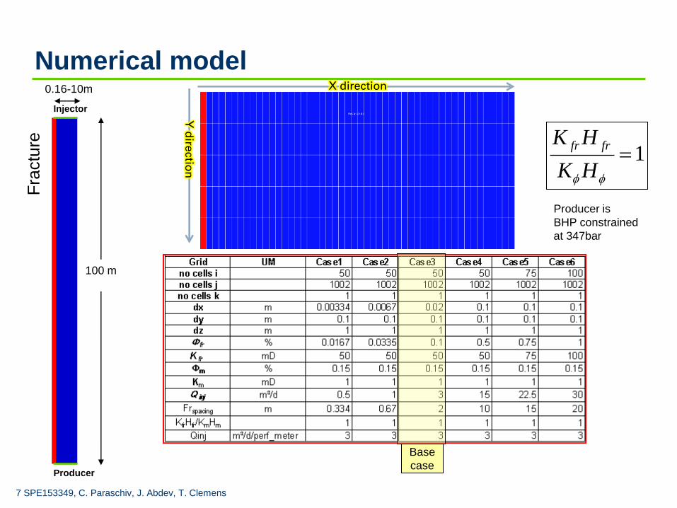
Numerical model
Matrix
Fra
ctu
re
Producer
Injector
For all cases it was used:
Km = 1;
Φm = 0.15
Kfr*dxfracture_cell = Km*dxmatrix_cell*no_cells
Φfr = Kfr*dx/10
Qinj = 3 m³ / day / perforated meter
100 m
0.16-10m
1HK
HK frfr
Base
case
Producer is
BHP constrained
at 347bar
X direction
Y d
irectio
n

8 SPE153349, C. Paraschiv, J. Abdev, T. Clemens
Fluid and rock properties
Fluid properties
A 15 components EoS was created and diffusion
coefficients were calculated using Silva and Belery
method. Dewpoint pressure is 342bar.
.
0
0.2
0.4
0.6
0.8
1
0 0.2 0.4 0.6 0.8 1
kr
Sw
Water-Oil Relative Permeabilities
k…
Rock properties
Connate water saturation was 30% in the matrix, 5%
residual oil sat, 15% trapped gas saturation, end points
of 1 and straight lines for fracture rel perms
0
0.2
0.4
0.6
0.8
1
0 0.2 0.4 0.6 0.8 1
kr
Sg
Gas Oil Rel. Perms
Krg…

9 SPE153349, C. Paraschiv, J. Abdev, T. Clemens
Diffusion coefficients
Diffusion coefficients decrease with increasing
molecular weight
Inj
Prod
N2
C1
C2
C3
C4
C30+
fracture coridor matrix
10 SPE153349, C. Paraschiv, J. Abdev, T. Clemens
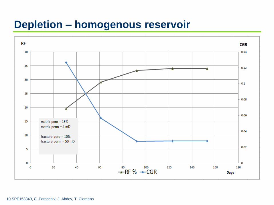
Depletion – homogenous reservoir

11 SPE153349, C. Paraschiv, J. Abdev, T. Clemens
N2 injection - homogenous reservoir
Diffusion activated

12 SPE153349, C. Paraschiv, J. Abdev, T. Clemens
N2 injection - fractured reservoir

13 SPE153349, C. Paraschiv, J. Abdev, T. Clemens
N2 injection - fractured reservoir
diffusion activated

14 SPE153349, C. Paraschiv, J. Abdev, T. Clemens
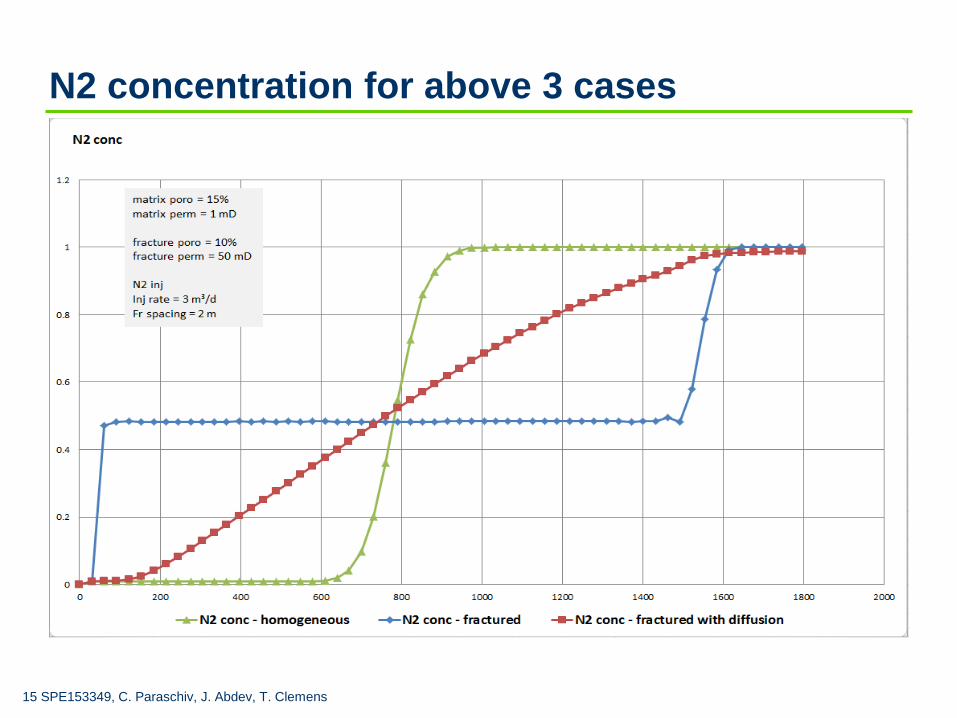
N2 concentration vs
time for the previous 3
cases after 340 days
of production
1. no fracture
2. fractures
3. fractures with diffusion
option activated
1 2 3
15 SPE153349, C. Paraschiv, J. Abdev, T. Clemens
N2 concentration for above 3 cases

16 SPE153349, C. Paraschiv, J. Abdev, T. Clemens
Components concentration into the matrix
Sampling
row of cells

17 SPE153349, C. Paraschiv, J. Abdev, T. Clemens
Fracture spacing
1m fr spacing, no cells = 50, Km=1, Kfr= 50mD
2m fr spacing, no cells = 100, Km=1, Kfr=100mD
4m fr spacing, no cells = 200, Km=1, Kfr=200mD
matrix poro = 15%
matrix perm = 1 mD
fracture poro = 10%
fracture perm = 50 mD
N2 inj
Inj rate = 3 m³/d

18 SPE153349, C. Paraschiv, J. Abdev, T. Clemens
Effect of porosity change for N2 injection
matrix perm = 1 mD
fracture poro = 10%
fracture perm = 50 mD
N2 inj
Inj rate = 3 m³/d
Fr spacing = 2 m
Normalised plot
19 SPE153349, C. Paraschiv, J. Abdev, T. Clemens
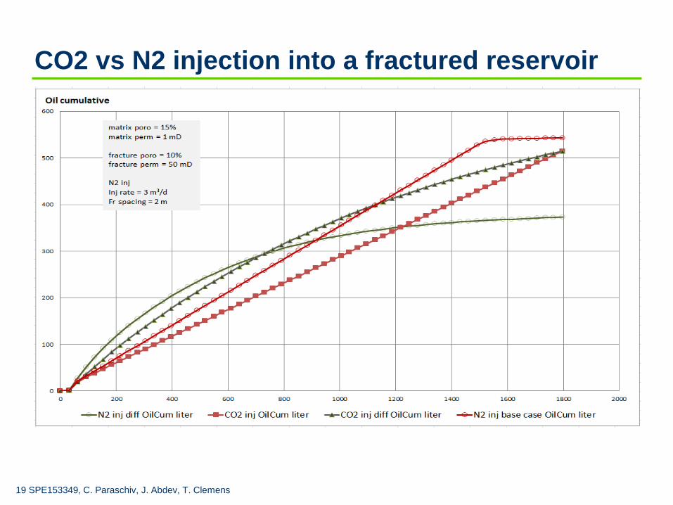
CO2 vs N2 injection into a fractured reservoir
20 SPE153349, C. Paraschiv, J. Abdev, T. Clemens
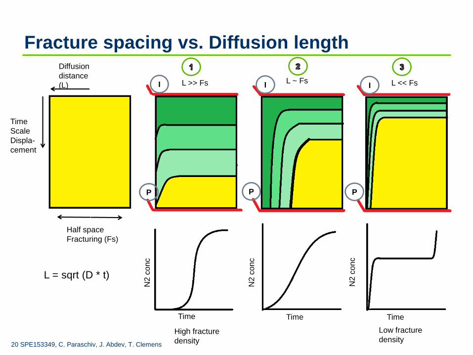
Fracture spacing vs. Diffusion length
L = sqrt (D * t)
Diffusion
distance
(L)
Time
Scale
Displa-
cement
Half space
Fracturing (Fs)
N2 c
on
c
N2
co
nc
N2 c
on
c
Time Time Time
I I I
P P P
L >> Fs
High fracture
density
Low fracture
density
L ~ Fs L << Fs
21 SPE153349, C. Paraschiv, J. Abdev, T. Clemens
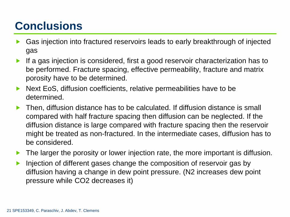
Conclusions
Gas injection into fractured reservoirs leads to early breakthrough of injected
gas
If a gas injection is considered, first a good reservoir characterization has to
be performed. Fracture spacing, effective permeability, fracture and matrix
porosity have to be determined.
Next EoS, diffusion coefficients, relative permeabilities have to be
determined.
Then, diffusion distance has to be calculated. If diffusion distance is small
compared with half fracture spacing then diffusion can be neglected. If the
diffusion distance is large compared with fracture spacing then the reservoir
might be treated as non-fractured. In the intermediate cases, diffusion has to
be considered.
The larger the porosity or lower injection rate, the more important is diffusion.
Injection of different gases change the composition of reservoir gas by
diffusion having a change in dew point pressure. (N2 increases dew point
pressure while CO2 decreases it)
22 SPE153349, C. Paraschiv, J. Abdev, T. Clemens
Acknowledgments
OMV E&P for the permission to publish the paper

Move & More.
Thank you!
SPE EUROPEC 4-7 June 2012
Copyright © 2022 FDOKUMEN