Geological Disposal - Gas Status Report - GOV.UK
140
Geological Disposal Gas Status Report December 2016 NDA Report no. DSSC/455/01
-
Upload
khangminh22 -
Category
Documents
-
view
0 -
download
0
Transcript of Geological Disposal - Gas Status Report - GOV.UK

Geological DisposalGas Status ReportDecember 2016
NDA Report no. DSSC/455/01


NDA Report no. DSSC/455/01
Geological DisposalGas Status ReportDecember 2016

DSSC/455/01
ii
Conditions of Publication This report is made available under the Radioactive Waste Management (RWM) Transparency Policy. In line with this policy, RWM is seeking to make information on its activities readily available, and to enable interested parties to have access to and influence on its future programmes. The report may be freely used for non-commercial purposes. RWM is a wholly owned subsidiary of the Nuclear Decommissioning Authority (NDA), accordingly all commercial uses, including copying and re publication, require permission from the NDA. All copyright, database rights and other intellectual property rights reside with the NDA.
Applications for permission to use the report commercially should be made to the NDA Information Manager.
Although great care has been taken to ensure the accuracy and completeness of the information contained in this publication, the NDA cannot assume any responsibility for consequences that may arise from its use by other parties.
© Nuclear Decommissioning Authority 2016. All rights reserved.
ISBN 978-1-84029-568-9
Other Publications If you would like to see other reports available from RWM, a complete listing can be viewed at our website https://rwm.nda.gov.uk, or please write to us at the address below.
Feedback Readers are invited to provide feedback on this report and on the means of improving the range of reports published. Feedback should be addressed to:
RWM Feedback Radioactive Waste Management Limited Building 587 Curie Avenue Harwell Oxford Didcot OX11 0RH
email [email protected]

DSSC/455/01
iii
Abstract The gas status report is part of a suite of eight research status reports. The purpose of the research status reports is to describe the science and technology underpinning geological disposal of UK higher activity wastes by providing a structured review and summary of relevant published scientific literature and discussing its relevance in the UK context. The reports have been written for an audience with a scientific or technical background and with some knowledge of the context of geological disposal. The current suite of research status reports (issue 2) updates and replaces the suite produced in 2010 (issue 1).
The objective of the gas status report is to summarise the scientific evidence relative to the generation and migration of radioactive trace gases and bulk gases during transport to, and storage in, the geological disposal facility (GDF) and after closure of the GDF. The key message emerging from the analysis presented in this status report is that the processes that contribute to gas generation during the transport of waste packages to the GDF, during the operational phase of the GDF and after closure of the GDF are understood. Gas migration from the GDF after closure will be site-specific and would need to be addressed in detail after a site has been chosen.


DSSC/455/01
v
Executive summary The gas status report is part of a suite of research status reports describing the science and technology underpinning geological disposal of UK higher activity wastes.
This report describes gas generation and migration processes during periods before and after closure of the GDF. Three host rocks are considered as the basis for discussion: higher strength rock, lower strength sedimentary rock and halite.
Gases will be formed in many waste packages after their production and thus gases will be generated during transport, operations and after closure of the GDF. In addition, the evolution of some of the other components of the engineered barrier system (EBS) will also contribute to gas generation after closure.
There is a general consensus that the key gas generation processes applicable to the GDF are the corrosion of metals, microbial action and radiolysis. Hydrogen will be the predominant gas formed, with lesser amounts of methane and carbon dioxide. In addition, radioactive gases and some non-radiological chemotoxic species may also be formed. The relative importance of the various generation processes, and hence the rates of gas formation and the gas composition, depend on the wasteform and variables such as water availability and water chemistry. These, in turn, depend on the illustrative geological disposal concept example considered.
The transport of radioactive waste packages to the GDF is also discussed in terms of the need to manage gas to meet transport regulations.
The main gas management issues that need to be addressed during the operational phase of the GDF are associated with the generation of flammable and radiotoxic gases. These can be addressed through the use of management control and engineering measures such as adequate ventilation and restricted access. Ventilation will keep the concentrations of flammable gases below their lower flammability limit in air. Ventilation and measures such as remote access to some areas (for example those containing unshielded Intermediate Level Waste packages) will be used to limit radiation doses to underground workers through the inhalation of radioactive gases. Discharge of air containing radioactive gases from the GDF to the atmosphere will be controlled to meet authorised discharge limits.
After closure of the GDF, materials within it, including the wastes, will continue to generate gas. The bulk gas will be composed largely of hydrogen, but there will be smaller quantities of carbon dioxide and methane. Radioactive gases will also be produced, including tritiated hydrogen and methane, molecules containing carbon-14 (for example methane and carbon dioxide) and radon. There is uncertainty about the rates at which these radioactive gases will be formed, partly because they depend on the release of a radionuclide from the waste matrix and the incorporation of the radionuclide into a gas. In developing our understanding of the consequences of gas generated in the GDF some conservative assumptions about the rates at which the radioactive gases will be produced have been made. Of the radioactive gases, molecules containing carbon-14 will be the most important with regard to any post-closure release of gas. Recent work has improved the understanding of the release of carbon-14 from irradiated graphite and ongoing work, including participation in the international EC CAST project, will provide further data for this material and for other waste materials that contain carbon-14.
The generation of gas in, and the migration of gas from, the GDF after closure will depend on the illustrative geological disposal concept example and the individual site(s) being considered because some factors are strongly influenced by the host rock; interfaces within the EBS and with the host rock may also be important. In the case of fractured higher strength rocks it is thought that, in addition to dissolved gas, a free gas phase will form and migrate away from the GDF through open fractures. However, a network of fractures may

DSSC/455/01
vi
not result in the rapid transport of gas if the rate of gas production cannot maintain a free gas pathway. In order to determine where the gas will migrate and when it might be released at the surface, a key factor is the nature of the geological strata overlying the host rock. For example, so-called ‘cap rocks’ may act as barriers to the migration of the gas. Possible consequences of gas in a fractured higher strength host rock include entrainment of contaminated water by gas and the release of flammable (hydrogen and methane) and radiotoxic (for example 14C- methane) gases to the environment (the 'biosphere').
In the case of lower strength sedimentary rocks the rates of gas generation may be limited by the supply of water from the host rock to the GDF. It will be difficult for any free gas phase formed to migrate from the GDF by flow through undisturbed clay because of its high gas entry pressure. Depending on the precise combination of gas generation, water inflow and gas migration in solution, the gas may be released through pore dilation and micro-fissuring in the clay. These micro-fissures will then close after the gas pressure has fallen, depending on the properties of the host rock. Possible consequences of gas in this geology are over-pressurisation and the displacement of contaminated water from the GDF.
In evaporite rocks (halite), the waste environment may be so dry that gas generation will be very limited (although water may be available in some waste packages, for example in the form of grout porewater). The host rock is expected to undergo creep, with the result that excavation damage to the host rock will tend to self-heal and voids will fill. The pressures required for the gas to enter the host rock are expected to be higher than for lower strength sedimentary rocks. Therefore, evaporite rocks can act as a natural cap rock for gas in petroleum-bearing rocks and are used for natural gas storage facilities.
The key message emerging from the analysis presented in this status report is that the processes that contribute to gas generation during the transport of waste packages to the GDF, during the operational phase of the GDF and after closure of the GDF are understood. Gas migration from the GDF after closure will be site-specific and will need to be addressed in detail after a site has been chosen.

DSSC/455/01
vii
List of contents
Abstract iii
Executive summary v
List of acronyms ix
1 Introduction 1
1.1 Background 1
1.2 Objectives and scope 1
1.3 Audience and users 2
1.4 Relationship with other status reports 3
1.5 Changes from the previous issue 3
1.6 Knowledge base reference period 4
1.7 Terminology 4
1.8 Document structure 4
2 Gas generation 5
2.1 Gas-generating materials in the GDF 5
2.2 Gas generation processes 6
2.3 Radiotoxic gases 19
2.4 Computer models for calculating rates of gas generation 36
2.5 Illustrative example calculation for gas generation 37
2.6 Uncertainty in calculations of gas generation 41
3 Gas migration 43
3.1 Barriers to gas migration 43
3.2 Mechanisms of gas migration 44
3.3 Approach to modelling gas migration 46
3.4 Instability, heterogeneity and bubble flow 51
3.5 Coupling to other processes 54
3.6 Computer models for simulating gas migration 55
3.7 Modelling gas migration at specific sites 56
4 Gas generation during transport 59
4.1 Waste packages and transport containers for ILW and some LLW 59
4.2 Gas generation in SWTCs under normal conditions of transport 63

DSSC/455/01
viii
4.3 4 metre and 2 metre boxes 64
4.4 HLW, spent fuel, plutonium and HEU disposal containers 65
5 Gas generation during operations 67
5.1 Flammable gases 68
5.2 Radioactive gases 69
5.3 HLW, spent fuel, plutonium and HEU packages 74
6 Gas generation and migration after closure 75
6.1 Gas generation 78
6.2 Gas migration through engineered barriers 93
6.3 Gas migration through different geological environments 99
6.4 Possible consequences of post-closure gas generation 109
7 Concluding remarks 113
References 115

DSSC/455/01
ix
List of acronyms AGR Advanced Gas-cooled Reactor
ALARP as low as reasonably practicable
BEP0 British Experimental Pile 0
BFS blast furnace slag
BWR boiling water reactor
CAST Carbon-14 source term (an EC project)
CoRWM Committee on Radioactive Waste Management
DCTC Disposal Canister Transport Container
DNLEU depleted, natural and low enriched uranium
DSSC Disposal System Safety Case
EBS engineered barrier system
EC European Commission
EDZ excavation disturbed zone
FORGE Fate Of Repository Gases (an EC project)
GDF geological disposal facility
GMT Gas Migration Test
GPA generic performance assessment
HEU highly enriched uranium
HHGW high heat-generating waste
HLW High Level Waste
IAEA International Atomic Energy Agency
ILW Intermediate Level Waste
ISA isosaccharinic acid
LASGIT Large Scale Gas Injection Test
LFL lower flammability limit
LLW Low Level Waste
NDA Nuclear Decommissioning Authority
NEA Nuclear Energy Agency
NRVB Nirex reference vault backfill
OPC ordinary Portland cement
PET positron emission tomography
PWR Pressurised Water Reactor
PVC polyvinylchloride
RWM Radioactive Waste Management
SF spent fuel
SILW shielded Intermediate Level Waste

DSSC/455/01
x
SMOGG Simplified Model of Gas Generation
STP Standard Temperature and Pressure
SWTC Standard Waste Transport Container
UILW unshielded Intermediate Level Waste
UNGG Uranium Naturel Graphite Gaz
WAGR Windscale Advanced Gas-cooled Reactor
WIPP Waste Isolation Pilot Plant

DSSC/455/01
1
1 Introduction
1.1 Background In order to build confidence in the safety of a future geological disposal facility (GDF) for the UK1, in the absence of potential disposal sites, RWM is developing a generic Disposal System Safety Case (DSSC), which shows how the waste inventory destined for geological disposal could be safely disposed of in a range of geological environments. Background information on geological disposal in the UK can be found in the Technical Background Document [1].
The documents comprising the generic DSSC are shown in Figure 1 and include a number of research status reports (‘knowledge base’). The purpose of the research status reports is to describe the science and technology underpinning geological disposal of UK higher activity wastes by providing a structured review and summary of relevant published scientific literature and discussing its relevance in the UK context. The current suite of research status reports (issue 2) updates and replaces the suite produced in 2010 (issue 1).
Figure 2 shows how research status reports underpin different safety cases. They include:
• reports on waste package evolution [2], engineered barrier system (EBS) evolution [3], and geosphere [4], describing the understanding of the evolution of the specific barriers of the multi-barrier system
• reports on behaviour of radionuclides and non-radiological species in groundwater [5] and gas generation and migration (this report), describing the release and movement of materials through the multi-barrier system, including the groundwater and any gas phase formed
• reports on criticality safety [6] and on waste package accident performance [7], describing the behaviour of waste packages and a GDF during low probability events
• a report on the biosphere [8], describing how we think the biosphere may evolve in the future and how radionuclide uptake might be expected to take place.
Research status reports need to be read in conjunction with other documentation, including:
• the Data Report [9], which describes the values of specific parameters used in the safety assessments based on scientific information presented in the status reports
• the Science and Technology Plan [10], which describes planned future research and development activities.
1.2 Objectives and scope The objective of the gas status report is to summarise the scientific evidence relative to the generation and migration of radioactive trace gases and bulk gases during transport to, and storage in, the GDF and after closure of the GDF. Available information is discussed, with the aim of providing a sufficiently-detailed evaluation of the implications of key processes to 1 Disposal of higher activity wastes in a GDF is current policy in England, Wales and Northern Ireland. Scottish Government policy is that the long-term management of higher activity waste should be in near-surface facilities. Facilities should be located as near to the sites where the waste is produced as possible.

DSSC/455/01
2
allow its direct use in the development of safety cases. Safety-related considerations are excluded from the scope of this document and are provided solely in the safety cases.
The scope covers all materials currently considered in the inventory for disposal, including Intermediate and Low Level Waste (ILW/LLW), High Level Waste (HLW), spent fuels, uranium (particularly depleted, natural and low-enriched uranium, DNLEU) and plutonium.
Figure 1 Structure of the generic Disposal System Safety Case (DSSC). The suite of research status reports represents the knowledge base
Figure 2 Safety cases and status reports in which underpinning information can be found
1.3 Audience and users The primary external audience of the status reports is our regulators. The audience is also expected to include academics, learned societies and stakeholders such as the Committee

DSSC/455/01
3
on Radioactive Waste Management (CoRWM) and Non-Governmental Organisations (NGOs). The reports have been written for an audience with a scientific or technical background and with some knowledge of the context of geological disposal. The primary internal user of the information presented in the status reports is RWM’s safety case team.
1.4 Relationship with other status reports The formation of gases from processes occurring in many wasteforms is unavoidable, so gases will be generated storage and transport of waste packages and during the operational phase of the GDF, as well as after closure. In addition, the evolution of some of the components of the Engineered Barrier System (EBS) will contribute to gas generation after closure. The impact of gases on the safety case falls into two broad areas: firstly, the effects associated with the production of non-radioactive (bulk) gases and secondly, the radiological impacts of (trace) gases containing radionuclides such as tritium, 14C and 222Rn.
There is a general consensus from generic research that the key gas generation processes applicable to the GDF are the corrosion of metals, degradation of organic materials and radiolysis. Hydrogen will be the predominant gas formed, principally from metal corrosion, with lesser amounts of methane and carbon dioxide formed from degradation of organic materials. In addition, radioactive gases and some non-radiological chemotoxic species may also be formed. The relative importance of the various generation processes, and hence the rates of gas formation and the gas composition, depend on the wasteform and variables such as water availability and water chemistry. The evolution of waste packages is described in the package evolution status report [2]. After closure of the GDF the availability of groundwater from the surrounding rocks will depend on the illustrative geological disposal concept implemented.
Migration of gas within the EBS and through the rocks surrounding the GDF will depend n the geological disposal concept and the individual site(s) being considered. The research requirement is to build understanding of the processes by which gas potentially moves through a range of relevant geological and engineering materials, and to develop models to represent those processes. The properties of the EBS and of the geological barrier are described in the engineered barrier system status report [3] and the geosphere status report respectively [4].
1.5 Changes from the previous issue This document updates and replaces the 2010 gas evolution status report [11], published as part of the 2010 generic DSSC suite. This issue includes the following developments:
• consideration of carbon-14 release from irradiated graphite
• updated gas generation calculations, treating uncertainty on a scenario basis
• review of G-values for gas generation from radiolysis
• improved treatment of coupling between gas generation and water availability in clay environments
• consideration of the importance of interfaces in gas transport from the engineered barrier system.
In line with the objectives of the document, and in order to respond to previous feedback, contextual and safety-related information have been removed from the text. Contextual information is provided in [1], while safety-related information is described entirely in the safety case documentation.

DSSC/455/01
4
1.6 Knowledge base reference period
The knowledge base described in this document contains scientific information available to RWM up to March 2016. Where, within RWM’s research programme, progress relative to important topics was made after such date, efforts have been made to reflect such progress up to the publication date of this document.
1.7 Terminology For information about use of language and terminology in this and other RWM documents please refer to our Glossary [1]. When necessary, we have introduced specific terminology used in the document through the use of footnotes.
1.8 Document structure The remainder of this report is structured according to the following format:
• Section 2 outlines the processes resulting in gas generation
• Section 3 outlines the general processes and factors that control the migration of gas through engineered barriers and a natural geological system
• Section 4 discusses gas generation during transport of radioactive waste packages to the GDF
• Section 5 discusses gas generation during the operational phase of the GDF
• Section 6 discusses the generation and migration of gas after closure of the GDF in the context of the illustrative concepts for the three different host rocks
• Section 7 provides some concluding remarks.
We have used coloured boxes at the beginning of each section to provide a short summary of the key messages and to help the reader in following the ‘golden thread’.

DSSC/455/01
5
2 Gas generation Gases will be formed from processes occurring in waste packages, for example corrosion of metals in the waste or the radiolysis of water, throughout their life:
• in storage at waste producers’ sites
• during transport to the GDF
• in the operational phase of the GDF
• after closure of the GDF.
In addition, components of the EBS will contribute to gas generation after closure (for example, anaerobic corrosion of stainless waste containers and gamma radiolysis of porewater in a cementitious backfill). Some of the gas will consist of radioactive molecules (for example, tritiated hydrogen gas, 3H1H) and, although these may be insignificant in terms of the volumes of gas generated, their release from waste packages can contribute to the radionuclide uptake by human and non-human biota.
Gas generation and release of gases during storage at waste producers’ sites will reduce the inventory of materials with the potential to generate gas in the GDF (as will the aerobic corrosion of steels, although this produces no hydrogen). Similarly, gas generation and release during the operational phase of the GDF will reduce the inventory of gas generating material after closure (the transport duration will be too short to be of significance in this respect).
This section summarises the understanding of gas generation and the approach to modelling gas generation in the GDF as follows:
• the materials that can generate gas (Section 2.1)
• the processes that generate gas (Section 2.2 - corrosion, microbial action, radiolysis and radioactive decay)
• the formation of radiotoxic gases (Section 2.3 - tritium, carbon-14 and radon-222)
• modelling of gas generation processes (Section 2.4) with results from an illustrative example calculation (Section 2.5 – for unshielded ILW (UILW) packages)
• the use of variant scenario calculations to address some aspects of uncertainty (Section 2.6).
2.1 Gas-generating materials in the GDF
Waste packages, other components of the engineered barrier system and materials associated with construction and operations in the GDF have the potential to generate gas.
The contents of the GDF that have the potential to generate gases and those of most relevance to gas production will include:
• the wastes (ILW/LLW, HLW, and possibly spent fuel, uranium and plutonium if they are declared as wastes); these include metals (for example steels, Zircaloy, Magnox, aluminium and uranium), which can generate gas by corrosion, organic materials (for example cellulose and synthetic polymers such as polyvinylchloride (PVC)), which can produce gas through biodegradation and radiolysis, and any water associated with the wastes, which will generate gas through radiolysis

DSSC/455/01
6
• the waste encapsulants, such as a cement grout (by radiolysis of associated water) or organic polymer (through radiolysis), where present
• the container materials, including iron or steel (likely to be used for most ILW/LLW containers) and some of the metals being considered for containers for other higher activity wastes [12] (by corrosion)
• the stillages for 500 litre drum waste packages (by corrosion)
• the buffer or backfill materials (through radiolysis of associated water)
• structural materials, such as steel reinforcement used in underground construction (by corrosion)
• equipment that is not removed from the GDF prior to closure, for example crane rails (by corrosion).
The disposal of waste containing pressurised gases (for example, gas cylinders) is prohibited by the requirement that the wasteform shall not contain hazardous materials, or have the potential to generate such materials, unless the treatment and packaging of such materials or items makes them safe. The definition of hazardous materials includes flammable, explosive, pyrophoric, chemotoxic and oxidising materials; sealed and/or pressurised containers [13].
The materials composition of ILW, LLW, spent fuel and HLW and their associated packaging is given in the Derived Inventory [14]. The Derived Inventory provides data for waste packages rather than waste streams. Because the geological environment for a future disposal facility is not known, no decision has yet been made on the geological disposal concept(s) to be adopted (including engineered barrier materials) although illustrative designs have been adopted for planning purposes. Hence, for the purposes of defining illustrative geological disposal concept examples, a range of packaging assumptions have been made [15,16]. RWM has worked in collaboration with waste producers to define a range of waste containers that are considered suitable for packaging the majority of the ILW and LLW expected to require geological disposal. For planning purposes it is currently assumed that HLW and spent fuel will be packaged in copper or carbon steel disposal containers, but these assumptions are subject to change.
2.2 Gas generation processes
The main mechanisms of gas generation are corrosion, radiolysis and microbial degradation. The bulk of the gas will be hydrogen. Radioactive gases include tritiated hydrogen, tritiated methane, 14C-methane, 14C-carbon dioxide and radon-222.
International understanding of the processes that can form gas from radioactive waste packages has been reviewed [17, 18]. The European Commission (EC) FORGE (Fate of Repository Gases) project concluded that gas generation processes are well understood for different types of material, including generation rates and how these are affected by conditions in the GDF [19, 20, 21]. The main mechanisms by which gas can be generated in the GDF are widely established as metal corrosion, radiolysis and microbial degradation. In the GDF, the main processes that generate bulk and radioactive gases are:
• corrosion of metals, including the release of carbon-14 from neutron-irradiated metals as they corrode
• microbial degradation of organic materials, including those arising from the hydrolysis of cellulose to smaller organic compounds
• radiolysis, in particular of water and some organic materials.

DSSC/455/01
7
Other processes that will also contribute are:
• diffusion, notably the release of tritium by solid-state diffusion from metals
• radioactive decay of radium, which leads to the generation of radon-222
• the release of radioactive gases containing tritium or carbon-14 by leaching of irradiated graphite.
The rates at which most of the gases will be generated are sensitive to environmental factors, which might change with time, such as: the presence of oxygen or water; the presence of hydrogen or chloride ions; and temperature. More details of the processes that will generate gas are provided in Sections 2.2.1 to 2.2.4 below.
The bulk of the gas generated (by volume) will be hydrogen, which will arise from the corrosion of metals (only under anaerobic conditions for steels and uranium) and the radiolysis of water and organic materials, and methane and carbon dioxide that will be generated mainly by microbial degradation of organic materials [22].
Figure 3 Conceptual gas generation processes
The relative amounts of gas generated by these processes will depend on the waste materials and the geological disposal concept that is utilised.
Most of the volume of gas generated will not be radioactive. However, a very small fraction of the volume will be radioactive. The radioactive component will consist mainly of tritiated hydrogen, 14C-containing gaseous molecules (such as methane or other hydrocarbons; carbon monoxide; and carbon dioxide, where a stable carbon-12 atom has been replaced by carbon-14), and radon-222.
The relative importance of the various generation processes, and hence the rates of gas formation and the resultant gas composition, depend partly on the type of wasteform. For example, no organic materials are present in HLW and spent fuel, hence only a small volume of carbon-containing gas would be expected to be formed from such wasteforms. Vitrified HLW is expected to contain little corrodible material, thus any gas generation will be from corrosion of the waste container or radiolysis of external water.
If some ILW were to be vitrified in the future the sources of gas are also likely to be from corrosion of the waste container or radiolysis of external water; organic material having been destroyed during the vitrification process. Metallic inclusions can be present (depending on the waste-stream composition) and these can generate gas through

DSSC/455/01
8
corrosion. In this case the access of water to such inclusions can be a determining factor in the rate of gas generation.
2.2.1 Corrosion
Hydrogen is produced from the corrosion of iron, steels, Zircaloys and metallic uranium exclusively under anaerobic conditions. Hydrogen is also produced from the corrosion of Magnox and aluminium under aerobic and anaerobic conditions. Under highly alkaline conditions Magnox, aluminium and uranium will corrode rapidly.
Based on an understanding of the inventory for disposal and the quantities of metal in the GDF, a significant amount of the bulk gas is likely to be generated by corrosion (for example [2, 22, 23]. Corrosion is also an important aspect of package evolution, and is discussed extensively in that context in reference [2].
Corrosion is defined as the degradation of a material by chemical reactions with its surroundings. For metals, corrosion occurs in the presence of water and an oxidising agent, which may be provided by a species such as oxygen or by the water itself (see Box 1). Corrosion typically produces oxide(s) and / or salt(s) of the original metal. The rusting of iron and steel is a familiar example.
Under some conditions, the oxide film that forms on a metal surface is impervious and protects it against further corrosion. This effect is called passivation. Passivation of iron reinforcement bars (re-bar) in concrete, for example, occurs because of the highly alkaline pH of 12 to13 in the porewater [24]. In the passive state, metal dissolution is determined by the balance between growth and slow dissolution of the passive oxide film.
Corrosion can be uniform (also known as general corrosion) or localised (for example pitting or stress corrosion cracking) [2]. Localised forms of corrosion, although they may lead to a loss of container integrity, are unlikely to contribute significantly to total metal loss and thus total gas generation because of the limited area over which they will occur. General corrosion will dominate overall gas generation from corrosion.
Gas generation by corrosion The instantaneous rate of hydrogen gas generation from a metal depends on the reaction stoichiometry, the surface area of the metal and the corrosion rate [25]. That is:
rAnq HH r−= (2.1)
where
qH is the rate of gas generation (mol s-1) nH is a stoichiometric coefficient, giving the number of moles of gas produced per
mole of metal corroded r is the molar density of the metal (mol m-3) A is the surface area of the metal (m2) r is the (general) corrosion rate (m s-1).
The available surface area of a metal is important and it is possible to estimate the surface area of the metal from an analysis of the inventory for disposal (see, for example, references [23, 26] for the 2004 ILW inventory). Stoichiometric coefficients and (general) corrosion rates are discussed below.

DSSC/455/01
9
Box 1 Corrosion of iron or steel Because a corroding metal is an electrical conductor, the release of metallic cations from the crystal lattice can take place locally and physically separated from the release of an equivalent amount of electrons. Therefore, the corrosion reaction can be split into anodic and cathodic sub-reactions.
The anodic process consists of metal dissolution (corrosion). For example, for iron:
Fe ⇒ Fe2+ + 2e- (2.2)
The cathodic sub-reaction depends on the oxidising agent. Under aerobic conditions, oxygen reduction prevails:
O2 + 2H2O + 4e- ⇒ 4OH- (2.3)
These sub-reactions can be combined to give the following overall reaction:
2Fe + O2 + 2H2O ⇒ 2Fe(OH)2 (2.4)
This reaction produces no gas and the ferrous iron produced will undergo subsequent oxidation under aerobic conditions.
Under anaerobic conditions, hydrogen ion reduction occurs, giving:
Fe + 2H+ + 2OH- ⇒ Fe(OH)2 + H2 (2.5)
This reaction does not depend on the availability of oxygen, and therefore dominates under anaerobic conditions. Note the production of hydrogen gas.
Because Fe(OH)2 is thermodynamically unstable, it may be transformed in a second reaction (known as the Schikorr reaction [27]) to magnetite:
3Fe(OH)2 ⇒ Fe3O4 + 2H2O + H2 (2.6)
Again note the production of hydrogen gas. Under some circumstances the final transformation to magnetite (Fe3O4) may be kinetically inhibited, and the end product of anaerobic corrosion may be ferrous hydroxide (Fe(OH)2).
Reaction stoichiometry Steel is likely to be abundant in the GDF. From Box 1, a simplified reaction stoichiometry for the corrosion of steel under anaerobic conditions is:
3Fe + 4H2O ⇒ Fe3O4 + 4H2 (2.7)
Thus, the anaerobic corrosion of 3 moles of metallic iron (representing the same mass of steel) will generate 4 moles of molecular hydrogen. Other metals of interest include both those that are expected to be relatively inert (for example Zircaloy) and others that will corrode more rapidly (for example Magnox, aluminium under high pH conditions, and uranium). Reaction stoichiometries for these metals are identified in Box 2.
DSSC/455/01
10
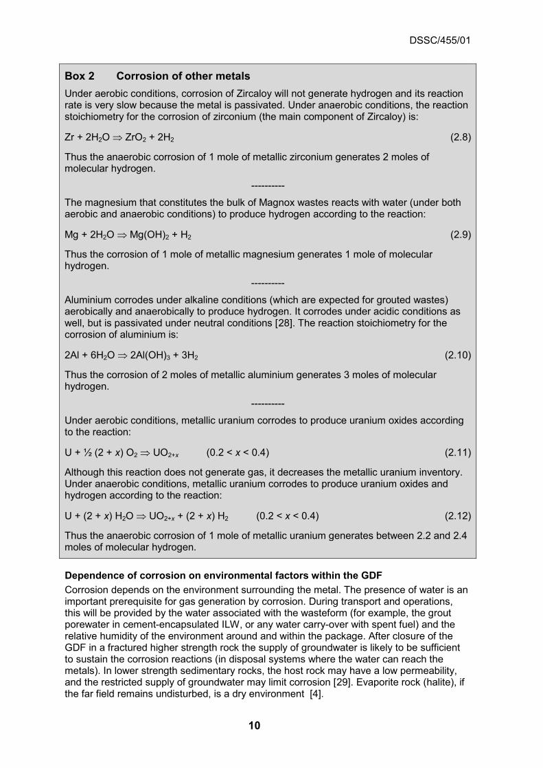
Box 2 Corrosion of other metals Under aerobic conditions, corrosion of Zircaloy will not generate hydrogen and its reaction rate is very slow because the metal is passivated. Under anaerobic conditions, the reaction stoichiometry for the corrosion of zirconium (the main component of Zircaloy) is:
Zr + 2H2O ⇒ ZrO2 + 2H2 (2.8)
Thus the anaerobic corrosion of 1 mole of metallic zirconium generates 2 moles of molecular hydrogen.
----------
The magnesium that constitutes the bulk of Magnox wastes reacts with water (under both aerobic and anaerobic conditions) to produce hydrogen according to the reaction:
Mg + 2H2O ⇒ Mg(OH)2 + H2 (2.9)
Thus the corrosion of 1 mole of metallic magnesium generates 1 mole of molecular hydrogen.
----------
Aluminium corrodes under alkaline conditions (which are expected for grouted wastes) aerobically and anaerobically to produce hydrogen. It corrodes under acidic conditions as well, but is passivated under neutral conditions [28]. The reaction stoichiometry for the corrosion of aluminium is:
2Al + 6H2O ⇒ 2Al(OH)3 + 3H2 (2.10)
Thus the corrosion of 2 moles of metallic aluminium generates 3 moles of molecular hydrogen.
----------
Under aerobic conditions, metallic uranium corrodes to produce uranium oxides according to the reaction:
U + ½ (2 + x) O2 ⇒ UO2+x (0.2 < x < 0.4) (2.11)
Although this reaction does not generate gas, it decreases the metallic uranium inventory. Under anaerobic conditions, metallic uranium corrodes to produce uranium oxides and hydrogen according to the reaction:
U + (2 + x) H2O ⇒ UO2+x + (2 + x) H2 (0.2 < x < 0.4) (2.12)
Thus the anaerobic corrosion of 1 mole of metallic uranium generates between 2.2 and 2.4 moles of molecular hydrogen.
Dependence of corrosion on environmental factors within the GDF Corrosion depends on the environment surrounding the metal. The presence of water is an important prerequisite for gas generation by corrosion. During transport and operations, this will be provided by the water associated with the wasteform (for example, the grout porewater in cement-encapsulated ILW, or any water carry-over with spent fuel) and the relative humidity of the environment around and within the package. After closure of the GDF in a fractured higher strength rock the supply of groundwater is likely to be sufficient to sustain the corrosion reactions (in disposal systems where the water can reach the metals). In lower strength sedimentary rocks, the host rock may have a low permeability, and the restricted supply of groundwater may limit corrosion [29]. Evaporite rock (halite), if the far field remains undisturbed, is a dry environment [4].

DSSC/455/01
11
A number of factors will affect corrosion rates in the GDF, for example the presence of oxygen, the chemistry of the groundwater (in particular, the pH and the presence of anions, of which chloride and sulphide are the most important), and the temperature.
In addition, corrosive agents may be formed from the degradation of some waste components; for example, hydrogen chloride from the radiolysis of PVC [30]. Microbial and thermal degradation may also lead to the formation of corrosive products (for example acids) that subsequently react with metals [2]. In addition, elevated temperatures (for example from high heat-generating waste or cementitious backfill curing) may induce or accelerate certain chemical reactions.
Corrosion rates In order to calculate rates of gas generation, corrosion rates are required for a number of combinations of metals and environmental conditions.
In the case of ILW/LLW, stainless steel and carbon steel will be present in the wastes and also as waste containers; there will also be some containers manufactured from ductile cast iron. Zircaloy, Magnox, aluminium and uranium will be present as wastes. Spent fuel will include stainless steel and Zircaloy; stainless steel will also be associated with HLW in the form of Waste Vitrification Plant containers. Although there have been no final decisions on how to package HLW and spent fuel, the containers for these wastes will be required to retain their integrity for a very long time (many millennia) after closure of the GDF. Possible container metals include carbon steel, copper, titanium and nickel alloys [12] and conceptual designs for copper and carbon steel disposal containers have been developed [31].
In some concepts, the metallic ILW may be encapsulated in grout and exposed to an alkaline (high pH) environment. The use of waste encapsulants other than cements (for example organic polymers) can limit water access to the waste and can also generate lower pH conditions. The ILW packages, which will be exposed to the atmosphere during storage, may be surrounded by a cementitious backfill prior to closure of a GDF in a higher strength rock or a lower strength sedimentary rock or may be in contact with a material such as magnesium oxide in a concept in an evaporite rock2. In other disposal system concepts (for example HLW/spent fuel (SF) disposal concepts with a bentonite buffer or salt backfill), near-neutral conditions may prevail outside the disposal packages and containers.
The environment experienced by a metal present in waste or as a waste container will change with time. Initially, after manufacture of the waste package and during storage, the environment will be aerobic. However, anaerobic regions can develop close to corroding metals (particularly uranium) in some wasteforms if the rate of oxygen supply by diffusion is less than the rate of consumption by corrosion, or if the waste encapsulant itself provides reducing conditions (for example, grout formulations based on blends with blast furnace slag, (BFS)).
At some time after closure of the GDF all of the oxygen will be consumed by processes such as corrosion, and conditions will become anaerobic. The timescale for this will depend upon the concept. For example it has been estimated that it will take less than five years to establish reducing conditions between waste containers in the UK ILW/LLW concept in a higher strength rock [32]. For bentonite-based concepts, the time taken for oxygen to be consumed in the engineered barrier system of the KBS-3V concept has been estimated at between 10 and 300 years, but with investigations of the buffer material from the prototype
2 Evaporite rocks comprising the chloride minerals rock-salt and potash are of interest.

DSSC/455/01
12
repository indicating that reducing conditions prevail in the buffer on even shorter timeframes. Similarly, redox evolution modelling performed by Nagra estimated that reducing conditions will develop within 100 years of closure, owing to corrosion of steels and the presence of minerals such as iron sulphide (pyrite) present in the Opalinus Clay [3].
For those concepts where metals (as wastes or container materials) will be exposed to alkaline cementitious environments, corrosion rates are required for conditions that evolve as follows:
• aerobic and high pH
• anaerobic and high pH
• anaerobic and high pH in the presence of anions (for example chloride) from the groundwater.
Given the importance of metal corrosion when calculating rates of gas generation, reviews of the literature have been undertaken and appropriate corrosion rates for use with various combinations of metals and associated environmental conditions determined [33, 34, 35, 36]. These lead to the following conclusions:
• the reactive metals (Magnox, aluminium and uranium) will corrode relatively quickly (for example rates of 10 µm y-1, or more) [34, 35].
• the Magnox corrosion rate depends strongly on the presence of chloride (in free water it increases at chloride concentrations above about 10 ppm). For chloride concentrations of about 100 to 1000 ppm in water the rate of Magnox corrosion can increase by about two orders of magnitude [34, 36]. Concentrations of chloride present in groundwaters at depth in the UK are likely to exceed such levels.
• the Magnox corrosion rate depends on temperature [34, 35]. For example, the initial chronic corrosion rate increases by a factor of between 30 and 40 for an increase in temperature from 20°C to 50°C [34].
• the aluminium corrosion rate depends strongly on pH; aluminium corrodes rapidly under high pH conditions, but is covered with a passive film of oxide at near-neutral pH [34].
• the corrosion rate of uranium depends on whether conditions are aerobic or anaerobic; anaerobic corrosion of the metal is significantly faster [34, 35]. The rates of aerobic and anaerobic corrosion both increase with temperature.
• carbon steel, stainless steel and Zircaloy all corrode slowly (for example, rates of uniform corrosion of about 0.01 µm y-1 or less) under high pH conditions [33].
The corrosion rate of grouted metallic uranium in waste packages has been considered as part of our carbon-14 integrated project [37]. Reference [35] includes data from experimental trials of uranium corrosion in BFS/ordinary Portland cement (OPC) and PFA/OPC matrices undertaken by BNFL and Sellafield that were not available when the review in reference [34] was made. A comparison of these data with the aerobic and anaerobic corrosion rates used in the Simplified Model of Gas Generation (SMOGG) program showed that the anaerobic rate overestimated the rate of corrosion of uranium seen in the experiments, whereas the aerobic rate significantly underestimated it [37]. BFS/OPC is a more reducing system than PFA/OPC and in some of the experiments with PFA/OPC the start of corrosion was delayed. This suggests that there was a delay in the establishment of anaerobic conditions because once anaerobic corrosion was established, the corrosion rates were comparable to those measured in BFS/OPC and water only systems [35]. These imply that even though vented wastes packages are exposed to air in surface stores and during the operational period of the GDF a significant proportion of any

DSSC/455/01
13
uranium in grout will corrode anaerobically, hence the uranium will consume any oxygen sufficiently rapidly for the establishment of anaerobic microenvironments within the waste packages [37].
Reviews of the state of understanding of the corrosion of steels and of zirconium alloys in the context of gas generation and carbon-14 release have recently been published as part of the EC CAST (CArbon-14 Source Term) project [38, 39]. The steels review [38] draws on more recent data than those used in reference [33], but the likely corrosion rates for carbon steel under disposal conditions are unchanged by its conclusions. However, the review discusses Japanese studies [40] that give very low corrosion rate data for stainless steel under alkaline anaerobic conditions. The measured rates are all below 0.01 μm per year, which was the recommended value in the previous review based on an upper limit [33], and indicate a mean anaerobic corrosion rate, for the stainless steel studied, of 0.0008 μm (equivalent to 0.8 nm) per year at 30°C after exposure for two years (more recent results indicate an even lower mean anaerobic corrosion rate of about 0.0004 µm per year [41]).
Similarly, the review of studies on Zircaloy corrosion [39] also suggests that the rate of corrosion under alkaline conditions (for example pH 12 to12.5) is likely to be less than the rate of 0.01 μm per year that was the recommended value in the previous review, again based on an upper limit [33]. Zirconium alloys are highly resistant to uniform corrosion at low or moderate temperatures and the most recent results lead to typical corrosion rates of 1 to 2 nm per year after a few years corrosion. However, the review noted that the knowledge of the corrosion resistance of zirconium alloys at low temperature is based on the beginning of the corrosion regime. Study of the corrosion behaviour of Zircaloy in high temperature water has shown that, when the zirconium oxide layer reaches a thickness of between 2 and 3 μm, there is a change in the corrosion kinetics from parabolic to a pseudo-linear behaviour. In addition, Zircaloy takes up hydrogen as it corrodes. The non-corroded metal will be gradually transformed into brittle zirconium hydride that may have corrosion behaviour different from the metal [39]. However, the amount of Zircaloy in ILW in the UK inventory for disposal is small compared to the quantity of steels so it is not be expected to be a major contributor to the rate or the total amount of hydrogen production after closure of the GDF, despite any uncertainties in the long-term corrosion rate.
Possible container materials for HLW and spent fuel include carbon steel and copper, although, as mentioned above, titanium and nickel alloys may be considered. The performance of these candidate container metals [12] has been reviewed and it was concluded that, for the conditions expected in the GDF, either they will resist corrosion or they will corrode very slowly. For example, carbon steel is expected to have a long-term general corrosion rate of about 0.1 to 1 μm y-1 under near-neutral conditions [42]. Carbon steel corrosion rates are reported to be higher in compacted bentonite than in free bentonite porewater [19, 43] and the rate of corrosion of carbon steel has been shown to be increased by gamma irradiation at a dose rate of 50 and 100 Gyh-1 [19]. However, these dose rates are considerably higher than those at the surface of a spent fuel container. For example, the calculated maximum gamma dose rate at the surface of a Finnish copper spent fuel container has been calculated to be about 0.25 Svh-1 (equivalent3 to 0.25 Gyh-1) [44].
The corrosion rates of titanium and nickel alloys are expected to be in the range of nm to tens of nm per year [12].
3 The Gray (Gy) is the unit of absorbed ionising radiation and has units Jkg-1. The Sievert (Sv)
is the unit of equivalent dose and also has units of Jkg-1. For gamma radiation the two are equivalent.

DSSC/455/01
14
Copper lies towards the noble end of the electrochemical series and does not normally displace hydrogen from water [45]. Corrosion of copper under anaerobic conditions only occurs in the presence of sulphide [2, 12]. Therefore, in the absence of sulphide, copper is not expected to contribute to hydrogen generation. However, some studies have reported the generation of hydrogen from corrosion of copper in pure water under anaerobic conditions [46], although these are reported to be difficult to reproduce [47]. The corrosion of copper is discussed further in the package evolution status report and it appears that the observed hydrogen may arise from the release of hydrogen absorbed during the fabrication process rather than from corrosion [2]. However, even if the observations of hydrogen are from anaerobic corrosion, the equilibrium hydrogen pressure for anaerobic corrosion of copper appears to be about one mbar (about 100 Pa) [48]. The rate of corrosion would then be limited by the diffusion of dissolved hydrogen away from the container surface (limiting any corrosion rate to the order of 1 nm y-1) [2] and will be insignificant in terms of total gas volume.
2.2.2 Microbial degradation
Microbial action requires the presence of water. The most important process is the degradation of cellulose. Gas production from microbial action within the GDF after closure will be very heterogeneous, with broad ranges of possible generation rates and time dependencies.
Microbial populations are ubiquitous and thus the GDF is expected to contain microbes, both in the waste packages and from introduction during construction and operations (for example on soil and dust particles). Therefore, gases such as carbon dioxide and methane will be generated as a result of microbial degradation of organic materials [18, 49, 50] in ILW and LLW, as shown in Figure 4.
Microbial gas generation occurs widely in conventional landfills for domestic waste [51]. Domestic waste can contain high amounts of readily-degraded organic material (for example vegetable waste) and the environmental conditions within these landfills are favourable for microbial activity. In contrast, many of the synthetic organic materials in ILW and LLW disposed of to the GDF are resistant to microbial degradation, with any microbial activity observed being supported by additives (for example plasticisers) leaching from polymers, or by other processes (for example radiolysis) breaking down the polymer structure into fragments that are then utilised by microbes [52]. Some wastes (for example HLW) contain no organic material. In the context of gas generation from organic materials in the GDF, the most important microbial process involves the degradation of cellulose.
Conditions within the GDF after closure are also much less favourable to microbial growth than those in a conventional landfill, in spite of the likelihood that microbial populations will evolve with time. For this reason, and because of the recalcitrance of many synthetic polymers to microbial degradation, the rates of gas generation from microbial action on radioactive wastes in the GDF will be much less than those from a similar volume of domestic waste in a conventional landfill.

DSSC/455/01
15
Figure 4 Microbial degradation of organic materials [50]
Originally, a detailed chemical and population dynamics model was developed for the processes that occur when cellulose degrades [53]. Subsequently, a simplified model has been developed, which captures the overall understanding of the complex process of cellulose degradation and microbial gas generation in the GDF (see Box 3). This has been implemented as part of the SMOGG program [25, 54] (see Section 2.4).
DSSC/455/01
16
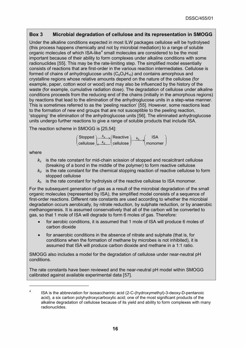
Box 3 Microbial degradation of cellulose and its representation in SMOGG Under the alkaline conditions expected in most ILW packages cellulose will be hydrolysed (this process happens chemically and not by microbial mediation) to a range of soluble organic molecules of which ISA-like4 small molecules are considered to be the most important because of their ability to form complexes under alkaline conditions with some radionuclides [55]. This may be the rate-limiting step. The simplified model essentially consists of reactions that are first-order in the various reaction intermediates. Cellulose is formed of chains of anhydroglucose units (C6O5H10) and contains amorphous and crystalline regions whose relative amounts depend on the nature of the cellulose (for example, paper, cotton wool or wood) and may also be influenced by the history of the waste (for example, cumulative radiation dose). The degradation of cellulose under alkaline conditions proceeds from the reducing end of the chains (initially in the amorphous regions) by reactions that lead to the elimination of the anhydroglucose units in a step-wise manner. This is sometimes referred to as the ‘peeling reaction’ [55]. However, some reactions lead to the formation of new end groups that are not susceptible to the peeling reaction, ‘stopping’ the elimination of the anhydroglucose units [56]. The eliminated anhydroglucose units undergo further reactions to give a range of soluble products that include ISA.
The reaction scheme in SMOGG is [25,54]:
→
←→
monomer
ISAcelluloseReactive
celluloseStopped h
d
s kk
k
where
ks is the rate constant for mid-chain scission of stopped and recalcitrant cellulose (breaking of a bond in the middle of the polymer) to form reactive cellulose
kd is the rate constant for the chemical stopping reaction of reactive cellulose to form stopped cellulose
kh is the rate constant for hydrolysis of the reactive cellulose to ISA monomer.
For the subsequent generation of gas as a result of the microbial degradation of the small organic molecules (represented by ISA), the simplified model consists of a sequence of first-order reactions. Different rate constants are used according to whether the microbial degradation occurs aerobically, by nitrate reduction, by sulphate reduction, or by anaerobic methanogenesis. It is assumed conservatively that all of the carbon will be converted to gas, so that 1 mole of ISA will degrade to form 6 moles of gas. Therefore:
• for aerobic conditions, it is assumed that 1 mole of ISA will produce 6 moles of carbon dioxide
• for anaerobic conditions in the absence of nitrate and sulphate (that is, for conditions when the formation of methane by microbes is not inhibited), it is assumed that ISA will produce carbon dioxide and methane in a 1:1 ratio.
SMOGG also includes a model for the degradation of cellulose under near-neutral pH conditions.
The rate constants have been reviewed and the near-neutral pH model within SMOGG calibrated against available experimental data [57].
4 ISA is the abbreviation for isosaccharinic acid (2-C-(hydroxymethyl)-3-deoxy-D-pentanoic
acid), a six carbon polyhydroxycarboxylic acid; one of the most significant products of the alkaline degradation of cellulose because of its yield and ability to form complexes with many radionuclides.

DSSC/455/01
17
Dependence of microbial activity on environmental factors within the GDF Microbial activity requires water. However, it is also dependent on a number of other factors [49, 50]:
• nutrient availability - organic materials will provide the carbon necessary for metabolism, with easily degradable materials (such as cellulosic wastes) being the most important.
• inorganic salts, for example nitrate or sulphate, may influence microbial activity.
• oxygen availability - most microbes are adapted to aerobic conditions (so they need oxygen for their survival) but some are adapted to anaerobic conditions, as will pertain in the GDF from some time after closure.
• temperature - peak activity for most microbes is reached at temperatures of about 50°C, and there is a large decrease in activity above 80°C.
• pH – although microbial activity is hampered in homogeneous high pH systems (for example in solution at pH 12), it is possible that microbial activity in heterogeneous systems would establish local lower-pH niches on surfaces (for example through the formation of biofilms5) so that localised conditions are more favourable for microbial activity.
• salinity - although halophiles exist, highly-saline groundwater may be toxic to many microbes, and would therefore reduce microbial activity.
• ionising radiation - at high dose rates, the radiation tolerance of microbes may be overcome, although it may be re-established by adaptation (recent studies have found that low radiation doses may in fact stimulate a Fe(III)-reducing microbial community [58]).
• pore size - the activity of microbes can be significantly reduced in highly compacted bentonite because of the small pore size [59].
Adaptation and selection may result in microbial populations that can tolerate extreme environments. Many such species have been identified, although evidence of natural populations that can tolerate all the conditions that will occur in the GDF is scarce [50]. In the long term, the main constraint on microbial activity is however likely to be the availability of nutrients, rather than the environmental conditions.
Gas production from microbial action within the GDF after closure will be very heterogeneous, with broad ranges of possible generation rates and time dependencies because of the range of possible microbes, wastes and environmental niches. However, the general prerequisites and dependencies discussed above provide an indication of those features that may hinder microbial gas generation in the GDF. The potential spatial and temporal variability of microbial activity, even in representative laboratory or large-scale experiments [60], makes validation of the microbial gas generation model in SMOGG difficult. However, confidence has been built by applying SMOGG to observed results after calibration against an independent set of data [57].
5 A biofilm is any group of microorganisms in which cells stick to each other on a surface.
These adherent cells are frequently embedded within a self-produced matrix of an extracellular polymeric substance.

DSSC/455/01
18
2.2.3 Radiolysis
Radiolysis of water and organic materials will contribute to gas generation.
Radiolysis is defined as the decomposition of chemical compounds by ionising radiation [61]. Radiolysis can occur both within a waste package (from α-, β-, and γ-irradiation) and external to a waste package in the buffer or backfill and possibly in the host rock (due to γ-irradiation). Gases can be produced as products of the radiolysis process. The archetype is the decomposition of water, resulting in the production of hydrogen. Two types of reactions occur during radiolysis of water: primary and secondary (see Box 4).
Box 4 Radiolysis of water The effect of ionising radiation on pure water is to produce several primary species and may be represented by:
H2O + αβγ → OH•·, H+, e-, H•, H2O2, H2, HO2• [61]
where the symbol '•' denotes a radical species6.
These primary species may then undergo further secondary reactions, for example:
H• + H• = H2
H• + OH• = H2O
OH• + OH• = H2O2
OH• + H2O2 = H2O + HO2•
OH- + H• = e- + H2O
To calculate rates of radiolytic gas generation such reaction schemes are not modelled in detail, but use a simplified model based on yields of products (commonly expressed as G-values, see Box 5).
Most materials (for example cements and metals) are not decomposed by radiation. However, in addition to hydrogen generated by radiolysis of water, gases such as hydrogen, carbon dioxide and methane can be generated from the radiolytic degradation of organic materials (for example cellulosic wastes, synthetic polymers, oils and small organic molecules). The radiolytic production of these gases is included in SMOGG using G-values for organic materials grouped as ‘cellulose’, ‘polymers’, ‘oils’ and ‘small organics’.
In practice, G-values are not constants, but depend on both chemical conditions (for example, the atmosphere present) and temperature. Therefore, it is important to choose appropriate G-values from the literature, where available, whilst acknowledging that such values are empirical and have some degree of uncertainty. A review of the G values for use in the model has recently been undertaken [62]. This provides a more detailed division of synthetic organic polymers into several individual types of plastics and rubbers, with their associated best-estimate and upper-bound G-values, than the G-values previously assigned to ‘polymers’ as a single class of materials [23].
The review also discussed the treatment of the radiolysis of pore water in cement encapsulants. The previous treatment was based on the G-value for pure water and the
6 A radical is an atom or molecule that has an unpaired electron, making it highly reactive.

DSSC/455/01
19
mass fraction of water in the cement. An alternative approach, using a single best estimate gamma G-value is given, based on a range of experimental data.
Box 5 Gas generation by radiolysis Gas generation by radiolysis of a material (for example water or an organic polymer) is characterised by the amount of gas produced per unit of absorbed radiation energy. Typically a linear relationship is assumed, so for hydrogen:
AH N100
GdQ = (2.13)
where
QH is the amount of hydrogen generated (mol) NA is the Avogadro constant (the number of molecules per mole) G is the G-value (historically expressed as molecules of hydrogen per 100 eV of
absorbed radiation energy) d is the absorbed radiation energy (eV).
The G-value for the radiolytic product depends on the material irradiated, the type of radiation and the irradiation conditions. G-values have been compiled for a large range of materials [61, 62, 63]. The G(H2) value for pure water under β/γ-radiation is about 1.4 molecules per 100 eV [62].
2.2.4 Radioactive decay
The amount of helium generated by radioactive decay will be small in terms of total bulk gas volume.
The decay of an alpha-emitting radionuclide will release one helium nucleus, which combines with two electrons to form a helium atom. The rate of helium production for UK intermediate-level wastes, where most containers are vented, will be small in comparison to the rate of overall bulk gas production from other processes. Helium generation within spent fuel packages, where the containers are sealed, is also considered not to be important because the volume of helium produced is small relative to the void volume of a spent fuel container [17, 19, 64].
2.3 Radiotoxic gases
The radiotoxic gases of potential importance are: tritium; gaseous molecules containing carbon-14, such as methane, carbon dioxide and carbon monoxide; and radon-222. Of these, carbon-14 is the only one with a sufficiently long half-life to be of post-closure interest from its presence in waste packages.
The radiotoxic gases potentially of importance are: tritium; gaseous molecules containing carbon-14, such as methane, carbon dioxide and carbon monoxide; and radon-222. Each of these is discussed in turn below. Of these, carbon-14 is the only radionuclide with a half-life of sufficient length for its release from wastes to be of post-closure relevance, with the potential for gaseous carbon-14 bearing species being of particular importance [65]. Although other radionuclides are gaseous species in their own right (for example krypton-85) or can be incorporated into volatile species (for example selenium-79 in hydrogen selenide or dimethyl selenide), these are expected to be of little relative significance because of their dissolution in water or chemical reaction within waste packages or the EBS [66]. Krypton-85 (t½ = 10.73 years) will be the only radioactive noble

DSSC/455/01
20
gas that could be left in irradiated spent fuel in any quantity at the time of transport and disposal and this will depend on the cooling period prior to transport [67].
2.3.1 Tritium
Tritium can be released from wastes as tritiated hydrogen, tritiated water or tritiated hydrocarbons/organic compounds. Much of the inventory of tritium will decay during the period of surface interim storage and during the operational phase of the GDF.
Tritium is generated by ternary fission of fissile material in nuclear fuel to produce gaseous tritium that interacts with, and diffuses through, the fuel cladding. Tritium also arises through neutron reactions involving boron or lithium [68]. Tritium has a half-life of 12.3 years and much of the inventory will decay during the period of surface interim storage and during the operational phase of the GDF.
Tritium may be present in metals (for example fuel cladding) as hydrides or as dissolved hydrogen. It will also be present in other materials (for example irradiated graphite) and trapped as tritiated water (1H3HO, also represented as HTO) on desiccants. Thus, it may be released as gas (tritiated hydrogen, 1H3H or HT) from the corrosion of metals, or from the consumption of tritiated water during their corrosion (under aerobic or anaerobic conditions, depending on the metal, as was discussed in Box 1 and Box 2). In addition, some irradiated metals will contain tritium that has diffused into the metal at high temperatures. Subsequently this tritium can be released as a result of solid-state diffusion. There are data for the solid-state diffusion coefficients of tritium in stainless steels [69, 70], and these can be used in semi-analytical solutions for diffusion in order to estimate the release rate of tritium.
Tritium may also be released from irradiated graphite in contact with alkaline water as tritiated hydrogen, tritiated water and tritiated hydrocarbon / organic compounds [71, 72, 73] as shown in Figure 5. There is some evidence that the relative distribution of tritium between these different molecules may depend on the source of the irradiated graphite [73].
Some tritium will also be generated from the radiolysis of tritiated water and tritiated organic material. RWM has issued guidance on the packaging of tritium-bearing wastes [74].
Figure 5 Release of tritium from Oldbury graphite [73]

DSSC/455/01
21
2.3.2 Carbon-14
Carbon-14 may be present in irradiated metals, irradiated graphite, spent ion-exchange resins and organic compounds. Only a small fraction of the carbon-14 in irradiated graphite is released to the gas phase when leached in alkaline solution. There is some evidence for the release of gaseous carbon-14 from the corrosion of irradiated metals.
In the UK, substantial quantities of carbon-14 are generated in nuclear power reactors [75]. In general, carbon-14 is produced by:
• 14N(n,p)14C reactions with nitrogen, which is present in air and as an impurity in fuels, moderators, coolants, and structural hardware
• 17O(n,α)14C reactions in oxide fuels, moderators and coolants
• 13C(n,γ)14C reactions in graphite moderators.
Additionally, a proportion of the products used in life-science research and medical drug production incorporate carbon-14. Therefore the possible sources of carbon-14 in the inventory for disposal are irradiated metals, irradiated graphite, spent ion-exchange resins and organic materials.
We have been carrying out a range of research and assessment activities on carbon-14 through an integrated project to develop an holistic approach to carbon-14 management in the GDF (see Box 6) [37, 76]. RWM is also coordinating the EC CAST project [77] (and see Tasks 201, 202, 207, 206, 227, 241, 251 in the Geological Disposal Science & Technology Plan), which is investigating the release of carbon-14 from steels, Zircaloys, spent ion-exchange resins and graphite. We also participated in the EC CARBOWASTE project that had the objective of developing best practices in the retrieval, treatment and disposal of irradiated graphite and other irradiated carbonaceous waste [78].

DSSC/455/01
22
Box 6 The integrated technical approach to carbon-14
RWM has been carrying out a range of research and assessment activities (see Tasks 203, 213, 204, 205, 228, 229, 230, 252, 253, 276, 297 in the Geological Disposal Science & Technology Plan [10]) on carbon-14 through an integrated project that aims to develop an holistic approach to carbon-14 management in the GDF [37, 76]. A number of factors must apply for a waste containing carbon-14 to be of significance with respect to gas:
• there must be a significant inventory of carbon-14 in the waste stream
AND
• that waste stream has to generate carbon-14 bearing gas
AND
• a bulk gas has to entrain the carbon-14 bearing gas
AND
• these gases must migrate through the engineered barriers in significant quantities
AND
• these gases must migrate through the geological environment in its entirety (either as a distinct gas phase or as dissolved gas)
AND
• these gases must interact with materials in the biosphere (for example plants) in a manner that leads to significant doses and risks to exposed groups or potentially exposed groups.
Carbon-14 in irradiated metals
There have been a few studies of carbon-14 release from irradiated stainless steels in Japan and these suggest small releases of carbon-14 as dissolved species and as gas.
Preliminary results from experiments on the corrosion of Magnox Fuel Element Debris under alkaline conditions show that carbon-14 is released to solution and to the gas phase.
Recent Japanese experiments of leaching Pressurised Water Reactor (PWR) and Boiling Water Reactor (BWR) Zircaloy cladding in alkaline solutions have observed small releases of carbon-14 to solution.
Carbon-14 may be present in irradiated metals, either in elemental form or as a metal carbide. On dissolution, the metal carbide may form hydrocarbons (such as methane or acetylene) or small organic molecules. The implications for the GDF of carbon-14 release from irradiated metals depend partly on the corrosion rate of the metal (which, in turn, depends on environmental conditions), the surface area of the metal, the distribution of carbon-14 in the metal and the form in which the carbon-14 is released (as well as other processes associated with its migration route from the GDF). At present carbon-14 is conservatively assumed to be released from the corrosion of irradiated metals entirely in the form of methane. The rate of release is assumed to be proportional to the corrosion rate.
Several experiments on inactive iron-water systems have shown evidence for the release of hydrocarbon species as a result of the hydrolysis of carbide species in the iron. Other

DSSC/455/01
23
studies on inactive carbon steel and iron carbide have found that soluble organic and inorganic species are released [38].
There has been little investigation of carbon-14 release from irradiated steels, with only a few Japanese studies reported. The findings of these studies were [38]:
• in an experiment in which a sample of irradiated stainless steel from a BWR grid was leached in pH 10 cement-equilibrated water, carbon-14 was reported to be released to the solution phase as a mixture of inorganic and organic species (no measurements of possible gaseous carbon-14 were undertaken and no information on the amount of carbon-14 released was given).
• in experiments with irradiated stainless steel, where the sample was first acid-cleaned to remove the passivating oxide film, carbon-14 was reported to be released into solution at rates that are consistent with metal corrosion rates.
• in the most recent experiment reported, a small amount of carbon-14 (about 5 Bq, equivalent to a release fraction of about 2 × 10⁻⁶) was released on leaching irradiated stainless steel in alkaline solution for 42 months, with one quarter of this to the gas phase and an inorganic to organic ratio of about 1 for the carbon-14 retained in solution.
Further studies of the release of carbon-14 from irradiated steels form part of the EC CAST project [77].
The release of carbon-14 from the corrosion of Magnox Fuel Element Debris (FED) under anaerobic and aerobic alkaline conditions (see Figure 6) is currently being investigated (see Task 204 in the Geological Disposal Science & Technology Plan). Preliminary results show that carbon-14 is released to solution and to the gas phase, and that the majority of the carbon-14 in the gas phase appears to be methane or other hydrocarbons.
Figure 6 Magnox corrosion experiment
a) Reaction vessel for Magnox corrosion experiments

DSSC/455/01
24
b) Magnox Fuel Element Debris and corrosion product, as retrieved
The carbon-14 content of samples of irradiated aluminium is also being determined in advance of a possible study of the release of carbon-14 from irradiated aluminium (see Task 204 in the Geological Disposal Science & Technology Plan). Studies may be commissioned to investigate the release of carbon-14 from irradiated uranium (metallic uranium from Magnox spent fuel) in the future if required (see Task 209 in the Geological Disposal Science & Technology Plan).
The mechanisms and the rate of carbon-14 release from Zircaloy hulls are expected to be controlled in large part by the uniform corrosion rate of Zircaloy, the diffusion rate of carbon-14 from zirconia oxide layers and/or the dissolution rate of zirconia oxide layers [39]. Zirconium alloys are highly resistant to uniform corrosion at low or moderate temperatures, as noted above in Section 2.2.1. It can be considered that carbon-14 in the bulk metal of hulls is released congruently with corrosion. However, there is a possibility that carbon-14 is not released immediately by corrosion, but is incorporated into the oxide film and then released by diffusion or during the dissolution of the oxide.
The most recent studies on Zircaloy measured corrosion rates of 1 to 2 nm per year after a few years’ corrosion. For a corrosion rate of 1 nm y-1, the lifetime of cladding hulls, assuming these corrode from both sides and are not extensively fractured, will be of the order of 250,000 to 400,000 years, corresponding to fractional corrosion rates of 2.5 × 10⁻⁶

DSSC/455/01
25
to 4 × 10⁻⁶ y-1. Such a low corrosion rate will lead to decay of much of the carbon-14 inventory (t½ = 5,730 years) before release can occur if it is distributed throughout the Zircaloy [39].
Recent Japanese experiments of leaching PWR and BWR Zircaloy cladding in alkaline solutions at pH 12.5 at room temperature suggest that 14C release will be congruent with the oxide layer dissolution and metal corrosion. For PWR irradiated hulls with an oxide layer the fraction of carbon-14 released was between 2 × 10⁻⁴ to 4 × 10⁻⁴ in one year. For irradiated hulls with the oxide removed the fraction released was 2 × 10⁻⁵ to 3 × 10⁻⁵. A fraction of about 6 × 10⁻⁶ to 4 × 10⁻⁵ was released from BWR irradiated hulls without an oxide layer after leaching for 2 years. These results show that the quantity of carbon-14 leached from a hull specimen without an oxide layer is one order of magnitude less than that leached from the same hull specimen with its oxide layer, and that the BWR samples gave a lower carbon-14 release fraction than the PWR samples during the first year of testing. Although the fractional release rates are higher than those expected on the basis of long-term corrosion rates this may reflect the influence of higher rates of corrosion at the beginning of the experiments [39].
Both organic and inorganic forms of carbon have been identified in leaching experiments with irradiated hulls or non-activated zirconium materials (zirconium powder, zirconium carbide). 14C-carbon dioxide and 14C-carbon monoxide have also been identified in the cover gas within casks used for the dry-storage of spent fuel [39].
Carbon-14 in irradiated graphite
A substantial fraction (at least 70%, and probably much more) of the carbon-14 in irradiated graphite will not be released under disposal conditions. The majority of the released carbon-14 remains in solution at high pH and only a small amount enters the gas phase. Carbon-14 may be released as a number of different species, including hydrocarbons (for example CH4), organic molecules, CO2 and CO. A large variation in leaching rates (up to around two orders of magnitude) is observed between different sources of irradiated graphite.
The chemical form of carbon-14 in irradiated graphite is not known, although at least some may be present as compounds of hydrogen, nitrogen or oxygen [79]. The mechanism(s) by which carbon-14 is released from irradiated graphite at low temperatures in aqueous solutions is also not well known at present.
An initial exploratory study for RWM found that about 4 Bq of carbon-14 was released to the gas phase in two weeks from static leaching of a 9 g sample of irradiated graphite taken from the Windscale Advanced Gas-cooled Reactor (WAGR) in alkaline solution under aerobic conditions at room temperature [80].
A further series of leaching experiments on the WAGR graphite and on irradiated graphite from British Experimental Pile 0 (BEP0) followed [71, 72, 81]. These studies measured gaseous carbon-14 release with time under similar conditions to those of the initial exploratory study and confirmed the observation that some carbon-14 was released as gaseous species during leaching of irradiated graphite at high pH. It also identified that these included inorganic species (assumed to be 14CO because 14CO2 should be retained in the alkaline leachate in the reaction vessel) as well as hydrocarbon/organic species.
In the case of BEP0 graphite it was found that about 0.1% of the carbon-14 inventory was released to the solution phase and about 0.005% to the gas phase over a period of 14 months. In the gas phase 80% was as inorganic species (assumed to be 14CO) and 20% as hydrocarbon/organic species (assumed to be 14CH4) [71, 72]. There was some evidence from residual carbon-14 activity in solution samples after acidification that a small fraction of the carbon-14 in solution (≤ 20%) was present as organic species (assuming

DSSC/455/01
26
that all the carbon-14 released from solution upon acidification was in the form of carbonate). The rate of gas phase release decreased with time. The apparatus for the collection of the carbon-14 gaseous species is shown in Figure 7.
Figure 7 Carbon-14 gas collection apparatus
Our most recent study [73] is on graphite samples sectioned as quadrants from an ‘installed set’ spacer (Figure 8 and Figure 9) removed from one of the Oldbury Magnox reactors in the UK (Figure 10 and Figure 11).

DSSC/455/01
27
Figure 8 Schematic diagram of Oldbury graphite spacer sectioning [73]
Figure 9 Oldbury graphite quadrant sample [73]

DSSC/455/01
28
This investigated the effect of experimental conditions on the speciation of carbon-14 and its release to the gas phase, namely:
• anaerobic compared to aerobic
• pH (alkaline compared to near neutral)
• temperature (room temperature compared to 50°C)
• the form of the graphite (crushed compared to intact).
Figure 10 Oldbury Magnox reactors
Figure 11 Oldbury core graphite blocks during construction

DSSC/455/01
29
In common with the previous BEP0 study, measurements of carbon-14 releases to the solution phase were only made at the end of the experiments to avoid the potential of compromising the gas phase sampling. However, a parallel experiment under anaerobic high-pH conditions was set up with periodic sampling to measure solution-phase releases only.
Figure 12 compares the gas-phase carbon-14 release (at pH 13 and ambient temperature) from an intact sample of the Oldbury graphite under anaerobic conditions with the equivalent experiment under aerobic conditions. Under aerobic conditions the ratio of 14C-hydrocarbon/organic compounds to 14CO was about 1:1; under anaerobic conditions it was closer to 2:1.
Figure 12 Fractional release of gaseous carbon-14 from leaching of irradiated Oldbury graphite at pH 13 and ambient room temperature a) under anaerobic conditions, b) under aerobic conditions [73]
a) under anaerobic conditions
b) under aerobic conditions

DSSC/455/01
30
A comparison of the total fractional gas and solution-phase releases of carbon-14 from Oldbury graphite under anaerobic high-pH conditions is shown in Figure 13. Releases to both solution and gas phases show an initial rapid release, followed by a slower release over longer timescales. The ratio of solution phase to gaseous release was of the order of 100:1 at most sampling points, but had increased to between 200:1 and 300:1 for samples taken after one year. In comparison, a lower ratio of about 20:1 was measured on termination of the BEP0 experiment after 431 days.
Figure 13 Comparison of cumulative fractional releases of carbon-14 to both solution and gas from leaching of irradiated Oldbury graphite at pH 13 and ambient room temperature under anaerobic conditions [73]
An important feature of these results is that release of carbon-14 to gas and solution phases continued over the last three to twelve months of the experiment, albeit at a slow rate. The rate of gaseous carbon-14 release from the Magnox graphite initially increased at 50°C, but then decreased more rapidly than the experiment at room temperature with time.
At pH 7 the gaseous releases were dominated by 14CO2 because of the lower solubility of CO2 at this pH. The gas phase releases of 14CO and 14C-hydrocarbon/organics were at similar rates and in a similar ratio to those at pH 13.
Carbon-14 gas-phase releases from a sample of powdered graphite were less than those measured from single piece samples, but the total carbon-14 release to solution over three months increased by about 65%. Thus crushing may increase the accessibility of carbon-14 to water but volatile carbon-14 may be lost during crushing.
The fractional release of carbon-14 to the gas phase was found to be about one order of magnitude lower for the Oldbury Magnox graphite than for the BEP0 graphite under aerobic conditions. However, a higher proportion of carbon-14 was released as 14C-hydrocarbons/ organics, even under aerobic conditions.
The data for the leaching of carbon-14 to solution from the Oldbury graphite [71] can be compared [82] with results dating back to the 1980s [83, 84, 85]. These data were acquired by leaching intact samples of irradiated graphite of different dimensions from different reactors under a variety of experimental conditions. As a result there is a wide variation in both the rates and the extent of carbon-14 releases over the experimental timescales. Also, because of the relatively short total duration of most of the experiments, they provide

DSSC/455/01
31
limited information on longer-term leaching behaviour. However, the largest variation in leaching rates (up to around two orders of magnitude) is between different sources of irradiated graphite [82]. This may be related to the manufacturing processes for the graphite blocks, different irradiation histories, operating conditions and the extent of radiolytic oxidation.
Similar results have been observed from a study on the leaching behaviour of graphites from two French UNGG (Uranium Naturel Graphite Gaz)-type reactors [86] performed as part of the European CARBOWASTE project. Experiments were undertaken on samples from the St. Laurent des Eaux A2 (SLA2) reactor and from the G2 reactor at Marcoule. Carbon-14 was detected in the gas phase and in solution. The dissolved carbon-14 was predominantly carbonate, with organic carbon-14 species comprising about 20 to 40% of the total carbon-14 in solution at the termination of the experiments. The fractional releases to the gas phase were about ten to thirty times lower than those to solution. The cumulative release of carbon-14 into solution in about 680 days was about 0.35 to 0.45% of the total carbon-14 content of the samples.
The results of these various studies, when considered together, show that:
• carbon-14 is released to the gas phase when irradiated graphite is leached under high-pH conditions
• gas-phase releases include volatile 14C-hydrocarbon/organics (probably 14CH4) and 14CO (14CO2 is only released from solution at near-neutral pH)
• the form of gaseous carbon-14 release is affected by redox conditions, with a lower redox seeming to favour 14C-hydrocarbon/organic compounds
• carbon-14 is released to the solution phase as organic and inorganic (14CO2/carbonate) molecules under alkaline conditions
• in general, only a small fraction of the total carbon-14 inventory (up to ~1%) in irradiated graphite is released over timescales of a few years on leaching under alkaline conditions that are representative of a potential GDF
• the majority of the released carbon-14 remains in solution at high pH and only a small amount is released to the gas phase
• there is an initial fast release of carbon-14, followed by an approach to a steady state with a very low incremental release rate.
A recent study on chemical leaching of UK irradiated graphite has also been undertaken as part of the CARBOWASTE project [87]. Although the principal objective of this work was to investigate the potential for chemical treatment of irradiated graphite to remove labile carbon-14 and tritium prior to disposal, it provides insight into the potential long-term availability of the carbon-14 content of irradiated graphites under disposal conditions.
Small monolithic or powdered irradiated graphite samples from BEP0 and Wylfa Magnox reactors were leached at room temperature under aerobic conditions. The leachants included demineralised water, a pH 13 buffer solution, solutions of oxidants, and strong acids. In each case there was a very fast initial release of carbon-14 into solution during the first day of leaching, followed by a much slower release over the remainder of the experiment. The total releases were limited to about ~6% in water, the pH 13 buffer solution and the oxidant solutions. However, much higher releases were measured in the more acidic solutions: up to 20 to 25% for the BEP0 samples and about 27% for the Magnox graphite. This higher release fraction was attributed to penetration of interlayer spaces within the graphite structure by anions, allowing the release of loosely-bound carbon-14 species located there. It can be assumed that the carbon-14 measured in the solution phase in the acid experiments is in the form of water-soluble organic species because carbon-14 released as CO2 is not retained in solution (although this is not

DSSC/455/01
32
discussed in [87]). Subsequent thermal analysis of leached samples confirmed that the majority of carbon-14 had remained in the graphite. It was concluded that, even under harsh acidic conditions, not more than 30% of the carbon-14 was released from the powdered graphites and provides evidence that a significant proportion of the carbon-14 content is part of the graphite matrix and is likely to be unavailable for leaching under disposal conditions.
The results discussed above suggest that three different forms of carbon-14, differing in their ability to be leached, may be present in irradiated graphite. It may be postulated that (see Figure 14) [82]:
• some carbon-14 is bound in the graphite matrix, this is least accessible for release and will only be released via oxidation of the bulk graphite
• some carbon-14 occurs in interstitial positions between the graphene layers, this will be accessible if degradation of the graphite structure occurs (for example by intercalation of anions between graphene sheets)
• some carbon-14 is associated with pore surfaces, edge sites and less ordered regions of the graphite, this will be most accessible for release during leaching.
Figure 14 Schematic diagram showing postulated locations of carbon-14 in irradiated graphite [82]
It can be concluded from the acidic leaching experiments [87] that the last two of these categories can contain no more than 30% of the carbon-14. The chemical form of carbon-14 is thus primarily elemental and it is bound in the graphite structure. Although the removal of this carbon-14 can occur by oxidation, with conversion to either 14CO or 14CO2, the graphite matrix is extremely resistant to oxidation at GDF temperatures and is unlikely to undergo oxidation once GDF conditions have become anaerobic after closure.
There is also supporting evidence that carbon-14 has both a homogeneously-distributed fraction throughout the graphite matrix, which arises primarily from the activation of carbon-13, and a heterogeneously distributed part that is enriched in hotspots and on surfaces. A comparison of samples of irradiated Pile Grade A (PGA) graphite taken from two different Magnox Stations in the UK has been made using a combination of focused ion beam milling and imaging and Raman spectroscopy [88]. Surface deposits of thickness 5 to 20 µm were observed on the channel wall surfaces of irradiated graphite samples trepanned from an Oldbury Magnox reactor. An example of the deposits is shown in Figure

DSSC/455/01
33
15a and c; for comparison, Figure 15b shows a cut surface from within the same graphite sample [89].
Figure 15 Deposits on Oldbury Magnox graphite [89]
a) SEM image of deposit on channel wall face of graphite
b) SEM image of cut surface from within the graphite sample
c) SEM image of deposit at higher magnification

DSSC/455/01
34
The deposits have a ‘cauliflower-like’ morphology and a different elemental composition (in particular increased oxygen) from the underlying irradiated graphite and also from un-irradiated PGA graphite. In contrast, although there was evidence that some deposits existed on samples taken from a different Magnox reactor, these were patchy, thin and insignificant compared with those found on samples from Oldbury. Subsequent work using magnetic sector secondary ion mass spectrometry(MS-SIMS) on further samples of irradiated graphite from one of the Oldbury station reactor cores in the UK found increased concentrations of carbon-14 in deposits on the channel wall faces (47 ± 8 ppm) compared to concentrations below the detection limit (estimated to be 5 to 10 ppm) within the graphite samples [90].
In the absence of a mechanistic understanding, a simple empirical approach to modelling the release of carbon-14 from irradiated graphite has previously been used in SMOGG. The release of volatile carbon-14 was assumed to be in the form of methane and its release rate was assumed to be proportional to the activity of carbon-14 in the graphite with the constant of proportionality estimated from experimental data. However, based on the above discussion, a revised conceptual model for the release of carbon-14 from irradiated graphites under cementitious disposal conditions can now be proposed to reflect:
• a substantial fraction (at least 70%) of the carbon-14 in graphite will not be released under disposal conditions
• some carbon-14 will be released rapidly on contact with alkaline solution, and some will be released more slowly at a rate reducing over time
• carbon-14 can be released to both the gaseous and aqueous phases and carbon-14 released to the gas phase may exist as a number of different species, including organic/hydrocarbon species (for example CH4), CO2 and CO
• release rates and speciation (the chemical form) of the released carbon-14 may change depending on the conditions (such as particle size, pH and the presence of oxygen).
This model is shown in Figure 16.
Figure 16 Conceptual model for release of carbon-14 from irradiated graphite under cementitious disposal conditions [82]

DSSC/455/01
35
Other sources of carbon-14
Organic compounds containing carbon-14 may be degraded by microbial action to form a mixture of carbon dioxide and methane.
The inventory of carbon-14 in spent ion-exchange materials is very low compared to other UK wastes and might be expected to be released to solution rather than as gas in the GDF. The available information suggests that the majority of carbon-14 will be inorganic.
Organic compounds containing carbon-14 may be degraded by microbial action to form a mixture of carbon dioxide and methane. As discussed above in Section 2.2.2, the rates of microbial degradation are determined by a number of factors, including the recalcitrance of the organic compound and the ability of the microbial population to grow under the conditions present in the GDF. It should be noted that GE Healthcare waste stream 1A07, a waste stream that is currently assumed not to be disposed to the GDF, but which is included in the 2013 Derived Inventory, contains much of the organic carbon-14.
The release of carbon-14 from spent ion-exchange materials was not considered in the previous gas status report. This inventory of carbon-14 is very low compared to other wastes [91] and, because it originates from solution species, might be expected to be released to the solution phase rather than the gas-phase in the GDF.
The release of carbon-14 from spent ion–exchange resins is being investigated under the EC project CAST. Only a very limited amount of information exists at present and this has been reviewed by the CAST project [92].
The review found that there is little information about the speciation of carbon-14 in spent ion-exchange resins (SIERs) and most of the information is related to the partition between inorganic (carbonate) and organic fractions. The available results seem to show that the majority of the carbon-14 is inorganic. Around 20% of the carbon-14 in samples of spent ion-exchange resins from PWRs was organic, compared to between 5% and 20% of the carbon-14 in samples of spent ion-exchange resins from CANDU reactors. In contrast, the inorganic versus organic partitioning in two cemented SIERs from RMBK graphite-moderated BWRs was more equal. No published studies of the speciation of organic molecules in leachates from spent ion-exchange resins, or of the release of gaseous carbon-14 from spent ion-exchange resins were found. It has been hypothesised that acetate and formate are possible organic forms of carbon-14 because they are expected in the reactor coolant of PWRs and BWRs [92].
The investigation of issues associated with carbon-14, including the release of carbon-14 from irradiated graphite and steels, continues as part of our research programme, through the carbon-14 integrated project and through participation and coordination of the EC CAST project (see Tasks 201, 207, 206, 210, 227, 241 and 251 in the Geological Disposal Science & Technology Plan [10]).
2.3.3 Radon-222
It will be necessary to package high radium content wastes suitably to limit the release of radon during the GDF operational phase. Because of the short half-life the radiological consequences arising from radon-222 generated within the waste packages after closure are likely to be insignificant. Radon-222 may be formed within the geological environment from naturally-occurring or GDF-derived uranium-238 and daughters.
DSSC/455/01
36
Radon-222 is produced from the radioactive decay of radium-2267. The rate of production of radon-222 within a package can be calculated readily from the activity of radium-226 present. However, this information is not necessarily relevant because much of the radon-222 will decay within the package as a result of its short half-life (3.82 days) [93].
A cementitious waste encapsulation grout alone may not provide a sufficient barrier to radon generated from such items in vented waste packages during the operational phase [94]. It will be necessary to package high radium content wastes (or individual items within these waste streams) suitably, for example in an organic polymer, to limit the release of radon during the GDF operational phase. RWM has issued guidance on the packaging of radon-generating wastes [95]. Radon-222 is also produced continuously from the decay of radium-226 in the uranium-238 decay chain. Therefore, it may be formed within the geological environment from the decay chain of naturally-occurring uranium-238 in some host rocks. This radon will need to be taken into account during the operational phase of the GDF.
The radiological consequences arising from radon-222 generated within the waste packages after closure of a GDF are likely to be insignificant, because of its short half-life it will decay within the EBS. However, although radon itself has a short half-life, its production from the decay chain of naturally-occurring uranium-238 in the host rock, or from uranium-238 and daughters that have migrated from the EBS, may lead to its formation close to the biosphere or entrainment by a flux of GDF-derived gas and transport to the biosphere.
2.4 Computer models for calculating rates of gas generation
Models for the calculation of gas generation rates have been developed and implemented in the SMOGG program, which has been benchmarked against other programs.
Models have been developed to describe gas generation at an appropriate level of detail from the understanding of the various gas generation processes described above and these have been implemented in the SMOGG program [25, 54, 96]. SMOGG has been used in various ways, for example to calculate rates of gas generation from individual waste packages (often as part of the Disposability Assessment process) or from specific waste streams. A gas generation module also forms part of Quintessa’s QPAC computer code, which has been benchmarked against SMOGG showing good agreement [97]. Similarly, results obtained from SMOGG have previously been compared to those obtained from MAGGAS [98, 99], a gas generation program developed for Magnox. by the same team responsible for SMOGG, for a number of test cases [100].
SMOGG represents all of the processes that will generate either large volumes of bulk gases or significant amounts of radioactive gases at an appropriate level of complexity. The manner in which the various models have been implemented within SMOGG is described in the specification document [25]. SMOGG accounts for both oxygen consumption (modelling the change from aerobic to anaerobic conditions), and water consumption (modelling the inflow of water and the attainment of fully-saturated conditions, albeit in an approximate way8).
7 Radium-226 will be present in some wastes at the time of packaging or will grow in as a
daughter in the uranium-238 decay chain. Uranium-238 will be present in some wastes and also occurs naturally in some host rocks.
8 The model assumes that initially there is a specified amount of water present in a package. After closure of the GDF, water flows into the package and its associated backfill at a constant rate. This model is a reasonable representation until the pressure in a GDF approaches

DSSC/455/01
37
As discussed above, the availability of water is an important prerequisite for corrosion and microbial action and is one source of bulk gas (from radiolysis). Controls on water availability include the water present in a waste package at the time of manufacture (from the waste itself and the waste encapsulation grout) and the subsequent rate of water inflow after closure of the GDF. The work reported in reference [97] concluded that SMOGG can represent most of the key aspects of gas evolution in the case of many higher strength rocks, where water inflows are relatively high and coupling between water and gas flow is expected to have relatively little significance, and in a halite where there is essentially no water inflow to a GDF. Gas generation and water availability are more strongly coupled in a lower strength sedimentary rock than in a higher strength rock and in these cases the neglect of coupling in SMOGG is likely to generate results that do not reflect the expected gas generation [97]. In these cases a coupled model is required, this is discussed further in Section 6.1.2.
The emphasis in SMOGG is mainly on ILW / LLW, which is likely to generate most of the gas, but models for HLW / spent fuel are also implemented in SMOGG. SMOGG has been verified against a suite of independent test cases [54].
To date SMOGG has been used for deterministic gas generation calculations using best-estimate values for individual parameters. Calculations have also been undertaken for a range of different assumptions and scenarios to examine the effect of uncertainty in gas generation calculations (see Section 2.6).
SMOGG can also be run in a probabilistic mode, in which a large number of calculations are carried out for parameter values that are sampled from probability distributions. This provides a possible approach to representing uncertainty in gas generation calculations in the future. A total system model for gas generation and migration is also being developed [37].
2.5 Illustrative example calculation for gas generation
It is useful to illustrate the processes outlined above using results from an example calculation of gas generation.
Figure 17 shows the results from a deterministic calculation of the net generation rates of free gas from the unshielded-ILW (UILW) packages from the 2007 Derived Inventory9 in a cement-based EBS using the 2010 DSSC GDF design data for ILW/LLW in a higher strength rock [22]. Calculations for the ILW concept in this geological environment are expected to be bounding in terms of gas generation rate because unlimited water availability is assumed (water availability may be more limited in other geological disposal concepts and this is discussed in Section 6.1). The conceptual model for this calculation
hydrostatic pressure. If the gas pressure reaches or exceeds the hydrostatic pressure the availability of water may decrease and this may limit the rate of gas generation. This means that SMOGG will be overly conservative in such cases in over-estimating gas generation rates and volumes.
9 Gas generation calculations based on the 2013 Derived Inventory are discussed later in Section 6.1. The calculation for the 2007 Derived Inventory is discussed here because it provides the base case for the scenario calculations addressing the effect of uncertainty in Section 2.6 .
The typical output from a SMOGG calculation is a graph of the generation rate of various bulk gases and radioactive gases against time.

DSSC/455/01
38
included the following assumptions (a full list of the conceptual model, data and SMOGG model assumptions and limitations is given in reference [22]):
• the GDF is constructed in a fractured host geology and hence rapid resaturation of the EBS at closure is expected and the EBS will be unlikely to pressurise.
• carbon dioxide reacts with cementitious materials, for example grout in some waste packages and the cement backfill after backfilling, and is not released from the facility. Thus carbon dioxide (as 12CO2 or 14CO2) does not form a free gas and does not appear on Figure 17.
• UILW packages are emplaced over 50 years from 2040 to 2090, followed by 50 years of care and maintenance (C&M) prior to backfilling and closure, which takes 10 years (the planning assumptions for the 2013 Derived Inventory differ and include DNLEU and ILW from new build [14]).
• the GDF resaturates with saline groundwater over a period of 5 years after closure (2150 to 2155).
• the waste package temperature during emplacement (2040 to 2090) and C&M (2090 to 2140) is 35°C; this increases to 45°C during backfilling and closure (2140 to 2150) and for five years after closure during resaturation (2150 to 2155) and then falls to 35°C (from 2155). These phases are represented as step changes in the model.
• it is assumed that that all of the pore/void space in the vaults that is not water-filled is air-filled at closure. The wasteforms are assumed to be fully saturated. The backfill is assumed to be 75% saturated, with the remainder of the pore space filled with air. In the case of a fractured crystalline host rock some of the gas in the GDF will dissolve on resaturation as the hydrostatic pressure increases, with the remainder being forced out from the EBS if the gas entry pressure of the host rock is exceeded. Any sensitivity of the results to this can be bounded by setting the initial oxygen content in SMOGG so that no oxygen is present after resaturation.
Best estimate values for the various parameters (for example, corrosion rates) were used. The bulk gases (hydrogen (H2) and methane (CH4)) are plotted against the left-hand axis10. The active gases (3HH, 14CH4 and 222Rn) are plotted against the right-hand axis. The volume of gas is dominated by the non-radioactive bulk gases. The volumes of the radioactive gases are negligible in comparison.
10 Note: volumes of gas are quoted for Standard conditions of Temperature, 0°C, and Pressure,
105 Pa. At possible depths for the GDF the pressure is likely to be 50 to 100 times greater after closure and the temperature tens of degrees higher. The effect of these on the volume of gas at depth can be calculated because the change in the volume of gas is proportional to the inverse of the change in pressure and proportional to the change in temperature.
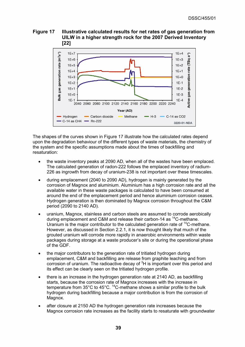
DSSC/455/01
39
Figure 17 Illustrative calculated results for net rates of gas generation from UILW in a higher strength rock for the 2007 Derived Inventory [22]
The shapes of the curves shown in Figure 17 illustrate how the calculated rates depend upon the degradation behaviour of the different types of waste materials, the chemistry of the system and the specific assumptions made about the times of backfilling and resaturation:
• the waste inventory peaks at 2090 AD, when all of the wastes have been emplaced. The calculated generation of radon-222 follows the emplaced inventory of radium-226 as ingrowth from decay of uranium-238 is not important over these timescales.
• during emplacement (2040 to 2090 AD), hydrogen is mainly generated by the corrosion of Magnox and aluminium. Aluminium has a high corrosion rate and all the available water in these waste packages is calculated to have been consumed at around the end of the emplacement period and hence aluminium corrosion ceases. Hydrogen generation is then dominated by Magnox corrosion throughout the C&M period (2090 to 2140 AD).
• uranium, Magnox, stainless and carbon steels are assumed to corrode aerobically during emplacement and C&M and release their carbon-14 as 14C-methane. Uranium is the major contributor to the calculated generation rate of 14C-methane. However, as discussed in Section 2.2.1, it is now thought likely that much of the grouted uranium will corrode more rapidly in anaerobic environments within waste packages during storage at a waste producer’s site or during the operational phase of the GDF.
• the major contributors to the generation rate of tritiated hydrogen during emplacement, C&M and backfilling are release from graphite leaching and from corrosion of uranium. The radioactive decay of 3H is important over this period and its effect can be clearly seen on the tritiated hydrogen profile.
• there is an increase in the hydrogen generation rate at 2140 AD, as backfilling starts, because the corrosion rate of Magnox increases with the increase in temperature from 35°C to 45°C. 14C-methane shows a similar profile to the bulk hydrogen during backfilling because a major contribution is from the corrosion of Magnox.
• after closure at 2150 AD the hydrogen generation rate increases because the Magnox corrosion rate increases as the facility starts to resaturate with groundwater

DSSC/455/01
40
that contains chloride. The resaturation process also provides water that restarts the corrosion of aluminium. However, the Magnox corrosion becomes water limited for a short period (around 2153 CE, despite the resaturation process) and at the same time a GDF becomes anaerobic as the oxygen has been consumed by the aerobic corrosion of steels and uranium. Therefore, hydrogen starts to be generated from anaerobic corrosion of uranium11, stainless and carbon steel wastes and containers and Zircaloy. In combination, these result in the calculated changes to the hydrogen gas generation rate seen between 2150 and 2155 AD (when the calculation assumes a GDF is fully resaturated). The rates of generation of 14C-methane and tritiated hydrogen show similar trends.
• once anaerobic conditions have become established at about 2153 AD, methane gas is generated from the degradation of small organic molecules (sulphate and nitrate have been assumed to be absent in this calculation and therefore do not delay the start of methanogenesis).
• at 2155 AD the GDF is assumed to be fully resaturated and the temperature to have decreased from 45°C to 35°C. Magnox continues to corrode (at a lower rate because of the lower temperature) and has fully corroded at around 2160 AD, as shown by the decrease in hydrogen generation at this time. Aluminium continues to corrode until it is all consumed at around 2172 AD, again shown by a decrease in the hydrogen generation rate.
• hydrogen generation after the Magnox and aluminium have corroded is mainly from the radiolysis of water, with contributions from the radiolysis of ‘polymers’ and the corrosion of stainless steel containers and smaller contributions from corrosion of stainless and carbon steel wastes, carbon steel containers, Zircaloy wastes and the radiolysis of oils and cellulose.
• at 2155 AD the 14C-methane production is dominated by carbon-14 released during the corrosion of Magnox. By 2160 AD the Magnox and uranium have fully corroded and 14C-methane is generated mainly from the degradation of small organic molecules,12 with contributions from the corrosion of stainless steel and carbon steel wastes and Zircaloy, radiolysis of organics and release from graphite.
Reference [22] also includes calculations for shielded intermediate level waste (SILW)/LLW and for depleted, natural and low-enriched uranium (DNLEU). The following conclusions from all the base case calculations reported in reference [22] can be drawn:
• the peak in the tritium gas generation rate is calculated to occur during the operational period of the GDF, both for UILW and SILW / LLW vaults
• the peak hydrogen gas generation rate from the UILW and SILW/LLW vaults is calculated to occur soon after the GDF starts to resaturate and is mainly as the result of the corrosion of Magnox wastes
• in the longer term the hydrogen generation rates are calculated to decrease substantially; the residual level is because of the corrosion of steels and, for UILW, the radiolysis of water
11 It is possible that much or all of the uranium may already have corroded anaerobically within
waste packages prior to this time. 12 This calculation included GE Healthcare waste stream 1A07, a waste stream that may not be
destined for the GDF but is included in the 2013 Derived Inventory.

DSSC/455/01
41
• the calculated peak 14C-methane gas generation rate arises mainly from the release of carbon-14 during the corrosion of Magnox wastes in UILW and from the leaching of graphite in SILW/LLW
• DNLEU is expected to give a much lower peak hydrogen gas generation rate than UILW or SILW / LLW
• the radon-222 generation rate, although several orders of magnitude lower than for UILW at early times, is expected to become much more significant by 105 years after closure due to ingrowth from the uranium-238 decay chain.
These base case calculations show similar general trends in gas generation to the later calculations for carbon-14 using the 2013 Derived Inventory that are described in Sections 5.2 and 6.1.1, but there are quantitative differences arising from the changes in the inventory for disposal, some different assumptions and revisions to the SMOGG model.
2.6 Uncertainty in calculations of gas generation
Uncertainty in calculated gas generation rates exists because of data uncertainty, assumptions in the conceptual model and assumptions about operations. Variant scenario calculations can be used to address aspects of uncertainty in deterministic gas generation calculations.
The results of deterministic calculations will have an associated uncertainty. This occurs because of, for example, uncertainties in corrosion rates, geometry of waste materials, inventory for disposal, groundwater composition and operational assumptions. At the current stage of the generic programme these uncertainties are addressed through variant deterministic calculations. In the future, as repository design progresses and site data become available, the use of probabilistic calculations may be considered.
A suite of variant SMOGG calculations have been undertaken to examine the effect of uncertainty on gas generation results [22] for UILW and SILW/LLW in the 2007 Derived Inventory. Thirteen variant case calculations were made that considered factors such as: water availability; groundwater salinity; oxygen availability; temperature; the effects of backfilling of individual GDF vaults when they are filled with waste packages during the waste emplacement period (referred to as staged backfilling); and the effects of using robust shielded intermediate-level waste containers manufactured from ductile cast iron for some wastes. The key observations from this sensitivity analysis are:
• a reduction in pore water saturation from 100% to 50% in the packages is calculated to have a relatively small effect on the peak hydrogen generation rates after closure because of the assumption of rapid resaturation. It also has little effect on hydrogen generation during the operational period and only results in a slight reduction in hydrogen generation during the period shortly after closure, when the engineered barrier system is resaturating. Applying a previous assumption of a lack of available water in packages during the operational period leads to a much reduced rate of hydrogen generation. Similar conclusions apply to the rate of 14C-methane generation.
• the calculated effect of resaturation with a non-saline groundwater is to reduce the corrosion rate of Magnox wastes and leads to a significant reduction in the calculated post-closure hydrogen and 14C-methane peak generation rates.
• the effect of higher temperatures during the backfilling and post-closure periods is expected to result in a significant increase in peak hydrogen gas generation rate and 14C- methane gas generation rate, mainly because of the increased Magnox

DSSC/455/01
42
corrosion rate, but has little effect on long-term ‘steady state’ gas generation rates after closure.
• the calculated effect of backfilling over a 50 year emplacement period is to reduce the peak hydrogen gas generation rate and the peak 14C-methane gas generation rate by less than one order of magnitude during the operational period. Although it increases the duration over which peak gas generation rates are observed, the long term ‘steady state’ for the hydrogen gas generation rate and 14C-methane gas generation rate are unaffected.
• the combined effects of staged backfilling and increased temperature are dominated by staged backfilling, and therefore the effect of increased temperature is relatively small in this case. Similarly, the combined effects of staged backfilling, increased temperature and reduced initial pore water in the packages are dominated by staged backfilling and the effect of the reduced initial water saturation in the packages is very small in this case.
• the calculated effect of allowing oxygen to be removed only by corrosion, irrespective of flushing of gas as the GDF resaturates, results in a very small reduction in the maximum hydrogen gas generation rate for SILW/LLW and has no effect on the gas generation rates for UILW.
• the use of ductile cast iron robust shielded containers to dispose of a fraction of the total volume of ILW is calculated to have a very small impact on the overall ILW gas generation results13. The more rapid corrosion of these containers (compared with the stainless steel containers they replace) is calculated to result in a small increase in the hydrogen generation rate if the insides of the containers are assumed to be freely accessible to water after closure of the GDF.
Based on the results of these variant scenario calculations, the key input variables that have a significant effect on the calculated gas generation modelling results for the illustrative ILW concept in a higher strength rock are:
• a lack of available water in the wasteform during the operational period
• resaturation of the GDF after closure by a non-saline groundwater
• an increased temperature within the GDF
• vault backfilling over a longer time period (staged backfilling).
13 It is acknowledged that the chosen inventory (a fraction of the ILW inventory for disposal) for
this case does not represent the waste likely to be disposed of in such robust shielded intermediate-level waste containers; it was however included to provide an indication of what gas generation might be expected for an equivalent waste volume.

DSSC/455/01
43
3 Gas migration The GDF will be located 200m to 1000m underground in the UK, far below the water table. Therefore, the main process by which some of the radionuclides may migrate from the facility after closure will be through dissolution and transport in the groundwater [4, 5]. However, gas generation by corrosion, microbial degradation and radiolysis (see Section 2) could be sufficient to cause a gas phase to form at some time after closure. For the period this gas phase is maintained it will co-exist with the groundwater; such conditions are referred to as a two–phase system. Therefore, a sound understanding of how gas might migrate, as part of a two-phase fluid system (liquid and gas), through the engineered barrier materials that will be used in the construction of the GDF and the surrounding rocks, is needed. This section summarises the approach to modelling gas migration through the various barriers, and has the following objectives:
• to introduce the barriers to, and mechanisms of, gas migration (Sections 3.1 and 3.2)
• to give a high-level overview of the conventional approach to modelling two-phase fluid flow (Section 3.3)
• to identify some limitations (Section 3.4) and some extensions (Section 3.5) of the conventional approach
• to describe some available computer programs for modelling gas migration (Section 3.6)
• to discuss the applicability of two-phase fluid flow models to the geological environments that could host a GDF, and also the data that may have to be acquired to parameterise the models (Section 3.7).
3.1 Barriers to gas migration
To give rise to consequences in the biosphere any free gas that is generated first has to: migrate out of the waste packages or disposal containers (for gas generated by the wasteforms); secondly, migrate through features of the GDF; and then pass through the host rock and, subsequently, the overlying rocks.
In this generic phase of the DSSC, before possible sites have been identified for investigation, RWM is considering illustrative concepts for three host rocks (higher strength rock, lower strength sedimentary rock and evaporite rocks) suitable for hosting the GDF [4].
In the illustrative concepts for a GDF in a higher strength rock and in a lower strength sedimentary rock the UILW and SILW/LLW packages will be surrounded with a cementitious backfill. The voids around the waste packages in the illustrative evaporite rock concept will be filled by the creep of the host rock [101].
In the illustrative concept for a GDF in a higher strength rock the disposal containers for high heat-generating waste (HHGW) will be surrounded by a buffer of compacted bentonite, consisting of bentonite rings and blocks14, and the access tunnels filled with a bentonite backfill consisting of pre-compacted blocks and pellets. A pelleted bentonite buffer is also used in the illustrative concept for a lower strength sedimentary rock. In the evaporite illustrative concept the disposal containers will be surrounded by crushed host rock [101].
14 Compacted bentonite swells when it absorbs water, resulting in low permeability.
DSSC/455/01
44
Plugs and seals will be used at various places in the GDF and their design will depend on the particular concept.
Before it can reach the biosphere, any free gas that is generated will have to migrate:
• out of the waste packages or disposal containers (for gas generated by the wasteforms)
• through features of the GDF (for example buffer, backfill and the Excavation Disturbed Zone, EDZ)
• into the host rock and, subsequently, into the overlying rocks [102].
A capability is thus needed to model two-phase (liquid and gas) flow through at least some of the following materials: cement; bentonite; fractures in higher strength rocks; lower strength sedimentary rocks (for example clay); and evaporite rocks.
3.2 Mechanisms of gas migration
Initially the gases produced in the GDF will dissolve and be transported by diffusion in, and advection with, porewater. A separate gas phase will only form if the solubility limit of any gas is exceeded. Chemical interactions, such as carbonation of cements, can occur and reduce the volume of free gas.
The different host rocks have different pore structures [102]:
• higher strength rocks tend to be fractured. The majority of the flow is through the porosity in large scale fractures, but there is the possibility of mass transfer between the fractures and the rock matrix. The fractures and the rock matrix are often simulated as 'dual porosity' systems. The total porosity (fracture, inter-granular and intra-granular) of a higher strength host rock may be in the range 0.0001 to 0.05.
• in contrast to a higher strength host rock, a lower strength sedimentary rock can have a higher total porosity in the range 0.05 to 0.5.
• an evaporite rock can have a total porosity of 0.00 to 0.04.
These pore structures, as explained below, lead to very different flow and transport characteristics.
Cements, fractures in higher strength rocks and some lower strength sedimentary rocks are examples of porous media. A porous medium is a solid (the matrix) permeated by an interconnected network of voids (the pores) filled with a fluid, for example a gas or an aqueous solution. A schematic illustration of a porous medium is shown in Figure 18 (for clarity the fluid is shown as separating the solid grains, in reality these will be in contact).
The porosity is an important characteristic of a porous medium and is defined to be the fraction of void space in the material (see Box 7).

DSSC/455/01
45
Figure 18 Schematic 2D-cross section of fluid-filled voidage in a porous volume
Box 7 Porosity Porosity is defined by the ratio:
T
v
VV
=φ (3.1)
where Vv is the volume of the void-space (the volume occupied by gas or aqueous solution) and VT is the total volume (including the void and solid components). Porosity can range from less than 0.01 for the matrix of crystalline rocks (excluding porosity in large-scale fracture zones) to more than 0.2 for some sedimentary rocks. The types of porosity include:
• primary porosity: the original porosity in a rock
• secondary porosity: a subsequent porosity in a rock; which can be the result of the chemical dissolution of minerals or the generation of discontinuities such as fractures and joints.
The gases produced in the GDF will migrate by a variety of mechanisms. Initially, as gases are generated, they will dissolve in the porewater in the EBS. The gas in solution will then diffuse as a result of concentration gradients and will also be advected in flowing groundwater [4, 5]. If the solubility limit of any gas is exceeded a separate gas phase will form. This gas phase will displace groundwater in the pores under the influence of capillary, gravitational and viscous forces.
For higher strength rocks, the conventional model of two-phase flow is believed to be capable of accounting for most of the gas migration processes, at least in principle. Possible complexities that arise when considering real systems include: determining the scale on which to represent processes (the size of a 'representative elementary volume' for a network of fractures), measuring two-phase flow parameters on an appropriate scale; and accounting for gravitational and viscous instabilities. These are discussed in Section 3.4.

DSSC/455/01
46
Clays and halite behave less like conventional porous media. In the case of clay (or bentonite), the gas phase will migrate at a sufficiently elevated pressure. This may involve significant dilation of pore channels and possible micro-fissuring. There is evidence that such gas pathways will subsequently close once the pressure has decreased [103, 104].
Undisturbed rock salt is believed to be more or less free of pore water and is impermeable (although halite often contains many tiny fluid inclusions that can migrate along thermal gradients and larger brine pockets are also possible though are rare). A gas phase will migrate through a crushed salt backfill in the GDF in a halite according to the conventional model of two-phase flow, but the backfill will gradually consolidate, changing its transport properties towards those of the host rock.
Finally, chemical interactions within the three-phase system (solid, groundwater and gas) can occur. For example, carbon dioxide will react with cement to form calcium carbonate.
In practice, macroscopic equations, which are generalisations of Darcy's Law for groundwater flow, are used to describe two-phase flow in porous media.
3.3 Approach to modelling gas migration
The purpose of this subsection is to give a high level overview of the conventional approach to modelling two-phase fluid flow and to define parameters. It begins with a simple discussion of fluid dynamics and single-phase (for example groundwater) flow, and then explains how this may be generalised to the flow of two phases (liquid and gas).
3.3.1 Continuity and constitutive equations
There are well established relations that give fluid density as a function of pressure and temperature. The flux of a fluid is generally given by Darcy's Law, except at low hydraulic gradients where it may not apply. Flows are likely to be larger through higher strength rocks than through clay, and will be virtually non-existent in halite.
A continuity equation describes the transport of a conserved quantity15. In fluid dynamics there is a continuity equation for the conservation of mass. In particular, this equation states that the change in the total amount of mass inside a region is equal to the net amount of mass that passes in or out through the boundary of the region, plus any source of mass inside the region (see Figure 18).
It is also necessary to define the fluid density and the fluid flux used in the continuity equation. These are given by 'constitutive equations', which require the input of some experimentally-determined parameters.
Fluid density There are well-established relations that give the fluid (liquid or gas) density as a function of pressure and temperature (as well as the concentrations of any salts in the case of groundwater). A simple example is the Ideal Gas Law, which links density, pressure and temperature for a theoretical gas composed of a set of randomly-moving, non-interacting point particles. The Ideal Gas Law is useful because it is a good approximation to the behaviour of many gases.
15 A conserved quantity cannot increase or decrease, it only can move from place to place. It
may be transformed in-situ, for example liquid water ↔ water vapour.
Gas migration through permeable rock can be modelled as two-phase fluid flow (liquid and gas).
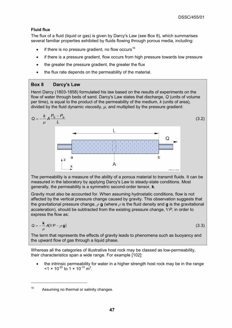
DSSC/455/01
47
Fluid flux The flux of a fluid (liquid or gas) is given by Darcy's Law (see Box 8), which summarises several familiar properties exhibited by fluids flowing through porous media, including:
• if there is no pressure gradient, no flow occurs16
• if there is a pressure gradient, flow occurs from high pressure towards low pressure
• the greater the pressure gradient, the greater the flux
• the flux rate depends on the permeability of the material.
Box 8 Darcy's Law Henri Darcy (1803-1858) formulated his law based on the results of experiments on the flow of water through beds of sand. Darcy's Law states that discharge, Q (units of volume per time), is equal to the product of the permeability of the medium, k (units of area), divided by the fluid dynamic viscosity, μ, and multiplied by the pressure gradient:
LPP
AkQ ab −−=µ
(3.2)
The permeability is a measure of the ability of a porous material to transmit fluids. It can be measured in the laboratory by applying Darcy's Law to steady-state conditions. Most generally, the permeability is a symmetric second-order tensor, k.
Gravity must also be accounted for. When assuming hydrostatic conditions, flow is not affected by the vertical pressure change caused by gravity. This observation suggests that the gravitational pressure change, r g (where r is the fluid density and g is the gravitational acceleration), should be subtracted from the existing pressure change, ∇P, in order to express the flow as:
( )gk rµ
−∇−= PAQ (3.3)
The term that represents the effects of gravity leads to phenomena such as buoyancy and the upward flow of gas through a liquid phase.
Whereas all the categories of illustrative host rock may be classed as low-permeability, their characteristics span a wide range. For example [102]:
• the intrinsic permeability for water in a higher strength host rock may be in the range <1 × 10-20 to 1 × 10-15 m2.
16 Assuming no thermal or salinity changes.

DSSC/455/01
48
• the intrinsic permeability for water in a lower strength sedimentary rock will be anisotropic with a range of 1 × 10-23 to 1 × 10-16 m2 for ‘flow’ parallel to the bedding, values perpendicular to the bedding may be up to a factor of about 100 lower.
• the intrinsic permeability for water in an evaporite rock may be in the range 1 × 10-23 to 1 × 10-18 m2. If interbeds are present the permeability may be anisotropic.
Therefore, flows are likely to be larger through higher strength rocks than through lower strength sedimentary rocks and will be virtually non-existent in halite.
Note that Darcy's Law, which predicts a linear relationship between flux and hydraulic gradient, has limitations when applied to porous media with very low permeability (for example clays). In particular, the small radii of the pores in such materials will cause rock water interactions to become significant, and so Darcy's Law may not apply at low hydraulic gradients.
3.3.2 Two-phase flow
Both liquid and gas phases may be present in a porous medium; this gives a two-phase fluid system. It is likely that the permeability will be higher for higher strength rocks, and the gas entry pressure lower, than lower strength sedimentary rocks or halite.
Both liquid and gas phases may be present in a porous medium. As mentioned above, this gives a two-phase system and the ideas discussed for single-phase flow can be generalised to such systems under many circumstances:
• first, the concept of saturation must be defined. The 'liquid saturation' is the volume fraction of the porosity occupied by liquid, with an analogous definition for the 'gas saturation'. The liquid and gas saturations sum to one.
• secondly, for two-phase flow, Darcy's Law is used for each phase, with the permeability replaced by the phase permeability, ki (which is the permeability of the rock, k, multiplied by a relative permeability, kri; see Box 9) as an approximation.
• finally, there is a difference in pressure across the interfaces between liquid and gas phases within the pores of a porous medium. This difference in pressure is called the capillary pressure (see Box 10). The capillary pressure causes gas to tend to access larger-sized pores before the smaller-sized pores so that, as the gas saturation increases and smaller-sized pores become gas filled, the capillary pressure increases. The relative permeability and capillary pressure functions (which jointly are called saturation functions) have important implications for gas migration through the different categories of host rock.
A gas phase, should one form, can migrate away from the GDF in higher strength rocks without developing a significant overpressure (see Section 6). In contrast, in lower strength sedimentary rocks or halite it will be less easy for a gas phase to migrate through the host rock, and can lead to an increase in pressure in the GDF. This is because for higher strength rocks, as compared to lower strength sedimentary rocks or halite, it is likely that:
• the permeability will be higher • the 'gas entry pressure' (the amount by which the pressure in the gas phase has to
exceed the pressure in the liquid phase before gas can migrate) will be lower.

DSSC/455/01
49
Box 9 Relative permeability Assuming that the flow of a phase (for example gas) in the presence of another phase (for example liquid) can be viewed as a single-phase flow with reduced porosity, the relative permeability, kri, for phase i can be defined as:
kkk rii = (3.4) The relative permeability must be between zero and one.
In applications, the relative permeability is represented as a function of liquid saturation. Many parameterised functional forms of the relative permeability have been introduced, and may be fitted to experimental data. For higher strength rocks, the relative permeability is often taken to be a linear function of the saturation based on studies of oil reservoirs where linear relative permeabilities are commonly used to describe two-phase flow in fractures. However, if the capillary pressure causes gas to occupy the larger-aperture channels, and water the smaller-aperture channels, then the gas relative permeability will increase more quickly at low gas saturations than expected from a linear function. Thus, at present there is not a consensus about the forms of the relative permeability functions that are appropriate for describing two-phase flow in fracture networks [18].
Particular functional forms that have been found useful in describing two-phase flows in lower strength sedimentary rocks and halite are those of van Genuchten [105] and of Brooks and Corey [106]. These relative permeability functions were developed for soils and porous sedimentary rocks with moderate saturation.
Box 10 Capillary pressure In fluid statics, the capillary pressure is the difference in pressure across the interface between two immiscible fluids (for example Pg is the gas pressure and Pl is the liquid pressure), and thus is defined as:
lgc PPP −= (3.5)
The Young–Laplace Equation states that this pressure difference is proportional to the surface tension, γ, and inversely proportional to the effective radius, r, of the interface. It also depends on the wetting angle, θ, of the liquid on the surface of the capillary:
( )θγ cosr
Pc = (3.6)
Hence, the capillary pressure will be much larger in clay, which has small void spaces, than in higher strength rocks.
Often the capillary pressure is assumed to be a function only of the liquid saturation. There are van Genuchten [105] and Brooks and Corey [106] capillary pressure functions. The most important difference between these two capillary pressure functions is that the Brooks and Corey form has a minimum capillary pressure that is strictly positive (that is, gas cannot migrate unless the gas pressure exceeds the liquid pressure by a finite amount).
Permeability should be independent of the fluid (that is, the permeability measured with water should be the same as the permeability measured with gas). However, the permeability to gas can be higher than that for water. This is known as the Klinkenberg Effect [107] and is interpreted as additional gas flow (‘slip flow’) at the pore walls when the mean free path between collisions of individual gas molecules is large compared to the pore dimensions. It can be important in low-permeability rocks (but the effect decreases as the mean free path decreases with increasing gas pressure). As an example, measurements of the permeability of some Taiwanese sedimentary rocks found that

DSSC/455/01
50
nitrogen permeability was greater than the water permeability by up to about one order of magnitude [108].
3.3.3 Henry's Law and vaporisation of water
Henry's Law is adequate for describing the solubility of most of the gases of interest in low ionic strength waters. The diffusion of water vapour can be important in some rocks in proximity to high heat-generating wastes.
The above description of two-phase flow does not include exchange between the liquid and gas phases. However, some gas will dissolve in, and be transported with, the groundwater and some water will vaporise into the gas phase.
Henry's Law states that, at a constant temperature, the amount of a given gas dissolved in a given type and volume of liquid is directly proportional to the partial pressure17 of that gas in equilibrium with that liquid. Henry's Law is strictly valid only for ideal gases and dilute porewaters. For real gases the fugacity (a function of temperature, pressure and the composition of the solution) should be used instead of the partial pressure and the activities of the dissolved species in solution. Thus, the Henry's Law 'constant' depends on the gas, the composition of the liquid and the temperature. This law is adequate for describing the solubility of most of the gases of interest in low ionic strength waters.
The behaviour of water as it vaporises into the gas phase should also be taken into account. This behaviour is well understood and is defined in engineering 'steam tables' [109]. The diffusion of water vapour can be an important mechanism for water migration in some rock types in proximity to heat-generating wastes.
3.3.4 Diffusion and dispersion
The relative contributions of advection, diffusion and dispersion to the transport of dissolved gas from the GDF depend on the groundwater chemistry and the rate of groundwater flow.
Groundwater dissolution of the gases generated in the GDF means that advection, diffusion and dispersion of the dissolved gases will contribute to the transport of gases away from the facility18, dependent on the groundwater chemistry and the rate of groundwater flow.
Diffusion of water vapour through the gas phase may be an important process for the transport of water in the vicinity of the GDF, particularly if the host rock is a low-permeability clay. The Dusty Gas Model provides a fundamental approach to modelling gas diffusion in porous media [110]. In contrast to the less rigorous Fick's First Law, which has been widely used, the Dusty Gas Model accounts for both gas-wall interactions and momentum transfer between the gases. For a binary mixture of gases, the Dusty Gas Model approximates to Fick's First Law, which states that a solute will move from a region of high concentration to a region of low concentration along a concentration gradient.
17 In a mixture of ideal gases, each gas has a partial pressure, which is the pressure that the gas
will have if it alone occupied the volume. The total pressure of the mixture of gases is the sum of the partial pressures of each individual gas in the mixture.
18 When gas is transported in solution upwards towards the biosphere its solubility will decrease (this is a consequence of Henry's Law, and the reduction in fluid pressure with decreasing depth), and therefore the gas can bubble out of solution to form a free gas phase.

DSSC/455/01
51
It is straightforward, at least in principle, to extend the model of two-phase flow in porous media to include these diffusion processes.
3.4 Instability, heterogeneity and bubble flow
The flow of gases in real two-phase systems will be affected by instability and heterogeneity. These are likely to be more significant for fractured systems than for clays and halite.
Real systems containing gas and water will depart from the continuum approach to modelling two-phase fluid flow discussed in Section 3.3 because of gravitational and viscous instability between the two fluids and the effects of heterogeneity. The effects of instability and heterogeneity are likely to be more significant for fractured systems than for clays and halite. In addition, bubble flow can be important in systems with large apertures (fractured rock) and is not well described by continuum models of two-phase flow. These are discussed below.
3.4.1 Instability
Gravitational and viscous instabilities lead to the formation of gas 'fingers' that propagate through a porous medium faster than a uniform gas front.
A particular feature of two-phase flow through a porous medium that affects gas migrating upwards through a liquid-saturated rock is the phenomenon of viscous fingering. Fingering may happen even in a homogeneous medium, and it is a well-understood physical phenomenon (see, for example, [111, 112]). In particular, gravitational and viscous instabilities occur because the gas has a lower density and a lower viscosity than the groundwater it is displacing from below. These instabilities lead to the formation of gas 'fingers' propagating through the porous medium at a higher rate than if the gas phase were to advance uniformly.
The width of the gas 'fingers' (and the length-scale of the heterogeneity that may trigger the instability) is generally smaller than the size of the grid blocks over which the rock properties are averaged when carrying out numerical simulations. In other words, fingering occurs on a smaller scale than the typical spatial resolution used in numerical simulations. Therefore, when considering the results of such simulations, it needs to be remembered that this potentially important process has not been captured in the typical model.
3.4.2 Heterogeneity and fractures
Heterogeneity will be present in all real systems and its effects on gas migration depend on the host geology. It may be most important for fractured systems.
Heterogeneity will be present in all real systems. Its effects on gas migration will depend on the host geology, but may be most important for fractured systems. Where two-phase flow occurs predominantly through a network of fractures, continuum two-phase flow models may be inadequate to describe the behaviour because:
• the fractures may be large compared to the length scale of the averaging implicitly assumed in the development of the continuum model
• gas flows may be localised in preferential pathways.
To address these issues, there have been a number of attempts to model two-phase flow through a network of fractures in alternative ways [18]. There is an extensive literature on both experimental (see, for example, references [113-115]) and theoretical (see for

DSSC/455/01
52
example, reference [116]) studies of two-phase flow in single fractures. In several cases, the purpose of these studies was to determine appropriate saturation functions for use in continuum two-phase flow models.
Figure 19 shows the results of an experiment measuring gas migration through a fracture using positron emission tomography. The gas flows in from the right and can be seen to fill parts of the fracture to different extents, with colours to the red/yellow end of the spectrum denoting high gas saturation. The Figure also shows a black outline of the calculated gas front. In both the experimental results and the model the effects of heterogeneity are apparent in the uneven progress of the gas front.
Figure 19 Gas invasion of a liquid-filled rough fracture [113]
There have also been studies of two-phase flow in idealised representations of a network of fractures (for example sets of parallel smooth fractures, or simple configurations of connected fractures [117, 118]), in which the movement of liquid-gas interfaces along the fractures is modelled explicitly. These studies typically show intermittent, rather than continuous, flow.
Exchange of water (and solutes such as dissolved gases) will also occur between the fractures and the rock matrix. This process is represented by 'dual porosity' models (see, for example [119, 120]), which are widely used in the oil industry, and generalisations thereof (for example, the ‘multiple interacting continua’ model [121]).
It is difficult to model the extent to which two-phase flow (based on the theoretical ideas described in Section 3.2) may be affected by viscous fingering and flow channelling, partly because the heterogeneity of the real system cannot be characterised to the required level of detail. An approach is to use simplified models, which still capture the effect of the heterogeneity as far as possible [122].
3.4.3 Bubble flow
Bubble flow may contribute to gas migration from the GDF in fractured systems.

DSSC/455/01
53
Bubble flow has been suggested as another mechanism that might contribute to gas migration from the GDF [18]. It is likely to be more relevant to fractured systems because pore throat constrictions will impede the bubbles in other porous media.
A possibility is that small 'micro bubbles' might form in the underground rocks and then migrate upwards (because of buoyancy). However, the stability of such ‘micro-bubbles’ is considered unlikely to be sufficient for them to persist long enough to make a significant contribution to gas migration [115]. In particular, the high pressure within a ‘micro-bubble’ (see Equation 3.6) forces gas into solution, decreasing the radius of a bubble and leading in time to complete dissolution.
Another possibility is that a gas front moving upwards through a water-filled vertical fracture might break up into a stream of bubbles. This mechanism, which is replicated by the flow of bubbles between two parallel flat plates separated by a small gap, has been observed and is known as Hele-Shaw bubble flow. Experimental and theoretical studies of Hele-Shaw bubble flow have been undertaken and bubble interactions (see Figure 20) observed. (If two bubbles get closer than a bubble diameter the trailing bubble accelerates and coalesces with the leading bubble. If the resulting bubble is larger than a critical diameter, bubble splitting occurs.)
Figure 20 Gas bubbles rising in a liquid-filled Hele-Shaw cell [115]
Bubble flow is not well described by the continuum model of two-phase flow that has been presented because: the scale of the bubbles is likely to be small compared with the scale of the volumes over which averaging is invoked when developing the continuum model

DSSC/455/01
54
equations; the saturation functions become ill-defined for bubble flow; and gas-water interactions are likely to occur as a consequence of viscous drag19. A simple model [123] for the upward flow of a stream of gas bubbles has been developed that may be used to scope the effects of this phenomenon. This demonstrated that bubble flow is insufficient to transport all of the gas away from the GDF based on estimates of the gas generation rate, rock permeability and repository dimensions at that time. Thus bubble flow occurs with simultaneous continuous gas flow, so that continuous gas flow and bubble flow are likely to exist over separate regions of the gas pathways. However, bubble flow can continue to occur if the overall gas generation rate decreases to a level that is no longer sufficient to support continuous gas flow [124].
3.5 Coupling to other processes
Gas migration will be coupled to other processes in the GDF. Upscaling uncoupled, or weakly-coupled, processes is relatively straightforward. Upscaling coupled processes can be complex. The resaturation behaviour of the GDF can be significantly different in different host rocks; small-scale features, coupled processes and upscaling can be important in lower permeability rocks.
Gas migration will be coupled to other processes in a GDF. Heat-generating wastes (for example spent fuel) will cause changes in temperature that result in thermal gradients. Temperature changes might cause the rock to expand and, more significantly, can affect the viscosity and density of the fluids and can lead to fluid migration even in low permeability rocks. It is straightforward to account for such changes in the two-phase flow model by incorporating an equation for conservation of energy (in addition to the equation for conservation of mass).
After excavation of the GDF, particularly in deformable rocks (for example clays and halite), the host rock will creep. Creep may be associated with changes in the Excavation Disturbed Zone around the GDF, and in particular with changes in the rock permeability in this region. This can affect the ability of gas to migrate away from the GDF. If the gas cannot migrate away from the GDF sufficiently quickly, the gas pressure will rise and oppose the creep of the rock. This is a coupled set of processes that can be modelled by joining a mechanical model for the rock to the two-phase flow model. In the application of such a model to a specific geology, the input parameters will be determined as part of a site characterisation programme.
There is ongoing discussion about the process of gas migration through relatively impermeable clays such as bentonite20. It has been suggested that at some threshold gas pressure the gas will create micro-fissures through the clay, a process termed dilatancy-controlled gas flow or pathway dilation. Modelling this also requires joining a mechanical model for the clay to the two-phase flow model. RWM is participating in the international Large Scale Gas Injection Test (LASGIT) (see Section 6.2.2) underground in the Äspo Hard Rock Laboratory in Sweden that is studying the migration of gas in compacted bentonite to gain more understanding of this process.
Some gases will be reactive under ambient conditions in a GDF. For example, carbon dioxide will dissolve and react with cements and cement porewaters to form calcium carbonate. Similarly, hydrogen chloride is highly soluble and will also be neutralised in
19 Due to friction between the surface of the gas bubble and the water. 20 Another complication with bentonite is that some of the water will be chemically-bound.

DSSC/455/01
55
cement pore waters. These mineral dissolution/precipitation reactions can potentially change the porosity, and also the permeability, in the affected region.
Work under the EC FORGE project has considered the upscaling of coupled processes in a study on resaturation behaviour of ILW/LLW disposal areas in the GDF in different host rocks [29]. It was concluded that upscaling uncoupled, or weakly-coupled, processes (such as may be the case for a fractured higher strength rock) is relatively straightforward. Upscaling coupled processes can be complex, for example the coupling between gas generation, GDF gas pressure, water inflow rate, and the availability of water to support corrosion and microbial processes. Therefore, the resaturation behaviour of the GDF can be significantly different in different host rocks and small-scale features, coupled processes and upscaling can be important factors in understanding gas migration in lower permeability rocks.
3.6 Computer models for simulating gas migration
The physical ideas introduced in Section 3.3 have been used as the basis of computer models of two-phase flow. Some of these computer models are described in this section.
3.6.1 Continuum two-phase flow models
The most widely used models, both in the context of managing radioactive waste and for other applications, are continuum two-phase flow models. Most such models only implement a limited dependence of rock properties on fluid pressures and are most applicable for rocks made of rigid material, such as higher strength rocks.
The most widely used model, both in the context of managing radioactive waste and for other applications, is the continuum two-phase flow model, which essentially is a direct application of the theory outlined in Section 3.3. In the field of oil reservoir engineering, such an approach is fairly standard for simulating two- and three-phase (groundwater, gas and oil) flows through porous media [125]. It is also the approach adopted in the TOUGH2v221 program [126], which has been widely used in studies relating to gas migration from radioactive waste disposal facilities.
Most finite-volume22 two-phase flow models (such as TOUGH2v2) only implement a limited dependence of rock properties on fluid pressures. This is because such models do not lend themselves to the convenient treatment of deformation behaviour. The pore volume may be changed with fluid pressure through the use of a compressibility term to represent the compression of the rock system, but more complex deformation behaviour is usually not modelled. Hence, these models are most applicable for rocks made of rigid material, such as higher strength rocks.
21 TOUGH2v2 is a computer program for simulating coupled fluid and heat flows for
multi-component, multiphase fluid mixtures in porous and fractured media. It was developed by Lawrence Berkeley National Laboratory, USA.
22 The finite-volume method is a method for solving partial differential equations such as those that describe two-phase flow.
A number of computer models for modelling two-phase flow can be used to simulate gas migration.

DSSC/455/01
56
3.6.2 Coupled two-phase flow and mechanical models
Deformation behaviour can be modelled, and coupled with two-phase flow, to model two-phase behaviour in deformable rocks.
Another class of continuum two-phase flow model has been developed for modelling two-phase behaviour in deformable rocks (for example clays and halite). In these models, the deformation behaviour is modelled, and is coupled with the two-phase flow (specifically through the capillary pressure, which depends on saturation).
Models of this type that have been used in research projects on gas migration from radioactive waste repositories include Code_Aster [127] and CODE-BRIGHT [128]. Code_Aster is an Open Source computer program for civil engineering finite-element analysis and numeric simulation that has been used to model the mechanical behaviour of clay around a GDF. CODE-BRIGHT was originally developed to model the mechanical behaviour of salt around a GDF, where convergence of the rock (and its effect on the porosity and permeability of crushed salt backfill, which is thereby compacted) is of importance in evaluating performance. BRAGFLO, a two-phase flow solver, primarily used to compute pressures and brine/gas saturations, has been used in the performance assessment of the Waste Isolation Pilot Plant (WIPP), the US repository for transuranic wastes in Carlsbad, New Mexico [129].
3.6.3 Coupled two-phase flow and reactive transport models
Carbon dioxide is one of the gases that will be produced in the GDF, and it may react chemically either with a cementitious backfill material (carbonation) or with the surrounding rocks. Models that couple two-phase flow and reactive transport have been developed in order to simulate problems such as the migration of carbon dioxide through porous materials and have been applied, for example, to the geological sequestration of carbon dioxide [130].
A model of this type is TOUGHREACT [131], which is a computer program for simulating chemically reactive flows of multiphase fluids in porous and fractured media. (TOUGHREACT was developed by introducing reactive chemistry into TOUGH2v2). In TOUGHREACT the gas phase can be chemically active, interactions between fluids and mineral assemblages can occur and precipitation and dissolution reactions can change the porosity, permeability, and saturation functions of the rock. Other computer programs such as QPAC [132] also allow the coupling of transport and chemical reactions.
3.7 Modelling gas migration at specific sites
The combination of the engineered barrier system and the entirety of the geological environment will affect gas migration at an individual site. As part of the site characterisation programme the porosity, the permeability, and the saturation functions of the geological units will be measured in order to develop a model of gas migration for each candidate site.
The ideas introduced in Section 3.3 (mass conservation, and a generalised version of Darcy's Law with relative permeability and capillary pressure effects), provide a conceptual basis for modelling the behaviour of two-phase systems. The concepts have a firm basis for porous sedimentary rocks, although even in these relatively well-understood rocks, hydrodynamic instabilities (as discussed above in Section 3.4) give rise to phenomena like
Models that couple two-phase flow and reactive transport have also been developed.

DSSC/455/01
57
the formation of gas fingers and intermittent flow. Such phenomena are strongly affected by heterogeneity and small-scale variability.
As part of a site characterisation programme the porosity, the permeability, and the saturation functions of the relevant geological units will be measured in order to develop a model of gas migration for a candidate site. In higher strength rocks, even though the generalised version of Darcy's Law may be applicable for describing two-phase flow, there are likely to be uncertainties in these parameters over the appropriate (large) length scales. This is because:
• gas migration in heterogeneous fractures and fracture networks will be subject to hydrodynamic instabilities, and may be affected by small-scale features such as heterogeneities of individual fractures and fracture intersections
• gas may flow preferentially along localised pathways (for example with dimensions of less than a metre in length) and it will be impractical to resolve all these pathways and characterise them in detail at sites to make quantitative deterministic modelling of gas flow on a scale of hundreds to thousands of metres.
Representing such uncertainties at a suitable level, and the appropriate application of continuum models, where volume averaging may be performed on a scale much larger than the intrinsic scale of the flow phenomena, will be considered as part of a future programme on a site-specific basis.
In some lower strength sedimentary rocks (for example some clays) or halite it has been suggested that, at low gas pressures, two-phase flow might occur, but that at some threshold gas pressure the gas will create micro-fissures into the host rock which may then close as the pressure falls. This behaviour will need to be understood for candidate sites in these host rocks.
The combination of EBS and the entirety of the geological environment will affect gas migration at an individual site. The overburden can have markedly different properties from the host rock and can act as a cap rock. In the absence of a site, RWM considers a range of host rocks and uses generic parameter values [4, 102]. Existing computer models (see Section 3.6) are capable of giving significant understanding of the process of gas migration from a GDF, but further development will be required (see Section 6.3). Some of these development needs will become better defined as concept development and site selection progress, but the generic modelling issues listed below may also need to be considered in order to develop capabilities on a timely basis:
• upscaling - the saturation functions (relative permeability and capillary pressure; and, indeed, all of the model parameters) will be measured in laboratory experiments on small rock samples (with dimensions of the order of a few centimetres). However, the numerical calculations typically have a spatial resolution of the order of ten metres, and therefore require saturation functions that represent the behaviour of large grid blocks (with dimensions of the order of ten metres). These saturation functions are upscaled functions to represent the overall behaviour of large grid blocks. They are calculated in oil reservoir studies and are referred to as pseudo-functions.
• fingering - as discussed in Section 3.4.1, fingering is potentially an important process affecting gas migration from the GDF and one whose effects may have to be examined. Suitable mathematical and numerical models to represent fingering on scales smaller than the grid blocks used in the numerical calculations may need to be developed.
• heterogeneity - typically each geological unit is modelled as homogeneous, although it is recognised that the units really are heterogeneous [133]. Such heterogeneity

DSSC/455/01
58
can cause large-scale fingering and this may need to be examined by calculations in which the heterogeneity in each geological unit is represented.
• uncertainty - the ways in which uncertainties in the gas migration models, and in how the results of gas migration calculations can be represented at a suitable level in the calculations of risk for the gas pathway, will need to be considered.
• GDF scale simulations - in some geological environments, the various components of the GDF may be an important pathway for gas. In such a case, it is desirable to represent the complexity of the GDF in sufficient detail in a model. However, two-phase flow calculations are computationally demanding, and therefore this may not always be possible.
The EC FORGE project [19] addressed some of these issues and investigated methodologies to integrate 'small scale' information into GDF scale models.
Other small-scale features, events and processes (FEPs) such as the EDZ, interfaces and piping may be important at the GDF scale. For example the shaft EDZ and seal performance can be important in relation to the migration of fluids to the biosphere. These small-scale features may need to be upscaled and captured in GDF scale models [29].
Information can also be gleaned from analogues [134] and larger-scale experiments can be conducted to investigate real systems [135, 136]. Such testing on a larger scale contributes to building confidence in understanding and modelling of gas generation and migration.

DSSC/455/01
59
4 Gas generation during transport Wastes may originate and be packaged at sites that may be some distance from the GDF. The Nuclear Decommissioning Authority is responsible for an integrated transport strategy that includes the movement of waste from the waste-producing sites to the GDF. This may include transport by rail, road or sea as appropriate and RWM is responsible for the development of a generic transport system design [137]. The objective of the radioactive waste transport system is to deliver packaged wastes safely to a geological disposal facility. This section describes RWM’s understanding of gas generation during the transport of packaged wastes by discussing:
• the waste packages and transport containers for ILW and LLW (Section 4.1)
• gas generation in the Standard Waste Transport Container (SWTC) during transport (Section 4.2)
• waste packages that can be transported in their own right (Section 4.3)
• HLW, spent fuel, plutonium and highly enriched uranium (HEU) disposal containers (4.4).
The historic focus in the UK on the transport of waste packages to the GDF has been on ILW and some LLW. Therefore, the discussion below in this section is mainly based on the transport of such packages. A conceptual design for the transport of standardised steel or copper disposal containers containing HLW, spent fuel, plutonium and HEU has been developed. This is referred to as the Disposal Container Transport Container (DCTC) [138].
The transport arrangements for wastes other than ILW and some LLW to the GDF are being developed [137]. Most of the general ideas in the discussion below also apply to the transport of HLW, spent fuel, plutonium and HEU in a DCTC, although the amount of gas generated may be less than from some ILW packages.
4.1 Waste packages and transport containers for ILW and some LLW
Unshielded ILW packages will be transported in reusable SWTCs that are sealed during transport. Some ILW packages will be transported in a Transport Overpack. Other ILW disposal packages are transportable in their own right.
Typical unshielded ILW containers are shown in Figure 21. These are designed to be transported within a SWTC, which can carry:
• four 500 litre drums, arranged in a stillage
• a single 3 cubic metre box
• a single 3 cubic metre drum, or
• a single Miscellaneous Beta-Gamma Waste Store (MBGWS) box.
The SWTC is a family of designs that is being developed for the transport of unshielded waste packages (see Figure 22). The unshielded waste packages will be removed from their SWTC in a shielded inlet cell, underground within the GDF, prior to emplacement. The thickness of the steel shielding will be either 70 mm, 150 mm or 285 mm, and the corresponding containers are designated the SWTC-70, SWTC-150 or SWTC-285.

DSSC/455/01
60
Figure 21 Typical unshielded-ILW containers
500 litre drum 3 cubic metre box
Figure 22 Standard Waste Transport Container SWTC-285

DSSC/455/01
61
Some packages will be transported in a Transport Overpack, these are:
• the 500 litre robust shielded drum
• the 3 cubic metre robust shielded box (Figure 23).
Figure 23 3 cubic metre robust shielded box
Other waste disposal packages (Figure 24 and Figure 25) are designed to be transportable in their own right:
• the 2 metre box
• the 4 metre box
• the 6 cubic metre concrete box
• the 500 litre concrete drum
• the 1 cubic metre drum.
Metallic LLW/ILW containers are vented by means of a filter in the lid that allows gas to be released while retaining solid particulate. The vent is normally made of fine metallic fibres contained within a coarser metal mesh. Concrete containers are not vented and gas is released through their permeable walls, base and lid.

DSSC/455/01
62
Figure 24 4 metre box, 2 metre box and 6 cubic metre concrete box waste containers
Figure 25 500 litre concrete drum and 1 cubic metre concrete drum

DSSC/455/01
63
4.2 Gas generation in SWTCs under normal conditions of transport
The contents of an intermediate-level waste package being transported in a SWTC must satisfy limits on the containment of radionuclides (in this context radiotoxic gases containing, for example, tritiated and carbon-14 species and radon-222) and gas generation and pressurisation of the SWTC cavity.
The SWTC is designed to meet the requirements for a Type B(M) package (see references [139,140] for further details). Type B packages are more robust than Industrial Package Type 2 packages. With respect to gas there are requirements that relate to the potential for pressurisation during transport and the release of radioactivity under normal conditions of transport:
• the SWTC cavity pressure must not exceed the maximum normal operating pressure of 7 bar gauge (8.01 Bar) [139, 141]
• during normal conditions of transport, the loss of radioactive contents from the SWTC is to be no more than 10-6 A2 per hour23.
Limits for the rate of generation of bulk gases by unshielded waste packages transported in a shielded transport container, together with specific limits on the rates of generation of certain toxic, flammable and radioactive gases, are given in the Generic Waste Package Specification [142]. These limits are defined by transport requirements rather than operational or post-closure requirements.
4.2.1 Bulk gas generation, pressurisation and flammability
Gas generated from waste packages in a SWTC will lead to an increase in pressure. Potential pressure increases can be evaluated using a cautious set of assumptions for conditions during transport and compared to the maximum normal operating pressure limit for the SWTC cavity. The SWTC is provided with a purge/vent valve to allow mitigation of the consequences of any gas generation.
Any gas generation from the waste packages in the SWTC will lead to an increase in pressure in the SWTC. In order to provide a robust evaluation of the potential pressure increase in the SWTC during transport it is cautiously assumed that the SWTC is closed at 1 atmosphere pressure and at -10°C and then reaches a maximum average temperature of 53°C during transport [141]. It is also assumed that there is no leakage from the SWTC during transport and that the transport period is 28 days.
The Ideal Gas Law can be used to estimate the volume of gas that can be released within a SWTC before the maximum normal operating pressure is reached. For example, assuming an SWTC-285 is filled with four 500 litre drums arranged in a stillage, the net cavity volume in an SWTC is 1.557 m3 and the amount of gas required to cause the cavity pressure to increase to 8.01 Bar corresponds to 8.69 m3 at Standard Temperature and Pressure (STP) [141]. Because gas generation is assumed to occur throughout a 28 day transport period, this is equivalent to a rate limit for gas generation of 113 m3 at STP per year. This number can be divided by four to get a gas generation rate limit for a 500 litre drum of 28.3 m3 at STP per year (similar approaches can be used for other waste packages such as the 3 cubic metre box and 3 cubic metre drum).
23 A2 values may be thought of as the amount of different radionuclides (in TBq) that give an
equivalent radiation dose through a combination of external radiation, ingestion and inhalation. Therefore, A2 values are different for different radionuclides.

DSSC/455/01
64
Rates of gas generation from waste packages can be calculated using SMOGG [100]. For example, the calculated rate of gas generation from corrosion in a 500 litre drum containing 435 kg of grouted Magnox fell from 7.25 m3 per year at the time of manufacture to a long-term rate of 0.325 m3 per year at 35°C after one hundred years (case 1(c) Reference [100]); examination of the plotted results in reference [100] shows that the lower rate is approached within a few years of manufacture of the wasteform. These gas generation rates were calculated for corrosion at a temperature of 35°C and will be greater at the maximum average temperature of 53°C assumed during transport. The best-estimate chronic corrosion rate of Magnox increases by a factor of about 5.5 from 0.78 µm y-1 at 35°C to 4.3 µm y-1 at 50°C [34]. Thus the total hydrogen generation rate from chronic Magnox corrosion in four 500 litre drum waste packages in a SWTC at 53°C can be in the region of 5 to 10 m3 at STP per year (0.325 × 5.5 × 4 = 7.2 m3 at 50°C). This is within the limit of 28.3 m3 at STP per year.
The SWTC is provided with a purge / vent valve [143] to allow mitigation of the consequences of any gas generation by:
• enabling the internal cavity to be purged with nitrogen prior to dispatch from the consignor when the container is carrying waste packages that can release significant quantities of flammable gases (mainly hydrogen) into the cavity
• allowing the pressure in the SWTC cavity to be equalised with that of its surroundings prior to removal of the lid.
Purging the internal cavity of air with an inert gas or nitrogen prior to transport reduces the risk of flammability. The SWTC will be vented on receipt in a controlled way, and any radionuclide release monitored.
4.2.2 Generation of gaseous radionuclides
To meet International Atomic Energy Agency (IAEA) regulations the loss of radioactive contents from an SWTC must be no more than 10-6 A2 per hour under normal conditions of transport.
To meet IAEA regulations the loss of radioactive contents from an SWTC (as a Type B package) must be no more than 10-6 A2 per hour under normal conditions of transport [139, 144]. The methodology for deriving the upper bound limits for concentrations of gaseous radionuclides in an SWTC cavity is described in the appendix of reference [144]. This can then be compared to the calculated amount of radioactive gas generated (for example using SMOGG [25, 54]). A lower A2 limit is currently used for tritium, compared to other radioactive gases, because of its higher permeation though container seals [144]. However, it is now thought that permeation leakage for hydrogen is not as large as originally estimated and that tritium should be treated as any other gas and subject only to by-pass leakage [145].
4.3 4 metre and 2 metre boxes
The regulatory requirements for transport of waste packages that are transport containers in their own right is that there should be no loss or dispersal of contents.
The above discussion, which leads to well-defined limits on the generation rates of bulk and active gases, applies only to those ILW packages that will be transported within a SWTC.
Other waste packages for ILW and some LLW (4 metre and 2 metre boxes) are transport containers in their own right and do not require the use of a separate transport container.

DSSC/455/01
65
The regulatory requirements for such transport containers are that there should be no loss or dispersal of contents during normal or accident conditions.
In the absence of formal criteria for compliance with these requirements for gas, RWM currently uses the same values for 2 metre and 4 metre box waste packages as the regulatory requirements [139] for a Type B(M) package (that is, the loss of radioactive contents from the box is to be no more than 10-6 A2 per hour). Alternatively, it may be a requirement that vents on 2 metre and 4 metre boxes should be sealed during transport.
4.4 HLW, spent fuel, plutonium and HEU disposal containers
Gas production from HLW, plutonium and HEU disposal containers during transport is expected to be negligible. A conceptual design for the transport of standardised steel or copper disposal containers containing HLW, spent fuel, plutonium and HEU has been developed.
The arrangements for transport and packaging of HLW and spent fuel for disposal are under development [137, 140]. Vitrified HLW in Waste Vitrification Plant containers is assumed in the DSSC to be packaged in steel or copper containers for disposal. The chemical form of the vitrified product means the wasteform itself will produce negligible amounts of gas. Gas production from corrosion and radiolysis is also expected to be negligible during transport because little or no water will be present within waste packages for HLW. Similar arguments apply for plutonium and HEU disposal containers.
Figure 26 DCTC with a copper disposal container
A conceptual design for the transport of standardised steel or copper disposal containers containing HLW, spent fuel, plutonium and HEU has been developed. This is referred to as the Disposal Container Transport Container (DCTC), which is shown in Figure 26. For the purposes of the DSSC illustrative concepts, spent fuel (which may include uranium oxide spent fuel from Advanced Gas-cooled Reactors (AGRs), Sizewell B and new build, and also mixed oxide (MOX) spent fuel) is assumed to be dried and packaged in copper containers with a steel insert or in steel containers. The chemical form of the spent fuel means the wasteform itself will produce negligible volumes of gas, although it is possible that small amounts of radioactive gases can leak from any defective fuel pins (but will be retained within the high-integrity containers).

DSSC/455/01
66
The most likely source of gas is from corrosion and radiolysis of any water remaining after the spent fuel has been dried and transferred into the disposal container [146, 147, 148]. Modelling of AGR spent fuel disposal packages has found that there is limited potential for internal pressurisation with a water carry-over representative of one waterlogged fuel assembly (out of 48 present in the disposal package).

DSSC/455/01
67
5 Gas generation during operations The operational phase is defined to cover the period from the receipt of waste packages at the GDF to the sealing and closure of the facility. The historic focus on the operational phase has been on ILW and some LLW. Therefore, the discussion in this section is based on the operations of the GDF containing such packages. However, HLW, spent fuel, plutonium and HEU are assumed to be packaged in unvented high integrity disposal containers in the illustrative concepts. Therefore, the release of radionuclides in gaseous form from these wasteforms under normal operating conditions is not expected. Hydrogen may be generated from the external corrosion of steel containers if these were used for HLW/spent fuel disposal and if conditions at the outer surfaces became anaerobic. However, this may be limited by water availability during the operational phase.
Although design and operation of the GDF will depend on the geological environment, some general features are:
• the vaults will be excavated in a host rock at depth
• the design, construction and maintenance of the vaults will allow monitoring and inspection, as required throughout the operational phase
• the environment in the vaults will be controlled to minimise container corrosion throughout the operational phase
• disposal vaults in higher strength rock can remain open until the end of the operational phase, whereas those in lower strength sedimentary rocks will be backfilled and closed, and those in a halite closed, once filled with waste packages
• the underground infrastructure and support facilities will allow the disposal of waste packages to take place at the same time as ongoing construction of new vaults, with physical separation of construction and disposal activities utilising airlocks and seals
• when waste emplacement is complete, a decision can be taken to backfill and close any open vaults, seal and close the facility.
The duration of the operational phase will depend on the time period over which the packages or disposal containers are emplaced and subsequently monitored and backfilled. This period may be up to several hundred years long if deferred backfilling is required by future generations. During this time the gases that need to be managed are mainly flammable (for example hydrogen), non-radiological chemotoxic (for example amines) and radiotoxic gases (for example those containing carbon-14). These gases are the same as those requiring management during interim surface storage. The ventilation system will ensure that the concentrations of gases within the facility, and the resulting discharges from the facility, are less than regulatory limits. Similar techniques to those used to ensure safety with respect to gas in surface stores will be applied to the GDF during the operational phase. Therefore, techniques for managing gas in the operational GDF will include:
• the use of management controls and engineered systems, such as restricted access and remote handling
• controlling the environmental conditions (for example humidity and temperature) to minimise gas generation (there are additional reasons for controlling the environmental conditions [2])
• ventilating the GDF (ensuring the ventilation rate is sufficient that there is no unacceptable build-up of gases)
• sampling and monitoring of the atmosphere within the GDF.
Backfilling of ILW/LLW packages with a cementitious material can be significant for gas generation from the waste packages as a cementitious backfill may supply water to the

DSSC/455/01
68
waste packages and also increase temperatures as it cures. These two factors can result in increased rates of corrosion and hence gas generation. Gas that is released from vented waste packages can migrate through a cementitious backfill while it is curing, thereby potentially altering the properties of the backfill.
The relative amounts of gas generated from the ILW, LLW, HLW and spent fuel disposal areas of the GDF during the operational phase and the post-closure phase will depend on the geological disposal concept and will be reviewed as the concepts and designs for the GDF progress. A significant proportion of the gas generated during the operational phase is expected to arise from packaged ILW and LLW in the facility. Gas generation during the operational phase in the HLW and spent fuel areas may be limited by lack of water both within, and external to, the disposal containers. The bentonite buffer (in concepts where this is used) surrounding the disposal containers may take many years to saturate and water availability will remain limited after saturation of the bentonite; this may continue to determine the rate of gas generation.
Different geological disposal concept examples may have different effects on gas generation during the operational phase. In concepts in lower strength sedimentary rocks and evaporite rocks it may be necessary to close a disposal vault or tunnel once the ILW packages or the spent fuel/HLW disposal containers have been emplaced. Where closed UILW or SILW and LLW disposal vaults are present during the operational phase it may be necessary to design features such as seals to allow gas to escape from the vaults because, as mentioned in Section 3.3.2, gas cannot easily migrate through some lower strength sedimentary rocks and evaporite rocks. Thus, seals may need to allow gas to pass whilst restricting flow of potentially contaminated water from the closed vaults or tunnels into the rest of a GDF. This may require the development of suitable backfill and sealing materials such as high-porosity mortars and sand/bentonite mixtures. For example, sand/bentonite mixtures may be used in seals in the Nagra concept for the disposal of ILW and LLW in Opalinus Clay as part of an engineered gas transport system [122]. These replace concrete plugs and compacted bentonite seals and combine low water transmissivity and long-term stability with higher gas permeability and/or lower gas entry pressure, so as to act as a 'gas valve'.
In the context of GDF operations, subsequent parts of this section discuss:
• flammable gases (Section 5.1)
• radioactive gases (Section 5.2)
• HHGW packages (Section 5.3).
5.1 Flammable gases
Hydrogen will be the main flammable gas generated in an operational GDF. Ventilation will keep concentrations in open areas below their lower flammability limit. In the event of a loss of forced ventilation, it will take many months for the concentration of hydrogen in a vault for unshielded ILW to exceed the lower flammability limit for this gas.
Hydrogen will be the main flammable gas generated in an operational GDF. Ventilation will be designed to be sufficient to keep the concentrations of the flammable gases in open areas below their lower flammability limit (LFL). Below this limit the concentration of the flammable gas is too low to burn (there is also an upper limit, above which the concentration of the gas is too high to burn). The LFL for hydrogen in air is approximately 4% [149].
A simple model of ventilation (see Box 11) can be used to illustrate the feasibility of this.

DSSC/455/01
69
Box 11 Simple model of ventilation The concentration of gases in the GDF will change over time because of variability in their generation by the waste packages and their removal by the ventilation system. If G is the rate of gas generation (at ambient conditions) per unit vault volume and R is the ventilation rate (the rate at which air and other gases are removed), then the rate of change of the gas concentration (as a volume fraction, C) is:
( )RGCGtC
+−=∆∆
(5.1)
The first term on the right-hand side of this equation is the generation of gas, and the second term is the removal of gas.
Hence, the equilibrium concentration of gas (when ∆C = 0) is:
RGGC+
= (5.2)
Using Equation (5.2), the minimum requisite ventilation rate, R, can be related to this upper bound hydrogen concentration, Cmax:
G1C
1Rmax
−≈
To limit the hydrogen concentration to 4%, a ventilation rate equal to about 25 times the generation rate of hydrogen is required. For example, in the GDF in a higher strength rock during the operational period after all the UILW packages have been emplaced, but the vaults remain open prior to backfilling and closure, the maximum generation rate of hydrogen is about 13,000 m3 per year from all UILW packages [22]. A minimum ventilation rate of about 325,000 m3 per year or 0.01 m3 per second is therefore required to maintain the hydrogen concentration below 4% assuming the atmosphere in an operational GDF remains well-mixed.
RWM has adopted a 2% limit for the hydrogen concentration in air for the conceptual design of the ventilation system in the GDF and ventilation simulation studies have shown this can be adequately ventilated using standard available technology [150]. Calculations have also indicated that, in the event of a loss of forced ventilation during the operational phase, it will take many months for the concentration of hydrogen generated from waste packages in a UILW vault to exceed the lower flammability limit for this gas [151].
Where there are anaerobic niches in the waste, methane can be generated (see Section 2). Because the LFL for methane in air is approximately 5%, similar illustrative arguments as for hydrogen can be made for this flammable gas, although it should be noted that the potential for the generation of this gas during the operational phase is much lower.
5.2 Radioactive gases
Radioactive gases (for example those containing tritium, carbon-14 and radon-222) will be produced during the operational phase of the GDF. The ventilation system for the GDF will be designed to ensure that doses to operators and members of the public are as low as reasonably practicable. Discharges will be monitored and doses to underground workers will be monitored and controlled. The host rock itself may contribute to the sources of gas, for example it can be a source of radon-222.

DSSC/455/01
70
Radioactive gases (for example those containing tritium, carbon-14 and radon-222) will be produced during the operational phase of a GDF.
Doses to underground workers within the GDF, in areas where packages are not handled remotely, may occur as a consequence of inhalation of these gases. The dose will depend on the activity concentration in the air, the breathing rate and the exposure time. Ventilation can be used to control the activity concentration in the air. The doses to underground workers will be monitored and controlled.
Doses to members of the public may arise from discharge of the radioactive gases from the stack of the operational GDF to the atmosphere. The ventilation system for the GDF will be designed to ensure that doses to members of the public are as low as reasonably practicable. Discharges from a ventilation stack will be monitored to ensure compliance with licensed discharge limits. The impact of the discharges will be affected by various factors, including meteorological conditions. The understanding and treatment of the biosphere is discussed further in reference [8]. The Generic Operational Environmental Safety Assessment report describes the approach to assessing the impact of such discharges [152].
Calculations of generation rates of bulk and radioactive gases from ILW and LLW in the GDF in a higher strength rock for the 2007 Derived Inventory have been made [22]. The results from the base case calculation for UILW were shown above (in Figure 17 in Section 2.5). In these calculations it was assumed that the waste packages were emplaced from 2040 to 2090 and that this was followed by a period of care and maintenance (C&M) prior to backfilling and closure from 2140 to 2150. Thus the operational period lasts from 2040 to 2150 in the calculations. The calculations assume that any carbon-14 in the form of carbon dioxide generated by the conditioned wastes during the operational phase prior to backfilling is trapped by carbonation of the grout [153] in waste packages. The key features with respect to the operational period are as discussed in Section 2.5:
• the generation of radon-222 follows the emplaced inventory of radium-226 (some host rocks will also release radon-222).
• during emplacement hydrogen is mainly generated by the corrosion of Magnox and aluminium.
• hydrogen generation is dominated by Magnox corrosion throughout the C&M period.
• uranium, Magnox, stainless and carbon steels are assumed to corrode aerobically during emplacement and C&M and release 14C-methane. Uranium is the major contributor to the calculated generation rate of 14C-methane.
• the major contributors to the calculated generation rate of tritiated hydrogen during emplacement, C&M and backfilling are release from graphite leaching and from the corrosion of uranium.
• the peak in the tritium gas generation rate is calculated to occur about 10 years after emplacement starts because of the relatively short half-life of tritium (t½ = 12.33 years).
• there is an increase in the hydrogen generation rate as backfilling starts because the temperature increases from 35°C to 45°C.
• 14C-methane shows a similar profile to the bulk hydrogen during backfilling because a major contribution is from the corrosion of Magnox.
Equivalent base case calculations were made for SILW/LLW and DNLEU. That for SILW/LLW shows broadly similar trends to UILW, but the generation rates are lower with the exception of the peak tritium generation rate. The calculated gas generation profile for DNLEU is much simpler, with only hydrogen from the radiolysis of water (the uranium oxide

DSSC/455/01
71
was assumed be intimately grouted for these calculations) and radon-222 generation featuring during the operational phase. The calculated hydrogen generation rate is less than for UILW or SILW/LLW.
Many of the variant calculations in reference [22] show little or no effect on gas generation during the emplacement and C&M periods, although different assumptions for backfilling and closure do have an impact on gas generation. Some variant calculations were also undertaken to scope the effect of packaging some wastes in robust shielded packages. These exploratory calculations considered a small proportion of mixed UILW and SILW/LLW24 to be packaged in robust shielded packages as this allowed a comparison with calculations for grouted ULIW and SILW/LLW packages. The calculations gave similar results to those for solely grouted UILW and SILW/LLW. The wastes packaged in robust shielded packages represented only a small proportion of the waste packages. There will be little total gas generation from them during the emplacement and C&M periods because the conditioned wastes will be dry.
More recent calculations of carbon-14 gas generation have been made for the 2013 Derived Inventory and have included some of the improved understanding of carbon-14 release from waste materials described in Section 2. The calculated generation rates of 14C-containing gases during GDF operations (and early post-closure) from these calculations, broken down by type of waste material, are shown in Figure 27 for legacy UILW, Figure 28 for legacy SILW/LLW and Figure 29 for new-build UILW [154].
The host rock itself may contribute to the sources of gas. For example, it can be a source of radon-222 generated from naturally-occurring radium in some host rocks that form the walls, floors and ceilings of the underground excavations of a GDF. Recent work [97] has derived indicative rates of radon-222 emanation from host rocks. This is a site specific issue, which will need to be addressed during the site selection process. Ventilation will be used to control the activity concentration in the air in the same manner as for the radon-222 released from waste packages.
24 It was recognised that this does not represent the composition of the waste streams that will
be packaged in robust shielded packages.

DSSC/455/01
72
Figure 27 Illustrative calculated results for carbon-14 gas generation during GDF operations and early post-closure from legacy UILW in a higher strength rock for the 2013 Derived Inventory [154]

DSSC/455/01
73
Figure 28 Illustrative calculated results for carbon-14 gas generation during GDF operations and early post-closure from legacy SILW/LLW in a higher strength rock for the 2013 Derived Inventory [154]
Figure 29 Illustrative calculated results for carbon-14 gas generation during GDF operations and early post-closure from new-build UILW in a higher strength rock for the 2013 Derived Inventory [154]

DSSC/455/01
74
5.3 HLW, spent fuel, plutonium and HEU packages
Release of gaseous radionuclides from the sealed disposal containers under normal operating conditions is not expected. Any hydrogen generation from external corrosion of steel containers will be limited by water availability in the surrounding bentonite buffer during the operational phase.
HLW, spent fuel (AGR, Sizewell B, new build and MOX), plutonium and HEU are assumed to be packaged in unvented high-integrity disposal containers [2, 31, 101]. Therefore, release of gaseous radionuclides from the disposal containers under normal operating conditions is not expected. Hydrogen may be generated from the external corrosion of steel HLW/spent fuel disposal containers if these were to be used and if conditions at the outer surfaces became anaerobic, but will be limited by water availability in the surrounding bentonite buffer.
Modelling of AGR spent fuel disposal packages, as discussed in Section 4.4, has shown that there is limited potential for internal pressurisation for a water carry-over representative of one waterlogged fuel assembly.

DSSC/455/01
75
6 Gas generation and migration after closure The range of geological environments suitable for hosting the GDF for higher activity wastes in the UK is wide and diverse. This section describes the knowledge base for the behaviour of gas in different geological environments, and identifies the post-closure considerations that may need to be investigated as part of a site selection process.
The properties of the host rock and the geosphere will control the migration of gas from the facility. Thus the combined properties of the EBS and the host rock should provide passive protection against significant over-pressurisation. In addition, the system should have properties that ensure that transport of radioactive, flammable and toxic gases to the biosphere does not result in the relevant regulatory guidance or limits being exceeded.
After closure of the GDF, any gas that is formed may dissolve in water, may undergo chemical reactions or form a free gas phase. The volume of any free gas phase, its effect on the EBS and the geological barrier, and its migration through the EBS and the geological barrier depend strongly on the illustrative geological disposal concept and on the properties of the geological environment, in particular the host rock. These issues have been a focus of investigation for many years in the UK and internationally.
The generation and migration of gas after closure of the GDF will depend on the combination of waste, EBS and geology. At this stage in our programme, as mentioned earlier, a number of possible geological environments that may be suitable for hosting the GDF are being considered. Some features of the GDF may help to reduce gas generation rates or the total volume of free gas. For example, in an environment where there is a low water flow-rate (such as some lower strength sedimentary rocks or halite) the limited availability of water may reduce the rates of corrosion of some metals and microbial activity, thus reducing the rate at which gas is generated. The conditions imposed on the waste packages by the buffer or backfill can limit the rate of microbial action or the rate of corrosion of some metals. The buffer or backfill also allow the passage of gas from the EBS and may also provide some capacity to store gas. Cements and magnesium oxide also absorb carbon dioxide and hence can reduce the total volume of free gas in an EBS containing such materials. Engineered seals will be installed during closure of disposal areas (for example vaults or tunnels), access ways, shafts and boreholes. These seals, depending on the disposal concept, may need to allow gas to be released from closed disposal areas to prevent excess pressurisation, but restrict the flow of water. Prior to closure of the GDF, low-permeability seals will be placed at suitable locations to limit the flow of water and gas along shafts and boreholes to the biosphere.
The migration of gas is site-specific, as is the persistence of any free gas phase. Gas migration has been compared previously for concepts in higher strength rocks and lower strength sedimentary rocks [155]. In a fractured higher strength rock environment the bulk gases, if formed in sufficient quantity, can migrate from the EBS, not only as dissolved species in the groundwater but also as a free gas phase. Once the gas has left the EBS, its migration to the biosphere will be determined by the physical nature of the geological environment (for example the presence of ‘cap rocks’), the amount of contact with deeper groundwater, the degree of dissolution and dilution in near-surface groundwater and the composition of those waters. In some cases the combination of such site-specific features may remove free gas by dissolution in groundwater and so may prevent the release of free gas to the biosphere. It is also possible that dissolved gas can be released from groundwater during advection towards the surface. This is a consequence of a decrease in gas solubility with the decrease in pressure with decreasing depth.
In lower strength sedimentary rocks (for example clays), the hydraulic conductivity of the host rock will be so low and the pressure for the gas to enter the host rock will be so high that, if all the gas formed cannot be dissolved, it may not be possible for a free gas phase

DSSC/455/01
76
to migrate from the GDF sufficiently quickly by flow through undisturbed clay to relieve the build-up of pressure. Clay formations tend to act as cap rocks and trap gas in nature. Depending on the combination of gas generation, water inflow and gas migration in solution, the gas may reach sufficient pressure that it creates micro-fissures in the host rock. These may then close after the gas pressure has fallen, depending on the properties of the host rock. Self-sealing is observed in laboratory experiments for some lower strength sedimentary rocks, such as the Boom Clay from Belgium and the Opalinus Clay from Switzerland [156]. Self-sealing is commonly observed over larger scales from tens of metres to the kilometre scale in geological systems. The rate will depend on the type of clay, the amount of hardening (induration) of the clay and the porewater chemistry.
The movement of bulk gas also affects the release of radiotoxic gases (present at trace volume levels in the bulk gas) from the EBS and their migration to the biosphere. Carbon-14 containing species, such as methane and carbon monoxide, will migrate with bulk gas and may reach the biosphere as gaseous or dissolved species depending on the processes described above for the migration of bulk gas. Carbon dioxide containing carbon-14 (14CO2) is expected to be retained by cementitious grouts within waste packages or cementitious components of an EBS (for example backfill). The formation of insoluble carbonates (for example by carbonation of cements) is one of the processes that minimises the possibility of the conversion of 14CO2 to 14CH4 by methanogens in the presence of hydrogen [157].
The current RWM understanding of the behaviour of gas after closure of the GDF in different geological environments [17, 18, 19, 23, 158, 159, 160] can be summarised as follows:
• materials in the GDF, including the wastes, will undergo reactions (corrosion, microbial degradation and radiolysis) and thereby generate gas.
• the bulk gas will be comprised largely of hydrogen, and there will be lesser amounts of carbon dioxide and methane. The hydrogen will be generated mainly from the corrosion of metals in the GDF. Because corrosion is a well-understood process, the rate at which the bulk gas will be generated can be calculated based on experimentally-determined corrosion rates. Uncertainties in such calculations, when applied to materials in the GDF, include those that arise from estimating the total surface area of each metal, the amount of water in contact with the metal surfaces and the effect of the solution chemistry on the corrosion rate. Such uncertainties can be investigated, for example, by calculations for expected bounding conditions.
• a free gas phase may form. If there is sufficient water availability for gas generation from corrosion not to be limited, then it is likely that bulk gas will be generated sufficiently quickly that not all of it will be able to dissolve in the groundwater.
• although very small volumes of radioactive gases will be produced, these volumes may correspond to significant amounts of radioactivity. The radioactive gases include tritium, molecules containing carbon-14 (including methane and carbon dioxide) and radon-222. There is uncertainty about the rates at which these active gases will be formed, because they depend first on the release of a radionuclide from the waste matrix, and second on the incorporation of the radionuclide into a gas. In developing our understanding of the consequences of gas generated in a GDF, conservative assumptions have been made about the rates at which the active gases will be produced.
• of the active gases, molecules containing carbon-14 other than carbon dioxide (for example methane or carbon monoxide) may be the most important because:
o tritium has a short half-life and so will decay to an insignificant level within a few hundred years of its creation in reactor operations.

DSSC/455/01
77
o assuming a cementitious backfill material is used in constructing a GDF, any carbon dioxide (including 14C-carbon dioxide) that is released from the waste packages will mostly react with the backfill material (carbonation) and will be immobilised in the facility [153, 161, 162]25.
o although radon-222 will be formed continuously as part of the radioactive decay chain of uranium, it has a very short half-life and therefore will decay before it can migrate from the GDF to the biosphere. However, radon generated nearer the biosphere from the decay of in-grown radium, resulting from the migration of uranium in groundwater, may need to be considered.
• gas migration from the GDF can occur by successive mechanisms (depending on the geological environment) as the amount of gas increases. Gas dissolution in water, and subsequent migration via advection and diffusion of dissolved species, will be followed by two-phase flow in existing porosity and fractures once the amount of gas generated is greater than the ability of the system to remove it by dissolution and transport of dissolved species.
• gas migration in bentonite may occur through pressure-induced micro-fissures.
• in the case of the GDF in fractured higher strength rocks, it is thought that a free gas phase will form. In order to determine where the gas will migrate and when, or indeed if, it might be released at the surface, it is necessary to consider the geology overlying the host rock. In particular, 'cap rocks' can act as barriers to the migration of the gas, while fault zones may or may not act as conduits. Thus the details of the gas pathway will be specific to the site.
• one possible consequence of gas in higher strength rocks is the release of flammable (hydrogen and methane) and radiotoxic (for example 14C-methane) gases to the biosphere. Assessments to date have shown that the flammable gases are expected to be of little concern [23, 158]. However, if gas was highly channelled within a single fault or fault zone this can lead to a confined area of release. The potential for such releases will depend very strongly on local geological characteristics and can only be properly addressed on a site-specific basis [23].
• in the case of lower strength sedimentary rocks (for example clay), the rates of gas generation may be limited by the supply of water from the host rock to the GDF. A free gas phase may form, but because clay has very small inter-granular pores (see Section 3), the gas will find it difficult to migrate away from a GDF. The pressure will increase, leading to migration through porosity dilation and localised microfissuring in un-fractured clays and mudrocks. If the pressure were to continue to increase, and eventually exceed the mechanical stress field, fracturing would result [163, 164]. Thus, for concepts in these host rocks one aim is to ensure that the maximum gas pressurisation of the GDF will not exceed the mechanical stress of the host rock at depth to prevent fracturing of the host rock. If it is thought possible that gas transport as dissolved species, by two-phase flow and by release through porosity dilation and microfissuring may be insufficient to ensure that the maximum gas pressure is acceptable then an engineering solution may be considered. For example, as mentioned in Section 5, the Nagra concept for the disposal of ILW and LLW in Opalinus Clay includes the option of an engineered gas transport system.
25 Carbonation of cements can lead to a reduction in total alkaline buffering capacity, through the
consumption of calcium hydroxide and calcium-silicate-hydrate phases, and the formation of reaction layers that may affect conditioning of porewater.

DSSC/455/01
78
• in the case of halites, the supply of water is even more limited than in lower strength sedimentary rocks (such as clay). Many of the issues that arise are similar to the case of lower strength sedimentary rocks, with the one difference that halites creep (move slowly under the influence of the lithostatic pressure) more. After closure of the GDF the host rock will creep, with the result that excavation damage to the host rock will tend to self-heal and voids will be filled.
• finally, a possible future human intrusion into the GDF (for example the drilling of a wellbore that penetrates a GDF) may create a pathway by which gas can migrate quickly from the GDF to the biosphere [165]. An important consequence of a human intrusion into the GDF is the possibility of radon, if it were present, bypassing the geosphere.
Subsequent parts of this Section discuss:
• gas generation (Section 6.1)
• gas migration through engineered barriers (Section 6.2)
• gas migration through different geological environments (Section 6.3)
• possible consequences of gas after closure of the GDF (Section 6.4).
6.1 Gas generation
6.1.1 Gas generation from ILW/LLW and DNLEU in a higher strength rock
The largest contribution to the total gas volume after closure is from hydrogen. The corrosion of reactive metals in UILW dominate its generation in early years, but the long-term hydrogen generation rate is mainly from the radiolysis of water in UILW.
Methane is generated from the microbial degradation of small organic molecules, for example from the alkaline degradation of cellulose.
UILW dominates the generation rate of gaseous carbon-14. In the very long-term the generation rate of radon-222 from the disposed wastes in determined by ingrowth of radium-226 in DNLEU.
Wastes will continue to undergo reactions after they are disposed of in the GDF, and in some cases will generate gas. This is of particular relevance for ILW and LLW, since these include the more reactive metals and organic materials, both of which can degrade relatively quickly to generate gas. Container metals, which will be used to package the waste, and structural metals used in the construction of the GDF, will also contribute to gas generation.
It is useful to discuss the long-term gas generation processes using results from an illustrative calculation of gas generation shown in Figure 30 [22]. This shows the calculated net rates of gas generation from the 2007 Derived Inventory of UILW in a higher strength rock. These are the longer-term results from the calculation discussed in the context of Figure 17 in Section 2.5. The bulk gases (hydrogen, carbon dioxide and methane) are plotted against the left-hand axis. The active gases (3HH, 14CO2 14CH4 and 222Rn) are
Materials in a GDF, including the wastes, will undergo reactions (corrosion, microbial degradation and radiolysis) and thereby generate gas. The bulk gas will be composed largely of hydrogen, but small volumes of radioactive gases will also be generated.

DSSC/455/01
79
plotted against the right-hand axis. Carbon dioxide is assumed in this calculation to react with cementitious materials and is thus not released as free gas26. Thus, carbon dioxide (as 12CO2 or 14CO2) does not appear on the Figure.
Figure 30 shows that the largest contribution to the calculated free gas volume is from hydrogen. Short-term contributions from reactive metals dominate the early years, as discussed for Figure 17. After that, hydrogen is generated at a rate that decreases slowly from about one thousand m3y-1 to a few hundred m3y-1 at STP over about 100,000 years. The long-term hydrogen generation rate is mainly from the radiolysis of water, with some contribution from the radiolysis of organic polymers and the corrosion of stainless steel containers, and smaller contributions from the corrosion of stainless steel wastes, carbon steel wastes and containers, Zircaloy and radiolysis of oils and cellulose. Methane is generated until around 10,000 AD from the microbial degradation of small organic molecules, for example from the alkaline degradation of cellulose. Because this calculation did not include nitrate and sulphate from the wastes, there is no inhibition of methanogenesis until they have been consumed. The long-term calculated generation rate of 14CH4 in this calculation is mainly due to the degradation of small organic molecules containing carbon-14 (the major waste stream of this type may now not be disposed of in the GDF) with contributions from the corrosion of stainless steel and carbon steel wastes and Zircaloy, radiolysis of organic molecules and releases from irradiated graphite.
Figure 30 Illustrative calculated results for gas generation from unshielded ILW in higher strength rocks for the 2007 Derived Inventory [22]
The long–term evolution of the release rate of radon-222 in Figure 30 shows the effect of the decay of radium-226 present at the time of waste package emplacement and the in-growth of radium-226 as part of the uranium-238 decay chain (half-life 4.47 × 10⁹ years). The time required for secular equilibrium between uranium-238 and radium-22627 is determined by the half-lives of the preceding radionuclides (thorium-234, protactinium-234m, uranium-234 and thorium-230) in the chain, and is very long. Hence, many uranium-containing wastes, where radium-226 has separated during previous processing of the uranium, are not at secular equilibrium. Thus the radon generation rate falls slowly after closure because of the decay of the initial radium-226 inventory before the in-growth of 'new' radium-226 becomes significant and the radon-222 generation rate starts
26 Carbonation of cements is discussed later in this report. 27 The point at which the amount of radium-226 remains constant because its rate of decay is
matched by its rate of in-growth.

DSSC/455/01
80
to rise again between 10,000 and 20,000 AD. This effect of the ‘in-growth’ of radium-226 can be seen clearly in calculations of the long-term generation rate of radon-222 from DNLEU (where little radium-226 will be present initially) shown in Figure 31.
Figure 31 Illustrative calculated results for gas generation from DNLEU in higher strength rocks for the 2007 Derived Inventory [22]
More recent calculations of carbon-14 gas generation have been made for the 2013 Derived Inventory and have included some of the improved understanding of carbon-14 release from waste materials described in Section 2 [37]. The calculated long-term generation rates of 14C-containing gases from these calculations, broken down by type of waste material, are shown in Figure 32 for legacy UILW, Figure 33 for legacy SILW/LLW and Figure 34 for new-build UILW. These are the longer-term results from the calculations whose results were shown in Figure 27, Figure 28 and Figure 29 in Section 5.2.

DSSC/455/01
81
Figure 32 Illustrative calculated results for carbon-14 gas generation from legacy UILW in a higher strength rock for the 2013 Derived Inventory [154]

DSSC/455/01
82
Figure 33 Illustrative calculated results for carbon-14 gas generation from legacy SILW/LLW in a higher strength rock for the 2013 Derived Inventory [154]
The corrosion of irradiated stainless steel AGR fuel cladding (waste stream 2F03/C), assembly components (waste stream 2F08) and Zircaloy are calculated to be the main contributors to the long-term generation of 14C-containing gas from UILW. The release of gaseous carbon-14 from SILW/LLW is from the corrosion of irradiated mild steel because the contribution from irradiated graphite falls away as the leachable fraction of carbon-14 is depleted relatively quickly. The corrosion of stainless steel is the only significant source of carbon-14 from waste from new build assumed for the 2013 Derived Inventory.
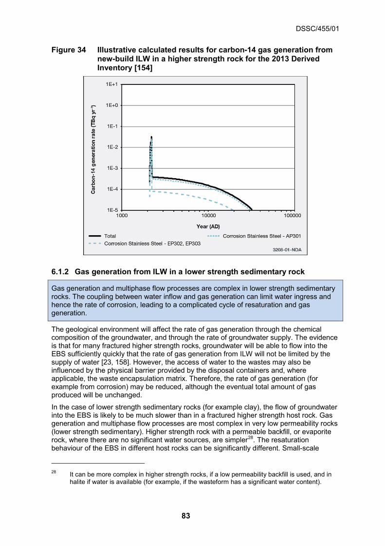
DSSC/455/01
83
Figure 34 Illustrative calculated results for carbon-14 gas generation from new-build ILW in a higher strength rock for the 2013 Derived Inventory [154]
6.1.2 Gas generation from ILW in a lower strength sedimentary rock
Gas generation and multiphase flow processes are complex in lower strength sedimentary rocks. The coupling between water inflow and gas generation can limit water ingress and hence the rate of corrosion, leading to a complicated cycle of resaturation and gas generation.
The geological environment will affect the rate of gas generation through the chemical composition of the groundwater, and through the rate of groundwater supply. The evidence is that for many fractured higher strength rocks, groundwater will be able to flow into the EBS sufficiently quickly that the rate of gas generation from ILW will not be limited by the supply of water [23, 158]. However, the access of water to the wastes may also be influenced by the physical barrier provided by the disposal containers and, where applicable, the waste encapsulation matrix. Therefore, the rate of gas generation (for example from corrosion) may be reduced, although the eventual total amount of gas produced will be unchanged.
In the case of lower strength sedimentary rocks (for example clay), the flow of groundwater into the EBS is likely to be much slower than in a fractured higher strength host rock. Gas generation and multiphase flow processes are most complex in very low permeability rocks (lower strength sedimentary). Higher strength rock with a permeable backfill, or evaporite rock, where there are no significant water sources, are simpler28. The resaturation behaviour of the EBS in different host rocks can be significantly different. Small-scale
28 It can be more complex in higher strength rocks, if a low permeability backfill is used, and in
halite if water is available (for example, if the wasteform has a significant water content).

DSSC/455/01
84
features, coupled processes and upscaling in lower permeability host rocks are important [29].
A modelling comparison of gas generation29 and water saturation for UILW vaults in a lower strength sedimentary host rock and a higher strength rock has been made [29]. Figure 35 shows the calculated water saturation of the waste vaults at closure and 40 years after closure in a higher strength rock (increasing water saturation is shown by the colour changing from blue through green towards red). At 40 years after closure there is some free gas present in the waste packages, as a result of ongoing gas generation (Figure 36a), and a small amount present in the vault backfill, but the system is almost completely resaturated, as shown in Figure 36b. Note that the rates of gas generation from Magnox were calculated for a groundwater containing no chloride. Hence, the rates are much lower than those shown above in Figure 17 and hence the Magnox persists for much longer as can be seen in Figure 36a.
The calculated behaviour in a lower strength sedimentary rock is much more complex because resaturation and the generation of gas are strongly coupled. Figure 37a shows the water saturation at three years, when the vaults are backfilled and closed, but the service and transfer tunnels are still open and being dewatered. The closed vaults begin to resaturate and gas starts to be generated from the wastes. After 30 years the service and transfer tunnels are assumed to be closed. Figure 37b shows water saturation at 30 years; the wasteforms ‘pull’ water in from the backfill and the vault backfill has largely dried out (in reality the containers will remain intact for tens of thousands of years, and will prevent water being drawn into the waste directly since water would have to be drawn in through the container vents).
Once the service and transfer tunnels have been closed, they resaturate more rapidly than the ILW vaults because of their smaller volume (per unit length), and because there is no gas generation in these tunnels. The concrete seals have higher capillary suction than the sand-bentonite tunnel fill, and therefore resaturate more rapidly than the tunnels. After 1,000 years the service and transfer tunnels, concrete plugs, waste packages and some of the vault backfill have largely resaturated. Gas is trapped in the vault crown spaces, which are fully desaturated (Figure 37c).
Gas generation continues beyond 1,000 years. Gas cannot readily escape from the vault and water saturation starts to decrease. After 10,000 years the backfill is calculated to be fully desaturated (is at its residual saturation); the water saturation in the wastes has decreased and gas is moving into the service and transfer tunnels (Figure 37d). The quantity of gas that can be generated is now limited by the amounts of water and gas generating materials remaining in the waste packages.
At 100,000 years the waste packages, vault backfill, service and transfer tunnels are calculated to be fully dry (that is, they are at their residual saturations) (Figure 37e). A small amount of water remains in the concrete plugs. Gas generating processes have consumed all the water that remained in the wastes at 10,000 years. However, Figure 38 shows that some of the waste is calculated to still be partially saturated. This arises because in the model the waste is in contact with the rock and is pulling in water by capillary suction (in reality, as mentioned above, the containers will remain intact for tens of thousands of years, and would prevent water being drawn into the waste for at least some of the time up to 100,000 years).
29 Note that the gas generation model used in these post-closure calculations is simpler than
SMOGG, for example it does not include radiolysis and assumes methanogenic conditions in the vaults.

DSSC/455/01
85
Plots of the calculated average water saturation in the waste and backfill in the UILW vaults, and gas generation with time, are shown in Figure 39a and Figure 39b respectively. The water saturations are average saturations and there is significant variation in saturation within the backfill with elevation, with higher gas saturation in the crown space and higher water saturation at the base of the vaults. As noted above, the model does not consider the container, which will act as a barrier to the direct drawing of water into the wasteform. The model is therefore likely to overestimate the water saturation in the waste and, consequently, the rate of gas generation may be overestimated (but see footnote 29 on the exclusion of radiolysis).
The calculated net rate of gas generation with time is shown in Figure 39b. Corrosion of Magnox and aluminium is not limited by the availability of water, because water is pulled in from the backfill in the model. All the aluminium has corroded by the time the service tunnel is closed (after 30 years) and the Magnox corrosion rate has decreased significantly at this time because the vault temperature has returned to ambient. The net gas generation rate falls to a minimum at about 60 years, when hydrogen from metal corrosion is consumed by microbial reduction of carbon dioxide to methane in the model, and then increases as carbon dioxide generation from the degradation of cellulosic wastes decreases. Gas is then generated from the ongoing corrosion of steels and residual Magnox, with complete corrosion of the Magnox at about 6,400 years.

DSSC/455/01
86
Figure 35 Illustrative calculated results for water saturation in ILW tunnels and vaults at closure and 40 years after closure in a higher strength rock [29]

DSSC/455/01
87
Figure 36 Illustrative calculated results for gas generation and water saturation in ILW tunnels and vaults in a higher strength rock [29]
a) Gas generation in one ILW vault in a higher strength rock
b) Average water saturation in the waste and backfill in a higher strength rock
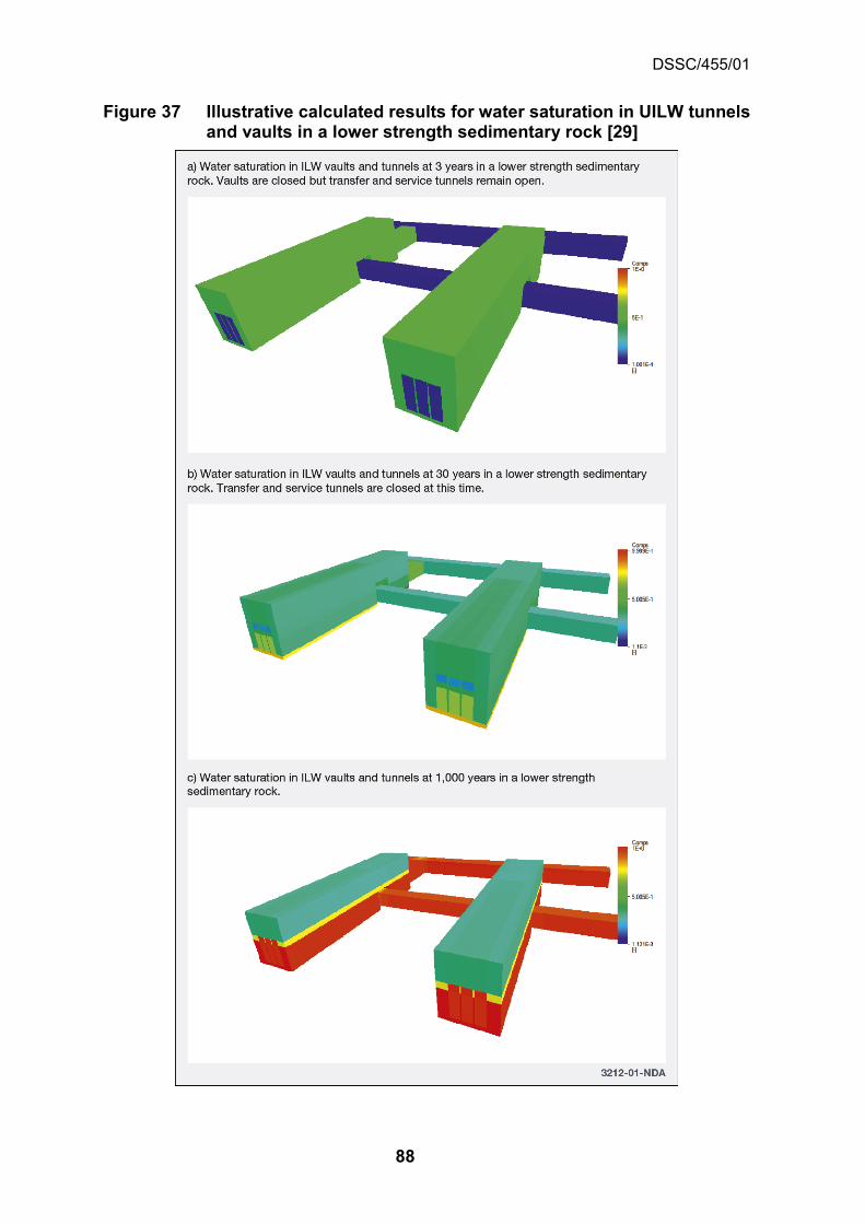
DSSC/455/01
88
Figure 37 Illustrative calculated results for water saturation in UILW tunnels and vaults in a lower strength sedimentary rock [29]

DSSC/455/01
89

DSSC/455/01
90
Figure 38 Illustrative calculated water saturation along a ILW vault at 100,000 years in a lower strength sedimentary rock [29]

DSSC/455/01
91
Figure 39 Illustrative calculated results for gas generation and water saturation in UILW tunnels and vaults in a lower strength sedimentary rock [29]
a) Average water saturation in the waste and backfill in a lower strength sedimentary host rock
b) Gas generation in one UILW vault in a lower strength sedimentary rock
These vault scale calculations were extended to a GDF scale model for the lower strength sedimentary rock and the effects of uncertainty were explored through a set of variant calculations that examined process and parameter uncertainty, upscaling and the influence of design [29].

DSSC/455/01
92
6.1.3 Gas generation from ILW in an evaporite rock
For a GDF in halite the gas generation rate will be more limited than for the other host rocks because of the lack of water. The water contents of the waste packages at closure constrain the amount of gas that can be generated.
In the case of halite the rate of flow of groundwater (brine) to the GDF is expected to be even lower than in other host rocks and the sacks of magnesium oxide used in the ILW disposal area will be dry. Therefore, the gas generation rate will be more limited than for the other host rocks and the water contents of the waste packages at closure constrain the amount of gas that can be generated [29, 166]. This may be less than the water content at the time of packaging because of ongoing water-consuming reactions during waste package storage prior to transport to the GDF.
6.1.4 Gas generation from HLW, SF, plutonium and HEU
The rate of gas generation by HLW and spent fuel containers will depend on the container material. The corrosion of copper under anaerobic conditions is slow and only proceeds in the presence of sulphide; such spent fuel containers will generate no gas from corrosion. The only source of gas from corrosion will be from the iron insert once penetration of the copper container has occurred.
Depending on choice of container and backfill/buffer materials, HLW, spent fuel, plutonium and HEU might also generate gas. The rate of gas generation by HLW and spent fuel containers will depend on the packaging. Vitrified HLW will produce negligible amounts of gas and only corrosion of the disposal container (and possibly radiolysis of the surrounding materials) will be important. The rate of hydrogen generation from HLW will depend on the total external surface area of the disposal containers and the corrosion rate of the metal. The corrosion rate of carbon steel (a candidate packaging material for HLW) in bentonite is about 1 µm y-1 [164].
For spent fuel, our illustrative disposal concept for a higher strength rock is based on the Swedish KBS-3V design, in which the spent fuel is packaged inside a copper container (for corrosion resistance) with a cast iron insert (for mechanical strength). The container is placed in a deposition hole drilled in the floor of a disposal tunnel. The annulus around the container will be filled with a buffer of highly-compacted bentonite, to isolate and protect the disposal container [15]. Because the corrosion of copper under anaerobic conditions is slow and only proceeds in the presence of sulphide, the spent fuel containers in this disposal concept example will generate no gas from corrosion.
The only source of gas from corrosion will be from corrosion of the iron insert once penetration of the copper container had occurred. However, assuming the gas can escape through the surrounding buffer material (see Section 6.2.2), scoping calculations suggest this scenario has only minor implications [167, 67]. For a scenario of a single KBS-3V type container with a perforation, because of an undetected manufacturing defect, there may be sufficient inflow of water to sustain corrosion over most of the surface area of the cast iron insert. However, on a timescale of a few tens of thousands of years the gas pressure in the container will increase and slow the inflow of water, hence restricting corrosion to a part of the surface. Corrosion is likely to occur more rapidly close to the penetration through which the water enters the container than at more distant locations. The corrosion products could also restrict diffusion of water vapour in the gap between the steel inner vessel and the copper shell. If corrosion occurs at a rate of 0.1 µm y-1, unrestricted by water availability, it will take around ~10,000 years to close a small (~1 mm) gap between the cast iron insert and the copper shell. Thus, corrosion is likely to occur over only a part of the surface of the cast iron insert, but it is difficult to predict either the location of corrosion or the corrosion rate.

DSSC/455/01
93
The corrosion of Magnox cladding and metallic uranium is relatively rapid in contact with water. In the case of the possible disposal of Magnox spent fuel this will lead to the generation of hydrogen and gaseous carbon-14 and the overall rates of gas generation will depend on the rate of supply of water to the spent fuel. The rate of water transport through the bentonite will be limited by its low permeability and gas generation is likely to be strongly-coupled to water ingress into a perforated container (similar strong coupling for gas generation from ILW in a lower strength sedimentary rock is discussed in Section 6.1.2). Thus, for a bentonite buffer that is fulfilling its safety functions, these will limit the rate at which groundwater can reach the metallic spent fuel and restrict the rates of corrosion and the generation rates of hydrogen and gaseous carbon-14. When the gas pressure reaches a threshold value, pressure–induced microfissures will open in the bentonite and allow the hydrogen to flow away from the spent fuel and the container. These microfissures in the bentonite may stay open for as long as gas pressure is sufficiently high and then close (discussed below in Section 6.2.2) because of the swelling pressure of the bentonite. The bentonite will be undamaged by this and its ability to perform as an engineered barrier [3] is expected to be unaffected. An alternative scenario making three cautious assumptions of an early breach of a container containing metallic fuel, unlimited water availability and the release of carbon-14 directly to a focused area in the biosphere leads to a significant radiological hazard [67]. However, the assumption of an unlimited water supply corresponds to a situation in which the bentonite buffer has already been lost as a functioning engineered barrier.
The rate of hydrogen generation from radiolysis of groundwater depends on the external dose rate and the concentration of dissolved species (for example iron(II)). Any oxygen produced will be consumed rapidly by oxidation processes, while the hydrogen may be transported away [168,169]. SKB has concluded that the wall thickness of their copper disposal canister (together with the insert) is sufficient for gas generation from γ-radiolysis to be negligible because the external radiation level is too low.
Because it is assumed that high-integrity containers will be used for spent fuel, fission gases such as tritium and krypton-85 (t½= 10.73 years) will decay within the waste disposal containers. Depending on the design life of the container, carbon-14 (t½= 5,730 years) may also decay significantly. For example, in geochemical conditions in which the use of copper containers has been proposed, their durability in a bentonite buffer is predicted to be greater than 100,000 years [2]. This is between 17 and 18 half-lives of carbon-14, which corresponds to a 131,000 to 262,000 fold decrease in the amount of carbon-14 through radioactive decay. Carbon steel has been considered as a container material for spent fuel in Belgium, France, Japan and Switzerland. Containers can be designed with a suitable corrosion allowance and will maintain their integrity for timescales of the order of several tens of thousands of years, by which time a major proportion of the carbon-14 will have decayed (a durability of 10,000 years, a likely minimum, corresponds to nearly two half-lives of carbon-14).
Decisions about the waste container materials for HLW, spent fuel, plutonium and HEU are yet to be made. The implications for gas generation depend on the choice of material. If a metal such as copper is used no gas is expected to be generated from corrosion of the disposal container. If carbon steel were to be used for the disposal containers, then the generation of hydrogen from their corrosion will need to be considered in the future.
6.2 Gas migration through engineered barriers
Various materials (for example, cementitious materials, bentonite, bentonite mixtures or crushed salt) may be used in buffers, backfills and seals in a GDF.
Various materials may be considered as buffers, backfills and seals in the GDF, for example:

DSSC/455/01
94
• compacted and pelleted bentonite may be employed as a buffer material in deposition holes and deposition tunnels
• cementitious materials30 (based on Portland cement), excavated clay, crushed salt, compacted/pelleted bentonite and sand/bentonite mixtures may be used as backfills
• concrete, bentonite, bentonite/sand and clay/bentonite mixtures may be used to construct plugs and seals.
The US repository in halite for transuranic wastes (WIPP) employs sacks of magnesium oxide placed on top of waste stacks, and elsewhere in the facility, which will consume carbon dioxide and reduce the amount of free water [170, 171].
For both cementitious and clay backfill materials, the gas has to be able to escape through the engineered barrier without degrading its subsequent performance. For example, in the case of cementitious materials, the gas should escape without disrupting either the structural or the chemical barriers that the backfill is designed to provide. Bentonite/sand mixtures are being considered as an option for cavern seals in the Nagra ILW/LLW concept to allow the escape of gas whilst restricting movement of groundwater [122].
6.2.1 Cementitious materials
Two-phase flow is the main mechanism of gas migration through cementitious materials. Carbonation of cementitious backfills can lead to changes in porosity and permeability. The rate of carbonation is affected by the degree of saturation and the cement formulation.
Cementitious materials have complex pore structures: the pore sizes are distributed between about 10-3 µm and 1 µm, and commonly the larger pores are linked by smaller pores. Moreover, water is present in the calcium-silicate-hydrate gel found in cement, and so drying modifies the behaviour of the material. Because of these characteristics:
• gas permeability coefficients cover a wide range, typically about 10-21 to 10-15 m2 (depending on the composition and condition of the material), with values at the lower end of the range measured for water-saturated materials [172].
• it is difficult to measure gas flow through cementitious materials as a function of water saturation.
It is possible to engineer the formulation of a cementitious backfill material to have high porosity and high gas permeability [122, 173] (for example the Nirex reference vault backfill (NRVB) has a gas permeability coefficient of about 10-16 m2 [173]) to provide gas capacity within the EBS and to assist gas release from the EBS. However, there is a relationship between pore structure/porosity (which are assumed to determine permeability) and strength. It may be necessary to balance strength requirements (for example to withstand stresses because of creep of the host rock in clays) with the need for suitable gas permeability.
Two-phase flow can be considered to be the main mechanism of gas migration through cementitious materials [19] and may be described by conventional models of two-phase flow in porous media (see Section 3). However, because there are few experimental data on gas migration through partly-saturated cementitious materials it is difficult to validate such models at present.
30 A wide range of cementitious materials may be used in the GDF, for example: waste
encapsulation grouts; backfill; and structural concrete.

DSSC/455/01
95
Carbon dioxide will dissolve in porewater and react with cementitious materials, resulting in their carbonation and the production of minerals such as calcite [174]. This provides a sink for the removal of carbon dioxide from the gas phase and is of interest because of its ability to retain 14CO2 within the engineered barrier system, as well as its potential impact on the alkaline buffering and sorption properties of the engineered barrier system [3]. The formation of insoluble carbonates (for example by carbonation of cements) is also one of the processes that minimises the possibility of the conversion of 14CO2 to 14CH4 by methanogens in the presence of hydrogen [157]. Carbonation is also of general interest because of its possible effects on the performance of engineered structures exposed to atmospheric carbon dioxide and is thus studied widely (see for example [175, 176]). In the UK the reaction of carbon dioxide with typical wasteform grouts and with NRVB has been studied [153, 161, 177]. Measurements of the carbonation capacity of NRVB give typical values of 5,000 to 6,000 mol m-3 [161, 162, 178]. The extent of carbonation of cements over time will depend on the rate of supply of carbon dioxide (for example from microbial degradation of cellulosic waste). The rate of uptake of carbon dioxide is also affected by the water saturation of the cement, with uptake being slower under fully-saturated conditions compared to partially-saturated conditions.
Carbonation of small NRVB samples (a few cm in size) has been studied under the EC FORGE project for saturated static systems containing dissolved CO2 (where diffusion is the transport process) and for systems with a CO2 flow (as gaseous, supercritical and dissolved CO2) [179, 180]. Carbonation gave increases in weight of up to 9%, with no increase in sample size, and resulted in a series of reaction fronts in the static samples separating four reaction zones, as shown in Figure 40:
• Zone 1 = minor carbonation with minimal apparent volume change
• Zone 2 = partial carbonation and very localised shrinkage
• Zone 3 = complete conversion of portlandite and CSH with localised shrinkage associated with the development of calcium carbonate-sealed micro-fractures
• Zone 4 = dissolution of initially formed carbonate minerals in the outermost parts of the sample by the surrounding, slightly acidic water.
Figure 40 Partially-carbonated NRVB showing zones of different degrees of carbonation and associated reaction fronts [179]
The shrinkage in Zone 2 appeared as small cracks (typically several mm long) that did not appear to extend beyond this zone and were located at the active carbonation front. One set of shrinkage cracks was oriented approximately parallel to the flow direction and the other set was approximately perpendicular to it. Each of the cracks was only a temporary feature, as secondary precipitation eventually sealed them as the carbonation front progressed through the sample (thus each individual crack is temporary, but a longer-lasting, narrow zone of cracks moves through the sample). Zone 3 contained an

DSSC/455/01
96
anastomising ‘3D chicken-wire’ mesh of interconnected, higher-density, carbonate-filled micro-fractures (typically on a 10s to 100s μm scale) that separated silica-rich areas having a lower density and high porosity, and sub-parallel ‘relic’ reaction fronts. The small fractures of Zone 2 appear to be filled with secondary precipitates in Zone 3. Appreciable amounts of a chloride-rich phase were formed at the boundary of Zones 2 and 3. Carbonated samples remained intact.
Controlled flow-rate carbonation experiments on the NRVB gave decreases in overall sample permeability because of the reduction in porosity resulting from the conversion of portlandite and CSH to secondary carbonate minerals and silica gel. The same reaction zones were observed as in the static experiments. Porosity and permeability were reduced, with the greatest reductions in porosity and permeability in a very narrow zone at the leading edge of the visible alteration front, as shown in Figure 41. Injection of free-phase (gaseous and supercritical) CO2 resulted in a halving of hydraulic permeability, whereas use of dissolved CO2 reduced hydraulic permeability by about three orders of magnitude. Carbonation did not lead to complete blockage of the cement however and CO2 migration was still possible (though to a reduced extent). In the context of a GDF, therefore, carbonated NRVB should still allow the passage of gas. The carbonation features, and the secondary phases observed, were noted to bear many similarities to those found in borehole cements used in CO2-storage that have much lower porosity/permeability than NRVB. Similarities to samples of naturally-occurring CSH phases that have been naturally-carbonated over prolonged timescales were also noted.
Figure 41 Partially-carbonated NRVB showing front between carbonated and relatively unaltered material and associated permeability [179]
Examination of unsaturated NRVB samples, which were partially-carbonated at a larger scale representative of NRVB above a vent in the lid of a 500 litre drum, showed similar features [162]. However, an increase in permeability was seen for the carbonated material despite a decreased porosity. It was postulated that this may indicate that the accessible microporosity is better connected than in unaltered NRVB, possibly due to the development

DSSC/455/01
97
of the ‘chicken-wire’ like mesh of micro-fractures in the carbonated material. Although these micro-fractures were observed to be largely filled by calcium carbonate reaction product, any unfilled connected micro-fractures will give a higher-permeability network. However, the differences between these results and those from the small-scale samples have yet to be rationalised. Unfortunately, the reaction front itself was too narrow for its permeability to be measured although, given its lack of porosity, it may have a lower permeability than either the uncarbonated or carbonated NRVB [162].
The rate of carbonation of BFS/OPC samples of various ratios increases with increasing BFS content [181]. The main carbonation products were calcium carbonate (as calcite and vaterite), silica gel, alumina gel and possibly silica-alumina gel. The relative fractions of vaterite and calcite varied with time during carbonation with air or CO2. Decalcification and dealumination of the CSH gel were seen. For all samples, the rate of carbonation slowed with time.
The flow of gases through a cementitious backfill may be strongly influenced by the presence of cracks. It is difficult to quantify the distribution and nature of cracks in a cementitious backfill [182], and this will introduce some uncertainty into the description of gas migration through a cement backfill. For example, if the gas flows through cracks then this can limit the amount of contact between carbon dioxide and cementitious materials, and therefore restrict the extent of the carbonation reaction. Dissolved carbon dioxide in water-filled cracks in saturated cement system will precipitate as calcium carbonate provided there is a sufficient supply of calcium ions into solution in relation to the generation rate.
6.2.2 Bentonite and bentonite/sand
The mechanism of gas transport in unsaturated or partially-saturated bentonite is two-phase flow. However, two-phase flow does not occur in saturated bentonite. Once the gas reaches a critical pressure, pressure-induced micro-fissures open and gas is released.
For HLW and spent fuel disposal containers surrounded by bentonite in a higher strength host rock or a lower strength sedimentary host rock, the bentonite buffer itself will be an important barrier to gas migration.
A gas phase can migrate through an initially water-saturated buffer clay only if the gas pressure exceeds a threshold value (or gas entry pressure, which has been related to the sum of the clay's swelling pressure and the water pressure). The degree of water saturation of bentonite determines the transport mechanism for gas. Two-phase flow is the dominant transport mechanism in an unsaturated or partially-saturated bentonite and in sand-bentonite mixtures if the sand content is sufficiently high [19, 183].
The transport behaviour of bentonite changes when it reaches a saturation of 80 to 90%. Confined bentonite at high saturations has a large swelling pressure and a commensurately large gas entry pressure. The gas entry pressure is so large that two-phase flow, accompanied by the displacement of water, cannot occur. The only transport mechanism available in this case is diffusion. If the gas pressure exceeds the pressure in the bentonite then consolidation of the bentonite (the bentonite is compressed) and/or the formation of dilatant pathways occurs [183]. The extent of consolidation will be limited and at some critical pressure pathways can form and gas will then migrate through these pressure-induced micro-fissures [184, 185] that are expected to close once the gas pressure has fallen.
RWM is participating in the LASGIT experiment at the Äspö Hard Rock Laboratory in Sweden in order to understand:
• how bentonite re-saturates
• how gas migrates through this buffer material.

DSSC/455/01
98
The LASGIT experiment is using a full-scale mock-up of a spent fuel container in a deposition hole. As mentioned above in Section 6.1.4, hydrogen will only be generated from corrosion in a disposal concept based on the Swedish KBS-3V concept if there is a penetration of the copper disposal container to allow the ingress of water. Corrosion of the cast iron insert and radiolysis of water that has entered the container will then generate gas. If the penetration in the copper container is small, then the rate at which hydrogen will be able to diffuse in the liquid phase away from the container will be less than the rate of hydrogen generation [167]. Therefore, the gas pressure in the container will rise. When the gas pressure reaches a threshold value, pathways in the bentonite will open and allow the hydrogen to flow away from the container. The pathways in the bentonite may stay open for as long as gas production is sufficient and may then close. Experiments show that the flow of gas will lead to little de-saturation of the bentonite [186]. LASGIT has confirmed at the field scale the coupling between gas, stress and pore-water pressure for flow before and after major gas entry. Pathway propagation and dilatancy predominated. Propagation was through localised features, with general movement towards the bottom of the deposition hole in the direction of the prevailing stress gradient. Interfaces between barriers are a key factor in the behaviour of bentonite systems [19, 187] and are discussed below in Section 6.2.3.
Sand/bentonite mixtures exhibit a significantly lower gas entry pressure than compacted bentonite, but can still provide the required low hydraulic conductivity [122] and the properties can be optimised by adjusting the sand/bentonite ratio and the emplacement density. The feasibility of emplacing sand/bentonite mixtures under possible construction conditions for the GDF has been demonstrated in the Gas Migration Test (GMT) at the Grimsel Test Site underground laboratory in Switzerland. The experiment was designed to investigate gas migration through an EBS and consisted of a concrete silo surrounded by sand/bentonite buffer. The results of the programme demonstrated the high gas transport capacity of sand/bentonite mixtures and the importance of interfaces as small voids for gas transport [122, 188]. The creep of some host rocks may lead to the eventual closure of such pathways.
6.2.3 The role of interfaces for a bentonite EBS
Interfaces will be the preferred pathway for gas in an unsaturated bentonite system. Gas will generally move along the interface between the clay and another material in a saturated system. Bentonite/bentonite interfaces will usually seal upon saturation and will not act as preferential pathways for gas.
The interfaces within the EBS, and between the EBS and the host rock, may act as a mechanical plane of weakness, but can also act as preferential pathways for gas migration [188, 189].
Laboratory tests with bentonite (Calcigel™)/sand blocks undertaken in FORGE have shown that under dry conditions gas flow along interfaces is at least four orders of magnitude higher than through the matrix. Increased confinement pressure significantly lowers gas flow, with the effect more pronounced for interfaces than for the matrix. When the bentonite bricks are saturated the interfaces between the bentonite/sand blocks seal and cease to act as a preferential pathway for gas, with the aggregated bentonite blocks behaving as a homogeneous matrix. Gas pressure induced re-opening of sealed interfaces was not observed. Despite saturation of the bentonite blocks, gas generally moved along the interface between the buffer and the host rock, which acts as a preferential pathway for gas migration [189].
DSSC/455/01
99
6.2.4 Seals and plugs
Saturated bentonite seals are expected to have a very low permeability. Concrete seals and plugs will be more permeable than bentonite seals.
The importance of seals and plugs in drifts and shafts is realised for most geological disposal concepts. During construction and operations, some degree of sealing may be required at the end of excavated regions of the host rock to provide temporary isolation or a more permanent long-term degree of isolation. Such seals may be required to be placed in strategic positions with respect to water inflow, as well as practical design aspects, such as the need for creating separation of disposal areas. Complete sealing systems may also be required to close disposal areas once wastes and the engineered barriers have been emplaced. Typically for most concepts, this involves high integrity sealing of the access tunnels and to some degree the access shafts to provide isolation of the GDF. For example, in evaporite rock concepts, sealing systems in the drifts and shafts are an important part of the safety concept to ensure that potential pathways for groundwater ingress are removed [3].
Saturated bentonite seals are expected to have a very low permeability and hence gas will be released if the pressure exceeds the threshold pressure for dilatant gas flow, as discussed above in Section 6.2.2. In a higher strength rock this is likely to be much higher than the gas entry pressure for fractures in the host rock. In a lower strength sedimentary rock the permeability of the EDZ, prior to any self-healing through creep, may be higher than that of the seals or the host rock and it may be necessary to clear the EDZ from around the location of intended seals. Concrete seals and plugs will be more permeable than bentonite seals.
6.3 Gas migration through different geological environments
The three categories of host rock considered in the illustrative geological disposal concepts are nominally low-permeability, but their characteristics span a wide range.
Whereas all the categories of host rock are nominally low-permeability, their characteristics span a wide range. For example [158]:
• higher strength rocks tend to be fractured and are dual porosity systems (with a fracture porosity of about 10-5 and a rock matrix porosity of about 10-2) in which the permeability is likely to be in the range 10-18 m2 to 10-16 m2 and the gas entry pressure is expected to be low
• clay, as an example of a lower strength sedimentary rock, in contrast, has a porosity of about 0.1 to 0.231, an anisotropic permeability32 with a magnitude of about 10-20 m2 and a gas entry pressure that is expected to be high33
• halite has a porosity of about 10-2 and are essentially impermeable (the permeability is below a detection limit of about 10-22 m2).
31 For example, Opalinus Clay has a porosity of between 0.12 and 0.16 [122] 32 The horizontal permeability might be an order of magnitude larger than the vertical
permeability. 33 Compiled data presented in Figure 3.3.2 of reference [42] show that the majority of typical gas
entry pressures for various low permeability rock formations (claystones, shales, sandstones) lie in the approximate range 1 to 50 MPa for permeabilities between 10-21 and 10-19 m2.

DSSC/455/01
100
These characteristics can lead to very different results for gas generation and its subsequent migration in the different geological environments. Gas migration from the GDF will also be determined by the nature of the rocks overlying the host rock. RWM considers a number of geological environments, including overlying rocks [102]:
• higher strength host rock to surface
• higher strength host rock overlain by higher permeability sedimentary rocks
• higher strength host rock overlain by a mixed sedimentary sequence
• lower strength sedimentary host rock overlain by higher permeability sedimentary rocks
• lower strength sedimentary host rock overlain by lower permeability sedimentary rocks
• evaporite host rock overlain by sedimentary rocks.
6.3.1 Barriers to gas migration in geological environments
There are a number of features, such as cap rocks or gas traps, that can trap gases in some geological environments.
In some geological environments, there may be features, such as cap rocks or gas traps, which can trap gases migrating through the geosphere and thereby delay or prevent their release to the biosphere [37].
Several trapping mechanisms are simply the result of the geometry of the geological sequence (as shown in Figure 42), and a common way to search for natural gas in the subsurface is to use seismic data exploration to identify the geological features that are known to trap gas.
For natural gas reservoirs, the cap rock (or seal) typically is a thick and laterally continuous layer of very low permeability rock, which has a very high capillary gas entry pressure. If the capillary gas entry pressure is sufficiently high, gas cannot enter the pore space and is trapped beneath the low permeability rock. The most common cap rock lithologies over commercial petroleum reservoirs are shales and evaporites (mainly halite) [190]. Although, cap rocks are unlikely to act as perfect seals, some failing due to capillary leakage (some gas gets into the pore space) and others failing due to fracturing [191], many have been good enough to enable large accumulations of gas (and oil) to build up over millions of years. Gas can migrate laterally along the base of a cap rock and successful gas traps usually include a structural component that focuses the gas flow to one location.

DSSC/455/01
101
Figure 42 Schematic showing the two basic examples of structural trap (the anticlinal trap and the fault trap) and a stratigraphic trap [37]
Structural traps are formed by processes such as faulting and folding, forming geometries into which gas can flow, but from which the gas is unlikely to leave. Examples include anticlines and fault traps, (see Figure 42). Fault traps may prevent gas migration because the fault itself is very impermeable, or because the reservoir layer is juxtaposed against a low permeability layer (as in Figure 42).
Stratigraphic traps arise from the geometry of the original deposition of the sediments, instead of from later movement, as in the case of structural traps. Stratigraphic traps can be caused by high permeability units pinching out, or eroding to form an unconformity.
As gas migrates through the pores in a rock, a small amount of gas may be trapped due to capillary forces (residual trapping). Once the gas is immobilised in the pore space, there is more time for the gas to dissolve in the formation water.
6.3.2 Higher strength rocks
Fractured higher strength rocks typically do not form a significant barrier to gas migration. Dependent on the flux of water through the vaults some or all of the gas dissolves in, and is then transported by, the groundwater. The most significant consequence of gas in higher strength rocks is the release of 14C-methane to the biosphere.
At the time of closure, the GDF will include an inventory of gas (air). Thereafter, more gas will be generated by the waste.
Before closure, the presence of the GDF at atmospheric pressure will lead to a region of drawdown around the facility, where the groundwater pressure is reduced and where groundwater flows towards the facility.
DSSC/455/01
102
After closure, when the groundwater flowing into the GDF is no longer drained and the gas being generated is not removed, the gas pressure in the facility will start to build up. The rate at which groundwater will flow into the GDF will depend on the hydrogeology. In the case of a higher strength rock, it is expected that at some time relatively soon after closure (simulations for ILW vaults in an example higher strength rock suggest a timescale of a few tens of years [23, 158]) the gas will be compressed sufficiently that its pressure will become comparable to hydrostatic pressure. After that time the groundwater flows will no longer be directed towards the GDF and the gas may move out of the facility into the surrounding rock.
In a higher strength rock the EDZ [4] around the EBS is likely to be more permeable than the vault and tunnel seals. For a higher strength rock the EDZ is not a key feature with respect to gas because the host rock is relatively permeable and the fractures in the host geology have a low gas entry pressure. The EDZ becomes more significant if the permeability of the host geology is dominated by discrete fracture zones. In this case the EDZ may connect discrete fracture zones and thereby increase the connection between vaults and fracture zones [29].
A possibility is that all of the gas will dissolve in the groundwater flowing through the GDF. To a good approximation, the solubility of a gas in water increases linearly with the partial pressure of the gas. For hydrogen under the conditions expected in the GDF, the constant of proportionality (Henry's constant) is 7.8 × 10⁻⁴ mol l-1 atm-1 [192], which can be expressed in terms of volume of an ideal gas at standard temperature and pressure (STP) of about 2 × 10⁻⁷ m3 at STP m-3 Pa-1. Thus, at a depth of 650 m, where the hydrostatic pressure is about 6.4 MPa, about 1.3 m3 at STP of hydrogen will be able to dissolve in 1 m3 of groundwater. Therefore, in order for all of the hydrogen to dissolve in the groundwater, the flow through the GDF has to be about 800 m3y-1. This may be greater than the groundwater flow rates for a GDF situated in a higher strength rock. For example, a volume flux of 300 m3y-1 was used in the reference case calculations for the UK Nirex generic performance assessment [160]. Thus, only some of the gas may be dissolved in groundwater in the EBS and carried away in solution, the remainder will form a free gas phase. Fractured higher strength rocks typically do not form a significant barrier to gas migration. In particular, the so-called gas entry pressure is low, and in a fractured higher strength rock it is likely that:
• gas will be released from the GDF without a significant overpressure
• a gas phase will migrate away from the GDF.
For example, Figure 43 shows the calculated build-up of gas pressure in a repository containing UILW and SILW/LLW (based on the 2004 Derived Inventory) in fractured higher strength host rock. The pressure increases to a maximum of only about 0.2 MPa above the hydrostatic pressure of 6.3 MPa before gas is released a few years after closure.

DSSC/455/01
103
Figure 43 Illustrative pressure evolution in the GDF containing ILW/LLW in a higher strength rock [23]
As the gas phase migrates through the geological environment, it comes into contact with groundwater. Some of the gas dissolves into, and is then transported by the groundwater. The amount of gas that dissolves depends on both the volume of groundwater contacted and the gas solubility (the latter is a function of pressure, temperature and salinity).
Figure 44 and Figure 45 show some examples of calculations of gas migration, as free gas and as dissolved gas respectively, through a realistic geology. The location of the GDF is depicted by the rectangle in the centre of the two figures.
Figure 44 Fraction of pore space occupied by gas at 240 years after closure for gas migration from the GDF in a higher strength rock [158]

DSSC/455/01
104
Figure 45 Mass fraction of dissolved gas at 240 years after closure for gas migration from the GDF in a higher strength rock [158]
Figure 44 shows a gas phase migrating from the GDF located at depth in a higher strength rock. The gas saturation (the fraction of the pore space in the rock that is occupied by gas) is shaded with a rainbow colour. Faults and the boundaries of the different types of rock are denoted by the black lines.
In this simulation, the gas moves upward through the host rock and overlying rocks until it comes to a low-permeability formation with a high 'gas entry pressure' (a barrier layer, or 'cap rock'). The barrier layer forces the gas to move towards the right. Eventually the gas finds a place where a major fault breaks the continuity of the barrier layer, and then it is able to move upwards into the more permeable, near-surface rocks. There the gas encounters a large flow of groundwater, into which it dissolves and the free gas phase ceases to exist.
Figure 45 shows the corresponding plume of dissolved gas. The mass fraction of dissolved gas is shown by colour coding, with the red end of the spectrum corresponding to higher concentrations. This example illustrates that the gas pathway will be complex and specific to both a site and the design of the GDF.
Possible consequences of gas in higher strength rocks include:
• the release of flammable (hydrogen and methane) and radiotoxic (for example 14C-methane) gases to the biosphere
• entrainment of contaminated water by gas.
It is considered that any release of hydrogen and methane at the surface is likely to be insufficient to present a hazard [21, 156].
It is possible that changes to a fracture network in a higher strength rock could occur as a result of an earthquake [4]. This can have an impact on gas migration from the GDF by opening alternative fracture pathways for gas.

DSSC/455/01
105
6.3.3 Lower strength sedimentary rocks
Resaturation will be coupled with hydrogen generation and migration. If the gas pressure exceeds the hydraulic pressure plus the gas entry pressure for the host rock then a gas phase will flow into the host rock. Gas pressure may create localised porosity dilation and temporary micro-fissuring in the host rock, which may close once the gas pressure drops.
Clay is being considered as a host rock by Nagra (Switzerland), Andra (France) [163] and Ondraf / Niras (Belgium). The Swiss concept for Opalinus Clay [122,164] is the illustrative disposal concept in the DSSC for both types of waste (ILW / LLW and HLW / spent fuel in carbon steel containers) in a lower strength sedimentary rock.
Our current view, based on references [18, 19, 29, 122, 163, 164, 193], is that the following processes will be important:
• because the facility will be ventilated throughout construction and operation, the host rock in the immediate vicinity of the operational GDF will de-saturate.
• outside the de-saturated zone, there will be a transient pressure build-up around the high heat generating waste packages, for example HLW and spent fuel (the temperature rise decreases the groundwater density and hence the pressure increases).
• after closure of the GDF, both the de-saturated zone and the facility will gradually re-saturate.
• the time for saturation of the bentonite surrounding a HLW/SF container will range from about 100 years to many hundreds of years.
• resaturation will be coupled with hydrogen generation (mainly from corrosion of metal components) and its migration; this will delay the attainment of full saturation in ILW / LLW emplacement tunnels, which can take tens of thousands of years.
• any hydrogen generated, as well as air trapped at the time of closure, will dissolve in the water in the engineered barrier system until the solubility limit at the GDF pressure is reached; dissolved gas will then diffuse away from the facility into the host rock.
• if the rate of gas generation is sufficiently high, the gas pressure will rise until a gas phase can migrate away from the GDF.
• a possible pathway will be the EDZ34, which is likely to contain stress relief fractures that will act as preferential pathways for free gas. However, the host rock around the GDF will creep slowly and the fractures in the EDZ may be healed as the rock converges under the lithostatic pressure.
• if the gas pressure exceeds the threshold for two-phase flow (the hydraulic pressure plus the gas entry pressure), then a gas phase will flow into the host rock.
• a further increase in the gas pressure may create localised porosity dilation and temporary micro-fissuring in the host rock, which closes once the gas pressure drops (depending on the properties of the host rock) and preventing the gas pressure exceeding the strength of the host rock.
34 The shafts and access tunnels, as well as the EDZ around those features, may provide a
preferential pathway for groundwater flow and gas migration; that is because they will be more permeable, and have a lower gas entry pressure, than the undisturbed rock. Sealing of the features will be an important issue for GDF design.

DSSC/455/01
106
• pore-water will be displaced from the ILW / LLW emplacement tunnels into the host rock once the gas pressure exceeds the hydrostatic pressure. However, pathway dilation will result in little displacement of water when gas is released into the host rock and Nagra have concluded that gas effects on the movement of dissolved contaminants from a LLW/ILW repository in Opalinus Clay will not compromise safety.
Figure 46 shows calculated gas pressures where resaturation is coupled to gas generation for the GDF in a lower strength sedimentary rock. A model that couples together waste evolution and heat / gas production, water inflow, and gas migration away from the facility may be required to simulate this fully.
Figure 46 Illustrative gas pressure in different waste modules/areas for the GDF in lower strength sedimentary rock [29]
Clay has very small inter-granular pores (see Section 3) and the movement of gas through these will be very slow. Figure 47 shows the results of an illustrative calculation for a gas phase migrating from the GDF located at 400m below ground level in clay. The gas saturation (SG) (the fraction of the pore space in the rock that is occupied by gas) is colour shaded with colours to the red end of the spectrum corresponding to higher gas saturation. In the model, free gas is released through the top boundary (at z = -280m) at approximately 20,000 years after closure. The system then settles down to a pseudo steady-state, in which the gas leaving the model is approximately equal to the gas generated, with the gas crossing the host rock in a relatively short period (of the order of years). Gas dissolves in the groundwater all along the pathway, followed by the migrating free gas, as can be seen by comparison of Figure 48 with Figure 47.

DSSC/455/01
107
Figure 47 Illustrative calculation of gas saturation post-closure for gas migration from the GDF in clay [158]
The colour corresponds to the degree of gas saturation (SG, see key) with increasing gas saturation towards the red end of the spectrum
(A) is at closure; (B) is at 100 years post-closure; (C) is at 1,000 years post-closure; (D) is at 10,000 years post-closure; (E) is at 20,000 years post-closure; and (F) is at 100,000 years post-closure.
Figure 48 Illustrative calculation of mass fraction of gas dissolved in liquid for gas migration from the GDF in clay [158]
The colour corresponds to the mass fraction of gas dissolved in liquid (XHYDL, see key) with increasing mass fraction towards the red end of the spectrum.
(A) is at closure; (B) is at 100 years post-closure; (C) is at 1,000 years post-closure; (D) is at 10,000 years post-closure; (E) is at 20,000 years post-closure; and (F) is at 100,000 years post-closure.
The performance of seals used to close underground spaces and access shafts and tunnels will be important because they represent possible pathways. It has been noted that for lower strength sedimentary host rock, the EDZ may be an important feature for gas migration as it can enable gas to bypass low-permeability seals, and may provide a preferential route for migration of gas [29]. The extent of an EDZ around an underground opening in a lower strength sedimentary rock is limited and, although some lower strength

DSSC/455/01
108
rocks respond to stress change in the short term by fracturing, there is much evidence for longer term creep which causes these fractures to self-heal [4]. Therefore the effects are considered to be largely or wholly reversible. In a lower strength sedimentary rock the EDZ should be considered in conjunction with interfaces between seals and rock that may provide a preferential pathway for gas migration.
The possible consequences of gas in this geological environment include:
• pressurisation of the GDF. For the clay host rocks being investigated as potential sites by Nagra and Andra, experimental data suggest that gas will enter the rock at pressures below those required for macroscopic fracturing. However, the option of engineered design features can be considered if excess over-pressurisation were to be a possible issue.
• gas-induced movement of contaminated water in the vicinity of a GDF.
6.3.4 Evaporite rock
Undisturbed halite host rock is virtually impermeable to gas. Creep of the host rock will tend to self-heal excavation damage and will compact a crushed salt backfill, gradually sealing the system. Brine inflow and gas outflow are only likely to occur via shafts or tunnels, hence the performance of seals will be important.
In an evaporite the rock around the GDF will begin to deform as soon as the GDF is excavated. As a result, there will be some degree of brittle fracturing and an EDZ will form around the facility. The host rock will subsequently creep, with the result that excavation damage to the host rock will tend to self-heal and restore the original water-tight and gas-tight performance [166]. Voids will be filled and if crushed salt were used as a backfill its permeability will also decrease because of creep.
In the absence of an artificially imposed hydraulic gradient, there is essentially no brine flow through the halite because of the extremely low permeability of the halite. Some fluid movement may occur because of thermal gradients.
Excavation of the GDF will disturb both the host rock and the natural hydraulic gradient, and can result in fluid flow. Small quantities of interstitial brine in the halite can move toward the facility. This flow can continue as long as the hydraulic potential within the facility is below the hydraulic potential in the far field. Although brine inflow into the vaults at WIPP was evident during the first three years following construction this has subsequently stopped [194]. This behaviour has been attributed to viscoelastic creep of the halite mineral, causing the damaged zone around the EDZ to self-heal. Brine inclusions also tend to migrate towards regions of higher temperature [195].
The gas phase initially will consist of the air trapped at closure. Subsequently, other gases will be formed as a result of waste degradation, for example anaerobic corrosion of steels in wastes will produce hydrogen. WIPP uses sacks of magnesium oxide in the waste disposal region. The magnesium oxide removes carbon dioxide, formed by the degradation of organic wastes, in a similar manner to cements. It also acts as a drying agent and reduces the availability of water to sustain metal corrosion.
The coupling of these gas generation reactions to the processes of fluid flow and halite creep is complex. Gas generation will increase the pressure in the facility, thereby decreasing the hydraulic gradient and the stress between the facility and the far field, and possibly decreasing any brine inflow. Anaerobic corrosion will consume brine because it breaks down water to oxidise the metal (for example iron) and release hydrogen. This is a self-limiting process, because once all the water available to the metal is consumed corrosion will cease.

DSSC/455/01
109
The approach to modelling gas generation and migration from the GDF in halites is similar to the approach in lower strength sedimentary rocks, except that creep is a more important process that needs to be taken into account. Undisturbed halite host rock is virtually impermeable to gas.
The pressures required for the gas to enter the host rock may be higher than for lower strength sedimentary rocks. For example, Evans and West [190] note that typical bedded evaporites, especially beds of predominantly monomineralic composition (for example, massive halite/rocksalt), have entry pressures greater than 3000 psi, with impure evaporite beds have typical entry pressures greater than 1000 psi (equivalent to approximately >20 MPa and >7 MPa respectively). These values are similar to, or greater than, the gas entry pressures of 4 to 5 MPa for undisturbed Callovo-Oxfordian argillites [163] and 5 MPa for Opalinus clay [164]. Gas migration in halite has some similarities to that in clay. Because of the high entry pressures, salt caverns can be used for natural gas storage.
The performance of seals used to close underground spaces and access shafts and tunnels will be important because they represent the most likely pathways for gas outflow or brine inflow. Creep of the host rock will tend to self-heal the EDZ [4] and will compact a crushed salt backfill (if this were used), gradually sealing the system. Understanding gas migration from a UK GDF in a halite will have to take account of the coupled processes of pressure build-up, convergence of the disposal caverns, brine inflow into emplacement areas, and displacement of any contaminated brine from emplacement areas.
6.4 Possible consequences of post-closure gas generation
Possible post-closure consequences of gas generation include: displacement of contaminated water, over-pressurisation of the GDF and the surrounding rock for lower strength sedimentary rocks, water-borne contaminant transport and transport of radioactive and flammable gases to the biosphere.
The previous subsections have illustrated various possible consequences of gas generation in the GDF, including:
• for higher strength rocks, the possible release to the biosphere of radioactive and flammable gases by transport through the geological barrier
• for higher strength rocks, water-borne contaminant transport, coupled with gas migration from the GDF, including the possibility of bubble flow
• for lower strength sedimentary rocks (for example clay) and for halite, over-pressurisation and displacement of contaminated water from the GDF.
These consequences may, or may not, occur.
An elevated gas pressure in regions of the GDF can displace contaminated pore water from the vaults, and possibly along tunnels and up shafts. This highlights the importance of designing engineered seals appropriate for the wastes and the disposal concept under consideration. For example, as mentioned previously in Section 5, Nagra is considering the option of an engineered gas transport system, using various designs of seals, to manage the effects of gas generation whilst restricting groundwater flow.
Conversely, the gas generated in the GDF might have some opposing effects on water-borne radionuclide transport. Particularly in a low permeability host rock (lower strength sedimentary rocks or halite), the accumulation of gases in and around the GDF might reduce the groundwater flow into the facility, thereby reducing radionuclide transport from the GDF via the groundwater to the host rock.
DSSC/455/01
110
The possible mechanisms by which gas flows might induce groundwater flow (or contaminant transport) include the collapsing and reforming of gas pathways, and the entrainment of groundwater in streams of bubbles. These are most likely to be associated with flow in fractures. The GASNET final report [17] concluded that, ‘there is no evidence at present that these mechanisms, if they operate in a real system, would have a significant effect on repository safety, although further investigation may be justified to confirm this’.
A related issue is the possibility of increased transport of radionuclides by gas bubbles because of sorption at the gas-liquid interface of colloidal particles [196] or hydrophobic liquids. This is only likely to be a possibility where there is flow in fractures and it may be limited by the lifetime of the gas bubbles.
Oxygen in air present in the GDF at the time of closure is expected to be consumed rapidly. Although large quantities of hydrogen will be generated after the closure of the GDF, the lack of oxygen, the absence of sources of ignition and limitation of voidage within the EBS prevents combustion or explosion in the GDF itself after closure. The release of flammable gases has been considered for a fractured hard rock and it is considered that any release of hydrogen and methane at the surface is likely to be insufficient to present a hazard [23, 158].
Radioactive gases will be produced in small quantities, and can migrate from the GDF to the biosphere in gaseous form only if a sufficient volume of carrier gas (for example hydrogen) is generated to create a gas pathway to the biosphere. The main radioactive gases are those containing tritium, carbon-14 and radon-222. Tritium is expected to decay in the EBS or the geological barrier and the risk from radon-222 released from wastes is insignificant, because of its very short half-life, resulting in releases that are likely to be below dose guidelines [160]. However, gaseous molecules that contain carbon-14 present more of a challenge to a post-closure safety case.
Carbon-14 will occur principally in 14CO2 and 14CH4. As discussed in Section 4, both may be produced from bio-degradation of organic wastes containing carbon-14. These wastes may be grouted and placed in a GDF backfilled with cement, so the 14CO2 is expected to be removed from the gas phase by a carbonation reaction with the cement.
Other sources of gases containing carbon-14 are discussed in Section 4. For example, irradiated metals such as uranium, Magnox, Zircaloy and steels may release 14CH4 (or other volatile small hydrocarbon or organic molecules containing carbon-14) as they corrode. While uranium and Magnox seem likely to release at least some of their carbon-14 in gaseous form as they corrode, the behaviour of Zircaloy and steels is more uncertain. At present methane is assumed to be released at the rate of metal corrosion.
The radiological hazard from 14CH4 is dependent on the manner of any release to the biosphere including, for example, the area over which it is released and the biological uptake path that is followed.
The manner of any release will be highly site-specific. If transport in the gas phase to the biosphere is considered to possibly occur, there is unlikely to be much decay of carbon-14 because of its long half-life (5,730 years). In this circumstance it might be conservative to assume instantaneous release of gaseous carbon-14 produced in the GDF to the near-surface environment. Transport through the geological environment may smooth the release rate to the biosphere over time, so that the peak arrival rate in the biosphere would be reduced compared to that released from the GDF [23]. The structure of the geological environment (for example the presence of cap rocks) and processes occurring in the geological environment (for example dissolution) may affect the amount and time of any gas release to the biosphere.
Although radon originating from the GDF is not expected to be a hazard, the flow of bulk gas (non-radioactive hydrogen) to the surface may 'strip' radon from the rocks along the pathway and transport this radon to the surface. To assess this particular hazard, a model
DSSC/455/01
111
has been developed that combines a simple model of advection by the flowing gas with a model of radon emanation (in which radon is released into the groundwater in the micro-pores of the rock, and then diffuses through the groundwater to the flowing bulk gas where it degasses) [197]. In addition, the migration of uranium from the GDF in groundwater can lead to the eventual generation of radon nearer to the biosphere from the decay of in-grown radium.
Pressure build-up is a potential issue in the GDF in a low permeability host rock. Current evidence suggests that gas may be able to create micro-fissure pathways through the clay at pressures below those at which macroscopic fracturing will occur, and that the pathways will reseal or heal when re-saturated with water [156].
If gas transport as dissolved species, by two-phase flow and by release through porosity dilation and micro-fissuring were insufficient to ensure that the maximum gas pressure was acceptable, then engineering solutions such as Nagra's engineered gas transport system [122], discussed above in Section 5, may be considered.

DSSC/455/01
113
7 Concluding remarks
The science and technology underpinning geological disposal of the materials currently considered in the inventory for disposal is well established. The knowledge base includes information from laboratory studies, demonstration experiments, models and studies from archaeological and natural analogues that can be used to support the implementation of geological disposal.
The key message emerging from the analysis presented in this status report is that the processes that contribute to gas generation during the transport of waste packages to the GDF, during the operational phase of the GDF and after closure of the GDF are understood. Gas migration from the GDF after closure will be site-specific and will need to be addressed in detail after a site has been chosen. Specifically:
• Gases will be generated during transport, operations and after closure of the GDF. The key gas generation processes applicable to a GDF are the corrosion of metals, microbial action and radiolysis. The relative importance of the various generation processes, and hence the rates of gas formation and the gas composition, depend partly on the type of wasteform and also on the disposal concept.
• Most of the volume of gas generated will not be radioactive and will consist of hydrogen, with lesser amounts of methane and carbon dioxide. A small fraction of the gas volume will be radioactive and some non-radiological chemotoxic species may also be formed.
• The radiotoxic gases of potential importance are: tritium; gaseous molecules containing carbon-14, such as methane, carbon dioxide and carbon monoxide; and radon-222. Of these, carbon-14 is the only one with a sufficiently long half-life to be of post-closure interest with respect to its release as gas from waste packages.
• Carbon-14 may be present in irradiated metals, irradiated graphite, spent ion-exchange resins and organic compounds. Only a small fraction of the carbon-14 in irradiated graphite is released to the gas phase when leached in alkaline solution and there is some evidence for the release of gaseous carbon-14 from the corrosion of irradiated metals.
• Waste packages must satisfy limits on the generation rates of both bulk gas and active gases during transport.
• During the operational phase of the GDF lifecycle flammable and radiotoxic gases, similar to those arising during interim surface storage will be generated. These can be removed by adequate ventilation and the subsequent discharge of air containing radioactive gases from the GDF to atmosphere will be controlled to meet regulatory limits on authorised discharges.
• After closure of a GDF, gases will continue to be generated. The bulk gas will be comprised largely of hydrogen, but there will be lesser quantities of carbon dioxide and methane. The generation of bulk gases may impact on the performance of the GDF, through reactions such as carbonation of cements and possible delayed resaturation, or the formation of preferential flow paths due to pressurisation. The formation of radioactive gases depends on the release of a radionuclide from the waste matrix, the incorporation of the radionuclide into a gas and the disposal concept. Of these, molecules that contain carbon-14 may be the most important if free gas migrates from the GDF after closure because of its relatively long half-life. Tritium has a short half-life and will have decayed significantly within a few hundred years of packaging. Although radon will be formed continually as part of the

DSSC/455/01
114
radioactive decay chain of uranium, it has a very short half-life and any originating from the waste packages will decay in the GDF. However, naturally-occurring radon may be released from some rocks.
• In a fractured higher strength rock a free gas phase may form and migrate away from the GDF. In order to determine where the gas will migrate and when it might be released at the surface, the properties of the host rock (fracture size, frequency and connectivity) and overlying geological formations are important. In particular, geological features (for example 'cap rocks') may act as barriers to the migration of the gas, while fault zones may or may not act as conduits, depending on their ability to maintain a free gas pathway. The volume of water that is available for gas to dissolve in is also important and will be determined by flow rate and porosity in the overlying rocks.
• In a lower strength sedimentary host rock the rates of gas generation may be limited by the supply of water from the host rock to the GDF. It will be difficult for any free gas phase formed to migrate from the GDF by flow through undisturbed rock because of high gas entry pressure. Depending on the precise combination of gas generation, water inflow and gas migration in solution, the gas may be released through a combination of dilation and microfissuring in the clay. These pathways are then expected to close after the gas pressure has fallen, depending on the properties of the host rock.
• In the case of an evaporite rock (halite), the GDF environment may be so dry that gas generation is very limited (although water may be available in some waste packages in the form of grout porewater). Many of the issues that arise are similar to the case of lower strength sedimentary rocks, with the one difference that the rock may creep more than a clay.
• Gas migration from the GDF will be site-specific (that is, geology and disposal concept specific) and will need to be addressed in detail after the site has been selected.
Information contained in the suite of research status reports has been used to underpin the development of the 2016 gDSSC. In particular, information from this status report has been used to provide technical underpinning to: the expected gas generation from waste packages during transport to the GDF and during the operational phase of the GDF; the expected gas generation from waste packages and EBS components after closure of the GDF; and gas migration from the GDF after closure.

DSSC/455/01
115
References
1. Radioactive Waste Management, Geological Disposal: Technical Background to the Generic Disposal System Safety Case, DSSC/421/01, 2016.
2. Radioactive Waste Management, Geological Disposal: Waste Package Evolution Status Report issue 2, DSSC/451/01, 2016.
3. Radioactive Waste Management, Geological Disposal: Engineered Barrier System Status Report issue 2, DSSC/452/01, 2016.
4. Radioactive Waste Management, Geological Disposal: Geosphere Status Report issue 2, DSSC/453/01, 2016.
5. Radioactive Waste Management, Geological Disposal: Behaviour of Radionuclides and Non-radiological Species in the Groundwater Status Report issue 2, DSSC/456/01, 2016.
6. Radioactive Waste Management, Geological Disposal: Criticality Safety Status Report issue 2, DSSC/458/01, 2016.
7. Radioactive Waste Management, Geological Disposal: Waste Package Accident Performance Status Report issue 2, DSSC/457/01, 2016.
8. Radioactive Waste Management, Geological Disposal: Biosphere Status Report issue 2, DSSC/454/01, 2016.
9. Radioactive Waste Management, Disposal System Safety Case: Data Report, DSSC/422/01, 2016.
10. Radioactive Waste Management, Geological Disposal: Science and Technology Plan, NDA/RWM/121, 2016.
11. Nuclear Decommissioning Authority, Geological Disposal: Gas Status Report, NDA/RWMD/037, 2010.
12. F. King and S. Watson, Review of the corrosion performance of selected metals as canister materials for UK spent fuel and/or HLW, Quintessa report QRS-1384J-1, 2010.
13. Radioactive Waste Management, Geological Disposal: Guidance on the production of encapsulated wasteforms, WPSGD WPS/502/01, 2015.
14. Radioactive Waste Management, Geological Disposal: Derived Inventory Report, DSSC/403/01, 2016.
15. Radioactive Waste Management, Geological Disposal: Generic Disposal System Specification Part A: High Level Requirements, DSSC/401/01, 2016.
16. Radioactive Waste Management, Geological Disposal: Generic Disposal System Specification Part B: Technical Requirements, DSSC/402/01, 2016.
17. W. Rodwell, S. Norris, W. Cool, M. Cuñado, L. Johnson, M. Mäntynen, W. Müller, P. Sellin, M. Snellman, J. Talandier, T. Vieno and S. Vines, A thematic network on gas issues in safety assessment of deep repositories for radioactive waste (GASNET), European Commission report EUR 20620 EN, 2003.
18. W.R. Rodwell, A.W. Harris, S.T. Horseman, P. Lalieux, W. Müller, L. Ortiz Amaya and K. Pruess, Gas migration and two-phase flow through engineered and

DSSC/455/01
116
geological barriers for a deep repository for radioactive waste, a joint EC/NEA status report, European Commission report EUR 19122 EN, 1999.
19. S. Norris (ed), Synthesis report: updated treatment of gas generation and migration in the safety case, FORGE Report D1.5R, 2013.
20. S. Norris, FORGE project: updated consideration of gas generation and migration in the safety case (in R.P. Shaw (ed.) Gas generation and migration in deep geological waste repositories), Geological Society, London, Special Publications, 415, 241-258, 2015.
21. R.P. Shaw (ed) Gas generation and migration in deep geological waste repositories, Geological Society, London, Special Publications, 415, 2015.
22. F.M.I. Hunter and B.T. Swift, An assessment of the generation of GDF-derived gas using the 2007 Derived Inventory, AMEC report AMEC/006255/001 issue 3, 2013.
23. A.R. Hoch, M.C. Thorne, B.T. Swift and F. Bate, Update of the GPA (03) assessment of the consequences of gas, Serco report SA/ENV–0948, 2008.
24. J.P. Broomfield, Corrosion of steel in concrete, Chapter 36, p581, (in R.W. Revie (ed) Uhlig’s corrosion handbook, Second edition), John Wiley and Sons, 2000.
25. B.T. Swift and W.R. Rodwell, Specification for SMOGG Version 5.0: a simplified model of gas generation from radioactive wastes, Serco report SA/ENV-0452 (Version 6), 2006.
26. NDA, Inventory data used in the 2007 assessment of the consequences of repository-derived gas, NDA Technical Note no. 13391336, 2010.
27. R. W. Revie and H.H. Uhlig, Corrosion and corrosion control an introduction to corrosion science and engineering, 4th Edition page 325, John Wiley and Sons, New Jersey, 2008.
28. E. Ghali, Aluminium and aluminium alloys, Chapter 20, p684, (in R.W. Revie (ed) Uhlig’s corrosion handbook, Second edition), John Wiley and Sons, 2000.
29. G. Towler and A. Bond, Investigation of gas generation and resaturation issues: Input to EC FORGE project, Quintessa report QRS-1378ZC-R2, Version 2.0, 2011.
30. J. Dawson, The potential for non-aqueous phase liquid production from irradiated PVC and vinylesterstyrene (VES), AMEC report AMEC/PPE-1008/001 issue 2, 2013.
31. Arup, Disposal container for HLW and spent fuel, conceptual design report, Arup report 218762-01-03 issue 4, 2014.
32. A.V. Chambers, L.J. Goud, A.W. Harris, N.J. Pilkington and S.J. Williams, Evolution of the near field of the Nirex disposal concept, AEA Technology report AEAT/R/ENV/0236, 2003.
33. N.R. Smart and A.R. Hoch, A survey of steel and Zircaloy corrosion data for use in the SMOGG gas generation model, Serco Assurance report SA/ENV-0841, 2010.
34. A.R. Hoch, N.R. Smart and B. Reddy, A survey of reactive metal corrosion data for use in the SMOGG gas generation model, Serco Assurance report SA/ENV-0895, 2010.
35. J. Cronin and N. Collier, Calculation of metal corrosion rates in grouted ILW packages, NNL report NNL(10)11220, issue 3, 2014.

DSSC/455/01
117
36. H. Godfrey and G. Cann, Effect of chloride on Magnox corrosion with respect to carbon-14 release post-closure, NNL report(14)13189, issue 6, 2016.
37. Radioactive Waste Management, Geological Disposal: Carbon-14 project phase 2: Overview report, NDA report NDA/RWM/137, 2016.
38. S.W. Swanton, G.M.N. Baston and N.R. Smart, Rates of steel corrosion and carbon-14 release from irradiated steels – state of the art review, CAST WP2 deliverable 2.1, EC Project CAST report D2.1, 2015.
39. J.-M. Gras, State of the art of 14C in Zircaloy and Zr alloys - 14C release from zirconium alloy hulls (D 3.1), EC Project CAST report D3.1, 2014.
40. The Agency of Natural Resources and Energy of the Ministry of Economy, Trade and Industry of Japan, Research and development of processing and disposal technique for TRU waste containing I-129 and C-14 (FY2012), 2013 (in Japanese). (cited in reference 38).
41. J. Mibus, S.W. Swanton, T. Suzuki-Muresan, M. Rodríguez Alcalá, J.L. Leganés Nieto, D. Bottomley, M. Herm, E. de Visser-Týnová, B.Z. Cvetković, T. Sakuragi, V. Jobbágy and T. Heikola, WP2 Annual Progress Report – Year 2 (D2.5), EC Project CAST report D2.5, 2015.
42. Nagra, Effects of post disposal gas generation in a repository for spent fuel, high level waste and long lived intermediate level waste sited in the Opalinus Clay, Nagra Technical report 04-06, 2004.
43. F. King, Corrosion of carbon steel under anaerobic conditions in a repository for SF and HLW in Opalinus clay, Nagra Technical report NTB 08-12, 2008.
44. M. Anttila, Gamma and neutron dose rates on the outer surface of the nuclear waste disposal canisters, Posiva report POSIVA-96-10, 1996.
45. L.L. Shrier, R.A. Jarman and G.T. Burstein, Corrosion, Vol 1, 3rd edition, Butterworth-Heinemann, 1994.
46. G. Hultquist, M.J. Graham, P. Szakalos, G.I. Sproule, A. Rosengren and L. Grasjö, Hydrogen gas production during corrosion of copper by water, Corr. Sci. 53, 310-319, 2011.
47. R. Becker and H-P. Hermansson, Evolution of hydrogen by pure copper in ultrapure water without dissolved oxygen, Swedish Radiation Safety Authority report 2001:34, 2011.
48. F. King, C. Lilja, K. Pedersen, P. Pitkänen and M. Vähänen, An update of the state-of-the-art report on the corrosion of copper under expected conditions in a deep geologic repository, SKB Technical report TR-10-67, 2010.
49. W.D. Grant, G.J. Holtom, A. Rosevear and D. Widdowson, A review of environmental microbiology relevant to the disposal of radioactive waste in a deep underground repository, UK Nirex report NSS/R329, 1997.
50. P.N. Humphreys, J.M. West and R. Metcalfe, Microbial effects on repository performance, Quintessa report QRS-1378Q-1, 2010.
51. P.T. Williams, Waste treatment and disposal, 2nd Edition, John Wiley and Sons, 2005.
52. B.F. Greenfield, A. Rosevear and S.J. Williams, Review of the microbiological, chemical and radiolytic degradation of organic material likely to be present in

DSSC/455/01
118
intermediate level and low level radioactive wastes, Department of the Environment HMIP–commissioned research report DOE/HMIP/RR/91/002, 1990.
53. P.J. Agg, Y. Gunn, G. Purdom and D. Wiblin, GAMMON (Version 1A): A computer program addressing gas generation in radioactive waste repositories, UK Nirex report NSS/R338, 1997.
54. B.T. Swift, SMOGG (Version 5.0), a simplified model of gas generation from radioactive wastes: User guide, Serco Assurance report SA/ENV–0511 (Version 6), 2006.
55. B.F. Greenfield, W.N. Harrison, G.P. Robertson, P.J. Somers and M.W. Spindler, Mechanistic studies of the alkaline degradation of cellulose in cement, UK Nirex report NSS/R272, 1993.
56. T.P. Nevell and S.H. Zeronian, Cellulose chemistry and its applications, Ellis Horwood, 1985.
57. J. Small and M. Dutton, Review of research on cellulose degradation and input data for the simplified model of gas generation (SMOGG), Nexia Solutions report (07) 8870, 2008.
58. A.R. Brown, C. Bootham, S.M. Pimblott and J.R. Lloyd, The impact of gamma radiation on sediment microbial processes, Applied & Environmental Microbiology 81, 4014-4025, 2015.
59. K. Pedersen, Analysis of copper corrosion in compacted bentonite clay as a function of clay density and growth conditions for sulphate-reducing bacteria, J. Appl. Microbiology 108, 1094-1104, 2010.
60. J. Small, M. Nykyri, M. Helin, U. Hovi, T. Sarlin and M. Itävaara, Experimental and modelling investigations of the biogeochemistry of gas production from low and intermediate level radioactive waste, Applied Geochemistry 23, 1383-1418, 2008.
61. W.G. Burns, J. Henshaw, W.S. Walters and S.J. Williams, Possible effects of radiolysis in the near field, AEA Technology report AEAT/R/ENV/0239, 2003.
62. F. Hunter, A, Adeogun, J. Dawson, J. LaVerne and S. Watson, Determination of G-values for use in SMOGG gas generation calculations, AMEC-FW report AMEC/200615/001 issue 3, 2015.
63. US DOE, Safety analysis report for the RH TRU 72 B waste shipping package, RH TRU 72 B Cask SAR, Rev. 3, 2002.
64. SKB, Processes in the repository evolution, SKB Technical report TR-99-07, 1999.
65. UK Nirex, The viability of a phased geological repository concept for the long-term management of the UK’s radioactive waste, UK Nirex report N/122, 2005.
66. P. Biddle, A.A. Davies, D.J. McGahan, J.H. Rees and P.E. Rushbrook, The evolution of minor active and toxic gases in repositories, UK Nirex report NSS/R118, 1988.
67. A.R. Hoch, B.T. Swift, N.R. Smart and P. Smith, Gas generation from HLW and spent fuel, AMEC-FW report 005126/001 issue 4, 2016.
68. N.L. Jefferies, The evolution of carbon-14 and tritium containing gases in a radioactive waste repository, UK Nirex report NSS/R198, 1990.
69. J.H. Austin and T.S. Elleman, Tritium diffusion in 304- and 316-stainless steels in the temperature range 25 to 222°C, J. Nucl. Materials 43, 119-125, 1972.

DSSC/455/01
119
70. S.M. Myers, G.R. Caskey Jr., D.E. Rawl Jr. and R.D. Sisson Jr., Ion-beam profiling of 3He in tritium-exposed Type 304L and Type 21-6-9 stainless steels, Metallurg. Trans. A 14A, 2261-2267, 1983.
71. G.M.N. Baston, T.A. Marshall, R.L. Otlet, A.J. Walker, I.D. Mather and S.J. Williams, Rate and speciation of volatile carbon-14 and tritium releases from irradiated graphite, Mineralogical Magazine 76(8), 3293-3302, 2012.
72. T.A. Marshall, G.M.N. Baston, R.L. Otlet, A.J. Walker and I.D. Mather, Longer term release of carbon-14 from irradiated graphite, Serco report SERCO/TAS/001190/001 issue 2, 2011.
73. G.M.N. Baston, S. Preston, R.L Otlet, A.J. Walker, A. Clacher, M. Kirkham and B.T. Swift, Carbon 14 release from Oldbury graphite, AMEC report AMEC/5352 issue 2, 2014.
74. UK Nirex, Waste Package Specification and Guidance Documentation, WPS/907: Guidance on the packaging of tritium bearing wastes, 2007.
75. R.P. Bush, G.M. Smith, and I.F. White, Carbon-14 waste management, European Commission Report EUR-8749-EN, 1984.
76. NDA, Geological Disposal: Carbon-14 project – phase 1 report, NDA report NDA/RWMD/092, 2012.
77. See www.projectcast.eu
78. A. Wareing, L. Abrahamsen, A. Banford, M. Metcalfe and W. von Lensa, Final publishable CARBOWASTE report, EC Project CARBOWASTE report Deliverable D-0.3.12, 7/6/2013.
79. B.J. Marsden, K.L. Hopkinson and A.J. Wickham, The chemical form of carbon-14 within graphite, Serco report SA/RJCB/RD03612001/R01 issue 4, 2002.
80. G.M.N. Baston, A.V. Chambers, M.M. Cowper, H.J. Fairbrother, L.D. Mather, B.J. Myatt, R.L. Otlet, A.J. Walker and S.J. Williams, A preliminary study of the possible release of volatile carbon-14 from irradiated graphite in contact with alkaline water, Serco report SA/ENV-0654, 2004.
81. B.J. Handy, Experimental study of C-14 and H-3 release from irradiated graphite spigot samples in alkaline solutions, NNC report 11996/TR/001, issue 1, 2005.
82. B.T. Swift, S.W. Swanton, W. Miller and G. Towler, Carbon-14 project phase 2: Irradiated graphite wastes, AMEC report AMEC/200047/004, 2016.
83. W.J. Gray and W.C Morgan, Leaching of 14C and 36Cl from Hanford reactor graphite, Pacific Northwest Laboratory report PNL-67699, 1988.
84. W.J. Gray and W.C. Morgan, Leaching of 14C and 36Cl from irradiated French graphite, Pacific Northwest Laboratory report PNL-6989, 1989.
85. I.F. White, G.M. Smith, L.J. Saunder, C.J. Kaye, T.J. Martin, G.H. Clarke and M.W. Wakerley, Assessment of management modes for graphite from reactor decommissioning, CEC report EUR 9232, 1984.
86. L. Vendé, Comportement des déchets graphite en situation de stockage: relâchement et répartition des espèces organiques et inorganiques due carbone 14 et du tritium en milieu alcalin, Thèse de Doctorate no. 2012EMNA0018, l’Ecole des Mines, de Nantes, L’Université Nantes, Angers et Le Mans, submitted 26 October 2012, accessed at www.theses.fr/2012EMNA0018/abes 10 January 2014.

DSSC/455/01
120
87. L. McDermott, Characterisation and chemical treatment of irradiated UK graphite waste, PhD thesis, University of Manchester, 2011.
88. P.J. Heard, L. Payne, M.R. Wootton and P.E.J. Flewitt, Evaluation of surface deposits on the channel wall of trepanned reactor core graphite samples, J. Nucl. Mats. 91-97, 445, 2014.
89. L. Payne, Understanding the distribution of carbon-14 in irradiated reactor graphite in relation to geological waste disposal, PhD thesis, University of Bristol, 2016.
90. L. Payne, P.J. Heard and T.B. Scott, Evaluation of the use of magnetic sector secondary ion mass spectrometry to investigate 14C distribution in Magnox reactor core graphite, Mineralogical Magazine 79(6), 1327-1334, 2015.
91. A.C. Adeogun and M. Plews, Carbon-14 project phase 2: Inventory, AMEC report AMEC/200047/003, 2015.
92. C. Rizzato, A. Rizzo, G. Heisbourg, P. Večerník, C. Bucur, J. Comte, D. Lebeau and P.E. Reiller, State of the art review on sample choice, analytical techniques and current knowledge of release from spent ion-exchange resins, EC Project CAST report D4.1, 2015.
93. M.C. Thorne, Development of increased understanding of potential radiological impacts of radioactive gases from a deep geological repository: Hold-up of Rn-222, Mike Thorne and Associates report MTA/P0011b/2005-8: issue 2, 2005.
94. F. Hunter, C. Leung and A. Adeogun, Emanation coefficients relating to in-package behaviour of radon, AMEC report AMEC/000142/001, issue 2, 2014.
95. UK Nirex, Waste Package Specification and Guidance Documentation WPS/902: Guidance note on the packaging of radon-generating wastes, 481716, 2005.
96. W.R. Rodwell, The use of SMOGG in place of GAMMON in gas generation assessments, Serco report SA/ENV–0781, 2005.
97. S. Watson, S. Benbow, P. Suckling, G. Towler, R. Metcalfe, J. Penfold, T. Hicks, M. Pekala, Assessment of issues relating to pre-closure to post-closure gas generation in a GDF, Quintessa report QRS-1378ZP-R1, Version 3, 2012.
98. B.T. Swift, The development of a calculational model for the estimation of gas generation rates from cement encapsulated wastes, Part 18; overview of the MAGGAS model, Serco Assurance report SA/ENV-0618 (Version 8), 2004.
99. B.T. Swift, The development of a calculational method for the estimation of gas generation rates from cement encapsulated wastes, Part 19: user guide, Serco Assurance report SA/ENV-0619 (Version 8), 2004.
100. A.R. Hoch, S. Norris, B.T. Swift and M.M. Askarieh, Comparison of results from the MAGGAS and SMOGG gas generation models, Serco report SA/ENV-0802, 2007.
101. Radioactive Waste Management, Geological Disposal: Generic Disposal Facility Design, DSSC/412/01, 2016.
102. R. Metcalfe, S. Watson and T. McEwen, Geosphere parameters for generic geological environments, Quintessa report QRS-1712C-1, 2016.
103. V. Gutiérrez-Rodrigo, M.V. Villar, P.L. Martín, F.J. Romero and J.M Barcala, Gas-breakthrough pressure of FEBEX bentonite, (in R.P. Shaw (ed) Gas generation and migration in deep geological waste repositories), Geological Society, London, Special Publications, 415, 47-57, 2015.
DSSC/455/01
121
104. T. Popp, W. Minkley, M. Wiedemann and K. Salzer, Gas-pressure-induced integrity of salt formations, (in R.P. Shaw (ed) Gas generation and migration in deep geological waste repositories), Geological Society, London, Special Publications, 415, 107-122, 2015.
105. L. Luckner, M. Th. van Genuchten and D.R. Nielsen, A consistent set of parametric models for the two-phase flow of immiscible fluids in the subsurface, Water Resour. Res., 25, 2187-2193, 1989.
106. R.H. Brooks and A.T. Corey, Hydraulic properties of porous media, Colorado State University, Hydrogeology Papers, 1964.
107. J.L. Klinkenberg, The permeability of porous media to liquids and gases, in Drilling and production practices, American Petroleum Institute, pp. 200-213, 1941.
108. W. Tanikawa and T. Shimamoto, Klinkenberg effect for gas permeability and its comparison to water permeability for porous sedimentary rocks, Hydrol. Earth Syst. Sci. Discuss., 3, 1315-1338, 2006.
109. ASME steam tables compact edition, ASME, 2006.
110. C.K. Ho and S.W. Webb, Gas transport in porous media, Springer, 2006.
111. P.G. Saffman and G.I. Taylor, The penetration of a fluid into a medium or Hele-Shaw cell containing a more viscous liquid, Proc. Roy. Soc. London A245, 312-329, 1958.
112. R.L. Chuoke, P. van Meurs and C. van der Poel, The instability of slow, immiscible, viscous liquid-liquid displacements in permeable media, Pet. Trans., AIME 216, 188-194, 1959.
113. M.P. Gardiner, B.T. Swift, C. Brock, M. Goodfield and D.J. Parker, Experiments to improve the visualisation of gas migration in fractures by positron emission tomography (PET) and comparison with numerical modelling results, AEA Technology report AEAT/ERRA-0328, 2002.
114. S.W. Swanton, B.T. Swift, B.J. Myatt, W.R. Rodwell and A.R. Hoch, Visualisation and modelling of gas migration in artificial rough liquid-filled fractures, AEA Technology report AEAT/ERRA-0334, 2003.
115. A.R. Hoch, S.W. Swanton, M.C. Manning, W.R. Rodwell, B.T. Swift and G.A. Dudderidge, Gas migration in low-permeability fractured rock: Theoretical and experimental studies, AEA Technology report AEAT/ERRA-0323, 2003.
116. K. Pruess and Y.W. Tsang, On two-phase relative permeability and capillary pressure of rough-walled fractures, Water Resour. Res. 26, 1915-1926, 1990.
117. A.R. Hoch, B.J. Myatt, W.R. Rodwell, S.W. Swanton and B.T. Swift, Visualisation and modelling of gas migration through simple models of intersecting channels in a fracture under liquid-saturated conditions, Serco report SERCO/ERRA-0449, 2003.
118. R. Thunvik and C. Braester, Gas migration in discrete fracture networks, Water Resour. Res. 26, 2425-2434, 1990.
119. J.E. Warren and P.J. Root, The behaviour of naturally fractured oil reservoirs, Soc. Pet. Eng. J., Trans. AIME, 228, 244-255, 1963.
120. H. Kazemi, L.S. Merrill, K.L. Porterfield and P.R. Zeman, Numerical simulation of water-oil flow in naturally fractured reservoirs, Soc. Pet. Eng. J. 16, 317-326, 1976.

DSSC/455/01
122
121. K. Pruess and T.N. Narasimhan, A practical method for modeling fluid and heat flow in fractured porous media, Soc. Pet. Eng. J. 25, 14-26, 1985.
122. Nagra, Effects of post-disposal gas generation in a repository for low- and intermediate-level waste sited in the Opalinus Clay of Northern Switzerland, Nagra Technical report 08-07, 2008.
123. W.R. Rodwell and P.J. Nash, Mechanisms and modelling of gas migration from deep radioactive waste repositories, UK Nirex report NSS/R250, 1992.
124. P.J. Nash, I.C.S. Cox and W.R. Rodwell, Gas-Water Interactions in Gas Migration from a Deep Repository in Fractured Hard Rock, UK Nirex report NSS/R251, 1997.
125. K. Aziz and A. Settari, Petroleum reservoir simulation, Kluwer Academic Publishers, 1979.
126. K. Pruess, C. Oldenburg and G. Moridis, TOUGH2 User's Guide - Version 2.0, Lawrence Berkeley National Laboratory report LBNL-43134, 1999.
127. EDF, Code_Aster home page, date accessed 24/12/2009.
128. S. Olivella, A. Gens, J. Carrera and E.E. Alonso, Numerical formulation for a simulator (CODE-BRIGHT) for the coupled analysis of saline media, Engineering Computations 13, 87-112, 1996.
129. A.M. Scopatz, M. Lee, C. Camphouse, J. March, W. Weckesser and E. Jones, A dynamic Waste Isolation Pilot Plant performance assessment tool, Paper presented at WM 2012 Conference, February 26 - March 1, 2012, Phoenix, Arizona, USA.
130. V. Lagneau, A. Pipart and H. Catalette, Reactive transport modelling of CO2 sequestration in deep saline aquifers, Oil & Gas Science and Technology – Rev IFP 60, 231-247, 2005.
131. T. Xu, E.L. Sonnenthal, N. Spycher and K. Pruess, TOUGHREACT User's guide: A simulation program for non-isothermal multiphase reactive geochemical transport in variably saturated geologic media, Lawrence Berkeley National Laboratory report LBNL-55460, 2004.
132. Quintessa, QPAC: Quintessa's general-purpose modelling code, Quintessa report QRS-QPAC-11, March 2010 (see the software page of the Quintessa website).
133. C.P. Jackson, M. Blunt, K.A. Cliffe and G. de Marsily, Review of approaches for dealing with spatial heterogeneity, Serco report SERCO/003865/001 issue 3, 2010.
134. UK Nirex, Analogue evidence for the migration of gases and non-aqueous phase liquids in the geosphere, UK Nirex report N/131, 2006.
135. T. Elliot, M.J. Tomlinson, K.A. Foxford, D.J. Halborough and D.M. Searle, Migration of gases through fractured argillaceous rocks: Experimental work at the Reskajaege Farm Quarry site, UK Nirex report NSS/R147, 1989.
136. SKB, Large scale gas injection test (Lasgit) perfomed at the Aspo Hard Rock Laboratory: Summary report 2008, SKB technical report TR-10-38, 2010.
137. Radioactive Waste Management, Geological Disposal: Generic Transport System Design, DSSC/411/01, 2016.
138. INS, Disposal container transport container – (DCTC): Generic design development, INS Report TD/ETS/R/12/282, 2013.
DSSC/455/01
123
139. IAEA Safety Standards, Regulations for the safe transport of radioactive material, Specific Safety Requirements No.SSR-6, 2012 Edition.
140. Radioactive Waste Management, Geological Disposal: Transport Package Safety Report, DSSC/302/01, 2016.
141. G. Steel, SWTC 285 contents specification methodology, Areva Risk Management Consulting report R09-019(C) issue A, 2009.
142. UK Nirex, Generic Waste Package Specification, UK Nirex report N104, 2007.
143. W.T. Roskilly, Concept design of a gas purge/vent valve for Nirex Reusable Shielded Transport Containers, GEC Alsthom Engineering Systems Report ESL/R(94)138, issue A, 1995.
144. G. Patterson, Contents activity limits for 500 litre drum waste packages, and 500 litre drum waste packages for annular grouted waste transported in an SWTC-285 transport container, International Nuclear Services report TD/ETS/R/12/288, 2012.
145. P. Purcell, Summary report – SWTC seal performance, International Nuclear Services Report INS/ENG/R/14/031 Rev 0, 2014.
146. W.S. Walters, B.J. Hands, D. Trivedi and A. Wareing, Initial assessment of water carry-over and potential for internal corrosion and pressurisation of spent AGR fuel waste packages, NNL report NNL(12)11378, issue 4, 2012.
147. D. Burt, S. Massey, A. Horvat and F. King, Impact of water carry over on the extent of structural damage and pressurisation on a Variant 1 AGR spent fuel disposal container, AMEC report 17697/TR/06, issue 1, 2014.
148. D. Burt, J. Ganeshalingam, S. Massey, A. Horvat and F. King, Impact of water carry over on the extent of structural damage and pressurisation on a Variant 2 AGR spent fuel disposal container, AMEC report 17697/TR/04, issue 2, 2014.
149. M.G. Zabetakis, Flammability characteristics of combustible gases and vapors, Bulletin 627 p.89, U.S. Dept of the Interior, Bureau of Mines, Washington, 1965.
150. D. Abi-Zadeh, T. Van Puyenbroeck, R. Doig, A. Fox, S. Brooker and S. Greenwood, Geological Disposal Facility Programme: Conceptual design of the nuclear ventilation system for a GDF, Report 244752-02, Issue 2, 2016.
151. H. Beaumont and C. Jackson, Assessment of the current GDF to withstand loss of off-site power, ARUP report 233944-01, 2016.
152. Radioactive Waste Management, Geological Disposal: Generic Operational Environmental Safety Assessment, DSSC/315/01, 2016.
153. A.W. Harris, K.A. Boult, M.C. Manning and W.M. Tearle, Experimental study of carbon dioxide uptake by NRVB and 3:1 BFS/OPC, Serco report Serco/ERRA-0453, 2003.
154. B.T. Swift and C. Leung, Carbon-14 project phase 2 report - Modelling, AMEC report AMEC/200047/008, 2016.
155. T.W. Hicks and T.D. Baldwin, Comparison of gas generation and gas transfer analyses for Nirex, Nagra and Andra ILW, HLW and SF repository concepts, Galson Sciences report 0573-1 Version 2, 2007.
156. F. Bernier, X.L. Li, W. Bastiaens, L. Ortiz, M. Van Geet, L. Wouters, B. Frieg, P. Blümling, J. Desrues, G. Viaggiani, C. Coll, S. Chanchole, V. De Greef, R. Hamza, L. Malinsky, A. Vervoort, Y. Vanbrabant, B. Debecker, J. Verstraelen, A. Govaerts,

DSSC/455/01
124
M. Wevers, V. Labiouse, S. Escoffier, J.-F. Mathier, L. Gastaldo and Ch. Bühler, SELFRAC – Fractures and self-sealing within the excavation disturbed zone in clays. – Final report, 5th Euratom Framework Programme, 2004.
157. G.J. Holtom, The biogenesis of 14C-labelled methane from 14C-labelled barium carbonate in intermediate-level radioactive waste, UK Nirex report NSS/R318, 1997.
158. A.R. Hoch and B.T. Swift, Post-closure performance assessment: Example approaches for gas modelling in generic environments, Serco report SERCO/TAS/000472/001, issue 2, 2010.
159. A.J. Baker, D.A. Lever, J.H. Rees, M.C. Thorne, C.J. Tweed, and R.S. Wikramaratna, Nirex 97: An assessment of the post-closure performance of a deep waste repository at Sellafield, Volume 4: The gas pathway, UK Nirex Science report S/97/012, 1997.
160. UK Nirex, Generic Repository Studies: Generic post-closure performance assessment, UK Nirex report N/080, 2003.
161. A.W. Harris, M.C. Manning and W.M. Tearle, Carbonation of Nirex reference vault backfill, Serco report Serco/ERRA-0454, 2003.
162. D.W. Heyes, E.J. Butcher, J. Borwick, A.E. Milodowski, L.P. Field, S.J. Kemp, I. Mounteney, S.A. Bernal, C.L. Corkhill, N.C. Hyatt, J.L. Provis and L. Black, Demonstration of the carbonation of the NRVB, NNL report (14)13296 issue 4 2015.
163. Andra, Dossier 2005 argile tome phenomenological evolution of a geological repository, Andra report, 2005.
164. Nagra, Effects of post disposal gas generation in a repository for spent fuel, high level waste and long lived intermediate level waste sited in Opalinus Clay, Nagra Technical report 04-06, 2004.
165. A.R. Hoch and M.C. Thorne, Gas and the human intrusion pathway, Serco Report SA/ENV–0966, issue 2, 2008.
166. T. Popp and A. Hoch, Gas generation and migration through evaporites, Serco report SERCO/005126/002 issue 3, 2013.
167. L. Hartley, A. Hoch, P. Jackson, S. Joyce, R. McCarthy, W. Rodwell, B. Swift and N. Marsic, Groundwater flow and transport modelling during the temperate period for the SR-Can assessment, SKB report R-06-98, 2006.
168. SKB, Long-term safety for the final repository for spent nuclear fuel at Forsmark Main report of the SR-Site project Volume III, SKB report TR-11-01, 2011.
169. SKB, Buffer, Backfill and closure process report for the safety assessment SR-Site, SKB Technical report TR-10-47, 2010.
170. US DOE, Compliance recertification application for the Waste Isolation Pilot Plant, 2004.
171. A.C. Snider, Hydration of magnesium oxide in the Waste Isolation Pilot Plant, MRS Fall meeting 2002.
172. A.W. Harris, A. Atkinson and P.A. Claisse, Migration of gases through concrete barriers, UK Nirex report NSS/R215, 1995.
DSSC/455/01
125
173. A.J. Francis, R. Cather and I.G. Crossland, Nirex safety assessment research programme: Development of the Nirex Reference Vault Backfill; report on current status in 1994, UK Nirex Science report S/97/014, 1997.
174. H.F.W. Taylor, Cement chemistry, 2nd Edition, Thomas Telford, London, 1997.
175. M. Thiery, G. Villain, P. Dangla and G. Platret, Investigation of the carbonation front shape on cementitious materials: Effects of chemical kinetics, Cement Concrete Research 37, 1047-1058, 2007.
176. L. Black, K. Garbev and I. Gee, Surface carbonation of synthetic C-S-H samples: A comparison between fresh and aged C-S-H using X-ray photoelectron spectroscopy, Cement Concrete Research 38, 745-750, 2008.
177. P.H.R. Borges, J.O. Costa, N.B. Milestone, C.J. Lynsdale and R.E. Streatfield, Carbonation of CH and C-S-H in composite cement pastes containing high amounts of BFS, Cement Concrete Research 40, 284-292, 2010.
178. Jia Sun, Carbonation kinetics of cementitious materials used in the geological disposal of radioactive waste, PhD thesis, University of London, 2010.
179. C.A. Rochelle, G. Purser, A.E. Milodowski, D. Noy, D. Wagner, A. Butcher and J.F. Harrington, CO2 migration and reaction in cementitious repositories: A summary of work conducted as part of the FORGE project, British Geological Survey Open Report, OR/13/004, FORGE report D3.37, 2013.
180. G. Purser, A.E. Milodowski, D.J. Noy, C.A. Rochelle, J.F. Harrington, A. Butcher and D. Wagner, Modification to the flow properties of repository cement as a result of carbonation, (in R.P. Shaw (ed.) Gas generation and migration in deep geological waste repositories), Geological Society, London, Special Publications, 415, 35-46, 2015.
181. Shuangxin Li, Carbonation of 20-year-old blended cement pastes, PhD thesis, University of Leeds, 2011.
182. B.T. Swift, P.B. Bamforth, A.R. Hoch, C.P. Jackson, D.A. Roberts and G.M.N. Baston, Cracking, flow and chemistry in NRVB, Serco report SERCO/TAS/000505/001, issue 1, 2008.
183. R.P. Shaw (compiler), Overview and key achievements of the FORGE project, FORGE report D0.07-R, 2014.
184. A.R. Hoch, K.A. Cliffe, B.T. Swift and W.R. Rodwell, Modelling gas migration in compacted bentonite: GAMBIT club phase 3 final report, Posiva report 2004-2, 2004.
185. E.E. Alonso, S. Olivella and D. Arnedo, Mechanisms of gas transport in clay barriers, Journal of Iberian Geology 32, 175-196, 2006.
186. J.F. Harrington and S.T. Horseman, Gas migration in KBS-3 buffer bentonite – Sensitivity of test parameters to experimental boundary conditions, SKB report TR-03-02, 2003.
187. R.J. Cuss, J.F. Harrington, D.J. Noy, and C.C. Graham., Final report of FORGE WP3.1.1: The large scale gas injection test (Lasgit) performed at the Äspö Hard Rock Laboratory, FORGE report D3.32, 2012.
188. T. Popp, State of the art report on gas transport through interfaces, FORGE report D3.1, 2009.

DSSC/455/01
126
189. T. Popp, C. Roelke and D. Naumann, Results from interface laboratory experiments – Final Report, FORGE Report D3.36, 2013.
190. D. Evans and J.M. West, An appraisal of underground gas storage technologies and incidents, for the development of risk assessment methodology, HSE Research Report RR605, 2008.
191. N.L. Watts, Theoretical aspects of cap rock and fault seals for single and two phase hydrocarbon columns, Mar. Petrol. Geol. 4, 274-307, 1987.
192. R. Sander, Compilation of Henry's Law constants for inorganic and organic species of potential importance in environmental chemistry, 1999, (version 3), http://www.henrys-law.org.
193. P. Wersin, L.H. Johnson, B. Schwyn U. Berner and E. Curti, Redox conditions in the near field of a repository for SF/HLW and ILW in Opalinus Clay, NAGRA NTB 02-13, 2003.
194. US DOE, Title 40 CFR 191 Compliance certification application for the Waste Isolation Pilot Plant, DOE/CAO-2184, Carlsbad, New Mexico, October 1996.
195. J. Rutqvist, L. Blanco-Martin, S. Molins, D. Trebotich and J. Birkholzer, Modeling coupled THM processes and brine migration in salt at high temperatures, Fuel Cycle Research and Development / Lawrence Berkeley National Laboratory report FCRD-UFD-2015-000366 / LBNL-191216, 2015.
196. J. Wan and J.L. Wilson, Visualisation of the role of the gas-water interface on the fate and transport of colloids in porous media, Water Resources Research 30, 11-23, 1994.
197. A.R. Hoch, C.P. Jackson and W.R. Rodwell, Modelling of the transport of radon by gas migrating from a radioactive waste repository, Serco report SERCO/ERRA-0446, 2002.


Radioactive Waste Management LimitedBuilding 587Curie AvenueHarwell OxfordDidcotOxfordshire OX11 0RH
t +44 (0)1925 802820f +44 (0)1925 802932
w www.gov.uk/rwm© Nuclear Decommissioning Authority 2016
Certificate No LRQ 4008580