GE Logiq 400 ultrahang - Basic users manual.pdf
622
GE Medical Systems Technical P#blica"ion! 2260260-100 Re$i!ion 1 LOGIQt 400 Ba!ic U!e! Man#al Copyright E 2000 By General Electric Co. Opea"ing Doc#men"a"ion
-
Upload
khangminh22 -
Category
Documents
-
view
1 -
download
0
Transcript of GE Logiq 400 ultrahang - Basic users manual.pdf

����������� ��
���������
�#�����"���!
�����������
��$�!��� �
����� ���
��!�� �!� ! ��#��
������� �� ���� �� ������ ������ ���
��� �"��� ��#���"�"���

Regulatory Requirement
This product complies with regulatory requirements of the following EuropeanDirective 93/42/EEC concerning medical devices
This manual is a reference for the LOGIQ 400 PRO. It applies to all versionsof 5.01 software for the LOGIQ 400 ultrasound systems.
GE Medical Systems
GE Medical Systems: Telex 3797371P.O. Box 414, Milwaukee, Wisconsin 53201 U.S.A.(Asia, Pacific, Latin America, North America)
�� � �$��% �/+, &+ 1 �-*() � � %� ��� ��� � � � ��� ,#(. '+,*�0 �� �(+,!��# �� �� �� ��� �� �(%$'" '�������

Revision History
LOGIQ 400 Basic User Manual2260260–100 Rev. 1 Revision History A
��&�#� � ��#$ "(
REV DATE REASON FOR CHANGE
01
February 7, 2000February 23, 2000
Initial ReleaseCorrections
��� �� ��������� ����
��� �������� ��� ��������
����� ����� ����� �����
��$�� ���� �
��&�#� � ��#$ "( ��� � �
���%��$ "( ��!%�"����$# � ��� � �
����� � � �$��$# � $�"% �� �
��� $�"% ��� �
��� $�"% ��� �
��� $�"% ���� �
��� $�"% ��� �
��� $�"% ��� �
�� $�"% ��� �
�� $�"% ��� �
��� $�"% ���� �
��� $�"% ���� �
���� $�"% ����� �
���� $�"% ����� �
���� ��� ����� �
���� $�"% ����� �
���� $�"% ������ �
���� $�"% ����� �
��� $�"% ���� �
����' � $�"% �� �
Please verify that you are using the latest revision of this document. Informationpertaining to this document is maintained on GPC (GE Medical Systems GlobalProduct Configuration). If you need to know the latest revision, contact your distributor, local GE Sales Representative or in the USA call the GE UltrasoundClinical Answer Center at 1-800-682-5327 or 262-524-5698.

Revision History
LOGIQ 400 Basic Users Manual2260260–100 Rev. 1Revision History B
This page left blank intentionally.

Regulatory Requirements
LOGIQ 400 Basic User Manual2260260–100 Rev. 1 Regulatory Req 1
Regulatory Requirements
This product complies with the regulatory requirements of thefollowing:
� Council Directive 93/42/EEC concerning medical devices:
the label affixed to the product testifies complianceto the Directive.
The location of the CE marking is shown on 2–24 of thismanual.
European registered place of business:
GE Medical Systems EuropeQuality Assurance ManagerBP 34F 78533 BUC CEDEX FranceTel: +33 (0)1 30 70 40 40
� Medical Device Good Manufacturing Practice Manualissued by the FDA (Food and Drug Administration,Department of Health, USA).
� Underwriters’ Laboratories, Inc. (UL), an independenttesting laboratory.
� Canadian Standards Association (CSA).
� International Electrotechnical Commission (IEC),international standards organizations, when applicable.
Caution: United States law restricts this device to sale or use byor on the order of a physician.
� General Electric Medical Systems is ISO 9001 andEN 46001 certified.
� The original document was written in English.
� For USAOnly

Regulatory Requirements
LOGIQ 400 Basic Users Manual2260260–100 Rev. 1Regulatory Req 2
NOTE: This equipment generates, uses and can radiate radio frequency energy. Theequipment may cause radio frequency interference to other medical andnon-medical devices and radio communications. To provide reasonableprotection against such interference, this product complies with emissions limitsfor a Group 1, Class A Medical Devices Directive as stated in EN 60601–1–2.However, there is no guarantee that interference will not occur in a particularinstallation.
NOTE: If this equipment is found to cause interference (which may be determined byturning the equipment on and off), the user (or qualified service personnel)should attempt to correct the problem by one or more of the followingmeasure(s):
– reorient or relocate the affected device(s)
– increase the separation between the equipment and the affected device
– power the equipment from a source different from that of the affected device
– consult the point of purchase or service representative for furthersuggestions
NOTE: The manufacturer is not responsible for any interference caused by using otherthan recommended interconnect cables or by unauthorized changes ormodifications to this equipment. Unauthorized changes or modifications couldvoid the users’ authority to operate the equipment.
NOTE: To comply with the regulations on electromagnetic interference for a Class AFCC Device, all interconnect cables to peripheral devices must be shielded andproperly grounded. Use of cables not properly shielded and grounded mayresult in the equipment causing radio frequency interference in violation of theFCC regulations.
NOTE: Do not use devices which intentionally transmit RF Signals (cellular phones,transceivers, or radio controlled products) in the vicinity of the equipment as itmay cause performance outside the published specifications. Keep the powerto these type devices turned off when near this equipment.
The medical staff in charge of this equipment is required to instruct technicians,patients, and other people who may be around this equipment to fully complywith the above requirement.

Table of Contents
LOGIQ 400 Basic User Manual2260260–100 Rev. 1 Table of Contents 1
Table of Contents
VOLUME 1
Front MatterTitle PageRevision History A. . . . . . . . . . . . . . . . . . . . . . . . . . . . . . . . . . . . . . . . . Regulatory Requirements Regulatory Req 1. . . . . . . . . . . . . . . . . . . . . . Table of Contents Table of Contents 1. . . . . . . . . . . . . . . . . . . . . . . . . . . . . .
Chapter 1—Introduction
System Overview 1–2. . . . . . . . . . . . . . . . . . . . . . . . . . . . . . . . . . . . . . . . . Attention 1–2. . . . . . . . . . . . . . . . . . . . . . . . . . . . . . . . . . . . . . . . . . . . . . . . . . . . Documentation 1–2. . . . . . . . . . . . . . . . . . . . . . . . . . . . . . . . . . . . . . . . . . . . . . Physical Principle Used 1–3. . . . . . . . . . . . . . . . . . . . . . . . . . . . . . . . . . . . . . . General Indications for Use 1–4. . . . . . . . . . . . . . . . . . . . . . . . . . . . . . . . . . . . Contraindications 1–5. . . . . . . . . . . . . . . . . . . . . . . . . . . . . . . . . . . . . . . . . . . . Prescription Device 1–5. . . . . . . . . . . . . . . . . . . . . . . . . . . . . . . . . . . . . . . . . . . LOGIQ 400/LOGIQ 400CL Functionality 1–6. . . . . . . . . . . . . . . . . . . . .
Who To Contact 1–9. . . . . . . . . . . . . . . . . . . . . . . . . . . . . . . . . . . . . . . . . . Contacting GE Medical Systems—Ultrasound 1–9. . . . . . . . . . . . . . . . . . . Manufacturer 1–12. . . . . . . . . . . . . . . . . . . . . . . . . . . . . . . . . . . . . . . . . . . . . . . .
How This Book is Organized 1–13. . . . . . . . . . . . . . . . . . . . . . . . . . . . . . . Manual Content 1–13. . . . . . . . . . . . . . . . . . . . . . . . . . . . . . . . . . . . . . . . . . . . . . Manual Format 1–15. . . . . . . . . . . . . . . . . . . . . . . . . . . . . . . . . . . . . . . . . . . . . .
Chapter 2—Safety
Safety Precautions 2–2. . . . . . . . . . . . . . . . . . . . . . . . . . . . . . . . . . . . . . . . Precaution Levels 2–2. . . . . . . . . . . . . . . . . . . . . . . . . . . . . . . . . . . . . . . . . . . . Hazard Symbols 2–3. . . . . . . . . . . . . . . . . . . . . . . . . . . . . . . . . . . . . . . . . . . . . Patient Safety 2–4. . . . . . . . . . . . . . . . . . . . . . . . . . . . . . . . . . . . . . . . . . . . . . . Equipment and Personnel Safety 2–6. . . . . . . . . . . . . . . . . . . . . . . . . . . . . . . Device Labels 2–8. . . . . . . . . . . . . . . . . . . . . . . . . . . . . . . . . . . . . . . . . . . . . . . Acoustic Output 2–17. . . . . . . . . . . . . . . . . . . . . . . . . . . . . . . . . . . . . . . . . . . . . . Warning Label Locations 2–19. . . . . . . . . . . . . . . . . . . . . . . . . . . . . . . . . . . . . .

Table of Contents
LOGIQ 400 Basic Users Manual2260260–100 Rev. 1Table of Contents 2
Chapter 3—Preparing the System for Use
Site Requirements 3–2. . . . . . . . . . . . . . . . . . . . . . . . . . . . . . . . . . . . . . . . Introduction 3–2. . . . . . . . . . . . . . . . . . . . . . . . . . . . . . . . . . . . . . . . . . . . . . . . . Before the system arrives 3–3. . . . . . . . . . . . . . . . . . . . . . . . . . . . . . . . . . . . . Environmental Requirements 3–4. . . . . . . . . . . . . . . . . . . . . . . . . . . . . . . . . .
Console Overview 3–5. . . . . . . . . . . . . . . . . . . . . . . . . . . . . . . . . . . . . . . . Console graphics 3–5. . . . . . . . . . . . . . . . . . . . . . . . . . . . . . . . . . . . . . . . . . . . Peripheral/Accessory Connection 3–8. . . . . . . . . . . . . . . . . . . . . . . . . . . . . .
System Positioning/Transporting 3–11. . . . . . . . . . . . . . . . . . . . . . . . . . Moving the System 3–11. . . . . . . . . . . . . . . . . . . . . . . . . . . . . . . . . . . . . . . . . . . Transporting the System 3–14. . . . . . . . . . . . . . . . . . . . . . . . . . . . . . . . . . . . . . Wheels 3–15. . . . . . . . . . . . . . . . . . . . . . . . . . . . . . . . . . . . . . . . . . . . . . . . . . . . .
Powering On the System 3–16. . . . . . . . . . . . . . . . . . . . . . . . . . . . . . . . . . Connecting and Using the System 3–16. . . . . . . . . . . . . . . . . . . . . . . . . . . . . .
Adjusting the Display Monitor 3–23. . . . . . . . . . . . . . . . . . . . . . . . . . . . . Rotate, tilt, raise and lower the monitor 3–23. . . . . . . . . . . . . . . . . . . . . . . . . Brightness and Contrast 3–24. . . . . . . . . . . . . . . . . . . . . . . . . . . . . . . . . . . . . . Manual Degauss 3–27. . . . . . . . . . . . . . . . . . . . . . . . . . . . . . . . . . . . . . . . . . . . . Speakers 3–28. . . . . . . . . . . . . . . . . . . . . . . . . . . . . . . . . . . . . . . . . . . . . . . . . . .
Probes 3–29. . . . . . . . . . . . . . . . . . . . . . . . . . . . . . . . . . . . . . . . . . . . . . . . . . . Introduction 3–29. . . . . . . . . . . . . . . . . . . . . . . . . . . . . . . . . . . . . . . . . . . . . . . . . Selecting a probe 3–29. . . . . . . . . . . . . . . . . . . . . . . . . . . . . . . . . . . . . . . . . . . . Connecting the Probe 3–29. . . . . . . . . . . . . . . . . . . . . . . . . . . . . . . . . . . . . . . . Cable Handling 3–31. . . . . . . . . . . . . . . . . . . . . . . . . . . . . . . . . . . . . . . . . . . . . . Activating the Probe 3–31. . . . . . . . . . . . . . . . . . . . . . . . . . . . . . . . . . . . . . . . . . Deactivating the Probe 3–32. . . . . . . . . . . . . . . . . . . . . . . . . . . . . . . . . . . . . . . . Disconnecting the Probe 3–33. . . . . . . . . . . . . . . . . . . . . . . . . . . . . . . . . . . . . . Transporting Probes 3–33. . . . . . . . . . . . . . . . . . . . . . . . . . . . . . . . . . . . . . . . . . Storing the Probe 3–33. . . . . . . . . . . . . . . . . . . . . . . . . . . . . . . . . . . . . . . . . . . .
Operator Controls 3–34. . . . . . . . . . . . . . . . . . . . . . . . . . . . . . . . . . . . . . . . Control Panel Map 3–34. . . . . . . . . . . . . . . . . . . . . . . . . . . . . . . . . . . . . . . . . . . Key Illumination 3–35. . . . . . . . . . . . . . . . . . . . . . . . . . . . . . . . . . . . . . . . . . . . . . Keyboard 3–36. . . . . . . . . . . . . . . . . . . . . . . . . . . . . . . . . . . . . . . . . . . . . . . . . . . Soft Menu Control Panel 3–37. . . . . . . . . . . . . . . . . . . . . . . . . . . . . . . . . . . . . . Mode, Display and Record 3–40. . . . . . . . . . . . . . . . . . . . . . . . . . . . . . . . . . . . Measurement and Annotation 3–42. . . . . . . . . . . . . . . . . . . . . . . . . . . . . . . . .

Table of Contents
LOGIQ 400 Basic User Manual2260260–100 Rev. 1 Table of Contents 3
Chapter 4—Preparing for an Exam
Beginning an Exam 4–2. . . . . . . . . . . . . . . . . . . . . . . . . . . . . . . . . . . . . . . Introduction 4–2. . . . . . . . . . . . . . . . . . . . . . . . . . . . . . . . . . . . . . . . . . . . . . . . . Beginning a New Patient 4–3. . . . . . . . . . . . . . . . . . . . . . . . . . . . . . . . . . . . . . ID/Name 4–6. . . . . . . . . . . . . . . . . . . . . . . . . . . . . . . . . . . . . . . . . . . . . . . . . . . .
Exam Application Preset Selection 4–7. . . . . . . . . . . . . . . . . . . . . . . . . Introduction 4–7. . . . . . . . . . . . . . . . . . . . . . . . . . . . . . . . . . . . . . . . . . . . . . . . . Selecting a probe 4–7. . . . . . . . . . . . . . . . . . . . . . . . . . . . . . . . . . . . . . . . . . . .
Chapter 5—Modes
B-Mode 5–2. . . . . . . . . . . . . . . . . . . . . . . . . . . . . . . . . . . . . . . . . . . . . . . . . . Introduction 5–2. . . . . . . . . . . . . . . . . . . . . . . . . . . . . . . . . . . . . . . . . . . . . . . . . B-Mode Key Operation 5–2. . . . . . . . . . . . . . . . . . . . . . . . . . . . . . . . . . . . . . . Reading the B-Mode Display 5–3. . . . . . . . . . . . . . . . . . . . . . . . . . . . . . . . . . Optimizing the Image 5–9. . . . . . . . . . . . . . . . . . . . . . . . . . . . . . . . . . . . . . . . .
Adding Color 5–26. . . . . . . . . . . . . . . . . . . . . . . . . . . . . . . . . . . . . . . . . . . . . Gray Scale Color 5–26. . . . . . . . . . . . . . . . . . . . . . . . . . . . . . . . . . . . . . . . . . . . . Color Flow Mode 5–26. . . . . . . . . . . . . . . . . . . . . . . . . . . . . . . . . . . . . . . . . . . . . Activating Color Flow 5–27. . . . . . . . . . . . . . . . . . . . . . . . . . . . . . . . . . . . . . . . . Reading the Color Flow Display 5–28. . . . . . . . . . . . . . . . . . . . . . . . . . . . . . . . Optimizing the Color Flow Image 5–29. . . . . . . . . . . . . . . . . . . . . . . . . . . . . . . Power Doppler Imaging (option) 5–43. . . . . . . . . . . . . . . . . . . . . . . . . . . . . . .
Doppler 5–44. . . . . . . . . . . . . . . . . . . . . . . . . . . . . . . . . . . . . . . . . . . . . . . . . . Introduction 5–44. . . . . . . . . . . . . . . . . . . . . . . . . . . . . . . . . . . . . . . . . . . . . . . . . Pulsed Wave Doppler 5–45. . . . . . . . . . . . . . . . . . . . . . . . . . . . . . . . . . . . . . . . . Continuous Wave Doppler 5–47. . . . . . . . . . . . . . . . . . . . . . . . . . . . . . . . . . . . Reading the Doppler Display 5–48. . . . . . . . . . . . . . . . . . . . . . . . . . . . . . . . . . Activating Doppler Mode 5–50. . . . . . . . . . . . . . . . . . . . . . . . . . . . . . . . . . . . . . Doppler Optimization 5–51. . . . . . . . . . . . . . . . . . . . . . . . . . . . . . . . . . . . . . . . .
M-Mode 5–65. . . . . . . . . . . . . . . . . . . . . . . . . . . . . . . . . . . . . . . . . . . . . . . . . . Introduction 5–65. . . . . . . . . . . . . . . . . . . . . . . . . . . . . . . . . . . . . . . . . . . . . . . . . Reading the M-Mode or Doppler Spectrum Only Display 5–65. . . . . . . . . . Reading the Dual Doppler Spectrum Only Display 5–66. . . . . . . . . . . . . . . . Optimizing the Timeline 5–67. . . . . . . . . . . . . . . . . . . . . . . . . . . . . . . . . . . . . . .
3DvieW Mode (Option) 5–73. . . . . . . . . . . . . . . . . . . . . . . . . . . . . . . . . . . . Overview 5–73. . . . . . . . . . . . . . . . . . . . . . . . . . . . . . . . . . . . . . . . . . . . . . . . . . .

Table of Contents
LOGIQ 400 Basic Users Manual2260260–100 Rev. 1Table of Contents 4
3D-Surface Mode (Option) 5–74. . . . . . . . . . . . . . . . . . . . . . . . . . . . . . . . . Overview 5–74. . . . . . . . . . . . . . . . . . . . . . . . . . . . . . . . . . . . . . . . . . . . . . . . . . .
Mixed Mode Display Formats 5–75. . . . . . . . . . . . . . . . . . . . . . . . . . . . . . Display Formats 5–75. . . . . . . . . . . . . . . . . . . . . . . . . . . . . . . . . . . . . . . . . . . . .
Chapter 6—Scanning/Display Functions
Zooming an Image 6–2. . . . . . . . . . . . . . . . . . . . . . . . . . . . . . . . . . . . . . . . Introduction 6–2. . . . . . . . . . . . . . . . . . . . . . . . . . . . . . . . . . . . . . . . . . . . . . . . . Zoom Methods 6–2. . . . . . . . . . . . . . . . . . . . . . . . . . . . . . . . . . . . . . . . . . . . . . Zooming an M-Mode Image 6–4. . . . . . . . . . . . . . . . . . . . . . . . . . . . . . . . . . . Multi–Image Zoom 6–5. . . . . . . . . . . . . . . . . . . . . . . . . . . . . . . . . . . . . . . . . . .
Freezing an Image 6–6. . . . . . . . . . . . . . . . . . . . . . . . . . . . . . . . . . . . . . . . Introduction 6–6. . . . . . . . . . . . . . . . . . . . . . . . . . . . . . . . . . . . . . . . . . . . . . . . . Freezing an Image (Freeze Key) 6–7. . . . . . . . . . . . . . . . . . . . . . . . . . . . . . . Freezing an Image (Foot Switch option) 6–7. . . . . . . . . . . . . . . . . . . . . . . . .
Using Cine 6–8. . . . . . . . . . . . . . . . . . . . . . . . . . . . . . . . . . . . . . . . . . . . . . . Introduction 6–8. . . . . . . . . . . . . . . . . . . . . . . . . . . . . . . . . . . . . . . . . . . . . . . . . Accessing Cine 6–10. . . . . . . . . . . . . . . . . . . . . . . . . . . . . . . . . . . . . . . . . . . . . . Using Cine Loop 6–11. . . . . . . . . . . . . . . . . . . . . . . . . . . . . . . . . . . . . . . . . . . . . Cine Loop Speed 6–13. . . . . . . . . . . . . . . . . . . . . . . . . . . . . . . . . . . . . . . . . . . . Multipl CINE 6–13. . . . . . . . . . . . . . . . . . . . . . . . . . . . . . . . . . . . . . . . . . . . . . . . . Side Change 6–14. . . . . . . . . . . . . . . . . . . . . . . . . . . . . . . . . . . . . . . . . . . . . . . . CINE Gauge 6–14. . . . . . . . . . . . . . . . . . . . . . . . . . . . . . . . . . . . . . . . . . . . . . . . CINE Capture (option) 6–14. . . . . . . . . . . . . . . . . . . . . . . . . . . . . . . . . . . . . . . . Exiting Cine 6–15. . . . . . . . . . . . . . . . . . . . . . . . . . . . . . . . . . . . . . . . . . . . . . . . . Helpful Hints 6–15. . . . . . . . . . . . . . . . . . . . . . . . . . . . . . . . . . . . . . . . . . . . . . . . ECG/Cine Gauge/Image Tracking 6–15. . . . . . . . . . . . . . . . . . . . . . . . . . . . . .
Annotating an Image 6–16. . . . . . . . . . . . . . . . . . . . . . . . . . . . . . . . . . . . . . Introduction 6–16. . . . . . . . . . . . . . . . . . . . . . . . . . . . . . . . . . . . . . . . . . . . . . . . . Annotation Library 6–19. . . . . . . . . . . . . . . . . . . . . . . . . . . . . . . . . . . . . . . . . . . . Adding Comments to an Image 6–21. . . . . . . . . . . . . . . . . . . . . . . . . . . . . . . . Special Annotation Keys 6–22. . . . . . . . . . . . . . . . . . . . . . . . . . . . . . . . . . . . . . Editing Annotations 6–26. . . . . . . . . . . . . . . . . . . . . . . . . . . . . . . . . . . . . . . . . . . Body Patterns 6–27. . . . . . . . . . . . . . . . . . . . . . . . . . . . . . . . . . . . . . . . . . . . . . .

Table of Contents
LOGIQ 400 Basic User Manual2260260–100 Rev. 1 Table of Contents 5
Chapter 7—General Measurements and Calculations
Introduction 7–2. . . . . . . . . . . . . . . . . . . . . . . . . . . . . . . . . . . . . . . . . . . . . . Overview 7–2. . . . . . . . . . . . . . . . . . . . . . . . . . . . . . . . . . . . . . . . . . . . . . . . . . . Measurement Controls 7–3. . . . . . . . . . . . . . . . . . . . . . . . . . . . . . . . . . . . . . . . Cursors 7–4. . . . . . . . . . . . . . . . . . . . . . . . . . . . . . . . . . . . . . . . . . . . . . . . . . . . . General Mode Measurements Method 7–4. . . . . . . . . . . . . . . . . . . . . . . . . . Measurement Key 7–5. . . . . . . . . . . . . . . . . . . . . . . . . . . . . . . . . . . . . . . . . . . . General Instructions 7–6. . . . . . . . . . . . . . . . . . . . . . . . . . . . . . . . . . . . . . . . . . Erasing Measurements 7–6. . . . . . . . . . . . . . . . . . . . . . . . . . . . . . . . . . . . . . .
Mode Measurements 7–7. . . . . . . . . . . . . . . . . . . . . . . . . . . . . . . . . . . . . . B-Mode Measurements 7–7. . . . . . . . . . . . . . . . . . . . . . . . . . . . . . . . . . . . . . . CFM B-Mode Measurements 7–12. . . . . . . . . . . . . . . . . . . . . . . . . . . . . . . . . . Doppler Mode Measurements 7–14. . . . . . . . . . . . . . . . . . . . . . . . . . . . . . . . . M-Mode Measurements 7–19. . . . . . . . . . . . . . . . . . . . . . . . . . . . . . . . . . . . . . .
Chapter 8—Abdomen and Small Parts
General Calculations 8–2. . . . . . . . . . . . . . . . . . . . . . . . . . . . . . . . . . . . . . Overview 8–2. . . . . . . . . . . . . . . . . . . . . . . . . . . . . . . . . . . . . . . . . . . . . . . . . . . Volume 8–2. . . . . . . . . . . . . . . . . . . . . . . . . . . . . . . . . . . . . . . . . . . . . . . . . . . . . Angle 8–3. . . . . . . . . . . . . . . . . . . . . . . . . . . . . . . . . . . . . . . . . . . . . . . . . . . . . . . Stenosis Ratio (% stenosis) 8–3. . . . . . . . . . . . . . . . . . . . . . . . . . . . . . . . . . . S/D Ratio, RI, A/B Ratio or PI 8–3. . . . . . . . . . . . . . . . . . . . . . . . . . . . . . . . . . Heart Rate 8–3. . . . . . . . . . . . . . . . . . . . . . . . . . . . . . . . . . . . . . . . . . . . . . . . . . Trace Auto 8–3. . . . . . . . . . . . . . . . . . . . . . . . . . . . . . . . . . . . . . . . . . . . . . . . . . Max PG 8–3. . . . . . . . . . . . . . . . . . . . . . . . . . . . . . . . . . . . . . . . . . . . . . . . . . . . . Mean PG 8–3. . . . . . . . . . . . . . . . . . . . . . . . . . . . . . . . . . . . . . . . . . . . . . . . . . . Cardiac Output (CO) 8–4. . . . . . . . . . . . . . . . . . . . . . . . . . . . . . . . . . . . . . . . . Stroke Volume Ratio (SV) 8–5. . . . . . . . . . . . . . . . . . . . . . . . . . . . . . . . . . . . . Heart Rate (HR) 8–6. . . . . . . . . . . . . . . . . . . . . . . . . . . . . . . . . . . . . . . . . . . . . Flow Volume (FV) 8–7. . . . . . . . . . . . . . . . . . . . . . . . . . . . . . . . . . . . . . . . . . . . Trace Auto 8–8. . . . . . . . . . . . . . . . . . . . . . . . . . . . . . . . . . . . . . . . . . . . . . . . . . Flow Volume Output (FVO) 8–8. . . . . . . . . . . . . . . . . . . . . . . . . . . . . . . . . . . . Helpful hints 8–8. . . . . . . . . . . . . . . . . . . . . . . . . . . . . . . . . . . . . . . . . . . . . . . . . Hip Dysplasia Measurement 8–9. . . . . . . . . . . . . . . . . . . . . . . . . . . . . . . . . . . General Calculation Formulas 8–11. . . . . . . . . . . . . . . . . . . . . . . . . . . . . . . . .

Table of Contents
LOGIQ 400 Basic Users Manual2260260–100 Rev. 1Table of Contents 6
Chapter 9—OB/GYN (Basic OB software option)
Exam Preparation 9–2. . . . . . . . . . . . . . . . . . . . . . . . . . . . . . . . . . . . . . . . . Overview 9–2. . . . . . . . . . . . . . . . . . . . . . . . . . . . . . . . . . . . . . . . . . . . . . . . . . .
Fetal Doppler 9–3. . . . . . . . . . . . . . . . . . . . . . . . . . . . . . . . . . . . . . . . . . . . . Doppler Mode for Fetal Exams 9–3. . . . . . . . . . . . . . . . . . . . . . . . . . . . . . . . .
Acoustic Output 9–4. . . . . . . . . . . . . . . . . . . . . . . . . . . . . . . . . . . . . . . . . . Considerations 9–4. . . . . . . . . . . . . . . . . . . . . . . . . . . . . . . . . . . . . . . . . . . . . .
OB Measurements and Formulas 9–5. . . . . . . . . . . . . . . . . . . . . . . . . . Introduction 9–5. . . . . . . . . . . . . . . . . . . . . . . . . . . . . . . . . . . . . . . . . . . . . . . . . OB Format Selection 9–5. . . . . . . . . . . . . . . . . . . . . . . . . . . . . . . . . . . . . . . . . OB Measurement Soft Menus and Formulas 9–6. . . . . . . . . . . . . . . . . . . . . Helpful Hints 9–26. . . . . . . . . . . . . . . . . . . . . . . . . . . . . . . . . . . . . . . . . . . . . . . .
OB Summary Reports 9–27. . . . . . . . . . . . . . . . . . . . . . . . . . . . . . . . . . . . . Starting an Exam 9–27. . . . . . . . . . . . . . . . . . . . . . . . . . . . . . . . . . . . . . . . . . . . OB Report Page Layout 9–28. . . . . . . . . . . . . . . . . . . . . . . . . . . . . . . . . . . . . . . Editing the Report 9–35. . . . . . . . . . . . . . . . . . . . . . . . . . . . . . . . . . . . . . . . . . . . Recording Summary Reports 9–37. . . . . . . . . . . . . . . . . . . . . . . . . . . . . . . . . .
Anatomical Survey 9–38. . . . . . . . . . . . . . . . . . . . . . . . . . . . . . . . . . . . . . . . Overview 9–38. . . . . . . . . . . . . . . . . . . . . . . . . . . . . . . . . . . . . . . . . . . . . . . . . . . Editing 9–39. . . . . . . . . . . . . . . . . . . . . . . . . . . . . . . . . . . . . . . . . . . . . . . . . . . . . . User Programmed Features 9–39. . . . . . . . . . . . . . . . . . . . . . . . . . . . . . . . . . .
OB Graphs 9–40. . . . . . . . . . . . . . . . . . . . . . . . . . . . . . . . . . . . . . . . . . . . . . . Overview 9–40. . . . . . . . . . . . . . . . . . . . . . . . . . . . . . . . . . . . . . . . . . . . . . . . . . . OB Graph Selection 9–41. . . . . . . . . . . . . . . . . . . . . . . . . . . . . . . . . . . . . . . . . .
Advanced Obstetrical Options 9–44. . . . . . . . . . . . . . . . . . . . . . . . . . . . . Options 9–44. . . . . . . . . . . . . . . . . . . . . . . . . . . . . . . . . . . . . . . . . . . . . . . . . . . . .
GYN Measurements 9–45. . . . . . . . . . . . . . . . . . . . . . . . . . . . . . . . . . . . . . . B-Mode 9–45. . . . . . . . . . . . . . . . . . . . . . . . . . . . . . . . . . . . . . . . . . . . . . . . . . . . . Doppler Mode 9–47. . . . . . . . . . . . . . . . . . . . . . . . . . . . . . . . . . . . . . . . . . . . . . .
GYN Summary Report 9–49. . . . . . . . . . . . . . . . . . . . . . . . . . . . . . . . . . . . . GYN Report Pages 9–49. . . . . . . . . . . . . . . . . . . . . . . . . . . . . . . . . . . . . . . . . . . Calculation Formulas 9–51. . . . . . . . . . . . . . . . . . . . . . . . . . . . . . . . . . . . . . . . .

Table of Contents
LOGIQ 400 Basic User Manual2260260–100 Rev. 1 Table of Contents 7
Chapter 10—Cardiology (software option)
Introduction 10–3. . . . . . . . . . . . . . . . . . . . . . . . . . . . . . . . . . . . . . . . . . . . . . Overview 10–3. . . . . . . . . . . . . . . . . . . . . . . . . . . . . . . . . . . . . . . . . . . . . . . . . . . Report Pages 10–5. . . . . . . . . . . . . . . . . . . . . . . . . . . . . . . . . . . . . . . . . . . . . . . . BSA Calculation Methods 10–6. . . . . . . . . . . . . . . . . . . . . . . . . . . . . . . . . . . . . Measuring Heart Rate (HR) 10–6. . . . . . . . . . . . . . . . . . . . . . . . . . . . . . . . . . .
LV Measurement Methods 10–7. . . . . . . . . . . . . . . . . . . . . . . . . . . . . . . . . Cubed Method 10–7. . . . . . . . . . . . . . . . . . . . . . . . . . . . . . . . . . . . . . . . . . . . . . . Teichholz Method 10–9. . . . . . . . . . . . . . . . . . . . . . . . . . . . . . . . . . . . . . . . . . . . Bullet Method 10–11. . . . . . . . . . . . . . . . . . . . . . . . . . . . . . . . . . . . . . . . . . . . . . . . Modified Simpson’s Rule Method 10–13. . . . . . . . . . . . . . . . . . . . . . . . . . . . . . . Single Plane Ellipsoid Method 10–15. . . . . . . . . . . . . . . . . . . . . . . . . . . . . . . . . Bi Plane Ellipsoid Methods 10–17. . . . . . . . . . . . . . . . . . . . . . . . . . . . . . . . . . . .
Additional Cardiology Calculations 10–19. . . . . . . . . . . . . . . . . . . . . . . . Volume 10–19. . . . . . . . . . . . . . . . . . . . . . . . . . . . . . . . . . . . . . . . . . . . . . . . . . . . . Angle 10–22. . . . . . . . . . . . . . . . . . . . . . . . . . . . . . . . . . . . . . . . . . . . . . . . . . . . . . . % Stenosis (stenosis ratio) 10–23. . . . . . . . . . . . . . . . . . . . . . . . . . . . . . . . . . . . PHT (Pressure Half Time) 10–24. . . . . . . . . . . . . . . . . . . . . . . . . . . . . . . . . . . . . MVA (Mitral Valve Area) 10–24. . . . . . . . . . . . . . . . . . . . . . . . . . . . . . . . . . . . . . . ET (Ejection Time) 10–25. . . . . . . . . . . . . . . . . . . . . . . . . . . . . . . . . . . . . . . . . . . Max PG 10–26. . . . . . . . . . . . . . . . . . . . . . . . . . . . . . . . . . . . . . . . . . . . . . . . . . . . . Mean PG 10–27. . . . . . . . . . . . . . . . . . . . . . . . . . . . . . . . . . . . . . . . . . . . . . . . . . . Trace Auto 10–28. . . . . . . . . . . . . . . . . . . . . . . . . . . . . . . . . . . . . . . . . . . . . . . . . . S/D (D/S) Ratio, RI, A/B Ratio or PI 10–29. . . . . . . . . . . . . . . . . . . . . . . . . . . . . Heart Rate (HR) 10–30. . . . . . . . . . . . . . . . . . . . . . . . . . . . . . . . . . . . . . . . . . . . . Transf Calcs 10–30. . . . . . . . . . . . . . . . . . . . . . . . . . . . . . . . . . . . . . . . . . . . . . . . .
ECG Option 10–31. . . . . . . . . . . . . . . . . . . . . . . . . . . . . . . . . . . . . . . . . . . . . . Overview 10–31. . . . . . . . . . . . . . . . . . . . . . . . . . . . . . . . . . . . . . . . . . . . . . . . . . . Physio Sweep Speed 10–32. . . . . . . . . . . . . . . . . . . . . . . . . . . . . . . . . . . . . . . . . ECG Sub-Menu 10–32. . . . . . . . . . . . . . . . . . . . . . . . . . . . . . . . . . . . . . . . . . . . . . ECG Lead Placement 10–33. . . . . . . . . . . . . . . . . . . . . . . . . . . . . . . . . . . . . . . . ECG Sync Mark Display 10–33. . . . . . . . . . . . . . . . . . . . . . . . . . . . . . . . . . . . . . ECG Sub-Menu Page 1 10–34. . . . . . . . . . . . . . . . . . . . . . . . . . . . . . . . . . . . . . . ECG Gain Pages 2 and 3 10–36. . . . . . . . . . . . . . . . . . . . . . . . . . . . . . . . . . . . . ECG/Cine Gauge/Image Tracking 10–36. . . . . . . . . . . . . . . . . . . . . . . . . . . . . .
Advanced Cardiac Calculations (AMCAL option) 10–37. . . . . . . . . . . . Overview 10–37. . . . . . . . . . . . . . . . . . . . . . . . . . . . . . . . . . . . . . . . . . . . . . . . . . .

Table of Contents
LOGIQ 400 Basic Users Manual2260260–100 Rev. 1Table of Contents 8
Chapter 11—Vascular (software option)
Exam Preparation 11–2. . . . . . . . . . . . . . . . . . . . . . . . . . . . . . . . . . . . . . . . . Introduction 11–2. . . . . . . . . . . . . . . . . . . . . . . . . . . . . . . . . . . . . . . . . . . . . . . . . General Guidelines 11–2. . . . . . . . . . . . . . . . . . . . . . . . . . . . . . . . . . . . . . . . . . .
Measurements 11–3. . . . . . . . . . . . . . . . . . . . . . . . . . . . . . . . . . . . . . . . . . . . Carotid Artery Measurements 11–3. . . . . . . . . . . . . . . . . . . . . . . . . . . . . . . . . . Heart Rate (HR) 11–5. . . . . . . . . . . . . . . . . . . . . . . . . . . . . . . . . . . . . . . . . . . . . Trace Auto 11–5. . . . . . . . . . . . . . . . . . . . . . . . . . . . . . . . . . . . . . . . . . . . . . . . . . Helpful Hints 11–5. . . . . . . . . . . . . . . . . . . . . . . . . . . . . . . . . . . . . . . . . . . . . . . .
Vascular Summary Report 11–6. . . . . . . . . . . . . . . . . . . . . . . . . . . . . . . . . Introduction 11–6. . . . . . . . . . . . . . . . . . . . . . . . . . . . . . . . . . . . . . . . . . . . . . . . . Displaying the Summary Report 11–6. . . . . . . . . . . . . . . . . . . . . . . . . . . . . . . . Editing the Summary Report 11–7. . . . . . . . . . . . . . . . . . . . . . . . . . . . . . . . . . . Recording Summary Reports 11–8. . . . . . . . . . . . . . . . . . . . . . . . . . . . . . . . . . Vascular Calculation Formulas 11–9. . . . . . . . . . . . . . . . . . . . . . . . . . . . . . . . .
Advanced Vascular (software option) 11–10. . . . . . . . . . . . . . . . . . . . . . . Overview 11–10. . . . . . . . . . . . . . . . . . . . . . . . . . . . . . . . . . . . . . . . . . . . . . . . . . . Menu Selections 11–10. . . . . . . . . . . . . . . . . . . . . . . . . . . . . . . . . . . . . . . . . . . . .
Chapter 12—Urology
Urology Basic Calculations 12–2. . . . . . . . . . . . . . . . . . . . . . . . . . . . . . . . Overview 12–2. . . . . . . . . . . . . . . . . . . . . . . . . . . . . . . . . . . . . . . . . . . . . . . . . . . Presumed Circle Area Ratio (PCAR) 12–3. . . . . . . . . . . . . . . . . . . . . . . . . . . . Stepper Volume (STVOL) 12–3. . . . . . . . . . . . . . . . . . . . . . . . . . . . . . . . . . . . .
Urology Calculation (software option) 12–5. . . . . . . . . . . . . . . . . . . . . . Urology Summary Report 12–5. . . . . . . . . . . . . . . . . . . . . . . . . . . . . . . . . . . . . Stepper Volume Calculation 12–8. . . . . . . . . . . . . . . . . . . . . . . . . . . . . . . . . . .

Table of Contents
LOGIQ 400 Basic User Manual2260260–100 Rev. 1 Table of Contents 9
Chapter 13—Recording Images
Recording Images 13–2. . . . . . . . . . . . . . . . . . . . . . . . . . . . . . . . . . . . . . . . Image Memory 13–2. . . . . . . . . . . . . . . . . . . . . . . . . . . . . . . . . . . . . . . . . . . . . . Recall 13–4. . . . . . . . . . . . . . . . . . . . . . . . . . . . . . . . . . . . . . . . . . . . . . . . . . . . . . Helpful hints 13–4. . . . . . . . . . . . . . . . . . . . . . . . . . . . . . . . . . . . . . . . . . . . . . . . . Peripheral Devices 13–5. . . . . . . . . . . . . . . . . . . . . . . . . . . . . . . . . . . . . . . . . . . Video Signal Specifications 13–16. . . . . . . . . . . . . . . . . . . . . . . . . . . . . . . . . . . . Maintenance 13–16. . . . . . . . . . . . . . . . . . . . . . . . . . . . . . . . . . . . . . . . . . . . . . . . Image Archive (option) 13–17. . . . . . . . . . . . . . . . . . . . . . . . . . . . . . . . . . . . . . . .
Advanced Recording Option (software option) 13–33. . . . . . . . . . . . . . DICOM 13–33. . . . . . . . . . . . . . . . . . . . . . . . . . . . . . . . . . . . . . . . . . . . . . . . . . . . .
Chapter 14—Customizing Your System
Time Adjustment 14–3. . . . . . . . . . . . . . . . . . . . . . . . . . . . . . . . . . . . . . . . . Overview 14–3. . . . . . . . . . . . . . . . . . . . . . . . . . . . . . . . . . . . . . . . . . . . . . . . . . . Time Adjustment 14–3. . . . . . . . . . . . . . . . . . . . . . . . . . . . . . . . . . . . . . . . . . . . .
Preset Parameters 14–5. . . . . . . . . . . . . . . . . . . . . . . . . . . . . . . . . . . . . . . . Overview 14–5. . . . . . . . . . . . . . . . . . . . . . . . . . . . . . . . . . . . . . . . . . . . . . . . . . .
Custom Display 14–7. . . . . . . . . . . . . . . . . . . . . . . . . . . . . . . . . . . . . . . . . . . Overview 14–7. . . . . . . . . . . . . . . . . . . . . . . . . . . . . . . . . . . . . . . . . . . . . . . . . . . Parameter Menu Command Lines 14–8. . . . . . . . . . . . . . . . . . . . . . . . . . . . . . Changing a Parameter Value 14–10. . . . . . . . . . . . . . . . . . . . . . . . . . . . . . . . . . Custom Display Contents 14–12. . . . . . . . . . . . . . . . . . . . . . . . . . . . . . . . . . . . . Page 1 of 18 (Imaging Parameter 1 – Probe Dependent 1) 14–13. . . . . . . . Page 2 of 18 (Imaging Parameter 2 – Probe Dependent 2) 14–15. . . . . . . . Page 3 of 18 (Imaging Parameter 3 – Probe Dependent 3) 14–18. . . . . . . . Page 4 of 18 (Imaging Parameter 4 – Probe Dependent 4) 14–20. . . . . . . . Page 5 of 18 (Imaging Parameter 5 – Probe Dependent 5) 14–22. . . . . . . . Page 6 of 18 (Imaging Parameter 6 – Probe Dependent 6) 14–23. . . . . . . . Page 7 of 18 (Imaging Parameter 7 – Probe Dependent 7) 14–25. . . . . . . . Page 8 of 18 (Imaging Parameter 8 – Probe Dependent 8) 14–26. . . . . . . . Page 9 of 18 (Imaging Parameter 9) 14–28. . . . . . . . . . . . . . . . . . . . . . . . . . . . Page 10 of 18 (Imaging Parameter 10) 14–29. . . . . . . . . . . . . . . . . . . . . . . . . . Page 11 of 18 (Imaging Parameter 11) 14–31. . . . . . . . . . . . . . . . . . . . . . . . . . Page 12 of 18 (Imaging Parameter 12) 14–32. . . . . . . . . . . . . . . . . . . . . . . . . .

Table of Contents
LOGIQ 400 Basic Users Manual2260260–100 Rev. 1Table of Contents 10
Page 13 of 18 (Imaging Parameter 13) 14–34. . . . . . . . . . . . . . . . . . . . . . . . . . Page 14 of 18 (Imaging Parameter 14) 14–37. . . . . . . . . . . . . . . . . . . . . . . . . . Page 15 of 18 (Imaging Parameter 15) 14–39. . . . . . . . . . . . . . . . . . . . . . . . . . Page 16 of 18 (Imaging Parameter 16) 14–41. . . . . . . . . . . . . . . . . . . . . . . . . . Page 17 of 18 (Imaging Parameter 17) 14–42. . . . . . . . . . . . . . . . . . . . . . . . . . Page 18 of 18 (Imaging Parameter 18) 14–44. . . . . . . . . . . . . . . . . . . . . . . . . .
System Parameters 14–46. . . . . . . . . . . . . . . . . . . . . . . . . . . . . . . . . . . . . . . Overview 14–46. . . . . . . . . . . . . . . . . . . . . . . . . . . . . . . . . . . . . . . . . . . . . . . . . . . System Parameters Contents 14–47. . . . . . . . . . . . . . . . . . . . . . . . . . . . . . . . . . Page 1 of 7 (System Setup) 14–48. . . . . . . . . . . . . . . . . . . . . . . . . . . . . . . . . . . Page 2 of 7 (System Setup) 14–50. . . . . . . . . . . . . . . . . . . . . . . . . . . . . . . . . . . Page 3 of 7 (System Setup) 14–53. . . . . . . . . . . . . . . . . . . . . . . . . . . . . . . . . . . Page 4 of 7 (System Setup – Body Pattern) 14–54. . . . . . . . . . . . . . . . . . . . . Page 5 of 7 (System Setup – Recording) 14–58. . . . . . . . . . . . . . . . . . . . . . . . Page 6 of 7 (System Setup – User ID and Password) 14–60. . . . . . . . . . . . . Page 7 of 7 (DICOM) 14–62. . . . . . . . . . . . . . . . . . . . . . . . . . . . . . . . . . . . . . . . .
Preset Program 14–63. . . . . . . . . . . . . . . . . . . . . . . . . . . . . . . . . . . . . . . . . . . Overview 14–63. . . . . . . . . . . . . . . . . . . . . . . . . . . . . . . . . . . . . . . . . . . . . . . . . . . Preset Program Contents 14–64. . . . . . . . . . . . . . . . . . . . . . . . . . . . . . . . . . . . . Page 1 of 10 (Application) 14–65. . . . . . . . . . . . . . . . . . . . . . . . . . . . . . . . . . . . . Page 2 of 10 (Application) 14–66. . . . . . . . . . . . . . . . . . . . . . . . . . . . . . . . . . . . . Page 3 of 10 (Application – Measurement) 14–67. . . . . . . . . . . . . . . . . . . . . . Page 4 of 10 (Application – Measurement) 14–70. . . . . . . . . . . . . . . . . . . . . . Page 5 & 6 of 10 (Application – Measurement Sub-Menu) 14–72. . . . . . . . . Page 7 of 10 (Application – Measurement Submenu) 14–72. . . . . . . . . . . . . Page 8 & 9 of 10 (Application – Annotation Library) 14–89. . . . . . . . . . . . . . . Page 10 of 10 (Application – Patient Information) 14–89. . . . . . . . . . . . . . . . .
Save Values 14–90. . . . . . . . . . . . . . . . . . . . . . . . . . . . . . . . . . . . . . . . . . . . . . Overview 14–90. . . . . . . . . . . . . . . . . . . . . . . . . . . . . . . . . . . . . . . . . . . . . . . . . . . Saving Scan Values 14–90. . . . . . . . . . . . . . . . . . . . . . . . . . . . . . . . . . . . . . . . . .
Exam Applications Presets 14–92. . . . . . . . . . . . . . . . . . . . . . . . . . . . . . . . Overview 14–92. . . . . . . . . . . . . . . . . . . . . . . . . . . . . . . . . . . . . . . . . . . . . . . . . . . Defining a User Preset 14–92. . . . . . . . . . . . . . . . . . . . . . . . . . . . . . . . . . . . . . . Naming a User Preset 14–95. . . . . . . . . . . . . . . . . . . . . . . . . . . . . . . . . . . . . . . . Deleting User Presets and Names 14–96. . . . . . . . . . . . . . . . . . . . . . . . . . . . . . Recall Preset 14–96. . . . . . . . . . . . . . . . . . . . . . . . . . . . . . . . . . . . . . . . . . . . . . . .

Table of Contents
LOGIQ 400 Basic User Manual2260260–100 Rev. 1 Table of Contents 11
User Define Function 14–97. . . . . . . . . . . . . . . . . . . . . . . . . . . . . . . . . . . . . . Overview 14–97. . . . . . . . . . . . . . . . . . . . . . . . . . . . . . . . . . . . . . . . . . . . . . . . . . . Programming the User Define Function 14–97. . . . . . . . . . . . . . . . . . . . . . . . . User Define Key Program Example 14–99. . . . . . . . . . . . . . . . . . . . . . . . . . . . . User Define Names & Lock/Unlock 14–100. . . . . . . . . . . . . . . . . . . . . . . . . . . . . Deleting User Define Functions 14–102. . . . . . . . . . . . . . . . . . . . . . . . . . . . . . . . Saving User Define Functions 14–102. . . . . . . . . . . . . . . . . . . . . . . . . . . . . . . . .
User Data Back-up 14–103. . . . . . . . . . . . . . . . . . . . . . . . . . . . . . . . . . . . . . . . Overview 14–103. . . . . . . . . . . . . . . . . . . . . . . . . . . . . . . . . . . . . . . . . . . . . . . . . . . Saving Presets 14–103. . . . . . . . . . . . . . . . . . . . . . . . . . . . . . . . . . . . . . . . . . . . . . Loading Presets 14–104. . . . . . . . . . . . . . . . . . . . . . . . . . . . . . . . . . . . . . . . . . . . .
Chapter 15—Probes and Biopsy
Probe Overview 15–2. . . . . . . . . . . . . . . . . . . . . . . . . . . . . . . . . . . . . . . . . . . Ergonomics 15–2. . . . . . . . . . . . . . . . . . . . . . . . . . . . . . . . . . . . . . . . . . . . . . . . . Cable handling 15–2. . . . . . . . . . . . . . . . . . . . . . . . . . . . . . . . . . . . . . . . . . . . . . Probe orientation 15–3. . . . . . . . . . . . . . . . . . . . . . . . . . . . . . . . . . . . . . . . . . . . . Labeling 15–3. . . . . . . . . . . . . . . . . . . . . . . . . . . . . . . . . . . . . . . . . . . . . . . . . . . . Applications 15–6. . . . . . . . . . . . . . . . . . . . . . . . . . . . . . . . . . . . . . . . . . . . . . . . . Specifications 15–7. . . . . . . . . . . . . . . . . . . . . . . . . . . . . . . . . . . . . . . . . . . . . . . Probe Usage 15–10. . . . . . . . . . . . . . . . . . . . . . . . . . . . . . . . . . . . . . . . . . . . . . . . Care and Maintenance 15–10. . . . . . . . . . . . . . . . . . . . . . . . . . . . . . . . . . . . . . . . Probe Safety 15–11. . . . . . . . . . . . . . . . . . . . . . . . . . . . . . . . . . . . . . . . . . . . . . . . Probe handling and infection control 15–13. . . . . . . . . . . . . . . . . . . . . . . . . . . . Coupling gels 15–19. . . . . . . . . . . . . . . . . . . . . . . . . . . . . . . . . . . . . . . . . . . . . . . . Planned Maintenance 15–19. . . . . . . . . . . . . . . . . . . . . . . . . . . . . . . . . . . . . . . .
Probe Discussion 15–20. . . . . . . . . . . . . . . . . . . . . . . . . . . . . . . . . . . . . . . . . Introduction 15–20. . . . . . . . . . . . . . . . . . . . . . . . . . . . . . . . . . . . . . . . . . . . . . . . . Curved Array (Convex) Probes 15–21. . . . . . . . . . . . . . . . . . . . . . . . . . . . . . . . Linear Array Probes 15–24. . . . . . . . . . . . . . . . . . . . . . . . . . . . . . . . . . . . . . . . . . Sector Probes 15–27. . . . . . . . . . . . . . . . . . . . . . . . . . . . . . . . . . . . . . . . . . . . . . . CWD Probes 15–29. . . . . . . . . . . . . . . . . . . . . . . . . . . . . . . . . . . . . . . . . . . . . . . .
Biopsy Special Concerns 15–30. . . . . . . . . . . . . . . . . . . . . . . . . . . . . . . . . . Precautions Concerning the Use of Biopsy Procedures 15–30. . . . . . . . . . .

Table of Contents
LOGIQ 400 Basic Users Manual2260260–100 Rev. 1Table of Contents 12
Preparing for a Biopsy 15–31. . . . . . . . . . . . . . . . . . . . . . . . . . . . . . . . . . . . Displaying the Guidezone 15–31. . . . . . . . . . . . . . . . . . . . . . . . . . . . . . . . . . . . . Determining Needle Length 15–32. . . . . . . . . . . . . . . . . . . . . . . . . . . . . . . . . . . Needle Guide Type Preset Selection 15–33. . . . . . . . . . . . . . . . . . . . . . . . . . . . Preparing the Biopsy Guide Attachment 15–36. . . . . . . . . . . . . . . . . . . . . . . . . E721 Probe Biopsy Guide 15–44. . . . . . . . . . . . . . . . . . . . . . . . . . . . . . . . . . . . . Biopsy Probes 15–48. . . . . . . . . . . . . . . . . . . . . . . . . . . . . . . . . . . . . . . . . . . . . . .
Chapter 16—User Maintenance
System Data 16–3. . . . . . . . . . . . . . . . . . . . . . . . . . . . . . . . . . . . . . . . . . . . . . Specifications 16–3. . . . . . . . . . . . . . . . . . . . . . . . . . . . . . . . . . . . . . . . . . . . . . . LOGIQ 400 Clinical Measurement Accuracy 16–5. . . . . . . . . . . . . . . . . . . LOGIQ 400 Clinical Calculation Accuracy 16–6. . . . . . . . . . . . . . . . . . . . . .
Warranties 16–7. . . . . . . . . . . . . . . . . . . . . . . . . . . . . . . . . . . . . . . . . . . . . . . Scope and Duration of Warranties 16–7. . . . . . . . . . . . . . . . . . . . . . . . . . . . . . Warranty Exclusions 16–9. . . . . . . . . . . . . . . . . . . . . . . . . . . . . . . . . . . . . . . . . . Exclusive Warranty Remedies 16–10. . . . . . . . . . . . . . . . . . . . . . . . . . . . . . . . .
System Care and Maintenance 16–11. . . . . . . . . . . . . . . . . . . . . . . . . . . . . Overview 16–11. . . . . . . . . . . . . . . . . . . . . . . . . . . . . . . . . . . . . . . . . . . . . . . . . . . Inspecting the System 16–11. . . . . . . . . . . . . . . . . . . . . . . . . . . . . . . . . . . . . . . . Weekly Maintenance 16–12. . . . . . . . . . . . . . . . . . . . . . . . . . . . . . . . . . . . . . . . . Other Maintenance 16–16. . . . . . . . . . . . . . . . . . . . . . . . . . . . . . . . . . . . . . . . . . .
Troubleshooting 16–19. . . . . . . . . . . . . . . . . . . . . . . . . . . . . . . . . . . . . . . . . . Introduction 16–19. . . . . . . . . . . . . . . . . . . . . . . . . . . . . . . . . . . . . . . . . . . . . . . . . Trouble images 16–19. . . . . . . . . . . . . . . . . . . . . . . . . . . . . . . . . . . . . . . . . . . . . . Loose cables 16–25. . . . . . . . . . . . . . . . . . . . . . . . . . . . . . . . . . . . . . . . . . . . . . . . Display Messages 16–26. . . . . . . . . . . . . . . . . . . . . . . . . . . . . . . . . . . . . . . . . . . . System Error Message Description 16–27. . . . . . . . . . . . . . . . . . . . . . . . . . . . . Operation Error Message Description 16–28. . . . . . . . . . . . . . . . . . . . . . . . . . . Operation Guide Message Description 16–32. . . . . . . . . . . . . . . . . . . . . . . . . . Warning Message Description 16–33. . . . . . . . . . . . . . . . . . . . . . . . . . . . . . . . .

Table of Contents
LOGIQ 400 Basic User Manual2260260–100 Rev. 1 Table of Contents 13
Operator Diagnostics 16–34. . . . . . . . . . . . . . . . . . . . . . . . . . . . . . . . . . . . . Introduction 16–34. . . . . . . . . . . . . . . . . . . . . . . . . . . . . . . . . . . . . . . . . . . . . . . . . Probe Selection 16–34. . . . . . . . . . . . . . . . . . . . . . . . . . . . . . . . . . . . . . . . . . . . . . Accessing Diagnostics 16–35. . . . . . . . . . . . . . . . . . . . . . . . . . . . . . . . . . . . . . . . System Test 1 (reduced) 16–36. . . . . . . . . . . . . . . . . . . . . . . . . . . . . . . . . . . . . . Test Pattern Black & White 16–37. . . . . . . . . . . . . . . . . . . . . . . . . . . . . . . . . . . . Test Pattern Color 16–38. . . . . . . . . . . . . . . . . . . . . . . . . . . . . . . . . . . . . . . . . . . . Test Pattern Graphics 16–38. . . . . . . . . . . . . . . . . . . . . . . . . . . . . . . . . . . . . . . . .
Assistance 16–39. . . . . . . . . . . . . . . . . . . . . . . . . . . . . . . . . . . . . . . . . . . . . . . Clinical Questions 16–39. . . . . . . . . . . . . . . . . . . . . . . . . . . . . . . . . . . . . . . . . . . . Service Questions 16–39. . . . . . . . . . . . . . . . . . . . . . . . . . . . . . . . . . . . . . . . . . . . Literature 16–39. . . . . . . . . . . . . . . . . . . . . . . . . . . . . . . . . . . . . . . . . . . . . . . . . . . Accessories 16–39. . . . . . . . . . . . . . . . . . . . . . . . . . . . . . . . . . . . . . . . . . . . . . . . . Supplies/Accessories 16–40. . . . . . . . . . . . . . . . . . . . . . . . . . . . . . . . . . . . . . . . .
Index Index 1. . . . . . . . . . . . . . . . . . . . . . . . . . . . . . . . . . . . . . . . . . . . . . . . . . . .

Table of Contents
LOGIQ 400 Basic Users Manual2260260–100 Rev. 1Table of Contents 14
This page left blank intentionally.

Introduction
LOGIQ 400 Basic User Manual2260260–100 Rev. 1 1–1
Introduction
System Overview 1–2. . . . . . . . . . . . . . . . . . . . . . . . . . . . . . . . . . . . . . . . . . . . . . . . . . . . . . . . . Attention 1–2. . . . . . . . . . . . . . . . . . . . . . . . . . . . . . . . . . . . . . . . . . . . . . . . . . . . . . . . . . . Documentation 1–2. . . . . . . . . . . . . . . . . . . . . . . . . . . . . . . . . . . . . . . . . . . . . . . . . . . . . Physical Principle Used 1–3. . . . . . . . . . . . . . . . . . . . . . . . . . . . . . . . . . . . . . . . . . . . . . General Indications for Use 1–4. . . . . . . . . . . . . . . . . . . . . . . . . . . . . . . . . . . . . . . . . . . Contraindications 1–5. . . . . . . . . . . . . . . . . . . . . . . . . . . . . . . . . . . . . . . . . . . . . . . . . . . Prescription Device 1–5. . . . . . . . . . . . . . . . . . . . . . . . . . . . . . . . . . . . . . . . . . . . . . . . . . LOGIQ 400/LOGIQ 400CL Functionality 1–6. . . . . . . . . . . . . . . . . . . . . . . . . . . .
Who To Contact 1–9. . . . . . . . . . . . . . . . . . . . . . . . . . . . . . . . . . . . . . . . . . . . . . . . . . . . . . . . . . . Contacting GE Medical Systems—Ultrasound 1–9. . . . . . . . . . . . . . . . . . . . . . . . . . Manufacturer 1–12. . . . . . . . . . . . . . . . . . . . . . . . . . . . . . . . . . . . . . . . . . . . . . . . . . . . .
How This Book is Organized 1–13. . . . . . . . . . . . . . . . . . . . . . . . . . . . . . . . . . . . . . . . . . . . . Manual Content 1–13. . . . . . . . . . . . . . . . . . . . . . . . . . . . . . . . . . . . . . . . . . . . . . . . . . . Manual Format 1–15. . . . . . . . . . . . . . . . . . . . . . . . . . . . . . . . . . . . . . . . . . . . . . . . . . .

System Overview
LOGIQ 400 Basic Users Manual2260260–100 Rev. 11–2
System Overview
Attention
This manual contains enough information to operate the systemsafely. Advanced equipment training may be provided by afactory trained Applications Specialist for the agreed upon timeperiod.
Read and understand all instructions in this manual beforeattempting to use the LOGIQ 400 system.
Keep this manual with the equipment at all times. Periodicallyreview the procedures for operation and safety precautions.
Documentation
LOGIQ 400 Documentation consists of three manuals:
� The Quick Start Guide (TRANSLATED) provides astep-by-step description of the basic features and operationof the LOGIQ 400. It is intended to be used inconjunction with the Basic User Manual in order to providethe information necessary to operate the system safely.
� The Basic User Manual (TRANSLATED) providesinformation needed by the user to operate the systemsafely. It describes basic functions of the system, safetyfeatures, operating modes, basic measurements/calculations, probes, user care and maintenance.
� The Advanced Reference Manual (ENGLISH ONLY) isintended for the trained, professional user. It contains theinformation on options, advanced customization techniquesand data tables.
The LOGIQ 400 manuals are written for users who arefamiliar with basic ultrasound principals and techniques. Theydo not include sonography training or clinical procedures.

System Overview
LOGIQ 400 Basic User Manual2260260–100 Rev. 1 1–3
Physical Principle Used
The transmission and reception of mechanical high frequencywaves through a transducer associated with a computer thatcreates the image in a digital memory, are used for the creationof medical ultrasound images. The spreading of mechanicalultrasound waves produces echoes when body changesdensity. In the case of human tissue, these echoes are createdwhen the signal goes from an adipose tissue (fat) region to amuscular tissue region, among others. The echoes arereturned through the same transducer that converts them backinto electrical signals. These signals are highly amplified,processed by filters with several frequency and time responseoptions, and finally scanned and stored in a digital memory.Once in the memory, the image can be displayed in real-time ona monitor. Several analog and digital circuits transform theelectrical high frequency signals into a flow of digital signals,allowing the composition of the image in the memory. All thesignal reception and transmission parameters are controlled bythe main computer. Through the selection of these parametersby the operator, the system modifies the transmission andreception features allowing a wide range of uses, fromobstetrics to peripheral vascular examinations. As its design isbased on solid state components, the system is free fromvariations over time and requires very little maintenance. Allthe transducers are accurate solid state devices, allowingcontrol of creation of images from convex, micro-convex andlinear transducers. The use of a solid state design allows awide range of sweep parameters that can be optimizedresulting in a consistent creation of fine anatomical details withexcellent penetration and dynamic contrast band in the tissue.The system features a sophisticated design, providing multiplefunctions of diagnostic and function setup keys. This makes thesystem user-friendly and easy to use.

System Overview
LOGIQ 400 Basic Users Manual2260260–100 Rev. 11–4
General Indications for Use
The LOGIQ 400 is a general purpose ultrasound imagingsystem intended for use in the dynamic evaluation of soft tissueand vascular diseases in the following areas:
� Head
� Neck
� Chest
� Abdomen
� Pelvis
� Male reproductive organs
� Female reproductive organs
� Limbs/Extremities
� Pregnant uterus
� Cardiac
Indications for Fetal Doppler use
The LOGIQ 400 system can be used for fetal examination inPulsed Wave Doppler, Continuous Wave Doppler, Color FlowDoppler, and Color M-Mode for the diagnosis of:
� Structural fetal cardiac anomalies for high-risk patients.
� Intrauterine growth retardation (IUGR) for high-risk patientswith one or more of the following known or suspectedconditions:
� Multiple pregnancy
� Maternal hypertension
� Hydrops
� Diabetes
� Lupus
� Placenta abnormality

System Overview
LOGIQ 400 Basic User Manual2260260–100 Rev. 1 1–5
Contraindications
The system is NOT intended for use in the following areas:
Ophthalmic use (or any use causing the acoustic beam to passthrough the eye).
Pulsed Wave Doppler, Continuous Wave Doppler, Color FlowDoppler, and Color M-Mode are not intended for routine fetalexamination or screening nor are they intended for fetalexamination in a low-risk population. The use of Doppler, evenat minimal output levels, in fetal examination must be adjunctivewith conventional fetal echocardiography and other clinicaldiagnostic methods, for high risk patients only.
Prescription Device
Caution: United States law restricts this device to sale or use byor on the order of a physician.
�
� For USAOnly

System Overview
LOGIQ 400 Basic Users Manual2260260–100 Rev. 11–6
LOGIQ 400/LOGIQ 400CL Functionality
Item LOGIQ 400 PRO Series
Color System Black/White System LOGIQ 400CL PRO
Image Memory B-Mode 4–8 images B-Mode 4–8 images B-Mode 4–8 images
Cine Memory 31 Standard *1 31 Standard *1 31 Standard *1
PWD, CFM function Available Available (with Dopplerand CFM Option)
Available
CWD function Available Available (with DopplerOption)
Available
Sector Scan Available Available Not Available
Extended Cine MemoryOption
Available Available Available
Third Probe Port Option Available Available Available
Foot Switch Option Available Available Available
Swivel Lock Option Available Available Available
Realtime Auto DopplerTrace Option
Available Available (with DopplerOption)
Available
Power Doppler ImagingOption (PDI Option)
Available Available (with CFMOption)
Available
B Color Option Available Available (with CFMOption)
Available
ATO Map Option Available Available Not Available
THI (Tissue HarmonicImaging) Option
Available Available Not Available
CFM Capture Option Available Available (with CFMOption)
Available
ACE Option Available Available (with CFMOption)
Available
ACE-2 OptionDirectional
Advanced CFM Map
Very Small for Packet Size
Available Available (with CFMOption)
Not Available
*1: Cine memory capacity is 31 frames with 128 beams.Available: Available as Option or Standard
Not Available: Not available as Option or Standard
Table 1–1. LOGIQ 400/LOGIQ 400CL Functionality

System Overview
LOGIQ 400 Basic User Manual2260260–100 Rev. 1 1–7
LOGIQ 400/LOGIQ 400CL Functionality (cont’d)
Item LOGIQ 400 PRO Series
Color System Black/White System LOGIQ 400CL PRO
3DvieW Option Available Available Not Available
3D-Surface Option Available Available Not Available
Image Archive Option Available (with VTRPB) Available (with VTRPB) Available (with VTRPB)
OB Calculation Option Available Available Available
Multi–gestation Calcula-tion Option
Available Available Available
Fetal Trend Option Available Available Available
Follicles Report Page Available Available Available
Basic Cardiac Calculation Option
Available Available Available
Advanced Cardiac Calculation Option
Available Available Not Available
ECG Option Available Available Available
Basic Vascular Calculation Option
Available Available Available
Advanced Vascular Calculation Option
Available Available Available
Heading VCR PlaybackOption
Available Available Available
VTR Playback (VTRPB)Option
Available Available Available
VTR Remote control Available Available Not Available
*1: Cine memory capacity is 31 frames with 128 beams.Available: Available as Option or Standard
Not Available: Not available as Option or Standard
Table 1–1. LOGIQ 400/LOGIQ 400CL Functionality (cont’d)
Who To Contact
LOGIQ 400 Basic Users Manual2260260–100 Rev. 11–8
Who To Contact
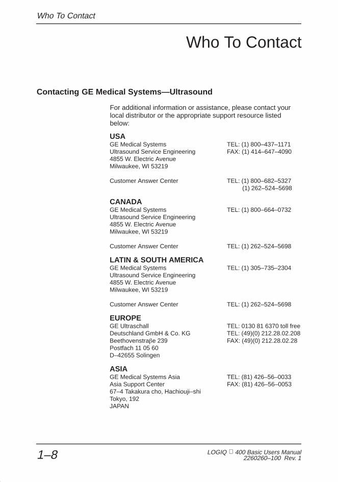
Contacting GE Medical Systems—Ultrasound
For additional information or assistance, please contact yourlocal distributor or the appropriate support resource listedbelow:
USAGE Medical Systems TEL: (1) 800–437–1171Ultrasound Service Engineering FAX: (1) 414–647–40904855 W. Electric AvenueMilwaukee, WI 53219
Customer Answer Center TEL: (1) 800–682–5327(1) 262–524–5698
CANADAGE Medical Systems TEL: (1) 800–664–0732Ultrasound Service Engineering4855 W. Electric AvenueMilwaukee, WI 53219
Customer Answer Center TEL: (1) 262–524–5698
LATIN & SOUTH AMERICAGE Medical Systems TEL: (1) 305–735–2304Ultrasound Service Engineering4855 W. Electric AvenueMilwaukee, WI 53219
Customer Answer Center TEL: (1) 262–524–5698
EUROPEGE Ultraschall TEL: 0130 81 6370 toll freeDeutschland GmbH & Co. KG TEL: (49)(0) 212.28.02.208Beethovenstra�e 239 FAX: (49)(0) 212.28.02.28Postfach 11 05 60D–42655 Solingen
ASIAGE Medical Systems Asia TEL: (81) 426–56–0033Asia Support Center FAX: (81) 426–56–005367–4 Takakura cho, Hachiouji–shiTokyo, 192JAPAN

Who To Contact
LOGIQ 400 Basic User Manual2260260–100 Rev. 1 1–9
Contacting GE Medical Systems—Ultrasound (cont’d)
ARGENTINAGEME S.A TEL: (1) 639–1619Miranda 5237 FAX: (1) 567–2678Buenos Aires – 1407
AUSTRIAGE GesmbH Medical Systems Austria TEL: 0660 8459 toll freePrinz Eugen Strasse 8/8 FAX: +43 1 505 38 74A–1040 WIEN TLX: 136314
BELGIUMGE Medical Systems Benelux TEL: 0 800 11733 toll freeGulkenrodestraat 3 FAX: +32 0 3 320 12 59B–2160 WOMMELGEM TLX: 72722
BRAZILGE Sistemas Médicos TEL: 0800–122345Av Nove de Julho 5229 FAX: (011) 3067–829801407–907 São Paulo SP
DENMARKGE Medical Systems Danmark TEL: +45 45 51 00 55Skovlytoften 4 FAX: +45 42 42 59 89DK–2840 HOLTE
FRANCEGE Medical Systems TEL: 05 49 33 71 toll free738 rue Yves Carmen FAX: +33 1 46 10 01 20F–92658 BOULOGNE CEDEX
GERMANYGE Ultraschall TEL: 0130 81 6370 toll freeDeutschland GmbH & Co. KG TEL: (49)(0) 212.28.02.208Beethovenstra�e 239 FAX: (49)(0) 212.28.02.28Postfach 11 05 60D–42655 Solingen
GREECEGE Medical Systems Hellas TEL: +30 1 93 24 58241, Nikolaou Plastira Street FAX: +30 1 93 58 414 G–171 21 NEA SMYRNI
ITALYGE Medical Systems Italia TEL: 1678 744 73 toll freeVia Monte Albenza 9 FAX: +39 39 73 37 86I–20052 MONZA TLX: 3333 28
LUXEMBOURGTEL: 0800 2603 toll free

Who To Contact
LOGIQ 400 Basic Users Manual2260260–100 Rev. 11–10
Contacting GE Medical Systems—Ultrasound (cont’d)
MEXICOGE Sistemas Médicos de Mexico S.A. de C.VRio Lerma #302, 1º y 2º Pisos TEL: (5) 228–9600Colonia Cuauhtémoc FAX: (5) 211–463106500–México, D.F.
NETHERLANDSGE Medical Systems Nederland B.V. TEL: 06 022 3797 toll freeAtoomweg 512 FAX: +31 304 11702NL–3542 AB UTRECHT
POLANDGE Medical Systems Polska TEL: +48 2 625 59 62Krzywickiego 34 FAX: +48 2 615 59 66P–02–078 WARSZAWA
PORTUGALGE Medical Systems Portuguesa S.A. TEL: 05 05 33 7313 toll freeRua Sa da Bandeira, 585 FAX: +351 2 2084494Apartado 4094 TLX: 22804P–4002 PORTO CODEX
RUSSIAGE VNIIEM TEL: +7 095 956 7037Mantulinskaya UI. 5A FAX: +7 502 220 32 59123100 MOSCOW TLX: 613020 GEMED SU
SPAINGE Medical Systems España TEL: 900 95 3349 toll freeHierro 1 Arturo Gimeno FAX: +34 1 675 3364Poligono Industrial I TLX: 22384 A/B GEMDEE–28850 TORREJON DE ARDOZ
SWEDENGE Medical Systems TEL: 020 795 433 toll freePO–BOX 1243 FAX: +46 87 51 30 90S–16428 KISTA TLX: 12228 CGRSWES
SWITZERLANDGE Medical Systems (Schweiz) AG TEL: 155 5306 toll freeSternmattweg 1 FAX: +41 41 421859CH–6010 KRIENS

Who To Contact
LOGIQ 400 Basic User Manual2260260–100 Rev. 1 1–11
Contacting GE Medical Systems—Ultrasound (cont’d)
TURKEYGE Medical Systems Turkiye A.S. TEL: +90 212 75 5552Mevluk Pehliran Sodak FAX: +90 212 211 2571Yilmaz Han, No 24 Kat 1GayretteppeISTANBUL
UNITED KINGDOMIGE Medical Systems TEL: 0800 89 7905 toll freeCoolidge House FAX: +44 753 696067352 Buckingham AvenueSLOUGHBerkshire SL1 4ER
OTHER COUNTRIESNO TOLL FREE TEL: international code +
33 1 39 20 0007
Manufacturer
GE YOKAGAWA MEDICAL SYSTEMS67-4 Takakura cho, Hachiouji-shiTokyo, 192JAPAN
OR
SAMSUNG GE MEDICAL SYSTEMS65-1, Sangdaewon-Dong, Chungwon-KuSungnam-Si, Kyunggi-DoKOREA

How This Book is Organized
LOGIQ 400 Basic Users Manual2260260–100 Rev. 11–12
How This Book is Organized
Manual Content
The LOGIQ 400 Basic User Manual is organized to providethe information needed to start scanning right away. Detailedinformation is also provided for more time-intensive studies.
� Getting started . These sections give an overview of thesystem to help the operator start scanning as soon aspossible.
� Introduction. Information concerning indications/contraindications for use, who to contact and how thisdocumentation is organized.
� Safety. Important information concerning the safeoperation of the LOGIQ 400 system.
� Preparing the System for Use. How to prepare thesystem for use and a map of the control layout.
� Preparing for an Exam. How to enter patientinformation, select an exam category and applicationpreset.
� Image optimization . These sections detail how to improveimage, trace, or spectral information.
� Modes. How to adjust and optimize B-Mode, ColorFlow, Doppler, M-Mode, 3-DvieW and 3D-Surfaceimaging.
� Scanning and Display Functions. Informationconcerning Zoom, Freeze, Cine and Annotationfunctions.

How This Book is Organized
LOGIQ 400 Basic User Manual2260260–100 Rev. 1 1–13
Manual Content (cont’d)
� Measurements and Reports . Shows how to do generaland exam category specific measurements andcalculations.
� General Measurements and Calculations. Emphasison basic measurements for each mode.
� Exam Categories.
� Abdomen and Small Parts.
� OB/GYN.
� Cardiology.
� Vascular.
� Urology.
� Recording Images . Explains the use of image archive andperipheral options.
� Customizing your system . Shows how to customize thesystem for your particular institution, clinic, or exam type.
� Probes and Biopsy . Provides intended uses,specifications, care and maintenance, and biopsy capabilityinstructions for each probe.
� User Maintenance. Provides information concerningsystem specifications, error messages, user diagnostics,quality assurance, system care and assistance.

How This Book is Organized
LOGIQ 400 Basic Users Manual2260260–100 Rev. 11–14
Manual Format
Information has been arranged and provided to help findinformation easily and quickly.
Finding information
Tables of Contents Locate topics in the main table of contents.
Tabs Chapter tabs are provided.
Headers/Footers The section name and page number appear on the outercorners of every page.
References See also page references that are noted.
Index Meant for frequent and easy reference. Extensive tool thatpresents ideas, topics, terms, titles, headings, and crossreferences. Also , use it to find all entries of a like topicthroughout the manual.
Text References
LOGIQ 400CL The LOGIQ 400CL system does not support every feature ofthe LOGIQ 400. When a feature does not apply to theLOGIQ 400CL, the symbol on the left appears.
LOGIQ 400 B/W The LOGIQ 400 Black/White system does not come standardwith this feature. When a feature is available as an option, thesymbol on the left appears.
CL
B/WOption

How This Book is Organized
LOGIQ 400 Basic User Manual2260260–100 Rev. 1 1–15
Text References (cont’d)
Notes Notes are set in italics.
Indicates precautions or prudent use recommendations thatshould be used in the operation of the ultrasound system.
References References to other chapters appear in italics.
Icons Various icons highlight safety issues.
CAUTIONWARNINGDANGER
Scanning hints help save time.
�
Hints

How This Book is Organized
LOGIQ 400 Basic Users Manual2260260–100 Rev. 11–16
This page left blank intentionally.

Safety
LOGIQ 400 Basic User Manual2260260–100 Rev. 1 2–1
Safety
Safety Precautions 2–2. . . . . . . . . . . . . . . . . . . . . . . . . . . . . . . . . . . . . . . . . . . . . . . . . . . . . . . . Precaution Levels 2–2. . . . . . . . . . . . . . . . . . . . . . . . . . . . . . . . . . . . . . . . . . . . . . . . . . . Hazard Symbols 2–3. . . . . . . . . . . . . . . . . . . . . . . . . . . . . . . . . . . . . . . . . . . . . . . . . . . . Patient Safety 2–4. . . . . . . . . . . . . . . . . . . . . . . . . . . . . . . . . . . . . . . . . . . . . . . . . . . . . . Equipment and Personnel Safety 2–6. . . . . . . . . . . . . . . . . . . . . . . . . . . . . . . . . . . . . . Device Labels 2–8. . . . . . . . . . . . . . . . . . . . . . . . . . . . . . . . . . . . . . . . . . . . . . . . . . . . . . Acoustic Output 2–17. . . . . . . . . . . . . . . . . . . . . . . . . . . . . . . . . . . . . . . . . . . . . . . . . . . Warning Label Locations 2–19. . . . . . . . . . . . . . . . . . . . . . . . . . . . . . . . . . . . . . . . . . .

Safety Precautions
LOGIQ 400 Basic Users Manual2260260–100 Rev. 1 2–2
Safety Precautions
Precaution Levels
Icon Description
Various levels of safety precautions may be found on theequipment and different levels of concern are identified by oneof the following flag words which precede the precautionarystatement.
Indicates that a specific hazard is known to exist which throughinappropriate conditions or actions will cause:
� Severe or fatal personal injury
� Substantial property damage.
Indicates that a specific hazard is known to exist which throughinappropriate conditions or actions may cause:
� Severe personal injury
� Substantial property damage.
Indicates that a potential hazard may exist which throughinappropriate conditions or actions will or can cause:
� Minor injury
� Property damage.
Indicates precautions or prudent use recommendations thatshould be used in the operation of the ultrasound system,specifically:
� Use of the ultrasound system as a prescription device,under the order of a physician
� Maintaining an optimum system environment
� Using this Manual
� Notes to emphasize or clarify a point.
DANGER
WARNING
CAUTION
�

Safety Precautions
LOGIQ 400 Basic User Manual2260260–100 Rev. 1 2–3
Hazard Symbols
Icon Description
Potential hazards are indicated by the following icons:
Icon Potential Hazard Usage Source
BiologicalHazard
� Patient/user infection dueto contaminatedequipment.
� Cleaning and careinstructions
� Sheath and gloveguidelines
ISO 7000No. 0659
ElectricalHazard
� Electrical micro-shock topatient, e.g., ventricularfibrillation initiated.
� Electrical micro-shock topatient/user.
� Probes
� ECG
� Connections to back panel
MovingHazard
� Console, accessories oroptional storage devicesfall on patient, user, orothers.
� Collision with persons orobjects results in injury whilemaneuvering or duringsystem transport.
� Injury to user from movingthe console.
� Moving
� Using brakes
� Transporting
AcousticOutputHazard
� Patient injury or tissuedamage from ultrasoundradiation.
� ALARA, the use of acousticoutput following the as lowas reasonably achievableprinciple
ExplosionHazard
� Risk of explosion if used inthe presence of flammableanesthetics.
� Flammable anesthetic
Smoke& Fire
Hazard
� Patient/user injury oradverse reaction from fire orsmoke.
� Patient/user injury fromexplosion and fire.
� Replacing fuses
� Outlet guidelines
Non–Ionizing
Radiation
� Console failure, erraticoperation or output errordue to RF interference.
� RF IEC 878No. 03-04
Table 2–1. Potential Hazards

Safety Precautions
LOGIQ 400 Basic Users Manual2260260–100 Rev. 1 2–4
Important Safety Considerations
The following topic headings (Patient Safety, and Equipmentand Personnel Safety) are intended to make the equipmentuser aware of particular hazards associated with the use of thisequipment and the extent to which injury can occur ifprecautions are not observed. Additional precautions may beprovided throughout the manual. The equipment user isobligated to be familiar with these concerns and avoidconditions that could result in injury.
Patient Safety
Related Hazards
The concerns listed can seriously affect the safety of patientsundergoing a diagnostic ultrasound examination.
Always include proper identification with all patient data andverify the accuracy of the patient’s name or ID numbers whenentering such data. Make sure correct patient ID is provided onall recorded data and hard copy prints. Identification errorscould result in an incorrect diagnosis.
Equipment malfunction or incorrect settings can result inmeasurement errors or failure to detect details within the image.The equipment user must become thoroughly familiar with theequipment operation in order to optimize its performance andrecognize possible malfunctions. Applications training isavailable through the local GE representative. Addedconfidence in the equipment operation can be gained byestablishing a quality assurance program.
Damaged probes or improper use and manipulation ofintracavitary probes can result in injury or increased risk ofinfection. Inspect probes often for sharp, pointed, or roughsurface damage that could cause injury or tear protectivebarriers. Never use excessive force when manipulatingintracavitary probes. Become familiar with all instructions andprecautions provided with special purpose probes.
WARNING
Patientidentification
Diagnosticinformation
Mechanicalhazards

Safety Precautions
LOGIQ 400 Basic User Manual2260260–100 Rev. 1 2–5
Related Hazards (cont’d)
A damaged probe can also increase the risk of electric shock ifconductive solutions come in contact with internal live parts.Inspect probes often for cracks or openings in the housing andholes in and around the acoustic lens or other damage thatcould allow liquid entry. Become familiar with the probe’s useand care precautions outlined in Probes and Biopsy.
Ultrasound energy, even at diagnostic levels, is capable ofdamaging sensitive tissues if adequate precautions are notfollowed. The wrong combination of equipment settings, probepositioning, and tissue type can result in injury. Please becomethoroughly familiar with equipment controls that affect acousticoutput levels as well as the output display.
Follow the principle of as low as reasonably achievable(ALARA) when scanning a patient. During each ultrasoundexamination, the clinical user is expected to weigh the medicalbenefit of the diagnostic information obtained against the risk ofpotential harmful effects. Once an optimal image is achievedthe need for increasing acoustic output or prolonging theexposure cannot be justified.
It is recommended that all users receive proper training inapplications before performing them in a clinical setting. Pleasecontact the local GE representative for training assistance.ALARA training is provided by GE Application Specialists.
ElectricalHazard
AcousticOutputHazard
Training

Safety Precautions
LOGIQ 400 Basic Users Manual2260260–100 Rev. 1 2–6
Equipment and Personnel Safety
Related Hazards
This equipment contains dangerous voltages that are capableof serious injury or death.
There are no user serviceable components inside the console.Refer all servicing to qualified service personnel only.
The concerns listed below can seriously affect the safety ofequipment and personnel during a diagnostic ultrasoundexamination.
Risk of explosion if used in the presence of flammableanesthetics.
To avoid injury:
� Do not remove protective covers. No user serviceableparts are inside. Refer servicing to qualified servicepersonnel.
� To assure adequate grounding, connect the attachmentplug to a reliable (hospital grade) grounding outlet (havingequalization conductor ).
� Do not place liquids on or above the console. Spilled liquidmay contact live parts and increase the risk of shock.
The system must be supplied from an adequately ratedelectrical circuit. The capacity of the supply circuit must be asspecified on 3–4.
WARNING
DANGER
ExplosionHazard
ElectricalHazard
Smoke& Fire
Hazard

Safety Precautions
LOGIQ 400 Basic User Manual2260260–100 Rev. 1 2–7
Related Hazards (cont’d)
For patient and personnel safety, beware of biological hazardswhile performing invasive procedures. To avoid the risk ofdisease transmission:
� Use protective barriers (gloves and probe sheaths)whenever possible. Follow sterile procedures whenappropriate.
� Thoroughly clean probes and reusable accessories aftereach patient examination and disinfect or sterilize asneeded. Refer to Probes and Biopsy for probe use andcare instructions.
� Follow all infection control policies established by youroffice, department or institution as they apply to personneland equipment.
Devices containing latex may cause severe allergic reaction inlatex sensitive individuals. USA customers should refer to theFDA’s March 29, 1991 Medical Alert on latex products.
BiologicalHazard
CAUTION

Safety Precautions
LOGIQ 400 Basic Users Manual2260260–100 Rev. 1 2–8
Device Labels
Label Icon Description
The following table describes the purpose and location of safetylabels and other important information provided on theequipment.
Label/Icon Purpose/Meaning Location
Identification and RatingPlate
� Manufacturer’s name and address
� Date of manufacture
� Model and serial numbers
� Electrical ratings (Volts, Amps, phase, andfrequency)
Rear of console near powerinlet
Type/Class Label Used to indicate the degree of safety orprotection.
IP Code (IPX1) Indicates the degree of protection provided bythe enclosure per IEC 529. IPX1 indicates dripproof.
Foot Switch
Equipment Type BF (man in the box symbol)IEC 878-02-03 indicates B Type equipmenthaving a floating applied part.
Probe connectors and PCGconnector
Equipment Type CF (heart in the box symbol)IEC 878-02-05 indicate equipment having afloating applied part having a degree ofprotection suitable for direct cardiac contact.
ECG connector and surgicalprobes
0459
The CE Mark of Conformity indicates thismachine conforms with the Council Directive93/42/EEC
Rear of console
Device Listing/Certification Labels
Laboratory logo or labels denotingconformance with industry safety standardssuch as UL or IEC.
Rear of console
“DANGER – Risk ofexplosion used in...”
The system is not designed for use withflammable anesthetic gases.
“CAUTION” The equilateral triangle is usuallyused in combination with other symbols toadvise or warn the user.
Various
Table 2–2. Label Icons

Safety Precautions
LOGIQ 400 Basic User Manual2260260–100 Rev. 1 2–9
Label Icon Description (cont’d)
Label/Icon Purpose/Meaning Location
“ATTENTION – Consult accompanyingdocuments” is intended to alert the user torefer to the operator manual or otherinstructions when complete information cannotbe provided on the label.
Various
“CAUTION – Dangerous voltage” (the lightningflash with arrowhead) is used to indicateelectric shock hazards.
“Mains OFF” Indicates the power off position ofthe mains power switch.
Rear of system,adjacent to mains switch
“Mains ON” Indicates the power on position ofthe mains power switch.
“ON” Indicates the power on position of thepower switch.CAUTION: This Power Switch DOES NOTISOLATE Mains Supply.
Adjacent to On-Off/StandbySwitch
“Off/Standby” Indicates the power off/standbyposition of the power switch.
CAUTION: This Power Switch DOES NOTISOLATE Mains Supply.
“Protective Earth” Indicates the protective earth(grounding) terminal.
Internal
“Equipotentiality” Indicates the terminal to beused for connecting equipotential conductorswhen interconnecting (grounding) with otherequipment.
CAUTION: This is only for ”FUNCTIONALGROUNDING”, NOT ”PROTECTIVE EARTH”.
Rear of console
Table 2–2. Label Icons (cont’d)
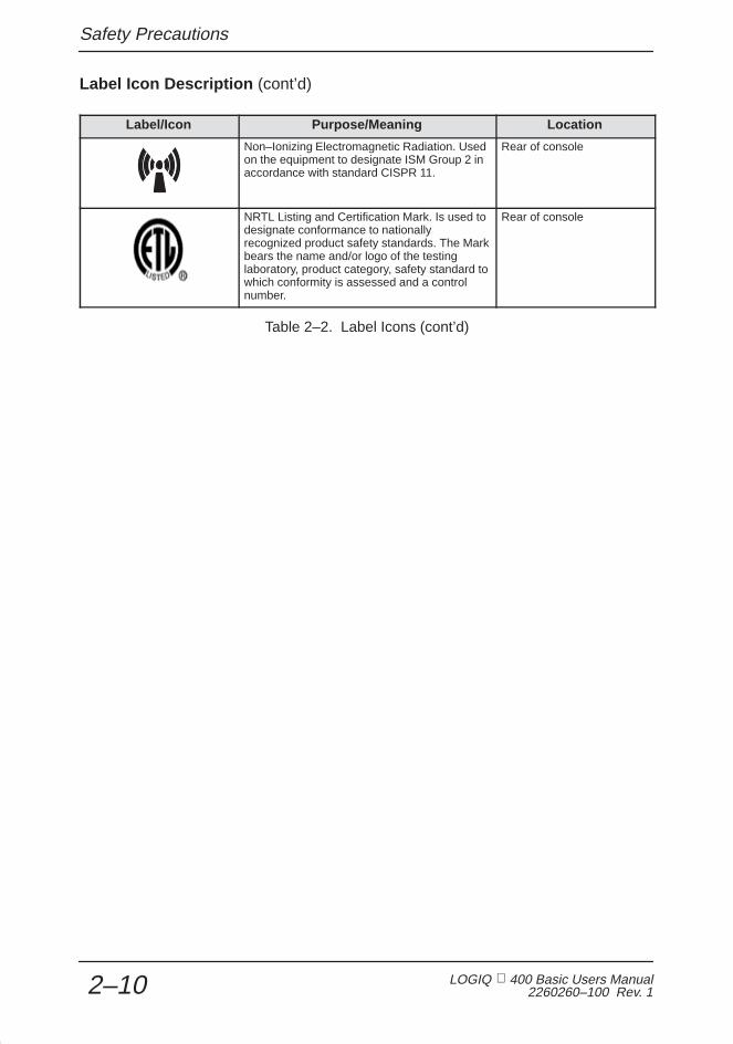
Safety Precautions
LOGIQ 400 Basic Users Manual2260260–100 Rev. 1 2–10
Label Icon Description (cont’d)
Label/Icon Purpose/Meaning Location
Non–Ionizing Electromagnetic Radiation. Usedon the equipment to designate ISM Group 2 inaccordance with standard CISPR 11.
Rear of console
NRTL Listing and Certification Mark. Is used todesignate conformance to nationallyrecognized product safety standards. The Markbears the name and/or logo of the testinglaboratory, product category, safety standard towhich conformity is assessed and a controlnumber.
Rear of console
Table 2–2. Label Icons (cont’d)

Safety Precautions
LOGIQ 400 Basic User Manual2260260–100 Rev. 1 2–11
Classifications
Type of protection against electric shockClass I Equipment (*1)
Degree of protection against electric shockType BF Equipment (*2) (Except ECG)Type CF Equipment (*3) (ECG Only)Ordinary EquipmentContinuous Operation
*1. Class I EQUIPMENT
EQUIPMENT in which protection against electric shock doesnot rely on BASIC INSULATION only, but includes an earthground. This additional safety precaution prevents exposedmetal parts from becoming LIVE in the event of an insulationfailure.
*2. Type BF EQUIPMENT
TYPE B EQUIPMENT with an F-TYPE APPLIED PARTTYPE B EQUIPMENT: EQUIPMENT providing a specifieddegree of protection against electric shock, with particularregard to allowable LEAKAGE CURRENT.
Normal Mode Single fault condition
Patient leakage current Less than 100 �A Less than 500 �A
*3. Type CF EQUIPMENT
EQUIPMENT providing a degree of protection higher than thatfor TYPE BF EQUIPMENT against electric shock particularlyregarding allowable LEAKAGE CURRENTS, and having anF-TYPE APPLIED PART.
Normal Mode Single fault condition
Patient leakage current Less than 10 �A Less than 50 �A

Safety Precautions
LOGIQ 400 Basic Users Manual2260260–100 Rev. 1 2–12
Classifications (cont’d)
*4. EMC (Electromagnetic Compatibility)
4.1 EMC Performance
All types of electronic equipment may characteristically causeelectromagnetic interference with other equipment, eithertransmitted through air or connecting cables. The term EMC(Electromagnetic Compatibility) indicates the capability ofequipment to curb electromagnetic influence from otherequipment and at the same time not affect other equipment withsimilar electromagnetic radiation from itself.
This product is designed to fully comply with the EN60601–1–2(IEC60601–1–2) in medical electric equipment EMCregulations.
Proper installation following the service manual is required inorder to achieve the full EMC performance of the product.
The product must be installed as stipulated in 4.2, Notice uponInstallation of Product.
In case of issues related to EMC, please call your servicepersonnel.
Do not use the following devices near this equipment. Use ofthese devices near this equipment could cause this equipmentto malfunction.
� Devices which intrinsically transmit radio waves such as:Cellular phone, radio transceiver, mobile radio transmitter,radio-controlled toys, etc.
Keep power to these devices turned off when near thisequipment.
Medical staff in charge of this equipment is required to instructtechnicians, patients and other people who may be around thisequipment to fully comply with the above regulaion.
CAUTION

Safety Precautions
LOGIQ 400 Basic User Manual2260260–100 Rev. 1 2–13
Classifications (cont’d)
4.2 Notice upon Installation of Product
1. Use either power supply cords provided by GE MedicalSystems or ones designated by GE Medical Systems.Products equipped with a power source plug should beplugged into the fixed power socket which has theprotective grounding conductor. Never use any adaptoror converter to connect with a power source plug (i.e.three-prong-to-two-prong converter).
2. Locate the equipment as far away as possible fromother electronic equipment.
3. Be sure to use only the cables provided by ordesignated by GE Medical Systems. Connect thesecables following the installation procedures (i.e. wirepower cables separately from signal cables).
4. Lay out the main equipment and other peripheralsfollowing the installation procedures described in theOption Installation manuals.
4.3 General Notice
1. Designation of Peripheral Equipment Connectable toThis Product.
The equipment indicated on 13–5 can be hooked up tothe product without compromising its EMCperformance.
Avoid using equipment not designated in the list.Failure to comply with this instruction may result in poorEMC performance of the product.

Safety Precautions
LOGIQ 400 Basic Users Manual2260260–100 Rev. 1 2–14
Classifications (cont’d)
4.3 General Notice (cont’d)
2. Notice against User Modification
The user should never modify this product. Usermodifications may cause degradation in EMCperformance.
Modification of the product includes changes in:
a. Cables (length, material, wiring, etc.)
b. System installation/layout
c. System configuration/components
d. Securing system parts (cover open/close, coverscrewing)
3. Operate the system with all covers closed. If a cover isopened for some reason, be sure to shut it beforestarting/resuming operation.
Operating the system with any cover open may affectEMC performance.
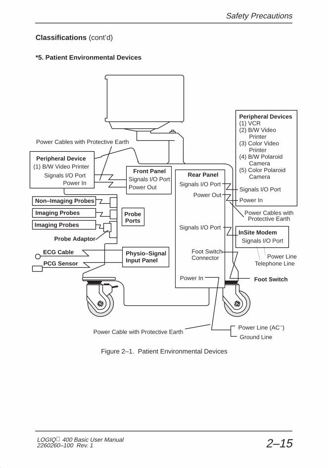
Safety Precautions
LOGIQ 400 Basic User Manual2260260–100 Rev. 1 2–15
Classifications (cont’d)
*5. Patient Environmental Devices
ÎÎÎÎÎÎÎÎÎÎÎÎÎÎÎÎÎÎÎÎÎÎÎÎÎÎÎÎÎÎÎÎÎÎÎÎÎÎÎÎÎÎÎÎÎÎÎÎÎÎÎÎÎÎÎÎÎÎÎÎÎÎÎÎÎÎÎÎÎÎ
Peripheral Devices(1) VCR(2) B/W Video Printer(3) Color Video Printer(4) B/W Polaroid Camera(5) Color Polaroid Camera
ÎÎÎÎÎÎÎÎÎÎÎÎÎÎÎÎÎÎÎÎÎÎÎÎÎÎÎ
ÎÎÎÎÎÎÎÎÎÎÎÎÎÎÎÎÎÎÎÎÎÎÎÎÎÎÎÎÎÎÎÎÎÎÎ
Non–Imaging Probes
Î
Signals I/O Port
ÎÎÎÎÎÎÎÎÎÎÎÎÎÎÎÎÎÎÎÎÎÎÎÎÎÎÎÎÎÎÎÎÎÎÎÎÎÎÎÎÎÎÎÎÎÎÎÎÎÎÎÎÎÎÎÎÎÎÎÎÎÎÎÎÎÎÎÎÎÎÎÎÎÎÎÎÎÎ
Power Out
ProbePorts
Front Panel
Power In
Signals I/O Port
ÎÎÎÎÎÎÎÎÎÎ
Probe Adaptor
Power Cables with Protective Earth
ECG Cable
PCG Sensor
Foot Switch
InSite ModemSignals I/O Port
Telephone LinePower Line
Power Cables withProtective Earth
ÎÎ
Imaging Probes
Imaging Probes
ÎÎÎÎÎÎÎÎÎÎÎÎÎÎÎÎ
Signals I/O PortPower In
Peripheral Device(1) B/W Video Printer
Physio–SignalInput Panel
Signals I/O Port
Power Out
Signals I/O Port
Power In
Rear Panel
Foot SwitchConnector
Power Line (AC~)Power Cable with Protective Earth
Ground Line
Figure 2–1. Patient Environmental Devices

Safety Precautions
LOGIQ 400 Basic Users Manual2260260–100 Rev. 1 2–16
Classifications (cont’d)
5.1 Acceptable Devices
The devices shown in Figure 2–1 are specified to be suitable foruse within the PATIENT ENVIRONMENT.
DO NOT connect any probes or accessories without approvalby GE.
Please refer to Peripheral Devices on 13–5 and Assistance on16–39 for more details. The devices listed have been testedand verified to be compatible with the LOGIQ 400 system.
5.2 Unapproved Devices
The user takes All Responsibility for connecting unapproveddevices.
If devices are connected without the approval of GE, thewarranty will be INVALID.
Any device connected to the LOGIQ 400 must conform to oneor more of the requirements listed below:
1. IEC 50, IEC 65, IEC 335, IEC 348, IEC 414, IEC 820,IEC 950, IEC 1010–1, ISO 7767, ISO 8185, ISO 8359or IEC 60601–1.
2. The devices shall be connected to PROTECTIVEEARTH (GROUND).
CAUTION
CAUTION
Safety Precautions
LOGIQ 400 Basic User Manual2260260–100 Rev. 1 2–17
Acoustic Output
Controls Affecting Output
The potential for producing mechanical or thermal bioeffects isinfluenced by the controls listed below (refer to 2–18).
Direct. The Acoustic Output control has the most significanteffect on Acoustic Output.
Indirect. Indirect effects may occur when adjusting the controlslisted on 2–18.
Always observe the output display for possible effects.
Best practices while scanning
� Raise the Acoustic Output only after attempting imageoptimization with controls that have no affect on AcousticOutput, such as Gain and TGC.
NOTE: Refer to the Optimization sections of the Modes chapterfor a complete discussion of each control.
Be sure to have read and understood control explanations foreach Mode intended to be used before attempting to adjust theAcoustic Output control or any control that can affect AcousticOutput.
Use the minimum necessary output to get the best diagnosticimage or measurement during an examination. Begin the examwith the probe that provides an optimum focal depth andpenetration.
Hints
�WARNING
AcousticOutputHazard

Safety Precautions
LOGIQ 400 Basic Users Manual2260260–100 Rev. 1 2–18
Best practices while scanning (cont’d)
Controls
Mode Control Affect Default Setting
All Acoustic Output Direct.Significant
The middle setting is a factory presetdetermined to be a reasonable setting for all
exams. Use presets to set the outputpreferred by scan mode and exam
combination.
B Focus Comb Indirect. Minor Off.
B/M/CFD Depth(FOV)
Indirect. Minor Probe-dependent operator preset.
B/M Focal Zone Positionand Number
Indirect. Minor Probe-dependent system preset.
B/CFD Scan Area Indirect. Off.
Doppler M/D Cursor Indirect. Minor Off.
Doppler Doppler SampleVolume Gate Length
Indirect. Minor Application-dependent system preset.
Doppler Velocity Scale Indirect. Minor Application-dependent operator preset.
PWD/CFD Freq. Hi/Low Indirect. Minor Low.
CFD Scan Area Indirect. Minor Off.
B/M/CFD Zoom Indirect. Minor Off.
Table 2–3. Controls Affecting Acoustic Output
Acoustic Output Default Levels
In order to assure that an exam does not start at a high outputlevel, the LOGIQ 400 initiates scanning at a reduced defaultoutput level. This reduced level is preset programmable anddepends upon exam category, application preset and probeselected. It takes effect when the system is powered on or NewPatient is selected.

Safety Precautions
LOGIQ 400 Basic User Manual2260260–100 Rev. 1 2–19
Warning Label Locations
Overview
LOGIQ 400 warning labels are provided in seven differentlanguages (English, Japanese, German, French, Italian,Portuguese, Spanish, Swedish, Danish, Russian, Greek andTurkish).
Monitor Labels
A temporary label is placed on the monitor face to warn not tomove the monitor support arm without the monitor attached.This label is removed after installation of the monitor.
Figure 2–2. Temporary Warning Label and Location

Safety Precautions
LOGIQ 400 Basic Users Manual2260260–100 Rev. 1 2–20
Monitor Labels (cont’d)
Two caution labels are found on the back of the monitor. Onewarns to only move the console with the monitor in its lowestposition; the second warns not to push the console from theside.
1 2
Figure 2–3. Lowering Monitor Caution Labels and Locations
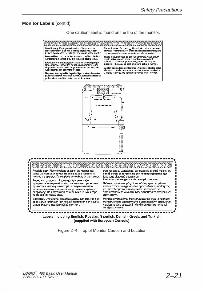
Safety Precautions
LOGIQ 400 Basic User Manual2260260–100 Rev. 1 2–21
Monitor Labels (cont’d)
One caution label is found on the top of the monitor.
Figure 2–4. Top of Monitor Caution and Location

Safety Precautions
LOGIQ 400 Basic Users Manual2260260–100 Rev. 1 2–22
Console Labels
Labels found on the back and side of the console will either betranslated to the twelve languages or be specific to the region.
Defibrillator Caution
Figure 2–5. Defibrillator Label Location

Safety Precautions
LOGIQ 400 Basic User Manual2260260–100 Rev. 1 2–23
Ground Point
Figure 2–6. Signal Ground Point Location and Label
This is only for “FUNCTIONAL GROUNDING”, NOT“PROTECTIVE EARTH”.
CAUTION

Safety Precautions
LOGIQ 400 Basic Users Manual2260260–100 Rev. 1 2–24
Regulatory Labels (European Systems)
Figure 2–7. Regulatory Label Location (European)

Safety Precautions
LOGIQ 400 Basic User Manual2260260–100 Rev. 1 2–25
Regulatory Labels (European Systems) (cont’d)
Figure 2–8. Regulatory Label Location (European) (cont’d)

Safety Precautions
LOGIQ 400 Basic Users Manual2260260–100 Rev. 1 2–26
Regulatory Labels (American Systems)
Figure 2–9. Regulatory Label Location (Americas)
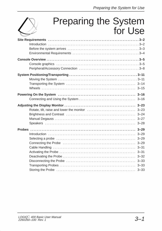
Preparing the System for Use
LOGIQ 400 Basic User Manual2260260–100 Rev. 1 3–1
Preparing the Systemfor Use
Site Requirements 3–2. . . . . . . . . . . . . . . . . . . . . . . . . . . . . . . . . . . . . . . . . . . . . . . . . . . . . . . . Introduction 3–2. . . . . . . . . . . . . . . . . . . . . . . . . . . . . . . . . . . . . . . . . . . . . . . . . . . . . . . . Before the system arrives 3–3. . . . . . . . . . . . . . . . . . . . . . . . . . . . . . . . . . . . . . . . . . . . Environmental Requirements 3–4. . . . . . . . . . . . . . . . . . . . . . . . . . . . . . . . . . . . . . . . .
Console Overview 3–5. . . . . . . . . . . . . . . . . . . . . . . . . . . . . . . . . . . . . . . . . . . . . . . . . . . . . . . . . Console graphics 3–5. . . . . . . . . . . . . . . . . . . . . . . . . . . . . . . . . . . . . . . . . . . . . . . . . . . Peripheral/Accessory Connection 3–8. . . . . . . . . . . . . . . . . . . . . . . . . . . . . . . . . . . . .
System Positioning/Transporting 3–11. . . . . . . . . . . . . . . . . . . . . . . . . . . . . . . . . . . . . . . . . . Moving the System 3–11. . . . . . . . . . . . . . . . . . . . . . . . . . . . . . . . . . . . . . . . . . . . . . . . . Transporting the System 3–14. . . . . . . . . . . . . . . . . . . . . . . . . . . . . . . . . . . . . . . . . . . Wheels 3–15. . . . . . . . . . . . . . . . . . . . . . . . . . . . . . . . . . . . . . . . . . . . . . . . . . . . . . . . . .
Powering On the System 3–16. . . . . . . . . . . . . . . . . . . . . . . . . . . . . . . . . . . . . . . . . . . . . . . . Connecting and Using the System 3–16. . . . . . . . . . . . . . . . . . . . . . . . . . . . . . . . . . .
Adjusting the Display Monitor 3–23. . . . . . . . . . . . . . . . . . . . . . . . . . . . . . . . . . . . . . . . . . . . Rotate, tilt, raise and lower the monitor 3–23. . . . . . . . . . . . . . . . . . . . . . . . . . . . . . Brightness and Contrast 3–24. . . . . . . . . . . . . . . . . . . . . . . . . . . . . . . . . . . . . . . . . . . Manual Degauss 3–27. . . . . . . . . . . . . . . . . . . . . . . . . . . . . . . . . . . . . . . . . . . . . . . . . . Speakers 3–28. . . . . . . . . . . . . . . . . . . . . . . . . . . . . . . . . . . . . . . . . . . . . . . . . . . . . . . .
Probes 3–29. . . . . . . . . . . . . . . . . . . . . . . . . . . . . . . . . . . . . . . . . . . . . . . . . . . . . . . . . . . . . . . . . Introduction 3–29. . . . . . . . . . . . . . . . . . . . . . . . . . . . . . . . . . . . . . . . . . . . . . . . . . . . . . Selecting a probe 3–29. . . . . . . . . . . . . . . . . . . . . . . . . . . . . . . . . . . . . . . . . . . . . . . . . Connecting the Probe 3–29. . . . . . . . . . . . . . . . . . . . . . . . . . . . . . . . . . . . . . . . . . . . . Cable Handling 3–31. . . . . . . . . . . . . . . . . . . . . . . . . . . . . . . . . . . . . . . . . . . . . . . . . . . Activating the Probe 3–31. . . . . . . . . . . . . . . . . . . . . . . . . . . . . . . . . . . . . . . . . . . . . . . Deactivating the Probe 3–32. . . . . . . . . . . . . . . . . . . . . . . . . . . . . . . . . . . . . . . . . . . . . Disconnecting the Probe 3–33. . . . . . . . . . . . . . . . . . . . . . . . . . . . . . . . . . . . . . . . . . . Transporting Probes 3–33. . . . . . . . . . . . . . . . . . . . . . . . . . . . . . . . . . . . . . . . . . . . . . . Storing the Probe 3–33. . . . . . . . . . . . . . . . . . . . . . . . . . . . . . . . . . . . . . . . . . . . . . . . .

Preparing the System for Use
LOGIQ 400 Basic Users Manual2260260–100 Rev. 13–2
Operator Controls 3–34. . . . . . . . . . . . . . . . . . . . . . . . . . . . . . . . . . . . . . . . . . . . . . . . . . . . . . . Control Panel Map 3–34. . . . . . . . . . . . . . . . . . . . . . . . . . . . . . . . . . . . . . . . . . . . . . . . Key Illumination 3–35. . . . . . . . . . . . . . . . . . . . . . . . . . . . . . . . . . . . . . . . . . . . . . . . . . . Keyboard 3–36. . . . . . . . . . . . . . . . . . . . . . . . . . . . . . . . . . . . . . . . . . . . . . . . . . . . . . . . Soft Menu Control Panel 3–37. . . . . . . . . . . . . . . . . . . . . . . . . . . . . . . . . . . . . . . . . . . Mode, Display and Record 3–40. . . . . . . . . . . . . . . . . . . . . . . . . . . . . . . . . . . . . . . . . Measurement and Annotation 3–42. . . . . . . . . . . . . . . . . . . . . . . . . . . . . . . . . . . . . .

Site Requirements
LOGIQ 400 Basic User Manual2260260–100 Rev. 1 3–3
Site Requirements
Introduction
Only qualified physicians or sonographers should performultrasound scanning on human subjects for medical diagnosticreasons. Request training, if needed.
Do not attempt to install the system alone. General Electric,Affiliate, or Distributor Field Engineers and ApplicationSpecialists will install and setup the system. Refer to Who ToContact on 1–8.
The LOGIQ 400 does not contain any operator serviceableinternal components. Ensure that unauthorized personnel donot tamper with the unit.
Perform regular preventive maintenance. Refer to 16–11 formaintenance instructions.
Maintain a clean environment. Turn off the system circuitbreaker before cleaning the unit. Refer to 16–12 for cleaninginstructions.
Never set liquids on the unit to ensure that liquid does not dripinto the control panel or unit.
�

Site Requirements
LOGIQ 400 Basic Users Manual2260260–100 Rev. 13–4
Before the system arrives
NOTICE This medical equipment is approved, in terms of the preventionof radio wave interference, to be used in hospitals, clinics andother institutions which are environmentally qualified. The useof this equipment in an inappropriate environment may causesome electronic interference to radios and televisions aroundthe equipment. This equipment can be used in residentialareas only under the supervision of physicians or qualifiedtechnicians.
Ensure that the following is provided for the new system:
� A separate power outlet with a 15 amp circuit breaker for120 VAC (USA) or 7.5 amp circuit breaker for 220–240 VAC(Europe, Latin America).
� Take precautions to ensure that the console is protectedfrom electromagnetic interference.
Precautions include:
� Operate the console at least 15 feet away from motors,typewriters, elevators, and other sources of strongelectromagnetic radiation.
� Operation in an enclosed area (wood, plaster orconcrete walls, floors and ceilings) helps preventelectromagnetic interference.
� Special shielding may be required if the console is to beoperated in the vicinity of radio broadcast equipment.

Site Requirements
LOGIQ 400 Basic User Manual2260260–100 Rev. 1 3–5
Environmental Requirements
The system should be operated, stored, or transported withinthe parameters outlined below. Either its operationalenvironment must be constantly maintained or the unit must beturned off.
Operational Storage Transport (<16 hrs.)
Temperature 10�- 40� C50�- 104� F
–10�- 60� C14�- 140� F
–40�- 60� C–40�- 140� F
Humidity 30-85%non-condensing
30-90%non-condensing
30-90%non-condensing
Pressure 700-1060hPa 700-1060hPa 700-1060hPa
Table 3–1. System Environmental Requirements

Console Overview
LOGIQ 400 Basic Users Manual2260260–100 Rev. 13–6
Console Overview
Console graphics
The following are illustrations of the console:
2
1 13
4
1 Monitor2 Optional Probe Cable Holder (wire holder standard for Americas’ systems)3 Probe and Gel Bottle Holder (Removable for Cleaning)4 Optional Cable Clipper for Probe Cable
Figure 3–1. LOGIQ 400 System (right and left side views)

Console Overview
LOGIQ 400 Basic User Manual2260260–100 Rev. 1 3–7
Console graphics (cont’d)
13
10
ON
OFF
1
0ON
ECG
!
PCG
Aux
2
3
4
5
6
7
8
9
7
11
12
5
1 1
14
1 Monitor2 Task Light Switch3 Task Light4 Optional B/W Video Page Printer5 Air Filter (front and back of system)6 Power Supply Air Filter7 Optional Probe Cable Holder (wire holder standard for Americas’ systems)8 VCR Microphone9 Release Button—to raise and lower video monitor
10 Optional Physiological Input Panel11 Swivel Lock on Video Monitor Arm12 Peripheral Cable Access Panel Door13 Cable Access Channel14 Optional Third Probe Port
Figure 3–2. LOGIQ 400 System (front and back views)

Console Overview
LOGIQ 400 Basic Users Manual2260260–100 Rev. 13–8
External disk drive
The external MOD drive is a 3.5 inch 128MB/230MB MOD drivelocated below the keyboard.
It can be used to perform software upgrades, image archiving(option) and service diagnostics.
Storage areas
Several convenient storage areas are provided within theconsole as shown by the shaded areas in Figure 3–3. Usethem to store gel, options, probe cables, accessories, etc.
1
1
1 Storage
Figure 3–3. Storage Areas

Console Overview
LOGIQ 400 Basic User Manual2260260–100 Rev. 1 3–9
Peripheral/Accessory Connection
Peripheral/Accessory Connector Panel
LOGIQ 400 peripherals and accessories can be properlyconnected using the rear connector panel located behind therear door. Only the B/W Page Printer (UP-890) can beconnected to the front accessory panel.
Located on the rear panel are video input and output, audioinput and output, camera expose, foot switch, power andcontrol connections for VCR, printer, MIC and service tools.See Figure 3–5.
Each outer (case) ground line of peripheral/accessoryconnectors are Earth Grounded .
Signal ground lines are Not Isolated , except the Service Port.
All of the signal lines (including the signal ground) of theService Port are Isolated.
Service
Figure 3–4. Service Port
Use only approved probes, peripherals or accessories.
CAUTION
CAUTION

Console Overview
LOGIQ 400 Basic Users Manual2260260–100 Rev. 13–10
Peripheral/Accessory Connector Panel (cont’d)
100V 2.5A Max.Includes front printer panel
120V 2.0A Max.Includes front printer panel
220–240V 1.0A Max.Includes front printer panel
1 21 Old Rear Panel 2 New Rear Panel
Figure 3–5. Peripheral/Accessory Connector Panel

Console Overview
LOGIQ 400 Basic User Manual2260260–100 Rev. 1 3–11
Foot Switch (option)
Use only the recommended optional multi-functional Foot Switchin parallel with or as an alternative to the Freeze and Record 1controls to:
� Freeze a real-time image (left switch).
� Send an image to the hard copy device (right switch).
The Foot Switch connection is located at the back of theconsole on the left-hand side of the back panel.
2
3
ON
OFF
1
0ON
1
1 Accessory Panel for Foot Switch Connector2 Store Foot Switch Here3 Console Air Filter Screen
Figure 3–6. Foot Switch Storage and Connectors
Other Peripherals/Accessories (options)
Refer to Chapter 13 (Recording Images) of this manual formore information.
Freeze
Record
Foot Switch

System Positioning/Transporting
LOGIQ 400 Basic Users Manual2260260–100 Rev. 13–12
System Positioning/Transporting
Moving the System
When moving or transporting the system, follow the precautionsbelow to ensure the maximum safety for personnel, the system,and other equipment.
Before moving the system:
1. Turn the system power switch off.
2. Unplug the power cord.
3. All cables from off-board peripheral devices (IIEcamera, external printer, VCR, etc.) must bedisconnected from the console.
4. Ensure that no loose items are left on the console.
5. Loop the cord around the handle on the back of thesystem or wrap the cord in a bundle and store it behindthe rear storage panel.
To prevent damage to the Power Cord, DO NOT pullexcessively on the cord or make sharp bends while wrapping.

System Positioning/Transporting
LOGIQ 400 Basic User Manual2260260–100 Rev. 1 3–13
Moving the System (cont’d)
ON
OFF
1
0ON
1 Handle2 Storage Area Behind Door
Figure 3–7. Location of Storage Area
6. Connect all probes to be used while off site. Ensurethat probe cables are out of the way from the wheelsand not protruding beyond the console.
NOTE: Store all probes that are intended to be used, but notconnected to the system, securely in the front storagearea.
7. Store all other probes in their original cases or in softcloth or foam to prevent damage.
8. Store sufficient gel, optical disks, and other essentialaccessories in the provided space.
9. Adjust the monitor to its lowest position possible.Ensure that the monitor arm is locked in place.
10. Unlock the front wheels.
�

System Positioning/Transporting
LOGIQ 400 Basic Users Manual2260260–100 Rev. 13–14
Moving the System (cont’d)
When moving the system:
1. Always use the rear handle grips to move the system.
2. Take extra care when moving the system longdistances and on inclines. Ask for help if necessary.
Avoid ramps that are steeper than ten degrees to avoidtipping over the system.
NOTE: Wheel chair ramps are usually less than five degrees.
Utilize additional care and personnel when moving onsteep incline (>5°) or loading into a vehicle fortransport.
NOTE: DO NOT attempt to move the console using any cablesor fixtures, such as the probe connectors.
3. Use the brake, located on the bottom of the system inthe front, when necessary.
4. Do not let the system strike walls or door frames.
5. Use extra care when crossing door or elevatorthresholds.
6. Once the destination is reached, lock the wheels.
The system weighs approximately 145 kg (320 lbs). To avoidpossible injury and equipment damage:
� Be sure the pathway is clear.
� Limit movement to a slow careful walk.
� Use two or more persons to move the system on inclines orlong distances.
�
�
CAUTION

System Positioning/Transporting
LOGIQ 400 Basic User Manual2260260–100 Rev. 1 3–15
Transporting the System
Use extra care when transporting the system using vehicles. Inaddition to the instructions used when moving the system (referto 3–12), do the following:
1. Only use vehicles that are designed for transport of theLOGIQ 400 system.
2. Load and unload the system to a vehicle parked on alevel surface.
3. Ensure that the transporting vehicle can handle theweight of the system plus the passengers.
4. Ensure that the load capacity of the lift (a minimum of180 kg [397 lbs] is recommended) is capable ofhandling the weight of the system.
5. Ensure that the lift is in good working order.
6. Secure the system while it is on the lift so that it cannotroll. Use either wood chocks, restraining straps, orother similar types of constraints. Do not attempt tohold it in place by hand.
NOTE: Strap the system below its handle so that the systemdoes not break loose.
Never ride on the lift with the system. A person’sweight coupled with the weight of the system mayexceed the load capacity of the lift.
7. Employ 2 to 3 persons to load and unload safely from avehicle.
8. Load the unit aboard the vehicle carefully and over itscenter of gravity. Keep the unit still and upright.
NOTE: Do not lay the unit down.
9. Ensure that the system is firmly secured while insidethe vehicle. Any movement, coupled with the weight ofthe system, could cause it to break loose.
10. Secure system with straps or as directed otherwise toprevent motion during transport.
11. Prevent vibration damage by driving cautiously. Avoidunpaved roads, excessive speeds, and erratic stops orstarts.
�WARNING
�

System Positioning/Transporting
LOGIQ 400 Basic Users Manual2260260–100 Rev. 13–16
Wheels
Examine the wheels frequently for any obvious defects thatcould cause them to break or bind.
Front wheels
The front wheels swivel, pivot, and lock.
Back wheels
The back wheels swivel and pivot but do not lock.
NOTE: For the USA version console, the back wheels do notpivot.
Setting the lock
To engage the wheel lock:
Press down on the lock pedal (located at the front ofthe wheels). The pedal remains depressed.
To release the lock:
Press down on the pedal again. The pedal returns toits normal position.
�
�

Powering On the System
LOGIQ 400 Basic User Manual2260260–100 Rev. 1 3–17
Powering On the System
Connecting and Using the System
To connect the system to the electrical supply:
1. Ensure that the wall outlet is of the appropriate type.
2. Ensure that the power switch is turned off.
3. Unwrap the power cable. Make sure to allow sufficientslack in the cable so that the plug is not pulled out ofthe wall if the system is moved slightly.
4. Push the power plug securely into the wall outlet.
To avoid risk of fire, the system power must be supplied from aseparate, properly rated outlet. See Site Requirements, Beforethe system arrives on 3–4 for rating information.
Under no circumstances should the AC power plug be altered,changed, or adapted to a configuration rated less thanspecified. Never use an extension cord or adapter plug.
To help assure grounding reliability, connect to a “hospitalgrade” or “hospital only” grounded power outlet.
����������
220–240 VAC, 1000 VA Plug and Outlet Configuration
(Europe)
����������
120 VAC, 1000 VA Plug and Outlet Configuration
(USA)
Figure 3–8. Example Plug and Outlet Configurations
WARNING

Powering On the System
LOGIQ 400 Basic Users Manual2260260–100 Rev. 13–18
Acclimation Time
After being transported, the unit requires one hour for each 2.5�increment its temperature is below 10� C or above 40� C.
� C 60 55 50 45 40 35 30 25 20 15 10
� F 140 131 122 113 104 95 86 77 68 59 50
hours 8 6 4 2 0 0 0 0 0 0 0
� C 5 0 –5 –10 –15 –20 –25 –30 –35 –40
� F 41 32 23 14 5 –4 –13 –22 –31 –40
hours 2 4 6 8 10 12 14 16 18 20
Table 3–2. System Acclimation Time Chart
Power On/Off Standby
Press the top portion of the Power On/Off Standby switch toturn the power on. The circuit breaker, on the rear of the unit,must also be in the on position (see 3–23).
Figure 3–9. Power Switch Location
CAUTION

Powering On the System
LOGIQ 400 Basic User Manual2260260–100 Rev. 1 3–19
Power Up Sequence
� The monitor and console power indicator light up.
� The system is initialized. During this time:
� Two beeps sound during the sequence.
� All lighted buttons on the keyboard light.
� System diagnostics run. Its status is reflected on themonitor by the graphics in Figure 3–10.
4 4
44
4
XXXXXXX–X
Start ofdiagnostic
run
Version X.XX
Version X.XX
End ofdiagnosticrun
XXXXXXX–X
Version X.XX
1
2
1 Current OBC Assembly Part Number 2 Current Software Version
Figure 3–10. Power Up Graphic Sequence

Powering On the System
LOGIQ 400 Basic Users Manual2260260–100 Rev. 13–20
Power Up Sequence (cont’d)
NOTE: If errors occur, an error message appears at the bottomof the screen. See User Maintenance, Troubleshootingfor more information.
If problems occur, freeze the image and take a picturefor reference. This will help if there is a need to call forservice.
� Probes are initialized for immediate operation.
NOTE: If no probes are connected, the system goes intostandby mode.
� Peripheral devices are activated on power up.
After initialization has been completed, the new patient entrymenu will be displayed.
Password Protection
A maximum of 8 personal IDs and associated passwords canbe preset in the LOGIQ 400 (see 14–60).
If IDs and passwords have been entered and the Password Askparameter is on, the following occurs in the power up sequence:
� The message USERID:__________ appears in the middleof the start up sequence.
� Type in a User ID and press Return .
� Keyboard lights go out.
� The message PASSWORD:__________ is highlighted.
� Type in the password that corresponds to the User ID andpress Return .
�
Hints
�

Powering On the System
LOGIQ 400 Basic User Manual2260260–100 Rev. 1 3–21
Password Protection (cont’d)
PASSWORD:USER ID :
Version X.XX
4
Figure 3–11. System Startup Screen with Password Ask on
If the correct User ID/Password is entered, the systemcontinues with the power up sequence.
If an incorrect User ID/Password is entered, the system allowsfour additional attempts. After the fifth incorrect entry, themessage “Login incorrect” appears. The power up sequencewill not continue. The system must be turned off, then on, tobegin again.
NOTE: If User ID/Passwords are registered and the PasswordAsk function is off, press Return at the ID__________ prompt.The system continues the power up sequence.
�

Powering On the System
LOGIQ 400 Basic Users Manual2260260–100 Rev. 13–22
Power Off
When switching off the system:
� Move the ON, OFF/STAND-BY switch to the OFF position.The message “WARNING: NOW STARTING THE POWEROFF PROCESS” appears at the bottom of the display.
� The LOGIQ 400 takes a few seconds to save currentscan parameter data in the temporary files to the hard drivebefore turning the power off.
During this time a message flashes on the screen:
“Do not pull Power Cable. Do not turn off Breaker.”
Pulling the power cable or turning off the circuit breaker,while the hard drive is working, may corrupt the systemoperating software on the hard drive.
If the system has not turned off five minutes after pressingthe power switch off, listen for hard drive activity. If there isno hard disk drive activity, the circuit breaker on the bottomof the power supply can be used to turn off the system. DoNOT turn off the circuit breaker while the hard disk isworking.
� Disconnect the probes.
Clean or sanitize all probes as necessary. Store them intheir shipping cases to avoid damage.
� If daily maintenance is to be performed, turn off the circuitbreaker in the back of the system.

Powering On the System
LOGIQ 400 Basic User Manual2260260–100 Rev. 1 3–23
Circuit breaker
The Circuit Breaker is located on the back of the console, at thebottom of the system. On supplies main power to all internalsystems. Off removes main power from all internal systems.The circuit breaker automatically shuts off power to the systemin case of a power overload.
If a power overload occurs:
1. Turn off all peripheral devices.
2. Turn off the Main Power Switch to the console.
3. Reactivate the Circuit Breaker switch.
The Circuit Breaker switch should stay in the On position; DONOT hold the switch in the On position. If the Circuit Breakerswitch remains On, follow the Power On procedure previouslydescribed.
NOTE: If the Circuit Breaker switch does not remain in the Onposition or trips again:
1. Disconnect the Power Cable.
2. Call Service immediately.
DO NOT attempt to use the system.
ON
OFF
1
0ON
1
1 Circuit Breaker
Figure 3–12. Location of Circuit Breaker
1
0
�

Adjusting the Monitor
LOGIQ 400 Basic Users Manual2260260–100 Rev. 13–24
Adjusting the Display Monitor
Rotate, tilt, raise and lower the monitor
The monitor position can be adjusted for easy viewing.
� The monitor can be rotated around it’s central pivot point.
� The monitor can be tilted for the optimum viewing angle.
� The monitor arm can swing forward or backwards.
� The monitor arm can be raised or lowered for the bestviewing height.
Figure 3–13. Display Monitor Movement
Movement of the monitor swing arm or height adjustmentrequires the release of the locking mechanism. After anadjustment is made, ensure that the mechanism is locked toprevent unexpected motion.
When moving the LOGIQ 400 system, lower the monitor to itslowest possible position to improve stability.
CAUTION

Adjusting the Monitor
LOGIQ 400 Basic User Manual2260260–100 Rev. 1 3–25
Brightness and Contrast
Adjusting the monitor’s contrast and brightness is one of themost important factors for proper image quality. If thesecontrols are set incorrectly, the Gain, TGC, Dynamic Range andeven Acoustic Output may have to be changed more often thannecessary to compensate.
The proper setup displays a complete gray scale. The lowestlevel of black should just disappear into the background and thehighest white should be bright, but not saturated.
To adjust the Brightness and Contast:
1. Press the monitor’s toggle button for brightness andcontrast. Confirm that the brightness (or contrast) isdisplayed on the monitor. If the contrast is displayed,press the toggle button again.
2. Adjust the brightness (or contrast) by pressing the�� (–) or �� (+) monitor’s adjustment buttons.
3. Select the Set Up Top Menu. From the Set UpSub-Menus, select Utility. The Utility Menu appears asshown in Figure 3–14.
Figure 3–14. Utility Menu

Adjusting the Monitor
LOGIQ 400 Basic Users Manual2260260–100 Rev. 13–26
Brightness and Contrast (cont’d)
4. Enter menu number “11” (Monitor Adjustment) in theUtility Menu and press Return . The Monitor AdjustmentMenu appears as shown in Figure 3–15.
Figure 3–15. Monitor Adjustment Menu
5. Enter the number of a gray scale map for adjustmentaccording to the brightness of the exam room and theexam category and press Return .
1: Dark Room —for a dimly lit room with a colormonitor.
2: Bright Room —for a well lit room with a colormonitor.
3: Cardiac —for a Cardiac Exam with a color monitor.
4: Dark Room (B/W) —for a dimly lit room with a blackand white monitor.
5: Bright Room (B/W) —for a well lit room with a blackand white monitor.
6: Cardiac (B/W) —for a Cardiac Exam with a blackand white monitor.

Adjusting the Monitor
LOGIQ 400 Basic User Manual2260260–100 Rev. 1 3–27
Brightness and Contrast (cont’d)
The adjustment maps’ gray scale bar appears on themonitor as shown in Figure 3–16.
Gray Scale Bar
1 2
�
�
�3 4 5
1 Task Light Switch 4 Brightness/Contrast Adjustment (+) Button2 Brightness/Contrast Toggle Button 5 Microphone3 Brightness/Contrast Adjustment (–) Button
Figure 3–16. Brightness and Contrast
6. Press the �� (+) monitor adjustment button to themaximum for brightness. Toggle to contrast. Press the�� (+) monitor adjustment button to the maximum forcontrast. Toggle to brightness.
7. Decrease the brightness by degrees by pressing the�� (–) monitor adjustment button until “B” in the grayscale bar is not visible. Toggle to contrast.
8. Decrease the contrast by degrees by pressing the ��
(–) monitor adjustment button until “A” in the gray scalebar is not visible.
9. Press the �� (+) monitor adjustment button to themaximum for brightness again.
10. Decrease the brightness by degrees by pressing the�� (–) monitor adjustment button until “C” in the grayscale bar is not visible.
11. Press the Utility up/down arrow keys to return to theprevious scan mode.

Adjusting the Monitor
LOGIQ 400 Basic Users Manual2260260–100 Rev. 13–28
Brightness and Contrast (cont’d)
Generally speaking, do not change the controls once they havebeen set. Once set, the display then becomes the reference forthe hard copy device(s).
NOTE: After readjusting the monitor’s Contrast and Brightness,readjust all preset and peripheral settings.
Manual Degauss
Degaussing refers to the process of removing magnetic-fieldeffects from the monitor. Operation of the monitor within amagnetic field may adversely effect color purity. Degaussingcan be used to correct this problem. The monitor automaticallydegausses at power on.
To activate the manual degauss:
1. Press the �� (–) or �� (+) monitor adjustmentbuttons while the brightness/contrast adjustmentindicator is not displayed on the monitor. To cancel themanual degauss, press the �� (–) or �� (+)adjustment button again.
2. Press the toggle button for brightness and contrast.
3. Press the �� (–) or �� (+) Adjustment button.
NOTE: Monitor degaussing (demagnetizing) is doneautomatically when the system is turned on.
�
�

Adjusting the Monitor
LOGIQ 400 Basic User Manual2260260–100 Rev. 1 3–29
Speakers
Stereo audio, provided by speakers located on the sides of theDisplay Monitor, is standard for:
� Audio Doppler operation (left side is blood flow away/rightside is blood flow toward)
� Audio playback of videotaped scan sessions
� Audio error notification
1
2 3
1 Speakers2 Toward3 Away
Figure 3–17. Display Monitor Speakers

Probes
LOGIQ 400 Basic Users Manual2260260–100 Rev. 13–30
Probes
Introduction
Only use approved probes.
All imaging probes can be plugged into any of the two probeports. Third probe port is optional.
Refer to the Probes chapter.
Selecting a probe
� Always start out with a probe that provides optimum focaldepths and penetration for the patient size and application.
� Begin the scan session using the default Acoustic Outputsetting for the probe and application.
NOTE: Selecting a new probe unfreezes the image.
Connecting the Probe
Probes can be connected at any time, regardless of whetherthe console is powered on or off. To ensure that the ports arenot active, place the system in the image freeze condition.
To connect a probe:
1. Place the probe’s carrying case on a stable surface andopen the case.
2. Carefully remove the probe and unwrap the probe cord.
3. DO NOT allow the probe head to hang free. Impact tothe probe head could result in irreparable damage.
4. Turn the connector locking handle counterclockwise.
5. Align the connector with the probe port and carefullypush into place.
For moreinformation
Hints
�
CAUTION

Probes
LOGIQ 400 Basic User Manual2260260–100 Rev. 1 3–31
Connecting the Probe (cont’d)
2 3
Figure 3–18. Probe Connector Panel
6. Turn the connector locking handle clockwise to securethe probe connector.
7. Carefully position the probe cord so it is free to moveand is not resting on the floor.
lock
unlock
Figure 3–19. Connecting a Probe

Probes
LOGIQ 400 Basic Users Manual2260260–100 Rev. 13–32
Cable Handling
Take the following precautions with probe cables:
� Keep free from wheels
� Do not bend the cable acutely
� Avoid crossing cables between probes.
Activating the Probe
To activate the probe, press the Probe Select key thatcorresponds to the probe port to which the desired probe isconnected. The Single CWD key is used to activate thededicated continuous wave Doppler (CWD) probe.
Figure 3–20. Probe Select Keys
The probe activates in the currently selected operating mode.The probe’s default settings for the mode and selectedapplication are used automatically.

Probes
LOGIQ 400 Basic User Manual2260260–100 Rev. 1 3–33
Probe Name Menu
If the Display Probe Name preset in the Setup/SystemParameters page one is ON, a list of names for the probes thatare attached to the system can be displayed by pressing theProbe Select key once. The desired probe can then beselected from the soft menu or by pressing the Probe Selectkey until the desired probe LED is lit. Press the Mode TopMenu key to exit the probe name display.
1/1B
739L(2)
C551(3)
????(1)
Figure 3–21. Probe Name Menu
Deactivating the Probe
When deactivating the probe, the probe is automatically placedin standby mode.
To deactivate a probe:
� Press the Freeze key.
� Gently wipe the excess gel from the face of the probe.
� Carefully slide the probe around the right side of thekeyboard, toward the probe holder.
� Ensure that the probe is placed gently in the probe holder.

Probes
LOGIQ 400 Basic Users Manual2260260–100 Rev. 13–34
Disconnecting the Probe
Probes can be disconnected at any time. However, the probeshould not be selected as the active probe.
� Move the probe locking handle counterclockwise.
� Pull the probe and connector straight out of the probe port.
� Carefully slide the probe and connector away from theprobe port and around the right side of the keyboard.
� Ensure the cable is free.
� Be sure that the probe head is clean before placing theprobe in its storage box.
Transporting Probes
Secure the probe in its holder for moving short distances.When transporting a probe a long distance, store it in itscarrying case.
Storing the Probe
It is recommended that all probes be stored in the carrying caseprovided.
� First place the probe connector into the carrying case.
� Carefully wind the cable into the carrying case.
� Carefully place the probe head into the carrying case. DONOT use excessive force or impact the probe head.

Operator Controls
LOGIQ 400 Basic User Manual2260260–100 Rev. 1 3–35
Operator Controls
Control Panel Map
Controls are grouped together by function for ease of use. Seethe callouts for this illustration on the following page.
1
3
4
5
6
7
9 8
2
Figure 3–22. Control Panel

Operator Controls
LOGIQ 400 Basic Users Manual2260260–100 Rev. 13–36
Control Panel Map (cont’d)
1. Alphanumeric Keyboard (see 3–35).
2. Patient Information (see 4–3).
3. Probe Selection (see 3–30).
4. Soft Menu (see 3–38).
5. Doppler CFM (see 5–29 and 5–51).
6. User Define (see 14–97).
7. Mode Display Record (see 3–41).
8. Measurements/Annotations (see 3–43).
9. TGC and Acoustic Output (see 5–10).
Key Illumination
All front panel keys have back lit illumination.

Operator Controls
LOGIQ 400 Basic User Manual2260260–100 Rev. 1 3–37
Keyboard
The standard alphanumeric keyboard has some specialfunctions.
The Cursor Home key brings the alphanumeric cursor to thevery upper left corner of the available field.
Control is used in conjunction with other keys to activate specialkeyboard functions.
Tab is used to move forward or backwards through the text oneword at a time, or eight characters at a time.
Red Shift is used to activate language-specific and specialsymbol characters highlighted in red on the keys to the rightside of the keyboard. See 6–22 for details.
For the LOGIQ 400, Blue Shift activates the VCR controls onthe keyboard for the approved Sony SVO-9500MD. The keyscan be used to control the Microphone, Stop, Play, Record andPause functions. The External Video key displays VCR videoon the monitor. Refer to the Advanced Reference Manual.
For the LOGIQ 400CL, Blue Shift activates two controlsassociated with approved Sony SVO-9500MD. The keys canbe used to control the Microphone and External Video key todisplay VCR video on the monitor.
User Define Function
Alphanumeric keys (A~Z and 1~0) can also be used for theUser Define Key function. Refer to 14–97 for details.
Red
Blue

Operator Controls
LOGIQ 400 Basic Users Manual2260260–100 Rev. 13–38
Soft Menu Control Panel
Additional functionality, not available as a control or key on thefront panel, can be found via the Soft Menus. The Soft Menu isdisplayed on the monitor. Different soft menus appeardepending on the mode, special function or calculation packageselected.
The Soft Menu consists of Top Menu Select and Sub-MenuSelect keys.
Figure 3–23. Soft Menu Control Keys
Top Menu Organization
The Top Menu Select key toggles the soft menu display on/offor returns to the top menu display from a sub menu.
The default selection is the far left side top menu or the lastselection made prior to deactivating the soft menu display. Onepage of its sub menus is automatically displayed when the topmenu is selected by an up/down arrow from the Sub MenuSelect keys.
The top menu groups are displayed as follows:
Mode Preset Set Up ECG Archive DICOM Auto CINEDefault Seq
Figure 3–24. Mode Default Top Menu

Operator Controls
LOGIQ 400 Basic User Manual2260260–100 Rev. 1 3–39
Top Menu Organization (cont’d)
� Mode Default Menu is the current highest priority activemode. The five possibilities are “B”, “M”, “PWD”, “CWD”and “CFM”.
� Preset is for user programmable application and factoryexam parameter preset selections.
� Set Up enables the system customization sub-menus.
� ECG (option) is used to adjust the ECG waveform and ECGsynchronized scanning.
� Archive is used with the Image Archive option for storingimages to MOD.
� DICOM (option) displays sub-menus for DICOM setup.
� Auto Sequence displays the user programmedmeasurement sequences.
� CINE is used when the image is frozen for review of theaccumulated image data.
Four keys on the front panel automatically disable all top menusand display specific sub-menu selections.
� Body Pattern displays the available graphic selections inthe sub-menu area.
� Comment displays the available selections from thecomment library.
� Measurement displays the available measurementssuitable for the current exam category, image format orindividual user sequences.
� Image Recall displays information pertaining to imagestemporarily stored in system memory.
NOTE: To return functions to the Top-Menus, press Clear.�

Operator Controls
LOGIQ 400 Basic Users Manual2260260–100 Rev. 13–40
Sub-Menu Organization
Different Sub-Menus are displayed according to the front panelkey pressed or Top Menu selected.
Each selection or parameter in the Sub-Menus relates directlyto the Top Menu that is highlighted.
Sub Menu Select keys turn on a sub menu, move through thesub menu selections and pages, change sub menu values orturn on/off sub menu selections.
The up/down arrow keys turn on the sub menu.
The left/right arrow keys move through the menu selections andpages.
The up/down arrow keys change the highlighted selection valueor turn the sub menu selection on/off.
Refer to Figure 3–25. The top row shows the top menuselected “B” and the number of pages available 1 of 4.
The second row are the parameter selections available. Beloweach parameter selection is a value or up/down arrows thatmay indicate increase/decrease or on/off.
42
1/4B
FocusNumber
GrayMap
DynamicRange
B–2 2
ATOOn/Off
ATOCreate
Figure 3–25. B Sub-Menu Organization

Operator Controls
LOGIQ 400 Basic User Manual2260260–100 Rev. 1 3–41
Mode, Display and Record
This group of controls provides various functions relating to thedisplay mode, display orientation, image recording/saving,freeze, gain and cine scroll.
The Mode Controls select the desired display mode orcombinations of display modes.
During dual display modes the L and R keys activate the Left orRight displayed image.
The Depth knob controls the image display depth.
The Reverse key toggles the left/right orientation of the scanimage.
The Image Memory key stores the current frozen displayedimage in system image memory.
Maximum number of B-Mode images is 8.Maximum number of Timeline images is 4.
All images are erased when the New Patient key is pressed orthere is a loss of system power.
The Image Recall key displays a menu of the images stored inmemory. After pressing Image Recall , select the desiredimage from the Soft Menu for display.
Increase Decrease

Operator Controls
LOGIQ 400 Basic Users Manual2260260–100 Rev. 13–42
Mode, Display and Record (cont’d)
Record 1 and Record 2 are used to activate/print thedesignated recording device (i.e. video page printer,multi-image camera, image archive option).
The Freeze key is used to stop the acquisition of ultrasounddata and freeze the image in system memory.
Pressing Freeze a second time continues live image dataacquisition.
Controls the gain of the displayed echoes during B-Modescanning. Controls the gain of the displayed timeline echoesduring B/M- and M-Mode. During B/M-Mode, B-Mode gain canbe controlled by the Doppler/CFM Angle Control.
The gain value displayed on the monitor is:
B-Mode B-Mode GainM-Mode M-Mode GainB/M-Mode M-Mode Gain
When the image is frozen it controls scrolling forwards andbackwards through the cine loop images in temporary memory.

Operator Controls
LOGIQ 400 Basic User Manual2260260–100 Rev. 1 3–43
Measurement and Annotation
This group of controls performs various functions related tomaking measurements, annotating and adjusting the imageinformation.
The Comment key enables the image text editor and displaysthe annotation library soft menu. For more details, refer to6–16.
The Body Pattern key enables the body pattern Soft Menu anddisplays the default pattern on the screen. For more details,refer to 6–27.
The M/D Cursor key enables Trackball control of the M-Mode orDoppler cursor line (not angle correction) or the CFM window inreal-time Color Flow Mode.
The Scan Area key enables Trackball control of the B-Modeimage area size and position in B/W, the CFM window size andposition in Color mode and the Zoomed area size and positionin Zoom.
The Measurement key is used in all types of basicmeasurements. It displays the measurement soft menu for thecurrent exam category.

Operator Controls
LOGIQ 400 Basic Users Manual2260260–100 Rev. 13–44
Measurement and Annotation (cont’d)
The Ellipse keys are used to activate the ellipse measurementfunction after the first distance measurement has been set. Italso toggles which cursor is the movable cursor during theellipse adjustment.
The Set key is used for various functions, but is generally usedto fix or finish an operation (i.e. to fix a measurement cursor orexit scan area size/position in B-Mode and zoom).
The Clear key is generally used to erase or exit functions suchas annotations/comments, measurements and zoom. This willreturn the system to the basic mode top menu.
Press the Zoom key to activate the zoom function. For moredetails, refer to 6–2.
This knob is used to control the zoom size with the zoomfunction in real-time or rotate the probe position indicator in thebody pattern function.
The Trackball is used with almost every key function in thisgroup. Trackball control depends on the last key functionpressed.

Preparing for an Exam
LOGIQ 400 Basic User Manual2260260–100 Rev. 1 4–1
Preparing for an Exam
Beginning an Exam 4–2. . . . . . . . . . . . . . . . . . . . . . . . . . . . . . . . . . . . . . . . . . . . . . . . . . . . . . . Introduction 4–2. . . . . . . . . . . . . . . . . . . . . . . . . . . . . . . . . . . . . . . . . . . . . . . . . . . . . . . . Beginning a New Patient 4–3. . . . . . . . . . . . . . . . . . . . . . . . . . . . . . . . . . . . . . . . . . . . . ID/Name 4–6. . . . . . . . . . . . . . . . . . . . . . . . . . . . . . . . . . . . . . . . . . . . . . . . . . . . . . . . . . .
Exam Application Preset Selection 4–7. . . . . . . . . . . . . . . . . . . . . . . . . . . . . . . . . . . . . . . . . Introduction 4–7. . . . . . . . . . . . . . . . . . . . . . . . . . . . . . . . . . . . . . . . . . . . . . . . . . . . . . . . Selecting a probe 4–7. . . . . . . . . . . . . . . . . . . . . . . . . . . . . . . . . . . . . . . . . . . . . . . . . . .
Beginning an Exam
LOGIQ 400 Basic Users Manual2260260–100 Rev. 14–2
Beginning an Exam
Introduction
Begin an exam by entering new patient information.
The operator should enter as much information as possible,such as:
� Exam category
� Patient name
� Patient ID
� Comments
� Exam Information
The patient’s name and ID number is retained with eachpatient’s image and transferred with each image duringarchiving or hard copy printing.

Beginning an Exam
LOGIQ 400 Basic User Manual2260260–100 Rev. 1 4–3
Beginning a New Patient
The New Patient key should be pressed at the beginning ofeach patient study. Pressing this key automatically erases allpatient data, annotations, measurements, calculations andsummary report pages. A preset parameter can be set toprompt the user if they wish to erase all patient data or not. Thesystem also resets every parameter (i.e. Zoom, 3D Mode,Triplex Mode, etc.).
NOTE: Oper ID and Ref MD will not be erased.
Enter patient data with the alphanumeric keyboard.
The Soft Menu automatically defaults to the last exam presettop menu when New Patient is pressed. An exam applicationspreset can be selected from the sub-menu to provide a suitablestarting point for system scan parameters.
NOTE: After a specific time interval the Soft Menu defaults tothe “Mode” Top Menu .
To avoid patient identification errors, always verify theidentification with the patient. Make sure the correct patientidentification appears on all screens and hard copy prints.
The Patient Entry Menu appears on the display monitor.
Figure 4–1. Patient Entry Menu
�
�CAUTION

Beginning an Exam
LOGIQ 400 Basic Users Manual2260260–100 Rev. 14–4
Beginning a New Patient (cont’d)
The first Data Entry field is presented in reversed display.
� Trackball to the exam category selection. Select from 7examination categories: Radiology/Abdominal, Obstetrics,Gynecology, Cardiology, Vascular, Urology and Small Parts.Input the appropriate number. The patient information inputmenu changes. Information pertinent to the selected examcategory appears in the menu.
To navigate through the Patient Entry Menu, use the Returnkey or the Trackball to move the cursor.
� Input the Patient Name (29 characters maximum).
� Input Patient ID Number (14 characters maximum).
� Input any desired Note (30 characters maximum).
� Input the desired Operator ID (four digits maximum).
NOTE: Patient Name, Patient ID, Notes, Oper ID, Ref MD, andComments are common to all exam category menus.
The Patient Name and Patient ID will appear on the imagescreen. All other information is automatically entered into theappropriate exam report page.
Information in the Exam Category patient entry menus isconsidered necessary for that type of exam. Fill in allinformation possible.
� The display units of measure for items such as weight orheight can be selected from the Set Up/Preset programmenu page 10. Choose the priority and unit of measure onthis Preset Menu page.
� Input Ref MD (16 characters maximum).
� Input comment field (2 lines of 50 characters each).
� When all patient data entries have been completed,highlight Exit and press Return or the New Patient key.
�

Beginning an Exam
LOGIQ 400 Basic User Manual2260260–100 Rev. 1 4–5
Beginning a New Patient (cont’d)
NOTE: If patient information needs to be edited or the examcategory changed, use the ID Name key. Pressing ID Nameallows for modification of the Patient Entry Menus withouterasing accumulated patient images, measurements,annotations, calculations and summary reports.
NOTE: Patient age entry information (years, months, weeks,days) is selected in Set Up/Preset Program page 10, “DisplayUnit Age”. Patient height is “Display Unit Height” and Patientweight is “Display Unit Weight”. Choose the unit values that areto appear on the patient entry menu.
OB/GYN Exam Category
BBT is a pregnancy origin data selection choice that appears inthe Tokyo University, Osaka University and European OBformats only. LMP, EDC and GA are the only choices in theUSA version.
If the Multigestational option is installed, “Fetus Number:” willappear to the right of Ref. MD:. If there is more than one fetus,enter the correct number of fetuses. If the Multigestationaloption is not installed, each fetus must be scanned separately.Re-enter the patient’s information for each fetus.
It is possible to read patient data from a PC (personalcomputer) into the LOGIQ 400 Patient Entry Menu. See theData Management Center (DMC) section of the AdvancedOptions chapter in the Advanced Reference Manual for details.
�
�

Beginning an Exam
LOGIQ 400 Basic Users Manual2260260–100 Rev. 14–6
ID/Name
The ID/Name key functions the same as the New Patient keyexcept it does NOT erase previous patient data (i.e.measurements, calculations, etc.) Use the ID/Name key toenter or replace patient data without changing the current statusof the system. One common reason might be to change theexam category.
Pressing ID/Name enables the Patient Entry Menu.
Edit the menu as described in Beginning a New Patient.
No other function can be started until ID/Name is completed.To complete the ID/Name process, press ID/Name a secondtime or move the highlighted cursor to Exit and press Return .
Helpful hints
If power is lost during the ID/Name function, any data that wasadded or modified will not be saved.
The following rules apply when filling in the New Patient menu:
� Press Caps Lock to type uppercase letters. Press CapsLock again to type lowercase letters.
� Press Back Space to erase characters and correct errors.
� To change information, press Return or use the Trackballto move to the field, then type over the existing informationwith correct information.
� Press Return to move to the next field.
� Use the Trackball to move the reversed cursor to thedesired item.
� When pressing Return at the last data entry field, thesystem returns to real-time scanning.
� Standard keyboard keys repeat when held down.
� To start over, press New Patient.
Remember, user and factory-defined presets aredependent upon the exam category selected when filling inthe New Patient menu.
Hints

Exam Applic. Preset Selection
LOGIQ 400 Basic User Manual2260260–100 Rev. 1 4–7
Exam Application Preset Selection
Introduction
Select the exam category application preset, that bestdescribes the desired study to be performed, from the factorydefault preset selections displayed on the Soft Menu.
A typical example for OB is shown in Figure 4–2.
NewbornTechDiff
FetalHeart
GeneralOB
1/2Preset
Figure 4–2. OB Preset Selection
Use these parameters as a starting point for the exam.
Selecting a probe
� Always start out with a probe that provides optimum focaldepths and penetration for the patient size and application.
� Begin the scan session using the default Acoustic Outputsetting for the probe and application.
The “Change Probe and Category” preset, found on SystemParameters page 1, allows the exam category to automaticallychange depending on the probe selected.
Some probes are used in more than one exam category. If thedefault for “Change Probe and Category” is set to Simultaneousand the wrong exam category is automatically activated, pressID/Name to select the correct exam category.

Exam Applic. Preset Selection
LOGIQ 400 Basic Users Manual2260260–100 Rev. 14–8
This page left blank intentionally.

Modes
LOGIQ 400 Basic User Manual2260260–100 Rev. 1 5–1
Modes
B-Mode 5–2. . . . . . . . . . . . . . . . . . . . . . . . . . . . . . . . . . . . . . . . . . . . . . . . . . . . . . . . . . . . . . . . . . . Introduction 5–2. . . . . . . . . . . . . . . . . . . . . . . . . . . . . . . . . . . . . . . . . . . . . . . . . . . . . . . . B-Mode Key Operation 5–2. . . . . . . . . . . . . . . . . . . . . . . . . . . . . . . . . . . . . . . . . . . . . . Reading the B-Mode Display 5–3. . . . . . . . . . . . . . . . . . . . . . . . . . . . . . . . . . . . . . . . . Optimizing the Image 5–9. . . . . . . . . . . . . . . . . . . . . . . . . . . . . . . . . . . . . . . . . . . . . . . .
Adding Color 5–26. . . . . . . . . . . . . . . . . . . . . . . . . . . . . . . . . . . . . . . . . . . . . . . . . . . . . . . . . . . Gray Scale Color 5–26. . . . . . . . . . . . . . . . . . . . . . . . . . . . . . . . . . . . . . . . . . . . . . . . . . Color Flow Mode 5–26. . . . . . . . . . . . . . . . . . . . . . . . . . . . . . . . . . . . . . . . . . . . . . . . . . Activating Color Flow 5–27. . . . . . . . . . . . . . . . . . . . . . . . . . . . . . . . . . . . . . . . . . . . . . Reading the Color Flow Display 5–28. . . . . . . . . . . . . . . . . . . . . . . . . . . . . . . . . . . . . Optimizing the Color Flow Image 5–29. . . . . . . . . . . . . . . . . . . . . . . . . . . . . . . . . . . . Power Doppler Imaging (option) 5–43. . . . . . . . . . . . . . . . . . . . . . . . . . . . . . . . . . . .
Doppler 5–44. . . . . . . . . . . . . . . . . . . . . . . . . . . . . . . . . . . . . . . . . . . . . . . . . . . . . . . . . . . . . . . . Introduction 5–44. . . . . . . . . . . . . . . . . . . . . . . . . . . . . . . . . . . . . . . . . . . . . . . . . . . . . . Pulsed Wave Doppler 5–45. . . . . . . . . . . . . . . . . . . . . . . . . . . . . . . . . . . . . . . . . . . . . . Continuous Wave Doppler 5–47. . . . . . . . . . . . . . . . . . . . . . . . . . . . . . . . . . . . . . . . . Reading the Doppler Display 5–48. . . . . . . . . . . . . . . . . . . . . . . . . . . . . . . . . . . . . . . Activating Doppler Mode 5–50. . . . . . . . . . . . . . . . . . . . . . . . . . . . . . . . . . . . . . . . . . . Doppler Optimization 5–51. . . . . . . . . . . . . . . . . . . . . . . . . . . . . . . . . . . . . . . . . . . . . .
M-Mode 5–65. . . . . . . . . . . . . . . . . . . . . . . . . . . . . . . . . . . . . . . . . . . . . . . . . . . . . . . . . . . . . . . . Introduction 5–65. . . . . . . . . . . . . . . . . . . . . . . . . . . . . . . . . . . . . . . . . . . . . . . . . . . . . . Reading the M-Mode or Doppler Spectrum Only Display 5–65. . . . . . . . . . . . . . . Reading the Dual Doppler Spectrum Only Display 5–66. . . . . . . . . . . . . . . . . . . . . Optimizing the Timeline 5–67. . . . . . . . . . . . . . . . . . . . . . . . . . . . . . . . . . . . . . . . . . . .
3DvieW Mode (Option) 5–73. . . . . . . . . . . . . . . . . . . . . . . . . . . . . . . . . . . . . . . . . . . . . . . . . . . Overview 5–73. . . . . . . . . . . . . . . . . . . . . . . . . . . . . . . . . . . . . . . . . . . . . . . . . . . . . . . .
3D-Surface Mode (Option) 5–74. . . . . . . . . . . . . . . . . . . . . . . . . . . . . . . . . . . . . . . . . . . . . . . Overview 5–74. . . . . . . . . . . . . . . . . . . . . . . . . . . . . . . . . . . . . . . . . . . . . . . . . . . . . . . .
Mixed Mode Display Formats 5–75. . . . . . . . . . . . . . . . . . . . . . . . . . . . . . . . . . . . . . . . . . . . Display Formats 5–75. . . . . . . . . . . . . . . . . . . . . . . . . . . . . . . . . . . . . . . . . . . . . . . . . .

B–Mode
LOGIQ 400 Basic Users Manual2260260–100 Rev. 15–2
B-Mode
Introduction
The LOGIQ 400 offers a wide variety of display formats. Eachformat shows the operator valuable information relating topatient data and system scan parameters.
B-Mode, also referred to as 2-D Mode, displays a twodimensional gray scale image of the structures within theprobe’s field of view. The anatomy imaged can be evaluated,measurements and calculations performed as well as makingan initial survey prior to entering other modes.
B-Mode Key Operation
Pressing the B-Mode key while in a combination of other modeswill result in the following:
Current Mode Resultant Mode
B/PD B
B/M B
B/CFM and PD B/CFM
B/CFM and M/CFM B/CFM
B/CFM B
M/CFM B/CFM
Table 5–1. B-Mode Key Operation

B–Mode
LOGIQ 400 Basic User Manual2260260–100 Rev. 1 5–3
Reading the B-Mode Display
Figure 5–1 shows the basic B-Mode display information.
ÏÏÏÏÏÏÏÏÏÏÏÏÏÏÏÏÏÏÏÏÏÏÏÏÏÏÏÏÏÏÏÏÏÏÏÏÏÏÏÏÏÏÏÏÏÏÏÏÏÏÏÏÏÏ
ÇÇÇÇÇÇÇÇÇÇÇÇÇ
MHzLMP=xx/xx/xx
Figure 5–1. B-Mode Display Format

B–Mode
LOGIQ 400 Basic Users Manual2260260–100 Rev. 15–4
Reading the B-Mode Display (cont’d)
LMP=xx/xx/xx MHz
B-Mode Display Description, Format, Values
Patient Name A maximum of 29 alphanumeric characters. Input at Patient Entry Menu.
ID Patient identification number. A maximum of 14 alphanumeric characters.Input at Patient Entry Menu.
Date Today’s date according to the system settings.Can be preset to display as MM/DD/YR, DD/MM/YR, or YR/MM/DD.
Time Displays the current time during normal operation. Can be preset to a 12 or 24hour clock. Displays the frame acquisition time when in Cine Mode.
Hospital Name A maximum of 29 alphanumeric characters. Input at Set Up/System Parameters,page 1.
LMP or GA In GYN Exam Category: In OB Exam Category:LMP=xx/xx/xx GA (xxx)=##W#DThe xxx after the GA shows how gestational age was calculated:LMP, EDD or OPE (operator entered) – These are input in the Patient Entry Menu.
Acoustic OutputPercentage
The percentage is preceeded by a “P” and then a number from 0–100.
Frequency ofOperation(Imaging Freq)
Frequency of Operation (for B- and M-Modes). The image frequency value isdisplayed in MHz. The Frequency of Operation value coincides with the “B ImageFrequency” and “M Image Frequency” presets located on Set Up/Custom Displaypages 2 and 3, respectively. The image frequency can range between Normal,Resolution, Penetration, Further Penetration, Harmonic 1 and Harmonic 2. Thetable on 5–20 shows the correlation between the image frequency optimizationsetting and the frequency of operation value. When Harmonic is active, the letter“T” is shown before the frequency value.
Probe Probe name or designation of the active probe.
Scan OrientationGE or �
GE or the marker is used for scan orientation. This should coincide with the probeorientation marking on the probe body. This marker can be turned off in Set Up/Custom Display page 10.
Table 5–2. B-Mode Display Explanation

B–Mode
LOGIQ 400 Basic User Manual2260260–100 Rev. 1 5–5
Reading the B-Mode Display (cont’d)
Graphic Display Description, Format, Values
B Gray Scale MapNumber
The B gray scale map number is displayed above the gray scale bar on only BMode. The B gray scale map number disappears when B-Color is active. WhenATO map is active, an asterisk (*) is displayed on the right side of the gray scalemap number.
Gray Scale
Color Scale
Shows the B-Mode Gray Scale assignment.
In Color Mode, the right half shows the Color Scale assignment.
Table 5–3. B-Mode Display Explanation
Graphic Display Description, Format, Values
FR/Cine Shows display acquisition frame rate.###Hz (Real-time) Can be turned off by a parameter in Set Up/Custom Displaypage 10.
In Cine Mode it shows the display playback frame number. CN### (Frozen)
Depth Shows the display in cm. ##cmDual Mode: ##cm##
DR Dynamic Range shows the range over which echo intensities are converted to grayscale. Displayed in dB. DR##
Dual Mode: ##DR##
Gain Displays the overall B-Mode or M-Mode Receive Gain. G##Dual Mode: ##G##
Body Pattern Shows the pattern selected for scan orientation.
VCR Counter Indicates the video tape location shown as: ##:##:##
�� VCR status indication shows the current operational status of the VCR.
TV Counter A two digit indication of the TV Frame count during VCR playback.
Table 5–4. B-Mode Display Explanation

B–Mode
LOGIQ 400 Basic Users Manual2260260–100 Rev. 15–6
Reading the B-Mode Display (cont’d)
ÏÏÏÏÏÏÏÏÏÏÏÏÏÏÏÏÏÏÏÏÏÏÏÏÏÏÏÏÏÏÏÏÏÏÏÏÏÏÏÏÏÏÏÏÏÏÏÏÏÏÏÏÏÏÏÏÏÏÏÏÏÏÏÏÏÏÏÏÏÏÏÏÏÏÏÏÏÏÏÏÏÏÏÏÏÏÏÏÏÏÏÏÏÏÏÏ
Graphic Display Description, Format, Values
Soft Menu Area Displays the Top Menu and selected Sub Menus in this area.
Measurements Lines of image measurement data are displayed in this area.
The format and value depends on the type of measurement.
The bottom line fills first and scrolls up as additional information is obtained.
Operator Messages System generated messages are displayed on this line (i.e. error messages)
HR Heart Rate is displayed here in beats per minute. ###BPM (Requires ECG input)
A Output Acoustic Output display for MI (Mechanical Index) or TI (Thermal Index). Thelarger one is displayed. If both are less than 0.4, the message “TI=<0.4” isdisplayed.
Table 5–5. B-Mode Display Explanation
Acoustic Output Display
The acoustic output display in the lower right corner of thescreen is intended to keep the user informed of the potentialbioeffects that can result when controls are changed.
The Acoustic Output display shows MI (Mechanical Index) while inB-Mode. When other modes are selected TIS, TIB or TIC aredisplayed. See Figure 5–2 on 5–7.
LOGIQ Display increments are 0.2 for values of one or less and1.0 for values greater than one. Display accuracy for MI is–50% to +50%. Display accuracy for TI is –50% to +100%. Forall index values, if the calculated value is less than 0.4, thedisplay will be “<0.4”.

B–Mode
LOGIQ 400 Basic User Manual2260260–100 Rev. 1 5–7
Acoustic Output Display (cont’d)
Acoustic Output IndexDisplay Function
Display TIS (SoftTissue Thermal
Index) Value
OtherOperation Mode
Display MI(MechanicalIndex) Value
Setup/CustomDisplay page 10
Selection
Display TIB (BoneThermal Index)
Value
Display TIC (CranialBone ThermalIndex) Value
TIS TIC
TIB
B Only
Figure 5–2. Acoustic Output Display Selection
Adjusting the Acoustic Output
The initial acoustic output may be preset within the range of 0%and 100% in Set Up/Custom Display page 1. Acoustic powersettings are available for B/M and D/CFM/PDI with the followingpresets:
� Acoustic Power B/M [%]
� Acoustic Power D/CFM/PDI [%]

B–Mode
LOGIQ 400 Basic Users Manual2260260–100 Rev. 15–8
Reading the B-Mode Display (cont’d)
ÏÏÏÏÏÏÏÏÏÏÏÏÏÏÏÏÏÏÏÏÏÏÏÏÏÏÏÏÏÏÏÏÏÏÏÏÏÏÏÏÏÏÏÏÏÏÏÏÏÏÏÏÏÏÏÏÏÏÏÏÏÏÏÏÏÏÏÏÏÏÏÏ
ÇÇÇÇÇÇÇÇÇÇÇÇÇ
(0 cm)(1 cm)
(5 cm)
(10 cm
MHz
Figure 5–3. B-Mode Display Format
Scale markers are presented along the right side of the displayas large marks every 5cm and small marks every 1cm.
The TGC curve displays the relative position of the TGC slidepots compared to their depth.
This display can be turned on or off in the Setup/CustomDisplay Menu page 10.
The number displayed next to the probe orientation symbol isthe zoom or scroll depth starting point for the image displayed.
(0 cm)(1 cm)
(5 cm)

B–Mode
LOGIQ 400 Basic User Manual2260260–100 Rev. 1 5–9
Optimizing the Image
Control Layout
Figure 5–4. Controls
Mode and Display controls are on the lower right side, whileAcoustic Output and TGC are on the lower left side.

B–Mode
LOGIQ 400 Basic Users Manual2260260–100 Rev. 15–10
Controls
Acoustic Output (Audio Volume knob) TGC
Description The Audio Volume knob allows for varying the poweroutput of the transmitted sound wave except inDoppler and CFM Modes.
Follow the principle of “as low as reasonablyachievable” (ALARA) when scanning patients.Always use the least amount of acoustic outputpossible to obtain an optimal image.
Amplifies returning signals tocorrect for the attenuationcaused by tissue at increasingdepths. The individual eightslide pots correspond to themaximum display depths foreach probe.
Accessing/Changing
NOTE: Always optimize gain before increasing theacoustic output.
Clockwise rotation increases the acoustic outputlevel. Counterclockwise rotation decreases theacoustic output level.
NOTE: Active slide potsbacklight.
Benefits Optimizes the image quality thereby minimizingexposure time to the patient while maximizingpenetration and echo return.
Balances the image so that thedensity of echoes is the samethroughout the image.
Values The mid-range acoustic output setting is factorypreset to be a reasonable setting for each type ofexam category.
Acoustic output levels are returned to the factorypreset value when changing the following:� Probe� Exam category� New patient
When display depth is changed,TGC is rescaled to affect thenew depth range. Each TGCpot is proportionally scaledacross the display depth rangeas shown in Figure 5–5 on5–11.
Affects on Other Controls
Acoustic output and gain interact to affect acousticoutput exposure. To a point, gain can be increasedto compensate for a reduction in acoustic output.This minimizes acoustic output exposure.
In Zoom, the TGC adjustsautomatically if the “TGC DepthRemap” preset, on CustomDisplay page 10, is set to ON.Only the TGC pots that affectthe zoomed region of interestwill be lighted.
Bioeffects
AcousticOutputHazard
Increasing acoustic output increases Mechanicaland Thermal Index values; decreasing acousticoutput decreases Mechanical and Thermal Indexvalues.
However, the improvement in image qualityshould allow the patient exposure time to bedecreased.
CAUTION Observe the effect ofCAUTION Observe the effect ofacoustic outputadjustment on the TI/MIdisplay. Increasing theindex values to levelsgreater than 1.0 shouldtake into account therisk/benefit potential.

B–Mode
LOGIQ 400 Basic User Manual2260260–100 Rev. 1 5–11
Controls (cont’d)
TGC breakpointsare proportioned tothe depth scale.
Half current depth
Current scan depth
Slide pot
IncreaseDecrease�20 dB
TGC
Figure 5–5. Time Gain Compensation

B–Mode
LOGIQ 400 Basic Users Manual2260260–100 Rev. 15–12
Controls (cont’d)
Depth B/M Gain
Description Controls the distance over which theB-Mode images anatomy. Display depthmay be changed according to theanatomical size or to the region of interest.Minimum/maximum values availabledepend on the probe. Select from 4, 5, 6,7, 8, 10, 12, 14, 16, 18, 20, 22, and 24 cmfor the desired depth.
Increases or decreases the amount ofecho information displayed in an image. Ithas the effect of brightening or darkeningall displayed echoes at any depth.
Accessing/Changing
To reduce depth (look at a shallowerimage), turn the Depth rotary encoderclockwise.
To increase depth (look at a deeperimage), turn the Depth rotary encodercounterclockwise.
NOTE: It is not possible to change thegain on a frozen image.
Changing the gain while in another modedoes not affect the B-Mode image gain.
The Angle knob controls B-Mode gain inB/M and CFM-B/M-Modes.
Benefits Depth adjusts the field of view. Increasethe field of view to look at larger or deeperstructures; decrease the field of view tolook at structures near the skin line.
Allows for the balance of echo contrast sothat cystic structures appear echofree andreflecting tissue fills in.
Values Depth increments vary by probe. Valuesmay be preset for each probe. Depthdisplays on the monitor in centimeters.
Gain displays on the monitor in dB. Gainincrements are available every 2 dB withinthe range of 0 to 98 dB, depending on theselected probe.
Affects on Other Controls
After adjusting the depth, it may benecessary to adjust the TGC, focus, framerate and edge enhance.
Changing depth while scanning clearsCine memory, but not Timeline Replay. Abar is displayed in the timeline at whichpoint it is not possible to scroll past thischange.
After adjusting acoustic output, there maybe a need to adjust the gain. Generallyspeaking, if acoustic output increases, thegain may need to decrease; a decrease inacoustic output may require an increase ingain.
Gain and TGC interact together. Gainchanges overall echo amplification whileTGC changes amplification at specificdepths.
Bioeffects
AcousticOutputHazard
Increasing the depth tends to decrease theMI and TI because the frame rate slowsdown.
Gain has no affect on Acoustic Output.However, with increased Gain, the outputlevel can usually be reduced to produceequivalent image quality.
Hazard
Hints Make sure enough space is left below theanatomy of interest to demonstrateshadowing or enhancement.

B–Mode
LOGIQ 400 Basic User Manual2260260–100 Rev. 1 5–13
Controls (cont’d)
Scan Area Size Scan Area Position
Description Widen or narrow the size of the sector tomaximize the image’s field of view forconvex and sector probes. Adjusts colorwindow for linear probes.
The reduced sector angle can be steeredto get more information without moving theprobe. Colored markers around the imageact as guides while steering the reducedsector angle.
Accessing/Changing
To narrow the angle:� Press Scan Area .� Move the Trackball toward the left.
To widen the angle:
� Press Scan Area (if not alreadyactivated).
� Move the Trackball toward the right.
NOTE: Pressing Scan Area togglesbetween size and steering control.
To assign trackball control to the scan areaposition mode and steer the angle:� Press Scan Area (adjust scan area
size).� Press Scan Area again.� Move the Trackball to the right or left.
Benefits Increase the sector width to see a wideanatomical structure, decrease the sectorwidth to have a faster frame rate.
Allows the movement of a reduced sectorangle laterally. Beneficial in GYN.
Values Sector/Convex Probe: Range from 10° tofull “B” width.
Linear Probe: Range from 10mm to full“B” width.
Continuous steer within the full maximumprobe width.
Affects on Other Controls
Increasing sector size decreases theframe rate; decreasing sector sizeincreases the frame rate.
In scan area position mode, press ScanArea to return trackball control to the scanarea sizing mode.
Bioeffects
Acoustic
As the sector width narrows, the TI tendsto increase since the target is being hitmore often and the MI may decrease sincethe peak power is reduced.Acoustic
OutputHazard
Observe the output display for possibleeffects.
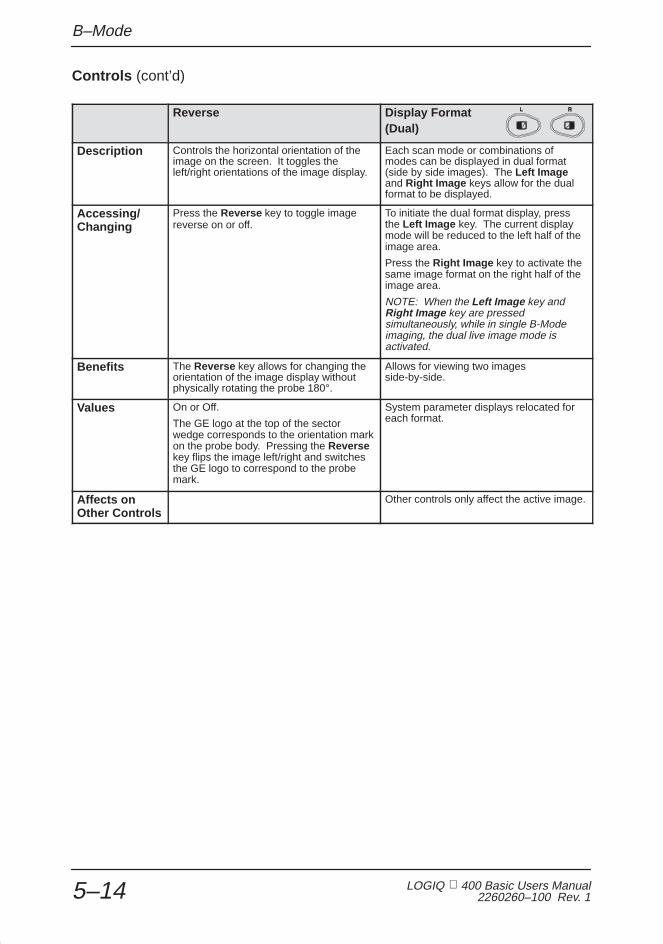
B–Mode
LOGIQ 400 Basic Users Manual2260260–100 Rev. 15–14
Controls (cont’d)
Reverse Display Format(Dual)
Description Controls the horizontal orientation of theimage on the screen. It toggles theleft/right orientations of the image display.
Each scan mode or combinations ofmodes can be displayed in dual format(side by side images). The Left Imageand Right Image keys allow for the dualformat to be displayed.
Accessing/Changing
Press the Reverse key to toggle imagereverse on or off.
To initiate the dual format display, pressthe Left Image key. The current displaymode will be reduced to the left half of theimage area.
Press the Right Image key to activate thesame image format on the right half of theimage area.
NOTE: When the Left Image key andRight Image key are pressedsimultaneously, while in single B-Modeimaging, the dual live image mode isactivated.
Benefits The Reverse key allows for changing theorientation of the image display withoutphysically rotating the probe 180°.
Allows for viewing two imagesside-by-side.
Values On or Off.
The GE logo at the top of the sectorwedge corresponds to the orientation markon the probe body. Pressing the Reversekey flips the image left/right and switchesthe GE logo to correspond to the probemark.
System parameter displays relocated foreach format.
Affects on Other Controls
Other controls only affect the active image.

B–Mode
LOGIQ 400 Basic User Manual2260260–100 Rev. 1 5–15
Controls (cont’d)
Focus Position
Description While in B-Mode only, Focus Position canbe adjusted using the Baseline Shift key.
Accessing/Changing
Access the Focus Position control while inB-Mode only.
To move the focal zone(s) up/down, pressthe Focus (Baseline Shift) up/downarrow key.
Benefits Easy front panel key access. Avoidsusing soft menu Focus Position selection.
Values Relative to depth of the display (FOV).Focal point indicators vary with positionchange up (shallow) or down (deep).
Pre-processing function.
Affects on OtherControls
Changing the focus position affects framerate. The deeper the focus, the slower theframe rate.
Bioeffects
AcousticOutputHazard
Moving the focal zone(s) may affectacoustic output requirements because ofconcentrating on a specific area ofinterest. Acoustic output may bedecreased with the front panel control ifthe focal zone is properly placed.
Observe the output display for possibleeffects.

B–Mode
LOGIQ 400 Basic Users Manual2260260–100 Rev. 15–16
B-Mode Sub-Menu Page 1
42
1/4B
FocusNumber
GrayMap
DynamicRange
B–2 2
ATOOn/Off
ATOCreate
Figure 5–6. B-Mode Sub-Menu Page 1
Dynamic Range Gray Scale Mapping (Gray Map)
Description Controls how echo intensities areconverted to shades of gray.
Determines how the echo intensity levelsreceived are presented as shades of gray.
Benefits Useful for optimizing tissue texture todifferentiate between echo levels that areclose together.
Dynamic range should be adjusted so thatthe highest amplitude edges appear aswhite while lowest levels (such as blood)are just visible.
Displays the received echo levels withdifferent weights on specific levels of gray.For example, a certain gray map mayenhance mid level echoes over a widerrange of grays verses high or low levelechoes.
Allows for better differentiation betweenecho levels through gray levels displayed.
Values The settings cycle in 6 dB steps from30 dB to 90 dB. Use presets to set theoutput preferred to any scan mode andexam combination. The default for BDynamic Range is set in the SetUp/Custom Display menu page 2.Dynamic range levels are returned to thepreset value when changing the following:
� Application� Exam category� New patient
Pre-processing function.
There are 16 selections of Gray ScaleMapping.
See Figure 14–6 on 14–16 for a graph ofthe Gray Scale Map.
Post-processing function.
Affects on Other Controls
Operates only in real-time, not in freeze,Cine, Timeline replay, or VCR playback.

B–Mode
LOGIQ 400 Basic User Manual2260260–100 Rev. 1 5–17
B-Mode Sub-Menu Page 1 (cont’d)
Focus Number ATO Create (software option)
Description Changes the number of focal zones sothat the beam can be tightened orexpanded for a specific area. A graphiccaret corresponding to the focal zoneposition(s) appears on the right edge ofthe image.
ATO, Automatic Tissue Optimization,optimizes the image based upon aspecified Region Of Interest (ROI) oranatomy within the display. ATO grayscale map is available only in B-Mode.The ATO option is not available on theLOGIQ 400CL.
ACCESSING/CHANGING:Once ATO Create has been selected, aROI box cursor is displayed on the image.
Use the trackball for changing the size andlocation of the ROI box cursor. PressScan Area to toggle between sizing andmoving the cursor.
Press Set. The system automaticallyoptimizes the entire image. Thehighlighted sub-menu selection changesautomatically from ATO Create to ATOON/OFF.
Benefits Optimizes the image by increasing theresolution for a specific area.
Improves productivity and patientthroughput with one touch imageoptimization. Improves contrast of thedisplayed image data.
Values Choose from 1, 2, 3 or 4 focal zones.
Pre-processing function.
On or off.
Affects on Other Controls
Changing the focus number affects framerate. The greater number of focus points,the slower the frame rate.
Bioeffects
AcousticOutputHazard
Adding focal zones tends to increase TI,although it may decrease MI.
Observe the output display for possibleeffects.

B–Mode
LOGIQ 400 Basic Users Manual2260260–100 Rev. 15–18
B-Mode Sub-Menu Page 1 (cont’d)
ATO On/Off (software option)
Description The ATO On/Off selection is highlighted when the ATO map is active on the image. ATOON/OFF can be toggled on and off to display that same ATO map again. When ATOmap is active, the asterisk (*) is displayed on the right side of the gray scale mapnumber. The B gray scale map number is displayed under the gray scale bar. The ATOoption is not available on the LOGIQ 400CL.
ATO gray scale map is available until changing the following:
� Probe� New Patient� Exam Category� User Preset� Gray Scale Map� Power Off� New ATO map creation.
Only one ATO gray map is available at a specific time.
Benefits Ability to access the previously created ATO map without any time delay.
Values On or off.

B–Mode
LOGIQ 400 Basic User Manual2260260–100 Rev. 1 5–19
B-Mode Sub-Menu Page 2
2/4B
ImageSoftner
ImagingFreq
FrameAverage
3DMode
Color
OFF 3.5MHz
Figure 5–7. B-Mode Sub-Menu Page 2
Frame Averaging Imaging Frequency
Description Averages previous frames of image datawith the current frame. Frame averaginguses more data points to make up 1image. This has the effect of presenting asmoother, softer image.
NOTE: Not available on Cine replay.
In B-Mode, imaging frequency can bechanged to allow more echoes to passthrough.
Benefits Helps to average out brief, suddenchanges in echo intensity information.Could help to filter out low intensity noise.
Allows for an increase in echo intensitywithout changing gain, TGC or acousticoutput with lower frequencies. Allows forincreased resolution with higherfrequencies.
Values Frame average values are off, 1, 2, 3, 4, 5and 6. Frame average values are returnedto the preset value when changing thefollowing:
� Probe� Exam category� New Patient� Application type.
Pre-processing function.
Values shown are probe dependent.
Table 5–6 shows the correlation betweenthe frequency values displayed and theimaging frequency mode preference(penetration, normal, resolution, furtherpenetration, harmonic 1 and harmonic 2).
To set the default image frequency forB-Mode and M-Mode, refer to CustomDisplay pages 2 and 3, respectively.
Further penetration mode is available onthe C358 probe only.
Refer to 5–21 for details on TissueHarmonics.
Affects on Other Controls
Acoustic output, gain and TGC may beable to be reduced due to increasedpenetration.

B–Mode
LOGIQ 400 Basic Users Manual2260260–100 Rev. 15–20
B-Mode Sub-Menu Page 2 (cont’d)
Frequency of Operation depends on Image Frequency Sub-Menu Selection
Probe Resolution Normal PenetrationFurther
Penetration Harmonic 1 Harmonic 2
B510 6.5MHz 5MHz 5MHz N/A N/A N/A
S317 4MHz 3.5MHz 2.5MHz N/A T5.0 T4.7
S222 3.5MHz 3MHz 2MHz N/A T3.5 T3.2
3S 2.8MHz 2.4MHz 2.0MHz N/A T3.5 T3.2
S611 6MHz 5MHz 4MHz N/A N/A N/A
S220 (W) 3MHz 2MHz 2MHz N/A N/A N/A
E721(MTZ) 7MHz 6MHz 5.5MHz N/A N/A N/A
C721 7MHz 6MHz 6MHz N/A N/A N/A
C551 (CAE) 6MHz 5MHz 4.4MHz N/A N/A N/A
C364 (CBF) 4MHz 3.5MHz 3MHz N/A N/A N/A
C386 5MHz 3.8MHz 3MHz N/A N/A N/A
C358 5MHz 4MHz 3MHz 2MHz T5.0 T4.5
739L 9MHz 7MHz 6MHz N/A N/A N/A
LA39 11MHz 9.6MHz 8.2MHz N/A N/A N/A
546L 6.6MHz 5.2MHz 4.6MHz N/A N/A N/A
LD 4MHz 3.5MHz 3MHz N/A N/A N/A
L764 (LH) 7MHz 7MHz 7MHz N/A N/A N/A
I739 8MHz 7MHz 6MHz N/A N/A N/A
T739 8MHz 7MHz 6MHz N/A N/A N/A
CWD2 N/A N/A N/A N/A N/A N/A
CWD5 N/A N/A N/A N/A N/A N/A
ERB7C 7MHz 6MHz 5.5MHz N/A N/A N/A
ERB7L 7MHz 6MHz 5.5MHz N/A N/A N/A
Table 5–6. Frequency of Operation

B–Mode
LOGIQ 400 Basic User Manual2260260–100 Rev. 1 5–21
B-Mode Sub-Menu Page 2 (cont’d)
Image Softener Color
Description B-Mode images may be adjusted for theamount of smoothing applied.
Color allows for enabling B-Mode imagecolorization.
Benefits Provides a smoother homogenous imagedisplay.
Displaying the gray scale as shades ofcolor may allow for improved differentiationbetween echo levels.
Values On or Off.
Pre-processing function.
On or Off.
The B-Mode color presented is a selectionin the Set Up/Custom Display menupage 11. There are 6 color choices.
Post-processing function.
3D Mode (option)
Description Allows for 3D Mode option activation fromthe B-Mode menu.
Benefits Allows for quick on/off of 3D Modefunction from B-Mode Sub-Menu.
Values On or Off.
THI (Tissue Harmonic Imaging) (option)
Description —Tissue Harmonic Imaging utilitizes the naturalharmonic characteristic inherent in non-linear soundpropagation properities in the human body. This function doesnot permit the use of any contrast agent. It is only available onthe S222, S317, C358 and 3S probes. The THI option is notavailable on the LOGIQ 400CL.
Benefits —Harmonic imaging diminishes low frequency highamplitude noise and often improves imaging technically difficultpatients. Tissue Harmonic imaging is beneficial to contrastresolution and cystic clearing.
Accessing/Changing —Access Tissue Harmonic frequencyusing the Imaging Freq sub-menu selection. See 5–19 fordetails. To easily recognize a tissue harmonic frequency, theletter “T” precedes the frequency value on the monitor and softmenu.

B–Mode
LOGIQ 400 Basic Users Manual2260260–100 Rev. 15–22
B-Mode Sub-Menu Page 3
TagPositn
ColorTag
3/4B
FocusPositn
Figure 5–8. B-Mode Sub-Menu Page 3
Focus Position Color Tag
Description Changes the depth at which the selectednumber of focal zones are optimized. Allgraphic carets representing focal pointswill move with a change in focal position.
Enables the colorization of a specific grayscale level range. This causes thespecified gray levels to be displayed as apredetermined color in the B-Mode image.
Benefits Optimizes the image by centering the focalpoint(s) to the depth of the area of interest.
Allows for the quick recognition of specificgray levels by colorization.
Values Relative to depth of the display (FOV).Focal point indicators vary with positionchange up (shallow) or down (deep).
Pre-processing function.
On or Off.
The color tag size presented is a selectionin the Set Up/Custom Display menupage 11.
Post-processing function.
Affects on OtherControls
Changing the focus position affects framerate. The deeper the focus, the slower theframe rate.
Bioeffects
AcousticOutputHazard
Moving the focal zone(s) may affectacoustic output requirements because ofconcentrating on a specific area ofinterest. Acoustic output may bedecreased with the front panel control ifthe focal zone is properly placed.
Observe the output display for possibleeffects.
Tag Position
Description Allows for the movement of the specified color tag range throughout the gray scaledisplayed.
Benefits Allows for setting the color tag to the desired level of gray scale colorization.
Values If the Color Tag selection is not enabled when Tag Positn is selected, Color Tag isautomatically activated.
Move the color tag up or down the gray scale. Color and size of the tag are determinedin the Set Up/Custom Display menu page 11.
Post-processing function.

B–Mode
LOGIQ 400 Basic User Manual2260260–100 Rev. 1 5–23
B-Mode Sub-Menu Page 4
SGL
4/4B
EdgeEnhance
RejectnImageRotatn
BiopsyZone
0DEG 30 MID
Figure 5–9. B-Mode Sub-Menu Page 4
Biopsy Zone Image Rotate
Description This selection enables any electronic biopsyguidezone(s) available for the active probe.
If the single fixed angle (SGL) was selected asthe needle guide type in Set Up/CustomDisplay page 1, the fixed zone angle isdisplayed.
If the needle guide type selected is multipleangle (MBX), the Biopsy Zone up/down arrowkeys can be used to cycle through the angleselections MBX1, MBX2, MBX3 and OFF.
Rotates the single real-time orzoomed B-Mode image in 90�increments.
When B-Mode is rotated 180�, theM-Mode (if active) is also rotated180�.
Benefits The electronic biopsy guidezone shows theexpected needle path during insertion.
Failure to match theguidezone displayed tothe guide may cause theneedle to track a pathoutside the zone.
DANGER
Orient image display for easyreference.
outside the zone.
It is extremely important that when using theadjustable angle biopsy guides, the angledisplayed on the screen matches the angle seton the guide, otherwise the needle will notfollow the displayed guidezone which couldresult in repeated biopsies or patient injury.
SafetyConcern
When the biopsyguidezone is displayed,the message:
“Confirm BX type of Bracket”
is displayed at the bottom of the screen withthe angle selected
DANGER
the angle selected.
Ensure that the (M)BX type selected for eachprobe is the same as the angle selected onthe biopsy guide.
NOTE: For specifics on availability of biopsyguide angles, see 15–33.

B–Mode
LOGIQ 400 Basic Users Manual2260260–100 Rev. 15–24
B-Mode Sub-Menu Page 4 (cont’d)
Biopsy Lines Image Rotate
Values On (SGL, MBX1, MBX2, MBX3, TV0, TR5,1~8, GBX) or Off.
NOTE: Press the Measurement key once todisplay the integrated biopsy depth cursor andcenter line while the guidezone is present. Usethe Trackball to measure the needle length.Needle length is from the top of needle barrelto the target.
See Figure 15–12 on 15–32 for measuring theneedle length.
The image rotates in 90� incrementsin a clockwise and counterclockwisedirection.
Post-processing function.
Affects on Other Controls
When reading arotated image,be careful toobserve the
probe orientation to avoid possibleconfusion over scan direction orright/left image reversal.
CAUTION
Rejection (Rejectn) B Edge Enhance
Description Allows for the elimination of low level echoesfrom the display. This is generally used toclear noise out of vessels or cysts.
B edge enhance brings out subtletissue differences and boundaries byenhancing the gray scale differencescorresponding to the edges ofstructures.
Benefits Allows for the elimination from the displayimage of low level echoes caused by noise.
Edge enhance modifies the B-Modeimage by accentuating the interfacesbetween organs or vessels.
Values Off and 2 through 40 in increments of 2.
Post-processing function.
The four selections are Off, Low, Midand High. The default for B EdgeEnhance is set in the Set Up/CustomDisplay menu page 2. Edge enhancelevels are returned to the preset valuewhen changes are made to thefollowing:� Application� Exam category� New patient
Pre-processing function.
Affects on Other Controls
Rejection affects real-time imaging, frozen,Cine or VCR playback images.
Operates in real-time only, not inFreeze, Cine, or VCR playback.

B–Mode
LOGIQ 400 Basic User Manual2260260–100 Rev. 1 5–25
B-Mode Optimization
B-Mode Optimization
Adjustmentsfor...
Do the Following...
Adjustmentsfor...
Do the Following...
Image too grainy 1. Increase Dynamic Range .
2. Increase Frame Average .
3. Decrease Edge Enhance .
4. Change Gray Map .
Image too soft 1. Decrease Dynamic Range .
2. Increase Edge Enhance .
3. Decrease Frame Average .
4. Change Gray Map .
Image too noisy 1. Decrease B/M GAIN .
2. Decrease Dynamic Range .
3. Increase Frame Average .
4. Increase Edge Enhance .
ImproveUniformity
1. Increase the number of focalzones.
2. Decrease SCAN AREASIZE.
3. Adjust TGC to compensatefor attenuation.
Cystic Imaging 1. Decrease the B/M GAIN .
2. Decrease Dynamic Range .
3. Use SCAN AREA SIZE toreduce image width.
4. Change Focus Number toincrease number of focalzones.
5. Optimize focal zoneplacement.
TechnicallyDifficult Patients
1. Select the proper probe orchange Imaging Freq. forthe exam (larger patient,lower frequency).
2. Increase ACOUSTICOUTPUT, if necessary.
3. Maintain a lower DynamicRange (45 to 48).
4. Decrease SCAN AREASIZE for faster frame rates.

Adding Color
LOGIQ 400 Basic Users Manual2260260–100 Rev. 15–26
Adding Color
Gray Scale Color
Each mode selection (except CFM) can display the shades ofgray as shades of a color. The system simply maps out thegray levels as hues of a color scale.
The gray scale bar changes color and the image displaychanges accordingly.
The color displayed is selected in the Set Up/Custom Displaymenu. The preset “Color Map” is chosen separately forB-Mode, M-Mode and Doppler displays. Details on the colormap selection are found in Customizing Your System.
Colorized gray scale is an on/off selection found in each modeTop Menu.
In each mode (B, M, PD and CWD), the color selection is foundon the Sub-Menu page two.
The Color rocker switch toggles colorized gray scale on or off.
Color Flow Mode
Color Flow Mapping (CFM) may also be referred to as ColorDoppler or Color Doppler Imaging. It is used to display colorcoded blood flow information super imposed on the B-Mode,M-Mode or Doppler displays.
B/WOption

Adding Color
LOGIQ 400 Basic User Manual2260260–100 Rev. 1 5–27
Activating Color Flow
To activate Color Flow Mapping, press the CFM key (colorflow). The key backlights while in Color Flow Mode. The colorflow image appears after a short pause.
Color Flow Mapping can be used with B-Mode, M-Mode orDoppler Imaging.
In B-Mode, the Color Flow information overlays the B-Modeimage.
The Scan Area key and Trackball now control the size andposition of the color flow window.
M-Mode
In M-Mode, the color flow information overlays the B-Modeimage. The color displayed in the M-Mode is that which is seenalong the timeline cursor.
The Color Map selected for B-Mode applies to M-Mode. Thesize and position of the color flow window in B-Modedetermines the color information displayed in M-Mode.
Exiting Color Flow
To exit Color, press CFM (color flow).

Adding Color
LOGIQ 400 Basic Users Manual2260260–100 Rev. 15–28
Reading the Color Flow Display
The following information displays on the Color Flow Modeimage:
ÇÇÇÇÇÇÇÇÇÇÇÇÇ
FR/Cine
ÏÏÏÏÏÏÏÏÏÏÏÏÏÏÏÏÏÏÏÏÏÏÏÏÏÏÏÏÏÏÏÏÏÏÏÏÏÏÏÏÏÏÏÏÏÏÏÏÏÏÏÏÏÏÏÏÏÏÏÏ
CG
MHz
Figure 5–10. Color Flow Mode Graphic Display
Graphic Display Description, Format, Values
Velocity Scale Raises/lowers the velocity scale on the color bar. Displayed in cm/m per second orHz.
Color Scale Displays the selected velocity, velocity & variance, power, or velocity & power map.
CFM Area Cursor Color displays only in this sector. Press the Scan Area key to toggle betweencursor size and position control. Size this window using the Trackball . Positionthis window via the Trackball .
MTI Filter Displays on the Color Flow bar as a black area surrounding the baseline.
Color ThresholdMarker
The color display threshold based on the B-Mode gray scale level.
Units (V or F) Indicates the unit of measure. Velocity (V) in meters per second or Frequency (F)in KHz.
Color Gain (CG) Displays the Color Receive Gain value from 0 to 31.CG## Dual Mode: ##CG##
Figure 5–11. Color Flow Mode Display Format

Adding Color
LOGIQ 400 Basic User Manual2260260–100 Rev. 1 5–29
Optimizing the Color Flow Image
Control Layout
Figure 5–12. Color Doppler Controls
Color Flow Mapping is basically Doppler velocity/directioninformation mapped as a color on top of the gray scale B-Mode(or M-Mode) Image.
Keyboard controls used to affect the Doppler spectrum alsoaffect CFM Mode. However, some Soft Menu controls affectonly the color processing and display.

Adding Color
LOGIQ 400 Basic Users Manual2260260–100 Rev. 15–30
Common Controls
Description
After initial transmission/reception, CFM processing is generallyseparate from gray scale processing.
Acoustic output affects the transmit power for both B-Mode andColor Flow Mapping signals.
TGC, Depth, B/M Gain and Reverse function only on theB-Mode image displayed.
The M/D Cursor key is not relevant to CFM scanning; it onlyaffects the Doppler/M-Mode.
Dual format keys (L–R) work the same as in dual B-Mode, butdisplay two B-Mode and CFM images on the left and right sideof the screen.
NOTE: If “L” and “R” keys are pressed simultaneously, both leftand right B-Mode images will be active. Pressing CFM will thenprovide a live B-Mode image on the left and a live B-Mode withCFM on the right.
�

Adding Color
LOGIQ 400 Basic User Manual2260260–100 Rev. 1 5–31
Controls
Color Doppler Gain CFM/Spectrum Invert
Description Amplifies the overall strength of theechoes being processed in the ColorDoppler section.
Allows for viewing blood flow from adifferent perspective, i.e., red away(negative velocities) and blue toward(positive velocities). Color reverses areal-time or frozen image.
NOTE: Invert reverses theforward/reverse color assignment.
Accessing/Changing
Gain values change depending on theprobe; gain is not associated with aparticular position of the knob.
To increase gain, turn the Gain knobclockwise.
To decrease gain, turn the Gain knobcounterclockwise.
To reverse the color assignment, pressCFM/Spect Invert.
Benefits Allows control of the amount of color withina vessel.
Allows viewing of blood flow according topersonal preference, or display propercolor without changing probe orientation.
Values The settings range is 32 levels, but valuesare not displayed on the image monitor.Usually set the dial in the middle,depending on the vessel.
Invert and non-invert.
Affects on Other Controls
The system automatically adjusts the gainbased on acoustic output.
Bioeffects Color Doppler gain has no affect onacoustic output. However, with increasedcolor Doppler gain, the output level canusually be reduced to produce anequivalent spectrum image quality.
When “Spec. Inv. in Triplex” preset onCustom Display page 14 is set toSimultaneous, the Doppler spectrum isalso inverted.

Adding Color
LOGIQ 400 Basic Users Manual2260260–100 Rev. 15–32
Controls (cont’d)
Velocity Scale Color Flow Baseline Shift
Description Increases or decreases the Velocity Scalerepresented by the color bar.
Minimizes aliasing by reallocating theforward/reverse color velocity scaleassignment. For example, it allows agreater portion of the color scale to beassigned to forward flow than to reverseflow.
Baseline Shift adjusts the point in the colorspectrum where the color velocity is atzero (black).
Accessing/Changing
To increase velocity scale, press theVelocity Scale up arrow key until reachingthe desired scale.
To decrease velocity scale, press theVelocity Scale down arrow key untilreaching the desired scale.
To adjust the baseline shift, press theBaseline Shift up or down arrow keys.
Baseline does not wrap. If the baseline ispositioned at the top of the color bar,shifting the baseline again will cause thesystem to beep.
Benefits If blood is flowing at a higher velocity,increase the velocity scale in order toavoid aliasing in the color display.
Minimize aliasing during color flowimaging.
Values Velocity scale is displayed in cm persecond.
Color flow baseline can be shifted to oneof 7 proportionately-spaced positions onthe color bar.
Zero velocity follows the baseline. Thetotal velocity range remains the same.
Affects on Other Controls
Velocity scale changes frame rate,acoustic output, and wall filter.
When adjusting velocity scale, Cinememory is cleared.
Bioeffects
AcousticOutputHazard
Changing the velocity scale tends tochange the MI.
Observe the output display for possibleeffects.

Adding Color
LOGIQ 400 Basic User Manual2260260–100 Rev. 1 5–33
Controls (cont’d)
Color Flow Window Size (Scan Area)
Description Color Flow data is placed on top of the gray scale image in a specific area. This isrepresented by a sector wedge outline with convex probes or a rectangle with linearprobes.
The size and position of this color area can be easily adjusted.
The Color Flow window is a solid line when position may be adjusted by the Trackball.The Color Flow window is a dotted line when the size (CFM area) may be adjusted bythe Trackball.
Accessing/Changing
While in the CFM Mode, press Scan Area once. This assigns trackball control to colorwindow size adjustment.
Use the Trackball to adjust the color window size.� Move the Trackball left to close the color window and right to open it.� Move the Trackball down to increase and up to decrease the color window vertical
size.
Press Scan Area a second time to assign trackball control to positioning the re-sizedwindow.
NOTE: Pressing Scan Area toggles between trackball control of window size orposition.
Pressing Set fixes the color window size and position. Trackball control is returned toits previous assignment.
Values Sector/Convex Probe. Ranges from 10° to full “B” width.
Linear Probe. Ranges from 10mm to full �B” width.
Bioeffects
AcousticOutputHazard
Narrowing the image size may increase the frame rate, thereby increasing the TI. Thischange also tends to decrease the MI.
Observe the output display for possible effects.

Adding Color
LOGIQ 400 Basic Users Manual2260260–100 Rev. 15–34
CFM Mode Sub-Menu Page 1
VT–1
1/4CFM
MTIFilter
DiagMode
SlantScan
CFMMap
– Map LOW
Figure 5–13. CFM Mode Sub-Menu Page 1
Color Flow Maps Slant Scan
Description Allows for the selection of how Dopplervelocities are mapped as color over thegray scale. The Color Bar represents theselected map.
Slant scan in CFM Imaging is used tocontrol the position of the CFM window forLINEAR PROBES ONLY .
Values The 6 color map selections available areassigned in the Set Up/Custom Displaypage 15. The parameters CFM Color Map1–6 can be assigned as Velocity maps (V1thru V8), Velocity/Turbulence maps (VT1thru VT8), or Turbulence maps (T1 andT2) or Advanced Velocity Mode Maps (A1thru A4). The Advanced Velocity Maps areonly available with the ACE-2 option. TheACE-2 option is not available on theLOGIQ 400CL.
+ (left), 0 (center) and – (right). SeeFigure 5–14.
Pre-processing function.
Benefits Provides a color flow window suitable forlinear probe operation.
0 (Center) – (Right)+ (Left)
Figure 5–14. Slant Scan Window Selections

Adding Color
LOGIQ 400 Basic User Manual2260260–100 Rev. 1 5–35
CFM Mode Sub-Menu Page 1 (cont’d)
Diag Mode Color Flow MTI Filter
Description Allows for the selection of the best color flow displayformat. The 4 methods are:
Survey Mode (Svy) —The Survey Modeis the default Diag Mode display and iscommon for each of the 2 programs.The Survey Mode displays the B/WB-Mode image and has an adjustable,full depth CF wedge that can be steeredwith the Trackball .
Survey/Detail Mode (SvyDtl) —TheSurvey/Detail Mode displays a highresolution color flow window that is halfthe depth of the B-Mode image. The CFwedge is adjustable horizontally and
ÇÇÇÇÇÇÇÇ
ÇÇÇÇ
Filters out low flow velocitycolor. This minimizesmotion artifacts causedfrom breathing.
edge s adjustab e o o ta y a dvertically and can be steered within thefull B-Mode image with the Trackball .
Map Mode (Map) —In the Map Mode,the B-Mode image and the color flow arethe same size. The Map Mode offershigher CF frame rates and a full sizeadjustable CF wedge.
Map/Detail Mode (MapDtl) —The DetailMode shows a high resolution, highframe rate color flow window that is halfof the B-Mode depth. The B-Mode andthe CF are the same adjustable angle.
ÇÇÇÇÇÇ
ÇÇÇÇÇÇ
Benefits Gives the operator a choice of CFM displays to optimizescanning.
Filters out the lowestvelocities (colors).
Values 4 sequences are available in the Set Up/Custom Displaymenu page 15:� Survey>Map>Map/Detail� Survey>Survey/Detail� Survey>Survey/Detail>Map� Survey/Detail>Map/Detail
Pre-processing function.
Values are Low, M1, M2,M3, M4 and High.
Pre-processing function.
Affects on Other Controls
Display frame rate could be improved by minimized grayscale B-Mode image size or CFM window size.

Adding Color
LOGIQ 400 Basic Users Manual2260260–100 Rev. 15–36
CFM Mode Sub-Menu Page 2
HighResoltn
MID
2/4CFM
CaptureDisplayThrshld
Penet.FrameAverage
32 OFF
Figure 5–15. CFM Mode Sub-Menu Page 2
Frame Average Penetration (Penet.)
Description Averages color information from previousframes with the current frame.
Penetration can be increased by loweringthe operating frequency of the activeprobe.
For reference, Color Flow Dopplerfrequencies (with penetration On or Off)are shown according to probe in Table 5–7on 5–46.
Benefits Averages out one time events like noisespikes.
Allows for a slight increase in penetrationwithout changing gain or acoustic output.
Values Off, low, medium and high.
Pre-processing function.
On or Off.
Pre-processing function.
Affects on Other Controls
Trade off between frame rate and colorquality. As the color quality increases, theframe rate decreases and as the framerate increases, the color quality decreases.
Acoustic output, gain and TGC may beable to be reduced due to increasedpenetration.
Bioeffects Decreasing the probe transmittingfrequency, without decreasing acousticoutput, tends to increase Mechanical andThermal Index values. However, improvedpenetration should allow for decreasingpatient exposure time.

Adding Color
LOGIQ 400 Basic User Manual2260260–100 Rev. 1 5–37
CFM Mode Sub-Menu Page 2 (cont’d)
High Resoltn (Resolution) Color Flow Display Threshold
Description Provides a quick way to maximizeresolution for the CFM display.
Color flow display threshold is the grayscale level at which the overlay of colorinformation stops.
If the display threshold is set at a grayshade percentage of 34, any colorinformation available will be overlaid below34% of the gray scale map. Colorinformation will not be placed on top of anypart of the gray scale greater than 34% ofmaximum (white).
Benefits Optimizes CFM color display by changingsystem parameters to maximize color linedensity.
Can limit color flow overlay to low levelechoes inside vessel walls. Helpsminimize color “bleeding” outside vesselwalls.
Values When High Resoltn is highlighted in thesub-menu display, the function is on.When it is not highlighted, it is off.
Pre-processing function.
Post processing function. The colorthreshold can be set on real-time or frozenimages.
The settings cycle through the followingvalues:
0% to 100% of the gray scale in 3%increments.
Affects on Other Controls
High Resolution will cause the scan framerate to decrease.
Color Capture (option)
Description Displays the highest mean velocity(average velocity) detected over a specifictime interval.
NOTE: If a velocity map is selected, theimage displays accumulated peak meanvelocities. If a variance map is selected,the image displays variance for theaccumulated peak mean velocities.
Benefits Useful in making slide presentations. Alsorefer to the 6–14 for post processing CineCapture and Capture Frame functions.
Values Off, 0.5 seconds, 1 second, 2 secondsand ECG.
Pre-processing function.

Adding Color
LOGIQ 400 Basic Users Manual2260260–100 Rev. 15–38
CFM Mode Sub-Menu Page 3
SpatialFilter
OFF
ColorTag
SMALL
3/4CFM
TagPositn
W.E.Cancel
PacketSize
Figure 5–16. CFM Mode Sub-Menu Page 3
Packet Size Spatial Filter
Description Controls the number of samples gatheredfor a single color flow vector.
Smooths color information so that it is lessgrainy. It averages the color informationout over time.
Benefits Allows for the improvement of the colorsensitivity.
Smooths color information.
Values Soft Menu values are VrySml, SMALL,MID and LARGE.
“VrySml” is necessary for the ACE-2option. The ACE-2 option is not availablewith the LOGIQ 400CL.
NOTE: The “CFM Packet Size” is aparameter that can be preset in the SetUp/Custom Display menu page 6.
Off, 1, 2, 3, 4 and 5.
NOTE: The “CFM Spatial Filter” is aparameter that can be preset in the SetUp/Custom Display menu page 6.
Affects on Other Controls
When the packet size is decreased, theframe rate is increased at the expense ofCFM image quality. When the packet sizeis increased, CFM image quality isimproved at the expense of frame rate.
Note: This function does not work in ColorM-Mode or B/CFM with Pulsed Doppler.
Affects frame rate. The slower the spatialfilter averaging, the faster the frame rate;the higher the spatial filter averaging, theslower the frame rate.
Bioeffects
AcousticOutputHazard
Changing packet size may change the TIand/or MI.
Observe the output display for possibleeffects.
Changing Spatial Average tends todecrease MI.
Observe the output display for possibleeffects.

Adding Color
LOGIQ 400 Basic User Manual2260260–100 Rev. 1 5–39
CFM Mode Sub-Menu Page 3 (cont’d)
W. E. (Wall Echo) Cancel Color Flow Velocity Tag (Color Tag)
Description Eliminates the low velocity echoes causedby the motion of vessel walls.
Allows for the assignment of a single colorto a range of velocities.
Real-time or frozen images may betagged. Velocity tags can be incorporatedinto velocity/variance color maps.
NOTE: The tag assignment appears onthe color bar for reference.
Benefits Eliminate low velocity echoes caused byvessel wall motion to help clean up thecolor Doppler display.
Provides the ability to emphasize specificblood flow velocities so that they stand outto the eye.
Values On or Off.
Pre-processing function.
On/Off.
Post-processing function.
NOTE: The “CFM Tag Width” is aparameter that can be preset in the SetUp/Custom Display menu page 15.
Affects on Other Controls
Tag Position (Positn)
Description Allows for the movement of the specifiedcolor tag range throughout the gray scaledisplayed.
Benefits Allows for setting the color tag to thedesired level of gray scale colorization.
Values If the Color Tag selection is not enabledwhen Tag Positn is selected, Color Tag isautomatically activated.
Move the color tag up or down the grayscale. Color and size of the tag isdetermined in the Set Up/Custom Displaymenu page 15.
Post-processing function.

Adding Color
LOGIQ 400 Basic Users Manual2260260–100 Rev. 15–40
CFM Mode Sub-Menu Page 4
NoiseBlanker
OFF
3DMode
OFF
4/4CFM
Persistence
ACE
OFF
Figure 5–17. CFM Sub-Menu Page 4
An option is available to enhance CFM/PDI signal processing.It requires the necessary hardware (Color Processing Board)and software (CFM/PDI Enhancement). The following choicesare added to the CFM Mode Soft-Menu:
� Adaptive Color Enhancement (ACE)
� Noise Blanker
� Persistence
ACE (Adaptive ColorEnhancement)
Noise Blanker
Description Designed to reduce “color artifact noise”.This noise can appear as a flash of colorsynchronized with the heart beat whilescanning the abdomen. The noise mayalso appear to fill the color window whenchanging window size/position or whenmoving the probe. Noise due to valuemotion in cardiac studies may beconsidered clutter noise.
Noise Blanker is intended to reduce therandom noise generated due to theincrease in Color Gain.
Benefits Reduces the “color artifact noise” asdescribed in the description section.
Noise Rejection increases color sensitivitywith the ability to use higher color gains.Very effective when observing low velocityblood flow.
Values On or Off. OFF No Noise BlankingLOW Minimum Noise BlankingMID Medium Noise BlankingHIGH Maximum Noise Blanking
Affects on Other Controls
May have a tendency to reduce frame ratedue to increased CFM processorfunctions.
Allows use of increased Color Gain orequivalent results with less gain.

Adding Color
LOGIQ 400 Basic User Manual2260260–100 Rev. 1 5–41
CFM Mode Sub-Menu Page 4 (cont’d)
Persistence 3D Mode
Description Retains the largest pixel color value until alarger value is detected or preset time haselapsed.
When a higher color value for a pixel isdetected, that value is retained and thepersistence time is reset for that pixel.When the persistence time elapses forthat pixel, color is deleted and it returns togray scale.
Allows for 3D Mode activation from theColor Flow menu.
Benefits Present a continuous, high sensitivitycolor image.
Allows for quick on/off of 3D Mode functionfrom CFM Sub-Menu.
Values OFF No PersistenceSHORT Short Persistence timeMID Medium Persistence timeHIGH Long Persistence time
On and Off.
Affects on Other Controls
The activation of the Persistence functionwill over ride any previous selectionsmade for CFM Capture or CFM B FrameAverage. When Persistence isdeactivated CFM Capture and CFM BFrame Average will return to normaloperation.

Adding Color
LOGIQ 400 Basic Users Manual2260260–100 Rev. 15–42
CFM Optimization
Color Flow Mode Optimization
Adjustmentsfor...
Do the Following...
Adjustmentsfor...
Do the Following...
Decrease MotionArtifact
1. Increase the VELOCITYSCALE .
2. Increase W.E. Cancel .
Eliminate Aliasing 1. Increase VELOCITYSCALE .
2. Lower BASELINE SHIFT.
ImproveSensitivity
1. Increase GAIN.
2. Decrease VELOCITYSCALE .
3. Increase ACOUSTICOUTPUT.
4. Switch Penet. on and HighResoltn on.
5. Decrease W.E. Cancel .
6. Increase Frame Average(this allows gain toincrease).
7. Increase Packet Size .
8. Reduce SCAN AREA SIZEto smallest size reasonable.
9. Optimize focal zoneposition.
Improve FrameRate/FlowDynamics
1. Decrease color windowusing SCAN AREA SIZEwidth.
2. Exit COLOR FLOW toreduce B-Mode image width(use SCAN AREA SIZE ).
3. Decrease DEPTH.
4. Increase VELOCITYSCALE (if flow state allowsit).
5. Decrease Frame Average .
Decrease ColorFlow Bleeding
1. Decrease GAIN.
2. Increase VELOCITYSCALE .
3. Decrease Display Thrshld .

Adding Color
LOGIQ 400 Basic User Manual2260260–100 Rev. 1 5–43
Power Doppler Imaging (option)
Power Doppler Imaging (option)
Description Power Doppler Imaging, also known as PDI, (option) is a color flow mapping techniqueused to map the strength of the Doppler signal rather than the frequency shift or velocityof the signal. PDI is a different way of processing the power information from the colorflow transmissions by using different color maps and not displaying directionalinformation. Using this technique, the system plots color based on the number ofreflectors that are moving, regardless of velocity.
Accessing/Changing
While scanning in the CFM Mode, enable the Blue Shift key (key will be lighted) andpress P.
NOTE: For USA systems, the User Define Key 6 has been locked and programmed totoggle the PDI mode on/off. User Define Key 6 can be reprogrammed for otherfunctions if it is unlocked.
Although remaining in the CFM Mode Top Menu, the system will shift to the PDI presetsand color maps.
Values Only power maps are available in the PDI mode.P1 thru P4 are PDI maps.P5 and P6 are Directional PDI Maps (ACE-2 option). ACE-2 option is not available forthe LOGIQ 400CL.
Changes between non-topo and topo maps can only be done in real-time, not on afrozen image.
Affects on Other Controls
Only changes between P1 thru P4, P5 and P6 are post-processing functions and do notaffect image acquisition controls. PDI parameters need to be changed in real-time.Some controls that affect CFM also affect PDI.
Hints
Optimizing thePDI Option
Custom Display pages 8 and 16 have parameters specific to PDI.
The PDI Velocity choice is a trade-off between low flow detectability and wall motion.
The PDI B High Resolution choice is a trade-off between frame rate and colorresolution.
The PDI B Frame Average choice is a trade-off between a sharper noisy appearance ora smoother less noisy appearance to the image.
The activation of the Persistence function will override any previous selections made forPDI B Frame Average. When Persistence is deactivated PDI B Frame Average willreturn to normal operation.
The PDI B Wall Filter choice is made depending on the frequency of the probe.
The PDI Map Transparency allows for the B-Mode image to be shown through the colorflow display. This preset is found on Set Up/Custom Display page 7.
NOTE: Remember that parameters found on Custom Display page 8 are probedependent. Set up these parameters for all probes that will be used for PDI.
NOTE: Parameters on Custom Display page 16 are effective for all probes.

Doppler
LOGIQ 400 Basic Users Manual2260260–100 Rev. 15–44
Doppler
Introduction
Time zero (the start of the trace) appears on the left side of thegraph. As time progresses, the trace moves to the right. Thebaseline of the graph (representing zero velocity, zerofrequency shift or no detected flow) appears as a solid linerunning horizontally across the display. By convention,movement toward the probe is positive frequencies or velocitieswhich appear above the baseline. Movement away from theprobe is negative frequencies or velocities which appear belowthe baseline.
Typically, blood flow is not uniform but is composed of a mix ofblood cells moving at different velocities and in differentdirections. Thus, the display is composed of a spectrum of grayscale values. Strong signals are displayed as bright shades ofgray while weak signals are displayed as darker shades.
Information about the Doppler display is automatically writtenon the screen and updated when scanning parameters arechanged.
The following can be used:
� Pulsed Wave (PW) Doppler
� Continuous Wave (CW) Doppler
� CW Non-Imaging Doppler
B/WOption

Doppler
LOGIQ 400 Basic User Manual2260260–100 Rev. 1 5–45
Pulsed Wave Doppler
PW Doppler is typically used for displaying the speed, direction,and spectral content of blood flow at selected anatomical sites.
PW Doppler can be combined with B-Mode for rapidly selectingthe anatomical site for PW Doppler examinations. This isdescribed under B/M-Mode operation. The site where PWDoppler data is derived appears graphically on the B-Modeimage (Sample Volume Gate). The site can be movedanywhere within the B-Mode image.

Doppler
LOGIQ 400 Basic Users Manual2260260–100 Rev. 15–46
Frequencies Used
For reference, Doppler frequencies (with penetration On or Off)are shown according to probe in the table below.
PROBE FREQUENCY (MHz)
ON OFF
B510 4.0 5.0
C358 2.5 3.3
C364/CBF 2.5 3.3
C386 2.5 3.3
C551/CAE 4.0 5.0
C721 5.0 6.6
E721/MTZ 5.0 6.6
ERB7 5.0 6.6
I739 5.0 6.6
546L 4.0 5.0
739L 5.0 6.6
LA39 5.0 6.6
LD 2.5 3.3
L764/LH 5.0 6.6
P509 * 4.0 5.0
S316/UC * 2.5 2.8
S317 * 2.5 2.8
S220/W * 2.2 2.5
S222 * 2.0 2.5
S611 * 4.0 5.0
3S * 2.0 2.2
T739 5.0 6.6
Table 5–7. Doppler/CFM Frequency
* Sector probes not available with LOGIQ 400CL.

Doppler
LOGIQ 400 Basic User Manual2260260–100 Rev. 1 5–47
Continuous Wave Doppler
Allows examination of blood flow data all along the DopplerMode cursor rather than from any specific depth. Gathersamples along the entire Doppler beam for rapid scanning ofheart. Range gated CW allows information to be gathered athigher velocity.
NOTE: If split crystal is activated, CW is automatically selected.
There are two CW Doppler operating modes: Steerable andNon-Imaging.
Steerable —Allows viewing of the B-Mode image to position theDoppler cursor to the area of interest while viewing the Dopplerspectrum (shown below the B-Mode image) and listening to theDoppler audio signal.
Works with sector probes only.
Non-Imaging —Provides only Doppler Spectrum and Audio forascending/descending aortic arch, other hard-to-get-to spacesor higher velocities.
Requires a single CWD probe and connection.
Works with CWD probes only (CWD2, CWD5).
�

Doppler
LOGIQ 400 Basic Users Manual2260260–100 Rev. 15–48
Reading the Doppler Display
NOTE: Timeline formats (M-Mode and Doppler) available fordisplay are enabled on the Set Up/Custom Display screenmenus.
First, choose the Side/Side or Top/Bottom display style onCustom Display page 12, “Timeline Format”. The two stylescannot be mixed.
Second, choose the default settings for the Doppler formatselections on Custom Display page 13.
The following information displays on the Doppler Mode image:
ÇÇÇÇÇÇÇ
ÇÇÇÇÇÇÇÇÇÇÇÇÇÇÇÇÇÇÇÇÇÇÇÇÇ
ÇÇÇÇÇÇÇÇÇÇÇÇÇÇÇÇÇÇ
ÏÏÏÏÏÏÏÏÏÏÏÏÏÏÏÏÏÏÏÏÏÏÏÏÏÏÏÏÏÏÏÏÏÏÏÏÏÏÏÏÏÏÏÏÏÏÏÏÏÏÏÏÏÏÏÏÏ
Spec t rumRef. Value
MHz
Figure 5–18. 1/2 B-Mode plus 1/2 D-Mode Display
�

Doppler
LOGIQ 400 Basic User Manual2260260–100 Rev. 1 5–49
Reading the Doppler Display (cont’d)
The following additional parameters are displayed when inDoppler Mode.
θSpec t rumRef. Value
Graphic Display Description, Format, Values
Doppler Frequency (D) The value is displayed in MHz (MegaHertz).
Pulse RepetitionFrequency (R)
Displays the frequency in KHz (KiloHertz).
Wall Filter (WV) (WF)
The velocity value is displayed in m/sec (meters per second) or the frequencyvalue in Hz. WV###
Dual Mode: ###WV###
Sample Volume(Length) (SV)
Displayed in mm. SV##Dual Mode: ##SV##
� �Angle) Indicates the Doppler Angle in � (degrees) between the Doppler Mode cursor andangle correction indicator. �##
Dual Mode: ##�##
D.G Doppler signal gain is displayed as a two digit number.
SPEC INV Displayed to indicate that the spectrum display is inverted from the prescribednorm.
D. Velocity The Doppler velocity or frequency maximum value is displayed in meters persecond when “Display Spectrm Ref. Value” preset, found on Set Up/CustomDisplay page 14, is set to “Off”. The forward velocity (frequency) is displayedabove the spectrum while the reverse velocity (frequency) is displayed below.When the spectrum is inverted, the velocity scale readings also invert.
Time Scale Three speeds:
Slow (4 second sweep). Major marker = 1 second; minor marker = 0.5 second.
Medium (2 second sweep). Major marker = 1 second; minor marker = 0.5 second.
Fast (1 second sweep). Major marker = 1 second; minor marker = 0.5 second.
Spectrum Ref. Value Doppler velocity or frequency value is displayed as a reference scale when“Display Spectrm Ref. Value” preset, found on Set Up/Custom Display page 14, isset to “On”. The scale size varies depending on velocity or frequency.
Table 5–8. Doppler Mode Display Format

Doppler
LOGIQ 400 Basic Users Manual2260260–100 Rev. 15–50
Activating Doppler Mode
Activating PW Doppler Mode
To activate PW Doppler Mode, press the PD key. The keybacklights while in PW Doppler Mode. The Doppler sample lineand cursor are displayed.
Press PD a second time and the Doppler spectrum displaysalong with the B-Mode image.
NOTE: Doppler display formats available depend on thepresettable parameters found in the Set Up/Custom Displaymenus.
Position and size the sample volume to get a spectrum display.Use the system’s audio to listen for when the sample volume ispositioned over an area of flow.
To exit PW Doppler Mode, press B-Mode.
NOTE: The Set Up/Preset Program allows the types ofB/Doppler display formats to be chosen. Each time the PD (orCWD) key is pressed, it cycles to the next display formatenabled in the Set Up/Preset Program.
Activating CW Doppler Mode
To activate CW Doppler Mode, select CWD from the soft-menu.
The Doppler spectrum displays along with the B-Mode image(Steerable CW Doppler, NOT Non-Imaging CW Doppler).
To exit CW Doppler Mode, press B-Mode.
�
�

Doppler
LOGIQ 400 Basic User Manual2260260–100 Rev. 1 5–51
Doppler Optimization
NOTE: This section discusses the Pulsed Doppler controls andmenu selections. If Continuous Wave Doppler is being usedthe keyboard controls are the same. Selections found in theCWD soft menu function the same as a like selection in thePWD soft menu.
Controls
Doppler Mode controls discussed in this section are shownbelow:
Figure 5–19. Doppler/CFM Controls
These functions are specific to pulsed or continuous waveDoppler when that mode is active, as well as color flow.
�

Doppler
LOGIQ 400 Basic Users Manual2260260–100 Rev. 15–52
B-Mode Controls
Description
Several Front Panel controls affect the B-Mode portion of thedisplay and not the echoes in the Doppler spectrum.
These are:
� TGC
� Depth
� B/M Gain
� Scan Area Size
� Scan Area Position
� Reverse
� Dual Format Keys (L/R)
NOTE: If the scan area size is reduced and the positionchanged, the Doppler cursor will follow the position change tostay within the displayed scan area.
See the B-Mode section of this chapter for details on B-Modecontrols.
�

Doppler
LOGIQ 400 Basic User Manual2260260–100 Rev. 1 5–53
Controls
M/D Cursor Audio Volume
Description Assigns trackball control to theB-Mode Doppler cursor. It alsodisplays and erases the theta anglecorrection cursor.
Controls Doppler audio output.
NOTE: The system automatically unwrapsaliased audio.
Accessing/Changing
Pressing PD will automaticallyassign trackball control to theB-Mode Doppler cursor.
To terminate trackball control of theM/D cursor, press SET.
To reactivate trackball control of theDoppler cursor, press M/D Cursor .
Pressing PD automatically activates DopplerAudio.
The volume is initially set to the Audio Volume %chosen in the Set Up/Custom Display page 14.
Doppler audio soundschange rapidly, oftenabruptly. Increase the
CAUTION,
NOTE: Pressing the M/D Cursorkey while the trackball is activelycontrolling the B-Mode Dopplercursor will display the theta anglecorrection cursor. (Refer to ThetaAngle Correction on 5–54 for moreinformation.)
yvolume in small steps toavoid startling the patient.
Benefits Allows for repositioning of theDoppler cursors after the trackballhas been assigned a differentfunction.
An audio representation of the flow within avessel can be used before activating thespectral trace or CWD.
Values On or Off.
The Doppler cursor displays in thecenter of the screen or changes tothe active color if already present.
The volume increases/decreases logarithmically,with positive flow through the right channel andnegative flow through the left channel.
Affects on Other Controls
Terminates trackball control from itscurrent function and assigns it to theDoppler cursor.
When angle correction is active, theM/D cursor returns angle correctionto zero degrees.
While in B-, M- and B/M-Modes, the AudioVolume knob adjusts Acoustic Output.

Doppler
LOGIQ 400 Basic Users Manual2260260–100 Rev. 15–54
Controls (cont’d)
Doppler Spectral Gain Theta Angle Correction
Description Amplifies the overall strength of theechoes being processed in theDoppler spectral trace.
Estimates the flow velocity in a direction at anangle to the Doppler vector by computing theangle between the Doppler vector and the flowto be measured.
Estimated flow velocity equals the velocitytoward the probe divided by the COS�.
Accessing/Changing
Gain (DG#) values are shown on theleft side of the display. The initialgain value is selected in the SetUp/Custom Display menu page 4.
Flow towards the probe is mapped above thebaseline of the spectral display and left speaker.
To adjust the angle clockwise relative to theprobe face, turn θ Angle clockwise.
To adjust the angle counterclockwise relative tothe probe face, turn θ Angle counterclockwise.
Press M/D Cursor to quickly return the anglecorrection to zero degrees and erase the anglecorrection cursor from the display.
The initial angle value is selected in the Set Up/Custom Display menu page 4.
Benefits Fills in or cleans out spectruminformation.
Optimizes the accuracy of the flow velocity. Thisis especially useful in vascular studies where itis necessary to measure velocity.
Values 0 to 32 in increments of 2.
Usually set in the middle of therange.
For optimum velocity measurements, the angleof incidence should be less than 20° for cardiacapplications. The usual setting is between 45°and 65° for vascular applications.
1° increments from 0° to 80°.
Bioeffects Doppler spectral gain has no affecton acoustic output. However, withincreased Doppler spectral gain, theoutput level can usually be reducedto produce an equivalent spectrumimage quality.
PW Doppler CW Doppler
Angle CorrectionCursor
Figure 5–20. Phased Array Doppler Display with Angle Correct

Doppler
LOGIQ 400 Basic User Manual2260260–100 Rev. 1 5–55
Controls (cont’d)
CFM/Spectrum Invert Baseline Shift
Description Vertically inverts the spectrum tracewithout affecting the baseline position.
Changes the spectrum baseline toaccommodate higher velocity blood flow.Minimizes aliasing by displaying a greaterrange of forward flow than reverse flow.With baseline shift, higher velocities in onedirection can be displayed without clippingoff the peaks.
Accessing/Changing
Forward flow (F) and Reverse flow (R)signs appear on the velocity scale whichreverse when the spectrum is inverted.Positive velocities go to the bottom of thespectrum and to the right speaker. Aspectral invert graphic appears on thedisplay to indicate that the spectrum hasbeen inverted.
NOTE: Inverting the spectrum does notaffect the baseline position.
Baseline shift adjusts the point in thespectrum where the velocity trace is atzero. The default baseline can be chosenin the Set Up/Custom Display menupage 15.
The baseline is displayed as a solid linerunning across the spectrum. Thebaseline is raised and lowered in equalincrements, depending on the currentDoppler scale factor.
The control does not wrap when themaximum baseline shift (in either direction)has been reached. This is a non-repeatingkey.
Benefits If the blood flow is still moving in the samedirection after changing the probe angle,the Doppler information may be reversed.It is easy to invert the spectrum instead ofreversing the probe orientation.
Unwraps the alias. Rearranges thevelocity scale display without changing thevelocity scale. Readjusts the positive andnegative velocities limit without changingthe total velocity range.
Values –75%, –50%, –25%, 0, +25%, +50%, and+75%, with zero being the center of thedisplay, +100% being the top edge of thedisplay and –100% being the bottom edgeof the display.
Affects on Other Controls
The polarity of the audio Doppler is alsoreversed.
When “Spec. Inv. in Triplex” preset onCustom Display page 14 is set toSimultaneous, the CFM spectrum is alsoinverted.

Doppler
LOGIQ 400 Basic Users Manual2260260–100 Rev. 15–56
Controls (cont’d)
B Pause Velocity Scale
Description Freezes the B-Mode image while keepingthe Doppler spectrum display active.
Adjusts the velocity scale to accommodatefaster/slower blood flow velocities. Adjustthe size of the presentation to show a lowvelocity scale for low flow and a highervelocity scale for high flow.
The display updates velocity scaleparameters after adjusting the velocityscale.
Accessing/Changing
To pause the B-Mode image, pressB Pause.
To cancel B-Mode image freezing, pressB Pause .
NOTE: A bar is inserted in the display witheach velocity scale change that cannot bemeasured across velocity scale changes.
Benefits The spectrum tracks the Doppler SampleVolume Gate in real-time.
Blood flow information is not cut off due tothe effect of aliasing.
Values Velocity range is in meters per second orKHz, depending upon preset velocity scaleunits. Velocity range is dependent on theprobe frequency.
Affects on Other Controls
B-Mode pause increases the Dopplerdisplay quality.
NOTE: When pressing Freeze while in BPause and then unfreezing the image, apreset selection will determine if the BPause key is released or the imageremains in B Pause. This is determined bythe Set Up/Custom Display menu page 12“Auto B Melt at Unfreeze”.
The echo level measurement is notavailable in B Pause. It is only availableon a frozen image.
When raising the velocity scale, thespectrum waveform decreases in size;when lowering the velocity scale, thespectrum waveform increases in size.Changes in the spectrum are relative tochanges in the velocity scale, that is, itsizes accordingly.
When adjusting the velocity scale, Cinememory is cleared.
Velocity scale units change with samplevolume size, depth, frame rate andDoppler wall filter.
NOTE: The velocity scale changes whenangle correct is changed.
Bioeffects
AcousticO
Adjusting this control may cause minorchanges in acoustic output. Observe theoutput display for possible effects.
OutputHazard

Doppler
LOGIQ 400 Basic User Manual2260260–100 Rev. 1 5–57
PW Doppler Mode Sub-Menu Page 1
40
1/4PWD
S.V.Length
WallFilter
SlantScan
DynamicRange
+ 20.2 5
Figure 5–21. PW Doppler Mode Sub-Menu Page 1
Dynamic Range Slant Scan
Description Controls how echo intensities areconverted to shades of gray, therebycreating a range of gray scale that can beadjusted. (Also found in the CWD softmenu.)
Slant Scan in Doppler imaging is used tocontrol the position of the Doppler cursorfor LINEAR PROBES ONLY . (Also foundin the CWD soft menu.)
When Slant Scan is selected while in aB-Mode display, the B-Mode is noteffected. Only the Doppler cursor willshow at a slant.
The Doppler angle remains constant inrelation to the anatomy when slant scandirection is changed.
Benefits Useful for optimizing tissue texture todifferentiate between echo levels that areclose together. Dynamic range should beadjusted so that the highest amplitudeedges appear as white while lowest levels(such as blood) are just visible.
Provides a Doppler cursor suitable forlinear probe operation.
Values The settings cycle in 6 dB steps from18 dB to 48 dB. Set the default value forPWD dynamic range in the Set Up/CustomDisplay menu page 4.
Dynamic range levels are returned to thepreset value when changing the following:� Application� Exam category� New patient.
Pre-processing function.
+ (Left), 0 (Center) and – (Right). SeeFigure 5–22 and Figure 5–23.
Pre-processing function.
Affects on Other Controls
Operates only in real-time, not in freeze,Cine, Timeline replay, or VCR playback.

Doppler
LOGIQ 400 Basic Users Manual2260260–100 Rev. 15–58
PW Doppler Mode Sub-Menu Page 1 (cont’d)
0 (Center) – (Right)+ (Left)
Figure 5–22. Slant Scan Cursor Selections
Figure 5–23. B-Mode Display with Slant Selection

Doppler
LOGIQ 400 Basic User Manual2260260–100 Rev. 1 5–59
PW Doppler Mode Sub-Menu Page 1 (cont’d)
Wall Filter Sample Volume (SV) Length
Description Removes the low level, low frequencyDoppler signal caused by movement of thevessel walls. (Also found in the CWD softmenu.)
Changes the size of the sample volumegate length.
NOTE: Adjustments to the sample volumegate size are made from the center pointof the sample volume position. A largergate will increase the spectral broadeningaffect to the spectrum.
Benefits Eliminates unnecessary information.Filters out low level noise above and belowthe baseline so it cannot be seen or heardon the spectrum.
A smaller gate produces accuratesampling results because it is moresensitive. The gate can be enlarged ifthere are problems hearing the Doppleraudio or for sampling large chambers.
Values The value can be displayed as velocity orfrequency (Setup/Custom Displaypage 13). Wall Filter cutoff values areselected as cm/s in Setup/Custom Displaypage 4.
1.0, 2.0, 3.0, 5.0, 7.0, 10, 15 or 20 cm/sec.The values could go as high as 50 cm/sdepending on the probe and the velocityscale.
Pre-processing function.
1, 2, 3, 4, 5, 6, 7, 8, 9, 10, 12, 14 and 16 mm.
Pre-processing function.
Affects on Other Controls
Wall filter changes with velocity scale.
Bioeffects
AcousticO
Adjusting this control may cause minorchanges in acoustic output. Observe theoutput display for possible effects.
OutputHazard

Doppler
LOGIQ 400 Basic Users Manual2260260–100 Rev. 15–60
PW Doppler Mode Sub-Menu Page 2
ColorTag
MID
PWD
TagPositn
ColorPenet.SweepSpeed
2/4
OFF OFF
Figure 5–24. PW Doppler Mode Sub-Menu Page 2
Sweep Speed Penetration (Penet.)
Description Changes the speed at which the timeline isupdated. (Also found in the CWD softmenu.)
NOTE: Time or distance measurementsare not allowed across sweep speedchanges.
Penetration can be increased by loweringthe operating frequency of the activeprobe.
For reference, Doppler frequencies (withpenetration On or Off) are shown accordingto probe in Table 5–7 on 5–46.
Benefits Speed up or slow down the spectrum foranalysis to record more or feweroccurrences over time.
Allows for a slight increase in penetrationwithout changing gain or acoustic output.
Values Slow (16 sec), Mid (8 sec), Fast (4 sec)and Very-Fast (2sec).
Very-Fast is a function in Doppler modeonly.
Pre-processing function.
On or Off.
Pre-processing function.
Affects on Other Controls
If more cardiac cycles are seen, thespectrum appears smaller; if less areseen, the spectrum appears larger or morespread out.
Acoustic output, gain and TGC may beable to be reduced due to increasedpenetration.
Bioeffects Decreasing the probe transmittingfrequency, without decreasing acousticoutput, tends to increase Mechanical andTh l I d l H i dThermal Index values. However, improvedpenetration should allow for decreasingpatient exposure time.

Doppler
LOGIQ 400 Basic User Manual2260260–100 Rev. 1 5–61
PW Doppler Mode Sub-Menu Page 2 (cont’d)
Color Color Tag
Description Color allows for enabling pulsed waveDoppler Mode image colorization. (Alsofound in the CWD soft menu.)
Color tag enables the colorization of aspecific gray scale level range. Thiscauses the specified gray levels to bedisplayed as a predetermined color in thepulsed wave Doppler Mode image. (Alsofound in the CWD soft menu.)
Benefits Displaying the gray scale as shades ofcolor may allow for improved differentiationbetween echo levels.
Allows for the quick recognition of specificgray levels by colorization.
Values On or Off.
The PW Doppler color presented is aselection in the Set Up/Custom Displaymenu page 13.
Post-processing function.
On or Off.
The color tag size presented is determinedby the Set Up/Custom Display menu page13.
Post-processing function.
Tag Position (Positn)
Description Tag position allows for the movement ofthe specified color tag range throughoutthe gray scale displayed. (Also found inthe CWD soft menu.)
If the Color Tag selection is not enabledwhen Tag Positn is selected, Color Tag isautomatically activated.
Benefits Allows for setting the color tag to thedesired level of gray scale colorization.
Values Move the color tag up or down the grayscale. Color and size of the tag isdetermined in the Set Up/Custom Displaymenu page 13.
Post-processing function.

Doppler
LOGIQ 400 Basic Users Manual2260260–100 Rev. 15–62
PW Doppler Mode Sub-Menu Page 3
OFF
PWD
CFMShrink
CFM/PWDRatio
Rejectn
1/2
3/4
Figure 5–25. PW Doppler Mode Sub-Menu Page 3
Rejection (Rejectn) CFM/PWD Ratio
Description Rejection allows for the elimination of lowlevel echoes from the display. This isgenerally used to clear noise out ofvessels or cysts. (Also found in the CWDsoft menu.)
CFM/PWD Ratio is active in triplex mode.It is used to set the velocity ratio betweenPWD and CFM.
Benefits Allows for the elimination from the displayimage of low level echoes caused bynoise.
Used to optimize frame rate in Triplexmode. Without changing CFM or PDIvelocity scale, PWD velocity scale can bechanged to decrease aliasing.
Values Off and 4 through 40 in increments of 4.
Post-processing function.
Choose from 1/1, 1/2 or 1/4.
1/1 CFM and PWD Velocity the same.1/2 PWD Velocity twice the CFM
Velocity.1/4 PWD Velocity four times the CFM
Velocity.
Affects on Other Controls
Rejection affects real-time imaging, frozen,Cine, or VCR playback images.
Affects display frame rate.
CFM Shrink
Description Reduces the CFM window to the sizespecified in Set Up/Custom Displaypage 4.
CFM Shrink can be turned on/off inSetup/Custom Display page 4.
Benefits Used to optimize frame rate in Triplexmode.
Values When On is selected, CFM Window size isset by the value selected in Set Up/Custom Display page 4.
When Off is selected, CFM window size isadjusted by scan area function.
Affects on Other Controls
Affects display frame rate.

Doppler
LOGIQ 400 Basic User Manual2260260–100 Rev. 1 5–63
PW Doppler Mode Sub-Menu page 4
CALC
4/4PWD
TraceMethod
CalcDir
RealtimTrace
Forwd PEAK
Figure 5–26. PW Doppler Mode Sub-Menu Page 4
Realtime Trace Calc Dir.
Description Automatically traces (real-time) theparameter selected in the Set Up/CustomDisplay Menu page 13. The choices arePeak, Floor, Mean, and Mode. (Also foundin the CWD soft menu.)
Choose which part of the Doppler Tracewill be used for automatic measurements/calculations. (Also found in the CWD softmenu.)
Benefits No need to manually trace a selectedvalue. Measurements and calculations willbe automatic.
Easy access to change which portion ofthe Doppler Trace is used for automaticmeasurements/calculations.
Values OFF RealTime Trace is turned off.
ON RealTime Trace is active.
NOTE: If the Realtime Doppler Calculationoption is not installed, the CALC selectionwill not be available.
CALC RealTime Trace is active andmeasurements/calculations aredisplayed.
Trace and calculations are done internally,even if RealTime Trace is turned off. Afterthe image is frozen, change the RealTimeTrace to ON or CALC to display the traceand calculations.
Compo Composite—Uses both forwardand reverse flow data.
Fored Forward—Trace only datatowards the transducer.
Revrs Reverse—Trace only data awayfrom the transducer.
Hints The best Doppler data is collected whenparallel to flow, with orientation alsoparallel to the anatomic target; whereas,the best B-Mode image data is collectedperpendicular to the anatomic target.Therefore, there usually is not both anideal B-Mode image and ideal Dopplerdata simultaneously.

Doppler
LOGIQ 400 Basic Users Manual2260260–100 Rev. 15–64
PW Doppler Mode Sub-Menu Page 4 (cont’d)
Trace Method
Description Choose which method is used to trace the Doppler waveform in realtime. (Also foundin the CWD soft menu.)
Benefits Front panel access through the VFD to change trace method.
Values Select the default parameter to be traced in the Set Up/Custom Display menupage 13.
Peak Peak or highest values
Floor Bottom or lowest values and peak
Mean Average values and peak
Mode Brightest echo trace and peak
Doppler Mode Optimization
Doppler Mode Optimization
Adjustmentsfor...
Do the Following... Adjustmentsfor...
Do the Following...
IncreaseSensitivity
1. Increase GAIN.
2. Increase ACOUSTICOUTPUT.
3. Decrease VELOCITYSCALE (if flow state allowsit).
4. Increase S.V. Length .
5. Use lower frequency probeor use lower Dopplerfrequency on someapplications.
6. Activate B-PAUSE to freezeB-Mode image.
Scan angle is critical to Dopplersensitivity.
Improve DisplayAesthetics
1. Activate B PAUSE to freezeB-Mode image.
2. Decrease GAIN.
3. Increase ACOUSTICOUTPUT.
4. Use smaller sample volumesize, whenever possible.
5. Increase/decrease DynamicRange .
6. Adjust BASELINE SHIFTand VELOCITY SCALE toadjust spectral size.
7. Lower Doppler SweepSpeed .
Increase SpectralClarity
1. Activate B PAUSE to freezeB-Mode image.
2. Increase ACOUSTICOUTPUT.
3. Decrease S.V. Length .
4. Decrease GAIN.
5. Decrease Dynamic Range .

M–Mode
LOGIQ 400 Basic User Manual2260260–100 Rev. 1 5–65
M-Mode
Introduction
M-Mode is used to determine patterns of motion for objectswithin the ultrasound beam. The most common use is forviewing motion patterns of the heart.
Be sure to read and understand Acoustic Output considerationsfor each mode (refer to Safety chapter) before adjusting theAcoustic Output control or any control affecting acoustic output.
Reading the M-Mode or Doppler Spectrum Only Display
The following information is displayed on the M-Mode orDoppler mode spectrum image:
ÇÇÇÇÇÇÇÇÇÇÇÇÇÇÇÇÇÇÇÇÇÇÇÇÇÇÇÇÇÇÇÇÇÇÇÇÇÇ
ÇÇÇÇÇÇÇÇÇÇÇÇÇ
�
ÏÏÏÏÏÏÏÏÏÏÏÏÏÏÏÏÏÏÏÏÏÏÏÏÏÏÏÏÏÏÏÏÏÏÏÏÏÏÏÏÏÏÏÏÏÏÏÏÏÏÏÏÏÏÏÏÏ
MHz
Figure 5–27. M-Mode or Doppler Spectrum Only Display Format

M–Mode
LOGIQ 400 Basic Users Manual2260260–100 Rev. 15–66
Reading the M-Mode or Doppler Spectrum Only Display (cont’d)
NOTE: Timeline formats (M-Mode and Doppler) available fordisplay are enabled on the Set Up/Custom Display screenmenus.
First, choose the Side/Side or Top/Bottom display style onCustom Display page 12, “Timeline Format”. The two stylescannot be mixed.
Second, choose the default settings for the M-Mode formatselections on Custom Display page 12.
Reading the Dual Doppler Spectrum Only Display
ÇÇÇÇÇÇÇÇÇÇÇÇÇ
ÇÇÇÇÇÇÇÇÇÇÇÇÇÇÇÇÇÇÇÇÇÇÇÇÇÇÇÇÇÇÇÇÇÇÇÇ
ÇÇÇÇÇÇÇÇÇÇ
�
ÏÏÏÏÏÏÏÏÏÏÏÏÏÏÏÏÏÏÏÏÏÏÏÏÏÏÏÏÏÏÏÏÏÏÏÏÏÏÏÏÏÏÏÏÏÏÏÏÏÏÏÏÏÏÏÏÏ
MHz
Figure 5–28. Dual D-Mode Display Format
NOTE: Dual M-Mode format is not currently available.
�
�

M–Mode
LOGIQ 400 Basic User Manual2260260–100 Rev. 1 5–67
Optimizing the Timeline
Common Controls
Description
Since M-Mode is basically a single B-Mode scan vectordisplayed over time, basic controls that affect the B-Modedisplay also affect the M-Mode display.
TGC, depth and B/M Gain affect both the M-Mode and B-Modedisplays.
Scan area size, scan area position and reverse affect B-Modeonly.
If the scan area size is reduced and the position changed, theM-Mode cursor will follow the position change to stay within thedisplayed scan area.
The Dual Format Keys (L–R) work the same as in dual B-Mode,but display both B-Mode and M-Mode on the left and right sideof the screen.
Accessing/Changing
See the B-Mode section of this chapter for details on thesecontrols.
�

M–Mode
LOGIQ 400 Basic Users Manual2260260–100 Rev. 15–68
Controls
M/D Cursor Zoom (M-Mode)
Description Entering M-Mode automaticallyassigns trackball control to the M/DCursor.
Acoustic zoom can be accomplished while inM-Mode. The B-Mode reference image doesnot zoom but the M-Mode display will enlarge.Display (freeze) zoom is not available withM-Mode. See Figure 5–29.
Accessing/Changing
To enable trackball control of theM/D cursor, press the M/D Cursorkey. The M-Mode cursor linechanges color.
To terminate trackball control of theM/D cursor, press Set. The M-Modecursor line changes color.
To access zoom while in B/M-Mode, press theZoom key.
Rotate the Zoom Size control to adjust the sizeof the zoom area cursors.
Use the Trackball to move the zoom areavertically along the M-Mode cursor line.
Press Set to fix the zoom function and continuescanning.
Press Clear to exit the zoom function.
Benefits Allows for repositioning of theM-Mode cursors after the trackballhas been assigned a differentfunction.
Allows for expanding a region of interest overthe entire M-Mode timeline display.
Values On or Off.
The M-Mode cursor displays in thecenter of the screen or changes tothe active color if already present.
Acoustic zoom has magnification values of 1,1.2, 1.5, 2, 2.5, 3.0 and 4.0. The default value isset in the Set Up/Custom Display menu page 1.
Affects on Other Controls
Terminates trackball control from itscurrent function and assigns it to theM-Mode cursor.
Changes the transmit focal point position whenmoved vertically.
Bioeffects
AcousticOutputHazard
Moving the focal zone affects acoustic output bybringing the near field closer and by adding focalzones. The amount of increase variesdepending on the probe and its frequency.Adding focal zones tends to increase TI,although it may decrease MI.
Observe the output display for possible effects.
Figure 5–29. Zoom (M-Mode) Display

M–Mode
LOGIQ 400 Basic User Manual2260260–100 Rev. 1 5–69
M-Mode Sub-Menu Page 1
40
1/2M
EdgeEnhance
RejectnGrayMap
DynamicRange
M–2 30 MID
Figure 5–30. M-Mode Sub-Menu Page 1
Dynamic Range Gray Scale Mapping (Gray Map)
Description Controls how echo intensities areconverted to shades of gray, therebycreating a range of gray scale that can beadjusted. Adjustments to M-Mode’sdynamic range affects the M-Modetimeline only.
Gray scale mapping determines how theecho intensity levels received arepresented as shades of gray.
Benefits Dynamic range is useful for optimizingtissue texture to differentiate betweenecho levels that are close together.Dynamic range should be adjusted so thatthe highest amplitude edges appear aswhite while lowest levels (such as blood)are just visible.
Displays the received echo levels withdifferent weights on specific levels of gray.For example, a certain gray map mayenhance mid level echoes over a widerrange of grays verses high or low levelechoes.
Allows for better differentiation betweenecho levels through gray levels displayed.
Values The settings cycle in 6 dB steps from30 dB to 90 dB. The default for M dynamicrange is set in the Set Up/Custom Displaymenu page 3. Dynamic range levels arereturned to the preset value whenchanging the following:� Probe� Exam category� New patient
Pre-processing function.
There are 6 selections of gray scalemapping.
Post-processing function.
Affects on Other Controls
Operates only in real-time, not in freeze,Cine, Timeline replay, or VCR playback.

M–Mode
LOGIQ 400 Basic Users Manual2260260–100 Rev. 15–70
M-Mode Sub-Menu Page 1 (cont’d)
Rejection (Rejectn) Edge Enhance
Description Deletes low level echoes. Brings out subtle tissue differences andboundaries by enhancing the gray scaledifferences corresponding to the edges ofstructures. Adjustments to M-Mode’s edgeenhancement affects the M-Mode timelineonly.
Benefits Higher rejection values will remove weak,low level echoes in a displayed image.
Modifies the M-Mode image byaccentuating the interfaces betweenorgans or vessels.
Values Off and 2 through 40 in increments of 2.
Rejection is a post-processing function.
The four selections are Off, Low, Mid andHigh. The default for M Edge Enhance isset in the Set Up/Custom Display Menupage 3. Edge enhance levels are returnedto the preset value when changes aremade to the following:� Application� Exam category� New patient
Pre-processing function.
Affects on Other Controls
Functions in real-time, as well as in freeze,Cine, or VTR playback.
Operates in real-time only, not in freeze,Cine, or VCR playback.

M–Mode
LOGIQ 400 Basic User Manual2260260–100 Rev. 1 5–71
M-Mode Sub-Menu Page 2
ColorTag
MID
2/2M
TagPositn
ColorSweepSpeed
OFF
Figure 5–31. M-Mode Sub-Menu Page 2
Sweep Speed Color
Description Changes the speed at which the timelineupdates across the display.
NOTE: Time or distance measurementsare not allowed across sweep speedchanges.
Allows for enabling M-Mode imagecolorization.
Benefits Speed up or slow down the timeline inorder to view more or fewer occurrencesover a period of time.
A fast speed shows less cycles but bettertransition definition.
A slow speed shows more cycles but lessdefinition during transitions.
Displaying the gray scale as shades ofcolor may allow for improved differentiationbetween echo levels.
Values Slow (16 sec), Mid (8 sec) and Fast (4sec).
Pre-processing function.
On or Off.
The M-Mode color presented is a selectionin the Set Up/Custom Display menupage 12.
Post processing function.
Affects on Other Controls
If more events are seen, the timelineappears smaller; if less events are seen,the timeline appears larger or more spreadout.
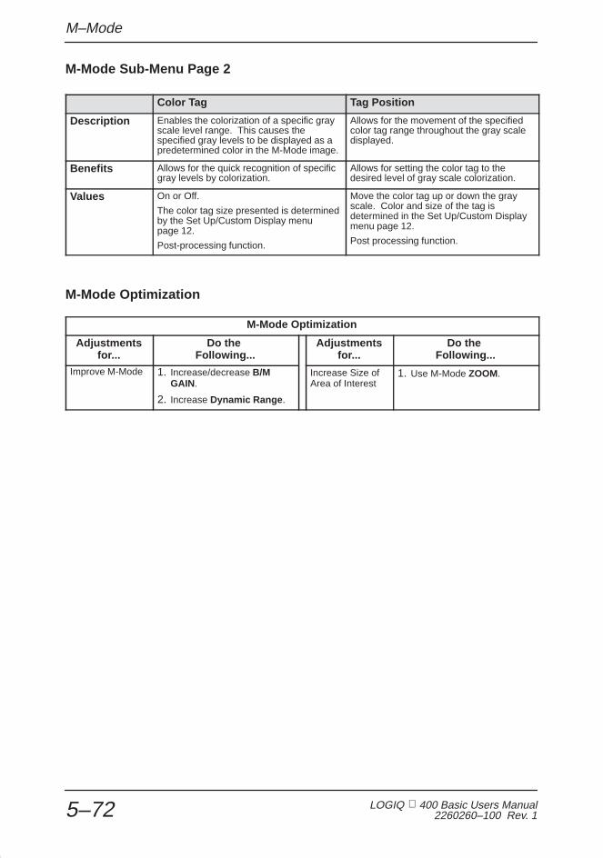
M–Mode
LOGIQ 400 Basic Users Manual2260260–100 Rev. 15–72
M-Mode Sub-Menu Page 2
Color Tag Tag Position
Description Enables the colorization of a specific grayscale level range. This causes thespecified gray levels to be displayed as apredetermined color in the M-Mode image.
Allows for the movement of the specifiedcolor tag range throughout the gray scaledisplayed.
Benefits Allows for the quick recognition of specificgray levels by colorization.
Allows for setting the color tag to thedesired level of gray scale colorization.
Values On or Off.
The color tag size presented is determinedby the Set Up/Custom Display menupage 12.
Post-processing function.
Move the color tag up or down the grayscale. Color and size of the tag isdetermined in the Set Up/Custom Displaymenu page 12.
Post processing function.
M-Mode Optimization
M-Mode Optimization
Adjustmentsfor...
Do the Following...
Adjustmentsfor...
Do the Following...
Improve M-Mode 1. Increase/decrease B/MGAIN.
2. Increase Dynamic Range .
Increase Size ofArea of Interest
1. Use M-Mode ZOOM.

3DvieW Mode
LOGIQ 400 Basic User Manual2260260–100 Rev. 1 5–73
3DvieW Mode(Option)
Overview
A 3D image can be rendered or constructed from the cine datacollected during a normal scan by using a process called MIP(Maximum/Minimum Intensity Projection).
When the scan data is properly collected MIP images can beused to display vascular structure using the Advanced VelocityMaps. MIP imaging is not a real-time function, but apost-processing function.
This 3DvieW option is designed for qualitative information onlyand has no provision for any measurement or computationability.
No specific reconstruction resolution or accuracy is provided orclaimed for this option.
Since positional information of the original scan is not available,all measurement functions cannot be performed on a MIPimage. Information concerning the front or back of the MIPimage may be uncertain.
Caution should be taken when viewing the MIP image due tothe fact that the algorithm used in the MIP process mayproduce a skewness to the MIP image displayed.
NOTE: Consider all of the above cautions when using MIPimages to evaluate a patient. MIP images should not be usedfor quantitative information but a qualitative supplement to allother diagnostic data collected for that patient.
Refer to the Advanced Reference Manual for further details.
CL
CAUTION
CAUTION
�

3D–Surface Mode
LOGIQ 400 Basic Users Manual2260260–100 Rev. 15–74
3D-Surface Mode(Option)
Overview
This option creates a projected image different from 3DvieW. Ituses images stored in Cine. The calculation used for theprojection is based on the transmission principle of light usingVolume-Rendering.
This function is available only in single B-Mode.
The 3D-Surface option is necessary before installing the3DvieW option. Refer to 3DvieW Mode section as needed.
This 3D-Surface option is designed for qualitative informationonly and has no provision for any measurement or computationability.
No specific reconstruction resolution or accuracy is provided orclaimed for this option.
Since positional information of the original scan is not available,all measurement functions cannot be performed on a3D-Surface image.
NOTE: Consider all of the above cautions when using3D-Surface images to evaluate a patient. 3D-Surface imagesshould not be used for quantitative information but a qualitativesupplement to all other diagnostic data collected for that patient.
Refer to the Advanced Reference Manual for further details.
CL
CAUTION
CAUTION
�

Mixed Mode Display Formats
LOGIQ 400 Basic User Manual2260260–100 Rev. 1 5–75
Mixed Mode Display Formats
Display Formats
Some possible display formats are:
ÇÇÇÇÇÇÇ
ÇÇÇÇÇÇÇÇÇÇÇÇÇÇÇÇÇÇÇÇÇÇÇÇ
Time Scale
�
WVSV
Angle
DepthDR
Gain
DGFR/Cine
ÎÎÎÎÎÎÎÎÎÎÎÎÎÎÎÎÎÎÎÎÎÎÎÎÎÎÎÎÎÎÎÎÎÎÎÎÎÎÎÎÎÎÎÎÎÎÎÎÎÎÎÎÎÎ
DR
MHz
Figure 5–32. Top/Bottom B Mid Preset

Mixed Mode Display Formats
LOGIQ 400 Basic Users Manual2260260–100 Rev. 15–76
Display Formats (cont’d)
ÇÇÇÇÇ
ÇÇÇÇÇÇÇÇÇÇÇÇÇÇÇÇÇÇÇÇÇÇÇÇÇÇÇ
�
WVSV
Angle
DepthDR
Gain
DGFR/Cine
ÎÎÎÎÎÎÎÎÎÎÎÎÎÎÎÎÎÎÎÎÎÎÎÎÎÎÎÎÎÎÎÎÎÎÎÎÎÎÎÎÎÎÎÎÎÎÎÎÎÎÎÎÎÎ
Time Scale
DR
MHz
Figure 5–33. Top/Bottom B Large Preset
ÇÇÇÇÇÇÇÇÇ
ÇÇÇÇÇÇÇÇÇÇÇÇÇÇÇÇÇÇÇÇÇÇÇ
�
WVSV
Angle
DepthDR
Gain
DGFR/Cine
ÎÎÎÎÎÎÎÎÎÎÎÎÎÎÎÎÎÎÎÎÎÎÎÎÎÎÎÎÎÎÎÎÎÎÎÎÎÎÎÎÎÎÎÎÎÎÎÎÎÎÎÎÎÎ
DR
MHz
Figure 5–34. Top/Bottom B Small Preset

Mixed Mode Display Formats
LOGIQ 400 Basic User Manual2260260–100 Rev. 1 5–77
Display Formats (cont’d)
ÇÇÇÇÇÇÇÇÇÇÇÇÇ
DepthDR
Gain
FR/Cine
ÎÎÎÎÎÎÎÎÎÎÎÎÎÎÎÎÎÎÎÎÎÎÎÎÎÎÎÎÎÎÎÎÎÎÎÎÎÎÎÎÎÎÎÎÎÎÎÎÎÎÎÎÎÎ
MHz
Figure 5–35. Dual B-Mode Display Format
ÇÇÇÇÇÇÇÇÇÇÇÇÇ
Zoom Depth
DepthDR
Gain
FR/Cine
ÎÎÎÎÎÎÎÎÎÎÎÎÎÎÎÎÎÎÎÎÎÎÎÎÎÎÎÎÎÎÎÎÎÎÎÎÎÎÎÎÎÎÎÎÎÎÎÎÎÎÎÎÎÎ
MHz
Figure 5–36. Zoom with Reference Mode Display Format

Mixed Mode Display Formats
LOGIQ 400 Basic Users Manual2260260–100 Rev. 15–78
Display Formats (cont’d)
ÇÇÇÇÇÇ
ÇÇÇÇÇÇÇÇÇÇÇÇÇÇÇÇÇÇÇÇÇÇÇÇÇÇ
ÇÇÇÇÇÇÇ
ÇÇÇÇÇÇÇÇÇÇÇÇÇÇÇÇÇÇÇSPEC INV D velocity
D velocity
SPEC INV D velocity
D velocity
M(D)M(D)Time Scale
�
WVSV
Angle
DepthDR
Gain
DGFR/Cine
ÎÎÎÎÎÎÎÎÎÎÎÎÎÎÎÎÎÎÎÎÎÎÎÎÎÎÎÎÎÎÎÎÎÎÎÎÎÎÎÎÎÎÎÎÎÎÎÎÎÎÎÎÎÎ
DR
MHz
Figure 5–37. Dual Format

Scanning/Display Functions
LOGIQ 400 Basic User Manual2260260–100 Rev. 1 6–1
Scanning/DisplayFunctions
Zooming an Image 6–2. . . . . . . . . . . . . . . . . . . . . . . . . . . . . . . . . . . . . . . . . . . . . . . . . . . . . . . . Introduction 6–2. . . . . . . . . . . . . . . . . . . . . . . . . . . . . . . . . . . . . . . . . . . . . . . . . . . . . . . . Zoom Methods 6–2. . . . . . . . . . . . . . . . . . . . . . . . . . . . . . . . . . . . . . . . . . . . . . . . . . . . . Zooming an M-Mode Image 6–4. . . . . . . . . . . . . . . . . . . . . . . . . . . . . . . . . . . . . . . . . . Multi–Image Zoom 6–5. . . . . . . . . . . . . . . . . . . . . . . . . . . . . . . . . . . . . . . . . . . . . . . . . .
Freezing an Image 6–6. . . . . . . . . . . . . . . . . . . . . . . . . . . . . . . . . . . . . . . . . . . . . . . . . . . . . . . . . Introduction 6–6. . . . . . . . . . . . . . . . . . . . . . . . . . . . . . . . . . . . . . . . . . . . . . . . . . . . . . . . Freezing an Image (Freeze Key) 6–7. . . . . . . . . . . . . . . . . . . . . . . . . . . . . . . . . . . . . . Freezing an Image (Foot Switch option) 6–7. . . . . . . . . . . . . . . . . . . . . . . . . . . . . . . .
Using Cine 6–8. . . . . . . . . . . . . . . . . . . . . . . . . . . . . . . . . . . . . . . . . . . . . . . . . . . . . . . . . . . . . . . . Introduction 6–8. . . . . . . . . . . . . . . . . . . . . . . . . . . . . . . . . . . . . . . . . . . . . . . . . . . . . . . . Accessing Cine 6–10. . . . . . . . . . . . . . . . . . . . . . . . . . . . . . . . . . . . . . . . . . . . . . . . . . . Using Cine Loop 6–11. . . . . . . . . . . . . . . . . . . . . . . . . . . . . . . . . . . . . . . . . . . . . . . . . . . Cine Loop Speed 6–13. . . . . . . . . . . . . . . . . . . . . . . . . . . . . . . . . . . . . . . . . . . . . . . . . Multipl CINE 6–13. . . . . . . . . . . . . . . . . . . . . . . . . . . . . . . . . . . . . . . . . . . . . . . . . . . . . . Side Change 6–14. . . . . . . . . . . . . . . . . . . . . . . . . . . . . . . . . . . . . . . . . . . . . . . . . . . . . CINE Gauge 6–14. . . . . . . . . . . . . . . . . . . . . . . . . . . . . . . . . . . . . . . . . . . . . . . . . . . . . CINE Capture (option) 6–14. . . . . . . . . . . . . . . . . . . . . . . . . . . . . . . . . . . . . . . . . . . . . Exiting Cine 6–15. . . . . . . . . . . . . . . . . . . . . . . . . . . . . . . . . . . . . . . . . . . . . . . . . . . . . . Helpful Hints 6–15. . . . . . . . . . . . . . . . . . . . . . . . . . . . . . . . . . . . . . . . . . . . . . . . . . . . . ECG/Cine Gauge/Image Tracking 6–15. . . . . . . . . . . . . . . . . . . . . . . . . . . . . . . . . . .
Annotating an Image 6–16. . . . . . . . . . . . . . . . . . . . . . . . . . . . . . . . . . . . . . . . . . . . . . . . . . . . Introduction 6–16. . . . . . . . . . . . . . . . . . . . . . . . . . . . . . . . . . . . . . . . . . . . . . . . . . . . . . Annotation Library 6–19. . . . . . . . . . . . . . . . . . . . . . . . . . . . . . . . . . . . . . . . . . . . . . . . . Adding Comments to an Image 6–21. . . . . . . . . . . . . . . . . . . . . . . . . . . . . . . . . . . . . Special Annotation Keys 6–22. . . . . . . . . . . . . . . . . . . . . . . . . . . . . . . . . . . . . . . . . . . Editing Annotations 6–26. . . . . . . . . . . . . . . . . . . . . . . . . . . . . . . . . . . . . . . . . . . . . . . . Body Patterns 6–27. . . . . . . . . . . . . . . . . . . . . . . . . . . . . . . . . . . . . . . . . . . . . . . . . . . .

Zooming an Image
LOGIQ 400 Basic Users Manual2260260–100 Rev. 16–2
Zooming an Image
Introduction
Zoom is used to magnify a specified region of interest (ROI).The system adjusts all imaging parameters accordingly.Decreasing the size of the ROI increases the magnificationfactor.
Cine and VCR playback images must be frozen to be zoomed.
Zoom Methods
The LOGIQ 400 offers two types of zoom capabilities,Acoustic (real-time) Zoom and Display (freeze) Zoom.
Acoustic Zoom
Acoustic Zoom is accomplished while scanning live (real-time).
While scanning, press the Zoom key to activate the zoomfunction.
Rotate the Zoom Size control to the desired magnification. Themagnification choices available are:
1.2, 1.5 (default), 2.0, 2.5, 3.0 and 4.0
The default value can be set in Set Up/Custom Display page 1“Zoom Factor”.
Use the Trackball to position the zoom region of interest.
Press Clear or Zoom to cancel the zoom function.

Zooming an Image
LOGIQ 400 Basic User Manual2260260–100 Rev. 1 6–3
Display Zoom
Display (freeze) Zoom is accomplished after the image isfrozen. This applies to the current image, a Cine image or aVCR playback image.
The magnification factor for Display Zoom is fixed at 2.0.
Press Freeze to stop image acquisition.
Press Zoom to activate the zoom function.
Use the Trackball to pan around the image area.
Press Clear or Zoom to cancel the zoom function.
NOTE: If an acoustic zoom image is frozen, display zoom willnot function.
The zoomed image can be panned around the B-Mode imageby moving the Trackball .
Measurements can be performed on zoomed images.
Changing the depth does not affect the zoomed image, unlessthe zoomed area is no longer contained within the new depth.
TGC pots within the zoom ROI are active (and these pots’ LEDslight up). When zoom is exited, the 8 TGC pots arereproportioned to the displayed depth scale.
�Hints

Zooming an Image
LOGIQ 400 Basic Users Manual2260260–100 Rev. 16–4
Zooming an M-Mode Image
If the Zoom key is pressed while in B/M-Mode, only theM-Mode image will be zoomed.
Press Zoom to display a magnified M-Mode image and aM-Mode zoom marker in the B-Mode image.
Adjust the Zoom Size control to the desired magnificationfactor. The six steps are the same as B-Mode.
Use the up/down movement of the Trackball to move the ZoomMarkers vertically along the M-Mode cursor.
Use the side to side movement of the Trackball to move theM cursor and Zoom cursor throughout the image.
Press Clear or Zoom to cancel the zoom function.
NOTE: Display Zoom does not function on a frozen B- andM-Mode Timeline Image.�

Zooming an Image
LOGIQ 400 Basic User Manual2260260–100 Rev. 1 6–5
Multi–Image Zoom
When using the Zoom function in a multiple image displayformat, a few basic rules apply.
� Display Zoom (Freeze) can be performed on any or all ofthe multiple images.
DisplayZoom
DisplayZoom
Figure 6–1. Dual Format Display Zoom
� A frozen acoustic zoom and active acoustic zoom can bedisplayed simultaneously.
Frozen AcousticAcousticZoom
Zoom
Figure 6–2. Dual Format Display, Frozen and Active
� Acoustic Zoom and Display Zoom cannot be mixed on thesame display.
DisplayZoom
AcousticZoom
Figure 6–3. Dual Format Display/Acoustic Zoom Unavailable

Freezing an Image
LOGIQ 400 Basic Users Manual2260260–100 Rev. 16–6
Freezing an Image
Introduction
Freezing a real-time image stops all acquisition of informationinto system memory.
This allows for measurements, annotations, printing or storageof images into temporary memory.
VCR playback images can also be frozen for similar reasons.
Post processing of the image
The following post processing image parameters can bechanged to affect the appearance of a frozen image:
� Display Zoom (x2 only)
� Reject
� Color (B Color or CFM Color Maps)
� Gray Scale Map Selection
� Image Rotation
� Color Tag

Freezing an Image
LOGIQ 400 Basic User Manual2260260–100 Rev. 1 6–7
Freezing an Image (Freeze Key)
To freeze an image:
� Press Freeze. The key backlights.
NOTE: If both B- and M-Modes are active, the B-Mode andtimeline trace stops immediately. Use the Cine Scroll Control tostart CINE review.
To reactivate the image:
� Press Freeze again. Deactivating Freeze restarts theB-Mode and timeline after a black and white bar indicatingdiscontinuity is inserted in the timeline (M-Mode Display).
NOTE: Deactivating Freeze erases all measurements andcalculations from the display (but not from the report page).
Selecting a new probe unfreezes the image.
Freezing an Image (Foot Switch option)
Toggle Freeze on and off by pressing the foot switch. Pressingthe left foot switch backlights the Freeze key on the console.
�
�
Foot Switch

Using Cine
LOGIQ 400 Basic Users Manual2260260–100 Rev. 16–8
Using Cine
Introduction
Cine is useful for focusing on images during a specific part ofthe heart cycle or to find an image before the patient moved orbreathed.
Cine images are constantly being stored by the system. Cinememory capacity is 31 (0–30) frames with 128 scan lines. TheCine Memory stores the most recent data available for playbackor manual review via Cine. The amount of time representeddepends on the system’s frame rate, scan mode, image sizeand other parameters.
Timeline data is continually stored at four times the displaywidth of timeline data (and updates the corresponding B-Modeimages).
View Cine as a continuous loop via Cine Loop or manuallyreview Cine images frame by frame via the Cine Scroll Control.
Data in Cine is available until new data is acquired. Cine isstored in the system’s memory and can be transferred to imagememory, video page printer, multi-image camera or optionaloptical disk (MOD).
An Extended Cine Memory Option is available to increase Cinestorage capabilities.
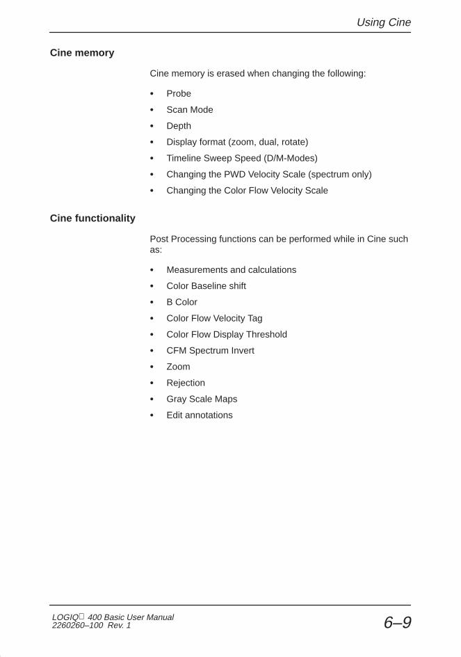
Using Cine
LOGIQ 400 Basic User Manual2260260–100 Rev. 1 6–9
Cine memory
Cine memory is erased when changing the following:
� Probe
� Scan Mode
� Depth
� Display format (zoom, dual, rotate)
� Timeline Sweep Speed (D/M-Modes)
� Changing the PWD Velocity Scale (spectrum only)
� Changing the Color Flow Velocity Scale
Cine functionality
Post Processing functions can be performed while in Cine suchas:
� Measurements and calculations
� Color Baseline shift
� B Color
� Color Flow Velocity Tag
� Color Flow Display Threshold
� CFM Spectrum Invert
� Zoom
� Rejection
� Gray Scale Maps
� Edit annotations

Using Cine
LOGIQ 400 Basic Users Manual2260260–100 Rev. 16–10
Accessing Cine
To access and manually review Cine:
1. Press Freeze.
NOTE: One click of the Cine Scroll knob erases displayedmeasurements.
2. Rotate the B/M Gain/Cine Scroll knob to activate Cine.
3. Rotate the Cine Scroll dial left (backward) and right(forward) to move through the images in Cine memory.
4. The current frame on the Cine gauge moves and theCine frame number is displayed on the lower left side ofthe screen, above the depth.
Current Frame
Cine Gauge
Figure 6–4. Cine Gauge Display
NOTE: Cine frame number 0 is the most current image. Thehigher the Cine frame number, the older the image.
Depth, dynamic range, and gain parameters are valid for Cineframe number zero only.
�
�

Using Cine
LOGIQ 400 Basic User Manual2260260–100 Rev. 1 6–11
Using Cine Loop
Specify which sections of Cine memory to playback by creatinga Cine Loop.
To create a Cine Loop:
1. Press Freeze. The key backlights.
2. Rotate the Cine Scroll dial to the desired startingposition in Cine memory. Display the Cine Sub Menu.
Cine
ReviewLoop
EndFrame
StartFrame
SideChange
CineGauge
LoopSpeed
1/1
1/2
MultiplCINE
Figure 6–5. Cine Sub-Menu
3. Select START FRAME on the Cine Sub-Menu.
Figure 6–6. Cine Gauge Frame Start
4. Rotate the Cine Scroll dial to the desired endingposition in Cine memory.
5. Select END FRAME on the Cine Sub-Menu.

Using Cine
LOGIQ 400 Basic Users Manual2260260–100 Rev. 16–12
Using Cine Loop (cont’d)
Figure 6–7. Cine Gauge Frame End
6. Select REVIEW LOOP on the Cine Sub-Menu.
Cine Review Loop playback begins right away at the selectedspeed.
Figure 6–8. Cine Loop Operation
NOTE: Cine Loop is not available during Timeline Review.
To deactivate Cine Loop:
� Select REVIEW LOOP on the Cine Sub-Menu or turn theCine Scroll knob. This returns to manual Cine review.
To reactivate Cine Loop:
� Select REVIEW LOOP on the Cine Sub-Menu.
�

Using Cine
LOGIQ 400 Basic User Manual2260260–100 Rev. 1 6–13
Cine Loop Speed
To adjust the speed of viewing Cine Loop playback, accessLOOP SPEED from the Cine Sub-Menu.
Cine
ReviewLoop
EndFrame
StartFrame
SideChange
CineGauge
LoopSpeed
1/1
1/2
MultiplCINE
Figure 6–9. Cine Sub-Menu
NOTE: Cine cannot be viewed faster than real-time.
Each press of the Sub Menu Select arrow key cycles to thenext speed setting (1/1, 1/2, 1/4 or 1/8).
Multipl CINE
The Multipl CINE Soft-Menu selection is used in Dual B-ModeCine Operation.
With Multipl CINE on (menu highlighted), Cine review of the twoB-Mode images can be done simultaneously.
With Multipl CINE off, Cine review is done separately using theL/R keys to designate the active Cine image.
Review with Multipl CINE on/off can be accomplished with theCine knob or review loop.
�
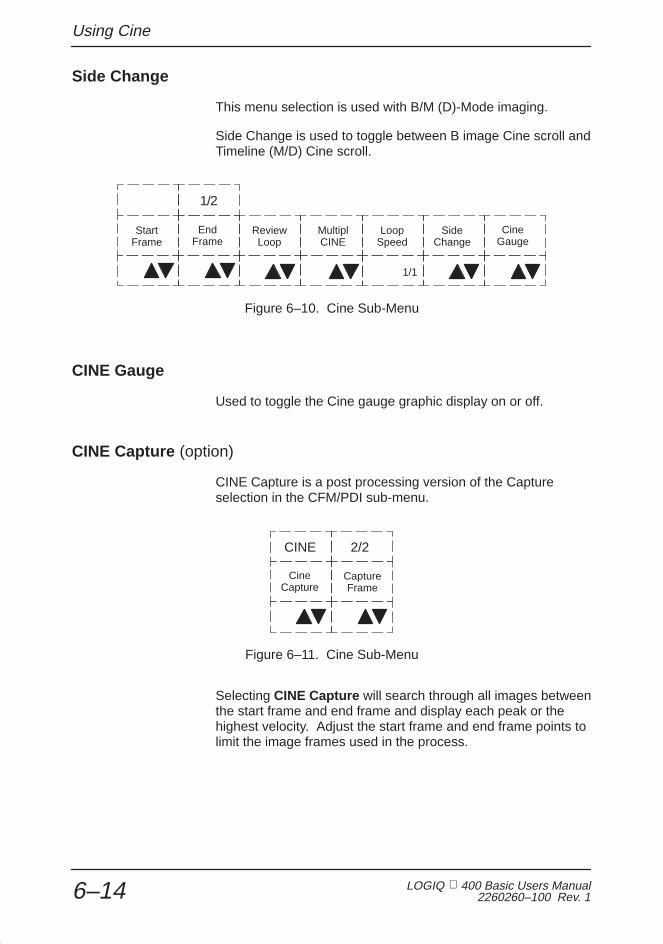
Using Cine
LOGIQ 400 Basic Users Manual2260260–100 Rev. 16–14
Side Change
This menu selection is used with B/M (D)-Mode imaging.
Side Change is used to toggle between B image Cine scroll andTimeline (M/D) Cine scroll.
Cine
ReviewLoop
EndFrame
StartFrame
SideChange
CineGauge
LoopSpeed
1/1
1/2
MultiplCINE
Figure 6–10. Cine Sub-Menu
CINE Gauge
Used to toggle the Cine gauge graphic display on or off.
CINE Capture (option)
CINE Capture is a post processing version of the Captureselection in the CFM/PDI sub-menu.
CINE
CaptureFrame
CineCapture
2/2
Figure 6–11. Cine Sub-Menu
Selecting CINE Capture will search through all images betweenthe start frame and end frame and display each peak or thehighest velocity. Adjust the start frame and end frame points tolimit the image frames used in the process.

Using Cine
LOGIQ 400 Basic User Manual2260260–100 Rev. 1 6–15
Capture Frame (option)
Capture frame can be used to eliminate specific image framesfrom the Cine Capture process.
Use the Cine Scroll knob to display an image frame to beeliminated, and select Capture Frame . A small mark will bedisplayed on the Cine gauge. Do this for all images that are notto be included in the Cine Capture process. When all frames tobe eliminated are marked, select Cine Capture to display thepeak velocity detected color image.
Exiting Cine
To exit Cine, press Freeze.
Helpful Hints
The following hints can help when freezing an image:
� Color, multi-format or M/D images take up more memorythan normal B-Mode. Therefore, less frames of informationare available for Cine storage.
ECG/Cine Gauge/Image Tracking
When an ECG waveform is displayed with the cine gauge, anarrow pointer appears above the ECG waveform.
As the cine gauge marker is moved with the Cine Scroll control,the arrow above the ECG waveform moves to indicate whereon the ECG cycle the displayed image was taken.
Hints

Annotating an Image
LOGIQ 400 Basic Users Manual2260260–100 Rev. 16–16
Annotating an Image
Introduction
The annotation keyboard is always active. Upon starting a newpatient or power up, the underscore cursor appears in themode’s home position. Annotation can commence after usingthe Trackball to specify where the comment should start.
Pressing the Comment key assigns the trackball function tocontrolling the cursor and displays the annotation library in thesoft menu.
The Comment key enables the image text editor and displaysthe annotation library soft menu. After the Comment key ispressed, text can be added through the Soft Menu commentlibrary or by typing comments from the alphanumeric keyboard.Turning off the cursor can be done by pressing the Set key.Pressing the Clear key erases all comments.
NOTE: If the “Use A/N Keys for User Define” preset inSet Up/System Parameters page 3 is ON, the Comment keymust be pressed first to activate the annotation function.
1
1 Underscore Cursor or Block
Figure 6–12. Annotation Cursor in Home Position
�

Annotating an Image
LOGIQ 400 Basic User Manual2260260–100 Rev. 1 6–17
Introduction (cont’d)
Annotations are input in type-over, not insert, mode. Be carefulnot to write over text when editing.
NOTE: The comment function will work with any report page.When the cursor is in a field designated for comments, thecomment key will illuminate and the annotation library willappear in the Soft Menu. All comment, edit and annotationfunctions are then available.
All annotations are permanently retained with the image.However, annotations are erased at power down or when Clearor New Patient are pressed.
In addition, the display’s home position can be changed(preferred annotation area) for each display so that allsubsequent annotations begin in the same spot.
Cursor Home : Established in Set Up/Preset Program page 1,the cursor returns to the upper left part of the screen or the userspecified position.
A new cursor home position is established by placing the cursorin the desired position and pressing Ctrl and M. The newcursor position is placed in the Preset Program values.
To end the Comment/Library annotation function, press Clear.Comments will be erased.
“Comment Clear Key Function” is a parameter found in the SetUp/Preset Program page 1. This parameter can be set to eraseall comments on the screen or just the comment line the cursoris on. With the line selection, the second time Clear is pressed,all comments will be erased.
“Measurement Clear Operation” is a parameter found in the SetUp/Preset Program page 3. This parameter can be set to haveonly measurements erased with the Clear key ormeasurements and comments.
�

Annotating an Image
LOGIQ 400 Basic Users Manual2260260–100 Rev. 16–18
Introduction (cont’d)
The Trackball and Keyboard Arrow keys are used to movethe cursor to the desired position on the image.
When the blinking cursor is in the desired position, commentsmay be typed in or a selection can be made from the annotationlibrary.
The Set key is used to end the Comment/Library function.
The Tab key will move the cursor to the right every eightcharacters or to the next word depending on the presetparameter. See 6–26 for more details.
Shift and Tab moves the cursor in the same manner but to theleft.
+

Annotating an Image
LOGIQ 400 Basic User Manual2260260–100 Rev. 1 6–19
Annotation Library
To reduce the amount of time spent annotating an image, storeoften-used annotations in the Annotation (Comment) Library.These scripts can be up to 20 characters in length. As many as24 scripts can be saved for each user application preset withineach exam category.
Entering/Editing the Library
Access the Annotation Library by selecting Set Up/PresetProgram.
Pages 7 and 8 of the Preset Program menus will be the 24annotation library selections.
Use the Trackball to move the arrow cursor to the desiredAnnotation Library location number.
NOTE: Remember the first 8 selections will appear onsub-menu page 1. Annotation Library 9 to 16 will be onsub-menu page 2. Annotation Library 17 to 24 will be onsub-menu page 3.
Press Set. The 20 character space for that library location willbe in reverse video.
Add or edit the desired script.
Select the next library location and press Set.
Continue until all additions or edits are complete.
To save all entries and edits, Trackball to the SAVE selectionand press Set.
The system prompt will read “overwrite existing data? ‘Y’ or ‘N’”.Press ‘Y’ to rewrite and save data. Press ‘N’ to program a newannotation library.
To avoid saving unwanted changes (all current changes), selectRESET and press SET.
�

Annotating an Image
LOGIQ 400 Basic Users Manual2260260–100 Rev. 16–20
Displaying annotation scripts
To review the Comment Library scripts:
Press Comment . The Library menu for the designated examcategory appears.
Use the Sub-Menu Select arrow keys to cycle through thethree pages of scripts available.
Annotation1
Annotation3
Annotation5
Annotation6
Annotation7
Annotation2
Annotation4
Annotation8
1/3
Figure 6–13. Comment Library Sub-Menu Display
The Library Sub-Menu display shows the first 14 characters ofeach script.
Print a hard copy of these codes from the Set Up/PresetProgram Menus if there are several operators in thedepartment.
There is a space following all programmed annotations.Example: PANCREAS_
Type in the 8 most used scripts first, so that they appear on thefirst Sub-Menu page.
Hints

Annotating an Image
LOGIQ 400 Basic User Manual2260260–100 Rev. 1 6–21
Adding Comments to an Image
To annotate an image:
� Type comments where the cursor is currently located (thedisplay’s home position) or use the Trackball /Arrow keysto place the annotation cursor in the desired location beforetyping.
� Press Return to move to the next line.
NOTE: Annotations wrap to the next line when they are withinone character of the right margin.
The word wrap starts one line below the start of that annotation.
Annotations appear on all prints, photos, and VCR recordings.
WORD WRAPBEFORE
WORDAFTER
WRAP
Figure 6–14. Next Line Word Wrap
If the cursor appears at the right edge of the lowest line, or aword cannot be completed in the lower right corner, word wrapcannot be executed.
To annotate an image using the Library:
� Press Comment . If the comment sub menu does notappear on the screen, press the Top Menu Select key.
� Move the annotation cursor to the desired start positionusing the Trackball /Arrow keys.
� Use the Sub-Menu Select arrow keys, if necessary, todisplay the desired script.
� Press the Sub Menu Select up or down arrow keys to writethe library script starting at the position of the cursor.
� The same word wrap principles apply for library scripts astyped comments.
�

Annotating an Image
LOGIQ 400 Basic Users Manual2260260–100 Rev. 16–22
Special Annotation Keys
Some special annotation symbols can be used by activating theBlue Shift or Red Shift keys. Red Shift does not function whileBlue Shift is active. The Blue Shift and Red Shift keys act as alock function (similiar to the Caps Lock key).
Special Symbols
Activating Blue Shift will cause the arrow , female and malesymbols to be printed on the screen during the commentfunction when the keys shown in Figure 6–15 are pressed.
Figure 6–15. Blue Shift Keys
Language–Specific Characters
The Red Shift key enables the special symbols shown in red onthe keyboard. The red symbols shown in the lower right portionof a key will print when the Red Shift is active. The redsymbols shown in the upper half of a key will print if the normalshift key is held down while the Red Shift is active.
The following illustrations and tables show the language-specific keyboards and characters. The appropriate languagemust be set in order to enable the language-specific keys.
The Language presets are found on Set Up/System Parameterspage 1. The language change takes effect after the system isturned off and powered up again.

Annotating an Image
LOGIQ 400 Basic User Manual2260260–100 Rev. 1 6–23
Language–specific characters (cont’d)
To type language-specific characters, while Red Shift is active,press the proper keys. For example, to type “À”, press “A” andpress the “ À ” key while the Red Shift is active.
Figure 6–16. Keyboard for English, French, German, Spanish, Italian, Portuguese, Swedish and Danish
A E I O U Y a e i o u y
À À È Ì Ò Ù à è ì ò ù
Á Á É Í Ó Ú � á é í ó ú �
Î Â Ê Î Ô Û â ê î ô û
ã Ã Õ ã õ
Ä Ä Ë Ï Ö Ü ä ë ï ö ü ÿ
Å Å å
Table 6–1. Language-specific characters for English, French, German, Spanish, Italian,Portuguese, Swedish and Danish

Annotating an Image
LOGIQ 400 Basic Users Manual2260260–100 Rev. 16–24
Language–specific characters (cont’d)
Figure 6–17. Greek Keyboard
A E H I O Y � � � � � � � �
� � � � � � � � � � � �
� � � �
Ä � � � �
� �
� � �
Table 6–2. Language-specific characters for Greek

Annotating an Image
LOGIQ 400 Basic User Manual2260260–100 Rev. 1 6–25
Language–specific characters (cont’d)
Figure 6–18. Turkish Keyboard
A E I O U a e i o u y
À À È Ì Ò Ù à è ì ò ù
Á Á É Í Ó Ú á é í ó ú
Î Â Ê Î Ô Û â ê î ô û
ã Ã Õ ã õ
Ä Ä Ë Ï Ö Ü ä ë ï ö ü ÿ
Å Å Ï å ï
Table 6–3. Language-specific characters for Turkish
Figure 6–19. Russian Keyboard

Annotating an Image
LOGIQ 400 Basic Users Manual2260260–100 Rev. 16–26
Editing Annotations
On screen annotations can be revised. Revision can beaccomplished by adding or deleting text, or completelyremoving all annotations by pressing Clear.
Editing while annotating
Backspace over any error(s) made. Blank spaces take theplace of the letter(s) that was there. Continue typing theannotation after backspacing over all incorrect letters.
NOTE: Text does not adjust automatically.
To delete previous character(s):
� Press Backspace as many times as necessary to make thedeletion.
� Retype the annotation from the point where backspacingwas stopped.
� Position the cursor and type over existing text.
To move through the text eight characters at a time:
� Press Tab to move to the right (Preset Keyboard Tab =Normal).
� Press Shift and Tab to move to the left.
To move through the text a word at a time:
� Press Tab to move to the right (Preset Keyboard Tab =Word)
� Press Shift and Tab to move to the left.
NOTE: The Tab selection is found on the Set Up/SystemParameter menu page 1.
�
�

Annotating an Image
LOGIQ 400 Basic User Manual2260260–100 Rev. 1 6–27
Body Patterns
An additional way to annotate the image display is with bodypatterns. Body patterns are a simple graphic of a portion of theanatomy that is frequently scanned.
This body pattern is generally displayed in the lower left cornerof the screen. Its placement can vary with the format of thedisplay.
Along with the body part graphic is a marker that illustrates theprobe position. This marker can be placed with the Trackballand rotated with the Zoom Size/Rotation control.
The body pattern and probe marker can serve as a referencefor patient and probe positioning when images are archived.
Probe OrientationMarker
Figure 6–20. Body Pattern with Probe Marker
Names of available body patterns can be displayed in theSoft-Menu by pressing the Body Pattern key.
Body Pattern packages are displayed according to examcategory and preset.
The 8 body pattern packages may be customized toaccomodate user preference. The 16 individual body patternsin the eight packages can be changed.

Annotating an Image
LOGIQ 400 Basic Users Manual2260260–100 Rev. 16–28
Body Patterns (cont’d)
Use the sub menu arrow keys to select the desired pattern tobe displayed. The Set Up/System Parameters menu page 4allows for the choice of displaying the pattern only during freezeor at all times.
Each Body Pattern Package (1–8) can be customized and thepackage for each preset selected in the Set Up/SystemParameters menus.
The Body Pattern Package (1–8) is selected from theSet Up/Preset Program page 1.
Figure 6–21 shows the body patterns available to be preset andthe order in which they appear in the selection cycle.
NeckLeft DecubitusLeft ObliqueRight ObliqueSupine
Right DecubitusProneMammoRight Oblique Left ObliqueNeck Neck
Vertex Brow DownVertex Brow UpLeft BreechRight BreechPregnancy
Figure 6–21. Body Patterns

Annotating an Image
LOGIQ 400 Basic User Manual2260260–100 Rev. 1 6–29
Body Patterns (cont’d)
PSAX–MitralPLAXLiverBack HeadRight Head
Aortic ArchApical 2Apical 4PSAX–AorticPSAX–Left
Left ArmAnter LegPoster LegRight ArmSub–costal
Ventricle ChamberChamberValve
4 Chamber
Valve
Left Vertex
ProstateProstateSagittal Medial 1
ProstateSagittal Lateral 1 Transverse 1
ProstateTransverse 2
Right Vertex
Left HeadHeadTransverse UterusRetroflex UterusAntiverted Uterus
ProstateSagittal Medial 2
ProstateProstateSagittal Lateral 2 Transverse 3
ProstateTransverse 4
Figure 6–21. Body Patterns (cont’d)

Annotating an Image
LOGIQ 400 Basic Users Manual2260260–100 Rev. 16–30
Body Patterns (cont’d)
Blank
Horse RearHorse FrontHorse RightHorse LeftHorse Uterus
Cattle RightCattle LeftCattle UterusCat LeftCat Right
Cat AbdomenDog LeftDog RightDog AbdomenHand Palm
Hand BackOvaryIntestineLungStomach
DuodenumBreast RightBreast LeftBreech Brow DownBreech Brow Up
Figure 6–21. Body Patterns (cont’d)
NOTE: Refer to 14–65 for details on selecting the body patternpackage to be used.�

General Measurements/Calcs
LOGIQ 400 Basic User Manual2260260–100 Rev. 1 7–1
General Measurementsand Calculations
Introduction 7–2. . . . . . . . . . . . . . . . . . . . . . . . . . . . . . . . . . . . . . . . . . . . . . . . . . . . . . . . . . . . . . Overview 7–2. . . . . . . . . . . . . . . . . . . . . . . . . . . . . . . . . . . . . . . . . . . . . . . . . . . . . . . . . . Measurement Controls 7–3. . . . . . . . . . . . . . . . . . . . . . . . . . . . . . . . . . . . . . . . . . . . . . . Cursors 7–4. . . . . . . . . . . . . . . . . . . . . . . . . . . . . . . . . . . . . . . . . . . . . . . . . . . . . . . . . . . . General Mode Measurements Method 7–4. . . . . . . . . . . . . . . . . . . . . . . . . . . . . . . . . Measurement Key 7–5. . . . . . . . . . . . . . . . . . . . . . . . . . . . . . . . . . . . . . . . . . . . . . . . . . . General Instructions 7–6. . . . . . . . . . . . . . . . . . . . . . . . . . . . . . . . . . . . . . . . . . . . . . . . . Erasing Measurements 7–6. . . . . . . . . . . . . . . . . . . . . . . . . . . . . . . . . . . . . . . . . . . . . .
Mode Measurements 7–7. . . . . . . . . . . . . . . . . . . . . . . . . . . . . . . . . . . . . . . . . . . . . . . . . . . . . . B-Mode Measurements 7–7. . . . . . . . . . . . . . . . . . . . . . . . . . . . . . . . . . . . . . . . . . . . . . CFM B-Mode Measurements 7–12. . . . . . . . . . . . . . . . . . . . . . . . . . . . . . . . . . . . . . . Doppler Mode Measurements 7–14. . . . . . . . . . . . . . . . . . . . . . . . . . . . . . . . . . . . . . M-Mode Measurements 7–19. . . . . . . . . . . . . . . . . . . . . . . . . . . . . . . . . . . . . . . . . . . .

Introduction
LOGIQ 400 Basic Users Manual2260260–100 Rev. 17–2
Introduction
Overview
Measurements and calculations derived from ultrasoundimages are intended to supplement other clinical proceduresavailable to the attending physician. The accuracy ofmeasurements is not only determined by system accuracy, butalso by the use of proper medical protocols by the user. Whenappropriate, be sure to note any protocols associated with aparticular measurement or calculation. Formulas anddatabases used within the system software that are associatedwith specific investigators are so noted. Be sure to refer to theoriginal article describing the investigator’s recommendedclinical procedures.
Measurements can be made in all modes and image formats,including real-time, freeze, CINE or VCR playback. Theselected exam category defines the default calculationsdisplayed on the Soft Menu.
Measurement values update on the display until themeasurement has been completed. 18 lines of measurementscan be displayed on the screen at one time.
The measurement cursor is not automatically fixed when theRecord key is pressed. Record all desired measurementsdisplayed on the screen before erasing them.
NOTE: If the Doppler option is not installed with theLOGIQ 400 Black/White systems, the Doppler Modemeasurements cannot be performed.
�

Introduction
LOGIQ 400 Basic User Manual2260260–100 Rev. 1 7–3
Measurement Controls
Figure 7–1. Locating Measurement Controls
Measurement The Measurement key is used to enable all types of basicmeasurements. It displays the measurement and calculationsoft menu for the current exam category.
Ellipse The Ellipse arrow keys are used to activate the ellipsemeasurement function after the first distance measurement hasbeen set. They also toggle which cursor is the movable cursorduring the ellipse adjustment.
Trackball Used to move the measurement cursors.
Set Fixes the cursor for measurements or completes themeasurement sequence.
Clear Erases measuring cursor and measurement data from thedisplay during a measurement sequence. Clears all cursorsand measurements from the display when not performing ameasurement sequence.

Introduction
LOGIQ 400 Basic Users Manual2260260–100 Rev. 17–4
Cursors
During the measurement process, the fixed and active cursorscan either be an “X” or “+” symbol. The “Active MeasurementCursor” preset, located on System Parameters page 3, allowsfor the choice of the Measurement cursor.
Once the measurement sequence is complete, the cursorsymbol changes to one of the eight shown below.
Figure 7–2. Measurement Completed Cursors
General Mode Measurements Method
When performing measurements, it is possible to choose thedisplay of and location of the caliper for subsequentmeasurements while in B, M or Doppler modes. These presets(“B Auto Caliper Control”, “M Auto Caliper Control” and “D AutoCaliper Control” ) are located on Preset Program page 4.

Introduction
LOGIQ 400 Basic User Manual2260260–100 Rev. 1 7–5
Measurement Key
The following table indicates the types of genericmeasurements available when the Measurement key ispressed and no specific calculation is chosen. The type ofmeasurement depends on the current scan mode and thenumber of times the Measurement key is pressed.
MODE
Key Pressed(while frozen)
B Spectral Doppler(with B)
M(with B)
CFM(with B)
Once DistanceEllipse/Circle
Peak Velocity Tissue Depth(Distance)
DistanceEllipse/Circle
Twice Trace/Circle TAMAX/TAMIN/TAMEAN/TAMODE
Time Interval Trace/Circle
Three Times Gray Scale Echo Level
2 Velocities Slope/Time Interval
Depth DifferenceSlope/Time Interval
Point Velocity
Four Times Arrow Mark * Time Interval Arrow Mark * Gray Scale Echo Level
Five Times Arrow Mark * Arrow Mark *
* Assuming the “Arrow Mark Display” preset is set to On.
Table 7–1. General Measurements by Mode
The “Arrow Mark Display” preset, found on Preset Programpage 4, allows the display of an arrow mark when theMeasurement key is pressed a certain number of times.

Introduction
LOGIQ 400 Basic Users Manual2260260–100 Rev. 17–6
General Instructions
Prior to making measurements, Freeze should be pressed tostop the acquisition of the image data.
For some types of measurements, press the Measurement keyto toggle between active cursors for fine adjustment prior tocompleting the measurements.
Pressing Clear prior to completing the measurement sequenceerases the active measuring marker and the current datameasured.
Pressing Clear after the sequence is complete erases all datathat has been measured to this point, but not data entered on toreport pages.
Any measurement can be repeated by selecting thatmeasurement again from the Sub-Menu.
Erasing Measurements
The following actions erase measurements from the system’smemory:
� Rotating the Cine Scroll knob erases measurements.
� Pressing New Patient erases all measurements andcalculations on the display and clears the report pages.
� Unfreezing the image erases measurements from thedisplay only, not from the report pages.
� Adding a new measurement that exceeds the maximumnumber of allowable measurements erases the first oroldest measurement.
� Pressing Clear erases all completed measurements andcalculations on the display. Measurements andcalculations, however, remain on the report pages.
“Measurement Clear Operation” is a parameter found in the SetUp/Preset Program page 3. This parameter can be set to haveonly measurements erased with the Clear key ormeasurements and comments.

Mode Measurements
LOGIQ 400 Basic User Manual2260260–100 Rev. 1 7–7
Mode Measurements
B-Mode Measurements
Three basic measurements can be made in B-Mode.
� Distance
� Circumference/Area (Ellipse or Trace Methods)
� Gray Scale Echo Level
Distance Measurement
Distance Measurements are typically made in the B-Modeportion of the image. To make a distance measurement:
Press the Measurement key once to display a “�” cursor.
Use the Trackball to move the “�” cursor to the measurementstart point.
Press Set to fix the measurement start point and display asecond “�” cursor.
Use the Trackball to move the second “�” cursor to themeasurement end point.

Mode Measurements
LOGIQ 400 Basic Users Manual2260260–100 Rev. 17–8
Distance Measurement (cont’d)
Press Measurement to toggle between which cursor isactivate.
Press Clear once to erase the second measuring marker andthe current data measured and start the measurement again.
Press Set to complete the measurement and fix the Distancevalue displayed on the bottom part of the screen.
Pressing Clear after the sequence is complete erases all datathat has been measured to this point, but not data entered on toreport pages.
Circumference/Area (Ellipse) Measurement
An ellipse can also be used to measure the circumference andarea of an organ. To measure with an ellipse:
Press Measurement to set up the measurement mode. The“�” cursor appears on the display.
Use the Trackball to move the “�” cursor to either end of themajor axis of the area to measure.
Press Set to fix the start point cursor.
Use the Trackball to move the second cursor to the major axismeasurement end point.
Hints
(continued)

Mode Measurements
LOGIQ 400 Basic User Manual2260260–100 Rev. 1 7–9
Circumference/Area (Ellipse) Measurement (cont’d)
Press the Ellipse up arrow key. An ellipse having an initialcircle shape appears.
Use the Trackball to position the ellipse, as necessary, and tosize the measured axis.
Press the Ellipse up arrow key to increase the size of the minoraxis.
Press the Ellipse down arrow key to decrease the size of theminor axis.
Press Measurement to toggle between which cursor isactivate.
Press Clear once to erase the ellipse and the current datameasured. The original cursor is displayed to restart themeasurement.
Press Set to complete the ellipse measurement and display thecircumference and area.
Pressing Clear a second time exits the measurement functionwithout completing the measurement.
Hints

Mode Measurements
LOGIQ 400 Basic Users Manual2260260–100 Rev. 17–10
Circumference/Area (Trace) Measurement
To trace the circumference of a portion of the anatomy andcalculate its area:
Press Measurement twice to display a dot “�” cursor on thescreen. The display on the bottom of the screen shows thecircumference in cm.
Use the Trackball to move the dot “�” cursor to themeasurement start point.
Press Set to change the dot “�” cursor to a “�” cursor.
Use the Trackball to trace the measurement area. Thecircumference displayed on the bottom of the screen willchange with the tracing.
NOTE: Press Clear to erase the measuring marker and thecurrent data measured and redo the measurement.
Press Set to fix the Circumference value displayed on thebottom of the screen and calculate the area.
NOTE: When using the trace method, the Zoom Size/Rotationknob can be used to edit the trace line. Turn it clockwise orcounterclockwise to erase the line (bit by bit) back from itscurrent point. This erase function is limited to a small portion ofthe most recent trace.
�
�

Mode Measurements
LOGIQ 400 Basic User Manual2260260–100 Rev. 1 7–11
Echo Level Measurement
To make an echo level measurement:
Press Measurement three times to enable the echo levelfunction. A box “�” cursor appears.
Use the Trackball to move the box “�” cursor over themeasurement area.
Press Set to fix the Echo value displayed.
� The size of the box cursor can be changed by using the SetUp/Preset Program menu page 3.
� The box is actual size and will appear to get larger orsmaller with changes in depth (scale).
� The echo level measurement is only available on a frozenimage, not on a B-paused image.
Hints

Mode Measurements
LOGIQ 400 Basic Users Manual2260260–100 Rev. 17–12
CFM B-Mode Measurements
While in the Color Flow and B-Mode combination, 4 basicmeasurements can be taken.
� Distance
� Circumference/Area (Ellipse or Trace Methods)
� Gray Scale Echo Level
� Velocity Point
Distance
Distance is measured the same as B/W B-Mode. Refer to7–7.
Circumference/Area
Circumference and area are measured the same as in B/WB-Mode. Refer to 7–8.
Gray Scale Echo Level
Gray scale echo level is measured the same as in B/W B-Mode.Refer to 7–11.

Mode Measurements
LOGIQ 400 Basic User Manual2260260–100 Rev. 1 7–13
Velocity point
This measurement provides an estimate of the average (or mean)velocity at one point in the CFM B-Mode display. This is achievedby calculating the numerical value equivalent to the color at theselected point in the display and adjusting it to the selected flowangle. This procedure cannot be used to determine maximum,minimum or other specific velocity estimates.
To measure the velocity at a certain point in the color display:
Press Measurement three times. A “�” cursor appears.
Use the Trackball to move the cursor to the desired portion ofthe display.
Use the Zoom Size/Rotation control to adjust to the angle ofblood flow.
Press Set to complete the measurement and to display thevelocity and angle values.
Potential for misdiagnosis. The CFM B-Mode velocity pointmeasurement only provides an average velocity estimate andshould not be used as a substitute for PW Doppler velocitymeasurement. Use PW Doppler Mode to obtain measurementsfrom specific portions of the Doppler spectrum.
CAUTION

Mode Measurements
LOGIQ 400 Basic Users Manual2260260–100 Rev. 17–14
Doppler Mode Measurements
4 basic measurements can be made in Doppler Mode or theDoppler Spectrum portion of the display.
� Peak Velocity
� TAMAX/TAMIN/TAMEAN/TAMODE (Manual or Auto Trace)
� Two Velocities with the Slope and Time Interval betweenthem.
� Time Interval
Peak Velocity
To measure peak velocity:
Press Measurement . The “�” cursor with a vertical dotted lineappears.
Use the Trackball to move the cursor to the desired point ofmeasurement in the Doppler Spectrum.
Press Set to fix the velocity cursor. The velocity measurementin m/s or cm/s will be displayed at the bottom of the screen.
The “Velocity Unit” preset, located on Preset Program page 3,allows the unit of display for all velocity measurements to beselected.
The “Display MaxPG with Velocity” preset, located on PresetProgram page 4, allows MaxPG to be displayed with the PeakVelocity measurement.

Mode Measurements
LOGIQ 400 Basic User Manual2260260–100 Rev. 1 7–15
TAMAX/TAMIN/TAMEAN/TAMODE (Manual or Auto Trace)
The value measured depends upon “D Realtime Trace Method”selection in the Set Up/Custom Display page 13. The 4selections available are: Peak (TAMAX), Floor (TAMIN),Mean (TAMEAN) and Mode (TAMODE).
To trace TAMAX/TAMIN/TAMEAN/TAMODE:
Press Measurement twice. A dot “�” cursor appears if thedefault method is manual. A “�” cursor with a vertical dottedline appears if the trace default method is auto.
Use the Trackball to move the cursor to the trace start point inthe Doppler spectrum.
Press Set to fix the start point.
If D Realtime Auto Trace (on or calc) is the default method orTrace Auto is on, use the Trackball to position the verticalcursor at the second value (end point).
Press Set. The system automatically fixes both cursors andtraces the maximum value between the two points. That valueis displayed at the bottom of the screen.
(continued)

Mode Measurements
LOGIQ 400 Basic Users Manual2260260–100 Rev. 17–16
TAMAX/TAMIN/TAMEAN/TAMODE (Manual or Auto Trace) (cont’d)
If D Realtime Auto Trace (off) is the default method, use theTrackball to trace the maximum values of the desired portion ofthe spectrum.
Press Set to complete the measurement.
NOTE: When using the manual trace method, the ZoomSize/Rotation knob can be used to edit the trace line.
Turn it clockwise or counterclockwise to erase the line (bit bybit) back from its current point. This erase function is limited toa small portion of the most recent trace.
�

Mode Measurements
LOGIQ 400 Basic User Manual2260260–100 Rev. 1 7–17
Slope/Time Interval
Two velocity values, the time interval (sec) and slope (m/s2) canbe measured by:
Press Measurement three times. A “�” cursor with verticaldotted lines appears.
Use the Trackball to move the cursor to the measurement startpoint.
Press Set to fix the start point.
Use the Trackball to move the end cursor to the measurementend point.
Press Set to complete the measurement.
The two peak end point velocities, time interval and slope aredisplayed.

Mode Measurements
LOGIQ 400 Basic Users Manual2260260–100 Rev. 17–18
Time Interval
To measure a horizontal time interval:
Press Measurement four times. A “�” cursor with a verticaldotted line appears when the cursor is in the Doppler spectrumportion of the display.
Use the Trackball to move the cursor to the measurement startpoint.
Press Set to fix the first cursor.
Use the Trackball to move the end cursor to the measurementend point.
Press Set to complete the measurement.
The time interval between the two cursors is displayed at thebottom of the screen.

Mode Measurements
LOGIQ 400 Basic User Manual2260260–100 Rev. 1 7–19
Realtime Doppler Calculations (option)
The ultrasound system has the ability to automatically measure,calculate and display specific parameters using the DopplerAuto Trace in realtime. This applies to all exam categoriesexcept GYN and Cardiology with AMCAL option. Refer to theAdvanced Options chapter of the Advanced Reference Manualfor further details.
M-Mode Measurements
Basic measurements that can be taken in the M-Mode portionof the display are:
� Tissue Depth (Distance)
� Time Interval
� Depth Difference with Time Interval and Slope

Mode Measurements
LOGIQ 400 Basic Users Manual2260260–100 Rev. 17–20
Tissue depth
Tissue depth measurement in M-Mode functions the same asthe distance measurement in B-Mode. It measures only verticaldistance between points.
Scan patient with M-Mode timeline displayed.
Press Measurement once. A “�” cursor with a vertical dottedline appears.
Use the Trackball to move the “�” cursor to the most anteriorpoint to be measured.
Press Set to fix the start point.
Use the Trackball to move the second point to the mostposterior point to be measured.
Press Set to complete the measurement.
The vertical distance between the two points is displayed at thebottom of the screen.
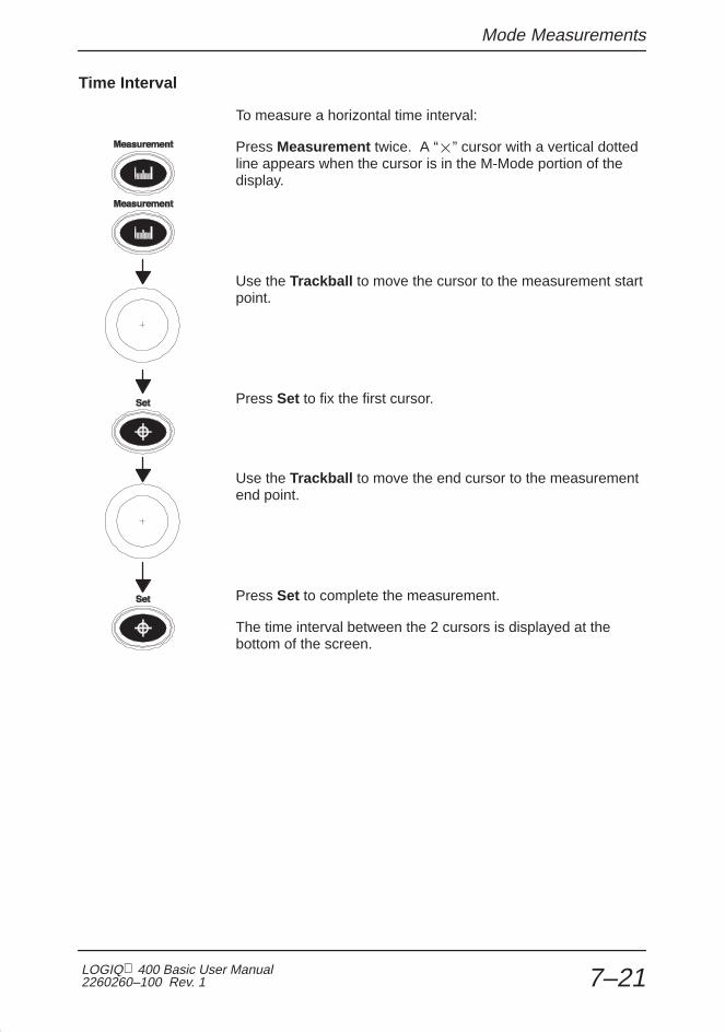
Mode Measurements
LOGIQ 400 Basic User Manual2260260–100 Rev. 1 7–21
Time Interval
To measure a horizontal time interval:
Press Measurement twice. A “�” cursor with a vertical dottedline appears when the cursor is in the M-Mode portion of thedisplay.
Use the Trackball to move the cursor to the measurement startpoint.
Press Set to fix the first cursor.
Use the Trackball to move the end cursor to the measurementend point.
Press Set to complete the measurement.
The time interval between the 2 cursors is displayed at thebottom of the screen.

Mode Measurements
LOGIQ 400 Basic Users Manual2260260–100 Rev. 17–22
Depth Difference with Time and Slope
To measure depth difference:
Press Measurement 3 times. With the cursor in the M-Modetimeline area, a “�” cursor with a vertical dotted line isdisplayed.
Use the Trackball to position the measurement start point.
Press Set to fix the start point.
Use the Trackball to position the measurement end point.
Press Set to complete the measurement.
The depth difference, time interval and slope between the 2 endpoints is displayed at the bottom of the screen.

Abdomen and Small Parts
LOGIQ 400 Basic User Manual2260260–100 Rev. 1 8–1
Abdomen andSmall Parts
General Calculations 8–2. . . . . . . . . . . . . . . . . . . . . . . . . . . . . . . . . . . . . . . . . . . . . . . . . . . . . . Overview 8–2. . . . . . . . . . . . . . . . . . . . . . . . . . . . . . . . . . . . . . . . . . . . . . . . . . . . . . . . . . Volume 8–2. . . . . . . . . . . . . . . . . . . . . . . . . . . . . . . . . . . . . . . . . . . . . . . . . . . . . . . . . . . . Angle 8–3. . . . . . . . . . . . . . . . . . . . . . . . . . . . . . . . . . . . . . . . . . . . . . . . . . . . . . . . . . . . . . Stenosis Ratio (% stenosis) 8–3. . . . . . . . . . . . . . . . . . . . . . . . . . . . . . . . . . . . . . . . . . S/D Ratio, RI, A/B Ratio or PI 8–3. . . . . . . . . . . . . . . . . . . . . . . . . . . . . . . . . . . . . . . . . Heart Rate 8–3. . . . . . . . . . . . . . . . . . . . . . . . . . . . . . . . . . . . . . . . . . . . . . . . . . . . . . . . . Trace Auto 8–3. . . . . . . . . . . . . . . . . . . . . . . . . . . . . . . . . . . . . . . . . . . . . . . . . . . . . . . . . Max PG 8–3. . . . . . . . . . . . . . . . . . . . . . . . . . . . . . . . . . . . . . . . . . . . . . . . . . . . . . . . . . . . Mean PG 8–3. . . . . . . . . . . . . . . . . . . . . . . . . . . . . . . . . . . . . . . . . . . . . . . . . . . . . . . . . . Cardiac Output (CO) 8–4. . . . . . . . . . . . . . . . . . . . . . . . . . . . . . . . . . . . . . . . . . . . . . . . Stroke Volume Ratio (SV) 8–5. . . . . . . . . . . . . . . . . . . . . . . . . . . . . . . . . . . . . . . . . . . . Heart Rate (HR) 8–6. . . . . . . . . . . . . . . . . . . . . . . . . . . . . . . . . . . . . . . . . . . . . . . . . . . . Flow Volume (FV) 8–7. . . . . . . . . . . . . . . . . . . . . . . . . . . . . . . . . . . . . . . . . . . . . . . . . . . Trace Auto 8–8. . . . . . . . . . . . . . . . . . . . . . . . . . . . . . . . . . . . . . . . . . . . . . . . . . . . . . . . . Flow Volume Output (FVO) 8–8. . . . . . . . . . . . . . . . . . . . . . . . . . . . . . . . . . . . . . . . . . . Helpful hints 8–8. . . . . . . . . . . . . . . . . . . . . . . . . . . . . . . . . . . . . . . . . . . . . . . . . . . . . . . . Hip Dysplasia Measurement 8–9. . . . . . . . . . . . . . . . . . . . . . . . . . . . . . . . . . . . . . . . . . General Calculation Formulas 8–11. . . . . . . . . . . . . . . . . . . . . . . . . . . . . . . . . . . . . . .

General Calculations
LOGIQ 400 Basic Users Manual2260260–100 Rev. 18–2
General Calculations
Overview
NOTE: If the Doppler option is not installed with theLOGIQ 400 Black/White systems, the Doppler Modemeasurements cannot be performed.
The General Calculations Sub-Menu can be invoked from theRad/Abdomen exam category. The calculations available are:
ANGLEVOLUME %STENO
1/3
PIS/DRatio
A/BRatio
RI HEARTRATE
TRACEAUTO
2/3
Transf.CALCs
Transf CALCS is only available with Realtime Doppler Calculation option installed
Mean PGMax PG CO SV HEARTRATE
TRACEAUTO
FVOFV
3/3
Figure 8–1. General Calculations Sub-Menus
Volume
Refer to the procedure found on 10–19.
�

General Calculations
LOGIQ 400 Basic User Manual2260260–100 Rev. 1 8–3
Angle
Refer to the procedure found on 10–22.
Stenosis Ratio (% stenosis)
Refer to the procedure found on 10–23.
S/D Ratio, RI, A/B Ratio or PI
Refer to the procedure found on 10–29.
Heart Rate
Refer to the procedure found on 10–30.
Trace Auto
Use the Trace Auto Sub-Menu selection to turn on/off theDoppler Auto Trace function. See 10–28 for more details.
Max PG
Refer to the procedure found on 10–26.
Mean PG
Refer to the procedure found on 10–27.

General Calculations
LOGIQ 400 Basic Users Manual2260260–100 Rev. 18–4
Cardiac Output (CO)
To measure CO (Cardiac Output), a velocity measurement istaken in the Doppler Spectrum. An FCA (Flow Cross SectionalArea) is measured on the vessel in B-Mode. These twomeasurements are used to calculate SV (Stroke Volume).Finally, a HR (Heart Rate) measurement is taken in the DopplerSpectrum. SV and HR are then used to calculate cardiacoutput.
Mean PGMax PG CO SV HEARTRATE
TRACEAUTO
FVOFV
3/3
Figure 8–2. General Calculations Sub-Menu (CO)
Select CO from the Calculation Sub-Menu. The trace cursor(horizontal dotted line) appears in the Doppler spectrum.
See Stroke Volume Ratio on 8–5 for a step-by-step procedureon SV. After the stroke volume measurements have beencompleted, a vertical line cursor appears in the Dopplerspectrum. Measure the Heart Rate. Refer to the procedurefound on 10–30.
CO (Cardiac Output) is computed from the SV and HR valuesand is displayed.
Automatic CO calculation
If the following measurements have previously been made inany order, CO (Cardiac Output) automatically calculates when itis selected from the Calculation Sub-Menu:
� Velocity in Doppler Mode
� Functional Cross Sectional Area in B-Mode(Circumference/Area)
� Heart Rate in Doppler Mode

General Calculations
LOGIQ 400 Basic User Manual2260260–100 Rev. 1 8–5
Stroke Volume Ratio (SV)
To measure stroke volume, a velocity measurement is taken inthe Doppler spectrum. An FCA (Flow Cross Sectional Area) ismeasured on the vessel in B-Mode. The velocity and FCAvalues are then used to calculate SV (Stroke Volume).
Mean PGMax PG CO SV HEARTRATE
TRACEAUTO
FVOFV
3/3
Figure 8–3. General Calculations Sub-Menu (SV)
Select SV from the Calculation Sub-Menu. The trace cursor(horizontal dotted line) appears in the Doppler spectrum.
Move the cursor to the measurement start point dependent onthe trace method chosen (peak, floor, mean or mode).
Press Set. The first cursor is fixed and a second is active.
If Trace Auto is enabled, use the Trackball to move the secondcursor to the velocity measurement end point.
Press Set. The waveform maximum velocities areautomatically traced and a velocity value is displayed.
If Trace Auto is disabled, use the Trackball to trace thewaveform.
Press Set. The trace waveform is fixed and the velocity valueis displayed.
(continued)

General Calculations
LOGIQ 400 Basic Users Manual2260260–100 Rev. 18–6
Stroke Volume Ratio (SV) (cont’d)
A cross-point cursor appears in the B-Mode image to measureFCA (Flow Cross Sectional Area).
Use the Trackball to move the cursor to a point on the vesselwall.
Press Set to fix the start point cursor. Use the Ellipse or Tracemethod to measure the circumference and area of the vessel asdescribed on 7–8 or 7–10, respectively.
Press Set to complete the circumference/area measurement.The FCA is displayed.
The SV (Stroke Volume) is also computed and displayed fromvelocity and FCA values.
Automatic SV calculation
If velocity was previously measured while in Doppler Mode andthe cross sectional area of a vessel was measured while inB-Mode, stroke volume will be automatically calculated fromthese previously measured values when SV is selected fromthe General Calculation Sub-Menu.
Heart Rate (HR)
Refer to the procedure found on 10–30.

General Calculations
LOGIQ 400 Basic User Manual2260260–100 Rev. 1 8–7
Flow Volume (FV)
Flow Volume estimates the volume of blood that flows through avessel per unit time. It is derived from a vessel’scross-sectional diameter obtained from the B-Mode portion ofthe image and the mean velocity of flow in the vessel obtainedfrom the Doppler portion of the image. It is measured inmilliliters. When the FV measurement is made, FVO isautomatically calculated.
To measure flow volume:
Mean PGMax PG CO SV HEARTRATE
TRACEAUTO
FVOFV
3/3
Figure 8–4. General Calculations Sub Menu (FV)
Select FV from the Calculation Sub Menu. Place the dottedhorizontal line cursor at each of the timebase on the Dopplerspectrum.
If Trace Auto is selected, the waveform is automatically traced.
If Trace Auto is not selected, manually trace the desired portionof the waveform.
The cursor moves to the B-Mode area.
Use the Ellipse or Trace method to measure the circumferenceand area of the vessel as described on 7–8 or 7–10,respectively.
The flow volume (FV) is calculated and displayed in milliliters.The flow volume output (FVO) is also calculated and displayedin milliliters/minute.

General Calculations
LOGIQ 400 Basic Users Manual2260260–100 Rev. 18–8
Trace Auto
Use the Trace Auto Sub-Menu selection to turn on/off theDoppler Auto Trace function. See 10–28 for more details.
Flow Volume Output (FVO)
This measurement is used to measure the flow volume outputin a vessel on the Doppler spectrum. It is measured inmilliliters/minute. When the FVO measurement is made, FV isautomatically calculated.
Refer to the FV measurement on 8–7 for details.
Helpful hints
The following hints can help when taking a measurement:
� If PRINT is pressed while making a measurement, thesystem completes the measurement and sends the data tothe report page (unless the VCR is assigned to the PRINTkey).
� Prior to making measurements, use the Cine function, ifnecessary, to display the best image.
� Measurements can continue to be made until allmeasurement/calculation cells are filled. The cells aredisplayed at the bottom center of the display.
� Once all measurement/calculation cells are filled on thedisplay, any further measurements will cause the top (first)cell to be erased and the new measurement added last(“first in, first out”).
� If there is a series of measurements/calculations that areroutinely taken in a specific sequence, the auto sequencefeature of the system can be used to program thesemeasurements/calculations to automatically appear on thedisplay in the desired order. Refer to 14–79 for details onprogramming an auto sequence.
Hints

General Calculations
LOGIQ 400 Basic User Manual2260260–100 Rev. 1 8–9
Hip Dysplasia Measurement
A HIP Dysplasia measurement is available. The HIPcalculation assists in assessing the development of the infanthip. In this calculation three straight lines are superimposed onthe image and aligned with the anatomical features. The 2angles are computed, displayed and can be used by thephysician in making a diagnosis.
The three lines are (Source: R GRAF, journal of PediatricOrthopedics, 4: 735–740(1984)).
1. The inclination line connects the osseous convexity tolabrum acetabulare.
2. The Acetabulum roof line connects the lower edge ofthe osilium to the osseous convexity.
3. The Baseline connects the osseous acetabulumconvexity to the point where the joint capsule and theperichondrium unite with the iliac bone.
The Angle α (Alpha) is the supplement of the angle between 1and 3. It characterizes the osseous convexity. The angle β(Beta) is the angle between lines 1 and 2. It characterizes thebone supplementing additional roofing by the cartilaginousconvexity.
NOTE: There are two methods (Cranial–left and Caudal–left)for the Hip Dysplasia Measurement Orientation. This preset,“Hip Orientation”, is located on Preset Program page 4.
�
�
Figure 3–26. Hip Dysplasia
�
General Calculations
LOGIQ 400 Basic Users Manual2260260–100 Rev. 18–10
HIP Dysplasia Measurement (cont’d)
To activate the Hip Dysplasia Measurement:
1. To add the HIP Measurement, select “MeasurementMenu B” in Preset Program page 7. If necessary,select NEXT CALC until HIP DYSPLASIA is displayed.Select HIP DYSPLASIA.
2. Press Measurement . Select the HIP measurement onB-Mode Measurement soft-menu. The system promptsthe user in the measurement process.
3. To set the 3 lines for the Hip measurement, use theTrackball , Zoom Size/Rotation knob and Set key.The hip measurements (α and β) are displayed on thebottom of the screen.

General Calculations
LOGIQ 400 Basic User Manual2260260–100 Rev. 1 8–11
General Calculation Formulas
CalcMnemonic Calc Name Input Measurements Formula
MaxPG Maximum PressureGradient
two Doppler blood flow peakvelocities
MaxPG[mmHg]=4x(v1^2–v2^2)
MeanPG Mean Pressure Gradient flow velocities from one timemarker to another time markerin a Doppler display
MeanPG[mmHg]= n4x � (Vi^2)/n i=1
SV Stroke Volume flow velocities from one timemarker to another time markerin a Doppler display and onearea
SV[ml]= (sum{Vt^2} from t1 tot2)x a1
CO Cardiac Output two distances and one 2 beattime interval
CO[1/min]=SVxHR/1000
FV Flow Volume flow velocities from one timemarker to another time markerin a Doppler display and onearea
FV [ml] = (sum{Vt[m/s]} fromt1 to t2) x a1[cm^2]
FVO Flow Volume Output flow velocities from one timemarker to another time markerin a Doppler display and onearea
FVO [ml/min] = FV [ml] /(t2–t1) x 60000
% Stenosis Stenosis Ratio two areas (by ellipse, trace,circle or distance)
% Stenosis= [1–(Aresidual/Alumen)]x100
PI Pulsatility Index two Doppler blood flow peakvelocities and TAMAX
PI=(Vmax–Vdiastole)/TAMAX*NOTE*
RI Resistivity Index two Doppler blood flow peakvelocities
RI=(Vmax–Vdiastole)/Vmax*NOTE*
HR Heart Rate (beats/minute) one 2 beat time interval HR[BPM]=120[sec]/2beat time [sec]
A/B Ratio Velocities Ratio two Doppler blood flow peakvelocities
A/B=V1/V2
TAMAX Time Averaged MaximumVelocity (Trace Method isPeak or manual)
two time marks in a Dopplerdisplay
TAMAX=sum{Vt} from t1 tot2/(t2–t1) [cm/s or m/s]
TAMIN Time Averaged MinimumVelocity (Trace method isFloor)
two time marks in a Dopplerdisplay
TAMIN=sum{Vt} from t1 tot2/(t2–t1) [cm/s or m/s]
TAMEAN Time Averaged MeanVelocity (Trace method isMean)
two time marks in a Dopplerdisplay
TAMEAN=sum{Vt} from t1 tot2/(t2–t1) [cm/s or m/s]
TAMODE Time Averaged ModeVelocity (Trace method isMode)
two time marks in a Dopplerdisplay
TAMODE=sum{Vt} from t1 tot2/(t2–t1) [cm/s or m/s]
*NOTE*: Vdiastole = Vmin or Vend–diastole
Table 8–1. General Calculation Formulas

General Calculations
LOGIQ 400 Basic Users Manual2260260–100 Rev. 18–12
This page left blank intentionally.

OB/GYN
LOGIQ 400 Basic User Manual2260260–100 Rev. 1 9–1
OB/GYN(Basic OB software option)
Exam Preparation 9–2. . . . . . . . . . . . . . . . . . . . . . . . . . . . . . . . . . . . . . . . . . . . . . . . . . . . . . . . . Overview 9–2. . . . . . . . . . . . . . . . . . . . . . . . . . . . . . . . . . . . . . . . . . . . . . . . . . . . . . . . .
Fetal Doppler 9–3. . . . . . . . . . . . . . . . . . . . . . . . . . . . . . . . . . . . . . . . . . . . . . . . . . . . . . . . . . . . Doppler Mode for Fetal Exams 9–3. . . . . . . . . . . . . . . . . . . . . . . . . . . . . . . . . . . . . . .
Acoustic Output 9–4. . . . . . . . . . . . . . . . . . . . . . . . . . . . . . . . . . . . . . . . . . . . . . . . . . . . . . . . . Considerations 9–4. . . . . . . . . . . . . . . . . . . . . . . . . . . . . . . . . . . . . . . . . . . . . . . . . . . .
OB Measurements and Formulas 9–5. . . . . . . . . . . . . . . . . . . . . . . . . . . . . . . . . . . . . . . . . . Introduction 9–5. . . . . . . . . . . . . . . . . . . . . . . . . . . . . . . . . . . . . . . . . . . . . . . . . . . . . . . OB Format Selection 9–5. . . . . . . . . . . . . . . . . . . . . . . . . . . . . . . . . . . . . . . . . . . . . . . OB Measurement Soft Menus and Formulas 9–6. . . . . . . . . . . . . . . . . . . . . . . . . . . Helpful Hints 9–26. . . . . . . . . . . . . . . . . . . . . . . . . . . . . . . . . . . . . . . . . . . . . . . . . . . . .
OB Summary Reports 9–27. . . . . . . . . . . . . . . . . . . . . . . . . . . . . . . . . . . . . . . . . . . . . . . . . . . Starting an Exam 9–27. . . . . . . . . . . . . . . . . . . . . . . . . . . . . . . . . . . . . . . . . . . . . . . . . OB Report Page Layout 9–28. . . . . . . . . . . . . . . . . . . . . . . . . . . . . . . . . . . . . . . . . . . . Editing the Report 9–35. . . . . . . . . . . . . . . . . . . . . . . . . . . . . . . . . . . . . . . . . . . . . . . . . Recording Summary Reports 9–37. . . . . . . . . . . . . . . . . . . . . . . . . . . . . . . . . . . . . . .
Anatomical Survey 9–38. . . . . . . . . . . . . . . . . . . . . . . . . . . . . . . . . . . . . . . . . . . . . . . . . . . . . . Overview 9–38. . . . . . . . . . . . . . . . . . . . . . . . . . . . . . . . . . . . . . . . . . . . . . . . . . . . . . . . Editing 9–39. . . . . . . . . . . . . . . . . . . . . . . . . . . . . . . . . . . . . . . . . . . . . . . . . . . . . . . . . . . User Programmed Features 9–39. . . . . . . . . . . . . . . . . . . . . . . . . . . . . . . . . . . . . . . .
OB Graphs 9–40. . . . . . . . . . . . . . . . . . . . . . . . . . . . . . . . . . . . . . . . . . . . . . . . . . . . . . . . . . . . . Overview 9–40. . . . . . . . . . . . . . . . . . . . . . . . . . . . . . . . . . . . . . . . . . . . . . . . . . . . . . . . OB Graph Selection 9–41. . . . . . . . . . . . . . . . . . . . . . . . . . . . . . . . . . . . . . . . . . . . . . .
Advanced Obstetrical Options 9–44. . . . . . . . . . . . . . . . . . . . . . . . . . . . . . . . . . . . . . . . . . . Options 9–44. . . . . . . . . . . . . . . . . . . . . . . . . . . . . . . . . . . . . . . . . . . . . . . . . . . . . . . . . .

OB/GYN
LOGIQ 400 Basic Users Manual2260260–100 Rev. 1 9–2
GYN Measurements 9–45. . . . . . . . . . . . . . . . . . . . . . . . . . . . . . . . . . . . . . . . . . . . . . . . . . . . . B-Mode 9–45. . . . . . . . . . . . . . . . . . . . . . . . . . . . . . . . . . . . . . . . . . . . . . . . . . . . . . . . . . Doppler Mode 9–47. . . . . . . . . . . . . . . . . . . . . . . . . . . . . . . . . . . . . . . . . . . . . . . . . . . .
GYN Summary Report 9–49. . . . . . . . . . . . . . . . . . . . . . . . . . . . . . . . . . . . . . . . . . . . . . . . . . . GYN Report Pages 9–49. . . . . . . . . . . . . . . . . . . . . . . . . . . . . . . . . . . . . . . . . . . . . . . . Calculation Formulas 9–51. . . . . . . . . . . . . . . . . . . . . . . . . . . . . . . . . . . . . . . . . . . . . .

Exam Preparation
LOGIQ 400 Basic User Manual2260260–100 Rev. 1 9–3
Exam Preparation
Overview
Prior to an ultrasound examination, the patient should beinformed of the clinical indication, specific benefits, potentialrisks, and alternatives, if any. In addition, if the patient requestsinformation about the exposure time and intensity, it should beprovided. Patient access to educational materials regardingultrasound is strongly encouraged to supplement theinformation communicated directly to the patient. Furthermore,these examinations should be conducted in a manner and takeplace in a setting which assures patient dignity and privacy.
� Prior material knowledge and approval of the presence ofnonessential personnel with the number of such personnelkept to a minimum.
� An intent to share with the parents, either during theexamination or shortly thereafter, the information derived.
� An offer of choice about viewing the fetus.
� An offer of choice about learning the sex of the fetus, ifsuch information becomes available.
Ultrasound examinations performed solely to satisfy the family’sdesire to know the fetal sex, to view the fetus or to obtain apicture of the fetus should be discouraged.

Fetal Doppler
LOGIQ 400 Basic Users Manual2260260–100 Rev. 1 9–4
Fetal Doppler
Doppler Mode for Fetal Exams
Indications for Fetal Doppler use
The LOGIQ 400 system can be used for fetal examination inPulsed Wave Doppler, Continuous Wave Doppler, Color FlowDoppler and Color M-Mode for the diagnosis of:
� Structural fetal cardiac anomalies (18 weeks gestation toterm) for high-risk patients.
� Intrauterine growth retardation (IUGR) (28 weeks gestationto term) for high-risk patients with one or more of thefollowing known or suspected conditions:
� Multiple pregnancy
� Maternal hypertension
� Hydrops
� Diabetes
� Lupus
� Placenta abnormality.
Contraindications
Pulsed Wave Doppler, Continuous Wave Doppler, Color FlowDoppler and Color M-Mode are not intended for routine fetalexamination or screening nor are they intended for fetalexamination in a low-risk population. The use of Doppler, evenat minimal output levels, in fetal examination must be adjunctivewith conventional fetal echocardiography and other clinicaldiagnostic methods, for high risk patients only.
B/WOption
Acoustic Output
LOGIQ 400 Basic User Manual2260260–100 Rev. 1 9–5
Acoustic Output
Considerations
General warning
The LOGIQ 400 system is a multi-use device which is capableof exceeding FDA Pre-enactment acoustic output (spatialpeak-temporal average) intensity limits for fetal applications.
Prudent use
It is prudent to conduct an exam with the minimum amount andduration of acoustic output necessary to optimize the image’sdiagnostic value.
Concerns surrounding fetal exposure
Always be aware of the acoustic output level by observing theAcoustic Output Display. In addition, become thoroughlyfamiliar with the Acoustic Output Display and equipmentcontrols affecting output.
Training
It is recommended that all users receive proper training in fetalDoppler applications before performing them in a clinicalsetting. Please contact a local sales representative for trainingassistance.
CAUTION

OB Measurements and Formulas
LOGIQ 400 Basic Users Manual2260260–100 Rev. 1 9–6
OB Measurements and Formulas
Introduction
Measurements and calculations derived from ultrasoundimages are intended to supplement other clinical proceduresavailable to the attending physician. The accuracy ofmeasurements is not only determined by the system accuracy,but also by use of proper medical protocols by the user. Whenappropriate, be sure to note any protocols associated with aparticular measurement or calculation. Formulas anddatabases used within the system software that are associatedwith specific investigators are so noted. Be sure to refer to theoriginal article describing the investigator’s recommendedclinical procedures.
If obstetrics was selected as the exam category on the PatientEntry Menu, the OB Menu automatically appears in theSoft-Menu when the Measurement key is pressed.
NOTE: If the Doppler option is not installed with theLOGIQ 400 Black/White systems, the Doppler Modemeasurements cannot be performed.
OB Format Selection
Four types of OB measurements and report pages can beselected from the Set Up/System Parameter Menu page 2.
The user may choose to measure and report items based onTokyo University, Osaka University, USA or European methods.
�

OB Measurements and Formulas
LOGIQ 400 Basic User Manual2260260–100 Rev. 1 9–7
OB Measurement Soft Menus and Formulas
The factory default measurement menus are shown inFigure 9–1 through Figure 9–4. The user should be familiarwith how to do basic distance and circumferencemeasurements, as described in the General Measurements andCalculations chapter.
Tokyo University Method
CRLGS BPD FL LV EFBW OBReport
APTD& TTD
EFCTAR USER1 USER2 USER3 OBGraph
OBReport
USER4
SelectLocatn
S/DRatio
RI A/BRatio
TRACEAUTO
PI
PLIVmax USER5 HEARTRATE
OBGraph
OBReport
ANATOMYSURVEY
2/4
1/4
OBReport
3/4
4/4
Figure 9–1. Tokyo University Sub-Menus
NOTE: Tokyo EFBW selection is made in the Set Up/SystemParameters menu page 2.�

OB Measurements and Formulas
LOGIQ 400 Basic Users Manual2260260–100 Rev. 1 9–8
Tokyo University Method (cont’d)
Calc Mnemonic Calc Name Input Measurements Formula
AuthorReference
HR Heart Rate(beats/minute)
one 2 beat time(measured manually orautomatically)
HR[BPM]=120[sec]/2beat time[sec]
n/a
GS Gestational Sac one distance Curve data is availablein the Advanced
Tokyo UniversityMethod 1986
CRL Crown RumpLength
one distancein the AdvancedReference Manual
Method 1986,6 by Univ. ofTokyo
FL Femur Length one distancey
BPD BiparietalDiameter
one distance
LV Length of Vertebra one distance
APTD Antero posteriorTrunk Diameter
one distance APTD = input
TTD Transverse TrunkDiameter
one distance TTD = input
EFBW Estimated FetalBody Weight
Average of BPD, Averageof APTD, Average of TTDand Average of FL
EFBW = 1.07 x BPD^ 3 +3.42 x APTDx TTD x FL
CTAR Cardio–ThoracicArea Ratio
four distances or twoareas
CTAR = (d1 x d2) / (d3 x d4) x100 or a1 / a2 x 100
Y.Chiba FetalDiagn Ther 1990 :5 : 175 – 188
PLI Preload Index two Doppler blood flowvelocities
PLI = | v1 / v2 | Y.Chiba FetalDiagn Ther 1990 :5 : 168 – 174
EF Ejection Fraction two distances on M-Mode(End-diastolic dimensionand End-systolicdimension on M-Mode)
EF = (1 – Ds^3 / Dd^3) n/a
Vmax Maximum Velocityin descendingaorta
one Doppler blood flowpeak velocities
Vmax = input n/a
S/D Ratio Systolic / DiastolicRatio
two Doppler blood flowpeak velocities
S/D = Vsystole /Vdiastole *NOTE*
n/a
A/B Ratio Velocities Ratio two Doppler blood flowpeak velocities
A/B = V1/V2 n/a
Pl Pulsatility Index two Doppler blood flowpeak velocities andTA_MAX
Pl = (Vmax – Vdiastole)/TA_MAX
*NOTE*
n/a
RI Resistivity Index two Doppler blood flowpeak velocities
RI = (Vmax – Vdiastole)/Vmax *NOTE*
n/a
*NOTE*: Vdiastole = Vmin or Vend–diastole
Table 9–1. OB Calculation Formulas—Tokyo University Factory Defaults

OB Measurements and Formulas
LOGIQ 400 Basic User Manual2260260–100 Rev. 1 9–9
Osaka University Method
BPDCRL FTA FL HL EFBW OBReport
USER1
2/4
1/4
3/4
4/4
EFCTAR USER2 USER3 USER4 OBGraph
OBReport
USER5
SelectLocatn
S/DRatio
RI A/BRatio
TRACEAUTO
PI OBReport
PLIVmax HEARTRATE
OBGraph
OBReport
ANATOMYSURVEY
Figure 9–2. Osaka University Sub-Menus

OB Measurements and Formulas
LOGIQ 400 Basic Users Manual2260260–100 Rev. 1 9–10
Osaka University Method (cont’d)
Calc Mnemonic Calc Name Input Measurements Formula
AuthorReference
HR Heart Rate(beats/minute)
one 2 beat time(measured manually orautomatically)
HR[BPM]=120[sec]/2beat time[sec]
n/a
CRL Crown RumpLength
one distance Curve data is available inthe Advanced ReferenceManual
Osaka UniversityMethod 1989,3 by Univ of
FL Femur Length one distanceManual 3 by Univ. of
OsakaBPD Biparietal
Diameterone distance
HL Humerus Length one distance
FTA Fetal Trunk CrossSectional Area
one area APTD = input
EFBW Estimated FetalBody Weight
Average of BPD, Averageof FTA and Average of FL
EFBW=1.25647xBPD^3+3.50655x FTA x FL+6.3 (<5000g)IUGR=1.229 xBPD^3+3.063 x FTA x FL–24.6Curve data is available inthe Advanced ReferenceManual
CTAR Cardio–ThoracicArea Ratio
four distances or twoareas
CTAR = (d1 x d2) / (d3 x d4) x 100or a1 / a2 x 100
Y.Chiba FetalDiagn Ther 1990 :5 : 175 – 188
PLI Preload Index two Doppler blood flowvelocities
PLI = | v1 / v2 | Y.Chiba FetalDiagn Ther 1990 :5 : 168 – 174
EF Ejection Fraction two distances on M–Mode(End–diastolic dimensionand End–systolicdimension on M–Mode)
EF = (1 – Ds^3 / Dd^3) n/a
Vmax Maximum Velocityin descendingaorta
one Doppler blood flowpeak velocities
Vmax = input n/a
S/D Ratio Systolic / DiastolicRatio
two Doppler blood flowpeak velocities
S/D = Vsystole /Vdiastole *NOTE*
n/a
A/B Ratio Velocities Ratio two Doppler blood flowpeak velocities
A/B = V1/V2 n/a
Pl Pulsatility Index two Doppler blood flowpeak velocities andTA_MAX
Pl = (Vmax – Vdiastole) /TA_MAX
*NOTE*
n/a
RI Resistivity Index two Doppler blood flowpeak velocities
RI = (Vmax – Vdiastole) /Vmax *NOTE*
n/a
*NOTE*: Vdiastole = Vmin or Vend–diastole
Table 9–2. OB Calculation Formulas—Osaka University Factory Defaults

OB Measurements and Formulas
LOGIQ 400 Basic User Manual2260260–100 Rev. 1 9–11
USA Method
BPDCRL FL HC OBReport
USER1
2/4
1/4
3/4
4/4
USER2 USER3 USER4 OBGraph
OBReport
USER5
SelectLocatn
S/DRatio
RI A/BRatio
TRACEAUTO
PI OBReport
HEARTRATE
OBGraph
OBReport
ACGS
AFI ANATOMYSURVEY
Figure 9–3. USA Sub-Menus
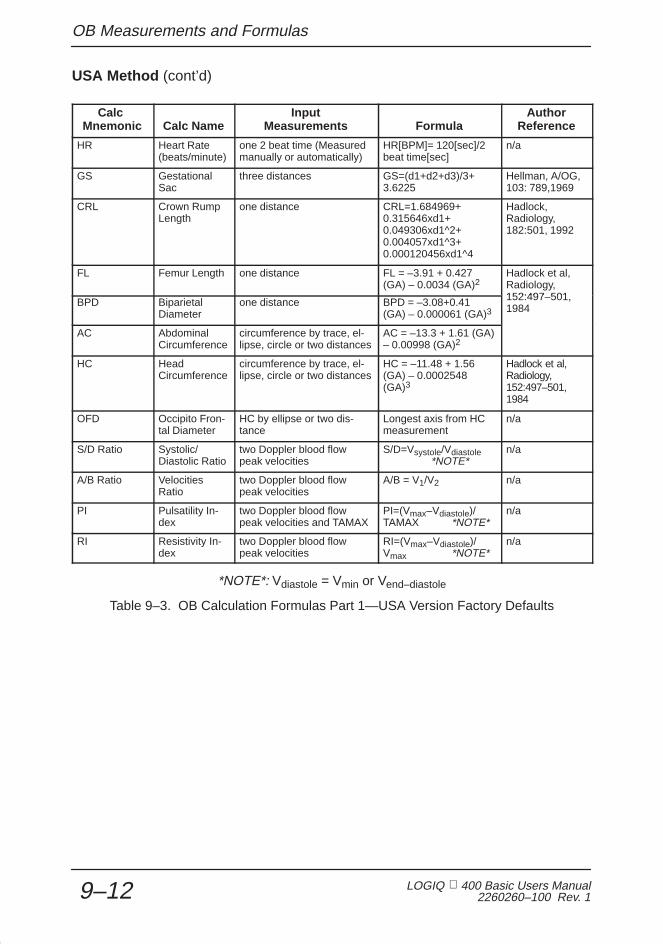
OB Measurements and Formulas
LOGIQ 400 Basic Users Manual2260260–100 Rev. 1 9–12
USA Method (cont’d)
Calc Mnemonic Calc Name
InputMeasurements Formula
AuthorReference
HR Heart Rate(beats/minute)
one 2 beat time (Measuredmanually or automatically)
HR[BPM]= 120[sec]/2beat time[sec]
n/a
GS GestationalSac
three distances GS=(d1+d2+d3)/3+3.6225
Hellman, A/OG,103: 789,1969
CRL Crown RumpLength
one distance CRL=1.684969+0.315646xd1+0.049306xd1^2+0.004057xd1^3+0.000120456xd1^4
Hadlock, Radiology,182:501, 1992
FL Femur Length one distance FL = –3.91 + 0.427(GA) – 0.0034 (GA)2
Hadlock et al,Radiology,152:497 501BPD Biparietal
Diameterone distance BPD = –3.08+0.41
(GA) – 0.000061 (GA)3152:497–501, 1984
AC Abdominal Circumference
circumference by trace, el-lipse, circle or two distances
AC = –13.3 + 1.61 (GA)– 0.00998 (GA)2
HC Head Circumference
circumference by trace, el-lipse, circle or two distances
HC = –11.48 + 1.56(GA) – 0.0002548(GA)3
Hadlock et al,Radiology,152:497–501,1984
OFD Occipito Fron-tal Diameter
HC by ellipse or two dis-tance
Longest axis from HCmeasurement
n/a
S/D Ratio Systolic/Diastolic Ratio
two Doppler blood flowpeak velocities
S/D=Vsystole/Vdiastole*NOTE*
n/a
A/B Ratio VelocitiesRatio
two Doppler blood flowpeak velocities
A/B = V1/V2 n/a
PI Pulsatility In-dex
two Doppler blood flowpeak velocities and TAMAX
PI=(Vmax–Vdiastole)/TAMAX *NOTE*
n/a
RI Resistivity In-dex
two Doppler blood flowpeak velocities
RI=(Vmax–Vdiastole)/Vmax *NOTE*
n/a
*NOTE*: Vdiastole = Vmin or Vend–diastole
Table 9–3. OB Calculation Formulas Part 1—USA Version Factory Defaults

OB Measurements and Formulas
LOGIQ 400 Basic User Manual2260260–100 Rev. 1 9–13
USA Method (cont’d)
Calc Mnemonic Calc Name Input Measurements Formula
AuthorReference
EFW #1 Estimated Fetal Weight
Average of BPD and Aver-age of AC
EFW=10^(-1.7492+0.166*BPD+ (0.046*AC)–((2.646*AC*BPD)/1000))
Shepard, AJOG,142:47, 1982
EFW #2 Estimated Fetal Weight
Average of FL and Average of AC
EFW=10^(1.304+(0.05281*AC)+(0.1938*FL)– (0.004*AC*FL))
Hadlock-Radiology150:535, 1984
EFW #3 Estimated Fetal Weight
Average of BPD, Average of AC and Averageof FL
EFW=10^(1.335–0.0034*AC*FL)+(0.0316*BPD)+0.0457*AC)+ (0.158*FL)
Hadlock, AJOG,151:333, 1985
EFW #4 Estimated Fetal Weight
Average of FL, Average of AC and Averageof HC
EFW=10^(1.326–(0.00326*AC*FL)) +(0.0170*HC)+(0.0438*AC)+(0.158*FL))
Hadlock, AJOG,151:333, 1985
EFW #5 Estimated Fetal Weight
Average of FL, Average of AC, Average of HC and Averageof BPD
EFW=10^(1.3596–(0.00386*AC*FL))+(0.0064*HC)+(0.00061*BPD*AC)+(0.0424*AC)+ (0.174*FL)
Hadlock, AJOG,151:333, 1985
EFW Graph EstimatedFetal WeightGraph
EFW Calculation LOG EFW Mean (g) =0.578 + (0.332 * MA) –(0.00354 * MA2)
1SD = 0.127 * EFWMean
Hadlock, Radiology, 1991;181
EFW[g]=exp(0.578+0.332*MA–0.00354*MA^2) where MA is menstrual age [weeks]
Table 9–3. OB Calculation Formulas Part 1—USA Version Factory Defaults (cont‘d)

OB Measurements and Formulas
LOGIQ 400 Basic Users Manual2260260–100 Rev. 1 9–14
USA Method (cont’d)
CalcMnemonic Calc Name Formula
AuthorReference
CUA** CompositeUltrasoundAge
1. CUA(BPD)=9.54+1.482*(BPD)+0.1676*(BPD)^22. CUA(HC)=8.96+0.540*(HC)+0.0003*(HC)^33. CUA(AC)=8.14+0.753*(AC)+0.0036*(AC)^24. CUA(FL)=10.35+2.460*(FL)+0.170*(FL)^25. CUA(BPD,AC)=9.57+0.524*(AC)+0.1220*(BPD)^26. CUA(BPD,HC)=10.32+0.009*(HC)^2+
1.3200*(BPD)+0.00012*(HC)^37. CUA(BPD,FL)=10.50+0.197*(BPD)*(FL)+
0.9500(FL)+0.7300*(BPD)8. CUA(HC,AC)=10.31+0.012*(HC)^2+0.3850*(AC)9. CUA(HC,FL)=11.19+0.070*(HC)*(FL)+0.2630*(HC)
10. CUA(AC,FL)=10.47+0.442*(AC)+0.3140*(FL)^2–0.0121*(FL)^3
11. CUA(BPD,AC,FL)=10.61+0.175*(BPD)*(FL)+0.2970*(AC)+0.7100*(FL)
12. CUA(HC,BPD,FL)=11.38+0.070*(HC)*(FL)+0.9800*(BPD)
13. CUA(HC,AC,FL)=10.33+0.031*(HC)*(FL)+0.3610*(HC)+0.0298*(AC)*(FL)
14. CUA(HC,AC,BPD)=10.58+0.005*(HC)^2+0.3635*(AC)+0.02864*(BPD)*(AC)
15. CUA(BPD,HC,AC,FL)=10.85+0.060*(HC)*(FL)+0.6700*(BPD)+0.1680*(AC)
Unit: CUA (week), BPD (cm), HC (cm), AC (cm), FL (cm)
Hadlock, Radiology, 1984152:497–501
FL/AC FL/AC ratio FL/AC Hadlock, AJR141:979, 1983
FL/HC FL/HC ratio FL/HC Hadlock, JUM 3:439,1984
FL/BPD FL/BPD ratio FL/BPD Hadlock, AJOG141:759, 1987
CI Cephalic Index
BPD/OFD short distance HC/long distance HC Hadlock, AJR 137:83,1981
HC/AC HC/AC ratio HC/AC Campbell, BRJ.OG84:165,1977
** Formulas are used only if Hadlock HC, FL, AC and BPD are used and the “CUA/AUAfor Hadlock” preset, found on System Parameters page 3, is set to “CUA”. If other
authors are used, CUA automatically changes to AUA and an average value is displayed.
Table 9–4. OB Calculation Formulas Part 2—USA Version Factory Defaults

OB Measurements and Formulas
LOGIQ 400 Basic User Manual2260260–100 Rev. 1 9–15
USA Method (cont’d)
CalcMnemonic Calc Name Formula
AuthorReference
AFI* AmnioticFluid Index
AFI=AFI1 (distance) + AFI2 (distance) + AFI3 (dis-tance) + AFI4 (distance)
Dr. Rutherford/Dr.Phelan, Obstetrics &Gynecology Volume70, No. 3, Part 1, p.353–6, Sept. 1987.Dr. C. C. Smith, TheFemale Patient, Vol-ume 15, p. 85-97,March 1990.
* The skip function using the Ellipse up/down arrow keys is not available for AFI.
Table 9–4. OB Calculation Formulas Part 2—USA Version Factory Defaults (cont’d)

OB Measurements and Formulas
LOGIQ 400 Basic Users Manual2260260–100 Rev. 1 9–16
European Method
CRLJEANTY
GSTOKYO
BPDJEANTY
FLJEANTY
ACJEANTY
TADERIKSEN
OBReport
HCJEANTY
OFDHANSMAN
BDJEANTY
FtPARIS
USER1 OBGraph
OBReport
ANATOMYSURVEY
3/4
SelectLocatn
D/SRatio
RI A/BRatio
TRACEAUTO
PI OBReport
USER5 HEARTRATE
OBGraph
OBReport
4/4
USER4USER3USER2
1/4
2/4
Figure 9–4. European Sub-Menus

OB Measurements and Formulas
LOGIQ 400 Basic User Manual2260260–100 Rev. 1 9–17
European Method (cont’d)
Calc Mnemonic Calc Name
InputMeasurements Formula
AuthorReference
HR Heart Rate(beats/minute)
one 2 beat time(Measured manually orautomatically)
HR[BPM]=120[sec]/2beat time[sec]
n/a
GS Gestational Sac one distance Curve data isavailable in theAdvanced ReferenceManual
Tokyo UniversityMethod 1986,6 by Univ. of Tokyo
CRL Crown RumpLength
one distanceManual
JEANTY :Radiology, 143 :513 1982
BPD Biparietal Diameter
one distance513, 1982
HC HeadCircumference
circumference by trace,ellipse, circle or twodistances
AC AbdominalCircumference
circumference by trace,ellipse, circle or twodistances
FL Femur Length one distance Curve data isavailable in the
JEANTY :Radiology 143 :
BD BinocularDistance
one distanceavailable in theAdvanced ReferenceManual
Radiology, 143 :513, 1982
TAD TransverseAbdominalDiameter
one distance ERIKSEN
OFD Occipito FrontalDiameter
one distance Known LMP Case: Hansmann:Ultraschalldiag–nostik in Begurtshilfe
Unknown LMP Case:tik in Begurtshilfeund Gynakologie1985
Ft Foot Distance one distance Curve data isavailable in theAdvanced ReferenceManual
PARIS
EFW Estimated FetalWeight
Average of BPD andAverage of AC [cm]
EFW[g] = 10�(1.7288+ 0.09184*BPD +(0.02581* AC) +(0.00011*BPD*AC))
Shepard/Warsoff
Table 9–5. OB Calculation Formulas—European Version Factory Defaults

OB Measurements and Formulas
LOGIQ 400 Basic Users Manual2260260–100 Rev. 1 9–18
European Method (cont’d)
Calc Mnemonic Calc Name
InputMeasurements Formula
AuthorReference
FL/AC FL/AC ratio Average of FL andAverage of AC
FL/AC Hadlock, AJR, 141 :979, 1983
FL/BPD FL/BPD ratio Average of FL andAverage of BPD
FL/BPD Hadlock, AJOG,141 : 759, 1987
CI Cephalic Index Average of BPD andAverage of OFD
BPD/OFD shortdistance HC/longdistance HC
Hadlock, AJR, 137 :83, 1981
HC/AC HC/AC ratio Average of HC andAverage of AC
HC/AC
FL/Ft FL/Ft ratio Average of FL andAverage of Ft
FL/Ft
BD/BPD BD/BPD ratio Average of BPD andAverage of BD
BD/BPD
D/S Ratio Diastolic/Systolic Ratio
two Doppler blood flowpeak velocities
D/S = V diastole/Vsystole *NOTE*
n/a
A/B Ratio Velocities Ratio two Doppler blood flowpeak velocities
A/B = V1/V2 n/a
Pl Pulsatility Index two Doppler blood flowpeak velocities andTA_MAX
Pl=(Vmax – Vdiastole)/TA_MAX
*NOTE*
n/a
RI Resistivity Index two Doppler blood flowpeak velocities
RI=(Vmax – Vdiastole)/Vmax *NOTE*
n/a
*NOTE*: Vdiastole = Vmin or Vend–diastole
Table 9–5. OB Calculation Formulas—European Version Factory Defaults (cont’d)

OB Measurements and Formulas
LOGIQ 400 Basic User Manual2260260–100 Rev. 1 9–19
Other OB Calculation Formulas
Calc Mnemonic Calc Name
InputMeasurements Formula
AuthorReference
BPD BiparietalDiameter
one distance Curve data isavailable in theAdvanced Reference
CAMPBELL : King’sCollege Hosp. London(Am J obst gynecol)
FL Femur Length one distanceAdvanced ReferenceManual
(Am.J. obst gynecol).Oct. 1, 1982
BD BinocularDistance
one distance,
GS GestationalSac
one distance HANSMANN: M and Al :Geburtsch, u, Frauenheilk39 : 656, 1979
CRL Crown RumpLength
one distance ROBINSON: Robins on andAl: Br J Gynecol, 82 : 702,1975
CRL Crown RumpLength
one distance PARIS
BPD BiparietalDiameter
one distance
TAD TransverseAbdominalDiameter
one distance
FL Femur Length one distance
BPD BiparietalDiameter
one distance SOSTOA: Hospital de laSanta Cruzy San Pablo,servieio de obst y gynecol
HC HeadCircumference
circumference bytrace, ellipse, circleor two distances
servieio de obst. y gynecol.
AC AbdominalCircumference
circumference bytrace, ellipse, circleor two distances
FL Femur Length one distance
BD BinocularDistance
one distance
OFD OccipitoFrontalDiameter
one distance
FL Femur Length one distance Hadlock, AJR, 138 : 875,1982
Table 9–6. OB Calculation Formulas—Other Selections

OB Measurements and Formulas
LOGIQ 400 Basic Users Manual2260260–100 Rev. 1 9–20
Other OB Calculation Formulas (cont’d)
Calc Mnemonic Calc Name
InputMeasurements Formula
AuthorReference
BPD BiparietalDiameter
one distance Curve data isavailable in theAdvanced Reference
Hadlock, JUM 1:97, 1982
AC AbdominalCircumference
circumference bytrace, ellipse, circleor two distances
Advanced ReferenceManual Hadlock, AJR, 139 : 367,
1982
HC HeadCircumference
circumference bytrace, ellipse, circleor two distances
Hadlock, AJR, 138 : 649,1982
CRL Crown RumpLength
one distance NELSON
BPD BiparietalDiameter
one distance KURTZ
BD BinocularDistance
one distance BERKOWITZ
EFW EstimatedFetal Weight
Average of BPD andAverage of TAD[mm]
EFW[kg] = 0.515263–(0.105775*BPD)+(0.000930707*(BPD)2) +(0.0649145*TAD) –(0.00020562*(TAD[mm])2)
German
EFW EstimatedFetal Weight
Average of BPD andAverage of AC [cm]
EFW [g] =10�(3–1.7492 +0.046*AC +0.166*BPD –0.002646*AC*BPD)
Shepard : Richards/Berkowitz
EFW EstimatedFetal Weight
Average of FL,Average of AC andAverage of HC [cm]
EFW [g] =10�(1.5662 –(0.0108*HC) +(0.0468*AC) +(0.171*FL) +(0.00034*(HC)2) –(0.003685*AC*FL) )
Hadlock, Radiology,150 : 535, 1984
FL/HC FL/HC ratio Average of FL andAverage of HC
FL/HC Hadlock, JUM, 3 : 439,1984
Table 9–6. OB Calculation Formulas—Other Selections (cont’d)

OB Measurements and Formulas
LOGIQ 400 Basic User Manual2260260–100 Rev. 1 9–21
Other OB Calculation Formulas (cont’d)
Calc Mnemonic Calc Name
InputMeasurements Formula
AuthorReference
GS GestationalSac
one distance Known LMP Case: RempenSac
Unknown LMP Case:
CRL Crown RumpLength
one distance Known LMP Case:Length
Unknown LMP Case:
BPD BiparietalDiameter
one distance Known LMP Case:Diameter
Unknown LMP Case:
BPD BiparietalDiameter
one distance Known LMP Case: Hansmann:Ultraschalldiag nostik inDiameter
Unknown LMP Case:Ultraschalldiag–nostik inBegurtshilfe und
CRL Crown RumpLength
one distance Known LMP Case:g
Gynakologie 1985Length
Unknown LMP Case:
HC HeadCircumference
Average of BIPAverage of FRO
HC [mm = 2.325*(BPD [mm] ^2 +OFD [mm] ^2)^0.5
ThD TransverseThorax
one distance Known LMP Case:ThoraxDiameter Unknown LMP Case:
FL Femur Length one distance Known LMP Case:
Unknown LMP Case:
AC AbdominalCircumference
one distance Known LMP Case:Circumference
Unknown LMP Case:
EFW EstimatedFetal Weight
Average of BPDAverage of AC
EFW[g] =–3200.40479 +157.07186 * AC[cm] +15.90391 * BPD [cm]
Merz, et al.,Womens Hospital,University of Mainz
BPD BiparietalDiameter
one distance Curve data isavailable in theAdvanced Reference
Tokyo Shinozuka Method,1996
APTD x TTD(AxT)
AnteroPosteriorTrunkDiameter
TransverseTrunkDiameter
two distanceAdvanced ReferenceManual
Table 9–6. OB Calculation Formulas—Other Selections (cont’d)

OB Measurements and Formulas
LOGIQ 400 Basic Users Manual2260260–100 Rev. 1 9–22
Other OB Calculation Formulas (cont’d)
Calc Mnemonic Calc Name
InputMeasurements Formula
AuthorReference
AC AbdominalCircumference
circumference bytrace, ellipse, circleor two distance
Curve data isavailable in theAdvanced ReferenceManual
Tokyo Shinozuka Method,1996
FL Femur Length one distanceManual
CRL Crown RumpLength
one distance
EFW1 EstimatedFetal Weight
four distance EFW1 [gram] = 1.07 *BPD^3 +3.42*APTDxTTD *FLG = [day] , BPD =[cm], FL = [cm],APTDxTTD = [cm2]
EFW2 EstimatedFetal Weight
2 distance and 1circumference
EFW2 [gram] = 1.07 *BPD^3 + 0.30 * AC^2* FLG = [day], BPD =[cm], AC = [cm], FL =[cm]
EFW3 EstimatedFetal Weight
four distance EFW3 [gram] = 1.07 *BPD^3 +2.91*APTDxTTD*LVG = [day], BPD =[cm], LV = [cm],APTDxTTD = [cm2]
BPD BiparietalDiameter
one distance Curve data isavailable in theAdvanced Reference
ASUM, D. Robinson et al,1990.8
CRL Crown RumpLength
one distanceAdvanced ReferenceManual ASUM, Silva et al, 1991.6
AC AbdominalCircumference
circumference bytrace, ellipse, circleor two distance
AC (mm) = –56.582 +11.402 * (GA–2)GA = [week]
ASUM, Deler
Table 9–6. OB Calculation Formulas—Other Selections (cont’d)
GS Measurement
GS Measurement for the Tokyo University and Europeanmethods requires only one distance measurement.
GS Measurement for the USA method requires 3 distancemeasurements obtained from longitudinal and transverseimages. The 3 measurements are anterior–posterior,transverse and longitudinal. It is advantageous to use thedual-image (split screen) feature for this GS measurement.

OB Measurements and Formulas
LOGIQ 400 Basic User Manual2260260–100 Rev. 1 9–23
Amniotic Fluid Index (AFI)
The Amniotic Fluid Index is determined by taking distancemeasurements of the 4 quadrants of the uterine cavity. These 4measurements are added together to calculate the AmnioticFluid Index.
Press the Measurement key once to display a “�” cursor onthe screen, and to display distance in cm on the bottom part ofscreen. Select AFI from the OB Measurement Soft Menu. Thedistance measurement changes to AFI1 (2, 3 or 4).
Perform a standard distance measurement as described in
When the measurement of the first quadrant is completed,unfreeze and move to the second quandrant. After the image isobtained, press Freeze and then Measurement . The user isthen prompted to continue with the AFI measurements.Perform a standard distance measurement for the secondquadrant.
Repeat these steps for quandrants 3 and 4.
When all 4 quadrants have been measured, the AFI will becalculated and displayed in the Calculation Result Area of thedisplay.
The skip function using the Ellipse up/down arrow keys is notavailable for AFI.
Unfreezing the image after doing an AFI measurement does notdelete the previous measurements. Unfreeze and change scanplanes as necessary. Make the remaining measurements toarrive at the AFI value by following the basic distancemeasurement procedure.
If any generic distance measurements are unassigned beforeinvoking the Amniotic Fluid Index these measurements will beused. Only the remaining distance measurements need to bemade to arrive at an AFI.
Hints

OB Measurements and Formulas
LOGIQ 400 Basic Users Manual2260260–100 Rev. 1 9–24
Amniotic Fluid Index (AFI) (cont’d)
The normal values are considered to be:
36–40 weeks0–5 cm = very low5.1–8.0 cm = low8.1 – 18.0 cm = normal>18.0 = high
Dr. Rutherford/Dr. Phelan, Obstetricsand Gynecology, Volume 70, No. 3,Part 1, p. 353–6, Sept. 1987.
28–40 weeks15.0 cm = average>20.0 – 24.0 = hydramnios<5.0–6.0 = Oligohydramnios
Dr. C.C. Smith, The Female Patient,Volume 15, p. 85–97, March 1990.
Select AFI from the OB Measurement Soft Menu.
Sagittal
Transverse

OB Measurements and Formulas
LOGIQ 400 Basic User Manual2260260–100 Rev. 1 9–25
EFW Using User Programmable Table Measurements
If it is desired to use User Programmable Table measurementsin the calculation and reporting of EFW, perform the followingsteps:
System Setup
1. Create the desired User Programmable Tables asdescribed on 14–75.
2. Assign the User Table measurement to the properMeasurement Mode Menu as described on 14–84.
3. Assign the User Programmable Table measurement tothe desired Report Page as described on 14–72.
Calculating EFW
4. Perform the measurements used in the calculation ofEFW.
For example, if Tokyo method is selected in the OBReport Format, found in System Parameters page 2,EFW is calculated by measuring BPD, FL, APTDxTTD.If user programmable tables are used in themeasurement of BPD, FL and/or APTDxTTD, thesemeasurements should be performed first prior to thefactory default measurements [i.e. FL (user1), BPD, FL,APTDxTTD].
After all measurements have been completed, EFW is notdisplayed in the measurements results area, but is displayed onthe Report Page.
If it is desired to use User Programmable Table measurementsin the calculation of EFW, it would be helpful to program a UserMeasurement Sequence as described on 14–79.
If measurement averaging is active, EFW will be calculatedfrom the average of similar factory default and userprogrammable table measurements.
Hints

OB Measurements and Formulas
LOGIQ 400 Basic Users Manual2260260–100 Rev. 1 9–26
User-Programmed Calculations (Tables)
User-programmed calculation tables are displayed in themeasurement menus only after they are entered by the user.
The User Table Editor is found in the Set Up/Preset ProgramMenu page 7. Refer to 14–75 on how to define these userselections and program the user tables.
Select Locatn
This choice is used to select 1 of 3 locations at which S/D (D/S)Ratio, A/B Ratio, RI and PI can be taken and recorded on thereport page.
The locations are numbered 1, 2 and 3 as a default from thefactory. However, the user can customize each locationdesignation with a 6 character name. This customization edit isdone in any report page that displays S/D (D/S) Ratio, A/BRatio, RI or PI. Changes will be permanently saved even aftersystem power down.
Up to three measurements can be taken for S/D (D/S) Ratio,A/B Ratio, RI or PI. The latest value or measurement averagecan be reported. Averaging depends upon the average activitypreset selection in the Set Up/Preset Program page 3.
Press the Select Locatn up/down arrow keys to change thelocation number as necessary.
3/4
SelectLocatn
D/SRatio
RI A/BRatio
TRACEAUTO
PI OBReport
Figure 9–5. European OB Calculation Sub-Menu

OB Measurements and Formulas
LOGIQ 400 Basic User Manual2260260–100 Rev. 1 9–27
S/D (D/S) Ratio, A/B Ratio, RI or PI
Refer to the procedure found on 10–29.
Trace Auto
Use the Trace Auto Sub-Menu selection to turn on/off theDoppler Auto Trace function. See 10–28 for more details.
Fetal Heart Rate Measurement
The fetal heart rate is typically taken in M-Mode, though it alsocan be performed in Doppler Mode. Refer to the procedurefound on 10–30.
Helpful Hints
� Any measurement can be repeated by selecting thatmeasurement again from the Soft-Menu.
� The system displays several measurements, but thesummary report retains only the last 3 measurements ofeach type.
� The 3 report page measurements can be averaged and theaverage used in other calculations. This averaging selectionis made in the Set Up/Preset Program page 3. Averageactivity on/off and average number (number of measurementsaveraged) can be set to the user’s preference. Other presetson this page that affect OB measurements for the Europeanmethod are Add 1 week to EDD and Display EDD with GAvalue.
� If results are displayed as question marks, themeasurement is not within the table range.
Hints

OB Summary Reports
LOGIQ 400 Basic Users Manual2260260–100 Rev. 1 9–28
OB Summary Reports
Starting an Exam
Accurate and complete Summary Report presentation starts atthe beginning of the patient exam. Always begin an exam byentering as much new patient information as possible.
NOTE: Refer to the Beginning an Exam section on 4–3 forinstructions.
After selecting the OB exam type, fill in the following informationafter PT Name, PT ID, Notes, and Oper ID:
1. AGE. Type the woman’s age.
2. PREGNANCY Enter 1 for LMP, 2 for BBT (not in USA ORIGIN DATA version), 3 for EDC (EDD in Europe) SELECTION and 4 for GA.. Type in the required information
for category selected.
NOTE: If this step (#2.) is omitted, growth percentiles andasterisks will not be displayed on the OB Report Pageand OB Graphs, respectively
3. GRAVIDA . Type the number of pregnancies.
4. PARA . Type the number of live births.
5. AB . Type the number of abortions, miscarriages, etc.
6. ECTOPIC. Type the number of pregnancies outside the uterus.
7. REF. MD. Type the name of the woman’s physician.
8. COMMENT Type any pertinent medical history with regard to this pregnancy, e.g., diabetes, bleeding.
�
�

OB Summary Reports
LOGIQ 400 Basic User Manual2260260–100 Rev. 1 9–29
Starting an Exam (cont’d)
9. EXIT Press Return after having completed filling in this information.
NOTE: If patient information needs to be edited, use theID/Name key to display the patient entry menu for editinginformation.
OB Report Page Layout
The basic OB Report format consists of 2 pages for each regionavailable (USA, Europe, Tokyo University and OsakaUniversity).
The first page consists of 4 basic areas. The first, or topportion, is generally patient data that was entered on the patiententry menu at the beginning of the exam. This area cannot beedited.
The second is the measurements area. It varies by regionformat. Generally this area contains measurement titles, thelast 3 measurements made, the measurement average (ifaveraging is used), estimated gestational age and the ability tochoose if the measurement is used in the calculation of thecomposite age. This area can be edited by deletingmeasurements, selecting yes/no for composite age orrearranging the vertical location of a measurement using theReport Format Editor in the Set Up/Preset Program page 7.
The third area is calculations. It varies by region format. Theseitems are results of measurements or patient data entered onthe Patient Entry Menu. This area cannot be edited.
The fourth area is comments. The same amount of area isavailable for user comments for each region. The user can editthis area freely. Comments made on page 1 are not reflectedon page 2. Therefore, comments on each page can be editedindividually.
�

OB Summary Reports
LOGIQ 400 Basic Users Manual2260260–100 Rev. 1 9–30
OB Report Page 1
Figure 9–6. USA Basic OB Summary Report Page 1
NOTE: When the head circumference (HC) is measured by theellipse or 2 distance method, the longer axis will automaticallybe assigned as the OFD measurement.
<AVG> or <LAST> indicates that the Average or Latest valuewill be displayed in this column. This depends on the preset,Average Activity, in the Set Up/Preset Program menu page 3.
Figure 9–7. European Basic OB Report Page 1
�

OB Summary Reports
LOGIQ 400 Basic User Manual2260260–100 Rev. 1 9–31
OB Report Page 1 (cont’d)
Figure 9–8. Tokyo University Basic OB Report Page 1
Figure 9–9. Osaka University Basic OB Report Page 1

OB Summary Reports
LOGIQ 400 Basic Users Manual2260260–100 Rev. 1 9–32
Composite Age Determination
The composite fetal age is displayed as CUA (CompositeUltrasound Age) on the USA Report and CGA (CompositeGestational Age) on the European, Tokyo University and OsakaUniversity Reports.
NOTE: There is a preset selection to choose how gestationalage is derived for the USA Hadlock formulas. The “CUA/AUAfor Hadlock” preset, found on System Parameters page 3,allows gestational age to be derived by linear regression (CUA)or averaging (AUA).
The CUA or CGA field can be edited on the report page by thedesignation ‘Y’ for yes or ‘N’ for no.
‘Y’ will include the last measurement or measurement averagein the calculation composite age. Changing the CUA/CGAdesignation to ‘N’ will exclude the measurement from thecomposite age calculation. The default value is ‘Y’.
NOTE: There is a preset selection on Set Up/SystemParameters page one that allows for the resetting of the CUAfields at New Patient selection (Reset on or off).
Fetal Weight Estimates
The estimated fetal birth weight calculation varies by region.EFW or EFBW is calculated for:
USA Version—The system automatically selects 1 of the 5available formulas based on the measurements taken. Refer to 9–13 for formula details.
Tokyo or European Version—It is based on the formula selectedin the Set Up/System Parameter menu page 2.
Osaka University Version—It is based on a single formula listedon 9–10. Standard Deviation is also displayed with EFBW inthe Osaka University OB Report.
�
�

OB Summary Reports
LOGIQ 400 Basic User Manual2260260–100 Rev. 1 9–33
OB Report Page 2
<AVG> or <LAST> indicates that the Average or Latest valuewill be displayed in this column. This depends on the preset,Average Activity, in the Set Up/Preset Program menu page 3.
SITE represents a Doppler site that the user can edit with a maximum of 6 characters. Factorydefault labels are 1, 2 and 3.
Figure 9–10. USA Basic OB Summary Report Page 2
Figure 9–11. Basic OB Report Page 2 for Europe, Tokyo University and Osaka University

OB Summary Reports
LOGIQ 400 Basic Users Manual2260260–100 Rev. 1 9–34
Biophysical Profile
A biophysical profile source is available to evaluate the wellbeing of the fetus. The user can rate the fetus with a score of 0,1 or 2 on the following items:
� Movement Rate fetal physical activity
� Tone Rate fetal tone
� Breathing Rate fetal breathing movement
� Fluid Rate fetal amniotic fluid
� Reactive NST Rate a Reactive Non-Stress Test
A sum of the above 5 items is then displayed as an overallbiophysical profile score.
If any value is entered other than 0, 1 or 2 for each of the 5items, an error message “Invalid, Input a proper data (0–2)” isdisplayed.
HR, PI, RI, S/D (D/S) Ratio and A/B Ratio
The largest portion of page 2 displays the last 3 measurementsand latest/average value for HR, PI, RI, S/D (D/S) Ratio andA/B Ratio. The last 4 measurements can be taken at 3 differentsites on the fetus.
The factory default for these site fields is 1, 2 and 3. However,the user can freely edit these site fields on the Report Page.For some regions, these site fields may be common betweenpages 1 and 2. If this is the case, edits on either page arereflected on the other. These edits are remembered afterpower down. The maximum length of the site field is 6characters.
The comments section can be edited freely using thealphanumeric keyboard or annotation library. Simply move thehighlight cursor into the comment area and press the Commentkey. The system is now in the annotation mode. When thehighlight cursor leaves the comment area, the system exits theannotation mode. These comments are separate from those onpage 1.

OB Summary Reports
LOGIQ 400 Basic User Manual2260260–100 Rev. 1 9–35
USA Only
Two items are different on the OB Summary Report page 2 forthe USA version.
1. The third line of the top portion will display all of theLMP, GA and EDD data based on the operator’s input.For example, if LMP was entered:
LMP (OPE) mm/dd/yy GA (LMP) ##W#D EDD (LMP) mm/dd/yy
will be displayed.
2. Amniotic Fluid Index (AFI) displays the sum of the 4measurements and the 4 individual measurementvalues.

OB Summary Reports
LOGIQ 400 Basic Users Manual2260260–100 Rev. 1 9–36
Editing the Report
Cursor Movement
Movement of the edit cursor on the report page can beaccomplished by using the Trackball or the up/down/left/rightarrow keys on the keyboard.
Edit Actions
When positioned on a measurement field the Back Space orSpace keys will delete the current value in that field. Afterpressing Back Space or Space , the only options remaining areto press Set or Esc .
Set deletes the old value.
Esc returns the old value to the report page.
NOTE: Any calculations relating to the deleted measurementfield are recomputed.
Logic Field Edits
The CUA/CGA field requires a “Y” or “N” to be entered in eitherupper or lower case.
When the cursor is positioning in the desired field, press “Y” or“N”. Once yes or no has been entered, press Return to recordthat entry and proceed to the next edit field.
NOTE: Calculations affected are recomputed.
�
�

OB Summary Reports
LOGIQ 400 Basic User Manual2260260–100 Rev. 1 9–37
Comment Edits
The comment field consists of 2 lines with a total of120 characters. Use normal keyboard functions to typenecessary comments.
Comments made on each report page are not reflected on theother report pages. Therefore, comments on each page can beedited individually.
When finished, press Return to complete the comment editfunction. Since this is the last edit field on the report page, thecursor moves to the first edit field.
Measurement Edits
Measurements on the OB Report Page can only be edited bydeletion. After a measurement is deleted, the average or otherrelated calculations will be recomputed and the report pagedisplayed again.
Operator Entered Values
In the calculations section of the report page, if the value is aresult of operator entered data (generally from the patient entrymenu) and not measurements, the designation “OPE” is seenafter the calculation name.
An example would be EDD (OPE). This means the estimatedate of delivery was a value entered by the operator on thepatient entry menu.

OB Summary Reports
LOGIQ 400 Basic Users Manual2260260–100 Rev. 1 9–38
Recording Summary Reports
The summary report can be saved like any ultrasound image.Once it is displayed on the screen, it can be recorded on theVCR, printed on the B/W or color page printer, photographed bythe multi-image camera, stored on a MOD with the ImageArchive option or placed on regular paper with a line printer.
Line Printer Operation
USA Only Refer to 13–15 for details on line printer operation.

Anatomical Survey
LOGIQ 400 Basic User Manual2260260–100 Rev. 1 9–39
Anatomical Survey
Overview
The Anatomical Survey page provides a checklist that promotesa thorough routine reporting of OB exams.
The header of the page is patient data similar to thecorresponding OB Report page. This information can only beedited by using the New Patient or ID Name keys.
The third line of the header will be different depending on thetype of OB Report Format selected.
There are 13 pre-programmed and a maximum of 6 userprogrammable anatomical features.
Figure 9–12. Anatomical Survey Page

Anatomical Survey
LOGIQ 400 Basic Users Manual2260260–100 Rev. 1 9–40
Editing
When the Anatomical Survey Page is enabled from the OBcalculation menu, the highlight cursor appears at the YES/NOfield of the first feature on the checklist. Both Yes and No aredisplayed for all items on the list.
The highlight cursor is moved by the Trackball or the up/down/left/right arrow keys.
YES/NO will appear in the “IMAGED?” column even if there isno entry in the user programmed fields. Select yes by pressing‘Y’ on the keyboard. When yes is selected, no will be erased.The cursor automatically moves to the comments field.
In the comments field, comments can be entered by typing orselecting annotations from the Soft-Menu. One line ofcomments is available for each anatomical feature. PressReturn when completed.
NOTE: Any meaningless entries will display the message:“Please select ‘y’ or ‘n’.” or “Please select ‘n’ or ‘a’.”
User Programmed Features
The user can program 6 anatomical feature fields. Themaximum number of characters is 19.
To enter a user feature:
Trackball the highlight cursor to a User Field.
Type in the desired feature name and press Return . Thehighlight cursor moves to the Yes/No field.
Repeat the steps as necessary for any additional feature fields.
The entries will be saved and retained even after the system ispowered down.
While in a user programmed field, rolling the Trackball up/downor pressing the up/down arrow keys have no effect on cursorposition. Only motion of the Trackball to the left/right orpressing the left/right arrow keys will work.
�
Hints

OB Graphs
LOGIQ 400 Basic User Manual2260260–100 Rev. 1 9–41
OB Graphs
Overview
The LOGIQ 400 can display a fetal growth curve graph (OBGraph) from data in each measurement table for fetal age.
The graphic displays a horizontal scale for gestational weeksand a vertical scale for the measurement value. The curvegraphic shows the standard values with 2 additional curvesrepresenting the standard deviation.
If the pregnancy origin data selection field was entered on thepatient data entry menu, an asterisk (*) is displayed on thegraph to show the current status of the fetus relative to themeasurement table.
The OB graph page also has patient data fields,measurement/calculation data fields and a comment field.
The system does not allow any field on the OB graph to beedited.
NOTE: The Pregnancy Origin Data Selection (LMP, BBT, EDC,EDD or GA) is required in order to properly compute the OBGraph. Ensure that this is properly entered in the Patient EntryMenu.
�

OB Graphs
LOGIQ 400 Basic Users Manual2260260–100 Rev. 1 9–42
OB Graph Selection
OB Graph is a factory default selection in the measurementmenus. Select OB Graph from the Measurement Menu.
Figure 9–13. Basic OB Graph Display (Osaka University)
NOTE: The label in the upper left corner of the graph indicatesthe standard deviation used to plot the graph.
NOTE: The system does not allow the selection of a defaultgraph. The first graph displayed is always the last B-Modemeasurement calculated.
OB Graph Labeling
Refer to the Advanced Reference Manual for the labeling foundin the OB Graph for standard deviation.
�
�

OB Graphs
LOGIQ 400 Basic User Manual2260260–100 Rev. 1 9–43
OB Graph Labeling (cont’d)
Author Measurement table Deviation Deviation Label
Hadlock BPD, HC, AC, FL Vertical +2SD/–2SD
CRL ––– No Label
EFW Vertical +2SD/–2SD
Hellman GS ––– No Label
ASUM BPD, AC Horizontal +2SD/–2SD(WEEK)
CRL ––– No Label
Tokyo GS, CRL, BPD, FL, LV Horizontal Deviation(WEEK)
Tokyo–S (Shinozuka) CRL, BPD, FL, AC,AxT(APTDxTTD), EFW
Vertical +1.64SD/–1.64SD
Osaka CRL, BPD, FL, HL, FTA, EFBW Vertical +1.5SD/–1.5SD
Hansmann BPD, CRL, OFD, HC, TThd, FL Vertical 95%/5%
GS, TAD Vertical 90%/10%
AC ––– No Label
Rempen GS, CRL, BPD Vertical 95%/5%
Campbell BPD, CRL, FL Vertical 90%/10%
BD ––– No Label
Berkowitz BD ––– No Label
Eriksen TAD ––– No Label
Kurtz BPD Vertical 90%/10%
Nelson CRL Vertical 90%/10%
Robinson CRL Vertical 90%/10%
Jeanty CRL, BPD, FL, AC, HC Vertical 90%/10%
BD ––– No Label
Paris CRL, BPD, FL, Ft Vertical 90%/10%
TAD ––– No Label
Sostoa BPD, FL, AC, HC Vertical 90%/10%
BD, OFD ––– No Label
User Table USA Horizontal Deviation(WEEK)
User Table TOKYO Horizontal Deviation(WEEK)
User Table OSAKA Vertical +1.5SD/–1.5SD
User Table Europe Vertical 90%/10%
Table 9–7. OB Graph Deviation Labeling

OB Graphs
LOGIQ 400 Basic Users Manual2260260–100 Rev. 1 9–44
Changing OB Graph Selection
After the OB graph has been displayed, the user can change orselect which measurement parameter is to be used to display agraph.
Highlight CHANGE GRAPH and press Return . The graphic isdeleted and a measurement selection menu appears.
Select the desired measurement value and press Return . Thenew measurements, calculations and graphic are displayed.
Exit OB Graph
Select OB Graph in the OB Calculation Sub-Menu.
The user is not allowed to edit any field on the OB Graphdisplay except the Comments section. Comments on the OBGraph page are different from any other OB Report Page.
If the Pregnancy Origin Data Selection is not entered on thePatient Entry Menu screen, the mark (*) indicating the currentstatus of the fetus will not be displayed on the graph.
Hints

Advanced Obstetrical Options
LOGIQ 400 Basic User Manual2260260–100 Rev. 1 9–45
Advanced Obstetrical Options
Options
The following advanced options are available for monitoringfetal development. Refer to the Advanced Reference Manualfor further details.
Fetal Trend Management
Patient data, measurements and calculations must be saved onthe hard drive or MOD during the initial examination. Duringfollow-up examinations, the OB Graph function can display thecurrent data or combine the current data with past data to showa fetal growth trend.
Multigestational OB
The LOGIQ 400 offers an optional calculation package thatallows the user to measure and report multiple fetusdevelopment. The system is capable of reporting a maximumof 4 fetuses.
Data Management Center (DMC)
The LOGIQ 400 is capable of interfacing with a personalcomputer (PC). This interface is used to send OB, GYN andVascular measurement and calculation data from theLOGIQ 400 to the PC for display, processing and evaluation.
Additionally, the LOGIQ 400 can accept patient id data from apersonal computer (PC) and transfer it to the patient entrymenu.

GYN Measurements
LOGIQ 400 Basic Users Manual2260260–100 Rev. 1 9–46
GYN Measurements
B-Mode
Ovarian Length, Height, and Width
The length, height and width of the left and right ovaries can bemeasured and recorded on the GYN summary report.
Each measurement is a typical distance measurement made ona B-Mode image in the appropriate scan plane.
Typically, the height and width are measured on the axial planewhile the length is measured on the sagittal plane.
To measure ovarian length:
Scan the patient’s right or left ovary in the sagittal plane.
1/4
Rt Ov–LLt Ov–L Rt Ov–HLt Ov–H Rt Ov–WLt Ov–W GYNReport
Figure 9–14. GYN Calculation Sub-Menu
Select Rt Ov-L or Lt Ov-L from the GYN CalculationSub-Menu. Perform a standard distance measurement asdescribed in 7–7.
To measure ovarian height and width:
Scan the patient’s right or left ovary in the axial plane.
Select Rt Ov-H , Rt Ov-W, Lt Ov-H or Lt Ov-W from the GYNCalculation Sub-Menu. Perform the necessary distancemeasurements as described in 7–7.

GYN Measurements
LOGIQ 400 Basic User Manual2260260–100 Rev. 1 9–47
Uterine Length, Height, and Width
The GYN Calculation Sub-Menu page 2 allows formeasurements to be recorded as uterine length (Ut-L), height(Ut-H) or width (Ut-W). Length is typically measured in thesagittal plane while height and width are measured in the axialplane.
Scan the patient in the appropriate scan plane.
2/4
EndoUt–L Ut–H Ut–W GYNReport
OFF
Figure 9–15. GYN Calculation Sub-Menu
Select the desired measurement from the GYN CalculationSub-Menu (Ut-L, Ut-H or Ut-W).
Measurements are recorded on the GYN Summary Report.The last 3 measurements of each type can be averaged by theSummary Report Page.
Ovary Follicles Measurements
Ovary Follicle (LtOvFo or RtOvFo) Measurements are availablein the GYN Calculation Sub-Menu page 3.
3/4
Ov FolReport
RtOvFoLtOvFo
Figure 9–16. GYN Calculation Sub-Menu
LtOvFo or RtOvFo measurements are calculated from one, two,or three distances.

GYN Measurements
LOGIQ 400 Basic Users Manual2260260–100 Rev. 1 9–48
Endometrium Thickness
An endometrium thickness measurement is also available onthe GYN Calculation Sub-Menu.
Scan the patient. Select ENDO from the GYN CalculationSub-Menu. Perform a standard distance measurement asdescribed in 7–7.
Doppler Mode
Three GYN related measurements can be taken in DopplerMode and recorded on the GYN Summary Report. These areresistive index measurements for a left ovarian vessel, uterinevessel and right ovarian vessel.
NOTE: If the Doppler option is not installed with theLOGIQ 400 Black/White systems, the Doppler Modemeasurements cannot be performed.
�
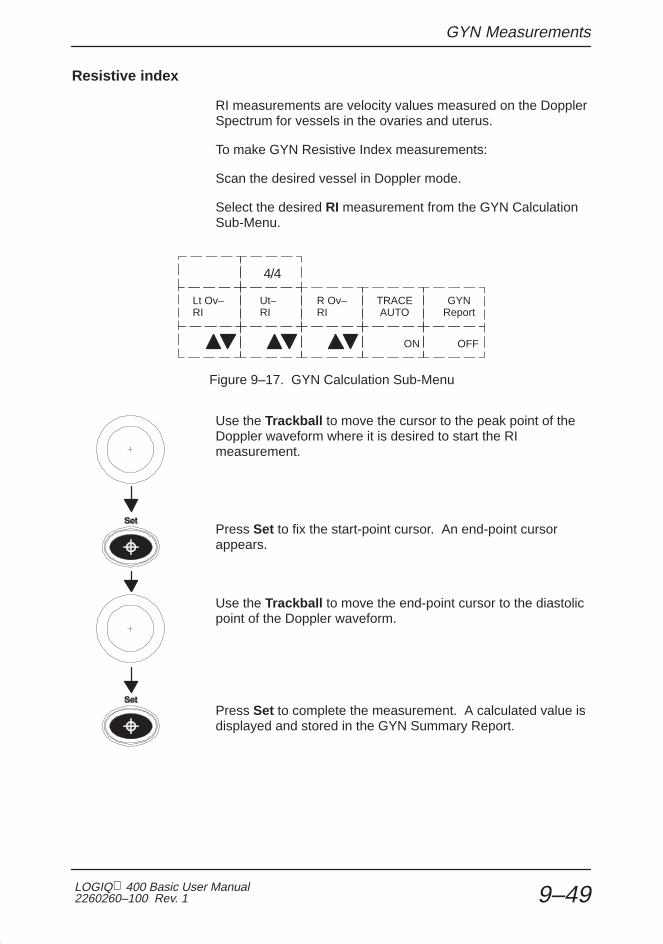
GYN Measurements
LOGIQ 400 Basic User Manual2260260–100 Rev. 1 9–49
Resistive index
RI measurements are velocity values measured on the DopplerSpectrum for vessels in the ovaries and uterus.
To make GYN Resistive Index measurements:
Scan the desired vessel in Doppler mode.
Select the desired RI measurement from the GYN CalculationSub-Menu.
Lt Ov–RI
Ut–RI
R Ov–RI
GYNReport
TRACEAUTO
OFFON
4/4
Figure 9–17. GYN Calculation Sub-Menu
Use the Trackball to move the cursor to the peak point of theDoppler waveform where it is desired to start the RImeasurement.
Press Set to fix the start-point cursor. An end-point cursorappears.
Use the Trackball to move the end-point cursor to the diastolicpoint of the Doppler waveform.
Press Set to complete the measurement. A calculated value isdisplayed and stored in the GYN Summary Report.

GYN Summary Report
LOGIQ 400 Basic Users Manual2260260–100 Rev. 1 9–50
GYN Summary Report
GYN Report Pages
GYN Report Layout
Figure 9–18. GYN Report Page
The top portion of the report contains patient informationentered into the Patient Entry Menu.
The middle portion of the report (measurements) shows thelast 3 measurement values made. <AVG> or <LAST> indicatesthat the Average or Latest value will be displayed in thiscolumn. This depends on the preset, Average Activity, in theSetup/Preset Program menu page 3.
The calculation section shows Doppler measurements and theiraverage, while the comments area provides 2 lines of commentdata.

GYN Summary Report
LOGIQ 400 Basic User Manual2260260–100 Rev. 1 9–51
Ovary Follicles Report Layout
Figure 9–19. Follicles Report Page
The top portion of the report contains patient informationentered into the Patient Entry Menu.
The middle portion of the report (measurements) shows the 3fields in which measured distances are reported. Meanindicates the average of the one, two, or three distancemeasurements. Volume is calculated from one, two or threedistances.
The Follicular Observation area (volume changes, borderappearance and contents) provides an area to input theappropriate descriptions.
Endometrium thickness is displayed when the Endomeasurement is performed. The comments area provides 2lines of comment data.

GYN Summary Report
LOGIQ 400 Basic Users Manual2260260–100 Rev. 1 9–52
Calculation Formulas
GYN Calculation Formulas
CalcMnemonic Calc Name
InputMeasurements Formula
UT-L Uterine Length one distance Ut-L[cm or mm]=d1
UT-H Uterine Height one distance Ut-H[cm or mm]=d1
UT-W Uterine Width one distance Ut-W[cm or mm]=d1
Endo Endometrium Thick-ness
one distance Endo[cm or mm]=d1
Lt. Ov-L Left Ovarian Length one distance Lt. Ov-L[cm or mm]=d1
Lt. Ov-H Left Ovarian Height one distance Lt. Ov-H[cm or mm]=d1
Lt. Ov-W Left Ovarian Width one distance Lt. Ov-W[cm or mm]=d1
Rt. Ov-L Right Ovarian Length one distance Rt. Ov-L[cm or mm]=d1
Rt. Ov-H Right Ovarian Height one distance Rt. Ov-H[cm or mm]=d1
Rt. Ov-W Right Ovarian Width one distance Rt. Ov-W[cm or mm]=d1
Lt. Ov-RI Left Ovarian VesselResistive Index
two Doppler blood flowpeak velocities
Lt. Ov-RI= (Vmax–Vdiastole)/Vmax*NOTE*
Ut-RI Uterine Vessel Resis-tive Index
two Doppler blood flowpeak velocities
Ut-RI= (Vmax–Vdiastole)/Vmax*NOTE*
Rt. Ov-RI Right Ovarian VesselResistive Index
two Doppler blood flowpeak velocities
Rt. Ov-RI= (Vmax–Vdiastole)/Vmax*NOTE*
LtOvFo[ml] Left Ovary Follicles One distance* D1[cm]3 x �/6
Two distances* D1[cm]2 x D2x[cm] �/6 : (D1 <D2)
D1[cm] x D2[cm]2 x �/6 : (D2 <D1)
Three distances D1[cm] x D2[cm]x D3[cm] x �/6
RtOvFo[ml] Rith Ovary Follicles One distance* D1[cm]3 x �/6
Two distances* D1[cm]2 x D2[cm] x �/6 : (D1 <D2)
D1[cm] x D2[cm]2 x �/6 : (D2 <D1)
Three distances D1[cm] x D2[cm] x D3[cm] x �/6
*NOTE*: Vdiastole = Vmin or Vend–diastole
* To calculate LtOvFo or RtOvFo with one (or two distances), press the Clear keyafter the first (or second distance) measurement(s).
Table 9–8. GYN Calculation Formulas

Cardiology
LOGIQ 400 Basic User Manual2260260–100 Rev. 1 10–1
Cardiology(software option)
Introduction 10–3. . . . . . . . . . . . . . . . . . . . . . . . . . . . . . . . . . . . . . . . . . . . . . . . . . . . . . . . . . . . Overview 10–3. . . . . . . . . . . . . . . . . . . . . . . . . . . . . . . . . . . . . . . . . . . . . . . . . . . . . . . . Report Pages 10–5. . . . . . . . . . . . . . . . . . . . . . . . . . . . . . . . . . . . . . . . . . . . . . . . . . . . . BSA Calculation Methods 10–6. . . . . . . . . . . . . . . . . . . . . . . . . . . . . . . . . . . . . . . . . . Measuring Heart Rate (HR) 10–6. . . . . . . . . . . . . . . . . . . . . . . . . . . . . . . . . . . . . . . .
LV Measurement Methods 10–7. . . . . . . . . . . . . . . . . . . . . . . . . . . . . . . . . . . . . . . . . . . . . . . Cubed Method 10–7. . . . . . . . . . . . . . . . . . . . . . . . . . . . . . . . . . . . . . . . . . . . . . . . . . . . Teichholz Method 10–9. . . . . . . . . . . . . . . . . . . . . . . . . . . . . . . . . . . . . . . . . . . . . . . . . Bullet Method 10–11. . . . . . . . . . . . . . . . . . . . . . . . . . . . . . . . . . . . . . . . . . . . . . . . . . . . Modified Simpson’s Rule Method 10–13. . . . . . . . . . . . . . . . . . . . . . . . . . . . . . . . . . . Single Plane Ellipsoid Method 10–15. . . . . . . . . . . . . . . . . . . . . . . . . . . . . . . . . . . . . Bi Plane Ellipsoid Methods 10–17. . . . . . . . . . . . . . . . . . . . . . . . . . . . . . . . . . . . . . . .
Additional Cardiology Calculations 10–19. . . . . . . . . . . . . . . . . . . . . . . . . . . . . . . . . . . . . . Volume 10–19. . . . . . . . . . . . . . . . . . . . . . . . . . . . . . . . . . . . . . . . . . . . . . . . . . . . . . . . . Angle 10–22. . . . . . . . . . . . . . . . . . . . . . . . . . . . . . . . . . . . . . . . . . . . . . . . . . . . . . . . . . . % Stenosis (stenosis ratio) 10–23. . . . . . . . . . . . . . . . . . . . . . . . . . . . . . . . . . . . . . . . PHT (Pressure Half Time) 10–24. . . . . . . . . . . . . . . . . . . . . . . . . . . . . . . . . . . . . . . . . MVA (Mitral Valve Area) 10–24. . . . . . . . . . . . . . . . . . . . . . . . . . . . . . . . . . . . . . . . . . . ET (Ejection Time) 10–25. . . . . . . . . . . . . . . . . . . . . . . . . . . . . . . . . . . . . . . . . . . . . . . Max PG 10–26. . . . . . . . . . . . . . . . . . . . . . . . . . . . . . . . . . . . . . . . . . . . . . . . . . . . . . . . . Mean PG 10–27. . . . . . . . . . . . . . . . . . . . . . . . . . . . . . . . . . . . . . . . . . . . . . . . . . . . . . . Trace Auto 10–28. . . . . . . . . . . . . . . . . . . . . . . . . . . . . . . . . . . . . . . . . . . . . . . . . . . . . . S/D (D/S) Ratio, RI, A/B Ratio or PI 10–29. . . . . . . . . . . . . . . . . . . . . . . . . . . . . . . . . Heart Rate (HR) 10–30. . . . . . . . . . . . . . . . . . . . . . . . . . . . . . . . . . . . . . . . . . . . . . . . . Transf Calcs 10–30. . . . . . . . . . . . . . . . . . . . . . . . . . . . . . . . . . . . . . . . . . . . . . . . . . . . .

Cardiology
LOGIQ 400 Basic Users Manual2260260–100 Rev. 110–2
ECG Option 10–31. . . . . . . . . . . . . . . . . . . . . . . . . . . . . . . . . . . . . . . . . . . . . . . . . . . . . . . . . . . . Overview 10–31. . . . . . . . . . . . . . . . . . . . . . . . . . . . . . . . . . . . . . . . . . . . . . . . . . . . . . . Physio Sweep Speed 10–32. . . . . . . . . . . . . . . . . . . . . . . . . . . . . . . . . . . . . . . . . . . . . ECG Sub-Menu 10–32. . . . . . . . . . . . . . . . . . . . . . . . . . . . . . . . . . . . . . . . . . . . . . . . . . ECG Lead Placement 10–33. . . . . . . . . . . . . . . . . . . . . . . . . . . . . . . . . . . . . . . . . . . . ECG Sync Mark Display 10–33. . . . . . . . . . . . . . . . . . . . . . . . . . . . . . . . . . . . . . . . . . ECG Sub-Menu Page 1 10–34. . . . . . . . . . . . . . . . . . . . . . . . . . . . . . . . . . . . . . . . . . . ECG Gain Pages 2 and 3 10–36. . . . . . . . . . . . . . . . . . . . . . . . . . . . . . . . . . . . . . . . . ECG/Cine Gauge/Image Tracking 10–36. . . . . . . . . . . . . . . . . . . . . . . . . . . . . . . . . .
Advanced Cardiac Calculations (AMCAL option) 10–37. . . . . . . . . . . . . . . . . . . . . . . . . Overview 10–37. . . . . . . . . . . . . . . . . . . . . . . . . . . . . . . . . . . . . . . . . . . . . . . . . . . . . . .

Introduction
LOGIQ 400 Basic User Manual2260260–100 Rev. 1 10–3
Introduction
Overview
The basic cardiac measurement package offers a choice of LVMeasurement methods. Analysis of the left ventricle can beperformed by 6 different methods.
� Cubed method
� Teichholz method
� Bullet method
� Modified Simpson’s Rule method
� Single-plane method
� Biplane ellipsoid method
Each selection requires a series of related measurementsspecific to that method.
Selection of the LV measurement method is made from theinitial Cardiac Calculation Sub-Menu.
LVTEICH
LVSIMPSON
LVBP–ELP
LVReport
LVCUBED
LVBULLET
LVSP–ELP
1/4
Figure 10–1. Cardiac Calculation Sub-Menu

Introduction
LOGIQ 400 Basic Users Manual2260260–100 Rev. 110–4
Overview (cont’d)
Once the LV measurement method is chosen, a Sub-Menu withthe available measurement selections appears.
In general, measurement techniques are the same as thosedescribed in the General Measurements and Calculationschapter. After selecting a measurement, be sure to follow theprompts on the image screen.
Measurements are organized in sequence to streamline systemusage and give easy access to calculated values on the reportpage. Some dependent calculations require severalmeasurements to be taken before the result can be calculated.
NOTE: If the Doppler option is not installed with theLOGIQ 400 Black/White systems, the Doppler Modemeasurements cannot be performed.
�

Introduction
LOGIQ 400 Basic User Manual2260260–100 Rev. 1 10–5
Report Pages
<AVG> or <LAST> indicates that the Average or Latest valuewill be displayed in this column. This depends on the preset,Average Activity, in the Set Up/Preset Program menu page 3.
The 3 report page measurements can be averaged and theaverage used in other calculations.
After displaying an LV Summary Report, the calculation methodcan be changed by moving the highlighted cursor to “ChangeMethod” and pressing Set.
The current report will be cleared and a method selection menuappears. Use the Trackball to select a new LV method andpress Set.
After pressing Set the new LV method report is displayed.
Figure 10–2. Report Page Change Method
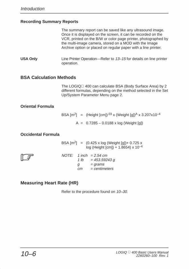
Introduction
LOGIQ 400 Basic Users Manual2260260–100 Rev. 110–6
Recording Summary Reports
The summary report can be saved like any ultrasound image.Once it is displayed on the screen, it can be recorded on theVCR, printed on the B/W or color page printer, photographed bythe multi-image camera, stored on a MOD with the ImageArchive option or placed on regular paper with a line printer.
USA Only Line Printer Operation—Refer to 13–15 for details on line printeroperation.
BSA Calculation Methods
The LOGIQ 400 can calculate BSA (Body Surface Area) by 2different formulas, depending on the method selected in the SetUp/System Parameter Menu page 2.
Oriental Formula
BSA [m2] = (Height [cm]).03 x (Weight [g])A x 3.207x10⁻⁴
A = 0.7285 – 0.0188 x log (Weight [g])
Occidental Formula
BSA [m2] = (0.425 x log (Weight [g])+ 0.725 x log (Height [cm]) + 1.8654) x 10–4
NOTE: 1 inch = 2.54 cm1 lb = 453.59243 gg = gramscm = centimeters
Measuring Heart Rate (HR)
Refer to the procedure found on 10–30.
�

LV Measurement Methods
LOGIQ 400 Basic User Manual2260260–100 Rev. 1 10–7
LV Measurement Methods
Cubed Method
LVIDs IVSs LVPWs ReturnLVIDd IVSd LVPWd HEARTRATE
1/1
Figure 10–3. Cardiac Calculation Sub-Menu—Cubed Method
Figure 10–4. Cubed Report Page Display

LV Measurement Methods
LOGIQ 400 Basic Users Manual2260260–100 Rev. 110–8
Cubed Method (cont’d)
B-Mode M-Mode
Figure 10–5. Cubed Method Measurements
Calc Mnemonic Calc Name Input Measurements Formula
LVIDd Left Ventricular InternalDiameter, Diastole
one distance LVIDd=d1[cm or mm]
LVIDs Left Ventricular InternalDiameter, Systole
one distance LVIDs=d1[cm or mm]
IVSd Interventricular SeptalThickness, Diastole
one distance IVSd=d1[cm or mm]
IVSs Interventricular SeptalThickness, Systole
one distance IVSs=d1[cm or mm]
LVPWd Left Ventricle PosteriorWall Thickness, Diastole
one distance LVPWd=d1[cm or mm]
LVPWs Left Ventricle PosteriorWall Thickness, Systole
one distance LVPWs=d1[cm or mm]
EdV End Diastole Volume one distance EdV[ml]=LVIDd^3
EsV End Systole Volume one distance EsV[ml]=LVIDs^3
SV Stroke Volume two distance SV[ml]=EdV–EsV
CO Cardiac Output two distances and one 2beat time interval
CO[1/min]=SVxHR/1000
EF Ejection Fraction two distances EF=SV/EdVx100
FS Fractional Shortening two distances FS=(1–LVIDs/LVIDd)x100
HR Heart Rate (beats/minute)
one 2 beat time interval HR[BPM]=/120 [sec]/2beat time [sec]
PHT Pressure Half Time one time interval PHT=t1[ms orsec]
MVA Mitral Valve Area one pressure half timeinterval
MVA[cm^2]= 220/PHT
ET Ejection Time one time interval ET=t1[ms or sec]
Table 10–1. Cubed Method Formulas

LV Measurement Methods
LOGIQ 400 Basic User Manual2260260–100 Rev. 1 10–9
Teichholz Method
LVIDs IVSs LVPWs ReturnLVIDd IVSd LVPWd HEARTRATE
1/1
Figure 10–6. Cardiac Calculation Sub-Menu—Teichholz Method
Figure 10–7. Teichholz Report Page Display
B-Mode M-Mode
Figure 10–8. Teichholz Methods Measurements

LV Measurement Methods
LOGIQ 400 Basic Users Manual2260260–100 Rev. 110–10
Teichholz Method (cont’d)
Calc Mnemonic Calc Name Input Measurements Formula
LVIDd Left Ventricular InternalDiameter, Diastole
one distance LVIDd=d1[cm or mm]
LVIDs Left Ventricular InternalDiameter, Systole
one distance LVIDs=d1[cm or mm]
IVSd Interventricular SeptalThickness, Diastole
one distance IVSd=d1[cm or mm]
IVSs Interventricular SeptalThickness, Systole
one distance IVSs=d1[cm or mm]
LVPWd Left Ventricle PosteriorWall Thickness, Diastole
one distance LVPWd=d1[cm or mm]
LVPWs Left Ventricle PosteriorWall Thickness, Systole
one distance LVPWs=d1[cm or mm]
EdV End Diastole Volume one distance EdV[ml]=LVIDd^3x7/(2.4+LVIDd)
EsV End Systole Volume one distance EsV[ml]=LVIDs^3x7/(2.4+LVIDs)
SV Stroke Volume two distances SV[ml]=EdV–EsV
CO Cardiac Output two distances and one 2beat time interval
CO[1/min]=SVxHR/1000
EF Ejection Fraction two distances EF=SV/EdVx100
FS Fractional Shortening two distances FS=(1–LVIDs/LVIDd)x100
HR Heart Rate (beats/minute)
one 2 beat time interval
HR=120[sec]/2 beat time[sec]
PHT Pressure Half Time one time interval PHT=t1[ms orsec]
MVA Mitral Valve Area one pressure half timeinterval
MVA[cm^2]= 220/PHT
ET Ejection Time one time interval ET=t1[ms or sec]
Table 10–2. Teichholz Method Formulas

LV Measurement Methods
LOGIQ 400 Basic User Manual2260260–100 Rev. 1 10–11
Bullet Method
LVLs LVAMs ReturnLVLd LVAMd HEARTRATE
1/1
Figure 10–9. Cardiac Calculation Sub-Menu—Bullet Method
Figure 10–10. Bullet Report Page Display
LVLdLVAMd
LVLsLVAMs
Figure 10–11. Bullet Method Measurements

LV Measurement Methods
LOGIQ 400 Basic Users Manual2260260–100 Rev. 110–12
Bullet Method (cont’d)
Calc Mnemonic Calc Name Input Measurements Formula
LVLd Left Ventricular Length,Diastole
one distance LVLd=d1[cm or mm]
LVLs Left Ventricular Length,Systole
one distance LVLs=d1[cm or mm]
LVAMd Left Ventricular Area, Mitral Valve, Diastole
one area (by ellipse,trace or circle)
LVAMd=a1[cm ^2]
LVAMs Left Ventricular Area, Mitral Valve, Systole
one area (by ellipse,trace or circle)
LVAMs=a1[cm ^2]
EdV End Diastole Volume one distance and onearea (by ellipse, trace orcircle)
EdV[ml]=5xLVLdxLVAMd/6
EsV End Systole Volume one distance and onearea (by ellipse, trace orcircle)
EsV[ml]=5xLVLsxLVAMs/6
SV Stroke Volume two distances and twoareas (by ellipse, traceor circle)
SV[ml]=EdV–EsV
CO Cardiac Output two distances and twoareas (by ellipse, traceor circle) and one 2 beattime interval
CO[1/min]=SVxHR/1000
EF Ejection Fraction two distances and twoareas (by ellipse, traceor circle)
EF=SV/EdVx100
HR Heart Rate (beats/minute)
one 2 beat time interval HR[BPM]=120 [sec]/ 2beat time [sec]
PHT Pressure Half Time one time interval PHT=t1[ms orsec]
MVA Mitral Valve Area one pressure half timeinterval
MVA[cm^2]= 220/PHT
ET Ejection Time one time interval ET=t1[ms or sec]
Table 10–3. Bullet Method Formulas

LV Measurement Methods
LOGIQ 400 Basic User Manual2260260–100 Rev. 1 10–13
Modified Simpson’s Rule Method
LVAPsLVAPd
1/1
LVLs LVAMs ReturnLVLd LVAMd HEARTRATE
Figure 10–12. Cardiac Calculation Sub-Menu—Modified Simpson’s Rule Method
Figure 10–13. Modified Simpson’s Rule Report Page Display
LVLdLVAMd
LVLsLVAPsLVAPdLVAMs
Figure 10–14. Modified Simpson’s Rule Method Measurements

LV Measurement Methods
LOGIQ 400 Basic Users Manual2260260–100 Rev. 110–14
Modified Simpson’s Rule Method (cont’d)
Calc Mnemonic Calc Name Input Measurements Formula
LVLd Left Ventricular Length,Diastole
one distance LVLd=d1[cm or mm]
LVLs Left Ventricular Length,Systole
one distance LVLs=d1[cm or mm]
LVAMd Left Ventricular Area, Mitral Valve, Diastole
one area (by ellipse,trace or circle)
LVAMd=a1[cm ^2]
LVAMs Left Ventricular Area, Mitral Valve, Systole
one area (by ellipse,trace or circle)
LVAMs=a1[cm ^2]
LVAPd Left Ventricular Area,Papillary Muscles, Diastole
one area (by ellipse,trace or circle)
LVAPd=a1[cm ^2]
LVAPs Left Ventricular Area,Papillary Muscles, Systole
one area (by ellipse,trace or circle)
LVAPs=a1[cm ^2]
EdV End Diastole Volume one distance and twoareas (by ellipse, traceor circle)
EdV[ml]=LVLd/3x(LVAMd+(LVAMd+LVAPd)/2+ LVAPd/3)
EsV End Systole Volume one distance and twoareas (by ellipse, traceor circle)
EsV[ml]=LVLs/3x(LVAMs+(LVAMs+LVAPs)/2+ LVAPs/3)
SV Stroke Volume two distances and fourareas (by ellipse, traceor circle)
SV[ml]=EdV–EsV
CO Cardiac Output two distances and fourareas (by ellipse, traceor circle) and one 2 beattime interval
CO[1/min]=SVxHR/1000
EF Ejection Fraction two distances and fourareas (by ellipse or traceor circle)
EF=SV/EdVx100
HR Heart Rate (beats/minute)
one 2 beat time interval HR=120[sec]/2 beat time[sec]
PHT Pressure Half Time one time interval PHT=t1[ms orsec]
MVA Mitral Valve Area one pressure half timeinterval
MVA[cm^2]= 220/PHT
ET Ejection Time one time interval ET=t1[ms or sec]
Table 10–4. Modified Simpson’s Rule Method Formulas

LV Measurement Methods
LOGIQ 400 Basic User Manual2260260–100 Rev. 1 10–15
Single Plane Ellipsoid Method
LVLs LVAs ReturnLVLd LVAd HEARTRATE
1/1
Figure 10–15. Cardiac Calculation Sub-Menu—Single Plane Ellipsoid Method
Figure 10–16. Single Plane Ellipsoid Report Page Display
LVAd LVAsLVLd LVLs
Figure 10–17. Single Plane Ellipsoid Method Measurements

LV Measurement Methods
LOGIQ 400 Basic Users Manual2260260–100 Rev. 110–16
Single Plane Ellipsoid Method (cont’d)
Calc Mnemonic Calc Name Input Measurements Formula
LVLd Left Ventricular Length,Diastole
one distance LVLd=d1[cm or mm]
LVLs Left Ventricular Length,Systole
one distance LVLs=d1[cm or mm]
LVAd Left Ventricular Area,Diastole
one area (by ellipse,trace or circle)
LVAd=a1[cm ^2]
LVAs Left Ventricular Area,Systole
one area (by ellipse,trace or circle)
LVAs=a1[cm ^2]
EdV End Diastole Volume one distance and twoareas (by ellipse, traceor circle)
EdV[ml]=8/(3 �)x(LVAd)^2/LVLd
EsV End Systole Volume one distance and twoareas (by ellipse, traceor circle)
EsV[ml]=8/(3 �)x(LVAs)^2/LVLs
SV Stroke Volume two distances and fourareas (by ellipse, traceor circle)
SV[ml]=EdV–EsV
CO Cardiac Output two distances and fourareas (by ellipse, traceor circle) and one 2 beattime interval
CO[1/min]=SVxHR/1000
EF Ejection Fraction two distances and fourareas (by ellipse, traceor circle)
EF=SV/EdVx100
HR Heart Rate (beats/minute)
one 2 beat time interval HR[BPM]=120 [sec]/ 2beat time [sec]
PHT Pressure Half Time one time interval PHT=t1[ms orsec]
MVA Mitral Valve Area one pressure half timeinterval
MVA[cm^2]= 220/PHT
ET Ejection Time one time interval ET=t1[ms or sec]
Table 10–5. Single Plane Ellipsoid Method Formulas

LV Measurement Methods
LOGIQ 400 Basic User Manual2260260–100 Rev. 1 10–17
Bi Plane Ellipsoid Methods
LVMLs LVAMs ReturnLVMLd LVAMd HEARTRATE
LVAsLVAd
1/1
Figure 10–18. Cardiac Calculation Sub-Menu—Bi Plane Ellipsoid Method
Figure 10–19. Bi Plane Ellipsoid Report Page Display
LVAd LVAsLVAMsLVAMdLVMLd LVMLs
Figure 10–20. Bi Plane Ellipsoid Methods Measurements
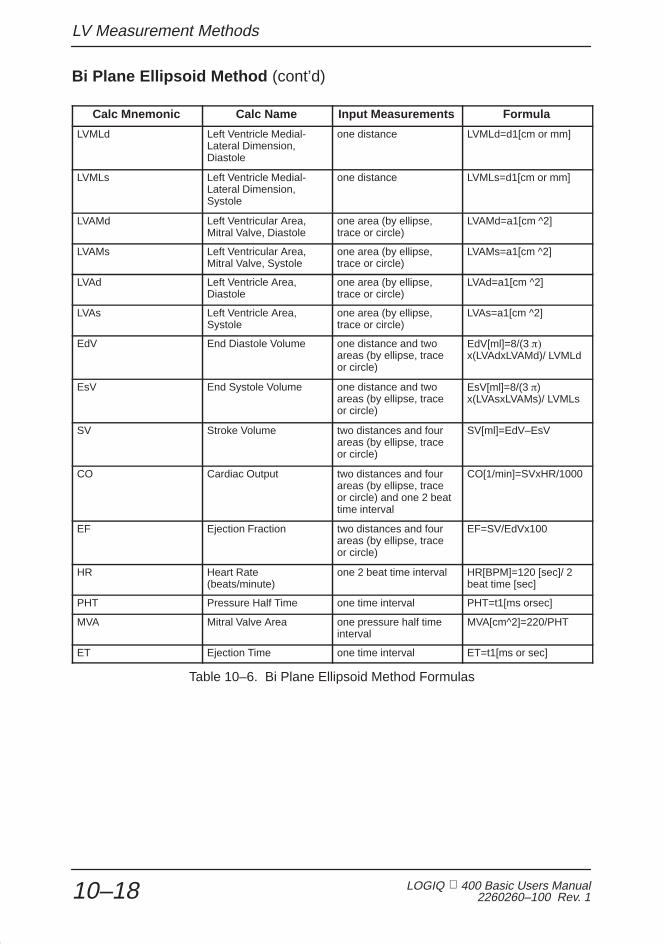
LV Measurement Methods
LOGIQ 400 Basic Users Manual2260260–100 Rev. 110–18
Bi Plane Ellipsoid Method (cont’d)
Calc Mnemonic Calc Name Input Measurements Formula
LVMLd Left Ventricle Medial-Lateral Dimension, Diastole
one distance LVMLd=d1[cm or mm]
LVMLs Left Ventricle Medial-Lateral Dimension, Systole
one distance LVMLs=d1[cm or mm]
LVAMd Left Ventricular Area, Mitral Valve, Diastole
one area (by ellipse,trace or circle)
LVAMd=a1[cm ^2]
LVAMs Left Ventricular Area, Mitral Valve, Systole
one area (by ellipse,trace or circle)
LVAMs=a1[cm ^2]
LVAd Left Ventricle Area,Diastole
one area (by ellipse,trace or circle)
LVAd=a1[cm ^2]
LVAs Left Ventricle Area, Systole
one area (by ellipse,trace or circle)
LVAs=a1[cm ^2]
EdV End Diastole Volume one distance and twoareas (by ellipse, traceor circle)
EdV[ml]=8/(3 ��x(LVAdxLVAMd)/ LVMLd
EsV End Systole Volume one distance and twoareas (by ellipse, traceor circle)
EsV[ml]=8/(3 �)x(LVAsxLVAMs)/ LVMLs
SV Stroke Volume two distances and fourareas (by ellipse, traceor circle)
SV[ml]=EdV–EsV
CO Cardiac Output two distances and fourareas (by ellipse, traceor circle) and one 2 beattime interval
CO[1/min]=SVxHR/1000
EF Ejection Fraction two distances and fourareas (by ellipse, traceor circle)
EF=SV/EdVx100
HR Heart Rate (beats/minute)
one 2 beat time interval HR[BPM]=120 [sec]/ 2beat time [sec]
PHT Pressure Half Time one time interval PHT=t1[ms orsec]
MVA Mitral Valve Area one pressure half timeinterval
MVA[cm^2]=220/PHT
ET Ejection Time one time interval ET=t1[ms or sec]
Table 10–6. Bi Plane Ellipsoid Method Formulas

Additional Cardiac Calculations
LOGIQ 400 Basic User Manual2260260–100 Rev. 1 10–19
Additional Cardiology Calculations
Volume
The volume calculation can be made from 1, 2 or 3 distances,from 1 distance and an ellipse, from a single ellipse or from 2ellipse measurements.
General Measurements and Calculations details how to makedistance and ellipse measurements.
IMPORTANT NOTE: When a volume calculation is desired, thenecessary measurements or combination of measurementsmust be made BEFORE selecting VOLUME in the Sub-menu.
ANGLE LVReport
VOLUME %Steno
2/4
Figure 10–21. Cardiac Calculation Sub-Menu
�

Additional Cardiac Calculations
LOGIQ 400 Basic Users Manual2260260–100 Rev. 110–20
Examples
When a volume calculation is desired, do one of the following:
� Make 1 distance measurement.
� Make 2 distance measurements.
� Make 1 ellipse measurement.
� Make 3 distance measurements.
NOTE: Three distances should be done in the dual formatmode (side by side images). One measurement is usuallymade in the sagittal plane and 2 measurements in the axialplane.
� Make 1 distance and 1 ellipse measurement.
� Make 2 ellipse measurements.
Formulas used are found in the table on 10–21.
� Volumes are most accurate when measurements are takenin the sagittal and axial scan planes.
� Use the side by side dual format option to display sagittaland axial plane images simultaneously.
� Make all necessary measurements before selectingvolume.
� See General Measurements and Calculations for details onthe steps to take when doing basic distance and areameasurements.
� An overflow error message (OOR) will occur during a 2ellipse, or 1 ellipse/1 distance volume calculation if: theminor (small) axis of the large ellipse is equal to/less thanthe major (large) axis of the small ellipse (d1), or equalto/less than the single distance measurement (d2).
d1 d2
Figure 10–22. Volume Calculation Error Possibilities
�
Hints

Additional Cardiac Calculations
LOGIQ 400 Basic User Manual2260260–100 Rev. 1 10–21
Volume Calculation Formulas
Calc Name Input Measurements Formula
Volume (spherical) one distance Vol[ml]=(�/6)xd^3
Volume (prolate spheroidal) two distances, d1>d2 Vol[ml]= (�/6)xd1xd2^2
Volume (prolate spheroidal) one ellipse, d1 major axis, d2 minoraxis
Vol[ml]= (�/6)xd1xd2^2
Volume (spheroidal) three distances Vol[ml]= (�/6)xd1xd2xd3
Volume (spheroidal) one distance d1, one ellipse, d2 ma-jor axis, d3 minor axis
Vol[ml]= (�/6)xd1xd2xd3
Volume (spheroidal) two ellipse, ellipse 1 with axes d1 andd2, ellipse 2 with axes d3 and d4,with |d2–d3| � |d1–d4| and d2>d3
Vol[ml]= (�/6)xd1xd2xd4(d3 is not used, assuming it is closeto d2)
Table 10–7. Volume Calculation Formulas
One distance
Two distances orone ellipse
Three distances or one distanceand one ellipse or two ellipses
Figure 10–23. Volume Calculation Examples

Additional Cardiac Calculations
LOGIQ 400 Basic Users Manual2260260–100 Rev. 110–22
Angle
This function is intended to measure the angle between 2intersecting planes:
ANGLE LVReport
VOLUME %Steno
2/4
Figure 10–24. Cardiac Calculations Sub-Menu
Select ANGLE from the Calculations Sub-Menu. A “�” cursorwith a vertical dashed line appears. The displayed angle iszero degrees.
Use the Trackball to position the line cursor and the ZoomSize/Rotation control to adjust the angle of the line cursor.
Press Set to fix the position of the first cursor.
Use the Trackball to position the second line cursor and theZoom Size/Rotation control to adjust the angle of the secondline cursor. The angle between the 2 cursors is constantlyupdated on the display.
(continued)

Additional Cardiac Calculations
LOGIQ 400 Basic User Manual2260260–100 Rev. 1 10–23
Angle (cont’d)
If a fine adjustment of the 2 cursors is needed, pressMeasurement to toggle which line cursor is active. Adjust theactive cursor with the Trackball and Zoom Size/Rotationcontrol.
Press Set to complete the angle measurement.
% Stenosis (stenosis ratio)
To calculate percent stenosis in a B-Mode image:
The area of the blood vessel can be measured by the ellipse,trace, circle, 2 distance or 1 distance methods. See GeneralMeasurements and Calculations for details on the steps to takewhen doing basic distance and area measurements. The SetUp/Preset Program page 3 defines the default method.
Select % Steno in the Calculations Sub-Menu.
ANGLE LVReport
VOLUME %Steno
2/4
Figure 10–25. Cardiac Calculations Sub-Menu
The first cursor is the residual area of the blood vessel and thesecond cursor is the lumen area of the blood vessel.
When using a distance measurement to calculate area for% stenosis, the measurement should always be taken from across sectional view of the vessel.
Do NOT take a distance measurement from a longitudinal viewfor an area calculation. This may lead to an inaccurateassessment of % stenosis.
CAUTION

Additional Cardiac Calculations
LOGIQ 400 Basic Users Manual2260260–100 Rev. 110–24
PHT (Pressure Half Time)
A PHT measurement is used to calculate Mitral Valve Area(MVA). The measurement is taken on the Doppler spectraldisplay of the mitral valve.
Figure 10–26. PHT Measurement on Mitral Valve Waveform
Select PHT from of the Calculation Sub-Menu. Perform a timeinterval measurement as described 7–18. Set the first cursoron the peak of the mitral valve waveform and the second on toa point halfway down the mitral valve waveform slope.
MVA Mean PG LVReport
PHT ET Max PG TRACEAUTO
3/4
Figure 10–27. Cardiac Calculation Sub-Menu
MVA (Mitral Valve Area)
A Mitral Valve Area is calculated from the pressure half timemeasurement. If PHT was selected, MVA is also calculated. IfMVA is selected, PHT must be measured in order to calculateMVA.

Additional Cardiac Calculations
LOGIQ 400 Basic User Manual2260260–100 Rev. 1 10–25
ET (Ejection Time)
Ejection time for the left ventricle is the time during which theaortic valve is open. It is measured on a Doppler Spectrumdisplay. The time between the two cursors is ejection time (ET).
Figure 10–28. Ejection Time for Aortic Valve
Select ET from of the Calculation Sub-Menu. Perform a timeinterval measurement as described on 7–18. Set the firstcursor at the opening of the aortic valve and the second at theclosing of the aortic valve.
MVA Mean PG LVReport
PHT ET Max PG TRACEAUTO
3/4
Figure 10–29. Cardiac Calculation Sub-Menu

Additional Cardiac Calculations
LOGIQ 400 Basic Users Manual2260260–100 Rev. 110–26
Max PG
To measure MAX PG (Maximum Pressure Gradient):
MVA Mean PG LVReport
PHT ET Max PG TRACEAUTO
3/4
Figure 10–30. Cardiac Calculations Sub-Menu
Select MAX PG from the Calculations Sub-Menu. Performpeak velocity measurements as described on 7–14. Set thefirst cursor on VMAX and the second on Vd.
Automatic Calculation of Max PG
If velocity was previously measured and calculated in DopplerMode, MAX PG is calculated from the VMAX and Vdmeasurements taken for velocity when MAX PG is first selectedin the Calculation Sub-Menu.

Additional Cardiac Calculations
LOGIQ 400 Basic User Manual2260260–100 Rev. 1 10–27
Mean PG
To measure Mean PG (Mean Pressure Gradient):
MVA Mean PG LVReport
PHT ET Max PG TRACEAUTO
3/4
Figure 10–31. Cardiac Calculation Sub-Menu
Select MEAN PG from the Calculation Sub-Menu. Perform themeasurement described on 7–15. Set the first cursor on thewaveform trace starting point.
If Trace Auto is selected, the waveform is automatically tracedafter the second cursor is fixed.
If Trace Auto is not selected, manually trace the desired portionof the waveform.
Press Set to complete the the Mean PG measurement.
Automatic Calculation of Mean PG
If velocity was previously measured and calculated in DopplerMode, Mean PG is calculated from the velocity value whenMean PG is first selected in the Calculation Sub-Menu.
The waveform is automatically traced. Velocity and Mean PGare also displayed on the screen.

Additional Cardiac Calculations
LOGIQ 400 Basic Users Manual2260260–100 Rev. 110–28
Trace Auto
To turn Doppler Auto Trace on or off:
MVA Mean PG LVReport
PHT ET Max PG TRACEAUTO
3/4
Figure 10–32. Cardiac Calculation Sub-Menu
Select TRACE AUTO from the Calculation Sub-Menu.
Use the Trace Auto Sub-Menu selection to turn on/off theDoppler Auto Trace function.
If Trace Auto is highlighted, the Doppler envelope willautomatically be traced as determined by parameters set inCustom Display page 13 and Preset Program page 7.
If Trace Auto is not highlighted, the Auto Trace function is offand traces can be performed manually.
Trace Method
The system will trace the peak value, floor and peak, mean andpeak or mode and peak, depending on the method selected bythe user.

Additional Cardiac Calculations
LOGIQ 400 Basic User Manual2260260–100 Rev. 1 10–29
S/D (D/S) Ratio, RI, A/B Ratio or PI
To measure the systolic/diastolic (diastolic/systolic) ratio,resistance index, velocity ratio and pulsatility index:
PIS/DRatio
A/BRatio
RI HEARTRATE
TRACEAUTO
4/4
Transf.CALCs
Transf CALCS is only available with Realtime Doppler Calculation option installed
Figure 10–33. Cardiac Calculation Sub-Menu
Select S/D (D/S) RATIO, RI, A/B RATIO or PI from theCalculations Sub-Menu. Perform peak velocity measurementsas described on 7–14.
The first cursor is the start point on the Doppler waveform. Thiswould be systole for S/D ratio (diastole for D/S ratio), peakvelocity for RI, “A” velocity for A/B ratio and VMAX for PI.
The second cursor is the end-point cursor to the end point ofthe Doppler waveform. This would be diastole for S/D ratio(systole for D/S ratio), minimum velocity for RI, “B” velocity forA/B ratio and Vd for PI.
NOTE: For the PI calculation, if Trace Auto is not selected,manually trace the waveform between VMAX and Vd.
If 2 velocity measurements are made prior to selecting S/D(D/S) ratio, A/B ratio or RI, the system automatically calculatesS/D (D/S) ratio, A/B ratio or RI from the last two velocitymeasurements recorded.
NOTE: For the PI calculation, if Trace Auto is on, the systemautomatically traces the waveform when Set is pressed to fixVd.
With S/D (D/S), PI and RI, if “Vd” is selected as the diastolevelocity in Preset Program page 4, the end point is defined asVd if Trace Auto is OFF.
�
�
Hints

Additional Cardiac Calculations
LOGIQ 400 Basic Users Manual2260260–100 Rev. 110–30
Heart Rate (HR)
To calculate the Heart Rate:
PIS/DRatio
A/BRatio
RI HEARTRATE
TRACEAUTO
4/4
Transf.CALCs
Transf CALCS is only available with Realtime Doppler Calculation option installed
Figure 10–34. Cardiac Calculations Sub-Menu
Select HEART RATE from the Calculations Sub-Menu.Measure the time between two heartbeats.
X X
Figure 10–35. Two Heart Beat Reference
NOTE: Set must be pressed to complete the measurement.Otherwise, the calculation does not transfer to the Report Page.
Transf Calcs
This selection is only available if the Realtime DopplerCalculation option is installed and Realtime DopplerCalculations are displayed in the upper left corner of the screen.See the Advanced Options chapter of the Advanced ReferenceManual for details on Realtime Doppler operation.
�

ECG Option
LOGIQ 400 Basic User Manual2260260–100 Rev. 1 10–31
ECG Option
Overview
A physiological input panel is available for the LOGIQ 400.This panel has inputs for ECG, physiological and auxiliarysignals.
The ECG Soft-Menu controls the signals connected to thePhysiological panel.
Approved accessory cables provide the proper signals to thePhysiological Panel.
ECG
!
PCG
Aux
Figure 10–36. Optional Physiological Input Panel
NOTE: The LOGIQ 400 can calculate heart rate in BPM fromthe ECG waveform. See Set Up/Custom Display page 17 toturn ECG Heart Rate Display on or off.
Do not use with defibrillator.
�
WARNING

ECG Option
LOGIQ 400 Basic Users Manual2260260–100 Rev. 110–32
Physio Sweep Speed
The sweep speed of the physio signal on the B-Mode imagecan be set independent of the timeline (M-Mode and Doppler)sweep speed.
This is accomplished using the preset parameter “PhysioSweep Speed on B”. It is found on Set Up/Custom Displaypage 3.
ECG Sub-Menu
The 3 pages of the ECG Sub-Menus provide for control of thephysiological input signals. In each case, select the propersub-menu page by pressing the Sub-Menu Select up/downarrow keys.

ECG Option
LOGIQ 400 Basic User Manual2260260–100 Rev. 1 10–33
ECG Lead Placement
The 3 patient ECG leads are color coded white, black andgreen.
White is connected to the patient’s right arm, black to the leftarm, and green (ground) to the right foot (often placed on theright side of the abdomen). The right arm connection maychange if the patient is in the decubitus position. Refer toFigure 10–37.
WHITE
Patient inProne Position
Patient inDecubitus Position
BLACK
GREEN
Figure 10–37. Common ECG Lead Placement
Once the leads are connected to the patient and theLOGIQ 400, the ECG waveform amplifier needs about10 seconds to stabilize the waveform on the CRT beforeadjustments are made.
ECG Sync Mark Display
A flashing heart can be displayed as a R-wave sync mark whena valid ECG trace is present. It can be turned on or off inSet Up/Custom Display page 17. This sync mark is added aftersystem memory. Therefore, it will not be able to be recalledduring cine review.

ECG Option
LOGIQ 400 Basic Users Manual2260260–100 Rev. 110–34
ECG Sub-Menu Page 1
1/3ECG
Sync.Selectn
DualSingle AuxWave
PCGWave
ECGWave
RDelay
Ref.Scan
Figure 10–38. ECG Sub-Menu Page 1
Single Dual
Description Updates the B-Mode image at the R1 time.Each time the R1 point is reached on theECG, PCG, or AUX Waveform, theB-Mode image changes. In between R1trigger points, the B-Mode image is frozen.The display shows the delay value as S1.
Updates the B-Mode image at the R1 andR2 times. Each time the R1 and R2 pointsare reached on the ECG, PCG, or Auxwaveform, the B-Mode image changes. Inbetween each trigger time, the B-Modeimage is frozen.
NOTE: R2 on the ECG will be marked witha vertical dotted line. The display showsthe delays as S1 and S2.
Benefits Allows for the acquisition of an image at aspecific point in the Cardiac Cycle.
Allows for the acquisition of an image attwo points in the Cardiac Cycle.
Values If Single is highlighted, the one-triggerfunction is on. If Single is not highlighted,the function is off.
NOTE: The Trackball can be used tochange the value of the active delay.
If Dual is highlighted, the two-triggerfunction is on. If Dual is not highlighted,the two-trigger function is off.
NOTE: The Trackball can be used tochange the value of the active delay.
Affects on Other Controls
If Dual was highlighted when single ispressed, the Dual function is turned offand the Single function turned on.
If Single is highlighted when Dual ispressed, the single function is turned offand the Dual function turned on.

ECG Option
LOGIQ 400 Basic User Manual2260260–100 Rev. 1 10–35
ECG Sub-Menu Page 1
Sync Selectn Ref Scan (Reference Scan)
Description In the Single trigger mode, Sync Selectionallows for the choice of triggering on R1 orR2.
In the Dual trigger mode, Sync Selectiontoggles trackball control of the S1 or S2delays displayed in the upper left corner ofthe monitor.
Reference Scan provides the ability todisplay both an active and trigger updatedimage simultaneously in the Dual B-Modedisplay format. Reference Scan functionsin the Single trigger Mode only. A real-timeimage can not be obtained in Dual TriggerMode.
In dual image mode, press Left to displaya trigger updated image on the left andactive image on the right. Press Right todisplay a trigger updated image on theright and active image on the left.
Benefits Provides trackball control of delay andselection of update trigger point.
Provides the ability to view the real-timeimage while simultaneously acquiringimages at a trigger point on the ECG, PCGor Aux waveform.
These images are best recorded on videotape.
Values R1 or R2 trigger select or variable delayadjustment.
The Reference Scan function is on whenthe Sub-Menu selection is highlighted.
The function is off when the Sub-Menuselection is not highlighted.
NOTE: The real-time image will onlyupdate at each trigger point. The image ispaused between the trigger points.
Affects on Other Controls
Changes trigger point in Single TriggerMode. Changes Trackball control ofdelays in Dual Mode.
R Delay ECG Wave, PCG Wave, Aux Wave
Description R Delay assigns Trackball Control to theadjustment of the trigger delays for R1(S1)or R2 (S2). The graphic display of thedelay is found in the upper left corner ofthe monitor.
These 3 menu selections provide theability to turn each waveform on for displayon the monitor.
Benefits Allows for the easy adjustment of the R1(S1) or R2 (S2) delays while scanning.
Allows for the choice to display awaveform.
Values When R Delay is highlighted, the Trackballcontrols the adjustment of the delays.
If R Delay is not highlighted, the delayscannot be adjusted with the Trackball.
NOTE: R Delay is automatically activatedwhen SINGLE or DUAL trigger modes areselected.
On or Off.

ECG Option
LOGIQ 400 Basic Users Manual2260260–100 Rev. 110–36
ECG Gain Pages 2 and 3
20
2/3ECG
PCGPositn
PCGGain
ECGPositn
ECGGain
20 20
3/3ECG
AuxPositn
AuxGain
Figure 10–39. ECG Sub-Menus Pages 2 and 3
ECG Gain, PCG Gain, Aux GainECG Positn, PCG Positn, AuxPositn (Position)
Description Allows for the amplitude control of theECG, PCG or Aux waveform.
Allows for the vertical positioning of theECG, PCG or Aux waveform on the imagedisplay.
Benefits Allows for amplitude adjustment tocompensate for different levels of ECG,PCG or Aux output.
Allows for positioning of the ECG, PCG orAux waveform to minimize impact on thescan image. Adjustable to userrequirements.
Values The PCG & AUX gain can be adjustedfrom –10 to +10 in 2-digit increments.EGC gain can be adjusted from –20 to+10 in 2-digit increments.
NOTE: ECG, PCG and Aux default gainsetting can be changed in the Set UpCustom Display menu page 17.
Changes display position of the waveform.
NOTE: ECG, PCG and Aux defaultposition can be changed in the Set UpCustom Display menu page 17.
ECG/Cine Gauge/Image Tracking
When an ECG waveform is displayed with the cine gauge, anarrow pointer will appear above the ECG waveform.
As the cine gauge marker is moved with the Cine Scroll control,the arrow above the ECG waveform will move to indicate whereon the ECG cycle the displayed image was taken.

Advanced Cardiac Calculations
LOGIQ 400 Basic User Manual2260260–100 Rev. 1 10–37
Advanced Cardiac Calculations(AMCAL option)
Overview
This option provides additional measurement, calculation andreport capabilities to the Left-Ventricular calculations not foundin the basic cardiac option package.
Added to the basic package is the Gibson, Single Plane–DISCand Bi-Plane–DISC methods of LV calculations. Additionalscan mode measurement categories are:
B-Mode Parasternal Long Axis (PLAX), ParasternalShort Axis (PSAX) Aortic Valve, PSAX MitralValve, PSAX Papillary Muscles, Apical 4chamber, Apical 2 chamber
M-Mode Left/Right Ventricles, Mitral Valve, Aortic Valve,Pulmonic Valve, Tricuspid Valve
D-Mode Mitral Valve, Aortic Valve, Pulmonic Valve,Tricuspid Valve
NOTE: If the Doppler option is not installed with theLOGIQ 400 Black/White systems, the Doppler Modemeasurements cannot be performed.
Refer to the Advanced Reference Manual for further details.
CL
�

Advanced Cardiac Calculations
LOGIQ 400 Basic Users Manual2260260–100 Rev. 110–38
This page left blank intentionally.

Vascular
LOGIQ 400 Basic User Manual2260260–100 Rev. 1 11–1
Vascular(software option)
Exam Preparation 11–2. . . . . . . . . . . . . . . . . . . . . . . . . . . . . . . . . . . . . . . . . . . . . . . . . . . . . . . . Introduction 11–2. . . . . . . . . . . . . . . . . . . . . . . . . . . . . . . . . . . . . . . . . . . . . . . . . . . . . . . General Guidelines 11–2. . . . . . . . . . . . . . . . . . . . . . . . . . . . . . . . . . . . . . . . . . . . . . . . .
Measurements 11–3. . . . . . . . . . . . . . . . . . . . . . . . . . . . . . . . . . . . . . . . . . . . . . . . . . . . . . . . . . . Carotid Artery Measurements 11–3. . . . . . . . . . . . . . . . . . . . . . . . . . . . . . . . . . . . . . . . Heart Rate (HR) 11–5. . . . . . . . . . . . . . . . . . . . . . . . . . . . . . . . . . . . . . . . . . . . . . . . . . . Trace Auto 11–5. . . . . . . . . . . . . . . . . . . . . . . . . . . . . . . . . . . . . . . . . . . . . . . . . . . . . . . . Helpful Hints 11–5. . . . . . . . . . . . . . . . . . . . . . . . . . . . . . . . . . . . . . . . . . . . . . . . . . . . . .
Vascular Summary Report 11–6. . . . . . . . . . . . . . . . . . . . . . . . . . . . . . . . . . . . . . . . . . . . . . . . Introduction 11–6. . . . . . . . . . . . . . . . . . . . . . . . . . . . . . . . . . . . . . . . . . . . . . . . . . . . . . . Displaying the Summary Report 11–6. . . . . . . . . . . . . . . . . . . . . . . . . . . . . . . . . . . . . . Editing the Summary Report 11–7. . . . . . . . . . . . . . . . . . . . . . . . . . . . . . . . . . . . . . . . . Recording Summary Reports 11–8. . . . . . . . . . . . . . . . . . . . . . . . . . . . . . . . . . . . . . . . Vascular Calculation Formulas 11–9. . . . . . . . . . . . . . . . . . . . . . . . . . . . . . . . . . . . . . .
Advanced Vascular (software option) 11–10. . . . . . . . . . . . . . . . . . . . . . . . . . . . . . . . . . . . Overview 11–10. . . . . . . . . . . . . . . . . . . . . . . . . . . . . . . . . . . . . . . . . . . . . . . . . . . . . . . Menu Selections 11–10. . . . . . . . . . . . . . . . . . . . . . . . . . . . . . . . . . . . . . . . . . . . . . . . .

Exam Preparation
LOGIQ 400 Basic Users Manual2260260–100 Rev. 1 11–2
Exam Preparation
Introduction
Measurements and calculations derived from ultrasoundimages are intended to supplement other clinical proceduresavailable to the attending physician. The accuracy ofmeasurements is not only determined by the system accuracy,but also by use of proper medical protocols by the user. Whenappropriate, be sure to note any protocols associated with aparticular measurement or calculation. Formulas anddatabases used within the system software that are associatedwith specific investigators are so noted. Be sure to refer to theoriginal article describing the investigator’s recommendedclinical procedures.
General Guidelines
Any measurement can be repeated by selecting thatmeasurement again from the Sub-Menu.
The system will retain as many as 8 measurements, but thesummary report retains only the last 3 measurements of eachtype.
The 3 report page measurements can be averaged and theaverage used in other calculations.

Measurements
LOGIQ 400 Basic User Manual2260260–100 Rev. 1 11–3
Measurements
Carotid Artery Measurements
Page 1 of the Vascular Sub-Menu contains measurements forthe patient’s right side. Page 2 of the Sub-Menu containsidentical left side measurements.
NOTE: If the Doppler option is not installed with theLOGIQ 400 Black/White systems, the Doppler Modemeasurements cannot be performed.
ECA, CCA, Bifurc and ICA
To measure the velocity of the blood through the right/leftexternal carotid artery, common carotid artery, carotid arterybifurcation or internal carotid artery in the Doppler spectrum:
RtCCA
RtECA
RtBIFURC
RtICA
RtICA/CCA
%Steno
VASCReport
LtCCA
LtECA
LtBIFURC
LtICA
%Steno
VASCReport
LtICA/CCA
1/3
2/3
Figure 11–1. Vascular Calculation Sub-Menu
Image the appropriate artery. Select the desired measurementfrom the Vascular Calculation Sub-Menu. The calculation modeis set and a “�” cursor with a vertical dotted line appears.
Move the cursor to the desired position on the Dopplerspectrum and press Set. The velocity measurement iscompleted and recorded on the Vascular Summary Report.
�

Measurements
LOGIQ 400 Basic Users Manual2260260–100 Rev. 1 11–4
RT (LT) ICA/CCA
To calculate a velocity ratio between the right (left) Internalcarotid artery and common carotid artery:
RtCCA
RtECA
RtBIFURC
RtICA
RtICA/CCA
%Steno
VASCReport
LtCCA
LtECA
LtBIFURC
LtICA
%Steno
VASCReport
LtICA/CCA
1/3
2/3
Figure 11–2. Vascular Calculation Sub-Menus
Image the left or right internal carotid artery first. Select RTICA/CCA from page 1 or LT ICA/CCA from page 2 of theVascular Calculation Sub-Menu.
Move the cursor to the peak point of the Internal carotid arteryDoppler spectrum and press Set.
Image the common carotid artery and press Freeze.
Press the Measurement key.
Move the cursor to the peak point (velocity) on the Dopplerspectrum of the common carotid artery and press Set. TheICA/CCA calculation is complete and a calculated value isdisplayed.
NOTE: If individual ICA and CCA measurements were alreadymade, the ICA/CCA will be automatically calculated fromprevious measurements.
�

Measurements
LOGIQ 400 Basic User Manual2260260–100 Rev. 1 11–5
Stenosis Ratio (% stenosis)
Refer to the procedure found on 10–23.
S/D (D/S) Ratio, RI, A/B Ratio or PI
Refer to the procedure found on 10–29.
S/DRatio
PI %Steno
HEARTRATE
RIA/BRatio
TRACEAUTO
VASCReport
3/3
Figure 11–3. Vascular Calculation Sub-Menu
Heart Rate (HR)
Refer to the procedure found on 10–30.
Trace Auto
Use the Trace Auto Sub-Menu selection to turn on/off theDoppler Auto Trace function. See 10–28 for more details.
Helpful Hints
If there is a series of measurements/calculations that areroutinely taken in a specific sequence, the auto sequencefeature of the system can be used to program thesemeasurements/calculations to automatically appear on thedisplay in the desired order. Refer to 14–79 for details onprogramming an auto sequence.
Hints

Vascular Summary Report
LOGIQ 400 Basic Users Manual2260260–100 Rev. 1 11–6
Vascular Summary Report
Introduction
The vascular summary report is structured to automaticallydisplay vascular measurements made at specific anatomicalsites. An average of the 3 measurements can also bedisplayed. Calculated ratios are automatically summarized anddisplayed.
Displaying the Summary Report
The summary report can be displayed at any time during theexam by selecting VASC REPORT from the VascularCalculation Sub-Menu.
Data entered as new patient data is automatically summarizedat the top of the summary report. Measurements aresummarized below the patient data. Calculations and ratiosappear at the bottom of the summary report.
To exit the summary report display and resume scanning, selectVASC REPORT from the Sub-Menu to deactivate it.

Vascular Summary Report
LOGIQ 400 Basic User Manual2260260–100 Rev. 1 11–7
Displaying the Summary Report (cont’d)
Figure 11–4. Vascular Report Page
<AVG> or <LAST> indicates that the Average or Latest valuewill be displayed in this column. This depends on the preset,Average Activity, in the Set Up/Preset Program menu page 3.
Editing the Summary Report
New patient data cannot be edited. Measurements can beedited by the operator.
To edit a measurement:
Select VASC REPORT from any page of the VascularCalculation Sub-Menu.
Use the Trackball or Return key to move the cursor to themeasurement that is to be edited. The measurement can bedeleted by pressing the BackSpace or Space bar and thenSet.
The average measurements, calculations and ratios areautomatically updated to reflect the edited values.
When editing is complete, select Exit to leave the summaryreport and resume imaging.

Vascular Summary Report
LOGIQ 400 Basic Users Manual2260260–100 Rev. 1 11–8
Recording Summary Reports
The summary report can be saved like any ultrasound image.Once it is displayed on the screen, it can be recorded on theVCR, printed on the B/W or color page printer, photographed bythe multi-image camera, stored on a MOD with the ImageArchive option or placed on regular paper with a line printer.
Line Printer Operation
USA Only Refer to 13–15 for details on line printer operation.

Vascular Summary Report
LOGIQ 400 Basic User Manual2260260–100 Rev. 1 11–9
Vascular Calculation Formulas
CalcMnemonic Calc Name Input Measurements Formula
RT ECA Right External Carotid Artery Velocity
one Doppler blood flowpeak velocity
RT ECA=v1[cm/s or m/s]
RT CCA Right Common Carotid ArteryVelocity
one Doppler blood flowpeak velocity
RT CCA=v1[cm/s or m/s]
RT BIFURC Right Carotid Bifurcation Velocity one Doppler blood flowpeak velocity
RT BIFURC=v1[cm/s or m/s]
RT ICA Right Internal Carotid Artery Velocity
one Doppler blood flowpeak velocity
RT ICA=v1[cm/s or m/s]
RT ICA/CCA Right Internal Carotid Artery Velocity/Common Carotid ArteryVelocity Ratio
two Doppler blood flowpeak velocities
RT ICA/CCA=VICA/VCCA
LT ECA, LT CCA, LT BIFURC, LT ICA, LT ICA/CCA
Same as above, for Left CarotidArtery
Same as above Same as above
A/B Ratio Velocities Ratio two Doppler blood flowpeak velocities
A/B=V1/V2
% Stenosis Stenosis Ratio two areas (by ellipse, trace, circle or distance)
% Stenosis=[1–(Aresidual/Alumen)]x100
S/D Ratio Systolic Velocity/DiastolicVelocities Ratio
two Doppler blood flowpeak velocities
S/D=Vsystole/Vdiastole*NOTE*
PI Pulsatility Index two Doppler blood flowpeak velocities and TAMAX
PI=(Vmax–Vdiastole)/TAMAX *NOTE*
RI Resistivity Index two Doppler blood flowpeak velocities
RI=(Vmax–Vdiastole)/Vmax *NOTE*
HR Heart Rate (beats/minute) one 2 beat time interval(measured manually or automatically)
HR[BPM]=120[sec]/2beat time[sec]
*NOTE*: Vdiastole = Vmin or Vend–diastole
Table 11–1. Vascular Calculation Formulas

Advanced Vascular
LOGIQ 400 Basic Users Manual2260260–100 Rev. 1 11–10
Advanced Vascular(software option)
Overview
The Advanced Vascular software option provides increasedmeasurement and reporting capabilities for vascular andvenous studies.
NOTE: If the Doppler option is not installed with theLOGIQ 400 Black/White systems, the Doppler Modemeasurements cannot be performed.
Menu Selections
The Advanced Vascular menu selections offer more flexibilitythan the Basic Software package.
In the Advanced Menus, the user can select
� left/right side on menu page 1.
� 3 Doppler sites on page 3.
� 3 stenosis sites on page 4.
Each Doppler and Stenosis site can be edited (5 charactersmaximum) on the Vascular Report pages.
The menus displayed will depend on the preset fordetermination of systole/diastole (auto/manual) in the Set Up/Preset Program page 3.
Refer to the Advanced Reference Manual for further details.
�

Urology
LOGIQ 400 Basic User Manual2260260–100 Rev. 1 12–1
Urology
Urology Basic Calculations 12–2. . . . . . . . . . . . . . . . . . . . . . . . . . . . . . . . . . . . . . . . . . . . . . Overview 12–2. . . . . . . . . . . . . . . . . . . . . . . . . . . . . . . . . . . . . . . . . . . . . . . . . . . . . . . . Presumed Circle Area Ratio (PCAR) 12–3. . . . . . . . . . . . . . . . . . . . . . . . . . . . . . . . . Stepper Volume (STVOL) 12–3. . . . . . . . . . . . . . . . . . . . . . . . . . . . . . . . . . . . . . . . . .
Urology Calculation (software option) 12–5. . . . . . . . . . . . . . . . . . . . . . . . . . . . . . . . . . . . Urology Summary Report 12–5. . . . . . . . . . . . . . . . . . . . . . . . . . . . . . . . . . . . . . . . . . Stepper Volume Calculation 12–8. . . . . . . . . . . . . . . . . . . . . . . . . . . . . . . . . . . . . . . .

Urology Basic Calculations
LOGIQ 400 Basic Users Manual2260260–100 Rev. 112–2
Urology Basic Calculations
Overview
The Urology Calculations factory default Sub-Menu consists of 3pages. The calculations available are the same as the generalmenu for Radiology/Abdomen and Small Parts. They are:
ANGLEVOLUME %STENO
1/3
UrologyReport
Urology Report is only available with Urology Calculation option installed
PIS/DRatio
A/BRatio
RI HEARTRATE
TRACEAUTO
2/3
Transf.CALCs
Transf CALCS is only available with Realtime Doppler Calculation option installed
Mean PGMax PG CO SV HEARTRATE
TRACEAUTO
FVOFV
3/3
Figure 12–1. Urology Calculation Menus
Refer to the chapters Abdomen and Small Parts (8) andCardiology (10) for steps to perform these measurements andcalculations.
NOTE: If the Doppler option is not installed with theLOGIQ 400 Black/White systems, the Doppler Modemeasurements cannot be performed.
�

Urology Basic Calculations
LOGIQ 400 Basic User Manual2260260–100 Rev. 1 12–3
Presumed Circle Area Ratio (PCAR)
Presumed Circle Area Ratio (PCAR) Measurement is availablewith the Urology Calculation Option.
This measurement must first be selected in the MeasurementVFD Softmenu Setup Submenu, which is accessed by selectingthe “Measurement Menu B” preset on Preset Program page 7.It will then be accessible from the B-Mode MeasurementSub-Menu.
PCAR
1/4
Figure 12–2. Urology Calculation Sub-Menu
Select PCAR from the Calcualtion Sub-Menu. The trace curosrappears in B-Mode.
Move the cursor to the measurement start point and press Set.Trace the measurement area and press Set to fix the PCARvalue displayed on the bottom of the screen and calculate thearea.
Stepper Volume (STVOL)
The ERB7 probe is designed to be used with the mechanicalstepping device option and needle placement guide. Theneedle placement guide matches the electronic needleplacement grid display on the monitor as the biopsy guidezoneis displayed.
This measurement must first be selected in the MeasurementVFD Softmenu Setup Submenu, which is accessed by selectingthe “Measurement Menu B” preset on Preset Program page 7.It will then be accessible from the B-Mode MeasurementSub-Menu.
Refer to the Advanced Options chapter of the AdvancedReference Manual for further details.

Urology Basic Calculations
LOGIQ 400 Basic Users Manual2260260–100 Rev. 112–4
This page left blank intentionally.

Urology Calculations (Option)
LOGIQ 400 Basic User Manual2260260–100 Rev. 1 12–5
Urology Calculation(software option)
Urology Summary Report
Urology Report Page
The Urology Report Page is is provided to improve productivityand facilitate consistency in Urology procedures. It is availableby selecting Urology Report from the measurement Sub-Menu.
Figure 12–3. Urology Report Page

Urology Calculations (Option)
LOGIQ 400 Basic Users Manual2260260–100 Rev. 1 12–6
Urology Report Page (cont’d)
The first, or top portion, is general patient data that was enteredon the patient entry menu at the beginning of the exam. Thisarea cannot be edited.
The second is the measurements area. There are 3 fields forvolume measurements. The first, second and third volumemeasurements taken are recorded as Volume #1, Volume #2and Volume #3, respectively. If the volume measurementswere performed by STVOL, “STVOL” is displayed.
The system stores the 3 most recent volume measurements. Ifa fourth measurement is made, Volume #1 is erased. Volume#2 becomes #1. Volume #3 becomes #2 and the fourthmeasurement is Volume #3. The very first measurement is lost.
Comments, pertinent for that specific volume measurement,may be added to the right of the volume measurement.
The third area is for Lesion Sites. A description can be input(maximum 20 characters each) for each lesion site. To indicatewhether the lesion site was biopsied, select “Y” for yes or “N”for no.
The fourth area is for calculations. The PAP (Prostatic AcidPhosphatese concentration) and PSA (Prostatic SpecificAntigen concentration) need to be input.
The PSAD is automatically calculated once the single digit fieldfollowing the words “BASED ON VOLUME” is entered (1, 2, or3). This represents which volume measurement (correspondingto the entire gland) should be used to compute PSAD. Thecalculation is dependent on the default selected in the “PSACalculation” preset found on Set Up/System Parameters page 3.
The DRE (Digital Rectal Exam) result are input below the PPSAcalculations. Any other exam which is desired to be reportedcan be input under DRE.
The fifth area is for comments and findings.

Urology Calculations (Option)
LOGIQ 400 Basic User Manual2260260–100 Rev. 1 12–7
PSA Measurement
The “PSA Calculation” preset, located on System Parameterspage 3, allows PSA to be calculated two ways. The twoselections are:
PSAD: Prostatic Specific Antigen (PSA) Density – defined as:
PSAD = PSA/Volume
PPSA: Predicted Prostate Specific Antigen – defined as:
PPSA = Volume � PPSA Coefficient
PPSA Coefficient is entered in the “PPSA Coefficient(1)” and “PPSA Coefficient (2)” presets, located onPreset Program page 4.
PSAD and PPSA are calculated on the Urology Report Page.

Urology Calculations (Option)
LOGIQ 400 Basic Users Manual2260260–100 Rev. 1 12–8
Stepper Volume Calculation
Overview
Using the ERB7 probe with the stepping device option, a newvolume measurement, named STVOL, is available with theUrology Calculation Option.
A stepper volume calculation (STVOL) is now available with theLOGIQ 400 when using the ERB7 probe with the steppingdevice option.
ERB7 Probe Preparation
The optional 7.0 MHz Transaxial (ERB7) Probe is amicro-convex and linear bi-plane probe for transaxial prostatescanning.
Figure 12–4. ERB7 Probe and cable
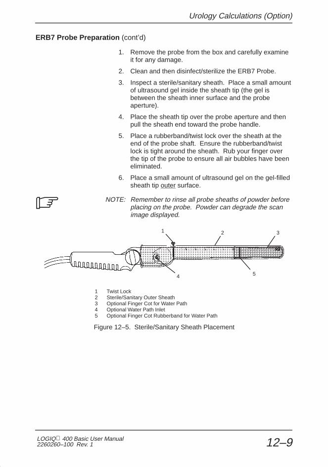
Urology Calculations (Option)
LOGIQ 400 Basic User Manual2260260–100 Rev. 1 12–9
ERB7 Probe Preparation (cont’d)
1. Remove the probe from the box and carefully examineit for any damage.
2. Clean and then disinfect/sterilize the ERB7 Probe.
3. Inspect a sterile/sanitary sheath. Place a small amountof ultrasound gel inside the sheath tip (the gel isbetween the sheath inner surface and the probeaperture).
4. Place the sheath tip over the probe aperture and thenpull the sheath end toward the probe handle.
5. Place a rubberband/twist lock over the sheath at theend of the probe shaft. Ensure the rubberband/twistlock is tight around the sheath. Rub your finger overthe tip of the probe to ensure all air bubbles have beeneliminated.
6. Place a small amount of ultrasound gel on the gel-filledsheath tip outer surface.
NOTE: Remember to rinse all probe sheaths of powder beforeplacing on the probe. Powder can degrade the scanimage displayed.
1
4
2
5
3
1 Twist Lock2 Sterile/Sanitary Outer Sheath3 Optional Finger Cot for Water Path4 Optional Water Path Inlet5 Optional Finger Cot Rubberband for Water Path
Figure 12–5. Sterile/Sanitary Sheath Placement
�

Urology Calculations (Option)
LOGIQ 400 Basic Users Manual2260260–100 Rev. 1 12–10
Performing STVOL Measurement
Stepper Volume (STVOL) is the method used to calculate thevolume of an organ using the LOGIQ 400 Urology software,Transaxial Probe and a mechanical stepping device that movesthe probe in fixed increments.
The stepper volume measurement works only in B-Mode withConvex Scan (NOT available Linear scan).
Stepper Volume Formula
Stepper Volume (STVOL) is the method used to calculate thevolume of an organ using the LOGIQ 400 Urology software,Transaxial Probe and a mechanical stepping device that movesthe probe in fixed increments.
The calculation is based on the fact that each step or areameasurement is taken at equal stepper increments. The areameasured at each slice is then used to compute the totalvolume of the organ, according to the following model:
For N slices, there are N–1 volumes between the slices plus asmall volume at each end.
It is assumed that the small volumes of the end caps are coneswith a base equal to the measured area of the end slice andheight equal to the slice spacing. The cones will have volumesV=A1 d/3 and AN d/3 for slices 1 and N respectively, where d isthe spacing between the slices.
The volumes between the slices are assumed to be segmentsof a paraboloid of revolution, where the volume between anyslice n and n+1 is (An+An+1)d/2.
The sum of the volumes between slices is:
V=d [ (A 1+A2/2)+(A2+A3/2)+....+(An–1+An/2)]
Therefore, the total volume of the organ is calculated as:
V=d [ (5/6)A 1+A2+A3+....+(5/6)AN]
Press Freeze to have an Image of the organ to be measured.The probe should be inserted to its most cephalic position (i.ebase of the prostate).
Press Measurement to fix the STVOL measurement.
CAUTION

Urology Calculations (Option)
LOGIQ 400 Basic User Manual2260260–100 Rev. 1 12–11
Mechanical Stepper/Needle Placement Guide Option
This mechanical stepping device is intended to be used with theLOGIQ 400 and the 7MHz Transaxial (ERB7) Probe.
The variable position mechanical stepping device is used tohold the 7MHz Transaxial (ERB7) Probe, lock the probe inplace and move the probe in small increments throughout anorgan in cross-sectional slice. Used with the LOGIQ 400Stepper Volume Calculation, a complete three–dimensionalvolume calculation can be made of an organ.
The needle placement guide template matches theLOGIQ 400 electronic needle placement grid for the 7MHzTransaxial (ERB7) Probe to aid in needle placement.
The universal table mounting system holds the stepper and iscompatible with most radiology and urologic tables.
Standard stepper increment is 5.0mm. Assembly for 2.5mmincrement movement is available. Therefore it is necessary tomatch the stepper movement to the ultrasound systemsoftware.
Refer to the Stepping Device Instructions for details.
CAUTION

Urology Calculations (Option)
LOGIQ 400 Basic Users Manual2260260–100 Rev. 1 12–12
This page left blank intentionally.

Recording Images
LOGIQ 400 Basic User Manual2260260–100 Rev. 1 13–1
Recording Images
Recording Images 13–2. . . . . . . . . . . . . . . . . . . . . . . . . . . . . . . . . . . . . . . . . . . . . . . . . . . . . . . Image Memory 13–2. . . . . . . . . . . . . . . . . . . . . . . . . . . . . . . . . . . . . . . . . . . . . . . . . . . Recall 13–4. . . . . . . . . . . . . . . . . . . . . . . . . . . . . . . . . . . . . . . . . . . . . . . . . . . . . . . . . . . Helpful hints 13–4. . . . . . . . . . . . . . . . . . . . . . . . . . . . . . . . . . . . . . . . . . . . . . . . . . . . . . Peripheral Devices 13–5. . . . . . . . . . . . . . . . . . . . . . . . . . . . . . . . . . . . . . . . . . . . . . . . Video Signal Specifications 13–16. . . . . . . . . . . . . . . . . . . . . . . . . . . . . . . . . . . . . . . . Maintenance 13–16. . . . . . . . . . . . . . . . . . . . . . . . . . . . . . . . . . . . . . . . . . . . . . . . . . . . Image Archive (option) 13–17. . . . . . . . . . . . . . . . . . . . . . . . . . . . . . . . . . . . . . . . . . . .
Advanced Recording Option (software option) 13–33. . . . . . . . . . . . . . . . . . . . . . . . . . . DICOM 13–33. . . . . . . . . . . . . . . . . . . . . . . . . . . . . . . . . . . . . . . . . . . . . . . . . . . . . . . . .

Recording Images
LOGIQ 400 Basic Users Manual2260260–100 Rev. 113–2
Recording Images
Image Memory
Storage
Without the optional Cine Memory extension, the followingnumber of images or proper combination of formats can besaved in memory:
� Single Format 8 images
� Dual Format 4 images
� Timeline Format 4 (NTSC) or 3 (PAL)
With the optional Cine Memory extension, the following numberof images or proper combinations of formats can be saved inmemory:
� Single Format 8 images
� Dual Format 8 images
� Timeline Format 4 (NTSC) or 3 (PAL)
The LOGIQ 400 has storage space for images in systemmemory.
This storage is temporary. The images are erased when theNew Patient key is pressed or power is turned off.

Recording Images
LOGIQ 400 Basic User Manual2260260–100 Rev. 1 13–3
Storage (cont’d)
To save images in system memory:
Press Freeze to stop image acquisition.
Use the Cine Scroll control, if necessary, to display the bestimage.
Press the Image Memory key. The displayed image is savedto system memory and the number of images currently stored isdisplayed at the bottom of the screen.
The system gives a Memory Full warning beep each time animage is about to be stored in a full memory.
Pressing Image Memory after the warning deletes the oldestimage in system memory and saves the current displayedimage.

Recording Images
LOGIQ 400 Basic Users Manual2260260–100 Rev. 113–4
Recall
To recall images stored in system memory for review orarchival:
� Press the Image Recall key. The soft-menu displays theImage Recall Sub-Menu with the display mode and time theimages were stored.
� The last image to be placed into Image Memory is displayed.
Use the appropriate Sub-Menu up/down arrow keys to selectthe desired image to recall.
After the recalled image is displayed, no image post processingcan be performed. Only Comment, Measurement, Body Pattern,Clear, Ext Video and Mic functions are available.
Press Freeze to continue scanning or press Image Recall toreturn to the previous system status before Image Recall wasinitially pressed.
Helpful hints
� Images stored in system memory will be lost if the NewPatient key is pressed or power is turned off.
� Images are stored in system memory on a “first in, first out”basis (maximum 8 images).
� Use the highest quality videotape possible and record in theslowest speed possible.
Hints

Recording Images
LOGIQ 400 Basic User Manual2260260–100 Rev. 1 13–5
Peripheral Devices
The LOGIQ 400 can save scan images to a variety of optionaldevices. Available archiving options are:
� Black/white video page printer
� Color video page printer
� Video cassette recorder (VCR or VTR)
� Line Printer – USA Only
� Laser camera
Device Manufacturer Model Video Signal
Black & White VideoPage Printer
SONY UP-890MD NTSCPage Printer
SONY UP-890CE PAL
SONY UP-890MDG NTSC/PAL
Color Video Page Printer SONY UP-1800 NTSC
SONY UP-2800 PAL
SONY UP-2850 PAL
SONY UP-2900 NTSC
SONY UP-2950 NTSC
VCR SONY SVO-9500MD NTSC
SONY SVO-9500MDP PAL
Table 8–2. Approved Optional Recording Devices
DO NOT connect any probes or accessories without approvalby GE.
All peripherals are considered options to the console. Thoselisted in this section have been tested and verified to becompatible with the LOGIQ 400 system. Please refer to thelocal Sales or Field Service representative for the latest list ofapproved peripherals.
When using any peripheral device or accessory, observe alldanger messages, warnings, and cautions given in peripheraloperator manuals.
CAUTION
WARNING

Recording Images
LOGIQ 400 Basic Users Manual2260260–100 Rev. 113–6
Black/White Video Page Printer
Operations Remote control of the B/W printer is limited to the print functiononly. Adjustments to print quality are done on the page printer.No status or error messages are available to be displayed onthe LOGIQ 400.
There is a six second delay built in to the Record keyrecognition. This eliminates improper operation if the Recordkey is pressed more than once in rapid succession.
To print an image:
Press Freeze to stop image acquisition.
NOTE: Remember that Cine Scroll may be used to look atprevious image frames to obtain the best image.
Press Record 1 to activate the print function on the standardB/W Video Page Printer.
NOTE: The Record 1 and Record 2 keys can be preset toactivate almost any peripheral device. This is done byassigning the key control to the output port to which theperipheral is attached in the Set Up/System Parameters menupage 5.
For details on the page printer operation, consult the SonyOperator Manual provided with the printer.
�
�

Recording Images
LOGIQ 400 Basic User Manual2260260–100 Rev. 1 13–7
Black/White Video Page Printer (cont’d)
Configurations The Sony UP-890 Black and White Video Page Printer ismounted on the left side of the LOGIQ 400 under thekeyboard. The Sony connections are Video, AC power, andRemote Shutter (Expose).
1
1 Black/White Page Printer
Figure 13–1. B/W Page Printer Location

Recording Images
LOGIQ 400 Basic Users Manual2260260–100 Rev. 113–8
Black/White Video Page Printer (cont’d)
Figure 13–2. B/W Printer Connections

Recording Images
LOGIQ 400 Basic User Manual2260260–100 Rev. 1 13–9
Color Video Page Printer
Operations The color video page printer allows for recording 1 or 4 imageson a single sheet of paper in color or Black/White.
When the LOGIQ 400 is powered on, the Preset/Set Upselections set the memory mode (1 or 4 images) and the inputsignal select (RGB, Video, S-Video) on the color printer. Allother functions need to be selected at the printer control panels.
The Record 1 or Record 2 keys can be programmed in thePreset/Set Up function to activate the print function on the Sonycolor page printer.
One image format: After the Record key is pressed, the imageis first stored in printer memory and then printed.
Four Image Format: The first, second and third time theRecord key is pressed, the image is stored in printer memory.The fourth time the Record key is pressed, the image is storedin printer memory and all four are printed on one sheet.
The color video page printer provides some feedback if there isan error in the print process. The following error messagescould be displayed due to color printer problems:
� Paper is jamming. Check paper.
� Check ribbon cassette setting.
� Check paper cassette setting.
� No paper. Set paper.
� Place paper print side up.
For details on the page printer operation, consult the SonyOperator Manual provided with the printer.

Recording Images
LOGIQ 400 Basic Users Manual2260260–100 Rev. 113–10
Color Video Page Printer (cont’d)
Configurations The Sony UP-1800 Color Video Page Printer connections areRed, Green, Blue, Sync, and RS-232 Remote Control.
OLD
Figure 13–3. Color Page Printer Connections with Old LOGIQ 400 Rear Panel

Recording Images
LOGIQ 400 Basic User Manual2260260–100 Rev. 1 13–11
Color Video Page Printer (cont’d)
NEW
Figure 13–4. Color Page Printer Connections with New LOGIQ 400 Rear Panel

Recording Images
LOGIQ 400 Basic Users Manual2260260–100 Rev. 113–12
Video Cassette Recorder (VCR)
Operations An optional video cassette recorder (VCR or VTR) is availablefor the LOGIQ 400. The optional VCR is S-VHS compatiblefor improved recording quality.
The LOGIQ 400 supports remote control of the SonySVO-9500MD/MDP S-VHS Video Cassette Recorder only.Other VCRs can record and playback video with theLOGIQ 400, however remote control, advanced searchfunctions and auto calibration will not be supported. Control ofapproved VCRs other than the Sony SVO-9500MD/MDP mustbe done by the VCR front panel.
NOTE: Measurements from VCR Playback video requires theoptional VCR measurement playback board for properoperation.
Explanation of VCR operations assumes that the SonySVO-9500 is being used. It also assumes that the “HeadingVCR Playback” option is installed.
The system can keep track of patient and tape information. Thesystem can search a tape for patient images. However, thesystem CANNOT:
� Stop or indicate when it comes to the end of the last studyon the tape.
� Prevent recording over previous studies if record is pressedwhile positioned in the middle of a study.
Without the Heading VCR Playback option:
� The hard drive does not store patient or tape id information.
� Auto calibration for playback measurements is notavailable.
� Image, Patient and Tape Search functions are not available.
The Record keys and foot switch can be programmed in thePreset/Set Up menu to activate the Record/Pause function forthe VCR.
CL
�
CAUTION

Recording Images
LOGIQ 400 Basic User Manual2260260–100 Rev. 1 13–13
Video Cassette Recorder (VCR) (cont’d)
Configurations The Sony SVO-9500MD connections are S-VHS Video In/Out,Audio In/Out, and RS-232 Remote Control.
OLD
Figure 13–5. VCR Connections with Old LOGIQ 400 Rear Panel

Recording Images
LOGIQ 400 Basic Users Manual2260260–100 Rev. 113–14
Video Cassette Recorder (VCR) (cont’d)
NEW
Figure 13–6. VCR Connections with New LOGIQ 400 Rear Panel
Recording Images
LOGIQ 400 Basic User Manual2260260–100 Rev. 1 13–15
Line Printer (USA ONLY)
Operations Display the desired report page:
� OB
� GYN
� OB Graph
� Cardiology
� Vascular
� Anatomical Survey
While the report page is displayed, press Ctrl + R to start theprinting process. This Ctrl + R function is not available unlessthe report page is displayed on the screen.
The message “Preparing for print now” is displayed. After twoseconds the message changes to “Newpt/Power Off will deleteprint data”. This message is displayed until the print operationis complete.
If more than one report page is to be printed, the desired reportpage must be displayed and Ctrl + R pressed.
If printing was not completed due to some sort of error, thefailed report must be displayed and Ctrl + R pressed again.
Ensure all reports have printed prior to deleting report data bypressing New Patient or power off.
Configurations The line printer will be connected to a serial port on the system.This can be accomplished at Port MIC, Port A or Port B on therear panel.
The appropriate parameter in Set Up/System Parameterspage 5 must be set to “Line Printer”.
Hints

Recording Images
LOGIQ 400 Basic Users Manual2260260–100 Rev. 113–16
Laser Camera
The LOGIQ 400 can print images to a Laser Camera forarchival.
Contact the local GE Service Representative for details abouthook-up and operation.
Video Signal Specifications
Table 8–3 gives the video specifications of the Ultrasoundsystem. This data may be needed when interfacing the systemwith OEM cameras or recording devices.
NTSC PAL
Total Lines per Frame [line] 525 625
Vertical Frame Frequency [Hz] 60 50
Horizontal Scanning Frequency [kHz] 31.469 31.250
Displayed Image Pixels [mm] 239.5 by 180 239.5 by 180
Total Horizontal Line Time [�s] 31.78 32.00
Horizontal Display [�s] 24.77 24.41
Front Porch Width [�s] 1.39 1.54
Sync Pulse Width [�s] 2.36 2.34
Back Porch Width [�s] 3.26 3.71
Total Horizontal Blanking [�s] 7.01 7.59
Vertical Blanking Interval [H] 31.50 38.50
Vertical Front Porch Width [H] 6.5 9.0
Vertical Sync Width [H] 3 2.5
Vertical Back Porch Width [H] 22 27
Pixel Clock [MHz] 24.5454 29.5000
H [�s] 31.78 32
Table 8–3. Video Signal Specifications
Maintenance
Consult the peripheral device operator manual for necessaryroutine maintenance.

Recording Images
LOGIQ 400 Basic User Manual2260260–100 Rev. 1 13–17
Image Archive (option)
Overview
Image Archive is an option to store and recall scan imagesusing a 3.5 inch Magneto Optical Disk (128 or 230 Megabytes)and/or a hard disk (HD). The Magneto Optical Disk (MOD)allows for much faster and greater storage capacity than aFloppy Disk Drive (FDD).
Along with the increased speed and storage capacity, the usercan perform measurements and calculations on imagesrecalled from a MOD/HD. Images recorded as hard copy (film)do not allow for additional measurements at a later date.Images recalled from a MOD/HD have much better resolutionthan VCR playback images, providing better detail for additionalmeasurements.
In addition to the image archive function, the MOD allows for aSystem Backup disk to be made in the unlikely event of a harddisk failure. System software updates and service diagnosticsmay also be accomplished much faster.
Archive Functions
The Image Archive option allows the user to perform thefollowing functions:
� Archive Image to MOD/HD
� Recall Image from MOD/HD
� Patient File search of MOD, HD or DICOM queue
� MOD Media file search
� Delete a file from MOD/HD
� Copy images to/from HD from/to MO
� Format the MOD disk
� Eject the MOD disk from the drive

Recording Images
LOGIQ 400 Basic Users Manual2260260–100 Rev. 113–18
Related Preset Parameters
Two selections must be made in the Set Up/Preset ProgramSub-Menu page 2 that affect image archiving.
Image Archive Compression:
� No is no DEFF format image compression.
� Yes is for DEFF format image compression. Storage timefor a compressed image is more than double.
NOTE: If image compression is used, images saved by theLOGIQ 400 cannot be read on other TIFF readers, DEFFdevices or the LOGIQ 700. However, they can be read onthe LOGIQ 500.
B/W Image Archive & Color Image Archive:
� B/W is for storing in black and white format (less storagespace required).
� Color is for storing in color format (more storage spacerequired).
NOTE: An External Video Image is recognized as a colorimage and will use the Color Image Archive preset.
System ID Entry/Display
The LOGIQ 400 system ID number is assigned at the factory.A System ID should be unique for a system. This number isused by the system when initializing a MOD (image archiveoption) for image storage.
If there is more than one system at a facility, the ID numbers willbe different. A scanner will write to a MOD if the media wasinitialized on a different scanner (different ID number).However, images can only be deleted on the system thatinitialized the MOD.
NOTE: If there is more than one LOGIQ 500 or LOGIQ 400in a facility or group of hospitals, each system should have it’sown unique System ID number, unless it is necessary to deleteMOD images on any system.
�
�
�

Recording Images
LOGIQ 400 Basic User Manual2260260–100 Rev. 1 13–19
Media Format (DEFF)
Display the Archive sub-menu.
Archive
MOArchive
MediaSearch
PatientSearch
HDStorage
DEFFFormat
1/1
MOEject
Figure 13–7. Archive Sub-Menu
Select DEFF Format . The following messages are displayedduring the disk initialization and formatting process:
“Do you continue ? (Y/N)”
Insert the disk and press ‘Y’ to continue or ‘N’ to quit. If ‘Y’ ispressed,
“Initializing now”
appears. The disk format function is in progress.
The MO (disk) ID and System ID will be written on the diskmedia. One system can register a maximum of 10,000 disks.
If the number of registered disks is greater than 10,000,previously registered disk information will be overwritten inorder to register the new disk information.
To avoid confusion, it is essential that care is taken not toattempt image storage to a previous (old) disk who’s MO ID andSystem ID is not available (IDs have been deleted from themedia file).
NOTE: The media list on the Media Search Menu containsboth previous (old) and current (new) disk information.�

Recording Images
LOGIQ 400 Basic Users Manual2260260–100 Rev. 113–20
Disk Verification
In order to protect images from being deleted by otherLOGIQ 400 systems, the disk is always verified by the systembefore it can be used.
If the MO disk is not inserted into the drive or an unformattedMO disk is inserted, the following message is displayed:
“MEDIA IS EITHER UNMOUNTED OR UNFORMATTED.”
When a disk is inserted into a drive, the system first reads theMO (disk ID) and System ID from the media. These two IDsare displayed at the bottom of the monitor while the systemverifies that they are registered in the verification list on thesystem hard drive.

Recording Images
LOGIQ 400 Basic User Manual2260260–100 Rev. 1 13–21
Archiving Images
Image Comments With the comment cursor in the home position, four characterscan be entered as a comment that is stored with the patientname, id and date of the scan. Refer to Figure 13–8 on 13–23for examples.
MO Archive An image can be archived to a MO drive. To archive the image,display the Archive sub-menu. Press the MO Archive up/downarrow keys.
Archive
MOArchive
MediaSearch
PatientSearch
HDStorage
DEFFFormat
1/1
MOEject
Figure 3–27. Archive Sub-Menu Page 1
The following message is displayed during the archive process:
“In Progress. Please wait. MO Free : xxxMB”where xxx is the space available on MOD for future archival.
System operation is interrupted for five seconds before scanoperation can continue. The image archival operation is thenperformed in the “background”.
NOTE: An alternative method to archive images to the MOdrive is by using the Record 1and/or Record 2 keys. TheRecord 1 B&W, Record 1 Color, Record 2 B&W and Record 2Color presets, located on Set Up/System Parameters page 5,allow these keys to be programmed to automatically archive theimage when pressed.
To save the Patient Entry Menu or a Report Page to MOD, thisalternative method must be used.
�

Recording Images
LOGIQ 400 Basic Users Manual2260260–100 Rev. 113–22
Archiving Images (cont’d)
Hard Disk Storage An image can be stored to a Hard Disk Drive. The capacity ofthe HDD storage is up to 600 images.
To store the image to the Hard Disk Drive, display the Archivesub-menu. Press the HD Storage up/down arrow keys.
Archive
MOArchive
MediaSearch
PatientSearch
HDStorage
DEFFFormat
1/1
MOEject
Figure 3–28. Archive Sub-Menu Page 1
The following message is displayed during the storage process:
“In progress. Please wait. HD Free : xxx”xxx is the number of images available for future archival.
System operation is interrupted for five seconds before scanoperation can continue. The image storage operation is thenperformed in the “background”.
NOTE: An alternative method to store images to the hard diskis by using the Record 1and/or Record 2 keys. The Record 1B&W, Record 1 Color, Record 2 B&W and Record 2 Colorpresets, located on Set Up/System Parameters page 5, allowthese keys to be programmed to automatically store the imagewhen pressed.
To save the Patient Entry Menu or a Report Page to MOD, thisalternative method must be used.
�

Recording Images
LOGIQ 400 Basic User Manual2260260–100 Rev. 1 13–23
Patient Search
Select Patient Search from the Archive Sub-Menu. The ImageArchive Patient Search Menu is displayed on the monitor asshown in Figure 13–8.
MO STATUS—Shows the type of disk in the drive as an image disk.MO FREE—Shows the amount of memory space available on the MOD in MegaBytes.HD FREE—Shows the number of images available to store on the Hard Drive.COMMENTS—Prior to storing an image, a four character comment can be entered ifthe comment cursor is in the home position. The comment is displayed to the right ofthe date column.
Figure 13–8. Patient Search Menu
From the Image Archive Patient Search Menu, the followingfunctions are available:
� Show the storage place (MO, HD or Queue)
� Show image(s) in the DICOM queue
� Copy image(s) to/from HD from/to MO
� Display the image(s) as Multi-Display format
� Show the type of an image
NOTE: DICOM related keys are not displayed if the DICOMStorage Option is not installed.�

Recording Images
LOGIQ 400 Basic Users Manual2260260–100 Rev. 113–24
Patient Search (cont’d)
Image Types The table below summarizes the functions on the ImageArchive Patient Search Menu as applied to different imagetypes.
Image Type
ImageSearch(list up)
ImageTag/
UntagImage Recall
ImageLock/
UnlockImageDelete
ImageCopy
DICOMSend
on MO � � � � � � �
on HD � � � � � � �
in Queue � � � NA NA � �
LZW compressed � � � � � � NA
NA: Not Available
Table 15–1. Search Menu Functions on Different Image Types
Search Criteria A specific MOD can be searched for patient files that meetcertain criteria. The hard disk data base and backup MODs canalso be searched for a list of MODs and files that meet thecriteria listed below.
Patient Name Maximum 29 charactersPatient ID Maximum 14 charactersDate Format specified in System
Parameters page 1.
A search list can be displayed from a combination of files on thehard disk, MO disk or DICOM queue. To select the search type,move the cursor over MO, HD and/or QUE in the “From MO HDQUE” portion of the Image Archive Patient Search Menu. Pressthe Set key. An asterisk mark (*) indicates the selection. Forexample, when only MO is selected, the screen displaychanges from “From MO HD QUE” to “From *MO HD QUE”.The search list will show MO archived images.

Recording Images
LOGIQ 400 Basic User Manual2260260–100 Rev. 1 13–25
Search Criteria File discriminators
There are discriminators displayed in front of the file name thatindicate whether they are archived. The following filediscriminators are:
SYMBOL DESCRIPTION
None Indicates a file on Hard Disk.+ Indicates a file on MO Disk./ Indicates a file on Hard Disk as DICOM queue.
Criteria Input Region Both the Patient Search Menu and Media Search Menu have acriteria input region as shown in Figure 13–9.
Figure 13–9. Criteria Input Region
Type the desired name in the highlighted region. Press Returnor Trackball to the PT ID region.
Input the Patient ID. Press Return or Trackball to the Dateregion.
Input the desired date. Press Return or Trackball to move thecursor out of the criteria input region. The search functionstarts immediately.
Spaces can be used as a wild card in the date entry. Forexample:
MM/ / lists everything for a specific month.
/ /YY lists all in a specific year.
MM/ /YY lists all within a specific month of aspecific year.
If nothing is entered in one or more of the search criteria, a listof files is displayed that match the remaining criteria entered.
Hints

Recording Images
LOGIQ 400 Basic Users Manual2260260–100 Rev. 113–26
Patient Search (cont’d)
Searching the MOD The search function is initiated when the Trackball is used tomove the highlighted cursor out of the criteria area or theReturn key is pressed while in the Date entry area.
The first 15 files are displayed on the monitor. If the search isnot complete, the message:
“In Progress, Please wait”
appears at the bottom of the monitor. This message remainsuntil the search process is totally complete.
NOTE: Images which are not stored on the GE LOGIQ series systems will not be listed by the patient search functionor displayed on a LOGIQ series machine.
In order to perform any other function, the user must wait untilthe search is complete or press Ctrl , C simultaneously tocancel the search function.
If no search criteria was entered by the user, a complete filelisting of the entire MOD is executed. Only 15 files aredisplayed at one time on the monitor.
Use the Ellipse up/down arrow keys to scroll to the next orprevious patient list page.
Copy an image To copy an image from the HD (MO) to MO (HD):
1. Select the image to copy by pressing the Set key.Multiple images can be selected.
2. Move the cursor to the Image Copy column.
3. Press the Set key. The image is copied to the MO (HD)from HD (MO).
4. Move the cursor to List All and press the Set key toreflect the copied image in the Image Archive PatientSearch Menu.
The following message is displayed if the capacity of the HD orMO is not enough for an image to be copied.
Too much data. Copy Failed.
�
Hints

Recording Images
LOGIQ 400 Basic User Manual2260260–100 Rev. 1 13–27
Patient Search (cont’d)
Display the image as Multi-Display format
Multi-Display format provides a way to view all images on thePatient Search Menu at one time. From the Image ArchivePatient Search Menu, the store image can be displayed inmultiple images as 2x2, 3x3 or 4x4.
To display the image as Multi-Display format:
1. Move the cursor to the right of Multi-Disp column.
2. Select the format (2x2, 3x3, or 4x4) by pressing theEllipse up/down arrow keys.
3. Move the cursor to the Multi–Disp column.
4. Press the Set key.
To select and display the image in the Multi-Display format:
1. Move the cursor to the desired image. The imageinformation (Patient Name, Patient ID, file name, etc) isdisplayed at the bottom of the monitor.
2. Press the Set key to select the image. If needed,multiple images can be selected.
3. Press the Ellipse up/down arrow keys to display theselected images.
4. If multiple images are selected, the next image will bedisplayed by pressing the Ellipse up/down arrow keys.
5. Press the Freeze key to return to the Multi-Displayformat screen.
6. Press the Freeze key again to return to the ImageArchive Patient Search Menu.
Type of an image A symbol appears in front of the date to indicate whether theimage is color or gray scale. The symbols are as follows:
SYMBOL DESCRIPTION
G Gray scale image.C Color image.g LZW compressed gray scale image.c LZW compressed color image.

Recording Images
LOGIQ 400 Basic Users Manual2260260–100 Rev. 113–28
Patient Search (cont’d)
Menu Commands The commands listed at the bottom of the Patient Search Menucan be used to manipulate the file information displayed.
Search Changes the current mode to the searchcriteria input mode.
Tag All Selects all images on the displayed page.
Recall Recalls an image from the MOD for display onthe monitor.
Lock Locks an image file.A locked file has an asterisk (*) after it’s filenumber and cannot be deleted while locked.
Unlock Unlocks an image file.
Multi-Disp Displays the images as multi-display format.
List All Displays all images on the MOD in the PatientSearch Menu.
Image Copy Copies an image to/from HD from/to MO.
Exit Exits the Patient Search Menu.
Delete Erases an unlocked image file from the list.A file must be unlocked before being erased.The image is not deleted from the affected MO.
NOTE: An image file will still be listed in the Media SearchMenu even though the file has been deleted from the PatientSearch Menu.
Ellipse Scrolls between the available pages to bedisplayed.
CTRL+C Cancels the search process.
�

Recording Images
LOGIQ 400 Basic User Manual2260260–100 Rev. 1 13–29
Image Selection for Recall
To select an image for recall from the Patient Search Menu:
� Trackball to highlight the desired image file and press Set.The image file data will be outlined with the box.
� Trackball to highlight the next image file and press Set.
� Repeat the procedure to “TAG” all of the desired image filesto be recalled.
NOTE: If all the files are required for recall, Trackball toTAG ALL and press Set.
Once all the desired image files are tagged, Trackball toRECALL and press Set.
The first image is displayed. The Ellipse up/down arrow keysare used to display the next or previous image.
Image Recall Process
During the Image Recall process, from the Patient SearchMenu, the message:
“In progress. Please wait.”
is displayed; changing modes and inputting scan parametersare not allowed.
To quit the recall process, press the Freeze key. The systemreturns to the previous menu displayed.
Storage of a recalled image can be accomplished as previouslydescribed. A new image is stored on the MOD and the originalrecalled image remains on the MOD unchanged.
�
Hints

Recording Images
LOGIQ 400 Basic Users Manual2260260–100 Rev. 113–30
Media Search
The Image Archive option has the ability to store a file of allregistered (Own–System) disks on the hard drive. This fileconsists of MO (disk) ID, Patient ID, Patient Name and Datewith note information.
Hard Disk Capacity The capacity of the hard drive to store all media information islimited.
When the hard disk has reached its capacity to store mediainformation, the user is asked to make a Backup MOD. Thefollowing message is displayed:
“Too much data. Store failed.”
The user should perform the Backup function at this time.
The Media Search function can search this data base orback-up MODs and indicate which Disk ID number containsinformation that meets the search criteria.
The media search menu is shown in Figure 13–10.
Figure 13–10. Media Search Menu

Recording Images
LOGIQ 400 Basic User Manual2260260–100 Rev. 1 13–31
Menu Commands The commands listed at the bottom of the Media Search Menucan be used to manipulate the file information displayed.
Ellipse Displays the next page or previous page offiles
CTRL+C Cancels the search process
Search Changes the current mode to the search (CTRL+S) criteria input mode
Backup Search Executes search of media backup MODs(CTRL+B)
CLEAR Clears (delete) entered characters inhighlighted criteria input area
Exit Exits the Media Search menu
Messages Messages displayed during the Media Search are similar tothose displayed during Store Image, Image Recall and PatientSearch. These messages are:
“In progress. Please wait.”“Search failed.”
“MEDIA IS EITHER UNMOUNTED OR UNFORMATTED.”
The following message is displayed when the last page of themedia list is displayed on the monitor:
“There may be file in Backup Media fits this criteria.”
The user should then search any Media backup disks fordesired files.
NOTE: When both NTSC and PAL images are stored on thesame MO (disk), the following message is displayed:“Incompatible image are not listed up.”
Media File Recall It is important to note that image files CANNOT be recalled fromthe media search menu. This function simply gives the user alist of all MO (disk) ID numbers, Patient Names, Patient IDs andDates that meet the search criteria.
�

Recording Images
LOGIQ 400 Basic Users Manual2260260–100 Rev. 113–32
MO Eject
To eject a disk from the drive, the user must select MO Ejectfrom the Archive sub-menu.
“Eject MO from the drive now.”
is displayed on the monitor. The inserted MO is then ejectedfrom the drive automatically.
NOTE: After a MO is inserted into the drive and the searchprocess is executed from the Patient Search Menu or the MediaSearch Menu, selecting MO EJECT from the soft menu is theonly method to eject the MO. The MO cannot be ejected by theeject button on the front of the drive.
�

Advanced Recording Option
LOGIQ 400 Basic User Manual2260260–100 Rev. 1 13–33
Advanced Recording Option(software option)
DICOM
Digital Imaging and COmmunications in Medicine (DICOM)provides an interface between the LOGIQ 400 andimaging/recording devices on a network.
DICOM implementation changes how peripherals are set up.Refer to the Advanced Reference Manual for further details.

Advanced Recording Option
LOGIQ 400 Basic Users Manual2260260–100 Rev. 113–34
This page left blank intentionally.

Customizing Your System
LOGIQ 400 Basic User Manual2260260–100 Rev. 1 14–1
CustomizingYour System
Time Adjustment 14–3. . . . . . . . . . . . . . . . . . . . . . . . . . . . . . . . . . . . . . . . . . . . . . . . . . . . . . . . Overview 14–3. . . . . . . . . . . . . . . . . . . . . . . . . . . . . . . . . . . . . . . . . . . . . . . . . . . . . . . . Time Adjustment 14–3. . . . . . . . . . . . . . . . . . . . . . . . . . . . . . . . . . . . . . . . . . . . . . . . . .
Preset Parameters 14–5. . . . . . . . . . . . . . . . . . . . . . . . . . . . . . . . . . . . . . . . . . . . . . . . . . . . . . Overview 14–5. . . . . . . . . . . . . . . . . . . . . . . . . . . . . . . . . . . . . . . . . . . . . . . . . . . . . . . .
Custom Display 14–7. . . . . . . . . . . . . . . . . . . . . . . . . . . . . . . . . . . . . . . . . . . . . . . . . . . . . . . . . Overview 14–7. . . . . . . . . . . . . . . . . . . . . . . . . . . . . . . . . . . . . . . . . . . . . . . . . . . . . . . . Parameter Menu Command Lines 14–8. . . . . . . . . . . . . . . . . . . . . . . . . . . . . . . . . . . Changing a Parameter Value 14–10. . . . . . . . . . . . . . . . . . . . . . . . . . . . . . . . . . . . . . Custom Display Contents 14–12. . . . . . . . . . . . . . . . . . . . . . . . . . . . . . . . . . . . . . . . . Page 1 of 18 (Imaging Parameter 1 – Probe Dependent 1) 14–13. . . . . . . . . . . . Page 2 of 18 (Imaging Parameter 2 – Probe Dependent 2) 14–15. . . . . . . . . . . . Page 3 of 18 (Imaging Parameter 3 – Probe Dependent 3) 14–18. . . . . . . . . . . . Page 4 of 18 (Imaging Parameter 4 – Probe Dependent 4) 14–20. . . . . . . . . . . . Page 5 of 18 (Imaging Parameter 5 – Probe Dependent 5) 14–22. . . . . . . . . . . . Page 6 of 18 (Imaging Parameter 6 – Probe Dependent 6) 14–23. . . . . . . . . . . . Page 7 of 18 (Imaging Parameter 7 – Probe Dependent 7) 14–25. . . . . . . . . . . . Page 8 of 18 (Imaging Parameter 8 – Probe Dependent 8) 14–26. . . . . . . . . . . . Page 9 of 18 (Imaging Parameter 9) 14–28. . . . . . . . . . . . . . . . . . . . . . . . . . . . . . . . Page 10 of 18 (Imaging Parameter 10) 14–29. . . . . . . . . . . . . . . . . . . . . . . . . . . . . . Page 11 of 18 (Imaging Parameter 11) 14–31. . . . . . . . . . . . . . . . . . . . . . . . . . . . . . Page 12 of 18 (Imaging Parameter 12) 14–32. . . . . . . . . . . . . . . . . . . . . . . . . . . . . . Page 13 of 18 (Imaging Parameter 13) 14–34. . . . . . . . . . . . . . . . . . . . . . . . . . . . . . Page 14 of 18 (Imaging Parameter 14) 14–37. . . . . . . . . . . . . . . . . . . . . . . . . . . . . . Page 15 of 18 (Imaging Parameter 15) 14–39. . . . . . . . . . . . . . . . . . . . . . . . . . . . . . Page 16 of 18 (Imaging Parameter 16) 14–41. . . . . . . . . . . . . . . . . . . . . . . . . . . . . . Page 17 of 18 (Imaging Parameter 17) 14–42. . . . . . . . . . . . . . . . . . . . . . . . . . . . . . Page 18 of 18 (Imaging Parameter 18) 14–44. . . . . . . . . . . . . . . . . . . . . . . . . . . . . .
System Parameters 14–46. . . . . . . . . . . . . . . . . . . . . . . . . . . . . . . . . . . . . . . . . . . . . . . . . . . . Overview 14–46. . . . . . . . . . . . . . . . . . . . . . . . . . . . . . . . . . . . . . . . . . . . . . . . . . . . . . . System Parameters Contents 14–47. . . . . . . . . . . . . . . . . . . . . . . . . . . . . . . . . . . . . . Page 1 of 7 (System Setup) 14–48. . . . . . . . . . . . . . . . . . . . . . . . . . . . . . . . . . . . . . . Page 2 of 7 (System Setup) 14–50. . . . . . . . . . . . . . . . . . . . . . . . . . . . . . . . . . . . . . .

Customizing Your System
LOGIQ 400 Basic Users Manual2260260–100 Rev. 114–2
Page 3 of 7 (System Setup) 14–53. . . . . . . . . . . . . . . . . . . . . . . . . . . . . . . . . . . . . . . Page 4 of 7 (System Setup – Body Pattern) 14–54. . . . . . . . . . . . . . . . . . . . . . . . . Page 5 of 7 (System Setup – Recording) 14–58. . . . . . . . . . . . . . . . . . . . . . . . . . . . Page 6 of 7 (System Setup – User ID and Password) 14–60. . . . . . . . . . . . . . . . . Page 7 of 7 (DICOM) 14–62. . . . . . . . . . . . . . . . . . . . . . . . . . . . . . . . . . . . . . . . . . . . .
Preset Program 14–63. . . . . . . . . . . . . . . . . . . . . . . . . . . . . . . . . . . . . . . . . . . . . . . . . . . . . . . . Overview 14–63. . . . . . . . . . . . . . . . . . . . . . . . . . . . . . . . . . . . . . . . . . . . . . . . . . . . . . . Preset Program Contents 14–64. . . . . . . . . . . . . . . . . . . . . . . . . . . . . . . . . . . . . . . . . Page 1 of 10 (Application) 14–65. . . . . . . . . . . . . . . . . . . . . . . . . . . . . . . . . . . . . . . . . Page 2 of 10 (Application) 14–66. . . . . . . . . . . . . . . . . . . . . . . . . . . . . . . . . . . . . . . . . Page 3 of 10 (Application – Measurement) 14–67. . . . . . . . . . . . . . . . . . . . . . . . . . Page 4 of 10 (Application – Measurement) 14–70. . . . . . . . . . . . . . . . . . . . . . . . . . Page 5 & 6 of 10 (Application – Measurement Sub-Menu) 14–72. . . . . . . . . . . . . Page 7 of 10 (Application – Measurement Submenu) 14–72. . . . . . . . . . . . . . . . . Page 8 & 9 of 10 (Application – Annotation Library) 14–89. . . . . . . . . . . . . . . . . . . Page 10 of 10 (Application – Patient Information) 14–89. . . . . . . . . . . . . . . . . . . . .
Save Values 14–90. . . . . . . . . . . . . . . . . . . . . . . . . . . . . . . . . . . . . . . . . . . . . . . . . . . . . . . . . . . Overview 14–90. . . . . . . . . . . . . . . . . . . . . . . . . . . . . . . . . . . . . . . . . . . . . . . . . . . . . . . Saving Scan Values 14–90. . . . . . . . . . . . . . . . . . . . . . . . . . . . . . . . . . . . . . . . . . . . . .
Exam Applications Presets 14–92. . . . . . . . . . . . . . . . . . . . . . . . . . . . . . . . . . . . . . . . . . . . . Overview 14–92. . . . . . . . . . . . . . . . . . . . . . . . . . . . . . . . . . . . . . . . . . . . . . . . . . . . . . . Defining a User Preset 14–92. . . . . . . . . . . . . . . . . . . . . . . . . . . . . . . . . . . . . . . . . . . Naming a User Preset 14–95. . . . . . . . . . . . . . . . . . . . . . . . . . . . . . . . . . . . . . . . . . . . Deleting User Presets and Names 14–96. . . . . . . . . . . . . . . . . . . . . . . . . . . . . . . . . . Recall Preset 14–96. . . . . . . . . . . . . . . . . . . . . . . . . . . . . . . . . . . . . . . . . . . . . . . . . . . .
User Define Function 14–97. . . . . . . . . . . . . . . . . . . . . . . . . . . . . . . . . . . . . . . . . . . . . . . . . . . Overview 14–97. . . . . . . . . . . . . . . . . . . . . . . . . . . . . . . . . . . . . . . . . . . . . . . . . . . . . . . Programming the User Define Function 14–97. . . . . . . . . . . . . . . . . . . . . . . . . . . . . User Define Key Program Example 14–99. . . . . . . . . . . . . . . . . . . . . . . . . . . . . . . . . User Define Names & Lock/Unlock 14–100. . . . . . . . . . . . . . . . . . . . . . . . . . . . . . . . Deleting User Define Functions 14–102. . . . . . . . . . . . . . . . . . . . . . . . . . . . . . . . . . . Saving User Define Functions 14–102. . . . . . . . . . . . . . . . . . . . . . . . . . . . . . . . . . . .
User Data Back-up 14–103. . . . . . . . . . . . . . . . . . . . . . . . . . . . . . . . . . . . . . . . . . . . . . . . . . . . Overview 14–103. . . . . . . . . . . . . . . . . . . . . . . . . . . . . . . . . . . . . . . . . . . . . . . . . . . . . . Saving Presets 14–103. . . . . . . . . . . . . . . . . . . . . . . . . . . . . . . . . . . . . . . . . . . . . . . . . Loading Presets 14–104. . . . . . . . . . . . . . . . . . . . . . . . . . . . . . . . . . . . . . . . . . . . . . . .

Time Adjustment
LOGIQ 400 Basic User Manual2260260–100 Rev. 1 14–3
Time Adjustment
Overview
The system clock for the LOGIQ 400 is set by servicepersonnel to the local time during the installation process.
If any other time adjustment is needed during the year, theclock can be changed in the Set Up/Utility Menu.
Time Adjustment
To adjust the system clock:
� Select the Set Up Top Menu.
� From the Set Up Sub-Menus, select Utility. The UtilityMenu appears as shown in Figure 14–1.
Figure 14–1. Utility Menu

Time Adjustment
LOGIQ 400 Basic Users Manual2260260–100 Rev. 114–4
Time Adjustment (cont’d)
� Enter menu number “1” or “01” (Time Adjustment) in theUtility Menu and press Return . The Time Adjustment Menuappears as shown in Figure 14–2.
Figure 14–2. Time Adjustment Menu
NOTE: Time is changed by adjusting the current time amaximum of plus or minus 12 hours.
� To Advance (add) the time, type in the number of hours andminutes to add to the currently displayed time. HH:MM isthe format to use.
� To Retard (subtract) the time, type a minus sign (–) then thehours and minutes to be subtracted from the currentlydisplayed time. –HH:MM is the format to use.
� Press Return . This completes the time adjustment and theUtility Menu reappears with the new time displayed.
� Press the Utility up/down arrow keys to return to theprevious scan mode.
The 12 hour display format has no am/pm indicator. The datewill change at noon if the set time is 12 hours off.
�

Preset Parameters
LOGIQ 400 Basic User Manual2260260–100 Rev. 1 14–5
Preset Parameters
Overview
LOGIQ 400 presets provide the user with a powerful tool tocustomize initial system operation for a particular exam type.
The organization structure of the presets in the system is asfollows:
� Within each of the 7 exam categories to choose from in thepatient entry menu, there are 8 user programmable and upto 8 factory applications presets.
� Parameters used in these presets are divided into 3 groups:Preset Program, Custom Display, and System Parameters.
� Changes to System Parameters affect all applicationspresets in all exam categories. These are the onlyparameters that affect factory presets. Nothing else can bechanged in factory presets by the user.
� User programmable application presets can also beaffected by parameters found in Preset Program andCustom Display. These parameters can customize thepreset within an exam category or every user preset withinan exam category.
� For additional flexibility, the first 9 pages of the CustomDisplay parameters are specific to the probe in use.
Decreased setup time and increased productivity can beaccomplished by establishing an application preset for types ofstudies that are frequently performed by customizing allparameters to values that are normally used at the start of anexam.

Preset Parameters
LOGIQ 400 Basic Users Manual2260260–100 Rev. 114–6
Overview (cont’d)
Each parameter may be affected by a change in exam category,user preset, or probe. Each parameter description in thissection is coded to show how it is affected. The codes are asfollows:
EC Exam Category dependent
UP User Preset dependent
P Probe dependent
R Reset to preset value with new patientselection.
NOTE: Doppler and CFM related parameters are not effectedin the LOGIQ 400 B/W system without the Doppler and CFMoption.
�

Custom Display
LOGIQ 400 Basic User Manual2260260–100 Rev. 1 14–7
Custom Display
Overview
Custom Display in the Set Up Top Menu is 18 pages of presetparameters that are exam category/preset name dependent.The first 9 pages are also probe dependent within the examcategory and preset name. The last 9 pages detailmode-specific items for the exam category/preset name.
1/1Set Up
PresetProgram
SystemParamtr
CustomDisplay
Diag.UserDefine
UtilitySaveValues
Figure 14–3. Setup Sub-Menus
A brief description of each preset parameter and the choicesavailable for that preset follows.
NOTE: If it is necessary to quickly return to the Custom DisplaySub-Menu page 1, press Ctrl and 1 simultaneously.
Refer to 14–6 for the key to the codes used to describe eachparameter’s affect.
�

Custom Display
LOGIQ 400 Basic Users Manual2260260–100 Rev. 114–8
Parameter Menu Command Lines
An example of a Custom Display parameter menu is shown inFigure 14–4.
Figure 14–4. Custom Display Menu
The top protected lines show the date, time, hospital name andactive probe. The next four lines provide information about themenu displayed plus commands to manipulate the menu pagesand parameters.
Command line 1
This line shows the parameter categories available with thecurrent one highlighted. The categories listed are:
� User Parameters is not active at this time.
� System Parameters has 7 pages of programmedparameters.
� Preset Program has 10 pages of programmableparameters.
� Custom Display has 18 pages of programmableparameters.

Custom Display
LOGIQ 400 Basic User Manual2260260–100 Rev. 1 14–9
Command line 2
This line shows the exam category and application presetname.
Command line 3
This line shows the menu page displayed (1/18 is page one ofeighteen).
PRIOR will display the previous menu page. NEXT will displaythe following menu page. CONTENTS will show a summary ofall Custom Display pages.
� Use the Trackball to place the arrow cursor on PRIOR orNEXT.
� Press Set to change menu pages.
Command line 4
This line lists 4 commands that affect the parameters in thecategory displayed. They are:
SAVE is used to save any preset parameterchange(s).
RESET if parameters were changed after the SAVEfunction was used, RESET will return thoseparameters to the saved values.
DELETE is used to erase the currently displayed userpreset. Factory presets cannot be erased.
EXIT returns the system to the last scan mode.Parameter changes will only be temporary ifthey were not saved before exiting.

Custom Display
LOGIQ 400 Basic Users Manual2260260–100 Rev. 114–10
Changing a Parameter Value
To change a parameter value:
Trackball the arrow cursor to the desired parameter.
Press Set to highlight the choice.
If the parameter lists several values, Trackball thearrow cursor to the desired value and press Set.
If the parameter needs the value to change, use theEllipse up/down arrow keys to increase or decreasethe value.
When the desired value is selected or changed, Trackball thearrow cursor to SAVE.
Press Set.
A prompt at the bottom of the screen asks:
“Overwrite Existing Data? ‘y’ or ‘n’”.
Press ‘y’ to save the new values for the preset displayed.
Press ‘n’ and the prompt “Input User Preset Number (1–8)”appears. Enter the desired number.
NOTE: If no is selected to overwrite current data, the system isasking to make a new user application preset. The eightavailable spaces are displayed by selecting the preset topmenu.
�

Custom Display
LOGIQ 400 Basic User Manual2260260–100 Rev. 1 14–11
Changing a Parameter Value (cont’d)
To customize the name of the new preset (1–8):
Trackball to the preset name in command line 2.
Press Set. Type in the personalized preset name.
Trackball to Save.
Press Set. All parameter data is saved as a new preset.
� Parameters on all of the menu pages can be customizedbefore selecting Save.
� Parameter changes will be lost if Save is not selected.
� A maximum of 8 user exam application presets can besaved.
� Only a change in System Parameters will affect factorypresets.
Hints

Custom Display
LOGIQ 400 Basic Users Manual2260260–100 Rev. 114–12
Custom Display Contents
Figure 14–5. Custom Display Contents Page
The custom display contents page shows a summary of the 18menu pages.
Note that the first 9 pages of presets are probe dependent aswell as category/preset dependent like the last 9 pages.
The 3D Mode menus (listed on pages 9 and 18) are availablewith the option installed.
Trackball the cursor to the desired page and press Set.

Custom Display
LOGIQ 400 Basic User Manual2260260–100 Rev. 1 14–13
Page 1 of 18 (Imaging Parameter 1 – Probe Dependent 1)
Enter Depth EC, UP, P, R
Choose the desired default display depth for the probe indicated.
4, 5, 6, 7, 8, 10, 12, 14, 16, 18, 20, 22 or 24 cm.
Focus Depth [mm] EC, UP, P, R
Choose the desired default focus depth for the probe indicated.
Depth from 1 to 240 mm in 1 mm increments.
Image Rotation EC, UP, P, R
Choose the desired default image orientation.
0 (N) Normal top to bottom orientation.90 (W) 90� left to right orientation.180 (S) Inverted bottom to top orientation.270 (E) 270� right to left orientation.
Image Reverse EC, UP, P, R
Choose the initial default setting of image reverse (left-right orientation).
On or Off.
Zoom Auto Start EC, UP, P
Choose to automatically place the image into the zoom mode after a probe selectionchange.
Off No auto zoom at probe change.On Auto zoom mode at probe change.
Zoom Reference EC, UP, P
Choose the zoom reference image default setting.
On or Off.
Zoom Factor EC, UP, P, R
Choose the default zoom factor for the read (freeze) zoom.
1.0, 1.2, 1.5, 2.0, 2.5, 3.0 or 4.0.

Custom Display
LOGIQ 400 Basic Users Manual2260260–100 Rev. 114–14
Page 1 of 18 (Imaging Parameter 1 – Probe Dependent 1) (cont’d)
Standoff Setting EC, UP, P
Choose a setting for the type of probe standoff, if used, for the 739L or L764 (LH)probes. When any other probe is selected the preset is “Not Available”.
Off (No standoff), WP (Water path) or CPL (Couplant)
Needle Guide Type EC, UP, P
Choose the type of biopsy guidezone to be displayed for the guide attachment used.For most probes, choose either Single Fixed Angle (SGL) or Multi Angle (MBX). For theE721/MTZ, the probe guidezone choices are:
TV0° Reusable metal guide with a 0 degree offset angle.TR5° Civco disposable guide with a 5 degree offset angle.
Needle Guide Biopsy Zone Guide Attachment Type Setting Soft Menu ChoicesMulti Angle Attachment MBX MBX1, MBX2, MBX3, OFFFixed Angle Attachment SGL SGL, OFFE721/MTZ Metal Guide TV0° TV0°, OFFE721/MTZ Disposable Guide TR5° TR5°, OFFERB7 Disposable Guide BX 1~8, OFFERB7 Needle Placement Guide GBX GBX, OFF
Failure to match the guidezone displayed to the guidemay cause the needle to track a path outside thedisplayed zone.
It is extremely important that when using the adjustableangle biopsy guides, the angle displayed on the screenmatches the angle set on the guide, otherwise the needlewill not follow the displayed guidezone which could resultin repeated biopsies or patient injury.
DANGER
Acoustic Power B/M [%] EC, UP, P, R
Set the initial percentage of acoustic power to be used when in B- or B/M-Modes.
Percentage from 0 to 100% in 10% increments.
Acoustic Power D/CFM/PDI [%] EC, UP, P, R
Set the initial percentage of acoustic power to be used when in Doppler, Color Flow orPower Doppler imaging modes.
Percentage from 0 to 100% in 10% increments.

Custom Display
LOGIQ 400 Basic User Manual2260260–100 Rev. 1 14–15
Page 2 of 18 (Imaging Parameter 2 – Probe Dependent 2)
B Gain EC, UP, P, R
Choose the default gain value for B-Mode.
Value from 0 to 98 in 2 digit increments. The maximum value is probe dependent andmay not reach 98.
B Dynamic Range EC, UP, P, R
Choose the default dynamic range value for B-Mode.
Value from 30 to 90 in 6 digit increments.
B Edge Enhance EC, UP, P, R
Choose the default edge enhancement value for B-Mode.
Off, Low, Mid or High.
B Image Softener EC, UP, P, R
Choose the B-Mode image softener function default.
On or Off.
B Softener Level EC, UP, P, R
Choose the B-Mode image softener default level.
D1, D2, D3, Low, Mid or High.
B Frame Average EC, UP, P
Choose the B-Mode frame averaging default value.
Off (no frame averaging), 1, 2, 3, 4, 5 or 6.
B Image Frequency EC, UP, P, R
Choose the B-Mode image frequency optimization setting.
Normal Compromise between resolution and penetration.Resolution Process image for best resolution.Penetration Process image for penetration.Further Penetration C358 Probe Only —Process image for more penetration.Harmonic1 3S, S222, S317 and C358 Probes Only —Process image with
tissue harmonic frequency.Harmonic2 3S, S222, S317 and C358 Probes Only —Process image with
tissue harmonic frequency.
The soft menu display shows this parameter as an imaging frequency depending on theactive probe.

Custom Display
LOGIQ 400 Basic Users Manual2260260–100 Rev. 114–16
Page 2 of 18 (Imaging Parameter 2 – Probe Dependent 2) (cont’d)
B Gray Scale Map EC, UP, P, R
Choose the B-Mode gray scale default map.
1, 2, 3, 4, 5, 6, 7, 8, 9,10, 11, 12, 13, 14, 15 or 16.
B6B7B8B9B10
B1B2B3B4B5
INPUT LEVEL INPUT LEVEL
INPUT LEVEL
B11B12B13B14B15B16
Figure 14–6. Gray Scale Map Graphs

Custom Display
LOGIQ 400 Basic User Manual2260260–100 Rev. 1 14–17
Page 2 of 18 (Imaging Parameter 2 – Probe Dependent 2) (cont’d)
B Rejection EC, UP, P, R
Choose the B-Mode rejection default level.
Level from 0 to 40 in 1 digit increments.
B Focus Combi Number EC, UP, P, R
Choose the default number of focus points in B-Mode.
1, 2 or 3.
B Combi Focus Width EC, UP, P
Choose the default width between focus points in B-Mode.
Narrow Focal points close together.Normal Focal point at nominal distance.Wide Focal points far apart.Range Improves near field resolution as well as that of the transmit focal zone set by
‘Focus Position’. Maximum number of displayed, moveable focus markers is 3.
B Angle/Width [deg, mm] EC, UP, P, R
Choose the amount of the scan angle to display as a default for B-Mode.
The amount or degrees available depends on the probe.
B Target Frame Rate EC, UP, P
Choose the default value for B-Mode frame rate.
Low Low frame rate, better resolution.Mid Mid range frame rate and resolution.High Higher frame rate, less resolution.

Custom Display
LOGIQ 400 Basic Users Manual2260260–100 Rev. 114–18
Page 3 of 18 (Imaging Parameter 3 – Probe Dependent 3)
Timeline Sweep Speed EC, UP, P, R
Choose the default value for the timeline (M-Mode and Doppler spectrum) sweep speed.
Slow 16 microseconds per pixelMid 8 microseconds per pixelFast 4 microseconds per pixelVery-Fast* 2 microseconds per pixel
* Works with Doppler only, not M-Mode or M/D-Modes.
Physio Sweep Speed on B EC, UP, P, R
Choose the default value for the physio signal sweep speed displayed on the B-Modeimage.
Slow 16 microseconds per pixelMid 8 microseconds per pixelFast 4 microseconds per pixel
M Gain (Delta from B) EC, UP, P, R
Choose the default value for M-Mode gain difference from the B-Mode Gain.
Value from –98 to 98 in 2 digit increments.
M Dynamic Range EC, UP, P, R
Choose the M-Mode dynamic range default value.
Value from 30 to 90 in 6 digit increments.
M Edge Enhance EC, UP, P, R
Choose the M-Mode edge enhancement default level.
Off, Low, Mid or High.
M Image Frequency EC, UP, P, R
Choose the M-Mode image frequency optimization setting.
Normal Compromise between resolution and penetration.Resolution Process image for best resolution.Penetration Process image for penetration.Further Penetration C358 Probe Only —Process image for more penetration.Harmonic1 3S, S222, S317 and C358 Probes Only— Process image with
tissue harmonic frequency.Harmonic2 3S, S222, S317 and C358 Probes Only— Process image with
tissue harmonic frequency.
This parameter is not selectable from the soft menu.

Custom Display
LOGIQ 400 Basic User Manual2260260–100 Rev. 1 14–19
Page 3 of 18 (Imaging Parameter 3 – Probe Dependent 3) (cont’d)
M Gray Scale Map EC, UP, P, R
Choose a M-Mode gray scale default map.
1, 2, 3, 4, 5, 6, 7, 8, 9 or 10.
M Rejection EC, UP, P, R
Choose the M-Mode rejection default level.
Level from 0 to 40 in 2 digit increments.
M Peak Hold EC, UP, P, R
Choose the default M-Mode peak hold function status.
On or Off.

Custom Display
LOGIQ 400 Basic Users Manual2260260–100 Rev. 114–20
Page 4 of 18 (Imaging Parameter 4 – Probe Dependent 4)
PWD/CFM/PDI Penetration EC, UP, P, R
Choose to have the default for penetration, using the lower probe frequency, for pulsedDoppler, color flow mapping and power Doppler imaging modes on or off.
Off Use higher probe frequency.On Use lower probe frequency.
PWD/CFM/PDI Slant Auto Start EC, UP, P, R
Choose the default position of the slant scan window.
Off Vertical (no slant)Other-Side Slanted away from the probe orientation markMarker-Side Slanted toward the probe orientation mark
PWD Gain EC, UP, P, R
Choose the default gain value for pulsed Doppler Mode.
Value from 0 to 32 in 2 digit increments.
PWD Dynamic Range EC, UP, P, R
Choose the default dynamic range value for pulsed Doppler Mode.
Value from 18 to 48 in 6 digit increments.
PWD Sample Volume [mm] EC, UP, P, R
Choose the default pulsed Doppler sample volume cursor size (in millimeters).
1, 2, 3, 4, 5, 6, 7, 8, 9, 10, 12, 14 or 16.
PWD Gray Scale Map EC, UP, P, R
Choose the pulsed Doppler Mode gray scale default map.
1, 2, 3, 4, 5, 6, 7, 8, 9 or 10.
PWD Rejection EC, UP, P, R
Choose the pulsed Doppler Mode rejection default level.
Level from 0 to 40 in 2 digit increments.
PWD Velocity [cm/s] EC, UP, P, R
Choose the pulsed Doppler Mode velocity scale default value.
Value from 10 to 1000 in 10 digit increments.
PWD Wall Filter [cm/s] EC, UP, P, R
Choose the pulsed Doppler Mode wall filter default value.
0.3, 0.5, 0.7,1.0, 1.5, 2.0, 3.0, 5.0, 7.0, 10, 15, 20, 30 or 50.

Custom Display
LOGIQ 400 Basic User Manual2260260–100 Rev. 1 14–21
Page 4 of 18 (Imaging Parameter 4 – Probe Dependent 4) (cont’d)
PWD Alternative Scan EC, UP, P
Choose the action of the B-Pause key while in PWD Mode.
On Pressing B-Pause toggles between B-Mode frozen/PWD real-time or B-Mode real-time/PWD frozen.
Off Pressing B-Pause freezes or unfreezes the B-Mode image only.
PWD/CWD Flow Angle [deg] EC, UP, P, R
Choose the default for the Doppler flow θ angle.
Value from -80 to +80 in 5° increments.
CFM/PWD Ratio in Triplex EC, UP, P, R
Choose the velocity ratio between the CFM display and Pulsed Doppler.
1/1 Same velocity display.1/2 Pulsed Doppler velocity 2 times CFM.1/4 Pulsed Doppler velocity 4 times CFM.
PDI/PWD Ratio in Triplex EC, UP, P, R
Choose the velocity ratio between the PDI display and Pulsed Doppler.
1/1 Same velocity display.1/2 Pulsed Doppler velocity 2 times PDI.1/4 Pulsed Doppler velocity 4 times PDI.
CFM/PDI Shrink in Triplex EC, UP, P, R
Choose to turn CFM/PDI shrink function on or off. Allows for shrinking of the CFM/PDIwindow to a specified value to improve frame rate.
On or Off.
CFM/PDI Shrink Angle/Width [deg, mm] EC, UP, P, R
Choose the shrink value for the CFM/PDI window in degrees for convex and sectorprobes or millimeters for linear probes.
Value range depends on probe type.

Custom Display
LOGIQ 400 Basic Users Manual2260260–100 Rev. 114–22
Page 5 of 18 (Imaging Parameter 5 – Probe Dependent 5)
CWD Gain EC, UP, P, R
Choose the default gain value for continuous wave Doppler Mode.
Value from 0 to 32 in 2 digit increments.
CWD Dynamic Range EC, UP, P, R
Choose the continuous wave Doppler Mode dynamic range default value.
Value from 18 to 48 in 6 digit increments.
CWD Gray Scale Map EC, UP, P, R
Choose the continuous wave Doppler Mode gray scale default map.
1, 2, 3, 4, 5, 6, 7, 8, 9 or 10.
CWD Rejection EC, UP, P, R
Choose the continuous wave Doppler Mode rejection default level.
Level from 0 to 40 in 2 digit increments.
CWD Velocity [cm/s] EC, UP, P, R
Choose the continuous wave Doppler Mode velocity scale default value.
Value from 10 to 1000 in 10 digit increments.
CWD Wall Filter [cm/s] EC, UP, P, R
Choose the continuous wave Doppler Mode wall filter default value.
0.3, 0.5, 0.7, 1.0, 1.5, 2.0, 3.0, 5.0, 7.0, 10, 15, 20, 30 or 50.

Custom Display
LOGIQ 400 Basic User Manual2260260–100 Rev. 1 14–23
Page 6 of 18 (Imaging Parameter 6 – Probe Dependent 6)
CFM Color Threshold EC, UP, P, R
Choose a priority level for B-Mode display during CFM mode. The higher the number,the greater the emphasis on CFM Mode (color) verses B-Mode (gray scale).
Level from 0 to 100 in 1 digit increments.
CFM Threshold Velocity EC, UP, P, R
Choose the level above which color will no longer be used to display velocity.
Level from 0 to 25 in 1 digit increments.
CFM Threshold Turbulence EC, UP, P, R
Choose the level above which color will no longer be used to display turbulence.
Level from 0 to 100 in 1 digit increments.
CFM Wall Echo Canceller EC, UP, P, R
Choose the initial default setting of the wall echo cancel function.
On or Off.
CFM/PDI Spatial Filter EC, UP, P
Choose the desired amount of averaging between color pixels.
Off, 1, 2, 3, 4, or 5.
CFM Target Frame Rate EC, UP, P
Choose the desired frame rate range while in CFM mode.
Density Lowest frame rate for high color densityLow Low frame rate for CFM.Mid Medium frame rate for CFM.High High frame rate for low color density.
CFM Target Frame Rate Dtl EC, UP, P
Choose the desired frame rate range while in the Detail (Dtl) Mode of CFM presentation.
Density Lowest frame rate for high color densityLow Low frame rate for CFM Detail Mode.Mid Medium frame rate for CFM Detail Mode.High High frame rate for CFM Detail Mode.
CFM Packet Size Survey, Map, SrvyDtl and MpDtl EC, UP, P
Choose the default packet size for each CFM diagnostic mode display. This will be forSurvey Mode, Map Mode, Survey-Detail Mode and Map-Detail Mode.
Very-Small Very Small packet size.Small Small packet size.Mid Medium packet size.Large Large packet size.
NOTE: The larger the packet size, the better the color presentation but with a slowerframe rate.

Custom Display
LOGIQ 400 Basic Users Manual2260260–100 Rev. 114–24
Page 6 of 18 (Imaging Parameter 6 – Probe Dependent 6) (cont’d)
CFM Velocity [cm/s] EC, UP, P, R
Choose the default CFM velocity scale in centimeters per second.
Value from 0 to 1000 in 10 digit increments.
CFM B Gain EC, UP, P, R
Choose the default B-Mode gain setting while in CFM Mode.
Value from 0 to 31 in 1 digit increments.
CFM B High Resolution EC, UP, P, R
Choose the initial default setting of the high resolution function in CFM Mode.
On or Off.
CFM B Frame Average EC, UP, P, R
Choose the level of frame averaging for CFM while in combination B-Mode with CFM.
Off No B-Mode frame averaging.Low Low frame averaging.Mid Medium frame averaging.High High frame averaging.
CFM B Wall Filter EC, UP, P, R
Choose the default level of wall filtering for B-Mode while in CFM.
Low, M1, M2, M3, M4 and High.
CFM B Angle/Width [deg, mm] EC, UP, P, R
Choose the default B-Mode angle or width of the display while in CFM.
Value from 1 to 124 in one digit increments. Maximum is determined by the probe type.
CFM/PDI Start Depth [mm] EC, UP, P, R
Set the start depth of the CFM/PDI window area.
Depth in millimeters ranging from 0 to 230.
CFM/PDI Vertical Size [mm] EC, UP, P, R
Set the vertical size of the CFM/PDI window.
Size in millimeters ranging from 10 to 240.
CFM/PDI Focus Depth [%] EC, UP, P, R
Set the desired depth of the focal zone in CFM/PDI Mode window.
Percentage ranging from 0 to 100.

Custom Display
LOGIQ 400 Basic User Manual2260260–100 Rev. 1 14–25
Page 7 of 18 (Imaging Parameter 7 – Probe Dependent 7)
CFM M Gain (Delta from B) EC, UP, P, R
Choose the default level for M-Mode gain while in CFM.
Level from –31 to 31 in 1 digit increments.
CFM M Wall Filter EC, UP, P, R
Choose the default level for the M-Mode Wall Filter while in CFM Mode.
Low, M1, M2, M3, M4, or High.
CFM ACE EC, UP, P, R
Choose the default setting for Adaptive Color Enhancement, which reduces clutter noiseor color flash.
On or Off.
CFM Noise Blanker EC, UP, P, R
Choose the default setting for Noise Blanker, which reduces random color noise.
OFF, LOW, MID or HIGH.
CFM Persistence EC, UP, P, R
Choose the default setting for Persistence, which retains highest color pixel value for aspecified period of time or until a higher value is detected.
OFF, SHORT, MID or HIGH.
CFM Map Transparency EC, UP, P
Choose the default CFM Transparency map. The higher the number, the moretransparent the map.
Off, 1, 2, 3, or 4
PDI Map Transparency EC, UP, P
Choose the default PDI Transparency map. The higher the number, the moretransparent the map.
Off, 1, 2, 3, or 4

Custom Display
LOGIQ 400 Basic Users Manual2260260–100 Rev. 114–26
Page 8 of 18 (Imaging Parameter 8 – Probe Dependent 8)
PDI Color Threshold EC, UP, P, R
Choose a priority level for B-Mode display during PDI mode. The higher the number, thegreater the emphasis on B-Mode verses PDI Mode.
Choose 0 to 100 in 1 digit increments.
PDI Threshold Power EC, UP, P, R
Set the threshold value (%) at which power information will start to be displayed.
Set from 0 to 50 percent.
Example: Setting = 20%; Power values less than 20% will not be displayed. They willbe set to the background color. Only power values over 20% will be displayed as color.
PDI Target Frame Rate EC, UP, P
Choose the desired frame rate range while in PDI mode.
Density Lowest frame rate for high color densityLow Low frame rate for PDI.Mid Medium frame rate for PDI.High High frame rate for PDI.
PDI Target Frame Rate Dtl EC, UP, P
Choose the desired frame rate range while in the Detail (Dtl) Mode of PDI presentation.
Density Lowest frame rate for high color densityLow Low frame rate for PDI Detail Mode.Mid Medium frame rate for PDI Detail Mode.High High frame rate for PDI Detail Mode.
PDI Packet Size Survey, Map, SrvyDtl and MpDtl EC, UP, P
Choose the default packet size for each PDI diagnostic mode display. This will be forSurvey Mode, Map Mode, Survey-Detail Mode and Map-Detail Mode.
Very-Small Very Small packet size.Small Small packet size.Mid Medium packet size.Large Large packet size.
NOTE: The larger the packet size the better the color presentation but with a slowerframe rate.
PDI Velocity [cm/s] EC, UP, P, R
Choose the default PDI velocity scale in centimeters per second.
Value from 0 to 1000 in 10 digit increments.
PDI B Gain EC, UP, P, R
Choose the default B-Mode gain setting while in PDI Mode.
Value from 0 to 31 in 1 digit increments.
PDI B High Resolution EC, UP, P, R
Choose the initial default setting of the high resolution function in PDI Mode.
On or Off.

Custom Display
LOGIQ 400 Basic User Manual2260260–100 Rev. 1 14–27
Page 8 of 18 (Imaging Parameter 8 – Probe Dependent 8) (cont’d)
PDI B Frame Average EC, UP, P, R
Choose the level of frame averaging for B-Mode while in PDI.
Off No B-Mode frame averaging.Low Low frame averaging.Mid Medium frame averaging.High High frame averaging.
PDI B Wall Filter EC, UP, P, R
Choose the default level of wall filtering for B-Mode while in PDI.
Low, M1, M2, M3, M4 and High.
PDI M Gain (Delta from B) EC, UP, P, R
Choose the default level for M-Mode gain while in PDI.
Level from –31 to 31 in 1 digit increments.
PDI M Wall Filter EC, UP, P, R
Choose the default level for the M-Mode Wall Filter while in PDI Mode.
Low, M1, M2, M3, M4, or High.
PDI ACE EC, UP, P, R
Choose the default setting for Adaptive Color Enhancement, which reduces clutter noise orcolor flash.
ON or OFF.
PDI Noise Blanker EC, UP, P, R
Choose the default setting for Noise Blanker, which reduces random color noise.
OFF, LOW, MID or HIGH.
PDI Persistence EC, UP, P, R
Choose the default setting for Persistence, which retains highest color pixel value for aspecified period of time or until a higher value is detected.
OFF, SHORT, MID or HIGH.

Custom Display
LOGIQ 400 Basic Users Manual2260260–100 Rev. 114–28
Page 9 of 18 (Imaging Parameter 9)
3D Aspect Ratio EC, UP, P, R
Choose the ratio between depth and width in 3D-Mode. Depth is the first number.Width is the second number.
2/1, 1/1, 1/2, 1/3, 1/4 or 1/5.
3D Swing Angle [deg] EC, UP, P
Choose the swinging angle of the MIP image display.
Angle from 5 to 60 degrees in 5 degree increments.
3D Swing Center [%] EC, UP, P
Choose the center position to swing the MIP image display.
Percentage from 0 to 100% in 10% increments.
3D View Direction EC, UP, P, R
Choose the viewpoint for the construction of the MIP images when in 3D-Mode.
Normal or Reverse.
Start Frame
End Frame
Normal
Reverse
X
Top View
Swing Center
Start Frame
End Frame
Figure 14–7. MIP Image Principles
The marker that indicates the viewpoint for the MIP image isdisplayed on the left side of the monitor.
Normal is indicated by the marker “ ”.
Reverse is indicated by the marker “ ”.
Ensure that this marker is consulted for MIP image viewpoint.
CAUTION
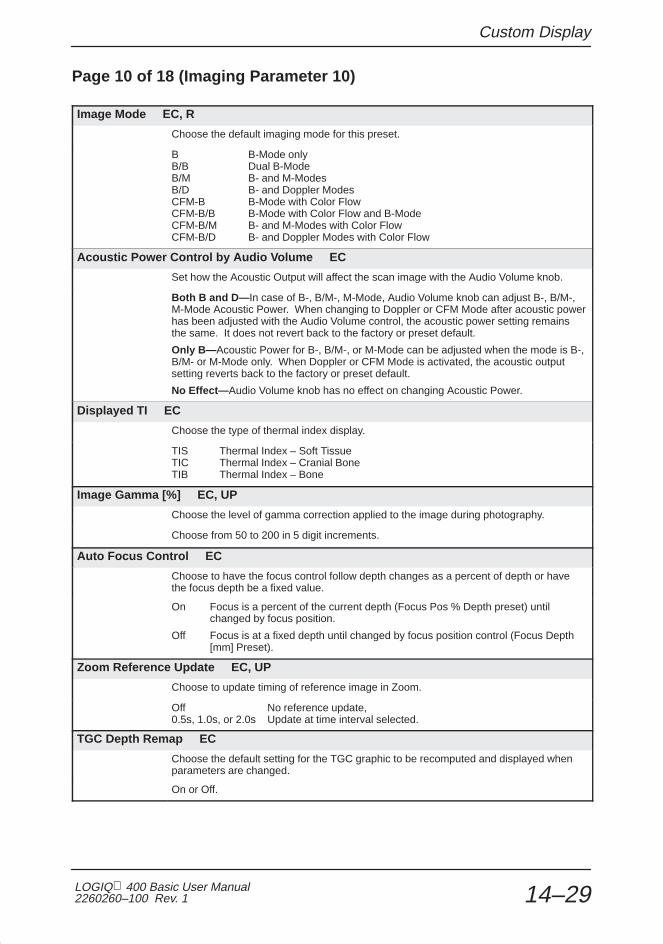
Custom Display
LOGIQ 400 Basic User Manual2260260–100 Rev. 1 14–29
Page 10 of 18 (Imaging Parameter 10)
Image Mode EC, R
Choose the default imaging mode for this preset.
B B-Mode onlyB/B Dual B-ModeB/M B- and M-ModesB/D B- and Doppler ModesCFM-B B-Mode with Color FlowCFM-B/B B-Mode with Color Flow and B-ModeCFM-B/M B- and M-Modes with Color FlowCFM-B/D B- and Doppler Modes with Color Flow
Acoustic Power Control by Audio Volume EC
Set how the Acoustic Output will affect the scan image with the Audio Volume knob.
Both B and D— In case of B-, B/M-, M-Mode, Audio Volume knob can adjust B-, B/M-,M-Mode Acoustic Power. When changing to Doppler or CFM Mode after acoustic powerhas been adjusted with the Audio Volume control, the acoustic power setting remainsthe same. It does not revert back to the factory or preset default.
Only B— Acoustic Power for B-, B/M-, or M-Mode can be adjusted when the mode is B-,B/M- or M-Mode only. When Doppler or CFM Mode is activated, the acoustic outputsetting reverts back to the factory or preset default.
No Effect— Audio Volume knob has no effect on changing Acoustic Power.
Displayed TI EC
Choose the type of thermal index display.
TIS Thermal Index – Soft TissueTIC Thermal Index – Cranial BoneTIB Thermal Index – Bone
Image Gamma [%] EC, UP
Choose the level of gamma correction applied to the image during photography.
Choose from 50 to 200 in 5 digit increments.
Auto Focus Control EC
Choose to have the focus control follow depth changes as a percent of depth or havethe focus depth be a fixed value.
On Focus is a percent of the current depth (Focus Pos % Depth preset) until changed by focus position.
Off Focus is at a fixed depth until changed by focus position control (Focus Depth [mm] Preset).
Zoom Reference Update EC, UP
Choose to update timing of reference image in Zoom.
Off No reference update,0.5s, 1.0s, or 2.0s Update at time interval selected.
TGC Depth Remap EC
Choose the default setting for the TGC graphic to be recomputed and displayed whenparameters are changed.
On or Off.

Custom Display
LOGIQ 400 Basic Users Manual2260260–100 Rev. 114–30
Page 10 of 18 (Imaging Parameter 10) (cont’d)
Cine Gauge Auto Display EC
Choose the initial default setting for the Cine gauge to be displayed when Cine isactivated.
On or Off.
Cine Speed EC, R
Choose the default Cine loop playback speed.
1, 1/2, 1/4, 1/8 or 1/16.
Image Back Color EC, UP
Choose the image area background color.
BLK Black DRD Dark RedGR1 10% Gray BDX Bordeaux RedGR2 20% Gray GGR Green GrayGR3 30% Gray DGR Dark Green
Frame Rate Display EC
Choose the default setting of the frame rate display on the screen.
On or Off.
Probe Direction Mark Display EC
Choose the default setting of the probe direction marker display.
On or Off.
Audio Tone Equalizer EC
Choose the desired type of audio output response
Flat Normal setting1 Reduced high tones, increased mid tones2 Reduced high tones, increased mid/low tones3 Reduced high tones, increased mid tones
Bass Mid TrebleFlat 0db 0db 0db1 0db 2db -4db2 2db 2db -2db3 0db 4db -2db
Display TGC Curve EC
Choose the default setting of the TGC Curve display for both large and small imageformat.
On or Off.

Custom Display
LOGIQ 400 Basic User Manual2260260–100 Rev. 1 14–31
Page 11 of 18 (Imaging Parameter 11)
B Focus Dual Marker EC, UP
Choose to display focus markers on both dual B-Mode images or just to the right side ofthe right image.
Off Only one focus marker is displayed.On Focus markers will be displayed to the right of both the right and left images.
B Color Auto Start EC, R
Choose the initial default setting for B color (colorized gray scale).
On or Off.
B Color Map EC, UP
Choose a B color default map.
1, 2, 3, 4, 5 or 6.
B Tag Auto Start EC, R
Choose the initial default setting for B color tag.
On or Off.
B Tag Center [%] EC, R
Choose the center point of the B color tag window as a default.
Percentage from 0 to 100%. A percentage of the entire displayed B color window(colorized gray scale).
B Tag Width [%] EC, R
Choose a default for the desired B color tag width.
Percentage from 0 to 100% for the B color window size.
B Format B Single EC
Choose a default display size for a single B-Mode image.
Large or small.
B Format B Dual EC
Choose a default display size for a dual B-Mode image.
Large or small.
B Scale Mark EC
Choose as a default what the scale markers will represent in B-Mode.
Depth/Width Depth and width marks.Depth Depth marks only.Comb Combination mode.
B Video Inverse EC
Choose as a default how to display B-Mode video.
Off White on black.On Black on white.

Custom Display
LOGIQ 400 Basic Users Manual2260260–100 Rev. 114–32
Page 12 of 18 (Imaging Parameter 12)
Timeline Sweep Method EC
Choose as a default between two types of timeline presentations.
Scroll Continuous update at edge of the screen.Moving-Bar Timeline is updated by a bar moving across the screen.
Timeline Format EC
Choose as a default how the timeline (M-Mode or Doppler spectrum) will be displayed.Only one type of display format is available at one time.
Side/Side B-Mode on left half of the display and the timeline on the right half.Top/Bottom B-Mode on the top of the display and the timeline across the bottom.
Auto B Melt at Unfreeze EC, UP
When the B Pause function is used to freeze B-Mode while in B/M or B/D, the presetsets the default to have the B-Mode image remain paused when the system is unfrozen.
Off B-Mode remains paused at unfreeze.On B-Mode exits pause condition at unfreeze.
M Mode Simul PD Activity EC
Choose as a default to have the ability to display simultaneous M-Mode and pulsedDoppler spectrum.
Off No simultaneous M and PD display.On Simultaneous display capable.
M Color Auto Start EC, R
Choose the initial default setting for M color (colorized gray scale).
On or Off.
M Color Map EC, UP
Choose a M color default map.
1, 2, 3, 4, 5 or 6.
M Tag Auto Start EC, R
Choose the initial default setting for M color tag.
On or Off.
M Tag Center [%] EC, R
Choose the center point of the M color tag window as a default.
Percentage from 0 to 100%. A percentage of the entire displayed M color window(colorized gray scale).

Custom Display
LOGIQ 400 Basic User Manual2260260–100 Rev. 1 14–33
Page 12 of 18 (Imaging Parameter 12) (cont’d)
M Tag Width [%] EC, R
Choose a default for the desired M color tag width.
Percentage from 0 to 100% for the M color window size.
M Format (Side/Side, Full) EC
Choose the default size for the M-Mode display format when it is full screen or side byside. Side/Side must be selected for “Timeline Format” on the Set Up/Custom DisplayMenu page 12 in order to display this format.
Large or small.
M Mode FULL B + Cursor EC
Choose the default setting for the full B plus M-Mode cursor display format.
On or Off.
M Mode Side/Side B Large EC
Choose the default setting for the large B-Mode (left side) and M-Mode (right side)format. Side/Side must be selected for “Timeline Format” on the Set Up/Custom DisplayMenu page 12 in order to display this format.
On or Off.
M Mode Side/Side B Small EC
Choose the default setting for the small B-Mode (left side) and M-Mode (right side)format. Side/Side must be selected for “Timeline Format” on the Set Up/Custom DisplayMenu page 12 in order to display this format.
On or Off.
M Mode Top/Bottom B Large EC
Choose the default setting for the large B-Mode (top) and M-Mode (bottom) format.Top/Bottom must be selected for “Timeline Format” on the Set Up/Custom Display Menupage 12 in order to display this format.
On or Off.
M Mode Top/Bottom B Mid EC
Choose the default setting for the medium size B-Mode (top) and M-Mode (bottom)format. Top/Bottom must be selected for “Timeline Format” on the Set Up/CustomDisplay Menu page 12 in order to display this format.
On or Off.

Custom Display
LOGIQ 400 Basic Users Manual2260260–100 Rev. 114–34
Page 12 of 18 (Imaging Parameter 12) (cont’d)
M Mode Top/Bottom B Small EC
Choose the default setting for the small size B-Mode (top) and M-Mode (bottom) format.Top/Bottom must be selected for “Timeline Format” on the Set Up/Custom Display Menupage 12 in order to display this format.
On or Off.
M Mode Full M EC
Choose the default setting for the full screen M-Mode format.
On or Off.
M Scale Mark EC
Choose the method to display scale markers in M-Mode.
Time/Depth Time horizontal and depth vertical.Time Time horizontal only.
M Video Inverse EC
Choose the display video type for the M-Mode portion of the display.
Off White on black (inverse off).On Black on white (inverse on).
Page 13 of 18 (Imaging Parameter 13)
D/CFM Scale Mark EC
Choose the default value for the scale markers in Doppler with color flow.
Velo VelocityFrq FrequencyVelo/Frq Velocity/FrequencyFrq/Velo Frequency/Velocity
D Type for Wall Filter EC
Choose the type of wall filter display while in Doppler.
Velo VelocityFreq Frequency
D Realtime Auto Trace EC, R
Choose the initial default setting for the auto trace function during real-time Doppler.
Off No Real-time trace function.On Real-time trace function enabled.Calc Real-time trace function with calculation display enabled.

Custom Display
LOGIQ 400 Basic User Manual2260260–100 Rev. 1 14–35
Page 13 of 18 (Imaging Parameter 13) (cont’d)
D Realtime Trace Method EC, R
Choose the value that will be traced during real-time Doppler.
Peak Peak or highest values (TAMAX).Floor Bottom or lowest values and peak (TAMIN).Mean Average values and peak (TAMEAN).Mode Brightest echo trace and peak (TAMODE).
D Realtime Calc Dir. EC, R
Choose the default for the portion of the Doppler signal to be auto traced.
Compo Forward and reverse flow.Forwd Only forward flow.Revrs Only reverse flow.
D Color Auto Start EC, R
Choose the initial default setting for D color (colorized gray scale).
On or Off.
D Color Map EC, UP
Choose a D color default map.
1, 2, 3, 4, 5 or 6.
D Tag Auto Start EC, R
Choose the initial default setting for D color tag.
On or Off.
D Tag Center [%] EC, R
Choose the center point of the D color tag window as a default.
Percentage from 0 to 100%. A percentage of the entire displayed D color window(colorized gray scale).
D Tag Width [%] EC, R
Choose a default for the desired D color tag width.
Percentage from 0 to 100% for the D color window size.
D Format (Side/Side, Full) EC
Choose the default Doppler display size for the side by side or full Doppler formats.Side/Side must be selected for “Timeline Format” on the Set Up/Custom Display Menupage 12 in order to display this format.
Large, small or very-small.

Custom Display
LOGIQ 400 Basic Users Manual2260260–100 Rev. 114–36
Page 13 of 18 (Imaging Parameter 13) (cont’d)
D Mode Full B + Cursor EC
Choose the default setting for the full B-Mode plus Doppler cursor format display.
On or Off.
D Mode Side/Side B Large EC
Choose the default setting for the large B-Mode (left side) and Doppler (right side)format. Side/Side must be selected for “Timeline Format” on the Set Up/Custom DisplayMenu page 12 in order to display this format.
On or Off.
D Mode Side/Side B Small EC
Choose the default setting for the small B-Mode (left side) and Doppler (right side)format. Side/Side must be selected for “Timeline Format” on the Set Up/Custom DisplayMenu page 12 in order to display this format.
On or Off.
D Mode Top/Bottom B Large EC
Choose the default setting for the large B-Mode (top) and Doppler spectrum (bottom)format. Top/Bottom must be selected for “Timeline Format” on the Set Up/CustomDisplay Menu page 12 in order to display this format.
On or Off.
D Mode Top/Bottom B Mid EC
Choose the default setting for the medium B-Mode (top) and Doppler spectrum (bottom)format. Top/Bottom must be selected for “Timeline Format” on the Set Up/CustomDisplay Menu page 12 in order to display this format.
On or Off.
D Mode Top/Bottom B Small EC
Choose the default setting for the small B-Mode (top) and Doppler spectrum (bottom)format. Top/Bottom must be selected for “Timeline Format” on the Set Up/CustomDisplay Menu page 12 in order to display this format.
On or Off.
D Mode Full D EC
Choose the default setting for the full screen Doppler spectrum format.
On or Off.

Custom Display
LOGIQ 400 Basic User Manual2260260–100 Rev. 1 14–37
Page 14 of 18 (Imaging Parameter 14)
D Image Processing EC
Choose the desired type of Doppler spectrum image processing.
Black Holes Filling Reduce the noise in the Doppler spectrum by filling in vertically.Normal Standard Processing. No additional filtering to reduce noise.Smoothing Reduce the noise in the Doppler spectrum by filling in vertically and
horizontally.Leveling Reduce the noise for Doppler spectrum direction.
D Time Resolution EC, UP
Choose the amount of emphasis to be placed on Doppler time resolution as comparedto frequency resolution.
1 Time resolution much greater than frequency resolution.2 Time resolution slightly greater than frequency resolution.3 Frequency resolution slightly greater than time resolution.4 Frequency resolution much greater than time resolution.5 Frequency resolution the greatest compared to time resolution.
D Audio to Speaker EC
Choose the default type of Doppler audio to be sent to the speakers.
Stereo Forward & Reverse signals separate.Mono–F Forward signals only.Mono–R Reverse signals only.
D Audio Volume [%] EC, R
Choose the default percentage value for the Doppler volume to the speakers.
Percentage from 0 to 100% in 4 digit steps.
D Video Inverse EC
Choose the default type of video used to display the Doppler spectrum.
Off White on black.On Black on white.
Display Dop Frequency EC
Choose the default setting for the Doppler Frequency display.
On or Off.
Display Dop PRF EC
Choose the default setting for the Doppler PRF display on the left side of the monitor.
On or Off.

Custom Display
LOGIQ 400 Basic Users Manual2260260–100 Rev. 114–38
Page 14 of 18 (Imaging Parameter 14) (cont’d)
Display Spectrm Ref. Value EC
Choose the default setting for the display of the Doppler velocity increments on thespectrum.
On Only Doppler velocity reference scale is displayed.Off Only Doppler velocity maximum value is displayed.
Spec. Inv in Triplex EC
Choose the default setting for the color scale bar when Doppler spectrum is inverted.
Independent The color scale bar remains the same when the Doppler spectrum is inverted.
Simultaneous The color scale bar inverts when the Doppler spectrum is inverted.

Custom Display
LOGIQ 400 Basic User Manual2260260–100 Rev. 1 14–39
Page 15 of 18 (Imaging Parameter 15)
PWD Base Line [%] EC, R
Choose the default percentage value for forward pulsed Doppler spectrum display.
Percentage from –75% to +75% in 25% increments (0 is 50% forward and 50%reverse).
CWD Base Line [%] EC, R
Choose the default percentage value for forward continuous wave Doppler spectrumdisplay.
Percentage from –75% to +75% in 25% increments (0 is 50% forward and 50%reverse).
CWD Non-aliasing mode EC
Choose how to process the CWD signal for aliasing.
Off Non-aliasing mode off.On Increase signal to noise ratio to reduce aliasing.
CFM Capture Interval [s] EC, R
Choose the default value (time) for the CFM capture interval.
Off No time interval update.1/2 Update at .5 second intervals.1 Update at 1 second intervals.2 Update at 2 second intervals.ECG Update synchronized with ECG signal.
CFM Velo Dynamic Range EC, UP
Choose the default value for the CFM velocity dynamic range display.
Value from 10 to 100 in 10 digit increments.
CFM/PDI Sequence EC, UP
Use the Ellipse up/down arrow keys to choose the default diagnostic mode sequence forColor Flow Mapping or Power Doppler Imaging.
Srvy>Mp>MpDtl Survey, map and map/detail.Srvy>SrvyDtl Survey and survey/detail.SrvyDtl>MpDtl Survey/detail and map/detail.Srvy>SrvyDtl>Map Survey, survey/detail and map.
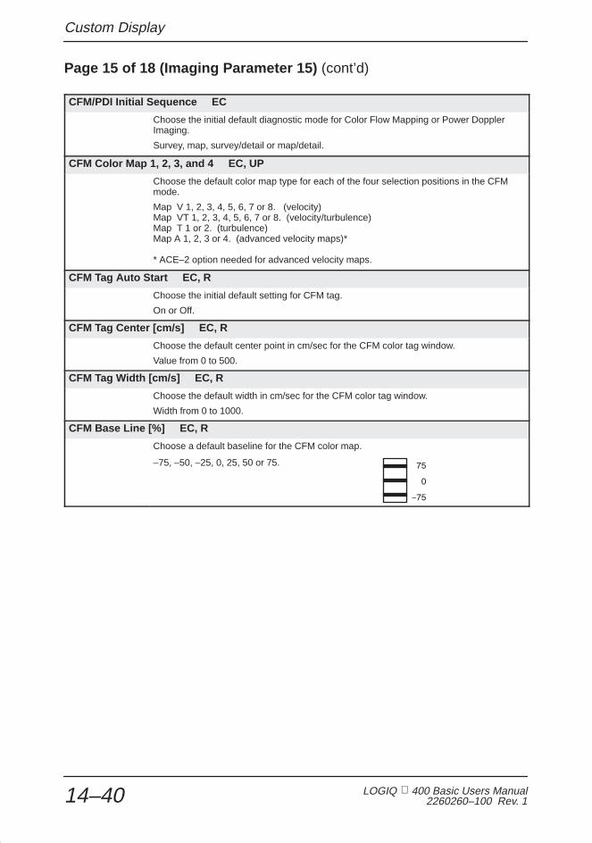
Custom Display
LOGIQ 400 Basic Users Manual2260260–100 Rev. 114–40
Page 15 of 18 (Imaging Parameter 15) (cont’d)
CFM/PDI Initial Sequence EC
Choose the initial default diagnostic mode for Color Flow Mapping or Power DopplerImaging.
Survey, map, survey/detail or map/detail.
CFM Color Map 1, 2, 3, and 4 EC, UP
Choose the default color map type for each of the four selection positions in the CFMmode.
Map V 1, 2, 3, 4, 5, 6, 7 or 8. (velocity)Map VT 1, 2, 3, 4, 5, 6, 7 or 8. (velocity/turbulence)Map T 1 or 2. (turbulence)Map A 1, 2, 3 or 4. (advanced velocity maps)*
* ACE–2 option needed for advanced velocity maps.
CFM Tag Auto Start EC, R
Choose the initial default setting for CFM tag.
On or Off.
CFM Tag Center [cm/s] EC, R
Choose the default center point in cm/sec for the CFM color tag window.
Value from 0 to 500.
CFM Tag Width [cm/s] EC, R
Choose the default width in cm/sec for the CFM color tag window.
Width from 0 to 1000.
CFM Base Line [%] EC, R
–75, –50, –25, 0, 25, 50 or 75.
Choose a default baseline for the CFM color map.

Custom Display
LOGIQ 400 Basic User Manual2260260–100 Rev. 1 14–41
Page 16 of 18 (Imaging Parameter 16)
CFM/PDI Initial Mode EC, R
Choose the default mode for color CFM or PDI.
CFM Regular CFM mode.PDI Power Dopper Imaging mode.
PDI B/W Display EC
Set the default parameter for the PDI transparent mode Maps 1 and 2.
On or Off.
PDI Default Map EC
Choose the default color map for the PDI mode.
P1, P2, P3, P4, P5, P6, P7 or P8.
PDI Dynamic Range EC, UP
Choose the default value for the Power Doppler dynamic range display.
Value from 10 to 100 in 10 digit increments.
PDI Tag Auto Start EC, R
Choose the initial default setting for PDI tag.
On or Off.
PDI Tag Center [cm/s] EC, R
Choose the default center point in cm/sec for the PDI color tag window.
Value from 0 to 500.
PDI Tag Width [cm/s] EC, R
Choose the default width in cm/sec for the PDI color tag window.
Width from 0 to 1000.
PDI Capture Interval [s] EC, R
Choose the default value (time) for the PDI capture interval.
Off No time interval update..5 Update at .5 second intervals.1 Update at 1 second intervals.2 Update at 2 second intervals.ECG Update synchronized with ECG signal.

Custom Display
LOGIQ 400 Basic Users Manual2260260–100 Rev. 114–42
Page 17 of 18 (Imaging Parameter 17)
ECG Auto Display EC
Choose the initial default setting for the ECG waveform to be displayed on the monitor.
On or Off.
ECG Gain EC, R
Choose the default value for ECG gain.
Value from –20 to +10 in 2 digit increments.
ECG Position EC, R
Choose the default value for the ECG display position (horizontal).
Value from –50 to +50 in 5 digit increments.
ECG Heart Rate Display EC
Choose the initial default setting for the heart rate, calculated from the ECG input, to bedisplayed on the monitor.
On or Off.
ECG R Delay 1 [ms] EC, UP, R
Choose the default value in milliseconds for the R wave Delay 1.
Value from 0 to 2000 in 5 digit increments.
ECG R Delay 1 to 2 [ms] EC, UP, R
Choose the default value in milliseconds for the R wave delay between Delay 1 andDelay 2.
Value from 0 to 2000 in 5 digit increments.
ECG Audio Beat Sound EC, UP
Choose the default setting to represent the ECG input as an audio tone.
On or Off.
ECG Audio Beat Sound Tone EC
Choose as a default the type of tone to be used to represent the ECG input.
Tone-1, tone-2 or tone-3.

Custom Display
LOGIQ 400 Basic User Manual2260260–100 Rev. 1 14–43
Page 17 of 18 (Imaging Parameter 17) (cont’d)
ECG Sync Mark Display EC, UP
Choose the default setting for the flashing heart mark display. The heart mark isdisplayed in sync with the R-wave only when a valid ECG trace is present.
On or Off.
PCG Auto Display EC
Choose the initial default setting for the PCG input displayed on the monitor.
On or Off.
PCG Gain EC, R
Choose the default value for PCG gain.
Value from –10 to +10 in 2 digit increments.
PCG Position EC, R
Choose as a default the horizontal position of the PCG waveform on the display.
Value from –50 to +50 in 5 digit increments.
AUX Auto Display EC
Choose the initial default setting for the auxiliary signal input to be displayed on themonitor.
On or Off.
AUX Gain EC, R
Choose the default gain value for the auxiliary input signal.
Value from –10 to +10 in 2 digit increments.
AUX Position EC, R
Choose as a default the horizontal position of the auxiliary waveform on the display.
Value from –50 to +50 in 5 digit increments.

Custom Display
LOGIQ 400 Basic Users Manual2260260–100 Rev. 114–44
Page 18 of 18 (Imaging Parameter 18)
3D Swing Speed EC, UP, R
Choose the swing speed of the displayed MIP image.
1/1, 1/2, 1/4, 1/8 or 1/16 with 1/1 being the fastest swing speed.
3D Scan Line Resolution EC, UP
Choose the default setting for 3D-Mode Scan Line Resolution.
Normal or High.
3D Number of Frames in Build EC, UP
Choose the number of frames to be constructed for the final MIP image. The higher thenumber the better the 3D resolution but with longer rendering time.
Number from 5 to 21 in 2 frame steps.
3D B Percent of Source Frames EC, UP
Choose the number of source frames to be used for constructing the B/W MIP image.
Number from 1/1, 1/2, 1/3, 1/4 or 1/5.
3D B Projection Technique EC, UP, R
Choose the method to be used in constructing the MIP image.
Min Minimum Intensity Projection.Max Maximum Intensity Projection.Grad Backward images are faded.Inv Same as Min but the gray levels of the constructed images are inverted.
3D B Gradient Threshold [%] EC, UP
Choose the gray level threshold percentage to be used in the B/W Gradient Mode.
Percentage from 0 to 100% in 2% increments.
3D B Background Level [%] EC, UP
Choose the percentage of the gray level for the background of the B/W MIP images.
Percentage from 0 to 100% in 2% increments.
3D B Frame Line Level [%] EC, UP
Choose the percentage of the gray level to be used for the frame line of the B/W MIPimage.
Percentage from 0 to 100% in 2% increments.

Custom Display
LOGIQ 400 Basic User Manual2260260–100 Rev. 1 14–45
Page 18 of 18 (Imaging Parameter 18) (cont’d)
3D CFM/PDI Percent of Source Frames [%] EC, UP *
Choose the number of source frames to be used for constructing the CFM MIP image.
1/1, 1/2, 1/3, 1/4 or 1/5.
3D CFM/PDI Projection Technique EC, UP, R *
Choose the method to be used in constructing the MIP images.
Norm Normal Maximum Intensity Construction.Grad Backward images are faded.Shaded Object’s edges are enhanced.
3D CFM/PDI Gradient Threshold [%] EC, UP *
Choose the color threshold percentage to be used in the Gradient Mode.
Percentage from 0 to 100% in 2% increments.
3D CFM/PDI Shade Object Threshold [%] EC, UP *
Choose the color threshold percentage to be used for the construction in Shaded Mode.
Percentage from 0 to 100% in 2% increments.
3D CFM/PDI Shade Boundary Threshold [%] EC, UP *
Choose the color threshold percentage to be used for the boundary in Shaded Mode.
Percentage from 0 to 100% in 2% increments.
3D CFM/PDI Frame Line Level [%] EC, UP *
Choose the percentage of the gray level to be used for the frame line of the B/W MIPimages.
Percentage from 0 to 100% in 2% increments.
* NOTE: 3D images cannot be rendered in PDI-Mode.�

System Parameters
LOGIQ 400 Basic Users Manual2260260–100 Rev. 114–46
System Parameters
Overview
System Paramtr (parameters) in the Set Up Top Menu is 7pages of preset parameters that when set, are the same for allexam categories and preset names. Changing systemparameters also affects these exam application presets found infactory default menu.
Generally, these items are common to modes, probes, formatsand applications.
1/1Set Up
PresetProgram
SystemParamtr
CustomDisplay
Diag.UserDefine
UtilitySaveValues
Figure 14–8. Setup Sub-Menu (System Parameters)
A brief description of each preset parameter and the choicesavailable for that preset follows.
NOTE: If it is necessary to quickly return to page one of theSystem Parameters Sub-Menus, press Ctrl and 1simultaneously.
�

System Parameters
LOGIQ 400 Basic User Manual2260260–100 Rev. 1 14–47
System Parameters Contents
Figure 14–9. System Parameters Contents Page
The System Parameters Contents page shows a summary ofthe 7 menu pages.
Trackball the cursor to the desired page and press Set.

System Parameters
LOGIQ 400 Basic Users Manual2260260–100 Rev. 114–48
Page 1 of 7 (System Setup)
Hospital Name
Enter the desired hospital or facility name. This appears at the top of all display screensand report pages.
Maximum of 29 alphanumeric characters.
Date Format
Choose the desired presentation format for all dates displayed.
Year/Month/Day, Month/Day/Year, Day/Month/Year
Time Format
Choose the desired presentation format for all time graphics displayed.
24 H 24 hour clock12 H 12 hour clock
Language
Choose the desired language for all displayed graphics by using the Ellipse up/downarrow keys.
English, French, German, Spanish, Italian, Portuguese, Swedish, Danish, Russian,Greek or Turkish.
Diag Category
Choose the desired default diagnostic category.
Rad/Abd Radiology/AbdomenObst ObstetricalGyne GynecologyCard CardiologyVasc VascularUrol UrologySmlPts Small Parts
Change Probe and Category
Choose to manually select the desired category with the probe.
Independent Manual selection of exam category and manual selection of probe.Simultaneous When the probe is manually selected, the system automatically
defaults to the assumed exam application for that probe.
Report Cursor Blink
Choose to have the report cursor blinking or solid.
Off SolidOn Blinking
Report Cursor Type
Choose the style of the report cursor desired.
Underscore
Block

System Parameters
LOGIQ 400 Basic User Manual2260260–100 Rev. 1 14–49
Page 1 of 7 (System Setup) (cont’d)
CUA Selection Reset on New Patient
Choose to reset all Composite Ultrasound Age flags on the OB Report pages to yeswhen New Patient is selected.
On or Off.
Insite Access Enable
Choose the default setting to access remote diagnostics via telephone line.
On or Off.
Keyboard Tab
Choose the comment cursor movement desired when using the Tab key.
Normal Eight character spaces.Word Next word (after a space).
Operation Error Beep
Choose to disable the audio error beep or set the volume of the tone that is heard whena keystroke error is made.
Off No error beep.Low Low volume beep on error.Loud High volume beep on error.
Standby Time [min]
The system can be set to go into stand-by mode if no keyboard activity is sensed for aspecific period of time.
5, 10, 15, 30, 45, 60 minutes or INF (infinity-never)
Power on Memory Test
Choose to execute the system memory test at power up.
On or Off.
Power on Status
The “Keep-Latest” function is not available. The system always resets theExam/System Parameters at power up, even if “Keep-Latest” is selected.
Keep-Latest Not available.Reset Reset to system defaults.
System Error Erase Interval
Set the time that a system error message is displayed on the monitor before it is erased.
0.1, 1, 10 minutes or infinity.Infinity is until the next error occurs.

System Parameters
LOGIQ 400 Basic Users Manual2260260–100 Rev. 114–50
Page 1 of 7 (System Setup) (cont’d)
CRT Menu Auto Erase Interval [sec]
Set the time in seconds that the Top or Sub Menus will be displayed on the monitorbefore they are automatically erased.
Choose from 5, 10, 15, 20 seconds or infinity.
Display Probe Name
Choose to display the names of the probes attached to the console in the soft menuwhen an available Probe Select key is pressed.
On or Off.
Page 2 of 7 (System Setup)
Setup Blue Back Start
Choose to display a color for the background of the preset menus. Color is set by ColBackGnd.
Off Background is transparent.On Display a colored background.
Mask Image Characters
Choose to mask (disable) the graphic characters on the image display.
On or Off.
PCG Filter
Choose the desired level of PCG (Physiological Signal) filtering.
Low Low level filtering.Mid1 Medium level filtering.
Delay Trigger Source
Choose the source for the cardiac trigger delay.
ECG Electrocardiogram input.AUX Auxiliary signal input.

System Parameters
LOGIQ 400 Basic User Manual2260260–100 Rev. 1 14–51
Page 2 of 7 (System Setup) (cont’d)
ID/Name Prohibition After Measurement
Choose to be able to use the ID/Name Key to change patient information after ameasurement has been taken or lockout the use of the ID/Name key after ameasurement is taken.
Off ID/Name Key functional after measurement.On ID/Name Key not functional after measurement.
BSA Type
Choose the formula used to calculate Body Surface Area.
Oriental Asian formula.Occidental USA formula.
OB Report Format
Choose the format for calculation and display of OB measurements.
Tokyo Tokyo University Method.Osaka Osaka University Method.USA United States Method.Europe European Method.
EFBW Form (Europe)
Choose the method for calculating estimate fetal birth weight for the European method.
Shep/Wars Shepherd/Warshoff Method.Rich/Berk Richards/Berkowitz Method.Hadlock Hadlock Method.German German Accepted Method.Merz German Method
EFBW Form (Tokyo)
Choose the formula to be used for calculating the estimate fetal birth weight for theTokyo method.
Tokyo Tokyo UniversityTokyo–S1 Tokyo Sinozuka EFW1Tokyo–S2 Tokyo Sinozuka EFW2Tokyo–S3 Tokyo Sinozuka EFW3
Col BackGnd
Choose the color for the background of Preset and Patient Entry menus displayed onthe monitor.
Color options are:BLK BlackGRY GrayULB Ultramarine BlueBLU BluePWB Periwinkle BlueMGR Moss GreenMNK MinkMRN Maroon

System Parameters
LOGIQ 400 Basic Users Manual2260260–100 Rev. 114–52
Page 2 of 7 (System Setup) (cont’d)
Col Sys Inf
Choose the color for all alphanumeric system information displayed on the monitor.
Color options are:WHT WhiteYLW YellowGRN GreenLGR Light GreenPBL Pale BluePNK Baby PinkRED VermilionYOR Yellow Orange
Col Imag Crs
Choose the color for the image characters on the display (Probe Orientation, ZoomDepth, and Image Recall graphics). See color options under Col Sys Inf.
Col Scale
Choose the color for the scale markers on the display. See color options under Col SysInf.
Col Comment
Choose the color for comments and annotations entered on the display. See coloroptions under Col Sys Inf.
Col Mes Crs
Choose the color for the fixed measurement cursor on the display. See color optionsunder Col Sys Inf.
Col Applcat
Choose the color for completed measurement information displayed on the monitor.See color options under Col Sys Inf.
Col Moving
Choose a color for the active movable cursor on the display. See color options underCol Sys Inf.
Col Aux
Choose a color for all auxiliary signal information displayed on the monitor (ECG, AUX,and PCG). See color options under Col Sys Inf.
Col Dop Trac
Choose a color for the Doppler Spectrum Trace function. See color options under ColSys Inf.

System Parameters
LOGIQ 400 Basic User Manual2260260–100 Rev. 1 14–53
Page 3 of 7 (System Setup)
Use A/N Keys for User Define
Choose to use the alphanumeric keys A~Z and 0~9 with the user define function.
On or Off.
User Define Key Names & Locks
Use this sub-menu to review, name or lock/unlock all available user define keys. The 11character name of each user defined key is displayed.
An asterisk to the left of the name means the key is locked. The user define functioncannot be deleted or modified when the key is locked.
See 14–100 for details.
CUA/AUA for HADLOCK
Choose how gestational age is derived for the Hadlock formulas.
CUA Composite Ultrasound Age—gestational age derived by linear regression.
AUA Average Ultrasound Age—gestational age derived by averaging.
PSA Calculation
Choose how the PSA Caclulation is derived.
PSAD Prostate Specific Antigen Density—defined as PSA divided by volume.
PPSA Predicted Prostate Specific Antigen—a number which gives the normal level of PSA that would be expected for a prostate of a given volume.
Active Measurement Cursor
Choose the Measurement active cursor type.
X–mark or Plus–mark.

System Parameters
LOGIQ 400 Basic Users Manual2260260–100 Rev. 114–54
Page 4 of 7 (System Setup – Body Pattern)
Body Pattern Package 1–8
Choose up to 16 body patterns (2 sub-menu pages) for each of the 8 packages. Eightcustom body pattern packages are then available for selection to be displayed in the SetUp/Preset Program Menu page one.
An illustration of each body pattern available is shown on 6–29. To select the bodypattern package to be used for each user preset within an exam category, refer to14–65.
See the following pages for details on Customizing or deleting a body pattern package.
Body Pattern Probe Change Erase
Choose to erase the displayed body pattern when a probe is changed.
On or Off.
Body Pattern Unfreeze Erase
Choose to erase the body pattern when the system exits the freeze function.
On or Off.
Body Pattern Copy To Active Side
Choose to have the selected body pattern copied to the active side during dual formatdisplays.
On or Off.

System Parameters
LOGIQ 400 Basic User Manual2260260–100 Rev. 1 14–55
Body pattern package (1–8) customization
Choose the Set Up Top Menu, then choose System Paramtr(system parameters) from the Set Up Sub-Menu and go topage 4.
Use the Trackball to move the arrow cursor to the word“Submenu” of the desired body pattern package number to becustomized.
Press Set. The body pattern selection Sub-Menu appears.
Figure 14–10. Initial Body Pattern Sub-Menu
The rectangle in the display represents space for two rows ofbody patterns (2 Sub-Menu display pages). There is a spacefor 8 body patterns in each row.
Use the Trackball to move the arrow cursor to a desired bodypattern location.
Press Set. A box appears around a Body Pattern or blankspace if no pattern is programmed.
(continued)

System Parameters
LOGIQ 400 Basic Users Manual2260260–100 Rev. 114–56
Body pattern package (1–8) customization (cont’d)
Figure 14–11. Adding Body Patterns
Use the Ellipse up/down arrow keys to cycle through the bodypattern choices.
When the desired body pattern is displayed, use the Trackballand Zoom Size/Rotation knob to position the probe orientationmarker to the desired default position on the body pattern.
Press Set to complete the selection for that menu position.
NOTE: As many as 16 selections (2 rows of 8) can be made foreach body pattern package.�

System Parameters
LOGIQ 400 Basic User Manual2260260–100 Rev. 1 14–57
Body Pattern Deletion
Use the Trackball to position the arrow cursor over the patternto be deleted.
Press Set. A box appears around the Body Pattern.
Use the Ellipse up/down arrow keys to cycle to the blank bodypattern selection.
Press Set to record a blank space for that body pattern location.

System Parameters
LOGIQ 400 Basic Users Manual2260260–100 Rev. 114–58
Page 5 of 7 (System Setup – Recording)
Report Video Inverse to Printer
Choose to send calculation summary report video to the print device in inverse (reverse)video.
On or Off.
Record 1 B&W or Color
Choose the type of device to be controlled by the Record 1 key for black and white orcolor images. Use the Ellipse up/down arrow keys to cycle through the selections.
Black and White Polaroid Camera, Color Polaroid Camera, Black and White Printer,Color Printer, Multi Image Camera, MO Archive, HD Storage or Computer.
Record 2 B&W or Color
Choose the type of device to be controlled by the Record 2 key for black and white orcolor images. Use the Ellipse up/down arrow keys to cycle through the selections.
Black and White Polaroid Camera, Color Polaroid Camera, Black and White Printer,Color Printer, Multi Image Camera, MO Archive, HD Storage or Computer.
Report
Choose the type of device that will be used to print the calculation summary reportpages.
Black and White Polaroid Camera, Color Polaroid Camera, Black and White Printer,Color Printer, Multi Image Camera or Image Archive.
External Video Signal
Choose the type of video signal, from an external source, that is being put into theLOGIQ 400.
S-Video Two component video.RGB Red, green, blue and sync.Col-Comp Composite color signal.
Color Printer Type
Choose the type of color printer (option) that is attached to the LOGIQ 400.
UP3030 Sony UP-3030MD.UP1850 Sony UP-1800/UP-1850/UP-2950/UP-2850.UP1850P Sony UP–1850P.
Color Printer Memory
Choose how printer memory will be divided and thus how the color print will beformatted.
Single One picture per sheet.Quad–Frm Four pictures per sheet.Quad–Frmls Not available.
Single Quad–FRMUP-1800 Series/UP-2800 Series/UP-2900 Series Available Not AvailableUP-1850 Series/UP-2850 Series/UP-2950 Series Available Available

System Parameters
LOGIQ 400 Basic User Manual2260260–100 Rev. 1 14–59
Page 5 of 7 (System Setup – Recording) (cont’d)
Color Printer Signal
Choose the type of video signal being sent to the color printer.
RGB Red, green, blue and sync.Video Composite Video.S-Video Two component video.
Plug 1–BW
Choose which device has its record/expose cable connected to plug one.
B&W–Prnt Black and white video page printer.B&W–Pola Black and white Polaroid camera.Col–Pola Color Polaroid camera.
Plug 2–CLR
Choose which device has its record/expose cable connected to plug two.
B&W–Prnt Black and white video page printer.B&W–Pola Black and white Polaroid camera.Col–Pola Color Polaroid camera.
Port A/B
Choose the type of device that has an interface cable connected to VCR/printer ports Aand B.
Off No connection.Multi Image Camera Multi Image Camera.VCR Video Cassette Recorder.Color Printer Color Printer.Computer Data Management Center Computer.Line Printer–USA Only Paper Line Printer.
Maskline Record
Choose to display the operator message area during the record function.
On or Off.
B&W Printer Exposure Pulse Length [msec]
Set the exposure pulse length needed to trigger the B&W printer print function.
Length from 50 to 500 ms in 50 ms intervals.
B&W Printer Exposure Min Interval [sec]
Set the minimum interval in seconds between B&W printer exposure capabilities.
Interval from 1 to 10 in 0.5 sec intervals.

System Parameters
LOGIQ 400 Basic Users Manual2260260–100 Rev. 114–60
Page 5 of 7 (System Setup – Recording) (cont’d)
B&W Image Archive
Choose how a Black & White image will be archived.
B&W or Color.
Color Image Archive
Choose how a Color image will be archived.
B&W or Color.
Page 6 of 7 (System Setup – User ID and Password)
Password Ask
Choose to use the password security option at power up by asking for the user ID andpassword.
On or Off.
NOTE: Refer to 3–20 for usage of the password function.
User ID 1–8
As many as eight user ID codes can be entered into the system parameters. These canbe used for security purposes. When used with an accompanying password, user IDestablishes limited access to the system at power up.
Maximum of 8 alphanumeric characters for each user ID.
Password 1–8
As many as 8 passwords can be entered to correspond with the 8 user ID codes. Thesemust be used when password ask is on.
Maximum of 8 alphanumeric characters for each password.
Initially, User ID Codes are blank. A User ID must be entered before a password can berecorded.
System Parameters
LOGIQ 400 Basic User Manual2260260–100 Rev. 1 14–61
Selecting an ID
� Select the desired User ID number on page 6 of theSet Up/System Parameter Menu, by moving the arrowcursor over the User ID number and pressing Set.
� The User ID entry area is highlighted.
� Type in a maximum of 8 characters for the User ID andpress Return .
The User ID is now recorded and displayed on the SystemParameter Menu.
Entering a Password
Once a User ID is established or changed, a password can beentered.
� Move the arrow cursor to the desired password and pressSet.
� Type in the new password. Press Return .
� Type in the new password a second time forre-confirmation. Press Return .
NOTE: The password function is upper and lower casesensitive.
The Password function is not active unless “Password Ask” inthe Set Up/System Parameter menu page 6 is set to On.
Changing/Deleting a Password
To change or delete a password:
� Move the arrow cursor to the desired password and pressSet.
� In the highlighted password area, type the old password.Press Return .
� To change a password, type in the new characters. PressReturn . To delete a password, type in 8 spaces. PressReturn .
� Type the new password or 8 spaces a second time forconfirmation. Press Return .
The password is now changed or deleted.
�

System Parameters
LOGIQ 400 Basic Users Manual2260260–100 Rev. 114–62
Changing/Deleting a User ID
To change or delete a User ID:
� Move the arrow cursor to the desired User ID and pressSet.
� Input the old password. Press Return .
� Type in the new User ID to change or type in spaces todelete the User ID. Press Return .
The User ID is now changed or deleted.
NOTE: If the User ID is deleted (all spaces), the correspondingpassword is also deleted.
If no password is selected with the User ID, the ID canbe changed or deleted directly. There is norequirement to enter the old password.
Page 7 of 7 (DICOM)
Menu Selection at New Patient
Choose what screen will be displayed when the New Patient key is pressed.
Patient_Entry Displays standard patient entry screen for the default exam category.Schedule Displays the DICOM patient schedule screen.
Sort Criteria for Schedule List
Choose how to sort the entries on the DICOM patient schedule screen.
Date&Time Arrange by date and time of patient session.Name Arrange by Patient Name.
Patient Name Format
Choose how the Patient Name entry will be displayed for the Patient Entry Menu.
Full_Name One block for entering patient name.Last &First Separate blocks for entering patient last name and patient first name.
Auto Deletion of Transferred Queue
Choose to automatically delete the image from the queue after successful DICOMtransfer.
Yes or No.
�

Preset Program
LOGIQ 400 Basic User Manual2260260–100 Rev. 1 14–63
Preset Program
Overview
Preset Program in the Set Up top menu is 10 pages of presetparameters that are generally considered applicationparameters. They are exam category and preset namedependent.
Special features in the Preset Program Sub-Menus are:
� Annotation Library script designation� Summary report display format editing� User programmable OB table editing� Calculation sequence programming� Mode measurement menu customizing
1/1Set Up
PresetProgram
SystemParamtr
CustomDisplay
Diag.UserDefine
UtilitySaveValues
Figure 14–12. Set Up Top Sub-Menus (Preset Program)
A brief description of each preset parameter and the choicesavailable for that preset follows.
NOTE: If it is necessary to quickly return to the Preset ProgramSub-Menu page 1, press Ctrl and 1 simultaneously.
Refer to 14–6 for the key to the codes used to describe eachparameter’s affect.
�

Preset Program
LOGIQ 400 Basic Users Manual2260260–100 Rev. 114–64
Preset Program Contents
Figure 14–13. Preset Program Contents Page
The Preset Program Contents pages shows a summary of the10 menu pages.
Trackball the cursor to the desired page and press Set.

Preset Program
LOGIQ 400 Basic User Manual2260260–100 Rev. 1 14–65
Page 1 of 10 (Application)
Body Pattern Probe Mark Preset EC, UP
Choose to activate the preset position of the probe marker graphic.
On or Off.
Body Pattern Package EC, UP
Choose one of the 8 customized body pattern packages to be displayed with the currentapplication preset.
Body pattern package 1, 2, 3, 4, 5, 6, 7 or 8.
Refer to 14–54 for details on programming the contents of each body pattern package.
Comment Erase at Display Change EC
Choose to erase all comments when a change is made in scan mode.
On or Off.
Comment Home Position Horizontal EC, R
Choose a point on the horizontal axis for the comment cursor home position.
Enter 1 to 56 in 1 digit increments.
Comment Home Position Vertical EC, R
Choose a point on the vertical axis for the comment cursor home position.
Enter 1 to 26 in 1 digit increments.
Comment Clear Key Function EC
Choose to erase all comments with the Clear key or just the line of comments that thecursor is on.
All Erase all comments on the screen.Line Erase the comments on the cursor line. The second time Clear is pressed, all
comments will be erased.
Trackball Function at Freeze EC
Choose the function assigned to the Trackball when the image is frozen.
No No function assigned.Measure Trackball assigned to the measurement function.Comment Trackball assigned to the comment function.Body Trackball assigned to the body pattern function.
CRT Menu Auto Display at Measurement EC
Choose to display the Measurement Sub-Menu automatically when the Measurementkey is pressed.
On or Off.
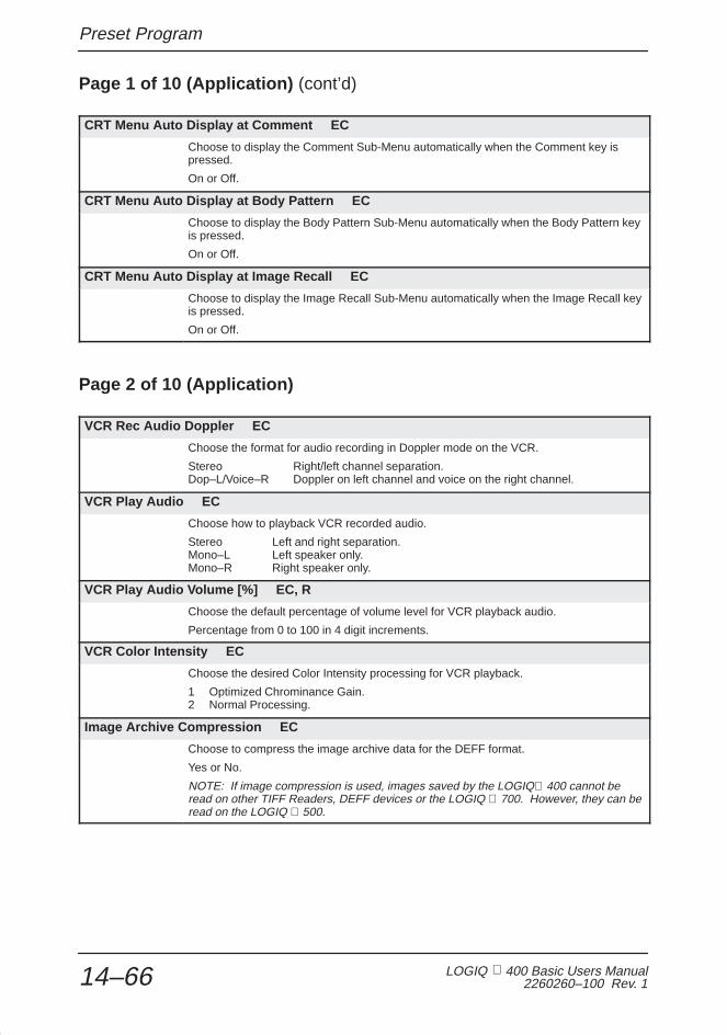
Preset Program
LOGIQ 400 Basic Users Manual2260260–100 Rev. 114–66
Page 1 of 10 (Application) (cont’d)
CRT Menu Auto Display at Comment EC
Choose to display the Comment Sub-Menu automatically when the Comment key ispressed.
On or Off.
CRT Menu Auto Display at Body Pattern EC
Choose to display the Body Pattern Sub-Menu automatically when the Body Pattern keyis pressed.
On or Off.
CRT Menu Auto Display at Image Recall EC
Choose to display the Image Recall Sub-Menu automatically when the Image Recall keyis pressed.
On or Off.
Page 2 of 10 (Application)
VCR Rec Audio Doppler EC
Choose the format for audio recording in Doppler mode on the VCR.
Stereo Right/left channel separation.Dop–L/Voice–R Doppler on left channel and voice on the right channel.
VCR Play Audio EC
Choose how to playback VCR recorded audio.
Stereo Left and right separation.Mono–L Left speaker only.Mono–R Right speaker only.
VCR Play Audio Volume [%] EC, R
Choose the default percentage of volume level for VCR playback audio.
Percentage from 0 to 100 in 4 digit increments.
VCR Color Intensity EC
Choose the desired Color Intensity processing for VCR playback.
1 Optimized Chrominance Gain.2 Normal Processing.
Image Archive Compression EC
Choose to compress the image archive data for the DEFF format.
Yes or No.
NOTE: If image compression is used, images saved by the LOGIQ 400 cannot beread on other TIFF Readers, DEFF devices or the LOGIQ 700. However, they can beread on the LOGIQ 500.

Preset Program
LOGIQ 400 Basic User Manual2260260–100 Rev. 1 14–67
Page 3 of 10 (Application – Measurement)
Time Unit EC
Choose the unit of display for all time measurements.
ms milliseconds.sec seconds.
Length Unit EC
Choose the unit of display for all length (distance) measurements.
mm millimeters.cm centimeters.
Velocity Unit EC, UP
Choose the unit of display for all velocity measurements.
cm/s centimeters per second.m/s meters/second.auto displays in either cm/s or m/s depending on velocity measured.
Circ/Area Method EC
Choose the method to be used for circumference/area measurements.
Trace Manually trace with the Trackball.Ellipse Ellipse method.Circle Circle method.2 Dist Two diameter (distance) method.Diameter Single distance method.
Echo Level Method EC
Choose the size of the echo level measurement box cursor.
Box 3mm 3mm x 3mm box.Box 5mm 5mm x 5mm box.Box 7mm 7mm x 7mm box.
Heart Rate Method EC
Choose the method for measuring heart rate.
Auto Automatic Calibration.Manual Manual Calibration.
VCRPB Calib Method EC
Choose the default method for VCR playback calibration.
Auto Automatic Calibration.Manual Manual Calibration.
Average Activity EC
Choose to enable the calculation summary report page measurement averagingfunction.
On or Off.

Preset Program
LOGIQ 400 Basic Users Manual2260260–100 Rev. 114–68
Page 3 of 10 (Application – Measurement) (cont’d)
Max Velocity (Advanced Vascular) EC
This selection is used with the Advanced Vascular option only. When turned on itoverrides the Average Activity preset to cause the Advanced Vascular report page todisplay maximum velocity rather than latest or average.
On or Off.
Average Number EC
Choose how many measurements will be used in the averaging function. TheCardiology exam category with AMCAL has a choice of 5 measurements whereas theother exam categories have a choice of 3 measurements.
1, 2, 3, 4 or 5.
Mask Image EC, UP
Choose to put the measurement/calculation results in a colored box over the image orjust the graphic characters over the image.
Off Graphics are placed on top of the image.On Graphics are placed in a colored box on top of the image.
Trace Auto EC
Choose to enable the automatic measurement of TAMAX, TAMIN, TAMEAN orTAMODE. See “D Realtime Trace Method” in Set Up/Custom Display page 13 for tracemethod selection on 14–35.
On or Off.
Add 1 Week to EDD EC
Choose to add an additional week to the displayed estimated date of delivery.
On or Off.
Display EDD with GA Value EC
Choose to display the estimated EDD with GA.
On or Off.
Diastole/Systole Determination EC
Used with Advanced Cardiac Calculation option. Determine if measurement is systoleor diastole automatically from the measurements relationship to the ECG wave.
Manual Automatic determination disabled.Auto Automatic determination enabled.
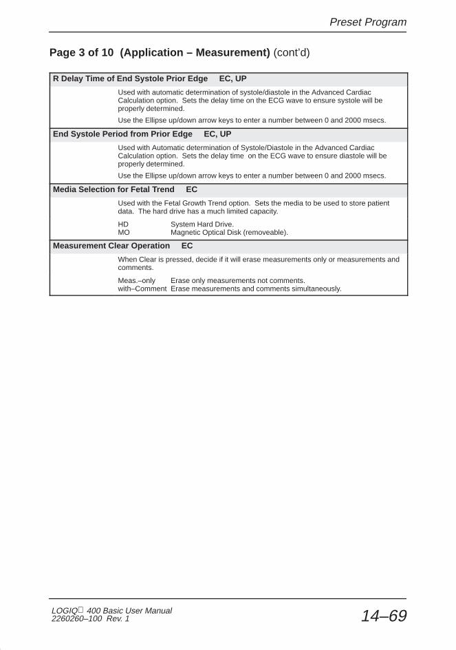
Preset Program
LOGIQ 400 Basic User Manual2260260–100 Rev. 1 14–69
Page 3 of 10 (Application – Measurement) (cont’d)
R Delay Time of End Systole Prior Edge EC, UP
Used with automatic determination of systole/diastole in the Advanced CardiacCalculation option. Sets the delay time on the ECG wave to ensure systole will beproperly determined.
Use the Ellipse up/down arrow keys to enter a number between 0 and 2000 msecs.
End Systole Period from Prior Edge EC, UP
Used with Automatic determination of Systole/Diastole in the Advanced CardiacCalculation option. Sets the delay time on the ECG wave to ensure diastole will beproperly determined.
Use the Ellipse up/down arrow keys to enter a number between 0 and 2000 msecs.
Media Selection for Fetal Trend EC
Used with the Fetal Growth Trend option. Sets the media to be used to store patientdata. The hard drive has a much limited capacity.
HD System Hard Drive.MO Magnetic Optical Disk (removeable).
Measurement Clear Operation EC
When Clear is pressed, decide if it will erase measurements only or measurements andcomments.
Meas.–only Erase only measurements not comments.with–Comment Erase measurements and comments simultaneously.

Preset Program
LOGIQ 400 Basic Users Manual2260260–100 Rev. 114–70
Page 4 of 10 (Application – Measurement)
Diastole Velocity for PI EC, UP
Choose which velocity value will be used to calculate end diastole.
Vmin Minimum value of the whole trace.Vd Minimum value detected before Vmax (end diastole). Minimum value part of a
heart rate period.
If Vd is not detected, use Vmin.
Diastole Velocity for RI EC, UP
Choose which velocity value will be used to calculate end diastole.
Vmin Minimum value of the whole trace.Vd Minimum value detected before Vmax (end diastole). Minimum value part of a
heart rate period.
If Vd is not detected, use Vmin.
Diastole Velocity for S/D (D/S) EC, UP
Choose which velocity value will be used to calculate end diastole.
Vmin Minimum value of the whole trace.Vd Minimum value detected before Vmax (end diastole). Minimum value part of a
heart rate period.
If Vd is not detected, use Vmin.
Averaging Number for Doppler Realtime Calc EC, UP
Choose how many heart rate periods will be averaged prior to being displayed in therealtime calculation window.
1, 2, 3, 4 or 5.
RI Calculation to bidirectional Flow EC, UP
When the flow direction for systolic velocity and diastolic velocity are different, set thisparameter to on for the RI calculation.
Off Bidirectional flow not considered in RI calculation.On Bidirectional flow considered in RI calculation.
Hip Orientation EC, UP
Choose the type of Hip Orientation method to be used for scanning the infant hip.
Cranial–left Cranial structures are on the left; caudal structures are on the right.Caudal–left Caudal structures are on the left; cranial structures are on the right.
Stepper Increment [mm] EC, UP
Choose the stepper increment for area measurements in millimeters.
5 or 2.5.
PPSA Coefficient (1) EC, UP
Set the desired default PPSA Coefficient for the first PPSA calculation on the UrologyReport page.
Coefficient from 0.01 to 0.99.

Preset Program
LOGIQ 400 Basic User Manual2260260–100 Rev. 1 14–71
Page 4 of 10 (Application – Measurement) (cont’d)
PPSA Coefficient (2) EC, UP
Set the desired default PPSA Coefficient for the second PPSA calculation on theUrology Report page.
Coefficient from 0.01 to 0.99.
Display MaxPG with Velocity EC, UP
Choose the default for displaying MaxPG with peak velocity.
Off or On.
Arrow Mark Display EC, UP
Choose the default for displaying the arrow mark when the Measurement key is presseda certain number of times. See Table 7–1 on 7–5 for more details.
Off or On.
% Stenosis Calculation EC, UP
In Advanced Vascular, choose the default measurement type for calculating % Stenosis.
Area or Distance.
CAUTION: If this preset is changed, the previous % Stenosis measurement results will be erased.
B Auto Caliper Control EC, UP
Choose the location of the caliper for subsequent measurements while in B-Mode.
Off The caliper is not displayed after a measurement is performed.On The caliper is in the home position.1’st The caliper is positioned at the previous measurement’s first cursor
position.2’nd The caliper is positioned at the previous measurement’s second cursor
position.
M Auto Caliper Control EC, UP
Choose the location of the caliper for subsequent measurements while in M-Mode.
Off The caliper is not displayed after a measurement is performed.On The caliper is in the home position.1’st The caliper is positioned at the previous measurement’s first cursor
position.2’nd The caliper is positioned at the previous measurement’s second cursor
position.
D Auto Caliper Control EC, UP
Choose the location of the caliper for subsequent measurements while in Doppler Mode.
Off The caliper is not displayed after a measurement is performed.On The caliper is in the home position.1’st The caliper is positioned at the previous measurement’s first cursor
position.2’nd The caliper is positioned at the previous measurement’s second cursor
position.

Preset Program
LOGIQ 400 Basic Users Manual2260260–100 Rev. 114–72
Page 5 & 6 of 10 (Application – Measurement Sub-Menu)
Cardiac Measurement Choices EC, UP
Used with Advanced Cardiac Calculation option. Determine if the measurement will beused in the automatic M-Mode calculation sequence.
Off Automatic measurement callout will NOT be made.On Automatic measurement callout WILL be made.
Page 7 of 10 (Application – Measurement Submenu)
Report Format EC
If the current exam category has an associated summary report page, select this menuoption to change the vertical (y) position of the measurement elements on the reportpage. The elements that can be edited depend on each report page.
Advanced Report Formatting
The LOGIQ 400 allows for user control of each exam categorysummary report measurement display format.
Except for the protected 5 lines of each report page (that hashospital and patient information) and the bottom area forcalculations and comments, the vertical position (“y”) of themeasurements can be customized by the user.
Factory default items can be deleted or user desired itemsadded.
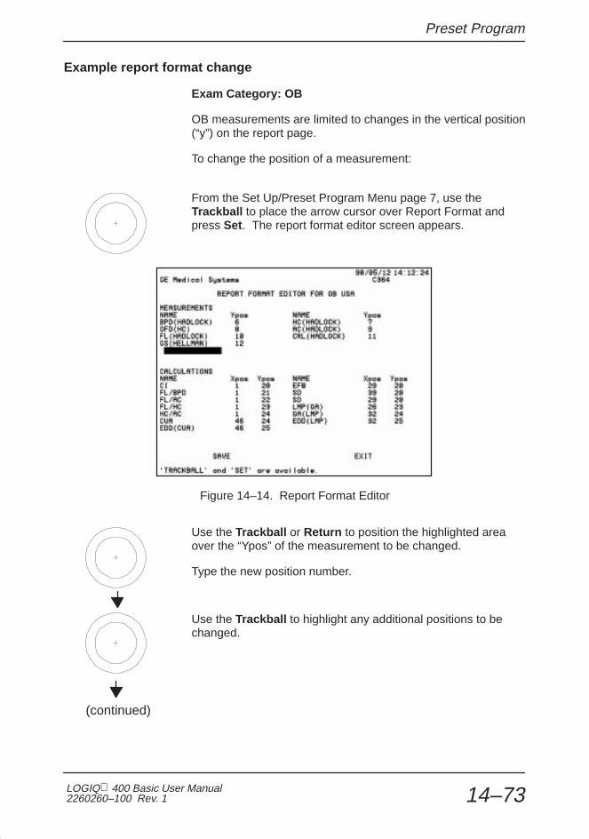
Preset Program
LOGIQ 400 Basic User Manual2260260–100 Rev. 1 14–73
Example report format change
Exam Category: OB
OB measurements are limited to changes in the vertical position(“y”) on the report page.
To change the position of a measurement:
From the Set Up/Preset Program Menu page 7, use theTrackball to place the arrow cursor over Report Format andpress Set. The report format editor screen appears.
Figure 14–14. Report Format Editor
Use the Trackball or Return to position the highlighted areaover the “Ypos” of the measurement to be changed.
Type the new position number.
Use the Trackball to highlight any additional positions to bechanged.
(continued)

Preset Program
LOGIQ 400 Basic Users Manual2260260–100 Rev. 114–74
Example report format change (cont’d)
When all changes are complete, highlight Save and press Set.
To exit the Report Format Editor and return to the Set Up/Preset Program Menu, highlight Exit and press Set.
To Add or Delete a measurement:
Enter the Report Format Editor in the same manner as “Tochange the position”.
Use the Trackball to highlight the desired measurement name(to delete or change) or highlight a blank area (to add).
To delete a name, type in all spaces. To change a name, type over the current name.To add a name, type in the new name.
NOTE: When adding or changing a measurement name, it mustcontain 2 important elements:
� Measurement type. For example, GS, BPD, CRL, HC.
� Author’s name. The author’s name must appear inparentheses, for example (Hadlock), (Hellman).
Highlight Save and press Set to record all changes.
Highlight Exit and press Set to return to the Set Up/PresetProgram menu.
NOTE: If 2 measurement names are placed in the sameposition, an error message appears.
“More than 1 Measurement Field Name at the SAME Ypos”.
�
�

Preset Program
LOGIQ 400 Basic User Manual2260260–100 Rev. 1 14–75
Page 7 of 10 (Application – Measurement Submenu) (cont’d)
User Table Editor
If the factory preset OB tables are not suitable, the user can input data for five OBtables. The titles given to these tables appear as selections in the OB CalculationsSoft-Menu when displayed.
To program a user table
Select the Set Up Top Menu.
1/1Set Up
PresetProgram
SystemParamtr
CustomDisplay
Diag.UserDefine
UtilitySaveValues
Figure 14–15. Set Up Top Menu
Select Preset Program from the Set Up Sub-Menu. The presetprogram selections are displayed over the image on themonitor.
Use the Trackball to place the arrow cursor over User TableEditor.
Press Set to display the User Table Programming Main Menu.
The User Table Programming main menu appears as shown inFigure 14–16.

Preset Program
LOGIQ 400 Basic Users Manual2260260–100 Rev. 114–76
To program a user table (cont’d)
Figure 14–16. User Table Programming
Use the Ellipse up/down arrow keys to select the desired tablenumber UT01 to UT10.
Press Set to select the desired table.
Use the Trackball to place the arrow cursor on the desiredtable dimension. The choices are Dist (mm) for distance inmillimeters, Circ (mm) for circumference in millimeters and Areafor area in square millimeters. Press Set when the cursor isover the correct dimension.
Use the Trackball to move the arrow cursor to the title block.Type in the desired table title (maximum 4 characters). PressReturn .
Type in the author’s name (maximum 8 characters). PressReturn .

Preset Program
LOGIQ 400 Basic User Manual2260260–100 Rev. 1 14–77
To program a user table (cont’d)
Type in any desired notes (maximum 30 characters). PressReturn .
Type in the minimum or beginning data value for the table(maximum 4 digits). Press Return .
Type in the interval value between each table data point(maximum 4 digits). Press Return .
The selection “Table-Edit” should now be highlighted. PressSet.
NOTE: The Return key or Trackball can be used to cyclethrough the menu selections. To make a choice, press Set.
User Table on EFW
The measurement made by the User Table can be used for thecalculation of EFW. Move the cursor to the right of “Title of” inthe User Table Programming Menu. The availablemeasurement name for calculation of the EFW is displayedafter the Ellipse up/down arrow key is pressed.
The OB Report Format preset, located on SetUp/SystemParameters page 2, determines which measurements aredisplayed.
�

Preset Program
LOGIQ 400 Basic Users Manual2260260–100 Rev. 114–78
To enter table values
The Table-Edit Menu shown in Figure 14–17 allows for addingdata, editing data or clearing (deleting) a User Table.
Figure 14–17. Table Edit Menu
For each data point, the weeks (2 digits), days (1 digit) anddeviation (2 digits) must be entered.
The menu choices at the bottom allow:
SAVE Saves the table in its current form.CLEAR Clears or deletes the entire table (and title).SETUP Returns to the User Table Programming Setup
menu.NEXT-PG Goes to the next page to continue data entry.EXIT Exits the User Programmable Table function.
Trackball to one of the above choices and press Set. Whenexit is selected without doing a “Save”, all additions or edits arelost. The table reverts to its previous state.
NOTE: If a new table was added, the measurement can beadded to the summary report. Follow the instructions underReport Format in the Set Up/Preset program.
�

Preset Program
LOGIQ 400 Basic User Manual2260260–100 Rev. 1 14–79
Page 7 of 10 (Application – Measurement Submenu) (cont’d)
Sequence 1–8 EC, UP (Auto Sequence Programming)
The user can program a maximum of 8 calculation sequences with a maximum of eightmeasurements per sequence.
These are labeled Sequence 1–8 in the Set Up/Preset Program Menu asUSERSEQUENCE1–8 in the Measurement Sub-Menu or in the Auto Sequence TopMenu.
When Sequence 1–8 is chosen from the Auto Sequences Top Menu or theMeasurement Sub-Menu, the system automatically prompts the user through thecalculations previously programmed.
Program a User Sequence
Use the Trackball to move the arrow cursor to the desiredsequence number (1–8) on page 7 of the Set Up/PresetProgram Menus.
Press Set. The first page of the 8 Measurement SequenceSub-Menus is displayed.
Figure 14–18. Measurement Sequence Sub-Menu
NOTE: The first row under the sub-menu title line shows 3important items:�

Preset Program
LOGIQ 400 Basic Users Manual2260260–100 Rev. 114–80
Program a User Sequence (cont’d)
USERSEQUENCE2 8 UNDEFINED NEXT CALCMeasurement Sequence Submenu************* *****************************
Figure 14–19. Sequence Sub-Menu Status Line
8 is the order in which the measurement or calculation will bemade in USERSEQUENCE 2. 1 is first, 2 is second.....8 is last.
UNDEFINED is the current measurement in that sequencelocation. Undefined means it is blank.
NEXTCALC allows the user to cycle through the 8 pages ofmeasurements and calculations available to be programmed.
Use the Ellipse up/down arrow keys to cycle to the desiredusersequence measurement number (1–8).
Use the Trackball to move the arrow cursor to the desiredmeasurement/calculation.
Move the arrow cursor to Next Calc and press Set if asub-menu page change is necessary.
Press Set when the arrow cursor is over the desiredmeasurement/calculation.
The newly selected measurement/calculation appears as thecurrent measurement for the highlighted USERSEQUENCEnumber replacing undefined.
Repeat the previous steps as necessary to program additionalsequence number locations for any of the 8 user sequences.
�

Preset Program
LOGIQ 400 Basic User Manual2260260–100 Rev. 1 14–81
Program a User Sequence (cont’d)
USERSEQUENCE1–8 are choices that can be programmed inthe Measurement Menus for each mode (B, M, D, and CFM)per exam category.
Auto Sequence Top Menu choices are exam categorydependent. Sequences programmed in Vascular are notavailable when the Cardiac exam category is selected.
UNDEFINED means no measurement/calculation is in thatlocation.
Use UNDEFINED to delete a desired measurement.
To customize the Usersequence/Auto Sequence name:
Move the Trackball to the USERSEQUENCE# at the top of oneof the 8 Calculation menus.
Press Set.
Type in the name of the Usersequence. The space available is2 lines of 7 characters each.
Move the Trackball to SAVE.
Press Set.
Hints

Preset Program
LOGIQ 400 Basic Users Manual2260260–100 Rev. 114–82
Performing an Auto Sequence (USERSEQUENCE)
Select an Auto Sequence, or a user programmable modemeasurement menu selection, the system automaticallyprompts the user to do the first measurement in the sequence.
After the first measurement/calculation is completed, thesystem automatically prompts the user to do the secondmeasurement in the sequence.
This continues until all measurements are completed.
Sequence Modification
During the Auto Sequence function:
Press the top of the Elllipse up/down arrow keys to skip adesired measurement and advance to the next measurement inthe sequence.
Press the bottom of the Ellipse up/down arrow keys to skipback to a previous measurement in the sequence.
Measurements skipped will appear again at the end of thesequence. This gives the user a second chance to make themeasurements prior to exiting the Auto Sequece function.

Preset Program
LOGIQ 400 Basic User Manual2260260–100 Rev. 1 14–83
Page 7 of 10 (Application – Measurement Submenu) (cont’d)
Measurement Menu B/M/D/CFM EC, UP
Each exam category has a set of factory default measurements/calculations. The 4measurement menu modes allow the user to add a maximum of 4 new pages to themeasurement sub-menus per exam category per mode within a user application preset.With 8 items per page, a total of 32 measurements/calculations can be added for eachexam category in B, M, D, which is distinct and separate from those that can beprogrammed into CFM-Mode.
NOTE: Measurements and Calculations setup for Measurement Menu B are nottransferred to Menu M, D, or CFM. Each one is separate.

Preset Program
LOGIQ 400 Basic Users Manual2260260–100 Rev. 114–84
Organization
There are 4 pages of space available for the user to addmeasurements and calculations to an exam categorymeasurement menu.
These pages do not appear in the Soft Menu display unlessitems are placed in the number location of that page.
Meas1
Meas3
Meas5
Meas6
Meas7
Meas2
Meas4
Meas8
1/4
Meas9
Meas11
Meas13
Meas14
Meas15
Meas10
Meas12
Meas16
2/4
Meas17
Meas19
Meas21
Meas22
Meas23
Meas18
Meas20
Meas24
3/4
Meas25
Meas27
Meas29
Meas30
Meas31
Meas26
Meas28
Meas32
4/4
Figure 14–20. Measurement Menu Key Numbers
The spaces available for calculations are called Key Numbers.Key Numbers 1 through 8 are on page 1, 9 through 16 on page2 etc. (See Figure 14–20).

Preset Program
LOGIQ 400 Basic User Manual2260260–100 Rev. 1 14–85
Programming Measurements
Use the Trackball to move the arrow cursor to the desiredMeasurement Menu (B, M, D, or CFM) on page 7 of theSet Up/Preset Program menus.
Press Set. The last page viewed of the 4 measurement pagesis displayed.
Figure 14–21. Measurement Setup Sub-Menu
NOTE: The first row under the sub-menu title line shows 3important items.�

Preset Program
LOGIQ 400 Basic Users Manual2260260–100 Rev. 114–86
Programming Measurements (cont’d)
KEY NUMBER 1 USERSEQUENCE1 NEXT CALC************* Measurement VFD Softmenu Setup Submenu*******************
Figure 14–22. Sequence Sub-Menu Status Line
1 is the position in the soft menu where the measurement forkey number one will be displayed.
USERSEQUENCE1, or the customized name, is the currentmeasurement sequence in that key number location.
NEXTCALC allows the user to cycle through the four pages ofmeasurements and calculations available.
Remembering how the key numbers are organized (seeFigure 14–20), use the Ellipse up/down arrow keys to changeto the desired key number.
Move the arrow cursor to NEXTCALC and press Set if asub-menu page change is necessary.
Press Set when the arrow cursor is over the desiredmeasurement/calculation.
The newly selected measurement/calculation appears in thehighlighted key number location.
NOTE: If key number is desired to be empty (blank, deleted)choose UNDEFINED.
Factory default measurements/calculations are protected andcannot be changed.
Adding authors to a measurement menu does NOTautomatically add the measurement to the report page.
Repeat the previous steps to program any key number in anymode menu. Be sure to use the Save function prior to exitingthe Calculation menus and the Preset Program menus.
�
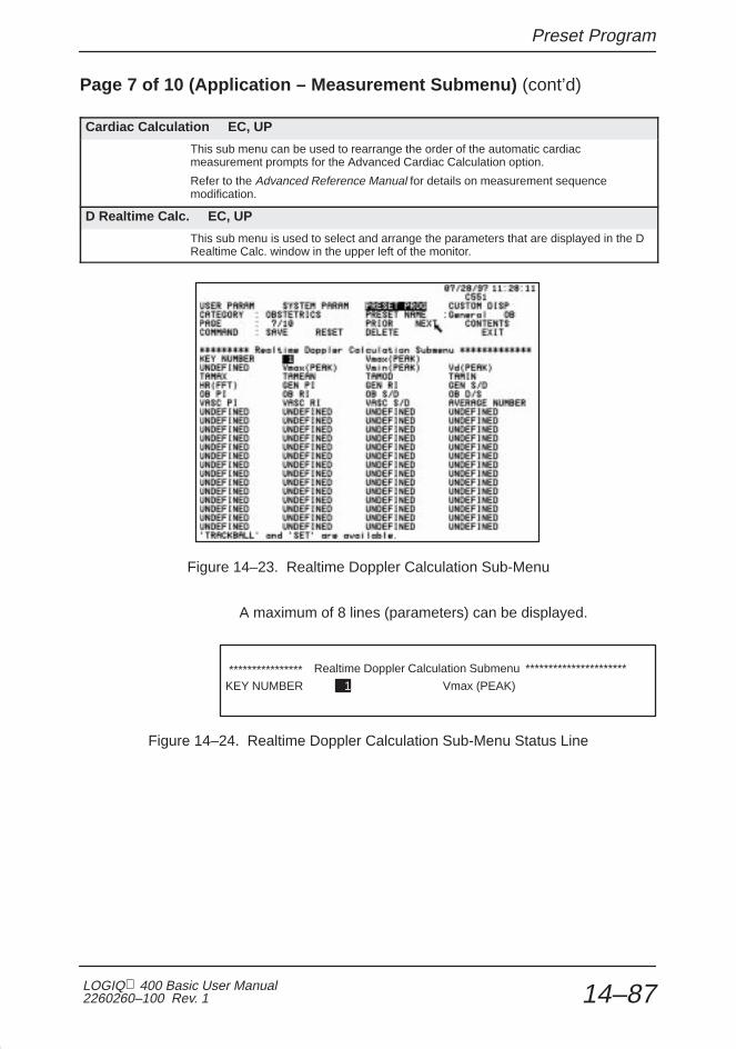
Preset Program
LOGIQ 400 Basic User Manual2260260–100 Rev. 1 14–87
Page 7 of 10 (Application – Measurement Submenu) (cont’d)
Cardiac Calculation EC, UP
This sub menu can be used to rearrange the order of the automatic cardiacmeasurement prompts for the Advanced Cardiac Calculation option.
Refer to the Advanced Reference Manual for details on measurement sequencemodification.
D Realtime Calc. EC, UP
This sub menu is used to select and arrange the parameters that are displayed in the DRealtime Calc. window in the upper left of the monitor.
Figure 14–23. Realtime Doppler Calculation Sub-Menu
A maximum of 8 lines (parameters) can be displayed.
KEY NUMBER 1 Vmax (PEAK)**************** Realtime Doppler Calculation Submenu **********************
Figure 14–24. Realtime Doppler Calculation Sub-Menu Status Line

Preset Program
LOGIQ 400 Basic Users Manual2260260–100 Rev. 114–88
Page 7 of 10 (Application – Measurement Submenu) (cont’d)
1 is the position number or line of the Doppler Realtimedisplay.
Use the Ellipse up/down arrow keys to change to the desiredline number (1–8).
Move the arrow cursor to the desired measurement/calculationto be displayed on that line.
Press Set when the arrow cursor is over the desiredmeasurement/calculation.
The newly selected measurement/calculation appears to theright of the position number.
NOTE: Remember that this setup is Exam Category and UserPreset dependent. If changes are desired to the factorydefaults, a new User Preset will be created.
�

Preset Program
LOGIQ 400 Basic User Manual2260260–100 Rev. 1 14–89
Page 8 & 9 of 10 (Application – Annotation Library)
Annotation Library 1–24 EC, UP
Type in the desired (most commonly used) display annotations. There is space for amaximum of 20 characters (numbers, letters and spaces) for each library script.A maximum of 24 annotation library scripts is available per exam cagegory.
Simply place the arrow cursor across from the desired annotation library number andpress Set.
Type the desired script.
Press Set to complete the entry.
Page 10 of 10 (Application – Patient Information)
New Patient Y/N Ask EC
In the new patient entry menu, choose to ask to erase all current patient data.
On or Off.
Display Unit Age 1–4 EC
Choose the priority for the units to be used to display patient age. Age 1 is the highestpriority. Age 4 is the lowest priority.
year Display age in years.month Display age in months.week Display age in weeks.day Display age in days.nodisp No display.
Display Unit Height 1–3 EC
Choose the priority to be used for the units to display the patient’s height.
cm Centimetersinch Inchesfeet-inch Feet and inchesnodisp No display
Display Unit Weight 1–2 EC
Choose the priority to be used for the units to display the patient’s weight.
kg Kilogramslbs Poundsnone None

Save Values
LOGIQ 400 Basic Users Manual2260260–100 Rev. 114–90
Save Values
Overview
Save Values is a selection in the Set Up Menu that allows forthe quick retention of a current system settings and presetparameters.
It works like the Save command in the Custom Display, SystemParameter or Preset Program sub-menus.
1/1Set Up
PresetProgram
SystemParamtr
CustomDisplay
Diag.UserDefine
UtilitySaveValues
Figure 14–25. Set Up Sub-Menu
Saving Scan Values
If at any time during a scan it is felt that the system settings areoptimized and should be saved as an Exam ApplicationsPreset, simply select Save Values .
The system will start the process of saving all of the currentsettings as a User Exam Applications Preset.
If a factory default applications preset is active when SaveValues is selected, the message:
“Input User Preset Number (1-8)”
appears at the bottom of the screen. Enter the preset positionnumber 1 through 8. The data is saved and available for recallat the designated preset location.

Save Values
LOGIQ 400 Basic User Manual2260260–100 Rev. 1 14–91
Saving Scan Values (cont’d)
If a User Preset is active when Save Values is selected, themessage:
“Overwrite existing data ‘Y’ or ‘N’”
appears at the bottom of the screen.
Choose ‘Y’ to overwrite data in the current preset location or ‘N’to designate a new preset location 1 through 8.

Exam Applications Presets
LOGIQ 400 Basic Users Manual2260260–100 Rev. 114–92
Exam Applications Presets
Overview
The top menu Preset selection will display a maximum of eightfactory application preset choices for each exam category.
The user may define a maximum of eight application presets fordisplay on the Preset sub-menu designated as page one.
Preset parameters that are exam category dependent andavailable for customization are found in the Preset Program andCustom Display menus. Some parameters are also probedependent within the application preset.
Items found under System Parameters affect each examcategory, application preset or probe.
Defining a User Preset
User presets appear on page one of the Preset Sub-Menu.They will appear on the Soft Menu Display, as shown inFigure 14–26.
Preset
UserPreset–3
1/3
UserPreset–1
UserPreset–5
UserPreset–4
UserPreset–2
UserPreset–7
UserPreset–6
UserPreset–8
Figure 14–26. User Preset Configuration

Exam Applications Presets
LOGIQ 400 Basic User Manual2260260–100 Rev. 1 14–93
Defining a User Preset (cont’d)
To define a User Preset (1–8), first ensure that:
� the system is set to the proper exam category by usingNew Patient or ID/Name keys
� the desired probe is connected and activated.
� all keyboard controls (mode, depth, gain, etc.) are set to thedesired values.
Mode Preset Set Up ECG Archive DICOM Auto CINEDefault Seq
Figure 14–27. Set Up Top Menu Selection
Select the Set Up Top Menu. Select Custom Display or PresetProgram.
Make all desired changes to the parameters in the CustomDisplay and Preset Parameter Sub Menus.
Use the Trackball to move the arrow cursor to Save.
Press Set. The message “Input User Preset Number (1–8)”appears at the bottom of the monitor.
Enter the desired preset number.
The Preset Name at the top of the menu now displays thenumber entered (1–8).
(continued)

Exam Applications Presets
LOGIQ 400 Basic Users Manual2260260–100 Rev. 114–94
Defining a User Preset (cont’d)
NOTE: If a user application preset was used at the start of theprocess, the system prompt states:
“Overwrite Existing Data? ‘y’ or ‘n’”
Enter ‘y’ to write over the existing user preset.Enter ‘n’ to get the message: “Input User Preset Number (1-8)”and create a new user preset.
Use the Trackball to move the arrow cursor over the PresetName area.
Press Set.
NOTE: If new data is not saved, all changes will be lost whenanother preset or New Patient is selected.
�
�

Exam Applications Presets
LOGIQ 400 Basic User Manual2260260–100 Rev. 1 14–95
Naming a User Preset
To give the user preset a name instead of a number:
While in a Custom Display or Preset Program menu page, usethe Trackball to move the arrow cursor over the Preset Namearea. Press Set.
Type in the desired name for the User Preset in the designatedexam category.
Use the Trackball to move the arrow cursor to SAVE and pressSet.
Answer Yes to the question “ Overwrite existing data? ‘Y’ or ‘N’ ”to save the new User Preset name.
IMPORTANT NOTE: To ensure that all parameters and theuser preset name are saved by the LOGIQ 400 before exitingthe Set Up function:
� select System Parameters, any menu pages 1/7through 7/7.
� Trackball to the SAVE function in the SystemParameters menu and press Set.
� IMPORTANT: Answer ‘Y’ to overwrite existing dataagain.
These steps are important to ensure that the new user presetname is saved.
�
Exam Applications Presets
LOGIQ 400 Basic Users Manual2260260–100 Rev. 114–96
Deleting User Presets and Names
Display any Set Up/Custom Display or Preset Program submenu page.
� Use the Trackball to move the arrow cursor to the presetname and press Set.
� Type in the User Preset position number (1–8) and use theSpace Bar to delete the rest of the name.
� Use the Trackball to move the arrow cursor to Delete menuselection and press Set.
� Answer Yes to the question. “ Delete data? ‘Y’ or ‘N’ ”.
� Select System Parameters, any menu page 1–7.
� Trackball to the SAVE function in the System Parametersmenu and press Set.
� Answer Yes to the question “Overwrite existing data? ‘Y’ or‘N’” to save the new User Preset name.
The last three steps are important to ensure that the UserPreset name is cleared.
Recall Preset
Recall Preset is a selection found on page 3 of the PresetSub-Menu. Recall Preset can be used during an examinationto return the majority of the parameters to the latest savedpreset values.
If front panel and soft menu values were changed whilescanning, Recall Preset quickly resets these values.
Recall Preset does not recover preset data that was changedwith the Save function or was deleted.

User Define Function
LOGIQ 400 Basic User Manual2260260–100 Rev. 1 14–97
User Define Function
Overview
Six keys in the middle of the right side of the console keyboardas well as alphanumeric (A/N) keys A�Z 1�0 may beprogrammed to duplicate a single keystroke or a sequence of64 keystrokes maximum.
A keystroke is considered to be a press of a key, onemovement of a knob or movement of the Trackball.
Programming the User Define Function
� Access the User Define function by pressing the Set UpTop Menu Select key.
� Select User Define from the Set Up Sub-Menu.
� Perform the keystroke or sequence of keystrokes to beprogrammed.
� When complete, press the desired User Define key numberor A/N key to record the programming.
� The system will ask: “Save data? ‘Y’ or ‘N’.” Press ‘Y’ onthe keyboard to save the user define sequence. Press ‘N’to cancel the user define programming function.
� If a sequence is already assigned to the selected key, themessage will be displayed:
“Overwrite Existing data? ‘y’ or ‘n’”
User Define keys that have been programmed will be halflighted (back lit).

User Define Function
LOGIQ 400 Basic Users Manual2260260–100 Rev. 114–98
Programming the User Define Function (cont’d)
� When ‘y’ is the reply for Save Data or Overwrite Existingdata,
“Input Name: ” is displayed
A user define function name must be entered with amaximum of 11 characters.
� Press the Mode Top Menu Select function to return to theprevious scan mode, if necessary.
The next time a programmed User Define or A/N key ispressed, the recorded keystroke or keystroke sequence will beperformed by a single key operation.
Ctrl, 1
If selecting Set Up Top Menu with Custom Display, SystemParameter or Preset Program as part of the User DefineSequence, press Ctrl and 1 simultaneously to set the sub-menupage to one. Press Set the appropriate number of times toensure proper movement to the desired sub-menu page.
Blue Shift, S
A pause can be valuable in a User Define or A/N key sequence,especially if it is desired to program a key to toggle functionson/off, between two different settings or between selections.
Enable the Blue Shift key and press S to add a pause in theUser Define or A/N key programming sequence.
With a pause in the user define sequence, the first time theUser Define or A/N key is pressed, all steps will be executed upto the pause. The next time the key is pressed, all steps will beexecuted from the pause to the end (or next pause). This isespecially useful in programming “toggle” functions.
Hints

User Define Function
LOGIQ 400 Basic User Manual2260260–100 Rev. 1 14–99
User Define Key Program Example
The following is a brief example of programming a user definesequence showing the use of Ctrl, 1 and Blue Shift, S.
As an example, assume that it is desired to turn themeasurement “Average Activity” on and off. This parameter isin the Set Up/Preset Program menu page 3. Perform thefollowing steps to program a User Define function to toggleAverage Activity:
� Press the Set Up top menu key.
� Select and highlight User Define in the Set Up Sub-menu.
� Select and highlight Preset Program in the Set UpSub-menu.
� Press Ctrl, 1 simultaneously (this ensures that the menupage displayed is number one).
� Press Set twice.
� Trackball to “Average Activity OFF” and press Set.
� Trackball to “Exit” and press Set.
� Enable the Blue Shift key (key is lighted) and press S.This adds the pause to the sequence.
� Disable the Blue Shift key (key is not lighted).
� Select and highlight Preset Program in the Set UpSub-menu.
� Press Ctrl, 1 simultaneously (this ensures that the menupage displayed is number one).
� Press Set twice.
� Trackball to “Average Activity ON” and press Set.
� Trackball to “Exit” and press Set.
� Press the desired User Define or A/N key. This ends theprogramming operation.

User Define Function
LOGIQ 400 Basic Users Manual2260260–100 Rev. 114–100
User Define Key Program Example (cont’d)
The first time the User Define or A/N key is pressed, AverageActivity will be set to OFF. The second time the User Define orA/N key is pressed, Average Activity will be set to ON. Thethird time the User Define or A/N key is pressed, AverageActivity will be set to OFF. Each press of the User Define orA/N key toggles the Average Activity setting.
User Define Names & Lock/Unlock
The User Define Key Names & Locks Sub-Menu in the SetUp/System Parameters menu page 3 will allow the user to locka key, keeping it from being deleted or reprogrammed. ThisSub-Menu also allows the user to name or change the name ofany user defined key.
Figure 14–28. User Define Key Names & Locks Sub-Menu

User Define Function
LOGIQ 400 Basic User Manual2260260–100 Rev. 1 14–101
Names
To enter or edit the name of a User Define key:
� Place the arrow cursor to the right of the desired key in thesub-menu.
� Press Set.
� In the highlighted area that appears, type in the desiredname. Eleven (11) characters maximum.
Lock/Unlock
An asterisk next to the User Define key indicates the key islocked. The key cannot be programmed or the function definedfor that key cannot be edited.
To lock or unlock a key:
� Place the arrow cursor on the desired key in the sub-menu.
� Press Set.
� An asterisk appears to indicate it is locked. No asteriskindicates it is unlocked.
Press Shift + User Define key to display the key name on themonitor.
Hints

User Define Function
LOGIQ 400 Basic Users Manual2260260–100 Rev. 114–102
Deleting User Define Functions
To delete a User Define or A/N key sequence:
� Ensure that the User Define or A/N key to be deleted isunlocked.
� Select Set Up Top Menu.
� Select User Define function.
� Press the User Define or A/N key number to be deleted.
� Press ‘Y’ (for Yes) to overwrite current data.
A User Define or A/N key can also be re-programmed by writingover (replacing) the existing sequence.
Saving User Define Functions
All user define functions can be saved to MOD by usingSetup/Utilities/User Data Back Up/Save. The data can beloaded back on to the system in the event of a hard drivefailure.

User Data Backup
LOGIQ 400 Basic User Manual2260260–100 Rev. 1 14–103
User Data Back-up
Overview
The Set Up/Utility Menu, option #04 allows the user to back-up(save) all user preset data to MOD. In the event of a systemupgrade or catastrophic hard drive failure, the user applicationpresets can be easily loaded back to the system if they havebeen previously saved to MOD.
Once presets have been backed up, the user data back-upshould be performed periodically to update any changes thathave been made to the user preset parameters.
Saving Presets
Before saving presets, the MOD must first be initialized(formatted) prior to saving user application preset data.
� Select Set Up/Utility Menu.
� Select #09 Media Initialize and press Return .
� Insert a MOD into the drive and press Return .
The system then takes the time to format the MOD (approx. 12minutes).
NOTE: If presets have already been saved on the MOD, theMOD should be initialized again to ensure that old preset datahas been deleted from the MOD.
To save presets:
� Enter #04 User Data Backup from the Utility Menu andpress Return .
� Enter # 1 (Save) and press Return .
�

User Data Backup
LOGIQ 400 Basic Users Manual2260260–100 Rev. 114–104
Saving Presets (cont’d)
� Set media to drive (ensure the MOD is in the drive) andpress Return .
� Select the exam category name to be saved (01–08) or “AllSystem & Application Data” (09), enter its number andpress Return .
The system takes a few minutes to save the selected item tothe MOD. A succeed or fail message will be displayed.
Eject the MOD, label it and store it in a secure place for futurereference.
Loading Presets
To load presets back onto the system:
� Type #04 User Data Backup from the Utility Menu andpress Return .
� Type #02 Load and press Return .
� Set the media to the drive (ensure the MOD is in the drive)and press Return .
� Select the application destination and press Return .
The system will take a few minutes to load the presets from theMOD to the system hard drive.
� Eject the MOD and store it in a secure place.
� Restart the system. The backup data will be recognized atpower up.

Probes and Biopsy
LOGIQ 400 Basic User Manual2260260–100 Rev. 1 15–1
Probes and Biopsy
Probe Overview 15–2. . . . . . . . . . . . . . . . . . . . . . . . . . . . . . . . . . . . . . . . . . . . . . . . . . . . . . . . . Ergonomics 15–2. . . . . . . . . . . . . . . . . . . . . . . . . . . . . . . . . . . . . . . . . . . . . . . . . . . . . . Cable handling 15–2. . . . . . . . . . . . . . . . . . . . . . . . . . . . . . . . . . . . . . . . . . . . . . . . . . . Probe orientation 15–3. . . . . . . . . . . . . . . . . . . . . . . . . . . . . . . . . . . . . . . . . . . . . . . . . . Labeling 15–3. . . . . . . . . . . . . . . . . . . . . . . . . . . . . . . . . . . . . . . . . . . . . . . . . . . . . . . . . Applications 15–6. . . . . . . . . . . . . . . . . . . . . . . . . . . . . . . . . . . . . . . . . . . . . . . . . . . . . . Specifications 15–7. . . . . . . . . . . . . . . . . . . . . . . . . . . . . . . . . . . . . . . . . . . . . . . . . . . . Probe Usage 15–10. . . . . . . . . . . . . . . . . . . . . . . . . . . . . . . . . . . . . . . . . . . . . . . . . . . . Care and Maintenance 15–10. . . . . . . . . . . . . . . . . . . . . . . . . . . . . . . . . . . . . . . . . . . . Probe Safety 15–11. . . . . . . . . . . . . . . . . . . . . . . . . . . . . . . . . . . . . . . . . . . . . . . . . . . . Probe handling and infection control 15–13. . . . . . . . . . . . . . . . . . . . . . . . . . . . . . . . Coupling gels 15–19. . . . . . . . . . . . . . . . . . . . . . . . . . . . . . . . . . . . . . . . . . . . . . . . . . . . Planned Maintenance 15–19. . . . . . . . . . . . . . . . . . . . . . . . . . . . . . . . . . . . . . . . . . . .
Probe Discussion 15–20. . . . . . . . . . . . . . . . . . . . . . . . . . . . . . . . . . . . . . . . . . . . . . . . . . . . . . Introduction 15–20. . . . . . . . . . . . . . . . . . . . . . . . . . . . . . . . . . . . . . . . . . . . . . . . . . . . . Curved Array (Convex) Probes 15–21. . . . . . . . . . . . . . . . . . . . . . . . . . . . . . . . . . . . Linear Array Probes 15–24. . . . . . . . . . . . . . . . . . . . . . . . . . . . . . . . . . . . . . . . . . . . . . Sector Probes 15–27. . . . . . . . . . . . . . . . . . . . . . . . . . . . . . . . . . . . . . . . . . . . . . . . . . . CWD Probes 15–29. . . . . . . . . . . . . . . . . . . . . . . . . . . . . . . . . . . . . . . . . . . . . . . . . . . .
Biopsy Special Concerns 15–30. . . . . . . . . . . . . . . . . . . . . . . . . . . . . . . . . . . . . . . . . . . . . . . Precautions Concerning the Use of Biopsy Procedures 15–30. . . . . . . . . . . . . . .
Preparing for a Biopsy 15–31. . . . . . . . . . . . . . . . . . . . . . . . . . . . . . . . . . . . . . . . . . . . . . . . . . Displaying the Guidezone 15–31. . . . . . . . . . . . . . . . . . . . . . . . . . . . . . . . . . . . . . . . . Determining Needle Length 15–32. . . . . . . . . . . . . . . . . . . . . . . . . . . . . . . . . . . . . . . Needle Guide Type Preset Selection 15–33. . . . . . . . . . . . . . . . . . . . . . . . . . . . . . . . Preparing the Biopsy Guide Attachment 15–36. . . . . . . . . . . . . . . . . . . . . . . . . . . . . E721 Probe Biopsy Guide 15–44. . . . . . . . . . . . . . . . . . . . . . . . . . . . . . . . . . . . . . . . . Biopsy Probes 15–48. . . . . . . . . . . . . . . . . . . . . . . . . . . . . . . . . . . . . . . . . . . . . . . . . . .

Probe Overview
LOGIQ 400 Basic Users Manual2260260–100 Rev. 115–2
Probe Overview
Ergonomics
Probes have been ergonomically designed to:
� Handle and manipulate with ease
� Connect to the system with one hand
� Be lightweight and balanced
� Have rounded edges and smooth surfaces.
Cables have been designed to:
� Connect to system with appropriate cable length
� Stand up to typical wear by cleaning and disinfectantagents, contact with approved gel, etc.
Cable handling
Take the following precautions with probe cables:
� Keep free from wheels
� Do not bend the cable acutely
� Avoid crossing cables between probes.

Probe Overview
LOGIQ 400 Basic User Manual2260260–100 Rev. 1 15–3
Probe orientation
Each probe is provided with an orientation marking (refer toFigure 15–1). This mark is used to identify the end of the probecorresponding to the side of the image having the orientationmark on the display.
1
1 Orientation Marking
Figure 15–1. Orientation Marking on Probe
Labeling
Each probe is labeled with the following information:
� Seller’s name and manufacturer
� Operating frequency
� GE part number
� Probe serial number
� Month and year of manufacture
� Probe designation—provided on the probe grip and the topof the connector housing, so it is easily read when mountedon the system and is also automatically displayed on thescreen when the probe is selected.

Probe Overview
LOGIQ 400 Basic Users Manual2260260–100 Rev. 115–4
Labeling (cont’d)
!
MANUFACTUREDe.g. SEPTEMBER 1993 Also found on
Probe Connector
GEMS–Am GEMS–E GEMS–A
Figure 15–2. Probe Adapter Label
Figure 15–3. Probe Handle Labels

Probe Overview
LOGIQ 400 Basic User Manual2260260–100 Rev. 1 15–5
Labeling (cont’d)
!
MANUFACTUREDe.g. SEPTEMBER 1993
GEMS–Am GEMS–E GEMS–A
3
2
2
3
1
1
Also found onProbe Adapter
Figure 15–4. Probe Connector Labels
ÇÇÇÇÇÇÇÇÇ
>
21
MHz
1 Probe Orientation Marker 2 Active Probe
Figure 15–5. Displayed Probe Information

Probe Overview
LOGIQ 400 Basic Users Manual2260260–100 Rev. 115–6
Applications
Below is a list of probes and their intended applications.
Probe
Application
B510 C364 C358 C386 C551 C721 E721 ERB7 I739 LA39 546L
Abdomen
Small Parts
Periph. Vasc.
Obstetrics
Gynecology
Pediatrics
Neonatal
Urology
Surgery
Cardiac
Endocavity
Biopsy
����� ���������� ������ �������������� ������� �������������
Probe
Application
739L L764 LD S220 S222 S317 S611 3S T739 CWD2 CWD5
Abdomen
Small Parts
Periph. Vasc.
Obstetrics
Gynecology
Pediatrics
Neonatal
Urology
Surgery
Cardiac
Transcranial
Biopsy
����� ���������� ������ �������������� ������� �������������
Table 15–2. Probe Indications for Use

Probe Overview
LOGIQ 400 Basic User Manual2260260–100 Rev. 1 15–7
Specifications
ProbeDesignation
PrincipalClinical
Uses
ImageFrequency
(MHz)
DopplerFrequency
(MHz)
B510 Cardiac 5.0 4.0
C358 Abdom./OB/GYN 3.8 2.5
C364 Radiology/Obstetrics
3.3 2.5
C386 OB/GYN/Abdom. 3.5 2.5
C551 Radiology/Obstetrics
5.0 4.0
C721 Neonatal 6.6 5.0
E721 TransvaginalTransrectal
6.6 5.0
ERB7 Urology 7.0 5.0
I739 Intra–operative 6.7 5.0
546L Deep Vascular/Small Parts
5.2 4.0
739L Peripheral Vascular/Small Parts
6.7 5.0
L764 Mammo, PV & SmallParts
6.6 5.0
LA39 Small Parts 8.7 5.0
LD Biopsy 3.5 2.5
S220 Cardiac 2.5 2.2
S222 Transcranial, Cardiac
2.9 2.0
S317 Cardiac/Abdom. 3.3 2.5
S611 Cardiac 5.7 4.0
T739 Intra–operative 6.7 5.0
3S Cardiology 2.4 2.0
B = Bipolar Sector C = Curved Array (Convex)E = Endocavitary I = Intra–operative LinearL = Linear Array S = Phased Array SectorT = Intra–operative Linear
Table 15–3. System Probe Definitions

Probe Overview
LOGIQ 400 Basic Users Manual2260260–100 Rev. 115–8
Specifications (cont’d)
Adapter Designation Adaptable Probe System Operates Probe As:
PA 51 CBF C364
CAE C551
LH L764
MTZ E721
5S W S220
Table 15–4. Probe Adapter Usage
ProbeName
Materialof
Headshell Use Type Mfg. by
Probe Family
(Headshell) Part No.
B510 PU Intercavity Biplane Sec-tor
GEYMS 2123593
C358 NORYL Abdom./OB/GYN Convex GEYMS 2193617
C364 PES Abdom. Convex GEYMS CBF P9607AB
C386 NORYL Abdom./OB/GYN Convex GEYMS 2147187–2
C551 PES Abdom. Convex GEYMS CAE P9607AD
C721 NORYL Neonatal Convex GEYMS MTZ 2121267-2
E721 PES Intercavity Convex GEYMS MTZ P9607AF
ERB7 NORYL Urology Convex/Lin-ear
GEYMS 2239590
I739 NORYL Intra–op. Linear GEYMS 2147189–2
546L NORYL Abdom.Superficial
Linear GEYMS 2144266–2
739L NORYL Superficial Linear GEYMS 2107460–2
L764 PES Sm. Parts Linear GEYMS LH 2121377-2
LA39 NORYL Superficial Linear GEYMS 2155078–2
LD PES Biopsy Linear GEYMS 2124318
S220 PES Cardiac Sector GEYMS W 2121793–2
S222 NORYL Trans-cranial
Sector GEYMS 2159263
S317 NORYL Cardiac/Abdom. Sector GEYMS 2144268–2
S611 NORYL Cardiac/Neonatal/Pediatric
Sector GEYMS 2144267–2
Table 15–5. LOGIQ 400 Probe List

Probe Overview
LOGIQ 400 Basic User Manual2260260–100 Rev. 1 15–9
Specifications (cont’d)
ProbeName
Materialof
Headshell Use Type Mfg. by
Probe Family
(Headshell) Part No.
T739 NORYL Intra–op. Linear GEYMS 2147188–2
3S NORYL Cardiology Sector GEMS 2252157
CWD2 NORYL Cardiac Single CWD GEYMS 2123594
CWD5 NORYL Peripheral Vascular Single CWD GEYMS 2123595
CBF PES Abdom. Convex GEYMS P9603AD
CAE PES Abdom. Convex GEYMS P9603AE
MTZ PES Intercavity Convex GEYMS P9603AU
LH PES Sm. Parts Linear GEYMS P9601AS
W PES Cardiac Sector GEYMS P9600BH
Table 15–5. LOGIQ 400 Probe List (cont’d)

Probe Overview
LOGIQ 400 Basic Users Manual2260260–100 Rev. 115–10
Probe Usage
For details on connecting, activating, deactivating,disconnecting, transporting and storing the probes, referto 3–30.
Care and Maintenance
Inspecting probes
Inspect the probe’s lens, cable, and casing after each use.Look for any damage that would allow liquid to enter the probe.If any damage is found, do not use the probe until it has beeninspected and repaired/replaced by a GE ServiceRepresentative.
Keep a log of all probe maintenance, along with a picture of anyprobe malfunction.
Environmental Requirements
Probes should be operated, stored, or transported within theparameters outlined below.
Operational Storage Transport
Temperature 10�- 40� C50�- 104� F
–10�- 60� C14�- 140� F
–40�- 60� C–40�- 140� F
Humidity 30-85%non-condensing
30-90%non-condensing
30-90%non-condensing
Pressure 700-1060hPa 700-1060hPa 700-1060hPa
Table 15–6. Probe Environmental Requirements
After Each Use
�

Probe Overview
LOGIQ 400 Basic User Manual2260260–100 Rev. 1 15–11
Probe Safety
Handling precautions
Ultrasound probes are highly sensitive medical instruments thatcan easily be damaged by improper handling. Use care whenhandling and protect from damage when not in use. DO NOTuse a damaged or defective probe. Failure to follow theseprecautions can result in serious injury and equipment damage.
Electrical shock hazard
The probe is driven with electrical energy that can injure thepatient or user if live internal parts are contacted by conductivesolution:
� DO NOT immerse the probe into any liquid beyond the levelindicated by the immersion level diagram. Refer toFigure 15–6 on 15–15. Never immerse the probeconnector or probe adaptors into any liquid.
� DO NOT drop the probes or subject them to other types ofmechanical shock or impact. Degraded performance ordamage such as cracks or chips in the housing may result.
� Inspect the probe before and after each use for damage ordegradation to the housing, strain relief, lens, and seal. Athorough inspection should be conducted during thecleaning process.
� DO NOT kink, tightly coil, or apply excessive force on theprobe cable. Insulation failure may result.
� Electrical leakage checks should be performed on a routinebasis by GE Service or qualified hospital personnel. Referto the service manual for leakage check procedures.
Mechanical hazards
A defective probe or excessive force can cause patient injury orprobe damage:
� Observe depth markings and do not apply excessive forcewhen inserting or manipulating intercavitary probes.
� Inspect probes for sharp edges or rough surfaces that couldinjure sensitive tissue.
WARNING
ElectricalHazard
CAUTION

Probe Overview
LOGIQ 400 Basic Users Manual2260260–100 Rev. 115–12
Special handling instructions
Using protective sheaths
Protective barriers may be required to minimize diseasetransmission. Probe sheaths are available for use with allclinical situations where infection is a concern. Use of legallymarketed, sterile probe sheaths is strongly recommended forintra-cavitary and intra-operative procedures. Use of legallymarketed, sterile, pyrogen free probe sheaths is REQUIRED forneurological intra-operative procedures.
Instructions. Custom made sheaths are available for eachprobe. Each probe sheath kit consists of a flexible sheath usedto cover the probe and cable and elastic bands used to securethe sheath.
Sterile probe sheaths are supplied as part of biopsy kits forthose probes intended for use in biopsy procedures. In additionto the sheath and elastic bands, there are associatedaccessories for performing a biopsy procedure which areincluded in the kit. Refer to the biopsy instructions for thespecific probes in the Discussion section of this chapter forfurther information.
Reordering. To reorder sheaths, refer to 16–43.
Devices containing latex may cause severe allergic reaction inlatex sensitive individuals. Refer to FDA’s March 29, 1991Medical Alert on latex products.
Do not use pre-lubricated condoms as a sheath. In somecases, they may damage the probe. Lubricants in thesecondoms may not be compatible with probe construction.
CAUTION
BiologicalHazard
CAUTION
CAUTION

Probe Overview
LOGIQ 400 Basic User Manual2260260–100 Rev. 1 15–13
Probe handling and infection control
This information is intended to increase user awareness of therisks of disease transmission associated with using thisequipment and provide guidance in making decisions directlyaffecting the safety of the patient as well as the equipment user.
Diagnostic ultrasound systems utilize ultrasound energy thatmust be coupled to the patient by direct physical contact.Depending on the type of examination, this contact occurs witha variety of tissues ranging from intact skin in a routine exam torecirculating blood in a surgical procedure. The level of risk ofinfection varies greatly with the type of contact.
One of the most effective ways to prevent transmissionbetween patients is with single use or disposable devices.However, ultrasound transducers are complex and expensivedevices that must be reused between patients. It is veryimportant, therefore, to minimize the risk of diseasetransmission by using barriers and through proper processingbetween patients.
Adequate cleaning and disinfection are necessary to preventdisease transmission. It is the responsibility of the equipmentuser to verify and maintain the effectiveness of the infectioncontrol procedures in use. Always use sterile, legally marketedprobe sheaths for intra-cavitary and intra-operative procedures.
For neurological intra-operative procedures, use of a legallymarketed, sterile, pyrogen free probe sheath is REQUIRED.Probes for neuro surgical use must not be sterilized with liquidchemical sterilants because of the possibility of neuro toxicresidues remaining on the probe.
CAUTION

Probe Overview
LOGIQ 400 Basic Users Manual2260260–100 Rev. 115–14
Probe Cleaning Process
To clean the probe:
1. After each use, disconnect the probe from theultrasound console and remove all coupling gel fromthe probe by wiping with a soft cloth and rinsing withflowing water.
2. Wash the probe with mild soap in lukewarm water.Scrub the probe as needed using a soft sponge, gauze,or cloth to remove all visible residue from the probesurface. Prolonged soaking or scrubbing with a softbristle brush (such as a toothbrush) may be necessaryif material has dried onto the probe surface.
3. Rinse the probe with enough clean potable water toremove all visible soap residue.
4. Air dry or dry with a soft cloth.
Special Cleaning Instructions for the E721(MTZ) and ERB7:When cleaning the E721(MTZ) or ERB7 probe, it is important tobe sure that all surfaces are thoroughly cleaned. This probehas an adjustable two-part handle that must be disassembled togain access to all surfaces. To disassemble the handle,completely remove the handle adjustment screw locatedmid-way between the cable entry and probe tip. The twohandle halves and adjustment screw must be thoroughlycleaned along with the main probe shaft as described earlier instep 2. After rinsing and drying is completed, the probe handlecan be loosely reassembled for the disinfection process.
After Each Use
�

Probe Overview
LOGIQ 400 Basic User Manual2260260–100 Rev. 1 15–15
Probe Cleaning Process (cont’d)
E721/MTZ
B510
ÏÏÏÏÏÏ
ÏÏÏÏÏÏ
CWD5 CWD2
I739 T739
C386C551/CAE
C364/CBF
739L
C721
ÏÏÏÏÏÏ
L764/LH
S220/W546L
S317S611
S222
LA39
Contact face withinPatient EnvironmentAperatureFluid Level
C358LD
ERB73S
Figure 15–6. Probe Immersion Levels

Probe Overview
LOGIQ 400 Basic Users Manual2260260–100 Rev. 115–16
Disinfecting probes
Ultrasound probes can be disinfected using liquid chemicalgermicides. The level of disinfection is directly related to theduration of contact with the germicide. Increased contact timeproduces a higher level of disinfection.
2% Glutaraldehyde-based solutions have been shown to bevery effective for this purpose. Cidex is the only germicide thathas been evaluated for compatibility with the material used toconstruct the probes.
In order for liquid chemical germicides to be effective, all visibleresidue must be removed during the cleaning process.Thoroughly clean the probe, as described earlier beforeattempting disinfection.
1. Prepare the germicide solution according to themanufacturer’s instructions. Be sure to follow allprecautions for storage, use and disposal.
2. Place the cleaned and dried probe in contact with thegermicide for the time specified by the germicidemanufacturer. High-level disinfection is recommendedfor surface probes and is required for endocavitary andintraoperative probes (follow the germicidemanufacturer’s recommended time).
Probes for neuro surgical intra-operative use must NOTbe sterilized with liquid chemical sterilants because ofthe possibility of neuro toxic residues remaining on theprobe. Neurological procedures must be done with theuse of legally marketed, sterile, pyrogen free probesheaths.
3. After removing from the germicide, rinse the probefollowing the germicide manufacturer’s rinsinginstructions. Flush all visible germicide residue fromthe probe and allow to air dry.
After Each Use
CAUTION

Probe Overview
LOGIQ 400 Basic User Manual2260260–100 Rev. 1 15–17
Disinfecting probes (cont’d)
Special Disinfecting Instructions for the E721(MTZ) and ERB7:To properly disinfect the E721(MTZ) or ERB7 probe, the probehandle can be reassembled loosely so that the entire probe withhandle can be immersed in the germicide solution. Theadjustment screw must be kept loose so that germicide canpenetrate to all surfaces. After immersing, rotate and shake theprobe while it is below the surface of the germicide to eliminateair pockets. Allow the germicide to remain in contact with thefully immersed probe, for high level disinfection, according tothe germicide manufacturer’s recommended time. To removeall germicide residue, final rinsing should be done following thegermicide manufacturer’s instructions. Remove excess waterby shaking and allow to air dry.
CREUTZFIELD–JACOB DISEASENeurological use on patients with this disease must be avoided.If a probe becomes contaminated, there is no adequatedisinfecting means.
�
CAUTION
BiologicalHazard

Probe Overview
LOGIQ 400 Basic Users Manual2260260–100 Rev. 115–18
Disinfecting probes (cont’d)
Ultrasound transducers can easily be damaged by improperhandling and by contact with certain chemicals. Failure tofollow these precautions can result in serious injury andequipment damage.
� Do not immerse the probe into any liquid beyond the levelspecified for that probe. Never immerse the transducerconnector or probe adapters into any liquid.
� Avoid mechanical shock or impact to the transducer and donot apply excessive bending or pulling force to the cable.
� Transducer damage can result from contact withinappropriate coupling or cleaning agents:
� Do not soak or saturate transducers with solutionscontaining alcohol, bleach, ammonium chloridecompounds or hydrogen peroxide
� Avoid contact with solutions or coupling gelscontaining mineral oil or lanolin
� Avoid temperatures above 60° C.
� Inspect the probe prior to use for damage or degenerationto the housing, strain relief, lens and seal. Do not use adamaged or defective probe.
WARNING

Probe Overview
LOGIQ 400 Basic User Manual2260260–100 Rev. 1 15–19
Coupling gels
Do not use unrecommended gels (lubricants). They maydamage the probe and void the warranty.
Applying In order to assure optimal transmission of energy between thepatient and probe, a conductive gel or couplant must be appliedliberally to the patient where scanning will be performed.
Precautions Coupling gels should not contain the following ingredients asthey are known to cause probe damage:
� Methanol, ethanol, isopropanol, or any other alcohol-basedproduct
� Mineral oil
� Iodine
� Lotions
� Lanolin
� Aloe Vera
� Olive Oil
� Methyl or Ethyl Parabens (para hydroxybenzoic acid)
� Dimethylsilicone
Planned Maintenance
The following maintenance schedule is suggested for thesystem and probes to ensure optimum operation and safety.
Do the Following Daily After Each Use As Necessary
Inspect the Probes X
Clean the Probes X
Disinfect Probes X
Table 15–7. Planned Maintenance Program
CAUTION
CAUTION

Probe Discussion
LOGIQ 400 Basic Users Manual2260260–100 Rev. 115–20
Probe Discussion
Introduction
The LOGIQ 400 supports four types of probes:
� Curved Array (Convex) . Curved Array (Convex) probes,including ‘micro’ convex, are usually designated by theprefix/suffix “C”; the endocavity probe is designated by theprefix/suffix “E”.
� Linear Array . Linear Array probes are designated by theprefix/suffix “L”; the linear intra-operative probes aredesignated by the prefix/suffix “I” or “T”.
� Phased Array Sector . Phased Array Sector probes aredesignated by the prefix/suffix “S”; the biplane TEE probe isdesignated by the prefix/suffix “B”.
� Continuous Wave Doppler . Continuous Wave Dopplerprobes are designated by the prefix/suffix “CWD”.
Probe naming conventions
SectorS
T–shaped intra–operativeT
C364
Type
Array Aperture (mm)
Center Frequency
*Type
* Type can be a prefix or a suffix
L
CWD2Type
Center Frequency
TYPE
C Convex
I–shaped intra–operative
Endo (TR/TV)
Biplane TEE
Pencil CWD
I
E
B
CWD
LinearL
Table 15–8. Probe Naming Conventions
CL
B/WOption

Probe Discussion
LOGIQ 400 Basic User Manual2260260–100 Rev. 1 15–21
Curved Array (Convex) Probes
The convex probes for the system are the C358, C364 (CBF),C386, C551 (CAE), C721, E721 (MTZ) and ERB7 probes. TheERB7 probe is a bi-plane (convex and linear) probe.
ERB7 probe not currently available in the USA.
Biopsy Guidezone
The type of guide displayed for the convex probes is illustratedbelow.
Figure 15–7. Typical Convex Probe Biopsy Guidezone
Probe Description IntendedUses
Capabilitiesand Features
Illustration
C358 The C358 probe is ageneral purpose probe forobtaining B-Mode,Doppler, and Color Flowdata.
� GeneralPurpose
� Wide field of view� Penetration� Good image uniformity� Good B-Mode
Resolution� CFM/Doppler
detectability� Ergonomics for
scanning and cleaning� Biopsy capability

Probe Discussion
LOGIQ 400 Basic Users Manual2260260–100 Rev. 115–22
Curved Array (Convex) Probes (cont’d)
Probe Description IntendedUses
Capabilitiesand Features
Illustration
C364(CBF)
The C364 probe is ageneral purpose probe forobtaining B-Mode,Doppler, and Color Flowdata.
� GeneralPurpose
� Radiology� OB/GYN
� Wide field of view� Penetration� Good B-Mode
Resolution� CFM/Doppler
detectability� Ergonomics for
scanning and cleaning� Biopsy capability
C386 The C386 probe is ageneral purpose convexprobe for obtainingB-Mode, Doppler andColor Flow data.
� OB/GYN� General
Abdominal
� Wideband for B-Moderesolution &homogenity
� CFM/Dopplersensitivity
� Wide field of view� Large radius for better
surface contact� Ergonomics for
scanning and cleaning� Biopsy capability
C551(CAE)
The C551 probe is ageneral purpose probe forobtaining B-Mode,Doppler, and Color Flowdata.
� GeneralPurpose
� Radiology� Obstetrics and
Gynecology
� Wide field of view� Good B-Mode
Resolution� CFM/Doppler
detectability� Ergonomics for
scanning and cleaning� Biopsy capability

Probe Discussion
LOGIQ 400 Basic User Manual2260260–100 Rev. 1 15–23
Curved Array (Convex) Probes (cont’d)
Probe Description IntendedUses
Capabilitiesand Features
Illustration
C721 The C721 probe is ageneral purpose probe forobtaining B-Mode,Doppler, and Color Flowdata.
� Neonatal� Pediatrics
� Small Footprint� Wide field of view� Good B-Mode
Resolution� CFM/Doppler
detectability� Ergonomics for
scanning and cleaning� Biopsy capability ÎÎÎ
E721(MTZ)
The E721 probe is anendocavitary probe forobtaining B-Mode,Doppler, and Color Flowdata.
� Transvaginal� Transrectal
� Wide field of view� Small headshell and
probe shaft� Adjustable handle
angle� Good B-Mode
Resolution� CFM/Doppler
sensitivity� Ergonomics for
scanning and cleaning� Biopsy capability
ERB7 The ERB7 probe is abi-plane (convex andlinear) probe forendocavity scanning andstepper volumemeasurements. TheERB7 can also be utilizedfor obtaining B-Mode,Doppler, and Color Flowimages.
The ERB7 probe is notavailable in the USA.
� Transrectal � Wide field of view� Small headshell and
probe shaft� Adjustable handle
angle� Good B-Mode
Resolution� CFM/Doppler
sensitivity� Ergonomics for
scanning and cleaning� Biopsy capability

Probe Discussion
LOGIQ 400 Basic Users Manual2260260–100 Rev. 115–24
Linear Array Probes
The linear probes for the system are the I739, 546L, 739L, L764(LH), T739, LA39, LD and ERB7 probes. The ERB7 probe is abi-plane (convex and linear) probe, see 15–23 for details.
Biopsy Guidezone
The type of guide displayed for the linear probe is illustratedbelow.
Figure 15–8. Typical Linear Probe Biopsy Guidezone

Probe Discussion
LOGIQ 400 Basic User Manual2260260–100 Rev. 1 15–25
Linear Array Probes (cont’d)
Probe Description IntendedUses
Capabilitiesand Features
Illustration
I739 The I739 probe is a linearprobe intended forintra-operativeapplications.
� Intra-operativeimaging
� Superficialimaging fororgans withspaceconstraints
� Low height “I” shapedmicro-case
� Long and light probecable
� Wideband for B-Moderesolution &homogenity
� Slant Scan� CFM Doppler
sensitivity� Ergonomics for
scanning and cleaning
546L The 546L probe is ageneral purpose linearprobe for obtainingB-Mode, Doppler andColor flow data.
� Small Parts� Deep vessel
vascular� General
Abdominal andOB/GYN
� Wide field of view� Slant Scan� Good penetration and
resolution for deepvascular
� Wideband for B-Moderesolution &homogenity
� CFM Dopplersensitivity
� Ergonomics forscanning and cleaning
� Biopsy capability
739L The 739L probe is ageneral purpose probe forobtaining B-Mode,Doppler, and Color Flowdata.
� Small Parts� Peripheral
Vascular
� Wide field of view� Slant scan� Wideband for B-Mode
resolution &homogenity
� CFM Dopplersensitivity
� Ergonomics forscanning and cleaning
� Biopsy capability
L764(LH)
The L764 probe is ageneral purpose probe forobtaining B-Mode,Doppler, and Color Flowdata.
� Mammography� Small Parts� Peripheral
Vascular
� Wide field of view� Good B-Mode
Resolution� CFM Doppler
detectability� Ergonomics for
scanning and cleaning� Biopsy capability

Probe Discussion
LOGIQ 400 Basic Users Manual2260260–100 Rev. 115–26
Linear Array Probes (cont’d)
Probe Description IntendedUses
Capabilitiesand Features
Illustration
T739 The T739 probe is a linearprobe intended forintra-operativeapplications.
� Intra-operativeimaging
� Superficialimaging fororgans withspaceconstraints
� Low height “T” shapedmicro-case
� Long and light probecable
� Slant scan� Wideband for B-Mode
resolution &homogenity
� CFM Dopplersensitivity
� Ergonomics forscanning and cleaning
� Biopsy capability
LA39 The LA39 probe is ageneral purpose linearprobe for obtainingB-Mode, Doppler andColor Flow data.
� Intra-operativeimaging
� Superficialimaging fororgans withspaceconstraints
� Slant scan� Wideband for B-Mode
resolution &homogenity
� CFM Dopplersensitivity
� Ergonomics forscanning and cleaning
� Biopsy capability
LD The LD probe is a linearprobe for biopsies
A portion of the lowsensitivity scan image forthe LD probe lies alongthe hollow portion of itsstructure used for thebiopsy guide sleeve.Keep this fact in mindwhen performing allbiopsies with the LDprobe.
The LD probe isavailable only inEurope.
CAUTION
� Biopsy � Ergonomics forscanning and cleaning
� High sensitivity ofneedle echo
� Wide field of view

Probe Discussion
LOGIQ 400 Basic User Manual2260260–100 Rev. 1 15–27
Sector Probes
The sector probes for the system are the S220 (W), S222,SS317, S611 and B510 probes.
Biopsy Guidezone
The type of guide displayed for the sector probes is illustratedbelow.
Figure 15–9. Typical Sector Probe Biopsy Guidezone
Probe Description IntendedUses
Capabilitiesand Features
Illustration
S220(W)
The S220 probe is ageneral purpose probe forobtaining B-Mode,Doppler, and Color Flowdata.
� Cardiology� General
Abdominal
� Small footprint� Penetration� Steerable Doppler� Good B-Mode
Resolution� CFM Doppler
detectability� Ergonomics for
scanning and cleaning
S222 The S222 probe is ageneral purpose probe forobtaining B-Mode,Doppler, and Color Flowdata.
� Transcranial� Cardiology
� Small footprint� Dedicated handle
design for Transcranial� Wideband for B-Mode
resolution &homogenity
� CFM Dopplersensitivity
� Ergonomics forscanning and cleaning
CL

Probe Discussion
LOGIQ 400 Basic Users Manual2260260–100 Rev. 115–28
Sector Probes (cont’d)
Probe Description IntendedUses
Capabilitiesand Features
Illustration
S317 The S317 probe is ageneral purpose sectorprobe for obtainingB-Mode, Doppler andColor Flow data.
� Cardiology� General
Abdomen
� Small footprint� Steerable Doppler� Wideband for B-Mode
resolution &homogenity
� CFM Dopplersensitivity
� Ergonomicallydesigned micro-casefor scanning andcleaning
� Biopsy capability
S611 The S611 probe is ageneral purpose sectorprobe for obtainingB-Mode, Doppler andColor Flow data.
� Cardiology,Pediatric andNeonatal
� Neonatal head
� Small footprint� Steerable Doppler� Wideband for B-Mode
resolution &homogenity
� CFM Dopplersensitivity
� Ergonomicallydesigned micro-casefor scanning andcleaning
� Biopsy capability
B510 The B510 probe is aBiplane Transesophagealprobe for obtainingB-Mode, Doppler, andColor Flow data.
NOTE: Refer to the UserManual that comes withthe probe for details onhandling, operation andcleaning.
� Cardiologyfrom theEsophagus
� Small footprint� Biplane imaging� Steerable Doppler� Good B-Mode
Resolution� CFM/Doppler
sensitivity� Ergonomics for one
hand manipulation ofthe handle
ÎÎÎÎÎÎ
ÎÎÎÎÎÎ

Probe Discussion
LOGIQ 400 Basic User Manual2260260–100 Rev. 1 15–29
Sector Probes (cont’d)
Probe Description IntendedUses
Capabilitiesand Features
Illustration
3S The 3S is a generalpurpose probe forobtaining B-Mode,Doppler, and Color Flowdata.
NOTE: The 3S probe hasan LED which is notactivated with theLOGIQ 400.
� Cardiology� Transcranial� Abdomen
� Small footprint� Dedicated handle
design for Transcranial� Wideband for B-Mode
resolution andhomogenity
� CFM Dopplersensitivity
� Ergonomics forscanning and cleaning
CWD Probes
The CWD probes for the system are the CWD2 and CWD5probes.
Probe Description IntendedUses
Capabilitiesand Features
Illustration
CWD2 The CWD2 probe is apencil CWD probe forobtaining ContinuousWave Doppler data.
� CW Dopplerfor Cardiologyand Abdomen
� High sensitivity� T-bar support for
holding� Ergonomics for
scanning and cleaning
CWD5 The CWD5 probe is apencil CWD probe forobtaining ContinuousWave Doppler data.
� CW Dopplerfor PeripheralVascular
� High sensitivity� T-bar support for
holding� Ergonomics for
scanning and cleaning
B/WOption

Biopsy Special Concerns
LOGIQ 400 Basic Users Manual2260260–100 Rev. 115–30
Biopsy Special Concerns
Precautions Concerning the Use of Biopsy Procedures
Do not freeze the image during a biopsy procedure. The imagemust be live to avoid a positioning error.
Biopsy guidezones are intended to assist the user indetermining optimal probe placement and approximate theneedle path. However, actual needle movement is likely todeviate from the guideline. Always monitor the relativepositions of the biopsy needle and the subject mass during theprocedure.
The use of biopsy devices and accessories that have not beenevaluated for use with this equipment may not be compatibleand could result in injury.
The invasive nature of biopsy procedures requires properpreparation and technique to control infection and diseasetransmission. Equipment must be cleaned as appropriate forthe procedure prior to use.
� Follow the probe cleaning and disinfection procedures andprecautions to properly prepare the probe.
� Follow the manufacturer’s instructions for the cleaning ofbiopsy devices and accessories.
� Use protective barriers such as gloves and probe sheaths.
� After use, follow proper procedures for decontamination,cleaning, and waste disposal.
A portion of the low sensitivity scan image for the LD probe liesalong the hollow portion of its structure used for the biopsyguide sleeve. Keep this fact in mind when performing allbiopsies with the LD probe.
Improper cleaning methods and the use of certain cleaning anddisinfecting agents can cause damage to the plasticcomponents that will degrade imaging performance or increasethe risk of electric shock. Refer to probe safety and handlingprecautions on 15–11.
WARNING
CAUTION
CAUTION
CAUTION
CAUTION

Preparing for a Biopsy
LOGIQ 400 Basic User Manual2260260–100 Rev. 1 15–31
Preparing for a Biopsy
Displaying the Guidezone
Activate the Biopsy Zone by selecting it from the B-ModeSub-Menu.
SGL
4/4B
EdgeEnhance
RejectnImageRotatn
BiopsyZone
0DEG 30 MID
Figure 15–10. B-Mode Sub-Menu (Biopsy Zone)
If the single fixed angle (SGL) was selected as the needle guidetype in Set Up/Custom Display page 1, the fixed zone angle isdisplayed.
If the needle guide type selected is multiple angle (MULTI), theBiopsy Zone up/down arrow keys can be used to cycle throughthe angle selections MBX1, MBX2, MBX3 and OFF.
The Biopsy Guidezone adjusts along with image adjustments,such as image inversion/rotations, zoom and depth changes.
MBX3
Figure 15–11. Biopsy Guidezone Example

Preparing for a Biopsy
LOGIQ 400 Basic Users Manual2260260–100 Rev. 115–32
Determining Needle Length
NOTE: Press the Measurement key once to display theintegrated biopsy depth cursor and center line while theguidezone is present. Use the Trackball to measure theneedle length. Needle length is from the top of needle barrel tothe target.
2
1
1 Needle Length2 Target
Figure 15–12. Needle Length Measurement
Pressing measurement while the biopsy guidezone is displayedwill add a line down the center of the guidezone with a depthmarker that can be adjusted with the Trackball.
The needle may vary from the center line or guidezone forvarious reasons:
� Needle barrel to needle clearance or strength.
� Bracket manufacturing tolerance.
� Needle deflection due to tissue resistance.
� Needle size chosen. Thinner needles may deflect more.
� Wrong needle guide type selection in Set Up/CustomDisplay page 1.
The display should be carefully monitored during a biopsy forany needle deviation from the center line or guidezone.
�
CAUTION

Preparing for a Biopsy
LOGIQ 400 Basic User Manual2260260–100 Rev. 1 15–33
Needle Guide Type Preset Selection
A preset is provided in Set Up/Custom Display page 1 tochoose single (SGL) or Multiple (MBX) guidezone anglecapabilities. Available selections for respective probes areshown in the chart below.
Depth in cm at Center Channel
Fixed–Angle
Multi–Angle(MBX)
Probe SGL MBX1 MBX2 MBX3
C358 n/a 4.0 6.0 8.0
C364/CBF 8.0 4.0 6.0 8.0
C386 n/a 4.0 6.0 8.0
C551/CAE 7.0 4.0 5.5 7.0
C721 3.0 2.0 3.0 4.5
546L n/a 4.0 5.5 7.0
L764/LH 2.0 2.0 4.0 7.0
739L 2.0 2.0 4.0 6.0
LA39 1.5 n/a n/a n/a
S316/UC 8.0 n/a n/a n/a
S317 8.0 4.0 6.0 8.0
S611 n/a 4.0 5.5 7.0
T739 2.0 2.0 4.0 6.0
Table 15–9. Biopsy Guide Attachment Selection
Failure to match the guidezone displayed to the guide maycause the needle to track a path outside the zone.
It is extremely important that when using the adjustable anglebiopsy guides, the angle displayed on the screen matches theangle set on the guide, otherwise the needle will not follow thedisplayed guidezone which could result in repeated biopsies orpatient injury.
NOTE: Although the multi-angle guides are compatible with theCivco Ultrapro and Ultrapro II, it is recommended themulti-angle guides only be used with the Ultrapro II.
DANGER
�

Preparing for a Biopsy
LOGIQ 400 Basic Users Manual2260260–100 Rev. 115–34
Needle Guide Type Preset (cont’d)
MBX1=4.0 cmMBX2=5.5 cmMBX3=7.0 cm (current)
C551
Figure 15–13. Biopsy Guide Depth Selection
When the biopsy guidezone is displayed, the message:
“Confirm BX type of Bracket”
is displayed at the bottom of the screen with the angle selected.
Ensure that the MBX type selected for each probe is the sameas the angle selected on the actual biopsy guide.
E721 Type Selection
When the E721 probe is attached and active, the needle guidetype selection choices in Set Up/Custom Display page 1 are:
� TV0° Reusable metal guide with a 0° offset angle.
� TR5° Civco disposable guide with a 5° offset angle.
TV0° TR5°
Figure 15–14. Biopsy Guides
DANGER

Preparing for a Biopsy
LOGIQ 400 Basic User Manual2260260–100 Rev. 1 15–35
ERB7 Type Selection
When the ERB7 probe is attached and active, the needle guide:
� BX Guide attachment with 5 mm increments for vertical orientation (1~8 selections are available).
� GBX Needle Placement guide with 5 mm increments for seed implant template grid alignment.
LD Type Selection
LD Probe Angle (degree)
MBX1 MBX2 MBX3 MBX4
–30 (30) –16.1 (16.1) 0 16.1 (–16.1)
Table 15–10. LD Probe Angle
ÁÁÁÁÁ������ �� �
ÁÁÁÁÁÁÁÁÁÁ
���� ���
�� ����
ÁÁÁÁÁÁ
����
ÁÁÁÁ� �� � ���
Figure 15–15. LD Probe Alignment
Figure 15–16. LD Probe with Needle Guide

Preparing for a Biopsy
LOGIQ 400 Basic Users Manual2260260–100 Rev. 115–36
Preparing the Biopsy Guide Attachment
Convex, Sector and Linear probes have optional biopsy guideattachments for each probe. The guide consists of anon-disposable bracket to attach to the probe, disposableneedle clip to attach to the bracket, sheath, gel (sterile gel ifnecessary) and disposable needle barrels.
The disposable needle barrels are available for a variety ofneedle sizes.
Please refer to the manufacturer’s instructions included in thebiopsy kit.
Fixed Needle Guide Assembly
Identify the appropriate biopsy guide bracket by matching thelabel on the bracket with the probe to be used.
Orient the bracket so that the needle clip attachment will be onthe same side as the probe orientation mark (ridge).
1
2
1 Probe Orientation Mark2 Bracket
Figure 15–17. Probe/Bracket Alignment
Attach the biopsy bracket to the probe by sliding the bracketover the end of the probe until it clicks or locks in place.
CAUTION

Preparing for a Biopsy
LOGIQ 400 Basic User Manual2260260–100 Rev. 1 15–37
Fixed Needle Guide Assembly (cont’d)
Place an adequate amount of coupling gel on the face of theprobe.
Place the proper sanitary sheath over the probe and biopsybracket. Use the rubber bands supplied to hold the sheath inplace.
Figure 15–18. Applying Sanitary Sheath
Snap the fixed or adjustable needle clip onto the biopsy guidebracket.
1
1 Sheath
Figure 15–19. Fixed Needle Clip Attachment
Choose the desired gauge (size) needle barrel. Twist it backand forth to remove it from the plastic tree.

Preparing for a Biopsy
LOGIQ 400 Basic Users Manual2260260–100 Rev. 115–38
Fixed Needle Guide Assembly (cont’d)
Figure 15–20. Needle Barrels
Place the needle barrel into the needle clip with the desiredgauge facing the needle clip and snap into place.
18
Figure 15–21. Needle Barrel Installation
Ensure that all guide parts are seated properly prior toperfoming a biopsy.
CAUTION

Preparing for a Biopsy
LOGIQ 400 Basic User Manual2260260–100 Rev. 1 15–39
Multi-Angle Biopsy Guide Assembly
DO NOT attempt to use the multi-angle biopsy bracket andneedle guide until the manufacturer’s instructions, provided withthe biopsy bracket and needle guide in the kit, have been readand thoroughly understood.
Scan the patient and identify the target for biopsy. Move theprobe to locate the target to the center of the image. Enablethe system biopsy guidezone and try guidezone angles MBX1to MBX3 to decide the best angle setting for needle path.
NOTE: The biospy guidezone type can be selected in the SetUp/Custom Display menu page 1.
Identify the appropriate biopsy guide bracket by matching thelabel on the bracket with the probe to be used.
ÎÎ
Figure 15–22. S317 Multi-Angle Biopsy Guide Bracket
Orient the bracket so that the needle clip attachment will be onthe same side as the probe orientation mark (ridge).
1
2ÎÎ
1 Probe Orientation Mark2 Bracket
Figure 15–23. Probe/Bracket Alignment
Attach the biopsy bracket to the probe by sliding the bracketover the end of the probe until it clicks or locks in place.
WARNING
�

Preparing for a Biopsy
LOGIQ 400 Basic Users Manual2260260–100 Rev. 115–40
Multi-Angle Biopsy Guide Assembly (cont’d)
Pull up on the knob to freely move the needle guide attachment.Align the knob with the selected position of the needle guideattachment from MBX1, MBX2 and MBX3, to match theguidezone display on the ultrasound system.
Pull upÎÎ
Figure 15–24. Select the angle position
Push the knob down into the desired slot to secure the angleposition of the needle guide attachment.
Push
Î
Figure 15–25. Fix the angle position
Hold the bracket in place on the probe when pushing the knobto secure the angle position of the needle guide attachment.Excessive force may cause the bracket to release from theprobe.
CAUTION

Preparing for a Biopsy
LOGIQ 400 Basic User Manual2260260–100 Rev. 1 15–41
Multi-Angle Biopsy Guide Assembly (cont’d)
Place an adequate amount of coupling gel on the face of theprobe.
Place the proper sanitary sheath tightly over the probe andbiopsy bracket. Use the rubber bands supplied to hold thesheath in place.
Î
Figure 15–26. Applying Sanitary Sheath
Snap the needle clip onto the biopsy guide bracket.
1
ÎÎ
1 Sheath
Figure 15–27. Fixing the Needle Clip Attachment

Preparing for a Biopsy
LOGIQ 400 Basic Users Manual2260260–100 Rev. 115–42
Multi-Angle Biopsy Guide Assembly (cont’d)
Push the locking mechanism towards the bracket to secure thelock. Make sure the needle guide is firmly attached to thebracket.
Lock
Figure 15–28. Locking the Needle Clip
Choose the desired gauge (size) needle barrel. Twist it backand forth to remove it from the plastic tree.
Figure 15–29. Needle Barrel Selection
Place the needle barrel into the needle clip with the desiredgauge facing the needle clip and snap into place.
Figure 15–30. Needle Barrel Installation
Ensure that all guide parts are seated properly prior toperfoming a biopsy.
CAUTION

Preparing for a Biopsy
LOGIQ 400 Basic User Manual2260260–100 Rev. 1 15–43
Biopsy Need Path Verification
To verify that the path of the needle is accurately indicatedwithin the guidezone on the system monitor, perform thefollowing:
� Properly install the bracket and biopsy guide.
� Scan in a container filled with water.
� Display the biopsy guidezone on the monitor.
� Ensure that the needle echo falls within the guidezonemarkers.
NOTE: The guidezone center line can be displayed by pressingthe Measurement key.
The Biopsy Procedure
Place coupling gel on the scanning surface of theprobe/sheath/biopsy guide assembly.
Activate the biopsy guidezone on the system through theB-Mode Sub-Menu. When using multi-angle guides, ensurethat the proper guidezone angle is displayed.
SGL
4/4B
EdgeEnhance
RejectnImageRotatn
BiopsyZone
0DEG 30 MID
Figure 15–31. B-Mode Sub-Menu (Biopsy Zone)
Scan to locate the target. Center the target in the electronicguidezone path.
NOTE: Enabling color flow would allow for visualization of thevascular structure around the area to be biopsied.
Place the needle in the guide between the needle barrel andneedle clip. Direct it into the area of interest for specimenretrieval.
�
�

Preparing for a Biopsy
LOGIQ 400 Basic Users Manual2260260–100 Rev. 115–44
Post Biopsy
When the biopsy is complete, remove the needle barrel, needleclip and probe sheath. Properly dispose of these items inaccordance with current facility guidelines.
The biopsy bracket can be sterilized in a recommendeddisinfecting agent and reused.
E721 Probe Biopsy Guide
Preparation
To prepare the E721 for use:
1. Remove the probe from the box and carefully examineit for any damage.
2. If the biopsy guide is to be attached, use the fillingremoval tool (Figure 15–32) to clean out the attachmentarea on the probe head.
1 Probe Head 2 Attachment 3 Filling Removal Tool
Figure 15–32. Attachment Filling Removal
3. Clean, then disinfect/sterilize the probe.
NOTE: Ensure that protective gloves are worn.�
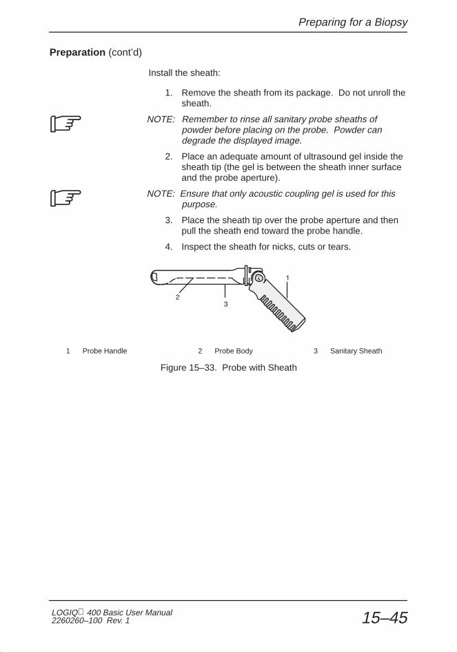
Preparing for a Biopsy
LOGIQ 400 Basic User Manual2260260–100 Rev. 1 15–45
Preparation (cont’d)
Install the sheath:
1. Remove the sheath from its package. Do not unroll thesheath.
NOTE: Remember to rinse all sanitary probe sheaths ofpowder before placing on the probe. Powder candegrade the displayed image.
2. Place an adequate amount of ultrasound gel inside thesheath tip (the gel is between the sheath inner surfaceand the probe aperture).
NOTE: Ensure that only acoustic coupling gel is used for thispurpose.
3. Place the sheath tip over the probe aperture and thenpull the sheath end toward the probe handle.
4. Inspect the sheath for nicks, cuts or tears.
1 Probe Handle 2 Probe Body 3 Sanitary Sheath
Figure 15–33. Probe with Sheath
�
�

Preparing for a Biopsy
LOGIQ 400 Basic Users Manual2260260–100 Rev. 115–46
Preparation (cont’d)
5. Rub a finger over the tip of the probe to ensure all airbubbles have been removed.
1
1 Biopsy Guide
Figure 15–34. Reusable Metal Biopsy Guide 0° Angle
6. If a biopsy is to be performed, snap the metal or plasticbiopsy guide on to the probe over the sheath(Figure 15–34).
7. Place an adequate amount of ultrasound gel on thegel-filled sheath tip outer surface.
1 Sanitary Sheath
Figure 15–35. Civco Disposable Biopsy Guide 5° Angle
8. Ensure the guide is properly seated and secure bypushing forward on the needle insertion end of theguide until the attachment node is firmly in place in it’shole.

Preparing for a Biopsy
LOGIQ 400 Basic User Manual2260260–100 Rev. 1 15–47
Scanning
1. Scan the patient. The probe handle orientation markindicates the image scan plane. Be sure that theImage Reverse function is Off .
Figure 15–36. Probe and Guidezone Alignment
2. Rotate, retract, or advance the probe, as necessary, tosee all pertinent anatomy.
3. If a biopsy is being performed, activate the biopsyguidezone.
Scan the patient to determine the correct puncturedepth and site before inserting the needle.
Ensure that the proper guidezone (TV0 or TR5) isdisplayed.
Post Biopsy
If the exam is over:
1. Remove the biopsy guide and twist lock/clamp.Remove and properly dispose of the sheath.
2. Thoroughly clean the probe and equipment. Refer toyour institution’s infection control guidelines fordisinfection/sterilization protocols.
3. After sterilization, return the probe to its carrying case.
CAUTION

Preparing for a Biopsy
LOGIQ 400 Basic Users Manual2260260–100 Rev. 115–48
Biopsy Probes
Biopsy Guide Attachment
Probe ���������� Mfg. Needle Sizes Repl. Kit
C364/CBF Abdominal, OB/GYN Civco 14, 16, 18, 20, 22, 25 AWG Civco Ultra-Pro
C551/CAE OB/GYN, Abdominal Civco 14, 16, 18, 20, 22, 25 AWG Civco Ultra-Pro
C721 Neonatal Civco 14, 16, 18, 20, 22, 25 AWG Civco Ultra–Pro
E721 Endocavitary YMS Requires 25 cm needles –––
Civco 18 AWG –––
739L Small Parts, Peripheral Vascular Civco 14, 16, 18, 20, 22, 25 AWG Civco Ultra-Pro
L764 Breast, Small Parts Civco 14, 16, 18, 20, 22, 25 AWG Civco Ultra–Pro
LA39 Small Parts, Mammography Civco 14, 16, 18, 20, 22, 25 AWG Civco Ultra-Pro
S317 Abdominal Civco 14, 16, 18, 20, 22, 25 AWG Civco Ultra-Pro
T739 Intra-operative Civco 14, 16, 18, 20, 22, 25 AWG Civco Ultra-Pro
Table 15–11. Probe Biopsy Chart–Fixed Angle
Multi Angle Biopsy Guide Attachment
Probe ���������� Mfg. Needle Sizes(not included)
Repl. Kit
C358 Abdominal, OB/GYN Civco 14 through 23 AWG Civco Ultra-Pro II
C364 Abdominal, OB/GYN Civco 14 through 23 AWG Civco Ultra-Pro II
C386 OB/GYN, Abdominal Civco 14 through 23 AWG Civco Ultra-Pro II
C551 OB/GYN, Abdominal Civco 14 through 23 AWG Civco Ultra-Pro II
C721 Small Parts Civco 14 through 23 AWG Civco Ultra-Pro II
546L Small Parts, Peripheral Vascular Civco 14 through 23 AWG Civco Ultra-Pro II
739L Small Parts, Peripheral Vascular Civco 14 through 23 AWG Civco Ultra-Pro II
L764 Breast, Small Parts Civco 14 through 23 AWG Civco Ultra-Pro II
S317 Abdominal, Cardiac Civco 14 through 23 AWG Civco Ultra-Pro II
S611 Abdominal, Pediatric Civco 14 through 23 AWG Civco Ultra-Pro II
T739 Intra-operative Civco 14 through 23 AWG Civco Ultra-Pro II
Table 15–12. Probe Biopsy Chart–Multi Angle

User Maintenance
LOGIQ 400 Basic User Manual2260260–100 Rev. 1 16–1
User Maintenance
System Data 16–3. . . . . . . . . . . . . . . . . . . . . . . . . . . . . . . . . . . . . . . . . . . . . . . . . . . . . . . . . . . . Specifications 16–3. . . . . . . . . . . . . . . . . . . . . . . . . . . . . . . . . . . . . . . . . . . . . . . . . . . . LOGIQ 400 Clinical Measurement Accuracy 16–5. . . . . . . . . . . . . . . . . . . . . . . . LOGIQ 400 Clinical Calculation Accuracy 16–6. . . . . . . . . . . . . . . . . . . . . . . . . . .
Warranties 16–7. . . . . . . . . . . . . . . . . . . . . . . . . . . . . . . . . . . . . . . . . . . . . . . . . . . . . . . . . . . . . . Scope and Duration of Warranties 16–7. . . . . . . . . . . . . . . . . . . . . . . . . . . . . . . . . . . Warranty Exclusions 16–9. . . . . . . . . . . . . . . . . . . . . . . . . . . . . . . . . . . . . . . . . . . . . . . Exclusive Warranty Remedies 16–10. . . . . . . . . . . . . . . . . . . . . . . . . . . . . . . . . . . . .
System Care and Maintenance 16–11. . . . . . . . . . . . . . . . . . . . . . . . . . . . . . . . . . . . . . . . . . Overview 16–11. . . . . . . . . . . . . . . . . . . . . . . . . . . . . . . . . . . . . . . . . . . . . . . . . . . . . . . Inspecting the System 16–11. . . . . . . . . . . . . . . . . . . . . . . . . . . . . . . . . . . . . . . . . . . . Weekly Maintenance 16–12. . . . . . . . . . . . . . . . . . . . . . . . . . . . . . . . . . . . . . . . . . . . . Other Maintenance 16–16. . . . . . . . . . . . . . . . . . . . . . . . . . . . . . . . . . . . . . . . . . . . . . .
Troubleshooting 16–19. . . . . . . . . . . . . . . . . . . . . . . . . . . . . . . . . . . . . . . . . . . . . . . . . . . . . . . Introduction 16–19. . . . . . . . . . . . . . . . . . . . . . . . . . . . . . . . . . . . . . . . . . . . . . . . . . . . . Trouble images 16–19. . . . . . . . . . . . . . . . . . . . . . . . . . . . . . . . . . . . . . . . . . . . . . . . . . Loose cables 16–25. . . . . . . . . . . . . . . . . . . . . . . . . . . . . . . . . . . . . . . . . . . . . . . . . . . . Display Messages 16–26. . . . . . . . . . . . . . . . . . . . . . . . . . . . . . . . . . . . . . . . . . . . . . . . System Error Message Description 16–27. . . . . . . . . . . . . . . . . . . . . . . . . . . . . . . . . Operation Error Message Description 16–28. . . . . . . . . . . . . . . . . . . . . . . . . . . . . . . Operation Guide Message Description 16–32. . . . . . . . . . . . . . . . . . . . . . . . . . . . . . Warning Message Description 16–33. . . . . . . . . . . . . . . . . . . . . . . . . . . . . . . . . . . . .
Operator Diagnostics 16–34. . . . . . . . . . . . . . . . . . . . . . . . . . . . . . . . . . . . . . . . . . . . . . . . . . . Introduction 16–34. . . . . . . . . . . . . . . . . . . . . . . . . . . . . . . . . . . . . . . . . . . . . . . . . . . . . Probe Selection 16–34. . . . . . . . . . . . . . . . . . . . . . . . . . . . . . . . . . . . . . . . . . . . . . . . . . Accessing Diagnostics 16–35. . . . . . . . . . . . . . . . . . . . . . . . . . . . . . . . . . . . . . . . . . . . System Test 1 (reduced) 16–36. . . . . . . . . . . . . . . . . . . . . . . . . . . . . . . . . . . . . . . . . . Test Pattern Black & White 16–37. . . . . . . . . . . . . . . . . . . . . . . . . . . . . . . . . . . . . . . . Test Pattern Color 16–38. . . . . . . . . . . . . . . . . . . . . . . . . . . . . . . . . . . . . . . . . . . . . . . . Test Pattern Graphics 16–38. . . . . . . . . . . . . . . . . . . . . . . . . . . . . . . . . . . . . . . . . . . . .

User Maintenance
LOGIQ 400 Basic Users Manual2260260–100 Rev. 116–2
Assistance 16–39. . . . . . . . . . . . . . . . . . . . . . . . . . . . . . . . . . . . . . . . . . . . . . . . . . . . . . . . . . . . Clinical Questions 16–39. . . . . . . . . . . . . . . . . . . . . . . . . . . . . . . . . . . . . . . . . . . . . . . . Service Questions 16–39. . . . . . . . . . . . . . . . . . . . . . . . . . . . . . . . . . . . . . . . . . . . . . . . Literature 16–39. . . . . . . . . . . . . . . . . . . . . . . . . . . . . . . . . . . . . . . . . . . . . . . . . . . . . . . Accessories 16–39. . . . . . . . . . . . . . . . . . . . . . . . . . . . . . . . . . . . . . . . . . . . . . . . . . . . . Supplies/Accessories 16–40. . . . . . . . . . . . . . . . . . . . . . . . . . . . . . . . . . . . . . . . . . . . .

System Data
LOGIQ 400 Basic User Manual2260260–100 Rev. 1 16–3
System Data
Specifications
System Dimensions
� Height: 51 in (130 cm)Taller Console: 54 in (137 cm)
� Width: 21 in (54cm)
� Depth: 37 in (94 cm)
� Weight: approx. 320 lbs (145 kg)Taller Console: approx. 364 lbs (165 kg)
Display Monitor
� 15 inch color or B/W display
� 512 Lines
� NTSC & PAL Formats
� Interlace
Operating/Display
� B-Mode
� M-Mode
� PW Doppler
� Color Flow
� Simultaneous B/D & B/CF
� Colorized B & M Display
� Steerable CW (Sector only)
� Non-Imaging Single CW
Doppler
� Steerable Sample Volume (SV)
� Variable SV Sizing
� Variable Spectral Scaling
� Selectable Spectral Smoothing
� Doppler Angle Correction with CalibratedVelocity Scaling
� Variable Sample Size
� Variable Wall Filter
� Scrolling Memory
Measurements
� Distance
� Circumference (Ellipse/Trace)
� Area (Ellipse/Trace)
� Volume (Ellipsoid)
� Angle Between Two Lines (B-Mode)
� Time & Slope (M-Mode)
� Single Velocity (Doppler)
� Time Average Maximum Velocity
Weight
Approximately 320 lbs. (145 kg) for fully configured
console.
Image Processing
� 64 Displayed Gray Levels
� Dynamic Range
� Acoustic Zoom
� Image Invert & Rotate
� Independent Dual Image Displays
Linear Imaging
� Steerable B, Doppler, CF: �30�
� Slant Scan Imaging
� Independent B/CF Steering
� 3.5 –6.7 MHz
Convex Imaging
� Variable Angle: 20� – 80�
� Steerable Scan Angle
� 3.5 – 5.0 MHz

System Data
LOGIQ 400 Basic Users Manual2260260–100 Rev. 116–4
Specifications (cont’d)
Color Flow Doppler
� Selectable Wall Rejection
� Variable FOV Size & Position
� Selectable Color Maps
� Color Baseline Shift
� Color Velocity Tag
� CINE Memory
Calculations
� Heart Rate (BPM, M-Mode)
� Fetal Age (GS, CRL, FL, BPD)
� Estimated Fetal Weight
� PI (Vascular)
� RI (Vascular)
� FVI (Vascular)
� Percent Stenosis (Vascular)
� Two-Velocity Ratio
Electrical Power
� 120/220-240 VAC
� 50/60 Hz
� 1000 VA Max Power Draw
Transducer Types
� Phased Array Sector
� Convex Array
� Linear Array
� Micro-Convex Endocavity (TV/TR) Array
� Pencil CWD
Sector Imaging
� Variable Angle: 20�–90�
� Steerable Scan Angle
� Trapezoidal and Slant Scan Imaging
� 3.3 – 7.5 MHz
Micro-Convex Imaging
� Variable Angle: 20� – 120�
� Steerable Scan Angle
� 3.5 – 6.7 MHz
CINE Memory
� 8 Megabyte Frame Memory (std.)
� Optional 40 megabyte Frame Memory
� 8 megabyte Frame B + CF Memory
� Dual Image CINE Display
� Measurement/Calculation & Annotations onCINE
� Loop Editing
� Variable Speed Display
Data Display
� Biopsy Guidelines with integrated distancemeasure
� New Patient Data Entry
� OB Summary Report
� GYN Summary Report
� LV Cardiac Summary Report
� Vascular Summary Report
� User Programmable Annotation Libraries foreach application

System Data
LOGIQ 400 Basic User Manual2260260–100 Rev. 1 16–5
LOGIQ 400 Clinical Measurement Accuracy
Basic Measurements
The following information is intended to provide guidance to theuser in determining the amount of variation or measurementerror that should be considered when performing clinicalmeasurements with this equipment. Error can be contributedby equipment limitations and improper user technique. Be sureto follow all measurement instructions and develop uniformmeasurement techniques among all users to minimize thepotential operator error. Also, in order to detect possibleequipment malfunctions that could affect measurementaccuracy, a quality assurance (QA) plan should be establishedfor the equipment that includes routine accuracy checks withtissue mimicking phantoms.
Please be advised that all distance and Doppler relatedmeasurements through tissue are dependent upon thepropagation velocity of sound within the tissue. Thepropagation velocity usually varies with the type of tissue, butan average velocity for soft tissue is assumed. This equipmentis designed for, and the accuracy statements listed on 16–6are based on, an assumed average velocity of 1540 m/s. Thepercent accuracy when stated applies to the measurementobtained (not the full scale range). Where the accuracy isstated as a percent with a fixed value, the expected inaccuracyis the greater of the two.

System Data
LOGIQ 400 Basic Users Manual2260260–100 Rev. 116–6
Basic Measurements (cont’d)
Measurement Units Useful Range AccuracyLimitations
or Conditions
Depth mm Full Screen � 5 % or 1 mm
Distance:AxialLateralLateralLateral
mmmmmmmm
Full ScreenFull ScreenFull ScreenFull Screen
� 5 % or 1 mm� 5 % or 2 mm� 5 % or 4 mm� 5 % or 4 mm
Linear ProbesConvex ProbesSector Probes
Circumference:TraceEllipse
mmmm
Full ScreenFull Screen
� 10 % or 1 mm� 5 % or 1 mm
Area:TraceEllipse
mm2
mm2Full ScreenFull Screen
� 5 % or 1 mm2
� 5 % or 1 mm2
Time s Timeline Display � 5 % or 10 ms M or Doppler
Slope mm/s Timeline Display � 5 % or 1 mm/s M-Mode Only
Doppler SV Position mm Full Screen � 2 mm Any Direction
Velocity cm/s From 0 to 100 cm/sFrom 100 to 130 cm/s
� 10 % or 1 cm/s� 5 % or 1 cm/s
PW Doppler
Point Velocity � 50 % Color Flow
Doppler AngleCorrection
cm/scm/s
From 0° to 60° From 60° to 80°
� 5 %� 12 %
Table 16–1. System Measurements and Accuracies
LOGIQ 400 Clinical Calculation Accuracy
Estimate the overall inaccuracy of a combined measurementand calculation by including the stated inaccuracy from thebasic measurement accuracy statements.
Diagnostic errors may result from the inappropriate use ofclinical calculations. Review the referenced source of thestated formula or method to become familiar with the intendeduses and possible limitations of the calculation.
Calculation formulas and databases are provided as a tool toassist the user, but should not be considered an undisputeddatabase, in making a clinical diagnosis. The user isencouraged to research the literature and judge the equipmentcapabilities on an ongoing basis in order to assess its utility asa clinical tool.
CAUTION
�
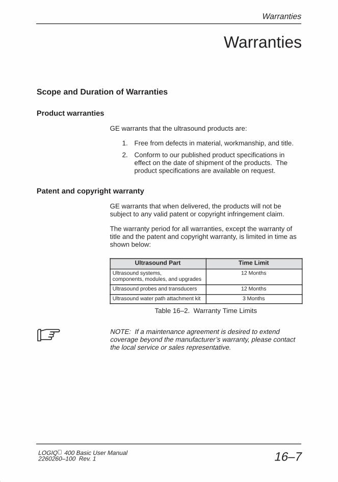
Warranties
LOGIQ 400 Basic User Manual2260260–100 Rev. 1 16–7
Warranties
Scope and Duration of Warranties
Product warranties
GE warrants that the ultrasound products are:
1. Free from defects in material, workmanship, and title.
2. Conform to our published product specifications ineffect on the date of shipment of the products. Theproduct specifications are available on request.
Patent and copyright warranty
GE warrants that when delivered, the products will not besubject to any valid patent or copyright infringement claim.
The warranty period for all warranties, except the warranty oftitle and the patent and copyright warranty, is limited in time asshown below:
Ultrasound Part Time Limit
Ultrasound systems, components, modules, and upgrades
12 Months
Ultrasound probes and transducers 12 Months
Ultrasound water path attachment kit 3 Months
Table 16–2. Warranty Time Limits
NOTE: If a maintenance agreement is desired to extendcoverage beyond the manufacturer’s warranty, please contactthe local service or sales representative.
�

Warranties
LOGIQ 400 Basic Users Manual2260260–100 Rev. 116–8
Patent and copyright warranty (cont’d)
The warranty period begins on the date the products aredelivered. But, if GE assembles the products, the warrantyperiod begins on the earlier of:
1. Five (5) days after the date GE notifies you that wehave completed assembly and the products areoperating in accordance with our published productspecifications
OR
2. The date you first use the products for patient use.
If assembly is delayed for 30 days or more after the date ofdelivery for a reason beyond our reasonable control, thewarranty period will begin on the thirtieth day after the date ofdelivery.
The warranty period for any product or part furnished to correcta warranty failure will be the unexpired term of the warrantyapplicable to the repaired or replaced products.

Warranties
LOGIQ 400 Basic User Manual2260260–100 Rev. 1 16–9
Warranty Exclusions
These warranties are exclusive and in lieu of all otherwarranties, whether written, oral, expressed, implied, orstatutory.
No warranty of merchantability or fitness for a particularpurpose applies.
The warranties DO NOT cover:
1. Any defect or deficiency (including failure to conform toproduct specifications) which results, in whole or inpart, from:
a. Any alteration, improper storage, handling, use ormaintenance, or any extraordinary use of theproducts, by anyone other than GE.
b. Failure to follow any of GE’s writtenrecommendations or instructions.
c. Combining the products with products of others orwith incompatible GE products.
d. Any of your designs, specifications or instructions.
OR
e. Any cause external to the products as furnished byGE or beyond our reasonable control.
2. Ultrasound supplies and accessories identified bycatalog numbers which start with the letter “E” (whichare covered by a separate printed warranty).
3. Products which are not listed in our price pages at thetime of sale. Non-listed products are provided with themanufacturer’s warranties, if any, GE is permitted topass on to you. Otherwise, non-listed products areprovided AS IS.
4. The payment and reimbursement of any facility costsarising from repair or replacement of the products orparts.
�

Warranties
LOGIQ 400 Basic Users Manual2260260–100 Rev. 116–10
Exclusive Warranty Remedies
Product warranties
If you promptly notify us of your warranty claim and make theproduct available for service, GE will at our option, repair,adjust, or replace (with new or exchange replacement parts) thenon-conforming product or parts of the product. Warrantyservice will be performed without charge from 8:00 am to5:00 pm, Monday through Friday, excluding our holidays, andoutside those hours at our prevailing service rates and subjectto the availability of personnel.
Patent and copyright warranty
GE will defend or settle any suit against you to the extent it isbased on an infringement claim which would be a breach of thepatent and copyright warranty. If the infringement claim is valid,GE will pay all damages and costs awarded against you due tothe breach. In addition, GE will obtain a license for you tocontinue using the infringing product, provide a non-infringingreplacement, alter the product so that it is non-infringing, orremove the infringing product and refund the price (lessreasonable depreciation) and any return transportation costspaid by you.
The above describes your exclusive remedies and our soleliability for any warranty claims. You agree that GE and ourrepresentatives have no liability to you for:
1. Any penal, incidental, or consequential damages suchas lost profit or revenue.
2. Any assistance not required under our quotation.
3. Anything occurring after the warranty period ends.

System Care and Maintenance
LOGIQ 400 Basic User Manual2260260–100 Rev. 1 16–11
System Care and Maintenance
Overview
Refer to Section 7 of the LOGIQ 400 Service Manual(2127661) for any additional maintenance guidance.
Contact the local Service Representative for parts or plannedmaintenance inspections. It is recommended that plannedmaintenance be performed on the system every six months.
Inspecting the System
Examine the following on a monthly basis:
� Connectors on cables for any mechanical defects.
� Entire length of electrical and power cables for cuts orabrasions.
� Equipment for loose or missing hardware.
� Control panel and keyboard for defects.
� Casters for proper locking operation.
To avoid electrical shock hazard, do not remove panels orcovers from console. This servicing must be performed byqualified service personnel. Failure to do so could causeserious injury.
If any defects are observed or malfunctions occur, do notoperate the equipment but inform a qualified service person.Contact a Service Representative for information.
DANGER
ElectricalHazard

System Care and Maintenance
LOGIQ 400 Basic Users Manual2260260–100 Rev. 116–12
Weekly Maintenance
The LOGIQ 400 system requires weekly care andmaintenance to function safely and properly. Clean thefollowing:
� System cabinet
� Monitor
� Operator control panel
� Foot switch
� Video Cassette Recorder (VCR)
� Video Page Printer
Failure to perform required maintenance may result inunnecessary service calls.
Cleaning the system
Prior to cleaning any part of the system:
1. Turn off the system power.
System cabinet To clean the system cabinet:
1. Moisten a soft, non-abrasive folded cloth with a mild,general purpose, non-abrasive soap and watersolution.
2. Wipe down the top, front, back, and both sides of thesystem cabinet.
NOTE: Do not spray any liquid directly into the unit.�

System Care and Maintenance
LOGIQ 400 Basic User Manual2260260–100 Rev. 1 16–13
Cleaning the system (cont’d)
Monitor To clean the monitor face and filter:
Remove the monitor filter as shown in Figure 16–1.
Figure 16–1. Monitor Filter Removal
1. Slide the filter clamps towards the monitor sides.
2. Pull the filter clamps out.

System Care and Maintenance
LOGIQ 400 Basic Users Manual2260260–100 Rev. 116–14
Cleaning the system (cont’d)
Monitor (cont’d)
Use a soft, folded cloth and a glass cleaner solution. Apply theglass cleaner to the cloth. Gently wipe the monitor face andfilter.
Do NOT use a glass cleaner that has a hydrocarbon base (suchas Benzene, Methyl Alcohol or Methyl Ethyl Ketone) onmonitors with the filter (anti-glare shield). Prolonged use ofsuch cleaners will damage the filter (anti-glare shield). Hardrubbing will also damage the filter.
NOTE: When cleaning the monitor, make sure not to scratchthe monitor.
After cleaning the monitor face and filter, re-install the filter onthe monitor by reversing the removal procedure in Figure 16–1.Insert the filter clamps and slide them inwards securely.
NOTE: Make sure that the filter is securely fixed by the filterclamps. These are important to prevent a hazard from the filterfalling. A “click” sound will be heard when the filter clamp issecured by the lock mechanism.
Operator Controls To clean the operator control panel:
1. Moisten a soft, non-abrasive folded cloth with a mild,general purpose, non-abrasive soap and water solution.
2. Wipe down operator control panel.
3. Use a cotton swab to clean around keys or controls.Use a toothpick to remove solids from between keysand controls.
NOTE: When cleaning the operator control panel, make surenot to spill or spray any liquid on the controls, into the systemcabinet, or in the probe connection receptacle.
CAUTION
�
�
�
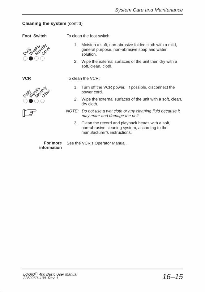
System Care and Maintenance
LOGIQ 400 Basic User Manual2260260–100 Rev. 1 16–15
Cleaning the system (cont’d)
Foot Switch To clean the foot switch:
1. Moisten a soft, non-abrasive folded cloth with a mild,general purpose, non-abrasive soap and watersolution.
2. Wipe the external surfaces of the unit then dry with asoft, clean, cloth.
VCR To clean the VCR:
1. Turn off the VCR power. If possible, disconnect thepower cord.
2. Wipe the external surfaces of the unit with a soft, clean,dry cloth.
NOTE: Do not use a wet cloth or any cleaning fluid because itmay enter and damage the unit.
3. Clean the record and playback heads with a soft,non-abrasive cleaning system, according to themanufacturer’s instructions.
See the VCR’s Operator Manual.
�
For moreinformation

System Care and Maintenance
LOGIQ 400 Basic Users Manual2260260–100 Rev. 116–16
Cleaning the system (cont’d)
Video Page Printer To clean the external surface of the video page printer:
1. Turn off the power. If possible, disconnect the powercord.
2. Wipe the external surfaces of the unit with a soft, clean,dry cloth.
3. Remove stubborn stains with a cloth lightly dampenedwith a mild detergent solution.
NOTE: Never use strong solvents, such as thinner or benzine,or abrasive cleansers because they will damage the cabinet.
No further maintenance, such as lubrication, is required.
To clean the surface of the print head:
1. Run the cleaning sheet (provided with the printer)through the printer.
Review the Video Page Printer’s Operator Manual for details.
Other Maintenance
Replacing illuminated key caps/lamps
Contact a local Service Representative when a key cap or lampneeds to be replaced.
�
For moreinformation
As Necessary

System Care and Maintenance
LOGIQ 400 Basic User Manual2260260–100 Rev. 1 16–17
Cleaning the air filters
Clean the system’s air filters to ensure that a clogged filter doesnot cause the system to overheat and reduce systemperformance and reliability. It is recommended the filters becleaned quarterly (once every three months).
Locating The 3 air filters are located in the front and back of the system:
ON
OFF
1
0ON
1
2
1
1 Console Air Filter Screen2 Power Supply Air Filters
Figure 16–2. Location of Air Filters
Quarterly

System Care and Maintenance
LOGIQ 400 Basic Users Manual2260260–100 Rev. 116–18
Removing To remove the console air filters:
1. Lift up on the Velcro tab securing the air filter.
2. Pull out the filter.
To remove the power supply air filter:
1. Pull out and up on the filter cover.
2. Pull the filter screen out.
ÏÏÏÏÏÏÏÏÏÏÏÏ
ÏÏÏÏÏÏÏÏÏÏÏÏ
ÏÏÏÏÏÏÏÏÏÏÏÏ
Figure 16–3. Filter Screen Removal
Cleaning To clean the filter:
1. Be sure to shake the filter in an area away from thesystem.
2. Wash the filter in a mild soapy solution, rinse and airdry or dry with a cloth.
NOTE: Allow wet filter to dry thoroughly before installing.
3. Slide the filter back into the system.
4. Secure the filter with the Velcro tab or cover.
�

Troubleshooting
LOGIQ 400 Basic User Manual2260260–100 Rev. 1 16–19
Troubleshooting
Introduction
Listed in this section are problem or system messages that maybe encountered, possible causes for the problem or message,and the appropriate action to take to correct the situation. Ifadditional information or assistance is needed contact yourlocal Applications, Sales or Service Representative.
Trouble images
The LOGIQ 400 has the capacity to store as many as eighttrouble images. The trouble image files may be saved to MODfor archival or loaded back into the system hard drive for displayand review. The trouble images on file can also be retrieved foranalysis through Insite , the exclusive remote diagnosticcapabilities of the LOGIQ family of products.

Troubleshooting
LOGIQ 400 Basic Users Manual2260260–100 Rev. 116–20
To Store a Trouble Image to the Hard Drive
Should the LOGIQ 400 ever have a problem imaging, thesystem has the capability of storing up to 8 trouble images onthe hard disk drive. To store a trouble image:
1. Freeze the trouble image.
2. Press the Ctrl, W keys simultaneously.
The message “In progress. Please wait.” is displayed while theimage is being saved to the hard drive.
After the image has been saved, the message “ Input comment? ‘y’or ‘n’ ” is displayed. Press ‘n’ for no comments. Press ‘y’ to add amaximum of 42 characters as comments to the trouble image file.Press Return after commenting is complete.
After the eighth image is saved, there is a warning to indicatethe disk space is full. The ninth attempt to save a trouble imagewill require writing over the first image, etc. (first in, first out).
The message “Overwrite the old image (DIAGIG00) ? ‘y’ or ‘n’”is displayed. Press ‘y’ to replace the old trouble image with thenew one. Press ‘n’ to cancel the trouble image store action.
NOTE: Trouble images do not display Patient Name, ID orHospital Name information. That portion of the image isblanked out and will not be shown when the file is recalled fordisplay.
�

Troubleshooting
LOGIQ 400 Basic User Manual2260260–100 Rev. 1 16–21
To Save Trouble Images to MOD
To save trouble images to MOD:
� Select the Set Up Top menu.
� From the Set Up Sub-Menu, select Utility. The Utility Menuappears as shown in Figure 16–4.
NOTE: MOD media used to save trouble images must first beinitialized (formatted) in the utility menu selection “09 MediaInitialization”.
Figure 16–4. Utility Menu
� From the Utility menu, select “03 Trouble ImageSave/Load/Display” . Enter menu number 03 and pressReturn.
�

Troubleshooting
LOGIQ 400 Basic Users Manual2260260–100 Rev. 116–22
To Save Trouble Images to MOD (cont’d)
� From the Trouble Image Save/Load/Display menu select “1: Save”. Enter menu number 1 and press Return .
Figure 16–5. Trouble Image Save/Load/Display Menu
� A message will be displayed to place an MOD disk in thedrive and press any key to continue.
The system will read all trouble images from the hard driveand display the image menu in 2 pages of 4 files each. Theline available under the file number, date/time and modeinformation is the 42 character comment line.
Figure 16–6. Saved Trouble Image Menu

Troubleshooting
LOGIQ 400 Basic User Manual2260260–100 Rev. 1 16–23
To Save Trouble Images to MOD (cont’d)
Trouble image files must be saved one at a time.
� Enter the number of the file (i.e. “01”) and press Return .
The message “Saving now” is displayed.
The system will take a few moments to save the image file.
After the save operation is complete, the message “Press‘Y’ to continue, or ‘Ctrl+R’ to return.” is displayed. Pressing‘Y’ will prompt for another file menu number to be saved.Pressing Ctrl+R will return to the previous menu screen.
Figure 16–7. Trouble Image Save Complete

Troubleshooting
LOGIQ 400 Basic Users Manual2260260–100 Rev. 116–24
To Load Trouble Images from MOD
Trouble images can be loaded from the MOD to the hard drive.To load trouble images from the MOD:
� From the Set Up/Utility menu select “03 Trouble ImageSave/Load/Display” . Enter menu number 03 and pressReturn .
� From the Trouble Image Save/Load/Display menu select “2: Load”. Enter menu number 2 and press Return .
� A message will be displayed to place a MOD disk in thedrive and press any key to continue.
The system will read all trouble images from the MOD anddisplay the image menu in 2 pages of 4 files each. The lineavailable under the file number, date/time and modeinformation is the 42 character comment line.
Trouble image files must be loaded one at a time.
� Enter the number of the file to be loaded (i.e. “01”)and press Return .
The message “Loading now” is displayed.
The system will take a few moments to load the image file.
After the load operation is complete, the message “Press ‘Y’to continue, or ‘Ctrl+R’ to return.” is displayed. Pressing ‘Y’will prompt for another file menu number to be loaded.Pressing Ctrl+R will return to the previous menu screen.
To Display Trouble Images
Trouble images can only be displayed from the files stored onthe hard drive.
� From the Set Up/Utility menu select “03 Trouble ImageSave/Load/Display” . Enter menu number 03 and pressReturn .
� From the Trouble Image Save/Load/Display menu select “3: Display”. Enter menu number 3 and press Return .
A menu of the trouble Image files on the hard drive is displayedin 2 pages of 4 files each if necessary.

Troubleshooting
LOGIQ 400 Basic User Manual2260260–100 Rev. 1 16–25
To Display Trouble Images (cont’d)
Figure 16–8. Trouble Image Display Menu
� Enter the number of the file to be displayed (i.e. “01”) and press Return .
The image will be displayed on the monitor for analysis.
Loose cables
If ECG cables are loose:
1. Check the ECG cable lead connection
OR
2. Check the connection on the back panel.
If peripheral cables are loose:
1. Check the connections on the back of the peripheral
OR
2. Check the connection on the back panel.

Troubleshooting
LOGIQ 400 Basic Users Manual2260260–100 Rev. 116–26
Display Messages
The LOGIQ 400 provides a variety of messages concerningthe status of the system’s operation.
� System Error Messages are displayed when a hardwareproblem is detected.
� Operation Error Messages are displayed when the userselects a control that is not appropriate to the current scanmode or function.
� Operation Guide Messages are displayed to inform theoperator of a completed task or required action.
� Warning Messages are displayed for patient safety orsystem failure reasons.
� System Preparation Message is displayed when the systempowers up.
These messages are displayed in the single line message areaat the bottom of the display. The message display time variesdepending on the type of message. Some messages may beaccompanied by an audio tone.
For Operation Error Messages, the user can choose to turnon/off the audio tone that accompanies the display in the SetUp/System Parameters page 1.
The User can turn on/off the recording of the error message linein the Set Up/System Parameters page 5 (Maskline Record).
The following tables outline the error messages, their possiblecause and cure.

Troubleshooting
LOGIQ 400 Basic User Manual2260260–100 Rev. 1 16–27
System Error Message Description
CategoryProblem/Message
PossibleCause
PossibleCorrective Action
General SYS ERROR: BUSERROR.PC: ########AD: ########
Bus error detected.*
SYS ERROR: FILENOT FOUND.FILE: ############
Requested file not found.*
SYS ERROR: BOARDNON EXISTENT.BOARD: #####
Hardware board is nonexistent. *
SYS ERROR:UNEXPECTED CPUEXCEPTION.
Unexpected CPUexception isencountered.
*
SYS ERROR: ILLEGALFILE FORMAT.FILE: ############
File format is illegal.*
SYS ERROR: SCSIERROR. DEVICE: ###CODE: ########
SCSI device error isencountered. *
SYS ERROR: LOCALCPU ERROR.BOARD: #####
Local CPU error isencountered. *
SYS ERROR:INTERRUPT TIME OUT.
BOARD: #####VECTOR: ##
Time out of waitinginterrupt. *
Table 16–3. System Error Message Description
* If System Error Message occurs, record the message andcontact a Service Representative. Be aware that the systemmay be operating at reduced capabilities, some functionsinoperative or not operating at all.

Troubleshooting
LOGIQ 400 Basic Users Manual2260260–100 Rev. 116–28
Operation Error Message Description
CategoryProblem/Message
PossibleCause
PossibleCorrective Action
General Register is filled. Cannot register anymore becauseregistration function hasreached its limit.
*
Register is empty. Cannot delete any morebecause registrationfunction is empty.
*
Save data? ‘y’ or ‘n’. System requiresoperator reaction to savesome data.
Y to save data,N to not save data.
Overwrite existing data?‘y’ or ‘n’.
There is pre-existingcustomized data whensaving.
Y to save changes,N to ignore changes.
Please Select ‘y’ or ‘n’. A key other than thosespecified was pressed.
Enter Y or N.
Improper Data Selected. The data input is notcorrect.
Enter correct data.
RecordingDevices
C l Vid P i
Check Printer. Paper isjammed.
Paper in the printer isjammed.
Locate and clear thepaper jam.
Color Video Printer Check Printer. RibbonCassette error.
Something is wrong withthe ribbon cassette or itssetting.
Remove ribbon andre-install.
Check Printer. PaperCassette error.
The paper cassettesetting is wrong.
Remove cassette, setand re-install.
Check Printer, PaperSupply empty.
The printer is out ofpaper.
Add paper.
Shut the top hatch ofprinter.
The top hatch of theprinter is open.
Open/shut top hatch.
Shut the bottom hatch ofprinter.
The bottom hatch of theprinter is open.
Open/shut bottom hatch.
Check Printer, Paper isincorrect.
The placing of paper isincorrect.
Remove casette, adjustand reinstall.
Check Printer. There is no responsefrom the printer.
Turn power off and onagain.
Table 16–4. Operation Error Message Description
* If System Error Message occurs, record the message andcontact a Service Representative. Be aware that the systemmay be operating at reduced capabilities, some functionsinoperative or not operating at all.

Troubleshooting
LOGIQ 400 Basic User Manual2260260–100 Rev. 1 16–29
Operation Error Message Description (cont’d)
CategoryProblem/Message
PossibleCause
PossibleCorrective Action
RecordingDevices
M l i I
Check M.I.C., NoExposures Left.
The maximum number ofprints have been made.
Reverse cassette orinstall a new cassette.
Multi ImageCamera
Check M.I.C., No VideoInput.
There is no video signalbeing input to the M.I.C.
Check all videoconnections.
Check M.I.C. There is no responsefrom the M.I.C.
Turn power off, turnpower on.
RecordingDevices
VCR
Check VCR. There is no responsefrom the VCR.
Check all VCR controls.
VCR Check VCR. NoCassette.
The VCR has no tape. Insert tape.
This function is notavailable.
The function selected isnot available in somesituations.
Perform from VCR frontpanel.
Protected. Check Tape. This tape has been writeprotected.
Use non protected tape.
Line Printer Check Line Printer. Theport isn’t set.
The line printer has notbeen assigned to PortMIC, A or B.
Assign the line printer toPort MIC, A or B.
Check Line Printer. NoPower.
The line printer ispowered off or the serialcable is not connected toport MIC, A or B.
Power on the line printeror connect the serialcable to port MIC, Aor B.
Check Line Printer.Printing Error.
An error has occurred insending data to the lineprinter or the printer isout of paper.
Resend the report dataor add paper to theprinter.
Check Line Printer.Printing isn’t finished.
Report Print Buffer is full. Ctrl + R cannot be useduntil space is available.The system can store 10reports for backgroundprinting.
Table 16–4. Operation Error Message Description (cont’d)

Troubleshooting
LOGIQ 400 Basic Users Manual2260260–100 Rev. 116–30
Operation Error Message Description (cont’d)
CategoryProblem/Message
PossibleCause
PossibleCorrective Action
Measurement &Calculation
Measurement(s)Required.
The system requires theoperator to inputmeasurement(s).
Input necessarymeasurements.
Press ‘FREEZE’ tocomplete.
The system requires theoperator to pressFREEZE beforecompletingmeasurements.
Freeze before allmeasurements.
No correct data left. The system no longerhas correct data.
Enter newmeasurements.
Manual CalibrationRequired.
The system cannotcalibrate automaticallybecause there is nobarcode data on tape.
Reply Yes to manualcalibration.
Barcode sum checkerror.
There is somethingwrong with the barcodedata.
Retry, use manualcalibration.
ScanningFunction
Transducer NotRecognized.
An invalid probe hasbeen connected.
Remove invalid probe.
Transducer Calibration inProcess.
Probe change is takingplace.
Wait for process tocomplete.
Option Setting Option Not Available. The option to performthe requested function isnot available.
Install desired option.
New Patient, ID/Name Function
Invalid, Input a properdata.
Improper data has beeninput.
Input valid data.
Press ’RETURN’ to exit. An invalid key has beenpressed.
Press Return .
Data range over, Inputproper data.
The input data is toolarge.
Numbers too large.
Please answer ’y’ or ’n’. A key other than thosespecified was pressed.
Y for yes, N for no.
Improper Data Selected. Improper data has beeninput.
Input proper data.
Table 16–4. Operation Error Message Description (cont’d)

Troubleshooting
LOGIQ 400 Basic User Manual2260260–100 Rev. 1 16–31
Operation Error Message Description (cont’d)
CategoryProblem/Message
PossibleCause
PossibleCorrective Action
Storage Function Mismatched System ID.Insert correct media.
The disk is not aregistered disk. Imagescannot be deleted.
Take disk to system withproper ID.
The MO is full, changeMO.
There is not enoughspace to store additionalimages on the disk.
Use a different disk.
Media is locked. The disk has been writeprotected.
Disable the writeprotection or use anotherdisk.
Media is eitherunmounted orunformatted.
The disk is either notformatted or inserted inthe drive.
Either format the disk orinsert it into the drive.
Too much data. Storefailed.
The hard drive capacityof the hard drive to storeadditional MOD mediasearch data is full.
Backup MOD mediasearch data from thehard drive to a separateMOD before attemptingimage storage.
This function in notavailable.
During the execution ofthe background storageprocess, this messageappears if Ctrl + W,Record 1 or Record 2keys are pressed.
Miscellaneous No function is defined. No function is defined forthe User Define key thatwas pressed.
Use setup menu todefine.
(Y/N) Operator DecisionRequested
Type in Y for Yes or N forNo
Table 16–4. Operation Error Message Description (cont’d)

Troubleshooting
LOGIQ 400 Basic Users Manual2260260–100 Rev. 116–32
Operation Guide Message Description
CategoryProblem/Message
PossibleCause
PossibleCorrective Action
Scan Guide Invalid CFM image wascleared.
The PRF is changed,and invalid CFM imageis cleared.
NA
Miscellaneous In progress. Pleasewait.
The system needsseveral seconds to dosomething.
NA
VCR Search Guide Searching. The VCR is searchingthe tape.
NA
Search was completed. The VCR search iscompleted.
NA
Requested informationdoesn’t exist on the tape.
The patient imagedoesn’t exist on the tape.
Perform a systemsearch.
Requested informationdoesn’t exist in System.
The information doesn’texist on the hard drive.
Check all patientinformation.
Can not read Tape ID.Register the new tape?(y/n)
The tape ID cannot beread.
“Yes” to register newtape, “No” to cancel.
Retry to read Tape ID?(y/n)
The tape ID cannot beread.
“Yes” to retry, “No” tocancel.
Please play VCR imageand freeze at the otherframe.
The operator has retriedto read the tape ID.
Press Play and Freeze.
Save patient informationon VCR Tape? (y/n)
Operator pressed key forsaving patientinformation on the VCRtape.
“Yes” to continue, “No” tocancel.
Save patient informationto System? (y/n)
Operator pressed key forsaving patientinformation on the harddrive.
“Yes” to save, “No” tocancel.
System ID = #####Tape ID = #####
Tape was mounted orthe new tape wasregistered.
NA
System ID = #####New Tape ID = #####
The tape was mounted. NA
Table 16–5. Operation Guide Message Description

Troubleshooting
LOGIQ 400 Basic User Manual2260260–100 Rev. 1 16–33
Operation Guide Message Description (cont’d)
CategoryProblem/Message
PossibleCause
PossibleCorrective Action
Preset & SetupFunction
Data is saved. The system completedsaving the data that wasrequested.
NA
Input value by RockerButton.
Operator can useup/down arrow keys toinput the value.
Use the Ellipse up/downarrow keys.
Input character strings. Operator needs to inputsome character strings.
Type in characters.
Select an initial data. Operator needs to selectinitial data.
Input proper data.
’TRACKBALL’ and ’SET’are available.
Operator can use theTrackball and Set key tooperate the function.
NA
Recommended value arecopyed.
The system completedcopying the data thatwas requested.
NA
Table 16–5. Operation Guide Message Description (cont’d)
Warning Message Description
CategoryProblem/Message
PossibleCause
PossibleCorrective Action
Temperature Safety WARNING:Temperature error.
System internaltemperature is at amaximum, but notcaused by fan failure.
Reduce roomtemperature.
WARNING WARNING: Cooling FanFailure.
System fan has stoppedworking properly.
Call service.
WARNING: Cooling FanFailure. Temperatureerror.
System internaltemperature is at amaximum, caused by thefan not working properly.
Reduce roomtemperature; call service.
WARNING: HVAbnormal.
The High Voltage isabnormal.
Call service.
WARNING: ProbeTemperature error.
The probe temperatureis at a maximum.
Call service.
WARNING: NOWSTART THE POWEROFF PROCESS.
The system shutdownprocess has begun.
Call service.
Table 16–6. Warning Message Description

Operator Diagnostics
LOGIQ 400 Basic Users Manual2260260–100 Rev. 116–34
Operator Diagnostics
Introduction
Refer to Section 4–3 of the LOGIQ 400 Service Manual(2127661).
The user is able to run diagnostic tests such as:
System Test 1 (reduced version)
Black & White Test Pattern
Color Test Pattern
Graphics Test Pattern
The test patterns can be used to adjust the display monitor orperipheral displays. The system test provides a reduced(pass/fail) version of the diagnostic used to check theLOGIQ 400 software.
Probe Selection
Connect and select the C364 probe for diagnostic testpurposes.

Operator Diagnostics
LOGIQ 400 Basic User Manual2260260–100 Rev. 1 16–35
Accessing Diagnostics
To access the available diagnostics, select the Set Up Top Menu.
1/1Set Up
PresetProgram
SystemParamtr
CustomDisplay
Diag.UserDefine
UtilitySaveValues
Figure 16–9. Set Up Sub-Menu
Select DIAG from the Set Up Sub-Menu. The diagnostic testmenu appears on the screen.
Figure 16–10. Diagnostic Test-Menu
Type in the desired test number and press Return . The testbegins running or the test pattern is displayed.
EXE TIME is the test execution time. (The time needed to runthe test.)

Operator Diagnostics
LOGIQ 400 Basic Users Manual2260260–100 Rev. 116–36
System Test 1 (reduced)
Select 01 from the diagnostic test menu.
System Test 1 is a collection of 24 individual tests that are runin sequence. These are the full or reduced versions of thehardware tests.
Three possible messages will be displayed to the right of thetest name.
RUNNING—Test is in progress.FAILED—Test was not completed successfully for some reason.PASSED—Test was run and completed successfully.
Figure 16–11 shows the screen display during system Test 1operation.
GE MEDICAL SYSTEMS
03 Beam Former Test 104 Beam Former Test 205 Log Test06 Frequency Characteristic Test08 Doppler Test 109 Doppler Test 211 Color Flow Test 112 Color Flow Test 213 TLMP Test (Reduced)14 DDSC Test (Reduced)15 CINE Test (Reduced)16 VIDO Test (Reduced)17 VIDO & VPBM Test (Reduced)18 EXBO Test (Reduced)19 RCTL Test (Reduced)20 PIOP Test (Reduced)21 Keyboard RAM Test (Reduced)27 Power Supply & Thermal Test29 B Mode Noise Floor Test30 D Mode Noise Floor Test31 CFM Mode Noise Floor Test
03/21/94 01: 31: 50
System Test
Running
Figure 16–11. System Test 1 Screen Display
Should any test fail, consider that the system may be operatingat reduced capabilities. Record the System Test 1 results andcontact a local service representative.
Total run time for System Test 1 is approximately 15 minutes.

Operator Diagnostics
LOGIQ 400 Basic User Manual2260260–100 Rev. 1 16–37
Test Pattern Black & White
Select 02 from the Diagnostic Test Menu.
A black/white test pattern is displayed.
This pattern can be used to adjust the LOGIQ 400 monitor orperipheral displays.

Operator Diagnostics
LOGIQ 400 Basic Users Manual2260260–100 Rev. 116–38
Test Pattern Color
Select 03 from the Diagnostic Test Menu.
A color video test pattern is displayed.
This pattern can be used to adjust the LOGIQ 400 orperipheral output devices.
Test Pattern Graphics
Select 04 from the Diagnostic Test Menu.
A graphic video test pattern is displayed.
This checks the graphics generator of the LOGIQ 400 andcan be used for monitors or peripheral devices.

Assistance
LOGIQ 400 Basic User Manual2260260–100 Rev. 1 16–39
Assistance
Clinical Questions
For information, call your local Applications, Sales or ServiceRepresentative.
GE Clinical Answer Center at 1–800–682–5327 or262–524–5698.
Service Questions
For service, call your local Service Representative.
GE CARES at 1–800–437–1171
Literature
To request the latest GE Accessories catalog or equipmentbrochures, call your local Applications, Sales or ServiceRepresentative.
Response Center at 1–800–643–6439
Accessories
To place an order, call your local Applications, Sales or ServiceRepresentative.
GE Access Center at 1–800–472–3666.
� For USAOnly
� For USAOnly
� For USAOnly
� For USAOnly
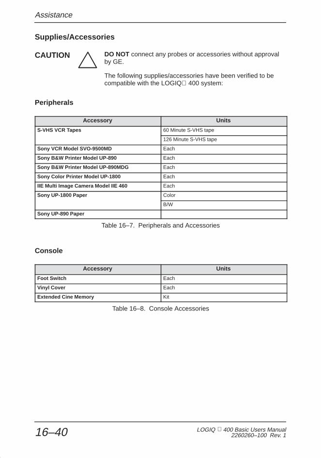
Assistance
LOGIQ 400 Basic Users Manual2260260–100 Rev. 116–40
Supplies/Accessories
DO NOT connect any probes or accessories without approvalby GE.
The following supplies/accessories have been verified to becompatible with the LOGIQ 400 system:
Peripherals
Accessory Units
S-VHS VCR Tapes 60 Minute S-VHS tape
126 Minute S-VHS tape
Sony VCR Model SVO-9500MD Each
Sony B&W Printer Model UP-890 Each
Sony B&W Printer Model UP-890MDG Each
Sony Color Printer Model UP-1800 Each
IIE Multi Image Camera Model IIE 460 Each
Sony UP-1800 Paper Color
B/W
Sony UP-890 Paper
Table 16–7. Peripherals and Accessories
Console
Accessory Units
Foot Switch Each
Vinyl Cover Each
Extended Cine Memory Kit
Table 16–8. Console Accessories
CAUTION

Assistance
LOGIQ 400 Basic User Manual2260260–100 Rev. 1 16–41
Probes
Accessory Units
B510 Each
C358 Each
C364 Each
C386 Each
C551 Each
C721 Each
E721 Each
ERB7 Each
I739 Each
LA39 Each
546L Each
739L Each
L764 Each
3S Each
S220 Each
S222 Each
S317 Each
S611 Each
T739 Each
CWD2 Each
CWD5 Each
PA51 Adapter Each
S5 Adapter Each
Probe Cable Arm Each
Left Side Holder Each
Special TV/TR Holder Each
Table 16–9. Probes and Accessories

Assistance
LOGIQ 400 Basic Users Manual2260260–100 Rev. 116–42
Gel
Accessory Units
Thermasonic Gel Warmer Holds three plastic bottles (250 ml or 8 oz).
Aquasonic 100 Scan Gel 5 liter jug
250 ml plastic bottles (12/case)
Scan Ultraound Gel 8 oz plastic bottles (12/case)
1 gallon plastic jug
Four 1-gallon plastic jugs
Table 16–10. Gel
Disinfectant
Accessory Units
Cidex Activated Dialdehyde 16/1 qt. bottles
4/1 gal. bottles
2/2.5 gal bottles
Table 16–11. Disinfectant
Civco Biopsy Starter Kits (includes bracket)
Accessory Units
C358 Probe Biopsy Kit Kit
C364 Probe Biopsy Kit Kit
C551 Probe Biopsy Kit Kit
739L Probe Biopsy Kit Kit
E721 Probe Biopsy Kit Reusable Kit
Disposable Kit
ERB7 Probe Biopsy Kit Kit (Needle Placement Guide)
Kit (5mm increments)
C721 Probe Biopsy Kit Kit
L764 Probe Biopsy Kit Kit
T739 Probe Biopsy Kit Kit
LA39 Probe Biopsy Kit Kit
Table 16–12. Probe Biopsy Brackets

Assistance
LOGIQ 400 Basic User Manual2260260–100 Rev. 1 16–43
Multi-Angle Brackets
Accessory Units
S317 Probe Each
C364 Probe Each
C386 Probe Each
546L Probe Each
T739 Probe Each
739L Probe Each
Table 16–13. Multi-Angle Brackets
Biopsy Replacement Kits
Accessory Units
Civco UltraPro Kit
Civco UltraPro II Kit
Civco Cleaning Brush for E721 Biopsy Guide 5 Brushes Per Set
Table 16–14. Biopsy Kits
Ultrasound Probe and Cord Sheath Sets
Accessory Units
Sterile Ultrasound Probe Sheath Set 20 Per Set
Sterile Ultrasound Cord Sheath Set 20 Per Set
Sanitary Rectal/Vaginal Probe Cover 20 Per Set
Sterile Combination Probe and Cord Cover Set 12 Per Set
Sterile Ultrasound Probe Sheath Set for Wide(2.5 and 3.5) Aperture Sector Probes
20 Per Set
Table 16–15. Biopsy Sheath Kits

Assistance
LOGIQ 400 Basic Users Manual2260260–100 Rev. 116–44
Physio Accessories
Accessory Units
Physio Input Panel Kit
ECG Cables Set
PCG Sensor Each
Table 16–16. Patient ECG Lead Wires
Patient Electrodes
Accessory Units
Adult Box/300
Pediatric Box/300
Adult/off center Box/500
Pediatric/off center Box/1000
Table 16–17. Patient ECG Electrodes
Contact the distributor, GE affiliate or sales representative forapproved peripherals.

Index
LOGIQ 400 Basic User Manual2260260–100 Rev. 1 Index 1
Index
Symbols% Stenosis, 8–3, 10–23, 11–5
% Stenosis Calculation [EC, UP], Preset Programmenu page 4, 14–71
Numbers3D Aspect Ratio [EC, UP, P, R], Custom Display
menu page 9, 14–28
3D B Background Level (%) [EC, UP], CustomDisplay menu page 18, 14–44
3D B Frame Line Level (%) [EC, UP], CustomDisplay menu page 18, 14–44
3D B Gradient Threshold (%) [EC, UP], CustomDisplay menu page 18, 14–44
3D B Percent of Source Frames [EC, UP], CustomDisplay menu page 18, 14–44
3D B Projection Technique [EC, UP, R], CustomDisplay menu page 18, 14–44
3D CFM/PDI Frame Line Level (%) [EC, UP],Custom Display menu page 18, 14–45
3D CFM/PDI Gradient Threshold (%) [EC, UP],Custom Display menu page 18, 14–45
3D CFM/PDI Percent of Source Frames (%) [EC,UP], Custom Display menu page 18, 14–45
3D CFM/PDI Projection Technique [EC, UP, R],Custom Display menu page 18, 14–45
3D CFM/PDI Shade Boundary Threshold (%) [EC,UP], Custom Display menu page 18, 14–45
3D CFM/PDI Shade Object Threshold (%) [EC, UP],Custom Display menu page 18, 14–45
3D ModeB–Mode, 5–21Color Flow, 5–41
3D Number of Frames in Build [EC, UP], CustomDisplay menu page 18, 14–44
3D Scan Line Resolution [EC, UP], Custom Displaymenu page 18, 14–44
3D Swing Angle (deg) [EC, UP, P, R], CustomDisplay menu page 9, 14–28
3D Swing Center (%) [EC, UP, P, R], CustomDisplay menu page 9, 14–28
3D Swing Speed [EC, UP, R], Custom Display menupage 18, 14–44
3D View [EC, UP, P, R], Custom Display menu page 9,14–28
3D–Surface Mode, 5–74Overview, 5–74
3DvieW Mode, 5–73Overview, 5–73
3S, 15–29
546L, 15–25
739L, 15–25
AA/B Ratio, 9–26
Abdomen/Small Parts, MeasurementsA/B Ratio, 8–3, 10–29Max PG, 8–3Mean PG, 8–3Pulsatility Index (PI), 8–3, 10–29Resistance Index (RI), 8–3, 10–29S/D Ratio, 8–3, 10–29
AccessoriesConnector Panel, 3–8Placing an order, 16–39Requesting a catalog, 16–39
Acclimation Time, 3–17
ACECFM/PDI Enhancement Option, 5–40Color Flow, 5–40

Index
LOGIQ 400 Basic Users Manual2260260–100 Rev. 1Index 2
Acoustic Output, 5–10Adjusting, 5–7Best Practices, 2–17Display, 5–6Fetal Exposure, 9–4General Warning, 9–4Hazard, 5–10Prudent Use, 9–4Safety, 2–17
Acoustic Output Hazard, 2–5
Acoustic Power B/M (%) [EC], Custom Displaymenu page 1, 14–14
Acoustic Power Control by Audio Volume [EC],Custom Display menu page 10, 14–29
Acoustic Power D/CFM/PDI (%) [EC], CustomDisplay menu page 1, 14–14
Acoustic Zoom, 6–2
Active Measurement Cursor, System Parametersmenu page 3, 14–53
Add 1 Week to EDD [EC], Preset Program menupage 3, 14–68
Advanced Obstetrical OptionsData Management Center (DMC), 9–44Fetal Trend Management. See Fetal Growth
TrendMultigestation, 9–44
Advanced Vascular, 11–10Menu Selections, 11–10
AFI, OB Measurements, 9–22
Air FilterCleaning, 16–18Locating, 16–17Removing, 16–18
ALARA, 5–10
Amniotic Fluid Index (AFI), 9–22
AngleCalculation, 8–3, 10–22Correction (Theta), Doppler, 5–54
Annotation, 6–16Blue Shift, 6–22Clear, 6–17CTRL+M, 6–17Cursor Home, 6–17Editing, 6–26
Image, 6–21Library, 6–19Red Shift, 6–22Set, 6–18Shift+TAB, 6–18Special Keys, 6–22
Blue Shift, 6–22Red Shift, 6–22
Tab, 6–18
Annotation Library 1–24 [EC, UP], Preset Programpages 8 & 9, 14–89
Application Presets, Defining a User Preset, 14–92
ArchiveDisk Verification, 13–20Hard Disk Storage, 13–22Image Recall Process, 13–29Image Selection for Recall, 13–29Media Format, 13–19Media Search, 13–30MO Archive, 13–21MO Eject, 13–32MOD, 13–17Patient Search, 13–23Preset Parameters, 13–18
Arrow Mark Display [EC, UP], Preset Program menupage 4, 14–71
ATO, B–Mode, 5–17
Audio, Speakers, 3–28
Audio Tone Equalizer [EC], Custom Display menupage 10, 14–30
Audio Volume, Doppler, 5–53
Auto B Melt at Unfreeze [EC, UP], Custom Displaymenu page 12, 14–32
Auto Deletion of Transferred Queue, SystemParameters menu page 7, 14–62
Auto Focus Control [EC], Custom Display menupage 10, 14–29
AuxGain, 10–36Positn, 10–36Wave, 10–35
AUX Auto Display [EC], Custom Display menupage 17, 14–43
AUX Gain [EC, R], Custom Display menu page 17,14–43

Index
LOGIQ 400 Basic User Manual2260260–100 Rev. 1 Index 3
AUX Position [EC, R], Custom Display menu page 17,14–43
Average Activity [EC], Preset Program menu page 3,14–67
Average Number [EC], Preset Program menu page 3,14–68
Averaging Number for Doppler Realtime Calc [EC,UP], Preset Program menu page 4, 14–70
BB Angle/Width (deg. mm) [EC, UP, P, R], Custom
Display menu page 2, 14–17
B Auto Caliper Control [EC, UP], Preset Programmenu page 4, 14–71
B Color Auto Start [EC, R], Custom Display menupage 11, 14–31
B Color Map [EC, UP], Custom Display menu page 11,14–31
B Combi Focus Width [EC, UP, P], Custom Displaymenu page 2, 14–17
B Dynamic Range [EC, UP, P, R], Custom Displaymenu page 2, 14–15
B Edge Enhance [EC, UP, P, R], Custom Displaymenu page 2, 14–15
B Focus Combi Number [EC, UP, P, R], CustomDisplay menu page 2, 14–17
B Focus Dual Marker [EC, UP], Custom Displaymenu page 11, 14–31
B Format B Dual [EC], Custom Display menu page 11,14–31
B Format B Single [EC], Custom Display menupage 11, 14–31
B Frame Average [EC, UP, P], Custom Displaymenu page 2, 14–15
B Gain [EC, UP, P, R], Custom Display menu page 2,14–15
B Gray Scale Map [EC, UP, P, R], Custom Displaymenu page 2, 14–16
B Image Frequency [EC, UP, P, R], Custom Displaymenu page 2, 14–15
B Image Softener [EC, UP, P, R], Custom Displaymenu page 2, 14–15
B Pause, Doppler, 5–56
B Rejection [EC, UP, P, R], Custom Display menupage 2, 14–17
B Scale Mark [EC], Custom Display menu page 11,14–31
B Softener Level [EC, UP, P], Custom Display menupage 2, 14–15
B Tag Auto Start [EC, R], Custom Display menupage 11, 14–31
B Tag Center (%) [EC, R], Custom Display menupage 11, 14–31
B Tag Width (%) [EC, R], Custom Display menupage 11, 14–31
B Target Frame Rate [EC, UP, P], Custom Displaymenu page 2, 14–17
B Video Inverse [EC], Custom Display menu page 11,14–31
B&W Image Archive, System Parameters menupage 5, 14–60
B&W Printer Exposure Min Interval [sec], SystemParameters menu page 5, 14–59
B&W Printer Exposure Pulse Length [msec], SystemParameters menu page 5, 14–59
B–Mode3D Mode, 5–21Acoustic Output, 5–10ATO
Create, 5–17On/Off, 5–18
B/M Gain, 5–12Biopsy Guidezone(s), 5–23Circumference/Area, 7–10Color, 5–21Color Tag, 5–22Colorized, 5–21Colorized Gray Scale, Color Tag, 5–22Depth, 5–12Display, 5–3Display Format(Dual), 5–14Distance Measurement, 7–7Dual Format, 5–14Dynamic Range, 5–16Echo Level Measurement, 7–11Edge Enhance, 5–24Focus Number, 5–17Focus Position, 5–17Focus Position (with Baseline Shift key), 5–15

Index
LOGIQ 400 Basic Users Manual2260260–100 Rev. 1Index 4
B–Mode (cont’d)Frame Averaging, 5–19Gray Scale, 5–21Gray Scale Map, 5–16Image Rotation, 5–23Image Softener, 5–21Imaging Freq, 5–19Optimizing the Image, 5–9Rejection, 5–24Reverse, 5–14Scan Area Position, 5–13Scan Area Size, 5–13TGC, 5–10With Doppler, 5–52
B/M Gain, 3–41B–Mode, 5–12M–Mode, 5–68
B/W Video Page Printer, 13–6
B510, 15–28
Backup, User Data, 14–103
Baseline ShiftColor Flow, 5–32Doppler, 5–56
Bi Plane Ellipsoid Method, 10–17
Biological Hazard, 2–3, 2–7
BiopsyDepth Cursor, 5–24, 15–32Guidezone(s), 5–23Procedures
Accessories & supplies, 15–31Guide attachment, 15–36Probes, 15–48Special concerns, 15–30
Blue Shift, 6–22
Body Pattern Copy to Active Side, SystemParameters menu page 4, 14–54
Body Pattern Package [EC, UP], Preset Programmenu page 1, 14–65
Body Pattern Package 1–8, System Parametersmenu page 4, 14–54
Body Pattern Probe Change Erase, SystemParameters menu page 4, 14–54
Body Pattern Probe Mark Preset [EC, UP], PresetProgram menu page 1, 14–65
Body Pattern Unfreeze Erase, System Parametersmenu page 4, 14–54
Body Patterns, 3–42, 6–27Illustrations, Patterns Available, 6–28Package Selections, 14–65Programming Packages 1–8, 14–54
BSA Type, System Parameters menu page 2, 14–51
Bullet Method, 10–11
CC358, 15–21
C364, 15–22
C386, 15–22
C551, 15–22
C721, 15–23
Calc Dir, Doppler, 5–63, 5–64
Calculation, Accuracy, 16–6
Calculation FormulasBiplane Ellipsoid Method, 10–18Bullet Method, 10–12General, 8–11GYN, 9–51Left Ventricular, 10–7Modified Simpson’s Rule Method, 10–14Ovary Follicles, 9–51Single Plane Ellipsoid Method, 10–16Teichholz Method, 10–9Vascular, 11–9
CalculationsCardiology, 10–19Erasing, 7–6Urology, 12–2Vascular, 11–3
Capture, Color Flow, 5–37
Cardiac Calculation, Preset Program menu page 7,14–87
Cardiac Measurement Choices [EC, UP], PresetProgram menu page 5 & 6, 14–72
Cardiac Output, 8–4Automatic Calculation, 8–4

Index
LOGIQ 400 Basic User Manual2260260–100 Rev. 1 Index 5
Cardiology, 10–1Bi Plane Ellipsoid Method, 10–17BSA Calculation Methods, 10–6Bullet Method, 10–11Calculations, 10–19Cubed Method, 10–7ECG, 10–31Measurements
% Stenosis, 10–23Angle, 10–22ET, 10–25Max PG, 10–26Mean PG, 10–27MVA, 10–24PHT, 10–24Volume, 10–19
Modified Simpson’s Rule Method, 10–13Overview, 10–3Single Plane Ellipsoid Method, 10–15Summary Report, Recording, 10–6Teichholz Method, 10–9
Cardiology CalculationsTrace Auto, 10–28Transf Calcs, 10–30
Care and Maintenance, Cleaning the systemAir Filters, 16–17Cabinet, 16–12Foot Switch, 16–15Monitor, 16–13Operator control panel, 16–14Page Printer, 16–16VCR, 16–15
Caution, 2–2, 16–40
CFM ACE [EC, UP, P, R], Custom Display menupage 7, 14–25
CFM B Angle/Width (deg/mm) [EC, UP, P, R],Custom Display menu page 6, 14–24
CFM B Frame Average [EC, UP, P, R], CustomDisplay menu page 6, 14–24
CFM B Gain [EC, UP, P, R], Custom Display menupage 6, 14–24
CFM B High Resolution [EC, UP, P, R], CustomDisplay menu page 6, 14–24
CFM B Wall Filter [EC, UP, P, R], Custom Displaymenu page 6, 14–24
CFM Base Line (%) [EC, R], Custom Display menupage 15, 14–40
CFM Capture Interval (s) [EC, R], Custom Displaymenu page 15, 14–39
CFM Color Map 1 [EC, UP], Custom Display menupage 15, 14–40
CFM Color Map 2 [EC, UP], Custom Display menupage 15, 14–40
CFM Color Map 3 [EC, UP], Custom Display menupage 15, 14–40
CFM Color Map 4 [EC, UP], Custom Display menupage 15, 14–40
CFM Color Map 5 [EC, UP], Custom Display menupage 15, 14–40
CFM Color Map 6 [EC, UP], Custom Display menupage 15, 14–40
CFM Color Threshold [EC, UP, P, R], CustomDisplay menu page 6, 14–23
CFM M Gain (Delta from B) [EC, UP, P, R], CustomDisplay menu page 7, 14–25
CFM M Wall Filter [EC, UP, P, R], Custom Displaymenu page 7, 14–25
CFM Noise Blanker [EC, UP, P, R], Custom Displaymenu page 7, 14–25
CFM Packet Size Map [EC, UP, P], Custom Displaymenu page 6, 14–23
CFM Packet Size MpDtl [EC, UP, P], CustomDisplay menu page 6, 14–23
CFM Packet Size SrvyDtl [EC, UP, P], CustomDisplay menu page 6, 14–23
CFM Packet Size Survey [EC, UP, P], CustomDisplay menu page 6, 14–23
CFM Persistance [EC, UP, P, R], Custom Displaymenu page 7, 14–25
CFM Tag Auto Start [EC, R], Custom Display menupage 15, 14–40
CFM Tag Center (cm/s) [EC, R], Custom Displaymenu page 15, 14–40
CFM Tag Width (cm/s) [EC, R], Custom Displaymenu page 15, 14–40
CFM Target Frame Rate [EC, UP, P], CustomDisplay menu page 6, 14–23

Index
LOGIQ 400 Basic Users Manual2260260–100 Rev. 1Index 6
CFM Target Frame Rate Dtl [EC, UP, P], CustomDisplay menu page 6, 14–23
CFM Threshold Turbulence [EC, UP, P, R], CustomDisplay menu page 6, 14–23
CFM Threshold Velocity [EC, UP, P, R], CustomDisplay menu page 6, 14–23
CFM Velo Dynamic Range [EC, UP], CustomDisplay menu page 15, 14–39
CFM Velocity (cm/s) [EC, UP, P, R]Custom Display menu page 5, 14–6Custom Display menu page 6, 14–24
CFM Wall Echo Canceller [EC, UP, P, R], CustomDisplay menu page 6, 14–23
CFM/PDI Enhancement, 5–40
CFM/PDI Focus Depth (%) [EC, UP, P], CustomDisplay menu page 6, 14–24
CFM/PDI Initial Mode [EC. R], Custom Display menupage 16, 14–41
CFM/PDI Initial Sequence [EC], Custom Displaymenu page 14, 14–40
CFM/PDI Sequence [EC, UP], Custom Displaymenu page 15, 14–39
CFM/PDI Shrink Angle/Width (deg, mm) [EC, UP, P,R], Custom Display menu page 4, 14–21
CFM/PDI Shrink in Triplex [EC, UP, P, R], CustomDisplay menu page 4, 14–21
CFM/PDI Spatical Filter [EC, UP, P], Custom Displaymenu page 6, 14–23
CFM/PDI Start Depth (mm) [EC, UP, P, R], CustomDisplay menu page 6, 14–24
CFM/PDI Vertical Size (mm) [EC, UP, P, R], CustomDisplay menu page 6, 14–24
CFM/PWD Ratio in Triplex [EC, UP, P, R], CustomDisplay menu page 4, 14–21
Change Probe and Category, System Parametersmemu page 1, 14–48
CINE, CINE Capture, 6–14
Cine, 6–12Accessing, 6–10Cine Gauge, 6–14Cine Guage/Image Tracking, 6–15Exiting, 6–15
Functionality, 6–9Helpful Hints, 6–15Introduction, 6–8Loop Speed, 6–13Memory, 6–9Multipl, 6–13Side Change, 6–14Using Cine Loop, 6–11
CINE Capture, 6–14
Cine Gauge Auto Display [EC], Custom Displaymenu page 10, 14–30
Cine Scroll, 3–41
Cine Speed [EC, R], Custom Display menu page 10,14–30
Circ/Area Method [EC], Preset Program menu page 3,14–67
Circuit breaker, 3–22
Class I Equipment, 2–11
CleaningFoot Switch, 16–15Monitor, 16–13Operator control panel, 16–14Page Printer, 16–16System cabinet, 16–12VCR, 16–15
Clear, 3–43
Col Applcat, System Parameters menu page 2,14–52
Col Aux, System Parameters menu page 2, 14–52
Col Back Gnd, System Parameters menu page 2,14–51
Col Comment, System Parameters menu page 2,14–52
Col Dop Trac, System Parameters menu page 2,14–52
Col Imag Crs, System Parameters menu page 2,14–52
Col Mes Crs, System Parameters menu page 2, 14–52
Col Moving, System Parameters menu page 2, 14–52
Col Scale, System Parameters menu page 2, 14–52
Col Sys Inf, System Parameters menu page 2, 14–52

Index
LOGIQ 400 Basic User Manual2260260–100 Rev. 1 Index 7
ColorB–Mode, 5–21Doppler, 5–61Gray Scale
B–Mode, 5–21Color Tag, 5–22
Basics, 5–26Doppler, 5–61
Color Tag, 5–61Tag Position, 5–61
M–Mode, 5–71M–Mode, 5–71
Color Flow3D Mode, 5–41ACE, 5–40Activating, 5–27Baseline Shift, 5–32Capture, 5–37Color Window, 5–27Common Controls, 5–30Control Layout, 5–29Diag Mode, 5–35Display, 5–28Exiting, 5–27Frame Average, 5–36Gain, 5–31High Resolution, 5–37M–Mode, 5–27Maps, 5–34Mode
Distance, 7–12Echo Level (gray scale), 7–12Ellipse/Trace, 7–12Velocity Point, 7–13
MR–Flow, 5–41MTI Filter, 5–35Noise Blanker, 5–40Packet Size, 5–38Penetration (Penet.), 5–36Persistence, 5–41Slant Scan, 5–34Spatial Filter, 5–38Spectrum Invert, 5–31Tag Position, 5–39Threshold, 5–37Velocity Scale, 5–32Velocity Tag, 5–39W.E. Cancel, 5–39Window, Linear Probe, 5–34Window Size, 5–33
Color Image Archive, System Parameters menupage 5, 14–60
Color Printer, Troubleshooting, 16–28
Color Printer Memory, System Parameters menupage 5, 14–58
Color Printer Signal, System Parameters menu page 5,14–59
Color Printer Type, System Parameters menu page 5,14–58
Color TagB–Mode, 5–22Color Flow, 5–39Doppler, 5–61
Color Threshold, Color Flow, 5–37
Color Video Page Printer, 13–9
Comment, 3–42, 6–16Displaying, 6–20Editing, 6–19, 6–26Entering, 6–19Scripts, 6–20
Comment Clear Key Function [EC], Preset Programmenu page 1, 14–65
Comment Erase at Display Change [EC], PresetProgram menu page 1, 14–65
Comment Home Position Horizontal [EC, R], PresetProgram menu page 1, 14–65
Comment Home Position Vertical [EC, R], PresetProgram menu page 1, 14–65
Console Labels, 2–22
Console Overview, 3–5
Contraindications, Doppler, 1–5
ControlAcoustic Output, 5–10B/M Gain, 3–41Cine Scroll, 3–41Depth, 3–40Rotation, 3–43TGC, 5–10Zoom Size, 3–43
Control PanelReplacing key caps, 16–16Replacing key lamps, 16–16
Controls, 3–34

Index
LOGIQ 400 Basic Users Manual2260260–100 Rev. 1Index 8
Coupling Gels, 15–19
CRT Menu Auto Display at Body Pattern [EC],Preset Program menu page 1, 14–66
CRT Menu Auto Display at Comment [EC], PresetProgram menu page 1, 14–66
CRT Menu Auto Display at Image Recall [EC],Preset Program menu page 1, 14–66
CRT Menu Auto Display at Measurement [EC],Preset Program menu page 1, 14–65
CRT Menu Auto Erase Interval, System Parametersmenu page 1, 14–50
CUA Selection Reset on New Patient, SystemParameters menu page 1, 14–49
CUA/AUA for HADLOCK, System Parameters menupage 3, 14–53
Cubed Method, 10–7
CursorAnnotation, 6–16Biopsy Depth, 5–24, 15–32Color Flow Doppler, 5–34Doppler, 5–53
Cursors, 7–4
Custom Display Presets, 14–7Contents, 14–12
Customizing Your System, 14–1
CWD Base Line (%) [EC, R], Custom Display menupage 15, 14–39
CWD Dynamic Range [EC, UP, P, R], CustomDisplay menu page 5, 14–22
CWD Gain [EC, UP, P, R], Custom Display menupage 5, 14–22
CWD Gray Scale Map [EC, UP, P, R], CustomDisplay menu page 5, 14–22
CWD Non–aliasing mode [EC, R], Custom Displaymenu page 15, 14–39
CWD Rejection [EC, UP, P, R], Custom Displaymenu page 5, 14–22
CWD Velocity (cm/s) [EC, UP, P, R], Custom Displaymenu page 5, 14–22
CWD Wall Filter (cm/s) [EC, UP, P, R], CustomDisplay menu page 5, 14–22
CWD2, 15–29
CWD5, 15–29
DD Audio to Speaker [EC], Custom Display menu
page 14, 14–37
D Audio Volume (%) [EC, R], Custom Display menupage 14, 14–37
D Auto Caliper Control [EC, UP], Preset Programmenu page 4, 14–71
D Color Auto Start [EC, R], Custom Display menupage 13, 14–35
D Color Map [EC, UP], Custom Display menu page 13,14–35
D Format (Side/Side, Full) [EC], Custom Displaymenu page 13, 14–35
D Image Processing [EC], Custom Display menupage 14, 14–37
D Mode Full B+ Cursor [EC], Custom Display menupage 13, 14–36
D Mode Full D [EC], Custom Display menu page 13,14–36
D Mode Side/Side B Large [EC], Custom Displaymenu page 13, 14–36
D Mode Side/Side B Small [EC], Custom Displaymenu page 13, 14–36
D Mode Top/Bottom B Large [EC], Custom Displaymenu page 13, 14–36
D Mode Top/Bottom B Mid [EC], Custom Displaymenu page 13, 14–36
D Mode Top/Bottom B Small [EC], Custom Displaymenu page 13, 14–36
D Realtime Auto Trace [EC, R], Custom Displaymenu page 13, 14–34
D Realtime Trace Method [EC, R], Custom Displaymenu page 13, 14–35
D Tag Auto Start [EC, R], Custom Display menupage 13, 14–35
D Tag Center (%) [EC, R], Custom Display menupage 13, 14–35
D Tag Width (%) [EC, R], Custom Display menupage 13, 14–35
D Time Resolution [EC], Custom Display menupage 14, 14–37
D Type for Wall Filter [EC], Custom Display menupage 13, 14–34

Index
LOGIQ 400 Basic User Manual2260260–100 Rev. 1 Index 9
D Video Inverse [EC], Custom Display menu page 14,14–37
D/CFM Scale Mark [EC], Custom Display menupage 13, 14–34
Danger, 2–2, 2–6
Data Management Center (DMC), 9–44
Date Format, System Parameters, SystemParameters menu page 1, 14–48
Defibrillator Caution, 2–22
Degauss, Monitor, 3–27
Delay Trigger Source, System Parameters menupage 2, 14–50
Depth, 3–40B–Mode, 5–12
Device Labels, 2–8
Diag Category, System Parameters, SystemParameters menu page 1, 14–48
Diag Mode, Color Flow, 5–35
Diagnostics, Operator, 16–34Accessing, 16–35
Diastole Velocity for PI [EC, UP], Preset Programmenu page 4, 14–70
Diastole Velocity for RI [EC, UP], Preset Programmenu page 4, 14–70
Diastole Velocity for S/D (D/S) [EC, UP], PresetProgram menu page 4, 14–70
Diastole/Systole Determination [EC], PresetProgram menu page 3, 14–68
Diastolic/Systolic Ratio (D/S), 9–26
Disk Drive, Floppy Disk, 3–7
DisplayA Output, 5–6Acoustic Output %, 5–4Angle, 5–49B Gray Scale Map Number, 5–5B–Mode, 5–3B–Mode Format, 5–3B/W Threshold Marker, 5–28Body Pattern, 5–5CFM Area Cursor, 5–28CG, 5–28Color Flow, 5–28
Color Scale, 5–5, 5–28D. Velocity, 5–49Date, 5–4Depth, 5–5DF, 5–49DG, 5–49Doppler, 5–48
Dual Spectrum, 5–66Spectrum, 5–65
Dual B–Mode Display Format, 5–77Dual Format, 5–78Dyn, 5–5FR/Cine, 5–5Gain, 5–5Gray Scale, 5–5Hospital Name, 5–4HR, 5–6ID, 5–4Image Rotation, 5–23LMP or GA, 5–4M–Mode
Dual Spectrum, 5–66Spectrum, 5–65
Measurements, 5–6MTI Filter, 5–28Operator Messages, 5–6Patient Name, 5–4PRF, 5–49Probe
Name, 5–4Orientation, 5–4
Sample Volume Length (SVL), 5–49Scale Marker, 5–8Scroll Depth, 5–8Soft Menu, 3–37SPEC INV, 5–49Spectrum Ref. Value, 5–49TGC Curve, 5–8Time, 5–4Time Scale, 5–49Top/Bottom B Large Preset, 5–76Top/Bottom B Mid Preset, 5–75Top/Bottom B Small Preset, 5–76TV Counter, 5–5Units (V or F), 5–28Velocity Scale, 5–28VTR Counter, 5–5VTR Status, 5–5Wall Filter (WV), 5–49Zoom, 5–8
with Reference, 5–77

Index
LOGIQ 400 Basic Users Manual2260260–100 Rev. 1Index 10
Display Dop Frequency [EC], Custom Display menupage 14, 14–37
Display Dop PRF [EC], Custom Display menupage 14, 14–37
Display EDD with GA Value [EC], Preset Programmenu page 3, 14–68
Display Format(Dual), B–Mode, 5–14
Display Height 1–3 [EC], Preset Program menupage 10, 14–89
Display MaxPG with Velocity [EC, UP], PresetProgram menu page 4, 14–71
Display Messages, 16–26
Display Probe Name, System Parameters menupage 1, 14–50
Display Spectrm Ref. Value [EC], Custom Displaymenu page 14, 14–38
Display TGC Curve [EC], Custom Display menupage 10, 14–30
Display Unit Age 1–4 [EC], Preset Program menupage 10, 14–89
Display Unit Weight 1–2 [EC], Preset Program menupage 10, 14–89
Displayed TI [EC], Custom Display menu page 10,14–29
DopplerActivating CWD, 5–50Activating PWD, 5–50Angle Correction, 5–54Audio Volume, 5–53B Pause, 5–56B–Mode Controls, 5–52Baseline Shift, 5–56Calc Dir, 5–63, 5–64Color, 5–61Color Flow
Activating, 5–27Common Controls, 5–30Control Layout, 5–29M–Mode, 5–27
Color Gain, 5–31Color Tag, 5–61Color Window, 5–27Colorized Gray Scale, 5–61
Color Tag, 5–61
Tag Position, 5–61Continuous Wave
Definition, 5–47Non–Imaging, 5–47Steerable, 5–47
Contraindications, 1–5Control Layout, 5–51CWD, Sub–Menus, 5–50Display, 5–48, 5–65Dual Display, 5–66Dynamic Range, 5–57Fetal Exams
Contraindications, 9–3Indications, 9–3
Fetal use, 1–4M/D Cursor, 5–53Optimization, 5–51Peak Velocity, 7–14Penetration, 5–60Pulsed Wave
Definition, 5–45Frequencies Used, 5–46
PWD, Sub–Menu, 5–50RealTime Trace, 5–63Rejection, 5–62Sample Volume Length, 5–59Slant Scan, 5–57Spectral Gain, 5–54Spectrum, Gain, 5–54Spectrum Invert, 5–55Sweep Speed, 5–60Tag Position, 5–61TAMAX/TAMIN/TAMEAN/TAMODE, 7–15Velocity Scale, 5–55Wall Filter, 5–59
Doppler Channel [EC, R], Custom Display menupage 13, 14–35
Doppler Realtime Calculation (EC, UP), PresetProgram menu page 7, 14–87
Dual, 10–34
Dual Format, B–Mode, 5–14
Dynamic RangeB–Mode, 5–16Doppler, 5–57M–Mode, 5–69

Index
LOGIQ 400 Basic User Manual2260260–100 Rev. 1 Index 11
EE721, 15–23
ECG, 10–31Cine Guage/Image Tracking, 6–15, 10–36Gain, 10–36Lead Placement, 10–33Positn, 10–36Soft Menu, 10–32Wave, 10–35
ECG Audio Beat Sound [EC, R], Custom Displaymenu page 17, 14–42
ECG Audio Beat Sound Tone [EC], Custom Displaymenu page 17, 14–42
ECG Auto Display [EC], Custom Display menupage 17, 14–42
ECG Gain [EC, R], Custom Display menu page 17,14–42
ECG Heart Rate Display [EC], Custom Displaymenu page 17, 14–42
ECG Position [EC, R], Custom Display menu page 17,14–42
ECG R Delay 1 (ms) [EC, UP, R], Custom Displaymenu page 17, 14–42
ECG R Delay 1 to 2 (ms) [EC, UP, R], CustomDisplay menu page 17, 14–42
ECG Sync Mark Display [EC], Custom Displaymenu page 17, 14–43
Echo Level Method [EC], Preset Program menupage 3, 14–67
Edge EnhanceB–Mode, 5–24M–Mode, 5–70
EFBW Form (Europe), System Parameters menupage 2, 14–51
EFBW Form (Tokyo), System Parameters menupage 2, 14–51
Electrical Hazard, 2–3, 2–5, 2–6
Ellipse, 3–43, 7–3
EMC (Electromagnetic Compatibility), 2–12
End Frame, 6–11
End Systole Period from Prior Edge [EC, UP],Preset Program menu page 3, 14–69
Endometrium Thickness, 9–47
Enter Depth [EC, UP, P, R], Custom Display menupage 1, 14–13
Equipment Safety, 2–6
ET (Ejection Time), 10–25
ExamApplication Preset Selection, 4–7Application Presets, Defining a User Preset,
14–92Beginning, 4–2
Explosion Hazard, 2–3, 2–6
External Video Signal, System Parameters menupage 5, 14–58
FFetal Doppler, 9–3
Fetal Heart Rate, 9–26
Fetal Trend Management, 9–44
Floppy Disk Drive, 3–7
Flow Volume (FV), 8–7
FocusNumber, B–Mode, 5–17Position, B–Mode, 5–17
Focus Depth [EC, UP, P, R], Custom Display menupage 1, 14–13
Focus Position (with Baseline Shift key), B–Mode,5–15
FolliclesLeft Ovary, 9–46Right Ovary, 9–46
Foot Switch, 3–10Cleaning, 16–15
Frame AveragingB–Mode, 5–19Color Flow, 5–36
Frame Rate Display [EC], Custom Display menupage 10, 14–30
Freeze, 3–41, 6–6Foot Switch, 6–7

Index
LOGIQ 400 Basic Users Manual2260260–100 Rev. 1Index 12
GGain, Color Doppler, 5–31
General Calculations% Stenosis, 8–3Angle, 8–3Cardiac Output (CO), 8–4CFM Mode, Velocity Point. See General
CalculationsFlow Volume (FV), 8–7Heart Rate (HR), 8–6, 8–8, 10–30Radiology/Abdomen. See General CalculationsSmall Parts. See General CalculationsStroke Volume Ratio (SV), 8–5Trace Auto, 8–3, 8–8, 11–5Urology. See General CalculationsVolume, 8–2
General Measurements, 7–1
Gestational Sac (GS), 9–21
Gray ScaleColorized
B–Mode, 5–21Color Tag, 5–22
Basics, 5–26Doppler, 5–61
Color Tag, 5–61Tag Position, 5–61
M–Mode, 5–71M–Mode, 5–69Map, B–Mode, 5–16
Ground Point, 2–23
GS, OB Measurements, 9–21
Guidezone(s), Biopsy, B–Mode, 5–23
GYNCalculation Formulas, 9–51Exam Preparation, 9–2Measurements, 9–45, 9–46
Endometrium Thickness, 9–47Ovarian Height, 9–45Ovarian Length, 9–45Ovarian Width, 9–45RI, 9–48Uterine Height, 9–46Uterine Length, 9–46Uterine Width, 9–46
Summary Report, Layout, 9–49
HHazard
Acoustic Output, 2–3Symbols, 2–3
Heart Rate (HR), 8–6, 8–8, 9–26, 10–30, 11–5
Heart Rate Method [EC], Preset Program menupage 3, 14–67
High Resolution, Color Flow, 5–37
Hip Orientation [EC, UP], Preset Program menupage 4, 14–70
Hospital Name, System Parameters menu page 1,14–48
HR, 9–26, 11–5
II739, 15–25
ID/Name, 4–6
ID/Name Prohibition After Measurement, SystemParameters menu page 2, 14–51
Illumination, key, 3–35
ImageAnnotation, 6–16, 6–21Freeze, 6–6Memory, 13–2Printing
B/W Video Page Printer, 13–6Color Video Page Printer, 13–9
Recall, 13–4Recording, 13–2Rotation, B–Mode, 5–23Softener, B–Mode, 5–21
Image ArchiveDisk Verification, 13–20Hard Disk Storage, 13–22Image Recall Process, 13–29Image Selection for Recall, 13–29Media Format, 13–19Media Search, 13–30MO Archive, 13–21MO Eject, 13–32MOD, 13–17Patient Search, 13–23Preset Parameters, 13–18

Index
LOGIQ 400 Basic User Manual2260260–100 Rev. 1 Index 13
Image Archive Compression [EC], Preset Programmenu page 2, 14–66
Image Back Color [EC, UP], Custom Display menupage 10, 14–30
Image Gamma (%) [EC, UP], Custom Display menupage 10, 14–29
Image Memory, 3–40
Image Mode [EC, R], Custom Display menu page 10,14–29
Image Recall, 3–40, 13–4
Image Reverse [EC, UP, P, R], Custom Displaymenu page 1, 14–13
Image Rotation [EC, UP, P, R], Custom Displaymenu page 1, 14–13
Imaging Freq, B–Mode, 5–19
Information, Requesting, 16–39
Insite Access Enable, System Parameters menupage 1, 14–49
Introduction, Who to Contact, 1–8
KKey
Body Pattern, 3–42Clear, 3–43Comment, 3–42Ellipse, 3–43, 7–3Freeze, 3–41Illumination, 3–35Image Memory, 3–40Image Recall, 3–40M/D Cursor, 3–42Measurement, 3–42, 7–3Mode, 3–40New Patient, 3–40Probe Controls, 3–31Record 1, 3–41Record 2, 3–41Reverse, 3–40Scan Area, 3–42Set, 3–43Soft Menu, 3–37Zoom, 3–43
Keyboard, 3–34, 3–36Blue Shift, 3–36Control, 3–36Cursor Home, 3–36Red Shift, 3–36Tab, 3–36
Keyboard Tab, System Parameters menu page 1,14–49
LL764, 15–25
LA39, 15–26
Labels, Icon Description, 2–8
Language, System Parameters menu page 1, 14–48
Language Specific Characters, 6–22
Laser Camera, 13–16
Leakage Current, 2–11
Left Ventricular, Calculation Formulas, 10–7
Length Unit [EC], Preset Program menu page 3,14–67
Library, Annotation, 6–19Entering/Editing, 6–19
Line PrinterBasic Operation, 13–15Error Messages, 16–29Setup, 13–15
Locatn (Location), 9–25
LOGIQ 500Back view, 3–6Front view, 3–6General Indications for Use, 1–4Left side view, 3–5Moving, 3–12, 3–13Relocating, 3–11Right side view, 3–5Transporting, 3–14Wheels, Setting the Lock, 3–15
Loop, Cine, 6–11
Loop Speed, 6–13

Index
LOGIQ 400 Basic Users Manual2260260–100 Rev. 1Index 14
LT Bifurc, 11–3
LT CCA, 11–3
LT ECA, 11–3
LT ICA, 11–3
LT ICA/CCA, 11–4
LtOvFo, 9–46
MM Auto Caliper Control [EC, UP], Preset Program
menu page 4, 14–71
M Color Auto Start [EC, R], Custom Display menupage 12, 14–32
M Color Map [EC, UP], Custom Display menupage 12, 14–32
M Dynamic Range [EC, UP, P, R], Custom Displaymenu page 3, 14–18
M Edge Enhance [EC, UP, P, R], Custom Displaymenu page 3, 14–18
M Format (Side/Side, Full) [EC], Custom Displaymenu page 12, 14–33
M Gain (Delta from B) [EC, UP, P, R], CustomDisplay menu page 3, 14–18
M Gray Scale Map [EC, UP, P, R], Custom Displaymenu page 3, 14–19
M Image Frequency [EC, UP, P, R], Custom Displaymenu page 3, 14–18
M Mode FULL B + Cursor [EC], Custom Displaymenu page 12, 14–33
M Mode Full M [EC], Custom Display menu page 12,14–34
M Mode Side/Side B Large [EC], Custom Displaymenu page 12, 14–33
M Mode Side/Side B Small [EC], Custom Displaymenu page 12, 14–33
M Mode Simul PD Activity [EC], Custom Displaymenu page 12, 14–32
M Mode Top/Bottom B Large [EC], Custom Displaymenu page 12, 14–33
M Mode Top/Bottom B Mid [EC], Custom Displaymenu page 12, 14–33
M Mode Top/Bottom B Small [EC], Custom Displaymenu page 12, 14–34
M Peak Hold [EC, UP, P, R], Custom Display menupage 3, 14–19
M Rejection [EC, UP, P, R], Custom Display menupage 3, 14–19
M Scale Mark [EC], Custom Display menu page 12,14–34
M Tag Auto Start [EC, UP], Custom Display menupage 12, 14–32
M Tag Center (%) [EC, R], Custom Display menupage 12, 14–32
M Tag Width (%) [EC, R], Custom Display menupage 12, 14–33
M Video Inverse [EC], Custom Display menu page 12,14–34
M–Mode, 5–67B/M Gain, 5–68Color, 5–71Color Flow, 5–27Colorized Gray Scale, 5–71Depth Difference, 7–22Display, 5–65Dual Display, 5–66Dynamic Range, 5–69Edge Enhance, 5–70Gray Scale, 5–69Introduction, 5–65M/D Cursor, 5–68Optimizing, 5–67Rejection, 5–70Sweep Speed, 5–71Time, 7–18, 7–21Tissue Depth, 7–20Typical Exam, 5–65Zoom, 5–68, 6–4
M/D Cursor, 3–42Doppler, 5–53M–Mode, 5–68
Maintenance, 16–11Cleaning the Air Filters, 16–17User, 16–1
Mask Image [EC], Preset Program menu page 3,14–68

Index
LOGIQ 400 Basic User Manual2260260–100 Rev. 1 Index 15
Mask Image Characters, System Parameters menupage 2, 14–50
Maskline Record, System Parameters menu page 5,14–59
Max PG, 8–3, 10–26Automatic Calculation, 10–26Cardiology Calculations, 10–26General Calculations, 8–3
Max Velocity (Advanced Vascular) [EC], PresetProgram menu page 3, 14–68
Mean PG, 8–3, 10–27Abdomen/Small Parts Calculations, 8–3Cardiology Calculations, 10–27
Measurement, 3–42, 7–3Accuracy, 16–5Cursors, 7–4Key, 7–5
Measurement Clear Operation [EC], Preset Programmenu page 3, 14–69
Measurement Menu B [EC, UP], Preset Programmenu page 7, 14–83
Measurement Menu CFM [EC, UP], Preset Programmenu page 7, 14–83
Measurement Menu D [EC, UP], Preset Programmenu page 7, 14–83
Measurement Menu M [EC, UP], Preset Programmenu page 7, 14–83
MeasurementsAbdomen/Small Parts
A/B Ratio, 8–3, 10–29Pulsatility Index (PI), 8–3, 10–29Resistance Index (RI), 8–3, 10–29S/D Ratio, 8–3, 10–29
B–ModeCircumference/Area, 7–10Distance, 7–7Echo Level, 7–11
Bi Plane Ellipsoid Method, 10–17Bullet Method, 10–11Calculations, 7–6Cardiology
% Stenosis, 10–23Angle, 10–22ET, 10–25MVA, 10–24PHT, 10–24Volume, 10–19
Color FlowDistance, 7–12
Echo Level (gray scale), 7–12Ellipse/Trace, 7–12Velocity Point. See General Calculations
Controls, 7–3Cubed Method, 10–7Doppler
Peak Velocity, 7–14TAMAX/TAMIN/TAMEAN/TAMODE, 7–15
General, 7–1GYN, 9–45, 9–46
Endometrium Thickness, 9–47Ovarian Height, 9–45Ovarian Length, 9–45Ovarian Width, 9–45Ovary Follicles, 9–46RI, 9–48Uterine Height, 9–46Uterine Length, 9–46Uterine Width, 9–46
M–ModeDepth Difference, 7–22Time, 7–18, 7–21Tissue Depth, 7–20
Modified Simpson’s Rule Method, 10–13OB
A/B Ratio, 9–26AFI, 9–22D/S Ratio, 9–26GS, 9–21Hints, 9–26HR, 9–26Locatn, 9–25Pulsatility Index (PI), 9–26Resistance Index (RI), 9–26S/D Ratio, 9–26Trace Auto, 9–26
Radiology/Abdomen. See General CalculationsSingle Plane Ellipsoid Method, 10–15Small Parts. See General CalculationsTeichholz Method, 10–9Urology. See General CalculationsVascular, 11–3
A/B Ratio, 11–5Heart Rate, 11–5Pulsatility Index (PI), 11–5Resistance Index (RI), 11–5RT(LT) Bifurc, 11–3RT(LT) CCA, 11–3RT(LT) ECA, 11–3RT(LT) ICA, 11–3RT(LT) ICA/CCA, 11–4S/D Ratio, 11–5
Volume, 10–19

Index
LOGIQ 400 Basic Users Manual2260260–100 Rev. 1Index 16
Media Selection for Fetal Trend [EC], PresetProgram menu page 3, 14–69
MemoryCine, 6–9Image, 13–2
Storage Space, 13–2Image Recall, 13–4
Menu Selection at New Patient, System Parametersmenu page 7, 14–62
Mode, Controls, 3–40
Modified Simpson’s Rule Method, 10–13
MonitorAdjustment
Brightness, 3–24Contrast, 3–24Degauss, 3–27Position, 3–23
Cleaning, 16–13Labels, 2–19
Moving Hazard, 2–3
MR–Flow, Color Flow, 5–41
MTI Filter, Color Flow, 5–35
Multi Image Camera, Troubleshooting, 16–29
Multigestation, OB option, 9–44
MVA (Mitral Valve Area), 10–24
NNeedle Guide Type [EC, UP, P, R], Custom Display
menu page 1, 14–14, 15–33
New Patient, 4–3Exam Category, 4–5Patient Entry Menu, 4–3
New Patient Y/N Ask [EC], Preset Program menupage 10, 14–89
Noise Blanker, Color Flow, 5–40
Non–Ionizing Radiation, 2–3
OOB, 9–27
Anatomical Survey, 9–38Editing, 9–39
User Programmed Features, 9–39Data Management Center (DMC), 9–44Exam Preparation, 9–2Fetal Trend Management. See Fetal Growth
TrendFormulas
European Version, 9–15Osaka University Method, 9–9Other Available Formulas, 9–18Tokyo University Method, 9–7USA Version, 9–10
Graph, 9–40Changing Selection, 9–43Selection, 9–41
MeasurementsA/B Ratio, 9–26AFI, 9–22D/S Ratio, 9–26GS, 9–21Hints, 9–26HR, 9–26Locatn, 9–25Pulsatility Index (PI), 9–26Resistance Index (RI), 9–26S/D Ratio, 9–26Soft Menu, 9–6Trace Auto, 9–26
Multigestation. See Fetal Growth TrendSummary Report, 9–27
Editing, 9–35European Version Layout, 9–30Recording, 9–37USA Version Layout, 9–29
OB Format Selection, 9–5
OB Measurements, Procedures, Amniotic FluidIndex, 9–22
OB Report Format, System Parameters menu page 2,14–51
OFD, Measurement from HC, 9–29
Operation Error Beep, System Parameters menupage 1, 14–49
Optimizing, B–Mode, 5–9

Index
LOGIQ 400 Basic User Manual2260260–100 Rev. 1 Index 17
Option, Advanced Vascular, 11–10
OptionsAdvanced Cardiac Calculations (AMCAL), 10–37Data Management Center (DMC), 9–44DICOM, 13–33Fetal Trend Management, 9–44Multigestation, 9–44
Ov–H, 9–45
Ov–L, 9–45
Ov–W, 9–45
OvarianHeight, 9–45Length, 9–45Width, 9–45
Ovary Follicles, Calculation Formulas, 9–51
PPacket Size
Affect on frame rate, 5–38Color Flow, 5–38
Page Printer, Cleaning, 16–16
Password, Protection at Power Up, 3–19
Password 1–8, System Parameters menu page 6,14–60
Password Ask, System Parameters menu page 6,14–60
Patient Entry Menu, 4–3
Patient Name Format, System Parameters menupage 7, 14–62
Patient Safety, 2–4
PCGGain, 10–36Positn, 10–36Wave, 10–35
PCG Auto Display [EC], Custom Display menupage 17, 14–43
PCG Filter, System Parameters menu page 2, 14–50
PCG Gain [EC, R], Custom Display menu page 17,14–43
PCG Position [EC, R], Custom Display menu page 17,14–43
PDI, 5–43Optimizing, 5–43
PDI ACE [EC, UP, P, R], Custom Display menupage 8, 14–27
PDI B Frame Average [EC, UP, P, R], CustomDisplay menu page 8, 14–27
PDI B Gain [EC, UP, P, R], Custom Display menupage 8, 14–26
PDI B High Resolution [EC, UP, P, R], CustomDisplay menu page 8, 14–26
PDI B Wall Filter [EC, UP, P, R], Custom Displaymenu page 8, 14–27
PDI B/W Display [EC], Custom Display menu page 16,14–41
PDI Capture Interval (s) [EC, R], Custom Displaymenu page 16, 14–41
PDI Color Threshold [EC, UP, P, R], Custom Displaymenu page 8, 14–26
PDI Default Map [EC], Custom Display menu page 16,14–41
PDI Dynamic Range [EC, UP], Custom Displaymenu page 16, 14–41
PDI M Gain (Delta from B) [EC, UP, P, R], CustomDisplay menu page 8, 14–27
PDI M Wall Filter [EC, UP, P, R], Custom Displaymenu page 8, 14–27
PDI Noise Blanker [EC, UP, P, R], Custom Displaymenu page 8, 14–27
PDI Packet Size Map [EC, UP, P], Custom Displaymenu page 8, 14–26
PDI Packet Size MpDtl [EC, UP, P], Custom Displaymenu page 8, 14–26
PDI Packet Size SrvyDtl [EC, UP, P], CustomDisplay menu page 8, 14–26
PDI Packet Size Survey [EC, UP, P], CustomDisplay menu page 8, 14–26
PDI Persistance [EC, UP, P, R], Custom Displaymenu page 8, 14–27
PDI Tag Auto Start [EC, R], Custom Display menupage 16, 14–41

Index
LOGIQ 400 Basic Users Manual2260260–100 Rev. 1Index 18
PDI Tag Center (cm/s) [EC, R], Custom Displaymenu page 16, 14–41
PDI Tag Width (cm/s) [EC, R], Custom Display menupage 16, 14–41
PDI Target Frame Rate [EC, UP, P], Custom Displaymenu page 8, 14–26
PDI Target Frame Rate Dtl [EC, UP, P], CustomDisplay menu page 8, 14–26
PDI Threshold Power [EC, UP, P, R], CustomDisplay menu page 8, 14–26
PDI Velocity (cm/s) [EC, UP, P, R], Custom Displaymenu page 8, 14–26
PDI/PWD Ratio in Triplex [EC, UP, P, R], CustomDisplay menu page 4, 14–21
Penet., Color Flow, 5–36
Penetration, Doppler, 5–60
PeripheralsBlack/White Video Printer, 13–7Color Video Printer, 13–10Connector Panel, 3–8S–VHS Video Cassette Recorder, 13–13
Persistence, Color Flow, 5–41
Personnel Safety, 2–6
PHT (Pressure Half Time), 10–24
Physio Sweep Speed, 10–32
Physio Sweep Speed on B [EC, UP, P, R], CustomDisplay menu page 3, 14–18
Plug 1–BW, System Parameters menu page 5, 14–59
Plug 2–CLR, System Parameters menu page 5, 14–59
Port A, System Parameters menu page 5, 14–59
Port B, System Parameters menu page 5, 14–59
Post ProcessingB–Mode
Color, 5–21Color Tag, 5–22Gray Scale Map, 5–16
Color FlowColor Tag, 5–39Color Threshold, 5–37Map, 5–34Packet Size, 5–38Spatial Filter, 5–38
Tag Position, 5–39W.E. Cancel, 5–39
DopplerColor, 5–61Color Tag, 5–61Tag Position, 5–61
Image Rotation, 5–23M–Mode
Color, 5–71Gray Scale Map, 5–69Rejection, 5–70
RejectionB–Mode, 5–24Doppler, 5–62
Power, 3–16Circuit Breaker, 3–22Connection, 3–16Cord, 3–11Off, 3–21On/Off Standby, 3–17
Power Doppler Imaging, 5–43
Power on Memory Test, System Parameters menupage 1, 14–49
Power on Status, System Parameters menu page 1,14–49
Power Up Sequence, 3–18
PPSA Coefficient (1) [EC, UP], Preset Programmenu page 4, 14–70
PPSA Coefficient (2) [EC, UP], Preset Programmenu page 4, 14–71
Pre–ProcessingB–Mode
Dynamic Range, 5–16Edge Enhance, 5–24Frame Averaging, 5–19Image Softener, 5–21
Color FlowCapture, 5–37Diag Mode, 5–35Frame Average, 5–36High Resolution, 5–37Penetration (Penet.), 5–36
Doppler, Dynamic Range, 5–57M–Mode
Dynamic Range, 5–69Edge Enhance, 5–70

Index
LOGIQ 400 Basic User Manual2260260–100 Rev. 1 Index 19
Precaution Levels, 2–2
Preset Parameters, 14–1, 14–7, 14–46, 14–63Overview, 14–5Save Values, 14–90Top Menu, Defining a User Preset, 14–92
Preset Program, 14–63
PresetsChanging a Value, 14–10Command lines, 14–8Custom Display Contents, 14–12How to Customize, 14–7
Printing, Images, 13–6
Probe, 3–29, 15–13S, 15–29546L, 15–25739L, 15–25Activating, 3–31Application, 15–6B510, 15–28Biopsy Guidezone(s), 5–23Body Pattern Marker, 6–27C358, 15–21C364, 15–22C386, 15–22C551, 15–22C721, 15–23Care and Maintenance, 15–10Cleaning, 15–13Connecting, 3–29Controls, 3–31Coupling Gels, 15–19Curved Array, Biopsy guidezone, 15–21Curved Array (Convex), 15–21CWD2, 15–29CWD5, 15–29Deactivating, 3–32Description, 15–20Disconnecting, 3–33Disinfecting, 15–16Dual Frequency Operation
Imaging Freq, 5–19Penetration, 5–60
E721, 15–23Environmental Requirements, 15–10I739, 15–25
Immersion Levels, 15–15L764, 15–25LA39, 15–26Labelling, 15–3LD, 15–26Linear
Color Flow Window, 5–34Doppler Cursor, 5–57
Linear Array, Biopsy guidezone, 15–24Naming Conventions, 15–20Orientation Marker, 6–27Planned Maintenance, 15–19S220, 15–27S222, 15–27S317, 15–28S611, 15–28Safety, 15–11
Coupling gelsApplying, 15–19Precautions, 15–19
Sector, biopsy guidezone, 15–27Special Handling Instructions, 15–12Specifications, 15–7Storing, 3–33T739, 15–26
Probe Direction Mark Display [EC], Custom Displaymenu page 10, 14–30
PSA Calculation, System Parameters menu page 3,14–53
Pulsatility Index (PI), 8–3, 9–26, 10–29, 11–5
Pulsed Wave Doppler, Introduction, 5–44
PWD. See Doppler
PWD Alternative Scan [EC, UP, P, R], CustomDisplay menu page 4, 14–21
PWD Base Line (%) [EC, R], Custom Display menupage 15, 14–39
PWD Dynamic Range [EC, UP, P, R], CustomDisplay menu page 4, 14–20
PWD Gain [EC, UP, P, R], Custom Display menupage 4, 14–20
PWD Gray Scale Map [EC, UP, P, R], CustomDisplay menu page 4, 14–20

Index
LOGIQ 400 Basic Users Manual2260260–100 Rev. 1Index 20
PWD Rejection [EC, UP, P, R], Custom Displaymenu page 4, 14–20
PWD Sample Volume (mm) [EC, UP, P, R], CustomDisplay menu page 4, 14–20
PWD Velocity (cm/s) [EC, UP, P, R], Custom Displaymenu page 4, 14–20
PWD Wall Filter (cm/s) [EC, UP, P, R], CustomDisplay menu page 4, 14–20
PWD/CFM/PDI Penetration [EC, UP, P, R], CustomDisplay menu page 4, 14–20
PWD/CFM/PDI Slant Auto Start [EC, UP, P, R],Custom Display menu page 4, 14–20
RR Delay, 10–35
Radiology/AbdomenCalculations. See General CalculationsMeasurements. See General Calculations
RDelay Time of End Systole Prior Edge [EC, UP],Preset Program menu page 3, 14–69
RealTime Trace, Doppler, 5–63
Record 1, 3–41, 13–6, 13–9
Record 1 B&W, System Parameters menu page 5,14–58
Record 1 Color, System Parameters menu page 5,14–58
Record 2, 3–41, 13–6, 13–9
Record 2 B&W, System Parameters menu page 5,14–58
Record 2 Color, System Parameters menu page 5,14–58
Recording, Image, 13–2
Red Shift, 6–22
Ref Scan, 10–35
Regulatory LabelsAmericas Systems, 2–26European Systems, 2–24
RejectionB–Mode, 5–24Doppler, 5–62M–Mode, 5–70
Report, System Parameters menu page 5, 14–58
Report Cursor Blink, System Parameters menu page 1,14–48
Report Cursor Type, System Parameters menu page 1,14–48
Report Format [EC], Preset Program menu page 7,14–72
Report Video Inverse to Printer, System Parametersmenu page 5, 14–58
Resistance Index (RI), 8–3, 9–26, 9–48, 10–29, 11–5
Reverse, 3–40B–Mode, 5–14
Review Loop, 6–12
RI, 9–48
RI Calculation to bidirectional Flow [EC, UP], PresetProgram menu page 4, 14–70
Rotation, 3–43B–Mode Image, 5–23
RT Bifurc, 11–3
RT CCA, 11–3
RT ECA, 11–3
RT ICA, 11–3
RT ICA/CCA, 11–4
RtOvFo, 9–46
SS220, 15–27
S222, 15–27
S317, 15–28
S611, 15–28

Index
LOGIQ 400 Basic User Manual2260260–100 Rev. 1 Index 21
Safety, 2–1Acoustic Output, 2–17BF Equipment, 2–11CF Equipment, 2–11Class I Equipment, 2–11EMC, 2–12Equipment and personnel safety
Explosion hazard, 2–6Smoke and fire hazard, 2–6
Hazard Symbols, Icon Description, 2–3Labels, Icon Description, 2–8Leakage Current, 2–11Patient
Diagnostic Information, 2–4Identification, 2–4Mechanical Hazards, 2–4
Patient safetyAcoustic Output hazard, 2–5Diagnostic information, 2–4Electrical hazard, 2–5Mechanical hazards, 2–4Patient identification, 2–4Training, ALARA, 2–5
Precaution Levels, Icon Description, 2–2Safety hazards, defined, 2–3– 2–4Safety icons, defined, 2–2Warning Label, Location, 2–19
Sample Volume Length, Doppler, 5–59
Save Values, 14–90
Scan Area, 3–42Color Flow Window Size, 5–33Position, B–Mode, 5–13Size, B–Mode, 5–13
Sequence 1–8 [EC], Preset Program menu page 7,14–79
Service, Requesting, 16–39
Set, 3–43
Setup Blue Back Start, System Parameters menupage 2, 14–50
Single, 10–34
Single Plane Ellipsoid Method, 10–15
Site Requirements, 3–2
Slant ScanColor Flow, 5–34
Doppler, 5–57
Small PartsCalculations. See General CalculationsMeasurements. See General Calculations
Smoke & Fire Hazard, 2–3, 2–6
Smoothing, B–Mode, Image Softener, 5–21
Soft Key, 3–37
Soft MenuB–Mode
3D Mode, 5–21ATO, 5–17Biopsy Guidezone(s), 5–23Color, 5–21Color Tag, 5–22Dynamic Range, 5–16Edge Enhance, 5–24Focus Number, 5–17Focus Position, 5–17Frame Averaging, 5–19Gray Scale Map, 5–16Image Rotation, 5–23Image Softener, 5–21Imaging Freq, 5–19Rejection, 5–24
Color Flow3D Mode, 5–41ACE, 5–40Color Capture, 5–37Color Flow Map, 5–34Color Tag, 5–39Color Threshold, 5–37Diag Mode, 5–35Frame Average, 5–36High Resolution, 5–37MR–Flow, 5–41MTI Filter, 5–35Noise Blanker, 5–40Packet Size, 5–38Penet., 5–36Persistence, 5–41Slant Scan, 5–34Spatial Filter, 5–38Tag Position, 5–39W.E. Cancel, 5–39
Control Panel, 3–37

Index
LOGIQ 400 Basic Users Manual2260260–100 Rev. 1Index 22
Soft Menu (cont’d)Doppler
Calc Dir, 5–63, 5–64Color, 5–61Color Tag, 5–61Dynamic Range, 5–57Penetration, 5–60RealTime Trace, 5–63Rejection, 5–62Sample Volume Length, 5–59Slant Scan, 5–57Sweep Speed, 5–60Tag Position, 5–61Wall Filter, 5–59
M–ModeColor, 5–71Dynamic Range, 5–69Edge Enhance, 5–70Gray Scale Map, 5–69Rejection, 5–70Sweep Speed, 5–71
Software OptionCardiology, 10–1OB, 9–1Vascular, 11–1
Sort Criteria for Schedule List, System Parametersmenu page 7, 14–62
Spatial Average, Affect on frame rate, 5–38
Spatial Filter, Color Flow, 5–38
Speakers, 3–28
Spec. Inv in Triplex [EC], Custom Display menupage 14, 14–38
Spectral Gain, Doppler, 5–54
SpectrumDoppler, Display, 5–65Gain, Doppler, 5–54Invert, 5–55
Color Flow, 5–31M–Mode, Display, 5–65
Standby Time (min), System Parameters menu page 1,14–49
Standoff Setting [EC, UP, P, R], Custom Displaymenu page 1, 14–14
Start Frame, 6–11
Stenosis Ratio. See % Stenosis
Stepper Increment [EC, UP], Preset Program menupage 4, 14–70
Storage areas, 3–7
Stroke Volume, 8–5Automatic Calculation, 8–6
Style Fun, Style Name, Page# SepE721, 15–23Probe, E721, 15–23
Sub–Menu, 3–37, 3–39
Summary ReportGYN, Layout, 9–49OB, 9–27Vascular
Displaying, 11–6Editing, 11–7
Sweep SpeedDoppler, 5–60M–Mode, 5–71
Sync Selectn, 10–35
SystemCare, 16–11Specifications, 16–3
System Error Erase Interval, System Parametersmenu page 1, 14–49
System Parameters, Preset Parameters, 14–46
Systolic/Diastolic Ratio (S/D), 8–3, 9–26, 10–29, 11–5
TT739, 15–26
TA Max Auto [EC], Preset Program menu page 3,14–68
Tag PositionColor Flow, 5–39Doppler, 5–61
Teichholz Method, 10–9
TGC, 5–10
TGC Curve, Disable, 5–8
TGC Depth Remap [EC], Custom Display menupage 10, 14–29
Time Adjustment, 14–3, 14–3
Time Format, System Parameters, SystemParameters menu page 1, 14–48

Index
LOGIQ 400 Basic User Manual2260260–100 Rev. 1 Index 23
Time Unit [EC], Preset Program menu page 3, 14–67
Timeline, Common Controls, 5–67
Timeline Format [EC], Custom Display menu page 12,14–32
Timeline Sweep Method [EC], Custom Display menupage 12, 14–32
Timeline Sweep Speed [EC, UP, P, R], CustomDisplay menu page 3, 14–18
Top Menu, 3–37Automatic, 3–38Disable, 3–38Mode Default Menu, 3–38
Top Menu Select, 3–37
Trace Auto, 8–3, 8–8, 10–28, 11–5Measurement Method, 9–26
Trackball, 3–43
Trackball Function at Freeze [EC], Preset Programmenu page 1, 14–65
Transf Calcs, 10–30
Troubleshooting, 16–19Color printer, 16–28Display Messages, 16–26Multi Image Camera, 16–29Operation Error Message, 16–28System Error Message, 16–27VCR, 16–29Warning Message, 16–33
Type BF Equipment, 2–11
Type CF Equipment, 2–11
UUrology
Calculations, 12–2Mechanical Stepping Device, Mechanical
Stepper/Needle Placement Guide, 12–11Stepper Volume Calculation, 12–8
Stepper Volume Formula, 12–10
Use A/N Keys for User Define, System Parametersmenu page 3, 14–53
UserData Backup, 14–103
Define Function, Programming, 14–97Programmed Calculations, Tables, 9–25Tables, 9–25
User Define Key Names and Locks, SystemParameters menu page 3, 14–53
User ID 1–8, System Parameters menu page 6,14–60
User Sequence 1–8, Programming, 14–79
User Table Editor, Preset Program menu page 7,14–75
Ut–H, 9–46
Ut–L, 9–46
Ut–W, 9–46
UterineHeight, 9–46Length, 9–46Width, 9–46
Uterine Cavity, 9–22
VVascular, 11–1
Advanced Option, 11–10Calculation Formulas, 11–9Calculations, 11–3Carotid Artery Measurements, 11–3Exam Preparation, 11–2Measurements, 11–3
A/B Ratio, 11–5Heart Rate, 11–5Pulsatility Index (PI), 11–5Resistance Index (RI), 11–5RT(LT) Bifurc, 11–3RT(LT) CCA, 11–3RT(LT) ECA, 11–3RT(LT) ICA, 11–3RT(LT) ICA/CCA, 11–4S/D Ratio, 11–5
Summary ReportDisplaying, 11–6Editing, 11–7Recording, 11–8
Vascular Calculations, % Stenosis, 11–5

Index
LOGIQ 400 Basic Users Manual2260260–100 Rev. 1Index 24
VCR, 13–12Cleaning, 16–15
VCR Color Intensity [EC, R], Preset Program menupage 2, 14–66
VCR Play Audio [EC], Preset Program menu page 2,14–66
VCR Play Audio Volume (%) [EC, R], PresetProgram menu page 2, 14–66
VCR Rec Audio Doppler [EC], Preset Program menupage 2, 14–66
VCRPB Calib Method [EC, R], Preset Programmenu page 3, 14–67
Velocity Ratio (A/B), 8–3, 9–26, 10–29, 11–5
Velocity ScaleColor Flow, 5–32Doppler, 5–55
Velocity Unit [EC], Preset Program menu page 3,14–67
Video Cassette Recorder. See VCR
Volume, 8–2, 10–19Doppler Audio, 5–53
VTR. See VCR
WW.E. Cancel, Color Flow, 5–39
Wall Filter, Doppler, 5–59
Warning, 2–2, 2–6, 13–5Label Locations, 2–19
WarrantiesDuration, 16–7Scope, 16–7
Wheels, 3–15
Word Wrap, 6–21
ZZoom, 3–43
Display Format, 5–77Introduction, 6–2M–Mode, 5–68, 6–4Methods
Acoustic Zoom, 6–2Display, 6–3
Multi–Image, 6–5Size, 3–43
Zoom Auto Start [EC, UP, P], Custom Display menupage 1, 14–13
Zoom Factor [EC, UP, P, R], Custom Display menupage 1, 14–13
Zoom Reference [EC, UP, P], Custom Display menupage 1, 14–13
Zoom Reference Update [EC, UP], Custom Displaymenu page 10, 14–29