Fuel Cells and Other Emerging Manportable Power ... - DTIC
138
NORTH ATLANTIC TREATY ORGANIZATION SCIENCE AND TECHNOLOGY ORGANIZATION AC/323(SET-173)TP/559 www.sto.nato.int STO TECHNICAL REPORT TR-SET-173-Part-I Fuel Cells and Other Emerging Manportable Power Technologies for the NATO Warfighter – Part I: Power Sources for Manportable/ Manwearable Applications (Piles à combustible et autres technologies portatives d'alimentation en énergie pour les combattants de l'OTAN − Partie I : Sources d’alimentation pour les applications transportables/portables par l’homme) This is the Final Report of SET-173 “Fuel Cells and Other Emerging Manportable Power Technologies for the NATO Warfighter” on the use of fuel cells in manwearable and manportable applications. Published October 2014 Distribution and Availability on Back Cover
-
Upload
khangminh22 -
Category
Documents
-
view
2 -
download
0
Transcript of Fuel Cells and Other Emerging Manportable Power ... - DTIC
NORTH ATLANTIC TREATY ORGANIZATION
SCIENCE AND TECHNOLOGY ORGANIZATION
AC/323(SET-173)TP/559 www.sto.nato.int
STO TECHNICAL REPORT TR-SET-173-Part-I
Fuel Cells and Other Emerging Manportable Power Technologies for the NATO Warfighter –
Part I: Power Sources for Manportable/ Manwearable Applications
(Piles à combustible et autres technologies portatives d'alimentation en énergie pour les combattants de l'OTAN −
Partie I : Sources d’alimentation pour les applications transportables/portables par l’homme)
This is the Final Report of SET-173 “Fuel Cells and Other Emerging
Manportable Power Technologies for the NATO Warfighter” on the
use of fuel cells in manwearable and manportable applications.
Published October 2014
Distribution and Availability on Back Cover


NORTH ATLANTIC TREATY ORGANIZATION
SCIENCE AND TECHNOLOGY ORGANIZATION
AC/323(SET-173)TP/559 www.sto.nato.int
STO TECHNICAL REPORT TR-SET-173-Part-I
Fuel Cells and Other Emerging Manportable Power Technologies for the NATO Warfighter –
Part I: Power Sources for Manportable/ Manwearable Applications
(Piles à combustible et autres technologies portatives d'alimentation en énergie pour les combattants de l'OTAN −
Partie I : Sources d’alimentation pour les applications transportables/portables par l’homme)
This is the Final Report of SET-173 “Fuel Cells and Other Emerging
Manportable Power Technologies for the NATO Warfighter” on the
use of fuel cells in manwearable and manportable applications.
The NATO Science and Technology Organization
Science & Technology (S&T) in the NATO context is defined as the selective and rigorous generation and application of state-of-the-art, validated knowledge for defence and security purposes. S&T activities embrace scientific research, technology development, transition, application and field-testing, experimentation and a range of related scientific activities that include systems engineering, operational research and analysis, synthesis, integration and validation of knowledge derived through the scientific method.
In NATO, S&T is addressed using different business models, namely a collaborative business model where NATO provides a forum where NATO Nations and partner Nations elect to use their national resources to define, conduct and promote cooperative research and information exchange, and secondly an in-house delivery business model where S&T activities are conducted in a NATO dedicated executive body, having its own personnel, capabilities and infrastructure.
The mission of the NATO Science & Technology Organization (STO) is to help position the Nations’ and NATO’s S&T investments as a strategic enabler of the knowledge and technology advantage for the defence and security posture of NATO Nations and partner Nations, by conducting and promoting S&T activities that augment and leverage the capabilities and programmes of the Alliance, of the NATO Nations and the partner Nations, in support of NATO’s objectives, and contributing to NATO’s ability to enable and influence security and defence related capability development and threat mitigation in NATO Nations and partner Nations, in accordance with NATO policies.
The total spectrum of this collaborative effort is addressed by six Technical Panels who manage a wide range of scientific research activities, a Group specialising in modelling and simulation, plus a Committee dedicated to supporting the information management needs of the organization.
• AVT Applied Vehicle Technology Panel
• HFM Human Factors and Medicine Panel
• IST Information Systems Technology Panel
• NMSG NATO Modelling and Simulation Group
• SAS System Analysis and Studies Panel
• SCI Systems Concepts and Integration Panel
• SET Sensors and Electronics Technology Panel
These Panels and Group are the power-house of the collaborative model and are made up of national representatives as well as recognised world-class scientists, engineers and information specialists. In addition to providing critical technical oversight, they also provide a communication link to military users and other NATO bodies.
The scientific and technological work is carried out by Technical Teams, created under one or more of these eight bodies, for specific research activities which have a defined duration. These research activities can take a variety of forms, including Task Groups, Workshops, Symposia, Specialists’ Meetings, Lecture Series and Technical Courses.
The content of this publication has been reproduced directly from material supplied by STO or the authors.
Published October 2014
Copyright © STO/NATO 2014 All Rights Reserved
ISBN 978-92-837-0210-8
Single copies of this publication or of a part of it may be made for individual use only by those organisations or individuals in NATO Nations defined by the limitation notice printed on the front cover. The approval of the STO Information Management Systems Branch is required for more than one copy to be made or an extract included in another publication. Requests to do so should be sent to the address on the back cover.
ii STO-TR-SET-173-Part-I

Table of Contents
Page
List of Figures viii
List of Tables x
SET-173 Membership List xi
Executive Summary and Synthèse ES-1
Chapter 1 – SET-173: Manwearable Power Overview 1-1 1.1 Overview 1-1 1.2 Background and Justification (Relevance to NATO) 1-1 1.3 Objectives 1-1
1.3.1 Topics to be Covered 1-2 1.3.2 Deliverable 1-2 1.3.3 Technical Team Leader and Lead Nation 1-2 1.3.4 SET-173: Groups 1-2
Chapter 2 – Manwearable Power Overview 2-1 2.1 Scope of Activity 2-1
2.1.1 The Dismounted Soldier System Aspects 2-1 2.1.2 Comparative Tables and Graphics 2-1 2.1.3 Soldier-Wearable Definition 2-1
2.1.3.1 Introduction 2-1 2.1.3.2 Soldier Wearable vs. Soldier Portable 2-2
Chapter 3 – Power for the Dismounted Soldier System 3-1 3.1 The Issues in Providing Manwearable Power 3-1
3.1.1 Power Sources Overview 3-1 3.1.1.1 Batteries 3-1 3.1.1.2 Fuel Cells 3-2 3.1.1.3 DSS Energy Needs 3-2 3.1.1.4 Integrated Dismounted Power System 3-6 3.1.1.5 Initial Exploration of Potential Solutions 3-7
3.1.2 Summary 3-8
Chapter 4 – Batteries: Specific Battery Information 4-1 4.1 General 4-1
4.1.1 Energy and Power 4-1 4.2 Basic Principles 4-1
4.2.1 Primary Battery 4-2 4.2.2 Secondary Battery 4-2
STO-TR-SET-173-Part-I iii
4.3 Common Primary (Non-Rechargeable) Types 4-4 4.3.1 Alkaline Manganese 4-4 4.3.2 Lithium Manganese Dioxide 4-4 4.3.3 Lithium Iron Disulphide 4-4 4.3.4 Lithium Sulphur Dioxide 4-5
4.4 Common Rechargeable Battery Types 4-7 4.4.1 Nickel-Cadmium Battery (NiCd) 4-7 4.4.2 Nickel-Metal Hydride Battery (NiMH) 4-7 4.4.3 Lithium-Ion Battery 4-7
4.5 Less Common Types 4-8 4.5.1 Lithium Sulphur Battery 4-8 4.5.2 Thin Film Battery (TFB) 4-8 4.5.3 Sodium Ion 4-9 4.5.4 Developments Since 2005 4-9 4.5.5 Polymeric Batteries 4-9 4.5.6 Metal-Air 4-10
4.6 Specific Battery Information 4-11 4.6.1 Smart Battery 4-11 4.6.2 Geometry 4-11 4.6.3 Performance of Example Battery Types 4-13
4.6.3.1 Potential Charging Issues 4-13 4.7 Barriers to Developing Technology Further 4-16
4.7.1 Horizon Charts 4-16 4.8 Future Batteries with Promise for DSS Applications 4-17
Chapter 5 – Fuel Cells: Overview 5-1 5.1 Overview 5-1 5.2 Introduction 5-1 5.3 Fuel Cell Basic Principles 5-2
5.3.1 How a Fuel Cell Works 5-4 5.3.2 Fuel Cell Stack 5-4
5.4 Classification of Fuel Cells 5-5 5.4.1 Other Fuel Cells 5-7 5.4.2 Fuel Cell Horizon Charts 5-8
5.5 Types of FC Currently Developed for Manwearable Applications 5-8 5.6 Key Parameters 5-13 5.7 Barriers to Developing Technology 5-14
5.7.1 Durability 5-14 5.7.2 Cost 5-14 5.7.3 Performance 5-17
5.8 Limitations 5-18 5.9 Hybridisation 5-18 5.10 Barriers to the DSS Adoption of Fuel Cells 5-18
Chapter 6 – Direct Methanol Fuel Cells (DMFC) 6-1 6.1 Introduction 6-1
iv STO-TR-SET-173-Part-I
6.2 Basic Principles 6-1 6.3 The System 6-2
6.3.1 Anode 6-2 6.3.2 Cathode 6-2 6.3.3 Membrane 6-2 6.3.4 Balance of Plant 6-2 6.3.5 Fuel 6-2
6.4 Current Status 6-2 6.4.1 Summary 6-3 6.4.2 Description of Existing Systems 6-3
6.5 Pros and Cons 6-5 6.5.1 Pros 6-5
6.5.1.1 Technical Maturity 6-5 6.5.1.2 High Energy Density 6-6 6.5.1.3 Fuel and Fuel Handling 6-7 6.5.1.4 Fast Start-Up 6-7
6.5.2 Cons 6-7 6.6 Limitations 6-7
6.6.1 Purity of Reactants 6-8 6.6.2 Temperature 6-8 6.6.3 Requires Hybrid Operation 6-8 6.6.4 Orientation 6-8 6.6.5 Emissions 6-8
6.7 Technical Barriers to Developing the Technology 6-8 6.7.1 Runtime 6-8 6.7.2 Miniaturisation of BOP 6-8
6.8 Dismounted Soldier Relevance 6-9
Chapter 7 – Reformed Methanol Fuel Cell (RMFC) 7-1 7.1 Introduction 7-1 7.2 Basic Principles 7-1 7.3 The System 7-1
7.3.1 Fuel Storage 7-1 7.3.2 Fuel Processing: Fuel Vaporization/Reformation 7-1 7.3.3 Fuel Processing: Water-Gas Shift Reaction / Hydrogen Purification 7-1 7.3.4 Anode 7-2 7.3.5 Membrane/Electrolyte 7-2 7.3.6 Cathode 7-2 7.3.7 Balance of Plant 7-2 7.3.8 Fuel 7-2
7.4 Examples of Existing Systems 7-2 7.5 Pros and Cons 7-4
7.5.1 Pros 7-4 7.5.1.1 Technical Maturity 7-4 7.5.1.2 High Energy Density 7-4 7.5.1.3 Fuel and Fuel Handling 7-5
7.5.2 Cons 7-5
STO-TR-SET-173-Part-I v

7.6 Limitations 7-5 7.6.1 Purity of Reactants 7-5 7.6.2 Requires Hybrid Operation 7-5 7.6.3 Orientation 7-6 7.6.4 Emissions 7-6
7.7 Technical Barriers to Developing the Technology 7-6 7.7.1 Runtime 7-6 7.7.2 Miniaturisation of BOP 7-6
7.8 Dismounted Soldier Relevance 7-6
Chapter 8 – Solid Oxide Fuel Cell (SOFC) 8-1 8.1 Introduction 8-1 8.2 Basic Principles 8-1 8.3 The System 8-1
8.3.1 Anode 8-1 8.3.2 Cathode 8-1 8.3.3 Interconnect 8-1 8.3.4 Electrolyte 8-1 8.3.5 Balance of Plant 8-2 8.3.6 Fuel 8-2
8.4 Current Status 8-3 8.4.1 Summary 8-3 8.4.2 Description of Existing Systems 8-3
8.5 Pros and Cons 8-4 8.5.1 Pros 8-4 8.5.2 Cons 8-4
8.6 Limitations 8-4 8.7 Technical Barriers to Developing the Technology 8-5 8.8 Dismounted Soldier Relevance 8-5
Chapter 9 – Hydrogen Generation 9-1 9.1 Hydrogen Generation for PEM Fuel Cells 9-1 9.2 Chemical Hydride 9-1 9.3 Comparison to Other Power Sources 9-3
9.3.1 Limitations 9-5 9.3.2 Pros and Cons 9-5
9.4 SoldierPak and Aeropak 9-5
Chapter 10 – Dismounted Soldier Relevance 10-1 10.1 Dismounted Soldier Relevance 10-1 10.2 Conformal Batteries 10-6 10.3 Summary 10-7
Chapter 11 – The Hybrid Solution 11-1
vi STO-TR-SET-173-Part-I

Chapter 12 – Summary and Conclusions 12-1 12.1 Overview 12-1 12.2 Battery Systems and the Future in Terms of DSS Power Source Options 12-1 12.3 Fuel Cells Current and Future Developments 12-2
12.3.1 Fuel Systems 12-3 12.3.2 Cost 12-4 12.3.3 Energy Harvesting and Power Managers 12-4 12.3.4 Recommendations 12-4
Chapter 13 – References 13-1 13.1 Data Source 13-1 13.2 Reports 13-3
Appendix 1: Soldier Relevance Data A1-1
STO-TR-SET-173-Part-I vii
List of Figures
Figure Page
Figure 2-1 Weight and Power Consumption of Different Specific Soldier Wearable and 2-2 Portable Systems
Figure 3-1 Ragone Chart Illustrating a Range of Systems 3-6 Figure 3-2 Examples of Soldier Systems 3-6 Figure 3-3 Mass Differential for Batteries Against Two Fuel Cell Types 3-7 Figure 3-4 Ragone Chart Illustrating a Range of Systems 3-8
Figure 4-1 Represents the Various Secondary Batteries Graphically 4-3 Figure 4-2 An Example of the Lithium Primary Battery Designated BA 5590 and with the 4-5 Back of the Casing Removed to Show the Internal Construction Figure 4-3 A Range of Rechargeable Lithium-Ion Batteries: BB 2590, LIPS and Bowman 4-7 Figure 4-4 A Range of Primary Cells 4-12 Figure 4-5 A Disassembled BB 2590 and Schematic to Show How the Component Cells are 4-13 Fixed into the Casing Figure 4-6 Connection Details of the More Advanced XX90 Type of Battery 4-15 Figure 4-7 Example Types of the BBXX90 Format Batteries 4-15 Figure 4-8 Horizon Chart for Primary Batteries 4-16 Figure 4-9 Horizon Chart for Rechargeable Batteries 4-16
Figure 5-1 A Schematic of a Generic Fuel Cell 5-1 Figure 5-2 Fuel Cell Primary Unit 5-3 Figure 5-3 Schematic of Fuel Cell 5-3 Figure 5-4 Stack Detail 5-5 Figure 5-5 Solid Oxide Fuel Cell Schematic 5-6 Figure 5-6 Horizon Chart for 1 W to 1 kW Fuel Cells 5-8 Figure 5-7 Oxygen Reduction Reaction of Various Systems 5-13 Figure 5-8 Cost Drivers for PEM Fuel Cell Stack 5-15 Figure 5-9 Cost Drivers for Planar Ceramic Fuel Cells 5-16 Figure 5-10 Cost Drivers for Tubular Ceramic Fuel Cells 5-16 Figure 5-11 Balance of Plant Cost Drivers 5-17
Figure 6-1 DMFC Reaction Schematic 6-1 Figure 6-2 Example DMFC. SFC Jenny 600S 6-3 Figure 6-3 Performance Characteristics of a SFC Jenny 600S 6-3 Figure 6-4 Example of an Akermin Alkaline Direct Methanol Fuel Cell 6-4 Figure 6-5 Example of Samsung SP-S25 DMFC 6-4
viii STO-TR-SET-173-Part-I
Figure 6-6 Performance Characteristics of a Samsung Direct Methanol System 6-5 Figure 6-7 Performance of Batteries Compared to a Typical DMFC (Jenny) 6-9 Figure 6-8 The Data for Jenny 600S in Terms of Runtime Versus Energy per Cartridge 6-11
Figure 7-1 The Ultracell RMFC Units (25 W and 50 W) 7-3 Figure 7-2 Serenergy (350) RMFC Fuel Cell 7-4 Figure 7-3 Comparative Figures for Fuel Consumption of the Jenny 600S (DMFC) and 7-7 XX55 (RMFC)
Figure 8-1 SOFC Reaction Schematic 8-2 Figure 8-2 Example of an AMI SOFC 300 W System 8-3 Figure 8-3 Example of an AMI SOFC 60 W System 8-3
Figure 9-1 Constant Power (Current) Test on 20 W AlH3 System Recharging a Battery 9-2 Figure 9-2 Energy Consumption of 20 W AlH3 Fuel Cell System 9-3 Figure 9-3 The Benefits of the High Energy Density AlH3 System vs. a Conformal Li-Ion 9-3 Battery when no Recharging Solution is Available Figure 9-4 Ragone Plot for a Li-CFx Battery, RMFC Systems and an AlH3-Based Fuel Cell 9-4 Figure 9-5 The Ardica System Showing the Chemical Hydride Cartridge Disassembled 9-5 Figure 9-6 An Example of the Aeropak 9-6 Figure 9-7 An Example of the SoldierPak 9-6
Figure 10-1 The Most Common Power Sources and Their Characteristics of Volumetric and 10-2 Gravimetric Energy Density Figure 10-2 A Comparison Graph of Fuel Cell, Primary and Secondary Battery Technologies 10-3 Against the Parameters of Total Weight and Total Volume Carried Figure 10-3 The Above Table Concentrates on Only the Weight Carried by the Various 10-4 Technologies at the Commencement of the Mission (Zero Hour) Figure 10-4 Potential Weight Savings Provided by Wearable Power Systems Based Upon 10-4 Current Projections Figure 10-5 The 6 Most Efficient Systems Able to Complete 72-Hour Mission Requirements 10-5 @ 20 W Figure 10-6 M32383/4-3 (BB-25xx) Lithium-Ion and M32383/4-4 (BB-35xx) Lithium 10-6 Polymer Conformal Batteries with Pin Out Configuration Figure 10-7 Graph Showing the Cross-Over Points for Battery and Fuel Cell Power Systems 10-8 as Functions of Available Energy and System Mass Figure 10-8 Power Source Energy Gap 10-8
Figure 11-1 Example Power Manager 11-1 Figure 11-2 Shows the Connection Options for the Power Manager 11-3 Figure 11-3 Soldier Portable Level 3 Smart Charger with Bespoke Interconnection Lead 11-3 Figure 11-4 Energy Harvesting – Typical Scenario 11-5 Figure 11-5 Performance of the Hybrid System 11-6
STO-TR-SET-173-Part-I ix
List of Tables
Figure Page
Table 3-1 Estimated Power Requirements for a DSS Role 3-3 Table 3-2 NSRDEC 2021 Power and Data Architecture Study NSRDEC and Draper 3-3 Collaboration (September 2013) Table 3-3 NRC Estimated Peak Power Requirements for a DSS Role 3-4 Table 3-4 Power Source Development Goals for the DSS 3-4 Table 3-5 Review of Table 3-1 for Actual Energy Consumption 3-5
Table 4-1 Energy and Power Units 4-1 Table 4-2 Examples of Secondary Types Detailing Their Performance Characteristics 4-3 Table 4-3 Characteristics of Primary Batteries Used in Military Equipment 4-6 Table 4-4 Specific Characteristics of a Range of Battery Types Suitable for the 4-14 Manwearable Application
Table 5-1 Comparison of Fuel Cell Performance for a Range of Types 5-9
Table 6-1 Jenny 600S Environmental Characteristics 6-6 Table 6-2 Results for the Assessment of a Jenny 600 @ 10 W Continuous for a 72-Hour 6-10 Mission Table 6-3 Power versus Fuel Weight for the Jenny 600S at Respective Variants 6-10
Table 7-1 Summary of the Candidate Fuel Cells and Their Respective Characteristics 7-6
Table 10-1 Mil M32383 Pin Out Configurations and Functional Identity 10-7
Table 11-1 SFC Power Manager Performance Characteristics 11-2 Table 11-2 SPC Performance Characteristics 11-4 Table 11-3 Hybrid Components and Their Respective Characteristics 11-5
Table A1-1 Power Source Data at 20 W for 72 h A1-1
x STO-TR-SET-173-Part-I

SET-173 Membership List
Dr. Eddie ANDRUKAITIS Government H/AVRS – Defence R&D Canada National Defence Headquarters 101 Colonel By Drive Ottawa, Ontario K1A 0K2 CANADA Email: [email protected] Ms. Maria del Pilar ARGUMOSA MARTINEZ INTA Carretera de Ajalvir KM 4 28850 Torrejon de Ardoz, Madrid SPAIN Email: [email protected] Mr. Kenneth L. BENSMAN Federal Bureau of Investigation ERF, BLG 27958A Quantico, VA 22135 UNITED STATES Email: [email protected] Mr. Patrick BERNARD SAFT 111-113 Boulevard Alfred Daney 33074 Bordeaux Cedex FRANCE Email: [email protected]
Ms. Sonja BRAUNECKER WDT 41 Kolonnenweg 54296 Trier GERMANY Email: [email protected] Prof. Nuno CORREIA INEGI, Campus Da Feup R.DR. Roberto Frias, 400 42000-465 Porto PORTUGAL Email: [email protected] Dr. Carsten CREMERS Fraunhofer Institute for Chemical Technology ICT P.O. Box 12 40 Joseph Von-Fraunhofer-Str.7 76327 Pfinztal GERMANY Email: [email protected]
Mr. Carl-Sibrand FOERSTER WTD 51 – GB 200 Universitätsstraße 5 56070 Koblenz GERMANY Email: [email protected] Mr. Christopher John FORD QinetiQ MOD Fort Halstead Room 11A Building Q8 Sevenoaks, Kent TN14 7BP UNITED KINGDOM Email: [email protected] Dr. Sissel FORSETH Norwegian Defence Research Establishment (FFI) P.O. Box 25, Instituttveien 20 2027 Kjeller NORWAY Email: [email protected] Mr. Nick FOUNDOS Federal Bureau of Investigation ERF, BLG 27958A Quantico, VA 22135 UNITED STATES Email: [email protected] Mr. Marc David GIETTER 5100 Magazine Road Aberdeen Proving Ground, MD 21005 UNITED STATES Email: [email protected] Dr. Johan-Martin GILLJAM Norwegian Defence Research Establishment (FFI) P.O. Box 25 Insituttveien 20 2027 Kjeller NORWAY Email: [email protected] Cdr. Grzegorz GRZECZKA Institute of Electrical Engineering and Automatics Faculty of Mechanics and Electrical Engineering Polish Naval Academy Smidowicza 69 81-103 Gdynia POLAND Email: [email protected]
STO-TR-SET-173-Part-I xi

Mr. James GUCINSKI NSWC CRANE Tiburon Associates 7395 West Airport Road Bloomington, IN 47403 UNITED STATES Email: [email protected] Dr. Jon Oistein HASVOLD Norwegian Defence Research Institute (FFI) Maritime Systems Division P.O. Box 25, Insituttveien 20 2027 Kjeller NORWAY Email: [email protected] Dipl. Ing. Peter HELBIG Bundeswehr Technical Center for Automotive and Armored Vehicles Wehrtechnische Dienststelle 41 der Bundeswehr GF 230 Kolonnenweg D 54296 Trier GERMANY Email: [email protected] Dr. Stanko HOCEVAR National Institute of Chemistry Laboratory of Catalysis and Reaction Engineering Hajdrihova 19, P.O. Box 660 SI-1001 Ljubljana SLOVENIA Email: [email protected] Ms. Veronique LE RHUN DGA 7-9 rue Des Mathurins 92221 Bagneux Cedex FRANCE Email: [email protected] Mr. Dirk LOOSE WTD 51 Universitätsstraße 5 56072 Koblenz GERMANY Email: [email protected] Mr. Steven S. MAPES PEO Soldier, PM Soldier Warrior 10125 Kingman Road, Bldg 317 Fort Belvoir, VA 22060 UNITED STATES Email: [email protected]
Ms. Veronica MESA Hynergreen Technologies S.A Campus Palmas Altas Parcela Ze-3 Edificio B Planta Baja 41014 Sevilla SPAIN Email: [email protected] Mme. Dominique MUNOZ DGA/DSA/SPART B.P. 31 18001 Bourges Cedex FRANCE Email: [email protected] Ms. Delia MUNOZ ALE Hynergreen Technologies S.A. (Abengoa) Campus Palmas Altas Edificio B, Planta Baja C/Energía Solar, 1 41014 Sevilla SPAIN Email: [email protected] Dr. Gad. A PINHASI Ariel University Centre 40700 Ariel ISRAEL Email: [email protected] Mr. Jillis Walter RAADSCHELDERS KEMA NLD MOD Utrechtseweg 310 6812 AR Arnhem NETHERLANDS Email: [email protected] Mr. Torsten REKER Wehrtechnische Dienststelle für Pionier- und Truppengerät Universitätsstraße 5 56070 Koblenz GERMANY Email: [email protected] Mr. Hendrik RIEZEBOS DNV KEMA P.O. Box 9035 Utrechtseweg 310 6812 AR Arnhem NETHERLANDS Email: [email protected]
xii STO-TR-SET-173-Part-I

Mr. Jose RODRIGUES SRE Sa Poligono Industrial do Alto do Ameal PAV. C-13 2565-641 Ramalhal TVD PORTUGAL Email: [email protected] Mr. Sébastien ROUAULT SAFT Rue Georges Leclanché 86000 Poitiers FRANCE Email: [email protected] Dipl. Ing. Iztok STEGEL MoD DLO/SOP/OVTRR Ministry of Defence Logistics Directorate Armament and Equiping Office Military Technology Research and Development Division Vojkova 55 1000 Ljubljana SLOVENIA Email: [email protected]
Cdr. Piotr SZYMAK Polish Naval Academy Institute of Electrical Engineering and Automatics Faculty of Mechanics and Electrical Engineering Smidowicza 69 81-103 Gdynia Pomorskie POLAND Email: [email protected] Dr. Avi WEINREB Israel Ministry of Defense (IMOD) Systèmes de défense et les Affaires R and D Ambassade d’Israël Mission Européenne 3 rue Rabelais 75008 Paris FRANCE Email: [email protected]
STO-TR-SET-173-Part-I xiii

xiv STO-TR-SET-173-Part-I
Fuel Cells and Other Emerging Manportable Power Technologies for the NATO Warfighter – Part I: Power Sources for Manportable/
Manwearable Applications (STO-TR-SET-173-Part-I)
Executive Summary Goal: To identify and report on the state-of the art of fuel cell technology for the manwearable Dismounted Soldier System (DSS) application. The high cost and excess weight of current batteries is proving unacceptable therefore alternatives to primary (non-rechargeable) batteries are being sought. Rechargeable batteries provide a lower initial cost option however this brings added complications in maintaining the batteries; providing charging, associated generators which require fuel particularly in remote locations. Adoption of an (integrated) soldier system power design which includes the ability to “charge on the move” will improve logistics with fewer batteries in the portfolio. Providing the ability to recharge as part of the manwearable role reduces the need to return to the FOB for recharging of batteries and also reduces the weight burden for the DSS as related to back up batteries.
The current state of the art Lithium-Ion rechargeable battery provides 180 – 200 Wh/kg, which driven by the portable electronic demands is improving at a rate of 3 – 5% year, but there is a need to seek a step change in performance to meet the DSS demand.
These rechargeable batteries are very good energy storage devices that provide very good power and energy in either a centralized/decentralized concept. With potential increasing demand for new manwearable devices system engineers are asking the R&D community to improve power sources (energy density) for soldier wearable needs. Various concepts are being developed and this report offers an overview of the state of art of fuel cells in particular. Further work will include alternative fuel conversion technologies. The current major deficiency of batteries are that the mission length is linearly proportional to weight/ volume of a battery (which must be returned to base for recharging/disposal) additionally there are no weight benefits in the used or unused condition. The finite life of these batteries also creates additional disposal/ recycling due to additional international carriage restrictions. Target improvements for rechargeable batteries are about 250 Wh/kg in next 5 – 7 years (logistics issues/charging station remain the same).
Fuel cells have been developed and demonstrated for manwearable use and results are reviewed in this report. The current technology offers about 1.5 – 2 times the energy density for a 72-hr mission over rechargeable batteries. Widespread use has not yet occurred, however, because the technology has not yet fully matured. Major operational constraints include: lifetime, fuel logistics, robustness, and environmental/ temperature sensitivity. At this time, a fuel cell is not a drop in replacement for batteries (actually needs a hybrid design for start/stop) and the cost/kW is high at this time. Furthermore, the reliability needs to improve as well as acceptance of non-logistic fuels (packaged fuel).
The long-term perspective is that further R&D needs to occur to improve fuelling logistics, overall system performance, also the cost and lifetime of systems is not acceptable and could improve with a civilian/ commercial application to help mass production (MRL).
STO-TR-SET-173-Part-I ES - 1
Conclusions: Fuel cells can be considered one of the leading candidates for reducing the weight burden and increasing mission duration based upon a 72-hr mission with an average power demand of 20 Watts. In the short-term military market entry will be restricted to special needs/operations in which weight/volume is mission critical. Once more systems enter the market this will improve system durability with improved MRL. Leading systems at this time are DMFC, RMFC, SOFC.
More R&D is needed to solve technical issues such as cost/kWh, lifetime and (durability).
ES - 2 STO-TR-SET-173-Part-I
Piles à combustible et autres technologies portatives d’alimentation en énergie pour les combattants de
l’OTAN – Partie I : Sources d’alimentation pour les applications transportables/portables par l’homme
(STO-TR-SET-173-Part-I)
Synthèse Objectif: identifier et rendre compte de l’état de la technologie des piles à combustible portables pour emploi par le soldat à pied (DSS). Le coût élevé et le poids excessif des piles actuelles sont inacceptables. Des alternatives aux piles primaires (non rechargeables) sont donc recherchées. Les piles rechargeables coûtent moins cher à l’acquisition, mais sont d’un entretien plus compliqué, en particulier dans les lieux reculés, puisqu’il faut les charger avec des générateurs qui exigent un combustible. L’adoption d’un modèle d’alimentation (intégré) de système pour soldat, incluant la capacité de « chargement en déplacement » améliorera la logistique en réduisant le nombre de piles. L’intégration de la fonction de rechargement dans la capacité de portabilité de la pile réduit le besoin de retourner à la base d’opérations avancée pour recharger les piles et réduit également le poids du DSS, en supprimant les piles de secours.
L’état actuel de la technique des piles rechargeables ion-lithium offre 180 à 200 Wh/kg, cette puissance augmentant de 3 à 5 % par an du fait de la demande d’électronique portable, mais il est nécessaire de rechercher un changement progressif de performance pour répondre aux besoins du DSS.
Ces piles rechargeables sont d’excellents appareils de stockage d’énergie, qui fournissent une très bonne puissance et énergie dans un concept centralisé ou décentralisé. Etant donné la demande croissante de nouveaux systèmes emportés, les ingénieurs systèmes demandent à la communauté de R&D d’améliorer les sources d’alimentation (densité d’énergie) pour les besoins des soldats. Différents concepts sont en cours de développement et le présent rapport donne une vue d’ensemble de l’état de la technique des piles à combustible en particulier. D’autres travaux incluront des technologies alternatives de conversion du combustible. La grande faiblesse actuelle des piles est que la durée de leur fonctionnement est linéairement proportionnelle au poids / volume de la pile (qui doit de plus être rapportée à la base pour le rechargement / l’élimination). De plus, le fait de les utiliser ou non ne réduit pas leur poids. La durée de vie limitée de ces piles impose également leur élimination ou leur recyclage sur place, en raison de restrictions supplémentaires liées aux règles de transport international. L’objectif de puissance des piles rechargeables visé au cours des 5 à 7 prochaines années est d’environ 250 Wh/kg (les problèmes logistiques / de chargement restant identiques).
Les piles à combustible ont été élaborées et testées pour une utilisation à dos d’homme et les résultats sont étudiés dans le présent rapport. La technologie actuelle offre environ 1,5 à 2 fois la densité d’énergie de piles rechargeables pour une mission de 72 heures. Leur utilisation n’est cependant pas répandue, parce que la technologie n’est pas encore arrivée à pleine maturité. Les principales contraintes opérationnelles sont la durée de vie, la logistique relative au combustible, la robustesse et la sensibilité à l’environnement / la température. A l’heure actuelle, les piles à combustible ne sont pas une solution de remplacement des batteries (elles ont besoin d’une conception hybride pour la mise en marche/arrêt) et le coût du kilowatt est élevé. De plus, il faut en améliorer la fiabilité, ainsi que l’acceptation des combustibles non ravitaillés (combustible conditionné).
STO-TR-SET-173-Part-I ES - 3

A long terme, la R&D doit améliorer la logistique d’alimentation en combustible et la performance globale du système. Le coût et la durée de vie des systèmes ne sont pas acceptables et pourraient s’améliorer avec une application civile ou commerciale produite à grande échelle (MRL).
Conclusions: les piles à combustible peuvent être considérées comme les plus prometteuses pour réduire le poids et augmenter la durée des missions, sur la base de 72 heures, sur la base d’un besoin moyen de puissance de l’ordre de 20 watts. A court terme, l’entrée sur le marché militaire sera limitée aux opérations ou besoins spéciaux dans lesquels le poids et le volume sont critiques pour la mission. Une fois que d’autres systèmes entreront sur le marché, leur durabilité augmentera grâce à un meilleur MRL. Les systèmes actuellement à la pointe sont la DMFC, la RMFC et la SOFC.
Davantage de R&D est nécessaire pour résoudre les problèmes techniques tels que le coût du kWh, la durée de vie et la résilience.
ES - 4 STO-TR-SET-173-Part-I
Chapter 1 – SET-173: MANWEARABLE POWER OVERVIEW
1.1 OVERVIEW
A Research Task Group was formed, named SET-173 “Fuel Cells and Other Emerging Manportable Power Technologies for the NATO War-fighter”. SET-173 was divided into two groups, one focusing on fuel cells for unmanned applications and one on manwearable applications.
The present document encompasses the information for “Manwearable (formerly Manportable) Power Study Group”.
1.2 BACKGROUND AND JUSTIFICATION (RELEVANCE TO NATO)
Recent NATO operations have illustrated how reliant today’s Dismounted Soldier System (DSS) is on electronic systems to successfully accomplish the battlefield mission. The devices used range from small computers and tactical radios to unmanned sensors both on the ground and in the air. With the increased dependency on these systems has come a significant increase in the demand for the generation of portable power. Historically, this demand was met with rechargeable (secondary) and non-rechargeable (primary) batteries for manwearable/manportable systems and fossil fuel generators/engines for larger weapon systems. The problem with using batteries as the primary form of energy is that:
a) They place a significant weight burden on the Dismounted Soldier (DS); b) It comes with a high financial cost (especially for non-rechargeable batteries); and c) They put a substantial burden on the logistical system due to the large numbers of batteries required
to be stored, transported to and from the battlespace and eventually processed for disposal.
Use of non-rechargeable (primary) batteries has been the predominant choice as they tend to have higher energy density, have a higher user confidence, operate over a wider temperature range and are ready for use; however they are expensive and place an increased burden on the logistic supply. The use of rechargeable batteries can be more economical in reducing the inventory costs but there is an increased operational burden in terms of providing chargers, maintenance and management of the inventory as well as providing the energy to the battery chargers is problematic, especially in remote locations where use of a fossil fuel generator is not a viable option. The logistics related to supply and re-supply to units in remote locations with little or no infrastructure, as well as those units that require power for extended missions, is quite challenging. There are also many vehicular and aviation systems that rely on heavy engines for power, but would benefit from lighter and silent power generation systems.
1.3 OBJECTIVES
The SET-173 program is intended to focus on Fuel Cells as an emerging technology across manwearable battlefield electronic systems, including the individual Dismounted Soldier to achieve the target mission duration at acceptable weight, volume, and cost. It will also encompass power systems for sensors and unmanned platforms. The initial focus of the group will be on fuel cell/hybrid systems with outputs of 100 W and below since these are considered to be the most advanced of the manwearable fuel cell systems. The development of a coordinated strategy is also important. Moreover the SET-173 activity will assess and forecast advances in fuel cell and fuel cell/hybrid technologies with the specific objectives of:
• Identifying and recommending the optimum applications for the use of fuel cells;
• The review is intended to examine the feasibility of using fuel cells to supplement or replace the use of batteries;
STO-TR-SET-173-Part-I 1 - 1

SET-173: MANWEARABLE POWER OVERVIEW
• Identifying the issues and make recommendations related to gaining wider acceptance of fuel cells by the NATO Dismounted Soldier;
• Conduct an assessment for emerging technologies and recommend leveraging of resources as appropriate; and
• Serve as subject-matter experts and act as a liaison to other NATO technical teams.
1.3.1 Topics to be Covered • Batteries in today’s DSS role.
• Fuel cells.
• Hybrid power.
• Review existing and emerging power technologies for manwearable applications and unattended sensors.
• Manwearable power and its relevance to the DSS role.
1.3.2 Deliverable The information within this report encompasses generic data for batteries and fuel cells, which has been collected during discussion with the working group members. In addition specific information from manufacturers products has been collected but it should be borne in mind that this information is not intended to be all encompassing and the data presented is representative of the products tested under normal laboratory conditions using a small sample size and may not be representative of the latest technology. Furthermore it is recognised that there may be other manufacturers’ products which could also provide supporting data but this information was not available to the working group members at the time this report was compiled.
1.3.3 Technical Team Leader and Lead Nation Chair: Mr. Marc David GIETTER – USA.
Lead Nation: USA.
1.3.4 SET-173: Groups • Manwearable Power Study Group (SET-173 MWSG) – Chair: Christopher Ford – GBR.
• Unmanned Vehicles (SET-173 UMSG) – Chair: Oistien Hasvold – NOR.
1 - 2 STO-TR-SET-173-Part-I

Chapter 2 – MANWEARABLE POWER OVERVIEW
2.1 SCOPE OF ACTIVITY
The scope of the activity reviews portable power for the Dismounted Soldier System (DSS) encompassed within the manwearable applications. It identifies a range of the equipment for the DSS role and the options for providing power for a given mission.
2.1.1 The Dismounted Soldier System Aspects Power for Remote Sensors and Issues: Providing power to sensors is in the main satisfied by the use of batteries which are inefficient forms of portable power in that they have a high cost, require replacement (the frequency of which is dependent upon the type and its application), require logistic management (to the point of use and for disposal once used). Historically such power was provided by primary (single use) batteries, which have a high cost and a logistic penalty in terms of the supply chain and disposal. Recent trends towards rechargeable systems has reduced the procurement costs but introduced additional management penalties which arise due to providing recharging and keeping the inventory operational and effective. In operational scenarios there arises the added complication of providing remote charging capabilities, which also creates its own logistic issues particularly in the use of fossil fuel generators.
DSS Power Architecture: A range of power sources are used to power the equipment whether fitted directly or interfaced through a body-worn wiring system. It is envisaged that power could be connected via helmet to body by an interruptible connection. It is envisaged that any handheld weaponry would have a separate power source. In building upon the benefits of rechargeable systems and providing integrated power with a sustainable charging capability enables the realisation of “power on the move” thereby extending operational mission times. Manwearable fuel cells have advanced sufficiently to be used on their own and/or utilised as a hybrid with rechargeable batteries. This capability can then be integrated into a body-worn circuit to provide power local to the respective sensors with adequate connectors, thereby reducing the battery inventory, logistics and more importantly the weight burden to the soldier, which is becoming unacceptable.
Type of Sources: The technology scope of this report will cover conventional battery systems both primary and rechargeable and review fuel cells suitable to support the hybrid manwearable requirement. A DSS soldier relevance chapter defines the various issues and utilises a 72-hour mission profile. Having defined the issues the report then describes the specific characteristics of example fuel cell systems with pros/cons and limitations. Finally the report illustrates how power management devices can be used to optimise the available power as well as thoughts on power scavenging (harvesting) systems.
2.1.2 Comparative Tables and Graphics Technology status tables are used to illustrate comparative performance of the available technologies. Ragone Charts are used to define comparisons between energy and power density to demonstrate the added advantages of the range of solutions to assist in the choice of the hybrid system.
2.1.3 Soldier-Wearable Definition
2.1.3.1 Introduction
Energy and power on the dismounted soldier is a key technical issue with many associated challenges and as the use of electrical equipment increases, the power source weight budget has to be traded against traditional soldier commodities such as ammunition, water and food. As the modernisation of soldier systems evolve to include new capabilities, the dependence on electrical energy will continue to grow.
STO-TR-SET-173-Part-I 2 - 1

MANWEARABLE POWER OVERVIEW
By introducing improved C4I and sensing capabilities at the soldier level, situational awareness and the ability to effectively collaborate with other soldiers increases. This improves soldier survivability as well as command and control. This will potentially also generate more data that will need to be processed and shared, requiring even more electrical energy and power.
Therefore, the generation, storage, distribution and management of electrical energy and power must be designed in a way to minimize the overall weight and volume of the soldier’s worn or carried power supply system.
2.1.3.2 Soldier Wearable vs. Soldier Portable
The distinction between wearable and portable soldier equipment is subjective and many different definitions have over time been suggested.
Soldier wearable (manwearable) equipment is often worn as part of a soldier’s normal combat equipment and used during manoeuvres on an everyday basis. Examples of soldier wearable equipment include, but are not restricted to, personal radios, C4I-units, GPS, low light enhancing devices, laser ranging equipment, thermal imaging devices, weapon flash lights and helmet-worn cameras. Figure 2-1 illustrates the weight and power consumption of different specific soldier wearable systems.
Figure 2-1: Weight and Power Consumption of Different Specific Soldier Wearable and Portable Systems.
Soldier portable (manportable) equipment is often of squad level type such as HF radios or other advanced communication systems. It may be carried in, for example, a backpack to be used later on or being used while being on the move. Examples of soldier portable equipment include, but are not restricted to, squad level (and above) communication equipment (~30 W, 10 kg), mini-UAV’s, portable IED jammers, digital
2 - 2 STO-TR-SET-173-Part-I

MANWEARABLE POWER OVERVIEW
system cameras, portable ground radars, metal detectors and projectile incoming direction systems. Figure 2-1 illustrates the weight and power consumption of a selection of soldier portable systems.
The rapid increase of wearable and portable electrical soldier equipment has added weight and volume to the soldier’s load in the form of different batteries for different equipment as well as a need for a bigger portfolio of battery chargers. Apart from increasing the soldier’s load, this also introduces a higher burden on the logistical chain with increased costs as a result. Therefore, the situation has brought forward a demand for better wearable and portable energy and power supply solutions.
One means of addressing this issue is removing the need for equipment specific batteries by moving towards a centralized power source. For redundancy reasons and to provide a reactive power source to respond to load changes, rechargeable batteries are often the preferred choice of technology. If combined with a low weight and low volume wearable or portable charging solution, the need for the equipment specific batteries potentially decreases even more. Moreover, if a high efficiency charging solution is powered using a high energy density fuel, the total weight of the power supply system can be further decreased. At the time of this report, batteries (primary and rechargeable) are the main choice of the centralized power source by the majority of the world’s soldier modernisation programs.
STO-TR-SET-173-Part-I 2 - 3
MANWEARABLE POWER OVERVIEW
2 - 4 STO-TR-SET-173-Part-I
Chapter 3 – POWER FOR THE DISMOUNTED SOLDIER SYSTEM
The Dismounted Soldier carries numerous electronic devices. Whilst in a mounted operation (such as within a host vehicle, MPV, helicopter, etc.) there may be opportunities to replenish or provide power to the DSS. For the purposes of this document the principle of operation is that of dismounted combatant and therefore a reliable optimised low weight power source is essential.
3.1 THE ISSUES IN PROVIDING MANWEARABLE POWER
The current manwearable power source is batteries which are available in a wide range of shapes, sizes, chemistries and hence capabilities. They range from single cells which can be fitted into a receptacle, (user replaceable at the point of use) to multi-cell batteries of either a primary (use once and discard) or secondary (rechargeable) where one discharges the battery and returns it for recharging and re-use. The latter are usually constructed from commercially available cells (singe batteries) into containers with output connectors and produced to complex performance standards, which are military specific.
In principle fuel cells have attracted significant investment in recent years as these have the potential to reduce the weight carried by the dismounted soldier and extend the mission time, however, they are not currently used in every day applications. In principle a fuel cell is a generator (generally comprising fuel cell stack (electricity generator), balance of plant and control electronics) and the fuel, which is consumed during use to produce an electrical output.
Batteries have a weight burden in that their mass is equivalent whether charged or discharged whereas fuel cells have a mass for the given generator but the fuel is consumed in providing power. Therefore for a given mission one need only take sufficient fuel and once consumed one is left with an empty lightweight container.
Lack of standardization has resulted in the proliferation of battery types, which again contributes to the burden particularly when at the outset the soldier has to make a choice of what equipment and hence batteries he will need. Batteries are in the majority equipment specific and as the demand of a particular scenario changes energy conservation and availability becomes even more critical. The establishment of a fuel cell with a central power manager therefore has the opportunity to provide a single source of power regardless of the equipment utilised. As an interim it is recognized that to manage the burden the opportunity of energy scavenging or harvesting with supporting equipment (DC to DC converters) enables the consumed batteries to be replenished from the unused ones in the field. Although not ideal as it necessitates carrying more equipment overall it can reduce the weight burden.
Most battery types do not have State Of Charge (SOC) or State Of Health (SOH) indication therefore the user has first to decide if the battery is fresh (new and unused) if used how long is it likely to last. This in itself provides reliability and confidence issues which coupled with the uncertainty of the mission usually results in taking more batteries than one actually needs which is unhelpful in reducing the weight burden.
3.1.1 Power Sources Overview A range of systems can provide power but not all of these are appropriate for the DSS manwearable application due to their size, weight, volume, noise, thermal signature, etc.
3.1.1.1 Batteries
Batteries are the generic solution for soldier power however; these provide an expensive logistic footprint. They could also be an integral part of a hybrid system but are likely to remain the stand-alone energy sources
STO-TR-SET-173-Part-I 3 - 1

POWER FOR THE DISMOUNTED SOLDIER SYSTEM
for the near future. The challenge is to make them smaller, lighter, cheaper, more reliable, and more energy-dense without sacrificing safety.
Dismounted Soldier systems are powered by a range of batteries. These will either be as single batteries (cells) of the more common types which are widely available in the commercial arena or special to type systems which tend to be only available in the defence and industrial markets. Larger batteries are multi-cell assemblies, which are configured in series/parallel with interconnections to provide multiples of the required voltage or system energy (referred to as capacity). The desired output is then available at the external connector.
3.1.1.2 Fuel Cells Fuel cells are seen as an emergent technology that can support the existing battery portfolio. These have the opportunity to provide improved energy density and could be utilised as a central power source.
Fuel cells are the focus of intense interest by the military because of their ability to operate continuously (as long as the fuel supply is connected) with increased energy density over a similar mission time thereby reducing the weight burden compared to batteries for a given power requirement. This energy source can meet specific energy requirements for high electrical loads and long mission duration and are an ideal candidate for use as a hybrid system like metal/air batteries. Fuel cells are air-breathing devices and therefore require a source of oxygen freely available in relatively clean air (this aspect is covered in detail in the accompanying unmanned report). Future acceptance of fuel cells on the battlefield will be determined to a great degree by logistics, particularly as current prototypes are fuelled by non-standard logistic fuel (methanol and hydrogen).
3.1.1.3 DSS Energy Needs As stated earlier – the amount of electrical energy required to support the DS has been steadily increasing. The items in Table 3-1 correspond to the items listed in Figure 2-1. Table 3-2 identifies those specific to the Squad Leader and Rifleman. The data in Table 3-3 illustrates how this power demand has grown over a ten year period Earlier assessments from the NRC are shown in Table 3-4.
3 - 2 STO-TR-SET-173-Part-I

POWER FOR THE DISMOUNTED SOLDIER SYSTEM
Estimated Power Requirements of Land Warrior System, by Function From Mapes, (2012) “OEF Afghanistan, 72-Hour Mission”
Table 3-1: Estimated Power Requirements for a DSS Role.
Equipment Battery TypeBattery QtyWeight Avg Power(lbs) (kg) (Watts)
AN/PVS 14 (Night Vision) AA 2 0.106 0.048 0.04Mark VII Lithium 3.9V 1 0.256 0.116 0.167MBITR BB 521 8 6.4 2.903 5.33Light (Sure Fire) CR-123A 6 0.222 0.101 0.219Light (Maglite) AA 2 0.106 0.048 0.019GPS (DAGR) AA+1/2AA 24 1.3 0.590 0.729Head Set AA 2 0.106 0.048 0.19PEQ-2A AA 2 0.106 0.048 0.011Night rfle scope (HTWS) AA Li-FeS 12 0.384 0.174 0.68Day rifle scope (M68 CCO) DL 1/3N 1 0.007 0.003 0.00006Radio (LMR) 3600 NiMH 8 6.4 2.903 1.15P-Beacon 9V 1 0.1 0.045 0.049TOTAL 15.49 7.03 8.58
Mission Hrs 72.00 Hr 618.05 Whr
Table 3-2: NSRDEC 2021 Power and Data Architecture Study NSRDEC and Draper Collaboration (September 2013).
STO-TR-SET-173-Part-I 3 - 3
POWER FOR THE DISMOUNTED SOLDIER SYSTEM
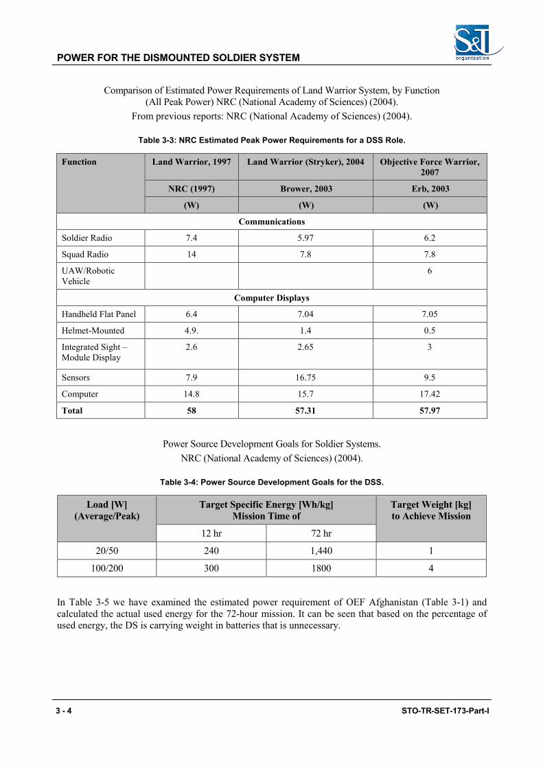
Comparison of Estimated Power Requirements of Land Warrior System, by Function (All Peak Power) NRC (National Academy of Sciences) (2004).
From previous reports: NRC (National Academy of Sciences) (2004).
Table 3-3: NRC Estimated Peak Power Requirements for a DSS Role.
Function Land Warrior, 1997 Land Warrior (Stryker), 2004 Objective Force Warrior, 2007
NRC (1997) Brower, 2003 Erb, 2003
(W) (W) (W)
Communications
Soldier Radio 7.4 5.97 6.2
Squad Radio 14 7.8 7.8
UAW/Robotic Vehicle
6
Computer Displays
Handheld Flat Panel 6.4 7.04 7.05
Helmet-Mounted 4.9. 1.4 0.5
Integrated Sight –Module Display
2.6 2.65 3
Sensors 7.9 16.75 9.5
Computer 14.8 15.7 17.42
Total 58 57.31 57.97
Power Source Development Goals for Soldier Systems. NRC (National Academy of Sciences) (2004).
Table 3-4: Power Source Development Goals for the DSS.
Load [W] (Average/Peak)
Target Specific Energy [Wh/kg] Mission Time of
Target Weight [kg] to Achieve Mission
12 hr 72 hr
20/50 240 1,440 1
100/200 300 1800 4
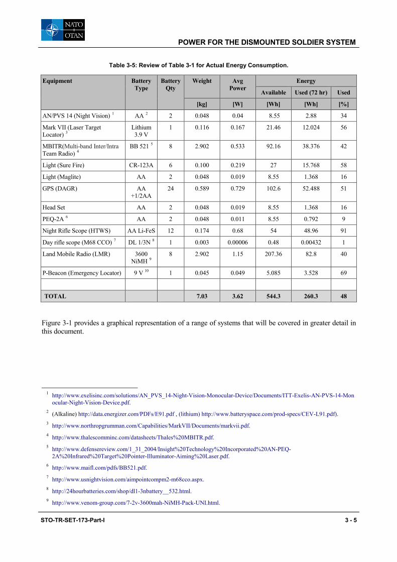
In Table 3-5 we have examined the estimated power requirement of OEF Afghanistan (Table 3-1) and calculated the actual used energy for the 72-hour mission. It can be seen that based on the percentage of used energy, the DS is carrying weight in batteries that is unnecessary.
3 - 4 STO-TR-SET-173-Part-I
POWER FOR THE DISMOUNTED SOLDIER SYSTEM
Table 3-5: Review of Table 3-1 for Actual Energy Consumption.
Equipment Battery Type
Battery Qty
Weight Avg Power
Energy
Available Used (72 hr) Used
[kg] [W] [Wh] [Wh] [%]
AN/PVS 14 (Night Vision) 1 AA 2 2 0.048 0.04 8.55 2.88 34
Mark VII (Laser Target Locator) 3
Lithium 3.9 V
1 0.116 0.167 21.46 12.024 56
MBITR(Multi-band Inter/Intra Team Radio) 4
BB 521 5 8 2.902 0.533 92.16 38.376 42
Light (Sure Fire) CR-123A 6 0.100 0.219 27 15.768 58
Light (Maglite) AA 2 0.048 0.019 8.55 1.368 16
GPS (DAGR) AA +1/2AA
24 0.589 0.729 102.6 52.488 51
Head Set AA 2 0.048 0.019 8.55 1.368 16
PEQ-2A 6 AA 2 0.048 0.011 8.55 0.792 9
Night Rifle Scope (HTWS) AA Li-FeS 12 0.174 0.68 54 48.96 91
Day rifle scope (M68 CCO) 7 DL 1/3N 8 1 0.003 0.00006 0.48 0.00432 1
Land Mobile Radio (LMR) 3600 NiMH 9
8 2.902 1.15 207.36 82.8 40
P-Beacon (Emergency Locator) 9 V 10 1 0.045 0.049 5.085 3.528 69
TOTAL 7.03 3.62 544.3 260.3 48
Figure 3-1 provides a graphical representation of a range of systems that will be covered in greater detail in this document.
1 http://www.exelisinc.com/solutions/AN_PVS_14-Night-Vision-Monocular-Device/Documents/ITT-Exelis-AN-PVS-14-Mon ocular-Night-Vision-Device.pdf.
2 (Alkaline) http://data.energizer.com/PDFs/E91.pdf , (lithium) http://www.batteryspace.com/prod-specs/CEV-L91.pdf). 3 http://www.northropgrumman.com/Capabilities/MarkVII/Documents/markvii.pdf. 4 http://www.thalescomminc.com/datasheets/Thales%20MBITR.pdf. 5 http://www.defensereview.com/1_31_2004/Insight%20Technology%20Incorporated%20AN-PEQ-
2A%20Infrared%20Target%20Pointer-Illuminator-Aiming%20Laser.pdf. 6 http://www.maifl.com/pdfs/BB521.pdf. 7 http://www.usnightvision.com/aimpointcompm2-m68cco.aspx. 8 http://24hourbatteries.com/shop/dl1-3nbattery__532.html. 9 http://www.venom-group.com/7-2v-3600mah-NiMH-Pack-UNI.html.
STO-TR-SET-173-Part-I 3 - 5
POWER FOR THE DISMOUNTED SOLDIER SYSTEM
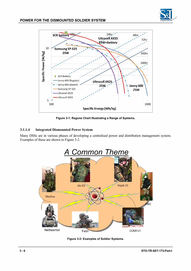
Figure 3-1: Ragone Chart Illustrating a Range of Systems.
3.1.1.4 Integrated Dismounted Power System
Many DSSs are in various phases of developing a centralised power and distribution management system. Examples of these are shown in Figure 3-2.
Figure 3-2: Examples of Soldier Systems.
3 - 6 STO-TR-SET-173-Part-I

POWER FOR THE DISMOUNTED SOLDIER SYSTEM
An example of a centralized integrated power system is the US Army’s Soldier Wearable Integrated Power System, known as SWIPES, which supplies power from a centrally located main battery for a range of sensors end-items. SWIPES utilises a pouch-mounted charger and power cables for batteries, GPS units, shot-detection systems and handheld communications into the vest (a single over garment worn by the soldier). It allows for extended mission times without the need to swap batteries or power sources by keeping devices charged at all times. The major benefit is the weight savings. For a typical 72-hour mission, a Soldier will save up to 6 kg.
3.1.1.5 Initial Exploration of Potential Solutions There are a number of mature fuel cell systems available and these have been evaluated by SET-173 members for a range of applications. In addition, performance data is widely available on the internet to demonstrate their performance. To provide comparative assessments we have combined some of this data in the following section to illustrate their respective performance to the DSS application.
This is expanded in greater detail in the body of the report.
In order to compare the capabilities of different systems we have used the Soldier Conformal Rechargeable (SCR) battery which is a 180 Wh, weighs 1.2 kg. Figure 3-3 compares the conformal battery (SCR) against a range of fuel cell systems and their performance under different loads, which are then matched to a range of mission durations.
Figure 3-3: Mass Differential for Batteries Against Two Fuel Cell Types.
In Figure 3-3 we illustrate the comparison between the SCR battery mass and two currently available fuel cell types. It is evident that beyond 10 hours of use, at 20 W, the fuel cell systems show a significant weight saving which for the 72-hour mission can be as much as 6 kg.
STO-TR-SET-173-Part-I 3 - 7
POWER FOR THE DISMOUNTED SOLDIER SYSTEM
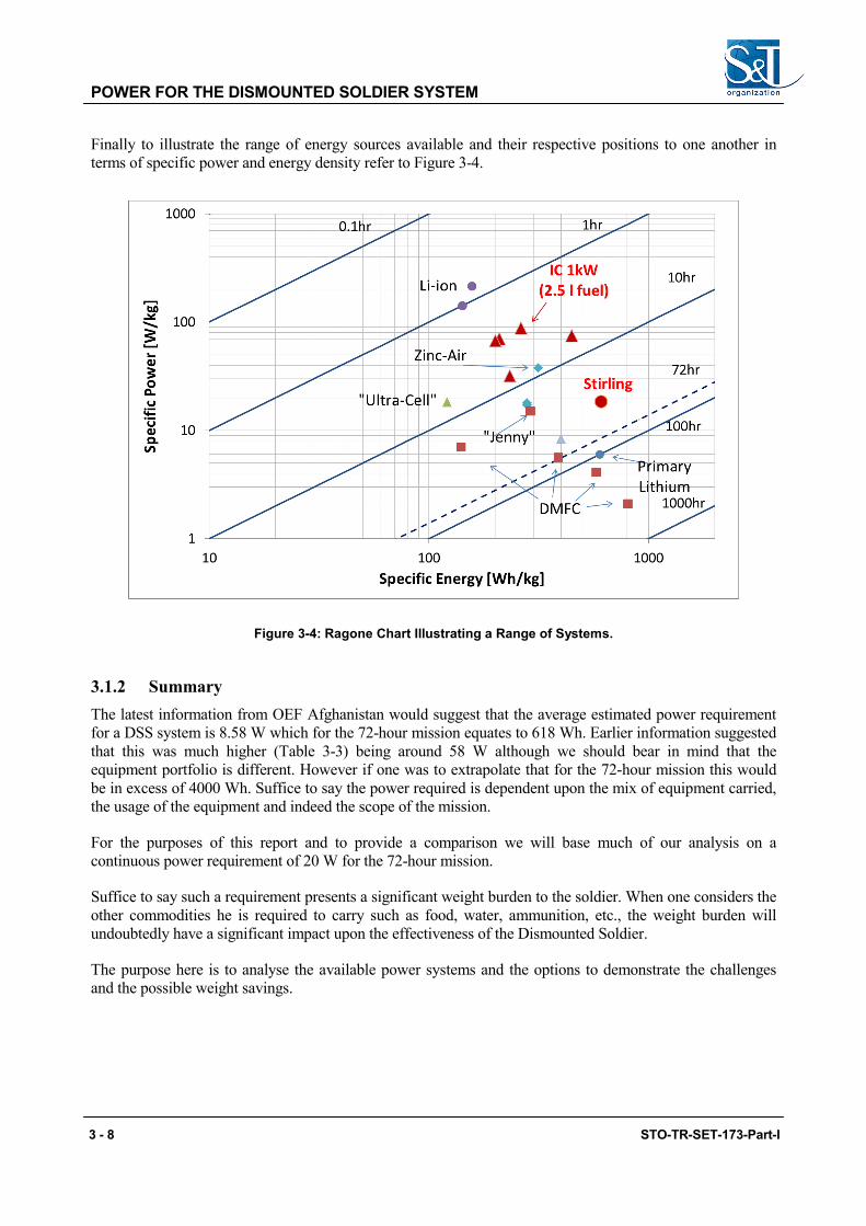
Finally to illustrate the range of energy sources available and their respective positions to one another in terms of specific power and energy density refer to Figure 3-4.
Figure 3-4: Ragone Chart Illustrating a Range of Systems.
3.1.2 Summary The latest information from OEF Afghanistan would suggest that the average estimated power requirement for a DSS system is 8.58 W which for the 72-hour mission equates to 618 Wh. Earlier information suggested that this was much higher (Table 3-3) being around 58 W although we should bear in mind that the equipment portfolio is different. However if one was to extrapolate that for the 72-hour mission this would be in excess of 4000 Wh. Suffice to say the power required is dependent upon the mix of equipment carried, the usage of the equipment and indeed the scope of the mission.
For the purposes of this report and to provide a comparison we will base much of our analysis on a continuous power requirement of 20 W for the 72-hour mission.
Suffice to say such a requirement presents a significant weight burden to the soldier. When one considers the other commodities he is required to carry such as food, water, ammunition, etc., the weight burden will undoubtedly have a significant impact upon the effectiveness of the Dismounted Soldier.
The purpose here is to analyse the available power systems and the options to demonstrate the challenges and the possible weight savings.
3 - 8 STO-TR-SET-173-Part-I

Chapter 4 – BATTERIES: SPECIFIC BATTERY INFORMATION
4.1 GENERAL
Batteries are currently the preferred choice of manwearable power today but they are far from ideal. For operational and security reasons, due to the IED threat, even discharged systems are required to be returned to the FOB, even if serving no useful purpose, for disposal and to prevent terrorist opportunists using the container to provide an improvised explosive device.
4.1.1 Energy and Power Table 4-1 defines the respective parameters that are used to describe energy and power.
Table 4-1: Energy and Power Units.
Parameter Description Unit
Energy Ability to do work Wh
Power Energy delivered by unit of time W = VA
Specific Energy Energy per mass of the source device Wh/g
Specific Power Power per mass of the source device W/g
Energy Density Energy per volume of the source device Wh/l
Power Density Power per volume of the source device W/l
4.2 BASIC PRINCIPLES
In its simplest form as a single unit a battery or cell is effectively one of the same and comprise a package of electrochemical energy with appropriate terminals. The difference is that a battery has a label whereas the cell does not. They are available in various shapes and sizes and different package configurations. The most common alkaline types have a rigid metal outer case where the parts are crimped or welded to form a sealed container. Others have flexible outer packaging similar to that used in food processing, which are flexible. Flexible packages are emerging which enable the battery to be inserted into a range of shapes and sizes with improved packing density.
The earlier more traditional systems tend to be cylindrical in form, which leads to inefficient packing density in multi-cell systems. As most multi-cell systems are rectangular, similarly shaped cells will provide efficient energy packages.
Batteries are essentially an energy package and in many types contain corrosive chemical constituents which if exposed present a hazard. External influences such as accidental short circuit or incorrect connection can result in increased internal pressure and therefore rupture of the sealed casing creating a hazard. Most types are equipped with an inbuilt vent designed to control the release of internal pressure and it is essential that this is not obstructed.
Being electrochemical a battery’s performance can vary depending upon the potential difference between the materials used in its construction, the environment in which it is used; the ambient temperature, the load (discharge rate) of the equipment that it is connected to dictates and the useful life additionally they have a finite shelf life. Consequently batteries are a replacement commodity for several iterations compared to the
STO-TR-SET-173-Part-I 4 - 1

BATTERIES: SPECIFIC BATTERY INFORMATION
life of the host equipment. In the manwearable role batteries have the disadvantage of weight, which is the same whether they are charged (fresh in the case of primary cells) or discharged (used). Furthermore practice has shown that in the case of primary batteries, on returning from a mission, these are discarded whether fully or partially discharged which is a waste of energy.
In concentrating on the safety of these systems, it is important to always follow the manufacturers’ instructions in terms of operation and use, to not alter the design, mix cell/batteries of different chemistry in the same configuration, and to protect exposed terminals when not in use. Do not crush, incinerate or short circuit.
The batteries (more precisely cells) used in military application are largely the same as those used commercially they are however selected against stringent military specifications to ensure they can meet the rigours of the military environment. It is uneconomic to produce specific cells for military applications, except for very specialised applications.
4.2.1 Primary Battery In general, the electrochemical reaction occurring in the cell is not reversible, rendering the cell unrechargeable. As a primary cell is used, chemical reactions in the battery consume the chemicals that generate the power; when they are gone, the battery stops producing electricity and it is no longer able to provide power. The terminal voltage of some designs reduces during discharge but in all cases reaches a point where it fails to deliver any useful energy and the host equipment fails, often without warning.
4.2.2 Secondary Battery A rechargeable battery comprises one or more electrochemical cells, and is a type of energy accumulator. It is known as a secondary cell because its electrochemical reactions are electrically reversible. Rechargeable batteries come in many different shapes and sizes, ranging from button cells, used in small handheld devices to megawatt systems connected to stabilize an electrical distribution network. Several different combinations of chemicals are commonly used in the commercial marketplace including: lead-acid, Nickel Cadmium (NiCd), Nickel Metal Hydride (NiMH), Lithium-Ion (Li-ion), and Lithium-Ion Polymer (Li-ion Polymer) and more latterly lithium sulphur to name but a few. For Li-ion this category comprises a family of chemistries that are used for positive (cobalt oxide, iron phosphate, etc.) and negative electrodes (carbon, silicon and titanate) the use of which affects the performance thereof. The lithium-based technologies are the most widely selected for manwearable applications. Regardless of the application, to select the most appropriate technology one needs to examine the respective performance and match this to the application requirements.
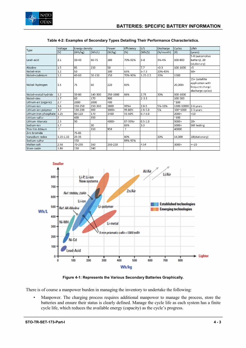
Rechargeable batteries have lower total cost of use and reduced environmental impact than primary batteries. Some rechargeable battery types are available in the same sizes as primary types, however their terminal voltage may differ and therefore they are not necessarily interchangeable. Rechargeable batteries have higher initial cost, but can be recharged relatively cheaply and used many times (cycle life). A range of available types and their performance characteristics is shown in Table 4-2; however it should be borne in mind that this identifies the range of types but only a limited number are suitable for manwearable applications. Sodium sulphur and molten salt are unsuitable as is lead acid. Figure 4-1 shows a range of types with respect to energy and volumetric density.
4 - 2 STO-TR-SET-173-Part-I
BATTERIES: SPECIFIC BATTERY INFORMATION
Table 4-2: Examples of Secondary Types Detailing Their Performance Characteristics.
Figure 4-1: Represents the Various Secondary Batteries Graphically.
There is of course a manpower burden in managing the inventory to undertake the following:
• Manpower. The charging process requires additional manpower to manage the process, store the batteries and ensure their status is clearly defined. Manage the cycle life as each system has a finite cycle life, which reduces the available energy (capacity) as the cycle’s progress.
STO-TR-SET-173-Part-I 4 - 3

BATTERIES: SPECIFIC BATTERY INFORMATION
• Manage the recharge programme, which may entail a pre-discharge, conditioning cycle or a simple charge. This in itself takes time from a few hours (2) to several (10) depending on the capability of the system. It may be necessary to increase the inventory three-fold to account for this (one in use, one being charged and one in store awaiting or recently completed charging).
• Charging equipment needs to be housed and supported which in the case of a FOB would need additional generating power. The type of charge can adversely impact the cycle life bearing in mind that fast charging tends to generate heat.
• Logistics to recover and return batteries. For secondary types establish controls and processes for re-charging. On exercise this may be impractical as it is not possible to readily establish the necessary logistical support and infrastructure. To maintain the supply which due to transportation limitations for some types results in lengthy routes by land over rough terrain exposing additional risks to personnel. Disposal can be an issue particularly as the process needs to comply with National regulations at the point of use/disposal which often are based upon the UN Transport regulations, which prohibit the transport of some types.
4.3 COMMON PRIMARY (NON-RECHARGEABLE) TYPES
4.3.1 Alkaline Manganese These are the most common primary cells and are widely available, aligned to domestic applications and available in common sizes of AAA (LR031), AA (LR6), C (LR14) and D (LR20) with limited temperature and power capabilities.
4.3.2 Lithium Manganese Dioxide Lithium manganese dioxide batteries operate from -40°C to +85°C and offer longer operating times from –10°C to +85°C when compared to the lithium sulfur dioxide versions used by the military. At lower temperature and higher discharge rates the lithium manganese dioxide system is less efficient than its lithium sulfur dioxide counterpart. At moderate discharge rates (typical of military communication requirements) and temperatures greater than 0°C, lithium manganese dioxide provides higher capacity than lithium sulfur dioxide. This technology’s favourable safety characteristics minimize the occurrence of a cell’s violent rupture. Although this risk is minimized, the flammable electrolyte does present other concerns should the cell rupture.
These batteries are widely used in both military and commercial applications because of the high specific energy density, safety characteristics associated with the low internal cell pressure, and a safety shutdown separator. The most common military configuration is the BA-5390 which is an alternative to the BA-5590 (LiSO2).
This technology is typically used in higher rate applications with lower temperature capability. The most common is the 2/3A size which is a single cell.
4.3.3 Lithium Iron Disulphide Lithium iron disulphide offers a high rate alternative to the alkaline type with low temperature capability which is available in the AAA (FR03) and AA (FR6) size. Recently, lithium-iron disulfide consumer batteries have reached the market and have found favour since they have similar voltage as alkaline batteries but with much more energy storage capacity, low self-discharge rate, and longer shelf life. Under high
1 These designations relate to the IEC designation (see Section 4.1.6.1 below) which identifies size, shape and electrochemistry and aligns to minimum average durations for a specific application.
4 - 4 STO-TR-SET-173-Part-I
BATTERIES: SPECIFIC BATTERY INFORMATION
current discharge conditions they perform better than alkaline and are more suitable for equipment such as digital cameras and thermal imagers.
4.3.4 Lithium Sulphur Dioxide An industrial grade battery available in two types of construction, bobbin and spirally wound, for high performance and or low temperature applications. It has a wide operating temperature range, long shelf life but depending upon the quantity of lithium presents an additional burden with respect to transportation legislation. Bobbin which is used for lower rate applications has a single layer of lithium within the construction. Spirally wound in which the active materials have a long surface area is assembled in a layer construction and rolled around a circular former and inserted into the cell. The cell is then available for use and can be assembled into multi-cell cases to provide the desired output. Additional safety issues arise in using this latter construction and it is usual for these to be fitted with additional electronic devices to prevent charging or forced discharge.
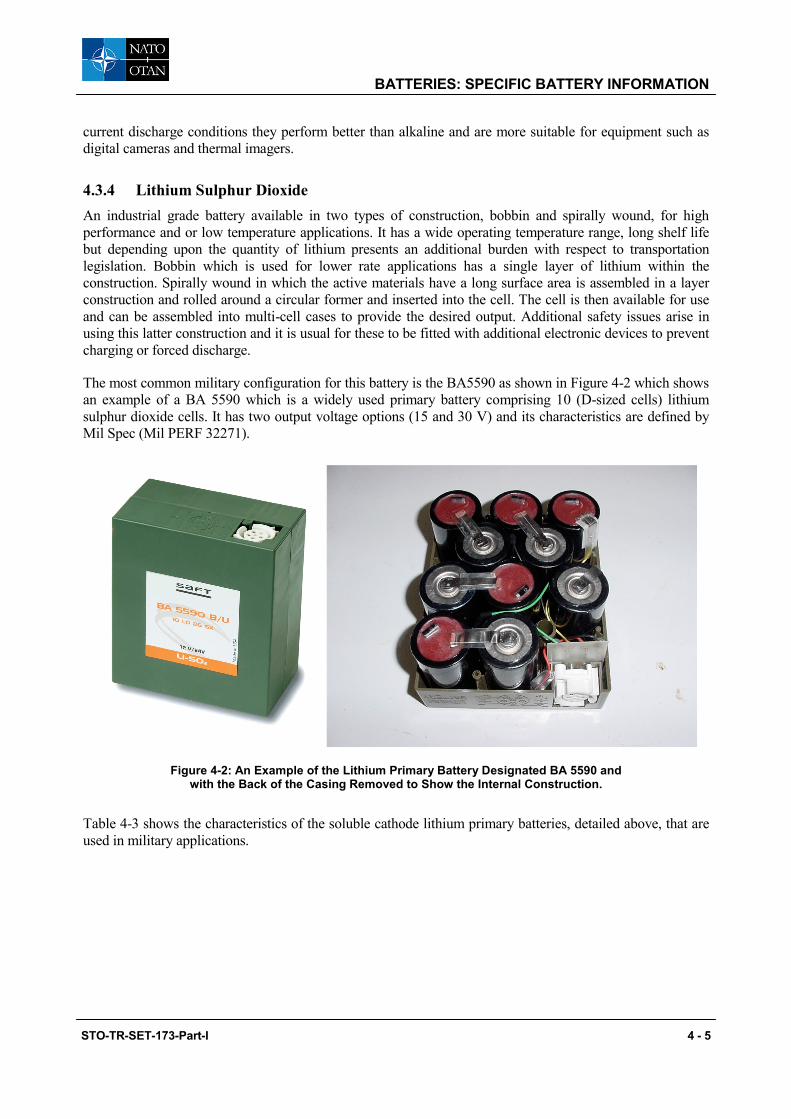
The most common military configuration for this battery is the BA5590 as shown in Figure 4-2 which shows an example of a BA 5590 which is a widely used primary battery comprising 10 (D-sized cells) lithium sulphur dioxide cells. It has two output voltage options (15 and 30 V) and its characteristics are defined by Mil Spec (Mil PERF 32271).
Figure 4-2: An Example of the Lithium Primary Battery Designated BA 5590 and with the Back of the Casing Removed to Show the Internal Construction.
Table 4-3 shows the characteristics of the soluble cathode lithium primary batteries, detailed above, that are used in military applications.
STO-TR-SET-173-Part-I 4 - 5

BATTERIES: SPECIFIC BATTERY INFORMATION
Table 4-3: Characteristics of Primary Batteries Used in Military Equipment.
4 - 6 STO-TR-SET-173-Part-I
m / organization
Soluble cathode batteries
Electrolyte Voltage, V Specific Energy energyt densityt
Working* Di scharge System Cathode Solvent Solute Separator Construction Nominal (20°C) Whlkg Wh i L Power den i ty profile Available sizes
Lithium / sul fur so2 with carbon AN LiBr M icroporous Spi ral " jelly-roll " 3.0 2.9- 2.7 260 415 High Very fl at Cylindrical batteries :lioxide and binder on Polypropylene cy lindrical con- up to 35 Ah (Li!SO:J AI screen structi on; glass-
to-metal seal Lithium lthionyl SOCI 2 with car- SOCI2 LiAICI4 Glass non- Wafer construe- 3.6 3.6--3.4 275 630 Low Flat 0.4- 1.7 Ah chloride bon and binder woven tion (Li / SOCI:J on Ni or SS
Lo w rate " Bobbin" in cy- 3.6 3.5- 3.3 590 1100 Medium Fl at Cylindical batteries I indrical construe- 1.2- 19 lion
High Prismatic with 3.6 3.5- 3.3 480 950 Medium Flat 12- 10,000 Ah capacity flat pl ates
High rate Spiral "j elly-roll " 3.6 3.5- 3.2 380 725 Medium to hi gh Flat Cylindrical : 5- 23 cylindri cal con- Ah struction or flat Flat di sk: up to 320 di sk Ah
SOCI 2 with LiAICI4 Gl ass mat Spiral "jell y-roll " 3.9 3.8- 3.3 450 900 Medium Flat 2- 30 Ah halogen cylindrical con-additives structi on
Lithium I sui- S02CI2 with S02CI2 (some LiAICI 4 Gl ass Spi ral " jelly-ro ll " 3.95 3.5- 3. 1 450 900 Medium to high Fl at 7- 30 Ah furyl chloride carbon and with additives) cylindrical con-(Li I 0 2CI2) binder SS struction; glass-
screen to-metal seal

BATTERIES: SPECIFIC BATTERY INFORMATION
4.4 COMMON RECHARGEABLE BATTERY TYPES
4.4.1 Nickel-Cadmium Battery (NiCd) Created by Waldemar Jungner of Sweden in 1899, it uses nickel oxide hydroxide and metallic cadmium as electrodes. Cadmium is a toxic element, and was banned for most uses by the European Union in 2004. Nickel-cadmium batteries have been almost completely superseded by Nickel-Metal Hydride (NiMH) batteries in most applications with the exception of specialist military requirements and rotary wing applications (these systems are more hardened to arduous vibration regimes). These are rarely used in the DSS role except for obsolescent items.
4.4.2 Nickel-Metal Hydride Battery (NiMH) First commercial types were available in 1989. These are now a common consumer and industrial type. The battery has a hydrogen-absorbing alloy for the negative electrode instead of cadmium. Following the restriction imposed by the EU these have found greater usage but the performance is inferior to lithium-ion which has become the favoured choice for most rechargeable requirements in military applications.
4.4.3 Lithium-Ion Battery The technology behind the lithium-ion battery has not yet fully reached maturity. However, the batteries are widely used in many consumer electronics and have one of the best energy-to-mass ratios and a very slow loss of charge when not in use. They have a variable operating voltage profile from around 2.7 V discharged to 4.3 V charged and require additional control circuitry to manage the charge and discharge without which the system could become hazardous. Problems have been observed with the introduction of Li-ion batteries into service which has been attributed to the parasitic consumption of the management circuitry.
A commonly used battery of this type is used in the DSS role and is defined as a BB-2590 that has an identical fit and form as the BA-5590 but not function. An example is shown in Figure 4-3.
Figure 4-3: A Range of Rechargeable Lithium-Ion Batteries. BB 2590 (Top Centre and Right) LIPS (Bottom) and Bowman (Top Left).
STO-TR-SET-173-Part-I 4 - 7

BATTERIES: SPECIFIC BATTERY INFORMATION
4.5 LESS COMMON TYPES
4.5.1 Lithium Sulphur Battery Lithium Sulphur batteries are a potential next step for high energy, lightweight, safe, low cost power storage.
A battery chemistry developed by Sion Power in 1994 claims superior energy to weight than current lithium technologies on the market. Also lower material cost may help this product reach the mass market. These have yet to see widespread use.
OXIS Energy has successfully developed a patented Polymer Lithium Sulphur (Li-S) based battery technology platform using:
• A Lithium Metal anode;
• A Sulphur-based cathode; and
• A Lithium Sulphide electrolyte rendering inherently safe Lithium Metal.
The key strengths of the technology are:
• Superior energy density;
• Lightweight;
• Inherently safe; and
• Superior Energy Density.
These battery systems use metallic Lithium and offer the highest specific energy. Sulphur represents a natural ‘cathode partner’ for metallic Li and a Lithium-Sulphur couple has theoretical specific energy in excess of 2700 Wh/kg, which is nearly 5 times higher than that of Li-ion.
OXIS claims their next generation lithium technology platform offers the highest energy density among lithium chemistry:
• 300 Wh/kg demonstrated in 2010 vs. 140 Wh/kg for most safe conventional Li-ion chemistry; and
• 600 Wh/kg target in 2016 vs. a target of 300 Wh/kg for the most promising mainstream Li-ion technology.
4.5.2 Thin Film Battery (TFB) Thin film lithium-ion batteries are similar to lithium-ion batteries, but they are composed of thin materials, some only nanometers or micrometres thick, which allow for the finished battery to be just millimetres thick. They have been developed and advanced primarily within the last decade. These are used in very low power applications.
An emerging refinement of the lithium-ion technology has been developed by Excellatron. The developers claim a very large increase in recharge cycles, around 40,000 cycles. Higher charge and discharge rates. At least 5 C2 charge rate. Sustained 60 C discharge, and 1000 C peak discharge rate. And also a significant increase in specific energy, and energy density.
Also Infinite Power Solutions makes Thin Film Batteries (TFB) for micro-electronics applications that are flexible, rechargeable, solid-state lithium batteries.
2 C is defined as the nominal cell capacity.
4 - 8 STO-TR-SET-173-Part-I

BATTERIES: SPECIFIC BATTERY INFORMATION
They are primarily used as smart cards or RFID tags and constructed using semiconductor processes and therefore unlikely to be available as larger sized systems most of the published data defines the characteristics in the mAh ranges.
4.5.3 Sodium Ion This type is meant for stationary storage and competes with lead-acid batteries. It aims at a very low total cost of ownership per kWh of storage. This is achieved by a long and stable lifetime. The number of cycles is above 5000 and the battery is not damaged by deep discharge. The energy density is rather low, somewhat lower than lead-acid. These are unsuitable for manwearable applications.
4.5.4 Developments Since 2005 In 2007, Yi Cui and colleagues at Stanford University‘s Department of Materials Science and Engineering discovered that using silicon nanowires as the anode of a lithium-ion battery increases the volumetric charge density of the anode by up to a factor of 10, leading to the development of the nanowire battery.
Another development is the paper-thin flexible self-rechargeable battery combining a thin-film organic solar cell with an extremely thin and highly flexible lithium-polymer battery, which recharges itself when exposed to light.
Ceramatec, a research and development sub-company of CoorsTek, as of 2009 was testing a battery comprising solid sodium metal mated to a sulphur compound by a paper-thin ceramic membrane which conducts ions back and forth to generate a current. The company claimed that it could fit about 40 kilowatt hours of energy into a package about the size of a refrigerator, and operate below 90°C; and that their battery would allow about 3,650 discharge/recharge cycles (or roughly 1 per day for one decade).
4.5.5 Polymeric Batteries Lithium-ion polymer batteries, polymer lithium-ion, or more commonly lithium polymer batteries (abbreviated Li-poly, Li-Pol, LiPo, LIP, PLI or LiP) are rechargeable (secondary cell) batteries. LiPo batteries are usually composed of several identical secondary cells in parallel to increase the discharge current capability, and are often available in series “packs” to increase the total available voltage.
This type has technologically evolved from lithium-ion batteries. The primary difference is that the lithium-salt electrolyte is not held in an organic solvent but in a solid polymer composite such as polyethylene oxide or polyacrylonitrile. The advantages of Li-ion polymer over the lithium-ion design include “potentially” lower cost of manufacture, adaptability to a wide variety of packaging shapes, reliability, and ruggedness, with the disadvantage of holding less charge. Lithium-ion polymer batteries started appearing in consumer electronics around 1995.
Cells sold today as polymer batteries are pouch cells. Unlike lithium-ion cylindrical cells, which have a rigid metal case, pouch cells have a flexible, foil-type (polymer laminate) case. In cylindrical cells, the rigid case presses the electrodes and the separator onto each other; whereas in polymer cells this external pressure is not required (nor often used) because the electrode sheets and the separator sheets are laminated onto each other. Since individual pouch cells have no strong metal casing, they are over 20% lighter than equivalent cylindrical cells.
The voltage of a Li-poly cell varies from about 2.7 V (discharged) to about 4.23 V (fully charged), and Li-poly cells have to be protected from overcharge by limiting the applied voltage to no more than 4.235 V per cell used in a series combination.
STO-TR-SET-173-Part-I 4 - 9

BATTERIES: SPECIFIC BATTERY INFORMATION
Early in its development, lithium polymer technology had problems with internal resistance. Other challenges include longer charge times and slower maximum discharge rates compared to more mature technologies. In December 2007 Toshiba announced a new design offering a much faster rate of charge (about 5 minutes to reach 90%). These cells were released onto the market in March 2008 and are expected to have a dramatic effect on the power tool and electric vehicle industries, and a major effect on consumer electronics. Recent design improvements have increased maximum discharge currents from 2 times to 65 or even 90 times the cell capacity charge per hour.
In recent years, manufacturers have been declaring upwards of 500 charge-discharge cycles before the capacity drops to 80%. Another variant of Li-poly cells, the “thin film rechargeable lithium battery”, has been reported to provide more than 10,000 cycles.
4.5.6 Metal-Air A metal-air battery is a type of fuel cell or battery that uses the oxidation of a metal with oxygen from air to produce electricity. They are available in the following types:
• Aluminium-Air;
• Lithium-Air; and
• Zinc Air.
Aluminium-air batteries or Al-air batteries produce electricity from the reaction of oxygen in the air with aluminium. They have one of the highest energy densities of all batteries, but they are not widely used because of problems with high anode cost and by product removal when using traditional electrolytes and this has restricted their use to mainly military applications.
Aluminium-air batteries are primary cells, i.e., non-rechargeable. Once the aluminium anode is consumed by its reaction with atmospheric oxygen at a cathode immersed in a water-based electrolyte to form hydrated aluminium oxide, the battery will no longer produce electricity. However, it is possible to mechanically recharge the battery with new aluminium anodes made from recycling the hydrated aluminium oxide. Such recycling will be essential if aluminium-air batteries are to be widely adopted.
The lithium-air battery, Li-air for short, is a metal-air battery chemistry available in both primary and rechargeable technologies it uses the oxidation of lithium at the anode and reduction of oxygen at the cathode to induce a current flow. Originally proposed in the 1970s as a possible power source for electric vehicles, Li-air batteries recaptured scientific interest in the late 2000s due to advances in materials technology and an increasing demand for environmentally safe and oil-independent energy sources.
The major appeal of the Li-air battery is the extremely high energy density, a measure of the amount of energy a battery can store for a given volume, which comes far closer than the energy density of most other types of batteries to that of traditional gasoline powered engines. Li-air batteries gain this advantage in energy density since they use oxygen from the air instead of storing an oxidizer internally.
The technology is still in its infancy and will require significant research efforts in a variety of fields before a viable commercial implementation is developed. However, scientists and industry alike see potential in its development. Currently, four types of Li-air batteries are being pursued; aprotic, aqueous, solid state, and mixed aqueous/aprotic.
According to Polyplus3 the technology has a theoretical energy density of 10,000 Wh/kg. Primary Li-Air is nearing commercialisation and has already achieved specific energy of 700 Wh/kg (2Ah cells). Rechargeable Li-Air is based on the protected electrode and expected to achieve higher specific energy than Li-ion.
3 http://www.polyplus.com/liair.html.
4 - 10 STO-TR-SET-173-Part-I

BATTERIES: SPECIFIC BATTERY INFORMATION
Zinc-air batteries (non-rechargeable), and zinc-air fuel cells, (mechanically-rechargeable) are electro-chemical batteries powered by oxidizing zinc with oxygen from the air. These batteries have high energy densities and are relatively inexpensive to produce. Sizes range from very small button cells for hearing aids, larger batteries used in film cameras that previously used mercury batteries, to very large batteries used for electric vehicle propulsion.
In operation, a mass of zinc particles forms a porous anode, which is saturated with an electrolyte. Oxygen from the air reacts at the cathode and forms hydroxyl ions which migrate into the zinc paste and form zincate releasing electrons to travel to the cathode. The zincate decays into zinc oxide and water returns to the electrolyte. The water and hydroxyls from the anode are recycled at the cathode, so the water is not consumed. The reactions produce a theoretical 1.65 volts, but this is reduced to 1.35 – 1.4 V in available cells.
Zinc-air batteries have some properties of fuel cells as well as batteries: the zinc is the fuel, the reaction rate can be controlled by varying the air flow, and oxidized zinc/electrolyte paste can be replaced with fresh paste.
Zn air weight is assumed to be invariant during discharge but in practice it will gain some weight during operation due to reaction of zinc with oxygen from the air. An example has shown this to be around 3 g per Ah.
4.6 SPECIFIC BATTERY INFORMATION
4.6.1 Smart Battery A smart battery has an integral electronic control circuit for safe operation including fuses, temperature measurement and state of charge monitoring. Lithium-ion unlike other secondary chemistries has strict limits on overcharging and discharging therefore an integrated safety monitoring system is required. The electronics enable the battery status to be communicated with a charger or soldier system. This information can also be displayed on a solid state LCD display. Second line interrogation enables the state of health of the battery to be monitored for such characteristics as cycle life, temperature extremes, and electrical capacity. Manufacturers can use these characteristics for warranty validation.
Integral systems such as SMBus enable the management of the battery through bespoke charging circuits to optimize charging procedures and hence battery life. This enables added features such as state of charge indication to advise the user of useful remaining life.
Primary batteries may also have control circuitry to provide safety features and state of charge information. Especially lithium thionyl chloride batteries may pose a safety hazard when over discharged which can be avoided by control circuitry.
4.6.2 Geometry Batteries are available in a wide range of shapes and sizes from small coin shapes to larger cylindrical cells and contain various electrochemical systems, which dictate their performance.
The cylindrical types are commonly identified by size such as AAA, AA, C and D.
There is a specific nomenclature for primary cells which defines the cell size, electrochemistry and hence performance which is detailed in an International Standard 4. An alkaline manganese cell of an AA size has
4 Primary batteries - Part 1: General, Publication date: 2011-2-17, Abstract: IEC 60086-1:2011.
STO-TR-SET-173-Part-I 4 - 11
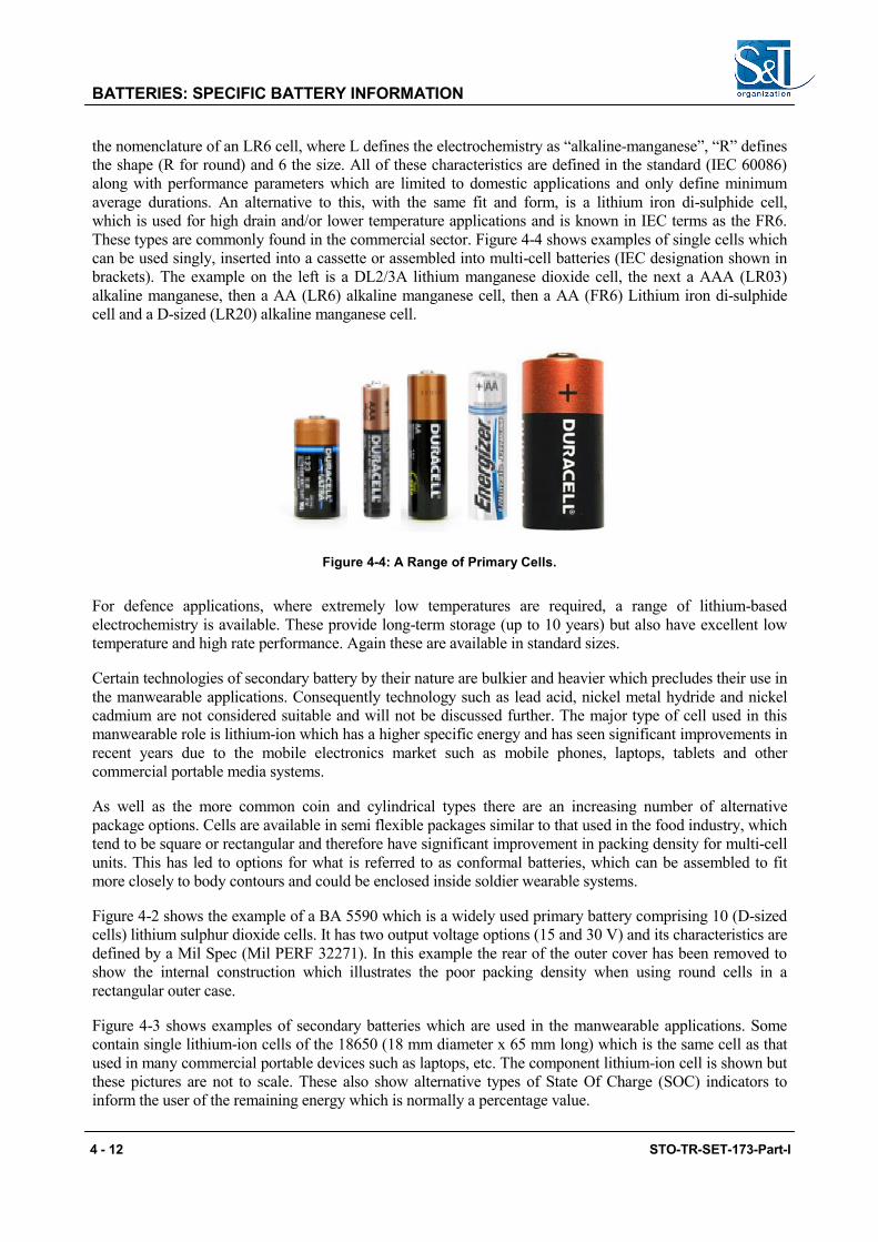
BATTERIES: SPECIFIC BATTERY INFORMATION
the nomenclature of an LR6 cell, where L defines the electrochemistry as “alkaline-manganese”, “R” defines the shape (R for round) and 6 the size. All of these characteristics are defined in the standard (IEC 60086) along with performance parameters which are limited to domestic applications and only define minimum average durations. An alternative to this, with the same fit and form, is a lithium iron di-sulphide cell, which is used for high drain and/or lower temperature applications and is known in IEC terms as the FR6. These types are commonly found in the commercial sector. Figure 4-4 shows examples of single cells which can be used singly, inserted into a cassette or assembled into multi-cell batteries (IEC designation shown in brackets). The example on the left is a DL2/3A lithium manganese dioxide cell, the next a AAA (LR03) alkaline manganese, then a AA (LR6) alkaline manganese cell, then a AA (FR6) Lithium iron di-sulphide cell and a D-sized (LR20) alkaline manganese cell.
Figure 4-4: A Range of Primary Cells.
For defence applications, where extremely low temperatures are required, a range of lithium-based electrochemistry is available. These provide long-term storage (up to 10 years) but also have excellent low temperature and high rate performance. Again these are available in standard sizes.
Certain technologies of secondary battery by their nature are bulkier and heavier which precludes their use in the manwearable applications. Consequently technology such as lead acid, nickel metal hydride and nickel cadmium are not considered suitable and will not be discussed further. The major type of cell used in this manwearable role is lithium-ion which has a higher specific energy and has seen significant improvements in recent years due to the mobile electronics market such as mobile phones, laptops, tablets and other commercial portable media systems.
As well as the more common coin and cylindrical types there are an increasing number of alternative package options. Cells are available in semi flexible packages similar to that used in the food industry, which tend to be square or rectangular and therefore have significant improvement in packing density for multi-cell units. This has led to options for what is referred to as conformal batteries, which can be assembled to fit more closely to body contours and could be enclosed inside soldier wearable systems.
Figure 4-2 shows the example of a BA 5590 which is a widely used primary battery comprising 10 (D-sized cells) lithium sulphur dioxide cells. It has two output voltage options (15 and 30 V) and its characteristics are defined by a Mil Spec (Mil PERF 32271). In this example the rear of the outer cover has been removed to show the internal construction which illustrates the poor packing density when using round cells in a rectangular outer case.
Figure 4-3 shows examples of secondary batteries which are used in the manwearable applications. Some contain single lithium-ion cells of the 18650 (18 mm diameter x 65 mm long) which is the same cell as that used in many commercial portable devices such as laptops, etc. The component lithium-ion cell is shown but these pictures are not to scale. These also show alternative types of State Of Charge (SOC) indicators to inform the user of the remaining energy which is normally a percentage value.
4 - 12 STO-TR-SET-173-Part-I
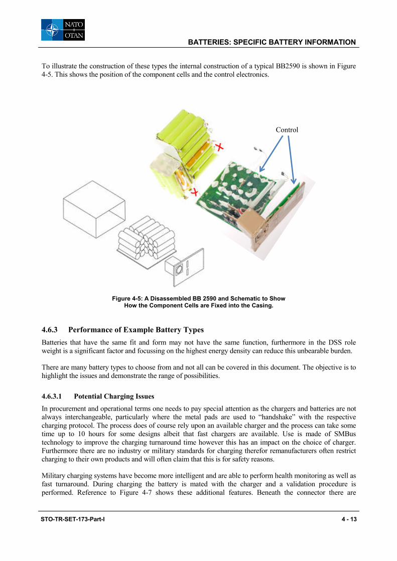
BATTERIES: SPECIFIC BATTERY INFORMATION
To illustrate the construction of these types the internal construction of a typical BB2590 is shown in Figure 4-5. This shows the position of the component cells and the control electronics.
Figure 4-5: A Disassembled BB 2590 and Schematic to Show How the Component Cells are Fixed into the Casing.
4.6.3 Performance of Example Battery Types Batteries that have the same fit and form may not have the same function, furthermore in the DSS role weight is a significant factor and focussing on the highest energy density can reduce this unbearable burden.
There are many battery types to choose from and not all can be covered in this document. The objective is to highlight the issues and demonstrate the range of possibilities.
4.6.3.1 Potential Charging Issues
In procurement and operational terms one needs to pay special attention as the chargers and batteries are not always interchangeable, particularly where the metal pads are used to “handshake” with the respective charging protocol. The process does of course rely upon an available charger and the process can take some time up to 10 hours for some designs albeit that fast chargers are available. Use is made of SMBus technology to improve the charging turnaround time however this has an impact on the choice of charger. Furthermore there are no industry or military standards for charging therefor remanufacturers often restrict charging to their own products and will often claim that this is for safety reasons.
Military charging systems have become more intelligent and are able to perform health monitoring as well as fast turnaround. During charging the battery is mated with the charger and a validation procedure is performed. Reference to Figure 4-7 shows these additional features. Beneath the connector there are
Control
STO-TR-SET-173-Part-I 4 - 13

BATTERIES: SPECIFIC BATTERY INFORMATION
additional circular pads (charge enable contacts) these are used in the charge validation process to identify the battery. If the charger does not recognise the battery it will not proceed with the charging procedure. This has a twofold limitation, firstly from a logistic perspective in ensuring the appropriate charger is deployed with the respective battery and secondly in ongoing procurement to ensure that replacement batteries are of a format appropriate for the in-service charger. There are also SMBus contacts and a state of charge indicators.
These additional features form integral systems within the battery and are often referred to as a Smart Batteries which enables the management of the battery through bespoke charging circuits to optimize charging procedures and hence battery life. This enables added features such as state of charge indication to advise the user of useful remaining life.
The use of SMBus or other smart battery technologies have impacted on the battery chargers themselves. The use of smart batteries has made/forced military charging systems to become more intelligent and is able to perform health monitoring as well as fast turnaround. During charging the battery is mated with the charger and a validation procedure is performed. The use of this “handshake” allows for the following:
• The proper charging algorithm is used;
• The battery charge is applied efficiently;
• The battery is charged safely; and
• A non-rechargeable battery of the same configuration is not accidently charged.
In the case of the lithium-ion technology these batteries have a finite life which can range from 300 to 800 cycles depending upon the usage pattern. It is therefore not unreasonable to look to replace batteries that are in daily use within a year. The charger on the other hand would have a 15 to 20 year life consequently the requirements of the charger must not be compromised. As most defence procurement is based upon competitive tendering it is imperative to ensure the specification is adequate.
Table 4-4 identifies batteries in the XX90 format with their respective performance that illustrates the variants in the same geometrical footprint.
Table 4-4: Specific Characteristics of a Range of Battery Types Suitable for the Manwearable Application.
Battery Type
Size Power Sources
Volume Mass Capacity (30 V / 15 V) Energy Density
l kg Ahr Whr/kg Whr/l Primary Batteries
5590 LiSo2 0.87 1 9.1/18.2 246 281 5390 LiMNO2 0.87 1.33 11.1/22.2 239 383 5790 CFX/MNO2 0.87 1.11 16/32 351 446 Rechargeable Batteries
2590 High Capacity 0.87 1.39 9.1/18.2 179 287 2590 Low Capacity 0.87 1.41 6.2/12.4 137 247
Note data extracted from Accumulators-Fuel Cell chart (WP).
4 - 14 STO-TR-SET-173-Part-I
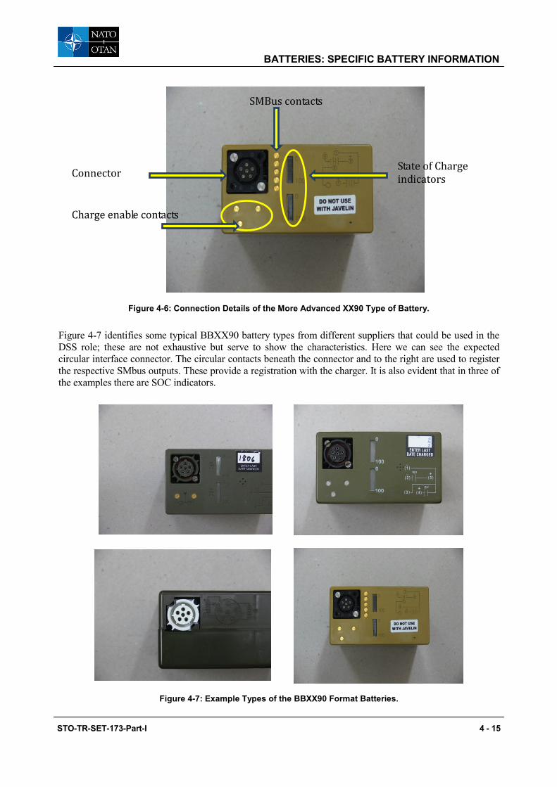
BATTERIES: SPECIFIC BATTERY INFORMATION
Figure 4-6: Connection Details of the More Advanced XX90 Type of Battery.
Figure 4-7 identifies some typical BBXX90 battery types from different suppliers that could be used in the DSS role; these are not exhaustive but serve to show the characteristics. Here we can see the expected circular interface connector. The circular contacts beneath the connector and to the right are used to register the respective SMbus outputs. These provide a registration with the charger. It is also evident that in three of the examples there are SOC indicators.
Figure 4-7: Example Types of the BBXX90 Format Batteries.
Connector
Charge enable contacts
State of Charge indicators
SMBus contacts
STO-TR-SET-173-Part-I 4 - 15

BATTERIES: SPECIFIC BATTERY INFORMATION
4.7 BARRIERS TO DEVELOPING TECHNOLOGY FURTHER In summary we can use Horizon charts to illustrate the maturity of the various battery types. Figure 4-8 and Figure 4-9 show some of the common primary and rechargeable types.
Figure 4-8: Horizon Chart for Primary Batteries.
Figure 4-9: Horizon Chart for Rechargeable Batteries.
4.7.1 Horizon Charts To graphically illustrate the projected investment and development of the major technologies for the near future we have referenced two “horizon 2 charts. These show the anticipated development for the next 10 years. The green colour is used to demonstrate fully mature progressing to red where significant development is needed/anticipated.
In Figure 4-8 we can see that there is some development to take place on lithium Manganese dioxide, zinc air with lithium carbon monoflouride and lithium Air reaching maturity in 10 years.
4 - 16 STO-TR-SET-173-Part-I
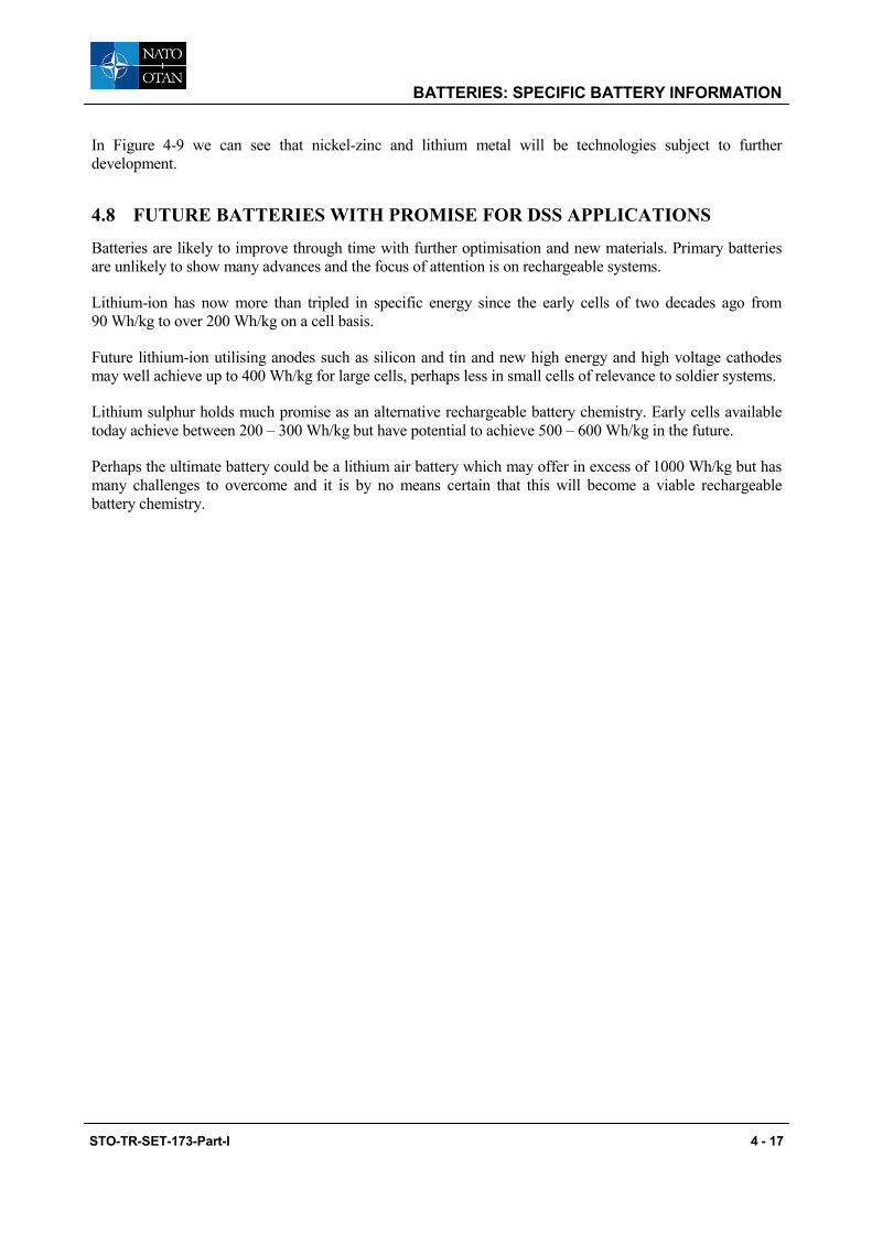
BATTERIES: SPECIFIC BATTERY INFORMATION
In Figure 4-9 we can see that nickel-zinc and lithium metal will be technologies subject to further development.
4.8 FUTURE BATTERIES WITH PROMISE FOR DSS APPLICATIONS
Batteries are likely to improve through time with further optimisation and new materials. Primary batteries are unlikely to show many advances and the focus of attention is on rechargeable systems.
Lithium-ion has now more than tripled in specific energy since the early cells of two decades ago from 90 Wh/kg to over 200 Wh/kg on a cell basis.
Future lithium-ion utilising anodes such as silicon and tin and new high energy and high voltage cathodes may well achieve up to 400 Wh/kg for large cells, perhaps less in small cells of relevance to soldier systems.
Lithium sulphur holds much promise as an alternative rechargeable battery chemistry. Early cells available today achieve between 200 – 300 Wh/kg but have potential to achieve 500 – 600 Wh/kg in the future.
Perhaps the ultimate battery could be a lithium air battery which may offer in excess of 1000 Wh/kg but has many challenges to overcome and it is by no means certain that this will become a viable rechargeable battery chemistry.
STO-TR-SET-173-Part-I 4 - 17
BATTERIES: SPECIFIC BATTERY INFORMATION
4 - 18 STO-TR-SET-173-Part-I

Chapter 5 – FUEL CELLS: OVERVIEW
5.1 OVERVIEW
This section provides a generic overview of fuel cells, identifying a number of types and discussing their relevance for the manwearable application. Some types are unsuitable; others show potential for use but have some further development before they can become viable for defence applications.
The component parts of a generic fuel cell are shown in Figure 5-1 and it could be noted that the system is far more complex than a battery system.
Figure 5-1: A Schematic of a Generic Fuel Cell.
5.2 INTRODUCTION
Fuel cells are electrochemical devices that combine a fuel and oxidant to produce electricity with heat as a by-product. Other by products such as water and carbon dioxide may be produced dependent upon the type of fuel cell. Unlike batteries, fuel cells generate electricity as long as a source of fuel is maintained. Fuel cells are quiet, generally pollution-free and two to three times more efficient than combustion engines. A fuel cell system can be a truly emission neutral source of electricity, when the fuel is produced from renewable sources.
There are four main markets for fuel cell technologies: stationary power, auxiliary power, transportation power, and portable power. The largest markets for fuel cells today are in stationary power, portable power, auxiliary power units, and material handling equipment (transportation power). Approximately 75,000 fuel cells had been shipped worldwide by the end of 2009 and approximately 15,000 additional fuel cells were
STO-TR-SET-173-Part-I 5 - 1
FUEL CELLS: OVERVIEW
shipped in 2012 (> 40% increase over 2008). In transportation applications in the U.S., there are currently (August 2011): > 200 fuel cell light duty vehicles, > 20 fuel cell buses, and ~60 fuelling stations. Several manufacturers, including GM, Toyota, Honda, Hyundai, and Daimler, have announced plans to begin commercializing fuel cell vehicles by 2015.1
5.3 FUEL CELL BASIC PRINCIPLES
All fuel cells have three basic sub-systems, fuel source, cell stack or bundle and balance of plant. The cell stack contains the active components anode, cathode, and electrolyte and electrical interconnects between the cells. It is where the fuel is converted to electricity. The balance of plant is all those components required to process and move the fuel and oxidant prior and after the cell stack and provides the electricity to the load. A basic definition of each of the major components of a fuel cell is as follows:
Fuel – The fuel is an electroactive material delivered from a source outside the system. The fuel will undergo electrochemical oxidation to produce ions and electrons.
Anode – The anode is the electrode with the lower electrical potential or negative electrode. The electrochemical oxidation reaction occurs at the anode. The anode acts as a charge transfer device conducting electrons to the external circuit and producing a current.
Oxidizer – The oxidizer is also an electroactive material delivered from a source outside the system. The oxidizer, in most cases oxygen (O2), will undergo electrochemical reduction with the electrons abstracted from the fuel.
Cathode – The cathode is the electrode with the higher electrical potential or positive electrode. The electrochemical reduction reaction occurs at the cathode. For PEM systems the ions generated at the anode move through the electrolyte, while the electrons move through the external circuit; both meet at the cathode, where the reaction takes place and by-products are generated.
Catalyst – A catalyst is a substance that increases the rate of a chemical reaction. In most cases catalysts are required to help both oxidize the fuel and reduce the oxidizer. The catalysts are found at the interface of anode/electrolyte and the interface of electrolyte/cathode. The anode catalyst is usually platinum.
Electrolyte – The medium for transfer of ions between the electrodes. The electrolyte is ionically conductive, but electrically insulating. Thereby allowing the movement of ions and preventing the conduction of electrons, which would cause a short circuit. The electrolyte should also not be reactive with the other materials in the cell. Furthermore it is required in most cases that the electrolyte is dense for the reaction media fuel and oxidant.
Load – The load is the device being powered. In order for a fuel cell to generate electricity it must be electrically connected through a load to complete the circuit.
Figure 5-2 is an illustration of a basic fuel cell with hydrogen as the fuel and oxygen as the oxidizer. Hydrogen (red circles) is oxidized at the anode (yellow) by removal of an electron (small beige circles), which moves through the load on the way to the cathode (blue) creating the current. These hydrogen ions (H+) then move through the electrolyte (green) to the cathode where they are reduced with the electrons and oxygen (light green) to produce water. Not shown in this image are the anode and cathode catalyst, which would be at the interface of the anode/electrolyte and electrolyte/cathode. Figure 5-3 shows a fuel cell stack and the associated reactions that take place.
1 US DoT Fuel Cell report (DOE Hydrogen Program (2011) “Hydrogen, Fuel Cells & Infrastructure Technologies Program: Fuel Cell Technologies Office Multi-Year Research, Development and Demonstration Plan, U.S. Department of Energy. (http://www1.eere.energy.gov/hydrogenandfuelcells/mypp/index.html).
5 - 2 STO-TR-SET-173-Part-I

FUEL CELLS: OVERVIEW
Figure 5-2: Fuel Cell Primary Unit.
Figure 5-3: Schematic of Fuel Cell.
STO-TR-SET-173-Part-I 5 - 3
FUEL CELLS: OVERVIEW
5.3.1 How a Fuel Cell Works The fuel cell consists of a Membrane Electrode Assembly (MEA), which is placed between two flow-field plates. The MEA consists of two electrodes, the anode and the cathode, which are each coated on one side with a thin catalyst layer and separated by a Proton Exchange Membrane (PEM). The flow-field plates direct hydrogen to the anode and oxygen (from the air) to the cathode. When hydrogen reaches the catalyst layer, it separates into protons (hydrogen ions) and electrons. The free electrons, produced at the anode, are conducted in the form of a usable electric current through the external circuit. At the cathode, oxygen from the air, electrons from the external circuit and protons combine to form water and heat.
Its key components are as follows:
• Expanded Single Fuel Cell – A single fuel cell consists of the membrane electrode assembly and two flow-field plates.
• Hydrogen – Hydrogen flows through channels in flow field plates to the anode where the catalyst promotes its separation into protons and electrons. Hydrogen can be supplied to a fuel cell directly or may be obtained from natural gas, methanol petroleum, propane or butane using a fuel processor, which converts the hydrocarbons into hydrogen and carbon dioxide through a catalytic chemical reaction.
• Membrane Electrode Assembly – Each membrane electrode assembly consists of two electrodes (the anode and the cathode) with a very thin layer of catalyst, bonded to either side of a proton exchange membrane.
• Air – Air flows through the channels in flow field plates to the cathode. The hydrogen protons that migrate through the proton exchange membrane combine with oxygen in air and electrons returning from the external circuit to form pure water and heat. The air stream also removes the water created as a by-product of the electrochemical process.
• Flow Field Plates – Gases (hydrogen and air) are supplied to the electrodes of the membrane electrode assembly through channels formed in flow field plates.
• Fuel Cell Stack – To obtain the desired amount of electrical power, individual fuel cells are combined to form a fuel cell stack. Increasing the number of cells in a stack increases the voltage, while increasing the surface area of the cells increases the current capability.
5.3.2 Fuel Cell Stack A single fuel cell can theoretically achieve any current or power requirements simply by increasing the surface area of the active electrodes and increasing reactant flow rates. However, the fuel and oxidizer determine the open circuit voltage. In most fuel air combinations the open circuit voltage is between 1 and 1.2 V, whereas the on load voltage is typically 0.4 – 0.5 V for DMFC, 0.65 – 0.7 V for PEMFC and 0.75 – 0.85 V SOFC). In order to achieve higher voltages and a more compact design individual cells are ordered in series to form stacks.
Figure 5-4 is an illustration of a fuel cell stack. In the image the cells are stacked in series and separated by bipolar plates etched with reactant flow channels. The ends of the stack are capped with end plates. The total current is proportional to the active electrode area of each cell. The total voltage is simply the sum of the individual cell voltages. (Ref: M. M. Mench, Fuel Cell Engines, John Wiley & Sons, 2008.)
5 - 4 STO-TR-SET-173-Part-I

FUEL CELLS: OVERVIEW
Figure 5-4: Stack Detail.
Other arrangements of cells can be used to achieve the same effect, e.g., bundles of tubular cells.
5.4 CLASSIFICATION OF FUEL CELLS Fuel cells are categorized by the type of electrolyte that is used. Additional sub-classifications of fuel cells are assigned in terms of fuel used or operating temperature.
Proton Exchange Membrane (PEM) Fuel Cell – The polymer electrolyte membrane or Proton Exchange Membrane (PEM) fuel cell is considered the most viable alternative to combustion engines or batteries and is currently the focus of the majority of research in the automotive industry. The electrolyte is a flexible solid perfluorosulfonic acid polymer with high H+ conductivity and negligible electronic conductivity. Figure 5-3 is an example of a PEM fuel cell. In the example pure hydrogen is the fuel source; however, PEM fuel cells can be fuelled by pure H2, a diluted form of H2 generated from a fuel reformation process, or methanol. As such the PEM fuel cell has 4 sub-categories: low temperature PEM (or the traditional PEM), high temperature PEM, Direct Methanol Fuel Cell (DMFC), and Reformed Methanol Fuel Cell (RMFC).
Low Temperature PEM (LT PEM) Fuel Cell – The LT PEM or traditional PEM fuel cell is fuelled by H2 or diluted H2 and operates between 50 – 100°C. LT PEM fuel cells typically require humidification of the electrolyte to promote H+ conductivity, which complicates the system of mechanics. Also because of the low operating temperature the LT PEM typically uses a noble metal platinum catalyst on the anode and cathode. These catalysts have a very low tolerance to Carbon Monoxide (CO) or sulphur compounds.
STO-TR-SET-173-Part-I 5 - 5
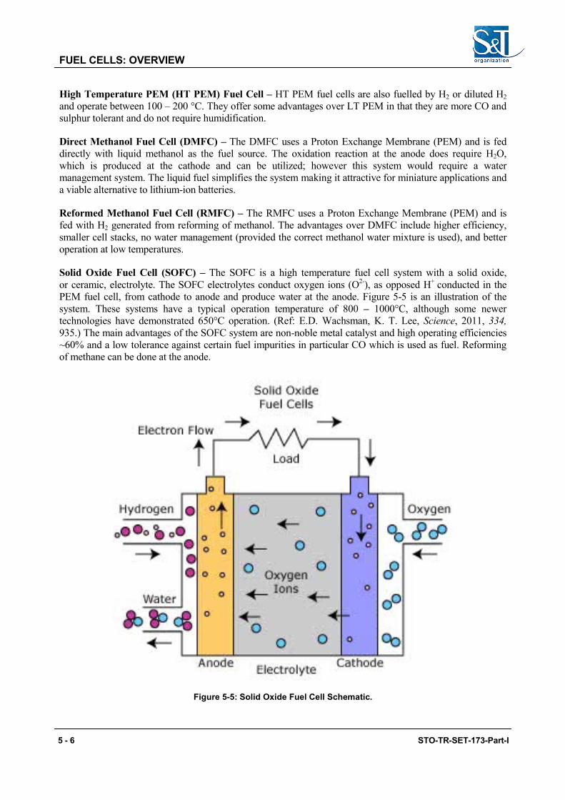
FUEL CELLS: OVERVIEW
High Temperature PEM (HT PEM) Fuel Cell – HT PEM fuel cells are also fuelled by H2 or diluted H2 and operate between 100 – 200 °C. They offer some advantages over LT PEM in that they are more CO and sulphur tolerant and do not require humidification.
Direct Methanol Fuel Cell (DMFC) – The DMFC uses a Proton Exchange Membrane (PEM) and is fed directly with liquid methanol as the fuel source. The oxidation reaction at the anode does require H2O, which is produced at the cathode and can be utilized; however this system would require a water management system. The liquid fuel simplifies the system making it attractive for miniature applications and a viable alternative to lithium-ion batteries.
Reformed Methanol Fuel Cell (RMFC) – The RMFC uses a Proton Exchange Membrane (PEM) and is fed with H2 generated from reforming of methanol. The advantages over DMFC include higher efficiency, smaller cell stacks, no water management (provided the correct methanol water mixture is used), and better operation at low temperatures.
Solid Oxide Fuel Cell (SOFC) – The SOFC is a high temperature fuel cell system with a solid oxide, or ceramic, electrolyte. The SOFC electrolytes conduct oxygen ions (O2-), as opposed H+ conducted in the PEM fuel cell, from cathode to anode and produce water at the anode. Figure 5-5 is an illustration of the system. These systems have a typical operation temperature of 800 – 1000°C, although some newer technologies have demonstrated 650°C operation. (Ref: E.D. Wachsman, K. T. Lee, Science, 2011, 334, 935.) The main advantages of the SOFC system are non-noble metal catalyst and high operating efficiencies ~60% and a low tolerance against certain fuel impurities in particular CO which is used as fuel. Reforming of methane can be done at the anode.
Figure 5-5: Solid Oxide Fuel Cell Schematic.
5 - 6 STO-TR-SET-173-Part-I

FUEL CELLS: OVERVIEW
5.4.1 Other Fuel Cells Many other fuel cell systems are being researched and show promise.
Alkaline Fuel Cell (AFC) – The AFC has an operating temperature between 60 – 250 °C, which varies with design. The electrolyte KOH solution in water has two configurations: static and mobile. For the static version the liquid is suspended in matrix, while the mobile version requires extensive plumbing to re-circulate the KOH solution. Each system has advantages and disadvantages. Further information can be found in (ref: M. M. Mench, Fuel Cell Engines, John Wiley & Sons, 2008.). In the AFC system the electrolyte conducts OH- ions from the cathode to anode where H2O is generated. The AFC system has two major advantages over other systems. The alkaline electrolytes are very inexpensive with KOH already used heavily in agriculture, a distribution network already exists. The kinetics at the cathode are more efficient in alkaline environment and so do not require the expensive noble metal catalyst. However, one major disadvantage of the AFC system is its high intolerance to CO2.
Alkaline Anion Exchange Membrane Fuel Cells (AEMFC) – The AEMFC uses a polymer electrolyte membrane which conducts hydroxyl anions. The cell set-up is very similar to the PEM set-up. However, because of the higher local pH in the electrodes it is expected that non-noble metal catalyst as in the AFC can be used. In contrast to AFC it was shown the AEM is not irreversibly destroyed by CO2. As with PEMFC, AEMFC also offers the possibility to be directly fuelled with liquid alcohols, e.g., methanol. AEMFC are in an early development stage.
Solid Acid Fuel Cell (SAFC) – The temperature interval between 200 and 600 °C is not covered by commercially available fuel cell systems based on all types of fuel cells enumerated above. Yet this temperature interval is most important from the point of thermodynamics and kinetics of most catalytic reactions relevant for renewable as well as fossil liquid fuels conversion to hydrogen containing fuels. For instance, Methanol Steam Reforming (MSR), Water Gas Shift (WGSR), Preferential CO Oxidation (PrOX) all run in the temperature interval between 160 and 250 °C. At temperatures higher than these one can expect the reforming of more “difficult” liquid fuels like ethanol, LPG, diesel. Therefore, the search for new electrolytes that are electrochemically stable and that have high enough ionic conductivity (> 10-2 S/cm) at temperatures between 200 and 400 °C is latently present in fuel cell community. Simultaneously, the thermodynamics and electrochemical kinetics of electrode reactions at these high temperatures enables the use of non-noble metal catalysts thus lowering the price of potential fuel cell systems. Among the success stories along this line of thoughts one can certainly mention the so-called Solid Acid Fuel Cell (SAFC).
Solid acid fuel cells are based on solid state proton conducting membranes – caesium dihydrogen phosphate. They operate in the temperature interval between 230 and 280 °C. This operating temperature range gives them high fuel flexibility, so they can use externally or internally reformed fuel like methanol, and externally reformed fuels like ethanol, propane, diesel. The temperature window is also optimal for performing low and high-temperature water gas shift reaction. SAFC have extremely high tolerance to CO (up to 100 %!), high sulphur tolerance (up to 100 ppm H2S) and NH3 (100 ppm). The system is rugged and low cost. It has the following advantages: mechanically robust cells, metal and polymer stack parts, and simple reforming/heating-cooling/water management sub-systems. The system components are commercially available. A demonstration project is currently running for 25 – 50 W system that would use diesel fuel and would therefore be most welcome for military applications due to logistic fuel use. [http://www.safcell. com/_press/20130624-50W%20Propane%20PhII%20SBIR.pdf].
Some of the notable systems include Direct Alcohol Fuel Cells (DAFCs), which are very similar to DMFC systems; Microbial Fuel Cells (MFCs) based on the anaerobic oxidation of organic material by bacteria; Enzymatic Fuel Cells (EFCs); and finally a weight loss fuel cell based on blood sugar as the fuel source.
STO-TR-SET-173-Part-I 5 - 7

FUEL CELLS: OVERVIEW
5.4.2 Fuel Cell Horizon Charts There are many developments streams for manwearable and manportable fuel cells which cross the spectrum of low to middle MRLs As demonstrated some systems have already been fielded in limited applications. Suppliers have made wide ranging claims of improving performance and many “soon to be available” promises. The SET Panel intend to maintain a technology watch in this area and to report the findings as they arise. Those that show promise are likely to be subjected to physical assessment. Figure 5-6 shows the status of some of the technologies.
Figure 5-6: Horizon Chart for 1 W to 1 kW Fuel Cells.
5.5 TYPES OF FC CURRENTLY DEVELOPED FOR MANWEARABLE APPLICATIONS
Of the systems defined above DMFC, RMFC and SOFC are developed to the stage of TRL 6 – 7 and therefore appropriate for manwearable and manportable applications. A summary of their characteristics is shown in Table 5-1.
5 - 8 STO-TR-SET-173-Part-I
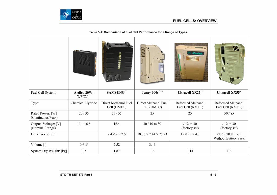
FUEL CELLS: OVERVIEW
Table 5-1: Comparison of Fuel Cell Performance for a Range of Types.
Fuel Cell System: Ardica 20W: WFC20 1
SAMSUNG 2 Jenny 600s 3. 4 Ultracell XX25 5 Ultracell XX55 6
Type: Chemical Hydride Direct Methanol Fuel Cell (DMFC)
Direct Methanol Fuel Cell (DMFC)
Reformed Methanol Fuel Cell (RMFC)
Reformed Methanol Fuel Cell (RMFC)
Rated Power: [W] (Continuous/Peak)
20 / 35 25 / 55 25 25 50 / 85
Output Voltage: [V] (Nominal/Range)
11 – 16.8 16.4 30 / 10 to 30 / 12 to 30 (factory set)
/ 12 to 30 (factory set)
Dimensions: [cm] 7.4 × 9 × 2.5 18.36 × 7.44 × 25.23 15 × 23 × 4.3 27.2 × 20.8 × 8.1 Without Battery Pack
Volume [l] 0.615 2.52 3.44
System Dry Weight: [kg] 0.7 1.87 1.6 1.14 1.6
STO-TR-SET-173-Part-I 5 - 9

FUEL CELLS: OVERVIEW
Fuel Cell System: Ardica 20W: WFC20 1
SAMSUNG 2 Jenny 600s 3. 4 Ultracell XX25 5 Ultracell XX55 6
Start Up Time: [min] Instantaneous full output power but has
integral battery
Instantaneous full output power but has
integral battery
20 20
Fuel Cartridge
Fuel: Regular Desert
Fuel: 8 [%] (Methanol/Water)
– 100 / 0 100 / 0 60 / 40 67 / 33 67 / 33
Fuel Cartridge Volume: (full) [ml]
62 260 350 250 550 250 550
Fuel Cartridge Weight: (full) [kg]
0.072 0.262 0.371 0.41 0.35 0.62 0.34 0.62
Energy capacity: [Whr] 65 300 400 285 180 430 210 505
5 - 10 STO-TR-SET-173-Part-I
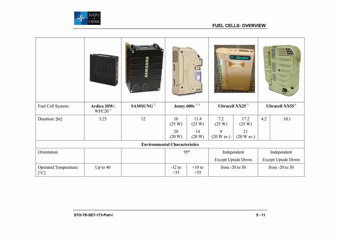
FUEL CELLS: OVERVIEW
Fuel Cell System: Ardica 20W: WFC20 1
SAMSUNG 2 Jenny 600s 3. 4 Ultracell XX25 5 Ultracell XX55 6
Duration: [hr] 3.25 12 16 (25 W)
20 (20 W)
11.4 (25 W)
14 (20 W)
7.2 (25 W)
9 (20 W av.)
17.2 (25 W)
21 (20 W av.)
4.2 10.1
Environmental Characteristics
Orientation
95° Independent
Except Upside Down
Independent
Except Upside Down
Operated Temperature: [°C]
Up to 40 -32 to +35
+10 to +55
from -20 to 50 from -20 to 50
STO-TR-SET-173-Part-I 5 - 11

FUEL CELLS: OVERVIEW
Misc.
Mission Power Density: [W/kg]
(24 / 72 hr)
10.4 / 7.3 7.6 / 11.6 6 / 10 10.8 / 5.4 12.5 / 6.7 14 / 6.65 16.3 / 8.1
Mission Energy Density: [W-hr/kg]
(24 / 72 hr)
385 / 616 (20 W) 251 / 530 278 / 551 244 / 430 260 / 388 299 / 482 336 / 479 390 / 598
The Costs: [$/System] 7,000 8 230 / 360 (25 W) 265 / 410 (50 W)
The Costs: [$/W] 350 Fuel Cell: 7 10,000
Cartridges: 35
This information is based upon data gathered from the DoD fuel cell technical working group. 1 http://www.ardica.com/. 2 http://fuelcellseminar.com/assets/2009/LRD32a-3_1130AM_Yoon.pdf. 3 http://www.tbm.nl/docs/document21.pdf. 4 http://www.sfc-defense.com/sites/default/files/datenblatt_jenny600s_v3_us.pdf. 5 http://www.ultracell-llc.com/assets/XX25_Data_Sheet_09-dec-2010.pdf. 6 http://www.ultracell-llc.com/assets/XX55_Data_Sheet_2-Dec-2012.pdf. 7 http://blogs.militarytimes.com/gearscout/2009/10/07/ultracell-xx55-fuel-cell/. 8 http://www.tomshardware.com/news/ultracell-fuelcell-idf,2392.html. 9 http://www.fuelcellseminar.com/assets/2009/DEM41-1_0830AM_Novoa.pdf.
5 - 12 STO-TR-SET-173-Part-I

FUEL CELLS: OVERVIEW
5.6 KEY PARAMETERS
The key parameters that influence system performance are:
• At the fuel cell level these are cathode and anode catalyst and electrolyte;
• At the stack level – water and heat management; and
• At the system level – heat management and miniaturisation of BOP components (sensors, actuators, pumps).
At the fuel cell level the most exigent problem is lowering of over-potential for oxygen reduction reaction (cathode reaction) in order to increase catalyst mass activity and simultaneously lowering of Platinum Group Metals (PMG) loading in the electrodes. The US DOE targets for mass activity (Am) for 2017 is 0.44 A/mgPMG, specific activity (As) is 0.8 mA/cm2 and target for loading is 0.1 mgPGM/cm2 geometric electrode area. Durability with cycling at 80°C target is set to 5000 hours. At the anode side the catalysts must be CO tolerable to CO concentration of around 100 ppm for the LT PEM FC. For HT PEMFC the catalysts must be resistant to support corrosion (nanoparticles detachment) and to fast degradation processes (Ostwald ripening, nanoparticles dissolution). Methanol Oxidation (MOR) electrocatalysts have to be improved substantially in order to lower the methanol oxidation potential and CO poisoning, which make their present time performance rather poor. Besides the high cost of proton exchange membranes, especially the perfluorinated ones, the issues are swelling (in LT PEMFCs), methanol cross-over (in DMFCs), and temperature resistance (in HT PEMFCs). The existing commercially available HT PEMFC membranes are based on polybenzimidazole and its derivatives doped with phosphoric acid. At temperature about 150 °C the ortophosphoric acid (which is water soluble) transforms into pyrophosphoric acid (water insoluble) and water. This is an equilibrium reaction. If excess water is present in the fuel reformate, at higher temperature it may cause the reverse reaction and the orthophosphoric acid leaches out from the membrane. Therefore, either proper solutions have to be found for these membranes or the new types of membranes for HT PEMFCs have to be synthesized.
Recent progress in new oxygen reduction reaction catalysts design is summarized in Figure 5-7.
Figure 5-7: Oxygen Reduction Reaction of Various Systems.
Figure 5-7 shows the kinetic activities of the main Pt-based electrocatalyst systems. The ORR Am versus As are shown for the major Pt-based electrocatalyst, a. Activities are measured by RDE at 900 mV for the following catalysts: standard Pt-alloys/C, de-alloyed PtM3/C (where M=Cu,Co), Pt/C, shape- and size-controlled particles, heat-treated Pt3Co/C, core-shell monolayer Pt , extended-surface-area NSTF alloys and
STO-TR-SET-173-Part-I 5 - 13

FUEL CELLS: OVERVIEW
commercial Pt blacks. b, Activities are measured in MEAs at 900 mV, 80 °C and 150 kPa saturated O2 for the following catalysts: core-shell Pt monolayer, average Pt/C, dealloyed PtCu3/C, three extended-surface-area NSTF alloys, the DOE 2017 and 2015 targets, best commercial Pt-alloys/C (data from GM, 3M), and shape- and size-controlled particles. The scattering of activity values for any one type or reference represent different catalyst compositions, loadings or preparation and process treatments, not statistical variations in measurement. [Taken from Debe, M.K., Nature 486 (2012) 43-51]
At the stack level the main issues to be resolved are: flowfields design in order to distribute reactants evenly across the electrodes Gas Diffusion Layer (GDL) (for both LT and HT PEMFC stacks) and to minimize the pressure drop across the stack; use of new materials for bipolar plates that would minimize electro-corrosion in HT PEMFC; new gasket materials resistant to high temperatures (in HT PEMFC); new cooling media suitable for HT PEMFC; new stack designs (engineering) based on reactive 3D CFD methods for optimization of fluid dynamics and heat management in both LT and HT PEMFC stacks.
At the system level the R&D has to be focused on heat management and miniaturisation of BOP components (sensors, actuators, pumps). The system design must be robust and simple as much as possible. Of course, this depends on the type of fuel cell (LT or HT PEMFC), the core technology materials (type of membrane, electrocatalyst). HT PEMFCs have the potential to be heat integrated in the future with fuel processor which will increase the overall efficiency of this energy conversion device. If the system is simple, the system regulation and control will also be less complicated. For manwearable applications the systems must be designed in such a way that the number of sensors and actuators will be as low as possible. This will consequently diminish the frequency of system failures and simplify the troubleshooting procedures.
5.7 BARRIERS TO DEVELOPING TECHNOLOGY Of the many barriers discussed here, cost and durability present two of the most significant challenges to achieving clean, reliable, cost-effective fuel cell systems. While addressing cost and durability, fuel cell performance must meet or exceed that of competing technologies.
5.7.1 Durability The chosen fuel cell system is required to be sufficiently robust to operate in the military environment and therefore meet the requirements for:
• Shock; • Vibration; • Temperature extremes; and • EMC and EMP compliance.
In the most demanding applications, realistic operating conditions include impurities in the fuel and air, starting and stopping, freezing and thawing, and humidity and load cycles that result in stresses on the chemical and mechanical stability of the fuel cell materials, components, and interfaces.
5.7.2 Cost For fuel cells and fuel cell systems to be commercially viable, significant reduction in cost is required. Materials and manufacturing costs for stack components need to be reduced. Low-cost, high-performance membranes, high-performance catalysts enabling ultra-low precious metal loading, and lower cost, lighter, corrosion-resistant bipolar plates are required to make fuel cell stacks competitive.
Balance-of-plant components are more demanding for manwearable applications due to the necessity to strive for miniaturisation and to meet military environmental requirements.
5 - 14 STO-TR-SET-173-Part-I

FUEL CELLS: OVERVIEW
It is obvious that putting a system into high volume production would result in a lower unit cost; there are still some significant cost drivers that are independent of production volumes. This was illustrated in a study conducted the US Navy’s Office of Naval Research on the manufacturing of fuel cells and the associated cost drivers. This study looked at both of the major sub-systems of any fuel cell, the portion that produces the energy (the “cell stack” for PEM and the equivalent planar or tubular cells for solid oxide) and the balance of plant. The major cost drivers for these three general sub-systems are defined in Figure 5-8.
Figure 5-8: Cost Drivers for PEM Fuel Cell Stack.
Of the cost drivers highlighted above, the costs associated with each item can be reduced through engineering/automation with the exceptions of the catalyst and possibly the gas diffusion layer since these are involved with the actual reaction dynamics within the fuel cell stack. Although engineering efforts related to reducing scrap rates during manufacturing will help reduce the impact of these components on cost, further research and develop in these components is required to have a significant impact.
The solid oxide fuel cell stack comes in two basic configurations, planar and tubular. For these technologies the cost drivers are identified in Figure 5-9 and Figure 5-10.
STO-TR-SET-173-Part-I 5 - 15

FUEL CELLS: OVERVIEW
Figure 5-9: Cost Drivers for Planar Ceramic Fuel Cells.
Figure 5-10: Cost Drivers for Tubular Ceramic Fuel Cells.
5 - 16 STO-TR-SET-173-Part-I

FUEL CELLS: OVERVIEW
It was determined that regardless of the actual stack technology; the cost drivers for the balance of plant remained unchanged. These are summarised in Figure 5-11 below.
Figure 5-11: Balance of Plant Cost Drivers.
5.7.3 Performance Fuel cell and fuel cell system performance with regard to power density and energy density must meet or exceed that of conventional Dismounted Soldier System technologies (see Soldier Relevance section – Chapter 10).
R&D efforts of special relevance to the military use and in particular for the use in DSS could be:
• Freeze/thaw cycling during system start of the system, N.B. the current British German standard on Manwearable Methanol Fuel Cells Def-Stan 61-23 supl. 01 / VG 97010-02 requires fuel cell start-ups only for system temperatures > 3°C because of limitations of available systems.
• Fuel efficiency is also a key point as fuel cells will require for the midterm future non-logistic fuels and high fuel efficiencies are mandatory to keep the logistic footprint acceptable.
• Tolerance against air pollutants including battlefield contaminants, in order to achieve their full weight saving potential fuel cells need to operate using ambient air as oxidant. Recent research results, e.g., by Fraunhofer ISE have shown that already the air contaminants found at German motorways have significant influence on the fuel cell performance. The air in battlefield environment must be expected to be even higher polluted. Research efforts to increase the fuel cell performance in this environment will not be performed in a commercial context.
• For the military environment the UK MoD organisation Dstl has identified that many contaminants, which may be present in a battlefield atmosphere, have the potential to reduce the performance of fuel cells. Some of the most likely sources of contaminants are obscurant smokes and explosive/ propellant residues. Less likely sources of contamination are chemical warfare agents and toxic industrial chemicals. The obscurant smokes favoured by the UK and other defence ministries contain a wide variety of compounds that are potentially harmful to fuel cells.
STO-TR-SET-173-Part-I 5 - 17

FUEL CELLS: OVERVIEW
5.8 LIMITATIONS
• Noise;
• Operation under water and without an air supply can present an issue;
• Thermal Signature; and
• Emergent technology not yet in large scale production and therefore limited availability/functionality and high cost.
5.9 HYBRIDISATION
• Requires hybrid operation;
• Defined as the provision of power using the fuel cell and a battery this could be an internal battery (which is always present and part of the system) or the addition of an extra auxiliary battery or external power source (battery/supercapacitor);
• Required for starting and powering the BOP during electrode cleaning; and
• Required for load following.
5.10 BARRIERS TO THE DSS ADOPTION OF FUEL CELLS
One of the current barriers to the military adoption of fuel cells is the initial cost of the systems themselves. The cost of these systems for a manwearable/manportable application is a more critical parameter than for other applications such as unmanned vehicles since they represent a larger portion of the system cost. Although the militaries have been investing in fuel cell development for many years, the lack of a true user “pull” and a very limited commercial marketplace has resulted in those fuel cells that have been delivered to be “custom, hand-made” types that are very expensive.
This is especially true for manwearable fuel cells which are virtually unique to the military. Those efforts that have been funded are for specific applications, resulting in point solutions and designs. The unique designs usually require unique components; the lack of standardization has inhibited the establishment of a supply chain that could drive costs down. The lack of a fuel cell supply chain means the designer must have parts custom made, or take components that are commercial available and have them modified.
5 - 18 STO-TR-SET-173-Part-I

Chapter 6 – DIRECT METHANOL FUEL CELLS (DMFC)
6.1 INTRODUCTION
Direct Methanol Fuel Cells (DMFCs) are a sub-category of PEM fuel cells and are well-suited for manwearable/portable power applications where the power density requirement is relatively low (in the range of 10 to 20 W/kg) and the energy density requirement is relatively high (1000 Wh/kg). A higher energy density alternative to existing technologies is required to fill the increasing gap between energy demand and energy storage capacity in these applications. Challenges for DMFCs include enhancing methanol oxidation reaction kinetics, reducing methanol cross-over to increase efficiency, reduce costs and simplify the BOP.
6.2 BASIC PRINCIPLES
DMFCs use a Proton Exchange Membrane (PEM) which is fed directly with liquid methanol as the fuel source. The oxidation reaction at the anode does require H2O, which is produced at the cathode and can be utilised; however this system requires a water management system. The liquid fuel simplifies the system and provides higher energy density making it attractive for manwearable applications requiring longer mission durations (refer to Figure 10-1 generic chart).
The DMFC relies upon the oxidation of methanol on a catalyst layer to form carbon dioxide. Water is consumed at the anode and is produced at the cathode. Protons (H+) are transported across the proton exchange membrane - often made from Nafion®- to the cathode where they react with oxygen to produce water. Electrons are transported through an external circuit from anode to cathode, providing power to connected devices. A schematic of the reaction is shown in Figure 6-1.
Figure 6-1: DMFC Reaction Schematic.
Methanol offers several advantages as a fuel. It is inexpensive but has a relatively high energy density and can be easily transported and stored. It can be supplied to the fuel cell unit from a liquid reservoir which can be kept topped up, or in cartridges which can be quickly changed out when spent.
DMFCs operate in the temperature range from 60°C to 130°C and tend to be used in applications with modest power requirements, such as mobile electronic devices or chargers and portable power packs.
STO-TR-SET-173-Part-I 6 - 1
DIRECT METHANOL FUEL CELLS (DMFC)
6.3 THE SYSTEM
Currently efficiency is quite low for these cells, so they are targeted especially to portable applications, where energy and power density are more important than efficiency.
6.3.1 Anode The system utilises a platinum-ruthenium catalyst on the DMFC anode which is able to draw the hydrogen from liquid methanol, eliminating the need for a fuel reformer. Therefore pure methanol can be used as fuel, hence the name. The required amount of catalyst is about 10 times higher than for the low temperature PEM fuel cells.
6.3.2 Cathode The required amount of catalyst is about 10 times higher than for the low temperature PEM fuel cells.
6.3.3 Membrane Requires high performance, high quality membranes to prevent cross-over of methanol and water to maintain the required system efficiency of the fuel cell.
6.3.4 Balance of Plant • Materials need to be resistant to methanol which could be a cost driver;
• Water management;
• Heat exchanger; and
• Miniaturisation of the BOP components is challenging.
6.3.5 Fuel The fuel is packaged in a cartridge format and is readily transportable and is reasonably stable liquid at all environmental conditions. However, methanol is toxic and flammable but is non-hazardous when used in a manufacturer supplied cartridge.
Pure methanol cannot be used without provision of water. The consumption of water is dependent upon the ambient operating temperature. Excess water is retained in a reservoir that may need to be drained periodically. In higher ambient temperatures (50°C) excess water is limited and therefore it may be necessary to use a fuel with a higher water concentration, however, this reduces the energy density by 25%.
High purity methanol is required; contaminants such as ethanol, chloride and sulphur compounds are to be avoided.
6.4 CURRENT STATUS
• Estimated current TRL for the technology – 9;
• Energy Density (Wh/kg) 250 (Jenny 600 – Table 5-1);
• Specific Power (W/kg) 14.7; and
• MTTR (1500 to 2000 hrs).
6 - 2 STO-TR-SET-173-Part-I
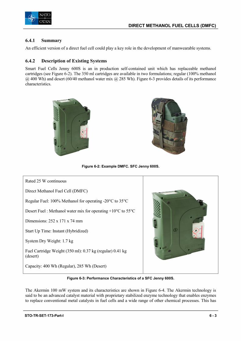
DIRECT METHANOL FUEL CELLS (DMFC)
6.4.1 Summary An efficient version of a direct fuel cell could play a key role in the development of manwearable systems.
6.4.2 Description of Existing Systems Smart Fuel Cells Jenny 600S is an in production self-contained unit which has replaceable methanol cartridges (see Figure 6-2). The 350 ml cartridges are available in two formulations; regular (100% methanol @ 400 Wh) and desert (60/40 methanol water mix @ 285 Wh). Figure 6-3 provides details of its performance characteristics.
Figure 6-2: Example DMFC. SFC Jenny 600S.
Rated 25 W continuous
Direct Methanol Fuel Cell (DMFC)
Regular Fuel: 100% Methanol for operating -20°C to 35°C
Desert Fuel : Methanol water mix for operating +10°C to 55°C
Dimensions: 252 x 171 x 74 mm
Start Up Time: Instant (Hybridized)
System Dry Weight: 1.7 kg
Fuel Cartridge Weight (350 ml): 0.37 kg (regular) 0.41 kg (desert)
Capacity: 400 Wh (Regular), 285 Wh (Desert)
Figure 6-3: Performance Characteristics of a SFC Jenny 600S.
The Akermin 100 mW system and its characteristics are shown in Figure 6-4. The Akermin technology is said to be an advanced catalyst material with proprietary stabilized enzyme technology that enables enzymes to replace conventional metal catalysts in fuel cells and a wide range of other chemical processes. This has
STO-TR-SET-173-Part-I 6 - 3

DIRECT METHANOL FUEL CELLS (DMFC)
the advantage of increased performance and lower costs than DMFC through the use of renewable resources that also provide environmentally friendly disposal. Akermin’s novel polymers serve as a protective coating to immobilize and stabilize enzymes, significantly extend enzyme operating lifetimes, and enable their use in conditions that would otherwise make them inactive.
Akermin 100 mW
Rated 100 mW continuous
Direct Methanol Fuel Cell (DMFC)
Fuel: Methanol/Potassium Hydroxide Mix
Dimensions: 3.63” x 2.5” x 1.5”
Start Up Time: Instant (Hybridized)
System Dry Weight: 160 g
Fuel Weight: 28 g (25 mL)
100 mW Mission Energy Density: Testing In Progress
Figure 6-4: Example of an Akermin Alkaline Direct Methanol Fuel Cell.
The Samsung SP-S25 is shown in Figure 6-5 with its performance detailed in Figure 6-6.
Figure 6-5: Example of Samsung SP-S25 DMFC.
6 - 4 STO-TR-SET-173-Part-I

DIRECT METHANOL FUEL CELLS (DMFC)
Samsung SP-S25
Rated 25 W continuous
Direct Methanol Fuel Cell (DMFC)
Fuel: 100% Methanol
Dimensions: 9” X 6.25” X 3.75”
Start Up Time: Instant (Hybridized)
System Dry Weight: 1.895 kg
Fuel Cartridge Weight: 0.25 kg (250 mL)
25 W Mission Energy Density: Testing in progress
Figure 6-6: Performance Characteristics of a Samsung Direct Methanol System.
6.5 PROS AND CONS
Taking into account the technical properties of DMFC as well as (current) technical limitations aspects can be defined which are in favour or against the use of DMFC. As the relevance of these aspects depends on the desired application they can help to decide whether the use of DMFC for a certain application is reasonable or not.
6.5.1 Pros • Commercially available (TRL9);
• No special training tools or equipment required to operate;
• Simple to use in that many systems have integral fuel cartridge and can be assembled ready to go;
• Short start up time which can be as low as 2 minutes to reach full power and in many supported by an integral battery;
• Potentially higher energy density comparing BB2590 with a Jenny 600 refer to Figure 3-3; and
• Have a lower exhaust temperature and heat signature than RMFC.
6.5.1.1 Technical Maturity
An aspect which is generally in favour of the DMFC is the high level of technical maturity that has been achieved. Because of this commercial products are available even for civil markets, e.g., as on-board battery charger for recreational vehicles. This level of maturity could be obtained as the general system set-up is comparatively simple with very few moving parts and control elements. This should also favour a certain robustness of the system. Table 6-1 Illustrates the Capabilities of the Jenny 600.
STO-TR-SET-173-Part-I 6 - 5

DIRECT METHANOL FUEL CELLS (DMFC)
Table 6-1: Jenny 600S Environmental Characteristics.
Parameter Achievable Performance
Operating temperature -32°C to +35°C (-26°F to +94°F) on Regular Fuel [1]
+10°C to +49°C (+50°F to +131°F) on Desert Fuel[2]
Start-up temperature +1°C to +55°C (+34°F to +131°F)[3]
Storage temperature
+1°C to +71°C (+34°F to +131°F)
-32°C to +71°C (-26°F to +160°F) in Frost-Protection Mode[4]
Warranty period Minimum 1500 operating hours[5] at 100% nominal power
2500 operating hours with a reduction to 85% nominal power (optional)
Humidity 0 to 100 %
Water protection MIL-STD 810F method 506.4, procedure I – blowing rain
Operation in heavy rainfall
Submergibility
Submergible at 30 cm (1 ft) for 1 min, during operation[6]
Submergible at 60 cm (2 ft) for 1 min in standby or in off-state
In off-state Jenny 600S can be transported down to 30 m water depth (submarine exit)
Sand and dust MIL-STD 810F method 510.4, procedure I
Vibration MIL-STD 810F method 514.5, category 5, 8 and 20
Drop MIL-STD 810F method 516.5, procedure I
Operating altitude Up to 4000 m (13,000 ft) without power loss
Noise < 37 dB(A) at 1 m (3 ft)
Orientation Inclination along the lateral/roll axis Permanent max +/- 95°
[1] For temperature range below -10°C (+14°F) the heating pouch should be used.
[2] At temperatures from +50°C … +55°C (+122°F … +131°F) operation is possible for limited time only.
[3] Start-up is possible down to -20°C (= 4°F) with optional heat pouch.
[4] Frost protection mode needs to be activated manually when putting the fuel cell in the off state.
[5] A routine service check is required after 750 operating hours.
[6] Fuel cell does not produce power when being submersed; operation with power generation is possible in heavy rainfall.
6.5.1.2 High Energy Density
A major point which is in favour of the use of DMFC is the high energy density that they can provide. This is due to the high energy storage density of the fuel used and is realised in spite of conversion efficiencies which are only about 30 %. The importance of this advantage becomes more important with longer operating times of the system corresponding to longer mission times.
6 - 6 STO-TR-SET-173-Part-I
DIRECT METHANOL FUEL CELLS (DMFC)
6.5.1.3 Fuel and Fuel Handling
Beside the high energy storage density of the liquid fuel the compactness of the cartridges provides easy handling and distribution. These are connected to the fuel cell system via a screw or bayonet coupling.
Other forms of fuel handling where the system has a fixed tank and is filled from a specially designed flask have been demonstrated, e.g., with the Toshiba DMFC charger for civil application, are however less common. For dismounted soldier the cartridge solution offers the advantage that additional cartridges can be carried as required. Also multiple cartridges allow for a better weight distribution.
The weight of the cartridge compared to the weight of methanol that it contains is usually almost negligible so that returning empty cartridges does not create a weight burden. Replacing the cartridge can be done rather quickly after some training and the methanol contained in the inner anode circuit in combination with the hybrid battery can sustain the power delivery during the period the cartridge is changed. Furthermore, the cartridge prevents the need to handle the flammable and toxic methanol in theatre. Indeed, the cartridge solutions are designed to prevent users from accessing the contained methanol as this is prohibited in much legislation.
6.5.1.4 Fast Start-Up
A further advantage of the DMFC compared with other fuel cell solutions in particular in comparison to such solutions that comprise an inline reformer is the fast start-up of the system. The start-up time for the fuel cell system is typically less than a minute. As this period can be covered by a hybrid battery from the user perspective even immediate power availability is possible.
6.5.2 Cons • Methanol fuel is both toxic and flammable;
• Higher catalyst loading will lead to higher MEA costs. This may limit the opportunity for cost reduction compared to other fuel cell technologies;
• Limited power density;
• Higher moisture content of the exhaust system requires a water management system;
• At higher ambient temperature it may be necessary to provide additional water to the fuel;
• At low ambient temperature start up time may be extended also specific preparation may be required to prevent pure water freezing. Additionally specific shut down procedures may be required for storage at low ambient temperature;
• Non-logistic fuel; and
• A more complex system that requires an integral battery to facilitate operation which can interrupt performance as in some systems charging of this internal battery take preference over the units power output.
6.6 LIMITATIONS
In spite of the many advantages direct methanol fuel cells also have some technical limitations compared to other types of fuel cells.
STO-TR-SET-173-Part-I 6 - 7

DIRECT METHANOL FUEL CELLS (DMFC)
6.6.1 Purity of Reactants • The methanol must be high purity; and
• Although water is generated as a by-product and consumed during the reaction in certain circumstances de-ionised water may need to be added.
6.6.2 Temperature • Low temperature start up is recognized as an issue (Some systems won’t start below 2°C and may also
require specific commissioning and maintenance procedures due to the presence of water in the system); and
• High temperature operation (will not run above 40°C without adding water or using a modified fuel) although this can be satisfied by the user using specifically prepared fuels which usually result in inferior performance.
6.6.3 Requires Hybrid Operation • Defined as the provision of power using the fuel cell and a battery this could be an internal battery
(which is always present and part of the system) or the addition of an extra auxiliary battery or external power source (battery/supercapacitor);
• Required for starting and powering the BOP during electrode cleaning;
• Required for load following; and
• Places additional burden on the user to ensure integral battery is charged and if the unit is not used for some time the time to the provision of power is extended as the integral battery charges first.
6.6.4 Orientation • Operational up to 95 degrees from the vertical.
6.6.5 Emissions During operation the system emits CO2 and potentially small amounts of other Volatile Organic Compounds (VOCs). Therefore care should be taken when using these systems in a non-ventilated environment.
6.7 TECHNICAL BARRIERS TO DEVELOPING THE TECHNOLOGY
6.7.1 Runtime • In storage the membrane dries out;
• In operation experience has shown variability. The operational design life is expected to be in the range 1500 – 2000 h; and
• Operational interruption – start, stop and storage that is thought to be attributed to water management. Experience has shown that continued static operation most units operate to a higher life.
6.7.2 Miniaturisation of BOP Availability of micro components such as pumps, filters, piping results in a larger volume than is ideal.
6 - 8 STO-TR-SET-173-Part-I
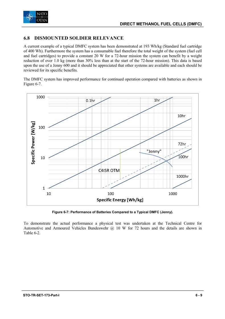
DIRECT METHANOL FUEL CELLS (DMFC)
6.8 DISMOUNTED SOLDIER RELEVANCE A current example of a typical DMFC system has been demonstrated at 193 Wh/kg (Standard fuel cartridge of 400 Wh). Furthermore the system has a consumable fuel therefore the total weight of the system (fuel cell and fuel cartridges) to provide a constant 20 W for a 72-hour mission the system can benefit by a weight reduction of over 1.0 kg (more than 30% less than at the start of the 72-hour mission). This data is based upon the use of a Jenny 600 and it should be appreciated that other systems are available and each should be reviewed for its specific benefits.
The DMFC system has improved performance for continued operation compared with batteries as shown in Figure 6-7.
Figure 6-7: Performance of Batteries Compared to a Typical DMFC (Jenny).
To demonstrate the actual performance a physical test was undertaken at the Technical Centre for Automotive and Armoured Vehicles Bundeswehr @ 10 W for 72 hours and the details are shown in Table 6-2.
STO-TR-SET-173-Part-I 6 - 9

DIRECT METHANOL FUEL CELLS (DMFC)
Table 6-2: Results for the Assessment of a Jenny 600 @ 10 W Continuous for a 72-Hour Mission.
Characteristic Result
Weight of Jenny 600 (without fuel) 1700 g
4 cartridges required for the test 1167 g
Results
Output 720 Wh
Energy density 251 Wh/kg
Power density (Jenny only) 14.7 W/kg (25 W / 1.7 kg)
Power density (72-hour mission including fuel) 8.72 W/kg
Calculation of the Jenny operating at 25 W shows the energy density to be 566 Wh/kg (for a 72-hour mission) therefore the fuel efficiency shown above is significantly less.
Calculation of Jenny 600S shows that we consume 280 g of fuel we have also established from the manufacturers datasheet and a single experiment the runtime and energy (Wh) per cartridge. From this we were able to calculate the fuel weight in grams per hour. This showed that the fuel consumption increases significantly when the unit is operated at lower than optimum performance. It will be appreciated that this was for a limited number of assessment points but suffices to show the trend. See Table 6-3 and Figure 6-8 below.
Table 6-3: Power versus Fuel Weight for the Jenny 600S at Respective Variants.
Fuel Weight Per Cartridge
Full 370 g
Empty 90 g
Fuel 280 g
Power (W) Fuel Weight (g/h) Runtime (h) Wh/Cartridge Data Reference
10 9,9 28,3 283 Bundeswehr Measurement
20 14,0 20,0 400 Datasheet
25 17,5 16,0 400 Datasheet
6 - 10 STO-TR-SET-173-Part-I

DIRECT METHANOL FUEL CELLS (DMFC)
Figure 6-8: The Data for Jenny 600S in Terms of Runtime Versus Energy per Cartridge.
STO-TR-SET-173-Part-I 6 - 11

DIRECT METHANOL FUEL CELLS (DMFC)
6 - 12 STO-TR-SET-173-Part-I
Chapter 7 – REFORMED METHANOL FUEL CELL (RMFC)
7.1 INTRODUCTION
Reformed Methanol Fuel Cells (RMFCs) is a sub-category of PEM fuel cells and are suitable for manwearable/portable power applications where the power density requirement is relatively low (in the range of 10 to 20 W/kg) and the energy density requirement is relatively high (1000 Wh/kg). A higher energy density alternative to existing technologies is required to fill the increasing gap between energy demand and energy storage capacity in these applications.
Two such systems currently available were developed by the U.S. Army Communication Electronics Research, Development and Engineering Command (CERDEC). These will be further discussed below.
7.2 BASIC PRINCIPLES
Reformed-methanol fuel cells or RMFCs uses a Proton Exchange Membrane (PEM) and is fuelled by a methanol water mixture which is reformed into hydrogen and is fed directly into the PEM fuel cell stack.
RMFCs are a type of reformer-based Polymer Electrolyte Membrane Fuel Cell System (PEMFC). Reformer-based systems avoid the complexities and safety concerns of pure H2 storage but instead convert hydrocarbon or alcohol fuels into H2 by directly processing the fuel. Fuel processing requires four major operations: fuel vaporization, reformation, a Water-Gas Shift (WGS) reaction, and purification. The reformate, consisting largely of CO2 and H2 gas and water vapour and usually contains small amounts of CO, is fed directly to the PEMFC where an electric current is generated. The by-products, CO2 and H2O are expelled in the exhaust.
7.3 THE SYSTEM
7.3.1 Fuel Storage Methanol is generally stored as a mixture of methanol-water. The dilution of methanol does however bring about additional fuel handling requirements. For example, the ratio may not deviate by more than a percent or two and both H2O and methanol must come from a highly pure source to prevent contamination.
7.3.2 Fuel Processing: Fuel Vaporization/Reformation Methanol is unquestionably the easiest of the potential liquid fuels to convert to hydrogen. It can be converted to hydrogen with efficiencies of > 90 percent and at temperatures below 250°C. A heat source is required to heat the system and vaporize the mixture, which then undergoes steam reformation at less than 250°C disassociating into carbon monoxide, carbon dioxide and hydrogen.
7.3.3 Fuel Processing: Water-Gas Shift Reaction / Hydrogen Purification Carbon monoxide, a poisonous gas to the noble metal catalysts, undergoes a mildly exothermic reaction with H2O in the water-gas shift reaction producing CO2 and H2. The Water Gas Shift (WGS) reaction reduces CO to approximately 0.5 – 1.5 %.
Further purification may be required dependent on PEFC requirements. For the case of a standard PEFC or Low Temperature PEFC (LTPEFCGS), more commonly referred to as LTPEM, low temperature polymer electrolyte membrane) CO concentrations must be < 10 ppm to avoid poisoning the catalyst. This is
STO-TR-SET-173-Part-I 7 - 1
REFORMED METHANOL FUEL CELL (RMFC)
generally accomplished by Preferential Oxidation (PrOx), which further oxidizes CO, via catalyst, to CO2. Alternatively methanisation may be used to remove the CO. This has the advantage that no air needs to be dosed into the fuel stream avoiding potential problems with dosing. It has the disadvantage that hydrogen is consumed, which however can be partially mitigated if the system design allows for the use of anode off-gas to fire the burner of the reformer.
Most RMFCs use high temperature (155°C) PEMFCs (HTPEMFC), which do not require further purification since CO does not poison the noble metal catalysts at temperatures > 150°C. The reformate produced by fuel processing is fed directly to HTPEMFC anode.
7.3.4 Anode Hydrogen is broken up into protons with the help of a catalyst. The catalyst generally consists of Pt or a Pt alloy on the HTPEMFC anode. Excess CO and CO2 are expelled through the exhaust.
7.3.5 Membrane/Electrolyte Protons are then conducted through the polymer electrolyte to the cathode. HTPEMFC electrolyte material, Polybenzimidazole (PBI) doped with phosphoric acid (H3PO4), operates at temperatures between 150°C to 180°C and does not require humidification as with LTPEFCs. This greatly benefits the system as water management is unnecessary.
On the other hand the phosphoric acid in the membrane is easily washed out by condensed water in the stack. Therefore care needs to be taken during system start and shut-down.
7.3.6 Cathode At the cathode, protons react with O2 and electrons form the outer electrical circuit to form H2O (g), which is expelled with the exhaust in the form of water vapour.
7.3.7 Balance of Plant • Materials (gaskets, membrane, tubing and reformer materials) need to be resistant to methanol which
could be a cost driver;
• Materials downstream of the cell need to be resistant to phosphoric acid;
• Heat exchanger; and
• Miniaturisation of the BOP components is challenging.
7.3.8 Fuel The fuel is packaged in a cartridge format and is readily transportable and is reasonably stable liquid at all environmental conditions. However, methanol is toxic and flammable but is non-hazardous when used in a manufacturer supplied cartridge.
7.4 EXAMPLES OF EXISTING SYSTEMS
Examples of some existing RMFC systems are shown in Figure 7-1 below. These could be classed as manwearable in that they could be worn on the body or carried in a Bergan. Figure 7-2 is a higher wattage unit that could be used for battery charging but is unlikely to be used in the manwearable role.
7 - 2 STO-TR-SET-173-Part-I
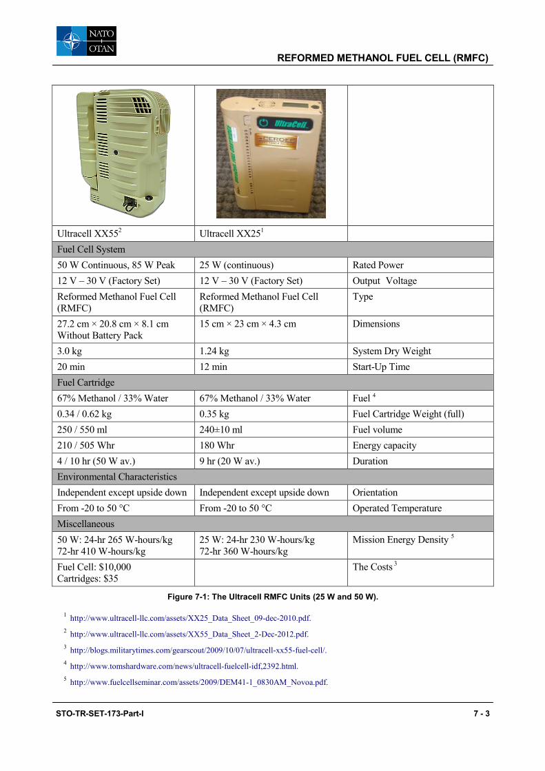
REFORMED METHANOL FUEL CELL (RMFC)
Ultracell XX552 Ultracell XX251
Fuel Cell System
50 W Continuous, 85 W Peak 25 W (continuous) Rated Power 12 V – 30 V (Factory Set) 12 V – 30 V (Factory Set) Output Voltage Reformed Methanol Fuel Cell (RMFC)
Reformed Methanol Fuel Cell (RMFC)
Type
27.2 cm × 20.8 cm × 8.1 cm Without Battery Pack
15 cm × 23 cm × 4.3 cm Dimensions
3.0 kg 1.24 kg System Dry Weight 20 min 12 min Start-Up Time Fuel Cartridge 67% Methanol / 33% Water 67% Methanol / 33% Water Fuel 4 0.34 / 0.62 kg 0.35 kg Fuel Cartridge Weight (full) 250 / 550 ml 240±10 ml Fuel volume 210 / 505 Whr 180 Whr Energy capacity 4 / 10 hr (50 W av.) 9 hr (20 W av.) Duration Environmental Characteristics Independent except upside down Independent except upside down Orientation From -20 to 50 °C From -20 to 50 °C Operated Temperature Miscellaneous 50 W: 24-hr 265 W-hours/kg 72-hr 410 W-hours/kg
25 W: 24-hr 230 W-hours/kg 72-hr 360 W-hours/kg
Mission Energy Density 5
Fuel Cell: $10,000 Cartridges: $35
The Costs 3
Figure 7-1: The Ultracell RMFC Units (25 W and 50 W).
1 http://www.ultracell-llc.com/assets/XX25_Data_Sheet_09-dec-2010.pdf. 2 http://www.ultracell-llc.com/assets/XX55_Data_Sheet_2-Dec-2012.pdf. 3 http://blogs.militarytimes.com/gearscout/2009/10/07/ultracell-xx55-fuel-cell/. 4 http://www.tomshardware.com/news/ultracell-fuelcell-idf,2392.html. 5 http://www.fuelcellseminar.com/assets/2009/DEM41-1_0830AM_Novoa.pdf.
STO-TR-SET-173-Part-I 7 - 3

REFORMED METHANOL FUEL CELL (RMFC)
Serenergy H3 350
Rated power 350 W
Reformed Methanol Fuel Cell (RMFC)
Fuel: 60% Methanol / 40% Water
Dimensions: 279 mm x 204 mm x 595 mm
Start Up Time: TBD
System Dry Weight: 13.7 kg
Operated from -20 to 40 °C
Figure 7-2: Serenergy (350) RMFC Fuel Cell.
7.5 PROS AND CONS
Taking into account the technical properties of RMFC as well as (current) technical limitations aspects can be defined which are in favour or against the use of RMFC. As the relevance of these aspects depends on the desired application they can help to decide whether the use of RMFC for a certain application is reasonable or not.
7.5.1 Pros • Commercially available (TRL9);
• No special training tools or equipment required to operate;
• Simple to use in that many systems have integral fuel cartridge and can be assembled ready to go;
• Short start up time in combination with a sufficiently large hybrid battery (in some designs it will need to sustain the load for up to 20 minutes);
• Potentially higher energy density than batteries; and
• No water management issues.
7.5.1.1 Technical Maturity
An aspect which is generally in favour of the RMFC is the good level of technical maturity that they have recently achieved. Because of this first fully commercial products are available even for civil markets, e.g., as on-board battery charger.
7.5.1.2 High Energy Density
A major point which is in favour of the use of RMFC is the high energy density that they can provide. This is due to higher efficiency of the stack as compared to a DMFC. However, as the fuel is a methanol water mix this may offset the benefits for longer term missions.
7 - 4 STO-TR-SET-173-Part-I
REFORMED METHANOL FUEL CELL (RMFC)
7.5.1.3 Fuel and Fuel Handling
The most common way of handling the fuel in the fuel cell system is by replaceable tanks or cartridges containing a premixed methanol/water fuel. These are connected to the fuel cell system via a screw or bayonet coupling.
The weight of the cartridge compared to the weight of methanol that it contains is usually almost negligible so that returning empty cartridges does not create a weight burden. In the Ultracell systems two sizes of cartridge are available the smaller has a full weight of 0.22 kg versus 0.13 kg empty and the larger 0.47 kg full and 0.15 kg empty. Replacing the cartridge can be done rather quickly after some training and the methanol contained in the inner anode circuit in combination with the hybrid battery can sustain the power delivery to consumers during the period the cartridge is changed. Furthermore, the cartridge prevents the need to handle the flammable and toxic methanol in theatre. Indeed, the cartridge solutions are designed to prevent civil users from accessing the contained methanol as this is prohibited in much legislation.
7.5.2 Cons • Methanol fuel is both toxic and flammable.
• The fuel handling in pre-mixed form is important as the correct mixture is essential for the thermal management of the RMFC. Improper mixtures could cause system failures. The difficulty may be that each system provides its own optimised mixture limiting the possibility for cost reduction by buying from secondary sources.
• Higher catalyst loading will lead to higher MEA costs. This may limit the opportunity for cost reduction compared to other fuel cell technologies.
• Limited power density compared to batteries.
• At low ambient temperature start up time may be extended also specific preparation may be required to prevent pure water freezing. Additionally specific shut down procedures may be required for storage at low ambient temperature.
• Non-logistic fuel.
• A more complex system that requires a hybrid battery to facilitate operation.
7.6 LIMITATIONS
In spite of the many advantages reformed methanol fuel cells also have some technical limitations compared to other types of fuel cells.
7.6.1 Purity of Reactants • The methanol and water must be of high purity in mixed in the correct ratio.
7.6.2 Requires Hybrid Operation • Defined as the provision of power using the fuel cell and a battery this could be an internal battery
(which is always present and part of the system) or the addition of an extra auxiliary battery or external power source (battery/supercapacitor);
• Required for starting and shutdown; and
• Required for load following.
STO-TR-SET-173-Part-I 7 - 5
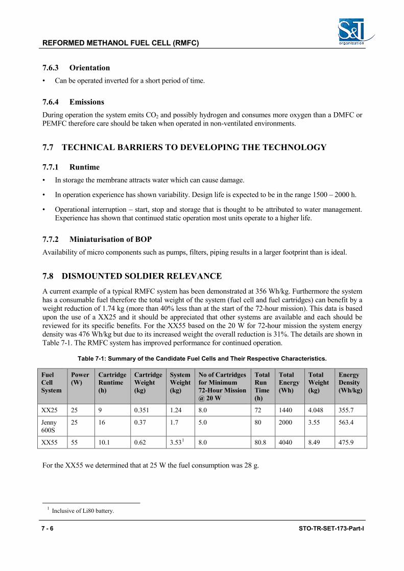
REFORMED METHANOL FUEL CELL (RMFC)
7.6.3 Orientation • Can be operated inverted for a short period of time.
7.6.4 Emissions During operation the system emits CO2 and possibly hydrogen and consumes more oxygen than a DMFC or PEMFC therefore care should be taken when operated in non-ventilated environments.
7.7 TECHNICAL BARRIERS TO DEVELOPING THE TECHNOLOGY
7.7.1 Runtime • In storage the membrane attracts water which can cause damage.
• In operation experience has shown variability. Design life is expected to be in the range 1500 – 2000 h.
• Operational interruption – start, stop and storage that is thought to be attributed to water management. Experience has shown that continued static operation most units operate to a higher life.
7.7.2 Miniaturisation of BOP Availability of micro components such as pumps, filters, piping results in a larger footprint than is ideal.
7.8 DISMOUNTED SOLDIER RELEVANCE
A current example of a typical RMFC system has been demonstrated at 356 Wh/kg. Furthermore the system has a consumable fuel therefore the total weight of the system (fuel cell and fuel cartridges) can benefit by a weight reduction of 1.74 kg (more than 40% less than at the start of the 72-hour mission). This data is based upon the use of a XX25 and it should be appreciated that other systems are available and each should be reviewed for its specific benefits. For the XX55 based on the 20 W for 72-hour mission the system energy density was 476 Wh/kg but due to its increased weight the overall reduction is 31%. The details are shown in Table 7-1. The RMFC system has improved performance for continued operation.
Table 7-1: Summary of the Candidate Fuel Cells and Their Respective Characteristics.
Fuel Cell System
Power (W)
Cartridge Runtime (h)
Cartridge Weight (kg)
System Weight (kg)
No of Cartridges for Minimum 72-Hour Mission @ 20 W
Total Run Time (h)
Total Energy (Wh)
Total Weight (kg)
Energy Density (Wh/kg)
XX25 25 9 0.351 1.24 8.0 72 1440 4.048 355.7
Jenny 600S
25 16 0.37 1.7 5.0 80 2000 3.55 563.4
XX55 55 10.1 0.62 3.531 8.0 80.8 4040 8.49 475.9
For the XX55 we determined that at 25 W the fuel consumption was 28 g.
1 Inclusive of Li80 battery.
7 - 6 STO-TR-SET-173-Part-I

REFORMED METHANOL FUEL CELL (RMFC)
Taking the example of the XX55 (rated at 55 W) when operated at partial load it is less efficient than at rated load. At 50 W the energy content of the cartridge is 505 Wh but at 40 W it is 440 Wh (datasheet) 25 W the energy content is 420 Wh leading us to conclude that the energy efficiency does drop at partial loads.
Figure 7-3: Comparative Figures for Fuel Consumption of the Jenny 600S (DMFC) and XX55 (RMFC).
STO-TR-SET-173-Part-I 7 - 7

REFORMED METHANOL FUEL CELL (RMFC)
7 - 8 STO-TR-SET-173-Part-I
Chapter 8 – SOLID OXIDE FUEL CELL (SOFC)
8.1 INTRODUCTION
A Solid Oxide Fuel Cell (SOFC) is a device that contains a solid oxide or ceramic electrolyte. It produces electricity directly from oxidizing a fuel. They operate at high temperatures, typically between 600 – 1000 °C. Unlike other fuel cells, SOFC cell stacks are available with different geometries. They can be planar which is where the electrolyte is sandwiched between the electrodes, or it can be tubular where one gas, either air or fuel, is passed through the inside of the tube and the other gas is passed along the outside of the tube. There are a variety of applications for SOFCs ranging from usage as auxiliary power units for vehicles and mobile generators to stationary power generation with outputs from 100 W to 100s MW.
8.2 BASIC PRINCIPLES
SOFCs have a solid, non-porous metal oxide electrolyte. The ceramics used in SOFCs do not become electrically and ionically active until they reach a high temperature. Air flows along the cathode. When an oxygen molecule contacts the cathode, it acquires electrons from the cathode and reduction of oxygen into oxygen ions occurs. The ions then diffuse into the electrolyte material and contact the anode. An oxidation reaction takes place at the anode when the oxygen ions encounter the fuel. Through this reaction, water, carbon dioxide, heat, and electrons are by-products. The electrons then flow through an external circuit, providing electrical energy, and the cycle repeats when those electrons enter the cathode material again.
8.3 THE SYSTEM
8.3.1 Anode The ceramic anode has to be porous to allow the fuel to flow towards the electrolyte, and it has to have ionic and electronically conductivity. The anode is in many cell types the thickest and strongest layer in each cell (anode supported SOFC). If the fuel is a light hydrocarbon such as methane, the anode acts as a catalyst for steam reforming the fuel into hydrogen.
8.3.2 Cathode The cathode is a thin porous layer that has to be ionic and electronically conductive. A common cathode material is LSM lanthanum strontium manganite. As this material differs from the yttrium stabilized zirconate YSZ used throughout the anode and the electrolyte the cathode electrolyte interface is rather sensitive to fast thermal variations.
8.3.3 Interconnect The interconnect is a ceramic or metallic layer that is in between each individual cell. It connects each cell in series. In many stack designs for mobile applications nowadays cassette solutions are found. Tubular bundles have manifold endplates instead.
8.3.4 Electrolyte The electrolyte is a dense layer of ceramic that conducts oxygen ions. Its electronic conductivity should be kept as low as possible to prevent losses from leakage currents.
STO-TR-SET-173-Part-I 8 - 1

SOLID OXIDE FUEL CELL (SOFC)
8.3.5 Balance of Plant Most of the downtime of a SOFC stems from the mechanical balance of plant, the air preheater, prereformer, afterburner, water heat exchanger, anode tail gas oxidizer, and electrical balance of plant, power electronics, hydrogen sulphide sensor and fans. Internal reforming leads to a large decrease in the balance of plant costs in designing a full system.
They operate at very high temperatures, typically between 600 and 1,000 °C. At these temperatures, SOFCs do not require expensive platinum catalyst material, as is currently necessary for lower temperature fuel cells such as PEMFCs, and are not vulnerable to carbon monoxide catalyst poisoning. However, vulnerability to sulphur poisoning has been widely observed and the sulphur must be removed before entering the cell through the use of adsorbent beds or other means.
8.3.6 Fuel The high operating temperature of SOFCs means that certain fuels and in particular methane can be reformed within the fuel cell itself. This ability eliminates the need for external reforming. Also it reduces the need for cooling via the cathode air stream (chemical cooling). However, the nickel used as anode material in most commercial SOFC today is very susceptible to soot formation. Too high amount of higher hydrocarbons can thus destroy the cell. Therefore, the SOFC can operate with a variety of hydrocarbon fuels after a preforming step leading to H2, CO, CH4 mixtures with low content of CnHm. In comparison with other types of fuel cells, they are relatively resistant to small quantities of sulphur, so they can be used with coal gas.1
Figure 8-1: SOFC Reaction Schematic.
1 http://www.fuelcelltoday.com/about-fuel-cells/technologies/sofc.
8 - 2 STO-TR-SET-173-Part-I
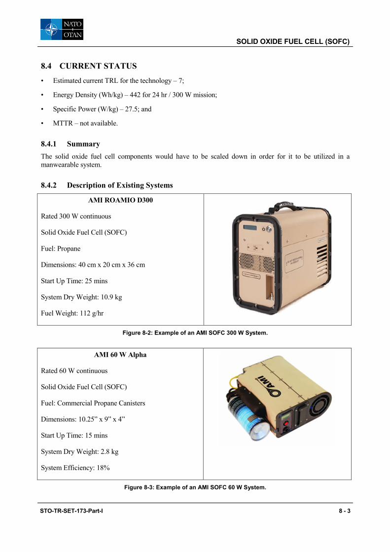
SOLID OXIDE FUEL CELL (SOFC)
8.4 CURRENT STATUS
• Estimated current TRL for the technology – 7;
• Energy Density (Wh/kg) – 442 for 24 hr / 300 W mission;
• Specific Power (W/kg) – 27.5; and
• MTTR – not available.
8.4.1 Summary The solid oxide fuel cell components would have to be scaled down in order for it to be utilized in a manwearable system.
8.4.2 Description of Existing Systems
AMI ROAMIO D300
Rated 300 W continuous
Solid Oxide Fuel Cell (SOFC)
Fuel: Propane
Dimensions: 40 cm x 20 cm x 36 cm
Start Up Time: 25 mins
System Dry Weight: 10.9 kg
Fuel Weight: 112 g/hr
Figure 8-2: Example of an AMI SOFC 300 W System.
AMI 60 W Alpha
Rated 60 W continuous
Solid Oxide Fuel Cell (SOFC)
Fuel: Commercial Propane Canisters
Dimensions: 10.25” x 9” x 4”
Start Up Time: 15 mins
System Dry Weight: 2.8 kg
System Efficiency: 18%
Figure 8-3: Example of an AMI SOFC 60 W System.
STO-TR-SET-173-Part-I 8 - 3

SOLID OXIDE FUEL CELL (SOFC)
8.5 PROS AND CONS
Solid Oxide Fuel Cells (SOFCs), challenges include stack survivability during repeated thermal cycling, air exposure of the anode during longer shutdowns causing catalyst re-oxidation, decreasing long start up times, and potential mechanical and chemical compatibility/reactivity issues between the various stack and cell components due to high temperature operation. For all these systems, improved fuel processing and clean-up, especially for fuel-flexible operation and operation on biofuels, are needed to improve durability and reduce system costs.
8.5.1 Pros There are several advantages to utilizing SOFCs. Various fuels can be used with this system which is beneficial from a logistical standpoint. Furthermore, the systems tend to have a higher efficiency than fuel cells with other chemistries:
• High efficiency;
• High power density;
• Long-term stability;
• Fuel flexibility;
• Low emissions; and
• Operate quietly.
8.5.2 Cons SOFCs have a long start up time due to the high operating temperature that has to be reached for the fuel cell to operate. This is a disadvantage if power is needed right away:
• High operating temperature;
• Long start up and shut down times; and
• Mechanical and chemical compatibility issues.
8.6 LIMITATIONS2
• Start-up time.
• SOFCs are most fuel-efficient operating at 1000°C, however the high temperature decreases cell lifetime and increases cost of materials.
• Cell performance is sensitive to operating temperature (10% drop in temperature results in about 12% drop in cell performance).
• Thermal insulation required for man wearable applications.
• Requires hybrid operation:
• Required for starting; and
• Required for load following.
2 http://www.engr.sjsu.edu/sgleixner/PRIME/Nanomaterials/References/Boudghene.pdf.
8 - 4 STO-TR-SET-173-Part-I

SOLID OXIDE FUEL CELL (SOFC)
8.7 TECHNICAL BARRIERS TO DEVELOPING THE TECHNOLOGY
• High temperature system therefore difficult to adapt for man wearability;
• Cathode materials;
• Low temperature electrolytes; and
• Interfaces.
8.8 DISMOUNTED SOLDIER RELEVANCE
• Tier I environment;
• Auxiliary power;
• Can be used to charge batteries;
• Propane is universally found; and
• Developed filter so can be used with propane found anywhere.
STO-TR-SET-173-Part-I 8 - 5

SOLID OXIDE FUEL CELL (SOFC)
8 - 6 STO-TR-SET-173-Part-I

Chapter 9 – HYDROGEN GENERATION
9.1 HYDROGEN GENERATION FOR PEM FUEL CELLS
As discussed previously PEM fuel cells offer the highest power density solution, however, the limitation in their use is the availability of hydrogen in a suitable format for the manwearable application.
A number of developments are underway to satisfy this need. One example currently being investigated is Chemical Hydrides.
9.2 CHEMICAL HYDRIDE
• Estimated current TRL for the technology – TRL 6.
• Introduction (see below).
• Basic Principles (see below).
• Current Status / Existing Systems:
• Power Density (kW/l) 0.032 kW/l;
• Specific Power (kW/kg) 0.029 kW/kg;
• Energy Density 580 Wh/kg (72-hour mission);
• Cost vs kW unknown at present (low TRL stage); and
• MTTR (unknown potentially ~ >> 1000 hrs).
Due to the risks associated with compressed H2 use, the deployment of H2 PEM systems in the battlefield has not been pursued. However the ability to store H2 as chemical hydride or a metal hydride1 provides an alternative to gas storage. These emerging systems offer fuel densities of 3300 Wh/kg2. However H2 generation and filtering decrease the realizable energy density significantly. High TRL systems are available ≥ 1 W 3,4.
The components of a H2 PEM system include a LT PEM fuel cell which is available at a high technological readiness level5 and a high manufacturing readiness level6. Excluding the fuel delivery system, the remaining Balance of Plant is at a high TRL.
Synthesized H2 dense fuels available include Sodium Borohydride, Ammonia Borane, Ethylene Diamine Borane and Aluminium Hydride (AlH3). To design a system, challenges of reaction control (hydrolysis, thermolysis), energy balance and effect of impurities on the PEM must be considered.
1 K. Pearson, Forward Deployable Renewable Energy Joint Service Power Expo 2011, Myrtle Beach, SC May 2-5th, 2011. 2 T. Motyka, Development of High Capacity Portable Power Systems, 2011 Fuel Cell Seminar Orlando, FL 1 Nov., 2011. 3 Horizon MINIPAK, http://www.horizonfuelcell.com/#!minipak/c156u, Accessed 7/19/13. 4 myFC PowerTrekk, http://powertrekk.com/, Accessed 7/19/13. 5 Protonex M300 system uses low temperature PEM Fuel Cell and has been utilized in an operation relevant environment. 6 LT PEM systems are being manufactured for various commercial applications such UPS systems and forklift applications.
STO-TR-SET-173-Part-I 9 - 1
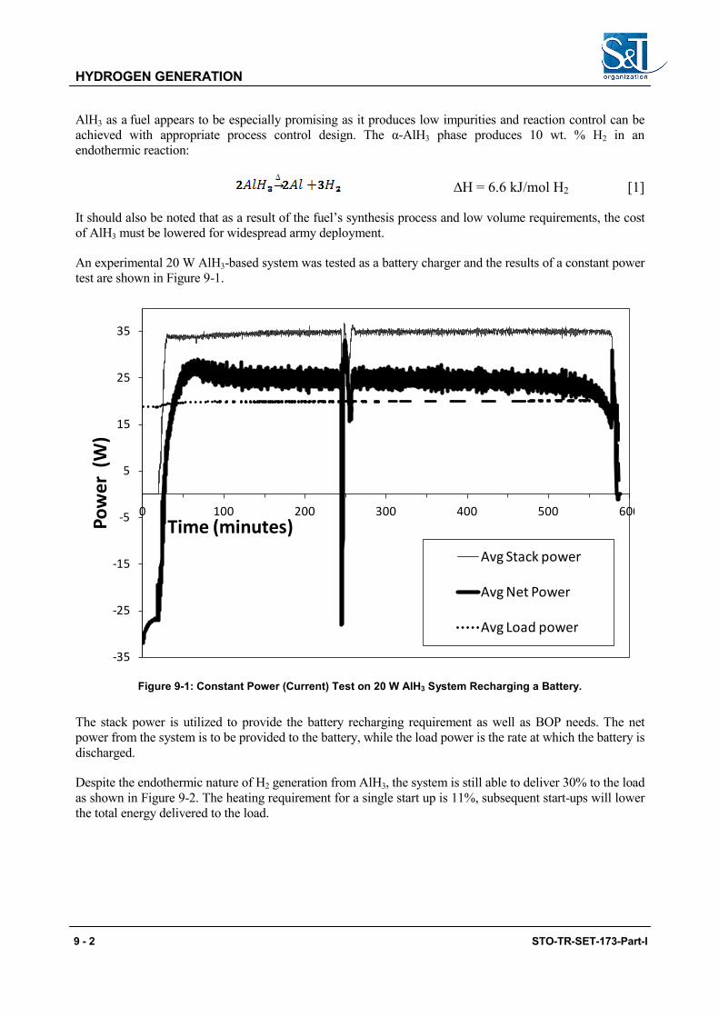
HYDROGEN GENERATION
AlH3 as a fuel appears to be especially promising as it produces low impurities and reaction control can be achieved with appropriate process control design. The α-AlH3 phase produces 10 wt. % H2 in an endothermic reaction:
∆H = 6.6 kJ/mol H2 [1]
It should also be noted that as a result of the fuel’s synthesis process and low volume requirements, the cost of AlH3 must be lowered for widespread army deployment.
An experimental 20 W AlH3-based system was tested as a battery charger and the results of a constant power test are shown in Figure 9-1.
-35
-25
-15
-5
5
15
25
35
0 100 200 300 400 500 600
Pow
er (
W)
Time (minutes)Avg Stack power
Avg Net Power
Avg Load power
Figure 9-1: Constant Power (Current) Test on 20 W AlH3 System Recharging a Battery.
The stack power is utilized to provide the battery recharging requirement as well as BOP needs. The net power from the system is to be provided to the battery, while the load power is the rate at which the battery is discharged.
Despite the endothermic nature of H2 generation from AlH3, the system is still able to deliver 30% to the load as shown in Figure 9-2. The heating requirement for a single start up is 11%, subsequent start-ups will lower the total energy delivered to the load.
9 - 2 STO-TR-SET-173-Part-I
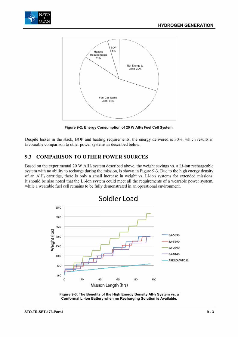
HYDROGEN GENERATION
Net Energy to Load 30%
Fuel Cell Stack Loss 54%
Heating Requirements
11%
BOP5%
Figure 9-2: Energy Consumption of 20 W AlH3 Fuel Cell System.
Despite losses in the stack, BOP and heating requirements, the energy delivered is 30%, which results in favourable comparison to other power systems as described below.
9.3 COMPARISON TO OTHER POWER SOURCES
Based on the experimental 20 W AlH3 system described above, the weight savings vs. a Li-ion rechargeable system with no ability to recharge during the mission, is shown in Figure 9-3. Due to the high energy density of an AlH3 cartridge, there is only a small increase in weight vs. Li-ion systems for extended missions. It should be also noted that the Li-ion system could meet all the requirements of a wearable power system, while a wearable fuel cell remains to be fully demonstrated in an operational environment.
Figure 9-3: The Benefits of the High Energy Density AlH3 System vs. a Conformal Li-Ion Battery when no Recharging Solution is Available.
STO-TR-SET-173-Part-I 9 - 3

HYDROGEN GENERATION
Weight savings due to the AlH3’s higher energy density (800 Wh/kg) vs. the conformal battery (127 Wh/kg) for mission lengths > 8 hrs.
The energy density is based on a 72-hour mission at the system output power. The system output power is shown next to the data point.
A Ragone plot is shown in Figure 9-4, as a comparison of the total weight of fuel cell systems and battery power sources for a constant 72-hour mission. The 25 W, 55 W and 300 W systems are based on RMFC technology (Chapter 8). The 20 W system is based on a tested AlH3 chemical hydride fuel cell system described previously. The performance metrics of Lithium Carbon Fluoride (LiCFx) technology7 are also plotted on Figure 9-4 based on manufacture’s published specification. It is noted that that the discharge rate significantly impacts the battery capacity.
20W
25W
55W
300W
10W
350
450
550
650
0 10 20 30
Spec
ific E
nerg
y (W
h/kg
) for
72h
r
Specific Power (W/kg)
Chem. Hydride FC
RMFC
Li-CFx
Figure 9-4: Ragone Plot for a Li-CFx Battery, RMFC Systems and an AlH3-Based Fuel Cell.
The AlH3 fuel cell has the highest power and energy density of all the systems compared, suggesting it is best suited for wearable applications, although advances in methanol fuel cells may alter this. An example system is shown in Figure 9-5.
7 Eagle Pitcher CFx technology – http://www.eaglepicher.com/technologies/battery-power/lithium-carbon-monofluoride Accessed 7/19/13.
9 - 4 STO-TR-SET-173-Part-I

HYDROGEN GENERATION
Figure 9-5: The Ardica System Showing the Chemical Hydride Cartridge Disassembled.
9.3.1 Limitations • No operation under water.
• Requires hybrid operation:
• Required for starting; and
• Required for load following.
9.3.2 Pros and Cons • Pros
• Low temperature signature.
• Cons
• Pure hydrogen as fuel;
• Cost of fuel is unknown;
• Water management difficult; and
• There are some safety concerns regarding the stability/reactivity of the AlH3 fuel (and other hydrogen producing reactants) in the event that a fuel cartridge ruptures.
• Barriers to developing technology
• Hydrogen Fuel storage.
9.4 SOLDIERPAK AND AEROPAK
Horizon Energy Systems have developed a range of fuel cell power systems which use indirect sodium borohydride to power the fuel cell. These are available in “dry” replaceable cartridges to which is added
STO-TR-SET-173-Part-I 9 - 5

HYDROGEN GENERATION
water prior to use. There are two types available the AEROPAK for UAV applications (Figure 9-6) and SOLDIERPAK for soldier systems Figure 9-7.
Figure 9-6: An Example of the Aeropak.
Figure 9-7: An Example of the SoldierPak.
The collection of waste fuel requires consideration. During use a hot liquid is purged in a series of high pressure spurts which quickly solidify therefore any restriction could result in a build-up of solids and the outlet could become blocked.
In the UAV applications as hydrogen is generated borax is produced which is “ejected” in flight, however, in the soldier system the borax is “ejected” through a tube which then needs to be disposed of and piped safely. Due to the volume of this by product it can be problematic.
9 - 6 STO-TR-SET-173-Part-I
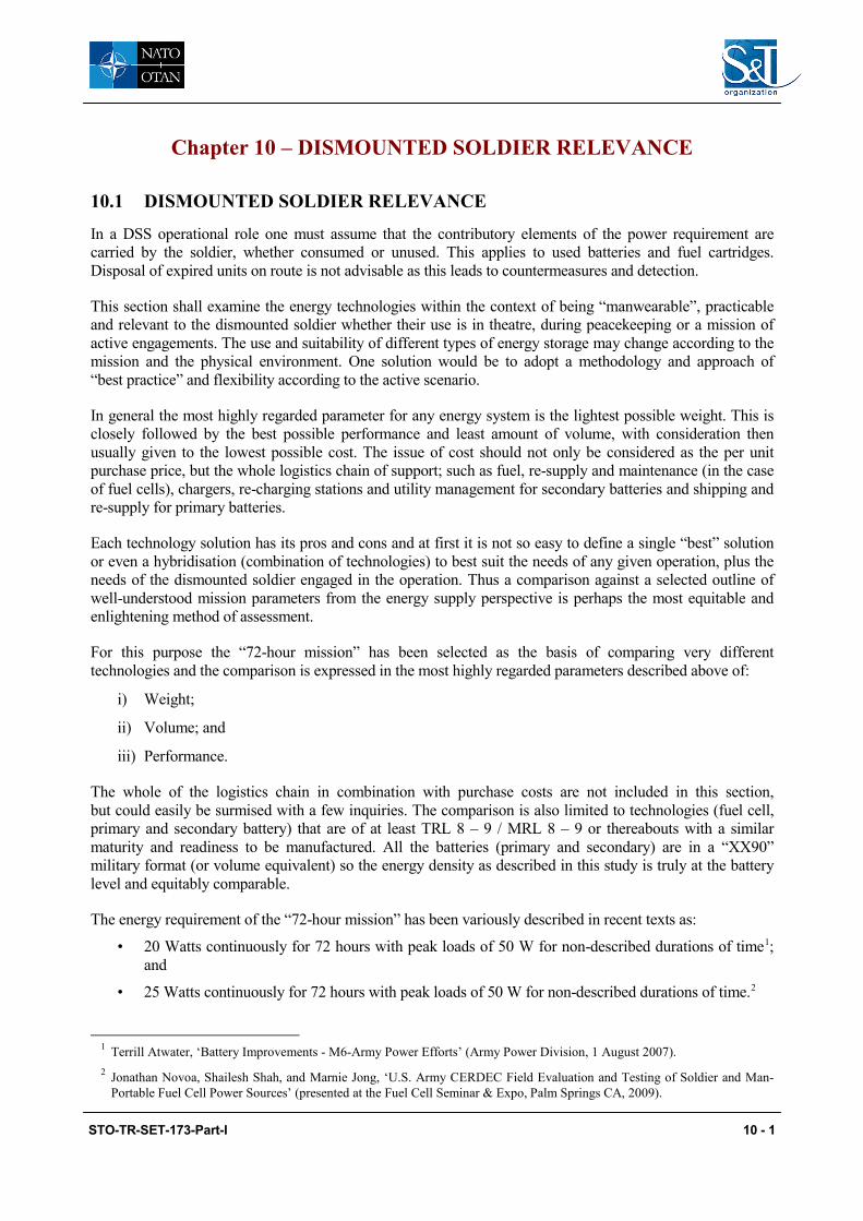
Chapter 10 – DISMOUNTED SOLDIER RELEVANCE
10.1 DISMOUNTED SOLDIER RELEVANCE
In a DSS operational role one must assume that the contributory elements of the power requirement are carried by the soldier, whether consumed or unused. This applies to used batteries and fuel cartridges. Disposal of expired units on route is not advisable as this leads to countermeasures and detection.
This section shall examine the energy technologies within the context of being “manwearable”, practicable and relevant to the dismounted soldier whether their use is in theatre, during peacekeeping or a mission of active engagements. The use and suitability of different types of energy storage may change according to the mission and the physical environment. One solution would be to adopt a methodology and approach of “best practice” and flexibility according to the active scenario.
In general the most highly regarded parameter for any energy system is the lightest possible weight. This is closely followed by the best possible performance and least amount of volume, with consideration then usually given to the lowest possible cost. The issue of cost should not only be considered as the per unit purchase price, but the whole logistics chain of support; such as fuel, re-supply and maintenance (in the case of fuel cells), chargers, re-charging stations and utility management for secondary batteries and shipping and re-supply for primary batteries.
Each technology solution has its pros and cons and at first it is not so easy to define a single “best” solution or even a hybridisation (combination of technologies) to best suit the needs of any given operation, plus the needs of the dismounted soldier engaged in the operation. Thus a comparison against a selected outline of well-understood mission parameters from the energy supply perspective is perhaps the most equitable and enlightening method of assessment.
For this purpose the “72-hour mission” has been selected as the basis of comparing very different technologies and the comparison is expressed in the most highly regarded parameters described above of:
i) Weight;
ii) Volume; and
iii) Performance.
The whole of the logistics chain in combination with purchase costs are not included in this section, but could easily be surmised with a few inquiries. The comparison is also limited to technologies (fuel cell, primary and secondary battery) that are of at least TRL 8 – 9 / MRL 8 – 9 or thereabouts with a similar maturity and readiness to be manufactured. All the batteries (primary and secondary) are in a “XX90” military format (or volume equivalent) so the energy density as described in this study is truly at the battery level and equitably comparable.
The energy requirement of the “72-hour mission” has been variously described in recent texts as:
• 20 Watts continuously for 72 hours with peak loads of 50 W for non-described durations of time1; and
• 25 Watts continuously for 72 hours with peak loads of 50 W for non-described durations of time.2
1 Terrill Atwater, ‘Battery Improvements - M6-Army Power Efforts’ (Army Power Division, 1 August 2007). 2 Jonathan Novoa, Shailesh Shah, and Marnie Jong, ‘U.S. Army CERDEC Field Evaluation and Testing of Soldier and Man-
Portable Fuel Cell Power Sources’ (presented at the Fuel Cell Seminar & Expo, Palm Springs CA, 2009).
STO-TR-SET-173-Part-I 10 - 1

DISMOUNTED SOLDIER RELEVANCE
For the purposes of providing an equitable comparison, a constant energy of 20 W for 72 hours was chosen, thus requiring a total energy deliverable of 1.44 kWh for the mission duration. Again for the purposes of a comparison of the various systems, a certain set of environmental conditions is assumed, as would nominally be found in a field of operation contemporary with some of today’s on-going engagements:
• Temperature: A minimum of -5°C overnight to maximum of 38°C during the day;
• Humidity: Desert conditions with an average relative humidity of ≈30%;
• Rainfall: It is assumed that rainfall does not factor into the environmental conditions for the purposes of this comparison;
• Dust: Blown particulates such as dust and sand are also not factored into this comparison;
• Sunlight: It is assumed that the conditions of solar insolation are approximately that of the spring equinox period with almost equal phases of darkness and light; and
• Cloud Cover: It is assumed that there will be none to light cloud cover to ensure the possibility of solar energy harvesting.
To provide further comparison we have selected 12 of the most common power sources that could be used in the manwearable role which are detailed in Figure 10-1. These have further been grouped into the three generic categories of primary and secondary batteries and fuel cells. It can be seen that primary batteries excel in both specific energy and energy density. However for an average 20 W load for 72-hour mission this situation changes.
Figure 10-1: The Most Common Power Sources and Their Characteristics of Volumetric and Gravimetric Energy Density.
10 - 2 STO-TR-SET-173-Part-I
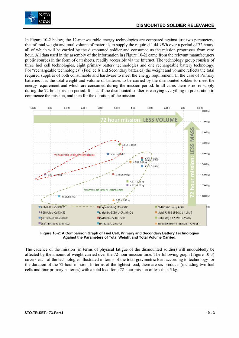
DISMOUNTED SOLDIER RELEVANCE
In Figure 10-2 below, the 12-manwearable energy technologies are compared against just two parameters, that of total weight and total volume of materials to supply the required 1.44 kWh over a period of 72 hours, all of which will be carried by the dismounted soldier and consumed as the mission progresses from zero hour. All data used in the assembly of the information in (Figure 10-2) came from the relevant manufacturers public sources in the form of datasheets, readily accessible via the Internet. The technology group consists of three fuel cell technologies, eight primary battery technologies and one rechargeable battery technology. For “rechargeable technologies” (Fuel cells and Secondary batteries) the weight and volume reflects the total required supplies of both consumable and hardware to meet the energy requirement. In the case of Primary batteries it is the total weight and volume of batteries to be carried by the dismounted soldier to meet the energy requirement and which are consumed during the mission period. In all cases there is no re-supply during the 72-hour mission period. It is as if the dismounted soldier is carrying everything in preparation to commence the mission, and then for the duration of the mission.
Figure 10-2: A Comparison Graph of Fuel Cell, Primary and Secondary Battery Technologies Against the Parameters of Total Weight and Total Volume Carried.
The cadence of the mission (in terms of physical fatigue of the dismounted soldier) will undoubtedly be affected by the amount of weight carried over the 72-hour mission time. The following graph (Figure 10-3) covers each of the technologies illustrated in terms of the total gravimetric load according to technology for the duration of the 72-hour mission. In terms of the lightest load, there are six products (including two fuel cells and four primary batteries) with a total load for a 72-hour mission of less than 5 kg.
STO-TR-SET-173-Part-I 10 - 3
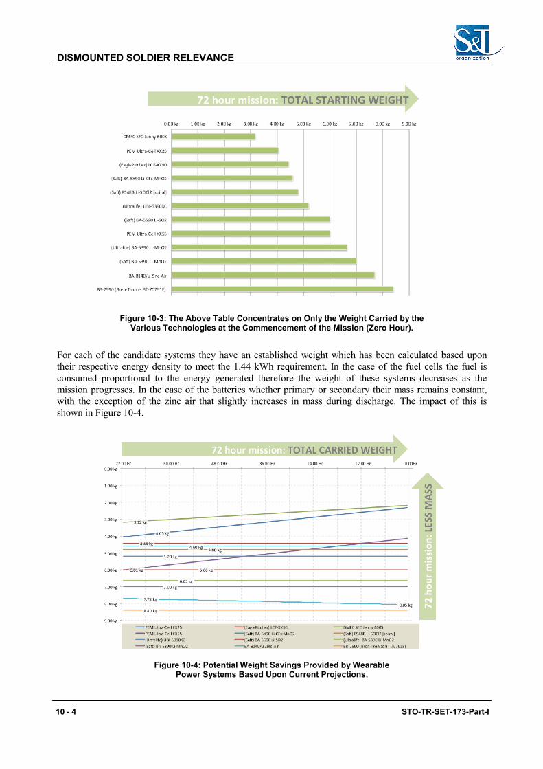
DISMOUNTED SOLDIER RELEVANCE
Figure 10-3: The Above Table Concentrates on Only the Weight Carried by the Various Technologies at the Commencement of the Mission (Zero Hour).
For each of the candidate systems they have an established weight which has been calculated based upon their respective energy density to meet the 1.44 kWh requirement. In the case of the fuel cells the fuel is consumed proportional to the energy generated therefore the weight of these systems decreases as the mission progresses. In the case of the batteries whether primary or secondary their mass remains constant, with the exception of the zinc air that slightly increases in mass during discharge. The impact of this is shown in Figure 10-4.
Figure 10-4: Potential Weight Savings Provided by Wearable Power Systems Based Upon Current Projections.
10 - 4 STO-TR-SET-173-Part-I
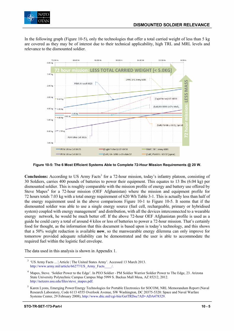
DISMOUNTED SOLDIER RELEVANCE
In the following graph (Figure 10-5), only the technologies that offer a total carried weight of less than 5 kg are covered as they may be of interest due to their technical applicability, high TRL and MRL levels and relevance to the dismounted soldier.
Figure 10-5: The 6 Most Efficient Systems Able to Complete 72-Hour Mission Requirements @ 20 W.
Conclusions: According to US Army Facts3 for a 72-hour mission, today’s infantry platoon, consisting of 30 Soldiers, carries 400 pounds of batteries to power their equipment. This equates to 13 lbs (6.04 kg) per dismounted soldier. This is roughly comparable with the mission profile of energy and battery use offered by Steve Mapes4 for a 72-hour mission (OEF Afghanistan) where the mission and equipment profile for 72 hours totals 7.03 kg with a total energy requirement of 620 Wh Table 3-1. This is actually less than half of the energy requirement used in the above comparisons Figure 10-1 to Figure 10-5. It seems that if the dismounted soldier was able to use a single energy source (fuel cell, rechargeable, primary or hybridised system) coupled with energy management5 and distribution, with all the devices interconnected to a wearable energy network, he would be much better off. If the above 72-hour OEF Afghanistan profile is used as a guide he could carry a total of around 4 kilos or less of batteries to power a 72-hour mission. That’s certainly food for thought, as the information that this document is based upon is today’s technology, and this shows that a 50% weight reduction is available now, so the manwearable energy dilemma can only improve for tomorrow provided adequate reliability can be demonstrated and the user is able to accommodate the required fuel within the logistic fuel envelope.
The data used in this analysis is shown in Appendix 1.
3 ‘US Army Facts ... | Article | The United States Army’. Accessed 13 March 2013. http://www.army.mil/article/66277/US_Army_Facts____/.
4 Mapes, Steve. ‘Soldier Power to the Edge’. In PEO Soldier - PM Soldier Warrior Soldier Power to The Edge, 23. Arizona State University Polytechnic Campus Campus Map 5999 S. Backus Mall Mesa, AZ 85212, 2012. http://netzero.asu.edu/files/steve_mapes.pdf.
5 Karen Lyons, Emerging Power/Energy Technologies for Portable Electronics for SOCOM, NRL Memorandum Report (Naval Research Laboratory, Code 6113 4555 Overlook Avenue, SW Washington, DC 20375-5320: Space and Naval Warfare Systems Center, 29 February 2008), http://www.dtic.mil/cgi-bin/GetTRDoc?AD=ADA478329.
STO-TR-SET-173-Part-I 10 - 5
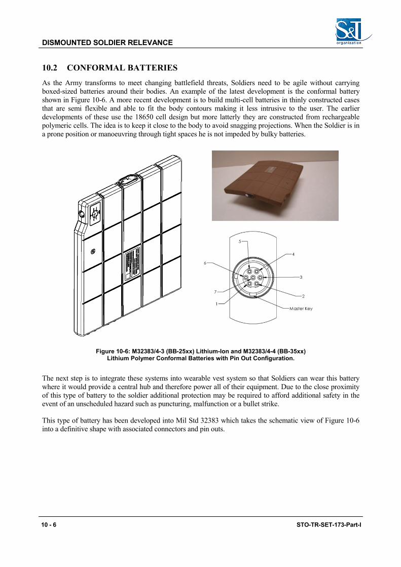
DISMOUNTED SOLDIER RELEVANCE
10.2 CONFORMAL BATTERIES
As the Army transforms to meet changing battlefield threats, Soldiers need to be agile without carrying boxed-sized batteries around their bodies. An example of the latest development is the conformal battery shown in Figure 10-6. A more recent development is to build multi-cell batteries in thinly constructed cases that are semi flexible and able to fit the body contours making it less intrusive to the user. The earlier developments of these use the 18650 cell design but more latterly they are constructed from rechargeable polymeric cells. The idea is to keep it close to the body to avoid snagging projections. When the Soldier is in a prone position or manoeuvring through tight spaces he is not impeded by bulky batteries.
Figure 10-6: M32383/4-3 (BB-25xx) Lithium-Ion and M32383/4-4 (BB-35xx) Lithium Polymer Conformal Batteries with Pin Out Configuration.
The next step is to integrate these systems into wearable vest system so that Soldiers can wear this battery where it would provide a central hub and therefore power all of their equipment. Due to the close proximity of this type of battery to the soldier additional protection may be required to afford additional safety in the event of an unscheduled hazard such as puncturing, malfunction or a bullet strike.
This type of battery has been developed into Mil Std 32383 which takes the schematic view of Figure 10-6 into a definitive shape with associated connectors and pin outs.
10 - 6 STO-TR-SET-173-Part-I

DISMOUNTED SOLDIER RELEVANCE
Table 10-1: Mil M32383 Pin Out Configurations and Functional Identity.
Connector Pin Out Identity
SOCKET DESCRIPTION TERMINAL MARKINGS
1 V+ Battery Voltage Batt +
2 V- Battery Ground Batt -
3 Charge + Charge +
4 SMBus Data Data
5 SMBus Clock Clock
6 SMBus ID (‘T-pin’) -103AT Thermister to Ground
SB ID 1/
7 (If Present) No Connection or 28 V+ Battery Voltage Blank / NC / Batt + 2/
Charge Contacts
POSITION (Left to Right) DESCRIPTION TITLE
1 Charge Terminal, Positive CHG +
2 Charger Terminal, Negative (Ground) CHG -
3 SMBus Data DATA
4 SMBus Clock CLK
10.3 SUMMARY
In Figure 10-7 (assumed system power level is 5 W. PEMFC is proton exchange membrane fuel cell. SOURCE: NRC, 1997) it can be seen that the cross-over points for a range of energy systems in which it can be seen that the current DSS rechargeable battery provides the highest mass for the given energy and the PEM fuelled by a high pressure gas cylinder the least. If we also consider that the energy required is around 1.5 kWh it is clear that fuel cells are the only favoured options. For energy less than 0.75 kWh then advanced rechargeable batteries become more favourable.
STO-TR-SET-173-Part-I 10 - 7
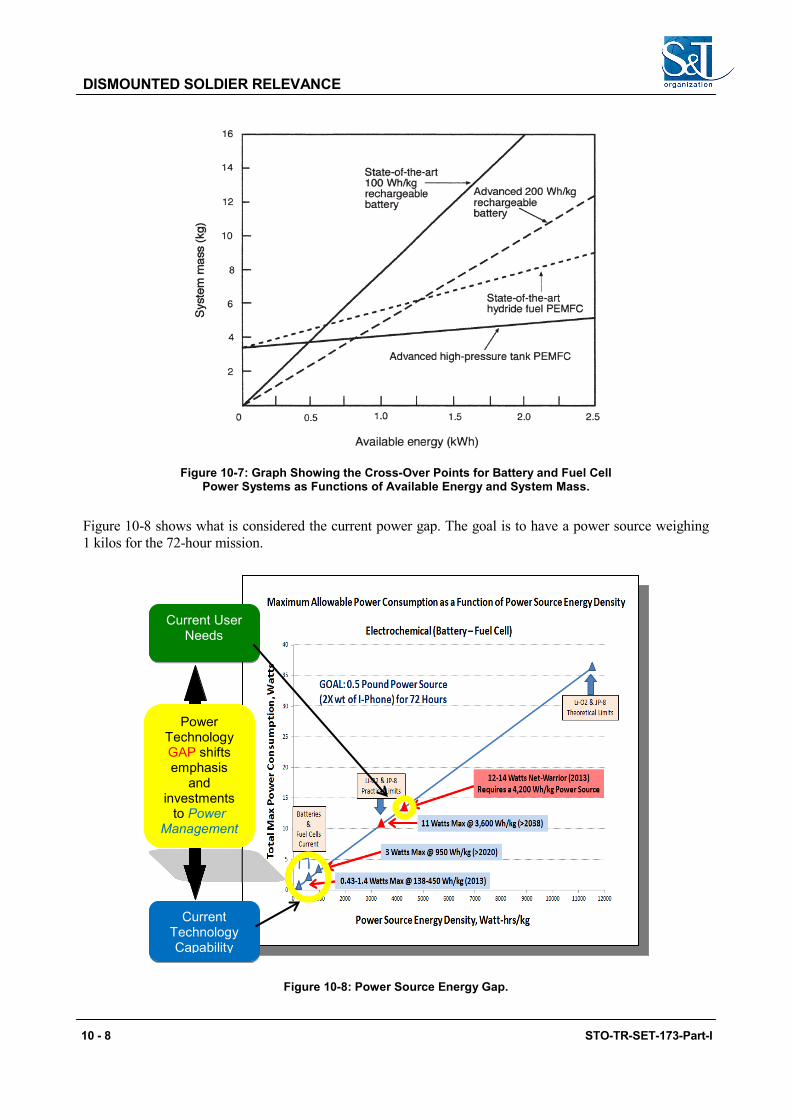
DISMOUNTED SOLDIER RELEVANCE
Figure 10-7: Graph Showing the Cross-Over Points for Battery and Fuel Cell Power Systems as Functions of Available Energy and System Mass.
Figure 10-8 shows what is considered the current power gap. The goal is to have a power source weighing 1 kilos for the 72-hour mission.
Figure 10-8: Power Source Energy Gap.
Current Technology Capability
Current User Needs
Power Technology GAP shifts emphasis
and investments
to Power Management
10 - 8 STO-TR-SET-173-Part-I

Chapter 11 – THE HYBRID SOLUTION
Hybrids offer enormous advantages from a simple energetics point of view for longer mission times. A hybrid power/energy system can be optimized for both high energy and high power demands. It can also provide the means to overcome the disadvantage of an air-breathing power source by combining an air-breathing system (e.g., metal/air battery, fuel cell, small engine) with a rechargeable battery.
There are a wide range of options available from simple dc to dc converters to sophisticated units with dedicated input and output options. One such device is the Smart Fuel Cell power manager, which is shown in Figure 11-1 below along with its specification detailed in Table 11-1. Figure 11-2 shows the options for utilising the Power Manager. A further device is the ABSL Soldier Portable Charger (SPC) which is detailed in Figure 11-3 and Table 11-2.
Figure 11-1: Example Power Manager.
STO-TR-SET-173-Part-I 11 - 1
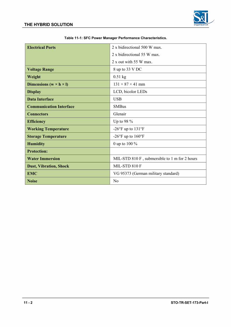
THE HYBRID SOLUTION
Table 11-1: SFC Power Manager Performance Characteristics.
Electrical Ports 2 x bidirectional 500 W max.
2 x bidirectional 55 W max.
2 x out with 55 W max.
Voltage Range 8 up to 33 V DC
Weight 0.51 kg
Dimensions (w × h × l) 131 × 87 × 41 mm
Display LCD, bicolor LEDs
Data Interface USB
Communication Interface SMBus
Connectors Glenair
Efficiency Up to 98 %
Working Temperature -26°F up to 131°F
Storage Temperature -26°F up to 160°F
Humidity 0 up to 100 %
Protection:
Water Immersion MIL-STD 810 F , submersible to 1 m for 2 hours
Dust, Vibration, Shock MIL-STD 810 F
EMC VG 95373 (German military standard)
Noise No
11 - 2 STO-TR-SET-173-Part-I

THE HYBRID SOLUTION
Figure 11-2: Shows the Connection Options for the Power Manager.
Figure 11-3: Soldier Portable Level 3 Smart Charger with Bespoke Interconnection Lead.
output connector
SPC (Soldier Portable Charger) ‘Smart’
Adaptor
STO-TR-SET-173-Part-I 11 - 3
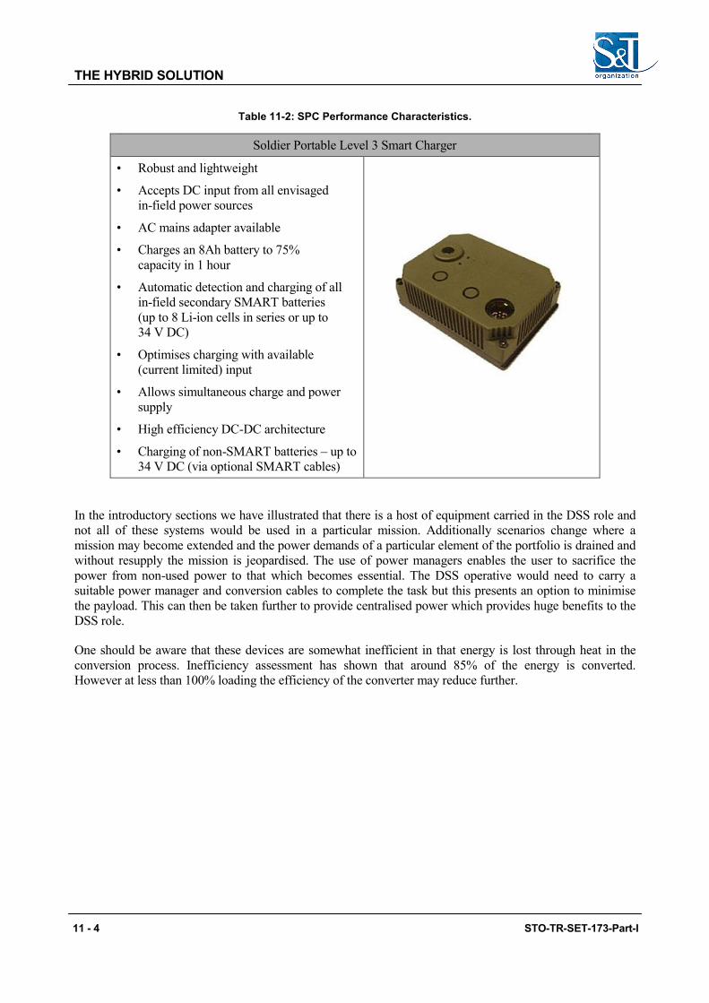
THE HYBRID SOLUTION
Table 11-2: SPC Performance Characteristics.
Soldier Portable Level 3 Smart Charger
• Robust and lightweight
• Accepts DC input from all envisaged in-field power sources
• AC mains adapter available
• Charges an 8Ah battery to 75% capacity in 1 hour
• Automatic detection and charging of all in-field secondary SMART batteries (up to 8 Li-ion cells in series or up to 34 V DC)
• Optimises charging with available (current limited) input
• Allows simultaneous charge and power supply
• High efficiency DC-DC architecture
• Charging of non-SMART batteries – up to 34 V DC (via optional SMART cables)
In the introductory sections we have illustrated that there is a host of equipment carried in the DSS role and not all of these systems would be used in a particular mission. Additionally scenarios change where a mission may become extended and the power demands of a particular element of the portfolio is drained and without resupply the mission is jeopardised. The use of power managers enables the user to sacrifice the power from non-used power to that which becomes essential. The DSS operative would need to carry a suitable power manager and conversion cables to complete the task but this presents an option to minimise the payload. This can then be taken further to provide centralised power which provides huge benefits to the DSS role.
One should be aware that these devices are somewhat inefficient in that energy is lost through heat in the conversion process. Inefficiency assessment has shown that around 85% of the energy is converted. However at less than 100% loading the efficiency of the converter may reduce further.
11 - 4 STO-TR-SET-173-Part-I

THE HYBRID SOLUTION
Figure 11-4: Energy Harvesting – Typical Scenario.
To illustrate the performance of an example hybrid system using a Jenny 600 fuel cell, an SCR battery for storage and a solar panel. The solar panel is used for one sixth of the time. The equipment characteristics are shown in Table 11-3 and Figure 11-5.
Table 11-3: Hybrid Components and Their Respective Characteristics.
Fuel Cell Battery Solar Panel Power
Manager Cables
Jenny 600 SCR PowerFLEX PMG3
Power (W) 25 60 1.268
Weight (dry) (Kg) 2.071 1.2 1.41 0.52 0.5
Operation [hr per day]
4 (1/6 of the total time)
Energy (Wh) 180
http://www.unatsolar.eu/images-2010/PDFs/UnatSolar-62%20watt%20spec%20sheet.pdf
1 Jenny 600 with Standard fuel cartridge.
STO-TR-SET-173-Part-I 11 - 5
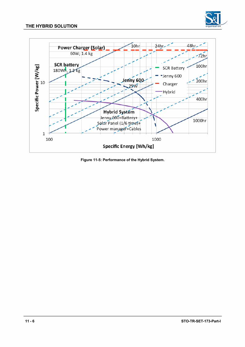
THE HYBRID SOLUTION
Figure 11-5: Performance of the Hybrid System.
11 - 6 STO-TR-SET-173-Part-I

Chapter 12 – SUMMARY AND CONCLUSIONS
12.1 OVERVIEW It is evident that Power Sources is a significant element of the Dismounted Soldiers portfolio and that the effectiveness of the role relies upon efficient systems that provide low weight, ease of use, with sufficient energy to meet or exceed the power required for the selected mission. The opportunity for charging or replenishment may not be an option.
12.2 BATTERY SYSTEMS AND THE FUTURE IN TERMS OF DSS POWER SOURCE OPTIONS
For batteries, current and near term, those based upon lithium offer the most energy dense solution. Li Air shows promise, however the developments are at an early stage and these are not expected to see widespread use in the near term. Other niche systems are also being examined such lithium sulphur and lithium titanate. Lithium sulphur is still limited to pilot production capabilities but shows promise to triple the current lithium-ion energy density and therefore have the potential to achieve 600 Wh/kg. It is envisaged that these niche systems will be researched under the follow on task (SET-206).
In respect to the follow on work it is envisaged that more dialogue should take place with the user community to refine the power source requirements as we believe these are not adequately quantified, e.g., duty cycle, max, min and average loads.
Batteries are likely to improve through time with further optimisation and new materials.
For the current main stay battery this is focussed on the commercial 18650 lithium-ion cell which has become the common building block for most DSS batteries, particularly in the XX90 format, however, the capability is commercially focussed and therefore not designed to meet the arduous military requirement which stretches the envelope. Unfortunately this results in performance limitation for some aspects such as low temperature (-40°C) where the performance is degraded.
Lithium-ion has now more than tripled in specific energy since the early cells of two decades ago from 90 Wh/kg to over 200 Wh/kg on a cell basis.
Future lithium-ion, utilising anodes such as silicon and tin and new high energy and high voltage cathodes may well achieve up to 400 Wh/kg for large cells, perhaps less in small cells of relevance to soldier systems.
Lithium sulphur holds much promise as an alternative rechargeable battery chemistry. Early cells available today achieve between 200 – 300 Wh/kg but have potential to achieve 500 to 600 Wh/kg in the future.
Perhaps the ultimate battery could be a lithium air battery, which may offer in excess of 1000 Wh/kg but has many challenges to overcome and it is by no means certain that this will become a viable rechargeable battery chemistry.
Rather than utilising bespoke batteries for individual equipments the ability to opt for a centralised power source system can offer distinct advantages. If we examine the content of Table 3-5 it is evident that some 50% of the energy is wasted. In the case of rechargeable batteries this is less of an issue, as the battery will hold residual charge therefore reducing the charge time and is to some extent not wasted. However, in the case of primaries this is likely to result in the unused power being thrown away, which is both wasteful and in critical missions places an unnecessary burden on the logistic supply network.
STO-TR-SET-173-Part-I 12 - 1

SUMMARY AND CONCLUSIONS
Centralised energy has the added advantage that it can be replenished from either a fuel cell or external source (energy harvester, PV panel, or standard DSS connector). Centralised power also enables the utilisation of power management to optimise distribution and energy use.
Conversely the architecture of DSS centralised energy raises many considerations one of which is a concern over single point failure.
Centralised power is likely to accommodate a single or double battery (the latter to overcome concerns over single point failure) this can then be networked through a cabling system to connector outlets to accommodate the desired systems. Applique interfaces can then be adopted to provide a suitable interface with the subject equipment.
Future manufacturers of manwearable devices should be encouraged to adopt our standard voltage range which would remove the necessity for additional dc-dc conversion steps.
For centralised batteries energy density is in the range 150 to 200 Wh/kg (check and reference table).
12.3 FUEL CELLS CURRENT AND FUTURE DEVELOPMENTS
A fuel cell is a generator (energy converter) to which is added a consumable fuel. For those systems investigated the fuel is available in self-contained receptacles called cartridges. These have a specific energy and can be carried in and then replaced in the field as required to meet the demands of the respective mission.
Currently the converter (fuel cell) has a significant volume (3.45 l for Jenny and 1.48 l for the XX25) whereas for the XX90 battery the volume is 0.87 l. Conversely the fuel has a significantly higher energy content than batteries.
In comparison for short run times the battery will have a lower volume and weight but for longer run times the fuel cell will have a lower volume and weight. Furthermore the user will need to take into consideration the following aspects:
• The overall energy density increases with run time. • The weight of the packaged fuel decreases as it is consumed and converted to electrical energy
therefore over the extended mission the weight of fuel and generator is less compared to the equivalent battery weight.
• Current fuel cell systems at increased mission duration (20 W for 72 h) demonstrate increasing specific energy with the DMFC returning 563 Wh/kg albeit with 4 fuel cartridges. Reference to Figure 10-2 shows that the DMFC is lighter by in excess of 5 kg than a typical Li-ion BB-2590, however the volumes are similar for both systems.
• Fuel cells are air breathing devices and therefore need oxygen to operate. They may also be affected by altitude and specific arrangements need to be incorporated for operation under water.
• Due to the balance of plant they do have a noise signature. • Most of the systems tested to date have a thermal signature which is greater than batteries.
Different fuel cell systems reported here have shown they have different characteristics and some of these are reiterated below.
We have shown that the load conditions do have an effect on the efficiency of a fuel cell system. For the systems investigated under partial load a reduction in fuel efficiency was shown. For the RMFC this was shown to be low whereas for the DMFC it was significant.
12 - 2 STO-TR-SET-173-Part-I

SUMMARY AND CONCLUSIONS
Although these different fuel cell systems have their respective advantages and disadvantages we have concluded that no one technology is ideally suited to the DSS role. Some of these issues include:
• Fuel cells are an engine converter and to some extent can be aligned to a car in that the engine has a specific energy as does the fuel but without each other there is no output. The converter being the engine is supplied with fuel to operate and the duration depends upon the volume of fuel used. In the examples assessed the fuel is contained in user replaceable cartridges each of which has a specific energy. Like batteries the user has to determine how many he needs for a specific mission. They are “hot” swappable and can be replaced on the move.
• Size is an issue. We have shown that for shorter run times batteries in the XX90 format have a smaller volume (0.87 l) compared to the smaller of the systems which was the Jenny 600 with a single cartridge at (3.45 l), however at extended mission durations this is less significant. For our idealised mission of 72 h @ 20 W this impact is less significant (for the BB2590 the volume was 5.21 litres and for the Jenny 600 it was 4.85 litres).
• Some fuel cell systems have an internal battery which although user replaceable in some designs (Jenny) plays an important role in the smooth operation of the fuel cell. The internal battery supports the external load when the fuel cell itself cannot such as during periods of high peak demands or when the fuel cell is performing a self cleaning cycle on the cell stack. That said the software control ensures that the battery capability is not sacrificed. Consequently in some start up situations the duration to the provision of external power is extended to enable the fuel cell to charge the internal battery. Other system rely on an external hybrid battery and the choice of the one used can add significantly to the resultant mass carried.
• For some systems orientation is an issue with some operating up to 95° from the vertical and others unaffected by orientation. Some tolerate temporary inversion others not.
• The start-up time is dependent upon the operating temperature of the system. A PEM or DMFC system is likely to start quicker than a reformed methanol system. A hybrid battery can be used to provide instantaneous power but there is a weight penalty.
• Reliability has shown to be an issue however it should be appreciated that the experience gained was with systems that are built in limited quantity and subject to system improvements. In addition the mode of manufacture (hand built in some cases) the complex miniaturisation of the balance of plant result in a stretch of the technology which not only impacts reliability but initial purchase price also.
• The advantage of high operating temperature of the converter enables a higher tolerance to impurities in both fuel and air, the use of noble metals in the construction is reduced. Development of alternative systems is ongoing to reduce the impact of lower temperature operation, reduction in the complexity and higher cost of the electrodes as well as reducing the reliance on the balance of plant, which adds to the size of the converter.
• Reference to Figure 3-3 clearly shows that is a longer duration mission fuel cells provide a significant advantage over conventional batteries.
• Many of the fuel cell systems (RMFC and DMFC) have been subjected to the full range of Mil Spec environmental tests (Mil Std 810) including both climatic, dynamic and electrical and found to be generally compliant and functional post-test.
12.3.1 Fuel Systems The fuel systems evaluated and currently adopted for what are termed DSS fuel cells are methanol (DMFC and RMFC), LPG (SOFC) and hydrogen for HTPEM (stored as hydrides). Hydrogen is the most energy advantageous fuel however to use this would be difficult without the use of bottled fuel.
STO-TR-SET-173-Part-I 12 - 3

SUMMARY AND CONCLUSIONS
The logistic fuel is diesel and is a lower grade “dirty” (sulphur rich) commodity known as JP8. Research and Development work is underway to establish JP8 tolerant fuel cells but as yet no viable systems have been identified. This would entail a system that reforms the fuel into a hydrogen gas that can then be fed into a PEM fuel cell.
Currently there are no JP8 tolerant fuel cell systems of sufficient maturity to be considered for the DSS role, however there are research, development and demonstration projects in such systems as SFAC and others which could be candidates for future investigation. It is envisaged that this would be the subject of the next panel (SET-206):
• JP8 (dirty diesel is favoured) fuel; and
• Fuel cell output voltage and can it be used to directly charge a battery?
12.3.2 Cost Generally the procurement cost of fuel cells for DSS systems are significantly higher than their battery counterparts and although these are available at TRL 9 they tend to be manufactured under pilot production and therefore it is difficult to be definitive in comparing these to batteries at this time.
Predictions have been made but these are not reliable at this time.
12.3.3 Energy Harvesting and Power Managers As stated above it is evident that power is a key focus in the success of the DSS role. The compliment of equipment carried is varied and each has in the main a bespoke power source. This leads to a varied inventory which in itself creates both a weight burden for the soldier and a logistic headache for the support services. Furthermore we have shown that spare energy is available. Additionally if the mission profile changes, some types may become exhausted prematurely leaving others unused. The use of energy harvesting capabilities can overcome this.
One can use simple dc to dc converters with appropriate cabling to transfer energy from those unused devices to those that are depleted. Additionally software controlled “power managers” can be incorporated into the system to automatically manage the system without soldier interaction. Additionally these can be interfaced with the central power arrangement.
12.3.4 Recommendations For the near term DSS role batteries are the most widely used power source. We have shown that current primary systems have an energy density of around 200 Wh/kg and can be relied upon to provide the requirement straight form the package, however there is an increased logistic burden. Secondary batteries in the same package (5590) have an energy density of around 180 Wh/kg but these can be re-used several times which in effect reduces the logistic burden but they bring other issues in their management (charging and health monitoring). Developments in lithium sulphur which currently demonstrate 300 Wh/kg are predicted to reach 600 Wh/kg in the next few years, however, these are not in widespread production and will come with a significant price increase.
Standardised batteries for the DSS role. As seen there are many choices of equipment each with bespoke batteries utilised in the DSS role which compounds the battery inventory and weight portable burden. Moves towards conformal batteries and power distribution is seen as the next step.
Fuel cells have demonstrated they can show an improvement in performance. The principle is to use the packaged generator and replace the fuel to meet the demand. The ongoing weight burden is significantly
12 - 4 STO-TR-SET-173-Part-I

SUMMARY AND CONCLUSIONS
reduced. The downside of this technology, based on the samples identified is that the volumetric density is unacceptably high making it difficult to accommodate them in the DSS role.
In terms of fuel cells the most advantageous system would be one which utilises PEM technology which can operate on JP8 to comply with the single fuel policy. There are no viable candidates at present.
STO-TR-SET-173-Part-I 12 - 5

SUMMARY AND CONCLUSIONS
12 - 6 STO-TR-SET-173-Part-I

Chapter 13 – REFERENCES
13.1 DATA SOURCE
Crumm, A. and Arbor, A. ‘ROAMIO D245XR’. In http://www.fuelcellseminar.com, 2012. http://www.fuel cellseminar.com/media/51149/b2b24-5.pdf.
Novoa, J., Shah, S., de Jong, M., Dominick, M. and Kowal, J.J. ‘US Army CERDEC Field Evaluation and Testing of Soldier and Man Portable Fuel Cell Power Sources’. 23. Palm Springs, 2009. http://www.fuelcell seminar.com/assets/2009/DEM41-1_0830AM_Novoa.pdf.
Rice, J. ‘Man Portable Fuel Cell Generator – Right Sizing Power Solutions’, 2012. http://netzero.asu.edu/ files/jon_rice.pdf.
‘2011_i1.pdf’. Accessed January 29, 2013. http://www.raytheon.com/technology_today/2011_i1/pdf/ 2011_i1.pdf.
‘A261467.pdf’. Accessed January 29, 2013. http://www.dtic.mil/dtic/tr/fulltext/u2/a261467.pdf.
‘BA5390-U_datasheet(NoSOCI).2a869fe7-f73a-49ae-81b9-924f512e4639.pdf’. Accessed January 28, 2013. http://www.saftbatteries.com/doc/Documents/primary/Cube536/BA5390-U_datasheet(NoSOCI). 2a869fe7-f73a-49ae-81b9-924f512e4639.pdf.
‘BA5590_A_U_0906.3030fe9b-5be2-40c4-b661-0cab91848f7a.pdf’. Accessed January 28, 2013. http://www.saftbatteries.com/doc/Documents/primary/Cube536/BA5590_A_U_0906.3030fe9b-5be2-40c4-b661-0cab91848f7a.pdf.
‘BA5590_HC_1205.370233fe-c19d-42c9-bab6-694ed6a067e5.pdf’. Accessed January 28, 2013. http://www.saftbatteries.com/doc/Documents/primary/Cube536/BA5590_HC_1205.370233fe-c19d-42c9-bab6-694ed6a067e5.pdf.
‘BB-490/U Sealed Lead Acid Battery’. Accessed January 29, 2013. http://www.prc68.com/I/ BB490.shtml.
‘Defense & Security | SFC’. Accessed January 28, 2013. http://www.sfc.com/en/markets/defense-and-security.
‘DEM41-1_0830AM_Novoa.pdf’. Accessed January 29, 2013. http://www.fuelcellseminar.com/assets/ 2009/DEM41-1_0830AM_Novoa.pdf.
‘DTIC Home Page’. Accessed January 29, 2013. http://www.dtic.mil/dtic/.
‘DTIC Home Page’. Accessed January 29, 2013. http://www.dtic.mil/dtic/.
‘Lithium Carbon Monofluoride (Li/CFx)’. Accessed January 29, 2013. http://www.eaglepicher.com/r-n-d/new-product-development/lithium-carbon-monofluoride-li-cfx.
‘Lithium Carbon Monofluoride (Li/CFx)’. Accessed January 29, 2013. http://www.eaglepicher.com/r-n-d/new-product-development/lithium-carbon-monofluoride-li-cfx.
STO-TR-SET-173-Part-I 13 - 1

REFERENCES
‘LS 33600_0710.b06b5456-0adb-43fc-9364-0c6ef169404f.pdf’. Accessed January 29, 2013. http://www.saftbatteries.com/doc/Documents/primary/Cube655/LS%2033600_0710.b06b5456-0adb-43fc-9364-0c6ef169404f.pdf.
‘LSH20_1006.4b1c2431-3028-48be-b4f2-a0b19f4a6e1e.pdf’. Accessed January 29, 2013. http://www.saftbatteries.com/doc/Documents/primary/Cube655/LSH20_1006.4b1c2431-3028-48be-b4f2-a0b19f4a6e1e.pdf.
‘Mathews Battery Assemblers’. Accessed January 29, 2013. http://www.maifl.com/.
‘Performance Characteristics of the Sealed Lead/Acid BB-490/U Battery’. Accessed January 29, 2013. http://oai.dtic.mil/oai/oai?verb=getRecord&metadataPrefix=html&identifier=ADA261467.
‘Portable Power Management for Soldiers: Fuel Cell Hybrid System Is Lighter, Safer – Military Embedded Systems’. Accessed January 28, 2013. http://mil-embedded.com/articles/portable-hybrid-system-lighter-safer/.
‘PortablePower.PDF’. Accessed January 29, 2013. http://www.eastwonderus.com/UploadFiles/ eaglepicher/PortablePower.PDF.
‘Protonex – Fuel Cell Power for Military and Commercial Use’. Accessed January 28, 2013. http://www. protonex.com/.
‘Saftbatteries.com – Technical & Commercial Documents’. Accessed January 28, 2013. http://www.saft batteries.com/DownloadCentre/Technicalcommercialdocuments/tabid/84/Language/en-US/Default.aspx.
‘Saftbatteries.com – Technical & Commercial Documents’. Accessed January 28, 2013. http://www.saftbatteries.com/DownloadCentre/Technicalcommercialdocuments/tabid/84/Language/en-US/Default.aspx.
‘SAI2590_datasheet_June2011.22699537-1172-4ae9-aed5-7f8cdbb5b767.pdf’. Accessed January 29, 2013.http://www.saftbatteries.com/doc/Documents/liion/Cube752/SAI2590_datasheet_June2011.22699537-1172-4ae9-aed5-7f8cdbb5b767.pdf.
‘UltraCell | Products Overview’. Accessed January 28, 2013. http://www.ultracellpower.com/ products.php.
PEM Ultra-Cell XX25 http://www.ultracellpower.com/assets/XX25_Data_Sheet_09-dec-2010.pdf.
(EaglePitcher) LCF-XX90 http://www.eaglepicher.com/images/Portable-devices/CFx_LCF-XX90_ SPECS.pdf. Accessed January 28, 2013.
DMFC SFC Jenny 600S http://www.sfc-defense.com/sites/default/files/3_datasheet_jenny600s_ v4_en.pdf. Accessed January 28, 2013.
PEM Ultra-Cell XX55 http://www.ultracellpower.com/assets/XX55_Data_Sheet_02-15-2011.pdf.
(Saft) BA-5X90 Li-CFx:MnO2 [undergoing final testing prior to commercial release].
(Saft) PS48B Li-SOCl2 [spiral] http://www.saftbatteries.com/doc/Documents/primary/Cube658/ SelectorGuide_full%20version_0909_revised2bis.c775780d-0002-4ccb-a6e9-f0ab6858a997.pdf. Accessed January 28, 2013.
13 - 2 STO-TR-SET-173-Part-I
REFERENCES
(Ultralife) UBI-5390XC. http://ultralifecorporation.com/be-military/products/military-non-recharge able/ub0032/. Accessed January 28, 2013.
(Saft) BA-5590 Li-SO2. http://saftbatteries.com/force_download/BA_5590_0.pdf. Accessed September 28, 2013.
(Ultralife) BA-5390 Li-MnO2. http://ultralifecorporation.com/be-military/products/military-non-rechargeable/ba-5390au/. Accessed January 28, 2013.
(Saft) BA-5390 Li-MnO2. http://www.saftbatteries.com/doc/Documents/primary/Cube536/BA5390-U_datasheet(SOCI).00313dda-c4f4-4d9d-bdba-2da432831996.pdf. Accessed January 28, 2013.
BA-8140/u Zinc-Air. http://www.efbpower.com/index.php/8140/. Accessed January 28, 2013.
13.2 REPORTS
((1997), NRC (National Academy of Sciences) n.d.) “Energy-Efficient Technologies for the Dismounted Soldier” Committee of Soldier Power/Energy Systems, National Research Council. Washington, DC, USA: National Academy Press. [pdf]
NRC (National Academy of Sciences) (2003) “Future Hydrogen Production and Use”. Letter Report. Washington, DC, USA: The National Academies Press.
NRC (National Academy of Sciences) (2004) “Meeting the Energy Needs of Future Warriors”, Committee of Soldier Power/Energy Systems, National Research Council. ISBN: 0-309-53344-9. [pdf]
Army (2010) “Power and Energy Strategy White Paper”, Army Capabilities Integration Center – Research, Development and Engineering Command – Deputy Chief of Staff, G-4, US Army. [pdf]
Dub (Ed.) (2011) Military Battery Technology, SPECIAL REPORT, EnerSys, Global Business Media. [pdf]
Gilman, S., Chu, D., Geil, B., Morgan, B. and Podlesak, T. (2008) “A Survey of Power Source Options for a Compact Battery Charger for Soldier Applications”, ARL-TR-4693. [pdf]
ONR (2012) “Manufacturing Fuel Cell Manhattan Project”, ACI Technologies, Inc. [pdf]
Iturrioz, E.C. (2007) “The Soldier of the Future: European Initiatives, Technological and Aerospace Committee”, A/1990. [pdf]
Rapporteur (2007) “The Soldier of the Future: European Initiatives”, European Security and Defense Assembly.
Lyons, J.W., Chait, R. and Valdes, J.J. (2011) “Assessing the Army Power and Energy Efforts for the Dismounted Soldier”, Center for Technology and National Security Policy, National Defense University.
DOE Hydrogen Program (2011) “Hydrogen, Fuel Cells & Infrastructure Technologies Program: Fuel Cell Technologies Office Multi-Year Research, Development and Demonstration Plan, U.S. Department of Energy.
13.2.1 Fuels Browning, D., Jones, P. and Packer, K. (1997) “An Investigation of Hydrogen Storage Methods for Fuel Cell Operation with Man-Portable Equipment”, Journal of Power Sources, 65, 187-195.
STO-TR-SET-173-Part-I 13 - 3
REFERENCES
Godula-Jopek, A., Jehle, W. and Wellnitz, J. (2012) Hydrogen Storage Technologies: New Materials, Transport, and Infrastructure, Wiley.
13.2.2 Soldier Power Atwater, T. et al. (2000) “Manwearable Power Needs of the 21st Century I. Applications for the Dismounted Soldier. II. Enhanced Capabilities Through the Use of Hybrid Power Sources”, Journal of Power Sources, 91, 27-36.
Christopher, H. et al. (1996) “Portable Power Source Needs of the Future Army – Batteries and Fuel Cells”, IEEE Aerospace and Electronic Systems Magazine, 11 (6), 19-23.
Raadschelders, J.W. and Jansen, T. (2001) “Energy sources for the Future Dismounted Soldier, the Total Integration of the Energy Consumption Within the Soldier System”, Journal of Power Sources, Proceedings of the 22nd International Power Sources Symposium, 96 (1), 160-166.
13.2.3 Man-Portable Reviews Mitsos, A., Chachuat, B. and Barton, P.I. (2007) “Methodology for the Design of Man-Portable Power Generation Devices”, Ind. Eng. Chem. Res., 46, 7164-7176.
Yunt, M., Chachuat, B., Mitsos, A. and Barton, P.I. (2008) “Designing Man-Portable Power Generation Systems for Varying Power Demand”, AIChE Journal, 54 (5), 1254-1269.
Flipsen, S.F.J. (2006) “Power Sources Compared: The Ultimate Truth?”, Journal of Power Sources, 162, 927-934.
Dunn-Rankin, D., Leal, E.M. and Walther, D.C. (2005) “Personal Power Systems”, Progress in Energy and Combustion Science, 31, 422-465.
Broussely, M. and Archdale, G. (2004) “Li-Ion Batteries and Portable Power Source Prospects for the Next 5-10 Years” Journal of Power Sources, 136, 386-394.
13.2.4 Solder – Misc. ‘Gear now costs 100 times more than in WWII’, The Crescent-News, Wednesday, October 3, 2007 Department of Defense; GlobalSecurity.org.
13.2.5 Batteries – Military Applications Hill, I.R. and Andrukaitis, E.E. (2004) “Lithium-ion Polymer Cells for Military Applications”, Journal of Power Sources, 129, 20-28.
13.2.6 Bibliography Hill, I.R. and Andrukaitis, E.E. (2004) “Lithium-ion Polymer Cells for Military Applications”, Journal of Power Sources, 129, 20-28.
13.2.7 Fuel Cell – Military Applications Bostic, E. et al. (2004) “The US Army Foreign Comparative Test Fuel Cell Program: Short Communication”, Journal of Power Sources, 137, 76-79.
13 - 4 STO-TR-SET-173-Part-I

REFERENCES
Cristiani, J., de Jong, M., Ferry, E. and Kowal, J.J. (2008) “Lifecycle Cost Assessment of Fuel Cell Technologies for Soldier Power System Applications”, The 43rd Power Sources Conference, 8-9 July 2008, Philadelphia, PA, USA. APPT-TR-08-03.
de Jong, M., (2008) “CERDEC Fuel Cell Team: Military Transitions for Soldier Fuel Cells”, Fuel Cell Seminar, 27-30 October 2008, Phoenix, AZ, USA, APPT-TR-08-04.
Moore, J.M., Lakeman, J.B. and Mepsted, G.O. (2002) “Development of a PEM Fuel Cell Powered Portable Field Generator for Dismounted Soldier”, Journal of Power Sources, 129, 16-22.
Narayan, R.S. and Valdez, I.T. (2008) “High-Energy Portable Fuel Cell Power Sources”, The Electrochemical interface, Winter, 2008. [pdf]
Patil, A.S., Dubois, T.G., Sifer, N., Bostic, E., Gardner, K., Quah, M. and Bolton, C. (2004) “Portable Fuel Cell Systems for America’s Army: Technology Transition to the Field”, Journal of Power Sources, 136, 220-225.
Palo, D.R. et al. (2002) “Development of a Soldier-Portable Fuel Cell Power System Part I: A Bread-Board Methanol Fuel Processor”, Journal of Power Sources, 108, 28-34.
Stephens, J. (1999) “The US Army Portable Fuel Cell Program”, Fuel Cells Bulletin, 13, 6-9.
Cowey, K., Green, K.J., Mepsted, G.O. and Reeve, R. (2004) “Portable and Military Fuel Cells”, Current Opinion in Solid State and Materials Science, 8, 367-371.
13.2.8 Thermo-Electric Amow, G. (2010) A Survey of Sub-10W Thermoelectric Generators for Military Applications, Defence R&D Canada – Atlantic. [pdf]
Abd Razak, A.N., Nor, N.M. and Ibrahim, T. (2011) “Heat Energy Harvesting for Portable Power Supply”, The 5th International Power Engineering and Optimization Conference (PEOCO2011), Shah Alam, Selangor, Malaysia: 6-7 June 2011. [pdf]
STO-TR-SET-173-Part-I 13 - 5

REFERENCES
13 - 6 STO-TR-SET-173-Part-I
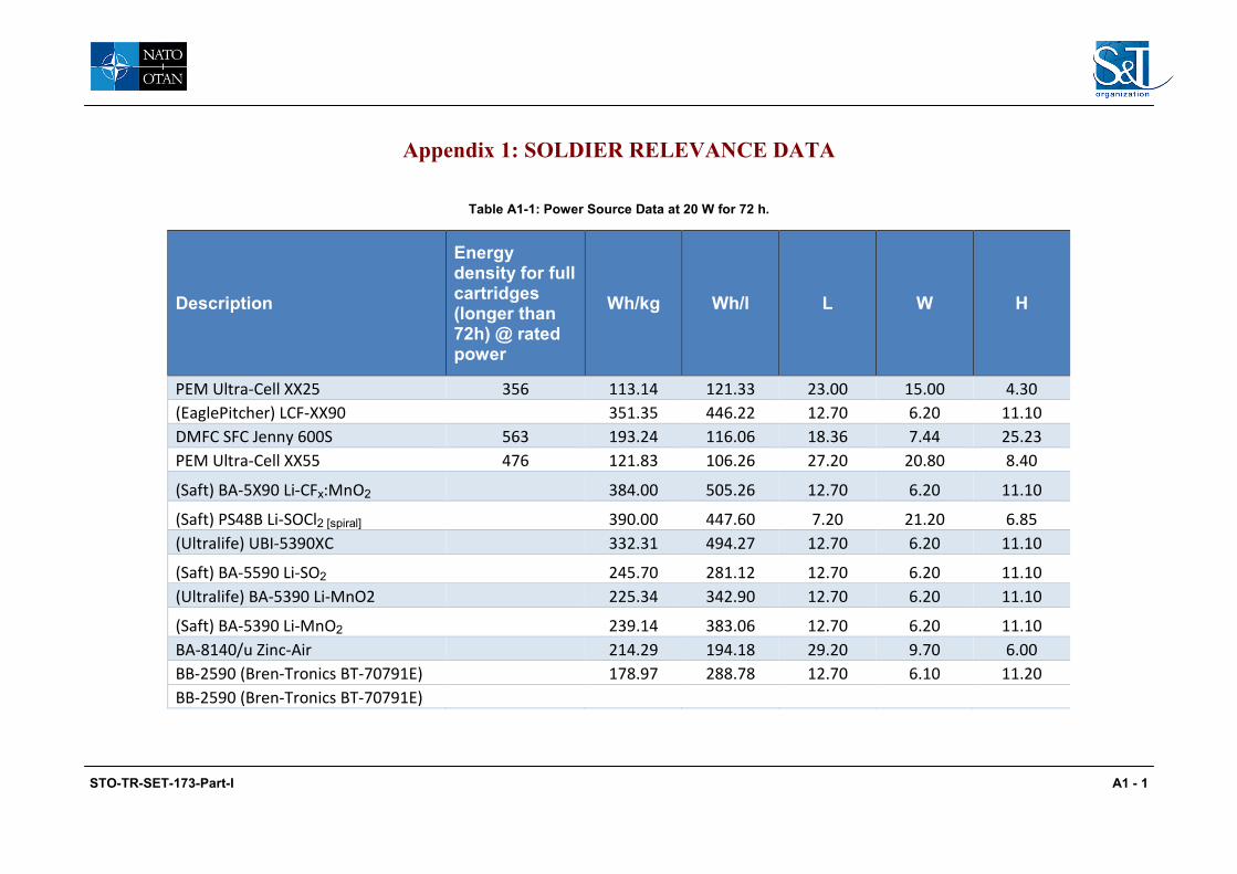
Appendix 1: SOLDIER RELEVANCE DATA
Table A1-1: Power Source Data at 20 W for 72 h.
Description
Energy density for full cartridges (longer than 72h) @ rated power
Wh/kg Wh/l L W H
PEM Ultra-Cell XX25 356 113.14 121.33 23.00 15.00 4.30 (EaglePitcher) LCF-XX90 351.35 446.22 12.70 6.20 11.10 DMFC SFC Jenny 600S 563 193.24 116.06 18.36 7.44 25.23 PEM Ultra-Cell XX55 476 121.83 106.26 27.20 20.80 8.40
(Saft) BA-5X90 Li-CFx:MnO2 384.00 505.26 12.70 6.20 11.10
(Saft) PS48B Li-SOCl2 [spiral] 390.00 447.60 7.20 21.20 6.85 (Ultralife) UBI-5390XC 332.31 494.27 12.70 6.20 11.10
(Saft) BA-5590 Li-SO2 245.70 281.12 12.70 6.20 11.10 (Ultralife) BA-5390 Li-MnO2 225.34 342.90 12.70 6.20 11.10
(Saft) BA-5390 Li-MnO2 239.14 383.06 12.70 6.20 11.10 BA-8140/u Zinc-Air 214.29 194.18 29.20 9.70 6.00 BB-2590 (Bren-Tronics BT-70791E) 178.97 288.78 12.70 6.10 11.20 BB-2590 (Bren-Tronics BT-70791E)
STO-TR-SET-173-Part-I A1 - 1
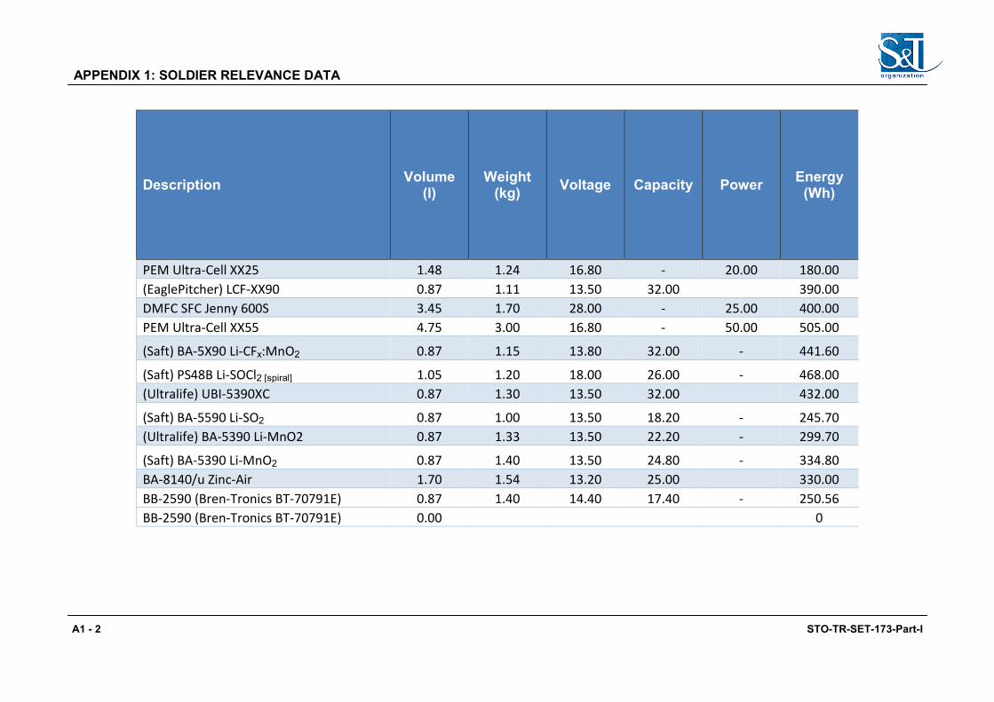
APPENDIX 1: SOLDIER RELEVANCE DATA
Description Volume (l)
Weight (kg) Voltage Capacity Power Energy
(Wh)
PEM Ultra-Cell XX25 1.48 1.24 16.80 - 20.00 180.00 (EaglePitcher) LCF-XX90 0.87 1.11 13.50 32.00 390.00 DMFC SFC Jenny 600S 3.45 1.70 28.00 - 25.00 400.00 PEM Ultra-Cell XX55 4.75 3.00 16.80 - 50.00 505.00
(Saft) BA-5X90 Li-CFx:MnO2 0.87 1.15 13.80 32.00 - 441.60
(Saft) PS48B Li-SOCl2 [spiral] 1.05 1.20 18.00 26.00 - 468.00 (Ultralife) UBI-5390XC 0.87 1.30 13.50 32.00 432.00
(Saft) BA-5590 Li-SO2 0.87 1.00 13.50 18.20 - 245.70 (Ultralife) BA-5390 Li-MnO2 0.87 1.33 13.50 22.20 - 299.70
(Saft) BA-5390 Li-MnO2 0.87 1.40 13.50 24.80 - 334.80 BA-8140/u Zinc-Air 1.70 1.54 13.20 25.00 330.00 BB-2590 (Bren-Tronics BT-70791E) 0.87 1.40 14.40 17.40 - 250.56 BB-2590 (Bren-Tronics BT-70791E) 0.00 0
A1 - 2 STO-TR-SET-173-Part-I

APPENDIX 1: SOLDIER RELEVANCE DATA
Description Runtime
hrs per
catrtidge
Standard cartridge (kg) (Fuel
Only)
Cartridge weight
(kg) empty
Fuel Cell Battery Weight
(kg)
Standard cartridge
(l)
72 hrs total @
20W cartridge/
battery [1.44kWh]
PEM Ultra-Cell XX25 9.00 0.22 0.13 0.51 8.00 (EaglePitcher) LCF-XX90 4.00 DMFC SFC Jenny 600S 20.00 0.28 0.09 0.35 4.00 PEM Ultra-Cell XX55 18.00 0.47 0.15 0.53 1.15 4.00
(Saft) BA-5X90 Li-CFx:MnO2 - - - 4.00
(Saft) PS48B Li-SOCl2 [spiral] - - - 4.00 (Ultralife) UBI-5390XC 4.00
(Saft) BA-5590 Li-SO2 - - - 6.00 (Ultralife) BA-5390 Li-MnO2 - - - 5.00
(Saft) BA-5390 Li-MnO2 - - - 5.00 BA-8140/u Zinc-Air 5.00 BB-2590 (Bren-Tronics BT-70791E) - - - 6.00 BB-2590 (Bren-Tronics BT-70791E)
STO-TR-SET-173-Part-I A1 - 3

APPENDIX 1: SOLDIER RELEVANCE DATA
Description
72 Hrs cartridge
weight (kg)
cartridge/ battery
[1.44kW]
Fuel weigh
per hour (kg) (Zn
Air weight gain)
72 hrs total
mission weight
(kg)
72hrs total
volume (l)
PEM Ultra-Cell XX25 1.76 0.02 4.05 kg 5.55 l (EaglePitcher) LCF-XX90 4.44 kg 3.50 l DMFC SFC Jenny 600S 1.12 0.01 3.18 kg 4.85 l PEM Ultra-Cell XX55 1.89 0.03 6.01 kg 9.33 l
(Saft) BA-5X90 Li-CFx:MnO2 4.60 kg 3.50 l
(Saft) PS48B Li-SOCl2 [spiral] 4.80 kg 4.18 l (Ultralife) UBI-5390XC 5.20 kg 3.50 l
(Saft) BA-5590 Li-SO2 6.00 kg 5.24 l (Ultralife) BA-5390 Li-MnO2 6.65 kg 4.37 l
(Saft) BA-5390 Li-MnO2 7.00 kg 4.37 l BA-8140/u Zinc-Air 0.01 8.08 kg 8.50 l BB-2590 (Bren-Tronics BT-70791E) 8.40 kg 5.21 l BB-2590 (Bren-Tronics BT-70791E)
A1 - 4 STO-TR-SET-173-Part-I
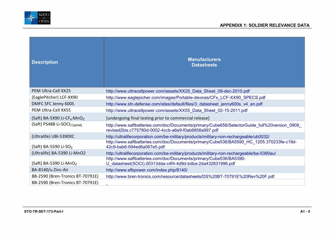
APPENDIX 1: SOLDIER RELEVANCE DATA
Description Manufacturers Datasheets
PEM Ultra-Cell XX25 http://www.ultracellpower.com/assets/XX25_Data_Sheet_09-dec-2010.pdf
(EaglePitcher) LCF-XX90 http://www.eaglepicher.com/images/Portable-devices/CFx_LCF-XX90_SPECS.pdf
DMFC SFC Jenny 600S http://www.sfc-defense.com/sites/default/files/3_datasheet_jenny600s_v4_en.pdf
PEM Ultra-Cell XX55 http://www.ultracellpower.com/assets/XX55_Data_Sheet_02-15-2011.pdf
(Saft) BA-5X90 Li-CFx:MnO2 [undergoing final testing prior to commercial release] (Saft) PS48B Li-SOCl2 [spiral]
http://www.saftbatteries.com/doc/Documents/primary/Cube658/SelectorGuide_full%20version_0909_ revised2bis.c775780d-0002-4ccb-a6e9-f0ab6858a997.pdf
(Ultralife) UBI-5390XC http://ultralifecorporation.com/be-military/products/military-non-rechargeable/ub0032/
(Saft) BA-5590 Li-SO2 http://www.saftbatteries.com/doc/Documents/primary/Cube536/BA5590_HC_1205.370233fe-c19d- 42c9-bab6-694ed6a067e5.pdf
(Ultralife) BA-5390 Li-MnO2 http://ultralifecorporation.com/be-military/products/military-non-rechargeable/ba-5390au/
(Saft) BA-5390 Li-MnO2 http://www.saftbatteries.com/doc/Documents/primary/Cube536/BA5390-U_datasheet(SOCI).00313dda-c4f4-4d9d-bdba-2da432831996.pdf
BA-8140/u Zinc-Air http://www.efbpower.com/index.php/8140/
BB-2590 (Bren-Tronics BT-70791E) http://www.bren-tronics.com/resource/datasheets/DS%20BT-70791E%20Rev%20F.pdf
BB-2590 (Bren-Tronics BT-70791E)
STO-TR-SET-173-Part-I A1 - 5

APPENDIX 1: SOLDIER RELEVANCE DATA
A1 - 6 STO-TR-SET-173-Part-I
REPORT DOCUMENTATION PAGE
1. Recipient’s Reference 2. Originator’s References 3. Further Reference
4. Security Classification of Document
STO-TR-SET-173-Part-I AC/323(SET-173)TP/559
ISBN 978-92-837-0210-8
PUBLIC RELEASE
5. Originator Science and Technology Organization North Atlantic Treaty Organization BP 25, F-92201 Neuilly-sur-Seine Cedex, France
6. Title Fuel Cells and Other Emerging Manportable Power Technologies for the NATO Warfighter – Part I: Power Sources for Manportable/Manwearable Applications
7. Presented at/Sponsored by
This is the Final Report of SET-173 “Fuel Cells and Other Emerging Manportable Power Technologies for the NATO Warfighter” on the use of fuel cells in manwearable and manportable applications.
8. Author(s)/Editor(s) 9. Date
Multiple October 2014
10. Author’s/Editor’s Address 11. Pages
Multiple 138
12. Distribution Statement There are no restrictions on the distribution of this document. Information about the availability of this and other STO unclassified publications is given on the back cover.
13. Keywords/Descriptors Battery charger Fuel cell Hydrogen Manportable
Manwearable Methanol Proton exchange membrane Solid oxide
14. Abstract
The high cost and excess weight of current batteries is proving unacceptable therefore alternatives to primary (non-rechargeable) batteries are being sought. Rechargeable batteries provide a lower initial cost option however this brings added complications in maintaining the batteries; providing charging, associated generators which require fuel particularly in remote locations. Adoption of an (integrated) soldier system power design which includes the ability to “charge on the move” will improve logistics with fewer batteries in the portfolio. Providing the ability to recharge as part of the manwearable role reduces the need to return to the Forward Operating Base (FOB) for recharging of batteries and also reduces the weight burden for the DSS as related to back up batteries. To identify and report on the state-of the art of fuel cell technology for the manwearable Dismounted Soldier System (DSS) application.
STO-TR-SET-173-Part-I

STO-TR-SET-173-Part-I

NORTH ATLANTIC TREATY ORGANIZATION SCIENCE AND TECHNOLOGY ORGANIZATION
BP 25
F-92201 NEUILLY-SUR-SEINE CEDEX • FRANCE Télécopie 0(1)55.61.22.99 • E-mail [email protected]
DIFFUSION DES PUBLICATIONS
STO NON CLASSIFIEES
Les publications de l’AGARD, de la RTO et de la STO peuvent parfois être obtenues auprès des centres nationaux de distribution indiqués ci-dessous. Si vous souhaitez recevoir toutes les publications de la STO, ou simplement celles qui concernent certains Panels, vous pouvez demander d’être inclus soit à titre personnel, soit au nom de votre organisation, sur la liste d’envoi. Les publications de la STO, de la RTO et de l’AGARD sont également en vente auprès des agences de vente indiquées ci-dessous. Les demandes de documents STO, RTO ou AGARD doivent comporter la dénomination « STO », « RTO » ou « AGARD » selon le cas, suivi du numéro de série. Des informations analogues, telles que le titre est la date de publication sont souhaitables. Si vous souhaitez recevoir une notification électronique de la disponibilité des rapports de la STO au fur et à mesure de leur publication, vous pouvez consulter notre site Web (http://www.sto.nato.int/) et vous abonner à ce service.
CENTRES DE DIFFUSION NATIONAUX ALLEMAGNE GRECE (Correspondant) REPUBLIQUE TCHEQUE
Streitkräfteamt / Abteilung III Defence Industry & Research General Vojenský technický ústav s.p. Fachinformationszentrum der Bundeswehr (FIZBw) Directorate, Research Directorate CZ Distribution Information Centre Gorch-Fock-Straße 7, D-53229 Bonn Fakinos Base Camp, S.T.G. 1020 Mladoboleslavská 944 Holargos, Athens PO Box 18
BELGIQUE 197 06 Praha 9 Royal High Institute for Defence – KHID/IRSD/RHID HONGRIE Management of Scientific & Technological Research Hungarian Ministry of Defence ROUMANIE for Defence, National STO Coordinator Development and Logistics Agency Romanian National Distribution Royal Military Academy – Campus Renaissance P.O.B. 25, H-1885 Budapest Centre Renaissancelaan 30, 1000 Bruxelles Armaments Department ITALIE 9-11, Drumul Taberei Street
CANADA Centro Gestione Conoscenza Sector 6 DSIGRD2 – Bibliothécaire des ressources du savoir Secretariat General of Defence 061353 Bucharest R et D pour la défense Canada National Armaments Directorate Ministère de la Défense nationale Via XX Settembre 123/A ROYAUME-UNI 305, rue Rideau, 9e étage 00187 Roma Dstl Knowledge and Information Ottawa, Ontario K1A 0K2 Services
LUXEMBOURG Building 247 DANEMARK Voir Belgique Porton Down, Salisbury SP4 0JQ
Danish Acquisition and Logistics Organization (DALO) NORVEGE SLOVAQUIE Lautrupbjerg 1-5 Norwegian Defence Research Akadémia ozbrojených síl gen. 2750 Ballerup Establishment, Attn: Biblioteket M.R. Štefánika, Distribučné a
P.O. Box 25, NO-2007 Kjeller informačné stredisko STO ESPAGNE Demänová 393
SDGTECIN (DGAM) PAYS-BAS 031 06 Liptovský Mikuláš 6 C/ Arturo Soria 289 Royal Netherlands Military Madrid 28033 Academy Library SLOVENIE
P.O. Box 90.002 Ministry of Defence ESTONIE 4800 PA Breda Central Registry for EU & NATO
Estonian Ministry of Defence Vojkova 55 Estonian National Coordinator for NATO STO POLOGNE 1000 Ljubljana Sakala 1 Centralna Biblioteka Wojskowa Tallinn 15094 ul. Ostrobramska 109 TURQUIE
04-041 Warszawa Milli Savunma Bakanlığı (MSB) ETATS-UNIS ARGE ve Teknoloji Dairesi
Defense Technical Information Center PORTUGAL Başkanlığı 8725 John J. Kingman Road Estado Maior da Força Aérea 06650 Bakanliklar – Ankara Fort Belvoir, VA 22060-6218 SDFA – Centro de Documentação Alfragide, P-2720 Amadora
FRANCE O.N.E.R.A. (ISP) 29, Avenue de la Division Leclerc - BP 72 92322 Châtillon Cedex
AGENCES DE VENTE
The British Library Document Canada Institute for Scientific and Supply Centre Technical Information (CISTI)
Boston Spa, Wetherby National Research Council Acquisitions West Yorkshire LS23 7BQ Montreal Road, Building M-55
ROYAUME-UNI Ottawa K1A 0S2 CANADA
Les demandes de documents STO, RTO ou AGARD doivent comporter la dénomination « STO », « RTO » ou « AGARD » selon le cas, suivie du numéro de série (par exemple AGARD-AG-315). Des informations analogues, telles que le titre et la date de publication sont souhaitables. Des références bibliographiques complètes ainsi que des résumés des publications STO, RTO et AGARD figurent dans le « NTIS Publications Database » (http://www.ntis.gov).

NORTH ATLANTIC TREATY ORGANIZATION SCIENCE AND TECHNOLOGY ORGANIZATION
BP 25
F-92201 NEUILLY-SUR-SEINE CEDEX • FRANCE Télécopie 0(1)55.61.22.99 • E-mail [email protected]
DISTRIBUTION OF UNCLASSIFIED STO PUBLICATIONS
AGARD, RTO & STO publications are sometimes available from the National Distribution Centres listed below. If you wish to receive all STO reports, or just those relating to one or more specific STO Panels, they may be willing to include you (or your Organisation) in their distribution. STO, RTO and AGARD reports may also be purchased from the Sales Agencies listed below. Requests for STO, RTO or AGARD documents should include the word ‘STO’, ‘RTO’ or ‘AGARD’, as appropriate, followed by the serial number. Collateral information such as title and publication date is desirable. If you wish to receive electronic notification of STO reports as they are published, please visit our website (http://www.sto.nato.int/) from where you can register for this service.
NATIONAL DISTRIBUTION CENTRES
BELGIUM GREECE (Point of Contact) ROMANIA Royal High Institute for Defence – KHID/IRSD/RHID Defence Industry & Research General Romanian National Distribution Management of Scientific & Technological Research Directorate, Research Directorate Centre
for Defence, National STO Coordinator Fakinos Base Camp, S.T.G. 1020 Armaments Department Royal Military Academy – Campus Renaissance Holargos, Athens 9-11, Drumul Taberei Street Renaissancelaan 30 Sector 6, 061353 Bucharest 1000 Brussels HUNGARY
Hungarian Ministry of Defence SLOVAKIA CANADA Development and Logistics Agency Akadémia ozbrojených síl gen
DRDKIM2 – Knowledge Resources Librarian P.O.B. 25, H-1885 Budapest M.R. Štefánika, Distribučné a Defence R&D Canada informačné stredisko STO Department of National Defence ITALY Demänová 393 305 Rideau Street, 9th Floor Centro Gestione Conoscenza 031 06 Liptovský Mikuláš 6 Ottawa, Ontario K1A 0K2 Secretariat General of Defence
National Armaments Directorate SLOVENIA CZECH REPUBLIC Via XX Settembre 123/A, 00187 Roma Ministry of Defence
Vojenský technický ústav s.p. Central Registry for EU & NATO CZ Distribution Information Centre LUXEMBOURG Vojkova 55 Mladoboleslavská 944 See Belgium 1000 Ljubljana PO Box 18 197 06 Praha 9 NETHERLANDS SPAIN
Royal Netherlands Military SDGTECIN (DGAM) DENMARK Academy Library C/ Arturo Soria 289
Danish Acquisition and Logistics Organization (DALO) P.O. Box 90.002 Madrid 28033 Lautrupbjerg 1-5 4800 PA Breda 2750 Ballerup TURKEY NORWAY Milli Savunma Bakanlığı (MSB)
ESTONIA Norwegian Defence Research ARGE ve Teknoloji Dairesi Estonian Ministry of Defence Establishment, Attn: Biblioteket Başkanlığı Estonian National Coordinator for NATO STO P.O. Box 25, NO-2007 Kjeller 06650 Bakanliklar – Ankara Sakala 1, Tallinn 15094
POLAND UNITED KINGDOM FRANCE Centralna Biblioteka Wojskowa Dstl Knowledge and Information
O.N.E.R.A. (ISP) ul. Ostrobramska 109 Services 29, Avenue de la Division Leclerc - BP 72 04-041 Warszawa Building 247 92322 Châtillon Cedex Porton Down, Salisbury SP4 0JQ PORTUGAL
GERMANY Estado Maior da Força Aérea UNITED STATES Streitkräfteamt / Abteilung III SDFA – Centro de Documentação Defense Technical Information Fachinformationszentrum der Bundeswehr (FIZBw) Alfragide, P-2720 Amadora Center Gorch-Fock-Straße 7 8725 John J. Kingman Road D-53229 Bonn Fort Belvoir, VA 22060-6218
SALES AGENCIES
The British Library Document Canada Institute for Scientific and Supply Centre Technical Information (CISTI)
Boston Spa, Wetherby National Research Council Acquisitions West Yorkshire LS23 7BQ Montreal Road, Building M-55
UNITED KINGDOM Ottawa K1A 0S2 CANADA
Requests for STO, RTO or AGARD documents should include the word ‘STO’, ‘RTO’ or ‘AGARD’, as appropriate, followed by the serial number (for example AGARD-AG-315). Collateral information such as title and publication date is desirable. Full bibliographical references and abstracts of STO, RTO and AGARD publications are given in “NTIS Publications Database” (http://www.ntis.gov).
ISBN 978-92-837-0210-8